US10302884B2 - Fiber distribution hub with swing frame and wrap-around doors - Google Patents
Fiber distribution hub with swing frame and wrap-around doorsDownload PDFInfo
- Publication number
- US10302884B2 US10302884B2US15/148,092US201615148092AUS10302884B2US 10302884 B2US10302884 B2US 10302884B2US 201615148092 AUS201615148092 AUS 201615148092AUS 10302884 B2US10302884 B2US 10302884B2
- Authority
- US
- United States
- Prior art keywords
- swing frame
- cabinet
- fiber distribution
- distribution hub
- region
- Prior art date
- Legal status (The legal status is an assumption and is not a legal conclusion. Google has not performed a legal analysis and makes no representation as to the accuracy of the status listed.)
- Expired - Fee Related
Links
Images


Classifications
- G—PHYSICS
- G02—OPTICS
- G02B—OPTICAL ELEMENTS, SYSTEMS OR APPARATUS
- G02B6/00—Light guides; Structural details of arrangements comprising light guides and other optical elements, e.g. couplings
- G02B6/44—Mechanical structures for providing tensile strength and external protection for fibres, e.g. optical transmission cables
- G02B6/4439—Auxiliary devices
- G02B6/444—Systems or boxes with surplus lengths
- G02B6/4452—Distribution frames
- G02B6/44524—Distribution frames with frame parts or auxiliary devices mounted on the frame and collectively not covering a whole width of the frame or rack
- G—PHYSICS
- G02—OPTICS
- G02B—OPTICAL ELEMENTS, SYSTEMS OR APPARATUS
- G02B6/00—Light guides; Structural details of arrangements comprising light guides and other optical elements, e.g. couplings
- G02B6/44—Mechanical structures for providing tensile strength and external protection for fibres, e.g. optical transmission cables
- G02B6/4439—Auxiliary devices
- G02B6/444—Systems or boxes with surplus lengths
- G02B6/4441—Boxes
- G02B6/445—Boxes with lateral pivoting cover
- G—PHYSICS
- G02—OPTICS
- G02B—OPTICAL ELEMENTS, SYSTEMS OR APPARATUS
- G02B6/00—Light guides; Structural details of arrangements comprising light guides and other optical elements, e.g. couplings
- G02B6/24—Coupling light guides
- G02B6/36—Mechanical coupling means
- G02B6/38—Mechanical coupling means having fibre to fibre mating means
- G02B6/3807—Dismountable connectors, i.e. comprising plugs
- G02B6/3897—Connectors fixed to housings, casing, frames or circuit boards
- G—PHYSICS
- G02—OPTICS
- G02B—OPTICAL ELEMENTS, SYSTEMS OR APPARATUS
- G02B6/00—Light guides; Structural details of arrangements comprising light guides and other optical elements, e.g. couplings
- G02B6/44—Mechanical structures for providing tensile strength and external protection for fibres, e.g. optical transmission cables
- G02B6/4439—Auxiliary devices
- G02B6/444—Systems or boxes with surplus lengths
- G02B6/4452—Distribution frames
- G—PHYSICS
- G02—OPTICS
- G02B—OPTICAL ELEMENTS, SYSTEMS OR APPARATUS
- G02B6/00—Light guides; Structural details of arrangements comprising light guides and other optical elements, e.g. couplings
- G02B6/44—Mechanical structures for providing tensile strength and external protection for fibres, e.g. optical transmission cables
- G02B6/4439—Auxiliary devices
- G02B6/444—Systems or boxes with surplus lengths
- G02B6/44528—Patch-cords; Connector arrangements in the system or in the box
- G—PHYSICS
- G02—OPTICS
- G02B—OPTICAL ELEMENTS, SYSTEMS OR APPARATUS
- G02B6/00—Light guides; Structural details of arrangements comprising light guides and other optical elements, e.g. couplings
- G02B6/44—Mechanical structures for providing tensile strength and external protection for fibres, e.g. optical transmission cables
- G02B6/4439—Auxiliary devices
- G02B6/4471—Terminating devices ; Cable clamps
- G02B6/4478—Bending relief means
Definitions
- Passive optical networksare becoming prevalent in part because service providers want to deliver high bandwidth communication capabilities to customers. Passive optical networks are a desirable choice for delivering high-speed communication data because they may not employ active electronic devices, such as amplifiers and repeaters, between a central office and a subscriber termination. The absence of active electronic devices may decrease network complexity and/or cost and may increase network reliability.
- FIG. 1illustrates a network 100 deploying passive fiber optic lines.
- the network 100can include a central office 110 that connects a number of end subscribers 115 (also called end users 115 herein) in a network.
- the central office 110can additionally connect to a larger network such as the Internet (not shown) and a public switched telephone network (PSTN).
- PSTNpublic switched telephone network
- the network 100can also include fiber distribution hubs (FDHs) 130 having one or more optical splitters (e.g., 1-to-8 splitters, 1-to-16 splitters, or 1-to-32 splitters) that generate a number of individual fibers that may lead to the premises of an end user 115 .
- the various lines of the networkcan be aerial or housed within underground conduits.
- the portion of network 100 that is closest to central office 110is generally referred to as the F1 region, where F1 is the “feeder fiber” from the central office.
- the F1 portion of the networkmay include a distribution cable having on the order of 12 to 48 fibers; however, alternative implementations can include fewer or more fibers.
- the portion of network 100 that includes an FDH 130 and a number of end users 115can be referred to as an F2 portion of network 100 .
- the network 100includes a plurality of break-out locations 125 at which branch cables are separated out from main cable lines. Branch cables are often connected to drop terminals 104 that include connector interfaces for facilitating coupling the fibers of the branch cables to a plurality of different subscriber locations.
- Splitters used in an FDH 130can accept a feeder cable having a number of fibers and may split those incoming fibers into, for example, 216 to 432 individual distribution fibers that may be associated with a like number of end user locations.
- an optical splitteris provided prepackaged in an optical splitter module housing and provided with a splitter output in pigtails that extend from the module.
- the splitter output pigtailsare typically connectorized with, for example, SC, LC, or LX.5 connectors.
- the optical splitter moduleprovides protective packaging for the optical splitter components in the housing and thus provides for easy handling for otherwise fragile splitter components. This modular approach allows optical splitter modules to be added incrementally to FDHs 130 as required.
- Certain aspects of the disclosurerelate to fiber distribution hubs (FDHs) that provide an interface between the F1 portion of the network and an F2 portion of the network. Certain aspects relate to features adapted to enhance access to components within the FDHs. Other aspects relate to features that enhance cable management, ease of use, and scalability. Still other aspects relate to features that inhibit water intrusion into the FDHs.
- FDHsfiber distribution hubs
- inventive aspectscan relate to individual features and to combinations of features. It is to be understood that both the forgoing general description and the following detailed description are exemplary and explanatory only and are not restrictive of the broad inventive concepts upon which the embodiments disclosed herein are based.
- FIG. 1shows a prior art passive fiber optic network
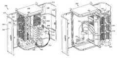
- FIG. 2shows a perspective view of an example fiber distribution hub with the doors in an open position and the swing frame detached;
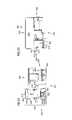
- FIG. 3is a schematic diagram showing an example cable routing scheme for the fiber distribution hub of FIG. 2 ;
- FIG. 4is a front perspective view of the fiber distribution hub of FIG. 2 with doors in the closed position;
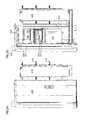
- FIG. 5is a front view of the fiber distribution hub of FIG. 4 ;
- FIG. 6is a left side view of the fiber distribution hub of FIG. 4 ;
- FIG. 7is a right side view of the fiber distribution hub of FIG. 4 ;
- FIG. 8is a top view of the fiber distribution hub of FIG. 4 ;
- FIG. 9is a bottom view of the fiber distribution hub of FIG. 4 ;
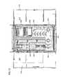
- FIG. 10is a cross-sectional view of the fiber distribution hub of FIG. 4 along lines C of FIG. 5 ;
- FIG. 11is a front perspective view of a the fiber distribution hub of FIG. 2 with doors in the open position;
- FIG. 12is a front view of the fiber distribution hub of FIG. 11 ;
- FIG. 13is a left side view of the fiber distribution hub of FIG. 11 ;
- FIG. 14is a right side view of the fiber distribution hub of FIG. 11 ;
- FIG. 15is a top view of the fiber distribution hub of FIG. 11 ;
- FIG. 16is a bottom view of the fiber distribution hub of FIG. 11 ;
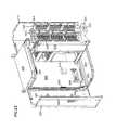
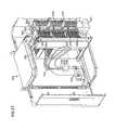
- FIG. 17is a front perspective view of the fiber distribution hub of FIG. 2 with the doors in the open position and the swing frame swung out.
- FIG. 18is a left side view of the fiber distribution hub of FIG. 17 ;
- FIG. 19shows the left side of FIG. 18 , except that the left door of the cabinet has been removed in for ease in viewing;
- FIG. 20is a front view of an example swing frame
- FIG. 21is a rear view of the swing frame of FIG. 20 ;
- FIG. 22is a left side view of the swing frame of FIG. 20 ;
- FIG. 23is a right side view of the swing frame of FIG. 20 ;
- FIG. 24is a top view of the swing frame of FIG. 20 ;
- FIG. 25is a bottom view of the swing frame of FIG. 20 ;
- FIG. 26is a front perspective, partially exploded view of the swing frame of FIG. 2 ;
- FIG. 27shows precabling of the splitter and termination modules of the fiber distribution hub of FIG. 17 ;
- FIG. 28shows front side view of the fiber distribution hub of FIG. 17 ;
- FIG. 29is a cabling diagram for routing a split fiber from the splitter module to the storage module.
- FIG. 30is a cabling diagram for routing a split fiber from the splitter module to the termination module.
- the FDH 200includes a cabinet 201 that houses internal components.
- the cabinet 201includes a main body 260 having a back panel 206 extending between a first end panel 202 and a second end panel 204 .
- the main body 260 of the cabinet 201defines a front opening 262 and side openings 264 , 266 (best shown in FIG. 15 ).
- Right and left doors 210 , 220wrap around the sides and front of the cabinet 201 .
- the doors 210 , 220are hingedly mounted to the rear of the main body 260 of the cabinet 201 and move between a closed position (see FIG. 4 ) and an open position (see FIG. 11 ).
- a first gasket 255can be provided adjacent an edge of one of the doors 210 , 220 . Edges of the main body 260 can also be lined with a second gasket 250 (see FIG. 11 ) adapted to seal the cabinet 201 from contaminants when the doors 210 , 220 are in the closed position.
- the cabinet 201also includes an opening 240 (see FIG. 10 ) through which a feeder cable (i.e., or F1 cable) 700 and a subscriber cable (i.e., or F2 cable) 708 enter and exit the cabinet 201 ( FIG. 3 ).
- a swing frame 300is pivotably mounted within the main body 260 of the cabinet 201 .
- the swing frame 300includes at least one termination region 340 and at least one splitter region 350 .
- the termination region 340is configured to retain adapters, such as the adapters of termination module 400 (see FIG. 19 ), and the splitter region 350 is configured to retain at least one splitter, such as splitter module 500 (see FIG. 26 ).
- the swing frame 300also includes a storage region 360 configured to retain at least one storage module 600 (see FIG. 26 ).
- the swing frame 300includes a pass-through region 370 .
- the swing frame 300includes a cable management panel 310 and a trough 330 for routing fibers between regions 340 , 350 , 360 , 370 ( FIGS. 17 and 18 ).
- FIG. 3is a schematic diagram showing an example cable routing scheme for the FDH 200 .
- the FDH 200generally administers connections at a termination panel between incoming fiber and outgoing fiber in an Outside Plant (OSP) environment.
- OSPOutside Plant
- a connectionbetween fibers includes both direct and indirect connections.
- incoming fibersinclude the feeder cable fibers that enter the cabinet and intermediate fibers that connect the feeder cable fibers to the termination region (e.g., connectorized pigtails extending from splitters and patching fibers/jumpers).
- Examples of outgoing fibersinclude the subscriber cable fibers that exit the cabinet and any intermediate fibers that connect the subscriber cable fibers to the termination region.
- the termination region of the FDH 200provides an interconnect interface for optical transmission signals at a location in the network where operational access and reconfiguration are desired.
- the FDH 200can be used to split the feeder cables and terminate the split feeder cables to distribution cables routed to subscriber locations 115 .
- the FDH 200is designed to accommodate a range of alternative sizes and fiber counts and support factory installation of pigtails, fanouts and splitters.
- a feeder cable 700is initially routed into the FDH 200 through the cabinet 201 (e.g., typically through the back or bottom of the main body 260 as shown in FIG. 17 ).
- the fibers of the feeder cable 700can include ribbon fibers.
- An example feeder cable 700may include twelve to forty-eight individual fibers connected to a service provider central office 110 .
- the fibers of the feeder cable 700are routed to a fanout device 805 .
- the fanout device 805separates the fibers of the feeder cable 700 .
- the fanout device 805can also upjacket the fibers of the feeder cable 700 .
- the separated feeder cable fibers 700are routed from the fanout device 805 to the splitter region 350 .
- the feeder cable fibers 700are connected to separate splitter modules 500 , in which the fibers 700 are each split into multiple pigtails 704 , each having connectorized ends 706 .
- the fibers of the feeder cable 700can be routed to a feeder cable interface 905 (e.g., a fiber optic adapter module, a splice tray, etc.).
- a feeder cable interface 905e.g., a fiber optic adapter module, a splice tray, etc.
- one or more of the fibers of the feeder cable 700are individually connected to separate splitter input fibers 702 that are routed to the splitter region 350 .
- the connectorized ends 706can be temporarily stored on a storage module 600 that is mounted at the storage region 360 of the swing frame 300 .
- the pigtails 704are routed from the splitter modules 500 to a termination module 400 that is provided at the termination region 340 of the swing frame 300 .
- the pigtails 704are connected to the fibers of a distribution cable 708 .
- the termination module 400therefore, is the dividing line between the incoming fibers and the outgoing fibers.
- a typical distribution cable 708forms the F2 portion of a network (see FIG. 1 ) and typically includes a plurality of fibers (e.g., 144, 216 or 432 fibers) that are routed from the FDHs 130 to subscriber locations 115 .
- one or more of the fibers of the feeder cable 700are not connected to any of the splitter modules 500 . Rather, these fibers of the feeder cable 700 are connected through an interface device 910 to pass-through fibers 712 having connectorized ends 714 .
- the connectorized ends 714 of the pass-through fibers 712are connected to the subscriber cable fibers 708 at the termination region 340 of the swing frame 300 without first connecting to the splitter region 350 . By refraining from splitting a fiber 700 , a stronger signal can be sent to one of the subscribers 115 .
- the connectorized ends 714 of the pass-through fibers 712can be stored at the storage region 360 of the swing frame 300 when not in use. In other embodiments, however, a feeder cable 700 having a connectorized end can be routed directly to the termination region 340 of the swing frame 300 .
- an example cabinet 201 of a FDH 200is shown in a closed position.
- the cabinet 201is relatively lightweight for easy installation, and breathable to prevent accumulation of moisture in the unit.
- an aluminum construction with a heavy powder coat finishalso provides for corrosion resistance.
- the cabinet 201is manufactured from heavy gauge aluminum and is NEMA-4X rated. In other embodiments, however, other materials can also be used.
- the cabinet 201includes a main body 260 , a right door 210 , and a left door 220 .
- the doors 210 , 220are pivotally mounted to the main body 260 of the cabinet 201 with hinge arrangements 203 , 205 to facilitate access to components mounted within the main body 260 .
- the hinge arrangements 203 , 205each include two spaced hinges.
- the doors 210 , 220are mounted at the rear of the main body 260 of the cabinet 201 .
- Each door 210 , 220includes a front portion 212 , 222 , respectively, a side portion 214 , 224 , respectively, and a connecting portion 216 , 226 , respectively, that enable the doors 210 , 220 to wrap around the side openings 264 , 266 and front opening 262 of the main body 260 of the cabinet 201 .
- the side portions 214 , 224 of the doors 210 , 220extend between the rear of the main body 260 and the front of the main body 260 .
- the front portions 212 , 222extend across the front of the main body 260 .
- the connecting portions 216 , 226arc between the front portions 212 , 222 and the side portions 214 , 224 . In other embodiments, however, the connecting portions 216 , 226 extend linearly between the front portions 212 , 222 and the side portions 214 , 224 .
- the doors 210 , 220also include a lock feature 218 ( FIG. 11 ) and a handle 228 . Opening the doors 210 , 220 facilitates access to the internal components of the cabinet 201 .
- one of the doors 210 , 220includes an angle feature 230 ( FIG. 11 ) enabling the doors 210 , 220 to overlap along a centerline of the front of the cabinet 201 .
- the angle feature 230includes a flange 232 ( FIG. 10 ) extending outwardly from the front portion 222 of the door 220 to form a channel 238 .
- the flange 232has a generally L-shaped cross-section including a first portion 231 aligned at an obtuse angle relative to the front portion 222 of the door 220 and a second portion 233 that extends rearwardly from the first portion 231 .
- End flanges 234 , 236located on either end of flange 232 , substantially close off the vertical channel 238 .
- the angle feature 230 of the doors 210 , 220includes a first gasket 255 for sealing the centerline of the doors 210 , 220 when the cabinet 201 is closed.
- a portion of the first gasket 255is shown in FIG. 11 lining the angle feature 230 .
- the first and second portions 231 , 233 of the angle feature 230are sized and angled to provide space for the first gasket 255 .
- the second portion 233 of the angle feature 230abuts against the front portion 212 of door 210 and the gasket/seal 255 is compressed between the first portion 231 of the angle feature 230 and an edge of the door 220 .
- the first gasket 255preferably extends vertically along the first portion 231 of the angle feature 230 from end flange 234 to end flange 236 .
- the main body 260 of the cabinet 201includes a back panel 206 extending between a first end panel 202 and a second end panel 204 .
- the second end panel 204includes an access opening 240 ( FIG. 10 ) through which the feeder cable 700 and the subscriber cable 708 enter and exit the main body 260 of the cabinet 201 .
- Both the first and second end panels 202 , 204include mounting holes 244 (see FIGS. 9 and 10 ) for deploying the cabinet 201 .
- the main body 260 of the cabinet 201can be deployed in either a pedestal mount or an aerial mount orientation.
- the cabinet 201is adapted to be secured to a pedestal mount.
- the main body 260is oriented so that the first end panel 202 is at the top of the cabinet 201 and the second end panel 204 is at the bottom of the cabinet 201 . ( FIG. 2 ).
- the access opening 240 of the second end panel 204is covered with an access panel 242 defining an opening sized to fit the feeder cable 700 and an opening sized to fit the subscriber cable 708 ( FIG. 9 ).
- Internal componentsare loaded into the main body 260 of the cabinet 201 .
- the door 210is mounted to hinge arrangement 203 and the door 220 is mounted to hinge arrangement 205 .
- the second end panel 204i.e., the bottom panel
- a feeder cable 700 and a subscriber cable 708can be routed upwardly through the access opening 240 and the access panel 242 ( FIG. 27 ).
- a cover 208( FIG. 4-8 ) is configured to mount over the end panel 202 (i.e., the top panel). In some embodiments, the cover 208 improves the overall aesthetic appearance of the cabinet 201 . In other embodiments, the cover 208 shields the four mounting holes 244 of the end panel 202 to prevent water, dirt, and other contaminants from accessing the FDH 200 . In one example embodiment, the cover 208 has a pitched surface to enable water to run off of the cover 208 when the FDH 200 is pedestal mounted.
- the cabinet 201is intended to be secured to an aerial mount.
- the main body 260 of the cabinet 201is oriented so that the first end panel 202 is at the bottom of the cabinet 201 and the second end panel 204 is at the top of the cabinet 201 .
- the access opening 240 of the second end panel 204is still covered with an access panel 242 .
- the access panel 242is located on the top of the cabinet 201 .
- the door 210mounts to hinge arrangement 205 and the door 220 mounts to hinge arrangement 203 .
- the cabinet 201is mounted on a pole by a pole mount configuration (not shown) having a platform on which the first end panel 202 (i.e., the bottom panel) of the cabinet 201 rests.
- the mounting holes 244 of the first end panel 202enable the cabinet 201 to be fastened to the platform.
- At least one aerial feeder cable 700 and subscriber cable 708can be routed downwardly into the cabinet 201 through the access opening 240 .
- the access panel 242covers the access opening 240 while enabling the feeder cable 700 and subscriber cable 708 to enter the cabinet 201 .
- the cabinet 201can include one or more carry loops 207 for facilitating deployment of the cabinet 201 at a desired location.
- the loops 207can be used to position the cabinet using a crane.
- the cranecan lower the cabinet 201 into an underground region.
- the carry loops 207are located adjacent to the cover 208 .
- the loops 207are removable or can be adjusted to not protrude past the cover 208 .
- the example FDH 200is shown in an open position.
- the doors 210 , 220are oriented to enable access to the front opening 262 and side openings 264 , 266 ( FIG. 15 ), defined by the main body 260 of the cabinet 201 .
- the doorsare oriented so that the side portions 214 , 224 are substantially parallel to the back panel 206 of the main body 260 and the front portions 212 , 222 are substantially perpendicular to and spaced from the back panel 206 . Opening the cabinet 201 in this way enables a user to access not only the front of the cabinet, but also the sides.
- the cabinet 201 of the FDH 200is configured to protect the internal components against rain, wind, dust, rodents and other contaminants.
- the cabinet 201includes a second gasket 250 (best seen in FIG. 11 ) lining the edges 252 , 254 , 256 of the first end panel 202 , the back panel 206 and the second end panel 204 , respectively, where the panels 202 , 204 , 206 interface with the doors 210 , 220 .
- the second gasket 250extends around the entire perimeter of the door interface.
- FIGS. 17-22opening the doors 210 , 220 enables a user to access the swing frame 300 pivotably mounted within the cabinet 201 .
- the swing frame 300is installed in the rear of the cabinet 201 after an orientation of the cabinet 201 has been determined.
- FIGS. 17-22illustrate an example swing frame 300 separate from the cabinet 201 .
- the swing frame 300has a front 302 , a rear 304 , a left side 303 , and a right side 305 ( FIGS. 21 and 22 ).
- the swing frame 300has a pivot axis Z extending through the swing frame 300 from the top of the swing frame 300 to the bottom.
- the pivot axis Zextends though the swing frame 300 on the right side 305 .
- the swing frame 300can be pivoted on the axis Z through the opening defined by the main body of the cabinet 201 when the doors 210 , 220 are open.
- the swing frame 300pivots between a first “swung in” position (see FIG. 11 ) in which the swing frame 300 fits within the footprint of the cabinet 201 and a second “swung out” position (best seen in FIG. 23 ) in which the swing frame 300 pivots out of the cabinet 201 .
- the swing frame 300can be swung out of the cabinet 201 at an angle of about 90 degrees.
- the swing frame 300includes at least one termination region 340 , at least one storage region 360 , at least one splitter region 350 , and at least one pass-through region 370 .
- Each termination region 340is configured to hold at least one termination module 400 ( FIG. 19 ) and each splitter region 350 is configured to hold at least one splitter module 500 .
- Each storage region 360is configured to hold at least one storage module 600 (best seen in FIG. 26 ).
- the termination, splitter, and storage modules 400 , 500 , 600respectively, will be described with more detail with reference to FIG. 26 .
- the pass-through region 370enables a feeder cable 700 , or intermediate fiber 712 , to interface with a subscriber distribution-cable 708 without first splitting the feeder cable 700 .
- the left side 303 of the swing frame 300includes a storage region 360 located on the front 302 of the swing frame 300 between a first termination region 340 and a second termination region 340 A.
- the opposite side 305 of the swing frame 300includes a first splitter region 350 located above a second splitter region 350 A.
- a pass-through region 370is located adjacent the second splitter region 350 A.
- the swing frame 300can include any desired number of termination regions 340 , storage regions 360 , and splitter regions 350 .
- the regions 340 , 350 , 360 , and 370can be arranged in any desired configuration on the swing frame 300 .
- the swing frame 300also includes a cable management panel 310 (see FIG. 17 ) for aid in routing fiber from one component module to another.
- the cable management panel 310includes a bend limiter 312 oriented to direct splitter pigtails 704 (see FIG. 3 ) from the splitter modules 500 to a first channel 320 .
- the first channel 320is defined by an array of flanges 322 .
- the flanges 322protrude forwardly from the panel 310 .
- the forward ends of the flanges 322are bent towards the sides 303 , 305 of the swing frame 300 , thereby forming the channel 320 .
- Flanges 328similarly form a second channel 326 adjacent channel 320 .
- An array of radius bend limiters 336also protrudes from the cable management panel 310 .
- the channels 320 , 326lead from the splitter region 350 to a trough 330 extending along the bottom of the swing frame 300 ( FIG. 19 ).
- the trough 330includes a flange 331 protruding upwardly to retain fiber in the trough 330 .
- First and second slack storage spools 332 , 334are positioned above the trough.
- the first spool 332is positioned adjacent the first and second channels 320 , 326 .
- the second spool 334is positioned intermediate the array of bend limiters 336 and the termination regions 340 , 340 A. Additional bend limiters 335 can be located in the remaining area between the trough 330 and the termination regions 340 , 340 A.
- FIG. 18is a rear view of the swing frame 300 shown in FIG. 17 .
- the termination region 340is substantially hidden from view by a back panel 316 .
- the splitter regions 350 and 350 Aare visible from the rear side 304 of the swing frame 300 .
- the splitter regions 350 , 350 Aare configured to enable one or more splitter modules 500 to be slid into guides 352 in the splitter regions 350 , 350 A.
- the splitter modules 500slide rearwardly into the guides 352 from the front side 302 of the swing frame 300 .
- adapter modules 354are mounted to the splitter regions 350 , 350 A.
- the adapter modules 354are adapted to receive an integral connector (not shown) projecting rearwardly from the splitter module 500 .
- dust caps 356can be mounted to the adapter module 354 to prevent dust and/or other contaminants from polluting the adapter module 354 prior to connection with the splitter module 500 .
- the pass-through region 370is located adjacent the second splitter region 350 A.
- the pass-through region 370includes at least one adapter module 374 .
- the adapter module 374is configured to accept a connectorized end of the feeder cable 700 , or an intermediate cable (not shown), on one end and a connectorized end of a pass-through pigtail 712 on an opposite end.
- the pass-through region 370includes cable management devices (not shown) enabling the feeder cable 700 to be routed through the pass-through region 370 to the front side 302 of the swing frame 300 .
- One of the array of fanout devices 810is also visible adjacent the back panel 316 .
- multiple fanout devices 810are mounted adjacent the termination modules 400 .
- the fanout devices 810are configured to receive fibers from the subscriber cable 708 extending from the termination modules 400 and to combine the fibers 708 into ribbon cables.
- FIG. 17shows a storage region 360 positioned between a first termination region 340 and a second termination region 340 A on the left side 305 of the swing frame 300 .
- the storage region 360includes at least one storage panel 362 that defines openings 364 in which the storage modules 600 can be mounted.
- the panel 362can be formed into angled shelves 366 (best seen in FIG. 26 ).
- the first termination region 340extends across the entire left side 305 of the swing frame 300 .
- a forward portion of the termination region 340defines a first channel 342 (best seen in FIGS. 21 and 27 ) and a rearward portion of the termination region 340 defines a second channel 344 (best seen in FIGS. 21 and 27 ).
- the first channel 342is formed from bent flanges 343 ( FIGS. 19 and 27 ), extending sideways and rearwardly from the storage region 360 .
- the second channel 344is formed from one or more bent flanges 345 extending sideways and forwardly from the back panel 316 .
- An array of radius bend limiters 346 , 348is located within each channel 342 , 344 , respectively ( FIGS. 17, 21, and 27 ).
- One or more termination modules 400are located intermediate the channels 342 , 344 .
- the second termination region 340 Ais similarly formed ( FIGS. 26 and 27 ).
- the pivot axis Zenables the opposite side 303 of the swing frame 300 to pass through the front opening 262 and side opening 266 when pivoted into the second position.
- the front 302 of the swing frame 300as well as substantial portions of side 303 and side 305 are accessible when the cabinet doors 210 , 212 are in the open position and the swing frame 300 is contained within the cabinet 201 .
- all of side 305 as well as the rear 304 of the swing frame 300are accessible when the swing frame 300 is pivoted out of the cabinet 201 .
- Opening the doors 210 , 220 and swinging out the frame 300provides a large amount of space S (see FIG. 28 ) for accessing the rear side of the swing frame 300 and maneuvering around the interior of the cabinet 201 .
- the provided space Sextends across most of the back panel 206 and across the side portion 224 of the door 220 . Providing such a space S facilitates access to the inside surface of the back panel 206 through the front opening 262 and the side opening 264 .
- a cable support panel 246is mounted to the inside surface of the back panel 206 above the access panel 242 in the second end panel 204 ( FIG. 23 ).
- the cable support panel 246is adapted to retain a feeder cable 700 and a subscriber cable 708 entering/exiting the cabinet 201 of the FDH 200 (see FIG. 27 ).
- a fanout device 815adapted to combine support cable fibers 708 or ribbon cables formed therefrom into a single cable. The large amount of maneuvering room provided by the doors 210 , 220 facilitates routing the feeder cable 700 to the splitter region 350 or the pass-through region 370 of the swing frame 300 .
- FIG. 26is a front perspective, partially exploded view of the FDH 200 .
- an example of a splitter module 500 and an example of a storage module 600are shown detached from the splitter region 350 A and the storage region 360 , respectively, of the swing frame 300 .
- Each splitter region 350 , 350 Ais designed to house at least one splitter module 500 .
- the splitter module 500includes a housing 505 from which at least one integral connector (not shown) protrudes rearwardly.
- the integral connectoris configured to plug into one end of an adapter unit 354 mounted to the splitter region 350 (see FIG. 25 ).
- the splitter module 500includes four integral connectors adapted to fit into one end of an adapter unit 354 .
- such an adapter unit 354is shown removed from the splitter region 350 in FIG. 26 .
- Dust caps 356are also visible extending out from the adapter units 354 .
- a connectorized end of a feeder cable fiber 700is connected to the splitter module 500 by plugging the connectorized end into an opposite end of the adapter unit 354 .
- FIG. 27shows a single fiber extending from the feeder cable 700 to the adapter unit 354 of the splitter region 350 . Only a single fiber of the feeder cable 700 is shown for ease in viewing.
- the feeder cable 700can include a ribbon cable that is directed to a fanout device 805 adjacent the splitter region 350 . The fanout device 805 separates the ribbon cable into individual fibers that are routed to the adapter units 354 .
- a connectorized end of a splitter input fiber 702(see FIG. 3 ) is plugged into the opposite end of the adapter unit 354 .
- the splitter input fiber 702can have a connectorized or unconnectorized end that interfaces with the feeder cable fibers 700 at a cable interface device 905 (see FIG. 3 ).
- the splitter input fiber 702connects to a splitter module 500 by passing through the housing 505 and entering the splitter module 500 .
- the splitter region 350does not include adapter units 354 .
- the fibers of the feeder cable 700 or the input pigtails 702are routed to the splitter modules 500 when the feeder cable 700 is initially installed in the cabinet or when each splitter module is incrementally installed. Precabling the splitter modules 500 facilitates the process of adding a subscriber to the network and reduces handling of the fibers 700 , 702 .
- Each splitter module 500includes at least one protective boot 510 protruding forwardly from the housing 505 ( FIG. 26 ).
- Connectorized splitter pigtails 704extend from the protective boot 510 .
- each splitter module 500receives between one and four input fibers (e.g., feeder cable fibers) and outputs between two and sixteen output fibers (e.g., pigtail fibers) for every input fiber.
- four input fibersenter a splitter module 500 and thirty-two output fibers exit the splitter module 500 .
- a tab 530extends outwardly from a front end of the splitter housing 505 for ease in mounting and removing the splitter module 500 from the splitter regions 350 , 350 A.
- splitter module 500can be found in the U.S. application Ser. No. 11/384,297, entitled “Fiber Optic Splitter Module,” filed Feb. 13, 2006, and which is hereby incorporated by reference. Additional information on other types of splitter modules can be found at U.S. application Ser. No. 10/980,978, filed Nov. 3, 2004, entitled “Fiber Optic Module And System Including Rear Connectors;” U.S. application Ser. No. 11/138,063, filed May 25, 2005, entitled “Fiber Optic Splitter Module;” U.S. application Ser. No. 11/215,837, filed Aug. 29, 2005, entitled “Fiber Optic Splitter Module With Connector Access;” and U.S. application Ser. No. 11/321,696, filed Dec. 28, 2005, entitled “Splitter Modules For Fiber Distribution Hubs,” the disclosures of which are hereby incorporated by reference.
- a splitter module 500is incrementally added to the swing frame 300 precabled to a storage module 600 as shown in FIG. 26 .
- the connectorized ends 706 of the pigtails 704 exiting the protective boot 510are stored in one or more storage modules 600 prior to installation of the splitter 500 on the swing frame 300 .
- the connector 706 of each pigtail 704is secured in a storage module 600 before the splitter module 500 leaves the factory.
- the storage module 600protects the connectors 706 on the ends of the pigtails 704 until the pigtails 704 are needed to connect a subscriber 115 to the network 100 (see FIG. 1 ).
- the connectorized pigtails 704 of each splitter module 500are routed to four storage modules 600 each holding eight connectors 706 .
- the storage module 600includes a body 605 defining at least one cavity sized to hold at least one fiber optic connector, such as connectors 706 .
- the body 605is configured to retain about eight connectors.
- the body 605is arranged to retain the fiber connectors in a single row configuration.
- the body 605can be arranged to retain the connectors in a square pattern or in any other desired configuration. More information regarding the storage modules 600 can be found in U.S. application Ser. No. 10/610,325, filed on Jun. 30, 2003, entitled “Fiber Optic Connector Holder and Method;” U.S. application Ser. No. 10/613,764, filed on Jul. 2, 2003, entitled “Telecommunications Connection Cabinet;” and U.S. application Ser. No. 10/871,555, filed on Jun. 18, 2004, entitled “Multi-position Fiber Optic Connector Holder and Method,” the disclosures of which are hereby incorporated by reference.
- the body 605 of the storage module 600is designed to snap into one of the openings 364 defined in the storage region 360 of the swing frame 300 .
- the openings 364can be arranged in any desired configuration within the storage region 360 .
- the storage region 360defines two columns of six openings 364 .
- the openings 364are defined by angled shelves 366 so that the attached connectors 706 are aimed downwardly to prevent excessive fiber bending.
- At least one termination module 400can be mounted to each termination region 340 of the swing frame 300 .
- each termination module 400includes a body 402 having multiple slots 404 in which adapter modules 410 can be slidably mounted.
- Each adapter module 410defines at least one open cavity 415 one side of each of the open cavities is adapted to receive the fiber optic connector 706 , 714 of a splitter pigtail 704 or pass-through pigtail 712 , respectively.
- the opposite side of each open cavity 415is adapted to receive a fiber optic connector 710 of a subscriber cable fiber 708 .
- an adapter module 410includes at least twelve open cavities 415 .
- the subscriber cable 708can be precabled to the termination modules 400 .
- the subscriber cable 708enters the cabinet 201 and is directed to a fanout device 815 that separates and upjackets the subscriber cable 708 into multiple ribbon cables 718 .
- the ribbon cables 718are directed to an array of fanout devices 810 .
- bend tubes 720further protect the ribbon cables 718 between the fanout 815 and the fanout 810 .
- Each fanout device 810separates one of the ribbon cables 718 into individual fibers.
- Each of the fibers of the ribbon cable 718are next routed from the fanout device 810 , up the second channel 344 ( FIG.
- each adapter module 410is configured to slide is a lateral direction from a first position within the termination region 340 to an extended position jutting outwardly from the termination region 340 .
- the first adapter module 410 in each termination module 400 shown in FIGS. 26 and 27is slid out in the second position.
- the sliding featureenables a user to access a particular set of fibers 700 , 708 without interfering with the remaining fibers in the termination region 340 .
- the sliding featurecombined with the wrap-around doors 210 , 212 of the cabinet 201 facilitate manipulation of the adapter modules 410 , even when the swing frame 300 is wholly contained within the cabinet 201 .
- each adapter module 410also includes a locking tab 418 that enables and prevents the adapter module 410 from sliding outwardly and inwardly within the termination module 400 .
- the locking tab 418is configured to lock the adapter module 410 into a fixed position. To slide the adapter module 410 into a different position, the tab 418 is flipped, rotated, or otherwise adjusted to release the adapter module 410 . Additional information regarding the termination modules 400 can be found in U.S. application Ser. No. 11/095,033, filed Mar. 31, 2005, and entitled “Adapter Block Including Connector Storage;” and U.S. Pat. Nos. 5,497,444; 5,717,810; 5,758,003; and 6,591,051, the disclosures of which are hereby incorporated by reference.
- FIGS. 29-30routing schemes for connecting the splitter modules 500 in the splitter region 350 to the termination modules 400 in the termination region 340 or to the storage modules 600 in the storage region 360 are shown.
- FIGS. 29 and 30show the front 302 of a swing frame 300 detached from the cabinet 201 of the FDH 200 .
- a single splitter 500is shown in the second splitter region 350 A of the swing frame 300 outputting a single pigtail 704 .
- the splitter pigtails 704are upjacketed and include strength members (e.g., Kevlar) to provide increased protection from handling when the pigtails 704 are added and removed from service.
- strength memberse.g., Kevlar
- the pigtails 704are routed over the bend limiter 312 to the first channel 320 of the cable management panel 310 .
- additional pigtails 704can be routed down the second channel 326 to avoid entangling the pigtails 704 .
- the pigtail 704is partially wrapped around the first storage spool 332 and routed upwardly along the array of radius bend limiters 336 .
- the pigtailis next draped over an appropriate bend limiter in the array 336 to store any excess fiber length and routed back down towards the trough 330 .
- the pigtailis routed across the trough 330 , wound over a bend limiter 335 , and up to the storage region 360 .
- the connector 706 on the end of the pigtail 704is plugged into a storage module 600 in the storage region 360 .
- the connector 706is removed from the storage module 600 .
- the appropriate adapter module 410 of one of the termination modules 400is slid outward.
- the subscriber cable fibers 708have been precabled to the termination module 400 so that the connector 710 of the appropriate subscribe cable 708 is already plugged into the cavity 415 on the adapter module 410 .
- the connector 706 of the splitter pigtail 704is plugged into the opposite side of the same cavity 415 on the adapter module 410 .
- the adapter module 410is then slid back into the termination region 340 .
- the pigtail 704will need to be rerouted across the front of the swing frame 300 during the connection process. For example, as shown in FIG. 30 , the pigtail 704 may need to be wound around a different bend limiter 337 adjacent the trough 330 . In other embodiments (not shown), the pigtail 704 may need to be wound around a different bend limiter in the array of bend limiters 336 to gain or take up additional fiber length.
- the feeder cable 700is not split. Rather, the feeder cable 700 is connected to a pass-through fiber 712 at a cable interface device 910 ( FIG. 3 ), such as the adapter module 374 shown in FIG. 18 .
- the pass-through fiber 712can be routed around the front side of the swing frame 300 to the termination region 340 or to the storage region 360 similar to the splitter pigtail 704 .
- the pass-through fiber 712is upjacketed similar to the splitter pigtails 704 .
Landscapes
- Physics & Mathematics (AREA)
- General Physics & Mathematics (AREA)
- Optics & Photonics (AREA)
- Light Guides In General And Applications Therefor (AREA)
Abstract
Description
Claims (22)
Priority Applications (2)
| Application Number | Priority Date | Filing Date | Title |
|---|---|---|---|
| US15/148,092US10302884B2 (en) | 2006-05-04 | 2016-05-06 | Fiber distribution hub with swing frame and wrap-around doors |
| US16/419,794US10845560B2 (en) | 2006-05-04 | 2019-05-22 | Fiber distribution hub with swing frame and wrap-around doors |
Applications Claiming Priority (5)
| Application Number | Priority Date | Filing Date | Title |
|---|---|---|---|
| US79789006P | 2006-05-04 | 2006-05-04 | |
| US11/743,941US7760984B2 (en) | 2006-05-04 | 2007-05-03 | Fiber distribution hub with swing frame and wrap-around doors |
| US12/839,852US8577198B2 (en) | 2006-05-04 | 2010-07-20 | Fiber distribution hub with swing frame and wrap-around doors |
| US14/072,254US9335504B2 (en) | 2006-05-04 | 2013-11-05 | Fiber distribution hub with swing frame and wrap-around doors |
| US15/148,092US10302884B2 (en) | 2006-05-04 | 2016-05-06 | Fiber distribution hub with swing frame and wrap-around doors |
Related Parent Applications (1)
| Application Number | Title | Priority Date | Filing Date |
|---|---|---|---|
| US14/072,254ContinuationUS9335504B2 (en) | 2006-05-04 | 2013-11-05 | Fiber distribution hub with swing frame and wrap-around doors |
Related Child Applications (1)
| Application Number | Title | Priority Date | Filing Date |
|---|---|---|---|
| US16/419,794ContinuationUS10845560B2 (en) | 2006-05-04 | 2019-05-22 | Fiber distribution hub with swing frame and wrap-around doors |
Publications (2)
| Publication Number | Publication Date |
|---|---|
| US20160327762A1 US20160327762A1 (en) | 2016-11-10 |
| US10302884B2true US10302884B2 (en) | 2019-05-28 |
Family
ID=39029259
Family Applications (5)
| Application Number | Title | Priority Date | Filing Date |
|---|---|---|---|
| US11/743,941Expired - Fee RelatedUS7760984B2 (en) | 2006-05-04 | 2007-05-03 | Fiber distribution hub with swing frame and wrap-around doors |
| US12/839,852Active2028-07-12US8577198B2 (en) | 2006-05-04 | 2010-07-20 | Fiber distribution hub with swing frame and wrap-around doors |
| US14/072,254ActiveUS9335504B2 (en) | 2006-05-04 | 2013-11-05 | Fiber distribution hub with swing frame and wrap-around doors |
| US15/148,092Expired - Fee RelatedUS10302884B2 (en) | 2006-05-04 | 2016-05-06 | Fiber distribution hub with swing frame and wrap-around doors |
| US16/419,794ActiveUS10845560B2 (en) | 2006-05-04 | 2019-05-22 | Fiber distribution hub with swing frame and wrap-around doors |
Family Applications Before (3)
| Application Number | Title | Priority Date | Filing Date |
|---|---|---|---|
| US11/743,941Expired - Fee RelatedUS7760984B2 (en) | 2006-05-04 | 2007-05-03 | Fiber distribution hub with swing frame and wrap-around doors |
| US12/839,852Active2028-07-12US8577198B2 (en) | 2006-05-04 | 2010-07-20 | Fiber distribution hub with swing frame and wrap-around doors |
| US14/072,254ActiveUS9335504B2 (en) | 2006-05-04 | 2013-11-05 | Fiber distribution hub with swing frame and wrap-around doors |
Family Applications After (1)
| Application Number | Title | Priority Date | Filing Date |
|---|---|---|---|
| US16/419,794ActiveUS10845560B2 (en) | 2006-05-04 | 2019-05-22 | Fiber distribution hub with swing frame and wrap-around doors |
Country Status (1)
| Country | Link |
|---|---|
| US (5) | US7760984B2 (en) |
Cited By (1)
| Publication number | Priority date | Publication date | Assignee | Title |
|---|---|---|---|---|
| US10845560B2 (en) | 2006-05-04 | 2020-11-24 | Commscope Technologies Llc | Fiber distribution hub with swing frame and wrap-around doors |
Families Citing this family (92)
| Publication number | Priority date | Publication date | Assignee | Title |
|---|---|---|---|---|
| US7623749B2 (en)* | 2005-08-30 | 2009-11-24 | Adc Telecommunications, Inc. | Fiber distribution hub with modular termination blocks |
| US7816602B2 (en) | 2006-02-13 | 2010-10-19 | Adc Telecommunications, Inc. | Fiber distribution hub with outside accessible grounding terminals |
| EP1931085B1 (en)* | 2006-12-06 | 2012-07-18 | Genexis B.V. | Modular network connection equipment |
| US7349616B1 (en) | 2007-01-12 | 2008-03-25 | Corning Cable Systems Llc | Fiber optic local convergence points for multiple dwelling units |
| US7522805B2 (en)* | 2007-03-09 | 2009-04-21 | Adc Telecommunications, Inc. | Wall mount distribution arrangement |
| NL2000643C2 (en)* | 2007-05-11 | 2008-11-13 | Brabantia Nederland Bv | Housing for a drying device. |
| ATE467962T1 (en)* | 2007-05-29 | 2010-05-15 | Packetfront Systems Ab | METHOD FOR CONNECTING VLAN SYSTEMS TO OTHER NETWORKS VIA A ROUTER |
| JP4891162B2 (en)* | 2007-06-29 | 2012-03-07 | キヤノン株式会社 | Image processing apparatus and profile creation method |
| ATE447278T1 (en)* | 2007-08-08 | 2009-11-15 | Packetfront Systems Ab | VLAN DATA FRAME AND TRANSMISSION |
| ATE464733T1 (en)* | 2007-10-12 | 2010-04-15 | Packetfront Systems Ab | CONFIGURATION OF ROUTERS FOR DHCP SERVICE REQUESTS |
| EP2048848B1 (en) | 2007-10-12 | 2013-12-18 | PacketFront Network Products AB | Optical data communications |
| US7751672B2 (en) | 2007-10-31 | 2010-07-06 | Adc Telecommunications, Inc. | Low profile fiber distribution hub |
| US8229265B2 (en)* | 2007-11-21 | 2012-07-24 | Adc Telecommunications, Inc. | Fiber distribution hub with multiple configurations |
| US8238709B2 (en) | 2007-12-18 | 2012-08-07 | Adc Telecommunications, Inc. | Multi-configuration mounting system for fiber distribution hub |
| WO2009146022A2 (en)* | 2008-04-03 | 2009-12-03 | 3M Innovative Properties Company | Optical fiber strain relief device and distribution cabinet |
| US20090277681A1 (en)* | 2008-04-04 | 2009-11-12 | Musolf Bruce R | Expansion cross-connect enclosure |
| US8639356B2 (en) | 2008-05-07 | 2014-01-28 | Cardiac Pacemakers, Inc. | Lead assembly and related methods |
| US9265936B2 (en) | 2008-05-07 | 2016-02-23 | Cardiac Pacemakers, Inc. | Lead assembly and related methods |
| WO2009143886A1 (en)* | 2008-05-28 | 2009-12-03 | Packetfront Systems Ab | Data retrieval in a network of tree structure |
| US8083302B2 (en)* | 2008-06-11 | 2011-12-27 | Adc Telecommunications, Inc. | L-shaped doors with trapezoidal seal |
| US8125785B2 (en)* | 2008-06-11 | 2012-02-28 | Adc Telecommunications, Inc. | Angled doors with continuous seal |
| GB0812268D0 (en)* | 2008-07-04 | 2008-08-13 | Tyco Electronics Raychem Nv | Improvements in or relating to optical fibre distribution systems |
| US11294136B2 (en) | 2008-08-29 | 2022-04-05 | Corning Optical Communications LLC | High density and bandwidth fiber optic apparatuses and related equipment and methods |
| US8452148B2 (en) | 2008-08-29 | 2013-05-28 | Corning Cable Systems Llc | Independently translatable modules and fiber optic equipment trays in fiber optic equipment |
| US20100201230A1 (en)* | 2009-02-02 | 2010-08-12 | Schweitzer Iii Edmund O | Electric power system control system with selective enclosure |
| EP2221932B1 (en) | 2009-02-24 | 2011-11-16 | CCS Technology Inc. | Holding device for a cable or an assembly for use with a cable |
| US20100220967A1 (en)* | 2009-02-27 | 2010-09-02 | Cooke Terry L | Hinged Fiber Optic Module Housing and Module |
| US8699838B2 (en) | 2009-05-14 | 2014-04-15 | Ccs Technology, Inc. | Fiber optic furcation module |
| US9075216B2 (en) | 2009-05-21 | 2015-07-07 | Corning Cable Systems Llc | Fiber optic housings configured to accommodate fiber optic modules/cassettes and fiber optic panels, and related components and methods |
| US8538226B2 (en) | 2009-05-21 | 2013-09-17 | Corning Cable Systems Llc | Fiber optic equipment guides and rails configured with stopping position(s), and related equipment and methods |
| EP2443497B1 (en) | 2009-06-19 | 2020-03-04 | Corning Cable Systems LLC | High density and bandwidth fiber optic apparatus |
| US8712206B2 (en) | 2009-06-19 | 2014-04-29 | Corning Cable Systems Llc | High-density fiber optic modules and module housings and related equipment |
| US20100322580A1 (en)* | 2009-06-22 | 2010-12-23 | Beamon Hubert B | Fiber Optic Cable Parking Device |
| ES2403007A1 (en)* | 2009-07-01 | 2013-05-13 | Adc Telecommunications, Inc | Wall-mounted fiber distribution hub |
| US8625950B2 (en) | 2009-12-18 | 2014-01-07 | Corning Cable Systems Llc | Rotary locking apparatus for fiber optic equipment trays and related methods |
| US8992099B2 (en) | 2010-02-04 | 2015-03-31 | Corning Cable Systems Llc | Optical interface cards, assemblies, and related methods, suited for installation and use in antenna system equipment |
| US8913866B2 (en) | 2010-03-26 | 2014-12-16 | Corning Cable Systems Llc | Movable adapter panel |
| CA2796221C (en) | 2010-04-16 | 2018-02-13 | Ccs Technology, Inc. | Sealing and strain relief device for data cables |
| EP2381284B1 (en) | 2010-04-23 | 2014-12-31 | CCS Technology Inc. | Under floor fiber optic distribution device |
| US8660397B2 (en) | 2010-04-30 | 2014-02-25 | Corning Cable Systems Llc | Multi-layer module |
| US8705926B2 (en) | 2010-04-30 | 2014-04-22 | Corning Optical Communications LLC | Fiber optic housings having a removable top, and related components and methods |
| US8879881B2 (en) | 2010-04-30 | 2014-11-04 | Corning Cable Systems Llc | Rotatable routing guide and assembly |
| US9632270B2 (en) | 2010-04-30 | 2017-04-25 | Corning Optical Communications LLC | Fiber optic housings configured for tool-less assembly, and related components and methods |
| US9519118B2 (en) | 2010-04-30 | 2016-12-13 | Corning Optical Communications LLC | Removable fiber management sections for fiber optic housings, and related components and methods |
| US9075217B2 (en) | 2010-04-30 | 2015-07-07 | Corning Cable Systems Llc | Apparatuses and related components and methods for expanding capacity of fiber optic housings |
| US9720195B2 (en) | 2010-04-30 | 2017-08-01 | Corning Optical Communications LLC | Apparatuses and related components and methods for attachment and release of fiber optic housings to and from an equipment rack |
| WO2011140461A2 (en)* | 2010-05-07 | 2011-11-10 | Adc Telecommunications, Inc. | Fiber distribution hub with pass-through interfaces |
| US8718436B2 (en) | 2010-08-30 | 2014-05-06 | Corning Cable Systems Llc | Methods, apparatuses for providing secure fiber optic connections |
| US9279951B2 (en) | 2010-10-27 | 2016-03-08 | Corning Cable Systems Llc | Fiber optic module for limited space applications having a partially sealed module sub-assembly |
| US9116324B2 (en) | 2010-10-29 | 2015-08-25 | Corning Cable Systems Llc | Stacked fiber optic modules and fiber optic equipment configured to support stacked fiber optic modules |
| US8662760B2 (en) | 2010-10-29 | 2014-03-04 | Corning Cable Systems Llc | Fiber optic connector employing optical fiber guide member |
| CA2819235C (en) | 2010-11-30 | 2018-01-16 | Corning Cable Systems Llc | Fiber device holder and strain relief device |
| WO2012106510A2 (en) | 2011-02-02 | 2012-08-09 | Corning Cable Systems Llc | Dense fiber optic connector assemblies and related connectors and cables suitable for establishing optical connections for optical backplanes in equipment racks |
| US9008485B2 (en) | 2011-05-09 | 2015-04-14 | Corning Cable Systems Llc | Attachment mechanisms employed to attach a rear housing section to a fiber optic housing, and related assemblies and methods |
| AU2012275598A1 (en) | 2011-06-30 | 2014-01-16 | Corning Optical Communications LLC | Fiber optic equipment assemblies employing non-U-width-sized housings and related methods |
| US8953924B2 (en) | 2011-09-02 | 2015-02-10 | Corning Cable Systems Llc | Removable strain relief brackets for securing fiber optic cables and/or optical fibers to fiber optic equipment, and related assemblies and methods |
| US9038832B2 (en) | 2011-11-30 | 2015-05-26 | Corning Cable Systems Llc | Adapter panel support assembly |
| CN102385129A (en)* | 2011-12-02 | 2012-03-21 | 宁波电业局 | Wall-mounted optical fiber wiring combined tank |
| US9250409B2 (en) | 2012-07-02 | 2016-02-02 | Corning Cable Systems Llc | Fiber-optic-module trays and drawers for fiber-optic equipment |
| US9042702B2 (en) | 2012-09-18 | 2015-05-26 | Corning Cable Systems Llc | Platforms and systems for fiber optic cable attachment |
| ES2551077T3 (en) | 2012-10-26 | 2015-11-16 | Ccs Technology, Inc. | Fiber optic management unit and fiber optic distribution device |
| FR2999371A1 (en)* | 2012-12-12 | 2014-06-13 | Thomson Licensing | ELECTRONIC HOUSING, IN PARTICULAR FOR ACCESSING THE INTERNET AND / OR FOR VIDEO DECODING |
| ES1141660Y (en) | 2012-12-19 | 2015-10-14 | Tyco Electronics Raychem Bvba | Distribution device with incrementally added dividers |
| US8985862B2 (en) | 2013-02-28 | 2015-03-24 | Corning Cable Systems Llc | High-density multi-fiber adapter housings |
| AU2015276109B2 (en)* | 2014-06-17 | 2020-11-19 | Adc Czech Republic, S.R.O. | Cable distribution system |
| US9575273B2 (en)* | 2014-07-31 | 2017-02-21 | Corning Optical Communications LLC | Splitter module holder and coupler for adding additional splitter modules to optical fiber distribution hub |
| US10103421B1 (en)* | 2014-09-16 | 2018-10-16 | CSC Holdings, LLC | Devices, assemblies, and methods for mounting a wireless access point to a post |
| US10362710B2 (en) | 2014-10-01 | 2019-07-23 | American Products, L.L.C. | Below grade enclosure |
| US20160216471A1 (en)* | 2015-01-27 | 2016-07-28 | Corning Optical Communications LLC | Fiber optic assemblies with a fiber optic cable movable between cable openings |
| US9851523B2 (en) | 2015-09-22 | 2017-12-26 | Go!Foton Holdings, Inc. | Apparatus for cable routing |
| US10606009B2 (en) | 2015-12-01 | 2020-03-31 | CommScope Connectivity Belgium BVBA | Cable distribution system with fan out devices |
| EP3408701B1 (en) | 2016-01-28 | 2023-04-26 | CommScope Connectivity Belgium BVBA | Modular telecommunications enclosure |
| WO2017158447A1 (en)* | 2016-03-15 | 2017-09-21 | 3M Innovative Properties Company | High density distribution frame with an integrated splicing compartment |
| US10295771B2 (en)* | 2016-05-03 | 2019-05-21 | Corning Optical Communications LLC | Telecommunications terminal with removable modules |
| DE102016009977B4 (en)* | 2016-08-19 | 2018-05-09 | Langmatz Gmbh | Fiber Network Distribution |
| EP3523687B1 (en)* | 2016-10-05 | 2023-09-27 | CommScope Connectivity Belgium BVBA | Telecommunications system and methods |
| US9946044B1 (en)* | 2016-12-16 | 2018-04-17 | Ccs Technology, Inc. | Equipment cabinet with movable stile |
| US10197756B2 (en)* | 2017-02-06 | 2019-02-05 | Afl Telecommunications Llc | Fiber optic interior distribution cabinets |
| US11662537B2 (en)* | 2017-02-27 | 2023-05-30 | Corning Optical Communications LLC | Fiber optic apparatus for retrofit fiber optic connectivity |
| US10436999B2 (en)* | 2017-02-27 | 2019-10-08 | Corning Optical Communications LLC | Fiber optic apparatus for retrofit fiber optic connectivity |
| US10310206B2 (en)* | 2017-05-22 | 2019-06-04 | Go!Foton Holdings, Inc. | Apparatus for cable routing |
| CN109640599B (en)* | 2019-01-15 | 2023-09-15 | 怀化学院 | PLC-based electric automation control device |
| US10585256B1 (en)* | 2019-03-29 | 2020-03-10 | Corning Research & Development Corporation | Terminal of an optical fiber network having a bypass module |
| CN109901271B (en)* | 2019-04-03 | 2020-08-11 | 杭州富阳宏扬光电设备有限公司 | High-capacity optical cable fiber distribution box |
| US11706894B2 (en)* | 2019-08-05 | 2023-07-18 | Panduit Corp. | Cable manager with a hinged door |
| CN211061733U (en)* | 2019-09-09 | 2020-07-21 | 张成菊 | Photoelectric split type optical port positioning device |
| WO2021071844A1 (en) | 2019-10-07 | 2021-04-15 | Commscope Technologies Llc | Fiber distribution hub including sealed splice module |
| CA3165116A1 (en) | 2020-01-29 | 2021-08-05 | David Lane | Terminal enclosure for a telecommunications system |
| CN111399136B (en)* | 2020-04-29 | 2021-03-26 | 北京瑞祺皓迪技术股份有限公司 | Network wiring device and wiring method thereof |
| USD1025982S1 (en)* | 2020-12-21 | 2024-05-07 | Charter Communications Operating, Llc | Media distribution hub enclosure |
| CN114040626B (en)* | 2021-11-10 | 2024-01-26 | 中国核动力研究设计院 | Cabinet suitable for electrical and electronic equipment |
| USD1043638S1 (en) | 2023-01-12 | 2024-09-24 | Charter Communications Operating, Llc | Router |
Citations (155)
| Publication number | Priority date | Publication date | Assignee | Title |
|---|---|---|---|---|
| US4003610A (en) | 1975-02-18 | 1977-01-18 | General Cable Corporation | Terminal housing |
| US4736100A (en) | 1986-07-31 | 1988-04-05 | Amp Incorporated | Optical loop attenuator simulating an optical system |
| US4747020A (en) | 1986-05-16 | 1988-05-24 | Adc Telecommunications, Inc. | Wire distribution apparatus |
| JPS63229409A (en) | 1987-03-18 | 1988-09-26 | Matsushita Electric Ind Co Ltd | Light emitting/light receiving module |
| US4792203A (en) | 1985-09-17 | 1988-12-20 | Adc Telecommunications, Inc. | Optical fiber distribution apparatus |
| US4824196A (en) | 1987-05-26 | 1989-04-25 | Minnesota Mining And Manufacturing Company | Optical fiber distribution panel |
| US4861134A (en) | 1988-06-29 | 1989-08-29 | American Telephone And Telegraph Company, At&T Bell Laboratories | Opto-electronic and optical fiber interface arrangement |
| US4900123A (en) | 1988-08-29 | 1990-02-13 | Gte Products Corporation | 1550 nm fiber distribution panel |
| US4948220A (en) | 1988-06-20 | 1990-08-14 | Societe Anonyme De Telecommunications | Module for distributing and connecting optical fibers |
| US4995688A (en) | 1989-07-31 | 1991-02-26 | Adc Telecommunications, Inc. | Optical fiber distribution frame |
| US5023646A (en) | 1985-12-27 | 1991-06-11 | Minolta Camera Kabushiki Kaisha | Automatic focus detection system |
| US5058983A (en) | 1990-07-06 | 1991-10-22 | Aster Corporation | Fiber optic connector terminator |
| US5073042A (en) | 1990-06-21 | 1991-12-17 | Amp Incorporated | Coupling bushing for various types of optical fiber connectors |
| US5076688A (en) | 1990-03-23 | 1991-12-31 | Amp Incorporated | Optical simulator with loop-back attenuator having metalized optical fiber |
| US5109467A (en) | 1991-02-27 | 1992-04-28 | Keptel, Inc. | Interconnect cabinet for optical fibers |
| US5142598A (en) | 1991-08-28 | 1992-08-25 | Porta Systems Corp. | Fiber optic connector having snap ring adjustment means |
| US5214735A (en) | 1992-04-06 | 1993-05-25 | Adc Telecommunications, Inc. | Fiber optic connector retainer |
| US5233674A (en) | 1991-11-21 | 1993-08-03 | Methode Electronics, Inc. | Fiber optic connector with sliding tab release |
| US5274729A (en) | 1992-07-30 | 1993-12-28 | At&T Bell Laboratories | Universal optical fiber buildout system |
| US5274731A (en) | 1992-12-24 | 1993-12-28 | Adc Telecommunications, Inc. | Optical fiber cabinet |
| US5317663A (en) | 1993-05-20 | 1994-05-31 | Adc Telecommunications, Inc. | One-piece SC adapter |
| US5333221A (en) | 1992-06-30 | 1994-07-26 | The Whitaker Corporation | Universal adapter for optical connectors |
| US5333222A (en) | 1993-05-14 | 1994-07-26 | Molex Incorporated | Adapter for interconnecting optical fiber connectors or the like |
| US5359688A (en) | 1994-03-04 | 1994-10-25 | Siecor Corporation | Metal internal holding clips for fiber optic connector coupling |
| US5367598A (en) | 1993-10-21 | 1994-11-22 | Nec America, Inc. | Interface chassis for fiber optic transport system |
| US5402515A (en) | 1994-03-01 | 1995-03-28 | Minnesota Mining And Manufacturing Company | Fiber distribution frame system, cabinets, trays and fiber optic connector couplings |
| US5408557A (en) | 1994-04-20 | 1995-04-18 | Hsu; Chung-Tang | FC-type optical fiber cable connector's adaptor |
| US5420958A (en) | 1990-05-21 | 1995-05-30 | Minnesota Mining And Manufacturing Company | Optical fiber distribution center |
| WO1995020175A1 (en) | 1994-01-21 | 1995-07-27 | Adc Telecommunications, Inc. | High-density fiber distribution frame |
| US5442726A (en) | 1994-02-22 | 1995-08-15 | Hubbell Incorporated | Optical fiber storage system |
| US5448015A (en) | 1991-12-30 | 1995-09-05 | Societe Anonyme Dite Alcatel Cit | Support and Guide device for cables carrying elcetrical or light signals |
| USD362255S (en) | 1992-12-24 | 1995-09-12 | Adc Telecommunications, Inc. | Optical fiber cabinet |
| US5469526A (en) | 1994-01-07 | 1995-11-21 | Porta Systems Corp. | Optical fiber support for printed circuit boards |
| US5506922A (en) | 1994-08-01 | 1996-04-09 | Molex Incorporated | Fiber optic component assembly with a movable protective shield |
| US5511144A (en) | 1994-06-13 | 1996-04-23 | Siecor Corporation | Optical distribution frame |
| US5542015A (en) | 1993-04-08 | 1996-07-30 | The Whitaker Corporation | Optical fiber connector latching mechanism |
| EP0743701A2 (en) | 1995-05-17 | 1996-11-20 | AT&T IPM Corp. | Insulation displacement contact including retention means |
| US5636138A (en) | 1992-12-29 | 1997-06-03 | Lucent Technologies Inc. | Jumper cable selection and routing system |
| US5647043A (en) | 1995-10-12 | 1997-07-08 | Lucent Technologies, Inc. | Unipartite jack receptacle |
| EP0788002A1 (en) | 1996-02-01 | 1997-08-06 | Molex Incorporated | Fiber optic connector receptacle with protective shutter |
| US5708751A (en) | 1996-04-24 | 1998-01-13 | Tii Industries, Inc. | Optical fiber enclosure system |
| US5734776A (en) | 1996-08-28 | 1998-03-31 | Adc Telecommunications, Inc. | Outside plant cross-connect apparatus |
| US5764844A (en) | 1994-03-21 | 1998-06-09 | N.V. Raychem S.A. | Splice organizing apparatus |
| US5774612A (en) | 1995-08-02 | 1998-06-30 | Molex Incorporated | Adapted for interconnecting optical fiber connectors |
| US5823646A (en) | 1997-09-02 | 1998-10-20 | Siecor Corporation | Door assembly for optical hardware cabinet |
| US5825955A (en) | 1997-02-05 | 1998-10-20 | Molex Incorporated | Fiber optic diversion connector |
| US5828807A (en) | 1996-04-30 | 1998-10-27 | Next Level Communications | Optical network unit (ONU) mechanical enclosure |
| WO1998053347A2 (en) | 1997-05-20 | 1998-11-26 | Adc Telecommunications, Inc. | Fiber connector and adapter |
| US5909526A (en) | 1998-04-08 | 1999-06-01 | Molex Incorporated | Fiber optic connector assembly |
| WO1999027404A1 (en) | 1997-11-20 | 1999-06-03 | Siemens Aktiengesellschaft | Device for guiding lines in communication systems |
| US5930425A (en) | 1998-04-21 | 1999-07-27 | Lucent Technologies Inc. | High density coupling module |
| US5945633A (en) | 1996-05-23 | 1999-08-31 | The Siemon Company | Rack mountable cable distribution enclosure having an angled adapter plate bracket |
| US5956444A (en) | 1997-02-13 | 1999-09-21 | Amphenol Corporation | Radiation absorbing shield for fiber optic systems |
| US5969294A (en) | 1997-12-31 | 1999-10-19 | Siecor Operations, Llc | Fiber optic connector cabinet with rotatably mounted adapter panels |
| EP0975180A1 (en) | 1998-07-24 | 2000-01-26 | Nippon Telegraph and Telephone Corporation | Optical fiber distribution module, optical fiber cord and fiber distribution system |
| US6027252A (en) | 1997-12-19 | 2000-02-22 | The Whitaker Corporation | Simplified fiber optic receptacle |
| US6041155A (en) | 1997-12-10 | 2000-03-21 | Lucent Technologies Inc. | Universal dust cover |
| US6044193A (en) | 1998-07-10 | 2000-03-28 | Siecor Operations, Llc | Fiber optic interconnection enclosure having a forced air system |
| US6061492A (en) | 1997-04-09 | 2000-05-09 | Siecor Corporation | Apparatus and method for interconnecting fiber cables |
| US6079881A (en) | 1998-04-08 | 2000-06-27 | Molex Incorporated | Fiber optic connector receptacle assembly |
| WO2000052504A2 (en) | 1999-03-01 | 2000-09-08 | Adc Telecommunications, Inc. | Optical fiber distribution frame with pivoting connector panels |
| EP1045267A1 (en) | 1999-04-15 | 2000-10-18 | Lucent Technologies Inc. | Dust cover for protecting optical fiber sleeve housing |
| US6149315A (en) | 1998-09-04 | 2000-11-21 | Lucent Technologies Inc. | Side load resistant buildout |
| US6160946A (en) | 1998-07-27 | 2000-12-12 | Adc Telecommunications, Inc. | Outside plant fiber distribution apparatus and method |
| WO2000075706A2 (en) | 1999-06-03 | 2000-12-14 | Adc Telecommunications, Inc. | Optical fiber distribution frame with connector modules |
| US6188687B1 (en) | 1994-11-30 | 2001-02-13 | Verizon Laboratories Inc. | Broadband switch that manages traffic and method therefor |
| US6208796B1 (en) | 1998-07-21 | 2001-03-27 | Adc Telecommunications, Inc. | Fiber optic module |
| CN2426610Y (en) | 2000-06-16 | 2001-04-11 | 上海恰时科技发展有限公司 | Intension optic fibre wiring case |
| US6227717B1 (en) | 1997-12-16 | 2001-05-08 | The Siemon Company | Dust caps for use with telecommunications adapters and connectors |
| US6234683B1 (en) | 1999-09-13 | 2001-05-22 | Stratos Lightwave, Inc. | Field repairable hermaphroditic connector |
| US6236795B1 (en) | 1999-06-07 | 2001-05-22 | E. Walter Rodgers | High-density fiber optic cable distribution frame |
| US6240229B1 (en) | 1998-12-21 | 2001-05-29 | Molex Incorporated | Connector assembly |
| US6247849B1 (en) | 1997-09-13 | 2001-06-19 | Alliance Fiber Optics Products, Inc. | Protection cap for fiber coupler |
| US6271484B1 (en) | 1997-10-08 | 2001-08-07 | Ishida Co., Ltd. | Weighing apparatus having an automatic filter adjusting capability |
| US6278829B1 (en) | 1999-05-05 | 2001-08-21 | Marconi Communications, Inc. | Optical fiber routing and support apparatus |
| US6347888B1 (en) | 1998-11-23 | 2002-02-19 | Adc Telecommunications, Inc. | Fiber optic adapter, including hybrid connector system |
| US6356697B1 (en) | 1999-05-04 | 2002-03-12 | Sumitomo Electric Lightwave Corp. | Optical fiber cable distribution shelf with pivotably mounted trays |
| WO2002021182A1 (en) | 2000-09-08 | 2002-03-14 | Telect, Inc. | High density fiber distribution tray system |
| US20020034290A1 (en) | 2000-09-15 | 2002-03-21 | Verizon Services Corp. | Methods and apparatus for facilitating the interaction between multiple telephone and computer users |
| US6385381B1 (en) | 1999-09-21 | 2002-05-07 | Lucent Technologies Inc. | Fiber optic interconnection combination closure |
| US6411767B1 (en) | 1999-08-24 | 2002-06-25 | Corning Cable Systems Llc | Optical fiber interconnection closures |
| JP3307618B2 (en) | 1999-10-28 | 2002-07-24 | 株式会社フジクラ | Optical distribution frame |
| US6425694B1 (en) | 2000-09-18 | 2002-07-30 | Molex Incorporated | Fiber optic receptacle with protective shutter |
| US6434313B1 (en) | 2000-10-31 | 2002-08-13 | Corning Cable Systems Llc | Fiber optic closure with couplers and splice tray |
| US6431762B1 (en) | 1999-04-09 | 2002-08-13 | Seiko Instruments Inc. | Optical connector adapter |
| US6453033B1 (en) | 1998-08-24 | 2002-09-17 | Verizon Services Corp. | Automated system and method for subscriber line service control |
| US6452925B1 (en) | 1996-04-18 | 2002-09-17 | Verizon Services Corp. | Universal access multimedia data network |
| US20020130598A1 (en) | 2001-03-19 | 2002-09-19 | Montezuma Welding & Mfg., Inc. | Industrial tool chest with modular shelving |
| US6464402B1 (en) | 1999-07-28 | 2002-10-15 | Fitel Usa Corp. | Optical fiber connector tuning index tool |
| US20020150372A1 (en) | 2001-02-12 | 2002-10-17 | Fiber Optic Network Solutions Corp. | Optical fiber enclosure system |
| US6480487B1 (en) | 1998-08-24 | 2002-11-12 | Verizon Services Group | Digital loop carrier remote terminal having integrated digital subscriber plug-in line cards for multiplexing of telephone and broadband signals |
| US6483977B2 (en) | 2001-04-12 | 2002-11-19 | Corning Cable Systems Llc | Fiber management frame having movable work platform |
| USD466087S1 (en) | 2001-01-30 | 2002-11-26 | Nexans | Optical fiber connection cabinet |
| US20020181893A1 (en) | 2001-02-16 | 2002-12-05 | James White | Strain relief boot assembly for optical fibers |
| US6496640B1 (en) | 1999-12-16 | 2002-12-17 | Corning Cable Systems Llc | Splice closure with removable and pivotable splice trays, and associated methods |
| WO2002103429A2 (en) | 2000-11-20 | 2002-12-27 | Adc Telecommunications, Inc. | Optical fiber distribution frame with outside plant enclosure |
| US6535682B1 (en) | 1999-03-01 | 2003-03-18 | Adc Telecommunications, Inc. | Optical fiber distribution frame with connector modules |
| US6539147B1 (en) | 1999-08-12 | 2003-03-25 | Bellsouth Intellectual Property Corporation | Connectorized inside fiber optic drop |
| US6539160B2 (en) | 2000-10-27 | 2003-03-25 | Corning Cable Systems Llc | Optical fiber splicing and connecting assembly with coupler cassette |
| US6542688B1 (en) | 2000-10-27 | 2003-04-01 | Corning Cable Systems Llc | Optical fiber splicing and connecting assembly |
| US6547450B2 (en) | 2001-06-27 | 2003-04-15 | Fitel Usa Corp. | Quick-release dust cap for an optical plug |
| US6554485B1 (en) | 2000-09-11 | 2003-04-29 | Corning Cable Systems Llc | Translucent dust cap and associated method for testing the continuity of an optical fiber jumper |
| US6577595B1 (en) | 1999-11-12 | 2003-06-10 | Genuity Inc. | Systems and methods for transporting associated data signals over a network |
| US6597670B1 (en) | 1998-01-26 | 2003-07-22 | Verizon Laboratories Inc. | Method and system for distributing subscriber services using wireless bidirectional broadband loops |
| US6614980B1 (en) | 1999-08-12 | 2003-09-02 | Bellsouth Intellectual Property Corporation | Connectorized outside fiber optic drop |
| US20030165315A1 (en) | 2000-01-24 | 2003-09-04 | Adc Telecommunications, Inc. | Cable management panel with sliding drawer |
| US6621975B2 (en) | 2001-11-30 | 2003-09-16 | Corning Cable Systems Llc | Distribution terminal for network access point |
| US20030174996A1 (en) | 2002-03-15 | 2003-09-18 | Fiber Optic Network Solutions, Inc. | Optical fiber enclosure system using integrated optical connector and coupler assembly |
| US6623170B2 (en) | 2001-06-20 | 2003-09-23 | Fci Americas Technology, Inc. | Angular mounted optical connector adaptor frame |
| US6625375B1 (en) | 1999-08-12 | 2003-09-23 | Bellsouth Intellectual Property Corporation | Fiber optic interface device |
| US6631237B2 (en) | 2001-03-06 | 2003-10-07 | Adc Telecommunications, Inc. | Termination and splice panel |
| US20030207601A1 (en) | 2002-05-01 | 2003-11-06 | Hataya Mfg. Co., Ltd. | Socket |
| US6654536B2 (en) | 2001-04-12 | 2003-11-25 | Corning Cable Systems Llc | Fiber management frame having connector platform |
| US6661961B1 (en) | 2000-11-01 | 2003-12-09 | Tyco Electronics Corporation | Fiber low profile network interface device |
| US6721484B1 (en) | 2002-09-27 | 2004-04-13 | Corning Cable Systems Llc | Fiber optic network interface device |
| US20040074852A1 (en) | 2002-10-21 | 2004-04-22 | Knudsen Clinton M. | High density panel with rotating tray |
| US6755574B2 (en) | 1997-10-23 | 2004-06-29 | Fujikura Ltd. And Nippon Telegraph And Telephone Corporation | Optical connector |
| US20040126069A1 (en) | 2002-12-30 | 2004-07-01 | Jong Michael De | Flexible, multi-fiber fiber optic jumper |
| US6760530B1 (en) | 2000-06-09 | 2004-07-06 | Cisco Technology, Inc. | Fiber cable connector clip |
| US6778752B2 (en) | 2002-05-31 | 2004-08-17 | Corning Cable Systems Llc | Below grade closure for local convergence point |
| US20040165852A1 (en) | 2001-07-27 | 2004-08-26 | Erwin Charles Matthew | Optical fiber management system and method and fiber bender thereof |
| US6788535B2 (en)* | 2002-12-12 | 2004-09-07 | 3M Innovative Properties Company | Outdoor electronic equipment cabinet |
| US6788786B1 (en) | 2000-09-22 | 2004-09-07 | Adc Telecommunications, Inc. | Multimedia patching box |
| US6792190B2 (en) | 2001-06-01 | 2004-09-14 | Telect, Inc. | High density fiber optic splitter/connector tray system |
| US6792191B1 (en) | 2003-04-22 | 2004-09-14 | Corning Cable Systems Llc | Local convergence cabinet |
| US6815612B2 (en) | 2002-10-18 | 2004-11-09 | Corning Cable Systems Llc | Watertight seal for network interface device |
| US20040228598A1 (en) | 2003-03-20 | 2004-11-18 | Allen Barry W. | Optical fiber interconnect cabinets, termination modules and fiber connectivity management for the same |
| US20040264873A1 (en) | 2003-06-30 | 2004-12-30 | Smith Trevor D. | Fiber optic connector holder and method |
| US20050002633A1 (en) | 2003-07-02 | 2005-01-06 | Solheid James J. | Telecommunications connection cabinet |
| US6850685B2 (en) | 2002-03-27 | 2005-02-01 | Adc Telecommunications, Inc. | Termination panel with pivoting bulkhead and cable management |
| US6853795B2 (en) | 2003-03-05 | 2005-02-08 | Corning Cable Systems Llc | High density fiber optic distribution frame |
| US6870734B2 (en)* | 2003-05-30 | 2005-03-22 | Adc Telecommunications, Inc. | Fiber containment system |
| US6901200B2 (en) | 2000-12-22 | 2005-05-31 | Fiber Optic Network Solutions, Inc. | Module and housing for optical fiber distribution and DWDM equipment |
| US20050129379A1 (en) | 2003-11-17 | 2005-06-16 | Fiber Optic Network Solutions Corporation | Systems and methods for optical fiber distribution and management |
| US6920274B2 (en) | 2003-12-23 | 2005-07-19 | Adc Telecommunications, Inc. | High density optical fiber distribution frame with modules |
| US20050163448A1 (en) | 2004-01-27 | 2005-07-28 | Blackwell Chois A.Jr. | Multi-port optical connection terminal |
| US6925241B2 (en) | 2002-10-11 | 2005-08-02 | 3M Innovative Properties Company | Drawer for the management of optical fibers |
| US6950593B2 (en) | 2001-05-21 | 2005-09-27 | Wave7 Optics, Inc. | Cable splice enclosure |
| US6980725B1 (en) | 2002-04-30 | 2005-12-27 | Calix Networks, Inc. | Space reuse during technology upgrade in a protection area of an outdoor enclosure |
| US20060008231A1 (en) | 2003-11-17 | 2006-01-12 | Fiber Optic Network Solutions Corporation | Hinged parking in fiber distribution hubs |
| JP3761762B2 (en) | 2000-02-23 | 2006-03-29 | 株式会社フジクラ | Optical distribution board |
| US7029322B2 (en) | 2003-02-27 | 2006-04-18 | Molex Incorporated | Connector panel mount system |
| US20060083475A1 (en) | 2003-10-06 | 2006-04-20 | Christopher Grubish | Optical fiber splice case |
| US20060115220A1 (en) | 2004-11-30 | 2006-06-01 | Elkins Robert B Ii | Adjustable tether assembly for fiber optic distribution cable |
| US20060204200A1 (en) | 2005-03-10 | 2006-09-14 | Yazaki Corporation | Dust shutter for an optical adapter |
| US20070047894A1 (en) | 2005-08-29 | 2007-03-01 | Matt Holmberg | Outside plant enclosure with pivoting fiber trays |
| US7218827B2 (en) | 2004-06-18 | 2007-05-15 | Adc Telecommunications, Inc. | Multi-position fiber optic connector holder and method |
| US7245809B1 (en) | 2005-12-28 | 2007-07-17 | Adc Telecommunications, Inc. | Splitter modules for fiber distribution hubs |
| US20070165995A1 (en) | 2005-08-30 | 2007-07-19 | Randy Reagan | Fiber distribution hub with modular termination blocks |
| US20070189691A1 (en) | 2006-02-13 | 2007-08-16 | Michael Barth | Fiber distribution hub with swing frame and modular termination panels |
| US20080042536A1 (en) | 2006-08-21 | 2008-02-21 | Afl Telecommunications Llc. | Strain relief system |
| US7397997B2 (en) | 2004-03-08 | 2008-07-08 | Adc Telecommunications, Inc. | Fiber access terminal |
| US7428365B1 (en) | 2007-03-29 | 2008-09-23 | Corning Cable Systems Llc | Retention and rotation clamp assembly for use with an angled optical fiber cleaver |
| US7474828B2 (en) | 2006-10-02 | 2009-01-06 | Emerson Network Power, Energy Systems, North America, Inc. | Slack limiting fiber management system for an optic fiber distribution hub |
| US7760984B2 (en) | 2006-05-04 | 2010-07-20 | Adc Telecommunications, Inc. | Fiber distribution hub with swing frame and wrap-around doors |
Family Cites Families (36)
| Publication number | Priority date | Publication date | Assignee | Title |
|---|---|---|---|---|
| US539716A (en)* | 1895-05-21 | Frederick wicks | ||
| US627829A (en)* | 1899-02-16 | 1899-06-27 | James J Rhinelander | Bottle-stopper. |
| US4073042A (en)* | 1975-11-26 | 1978-02-14 | Esco Corporation | Safety hook |
| DE3414602C2 (en)* | 1984-04-18 | 1991-10-24 | Franz 5305 Alfter Fourné | Thread cooling shaft for cooling and solidifying melt-spun threads and bundles of threads |
| US4819530A (en)* | 1986-10-24 | 1989-04-11 | Teh Yor Industrial Co., Ltd. | Apparatus and method for trimming a venetian blind assembly |
| US5072494A (en)* | 1988-08-19 | 1991-12-17 | Newell Operating Company | Method and apparatus of infinitely sizing a mini blind |
| US4993131C1 (en)* | 1988-08-19 | 2001-04-24 | Newell Window Furnishings Inc | Method and apparatus of infinitely sizing a mini blind |
| US5103702A (en)* | 1988-12-21 | 1992-04-14 | Levolor Lorentzen, Inc. | Method of cutting slats for a venetian blind |
| CA2108030C (en)* | 1991-04-08 | 1996-11-05 | Norbert Marocco | Method and apparatus for the manufacture of blinds |
| AU663362B2 (en)* | 1992-03-26 | 1995-10-05 | Vergola Pty Ltd | Improved cut-off means |
| US5456149A (en)* | 1993-02-18 | 1995-10-10 | Newell Operating Co. | Sizing system for window coverings |
| US6178857B1 (en)* | 1995-09-11 | 2001-01-30 | Shade-O-Matic Limited | Method of end trimming of blinds |
| US6196099B1 (en)* | 1995-09-11 | 2001-03-06 | Shade-O-Matic Limited | End trimming apparatus for blinds |
| US5806394A (en)* | 1995-09-11 | 1998-09-15 | Shade-O-Matic Limited | End trimming device for blinds |
| US5816126A (en)* | 1996-02-02 | 1998-10-06 | Holis Metal Industries, Ltd. Israeli Co. | Cutter for shortening blinds |
| US6357716B1 (en)* | 1997-02-10 | 2002-03-19 | Lawrence Kratish | Tool for hanging an object |
| US5799557A (en)* | 1997-03-19 | 1998-09-01 | Wang; Cherng-Fa | Venetian blind cutting machine |
| US6435066B1 (en)* | 1997-12-18 | 2002-08-20 | Springs Window Fashions Division, Inc. | Cutting apparatus for window covering and methods therefor |
| US5927172A (en)* | 1998-01-21 | 1999-07-27 | Wang; Cherng-Fa | Venetian blind cutting machine |
| CA2230839C (en)* | 1998-02-26 | 2004-01-06 | Stores All-Teck P.T.B. Inc./All-Teck Blinds P.T.B. Inc. | Mini-blind cut-down machine |
| US6079306A (en)* | 1998-06-05 | 2000-06-27 | Liu; Tai-Ping | Cutting-off machine for a venetian blind |
| US6076975A (en) | 1998-10-15 | 2000-06-20 | Molex Incorporated | Fiber optic connector assembly |
| US6336388B1 (en)* | 1999-07-23 | 2002-01-08 | Shade-O-Matic Limited | Rotary saw cutter blind cut down machine |
| US6089134A (en)* | 1999-07-23 | 2000-07-18 | Shade-O-Matic Limited | Multi blind trim machine |
| TW453243U (en)* | 1999-12-16 | 2001-09-01 | Ind Tech Res Inst | Improved sawing and cutting mechanism for venetian blind |
| US6422288B1 (en)* | 2000-05-19 | 2002-07-23 | Hunter Douglas Industries B.V. | Venetian blind with variable tilting |
| US6427571B1 (en)* | 2000-08-24 | 2002-08-06 | Ching Feng Blinds Ind. Co., Ltd. | Venetian blind cutting machine |
| US6688204B2 (en)* | 2001-02-26 | 2004-02-10 | Shien-Te Huang | Cutting machine of dual blade feeding for blind of foamed plastics |
| US6615698B2 (en)* | 2001-05-30 | 2003-09-09 | Custom Craft Co. | Dual-end blinds trimming machine |
| US6604443B2 (en)* | 2001-07-23 | 2003-08-12 | Newell Window Furnishings, Inc. | Blind and shade cutting center |
| US6945152B2 (en)* | 2001-07-31 | 2005-09-20 | Abbas Jabbari | Automated blind cutting machine |
| CA2357217A1 (en)* | 2001-09-10 | 2003-03-10 | Industrial Technology Research Institute | Multi-module venetian blind cutting machine |
| TW545360U (en)* | 2001-12-27 | 2003-08-01 | Ind Tech Res Inst | Automatic tightening mechanism for window curtain cutting machine |
| TW576321U (en)* | 2002-10-02 | 2004-02-11 | Ind Tech Res Inst | Feeding tank lifting mechanism for curtain cutting machine |
| TWM240330U (en)* | 2002-11-15 | 2004-08-11 | Ind Tech Res Inst | Multi-functional cutting machine for shutters curtain |
| US20050188515A1 (en)* | 2004-02-26 | 2005-09-01 | Springs Window Fashions Lp | Louver retainer and method of use |
- 2007
- 2007-05-03USUS11/743,941patent/US7760984B2/ennot_activeExpired - Fee Related
- 2010
- 2010-07-20USUS12/839,852patent/US8577198B2/enactiveActive
- 2013
- 2013-11-05USUS14/072,254patent/US9335504B2/enactiveActive
- 2016
- 2016-05-06USUS15/148,092patent/US10302884B2/ennot_activeExpired - Fee Related
- 2019
- 2019-05-22USUS16/419,794patent/US10845560B2/enactiveActive
Patent Citations (206)
| Publication number | Priority date | Publication date | Assignee | Title |
|---|---|---|---|---|
| US4003610A (en) | 1975-02-18 | 1977-01-18 | General Cable Corporation | Terminal housing |
| US4792203A (en) | 1985-09-17 | 1988-12-20 | Adc Telecommunications, Inc. | Optical fiber distribution apparatus |
| US5023646A (en) | 1985-12-27 | 1991-06-11 | Minolta Camera Kabushiki Kaisha | Automatic focus detection system |
| US4747020A (en) | 1986-05-16 | 1988-05-24 | Adc Telecommunications, Inc. | Wire distribution apparatus |
| US4736100A (en) | 1986-07-31 | 1988-04-05 | Amp Incorporated | Optical loop attenuator simulating an optical system |
| JPS63229409A (en) | 1987-03-18 | 1988-09-26 | Matsushita Electric Ind Co Ltd | Light emitting/light receiving module |
| US4824196A (en) | 1987-05-26 | 1989-04-25 | Minnesota Mining And Manufacturing Company | Optical fiber distribution panel |
| US4948220A (en) | 1988-06-20 | 1990-08-14 | Societe Anonyme De Telecommunications | Module for distributing and connecting optical fibers |
| US4861134A (en) | 1988-06-29 | 1989-08-29 | American Telephone And Telegraph Company, At&T Bell Laboratories | Opto-electronic and optical fiber interface arrangement |
| US4900123A (en) | 1988-08-29 | 1990-02-13 | Gte Products Corporation | 1550 nm fiber distribution panel |
| US4995688A (en) | 1989-07-31 | 1991-02-26 | Adc Telecommunications, Inc. | Optical fiber distribution frame |
| USRE34955E (en) | 1989-07-31 | 1995-05-30 | Adc Telecommunications, Inc. | Optical fiber distribution frame |
| USRE37489E1 (en) | 1989-07-31 | 2002-01-01 | Adc Telecommunications, Inc. | Optical fiber distribution frame |
| US5076688A (en) | 1990-03-23 | 1991-12-31 | Amp Incorporated | Optical simulator with loop-back attenuator having metalized optical fiber |
| US5420958A (en) | 1990-05-21 | 1995-05-30 | Minnesota Mining And Manufacturing Company | Optical fiber distribution center |
| US5073042A (en) | 1990-06-21 | 1991-12-17 | Amp Incorporated | Coupling bushing for various types of optical fiber connectors |
| US5058983A (en) | 1990-07-06 | 1991-10-22 | Aster Corporation | Fiber optic connector terminator |
| US5109467A (en) | 1991-02-27 | 1992-04-28 | Keptel, Inc. | Interconnect cabinet for optical fibers |
| US5142598A (en) | 1991-08-28 | 1992-08-25 | Porta Systems Corp. | Fiber optic connector having snap ring adjustment means |
| US5233674A (en) | 1991-11-21 | 1993-08-03 | Methode Electronics, Inc. | Fiber optic connector with sliding tab release |
| US5448015A (en) | 1991-12-30 | 1995-09-05 | Societe Anonyme Dite Alcatel Cit | Support and Guide device for cables carrying elcetrical or light signals |
| US5214735A (en) | 1992-04-06 | 1993-05-25 | Adc Telecommunications, Inc. | Fiber optic connector retainer |
| US5333221A (en) | 1992-06-30 | 1994-07-26 | The Whitaker Corporation | Universal adapter for optical connectors |
| US5274729A (en) | 1992-07-30 | 1993-12-28 | At&T Bell Laboratories | Universal optical fiber buildout system |
| USD362255S (en) | 1992-12-24 | 1995-09-12 | Adc Telecommunications, Inc. | Optical fiber cabinet |
| US5274731A (en) | 1992-12-24 | 1993-12-28 | Adc Telecommunications, Inc. | Optical fiber cabinet |
| US5636138A (en) | 1992-12-29 | 1997-06-03 | Lucent Technologies Inc. | Jumper cable selection and routing system |
| US5542015A (en) | 1993-04-08 | 1996-07-30 | The Whitaker Corporation | Optical fiber connector latching mechanism |
| US5333222A (en) | 1993-05-14 | 1994-07-26 | Molex Incorporated | Adapter for interconnecting optical fiber connectors or the like |
| US5317663A (en) | 1993-05-20 | 1994-05-31 | Adc Telecommunications, Inc. | One-piece SC adapter |
| US5367598A (en) | 1993-10-21 | 1994-11-22 | Nec America, Inc. | Interface chassis for fiber optic transport system |
| US5469526A (en) | 1994-01-07 | 1995-11-21 | Porta Systems Corp. | Optical fiber support for printed circuit boards |
| US5497444A (en) | 1994-01-21 | 1996-03-05 | Adc Telecommunications, Inc. | High-density fiber distribution frame |
| WO1995020175A1 (en) | 1994-01-21 | 1995-07-27 | Adc Telecommunications, Inc. | High-density fiber distribution frame |
| EP0871047A1 (en) | 1994-01-21 | 1998-10-14 | Adc Telecommunications, Inc. | High-density fiber distribution frame |
| US5442726A (en) | 1994-02-22 | 1995-08-15 | Hubbell Incorporated | Optical fiber storage system |
| US5402515A (en) | 1994-03-01 | 1995-03-28 | Minnesota Mining And Manufacturing Company | Fiber distribution frame system, cabinets, trays and fiber optic connector couplings |
| US5359688A (en) | 1994-03-04 | 1994-10-25 | Siecor Corporation | Metal internal holding clips for fiber optic connector coupling |
| US5764844A (en) | 1994-03-21 | 1998-06-09 | N.V. Raychem S.A. | Splice organizing apparatus |
| US5408557A (en) | 1994-04-20 | 1995-04-18 | Hsu; Chung-Tang | FC-type optical fiber cable connector's adaptor |
| US5511144A (en) | 1994-06-13 | 1996-04-23 | Siecor Corporation | Optical distribution frame |
| US5506922A (en) | 1994-08-01 | 1996-04-09 | Molex Incorporated | Fiber optic component assembly with a movable protective shield |
| US6188687B1 (en) | 1994-11-30 | 2001-02-13 | Verizon Laboratories Inc. | Broadband switch that manages traffic and method therefor |
| EP0743701A2 (en) | 1995-05-17 | 1996-11-20 | AT&T IPM Corp. | Insulation displacement contact including retention means |
| US5774612A (en) | 1995-08-02 | 1998-06-30 | Molex Incorporated | Adapted for interconnecting optical fiber connectors |
| US5647043A (en) | 1995-10-12 | 1997-07-08 | Lucent Technologies, Inc. | Unipartite jack receptacle |
| EP0788002A1 (en) | 1996-02-01 | 1997-08-06 | Molex Incorporated | Fiber optic connector receptacle with protective shutter |
| US6452925B1 (en) | 1996-04-18 | 2002-09-17 | Verizon Services Corp. | Universal access multimedia data network |
| US5708751A (en) | 1996-04-24 | 1998-01-13 | Tii Industries, Inc. | Optical fiber enclosure system |
| US5828807A (en) | 1996-04-30 | 1998-10-27 | Next Level Communications | Optical network unit (ONU) mechanical enclosure |
| US5982972A (en) | 1996-04-30 | 1999-11-09 | Next Level Communications | Line card for optical network unit mechanical enclosure |
| US5945633A (en) | 1996-05-23 | 1999-08-31 | The Siemon Company | Rack mountable cable distribution enclosure having an angled adapter plate bracket |
| US5734776A (en) | 1996-08-28 | 1998-03-31 | Adc Telecommunications, Inc. | Outside plant cross-connect apparatus |
| US5825955A (en) | 1997-02-05 | 1998-10-20 | Molex Incorporated | Fiber optic diversion connector |
| US5956444A (en) | 1997-02-13 | 1999-09-21 | Amphenol Corporation | Radiation absorbing shield for fiber optic systems |
| US6061492A (en) | 1997-04-09 | 2000-05-09 | Siecor Corporation | Apparatus and method for interconnecting fiber cables |
| WO1998053347A2 (en) | 1997-05-20 | 1998-11-26 | Adc Telecommunications, Inc. | Fiber connector and adapter |
| US5883995A (en) | 1997-05-20 | 1999-03-16 | Adc Telecommunications, Inc. | Fiber connector and adapter |
| US5823646A (en) | 1997-09-02 | 1998-10-20 | Siecor Corporation | Door assembly for optical hardware cabinet |
| US6247849B1 (en) | 1997-09-13 | 2001-06-19 | Alliance Fiber Optics Products, Inc. | Protection cap for fiber coupler |
| US6271484B1 (en) | 1997-10-08 | 2001-08-07 | Ishida Co., Ltd. | Weighing apparatus having an automatic filter adjusting capability |
| US6755574B2 (en) | 1997-10-23 | 2004-06-29 | Fujikura Ltd. And Nippon Telegraph And Telephone Corporation | Optical connector |
| WO1999027404A1 (en) | 1997-11-20 | 1999-06-03 | Siemens Aktiengesellschaft | Device for guiding lines in communication systems |
| US6041155A (en) | 1997-12-10 | 2000-03-21 | Lucent Technologies Inc. | Universal dust cover |
| US6227717B1 (en) | 1997-12-16 | 2001-05-08 | The Siemon Company | Dust caps for use with telecommunications adapters and connectors |
| US6027252A (en) | 1997-12-19 | 2000-02-22 | The Whitaker Corporation | Simplified fiber optic receptacle |
| US5969294A (en) | 1997-12-31 | 1999-10-19 | Siecor Operations, Llc | Fiber optic connector cabinet with rotatably mounted adapter panels |
| US6597670B1 (en) | 1998-01-26 | 2003-07-22 | Verizon Laboratories Inc. | Method and system for distributing subscriber services using wireless bidirectional broadband loops |
| US6079881A (en) | 1998-04-08 | 2000-06-27 | Molex Incorporated | Fiber optic connector receptacle assembly |
| US5909526A (en) | 1998-04-08 | 1999-06-01 | Molex Incorporated | Fiber optic connector assembly |
| US5930425A (en) | 1998-04-21 | 1999-07-27 | Lucent Technologies Inc. | High density coupling module |
| US6044193A (en) | 1998-07-10 | 2000-03-28 | Siecor Operations, Llc | Fiber optic interconnection enclosure having a forced air system |
| US6208796B1 (en) | 1998-07-21 | 2001-03-27 | Adc Telecommunications, Inc. | Fiber optic module |
| EP0975180A1 (en) | 1998-07-24 | 2000-01-26 | Nippon Telegraph and Telephone Corporation | Optical fiber distribution module, optical fiber cord and fiber distribution system |
| US6256443B1 (en) | 1998-07-24 | 2001-07-03 | Nippon Telegraph And Telephone Corporation | Optical fiber distribution module for holding an optical fiber cord and fiber distribution system using optical fiber cords |
| US6363200B1 (en) | 1998-07-27 | 2002-03-26 | Adc Telecommunications, Inc. | Outside plant fiber distribution apparatus and method |
| US6160946A (en) | 1998-07-27 | 2000-12-12 | Adc Telecommunications, Inc. | Outside plant fiber distribution apparatus and method |
| US6453033B1 (en) | 1998-08-24 | 2002-09-17 | Verizon Services Corp. | Automated system and method for subscriber line service control |
| US6480487B1 (en) | 1998-08-24 | 2002-11-12 | Verizon Services Group | Digital loop carrier remote terminal having integrated digital subscriber plug-in line cards for multiplexing of telephone and broadband signals |
| US6149315A (en) | 1998-09-04 | 2000-11-21 | Lucent Technologies Inc. | Side load resistant buildout |
| US6347888B1 (en) | 1998-11-23 | 2002-02-19 | Adc Telecommunications, Inc. | Fiber optic adapter, including hybrid connector system |
| US6240229B1 (en) | 1998-12-21 | 2001-05-29 | Molex Incorporated | Connector assembly |
| WO2000052504A2 (en) | 1999-03-01 | 2000-09-08 | Adc Telecommunications, Inc. | Optical fiber distribution frame with pivoting connector panels |
| US6760531B1 (en) | 1999-03-01 | 2004-07-06 | Adc Telecommunications, Inc. | Optical fiber distribution frame with outside plant enclosure |
| US6535682B1 (en) | 1999-03-01 | 2003-03-18 | Adc Telecommunications, Inc. | Optical fiber distribution frame with connector modules |
| US6424781B1 (en) | 1999-03-01 | 2002-07-23 | Adc Telecommunications, Inc. | Optical fiber distribution frame with pivoting connector panels |
| US6431762B1 (en) | 1999-04-09 | 2002-08-13 | Seiko Instruments Inc. | Optical connector adapter |
| EP1045267A1 (en) | 1999-04-15 | 2000-10-18 | Lucent Technologies Inc. | Dust cover for protecting optical fiber sleeve housing |
| US6188825B1 (en) | 1999-04-15 | 2001-02-13 | Lucent Technologies, Inc. | Dust cover for protecting optical fiber sleeve housing |
| US6356697B1 (en) | 1999-05-04 | 2002-03-12 | Sumitomo Electric Lightwave Corp. | Optical fiber cable distribution shelf with pivotably mounted trays |
| US6278829B1 (en) | 1999-05-05 | 2001-08-21 | Marconi Communications, Inc. | Optical fiber routing and support apparatus |
| WO2000075706A2 (en) | 1999-06-03 | 2000-12-14 | Adc Telecommunications, Inc. | Optical fiber distribution frame with connector modules |
| US6236795B1 (en) | 1999-06-07 | 2001-05-22 | E. Walter Rodgers | High-density fiber optic cable distribution frame |
| US6464402B1 (en) | 1999-07-28 | 2002-10-15 | Fitel Usa Corp. | Optical fiber connector tuning index tool |
| US6668127B1 (en) | 1999-08-12 | 2003-12-23 | Bellsouth Intellectual Property Corporation | Connectorized inside fiber optic drop |
| US6625375B1 (en) | 1999-08-12 | 2003-09-23 | Bellsouth Intellectual Property Corporation | Fiber optic interface device |
| US6614980B1 (en) | 1999-08-12 | 2003-09-02 | Bellsouth Intellectual Property Corporation | Connectorized outside fiber optic drop |
| US6539147B1 (en) | 1999-08-12 | 2003-03-25 | Bellsouth Intellectual Property Corporation | Connectorized inside fiber optic drop |
| US6411767B1 (en) | 1999-08-24 | 2002-06-25 | Corning Cable Systems Llc | Optical fiber interconnection closures |
| US6234683B1 (en) | 1999-09-13 | 2001-05-22 | Stratos Lightwave, Inc. | Field repairable hermaphroditic connector |
| US6385381B1 (en) | 1999-09-21 | 2002-05-07 | Lucent Technologies Inc. | Fiber optic interconnection combination closure |
| JP3307618B2 (en) | 1999-10-28 | 2002-07-24 | 株式会社フジクラ | Optical distribution frame |
| US6577595B1 (en) | 1999-11-12 | 2003-06-10 | Genuity Inc. | Systems and methods for transporting associated data signals over a network |
| US6496640B1 (en) | 1999-12-16 | 2002-12-17 | Corning Cable Systems Llc | Splice closure with removable and pivotable splice trays, and associated methods |
| US20030165315A1 (en) | 2000-01-24 | 2003-09-04 | Adc Telecommunications, Inc. | Cable management panel with sliding drawer |
| JP3761762B2 (en) | 2000-02-23 | 2006-03-29 | 株式会社フジクラ | Optical distribution board |
| US6760530B1 (en) | 2000-06-09 | 2004-07-06 | Cisco Technology, Inc. | Fiber cable connector clip |
| CN2426610Y (en) | 2000-06-16 | 2001-04-11 | 上海恰时科技发展有限公司 | Intension optic fibre wiring case |
| WO2002021182A1 (en) | 2000-09-08 | 2002-03-14 | Telect, Inc. | High density fiber distribution tray system |
| US6554485B1 (en) | 2000-09-11 | 2003-04-29 | Corning Cable Systems Llc | Translucent dust cap and associated method for testing the continuity of an optical fiber jumper |
| US20020034290A1 (en) | 2000-09-15 | 2002-03-21 | Verizon Services Corp. | Methods and apparatus for facilitating the interaction between multiple telephone and computer users |
| US6425694B1 (en) | 2000-09-18 | 2002-07-30 | Molex Incorporated | Fiber optic receptacle with protective shutter |
| US6788786B1 (en) | 2000-09-22 | 2004-09-07 | Adc Telecommunications, Inc. | Multimedia patching box |
| US6542688B1 (en) | 2000-10-27 | 2003-04-01 | Corning Cable Systems Llc | Optical fiber splicing and connecting assembly |
| US6539160B2 (en) | 2000-10-27 | 2003-03-25 | Corning Cable Systems Llc | Optical fiber splicing and connecting assembly with coupler cassette |
| US6434313B1 (en) | 2000-10-31 | 2002-08-13 | Corning Cable Systems Llc | Fiber optic closure with couplers and splice tray |
| US6661961B1 (en) | 2000-11-01 | 2003-12-09 | Tyco Electronics Corporation | Fiber low profile network interface device |
| WO2002103429A2 (en) | 2000-11-20 | 2002-12-27 | Adc Telecommunications, Inc. | Optical fiber distribution frame with outside plant enclosure |
| US6901200B2 (en) | 2000-12-22 | 2005-05-31 | Fiber Optic Network Solutions, Inc. | Module and housing for optical fiber distribution and DWDM equipment |
| USD466087S1 (en) | 2001-01-30 | 2002-11-26 | Nexans | Optical fiber connection cabinet |
| US6845207B2 (en) | 2001-02-12 | 2005-01-18 | Fiber Optic Network Solutions Corp. | Optical fiber enclosure system |
| US20020150372A1 (en) | 2001-02-12 | 2002-10-17 | Fiber Optic Network Solutions Corp. | Optical fiber enclosure system |
| US20020181893A1 (en) | 2001-02-16 | 2002-12-05 | James White | Strain relief boot assembly for optical fibers |
| US6631237B2 (en) | 2001-03-06 | 2003-10-07 | Adc Telecommunications, Inc. | Termination and splice panel |
| US20020130598A1 (en) | 2001-03-19 | 2002-09-19 | Montezuma Welding & Mfg., Inc. | Industrial tool chest with modular shelving |
| US6483977B2 (en) | 2001-04-12 | 2002-11-19 | Corning Cable Systems Llc | Fiber management frame having movable work platform |
| US6654536B2 (en) | 2001-04-12 | 2003-11-25 | Corning Cable Systems Llc | Fiber management frame having connector platform |
| US6950593B2 (en) | 2001-05-21 | 2005-09-27 | Wave7 Optics, Inc. | Cable splice enclosure |
| US6792190B2 (en) | 2001-06-01 | 2004-09-14 | Telect, Inc. | High density fiber optic splitter/connector tray system |
| US6623170B2 (en) | 2001-06-20 | 2003-09-23 | Fci Americas Technology, Inc. | Angular mounted optical connector adaptor frame |
| US6547450B2 (en) | 2001-06-27 | 2003-04-15 | Fitel Usa Corp. | Quick-release dust cap for an optical plug |
| US20040165852A1 (en) | 2001-07-27 | 2004-08-26 | Erwin Charles Matthew | Optical fiber management system and method and fiber bender thereof |
| US6621975B2 (en) | 2001-11-30 | 2003-09-16 | Corning Cable Systems Llc | Distribution terminal for network access point |
| US6909833B2 (en) | 2002-03-15 | 2005-06-21 | Fiber Optic Network Solutions, Inc. | Optical fiber enclosure system using integrated optical connector and coupler assembly |
| US20030174996A1 (en) | 2002-03-15 | 2003-09-18 | Fiber Optic Network Solutions, Inc. | Optical fiber enclosure system using integrated optical connector and coupler assembly |
| US6850685B2 (en) | 2002-03-27 | 2005-02-01 | Adc Telecommunications, Inc. | Termination panel with pivoting bulkhead and cable management |
| US6980725B1 (en) | 2002-04-30 | 2005-12-27 | Calix Networks, Inc. | Space reuse during technology upgrade in a protection area of an outdoor enclosure |
| US20030207601A1 (en) | 2002-05-01 | 2003-11-06 | Hataya Mfg. Co., Ltd. | Socket |
| US6778752B2 (en) | 2002-05-31 | 2004-08-17 | Corning Cable Systems Llc | Below grade closure for local convergence point |
| US6721484B1 (en) | 2002-09-27 | 2004-04-13 | Corning Cable Systems Llc | Fiber optic network interface device |
| US6925241B2 (en) | 2002-10-11 | 2005-08-02 | 3M Innovative Properties Company | Drawer for the management of optical fibers |
| US6815612B2 (en) | 2002-10-18 | 2004-11-09 | Corning Cable Systems Llc | Watertight seal for network interface device |
| US7086539B2 (en) | 2002-10-21 | 2006-08-08 | Adc Telecommunications, Inc. | High density panel with rotating tray |
| US20040074852A1 (en) | 2002-10-21 | 2004-04-22 | Knudsen Clinton M. | High density panel with rotating tray |
| US6788535B2 (en)* | 2002-12-12 | 2004-09-07 | 3M Innovative Properties Company | Outdoor electronic equipment cabinet |
| US20040126069A1 (en) | 2002-12-30 | 2004-07-01 | Jong Michael De | Flexible, multi-fiber fiber optic jumper |
| US7029322B2 (en) | 2003-02-27 | 2006-04-18 | Molex Incorporated | Connector panel mount system |
| US6853795B2 (en) | 2003-03-05 | 2005-02-08 | Corning Cable Systems Llc | High density fiber optic distribution frame |
| US7298952B2 (en) | 2003-03-20 | 2007-11-20 | Tyco Electronics Corporation | Optical fiber interconnect cabinets, termination modules and fiber connectivity management for the same |
| US20040228598A1 (en) | 2003-03-20 | 2004-11-18 | Allen Barry W. | Optical fiber interconnect cabinets, termination modules and fiber connectivity management for the same |
| US7142764B2 (en) | 2003-03-20 | 2006-11-28 | Tyco Electronics Corporation | Optical fiber interconnect cabinets, termination modules and fiber connectivity management for the same |
| US6792191B1 (en) | 2003-04-22 | 2004-09-14 | Corning Cable Systems Llc | Local convergence cabinet |
| US6870734B2 (en)* | 2003-05-30 | 2005-03-22 | Adc Telecommunications, Inc. | Fiber containment system |
| US20080019644A1 (en) | 2003-06-30 | 2008-01-24 | Adc Telecommunications, Inc. | Fiber optic connector holder and method |
| US20040264873A1 (en) | 2003-06-30 | 2004-12-30 | Smith Trevor D. | Fiber optic connector holder and method |
| US7407330B2 (en) | 2003-06-30 | 2008-08-05 | Adc Telecommunications, Inc. | Fiber optic connector holder and method |
| US20090087157A1 (en) | 2003-06-30 | 2009-04-02 | Adc Telecommunications, Inc. | Fiber optic connector holder and method |
| US7198409B2 (en) | 2003-06-30 | 2007-04-03 | Adc Telecommunications, Inc. | Fiber optic connector holder and method |
| US20090074372A1 (en) | 2003-07-02 | 2009-03-19 | Adc Telecommunications, Inc. | Telecommunications connection cabinet |
| US20050002633A1 (en) | 2003-07-02 | 2005-01-06 | Solheid James J. | Telecommunications connection cabinet |
| US7233731B2 (en) | 2003-07-02 | 2007-06-19 | Adc Telecommunications, Inc. | Telecommunications connection cabinet |
| US7457503B2 (en) | 2003-07-02 | 2008-11-25 | Adc Telecommunications, Inc. | Telecommunications connection cabinet |
| US20060083475A1 (en) | 2003-10-06 | 2006-04-20 | Christopher Grubish | Optical fiber splice case |
| US7146089B2 (en) | 2003-11-17 | 2006-12-05 | Fiber Optic Network Solutions Corporation | Systems and methods for fiber distribution hub administration |
| US20090317045A1 (en) | 2003-11-17 | 2009-12-24 | Fiber Optic Network Solutions Corporation | Fiber distribution hub with half-loop pigtail storage |
| US7171102B2 (en) | 2003-11-17 | 2007-01-30 | Fiber Optic Network Solutions Corporation | Optical communication signal distribution enclosure |
| US7809235B2 (en) | 2003-11-17 | 2010-10-05 | Adc Telecommunications, Inc. | Fiber distribution device |
| US7103255B2 (en) | 2003-11-17 | 2006-09-05 | Fiber Optic Networks Solutions Corporation | Optical splitter module |
| US7200317B2 (en) | 2003-11-17 | 2007-04-03 | Fiber Optic Network Solutions Corporation | Systems and methods for optical fiber distribution and management |
| US7809232B2 (en) | 2003-11-17 | 2010-10-05 | Adc Telecommunications, Inc. | Fiber distribution hub |
| US7088899B2 (en) | 2003-11-17 | 2006-08-08 | Fiber Optic Networks Solutions Corporation | Configuring pigtails in a fiber distribution hub |
| US20100226615A1 (en) | 2003-11-17 | 2010-09-09 | Adc Telecommunications, Inc. | Fiber distribution hub |
| US20100124392A1 (en) | 2003-11-17 | 2010-05-20 | Adc Telecommunications, Inc. | Fiber Distribution Hubs with Swing Frame Chassis |
| US7646958B1 (en) | 2003-11-17 | 2010-01-12 | Adc Telecommunications, Inc. | Fiber distribution hub with half-loop pigtail storage |
| US7369741B2 (en)* | 2003-11-17 | 2008-05-06 | Fiber Optics Network Solutions Corp. | Storage adapter with dust cap posts |
| US20090297111A1 (en) | 2003-11-17 | 2009-12-03 | Adc Telecommunications, Inc. | Parking in fiber distribution hubs |
| US20080008436A1 (en) | 2003-11-17 | 2008-01-10 | Fiber Optics Network Solutions Corp. | Hinged parking in fiber distribution hubs |
| US20080008437A1 (en) | 2003-11-17 | 2008-01-10 | Fiber Optics Network Solutions Corp. | Hinged parking in fiber distribution hubs |
| US20080013910A1 (en) | 2003-11-17 | 2008-01-17 | Fiber Optics Network Solutions Corp. | Hinged parking in fiber distribution hubs |
| US20060008231A1 (en) | 2003-11-17 | 2006-01-12 | Fiber Optic Network Solutions Corporation | Hinged parking in fiber distribution hubs |
| US20050129379A1 (en) | 2003-11-17 | 2005-06-16 | Fiber Optic Network Solutions Corporation | Systems and methods for optical fiber distribution and management |
| US6983095B2 (en) | 2003-11-17 | 2006-01-03 | Fiber Optic Network Solutions Corporation | Systems and methods for managing optical fibers and components within an enclosure in an optical communications network |
| US7471869B2 (en) | 2003-11-17 | 2008-12-30 | Fiber Optics Network Solutions Corp. | Equipment layout for fiber distribution hubs |
| US6920274B2 (en) | 2003-12-23 | 2005-07-19 | Adc Telecommunications, Inc. | High density optical fiber distribution frame with modules |
| US20050163448A1 (en) | 2004-01-27 | 2005-07-28 | Blackwell Chois A.Jr. | Multi-port optical connection terminal |
| US7400815B2 (en) | 2004-03-08 | 2008-07-15 | Adc Telecommunications, Inc. | Fiber access terminal |
| US7397997B2 (en) | 2004-03-08 | 2008-07-08 | Adc Telecommunications, Inc. | Fiber access terminal |
| US7277620B2 (en) | 2004-06-18 | 2007-10-02 | Adc Telecommunications, Inc. | Fiber optic splitter |
| US7218827B2 (en) | 2004-06-18 | 2007-05-15 | Adc Telecommunications, Inc. | Multi-position fiber optic connector holder and method |
| US20080025684A1 (en) | 2004-06-18 | 2008-01-31 | Adc Telecommunications, Inc. | Fiber Optic Splitter |
| US20080019655A1 (en) | 2004-06-18 | 2008-01-24 | Adc Telecommunications, Inc. | Fiber Optic Splitter |
| US20060115220A1 (en) | 2004-11-30 | 2006-06-01 | Elkins Robert B Ii | Adjustable tether assembly for fiber optic distribution cable |
| US20060204200A1 (en) | 2005-03-10 | 2006-09-14 | Yazaki Corporation | Dust shutter for an optical adapter |
| US20070047894A1 (en) | 2005-08-29 | 2007-03-01 | Matt Holmberg | Outside plant enclosure with pivoting fiber trays |
| US7352945B2 (en) | 2005-08-29 | 2008-04-01 | Adc Telecommunications, Inc. | Outside plant enclosure with pivoting fiber trays |
| US20070165995A1 (en) | 2005-08-30 | 2007-07-19 | Randy Reagan | Fiber distribution hub with modular termination blocks |
| US7245809B1 (en) | 2005-12-28 | 2007-07-17 | Adc Telecommunications, Inc. | Splitter modules for fiber distribution hubs |
| US7526172B2 (en) | 2005-12-28 | 2009-04-28 | Adc Telecommunications, Inc. | Splitter modules for fiber distribution hubs |
| US20070189691A1 (en) | 2006-02-13 | 2007-08-16 | Michael Barth | Fiber distribution hub with swing frame and modular termination panels |
| US7760984B2 (en) | 2006-05-04 | 2010-07-20 | Adc Telecommunications, Inc. | Fiber distribution hub with swing frame and wrap-around doors |
| US8577198B2 (en) | 2006-05-04 | 2013-11-05 | Adc Telecommunications, Inc. | Fiber distribution hub with swing frame and wrap-around doors |
| US9335504B2 (en) | 2006-05-04 | 2016-05-10 | Commscope Technologies Llc | Fiber distribution hub with swing frame and wrap-around doors |
| US20080042536A1 (en) | 2006-08-21 | 2008-02-21 | Afl Telecommunications Llc. | Strain relief system |
| US20080042535A1 (en) | 2006-08-21 | 2008-02-21 | Afl Telecommunications Llc. | Novel design for a fiber distribution cabinet |
| US7474828B2 (en) | 2006-10-02 | 2009-01-06 | Emerson Network Power, Energy Systems, North America, Inc. | Slack limiting fiber management system for an optic fiber distribution hub |
| US7428365B1 (en) | 2007-03-29 | 2008-09-23 | Corning Cable Systems Llc | Retention and rotation clamp assembly for use with an angled optical fiber cleaver |
Non-Patent Citations (40)
| Title |
|---|
| 21 photographs showing what AFL Telecommunications LLC purports to be the ECOE cabinet referenced in the Prior art statement and the Supplemental prior art statement listed above. AFL Telecommunications LLC asserts the cabinet was on sale as early as 2001. |
| 24 photos of LambdaUnite® Blank Card; "LambdaUnite® MultiService Switch (MSS)" brochure (2003); and "Lucent's LambdaUnite® Busts Out" official release (Jan. 29, 2002). |
| 24-Fiber Wall-Mount Box FPL Duplex Adapters, ADC Telecommunications; Fiber Panel Products—Specialty Panels, Jul. 1996, p. 65. |
| ADC Telecommunications, Inc., brochure titled Value Added module System, © 2000 (29 pages). |
| ADC Telecommunications, Inc., brochure titled Value-Added module System: Optical Distribution Frame (OMX™ 600), © 2001 (11 pages). |
| ADC Telecommunications, Inc.'s 2nd Edition of Fiber Panel Products; front cover, Table of Contents, pp. 1-111, and back cover; revised Jul. 1996, Item No. 846. |
| ADC Telecommunications, Inc.'s 6th Edition of Next Generation Frame (NGF) Product Family Ordering Guide; front cover, Table of Contents, pp. 1-41, and back cover; revised Feb. 2003, Item No. 820. |
| ADC Telecommunications, Inc.'s Fiber Optic, Cable Assemblies and Accessories Brochure; front cover, Table of Contents, pp. 1-23, and back cover; revised Apr. 2003, Item No. 100300. |
| ADC Telecommunications, Inc.'s OMX™ 600, Optical Distribution Frame Brochure; front cover, Table of Contents, pp. 1-14, and back cover; revised Feb. 2000, Item No. 854. |
| ADC Telecommunications, Inc.'s Outside Plant, Fiber Cross-Connect Solutions Products Brochure; front cover, Table of Contents, pp. 1-48, and back cover.; revised Jun. 2002, Item No. 1047. |
| ADC Telecommunications, Inc.'s Secure Fiber Entrance Terminal (SFET) Brochure; front cover, pp. 2-7, and back cover; revised May 1998, Item No. 1005. |
| AMP Inc. catalog entitled "Fiber Optic Products," front and back covers and p. 59, (4 pgs.) (© 1991). |
| Assembly reference drawings having drawing No. 1067101, dated Aug. 17, 1999 (8 pages). |
| AT&T Network Systems catalog entitled "Fiber Optic Products Innovation for wide ranging applications," front and back covers and pp. 6-1 through 6-16 (18 pages) (© 1995). |
| ATI Optique Catalog, ATI Optique Division of TI electronique, Version 2.6, released Mar. 27, 2002 (50 pages). |
| Brochure from Amphenol Corp. entitled "Amphenol® 954 Series one piece SC Connector," 2 pgs. (1990). |
| Certified English translation of PCT publication WO 99/27404, which was published Jun. 3, 1999. |
| Connectorized splitter drawings having drawing No. 1067961, dated Aug. 18, 1999 (2 pages). |
| Couplers: Couplers WDMS Packaging, Alcoa Fujikura Ltd., Telecommunications Division, © 2000 (5 pages) showing AFL splitters. |
| European Search Report dated Apr. 2, 2008 for a European application having Publication No. EP 1914578. |
| Fiber distribution drawings having drawing No. 1069967, dated Aug. 17, 1999 (2 pages). |
| FL1000—Customer Premises Fiber Distribution Products, ADC Telecommunications; © 1998, pp. 1-8. |
| FONS Corporation's MDC Series Rack or Wall Mount Enclosures product sheet, 3 pages, (2002). |
| FONS Corporation's Modular Distribution Cabinets Rack Mount Enclosures, Model MDC-7, product sheet, 2 pages (2005) (shows the same device as shown in Exhibit L). |
| FONS Corporation's Technical Drawing No. 11669, Rev. D, of Distribution Cabinet Assembly MFDC-7, 1 page (technical drawing depicting the device shown in Exhibit M). |
| FONS LX-10 Series Cabinets, Wall Mount Enclosures, FONS® Fiber Optic Network Solutions, now part of ADC Telecommunications, Inc., FONS Corp. © 2005, pp. 1-3. |
| FONS Small Termination Interconnect Cabinet; FONS® Fiber Optic Network Solutions, now part of ADC Telecommunications, Inc., FONS Corp. © 2005, 2 pages. |
| FONS TIC Series Cabinets, Indoor Wall Mount Terminals, FONS® Fiber Optic Network Solutions, now part of ADC Telecommunications, Inc., FONS Corp. © 2005, pp. 1-3. |
| FONS Wall Mount Patch/Splice Enclosure, Indoor Wall Mount Terminals, FONS® Fiber Optic Network Solutions, now part of ADC Telecommunications, Inc., FONS Corp. © 2005, 1 page. |
| Hasegawa et al., 100GHz-48CH Athermal AWG with a Novel Temperature Insensitive Principle, National Fiber Optics Engineers Conference, 2003 Technical Proceedings, pp. 801-808. |
| HRS catalog entitled "Optical Fibre Connectors," front and back covers and pp. 16, 17 and 49 (5 pages) (Mar. 1991). |
| Installation drawings having drawing No. 1069965, dated Aug. 14, 1999 (3 pages). |
| Iwano, S. et al., "MU-type Optical Fiber Connector System," NTT Review, vol. 9, No. 2, pp. 63-71 (Mar. 1997). |
| Nexans, Cross-Connect Cabinet III: Plastic Watertight Cabinet for FTTH Applications, dated 2002 (2 pages). |
| Nexans, Cross-Connect Cabinet V: Metallic Watertight Cabinet for FTTH Applications, dated 2002 (2 pages). |
| NTT Int'l Fiber Termination Module (FTM) & Premises Optical Distribution Cabinets (PODC) product brochure, 3 pages, undated. |
| Optical fiber coupler review, Technical Report 2001, showing Sumitomo Osaka Cement Co. Ltd's Optical Coupler (pp. 41-42). |
| Portions of the prosecution history of copending and commonly assigned patent application having U.S. Publication No. 2007/0165995 including Restriction Requirement dated Nov. 1, 2007, Response to Restriction Requirement dated Dec. 3, 2007, Non-final Office Action dated Jan. 2, 2008, Response to Non-final Office Action dated May 2, 2008, Notice of Allowance dated Jun. 26, 2008, Amendment After Allowance and Issue fee payment dated Sep. 25, 2008, Response to Amendment After Allowance dated Oct. 10, 2008, an Issue Notification dated Oct. 29, 2008, Petition to Withdraw from Issue, RCE, and Amendment dated Nov. 14, 2008, Patent Withdrawal Notice dated Nov. 17, 2008, Non-final Office Action dated Dec. 11, 2008, and Response to Non-final Office Action dated Mar. 27, 2009 (88 pages total). |
| Sugita, E. et al., "SC-Type Single-Mode Optical Fiber Connectors," Journal of Lightwave Technology, vol. 7, No. 11, pp. 1689-1696 (Nov. 1989). |
| Tachikura et al., Newly Developed Optical Fiber Distribution System and Cable Management in Central Office, International Wire & Cable Symposium, Proceedings of the 50th IWCS (which took place in 2001), pp. 98-105. |
Cited By (1)
| Publication number | Priority date | Publication date | Assignee | Title |
|---|---|---|---|---|
| US10845560B2 (en) | 2006-05-04 | 2020-11-24 | Commscope Technologies Llc | Fiber distribution hub with swing frame and wrap-around doors |
Also Published As
| Publication number | Publication date |
|---|---|
| US8577198B2 (en) | 2013-11-05 |
| US20080031585A1 (en) | 2008-02-07 |
| US7760984B2 (en) | 2010-07-20 |
| US9335504B2 (en) | 2016-05-10 |
| US20110064372A1 (en) | 2011-03-17 |
| US20140248027A1 (en) | 2014-09-04 |
| US20160327762A1 (en) | 2016-11-10 |
| US10845560B2 (en) | 2020-11-24 |
| US20200012060A1 (en) | 2020-01-09 |
Similar Documents
| Publication | Publication Date | Title |
|---|---|---|
| US10845560B2 (en) | Fiber distribution hub with swing frame and wrap-around doors | |
| US7720344B2 (en) | Fiber distribution hub | |
| US10067308B2 (en) | Low profile fiber distribution hub | |
| US7728225B2 (en) | Fiber distribution hub with dual swing frames | |
| US8121458B2 (en) | Fiber distribution hub with swing frame and modular termination panels | |
| US8498511B2 (en) | Fiber distribution hub with modular termination blocks | |
| US8380036B2 (en) | Splitter module with connectorized pigtail manager | |
| US8891927B2 (en) | Fiber distribution hub with pass-through interfaces |
Legal Events
| Date | Code | Title | Description |
|---|---|---|---|
| STPP | Information on status: patent application and granting procedure in general | Free format text:NOTICE OF ALLOWANCE MAILED -- APPLICATION RECEIVED IN OFFICE OF PUBLICATIONS | |
| STPP | Information on status: patent application and granting procedure in general | Free format text:PUBLICATIONS -- ISSUE FEE PAYMENT VERIFIED | |
| STCF | Information on status: patent grant | Free format text:PATENTED CASE | |
| AS | Assignment | Owner name:JPMORGAN CHASE BANK, N.A., NEW YORK Free format text:ABL SECURITY AGREEMENT;ASSIGNORS:COMMSCOPE, INC. OF NORTH CAROLINA;COMMSCOPE TECHNOLOGIES LLC;ARRIS ENTERPRISES LLC;AND OTHERS;REEL/FRAME:049892/0396 Effective date:20190404 Owner name:WILMINGTON TRUST, NATIONAL ASSOCIATION, AS COLLATE Free format text:PATENT SECURITY AGREEMENT;ASSIGNOR:COMMSCOPE TECHNOLOGIES LLC;REEL/FRAME:049892/0051 Effective date:20190404 Owner name:JPMORGAN CHASE BANK, N.A., NEW YORK Free format text:TERM LOAN SECURITY AGREEMENT;ASSIGNORS:COMMSCOPE, INC. OF NORTH CAROLINA;COMMSCOPE TECHNOLOGIES LLC;ARRIS ENTERPRISES LLC;AND OTHERS;REEL/FRAME:049905/0504 Effective date:20190404 Owner name:WILMINGTON TRUST, NATIONAL ASSOCIATION, AS COLLATERAL AGENT, CONNECTICUT Free format text:PATENT SECURITY AGREEMENT;ASSIGNOR:COMMSCOPE TECHNOLOGIES LLC;REEL/FRAME:049892/0051 Effective date:20190404 | |
| AS | Assignment | Owner name:WILMINGTON TRUST, DELAWARE Free format text:SECURITY INTEREST;ASSIGNORS:ARRIS SOLUTIONS, INC.;ARRIS ENTERPRISES LLC;COMMSCOPE TECHNOLOGIES LLC;AND OTHERS;REEL/FRAME:060752/0001 Effective date:20211115 | |
| FEPP | Fee payment procedure | Free format text:MAINTENANCE FEE REMINDER MAILED (ORIGINAL EVENT CODE: REM.); ENTITY STATUS OF PATENT OWNER: LARGE ENTITY | |
| LAPS | Lapse for failure to pay maintenance fees | Free format text:PATENT EXPIRED FOR FAILURE TO PAY MAINTENANCE FEES (ORIGINAL EVENT CODE: EXP.); ENTITY STATUS OF PATENT OWNER: LARGE ENTITY | |
| STCH | Information on status: patent discontinuation | Free format text:PATENT EXPIRED DUE TO NONPAYMENT OF MAINTENANCE FEES UNDER 37 CFR 1.362 | |
| FP | Lapsed due to failure to pay maintenance fee | Effective date:20230528 | |
| AS | Assignment | Owner name:RUCKUS WIRELESS, LLC (F/K/A RUCKUS WIRELESS, INC.), NORTH CAROLINA Free format text:RELEASE OF SECURITY INTEREST AT REEL/FRAME 049905/0504;ASSIGNOR:JPMORGAN CHASE BANK, N.A., AS COLLATERAL AGENT;REEL/FRAME:071477/0255 Effective date:20241217 Owner name:COMMSCOPE TECHNOLOGIES LLC, NORTH CAROLINA Free format text:RELEASE OF SECURITY INTEREST AT REEL/FRAME 049905/0504;ASSIGNOR:JPMORGAN CHASE BANK, N.A., AS COLLATERAL AGENT;REEL/FRAME:071477/0255 Effective date:20241217 Owner name:COMMSCOPE, INC. OF NORTH CAROLINA, NORTH CAROLINA Free format text:RELEASE OF SECURITY INTEREST AT REEL/FRAME 049905/0504;ASSIGNOR:JPMORGAN CHASE BANK, N.A., AS COLLATERAL AGENT;REEL/FRAME:071477/0255 Effective date:20241217 Owner name:ARRIS SOLUTIONS, INC., NORTH CAROLINA Free format text:RELEASE OF SECURITY INTEREST AT REEL/FRAME 049905/0504;ASSIGNOR:JPMORGAN CHASE BANK, N.A., AS COLLATERAL AGENT;REEL/FRAME:071477/0255 Effective date:20241217 Owner name:ARRIS TECHNOLOGY, INC., NORTH CAROLINA Free format text:RELEASE OF SECURITY INTEREST AT REEL/FRAME 049905/0504;ASSIGNOR:JPMORGAN CHASE BANK, N.A., AS COLLATERAL AGENT;REEL/FRAME:071477/0255 Effective date:20241217 Owner name:ARRIS ENTERPRISES LLC (F/K/A ARRIS ENTERPRISES, INC.), NORTH CAROLINA Free format text:RELEASE OF SECURITY INTEREST AT REEL/FRAME 049905/0504;ASSIGNOR:JPMORGAN CHASE BANK, N.A., AS COLLATERAL AGENT;REEL/FRAME:071477/0255 Effective date:20241217 |