US10300236B2 - Quiet nasal cannula - Google Patents
Quiet nasal cannulaDownload PDFInfo
- Publication number
- US10300236B2 US10300236B2US13/665,100US201213665100AUS10300236B2US 10300236 B2US10300236 B2US 10300236B2US 201213665100 AUS201213665100 AUS 201213665100AUS 10300236 B2US10300236 B2US 10300236B2
- Authority
- US
- United States
- Prior art keywords
- lumen
- lumens
- breathing gas
- flow
- outlet end
- Prior art date
- Legal status (The legal status is an assumption and is not a legal conclusion. Google has not performed a legal analysis and makes no representation as to the accuracy of the status listed.)
- Active, expires
Links
- 230000029058respiratory gaseous exchangeEffects0.000claimsabstractdescription66
- 238000002644respiratory therapyMethods0.000claimsabstractdescription11
- 239000000463materialSubstances0.000claimsdescription4
- 239000007789gasSubstances0.000description41
- 230000003247decreasing effectEffects0.000description3
- QVGXLLKOCUKJST-UHFFFAOYSA-Natomic oxygenChemical compound[O]QVGXLLKOCUKJST-UHFFFAOYSA-N0.000description2
- 230000008878couplingEffects0.000description2
- 238000010168coupling processMethods0.000description2
- 238000005859coupling reactionMethods0.000description2
- 239000007788liquidSubstances0.000description2
- 239000001301oxygenSubstances0.000description2
- 229910052760oxygenInorganic materials0.000description2
- 230000000241respiratory effectEffects0.000description2
- 241001631457CannulaSpecies0.000description1
- 230000015572biosynthetic processEffects0.000description1
- 230000001419dependent effectEffects0.000description1
- -1e.g.Substances0.000description1
- 210000005069earsAnatomy0.000description1
- 229940100563gas for inhalationDrugs0.000description1
- 230000003434inspiratory effectEffects0.000description1
- 238000012986modificationMethods0.000description1
- 230000004048modificationEffects0.000description1
- 230000000717retained effectEffects0.000description1
- 229920002379silicone rubberPolymers0.000description1
- 239000004945silicone rubberSubstances0.000description1
- 239000007921spraySubstances0.000description1
- 230000000153supplemental effectEffects0.000description1
- 230000007704transitionEffects0.000description1
- XLYOFNOQVPJJNP-UHFFFAOYSA-NwaterSubstancesOXLYOFNOQVPJJNP-UHFFFAOYSA-N0.000description1
Images


Classifications
- A—HUMAN NECESSITIES
- A61—MEDICAL OR VETERINARY SCIENCE; HYGIENE
- A61M—DEVICES FOR INTRODUCING MEDIA INTO, OR ONTO, THE BODY; DEVICES FOR TRANSDUCING BODY MEDIA OR FOR TAKING MEDIA FROM THE BODY; DEVICES FOR PRODUCING OR ENDING SLEEP OR STUPOR
- A61M16/00—Devices for influencing the respiratory system of patients by gas treatment, e.g. ventilators; Tracheal tubes
- A61M16/06—Respiratory or anaesthetic masks
- A61M16/0666—Nasal cannulas or tubing
- A61M16/0672—Nasal cannula assemblies for oxygen therapy
- A—HUMAN NECESSITIES
- A61—MEDICAL OR VETERINARY SCIENCE; HYGIENE
- A61M—DEVICES FOR INTRODUCING MEDIA INTO, OR ONTO, THE BODY; DEVICES FOR TRANSDUCING BODY MEDIA OR FOR TAKING MEDIA FROM THE BODY; DEVICES FOR PRODUCING OR ENDING SLEEP OR STUPOR
- A61M16/00—Devices for influencing the respiratory system of patients by gas treatment, e.g. ventilators; Tracheal tubes
- A61M16/08—Bellows; Connecting tubes ; Water traps; Patient circuits
- A61M16/0875—Connecting tubes
- A—HUMAN NECESSITIES
- A61—MEDICAL OR VETERINARY SCIENCE; HYGIENE
- A61M—DEVICES FOR INTRODUCING MEDIA INTO, OR ONTO, THE BODY; DEVICES FOR TRANSDUCING BODY MEDIA OR FOR TAKING MEDIA FROM THE BODY; DEVICES FOR PRODUCING OR ENDING SLEEP OR STUPOR
- A61M16/00—Devices for influencing the respiratory system of patients by gas treatment, e.g. ventilators; Tracheal tubes
- A61M16/10—Preparation of respiratory gases or vapours
- A61M16/1075—Preparation of respiratory gases or vapours by influencing the temperature
- A—HUMAN NECESSITIES
- A61—MEDICAL OR VETERINARY SCIENCE; HYGIENE
- A61M—DEVICES FOR INTRODUCING MEDIA INTO, OR ONTO, THE BODY; DEVICES FOR TRANSDUCING BODY MEDIA OR FOR TAKING MEDIA FROM THE BODY; DEVICES FOR PRODUCING OR ENDING SLEEP OR STUPOR
- A61M16/00—Devices for influencing the respiratory system of patients by gas treatment, e.g. ventilators; Tracheal tubes
- A61M16/10—Preparation of respiratory gases or vapours
- A61M16/14—Preparation of respiratory gases or vapours by mixing different fluids, one of them being in a liquid phase
- A61M16/16—Devices to humidify the respiration air
Definitions
- the present inventionrelates generally to respiratory therapy, and more particularly to devices for use in providing respiratory therapy.
- Patients with respiratory ailmentsmay be administered a supplemental flow of breathing gases, such as oxygen, for example, to aid in respiration.
- breathing gasesare typically provided from a breathing gas supply, such as an oxygen tank, to a patient interface.
- the patient interfacemay be coupled to the breathing gas supply and in communication with a patient's nasal passages for delivery of the flow of breathing gas to the patient for nasal or oral inhalation.
- the flow of breathing gas provided to the patientmay be selected based on the patient's inspiratory rate and the patient's respiratory ailment.
- a nasal cannulatypically includes one or more nasal prongs, with each prong inserted into a respective nostril during use.
- the nasal cannulamay optionally be retained during use by looping tubing attached to the cannula over the user's ears and drawing the tubing tight under the user's chin, or may be secured to the user by some other means.
- a conventional nasal cannulais described in U.S. Patent Application Publication No. U.S. 2008/0121230 A1.
- a device for providing respiratory therapy to a patientcomprises a pair of elongated lumens and a nosepiece.
- the first elongated lumenhas a constant internal diameter.
- the first lumenhas an inlet end and an outlet end.
- the second elongated lumenhas a constant internal diameter.
- the second lumenhas an inlet end and an outlet end.
- the nosepiece portionis configured to be connected to the outlet ends of the first and second lumens.
- the nosepiece portionhas a third lumen and a fourth lumen.
- the third lumenhas a constant internal diameter equal to the constant internal diameter of the first lumen.
- the third lumenhas an inlet end adapted to be connected to the outlet end of the first lumen without constricting the internal diameter of the first lumen.
- the third lumenis configured to receive a first flow of breathing gas from the first lumen and deliver the first flow of breathing gas to an outlet end of the third lumen.
- the fourth lumenhas a constant internal diameter equal to the constant internal diameter of the second lumen.
- the fourth lumenhas an inlet end adapted to be connected to the outlet end of the second lumen without constricting the internal diameter of the second lumen.
- the fourth lumenis configured to receive a second flow of breathing gas from the second lumen and deliver the second flow of breathing gas to an outlet end of the fourth lumen. The second flow of breathing gas is maintained separate from the first flow of breathing gas within the nosepiece portion.
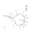
- FIG. 1Ais an image illustrating an exemplary device for providing respiratory therapy to a patient in accordance with aspects of the present invention
- FIG. 1Bis an enlarged image illustrating a nosepiece portion of the exemplary device of FIG. 1A ;
- FIG. 1Cis a cross-sectional view of the nosepiece portion of FIG. 1B .
- Embodiments of the present inventionare directed to devices for providing respiratory therapy to a patient. These exemplary embodiments are particularly suitable to provide high flows of breathing gas to a patient while minimizing noise created during breathing gas delivery. The disclosed embodiments may thereby achieve quieter breathing gas delivery than convention nasal cannulas.
- the disclosed embodiments of the present inventionminimize noise creation during breathing gas delivery by preventing disruptions (e.g. eddies) in breathing gas flow.
- the disclosed embodimentsalso prevent other disruptions in the flow of breathing gas, including decreasing loss of heat from the breathing gas, decreasing liquid formation/liquid spray to patient, and decreasing excess water dripping.
- These disruptions in breathing gas flowmay be prevented with a number of different features encompassed by the present invention, including, for example, (i) providing a channel for breathing gas flow that maintains a substantially constant internal diameter; (ii) preventing separate breathing gas flows from mixing with each other; and/or (iii) preventing sharp changes in direction of breathing gas flow.
- FIGS. 1A-1Cillustrate an exemplary device 100 for providing respiratory therapy to a patient in accordance with aspects of the present invention.
- device 100includes a pair of elongated lumens 110 and a nosepiece portion 130 . Additional details of device 100 will be described herein.
- Lumens 110provide flow paths for providing breathing gas to the patient. As shown in FIG. 1A , each lumen 110 has an inlet end 112 for receiving the flow of breathing gas and an outlet end 114 for transmitting the flow of breathing gas. In an exemplary embodiment, lumens 110 are elongated flexible tubes. Suitable tubes for use as lumens 110 will be known to one of ordinary skill in the art from the description herein.
- Each illustrated lumen 110has a constant internal diameter, i.e., an internal diameter that is substantially constant along the entire length of the lumen 110 .
- the constant internal diameter of one lumen 110may be approximately equal to or different from the constant internal diameter of the other lumen 110 .
- each lumen 110has a constant internal diameter dependent on its intend use: for infants, approximately 0.055 inches; for pediatric patients, approximately 0.075 inches; for adults, approximately 0.125 inches.
- Lumens 110may also have the approximately equal lengths, or may have different lengths.
- lumens 110each have a length of between approximately 10-18 inches.
- lumens 110may in an exemplary embodiment comprise flexible tubing, it may be desirable that the flexibility of lumens 110 be limited, e.g., in order to prevent sharp changes in direction of the flow of breathing gas within lumens 110 .
- the flexibility of lumens 110may be limited, for example, based on the materials and thicknesses selected for the walls of lumen 110 , as would be understood by one of ordinary skill in the art from the description herein.
- lumens 110have a minimum radius of curvature of approximately one half inch along their respective lengths.
- Nosepiece portion 130receives the breathing gas from lumens 110 .
- Nosepiece portion 130is configured to be connected to the outlet ends 114 of lumens 110 .
- nosepiece portion 130includes a pair of lumens 132 .
- Each lumen 132has an inlet end 134 for receiving the flow of breathing gas from lumen 110 , and an outlet end 136 for delivering the flow of breathing gas to the patient.
- inlet end 134 of lumen 132is adapted to be connected to outlet end 114 of lumen 110 .
- Outlet end 136 of lumen 132is adapted to be positioned within the nare of the patient, for inhalation of the breathing gas by the patient.
- outlet ends 136function as nasal prongs of nosepiece portion 130 .
- each lumen 132maintains its respective flow of breathing gas separate from the flow of breathing gas in the other lumen 132 .
- Each illustrated lumen 132has a constant internal diameter.
- the constant internal diameter of one lumen 132may be approximately equal to or different from the constant internal diameter of the other lumen 132 .
- the constant internal diameter of each lumen 132is equal to the constant internal diameter of the respective lumen 110 to which it is coupled.
- each lumen 132is adapted to be connected with a respective lumen 110 .
- each pair of lumens 110 and 132defines a substantially constant diameter flow path for a flow of breathing gas, extending from the inlet 112 of lumen 110 to the outlet 136 of lumen 132 .
- lumen 132is connected to lumen 110 without constricting the internal diameter of lumen 110 .
- the inventionis not limited to any particular mechanism for connecting lumen 110 with lumen 132 .
- An exemplary embodimentis provided herein for the purposes of illustration.
- FIG. 1Billustrates an exemplary mechanism for coupling outlet end 114 of lumen 110 to inlet end 134 of lumen 132 .
- inlet end 134 of lumen 132comprises an enlarged portion 138 .
- Enlarged portion 138has a larger internal diameter than the rest of lumen 132 .
- enlarged portion 138has an internal diameter substantially equal to an external diameter of outlet end 114 of lumen 110 . Accordingly, outlet end 114 of lumen 110 can be slidably positioned within enlarged portion 138 in a friction fitting.
- FIGS. 1B and 1Cillustrate nosepiece portion 130 as including the enlarged portion, it will be understood that it is not so limited.
- the enlarged portionmay be located on either nosepiece portion 130 or on lumen 110 .
- nosepiece portion 130is formed from a flexible material, e.g., silicone rubber. Accordingly, lumens 132 may desirably be shaped to prevent sharp changes in direction of the flow of breathing gas within lumens 132 , as described above with respect to lumens 110 . In an exemplary embodiment, lumens 132 have a minimum radius of curvature of approximately one quarter inch along their respective lengths.
- Device 100is not limited to the above components, but may include alternative or additional components, as would be understood by one of ordinary skill in the art from the description herein.
- Device 100may further include a connector 140 .
- Connector 140is adapted to be connected to inlet ends 112 of lumens 110 .
- Connector 140defines an inlet port 142 and is configured to be connected to a delivery tube from a source of breathing gas.
- Connector 140is desirably connected to lumens 110 without constricting the constant internal diameters of lumens 110 , as described above with respect to nosepiece portion 130 .
- connector 140may include similar coupling mechanism(s) to those used by nosepiece portion 130 .
- Device 100may further include a source of breathing gas for inhalation by the patient.
- the sourcegenerates heated and humidified breathing gas for delivery to the patient.
- the sourcemay be configured to provide breathing gas at flow rates between 1 and 8 liters per minute (lpm) for infants, between 5 and 20 lpm for pediatric patients, or up to 40 lpm for adults.
- Suitable sources of heated and humidified gaswill be known to one of ordinary skill in the art.
- the sourcemay be the Vapotherm Flowrest System, Vapotherm Careflow System, Precision Flow unit, or the Vapotherm 2000i, all of which are provided by Vapotherm, Inc. of Stevensville, Md., USA.
- Other suitable sources of breathing gaswill be known to one of ordinary skill in the art from the description herein.
Landscapes
- Health & Medical Sciences (AREA)
- Pulmonology (AREA)
- Emergency Medicine (AREA)
- Otolaryngology (AREA)
- Hematology (AREA)
- Anesthesiology (AREA)
- Biomedical Technology (AREA)
- Heart & Thoracic Surgery (AREA)
- Engineering & Computer Science (AREA)
- Life Sciences & Earth Sciences (AREA)
- Animal Behavior & Ethology (AREA)
- General Health & Medical Sciences (AREA)
- Public Health (AREA)
- Veterinary Medicine (AREA)
- Respiratory Apparatuses And Protective Means (AREA)
- Pharmaceuticals Containing Other Organic And Inorganic Compounds (AREA)
Abstract
Description
Claims (16)
Priority Applications (8)
| Application Number | Priority Date | Filing Date | Title |
|---|---|---|---|
| US13/665,100US10300236B2 (en) | 2012-10-31 | 2012-10-31 | Quiet nasal cannula |
| JP2015539934AJP6266004B2 (en) | 2012-10-31 | 2013-10-30 | Quiet nasal cannula |
| AU2013337995AAU2013337995B2 (en) | 2012-10-31 | 2013-10-30 | Quiet nasal cannula |
| PCT/US2013/067407WO2014070833A1 (en) | 2012-10-31 | 2013-10-30 | Quiet nasal cannula |
| EP13851754.5AEP2914322B1 (en) | 2012-10-31 | 2013-10-30 | Quiet nasal cannula |
| CN201380063096.XACN104902948B (en) | 2012-10-31 | 2013-10-30 | Quiet nasal cannula |
| US16/382,986US11439784B2 (en) | 2012-10-31 | 2019-04-12 | Quiet nasal cannula |
| US17/885,707US20230226299A1 (en) | 2012-10-31 | 2022-08-11 | Quiet nasal cannula |
Applications Claiming Priority (1)
| Application Number | Priority Date | Filing Date | Title |
|---|---|---|---|
| US13/665,100US10300236B2 (en) | 2012-10-31 | 2012-10-31 | Quiet nasal cannula |
Related Child Applications (1)
| Application Number | Title | Priority Date | Filing Date |
|---|---|---|---|
| US16/382,986ContinuationUS11439784B2 (en) | 2012-10-31 | 2019-04-12 | Quiet nasal cannula |
Publications (2)
| Publication Number | Publication Date |
|---|---|
| US20140116447A1 US20140116447A1 (en) | 2014-05-01 |
| US10300236B2true US10300236B2 (en) | 2019-05-28 |
Family
ID=50545813
Family Applications (3)
| Application Number | Title | Priority Date | Filing Date |
|---|---|---|---|
| US13/665,100Active2035-04-06US10300236B2 (en) | 2012-10-31 | 2012-10-31 | Quiet nasal cannula |
| US16/382,986Active2034-09-13US11439784B2 (en) | 2012-10-31 | 2019-04-12 | Quiet nasal cannula |
| US17/885,707PendingUS20230226299A1 (en) | 2012-10-31 | 2022-08-11 | Quiet nasal cannula |
Family Applications After (2)
| Application Number | Title | Priority Date | Filing Date |
|---|---|---|---|
| US16/382,986Active2034-09-13US11439784B2 (en) | 2012-10-31 | 2019-04-12 | Quiet nasal cannula |
| US17/885,707PendingUS20230226299A1 (en) | 2012-10-31 | 2022-08-11 | Quiet nasal cannula |
Country Status (6)
| Country | Link |
|---|---|
| US (3) | US10300236B2 (en) |
| EP (1) | EP2914322B1 (en) |
| JP (1) | JP6266004B2 (en) |
| CN (1) | CN104902948B (en) |
| AU (1) | AU2013337995B2 (en) |
| WO (1) | WO2014070833A1 (en) |
Cited By (8)
| Publication number | Priority date | Publication date | Assignee | Title |
|---|---|---|---|---|
| WO2021183817A1 (en) | 2020-03-12 | 2021-09-16 | Vapotherm, Inc. | High velocity respiratory therapy unit with non-contact sensing and control |
| US11364358B2 (en) | 2015-06-30 | 2022-06-21 | Vapotherm, Inc. | Nasal cannula for continuous and simultaneous delivery of aerosolized medicament and high flow therapy |
| USD957622S1 (en)* | 2019-10-16 | 2022-07-12 | Aires Medical LLC | Nasal cannula |
| US11583650B2 (en) | 2019-06-28 | 2023-02-21 | Vapotherm, Inc. | Variable geometry cannula |
| US11724056B2 (en) | 2017-09-08 | 2023-08-15 | Vapotherm, Inc. | Birfurcated cannula device |
| US11878115B2 (en) | 2019-09-26 | 2024-01-23 | Vapotherm, Inc. | Internal cannula mounted nebulizer |
| USD1034960S1 (en)* | 2020-04-10 | 2024-07-09 | Shanghai Asclepius Meditec Co., Ltd. | Nasal cannula assembly |
| US12285563B2 (en) | 2016-06-30 | 2025-04-29 | Vapotherm, Inc. | Cannula device for high flow therapy |
Families Citing this family (11)
| Publication number | Priority date | Publication date | Assignee | Title |
|---|---|---|---|---|
| CA3117178C (en) | 2009-12-23 | 2023-06-13 | Fisher & Paykel Healthcare Limited | An interface and a method of supplying breathing gas |
| US20150020811A1 (en)* | 2013-07-17 | 2015-01-22 | Upods, Llc | Oxygen delivery device |
| US9925348B2 (en) | 2013-07-17 | 2018-03-27 | Upods, Llc | Gas delivery device |
| US9440039B2 (en)* | 2013-07-17 | 2016-09-13 | Upods, Llc | Gas delivery device |
| JP6317647B2 (en)* | 2014-08-19 | 2018-04-25 | アトムメディカル株式会社 | Nostril cannula |
| WO2016115192A1 (en)* | 2015-01-16 | 2016-07-21 | Upods, Llc | Gas delivery device |
| USD911515S1 (en)* | 2018-03-21 | 2021-02-23 | Medin Medical Innovations Gmbh | Nasal cannula |
| JP7064920B2 (en)* | 2018-03-27 | 2022-05-11 | 日本光電工業株式会社 | Respiratory aid |
| WO2020154933A1 (en)* | 2019-01-30 | 2020-08-06 | 唐山哈船科技有限公司 | Medicinal oxygen cannula |
| US20200384231A1 (en)* | 2019-06-10 | 2020-12-10 | Neotech Products Llc | Nasal cannula and tubing |
| USD1088225S1 (en)* | 2021-08-02 | 2025-08-12 | Fisher & Paykel Healthcare Limited | Surgical gas diffuser |
Citations (52)
| Publication number | Priority date | Publication date | Assignee | Title |
|---|---|---|---|---|
| US2735432A (en) | 1956-02-21 | hudson | ||
| US2868199A (en) | 1955-05-20 | 1959-01-13 | Charles H Hudson | Cannula |
| US3513844A (en) | 1968-04-30 | 1970-05-26 | Metro Hospital Supply Co Inc | Adjustable nonrestrictive nasal cannula |
| US3643660A (en)* | 1969-11-21 | 1972-02-22 | Allan C Hudson | Nasal cannula |
| US3726275A (en) | 1971-12-14 | 1973-04-10 | I Jackson | Nasal cannulae |
| US3802431A (en) | 1971-10-08 | 1974-04-09 | Bard Inc C R | Nasal cannula |
| US4106505A (en) | 1977-01-17 | 1978-08-15 | Salter Labs., Inc. | Nasal cannula assembly |
| US4273124A (en) | 1979-06-01 | 1981-06-16 | Zimmerman J Earl | Nasal cannula |
| US4278082A (en)* | 1979-05-11 | 1981-07-14 | Blackmer Richard H | Adjustable nasal cannula |
| US4422456A (en) | 1981-09-08 | 1983-12-27 | City Of Hope National Medical Center | Nasal cannula structure |
| US4535767A (en) | 1982-10-01 | 1985-08-20 | Tiep Brian L | Oxygen delivery apparatus |
| US4648398A (en) | 1984-10-31 | 1987-03-10 | Sherwood Medical Company | Nasal cannula |
| US4660555A (en) | 1984-09-21 | 1987-04-28 | Payton Hugh W | Oxygen delivery and administration system |
| US4736741A (en) | 1987-01-02 | 1988-04-12 | Hugh W. Payton | Nosepiece for administering supplemental oxygen |
| US4742824A (en) | 1986-11-19 | 1988-05-10 | Hugh W. Payton | Oxygen tube support patch |
| US4753233A (en) | 1987-02-10 | 1988-06-28 | Advantage Medical | Nasal cannula |
| US4808160A (en) | 1986-04-14 | 1989-02-28 | Timmons John W | Nasal cannula apparatus |
| US4995384A (en) | 1989-10-30 | 1991-02-26 | Keeling James L | Neck support for nasal cannula |
| US5025805A (en) | 1990-07-11 | 1991-06-25 | Betty Nutter | Nasal cannula assembly |
| US5046491A (en) | 1990-03-27 | 1991-09-10 | Derrick Steven J | Apparatus and method for respired gas collection and analysis |
| US5404885A (en) | 1992-06-16 | 1995-04-11 | Natus Medical, Incorporated | Filter unit for end-tidal carbon monoxide monitor |
| US5509409A (en) | 1994-09-12 | 1996-04-23 | The Living Trust Of Marjorie F. Weatherholt | Nasal cannula assembly |
| US5526806A (en) | 1995-04-04 | 1996-06-18 | Sansoni; Jean | Non-invasive nasal cannula |
| WO2000064521A1 (en) | 1999-04-27 | 2000-11-02 | Loma Linda University Medical Center | Device and method for the administration of oxygen |
| US20020157673A1 (en) | 1998-07-14 | 2002-10-31 | Kessler Fred B. | Nasal cannula retainer |
| EP1342484A1 (en) | 2002-03-06 | 2003-09-10 | The BOC Group plc | Improvements in nasal cannulae |
| US20030209246A1 (en) | 1999-12-10 | 2003-11-13 | Gary Schroeder | Apparatus and method for respiratory tract therapy |
| US6655385B1 (en) | 1998-04-03 | 2003-12-02 | Salter Labs | Nasal cannula |
| US6679265B2 (en) | 2001-10-25 | 2004-01-20 | Worldwide Medical Technologies | Nasal cannula |
| US20040035430A1 (en) | 2002-08-21 | 2004-02-26 | Wright Clifford A. | Oxygen delivery system and method of using same |
| US6763832B1 (en) | 1999-04-27 | 2004-07-20 | Loma Linda University Medical Center | Device and method for the administration of oxygen |
| US6799575B1 (en) | 2001-04-21 | 2004-10-05 | Aaron Carter | Cannula for the separation of inhaled and exhaled gases |
| US20050029757A1 (en) | 2002-02-01 | 2005-02-10 | Jon Fiebing | Swivelable mount for attaching a binding to a snowboard |
| WO2005011556A2 (en) | 2003-07-28 | 2005-02-10 | Salter Labs | Respiratory therapy system including a nasal cannula assembly |
| WO2005014080A2 (en) | 2003-08-08 | 2005-02-17 | Innomed Technologies, Inc. | Nasal ventilation interface |
| US20050039757A1 (en) | 1999-03-13 | 2005-02-24 | Wood Thomas J. | Ventilation interface for sleep apnea therapy |
| US20050121038A1 (en) | 2000-04-26 | 2005-06-09 | Cs Medical, Inc. | Method and apparatus for pharyngeal augmentation of ventilation |
| US6913017B2 (en) | 2002-01-04 | 2005-07-05 | Bevely Roberts | Apparatus for delivering inhalant and monitoring exhaled fluid, method of making same, and method of delivering inhalant and monitoring exhaled fluid |
| US20050161049A1 (en) | 2002-08-21 | 2005-07-28 | Medical Device Group, Inc., A California Corporation | Divided nasal cannula assembly |
| US20060005842A1 (en) | 2004-07-09 | 2006-01-12 | Rashad M A | Nasal pressure sensor oxygen therapy device |
| US20060130840A1 (en) | 2004-11-22 | 2006-06-22 | Oridion Medical (1987) Ltd. | Oral nasal cannula |
| WO2006072231A2 (en) | 2005-01-07 | 2006-07-13 | Seleon Gmbh | Air glasses, nosepiece, y-shaped element and corresponding method |
| US20060180151A1 (en)* | 2005-02-12 | 2006-08-17 | Rinaldi Tracey L | Adjustable nasal cannula apparatus and method of use |
| EP1695732A1 (en) | 2005-02-28 | 2006-08-30 | Fisher & Paykel Healthcare Limited | Pressure relief valve |
| US7146979B2 (en) | 2000-03-21 | 2006-12-12 | Fisher & Paykel Healthcare Limited | Humidifier with parallel gas flow paths |
| WO2007111935A2 (en) | 2006-03-23 | 2007-10-04 | Vapotherm, Inc. | Apparatus configured to reduce microbial infection |
| WO2008019294A2 (en) | 2006-08-04 | 2008-02-14 | Ric Investments, Llc. | Nasal and oral patient interface |
| US7493902B2 (en)* | 2003-05-30 | 2009-02-24 | Fisher & Paykel Healthcare Limited | Breathing assistance apparatus |
| WO2010102094A1 (en) | 2009-03-04 | 2010-09-10 | JeMi Airway Management LLC | Nasal cannula assembly |
| US20110067704A1 (en) | 2008-03-04 | 2011-03-24 | Resmed Limited | Unobtrusive interface systems |
| US20110125052A1 (en) | 2008-01-25 | 2011-05-26 | Salter Labs | Respiratory therapy system including a nasal cannula assembly |
| US20130042862A1 (en)* | 2010-05-04 | 2013-02-21 | Region Nordjylland, Aalborg Sygehus | Fluid guide for a soother |
Family Cites Families (5)
| Publication number | Priority date | Publication date | Assignee | Title |
|---|---|---|---|---|
| US4790308A (en)* | 1984-04-04 | 1988-12-13 | Sherwood Medical Company | Nasal cannula harness |
| CN2170768Y (en)* | 1993-10-25 | 1994-07-06 | 宋国强 | Hanging ear type oxygen inhalation tube |
| US7007694B2 (en)* | 2004-05-21 | 2006-03-07 | Acoba, Llc | Nasal cannula |
| WO2008060587A2 (en) | 2006-11-15 | 2008-05-22 | Vapotherm, Inc. | Nasal cannula with reduced heat loss to reduce rainout |
| US20130092165A1 (en)* | 2011-09-26 | 2013-04-18 | Anthony David Wondka | Nasal Ventilation Cannula System and Methods |
- 2012
- 2012-10-31USUS13/665,100patent/US10300236B2/enactiveActive
- 2013
- 2013-10-30WOPCT/US2013/067407patent/WO2014070833A1/enactiveApplication Filing
- 2013-10-30EPEP13851754.5Apatent/EP2914322B1/enactiveActive
- 2013-10-30JPJP2015539934Apatent/JP6266004B2/ennot_activeExpired - Fee Related
- 2013-10-30CNCN201380063096.XApatent/CN104902948B/enactiveActive
- 2013-10-30AUAU2013337995Apatent/AU2013337995B2/ennot_activeCeased
- 2019
- 2019-04-12USUS16/382,986patent/US11439784B2/enactiveActive
- 2022
- 2022-08-11USUS17/885,707patent/US20230226299A1/enactivePending
Patent Citations (57)
| Publication number | Priority date | Publication date | Assignee | Title |
|---|---|---|---|---|
| US2735432A (en) | 1956-02-21 | hudson | ||
| US2868199A (en) | 1955-05-20 | 1959-01-13 | Charles H Hudson | Cannula |
| US3513844A (en) | 1968-04-30 | 1970-05-26 | Metro Hospital Supply Co Inc | Adjustable nonrestrictive nasal cannula |
| US3643660A (en)* | 1969-11-21 | 1972-02-22 | Allan C Hudson | Nasal cannula |
| US3802431A (en) | 1971-10-08 | 1974-04-09 | Bard Inc C R | Nasal cannula |
| US3726275A (en) | 1971-12-14 | 1973-04-10 | I Jackson | Nasal cannulae |
| US4106505A (en) | 1977-01-17 | 1978-08-15 | Salter Labs., Inc. | Nasal cannula assembly |
| US4278082A (en)* | 1979-05-11 | 1981-07-14 | Blackmer Richard H | Adjustable nasal cannula |
| US4273124A (en) | 1979-06-01 | 1981-06-16 | Zimmerman J Earl | Nasal cannula |
| US4422456A (en) | 1981-09-08 | 1983-12-27 | City Of Hope National Medical Center | Nasal cannula structure |
| US4535767A (en) | 1982-10-01 | 1985-08-20 | Tiep Brian L | Oxygen delivery apparatus |
| US4660555A (en) | 1984-09-21 | 1987-04-28 | Payton Hugh W | Oxygen delivery and administration system |
| US4648398A (en) | 1984-10-31 | 1987-03-10 | Sherwood Medical Company | Nasal cannula |
| US4808160A (en) | 1986-04-14 | 1989-02-28 | Timmons John W | Nasal cannula apparatus |
| US4742824A (en) | 1986-11-19 | 1988-05-10 | Hugh W. Payton | Oxygen tube support patch |
| US4736741A (en) | 1987-01-02 | 1988-04-12 | Hugh W. Payton | Nosepiece for administering supplemental oxygen |
| US4753233A (en) | 1987-02-10 | 1988-06-28 | Advantage Medical | Nasal cannula |
| US4995384A (en) | 1989-10-30 | 1991-02-26 | Keeling James L | Neck support for nasal cannula |
| US5046491A (en) | 1990-03-27 | 1991-09-10 | Derrick Steven J | Apparatus and method for respired gas collection and analysis |
| US5025805A (en) | 1990-07-11 | 1991-06-25 | Betty Nutter | Nasal cannula assembly |
| US5404885A (en) | 1992-06-16 | 1995-04-11 | Natus Medical, Incorporated | Filter unit for end-tidal carbon monoxide monitor |
| US5509409A (en) | 1994-09-12 | 1996-04-23 | The Living Trust Of Marjorie F. Weatherholt | Nasal cannula assembly |
| US5526806A (en) | 1995-04-04 | 1996-06-18 | Sansoni; Jean | Non-invasive nasal cannula |
| US6655385B1 (en) | 1998-04-03 | 2003-12-02 | Salter Labs | Nasal cannula |
| US20020157673A1 (en) | 1998-07-14 | 2002-10-31 | Kessler Fred B. | Nasal cannula retainer |
| US20050039757A1 (en) | 1999-03-13 | 2005-02-24 | Wood Thomas J. | Ventilation interface for sleep apnea therapy |
| WO2000064521A1 (en) | 1999-04-27 | 2000-11-02 | Loma Linda University Medical Center | Device and method for the administration of oxygen |
| US6763832B1 (en) | 1999-04-27 | 2004-07-20 | Loma Linda University Medical Center | Device and method for the administration of oxygen |
| US20030209246A1 (en) | 1999-12-10 | 2003-11-13 | Gary Schroeder | Apparatus and method for respiratory tract therapy |
| US7146979B2 (en) | 2000-03-21 | 2006-12-12 | Fisher & Paykel Healthcare Limited | Humidifier with parallel gas flow paths |
| US20050121038A1 (en) | 2000-04-26 | 2005-06-09 | Cs Medical, Inc. | Method and apparatus for pharyngeal augmentation of ventilation |
| US6799575B1 (en) | 2001-04-21 | 2004-10-05 | Aaron Carter | Cannula for the separation of inhaled and exhaled gases |
| US6679265B2 (en) | 2001-10-25 | 2004-01-20 | Worldwide Medical Technologies | Nasal cannula |
| US6913017B2 (en) | 2002-01-04 | 2005-07-05 | Bevely Roberts | Apparatus for delivering inhalant and monitoring exhaled fluid, method of making same, and method of delivering inhalant and monitoring exhaled fluid |
| US20050029757A1 (en) | 2002-02-01 | 2005-02-10 | Jon Fiebing | Swivelable mount for attaching a binding to a snowboard |
| EP1342484A1 (en) | 2002-03-06 | 2003-09-10 | The BOC Group plc | Improvements in nasal cannulae |
| US6776163B2 (en) | 2002-03-06 | 2004-08-17 | The Boc Group, Plc | Nasal cannulae |
| US20050161049A1 (en) | 2002-08-21 | 2005-07-28 | Medical Device Group, Inc., A California Corporation | Divided nasal cannula assembly |
| US20040035430A1 (en) | 2002-08-21 | 2004-02-26 | Wright Clifford A. | Oxygen delivery system and method of using same |
| US7493902B2 (en)* | 2003-05-30 | 2009-02-24 | Fisher & Paykel Healthcare Limited | Breathing assistance apparatus |
| WO2005011556A2 (en) | 2003-07-28 | 2005-02-10 | Salter Labs | Respiratory therapy system including a nasal cannula assembly |
| US20080051674A1 (en)* | 2003-07-28 | 2008-02-28 | Davenport James M | Respiratory Therapy System Including a Nasal Cannula Assembly |
| WO2005014080A2 (en) | 2003-08-08 | 2005-02-17 | Innomed Technologies, Inc. | Nasal ventilation interface |
| US20060005842A1 (en) | 2004-07-09 | 2006-01-12 | Rashad M A | Nasal pressure sensor oxygen therapy device |
| US20060130840A1 (en) | 2004-11-22 | 2006-06-22 | Oridion Medical (1987) Ltd. | Oral nasal cannula |
| WO2006072231A2 (en) | 2005-01-07 | 2006-07-13 | Seleon Gmbh | Air glasses, nosepiece, y-shaped element and corresponding method |
| CN101098726A (en) | 2005-01-07 | 2008-01-02 | 塞利昂有限公司 | Air glasses, nosepiece, y-shaped element and corresponding method |
| US7775210B2 (en)* | 2005-01-07 | 2010-08-17 | Schoebel Nee Bauer Ulla | Nasal cannula |
| US20060180151A1 (en)* | 2005-02-12 | 2006-08-17 | Rinaldi Tracey L | Adjustable nasal cannula apparatus and method of use |
| EP1695732A1 (en) | 2005-02-28 | 2006-08-30 | Fisher & Paykel Healthcare Limited | Pressure relief valve |
| WO2007111935A2 (en) | 2006-03-23 | 2007-10-04 | Vapotherm, Inc. | Apparatus configured to reduce microbial infection |
| US20080190436A1 (en) | 2006-08-04 | 2008-08-14 | Jaffe Michael B | Nasal and oral patient interface |
| WO2008019294A2 (en) | 2006-08-04 | 2008-02-14 | Ric Investments, Llc. | Nasal and oral patient interface |
| US20110125052A1 (en) | 2008-01-25 | 2011-05-26 | Salter Labs | Respiratory therapy system including a nasal cannula assembly |
| US20110067704A1 (en) | 2008-03-04 | 2011-03-24 | Resmed Limited | Unobtrusive interface systems |
| WO2010102094A1 (en) | 2009-03-04 | 2010-09-10 | JeMi Airway Management LLC | Nasal cannula assembly |
| US20130042862A1 (en)* | 2010-05-04 | 2013-02-21 | Region Nordjylland, Aalborg Sygehus | Fluid guide for a soother |
Non-Patent Citations (5)
| Title |
|---|
| European Supplementary Search Report for Application No. 13851754.5 dated Mar. 21, 2016. |
| International Application Serial No. PCT/US2007/023973, International Search Report dated Aug. 12, 2008, 5 pgs. |
| International Application Serial No. PCT/US2007/023973, International Written Opinion dated Aug. 12, 2008, 11 pgs. |
| International Search Report dated Jan. 30, 2014, application No. PCT/US2013/067407. |
| International Search Report for PCT/US2013/067407 dated May 5, 2015. |
Cited By (9)
| Publication number | Priority date | Publication date | Assignee | Title |
|---|---|---|---|---|
| US11364358B2 (en) | 2015-06-30 | 2022-06-21 | Vapotherm, Inc. | Nasal cannula for continuous and simultaneous delivery of aerosolized medicament and high flow therapy |
| US12285563B2 (en) | 2016-06-30 | 2025-04-29 | Vapotherm, Inc. | Cannula device for high flow therapy |
| US11724056B2 (en) | 2017-09-08 | 2023-08-15 | Vapotherm, Inc. | Birfurcated cannula device |
| US12226580B2 (en) | 2017-09-08 | 2025-02-18 | Vapotherm, Inc. | Bifurcated cannula device |
| US11583650B2 (en) | 2019-06-28 | 2023-02-21 | Vapotherm, Inc. | Variable geometry cannula |
| US11878115B2 (en) | 2019-09-26 | 2024-01-23 | Vapotherm, Inc. | Internal cannula mounted nebulizer |
| USD957622S1 (en)* | 2019-10-16 | 2022-07-12 | Aires Medical LLC | Nasal cannula |
| WO2021183817A1 (en) | 2020-03-12 | 2021-09-16 | Vapotherm, Inc. | High velocity respiratory therapy unit with non-contact sensing and control |
| USD1034960S1 (en)* | 2020-04-10 | 2024-07-09 | Shanghai Asclepius Meditec Co., Ltd. | Nasal cannula assembly |
Also Published As
| Publication number | Publication date |
|---|---|
| JP2015532888A (en) | 2015-11-16 |
| US11439784B2 (en) | 2022-09-13 |
| CN104902948A (en) | 2015-09-09 |
| US20190328990A1 (en) | 2019-10-31 |
| CN104902948B (en) | 2017-05-03 |
| WO2014070833A1 (en) | 2014-05-08 |
| US20140116447A1 (en) | 2014-05-01 |
| JP6266004B2 (en) | 2018-01-24 |
| AU2013337995A1 (en) | 2015-05-21 |
| EP2914322A1 (en) | 2015-09-09 |
| US20230226299A1 (en) | 2023-07-20 |
| AU2013337995B2 (en) | 2018-03-01 |
| EP2914322B1 (en) | 2018-12-05 |
| EP2914322A4 (en) | 2016-04-20 |
Similar Documents
| Publication | Publication Date | Title |
|---|---|---|
| US20230226299A1 (en) | Quiet nasal cannula | |
| US8171935B2 (en) | Nasal cannula with reduced heat loss to reduce rainout | |
| CN209253882U (en) | Nasal cannula and respiratory therapy system for delivery of humidified breathing gas and nebulized medication | |
| US9211398B2 (en) | Connector system for an apparatus that delivers breathable gas to a patient | |
| US20120125332A1 (en) | Apparatus, systems, and methods for respiratory therapy | |
| EP2934644B1 (en) | Inline adapter for a respiratory therapy device | |
| US12296101B2 (en) | Adaptor for respiratory assistance systems | |
| CN104470572B (en) | pediatric full face mask | |
| US20120304992A1 (en) | Breathing treatment system and method | |
| US20080210236A1 (en) | Tubing management system | |
| CN218165762U (en) | Nasal and Patient Interface | |
| US20160243329A1 (en) | High flow ventilation system for endoscopy procedures | |
| ES2768383T3 (en) | Apparatus for controlling the flow of oxygen and / or air to nasal cannulas | |
| US11339770B2 (en) | Mask with primary and secondary air delivery | |
| US9808593B1 (en) | Apparatus for enhancement of oxygen and/or air flow control to nasal prongs | |
| CN105125412A (en) | Single-cavity high-flow rate nose catheter |
Legal Events
| Date | Code | Title | Description |
|---|---|---|---|
| AS | Assignment | Owner name:VAPOTHERM, INC., MARYLAND Free format text:ASSIGNMENT OF ASSIGNORS INTEREST;ASSIGNORS:CORTEZ, FELINO V., JR.;NILAND, WILLIAM F.;MCGARRITY, GEORGE;REEL/FRAME:029587/0581 Effective date:20121129 | |
| AS | Assignment | Owner name:BRIDGE BANK, NATIONAL ASSOCIATION, CALIFORNIA Free format text:SECURITY AGREEMENT;ASSIGNOR:VAPOTHERM, INC.;REEL/FRAME:030208/0453 Effective date:20130320 | |
| AS | Assignment | Owner name:VAPOTHERM, INC., NEW HAMPSHIRE Free format text:RELEASE BY SECURED PARTY;ASSIGNOR:WESTERN ALLIANCE BANK;REEL/FRAME:040348/0648 Effective date:20161115 | |
| AS | Assignment | Owner name:PERCEPTIVE CREDIT HOLDINGS II, LP, NEW YORK Free format text:PATENT SECURITY AGREEMENT;ASSIGNOR:VAPOTHERM, INC.;REEL/FRAME:045853/0554 Effective date:20180406 | |
| STPP | Information on status: patent application and granting procedure in general | Free format text:NOTICE OF ALLOWANCE MAILED -- APPLICATION RECEIVED IN OFFICE OF PUBLICATIONS | |
| STPP | Information on status: patent application and granting procedure in general | Free format text:PUBLICATIONS -- ISSUE FEE PAYMENT VERIFIED | |
| STCF | Information on status: patent grant | Free format text:PATENTED CASE | |
| AS | Assignment | Owner name:CANADIAN IMPERIAL BANK OF COMMERCE, CANADA Free format text:SECURITY INTEREST;ASSIGNOR:VAPOTHERM, INC.;REEL/FRAME:054145/0212 Effective date:20201021 Owner name:VAPOTHERM, INC., NEW HAMPSHIRE Free format text:RELEASE BY SECURED PARTY;ASSIGNOR:PERCEPTIVE CREDIT HOLDINGS II, LP;REEL/FRAME:054145/0225 Effective date:20201021 | |
| AS | Assignment | Owner name:VAPOTHERM, INC., NEW HAMPSHIRE Free format text:RELEASE BY SECURED PARTY;ASSIGNOR:PERCEPTIVE CREDIT HOLDINGS II, LP;REEL/FRAME:059106/0517 Effective date:20201021 | |
| AS | Assignment | Owner name:SLR INVESTMENT CORP., NEW YORK Free format text:SECURITY INTEREST;ASSIGNOR:VAPOTHERM, INC.;REEL/FRAME:059203/0137 Effective date:20220218 | |
| AS | Assignment | Owner name:VAPOTHERM, INC., NEW HAMPSHIRE Free format text:RELEASE BY SECURED PARTY;ASSIGNOR:CANADIAN IMPERIAL BANK OF COMMERCE;REEL/FRAME:059218/0087 Effective date:20220218 | |
| MAFP | Maintenance fee payment | Free format text:PAYMENT OF MAINTENANCE FEE, 4TH YR, SMALL ENTITY (ORIGINAL EVENT CODE: M2551); ENTITY STATUS OF PATENT OWNER: SMALL ENTITY Year of fee payment:4 |