US10299594B2 - Shelving unit with capacity increasing tie members - Google Patents
Shelving unit with capacity increasing tie membersDownload PDFInfo
- Publication number
- US10299594B2 US10299594B2US15/937,061US201815937061AUS10299594B2US 10299594 B2US10299594 B2US 10299594B2US 201815937061 AUS201815937061 AUS 201815937061AUS 10299594 B2US10299594 B2US 10299594B2
- Authority
- US
- United States
- Prior art keywords
- elongate
- walls
- wall
- tie bar
- extending
- Prior art date
- Legal status (The legal status is an assumption and is not a legal conclusion. Google has not performed a legal analysis and makes no representation as to the accuracy of the status listed.)
- Active
Links
Images


Classifications
- A—HUMAN NECESSITIES
- A47—FURNITURE; DOMESTIC ARTICLES OR APPLIANCES; COFFEE MILLS; SPICE MILLS; SUCTION CLEANERS IN GENERAL
- A47B—TABLES; DESKS; OFFICE FURNITURE; CABINETS; DRAWERS; GENERAL DETAILS OF FURNITURE
- A47B96/00—Details of cabinets, racks or shelf units not covered by a single one of groups A47B43/00 - A47B95/00; General details of furniture
- A47B96/14—Bars, uprights, struts, or like supports, for cabinets, brackets, or the like
- A47B96/1441—Horizontal struts
- A—HUMAN NECESSITIES
- A47—FURNITURE; DOMESTIC ARTICLES OR APPLIANCES; COFFEE MILLS; SPICE MILLS; SUCTION CLEANERS IN GENERAL
- A47B—TABLES; DESKS; OFFICE FURNITURE; CABINETS; DRAWERS; GENERAL DETAILS OF FURNITURE
- A47B47/00—Cabinets, racks or shelf units, characterised by features related to dismountability or building-up from elements
- A47B47/0025—Horizontal connecting members adapted to receive and retain the edges of several panel elements
- A47B47/0041—Bars
- A—HUMAN NECESSITIES
- A47—FURNITURE; DOMESTIC ARTICLES OR APPLIANCES; COFFEE MILLS; SPICE MILLS; SUCTION CLEANERS IN GENERAL
- A47B—TABLES; DESKS; OFFICE FURNITURE; CABINETS; DRAWERS; GENERAL DETAILS OF FURNITURE
- A47B47/00—Cabinets, racks or shelf units, characterised by features related to dismountability or building-up from elements
- A47B47/0083—Cabinets, racks or shelf units, characterised by features related to dismountability or building-up from elements with four vertical uprights
- A—HUMAN NECESSITIES
- A47—FURNITURE; DOMESTIC ARTICLES OR APPLIANCES; COFFEE MILLS; SPICE MILLS; SUCTION CLEANERS IN GENERAL
- A47B—TABLES; DESKS; OFFICE FURNITURE; CABINETS; DRAWERS; GENERAL DETAILS OF FURNITURE
- A47B47/00—Cabinets, racks or shelf units, characterised by features related to dismountability or building-up from elements
- A47B47/02—Cabinets, racks or shelf units, characterised by features related to dismountability or building-up from elements made of metal only
- A47B47/021—Racks or shelf units
- A47B47/024—Racks or shelf units with shelves between uprights without separate horizontal shelf supports
- A—HUMAN NECESSITIES
- A47—FURNITURE; DOMESTIC ARTICLES OR APPLIANCES; COFFEE MILLS; SPICE MILLS; SUCTION CLEANERS IN GENERAL
- A47B—TABLES; DESKS; OFFICE FURNITURE; CABINETS; DRAWERS; GENERAL DETAILS OF FURNITURE
- A47B47/00—Cabinets, racks or shelf units, characterised by features related to dismountability or building-up from elements
- A47B47/02—Cabinets, racks or shelf units, characterised by features related to dismountability or building-up from elements made of metal only
- A47B47/021—Racks or shelf units
- A47B47/027—Racks or shelf units with frames only
- A—HUMAN NECESSITIES
- A47—FURNITURE; DOMESTIC ARTICLES OR APPLIANCES; COFFEE MILLS; SPICE MILLS; SUCTION CLEANERS IN GENERAL
- A47B—TABLES; DESKS; OFFICE FURNITURE; CABINETS; DRAWERS; GENERAL DETAILS OF FURNITURE
- A47B47/00—Cabinets, racks or shelf units, characterised by features related to dismountability or building-up from elements
- A47B47/02—Cabinets, racks or shelf units, characterised by features related to dismountability or building-up from elements made of metal only
- A47B47/021—Racks or shelf units
- A47B47/028—Racks or shelf units with crossbars
- A—HUMAN NECESSITIES
- A47—FURNITURE; DOMESTIC ARTICLES OR APPLIANCES; COFFEE MILLS; SPICE MILLS; SUCTION CLEANERS IN GENERAL
- A47B—TABLES; DESKS; OFFICE FURNITURE; CABINETS; DRAWERS; GENERAL DETAILS OF FURNITURE
- A47B55/00—Cabinets, racks or shelf units, having essential features of rigid construction
- A—HUMAN NECESSITIES
- A47—FURNITURE; DOMESTIC ARTICLES OR APPLIANCES; COFFEE MILLS; SPICE MILLS; SUCTION CLEANERS IN GENERAL
- A47B—TABLES; DESKS; OFFICE FURNITURE; CABINETS; DRAWERS; GENERAL DETAILS OF FURNITURE
- A47B57/00—Cabinets, racks or shelf units, characterised by features for adjusting shelves or partitions
- A47B57/06—Cabinets, racks or shelf units, characterised by features for adjusting shelves or partitions with means for adjusting the height of the shelves
- A47B57/16—Cabinets, racks or shelf units, characterised by features for adjusting shelves or partitions with means for adjusting the height of the shelves consisting of hooks coacting with openings
- A—HUMAN NECESSITIES
- A47—FURNITURE; DOMESTIC ARTICLES OR APPLIANCES; COFFEE MILLS; SPICE MILLS; SUCTION CLEANERS IN GENERAL
- A47B—TABLES; DESKS; OFFICE FURNITURE; CABINETS; DRAWERS; GENERAL DETAILS OF FURNITURE
- A47B57/00—Cabinets, racks or shelf units, characterised by features for adjusting shelves or partitions
- A47B57/06—Cabinets, racks or shelf units, characterised by features for adjusting shelves or partitions with means for adjusting the height of the shelves
- A47B57/20—Cabinets, racks or shelf units, characterised by features for adjusting shelves or partitions with means for adjusting the height of the shelves consisting of tongues, pins or similar projecting means coacting with openings
- A—HUMAN NECESSITIES
- A47—FURNITURE; DOMESTIC ARTICLES OR APPLIANCES; COFFEE MILLS; SPICE MILLS; SUCTION CLEANERS IN GENERAL
- A47B—TABLES; DESKS; OFFICE FURNITURE; CABINETS; DRAWERS; GENERAL DETAILS OF FURNITURE
- A47B57/00—Cabinets, racks or shelf units, characterised by features for adjusting shelves or partitions
- A47B57/30—Cabinets, racks or shelf units, characterised by features for adjusting shelves or partitions with means for adjusting the height of detachable shelf supports
- A47B57/36—Cabinets, racks or shelf units, characterised by features for adjusting shelves or partitions with means for adjusting the height of detachable shelf supports consisting of side walls of the ladder type
- A47B57/38—Cabinets, racks or shelf units, characterised by features for adjusting shelves or partitions with means for adjusting the height of detachable shelf supports consisting of side walls of the ladder type with hooks on the shelf supports to engage the rungs of the ladder
- A—HUMAN NECESSITIES
- A47—FURNITURE; DOMESTIC ARTICLES OR APPLIANCES; COFFEE MILLS; SPICE MILLS; SUCTION CLEANERS IN GENERAL
- A47B—TABLES; DESKS; OFFICE FURNITURE; CABINETS; DRAWERS; GENERAL DETAILS OF FURNITURE
- A47B57/00—Cabinets, racks or shelf units, characterised by features for adjusting shelves or partitions
- A47B57/30—Cabinets, racks or shelf units, characterised by features for adjusting shelves or partitions with means for adjusting the height of detachable shelf supports
- A47B57/48—Cabinets, racks or shelf units, characterised by features for adjusting shelves or partitions with means for adjusting the height of detachable shelf supports consisting of tongues, pins or similar projecting means coacting with openings
- A—HUMAN NECESSITIES
- A47—FURNITURE; DOMESTIC ARTICLES OR APPLIANCES; COFFEE MILLS; SPICE MILLS; SUCTION CLEANERS IN GENERAL
- A47B—TABLES; DESKS; OFFICE FURNITURE; CABINETS; DRAWERS; GENERAL DETAILS OF FURNITURE
- A47B96/00—Details of cabinets, racks or shelf units not covered by a single one of groups A47B43/00 - A47B95/00; General details of furniture
- A47B96/02—Shelves
- A47B96/021—Structural features of shelf bases
- A—HUMAN NECESSITIES
- A47—FURNITURE; DOMESTIC ARTICLES OR APPLIANCES; COFFEE MILLS; SPICE MILLS; SUCTION CLEANERS IN GENERAL
- A47B—TABLES; DESKS; OFFICE FURNITURE; CABINETS; DRAWERS; GENERAL DETAILS OF FURNITURE
- A47B96/00—Details of cabinets, racks or shelf units not covered by a single one of groups A47B43/00 - A47B95/00; General details of furniture
- A47B96/06—Brackets or similar supporting means for cabinets, racks or shelves
- A47B96/067—Horizontal rails as suspension means in a cantilever arrangement
- A—HUMAN NECESSITIES
- A47—FURNITURE; DOMESTIC ARTICLES OR APPLIANCES; COFFEE MILLS; SPICE MILLS; SUCTION CLEANERS IN GENERAL
- A47B—TABLES; DESKS; OFFICE FURNITURE; CABINETS; DRAWERS; GENERAL DETAILS OF FURNITURE
- A47B57/00—Cabinets, racks or shelf units, characterised by features for adjusting shelves or partitions
- A47B57/30—Cabinets, racks or shelf units, characterised by features for adjusting shelves or partitions with means for adjusting the height of detachable shelf supports
- A47B57/40—Cabinets, racks or shelf units, characterised by features for adjusting shelves or partitions with means for adjusting the height of detachable shelf supports consisting of hooks coacting with openings
- A47B57/402—Hooks attached to a member embracing at least two sides of an upright, e.g. an angle bracket
Definitions
- This inventionrelates to shelving units and more particularly, to tie members, such as tie bars and tie rods, used in shelving units for connecting horizontal front and rear shelf-supporting beams.
- Shelving unitsare commonly used for storing various items in a space-efficient manner.
- Typical shelving unitsmay include four vertical supporting posts, any suitable number of horizontal front and corresponding horizontal rear shelf-supporting beams extending respectively between the front pair and rear pair of posts, and a corresponding number of shelves resting on and supported by the pairs of front and rear beams.
- Such shelving unitsmay be constructed at least partially of sheet metal or formed steel components and are commonly referred to as steel shelving or storage units.
- the front and rear horizontal beamsare susceptible to undesirable twisting or torquing, in cross-section, out of their positions, particularly when strained beyond their capacity to remain in their design position.
- This twistingpresents undesirable structural responses and could lead to shelving unit failure.
- undue twisting of the front and rear horizontal shelf-supporting beamscould separate the supporting inter-connection of the shelves to the beams, allowing the beams to pull away from the shelves thereby letting them drop, or could separate the beam ends from the corner posts thereby catastrophically destroying the shelving unit.
- a tie bar for connecting two horizontal beamsincludes first and second elongate walls arranged parallel to each other, and a third elongate wall arranged perpendicular to the first and second elongate walls and coupled to a lateral side of each of the first and second elongate walls.
- the tie barfurther includes at least one pair of hook elements positioned at terminal ends of at least one of the first, second, or third elongate walls.
- Each of the hook elementsincludes a depending tab configured to be received by an elongate slot of a horizontal beam of a shelving unit.
- the first and second elongate wallsare side walls, the third elongate wall is a top wall, and the at least one pair of hook elements includes first and second hook elements positioned on the third elongate wall.
- the first and second elongate wallsmay each include end extensions extending longitudinally beyond the terminal ends of the third elongate wall and the end extensions may each be configured to be received within an interior space of the corresponding horizontal beam.
- the first and second elongate wallsmay each include recesses extending inwardly at or near the terminal ends of the third elongate wall and the recesses may each be configured to receive a portion of a flange of the corresponding horizontal beam.
- first and second elongate wallsare top and bottom walls, respectively, the third elongate wall is a side wall, and the at least one pair of hook elements includes first and second hook elements positioned on the second elongate wall.
- the at least one pair of hook elementsmay further include third and fourth hook elements positioned on the first elongate wall.
- the third elongate wallmay include end extensions extending longitudinally beyond the terminal ends of the first elongate wall and the end extensions may each be configured to be received within an interior space of the corresponding horizontal beam.
- the third elongate wallmay include recesses extending inwardly at or near the terminal ends of the first elongate wall and the recesses may each be configured to receive a portion of a flange of the corresponding horizontal beam.
- the tie barmay further include first and second extending tabs positioned at and extending longitudinally beyond the terminal ends of the first elongate wall. Each of the first and second extending tabs may include an opening for receiving a pin configured to securely couple the first elongate wall to the corresponding beam.
- the first elongate wallmay be free of any depending tabs.
- a shelving unitincludes such a tie bar.
- a shelving unitin another embodiment, includes at least one front horizontal shelf-supporting beam including at least one first flange, at least one first elongate slot, and at least one first interior space.
- the shelving unitalso includes at least one rear horizontal shelf-supporting beam including at least one second flange, at least one second elongate slot, and at least one second interior space.
- the shelving unitfurther includes a tie bar connecting the at least one front and rear horizontal shelf-supporting beams.
- the tie barincludes first and second elongate walls arranged parallel to each other, a third elongate wall arranged perpendicular to the first and second elongate walls and coupled to a lateral side of each of the first and second elongate walls, and at least one pair of hook elements positioned at terminal ends of at least one of the first, second, or third elongate walls.
- Each of the hook elementsincludes a depending tab received by one of the at least one first or second elongate slots.
- the first and second elongate wallsare top and bottom walls, respectively, the third elongate wall is a side wall, and the at least one pair of hook elements includes first and second hook elements positioned on the second elongate wall.
- the at least one pair of hook elementsmay further include third and fourth hook elements positioned on the first elongate wall.
- the third elongate wallmay include end extensions extending longitudinally beyond the terminal ends of the first elongate wall and the end extensions may each be received within one of the at least one first or second interior spaces.
- the third elongate wallmay include recesses extending inwardly at or near the terminal ends of the first elongate wall and the recesses may each receive a portion of one of the at least one first or second flanges.
- the shelving unitmay further include first and second extending tabs positioned at and extending longitudinally beyond the terminal ends of the first elongate wall. Each of the first and second extending tabs may include an opening for receiving a pin configured to securely couple the first elongate wall to the corresponding beam.
- the first elongate wallmay be free of any depending tabs.
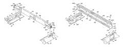
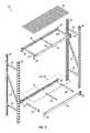
- FIG. 1is an isometric view of an exemplary shelving unit in accordance with an embodiment of the invention
- FIG. 2is an exploded view of the shelving unit of FIG. 1 ;
- FIG. 3is a broken isometric view of the lower end of the shelving unit of FIG. 1 ;
- FIG. 4Ais a partial isometric view of an exemplary tie bar connecting a pair of front and rear horizontal shelf-supporting beams of the shelving unit of FIG. 1 ;
- FIG. 4Bis an exploded isometric view illustrating the tie bar and associated portions of the shelf-supporting beams of FIG. 4A ;
- FIG. 4Cis an end view of the tie bar of FIGS. 4A and 4B ;
- FIG. 5is a cross-sectional view taken along section line 5 - 5 of FIG. 4A ;
- FIG. 6Ais a partial isometric view of another exemplary tie bar connecting a pair of front and rear horizontal shelf-supporting beams of the shelving unit of FIG. 1 ;
- FIG. 6Bis an exploded isometric view illustrating the tie bar and associated portions of the shelf-supporting beams of FIG. 6A ;
- FIG. 6Cis an end view of the tie bar of FIGS. 6A and 6B ;
- FIG. 7is a cross-sectional view taken along section line 7 - 7 of FIG. 6A ;
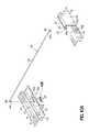
- FIG. 8Ais a partial isometric view of an exemplary tie rod connecting a pair of front and rear horizontal shelf-supporting beams of the shelving unit of FIG. 1 ;
- FIG. 8Bis an exploded isometric view illustrating the tie rod and associated portions of the shelf-supporting beams of FIG. 8A ;
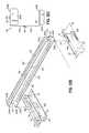
- FIG. 9Ais an exploded isometric view of another exemplary tie rod connecting a pair of front and rear horizontal shelf-supporting beams of the shelving unit of FIG. 1 ;
- FIGS. 9B and 9Care partial top plan views illustrating the connection of the tie rod shown in FIG. 9A to the horizontal beams;
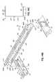
- FIG. 10Ais an exploded isometric view similar to FIG. 9A illustrating an alternative connection of the tie rod to the horizontal beams;
- FIGS. 10B and 10Care magnified isometric views illustrating the connection to the tie rod shown in FIG. 10A to one of the horizontal beams and the insertion of a plug;
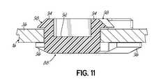
- FIG. 11is a cross-sectional view taken along section line 11 - 11 of FIG. 10C ;
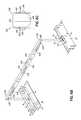
- FIG. 12Ais a partial isometric view of an exemplary tie bar connecting a pair of front and rear horizontal shelf-supporting beams in accordance with another embodiment of the invention.
- FIG. 12Bis an exploded isometric view illustrating the tie bar and associated portions of the shelf-supporting beams of FIG. 12A ;
- FIG. 12Cis an end view of tie bar of FIGS. 12A and 12B ;
- FIG. 13is a cross-sectional view taken along section line 13 - 13 of FIG. 12A ;
- FIG. 14Ais a partial isometric view of an exemplary tie bar connecting a pair of front and rear horizontal shelf-supporting beams in accordance with another embodiment of the invention.
- FIG. 14Bis an exploded isometric view illustrating the tie bar and associated portions of the shelf-supporting beams of FIG. 14A ;
- FIG. 14Cis an end view of tie bar of FIGS. 14A and 14B ;
- FIG. 15is a cross-sectional view taken along section line 15 - 15 of FIG. 14A .
- an exemplary shelving unit 10which may be a steel and/or storage shelving unit, is shown in accordance with one embodiment.
- the shelving unit 10is equipped with one or more tie members such as tie bars 12 a , 12 b for coupling one or more front horizontal shelf-supporting beams 14 with one or more corresponding rear horizontal shelf-supporting beams 16 for increasing the load capacity and structural integrity of the shelving unit 10 .
- the tie bars 12 a , 12 bmay resist undesirable torquing or twisting of the beams 14 , 16 thereby increasing the shelf-bearing capacity of the beams 14 , 16 and the shelving unit 10 .
- tie bars 12 a , 12 bmay provide direct torque resistance to upper portions of the beams 14 , 16 .
- the features of the shelving unit 10 and tie bars 12 a , 12 bare set forth in further detail below to clarify each of these functional advantages and other benefits provided in this disclosure.
- the shelving unit 10includes four corner posts 18 arranged in a generally rectangular configuration.
- the front pair of corner posts 18cooperate to carry the front horizontal shelf supporting beams 14 via brackets 20
- the rear pair of corner posts 18similarly cooperate to carry the rear horizontal shelf supporting beams 16 via brackets 20 .
- the coupling of the brackets 20 to the posts 18may be adjustable such that the number of front horizontal shelf supporting beams 14 and corresponding rear horizontal shelf supporting beams 16 , and their respective heights along the posts 18 , may be varied as may be desired.
- the lefthand pair of corner posts 18are coupled to each other via one or more braces 22
- the righthand pair of corner posts 18are similarly coupled to each other via one or more braces 22 .
- the braces 22may contribute to the structural stability of the shelving unit 10 during use, and/or may allow the corner posts 18 to be shipped in pairs as subassemblies of the shelving unit 10 prior to final assembly of the shelving unit 10 .
- the illustrated shelving unit 10includes a plurality of shelves for carrying items, including at least one horizontal wire shelf 24 and at least one horizontal solid shelf 26 , each supported by a corresponding pair of front and rear horizontal shelf supporting beams 14 , 16 .
- a plurality of shelves for carrying itemsincluding at least one horizontal wire shelf 24 and at least one horizontal solid shelf 26 , each supported by a corresponding pair of front and rear horizontal shelf supporting beams 14 , 16 .
- two horizontal wire shelves 24 and one horizontal solid shelf 26are provided, such that a total of three pairs of front and rear horizontal shelf supporting beams 14 , 16 are used.
- any number of shelves 24 , 26 and corresponding front and rear horizontal shelf supporting beams 14 , 16may be used, as may be desired.
- each pair of front and rear horizontal shelf supporting beams 14 , 16is coupled together by at least one tie bar 12 a , 12 b for improving the structural integrity of the shelving unit 10 .
- each beam 14 , 16may be of a generally standard construction.
- each of the illustrated beams 14 , 16includes a vertical outer wall 28 , a horizontal upper wall 30 , a vertical inner wall 32 , a horizontal shelf supporting flange 34 , and a horizontal lower flange 36 .
- the vertical outer wall 28 , horizontal upper wall 30 , vertical inner wall 32 , horizontal shelf supporting flange 34 , and horizontal lower flange 36define a partially enclosed interior space 38 ( FIG. 5 ).
- At least one longitudinally extending slot 40is provided in the horizontal shelf supporting flange 34 of each of the beams 14 , 16 , the purpose of which is discussed below.
- each of the peripheral tie bars 12 ais an elongated member including a top wall 42 a and first and second parallel side walls 44 a , 46 a extending downwardly from and perpendicular to lateral sides of the top wall 42 a such that the tie bar 12 a has a generally inverted U-shaped cross section ( FIG. 4C ).
- the first and second side walls 44 a , 46 ainclude respective end extensions 48 a , 50 a which extend longitudinally beyond the terminal ends of the top wall 42 a .
- the recesses 52 a , 54 aare provided in the side walls 44 a , 46 a above the end extensions 48 a , 50 a and extend inwardly at or near the terminal ends of the top wall 42 a .
- the recesses 52 a , 54 amay each be of sufficient width and depth to receive a portion of the horizontal shelf supporting flange 34 of one of the beams 14 , 16 , as discussed below.
- each peripheral tie bar 12 aincludes first and second hook elements 56 a , 58 a at or near respective terminal ends of the top wall 42 a .
- the hook elements 56 a , 58 aeach include a depending tab 60 a extending downwardly from the respective terminal end of the top wall 42 a for engagement with one of the slots 40 of one of the beams 14 , 16 .
- the illustrated tabs 60 aextend downwardly along and are narrowly spaced apart from the ends of the first and second side walls 44 a , 46 a .
- the end extensions 48 a , 50 aextend longitudinally beyond the respective hook elements 56 a , 58 a and corresponding tabs 60 a.
- a plurality of vertically and/or horizontally extending embossments or ribs 62 aare provided on the tie bar 12 a for improving the stiffness and rigidity of the tie bar 12 a . While three horizontal ribs 62 a and two vertical ribs 62 a are positioned on portions of each of the side walls 44 a , 46 a , including the end extensions 48 a , 50 a , of the illustrated tie bar 12 a , it will be appreciated that any number and/or size of ribs 62 a may positioned on any suitable portion of the tie bar 12 a in any suitable orientation. For example, the ribs 62 a may be positioned on surfaces different from those illustrated. It will be appreciated that the ribs 62 a may be formed through a pressing operation or using any other suitable method of formation.
- the tabs 60 a of the hook elements 56 a , 58 aare inserted into and received by the corresponding slots 40 of the respective front and rear beams 14 , 16 .
- the tabs 60 aare received by the slots 40 , at least a portion of the top wall 42 a and/or side walls 44 a , 46 a may rest on, and be supported by, the corresponding horizontal shelf supporting flange 34 .
- each beam 14 , 16includes three slots 40 , wherein each slot 40 of the front beam 14 is configured to be positioned opposite a corresponding slot 40 of the rear beam 16 when in use so that the tabs 60 a of each tie bar 12 a may be selectively inserted into opposing slots 40 of a pair of front and rear beams 14 , 16 to connect the front and rear beams 14 , 16 and improve the structural integrity of the shelving unit 10 .
- the positioning of each tie bar 12 a along the respective front and rear beams 14 , 16may be selected based on the locations of the slots 40 therealong. In this regard, any number of slots 40 may be provided on the beams 14 , 16 at any desirable locations for providing various options for positioning one or more tie bars 12 a .
- tie bars 12 aare shown and described as being positioned at or near the peripheral ends of the respective beams 14 , 16 , it will be appreciated that the tie bars 12 a may be positioned more centrally along the respective beams 14 , 16 .
- each tab 60 ais received in the respective slot 40 , a portion of the corresponding horizontal shelf supporting flange 34 is received by the recess 52 a , 54 a in the respective side wall 44 a , 46 a of the tie bar 12 a .
- the recesses 52 a , 54 amay accommodate the horizontal shelf supporting flanges 34 such that the side walls 44 a , 46 a of the tie bar 12 a may avoid interfering with the insertion of the tabs 60 a in the respective slots 40 .
- each tab 60 ais received in the respective slot 40 , the corresponding end extensions 48 a , 50 a of the side walls 44 a , 46 a are received in the interior space 38 of the respective beam 14 , 16 .
- This configurationmay improve the securement of the tie bar 12 a to the respective beams 14 , 16 and/or improve the structural integrity of the shelving unit 10 .
- engagement between either of the end extensions 48 a , 50 a and the respective horizontal shelf supporting flange 34may limit undesirable bowing of the tie bar 12 a .
- the end extensions 48 a , 50 amay aid in rigidifying the tie bar 12 a at or near the various interfaces with the beams 14 , 16 .
- the central tie bar 12 bis an elongated member including a top wall 42 b and first and second parallel side walls 44 b , 46 b extending downwardly from and perpendicular to lateral sides of the top wall 42 b such that the tie bar 12 b has a generally inverted U-shaped cross section ( FIG. 6C ).
- Recesses 52 b , 54 bare provided in the side walls 44 b , 46 b and extend inwardly at or near the terminal ends of the top wall 42 b .
- the recesses 52 b , 54 bmay each be of sufficient width and depth to receive a portion of the horizontal shelf supporting flange 34 of one of the beams 14 , 16 , as discussed below.
- the central tie bar 12 bincludes first and second hook elements 56 b , 58 b at or near respective terminal ends of the top wall 42 b .
- the hook elements 56 b , 58 beach include a depending tab 60 b extending downwardly from the respective terminal end of the top wall 42 b for engagement with one of the slots 40 of one of the beams 14 , 16 .
- the illustrated tabs 60 bextend downwardly along and are narrowly spaced apart from the ends of the first and second side walls 42 b , 44 b.
- a plurality of vertically and/or horizontally extending embossments or ribs 62 bare provided on the tie bar 12 b for improving the stiffness and rigidity of the tie bar 12 b . While three horizontal ribs 62 b are positioned on portions of each of the side walls 44 b , 46 b of the illustrated tie bar 12 b , it will be appreciated that any number and/or size of ribs 62 b may positioned on any suitable portion of the tie bar 12 b in any suitable orientation. For example, the ribs 62 b may be positioned on surfaces different from those illustrated. It will be appreciated that the ribs 62 b may be formed through a pressing operation or using any other suitable method of formation.
- the tabs 60 b of the hook elements 56 b , 58 bare inserted into and received by the corresponding slots 40 of the respective front and rear beams 14 , 16 .
- the tabs 60 bare received by the slots 40 , at least a portion of the top wall 42 b and/or side walls 44 b , 46 b may rest on, and be supported by, the corresponding horizontal shelf supporting flange 34 .
- the tabs 60 of the tie bar 12 bmay be selectively inserted into opposing slots 40 of a pair of front and rear beams 14 , 16 to connect the front and rear beams 14 , 16 and improve the structural integrity of the shelving unit 10 , in a manner similar to that described above with respect to the peripheral tie bars 12 a . While the illustrated tie bar 12 b is shown and described as being positioned at or near the longitudinal center point of the respective beams 14 , 16 , it will be appreciated that the tie bar 12 b may be positioned more peripherally along the respective beams 14 , 16 .
- each tab 60 bis received in the respective slot 40 , a portion of the corresponding horizontal shelf supporting flange 34 is received by the recess 52 b , 54 b in the respective side wall 44 b , 46 b of the tie bar 12 b .
- the recesses 52 b , 54 bmay accommodate the horizontal shelf supporting flanges 34 such that the side walls 44 b , 46 b of the tie bar 12 b may avoid interfering with the insertion of the tabs 60 b in the respective slots 40 .
- the same slots 40 on the beams 14 , 16may be used for attaching either of the illustrated tie bars 12 a , 12 b thereto.
- dedicated slots(not shown) may be provided for each of the different configurations of tie bars 12 a , 12 b.
- each pair of front and rear horizontal shelf supporting beams 14 , 16may be coupled together by at least one tie rod 70 for improving the structural integrity of the shelving unit 10 .
- each beam 14 , 16may include at least one aperture such as a tapered aperture or keyhole 72 provided in the horizontal lower flange 36 .
- the keyhole 72includes a large portion 74 and a small portion 76 , the purposes of which are discussed below.
- the tie rod 70includes an elongated body 78 having downwardly angled end portions 80 , 82 terminating in radially enlarged portions 84 , 86 .
- the downwardly angled end portions 80 , 82may be at an angle of approximately 90° relative to the elongated body 78 .
- the radially enlarged portions 84 , 86may each be of sufficiently small width to pass vertically through the large portions 74 of the keyholes 72 , and of sufficiently large width to be unable to pass vertically through the small portions 76 of the keyholes 72 , as discussed below.
- the radially enlarged portions 84 , 86 of the tie rod 70are inserted into and received by the large portions 74 of the corresponding keyholes 72 of the respective front and rear beams 14 , 16 .
- the radially enlarged portions 84 , 86may then be moved below the respective small portions 76 of the keyholes 72 in order to lock the tie rod 70 in place.
- the tie rod 70may be constructed of a sufficiently flexible material to allow manipulation of the end portions 80 , 82 for positioning the radially enlarged portions 84 , 86 .
- Each beam 14 , 16may include any number of keyholes 72 , wherein each keyhole 72 of the front beam 14 is configured to be positioned opposite a corresponding keyhole 72 of the rear beam 16 when in use so that the radially enlarged portions 84 , 86 of the tie rod 70 may be selectively inserted into opposing keyholes 72 of a pair of front and rear beams 14 , 16 to connect the front and rear beams 14 , 16 and resist motion of the lower portions of the beams 14 , 16 away from each other to avoid undesirable outward twisting of the lower portions of the beams 14 , 16 .
- the positioning of the tie rod 70 along the respective front and rear beams 14 , 16may be selected based on the locations of the keyholes 72 therealong.
- the keyholes 72may be configured so that one or more tie rods 70 may be positioned below and/or longitudinally offset from any of the tie bars 12 a , 12 b along the respective beams 14 , 16 .
- an alternative tie rod 170may be used for coupling each pair of front and rear horizontal shelf supporting beams 14 , 16 for improving the structural integrity of the shelving unit 10 .
- each beam 14 , 16may include at least one aperture such as an L-shaped aperture 172 a provided in the horizontal lower flange 36 .
- the aperture 172 aincludes a laterally extending leg 174 a and a longitudinally extending leg 176 a which terminates in a notch 177 a , the purposes of which are discussed below.
- the tie rod 170includes an elongated body 178 having downwardly curved end portions 180 , 182 terminating in J-shaped hook portions 184 , 186 .
- the J-shaped hook portions 184 , 186may define an approximately 360° turn relative to the elongated body 78 .
- the J-shaped hook portions 184 , 186may each be of sufficiently small width and length to pass vertically through the lateral legs 174 a of the apertures 172 a , and of sufficiently large length to be unable to pass vertically through the notches 177 a of the apertures 172 a , as discussed below.
- the J-shaped hook portions 184 , 186 of the tie rod 170are inserted into and received by the lateral legs 174 a of the corresponding apertures 172 a of the respective front and rear beams 14 , 16 ( FIG. 9B ).
- the J-shaped hook portions 184 , 186may then be moved below the respective longitudinal legs 176 a of the apertures 172 a to the respective notches 177 a ( FIG. 9C ).
- the J-shaped hook portions 184 , 186 and notches 177 amay be relatively sized to provide a snap-fit therebetween for locking the tie rod 170 in place. As best shown in FIG.
- the illustrated tie rod 170may be angled or canted to position the J-shaped hook portions 184 , 186 in the respective notches 177 a .
- Each beam 14 , 16may include any number of apertures 172 a , wherein each aperture 172 a of the front beam 14 is configured to be positioned opposite a corresponding aperture 172 a of the rear beam 16 when in use so that the J-shaped hook portions 184 , 186 of each tie rod 170 may be selectively inserted into opposing apertures 172 a of a pair of front and rear beams 14 , 16 to connect the front and rear beams 14 , 16 and resist motion of the lower portions of the beams 14 , 16 away from each other to avoid undesirable outward twisting of the lower portions of the beams 14 , 16 .
- each aperture 172 a of the front beam 14is configured to be inverted relative to the corresponding aperture 172 a of the rear beam 16 and to be slightly longitudinally offset relative thereto. More particularly, the lateral leg 174 a and notch 177 a of the front beam 14 are arranged on opposite ends of the longitudinal leg 176 a relative to the corresponding lateral leg 174 a and notch 177 a of the rear beam 16 .
- the notch 177 a of the front beam 14is also configured to be opposite the notch 177 a of the rear beam 16 such that, when the tie rod 170 is canted to position the J-shaped hook portions 184 , 186 in the respective notches 177 a , the tie rod 170 may be substantially perpendicular to each of the front and rear beams 14 , 16 .
- the positioning of each tie rod 170 along the respective front and rear beams 14 , 16may be selected based on the locations of the apertures 172 a therealong.
- the apertures 172 amay be configured so that one or more tie rods 170 may be positioned below and/or longitudinally offset from any of the tie bars 12 a , 12 b along the respective beams 14 , 16 .
- each beam 14 , 16may include at least one trapezoidal aperture 172 b provided in the horizontal lower flange 36 for receiving a corresponding J-shaped hook portion 184 , 186 of the tie rod 170 .
- the aperture 172 bincludes a large portion 174 b which tapers laterally inwardly toward a notch 177 b , the purposes of which are discussed below.
- the J-shaped hook portions 184 , 186 of the tie rod 170are inserted into and received by the large portions 174 b of the corresponding apertures 172 b of the respective front and rear beams 14 , 16 ( FIG. 10B ).
- the J-shaped hook portions 184 , 186may then be moved below the large portions 174 b of the apertures 172 b to the respective notches 177 b ( FIG. 10C ).
- the J-shaped hook portions 184 , 186 and notches 177 bmay be relatively sized to provide a snap-fit therebetween for locking the tie rod 170 in place.
- the tie rod 170may be angled or canted to position the J-shaped hook portions 184 , 186 in the respective notches 177 b .
- Each beam 14 , 16may include any number of apertures 172 b , wherein each aperture 172 b of the front beam 14 is configured to be positioned opposite a corresponding aperture 172 b of the rear beam 16 when in use so that the J-shaped hook portions 184 , 186 of each tie rod 170 may be selectively inserted into opposing apertures 172 b of a pair of front and rear beams 14 , 16 to connect the front and rear beams 14 , 16 and resist motion of the lower portions of the beams 14 , 16 away from each other to avoid undesirable outward twisting of the lower portions of the beams 14 , 16 .
- each aperture 172 b of the front beam 14is configured to be inverted relative to the corresponding aperture 172 b of the rear beam 16 and to be slightly offset relative thereto. More particularly, the notch 177 b of the front beam 14 is arranged on an opposite end of the large portion 174 b relative to the corresponding notch 177 b of the rear beam 16 , and the large portion 174 b of the front beam 14 tapers in the opposite direction relative to the corresponding large portion 174 b of the rear beam 16 .
- the notch 177 b of the front beam 14is also configured to be opposite the notch 177 b of the rear beam 16 such that, when the tie rod 170 is canted to position the J-shaped hook portions 184 , 186 in the respective notches 177 b , the tie rod 170 may be substantially perpendicular to each of the front and rear beams 14 , 16 .
- the positioning of each tie rod 170 along the respective front and rear beams 14 , 16may be selected based on the locations of the apertures 172 b therealong.
- the apertures 172 bmay be configured so that one or more tie rods 170 may be positioned below and/or longitudinally offset from any of the tie bars 12 a , 12 b along the respective beams 14 , 16 .
- a plug 88may be selectively and removably positioned in the aperture 172 b to further secure the corresponding J-shaped hook portion 184 , 186 in place and thereby assist in preventing unintentional dislodgment of the tie rod 170 .
- the illustrated plug 88is constructed of a resilient material and is sized and shaped to provide an interference fit with at least a portion of the aperture 172 b .
- the plug 88may be generally trapezoidal for providing an interference fit with the large portion 174 b of the aperture 172 b , and may include an at least partially curved finger extension 90 configured to be received in the notch 177 b and to engage the end 180 , 182 of the tie rod 170 when the J-shaped hook portion 184 , 186 is snapped in place in the notch 177 b .
- the illustrated plug 88includes a trapezoidal base 92 and a plurality of walls 94 extending upwardly therefrom.
- a flange 96extends around at least a portion of the lower periphery of the plug 88 for engaging a bottom surface of the lower horizontal flange 36 of the respective beam 14 , 16 .
- the flange 96is discontinuous or interrupted, it will be appreciated that the flange 96 may alternatively extend continuously around the entire lower periphery of the plug 88 .
- the plug 88further includes a flexible tab 98 positioned at or near an upper end of one of the walls 94 .
- each plug 88may be aligned below the respective aperture 172 b after the J-shaped hook portion 184 , 186 has been properly positioned in the corresponding notch 177 b , and may then be moved upwardly into the apertures 172 b , as shown in FIGS. 10B and 10C .
- the tab 98may contact the bottom surface of the lower horizontal flange 36 and may be flexed thereby from a natural state to a flexed state.
- the tab 98may include an angled upper surface configured to encourage such flexing.
- the flexible tab 98may pass through the aperture 172 b and return to its natural, non-flexed state. As best shown in FIG. 11 , in this position the flexible tab 98 may be in abutment with and/or adjacent to an upper surface of the lower horizontal flange 36 of the beam 14 , 16 and the flange 96 may be in abutment with and/or adjacent to the lower surface of the lower horizontal flange 36 of the beam 14 , 16 . In this manner, the lower horizontal flange 36 of the beam 14 , 16 may be at least partially sandwiched between the flange 96 and the tab 98 in order to assist in preventing the plug 88 from becoming dislodged.
- the curved surface of the finger extension 90may be in abutment with and/or adjacent to the respective end 180 , 182 of the tie rod 170 so as to limit and/or prohibit movement of the end 180 , 182 of the rod 170 in a direction away from the notch 177 b .
- the plug 88may at least partially conceal the respective aperture 172 b.
- Each plug 88may be selectively removed from the aperture 172 b to facilitate removal of the corresponding tie rod 170 , such as during disassembly of the shelving unit 10 or rearrangement of the tie rod 170 .
- the flexible tab 98 of the plug 88may be depressed to a flexed state to allow the plug 88 to pass downwardly through the respective aperture 172 b and thereby release the plug 88 .
- the tie rod 170may then be canted to position the hook portions 184 , 186 in the large portions 174 b of the apertures 172 b thereby allowing the hook portions 184 , 186 to be easily removed from the apertures 172 b for removal and/or repositioning of the tie rod 170 at another location along the same or different pair of beams 14 , 16 .
- each beam 14 , 16may include at least one upper longitudinally extending slot 40 a provided in the horizontal shelf supporting flange 34 and at least one lower longitudinally extending slot 40 b provided in the lower horizontal flange 36 , the purposes of which are discussed below.
- the upper and lower slots 40 a , 40 bare longitudinally aligned and laterally offset from each other. More particularly, the lower slot 40 b is positioned laterally deeper (e.g., closer to the vertical wall 28 ) than the upper slot 40 a.
- Each of the tie bars 112is an elongated member including parallel top and bottom walls 142 , 143 , and a side wall 146 extending between and perpendicular to lateral sides of the top and bottom walls 142 , 143 such that the tie bar 112 has a generally C-shaped cross section ( FIG. 12C ).
- the bottom wall 143is of a greater length than the top wall 142 .
- the side wall 146includes end extensions 150 which extend longitudinally beyond the terminal ends of the top wall 142 and terminate at or near the terminal ends of the bottom wall 143 .
- Longitudinally extending recesses 154are provided in the side wall 146 above the end extensions 150 and extend inwardly at or near the terminal ends of the top wall 142 .
- the recesses 154may each be of sufficient width and depth to receive a portion of the horizontal shelf supporting flange 34 of one of the beams 14 , 16 , as discussed below.
- each tie bar 112includes first and second upper hook elements 156 a , 158 a at or near respective terminal ends of the top wall 142 , and first and second lower hook elements 156 b , 158 b at or near respective terminal ends of the bottom wall 143 .
- the upper hook elements 156 a , 158 aeach include a depending tab 160 a extending downwardly from the respective terminal end of the top wall 142 for engagement with one of the upper slots 40 a of one of the beams 14 , 16 .
- the lower hook elements 156 b , 158 beach include a depending tab 160 b extending downwardly from the respective terminal end of the bottom wall 143 for engagement with one of the lower slots 40 b of one of the beams 14 , 16 .
- the illustrated lower depending tabs 160 bare each angled so as to form an acute angle relative to the bottom wall 143 .
- the lower depending tabs 160 bmay be angled at approximately 70° relative to the bottom wall 143 .
- the end extensions 150extend longitudinally beyond the respective upper hook elements 156 a , 158 a and corresponding tabs 160 a and terminate at or near the respective lower hook elements 156 b , 158 b and corresponding tabs 160 b , and the lower tabs 60 b extend longitudinally beyond the upper tabs 60 a.
- a plurality of vertically and/or horizontally extending embossments or ribs 162are provided on the tie bar 112 for improving the stiffness and rigidity of the tie bar 112 . While a total of three horizontal ribs 162 are positioned on the top, bottom and side walls 142 , 143 , 146 of the illustrated tie bar 112 along substantially the entire lengths thereof, it will be appreciated that any number and/or size of ribs 162 may positioned on any suitable portion of the tie bar 112 in any suitable orientation. For example, the ribs 162 may be positioned on surfaces different from those illustrated. It will be appreciated that the ribs 162 may be formed through a pressing operation or using any other suitable method of formation. Furthermore, the ribs 262 may extend upwardly or downwardly from the walls (e.g., downwardly on the bottom wall).
- the tabs 160 a of the upper hook elements 156 a , 158 aare inserted into and received by the corresponding upper slots 40 a of the respective front and rear beams 14 , 16
- the tabs 160 b of the lower hook elements 156 b , 158 bare inserted into and received by the corresponding lower slots 40 b of the respective front and rear beams 14 , 16 .
- the tabs 160 a , 160 bare received by the slots 40 a , 40 b
- at least a portion of the bottom wall 143 and/or side wall 146may rest on, and be supported by, the corresponding lower horizontal flange 36 .
- the angling of the lower tabs 160 bmay assist in preventing dislodgement of the lower tabs 160 b from the slots 40 b .
- the positioning of the tie bar 112 along the respective front and rear beams 14 , 16may be selected based on the locations of the slots 40 a , 40 b therealong.
- the tabs 60 a , 60 b of the tie bar 112may be selectively inserted into opposing slots 40 a , 40 b of a pair of front and rear beams 14 , 16 to connect the front and rear beams 14 , 16 and improve the structural integrity of the shelving unit 10 , in a manner similar to that described above with respect to the tie bars 12 a , 12 b.
- each tab 160 a , 160 bis received in the respective slot 40 a , 40 b , a portion of the corresponding horizontal shelf supporting flange 34 is received by the recess 154 in the side wall 146 of the tie bar 112 .
- the recesses 154may accommodate the horizontal shelf supporting flanges 34 such that the side wall 146 of the tie bar 112 may avoid interfering with the insertion of the tabs 160 a , 160 b in the respective slots 40 a , 40 b .
- each tab 160 a , 160 bis received in the respective slot 40 a , 40 b , the corresponding end extensions 150 of the side wall 146 are received in the interior space 38 of the respective beam 14 , 16 .
- This configurationmay improve the securement of the tie bar 112 to the respective beams 14 , 16 and/or improve the structural integrity of the shelving unit 10 .
- the end extensions 150may aid in rigidifying the tie bar 112 at or near the various interfaces with the beams 14 , 16 .
- the illustrated tie bar 112couples to the front and rear horizontal shelf supporting beams 14 , 16 at both the upper shelf supporting flange 34 and the lower horizontal flange 36 .
- the tie bar 112may provide the benefits of the tie bars 12 a , 12 b as well as the benefits of the tie rods 70 , 170 .
- one or more tie bars 112may be used alone or in conjunction with one or more tie bars 12 a , 12 b and/or tie rods 70 , 170 for improving the structural integrity of the shelving unit 10 .
- each beam 14 , 16may include at least one upper longitudinally extending slot 40 c provided in the horizontal shelf supporting flange 34 and at least one lower longitudinally extending slot 40 d provided in the lower horizontal flange 36 , the purposes of which are discussed below.
- the upper and lower slots 40 c , 40 dare longitudinally aligned and laterally offset from each other. More particularly, the lower slot 40 d is positioned laterally deeper (e.g., closer to the vertical wall 28 ) than the upper slot 40 c.
- Each of the tie bars 212is an elongated member including parallel top and bottom walls 242 , 243 , and a side wall 246 extending between and perpendicular to lateral sides of the top and bottom walls 242 , 243 such that the tie bar 212 has a generally C-shaped cross section ( FIG. 14C ).
- the bottom wall 243is of a greater length than the top wall 242 .
- the side wall 246includes end extensions 250 which extend longitudinally beyond the terminal ends of the top wall 242 and terminate at or near the terminal ends of the bottom wall 243 .
- Longitudinally extending recesses 254are provided in the side wall 246 above the end extensions 250 and extend inwardly at or near the terminal ends of the top wall 242 .
- the recesses 254may each be of sufficient width and depth to receive a portion of the horizontal shelf supporting flange 34 of one of the beams 14 , 16 , as discussed below.
- each tie bar 212includes extending tabs 260 a which extend longitudinally beyond the terminal ends of the top wall 242 within the same plane as the top wall 242 , and which each include an aperture 261 .
- Each tie bar 212also includes first and second hook elements 256 , 258 at or near respective terminal ends of the bottom wall 243 .
- the hook elements 256 , 258each include a depending tab 260 b extending downwardly from the respective terminal end of the bottom wall 243 for engagement with one of the lower slots 40 d of one of the beams 14 , 16 .
- the illustrated depending tabs 260 bare each angled so as to form an acute angle relative to the bottom wall 243 .
- the depending tabs 260 bmay be angled at approximately 70° relative to the bottom wall 243 .
- the end extensions 250extend longitudinally beyond the respective upper tabs 260 a and terminate at or near the respective hook elements 256 , 258 and corresponding tabs 260 b
- the lower tabs 260 bextend longitudinally beyond the upper tabs 260 a.
- a plurality of vertically and/or horizontally extending embossments or ribs 262are provided on the tie bar 212 for improving the stiffness and rigidity of the tie bar 212 . While a total of three horizontal ribs 262 are positioned on the top, bottom and side walls 242 , 243 , 246 of the illustrated tie bar 212 along substantially the entire lengths thereof, it will be appreciated that any number and/or size of ribs 262 may positioned on any suitable portion of the tie bar 212 in any suitable orientation. For example, the ribs 262 may be positioned on surfaces different from those illustrated. It will be appreciated that the ribs 262 may be formed through a pressing operation or using any other suitable method of formation. Furthermore, the ribs 262 may extend upwardly or downwardly from the walls (e.g., downwardly on the bottom wall).
- the extending tabs 260 a and/or the top wall 242rest on, and are supported by, the horizontal shelf supporting flange 34 of the respective front and rear beams 14 , 16 , and the depending tabs 260 b of the hook elements 256 , 258 are inserted into and received by the corresponding lower slots 40 d of the respective front and rear beams 14 , 16 .
- the tabs 260 bare received by the slots 40 d , at least a portion of the bottom wall 243 and/or side wall 246 may rest on, and be supported by, the corresponding lower horizontal flange 36 .
- each of the apertures 261is aligned with the corresponding upper slot 40 c and a pin or rivet 263 is inserted therethrough to assist in securing the tie bar 212 to each of the front and rear beams 14 , 16 .
- the rivet 263may include a bent or angled portion that extends beyond the terminal ends of the upper slot 40 c such that the tie bar 212 may not be pulled vertically out of position.
- the shelf 24 , 26may include an opening (not shown) configured for alignment with the upper slot 40 c and aperture 261 to also receive the rivet 263 , thereby additionally securing the shelf 24 , 26 to the tie bar(s) 212 .
- the rivet 263may be eliminated. In any event, the positioning of the tie bar 212 along the respective front and rear beams 14 , 16 may be selected based on the locations of the slots 40 c , 40 d therealong.
- the tabs 260 b of the tie bar 212may be selectively inserted into opposing slots 240 b of a pair of front and rear beams 14 , 16 to connect the front and rear beams 14 , 16 and improve the structural integrity of the shelving unit 10 , in a manner similar to that described above with respect to the tie bars 12 a , 12 b , 112 .
- each tab 260 bwhen each tab 260 b is received in the respective slot 40 d , a portion of the corresponding horizontal shelf supporting flange 34 is received by the recess 254 in the side wall 146 of the tie bar 212 .
- the recesses 254may accommodate the horizontal shelf supporting flanges 34 such that the side wall 246 of the tie bar 212 may avoid interfering with the insertion of the tabs 260 b in the respective slots 40 d .
- the corresponding end extensions 250 of the side wall 246are received in the interior space 38 of the respective beam 14 , 16 .
- This configurationmay improve the securement of the tie bar 212 to the respective beams 14 , 16 and/or improve the structural integrity of the shelving unit 10 .
- the end extensions 250may aid in rigidifying the tie bar 212 at or near the various interfaces with the beams 14 , 16 .
- the illustrated tie bar 212couples to the front and rear horizontal shelf supporting beams 14 , 16 at the lower horizontal flange 36 , and is supported by and optionally coupled to the upper shelf supporting flange 34 .
- the tie bar 212may provide the benefits of the tie bars 12 a , 12 b as well as the benefits of the tie rods 70 , 170 .
- one or more tie bars 212may be used alone or in conjunction with one or more tie bars 12 a , 12 b , 112 and/or tie rods 70 , 170 for improving the structural integrity of the shelving unit 10 .
Landscapes
- Warehouses Or Storage Devices (AREA)
Abstract
Description
Claims (33)
Priority Applications (1)
| Application Number | Priority Date | Filing Date | Title |
|---|---|---|---|
| US15/937,061US10299594B2 (en) | 2017-03-28 | 2018-03-27 | Shelving unit with capacity increasing tie members |
Applications Claiming Priority (5)
| Application Number | Priority Date | Filing Date | Title |
|---|---|---|---|
| US201762477723P | 2017-03-28 | 2017-03-28 | |
| US201762577492P | 2017-10-26 | 2017-10-26 | |
| US201762610210P | 2017-12-24 | 2017-12-24 | |
| US201862640908P | 2018-03-09 | 2018-03-09 | |
| US15/937,061US10299594B2 (en) | 2017-03-28 | 2018-03-27 | Shelving unit with capacity increasing tie members |
Publications (2)
| Publication Number | Publication Date |
|---|---|
| US20180279782A1 US20180279782A1 (en) | 2018-10-04 |
| US10299594B2true US10299594B2 (en) | 2019-05-28 |
Family
ID=63668681
Family Applications (1)
| Application Number | Title | Priority Date | Filing Date |
|---|---|---|---|
| US15/937,061ActiveUS10299594B2 (en) | 2017-03-28 | 2018-03-27 | Shelving unit with capacity increasing tie members |
Country Status (2)
| Country | Link |
|---|---|
| US (1) | US10299594B2 (en) |
| CA (1) | CA2999567A1 (en) |
Cited By (27)
| Publication number | Priority date | Publication date | Assignee | Title |
|---|---|---|---|---|
| US20180265290A1 (en)* | 2014-12-09 | 2018-09-20 | Swisslog Logistics, Inc. | Structure for Automated Pallet Storage and Retrieval |
| US20190290000A1 (en)* | 2018-02-15 | 2019-09-26 | Hercke LLC | Shelving unit |
| US10736415B1 (en)* | 2019-07-22 | 2020-08-11 | Frazier Industrial Company | Formed support member with tab securing feature |
| US10806257B1 (en)* | 2020-02-12 | 2020-10-20 | Taiwan Shin Yeh Enterprise Co., Ltd. | Wire shelving assembly |
| US10947040B2 (en)* | 2019-07-22 | 2021-03-16 | Frazier Industrial Company | Formed support member |
| USD914406S1 (en)* | 2018-06-21 | 2021-03-30 | The Ondrasik Family Trust | Wire receiving shelf post |
| US10968039B2 (en)* | 2019-07-29 | 2021-04-06 | J&L Wire Cloth, LLC | Storage decks and storage rack assemblies including same |
| US11006750B2 (en)* | 2019-04-19 | 2021-05-18 | Wu Hsu Chiu | Shelf frame for a rack of shelves |
| US11026509B2 (en)* | 2016-12-16 | 2021-06-08 | Peak Innovations Inc. | Shelving system |
| US11344114B2 (en)* | 2018-03-12 | 2022-05-31 | Hangzhou United Tools Co., Ltd. | Shelf |
| US11390460B2 (en)* | 2019-08-02 | 2022-07-19 | Frazier Industrial Company | Storage support member and grating system |
| US20220275632A1 (en)* | 2019-08-27 | 2022-09-01 | Intex Holdings Pty Ltd | Improved component of a modular building |
| US20220378195A1 (en)* | 2021-05-28 | 2022-12-01 | Protrend Co., Ltd. | Combined type shelf |
| US20230044061A1 (en)* | 2021-08-05 | 2023-02-09 | Speedrack Co., Ltd. | Reinforcement beam for horizontal frames and prefabricated shelf using same |
| US11602221B1 (en)* | 2021-12-20 | 2023-03-14 | Ll&T International, Llc | Shelving unit tie bar |
| US11647833B2 (en) | 2020-09-16 | 2023-05-16 | Perfect Site LLC | Utility rack |
| US20230218083A1 (en)* | 2020-09-01 | 2023-07-13 | Nedcon B.V. | Goods storage rack |
| US20230307765A1 (en)* | 2022-03-25 | 2023-09-28 | Calb Co., Ltd. | Battery shelf, energy storage frame, and energy storage battery cluster |
| US20230313523A1 (en)* | 2020-05-11 | 2023-10-05 | Shanghai Morimatsu Pharmaceutical Equipment Engineering Co., Ltd. | Modular factory building |
| US20230389699A1 (en)* | 2022-06-01 | 2023-12-07 | Kangyan Group | Shelving system |
| US20240041202A1 (en)* | 2020-05-14 | 2024-02-08 | Hangzhou Great Star Industrial Co., Ltd. | Industrial rack |
| RU2819180C2 (en)* | 2022-02-04 | 2024-05-15 | Общество с ограниченной ответственностью "Металл-Завод" | Rack shelf |
| USD1050784S1 (en)* | 2022-05-16 | 2024-11-12 | Edsal Manufacturing Company, Llc | Shelving unit post with keyhole |
| USD1050781S1 (en)* | 2022-05-16 | 2024-11-12 | Edsal Manufacturing Company, Llc | Support beam of a shelving unit |
| USD1050780S1 (en)* | 2022-05-16 | 2024-11-12 | Edsal Manufacturing Company, Llc | Support beam of a shelving unit |
| US20240423360A1 (en)* | 2023-06-22 | 2024-12-26 | Taiwan Shin Yeh Enterprise Co., Ltd. | Shelving units utilizing hybrid connection system |
| USD1088845S1 (en) | 2023-05-11 | 2025-08-19 | Kangyan Group | Shelf support bracket |
Families Citing this family (16)
| Publication number | Priority date | Publication date | Assignee | Title |
|---|---|---|---|---|
| US11470962B2 (en)* | 2016-08-24 | 2022-10-18 | Clairson, Inc. | Storage systems including back channels and walls mountable along the back channels |
| USD1004409S1 (en) | 2017-02-16 | 2023-11-14 | Clairson, Inc. | Bracket |
| US11019921B2 (en)* | 2018-11-27 | 2021-06-01 | Edsal Manufacturing Company, Inc. | Shelving unit with capacity increasing shelving |
| USD907946S1 (en) | 2019-03-04 | 2021-01-19 | Edsal Manufacturing Company, Inc. | Shelf support beam |
| US11583073B2 (en) | 2019-04-23 | 2023-02-21 | Edsal Manufacturing Company, Inc. | Shelf support beams and shelving units utilizing same |
| US20220110450A1 (en)* | 2019-04-23 | 2022-04-14 | Edsal Manufacturing Company, Inc. | Shelf support beams and shelving units utilizing same |
| CN210471537U (en)* | 2019-05-10 | 2020-05-08 | 佛山市迪赛纳科技有限公司 | Bracket of storage rack |
| DE102021107910A1 (en) | 2021-03-29 | 2022-09-29 | Meta-Regalbau GmbH & Co. Kommanditgesellschaft | Shelf for a long-span shelf and long-span shelf with such a shelf |
| MX2024001842A (en)* | 2021-10-27 | 2024-02-28 | Edsal Mfg Company Llc | Weldless shelf support beams and shelving units utilizing same. |
| US11925258B2 (en)* | 2021-10-27 | 2024-03-12 | Edsal Manufacturing Company, Llc | Weldless shelf support beams and shelving units utilizing same |
| JP7734959B2 (en)* | 2021-11-05 | 2025-09-08 | 三進金属工業株式会社 | Lock pin |
| US11871856B1 (en)* | 2022-09-16 | 2024-01-16 | Henschel-Steinau, Inc. | Pullout support assembly for merchandise display and dispensing modules |
| US12207743B2 (en) | 2022-09-16 | 2025-01-28 | Henschel-Steinau, Inc. | Pullout support assembly for merchandise display and dispensing modules |
| TWI823576B (en)* | 2022-09-20 | 2023-11-21 | 盈太企業股份有限公司 | Combined type shelf |
| JP2024110901A (en)* | 2023-02-03 | 2024-08-16 | レヨ ホールディングス エスディーエヌ ビーエイチディー | Storage Rack Assembly |
| DE102023111918A1 (en)* | 2023-05-08 | 2024-11-14 | Nedcon B.V. | shelf arrangement |
Citations (63)
| Publication number | Priority date | Publication date | Assignee | Title |
|---|---|---|---|---|
| US2815130A (en)* | 1956-02-06 | 1957-12-03 | Norvin H Franks | Shelving unit |
| USRE24535E (en)* | 1958-09-16 | - shelving unit | ||
| US2895619A (en)* | 1958-06-27 | 1959-07-21 | Midland Machine Corp | Storage rack |
| US2918176A (en)* | 1957-02-25 | 1959-12-22 | Allen Iron & Steel Company | Storage rack |
| US2925920A (en)* | 1957-03-22 | 1960-02-23 | Paltier Corp | Vertically adjustable pallet rack |
| US2937767A (en)* | 1958-12-15 | 1960-05-24 | Unistrut Products Company | Shelving structure |
| US3042221A (en)* | 1960-08-19 | 1962-07-03 | Acme Steel Co | Pallet rack |
| US3048245A (en)* | 1960-02-29 | 1962-08-07 | Arean Eastern Ltd | Locking mechanism |
| US3142386A (en)* | 1960-04-15 | 1964-07-28 | Paltier Corp | Pallet rack |
| US3266635A (en)* | 1964-09-09 | 1966-08-16 | Interlake Steel Corp | Control rib for different thickness material of uprights |
| US3285428A (en)* | 1964-12-21 | 1966-11-15 | Unarco Industries | Storage rack |
| US3297374A (en)* | 1964-01-02 | 1967-01-10 | Ready Metal Mfg Co | Merchandise display cabinet |
| US3349924A (en)* | 1965-12-06 | 1967-10-31 | American Handling Equipment Co | Storage device for articles and method |
| US3353507A (en)* | 1966-07-11 | 1967-11-21 | George R Squires | Adjustable shelving |
| US3378976A (en)* | 1965-09-09 | 1968-04-23 | R B M Metals Company Inc | Ceiling framework |
| US3463325A (en)* | 1967-06-22 | 1969-08-26 | Interlake Steel Corp | Pallet rack beam retainer |
| US3584904A (en)* | 1969-03-13 | 1971-06-15 | Flangeklamp Corp | Locking connection for supporting grid systems |
| US3695456A (en)* | 1970-07-17 | 1972-10-03 | Bernard Gloekler | Pallet rack |
| US3846944A (en)* | 1970-12-21 | 1974-11-12 | Barton King Syst Corp | Structural self-supporting system |
| US3865248A (en)* | 1973-11-12 | 1975-02-11 | Hallmark Cards | Wall mounted display system |
| US3989399A (en)* | 1974-10-04 | 1976-11-02 | Slowbe Joseph A | Structural joint assembly |
| US4048059A (en)* | 1975-11-24 | 1977-09-13 | Aurora Equipment Company | Pallet rack and decking combination |
| US4078664A (en)* | 1977-03-25 | 1978-03-14 | Interlake, Inc. | Cross bar |
| US4261470A (en)* | 1979-05-01 | 1981-04-14 | Dolan Donald L | Collapsible rack |
| US4285436A (en)* | 1978-12-26 | 1981-08-25 | Speedshelf International, Inc. | Integral locking tab for storage racks |
| US4342397A (en)* | 1980-09-08 | 1982-08-03 | Halstrick Robert T | Fastenings for storage racks |
| US4549665A (en)* | 1982-09-03 | 1985-10-29 | Republic Steel Corporation | Shelf assembly |
| US4665838A (en)* | 1985-09-26 | 1987-05-19 | Minshall Aubrey W | Shelving unit |
| US4955490A (en)* | 1986-12-30 | 1990-09-11 | Fritz Schafer Geselllschaft mit beschrankter Haftung | Shelf system, particularly pallet shelf system |
| US5011031A (en)* | 1989-08-11 | 1991-04-30 | Konstant Anthony N | Crossbar system for rack |
| US5012938A (en)* | 1990-02-16 | 1991-05-07 | S&K Enterprises, Inc. | Storage rack corner post |
| US5189857A (en)* | 1991-07-17 | 1993-03-02 | Herren Thomas R | Flush mount bridging and backing |
| US5279431A (en)* | 1992-12-09 | 1994-01-18 | Unr Industries, Inc. | Storage rack with improved beam-to-crossbar connections |
| US5310066A (en)* | 1992-10-28 | 1994-05-10 | Konstant Products, Inc. | Cantilever rack storage system |
| US5415301A (en)* | 1993-07-26 | 1995-05-16 | Knape & Vogt Canada, Inc. | Structural post member for merchandise display rack |
| US5433327A (en)* | 1993-07-26 | 1995-07-18 | Knape & Vogt Canada, Inc. | Merchandise display rack with reinforced bases |
| US5577623A (en)* | 1993-02-11 | 1996-11-26 | L&P Property Management Company | Composite gravity feed shelf |
| US5628415A (en)* | 1995-06-07 | 1997-05-13 | Econo-Rack Storage Equipment Limited | Storage rack and safety bars for use therein |
| US5921412A (en)* | 1997-09-02 | 1999-07-13 | Merl; Milton J. | Shelf assembly |
| US6039192A (en)* | 1997-06-03 | 2000-03-21 | Nedcon Magazijninrichting B. V. | Storage shelf system having shelf members with securing elements engaging cutouts at horizontal bars |
| US6105798A (en)* | 1998-11-06 | 2000-08-22 | Interlake Material Handling, Inc. | Rack with special mounting arrangement |
| US6173846B1 (en)* | 1998-01-26 | 2001-01-16 | Michael R. Anderson | Safety stop for pallet rack |
| US6260318B1 (en)* | 2000-01-12 | 2001-07-17 | Thomas Ross Herren | Unitary metal bridge, fire stop and backing device |
| US6520357B1 (en)* | 2001-01-10 | 2003-02-18 | Interlake Material Handling, Inc. | Rack with members attached by clips |
| US7228978B2 (en)* | 2003-06-13 | 2007-06-12 | Cross David J | Storage surface assembly |
| US7614511B2 (en)* | 2004-06-01 | 2009-11-10 | Konstant Products, Inc. | Locking cross bar |
| US7641063B2 (en)* | 2001-05-25 | 2010-01-05 | L&P Property Management Company | Modular rack conversion apparatus and method |
| US20100181274A1 (en)* | 2009-01-20 | 2010-07-22 | Vargo William R | Demountable shelving unit |
| US7810770B2 (en)* | 2006-05-24 | 2010-10-12 | Treadwell Charles R | Storage rack pallet support bar and method of its manufacture |
| US7891507B2 (en)* | 2007-12-20 | 2011-02-22 | Jakie Shetler | Storage rack decking derived from a single sheet of sheet metal |
| US20110042336A1 (en)* | 2009-08-20 | 2011-02-24 | Cheng Yang-Chiang | Combination shelf structure |
| USD637427S1 (en)* | 2010-07-02 | 2011-05-10 | Edsal Manufacturing Co., Inc. | Shelf and support for shelving unit |
| US8443992B2 (en)* | 2010-09-21 | 2013-05-21 | Whalen Furniture Manufacturing, Inc. a California corporation | Industrial frame rack support assembly |
| US9027767B2 (en)* | 2012-10-29 | 2015-05-12 | Whirlpool Corporation | Rack shelving unit |
| US9215931B1 (en)* | 2014-06-14 | 2015-12-22 | Lt Centennial Limited | Storage rack with improved tie support |
| US9215926B1 (en)* | 2014-06-14 | 2015-12-22 | Lf Centennial Limited | Storage rack with improved tie support |
| US9247809B1 (en)* | 2015-01-21 | 2016-02-02 | Seville Classics | Connector for modular rack assembly |
| US9290322B2 (en)* | 2013-09-19 | 2016-03-22 | Nedcon Magazijninrichting B.V. | Article store |
| US9375102B2 (en)* | 2010-07-02 | 2016-06-28 | Edsal Manufacturing Company, Inc. | Portion of shelf and support for shelving unit |
| US9386855B2 (en)* | 2013-09-27 | 2016-07-12 | Pro-Mart Industries, Inc. | Storage rack and cross-bar support |
| US20170280875A1 (en)* | 2016-03-31 | 2017-10-05 | Whirlpool Corporation | Weldless support beam for rack shelving |
| US20180066691A1 (en)* | 2015-05-08 | 2018-03-08 | Mitsubishi Electric Corporation | Frame assembly body and casing |
| US10035030B2 (en)* | 2016-03-04 | 2018-07-31 | Firebird Sprinkler Company Llc | Water collecting pallet rack and method of fire protection |
- 2018
- 2018-03-27USUS15/937,061patent/US10299594B2/enactiveActive
- 2018-03-28CACA2999567Apatent/CA2999567A1/ennot_activeAbandoned
Patent Citations (63)
| Publication number | Priority date | Publication date | Assignee | Title |
|---|---|---|---|---|
| USRE24535E (en)* | 1958-09-16 | - shelving unit | ||
| US2815130A (en)* | 1956-02-06 | 1957-12-03 | Norvin H Franks | Shelving unit |
| US2918176A (en)* | 1957-02-25 | 1959-12-22 | Allen Iron & Steel Company | Storage rack |
| US2925920A (en)* | 1957-03-22 | 1960-02-23 | Paltier Corp | Vertically adjustable pallet rack |
| US2895619A (en)* | 1958-06-27 | 1959-07-21 | Midland Machine Corp | Storage rack |
| US2937767A (en)* | 1958-12-15 | 1960-05-24 | Unistrut Products Company | Shelving structure |
| US3048245A (en)* | 1960-02-29 | 1962-08-07 | Arean Eastern Ltd | Locking mechanism |
| US3142386A (en)* | 1960-04-15 | 1964-07-28 | Paltier Corp | Pallet rack |
| US3042221A (en)* | 1960-08-19 | 1962-07-03 | Acme Steel Co | Pallet rack |
| US3297374A (en)* | 1964-01-02 | 1967-01-10 | Ready Metal Mfg Co | Merchandise display cabinet |
| US3266635A (en)* | 1964-09-09 | 1966-08-16 | Interlake Steel Corp | Control rib for different thickness material of uprights |
| US3285428A (en)* | 1964-12-21 | 1966-11-15 | Unarco Industries | Storage rack |
| US3378976A (en)* | 1965-09-09 | 1968-04-23 | R B M Metals Company Inc | Ceiling framework |
| US3349924A (en)* | 1965-12-06 | 1967-10-31 | American Handling Equipment Co | Storage device for articles and method |
| US3353507A (en)* | 1966-07-11 | 1967-11-21 | George R Squires | Adjustable shelving |
| US3463325A (en)* | 1967-06-22 | 1969-08-26 | Interlake Steel Corp | Pallet rack beam retainer |
| US3584904A (en)* | 1969-03-13 | 1971-06-15 | Flangeklamp Corp | Locking connection for supporting grid systems |
| US3695456A (en)* | 1970-07-17 | 1972-10-03 | Bernard Gloekler | Pallet rack |
| US3846944A (en)* | 1970-12-21 | 1974-11-12 | Barton King Syst Corp | Structural self-supporting system |
| US3865248A (en)* | 1973-11-12 | 1975-02-11 | Hallmark Cards | Wall mounted display system |
| US3989399A (en)* | 1974-10-04 | 1976-11-02 | Slowbe Joseph A | Structural joint assembly |
| US4048059A (en)* | 1975-11-24 | 1977-09-13 | Aurora Equipment Company | Pallet rack and decking combination |
| US4078664A (en)* | 1977-03-25 | 1978-03-14 | Interlake, Inc. | Cross bar |
| US4285436A (en)* | 1978-12-26 | 1981-08-25 | Speedshelf International, Inc. | Integral locking tab for storage racks |
| US4261470A (en)* | 1979-05-01 | 1981-04-14 | Dolan Donald L | Collapsible rack |
| US4342397A (en)* | 1980-09-08 | 1982-08-03 | Halstrick Robert T | Fastenings for storage racks |
| US4549665A (en)* | 1982-09-03 | 1985-10-29 | Republic Steel Corporation | Shelf assembly |
| US4665838A (en)* | 1985-09-26 | 1987-05-19 | Minshall Aubrey W | Shelving unit |
| US4955490A (en)* | 1986-12-30 | 1990-09-11 | Fritz Schafer Geselllschaft mit beschrankter Haftung | Shelf system, particularly pallet shelf system |
| US5011031A (en)* | 1989-08-11 | 1991-04-30 | Konstant Anthony N | Crossbar system for rack |
| US5012938A (en)* | 1990-02-16 | 1991-05-07 | S&K Enterprises, Inc. | Storage rack corner post |
| US5189857A (en)* | 1991-07-17 | 1993-03-02 | Herren Thomas R | Flush mount bridging and backing |
| US5310066A (en)* | 1992-10-28 | 1994-05-10 | Konstant Products, Inc. | Cantilever rack storage system |
| US5279431A (en)* | 1992-12-09 | 1994-01-18 | Unr Industries, Inc. | Storage rack with improved beam-to-crossbar connections |
| US5577623A (en)* | 1993-02-11 | 1996-11-26 | L&P Property Management Company | Composite gravity feed shelf |
| US5415301A (en)* | 1993-07-26 | 1995-05-16 | Knape & Vogt Canada, Inc. | Structural post member for merchandise display rack |
| US5433327A (en)* | 1993-07-26 | 1995-07-18 | Knape & Vogt Canada, Inc. | Merchandise display rack with reinforced bases |
| US5628415A (en)* | 1995-06-07 | 1997-05-13 | Econo-Rack Storage Equipment Limited | Storage rack and safety bars for use therein |
| US6039192A (en)* | 1997-06-03 | 2000-03-21 | Nedcon Magazijninrichting B. V. | Storage shelf system having shelf members with securing elements engaging cutouts at horizontal bars |
| US5921412A (en)* | 1997-09-02 | 1999-07-13 | Merl; Milton J. | Shelf assembly |
| US6173846B1 (en)* | 1998-01-26 | 2001-01-16 | Michael R. Anderson | Safety stop for pallet rack |
| US6105798A (en)* | 1998-11-06 | 2000-08-22 | Interlake Material Handling, Inc. | Rack with special mounting arrangement |
| US6260318B1 (en)* | 2000-01-12 | 2001-07-17 | Thomas Ross Herren | Unitary metal bridge, fire stop and backing device |
| US6520357B1 (en)* | 2001-01-10 | 2003-02-18 | Interlake Material Handling, Inc. | Rack with members attached by clips |
| US7641063B2 (en)* | 2001-05-25 | 2010-01-05 | L&P Property Management Company | Modular rack conversion apparatus and method |
| US7228978B2 (en)* | 2003-06-13 | 2007-06-12 | Cross David J | Storage surface assembly |
| US7614511B2 (en)* | 2004-06-01 | 2009-11-10 | Konstant Products, Inc. | Locking cross bar |
| US7810770B2 (en)* | 2006-05-24 | 2010-10-12 | Treadwell Charles R | Storage rack pallet support bar and method of its manufacture |
| US7891507B2 (en)* | 2007-12-20 | 2011-02-22 | Jakie Shetler | Storage rack decking derived from a single sheet of sheet metal |
| US20100181274A1 (en)* | 2009-01-20 | 2010-07-22 | Vargo William R | Demountable shelving unit |
| US20110042336A1 (en)* | 2009-08-20 | 2011-02-24 | Cheng Yang-Chiang | Combination shelf structure |
| USD637427S1 (en)* | 2010-07-02 | 2011-05-10 | Edsal Manufacturing Co., Inc. | Shelf and support for shelving unit |
| US9375102B2 (en)* | 2010-07-02 | 2016-06-28 | Edsal Manufacturing Company, Inc. | Portion of shelf and support for shelving unit |
| US8443992B2 (en)* | 2010-09-21 | 2013-05-21 | Whalen Furniture Manufacturing, Inc. a California corporation | Industrial frame rack support assembly |
| US9027767B2 (en)* | 2012-10-29 | 2015-05-12 | Whirlpool Corporation | Rack shelving unit |
| US9290322B2 (en)* | 2013-09-19 | 2016-03-22 | Nedcon Magazijninrichting B.V. | Article store |
| US9386855B2 (en)* | 2013-09-27 | 2016-07-12 | Pro-Mart Industries, Inc. | Storage rack and cross-bar support |
| US9215926B1 (en)* | 2014-06-14 | 2015-12-22 | Lf Centennial Limited | Storage rack with improved tie support |
| US9215931B1 (en)* | 2014-06-14 | 2015-12-22 | Lt Centennial Limited | Storage rack with improved tie support |
| US9247809B1 (en)* | 2015-01-21 | 2016-02-02 | Seville Classics | Connector for modular rack assembly |
| US20180066691A1 (en)* | 2015-05-08 | 2018-03-08 | Mitsubishi Electric Corporation | Frame assembly body and casing |
| US10035030B2 (en)* | 2016-03-04 | 2018-07-31 | Firebird Sprinkler Company Llc | Water collecting pallet rack and method of fire protection |
| US20170280875A1 (en)* | 2016-03-31 | 2017-10-05 | Whirlpool Corporation | Weldless support beam for rack shelving |
Cited By (38)
| Publication number | Priority date | Publication date | Assignee | Title |
|---|---|---|---|---|
| US11794950B2 (en) | 2014-12-09 | 2023-10-24 | Swisslog Logistics, Inc. | Structure for automated pallet storage and retrieval |
| US20180265290A1 (en)* | 2014-12-09 | 2018-09-20 | Swisslog Logistics, Inc. | Structure for Automated Pallet Storage and Retrieval |
| US11084622B2 (en)* | 2014-12-09 | 2021-08-10 | Swisslog Logistics, Inc. | Structure for automated pallet storage and retrieval |
| US11026509B2 (en)* | 2016-12-16 | 2021-06-08 | Peak Innovations Inc. | Shelving system |
| US11297942B2 (en)* | 2016-12-16 | 2022-04-12 | Peak Innovations Inc. | Shelving system |
| US20190290000A1 (en)* | 2018-02-15 | 2019-09-26 | Hercke LLC | Shelving unit |
| US11992120B2 (en)* | 2018-02-15 | 2024-05-28 | Eagle Industrial Group Inc. | Shelving unit |
| US11344114B2 (en)* | 2018-03-12 | 2022-05-31 | Hangzhou United Tools Co., Ltd. | Shelf |
| USD914406S1 (en)* | 2018-06-21 | 2021-03-30 | The Ondrasik Family Trust | Wire receiving shelf post |
| US11006750B2 (en)* | 2019-04-19 | 2021-05-18 | Wu Hsu Chiu | Shelf frame for a rack of shelves |
| US10945521B2 (en)* | 2019-07-22 | 2021-03-16 | Frazier Industrial Company | Formed support member |
| US10947040B2 (en)* | 2019-07-22 | 2021-03-16 | Frazier Industrial Company | Formed support member |
| US10736415B1 (en)* | 2019-07-22 | 2020-08-11 | Frazier Industrial Company | Formed support member with tab securing feature |
| US10968039B2 (en)* | 2019-07-29 | 2021-04-06 | J&L Wire Cloth, LLC | Storage decks and storage rack assemblies including same |
| US11390460B2 (en)* | 2019-08-02 | 2022-07-19 | Frazier Industrial Company | Storage support member and grating system |
| US20220275632A1 (en)* | 2019-08-27 | 2022-09-01 | Intex Holdings Pty Ltd | Improved component of a modular building |
| US10806257B1 (en)* | 2020-02-12 | 2020-10-20 | Taiwan Shin Yeh Enterprise Co., Ltd. | Wire shelving assembly |
| US20230313523A1 (en)* | 2020-05-11 | 2023-10-05 | Shanghai Morimatsu Pharmaceutical Equipment Engineering Co., Ltd. | Modular factory building |
| US20240041202A1 (en)* | 2020-05-14 | 2024-02-08 | Hangzhou Great Star Industrial Co., Ltd. | Industrial rack |
| US12268298B2 (en)* | 2020-05-14 | 2025-04-08 | Hangzhou Great Star Industrial Co., Ltd. | Industrial rack |
| US20230218083A1 (en)* | 2020-09-01 | 2023-07-13 | Nedcon B.V. | Goods storage rack |
| US12004646B2 (en)* | 2020-09-01 | 2024-06-11 | Nedcon B.V. | Goods storage rack |
| US20230276941A1 (en)* | 2020-09-16 | 2023-09-07 | Perfect Site LLC | Utility rack |
| US11647833B2 (en) | 2020-09-16 | 2023-05-16 | Perfect Site LLC | Utility rack |
| US12144421B2 (en)* | 2020-09-16 | 2024-11-19 | Perfect Site LLC | Utility rack |
| US20220378195A1 (en)* | 2021-05-28 | 2022-12-01 | Protrend Co., Ltd. | Combined type shelf |
| US20230044061A1 (en)* | 2021-08-05 | 2023-02-09 | Speedrack Co., Ltd. | Reinforcement beam for horizontal frames and prefabricated shelf using same |
| US11871844B2 (en)* | 2021-08-05 | 2024-01-16 | Speedrack Co., Ltd. | Reinforcement beam for horizontal frames and prefabricated shelf using same |
| US20230189993A1 (en)* | 2021-12-20 | 2023-06-22 | Ll&T International, Llc | Shelving unit tie bar |
| US11602221B1 (en)* | 2021-12-20 | 2023-03-14 | Ll&T International, Llc | Shelving unit tie bar |
| RU2819180C2 (en)* | 2022-02-04 | 2024-05-15 | Общество с ограниченной ответственностью "Металл-Завод" | Rack shelf |
| US20230307765A1 (en)* | 2022-03-25 | 2023-09-28 | Calb Co., Ltd. | Battery shelf, energy storage frame, and energy storage battery cluster |
| USD1050784S1 (en)* | 2022-05-16 | 2024-11-12 | Edsal Manufacturing Company, Llc | Shelving unit post with keyhole |
| USD1050781S1 (en)* | 2022-05-16 | 2024-11-12 | Edsal Manufacturing Company, Llc | Support beam of a shelving unit |
| USD1050780S1 (en)* | 2022-05-16 | 2024-11-12 | Edsal Manufacturing Company, Llc | Support beam of a shelving unit |
| US20230389699A1 (en)* | 2022-06-01 | 2023-12-07 | Kangyan Group | Shelving system |
| USD1088845S1 (en) | 2023-05-11 | 2025-08-19 | Kangyan Group | Shelf support bracket |
| US20240423360A1 (en)* | 2023-06-22 | 2024-12-26 | Taiwan Shin Yeh Enterprise Co., Ltd. | Shelving units utilizing hybrid connection system |
Also Published As
| Publication number | Publication date |
|---|---|
| CA2999567A1 (en) | 2018-09-28 |
| US20180279782A1 (en) | 2018-10-04 |
Similar Documents
| Publication | Publication Date | Title |
|---|---|---|
| US10299594B2 (en) | Shelving unit with capacity increasing tie members | |
| US10806251B2 (en) | Shelving unit with load capacity increasing tie clips | |
| US20210267365A1 (en) | Shelving system | |
| CN108477884B (en) | Cantilevered shelving system | |
| EP2663212B1 (en) | Connector assembly for an article of furniture | |
| US5685238A (en) | Shelving apparatus | |
| US8196761B2 (en) | Easily assembled shelving system of small overall size | |
| US20150090683A1 (en) | Storage rack and cross-bar support | |
| EP0633742A1 (en) | Framework for shelving unit. | |
| US4805785A (en) | Shelf unit | |
| US11272795B2 (en) | Storage system | |
| US20170238703A1 (en) | Supporting Beam and Net Shelf for Shelving Apparatus | |
| KR102075150B1 (en) | Non-bolt prefabricated angle frame structure and angle frame assembly using the same | |
| US3480155A (en) | Steel shelving | |
| US3465898A (en) | Connections for tiered storage rack units | |
| WO2025180212A1 (en) | Rack and warehousing system | |
| GB1585947A (en) | Collapsible shelf | |
| US10813453B2 (en) | Corner shelf | |
| EP4069034B1 (en) | A goods storage system | |
| US2263837A (en) | Shelving construction | |
| KR102168248B1 (en) | frame structured shelves | |
| US20070045209A1 (en) | Stacking shelving system for utility shed | |
| EP2520196B1 (en) | Modular shelves structure | |
| US9232858B2 (en) | Stabilizer bracket for a rack for supporting objects | |
| WO1993019642A1 (en) | Framework for shelving unit |
Legal Events
| Date | Code | Title | Description |
|---|---|---|---|
| FEPP | Fee payment procedure | Free format text:ENTITY STATUS SET TO UNDISCOUNTED (ORIGINAL EVENT CODE: BIG.); ENTITY STATUS OF PATENT OWNER: LARGE ENTITY | |
| AS | Assignment | Owner name:EDSAL MANUFACTURING COMPANY, INC., ILLINOIS Free format text:ASSIGNMENT OF ASSIGNORS INTEREST;ASSIGNORS:LISS, MITCHELL;WOJTOWICZ, DAVID J.;TROYNER, ANTHONY J.;AND OTHERS;SIGNING DATES FROM 20180626 TO 20180628;REEL/FRAME:046229/0042 | |
| AS | Assignment | Owner name:CERBERUS BUSINESS FINANCE AGENCY, LLC, AS COLLATERAL AGENT, NEW YORK Free format text:GRANT OF A SECURITY INTEREST -- PATENTS;ASSIGNOR:EDSAL MANUFACTURING COMPANY, LLC;REEL/FRAME:046382/0113 Effective date:20180629 Owner name:CERBERUS BUSINESS FINANCE AGENCY, LLC, AS COLLATER Free format text:GRANT OF A SECURITY INTEREST -- PATENTS;ASSIGNOR:EDSAL MANUFACTURING COMPANY, LLC;REEL/FRAME:046382/0113 Effective date:20180629 | |
| AS | Assignment | Owner name:EDSAL MANUFACTURING COMPANY, LLC, ILLINOIS Free format text:MERGER AND CHANGE OF NAME;ASSIGNORS:EDSAL MANUFACTURING COMPANY, INC.;EDSAL MANUFACTURING COMPANY, LLC;REEL/FRAME:046756/0189 Effective date:20180614 | |
| AS | Assignment | Owner name:BMO HARRIS BANK N.A., AS ADMINISTRATIVE AGENT, ILLINOIS Free format text:SECURITY INTEREST;ASSIGNOR:EDSAL MANUFACTURING COMPANY, LLC;REEL/FRAME:047015/0077 Effective date:20180629 Owner name:BMO HARRIS BANK N.A., AS ADMINISTRATIVE AGENT, ILL Free format text:SECURITY INTEREST;ASSIGNOR:EDSAL MANUFACTURING COMPANY, LLC;REEL/FRAME:047015/0077 Effective date:20180629 | |
| STPP | Information on status: patent application and granting procedure in general | Free format text:FINAL REJECTION MAILED | |
| STPP | Information on status: patent application and granting procedure in general | Free format text:RESPONSE AFTER FINAL ACTION FORWARDED TO EXAMINER | |
| STPP | Information on status: patent application and granting procedure in general | Free format text:NOTICE OF ALLOWANCE MAILED -- APPLICATION RECEIVED IN OFFICE OF PUBLICATIONS | |
| STPP | Information on status: patent application and granting procedure in general | Free format text:PUBLICATIONS -- ISSUE FEE PAYMENT VERIFIED | |
| STCF | Information on status: patent grant | Free format text:PATENTED CASE | |
| MAFP | Maintenance fee payment | Free format text:PAYMENT OF MAINTENANCE FEE, 4TH YEAR, LARGE ENTITY (ORIGINAL EVENT CODE: M1551); ENTITY STATUS OF PATENT OWNER: LARGE ENTITY Year of fee payment:4 |