US10298177B2 - N-way doherty distributed power amplifier with power tracking - Google Patents
N-way doherty distributed power amplifier with power trackingDownload PDFInfo
- Publication number
- US10298177B2 US10298177B2US14/885,890US201514885890AUS10298177B2US 10298177 B2US10298177 B2US 10298177B2US 201514885890 AUS201514885890 AUS 201514885890AUS 10298177 B2US10298177 B2US 10298177B2
- Authority
- US
- United States
- Prior art keywords
- peaking
- output
- circuit
- input
- amplifier
- Prior art date
- Legal status (The legal status is an assumption and is not a legal conclusion. Google has not performed a legal analysis and makes no representation as to the accuracy of the status listed.)
- Active
Links
Images


Classifications
- H—ELECTRICITY
- H03—ELECTRONIC CIRCUITRY
- H03F—AMPLIFIERS
- H03F1/00—Details of amplifiers with only discharge tubes, only semiconductor devices or only unspecified devices as amplifying elements
- H03F1/02—Modifications of amplifiers to raise the efficiency, e.g. gliding Class A stages, use of an auxiliary oscillation
- H03F1/0205—Modifications of amplifiers to raise the efficiency, e.g. gliding Class A stages, use of an auxiliary oscillation in transistor amplifiers
- H03F1/0288—Modifications of amplifiers to raise the efficiency, e.g. gliding Class A stages, use of an auxiliary oscillation in transistor amplifiers using a main and one or several auxiliary peaking amplifiers whereby the load is connected to the main amplifier using an impedance inverter, e.g. Doherty amplifiers
- H—ELECTRICITY
- H03—ELECTRONIC CIRCUITRY
- H03F—AMPLIFIERS
- H03F1/00—Details of amplifiers with only discharge tubes, only semiconductor devices or only unspecified devices as amplifying elements
- H03F1/02—Modifications of amplifiers to raise the efficiency, e.g. gliding Class A stages, use of an auxiliary oscillation
- H03F1/0205—Modifications of amplifiers to raise the efficiency, e.g. gliding Class A stages, use of an auxiliary oscillation in transistor amplifiers
- H03F1/0261—Modifications of amplifiers to raise the efficiency, e.g. gliding Class A stages, use of an auxiliary oscillation in transistor amplifiers with control of the polarisation voltage or current, e.g. gliding Class A
- H—ELECTRICITY
- H03—ELECTRONIC CIRCUITRY
- H03F—AMPLIFIERS
- H03F1/00—Details of amplifiers with only discharge tubes, only semiconductor devices or only unspecified devices as amplifying elements
- H03F1/56—Modifications of input or output impedances, not otherwise provided for
- H—ELECTRICITY
- H03—ELECTRONIC CIRCUITRY
- H03F—AMPLIFIERS
- H03F3/00—Amplifiers with only discharge tubes or only semiconductor devices as amplifying elements
- H03F3/189—High-frequency amplifiers, e.g. radio frequency amplifiers
- H03F3/19—High-frequency amplifiers, e.g. radio frequency amplifiers with semiconductor devices only
- H03F3/193—High-frequency amplifiers, e.g. radio frequency amplifiers with semiconductor devices only with field-effect devices
- H—ELECTRICITY
- H03—ELECTRONIC CIRCUITRY
- H03F—AMPLIFIERS
- H03F3/00—Amplifiers with only discharge tubes or only semiconductor devices as amplifying elements
- H03F3/20—Power amplifiers, e.g. Class B amplifiers, Class C amplifiers
- H03F3/21—Power amplifiers, e.g. Class B amplifiers, Class C amplifiers with semiconductor devices only
- H03F3/211—Power amplifiers, e.g. Class B amplifiers, Class C amplifiers with semiconductor devices only using a combination of several amplifiers
- H—ELECTRICITY
- H03—ELECTRONIC CIRCUITRY
- H03F—AMPLIFIERS
- H03F3/00—Amplifiers with only discharge tubes or only semiconductor devices as amplifying elements
- H03F3/60—Amplifiers in which coupling networks have distributed constants, e.g. with waveguide resonators
- H03F3/605—Distributed amplifiers
- H03F3/607—Distributed amplifiers using FET's
- H—ELECTRICITY
- H03—ELECTRONIC CIRCUITRY
- H03F—AMPLIFIERS
- H03F2200/00—Indexing scheme relating to amplifiers
- H03F2200/451—Indexing scheme relating to amplifiers the amplifier being a radio frequency amplifier
- H—ELECTRICITY
- H03—ELECTRONIC CIRCUITRY
- H03F—AMPLIFIERS
- H03F2203/00—Indexing scheme relating to amplifiers with only discharge tubes or only semiconductor devices as amplifying elements covered by H03F3/00
- H03F2203/20—Indexing scheme relating to power amplifiers, e.g. Class B amplifiers, Class C amplifiers
- H03F2203/21—Indexing scheme relating to power amplifiers, e.g. Class B amplifiers, Class C amplifiers with semiconductor devices only
- H03F2203/211—Indexing scheme relating to power amplifiers, e.g. Class B amplifiers, Class C amplifiers with semiconductor devices only using a combination of several amplifiers
- H03F2203/21106—An input signal being distributed in parallel over the inputs of a plurality of power amplifiers
Definitions
- the present inventiongenerally relates to high power communication systems. More specially, the present invention relates to high efficiency high power amplifiers for such systems.
- the power amplifiershave advanced towards having a wide bandwidth and large number of carriers.
- OFDMorthogonal frequency division multiplexing
- the OFDM signalconsists of a number of independently modulated sub-carriers, it produces a higher peak-to-average power ratio (PAR) signal.
- PARpeak-to-average power ratio
- a typical PAR for a 64-subcarrier OFDM signalis around 8-13 dB.
- the PARalso increases, typically from 11 to 16 dB.
- the power amplifiers designed to operate with these high PARstypically have significantly deteriorated efficiency.
- the Doherty amplifieris known as a technique for improving the efficiency at high output back-off power. Its primary advantage is the ease of configuration when applied to high power amplifiers, unlike other efficiency enhancement amplifiers or techniques such as switching mode amplifiers, EER, LINC and so on. Recent results have been reported on its use as: a symmetric Doherty structure, an asymmetric Doherty structure with uneven power transistors, and an N-way Doherty structure using multi-paralleled transistors. In the case of the symmetric Doherty amplifier, the maximum efficiency point is obtained at 6 dB back-off power.
- the asymmetric Doherty amplifiercan obtain a high efficiency at various back-off powers using a combination of different power device sizes for the main and peaking amplifiers. Unfortunately, it is difficult to optimize the gain and output power of the asymmetric Doherty amplifier because of the different device matching circuits and the delay mismatch between the main amplifier and the peaking amplifier.
- the conventional N-way Doherty amplifiergains an efficiency enhancement over a conventional 2-way Doherty structure by using the multiple parallel transistors of identical devices. Its one drawback is that the total gain will be reduced due to the loss of the N-way input power splitter. Under low gain situations this will increase the power dissipation of the driving amplifier.
- the conventional N-way Doherty amplifiercan offer improved efficiency at high output back-off power
- the performance of conventional N-way Doherty amplifiersdeteriorates as to both gain and efficiency for higher peak-to-average power ratio (PAPR) signals.
- PAPRpeak-to-average power ratio
- the present inventionhas been made in view of the above problems, and it is an object of the present invention to provide a method for improving the gain and efficiency performance of the Doherty amplifying structure at high output back-off power for high power communication system applications.
- the techniqueemploys dual-feed distributed amplifying.
- the power splitter and combiner of the conventional N-way Doherty amplifierare replaced by hybrid couplers with transmission lines.
- the present inventionis able to achieve good isolation at the input and output as well as high gain performance with high efficiency.
- a power tracking adaptive bias supply techniqueis employed.
- the drain bias voltages and gate bias voltagesare adaptively controlled by the input power level.
- the envelope tracking techniquerequires a fast switching power supply whereas the average power tracking technique adapts significantly slower.
- the power detection circuitcan be implemented either using analog circuitry or using digital signal processing.
- FIG. 1is schematic diagram showing an embodiment of an N-way Doherty amplifier using a dual-feed distributed (DFD) method in accordance with the present invention
- FIG. 2is a graph showing efficiency characteristics of an N-way Doherty dual-feed distributed amplifier at various levels of output back-off power with analog adaptive power tracking in accordance with the invention
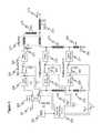
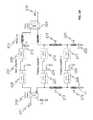
- FIG. 3is a schematic diagram showing an embodiment of a 3-way Doherty distributed amplifier with digital adaptive power tracking in accordance with the present invention
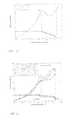
- FIG. 4is a graph showing simulation results of gain and power added efficiency performance (PAE) of an embodiment of a 3-way Doherty distributed amplifier in accordance with the present invention
- FIG. 5is a graph showing measurement results of gain and power added efficiency performance (PAE) of an embodiment of a 3-way Doherty distributed amplifier in accordance with the present invention
- FIG. 6is a graph showing measurement results of gain and PAE performance variation as a function of the shunt capacitor and bias voltage of peaking amplifiers for a single-tone signal using an embodiment of a 3-way Doherty distributed amplifier in accordance with the present invention
- FIG. 7is a graph showing measurement results of spectrum for a single WCDMA carrier using the 3-way Doherty distributed amplifier of the present invention.
- FIG. 8shows a hybrid mode power amplifier system in accordance with the invention
- FIG. 9shows an adaptive power tracking system based on digital signal processing
- FIG. 10shows an adaptive power tracking technique based on analog power tracking
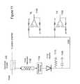
- FIG. 11shows an embodiment of an analog adaptive power tracking circuit
- FIG. 12shows an embodiment of a digital power tracking algorithm
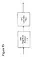
- FIG. 13depicts an embodiment of an envelope tracking algorithm
- FIG. 14is a schematic diagram showing an embodiment of a 3-way Doherty distributed amplifier with a hybrid coupler at the output in accordance with the present invention.
- the present inventioninvolves the use of a single-ended dual-feed distributed (SEDFD) amplifying method with an N-way Doherty amplifier structure, so as to achieve high gain and high efficiency performances at high output back-off power.
- the gain and efficiency performanceis also maximized by adjusting the gate bias of N-way peaking amplifiers and shunt capacitors at the end of the half-wave length gate and drain lines, respectively.
- the present inventionachieves higher power added efficiency (PAE) and higher gain for the multiplexing modulated signals.
- the method and apparatus provided by the present inventionis therefore referred as an N-way Doherty Distributed Power Amplifier (NWDPA) hereafter.
- NWDPAN-way Doherty Distributed Power Amplifier
- FIG. 1is a schematic diagram showing an N-way Doherty amplifier using the SEDFD method of the present invention.
- the RF input signal 101is provided as an input to main SEDFD amplifier 108 and peaking SEDFD amplifier 107 by means of a power splitter 102 .
- Each SEDFD amplifierconsists of two transmission lines 109 , 110 , 111 , 112 and N multiple transistors 113 , 114 . All transistors 113 , 114 in the SEDFD main amplifier 107 and peaking amplifier 108 are connected by both gate and drain lines 109 , 110 , 111 , 112 with a half-wave length at the center frequency and operate identically.
- the input signal of the SEDFD amplifier 107 , 108is distributed along the gate line 109 , 111 and the amplified output signal is combined along the drain line 110 , 112 . Since each transistor adds power in phase to the signal, the SEDFD amplifier 107 , 108 is able to provide higher gain.
- a ⁇ /4 microstrip line 103is prior to the SEDFD peaking amplifier 107 in order to synchronize the phases between the SEDFD main amplifier 108 and the SEDFD peaking amplifier 107 .
- the output signal 106 of the SEDFD main amplifier 108is passed through a microstrip ⁇ /4 impedance transformer 104 and combined with the output signal of the SEDFD peaking amplifier 107 by the power combiner 105 .
- FIG. 2is a graph showing efficiency characteristics of an NWDPA at various output back-off power. The efficiency of the NWDPA for the maximum power level is given by
- n⁇ 4 ⁇ ( P M + 1 ) ⁇ ( v o v max ) 2 ( P M + 2 ) ⁇ ( v o v max ) - 1
- v o and v maxare the output voltage and the maximum output voltage, respectively
- Mis the number of transistors for the main amplifier
- Pthe number of transistors for the peaking amplifier.
- the main and peaking amplifierscan be either single transistors or multiple transistors, or other forms of amplifiers.
- the transistorscan be discrete or integrated, again depending upon the embodiment.
- the efficiency of the NWDPAis expressed as
- n⁇ 4 ⁇ ( P M + 1 ) ⁇ v o v max .
- the efficiency of the amplifier for various levels of output back-off poweris calculated as a function of the number of the main and peaking amplifiers.
- the relationship between the extended back-off state X BO and the number of main and peaking amplifiersis given by
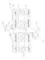
- FIG. 3is a schematic diagram showing an embodiment of a 3-way Doherty SEDFD amplifier of the present invention.
- the amplifierconsists of one main amplifier 203 and two peaking amplifiers 204 , 205 using the same type of transistors.
- the RF input signal 201is passed through a 90° hybrid coupler 202 and divided to a main amplifier 203 and two peaking amplifiers 204 , 205 .
- Input impedance matching circuits 206 , 207 , 208are connected between the coupler 202 and the main amplifier 203 and the peaking amplifiers 204 , 205 , respectively.
- the main amplifier 203is biased as a Class-AB amplifier and the peaking amplifiers 204 , 205 biased as Class-C amplifiers. If the main amplifier 203 is generally biased in Class AB mode, it will have a gain compression characteristic. In contrast, if the peaking amplifier 204 , 205 is generally biased in Class C mode, it will have a gain expansion characteristic. In at least some embodiments, the present invention takes advantage of the complimentary characteristics, so that the gain compression of the Class AB main amplifier will be compensated by the gain expansion of the Class C peaking amplifiers to create a more linear power amplifier.
- output impedance matching circuits 209 , 210 , 211are connected to the outputs of the main amplifier 203 and the peaking amplifiers 204 , 205 .
- a shunt capacitor CM 212is connected to the output impedance matching circuit 209 of the main amplifier 203 so as to optimize the linearity of the NWDPA based on the linearity optimized Doherty amplifier method of U.S. provisional application No. 60/846,905 filed on November 2006, incorporated herein by reference.
- compensation lines 213are inserted between output impedance matching circuits 209 , 210 , 211 and ⁇ /4 impedance transformers 214 , 215 .
- the peaking amplifiers 204 , 205are combined using the dual-feed distributed structure which has, in some embodiments, half-wave micro-strip lines 217 , 218 at each gate and drain of the first peaking amplifier, shown as a FET for purposes of illustration and clarity.
- the first peaking amplifier 204is combined with the second peaking amplifier 205 using a dual-feed distributed structure.
- the dual-feed distributed structurecomprises the half wavelength and quarter wavelength lines and short-circuited quarter-wave length micro-strip lines 219 , 220 at each gate and drain of the second peaking amplifier 205 , respectively, connected through the associated input and output impedance matching circuits.
- the second peaking amplifier 205is shown in the illustrated embodiment as a single transistor for purposes of simplicity, but could be one or more transistors.
- the quarter wavelength transmission lines 214 , 215 at the outputcould in some embodiments be replaced by a hybrid coupler 224 .
- FIG. 14shows the quarter wavelength transmission lines 214 , 215 replaced by the hybrid coupler 224 .
- the half-wave lines 217 and 218are, in some embodiments, set at the center frequency of the operating power amplifier bandwidth.
- Shunt capacitors C P 221 , 222are connected in some embodiments to both ends of the short-circuited quarter-wave length micro-strip lines 219 , 220 for optimizing both gain and efficiency characteristics of the NWDPA.
- Offset line 213can be included to prevent leakage power between the main amplifier 203 and the peaking amplifiers 204 , 205 .
- the hybrid coupler 202will cause some gain compression, and this can be compensated by the gain expansion of the peaking amplifiers 204 , 205 .
- An additional hybrid couplercan be connected at the output in some embodiments. Further, those skilled in the art will appreciate that the main distributed amplifiers and peaking distributed amplifiers can be constructed either as separate miniature microwave integrated circuits or on one integrated MMIC.
- FIG. 10An embodiment of an analog power tracking system in accordance with the invention is shown in FIG. 10 and comprises two primary blocks: power detection circuitry 234 and Adaptive Bias Supply Circuit 233 , together with the N-way Doherty Amplifier of FIG. 3 .
- a directional coupler 232is typically used at the input of the N-Way Doherty power amplifier. The directional coupler 232 extracts a sampling of the input signal.
- the output of the Adaptive Bias Supply Circuit 233is fed to the various gate and drain voltage terminals via an RF choke.
- the RF chokeserves to supply DC bias to the active devices while not altering the RF performance.
- FIG. 11One possible embodiment of the power detection circuit 234 is shown in FIG. 11 and comprises an attenuator 1100 , logarithmic detector 1105 , rectifier 1110 including capacitor 1115 and resistor 1120 , and operational amplifiers 1125 and 1130 .
- the value of the capacitor 1115 in the rectifier circuit implementation of FIG. 11controls the averaging time constant. By setting this time constant much faster than the incoming modulation, the circuit of FIG. 11 performs envelope tracking By setting this time constant much slower than the incoming modulation, the circuit of FIG. 11 performs average power tracking.
- the digital power tracking system in FIG. 9comprises baseband digital signal processing using DSP 230 —to extract either the envelope or the average power of the incoming signal—as well as an adaptive bias supply circuit 231 .
- the input signal modulationis accessible at baseband using digital signal processing. Therefore, a power detection algorithm can be easily developed at baseband.
- the output of the DSP power detection algorithmis fed to a Digital to Analog converter (not shown) which feeds the Adaptive Bias Supply circuit 231 .
- FIG. 12shows an embodiment of the average power tracking algorithm based on a digital signal processing implementation, and comprises a square law function 1200 followed by a low pass filter function 1210 and an averaging of the function X; from 1 to N, as shown, at 1220 . The value of N controls the time window for averaging the input power.
- FIG. 13depicts an embodiment of an envelope tracking algorithm. The magnitude 1300 of the incoming modulation is processed and followed by a low pass filter 1310 . No averaging occurs in this implementation.
- a 42 dBm high power amplifieris designed and implemented by using LDMOS FET's with pldB of 150 W.
- FIG. 4is a graph showing simulation results of gain and PAE for a single tone signal at the frequency of 2140 MHz using a 3-way Doherty distributed amplifier such as shown in FIG. 3 .
- the output impedance of the combined peaking amplifier using a dual-feed distributed structureis 4.65+j2.1 ⁇ .
- FIG. 5is a graph showing measurement results of gain and PAE of the 3-way Doherty distributed amplifier of the present invention.
- the shunt capacitors, C P and C Mof 15 pF and 0.5 pF are used, respectively.
- a 42.7% PAE at PEP of 131 W and 39.5% PAE at 9.5 dB back offare achieved, respectively.
- a gain of approximately 11 dBwas obtained at 9.5 dB back off.
- FIG. 6is a graph showing measurement results of gain and PAE performance variation as a function of the shunt capacitor and bias voltage of peaking amplifiers for single-tone signal using the 3-way Doherty distributed amplifier of the present invention. Optimization of C P and the bias point of the two-peaking amplifiers produced efficiency and gain improvement of approximately 8% and 2 dB at 9.5 dB back off, even though the PAE is reduced at PEP.
- FIG. 7is a graph showing measurement results of spectrum for a single WCDMA carrier using a 3-way Doherty distributed amplifier in accordance with the present invention.
- the shunt capacitors, C P and C M of 9.1 pF and 0.5 pFwere used, respectively.
- both memoryless and memory-based digital predistortionwere applied.
- the ACLR performances of ⁇ 51 dBc after memoryless and ⁇ 54 dBc after memory compensationwere obtained at 41 dBm output power and +2.5 MHz offset frequency.
- the NWDPA of the present inventioncompared to the conventional N-way Doherty amplifier, improves the gain performance more effectively since the NWDPA uses a SEDFD structure in conjunction with a Doherty amplifier.
- a hybrid mode power amplifier system in accordance with the inventionis shown in FIG. 8 , in which a modulated RF input signal 800 is provided to a digital predistortion controller 805 , which in turn provides its output to a power amplifier 810 in accordance with the present invention.
- the RF output 815is monitored, and a signal representative of the output is fed back to the controller 805 as a feedback signal 820 .
Landscapes
- Engineering & Computer Science (AREA)
- Power Engineering (AREA)
- Amplifiers (AREA)
Abstract
Description
This application is a continuation of U.S. patent application Ser. No. 14/087,682, filed Nov. 22, 2013, now U.S. Pat. No. 9,184,703, issued Nov. 11, 2015, which is a continuation of U.S. patent application Ser. No. 13/553,967, filed Jul. 20, 2012, now U.S. Pat. No. 8,618,883, issued Dec. 31, 2013, which is a continuation of U.S. patent application Ser. No. 12/603,419, filed Oct. 21, 2009, now U.S. Pat. No. 8,274,332, issued Sep. 25, 2012, which is a continuation-in-part of U.S. patent application Ser. No. 12/108,507, filed Apr. 23, 2008, now U.S. Pat. No. 7,688,135, issued Mar. 30, 2010, which claims the benefit under 35 U.S.C. § 119(e) of U.S. Provisional Application No. 60/925,577, filed Apr. 23, 2007. Each of these applications is hereby incorporated by reference in its entirety for all purposes.
The present invention generally relates to high power communication systems. More specially, the present invention relates to high efficiency high power amplifiers for such systems.
In modern digital wireless communication systems, such as IS-95, PCS, WCDMA, OFDM, and so on, the power amplifiers have advanced towards having a wide bandwidth and large number of carriers. Recently, orthogonal frequency division multiplexing (OFDM) modulation has become an attractive technique for transmitting information efficiently within a limited bandwidth like WiBRO and WiMAX. However, since the OFDM signal consists of a number of independently modulated sub-carriers, it produces a higher peak-to-average power ratio (PAR) signal. A typical PAR for a 64-subcarrier OFDM signal is around 8-13 dB. When the number of sub-carriers is increased to 2048, the PAR also increases, typically from 11 to 16 dB. The power amplifiers designed to operate with these high PARs typically have significantly deteriorated efficiency.
The Doherty amplifier is known as a technique for improving the efficiency at high output back-off power. Its primary advantage is the ease of configuration when applied to high power amplifiers, unlike other efficiency enhancement amplifiers or techniques such as switching mode amplifiers, EER, LINC and so on. Recent results have been reported on its use as: a symmetric Doherty structure, an asymmetric Doherty structure with uneven power transistors, and an N-way Doherty structure using multi-paralleled transistors. In the case of the symmetric Doherty amplifier, the maximum efficiency point is obtained at 6 dB back-off power.
The asymmetric Doherty amplifier can obtain a high efficiency at various back-off powers using a combination of different power device sizes for the main and peaking amplifiers. Unfortunately, it is difficult to optimize the gain and output power of the asymmetric Doherty amplifier because of the different device matching circuits and the delay mismatch between the main amplifier and the peaking amplifier.
The conventional N-way Doherty amplifier gains an efficiency enhancement over a conventional 2-way Doherty structure by using the multiple parallel transistors of identical devices. Its one drawback is that the total gain will be reduced due to the loss of the N-way input power splitter. Under low gain situations this will increase the power dissipation of the driving amplifier.
Further, while the conventional N-way Doherty amplifier can offer improved efficiency at high output back-off power, the performance of conventional N-way Doherty amplifiers deteriorates as to both gain and efficiency for higher peak-to-average power ratio (PAPR) signals.
Hence, a need remains in the art for a method of applying both circuit-level and system-level techniques simultaneously for improving the gain and efficiency performance of N-way Doherty amplifier at high output back-off power in the high power communication systems.
Accordingly, the present invention has been made in view of the above problems, and it is an object of the present invention to provide a method for improving the gain and efficiency performance of the Doherty amplifying structure at high output back-off power for high power communication system applications. To achieve the above objects, according to the present invention, the technique employs dual-feed distributed amplifying. The power splitter and combiner of the conventional N-way Doherty amplifier are replaced by hybrid couplers with transmission lines. Compared to the conventional N-way Doherty amplifier, the present invention is able to achieve good isolation at the input and output as well as high gain performance with high efficiency. In an embodiment, a power tracking adaptive bias supply technique is employed. The drain bias voltages and gate bias voltages are adaptively controlled by the input power level. Two alternative approaches as disclosed: 1) Envelope tracking and 2) Average power tracking. The envelope tracking technique requires a fast switching power supply whereas the average power tracking technique adapts significantly slower. The power detection circuit can be implemented either using analog circuitry or using digital signal processing.
Further objects and advantages of the invention can be more fully understood from the following detailed description taken in conjunction with the accompanying drawings in which:
In general, the present invention, involves the use of a single-ended dual-feed distributed (SEDFD) amplifying method with an N-way Doherty amplifier structure, so as to achieve high gain and high efficiency performances at high output back-off power. In some embodiments, the gain and efficiency performance is also maximized by adjusting the gate bias of N-way peaking amplifiers and shunt capacitors at the end of the half-wave length gate and drain lines, respectively. Compared to conventional N-way Doherty amplifiers, therefore, the present invention achieves higher power added efficiency (PAE) and higher gain for the multiplexing modulated signals. The method and apparatus provided by the present invention is therefore referred as an N-way Doherty Distributed Power Amplifier (NWDPA) hereafter. Various embodiments of the NWDPA according to the present invention will now be described in detail with reference to the accompanying drawings.
and the efficiency for the medium power level is given by
where voand vmax, are the output voltage and the maximum output voltage, respectively, M is the number of transistors for the main amplifier, and P the number of transistors for the peaking amplifier. Depending upon the embodiment, the main and peaking amplifiers can be either single transistors or multiple transistors, or other forms of amplifiers. In addition, the transistors can be discrete or integrated, again depending upon the embodiment.
For the low power level, the efficiency of the NWDPA is expressed as
The efficiency of the amplifier for various levels of output back-off power is calculated as a function of the number of the main and peaking amplifiers. The relationship between the extended back-off state XBOand the number of main and peaking amplifiers is given by
In order to achieve optimized power, outputimpedance matching circuits main amplifier 203 and the peakingamplifiers shunt capacitor CM 212 is connected to the outputimpedance matching circuit 209 of themain amplifier 203 so as to optimize the linearity of the NWDPA based on the linearity optimized Doherty amplifier method of U.S. provisional application No. 60/846,905 filed on November 2006, incorporated herein by reference. To obtain peak efficiency point at a desired output back-off power,compensation lines 213 are inserted between outputimpedance matching circuits impedance transformers amplifiers wave micro-strip lines FIG. 3 , thefirst peaking amplifier 204 is combined with thesecond peaking amplifier 205 using a dual-feed distributed structure. The dual-feed distributed structure comprises the half wavelength and quarter wavelength lines and short-circuited quarter-wavelength micro-strip lines second peaking amplifier 205, respectively, connected through the associated input and output impedance matching circuits. Thesecond peaking amplifier 205 is shown in the illustrated embodiment as a single transistor for purposes of simplicity, but could be one or more transistors. The quarterwavelength transmission lines hybrid coupler 224.FIG. 14 shows the quarterwavelength transmission lines hybrid coupler 224.
The half-wave lines Shunt capacitors C length micro-strip lines line 213 can be included to prevent leakage power between themain amplifier 203 and the peakingamplifiers hybrid coupler 202 will cause some gain compression, and this can be compensated by the gain expansion of the peakingamplifiers
An embodiment of an analog power tracking system in accordance with the invention is shown inFIG. 10 and comprises two primary blocks: power detection circuitry234 and AdaptiveBias Supply Circuit 233, together with the N-way Doherty Amplifier ofFIG. 3 . For simplicity and clarity, like elements fromFIG. 3 are shown with like reference numerals inFIG. 10 . Adirectional coupler 232 is typically used at the input of the N-Way Doherty power amplifier. Thedirectional coupler 232 extracts a sampling of the input signal. The output of the AdaptiveBias Supply Circuit 233 is fed to the various gate and drain voltage terminals via an RF choke. The RF choke serves to supply DC bias to the active devices while not altering the RF performance. One possible embodiment of the power detection circuit234 is shown inFIG. 11 and comprises an attenuator1100,logarithmic detector 1105,rectifier 1110 includingcapacitor 1115 andresistor 1120, andoperational amplifiers 1125 and1130. The value of thecapacitor 1115 in the rectifier circuit implementation ofFIG. 11 controls the averaging time constant. By setting this time constant much faster than the incoming modulation, the circuit ofFIG. 11 performs envelope tracking By setting this time constant much slower than the incoming modulation, the circuit ofFIG. 11 performs average power tracking.
The digital power tracking system inFIG. 9 comprises baseband digital signalprocessing using DSP 230—to extract either the envelope or the average power of the incoming signal—as well as an adaptivebias supply circuit 231. The input signal modulation is accessible at baseband using digital signal processing. Therefore, a power detection algorithm can be easily developed at baseband. The output of the DSP power detection algorithm is fed to a Digital to Analog converter (not shown) which feeds the AdaptiveBias Supply circuit 231.FIG. 12 shows an embodiment of the average power tracking algorithm based on a digital signal processing implementation, and comprises asquare law function 1200 followed by a lowpass filter function 1210 and an averaging of the function X; from 1 to N, as shown, at1220. The value of N controls the time window for averaging the input power.FIG. 13 depicts an embodiment of an envelope tracking algorithm. Themagnitude 1300 of the incoming modulation is processed and followed by alow pass filter 1310. No averaging occurs in this implementation.
In examining the performance of NWDPA, a 42 dBm high power amplifier is designed and implemented by using LDMOS FET's with pldB of 150 W.
In summary, the NWDPA of the present invention, compared to the conventional N-way Doherty amplifier, improves the gain performance more effectively since the NWDPA uses a SEDFD structure in conjunction with a Doherty amplifier. A hybrid mode power amplifier system in accordance with the invention is shown inFIG. 8 , in which a modulatedRF input signal 800 is provided to adigital predistortion controller 805, which in turn provides its output to apower amplifier 810 in accordance with the present invention. TheRF output 815 is monitored, and a signal representative of the output is fed back to thecontroller 805 as afeedback signal 820.
Although the present invention has been described with reference to the preferred embodiments, it will be understood that the invention is not limited to the details described thereof. Various substitutions and modifications are disclosed in the foregoing description, and others will be apparent to those of ordinary skill in the art based on the teachings herein. Therefore, all such substitutions and modifications are intended to be embraced within the scope of the invention as defined in the appended claims.
Claims (19)
1. An amplifier device comprising:
an input circuit having a radiofrequency input configured to receive a radiofrequency signal for amplification, the input circuit including a hybrid coupler, a first output, and a second output;
a main amplification circuit having a main input coupled to the first output of the input circuit, the main amplification circuit having a main output;
a first peaking amplification circuit having a first peaking input coupled to the second output of the input circuit, the first peaking amplification circuit having a first peaking output;
a second peaking amplification circuit having a second peaking input coupled to the first peaking input of the first peaking amplification circuit via a first half-wave transmission line, the second peaking amplification circuit having a second peaking output coupled to the first peaking output via a second half-wave transmission line;
an output circuit having a third input coupled to the main output of the main amplification circuit and a fourth input coupled to the first peaking output of the first peaking amplification circuit, the output circuit having a radiofrequency output providing an amplified radiofrequency signal, wherein the output circuit includes:
an offset line coupled to each of the third input and the fourth input of the output circuit; and
a second hybrid coupler coupled to the third input and the fourth input of the output circuit and the radiofrequency output of the output circuit.
2. The amplifier device ofclaim 1 , wherein the main amplification circuit includes a first input impedance matching circuit.
3. The amplifier device ofclaim 2 , wherein the first peaking amplification circuit includes a second input impedance matching circuit.
4. The amplifier device ofclaim 1 , wherein the main amplification circuit includes a first output impedance matching circuit and wherein the first peaking amplification circuit includes a second output impedance matching circuit.
5. The amplifier device ofclaim 1 , wherein the output circuit includes:
the offset line coupled to each of the third input and the fourth input of the output circuit; and
impedance transformers coupled to the offset line and the radiofrequency output of the output circuit.
6. The amplifier device ofclaim 1 , wherein the main amplification circuit includes a main amplifier, and wherein the main amplifier is biased as a Class AB amplifier.
7. The amplifier device ofclaim 6 , wherein the main amplifier comprises at least one transistor.
8. The amplifier device ofclaim 1 , wherein the first peaking amplification circuit includes a peaking amplifier, and wherein the peaking amplifier is biased as a Class C amplifier.
9. The amplifier device ofclaim 1 , wherein the first peaking amplification circuit comprises at least one transistor.
10. The amplifier device ofclaim 1 , wherein the first peaking amplification circuit includes a dual-feed distributed structure.
11. The amplifier device ofclaim 1 , further comprising:
a first shunt capacitor coupled to the second peaking input of the second peaking amplification circuit; and
a second shunt capacitor coupled to the second peaking output of the second peaking amplification circuit.
12. The amplifier device ofclaim 11 , wherein the first shunt capacitor is coupled to the second peaking input of the second peaking amplification circuit via a first quarter-wave transmission line, and wherein the second shunt capacitor is coupled to the second peaking output of the second peaking amplification circuit via a second quarter-wave transmission line.
13. A method for amplifying a radiofrequency signal, comprising:
producing, using an input circuit including a hybrid coupler, a first output and a second output, the input circuit having an input configured to receive the radiofrequency signal;
amplifying, using a main amplification circuit, the first output of the input circuit, the main amplification circuit having a main output providing a main amplified signal;
amplifying, using a first peaking amplification circuit and a second peaking amplification circuit, the second output of the input circuit, the first peaking amplification circuit having a first peaking input coupled to a second peaking input of the second peaking amplification circuit via a first half-wave transmission line, the first peaking amplification circuit having a first peaking output providing a first peaking amplified signal, the second peaking amplification circuit having a second peaking output coupled to the first peaking output of the first peaking amplification circuit via a second half-wave transmission line and providing a second peaking amplified signal; and
combining, using an output circuit, the main amplified signal, the first peaking amplified signal, and the second peaking amplified signal, wherein the output circuit drives each of the main amplified signal, the first peaking amplified signal, and the second peaking amplified signal through an offset line, wherein the output circuit combines an offset line output using a second hybrid coupler, wherein the second hybrid coupler produces a coupled output associated with the output circuit, wherein the coupled output associated with the output circuit provides an amplified radiofrequency output signal.
14. The method ofclaim 13 , further comprising:
impedance matching, using a first input impedance matching circuit, the first output of the input circuit; and
impedance matching, using a second input impedance matching circuit, the second output of the input circuit.
15. The method ofclaim 13 , further comprising:
impedance matching, using a first output impedance matching circuit, the main output of the main amplification circuit to produce the main amplified signal; and
impedance matching, using a second output impedance matching circuit, the first peaking output of the first peaking amplification circuit to produce the first peaking amplified signal.
16. The method ofclaim 13 , wherein combining the main amplified signal and the first peaking amplified signal includes:
driving each of the main amplified signal and the first peaking amplified signal through the offset line of the output circuit; and
combining the offset line output using impedance transformers, the impedance transformers producing the coupled output of the output circuit.
17. The method ofclaim 13 , wherein the main amplification circuit includes a main amplifier, and wherein the main amplifier is biased as a Class AB amplifier.
18. The method ofclaim 13 , wherein the first peaking amplification circuit includes a peaking amplifier, and wherein the peaking amplifier is biased as a Class C amplifier.
19. The method ofclaim 13 , wherein the first peaking amplification circuit includes a dual-feed distributed structure.
Priority Applications (1)
| Application Number | Priority Date | Filing Date | Title |
|---|---|---|---|
| US14/885,890US10298177B2 (en) | 2007-04-23 | 2015-10-16 | N-way doherty distributed power amplifier with power tracking |
Applications Claiming Priority (6)
| Application Number | Priority Date | Filing Date | Title |
|---|---|---|---|
| US92557707P | 2007-04-23 | 2007-04-23 | |
| US12/108,507US7688135B2 (en) | 2007-04-23 | 2008-04-23 | N-way Doherty distributed power amplifier |
| US12/603,419US8274332B2 (en) | 2007-04-23 | 2009-10-21 | N-way Doherty distributed power amplifier with power tracking |
| US13/553,967US8618883B2 (en) | 2007-04-23 | 2012-07-20 | N-way doherty distributed power amplifier with power tracking |
| US14/087,682US9184703B2 (en) | 2007-04-23 | 2013-11-22 | N-way doherty distributed power amplifier with power tracking |
| US14/885,890US10298177B2 (en) | 2007-04-23 | 2015-10-16 | N-way doherty distributed power amplifier with power tracking |
Related Parent Applications (1)
| Application Number | Title | Priority Date | Filing Date |
|---|---|---|---|
| US14/087,682ContinuationUS9184703B2 (en) | 2007-04-23 | 2013-11-22 | N-way doherty distributed power amplifier with power tracking |
Publications (2)
| Publication Number | Publication Date |
|---|---|
| US20160173040A1 US20160173040A1 (en) | 2016-06-16 |
| US10298177B2true US10298177B2 (en) | 2019-05-21 |
Family
ID=42318625
Family Applications (4)
| Application Number | Title | Priority Date | Filing Date |
|---|---|---|---|
| US12/603,419ActiveUS8274332B2 (en) | 2007-04-23 | 2009-10-21 | N-way Doherty distributed power amplifier with power tracking |
| US13/553,967ActiveUS8618883B2 (en) | 2007-04-23 | 2012-07-20 | N-way doherty distributed power amplifier with power tracking |
| US14/087,682ActiveUS9184703B2 (en) | 2007-04-23 | 2013-11-22 | N-way doherty distributed power amplifier with power tracking |
| US14/885,890ActiveUS10298177B2 (en) | 2007-04-23 | 2015-10-16 | N-way doherty distributed power amplifier with power tracking |
Family Applications Before (3)
| Application Number | Title | Priority Date | Filing Date |
|---|---|---|---|
| US12/603,419ActiveUS8274332B2 (en) | 2007-04-23 | 2009-10-21 | N-way Doherty distributed power amplifier with power tracking |
| US13/553,967ActiveUS8618883B2 (en) | 2007-04-23 | 2012-07-20 | N-way doherty distributed power amplifier with power tracking |
| US14/087,682ActiveUS9184703B2 (en) | 2007-04-23 | 2013-11-22 | N-way doherty distributed power amplifier with power tracking |
Country Status (1)
| Country | Link |
|---|---|
| US (4) | US8274332B2 (en) |
Cited By (1)
| Publication number | Priority date | Publication date | Assignee | Title |
|---|---|---|---|---|
| US11750156B2 (en) | 2020-08-24 | 2023-09-05 | City University Of Hong Kong | Power amplifier |
Families Citing this family (116)
| Publication number | Priority date | Publication date | Assignee | Title |
|---|---|---|---|---|
| US8811917B2 (en) | 2002-05-01 | 2014-08-19 | Dali Systems Co. Ltd. | Digital hybrid mode power amplifier system |
| US8380143B2 (en) | 2002-05-01 | 2013-02-19 | Dali Systems Co. Ltd | Power amplifier time-delay invariant predistortion methods and apparatus |
| CN102017553B (en) | 2006-12-26 | 2014-10-15 | 大力系统有限公司 | Method and system for baseband predistortion linearization in a multi-channel broadband communication system |
| US8274332B2 (en) | 2007-04-23 | 2012-09-25 | Dali Systems Co. Ltd. | N-way Doherty distributed power amplifier with power tracking |
| US9112452B1 (en) | 2009-07-14 | 2015-08-18 | Rf Micro Devices, Inc. | High-efficiency power supply for a modulated load |
| EP2905895A1 (en)* | 2009-09-28 | 2015-08-12 | NEC Corporation | Doherty amplifier |
| EP3376667B1 (en) | 2010-04-19 | 2021-07-28 | Qorvo US, Inc. | Pseudo-envelope following power management system |
| US9099961B2 (en) | 2010-04-19 | 2015-08-04 | Rf Micro Devices, Inc. | Output impedance compensation of a pseudo-envelope follower power management system |
| US9431974B2 (en) | 2010-04-19 | 2016-08-30 | Qorvo Us, Inc. | Pseudo-envelope following feedback delay compensation |
| DE102010034067A1 (en)* | 2010-08-12 | 2012-02-16 | Rohde & Schwarz Gmbh & Co. Kg | High frequency power amplifier with Doherty extension |
| KR101835254B1 (en) | 2010-08-17 | 2018-03-06 | 달리 시스템즈 씨오. 엘티디. | Neutral host architecture for a distributed antenna system |
| CN102130657A (en)* | 2010-09-14 | 2011-07-20 | 华为技术有限公司 | A power amplifier, asymmetric Daherdy power amplification equipment and base station |
| CN103597807B (en) | 2010-09-14 | 2015-09-30 | 大理系统有限公司 | Remotely reconfigurable distributed antenna system and method |
| WO2012047738A1 (en) | 2010-09-29 | 2012-04-12 | Rf Micro Devices, Inc. | SINGLE μC-BUCKBOOST CONVERTER WITH MULTIPLE REGULATED SUPPLY OUTPUTS |
| WO2012068260A1 (en) | 2010-11-16 | 2012-05-24 | Rf Micro Devices, Inc. | Digital gain multiplier for envelop tracking systems and corresponding method |
| WO2012109227A2 (en) | 2011-02-07 | 2012-08-16 | Rf Micro Devices, Inc. | Group delay calibration method for power amplifier envelope tracking |
| KR101145666B1 (en)* | 2011-02-24 | 2012-05-25 | 포항공과대학교 산학협력단 | Three-stage gan hemt doherty power amplifier for high frequency applications |
| US9247496B2 (en) | 2011-05-05 | 2016-01-26 | Rf Micro Devices, Inc. | Power loop control based envelope tracking |
| US9246460B2 (en) | 2011-05-05 | 2016-01-26 | Rf Micro Devices, Inc. | Power management architecture for modulated and constant supply operation |
| US9379667B2 (en) | 2011-05-05 | 2016-06-28 | Rf Micro Devices, Inc. | Multiple power supply input parallel amplifier based envelope tracking |
| US20130293295A1 (en)* | 2011-05-17 | 2013-11-07 | Electronics And Telecommunications Research Institute | Compact rf power amplifier |
| US8604881B2 (en)* | 2011-05-24 | 2013-12-10 | Samsung Electronics Co., Ltd. | Efficiency improvement of doherty power amplifier using supply switching and digitally controlled gate bias modulation of peaking amplifier |
| US9178627B2 (en) | 2011-05-31 | 2015-11-03 | Rf Micro Devices, Inc. | Rugged IQ receiver based RF gain measurements |
| US9019011B2 (en) | 2011-06-01 | 2015-04-28 | Rf Micro Devices, Inc. | Method of power amplifier calibration for an envelope tracking system |
| US8339201B1 (en)* | 2011-06-17 | 2012-12-25 | Infineon Technologies Ag | Wideband doherty amplifier circuit having a constant impedance combiner |
| DE102011079613A1 (en)* | 2011-06-30 | 2013-01-03 | Rohde & Schwarz Gmbh & Co. Kg | Doherty amplifier with efficiency optimization |
| US8952710B2 (en) | 2011-07-15 | 2015-02-10 | Rf Micro Devices, Inc. | Pulsed behavior modeling with steady state average conditions |
| US9263996B2 (en) | 2011-07-20 | 2016-02-16 | Rf Micro Devices, Inc. | Quasi iso-gain supply voltage function for envelope tracking systems |
| US8754706B2 (en) | 2011-08-02 | 2014-06-17 | Qualcomm Incorporated | Power based feedback for improved power amplifier (PA) efficiency |
| US8942652B2 (en) | 2011-09-02 | 2015-01-27 | Rf Micro Devices, Inc. | Split VCC and common VCC power management architecture for envelope tracking |
| US9041464B2 (en) | 2011-09-16 | 2015-05-26 | Qualcomm Incorporated | Circuitry for reducing power consumption |
| US8957728B2 (en) | 2011-10-06 | 2015-02-17 | Rf Micro Devices, Inc. | Combined filter and transconductance amplifier |
| US9024688B2 (en) | 2011-10-26 | 2015-05-05 | Rf Micro Devices, Inc. | Dual parallel amplifier based DC-DC converter |
| US9484797B2 (en) | 2011-10-26 | 2016-11-01 | Qorvo Us, Inc. | RF switching converter with ripple correction |
| WO2013063364A1 (en) | 2011-10-26 | 2013-05-02 | Rf Micro Devices, Inc. | Average frequency control of switcher for envelope tracking |
| US8975959B2 (en) | 2011-11-30 | 2015-03-10 | Rf Micro Devices, Inc. | Monotonic conversion of RF power amplifier calibration data |
| US9515621B2 (en) | 2011-11-30 | 2016-12-06 | Qorvo Us, Inc. | Multimode RF amplifier system |
| US9250643B2 (en) | 2011-11-30 | 2016-02-02 | Rf Micro Devices, Inc. | Using a switching signal delay to reduce noise from a switching power supply |
| US9041365B2 (en) | 2011-12-01 | 2015-05-26 | Rf Micro Devices, Inc. | Multiple mode RF power converter |
| US8947161B2 (en) | 2011-12-01 | 2015-02-03 | Rf Micro Devices, Inc. | Linear amplifier power supply modulation for envelope tracking |
| US9256234B2 (en) | 2011-12-01 | 2016-02-09 | Rf Micro Devices, Inc. | Voltage offset loop for a switching controller |
| US9280163B2 (en) | 2011-12-01 | 2016-03-08 | Rf Micro Devices, Inc. | Average power tracking controller |
| US9494962B2 (en) | 2011-12-02 | 2016-11-15 | Rf Micro Devices, Inc. | Phase reconfigurable switching power supply |
| US9813036B2 (en)* | 2011-12-16 | 2017-11-07 | Qorvo Us, Inc. | Dynamic loadline power amplifier with baseband linearization |
| US9298198B2 (en) | 2011-12-28 | 2016-03-29 | Rf Micro Devices, Inc. | Noise reduction for envelope tracking |
| US8514007B1 (en) | 2012-01-27 | 2013-08-20 | Freescale Semiconductor, Inc. | Adjustable power splitter and corresponding methods and apparatus |
| US8958762B2 (en) | 2012-03-08 | 2015-02-17 | Htc Corporation | Apparatus and method for power management |
| JP5810989B2 (en)* | 2012-03-15 | 2015-11-11 | 富士通株式会社 | Amplifying apparatus and control method |
| US9077285B2 (en)* | 2012-04-06 | 2015-07-07 | Freescale Semiconductor, Inc. | Electronic devices with multiple amplifier stages and methods of their manufacture |
| US8981839B2 (en) | 2012-06-11 | 2015-03-17 | Rf Micro Devices, Inc. | Power source multiplexer |
| WO2014018861A1 (en) | 2012-07-26 | 2014-01-30 | Rf Micro Devices, Inc. | Programmable rf notch filter for envelope tracking |
| DE202013012858U1 (en) | 2012-08-09 | 2021-05-07 | Axel Wireless Ltd. | Capacity-centered digital distributed antenna system |
| US9225231B2 (en) | 2012-09-14 | 2015-12-29 | Rf Micro Devices, Inc. | Open loop ripple cancellation circuit in a DC-DC converter |
| US9197256B2 (en) | 2012-10-08 | 2015-11-24 | Rf Micro Devices, Inc. | Reducing effects of RF mixer-based artifact using pre-distortion of an envelope power supply signal |
| WO2014062902A1 (en) | 2012-10-18 | 2014-04-24 | Rf Micro Devices, Inc | Transitioning from envelope tracking to average power tracking |
| US20140111279A1 (en)* | 2012-10-19 | 2014-04-24 | Samsung Electronics Co., Ltd | Envelope tracking distributed amplifier |
| US8818305B1 (en)* | 2012-11-14 | 2014-08-26 | Motorola Mobility Llc | Supply transitions in an envelope tracked power amplifier |
| US9627975B2 (en) | 2012-11-16 | 2017-04-18 | Qorvo Us, Inc. | Modulated power supply system and method with automatic transition between buck and boost modes |
| CA2892093A1 (en) | 2012-11-26 | 2014-05-30 | Adc Telecommunications, Inc. | Forward-path digital summation in digital radio frequency transport |
| US20140146797A1 (en) | 2012-11-26 | 2014-05-29 | Adc Telecommunications, Inc. | Timeslot mapping and/or aggregation element for digital radio frequency transport architecture |
| CA2892759A1 (en) | 2012-11-26 | 2014-05-30 | Adc Telecommunications, Inc. | Flexible, reconfigurable multipoint-to-multipoint digital radio frequency transport architecture |
| US9929696B2 (en) | 2013-01-24 | 2018-03-27 | Qorvo Us, Inc. | Communications based adjustments of an offset capacitive voltage |
| WO2014117402A1 (en)* | 2013-02-04 | 2014-08-07 | 华为技术有限公司 | Power amplifier, transceiver, and base station |
| US9178472B2 (en) | 2013-02-08 | 2015-11-03 | Rf Micro Devices, Inc. | Bi-directional power supply signal based linear amplifier |
| US9203353B2 (en) | 2013-03-14 | 2015-12-01 | Rf Micro Devices, Inc. | Noise conversion gain limited RF power amplifier |
| WO2014152903A2 (en) | 2013-03-14 | 2014-09-25 | Rf Micro Devices, Inc | Envelope tracking power supply voltage dynamic range reduction |
| US9479118B2 (en) | 2013-04-16 | 2016-10-25 | Rf Micro Devices, Inc. | Dual instantaneous envelope tracking |
| US9124217B2 (en)* | 2013-05-15 | 2015-09-01 | City University Of Hong Kong | Power amplifier |
| US9374005B2 (en) | 2013-08-13 | 2016-06-21 | Rf Micro Devices, Inc. | Expanded range DC-DC converter |
| WO2015024208A1 (en) | 2013-08-21 | 2015-02-26 | 华为技术有限公司 | Balanced doherty power amplifier circuit and wireless transmitter |
| DE102013220160A1 (en)* | 2013-10-05 | 2015-04-09 | Rwth Aachen | Sequential broadband Doherty power amplifier with adjustable output line back-off |
| US9750082B2 (en) | 2013-10-07 | 2017-08-29 | Commscope Technologies Llc | Systems and methods for noise floor optimization in distributed antenna system with direct digital interface to base station |
| US9787457B2 (en) | 2013-10-07 | 2017-10-10 | Commscope Technologies Llc | Systems and methods for integrating asynchronous signals in distributed antenna system with direct digital interface to base station |
| EP3058653A4 (en)* | 2013-10-18 | 2016-11-09 | Ericsson Telefon Ab L M | Power amplifier for amplification of an input signal into an output signal |
| US9397616B2 (en)* | 2013-11-06 | 2016-07-19 | Commscope Technologies Llc | Quasi-doherty architecture amplifier and method |
| CN103560754A (en)* | 2013-11-18 | 2014-02-05 | 上海无线电设备研究所 | Compact microstrip resonant cell structure based high-linearity Doherty power amplifier |
| US9614476B2 (en) | 2014-07-01 | 2017-04-04 | Qorvo Us, Inc. | Group delay calibration of RF envelope tracking |
| EP2983291B1 (en)* | 2014-08-07 | 2017-12-06 | Ampleon Netherlands B.V. | Integrated 3-way doherty amplifier |
| EP3490141B1 (en) | 2014-08-11 | 2020-04-01 | Huawei Technologies Co., Ltd. | Power amplifier, radio remote unit, and base station |
| CA2961696A1 (en) | 2014-09-23 | 2016-03-31 | Axell Wireless Ltd. | Automatic mapping and handling pim and other uplink interferences in digital distributed antenna systems |
| US9774299B2 (en) | 2014-09-29 | 2017-09-26 | Nxp Usa, Inc. | Modifiable signal adjustment devices for power amplifiers and corresponding methods and apparatus |
| DK3205015T3 (en)* | 2014-10-06 | 2020-06-02 | Ericsson Telefon Ab L M | Amplifier circuit and method |
| DK3205016T3 (en)* | 2014-10-06 | 2021-01-11 | Ericsson Telefon Ab L M | Amplifier circuit and procedure |
| CN104410393B (en)* | 2014-11-05 | 2023-06-16 | 西安博瑞集信电子科技有限公司 | High-speed high-frequency modulator circuit and method |
| WO2016084069A1 (en)* | 2014-11-24 | 2016-06-02 | Oren Bar-On Ltd. | Adaptive impedance power amplifier |
| US9843255B1 (en) | 2014-12-08 | 2017-12-12 | Nxp Usa, Inc. | Charge pump apparatus, phase-locked loop, and method of operating a charge pump apparatus |
| EP3238352A4 (en) | 2014-12-23 | 2018-08-22 | Axell Wireless Ltd. | Harmonizing noise aggregation and noise management in distributed antenna system |
| EP3322091B1 (en)* | 2015-02-04 | 2019-09-18 | Ampleon Netherlands B.V. | Doherty amplifier |
| US10334572B2 (en) | 2015-02-05 | 2019-06-25 | Commscope Technologies Llc | Systems and methods for emulating uplink diversity signals |
| US9712125B2 (en)* | 2015-02-15 | 2017-07-18 | Skyworks Solutions, Inc. | Power amplification system with shared common base biasing |
| US9712343B2 (en) | 2015-06-19 | 2017-07-18 | Andrew Wireless Systems Gmbh | Scalable telecommunications system |
| US9941844B2 (en) | 2015-07-01 | 2018-04-10 | Qorvo Us, Inc. | Dual-mode envelope tracking power converter circuitry |
| US9912297B2 (en) | 2015-07-01 | 2018-03-06 | Qorvo Us, Inc. | Envelope tracking power converter circuitry |
| PL3369174T3 (en) | 2015-10-27 | 2020-07-13 | Telefonaktiebolaget Lm Ericsson (Publ) | Distributed power amplifiers |
| US9647611B1 (en)* | 2015-10-28 | 2017-05-09 | Nxp Usa, Inc. | Reconfigurable power splitters and amplifiers, and corresponding methods |
| BR112018012904B1 (en) | 2015-12-24 | 2023-12-19 | Huawei Technologies Co., Ltd | POWER AMPLIFIER CONTROL METHOD AND APPARATUS, POWER AMPLIFIER CONTROL SYSTEM AND COMPUTER READABLE STORAGE MEDIA |
| GB2551103B (en)* | 2016-04-11 | 2022-03-23 | Filtronic Broadband Ltd | A method of optimising a mm wave power amplifier |
| US9973147B2 (en) | 2016-05-10 | 2018-05-15 | Qorvo Us, Inc. | Envelope tracking power management circuit |
| EP3255796B1 (en) | 2016-06-08 | 2020-01-08 | NXP USA, Inc. | Method and apparatus for generating a charge pump control signal |
| US10367463B2 (en)* | 2016-06-09 | 2019-07-30 | Keysight Technologies, Inc. | Variable gain distributed amplifier systems and methods |
| EP3476041B1 (en) | 2016-06-28 | 2024-06-12 | Telefonaktiebolaget LM Ericsson (PUBL) | Linear doherty power amplifier |
| EP3312990B1 (en)* | 2016-10-24 | 2019-12-11 | NXP USA, Inc. | Amplifier devices with input line termination circuits |
| US10630242B2 (en)* | 2016-12-29 | 2020-04-21 | Nxp Usa, Inc. | Doherty amplifiers with passive phase compensation circuits |
| US10211785B2 (en)* | 2016-12-29 | 2019-02-19 | Nxp Usa, Inc. | Doherty amplifiers with passive phase compensation circuits |
| WO2018137185A1 (en)* | 2017-01-25 | 2018-08-02 | 华为技术有限公司 | Power amplification device, radio remote unit, and base station |
| JP2020516192A (en)* | 2017-04-06 | 2020-05-28 | テレフオンアクチーボラゲット エルエム エリクソン(パブル) | Broadband power amplifier device |
| WO2018205237A1 (en)* | 2017-05-12 | 2018-11-15 | 清华大学 | Single-frequency line-based millimeter wave dual-band doherty power amplifier |
| US10601375B2 (en)* | 2017-10-03 | 2020-03-24 | Sumitomo Electronic Devices Innovations, Inc. | Modified three-stage doherty amplifier |
| US10454427B2 (en) | 2017-11-01 | 2019-10-22 | Mitsubishi Electric Research Laboratories, Inc. | Power amplifier system and learning-based autotuning method thereof |
| US10476437B2 (en) | 2018-03-15 | 2019-11-12 | Qorvo Us, Inc. | Multimode voltage tracker circuit |
| US11037453B2 (en) | 2018-10-12 | 2021-06-15 | Aurora Flight Sciences Corporation | Adaptive sense and avoid system |
| US11108361B2 (en) | 2019-08-15 | 2021-08-31 | Nxp Usa, Inc. | Integrated multiple-path power amplifier with interdigitated transistors |
| US11356069B2 (en)* | 2019-10-21 | 2022-06-07 | Kabushiki Kaisha Toshiba | Digital power amplifier |
| US12074149B2 (en)* | 2021-02-05 | 2024-08-27 | Macom Technology Solutions Holdings, Inc. | Device packages with uniform components and methods of forming the same |
| CN114400975B (en)* | 2021-12-15 | 2022-09-27 | 陕西亚成微电子股份有限公司 | A power amplifier circuit and design method based on envelope tracking technology |
| CN114285378B (en)* | 2021-12-15 | 2022-09-27 | 陕西亚成微电子股份有限公司 | Power amplification circuit based on envelope tracking technology and Doherty framework and design method thereof |
Citations (110)
| Publication number | Priority date | Publication date | Assignee | Title |
|---|---|---|---|---|
| US4638248A (en) | 1985-06-10 | 1987-01-20 | Massachusetts Institute Of Technology | Methods and apparatus for measuring relative gain and phase of voltage input signals versus voltage output signals |
| US4700151A (en) | 1985-03-20 | 1987-10-13 | Nec Corporation | Modulation system capable of improving a transmission system |
| US4890300A (en) | 1987-04-28 | 1989-12-26 | Racal Communications Equipment Limited | Radio transmitters |
| US4929906A (en) | 1989-01-23 | 1990-05-29 | The Boeing Company | Amplifier linearization using down/up conversion |
| JPH03190310A (en) | 1989-12-19 | 1991-08-20 | Mitsubishi Electric Corp | Variable gain amplifier |
| US5049832A (en) | 1990-04-20 | 1991-09-17 | Simon Fraser University | Amplifier linearization by adaptive predistortion |
| US5121412A (en) | 1989-01-03 | 1992-06-09 | Motorola, Inc. | All-digital quadrature modulator |
| US5132639A (en) | 1989-09-07 | 1992-07-21 | Ortel Corporation | Predistorter for linearization of electronic and optical signals |
| US5396190A (en) | 1993-04-20 | 1995-03-07 | Mitsubishi Denki Kabushiki Kaisha | Circuit for compensating for nonlinear distortion in transmit power amplifier |
| US5486789A (en) | 1995-02-28 | 1996-01-23 | Motorola, Inc. | Apparatus and method for providing a baseband digital error signal in an adaptive predistorter |
| US5579342A (en) | 1994-09-22 | 1996-11-26 | Her Majesty The Queen In Right Of Canada As Represented By The Minister Of Communications | Pre-compensated frequency modulation (PFM) |
| US5675287A (en) | 1996-02-12 | 1997-10-07 | Motorola, Inc. | Digital DC correction circuit for a linear transmitter |
| US5678198A (en) | 1991-05-22 | 1997-10-14 | Southwestern Bell Technology Resources, Inc. | System for controlling signal level at both ends of a transmission link, based upon a detected value |
| US5732333A (en) | 1996-02-14 | 1998-03-24 | Glenayre Electronics, Inc. | Linear transmitter using predistortion |
| US5757229A (en) | 1996-06-28 | 1998-05-26 | Motorola, Inc. | Bias circuit for a power amplifier |
| US5786728A (en) | 1995-06-30 | 1998-07-28 | Nokia Mobile Phones, Ltd. | Cuber based predistortion circuit and mobile station using the same |
| US5937011A (en) | 1996-03-26 | 1999-08-10 | Airnet Communications Corp. | Multi-carrier high power amplifier using digital pre-distortion |
| US5936464A (en) | 1997-11-03 | 1999-08-10 | Motorola, Inc. | Method and apparatus for reducing distortion in a high efficiency power amplifier |
| US5949283A (en) | 1996-09-20 | 1999-09-07 | Spectrian | Adaptive digital predistortion linearization and feed-forward correction of RF power amplifier |
| US5959499A (en) | 1997-09-30 | 1999-09-28 | Motorola, Inc. | Predistortion system and method using analog feedback loop for look-up table training |
| US5963549A (en) | 1997-12-10 | 1999-10-05 | L-3 Communications Corporation | Fixed wireless loop system having baseband combiner predistortion summing table |
| US6055418A (en) | 1996-07-05 | 2000-04-25 | Thomcast Communications, Inc. | Computer program product configured to control modular transmission system components |
| US6054896A (en) | 1998-12-17 | 2000-04-25 | Datum Telegraphic Inc. | Controller and associated methods for a linc linear power amplifier |
| US6091941A (en) | 1995-09-19 | 2000-07-18 | Fujitsu Limited | Radio apparatus |
| WO2000046916A1 (en) | 1999-02-05 | 2000-08-10 | Fujant, Inc. | A closed loop calibration for an amplitude reconstruction amplifier |
| JP2000278237A (en) | 1999-03-25 | 2000-10-06 | Toshiba Corp | Relay device for OFDM |
| US6141390A (en) | 1997-05-05 | 2000-10-31 | Glenayre Electronics, Inc. | Predistortion in a linear transmitter using orthogonal kernels |
| US6166601A (en) | 1999-01-07 | 2000-12-26 | Wiseband Communications Ltd. | Super-linear multi-carrier power amplifier |
| US6240144B1 (en) | 1998-08-06 | 2001-05-29 | Samsung Electronics Co., Ltd. | Apparatus and method of linearizing a power amplifier in a mobile radio communication system |
| US6242979B1 (en) | 2000-02-23 | 2001-06-05 | Motorola, Inc. | Linearization using parallel cancellation in linear power amplifier |
| US6246286B1 (en) | 1999-10-26 | 2001-06-12 | Telefonaktiebolaget Lm Ericsson | Adaptive linearization of power amplifiers |
| US6246865B1 (en) | 1997-02-04 | 2001-06-12 | Samsung Electronics Co., Ltd. | Device and method for controlling distortion characteristic of predistorter |
| US6275685B1 (en) | 1998-12-10 | 2001-08-14 | Nortel Networks Limited | Linear amplifier arrangement |
| US6301579B1 (en) | 1998-10-20 | 2001-10-09 | Silicon Graphics, Inc. | Method, system, and computer program product for visualizing a data structure |
| US20020034260A1 (en) | 2000-09-15 | 2002-03-21 | Lg Electronics Inc. | Adaptive predistortion transmitter |
| US20020044014A1 (en) | 1999-07-13 | 2002-04-18 | Wright Andrew S. | Amplifier measurement and modeling processes for use in generating predistortion parameters |
| US6400774B1 (en) | 1997-12-10 | 2002-06-04 | Matsushita Electric Industrial Co., Ltd. | Nonlinearity-caused distortion compensating system |
| US20020080891A1 (en) | 2000-12-27 | 2002-06-27 | Lg Electronics | Base station transmitter having digital predistorter and predistortion method thereof |
| US6424225B1 (en) | 2000-11-27 | 2002-07-23 | Conexant Systems, Inc. | Power amplifier circuit for providing constant bias current over a wide temperature range |
| US20020101937A1 (en) | 1998-06-26 | 2002-08-01 | Franklin P. Antonio | Predistortion technique for high power amplifiers |
| US20020101938A1 (en) | 2001-02-01 | 2002-08-01 | Masato Horaguchi | Predistortion type distortion compensation apparatus |
| US6474649B1 (en) | 1998-07-08 | 2002-11-05 | Vegas Amusement Incorporated | Apparatus and method for playing a card game |
| US20020179830A1 (en) | 2000-11-01 | 2002-12-05 | Pearson Robert M. | Halbach Dipole magnet shim system |
| US20020187761A1 (en) | 2001-02-21 | 2002-12-12 | Solid Technologies, Inc. | Device and method for compensating for nonlinearity of power amplifier with redistortion in if band |
| US20020186783A1 (en) | 2001-06-07 | 2002-12-12 | Motorola, Inc | Amplifier predistortion system and method |
| US20020193085A1 (en) | 2001-06-15 | 2002-12-19 | Telefonaktiebolaget Lm Ericsson | Systems and methods for amplification of a communication signal |
| US6512417B2 (en) | 2000-05-11 | 2003-01-28 | Nortel Networks Limited | Linear amplifier arrangement |
| US6552634B1 (en) | 1997-08-25 | 2003-04-22 | Frederick Herbert Raab | Wideband, minimum-rating filters and multicouplers for power amplifiers |
| US6552609B2 (en) | 2000-10-03 | 2003-04-22 | Fujitsu Limited | Signal distortion compensating apparatus and method |
| US20030095608A1 (en) | 2001-11-16 | 2003-05-22 | Koninklijke Philips Electronics N.V. | Transmitter with transmitter chain phase adjustment on the basis of pre-stored phase information |
| US6625429B1 (en) | 1999-07-02 | 2003-09-23 | Nec Corporation | Mobile radio communication apparatus |
| US20030179830A1 (en) | 2002-03-25 | 2003-09-25 | Eidson Donald B. | Efficient, high fidelity transmission of modulation schemes through power-constrained remote relay stations by local transmit predistortion and local receiver feedback |
| US20030179829A1 (en) | 2002-03-19 | 2003-09-25 | Motorola, Inc. | Method and apparatus using base band transformation to improve transmitter performance |
| JP2003304122A (en) | 2002-04-10 | 2003-10-24 | Matsushita Electric Ind Co Ltd | Nonlinear distortion compensator and transmitter |
| US6639050B1 (en) | 1997-07-21 | 2003-10-28 | Ohio University | Synthetic genes for plant gums and other hydroxyproline-rich glycoproteins |
| US20030207680A1 (en) | 2002-05-01 | 2003-11-06 | Dali Yang | System and method for digital memorized predistortion for wireless communication |
| US20040017859A1 (en) | 2002-07-25 | 2004-01-29 | Sills James A. | Transmitter with limited spectral regrowth and method therefor |
| US6697436B1 (en) | 1999-07-13 | 2004-02-24 | Pmc-Sierra, Inc. | Transmission antenna array system with predistortion |
| US6703897B2 (en) | 2001-12-26 | 2004-03-09 | Nortel Networks Limited | Methods of optimising power amplifier efficiency and closed-loop power amplifier controllers |
| US6741663B1 (en) | 1998-04-30 | 2004-05-25 | Nokia Corporation | Linearization method for amplifier, and amplifier arrangement |
| US6751447B1 (en) | 1999-12-30 | 2004-06-15 | Samsung Electronics Cop., Ltd. | Adaptive digital pre-distortion circuit using output reference signal and method of operation |
| US20040174212A1 (en) | 2003-03-08 | 2004-09-09 | Postech Foundation | Doherty amplifier using adaptive bias control |
| US6794931B2 (en) | 2000-02-25 | 2004-09-21 | Andrew Corporation | Switched amplifier |
| US6798295B2 (en) | 2002-12-13 | 2004-09-28 | Cree Microwave, Inc. | Single package multi-chip RF power amplifier |
| US20040212428A1 (en) | 2001-04-18 | 2004-10-28 | Takayoshi Ode | Distortion compensation device |
| US20040240585A1 (en) | 2001-06-15 | 2004-12-02 | John Bishop | Time alignment of signals |
| US20050059360A1 (en) | 2003-09-16 | 2005-03-17 | Andrew Corporation, A Delaware Corporation | Compensation of filters in radio transmitters |
| US20050079834A1 (en) | 2002-05-31 | 2005-04-14 | Toru Maniwa | Table reference type predistorter |
| US20050159117A1 (en) | 2002-01-15 | 2005-07-21 | Igor Bausov | Class-L power-output amplifier |
| US6963242B2 (en) | 2003-07-31 | 2005-11-08 | Andrew Corporation | Predistorter for phase modulated signals with low peak to average ratios |
| US20050262498A1 (en) | 2004-05-20 | 2005-11-24 | Ferguson Alan L | Systems and methods for remotely modifying software on a work machine |
| US6983025B2 (en) | 2001-04-11 | 2006-01-03 | Tropian, Inc. | High quality power ramping in a communications transmitter |
| US20060012426A1 (en) | 2004-07-14 | 2006-01-19 | Raytheon Company | Performing remote power amplifier linearization |
| US7035345B2 (en) | 2001-06-08 | 2006-04-25 | Polyvalor S.E.C. | Adaptive predistortion device and method using digital receiver |
| US7042287B2 (en) | 2003-07-23 | 2006-05-09 | Northrop Grumman Corporation | System and method for reducing dynamic range and improving linearity in an amplication system |
| US20060097783A1 (en) | 2004-11-05 | 2006-05-11 | Hitachi Kokusai Electric Inc. | Amplifier |
| US7061314B2 (en) | 2002-02-01 | 2006-06-13 | Youngwoo Kwon | High linearity doherty communication amplifier with phase control |
| US7064606B2 (en)* | 2003-03-28 | 2006-06-20 | Andrew Corporation | High efficiency amplifier and method of designing same |
| EP1677414A1 (en) | 2004-12-31 | 2006-07-05 | Postech Foundation | Power amplifying apparatus using asymmetric power drive |
| US7079818B2 (en) | 2002-02-12 | 2006-07-18 | Broadcom Corporation | Programmable mutlistage amplifier and radio applications thereof |
| US7102442B2 (en) | 2004-04-28 | 2006-09-05 | Sony Ericsson Mobile Communications Ab | Wireless terminals, methods and computer program products with transmit power amplifier input power regulation |
| US7103329B1 (en) | 2001-10-25 | 2006-09-05 | Rockwell Collins, Inc. | Adaptive feedback channel for radio frequency power amplifiers |
| US7104310B2 (en) | 2004-12-27 | 2006-09-12 | Hunter Automated Machinery Corporation | Mold making machine with separated safety work zones |
| US7106806B1 (en) | 1999-06-30 | 2006-09-12 | Andrew Corporation | Reducing distortion of signals |
| US7109792B2 (en) | 2003-09-17 | 2006-09-19 | Andrew Corporation | Table-based pre-distortion for amplifier systems |
| US7109998B2 (en) | 2001-10-03 | 2006-09-19 | Sun Microsystems, Inc. | Stationary semantic zooming |
| US20060270366A1 (en) | 2005-05-24 | 2006-11-30 | Dmitriy Rozenblit | Dual voltage regulator for a supply voltage controlled power amplifier in a closed power control loop |
| US7151913B2 (en) | 2003-06-30 | 2006-12-19 | M/A-Com, Inc. | Electromagnetic wave transmitter, receiver and transceiver systems, methods and articles of manufacture |
| US7158765B2 (en) | 2001-07-31 | 2007-01-02 | Agere Systems, Inc. | Method and apparatus for controlling power of a transmitted signal |
| US7193472B2 (en) | 2004-04-14 | 2007-03-20 | Mitsubishi Denki Kabushiki Kaisha | Power amplifier |
| US20070075780A1 (en) | 2005-10-05 | 2007-04-05 | Enver Krvavac | Apparatus and method for adaptive biasing of a Doherty amplifier |
| US7248642B1 (en) | 2002-02-05 | 2007-07-24 | Andrew Corporation | Frequency-dependent phase pre-distortion for reducing spurious emissions in communication networks |
| US20070171234A1 (en) | 2006-01-24 | 2007-07-26 | Roger Crawfis | System and method for asynchronous continuous-level-of-detail texture mapping for large-scale terrain rendering |
| US7259630B2 (en) | 2003-07-23 | 2007-08-21 | Andrew Corporation | Elimination of peak clipping and improved efficiency for RF power amplifiers with a predistorter |
| US7262656B2 (en)* | 2004-08-26 | 2007-08-28 | Nec Corporation | Circuit for parallel operation of Doherty amplifiers |
| US20070241812A1 (en) | 2002-05-01 | 2007-10-18 | Dali Systems Co. Ltd. | High efficiency linearization power amplifier for wireless communication |
| US7321636B2 (en) | 2001-05-31 | 2008-01-22 | Magnolia Broadband Inc. | Communication device with smart antenna using a quality-indication signal |
| US7321635B2 (en) | 2002-08-16 | 2008-01-22 | Andrew Corporation | Linearization of amplifiers using baseband detection and non-baseband pre-distortion |
| US7372918B2 (en) | 2003-09-30 | 2008-05-13 | Infineon Technologies Ag | Transmission device with adaptive digital predistortion, transceiver with transmission device, and method for operating a transmission device |
| US7382194B2 (en) | 2006-01-18 | 2008-06-03 | Triquint Semiconductor, Inc. | Switched distributed power amplifier |
| US20080191801A1 (en) | 2007-02-14 | 2008-08-14 | Postech Academy-Industry Foundation | Doherty amplifying apparatus using a harmonic control circuit |
| US20080265996A1 (en) | 2002-05-01 | 2008-10-30 | Dali Systems Co., Ltd | Digital Hybrid Mode Power Amplifier System |
| US7469491B2 (en) | 2004-01-27 | 2008-12-30 | Crestcom, Inc. | Transmitter predistortion circuit and method therefor |
| WO2009031042A2 (en) | 2007-04-23 | 2009-03-12 | Dali Systems, Co., Ltd. | N-way doherty distributed power amplifier |
| US20090115512A1 (en) | 2007-11-05 | 2009-05-07 | Grondahl Christopher D | Distributed doherty amplifiers |
| US7831221B2 (en) | 2005-12-13 | 2010-11-09 | Andrew Llc | Predistortion system and amplifier for addressing group delay modulation |
| USRE42287E1 (en) | 1998-03-17 | 2011-04-12 | Pixar | Stochastic level of detail in computer animation |
| US20110175677A1 (en) | 2010-01-20 | 2011-07-21 | Postech Academy-Industry Foundation | Distributed doherty power amplifier |
| US7986186B2 (en) | 2006-12-15 | 2011-07-26 | Lehigh University | Adaptive bias technique for field effect transistor |
| US8274332B2 (en) | 2007-04-23 | 2012-09-25 | Dali Systems Co. Ltd. | N-way Doherty distributed power amplifier with power tracking |
Family Cites Families (2)
| Publication number | Priority date | Publication date | Assignee | Title |
|---|---|---|---|---|
| US710998A (en)* | 1902-02-17 | 1902-10-14 | Fred Pollard Jr | Show-case. |
| US6747649B1 (en) | 2002-03-19 | 2004-06-08 | Aechelon Technology, Inc. | Terrain rendering in a three-dimensional environment |
- 2009
- 2009-10-21USUS12/603,419patent/US8274332B2/enactiveActive
- 2012
- 2012-07-20USUS13/553,967patent/US8618883B2/enactiveActive
- 2013
- 2013-11-22USUS14/087,682patent/US9184703B2/enactiveActive
- 2015
- 2015-10-16USUS14/885,890patent/US10298177B2/enactiveActive
Patent Citations (123)
| Publication number | Priority date | Publication date | Assignee | Title |
|---|---|---|---|---|
| US4700151A (en) | 1985-03-20 | 1987-10-13 | Nec Corporation | Modulation system capable of improving a transmission system |
| US4638248A (en) | 1985-06-10 | 1987-01-20 | Massachusetts Institute Of Technology | Methods and apparatus for measuring relative gain and phase of voltage input signals versus voltage output signals |
| US4890300A (en) | 1987-04-28 | 1989-12-26 | Racal Communications Equipment Limited | Radio transmitters |
| US5121412A (en) | 1989-01-03 | 1992-06-09 | Motorola, Inc. | All-digital quadrature modulator |
| US4929906A (en) | 1989-01-23 | 1990-05-29 | The Boeing Company | Amplifier linearization using down/up conversion |
| US5132639A (en) | 1989-09-07 | 1992-07-21 | Ortel Corporation | Predistorter for linearization of electronic and optical signals |
| JPH03190310A (en) | 1989-12-19 | 1991-08-20 | Mitsubishi Electric Corp | Variable gain amplifier |
| US5049832A (en) | 1990-04-20 | 1991-09-17 | Simon Fraser University | Amplifier linearization by adaptive predistortion |
| US5678198A (en) | 1991-05-22 | 1997-10-14 | Southwestern Bell Technology Resources, Inc. | System for controlling signal level at both ends of a transmission link, based upon a detected value |
| US5396190A (en) | 1993-04-20 | 1995-03-07 | Mitsubishi Denki Kabushiki Kaisha | Circuit for compensating for nonlinear distortion in transmit power amplifier |
| US5579342A (en) | 1994-09-22 | 1996-11-26 | Her Majesty The Queen In Right Of Canada As Represented By The Minister Of Communications | Pre-compensated frequency modulation (PFM) |
| US5486789A (en) | 1995-02-28 | 1996-01-23 | Motorola, Inc. | Apparatus and method for providing a baseband digital error signal in an adaptive predistorter |
| US5786728A (en) | 1995-06-30 | 1998-07-28 | Nokia Mobile Phones, Ltd. | Cuber based predistortion circuit and mobile station using the same |
| US6091941A (en) | 1995-09-19 | 2000-07-18 | Fujitsu Limited | Radio apparatus |
| US5675287A (en) | 1996-02-12 | 1997-10-07 | Motorola, Inc. | Digital DC correction circuit for a linear transmitter |
| US5732333A (en) | 1996-02-14 | 1998-03-24 | Glenayre Electronics, Inc. | Linear transmitter using predistortion |
| US5937011A (en) | 1996-03-26 | 1999-08-10 | Airnet Communications Corp. | Multi-carrier high power amplifier using digital pre-distortion |
| US5757229A (en) | 1996-06-28 | 1998-05-26 | Motorola, Inc. | Bias circuit for a power amplifier |
| US6055418A (en) | 1996-07-05 | 2000-04-25 | Thomcast Communications, Inc. | Computer program product configured to control modular transmission system components |
| US5949283A (en) | 1996-09-20 | 1999-09-07 | Spectrian | Adaptive digital predistortion linearization and feed-forward correction of RF power amplifier |
| US6246865B1 (en) | 1997-02-04 | 2001-06-12 | Samsung Electronics Co., Ltd. | Device and method for controlling distortion characteristic of predistorter |
| US6141390A (en) | 1997-05-05 | 2000-10-31 | Glenayre Electronics, Inc. | Predistortion in a linear transmitter using orthogonal kernels |
| US6639050B1 (en) | 1997-07-21 | 2003-10-28 | Ohio University | Synthetic genes for plant gums and other hydroxyproline-rich glycoproteins |
| US6552634B1 (en) | 1997-08-25 | 2003-04-22 | Frederick Herbert Raab | Wideband, minimum-rating filters and multicouplers for power amplifiers |
| US5959499A (en) | 1997-09-30 | 1999-09-28 | Motorola, Inc. | Predistortion system and method using analog feedback loop for look-up table training |
| US5936464A (en) | 1997-11-03 | 1999-08-10 | Motorola, Inc. | Method and apparatus for reducing distortion in a high efficiency power amplifier |
| US5963549A (en) | 1997-12-10 | 1999-10-05 | L-3 Communications Corporation | Fixed wireless loop system having baseband combiner predistortion summing table |
| US6400774B1 (en) | 1997-12-10 | 2002-06-04 | Matsushita Electric Industrial Co., Ltd. | Nonlinearity-caused distortion compensating system |
| USRE42287E1 (en) | 1998-03-17 | 2011-04-12 | Pixar | Stochastic level of detail in computer animation |
| US6741663B1 (en) | 1998-04-30 | 2004-05-25 | Nokia Corporation | Linearization method for amplifier, and amplifier arrangement |
| US20020101937A1 (en) | 1998-06-26 | 2002-08-01 | Franklin P. Antonio | Predistortion technique for high power amplifiers |
| US6474649B1 (en) | 1998-07-08 | 2002-11-05 | Vegas Amusement Incorporated | Apparatus and method for playing a card game |
| US6240144B1 (en) | 1998-08-06 | 2001-05-29 | Samsung Electronics Co., Ltd. | Apparatus and method of linearizing a power amplifier in a mobile radio communication system |
| US6301579B1 (en) | 1998-10-20 | 2001-10-09 | Silicon Graphics, Inc. | Method, system, and computer program product for visualizing a data structure |
| US6275685B1 (en) | 1998-12-10 | 2001-08-14 | Nortel Networks Limited | Linear amplifier arrangement |
| US6054896A (en) | 1998-12-17 | 2000-04-25 | Datum Telegraphic Inc. | Controller and associated methods for a linc linear power amplifier |
| US6166601A (en) | 1999-01-07 | 2000-12-26 | Wiseband Communications Ltd. | Super-linear multi-carrier power amplifier |
| WO2000046916A1 (en) | 1999-02-05 | 2000-08-10 | Fujant, Inc. | A closed loop calibration for an amplitude reconstruction amplifier |
| JP2002536902A (en) | 1999-02-05 | 2002-10-29 | フジャント インコーポレイテッド | Closed-loop calibration for amplitude reconstruction amplifiers |
| JP2000278237A (en) | 1999-03-25 | 2000-10-06 | Toshiba Corp | Relay device for OFDM |
| US7106806B1 (en) | 1999-06-30 | 2006-09-12 | Andrew Corporation | Reducing distortion of signals |
| US6625429B1 (en) | 1999-07-02 | 2003-09-23 | Nec Corporation | Mobile radio communication apparatus |
| US20020044014A1 (en) | 1999-07-13 | 2002-04-18 | Wright Andrew S. | Amplifier measurement and modeling processes for use in generating predistortion parameters |
| US6697436B1 (en) | 1999-07-13 | 2004-02-24 | Pmc-Sierra, Inc. | Transmission antenna array system with predistortion |
| US6246286B1 (en) | 1999-10-26 | 2001-06-12 | Telefonaktiebolaget Lm Ericsson | Adaptive linearization of power amplifiers |
| US6751447B1 (en) | 1999-12-30 | 2004-06-15 | Samsung Electronics Cop., Ltd. | Adaptive digital pre-distortion circuit using output reference signal and method of operation |
| US6242979B1 (en) | 2000-02-23 | 2001-06-05 | Motorola, Inc. | Linearization using parallel cancellation in linear power amplifier |
| US6794931B2 (en) | 2000-02-25 | 2004-09-21 | Andrew Corporation | Switched amplifier |
| US6512417B2 (en) | 2000-05-11 | 2003-01-28 | Nortel Networks Limited | Linear amplifier arrangement |
| US20020034260A1 (en) | 2000-09-15 | 2002-03-21 | Lg Electronics Inc. | Adaptive predistortion transmitter |
| US6552609B2 (en) | 2000-10-03 | 2003-04-22 | Fujitsu Limited | Signal distortion compensating apparatus and method |
| US20020179830A1 (en) | 2000-11-01 | 2002-12-05 | Pearson Robert M. | Halbach Dipole magnet shim system |
| US6424225B1 (en) | 2000-11-27 | 2002-07-23 | Conexant Systems, Inc. | Power amplifier circuit for providing constant bias current over a wide temperature range |
| US20020080891A1 (en) | 2000-12-27 | 2002-06-27 | Lg Electronics | Base station transmitter having digital predistorter and predistortion method thereof |
| US20020101938A1 (en) | 2001-02-01 | 2002-08-01 | Masato Horaguchi | Predistortion type distortion compensation apparatus |
| US20020187761A1 (en) | 2001-02-21 | 2002-12-12 | Solid Technologies, Inc. | Device and method for compensating for nonlinearity of power amplifier with redistortion in if band |
| US6677870B2 (en) | 2001-02-21 | 2004-01-13 | Solid Technologies, Inc. | Device and method for compensating for nonlinearity of power amplifier with predistortion in IF band |
| US6983025B2 (en) | 2001-04-11 | 2006-01-03 | Tropian, Inc. | High quality power ramping in a communications transmitter |
| US20040212428A1 (en) | 2001-04-18 | 2004-10-28 | Takayoshi Ode | Distortion compensation device |
| US7321636B2 (en) | 2001-05-31 | 2008-01-22 | Magnolia Broadband Inc. | Communication device with smart antenna using a quality-indication signal |
| US20020186783A1 (en) | 2001-06-07 | 2002-12-12 | Motorola, Inc | Amplifier predistortion system and method |
| US7035345B2 (en) | 2001-06-08 | 2006-04-25 | Polyvalor S.E.C. | Adaptive predistortion device and method using digital receiver |
| US20020193085A1 (en) | 2001-06-15 | 2002-12-19 | Telefonaktiebolaget Lm Ericsson | Systems and methods for amplification of a communication signal |
| US20040240585A1 (en) | 2001-06-15 | 2004-12-02 | John Bishop | Time alignment of signals |
| US7158765B2 (en) | 2001-07-31 | 2007-01-02 | Agere Systems, Inc. | Method and apparatus for controlling power of a transmitted signal |
| US7109998B2 (en) | 2001-10-03 | 2006-09-19 | Sun Microsystems, Inc. | Stationary semantic zooming |
| US7103329B1 (en) | 2001-10-25 | 2006-09-05 | Rockwell Collins, Inc. | Adaptive feedback channel for radio frequency power amplifiers |
| US20030095608A1 (en) | 2001-11-16 | 2003-05-22 | Koninklijke Philips Electronics N.V. | Transmitter with transmitter chain phase adjustment on the basis of pre-stored phase information |
| US6703897B2 (en) | 2001-12-26 | 2004-03-09 | Nortel Networks Limited | Methods of optimising power amplifier efficiency and closed-loop power amplifier controllers |
| US20050159117A1 (en) | 2002-01-15 | 2005-07-21 | Igor Bausov | Class-L power-output amplifier |
| US7061314B2 (en) | 2002-02-01 | 2006-06-13 | Youngwoo Kwon | High linearity doherty communication amplifier with phase control |
| US7248642B1 (en) | 2002-02-05 | 2007-07-24 | Andrew Corporation | Frequency-dependent phase pre-distortion for reducing spurious emissions in communication networks |
| US7079818B2 (en) | 2002-02-12 | 2006-07-18 | Broadcom Corporation | Programmable mutlistage amplifier and radio applications thereof |
| US20030179829A1 (en) | 2002-03-19 | 2003-09-25 | Motorola, Inc. | Method and apparatus using base band transformation to improve transmitter performance |
| US20030179830A1 (en) | 2002-03-25 | 2003-09-25 | Eidson Donald B. | Efficient, high fidelity transmission of modulation schemes through power-constrained remote relay stations by local transmit predistortion and local receiver feedback |
| JP2003304122A (en) | 2002-04-10 | 2003-10-24 | Matsushita Electric Ind Co Ltd | Nonlinear distortion compensator and transmitter |
| US6985704B2 (en) | 2002-05-01 | 2006-01-10 | Dali Yang | System and method for digital memorized predistortion for wireless communication |
| US20070241812A1 (en) | 2002-05-01 | 2007-10-18 | Dali Systems Co. Ltd. | High efficiency linearization power amplifier for wireless communication |
| US20080265996A1 (en) | 2002-05-01 | 2008-10-30 | Dali Systems Co., Ltd | Digital Hybrid Mode Power Amplifier System |
| US20030207680A1 (en) | 2002-05-01 | 2003-11-06 | Dali Yang | System and method for digital memorized predistortion for wireless communication |
| US20050079834A1 (en) | 2002-05-31 | 2005-04-14 | Toru Maniwa | Table reference type predistorter |
| US20040017859A1 (en) | 2002-07-25 | 2004-01-29 | Sills James A. | Transmitter with limited spectral regrowth and method therefor |
| US7321635B2 (en) | 2002-08-16 | 2008-01-22 | Andrew Corporation | Linearization of amplifiers using baseband detection and non-baseband pre-distortion |
| US6798295B2 (en) | 2002-12-13 | 2004-09-28 | Cree Microwave, Inc. | Single package multi-chip RF power amplifier |
| US20040174212A1 (en) | 2003-03-08 | 2004-09-09 | Postech Foundation | Doherty amplifier using adaptive bias control |
| US7064606B2 (en)* | 2003-03-28 | 2006-06-20 | Andrew Corporation | High efficiency amplifier and method of designing same |
| US7151913B2 (en) | 2003-06-30 | 2006-12-19 | M/A-Com, Inc. | Electromagnetic wave transmitter, receiver and transceiver systems, methods and articles of manufacture |
| US7259630B2 (en) | 2003-07-23 | 2007-08-21 | Andrew Corporation | Elimination of peak clipping and improved efficiency for RF power amplifiers with a predistorter |
| US7042287B2 (en) | 2003-07-23 | 2006-05-09 | Northrop Grumman Corporation | System and method for reducing dynamic range and improving linearity in an amplication system |
| US6963242B2 (en) | 2003-07-31 | 2005-11-08 | Andrew Corporation | Predistorter for phase modulated signals with low peak to average ratios |
| US20050059360A1 (en) | 2003-09-16 | 2005-03-17 | Andrew Corporation, A Delaware Corporation | Compensation of filters in radio transmitters |
| US7109792B2 (en) | 2003-09-17 | 2006-09-19 | Andrew Corporation | Table-based pre-distortion for amplifier systems |
| US7372918B2 (en) | 2003-09-30 | 2008-05-13 | Infineon Technologies Ag | Transmission device with adaptive digital predistortion, transceiver with transmission device, and method for operating a transmission device |
| US7469491B2 (en) | 2004-01-27 | 2008-12-30 | Crestcom, Inc. | Transmitter predistortion circuit and method therefor |
| US7193472B2 (en) | 2004-04-14 | 2007-03-20 | Mitsubishi Denki Kabushiki Kaisha | Power amplifier |
| US7102442B2 (en) | 2004-04-28 | 2006-09-05 | Sony Ericsson Mobile Communications Ab | Wireless terminals, methods and computer program products with transmit power amplifier input power regulation |
| US20050262498A1 (en) | 2004-05-20 | 2005-11-24 | Ferguson Alan L | Systems and methods for remotely modifying software on a work machine |
| US20060012426A1 (en) | 2004-07-14 | 2006-01-19 | Raytheon Company | Performing remote power amplifier linearization |
| US7262656B2 (en)* | 2004-08-26 | 2007-08-28 | Nec Corporation | Circuit for parallel operation of Doherty amplifiers |
| US20060097783A1 (en) | 2004-11-05 | 2006-05-11 | Hitachi Kokusai Electric Inc. | Amplifier |
| US7847630B2 (en) | 2004-11-05 | 2010-12-07 | Hitachi Kokusai Electric Inc. | Amplifier |
| US7104310B2 (en) | 2004-12-27 | 2006-09-12 | Hunter Automated Machinery Corporation | Mold making machine with separated safety work zones |
| US7342444B2 (en) | 2004-12-31 | 2008-03-11 | Postech Foundation | Power amplifying apparatus using asymmetric power drive |
| EP1677414A1 (en) | 2004-12-31 | 2006-07-05 | Postech Foundation | Power amplifying apparatus using asymmetric power drive |
| US20060270366A1 (en) | 2005-05-24 | 2006-11-30 | Dmitriy Rozenblit | Dual voltage regulator for a supply voltage controlled power amplifier in a closed power control loop |
| US20070075780A1 (en) | 2005-10-05 | 2007-04-05 | Enver Krvavac | Apparatus and method for adaptive biasing of a Doherty amplifier |
| US7831221B2 (en) | 2005-12-13 | 2010-11-09 | Andrew Llc | Predistortion system and amplifier for addressing group delay modulation |
| US7382194B2 (en) | 2006-01-18 | 2008-06-03 | Triquint Semiconductor, Inc. | Switched distributed power amplifier |
| US20070171234A1 (en) | 2006-01-24 | 2007-07-26 | Roger Crawfis | System and method for asynchronous continuous-level-of-detail texture mapping for large-scale terrain rendering |
| US7986186B2 (en) | 2006-12-15 | 2011-07-26 | Lehigh University | Adaptive bias technique for field effect transistor |
| US7663435B2 (en)* | 2007-02-14 | 2010-02-16 | Postech Academy-Industry Foundation | Doherty amplifying apparatus using a harmonic control circuit |
| US20080191801A1 (en) | 2007-02-14 | 2008-08-14 | Postech Academy-Industry Foundation | Doherty amplifying apparatus using a harmonic control circuit |
| CN102089966A (en) | 2007-04-23 | 2011-06-08 | 大力系统有限公司 | N-way DOHERTY distributed power amplifier |
| EP2145385A2 (en) | 2007-04-23 | 2010-01-20 | Dali Systems Co. Ltd | N-way doherty distributed power amplifier |
| WO2009031042A2 (en) | 2007-04-23 | 2009-03-12 | Dali Systems, Co., Ltd. | N-way doherty distributed power amplifier |
| US7688135B2 (en) | 2007-04-23 | 2010-03-30 | Dali Systems Co. Ltd. | N-way Doherty distributed power amplifier |
| KR20100017214A (en) | 2007-04-23 | 2010-02-16 | 달리 시스템즈 씨오. 엘티디. | N-way doherty distributed power amplifier |
| US8274332B2 (en) | 2007-04-23 | 2012-09-25 | Dali Systems Co. Ltd. | N-way Doherty distributed power amplifier with power tracking |
| US8618883B2 (en) | 2007-04-23 | 2013-12-31 | Dali Systems Co. Ltd. | N-way doherty distributed power amplifier with power tracking |
| JP5474764B2 (en) | 2007-04-23 | 2014-04-16 | ダリ システムズ カンパニー リミテッド | N-way distributed power amplifier |
| US9184703B2 (en) | 2007-04-23 | 2015-11-10 | Dali Systems Co. Ltd. | N-way doherty distributed power amplifier with power tracking |
| US20090115512A1 (en) | 2007-11-05 | 2009-05-07 | Grondahl Christopher D | Distributed doherty amplifiers |
| US20110175677A1 (en) | 2010-01-20 | 2011-07-21 | Postech Academy-Industry Foundation | Distributed doherty power amplifier |
Non-Patent Citations (23)
| Title |
|---|
| English Translation and First Office Action for corresponding Chinese Application No. 200880021149.0 dated Apr. 2, 2013, 11 pages. |
| English Translation and Fourth Office Action for corresponding Chinese Patent Application No. 200880021149.0, dated Apr. 23, 2015, 9 pages. |
| English Translation and Office Action for corresponding Japanese Application No. 2010-504909 dated Aug. 14, 2012, 7 pages. |
| English Translation and Office Action for corresponding Japanese Application No. 2010-504909 dated Aug. 6, 2013, 5 pages. |
| English Translation and Third Office Action for corresponding Chinese Patent Application No. 200880021149.0, dated Nov. 5, 2014, 9 pages. |
| Extended European Search Report for corresponding European Application No. 08829011.9 dated May 12, 2014, 9 pagees. |
| Final Office Action for U.S. Appl. No. 12/603,419 dated Dec. 5, 2011, 8 pages. |
| Final Office Action for U.S. Appl. No. 12/603,419 dated Sep. 27, 2011, 8 pages. |
| Final Office Action for U.S. Appl. No. 13/553,967 dated Feb. 26, 2013, 4 pages. |
| International Preliminary Report on Patentability and Written Opinion of the International Searching Authority for International Application No. PCT/162008/003079 dated May 11, 2009, 6 pages. |
| Non-Final Office Action for U.S. Appl. No. 114/087,682 dated Feb. 9, 2015, 8 pages. |
| Non-Final Office Action for U.S. Appl. No. 12/603,419 dated Jan. 24, 2011, 7 pages. |
| Non-Final Office Action for U.S. Appl. No. 12/603,419 dated Mar. 15, 2012, 6 pages. |
| Non-Final Office Action for U.S. Appl. No. 13/553,967 dated Nov. 23, 2012, 7 pages. |
| Non-Final Office Action for U.S. Appl. No. 14/087,682 dated Sep. 12, 2014, 4 pages. |
| Notice of Allowance for corresponding Korean Patent Application No. 10-2009-7024268, dated Oct. 15, 2014. |
| Notice of Allowance for U.S. Appl. No. 12/108,507 dated Jun. 19, 2009, 8 pages. |
| Notice of Allowance for U.S. Appl. No. 12/603,419 dated Apr. 13, 2012, 7 pages. |
| Notice of Allowance for U.S. Appl. No. 12/603,419 dated May 25, 2012, 7 pages. |
| Notice of Allowance for U.S. Appl. No. 13/553,967 dated Apr. 30, 2013, 9 pages. |
| Notice of Allowance for U.S. Appl. No. 14/087,682 dated Apr. 30, 2013, 9 pages. |
| Stapleton, S., et al. "An Adaptive Predistorter for a Power Amplifier Based on Adjacent Channel Emissions", IEEE Transactions on Vehicular Technology, vol. 41, No. 1, 1992, 8 pages. |
| Yang, Y., "A Fully Matched N-Way Dehrty Amplifier With Optimized Linearity", IEEE Transactions on Microwave Theory and Techniques, Mar. 2003, vol. 51, 8 pages. |
Cited By (1)
| Publication number | Priority date | Publication date | Assignee | Title |
|---|---|---|---|---|
| US11750156B2 (en) | 2020-08-24 | 2023-09-05 | City University Of Hong Kong | Power amplifier |
Also Published As
| Publication number | Publication date |
|---|---|
| US20160173040A1 (en) | 2016-06-16 |
| US20130009707A1 (en) | 2013-01-10 |
| US20100176885A1 (en) | 2010-07-15 |
| US8618883B2 (en) | 2013-12-31 |
| US9184703B2 (en) | 2015-11-10 |
| US8274332B2 (en) | 2012-09-25 |
| US20140191805A1 (en) | 2014-07-10 |
Similar Documents
| Publication | Publication Date | Title |
|---|---|---|
| US10298177B2 (en) | N-way doherty distributed power amplifier with power tracking | |
| US7688135B2 (en) | N-way Doherty distributed power amplifier | |
| CA2468625C (en) | N-way rf power amplifier with increased backoff power and power added efficiency | |
| JP5425238B2 (en) | N-way RF power amplifier circuit with increased backoff capability and power added efficiency using unequal input power splitting | |
| JP4974673B2 (en) | N-way RF power amplifier circuit with increased backoff capability and power added efficiency using selected phase length and output impedance | |
| Kwon et al. | Inverted-load network for high-power Doherty amplifier | |
| Cho et al. | N-way distributed Doherty amplifier with an extended efficiency range | |
| Sajedin et al. | Modified Symmetric Three-stage Doherty Power Amplifier for 5G | |
| Sahan et al. | Designing an Octave-Bandwidth doherty amplifier using a novel power combination method |
Legal Events
| Date | Code | Title | Description |
|---|---|---|---|
| AS | Assignment | Owner name:DALI SYSTEMS CO. LTD., CAYMAN ISLANDS Free format text:ASSIGNMENT OF ASSIGNORS INTEREST;ASSIGNORS:KIM, WAN JONG;CHO, KYOUNG JOON;STAPLETON, SHAWN PATRICK;REEL/FRAME:047085/0868 Effective date:20100120 | |
| STPP | Information on status: patent application and granting procedure in general | Free format text:NOTICE OF ALLOWANCE MAILED -- APPLICATION RECEIVED IN OFFICE OF PUBLICATIONS | |
| STPP | Information on status: patent application and granting procedure in general | Free format text:PUBLICATIONS -- ISSUE FEE PAYMENT VERIFIED | |
| STCF | Information on status: patent grant | Free format text:PATENTED CASE | |
| AS | Assignment | Owner name:DALI RESEARCH (NORTHWIND) LLC, NEW YORK Free format text:SECURITY INTEREST;ASSIGNOR:DALI WIRELESS, INC.;REEL/FRAME:049846/0055 Effective date:20190618 | |
| MAFP | Maintenance fee payment | Free format text:PAYMENT OF MAINTENANCE FEE, 4TH YR, SMALL ENTITY (ORIGINAL EVENT CODE: M2551); ENTITY STATUS OF PATENT OWNER: SMALL ENTITY Year of fee payment:4 |