US10296965B2 - Device configuration - Google Patents
Device configurationDownload PDFInfo
- Publication number
- US10296965B2 US10296965B2US14/535,576US201414535576AUS10296965B2US 10296965 B2US10296965 B2US 10296965B2US 201414535576 AUS201414535576 AUS 201414535576AUS 10296965 B2US10296965 B2US 10296965B2
- Authority
- US
- United States
- Prior art keywords
- configuration
- sales order
- configuration settings
- monitor device
- vital signs
- Prior art date
- Legal status (The legal status is an assumption and is not a legal conclusion. Google has not performed a legal analysis and makes no representation as to the accuracy of the status listed.)
- Active, expires
Links
Images


Classifications
- G—PHYSICS
- G06—COMPUTING OR CALCULATING; COUNTING
- G06Q—INFORMATION AND COMMUNICATION TECHNOLOGY [ICT] SPECIALLY ADAPTED FOR ADMINISTRATIVE, COMMERCIAL, FINANCIAL, MANAGERIAL OR SUPERVISORY PURPOSES; SYSTEMS OR METHODS SPECIALLY ADAPTED FOR ADMINISTRATIVE, COMMERCIAL, FINANCIAL, MANAGERIAL OR SUPERVISORY PURPOSES, NOT OTHERWISE PROVIDED FOR
- G06Q30/00—Commerce
- G06Q30/06—Buying, selling or leasing transactions
- G06Q30/0601—Electronic shopping [e-shopping]
- G06Q30/0633—Managing shopping lists, e.g. compiling or processing purchase lists
- G06Q30/0635—Managing shopping lists, e.g. compiling or processing purchase lists replenishment orders; recurring orders
- A—HUMAN NECESSITIES
- A61—MEDICAL OR VETERINARY SCIENCE; HYGIENE
- A61B—DIAGNOSIS; SURGERY; IDENTIFICATION
- A61B5/00—Measuring for diagnostic purposes; Identification of persons
- A61B5/01—Measuring temperature of body parts ; Diagnostic temperature sensing, e.g. for malignant or inflamed tissue
- A—HUMAN NECESSITIES
- A61—MEDICAL OR VETERINARY SCIENCE; HYGIENE
- A61B—DIAGNOSIS; SURGERY; IDENTIFICATION
- A61B5/00—Measuring for diagnostic purposes; Identification of persons
- A61B5/02—Detecting, measuring or recording for evaluating the cardiovascular system, e.g. pulse, heart rate, blood pressure or blood flow
- A61B5/021—Measuring pressure in heart or blood vessels
- A—HUMAN NECESSITIES
- A61—MEDICAL OR VETERINARY SCIENCE; HYGIENE
- A61B—DIAGNOSIS; SURGERY; IDENTIFICATION
- A61B5/00—Measuring for diagnostic purposes; Identification of persons
- A61B5/74—Details of notification to user or communication with user or patient; User input means
- A61B5/7475—User input or interface means, e.g. keyboard, pointing device, joystick
- G—PHYSICS
- G06—COMPUTING OR CALCULATING; COUNTING
- G06F—ELECTRIC DIGITAL DATA PROCESSING
- G06F9/00—Arrangements for program control, e.g. control units
- G06F9/06—Arrangements for program control, e.g. control units using stored programs, i.e. using an internal store of processing equipment to receive or retain programs
- G06F9/44—Arrangements for executing specific programs
- G06F9/445—Program loading or initiating
- G06F9/44505—Configuring for program initiating, e.g. using registry, configuration files
- A—HUMAN NECESSITIES
- A61—MEDICAL OR VETERINARY SCIENCE; HYGIENE
- A61B—DIAGNOSIS; SURGERY; IDENTIFICATION
- A61B2562/00—Details of sensors; Constructional details of sensor housings or probes; Accessories for sensors
- A61B2562/12—Manufacturing methods specially adapted for producing sensors for in-vivo measurements
- A—HUMAN NECESSITIES
- A61—MEDICAL OR VETERINARY SCIENCE; HYGIENE
- A61B—DIAGNOSIS; SURGERY; IDENTIFICATION
- A61B5/00—Measuring for diagnostic purposes; Identification of persons
- A61B5/08—Measuring devices for evaluating the respiratory organs
- A61B5/0816—Measuring devices for examining respiratory frequency
- A—HUMAN NECESSITIES
- A61—MEDICAL OR VETERINARY SCIENCE; HYGIENE
- A61B—DIAGNOSIS; SURGERY; IDENTIFICATION
- A61B5/00—Measuring for diagnostic purposes; Identification of persons
- A61B5/145—Measuring characteristics of blood in vivo, e.g. gas concentration or pH-value ; Measuring characteristics of body fluids or tissues, e.g. interstitial fluid or cerebral tissue
- A61B5/14542—Measuring characteristics of blood in vivo, e.g. gas concentration or pH-value ; Measuring characteristics of body fluids or tissues, e.g. interstitial fluid or cerebral tissue for measuring blood gases
Definitions
- Computerized devicessuch as some medical monitoring devices, often require configuring many parameters so that the device functions in the manner desired by the user.
- a “generic” hardware deviceis manufactured, and then the device is configured at a user site by the user or a technician.
- health care practitionerssuch as nurses or physicians
- Some health-care equipmentincludes one or more modules that are designed to perform one or more functions, such as temperature measurement, blood pressure measurement, oxygen level measurement, etc.
- many software settingsare provided that determine device management and security, data transmission, parameter defaults, interval timing, etc. Providing many varied configuration settings allows a device to function in many different ways, providing flexibility to the user. However, such increased configurability also can add complexity to the device set up process.
- a system and method for configuring a deviceinclude determining a plurality of configuration settings for the device.
- the deviceis a vital signs monitor.
- the configuration settingsare saved in a configuration file, and a sales order for the device is generated.
- the configuration fileis assigned to the sales order. Based on the sales order, the configuration file is retrieved and applied to the configuration settings to the device.
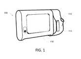
- FIG. 1is a perspective view of a configurable device suitable for being configured according to disclosed configuration methods and systems.
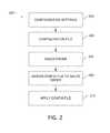
- FIG. 2is a flow diagram illustrating an example of a configuration process in accordance with aspects of the present disclosure.
- FIG. 3is a flow diagram illustrating a further example of a configuration process in accordance with aspects of the present disclosure.
- FIG. 4is a flow diagram illustrating further aspects of the configuration process shown in FIG. 3 .
- FIG. 5is a flow diagram illustrating further aspects of the configuration process shown in FIG. 3 .
- FIG. 6is a flow diagram illustrating further aspects of the configuration process shown in FIG. 3 .
- FIG. 7is a flow diagram illustrating further aspects of the configuration process shown in FIG. 4 .
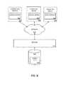
- FIG. 8is a block diagram illustrating an example architecture of a configuration system in accordance with the present disclosure.
- FIG. 9is a block diagram illustrating an example computing system suitable for running a configuration application in accordance with the present disclosure.
- FIG. 10is a flow diagram illustrating an example of a process for generating a configuration file and sales order in accordance with aspects of the present disclosure.
- FIG. 11is a flow diagram illustrating an example of a manufacturing process for applying configuration settings to a device in accordance with aspects of the present disclosure.
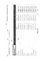
- FIG. 12illustrates a first screen shot from an example of a configuration tool in accordance with aspects of the present disclosure.
- FIG. 13illustrates a second screen shot from an example of a configuration tool in accordance with aspects of the present disclosure.
- FIG. 14illustrates a third screen shot from an example of a configuration tool in accordance with aspects of the present disclosure.
- FIG. 15illustrates a fourth screen shot from an example of a configuration tool in accordance with aspects of the present disclosure.
- FIG. 16illustrates a fifth screen shot from an example of a configuration tool in accordance with aspects of the present disclosure.
- FIG. 17illustrates a sixth screen shot from an example of a configuration tool in accordance with aspects of the present disclosure.
- FIG. 1illustrates an example of a medical device 100 that can be configured to measure and monitor a variety of patient parameters.
- the illustrated medical device 100is functionally connected to one or more sensors that enable monitoring of at least one physiological parameter associated with a patent.
- each sensoris physically attached to the patient while the device 100 is operating to acquire measurements of a parameter associated with the sensor.
- the medical device 100includes a user interface 118 , such as a touch screen, and includes the ability to execute multiple workflows or profiles.
- a profileis a series of one or more tasks that a user of the medical device 100 performs.
- the medical device 100provides functionality suitable for assisting the user in performing the profile.
- the medical device 100provides different functionality.
- Some examples of the medical device 100are configured to be mounted on a mobile cart or on a wall such as the wall of a patient exam room. In other examples, the medical device 100 is a stand-alone device, which can mean that it is not part of a mobile cart and it is not part of a wall-mounted station.
- the medical device 100is configured to measure one or more physiological parameters of a health-care recipient, also referred to herein as a patient.
- a health-care recipientalso referred to herein as a patient.
- Various versions of the device 100are configured more measuring and/or monitoring different parameters and such as temperature, SpO2, blood pressure (NIBP), respiratory rate, etc.
- the user interface 118is configured to display representations of measurements of the physiological parameters of the patient and to receive commands, instructions, and/or inputs based on interaction of a clinician or user with the user interface 118 .
- the medical device 100includes various monitoring and/or measurement devices that include a plug received by a port 112 .
- a slot 114provides storage for accessories associated with the particular configuration of the device 100 .
- the device 100can be configured to measure and monitor different types of physiological parameters.
- the device 100further includes a variety of other configuration settings, such as clinical settings, information settings, data management settings, biomedical settings, etc.
- FIG. 2is a flow diagram broadly illustrating an example process 200 for configuring a device such as the monitor device 100 .
- the device 100is configured in accordance with the purchaser's desires, prior to shipping the manufactured device to the use location. For example, in some implementations a customer or potential customer determines desired configuration settings for a device such as the monitor device 100 in block 202 during a pre-sales meeting, and the configuration settings are saved in a configuration file in block 204 .
- a sales order for the deviceis generated in block 206 , and the configuration file is assigned to the sales order in block 208 , allowing the configuration file to be retrieved and applied to the device during the manufacturing process in block 210 .
- the configuration settingsare generated using a web-based configuration application that gathers the configuration settings. Groups of settings may be based on user responses to a smaller, simple set of questions. In this manner, the user can respond to a relatively small number of questions presented in the configuration application, and based on the user responses, a greater number of configuration settings are generated.
- a process 300 for determining configuration settings 200includes a start block 302 and a decision block 304 , where a user selects whether to open a new configuration ticket 310 , edit an existing ticket 312 , or modify a configuration file 314 that includes several configurations. Based on the user selection at block 304 , further questions are presented to the user, or predetermined configuration settings could be used based on the user selection.
- FIG. 4illustrates an example process in which the user selected “Open New Ticket” 310 in the process 300 shown in FIG. 3 .
- the new ticket process shown in FIG. 4begins with a decision block 320 in which the user selects the desired product, then selects the user location in block 324 .
- decision block 320in which the user selects the desired product, then selects the user location in block 324 .
- corresponding configuration settingsare presented in blocks 330 , 332 , and 334 respectively.
- FIGS. 5 and 6illustrate examples of processes for instances where “Edit Open Ticket” and “Modify a Config File,” respectively, are selected in decision block 324 of FIG. 3 .
- FIG. 5if a valid open ticket number is entered as determined in block 340 , the previous configuration process is continued in block 344 .
- FIG. 6if a valid configuration file is found in block 350 , the relevant previous configuration is continued in block 354 .
- FIG. 7illustrates further configuration settings associated with the selection of the desired use location as selected in decision block 324 of FIG. 4 .
- further configuration settingsare displayed for selection by the user.
- the selected use locationis a Hospital 330
- configuration settings for clinical 360are displayed for selection by the user.
- informatics 362are displayed for selection by the user.
- ITinformation technology
- the Office selection 332includes clinical settings 360
- the long term care location 334includes biomed configuration settings 366 .
- configuration settings in one of more these categoriescould be predetermined and applied based on the user's responses.
- FIG. 8illustrates one embodiment of the architecture of a system for processing configuration settings received from a remote source, such as a computing device 400 .
- the computing device 400contains a configuration application 402 configured to execute processes illustrated and described herein.
- Configuration filesmay be stored locally on the computing device 400 , stored on portable storage media, and/or sent via a network 410 such as the internet to a server 412 and database 420 that stores the configuration files 414 . In this manner, configuration files 414 can be remotely generated, then saved in a central location for later access from a variety of locations.
- the user devices 400may be embodied in a personal computer, a tablet computing device and/or a mobile computing device (e.g., a smart phone).
- FIG. 9illustrates aspects of an example computing device 400 running the configuration application 402 .
- the computing device 400 illustrated and discussed with respect to FIG. 9is for purposes of example and illustration and are not limiting of a vast number of computing device configurations that may be utilized for practicing embodiments of the disclosure, described herein
- FIG. 9is a block diagram illustrating physical components (e.g., hardware) of a computing device 400 with which embodiments of the disclosure may be practiced.
- the configuration application 402 shown in FIG. 8could be implemented by the computing device 400 .
- the computing device components described belowmay include computer executable instructions for a configuration module or application 402 that can be executed to create configuration settings files as disclosed herein.
- the computing device 400may include at least one processing unit 502 and a system memory 504 .
- the system memory 504may comprise, but is not limited to, volatile storage (e.g., random access memory), non-volatile storage (e.g., read-only memory), flash memory, or any combination of such memories.
- the system memory 504may include an operating system 505 and one or more program modules 506 suitable for running software applications 520 such as the configuration application 402 .
- the operating system 505may be suitable for controlling the operation of the computing device 400 .
- embodiments of the disclosuremay be practiced in conjunction with a graphics library, other operating systems, or any other application program and is not limited to any particular application or system.
- This basic configurationis illustrated in FIG. 9 by those components within a dashed line 508 .
- the computing device 400may have additional features or functionality.
- the computing device 400may also include additional data storage devices (removable and/or non-removable) such as, for example, magnetic disks, optical disks, or tape.
- additional storageis illustrated in FIG. 9 by a removable storage device 509 and a non-removable storage device 510 .
- configuration settings filescould be stored on any of the illustrated storage devices.
- program modules 506may perform processes including, but not limited to, generating configuration files as described herein.
- Other program modulesmay include electronic mail and contacts applications, word processing applications, spreadsheet applications, database applications, slide presentation applications, drawing, messaging applications, and/or computer-aided application programs, etc.
- the computing device 400may also have one or more input device(s) 512 such as a keyboard, a mouse, a pen, a sound or voice input device, a touch or swipe input device, etc.
- the output device(s) 514such as a video display, speakers, a printer, etc. may also be included.
- the aforementioned devicesare examples and others may be used.
- the computing device 400may include one or more communication connections 516 allowing communications with other computing devices 518 . Examples of suitable communication connections 516 include, but are not limited to, RF transmitter, receiver, and/or transceiver circuitry; universal serial bus (USB), parallel, and/or serial ports.
- Computer readable mediamay include computer storage media.
- Computer storage mediamay include volatile and nonvolatile, removable and non-removable media implemented in any method or technology for storage of information, such as computer readable instructions, data structures, or program modules.
- the system memory 504 , the removable storage device 509 , and the non-removable storage device 510are all computer storage media examples (e.g., memory storage).
- Computer storage mediamay include RAM, ROM, electrically erasable read-only memory (EEPROM), flash memory or other memory technology, CD-ROM, digital versatile disks (DVD) or other optical storage, magnetic cassettes, magnetic tape, magnetic disk storage or other magnetic storage devices, or any other article of manufacture which can be used to store information and which can be accessed by the computing device 400 . Any such computer storage media may be part of the computing device 400 .
- Computer storage mediadoes not include a carrier wave or other propagated or modulated data signal.
- Communication mediamay be embodied by computer readable instructions, data structures, program modules, or other data in a modulated data signal, such as a carrier wave or other transport mechanism, and includes any information delivery media.
- modulated data signalmay describe a signal that has one or more characteristics set or changed in such a manner as to encode information in the signal.
- communication mediamay include wired media such as a wired network or direct-wired connection, and wireless media such as acoustic, radio frequency (RF), infrared, and other wireless media.
- RFradio frequency
- FIG. 10illustrates an example of a presale process 600 in which a sales order for a device is generated.
- a presale profile 602is consulted, for example, during a meeting with a potential purchaser and a sales representative and/or a systems architect.
- the web-based configuration application 402 and a computing device 400may be used in the process 600 .
- Configuration informationis gathered in block 604 , using processes disclosed in conjunction with FIGS. 3-7 in some implementations. If configuration settings are gathered in block 604 , the approved configuration file 414 is stored. Approved quote information is used to create a quote in block 606 , and when the quote is approved a sales order is generated in block 608 .
- the sales orderincludes a device to be configured during the manufacturing process
- the sales orderis flagged to identify it as requiring configuration. In some implementations, this includes adding a generic part number to a line item in the sales order at block 608 .
- the sales orderis saved as indicated at item 620 . If the sales order 608 includes the flag identifying the order as requiring configuration, the configuration information is associated with the sales order at block 612 , and the sales 620 is saved.
- FIG. 11illustrates portions of an example of a manufacturing process in which a configuration file is applied to a device during the manufacturing process, allowing a configured device to be shipped to the customer.
- the sales order 608is retrieved and device hardware is built per the sales order 608 .
- a manufacturing “traveler”is created that accompanies the device through the manufacturing process. The traveler includes, for example, the sales order number, sales order items, customer number, customer name, configuration file identification, etc.
- the sales order 608is reviewed and if is determined that the sales order 608 requires a custom configuration, the manufactured device is configured using the configuration file 414 at block 650 . If the sales order 608 does not require a custom configuration, a default configuration may be loaded into the device at block 652 .
- the manufactured deviceis shipped to the customer.
- the processes disclosed in conjunction with FIGS. 10 and 11allow, among other things, assigning individual custom configuration files to line items within a sales order. This allows, for example, multiple devices to be built having the same hardware configuration, yet different software configurations. Referring back to FIG. 10 , the sales order 608 created could include several of the devices 100 . The customer may desire to have different devices configured differently.
- FIGS. 12-17illustrate examples of screen shots from an on-line configuration application in accordance with aspects of the present disclosure.
- the illustrated screen shotsmay be displayed on an output device 514 such as a video display monitor of the computing device 400 illustrated in FIG. 9 , for example.
- User inputsmay be received via any suitable input device(s) 512 , such as those discussed in conjunction with the description of FIG. 9 herein above.
- FIG. 12shows an example “dashboard” screen 700 in which user choices include list configurations 701 , new configuration 702 , and assign configuration 703 .
- FIG. 12illustrates the dashboard for a “Monitor Device” 704 with list configurations 701 selected.
- a configurations listis displayed in which various configurations 706 are listed, along with creation and update dates/times for each configuration 706 .
- options for edit 710 , copy 711 , delete 712 and download 713 functionsare displayed.
- the new configuration 702 optionallows a user to create a new configuration
- the assign configuration 703 optionallows a user to assign a configuration to a line item of a sales order.
- FIG. 13illustrates an example of the dashboard screen 700 in which the new configuration 702 option has been selected, wherein a new configuration file is created for the desired device.
- configuration settingsare determined by a user and saved in a configuration file, such as an XML file.
- a configuration filesuch as an XML file.
- desired units 720which include English 721 , Metric 722 and Custom 723 measurement units in the illustrated screen.
- English units 721have been selected.
- appropriate predetermined English measurement units for various measured parametersare saved in the configuration file.
- FIG. 14illustrates a screen shot where the Custom measurement units option 723 has been selected.
- various monitored parameterssuch as blood pressure 724 , temperature 726 and manual parameter units 728 are displayed, and the user may select the desired measurement units for the various parameters.
- FIG. 15illustrates a configuration screen 730 displaying general device options including mobile 731 , wall mounted 732 and custom 733 . If the user selects mobile 731 or wall mounted 732 , preset device settings for the respective device configurations are included in the created configuration for the device.
- FIG. 15illustrates a configuration screen 730 in which the custom option 733 has been selected. For the custom option 733 , the user may select among various choices corresponding to various categories, including power management 734 , other 736 and software upgrades 738 in the illustrated example. The selected choices are included in the configuration file for the device.
- FIG. 16illustrates an example of the dashboard screen 700 where the assign configuration option 703 has been selected.
- selection of this optioncauses the configuration tool to communicate with a sales or order-entry system including the database 620 in which sales orders 608 are stored.
- the database 620is queried and orders 740 for the logged-in user are displayed.
- a query of the database 620is conducted to identify open and flagged orders, such that open orders requiring assignment of configurations are displayed.
- FIG. 17illustrates an example where the first order number, 100001 has been selected in the previous screen shown in the example of FIG. 16 .
- the line items for the selected order numberare displayed.
- line item 00001has been selected by the user and available configurations for the selected line item are displayed.
- Configuration 2has been selected to be assigned to line item 000001 of order number 10001.
- the usermay select a desired configuration for each line item in the selected order that requires a custom configuration. In this manner, a sales order that includes several devices listed as line items in the sales order can have desired configurations assigned thereto.
- Embodiments of the present disclosureare described above with reference to block diagrams and/or operational illustrations of methods, systems, and computer program products according to embodiments of the disclosure.
- the functions/acts noted in the blocksmay occur out of the order as shown in any flowchart.
- two blocks shown in successionmay in fact be executed substantially concurrently or the blocks may sometimes be executed in the reverse order, depending upon the functionality/acts involved.
Landscapes
- Health & Medical Sciences (AREA)
- Engineering & Computer Science (AREA)
- Life Sciences & Earth Sciences (AREA)
- Physics & Mathematics (AREA)
- Business, Economics & Management (AREA)
- Theoretical Computer Science (AREA)
- Software Systems (AREA)
- Public Health (AREA)
- Pathology (AREA)
- Biomedical Technology (AREA)
- Heart & Thoracic Surgery (AREA)
- Medical Informatics (AREA)
- Molecular Biology (AREA)
- Surgery (AREA)
- Animal Behavior & Ethology (AREA)
- General Health & Medical Sciences (AREA)
- Biophysics (AREA)
- Veterinary Medicine (AREA)
- General Physics & Mathematics (AREA)
- Finance (AREA)
- Accounting & Taxation (AREA)
- Cardiology (AREA)
- Development Economics (AREA)
- General Engineering & Computer Science (AREA)
- Economics (AREA)
- Marketing (AREA)
- Strategic Management (AREA)
- General Business, Economics & Management (AREA)
- Vascular Medicine (AREA)
- Physiology (AREA)
- User Interface Of Digital Computer (AREA)
- Medical Treatment And Welfare Office Work (AREA)
- Computer Networks & Wireless Communication (AREA)
Abstract
Description
Claims (12)
Priority Applications (2)
| Application Number | Priority Date | Filing Date | Title |
|---|---|---|---|
| US14/535,576US10296965B2 (en) | 2014-11-07 | 2014-11-07 | Device configuration |
| PCT/US2015/059435WO2016073839A1 (en) | 2014-11-07 | 2015-11-06 | Device configuration |
Applications Claiming Priority (1)
| Application Number | Priority Date | Filing Date | Title |
|---|---|---|---|
| US14/535,576US10296965B2 (en) | 2014-11-07 | 2014-11-07 | Device configuration |
Publications (2)
| Publication Number | Publication Date |
|---|---|
| US20160132957A1 US20160132957A1 (en) | 2016-05-12 |
| US10296965B2true US10296965B2 (en) | 2019-05-21 |
Family
ID=55909853
Family Applications (1)
| Application Number | Title | Priority Date | Filing Date |
|---|---|---|---|
| US14/535,576Active2038-02-11US10296965B2 (en) | 2014-11-07 | 2014-11-07 | Device configuration |
Country Status (2)
| Country | Link |
|---|---|
| US (1) | US10296965B2 (en) |
| WO (1) | WO2016073839A1 (en) |
Citations (30)
| Publication number | Priority date | Publication date | Assignee | Title |
|---|---|---|---|---|
| US6003012A (en) | 1997-12-05 | 1999-12-14 | Square D Company | Methodology and computer-based tools for design, production and sales of customized switchboards |
| WO2001033464A1 (en) | 1999-11-01 | 2001-05-10 | Solomon Neal E | Customer demand-initiated system and method for on-line information retrieval, interactive negotiation, procurement, and exchange |
| WO2001080739A1 (en) | 2000-04-26 | 2001-11-01 | Ge Medical Systems Global Technology Company, Llc | Automating user customization of a medical device |
| US20020007294A1 (en) | 2000-04-05 | 2002-01-17 | Bradbury Thomas J. | System and method for rapidly customizing a design and remotely manufacturing biomedical devices using a computer system |
| US20020103505A1 (en) | 2001-02-01 | 2002-08-01 | Medtronic, Inc. | Custom manufacturing of implantable medical devices |
| US6493677B1 (en) | 2000-01-19 | 2002-12-10 | Jones Soda Co. | Method and apparatus for creating and ordering customized branded merchandise over a computer network |
| US20030009354A1 (en)* | 2001-06-29 | 2003-01-09 | Ohio Willow Wood Company | System, method, and computer program product for configuring and purchasing a medical device |
| US20030115108A1 (en) | 2001-12-17 | 2003-06-19 | William Scott | Method and system for designing and ordering products for manufacture on-line |
| US6882982B2 (en) | 2000-02-04 | 2005-04-19 | Medtronic, Inc. | Responsive manufacturing and inventory control |
| US20050144528A1 (en) | 2003-08-29 | 2005-06-30 | Tim Bucher | Computing device configuration manager |
| US7013290B2 (en) | 2001-08-03 | 2006-03-14 | John Allen Ananian | Personalized interactive digital catalog profiling |
| US7016865B1 (en) | 2000-04-14 | 2006-03-21 | Deluxe Corporation | Personalization format converter system and method |
| US20060253789A1 (en)* | 2001-06-08 | 2006-11-09 | Mci, Llc. | Graphical user interface (GUI) based call application system |
| KR20070018341A (en) | 2005-08-09 | 2007-02-14 | 삼성전자주식회사 | Apparatus and method for providing a user option of an image forming apparatus using a memory having a RF function |
| US7216092B1 (en) | 2000-04-14 | 2007-05-08 | Deluxe Corporation | Intelligent personalization system and method |
| US20070118431A1 (en)* | 2005-11-21 | 2007-05-24 | Johansson Mikael I | System for configuring a chemical separation system |
| US20080141217A1 (en)* | 2006-12-06 | 2008-06-12 | Medtronic, Inc. | Operating environment monitor for medical device programming |
| US20090063187A1 (en)* | 2007-08-31 | 2009-03-05 | Johnson David C | Medical data transport over wireless life critical network employing dynamic communication link mapping |
| US20090171175A1 (en) | 2007-12-31 | 2009-07-02 | Nellcor Puritan Bennett Llc | Personalized Medical Monitoring: Auto-Configuration Using Patient Record Information |
| US7627503B1 (en) | 1999-11-05 | 2009-12-01 | Ford Motor Company | Online system of ordering and specifying consumer product having specific configurations |
| US7890870B1 (en) | 2007-12-06 | 2011-02-15 | Sprint Communications Company L.P. | Monitoring network functions concurrently utilizing a performance display |
| US20110071420A1 (en) | 2009-09-18 | 2011-03-24 | St Pierre Shawn C | Physiological Parameter Measuring Platform Device Supporting Multiple Workflows |
| US20110245630A1 (en) | 2010-03-31 | 2011-10-06 | St Pierre Shawn C | Integrated Patient Data Management for Physiological Monitor Devices |
| US20120296183A1 (en) | 2011-05-17 | 2012-11-22 | Welch Allyn, Inc. | Device configuration for supporting a patient oxygenation test |
| US20130245467A1 (en) | 2011-09-09 | 2013-09-19 | Welch Allyn, Inc. | Blood pressure monitoring system and method |
| US20140156812A1 (en) | 2012-12-05 | 2014-06-05 | Fortinet, Inc. | Customized configuration settings for a network appliance |
| US20140288950A1 (en)* | 2013-03-20 | 2014-09-25 | Samsung Electronics Co., Ltd. | System and method for recommending health management device using mobile device connectivity information |
| US20140337152A1 (en)* | 2013-05-13 | 2014-11-13 | Motorola Mobility Llc | Method and System Having a Virtual Stock Keeping Unit for Configurable Mobile Phone Purchases |
| US20150378798A1 (en)* | 2014-06-27 | 2015-12-31 | Welch Allyn, Inc. | Low acuity vitals system architecture |
| US20160203304A1 (en)* | 2013-08-29 | 2016-07-14 | Physio-Control, Inc. | Adaptive electronic device interface |
- 2014
- 2014-11-07USUS14/535,576patent/US10296965B2/enactiveActive
- 2015
- 2015-11-06WOPCT/US2015/059435patent/WO2016073839A1/enactiveApplication Filing
Patent Citations (31)
| Publication number | Priority date | Publication date | Assignee | Title |
|---|---|---|---|---|
| US6003012A (en) | 1997-12-05 | 1999-12-14 | Square D Company | Methodology and computer-based tools for design, production and sales of customized switchboards |
| WO2001033464A1 (en) | 1999-11-01 | 2001-05-10 | Solomon Neal E | Customer demand-initiated system and method for on-line information retrieval, interactive negotiation, procurement, and exchange |
| US7627503B1 (en) | 1999-11-05 | 2009-12-01 | Ford Motor Company | Online system of ordering and specifying consumer product having specific configurations |
| US6493677B1 (en) | 2000-01-19 | 2002-12-10 | Jones Soda Co. | Method and apparatus for creating and ordering customized branded merchandise over a computer network |
| US6882982B2 (en) | 2000-02-04 | 2005-04-19 | Medtronic, Inc. | Responsive manufacturing and inventory control |
| US20020007294A1 (en) | 2000-04-05 | 2002-01-17 | Bradbury Thomas J. | System and method for rapidly customizing a design and remotely manufacturing biomedical devices using a computer system |
| US7216092B1 (en) | 2000-04-14 | 2007-05-08 | Deluxe Corporation | Intelligent personalization system and method |
| US7016865B1 (en) | 2000-04-14 | 2006-03-21 | Deluxe Corporation | Personalization format converter system and method |
| WO2001080739A1 (en) | 2000-04-26 | 2001-11-01 | Ge Medical Systems Global Technology Company, Llc | Automating user customization of a medical device |
| US20020103505A1 (en) | 2001-02-01 | 2002-08-01 | Medtronic, Inc. | Custom manufacturing of implantable medical devices |
| US20060253789A1 (en)* | 2001-06-08 | 2006-11-09 | Mci, Llc. | Graphical user interface (GUI) based call application system |
| US20030009354A1 (en)* | 2001-06-29 | 2003-01-09 | Ohio Willow Wood Company | System, method, and computer program product for configuring and purchasing a medical device |
| US7013290B2 (en) | 2001-08-03 | 2006-03-14 | John Allen Ananian | Personalized interactive digital catalog profiling |
| US20030115108A1 (en) | 2001-12-17 | 2003-06-19 | William Scott | Method and system for designing and ordering products for manufacture on-line |
| US20050144528A1 (en) | 2003-08-29 | 2005-06-30 | Tim Bucher | Computing device configuration manager |
| KR20070018341A (en) | 2005-08-09 | 2007-02-14 | 삼성전자주식회사 | Apparatus and method for providing a user option of an image forming apparatus using a memory having a RF function |
| US20070118431A1 (en)* | 2005-11-21 | 2007-05-24 | Johansson Mikael I | System for configuring a chemical separation system |
| US9471752B2 (en)* | 2006-12-06 | 2016-10-18 | Medtronic, Inc. | Operating environment monitor for medical device programming |
| US20080141217A1 (en)* | 2006-12-06 | 2008-06-12 | Medtronic, Inc. | Operating environment monitor for medical device programming |
| US20090063187A1 (en)* | 2007-08-31 | 2009-03-05 | Johnson David C | Medical data transport over wireless life critical network employing dynamic communication link mapping |
| US7890870B1 (en) | 2007-12-06 | 2011-02-15 | Sprint Communications Company L.P. | Monitoring network functions concurrently utilizing a performance display |
| US20090171175A1 (en) | 2007-12-31 | 2009-07-02 | Nellcor Puritan Bennett Llc | Personalized Medical Monitoring: Auto-Configuration Using Patient Record Information |
| US20110071420A1 (en) | 2009-09-18 | 2011-03-24 | St Pierre Shawn C | Physiological Parameter Measuring Platform Device Supporting Multiple Workflows |
| US20110245630A1 (en) | 2010-03-31 | 2011-10-06 | St Pierre Shawn C | Integrated Patient Data Management for Physiological Monitor Devices |
| US20120296183A1 (en) | 2011-05-17 | 2012-11-22 | Welch Allyn, Inc. | Device configuration for supporting a patient oxygenation test |
| US20130245467A1 (en) | 2011-09-09 | 2013-09-19 | Welch Allyn, Inc. | Blood pressure monitoring system and method |
| US20140156812A1 (en) | 2012-12-05 | 2014-06-05 | Fortinet, Inc. | Customized configuration settings for a network appliance |
| US20140288950A1 (en)* | 2013-03-20 | 2014-09-25 | Samsung Electronics Co., Ltd. | System and method for recommending health management device using mobile device connectivity information |
| US20140337152A1 (en)* | 2013-05-13 | 2014-11-13 | Motorola Mobility Llc | Method and System Having a Virtual Stock Keeping Unit for Configurable Mobile Phone Purchases |
| US20160203304A1 (en)* | 2013-08-29 | 2016-07-14 | Physio-Control, Inc. | Adaptive electronic device interface |
| US20150378798A1 (en)* | 2014-06-27 | 2015-12-31 | Welch Allyn, Inc. | Low acuity vitals system architecture |
Non-Patent Citations (2)
| Title |
|---|
| International Search Report and Written Opinion for PCT/US2015/059435, dated Feb. 17, 2016, 12 pages. |
| Tudjarov, B. et al., "Web Virtual Reality for Product Customization," Advances in Production Engineering & Management, vol. 4, 1 special, pp. 25-34 (2009). |
Also Published As
| Publication number | Publication date |
|---|---|
| WO2016073839A1 (en) | 2016-05-12 |
| US20160132957A1 (en) | 2016-05-12 |
Similar Documents
| Publication | Publication Date | Title |
|---|---|---|
| KR102293340B1 (en) | Presentation of physiological data | |
| JP2020091885A (en) | System, method and non-transitory machine readable medium for generating, displaying and tracking wellness tasks | |
| US20150324549A1 (en) | Management of implantable cardiac device interrogation data and reports | |
| US11037678B2 (en) | Medical device with interfaces for capturing vital signs data and affirmatively skipping parameters associated with the vital signs data | |
| US11468992B2 (en) | Predicting adverse health events using a measure of adherence to a testing routine | |
| EP3077931A1 (en) | Wellness registry | |
| US20230113333A1 (en) | Intelligent prompting of protocols | |
| Lin et al. | Optimal nurse scheduling based on quantitative models of work-related fatigue | |
| WO2021076652A1 (en) | Method for enhancing patient compliance with a medical therapy plan and mobile device therefor | |
| US20160128647A1 (en) | Medical Device With Enhanced Viewing Mode | |
| CN113593701A (en) | Health suggestion information processing method, research platform, first terminal and system | |
| US10915315B2 (en) | Medical device, system, and software architecture for monitoring low acuity vitals | |
| CN107403059A (en) | Medical treatment device with enhancing user interface controls | |
| US20180137562A1 (en) | Processing for requirement requests | |
| US10296965B2 (en) | Device configuration | |
| US20130236871A1 (en) | Method and system for delivering patient specific content | |
| KR20130040494A (en) | Wellbeing index framework based on xml and wellbeing index calculating method | |
| US20200184209A1 (en) | Generating document content by data analysis | |
| US11450427B1 (en) | Computing system for displaying locations of clinical events undergone by patients | |
| US20150379233A1 (en) | Method, apparatus, and computer-readable medium for determining a target geographic area for a target drug | |
| US20210383903A1 (en) | Provider-curated applications for accessing patient data in an ehr system | |
| Dorokhov et al. | Consumer Choice of Fitness Trackers: An Example of Modeling | |
| WO2014062797A1 (en) | Methods for configuring biometric devices for transmitting health information | |
| KR20130035310A (en) | Support system and method for healthcare |
Legal Events
| Date | Code | Title | Description |
|---|---|---|---|
| AS | Assignment | Owner name:WELCH ALLYN, INC., NEW YORK Free format text:ASSIGNMENT OF ASSIGNORS INTEREST;ASSIGNOR:ST. PIERRE, SHAWN C.;REEL/FRAME:034205/0862 Effective date:20141118 | |
| AS | Assignment | Owner name:JPMORGAN CHASE BANK, N.A., AS COLLATERAL AGENT, ILLINOIS Free format text:SECURITY INTEREST;ASSIGNORS:ALLEN MEDICAL SYSTEMS, INC.;HILL-ROM SERVICES, INC.;ASPEN SURGICAL PRODUCTS, INC.;AND OTHERS;REEL/FRAME:036582/0123 Effective date:20150908 Owner name:JPMORGAN CHASE BANK, N.A., AS COLLATERAL AGENT, IL Free format text:SECURITY INTEREST;ASSIGNORS:ALLEN MEDICAL SYSTEMS, INC.;HILL-ROM SERVICES, INC.;ASPEN SURGICAL PRODUCTS, INC.;AND OTHERS;REEL/FRAME:036582/0123 Effective date:20150908 | |
| AS | Assignment | Owner name:JPMORGAN CHASE BANK, N.A., AS COLLATERAL AGENT, ILLINOIS Free format text:SECURITY AGREEMENT;ASSIGNORS:HILL-ROM SERVICES, INC.;ASPEN SURGICAL PRODUCTS, INC.;ALLEN MEDICAL SYSTEMS, INC.;AND OTHERS;REEL/FRAME:040145/0445 Effective date:20160921 Owner name:JPMORGAN CHASE BANK, N.A., AS COLLATERAL AGENT, IL Free format text:SECURITY AGREEMENT;ASSIGNORS:HILL-ROM SERVICES, INC.;ASPEN SURGICAL PRODUCTS, INC.;ALLEN MEDICAL SYSTEMS, INC.;AND OTHERS;REEL/FRAME:040145/0445 Effective date:20160921 | |
| STPP | Information on status: patent application and granting procedure in general | Free format text:NOTICE OF ALLOWANCE MAILED -- APPLICATION RECEIVED IN OFFICE OF PUBLICATIONS | |
| STPP | Information on status: patent application and granting procedure in general | Free format text:PUBLICATIONS -- ISSUE FEE PAYMENT VERIFIED | |
| STCF | Information on status: patent grant | Free format text:PATENTED CASE | |
| AS | Assignment | Owner name:MORTARA INSTRUMENT SERVICES, INC., WISCONSIN Free format text:RELEASE BY SECURED PARTY;ASSIGNOR:JPMORGAN CHASE BANK, N.A.;REEL/FRAME:050254/0513 Effective date:20190830 Owner name:HILL-ROM COMPANY, INC., ILLINOIS Free format text:RELEASE BY SECURED PARTY;ASSIGNOR:JPMORGAN CHASE BANK, N.A.;REEL/FRAME:050254/0513 Effective date:20190830 Owner name:ALLEN MEDICAL SYSTEMS, INC., ILLINOIS Free format text:RELEASE BY SECURED PARTY;ASSIGNOR:JPMORGAN CHASE BANK, N.A.;REEL/FRAME:050254/0513 Effective date:20190830 Owner name:MORTARA INSTRUMENT, INC., WISCONSIN Free format text:RELEASE BY SECURED PARTY;ASSIGNOR:JPMORGAN CHASE BANK, N.A.;REEL/FRAME:050254/0513 Effective date:20190830 Owner name:VOALTE, INC., FLORIDA Free format text:RELEASE BY SECURED PARTY;ASSIGNOR:JPMORGAN CHASE BANK, N.A.;REEL/FRAME:050254/0513 Effective date:20190830 Owner name:HILL-ROM, INC., ILLINOIS Free format text:RELEASE BY SECURED PARTY;ASSIGNOR:JPMORGAN CHASE BANK, N.A.;REEL/FRAME:050254/0513 Effective date:20190830 Owner name:HILL-ROM SERVICES, INC., ILLINOIS Free format text:RELEASE BY SECURED PARTY;ASSIGNOR:JPMORGAN CHASE BANK, N.A.;REEL/FRAME:050254/0513 Effective date:20190830 Owner name:ANODYNE MEDICAL DEVICE, INC., FLORIDA Free format text:RELEASE BY SECURED PARTY;ASSIGNOR:JPMORGAN CHASE BANK, N.A.;REEL/FRAME:050254/0513 Effective date:20190830 Owner name:WELCH ALLYN, INC., NEW YORK Free format text:RELEASE BY SECURED PARTY;ASSIGNOR:JPMORGAN CHASE BANK, N.A.;REEL/FRAME:050254/0513 Effective date:20190830 | |
| AS | Assignment | Owner name:JPMORGAN CHASE BANK, N.A., ILLINOIS Free format text:SECURITY AGREEMENT;ASSIGNORS:HILL-ROM HOLDINGS, INC.;HILL-ROM, INC.;HILL-ROM SERVICES, INC.;AND OTHERS;REEL/FRAME:050260/0644 Effective date:20190830 | |
| AS | Assignment | Owner name:HILL-ROM HOLDINGS, INC., ILLINOIS Free format text:RELEASE OF SECURITY INTEREST AT REEL/FRAME 050260/0644;ASSIGNOR:JPMORGAN CHASE BANK, N.A.;REEL/FRAME:058517/0001 Effective date:20211213 Owner name:BARDY DIAGNOSTICS, INC., ILLINOIS Free format text:RELEASE OF SECURITY INTEREST AT REEL/FRAME 050260/0644;ASSIGNOR:JPMORGAN CHASE BANK, N.A.;REEL/FRAME:058517/0001 Effective date:20211213 Owner name:VOALTE, INC., FLORIDA Free format text:RELEASE OF SECURITY INTEREST AT REEL/FRAME 050260/0644;ASSIGNOR:JPMORGAN CHASE BANK, N.A.;REEL/FRAME:058517/0001 Effective date:20211213 Owner name:HILL-ROM, INC., ILLINOIS Free format text:RELEASE OF SECURITY INTEREST AT REEL/FRAME 050260/0644;ASSIGNOR:JPMORGAN CHASE BANK, N.A.;REEL/FRAME:058517/0001 Effective date:20211213 Owner name:WELCH ALLYN, INC., NEW YORK Free format text:RELEASE OF SECURITY INTEREST AT REEL/FRAME 050260/0644;ASSIGNOR:JPMORGAN CHASE BANK, N.A.;REEL/FRAME:058517/0001 Effective date:20211213 Owner name:ALLEN MEDICAL SYSTEMS, INC., ILLINOIS Free format text:RELEASE OF SECURITY INTEREST AT REEL/FRAME 050260/0644;ASSIGNOR:JPMORGAN CHASE BANK, N.A.;REEL/FRAME:058517/0001 Effective date:20211213 Owner name:HILL-ROM SERVICES, INC., ILLINOIS Free format text:RELEASE OF SECURITY INTEREST AT REEL/FRAME 050260/0644;ASSIGNOR:JPMORGAN CHASE BANK, N.A.;REEL/FRAME:058517/0001 Effective date:20211213 Owner name:BREATHE TECHNOLOGIES, INC., CALIFORNIA Free format text:RELEASE OF SECURITY INTEREST AT REEL/FRAME 050260/0644;ASSIGNOR:JPMORGAN CHASE BANK, N.A.;REEL/FRAME:058517/0001 Effective date:20211213 | |
| MAFP | Maintenance fee payment | Free format text:PAYMENT OF MAINTENANCE FEE, 4TH YEAR, LARGE ENTITY (ORIGINAL EVENT CODE: M1551); ENTITY STATUS OF PATENT OWNER: LARGE ENTITY Year of fee payment:4 |