US10293129B2 - Apparatus and method for forming an opening in patient's tissue - Google Patents
Apparatus and method for forming an opening in patient's tissueDownload PDFInfo
- Publication number
- US10293129B2 US10293129B2US15/452,323US201715452323AUS10293129B2US 10293129 B2US10293129 B2US 10293129B2US 201715452323 AUS201715452323 AUS 201715452323AUS 10293129 B2US10293129 B2US 10293129B2
- Authority
- US
- United States
- Prior art keywords
- surgical instrument
- shaft
- instrument system
- patient
- tissue
- Prior art date
- Legal status (The legal status is an assumption and is not a legal conclusion. Google has not performed a legal analysis and makes no representation as to the accuracy of the status listed.)
- Expired - Fee Related, expires
Links
- 238000000034methodMethods0.000titledescription28
- 239000004020conductorSubstances0.000claimsdescription39
- 230000007246mechanismEffects0.000claimsdescription30
- 230000000007visual effectEffects0.000claimsdescription4
- 238000001356surgical procedureMethods0.000abstractdescription7
- 239000007788liquidSubstances0.000abstractdescription6
- 210000001519tissueAnatomy0.000description82
- 230000010339dilationEffects0.000description12
- 239000000523sampleSubstances0.000description12
- 210000003437tracheaAnatomy0.000description12
- 239000000463materialSubstances0.000description11
- 230000008859changeEffects0.000description10
- 230000004044responseEffects0.000description8
- 238000003780insertionMethods0.000description6
- 230000037431insertionEffects0.000description6
- 230000000916dilatatory effectEffects0.000description5
- 230000014759maintenance of locationEffects0.000description5
- 238000012544monitoring processMethods0.000description5
- 239000012530fluidSubstances0.000description4
- 239000012811non-conductive materialSubstances0.000description4
- 210000004872soft tissueAnatomy0.000description4
- 230000003213activating effectEffects0.000description3
- 230000008901benefitEffects0.000description3
- 239000000919ceramicSubstances0.000description3
- 238000010586diagramMethods0.000description3
- 238000012986modificationMethods0.000description3
- 230000004048modificationEffects0.000description3
- 230000004913activationEffects0.000description2
- 238000011161developmentMethods0.000description2
- -1for exampleSubstances0.000description2
- 239000007769metal materialSubstances0.000description2
- 230000035515penetrationEffects0.000description2
- 238000002627tracheal intubationMethods0.000description2
- RYGMFSIKBFXOCR-UHFFFAOYSA-NCopperChemical compound[Cu]RYGMFSIKBFXOCR-UHFFFAOYSA-N0.000description1
- 229910000831SteelInorganic materials0.000description1
- 101150013568US16 geneProteins0.000description1
- 229910052802copperInorganic materials0.000description1
- 239000010949copperSubstances0.000description1
- 238000011846endoscopic investigationMethods0.000description1
- 238000005516engineering processMethods0.000description1
- 238000002692epidural anesthesiaMethods0.000description1
- 210000003238esophagusAnatomy0.000description1
- 238000001802infusionMethods0.000description1
- 238000002690local anesthesiaMethods0.000description1
- 230000000149penetrating effectEffects0.000description1
- 229920001296polysiloxanePolymers0.000description1
- 239000010959steelSubstances0.000description1
- 238000002691topical anesthesiaMethods0.000description1
Images


Classifications
- A—HUMAN NECESSITIES
- A61—MEDICAL OR VETERINARY SCIENCE; HYGIENE
- A61M—DEVICES FOR INTRODUCING MEDIA INTO, OR ONTO, THE BODY; DEVICES FOR TRANSDUCING BODY MEDIA OR FOR TAKING MEDIA FROM THE BODY; DEVICES FOR PRODUCING OR ENDING SLEEP OR STUPOR
- A61M16/00—Devices for influencing the respiratory system of patients by gas treatment, e.g. ventilators; Tracheal tubes
- A61M16/04—Tracheal tubes
- A61M16/0465—Tracheostomy tubes; Devices for performing a tracheostomy; Accessories therefor, e.g. masks, filters
- A61M16/0472—Devices for performing a tracheostomy
- A—HUMAN NECESSITIES
- A61—MEDICAL OR VETERINARY SCIENCE; HYGIENE
- A61B—DIAGNOSIS; SURGERY; IDENTIFICATION
- A61B17/00—Surgical instruments, devices or methods
- A61B17/34—Trocars; Puncturing needles
- A61B17/3403—Needle locating or guiding means
- A—HUMAN NECESSITIES
- A61—MEDICAL OR VETERINARY SCIENCE; HYGIENE
- A61B—DIAGNOSIS; SURGERY; IDENTIFICATION
- A61B17/00—Surgical instruments, devices or methods
- A61B17/34—Trocars; Puncturing needles
- A61B17/3494—Trocars; Puncturing needles with safety means for protection against accidental cutting or pricking, e.g. limiting insertion depth, pressure sensors
- A61B17/3496—Protecting sleeves or inner probes; Retractable tips
- A—HUMAN NECESSITIES
- A61—MEDICAL OR VETERINARY SCIENCE; HYGIENE
- A61B—DIAGNOSIS; SURGERY; IDENTIFICATION
- A61B17/00—Surgical instruments, devices or methods
- A61B2017/00017—Electrical control of surgical instruments
- A61B2017/00022—Sensing or detecting at the treatment site
- A61B2017/00026—Conductivity or impedance, e.g. of tissue
- A—HUMAN NECESSITIES
- A61—MEDICAL OR VETERINARY SCIENCE; HYGIENE
- A61B—DIAGNOSIS; SURGERY; IDENTIFICATION
- A61B17/00—Surgical instruments, devices or methods
- A61B2017/00017—Electrical control of surgical instruments
- A61B2017/00115—Electrical control of surgical instruments with audible or visual output
- A61B2017/00128—Electrical control of surgical instruments with audible or visual output related to intensity or progress of surgical action
- A—HUMAN NECESSITIES
- A61—MEDICAL OR VETERINARY SCIENCE; HYGIENE
- A61B—DIAGNOSIS; SURGERY; IDENTIFICATION
- A61B17/00—Surgical instruments, devices or methods
- A61B2017/00681—Aspects not otherwise provided for
- A61B2017/00734—Aspects not otherwise provided for battery operated
- A—HUMAN NECESSITIES
- A61—MEDICAL OR VETERINARY SCIENCE; HYGIENE
- A61B—DIAGNOSIS; SURGERY; IDENTIFICATION
- A61B17/00—Surgical instruments, devices or methods
- A61B17/34—Trocars; Puncturing needles
- A61B17/3403—Needle locating or guiding means
- A61B2017/3405—Needle locating or guiding means using mechanical guide means
- A61B2017/3409—Needle locating or guiding means using mechanical guide means including needle or instrument drives
- A—HUMAN NECESSITIES
- A61—MEDICAL OR VETERINARY SCIENCE; HYGIENE
- A61B—DIAGNOSIS; SURGERY; IDENTIFICATION
- A61B90/00—Instruments, implements or accessories specially adapted for surgery or diagnosis and not covered by any of the groups A61B1/00 - A61B50/00, e.g. for luxation treatment or for protecting wound edges
- A61B90/08—Accessories or related features not otherwise provided for
- A61B2090/0807—Indication means
- A—HUMAN NECESSITIES
- A61—MEDICAL OR VETERINARY SCIENCE; HYGIENE
- A61M—DEVICES FOR INTRODUCING MEDIA INTO, OR ONTO, THE BODY; DEVICES FOR TRANSDUCING BODY MEDIA OR FOR TAKING MEDIA FROM THE BODY; DEVICES FOR PRODUCING OR ENDING SLEEP OR STUPOR
- A61M2205/00—General characteristics of the apparatus
- A61M2205/33—Controlling, regulating or measuring
- A61M2205/3327—Measuring
- A—HUMAN NECESSITIES
- A61—MEDICAL OR VETERINARY SCIENCE; HYGIENE
- A61M—DEVICES FOR INTRODUCING MEDIA INTO, OR ONTO, THE BODY; DEVICES FOR TRANSDUCING BODY MEDIA OR FOR TAKING MEDIA FROM THE BODY; DEVICES FOR PRODUCING OR ENDING SLEEP OR STUPOR
- A61M2205/00—General characteristics of the apparatus
- A61M2205/33—Controlling, regulating or measuring
- A61M2205/3331—Pressure; Flow
- A61M2205/3344—Measuring or controlling pressure at the body treatment site
- A—HUMAN NECESSITIES
- A61—MEDICAL OR VETERINARY SCIENCE; HYGIENE
- A61M—DEVICES FOR INTRODUCING MEDIA INTO, OR ONTO, THE BODY; DEVICES FOR TRANSDUCING BODY MEDIA OR FOR TAKING MEDIA FROM THE BODY; DEVICES FOR PRODUCING OR ENDING SLEEP OR STUPOR
- A61M2205/00—General characteristics of the apparatus
- A61M2205/35—Communication
- A61M2205/3546—Range
- A61M2205/3569—Range sublocal, e.g. between console and disposable
- A—HUMAN NECESSITIES
- A61—MEDICAL OR VETERINARY SCIENCE; HYGIENE
- A61M—DEVICES FOR INTRODUCING MEDIA INTO, OR ONTO, THE BODY; DEVICES FOR TRANSDUCING BODY MEDIA OR FOR TAKING MEDIA FROM THE BODY; DEVICES FOR PRODUCING OR ENDING SLEEP OR STUPOR
- A61M2205/00—General characteristics of the apparatus
- A61M2205/50—General characteristics of the apparatus with microprocessors or computers
- A—HUMAN NECESSITIES
- A61—MEDICAL OR VETERINARY SCIENCE; HYGIENE
- A61M—DEVICES FOR INTRODUCING MEDIA INTO, OR ONTO, THE BODY; DEVICES FOR TRANSDUCING BODY MEDIA OR FOR TAKING MEDIA FROM THE BODY; DEVICES FOR PRODUCING OR ENDING SLEEP OR STUPOR
- A61M2205/00—General characteristics of the apparatus
- A61M2205/58—Means for facilitating use, e.g. by people with impaired vision
- A61M2205/581—Means for facilitating use, e.g. by people with impaired vision by audible feedback
- A—HUMAN NECESSITIES
- A61—MEDICAL OR VETERINARY SCIENCE; HYGIENE
- A61M—DEVICES FOR INTRODUCING MEDIA INTO, OR ONTO, THE BODY; DEVICES FOR TRANSDUCING BODY MEDIA OR FOR TAKING MEDIA FROM THE BODY; DEVICES FOR PRODUCING OR ENDING SLEEP OR STUPOR
- A61M2205/00—General characteristics of the apparatus
- A61M2205/58—Means for facilitating use, e.g. by people with impaired vision
- A61M2205/583—Means for facilitating use, e.g. by people with impaired vision by visual feedback
- A—HUMAN NECESSITIES
- A61—MEDICAL OR VETERINARY SCIENCE; HYGIENE
- A61M—DEVICES FOR INTRODUCING MEDIA INTO, OR ONTO, THE BODY; DEVICES FOR TRANSDUCING BODY MEDIA OR FOR TAKING MEDIA FROM THE BODY; DEVICES FOR PRODUCING OR ENDING SLEEP OR STUPOR
- A61M2205/00—General characteristics of the apparatus
- A61M2205/82—Internal energy supply devices
- A61M2205/8206—Internal energy supply devices battery-operated
Definitions
- the present disclosurerelates to instruments for forming and dilating an opening in a patient's tissue and, more specifically, for dilating an opening through a tracheal wall of a patient.
- endotracheal intubationwhich involves the insertion of a tube through the nostrils or mouth and into the trachea itself, may be used.
- endotracheal tube system for use in endotracheal intubationis described in International Patent Application Publication No. WO2014/088904, which is incorporated herein by reference.
- Another technique for establishing an adequate air passagewayinvolves the creation of a puncture or incision in the tracheal wall.
- a tracheostomy tubemay then be inserted through the opening to form a passageway that effectively bypasses the upper trachea, nostrils and/or mouth.
- the initial incisionmay be made with a smaller needle and then enlarged or dilated to receive the tracheostomy tube.
- a surgical instrument systemcomprises a housing including a handle, a shaft extending outwardly from the housing to a distal end configured to form a puncture in a patient's tissue, a conductor plate positioned in the shaft, a retraction mechanism operable to move the distal end of the shaft in a first direction toward the housing, and a controller positioned in the housing.
- the controlleris configured to energize a sensor circuit including a section of the shaft and the conductor plate, and monitor an electrical signal received from the sensor circuit. When an electrical resistance value based on the monitored electrical signal is greater than a predetermined threshold, the controller is configured to activate an indicator, and energize the retraction mechanism to move the distal end of the shaft in a direction toward the housing.
- the predetermined threshold for the resistance valuemay be greater than or equal to 100 kilo-ohms.
- the conductor platemay be positioned in an opening defined in the distal end of the shaft. Additionally, in some embodiments, the conductor plate may be a metallic inner shaft positioned in a passageway defined in the outer shaft.
- the systemmay comprise a non-conductive film positioned in the opening defined in the distal end of the shaft between the conductor plate and the shaft that electrically isolates the conductor plate from the shaft.
- the non-conductive filmmay include an annular ring that surrounds the conductor plate.
- the non-conductive filmmay include a cylindrical ring that is positioned in a passageway defined in the outer shaft between a metallic inner shaft of the conductor plate and the outer shaft.
- the annular ring or cylindrical ringmay have a thickness of 0.5 millimeters.
- the non-conductive filmmay be formed from a non-conductive plastic or silicone material.
- the indicatoris a visual indicator.
- the controllermay be configured to determine whether the distal end has engaged tissue of a patient based on the electrical signal received from the sensor circuit, energize the indicator in a first state when the controller has determined that the distal end has engaged tissue of the patient, and energize the indicator in a second state to activate the indicator when the controller has determined that the distal end has penetrated the lumen of the patient.
- the second stateis different from the first state such that a user may determine whether the instrument is armed and/or has penetrated the lumen.
- the controllerwhen the resistance value based on the monitored electrical signal is less than a predetermined value for a predetermined period of time, the controller may be configured to energize the indicator in a first state to indicate the instrument is armed.
- the predetermined valuemay be in a range of 1 kilo-ohm to 100 kilo-ohms In some embodiments, the predetermined period of time may be equal to 200 milliseconds.
- the instrumentmay include a switch operable to be toggled by a user to disarm the instrument.
- the first statemay be one of a flashing light and a continuous light
- the second statemay be the other of a flashing light and a continuous light. It should be appreciated that in some embodiments the first state may include flashing the indicator at a first frequency, and the second state may include flashing the indicator at a second frequency different from the first frequency.
- the retraction mechanismmay include a linear actuator that is electrically-operated. Additionally, in some embodiments, the shaft may be operable to move along a first axis, and the linear actuator may be operable to move along a second axis extending orthogonal to the first axis to cause the shaft to move along the first axis.
- the shaftmay extend from the distal end to a proximal end positioned in the housing, and the retraction mechanism includes a mounting frame secured to the proximal end of the shaft.
- the retraction mechanismmay include a locking arm operable to rotate about a pivot pin between a first position in which a proximal end of the mounting frame is engaged with a first surface of the locking arm and a second position in which the proximal end of the mounting frame is received in a passageway defined in the shaft.
- the linear actuatoris operable to advance into contact with the locking arm to cause the locking arm to rotate between the first position and the second position.
- the retraction mechanismmay further comprise a biasing element attached to an end of the locking arm, and the biasing element may be operable to bias the locking arm in the first position.
- the mounting framemay include a mounting bracket that has a first end secured to the shaft and a second, opposite end secured to an elongated rod, and the elongated rod may include the proximal end of the mounting frame.
- the locking armmay include a sleeve that includes the first surface.
- retraction mechanismmay further comprise a biasing element operable to urge the shaft in the first direction, and the biasing element may be positioned between a plate of the mounting frame and a wall of the housing.
- a method for performing a surgical procedureincludes inserting a needle tip of a surgical instrument into a patient's tissue, advancing the needle tip through the tissue, monitoring an indicator of the surgical instrument while advancing the needle tip through the tissue, and maintaining a position of the surgical instrument in response to the indicator indicating the needle tip has entered a target lumen of the patient.
- the surgical instrumentmay be operable to automatically retract the needle tip when the needle tip has entered the target lumen of the patient. Additionally, in some embodiments, the surgical instrument may include a control circuit operable to measure a change in electrical resistance to determine when the needle tip has entered the target lumen of the patient and activate the indicator to indicate the needle tip has entered a target lumen of the patient.
- a method of performing a surgical procedurecomprises energizing a sensor circuit of a surgical instrument including a needle tip configured for insertion into a patient's tissue, monitoring an electrical signal received from the sensor circuit, energizing an indicator in a first state when a resistance value based on the electrical signal is less than a predetermined value corresponding to the needle tip being positioned in the patient's tissue, energizing the indicator in a second state when the resistance value based on the electrical signal is greater than a predetermined threshold corresponding to the needle tip being positioned in a patient's lumen, and energizing a retraction mechanism of the surgical instrument to move the needle tip away from the patient's lumen.
- the methodmay further comprising activating a timer when the resistance value based on the electrical signal is less than a predetermined value.
- the step of energizing the indicator in the first statemay include energizing the indicator in the first state after a predetermined amount of time has elapsed from the activation of the timer.
- the methodmay further include activating a timer when the resistance value based on the electrical signal is greater than a predetermined threshold.
- the step of energizing the retraction mechanism of the surgical instrumentmay include energizing the retraction mechanism of the surgical instrument after a predetermined amount of time has elapsed from the activation of the timer.
- the surgical instrumentmay include an elongated shaft
- the sensor circuitmay include a portion of the shaft and a conductor plate or shaft positioned in the shaft.
- the sensor circuitmay include a pair of conductor plates, and the elongated shaft may be formed from a non-conductive material.
- a surgical instrument systemfor detecting a lumen in a patient's body.
- the instrumentmay then activate an indicator such as, for example, a flashing light emitting diode (LED) in the instrument to alert the operator to not advance further.
- the instrumentmay also be programed to instantaneously retract its tip a distance of, for example, about 8 mm
- the tip of the instrumentmay remain stationary to facilitate fluid infusion or suction.
- the systemmay include a noncompliant dilation balloon on a catheter for use in procedures such as, for example, percutaneous tracheostomy or percutaneous gastrostomy.
- the surgical instrumentmay be another cutting tool such as, for example, a cutting blade in which the entire blade but a portion of the cutting edge may be insulated.
- a method for performing a surgical procedurecomprises inserting a needle tip of a surgical instrument into a patient's tissue, advancing the needle tip through the tissue, monitoring an indicator of the surgical instrument while advancing the needle tip through the tissue, and maintaining a position of the surgical instrument in response to the indicator indicating the needle tip has entered a target lumen of the patient.
- the surgical instrumentmay be operable to automatically retract the needle tip when the needle tip has entered the target lumen of the patient.
- a method for performing a surgical procedurecomprises energizing an indicator of a surgical instrument to provide a first indication to a user when a needle tip is engaged with a portion of patient's tissue and energizing the indicator to provide a second indication different from the first indication in response to the needle tip exiting the portion of the patient's tissue.
- the methodmay further comprise automatically retracting the needle tip in response to the needle tip exiting the portion of the patient's tissue.
- energizing the indicator to provide the second indication different from the first indication in response to the needle tip exiting the portion of the patient's tissueincludes energizing the indicator when the needle tip has entered the target lumen of the patient.
- energizing the indicator to provide the second indication different from the first indication in response to the needle tip exiting the portion of the patient's tissueincludes energizing the indicator when the needle tip has entered another portion of the patient.
- a dilation instrument systemincludes a percutaneous dilation balloon and a moveably positionable retainer.
- the percutaneous dilation balloonis included in a balloon catheter configured to be positioned in an opening defined in a tracheal wall of a patient.
- the catheterincludes a sheath having a proximal end and a distal end, the balloon extending over the sheath between the proximal end and the distal end, and a deflectable retention flange secured to the distal end of the sheath.
- the retaineris positioned over the balloon and is configured to move relative to the balloon such that upon inflation of the balloon when the balloon is positioned in the opening in the tracheal wall, the retainer engages the tracheal wall to inhibit movement of the balloon catheter.
- a dilation instrument systemcomprises a percutaneous dilation balloon, a stationary deflectable retention flange, and a moveably positionable retainer.
- the retaineris positioned over the balloon and is configured to move relative to the balloon such that upon inflation of the balloon when the balloon is positioned in an opening in a wall of the patient's tissue, the retainer is positioned adjacent to the wall to inhibit movement of the balloon catheter.
- the inflatable balloonmay have a maximum diameter when inflated
- the retainermay include an annular body having an inner diameter that is less than the maximum diameter of the inflatable balloon.
- the annular bodymay include a first collar extending in a first direction, a second collar extending outwardly in a second direction opposite the first direction, and a passageway extending between an opening defined in the first collar and an opening defined in the second collar. The passageway may define the inner diameter of the annular body.
- the sheathmay comprise a tip positioned at the distal end and that is formed from a first material.
- the sheathmay comprise an elongated body extending from the tip to the proximal end.
- the elongated bodymay be formed from a second material that is harder than the first material.
- the dilation instrument systemmay further comprise a surgical instrument configured to be coupled to the balloon catheter.
- the surgical instrumentmay comprise an elongated shaft sized to be positioned in a lumen defined in the sheath and a needle tip configured to puncture the tracheal wall.
- the needle tipmay be configured to extend outwardly from the distal end of the sheath when the surgical instrument is coupled to the balloon catheter.
- the surgical instrument of the dilation instrument systemmay further comprise a handle coupled to the elongated shaft, an indicator including a light source in the handle, and a sensor operable to energize the light source when the needle tip penetrates a lumen of the patient's trachea.
- the surgical instrument of the dilation instrument systemmay comprise a retraction mechanism operable to automatically retract the needle tip after the needle tip penetrates the lumen of the patient's trachea.
- a surgical instrument systemcomprising a catheter having a lumen defined therein, the catheter further including a distal tip formed from a first material and an elongated body extending from the distal tip to an opposite proximal end, the elongated body being formed from a second material that has a hardness greater than the first material.
- a method of dilating an opening in a patient's tissuecomprises advancing a distal end of a balloon catheter in a first direction through the opening in the patient's tissue, pulling the balloon catheter in a second direction opposite the first direction to engage a retention flange secured to the distal end with an inner surface of the patient's tissue, advancing a retainer along the balloon catheter in the first direction to engage an outer surface of the patient's tissue opposite the inner surface, and inflating a balloon of the balloon catheter to dilate the opening in the patient's tissue.
- a method of dilating an opening in a patient's tissuecomprises positioning an uninflated dilation balloon in the opening in the patient's tissue, engaging a retention flange with an inner surface of the patient's tissue, advancing a moveable retainer along the balloon to a position adjacent to an outer surface of the patient's tissue opposite the inner surface, and inflating the balloon to dilate the opening in the patient's tissue.
- the methodmay further comprise positioning an elongated shaft of a surgical instrument in a lumen defined in the balloon catheter such that a needle tip of the surgical instrument extends outwardly from the distal end of the balloon catheter, inserting the needle tip of the surgical instrument into the outer surface of the patient's tissue, and advancing the needle tip through the tissue to define the opening.
- the surgical instrumentmay be operable to automatically retract the needle tip into the lumen of the balloon catheter when the needle tip has penetrated the inner surface of the tissue.
- the methodmay further comprise monitoring an indicator of the surgical instrument while advancing the needle tip through the tissue.
- the surgical instrumentmay be operable to automatically retract the needle tip in response to the indicator indicating the needle tip has penetrated the inner surface of the tissue.
- the indicatormay be operable to provide a visual indication when the needle tip has penetrated the inner surface of the tissue.
- advancing the retainer along the balloon catheter in the first directionmay include engaging an annular body of the retainer with the outer surface of the tissue.
- a dilation instrument systemcomprising a balloon catheter configured to be positioned in an opening defined in a patient's tissue.
- the catheterincludes a sheath having a proximal end and an elastomeric distal end, an inflatable balloon extending over the sheath between the proximal end and the distal end, and a deformable retention flange secured to the distal end of the sheath.
- the systemalso includes a retainer positioned over the balloon and configured to move relative to the balloon such that upon inflation of the balloon when the balloon is positioned in the opening in the patient's tissue, the retainer engages the patient's tissue to inhibit movement of the balloon catheter.
- the systemalso includes a surgical instrument removably coupled to the sheath.
- the surgical instrumentcomprises a needle tip extending outwardly from the sheath that is configured to puncture the patient's tissue.
- the surgical instrumentmay further comprise a retraction mechanism operable to automatically retract the needle tip after the needle tip penetrates a lumen of the patient's tissue.
- the sheathmay comprise a tip positioned at the distal end that is formed from a first material, and an elongated body extending from the tip to the proximal end of the sheath.
- the elongated bodymay be formed from a second material that is harder than the first material, and the retraction mechanism is operable to retract the needle tip into the tip of the sheath.
- a surgical instrument systemcomprises an elongated body including a handle and a shaft extending from the handle to a distal end configured to pass through a patient's tissue, an indicator, a sensor operable to generate an electrical signal, and a control circuit.
- the control circuitis configured to receive the electrical signal from the sensor, determine whether the distal end has penetrated a lumen of a patient, and activate the indicator when the distal end has penetrated the lumen of the patient.
- control circuitmay be configured to determine whether the distal end has engaged tissue of a patient, energize the light source in a first state when the distal end has engaged tissue of the patient, and energize the light source in a second state when the distal end has penetrated the lumen of the patient.
- the second statemay be different from the first state.
- the light sourcewhen the light source is in the first state, the light source may be flashing.
- the systemmay further comprise a retraction mechanism operable to retract the distal end.
- the control circuitmay be configured to energize the retraction mechanism when the distal end has penetrated the lumen of the patient.
- the retraction mechanismmay include a biasing element configured to bias the distal end in a retracted position. In some embodiments, the retraction mechanism may include a locking arm configured to maintain the distal end in an extended position.
- control circuitmay be configured to determine whether the distal end has engaged tissue of a patient, energize the light source in a first state when the distal end has engaged tissue of the patient, and energize the light source in a second state when the distal end has penetrated the lumen of the patient, the second state being different from the first state.
- systemmay further comprise a retraction mechanism operable to retract the distal end. The control circuit may be configured to energize the retraction mechanism when the distal end has penetrated the lumen of the patient.
- the senormay include an outer surface of the shaft electrically connected to the control circuit and a first plate positioned at the distal end of the shaft.
- the first platemay be electrically connected to the control circuit.
- control circuitmay be operable to apply an electrical charge to the first plate.
- the sensormay be operable to measure changes in electrical properties of the patient's tissue.
- the senormay be operable to measure changes in resistance.
- a method for performing a surgical procedurecomprises inserting a needle tip of a surgical instrument into a patient's tissue, advancing the needle tip through the tissue, monitoring an indicator of the surgical instrument while advancing the needle tip through the tissue, and maintaining a position of the surgical instrument in response to the indicator indicating the needle tip has entered a target lumen of the patient.
- the surgical instrumentmay be operable to automatically retract the needle tip when the needle tip has entered the target lumen of the patient. Additionally, in some embodiments, the surgical instrument may include a control circuit operable to measure a change in electrical properties to determine when the needle tip has entered the target lumen of the patient and activate the indicator to indicate the needle tip has entered a target lumen of the patient.
- the surgical instrumentmay be operable to apply an electrical charge to a plate positioned at the needle tip.
- the control circuitmay be operable to determine when the needle tip has entered the target lumen of the patient based on a change in electrical resistance.
- control circuitmay be operable to determine when the needle tip has entered the target lumen of the patient based on a change in resistance.
- the target lumenmay be devoid of liquid and/or tissue.
- liquidmay be present in the target lumen.
- a surgical instrument systemconfigured to perform any of the methods described herein is disclosed.
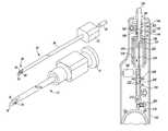
- FIG. 1is a perspective view of one embodiment of a surgical instrument system for use in performing a surgical procedure
- FIG. 2is a perspective view of some of the components of the system of FIG. 1 ;
- FIG. 3illustrates a circuit diagram of an electrical circuit of the surgical instrument system of FIG. 1 ;
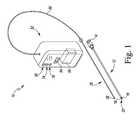
- FIG. 4is a perspective view illustrating another surgical instrument system
- FIG. 4Ais a partial cross-section elevation view of a detail of FIG. 4 ;
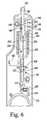
- FIGS. 5-6are partial cross-sectional plan views of a surgical instrument of the instrument system of FIG. 4 ;
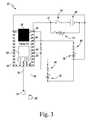
- FIG. 7is a circuit diagram of an electrical circuit of the surgical instrument system of FIG. 4 ;
- FIG. 8is a side elevation view of the surgical instrument of FIGS. 4-7 positioned for insertion into a patient's soft tissue;
- FIG. 9illustrates the surgical instrument of FIGS. 4-7 as it enters a lumen of the patient
- FIG. 10illustrates the surgical instrument of FIGS. 4-7 after the needle of the surgical instrument has been retracted
- FIG. 11is a circuit diagram of an electrical circuit for the surgical instrument system of FIG. 4 .
- a surgical instrument system 10configured for insertion into the soft tissue of a patient is illustrated.
- the surgical instrument 10may be use to form a puncture between the skin of the neck and the anterior wall of the trachea of a patient, but it should be appreciated that the surgical instrument 10 may be used to form other punctures, incisions, or openings in the patient's tissue.
- the surgical instrument system 10includes an elongated needle body 12 that extends from a proximal end 14 to a distal end 16 .
- a needle tip 18configured to pierce the tissue is formed at the distal end 16 of the body 12 .
- the needle body 12has a lumen or passageway 20 extending through the ends 14 , 16 , as shown in FIG. 2 .
- a cathetermay be inserted into the passageway 20 to provide, for example, epidural anesthesia, to a patient.
- the surgical instrument system 10also includes a probe 28 that is sized to be positioned in the passageway 20 of the needle 12 .
- the probe 28is connected to an indicator 30 that is configured to notify a user that the needle tip 18 has penetrated the tissue, as described in greater detail below.
- the probe 28includes a base 32 and a shaft 36 that extends distally away from the base 32 to a tip 38 .
- the shaft 36is a cannula formed from an electrically conductive material.
- the tip 38 and the shaft 36are integral, but it should be appreciated that in other embodiments the tip 38 and the shaft 36 may be formed as separate components and assembled.
- the probe 28includes a conductor plate 40 that is positioned in the distal opening 42 of the tip 38 .
- the plate 40is electrically insulated from the tip 38 by a non-conductive film 44 .
- the film 44is a ring having a predetermined thickness that surrounds the plate 40 .
- the shaftmay be formed from a non-conductive material such as ceramic or plastic to insulate the plate.
- the plate 40 and the film 44cooperate to cover the opening 42 such that fluid is prevented from entering the tip 38 .
- electrical circuitry 50 of the system 10is operable to detect the change in electrical resistance caused by the contact with the tissue, as described in greater detail below.
- the system 10includes a control box 52 that houses the electrical circuitry 50 , including the indicator 30 .
- the control box 52has a power switch 54 that may be toggled to energize the electrical circuitry 50 .
- a cable 56connects the electrical circuitry 50 with the probe 28 .
- the electrical circuitry 50 for the system 10is shown in greater detail.
- the circuitry 50is operable to detect a change in electrical resistance that is produced when the probe tip 38 exits one type of tissue and enters another type of tissue or lumen, as described in greater detail below.
- the circuitry 50includes a microprocessor 60 such as, for example, an 8-Bit AVR 16 MHz Processor (ATMEGA32U4) commercially available from Atmel Corporation.
- the microprocessor 60is attached a circuit 62 that also includes various terminals 64 connected to other circuitry 50 .
- An I/O port 66such as, for example, a USB port, is attached to the circuit 62 to permit a user to upload software and data to, and download from, the microprocessor 60 .
- the microprocessor 60 , the circuit 62 , and the I/O port 66are available in a Teensy 2.0 USB-based microcontroller development system.
- a voltage supplyincludes two 3 VDC batteries 68 , the anodes of which are coupled to one terminal 70 of the power switch 54 .
- the other terminal 72 of switch 54is coupled to the 5V terminal of the circuit 62 and to the anode of a “Power Indicator” LED 74 .
- the cathode of the Power Indicator LED 74is coupled to the cathodes of the batteries 68 and to the GrouND terminal of the circuit 62 at the terminal 76 .
- the circuitry 50also includes a “Low Battery” LED 78 , which is energized by the microprocessor 60 when battery voltage drops below a predetermined threshold.
- the cathode of the LED 78is connected through a 220 ⁇ resistor 80 to the “19” terminal of the circuit 62 .
- the anode of the LED 78is connected to the GrouND terminal of the circuit 62 and an anode of the indicator LED 30 .
- the cathode of the LED 30is connected to the “13” terminal of the circuit 62 through another 220 ⁇ resistor 84 .
- the shaft 36 of the probe 28is coupled via a wire 90 to a ground terminal of the circuit 62 .
- the conductor plate 40 of the tip 38is coupled via a wire 92 through a 4.7 k ⁇ resistor to the “15” terminal and the 5V terminal of the circuit 62 .
- the microprocessor 60applies 4.7V dc to the conductor plate 40 while the shaft 36 is connected to ground.
- the microprocessor 60is programmed to measure the resistance received by the circuit 62 at a controlled distance.
- the distanceis equal to a 0.5 millimeter gap between the conductor plate 40 and the cutting end of the shaft 36 that is created by the film 44 .
- the 0.5 millimeter gapcorresponds to the thickness of the film ring 44 .
- the resistance sensed at the conductor plate 40experiences a “step” change, which the microprocessor 60 is programmed to register as indicating, for example, that the tip 38 has penetrated a lumen.
- the microprocessor 60is programmed to switch the “13” terminal continuously “high,” thereby turning the indicator LED 30 continuously “on.”
- the microprocessor 60is programmed to consecutively toggle the “13” terminal “high” and “low,” thereby causing the LED 30 to flash “on” and “off” to indicate to the user that the instrument system 10 is armed. As the needle 12 (and hence the probe 38 ) is advanced into the spinal column, the conductor plate 40 remains engaged with the patient's tissue.
- the electrical resistance in the circuitchanges sharply, and the microprocessor 60 is programmed to switch the “13” terminal continuously “high,” thereby turning the indicator LED 30 continuously “on” to inform the user to hold the needle 12 in position.
- the usermay then remove the probe 28 from the lumen 20 of the needle 12 while leaving the needle 12 inserted into the patient's tissue.
- the usermay then use the lumen 20 to position, for example, a catheter to provide fluids to the patient.
- FIG. 4another instrument system 110 configured for insertion into the soft tissue of a patient is illustrated.
- the system 110is also configured for forming and dilating an opening in a patient's tissue is shown.
- the instrument system 110includes a puncture instrument 112 and a balloon catheter 114 that is removably coupled to the puncture instrument.
- An exemplary balloon catheter for use in the system 110is shown and described in U.S. patent application Ser. No. 14/996,426, which is expressly incorporated herein by reference.
- the instrument system 110may be used, for example, to create a puncture or incision in a tracheal wall of a patient and dilate the incision to receive a prosthesis such as, for example, a tracheostomy tube to form an air passageway for the patient.
- a prosthesissuch as, for example, a tracheostomy tube to form an air passageway for the patient.
- the balloon catheter 114is not shown in the illustrations of FIGS. 5-10 .
- the puncture instrument 112may be used to form a puncture between the skin of the neck and the anterior wall of the trachea of a patient, but it should be appreciated that the puncture instrument 112 may be used to form other punctures, incisions, or openings in the patient's tissue.
- the puncture instrument 112includes an elongated body 120 having a proximal end 122 and a distal end 124 .
- a needle tip 126configured to pierce the tissue is formed at the distal end 124 of the body 120 .
- the puncture instrument 112also includes an indicator 128 configured to notify a user that the needle tip 126 has penetrated the tissue and an automatic needle retraction mechanism 130 operable quickly to retract the needle tip 126 a short distance after the needle tip 126 has penetrated the tissue.
- the elongated body 120includes a handle 132 extending from the proximal end 122 to a distal handle end 134 .
- a shaft 136extends distally away from the handle 132 to the needle tip 126 .
- the shaft 136is a cannula formed from a metallic material. In other embodiments, the shaft may be formed from a ceramic or plastic material.
- the needle tip 126 and the shaft 136are integral, but it should be appreciated that in other embodiments the needle tip 126 and the shaft 136 may be formed as separate components and assembled.
- the handle 132illustratively includes an upper housing 140 that is configured to be coupled to a lower housing 142 .
- the indicator 128includes a light source such as, for example, a plurality of light emitting diodes (LED) 146 that is illustratively visible through an opening in the upper housing 140 .
- the housings 140 , 142cooperate to define a chamber in which other electrical circuitry 148 is positioned.
- the circuitry 148is operable to energize the LED 146 to provide a visual output to the user.
- the indicator 128may include other electrical circuitry to provide an audible output to the user.
- the puncture instrument 112also includes a power switch 150 , which is operable to supply power to the electrical circuitry 148 including LEDs 146 .
- the electrical circuitry 148includes a battery pack 152 positioned at one end of the handle 132 and the automatic needle retraction mechanism 160 , which is operable to retract the needle tip 126 a short distance after the needle tip 126 has penetrated the tissue. In illustrative embodiment, the distance is 8 millimeters.
- a metallic plate(not shown) is positioned in handle 132 is formed from copper and is configured to provide a ground plane for the electrical circuitry 148 , which makes the user the ground for the electrical circuitry.
- the instrument 112also includes a conductor plate 164 that is positioned in the distal opening 166 of the needle tip 126 .
- the plate 164is a metallic shaft that is electrically insulated from the needle tip 126 by a non-conductive film 168 .
- the film 44is a cylindrical ring having a predetermined thickness that surrounds the plate 40 .
- the needle tip and/or needle shaftmay be formed from a non-conductive material such as, for example, ceramic or plastic to electrically insulate the plate.
- the shaft 164 and the film 168cooperate to cover the opening 166 such that fluid is prevented from entering the needle tip 126 .
- a wire or conductor 170connects the shaft 164 to the electrical circuitry 148
- another wire or conductor 172connects the outer cannula shaft 136 to the electrical circuitry 148 .
- the electrical circuitry 148is operable to detect the change in electrical resistance caused by the contact with the tissue, as described in greater detail below.
- the instrument 112includes an automatic needle retraction mechanism 160 operable to retract the needle tip 126 a short distance after the needle tip 126 has penetrated the tissue.
- the needle retraction mechanism 160includes an actuator 180 .
- the actuator 180is a linear actuator such as, for example, a solenoid, which includes an output shaft 182 operable to move along a straight line.
- An exemplary actuatoris the Uxcell a14092600ux0438 Open Frame Actuator, which is electrically-operated.
- the actuatormay be embodied as an electric motor, electromagnet, or other electromechanical device operable to move the locking arm 184 , as described in greater detail below. As shown in FIG. 5 , the locking arm 184 that maintains the needle shaft 136 in an extended position.
- the needle shaft 136extends through an opening 186 defined in the distal handle end 134 , and the shaft 136 includes a proximal end 190 that is secured to a mounting bracket 192 positioned in the handle 132 .
- the mounting bracket 192includes a cylindrical body 194 and a slide plate 196 that extends outwardly from the body 194 .
- an aperture 198is defined at one end of the cylindrical body 194 , which receives the proximal end 190 of the shaft 136 and provides a passageway through which the connecting wire 170 passes to connect the conductor plate 164 to the other electrical circuitry 148 .
- the edges of the slide plate 196are received in a pair of guide slots 200 defined in the handle 132 , which guide the movement of the mounting bracket 192 as the needle tip 126 is retracted.
- a biasing elementsuch as, for example, a spring 202 positioned between the slide plate 196 and the distal handle end 134 .
- the spring 202is configured to bias the slide plate 196 away from the distal handle end 134 and hence bias the needle tip 126 is the retracted position.
- a rod 204extends between the cylindrical body 194 and the locking arm 184 . As shown in FIG. 6 , the rod 204 is received in an aperture 206 defined in the locking arm 184 .
- the locking arm 184includes a sleeve 208 positioned in the aperture 206 , and the rod 204 engages the sleeve 208 when the needle shaft 136 is an extended position.
- the sleeve 208is formed from a metallic material such as, for example, steel.
- a pivot pin 212extends outwardly from the lower housing 142 and is received in a bore defined in the locking arm 184 near an end 216 .
- the retraction mechanism 160also includes another biasing element, illustratively embodied as an elastic band 220 , which is coupled to the shaft end 216 and the lower housing 142 .
- the sleeve 208When the needle shaft 136 is in its extended position and ready for insertion into a patient's tissue, the sleeve 208 is initially engaged with the rod 204 , as shown in FIG. 6 .
- the band 220applies a force to the locking arm 184 to bias in the position shown in FIG. 6 to keep the rod 204 engaged with the sleeve 208 , thereby resisting the force exerted by the spring 202 against the slide plate 196 and maintaining the needle shaft 136 in the extended position.
- the automatic needle retraction mechanism 130is operable to quickly retract the needle tip 126 a short distance after the needle tip 126 has penetrated the tissue.
- the linear actuator 180is energized to advance its shaft 182 into contact with the locking arm 184 , thereby causing the arm 184 to pivot about the pin 212 as indicated by arrow 222 .
- the end of the rod 204disengages from the sleeve 208 and moves toward the center of the aperture 206 .
- the spring 202urges the mounting bracket 192 in the direction indicated by arrow 224 in FIG. 6 .
- the needle tip 126retracts away from the opposite wall of the patient's lumen.
- the electrical circuitry 148is shown. As described above, the electrical circuitry 148 is operable to detect a change in electrical resistance that is produced when the needle tip 126 exits one type of tissue and enters another type of tissue or lumen, as described in greater detail below. In that way, the electrical circuitry 148 functions as a sensor.
- the circuitry 148includes a microprocessor 230 such as, for example, an 8-Bit AVR 16 MHz Processor (ATMEGA32U4), which is commercially available from Atmel Corporation.
- the microprocessor 230is attached a circuit 232 that also includes various terminals 234 connected to other circuitry 148 .
- An I/O port 236such as, for example, a USB port, is attached to the circuit 232 to permit a user to upload software and data to, and download from, the microprocessor 230 .
- the microprocessor 230 , the circuit 232 , and the I/O port 236are available in a Teensy 2.0 USB-based microcontroller development system.
- a voltage supplyincludes a single 9 VDC battery 152 , the anode of which is coupled to one terminal 260 of the power switch 150 .
- the other terminal 262 of switch 150is coupled to a voltage regulator 154 and to the anode of a “Power Indicator” LED 264 of the LEDs 146 through a 220 ⁇ resistor 156 .
- the cathode of the Power Indicator LED 264is coupled to the cathode of the battery 152 and to the GrouND terminal of the circuit 232 .
- the voltage regulator 154is a Texas Instruments LP2981 regulator.
- the voltage regulator 154is connected to the 5V terminal of the circuit 232 and is configured to condition the 9 VDC battery voltage to 5 volts.
- the circuitry 148also includes a “Low Battery” LED 270 , which is energized by the microprocessor 230 when battery voltage drops below a predetermined threshold.
- the cathode of the LED 270is connected through a 220 ⁇ resistor 272 to the “13” terminal of the circuit 232 .
- the anode of the LED 270is connected to the GrouND terminal of the circuit 232 and an anode of the penetration indicator LED 274 .
- the cathode of the LED 274is connected to the “13” terminal of the circuit 232 through another 220 ⁇ resistor 276 .
- a battery monitor(not shown) may be connected to another terminal of the circuit 232 .
- the shaft 136 of the instrument 112is coupled via a wire 172 to a ground terminal of the circuit 232 .
- the conductor plate 164 in the tip 126is coupled via a wire 170 through a 68 ⁇ resistor 280 and a 100 k ⁇ resistor 282 to the “18” terminal and the 5V terminal of the circuit 232 .
- the shaft 136 and the plate 164form part of the sensor circuit used to detect when the needle tip 126 has penetrated a lumen. It should be appreciated that in other embodiments the sensor circuit may include a pair of conductor plates, which are electrically isolated from one another, and the elongated shaft may be formed from a non-conductive material.
- the linear actuator 180is connected to the anodes of the LEDs 270 , 274 and the GrouND terminal of the circuit 232 .
- the linear actuator 180is also connected to a relay switch 290 , which is positioned between the actuator 180 and the terminal 262 of the switch 150 .
- the relay switch 290is also connected to the “17” terminal of the circuit 232 and to the GrouND terminal, as shown in FIG. 7 .
- the circuitry 148also includes a snubber diode 292 that is connected between the positive and negative poles of the actuator 180 and the power supply 152 . As shown in FIG. 7 , the cathode 294 of the diode 292 is connected to the relay switch 290 , while the anode 296 of the diode 292 is connected to the linear actuator 180 and the power supply 152 .
- the microprocessor 230applies 4.7 VDC to the conductor plate 164 while the shaft 136 is connected to ground (e.g., the user's hand).
- the microprocessor 230is programmed to measure the electrical resistance in the circuit 232 at a controlled distance.
- the distanceis equal to a 0.5 millimeter gap between the conductor plate 164 and the cutting end of the shaft 136 that is created the non-conductive film 168 .
- the 0.5 millimeter gapcorresponds to the thickness of the film ring 168 .
- the microprocessor 230is programmed to register as indicating, for example, that the tip 126 has penetrated a lumen.
- the microprocessor 230is programmed to switch the “13” terminal continuously “high,” thereby turning the indicator LED 274 continuously “on.”
- the needle tip 126 of the surgical instrument 112may be used to form a puncture in a patient's issue.
- a surgeon or other usermay align the needle tip 126 with the target lumen of the patient's body (in this case, a patient's trachea 300 ) and toggle the power switch 150 to energize the sensor circuit formed by the microprocessor 230 , the conductor shaft 164 , and the outer cannula 136 .
- the circuitis open and the resistance value effectively infinite.
- the needle tip 126may be advanced into contact with the patient's tissue and through the anterior wall 306 .
- the circuitis closed, and the resistance value measured by the microprocessor 230 enters a predetermined range.
- the rangeis between 1 kilo-ohm and 100 kilo-ohms. It should be appreciated that in other embodiments other ranges of resistance values may be used.
- the controller 230activates a timer when the resistance value enters the predetermined range, and after a predetermined amount of time, the microprocessor 230 activates the LED 274 .
- the predetermined amount of timeis 200 milliseconds.
- the microprocessor 230When the microprocessor 230 activates the LED 274 in the illustrative embodiment, the microprocessor 230 is programmed to consecutively toggle the “13” terminal “high” and “low,” thereby causing the LED 274 to flash “on” and “off” to indicate to the user that the instrument 112 is armed.
- the instrument 112may include a pressure sensor that measures the pressure on the needle tip such that when the pressure surpasses the amount of pressure associated with penetrating the patient's tissue, the controller would activate the indicator and arm the instrument 112 .
- the instrument 112may also include a cancel switch that the user may toggle to disarm the instrument 112 .
- the conductor plate 164remains engaged with the patient's tissue.
- the target lumene.g., the trachea 300 , esophagus, or spinal column
- the resistance at the conductor plate 164changes sharply.
- the sensor circuiteffectively opens.
- the thresholdis 100 kilo-ohms or greater.
- the microprocessor 230is also programmed to switch the “17” terminal to “high” after a preset delay, thereby activating the relay switch 290 . It should be appreciated that in other embodiments the preset delay may be omitted and the switch 290 activated immediately.
- the switch 290When the switch 290 is activated, it connects the linear actuator 180 to the battery 152 , thereby energizing the actuator.
- the actuator 180is operable to advance its output shaft 182 into contact with the locking arm 184 and causing the locking arm 184 to pivot. As the arm 184 pivots, the end of the rod 204 disengages from the sleeve 208 and moves toward the center of the aperture 206 .
- the spring 202urges the mounting bracket 192 in the direction indicated by arrow 224 in FIG. 6 .
- the needle tip 126retracts in direction shown in FIG. 9 , away from the opposite wall 302 of the patient's trachea 300 and out of the incision 304 , as shown in FIG. 10 .
- the actuatormay be embodied as an electric motor, electromagnet, or other electromechanical device operable to move the locking arm 184 within a sufficient period of time after the microprocessor detects penetration of the lumen.
- the actuator 180is operable to move the locking arm 184 such that the needle is retracted in 100 milliseconds.
- FIG. 11another embodiment of electrical circuitry 348 is illustrated.
- the electrical circuitry 348is identical to the circuitry 148 described above, except for the use of two 3 VDC batteries and the omission of a voltage regulator and snubber diode.
- the anodes of the two 3 VDC batteries 352are coupled to one terminal 260 of the power switch 150 .
- the other terminal 262 of switch 150is coupled to the 5V terminal of the circuit 232 and to the anode of the “Power Indicator” LED 264 of the LEDs 146 .
- any surgical cutting toolsuch as, for example, a cutting blade, reamer, drill, or other instrument may include circuitry to detect fluctuating levels of electrical resistance and thereby determine when a distal end of the cutting tool has entered a lumen.
- Other surgical instrumentssuch as, for example, guides, trials, probes, and so forth may also include circuitry to detect fluctuating levels of electrical resistance and thereby determine when a distal end of the surgical instrument has entered a lumen.
Landscapes
- Health & Medical Sciences (AREA)
- Life Sciences & Earth Sciences (AREA)
- Surgery (AREA)
- Veterinary Medicine (AREA)
- Public Health (AREA)
- Biomedical Technology (AREA)
- Heart & Thoracic Surgery (AREA)
- Engineering & Computer Science (AREA)
- Animal Behavior & Ethology (AREA)
- General Health & Medical Sciences (AREA)
- Pulmonology (AREA)
- Pathology (AREA)
- Nuclear Medicine, Radiotherapy & Molecular Imaging (AREA)
- Medical Informatics (AREA)
- Molecular Biology (AREA)
- Emergency Medicine (AREA)
- Anesthesiology (AREA)
- Hematology (AREA)
- Surgical Instruments (AREA)
Abstract
Description
Claims (20)
Priority Applications (3)
| Application Number | Priority Date | Filing Date | Title |
|---|---|---|---|
| US15/452,323US10293129B2 (en) | 2016-03-07 | 2017-03-07 | Apparatus and method for forming an opening in patient's tissue |
| US16/415,922US20190269869A1 (en) | 2016-03-07 | 2019-05-17 | Apparatus and method for forming an opening in patient's tissue |
| US16/553,146US20200009341A1 (en) | 2015-01-15 | 2019-08-27 | Apparatus and method for differential capacitive sensing in patient's tissue |
Applications Claiming Priority (3)
| Application Number | Priority Date | Filing Date | Title |
|---|---|---|---|
| US201662304756P | 2016-03-07 | 2016-03-07 | |
| US201662364812P | 2016-07-20 | 2016-07-20 | |
| US15/452,323US10293129B2 (en) | 2016-03-07 | 2017-03-07 | Apparatus and method for forming an opening in patient's tissue |
Related Child Applications (1)
| Application Number | Title | Priority Date | Filing Date |
|---|---|---|---|
| US16/415,922DivisionUS20190269869A1 (en) | 2015-01-15 | 2019-05-17 | Apparatus and method for forming an opening in patient's tissue |
Publications (2)
| Publication Number | Publication Date |
|---|---|
| US20170252526A1 US20170252526A1 (en) | 2017-09-07 |
| US10293129B2true US10293129B2 (en) | 2019-05-21 |
Family
ID=59722563
Family Applications (2)
| Application Number | Title | Priority Date | Filing Date |
|---|---|---|---|
| US15/452,323Expired - Fee RelatedUS10293129B2 (en) | 2015-01-15 | 2017-03-07 | Apparatus and method for forming an opening in patient's tissue |
| US16/415,922AbandonedUS20190269869A1 (en) | 2015-01-15 | 2019-05-17 | Apparatus and method for forming an opening in patient's tissue |
Family Applications After (1)
| Application Number | Title | Priority Date | Filing Date |
|---|---|---|---|
| US16/415,922AbandonedUS20190269869A1 (en) | 2015-01-15 | 2019-05-17 | Apparatus and method for forming an opening in patient's tissue |
Country Status (2)
| Country | Link |
|---|---|
| US (2) | US10293129B2 (en) |
| WO (1) | WO2017155999A1 (en) |
Cited By (109)
| Publication number | Priority date | Publication date | Assignee | Title |
|---|---|---|---|---|
| US11090047B2 (en) | 2018-03-28 | 2021-08-17 | Cilag Gmbh International | Surgical instrument comprising an adaptive control system |
| US11096693B2 (en) | 2017-12-28 | 2021-08-24 | Cilag Gmbh International | Adjustment of staple height of at least one row of staples based on the sensed tissue thickness or force in closing |
| US11100631B2 (en) | 2017-12-28 | 2021-08-24 | Cilag Gmbh International | Use of laser light and red-green-blue coloration to determine properties of back scattered light |
| US11114195B2 (en) | 2017-12-28 | 2021-09-07 | Cilag Gmbh International | Surgical instrument with a tissue marking assembly |
| US11129611B2 (en) | 2018-03-28 | 2021-09-28 | Cilag Gmbh International | Surgical staplers with arrangements for maintaining a firing member thereof in a locked configuration unless a compatible cartridge has been installed therein |
| US11132462B2 (en) | 2017-12-28 | 2021-09-28 | Cilag Gmbh International | Data stripping method to interrogate patient records and create anonymized record |
| US11129636B2 (en) | 2017-10-30 | 2021-09-28 | Cilag Gmbh International | Surgical instruments comprising an articulation drive that provides for high articulation angles |
| US11141160B2 (en) | 2017-10-30 | 2021-10-12 | Cilag Gmbh International | Clip applier comprising a motor controller |
| US11160605B2 (en) | 2017-12-28 | 2021-11-02 | Cilag Gmbh International | Surgical evacuation sensing and motor control |
| US11166772B2 (en) | 2017-12-28 | 2021-11-09 | Cilag Gmbh International | Surgical hub coordination of control and communication of operating room devices |
| US11179208B2 (en) | 2017-12-28 | 2021-11-23 | Cilag Gmbh International | Cloud-based medical analytics for security and authentication trends and reactive measures |
| US11179204B2 (en) | 2017-12-28 | 2021-11-23 | Cilag Gmbh International | Wireless pairing of a surgical device with another device within a sterile surgical field based on the usage and situational awareness of devices |
| US11202570B2 (en) | 2017-12-28 | 2021-12-21 | Cilag Gmbh International | Communication hub and storage device for storing parameters and status of a surgical device to be shared with cloud based analytics systems |
| US11207067B2 (en) | 2018-03-28 | 2021-12-28 | Cilag Gmbh International | Surgical stapling device with separate rotary driven closure and firing systems and firing member that engages both jaws while firing |
| US11213359B2 (en) | 2017-12-28 | 2022-01-04 | Cilag Gmbh International | Controllers for robot-assisted surgical platforms |
| US11219453B2 (en) | 2018-03-28 | 2022-01-11 | Cilag Gmbh International | Surgical stapling devices with cartridge compatible closure and firing lockout arrangements |
| US11229436B2 (en) | 2017-10-30 | 2022-01-25 | Cilag Gmbh International | Surgical system comprising a surgical tool and a surgical hub |
| US11234756B2 (en) | 2017-12-28 | 2022-02-01 | Cilag Gmbh International | Powered surgical tool with predefined adjustable control algorithm for controlling end effector parameter |
| US11257589B2 (en) | 2017-12-28 | 2022-02-22 | Cilag Gmbh International | Real-time analysis of comprehensive cost of all instrumentation used in surgery utilizing data fluidity to track instruments through stocking and in-house processes |
| US11253315B2 (en) | 2017-12-28 | 2022-02-22 | Cilag Gmbh International | Increasing radio frequency to create pad-less monopolar loop |
| US11259806B2 (en) | 2018-03-28 | 2022-03-01 | Cilag Gmbh International | Surgical stapling devices with features for blocking advancement of a camming assembly of an incompatible cartridge installed therein |
| US11259807B2 (en) | 2019-02-19 | 2022-03-01 | Cilag Gmbh International | Staple cartridges with cam surfaces configured to engage primary and secondary portions of a lockout of a surgical stapling device |
| US11259830B2 (en) | 2018-03-08 | 2022-03-01 | Cilag Gmbh International | Methods for controlling temperature in ultrasonic device |
| US11266468B2 (en) | 2017-12-28 | 2022-03-08 | Cilag Gmbh International | Cooperative utilization of data derived from secondary sources by intelligent surgical hubs |
| US11273001B2 (en) | 2017-12-28 | 2022-03-15 | Cilag Gmbh International | Surgical hub and modular device response adjustment based on situational awareness |
| US11278281B2 (en) | 2017-12-28 | 2022-03-22 | Cilag Gmbh International | Interactive surgical system |
| US11278280B2 (en) | 2018-03-28 | 2022-03-22 | Cilag Gmbh International | Surgical instrument comprising a jaw closure lockout |
| US11284936B2 (en) | 2017-12-28 | 2022-03-29 | Cilag Gmbh International | Surgical instrument having a flexible electrode |
| US11291510B2 (en) | 2017-10-30 | 2022-04-05 | Cilag Gmbh International | Method of hub communication with surgical instrument systems |
| US11291495B2 (en) | 2017-12-28 | 2022-04-05 | Cilag Gmbh International | Interruption of energy due to inadvertent capacitive coupling |
| US11298148B2 (en) | 2018-03-08 | 2022-04-12 | Cilag Gmbh International | Live time tissue classification using electrical parameters |
| US11304720B2 (en) | 2017-12-28 | 2022-04-19 | Cilag Gmbh International | Activation of energy devices |
| US11308075B2 (en) | 2017-12-28 | 2022-04-19 | Cilag Gmbh International | Surgical network, instrument, and cloud responses based on validation of received dataset and authentication of its source and integrity |
| US11304745B2 (en) | 2017-12-28 | 2022-04-19 | Cilag Gmbh International | Surgical evacuation sensing and display |
| US11304699B2 (en) | 2017-12-28 | 2022-04-19 | Cilag Gmbh International | Method for adaptive control schemes for surgical network control and interaction |
| US11304763B2 (en) | 2017-12-28 | 2022-04-19 | Cilag Gmbh International | Image capturing of the areas outside the abdomen to improve placement and control of a surgical device in use |
| US11311342B2 (en) | 2017-10-30 | 2022-04-26 | Cilag Gmbh International | Method for communicating with surgical instrument systems |
| US11311306B2 (en) | 2017-12-28 | 2022-04-26 | Cilag Gmbh International | Surgical systems for detecting end effector tissue distribution irregularities |
| US11317937B2 (en) | 2018-03-08 | 2022-05-03 | Cilag Gmbh International | Determining the state of an ultrasonic end effector |
| USD950728S1 (en) | 2019-06-25 | 2022-05-03 | Cilag Gmbh International | Surgical staple cartridge |
| US11317919B2 (en) | 2017-10-30 | 2022-05-03 | Cilag Gmbh International | Clip applier comprising a clip crimping system |
| US11317915B2 (en) | 2019-02-19 | 2022-05-03 | Cilag Gmbh International | Universal cartridge based key feature that unlocks multiple lockout arrangements in different surgical staplers |
| US11324557B2 (en) | 2017-12-28 | 2022-05-10 | Cilag Gmbh International | Surgical instrument with a sensing array |
| USD952144S1 (en) | 2019-06-25 | 2022-05-17 | Cilag Gmbh International | Surgical staple cartridge retainer with firing system authentication key |
| US11337746B2 (en) | 2018-03-08 | 2022-05-24 | Cilag Gmbh International | Smart blade and power pulsing |
| US11357503B2 (en) | 2019-02-19 | 2022-06-14 | Cilag Gmbh International | Staple cartridge retainers with frangible retention features and methods of using same |
| US11364075B2 (en) | 2017-12-28 | 2022-06-21 | Cilag Gmbh International | Radio frequency energy device for delivering combined electrical signals |
| US11369377B2 (en) | 2019-02-19 | 2022-06-28 | Cilag Gmbh International | Surgical stapling assembly with cartridge based retainer configured to unlock a firing lockout |
| US11376002B2 (en) | 2017-12-28 | 2022-07-05 | Cilag Gmbh International | Surgical instrument cartridge sensor assemblies |
| US11382697B2 (en) | 2017-12-28 | 2022-07-12 | Cilag Gmbh International | Surgical instruments comprising button circuits |
| US11410259B2 (en) | 2017-12-28 | 2022-08-09 | Cilag Gmbh International | Adaptive control program updates for surgical devices |
| US11423007B2 (en) | 2017-12-28 | 2022-08-23 | Cilag Gmbh International | Adjustment of device control programs based on stratified contextual data in addition to the data |
| US11419667B2 (en) | 2017-12-28 | 2022-08-23 | Cilag Gmbh International | Ultrasonic energy device which varies pressure applied by clamp arm to provide threshold control pressure at a cut progression location |
| US11419630B2 (en) | 2017-12-28 | 2022-08-23 | Cilag Gmbh International | Surgical system distributed processing |
| US11432885B2 (en) | 2017-12-28 | 2022-09-06 | Cilag Gmbh International | Sensing arrangements for robot-assisted surgical platforms |
| USD964564S1 (en) | 2019-06-25 | 2022-09-20 | Cilag Gmbh International | Surgical staple cartridge retainer with a closure system authentication key |
| US11446052B2 (en) | 2017-12-28 | 2022-09-20 | Cilag Gmbh International | Variation of radio frequency and ultrasonic power level in cooperation with varying clamp arm pressure to achieve predefined heat flux or power applied to tissue |
| US11464559B2 (en) | 2017-12-28 | 2022-10-11 | Cilag Gmbh International | Estimating state of ultrasonic end effector and control system therefor |
| US11464535B2 (en) | 2017-12-28 | 2022-10-11 | Cilag Gmbh International | Detection of end effector emersion in liquid |
| US11464511B2 (en) | 2019-02-19 | 2022-10-11 | Cilag Gmbh International | Surgical staple cartridges with movable authentication key arrangements |
| US11471156B2 (en) | 2018-03-28 | 2022-10-18 | Cilag Gmbh International | Surgical stapling devices with improved rotary driven closure systems |
| US11504192B2 (en) | 2014-10-30 | 2022-11-22 | Cilag Gmbh International | Method of hub communication with surgical instrument systems |
| US11510741B2 (en) | 2017-10-30 | 2022-11-29 | Cilag Gmbh International | Method for producing a surgical instrument comprising a smart electrical system |
| US11529187B2 (en) | 2017-12-28 | 2022-12-20 | Cilag Gmbh International | Surgical evacuation sensor arrangements |
| US11540855B2 (en) | 2017-12-28 | 2023-01-03 | Cilag Gmbh International | Controlling activation of an ultrasonic surgical instrument according to the presence of tissue |
| US11559308B2 (en) | 2017-12-28 | 2023-01-24 | Cilag Gmbh International | Method for smart energy device infrastructure |
| US11559307B2 (en) | 2017-12-28 | 2023-01-24 | Cilag Gmbh International | Method of robotic hub communication, detection, and control |
| US11564756B2 (en) | 2017-10-30 | 2023-01-31 | Cilag Gmbh International | Method of hub communication with surgical instrument systems |
| US11571234B2 (en) | 2017-12-28 | 2023-02-07 | Cilag Gmbh International | Temperature control of ultrasonic end effector and control system therefor |
| US11576677B2 (en) | 2017-12-28 | 2023-02-14 | Cilag Gmbh International | Method of hub communication, processing, display, and cloud analytics |
| US11589932B2 (en) | 2017-12-28 | 2023-02-28 | Cilag Gmbh International | Usage and technique analysis of surgeon / staff performance against a baseline to optimize device utilization and performance for both current and future procedures |
| US11601371B2 (en) | 2017-12-28 | 2023-03-07 | Cilag Gmbh International | Surgical network determination of prioritization of communication, interaction, or processing based on system or device needs |
| US11596291B2 (en) | 2017-12-28 | 2023-03-07 | Cilag Gmbh International | Method of compressing tissue within a stapling device and simultaneously displaying of the location of the tissue within the jaws |
| US11602393B2 (en) | 2017-12-28 | 2023-03-14 | Cilag Gmbh International | Surgical evacuation sensing and generator control |
| US11612408B2 (en) | 2017-12-28 | 2023-03-28 | Cilag Gmbh International | Determining tissue composition via an ultrasonic system |
| US11659023B2 (en) | 2017-12-28 | 2023-05-23 | Cilag Gmbh International | Method of hub communication |
| US11666331B2 (en) | 2017-12-28 | 2023-06-06 | Cilag Gmbh International | Systems for detecting proximity of surgical end effector to cancerous tissue |
| US11696760B2 (en) | 2017-12-28 | 2023-07-11 | Cilag Gmbh International | Safety systems for smart powered surgical stapling |
| US11744604B2 (en) | 2017-12-28 | 2023-09-05 | Cilag Gmbh International | Surgical instrument with a hardware-only control circuit |
| US11771487B2 (en) | 2017-12-28 | 2023-10-03 | Cilag Gmbh International | Mechanisms for controlling different electromechanical systems of an electrosurgical instrument |
| US11779337B2 (en) | 2017-12-28 | 2023-10-10 | Cilag Gmbh International | Method of using reinforced flexible circuits with multiple sensors to optimize performance of radio frequency devices |
| US11786245B2 (en) | 2017-12-28 | 2023-10-17 | Cilag Gmbh International | Surgical systems with prioritized data transmission capabilities |
| US11786251B2 (en) | 2017-12-28 | 2023-10-17 | Cilag Gmbh International | Method for adaptive control schemes for surgical network control and interaction |
| US11801098B2 (en) | 2017-10-30 | 2023-10-31 | Cilag Gmbh International | Method of hub communication with surgical instrument systems |
| US11818052B2 (en) | 2017-12-28 | 2023-11-14 | Cilag Gmbh International | Surgical network determination of prioritization of communication, interaction, or processing based on system or device needs |
| US11832899B2 (en) | 2017-12-28 | 2023-12-05 | Cilag Gmbh International | Surgical systems with autonomously adjustable control programs |
| US11832840B2 (en) | 2017-12-28 | 2023-12-05 | Cilag Gmbh International | Surgical instrument having a flexible circuit |
| US11857152B2 (en) | 2017-12-28 | 2024-01-02 | Cilag Gmbh International | Surgical hub spatial awareness to determine devices in operating theater |
| US11864728B2 (en) | 2017-12-28 | 2024-01-09 | Cilag Gmbh International | Characterization of tissue irregularities through the use of mono-chromatic light refractivity |
| US11871901B2 (en) | 2012-05-20 | 2024-01-16 | Cilag Gmbh International | Method for situational awareness for surgical network or surgical network connected device capable of adjusting function based on a sensed situation or usage |
| US11890065B2 (en) | 2017-12-28 | 2024-02-06 | Cilag Gmbh International | Surgical system to limit displacement |
| US11896443B2 (en) | 2017-12-28 | 2024-02-13 | Cilag Gmbh International | Control of a surgical system through a surgical barrier |
| US11903587B2 (en) | 2017-12-28 | 2024-02-20 | Cilag Gmbh International | Adjustment to the surgical stapling control based on situational awareness |
| US11903601B2 (en) | 2017-12-28 | 2024-02-20 | Cilag Gmbh International | Surgical instrument comprising a plurality of drive systems |
| US11911045B2 (en) | 2017-10-30 | 2024-02-27 | Cllag GmbH International | Method for operating a powered articulating multi-clip applier |
| US11937769B2 (en) | 2017-12-28 | 2024-03-26 | Cilag Gmbh International | Method of hub communication, processing, storage and display |
| US11969216B2 (en) | 2017-12-28 | 2024-04-30 | Cilag Gmbh International | Surgical network recommendations from real time analysis of procedure variables against a baseline highlighting differences from the optimal solution |
| US11998193B2 (en) | 2017-12-28 | 2024-06-04 | Cilag Gmbh International | Method for usage of the shroud as an aspect of sensing or controlling a powered surgical device, and a control algorithm to adjust its default operation |
| US12029506B2 (en) | 2017-12-28 | 2024-07-09 | Cilag Gmbh International | Method of cloud based data analytics for use with the hub |
| US12035890B2 (en) | 2017-12-28 | 2024-07-16 | Cilag Gmbh International | Method of sensing particulate from smoke evacuated from a patient, adjusting the pump speed based on the sensed information, and communicating the functional parameters of the system to the hub |
| US12048496B2 (en) | 2017-12-28 | 2024-07-30 | Cilag Gmbh International | Adaptive control program updates for surgical hubs |
| US12062442B2 (en) | 2017-12-28 | 2024-08-13 | Cilag Gmbh International | Method for operating surgical instrument systems |
| US12133773B2 (en) | 2017-12-28 | 2024-11-05 | Cilag Gmbh International | Surgical hub and modular device response adjustment based on situational awareness |
| US12226151B2 (en) | 2017-12-28 | 2025-02-18 | Cilag Gmbh International | Capacitive coupled return path pad with separable array elements |
| US12303159B2 (en) | 2018-03-08 | 2025-05-20 | Cilag Gmbh International | Methods for estimating and controlling state of ultrasonic end effector |
| US12318152B2 (en) | 2017-12-28 | 2025-06-03 | Cilag Gmbh International | Computer implemented interactive surgical systems |
| US12376855B2 (en) | 2017-12-28 | 2025-08-05 | Cilag Gmbh International | Safety systems for smart powered surgical stapling |
| US12396806B2 (en) | 2017-12-28 | 2025-08-26 | Cilag Gmbh International | Adjustment of a surgical device function based on situational awareness |
| US12433508B2 (en) | 2017-12-28 | 2025-10-07 | Cilag Gmbh International | Surgical system having a surgical instrument controlled based on comparison of sensor and database data |
Families Citing this family (8)
| Publication number | Priority date | Publication date | Assignee | Title |
|---|---|---|---|---|
| US11896322B2 (en) | 2017-12-28 | 2024-02-13 | Cilag Gmbh International | Sensing the patient position and contact utilizing the mono-polar return pad electrode to provide situational awareness to the hub |
| US11424027B2 (en)* | 2017-12-28 | 2022-08-23 | Cilag Gmbh International | Method for operating surgical instrument systems |
| US12127729B2 (en) | 2017-12-28 | 2024-10-29 | Cilag Gmbh International | Method for smoke evacuation for surgical hub |
| US11589888B2 (en) | 2017-12-28 | 2023-02-28 | Cilag Gmbh International | Method for controlling smart energy devices |
| US11612444B2 (en) | 2017-12-28 | 2023-03-28 | Cilag Gmbh International | Adjustment of a surgical device function based on situational awareness |
| US20190374247A1 (en)* | 2018-06-11 | 2019-12-12 | Norman A. Paradis | Device to Assist in the Cannulation of Vascular or Other Anatomic Structures |
| US20230149042A1 (en)* | 2021-11-16 | 2023-05-18 | Mukesh Gupta | Needle and cannula assembly for cannulation and treatment of subcutaneous vessels |
| CN114224454B (en)* | 2022-01-20 | 2024-09-20 | 池州市人民医院 | Visual display cricothyroid membrane puncture instrument |
Citations (30)
| Publication number | Priority date | Publication date | Assignee | Title |
|---|---|---|---|---|
| US4321926A (en) | 1979-04-16 | 1982-03-30 | Roge Ralph R | Insertion detecting probe and electrolysis system |
| US5217005A (en) | 1991-11-01 | 1993-06-08 | Weinstein James D | Apparatus for performing percutaneous tracheostomies and cricothyroidectomies |
| US5335668A (en) | 1993-04-30 | 1994-08-09 | Medical Scientific, Inc. | Diagnostic impedance measuring system for an insufflation needle |
| US5353800A (en) | 1992-12-11 | 1994-10-11 | Medtronic, Inc. | Implantable pressure sensor lead |
| US5383465A (en)* | 1989-12-18 | 1995-01-24 | Lesny; Jan | Ultrasonic instrument |
| US5421821A (en) | 1993-11-12 | 1995-06-06 | Marlow Surgical Technologies, Inc. | Verres needle system and method |
| US5423796A (en)* | 1993-10-08 | 1995-06-13 | United States Surgical Corporation | Trocar with electrical tissue penetration indicator |
| US5429636A (en)* | 1993-10-08 | 1995-07-04 | United States Surgical Corporation | Conductive body tissue penetrating device |
| US5460182A (en)* | 1992-09-14 | 1995-10-24 | Sextant Medical Corporation | Tissue penetrating apparatus and methods |
| JPH08542A (en) | 1994-04-21 | 1996-01-09 | Olympus Optical Co Ltd | Endoscope position detector |
| US5496313A (en)* | 1994-09-20 | 1996-03-05 | Conmed Corporation | System for detecting penetration of medical instruments |
| US5653230A (en) | 1996-01-19 | 1997-08-05 | Cook Incorporated | Percutaneous balloon dilational tracheostomy tube |
| US5800350A (en) | 1993-11-01 | 1998-09-01 | Polartechnics, Limited | Apparatus for tissue type recognition |
| US6337994B1 (en) | 1998-04-30 | 2002-01-08 | Johns Hopkins University | Surgical needle probe for electrical impedance measurements |
| US6466817B1 (en) | 1999-11-24 | 2002-10-15 | Nuvasive, Inc. | Nerve proximity and status detection system and method |
| US6471659B2 (en) | 1999-12-27 | 2002-10-29 | Neothermia Corporation | Minimally invasive intact recovery of tissue |
| US6603997B2 (en) | 2001-11-02 | 2003-08-05 | Michael C. Doody | Probe penetration detector and method of operation |
| US6760616B2 (en) | 2000-05-18 | 2004-07-06 | Nu Vasive, Inc. | Tissue discrimination and applications in medical procedures |
| US6962587B2 (en) | 2000-07-25 | 2005-11-08 | Rita Medical Systems, Inc. | Method for detecting and treating tumors using localized impedance measurement |
| US20080091227A1 (en) | 2006-08-25 | 2008-04-17 | Baxano, Inc. | Surgical probe and method of making |
| US8034049B2 (en) | 2006-08-08 | 2011-10-11 | Covidien Ag | System and method for measuring initial tissue impedance |
| US20120004535A1 (en) | 2010-06-30 | 2012-01-05 | Mohajer Reza S | Veress needle with illuminated tip and cavity penetration indicator |
| US20120180787A1 (en) | 2011-01-19 | 2012-07-19 | Cook Incorporated (d/b/a Cook Critical Care Incorporated) | Percutaneous dilational device having balloon retention mechanism |
| US20120209167A1 (en) | 2011-02-11 | 2012-08-16 | Mectra Labs, Inc. | Insufflation needle with dual indicator and method of use |
| US8374673B2 (en) | 2007-01-25 | 2013-02-12 | Warsaw Orthopedic, Inc. | Integrated surgical navigational and neuromonitoring system having automated surgical assistance and control |
| US8696697B2 (en) | 2012-04-13 | 2014-04-15 | Helix Medical, Llc | Trocar and device for measuring a tracheoesophageal puncture |
| WO2014088904A1 (en) | 2012-12-03 | 2014-06-12 | Hansa Medical Products, Inc. | Endotracheal tube having outer and inner cannulae |
| US20140303494A1 (en) | 2011-10-19 | 2014-10-09 | Lumoptik Llc | Needle guidance system |
| US20150011853A1 (en) | 2011-05-05 | 2015-01-08 | Nemodevices Ag | Measuring Device for Measuring Cerebral Parameters |
| US20160206842A1 (en) | 2015-01-15 | 2016-07-21 | Eric D. Blom | Apparatus and method for forming an opening in patient's tissue |
Family Cites Families (3)
| Publication number | Priority date | Publication date | Assignee | Title |
|---|---|---|---|---|
| US6246898B1 (en)* | 1995-03-28 | 2001-06-12 | Sonometrics Corporation | Method for carrying out a medical procedure using a three-dimensional tracking and imaging system |
| WO2006058195A2 (en)* | 2004-11-23 | 2006-06-01 | Pneumrx, Inc. | Steerable device for accessing a target site and methods |
| US10219828B2 (en)* | 2010-10-27 | 2019-03-05 | Dtherapeutics, Llc | Devices, systems, and methods for transradial access |
- 2017
- 2017-03-07WOPCT/US2017/021161patent/WO2017155999A1/ennot_activeCeased
- 2017-03-07USUS15/452,323patent/US10293129B2/ennot_activeExpired - Fee Related
- 2019
- 2019-05-17USUS16/415,922patent/US20190269869A1/ennot_activeAbandoned
Patent Citations (32)
| Publication number | Priority date | Publication date | Assignee | Title |
|---|---|---|---|---|
| US4321926A (en) | 1979-04-16 | 1982-03-30 | Roge Ralph R | Insertion detecting probe and electrolysis system |
| US5383465A (en)* | 1989-12-18 | 1995-01-24 | Lesny; Jan | Ultrasonic instrument |
| US5217005A (en) | 1991-11-01 | 1993-06-08 | Weinstein James D | Apparatus for performing percutaneous tracheostomies and cricothyroidectomies |
| US5460182A (en)* | 1992-09-14 | 1995-10-24 | Sextant Medical Corporation | Tissue penetrating apparatus and methods |
| US5353800A (en) | 1992-12-11 | 1994-10-11 | Medtronic, Inc. | Implantable pressure sensor lead |
| US5335668A (en) | 1993-04-30 | 1994-08-09 | Medical Scientific, Inc. | Diagnostic impedance measuring system for an insufflation needle |
| US5423796A (en)* | 1993-10-08 | 1995-06-13 | United States Surgical Corporation | Trocar with electrical tissue penetration indicator |
| US5429636A (en)* | 1993-10-08 | 1995-07-04 | United States Surgical Corporation | Conductive body tissue penetrating device |
| US5800350A (en) | 1993-11-01 | 1998-09-01 | Polartechnics, Limited | Apparatus for tissue type recognition |
| US5421821A (en) | 1993-11-12 | 1995-06-06 | Marlow Surgical Technologies, Inc. | Verres needle system and method |
| JPH08542A (en) | 1994-04-21 | 1996-01-09 | Olympus Optical Co Ltd | Endoscope position detector |
| US5496313A (en)* | 1994-09-20 | 1996-03-05 | Conmed Corporation | System for detecting penetration of medical instruments |
| US5653230A (en) | 1996-01-19 | 1997-08-05 | Cook Incorporated | Percutaneous balloon dilational tracheostomy tube |
| US6337994B1 (en) | 1998-04-30 | 2002-01-08 | Johns Hopkins University | Surgical needle probe for electrical impedance measurements |
| US6466817B1 (en) | 1999-11-24 | 2002-10-15 | Nuvasive, Inc. | Nerve proximity and status detection system and method |
| US6471659B2 (en) | 1999-12-27 | 2002-10-29 | Neothermia Corporation | Minimally invasive intact recovery of tissue |
| US6760616B2 (en) | 2000-05-18 | 2004-07-06 | Nu Vasive, Inc. | Tissue discrimination and applications in medical procedures |
| US7419487B2 (en) | 2000-07-25 | 2008-09-02 | Angiodynamics, Inc. | Apparatus for detecting and treating tumors using localized impedance measurement |
| US6962587B2 (en) | 2000-07-25 | 2005-11-08 | Rita Medical Systems, Inc. | Method for detecting and treating tumors using localized impedance measurement |
| US6603997B2 (en) | 2001-11-02 | 2003-08-05 | Michael C. Doody | Probe penetration detector and method of operation |
| US8034049B2 (en) | 2006-08-08 | 2011-10-11 | Covidien Ag | System and method for measuring initial tissue impedance |
| US20080091227A1 (en) | 2006-08-25 | 2008-04-17 | Baxano, Inc. | Surgical probe and method of making |
| US8374673B2 (en) | 2007-01-25 | 2013-02-12 | Warsaw Orthopedic, Inc. | Integrated surgical navigational and neuromonitoring system having automated surgical assistance and control |
| US20120004535A1 (en) | 2010-06-30 | 2012-01-05 | Mohajer Reza S | Veress needle with illuminated tip and cavity penetration indicator |
| US8838206B2 (en) | 2010-06-30 | 2014-09-16 | Reza S. Mohajer | Veress needle with illuminated tip and cavity penetration indicator |
| US20120180787A1 (en) | 2011-01-19 | 2012-07-19 | Cook Incorporated (d/b/a Cook Critical Care Incorporated) | Percutaneous dilational device having balloon retention mechanism |
| US20120209167A1 (en) | 2011-02-11 | 2012-08-16 | Mectra Labs, Inc. | Insufflation needle with dual indicator and method of use |
| US20150011853A1 (en) | 2011-05-05 | 2015-01-08 | Nemodevices Ag | Measuring Device for Measuring Cerebral Parameters |
| US20140303494A1 (en) | 2011-10-19 | 2014-10-09 | Lumoptik Llc | Needle guidance system |
| US8696697B2 (en) | 2012-04-13 | 2014-04-15 | Helix Medical, Llc | Trocar and device for measuring a tracheoesophageal puncture |
| WO2014088904A1 (en) | 2012-12-03 | 2014-06-12 | Hansa Medical Products, Inc. | Endotracheal tube having outer and inner cannulae |
| US20160206842A1 (en) | 2015-01-15 | 2016-07-21 | Eric D. Blom | Apparatus and method for forming an opening in patient's tissue |
Non-Patent Citations (9)
| Title |
|---|
| "LM Linear Probes-User's Guide", Bioanalytical Systems, Inc., Retrieved from Online on Aug. 28, 2016 (Aug. 28, 2016); Retrieved from URL: https://www.basinc.com/assets/library/manuals/lmlp.pdf, 4 pages. |
| "LM Linear Probes—User's Guide", Bioanalytical Systems, Inc., Retrieved from Online on Aug. 28, 2016 (Aug. 28, 2016); Retrieved from URL: https://www.basinc.com/assets/library/manuals/lmlp.pdf, 4 pages. |
| Blom-Singer® Voice Prosthesis Placement Surgical Kit available from Inhealth® Technologies. |
| Desyatnikova et al., "Tracheosophageal Puncture in the Office Setting with Local Anesthesia", Annals of Ontology, Rhineology and Laryngology, 110, 613-616, 2001. |
| International Search Report and Written Opinion, International Application No. PCT/US2016/013528, search completed Apr. 19, 2016, 14 pages. |
| Kalvoy et al., "Impedance-based tissue discrimination for needle guidance", Physiol. Meas. 30 (2009), pp. 129-140. |
| Kalvoy, "Needle Guidance in Clinical Applications based on Electrical Impedance", Oslo University Hospital, Department of Clinical and Biomedical Engineering, Rikshospitalet, Oslo University Hospital Norway, 2010, 82 pages. |
| Koch, "A Failsafe Technique for Tracheoesphageal Puncture", The Laryngoscope, 111, Sep. 2001. |
| Trebbels et al., "Real-Time Cannula Navigation in Biological Tissue with high temporal and spatial resolution based on Impedance Spectroscopy", 32nd Annual International Conference of the IEEE EMBS, Aug. 31-Sep. 4, 2010, 4 pages. |
Cited By (191)
| Publication number | Priority date | Publication date | Assignee | Title |
|---|---|---|---|---|
| US11871901B2 (en) | 2012-05-20 | 2024-01-16 | Cilag Gmbh International | Method for situational awareness for surgical network or surgical network connected device capable of adjusting function based on a sensed situation or usage |
| US11504192B2 (en) | 2014-10-30 | 2022-11-22 | Cilag Gmbh International | Method of hub communication with surgical instrument systems |
| US11793537B2 (en) | 2017-10-30 | 2023-10-24 | Cilag Gmbh International | Surgical instrument comprising an adaptive electrical system |
| US11406390B2 (en) | 2017-10-30 | 2022-08-09 | Cilag Gmbh International | Clip applier comprising interchangeable clip reloads |
| US12035983B2 (en) | 2017-10-30 | 2024-07-16 | Cilag Gmbh International | Method for producing a surgical instrument comprising a smart electrical system |
| US11925373B2 (en) | 2017-10-30 | 2024-03-12 | Cilag Gmbh International | Surgical suturing instrument comprising a non-circular needle |
| US11129636B2 (en) | 2017-10-30 | 2021-09-28 | Cilag Gmbh International | Surgical instruments comprising an articulation drive that provides for high articulation angles |
| US11141160B2 (en) | 2017-10-30 | 2021-10-12 | Cilag Gmbh International | Clip applier comprising a motor controller |
| US11911045B2 (en) | 2017-10-30 | 2024-02-27 | Cllag GmbH International | Method for operating a powered articulating multi-clip applier |
| US12121255B2 (en) | 2017-10-30 | 2024-10-22 | Cilag Gmbh International | Electrical power output control based on mechanical forces |
| US11819231B2 (en) | 2017-10-30 | 2023-11-21 | Cilag Gmbh International | Adaptive control programs for a surgical system comprising more than one type of cartridge |
| US11801098B2 (en) | 2017-10-30 | 2023-10-31 | Cilag Gmbh International | Method of hub communication with surgical instrument systems |
| US11291510B2 (en) | 2017-10-30 | 2022-04-05 | Cilag Gmbh International | Method of hub communication with surgical instrument systems |
| US11759224B2 (en) | 2017-10-30 | 2023-09-19 | Cilag Gmbh International | Surgical instrument systems comprising handle arrangements |
| US12059218B2 (en) | 2017-10-30 | 2024-08-13 | Cilag Gmbh International | Method of hub communication with surgical instrument systems |
| US11602366B2 (en) | 2017-10-30 | 2023-03-14 | Cilag Gmbh International | Surgical suturing instrument configured to manipulate tissue using mechanical and electrical power |
| US11696778B2 (en) | 2017-10-30 | 2023-07-11 | Cilag Gmbh International | Surgical dissectors configured to apply mechanical and electrical energy |
| US11564703B2 (en) | 2017-10-30 | 2023-01-31 | Cilag Gmbh International | Surgical suturing instrument comprising a capture width which is larger than trocar diameter |
| US11564756B2 (en) | 2017-10-30 | 2023-01-31 | Cilag Gmbh International | Method of hub communication with surgical instrument systems |
| US11229436B2 (en) | 2017-10-30 | 2022-01-25 | Cilag Gmbh International | Surgical system comprising a surgical tool and a surgical hub |
| US11510741B2 (en) | 2017-10-30 | 2022-11-29 | Cilag Gmbh International | Method for producing a surgical instrument comprising a smart electrical system |
| US12329467B2 (en) | 2017-10-30 | 2025-06-17 | Cilag Gmbh International | Method of hub communication with surgical instrument systems |
| US11413042B2 (en) | 2017-10-30 | 2022-08-16 | Cilag Gmbh International | Clip applier comprising a reciprocating clip advancing member |
| US11648022B2 (en) | 2017-10-30 | 2023-05-16 | Cilag Gmbh International | Surgical instrument systems comprising battery arrangements |
| US11317919B2 (en) | 2017-10-30 | 2022-05-03 | Cilag Gmbh International | Clip applier comprising a clip crimping system |
| US11311342B2 (en) | 2017-10-30 | 2022-04-26 | Cilag Gmbh International | Method for communicating with surgical instrument systems |
| US11291465B2 (en) | 2017-10-30 | 2022-04-05 | Cilag Gmbh International | Surgical instruments comprising a lockable end effector socket |
| US11903601B2 (en) | 2017-12-28 | 2024-02-20 | Cilag Gmbh International | Surgical instrument comprising a plurality of drive systems |
| US11202570B2 (en) | 2017-12-28 | 2021-12-21 | Cilag Gmbh International | Communication hub and storage device for storing parameters and status of a surgical device to be shared with cloud based analytics systems |
| US11278281B2 (en) | 2017-12-28 | 2022-03-22 | Cilag Gmbh International | Interactive surgical system |
| US12433508B2 (en) | 2017-12-28 | 2025-10-07 | Cilag Gmbh International | Surgical system having a surgical instrument controlled based on comparison of sensor and database data |
| US11284936B2 (en) | 2017-12-28 | 2022-03-29 | Cilag Gmbh International | Surgical instrument having a flexible electrode |
| US12396806B2 (en) | 2017-12-28 | 2025-08-26 | Cilag Gmbh International | Adjustment of a surgical device function based on situational awareness |
| US11273001B2 (en) | 2017-12-28 | 2022-03-15 | Cilag Gmbh International | Surgical hub and modular device response adjustment based on situational awareness |
| US11291495B2 (en) | 2017-12-28 | 2022-04-05 | Cilag Gmbh International | Interruption of energy due to inadvertent capacitive coupling |
| US12383115B2 (en) | 2017-12-28 | 2025-08-12 | Cilag Gmbh International | Method for smart energy device infrastructure |
| US11266468B2 (en) | 2017-12-28 | 2022-03-08 | Cilag Gmbh International | Cooperative utilization of data derived from secondary sources by intelligent surgical hubs |
| US12376855B2 (en) | 2017-12-28 | 2025-08-05 | Cilag Gmbh International | Safety systems for smart powered surgical stapling |
| US11096693B2 (en) | 2017-12-28 | 2021-08-24 | Cilag Gmbh International | Adjustment of staple height of at least one row of staples based on the sensed tissue thickness or force in closing |
| US12318152B2 (en) | 2017-12-28 | 2025-06-03 | Cilag Gmbh International | Computer implemented interactive surgical systems |
| US11304720B2 (en) | 2017-12-28 | 2022-04-19 | Cilag Gmbh International | Activation of energy devices |
| US11308075B2 (en) | 2017-12-28 | 2022-04-19 | Cilag Gmbh International | Surgical network, instrument, and cloud responses based on validation of received dataset and authentication of its source and integrity |
| US11304745B2 (en) | 2017-12-28 | 2022-04-19 | Cilag Gmbh International | Surgical evacuation sensing and display |
| US11304699B2 (en) | 2017-12-28 | 2022-04-19 | Cilag Gmbh International | Method for adaptive control schemes for surgical network control and interaction |
| US11304763B2 (en) | 2017-12-28 | 2022-04-19 | Cilag Gmbh International | Image capturing of the areas outside the abdomen to improve placement and control of a surgical device in use |
| US12310586B2 (en) | 2017-12-28 | 2025-05-27 | Cilag Gmbh International | Method for adaptive control schemes for surgical network control and interaction |
| US11311306B2 (en) | 2017-12-28 | 2022-04-26 | Cilag Gmbh International | Surgical systems for detecting end effector tissue distribution irregularities |
| US12295674B2 (en) | 2017-12-28 | 2025-05-13 | Cilag Gmbh International | Usage and technique analysis of surgeon / staff performance against a baseline to optimize device utilization and performance for both current and future procedures |
| US12256995B2 (en) | 2017-12-28 | 2025-03-25 | Cilag Gmbh International | Surgical network recommendations from real time analysis of procedure variables against a baseline highlighting differences from the optimal solution |
| US12239320B2 (en) | 2017-12-28 | 2025-03-04 | Cilag Gmbh International | Method of using reinforced flexible circuits with multiple sensors to optimize performance of radio frequency devices |
| US12232729B2 (en) | 2017-12-28 | 2025-02-25 | Cilag Gmbh International | Systems for detecting proximity of surgical end effector to cancerous tissue |
| US11324557B2 (en) | 2017-12-28 | 2022-05-10 | Cilag Gmbh International | Surgical instrument with a sensing array |
| US12226151B2 (en) | 2017-12-28 | 2025-02-18 | Cilag Gmbh International | Capacitive coupled return path pad with separable array elements |
| US12226166B2 (en) | 2017-12-28 | 2025-02-18 | Cilag Gmbh International | Surgical instrument with a sensing array |
| US12207817B2 (en) | 2017-12-28 | 2025-01-28 | Cilag Gmbh International | Safety systems for smart powered surgical stapling |
| US12193766B2 (en) | 2017-12-28 | 2025-01-14 | Cilag Gmbh International | Situationally aware surgical system configured for use during a surgical procedure |
| US12193636B2 (en) | 2017-12-28 | 2025-01-14 | Cilag Gmbh International | Characterization of tissue irregularities through the use of mono-chromatic light refractivity |
| US12144518B2 (en) | 2017-12-28 | 2024-11-19 | Cilag Gmbh International | Surgical systems for detecting end effector tissue distribution irregularities |
| US11364075B2 (en) | 2017-12-28 | 2022-06-21 | Cilag Gmbh International | Radio frequency energy device for delivering combined electrical signals |
| US12137991B2 (en) | 2017-12-28 | 2024-11-12 | Cilag Gmbh International | Display arrangements for robot-assisted surgical platforms |
| US11376002B2 (en) | 2017-12-28 | 2022-07-05 | Cilag Gmbh International | Surgical instrument cartridge sensor assemblies |
| US11382697B2 (en) | 2017-12-28 | 2022-07-12 | Cilag Gmbh International | Surgical instruments comprising button circuits |
| US12133773B2 (en) | 2017-12-28 | 2024-11-05 | Cilag Gmbh International | Surgical hub and modular device response adjustment based on situational awareness |
| US12133660B2 (en) | 2017-12-28 | 2024-11-05 | Cilag Gmbh International | Controlling a temperature of an ultrasonic electromechanical blade according to frequency |
| US11410259B2 (en) | 2017-12-28 | 2022-08-09 | Cilag Gmbh International | Adaptive control program updates for surgical devices |
| US12133709B2 (en) | 2017-12-28 | 2024-11-05 | Cilag Gmbh International | Communication hub and storage device for storing parameters and status of a surgical device to be shared with cloud based analytics systems |
| US11100631B2 (en) | 2017-12-28 | 2021-08-24 | Cilag Gmbh International | Use of laser light and red-green-blue coloration to determine properties of back scattered light |
| US11253315B2 (en) | 2017-12-28 | 2022-02-22 | Cilag Gmbh International | Increasing radio frequency to create pad-less monopolar loop |
| US11423007B2 (en) | 2017-12-28 | 2022-08-23 | Cilag Gmbh International | Adjustment of device control programs based on stratified contextual data in addition to the data |
| US11419667B2 (en) | 2017-12-28 | 2022-08-23 | Cilag Gmbh International | Ultrasonic energy device which varies pressure applied by clamp arm to provide threshold control pressure at a cut progression location |
| US11419630B2 (en) | 2017-12-28 | 2022-08-23 | Cilag Gmbh International | Surgical system distributed processing |
| US11432885B2 (en) | 2017-12-28 | 2022-09-06 | Cilag Gmbh International | Sensing arrangements for robot-assisted surgical platforms |
| US12096985B2 (en) | 2017-12-28 | 2024-09-24 | Cilag Gmbh International | Surgical network recommendations from real time analysis of procedure variables against a baseline highlighting differences from the optimal solution |
| US11446052B2 (en) | 2017-12-28 | 2022-09-20 | Cilag Gmbh International | Variation of radio frequency and ultrasonic power level in cooperation with varying clamp arm pressure to achieve predefined heat flux or power applied to tissue |
| US12096916B2 (en) | 2017-12-28 | 2024-09-24 | Cilag Gmbh International | Method of sensing particulate from smoke evacuated from a patient, adjusting the pump speed based on the sensed information, and communicating the functional parameters of the system to the hub |
| US11464559B2 (en) | 2017-12-28 | 2022-10-11 | Cilag Gmbh International | Estimating state of ultrasonic end effector and control system therefor |
| US12076010B2 (en) | 2017-12-28 | 2024-09-03 | Cilag Gmbh International | Surgical instrument cartridge sensor assemblies |
| US11464535B2 (en) | 2017-12-28 | 2022-10-11 | Cilag Gmbh International | Detection of end effector emersion in liquid |
| US12059169B2 (en) | 2017-12-28 | 2024-08-13 | Cilag Gmbh International | Controlling an ultrasonic surgical instrument according to tissue location |
| US12059124B2 (en) | 2017-12-28 | 2024-08-13 | Cilag Gmbh International | Surgical hub spatial awareness to determine devices in operating theater |
| US11257589B2 (en) | 2017-12-28 | 2022-02-22 | Cilag Gmbh International | Real-time analysis of comprehensive cost of all instrumentation used in surgery utilizing data fluidity to track instruments through stocking and in-house processes |
| US11234756B2 (en) | 2017-12-28 | 2022-02-01 | Cilag Gmbh International | Powered surgical tool with predefined adjustable control algorithm for controlling end effector parameter |
| US12062442B2 (en) | 2017-12-28 | 2024-08-13 | Cilag Gmbh International | Method for operating surgical instrument systems |
| US11529187B2 (en) | 2017-12-28 | 2022-12-20 | Cilag Gmbh International | Surgical evacuation sensor arrangements |
| US11114195B2 (en) | 2017-12-28 | 2021-09-07 | Cilag Gmbh International | Surgical instrument with a tissue marking assembly |
| US11540855B2 (en) | 2017-12-28 | 2023-01-03 | Cilag Gmbh International | Controlling activation of an ultrasonic surgical instrument according to the presence of tissue |
| US11559308B2 (en) | 2017-12-28 | 2023-01-24 | Cilag Gmbh International | Method for smart energy device infrastructure |
| US11559307B2 (en) | 2017-12-28 | 2023-01-24 | Cilag Gmbh International | Method of robotic hub communication, detection, and control |
| US12053159B2 (en) | 2017-12-28 | 2024-08-06 | Cilag Gmbh International | Method of sensing particulate from smoke evacuated from a patient, adjusting the pump speed based on the sensed information, and communicating the functional parameters of the system to the hub |
| US11213359B2 (en) | 2017-12-28 | 2022-01-04 | Cilag Gmbh International | Controllers for robot-assisted surgical platforms |
| US11571234B2 (en) | 2017-12-28 | 2023-02-07 | Cilag Gmbh International | Temperature control of ultrasonic end effector and control system therefor |
| US11576677B2 (en) | 2017-12-28 | 2023-02-14 | Cilag Gmbh International | Method of hub communication, processing, display, and cloud analytics |
| US12048496B2 (en) | 2017-12-28 | 2024-07-30 | Cilag Gmbh International | Adaptive control program updates for surgical hubs |
| US12042207B2 (en) | 2017-12-28 | 2024-07-23 | Cilag Gmbh International | Estimating state of ultrasonic end effector and control system therefor |
| US11589932B2 (en) | 2017-12-28 | 2023-02-28 | Cilag Gmbh International | Usage and technique analysis of surgeon / staff performance against a baseline to optimize device utilization and performance for both current and future procedures |
| US11601371B2 (en) | 2017-12-28 | 2023-03-07 | Cilag Gmbh International | Surgical network determination of prioritization of communication, interaction, or processing based on system or device needs |
| US11596291B2 (en) | 2017-12-28 | 2023-03-07 | Cilag Gmbh International | Method of compressing tissue within a stapling device and simultaneously displaying of the location of the tissue within the jaws |
| US11602393B2 (en) | 2017-12-28 | 2023-03-14 | Cilag Gmbh International | Surgical evacuation sensing and generator control |
| US12035890B2 (en) | 2017-12-28 | 2024-07-16 | Cilag Gmbh International | Method of sensing particulate from smoke evacuated from a patient, adjusting the pump speed based on the sensed information, and communicating the functional parameters of the system to the hub |
| US11612408B2 (en) | 2017-12-28 | 2023-03-28 | Cilag Gmbh International | Determining tissue composition via an ultrasonic system |
| US12029506B2 (en) | 2017-12-28 | 2024-07-09 | Cilag Gmbh International | Method of cloud based data analytics for use with the hub |
| US12009095B2 (en) | 2017-12-28 | 2024-06-11 | Cilag Gmbh International | Real-time analysis of comprehensive cost of all instrumentation used in surgery utilizing data fluidity to track instruments through stocking and in-house processes |
| US11659023B2 (en) | 2017-12-28 | 2023-05-23 | Cilag Gmbh International | Method of hub communication |
| US11666331B2 (en) | 2017-12-28 | 2023-06-06 | Cilag Gmbh International | Systems for detecting proximity of surgical end effector to cancerous tissue |
| US11672605B2 (en) | 2017-12-28 | 2023-06-13 | Cilag Gmbh International | Sterile field interactive control displays |
| US11678881B2 (en) | 2017-12-28 | 2023-06-20 | Cilag Gmbh International | Spatial awareness of surgical hubs in operating rooms |
| US11998193B2 (en) | 2017-12-28 | 2024-06-04 | Cilag Gmbh International | Method for usage of the shroud as an aspect of sensing or controlling a powered surgical device, and a control algorithm to adjust its default operation |
| US11969216B2 (en) | 2017-12-28 | 2024-04-30 | Cilag Gmbh International | Surgical network recommendations from real time analysis of procedure variables against a baseline highlighting differences from the optimal solution |
| US11696760B2 (en) | 2017-12-28 | 2023-07-11 | Cilag Gmbh International | Safety systems for smart powered surgical stapling |
| US11937769B2 (en) | 2017-12-28 | 2024-03-26 | Cilag Gmbh International | Method of hub communication, processing, storage and display |
| US11701185B2 (en) | 2017-12-28 | 2023-07-18 | Cilag Gmbh International | Wireless pairing of a surgical device with another device within a sterile surgical field based on the usage and situational awareness of devices |
| US11931110B2 (en) | 2017-12-28 | 2024-03-19 | Cilag Gmbh International | Surgical instrument comprising a control system that uses input from a strain gage circuit |
| US11132462B2 (en) | 2017-12-28 | 2021-09-28 | Cilag Gmbh International | Data stripping method to interrogate patient records and create anonymized record |
| US11918302B2 (en) | 2017-12-28 | 2024-03-05 | Cilag Gmbh International | Sterile field interactive control displays |
| US11712303B2 (en) | 2017-12-28 | 2023-08-01 | Cilag Gmbh International | Surgical instrument comprising a control circuit |
| US11737668B2 (en) | 2017-12-28 | 2023-08-29 | Cilag Gmbh International | Communication hub and storage device for storing parameters and status of a surgical device to be shared with cloud based analytics systems |
| US11744604B2 (en) | 2017-12-28 | 2023-09-05 | Cilag Gmbh International | Surgical instrument with a hardware-only control circuit |
| US11751958B2 (en) | 2017-12-28 | 2023-09-12 | Cilag Gmbh International | Surgical hub coordination of control and communication of operating room devices |
| US11160605B2 (en) | 2017-12-28 | 2021-11-02 | Cilag Gmbh International | Surgical evacuation sensing and motor control |
| US11903587B2 (en) | 2017-12-28 | 2024-02-20 | Cilag Gmbh International | Adjustment to the surgical stapling control based on situational awareness |
| US11775682B2 (en) | 2017-12-28 | 2023-10-03 | Cilag Gmbh International | Data stripping method to interrogate patient records and create anonymized record |
| US11771487B2 (en) | 2017-12-28 | 2023-10-03 | Cilag Gmbh International | Mechanisms for controlling different electromechanical systems of an electrosurgical instrument |
| US11779337B2 (en) | 2017-12-28 | 2023-10-10 | Cilag Gmbh International | Method of using reinforced flexible circuits with multiple sensors to optimize performance of radio frequency devices |
| US11786245B2 (en) | 2017-12-28 | 2023-10-17 | Cilag Gmbh International | Surgical systems with prioritized data transmission capabilities |
| US11786251B2 (en) | 2017-12-28 | 2023-10-17 | Cilag Gmbh International | Method for adaptive control schemes for surgical network control and interaction |
| US11179204B2 (en) | 2017-12-28 | 2021-11-23 | Cilag Gmbh International | Wireless pairing of a surgical device with another device within a sterile surgical field based on the usage and situational awareness of devices |
| US11179208B2 (en) | 2017-12-28 | 2021-11-23 | Cilag Gmbh International | Cloud-based medical analytics for security and authentication trends and reactive measures |
| US11818052B2 (en) | 2017-12-28 | 2023-11-14 | Cilag Gmbh International | Surgical network determination of prioritization of communication, interaction, or processing based on system or device needs |
| US11166772B2 (en) | 2017-12-28 | 2021-11-09 | Cilag Gmbh International | Surgical hub coordination of control and communication of operating room devices |
| US11832899B2 (en) | 2017-12-28 | 2023-12-05 | Cilag Gmbh International | Surgical systems with autonomously adjustable control programs |
| US11832840B2 (en) | 2017-12-28 | 2023-12-05 | Cilag Gmbh International | Surgical instrument having a flexible circuit |
| US11896443B2 (en) | 2017-12-28 | 2024-02-13 | Cilag Gmbh International | Control of a surgical system through a surgical barrier |
| US11890065B2 (en) | 2017-12-28 | 2024-02-06 | Cilag Gmbh International | Surgical system to limit displacement |
| US11857152B2 (en) | 2017-12-28 | 2024-01-02 | Cilag Gmbh International | Surgical hub spatial awareness to determine devices in operating theater |
| US11864845B2 (en) | 2017-12-28 | 2024-01-09 | Cilag Gmbh International | Sterile field interactive control displays |
| US11864728B2 (en) | 2017-12-28 | 2024-01-09 | Cilag Gmbh International | Characterization of tissue irregularities through the use of mono-chromatic light refractivity |
| US11337746B2 (en) | 2018-03-08 | 2022-05-24 | Cilag Gmbh International | Smart blade and power pulsing |
| US11317937B2 (en) | 2018-03-08 | 2022-05-03 | Cilag Gmbh International | Determining the state of an ultrasonic end effector |
| US11839396B2 (en) | 2018-03-08 | 2023-12-12 | Cilag Gmbh International | Fine dissection mode for tissue classification |
| US11298148B2 (en) | 2018-03-08 | 2022-04-12 | Cilag Gmbh International | Live time tissue classification using electrical parameters |
| US11259830B2 (en) | 2018-03-08 | 2022-03-01 | Cilag Gmbh International | Methods for controlling temperature in ultrasonic device |
| US12303159B2 (en) | 2018-03-08 | 2025-05-20 | Cilag Gmbh International | Methods for estimating and controlling state of ultrasonic end effector |
| US11707293B2 (en) | 2018-03-08 | 2023-07-25 | Cilag Gmbh International | Ultrasonic sealing algorithm with temperature control |
| US11464532B2 (en) | 2018-03-08 | 2022-10-11 | Cilag Gmbh International | Methods for estimating and controlling state of ultrasonic end effector |
| US11344326B2 (en) | 2018-03-08 | 2022-05-31 | Cilag Gmbh International | Smart blade technology to control blade instability |
| US11389188B2 (en) | 2018-03-08 | 2022-07-19 | Cilag Gmbh International | Start temperature of blade |
| US11701139B2 (en) | 2018-03-08 | 2023-07-18 | Cilag Gmbh International | Methods for controlling temperature in ultrasonic device |
| US11399858B2 (en) | 2018-03-08 | 2022-08-02 | Cilag Gmbh International | Application of smart blade technology |
| US12121256B2 (en) | 2018-03-08 | 2024-10-22 | Cilag Gmbh International | Methods for controlling temperature in ultrasonic device |
| US11678927B2 (en) | 2018-03-08 | 2023-06-20 | Cilag Gmbh International | Detection of large vessels during parenchymal dissection using a smart blade |
| US11986233B2 (en) | 2018-03-08 | 2024-05-21 | Cilag Gmbh International | Adjustment of complex impedance to compensate for lost power in an articulating ultrasonic device |
| US11457944B2 (en) | 2018-03-08 | 2022-10-04 | Cilag Gmbh International | Adaptive advanced tissue treatment pad saver mode |
| US11678901B2 (en) | 2018-03-08 | 2023-06-20 | Cilag Gmbh International | Vessel sensing for adaptive advanced hemostasis |
| US11701162B2 (en) | 2018-03-08 | 2023-07-18 | Cilag Gmbh International | Smart blade application for reusable and disposable devices |
| US11617597B2 (en) | 2018-03-08 | 2023-04-04 | Cilag Gmbh International | Application of smart ultrasonic blade technology |
| US11844545B2 (en) | 2018-03-08 | 2023-12-19 | Cilag Gmbh International | Calcified vessel identification |
| US11534196B2 (en) | 2018-03-08 | 2022-12-27 | Cilag Gmbh International | Using spectroscopy to determine device use state in combo instrument |
| US11589915B2 (en) | 2018-03-08 | 2023-02-28 | Cilag Gmbh International | In-the-jaw classifier based on a model |
| US11589865B2 (en) | 2018-03-28 | 2023-02-28 | Cilag Gmbh International | Methods for controlling a powered surgical stapler that has separate rotary closure and firing systems |
| US11219453B2 (en) | 2018-03-28 | 2022-01-11 | Cilag Gmbh International | Surgical stapling devices with cartridge compatible closure and firing lockout arrangements |
| US11213294B2 (en) | 2018-03-28 | 2022-01-04 | Cilag Gmbh International | Surgical instrument comprising co-operating lockout features |
| US11278280B2 (en) | 2018-03-28 | 2022-03-22 | Cilag Gmbh International | Surgical instrument comprising a jaw closure lockout |
| US11129611B2 (en) | 2018-03-28 | 2021-09-28 | Cilag Gmbh International | Surgical staplers with arrangements for maintaining a firing member thereof in a locked configuration unless a compatible cartridge has been installed therein |
| US11471156B2 (en) | 2018-03-28 | 2022-10-18 | Cilag Gmbh International | Surgical stapling devices with improved rotary driven closure systems |
| US11207067B2 (en) | 2018-03-28 | 2021-12-28 | Cilag Gmbh International | Surgical stapling device with separate rotary driven closure and firing systems and firing member that engages both jaws while firing |
| US11986185B2 (en) | 2018-03-28 | 2024-05-21 | Cilag Gmbh International | Methods for controlling a surgical stapler |
| US11197668B2 (en) | 2018-03-28 | 2021-12-14 | Cilag Gmbh International | Surgical stapling assembly comprising a lockout and an exterior access orifice to permit artificial unlocking of the lockout |
| US11166716B2 (en) | 2018-03-28 | 2021-11-09 | Cilag Gmbh International | Stapling instrument comprising a deactivatable lockout |
| US11406382B2 (en) | 2018-03-28 | 2022-08-09 | Cilag Gmbh International | Staple cartridge comprising a lockout key configured to lift a firing member |
| US11259806B2 (en) | 2018-03-28 | 2022-03-01 | Cilag Gmbh International | Surgical stapling devices with features for blocking advancement of a camming assembly of an incompatible cartridge installed therein |
| US11090047B2 (en) | 2018-03-28 | 2021-08-17 | Cilag Gmbh International | Surgical instrument comprising an adaptive control system |
| US11931027B2 (en) | 2018-03-28 | 2024-03-19 | Cilag Gmbh Interntional | Surgical instrument comprising an adaptive control system |
| US11937817B2 (en) | 2018-03-28 | 2024-03-26 | Cilag Gmbh International | Surgical instruments with asymmetric jaw arrangements and separate closure and firing systems |
| US11464511B2 (en) | 2019-02-19 | 2022-10-11 | Cilag Gmbh International | Surgical staple cartridges with movable authentication key arrangements |
| US11357503B2 (en) | 2019-02-19 | 2022-06-14 | Cilag Gmbh International | Staple cartridge retainers with frangible retention features and methods of using same |
| US11369377B2 (en) | 2019-02-19 | 2022-06-28 | Cilag Gmbh International | Surgical stapling assembly with cartridge based retainer configured to unlock a firing lockout |
| US11517309B2 (en) | 2019-02-19 | 2022-12-06 | Cilag Gmbh International | Staple cartridge retainer with retractable authentication key |
| US11331100B2 (en) | 2019-02-19 | 2022-05-17 | Cilag Gmbh International | Staple cartridge retainer system with authentication keys |
| US11331101B2 (en) | 2019-02-19 | 2022-05-17 | Cilag Gmbh International | Deactivator element for defeating surgical stapling device lockouts |
| US11317915B2 (en) | 2019-02-19 | 2022-05-03 | Cilag Gmbh International | Universal cartridge based key feature that unlocks multiple lockout arrangements in different surgical staplers |
| US11259807B2 (en) | 2019-02-19 | 2022-03-01 | Cilag Gmbh International | Staple cartridges with cam surfaces configured to engage primary and secondary portions of a lockout of a surgical stapling device |
| US11291444B2 (en) | 2019-02-19 | 2022-04-05 | Cilag Gmbh International | Surgical stapling assembly with cartridge based retainer configured to unlock a closure lockout |
| US11925350B2 (en) | 2019-02-19 | 2024-03-12 | Cilag Gmbh International | Method for providing an authentication lockout in a surgical stapler with a replaceable cartridge |
| US11751872B2 (en) | 2019-02-19 | 2023-09-12 | Cilag Gmbh International | Insertable deactivator element for surgical stapler lockouts |
| US11272931B2 (en) | 2019-02-19 | 2022-03-15 | Cilag Gmbh International | Dual cam cartridge based feature for unlocking a surgical stapler lockout |
| US11291445B2 (en) | 2019-02-19 | 2022-04-05 | Cilag Gmbh International | Surgical staple cartridges with integral authentication keys |
| US11298130B2 (en) | 2019-02-19 | 2022-04-12 | Cilag Gmbh International | Staple cartridge retainer with frangible authentication key |
| US11298129B2 (en) | 2019-02-19 | 2022-04-12 | Cilag Gmbh International | Method for providing an authentication lockout in a surgical stapler with a replaceable cartridge |
| USD964564S1 (en) | 2019-06-25 | 2022-09-20 | Cilag Gmbh International | Surgical staple cartridge retainer with a closure system authentication key |
| USD950728S1 (en) | 2019-06-25 | 2022-05-03 | Cilag Gmbh International | Surgical staple cartridge |
| USD952144S1 (en) | 2019-06-25 | 2022-05-17 | Cilag Gmbh International | Surgical staple cartridge retainer with firing system authentication key |
Also Published As
| Publication number | Publication date |
|---|---|
| US20190269869A1 (en) | 2019-09-05 |
| US20170252526A1 (en) | 2017-09-07 |
| WO2017155999A1 (en) | 2017-09-14 |
Similar Documents
| Publication | Publication Date | Title |
|---|---|---|
| US10293129B2 (en) | Apparatus and method for forming an opening in patient's tissue | |
| ES2886214T3 (en) | Cannula insertion detection | |
| US5221281A (en) | Electrosurgical tubular trocar | |
| KR0145453B1 (en) | Electrosurgical trocar control device | |
| US5336176A (en) | Automatic retractable safety penetrating instrument | |
| US8137312B2 (en) | Detection apparatus and method | |
| EP0052483B1 (en) | Tracheostomy apparatus | |
| US20180147380A1 (en) | Apparatus and method for forming an opening in patient's tissue | |
| US20180064465A1 (en) | Fluid vessel communication device | |
| CN113412133B (en) | Systems, devices and methods for performing percutaneous tracheotomy | |
| EP1393768B1 (en) | Medico-surgical instruments | |
| US20150073465A1 (en) | Puncture apparatus | |
| JP2012179087A (en) | Puncture needle | |
| JP2004290582A (en) | Catheter with puncture sensor | |
| US20200009341A1 (en) | Apparatus and method for differential capacitive sensing in patient's tissue | |
| US20190336715A1 (en) | Apparatus for performing a cricothyrotomy/tracheotomy and method therefor | |
| JP2006055219A (en) | Percutaneous ovum collecting device | |
| GB2397235A (en) | Medico-surgical apparatus for making access to body cavities | |
| CN215914842U (en) | Pneumoperitoneum needle with pressure sensing and displaying functions | |
| WO2024092250A1 (en) | Medical device with retractable sensor | |
| CN118924363A (en) | Suture guide device for tubular tissue | |
| WO2013146305A1 (en) | Device for injecting drug solution into body | |
| HK1187844A (en) | Fluid vessel communication device | |
| HK1187844B (en) | Fluid vessel communication device |
Legal Events
| Date | Code | Title | Description |
|---|---|---|---|
| STPP | Information on status: patent application and granting procedure in general | Free format text:NOTICE OF ALLOWANCE MAILED -- APPLICATION RECEIVED IN OFFICE OF PUBLICATIONS | |
| AS | Assignment | Owner name:HANSA MEDICAL PRODUCTS, INC., INDIANA Free format text:ASSIGNMENT OF ASSIGNORS INTEREST;ASSIGNOR:KAMRADT, BRIAN;REEL/FRAME:048734/0644 Effective date:20190326 Owner name:HANSA MEDICAL PRODUCTS, INC., INDIANA Free format text:ASSIGNMENT OF ASSIGNORS INTEREST;ASSIGNOR:FOX, DART A.;REEL/FRAME:048734/0636 Effective date:20190326 Owner name:HANSA MEDICAL PRODUCTS, INC., INDIANA Free format text:ASSIGNMENT OF ASSIGNORS INTEREST;ASSIGNOR:BLOM, ERIC D.;REEL/FRAME:048742/0971 Effective date:20190327 | |
| STPP | Information on status: patent application and granting procedure in general | Free format text:AWAITING TC RESP, ISSUE FEE PAYMENT VERIFIED | |
| STPP | Information on status: patent application and granting procedure in general | Free format text:PUBLICATIONS -- ISSUE FEE PAYMENT VERIFIED | |
| STCF | Information on status: patent grant | Free format text:PATENTED CASE | |
| FEPP | Fee payment procedure | Free format text:MAINTENANCE FEE REMINDER MAILED (ORIGINAL EVENT CODE: REM.); ENTITY STATUS OF PATENT OWNER: SMALL ENTITY | |
| LAPS | Lapse for failure to pay maintenance fees | Free format text:PATENT EXPIRED FOR FAILURE TO PAY MAINTENANCE FEES (ORIGINAL EVENT CODE: EXP.); ENTITY STATUS OF PATENT OWNER: SMALL ENTITY | |
| STCH | Information on status: patent discontinuation | Free format text:PATENT EXPIRED DUE TO NONPAYMENT OF MAINTENANCE FEES UNDER 37 CFR 1.362 | |
| FP | Lapsed due to failure to pay maintenance fee | Effective date:20230521 |