US10293116B2 - Device for facilitating intravenous needle insertion or cannulation with vacuum generation means and tourniquet fastener - Google Patents
Device for facilitating intravenous needle insertion or cannulation with vacuum generation means and tourniquet fastenerDownload PDFInfo
- Publication number
- US10293116B2 US10293116B2US14/235,017US201214235017AUS10293116B2US 10293116 B2US10293116 B2US 10293116B2US 201214235017 AUS201214235017 AUS 201214235017AUS 10293116 B2US10293116 B2US 10293116B2
- Authority
- US
- United States
- Prior art keywords
- fluid chamber
- patient
- fastener
- skin
- vein
- Prior art date
- Legal status (The legal status is an assumption and is not a legal conclusion. Google has not performed a legal analysis and makes no representation as to the accuracy of the status listed.)
- Active, expires
Links
Images


Classifications
- A—HUMAN NECESSITIES
- A61—MEDICAL OR VETERINARY SCIENCE; HYGIENE
- A61M—DEVICES FOR INTRODUCING MEDIA INTO, OR ONTO, THE BODY; DEVICES FOR TRANSDUCING BODY MEDIA OR FOR TAKING MEDIA FROM THE BODY; DEVICES FOR PRODUCING OR ENDING SLEEP OR STUPOR
- A61M5/00—Devices for bringing media into the body in a subcutaneous, intra-vascular or intramuscular way; Accessories therefor, e.g. filling or cleaning devices, arm-rests
- A61M5/42—Devices for bringing media into the body in a subcutaneous, intra-vascular or intramuscular way; Accessories therefor, e.g. filling or cleaning devices, arm-rests having means for desensitising skin, for protruding skin to facilitate piercing, or for locating point where body is to be pierced
- A61M5/425—Protruding skin to facilitate piercing, e.g. vacuum cylinders, vein immobilising means
- A—HUMAN NECESSITIES
- A61—MEDICAL OR VETERINARY SCIENCE; HYGIENE
- A61B—DIAGNOSIS; SURGERY; IDENTIFICATION
- A61B17/00—Surgical instruments, devices or methods
- A61B17/12—Surgical instruments, devices or methods for ligaturing or otherwise compressing tubular parts of the body, e.g. blood vessels or umbilical cord
- A61B17/132—Tourniquets
- A61B17/1322—Tourniquets comprising a flexible encircling member
- A—HUMAN NECESSITIES
- A61—MEDICAL OR VETERINARY SCIENCE; HYGIENE
- A61M—DEVICES FOR INTRODUCING MEDIA INTO, OR ONTO, THE BODY; DEVICES FOR TRANSDUCING BODY MEDIA OR FOR TAKING MEDIA FROM THE BODY; DEVICES FOR PRODUCING OR ENDING SLEEP OR STUPOR
- A61M2209/00—Ancillary equipment
- A61M2209/08—Supports for equipment
- A61M2209/088—Supports for equipment on the body
- A—HUMAN NECESSITIES
- A61—MEDICAL OR VETERINARY SCIENCE; HYGIENE
- A61M—DEVICES FOR INTRODUCING MEDIA INTO, OR ONTO, THE BODY; DEVICES FOR TRANSDUCING BODY MEDIA OR FOR TAKING MEDIA FROM THE BODY; DEVICES FOR PRODUCING OR ENDING SLEEP OR STUPOR
- A61M2210/00—Anatomical parts of the body
- A61M2210/08—Limbs
Definitions
- This inventionrelates to intravenous needle insertion or cannulation, and in particular to a device for facilitating insertion of a needle or cannula into a vein of a patient.
- Intravenous cannulationis a commonly used medical technique for withdrawing blood from a patient or for administering medication intravenously.
- the veinPrior to cannulation of a vein, the vein must be prepared. This preparation involves applying a tourniquet around the part of the patient's body containing the vein, but at a position downstream of the cannulation site. The pressure applied by the tourniquet causes localised expansion of the vein, and hence localised inflation of the vein with venous blood.
- a devicemay be used to reduce the air pressure at the surface of the skin. This causes further inflation of the vein with venous blood. The cannula can then be inserted into the expanded part of the vein.
- a device for facilitating insertion of a needle or a cannula into a vein of a patientcomprising a fluid chamber adapted to be held in operable engagement with a surface of the patient's skin by a fastener that extends about a limb of the patient, the device being adapted to create a volume of reduced pressure within the fluid chamber, so as to facilitate expansion of an underlying part of the vein, the device being arranged to enable insertion of a needle or cannula into the expanded part of the vein, whilst the fluid chamber remains operably engaged with the surface of a patient's skin.
- the device according to the inventionis advantageous principally because the fastener holds the fluid chamber in operable engagement with a surface of the patient's skin, during use. This may increase the effectiveness of the device at facilitating expansion of an underlying part of the vein, and may also reduce the likelihood that the device will be dislodged during use.
- the fastenermay be adapted to act as a tourniquet, in order to further enhance expansion of the vein.
- the fasteneris preferably integrally formed with the fluid chamber, such that the fluid chamber and the fastener are formed as a single component. This provides a high security of connection between the fastener and the fluid chamber. Furthermore, it enables the device to be readily manufactured by injection moulding, and may enable only one shot injection moulding, and no significant assembly steps thereafter.
- the fastenercomprises an arm extending from each side of the fluid chamber, the fastener arms being adapted to connect together to form a loop about the patient's limb.
- the connection between the fastener armsis preferably releasable, and adjustable between a range of connected configurations. In this way, the fastener is preferably adapted to be secured tightly about a range of differently sized limbs.
- the fastener armspreferably have the form of straps, and in particular flexible straps.
- the flexible strapsmay, however, have sufficient resilience to maintain an open, unconnected configuration, to facilitate location on a patient's limb, prior to fastening.
- a ratchet-type connecting meansis used.
- one of the fastener armsis provided with a projection and the other fastener arm is provided with a series of recesses, each dimensioned to receive the projection.
- the fastener arm provided with the projectionis preferably also provided with a guide sleeve for receiving the other fastener arm, and maintaining engagement between the projection and a corresponding recess.
- the projectionmay be disposed at an angle between 45° and 90° to the part of the strap which connects to the fluid chamber.
- the recessesmay be angled to correspond to the angle of the projection. This arrangement enables the strap provided with the recesses to be more easily pulled past the projection during tightening. The engagement between connection and recess is more secure in such embodiments.
- the projectionmay be obliquely angled relative to the strap, for example, so as to resist unfastening. That is to say the projection may be at an angle other than perpendicular.
- a cut-out portionmay be provided in the guide sleeve for facilitating disconnection of the two fastener arms, for example by providing a second position for one of the fastener arms, in which the projection and corresponding recesses are separated from each other.
- Alternative connection meansinclude hook-and-loop type fasteners, adhesive fasteners, and buckle-type fasteners.
- the deviceis preferably adapted to create a volume of reduced pressure in the fluid chamber by providing the fluid chamber with an outlet, whereby expulsion of fluid from the fluid chamber through the outlet results in the creation of an area of reduced pressure within the chamber.
- the fluidwill typically be air. However, the use of alternative fluids such as liquid, or a gel may be envisaged.
- the outletis preferably arranged so as not to allow fluid, eg atmospheric air, to enter the fluid chamber, during pressure reduction. This arrangement enables the pressure within the fluid chamber to be maintained, so that the reduced pressure is maintained.
- the outlethas the form of a one-way valve, which may have the form of an umbrella valve, a duck-billed valve, or any other suitable valve.
- the one-way valvemay be a separate component, or may be integrally formed in the wall of the fluid chamber.
- a sealing memberforms a seal between the fluid chamber and the patient's skin, and the valve is provided by a part of the sealing member in contact with the patient's skin that is more deformable than the remainder of the sealing member.
- the means for expelling fluid from the chambermay take the form of at least part of the wall of the chamber being resiliently deformable, and the chamber being adapted to be collapsed by a user so as to expel fluid through the outlet.
- the resilient nature of the wall of the chambermay cause elastic energy to be stored within the material of the chamber during its collapse, and atomic forces within that material act to reform the chamber towards its original configuration.
- airis prevented from entering the chamber from the surroundings, and hence the pressure within the chamber is reduced relative to atmospheric pressure.
- the chamberwill continue to reform back to its original shape until the atomic forces causing this reformation are balanced by the difference between the pressure within the chamber and atmospheric pressure.
- This arrangementmay be of simple construction, and hence have reduced manufacturing costs relative to alternative methods.
- the devicemay include a resiliently deformable fluid chamber, an outlet with a one-way valve, and means for connecting a syringe, a vacuum pump or other suction device to the one-way valve to further expel fluid from the fluid chamber.
- the devicepreferably includes a first end that is adapted to apply more pressure to the skin of a patient than the pressure applied by a second end of the device, where the first end is adapted to be located, in use, downstream relative to the second end, with reference to blood flow within the vein.
- the first endmay have a contact surface of reduced area relative to the contact surface of the second end.
- the first endmay include a projection for engaging the skin of the patient with a reduced contact surface, for example a projecting rib.
- first and second endsmay have a different flexibility, and hence a different deformability.
- the first endmay be less flexible, and hence less deformable, than the second end.
- the second endmay include a region of reduced thickness relative to the remainder of the device, in order to increase the flexibility of the second end of the device.
- the deviceis generally dome-shaped having an upper dome-shaped region which is resiliently deformable. It is this upper region that preferably deforms to the greatest extent when the user collapses the device.
- the devicemay have a more resilient support portion, to which the dome is connected.
- the devicepreferably includes a sealing flange that engages the patient's skin, during use, and the support portion may be connected between the upper dome-shaped region and this sealing flange.
- the dome, support portion and sealing flangeare typically formed from the same material, but having different thicknesses to provide the desired resilience.
- the underside of the sealing flangepreferably forms an engagement surface with the skin.
- the support portionmay extend generally upwardly from the flange.
- the surface of the device that engages the skin of the patientis preferably adapted to substantially match the contours of the part of the patient's skin with which the device is to be engaged.
- the engagement surfacepreferably has an arched cross-sectional shape.
- the devicemay include means for equalising the localised area of reduced pressure with atmospheric pressure, thereby facilitating removal of the device from the patient's skin.
- detachment meansmay be adapted to equalise the localised area of reduced pressure with atmospheric pressure.
- the detachment meanspreferably has the form of a flap which can be gripped by a user and pulled upwardly, to remove the device from the skin surface.
- the flapmay extend from the front of the device.
- the flappreferably also forms part of the outlet of the fluid chamber.
- the first end of the devicemay include a projection for engaging the skin of the patient with a reduced contact surface, for example a projecting rib.
- the projecting ribpreferably has a horseshoe shape, so that it extends in the region of the first end, and the sides, of the device. This shape allows the rib to perform the further function of enabling a high-integrity seal with the patient's skin to be established.
- the device according to the inventiondoes not require a dressing to hold the fluid chamber in place, or provide an effective seal with a patient's skin.
- the devicemay be supplied with a dressing for application following cannulation, in order to secure the cannula to the patient's skin.
- This dressingmay be a standard cannula dressing, and hence no bespoke dressing is needed.
- a method of inserting a needle or cannula into a veincomprises the steps of using the device described above to create a volume of reduced pressure at a surface of the patient's skin, so as to facilitate expansion of an underlying part of the vein, and inserting a needle or cannula into the expanded part of the vein.
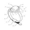
- FIG. 1is a first perspective view of a device according to the invention
- FIG. 2is a side view of the device of FIG. 1 ;
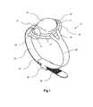
- FIG. 3is a sectional view of the device of FIGS. 1 and 2 ;
- FIG. 4is a sectional view of the connection of the straps of the device of FIGS. 1 to 3 ;
- FIG. 5is a further sectional view of the connection of the straps of the device of FIGS. 1 to 3 , this view being orthogonal to the view of FIG. 4 ;
- FIG. 6is an underside view of the device of FIGS. 1 to 3 ;
- FIG. 7is a further sectional view of the device of FIGS. 1 to 3 ;
- FIG. 8is a front view of the device of FIGS. 1 to 3 ;
- FIG. 9is a plan view of the device of FIGS. 1 to 3 ;
- FIGS. 1 to 9show a device according to the invention, which is generally designated 10 .
- the device 10comprises a pressure-reduction part 20 and a tourniquet 30 .
- the device 10is formed as a single component of an elastically deformable material by injection moulding.
- the device 10is injection moulded with a single shot of thermoplastic elastomer (TPE), with a hardness of approximately 60-70 shore A.
- TPEthermoplastic elastomer
- the pressure-reduction part 20has a length of approximately 5 to 10 cm, and a width of approximately 5 to 6 cm.
- the pressure-reduction part 20comprises an enclosure 24 , having the form of a slightly elongated dome, and a peripheral flange 27 .
- the flange 27has a reduced thickness relative to the wall of the enclosure 24 , and hence is more flexible than the enclosure 24 , and facilitates formation of a seal between the pressure-reduction part 20 and the surface of the patient's skin, in use.
- the flange 27includes an enlarged portion 25 , located at the front of the device, which is intended to be the end of the pressure-reduction part 20 that would be positioned furthest from the patient's heart and close to the site of cannulation or needle insertion.
- the enlarged portion 25comprises a region of the pressure reduction part 20 that has a reduced thickness, and hence greater flexibility, than the remainder of the pressure reduction part 20 .
- the enclosure 24is resiliently deformable, save for a peripheral support portion 21 that joins the enclosure 24 to the flange 27 .
- the enclosureis capable of being resiliently collapsed, at least partially, thereby reducing the volume of the air chamber 23 .
- the enclosure 24is adapted such that manual pressure applied by a user to an upper surface of the enclosure 24 , in the general direction of the patient's skin, will collapse the enclosure 24 .
- the air chamber 23is substantially air-tight, when sealed against the patient's skin.
- the front portion 25acts as a one-way valve 28 , which enables air to exit the air chamber 23 , during collapse of the enclosure 24 , but prevents air entering the air chamber 23 .
- the resilient nature of the enclosure 24causes elastic energy to be stored within the material of the enclosure 24 during its collapse, and following release of manual pressure from the enclosure 24 , atomic forces within that material act to reform the enclosure 24 towards its original configuration.
- atomic forces within that materialact to reform the enclosure 24 towards its original configuration.
- airis prevented from entering the air chamber 23 from the surroundings, and hence the pressure within the air chamber 23 is reduced relative to atmospheric pressure.
- the enclosure 24will continue to reform back to its original shape until the atomic forces causing this reformation are balanced by the difference between the pressure within the air chamber 23 and atmospheric pressure. An area of reduced pressure is therefore formed across the surface of the skin that underlies the air chamber 23 .
- the enclosure 24includes a peripheral support portion 21 that joins the enclosure 24 to the flange 27 .
- the thickness of the material of the support portion 21is greater than that of the flange 27 .
- a groove 44 in the outer surface of the pressure reducing part 20is located between the support portion 21 and remainder of the enclosure 24 , which extends around the circumference of the enclosure 24 .
- the thickness of the device 10 in the region of the groove 44is less than the thickness of the material in the region of the support portion 21 or the remainder of the enclosure 24 .
- the rear end 22 of the pressure-reduction part 20is intended to be the end of the device 10 that would be situated downstream of the intended cannulation or needle insertion site, and hence the end of the device 10 that would point towards the heart of the patient. If pressure is applied to the device 10 , the rear end of the device 10 will act to collapse the vein at that point, and hence facilitate expansion of the vein at the front portion 25 and the site of cannulation or needle insertion.
- the rear end 22 of the pressure-reduction part 20is therefore sufficiently rigid to enable this collapse of the underlying part of the vein on application of pressure by a user.
- the underside of the pressure-reduction part 20is provided with a projecting rib 29 , which projects downwardly from the interior edge of the flange 27 .
- the rib 29is generally horseshoe shaped, such that it projects downwardly from the flange 27 at the rear and sides of the device 10 , but not at the front of the device 10 .
- the rib 29increases the pressure applied to the skin of the patient at the rear end of the pressure-reduction part 20 .
- a further function of the rib 29is to assist in the formation of the seal between the device 10 and the skin of the patient.
- the enlarged portion of the flange 27is intended to be located at the end of the device 10 that would be positioned furthest from the patient's heart and close to the site of cannulation or needle insertion.
- the enlarged portion of the flange 27 at the front of the pressure-reduction part 20has greater flexibility than the rear portion, less pressure is applied by the device 10 to the patient's skin at the front end of the device 10 than at the rear end of the device 10 . This arrangement facilitates expansion of the vein in the region of the cannulation site.
- a tourniquet 30extends from each side of the pressure-reduction part 20 .
- the tourniquet 30comprises two straps 34 , 35 , each strap having one connection end, and one end which extends from the pressure-reduction part 20 .
- a proximal end of each strap 34 , 35extends from the upper surface of the flange 27 of the pressure-reduction 27 part, at a location which is between the front and rear ends of the pressure-reduction part 20 , and the distal ends of the straps 34 , 35 are adapted to connect to each other.
- Each strap 34 , 35includes a resiliently deformable thin strip 32 of plastics material.
- Two connecting tabs 33extend from the proximal end of each strip 32 .
- the tabs 33are of approximately the same thickness and are approximately one-third of the width of the strip 32 .
- the tabs 33lie in substantially the same plane as the end of the strip 32 from which they extend, and are curved in that plane such that they form a U-shape and have a U-shaped gap between them.
- the tabs 33are integrally formed with the upper surface of the flange 27 of the pressure-reduction part 20 .
- the straps 34 , 35join the pressure-reduction part 20 at locations which are slightly closer to the rear of the pressure-reduction part 20 than the front. This means that, when the tourniquet 30 is in place around the limb of a patient, the line of force applied by the tourniquet 30 lies closer to the rear of the pressure-reduction part 20 than the front. This assists the projecting rib 29 in applying pressure to the vein.
- the free ends of the straps 34 , 35are adapted to connect to each other with a ratcheted connection.
- the inward-facing surface of a first strap 34is provided with a series of closely-spaced, transverse recesses 36 .
- the recesses 36are elongate in a direction which is orthogonal to the plane in which the straps 34 , 35 lie.
- the outward-facing surface of the second strap 35is provided with an elongate projection 37 , located within a guide sleeve 38 .
- the projection 37has a profile which corresponds to the profile of the elongate recesses 36 on the first strap 34 .
- the guide sleeve 38has a generally rectangular cross section and is adapted to receive the first strap 34 , such that pushing the first strap 34 into the sleeve causes the projection 37 to enter one of the recesses 36 and be resiliently held therein. This engagement of the projection 37 with a recess 36 acts to hold the straps 34 ; 35 together.
- the projection 37may be obliquely angled relative to the strap 35 , for example, so as to resist unfastening.
- the recesses 36may be angled to correspond to the angle of the projection 37 .
- the projection 37 and guide sleeve 38may be located, for example, in the circled portion, labelled 50 , in FIG. 3 .
- the connecting arrangementmay be offset in this manner for ease of access by a person applying the device and/or fastening the straps.
- the outer wall of the sleeve 38is provided with a cut-out 40 to facilitate disengagement of the projection 37 from the recess 36 .
- the guide sleeve 38comprises two short, retaining tabs which lie in the plane of the wall and in opposition to one another.
- the device 10is placed on a suitably prepared area of a patient's skin over the vein into which the cannula is to be inserted, with the longitudinal axis of the device 10 aligned along the longitudinal axis of the vein.
- the front portion 25 of the pressure-reduction part 20is located close to the intended site of cannulation or needle insertion, and the rear end of the pressure-reduction part 20 is located downstream of the front portion 25 .
- the two straps of the tourniquet 30are then connected using the ratcheting mechanism described above. This holds the device 10 in place, and causes pressure to be applied to the rear end of the device 10 , which acts to collapse the vein and hence facilitate expansion of the vein at the front portion 25 and the site of cannulation or needle insertion.
- applying the tourniquet 30applies a force to the device 10 which is transmitted through the rear end of the pressure-reduction part 20 and the projecting rib 29 in order to collapse of the underlying part of the vein.
- the enclosure 24 of the pressure-reduction part 20is at this stage in its non-deformed configuration, and hence the air chamber 18 is charged with a volume of air. A portion of that volume of air is then removed from the air chamber 23 by the application of thumb or finger pressure to the upper surface of the enclosure 24 , such that the enclosure 24 is collapsed and the volume of the air chamber 23 is reduced. A portion of the air within the air chamber 23 therefore exits the air chamber 18 via the one-way valve 28 . When pressure is released by the user from the enclosure 24 , the enclosure 24 reforms towards its non-deformed configuration and hence the volume of the air chamber 23 increases.
- This actionreduces the pressure within the air chamber 23 relative to atmospheric pressure, and hence reduces the pressure acting upon the area of skin underlying the air chamber 23 of the device 10 .
- a localised region of reduced pressureis therefore formed over the vein, which causes a section of the vein, lying upstream from the rear of the device, to expand. This expanded section of the vein extends a short distance upstream from the front edge of the device.
- the cannulais then inserted into the skin at a location approximately 1 cm upstream from the front end of the device.
- the expanded part 25 of the flange 27has a flap 41 .
- the flap 41does not form part of the seal which is made between the device 10 and the skin of the patient.
- a small gapexists between the flap 41 and the skin.
- the flap 41therefore facilitates removal of the device 10 after use.
Landscapes
- Health & Medical Sciences (AREA)
- Vascular Medicine (AREA)
- Life Sciences & Earth Sciences (AREA)
- General Health & Medical Sciences (AREA)
- Veterinary Medicine (AREA)
- Biomedical Technology (AREA)
- Heart & Thoracic Surgery (AREA)
- Public Health (AREA)
- Engineering & Computer Science (AREA)
- Animal Behavior & Ethology (AREA)
- Surgery (AREA)
- Dermatology (AREA)
- Hematology (AREA)
- Anesthesiology (AREA)
- Reproductive Health (AREA)
- Nuclear Medicine, Radiotherapy & Molecular Imaging (AREA)
- Medical Informatics (AREA)
- Molecular Biology (AREA)
- Surgical Instruments (AREA)
- Infusion, Injection, And Reservoir Apparatuses (AREA)
Abstract
Description
Claims (13)
Applications Claiming Priority (3)
| Application Number | Priority Date | Filing Date | Title |
|---|---|---|---|
| GB1112933.5 | 2011-07-27 | ||
| GBGB1112933.5AGB201112933D0 (en) | 2011-07-27 | 2011-07-27 | Improvements relating to needle insertion or cannulation |
| PCT/GB2012/051820WO2013014468A1 (en) | 2011-07-27 | 2012-07-27 | Device for facilitating intravenous needle insertion or cannulation with vacuum generation means and tourniquet fastener |
Publications (2)
| Publication Number | Publication Date |
|---|---|
| US20140188077A1 US20140188077A1 (en) | 2014-07-03 |
| US10293116B2true US10293116B2 (en) | 2019-05-21 |
Family
ID=44676270
Family Applications (1)
| Application Number | Title | Priority Date | Filing Date |
|---|---|---|---|
| US14/235,017Active2033-06-27US10293116B2 (en) | 2011-07-27 | 2012-07-27 | Device for facilitating intravenous needle insertion or cannulation with vacuum generation means and tourniquet fastener |
Country Status (7)
| Country | Link |
|---|---|
| US (1) | US10293116B2 (en) |
| EP (1) | EP2736568B1 (en) |
| JP (1) | JP6147742B2 (en) |
| KR (1) | KR20140079764A (en) |
| CN (1) | CN103906541B (en) |
| GB (1) | GB201112933D0 (en) |
| WO (1) | WO2013014468A1 (en) |
Families Citing this family (9)
| Publication number | Priority date | Publication date | Assignee | Title |
|---|---|---|---|---|
| GB201112933D0 (en) | 2011-07-27 | 2011-09-14 | Olberon Ltd | Improvements relating to needle insertion or cannulation |
| CN105960209B (en)* | 2013-11-18 | 2020-02-21 | 欧伯伦医疗创新公司 | Pulse pressing belt |
| US10092297B2 (en) | 2014-04-25 | 2018-10-09 | Medtronic Vascular, Inc. | Tissue compression device with fixation and tension straps |
| CN105983152B (en)* | 2014-11-07 | 2019-09-10 | 滨州医学院 | Bell-type scalp infusion vacuum needle inserting device |
| US9803913B2 (en)* | 2015-04-02 | 2017-10-31 | Whirlpool Corporation | Tiered storage system for refrigerator door |
| CN109640842A (en)* | 2016-08-17 | 2019-04-16 | 波士顿科学有限公司 | Sleeve pipe with integrated closing device |
| CN108338818A (en)* | 2018-04-24 | 2018-07-31 | 苏州诺来宁医疗科技有限公司 | A kind of four limbs pressurizing unit of medical application |
| SG11202106928PA (en)* | 2018-12-25 | 2021-07-29 | Univ Hirosaki | Medicine administering device and medicine administering system |
| KR102434193B1 (en) | 2020-04-03 | 2022-08-19 | 전북대학교산학협력단 | Pressure device of arm |
Citations (61)
| Publication number | Priority date | Publication date | Assignee | Title |
|---|---|---|---|---|
| FR542914A (en) | 1921-10-29 | 1922-08-24 | Injection syringe | |
| US1447967A (en) | 1922-10-04 | 1923-03-13 | Davis Frank Rutledge | Tourniquet |
| US1824516A (en) | 1930-05-05 | 1931-09-22 | Raymond E Tyvand | Vein retainer |
| US2103174A (en) | 1936-01-27 | 1937-12-21 | Posada Victor Manuel | Surgical instrument |
| US2198666A (en) | 1936-09-30 | 1940-04-30 | Lakeland Foundation | Syringe |
| GB553728A (en) | 1942-04-21 | 1943-06-02 | Louis Van Lier | Improvements in illuminable specula retractors and like surgical instruments |
| US2457464A (en) | 1946-11-08 | 1948-12-28 | Joseph Grose | Surgical instrument |
| US2839062A (en) | 1953-06-23 | 1958-06-17 | Kidde Mfg Co Inc | Pneumatic tourniquet cuff |
| US3324854A (en) | 1964-04-23 | 1967-06-13 | Harry Swartz | Apparatus for facilitating the insertion of a hypodermic syringe needle |
| US3996646A (en) | 1974-08-05 | 1976-12-14 | Panduit Corporation | Cable tie and method for making same |
| US4299219A (en) | 1979-12-17 | 1981-11-10 | Norris Jr George P | Intravenous needle insertion device |
| US4314568A (en)* | 1980-01-11 | 1982-02-09 | Baxter Travenol Laboratories, Inc. | Vascular stabilizer |
| US4324568A (en) | 1980-08-11 | 1982-04-13 | Flanders Filters, Inc. | Method and apparatus for the leak testing of filters |
| US4332248A (en) | 1980-07-31 | 1982-06-01 | Devitis Thomas N | Medical apparatus |
| US4393870A (en) | 1974-11-19 | 1983-07-19 | Wolfgang Wagner | Suction injector |
| US4576168A (en) | 1983-01-05 | 1986-03-18 | Jalowayski Alfredo A | Nasal dilator |
| US4586924A (en) | 1984-07-09 | 1986-05-06 | Lanning Charles T | Vein constrictor and immobilizer |
| US4619248A (en) | 1984-08-22 | 1986-10-28 | Walsh David J | Light attachment for speculum |
| US4638792A (en) | 1979-12-20 | 1987-01-27 | Burgin Kermit H | Adjustable speculum with incorporated lighting system |
| US4664651A (en) | 1985-03-01 | 1987-05-12 | The Procter & Gamble Company | Subatmospheric method and apparatus for expanding blood vessels to facilitate puncture with a cannula |
| FR2612401A1 (en) | 1987-03-16 | 1988-09-23 | Denance Raymond | Stabiliser end-piece for hypodermic needle comprising a means acting as a prop for regulating the penetration as a function of attack of the needle in the skin |
| US4834802A (en)* | 1987-08-06 | 1989-05-30 | Prier David A | Heat generating tourniquet for venipuncture applications |
| FR2698778A1 (en) | 1992-12-08 | 1994-06-10 | Mersch Patrick | Two-part speculum for inspection of human or animal body cavity - comprises hollow guide tube with longitudinal slot, including conical inner portion receiving spacer tube to cause radial expansion |
| US5320607A (en) | 1992-02-13 | 1994-06-14 | Kabushiki Kaisya Advance | Simple blood sampling device |
| US5364362A (en) | 1992-02-19 | 1994-11-15 | Henke-Sass, Wolf Gmbh | Front syringe attachment for hypodermic syringes for subcutaneous injection in veterinary medicine |
| WO1995007722A1 (en) | 1993-09-14 | 1995-03-23 | North Shore Laboratories Pty. Ltd. | Injection device |
| US5415647A (en) | 1994-09-15 | 1995-05-16 | Pisarik; Paul | Flexible, multi-grooved vascular immobilizer |
| US5478315A (en) | 1994-08-08 | 1995-12-26 | Brothers Family Investments, L.C. | Local anesthetic injection system |
| GB2301035A (en) | 1994-05-30 | 1996-11-27 | Carlos Maria Baron | Non-resusable syringe |
| US5647850A (en) | 1995-03-15 | 1997-07-15 | Allen; William Ray | Method and apparatus for vein location |
| US5680872A (en) | 1993-08-10 | 1997-10-28 | Kabushiki Kaisya Advance | Simple blood-collecting device |
| DE19620314A1 (en) | 1996-05-21 | 1997-11-27 | Simon Pal | Puncture appliance for blood vessels |
| RU2109525C1 (en) | 1993-04-28 | 1998-04-27 | Акционерное общество по разработке и внедрению медицинских приборов, методов и средств психодиагностики "Медтест" | Apparatus for examining ear and nose cavity |
| WO1998025512A1 (en) | 1996-12-13 | 1998-06-18 | Solution S.A.S. | Light and handle device for vaginal speculum |
| US5984890A (en) | 1996-09-27 | 1999-11-16 | American Home Products Corporation | Medical device for the placement of solid materials |
| WO2001034019A1 (en) | 1999-11-11 | 2001-05-17 | Karl Storz Gmbh & Co. Kg | Medical instrument that can be spread, especially a laryngoscope |
| US6254580B1 (en) | 1995-04-27 | 2001-07-03 | Pal Svedman | Suction blister sampling |
| US20010044606A1 (en) | 1998-04-15 | 2001-11-22 | Inkpen Thomas Randall | Needle injection-facilitating device |
| US6394984B1 (en) | 1999-10-28 | 2002-05-28 | Frank C Hill | Syringe |
| WO2002100457A2 (en) | 2001-04-20 | 2002-12-19 | Medtronic Minimed, Inc. | Insertion device for an insertion set and method of using the same |
| US20040199140A1 (en) | 2003-04-03 | 2004-10-07 | Rue Matthew L. | Implanting device and method of using same |
| WO2006007629A1 (en) | 2004-07-23 | 2006-01-26 | Afra Design Pty Limited | Vertical cannula |
| US20060058839A1 (en) | 2004-09-14 | 2006-03-16 | Madison Michael T | Blood vessel locating and stabilizing device and method of using same |
| WO2006054280A2 (en) | 2004-11-18 | 2006-05-26 | Nanopass Technologies Ltd. | System and method for delivering fluid into flexible biological barrier |
| US20060211987A1 (en)* | 2005-03-18 | 2006-09-21 | Williams Arthur M | Vein stabilizer devices and methods of using same |
| US20070191881A1 (en) | 2004-03-29 | 2007-08-16 | Shai Amisar | Tourniquet |
| CN200951117Y (en) | 2006-09-26 | 2007-09-26 | 卢学春 | Device for filling blood vessel |
| GB2438518A (en) | 2006-05-26 | 2007-11-28 | Olberon Ltd | A device that enlarges a vein using a vacuum ready for insertion of a needle or cannula |
| EP1944051A1 (en) | 2005-10-31 | 2008-07-16 | Terumo Kabushiki Kaisha | Puncture device, dosing device and puncture method |
| US20100049241A1 (en) | 2008-08-19 | 2010-02-25 | Persson James L | Ratchet hook tourniquet |
| WO2010056280A1 (en) | 2008-11-12 | 2010-05-20 | Semler Technologies, Inc. | Vascular compression apparatus, pad and method of use |
| US20100137799A1 (en) | 2007-04-27 | 2010-06-03 | Terumo Kabushiki Kaisha | Piercing tool |
| CN201814620U (en) | 2010-10-25 | 2011-05-04 | 储开建 | Releasable self-locking type hepatic portal blocking belt |
| WO2011090429A1 (en) | 2010-01-19 | 2011-07-28 | St Jude Medical Systems Ab | Compression unit and a radial artery compression system |
| US20120265240A1 (en) | 2011-04-15 | 2012-10-18 | CellAegis Devices Inc. | System for performing remote ischemic conditioning |
| US20130014350A1 (en) | 2011-07-15 | 2013-01-17 | Jabaa Innovations Limited | Multi-purpose tie strip and method of tying items together |
| WO2013014468A1 (en) | 2011-07-27 | 2013-01-31 | Olberon Limited | Device for facilitating intravenous needle insertion or cannulation with vacuum generation means and tourniquet fastener |
| US20140336697A1 (en) | 2011-12-07 | 2014-11-13 | J. Hewitt Inc. | Simple automatic electronic tourniquet |
| US20150201948A1 (en) | 2012-08-13 | 2015-07-23 | Mor Research Application Ltd. | Radial artery device |
| US20160022269A1 (en) | 2013-03-15 | 2016-01-28 | CellAegis Devices Inc. | Gas powered system for performing remote ischemic conditioning |
| US20160296239A1 (en) | 2013-11-18 | 2016-10-13 | Olberon Medical Innovation Sas | Tourniquet |
- 2011
- 2011-07-27GBGBGB1112933.5Apatent/GB201112933D0/ennot_activeCeased
- 2012
- 2012-07-27USUS14/235,017patent/US10293116B2/enactiveActive
- 2012-07-27EPEP12753196.0Apatent/EP2736568B1/enactiveActive
- 2012-07-27WOPCT/GB2012/051820patent/WO2013014468A1/enactiveApplication Filing
- 2012-07-27JPJP2014522161Apatent/JP6147742B2/enactiveActive
- 2012-07-27KRKR1020147005348Apatent/KR20140079764A/ennot_activeWithdrawn
- 2012-07-27CNCN201280037637.7Apatent/CN103906541B/enactiveActive
Patent Citations (64)
| Publication number | Priority date | Publication date | Assignee | Title |
|---|---|---|---|---|
| FR542914A (en) | 1921-10-29 | 1922-08-24 | Injection syringe | |
| US1447967A (en) | 1922-10-04 | 1923-03-13 | Davis Frank Rutledge | Tourniquet |
| US1824516A (en) | 1930-05-05 | 1931-09-22 | Raymond E Tyvand | Vein retainer |
| US2103174A (en) | 1936-01-27 | 1937-12-21 | Posada Victor Manuel | Surgical instrument |
| US2198666A (en) | 1936-09-30 | 1940-04-30 | Lakeland Foundation | Syringe |
| GB553728A (en) | 1942-04-21 | 1943-06-02 | Louis Van Lier | Improvements in illuminable specula retractors and like surgical instruments |
| US2457464A (en) | 1946-11-08 | 1948-12-28 | Joseph Grose | Surgical instrument |
| US2839062A (en) | 1953-06-23 | 1958-06-17 | Kidde Mfg Co Inc | Pneumatic tourniquet cuff |
| US3324854A (en) | 1964-04-23 | 1967-06-13 | Harry Swartz | Apparatus for facilitating the insertion of a hypodermic syringe needle |
| US3996646A (en) | 1974-08-05 | 1976-12-14 | Panduit Corporation | Cable tie and method for making same |
| US4393870A (en) | 1974-11-19 | 1983-07-19 | Wolfgang Wagner | Suction injector |
| US4299219A (en) | 1979-12-17 | 1981-11-10 | Norris Jr George P | Intravenous needle insertion device |
| US4638792A (en) | 1979-12-20 | 1987-01-27 | Burgin Kermit H | Adjustable speculum with incorporated lighting system |
| US4314568A (en)* | 1980-01-11 | 1982-02-09 | Baxter Travenol Laboratories, Inc. | Vascular stabilizer |
| US4332248A (en) | 1980-07-31 | 1982-06-01 | Devitis Thomas N | Medical apparatus |
| US4324568A (en) | 1980-08-11 | 1982-04-13 | Flanders Filters, Inc. | Method and apparatus for the leak testing of filters |
| US4576168A (en) | 1983-01-05 | 1986-03-18 | Jalowayski Alfredo A | Nasal dilator |
| US4586924A (en) | 1984-07-09 | 1986-05-06 | Lanning Charles T | Vein constrictor and immobilizer |
| US4619248A (en) | 1984-08-22 | 1986-10-28 | Walsh David J | Light attachment for speculum |
| US4664651A (en) | 1985-03-01 | 1987-05-12 | The Procter & Gamble Company | Subatmospheric method and apparatus for expanding blood vessels to facilitate puncture with a cannula |
| FR2612401A1 (en) | 1987-03-16 | 1988-09-23 | Denance Raymond | Stabiliser end-piece for hypodermic needle comprising a means acting as a prop for regulating the penetration as a function of attack of the needle in the skin |
| US4834802A (en)* | 1987-08-06 | 1989-05-30 | Prier David A | Heat generating tourniquet for venipuncture applications |
| US5320607A (en) | 1992-02-13 | 1994-06-14 | Kabushiki Kaisya Advance | Simple blood sampling device |
| US5364362A (en) | 1992-02-19 | 1994-11-15 | Henke-Sass, Wolf Gmbh | Front syringe attachment for hypodermic syringes for subcutaneous injection in veterinary medicine |
| FR2698778A1 (en) | 1992-12-08 | 1994-06-10 | Mersch Patrick | Two-part speculum for inspection of human or animal body cavity - comprises hollow guide tube with longitudinal slot, including conical inner portion receiving spacer tube to cause radial expansion |
| RU2109525C1 (en) | 1993-04-28 | 1998-04-27 | Акционерное общество по разработке и внедрению медицинских приборов, методов и средств психодиагностики "Медтест" | Apparatus for examining ear and nose cavity |
| US5680872A (en) | 1993-08-10 | 1997-10-28 | Kabushiki Kaisya Advance | Simple blood-collecting device |
| WO1995007722A1 (en) | 1993-09-14 | 1995-03-23 | North Shore Laboratories Pty. Ltd. | Injection device |
| GB2301035A (en) | 1994-05-30 | 1996-11-27 | Carlos Maria Baron | Non-resusable syringe |
| US5478315A (en) | 1994-08-08 | 1995-12-26 | Brothers Family Investments, L.C. | Local anesthetic injection system |
| US5415647A (en) | 1994-09-15 | 1995-05-16 | Pisarik; Paul | Flexible, multi-grooved vascular immobilizer |
| US5647850A (en) | 1995-03-15 | 1997-07-15 | Allen; William Ray | Method and apparatus for vein location |
| US6254580B1 (en) | 1995-04-27 | 2001-07-03 | Pal Svedman | Suction blister sampling |
| DE19620314A1 (en) | 1996-05-21 | 1997-11-27 | Simon Pal | Puncture appliance for blood vessels |
| US5984890A (en) | 1996-09-27 | 1999-11-16 | American Home Products Corporation | Medical device for the placement of solid materials |
| WO1998025512A1 (en) | 1996-12-13 | 1998-06-18 | Solution S.A.S. | Light and handle device for vaginal speculum |
| US20010044606A1 (en) | 1998-04-15 | 2001-11-22 | Inkpen Thomas Randall | Needle injection-facilitating device |
| US6394984B1 (en) | 1999-10-28 | 2002-05-28 | Frank C Hill | Syringe |
| WO2001034019A1 (en) | 1999-11-11 | 2001-05-17 | Karl Storz Gmbh & Co. Kg | Medical instrument that can be spread, especially a laryngoscope |
| WO2002100457A2 (en) | 2001-04-20 | 2002-12-19 | Medtronic Minimed, Inc. | Insertion device for an insertion set and method of using the same |
| US20040199140A1 (en) | 2003-04-03 | 2004-10-07 | Rue Matthew L. | Implanting device and method of using same |
| US20070191881A1 (en) | 2004-03-29 | 2007-08-16 | Shai Amisar | Tourniquet |
| WO2006007629A1 (en) | 2004-07-23 | 2006-01-26 | Afra Design Pty Limited | Vertical cannula |
| US20060058839A1 (en) | 2004-09-14 | 2006-03-16 | Madison Michael T | Blood vessel locating and stabilizing device and method of using same |
| WO2006054280A2 (en) | 2004-11-18 | 2006-05-26 | Nanopass Technologies Ltd. | System and method for delivering fluid into flexible biological barrier |
| US20060211987A1 (en)* | 2005-03-18 | 2006-09-21 | Williams Arthur M | Vein stabilizer devices and methods of using same |
| EP1944051A1 (en) | 2005-10-31 | 2008-07-16 | Terumo Kabushiki Kaisha | Puncture device, dosing device and puncture method |
| GB2438518A (en) | 2006-05-26 | 2007-11-28 | Olberon Ltd | A device that enlarges a vein using a vacuum ready for insertion of a needle or cannula |
| US8795229B2 (en)* | 2006-05-26 | 2014-08-05 | Olberon Medical Innovation Sas | Intravenous needle insertion or cannulation |
| CN200951117Y (en) | 2006-09-26 | 2007-09-26 | 卢学春 | Device for filling blood vessel |
| US20100137799A1 (en) | 2007-04-27 | 2010-06-03 | Terumo Kabushiki Kaisha | Piercing tool |
| US7988667B2 (en) | 2007-04-27 | 2011-08-02 | Terumo Kabushiki Kaisha | Piercing tool |
| US20100049241A1 (en) | 2008-08-19 | 2010-02-25 | Persson James L | Ratchet hook tourniquet |
| US20120053617A1 (en) | 2008-11-12 | 2012-03-01 | Semler Technologies, Inc | Vascular Compression Apparatus, Pad and Method Of Use |
| WO2010056280A1 (en) | 2008-11-12 | 2010-05-20 | Semler Technologies, Inc. | Vascular compression apparatus, pad and method of use |
| WO2011090429A1 (en) | 2010-01-19 | 2011-07-28 | St Jude Medical Systems Ab | Compression unit and a radial artery compression system |
| CN201814620U (en) | 2010-10-25 | 2011-05-04 | 储开建 | Releasable self-locking type hepatic portal blocking belt |
| US20120265240A1 (en) | 2011-04-15 | 2012-10-18 | CellAegis Devices Inc. | System for performing remote ischemic conditioning |
| US20130014350A1 (en) | 2011-07-15 | 2013-01-17 | Jabaa Innovations Limited | Multi-purpose tie strip and method of tying items together |
| WO2013014468A1 (en) | 2011-07-27 | 2013-01-31 | Olberon Limited | Device for facilitating intravenous needle insertion or cannulation with vacuum generation means and tourniquet fastener |
| US20140336697A1 (en) | 2011-12-07 | 2014-11-13 | J. Hewitt Inc. | Simple automatic electronic tourniquet |
| US20150201948A1 (en) | 2012-08-13 | 2015-07-23 | Mor Research Application Ltd. | Radial artery device |
| US20160022269A1 (en) | 2013-03-15 | 2016-01-28 | CellAegis Devices Inc. | Gas powered system for performing remote ischemic conditioning |
| US20160296239A1 (en) | 2013-11-18 | 2016-10-13 | Olberon Medical Innovation Sas | Tourniquet |
Non-Patent Citations (2)
| Title |
|---|
| International Preliminary Report on Patentability for PCT/GB2012/051820 dated Jan. 28, 2014 in 8 pages. |
| International Search Report and Written Opinion in PCT/GB2012/051820 dated Nov. 5, 2012. |
Also Published As
| Publication number | Publication date |
|---|---|
| EP2736568A1 (en) | 2014-06-04 |
| JP6147742B2 (en) | 2017-06-14 |
| JP2014528742A (en) | 2014-10-30 |
| US20140188077A1 (en) | 2014-07-03 |
| WO2013014468A1 (en) | 2013-01-31 |
| CN103906541A (en) | 2014-07-02 |
| EP2736568B1 (en) | 2017-06-28 |
| CN103906541B (en) | 2017-10-20 |
| GB201112933D0 (en) | 2011-09-14 |
| KR20140079764A (en) | 2014-06-27 |
Similar Documents
| Publication | Publication Date | Title |
|---|---|---|
| US10293116B2 (en) | Device for facilitating intravenous needle insertion or cannulation with vacuum generation means and tourniquet fastener | |
| US20230049545A1 (en) | Systems and methods for anchoring medical devices | |
| RU2435614C2 (en) | Improvements concerned introduction of intravenous needle or cannulation | |
| US11432824B2 (en) | Radial and ulnar compression band | |
| JP4871484B2 (en) | Low profile infusion set | |
| CN102231966B (en) | Systems and methods for mechanical closure of wounds | |
| US20200030578A1 (en) | Stabilizing Device Having A Snap Clamp | |
| EP1185195B1 (en) | Tissue retractor retention band | |
| US20180185032A1 (en) | Hemostatic device | |
| US20100179483A1 (en) | Medical article securement device | |
| US20170273693A1 (en) | Radial compression band | |
| KR20110131297A (en) | Gastrosurgery tube extension | |
| US20030149405A1 (en) | Drug delivery needle device | |
| US10946174B2 (en) | Tube securing device | |
| US20190314037A1 (en) | Tourniquet | |
| HK1194015A (en) | Device for facilitating intravenous needle insertion or cannulation with vacuum generation means and tourniquet fastener | |
| HK1194015B (en) | Device for facilitating intravenous needle insertion or cannulation with vacuum generation means and tourniquet fastener | |
| EP4473920A1 (en) | Hemostasis device |
Legal Events
| Date | Code | Title | Description |
|---|---|---|---|
| AS | Assignment | Owner name:OLBERON LIMITED, UNITED KINGDOM Free format text:ASSIGNMENT OF ASSIGNORS INTEREST;ASSIGNORS:BAKHTYARI-NEJAD-ESFAHANI, ARASH;ALTRIP, JOHN LAWRENCE;REEL/FRAME:032061/0038 Effective date:20111218 | |
| AS | Assignment | Owner name:OLBERON MEDICAL INNOVATION SAS, FRANCE Free format text:ASSIGNMENT OF ASSIGNORS INTEREST;ASSIGNOR:OLBERON LIMITED;REEL/FRAME:032078/0577 Effective date:20120906 | |
| STPP | Information on status: patent application and granting procedure in general | Free format text:NOTICE OF ALLOWANCE MAILED -- APPLICATION RECEIVED IN OFFICE OF PUBLICATIONS | |
| STPP | Information on status: patent application and granting procedure in general | Free format text:PUBLICATIONS -- ISSUE FEE PAYMENT VERIFIED | |
| STCF | Information on status: patent grant | Free format text:PATENTED CASE | |
| AS | Assignment | Owner name:ALTRIP, JOHN LAWRENCE, UNITED KINGDOM Free format text:ASSIGNMENT OF ASSIGNORS INTEREST;ASSIGNOR:OLBERON MEDICAL INNOVATION SAS;REEL/FRAME:054201/0347 Effective date:20201028 | |
| AS | Assignment | Owner name:OLBERON LIMITED, UNITED KINGDOM Free format text:ASSIGNMENT OF ASSIGNORS INTEREST;ASSIGNOR:ALTRIP, JOHN LAWRENCE;REEL/FRAME:054261/0264 Effective date:20201028 | |
| MAFP | Maintenance fee payment | Free format text:PAYMENT OF MAINTENANCE FEE, 4TH YR, SMALL ENTITY (ORIGINAL EVENT CODE: M2551); ENTITY STATUS OF PATENT OWNER: SMALL ENTITY Year of fee payment:4 |