US10292881B2 - Dynamic apnea therapy surface - Google Patents
Dynamic apnea therapy surfaceDownload PDFInfo
- Publication number
- US10292881B2 US10292881B2US14/848,513US201514848513AUS10292881B2US 10292881 B2US10292881 B2US 10292881B2US 201514848513 AUS201514848513 AUS 201514848513AUS 10292881 B2US10292881 B2US 10292881B2
- Authority
- US
- United States
- Prior art keywords
- support
- person
- lateral rotation
- dynamic
- supine position
- Prior art date
- Legal status (The legal status is an assumption and is not a legal conclusion. Google has not performed a legal analysis and makes no representation as to the accuracy of the status listed.)
- Active, expires
Links
Images


Classifications
- A—HUMAN NECESSITIES
- A61—MEDICAL OR VETERINARY SCIENCE; HYGIENE
- A61G—TRANSPORT, PERSONAL CONVEYANCES, OR ACCOMMODATION SPECIALLY ADAPTED FOR PATIENTS OR DISABLED PERSONS; OPERATING TABLES OR CHAIRS; CHAIRS FOR DENTISTRY; FUNERAL DEVICES
- A61G7/00—Beds specially adapted for nursing; Devices for lifting patients or disabled persons
- A61G7/002—Beds specially adapted for nursing; Devices for lifting patients or disabled persons having adjustable mattress frame
- A61G7/015—Beds specially adapted for nursing; Devices for lifting patients or disabled persons having adjustable mattress frame divided into different adjustable sections, e.g. for Gatch position
- A—HUMAN NECESSITIES
- A61—MEDICAL OR VETERINARY SCIENCE; HYGIENE
- A61B—DIAGNOSIS; SURGERY; IDENTIFICATION
- A61B5/00—Measuring for diagnostic purposes; Identification of persons
- A61B5/48—Other medical applications
- A61B5/4806—Sleep evaluation
- A61B5/4809—Sleep detection, i.e. determining whether a subject is asleep or not
- A—HUMAN NECESSITIES
- A61—MEDICAL OR VETERINARY SCIENCE; HYGIENE
- A61B—DIAGNOSIS; SURGERY; IDENTIFICATION
- A61B5/00—Measuring for diagnostic purposes; Identification of persons
- A61B5/48—Other medical applications
- A61B5/4806—Sleep evaluation
- A61B5/4812—Detecting sleep stages or cycles
- A—HUMAN NECESSITIES
- A61—MEDICAL OR VETERINARY SCIENCE; HYGIENE
- A61B—DIAGNOSIS; SURGERY; IDENTIFICATION
- A61B5/00—Measuring for diagnostic purposes; Identification of persons
- A61B5/48—Other medical applications
- A61B5/4806—Sleep evaluation
- A61B5/4818—Sleep apnoea
- A—HUMAN NECESSITIES
- A61—MEDICAL OR VETERINARY SCIENCE; HYGIENE
- A61B—DIAGNOSIS; SURGERY; IDENTIFICATION
- A61B5/00—Measuring for diagnostic purposes; Identification of persons
- A61B5/68—Arrangements of detecting, measuring or recording means, e.g. sensors, in relation to patient
- A61B5/6887—Arrangements of detecting, measuring or recording means, e.g. sensors, in relation to patient mounted on external non-worn devices, e.g. non-medical devices
- A61B5/6892—Mats
- A—HUMAN NECESSITIES
- A61—MEDICAL OR VETERINARY SCIENCE; HYGIENE
- A61G—TRANSPORT, PERSONAL CONVEYANCES, OR ACCOMMODATION SPECIALLY ADAPTED FOR PATIENTS OR DISABLED PERSONS; OPERATING TABLES OR CHAIRS; CHAIRS FOR DENTISTRY; FUNERAL DEVICES
- A61G13/00—Operating tables; Auxiliary appliances therefor
- A61G13/02—Adjustable operating tables; Controls therefor
- A61G13/08—Adjustable operating tables; Controls therefor the table being divided into different adjustable sections
- A—HUMAN NECESSITIES
- A61—MEDICAL OR VETERINARY SCIENCE; HYGIENE
- A61G—TRANSPORT, PERSONAL CONVEYANCES, OR ACCOMMODATION SPECIALLY ADAPTED FOR PATIENTS OR DISABLED PERSONS; OPERATING TABLES OR CHAIRS; CHAIRS FOR DENTISTRY; FUNERAL DEVICES
- A61G7/00—Beds specially adapted for nursing; Devices for lifting patients or disabled persons
- A61G7/001—Beds specially adapted for nursing; Devices for lifting patients or disabled persons with means for turning-over the patient
- A—HUMAN NECESSITIES
- A61—MEDICAL OR VETERINARY SCIENCE; HYGIENE
- A61G—TRANSPORT, PERSONAL CONVEYANCES, OR ACCOMMODATION SPECIALLY ADAPTED FOR PATIENTS OR DISABLED PERSONS; OPERATING TABLES OR CHAIRS; CHAIRS FOR DENTISTRY; FUNERAL DEVICES
- A61G7/00—Beds specially adapted for nursing; Devices for lifting patients or disabled persons
- A61G7/002—Beds specially adapted for nursing; Devices for lifting patients or disabled persons having adjustable mattress frame
- A61G7/018—Control or drive mechanisms
- A—HUMAN NECESSITIES
- A61—MEDICAL OR VETERINARY SCIENCE; HYGIENE
- A61G—TRANSPORT, PERSONAL CONVEYANCES, OR ACCOMMODATION SPECIALLY ADAPTED FOR PATIENTS OR DISABLED PERSONS; OPERATING TABLES OR CHAIRS; CHAIRS FOR DENTISTRY; FUNERAL DEVICES
- A61G13/00—Operating tables; Auxiliary appliances therefor
- A61G13/02—Adjustable operating tables; Controls therefor
- A61G13/04—Adjustable operating tables; Controls therefor tiltable around transverse or longitudinal axis
- A—HUMAN NECESSITIES
- A61—MEDICAL OR VETERINARY SCIENCE; HYGIENE
- A61G—TRANSPORT, PERSONAL CONVEYANCES, OR ACCOMMODATION SPECIALLY ADAPTED FOR PATIENTS OR DISABLED PERSONS; OPERATING TABLES OR CHAIRS; CHAIRS FOR DENTISTRY; FUNERAL DEVICES
- A61G7/00—Beds specially adapted for nursing; Devices for lifting patients or disabled persons
- A61G7/002—Beds specially adapted for nursing; Devices for lifting patients or disabled persons having adjustable mattress frame
- A61G7/008—Beds specially adapted for nursing; Devices for lifting patients or disabled persons having adjustable mattress frame tiltable around longitudinal axis, e.g. for rolling
- A—HUMAN NECESSITIES
- A61—MEDICAL OR VETERINARY SCIENCE; HYGIENE
- A61G—TRANSPORT, PERSONAL CONVEYANCES, OR ACCOMMODATION SPECIALLY ADAPTED FOR PATIENTS OR DISABLED PERSONS; OPERATING TABLES OR CHAIRS; CHAIRS FOR DENTISTRY; FUNERAL DEVICES
- A61G7/00—Beds specially adapted for nursing; Devices for lifting patients or disabled persons
- A61G7/05—Parts, details or accessories of beds
- A61G7/057—Arrangements for preventing bed-sores or for supporting patients with burns, e.g. mattresses specially adapted therefor
- A61G7/05769—Arrangements for preventing bed-sores or for supporting patients with burns, e.g. mattresses specially adapted therefor with inflatable chambers
- A61G7/05776—Arrangements for preventing bed-sores or for supporting patients with burns, e.g. mattresses specially adapted therefor with inflatable chambers with at least two groups of alternately inflated chambers
- A—HUMAN NECESSITIES
- A61—MEDICAL OR VETERINARY SCIENCE; HYGIENE
- A61M—DEVICES FOR INTRODUCING MEDIA INTO, OR ONTO, THE BODY; DEVICES FOR TRANSDUCING BODY MEDIA OR FOR TAKING MEDIA FROM THE BODY; DEVICES FOR PRODUCING OR ENDING SLEEP OR STUPOR
- A61M21/00—Other devices or methods to cause a change in the state of consciousness; Devices for producing or ending sleep by mechanical, optical, or acoustical means, e.g. for hypnosis
- A61M21/02—Other devices or methods to cause a change in the state of consciousness; Devices for producing or ending sleep by mechanical, optical, or acoustical means, e.g. for hypnosis for inducing sleep or relaxation, e.g. by direct nerve stimulation, hypnosis, analgesia
Definitions
- This disclosurerelates generally to dynamic person support surfaces, devices, systems, and methods configured to provide apnea therapy and/or therapy for other disorders.
- a dynamic person support systemmay include a person support surface that may have a pair of laterally spaced support segments. At least one of the support segments may include a lateral rotation apparatus.
- the lateral rotation apparatusmay have a plurality of independently rotatable longitudinally arranged support planes and a lateral rotation actuator that may be operably coupled to one or more of the support planes.
- a first occupant sensormay be coupled to the support segment comprising the lateral rotation apparatus.
- a second occupant sensormay be coupled to the other support segment.
- a control unitmay include a processor and a non-transitory machine readable storage medium that may have a dynamic therapy routine.
- the dynamic therapy routinemay include instructions executable by the processor to cause the control unit to control the operation of the lateral rotation apparatus by: with the first occupant sensor, detecting a state of a first human subject on the support segment comprising the lateral rotation apparatus; with the second occupant sensor, detecting a state of a second human subject on the other support segment; and in response to the detected state of the first human subject and the detected state of the second human subject, controlling the lateral rotation actuator of the lateral rotation apparatus.
- the lateral rotation actuatormay include an electromechanical device configured to drive lateral rotation of the independently rotatable support planes.
- the lateral rotation actuatormay include a plurality of inflatable bladders supporting the independently rotatable support planes and an air supply operably coupled to the inflatable bladders.
- the second occupant sensormay be configured to detect a sleep state of the second human subject and the control unit may be configured to delay operation of the lateral rotation actuator until the second human subject is detected as being asleep.
- the first occupant sensormay be configured to detect a position of the first human subject relative to the support segment comprising the lateral rotation apparatus and the control unit may be configured to delay operation of the lateral rotation actuator if the detected position of the first human subject is not substantially on the support segment comprising the lateral rotation apparatus.
- the control unitmay be configured to control the lateral rotation apparatus based on a combination of criteria including at least one criterion relating to the first human subject and at least one criterion relating to the second human subject.
- the control unitmaybe configured to delay operation of the actuator until both the first human subject and the second human subject are detected as being asleep.
- a dynamic person support systemmay include a person support surface and a lateral rotation apparatus that may be coupled to the person support surface.
- the lateral rotation apparatusmay include a plurality of independently rotatable longitudinally arranged support planes and a lateral rotation actuator operably coupled to one or more of the support planes.
- a control unitmay include a processor and a non-transitory machine readable storage medium that may have a dynamic therapy routine.
- the dynamic therapy routinemay include instructions that may be executable by the processor to cause the control unit to control the operation of the lateral rotation apparatus by: determining a maximum supine position duration; monitoring the actual supine position duration of a human subject positioned on the person support apparatus; and controlling the lateral rotation actuator to maintain the actual supine position duration below the maximum supine position duration.
- the lateral rotation actuatormay include an electromechanical device configured to drive lateral rotation of the independently rotatable support planes.
- the lateral rotation actuatormay include a plurality of inflatable bladders supporting the independently rotatable support planes and an air supply operably coupled to the inflatable bladders.
- the control unitmay be configured to compute the maximum supine position duration as a function of an apnea-hypopnea index (AHI) value of the monitored human subject.
- the control unitmay be configured to compute the maximum supine position duration based on a first apnea-hypopnea index (AHI) value and a second AHI value.
- AHIapnea-hypopnea index
- the first AHI valuemay be determined while the human subject is in a supine position and the second AHI value may be determined while the human subject is in a non-supine position.
- the dynamic person support systemmay include a sensor in communication with the control unit.
- the control unitmay be configured to receive a sensed value from the sensor and determine the maximum supine position duration based on the sensed value.
- the sensed valuemay be indicative of an apnea-hypopnea index (AHI) of the monitored human subject.
- AHIapnea-hypopnea index
- the sensed valuemay be indicative of a sleep state of the monitored human subject.
- the control unitmay be configured to adjust the maximum supine position duration in response to the sensed value.
- the control unitmay be configured to increase the maximum supine position duration in response to the sensed value being below a threshold value.
- the control unitmay be configured to decrease the maximum supine position duration in response to the sensed value being above a second threshold value.
- a lateral rotation apparatusmay include a person support surface that may have head, torso and leg segments each of which may have an independently rotatable person support plane.
- a lateral rotation actuatormay be operable to rotate the head segment to a head tilt angle in the range of about 7 to about 30 degrees relative to a horizontal support plane and to rotate the torso segment to a torso tilt angle that is within a range of about 5 degrees to about 10 degrees less than the head tilt angle.
- the lateral rotation actuatormay include a plurality of inflatable bladders, and each person support plane may be supported by an inflatable bladder.
- the lateral rotation actuatormay include an electromechanical device.
- the lateral rotation actuatormay be operable to rotate the torso segment to a torso tilt angle in the range of about zero to about 25 degrees.
- the lateral rotation actuatormay be operable to rotate the head segment to a head tilt angle in the range of about 10 to about 15 degrees.
- the lateral rotation actuatormay be operable to rotate the torso segment to a torso tilt angle in the range of about 5 to about 10 degrees.
- the lateral rotation actuatormay be operable to rotate the leg segment to a leg tilt angle in the range of about 0 to about 5 degrees.
- the lateral rotation apparatusmay include a control unit that may control inflation of the bladders to maintain a differential between the head tilt angle and the torso tilt angle.
- the differentialmay be in the range of about 5 to about 10 degrees.
- the torso segmentmay be longitudinally longer than the head segment and the leg segment may be longitudinally longer than the torso segment.
- the head segmentmay have a longitudinal length of about 16 inches
- the torso segmentmay have a longitudinal length of about 24 inches
- the leg segmentmay have a longitudinal length of about 40 inches.
- the person support surfacemay include a support material having a density and the head tilt angle may be a function of the density of the support material.
- the torso tilt anglemay be a function of the density of the support material.
- FIG. 1is a simplified schematic view of at least one embodiment of a person support system, including a simplified top view of a dynamic therapy surface configured for multiple occupants;
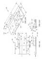
- FIG. 2is a simplified perspective view of at least one embodiment of the dynamic therapy surface of FIG. 1 , showing at least one embodiment of a lateral rotation apparatus supporting one of the occupants in a therapy position on a segment of the dynamic therapy surface;
- FIG. 3is another simplified perspective view of at least one embodiment of the dynamic therapy surface of FIG. 1 , showing at least one embodiment of the lateral rotation apparatus supporting the occupant in the therapy position on a different segment of the dynamic therapy surface;
- FIG. 4is a simplified block diagram of at least one embodiment of the control unit and other components of the person support system of FIG. 1 ;
- FIG. 5is a simplified flow diagram of at least one embodiment of a method for controlling a lateral rotation apparatus such as the lateral rotation apparatus of FIG. 1 based on inputs relating to multiple occupants of a dynamic therapy surface such as the dynamic therapy surface of FIG. 1 ;
- FIG. 6is a simplified flow diagram of at least one embodiment of a method for controlling a lateral rotation apparatus such as the lateral rotation apparatus shown in FIG. 1 based on supine position duration of an occupant of a dynamic therapy surface such as the dynamic therapy surface of FIG. 1 ;
- FIG. 7is a simplified schematic view of at least one embodiment of an adverse event mitigation system, which may include portions of the person support system of FIG. 1 and/or other features disclosed herein;
- FIG. 8is a simplified side perspective view of at least one embodiment of a person support apparatus and a person support surface, each or either of which may include one or more of the features disclosed herein;
- FIG. 9is a simplified perspective view of at least one embodiment of a dynamic therapy surface that may include one or more of the features disclosed herein, taken from a viewpoint looking toward a longitudinal side of the dynamic therapy surface;
- FIG. 10is another simplified perspective side view of the dynamic therapy surface of FIG. 9 , taken from a viewpoint looking toward a longitudinal side opposite the longitudinal side of the viewpoint of FIG. 9 ;
- FIG. 11is a simplified longitudinal elevational view of the dynamic therapy surface of FIG. 9 , taken from a viewpoint looking toward the same longitudinal side as the viewpoint of FIG. 10 ;
- FIG. 12is a simplified lateral elevational view of the dynamic therapy surface of FIG. 9 , taken from a viewpoint near a head end (e.g., element 1118 ) of the dynamic therapy surface;
- FIG. 13Ais a simplified perspective view of at least one embodiment of a dynamic therapy surface as disclosed herein;
- FIG. 13Bis a simplified top view of the dynamic therapy surface of FIG. 13A , looking in the direction labeled 13 B in FIG. 13A ;
- FIG. 13Cis a simplified longitudinal side view (viewed along the longer side) of the dynamic therapy surface of FIG. 13A , looking in the direction labeled 13 C in FIG. 13B ;
- FIG. 13Dis a simplified lateral side view (viewed along the shorter side, or end) of the dynamic therapy surface of FIG. 13A , looking in the direction labeled 13 D in FIG. 13C ;
- FIG. 14is a simplified schematic view of components of an exemplary dynamic support system that may include one or more of the features disclosed herein;
- FIG. 15is a simplified schematic diagram of a method for monitoring sleep activities of a person positioned on a dynamic therapy surface, which may include one or more of the features disclosed herein.
- these technologiescan be improved by controlling the support surface based on a maximum allowable supine sleep position duration.
- a maximum allowable supine sleep position durationFor example, whereas current approaches may strive to eliminate all supine sleep activities in order to reduce a person's apnea-hypopnea index (AHI) to below a threshold value, the control methods disclosed herein, which manage a dynamic sleep surface to a specified maximum supine sleep position duration value, can be applied to achieve that same goal with less aggressive therapy.
- a person support system 100includes a person support surface 102 , a lateral rotation apparatus 108 , and a control unit 156 .
- a number of occupant sensors 140 , 142are in communication with the control unit 156 (e.g., by wired, wireless, optical, or other signal communication mechanism).
- the illustrative person support surface 102includes a pair of laterally spaced support segments 104 , 106 , although other embodiments may only include a single support segment (e.g., support segment 104 ). At least one of the support segments 104 , 106 is configured as or includes a lateral rotation apparatus 108 .
- the illustrative lateral rotation apparatus 108includes a number of different support sections, including independently rotatable longitudinally arranged support planes 110 , 112 , 114 and lateral rotation sections 116 , 118 , 120 .
- the lateral rotation sections 116 , 118 , 120may be embodied as, for example, a non-inflatable support material, such as foam, or as inflatable bladders, or as a combination of a non-inflatable support material and bladders.
- FIGS. 10-12 and 13A-13Ddescribed below, show illustrative embodiments of a person support surface 102 and lateral rotation sections 116 , 118 , 120 .
- the lateral rotation sections 116 , 118 , 120are coupled to the support planes 110 , 112 , 114 by linkages 122 , 124 , 126 , 128 , 130 , 132 , 134 , and one or more lateral rotation actuators 136 .
- the lateral rotation actuators 136drive lateral rotation of the support planes 110 , 112 , 114 .
- the operation of the lateral rotation actuators 136is dynamically controlled by the control unit 156 , as described in more detail below.
- the lateral rotation actuators 136are powered (e.g., electronic or electromechanical) devices, such as electric motors or linear actuators, and the linkages 122 , 124 , 126 , 128 , 130 , 132 , 134 include, e.g., drive arms or output shafts.
- the support sections 116 , 118 , 120each include one or more inflatable bladders, which support the support planes 110 , 112 , 114 , respectively;
- the actuator 136is an air supply unit, and the linkages 122 , 124 , 126 , 128 , 130 , 132 , 134 are pneumatic couplings including, e.g., air supply lines 128 , 130 , 132 , 134 and valves 122 , 124 , 126 .
- the bladders 116 , 118 , 120are selectively inflated and deflated by the air supply 136 via the pneumatic couplings 122 , 124 , 126 , 128 , 130 , 132 , 134 .
- the inflation and deflation of the bladders 116 , 118 , 120is dynamically controlled by the control unit 156 operating the air supply 136 to supply air to or extract air from the bladders 116 , 118 , 120 , as the case may be, in response to inputs from the occupant sensors 140 , 142 .
- the air supply 136delivers air to the bladders 116 , 118 , 120 via one or more supply lines 128 , 130 , 132 , 134 and valves 122 , 124 , 126 .
- the air supply 136may be embodied as, e.g., a blower, a compressor, or a vacuum/blower. Any suitable configuration of air supply lines and valves may be used. For example, multiple air supply lines may be connected to a valve manifold, in some embodiments.
- the valves 122 , 124 , 126may be electronically controlled, e.g., by the control unit 156 , in some embodiments.
- the actuator(s)can be configured to operate slowly and quietly, in order to minimize disruption to any occupant on the bed. For instance, the actuator 136 's rate of change may be controlled by algorithms taking inputs from one or more of the sensors 140 , 142 or other sensors.
- the support segment 106is embodied as a support section having a single support plane 138 .
- the support segment 106may include multiple different support planes.
- the support segment 106may be embodied in a similar fashion to the support segment 104 and may include another lateral rotation apparatus or another type of therapy device.
- the senor 140is operably coupled to the support segment 104 by a coupler 144
- the sensor 142is operably coupled to the support segment 106 by a coupler 146 .
- Each or either of the sensors 140 , 142may be attached to a surface of the support segment 104 , 106 , respectively, embedded in the respective support segment 104 , 106 , or mounted to a frame or deck that supports the support segment 104 , 106 , (e.g., a frame or deck that is similar or analogous to the frame 80 or the deck 86 shown in FIG. 8 ).
- the couplers 144 , 146may be embodied as, for example, screws, rivets, stitching, brackets, adhesive, or other suitable fasteners.
- one or more of the sensors 140 , 142may simply rest on a frame or deck surface, within a pocket or enclosure of the support segment 104 , 106 , etc.
- each or any of the sensors 140 , 142may be in communication with the control unit 156 but not directly coupled to the support surface 102 .
- any of the sensors 140 , 142may be embodied in a mobile or wearable computing device, such as a smart phone, a tablet computer, a smart watch, smart jewelry (e.g., a smart bracelet), smart glasses, or as a wearable sensor, such as a smart textile, a “clip-on” sensor, or a body-worn sensor (e.g., an electrode).
- a mobile or wearable computing devicesuch as a smart phone, a tablet computer, a smart watch, smart jewelry (e.g., a smart bracelet), smart glasses, or as a wearable sensor, such as a smart textile, a “clip-on” sensor, or a body-worn sensor (e.g., an electrode).
- each or any of the sensors 140 , 142may be associated with a person using the support surface 102 (e.g., person 1 or person), rather than being directly associated with the support surface 102 or a section thereof.
- the links 144 , 146may represent logical associations of sensors 140 , 142 with persons carrying the sensors 140 , 142 , rather than physical connections with the support surface 102 .
- a sensor identifiermay be associated with a person by a user identifier (user ID), and the data identifying persons and associated sensors may be stored in memory of the sensor 140 , 142 or another device (e.g., in an electronic file, mapping table, or database).
- the sensor communicationsmay include the sensed information as well as the user ID of the person with whom the sensor 140 , 142 is associated.
- Each or any of the sensors 140 , 142may be embodied as a single sensor or an array or combination of multiple sensors (e.g., a pressure map).
- the sensors 140 , 142may be of the same type or of different types.
- the sensors 140 , 142may each be embodied as any suitable type of device that is capable of sensing an indicator of a state of a person positioned on the person support surface 102 , and may include, e.g., a pressure sensor, a force sensor, a temperature sensor, an accelerometer, an inclinometer, a physiological or vital signs sensor, a microphone or other sound detector, a sleep sensor (e.g., any type of sensor that can detect an indicator of a person's sleep, including any of the foregoing), an array of any of the foregoing types of sensors, or any combination of any of the foregoing types of sensors and/or others sensors.
- a pressure sensore.g., a force sensor, a temperature sensor, an accelerometer, an inclin
- the senor 140detects state information about a person 1 situated on the support segment 104
- the sensor 142detects state information about a person 2 situated on the support segment 106 (illustratively, with head supported by a pillow 4 ), over a fixed or variable time interval.
- Each of the respective person 1 and person 2 state informationmay include, for example, an indication of: whether the person is awake or asleep, the particular stage of the person's sleep (e.g., rapid eye movement (REM) phase or not), the person's position relative to the support segment 104 or 106 (e.g., in order for the control unit 156 to determine whether the person in a proper position for a therapy to be performed), the person's activity level, one or more physiological parameters of the person (e.g., blood pressure, blood oxygen saturation, heart rate, respiration rate, etc.) and/or other person state indicators.
- the system 100can be programmed to automatically disable or terminate the rotation (e.g., apnea therapy) if the system 100 detects an adverse condition. Alternatively or in addition, the system 100 can terminate or suspend the rotation (e.g., apnea therapy) by a manual override (such as a switch).
- a manual overridesuch as a switch
- the control unit 156receives person 1 state indicators 148 from time to time from the sensor 140 , and receives person 2 state indicators 152 from time to time from the sensor 142 , by way of suitable communication links 150 , 154 as shown in FIG. 4 , described below.
- the control unit 156includes electrical circuitry and/or computer components, as shown in FIG. 4 , which are configured as a dynamic therapy system 162 . Aspects of the dynamic therapy system 162 may be embodied in a similar fashion to the computer system shown in FIGS. 14-15 , described below.
- the illustrative dynamic therapy system 162includes a multi-occupant control module 164 and a supine position control module 166 .
- the modules 162 , 164may each be embodied as computer hardware, software, firmware, or a combination thereof.
- the multi-occupant control module 164causes the control unit 156 to read and analyze the person 1 state indicator 148 and the person 2 state indicator 152 , execute control algorithms, and issue lateral rotation apparatus control signals 158 from time to time based on a combination of the person 1 and person 2 state indicators 148 , 152 .
- the supine position control module 166causes the control unit 156 to read and analyze at least the person 1 state indicator 148 , execute control algorithms, and issue lateral rotation apparatus control signals 158 from time to time based on at least the person 1 state indicator 148 in combination with maximum supine position duration information stored in e.g., a memory accessible by the control unit 156 .
- the control unit 156transmits the lateral rotation apparatus control signals 158 to the actuator 136 via a communication link 160 , to activate or deactivate the actuator 136 .
- the control signals 158may cause a motor to drive mechanical elements (e.g., linkages 122 , 124 , 126 , 128 , 130 , 132 , 134 ) to rotate a support section 116 , 118 , 120 , or may cause an air supply to increase or decrease a supply of air to one or more of the bladders 116 , 118 , 120 in response to the lateral rotation apparatus control signals 158 .
- control signals 158may cause one or more of the actuator(s) 136 to turn on or off, increase or decrease a power level, or supply positive or negative pressure to one or more of the support sections or bladders 116 , 118 , 120 .
- the multi-occupant control module 164 and the supine position control module 166are described in more detail below, with reference to FIGS. 5 and 6 , respectively.
- the person support surface 102is shown in a state in which the lateral rotation apparatus 108 of the support segment 104 is activated to place the person 1 in a non-supine position on the support segment 104 .
- the support segment 106remains in a flat position, allowing the person 2 to remain in a supine position.
- the position of the person 1 in FIG. 2is considered “non-supine” in that while the person 1 is laying on his back, the head, torso, and legs are rotated at different angles, so that the person 1 is not laying flat.
- the support segment 104has a width W 1
- the support segment 106has a width W 2 .
- the widths W 1 , W 2may be the same or different.
- the width Wis greater than either the width W 1 or the width W 2 , and may equal the sum of W 1 plus W 2 .
- the person support surface 102has a length L, which is greater than either of W 1 and W 2 and typically greater than the width W.
- both of the support segments 104 , 106have the same length L, but may have different lengths, in other embodiments.
- the support segments 104 , 106can be subcomponents of the same support surface (e.g., a double bed, with one mattress having two lateral sides), such that both person 1 and person 2 are on the same surface), or the support segments 104 , 106 may be separate surfaces (e.g., two mattresses supported by a common support frame).
- Each or either of the support segments 104 , 106may be equipped with a lateral rotation apparatus 108 .
- both persons 1 and 2could be apnea sufferers and thus both sides of the person support surface 102 would be equipped with a lateral rotation apparatus 108 .
- the operation of both of the lateral rotation apparatusescan be coordinated by the control unit 156 .
- the person support surface 102is shown in a configuration in which a lateral rotation apparatus 308 is part of the support segment 106 .
- a lateral rotation apparatus 308is part of the support segment 106 .
- the lateral rotation apparatus 308includes support planes 310 , 312 , 314 and support sections (e.g., foam and/or bladders) 316 , 318 , 320 .
- the illustrative lateral rotation apparatus 308is analogous to the lateral rotation apparatus 108 .
- the support planes 310 , 312 , 314may be embodied in a similar manner as the support planes 110 , 112 , 114 , and the support sections 316 , 318 , 320 may be embodied in a similar manner as the support sections 116 , 118 , 120 , described above.
- the components of the person support surface 102 and more particularly, the lateral rotation apparatus 108 , 308may include other components and/or other configurations of the same components.
- portions of the person support surface 102 , and more generally the person support system 100may include one or more of the features shown in FIGS. 7-12 and 13A-13D .
- the illustrative lateral rotation apparatus 108includes a support surface comprising head, torso and leg segments each having an independently rotatable person support plane 110 , 112 , 114 ; and corresponding support sections 116 , 118 , 120 , which support each person support plane.
- the support sections 116 , 118 120may be embodied as different subsections of a common support surface or as separate support surfaces. Further, the support sections 116 , 118 , 120 need not be independent from one another. For example, the support sections 116 , 118 , 120 may share a common layer, with one or more additional layers above or below the support sections 116 , 118 , 120 .
- the ranges of lateral tilt angles that the support planes 110 , 112 , 114 can assumeare as follows.
- the actuator 136may be operable to rotate the support plane 110 (e.g., head segment) to a head tilt angle in the range of about 7 to about 30 degrees relative to a horizontal support plane; and the actuator 136 may be operable to rotate to rotate the support plane 112 (e.g., torso segment) to a torso tilt angle that is within a range of about 5 degrees to about 10 degrees less than the head tilt angle.
- the support section 118may be configured to rotate the support plane 112 (e.g., torso segment) to a torso tilt angle in the range of about zero to about 25 degrees.
- the support section 116may be configured to rotate the support plane 110 (e.g., head segment) to a head tilt angle in the range of about 10 to about 15 degrees.
- the support section 118may be configured to rotate the support plane 112 (e.g., torso segment) to a torso tilt angle in the range of about 5 to about 10 degrees.
- the support section 120may be inflatable to rotate the support plane 114 (e.g., leg segment) to a leg tilt angle in the range of about 0 to about 5 degrees.
- the lateral rotation apparatus 108is configured to position/rotate all of the support planes 110 , 112 , 114 to the same angle (e.g., all of the support planes 110 , 112 , 114 rotated to an angle of about 10 degrees).
- the head, torso, and/or leg tilt anglesmay be computed in order to allow for indentation of the support surface 102 underneath body parts such as shoulders, arms and hips (e.g., so that the patient's shoulder, arm, or hip can rest comfortably underneath the body).
- the control unit 156may control inflation of the bladder 116 and the bladder 118 to maintain a differential between the head tilt angle and the torso tilt angle that is in the range of about 5 to about 10 degrees.
- the control unit 156may coordinate lateral rotation (e.g., lateral tilt) angle changes of the support planes 110 , 112 so that the differential between the two angles does not exceed a desired amount.
- the support plane 112(e.g., torso segment) may be longitudinally longer than the support plane 110 (e.g., head segment), and the support plane 114 (e.g., leg segment) may be longitudinally longer than the support plane 112 (e.g., torso segment).
- the support plane 110e.g., head segment
- the support plane 112e.g., the torso segment
- the support plane 114e.g., the leg segment
- the support plane 112(e.g., the leg segment) may have a longitudinal length in the range of about 40 inches.
- Portions of the person support surface 102may be made of a support material that has a density, such as a foam material.
- the head tilt anglemay be configured as a function of the density of the support material.
- Either or both of the torso tilt angle and the leg tilt anglemay also be configured as a function of the density of the support material.
- the head, torso and leg tilt anglesmay vary according to the density of the material used to build the person support surface 102 or person-supporting portions thereof.
- the head, torso, and leg tilt anglesmay be configured as a function of an occupant's body weight and/or as a function of the morphology of the person's body interfacing with the person support surface 102 .
- the occupant's body weightcan be an additional input for the calculation of the tilt angle.
- a sensor that measures the actual tilt angle of the person's bodycan be used in a closed-loop system to determine the optimum tilt angles for the support planes 110 , 112 , 114 .
- the person support system 400includes the lateral rotation control unit 156 , one or more communication links 426 , the air supply 136 , the sensors 140 , 142 , and one or more other devices 428 . While the illustrative embodiment 400 is shown as involving multiple components and devices, it should be understood that the person support system 400 may constitute a single device, alone or in combination with other devices.
- the air supply 136may be a component of the control unit 156 , a component of the person support surface 102 , or a separate component.
- Each or any of the components 156 , 140 , 142 , 428 , 136may be in communication with one another via one or more of the communication links 426 .
- portions of the system 400may be incorporated into other systems or computer applications.
- Such applications or systemsmay include, for example, commercial off the shelf (COTS) or custom-developed devices or systems.
- COTScommercial off the shelf
- module or “component”may refer to, among other things, any type of computer program or group of computer programs, whether implemented in software, hardware, firmware, or a combination thereof, and includes self-contained, vertical, and/or shrink-wrapped applications, distributed and cloud-based applications, and/or others.
- the illustrative lateral rotation control unit 156includes at least one processor 410 (e.g. a microprocessor, microcontroller, digital signal processor, etc.), memory 412 , and an input/output (I/O) subsystem 414 .
- the control unit 156may be embodied as any type of computing device capable of performing the functions described herein.
- the I/O subsystem 414can include, among other things, an I/O controller, a memory controller, and one or more I/O ports.
- the processor 410 and the I/O subsystem 414are communicatively coupled to the memory 412 .
- the memory 412may be embodied as any type of suitable computer memory device, including fixed and/or removable memory devices (e.g., volatile memory such as a form of random access memory or a combination of random access memory and read-only memory, such as memory cards, e.g., SD cards, memory sticks, hard drives, and/or others).
- volatile memorysuch as a form of random access memory or a combination of random access memory and read-only memory, such as memory cards, e.g., SD cards, memory sticks, hard drives, and/or others.
- the I/O subsystem 414is communicatively coupled to a number of hardware, firmware, and/or software components, including the multi-occupant control module 164 and the supine position control module 166 .
- the I/O subsystem 414is also communicatively coupled to one or more data storage devices 418 , a communication subsystem 424 , and a user interface subsystem 422 .
- the user interface subsystem 422may include, for example, hardware or software buttons or actuators, a keypad, a display device, visual cue illuminators, and/or others.
- the data storage device 416is embodied as one or more machine readable storage media and may include one or more hard drives or other suitable data storage devices (e.g., flash memory, memory cards, memory sticks, and/or others).
- portions of the system 400 containing data or stored informatione.g., multi-occupant position data 418 , supine sleep limit data 420 , and/or other data, reside at least temporarily in the data storage device 416 .
- Portions of the system 400e.g., multi-occupant position data 418 , supine sleep limit data 420 , and/or other data, may be copied to the memory 412 during operation of the control unit 156 , for faster processing or other reasons.
- the communication subsystem 424communicatively couples the control unit 156 to one or more other devices, systems, or communication networks, e.g., a local area network, wide area network, personal cloud, enterprise cloud, public cloud, and/or the Internet, for example.
- the communication subsystem 424may include a databus, datalink, one or more wired or wireless network interface software, firmware, or hardware, for example, as may be needed pursuant to the specifications and/or design of the particular embodiment of the control unit 156 .
- the system 100may also access data on a personal mobile device, where such data is either stored in the device memory or through its connection to the Internet, cloud, or other communication network.
- a WIFI-enabled devicesuch as a body weight scale or fitness tracker can send measured body weight data to an app on the mobile device.
- body weight datacan be transmitted wirelessly to and used by the control unit 156 to, e.g., calculate the tilt angles of the support planes 110 , 112 , 114 .
- the other device(s) 428may be embodied as any suitable type of computing device, electronic device, or electromechanical device capable of performing the functions described herein, such as any of the aforementioned types of devices or other electronic devices.
- a device 428may operate a “back end” portion of the dynamic therapy system 162 , by performing data storage or other operations of the control unit 156 .
- a device 428may operate a “front end” portion of the dynamic therapy system 162 .
- a front end portionmay be embodied as an “app” that runs on a personal mobile electronic device, which enables user input to the dynamic therapy system 162 and display of output produced by the dynamic therapy system 162 .
- the system 400may include other components, sub-components, and devices not illustrated in FIG. 4 for clarity of the description.
- the components of the system 40are communicatively coupled as shown in FIG. 4 by one or more communication links 2048 , e.g., signal paths, which may be embodied as any type of wired, optical, or wireless signal paths capable of facilitating communication between the respective devices and components, including direct connections, public and/or private network connections (e.g., Ethernet, Internet, etc.), or a combination thereof, and including short range (e.g., Near Field Communication) and longer range (e.g., Wi-Fi or cellular) wireless communication links.
- short rangee.g., Near Field Communication
- Wi-FiWireless Fidelity
- the method 500may be embodied as computerized programs, routines, logic and/or instructions, which may be embodied in hardware, software, firmware, or a combination thereof, of the system 100 and/or one or more other systems or devices in communication with the system 100 .
- the system 100determines whether a “person 1 ” (e.g., a person needing apnea therapy or another type of therapy provided by the lateral rotation apparatus 108 ) is in position for the therapy to begin.
- a “person 1 ”e.g., a person needing apnea therapy or another type of therapy provided by the lateral rotation apparatus 108
- the system 100reads and analyzes data signals from an occupant sensor monitoring a portion of a person support surface that includes a lateral rotation apparatus (e.g., the support segment 104 ).
- the system 100may compare the sensed data values to known values indicative of various patient positions, which may be determined based on experimentation and test results. In doing so, the system 100 may query a database or access a lookup table (e.g., multi-occupant data 418 ), and then perform a logical comparison of the current sensed value to one or more known values indicative of a person position relative to the support surface. For instance, the system 100 may determine from force sensor or pressure sensor readings that person 1 is laying down on the therapy-providing support segment.
- a lookup tablee.g., multi-occupant data 418
- the system 100may determine, based on one or more sensor inputs, that a substantial portion of person 1 is not positioned on the therapy-providing support segment. This may occur if person 1 is sitting on the edge of the person support surface or laying partially on the other lateral side of the person support surface (e.g., the support segment 106 ).
- the specific parameters for determining whether person 1 is in a therapy-enabling positionmay be selected according to the requirements of a particular design of the system 100 . If the system 100 does not detect that person 1 is in a therapy-enabling position, the system 100 remains in block 510 . If the system 100 detects that person 1 is in a therapy-enabling position, the system 100 proceeds to block 512 .
- the system 100determines whether a “person 2 ” is in a therapy-enabling state.
- the specific parameters for determining whether person 2 is in a therapy enabling statemay be selected according to the requirements of a particular design of the system 100 .
- the therapy enabling statemay be defined as a sleep state, e.g., whether the person 2 is fully asleep, or in a REM state of sleep, or not yet asleep, or fully awake, or as an activity state, based on the person 2 's level of motor activity in relation to the patient support surface.
- the system 100To determine whether person 2 is in a therapy-enabling state, the system 100 reads and analyzes data signals from an occupant sensor monitoring a portion of a person support surface that supports person 2 (e.g., the sensor 142 ). The system 100 may compare the sensed data values to known values indicative of various therapy-enabling states, which may be determined based on experimentation and test results. In doing so, the system 100 may query a database or access a lookup table (e.g., supine sleep limit data 420 ), and then perform a logical comparison of the current sensed value to one or more known values indicative of a desired therapy-enabling state.
- a lookup tablee.g., supine sleep limit data 420
- the system 100determines in block 512 that person 2 is not in a therapy-enabling state (e.g., person 2 is not yet asleep)
- the system 100proceeds to block 514 .
- the system 100determines in block 512 that person 2 is in a therapy-enabling state (e.g., person 2 is in a deep sleep and is therefore unlikely to be bothered by the therapy)
- the system 100proceeds to block 516 .
- the system 100controls the lateral rotation apparatus to a non-therapy state.
- the system 100returns the therapy-providing segment of the person support surface (e.g., the support segment 104 ) to a non-therapy position (e.g., a flat position), if the segment was, immediately prior to block 512 , in a therapy-providing position, or allows the therapy-providing segment to remain in the non-therapy position (if the segment was already in a non-therapy, e.g., flat, position).
- the system 100delays the lateral rotation therapy for person 1 if person 2 is not detected as being in the desired therapy enabling state.
- the system 100controls the lateral rotation apparatus to a therapy state.
- the system 100transitions the therapy-providing segment of the person support surface (e.g., the support segment 104 ) to a therapy position (e.g., a progressive lateral tilt angle position), if the segment was, immediately prior to block 516 , in a non-therapy-providing position, or allows the therapy-providing segment to remain in the therapy position (if the segment was already in a therapy, e.g., progressive lateral tilt, position).
- the system 100initiates the lateral rotation therapy for person 1 if person 2 is detected as being in the desired therapy enabling state.
- the system 100terminates or suspends the lateral rotation therapy if either person 1 or person 2 is not in the desired state. For example, if person 2 wakes up or is detected as having a restless sleep, the system 100 may suspend the lateral rotation therapy in block 514 . Following block 516 , the method 500 may conclude or return to block 510 .
- the system 100activates or deactivates the actuator(s) 136 by an appropriate amount or for an appropriate duration of time, in order to achieve the desired configuration of the person support surface. For example, the system 100 may turn a motor or an air supply on or off, adjust the power level, or adjust other operating parameters of the actuator 136 .
- the method 600may be embodied as computerized programs, routines, logic and/or instructions, which may be embodied in hardware, software, firmware, or a combination thereof, of the system 100 and/or one or more other systems or devices in communication with the system 100 .
- the system 100identifies one or more supine position evaluation parameters.
- the supine position evaluation parametersmay be defined or selected according to the requirements of a particular design of the system 100 , and may include AHI, occupant position, occupant sleep state, and/or other parameters.
- the system 100computes or determines data indicative of a maximum supine position duration.
- maximum supine position durationmay refer to, among other things, a maximum amount of time that a person (e.g., a person needing apnea therapy) should spend in the supine position, in order to minimize the risk of occurrence of an apnea event.
- the system 100may query a database or access a lookup table, or read sensed values from, e.g., sensor 140 , to obtain a data value indicating the maximum supine position duration based on demographic criteria or patient-specific criteria (such as the patient's AHI score, sleep state, or sleep position).
- a sensor 140may be used to perform real-time (e.g., continuous) monitoring of AHI values (e.g., both supine and non-supine), and the system 100 can adjust the maximum supine position duration and/or tilt angle in response to changes in the AHI score as detected in real-time.
- the person's supine AHI and lateral AHImay be used alone or in combination to calculate the maximum supine position duration (and/or other data values used by the control unit 156 ).
- the supine position parameter(s) identified in block 610may be used to determine or compute the maximum supine position duration in block 612 , either statically or dynamically.
- system 100enters a loop 624 in which the system 100 iteratively and dynamically monitors the supine position evaluation parameter(s) and adjusts the lateral rotation apparatus as needed to avoid the occupant's supine position evaluation parameter(s) falling outside an acceptable range (e.g., an AHI score greater than about 5).
- the system 100may be configured to dynamically adjust the subject's supine position duration based on his or her current AHI score.
- the system 100may monitor the length of time that the occupant (e.g., person 1 of FIG.
- the system 100may implement a fixed maximum supine position duration and simply track the amount of time the occupant spends in the supine position (e.g., by setting a timer) and compare the detected amount of time to the pre-determined maximum supine position duration value (which may be determined based on testing with a representative sample of subjects using the patient support surface in a number of different surface configurations).
- the system 100can change the tilt position durations dynamically as well (e.g., as AHI rates change throughout a night of sleep, the amount of time spent in a tilt position can be dynamically adjusted).
- the system 100determines whether the patient/occupant (e.g., person 1 ) is in the supine position. To do this, the system 100 may read and analyze data signals from an occupant sensor (e.g., sensor 140 ) and compare the sensed data values to known values indicative of various patient positions. Alternatively or in addition, the system 100 may determine the current state of the lateral rotation apparatus (e.g., by checking to see whether the bladders 116 , 118 , 120 are inflated or deflated, or by checking the current operational state of the actuator 136 , or by checking to see the current rotational angle of the support sections 116 , 118 , 120 , using, e.g., an angle sensor). If the system 100 does not detect that the patient/occupant is in a supine position, the system 100 remains in block 614 . If the system 100 detects that the patient/occupant is in the supine position, the system 100 proceeds to block 616 .
- an angle sensore.g., a sensor 140
- the system 100begins monitoring the patient/occupant's supine position evaluation parameter (e.g., AHI, sleep state, or current supine position duration).
- the system 100determines whether the monitored supine position evaluation parameter indicates that the patient/occupant's supine position duration equals or exceeds the maximum supine position duration. For example, the system 100 may compare the patient/occupant's AHI value to a threshold value or compare the current supine position duration to the maximum supine position duration determined in block 612 . Alternatively or in addition, an algorithm may determine the minimum effective tilt angle to reduce AHI to below a threshold value in order to increase compliance by minimizing discomfort caused by a higher tilt angle. The system 100 remains in block 618 if the supine position duration does not exceed the maximum supine position duration value. If the supine position duration equals or exceeds the maximum supine position duration, the system 100 proceeds to block 620 .
- the system 100proceeds to block 620 .
- the system 100determines or computes the surface angle adjustments needed to transition the patient/occupant out of the supine position. To do this, the system 100 may query a database or access a lookup table that maps patient characteristics (such as gender, size, body weight, or AHI) to appropriate surface angles, for example.
- patient characteristicssuch as gender, size, body weight, or AHI
- the system 100controls the lateral rotation apparatus to make the surface angle adjustments determined or computed in block 620 .
- the system 100may activate or deactivate the actuator(s) 136 to rotate one or more of the support sections 116 , 118 , 120 , or inflate or deflate one or more of the bladders 116 , 118 , 120 , by an appropriate amount, to achieve the desired surface angles.
- the supine position control module 166need not be used on a multi-occupant surface.
- the features of the method 600 and the supine position control module 166are applicable to single-person support surfaces, such as those shown in 8 - 12 and 13 A- 13 D, and can be used in connection with single-person support surfaces in the manner described above. Further, in multi-occupant embodiments, operation of the method 600 and/or the supine position control module 166 may be coordinated with the operation of the multi-occupant control module 164 and method 500 . For instance, the method 600 may be initiated as a result of the system 100 determining in block 512 of FIG. 5 that a person 2 is in a therapy-enabling state.
- an adverse event mitigation system 70is shown.
- the illustrative adverse event mitigation system 70is configured to help reduce the likelihood of an adverse event occurring and/or stop an adverse event in progress.
- the adverse event mitigation system 70may help reduce the likelihood of obstructive sleep apnea occurring and/or may help stop an obstructive apnea event in progress.
- the adverse event mitigation system 70may help reduce the likelihood of other adverse events occurring and/or stop other adverse events in progress.
- the adverse event mitigation system 70includes a person support apparatus 72 , a person support surface 74 supported on the person support apparatus 72 , and a control system 76 as shown in FIG. 7 .
- the person support apparatus 72is a hospital bed frame and the person support surface 74 is supported thereon as shown in FIG. 8 .
- the person support apparatus 72can be a stretcher, an operating room table, or other person supporting structure (including a consumer-oriented device, such as a lounger or a recliner).
- the person support apparatus 72includes a lower frame 87 , supports 88 or lift mechanisms 88 coupled to the lower frame 87 , and an upper frame 80 movably supported above the lower frame 87 by the supports 88 as shown in FIG. 8 .
- the lift mechanisms 88are configured to raise and lower the upper frame 80 with respect to the lower frame 87 and move the upper frame 80 between various orientations, such as Trendelenburg and reverse Trendelenburg.
- the upper frame 80includes an upper frame base 84 , a deck 86 coupled to the upper frame base 84 , and a plurality of actuators 87 coupled to the upper frame base 84 and the deck 86 as shown in FIG. 8 .
- the plurality of actuators 87are configured to move at least a portion of the deck 86 along at least one of a longitudinal axis, which extends along the length of the upper frame 80 , and a lateral axis, which extends across the width of the upper frame 80 , between various articulated configurations with respect to the upper frame base 84 .
- the person support surface 74is configured to support a person thereon and move with the deck 86 between various configurations including a chair position, a horizontal position, and positions intermediate the horizontal and chair positions.
- the person support surface 74is a hospital bed mattress. In other embodiments, the person support surface 74 is a consumer mattress.
- one or more articulating sections of the deck 86help move and/or maintain the various portions of the person support surface 74 at different lateral rotation angles (such as the angles ⁇ , ⁇ and ⁇ shown in the embodiment of FIG. 12 ) with respect to the reference plane RPI.
- the person support surface 74is a powered (e.g., dynamic) surface configured to receive fluid (e.g., air) from a fluid supply (e.g., the air supply 136 ).
- the person support surface 74has a mattress core that can be composed of a single type of material or a combination of materials and/or devices.
- the mattress coreincludes at least one fluid bladder therein that receives fluid from a fluid supply to maintain the fluid pressure within the fluid bladder at a predetermined level.
- the powered surfacecan include non-powered components, such as a foam frame surrounding or supporting one or more fluid bladders.
- the mattress coreincludes dynamically inflatable or static fluid bladders that are configured to support the cervical vertebrae and scapula, respectively, when inflated.
- the arrangement of the inflatable fluid bladderscan vary depending on any number of factors, including, but not limited to, a person's body type and the angle at which the surface is at with respect to the reference plane RP 1 .
- the fluid bladdersare configured to laterally tilt the head and/or torso of the occupant.
- wedge shaped fluid bladders(not shown) are positioned in head and torso portions of the support surface 74 and are configured to increase the angles of the occupant-contacting surfaces of the head and torso portions, respectively.
- the head and torso of the occupantcan be tilted at different angles.
- the person support apparatus 72 and/or the person support surface 74can laterally rotate the occupant so that the torso is at an angle in the range of about 10 degrees to about 15 degrees or more, with respect to the reference plane RP 1 , and the occupant's head is at a non-supine angle (e.g., an angle of about 180° with respect to the reference plane RP 1 , or, an angle that is not within a range of about 35 to about 45 degrees of vertical orientation).
- Rotation of the occupant's torsocan help the occupant maintain his or her head at a non-supine angle (e.g., an angle of about 180° with respect to the reference plane RP 1 or an angle that is not within a range of about 35 to about 45 degrees of vertical orientation).
- a non-supine anglee.g., an angle of about 180° with respect to the reference plane RP 1 or an angle that is not within a range of about 35 to about 45 degrees of vertical orientation.
- Portions of the mattress core of the support surfacemay be composed of a cellular engineered material, such as a single density foam.
- the support surface 74includes multiple zones with different support characteristics configured to, e.g., enhance pressure redistribution as a function of the proportional differences of a person's body.
- the mattress core of the support surface 74includes various layers and/or sections of foam having different impression load deflection (ILD) characteristics, such as may be found in the NP100 Prevention Surface, AccuMax QuantumTM VPC Therapy Surface, and NP200 Wound Surfaces sold by Hill-Rom®.
- ILDimpression load deflection
- the control system 76is configured to change at least one characteristic of the person support apparatus 72 and/or person support surface 74 , e.g., to help reduce the likelihood of an adverse event occurring and/or stop an adverse event in progress.
- the control system 76includes a processor 700 , an input 702 , and memory 704 .
- the input 702includes a sensor 706 , such as, a position sensor, a pressure sensor, a temperature sensor, an acoustic sensor, and/or a moisture sensor, configured to provide an input signal to the processor 700 indicative of a physiological characteristic of the occupant, such as, the occupant's heart rate, respiration rate, respiration amplitude, skin temperature, weight, and position.
- the sensors 706are incorporated into the person support surface 74 or a topper positioned on the person support surface, for example, as disclosed in U.S. Pat. No. 7,515,059 to Price et al. and U.S. Patent Publication No. 2011/0068928 to Riley et al.
- the sensors 706include, for example, RFID tags, accelerometers, proximity sensors, level sensors, or other physical tracking sensors that may be integrated into or coupled to, for example, ear plugs, ear phones, adhesive sensors, earlobe clips, eye covers, hats, nose strips or other devices that are attached to the patient's head or worn by the patient so that the position/orientation of the patient's head can be tracked.
- Information captured by monitoring the lateral position of the user's upper respiratory tracthas several benefits, including one or more of the following: providing more accurate measurements of the upper respiratory angle for diagnosis of positional obstructive sleep apnea (in one example, sleep labs can use the information to more accurately diagnose POSA); providing biofeedback to help the user to train to maintain a posture that prevents POSA (positional obstructive sleep apnea); tracking performance of the system to determine if the system is achieving a sufficient upper respiratory angle to prevent apnea; monitoring compliance to determine if the system is being used; monitoring the upper respiratory angle and recording the angle when a sleep apnea event occurs; and controlling a surface capable of providing lateral rotation as a function of the inputs from the sensors 706 , tracking whether optimal lateral position has been achieved, and controlling the system to achieve a desired head lateral position and/or upper respiratory angle.
- the sensors 706are tracked by reading devices (i.e., an RFID or radio frequency identification, reader) in a siderail, person support surface, deck, headboard, or location on or in the person support apparatus 70 or person support surface 74 , or on or in a headwall in the room or other location in the room.
- the sensor 706includes a camera positioned at the foot of the bed or above the bed, as disclosed in U.S. Patent Publication No. 2012/0029879 to Sing et al., for example, to track the orientation of the person's head.
- the input 702includes a user interface 708 configured to receive information from a caregiver or other user.
- the input 702is an Electronic Medical Record (EMR) system 710 in communication with the processor 700 via a hospital network 712 .
- EMRElectronic Medical Record
- the processor 700can output information, automatically or manually upon caregiver input, to the EMR for charting, which can include therapy initiation and termination, adverse event occurrence information, therapy protocol used, caregiver ID, and any other information associated with the occupant, caregiver, person support apparatus 72 , person support surface 74 , and an adverse event.
- the memory 704stores one or more instruction sets configured to be executed by the processor 700 .
- the instruction setsdefine procedures that, when executed by the processor, cause the processor 700 to implement one or more protocols that modify the configuration of the person support apparatus 72 and/or the person support surface 14 .
- the instruction setdefines a proactive procedure that causes the processor 700 to configure the person support apparatus 72 and/or the person support surface 74 in response to an input specifying that the occupant is at risk for sleep apnea.
- a procedurebegins when the processor 700 receives an input signal from the input 702 indicative of the level of risk for an apnea event occurring.
- the level of riskis input from a field in the occupant's EMR.
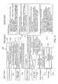
- the level of riskis input by a caregiver through the user interface, which may arise from a doctor's order or be based on a patient scoring system. In some contemplated embodiments, the level of risk is determined based on a risk score that is calculated by the processor 700 based on a number of factors, including, but not limited to, one or more of the factors listed in TABLE 1 below:
- the position and/or the orientation of the occupant with respect to patient facing surface of the person support surface 74is detected and can influence how the person support surface 74 and/or the person support apparatus 72 are configured to move the occupant to the desired position. For example, if the occupant is positioned along the left edge of the patient facing surface of the person support surface 74 , the protocol will not rotate them to the left. In some contemplated embodiments, the protocol is terminated because the occupant is in the correct position. In some contemplated embodiments, the protocol helps to maintain the occupant in the position.
- the position of the occupant on the person support surface 74can be determined a number of ways, including sensing the force distribution on the upper frame 80 utilizing one or more load cells (not shown) coupled to the upper frame 80 , calculating the occupant's center of gravity using the one or more load cells, sensing pressures within the fluid bladders, using a camera (not shown) or 3D sensor (not shown), or using other methods.
- a procedurecan be used to determine if a person is at risk for or has gastroesophageal reflux disease and select a protocol that assists the occupant in maintaining a left lateral decubitus position or semi-reclining position while sleeping.
- the procedurecan be used to determine if a person is at risk for or has chronic respiratory insufficiency and select a protocol for the caregiver to approve that assists the occupant in maintaining a left lateral decubitus position while sleeping.
- the procedurecan be used to determine if a person is at risk for of has allergies to, for example, feather or down filled pillows, cushions or covers, and can alert the caregiver so that they can remove the item.
- the above-described described procedurecan be used to determine if the person is at risk for or has one or more other conditions, such as, for example, asthma, pregnancy, sleep paralysis or hallucinations, snoring, stroke bruxism, coughing, hypoxaemia in geriatric inpatients, stroke, or tuberculosis, that might be affected negatively by sleeping in the supine position and select a protocol and/or alert the caregiver so that the person support apparatus 72 and/or the person support surface 74 can be configured to maintain the occupant in a desirable position.
- the procedurecan be used to change the sleeping position of occupants to help stimulate blood oxygenation, which can undesirably decrease as the occupant remains stationary.
- Some patientsmay have a contraindication to be laterally tilted to one side but not the other, and thus rotation will only tilt to the non-contraindicated side.
- a recent orthopedic procedure on an armmay induce pain when lying on that side, or a collapsed lung may cause pain on one side.
- Data indicative of these and other types of patient-specific health conditionsmay be input by a caregiver (e.g., by a user interface of the control unit 156 ) or by a communications interface with, e.g., an electronic medical records (EMR) system.
- EMRelectronic medical records
- a support system 1100 suitable for supporting a userincludes plurality of support pieces, namely a first or leg support piece 1102 forming a first support plane 1104 , a second or torso support piece 1106 forming a second support plane 1108 , and a third or head support piece 1110 forming a third support plane 1112 that collectively define a segmented, multi-plane, laterally angled sleep surface 1114 having progressively greater angles of rotation along a longitudinal axis 1115 of support system 1100 , from a first or bottom edge 1116 of sleep surface 1114 to an opposing second or top edge 1118 of sleep surface 1114 , resulting in relatively greater rotation of the upper respiratory tract of the user (as necessary for efficacy in preventing obstructive apnea) and relatively lesser rotation in the lower body of the user (resulting in greater comfort and perceived stability by avoiding rotation of a majority of the user's body mass).
- sleep surface 1114is formed using any suitable number of support pieces defining corresponding support planes, for example, one support piece forming a smooth contour over a length of sleep surface 1114 from first edge 1116 to opposing second edge 1118 or a plurality of support pieces, such as two support pieces, three support pieces, or more than three support pieces forming a smooth contour over the length of sleep surface 1114 .
- the system described hereinuses multiple support planes formed by one or more support pieces to laterally rotate the user.
- two support piecesprovide two separate support planes, with a first support plane defined by the first support piece configured to support the torso and the legs of the user, and a second support plane defined by the second support piece configured to support the neck and the head of the user.
- three support piecesprovide three separate support planes, with a first support plane defined by the first support piece configured to support the legs of the user, a second support plane defined by the second support piece configured to support the torso of the user, and a third support plane defined by the third support piece configured to support the head of the user.
- more than three support piecesfor example, numerous independent support pieces having a length in a longitudinal direction of sleep surface 1114 of 2-18 inches or, more specifically, 4-12 inches, or, even more specifically, 6 inches, provide a corresponding number of separate support planes.
- Each support piececan be laterally rotated independently of other support pieces to collectively form sleep surface 1114 .
- the numerous support piecescan be combined to form separate support pieces, for example, creating a first support piece having a length of 18 inches in the longitudinal direction at the foot of the support system 1100 , an adjacent second support piece having a length of 12 inches in the longitudinal direction, and a third support piece adjacent the second support piece having a length in the longitudinal direction of 6 inches.
- the support pieces forming the support planescan be rotated as necessary or desired to achieve an optimal configuration that is clinically effective (i.e., prevents apnea) and demonstrates acceptable tolerance (i.e., allows the user to sleep comfortably).
- a continuously sloped sleep surfaceis formed by a plurality of support pieces without step increases in lateral rotational angle; this is illustrated as a sleep surface with an infinite number of support pieces.
- each support piece and defined support planeis designed to achieve clinical efficacy and tolerability. Therefore, a specific length can be defined in a number of configurations, including without limitations: (a) generic plane dimensions (e.g., based on average body geometry, a length of a torso section of the user defined so that when an average user's head is supported by a head support piece, a transition between the torso support piece and the leg support piece occurs below the user's S3 vertebrae); (b) customized plane dimensions (e.g., a torso support plane has a suitable length in the longitudinal direction appropriate to the user's leg length, torso length, and/or a distance from the user's shoulder to his/her inseam); or (c) dynamic plane dimensions (e.g., transitions selected on dynamic surface appropriate to user, selection being either user-selected, care-giver defined, or automatically calculated).
- generic plane dimensionse.g., based on average body geometry, a length of a torso section of the user
- each support piece defining the corresponding support planesis independently rotatable about an axis extending parallel with a longitudinal axis of the support system.
- the independent rotation of each support pieceallows the caregiver or the user the ability to focus on progressively increasing an angle of rotation in one or more support pieces having support planes positioned to support the torso of the user, and the neck and/or the head of the user.
- an angle of rotation (or lateral rotational angle) at which the one or more support planes defined by the support pieces configured to support the neck and/or the head of the user is positionedis greater than a rotational angle of the one or more support planes defined by the support pieces configured to support the torso of the user, which is greater than a rotational angle at which the one or more support planes defined by the support pieces configured to support the legs of the user is positioned.
- the support plane defined by the support piece configured to support the legs and the torso of the useris positioned at a rotational angle of 10° with respect to a base surface of the support piece, while the support plane defined by the support piece configured to support the head of the user is positioned at a rotational angle of 20° with respect to a base surface of the support piece.
- a first support plane defined by the support piece configured to support the legs of the useris positioned at a rotational angle of 10° with respect to a base surface of the first support piece
- a second support plane defined by a second support piece configured to support the torso of the useris positioned at a rotational angle of 15° with respect to a base surface of the second support piece
- a third support plane defined by the third support piece configured to support the head of the useris positioned at a rotational angle of 20° with respect to a base surface of the third support piece.
- the support planescan be positioned at any suitable rotational angle including any suitable lateral rotational angle and/or any suitable longitudinal rotational angle.
- first support piece 1102defines support plane 1104 positioned at a lateral rotational angle ⁇ of 20° to 30°, or more specifically, 20° to 25°, or, even more specifically, 25° with respect to a base surface 1122 of first support piece 1102 .
- Second support piece 1106defines support plane 1108 positioned at a lateral rotational angle ⁇ of 10° to 20°, or more specifically, 10° to 15°, or, even more specifically, 15°, with respect to a base surface 1124 of second support piece 1106 .
- Third support piece 1110defines support plane 1112 positioned at a lateral rotational angle ⁇ of 5° to 15°, or more specifically, 10°, with respect to a base surface 1126 of third support piece 1106 .
- Other lateral rotational angles and step increases in lateral rotational angles between each support piecemay also be used to achieve a progressive lateral rotational angle.
- each of support pieces 1102 , 1106 , 1110are rotatable about longitudinal axis 1115 to provide sleep surface 1114 having a right side slope or, alternatively, a left side slope to allow the user to sleep on his/her right side or left side, respectively.
- one or more cylindrical or tubular sectionsare positioned within at least a portion of first support piece 1102 , second support piece 1106 , and third support piece 1110 and coaxially aligned with longitudinal axis 1115 to allow each support piece 1102 , 1106 , 1110 to rotate about longitudinal axis 1115 independently of the other support pieces 1102 , 1106 , 1110 .
- support pieces 1102 , 1106 , 1110are formed of more than one material, for example, two or more materials, such as two foam materials, having different densities, with the less dense material covering the denser material.
- the less dense materialis laid on the denser material at the respective base surface and the respective support plane of the support piece to allow sleep surface 1114 to function properly, whether with a right side slope or a left side slope. With the denser material sandwiched between the less dense material, the user will be positioned on the less dense material in either the first or the second orientation.
- support system 1100allows the user to sleep on either his/her right side or left side, based on the user's sleeping preference.
- This sleeping preferencemay not be static.
- the orientation of sleep surface 1114can be changed at any time to accommodate the user's sleeping preference. The orientation can be changed from day to day or during the night.
- a versatile support system 1100prevents having to manufacture and distribute a sleep surface 1114 having a right side slope and a separate sleep surface 1114 having a left side slope, which would increase production and distribution costs.
- a potential purchaserwould not have to commit to a sleep side before purchasing the product, which might be a deterrent to purchasing the product.
- each support piece 1102 , 1106 , 1110includes one or more inflatable fluid bladders configured to contain a fluid, such as air.
- a length of each support piece 1102 , 1106 , 1110is adjustable by adding fluid or removing fluid from one or more respective fluid bladders. By adding fluid to one or more of the respective fluid bladders, the length of the respective support piece 1102 , 1106 , 1110 is increased and the length of the respective support plane 1104 , 1108 , 1112 is also increased. Conversely, removing fluid from one or more of the respective fluid bladders, the length of the respective support piece 1102 , 1106 , 1110 is decreased and the length of the respective support plane 1104 , 1108 , 1112 is also decreased.
- the amount of fluid within the respective fluid bladderscan be monitored and controlled electronically or by the user or caregiver using a suitable device including, without limitation, a suitable pneumatic pump or nozzle.
- a couplersuch as one or more snaps or straps, are utilized to maintain the desired amount of fluid within the respective fluid bladders and provide additional support to the respective support plane(s), for example, when the fluid bladders are not inflated.
- sleep surface 1114is customizable to anthropometric dimensions of the individual user to facilitate support system 1100 performance that optimizes or matches the design intent—the body position of the user will prevent or limit undesirable sleep apnea episodes and provide improved comfort.
- the fluid bladdersare inflatable with air or another suitable fluid (which can be drained as desired from within the cavities of the fluid bladders into a reservoir).
- a fluid supplycan be positioned at or near support system 1100 , such as on the floor, beneath the bed, or coupled to the bed.
- the fluid supplyis in independent fluid communication with each pair of fluid bladders by an air system to supply a desired amount of fluid to each fluid bladder based on a signal from a control, for example.
- the mattress 900comprises a base 902 which supports a head section 904 , a torso section 906 , a leg section 908 , and a bolster 909 .
- the mattress 900has a longitudinal length l and a lateral width w.
- a central longitudinal axis, or centerline, a 1runs through the middle of the mattress 900 longitudinally from end to end and a central lateral axis a 2 runs through the mattress laterally from side to side.
- the mattress 900is made of polyurethane foam, although the mattress could be made from many other foam (including memory foam or closed cell foam), cloth, and/or fabric materials, and/or structural elements such as springs and air bladders.
- a viscoelastic foam with an ILD (indention load deflection) rating of about 50could be used when the angle ⁇ 1 (described below) is from about 25 to about 30 degrees.
- ILDindention load deflection
- the angles disclosed hereincan be adjusted somewhat. Smaller angles maybe used when a higher ILD (stiffer) material is utilized, and vice versa.
- the materialcomprises foam having an ILD of from about 25 to about 275.
- the mattress 900 in this embodimentis coated with three coats of F-874 Muraculon vinyl based coating, and one coat of F-894 Muraculon vinyl based coating.
- Other coveringscan be utilized, including those which preserve the density or durability of the foam, or increase its infection control or antimicrobial properties. In some embodiments, no coatings or coverings could be utilized.
- FIG. 13Bis a top view of the illustrative embodiment of FIG. 13A looking in the direction labeled 13 B in FIG. 13A .
- the head section 904includes a flat top surface 903 and an angled top surface 905 which slants in the lateral direction at an angle relative to the lateral axis a 2 .
- the bolster 909includes a flat top surface 907 and an angled top surface 911 which slants in the longitudinal direction at an angle relative to the longitudinal axis a 1 .
- the bolster 909extends along the leg section 908 and a portion of the torso section 906 , but not along the head section 904 . As shown in FIGS.
- a ramping or tapering down of the bolster 909occurs about midway along the torso section 906 (below the location where the elbow would typically be supported). Accordingly, when this embodiment is used as intended, the head of the patient will typically not migrate adjacent the bolster 909 and will turn sideways at an angle, with a cheek supported by the angled top surface 903 , thereby supporting the head at an angle relative to the lateral axis a 2 .
- FIG. 13Cis a longitudinal side view (viewed along the longer side) of the illustrative embodiment of FIG. 13A , looking in the direction labeled 13 C in FIG. 13B .
- FIG. 13Dis a lateral side view (viewed along the shorter side, or end) of the illustrative embodiment of FIG. 13A , looking in the direction labeled 13 D in FIG. 13C .
- each of the head section 904 , torso section 906 , and leg section 908includes an angled top support surface in this embodiment.
- the head section 904includes the angled top surface 905 which slants in the lateral direction
- the torso section 906includes an angled top surface 915 which slants in the lateral direction
- the leg sectionincludes an angled top surface 917 which slants in the lateral direction.
- the top surface 905 of the head section 904is intended to support at least a portion of a person's head, and is generally tilted in the lateral direction at a first angle relative the lateral axis a 2 .
- the top surface 915 of the torso section 906is intended to support at least a portion of a person's torso, and is generally tilted in the lateral direction at a second angle relative to the lateral axis a 2 .
- the top surface 917 of the leg section 908is intended to support at least a portion of a person's leg, and is generally tilted in the lateral direction at a third angle relative to the lateral axis a 2 .
- the top surface 905 of the head section 904is at an angle ⁇ 1 of about 25 degrees
- the top surface 915 of the torso sectionis at an angle ⁇ 2 of about 17.5 degrees
- the top surface 917 of the leg sectionis at an angle ⁇ 3 of about 10 degrees.
- the angle ⁇ 1is from about 10 to about 30 degrees, and the angle ⁇ 2 is from about 0 to about 25 degrees (such as from about 1 to about 20 degrees). In some embodiments, angle ⁇ 1 is at least about 10 degrees, and in some embodiments is at least about 15 degrees. In some embodiments angle ⁇ 1 is at least 20 degrees, such as from about 20 to about 25 degrees, and the angle ⁇ 2 is at least about 10 degrees, such as from about 10 to about 25 degrees.
- the angle ⁇ 2is from about 5 to about 15 degrees less than the angle ⁇ 1. In some embodiments, the angle ⁇ 2 is from about 5 to about 10 degrees less than the angle ⁇ 1, and in some embodiments the angle ⁇ 2 is about 7.5 degrees less than the angle ⁇ 1. In some embodiments, the angle ⁇ 2 is from about 15 to about 17.5 degrees. In some embodiments where the head section angle ⁇ 1 is at about 30 degrees, the angle ⁇ 2 is at about 15 to about 22.5 degrees.
- such gradual turning by having angle ⁇ 2 be somewhat less than angle ⁇ 1, and somewhat more horizontal,has been found to increase comfort while still promoting a good sleeping position and urging the head turn significantly away from the vertical up direction (e.g., 35 degrees or more in both directions, clockwise and counterclockwise from vertical up, regardless of sleeping position.)
- the angle ⁇ 3is from about 0 degrees to about 15 degrees. In some embodiments, the angle ⁇ 3 is from about 0 degrees to about 12.5 degrees, and in some embodiments is about 10 degrees. In some embodiments, the angle ⁇ 3 is from about 0 to about 15 degrees less than the angle ⁇ 2. In some embodiments, the angle ⁇ 3 is from about 5 to about 10 degrees less than the angle ⁇ 2, and in some embodiments the angle ⁇ 3 is about 7.5 degrees less than the angle ⁇ 2.
- the base 902is flat in this embodiment, on both its top and bottom, these angles ⁇ 1, ⁇ 2, and ⁇ 3 are likewise relative to the base and to the underside of the mattress in this embodiment.
- the top surfaces 905 , 915 , and 917can be curved or non-linear or otherwise follow a non-straight or smooth path in the longitudinal and/or lateral directions.
- the angle ⁇ 1 of general lateral sloping of the top surface 905 of the head sectioncan be defined by the angle of a line connecting a point defining the lateral start of the head support surface to a point defining its lateral end (laterally directly across, left to right), or a point at the approximate middle of the support surface (or by averaging the angles of all, or a plurality, of such lines, taken along the section).
- the angle ⁇ 2 of general sloping of the top surface 915 of the torso sectioncan be defined by the line connecting the point defining the lateral start of the torso support surface to the point defining its lateral end, or a point at the approximate middle of the support surface (or by averaging the angles of all or a plurality of such lines taken along the section).
- the angle ⁇ 3 of general sloping of the top surface 917 of the leg sectioncan be defined by the line connecting the point defining the lateral start of the leg support surface to the point defining its lateral end, or a point at the approximate middle of the support surface (or by averaging the angles of all or a plurality of such lines taken along the section).
- the head support surface 905is sized to support a person's head
- the torso support surface 915is sized to support a person's torso
- the leg support surface 917is sized to support a person's legs.
- the head section 904is from about 5 inches to about 30 inches in length (such as from about 15 to about 25 inches, or at about 20 inches for example)
- the torso section 906is from about 15 inches to about 50 inches in length (such as from about 20 to about 35 inches, or at about 24 inches for example)
- the leg sectionis from about 25 inches to about 50 inches in length (such as from about 30 to about 40 inches, or about 35 inches for example).
- support system 1100includes a suitable computer-implemented control system 1190 operatively coupled to the air system.
- the computer-implemented control systemincludes a computer 1192 having one or more processors 1194 and one or more sleep sensors 1196 , such as one or more pressure sensors, coupled in signal communication with processors 1194 .
- Sleep sensors 1196are configured to monitor the user's sleep patterns and transmit signals indicative of the sensed sleep patterns to processors 1194 for manipulation and evaluation of the data.
- control system 1190is configured to inflate or deflate select fluid bladders to reposition the user during sleep to prevent or limit the occurrence of a sleep apnea episode, for example.
- the air systemis configured to rest on a conventional mattress or may be configured or reinforced to rest directly on a support structure, such as a bed frame or a floor. With the fluid substantially removed from each of the fluid bladders, the air system can be folded or rolled into a compact configuration to facilitate storing and transporting the air system. In certain embodiments, the air system is less expensive than a conventional mattress and more compact to facilitate portability of support system 1100 . Additionally, air system as configured prevents or limits disturbance to the user's partner sleeping next to the user.
- the illustrative support system 1100is a dynamic support system, rather than a static support system, that is configured to control the configuration of sleep surface 1114 based at least in part on data entered into control system 1190 using computer 1192 , or another control operatively coupled to computer 1192 , and/or sensed by one or more sleep sensors 1196 , for example, to improve the performance of sleep surface 1114 in terms of clinical efficacy and user tolerability.
- dynamic support system 1100includes, in addition to other components, a plurality of sleep sensors 1196 configured to sense and monitor various activities including without limitation, the user's body position, a location of the user with respect to sleep surface 1114 , an orientation, for example, a left side orientation or a rights side sleep orientation, of the user, the user's vital signs including his/her sleep state, and additional relevant user activity during sleep.
- Each sleep sensor 1196is in signal communication with one or more processors 1194 contained within computer 1192 and configured to gather relevant data and generate and transmit to processors 1194 signals indicative of the data gathered. Sleep sensors 1196 are also configured to receive operation control signals from processors 1194 .
- computer 1192data received from sleep sensors 1196 is analyzed and operational control signals are transmitted to sleep sensors 1196 as well as to other components of support system 1100 , such as to fluid supply 1188 to activate fluid supply 1188 to provide air to one or more fluid bladders and/or remove air from one or more fluid bladders to adjust sleep surface 1114 based on signals generated by sleep sensors 1196 and analyzed within computer 1192 .
- computer 1192includes suitable memory 1198 to store data sensed and/or generated by control system 1190 .
- control system 1190includes one or more processors 1194 configured to perform the steps as described herein.
- Control system 1190is activated 1202 either manually or automatically to monitor the user's sleep activities and patterns as user begins to sleep. In one embodiment, control system 1190 detects when the user begins to fall asleep 1204 and activates support system 1100 (or a dynamic sleep surface) on a delay 1206 to rotate the user at a suitable time after sleep is detected, such as after the user has been asleep for 30 minutes. In an alternative embodiment, control system 1190 is programmed to activate support system 1100 at a preset time, for example, at a 30 minute delay, without relying on monitoring the user's sleep activity. In a particular embodiment, control system 1190 delays inter-sleep rotation of the user until the user is in a deep sleep.
- control system 1190when control system 1190 detects that the user is waking, control system 1190 will activate support system 1100 to move sleep surface 1114 to an initial configuration such that the user can exit from support system 1100 . In a further embodiment, control system 1190 prevents activation of support system 1100 if control system 1190 detects the user is sleeping in a lateral decubitus position.
- control system 1190Prior to sleep, the user is able to input 1208 to control system 1190 sleep data 1210 including without limitation, preferred sleeping sides and positions, the user's measurements including, for example, the user's height, weight, and inseam and torso measurements, preferred lateral rotational angles and/or longitudinal rotational angles of one or more support planes defining sleep surface 1114 .
- control system 1190is configured to activate support system 1100 to adjust a direction and/or a level of rotation of one or more support planes defining sleep surface 1114 .
- control system 1114activates fluid bladders within support system 1100 to form the desired lateral left side slope, or if the user's partner is sleeping on the left side of the user, a left angle may be created.
- minimal adjustmentsare made to sleep surface 1114 to maintain the user's AHI under 5 and/or prevent snoring because apneas events and snoring may or may not be equivalent, depending on the user.
- control system 1190is configured to collected and record data obtained as the user sleeps to diagnose any undesirable or abnormal sleep activities or conditions, including the user's apnea-hypopnea index (AHI), for example.
- AHIapnea-hypopnea index
- control system 1190assesses the user's comfort level 1214 and, in a particular embodiment, compares the current evaluation with previous evaluations.
- the user's bodyis then mapped 1216 to map body region locations 1218 , and user activities and movements 1220 during sleep.
- the collected datais then analyzed 1222 to determine: the location of joints including, for example, the user's neck, hips, and knees; preferred surface orientation (right side vs. left side orientation); and body orientation (e.g., mapping pressures at various locations on sleep surface 1114 as a result of the user's body orientation, for example, a lateral sleep position indicated by a narrow pressure mapping profile).
- location of one or more support planesare calculated and located based on transition points. Under the pressure mapping, specific pressure points are identified to increase or decrease pressure. For example, select fluid bladders are inflated or deflated based on body location and desired lateral rotational angles.
- Control system 1190then assesses 1224 the user's body orientation including, for example a determination of head angle 1226 and chest angle 1228 .
- control systemsalso actively monitors 1230 the user's vital signs, which includes measuring and monitoring the user's respiratory rate and amplitude, AHI, sleep state, snoring, and oxygen saturation (SpO 2 ), for example. If an adverse event is detected, control system 1190 activates 1234 one or more components of support system 1100 to respond appropriately.
- fluid supply 1188may be activated to inflate or deflate one or more fluid bladders.
- Control system 1190may activate fluid supply 1188 based on one or more of the following events: detection of snoring, detection of an AHI episode (apnea and/or hypopnea), and detection that the user is in a supine position (e.g., supine torso, upper respiratory tract (URT) within 45° of vertical).
- Control system 1190may also activate support system 1100 to vibrate to wake the user should control system 1190 detect an adverse event, such as an apnea episode.
- an adverse eventsuch as an apnea episode.
- An embodiment of the technologies disclosed hereinmay include any one or more, and any combination of, the examples described below.
- a dynamic person support systemincludes a person support surface including a pair of laterally spaced support segments, at least one of the support segments including a lateral rotation apparatus, the lateral rotation apparatus including a plurality of independently rotatable longitudinally arranged support planes and a lateral rotation actuator operably coupled to one or more of the support planes; a first occupant sensor coupled to the support segment including the lateral rotation apparatus; a second occupant sensor coupled to the other support segment; and a control unit including a processor and a non-transitory machine readable storage medium including a dynamic therapy routine, the dynamic therapy routine including instructions executable by the processor to cause the control unit to control the operation of the lateral rotation apparatus by: with the first occupant sensor, detecting a state of a first human subject on the support segment including the lateral rotation apparatus; with the second occupant sensor, detecting a state of a second human subject on the other support segment; and in response to the detected state of the first human subject and the detected state of the second human subject, controlling the lateral rotation actuator
- An example 2includes the dynamic person support system of example 1, where the lateral rotation actuator includes an electromechanical device configured to drive lateral rotation of the independently rotatable support planes.
- An example 3includes the dynamic person support system of example 1 or example 2, where the lateral rotation actuator includes a plurality of inflatable bladders supporting the independently rotatable support planes and an air supply operably coupled to the inflatable bladders.
- An example 4includes the dynamic person support system of example 3, where the second occupant sensor is configured to detect a sleep state of the second human subject and the control unit is configured to delay operation of the lateral rotation actuator until the second human subject is detected as being asleep.
- An example 5includes the dynamic person support system of any of the preceding examples, where the first occupant sensor is configured to detect a position of the first human subject relative to the support segment including the lateral rotation apparatus, and the control unit is configured to delay operation of the lateral rotation actuator if the detected position of the first human subject is not substantially on the support segment including the lateral rotation apparatus.
- An example 6includes the dynamic person support system of any of the preceding examples, where the control unit is configured to control the lateral rotation apparatus based on a combination of criteria including at least one criterion relating to the first human subject and at least one criterion relating to the second human subject.
- An example 7includes the dynamic person support system of any of the preceding examples, where the control unit is configured to delay operation of the actuator until both the first human subject and the second human subject are detected as being asleep.
- a dynamic person support systemincluding: a person support surface; a lateral rotation apparatus coupled to the person support surface, the lateral rotation apparatus including a plurality of independently rotatable longitudinally arranged support planes and a lateral rotation actuator operably coupled to one or more of the support planes; a control unit including a processor and a non-transitory machine readable storage medium including a dynamic therapy routine, the dynamic therapy routine including instructions executable by the processor to cause the control unit to control the operation of the lateral rotation apparatus by: determining a maximum supine position duration; monitoring the actual supine position duration of a human subject positioned on the person support apparatus; and controlling the lateral rotation actuator to maintain the actual supine position duration below the maximum supine position duration.
- An example 9includes the dynamic person support system of example 8, where the lateral rotation actuator includes an electromechanical device configured to drive lateral rotation of the independently rotatable support planes.
- An example 10includes the dynamic person support system of example 8 or example 9, where the lateral rotation actuator includes a plurality of inflatable bladders supporting the independently rotatable support planes and an air supply operably coupled to the inflatable bladders.
- An example 11includes the dynamic person support system of any of examples 8-10, where the control unit is configured to compute the maximum supine position duration as a function of an apnea-hypopnea index (AHI) value of the monitored human subject.
- AHIapnea-hypopnea index
- An example 12includes the dynamic person support system of any of examples 8-11, where the control unit is configured to compute the maximum supine position duration and/or tilt angle based on a first apnea-hypopnea index (AHI) value and a second AHI value, where the first AHI value is determined while the human subject is in a supine position and the second AHI value is determined while the human subject is in a non-supine position.
- An example 13includes the dynamic person support system of any of examples 8-12, including a sensor in communication with the control unit, where the control unit is configured to receive a sensed value from the sensor and determine the maximum supine position duration based on the sensed value.
- An example 14includes the dynamic person support system of example 13, where the sensed value is indicative of an apnea-hypopnea index (AHI) of the monitored human subject.
- An example 15includes the dynamic person support system of example 13, where the sensed value is indicative of a sleep state of the monitored human subject.
- An example 16includes the dynamic person support system of example 13, where the control unit is configured to adjust the maximum supine position duration in response to the sensed value.
- An example 17includes the dynamic person support system of example 14, where the control unit is configured to increase the maximum supine position duration in response to the sensed value being below a threshold value.
- An example 18includes the dynamic person support system of example 17, where the control unit is configured to decrease the maximum supine position duration in response to the sensed value being above a second threshold value.
- a lateral rotation apparatusincludes: a person support surface including head, torso and leg segments each having an independently rotatable person support plane; and a lateral rotation actuator operable to: rotate the head segment to a head tilt angle in the range of about 7 to about 30 degrees relative to a horizontal support plane; and rotate the torso segment to a torso tilt angle that is within a range of about 5 degrees to about 10 degrees less than the head tilt angle.
- An example 20includes the lateral rotation apparatus of example 19, where the lateral rotation actuator includes a plurality of inflatable bladders, and each person support plane is supported by an inflatable bladder.
- An example 21includes the lateral rotation apparatus of example 19 or example 20, where the lateral rotation actuator includes an electromechanical device.
- An example 22includes the lateral rotation apparatus of any of examples 19-21, where the lateral rotation actuator is operable to rotate the torso segment to a torso tilt angle in the range of about zero to about 25 degrees.
- An example 23includes the lateral rotation apparatus of any of examples 19-22, where the lateral rotation actuator is operable to rotate the head segment to a head tilt angle in the range of about 10 to about 15 degrees.
- An example 24includes the lateral rotation apparatus of any of examples 19-23, where the lateral rotation actuator is operable to rotate the torso segment to a torso tilt angle in the range of about 5 to about 10 degrees.
- An example 25includes the lateral rotation apparatus of any of examples 19-24, where the lateral rotation actuator is operable to rotate the leg segment to a leg tilt angle in the range of about 0 to about 5 degrees.
- An example 26includes the lateral rotation apparatus of example 20, including a control unit to control inflation of the bladders to maintain a differential between the head tilt angle and the torso tilt angle, where the differential is in the range of about 5 to about 10 degrees.
- An example 27includes the lateral rotation apparatus of any of examples 19-26, where the torso segment is longitudinally longer than the head segment and the leg segment is longitudinally longer than the torso segment.
- An example 28includes the lateral rotation apparatus of example 27, where the head segment has a longitudinal length in the range of about 16 inches, the torso segment has a longitudinal length in the range of about 24 inches, and the leg segment has a longitudinal length in the range of about 40 inches.
- An example 29includes the lateral rotation apparatus of any of examples 19-28, where the person support surface includes a support material having a density, and the head tilt angle is a function of the density of the support material.
- An example 30includes the lateral rotation apparatus of example 29, where the torso tilt angle is a function of the density of the support material.
- portions of the above embodimentsmay be described in terms of functional block components and various processing steps. Such functional blocks may be realized by any number of hardware and/or software components configured to perform the specified functions. For example, embodiments may employ various integrated circuit components, e.g., memory elements, processing elements, logic elements, look-up tables, and the like, which may carry out a variety of functions under the control of one or more processors, microprocessors or other control devices. Similarly, where the elements of the above embodiments are implemented using software programming or software elements the embodiments may be implemented with any programming or scripting language such as C, C++, Java, assembler, or the like, with the various algorithms being implemented with any combination of data structures, objects, processes, routines or other programming elements. Furthermore, the embodiments can employ any number of conventional techniques for electronics configuration, signal processing and/or control, data processing and the like. Words such as mechanism may be used broadly and are not limited to mechanical or physical embodiments, but can include software routines in conjunction with processors, etc.
- Embodimentsmay be implemented with computer-executable instructions.
- the computer-executable instructionsmay be organized into one or more computer-executable components or modules (e.g., hardware, software, firmware, or a combination thereof).
- aspects of the disclosuremay be implemented with any number and organization of such components or modules.
- aspects of the disclosureare not limited to the specific computer-executable instructions or the specific components or modules illustrated in the figures and/or described herein.
- Other embodimentsmay include different computer-executable instructions or components having more or less functionality than illustrated and described herein.
Landscapes
- Health & Medical Sciences (AREA)
- Life Sciences & Earth Sciences (AREA)
- Veterinary Medicine (AREA)
- Public Health (AREA)
- General Health & Medical Sciences (AREA)
- Animal Behavior & Ethology (AREA)
- Engineering & Computer Science (AREA)
- Biomedical Technology (AREA)
- Physics & Mathematics (AREA)
- Heart & Thoracic Surgery (AREA)
- Surgery (AREA)
- Molecular Biology (AREA)
- Medical Informatics (AREA)
- Pathology (AREA)
- Biophysics (AREA)
- Nursing (AREA)
- Anesthesiology (AREA)
- Invalid Beds And Related Equipment (AREA)
- Pain & Pain Management (AREA)
- Acoustics & Sound (AREA)
- Psychology (AREA)
- Hematology (AREA)
Abstract
Description
| TABLE 1 |
| Illustrative Risk Factors. |
| Predisposing physical | BMI in the 95th percentile for age and gender (i.e., 35 kg/m2) |
| characteristics | 17 inch neck circumference for men (16 inches for women) |
| craniofacial abnormalities that affect the airway | |
| anatomical nasal obstructions | |
| tonsils that nearly touch or do touch in the medline | |
| History of apparent | loud or frequent snoring |
| airway obstruction | observed pauses in breathing while asleep |
| during sleep | awakening from sleep with a choking sensation |
| frequent arousal from sleep | |
| Somnolence | frequent somnolence or fatigue despite getting |
| an adequate amount of sleep | |
| falling asleep easily in a nonstimulating place | |
| despite adequate sleep | |
| Sleep study results | |
| Invasiveness of | superficial under local or peripheral nerve block |
| surgery and anesthesia | without sedation |
| superficial with moderate sedation or general anesthesia | |
| peripheral with spinal or epidural anesthesia and no more | |
| than moderate sedation | |
| peripheral with general anesthesia | |
| airway surgery with moderate sedation | |
| major surgery with general anesthesia | |
| airway surgery with general anesthesia | |
| Requirement of | none |
| postoperative opioids | low-dose oral opioids |
| high-dose oral opioids or neuraxial or parenteral opioids | |
| Estimation of perioperative risk | |
| Sex and age of occupant | Estimated sleep disordered breathing is 9% in women and |
| 24% in men with the prevalence for obstructive sleep apnea | |
| being 2% in women and 4% in men. The percentages likely | |
| increase for older and more obese people | |
Claims (20)
Priority Applications (2)
| Application Number | Priority Date | Filing Date | Title |
|---|---|---|---|
| US14/848,513US10292881B2 (en) | 2014-10-31 | 2015-09-09 | Dynamic apnea therapy surface |
| US16/372,721US11007097B2 (en) | 2014-10-31 | 2019-04-02 | Dynamic apnea therapy surface |
Applications Claiming Priority (2)
| Application Number | Priority Date | Filing Date | Title |
|---|---|---|---|
| US201462073565P | 2014-10-31 | 2014-10-31 | |
| US14/848,513US10292881B2 (en) | 2014-10-31 | 2015-09-09 | Dynamic apnea therapy surface |
Related Child Applications (1)
| Application Number | Title | Priority Date | Filing Date |
|---|---|---|---|
| US16/372,721DivisionUS11007097B2 (en) | 2014-10-31 | 2019-04-02 | Dynamic apnea therapy surface |
Publications (2)
| Publication Number | Publication Date |
|---|---|
| US20160120716A1 US20160120716A1 (en) | 2016-05-05 |
| US10292881B2true US10292881B2 (en) | 2019-05-21 |
Family
ID=54360040
Family Applications (2)
| Application Number | Title | Priority Date | Filing Date |
|---|---|---|---|
| US14/848,513Active2038-02-15US10292881B2 (en) | 2014-10-31 | 2015-09-09 | Dynamic apnea therapy surface |
| US16/372,721Active2036-05-27US11007097B2 (en) | 2014-10-31 | 2019-04-02 | Dynamic apnea therapy surface |
Family Applications After (1)
| Application Number | Title | Priority Date | Filing Date |
|---|---|---|---|
| US16/372,721Active2036-05-27US11007097B2 (en) | 2014-10-31 | 2019-04-02 | Dynamic apnea therapy surface |
Country Status (2)
| Country | Link |
|---|---|
| US (2) | US10292881B2 (en) |
| EP (2) | EP3708068B1 (en) |
Cited By (5)
| Publication number | Priority date | Publication date | Assignee | Title |
|---|---|---|---|---|
| US20180289174A1 (en)* | 2017-04-10 | 2018-10-11 | Hill-Rom Services, Inc. | Mattress overlay for p&v, turn assist and mcm |
| USD882296S1 (en)* | 2018-09-07 | 2020-04-28 | Shenzhen Lantise Technology Co., Ltd. | Multi-configurable bed wedge pillow |
| US11007097B2 (en) | 2014-10-31 | 2021-05-18 | Hill-Rom Services, Inc. | Dynamic apnea therapy surface |
| US20230037482A1 (en)* | 2017-12-28 | 2023-02-09 | Sleep Number Corporation | Bed having sensors features for determining snore and breathing parameters of two sleepers |
| US20230157630A1 (en)* | 2021-10-22 | 2023-05-25 | WELT Corp., Ltd | Method for treating sleep disorder based on data and apparatus for performing the method |
Families Citing this family (28)
| Publication number | Priority date | Publication date | Assignee | Title |
|---|---|---|---|---|
| US9526652B2 (en)* | 2011-01-18 | 2016-12-27 | The Regents Of The University Of California | Device and method for correcting obstructive sleep apnea |
| JP6110008B2 (en)* | 2013-03-14 | 2017-04-05 | セレクト コンフォート コーポレーションSelect Comfort Corporation | Inflatable air mattress snoring detection and response |
| USD779236S1 (en)* | 2013-05-22 | 2017-02-21 | Hill-Rom Services, Inc. | Mattress |
| US20150351700A1 (en) | 2014-06-05 | 2015-12-10 | Morphy Inc. | Methods and systems for monitoring of human biological signals |
| US20210034989A1 (en)* | 2015-01-05 | 2021-02-04 | Sleep Number Corporation | Bed with User Tracking Features |
| US10437213B2 (en)* | 2015-06-19 | 2019-10-08 | Hill-Rom Services, Inc. | Methods and apparatuses for controlling angular orientations of a person support apparatus |
| US20170135881A1 (en)* | 2015-11-16 | 2017-05-18 | Eight Sleep Inc. | Adjustable bedframe and operating methods |
| US10154932B2 (en) | 2015-11-16 | 2018-12-18 | Eight Sleep Inc. | Adjustable bedframe and operating methods for health monitoring |
| US10105092B2 (en) | 2015-11-16 | 2018-10-23 | Eight Sleep Inc. | Detecting sleeping disorders |
| US10285885B2 (en)* | 2015-12-23 | 2019-05-14 | Stryker Corporation | Medical apparatus cover |
| DE102016109524A1 (en)* | 2015-12-30 | 2017-07-06 | Dewertokin Gmbh | Sleeping or rest furniture and electromotive furniture drive for such furniture and method for providing an information and / or warning signal by an electromotive furniture drive |
| TWI593390B (en)* | 2016-05-05 | 2017-08-01 | 國立中央大學 | Bed set for inhibition of obstructive sleep apnea |
| JP6268219B2 (en)* | 2016-05-17 | 2018-01-24 | ミネベアミツミ株式会社 | Respiratory waveform drawing system and biological information monitoring system |
| JP6284574B2 (en)* | 2016-05-20 | 2018-02-28 | ミネベアミツミ株式会社 | Biological information monitoring system |
| CN110325110B (en) | 2016-11-10 | 2022-08-09 | 纽约州立大学研究基金会 | Systems, methods, and biomarkers for airway obstruction |
| US10945679B2 (en) | 2017-01-31 | 2021-03-16 | Welch Allyn, Inc. | Modular monitoring smart bed |
| US10943680B1 (en) | 2017-09-07 | 2021-03-09 | Massachusetts Mutual Life Insurance Company | Intelligent health-based blockchain |
| EP3476380B1 (en)* | 2017-10-24 | 2020-05-13 | Hill-Rom Services, Inc. | Modular turn assist apparatus and method therefor |
| KR101959031B1 (en)* | 2017-11-28 | 2019-03-18 | 주식회사 아이오베드 | Smart mattress system for prevention of snoring |
| US11737938B2 (en)* | 2017-12-28 | 2023-08-29 | Sleep Number Corporation | Snore sensing bed |
| US11571346B2 (en)* | 2017-12-28 | 2023-02-07 | Sleep Number Corporation | Bed having rollover identifying feature |
| GB2584242B (en) | 2018-01-09 | 2022-09-14 | Eight Sleep Inc | Systems and methods for detecting a biological signal of a user of an article of furniture |
| GB2584241B (en) | 2018-01-19 | 2023-03-08 | Eight Sleep Inc | Sleep pod |
| US20200070848A1 (en)* | 2018-08-30 | 2020-03-05 | Arm Limited | Method and System for Initiating Autonomous Drive of a Vehicle |
| US12042453B2 (en) | 2019-02-26 | 2024-07-23 | Hill-Rom Services, Inc. | Patient positioning apparatus and mattress |
| JP7052813B2 (en)* | 2020-02-21 | 2022-04-12 | トヨタ自動車株式会社 | Sleeping equipment |
| CN115153426A (en)* | 2021-04-06 | 2022-10-11 | 光禾感知科技股份有限公司 | Monitoring system and monitoring method for sleep apnea |
| TWI803397B (en)* | 2022-07-21 | 2023-05-21 | 施權航 | electric bed |
Citations (86)
| Publication number | Priority date | Publication date | Assignee | Title |
|---|---|---|---|---|
| US3775785A (en) | 1972-12-26 | 1973-12-04 | T Mittendorf | Adjustable pillow apparatus |
| US4754510A (en) | 1986-03-06 | 1988-07-05 | King Harry A | Body pillow |
| US4807313A (en) | 1985-12-03 | 1989-02-28 | Ryder International Corporation | Inflatable inclined mattress support system |
| US4941221A (en)* | 1986-08-15 | 1990-07-17 | Ian Donald Butcher | Body supporting apparatus |
| EP0262771B1 (en) | 1986-08-06 | 1991-04-24 | Turnblade Ltd. | Tilting bed |
| US5092007A (en) | 1991-02-21 | 1992-03-03 | Hasty Charles E | Air mattress overlay for lateral patient roll |
| US5097551A (en) | 1991-05-20 | 1992-03-24 | Smith Jason D | Skeletal support pillow |
| DE4137631A1 (en) | 1990-11-22 | 1992-05-27 | Sieglinda Fuchs | Mattress joggler for sleeper who snores - uses air pump to tilt up mattress beneath sleeper and has sound sensor to initiate operation |
| US5611096A (en) | 1994-05-09 | 1997-03-18 | Kinetic Concepts, Inc. | Positional feedback system for medical mattress systems |
| US5640729A (en) | 1994-03-03 | 1997-06-24 | Marino; Mario Hector Silvio | Ergonomic mechanism for use in hospitals |
| US5745937A (en) | 1995-08-04 | 1998-05-05 | Hill-Rom, Inc. | Support surfaces for a bed |
| US5754998A (en) | 1996-08-19 | 1998-05-26 | Selton; Daniel E. | Therapeutic bedding pad |
| US5966762A (en) | 1998-07-01 | 1999-10-19 | Wu; Shan-Chieh | Air mattress for modulating ridden positions |
| US6047419A (en) | 1999-04-01 | 2000-04-11 | Ferguson; Patricia A. | Maternal positioning support system |
| US6154900A (en) | 1999-07-28 | 2000-12-05 | Shaw; Mark | Patient turning apparatus |
| US6163903A (en) | 1994-01-25 | 2000-12-26 | Hill-Rom Inc. | Chair bed |
| USD446676S1 (en) | 2000-09-18 | 2001-08-21 | William F. Mayes | Folding wedge pillow |
| US6370716B1 (en) | 1999-04-20 | 2002-04-16 | John W. Wilkinson | Inflatable cushioning device with tilting apparatus |
| US6485441B2 (en) | 2000-07-14 | 2002-11-26 | The Board Of Trustees Of The Leland Stanford Junior University | SensorBed |
| US6536056B1 (en) | 1996-11-18 | 2003-03-25 | John H. Vrzalik | Bariatric treatment system and related methods |
| US6578219B1 (en)* | 1999-05-26 | 2003-06-17 | Kci Licensing, Inc. | Mattress overlay for operating room table |
| US6671907B1 (en) | 2003-04-15 | 2004-01-06 | Najeeb Zuberi | Sleep apnea avoidance process and apparatus |
| US6681424B1 (en) | 2000-10-02 | 2004-01-27 | Ferno-Washington, Inc. | Tilt-top mortuary cot |
| US20040031103A1 (en)* | 2000-11-07 | 2004-02-19 | Wyatt Charles C | Therapeutic mattress assembly |
| US6751817B1 (en) | 2003-05-02 | 2004-06-22 | Jamie S. Leach | Contoured body pillow |
| US7007327B2 (en) | 2002-09-11 | 2006-03-07 | Sanyo Electric Co., Ltd. | Adjustable bed |
| US7017213B2 (en) | 2004-04-19 | 2006-03-28 | Joseph Chisari | Stomach sleeper |
| US7089615B1 (en) | 2003-09-26 | 2006-08-15 | Carl Parimuha | Ergonomic wedge pillow |
| US20060179580A1 (en) | 2005-02-14 | 2006-08-17 | Span-America Medical Systems, Inc. | Inclined mattress pad |
| USD527937S1 (en) | 2005-05-13 | 2006-09-12 | Aiken Jacqueline A | Body pillow |
| US20070163051A1 (en) | 2006-01-19 | 2007-07-19 | Mariann Straub | Infant wedge sleep positioner |
| US20070163043A1 (en)* | 2005-12-19 | 2007-07-19 | Stryker Corporation | Hospital bed |
| US7346945B2 (en) | 1996-11-18 | 2008-03-25 | Kci Licensing, Inc. | Bariatric treatment system and related methods |
| US20080109965A1 (en) | 2006-11-14 | 2008-05-15 | L&P Property Management Company | Anti-Snore Bed Having Inflatable Members |
| US20080148487A1 (en) | 2006-11-24 | 2008-06-26 | Basic Comfort, Inc. | Multi-purpose body pillow with insert panel and method of using the same |
| US7464422B2 (en) | 2005-07-07 | 2008-12-16 | Bobie Kenneth Townsend | Inflatable device for turning people on their side and back again |
| US20090144909A1 (en)* | 2005-07-08 | 2009-06-11 | Skinner Andrew F | Pressure control for a hospital bed |
| US20090250070A1 (en) | 2008-04-02 | 2009-10-08 | Dr. Thomas Pfeifer | Apparatus and Method for Influencing the Sleep of a Person, Operating Unit and Computer Program Product |
| US7654974B2 (en) | 2005-04-01 | 2010-02-02 | David B. Bass | Recliner spinal traction device |
| EP2162771A2 (en) | 2007-07-02 | 2010-03-17 | Tyco Electronics Raychem BVBA | Hole arranged photonic crystal fiber for low loss, tight fiber bending applications |
| WO2010048310A1 (en) | 2008-10-22 | 2010-04-29 | Zeo, Inc. | Data-driven sleep coaching system |
| US20110035057A1 (en)* | 2009-08-07 | 2011-02-10 | Receveur Timothy J | Patient health based support apparatus configuration |
| US7886379B2 (en) | 2007-10-14 | 2011-02-15 | Bedlab, Llc | Support surface that modulates to cradle a patient's midsection |
| US7975335B2 (en) | 2006-05-09 | 2011-07-12 | Hill-Rom Services, Inc. | Pulmonary mattress |
| KR20110083167A (en) | 2010-01-13 | 2011-07-20 | 최광훈 | Functional bed |
| JP2011143237A (en) | 2009-12-16 | 2011-07-28 | Kazuo Oba | Air bag with inclined face for bedding |
| US8006332B2 (en) | 2005-12-19 | 2011-08-30 | Stryker Corporation | Hospital bed |
| US20110263950A1 (en)* | 2010-04-22 | 2011-10-27 | Centauri Medical, INC. | Systems, devices and methods for preventing, detecting and treating pressure-induced ischemia, pressure ulcers, and other conditions |
| US20110301440A1 (en)* | 2010-06-07 | 2011-12-08 | Riley Carl W | Apparatus for supporting and monitoring a person |
| EP2175822B1 (en) | 2007-10-09 | 2012-01-25 | Bedlab, LLC | Bed with adjustable patient support framework |
| US20120073054A1 (en)* | 2010-09-28 | 2012-03-29 | O'keefe Christopher R | Hospital bed with chair lockout |
| US20120138067A1 (en)* | 2007-09-14 | 2012-06-07 | Rawls-Meehan Martin B | System and method for mitigating snoring in an adjustable bed |
| US8220091B2 (en) | 2008-01-25 | 2012-07-17 | Squire Sleep Systems LLC | Sleep system |
| EP2494946A2 (en) | 2011-03-03 | 2012-09-05 | Hill-Rom Services, Inc. | Occupant support and method for positioning an occupant on the occupant support |
| US8261380B2 (en) | 2009-06-12 | 2012-09-11 | Bedlab, Llc | Stretcher accessory for turning a patient |
| US8356602B2 (en) | 2006-05-03 | 2013-01-22 | Joseph Crocetti | Devices for treating obstructive sleep apnea and/or snoring |
| WO2013031504A1 (en) | 2011-08-29 | 2013-03-07 | Ooba Kazuo | Inclination device for bedding provide with fluid bag |
| US8413271B2 (en) | 2004-10-29 | 2013-04-09 | Stryker Corporation | Patient support apparatus |
| US20130198965A1 (en) | 2012-02-03 | 2013-08-08 | Amenity Health, Inc. | Therapeutic cushion systems and methods |
| US20130245395A1 (en) | 2010-10-25 | 2013-09-19 | Armin Bidarian Moniri | Pillow and Mattress for Reducing Snoring and Sleep Apnea |
| US8544126B2 (en) | 2005-12-19 | 2013-10-01 | Stryker Corporation | Patient support with improved control |
| US20130267791A1 (en) | 2008-05-12 | 2013-10-10 | Earlysense Ltd. | Monitoring, predicting and treating clinical episodes |
| WO2013166003A1 (en) | 2012-04-30 | 2013-11-07 | Stryker Corporation | Patient turner |
| WO2013177338A2 (en) | 2012-05-22 | 2013-11-28 | Hill-Rom Services, Inc. | Adverse event mitigation systems, methods and devices |
| US20140088373A1 (en) | 2012-09-19 | 2014-03-27 | Resmed Sensor Technologies Limited | System and method for determining sleep stage |
| US8689376B2 (en) | 2005-11-07 | 2014-04-08 | Stryker Corporation | Patient handling device including local status indication, one-touch fowler angle adjustment, and power-on alarm configuration |
| WO2014069713A1 (en) | 2012-10-30 | 2014-05-08 | 부산가톨릭대학교 산학협력단 | Automatic posture changing bed for correcting posture of obstructive sleep apnea patient, and method for controlling same |
| US8720447B2 (en) | 2006-07-28 | 2014-05-13 | Family Concepts Tjh, Llc | Suspended back pillow for sustaining a side sleeping position |
| US8756736B1 (en) | 2013-08-29 | 2014-06-24 | Kelli L. Minson | Inclined air mattress having internal air baffles and supports |
| US20140180036A1 (en) | 2012-12-21 | 2014-06-26 | The Board Of Regents For Oklahoma State University | Device and method for predicting and preventing obstructive sleep apnea (osa) episodes |
| US8832887B2 (en) | 2012-08-20 | 2014-09-16 | L&P Property Management Company | Anti-snore bed having inflatable members |
| US20140259418A1 (en) | 2013-03-14 | 2014-09-18 | Rob Nunn | Inflatable air mattress with light and voice controls |
| US20140277822A1 (en) | 2013-03-14 | 2014-09-18 | Rob Nunn | Inflatable air mattress sleep environment adjustment and suggestions |
| US20140277611A1 (en) | 2013-03-14 | 2014-09-18 | Rob Nunn | Inflatable air mattress system architecture |
| US20140259417A1 (en) | 2013-03-14 | 2014-09-18 | Rob Nunn | Inflatable air mattress snoring detection and response |
| US20140259434A1 (en) | 2013-03-14 | 2014-09-18 | Rob Nunn | Inflatable air mattress system with detection techniques |
| US20140259419A1 (en) | 2013-03-14 | 2014-09-18 | Select Comfort Corporation | Partner snore feature for adjustable bed foundation |
| US20140259433A1 (en) | 2013-03-14 | 2014-09-18 | Rob Nunn | Inflatable air mattress alarm and monitoring system |
| US20140266733A1 (en) | 2013-03-15 | 2014-09-18 | Stryker Corporation | Patient support apparatus with patient information sensors |
| US20140283302A1 (en) | 2013-03-23 | 2014-09-25 | Uwe Horstmann | Device for the insertion in bedsteads, bedding boxes or bed frames for use as a lying surface with a mattress on top of it for primarily a single person |
| WO2014149392A1 (en) | 2013-03-15 | 2014-09-25 | Hill-Rom Services, Inc. | Adverse event mitigation systems, methods and devices |
| US8870764B2 (en) | 2011-09-06 | 2014-10-28 | Resmed Sensor Technologies Limited | Multi-modal sleep system |
| US20140345060A1 (en)* | 2012-05-22 | 2014-11-27 | Hill-Rom Services, Inc. | Systems, methods, and devices for the treatment of sleep disorders |
| US8978184B1 (en)* | 2013-01-21 | 2015-03-17 | Rick Garrett | Patient movement assist device |
| US20150335507A1 (en)* | 2012-05-22 | 2015-11-26 | Hill-Rom Services, Inc. | Systems, methods, and devices for treatment of sleep disorders |
| US20160120716A1 (en)* | 2014-10-31 | 2016-05-05 | Hill-Rom Services, Inc. | Dynamic apnea therapy surface |
Family Cites Families (6)
| Publication number | Priority date | Publication date | Assignee | Title |
|---|---|---|---|---|
| US6721980B1 (en) | 1998-10-28 | 2004-04-20 | Hill-Fom Services, Inc. | Force optimization surface apparatus and method |
| JP2007222463A (en)* | 2006-02-24 | 2007-09-06 | Yokogawa Electric Corp | Postural change device |
| EP3533424B1 (en)* | 2009-06-05 | 2024-10-02 | Advanced Brain Monitoring, Inc. | Wearable device for controlling position and provide feedbck to the user |
| US8525680B2 (en) | 2009-09-18 | 2013-09-03 | Hill-Rom Services, Inc. | Apparatuses for supporting and monitoring a condition of a person |
| US8620625B2 (en) | 2010-07-30 | 2013-12-31 | Hill-Rom Services, Inc. | Above bed sensor |
| US20120240941A1 (en)* | 2011-03-22 | 2012-09-27 | Restorics, Inc. | Methods and systems for monitoring sleep positions |
- 2015
- 2015-09-09USUS14/848,513patent/US10292881B2/enactiveActive
- 2015-10-22EPEP19210152.5Apatent/EP3708068B1/enactiveActive
- 2015-10-22EPEP15190984.3Apatent/EP3015058B1/enactiveActive
- 2019
- 2019-04-02USUS16/372,721patent/US11007097B2/enactiveActive
Patent Citations (115)
| Publication number | Priority date | Publication date | Assignee | Title |
|---|---|---|---|---|
| US3775785A (en) | 1972-12-26 | 1973-12-04 | T Mittendorf | Adjustable pillow apparatus |
| US4807313A (en) | 1985-12-03 | 1989-02-28 | Ryder International Corporation | Inflatable inclined mattress support system |
| US4754510A (en) | 1986-03-06 | 1988-07-05 | King Harry A | Body pillow |
| EP0262771B1 (en) | 1986-08-06 | 1991-04-24 | Turnblade Ltd. | Tilting bed |
| US4941221A (en)* | 1986-08-15 | 1990-07-17 | Ian Donald Butcher | Body supporting apparatus |
| DE4137631A1 (en) | 1990-11-22 | 1992-05-27 | Sieglinda Fuchs | Mattress joggler for sleeper who snores - uses air pump to tilt up mattress beneath sleeper and has sound sensor to initiate operation |
| US5092007A (en) | 1991-02-21 | 1992-03-03 | Hasty Charles E | Air mattress overlay for lateral patient roll |
| US5097551A (en) | 1991-05-20 | 1992-03-24 | Smith Jason D | Skeletal support pillow |
| US6163903A (en) | 1994-01-25 | 2000-12-26 | Hill-Rom Inc. | Chair bed |
| US5640729A (en) | 1994-03-03 | 1997-06-24 | Marino; Mario Hector Silvio | Ergonomic mechanism for use in hospitals |
| US5611096A (en) | 1994-05-09 | 1997-03-18 | Kinetic Concepts, Inc. | Positional feedback system for medical mattress systems |
| US7418751B1 (en) | 1994-05-09 | 2008-09-02 | Kci Licensing, Inc. | Positional feedback system for medical mattress systems |
| US5745937A (en) | 1995-08-04 | 1998-05-05 | Hill-Rom, Inc. | Support surfaces for a bed |
| US5910080A (en) | 1996-08-19 | 1999-06-08 | Selton; Daniel E. | Therapeutic bedding pad |
| US6081950A (en) | 1996-08-19 | 2000-07-04 | Selton; Daniel E. | Therapeutic bedding pad |
| US5754998A (en) | 1996-08-19 | 1998-05-26 | Selton; Daniel E. | Therapeutic bedding pad |
| US6536056B1 (en) | 1996-11-18 | 2003-03-25 | John H. Vrzalik | Bariatric treatment system and related methods |
| US6904631B2 (en) | 1996-11-18 | 2005-06-14 | Kci Licensing, Inc. | Bariatric treatment system and related methods |
| US7346945B2 (en) | 1996-11-18 | 2008-03-25 | Kci Licensing, Inc. | Bariatric treatment system and related methods |
| US5966762A (en) | 1998-07-01 | 1999-10-19 | Wu; Shan-Chieh | Air mattress for modulating ridden positions |
| US6047419A (en) | 1999-04-01 | 2000-04-11 | Ferguson; Patricia A. | Maternal positioning support system |
| US6370716B1 (en) | 1999-04-20 | 2002-04-16 | John W. Wilkinson | Inflatable cushioning device with tilting apparatus |
| US6578219B1 (en)* | 1999-05-26 | 2003-06-17 | Kci Licensing, Inc. | Mattress overlay for operating room table |
| US6154900A (en) | 1999-07-28 | 2000-12-05 | Shaw; Mark | Patient turning apparatus |
| US6485441B2 (en) | 2000-07-14 | 2002-11-26 | The Board Of Trustees Of The Leland Stanford Junior University | SensorBed |
| USD446676S1 (en) | 2000-09-18 | 2001-08-21 | William F. Mayes | Folding wedge pillow |
| US6681424B1 (en) | 2000-10-02 | 2004-01-27 | Ferno-Washington, Inc. | Tilt-top mortuary cot |
| EP2140847B1 (en) | 2000-11-07 | 2012-07-25 | Tempur World, LLC | Therapeutic mattress assembly |
| US20040031103A1 (en)* | 2000-11-07 | 2004-02-19 | Wyatt Charles C | Therapeutic mattress assembly |
| US7007327B2 (en) | 2002-09-11 | 2006-03-07 | Sanyo Electric Co., Ltd. | Adjustable bed |
| US6671907B1 (en) | 2003-04-15 | 2004-01-06 | Najeeb Zuberi | Sleep apnea avoidance process and apparatus |
| US6751817B1 (en) | 2003-05-02 | 2004-06-22 | Jamie S. Leach | Contoured body pillow |
| US7089615B1 (en) | 2003-09-26 | 2006-08-15 | Carl Parimuha | Ergonomic wedge pillow |
| US7017213B2 (en) | 2004-04-19 | 2006-03-28 | Joseph Chisari | Stomach sleeper |
| US9126571B2 (en) | 2004-10-29 | 2015-09-08 | Stryker Corporation | Hospital bed |
| US20110231996A1 (en) | 2004-10-29 | 2011-09-29 | Stryker Corporation | Hospital bed |
| US8789222B2 (en) | 2004-10-29 | 2014-07-29 | Stryker Corporation | Patient support apparatus |
| US8413271B2 (en) | 2004-10-29 | 2013-04-09 | Stryker Corporation | Patient support apparatus |
| US20060179580A1 (en) | 2005-02-14 | 2006-08-17 | Span-America Medical Systems, Inc. | Inclined mattress pad |
| US7654974B2 (en) | 2005-04-01 | 2010-02-02 | David B. Bass | Recliner spinal traction device |
| USD527937S1 (en) | 2005-05-13 | 2006-09-12 | Aiken Jacqueline A | Body pillow |
| US7464422B2 (en) | 2005-07-07 | 2008-12-16 | Bobie Kenneth Townsend | Inflatable device for turning people on their side and back again |
| US20090144909A1 (en)* | 2005-07-08 | 2009-06-11 | Skinner Andrew F | Pressure control for a hospital bed |
| US20140059768A1 (en) | 2005-11-07 | 2014-03-06 | Stryker Corporation | Hospital bed |
| US8689376B2 (en) | 2005-11-07 | 2014-04-08 | Stryker Corporation | Patient handling device including local status indication, one-touch fowler angle adjustment, and power-on alarm configuration |
| US8393026B2 (en) | 2005-11-07 | 2013-03-12 | Stryker Corporation | Hospital bed |
| US8844076B2 (en) | 2005-11-07 | 2014-09-30 | Stryker Corporation | Patient handling device including local status indication, one-touch fowler angle adjustment, and power-on alarm configuration |
| US20150000035A1 (en) | 2005-11-07 | 2015-01-01 | Stryker Corporation, A Corporation Of The State Of Michigan | Patient handling device including local status indication, one-touch fowler angle adjustment, and power-on alarm configuration |
| US8006332B2 (en) | 2005-12-19 | 2011-08-30 | Stryker Corporation | Hospital bed |
| US20070163043A1 (en)* | 2005-12-19 | 2007-07-19 | Stryker Corporation | Hospital bed |
| US7962981B2 (en) | 2005-12-19 | 2011-06-21 | Stryker Corporation | Hospital bed |
| US8544126B2 (en) | 2005-12-19 | 2013-10-01 | Stryker Corporation | Patient support with improved control |
| US8701229B2 (en) | 2005-12-19 | 2014-04-22 | Stryker Corporation | Hospital bed |
| US7861334B2 (en) | 2005-12-19 | 2011-01-04 | Stryker Corporation | Hospital bed |
| US7805784B2 (en) | 2005-12-19 | 2010-10-05 | Stryker Corporation | Hospital bed |
| US9038217B2 (en) | 2005-12-19 | 2015-05-26 | Stryker Corporation | Patient support with improved control |
| US7690059B2 (en) | 2005-12-19 | 2010-04-06 | Stryker Corporation | Hospital bed |
| US20070163051A1 (en) | 2006-01-19 | 2007-07-19 | Mariann Straub | Infant wedge sleep positioner |
| US8356602B2 (en) | 2006-05-03 | 2013-01-22 | Joseph Crocetti | Devices for treating obstructive sleep apnea and/or snoring |
| US7975335B2 (en) | 2006-05-09 | 2011-07-12 | Hill-Rom Services, Inc. | Pulmonary mattress |
| US8720447B2 (en) | 2006-07-28 | 2014-05-13 | Family Concepts Tjh, Llc | Suspended back pillow for sustaining a side sleeping position |
| US20080109965A1 (en) | 2006-11-14 | 2008-05-15 | L&P Property Management Company | Anti-Snore Bed Having Inflatable Members |
| US7513003B2 (en) | 2006-11-14 | 2009-04-07 | L & P Property Management Company | Anti-snore bed having inflatable members |
| US20080148487A1 (en) | 2006-11-24 | 2008-06-26 | Basic Comfort, Inc. | Multi-purpose body pillow with insert panel and method of using the same |
| EP2162771A2 (en) | 2007-07-02 | 2010-03-17 | Tyco Electronics Raychem BVBA | Hole arranged photonic crystal fiber for low loss, tight fiber bending applications |
| US20120138067A1 (en)* | 2007-09-14 | 2012-06-07 | Rawls-Meehan Martin B | System and method for mitigating snoring in an adjustable bed |
| EP2175822B1 (en) | 2007-10-09 | 2012-01-25 | Bedlab, LLC | Bed with adjustable patient support framework |
| US7886379B2 (en) | 2007-10-14 | 2011-02-15 | Bedlab, Llc | Support surface that modulates to cradle a patient's midsection |
| US8220091B2 (en) | 2008-01-25 | 2012-07-17 | Squire Sleep Systems LLC | Sleep system |
| US8695134B2 (en) | 2008-01-25 | 2014-04-15 | Squire Sleep Systems LLC | Sleep system |
| US20090250070A1 (en) | 2008-04-02 | 2009-10-08 | Dr. Thomas Pfeifer | Apparatus and Method for Influencing the Sleep of a Person, Operating Unit and Computer Program Product |
| US20130267791A1 (en) | 2008-05-12 | 2013-10-10 | Earlysense Ltd. | Monitoring, predicting and treating clinical episodes |
| WO2010048310A1 (en) | 2008-10-22 | 2010-04-29 | Zeo, Inc. | Data-driven sleep coaching system |
| US8261380B2 (en) | 2009-06-12 | 2012-09-11 | Bedlab, Llc | Stretcher accessory for turning a patient |
| US20110035057A1 (en)* | 2009-08-07 | 2011-02-10 | Receveur Timothy J | Patient health based support apparatus configuration |
| JP2011143237A (en) | 2009-12-16 | 2011-07-28 | Kazuo Oba | Air bag with inclined face for bedding |
| KR20110083167A (en) | 2010-01-13 | 2011-07-20 | 최광훈 | Functional bed |
| US20110263950A1 (en)* | 2010-04-22 | 2011-10-27 | Centauri Medical, INC. | Systems, devices and methods for preventing, detecting and treating pressure-induced ischemia, pressure ulcers, and other conditions |
| US20110301440A1 (en)* | 2010-06-07 | 2011-12-08 | Riley Carl W | Apparatus for supporting and monitoring a person |
| US20120073054A1 (en)* | 2010-09-28 | 2012-03-29 | O'keefe Christopher R | Hospital bed with chair lockout |
| US20130245395A1 (en) | 2010-10-25 | 2013-09-19 | Armin Bidarian Moniri | Pillow and Mattress for Reducing Snoring and Sleep Apnea |
| EP2494946A2 (en) | 2011-03-03 | 2012-09-05 | Hill-Rom Services, Inc. | Occupant support and method for positioning an occupant on the occupant support |
| US20120222214A1 (en) | 2011-03-03 | 2012-09-06 | Lachenbruch Charles A | Occupant Support and Method for Positioning an Occupant on the Occupant Support |
| WO2013031504A1 (en) | 2011-08-29 | 2013-03-07 | Ooba Kazuo | Inclination device for bedding provide with fluid bag |
| US20140245539A1 (en) | 2011-08-29 | 2014-09-04 | Kazuo Ooba | Inclination device for bedding provide with air bag |
| US8870764B2 (en) | 2011-09-06 | 2014-10-28 | Resmed Sensor Technologies Limited | Multi-modal sleep system |
| WO2013116676A1 (en) | 2012-02-03 | 2013-08-08 | Amenity Health, Inc. | Therapeutic cushion systems and methods |
| US8661586B2 (en) | 2012-02-03 | 2014-03-04 | Amenity Health, Inc. | Therapeutic cushion systems and methods |
| US20130198965A1 (en) | 2012-02-03 | 2013-08-08 | Amenity Health, Inc. | Therapeutic cushion systems and methods |
| US20140173829A1 (en) | 2012-02-03 | 2014-06-26 | Amenity Health, Inc. | Therapeutic cushion systems and methods |
| US20140366274A1 (en) | 2012-02-03 | 2014-12-18 | Amenity Health, Inc. | Therapeutic cushion systems and methods |
| WO2013166003A1 (en) | 2012-04-30 | 2013-11-07 | Stryker Corporation | Patient turner |
| US20140345060A1 (en)* | 2012-05-22 | 2014-11-27 | Hill-Rom Services, Inc. | Systems, methods, and devices for the treatment of sleep disorders |
| WO2013177338A2 (en) | 2012-05-22 | 2013-11-28 | Hill-Rom Services, Inc. | Adverse event mitigation systems, methods and devices |
| US20150136146A1 (en)* | 2012-05-22 | 2015-05-21 | Hill-Rom Services, Inc. | Adverse event mitigation systems, methods and devices |
| US20150335507A1 (en)* | 2012-05-22 | 2015-11-26 | Hill-Rom Services, Inc. | Systems, methods, and devices for treatment of sleep disorders |
| US8832887B2 (en) | 2012-08-20 | 2014-09-16 | L&P Property Management Company | Anti-snore bed having inflatable members |
| US20140088373A1 (en) | 2012-09-19 | 2014-03-27 | Resmed Sensor Technologies Limited | System and method for determining sleep stage |
| WO2014069713A1 (en) | 2012-10-30 | 2014-05-08 | 부산가톨릭대학교 산학협력단 | Automatic posture changing bed for correcting posture of obstructive sleep apnea patient, and method for controlling same |
| US20140180036A1 (en) | 2012-12-21 | 2014-06-26 | The Board Of Regents For Oklahoma State University | Device and method for predicting and preventing obstructive sleep apnea (osa) episodes |
| US8978184B1 (en)* | 2013-01-21 | 2015-03-17 | Rick Garrett | Patient movement assist device |
| US20140259419A1 (en) | 2013-03-14 | 2014-09-18 | Select Comfort Corporation | Partner snore feature for adjustable bed foundation |
| WO2014152891A1 (en) | 2013-03-14 | 2014-09-25 | Select Comfort Corporation | Partner snore feature for adjustable bed foundation |
| US20140277822A1 (en) | 2013-03-14 | 2014-09-18 | Rob Nunn | Inflatable air mattress sleep environment adjustment and suggestions |
| US20140259418A1 (en) | 2013-03-14 | 2014-09-18 | Rob Nunn | Inflatable air mattress with light and voice controls |
| WO2014151707A1 (en) | 2013-03-14 | 2014-09-25 | Nunn Rob | Inflatable air mattress alert and monitoring system |
| US20140259433A1 (en) | 2013-03-14 | 2014-09-18 | Rob Nunn | Inflatable air mattress alarm and monitoring system |
| US20140259434A1 (en) | 2013-03-14 | 2014-09-18 | Rob Nunn | Inflatable air mattress system with detection techniques |
| US20140259417A1 (en) | 2013-03-14 | 2014-09-18 | Rob Nunn | Inflatable air mattress snoring detection and response |
| US20140277611A1 (en) | 2013-03-14 | 2014-09-18 | Rob Nunn | Inflatable air mattress system architecture |
| WO2014149392A1 (en) | 2013-03-15 | 2014-09-25 | Hill-Rom Services, Inc. | Adverse event mitigation systems, methods and devices |
| US20140266733A1 (en) | 2013-03-15 | 2014-09-18 | Stryker Corporation | Patient support apparatus with patient information sensors |
| US20140283302A1 (en) | 2013-03-23 | 2014-09-25 | Uwe Horstmann | Device for the insertion in bedsteads, bedding boxes or bed frames for use as a lying surface with a mattress on top of it for primarily a single person |
| US8756736B1 (en) | 2013-08-29 | 2014-06-24 | Kelli L. Minson | Inclined air mattress having internal air baffles and supports |
| US20160120716A1 (en)* | 2014-10-31 | 2016-05-05 | Hill-Rom Services, Inc. | Dynamic apnea therapy surface |
Non-Patent Citations (161)
| Title |
|---|
| Adesanya, Adebola O., et al., Perioperative Management of Obstructive Sleep Apnea, CHEST/138/6, Dec. 2010 (10 pages). |
| American Society of Anesthesiologists, Inc., Practice Guidelines for the Perioperative Management of Patients with Obstructive Sleep Apnea, Anesthesiology 2006, V. 104, 1081-93, No. 5, May 2006, (13 pages). |
| Ankichetty, Saravanan and Frances Chung, Considerations for Patients with Obstructive Sleep Apnea Undergoing Ambulatory Surgery, Current Opinion in Anesthesiology 2011, 24:605-611 (7 pages). |
| Arnold, Donald H., et al., Estimation of Airway Obstruction Using Oximeter Plethysmograph Waveform Data, Respiratory Research 2005, 6:65 (8 pages). |
| Author Unknown, A Promising Concept of Combination Therapy for Positional Obstructive Sleep Apnea, Springer Link, http://link.springer.com/article/10.1007/s11325-014-1068-8, Oct. 2014 (4 pages). |
| Author Unknown, National Sleep Foundation Sleep Diary, National Sleep Foundation, last modified Apr. 18, 2003 (2 pages). |
| Author Unknown, Obstructive Sleep Apnea (OSA), Care of Adult Patients, St. Anthony Central Hospital Clinical Standards, Jul. 8, 2009 (9 pages). |
| Author Unknown, Obstructive Sleep Apnea May Block the Path to a Positive Postoperative Outcome, 2007 Pennsylvania Patient Safety Authority, reprinted from the PA-PSRS Patient Safety Advisory, vol. 4, No. 3 (Sep. 2007) (9 pages). |
| Author Unknown, Positioning of Surgical Patients With Sleep Apnea, ClinicalTrials.gov, http://clinicaltrials.gov/ct2/show/NCT02123238?term=apnea+and+position&rank=3 (2014) (5 pages). |
| Author unknown, Sleep right, Sleep tight, Natural sleep before medicines, Sleep Diary, www.nps.org.au/sleep, last modified Jul. 7, 2010 (4 pages). |
| Author Unknown, There's More than One Way to Improve Nightime Breathing, European Sleep Works, http://www.sleepworks.com/resource/medical-needs/sleep-apnea (2014) (3 pages). |
| Author Unknown, Upper Airway Collapse During Drug Induced Sleep Endoscopy: Head Rotation in Supine Position Compared with Lateral Head and Truck Position, Springer Link, http://link.springer.com/article/10.1007/s00405-014-3215-z, Aug. 2014 (4 pages). |
| Benumof, Jonathan L., Obstructive Sleep Apnea in the Adult Obese Patient: Implications for Airway Management, Journal of Clinical Anesthesia 13:144-156, 2001 (13 pages). |
| Berend, Keith R., et al., Prevalence and Management of Obstructive Sleep Apnea in Patients Undergoing Total Joint Arthroplasty, The Journal of Arthroplasty vol. 25 No. 6 Suppl. 1 2010 (4 pages). |
| Berger, G., et al., Progression of Snoring and Obstructive Sleep Apnoea: The Role of Increasing Weight and Time, European Respiratory Journal, vol. 33, No. 2, 2009 (8 pages). |
| Bianchi, Matt T., Screening for Obstructive Sleep Apnea: Bayes Weighs In, The Open Sleep Hournal, 2009, 56-59 (4 pages). |
| Bignold, James J., et al., Accurate Position Monitoring and Improved Supine-Dependent Obstructive Sleep Apnea with a New Position Recording and Supine Avoidance Device, Journal of Clinical Sleep Medicine, vol. 7, No. 4, 2001 (8 pages). |
| Bloom, Harrison G., et al., Evidence-Based Recommendations for the Assessment and Management of Sleep Disorders in Older Persons, J Am Geriatr Soc 57:761-789, 2009 (30 pages). |
| Bolden, Norman, et al., Avoiding Adverse Outcomes in Patients with Obstructive Sleep Apnea (OSA): Development and Implementation of a Perioperative OSA Protocol, Journal of Clinical Anesthesia (2009) 21, 286-293 (8 pages). |
| Bourne, Richard S., et al., Clinical Review: Sleep Measurement in Critical Care Patients: Research and Clinical Implications, Critical Care 2007, 11:226 (17 pages). |
| Brown, Carlos VR and George C. Velmahos, The Consequences of Obesity on Trauma, Emergency Surgery, and Surgical Critical Care, World Journal of Emergency Surgery 2006, 1:27 (5 pages). |
| Bush, Haydn, Screening for Sleep Apnea, American Hospital Association Health Forum, Hospital & Health Networks, hhn@omeda.com, 2013 (2 pages). |
| Camilo, Millene R., et al., Supine Sleep and Positional Sleep Apnea After Acute Ischemic Stroke and Intracerebral Hemorrhage, CLINICS 2012; 67(12); 1357-1360 (4 pages). |
| Carlisle, Heather, The Case for Capnography in Patients Receiving Opioids, American Nurse Today, vol. 9, No. 9 (Sep. 2014) 22-27 (69 pages). |
| Carr, Gordon E., et al., Acute Cardiopulmonary Failure From Sleep-Disordered Breathing, CHEST 2012; 141(3); 798-808 (11 pages). |
| Casey, Kenneth R. and Michael J. Lefor, Management of the Hospitalized Patient with Sleep Disordered Breathing, Current Opinion in Pulmonary Medicine 2002, 8:511-515 (5 pages). |
| Chia, P., et al., The Association of Pre-Operative STOP-BANG Scores with Postoperative Critical Care Admission, Anaesthesia 2013, 68, 950-952 (3 pages). |
| Choi, Jae-Kap, et al., Effect of Jaw and Head Position on Airway Resistance in Obstructive Sleep Apnea, Sleep and Breathing, vol. 4, No. 4, 163-168, 2000 (8 pages). |
| Choi, Ji Ho, et al., Efficacy Study of a Vest-Type Device for Positional Therapy in Position Dependent Snorers, Sleep and Biological Rhythms 2009; 7; 181-187 (7 pages). |
| Chung, F., et al., High STOP-Band Score Indicates a High Probability of Obstructive Sleep Apnoea, British Journal of Anaesthesia 108 (5): 768-75 (2012), (8 pages). |
| Chung, Frances and Babak Mokhlesi, Postoperative Complications Associates with Obstructive Sleep Apnea: Time to Wake Up!, Anesthesia & Analgesia, Feb. 2014, vol. 118, No. 2, 251-253 (3 pages). |
| Chung, Frances and Hisham Elsaid, Screening for Obstructive Sleep Apnea Before Surgery: Why is it Important?, Current Opinion in Anaesthesiology 2009, 22:405-411 (7 pages). |
| Chung, Frances et al., Preoperative Identification of Sleep Apnea Risk in Elective Surgical Patient6s, Using the Berlin Questionnaire, Journal of Clinical Anesthesia (2007) 19, 130-134 (5 pages). |
| Chung, Frances, et al., Validation of the Berlin Questionnaire and American Society of Anesthesiologists Checklist as Screening Tools for Obstructive Sleep Apnea in Surgical Patients, Anesthesiology, vol. 108, No. 5, May 2008, 822-830 (9 pages). |
| Chung, Frances, Semi-up Right Position Study, Clinical Trials.gov, last updated May 28, 2014 (5 pages). |
| Chung, Sharon A., et al., A Systemic Review of Obstructive Sleep Apnea and Its Implications for Anesthesiologists, Ambulatory Anesthesiology, vol. 107, No. 5, Nov. 2008, 1543-1563 (21 pages). |
| Curry, J. Paul and Lawrence A. Lynn, Threshold Monitoring, Alarm Fatigue, and the Patterns of Unexpected Hospital Death, The Official Journal of the Anesthesia Patient Safety Foundation, Fall 2011 (8 pages). |
| D'Apuzzo, Michele R. and James A. Browne, Obstructive Sleep Apnea as a Risk Factor for Postoperative Complications After Revision Joint Arthroplasty, The Journal of Arthroplasty, vol. 27, No. 8, Suppl. 1 (2012), 95-98 (4 pages). |
| De Vries, Nico and Madeline Ravesloot, Apnea Calculator, http://apneacalculator.com (2014) (2 pages). |
| der Herder, Cindy, et al., Risks of General Anaesthesia in People with Obstructive Sleep Apnoea, British Medical Journal, vol. 329, Oct. 23, 2004, 955-959 (5 pages). |
| Dolezal, Donna, et al., Implementing Preoperative Screening of Undiagnosed Obstructive Sleep Apnea, Journal of PeriAnesthesia Nursing, vol. 26, No. 5 Oct. 2011, 338-342 (5 pages). |
| Ead, Heather, Meeting the Challenge of Obstructive Sleep Apnea: Developing a Protocol that Guides Perianesthesia Patient Care, Journal of PeriAnesthesia Nursing, vol. 24, No. 2 Apr. 2009, 103-113 (11 pages). |
| EP Search Report for Application No. 15180086.9-1651, dated Dec. 22, 2015, 7 pages. |
| EP Search Report for Application No. EP 13 79 3571, dated Sep. 8, 2015 (9 pages). |
| Extended EP Search report for Application No. 15190984.3, dated Mar. 11, 2016 (7 pages). |
| Farney, Robert J., et al., The STOP-Bang Equivalent Model and Prediction of Severity of Obstructive Sleep Apnea: Relation to Polysomnographic Measurements of the Apnea/Hypopnea Index, Journal of Clinical Sleep Medicine, vol. 7, No. 5, 2011, 459-467 (9 pages). |
| Finkel, Kevin J., et al., Prevalence of Undiagnosed Obstructive Sleep Apnea Among Adult Surgical Patients in an Academic Medical Center, Sleep Medicine 10 (2009) 753-758 (6 pages). |
| Finucane, Thomas E., Evidence-Based Recommendations for the Assessment and Management of Sleep Disorders in Older Persons, JAGS, Nov. 2009, vol. 57, No. 11, 2173-2174 (3 pages). |
| Fletcher, Eugene C., "Near Miss" Death in Obstructive Sleep Apnea: A Critical Care Syndrome, Critical Care Medicine, vol. 19, No. 9, Sep. 1991, 1158-1164 (7 pages). |
| Gabbott, D.A., The Effect of Single-Handed Cricoid Pressure on Neck Movement After Applying Manual In-Line Stabilisation, Anaesthesia, 1997, 52, 586-602 (17 pages). |
| Galhotra, Sanjay, Mature Rapid Response System and Potentially Avoidable Cardiopulmonary Arrests in Hospital, Qual. Saf. Health Care 2007, 16:260-265 (6 pages). |
| Gammon, Brian T. and Karen F. Ricker, An Evidence-Based Checklist for the Postoperative Management of Obstructive Sleep Apnea, Journal of PeriAnesthesia Nursing, vol. 27, No. 5 Oct. 2012, 316-322 (7 pages). |
| Gay, Peter C., Sleep and Sleep-Disordered Breathing in the Hospitalized Patient, Respiratory Care, Sep. 2010, vol. 55, No. 9, 1240-1254 (15 pages). |
| Gay, Peter C., The Value of Assessing Risk of Obstructive Sleep Apnea in Surgical Patients: It Only Takes One, Journal of Clinical Sleep Medicine, vol. 6, No. 5, 2010, 473-474 (2 pages). |
| Gibson, G. J., Obstructive Sleep Apnoea Syndrome: Underestimated and Undertreated, British Medical Bulletin 2004; 72: 49-64 (16 pages). |
| Global Industry Analysts, Inc., GIA Market Report: Sleep Apnea Diagnostic and Therapeutic Devices, A Global Strategic Business Report, MCP-3307, Oct. 2010, www.StrategyR.com, (321 pages). |
| Gold, Jenny, The Sleep Apnea Business Is Booming, And Insurers Aren't Happy, NPR_ApnesvsInsurers.mht, (Jan. 16, 2012) (3 pages). |
| Gross, Jeffrey B., Practice Guidelines for the Perioperative Management of Patients with Obstructive Sleep Apnea: An Updated Report by the American Society of Anesthesiologists Task Force on Perioperative Management of Patients with Obstructive Sleep Apnea, U.S. Department of Health & Human Services, updated on May 9, 2014 (13 pages). |
| Gupta, Rakesh M., et al., Postoperative Complications in Patients With Obstructive Sleep Apnea Syndrome Undergoing Hip or Knee Replacement: A Case-Control Study, May Clin Proc. 2001; 76:897-905 (9 pages). |
| Guralnick, Amy S., et al., CPAP Adherence in Patients with Newly Diagnosed Obstructive Sleep Apnea Prior to Elective Surgery, Journal of Clinical Sleep Medicine, vol. 8, No. 5, 2012, 501-506 (6 pages). |
| Heinzer, Raphael C., et al., Positional Therapy for Obstructive Sleep Apnea: An Objective Measurement of Patients' Usage and Efficacy at Home, Sleep Medicine 13 (2012) 425-428 (4 pages). |
| Hoque, Enamul, et al., Monitoring Body Positions and Movements During Sleep Using WISPs, Wireless Health '10, Oct. 5-7, 2010 (10 pages). |
| Isono, Shiroh, et al., Lateral Position Decreases Collapsibility of the Passive Pharynx in Patients with Obstructive Sleep Apnea, Anesthesiology, vol. 97, No. 4, Oct. 2002, 780-785 (6 pages). |
| Itasaka, Yoshiaki and Kazuo Ishikawa, The Influence of Sleep Position and Obesity on Sleep Apnea, Psychiatry and Clinical Neurosciences (2000), 54, 340-341 (3 pages). |
| Jackman, Shawn M. and Bruce Hubbert, Riding the Wireless Wave (without wiping out), HIMSS12 Annual Conference & Exhibition, last modified Feb. 20, 2012 (133 pages). |
| Japanese Office Action for Japanese Patent Application No. 2017-073542 dated Feb. 7, 2018 and its English translation; 11 pages total. |
| Japanese Patent Application Publication No. JP 2011-143237A dated Jul. 28, 2011 and its machine-generated English translation; 34 pages total. |
| Jensen, Candice, et al., Postoperative CPAP and BiPAP Use Can be Safely Omitted after Laparoscopic Roux-en-Y Gastric Bypass, Surgery for Obesity and Related Diseases 4 (2008) 512-514 (3 pages). |
| Joho, Shuji, et al., Impact of Sleeping Position on Central Sleep Apnea/Cheyne-Stokes Respiration in Patients with Heart Failure, Sleep Medicine 11 (2010) 143-148 (6 pages). |
| Jokie, Ruzica, et al., Positional Treatment vs. Continuous Positive Airway Pressure in Patients with Positional Obstructive Sleep Apnea Syndrome, Chest/115/3/Mar. 1999, 771-781 (11 pages). |
| Joosten, S.A., et al., Obstructive Sleep Apnea Phenotypic Trait Changes from Supine to Lateral Position, Am J Respir Crit Care Med 189; 2014; A3909 (1 page). |
| Joshi, Girish P., et al., Society for Ambulatory Anesthesia Consensus Statement on Preoperative Selection of Adult Patients with Obstructive Sleep Apnea Scheduled for Ambulatory Surgery, Anesthesia & Analgesia, Nov. 2012, vol. 115, No. 5, 1060-1068 (9 pages). |
| Keenan, Sean P., et al., Clinical Practice Guidelines for the Use of Noninvasive Positive-Pressure Ventilation and Noninvasive Continuous Positive Airway Pressure in the Acute Care Setting, Canadian Medical Association Journal, Feb. 22, 2011, 183(3) (21 pages). |
| Khayat, Rami, et al., In-Hospital Resting for Sleep-Disordered Breathing in Hospitalized Patients with Decompensated Heart Failure: Report of Prevalence and Patient Characteristics, Journal of Cardiac Failure, vol. 15, No. 9 (2009) (739-746). |
| Kim, Eun Joonǵ, The Prevalence and Characteristics of Positional Sleep Apnea in Korea, Korean J Otorhinolaryngol-Head Neck Surg. 2009:52:407-12 (6 pages). |
| Kulkarni, Gaurav V., et al., Obstructive Sleep Apnea in General Surgery Patients: Is it More Common than we Think?, The American Journal of Surgery (2014) 207, 436-440 (5 pages). |
| Lakdawala, Linda, Creating a Safer Perioperative Environment With an Obstructive Sleep Apnea Screening Tool, Journal of PeriAnesthesia Nursing, vol. 26, No. 1 Feb. 2001, 15-24 (10 pages). |
| Lee, Chul Hee, et al., Changes in Site of Obstruction in Obstructive Sleep Apnea Patients According to Sleep Position: A DISE Study, Laryngoscope 00: Month 2014 (7 pages). |
| Lee, Jung Bok, et al., Determining Optimal Sleep Position in Patients with Positional Sleep-Disordered Breathing Using Response Surface Analysis, J. Sleep Res. (2009) 18, 26-35 (10 pages). |
| Lockhart, Ellen M., et al. Obstructive Sleep Apnea Screening and Postoperative Mortality in a Large Surgical Cohort, Sleep Medicine 14 (2013) 407-415 (9 pages). |
| Lynn, Lawrence A. and J. Paul Curry, Patterns of Unexpected In-Hospital Deaths: A Root Cause Analysis, Patient Safety in Surgery 2011, 5:3 (25 pages). |
| Mador, M. Jeffrey, et al., Are the Adverse Effects of Body Position in Patients with Obstructive Sleep Apnea Dependent on Sleep Stage?, Sleep Breath (2010) 14:13-17 (7 pages). |
| Mador, M. Jeffrey, et al., Prevalence of Positional Sleep Apnea in Patients Undergoing Polysomnography, CHEST 2005; 128:2130-2137 (8 pages). |
| Marcus, Howard, Obesity and Postoperative Surgical Risk, The Doctors Company, Third Quarter 2010, 1-8 (8 pages). |
| Marks, Steve, Hospital Care of Patients with Sleep Apnea, Areté Sleep Health, last modified on May 16, 2013 (63 pages). |
| Martin-Du Pan, Rémy, et al., The Role of Body Position and Gravity in the Symptoms and Treatment of Various Medical Diseases, Swiss Med. Wkly. 2004: 134:543-551 (10 pages). |
| Matthews, Dan, Mattresses—A Futile Weapon in the Fight Against Sleep Apnea, http://www.danmatthewsdds.com/mattresses-%E2%80%93-futile-weapon-fight-sleep-apnea/ (2014) (1 page). |
| Maurer, J. T., et al., Treatment of Obstructive Sleep Apnea with a New Vest Preventing the Supine Position, Thieme-Connect (2003) (1 page). |
| Memtsoudis, Stavros G., et al., A Rude Awakening—The Perioperative Sleep Apnea Epidemic, N Engl. J. Med. 368:25, 2352-2353 (Jun. 20, 2013) (2 pages). |
| Menon, Akshay and Manoj Kumar, Influence of Body Position on Severity of Obstructive Sleep Apnea: A Systematic Review, Otolaryngology, vol. 2013, Article ID 670381 (2013) (8 pages). |
| Mininni, Nicolette C., et al., Pulse Oximetry: An Essential Tool for the Busy Med-Surg Nurse, American Nurse Today, Nov./Dec. 2009, 31-33 (3 pages). |
| Mokhlesi, Babak, Empiric Postoperative Autotitrating Positive Airway Pressure Therapy / Generating Evidence in the Perioperative Care of Patients at Risk for Obstructive Sleep Apnea, CHEST 144/1 (Jul. 2013) 5-7 (3 pages). |
| Monk, Timothy H., et al., Measuring Sleep Habits Without Using a Diary: The Sleep Timing Questionnaire, SLEEP, vol. 26, No. 2 (2003) 208-212 (5 pages). |
| Moon, Il Joon, et al., Sleep Magnetic Resonance Imagine as a New Diagnostic Method in Obstructive Sleep Apnea Syndrome, Laryngoscope 120: Dec. 2010, 2546-2554 (9 pages). |
| Mull, Yvonne and Marshall Bedder, Obstructive Sleep Apnea Syndrome in Ambulatory Surgical Patients, AORN Journal, vol. 76, No. 3, 458-462 (Sep. 2002) (5 pages). |
| Nader, Nizar Z., et al., Newly Identified Obstructive Sleep Apnea in Hospitalized Patients: Analysis of an Evaluation and Treatment Strategy, Journal of Sleep Medicine, vol. 2, No. 4, 2006, 431-437 (7 Pages). |
| Nepomnayshy, Dmitry, et al., Sleep Apnea: Is Routine Preoperative Screening Necessary?, OBES Surg (2013) 23:287-192 (5 pages). |
| O'Connor, Anahad, Treating Sleep Apnea Without the Mask, NYTimes.com, Apr. 9, 2012 (7 pages). |
| Oexman, Robert, Can a Mattress Really Impact Your Sleep?, Huffpost Healthy Living, Posted Oct. 14, 2012, 10:00 a.m. (8 pages). |
| Oksenberg, Ade and Donald Silverberg, The Effect of Body Posture on Sleep-Related Breathing Disorders: Facts and Therapeutic Implications, Sleep Medicine Reviews, vol. 2, No. 3, 139-162 (1998) (25 pages). |
| Oksenberg, Arie, Are We Missing a Simple Treatment for Most Adults Sleep Apnea Patients? The Avoidance of the Supine Sleep Position, ResearchGate.net, Aug. 12, 2014 (2 pages). |
| Oksenberg, Arie, et al., Association of Body Position with Severity of Apneic Events in Patients with Severe Nonpositional Obstructive Sleep Apnea, CHEST 2000; 118; 1018-1024 (9 pages). |
| Oksenberg, Arie, et al., Positional Therapy for Obstructive Sleep Apnea Patients: A 6-Month Follow-Up Study, Laryngoscope 116, Nov. 2006, 1995-2000 (6 pages). |
| Oksenberg, Arie, et al., REM-Related Obstructive Sleep Apnea: The Effect of Body Position, Journal of Clinical Sleep Medicine, vol. 6, No. 4 (2010), 343-348 (6 pages). |
| Oksenberg, Arie, The Avoidance of the Supine Posture during Sleep for Patients with Supine-related Sleep Apnea, BSM Protocols for Adherence and Treatment of Intrinsic Sleep Disorders, Chapter 23, 223-236 (14 pages). |
| Ozeke, Ozcan, et al., Influence of the Right- Versus Left-Sided Sleeping Position on the Apnea-Hypopnea Index in Patients with Sleep Apnea, Sleep Breath, published online Jun. 16, 2011 (5 pages). |
| Ozeke, Ozcan, et al., Sleep Apnea, Heart Failure, and Sleep Position, Sleep Breath, published online Nov. 9, 2011 (4 pages). |
| Palmer, Laura and Suzanne R. Morrison, Obesity and Obstructive Sleep Apnea / Is there a limit for ambulatory surgery?, OR Nurse Journal, Sep. 2014 (9 pages). |
| Park, Steven V., Sleep Apnea CPAP Compliance Craziness, Doctor Steven Y_ Park, MD New York, NY Integrative Solutions for Obstructive Sleep Apnea, Upper Airway Resistance Syndrome, and Snoring (Nov. 10, 2009) (7 pages). |
| PCT Patent Application Publication No. WO 2013/031504 A1 published on Mar. 7, 2018 and the English translation of the Abstract only; 63 pages total. |
| PCT Search Report and Written Opinion for PCT/US2014/18033, completed Aug. 18, 2014 (17 pages). |
| PCT Search Report for PC5T/US2013/042313, completed Dec. 6, 2013 (4 pages). |
| Permut, Irene, et al., Comparison of Positional Therapy to CPAP in Patients with Positional Obstructive Sleep Apnea, Journal of Clinical Sleep Medicine, vol. 6, No. 3 (2010), 238-243 (6 pages). |
| Pevernagie, Dirk A., et al., Effects of Body Position on the Upper Airway of Patients with Obstructive Sleep Apnea, Am J Respir Crit Care Med, vol. 152, 179-185, 1995 (7 pages). |
| Press Release: World's Leading Health Media Promotes Disinformation on Best Sleeping Positions (Sep. 22, 2010), Sleeping Positions Summary (24 Studies), http://www.normalbreathing.com/l-6-best-sleep-positions.php (14 pages). |
| Proczko, Monika, et al., STOP-Bang and the Effect on Patient Outcome and Length of Hospital Stay when Patients are not Using Continuous Positive Airway Pressure, J Anesth, published online May 29, 2014 (7 pages). |
| Pyke, Josh, et al, Continuous Pulse Oximetry Monitoring in the Inpatient Population, Patient Safety & Quality Healthcare, May/Jun. 2009 (5 pages). |
| Quan, S. F., Evolution of OSA, Thorax 1998; 53:532 (4 pages). |
| Qureshi, Asher and Robert D. Ballard, Obstructive Sleep Apnea, J Allergy Clin Immunol, vol. 112, No. 4, 643-651 (2003) (9 pages). |
| Ramachandran, Satya Krishna, et al., Derivation and Validation of a Simple Perioperative Sleep Apnea Prediction Score, Society for Ambulatory Anesthesiology, vol. 110, No. 4 (Apr. 2010), 1007-1015 (9 pages). |
| Ravesloot, M.J.L. and N. de Vries, Calculation of Surgical and Non-Surgical Efficacy for OSA / Reliable Calculation of the Efficacy of Non-Surgical and Surgical Treatment of Obstructive Sleep Apnea Revisted, vol. 34, Issue 01 (2001) 105-110 (2 pages). |
| Ravesloot, M.J.L., and N. de Vries, Reliable Calculation of the Efficacy of Non-Surgical Treatment of Obstructive Sleep Apnea Revisted, SLEEP, vol. 34, No. 1 (2011), 105-110 (6 pages). |
| Ravesloot, M.J.L., et al., The Undervalued Potential of Positional Therapy in Position-Dependent Snoring and Obstructive Sleep Apnea—A Review of the Literature, Sleep Breath, published online Mar. 24, 2012 (11 pages). |
| Ravesloot, Madeline J.L., et al., Treatment Adherence Should be Taken into Account when Reporting Treatment Outcomes in Obstructive Sleep Apnea, Sleep Medicine, vol. 124, Issue 1 (Jan. 2014) 344-345 (3 pages). |
| Richard, Wietske, et al., The Role of Sleep Position in Obstructive Sleep Apnea Syndrome, Eur Arch Otorhinolaryngol (2006) 263:946-950 (5 pages). |
| Richardson, Annette and Anne Killen, How Long do Patients Spend Weaning from CPAP in Critical Care?, Intensive and Critical Care Nursing (2006) 22, 206-213 (8 pages). |
| Rocke, Daniel, et al., Effectiveness of a Postoperative Disposition Protocol for Sleep Apnea Surgery, American Journal of Otolaryngology—Head and Neck Medicine and Surgery 34 (2013) 273-277 (5 pages). |
| Rosenberg, Russell and Paul Doghramji, Optimal Treatment of Obstructive Sleep Apnea and Excessive Sleepiness, Springer Healthcare Communication, published online Apr. 3, 2009, 295-312 (18 pages). |
| Rosenthal, Leon, Got CPAP? Use it in the Hospital!, Sleep Breath, published online Nov. 25, 2011 (4 pages). |
| Ross, Jacqueline, Obstructive Sleep Apnea: Knowledge to Improve Patient Outcomes, Journal of PeriAnesthesia Nursing, vol. 23, No. 4 Aug. 2008, 273-275 (3 pages). |
| Safiruddin, Faiza, et al., Analysis of the Influence of Head Rotation During Drug-Induced Sleep Endoscopy in Obstructive Sleep Apnea, Laryngoscope 124: Sep. 2014, 2195-2199 (5 pages). |
| Schreuder, K.E., The Effect of Cervical Positioning on Benign Snoring by Means of a Custom-Fitted Pillow, Centre for Sleep and Wake Disorders Kempenhaeghe, 5591 Ve Heeze, the Netherlands, last modified Dec. 1, 2011 (4 pages). |
| Seet, Edwin and Frances Chung, Obstructive Sleep Apnea: Preoperative Assessment, Anesthesiology Clin 28 (2010) 199-215 (17 pages). |
| Seet, Edwin, et al., Perioperative Clinical Pathways to Manage Sleep-Disordered Breathing, Sleep Med Clin 8 (2013) 105-120 (16 pages). |
| Seren, Suaf, The Effect of Pure Prone Positioning Therapy for the Patients With Mild to Moderate Obstructive Sleep Apnea, ClinicalTrials.gov, last updated Jun. 7, 2011 (4 pages). |
| Service Manual—"TotalCare® Bed System" from Hill-Rom, Product No. P1900, MAN112 REV 7, by Hill-Rom Services, Inc. (2007) (1105 pages). |
| Setaro, Jill, Obstructive Sleep Apnea: A Standard of Care That Works, Journal of PeriAnesthesia Nursing, vol. 27, No. 5 Oct. 2012, 323-328 (6 pages). |
| Sforza, E., et al., Natural Evolution of Sleep Apnoea Syndrome: A Five Year Longitudinal Study, European Respiratory Journal, 1994, 7, 1765-1770 (6 pages). |
| Sforza, Emilia, et al., A 3-Year Longitudinal Study of Sleep Disordered Breathing in the Elderly, European Respiratory Journal, vol. 40, No. 3 (2012) 665-672 (8 pages). |
| Shafazand, Shirin, Perioperative Management of Obstructive Sleep Apnea: Ready for Prime Time?, Cleveland Clinic Journal of Medicine, vol. 76, Supp. 4, Nov. 2009 (6 pages). |
| Sheldon, Alison, et al., Nursing Assessment of Obstructive Sleep Apnea in Hospitalised Adults: A Review of Risk Factors and Screening Tools, Contemporary Nurse, vol. 34, Issue 1, Dec. 2009/Jan. 2010, 19-33 (16 pages). |
| Siddiqui, Fouzia, et al. Half of Patients with Obstructive Sleep Apnea have a Higher NREM AHI than REM AHI, Sleep Medicine 7 (2006) 281-285 (5 pages). |
| Singh, M., et al., Proportion of Surgical Patients with Undiagnosed Obstructive Sleep Apnoea, British Journal of Anaesthesia 110 (4); 629-636 (2013) (8 pages). |
| Skinner, Margot A., et al., Efficacy of the ‘Tennis Ball Technique’ Versus nCPAP in the Management of Position-Dependent Obstructive Sleep Apnoea Sydrome, Respirology (2008) 13, 708-715 (8 pages). |
| Skinner, Margot A., et al., Elevated Posture for the Management of Obstructive Sleep Apnea, Sleep and Breathing, vol. 8, No. 4 (2004) 193-200 (10 pages). |
| SleepEducation-Blog, "Positional therapy harness helps reduce sleep apnea for some," www.sleepeducation.com, posted Friday, Jun. 18, 2010 (7 pages). |
| Sorscher, Adam J. and Evan M. Caruso, Frequency of Provision of CPAP in the Inpatient Setting: An Observational Study, Sleep Breath, published online Nov. 23, 2011 (6 pages). |
| SPANAmerica: PressureGuard® Turn Select®, www.archive.org/web/20090201172625/http://spanamerica.com/turn_select.php; Aug. 18, 2014 (2 pages). |
| Spurr, Kathy F., et al., Prevalence of Unspecified Sleep Apnea and the use of Continuous Positive Airway Pressure in Hospitalized Patients, 2004 National Hospital Discharge Survey, Sleep Breath (2008) 12:229-234 (8 pages). |
| Srijithesh PR, et al., Positional Therapy for Obstructive Sleep Apnoea (Protocol), The Cochrane Library 2014, Issue 2 (11 pages). |
| Stearns, Joshua D. and Tracey L. Stierer, Peri-Operative Identification of Patients at Risk for Obstructive Sleep Apnea, Seminars in Anesthesia, Perioperative Medicine and Pain (2007) 26, 73-82 (10 pages). |
| Stradling, J. R. and R. J. O. Davies, Sleep 1: Obstructive Sleep Apnea/Hypopnoea Syndrome: Definitions, Epidemiology, and Natural History, Thorax 2004;59:73-78 (6 pages). |
| Sundar, Eswar, et al., Perioperative Screening for the Management of Patients with Obstructive Sleep Apnea, JCOM, vol. 18, No. 9, Sep. 2011, 399-411 (13 pages). |
| Szollosi, Irene, et al., Lateral Sleeping Position Reduces Severity of Central Sleep Apnea/Cheyne-Stokes Respiration, SLEEP, vol. 29, No. 8 (2006), 1045-1051 (7 pages). |
| Takaoka, Shanon, CPAP Adherence, Is it too much "pressure"?, Feb. 7, 2007 (41 pages). |
| User Manual—"TotalCare® Bed System" from Hill-Rom, Product No. P1900, USR042 REV11, by Hill-Rom Services, Inc. (2009) (112 pages). |
| Van Kesteren, Ellen R., et al., Quantitative Effects of Trunk and Head Position on the Apnea Hypopnea Index in Obstructive Sleep Apnea, SLEEP, vol. 34, No. 8 (2011), 1075-1081 (7 pages). |
| Vasu, Tajender S., et al., Obstructive Sleep Apnea Syndrome and Postoperative Complications, Arch Otolaryngol Head Neck Surg, vol. 136, No. 10, Oct. 2010 (5 pages). |
| Veasey, Sigrid C., et al., Medical Therapy for Obstructive Sleep Apnea: A Review by the Medical Therapy for Obstructive Sleep Apnea Task Force of the Standards of Practice Committee of the American Academy of Sleep Medicine, SLEEP, vol. 29, No. 8 (2006), 1036-1044 (9 pages). |
| Wolfson, Alexander, et al., Postoperative Analgesia for Patients with Obstructive Sleep Apnea Syndrome, Seminars in Anesthesia, Perioperative Medicine and Pain (2007), 26, 103-109 (7 pages). |
| Yantis, Mary Ann, Decreasing Surgical Risks for Patients with Obstructive Sleep Apnea, AORN Journal, vol. 68, No. 1 (Jul. 1998), 50-55 (6 pages). |
Cited By (7)
| Publication number | Priority date | Publication date | Assignee | Title |
|---|---|---|---|---|
| US11007097B2 (en) | 2014-10-31 | 2021-05-18 | Hill-Rom Services, Inc. | Dynamic apnea therapy surface |
| US20180289174A1 (en)* | 2017-04-10 | 2018-10-11 | Hill-Rom Services, Inc. | Mattress overlay for p&v, turn assist and mcm |
| US10856668B2 (en)* | 2017-04-10 | 2020-12-08 | Hill-Rom Services, Inc. | Mattress overlay control system with rotary valves and graphical user interface for percussion and vibration, turn assist and microclimate management |
| US11684169B2 (en) | 2017-04-10 | 2023-06-27 | Hill-Rom Services, Inc. | Rotary plate valve having seal anti-herniation structure |
| US20230037482A1 (en)* | 2017-12-28 | 2023-02-09 | Sleep Number Corporation | Bed having sensors features for determining snore and breathing parameters of two sleepers |
| USD882296S1 (en)* | 2018-09-07 | 2020-04-28 | Shenzhen Lantise Technology Co., Ltd. | Multi-configurable bed wedge pillow |
| US20230157630A1 (en)* | 2021-10-22 | 2023-05-25 | WELT Corp., Ltd | Method for treating sleep disorder based on data and apparatus for performing the method |
Also Published As
| Publication number | Publication date |
|---|---|
| EP3015058B1 (en) | 2019-11-27 |
| EP3708068A1 (en) | 2020-09-16 |
| US20160120716A1 (en) | 2016-05-05 |
| US11007097B2 (en) | 2021-05-18 |
| EP3708068B1 (en) | 2024-11-27 |
| EP3015058A1 (en) | 2016-05-04 |
| US20190224060A1 (en) | 2019-07-25 |
Similar Documents
| Publication | Publication Date | Title |
|---|---|---|
| US11007097B2 (en) | Dynamic apnea therapy surface | |
| JP6388979B2 (en) | User holding surface | |
| US20200360207A1 (en) | Adverse event mitigation systems, methods, and devices | |
| US10660807B2 (en) | Systems, methods, and devices for the treatment of sleep disorders | |
| JP6915020B2 (en) | Automatic orientation change management system | |
| JP6450431B2 (en) | Sleeping posture control bed system | |
| WO2014149392A1 (en) | Adverse event mitigation systems, methods and devices | |
| EP2982358B1 (en) | Systems, methods, and devices for treatment of sleep disorders | |
| JP7059206B2 (en) | A system that manages the reorientation protocol | |
| CN101677639A (en) | Garment and method for preventing sleep disordered breathing and/or decubitus ulcers | |
| US20220203063A1 (en) | Sleep therapy system | |
| WO2019207576A1 (en) | A system for changing the sleeping position of a sleeping subject | |
| EP4023156A1 (en) | A sleep therapy system |
Legal Events
| Date | Code | Title | Description |
|---|---|---|---|
| AS | Assignment | Owner name:HILL-ROM SERVICES, INC., INDIANA Free format text:ASSIGNMENT OF ASSIGNORS INTEREST;ASSIGNORS:RIBBLE, DAVID L.;HOOD, MICHAEL S.;HOWELL, CHARLES A.;AND OTHERS;SIGNING DATES FROM 20141111 TO 20141211;REEL/FRAME:036521/0546 | |
| AS | Assignment | Owner name:JPMORGAN CHASE BANK, N.A., AS COLLATERAL AGENT, ILLINOIS Free format text:SECURITY AGREEMENT;ASSIGNORS:HILL-ROM SERVICES, INC.;ASPEN SURGICAL PRODUCTS, INC.;ALLEN MEDICAL SYSTEMS, INC.;AND OTHERS;REEL/FRAME:040145/0445 Effective date:20160921 Owner name:JPMORGAN CHASE BANK, N.A., AS COLLATERAL AGENT, IL Free format text:SECURITY AGREEMENT;ASSIGNORS:HILL-ROM SERVICES, INC.;ASPEN SURGICAL PRODUCTS, INC.;ALLEN MEDICAL SYSTEMS, INC.;AND OTHERS;REEL/FRAME:040145/0445 Effective date:20160921 | |
| STPP | Information on status: patent application and granting procedure in general | Free format text:PUBLICATIONS -- ISSUE FEE PAYMENT VERIFIED | |
| STCF | Information on status: patent grant | Free format text:PATENTED CASE | |
| AS | Assignment | Owner name:MORTARA INSTRUMENT, INC., WISCONSIN Free format text:RELEASE BY SECURED PARTY;ASSIGNOR:JPMORGAN CHASE BANK, N.A.;REEL/FRAME:050254/0513 Effective date:20190830 Owner name:HILL-ROM SERVICES, INC., ILLINOIS Free format text:RELEASE BY SECURED PARTY;ASSIGNOR:JPMORGAN CHASE BANK, N.A.;REEL/FRAME:050254/0513 Effective date:20190830 Owner name:HILL-ROM COMPANY, INC., ILLINOIS Free format text:RELEASE BY SECURED PARTY;ASSIGNOR:JPMORGAN CHASE BANK, N.A.;REEL/FRAME:050254/0513 Effective date:20190830 Owner name:WELCH ALLYN, INC., NEW YORK Free format text:RELEASE BY SECURED PARTY;ASSIGNOR:JPMORGAN CHASE BANK, N.A.;REEL/FRAME:050254/0513 Effective date:20190830 Owner name:ALLEN MEDICAL SYSTEMS, INC., ILLINOIS Free format text:RELEASE BY SECURED PARTY;ASSIGNOR:JPMORGAN CHASE BANK, N.A.;REEL/FRAME:050254/0513 Effective date:20190830 Owner name:MORTARA INSTRUMENT SERVICES, INC., WISCONSIN Free format text:RELEASE BY SECURED PARTY;ASSIGNOR:JPMORGAN CHASE BANK, N.A.;REEL/FRAME:050254/0513 Effective date:20190830 Owner name:VOALTE, INC., FLORIDA Free format text:RELEASE BY SECURED PARTY;ASSIGNOR:JPMORGAN CHASE BANK, N.A.;REEL/FRAME:050254/0513 Effective date:20190830 Owner name:ANODYNE MEDICAL DEVICE, INC., FLORIDA Free format text:RELEASE BY SECURED PARTY;ASSIGNOR:JPMORGAN CHASE BANK, N.A.;REEL/FRAME:050254/0513 Effective date:20190830 Owner name:HILL-ROM, INC., ILLINOIS Free format text:RELEASE BY SECURED PARTY;ASSIGNOR:JPMORGAN CHASE BANK, N.A.;REEL/FRAME:050254/0513 Effective date:20190830 | |
| AS | Assignment | Owner name:JPMORGAN CHASE BANK, N.A., ILLINOIS Free format text:SECURITY AGREEMENT;ASSIGNORS:HILL-ROM HOLDINGS, INC.;HILL-ROM, INC.;HILL-ROM SERVICES, INC.;AND OTHERS;REEL/FRAME:050260/0644 Effective date:20190830 | |
| AS | Assignment | Owner name:HILL-ROM HOLDINGS, INC., ILLINOIS Free format text:RELEASE OF SECURITY INTEREST AT REEL/FRAME 050260/0644;ASSIGNOR:JPMORGAN CHASE BANK, N.A.;REEL/FRAME:058517/0001 Effective date:20211213 Owner name:BARDY DIAGNOSTICS, INC., ILLINOIS Free format text:RELEASE OF SECURITY INTEREST AT REEL/FRAME 050260/0644;ASSIGNOR:JPMORGAN CHASE BANK, N.A.;REEL/FRAME:058517/0001 Effective date:20211213 Owner name:VOALTE, INC., FLORIDA Free format text:RELEASE OF SECURITY INTEREST AT REEL/FRAME 050260/0644;ASSIGNOR:JPMORGAN CHASE BANK, N.A.;REEL/FRAME:058517/0001 Effective date:20211213 Owner name:HILL-ROM, INC., ILLINOIS Free format text:RELEASE OF SECURITY INTEREST AT REEL/FRAME 050260/0644;ASSIGNOR:JPMORGAN CHASE BANK, N.A.;REEL/FRAME:058517/0001 Effective date:20211213 Owner name:WELCH ALLYN, INC., NEW YORK Free format text:RELEASE OF SECURITY INTEREST AT REEL/FRAME 050260/0644;ASSIGNOR:JPMORGAN CHASE BANK, N.A.;REEL/FRAME:058517/0001 Effective date:20211213 Owner name:ALLEN MEDICAL SYSTEMS, INC., ILLINOIS Free format text:RELEASE OF SECURITY INTEREST AT REEL/FRAME 050260/0644;ASSIGNOR:JPMORGAN CHASE BANK, N.A.;REEL/FRAME:058517/0001 Effective date:20211213 Owner name:HILL-ROM SERVICES, INC., ILLINOIS Free format text:RELEASE OF SECURITY INTEREST AT REEL/FRAME 050260/0644;ASSIGNOR:JPMORGAN CHASE BANK, N.A.;REEL/FRAME:058517/0001 Effective date:20211213 Owner name:BREATHE TECHNOLOGIES, INC., CALIFORNIA Free format text:RELEASE OF SECURITY INTEREST AT REEL/FRAME 050260/0644;ASSIGNOR:JPMORGAN CHASE BANK, N.A.;REEL/FRAME:058517/0001 Effective date:20211213 | |
| MAFP | Maintenance fee payment | Free format text:PAYMENT OF MAINTENANCE FEE, 4TH YEAR, LARGE ENTITY (ORIGINAL EVENT CODE: M1551); ENTITY STATUS OF PATENT OWNER: LARGE ENTITY Year of fee payment:4 |