US10292742B2 - Implant for bone fixation - Google Patents
Implant for bone fixationDownload PDFInfo
- Publication number
- US10292742B2 US10292742B2US14/991,181US201614991181AUS10292742B2US 10292742 B2US10292742 B2US 10292742B2US 201614991181 AUS201614991181 AUS 201614991181AUS 10292742 B2US10292742 B2US 10292742B2
- Authority
- US
- United States
- Prior art keywords
- implant
- elongated member
- fastening member
- bone
- engagement
- Prior art date
- Legal status (The legal status is an assumption and is not a legal conclusion. Google has not performed a legal analysis and makes no representation as to the accuracy of the status listed.)
- Active, expires
Links
Images


Classifications
- A—HUMAN NECESSITIES
- A61—MEDICAL OR VETERINARY SCIENCE; HYGIENE
- A61B—DIAGNOSIS; SURGERY; IDENTIFICATION
- A61B17/00—Surgical instruments, devices or methods
- A61B17/56—Surgical instruments or methods for treatment of bones or joints; Devices specially adapted therefor
- A61B17/58—Surgical instruments or methods for treatment of bones or joints; Devices specially adapted therefor for osteosynthesis, e.g. bone plates, screws or setting implements
- A61B17/68—Internal fixation devices, including fasteners and spinal fixators, even if a part thereof projects from the skin
- A61B17/82—Internal fixation devices, including fasteners and spinal fixators, even if a part thereof projects from the skin for bone cerclage
- A—HUMAN NECESSITIES
- A61—MEDICAL OR VETERINARY SCIENCE; HYGIENE
- A61B—DIAGNOSIS; SURGERY; IDENTIFICATION
- A61B17/00—Surgical instruments, devices or methods
- A61B17/56—Surgical instruments or methods for treatment of bones or joints; Devices specially adapted therefor
- A61B17/58—Surgical instruments or methods for treatment of bones or joints; Devices specially adapted therefor for osteosynthesis, e.g. bone plates, screws or setting implements
- A61B17/68—Internal fixation devices, including fasteners and spinal fixators, even if a part thereof projects from the skin
- A61B17/80—Cortical plates, i.e. bone plates; Instruments for holding or positioning cortical plates, or for compressing bones attached to cortical plates
- A61B17/8061—Cortical plates, i.e. bone plates; Instruments for holding or positioning cortical plates, or for compressing bones attached to cortical plates specially adapted for particular bones
- A61B17/8076—Cortical plates, i.e. bone plates; Instruments for holding or positioning cortical plates, or for compressing bones attached to cortical plates specially adapted for particular bones for the ribs or the sternum
- A—HUMAN NECESSITIES
- A61—MEDICAL OR VETERINARY SCIENCE; HYGIENE
- A61B—DIAGNOSIS; SURGERY; IDENTIFICATION
- A61B17/00—Surgical instruments, devices or methods
- A61B17/56—Surgical instruments or methods for treatment of bones or joints; Devices specially adapted therefor
- A61B17/58—Surgical instruments or methods for treatment of bones or joints; Devices specially adapted therefor for osteosynthesis, e.g. bone plates, screws or setting implements
- A61B17/68—Internal fixation devices, including fasteners and spinal fixators, even if a part thereof projects from the skin
- A61B17/82—Internal fixation devices, including fasteners and spinal fixators, even if a part thereof projects from the skin for bone cerclage
- A61B17/823—Internal fixation devices, including fasteners and spinal fixators, even if a part thereof projects from the skin for bone cerclage for the sternum
- A—HUMAN NECESSITIES
- A61—MEDICAL OR VETERINARY SCIENCE; HYGIENE
- A61B—DIAGNOSIS; SURGERY; IDENTIFICATION
- A61B17/00—Surgical instruments, devices or methods
- A61B17/56—Surgical instruments or methods for treatment of bones or joints; Devices specially adapted therefor
- A61B17/58—Surgical instruments or methods for treatment of bones or joints; Devices specially adapted therefor for osteosynthesis, e.g. bone plates, screws or setting implements
- A61B17/68—Internal fixation devices, including fasteners and spinal fixators, even if a part thereof projects from the skin
- A61B17/80—Cortical plates, i.e. bone plates; Instruments for holding or positioning cortical plates, or for compressing bones attached to cortical plates
- A61B17/8052—Cortical plates, i.e. bone plates; Instruments for holding or positioning cortical plates, or for compressing bones attached to cortical plates immobilised relative to screws by interlocking form of the heads and plate holes, e.g. conical or threaded
- A—HUMAN NECESSITIES
- A61—MEDICAL OR VETERINARY SCIENCE; HYGIENE
- A61B—DIAGNOSIS; SURGERY; IDENTIFICATION
- A61B17/00—Surgical instruments, devices or methods
- A61B17/56—Surgical instruments or methods for treatment of bones or joints; Devices specially adapted therefor
- A61B17/58—Surgical instruments or methods for treatment of bones or joints; Devices specially adapted therefor for osteosynthesis, e.g. bone plates, screws or setting implements
- A61B17/68—Internal fixation devices, including fasteners and spinal fixators, even if a part thereof projects from the skin
- A61B17/80—Cortical plates, i.e. bone plates; Instruments for holding or positioning cortical plates, or for compressing bones attached to cortical plates
- A61B17/8085—Cortical plates, i.e. bone plates; Instruments for holding or positioning cortical plates, or for compressing bones attached to cortical plates with pliable or malleable elements or having a mesh-like structure, e.g. small strips
- A—HUMAN NECESSITIES
- A61—MEDICAL OR VETERINARY SCIENCE; HYGIENE
- A61B—DIAGNOSIS; SURGERY; IDENTIFICATION
- A61B17/00—Surgical instruments, devices or methods
- A61B17/56—Surgical instruments or methods for treatment of bones or joints; Devices specially adapted therefor
- A61B17/58—Surgical instruments or methods for treatment of bones or joints; Devices specially adapted therefor for osteosynthesis, e.g. bone plates, screws or setting implements
- A61B17/68—Internal fixation devices, including fasteners and spinal fixators, even if a part thereof projects from the skin
- A61B17/84—Fasteners therefor or fasteners being internal fixation devices
- A61B17/86—Pins or screws or threaded wires; nuts therefor
- A—HUMAN NECESSITIES
- A61—MEDICAL OR VETERINARY SCIENCE; HYGIENE
- A61B—DIAGNOSIS; SURGERY; IDENTIFICATION
- A61B17/00—Surgical instruments, devices or methods
- A61B2017/00367—Details of actuation of instruments, e.g. relations between pushing buttons, or the like, and activation of the tool, working tip, or the like
- A61B2017/00407—Ratchet means
- A—HUMAN NECESSITIES
- A61—MEDICAL OR VETERINARY SCIENCE; HYGIENE
- A61B—DIAGNOSIS; SURGERY; IDENTIFICATION
- A61B17/00—Surgical instruments, devices or methods
- A61B2017/00526—Methods of manufacturing
- A—HUMAN NECESSITIES
- A61—MEDICAL OR VETERINARY SCIENCE; HYGIENE
- A61B—DIAGNOSIS; SURGERY; IDENTIFICATION
- A61B17/00—Surgical instruments, devices or methods
- A61B2017/00831—Material properties
- A61B2017/00955—Material properties thermoplastic
- A—HUMAN NECESSITIES
- A61—MEDICAL OR VETERINARY SCIENCE; HYGIENE
- A61B—DIAGNOSIS; SURGERY; IDENTIFICATION
- A61B90/00—Instruments, implements or accessories specially adapted for surgery or diagnosis and not covered by any of the groups A61B1/00 - A61B50/00, e.g. for luxation treatment or for protecting wound edges
- A61B90/03—Automatic limiting or abutting means, e.g. for safety
- A61B2090/037—Automatic limiting or abutting means, e.g. for safety with a frangible part, e.g. by reduced diameter
- B—PERFORMING OPERATIONS; TRANSPORTING
- B29—WORKING OF PLASTICS; WORKING OF SUBSTANCES IN A PLASTIC STATE IN GENERAL
- B29C—SHAPING OR JOINING OF PLASTICS; SHAPING OF MATERIAL IN A PLASTIC STATE, NOT OTHERWISE PROVIDED FOR; AFTER-TREATMENT OF THE SHAPED PRODUCTS, e.g. REPAIRING
- B29C45/00—Injection moulding, i.e. forcing the required volume of moulding material through a nozzle into a closed mould; Apparatus therefor
- B29C45/14—Injection moulding, i.e. forcing the required volume of moulding material through a nozzle into a closed mould; Apparatus therefor incorporating preformed parts or layers, e.g. injection moulding around inserts or for coating articles
- B29C45/14336—Coating a portion of the article, e.g. the edge of the article
- B—PERFORMING OPERATIONS; TRANSPORTING
- B29—WORKING OF PLASTICS; WORKING OF SUBSTANCES IN A PLASTIC STATE IN GENERAL
- B29L—INDEXING SCHEME ASSOCIATED WITH SUBCLASS B29C, RELATING TO PARTICULAR ARTICLES
- B29L2031/00—Other particular articles
- B29L2031/753—Medical equipment; Accessories therefor
- B29L2031/7532—Artificial members, protheses
Definitions
- the present disclosuregenerally relates to bone fixation. Specifically, the disclosure relates to an implant for fixing bone parts, to systems comprising the implant, and to methods of manufacturing the implant.
- Various surgical proceduresrequire the surgeon to access the thoracic region of a patient.
- a known approach to access the thoracic regionis to cut the sternum in two parts and separate these two parts from each other for gaining access to the thoracic region.
- the separated parts of the sternumare brought back to their initial positions and fixed, for example, with a bone plate attached to the sternum parts or a wire tensioned around the circumference of the sternum.
- U.S. Pat. No. 5,417,698discloses a closure element to be looped around a human sternum.
- the closure elementcomprises a strap which is inserted through and retained by a tightening plate.
- U.S. Pat. No. 8,460,295discloses a sternum repair device including a central body and a plurality of bands extending from the central body. The bands are wrapped around the sternum to keep the sternum parts together.
- the central bodyincludes a view window which is used by a surgeon to line up the device during installation on the sternum.
- U.S. Pat. No. 8,486,114discloses a cerclage system including a cable that encircles the sternum parts and a bone plate having channels to receive segments of the cable.
- the bone platefurther includes a pair of locking studs to lock the cable within the channels to the bone plate.
- EP 0 608 592 B1discloses an assembly for banding a sternum.
- the assemblycomprises an elongated flexible band, a needle at one end of the band and a buckle proximate the other end of the band.
- a main section of the bandincludes a plurality of spaced apart slots which can engage at a locking mechanism.
- the patientAfter the thoracic procedure such as, for example, a bypass operation has been carried out on a patient and the sternum parts have been fixed using a suitable fixation assembly, the patient is normally kept under surveillance. If it is detected that the surgical procedure has failed or that complications occur, it may be desirable for the surgeon to again open the fixation system for accessing the thoracic region. The time required for this opening procedure may be critical for the patient's health and even life.
- a cable or wire tensioned around the sternum partsmight become loose or break due to the load applied to the thoracic region of the patient.
- the sternum part fixationmay need to be stabilized by, for example, a bone plate (so-called “secondary closure”).
- an implant for bone fixationcomprises an elongated member, an engagement member, a fastening member, and at least one visual indicator.
- the elongated memberis configured to be wound around bone parts that are to be fixed and the engagement member is coupled to the elongated member and configured to engage a portion of the elongated member so as to secure the implant in a loop around the bone parts.
- the fastening memberis arranged between and coupled to the elongated member and the engagement member, the fastening member comprising at least one opening for receiving a bone fastener.
- the at least one visual indicatorindicates a region of the fastening member to be severed in order to detach the implant.
- the elongated member and the fastening membermay be made of different materials.
- the elongated membermay be made from a material that exhibits a certain flexibility so that the elongated member can be wound around the bone parts.
- the fastening membermay be made from a rigid material that will not, or not easily, deform upon an engagement with the bone fastener. As such, the rigidity of the fastening member material may generally be higher than the rigidity of the engagement member material.
- the region of the fastening member indicated by the visual indicatormay be a region of reduced mechanical strength of the fastening member.
- the mechanical strength of the fastening membermay be lower in the region indicated by the visual indicator than in other regions of the fastening member.
- the mechanical strengthmay be defined in relation to a force required to sever (cut, saw, etc.) the fastening member.
- the region of the fastening member indicated by the visual indicatormay be a region that is to be severed from a surgical viewpoint (e.g., so as to separate the bone parts).
- the fastening membermay be coupled to at least one of the elongated member and the engagement member by injection molding.
- the fastening membercomprises a first end and a second end opposite to the first end.
- the elongated membermay be injection molded to the first end of the fastening member.
- the engagement membermay be injection molded to the second end of the fastening member.
- the elongated membermay be injection molded to the first end of the fastening member in a first injection molding process and the engagement member may be injection molded to the second end of the fastening member in a second injection molding process separate from the first injection molding process.
- the first and second injection molding processesmay be performed at separate points in time (e.g., one after the other) or substantially at the same point in time (e.g., simultaneously).
- the visual indicatormay be defined by a portion of the fastening member that remains exposed from injection molding.
- the exposed regionmay be located between the first end of the fastening member associated with the first injection molding process and the second end of the fastening member associated with the second injection molding process.
- the exposed regionmay have a width of 1 to 10 mm.
- the visual indicatormay also be realized in any other manner.
- the visual indicatormay be printed on the implant.
- the visual indicatormay be realized as a three-dimensional structure, for example so as to comprise a notch or a groove. As will be appreciated, such a three-dimensional structure could also facilitate severing of the fastening member.
- the visual indicatormay in one variant extend in a direction substantially perpendicular to an extension of the elongated member.
- the visual indicatormay indicate a direction in which the fastening member is to be severed.
- the visual indicatormay have no preferred extension (e.g., it may take the form of a point, circle, or similar non-directed feature).
- the fastening membermay comprise a plurality of openings.
- the fastening membermay comprise at least a first opening and a second opening that are substantially aligned with an extension of the elongated member.
- the visual indicatormay be located between the first opening and the second opening.
- a single visual indicatormay be provided (e.g., separating the plurality of openings in two sets of two or more openings each).
- the first openingmay be configured to be located proximate to a first bone portion and the second opening may configured to be located proximate to a second bone portion to be fixed. There may be further openings located proximate to the first and second bone portions, respectively (e.g., to insert two or more bone fasteners in each bone portion).
- a further implant for bone fixationcomprises an elongated member configured to be wound around bone parts that are to be fixed, an engagement member coupled to the elongated member and configured to engage a portion of the elongated member so as to secure the implant in a loop around the bone parts, and a fastening member arranged between and coupled to the elongated member and the engagement member.
- the fastening membercomprises at least one opening for receiving a bone fastener and is coupled to at least one of the elongated member and the engagement member by injection molding.
- the implant of the second aspectmay comprise a visual indicator as generally discussed herein. In other variants, no such visual indicator may be provided.
- the elongated membermay comprise a plurality of engagement features provided along an extension of the elongated member.
- the engagement membermay be configured to be brought into selective engagement with one of the engagement features.
- the engagement features and the engagement memberrealize a zip tie-type engagement mechanism.
- a hook membermay be coupled to the elongated member at an end thereof opposite to the engagement member.
- the hook membermay be coupled to the elongated member by injection molding or may form an integral part of the elongated member.
- the at least one opening of the fastening membermay comprise a locking feature configured to lock the bone fastener to the fastening member. Further, the locking feature may be configured to engage the bone fastener at a selected angular orientation.
- the locking featuremay take the form of a circumferential lip (e.g., of increased material thickness) or of a thread.
- the at least one opening of the fastening membermay comprise a threaded portion on a bone facing side of the fastening member and an unthreaded portion on a side opposite to the bone facing side.
- a portion of the fastening member adjacent to the at least one openingmay have a conical, convex or spherical taper which substantially tapers inwardly in a direction toward a bone facing surface of the fastening member.
- the fastening membercan be configured to exert a compression force when a bone fastener is screwed or inserted through the opening into a bone part.
- the at least one opening of the fastening membermay be adjacent to an inclined surface onto which a bone fastener is able to slide in a fastening or compression position.
- the inclined surfacemay permit a bone fastener to slide laterally or longitudinally with respect to the opening or the fastening member.
- at least one opening of the fastening membermay define a predetermined direction for a bone fastener.
- the inclined surfacemay have a predetermined angle with respect to an extension plane of the attachment member. The predetermined angle can be between about 20 and 70 degrees, for example about 40 to 50 degrees (e.g., about 45 degrees).
- the at least one opening of the fastening membermay generally be a circular or elongated hole.
- the elongated holemay be an oblong hole. Further, the elongated hole may extend substantially parallel with respect to a longitudinal direction of the fastening member or of the flexible elongated member. Alternatively, the elongated hole may extend substantially perpendicular to a longitudinal direction of the fastening member or of the elongated member.
- the implantmay have a larger width in a region of the one or more openings compared to a general width of the elongated member.
- the thickness of the fixation assemblymay be larger in a region of the one or more openings compared to a general thickness of the elongated member.
- the fastening membermay be made from a metallic material (e.g., stainless steel, titanium or a titanium alloy).
- at least one of the elongated member and the engagement membermay be made from a polymeric material (e.g., polyetheretherketone, PEEK).
- the engagement member and the fastening membermay at least partially be realized as a one-piece structure. As such, the engagement member may at least partially be made from the same material than the fastening member.
- an implant systemcomprising the implant presented herein and at least one bone fastener configured to be inserted through the at least one opening of the fastening member into bone.
- the at least one openingmay comprise a first locking feature configured to lock the bone fastener to the fastening member.
- the bone fastenermay comprise a second locking feature configured to engage the first locking feature.
- the first locking featuremay take the form of a circumferential lip or thread.
- the second locking featuremay take the form of a thread. This thread may be provided in a head region of the bone fastener or immediately below the head region. The second locking feature may be different from a bone engaging thread of the bone fastener.
- a method of manufacturing an implantwherein the implant has an elongated member configured to be wound around bone parts that are to be fixed, an engagement member coupled to the elongated member and configured to engage a portion of the elongated member so as to secure the implant in a loop around the bone parts, and a fastening member arranged between and coupled to the elongated member and the engagement member, the fastening member comprising at least one opening for receiving a bone fastener.
- the methodcomprises coupling the fastening member to at least one of the elongated member and the engagement member by injection molding.
- the method aspectmay comprise one or more further steps or substeps to manufacture the implant presented herein.
- FIG. 1is a perspective view of an embodiment of an implant for bone fixation
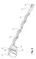
- FIG. 2is an enlarged perspective view of a portion of the implant of FIG. 1 ;
- FIG. 3is a perspective cross-sectional view of the implant portion shown in FIG. 2 ;
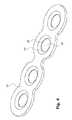
- FIG. 4is a perspective view of a fastening member for use in connection with the implant of FIG. 1 ;
- FIG. 5is a perspective cross-sectional view of the fastening member shown in FIG. 4 ;
- FIG. 6is a schematic cross-sectional view illustrating an angular orientation of a bone fastener relative to a fastening member in accordance with a further embodiment
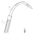
- FIG. 7is an enlarged perspective view of another portion of the implant of FIG. 1 ;
- FIG. 8is a perspective view of a hook member of the implant of FIG. 1 .
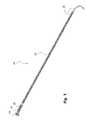
- FIG. 1shows a perspective view of an embodiment of a bone fixation implant 10 .
- the implant 10is configured and dimensioned for fixing bone parts of a sternum. It will be appreciated that the present disclosure is not limited to this surgical indication. Rather, the present disclosure can also be applied in connection with fixing bone parts in other regions of the human anatomy, possibly with suitably adapted configurations and dimensions.
- the implant 10 shown in FIG. 1comprises an elongated member 12 , an engagement member 14 coupled to the elongated member 12 , and a fastening member 16 arranged between and coupled to the elongated member 12 and the engagement member 14 .
- the elongated member 12is configured to be wound around the sternum parts that are to be fixed. As such, the elongated member 12 is made from a generally flexible material and has a suitable length of approximately 10 to 35 cm.
- the engagement member 14is configured to engage a portion of the elongated member 12 so as to secure the implant 10 in a loop around the sternum parts. Details of how the engagement member 14 engages the elongated member 12 will be described in more detail below.
- the implant 10further comprises a hook member 18 coupled to the elongated member 12 at an end thereof opposite to the engagement member 14 .
- the hook member 18is configured to facilitate threading of the elongated member 12 around the sternum parts that are to be fixed. It will be appreciated that depending on the surgical indication, the hook member 18 could also be omitted or substituted by another member (e.g., a linear needle) to support a proper placement of the elongated member 12 by a surgeon.
- the fastening member 16comprises a plurality of openings 20 .
- Each opening 20is configured to receive a bone fastener such as a bone screw or a bone pin.
- the openings 20are substantially aligned with an extension of the elongated member 12 .
- the centers of the openings 20lie on an axis that coincides with an axis of the elongated member 12 in a non-wound (i.e., planar) state.
- the fastening member 16 of the present embodimentcomprises four openings 20 . It will be appreciated that more or less openings 20 could be provided in other embodiments depending on the surgical needs.
- the four openings 20are divided by a visual indicator 22 into two sets of two openings 20 each.
- the visual indicator 22indicates a region of the fastening member 16 to be severed in order to detach the implant 10 after implantation.
- the visual indicator 22has a generally rectangular shape with a larger extension that extends in a direction substantially perpendicular to the extension of the elongated member 12 . The visual indicator 22 thus indicates the direction in which the fastening member 16 is to be severed.
- the visual indicator 22 in the present embodimentmarks a region of reduced mechanical strength of the fastening member 16 (explained in more detail below with reference to FIG. 4 ). As such, the visual indicator 22 indicates the region of the fastening member 16 that is easiest to sever by a surgical cutter in order to detach the implant 10 .
- the visual indicator 22 of the implant 10 after implantationwill generally lie on a line along which the two sternum parts have been joined. That joining line will generally extend perpendicular to the extension of the fastening member 16 . For this reason the visual indicator 22 separates a first set of two openings 20 that will be located proximate to one sternum portion from another set of two openings 16 that will be located proximate to the other sternum portion. Severing the fastening member in the region of the visual indicator 22 will therefore permit to separate the two sternum parts (e.g., in the case of medical complications) even when the bone fasteners attached via the openings 20 to the sternum parts remain in place.
- severing the fastening member 16 in the region of the visual indicator 22 in order to detach the implant 10provides a much quicker access to the thoracic region than detaching the implant 10 by removing multiple bone fasteners inserted to the openings 20 into the sternum parts. It should be noted that after severing the fastening member 16 it may still be required to also sever the elongated member 12 or another portion of the implant 10 to fully separate the sternum parts. In any case, the visual indicator 22 guides the surgeon towards the optimal fastening member region to be severed in order to quickly detach the implant 10 .
- the visual indicator 22may generally be provided in many different ways, for example by printing it on the implant 10 (e.g., directly on the fastening member 10 ), by stamping a line or any other three-dimensional pattern in the implant 10 (e.g., directly in the fastening member 16 ), or in other ways.
- the visual indicator 22is realized during the manufacturing process of the implant 10 by exposing a portion of the fastening member 16 during an injection molding process.
- the fastening member 16is coupled to the elongated member 12 and the engagement member 14 by injection molding.
- the elongated member 12is injection molded to a first end of the fastening member 16
- the engagement member 14is injection molded to an opposite end of the fastening member 16 .
- the visual indicator 22is thus defined by a central portion of the fastening member 16 that remains exposed from injection molding.
- the elongated member 12is injection molded to the fastening member 16 in a first injection molding process and the engagement member 14 is injection molded to the fastening member 16 in a second injection molding process separate from the first injection molding process.
- the two injection molding processesmay be performed essentially at the same point in time or at spaced apart points in time.
- the visual indicator 22may be omitted. In such a case, or in other cases, the fastening member 16 may be injection molded to the elongated member 12 and to the engagement member 14 in a single injection molding process.
- the fastening function of the fastening member 16can best be fulfilled in case the fastening member 26 is made from a rigid material, such as metal (e.g., stainless steel, titanium, or a titanium alloy), especially if compression forces are to be applied via the bone fasteners inserted through the openings 20 .
- the elongated member 12will be manufactured from an at least partially flexible material since it needs to be wound around the bone parts that are to be fixed.
- the elongated membercan be made from a polymeric material such as PEEK.
- the engagement member 14may be made from the same material as the elongated member 12 or from a different material. As an example, the engagement member 14 may also be made from PEEK. In another variant, the engagement member 14 may at least partially be made from the same material as the fastening member 16 . As an example, the engagement member 14 and the fastening member 16 may at least partially be realized as a one-piece structure.
- the present disclosure in relation to the visual indicator 22is not limited to manufacturing the implant 10 using one or more injection molding processes.
- the visual indicator 22could also be realized in connection with an implant 10 that is realized as a one-piece structure (e.g., from a polymeric material and, optionally, in a single injection molding process).
- FIGS. 2 and 3also illustrate the engagement mechanism that allows the engagement member 14 to engage a portion of the elongated member 12 so as to secure the implant 10 in a loop around the sternum parts.
- the elongated member 12comprises a plurality of engagement features 24 that are provided along essentially the entire length of the elongated member 12 (see FIG. 1 ).
- each individual engagement feature 24has a sawtooth-like cross-section with a first surface that extends generally perpendicular to a plane defined by the elongated member 12 in an un-wound state, and a second surface at an angle to that plane.
- the engagement member 14comprises complementary engagement features 26 with a sawtooth-like profile. As shown in FIG. 3 , those complementary engagement features 26 are provided on a deflectable pawl 28 .
- the pawl 28is located within an opening 30 that extends through a head portion 32 of the engagement member 14 .
- the opening 30has an axis that is substantially parallel to a center axis of each of the openings 20 in the fastening member 16 .
- the deflectable pawl 28is attached to the head portion 14 at a bone facing side of the head portion 32 and configured to engage the engagement features 24 of the elongated member 12 in a zip tie-like manner upon threading the elongated member 12 through the opening 30 in the head portion 32 of the engagement member 14 .
- the zip tie-like configuration of the engagement mechanismpermits to generate a compression force when the implant 10 is looped around the sternum parts. This compression force presses the sternum parts against each other and facilitates bone healing.
- the elongated member 12 and the engagement member 14could each also take the form of a band or wire that can be brought into engagement via knot or a dedicated coupling feature.
- the fastening member 16generally takes the form of an elongated bone plate with an undulating outer profile. Specifically, the undulations in the outer profile correspond to the location of the openings 20 in the fastening member 16 .
- the central portion of the fastening member 16i.e., the region between a first set of two adjacent openings and a second set of two adjacent openings
- the central portion of the fastening member 16is the region of the fastening member 16 with the smallest width. As illustrated in FIGS. 2 and 3 , that fastening member region with the smallest width corresponds to the location of the visual indicator 22 .
- the fastening member 16comprises a conically tapering portion 34 towards each opening 20 .
- a spherical tapermay be provided.
- the tapering portion 34permits the generation of compression forces upon inserting a bone fastener through one of the openings 20 .
- the compression forcesresult in the sternum parts being drawn towards the fastening member 16 so as to increase the implant-bone-construct-stability.
- each tapering portion 34ends in a circumferential lip 36 of reduced material thickness around the respective hole 20 .
- the lip 36constitutes a locking feature configured to lock a bone fastener to the fastening member 16 as generally illustrated in FIG. 6 (for a different cross-sectional configuration of the fastening member 16 ).
- FIG. 6illustrates a bone screw 40 with a shaft 42 and a head 44 .
- the shaft 42 of the bone screw 40carries a bone thread 46 configured to engage bone.
- the head 44 of the bone screw 40comprises a further thread 48 configured to engage the circumferential lip 36 at a selected angular orientation.
- the selected angular orientation of the bone screw 40may be within a range of 0° to 10° relative to the central axis of the opening 20 .
- the thread 48 at the head portion 44 of the bone screw 40will engage the circumferential lip 36 to lock the bone screw 40 at the selected angular orientation to the fastening member 14 .
- the thread 48 at the head 44 of the bone screw 40constitutes a locking feature complementary to the circumferential lip 36 at the fastening member 16 .
- circumferential lip 36may be omitted or replaced by another locking feature, such as a thread.
- thread 48 provided at the head 44 of the bone screw 40could also be omitted. In such a case the head 44 of the bone screw 40 could have a smooth and spherically or conically tapering configuration.
- hole 20tapers from a bone facing side of the fastening member 16 towards the lip 36 and also from the opposite side towards the circumferential lip 36 .
- One or both of those taperscould be omitted.
- FIGS. 7 and 8illustrate the hook member 18 as well as the attachment of the hook member 18 to the elongated member 12 .
- the hook member 18comprises a sharpened tip 18 A at one end thereof as well as a structured region 18 B at the opposite end.
- the structured region 18 Bfacilitates injection molding of the elongated member 12 to the hook member 18 , as generally illustrated in FIG. 7 .
- the elongated member 12is wound around the two sternum parts that are to be fixed. Winding the elongated member 12 around the sternum parts is facilitated by the hook member 18 with the sharpened tip 18 A.
- the hook member 18 and then the elongated member 12are threaded through the opening 30 of the engagement member 14 .
- the hook member 18may be cut prior to that threading step, so that only the free end of the elongated member 12 (without the hook member 18 ) is threaded through the corresponding opening 30 .
- the engagement features 24 on the elongated member 12are engaged by the complementary engagement feature 26 on the pawl 29 in a zip tie-like manner (i.e., such that the elongated member 12 can only be tightened, but cannot become loose).
- the elongated member 12is further drawn through the opening 30 so as to tighten the implant 10 around the two sternum parts.
- the surgeonobserves that the visual indicator 22 will substantially be placed on the joining line of the two sternum parts to enable a proper detachment.
- the tightening forceis then increased further so as to compress the sternum parts together.
- the above stepsmay be repeated one or multiple times for one or more further implants 10 .
- For primary closureno further fixing of the implant 10 to the sternum parts using bone fasteners is needed.
- each bone fastenersmay be inserted at a selected angular orientation and may be locked to the implant 10 using the corresponding locking features 36 , 48 .
- the bone fasteners 40may each have a self-drilling thread 46 .
- pilot holesmay be drilled through the openings 20 prior to insertion of the bone fasteners 40 .
- the thread 46may be self-tapping.
- the surgeonuses a cutter to sever the fasting member 16 in the region of the visual indicator 22 .
- the surgeoncuts the elongated member 12 so the sternum parts can be separated from each other.
- the bone fasteners 40may remain in place until after the thoracic region needs to be closed again via a primary or secondary closure process.
Landscapes
- Health & Medical Sciences (AREA)
- Orthopedic Medicine & Surgery (AREA)
- Surgery (AREA)
- Life Sciences & Earth Sciences (AREA)
- Heart & Thoracic Surgery (AREA)
- Nuclear Medicine, Radiotherapy & Molecular Imaging (AREA)
- Engineering & Computer Science (AREA)
- Biomedical Technology (AREA)
- Neurology (AREA)
- Medical Informatics (AREA)
- Molecular Biology (AREA)
- Animal Behavior & Ethology (AREA)
- General Health & Medical Sciences (AREA)
- Public Health (AREA)
- Veterinary Medicine (AREA)
- Prostheses (AREA)
Abstract
Description
Claims (17)
Priority Applications (3)
| Application Number | Priority Date | Filing Date | Title |
|---|---|---|---|
| US16/374,942US11259853B2 (en) | 2015-01-09 | 2019-04-04 | Implant for bone fixation |
| US17/580,901US12396772B2 (en) | 2015-01-09 | 2022-01-21 | Implant for bone fixation |
| US19/024,558US20250152217A1 (en) | 2015-01-09 | 2025-01-16 | Implant for Bone Fixation |
Applications Claiming Priority (3)
| Application Number | Priority Date | Filing Date | Title |
|---|---|---|---|
| EPEP15000033.9 | 2015-01-09 | ||
| EP15000033.9AEP3042622B1 (en) | 2015-01-09 | 2015-01-09 | Implant for bone fixation |
| EP15000033 | 2015-01-09 |
Related Child Applications (1)
| Application Number | Title | Priority Date | Filing Date |
|---|---|---|---|
| US16/374,942ContinuationUS11259853B2 (en) | 2015-01-09 | 2019-04-04 | Implant for bone fixation |
Publications (2)
| Publication Number | Publication Date |
|---|---|
| US20160199111A1 US20160199111A1 (en) | 2016-07-14 |
| US10292742B2true US10292742B2 (en) | 2019-05-21 |
Family
ID=52338971
Family Applications (4)
| Application Number | Title | Priority Date | Filing Date |
|---|---|---|---|
| US14/991,181Active2037-03-01US10292742B2 (en) | 2015-01-09 | 2016-01-08 | Implant for bone fixation |
| US16/374,942Active2036-06-04US11259853B2 (en) | 2015-01-09 | 2019-04-04 | Implant for bone fixation |
| US17/580,901Active2037-10-15US12396772B2 (en) | 2015-01-09 | 2022-01-21 | Implant for bone fixation |
| US19/024,558PendingUS20250152217A1 (en) | 2015-01-09 | 2025-01-16 | Implant for Bone Fixation |
Family Applications After (3)
| Application Number | Title | Priority Date | Filing Date |
|---|---|---|---|
| US16/374,942Active2036-06-04US11259853B2 (en) | 2015-01-09 | 2019-04-04 | Implant for bone fixation |
| US17/580,901Active2037-10-15US12396772B2 (en) | 2015-01-09 | 2022-01-21 | Implant for bone fixation |
| US19/024,558PendingUS20250152217A1 (en) | 2015-01-09 | 2025-01-16 | Implant for Bone Fixation |
Country Status (2)
| Country | Link |
|---|---|
| US (4) | US10292742B2 (en) |
| EP (1) | EP3042622B1 (en) |
Cited By (3)
| Publication number | Priority date | Publication date | Assignee | Title |
|---|---|---|---|---|
| US11259853B2 (en)* | 2015-01-09 | 2022-03-01 | Stryker European Operations Holdings Llc | Implant for bone fixation |
| US11576707B2 (en) | 2013-07-11 | 2023-02-14 | Stryker European Operations Holdings Llc | Fixation assembly with a flexible elongated member for securing parts of a sternum |
| US11596458B2 (en) | 2016-11-11 | 2023-03-07 | Stryker European Operations Holdings Llc | Implant for bone fixation |
Families Citing this family (6)
| Publication number | Priority date | Publication date | Assignee | Title |
|---|---|---|---|---|
| US9131968B2 (en) | 2013-02-27 | 2015-09-15 | Biomet C.V. | Periprosthetic plating system including plate with system for retaining tension on a cable |
| CN119279661A (en) | 2017-01-13 | 2025-01-10 | Tas医药公司 | Systems, devices and methods for closing abdominal wall defects |
| CN106798585A (en)* | 2017-03-06 | 2017-06-06 | 西安康拓医疗技术有限公司 | A kind of Median sternotomy incision suture fixation bandage |
| US11457964B2 (en) | 2018-02-27 | 2022-10-04 | 41Medical Ag | Variable angle bone plate system |
| WO2020056063A1 (en)* | 2018-09-14 | 2020-03-19 | University Of Rochester | Tendon repair implant and surgical instruments for tendon repair |
| CN110480927B (en)* | 2019-08-14 | 2021-03-26 | 西安康拓医疗技术有限公司 | Molding method of PEEK sternum fixing band |
Citations (22)
| Publication number | Priority date | Publication date | Assignee | Title |
|---|---|---|---|---|
| US4535764A (en)* | 1983-04-15 | 1985-08-20 | Tayco Developments, Inc. | Surgical bone tie |
| EP0597259A2 (en) | 1992-10-09 | 1994-05-18 | United States Surgical Corporation | Apparatus for tightening elongated wound closure elements |
| EP0608592A1 (en) | 1993-01-26 | 1994-08-03 | Stony Brook Surgical Innovations, Inc. | Sternum banding assembly |
| US5941881A (en) | 1998-01-09 | 1999-08-24 | Medidea, Llc | Bone fastening apparatus and related procedures |
| WO2002067795A1 (en) | 2001-02-23 | 2002-09-06 | Synthes (U.S.A.) | Sternum fixation device |
| US20020128654A1 (en)* | 1998-02-18 | 2002-09-12 | Steger Shon D. | Method and apparatus for bone fracture fixation |
| US20030212399A1 (en) | 2002-02-25 | 2003-11-13 | Dinh Dzung H. | Methods and apparatuses for promoting fusion of vertebrae |
| US20050070928A1 (en) | 2003-09-09 | 2005-03-31 | Harri Heino | Bioabsorbable band system |
| US20050267475A1 (en) | 2004-05-27 | 2005-12-01 | Miller Archibald S Iii | Surgical device for capturing, positioning and aligning portions of a severed human sternum |
| EP1654994A1 (en) | 2004-11-03 | 2006-05-10 | Walter Lorenz Surgical, Inc. | Method and apparatus for bone fracture fixation |
| US20060116683A1 (en) | 2004-12-01 | 2006-06-01 | Barrall Benjamin S | Unidirectional translation system for bone fixation |
| US20060259141A1 (en) | 2005-05-13 | 2006-11-16 | Walter Lorenz Surgical, Inc. | Pectus bar stabilizer |
| US20060276794A1 (en) | 2005-05-12 | 2006-12-07 | Stern Joseph D | Revisable anterior cervical plating system |
| WO2006135935A1 (en) | 2005-06-13 | 2006-12-21 | Synthes (Usa) | Sternal reconstruction system |
| US20080154312A1 (en) | 2006-12-12 | 2008-06-26 | Dennis Colleran | Active settling plate with elastomeric members and method of use |
| US20100094294A1 (en) | 2008-10-10 | 2010-04-15 | Joel Gillard | Cerclage system for bone |
| US20110015681A1 (en)* | 2009-07-16 | 2011-01-20 | Nexxt Spine, LLC | Cervical Plate Fixation System |
| US20110295257A1 (en) | 2009-03-19 | 2011-12-01 | Mcclellan William Thomas | Systems and methods for sternum repair |
| CN202235628U (en) | 2011-09-23 | 2012-05-30 | 张晓膺 | Sternum closing fixator |
| US20140100573A1 (en)* | 2012-10-08 | 2014-04-10 | Neos Surgery, S.L. | Apparatus and methods for securing together bone fragments |
| US20140142638A1 (en)* | 2012-11-21 | 2014-05-22 | Robert Goodwin | Bone plate system and method |
| WO2014144479A1 (en) | 2013-03-15 | 2014-09-18 | Biomet Microfixation, Llc | Sternal closure cerclage, plate implant and instrumentation |
Family Cites Families (101)
| Publication number | Priority date | Publication date | Assignee | Title |
|---|---|---|---|---|
| US1616232A (en) | 1925-11-27 | 1927-02-01 | Roberts Glen | Screw clamp |
| US3469573A (en) | 1966-05-04 | 1969-09-30 | Michael A Florio | Orthopedic clamp |
| US3926193A (en) | 1971-12-17 | 1975-12-16 | Harrith M Hasson | Surgical closure having ease of assembly |
| US3887965A (en) | 1973-09-04 | 1975-06-10 | Fastway Fasteners | Bundling tie |
| US4003106A (en) | 1975-06-19 | 1977-01-18 | Panduit Corporation | Ladder strap cable tie with pivotal dog |
| US3991444A (en) | 1976-02-18 | 1976-11-16 | Panduit Corporation | Releasable cable tie |
| GB1552677A (en) | 1976-07-06 | 1979-09-19 | Chichester Partridge Ltd | Tie for use in surgery |
| US4136148A (en) | 1976-10-21 | 1979-01-23 | Dennison Manufacturing Co. | Webbed harnessing device |
| US4135749A (en) | 1977-01-19 | 1979-01-23 | Panduit Corp. | Cable tie |
| US4201215A (en) | 1977-09-06 | 1980-05-06 | Crossett E S | Apparatus and method for closing a severed sternum |
| US4279248A (en) | 1979-07-20 | 1981-07-21 | Shlomo Gabbay | Sternum closure device and procedure for using same |
| US4473524A (en) | 1980-02-28 | 1984-09-25 | Paradis Joseph R | Method for molding and stretching a harnessing device |
| US4512346A (en) | 1983-04-25 | 1985-04-23 | Lemole Gerald M | Sternal closure method and means |
| US4583541A (en) | 1984-05-07 | 1986-04-22 | Barry Joseph P | Sternal stabilization device |
| DE8533814U1 (en) | 1985-11-30 | 1986-01-16 | Beiersdorf Ag, 2000 Hamburg | Device for flushing the intestines |
| US4730615A (en) | 1986-03-03 | 1988-03-15 | Pfizer Hospital Products Group, Inc. | Sternum closure device |
| NZ222159A (en) | 1986-10-27 | 1989-12-21 | Johnson & Johnson Prod Inc | Absorbable bone plate |
| US4802477A (en) | 1987-05-07 | 1989-02-07 | Shlomo Gabbay | Sternum closure device |
| US5057111A (en) | 1987-11-04 | 1991-10-15 | Park Joon B | Non-stress-shielding bone fracture healing device |
| US5053212A (en) | 1988-04-20 | 1991-10-01 | Norian Corporation | Intimate mixture of calcium and phosphate sources as precursor to hydroxyapatite |
| US4944753A (en) | 1988-09-26 | 1990-07-31 | Burgess Frank M | Method for producing retro-sternal space |
| SE462137B (en) | 1988-10-18 | 1990-05-14 | Freddy Rafael Astudillo Ley | DEVICE FOR CONNECTING AN OPENING IN STERNUM |
| US5188670A (en) | 1990-04-05 | 1993-02-23 | Norian Corporation | Apparatus for hydroxyapatite coatings of substrates |
| US5164187A (en) | 1990-04-05 | 1992-11-17 | Norian Corporation | Hydroxyapatite prosthesis coatings |
| US5047034A (en) | 1990-05-29 | 1991-09-10 | Ace Orthopedic Manufacturing | Intramedullary rod screw guide |
| US5146654A (en) | 1991-05-03 | 1992-09-15 | Panduit Corp. | Stretched cable tie |
| GB9111972D0 (en) | 1991-06-04 | 1991-07-24 | Clinical Product Dev Ltd | Medical/surgical devices |
| WO1995005782A1 (en) | 1993-08-27 | 1995-03-02 | Robin Peter Brown | Apparatus and method for surgically securing bone parts |
| US5653711A (en) | 1994-08-08 | 1997-08-05 | Kijuro Hayano | Wire fastening tool |
| US5496399A (en) | 1994-08-23 | 1996-03-05 | Norian Corporation | Storage stable calcium phosphate cements |
| US5520690A (en) | 1995-04-13 | 1996-05-28 | Errico; Joseph P. | Anterior spinal polyaxial locking screw plate assembly |
| EP0806212B1 (en) | 1996-05-10 | 2003-04-02 | IsoTis N.V. | Device for incorporation and release of biologically active agents |
| US6004323A (en) | 1997-02-04 | 1999-12-21 | The University Of Iowa Research Foundation | Surgically implantable fastening system |
| US5827286A (en) | 1997-02-14 | 1998-10-27 | Incavo; Stephen J. | Incrementally adjustable tibial osteotomy fixation device and method |
| IL120636A0 (en) | 1997-04-10 | 1997-08-14 | Technion Res & Dev Foundation | Kit for sternum fixation in chest surgery |
| US6007538A (en) | 1997-07-25 | 1999-12-28 | Duke University | Sternal closure device |
| US6051007A (en) | 1998-03-02 | 2000-04-18 | Corvascular, Inc. | Sternal closure device and instruments therefor |
| US5968253A (en) | 1998-07-31 | 1999-10-19 | Norian Corporation | Calcium phosphate cements comprising antimicrobial agents |
| US6045572A (en) | 1998-10-16 | 2000-04-04 | Cardiac Assist Technologies, Inc. | System, method and apparatus for sternal closure |
| US6093201A (en) | 1999-01-19 | 2000-07-25 | Ethicon, Inc. | Biocompatible absorbable polymer plating system for tissue fixation |
| US6190389B1 (en) | 1999-11-09 | 2001-02-20 | Bioplate, Inc. | Bone alignment and fixation device and method |
| US6331179B1 (en) | 2000-01-06 | 2001-12-18 | Spinal Concepts, Inc. | System and method for stabilizing the human spine with a bone plate |
| US6730127B2 (en) | 2000-07-10 | 2004-05-04 | Gary K. Michelson | Flanged interbody spinal fusion implants |
| US6558709B2 (en) | 2001-01-05 | 2003-05-06 | Howmedica Osteonics Corp. | Calcium phosphate composition and method of preparing same |
| IS6389A (en) | 2001-08-31 | 2003-03-03 | Heraeus Kulzer Gmbh & Co. Kg | Experiences of antibiotic coating of carcasses containing microspheres, and also of such coated carcasses and their use |
| US6652530B2 (en) | 2001-09-19 | 2003-11-25 | The University Of Hong Kong | Fixation device |
| US6596338B2 (en) | 2001-10-24 | 2003-07-22 | Howmedica Osteonics Corp. | Antibiotic calcium phosphate coating |
| US20030083694A1 (en) | 2001-10-31 | 2003-05-01 | Miller Archibald S. | Method and apparatus for closing a severed sternum |
| US6540769B1 (en) | 2001-10-31 | 2003-04-01 | Miller, Iii Archibald S. | Method and apparatus for closing a severed sternum |
| US7001389B1 (en)* | 2002-07-05 | 2006-02-21 | Navarro Richard R | Fixed and variable locking fixation assembly |
| KR100505131B1 (en) | 2002-07-11 | 2005-08-01 | 메디칸(주) | Surgical saw system for the non-incisional zygoma infracture technique through a stab incision |
| US6712821B2 (en) | 2002-07-12 | 2004-03-30 | Shlomo Gabbay | Sternum closure apparatus and method for helping maintain a space between parts of the sternum |
| US20060134160A1 (en) | 2002-09-13 | 2006-06-22 | The University Of British Columbia | Calcium phosphate coated implantable medical devices and processes for making same |
| US7914561B2 (en) | 2002-12-31 | 2011-03-29 | Depuy Spine, Inc. | Resilient bone plate and screw system allowing bi-directional assembly |
| IL154814A0 (en) | 2003-03-09 | 2003-10-31 | Edward G Shifrin | Sternal closure system, method and apparatus therefor |
| DE10326690B4 (en) | 2003-06-04 | 2005-04-28 | Aesculap Ag & Co Kg | Sternum closure |
| US7017237B2 (en) | 2003-12-02 | 2006-03-28 | Thomas & Betts International, Inc. | High performance cable tie |
| AT413479B (en) | 2003-12-12 | 2006-03-15 | Rokitansky Alexander Dr | IMPLANT FOR THE CHICKEN BREAST CORRECTION |
| ITRM20040082A1 (en) | 2004-02-16 | 2004-05-16 | Sic Brevetti S R L | POST STERNOTOMY OR STERNAL FRACTURE REINFORCEMENT DEVICE. |
| US7740649B2 (en) | 2004-02-26 | 2010-06-22 | Pioneer Surgical Technology, Inc. | Bone plate system and methods |
| US20050277939A1 (en) | 2004-05-27 | 2005-12-15 | Miller Archibald S Iii | Surgical device for capturing, positioning and aligning portions of a horizontally severed human sternum |
| US7008429B2 (en) | 2004-06-23 | 2006-03-07 | Golobek Donald D | Bio-absorbable bone tie with convex head |
| US8518089B2 (en) | 2005-01-25 | 2013-08-27 | Karl-Leibinger Medizintechnik | Lock and release mechanism for a sternal clamp |
| US20090118774A1 (en) | 2005-02-09 | 2009-05-07 | Mavrek Medical, Llc. | Sternal Closure Device with Ratchet Closure Mechanism |
| US7749256B2 (en) | 2005-04-05 | 2010-07-06 | Warsaw Orthopedic, Inc. | Ratcheting fixation plate |
| US7871411B2 (en) | 2005-08-12 | 2011-01-18 | Mark Grevious | Sternal closure device |
| US7803176B2 (en) | 2005-08-19 | 2010-09-28 | Kls-Martin, L.P. | Sternal closure clamp device |
| WO2007044229A2 (en) | 2005-09-28 | 2007-04-19 | Calcitec, Inc. | Surface treatments for calcium phosphate-based implants |
| US7695473B2 (en) | 2006-01-18 | 2010-04-13 | Biodynamics Llc | Adjustable bone plate |
| US7730592B2 (en) | 2006-02-09 | 2010-06-08 | Panduit Corp. | In-line cable tie with fixed and hinged locking mechanisms |
| US20070259101A1 (en) | 2006-05-02 | 2007-11-08 | Kleiner Lothar W | Microporous coating on medical devices |
| DE102006046428A1 (en) | 2006-09-22 | 2008-04-03 | Aesculap Ag & Co. Kg | sternal closure |
| DE102006046424B3 (en) | 2006-09-22 | 2007-11-08 | Aesculap Ag & Co. Kg | Sternum closure comprises pairs of plates with L-shaped cross-section positioned on inner surface of sternum and plates with C-shaped cross-section on its outer surface, plates being fastened together by pins passing through them |
| US20100318085A1 (en) | 2007-03-13 | 2010-12-16 | Smith & Nephew, Inc. | Internal fixation devices |
| US8328867B2 (en) | 2007-06-08 | 2012-12-11 | Medtronic Vascular, Inc. | Drug loaded implantable medical device |
| BRPI0818349A2 (en) | 2007-10-12 | 2015-04-07 | Synthes Gmbh | Reconstruction device |
| US20090118775A1 (en) | 2007-11-01 | 2009-05-07 | Burke Shawn M | Sternal Clamp |
| US8366754B2 (en) | 2007-11-02 | 2013-02-05 | Kls-Martin, L.P. | Bi-directionally expandable sternal clamp device |
| DE102008008517B4 (en) | 2008-02-11 | 2014-12-31 | Stryker Trauma Gmbh | Antimicrobial finish of titanium and titanium alloys with silver |
| US20090248091A1 (en) | 2008-03-19 | 2009-10-01 | Mike Teague | Sternal clamp with rib extension |
| CN101537208A (en) | 2008-03-21 | 2009-09-23 | 中国科学院金属研究所 | Biological active coating on surface of titanium or titanium alloy and preparation method thereof |
| US20090269480A1 (en) | 2008-04-24 | 2009-10-29 | Medtronic Vascular, Inc. | Supercritical Fluid Loading of Porous Medical Devices With Bioactive Agents |
| JP5613668B2 (en) | 2008-08-19 | 2014-10-29 | コルポラシオ サニタリア パルク タウリ | Devices and kits for use in funnel chest surgical procedures |
| US8015662B2 (en) | 2008-08-27 | 2011-09-13 | Euro-Pro Operating Llc | Cleaning device |
| US7934297B2 (en) | 2008-09-22 | 2011-05-03 | Mark Kent Williams | Twist off tamper-proof fastener |
| SE535536C2 (en) | 2009-04-27 | 2012-09-11 | Biomatcell Ab | Ion-substituted hydroxyapatite coatings |
| DE102010021737A1 (en) | 2010-05-21 | 2011-11-24 | Aesculap Ag | Bone plate for use as sternal closure to connect two bone parts during maxillofacial surgery, has projections pressed into bone parts and arranged at distance from each other in series for staying along direction from contact surface |
| CN201727571U (en) | 2010-06-07 | 2011-02-02 | 刘鸿箫 | Median incision connector for breastbone |
| WO2013013218A2 (en) | 2011-07-20 | 2013-01-24 | Horwitz Michael H | Minimal incision removable bone screw, driver, and method of use |
| DE102011109677B4 (en) | 2011-08-08 | 2018-07-26 | Human Tech Germany Gmbh | Plate system for cervical stabilization and fixation |
| US10369253B2 (en) | 2011-10-31 | 2019-08-06 | The University Of Toledo | Method for modifying surfaces for better osseointegration |
| FR2982507B1 (en) | 2011-11-14 | 2016-05-20 | Obl | METHOD FOR SURFACE TREATMENT OF TITANIUM BONE IMPLANTS SUCCESSIVELY USING SODIUM HYDROXIDE BATH AND ANODIZATION |
| US9517096B2 (en) | 2012-01-10 | 2016-12-13 | The Charlotte-Mecklenburg Hospital Authority | Method and system for longitudinal closure of dissected sternums |
| EP2830512B1 (en)* | 2012-03-28 | 2016-08-03 | Synthes GmbH | Bone fixation member systems |
| CA2899167C (en) | 2013-01-25 | 2021-08-31 | DePuy Synthes Products, Inc. | Caps for implants, implant assemblies, and methods of use |
| US10433889B2 (en) | 2013-07-11 | 2019-10-08 | Stryker European Holdings I, Llc | Fixation assembly with a flexible elongated member for securing parts of a sternum |
| JP6585071B2 (en) | 2014-03-14 | 2019-10-02 | ジンマー バイオメット シーエムエフ アンド ソラシック,リミティド ライアビリティ カンパニー | Closure system |
| EP3042622B1 (en)* | 2015-01-09 | 2018-05-09 | Stryker European Holdings I, LLC | Implant for bone fixation |
| CN105877831B (en) | 2015-02-18 | 2020-09-25 | 比德尔曼技术有限责任两合公司 | Bone plate |
| CA3041845A1 (en) | 2016-10-27 | 2018-05-03 | Eca Medical Instruments | Flexible radiopaque trial, plate and method of use |
| EP3320867B1 (en) | 2016-11-14 | 2021-08-04 | Biedermann Technologies GmbH & Co. KG | Modular bone plate and member of such a modular bone plate |
- 2015
- 2015-01-09EPEP15000033.9Apatent/EP3042622B1/enactiveActive
- 2016
- 2016-01-08USUS14/991,181patent/US10292742B2/enactiveActive
- 2019
- 2019-04-04USUS16/374,942patent/US11259853B2/enactiveActive
- 2022
- 2022-01-21USUS17/580,901patent/US12396772B2/enactiveActive
- 2025
- 2025-01-16USUS19/024,558patent/US20250152217A1/enactivePending
Patent Citations (28)
| Publication number | Priority date | Publication date | Assignee | Title |
|---|---|---|---|---|
| US4535764A (en)* | 1983-04-15 | 1985-08-20 | Tayco Developments, Inc. | Surgical bone tie |
| EP0597259A2 (en) | 1992-10-09 | 1994-05-18 | United States Surgical Corporation | Apparatus for tightening elongated wound closure elements |
| US5417698A (en) | 1992-10-09 | 1995-05-23 | United States Surgical Corporation | Apparatus for tightening elongated wound closure elements |
| EP0608592A1 (en) | 1993-01-26 | 1994-08-03 | Stony Brook Surgical Innovations, Inc. | Sternum banding assembly |
| US5941881A (en) | 1998-01-09 | 1999-08-24 | Medidea, Llc | Bone fastening apparatus and related procedures |
| US20020128654A1 (en)* | 1998-02-18 | 2002-09-12 | Steger Shon D. | Method and apparatus for bone fracture fixation |
| WO2002067795A1 (en) | 2001-02-23 | 2002-09-06 | Synthes (U.S.A.) | Sternum fixation device |
| US6872210B2 (en) | 2001-02-23 | 2005-03-29 | James P. Hearn | Sternum fixation device |
| US20030212399A1 (en) | 2002-02-25 | 2003-11-13 | Dinh Dzung H. | Methods and apparatuses for promoting fusion of vertebrae |
| US20050070928A1 (en) | 2003-09-09 | 2005-03-31 | Harri Heino | Bioabsorbable band system |
| US20050267475A1 (en) | 2004-05-27 | 2005-12-01 | Miller Archibald S Iii | Surgical device for capturing, positioning and aligning portions of a severed human sternum |
| EP1654994A1 (en) | 2004-11-03 | 2006-05-10 | Walter Lorenz Surgical, Inc. | Method and apparatus for bone fracture fixation |
| US20060116683A1 (en) | 2004-12-01 | 2006-06-01 | Barrall Benjamin S | Unidirectional translation system for bone fixation |
| US20060276794A1 (en) | 2005-05-12 | 2006-12-07 | Stern Joseph D | Revisable anterior cervical plating system |
| US20060259141A1 (en) | 2005-05-13 | 2006-11-16 | Walter Lorenz Surgical, Inc. | Pectus bar stabilizer |
| WO2006135935A1 (en) | 2005-06-13 | 2006-12-21 | Synthes (Usa) | Sternal reconstruction system |
| US20080154312A1 (en) | 2006-12-12 | 2008-06-26 | Dennis Colleran | Active settling plate with elastomeric members and method of use |
| US8486114B2 (en) | 2008-10-10 | 2013-07-16 | Acute Innovations Llc | Cerclage system for bone |
| WO2010042946A1 (en) | 2008-10-10 | 2010-04-15 | Acute Innovations, Llc | Cerclage system for bone |
| US20100094294A1 (en) | 2008-10-10 | 2010-04-15 | Joel Gillard | Cerclage system for bone |
| US20110295257A1 (en) | 2009-03-19 | 2011-12-01 | Mcclellan William Thomas | Systems and methods for sternum repair |
| US8460295B2 (en) | 2009-03-19 | 2013-06-11 | Figure 8 Surgical, Inc. | Systems and methods for sternum repair |
| US20110015681A1 (en)* | 2009-07-16 | 2011-01-20 | Nexxt Spine, LLC | Cervical Plate Fixation System |
| CN202235628U (en) | 2011-09-23 | 2012-05-30 | 张晓膺 | Sternum closing fixator |
| US20140100573A1 (en)* | 2012-10-08 | 2014-04-10 | Neos Surgery, S.L. | Apparatus and methods for securing together bone fragments |
| US20140142638A1 (en)* | 2012-11-21 | 2014-05-22 | Robert Goodwin | Bone plate system and method |
| WO2014144479A1 (en) | 2013-03-15 | 2014-09-18 | Biomet Microfixation, Llc | Sternal closure cerclage, plate implant and instrumentation |
| US20150045794A1 (en)* | 2013-03-15 | 2015-02-12 | Biomet Microfixation, Llc | Sternal Closure Cerclage, Plate Implant And Instrumentation |
Non-Patent Citations (4)
| Title |
|---|
| European Search Report for EP 13003896.1 dated Jul. 17, 2014. |
| Extended European Search Report for Application No. 15000033.9 dated Jun. 24, 2015. |
| International Preliminary Report on Patentability Chapter II, for Application No. PCT/EP2013/066408 dated Sep. 25, 2015. |
| International Search Report and Written Opinion for Application No. PCT/EP2013/066408 dated Oct. 22, 2013. |
Cited By (4)
| Publication number | Priority date | Publication date | Assignee | Title |
|---|---|---|---|---|
| US11576707B2 (en) | 2013-07-11 | 2023-02-14 | Stryker European Operations Holdings Llc | Fixation assembly with a flexible elongated member for securing parts of a sternum |
| US11259853B2 (en)* | 2015-01-09 | 2022-03-01 | Stryker European Operations Holdings Llc | Implant for bone fixation |
| US12396772B2 (en) | 2015-01-09 | 2025-08-26 | Stryker European Operations Holdings Llc | Implant for bone fixation |
| US11596458B2 (en) | 2016-11-11 | 2023-03-07 | Stryker European Operations Holdings Llc | Implant for bone fixation |
Also Published As
| Publication number | Publication date |
|---|---|
| US20220142689A1 (en) | 2022-05-12 |
| US20250152217A1 (en) | 2025-05-15 |
| US20160199111A1 (en) | 2016-07-14 |
| EP3042622B1 (en) | 2018-05-09 |
| US20190223928A1 (en) | 2019-07-25 |
| US11259853B2 (en) | 2022-03-01 |
| US12396772B2 (en) | 2025-08-26 |
| EP3042622A1 (en) | 2016-07-13 |
Similar Documents
| Publication | Publication Date | Title |
|---|---|---|
| US12396772B2 (en) | Implant for bone fixation | |
| US11576707B2 (en) | Fixation assembly with a flexible elongated member for securing parts of a sternum | |
| US11596458B2 (en) | Implant for bone fixation | |
| US5797916A (en) | Trochanteric reattachment cerclage device | |
| US12178482B2 (en) | Orthopaedic fixation devices, systems and methods | |
| US8696670B2 (en) | Fixation device for the fixation of bone fragments | |
| US8398678B2 (en) | Hallux valgus repairs using suture-button construct | |
| US20120041441A1 (en) | Cable tie system for stabilizing bone | |
| US20120004690A1 (en) | Screw fixation system | |
| EP2853233B1 (en) | Tissue fixation system with auxiliary plate | |
| US10231762B2 (en) | Bone plate system | |
| US20210186580A1 (en) | Knotless suture locking bone plate | |
| US20190254713A1 (en) | Knotless syndesmosis system | |
| US20070055258A1 (en) | Suture band | |
| US20140148863A1 (en) | Orthopaedic fixation apparatus and method | |
| KR20210136034A (en) | Suture tensioning and anchoring devices, systems, and methods |
Legal Events
| Date | Code | Title | Description |
|---|---|---|---|
| AS | Assignment | Owner name:STRYKER LEIBINGER GMBH & CO. KG, GERMANY Free format text:ASSIGNMENT OF ASSIGNORS INTEREST;ASSIGNORS:KNOEPFLE, CHRISTIAN;GREINER, KARL;SCHMUCK, MANFRED;REEL/FRAME:040160/0157 Effective date:20160229 | |
| AS | Assignment | Owner name:STRYKER EUROPEAN HOLDINGS I, LLC, MICHIGAN Free format text:ASSIGNMENT OF ASSIGNORS INTEREST;ASSIGNOR:STRYKER LEIBINGER GMBH & CO. KG;REEL/FRAME:040174/0440 Effective date:20160301 | |
| STPP | Information on status: patent application and granting procedure in general | Free format text:NOTICE OF ALLOWANCE MAILED -- APPLICATION RECEIVED IN OFFICE OF PUBLICATIONS | |
| STPP | Information on status: patent application and granting procedure in general | Free format text:PUBLICATIONS -- ISSUE FEE PAYMENT VERIFIED | |
| STCF | Information on status: patent grant | Free format text:PATENTED CASE | |
| AS | Assignment | Owner name:STRYKER EUROPEAN HOLDINGS III, LLC, DELAWARE Free format text:NUNC PRO TUNC ASSIGNMENT;ASSIGNOR:STRYKER EUROPEAN HOLDINGS I, LLC;REEL/FRAME:056969/0771 Effective date:20210219 Owner name:STRYKER EUROPEAN OPERATIONS HOLDINGS LLC, MICHIGAN Free format text:CHANGE OF NAME;ASSIGNOR:STRYKER EUROPEAN HOLDINGS III, LLC;REEL/FRAME:056969/0893 Effective date:20190226 | |
| MAFP | Maintenance fee payment | Free format text:PAYMENT OF MAINTENANCE FEE, 4TH YEAR, LARGE ENTITY (ORIGINAL EVENT CODE: M1551); ENTITY STATUS OF PATENT OWNER: LARGE ENTITY Year of fee payment:4 | |
| AS | Assignment | Owner name:STRYKER EUROPEAN OPERATIONS HOLDINGS LLC, MICHIGAN Free format text:CHANGE OF ADDRESS;ASSIGNOR:STRYKER EUROPEAN OPERATIONS HOLDINGS LLC;REEL/FRAME:069730/0754 Effective date:20241217 |