US10292619B2 - Patient breathing modeling - Google Patents
Patient breathing modelingDownload PDFInfo
- Publication number
- US10292619B2 US10292619B2US12/170,385US17038508AUS10292619B2US 10292619 B2US10292619 B2US 10292619B2US 17038508 AUS17038508 AUS 17038508AUS 10292619 B2US10292619 B2US 10292619B2
- Authority
- US
- United States
- Prior art keywords
- patient
- breathing cycle
- breathing
- points
- interest
- Prior art date
- Legal status (The legal status is an assumption and is not a legal conclusion. Google has not performed a legal analysis and makes no representation as to the accuracy of the status listed.)
- Active, expires
Links
Images


Classifications
- A—HUMAN NECESSITIES
- A61—MEDICAL OR VETERINARY SCIENCE; HYGIENE
- A61B—DIAGNOSIS; SURGERY; IDENTIFICATION
- A61B5/00—Measuring for diagnostic purposes; Identification of persons
- A61B5/06—Devices, other than using radiation, for detecting or locating foreign bodies ; Determining position of diagnostic devices within or on the body of the patient
- A61B5/065—Determining position of the probe employing exclusively positioning means located on or in the probe, e.g. using position sensors arranged on the probe
- A61B5/066—Superposing sensor position on an image of the patient, e.g. obtained by ultrasound or x-ray imaging
- A—HUMAN NECESSITIES
- A61—MEDICAL OR VETERINARY SCIENCE; HYGIENE
- A61B—DIAGNOSIS; SURGERY; IDENTIFICATION
- A61B1/00—Instruments for performing medical examinations of the interior of cavities or tubes of the body by visual or photographical inspection, e.g. endoscopes; Illuminating arrangements therefor
- A61B1/267—Instruments for performing medical examinations of the interior of cavities or tubes of the body by visual or photographical inspection, e.g. endoscopes; Illuminating arrangements therefor for the respiratory tract, e.g. laryngoscopes, bronchoscopes
- A—HUMAN NECESSITIES
- A61—MEDICAL OR VETERINARY SCIENCE; HYGIENE
- A61B—DIAGNOSIS; SURGERY; IDENTIFICATION
- A61B34/00—Computer-aided surgery; Manipulators or robots specially adapted for use in surgery
- A61B34/10—Computer-aided planning, simulation or modelling of surgical operations
- A61B2034/101—Computer-aided simulation of surgical operations
- A61B2034/105—Modelling of the patient, e.g. for ligaments or bones
- A—HUMAN NECESSITIES
- A61—MEDICAL OR VETERINARY SCIENCE; HYGIENE
- A61B—DIAGNOSIS; SURGERY; IDENTIFICATION
- A61B6/00—Apparatus or devices for radiation diagnosis; Apparatus or devices for radiation diagnosis combined with radiation therapy equipment
- A61B6/54—Control of apparatus or devices for radiation diagnosis
- A61B6/541—Control of apparatus or devices for radiation diagnosis involving acquisition triggered by a physiological signal
Definitions
- the method of the present inventionrelates generally to the accurate registration of a detected sensor located in moving lungs to a static image of the lungs.
- the evolution of procedures using less-invasive scopeshas resulted in the development of sensors that can be attached to end of an endoscope and used to determine the three-dimensional location and orientation of the end of the endoscope. Examples of such sensor technology is shown and described in various patents and patent publications including U.S. Pat. No. 6,188,355 to Gilboa, U.S. Pat. No. 6,380,732 to Gilboa, U.S. Pat. No. 6,593,884 to Gilboa et al., U.S. Pat. No. 6,615,155 to Gilboa, U.S. Pat. No.
- a displayin order to provide information that is useful to a physician, a display must be used that shows a representation of the tool superimposed on an image of the lungs. If a static image of the lungs is used, the tool, which is moving with the lungs as the patient breathes, appears to float in and out of the airways in the preliminary, relatively static image. Accurately matching the position of the sensor in the lungs to an image of the lungs is achieved by “registration.” Ideally, the desired result of registration would involve matching the tool representation to a real-time, dynamic image of the lungs. However, this would require constant exposure to X-ray radiation by both the patient and the medical staff during while performing the dynamic registration.
- Shaois directed to reconciling a dynamic, PET imaging data set with a static CT imaging data set. Shao accomplishes this by merely morphing (stretching or distorting) the image sets together. Doing so does not necessarily improve the accuracy of the real-time data being displayed because at least one of the data sets is being distorted. Rather, this approach merely makes the display appear to be more accurate. Moreover, PET requires prolonged exposure to radioactive imaging agents.
- the method of the present inventionprovides a representative modeling of the human lungs, based on statistical anatomical data, which can be tailored to the size and shape of an individual patient.
- the method of the present inventionalso utilizes a compilation of statistical anatomical data regarding lung movement in order to predict the movement of an individual patient's lungs during the breathing cycle.
- Breathingcauses the lungs to move cyclically.
- the movementvaries by amplitude and direction during the breathing cycle from 5 mm to 30 mm depending on such breathing characteristics as patient size, age, altitude, health, etc.
- this movementcauses between a living patient and a static image, lung movement is modeled.
- Dynamic modelingis based on a comparison of multiple CT data sets.
- one or more static imagesmay be “brought to life” by applying a mathematical model that predicts how a given point in the lungs will move during the breathing cycle, based on a large sample of statistical data.
- the mathematical modelis tied to one or more external position sensors on the patient's chest. Hence, by monitoring the external sensor(s), and applying the mathematical movement model, an instantaneous position of a given point in the lungs can be predicted.
- the patient's breathing cycle and its parametersmay alternatively be monitored using internal sensors, or other devices such as spirometry devices, for example.
- each data setwill preferably include at least one exhale scan and one inhale CT scan, acquired while the patient is holding an exhaled state or inhaled state, respectively. These scans will then be used as the extreme positions of the patient's breathing cycle.
- the aforementioned mathematical movement modelis then used to fill in the lung positions between the inhalation and exhalation points acquired by the CT scans of the actual patient. Additionally, any scans taken of the patient's lungs in intermediate breathing positions could also be added to the dynamic modeling set. Such acquired actual position data may be used to validate or modify the mathematical model as appropriate.
- the path a given point in a lung travels between inhalation and exhalationcan be described mathematically and stored in a computer.
- the mathematical equations of the movementcan be tied to one or more marker positions, so as the patient breathes, the computer may calculate the corresponding position of the point based on the position of the one or more markers.
- the computercan then implement the mathematical equations stored for a plurality of points to either create a dynamic representation of the lungs and present this to the user via a display, or synchronize this movement with the real-time movement of the LG and present the LG as though it were not moving cyclically, just advancing and turning according to its manipulation by the user.
- the computercan use the plurality of mathematical equations as a filter, applied to the graphic display of the LG.
- Constantly measuring the point at which a patient is in the breathing cycleallows a corresponding CT scan, which is closer to the actual position to the location of the sensor to be displayed over the sensor image.
- the measured location of the toolcan be corrected using the patient breathing model. In this way the tool may be localized more correctly inside the CT volume. And therefore any geometric model derived from the CT volume can be more accurately represented relative to the tool inside the body.
- the CT Volumecan be changed dynamically using the patient breathing model and according to the monitored phase of breathing cycle.
- Thiscan be used to display augmented reality images to perform the simulation of dynamic X-Ray modalities such as fluoroscopy, dynamic CT, etc., to simulate the patient physiology synchronized to the actual patient, study the tissue movement relative to the inserted tools, and for other purposes as well.
- FIG. 1is a flowchart of one embodiment of the method of the present invention
- FIG. 2is a flowchart of a second embodiment of the method of the present invention.
- FIGS. 3-12are graphs and charts showing the data results of experiments conducted on seven patients using the methods of the present invention.
- FIG. 1there is shown a flowchart that illustrates one embodiment 20 of the method of the present invention.
- Patient characteristicsis a term defined herein as any attribute of the patient that will influence the position of his or her lungs during any given point in the breathing cycle.
- Patient characteristicsinclude, but are not limited to patient size (lung size), lung shape, lung health, altitude, patient age, diaphragm size, and diaphragm health.
- altitudeis not intrinsic to any given patient, the elevation at which a patient is breathing impacts the depth and/or the frequency of the breaths taken during the breathing cycle.
- Lung healthrelates to the lung capacity of a given patient and includes such factors as whether the patient smokes, whether the patient has an increased lung capacity due to athletic training, whether the patient has a condition such as cystic fibrosis, etc.
- the patientis imaged using any imaging modality that shows the lungs or desired target area.
- CT imagingwill be used.
- the CT imagingmay be high definition CT and preferably a first image set is taken with the lungs full of air and a second image set is taken after the patient has fully exhaled.
- a single CT image setmay be used if there is accurate data regarding how full the lungs are when the image is taken.
- AOIarea of interest
- the patient position sensorsare sensors on the chest, sensors in the lungs, or a device such as a spirometry device, that are used to measure the positions of key points on the patient's body in order to determine where the patient is in the breathing cycle.
- the data from these sensorsare not only used as an entering argument for the upcoming mathematical modeling step 70 , but also to monitor the physical location of the patient in order to register a real-time image (such as that acquired to show the position of the locatable guide) to the CT scan image(s).
- a mathematical modelis developed to describe the movement at one or more points in the AOI(s) during the breathing cycle.
- the mathematical modeluses data from the patient position sensors as entering arguments and the result of the solved algorithm is a three dimensional position of the point in question. Selecting more points in a given AOI will result in a better registration between a display of the locatable guide (LG) and the CT scan taken at 40 .
- the mathematical algorithm used to develop the modelmay be obtained by collecting data on a number of subjects in a study and relating the movement of given points to the point in the breathing cycle in which the positions were acquired.
- the mathematical algorithmmay be developed using computer simulated models, such as those described in the aforementioned Garrity et al. reference. Examples of algorithms developed for the present invention and proven useful through experimentation are described below.
- the procedurebegins on the patient.
- the patient movement sensorsare placed on or in the patient.
- the physicianintubates the patient and the LG is inserted and tracked.
- the CT scan from 40is displayed and registered to the superimposed LG display.
- the location(s) of the patient location sensorsare constantly monitored and entered into the algorithm to provide three dimensional location data on the AOI(s). This information is then used at 90 to ensure that the display is modified such that the LG display maintains an accurate registration with the CT scan, despite the movement of the lungs, which cause the LG to move.
- the data acquired at 80may be used to determine which CT scan most accurately depicts the configuration of the lungs and can thus be superimposed onto the LG display.
- the measured location of the LGcan be corrected using the data acquired at 80 .
- the real-time datais manipulated so the LG appears in the correct location on the CT scan, which may be static or dynamic. In this way the tool may be localized more correctly inside the CT volume.
- the geometric model derived from the CT volumecan thus be more accurately represented relative to the tool inside the body.
- the CT Volumecan be changed dynamically using the data acquired at 80 and according to the monitored phase of breathing cycle.
- Thiscan be used to display augmented images to perform the simulation of dynamic X-Ray modalities such as fluoroscopy, dynamic CT, etc., to simulate the patient physiology synchronized to the actual patient, study the tissue movement relative to the inserted tools, and for other purposes as well.
- FIG. 2there is shown a flowchart that illustrates another embodiment 120 of the method of the present invention.
- Patient characteristicsis a term defined herein as any attribute of the patient that will influence the position of his or her lungs during any given point in the breathing cycle.
- Patient characteristicsinclude, but are not limited to patient size (lung size), lung shape, lung health, altitude, patient age, diaphragm size, and diaphragm health.
- altitudeis not intrinsic to any given patient, the elevation at which a patient is breathing impacts the depth and/or the frequency of the breaths taken during the breathing cycle.
- Lung healthrelates to the lung capacity of a given patient and includes such factors as whether the patient smokes, whether the patient has an increased lung capacity due to athletic training, whether the patient has a condition such as cystic fibrosis, etc.
- the patientis imaged using any imaging modality that shows the lungs or desired target area. Most likely, CT imaging will be used. Preferably a first image set is taken with the lungs full of air and a second image set is taken after the patient has fully exhaled.
- the patientis matched to an archived data set taken from a data library. It is desirable to find an archived data set that matches the patient's breathing cycle as closely as possible.
- the patient characteristicsare used as matching criteria. The specific characteristics that are used, and the number of different characteristics that are used, are largely dependent on the size of the data library. However, if the patient has any distinguishing lung traits, such as a significantly reduced capacity due to smoking, they should be given more weight than other, less-distinguishing traits when looking for a matching data set.
- the inhaled and exhaled positions recorded and measured using CT scanscould be used as the entering arguments for matching the patient to a data set. If the inhaled and exhaled positions are closely matched to a data set, it will be likely that the intermediate points between inhalation and exhalation will also match. However, considerations like patient size should still be considered to ensure that the lung geometries are also matched.
- a CT image set for the patientis generated.
- the closely-matched data setis either used alone, or if inhalation and exhalation CT scans have been taken, they are added to the data set to improve the degree to which the data set is matched to the actual patient geometry.
- each image of the image setis assigned to a lung position, as measured by external or internal means. Because each of the images will be displayed during the procedure at different times during the breathing cycle, it is necessary to determine, in advance, when each image will be cued for display. There are at least two ways in which this may be done. First, the positions of sensors, such as external sensors placed on the patient's chest, may be monitored throughout the breathing cycle. Each image may be examined to determine a position of the lungs that is most closely matched to that particular image. When the external sensors indicate a particular lung position, the image will be changed to the most closely matched image.
- sensorssuch as external sensors placed on the patient's chest
- an average breathing cyclemay be measured to determine the inhaling period (defined herein as the amount of time between inhalation and exhalation) and the exhaling period (defined herein as the amount of time between exhalation and inhalation).
- the inhaling perioddefined herein as the amount of time between inhalation and exhalation
- the exhaling perioddefined herein as the amount of time between exhalation and inhalation.
- the measured periodsmay be divided by the number of intermediate images in the data set to determine an interval time. The images will then be changed each interval.
- the actual procedurebegins.
- the lung positionis monitored. If the first method at 170 was used, sensors on the chest, sensors in the lungs, or a device such as a spirometry device is used to determine when the images shall be displayed at 190 to most accurately represent the actual lungs. If the second method at 170 was used, the breathing cycle will be monitored using any of the aforementioned sensors or devices, to update the average inhaling and exhaling periods of the breathing cycle. At 190 , the images will be changed according to the constantly-updated intervals.
- the second method at 160avoids the process of examining each individual image of the data set to assign it to a point in the breathing cycle.
- the first methodis used and the lung positions are monitored to determine which image to display at 190 , during times of shallow breathing, the inhalation and exhalation scans may never be displayed. This is because during times of shallow breathing, the sensors will never measure a lung position that triggers the display of the scans taken at 140 .
- the second methodis used, the extremes are shown each cycle. The only variance will be the frequency of the image changes.
- step 170maintains a constant image interval during shallow breaths but ends the progression of images shown from exhalation point when it is determined that the patient is no longer inhaling. In other words, it is assumed that no matter how shallow the breaths being taken are, the patient is still achieving a full exhalation. Shallow breaths mean the patient is not achieving a full inhalation. Thus, images are shown at a regular interval until the patient begins to exhale. Then, the images are shown in reverse order at the exhalation interval.
- Each patientabout 200 pairs of points (landmarks) were marked on both exhalation and inhalations CT images.
- the anatomical pointswere marked on airway bifurcations or on blood vessels bifurcations for the peripheral areas where airway bifurcations were hardly to identify.
- Each pair of matching pointsrepresents a breathing vector at that specific anatomic location. Landmark locations were chosen to be uniformly distributed throughout the lung volume.
- Local tissue deformationscan be learned by analyzing the displacements of each landmark point.
- the missing data between the displacements of each landmark pointcan be interpolated.
- Non-rigid registration techniqueswere used in order to get marked landmark points to smoothly transform from one state to another.
- the methods, functions and kernelsare chosen according to the stability of the transformation and robustness to possible outliers.
- the transformation techniques usedinclude polynomials, basis functions, and splines.
- Modelingcan be performed for all landmarks to attain a global lung deformation function that can be used for global calculations. It is also possible to divide the lungs to smaller sub-parts that can be modeled separately while simplifying the needed transformation. For example, analyzing the left and right sides of the lungs separately yielded good results.
- the methods of the present inventionallow describing lung tissue deformations during breathing cycles using a low number of degrees of freedom with an acceptable level of inaccuracy. Hence, the transformation can be produced or reproduced using a small number of control points (internal and/or external) with locations sampled in real time.
- the accuracy of the modelis affected by the number of degrees of freedom of the transformation.
- over-fitting the model to the datacan make the model less robust.
- Approaching high transformation precision values on the landmarks themselves (less then 1 mm)requires the use of complicated solutions that can behave poorly on the volumes between landmarks and are, therefore, less suitable for modeling.
- the vectorsmay be divided according to anatomical regions, such as left lung and right lung, for example.
- Linear transformation modelscan be extended to non-linear transformation models.
- second order polynomial transformationFor second order polynomial transformation:
- a polynomial fitis a specific type of linear multiple regression.
- U and Vdenote coordinates matrix of size 4 ⁇ N for points of two states, inhalation and exhalation respectively:
- U( , . . . )
- V( , , . . . )
- the minimum number of point pairs needed for identification of the transformationis determined by the number of DOFs (degrees of freedom) for an output space of function f.
- DOFsdegree of freedom
- the mean erroris calculated for all available points by:
- Nelder-Mead methoduses the concept of a Simplex, which is a polytope (generalization to any dimension of polygon) of N+1 vertex in N dimensions; a line segment on a line, a triangle on a plane, a tetrahedron in three-dimensional space and so forth.
- the methodapproximately finds a locally optimal solution to a problem with N variables when the objective function varies smoothly.
- the search for the global minimumis performed as a part of the optimization task on the function F, defined above, in multi-dimensional space, which has 16 dimensions in this case.
- the resulting Sbest is used to fit the known polynomial function to other patient with undefined breathing model.
- the described procedurewas applied for 4 different patients after CT volume normalization and registration.
- the final 3D vector fieldwas generated by averaging results of all patients.
- the integrationis performed over defined volume space around (using defined kernel function).
- the integration boundariescan be 3D cube of size N or sphere with radius N.
- the respiratory motioncan also be described by means of modeling the “skeletal” motion of the lungs.
- a skeletal tree of the lungsis produced by representing the bifurcations of the airways as nodes and then connecting the nodes to form a skeleton of the airways.
- Skeletal treesare generated for two breathing states of the same patient. Then the trees are combined together in order to identify the changes that are modeled later by measuring the relative angles at the nodes.
- Skeletal trees from different individualscan be further analyzed by comparing the behavior of corresponding nodes from each patient.
- the available data sethas been divided to training and testing sets.
- the model parametershave been estimated by the training set and verified with the testing set proving the feasibility of the method.
- Transformation methodtissue deformations of the entire lung were modeled using smooth vector function with an average fit error of about 2 mm.
- Grid method3 patients were used for building the model and 1 patient for verification. After applying cross validation, the average error was about 4 mm.
- Breathing vectors for patients with normal breathing intensitywas 1-2 mm in the central lung regions and 10-15 mm at the periphery (diaphragm).
- the general breathing models that were obtained using the aforementioned techniquewere verified using cross-reference method.
- the modelis derived from each of the available patients and then used for modeling breathing for other available patients, including one used for model generation in order to have a comparative lower limit error estimation.
- the italicized cells in the tables abovedetermine the quality of self-error, when the same patient used both for model derivation and for error calculation. This number is expected to have the lowest value in the row and column.
- Patient 1Patient 2
- Patient 3Patient 4
- Patient 5Patient 6
- Patient 7Mean 10.4010 10.1197 11.9469 14.7198 14.5926 22.4039 14.7366 Std 7.2987 6.4501 7.5849 8.4310 8.6562 19.1004 10.0350
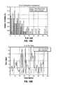
- FIGS. 4-10Graphs showing the breathing error distributions for each individual patient are provided as FIGS. 4-10 :
- Patient1See FIGS. 4 a and 4 b.
- Patient2See FIGS. 5 a and 5 b.
- Patient3See FIGS. 6 a and 6 b.
- Patient4See FIGS. 7 a and 7 b.
- Patient5See FIGS. 8 a and 8 b.
- Patient6See FIGS. 9 a and 9 b.
- Patient7See FIGS. 10 a and 10 b.
- the graph of FIG. 11shows the comparison of registration error between rigid and polynomial-based transformations. Note that each value shown on the graph corresponds to the specific pair that did not participate in registration data set. This way the results are not biased by the transformation.
- the FIG. 11 graphis based on left side lung registration.
- the mean registration errorsare shown with confidence levels of two standard deviations on the graph of FIG. 12 . Note that both left and right lungs were used for registration.
- the polynomial degree and element choiceis determined by model accuracy specifications.
- Tissue deformations during the breathing cyclecan be described using a low number of degrees of freedom with acceptable accuracy.
- the transformationcan be reproduced using a small number of control points.
- the “breathing vectors” correction techniquecan be successfully used during electromagnetic bronchoscopy procedures to reduce localization errors. However, additional data sets are needed if method verification is desired.
- the other related issuedeals with possible outlier removal.
- the outlierscan be determined with regard to their correlation with registration data set and filtered out.
- Such filteringis essential for breathing motion generic model generation.
- Non-uniform distribution of pointsis a problem that should be also addressed during while modeling the breathing cycle.
- One possible solutionis to use the same points several times in the data set in order to assign them more weight in the algorithm.
Landscapes
- Health & Medical Sciences (AREA)
- Life Sciences & Earth Sciences (AREA)
- Engineering & Computer Science (AREA)
- Biomedical Technology (AREA)
- Medical Informatics (AREA)
- Human Computer Interaction (AREA)
- Physics & Mathematics (AREA)
- Veterinary Medicine (AREA)
- Biophysics (AREA)
- Pathology (AREA)
- Public Health (AREA)
- Heart & Thoracic Surgery (AREA)
- General Health & Medical Sciences (AREA)
- Molecular Biology (AREA)
- Surgery (AREA)
- Animal Behavior & Ethology (AREA)
- Radiology & Medical Imaging (AREA)
- Gynecology & Obstetrics (AREA)
- Nuclear Medicine, Radiotherapy & Molecular Imaging (AREA)
- Apparatus For Radiation Diagnosis (AREA)
- Image Processing (AREA)
Abstract
Description
U=(


V=(


is the function that transforms each column vector of U containing x, y, z to a column vector of higher dimension. In case of a second degree polynomial, the 3D vector is transformed to 10D space by:
Tsimple(W)=S·g(W)
where the g( ) transforms each vector to higher dimensional space and S is the appropriate coefficient matrix.
ε=A·ƒ(S·U)−S·V
| Patient |
| 1 | ||||||
| 1.4441 | 30.3849 | 22.3949 | 9.579 | 6.7975 | 9.1251 | 17.5015 | |
| 8.0471 | 2.1803 | 26.975 | 7.3234 | 6.2768 | 6.2002 | 9.4439 | |
| 27.2102 | 31.8968 | 3.9853 | 12.5647 | 10.1514 | 18.2088 | 32.9139 | |
| 4.7568 | 5.1671 | 8.9472 | 3.4243 | 7.0903 | 5.7553 | 6.1695 | |
| 57.6078 | 22.6204 | 21.88 | 13.0142 | 3.6763 | 24.7327 | 41.5406 | |
| 31.4134 | 15.3444 | 51.4794 | 14.9238 | 13.7905 | 4.1377 | 27.2752 | |
| 19.0761 | 6.8696 | 8.2957 | 12.2098 | 6.9798 | 10.0902 | 2.403 | |
Standard Deviation Values:
| Standard deviation values |
| 0.8592 | 12.2057 | 4.9473 | 4.4579 | 2.5962 | 5.4156 | 9.8278 | |
| 4.701 | 1.6283 | 13.9169 | 4.2816 | 3.4003 | 3.5902 | 7.437 | |
| 15.7571 | 17.4782 | 3.2823 | 6.9061 | 5.8878 | 12.9119 | 16.6467 | |
| 2.7333 | 3.9613 | 4.9235 | 2.321 | 3.1751 | 4.0883 | 4.2487 | |
| 3.8712 | 13.2514 | 9.6508 | 5.0819 | 2.6654 | 11.5002 | 16.0817 | |
| 9.4778 | 7.577 | 14.7764 | 9.0923 | 7.0307 | 2.7028 | 10.835 | |
| 9.6453 | 5.2156 | 5.168 | 5.9022 | 4.2303 | 6.7865 | 1.3058 | |
| Mean | 10.4010 | 10.1197 | 11.9469 | 14.7198 | 14.5926 | 22.4039 | 14.7366 |
| Std | 7.2987 | 6.4501 | 7.5849 | 8.4310 | 8.6562 | 19.1004 | 10.0350 |
Claims (9)
Priority Applications (6)
| Application Number | Priority Date | Filing Date | Title |
|---|---|---|---|
| US12/170,385US10292619B2 (en) | 2007-07-09 | 2008-07-09 | Patient breathing modeling |
| US13/286,947US20120046543A1 (en) | 2007-07-09 | 2011-11-01 | Patient Breathing Modeling |
| US13/286,918US20120046567A1 (en) | 2007-07-09 | 2011-11-01 | Patient Breathing Modeling |
| US13/286,977US20120046545A1 (en) | 2007-07-09 | 2011-11-01 | Patient Breathing Modeling |
| US16/357,537US11089974B2 (en) | 2007-07-09 | 2019-03-19 | Monitoring the location of a probe during patient breathing |
| US17/169,770US20210161424A1 (en) | 2007-07-09 | 2021-02-08 | Method and system for modeling lung movement |
Applications Claiming Priority (3)
| Application Number | Priority Date | Filing Date | Title |
|---|---|---|---|
| US94864007P | 2007-07-09 | 2007-07-09 | |
| US4398708P | 2008-04-10 | 2008-04-10 | |
| US12/170,385US10292619B2 (en) | 2007-07-09 | 2008-07-09 | Patient breathing modeling |
Related Child Applications (3)
| Application Number | Title | Priority Date | Filing Date |
|---|---|---|---|
| US13/286,918DivisionUS20120046567A1 (en) | 2007-07-09 | 2011-11-01 | Patient Breathing Modeling |
| US13/286,947DivisionUS20120046543A1 (en) | 2007-07-09 | 2011-11-01 | Patient Breathing Modeling |
| US13/286,977DivisionUS20120046545A1 (en) | 2007-07-09 | 2011-11-01 | Patient Breathing Modeling |
Publications (2)
| Publication Number | Publication Date |
|---|---|
| US20090156951A1 US20090156951A1 (en) | 2009-06-18 |
| US10292619B2true US10292619B2 (en) | 2019-05-21 |
Family
ID=40754184
Family Applications (6)
| Application Number | Title | Priority Date | Filing Date |
|---|---|---|---|
| US12/170,385Active2034-10-23US10292619B2 (en) | 2007-07-09 | 2008-07-09 | Patient breathing modeling |
| US13/286,918AbandonedUS20120046567A1 (en) | 2007-07-09 | 2011-11-01 | Patient Breathing Modeling |
| US13/286,947AbandonedUS20120046543A1 (en) | 2007-07-09 | 2011-11-01 | Patient Breathing Modeling |
| US13/286,977AbandonedUS20120046545A1 (en) | 2007-07-09 | 2011-11-01 | Patient Breathing Modeling |
| US16/357,537Expired - Fee RelatedUS11089974B2 (en) | 2007-07-09 | 2019-03-19 | Monitoring the location of a probe during patient breathing |
| US17/169,770AbandonedUS20210161424A1 (en) | 2007-07-09 | 2021-02-08 | Method and system for modeling lung movement |
Family Applications After (5)
| Application Number | Title | Priority Date | Filing Date |
|---|---|---|---|
| US13/286,918AbandonedUS20120046567A1 (en) | 2007-07-09 | 2011-11-01 | Patient Breathing Modeling |
| US13/286,947AbandonedUS20120046543A1 (en) | 2007-07-09 | 2011-11-01 | Patient Breathing Modeling |
| US13/286,977AbandonedUS20120046545A1 (en) | 2007-07-09 | 2011-11-01 | Patient Breathing Modeling |
| US16/357,537Expired - Fee RelatedUS11089974B2 (en) | 2007-07-09 | 2019-03-19 | Monitoring the location of a probe during patient breathing |
| US17/169,770AbandonedUS20210161424A1 (en) | 2007-07-09 | 2021-02-08 | Method and system for modeling lung movement |
Country Status (3)
| Country | Link |
|---|---|
| US (6) | US10292619B2 (en) |
| EP (1) | EP2192855B1 (en) |
| WO (1) | WO2009074872A2 (en) |
Cited By (2)
| Publication number | Priority date | Publication date | Assignee | Title |
|---|---|---|---|---|
| US20190366124A1 (en)* | 2017-02-24 | 2019-12-05 | Brainlab Ag | Deep inspiration breath-hold setup using x-ray imaging |
| US11944388B2 (en) | 2018-09-28 | 2024-04-02 | Covidien Lp | Systems and methods for magnetic interference correction |
Families Citing this family (24)
| Publication number | Priority date | Publication date | Assignee | Title |
|---|---|---|---|---|
| US20070066881A1 (en) | 2005-09-13 | 2007-03-22 | Edwards Jerome R | Apparatus and method for image guided accuracy verification |
| EP1924198B1 (en) | 2005-09-13 | 2019-04-03 | Veran Medical Technologies, Inc. | Apparatus for image guided accuracy verification |
| CN102858229B (en) | 2010-02-18 | 2015-11-25 | 皇家飞利浦电子股份有限公司 | Systems and methods for tumor motion simulation and motion compensation using tracked bronchoscopy |
| JP5897273B2 (en)* | 2010-07-22 | 2016-03-30 | 株式会社東芝 | Medical image display apparatus and X-ray computed tomography apparatus |
| EP3659490B1 (en)* | 2010-08-20 | 2025-10-01 | Veran Medical Technologies, Inc. | Apparatus and method for four dimensional soft tissue navigation |
| EP2816966B1 (en) | 2012-02-22 | 2023-10-25 | Veran Medical Technologies, Inc. | Steerable surgical catheter comprising a biopsy device at the distal end portion thereof |
| KR102070427B1 (en) | 2012-08-08 | 2020-01-28 | 삼성전자주식회사 | Method and Apparatus for tracking the position of tumor |
| EP2953532B1 (en)* | 2013-02-08 | 2020-01-15 | Covidien LP | System for lung denervation |
| AU2014214766B2 (en) | 2013-02-08 | 2018-04-05 | Covidien Lp | System and method for lung denervation |
| WO2015132787A1 (en) | 2014-03-04 | 2015-09-11 | Xact Robotics Ltd. | Dynamic planning method for needle insertion |
| US20150305612A1 (en) | 2014-04-23 | 2015-10-29 | Mark Hunter | Apparatuses and methods for registering a real-time image feed from an imaging device to a steerable catheter |
| US20150305650A1 (en) | 2014-04-23 | 2015-10-29 | Mark Hunter | Apparatuses and methods for endobronchial navigation to and confirmation of the location of a target tissue and percutaneous interception of the target tissue |
| US20150313445A1 (en)* | 2014-05-01 | 2015-11-05 | Endochoice, Inc. | System and Method of Scanning a Body Cavity Using a Multiple Viewing Elements Endoscope |
| KR101647361B1 (en)* | 2014-08-08 | 2016-08-11 | 경북대학교 산학협력단 | Apparatus and method for predicting respiratory motion |
| EP3324852B1 (en)* | 2015-07-17 | 2025-06-25 | Elekta, Inc. | Guidance for lung cancer radiation |
| US20170329927A1 (en)* | 2016-05-11 | 2017-11-16 | InFluidS LLC | System and method for analyzing airway-pulmonary response using computational fluid dynamics to diagnose and monitoring potential health anomalies |
| US20180049808A1 (en)* | 2016-08-17 | 2018-02-22 | Covidien Lp | Method of using soft point features to predict breathing cycles and improve end registration |
| US10939963B2 (en) | 2016-09-01 | 2021-03-09 | Covidien Lp | Systems and methods for providing proximity awareness to pleural boundaries, vascular structures, and other critical intra-thoracic structures during electromagnetic navigation bronchoscopy |
| KR20190067917A (en) | 2016-11-02 | 2019-06-17 | 인튜어티브 서지컬 오퍼레이션즈 인코포레이티드 | Continuous political system and method for visual guided surgery |
| CN111179409B (en)* | 2019-04-23 | 2024-04-02 | 艾瑞迈迪科技石家庄有限公司 | Respiratory motion modeling method, device and system |
| KR102404649B1 (en)* | 2020-01-16 | 2022-06-07 | 아주대학교 산학협력단 | Estimation method and appratus for polmonary function according to radiation therapy |
| FR3114957B1 (en)* | 2020-10-08 | 2022-09-30 | Quantum Surgical | Augmented reality navigation system for a medical robot |
| CN114565741A (en)* | 2021-12-28 | 2022-05-31 | 杭州堃博生物科技有限公司 | Operation-assisted data processing method, device, equipment, medium and system |
| CN116392105B (en)* | 2023-06-08 | 2023-08-25 | 深圳大学 | A method and device for building a breathing training model based on personalized feature fitting |
Citations (64)
| Publication number | Priority date | Publication date | Assignee | Title |
|---|---|---|---|---|
| US5480422A (en) | 1993-07-20 | 1996-01-02 | Biosense, Inc. | Apparatus for treating cardiac arrhythmias |
| US5558091A (en) | 1993-10-06 | 1996-09-24 | Biosense, Inc. | Magnetic determination of position and orientation |
| US5729129A (en) | 1995-06-07 | 1998-03-17 | Biosense, Inc. | Magnetic location system with feedback adjustment of magnetic field generator |
| US5752513A (en) | 1995-06-07 | 1998-05-19 | Biosense, Inc. | Method and apparatus for determining position of object |
| US5928248A (en) | 1997-02-14 | 1999-07-27 | Biosense, Inc. | Guided deployment of stents |
| US6016439A (en) | 1996-10-15 | 2000-01-18 | Biosense, Inc. | Method and apparatus for synthetic viewpoint imaging |
| US6147480A (en) | 1997-10-23 | 2000-11-14 | Biosense, Inc. | Detection of metal disturbance |
| US6161032A (en) | 1998-03-30 | 2000-12-12 | Biosense, Inc. | Three-axis coil sensor |
| US6201387B1 (en) | 1997-10-07 | 2001-03-13 | Biosense, Inc. | Miniaturized position sensor having photolithographic coils for tracking a medical probe |
| US6203493B1 (en) | 1996-02-15 | 2001-03-20 | Biosense, Inc. | Attachment with one or more sensors for precise position determination of endoscopes |
| US6211666B1 (en) | 1996-02-27 | 2001-04-03 | Biosense, Inc. | Object location system and method using field actuation sequences having different field strengths |
| US6233476B1 (en) | 1999-05-18 | 2001-05-15 | Mediguide Ltd. | Medical positioning system |
| US20010031919A1 (en) | 1999-05-18 | 2001-10-18 | Mediguide Ltd | Medical imaging and navigation system |
| US6314310B1 (en) | 1997-02-14 | 2001-11-06 | Biosense, Inc. | X-ray guided surgical location system with extended mapping volume |
| US6332089B1 (en) | 1996-02-15 | 2001-12-18 | Biosense, Inc. | Medical procedures and apparatus using intrabody probes |
| US6335617B1 (en) | 1996-05-06 | 2002-01-01 | Biosense, Inc. | Method and apparatus for calibrating a magnetic field generator |
| US6366799B1 (en) | 1996-02-15 | 2002-04-02 | Biosense, Inc. | Movable transmit or receive coils for location system |
| US6373240B1 (en) | 1998-10-15 | 2002-04-16 | Biosense, Inc. | Metal immune system for tracking spatial coordinates of an object in the presence of a perturbed energy field |
| US6380732B1 (en)* | 1997-02-13 | 2002-04-30 | Super Dimension Ltd. | Six-degree of freedom tracking system having a passive transponder on the object being tracked |
| US6453190B1 (en) | 1996-02-15 | 2002-09-17 | Biosense, Inc. | Medical probes with field transducers |
| US6484118B1 (en) | 2000-07-20 | 2002-11-19 | Biosense, Inc. | Electromagnetic position single axis system |
| US20030086599A1 (en) | 2001-06-15 | 2003-05-08 | University Of Chicago | Automated method and system for the delineation of the chest wall in computed tomography scans for the assessment of pleural disease |
| US6580938B1 (en) | 1997-02-25 | 2003-06-17 | Biosense, Inc. | Image-guided thoracic therapy and apparatus therefor |
| US6591129B1 (en) | 1996-02-15 | 2003-07-08 | Biosense, Inc. | Method for treating tissue through injection of a therapeutic agent |
| US6618612B1 (en) | 1996-02-15 | 2003-09-09 | Biosense, Inc. | Independently positionable transducers for location system |
| US6650927B1 (en) | 2000-08-18 | 2003-11-18 | Biosense, Inc. | Rendering of diagnostic imaging data on a three-dimensional map |
| US6690963B2 (en) | 1995-01-24 | 2004-02-10 | Biosense, Inc. | System for determining the location and orientation of an invasive medical instrument |
| US20040086161A1 (en) | 2002-11-05 | 2004-05-06 | Radhika Sivaramakrishna | Automated detection of lung nodules from multi-slice CT image data |
| US20040097805A1 (en) | 2002-11-19 | 2004-05-20 | Laurent Verard | Navigation system for cardiac therapies |
| US20040097804A1 (en) | 2002-11-18 | 2004-05-20 | Mediguide Ltd. | Method and system for mounting an MPS sensor on a catheter |
| US20040138548A1 (en) | 2003-01-13 | 2004-07-15 | Mediguide Ltd. | Method and system for registering a medical situation associated with a first coordinate system, in second coordinate system using an MPS system |
| US20040249267A1 (en) | 2002-04-17 | 2004-12-09 | Pinhas Gilboa | Endoscope structures and techniques for navigating to a target in branched structure |
| US20050107688A1 (en) | 1999-05-18 | 2005-05-19 | Mediguide Ltd. | System and method for delivering a stent to a selected position within a lumen |
| US20050197566A1 (en) | 2004-03-08 | 2005-09-08 | Mediguide Ltd. | Automatic guidewire maneuvering system and method |
| US6995729B2 (en) | 2004-01-09 | 2006-02-07 | Biosense Webster, Inc. | Transponder with overlapping coil antennas on a common core |
| US20060058647A1 (en) | 1999-05-18 | 2006-03-16 | Mediguide Ltd. | Method and system for delivering a medical device to a selected position within a lumen |
| US20060064006A1 (en) | 1999-05-18 | 2006-03-23 | Mediguide Ltd. | Method and system for determining a three dimensional representation of a tubular organ |
| US20060074292A1 (en) | 2004-09-30 | 2006-04-06 | Accuray, Inc. | Dynamic tracking of moving targets |
| US20060149134A1 (en)* | 2003-12-12 | 2006-07-06 | University Of Washington | Catheterscope 3D guidance and interface system |
| WO2006095221A2 (en) | 2005-03-11 | 2006-09-14 | Philips Intellectual Property & Standards Gmbh | Imaging method |
| US7197354B2 (en) | 2004-06-21 | 2007-03-27 | Mediguide Ltd. | System for determining the position and orientation of a catheter |
| US7236567B2 (en) | 2005-03-24 | 2007-06-26 | Siemens Aktiengesellschaft | Method and apparatus for synchronizing operation of an x-ray system and a magnetic system |
| US20070167743A1 (en) | 2004-03-29 | 2007-07-19 | Olympus Corporation | Intra-subject position detection system |
| US20070167738A1 (en) | 2004-01-20 | 2007-07-19 | Koninklijke Philips Electronics N.V. | Device and method for navigating a catheter |
| US20070167806A1 (en) | 2005-11-28 | 2007-07-19 | Koninklijke Philips Electronics N.V. | Multi-modality imaging and treatment |
| US7286868B2 (en) | 2001-06-15 | 2007-10-23 | Biosense Inc. | Medical device with position sensor having accuracy at high temperatures |
| US7301332B2 (en) | 2005-10-06 | 2007-11-27 | Biosense Webster, Inc. | Magnetic sensor assembly |
| US7321228B2 (en) | 2003-07-31 | 2008-01-22 | Biosense Webster, Inc. | Detection of metal disturbance in a magnetic tracking system |
| US7324915B2 (en) | 2005-07-14 | 2008-01-29 | Biosense Webster, Inc. | Data transmission to a position sensor |
| US7343195B2 (en) | 1999-05-18 | 2008-03-11 | Mediguide Ltd. | Method and apparatus for real time quantitative three-dimensional image reconstruction of a moving organ and intra-body navigation |
| US7353125B2 (en) | 2003-04-17 | 2008-04-01 | Northern Digital Inc. | Eddy current detection and compensation |
| US20080097187A1 (en) | 2006-09-08 | 2008-04-24 | Medtronic, Inc. | System for navigating a planned procedure within a body |
| US7366562B2 (en) | 2003-10-17 | 2008-04-29 | Medtronic Navigation, Inc. | Method and apparatus for surgical navigation |
| US7370656B2 (en) | 2003-04-15 | 2008-05-13 | Koninklijke Philips Electronics N.V. | Method and arrangement for influencing magnetic particles and detecting interfering material |
| US7373271B1 (en) | 2004-09-20 | 2008-05-13 | Ascension Technology Corporation | System and method for measuring position and orientation using distortion-compensated magnetic fields |
| US20080132911A1 (en) | 2006-11-27 | 2008-06-05 | Mediguide Ltd. | System and method for navigating a surgical needle toward an organ of the body of a patient |
| US20080132909A1 (en) | 2006-12-01 | 2008-06-05 | Medtronic Navigation, Inc. | Portable electromagnetic navigation system |
| US20080139915A1 (en) | 2006-12-07 | 2008-06-12 | Medtronic Vascular, Inc. | Vascular Position Locating and/or Mapping Apparatus and Methods |
| US20080161682A1 (en) | 2007-01-02 | 2008-07-03 | Medtronic Navigation, Inc. | System and method for tracking positions of uniform marker geometries |
| US20080157755A1 (en) | 2004-02-18 | 2008-07-03 | Koninklijke Philips Electronics N.V. | Correction of Measured Values for a Magnetic Localization Device |
| US7397364B2 (en) | 2003-11-11 | 2008-07-08 | Biosense Webster, Inc. | Digital wireless position sensor |
| US20080183071A1 (en) | 2007-01-10 | 2008-07-31 | Mediguide Lit. | System and method for superimposing a representation of the tip of a catheter on an image acquired by a moving imager |
| US20080188749A1 (en) | 2005-04-11 | 2008-08-07 | Koninklijke Philips Electronics N.V. | Three Dimensional Imaging for Guiding Interventional Medical Devices in a Body Volume |
| US20090182224A1 (en) | 1999-05-18 | 2009-07-16 | Mediguide Ltd. | Method and apparatus for invasive device tracking using organ timing signal generated from MPS sensors |
Family Cites Families (15)
| Publication number | Priority date | Publication date | Assignee | Title |
|---|---|---|---|---|
| IL119262A0 (en)* | 1996-02-15 | 1996-12-05 | Biosense Israel Ltd | Locatable biopsy needle |
| IL122578A (en) | 1997-12-12 | 2000-08-13 | Super Dimension Ltd | Wireless six-degree-of-freedom locator |
| WO2000010456A1 (en) | 1998-08-02 | 2000-03-02 | Super Dimension Ltd. | Intrabody navigation system for medical applications |
| US20030074011A1 (en)* | 1998-09-24 | 2003-04-17 | Super Dimension Ltd. | System and method of recording and displaying in context of an image a location of at least one point-of-interest in a body during an intra-body medical procedure |
| US6615155B2 (en) | 2000-03-09 | 2003-09-02 | Super Dimension Ltd. | Object tracking using a single sensor or a pair of sensors |
| US6714810B2 (en)* | 2000-09-07 | 2004-03-30 | Cbyon, Inc. | Fluoroscopic registration system and method |
| EP1365686A4 (en)* | 2000-09-23 | 2009-12-02 | Ramin Shahidi | Endoscopic targeting method and system |
| US6666579B2 (en)* | 2000-12-28 | 2003-12-23 | Ge Medical Systems Global Technology Company, Llc | Method and apparatus for obtaining and displaying computed tomography images using a fluoroscopy imaging system |
| US20030018251A1 (en)* | 2001-04-06 | 2003-01-23 | Stephen Solomon | Cardiological mapping and navigation system |
| DE50209767D1 (en) | 2002-03-27 | 2007-05-03 | Brainlab Ag | Medical navigation or pre-operative treatment planning with the support of generic patient data |
| US7117026B2 (en) | 2002-06-12 | 2006-10-03 | Koninklijke Philips Electronics N.V. | Physiological model based non-rigid image registration |
| US8150495B2 (en)* | 2003-08-11 | 2012-04-03 | Veran Medical Technologies, Inc. | Bodily sealants and methods and apparatus for image-guided delivery of same |
| US8611983B2 (en)* | 2005-01-18 | 2013-12-17 | Philips Electronics Ltd | Method and apparatus for guiding an instrument to a target in the lung |
| WO2006077534A1 (en)* | 2005-01-19 | 2006-07-27 | Philips Intellectual Property & Standard Gmbh | Image processing system and method for alignment of images |
| US20090080737A1 (en)* | 2007-09-25 | 2009-03-26 | General Electric Company | System and Method for Use of Fluoroscope and Computed Tomography Registration for Sinuplasty Navigation |
- 2008
- 2008-07-09EPEP08860538.1Apatent/EP2192855B1/enactiveActive
- 2008-07-09USUS12/170,385patent/US10292619B2/enactiveActive
- 2008-07-09WOPCT/IB2008/003728patent/WO2009074872A2/enactiveApplication Filing
- 2011
- 2011-11-01USUS13/286,918patent/US20120046567A1/ennot_activeAbandoned
- 2011-11-01USUS13/286,947patent/US20120046543A1/ennot_activeAbandoned
- 2011-11-01USUS13/286,977patent/US20120046545A1/ennot_activeAbandoned
- 2019
- 2019-03-19USUS16/357,537patent/US11089974B2/ennot_activeExpired - Fee Related
- 2021
- 2021-02-08USUS17/169,770patent/US20210161424A1/ennot_activeAbandoned
Patent Citations (70)
| Publication number | Priority date | Publication date | Assignee | Title |
|---|---|---|---|---|
| US5480422A (en) | 1993-07-20 | 1996-01-02 | Biosense, Inc. | Apparatus for treating cardiac arrhythmias |
| US6427314B1 (en) | 1993-10-06 | 2002-08-06 | Biosense, Inc. | Magnetic determination of position and orientation |
| US5558091A (en) | 1993-10-06 | 1996-09-24 | Biosense, Inc. | Magnetic determination of position and orientation |
| US6690963B2 (en) | 1995-01-24 | 2004-02-10 | Biosense, Inc. | System for determining the location and orientation of an invasive medical instrument |
| US5729129A (en) | 1995-06-07 | 1998-03-17 | Biosense, Inc. | Magnetic location system with feedback adjustment of magnetic field generator |
| US5752513A (en) | 1995-06-07 | 1998-05-19 | Biosense, Inc. | Method and apparatus for determining position of object |
| US6203493B1 (en) | 1996-02-15 | 2001-03-20 | Biosense, Inc. | Attachment with one or more sensors for precise position determination of endoscopes |
| US6453190B1 (en) | 1996-02-15 | 2002-09-17 | Biosense, Inc. | Medical probes with field transducers |
| US6591129B1 (en) | 1996-02-15 | 2003-07-08 | Biosense, Inc. | Method for treating tissue through injection of a therapeutic agent |
| US6618612B1 (en) | 1996-02-15 | 2003-09-09 | Biosense, Inc. | Independently positionable transducers for location system |
| US6332089B1 (en) | 1996-02-15 | 2001-12-18 | Biosense, Inc. | Medical procedures and apparatus using intrabody probes |
| US6366799B1 (en) | 1996-02-15 | 2002-04-02 | Biosense, Inc. | Movable transmit or receive coils for location system |
| US6211666B1 (en) | 1996-02-27 | 2001-04-03 | Biosense, Inc. | Object location system and method using field actuation sequences having different field strengths |
| US6335617B1 (en) | 1996-05-06 | 2002-01-01 | Biosense, Inc. | Method and apparatus for calibrating a magnetic field generator |
| US6016439A (en) | 1996-10-15 | 2000-01-18 | Biosense, Inc. | Method and apparatus for synthetic viewpoint imaging |
| US6380732B1 (en)* | 1997-02-13 | 2002-04-30 | Super Dimension Ltd. | Six-degree of freedom tracking system having a passive transponder on the object being tracked |
| US5928248A (en) | 1997-02-14 | 1999-07-27 | Biosense, Inc. | Guided deployment of stents |
| US6314310B1 (en) | 1997-02-14 | 2001-11-06 | Biosense, Inc. | X-ray guided surgical location system with extended mapping volume |
| US6580938B1 (en) | 1997-02-25 | 2003-06-17 | Biosense, Inc. | Image-guided thoracic therapy and apparatus therefor |
| US6788967B2 (en) | 1997-05-14 | 2004-09-07 | Biosense, Inc. | Medical diagnosis, treatment and imaging systems |
| US6201387B1 (en) | 1997-10-07 | 2001-03-13 | Biosense, Inc. | Miniaturized position sensor having photolithographic coils for tracking a medical probe |
| US6147480A (en) | 1997-10-23 | 2000-11-14 | Biosense, Inc. | Detection of metal disturbance |
| US6161032A (en) | 1998-03-30 | 2000-12-12 | Biosense, Inc. | Three-axis coil sensor |
| US6373240B1 (en) | 1998-10-15 | 2002-04-16 | Biosense, Inc. | Metal immune system for tracking spatial coordinates of an object in the presence of a perturbed energy field |
| US20090182224A1 (en) | 1999-05-18 | 2009-07-16 | Mediguide Ltd. | Method and apparatus for invasive device tracking using organ timing signal generated from MPS sensors |
| US20010031919A1 (en) | 1999-05-18 | 2001-10-18 | Mediguide Ltd | Medical imaging and navigation system |
| US7386339B2 (en) | 1999-05-18 | 2008-06-10 | Mediguide Ltd. | Medical imaging and navigation system |
| US7343195B2 (en) | 1999-05-18 | 2008-03-11 | Mediguide Ltd. | Method and apparatus for real time quantitative three-dimensional image reconstruction of a moving organ and intra-body navigation |
| US20070287901A1 (en) | 1999-05-18 | 2007-12-13 | Mediguide Ltd. | Medical imaging and navigation system |
| US6233476B1 (en) | 1999-05-18 | 2001-05-15 | Mediguide Ltd. | Medical positioning system |
| US20060058647A1 (en) | 1999-05-18 | 2006-03-16 | Mediguide Ltd. | Method and system for delivering a medical device to a selected position within a lumen |
| US20050107688A1 (en) | 1999-05-18 | 2005-05-19 | Mediguide Ltd. | System and method for delivering a stent to a selected position within a lumen |
| US20060064006A1 (en) | 1999-05-18 | 2006-03-23 | Mediguide Ltd. | Method and system for determining a three dimensional representation of a tubular organ |
| US6484118B1 (en) | 2000-07-20 | 2002-11-19 | Biosense, Inc. | Electromagnetic position single axis system |
| US6650927B1 (en) | 2000-08-18 | 2003-11-18 | Biosense, Inc. | Rendering of diagnostic imaging data on a three-dimensional map |
| US20030086599A1 (en) | 2001-06-15 | 2003-05-08 | University Of Chicago | Automated method and system for the delineation of the chest wall in computed tomography scans for the assessment of pleural disease |
| US7286868B2 (en) | 2001-06-15 | 2007-10-23 | Biosense Inc. | Medical device with position sensor having accuracy at high temperatures |
| US20040249267A1 (en) | 2002-04-17 | 2004-12-09 | Pinhas Gilboa | Endoscope structures and techniques for navigating to a target in branched structure |
| US20040086161A1 (en) | 2002-11-05 | 2004-05-06 | Radhika Sivaramakrishna | Automated detection of lung nodules from multi-slice CT image data |
| US20040097804A1 (en) | 2002-11-18 | 2004-05-20 | Mediguide Ltd. | Method and system for mounting an MPS sensor on a catheter |
| US20040097805A1 (en) | 2002-11-19 | 2004-05-20 | Laurent Verard | Navigation system for cardiac therapies |
| US20040138548A1 (en) | 2003-01-13 | 2004-07-15 | Mediguide Ltd. | Method and system for registering a medical situation associated with a first coordinate system, in second coordinate system using an MPS system |
| US20050033149A1 (en) | 2003-01-13 | 2005-02-10 | Mediguide Ltd. | Method and system for registering a medical situation associated with a first coordinate system, in a second coordinate system using an MPS system |
| US7370656B2 (en) | 2003-04-15 | 2008-05-13 | Koninklijke Philips Electronics N.V. | Method and arrangement for influencing magnetic particles and detecting interfering material |
| US7353125B2 (en) | 2003-04-17 | 2008-04-01 | Northern Digital Inc. | Eddy current detection and compensation |
| US7321228B2 (en) | 2003-07-31 | 2008-01-22 | Biosense Webster, Inc. | Detection of metal disturbance in a magnetic tracking system |
| US7366562B2 (en) | 2003-10-17 | 2008-04-29 | Medtronic Navigation, Inc. | Method and apparatus for surgical navigation |
| US7397364B2 (en) | 2003-11-11 | 2008-07-08 | Biosense Webster, Inc. | Digital wireless position sensor |
| US20060149134A1 (en)* | 2003-12-12 | 2006-07-06 | University Of Washington | Catheterscope 3D guidance and interface system |
| US6995729B2 (en) | 2004-01-09 | 2006-02-07 | Biosense Webster, Inc. | Transponder with overlapping coil antennas on a common core |
| US20070167738A1 (en) | 2004-01-20 | 2007-07-19 | Koninklijke Philips Electronics N.V. | Device and method for navigating a catheter |
| US20080157755A1 (en) | 2004-02-18 | 2008-07-03 | Koninklijke Philips Electronics N.V. | Correction of Measured Values for a Magnetic Localization Device |
| US20050197566A1 (en) | 2004-03-08 | 2005-09-08 | Mediguide Ltd. | Automatic guidewire maneuvering system and method |
| US20070167743A1 (en) | 2004-03-29 | 2007-07-19 | Olympus Corporation | Intra-subject position detection system |
| US7197354B2 (en) | 2004-06-21 | 2007-03-27 | Mediguide Ltd. | System for determining the position and orientation of a catheter |
| US20080162074A1 (en) | 2004-09-20 | 2008-07-03 | Ascension Technology Corp. | System and Method for Measuring Position and Orientation Using Distortion-Compensated Magnetic Fields |
| US7373271B1 (en) | 2004-09-20 | 2008-05-13 | Ascension Technology Corporation | System and method for measuring position and orientation using distortion-compensated magnetic fields |
| US20060074292A1 (en) | 2004-09-30 | 2006-04-06 | Accuray, Inc. | Dynamic tracking of moving targets |
| WO2006095221A2 (en) | 2005-03-11 | 2006-09-14 | Philips Intellectual Property & Standards Gmbh | Imaging method |
| US7236567B2 (en) | 2005-03-24 | 2007-06-26 | Siemens Aktiengesellschaft | Method and apparatus for synchronizing operation of an x-ray system and a magnetic system |
| US20080188749A1 (en) | 2005-04-11 | 2008-08-07 | Koninklijke Philips Electronics N.V. | Three Dimensional Imaging for Guiding Interventional Medical Devices in a Body Volume |
| US7324915B2 (en) | 2005-07-14 | 2008-01-29 | Biosense Webster, Inc. | Data transmission to a position sensor |
| US7301332B2 (en) | 2005-10-06 | 2007-11-27 | Biosense Webster, Inc. | Magnetic sensor assembly |
| US20070167806A1 (en) | 2005-11-28 | 2007-07-19 | Koninklijke Philips Electronics N.V. | Multi-modality imaging and treatment |
| US20080097187A1 (en) | 2006-09-08 | 2008-04-24 | Medtronic, Inc. | System for navigating a planned procedure within a body |
| US20080132911A1 (en) | 2006-11-27 | 2008-06-05 | Mediguide Ltd. | System and method for navigating a surgical needle toward an organ of the body of a patient |
| US20080132909A1 (en) | 2006-12-01 | 2008-06-05 | Medtronic Navigation, Inc. | Portable electromagnetic navigation system |
| US20080139915A1 (en) | 2006-12-07 | 2008-06-12 | Medtronic Vascular, Inc. | Vascular Position Locating and/or Mapping Apparatus and Methods |
| US20080161682A1 (en) | 2007-01-02 | 2008-07-03 | Medtronic Navigation, Inc. | System and method for tracking positions of uniform marker geometries |
| US20080183071A1 (en) | 2007-01-10 | 2008-07-31 | Mediguide Lit. | System and method for superimposing a representation of the tip of a catheter on an image acquired by a moving imager |
Non-Patent Citations (17)
| Title |
|---|
| (Merriam-Webster dictionary (1974) p. 629).* |
| Cai et al. Phys Med Biol 2007;52:365-73.* |
| Davis, Med Engineer Phys 1999;21:619-23.* |
| Deligianni et al., IEEE Trans Medical Imaging 2006;25:1462-71.* |
| European Examination Report dated Apr. 21, 2016 for Application No. 08 860 538.1. |
| European Search Report dated Jul. 10, 2013 from corresponding Euopean Application No. 08860538.1 (9 pgs.). |
| Koch et al. Int J Radiat Oncol Biol Phys 2004;1459-72.* |
| Manke et al. IEEE Transact Med Imag 2002;21:1132-41.* |
| McClelland et al. Med Phys 2006;33:3348-58.* |
| McLeish et al (IEEE transactions on Medical imaging (2002) vol. 21, 1142).* |
| Murthy et al. IEEE EMBS 2004.* |
| Nehrke et al. Magn Reson Med 2005;54:1130-8.* |
| Radiofrequency coil. Wikipedia 2004, retrieved 2016.* |
| Shmarak, Itzhak, U.S. Appl. No. 10/986,567, specification and drawings as filed Nov. 10, 2004 (unpublished), assignee Mediguide Ltd., 84 pages. |
| Tsunashima et al., Int. J Radiat Oncol Biol Phys 2004;60;951-8.* |
| WIPO, U.S. International Search Authority, International Search Report and Written Opinion dated Sep. 24, 2009 in International Patent Application No. PCT/IB2008/003728, 8 pages. |
| Zaporozhan et al., Invest Radiol 2006;41:468-75.* |
Cited By (4)
| Publication number | Priority date | Publication date | Assignee | Title |
|---|---|---|---|---|
| US20190366124A1 (en)* | 2017-02-24 | 2019-12-05 | Brainlab Ag | Deep inspiration breath-hold setup using x-ray imaging |
| US11443441B2 (en)* | 2017-02-24 | 2022-09-13 | Brainlab Ag | Deep inspiration breath-hold setup using x-ray imaging |
| US11944388B2 (en) | 2018-09-28 | 2024-04-02 | Covidien Lp | Systems and methods for magnetic interference correction |
| US12251174B2 (en) | 2018-09-28 | 2025-03-18 | Covidien Lp | Systems and methods for magnetic interference correction |
Also Published As
| Publication number | Publication date |
|---|---|
| EP2192855A4 (en) | 2013-08-07 |
| WO2009074872A2 (en) | 2009-06-18 |
| US20120046543A1 (en) | 2012-02-23 |
| US11089974B2 (en) | 2021-08-17 |
| US20190274583A1 (en) | 2019-09-12 |
| US20120046567A1 (en) | 2012-02-23 |
| WO2009074872A3 (en) | 2009-12-30 |
| US20090156951A1 (en) | 2009-06-18 |
| EP2192855A2 (en) | 2010-06-09 |
| US20120046545A1 (en) | 2012-02-23 |
| US20210161424A1 (en) | 2021-06-03 |
| EP2192855B1 (en) | 2020-03-25 |
Similar Documents
| Publication | Publication Date | Title |
|---|---|---|
| US20210161424A1 (en) | Method and system for modeling lung movement | |
| US9076201B1 (en) | Volumetric deformable registration method for thoracic 4-D computed tomography images and method of determining regional lung function | |
| EP3057660B1 (en) | Estimating position of an organ with a biomechanical model | |
| Zhang et al. | A novel boundary condition using contact elements for finite element based deformable image registration | |
| US11779241B2 (en) | Systems, methods, and computer-readable media of estimating thoracic cavity movement during respiration | |
| EP3468668B1 (en) | Soft tissue tracking using physiologic volume rendering | |
| US11715212B2 (en) | Heatmap and atlas | |
| Achenbach et al. | A Multilinear Model for Bidirectional Craniofacial Reconstruction. | |
| Santhanam et al. | Modeling real-time 3-D lung deformations for medical visualization | |
| Tustison et al. | Pulmonary kinematics from image data: a review | |
| Cao | Mechanical analysis of lung CT images using nonrigid registration | |
| Santhanam et al. | Visualization of tumor-influenced 3D lung dynamics | |
| Minaeizaeim | Development of a Biomechanical Basis for Lung Image Registration | |
| Kidane | Development and Validation of a Three-Dimensional Optical Imaging System for Chest Wall Deformity Measurement | |
| Giroux | Patient-specific biomechanical model of the respiratory system for radiation therapy | |
| Liu | Shape-correlated statistical modeling and analysis for respiratory motion estimation | |
| Cook et al. | Pulmonary Kinematics via Registration of Serial Lung Images | |
| Ding | Regional lung function and mechanics using image registration | |
| Du | Regional pulmonary function analysis using image registration and 4DCT |
Legal Events
| Date | Code | Title | Description |
|---|---|---|---|
| AS | Assignment | Owner name:SUPERDIMENSION, LTD., ISRAEL Free format text:ASSIGNMENT OF ASSIGNORS INTEREST;ASSIGNOR:AVERBUCH, DORIAN;REEL/FRAME:022167/0307 Effective date:20090112 | |
| AS | Assignment | Owner name:OXFORD FINANCE CORPORATION, VIRGINIA Free format text:SECURITY AGREEMENT;ASSIGNOR:SUPERDIMENSION LTD.;REEL/FRAME:026572/0849 Effective date:20100331 | |
| AS | Assignment | Owner name:SUPERDIMENSION LTD., ISRAEL Free format text:RELEASE BY SECURED PARTY;ASSIGNOR:OXFORD FINANCE CORPORATION;REEL/FRAME:028363/0016 Effective date:20120608 | |
| AS | Assignment | Owner name:COVIDIEN LP, MASSACHUSETTS Free format text:ASSIGNMENT OF ASSIGNORS INTEREST;ASSIGNOR:COVIDIEN GROUP S.A.R.L.;REEL/FRAME:031505/0701 Effective date:20121113 Owner name:COVIDIEN GROUP S.A.R.L., LUXEMBOURG Free format text:ASSIGNMENT OF ASSIGNORS INTEREST;ASSIGNOR:SUPERDIMENSION, LTD.;REEL/FRAME:031505/0358 Effective date:20121112 | |
| FEPP | Fee payment procedure | Free format text:ENTITY STATUS SET TO UNDISCOUNTED (ORIGINAL EVENT CODE: BIG.); ENTITY STATUS OF PATENT OWNER: LARGE ENTITY | |
| STPP | Information on status: patent application and granting procedure in general | Free format text:PUBLICATIONS -- ISSUE FEE PAYMENT VERIFIED | |
| STCF | Information on status: patent grant | Free format text:PATENTED CASE | |
| AS | Assignment | Owner name:SUPERDIMENSION LTD., ISRAEL Free format text:CORRECTIVE ASSIGNMENT TO CORRECT THE SUPPORTING LEGAL DOCUMENTATION OF THE ORIGINAL SUBMISSION PREVIOUSLY RECORDED AT REEL: 028363 FRAME: 0016. ASSIGNOR(S) HEREBY CONFIRMS THE ASSIGNMENT;ASSIGNOR:OXFORD FINANCE CORPORATION;REEL/FRAME:055305/0943 Effective date:20120514 | |
| MAFP | Maintenance fee payment | Free format text:PAYMENT OF MAINTENANCE FEE, 4TH YEAR, LARGE ENTITY (ORIGINAL EVENT CODE: M1551); ENTITY STATUS OF PATENT OWNER: LARGE ENTITY Year of fee payment:4 | |
| CC | Certificate of correction |