US10291067B2 - Computer modeling for resonant power transfer systems - Google Patents
Computer modeling for resonant power transfer systemsDownload PDFInfo
- Publication number
- US10291067B2 US10291067B2US14/414,840US201314414840AUS10291067B2US 10291067 B2US10291067 B2US 10291067B2US 201314414840 AUS201314414840 AUS 201314414840AUS 10291067 B2US10291067 B2US 10291067B2
- Authority
- US
- United States
- Prior art keywords
- circuits
- receiver
- circuit
- population
- computer
- Prior art date
- Legal status (The legal status is an assumption and is not a legal conclusion. Google has not performed a legal analysis and makes no representation as to the accuracy of the status listed.)
- Active, expires
Links
Images


Classifications
- H—ELECTRICITY
- H02—GENERATION; CONVERSION OR DISTRIBUTION OF ELECTRIC POWER
- H02J—CIRCUIT ARRANGEMENTS OR SYSTEMS FOR SUPPLYING OR DISTRIBUTING ELECTRIC POWER; SYSTEMS FOR STORING ELECTRIC ENERGY
- H02J50/00—Circuit arrangements or systems for wireless supply or distribution of electric power
- H02J50/10—Circuit arrangements or systems for wireless supply or distribution of electric power using inductive coupling
- H02J5/005—
- H—ELECTRICITY
- H02—GENERATION; CONVERSION OR DISTRIBUTION OF ELECTRIC POWER
- H02J—CIRCUIT ARRANGEMENTS OR SYSTEMS FOR SUPPLYING OR DISTRIBUTING ELECTRIC POWER; SYSTEMS FOR STORING ELECTRIC ENERGY
- H02J50/00—Circuit arrangements or systems for wireless supply or distribution of electric power
- H02J50/10—Circuit arrangements or systems for wireless supply or distribution of electric power using inductive coupling
- H02J50/12—Circuit arrangements or systems for wireless supply or distribution of electric power using inductive coupling of the resonant type
- H—ELECTRICITY
- H02—GENERATION; CONVERSION OR DISTRIBUTION OF ELECTRIC POWER
- H02J—CIRCUIT ARRANGEMENTS OR SYSTEMS FOR SUPPLYING OR DISTRIBUTING ELECTRIC POWER; SYSTEMS FOR STORING ELECTRIC ENERGY
- H02J50/00—Circuit arrangements or systems for wireless supply or distribution of electric power
- H02J50/40—Circuit arrangements or systems for wireless supply or distribution of electric power using two or more transmitting or receiving devices
Definitions
- This disclosurerelates generally to apparatus for transmitting and receiving power wirelessly, and in various respects, methods for optimizing wireless power transfer systems.
- Powered devicesneed to have a mechanism to supply power to the operative parts.
- systemsuse a physical power cable to transfer energy over a distance.
- Wireless energy transmissiongreatly expands the types of applications for electrically powered devices.
- One such exampleis the field of implantable medical devices.
- Implantable medical devicestypically require an internal power source able to supply adequate power for the reasonable lifetime of the device or an electrical cable that traverses the skin.
- an internal power sourcee.g. battery
- a transcutaneous power cablesignificantly affects quality of life (QoL), infection risk, and product life, among many drawbacks.
- TETSTranscutaneous Energy Transfer System
- energy transferis accomplished using two magnetically coupled coils set up like a transformer so power is transferred magnetically across the skin.
- Conventional systemsare relatively insensitive to variations in position and alignment of the coils. In order to provide constant and adequate power, the two coils need to be physically close together and well aligned.
- Wireless power transfer systemssuch as TETS, include a number of components working in concert.
- the number and complexity of the interrelated componentsmakes the process of optimizing the system unwieldy, lengthy, and in some cases impossible, using conventional techniques. In most cases, it is impossible to generate a set of closed equations to perfectly model the system. Accordingly, there is a need for a method to discover an optimum solution, in a timely manner, for a wireless power transfer system.
- circuit designit can be used to optimize a problem for several parameters at once even when the circuit is very complicated and has a lot of interrelations.
- one aspect of the present inventionis directed to a method for optimizing a power transfer system.
- the power transfer systemis a resonant power transfer system including four or more coils.
- the power transfer systemis a TET system.
- the method for optimizing the power transfer systemuses an artificial intelligence (AI) and/or an expert system.
- the method for optimizing the power transfer systemuses a genetic algorithm or a search heuristic.
- the method for optimizing the power transfer systemuses a search and optimization technique, logic, probabilistic methods (e.g. fuzzy logic), statistical learning, heuristic searching, and/or neural networks.
- the method for optimizing the power transfer systemcomprises preparation of the algorithm and input parameters. In one embodiment, several small sets of input parameters are randomly chosen.
- the methodcomprises generating an initial population of circuits, optionally based on the set of input parameters.
- Individual component valuescan be chosen based on a simplified analysis of resonant frequencies. These component values can be randomly varied to generate a large population of circuits.
- the methodcomprises evaluating the initial population of circuits.
- each circuit in the populationis assigned a score based on a merit function.
- the merit equationcan include weighting to assign a higher or lower value to certain parameters.
- the circuits in the populationare scored using parameters based on efficiency of wireless power transfer, voltage gain, input current, power lost at the receiver, resonator voltage, and any combination of the same.
- the figure of meritis the RMS sum of the scores for each parameter evaluated.
- the methodcomprises using the best circuits (e.g., the circuits that scored the best above) from the initial population to create a next generation of circuits.
- a small number of circuitse.g., the best 5-10 circuits
- the small number of circuitsis selected to have diverse characteristics with respect to another.
- the selectingcomprising adding circuits to the population to achieve a bias towards better circuits (e.g. circuits with a Gausian, PDF, ⁇ 10%).
- the methodcomprises selecting a top or best circuit or circuits to create a new population of circuits.
- individual components or parts of circuitsare “mated” or merged to generate “children.”
- the methodcomprises generating a new population of circuits based on processes described above in paragraphs 00010 to 00011.
- the new populationincludes at least the parents from the earlier generation or selected circuits.
- the selected circuitsmay be selected to ensure that each successive generation improves on previous generations.
- the methodcomprises evaluating the new population as described in paragraph 0009. In various embodiments, the method comprises repeating the processes in paragraphs 0009 to 00013 until an optimum circuit is discovered.
- the optimization algorithmmakes use of any of the techniques described above in any combination.
- Another aspect of the present inventionis directed to a computer program product comprising instructions to generate an initial population of circuits; instructions to evaluate the initial population of circuits; instructions to select a circuit or circuits based on the evaluation; and instructions to generate a new population based on the selected circuit or circuits.
- the instructions to generate a new populationcomprises generating a plurality of circuits based on combinations of parts of the circuits in the new population, initial population, or both.
- the instructions to selectcomprises assigning a score based on a plurality of parameters. The scoring optionally includes weighting.
- the computer program productcomprises instructions to repeat the instructions to generate successive generations until an optimized result is identified.
- FIG. 1illustrates a basic wireless power transfer system
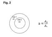
- FIG. 2illustrates the flux generated by a pair of coils.
- FIGS. 3A-3Billustrate the effect of coil alignment on the coupling coefficient.
- FIG. 4is a flowchart illustrating an exemplary approach to designing and optimizing the TET system of FIG. 1 .
- Powermay be transmitted wirelessly by magnetic induction.
- the transmitter and receiverare closely coupled.
- close coupledor “close coupling” refers to a system that requires the coils to be very near each other in order to operate.
- loosely coupledor “loose coupling” refers to a system configured to operate when the coils have a significant spatial and/or axial separation, and in some cases up to distance equal to or less than the diameter of the larger of the coils.
- loosely coupledor “loose coupling” refers a system that is relatively insensitive to changes in physical separation and/or orientation of the receiver and transmitter.
- the transmitter and receiverare non-resonant coils.
- a change in current in one coilinduces a changing magnetic field.
- the second coil within the magnetic fieldpicks up the magnetic flux, which in turn induces a current in the second coil.
- An example of a closely coupled system with non-resonant coilsis described in International Pub. No. WO2000/074747, incorporated herein for all purposes by reference.
- a conventional transformeris another example of a closely coupled, non-resonant system.
- the transmitter and receiverare resonant coils.
- one or both of the coilsis connected to a tuning capacitor or other means for controlling the frequency in the respective coil.
- An example of closely coupled system with resonant coilsis described in International Pub.
- the transmitter and receiverare loosely coupled.
- the transmittercan resonate to propagate magnetic flux that is picked up by the receiver at relatively great distances. In some cases energy can be transmitted over several meters.
- power transfermay not necessarily depend on a critical distance. Rather, the system may be able to accommodate changes to the coupling coefficient between the transmitter and receiver.
- An example of a loosely coupled systemis described in International Pub. No. WO2012/045050, incorporated herein for all purposes by reference.
- the systemcomprises antennas.
- the antennasmay be resonant or non-resonant.
- non-resonant antennasmay radiate electromagnetic waves to create a field.
- the fieldcan be near field or far field.
- the fieldcan be directional. Generally far field has greater range but a lower power transfer rate.
- An example of such a system for radiating energy with resonatorsis described in International Pub. No. WO2010/089354, incorporated herein for all purposes by reference.
- An example of such a non-resonant systemis described in International Pub. No. WO2009/018271, incorporated herein for all purposes by reference.
- the systemmay comprise a high energy light source such as a laser.
- the systemcan be configured so photons carry electromagnetic energy in a spatially restricted, direct, coherent path from a transmission point to a receiving point.
- An example of such a systemis described in International Pub. No. WO2010/089354, incorporated herein for all purposes by reference.
- Powermay also be transmitted by taking advantage of the material or medium through which the energy passes.
- volume conductioninvolves transmitting electrical energy through tissue between a transmitting point and a receiving point.
- An example of such a systemis described in International Pub. No. WO2008/066941, incorporated herein for all purposes by reference.
- Powermay also be transferred using a capacitor charging technique.
- the systemcan be resonant or non-resonant. Exemplars of capacitor charging for wireless energy transfer are described in International Pub. No. WO2012/056365, incorporated herein for all purposes by reference.
- FIG. 1the system in accordance with various aspects of the invention will now be described in connection with a system for wireless energy transfer by magnetic induction.
- the exemplary systemutilizes resonant power transfer.
- the systemworks by transmitting power between the two inductively coupled coils.
- the exemplary coilsare not coupled together closely.
- a transformergenerally requires the coils to be aligned and positioned directly adjacent each other.
- the exemplary systemaccommodates looser coupling of the coils.
- the systemmay use two or more receiver coils and two or more transmitter coils.
- the transmittermay be configured with two coils—a first coil to resonate flux and a second coil to excite the first coil.
- each of “resonator” and “coil”may be used somewhat interchangeably. In various respects, “resonator” refers to a coil and a capacitor connected together.
- the systemcomprises one or more transmitters configured to transmit power wirelessly to one or more receivers.
- the systemincludes a transmitter and more than one receiver in a multiplexed arrangement.
- a frequency generatormay be electrically coupled to the transmitter to drive the transmitter to transmit power at a particular frequency or range of frequencies.
- the frequency generatorcan include a voltage controlled oscillator and one or more switchable arrays of capacitors, a voltage controlled oscillator and one or more varactors, a phase-locked-loop, a direct digital synthesizer, or combinations thereof.
- the transmittercan be configured to transmit power at multiple frequencies simultaneously.
- the frequency generatorcan include two or more phase-locked-loops electrically coupled to a common reference oscillator, two or more independent voltage controlled oscillators, or combinations thereof.
- the transmittercan be arranged to simultaneously delivery power to multiple receivers at a common frequency.
- the transmitteris configured to transmit a low power signal at a particular frequency.
- the transmittermay transmit the low power signal for a particular time and/or interval.
- the transmitteris configured to transmit a high power signal wirelessly at a particular frequency.
- the transmittermay transmit the high power signal for a particular time and/or interval.
- the receiverincludes a frequency selection mechanism electrically coupled to the receiver coil and arranged to allow the coil to change a frequency or a range of frequencies that the receiver can receive.
- the frequency selection mechanismcan include a switchable array of discrete capacitors, one or more inductors electrically coupled to the receiving antenna, additional turns of a coil of the receiving antenna, or combinations thereof.
- the systemis configured to maintain a value of k in the range of between about 0.2 to about 0.01. In various embodiments, the system is configured to maintain a value of k of at least 0.01, at least 0.02, at least 0.03, at least 0.04, or at least 0.05.
- the coilsare physically separated. In various embodiments, the separation is greater than a thickness of the receiver coil. In various embodiments, the separation distance is equal to or less than the diameter of the larger of the receiver and transmitter coil.
- the transmitter coilmust generate a much larger field than what is coupled to the receiver. In various embodiments, this is accomplished by configuring the transmitter with a large number of amp-turns in the coil.
- the current in the coilcan be sustained with a capacitor connected to the coil to create a resonator.
- the power sourcethus only needs to supply the energy absorbed by the receiver.
- the resonant capacitormaintains the excess flux that is not coupled to the receiver.
- the impedance of the receiveris matched to the transmitter. This allows efficient transfer of energy out of the receiver.
- the receiver coilmay not need to have a resonant capacitor.
- FIG. 1is a simplified circuit topology for wireless energy transmission.
- the exemplary systemshows a series connection, but the system can be connected as either series or parallel.
- the exemplary transmitterincludes a coil Lx connected to a power source Vs by a capacitor Cx.
- the exemplary receiverincludes a coil Ly connected to a load by a capacitor Cy.
- Capacitor Cxmay be configured to make Lx resonate at a desired frequency.
- Capacitance Cx of the transmitter coilmay be defined by its geometry.
- Inductors Lx and Lyare connected by coupling coefficient k.
- Mxyis the mutual inductance between the two coils. The mutual inductance, Mxy, is related to coupling coefficient, k.
- Mxyk ⁇ square root over (Lx ⁇ Ly) ⁇
- the power source Vsis in series with the transmitter coil Lx so it may have to carry all the reactive current. This puts a larger burden on the current rating of the power source and any resistance in the source will add to losses.
- the exemplary systemincludes a receiver configured to receive energy wirelessly transmitted by the transmitter.
- the exemplary receiveris connected to a load.
- the receiver and loadmay be connected electrically with a controllable switch.
- the receiverincludes a circuit element configured to be connected or disconnected from the receiver coil by an electronically controllable switch.
- the electrical couplingcan include both a serial and parallel arrangement.
- the circuit elementcan include a resistor, capacitor, inductor, lengths of an antenna structure, or combinations thereof.
- the systemcan be configured such that power is transmitted by the transmitter and can be received by the receiver in predetermined time increments.
- the transmitter coil and/or the receiver coilis a substantially two-dimensional structure.
- the transmitter coilmay be coupled to a transmitter impedance-matching structure.
- the receiver coilmay be coupled to a receiver impedance-matching structure.
- suitable impedance-matching structuresinclude, but are not limited to, a coil, a loop, a transformer, and/or any impedance-matching network.
- An impedance-matching networkmay include inductors or capacitors configured to connect a signal source to the resonator structure.
- the transmitteris controlled by a controller (not shown) and driving circuit.
- the controller and/or driving circuitmay include a directional coupler, a signal generator, and/or an amplifier.
- the controllermay be configured to adjust the transmitter frequency to compensate for changes to the coupling between the receiver and transmitter.
- the transmitter coilis connected to an impedance-matched coil loop.
- the loopis connected to a power source and is configured to excite the transmitter coil.
- the first coil loopmay have finite output impedance.
- a signal generator outputmay be amplified and fed to the transmitter coil. In use power is transferred magnetically between the first coil loop and the main transmitter coil, which in turns transmits flux to the receiver. Energy received by the receiver coil is delivered by Ohmic connection to the load.
- the systemis configured to achieve an approximate energy balance by analyzing the system characteristics and estimating voltages and currents involved.
- the system load power, P Lis assumed to be 15 Watts and the operating frequency, ⁇ , is 250 kHz. Then, for each cycle the load removes a certain amount of energy from the resonance:
- the energy in the receiver resonanceis typically several times larger than the energy removed by the load for operative, implantable medical devices.
- the systemassumes a ratio 7:1 for energy at the receiver versus the load removed. Under this assumption, the energy in the exemplary receiver resonance is 420 ⁇ J.
- the exemplary circuitwas analyzed and the self inductance of the receiver coil was found to be 60 uH. From the energy and the inductance, the voltage and current in the resonator could be calculated.
- the voltage and currentcan be traded off against each other.
- the inductormay couple the same amount of flux regardless of the number of turns.
- the Amp-turns of the coilneeds to stay the same in this example, so more turns means the current is reduced.
- the coil voltagewill need to increase. Likewise, the voltage can be reduced at the expense of a higher current.
- the transmitter coilneeds to have much more flux.
- the transmitter fluxis related to the receiver flux by the coupling coefficient. Accordingly, the energy in the field from the transmitter coil is scaled by k.
- the competing factors and how to balance voltage, current, and inductance to suit the circumstance and achieve the desired outcomecan be traded off against each other.
- the voltages and currents in the systemare relatively high.
- the coupling coefficient, kmay be useful for a number of reasons.
- the coupling coefficientcan be used to understand the arrangement of the coils relative to each other so tuning adjustments can be made to ensure adequate performance. If the receiver coil moves away from the transmitter coil, the mutual inductance will decrease, and ceteris paribus, less power will be transferred.
- the systemis configured to make tuning adjustments to compensate for the drop in coupling efficiency.
- the exemplary system described aboveoften has imperfect information. For various reasons as would be understood by one of skill in the art, the system does not collect data for all parameters. Moreover, because of the physical gap between coils and without an external means of communications between the two resonators, the transmitter may have information that the receiver does not have and vice versa. These limitations make it difficult to directly measure and derive the coupling coefficient, k, in real time.
- kthe coupling coefficient
- the approachesmay make use of techniques such as Biot-Savart calculations or finite element methods. Certain assumptions and generalizations, based on how the coils interact in specific orientations, are made for the sake of simplicity of understanding. From an electric circuit point of view, all the physical geometry permutations can generally lead to the coupling coefficient.
- the coupling coefficientcan be estimated to be roughly proportional to the ratio of the area of the two coils. This assumes the flux generated by coil 1 is roughly uniform over the area it encloses as shown in FIG. 2 .
- the coupling coefficientwill decrease.
- the amount of the decreaseis estimated to be about equal to the cosine of the angle as shown in FIG. 3A . If the coils are orthogonal to each other such that theta ( ⁇ ) is 90 degrees, the flux will not be received by the receiver and the coupling coefficient will be zero.
- the coilsare arraigned such that half the flux from one coil is in one direction and the other half is in the other direction, the flux cancels out and the coupling coefficient is zero, as shown in FIG. 3B .
- a typical TET systemcan be subdivided into two parts, the transmitter and the receiver. Control and tuning may or may not operate on the two parts independently.
- an algorithmmay be used to model and optimize tuning in a TET system.
- the TET systemmay be designed by making certain assumptions and solving for an equation or “brute force” empirical data.
- Algorithmsmay also be used to design the TET system. Suitable algorithms include, but are not limited to, artificial intelligence (AI) and expert systems. Artificial intelligence solutions may include search and optimization approaches, logic, probabilistic methods (fuzzy logic), statistical learning, heuristic searching, and neural networks.
- FIG. 4illustrates an exemplary approach to modeling and optimizing a resonant TET system according to FIG. 1 .
- the exemplary approachmakes use of a genetic algorithm, or a search heuristic, with various evolutions.
- An evolutionary optimization algorithmis a technique to find an optimum solution to a complicated problem that is difficult and time consuming to analyze directly. For circuit design it can be used to optimize a problem for several parameters at once even when the circuit is very complicated and has a lot of interrelations.
- TET systemscan include any number of coils or inductors in the system for wireless power transmission.
- a methodwill be described below for generating an optimization equation for a four coil circuit. It should be understood however that similar concepts can be used for other circuit topologies, including any number of coils and non-resonant systems.
- the circuit structureis fixed, and only component values are optimized.
- the circuitis modeled based on the circuit topology shown in FIG. 1 .
- the modelmay also make use of any of the techniques described above for modeling the subcomponents and features of the system.
- Step S 1comprises preparation of the algorithm and input parameters.
- several small sets of input parametersare randomly chosen.
- One of the setsis selecting using conventional techniques.
- a setis selected from the various sets based on the calculated efficiency.
- Step S 2an initial population of circuits can be generated based on the set of input parameters from S 1 .
- Individual component valuescan be chosen based on a simplified analysis of resonant frequencies. These component values can then be randomly varied to generate a large population of circuits (e.g., such as about 10,000 variations).
- Step S 3the large population of circuits is evaluated.
- each circuit in the populationis assigned a score based on a merit function.
- the merit equationcan include weighting to assign a higher or lower value to certain parameters.
- the circuits in the populationare scored using parameters based on efficiency of wireless power transfer, voltage gain, input current, power lost at the receiver, resonator voltage, and any combination of the same.
- the figure of meritcan be the RMS sum of the scores for each parameter evaluated, and typically a smaller number is better.
- the best circuits(e.g., the circuits that scored the best above) from the original population can be used to create the next generation of circuits.
- a small number of circuitse.g., the best 5-10 circuits
- a diverse population of circuit componentscan help avoid getting stuck in a local optimum.
- Additional circuitscan be randomly selected a bias towards the better ones, e.g., having a Gausian PDF, ⁇ 10%.
- a top circuitcan be selected and used to create a new population of circuits. Individual components or parts of circuits can be “mated” or merged to generate “children” related to the top choices. For example, in a TET system, transmitter and receiver circuits can be swapped amongst the circuits. The same thing goes for exciter and resonator circuits in the TET system. The number and variety of parts of the circuit changed can be modified depending on the size of the population desired and degree of diversity desired, and algorithm efficiency. For example, a smaller number of variations may be introduced to cause the algorithm to operate faster.
- Step S 6a new population of circuits is generated based on Step S 5 .
- the new populationcan be adjusted.
- the new populationincludes at least the parents from the earlier generation or selected circuits.
- the new populationmay be forced to include a selected set of best circuits from the previous generation to ensure that each successive generation improves on previous generations.
- Step S 6the new population of circuits (new generation) is evaluated again in Step S 3 . The process is then repeated until an optimum circuit is discovered.
- the optimization algorithmmakes use of any of the techniques described above in any combination.
Landscapes
- Engineering & Computer Science (AREA)
- Computer Networks & Wireless Communication (AREA)
- Power Engineering (AREA)
- Charge And Discharge Circuits For Batteries Or The Like (AREA)
Abstract
Description
Mxy=k√{square root over (Lx·Ly)}
Mxy=Myx
Claims (15)
Priority Applications (1)
| Application Number | Priority Date | Filing Date | Title |
|---|---|---|---|
| US14/414,840US10291067B2 (en) | 2012-07-27 | 2013-07-29 | Computer modeling for resonant power transfer systems |
Applications Claiming Priority (3)
| Application Number | Priority Date | Filing Date | Title |
|---|---|---|---|
| US201261676706P | 2012-07-27 | 2012-07-27 | |
| US14/414,840US10291067B2 (en) | 2012-07-27 | 2013-07-29 | Computer modeling for resonant power transfer systems |
| PCT/US2013/052545WO2014018972A1 (en) | 2012-07-27 | 2013-07-29 | Computer modeling for resonant power transfer systems |
Publications (2)
| Publication Number | Publication Date |
|---|---|
| US20150180241A1 US20150180241A1 (en) | 2015-06-25 |
| US10291067B2true US10291067B2 (en) | 2019-05-14 |
Family
ID=49997893
Family Applications (1)
| Application Number | Title | Priority Date | Filing Date |
|---|---|---|---|
| US14/414,840Active2035-04-18US10291067B2 (en) | 2012-07-27 | 2013-07-29 | Computer modeling for resonant power transfer systems |
Country Status (2)
| Country | Link |
|---|---|
| US (1) | US10291067B2 (en) |
| WO (1) | WO2014018972A1 (en) |
Cited By (1)
| Publication number | Priority date | Publication date | Assignee | Title |
|---|---|---|---|---|
| US12210805B2 (en) | 2020-02-24 | 2025-01-28 | Tc1 Llc | Systems and methods for modeling wireless power transfer systems including stacked plate resonators |
Families Citing this family (5)
| Publication number | Priority date | Publication date | Assignee | Title |
|---|---|---|---|---|
| WO2014018974A1 (en) | 2012-07-27 | 2014-01-30 | Thoratec Corporation | Magnetic power transmission utilizing phased transmitter coil arrays and phased receiver coil arrays |
| WO2014018973A1 (en) | 2012-07-27 | 2014-01-30 | Thoratec Corporation | Resonant power transmission coils and systems |
| WO2014018971A1 (en) | 2012-07-27 | 2014-01-30 | Thoratec Corporation | Resonant power transfer systems with protective algorithm |
| EP2984731B8 (en) | 2013-03-15 | 2019-06-26 | Tc1 Llc | Malleable tets coil with improved anatomical fit |
| WO2019087010A1 (en)* | 2017-11-02 | 2019-05-09 | 株式会社半導体エネルギー研究所 | Power supply device, electronic device, and operation method for power supply device |
Citations (301)
| Publication number | Priority date | Publication date | Assignee | Title |
|---|---|---|---|---|
| US4041955A (en) | 1976-01-29 | 1977-08-16 | Pacesetter Systems Inc. | Implantable living tissue stimulator with an improved hermetic metal container |
| US4352960A (en) | 1980-09-30 | 1982-10-05 | Baptist Medical Center Of Oklahoma, Inc. | Magnetic transcutaneous mount for external device of an associated implant |
| US4561443A (en) | 1983-03-08 | 1985-12-31 | The Johns Hopkins University | Coherent inductive communications link for biomedical applications |
| US4561444A (en) | 1981-08-10 | 1985-12-31 | Cordis Corporation | Implantable cardiac pacer having dual frequency programming and bipolar/linipolar lead programmability |
| US4630615A (en) | 1984-05-21 | 1986-12-23 | Cordis Corporation | Apparatus for measuring impedance |
| US4679560A (en) | 1985-04-02 | 1987-07-14 | Board Of Trustees Of The Leland Stanford Junior University | Wide band inductive transdermal power and data link |
| US4726378A (en) | 1986-04-11 | 1988-02-23 | Minnesota Mining And Manufacturing Company | Adjustable magnetic supercutaneous device and transcutaneous coupling apparatus |
| US4736747A (en) | 1986-04-11 | 1988-04-12 | Minnesota Mining And Manufacturing Company | Adjustable magnetic supercutaneous device and transcutaneous coupling apparatus |
| US4924171A (en) | 1987-10-08 | 1990-05-08 | Tokyo Keiki Co., Ltd. | System for supplying power source by electromagnetic induction coupling |
| US4945305A (en) | 1986-10-09 | 1990-07-31 | Ascension Technology Corporation | Device for quantitatively measuring the relative position and orientation of two bodies in the presence of metals utilizing direct current magnetic fields |
| JPH03109063A (en) | 1989-09-22 | 1991-05-09 | Tanaka Kikinzoku Kogyo Kk | connector |
| US5070223A (en) | 1989-03-01 | 1991-12-03 | Colasante David A | Microwave reheatable clothing and toys |
| EP0589608A2 (en) | 1992-09-14 | 1994-03-30 | Aprex Corporation | Contactless communication system |
| US5346458A (en) | 1990-06-25 | 1994-09-13 | Klaus Affeld | Electrohydraulic energy converter for cardiac assist devices and artificial hearts |
| US5350413A (en) | 1990-06-21 | 1994-09-27 | The University Of Ottawa | Transcutaneous energy transfer device |
| US5569156A (en) | 1993-09-10 | 1996-10-29 | Ottawa Heart Institute Research Corporation | Electrohydraulic ventricular assist device |
| US5630836A (en) | 1995-01-19 | 1997-05-20 | Vascor, Inc. | Transcutaneous energy and information transmission apparatus |
| US5690693A (en) | 1995-06-07 | 1997-11-25 | Sulzer Intermedics Inc. | Transcutaneous energy transmission circuit for implantable medical device |
| US5702431A (en) | 1995-06-07 | 1997-12-30 | Sulzer Intermedics Inc. | Enhanced transcutaneous recharging system for battery powered implantable medical device |
| US5755748A (en) | 1996-07-24 | 1998-05-26 | Dew Engineering & Development Limited | Transcutaneous energy transfer device |
| US5771438A (en) | 1995-05-18 | 1998-06-23 | Aura Communications, Inc. | Short-range magnetic communication system |
| US5831248A (en) | 1996-05-23 | 1998-11-03 | Sharp Kabushiki Kaisha | Heat-controlling device |
| US5948006A (en) | 1998-10-14 | 1999-09-07 | Advanced Bionics Corporation | Transcutaneous transmission patch |
| WO2000001442A2 (en) | 1998-07-06 | 2000-01-13 | Abiomed, Inc. | Transcutaneous energy transfer device with magnetic field protected components in secondary coil |
| US6123726A (en) | 1997-07-25 | 2000-09-26 | Seiko Epson Corporation | Portable drive system for artificial heart |
| US6149683A (en) | 1998-10-05 | 2000-11-21 | Kriton Medical, Inc. | Power system for an implantable heart pump |
| WO2000074747A1 (en) | 1999-06-03 | 2000-12-14 | Arrow International, Inc. | Ventricular assist device |
| US6212430B1 (en) | 1999-05-03 | 2001-04-03 | Abiomed, Inc. | Electromagnetic field source with detection of position of secondary coil in relation to multiple primary coils |
| WO2001037926A1 (en) | 1999-11-22 | 2001-05-31 | Abiomed, Inc. | Apparatus for transferring energy across a boundary |
| US6296533B1 (en) | 1998-08-31 | 2001-10-02 | The Whitaker Corporation | Electrical receptacle contact |
| US6312338B1 (en) | 1998-10-21 | 2001-11-06 | Nintendo Company, Ltd. | Electronic accessory for game machine |
| US6320354B1 (en) | 2000-07-21 | 2001-11-20 | Motorola, Inc. | Method and apparatus for battery charging |
| US6327504B1 (en) | 2000-05-10 | 2001-12-04 | Thoratec Corporation | Transcutaneous energy transfer with circuitry arranged to avoid overheating |
| US6389318B1 (en) | 1998-07-06 | 2002-05-14 | Abiomed, Inc. | Magnetic shield for primary coil of transcutaneous energy transfer device |
| US20020087204A1 (en) | 2001-01-04 | 2002-07-04 | Kung Robert T. V. | Flexible transcutaneous energy transfer (TET) primary coil |
| US20020093456A1 (en) | 2000-12-11 | 2002-07-18 | Masatoshi Sawamura | Dual band built-in antenna device and mobile wireless terminal equipped therewith |
| US6442434B1 (en) | 1999-10-19 | 2002-08-27 | Abiomed, Inc. | Methods and apparatus for providing a sufficiently stable power to a load in an energy transfer system |
| US6451055B1 (en) | 2000-04-25 | 2002-09-17 | The Penn State Research Foundation | Artificial heart data communication system |
| US6458164B1 (en) | 2000-04-25 | 2002-10-01 | The Penn State Research Foundation | Artificial heart with energy recovery |
| US6478820B1 (en) | 2000-04-25 | 2002-11-12 | The Penn State Research Foundation | Artificial heart with synchronous rectification |
| KR20020089605A (en) | 2001-05-23 | 2002-11-30 | 안태영 | Apparatus for contactless power transfer for medical implant |
| US6553263B1 (en) | 1999-07-30 | 2003-04-22 | Advanced Bionics Corporation | Implantable pulse generators using rechargeable zero-volt technology lithium-ion batteries |
| US6579315B1 (en) | 2000-04-25 | 2003-06-17 | The Penn State Research Foundation | Artificial heart power supply system |
| US6591139B2 (en) | 2000-09-06 | 2003-07-08 | Advanced Bionics Corporation | Low-power, high-modulation-index amplifier for use in battery-powered device |
| US6605032B2 (en) | 1997-10-02 | 2003-08-12 | Micromed Technology, Inc. | Implantable pump system |
| US20030171792A1 (en) | 1998-07-06 | 2003-09-11 | Farhad Zarinetchi | Transcutaneous energy transfer module with integrated conversion circuitry |
| US6647298B2 (en) | 2001-06-04 | 2003-11-11 | St. Jude Medical Ab | Implantable medical device with variable incoming communication signal discrimination, and method for operating same |
| US6650213B1 (en) | 2000-06-02 | 2003-11-18 | Yamatake Corporation | Electromagnetic-induction coupling apparatus |
| US6723039B2 (en) | 2001-04-27 | 2004-04-20 | The Foundry, Inc. | Methods, systems and devices relating to implantable fluid pumps |
| US20040138725A1 (en) | 2002-09-20 | 2004-07-15 | Peter Forsell | Harmless wireless energy transmission to implant |
| US6772011B2 (en) | 2002-08-20 | 2004-08-03 | Thoratec Corporation | Transmission of information from an implanted medical device |
| US6801807B2 (en) | 2001-01-31 | 2004-10-05 | St. Jude Medical Ab | Communication system and method for communicating between an implanted medical device and another device |
| US6810289B1 (en) | 2000-04-20 | 2004-10-26 | Cochlear Limited | Transcutaneous power optimization circuit for cochlear implant |
| US20040256146A1 (en) | 2003-06-17 | 2004-12-23 | W.C. Heraeus Gmbh & Co., Kg | Electrode structure and methods for producing and using the same |
| US20050006083A1 (en) | 2003-07-02 | 2005-01-13 | Yin-Yuan Chen | Temperature-homogenizing device |
| US6850803B1 (en) | 2000-06-16 | 2005-02-01 | Medtronic, Inc. | Implantable medical device with a recharging coil magnetic shield |
| EP1513241A1 (en) | 2002-05-23 | 2005-03-09 | Limited Company TM | Non-intrusion type charging system for artificial organ, capacitor and power supplying device used in the system |
| US6894456B2 (en) | 2001-11-07 | 2005-05-17 | Quallion Llc | Implantable medical power module |
| US6895281B1 (en) | 2000-03-31 | 2005-05-17 | Cardiac Pacemakers, Inc. | Inductive coil apparatus for bio-medical telemetry |
| US6949065B2 (en) | 2001-04-20 | 2005-09-27 | DEUTSCHES ZENTRUM FüR LUFT-UND RAUMFAHRT E.V. | Left ventricular assist system |
| US6960968B2 (en) | 2002-06-26 | 2005-11-01 | Koninklijke Philips Electronics N.V. | Planar resonator for wireless power transfer |
| WO2005106901A2 (en) | 2004-05-04 | 2005-11-10 | Philips Intellectual Property & Standards Gmbh | A wireless powering device, an energizable load, a wireless system and a method for a wireless energy transfer |
| US6967621B1 (en) | 2004-03-16 | 2005-11-22 | The United States Of America As Represented By The Secretary Of The Army | Small low profile antennas using high impedance surfaces and high permeability, high permittivity materials |
| US6985773B2 (en) | 2002-02-07 | 2006-01-10 | Cardiac Pacemakers, Inc. | Methods and apparatuses for implantable medical device telemetry power management |
| US7015769B2 (en) | 2002-06-20 | 2006-03-21 | Alfred E. Mann Foundation For Scientific Research | System and method for automatic tuning of a magnetic field generator |
| US20060199997A1 (en) | 2005-02-24 | 2006-09-07 | Ethicon Endo-Surgery, Inc. | Monitoring of a food intake restriction device |
| US7107103B2 (en) | 1997-02-26 | 2006-09-12 | Alfred E. Mann Foundation For Scientific Research | Full-body charger for battery-powered patient implantable device |
| US7126310B1 (en) | 2001-04-20 | 2006-10-24 | Abiomed, Inc. | Apparatus and method for balanced charging of a multiple-cell battery pack |
| US20060271129A1 (en) | 2005-05-27 | 2006-11-30 | California Institute Of Technology | Magnetic material-containing microfabricated devices for wireless data and power transfer |
| US20070096686A1 (en) | 2005-05-06 | 2007-05-03 | Medtronic, Inc. | Implantable device with heat absorption material |
| WO2007053881A1 (en) | 2005-11-08 | 2007-05-18 | Ventrassist Pty Ltd | Improvements to control systems and power systems for rotary blood pumps |
| US7225032B2 (en) | 2003-10-02 | 2007-05-29 | Medtronic Inc. | External power source, charger and system for an implantable medical device having thermal characteristics and method therefore |
| US20070123948A1 (en) | 2005-09-01 | 2007-05-31 | Ela Medical S.A.S | Telemetry apparatus for communications with an active device implanted in a patient's thoracic region |
| US20070142696A1 (en) | 2005-12-08 | 2007-06-21 | Ventrassist Pty Ltd | Implantable medical devices |
| US7246040B2 (en) | 2004-09-15 | 2007-07-17 | Deutsches Zentrum für Luft- und Raumfahrt e.V. | Process of remote sensing data |
| US20070191706A1 (en) | 2005-05-12 | 2007-08-16 | General Electric Company | Patient table system and apparatus |
| US7286880B2 (en) | 2003-10-02 | 2007-10-23 | Medtronic, Inc. | System and method for transcutaneous energy transfer achieving high efficiency |
| US20080009198A1 (en) | 2004-08-27 | 2008-01-10 | Marino Jay C | Flexible connector for implantable wiring harness |
| US20080027293A1 (en) | 2006-07-27 | 2008-01-31 | Deutsches Zentrum Fuer Luft-Und Raumfahrt E.V. | Transfer assembly |
| US20080054638A1 (en) | 2006-09-01 | 2008-03-06 | Powercast Corporation | Hybrid power harvesting and method |
| US20080100294A1 (en) | 2006-10-31 | 2008-05-01 | Rohling Kenneth W | Flexible rf coil assembly and method of making same |
| WO2008066941A2 (en) | 2006-03-31 | 2008-06-05 | University Of Pittsburgh-Of The Commonwealth System Of Higher Education | A portable apparatus that delivers power and information to implantable devices |
| US20080149736A1 (en) | 2006-12-21 | 2008-06-26 | Korea Advanced Institute Of Science And Technology | System-in-package having reduced influence between conductor and antenna and method of designing the same |
| US20080167531A1 (en) | 2007-01-05 | 2008-07-10 | Cardiac Pacemakers, Inc. | System and method to monitor battery status in an implantable medical device |
| US20080211320A1 (en) | 2007-03-02 | 2008-09-04 | Nigelpower, Llc | Wireless power apparatus and methods |
| US7428438B2 (en) | 2002-06-28 | 2008-09-23 | Boston Scientific Neuromodulation Corporation | Systems and methods for providing power to a battery in an implantable stimulator |
| US7471986B2 (en) | 2004-02-20 | 2008-12-30 | Cardiac Pacemakers, Inc. | System and method for transmitting energy to and establishing a communications network with one or more implanted devices |
| US20090018616A1 (en) | 2006-07-17 | 2009-01-15 | Advanced Bionics, Llc | Systems and Methods for Determining a Threshold Current Level Required to Evoke a Stapedial Muscle Reflex |
| WO2009018271A1 (en) | 2007-08-02 | 2009-02-05 | University Of Pittsburgh-Of The Commonwealth System Of Higher Education | Wireless systems having multiple electronic devices and employing simplified fabrication and matching, and associated methods |
| WO2009021220A1 (en) | 2007-08-08 | 2009-02-12 | Radeum, Inc. | Near field communications system having enhanced security |
| US7496733B2 (en) | 2004-04-21 | 2009-02-24 | International Business Machines Corporation | System and method of execution of register pointer instructions ahead of instruction issues |
| US20090051224A1 (en) | 2007-03-02 | 2009-02-26 | Nigelpower, Llc | Increasing the q factor of a resonator |
| WO2009023905A1 (en) | 2007-08-17 | 2009-02-26 | Ventrassist Pty Ltd | Transcutaneous energy transfer coil assemblies and systems |
| US7505816B2 (en) | 2005-04-29 | 2009-03-17 | Medtronic, Inc. | Actively cooled external energy source, external charger, system of transcutaneous energy transfer, system of transcutaneous charging and method therefore |
| US20090072628A1 (en) | 2007-09-13 | 2009-03-19 | Nigel Power, Llc | Antennas for Wireless Power applications |
| US20090081943A1 (en) | 2007-09-26 | 2009-03-26 | Radeum, Inc. Dba Freelinc | System and method for near field communications having local security |
| US7515012B2 (en) | 2002-06-20 | 2009-04-07 | Alfred E. Mann Foundation For Scientific Research | System and method for automatic tuning of a magnetic field generator |
| US7522878B2 (en) | 1999-06-21 | 2009-04-21 | Access Business Group International Llc | Adaptive inductive power supply with communication |
| US7532901B1 (en) | 2001-03-16 | 2009-05-12 | Radeum, Inc. | Methods and apparatus to detect location and orientation in an inductive system |
| US20090174264A1 (en) | 2008-01-09 | 2009-07-09 | Seiko Epson Corporation | Power transmission control device, power transmitting device, non-contact power transmission system, electronic instrument, and power transmission control method |
| US7565187B1 (en) | 2002-04-11 | 2009-07-21 | Radeum, Inc. | Transceiver device and fastener |
| US7571007B2 (en) | 2004-04-12 | 2009-08-04 | Advanced Neuromodulation Systems, Inc. | Systems and methods for use in pulse generation |
| US7574173B2 (en) | 2001-03-16 | 2009-08-11 | Radeum, Inc. | Wireless communication over a transducer device |
| US20090212736A1 (en) | 2008-02-22 | 2009-08-27 | Access Business Group International Llc | Inductive power supply system with battery type detection |
| US7587241B2 (en) | 2002-06-28 | 2009-09-08 | Boston Scientific Neuromodulation Corporation | Method for controlling telemetry in an implantable medical device based on power source capacity |
| US20090226328A1 (en) | 2004-11-16 | 2009-09-10 | Micromed Technology, Inc. | Remote Data Monitor For Heart Pump System |
| US7599743B2 (en) | 2004-06-24 | 2009-10-06 | Ethicon Endo-Surgery, Inc. | Low frequency transcutaneous energy transfer to implanted medical device |
| US20090270679A1 (en) | 2008-04-25 | 2009-10-29 | Hans David Hoeg | Wirelessly powered medical devices and instruments |
| US20090284220A1 (en) | 2008-05-13 | 2009-11-19 | Qualcomm Incorporated | Method and apparatus for adaptive tuning of wireless power transfer |
| US7650187B2 (en) | 2003-11-18 | 2010-01-19 | DEUTSCHES ZENTRUM FüR LUFT-UND RAUMFAHRT E.V. | Assembly for wireless energy communication to an implanted device |
| US7650192B2 (en) | 2005-12-02 | 2010-01-19 | Medtronic, Inc. | Passive charge of implantable medical device utilizing external power source and method |
| US20100019985A1 (en) | 2008-07-24 | 2010-01-28 | Jacob Bashyam | Header with integral antenna for implantable medical devices |
| US20100035453A1 (en) | 2005-10-31 | 2010-02-11 | Medtronic, Inc. | Axial lead connector for implantable medical device |
| US20100033021A1 (en) | 2008-08-05 | 2010-02-11 | Broadcom Corporation | Phased array wireless resonant power delivery system |
| US20100045114A1 (en) | 2008-08-20 | 2010-02-25 | Sample Alanson P | Adaptive wireless power transfer apparatus and method thereof |
| US20100063347A1 (en) | 2008-09-10 | 2010-03-11 | Barry Yomtov | Tet system for implanted medical device |
| US20100069992A1 (en) | 2000-03-17 | 2010-03-18 | Boston Scientific Neuromodulation Corporation | Implantable Medical Device with Single Coil for Charging and Communicating |
| US20100066305A1 (en) | 2006-11-08 | 2010-03-18 | Panasonic Corporation | Contactless battery charger, electronic device, battery pack, and contactless charging system |
| US7711433B2 (en) | 2004-07-20 | 2010-05-04 | Medtronic, Inc. | Switched power using telemetry in an implantable medical device |
| US20100109958A1 (en) | 2008-10-31 | 2010-05-06 | Haubrich Gregory J | High Dielectric Substrate Antenna For Implantable Miniaturized Wireless Communications and Method for Forming the Same |
| US20100114143A1 (en) | 2008-10-30 | 2010-05-06 | Albrecht Thomas E | Wearable elements for intra-gastric satiety creations systems |
| US7720546B2 (en) | 2004-09-30 | 2010-05-18 | Codman Neuro Sciences Sárl | Dual power supply switching circuitry for use in a closed system |
| US20100122995A1 (en) | 2008-11-18 | 2010-05-20 | Thoratec Corporation | Medical Device Accessory Carrier |
| US7741734B2 (en) | 2005-07-12 | 2010-06-22 | Massachusetts Institute Of Technology | Wireless non-radiative energy transfer |
| US20100171368A1 (en) | 2008-09-27 | 2010-07-08 | Schatz David A | Wireless energy transfer with frequency hopping |
| US7761164B2 (en) | 2005-11-30 | 2010-07-20 | Medtronic, Inc. | Communication system for medical devices |
| US20100184371A1 (en) | 2008-09-17 | 2010-07-22 | Qualcomm Incorporated | Transmitters for wireless power transmission |
| US20100190459A1 (en)* | 2009-01-26 | 2010-07-29 | Qualcomm Incorporated | Automatic gain control in a wireless communication network |
| US20100194334A1 (en) | 2008-11-20 | 2010-08-05 | Qualcomm Incorporated | Retrofitting wireless power and near-field communication in electronic devices |
| US7774069B2 (en) | 2005-04-29 | 2010-08-10 | Medtronic, Inc. | Alignment indication for transcutaneous energy transfer |
| WO2010089354A2 (en) | 2009-02-04 | 2010-08-12 | Infineon Technologies Ag | Determining device, method for determining of transmitting parameter, energy transmitting device and method for wirelessly transmitting energy |
| US20100211134A1 (en) | 2007-10-16 | 2010-08-19 | Peter Forsell | Method and apparatus for supplying energy to a medical device |
| US20100210233A1 (en) | 2008-09-08 | 2010-08-19 | Qualcomm Incorporated | Receive antenna arrangement for wireless power |
| US7782190B1 (en) | 2004-04-19 | 2010-08-24 | Advanced Neuromodulation Systems, Inc. | Implantable device and system and method for wireless communication |
| US20100222848A1 (en) | 2007-10-16 | 2010-09-02 | Peter Forsell | Method and apparatus for supplying energy to a medical device |
| US20100225174A1 (en) | 2009-03-05 | 2010-09-09 | Hao Jiang | Wireless Power Transfer Using Magnets |
| US20100225271A1 (en)* | 2007-10-25 | 2010-09-09 | Toyota Jidosha Kabushiki Kaisha | Electrical powered vehicle and power feeding device for vehicle |
| US7805200B2 (en) | 2000-06-19 | 2010-09-28 | Medtronic, Inc. | Implantable medical device with external housing for a recharging coil |
| US20100244576A1 (en) | 2009-03-25 | 2010-09-30 | Qualcomm Incorporated | Optimization of wireless power devices |
| US20100253340A1 (en) | 2009-04-02 | 2010-10-07 | Regents Of The University Of Minnesota | Adiabatic magnetization preparation for b1 and b0 insensitive high contrast mri |
| US20100256708A1 (en) | 2009-04-03 | 2010-10-07 | Thornton Arnold W | Implantable device with heat storage |
| US7812481B2 (en) | 2007-06-29 | 2010-10-12 | Seiko Epson Corporation | Power transmission control device, power transmission device, electronic instrument, and non-contact power transmission system |
| US7818037B2 (en) | 2003-09-19 | 2010-10-19 | Radeum, Inc. | Techniques for wirelessly controlling push-to-talk operation of half-duplex wireless device |
| US7818036B2 (en) | 2003-09-19 | 2010-10-19 | Radeum, Inc. | Techniques for wirelessly controlling push-to-talk operation of half-duplex wireless device |
| US7825543B2 (en) | 2005-07-12 | 2010-11-02 | Massachusetts Institute Of Technology | Wireless energy transfer |
| US20100277121A1 (en) | 2008-09-27 | 2010-11-04 | Hall Katherine L | Wireless energy transfer between a source and a vehicle |
| US20100277120A1 (en)* | 2009-04-28 | 2010-11-04 | Qualcomm Incorporated | Parasitic devices for wireless power transfer |
| US7830114B2 (en) | 2007-06-14 | 2010-11-09 | Visteon Global Technologies, Inc. | Flex circuit interface for wireless charging |
| US20100308939A1 (en) | 2008-09-27 | 2010-12-09 | Kurs Andre B | Integrated resonator-shield structures |
| US20100314946A1 (en) | 2006-10-26 | 2010-12-16 | Koninklijke Philips Electronics N.V. | Floor covering and inductive power system |
| EP2267864A2 (en) | 2009-06-25 | 2010-12-29 | Panasonic Electric Works Co., Ltd. | Non-contact charger with an indicator |
| US20100331919A1 (en) | 2009-06-30 | 2010-12-30 | Boston Scientific Neuromodulation Corporation | Moldable charger having hinged sections for charging an implantable pulse generator |
| US7865245B2 (en) | 2000-04-28 | 2011-01-04 | Medtronic, Inc. | Battery recharge management for implantable medical device |
| US7872367B2 (en) | 2005-12-13 | 2011-01-18 | Airbus Deutschland Gmbh | Method and device for redundantly supplying several electric servomotors or drive motors by means of a common power electronics unit |
| US20110025132A1 (en) | 2008-04-22 | 2011-02-03 | Olympus Corporation | Power transmission system |
| US20110046699A1 (en) | 2009-08-20 | 2011-02-24 | Envoy Medical Corporation | Self-regulating transcutaneous energy transfer |
| US20110043050A1 (en) | 2008-05-22 | 2011-02-24 | Mitsubishi Electric Corporation | Electronic equipment and method for connecting electronic circuit substrate |
| US7904170B2 (en) | 2007-01-26 | 2011-03-08 | Medtronic, Inc. | Radio frequency transponder based implantable medical system |
| US20110057607A1 (en) | 2009-09-10 | 2011-03-10 | Qualcomm Incorporated | Variable wireless power transmission |
| US7932696B2 (en) | 2007-05-14 | 2011-04-26 | Boston Scientific Neuromodulation Corporation | Charger alignment indicator with adjustable threshold |
| US20110101790A1 (en) | 2008-01-18 | 2011-05-05 | Telemetry Research Limited | Selectable resonant frequency transcutaneous energy transfer system |
| US20110109263A1 (en) | 2009-11-09 | 2011-05-12 | Kabushiki Kaisha Toyota Jidoshokki | Resonance type non-contact charging apparatus |
| US20110115431A1 (en) | 2009-11-17 | 2011-05-19 | Qualcomm Incorporated | Selective wireless power transfer |
| US20110127848A1 (en) | 2009-11-30 | 2011-06-02 | Samsung Electronics Co., Ltd. | Wireless Power Transceiver and Wireless Power System |
| US7962222B2 (en) | 2005-12-07 | 2011-06-14 | Boston Scientific Neuromodulation Corporation | Battery protection and zero-volt battery recovery system for an implantable medical device |
| US20110148215A1 (en) | 2009-12-21 | 2011-06-23 | Alcatel-Lucent Usa Inc. | Automatic tuning for wireless power transfer |
| WO2011081626A1 (en) | 2009-12-30 | 2011-07-07 | Thoratec Corporation | Mobility-enhancing blood pump system |
| GB2477034A (en) | 2010-01-15 | 2011-07-20 | Wfs Technologies Ltd | Subsea system providing inductive power transfer and acoustic and/or radio communication of navigation information and other data |
| US20110178361A1 (en) | 2010-01-19 | 2011-07-21 | Barry Yomtov | Physiologically responsive vad |
| US20110181235A1 (en) | 2010-01-26 | 2011-07-28 | Broadcom Corporation | Smart Charging System and Related Method |
| US20110205083A1 (en) | 2007-09-06 | 2011-08-25 | Smith & Nephew, Inc. | System and method for communicating with a telemetric implant |
| USRE42682E1 (en) | 1996-08-01 | 2011-09-06 | Medtronic, Inc. | RF coupled, implantable medical device with rechargeable back-up power source |
| WO2011113934A1 (en) | 2010-03-18 | 2011-09-22 | Deutsches Zentrum für Luft- und Raumfahrt e.V. | Device for supplying energy to hydraulically or pneumatically actuated active implants |
| US20110234155A1 (en) | 2010-03-26 | 2011-09-29 | Boston Scientific Neuromodulation Corporation | Inductive Charger with Magnetic Shielding |
| US20110245892A1 (en) | 2010-04-05 | 2011-10-06 | Medtronic, Inc. | Flexible recharge coil techniques |
| US20110241436A1 (en) | 2010-04-02 | 2011-10-06 | Advantest Corporation | Wireless power receiving apparatus and wireless power supply system |
| US20110266880A1 (en) | 2010-05-03 | 2011-11-03 | Samsung Electronics Co., Ltd. | Apparatus and method of matching in a source-target structure |
| US20110276110A1 (en) | 2010-05-07 | 2011-11-10 | Boston Scientific Neuromodulation Corporation | Power Circuitry for an Implantable Medical Device Using a DC-DC Converter |
| US20110278948A1 (en) | 2008-11-21 | 2011-11-17 | Milux Holdings SA | System for supplying energy |
| US20110291613A1 (en) | 2010-05-28 | 2011-12-01 | Qualcomm Incorporated | Temperature sensor interface for wireless and wired charging |
| US20110291489A1 (en) | 2010-05-31 | 2011-12-01 | Tsai Ming-Chiu | Power transmission method of high-power wireless induction power supply system |
| US20110295345A1 (en) | 2010-05-28 | 2011-12-01 | Lockheed Martin Corporation | Implantable infrared nerve stimulation devices for peripheral and cranial nerve interfaces |
| US20110301667A1 (en) | 2003-10-02 | 2011-12-08 | Medtronic, Inc. | Inductively rechargeable external energy source, charger, system and method for a transcutaneous inductive charger for an implantable medical device |
| US20110298294A1 (en) | 2008-11-04 | 2011-12-08 | Toyota Jidosha Kabushiki Kaisha | Non-contact power transmission device and design method thereof |
| US8076801B2 (en) | 2008-05-14 | 2011-12-13 | Massachusetts Institute Of Technology | Wireless energy transfer, including interference enhancement |
| US8081925B2 (en) | 2008-05-08 | 2011-12-20 | Boston Scientific Neuromodulation Corporation | Transceiver for an implantable medical device having switchable series-to-parallel tank circuit |
| US20110313238A1 (en) | 2010-06-22 | 2011-12-22 | Reichenbach Steven H | Fluid delivery system and method for monitoring fluid delivery system |
| US20120001485A1 (en)* | 2009-03-30 | 2012-01-05 | Fujitsu Limited | Wireless power supply system, wireless power transmitting device, and wireless power receiving device |
| WO2012002063A1 (en) | 2010-06-30 | 2012-01-05 | パナソニック電工 株式会社 | Non-contact electric power feeding system and metal foreign-object detection apparatus for non-contact electric power feeding system |
| US8096954B2 (en) | 2006-11-29 | 2012-01-17 | Cardiac Pacemakers, Inc. | Adaptive sampling of heart sounds |
| KR20120007296A (en) | 2010-07-14 | 2012-01-20 | 한국전기연구원 | Wireless power transmission system and method for in vivo sensor |
| US20120032522A1 (en)* | 2008-09-27 | 2012-02-09 | Schatz David A | Wireless energy transfer for implantable devices |
| US20120039102A1 (en) | 2009-04-27 | 2012-02-16 | Murata Manufacturing Co., Ltd. | Wireless power transfer terminal |
| US20120057322A1 (en) | 2009-05-20 | 2012-03-08 | Koninklijke Philips Electronics N.V. | Electronic device having an inductive receiver coil with ultra-thin shielding layer and method |
| US20120065458A1 (en) | 2009-05-15 | 2012-03-15 | Koninklijke Philips Electronics N.V. | Implantable device with communication means |
| WO2012032385A2 (en)* | 2010-09-10 | 2012-03-15 | Toyota Jidosha Kabushiki Kaisha | Power supply device, power receiving device and vehicle including power receiving device, and control method for power supply system |
| US8140168B2 (en) | 2003-10-02 | 2012-03-20 | Medtronic, Inc. | External power source for an implantable medical device having an adjustable carrier frequency and system and method related therefore |
| US8150529B2 (en) | 2008-04-16 | 2012-04-03 | Pacesetter, Inc. | Medical devices and systems having separate power sources for enabling different telemetry systems |
| US20120080957A1 (en)* | 2008-08-20 | 2012-04-05 | Cooper Emily B | Wireless power transfer apparatus and method thereof |
| US20120091951A1 (en) | 2010-10-19 | 2012-04-19 | Sohn Hyun Yeo | Apparatus and method for displaying measured strength in wirelessly charging battery |
| US8165694B2 (en) | 2008-01-29 | 2012-04-24 | Boston Scientific Neuromodulation Corporation | Thermal management of implantable medical devices |
| US20120104997A1 (en) | 2010-11-01 | 2012-05-03 | Qualcomm Incorporated | Wireless charging device |
| WO2012056365A2 (en) | 2010-10-28 | 2012-05-03 | Koninklijke Philips Electronics N.V. | Wireless electrical power supply unit and arrangement comprising a light transmissive cover and lighting system |
| US20120109256A1 (en) | 2010-10-28 | 2012-05-03 | Werner Meskins | Magnetic induction communication system for an implantable medical device |
| US20120119914A1 (en) | 2009-07-23 | 2012-05-17 | Fujitsu Limited | Power transmission device, wireless power supply system, and wireless power supply device |
| US8193766B2 (en) | 2008-04-30 | 2012-06-05 | Medtronic, Inc. | Time remaining to charge an implantable medical device, charger indicator, system and method therefore |
| US20120150259A1 (en) | 2010-12-10 | 2012-06-14 | Werner Meskens | Portable power charging of implantable medical devices |
| US20120149229A1 (en) | 2010-12-08 | 2012-06-14 | Keith Hamilton Kearsley | Modular driveline |
| US20120146575A1 (en) | 2010-12-10 | 2012-06-14 | EverHeart Systems LLC | Implantable wireless power system |
| US8203434B2 (en) | 2006-06-13 | 2012-06-19 | Olympus Corporation | Wireless power feeding system and capsule endoscope system applied with the same |
| US20120157753A1 (en) | 2010-12-20 | 2012-06-21 | Abiomed, Inc. | Transcutaneous energy transfer system with multiple secondary coils |
| US20120153954A1 (en) | 2010-11-17 | 2012-06-21 | Ota Miyuki | Rf coil device and magnetic resonance imaging apparatus |
| US20120158407A1 (en) | 2008-10-10 | 2012-06-21 | Milux Holding Sa | Voice control system for an implant |
| US20120153739A1 (en) | 2010-12-21 | 2012-06-21 | Cooper Emily B | Range adaptation mechanism for wireless power transfer |
| US20120157754A1 (en) | 2010-12-20 | 2012-06-21 | Abiomed, Inc. | Compact battery and controller module for a transcutaneous energy transfer system |
| US20120164943A1 (en) | 2008-08-05 | 2012-06-28 | Broadcom Corporation | Integrated wireless resonant power charging and communication channel |
| US20120161539A1 (en) | 2010-12-23 | 2012-06-28 | Nam Yun Kim | System for wireless power transmission and reception using in-band communication |
| WO2012087819A2 (en) | 2010-12-20 | 2012-06-28 | Abiomed, Inc. | Transcutaneous energy transfer system with vibration inducing warning circuitry |
| WO2012087816A2 (en) | 2010-12-20 | 2012-06-28 | Abiomed, Inc. | Method and apparatus for accurately tracking available charge in a transcutaneous energy transfer system |
| US20120169278A1 (en) | 2011-01-03 | 2012-07-05 | Samsung Electronics Co., Ltd. | Wireless power transmission apparatus and system for wireless power transmission thereof |
| US20120169137A1 (en) | 2010-12-29 | 2012-07-05 | Gianpaolo Lisi | Resonant system for wireless power transmission to multiple receivers |
| US20120169139A1 (en) | 2009-12-24 | 2012-07-05 | Kabushiki Kaisha Toshiba | Wireless power transmission apparatus |
| US20120169133A1 (en) | 2010-12-29 | 2012-07-05 | Gianpaolo Lisi | Transmitter and receiver tuning in a wireless charging system |
| US20120169132A1 (en)* | 2010-12-29 | 2012-07-05 | Choudhary Vijay N | Resonance tuning |
| KR20120077448A (en) | 2010-12-30 | 2012-07-10 | 전자부품연구원 | Wireless power transmission apparatus using magnetic resonance induction capable of detecting obstacles |
| US20120175967A1 (en) | 2007-12-21 | 2012-07-12 | Access Business Group International Llc | Inductive power transfer |
| WO2012099965A2 (en) | 2011-01-18 | 2012-07-26 | Afshin Partovi | Systems and methods for providing positioning freedom, and support of different voltages, protocols, and power levels in a wireless power system |
| US8244367B2 (en) | 2007-10-26 | 2012-08-14 | Medtronic, Inc. | Closed loop long range recharging |
| US8247926B2 (en) | 2007-11-27 | 2012-08-21 | Extremely Ingenious Engineering, Llc | Methods and systems for wireless energy and data transmission |
| US8258653B2 (en) | 2009-01-27 | 2012-09-04 | Panasonic Corporation | Contactless power transmission system |
| US8265770B2 (en) | 2003-10-02 | 2012-09-11 | Medtronic, Inc. | Driver circuitry switchable between energy transfer and telemetry for an implantable medical device |
| US20120235364A1 (en) | 2011-03-18 | 2012-09-20 | Wang Zhensheng | Compressive stress water stopper |
| US20120239118A1 (en) | 2009-05-26 | 2012-09-20 | Boston Scientific Neuromodulation Corporation | Techniques for Controlling Charging of Batteries in an External Charger and an Implantable Medical Device |
| US20120245664A1 (en) | 2011-03-22 | 2012-09-27 | Greatbatch Ltd. | Thin profile stacked layer contact |
| US20120245649A1 (en) | 2011-03-21 | 2012-09-27 | General Electric Company | System and method for contactless power transfer in implantable devices |
| US8278784B2 (en) | 2008-07-28 | 2012-10-02 | Qualcomm Incorporated | Wireless power transmission for electronic devices |
| US20120259398A1 (en) | 2009-07-21 | 2012-10-11 | Boston Scientific Neuromodulation Corporation | Spring passive lead anchor and methods and devices using the anchor |
| WO2012141752A2 (en) | 2011-04-14 | 2012-10-18 | Abiomed Inc. | Transcutaneous energy transfer coil with integrated radio frequency antenna |
| US8292052B2 (en) | 2010-06-24 | 2012-10-23 | General Electric Company | Power transfer system and method |
| US8299652B2 (en) | 2008-08-20 | 2012-10-30 | Intel Corporation | Wireless power transfer apparatus and method thereof |
| US20120274148A1 (en) | 2011-04-27 | 2012-11-01 | Samsung Electro-Mechanics Co., Ltd. | Contactless power transmission device and electronic device having the same |
| US8319473B2 (en) | 2010-04-05 | 2012-11-27 | Samsung Electro-Mechanics Co., Ltd. | Wireless energy transmission structure |
| US20120306433A1 (en) | 2011-05-31 | 2012-12-06 | Nam Yun Kim | Wireless power transmission and charging system, and power control method of wireless power transmission and charging system |
| US20130007949A1 (en) | 2011-07-08 | 2013-01-10 | Witricity Corporation | Wireless energy transfer for person worn peripherals |
| US8362742B2 (en) | 2007-10-26 | 2013-01-29 | Medtronic, Inc. | Method and apparatus for dynamic adjustment of recharge parameters |
| US8373310B2 (en) | 2009-01-06 | 2013-02-12 | Access Business Group International Llc | Inductive power supply |
| US8378523B2 (en) | 2007-03-02 | 2013-02-19 | Qualcomm Incorporated | Transmitters and receivers for wireless energy transfer |
| US8378522B2 (en) | 2007-03-02 | 2013-02-19 | Qualcomm, Incorporated | Maximizing power yield from wireless power magnetic resonators |
| US20130060103A1 (en) | 2010-05-13 | 2013-03-07 | Sensible Medical Innovations Ltd. | Method and system for using distributed electromagnetic (em) tissue(s) monitoring |
| DE202012000166U1 (en) | 2012-01-10 | 2013-04-12 | Dualis Medtech Gmbh | A system for transferring energy to an implanted device |
| US20130119773A1 (en) | 2011-11-15 | 2013-05-16 | Qualcomm Incorporated | Systems and methods for induction charging with a closed magnetic loop |
| JP2013094456A (en) | 2011-11-01 | 2013-05-20 | Nidek Co Ltd | Intracorporeal implantation device |
| US20130127253A1 (en) | 2011-11-21 | 2013-05-23 | Joseph Stark | Transcutaneous power transmission utilizing non-planar resonators |
| US20130149960A1 (en) | 2011-12-09 | 2013-06-13 | Bae Systems Information & Electronic Systems Integration Inc. | Drop zone rally point beacon |
| US20130159956A1 (en) | 2011-11-04 | 2013-06-20 | Witricity Corporation | Wireless energy transfer modeling tool |
| US20130190551A1 (en) | 2012-01-24 | 2013-07-25 | Justin Aron Callaway | Driveline cable assembly |
| DE102012201073A1 (en) | 2012-01-25 | 2013-07-25 | Dualis Medtech Gmbh | Carrying device for carrying a transmitting coil on the body of a patient |
| US20130197607A1 (en) | 2011-06-28 | 2013-08-01 | Greatbatch Ltd. | Dual patient controllers |
| JP2013161640A (en) | 2012-02-03 | 2013-08-19 | Hirose Electric Co Ltd | Electric connector |
| US20130214731A1 (en) | 2012-02-16 | 2013-08-22 | David A. Dinsmoor | Self-tuning external device for wirelessly recharging implantable medical devices |
| US20130241468A1 (en) | 2010-12-27 | 2013-09-19 | Mehran Moshfeghi | Method and system for wireless battery charging utilizing ultrasonic transducer array based beamforming |
| WO2013138451A1 (en) | 2012-03-13 | 2013-09-19 | Sunshine Heart Company Pty Ltd | Methods, systems, and devices relating to wireless power transfer |
| US20130241306A1 (en) | 2010-12-10 | 2013-09-19 | Everheart Systems Inc. | Mobile wireless power system |
| US20130271088A1 (en) | 2012-04-16 | 2013-10-17 | Electronics And Telecommunications Research Institute | Ultrasonic wireless power transmitter and receiver apparatuses, and method for wireless charging thereof |
| US8562508B2 (en) | 2009-12-30 | 2013-10-22 | Thoratec Corporation | Mobility-enhancing blood pump system |
| US20130289334A1 (en) | 2011-07-11 | 2013-10-31 | Kurt D. Badstibner | Transcutaneous power transmission and communication for implanted heart assist and other devices |
| US8581793B2 (en) | 2009-08-05 | 2013-11-12 | William N. Carr | RFID antenna with asymmetrical structure and method of making same |
| US8587154B2 (en) | 2007-08-28 | 2013-11-19 | Access Business Group International Llc | Inductive power supply |
| US20130310630A1 (en) | 2012-05-21 | 2013-11-21 | University Of Washington Through Its Center For Commercialization | Method and system for powering implantable devices |
| US20130331638A1 (en) | 2012-06-11 | 2013-12-12 | Heartware, Inc. | Self-adhesive tet coil holder with alignment feature |
| US20140011447A1 (en) | 2012-07-03 | 2014-01-09 | Anand S Konanur | Transmitting magnetic field through metal chassis using fractal surfaces |
| US8629578B2 (en) | 2008-09-27 | 2014-01-14 | Witricity Corporation | Wireless energy transfer systems |
| US8628460B2 (en) | 2009-09-21 | 2014-01-14 | Heartware, Inc. | Hard-wired implanted controller system |
| US20140028111A1 (en) | 2012-07-27 | 2014-01-30 | John Freddy Hansen | Magnetic power transmission utilizing phased transmitter coil arrays and phased receiver coil arrays |
| US20140028110A1 (en) | 2012-07-27 | 2014-01-30 | Ethan Petersen | Self-tuning resonant power transfer systems |
| US20140031606A1 (en) | 2012-07-27 | 2014-01-30 | John Freddy Hansen | Thermal Management for Implantable Wireless Power Transfer Systems |
| US8668473B2 (en) | 2004-12-03 | 2014-03-11 | Heartware, Inc. | Axial flow pump with multi-grooved rotor |
| WO2014039673A1 (en) | 2012-09-05 | 2014-03-13 | Heartware, Inc. | Vad integrated flow sensor |
| US8694117B2 (en) | 2009-07-06 | 2014-04-08 | Boston Scientific Neuromodulation Corporation | External charger for a medical implantable device using field sensing coils to improve coupling |
| US20140152252A1 (en) | 2012-12-05 | 2014-06-05 | Lockheed Martin Corporation | Re-configurable coded inductive charging system |
| US20140163644A1 (en) | 2012-12-07 | 2014-06-12 | Medtronic, Inc. | Minimally invasive implantable neurostimulation system |
| US8810071B2 (en) | 2008-04-03 | 2014-08-19 | Koninklijke Philips N.V. | Wireless power transmission system |
| JP2014160611A (en) | 2013-02-20 | 2014-09-04 | Japan Aviation Electronics Industry Ltd | Electric vehicle power connector |
| US20140275727A1 (en) | 2013-03-14 | 2014-09-18 | University Of Washington Through Its Center For Commercialization | Implantable Heart Pump Controller |
| US20140265620A1 (en) | 2013-03-15 | 2014-09-18 | Carine Hoarau | Malleable TETS Coil with Improved Anatomical Fit |
| US20140265621A1 (en) | 2013-03-15 | 2014-09-18 | Kenneth Wong | Integrated Implantable TETS Housing Including Fins and Coil Loops |
| US8909351B2 (en) | 2010-02-03 | 2014-12-09 | Medtronic, Inc. | Implantable medical devices and systems having dual frequency inductive telemetry and recharge |
| US8971958B2 (en) | 2005-04-11 | 2015-03-03 | Roche Diagnostics International Ag | Web-enabled portable medical device |
| US9002468B2 (en) | 2011-12-16 | 2015-04-07 | Abiomed, Inc. | Automatic power regulation for transcutaneous energy transfer charging system |
| US20150123654A1 (en)* | 2012-04-27 | 2015-05-07 | Socovar S.E.C. | Wireless sensor network for measurement of electrical energy consumption |
| US20150229289A1 (en) | 2011-06-07 | 2015-08-13 | Pioneer Corporation | Impedance matching device and control method |
| US20150290373A1 (en) | 2014-04-15 | 2015-10-15 | Heartware, Inc. | Transcutaneous energy transfer systems |
| US9302093B2 (en) | 2011-09-30 | 2016-04-05 | Nyxoah SA | Devices and methods for delivering energy as a function of condition severity |
| US20160135684A1 (en) | 2014-11-12 | 2016-05-19 | Infineon Technologies Ag | Functional Skin Patch |
| US20160218732A1 (en) | 2015-01-27 | 2016-07-28 | Samsung Electronics Co., Ltd. | Signal processing apparatus and method |
| US20160250484A1 (en) | 2013-11-11 | 2016-09-01 | Thoratec Corporation | Hinged resonant power transfer coil |
| US20160254704A1 (en) | 2013-11-11 | 2016-09-01 | Thoratec Corporation | Resonant power transfer systems with communications |
| US20160254703A1 (en) | 2013-11-11 | 2016-09-01 | Thoratec Corporation | Resonant power transfer systems with communications |
| US9515495B2 (en) | 2008-09-27 | 2016-12-06 | Witricity Corporation | Wireless energy transfer in lossy environments |
| US9515494B2 (en) | 2008-09-27 | 2016-12-06 | Witricity Corporation | Wireless power system including impedance matching network |
| US9560787B2 (en) | 2011-10-28 | 2017-01-31 | Medtronic, Inc. | Removable heat management for recharge coils |
- 2013
- 2013-07-29USUS14/414,840patent/US10291067B2/enactiveActive
- 2013-07-29WOPCT/US2013/052545patent/WO2014018972A1/enactiveApplication Filing
Patent Citations (324)
| Publication number | Priority date | Publication date | Assignee | Title |
|---|---|---|---|---|
| US4041955A (en) | 1976-01-29 | 1977-08-16 | Pacesetter Systems Inc. | Implantable living tissue stimulator with an improved hermetic metal container |
| US4352960A (en) | 1980-09-30 | 1982-10-05 | Baptist Medical Center Of Oklahoma, Inc. | Magnetic transcutaneous mount for external device of an associated implant |
| US4561444A (en) | 1981-08-10 | 1985-12-31 | Cordis Corporation | Implantable cardiac pacer having dual frequency programming and bipolar/linipolar lead programmability |
| US4561443A (en) | 1983-03-08 | 1985-12-31 | The Johns Hopkins University | Coherent inductive communications link for biomedical applications |
| US4630615A (en) | 1984-05-21 | 1986-12-23 | Cordis Corporation | Apparatus for measuring impedance |
| US4679560A (en) | 1985-04-02 | 1987-07-14 | Board Of Trustees Of The Leland Stanford Junior University | Wide band inductive transdermal power and data link |
| US4726378A (en) | 1986-04-11 | 1988-02-23 | Minnesota Mining And Manufacturing Company | Adjustable magnetic supercutaneous device and transcutaneous coupling apparatus |
| US4736747A (en) | 1986-04-11 | 1988-04-12 | Minnesota Mining And Manufacturing Company | Adjustable magnetic supercutaneous device and transcutaneous coupling apparatus |
| US4945305A (en) | 1986-10-09 | 1990-07-31 | Ascension Technology Corporation | Device for quantitatively measuring the relative position and orientation of two bodies in the presence of metals utilizing direct current magnetic fields |
| US4924171A (en) | 1987-10-08 | 1990-05-08 | Tokyo Keiki Co., Ltd. | System for supplying power source by electromagnetic induction coupling |
| US5070223A (en) | 1989-03-01 | 1991-12-03 | Colasante David A | Microwave reheatable clothing and toys |
| JPH03109063A (en) | 1989-09-22 | 1991-05-09 | Tanaka Kikinzoku Kogyo Kk | connector |
| US5350413A (en) | 1990-06-21 | 1994-09-27 | The University Of Ottawa | Transcutaneous energy transfer device |
| US5350413B1 (en) | 1990-06-21 | 1999-09-07 | Heart Inst Research Corp | Transcutaneous energy transfer device |
| US5346458A (en) | 1990-06-25 | 1994-09-13 | Klaus Affeld | Electrohydraulic energy converter for cardiac assist devices and artificial hearts |
| EP0589608A2 (en) | 1992-09-14 | 1994-03-30 | Aprex Corporation | Contactless communication system |
| US5569156A (en) | 1993-09-10 | 1996-10-29 | Ottawa Heart Institute Research Corporation | Electrohydraulic ventricular assist device |
| US5630836A (en) | 1995-01-19 | 1997-05-20 | Vascor, Inc. | Transcutaneous energy and information transmission apparatus |
| US5771438A (en) | 1995-05-18 | 1998-06-23 | Aura Communications, Inc. | Short-range magnetic communication system |
| JPH11506646A (en) | 1995-06-07 | 1999-06-15 | サルザー インターメディクス インコーポレーテッド | Transdermal energy transmission circuit for implantable medical devices |
| US5702431A (en) | 1995-06-07 | 1997-12-30 | Sulzer Intermedics Inc. | Enhanced transcutaneous recharging system for battery powered implantable medical device |
| US5690693A (en) | 1995-06-07 | 1997-11-25 | Sulzer Intermedics Inc. | Transcutaneous energy transmission circuit for implantable medical device |
| US5831248A (en) | 1996-05-23 | 1998-11-03 | Sharp Kabushiki Kaisha | Heat-controlling device |
| US5755748A (en) | 1996-07-24 | 1998-05-26 | Dew Engineering & Development Limited | Transcutaneous energy transfer device |
| USRE42682E1 (en) | 1996-08-01 | 2011-09-06 | Medtronic, Inc. | RF coupled, implantable medical device with rechargeable back-up power source |
| US7107103B2 (en) | 1997-02-26 | 2006-09-12 | Alfred E. Mann Foundation For Scientific Research | Full-body charger for battery-powered patient implantable device |
| US6123726A (en) | 1997-07-25 | 2000-09-26 | Seiko Epson Corporation | Portable drive system for artificial heart |
| US6605032B2 (en) | 1997-10-02 | 2003-08-12 | Micromed Technology, Inc. | Implantable pump system |
| US6389318B1 (en) | 1998-07-06 | 2002-05-14 | Abiomed, Inc. | Magnetic shield for primary coil of transcutaneous energy transfer device |
| US8489200B2 (en) | 1998-07-06 | 2013-07-16 | Abiomed, Inc. | Transcutaneous energy transfer module with integrated conversion circuitry |
| WO2000001442A2 (en) | 1998-07-06 | 2000-01-13 | Abiomed, Inc. | Transcutaneous energy transfer device with magnetic field protected components in secondary coil |
| US20030171792A1 (en) | 1998-07-06 | 2003-09-11 | Farhad Zarinetchi | Transcutaneous energy transfer module with integrated conversion circuitry |
| US6324431B1 (en) | 1998-07-06 | 2001-11-27 | Abiomed, Inc. | Transcutaneous energy transfer device with magnetic field protected components in secondary coil |
| US20020038138A1 (en) | 1998-07-06 | 2002-03-28 | Farhad Zarinetchi | Transcutaneous energy transfer device with magnetic field protected components in secondary coil |
| US6296533B1 (en) | 1998-08-31 | 2001-10-02 | The Whitaker Corporation | Electrical receptacle contact |
| US6149683A (en) | 1998-10-05 | 2000-11-21 | Kriton Medical, Inc. | Power system for an implantable heart pump |
| US5948006A (en) | 1998-10-14 | 1999-09-07 | Advanced Bionics Corporation | Transcutaneous transmission patch |
| US6312338B1 (en) | 1998-10-21 | 2001-11-06 | Nintendo Company, Ltd. | Electronic accessory for game machine |
| US6400991B1 (en) | 1999-05-03 | 2002-06-04 | Abiomed, Inc. | Electromagnetic field source method with detection of position of secondary coil in relation to multiple primary coils |
| US6212430B1 (en) | 1999-05-03 | 2001-04-03 | Abiomed, Inc. | Electromagnetic field source with detection of position of secondary coil in relation to multiple primary coils |
| WO2000074747A1 (en) | 1999-06-03 | 2000-12-14 | Arrow International, Inc. | Ventricular assist device |
| US7522878B2 (en) | 1999-06-21 | 2009-04-21 | Access Business Group International Llc | Adaptive inductive power supply with communication |
| US6553263B1 (en) | 1999-07-30 | 2003-04-22 | Advanced Bionics Corporation | Implantable pulse generators using rechargeable zero-volt technology lithium-ion batteries |
| US6442434B1 (en) | 1999-10-19 | 2002-08-27 | Abiomed, Inc. | Methods and apparatus for providing a sufficiently stable power to a load in an energy transfer system |
| WO2001037926A1 (en) | 1999-11-22 | 2001-05-31 | Abiomed, Inc. | Apparatus for transferring energy across a boundary |
| US20100069992A1 (en) | 2000-03-17 | 2010-03-18 | Boston Scientific Neuromodulation Corporation | Implantable Medical Device with Single Coil for Charging and Communicating |
| US6895281B1 (en) | 2000-03-31 | 2005-05-17 | Cardiac Pacemakers, Inc. | Inductive coil apparatus for bio-medical telemetry |
| US6810289B1 (en) | 2000-04-20 | 2004-10-26 | Cochlear Limited | Transcutaneous power optimization circuit for cochlear implant |
| US6458164B1 (en) | 2000-04-25 | 2002-10-01 | The Penn State Research Foundation | Artificial heart with energy recovery |
| US6579315B1 (en) | 2000-04-25 | 2003-06-17 | The Penn State Research Foundation | Artificial heart power supply system |
| US6478820B1 (en) | 2000-04-25 | 2002-11-12 | The Penn State Research Foundation | Artificial heart with synchronous rectification |
| US6451055B1 (en) | 2000-04-25 | 2002-09-17 | The Penn State Research Foundation | Artificial heart data communication system |
| US7865245B2 (en) | 2000-04-28 | 2011-01-04 | Medtronic, Inc. | Battery recharge management for implantable medical device |
| US6327504B1 (en) | 2000-05-10 | 2001-12-04 | Thoratec Corporation | Transcutaneous energy transfer with circuitry arranged to avoid overheating |
| US6650213B1 (en) | 2000-06-02 | 2003-11-18 | Yamatake Corporation | Electromagnetic-induction coupling apparatus |
| US6850803B1 (en) | 2000-06-16 | 2005-02-01 | Medtronic, Inc. | Implantable medical device with a recharging coil magnetic shield |
| US7805200B2 (en) | 2000-06-19 | 2010-09-28 | Medtronic, Inc. | Implantable medical device with external housing for a recharging coil |
| US6320354B1 (en) | 2000-07-21 | 2001-11-20 | Motorola, Inc. | Method and apparatus for battery charging |
| US6591139B2 (en) | 2000-09-06 | 2003-07-08 | Advanced Bionics Corporation | Low-power, high-modulation-index amplifier for use in battery-powered device |
| US20020093456A1 (en) | 2000-12-11 | 2002-07-18 | Masatoshi Sawamura | Dual band built-in antenna device and mobile wireless terminal equipped therewith |
| US20020087204A1 (en) | 2001-01-04 | 2002-07-04 | Kung Robert T. V. | Flexible transcutaneous energy transfer (TET) primary coil |
| US6801807B2 (en) | 2001-01-31 | 2004-10-05 | St. Jude Medical Ab | Communication system and method for communicating between an implanted medical device and another device |
| US7532901B1 (en) | 2001-03-16 | 2009-05-12 | Radeum, Inc. | Methods and apparatus to detect location and orientation in an inductive system |
| US7574173B2 (en) | 2001-03-16 | 2009-08-11 | Radeum, Inc. | Wireless communication over a transducer device |
| US6949065B2 (en) | 2001-04-20 | 2005-09-27 | DEUTSCHES ZENTRUM FüR LUFT-UND RAUMFAHRT E.V. | Left ventricular assist system |
| US7126310B1 (en) | 2001-04-20 | 2006-10-24 | Abiomed, Inc. | Apparatus and method for balanced charging of a multiple-cell battery pack |
| US6723039B2 (en) | 2001-04-27 | 2004-04-20 | The Foundry, Inc. | Methods, systems and devices relating to implantable fluid pumps |
| KR20020089605A (en) | 2001-05-23 | 2002-11-30 | 안태영 | Apparatus for contactless power transfer for medical implant |
| US20050288743A1 (en) | 2001-05-23 | 2005-12-29 | Ahn Tae Y | Implantable medical device with contactless power transfer housing |
| US6647298B2 (en) | 2001-06-04 | 2003-11-11 | St. Jude Medical Ab | Implantable medical device with variable incoming communication signal discrimination, and method for operating same |
| US6894456B2 (en) | 2001-11-07 | 2005-05-17 | Quallion Llc | Implantable medical power module |
| US6985773B2 (en) | 2002-02-07 | 2006-01-10 | Cardiac Pacemakers, Inc. | Methods and apparatuses for implantable medical device telemetry power management |
| US7565187B1 (en) | 2002-04-11 | 2009-07-21 | Radeum, Inc. | Transceiver device and fastener |
| EP1513241A1 (en) | 2002-05-23 | 2005-03-09 | Limited Company TM | Non-intrusion type charging system for artificial organ, capacitor and power supplying device used in the system |
| US7015769B2 (en) | 2002-06-20 | 2006-03-21 | Alfred E. Mann Foundation For Scientific Research | System and method for automatic tuning of a magnetic field generator |
| US7515012B2 (en) | 2002-06-20 | 2009-04-07 | Alfred E. Mann Foundation For Scientific Research | System and method for automatic tuning of a magnetic field generator |
| US6960968B2 (en) | 2002-06-26 | 2005-11-01 | Koninklijke Philips Electronics N.V. | Planar resonator for wireless power transfer |
| US7428438B2 (en) | 2002-06-28 | 2008-09-23 | Boston Scientific Neuromodulation Corporation | Systems and methods for providing power to a battery in an implantable stimulator |
| US7587241B2 (en) | 2002-06-28 | 2009-09-08 | Boston Scientific Neuromodulation Corporation | Method for controlling telemetry in an implantable medical device based on power source capacity |
| US8185212B2 (en) | 2002-06-28 | 2012-05-22 | Boston Scientific Neuromodulation Corporation | Chair pad charging and communication system for a battery-powered microstimulator |
| US6772011B2 (en) | 2002-08-20 | 2004-08-03 | Thoratec Corporation | Transmission of information from an implanted medical device |
| US20040138725A1 (en) | 2002-09-20 | 2004-07-15 | Peter Forsell | Harmless wireless energy transmission to implant |
| US8301079B2 (en) | 2003-02-04 | 2012-10-30 | Access Business Group International Llc | Adaptive inductive power supply with communication |
| US20040256146A1 (en) | 2003-06-17 | 2004-12-23 | W.C. Heraeus Gmbh & Co., Kg | Electrode structure and methods for producing and using the same |
| US20050006083A1 (en) | 2003-07-02 | 2005-01-13 | Yin-Yuan Chen | Temperature-homogenizing device |
| US7818037B2 (en) | 2003-09-19 | 2010-10-19 | Radeum, Inc. | Techniques for wirelessly controlling push-to-talk operation of half-duplex wireless device |
| US7818036B2 (en) | 2003-09-19 | 2010-10-19 | Radeum, Inc. | Techniques for wirelessly controlling push-to-talk operation of half-duplex wireless device |
| US20110301667A1 (en) | 2003-10-02 | 2011-12-08 | Medtronic, Inc. | Inductively rechargeable external energy source, charger, system and method for a transcutaneous inductive charger for an implantable medical device |
| US7286880B2 (en) | 2003-10-02 | 2007-10-23 | Medtronic, Inc. | System and method for transcutaneous energy transfer achieving high efficiency |
| US8265770B2 (en) | 2003-10-02 | 2012-09-11 | Medtronic, Inc. | Driver circuitry switchable between energy transfer and telemetry for an implantable medical device |
| US7225032B2 (en) | 2003-10-02 | 2007-05-29 | Medtronic Inc. | External power source, charger and system for an implantable medical device having thermal characteristics and method therefore |
| US8140168B2 (en) | 2003-10-02 | 2012-03-20 | Medtronic, Inc. | External power source for an implantable medical device having an adjustable carrier frequency and system and method related therefore |
| US7650187B2 (en) | 2003-11-18 | 2010-01-19 | DEUTSCHES ZENTRUM FüR LUFT-UND RAUMFAHRT E.V. | Assembly for wireless energy communication to an implanted device |
| US7471986B2 (en) | 2004-02-20 | 2008-12-30 | Cardiac Pacemakers, Inc. | System and method for transmitting energy to and establishing a communications network with one or more implanted devices |
| US6967621B1 (en) | 2004-03-16 | 2005-11-22 | The United States Of America As Represented By The Secretary Of The Army | Small low profile antennas using high impedance surfaces and high permeability, high permittivity materials |
| US7571007B2 (en) | 2004-04-12 | 2009-08-04 | Advanced Neuromodulation Systems, Inc. | Systems and methods for use in pulse generation |
| US7782190B1 (en) | 2004-04-19 | 2010-08-24 | Advanced Neuromodulation Systems, Inc. | Implantable device and system and method for wireless communication |
| US7496733B2 (en) | 2004-04-21 | 2009-02-24 | International Business Machines Corporation | System and method of execution of register pointer instructions ahead of instruction issues |
| WO2005106901A2 (en) | 2004-05-04 | 2005-11-10 | Philips Intellectual Property & Standards Gmbh | A wireless powering device, an energizable load, a wireless system and a method for a wireless energy transfer |
| US7599743B2 (en) | 2004-06-24 | 2009-10-06 | Ethicon Endo-Surgery, Inc. | Low frequency transcutaneous energy transfer to implanted medical device |
| US7711433B2 (en) | 2004-07-20 | 2010-05-04 | Medtronic, Inc. | Switched power using telemetry in an implantable medical device |
| US20080009198A1 (en) | 2004-08-27 | 2008-01-10 | Marino Jay C | Flexible connector for implantable wiring harness |
| US7246040B2 (en) | 2004-09-15 | 2007-07-17 | Deutsches Zentrum für Luft- und Raumfahrt e.V. | Process of remote sensing data |
| US7720546B2 (en) | 2004-09-30 | 2010-05-18 | Codman Neuro Sciences Sárl | Dual power supply switching circuitry for use in a closed system |
| US20090226328A1 (en) | 2004-11-16 | 2009-09-10 | Micromed Technology, Inc. | Remote Data Monitor For Heart Pump System |
| US8668473B2 (en) | 2004-12-03 | 2014-03-11 | Heartware, Inc. | Axial flow pump with multi-grooved rotor |
| US20060199997A1 (en) | 2005-02-24 | 2006-09-07 | Ethicon Endo-Surgery, Inc. | Monitoring of a food intake restriction device |
| US8971958B2 (en) | 2005-04-11 | 2015-03-03 | Roche Diagnostics International Ag | Web-enabled portable medical device |
| US7505816B2 (en) | 2005-04-29 | 2009-03-17 | Medtronic, Inc. | Actively cooled external energy source, external charger, system of transcutaneous energy transfer, system of transcutaneous charging and method therefore |
| US7774069B2 (en) | 2005-04-29 | 2010-08-10 | Medtronic, Inc. | Alignment indication for transcutaneous energy transfer |
| US20070096686A1 (en) | 2005-05-06 | 2007-05-03 | Medtronic, Inc. | Implantable device with heat absorption material |
| US20070191706A1 (en) | 2005-05-12 | 2007-08-16 | General Electric Company | Patient table system and apparatus |
| US20060271129A1 (en) | 2005-05-27 | 2006-11-30 | California Institute Of Technology | Magnetic material-containing microfabricated devices for wireless data and power transfer |
| US7825543B2 (en) | 2005-07-12 | 2010-11-02 | Massachusetts Institute Of Technology | Wireless energy transfer |
| US7741734B2 (en) | 2005-07-12 | 2010-06-22 | Massachusetts Institute Of Technology | Wireless non-radiative energy transfer |
| US20070123948A1 (en) | 2005-09-01 | 2007-05-31 | Ela Medical S.A.S | Telemetry apparatus for communications with an active device implanted in a patient's thoracic region |
| US20100035453A1 (en) | 2005-10-31 | 2010-02-11 | Medtronic, Inc. | Axial lead connector for implantable medical device |
| WO2007053881A1 (en) | 2005-11-08 | 2007-05-18 | Ventrassist Pty Ltd | Improvements to control systems and power systems for rotary blood pumps |
| US7761164B2 (en) | 2005-11-30 | 2010-07-20 | Medtronic, Inc. | Communication system for medical devices |
| US7650192B2 (en) | 2005-12-02 | 2010-01-19 | Medtronic, Inc. | Passive charge of implantable medical device utilizing external power source and method |
| US7962222B2 (en) | 2005-12-07 | 2011-06-14 | Boston Scientific Neuromodulation Corporation | Battery protection and zero-volt battery recovery system for an implantable medical device |
| US20140005466A1 (en) | 2005-12-08 | 2014-01-02 | Thoratec Corporation | Implantable Medical Devices |
| US20070142696A1 (en) | 2005-12-08 | 2007-06-21 | Ventrassist Pty Ltd | Implantable medical devices |
| US7872367B2 (en) | 2005-12-13 | 2011-01-18 | Airbus Deutschland Gmbh | Method and device for redundantly supplying several electric servomotors or drive motors by means of a common power electronics unit |
| WO2008066941A2 (en) | 2006-03-31 | 2008-06-05 | University Of Pittsburgh-Of The Commonwealth System Of Higher Education | A portable apparatus that delivers power and information to implantable devices |
| US8203434B2 (en) | 2006-06-13 | 2012-06-19 | Olympus Corporation | Wireless power feeding system and capsule endoscope system applied with the same |
| US20090018616A1 (en) | 2006-07-17 | 2009-01-15 | Advanced Bionics, Llc | Systems and Methods for Determining a Threshold Current Level Required to Evoke a Stapedial Muscle Reflex |
| US20080027293A1 (en) | 2006-07-27 | 2008-01-31 | Deutsches Zentrum Fuer Luft-Und Raumfahrt E.V. | Transfer assembly |
| US20080054638A1 (en) | 2006-09-01 | 2008-03-06 | Powercast Corporation | Hybrid power harvesting and method |
| US20100314946A1 (en) | 2006-10-26 | 2010-12-16 | Koninklijke Philips Electronics N.V. | Floor covering and inductive power system |
| US20080100294A1 (en) | 2006-10-31 | 2008-05-01 | Rohling Kenneth W | Flexible rf coil assembly and method of making same |
| US20100066305A1 (en) | 2006-11-08 | 2010-03-18 | Panasonic Corporation | Contactless battery charger, electronic device, battery pack, and contactless charging system |
| US8096954B2 (en) | 2006-11-29 | 2012-01-17 | Cardiac Pacemakers, Inc. | Adaptive sampling of heart sounds |
| US20080149736A1 (en) | 2006-12-21 | 2008-06-26 | Korea Advanced Institute Of Science And Technology | System-in-package having reduced influence between conductor and antenna and method of designing the same |
| US20080167531A1 (en) | 2007-01-05 | 2008-07-10 | Cardiac Pacemakers, Inc. | System and method to monitor battery status in an implantable medical device |
| US7904170B2 (en) | 2007-01-26 | 2011-03-08 | Medtronic, Inc. | Radio frequency transponder based implantable medical system |
| US20090051224A1 (en) | 2007-03-02 | 2009-02-26 | Nigelpower, Llc | Increasing the q factor of a resonator |
| US8378522B2 (en) | 2007-03-02 | 2013-02-19 | Qualcomm, Incorporated | Maximizing power yield from wireless power magnetic resonators |
| US8378523B2 (en) | 2007-03-02 | 2013-02-19 | Qualcomm Incorporated | Transmitters and receivers for wireless energy transfer |
| US20080211320A1 (en) | 2007-03-02 | 2008-09-04 | Nigelpower, Llc | Wireless power apparatus and methods |
| US7932696B2 (en) | 2007-05-14 | 2011-04-26 | Boston Scientific Neuromodulation Corporation | Charger alignment indicator with adjustable threshold |
| US7830114B2 (en) | 2007-06-14 | 2010-11-09 | Visteon Global Technologies, Inc. | Flex circuit interface for wireless charging |
| US7812481B2 (en) | 2007-06-29 | 2010-10-12 | Seiko Epson Corporation | Power transmission control device, power transmission device, electronic instrument, and non-contact power transmission system |
| WO2009018271A1 (en) | 2007-08-02 | 2009-02-05 | University Of Pittsburgh-Of The Commonwealth System Of Higher Education | Wireless systems having multiple electronic devices and employing simplified fabrication and matching, and associated methods |
| WO2009021220A1 (en) | 2007-08-08 | 2009-02-12 | Radeum, Inc. | Near field communications system having enhanced security |
| WO2009023905A1 (en) | 2007-08-17 | 2009-02-26 | Ventrassist Pty Ltd | Transcutaneous energy transfer coil assemblies and systems |
| US8587154B2 (en) | 2007-08-28 | 2013-11-19 | Access Business Group International Llc | Inductive power supply |
| US20110205083A1 (en) | 2007-09-06 | 2011-08-25 | Smith & Nephew, Inc. | System and method for communicating with a telemetric implant |
| US20090072628A1 (en) | 2007-09-13 | 2009-03-19 | Nigel Power, Llc | Antennas for Wireless Power applications |
| US20090081943A1 (en) | 2007-09-26 | 2009-03-26 | Radeum, Inc. Dba Freelinc | System and method for near field communications having local security |
| WO2009042977A1 (en) | 2007-09-26 | 2009-04-02 | Radeum, Inc. Dba Freelinc | System and method for near field communications having local security |
| US8463395B2 (en) | 2007-10-16 | 2013-06-11 | Teslux Holding Sa | Method and apparatus for supplying energy to a medical device |
| US20100222849A1 (en) | 2007-10-16 | 2010-09-02 | Peter Forsell | Method and apparatus for supplying energy to a medical device |
| US20100211134A1 (en) | 2007-10-16 | 2010-08-19 | Peter Forsell | Method and apparatus for supplying energy to a medical device |
| US20100222848A1 (en) | 2007-10-16 | 2010-09-02 | Peter Forsell | Method and apparatus for supplying energy to a medical device |
| US20100225271A1 (en)* | 2007-10-25 | 2010-09-09 | Toyota Jidosha Kabushiki Kaisha | Electrical powered vehicle and power feeding device for vehicle |
| US8244367B2 (en) | 2007-10-26 | 2012-08-14 | Medtronic, Inc. | Closed loop long range recharging |
| US8362742B2 (en) | 2007-10-26 | 2013-01-29 | Medtronic, Inc. | Method and apparatus for dynamic adjustment of recharge parameters |
| US8247926B2 (en) | 2007-11-27 | 2012-08-21 | Extremely Ingenious Engineering, Llc | Methods and systems for wireless energy and data transmission |
| US20120175967A1 (en) | 2007-12-21 | 2012-07-12 | Access Business Group International Llc | Inductive power transfer |
| US8884468B2 (en) | 2007-12-21 | 2014-11-11 | Access Business Group International Llc | Circuitry for inductive power transfer |
| US20090174264A1 (en) | 2008-01-09 | 2009-07-09 | Seiko Epson Corporation | Power transmission control device, power transmitting device, non-contact power transmission system, electronic instrument, and power transmission control method |
| US20110101790A1 (en) | 2008-01-18 | 2011-05-05 | Telemetry Research Limited | Selectable resonant frequency transcutaneous energy transfer system |
| US8165694B2 (en) | 2008-01-29 | 2012-04-24 | Boston Scientific Neuromodulation Corporation | Thermal management of implantable medical devices |
| US20090212736A1 (en) | 2008-02-22 | 2009-08-27 | Access Business Group International Llc | Inductive power supply system with battery type detection |
| US8810071B2 (en) | 2008-04-03 | 2014-08-19 | Koninklijke Philips N.V. | Wireless power transmission system |
| US8150529B2 (en) | 2008-04-16 | 2012-04-03 | Pacesetter, Inc. | Medical devices and systems having separate power sources for enabling different telemetry systems |
| US20110025132A1 (en) | 2008-04-22 | 2011-02-03 | Olympus Corporation | Power transmission system |
| US20090270679A1 (en) | 2008-04-25 | 2009-10-29 | Hans David Hoeg | Wirelessly powered medical devices and instruments |
| US8193766B2 (en) | 2008-04-30 | 2012-06-05 | Medtronic, Inc. | Time remaining to charge an implantable medical device, charger indicator, system and method therefore |
| US8081925B2 (en) | 2008-05-08 | 2011-12-20 | Boston Scientific Neuromodulation Corporation | Transceiver for an implantable medical device having switchable series-to-parallel tank circuit |
| US20090284220A1 (en) | 2008-05-13 | 2009-11-19 | Qualcomm Incorporated | Method and apparatus for adaptive tuning of wireless power transfer |
| US8076801B2 (en) | 2008-05-14 | 2011-12-13 | Massachusetts Institute Of Technology | Wireless energy transfer, including interference enhancement |
| US20110043050A1 (en) | 2008-05-22 | 2011-02-24 | Mitsubishi Electric Corporation | Electronic equipment and method for connecting electronic circuit substrate |
| US20100019985A1 (en) | 2008-07-24 | 2010-01-28 | Jacob Bashyam | Header with integral antenna for implantable medical devices |
| US8278784B2 (en) | 2008-07-28 | 2012-10-02 | Qualcomm Incorporated | Wireless power transmission for electronic devices |
| US20120164943A1 (en) | 2008-08-05 | 2012-06-28 | Broadcom Corporation | Integrated wireless resonant power charging and communication channel |
| US20100033021A1 (en) | 2008-08-05 | 2010-02-11 | Broadcom Corporation | Phased array wireless resonant power delivery system |
| US8299652B2 (en) | 2008-08-20 | 2012-10-30 | Intel Corporation | Wireless power transfer apparatus and method thereof |
| US20120080957A1 (en)* | 2008-08-20 | 2012-04-05 | Cooper Emily B | Wireless power transfer apparatus and method thereof |
| US20100045114A1 (en) | 2008-08-20 | 2010-02-25 | Sample Alanson P | Adaptive wireless power transfer apparatus and method thereof |
| US20100210233A1 (en) | 2008-09-08 | 2010-08-19 | Qualcomm Incorporated | Receive antenna arrangement for wireless power |
| WO2010030378A1 (en) | 2008-09-10 | 2010-03-18 | Heartware, Inc. | Tet system for implanted medical device |
| US20100063347A1 (en) | 2008-09-10 | 2010-03-11 | Barry Yomtov | Tet system for implanted medical device |
| US9192704B2 (en) | 2008-09-10 | 2015-11-24 | Heartware, Inc. | TET system for implanted medical device |
| US20100184371A1 (en) | 2008-09-17 | 2010-07-22 | Qualcomm Incorporated | Transmitters for wireless power transmission |
| US20120032522A1 (en)* | 2008-09-27 | 2012-02-09 | Schatz David A | Wireless energy transfer for implantable devices |
| US20100171368A1 (en) | 2008-09-27 | 2010-07-08 | Schatz David A | Wireless energy transfer with frequency hopping |
| US20100277121A1 (en) | 2008-09-27 | 2010-11-04 | Hall Katherine L | Wireless energy transfer between a source and a vehicle |
| US9515495B2 (en) | 2008-09-27 | 2016-12-06 | Witricity Corporation | Wireless energy transfer in lossy environments |
| US8629578B2 (en) | 2008-09-27 | 2014-01-14 | Witricity Corporation | Wireless energy transfer systems |
| US9515494B2 (en) | 2008-09-27 | 2016-12-06 | Witricity Corporation | Wireless power system including impedance matching network |
| US20100308939A1 (en) | 2008-09-27 | 2010-12-09 | Kurs Andre B | Integrated resonator-shield structures |
| US20130320773A1 (en) | 2008-09-27 | 2013-12-05 | Witricity Corporation | Wireless energy transfer for implantable devices |
| US20120158407A1 (en) | 2008-10-10 | 2012-06-21 | Milux Holding Sa | Voice control system for an implant |
| US20100114143A1 (en) | 2008-10-30 | 2010-05-06 | Albrecht Thomas E | Wearable elements for intra-gastric satiety creations systems |
| US20100109958A1 (en) | 2008-10-31 | 2010-05-06 | Haubrich Gregory J | High Dielectric Substrate Antenna For Implantable Miniaturized Wireless Communications and Method for Forming the Same |
| US20110298294A1 (en) | 2008-11-04 | 2011-12-08 | Toyota Jidosha Kabushiki Kaisha | Non-contact power transmission device and design method thereof |
| US20100122995A1 (en) | 2008-11-18 | 2010-05-20 | Thoratec Corporation | Medical Device Accessory Carrier |
| US20100194334A1 (en) | 2008-11-20 | 2010-08-05 | Qualcomm Incorporated | Retrofitting wireless power and near-field communication in electronic devices |
| US20110278948A1 (en) | 2008-11-21 | 2011-11-17 | Milux Holdings SA | System for supplying energy |
| US8373310B2 (en) | 2009-01-06 | 2013-02-12 | Access Business Group International Llc | Inductive power supply |
| US20100190459A1 (en)* | 2009-01-26 | 2010-07-29 | Qualcomm Incorporated | Automatic gain control in a wireless communication network |
| US8258653B2 (en) | 2009-01-27 | 2012-09-04 | Panasonic Corporation | Contactless power transmission system |
| WO2010089354A2 (en) | 2009-02-04 | 2010-08-12 | Infineon Technologies Ag | Determining device, method for determining of transmitting parameter, energy transmitting device and method for wirelessly transmitting energy |
| US20100225174A1 (en) | 2009-03-05 | 2010-09-09 | Hao Jiang | Wireless Power Transfer Using Magnets |
| US20100244576A1 (en) | 2009-03-25 | 2010-09-30 | Qualcomm Incorporated | Optimization of wireless power devices |
| US20120001485A1 (en)* | 2009-03-30 | 2012-01-05 | Fujitsu Limited | Wireless power supply system, wireless power transmitting device, and wireless power receiving device |
| US20100253340A1 (en) | 2009-04-02 | 2010-10-07 | Regents Of The University Of Minnesota | Adiabatic magnetization preparation for b1 and b0 insensitive high contrast mri |
| US20100256708A1 (en) | 2009-04-03 | 2010-10-07 | Thornton Arnold W | Implantable device with heat storage |
| US20120039102A1 (en) | 2009-04-27 | 2012-02-16 | Murata Manufacturing Co., Ltd. | Wireless power transfer terminal |
| US20100277120A1 (en)* | 2009-04-28 | 2010-11-04 | Qualcomm Incorporated | Parasitic devices for wireless power transfer |
| US20120065458A1 (en) | 2009-05-15 | 2012-03-15 | Koninklijke Philips Electronics N.V. | Implantable device with communication means |
| US20120057322A1 (en) | 2009-05-20 | 2012-03-08 | Koninklijke Philips Electronics N.V. | Electronic device having an inductive receiver coil with ultra-thin shielding layer and method |
| US20120239118A1 (en) | 2009-05-26 | 2012-09-20 | Boston Scientific Neuromodulation Corporation | Techniques for Controlling Charging of Batteries in an External Charger and an Implantable Medical Device |
| EP2267864A2 (en) | 2009-06-25 | 2010-12-29 | Panasonic Electric Works Co., Ltd. | Non-contact charger with an indicator |
| US20100331919A1 (en) | 2009-06-30 | 2010-12-30 | Boston Scientific Neuromodulation Corporation | Moldable charger having hinged sections for charging an implantable pulse generator |
| US8694117B2 (en) | 2009-07-06 | 2014-04-08 | Boston Scientific Neuromodulation Corporation | External charger for a medical implantable device using field sensing coils to improve coupling |
| US20120259398A1 (en) | 2009-07-21 | 2012-10-11 | Boston Scientific Neuromodulation Corporation | Spring passive lead anchor and methods and devices using the anchor |
| US20120119914A1 (en) | 2009-07-23 | 2012-05-17 | Fujitsu Limited | Power transmission device, wireless power supply system, and wireless power supply device |
| US8581793B2 (en) | 2009-08-05 | 2013-11-12 | William N. Carr | RFID antenna with asymmetrical structure and method of making same |
| US20110046699A1 (en) | 2009-08-20 | 2011-02-24 | Envoy Medical Corporation | Self-regulating transcutaneous energy transfer |
| US20110057607A1 (en) | 2009-09-10 | 2011-03-10 | Qualcomm Incorporated | Variable wireless power transmission |
| US8628460B2 (en) | 2009-09-21 | 2014-01-14 | Heartware, Inc. | Hard-wired implanted controller system |
| US20110109263A1 (en) | 2009-11-09 | 2011-05-12 | Kabushiki Kaisha Toyota Jidoshokki | Resonance type non-contact charging apparatus |
| US20110115431A1 (en) | 2009-11-17 | 2011-05-19 | Qualcomm Incorporated | Selective wireless power transfer |
| US20110127848A1 (en) | 2009-11-30 | 2011-06-02 | Samsung Electronics Co., Ltd. | Wireless Power Transceiver and Wireless Power System |
| US20110148215A1 (en) | 2009-12-21 | 2011-06-23 | Alcatel-Lucent Usa Inc. | Automatic tuning for wireless power transfer |
| US20120169139A1 (en) | 2009-12-24 | 2012-07-05 | Kabushiki Kaisha Toshiba | Wireless power transmission apparatus |
| US8562508B2 (en) | 2009-12-30 | 2013-10-22 | Thoratec Corporation | Mobility-enhancing blood pump system |
| WO2011081626A1 (en) | 2009-12-30 | 2011-07-07 | Thoratec Corporation | Mobility-enhancing blood pump system |
| GB2477034A (en) | 2010-01-15 | 2011-07-20 | Wfs Technologies Ltd | Subsea system providing inductive power transfer and acoustic and/or radio communication of navigation information and other data |
| US20110178361A1 (en) | 2010-01-19 | 2011-07-21 | Barry Yomtov | Physiologically responsive vad |
| US20110181235A1 (en) | 2010-01-26 | 2011-07-28 | Broadcom Corporation | Smart Charging System and Related Method |
| US8909351B2 (en) | 2010-02-03 | 2014-12-09 | Medtronic, Inc. | Implantable medical devices and systems having dual frequency inductive telemetry and recharge |
| WO2011113934A1 (en) | 2010-03-18 | 2011-09-22 | Deutsches Zentrum für Luft- und Raumfahrt e.V. | Device for supplying energy to hydraulically or pneumatically actuated active implants |
| US20110234155A1 (en) | 2010-03-26 | 2011-09-29 | Boston Scientific Neuromodulation Corporation | Inductive Charger with Magnetic Shielding |
| US20110241436A1 (en) | 2010-04-02 | 2011-10-06 | Advantest Corporation | Wireless power receiving apparatus and wireless power supply system |
| US8319473B2 (en) | 2010-04-05 | 2012-11-27 | Samsung Electro-Mechanics Co., Ltd. | Wireless energy transmission structure |
| US20110245892A1 (en) | 2010-04-05 | 2011-10-06 | Medtronic, Inc. | Flexible recharge coil techniques |
| US20110266880A1 (en) | 2010-05-03 | 2011-11-03 | Samsung Electronics Co., Ltd. | Apparatus and method of matching in a source-target structure |
| US20110276110A1 (en) | 2010-05-07 | 2011-11-10 | Boston Scientific Neuromodulation Corporation | Power Circuitry for an Implantable Medical Device Using a DC-DC Converter |
| US20130060103A1 (en) | 2010-05-13 | 2013-03-07 | Sensible Medical Innovations Ltd. | Method and system for using distributed electromagnetic (em) tissue(s) monitoring |
| US20110291613A1 (en) | 2010-05-28 | 2011-12-01 | Qualcomm Incorporated | Temperature sensor interface for wireless and wired charging |
| US20110295345A1 (en) | 2010-05-28 | 2011-12-01 | Lockheed Martin Corporation | Implantable infrared nerve stimulation devices for peripheral and cranial nerve interfaces |
| US20110291489A1 (en) | 2010-05-31 | 2011-12-01 | Tsai Ming-Chiu | Power transmission method of high-power wireless induction power supply system |
| US20110313238A1 (en) | 2010-06-22 | 2011-12-22 | Reichenbach Steven H | Fluid delivery system and method for monitoring fluid delivery system |
| US8292052B2 (en) | 2010-06-24 | 2012-10-23 | General Electric Company | Power transfer system and method |
| WO2012002063A1 (en) | 2010-06-30 | 2012-01-05 | パナソニック電工 株式会社 | Non-contact electric power feeding system and metal foreign-object detection apparatus for non-contact electric power feeding system |
| KR20120007296A (en) | 2010-07-14 | 2012-01-20 | 한국전기연구원 | Wireless power transmission system and method for in vivo sensor |
| WO2012032385A2 (en)* | 2010-09-10 | 2012-03-15 | Toyota Jidosha Kabushiki Kaisha | Power supply device, power receiving device and vehicle including power receiving device, and control method for power supply system |
| US8551163B2 (en) | 2010-10-07 | 2013-10-08 | Everheart Systems Inc. | Cardiac support systems and methods for chronic use |
| US20120091951A1 (en) | 2010-10-19 | 2012-04-19 | Sohn Hyun Yeo | Apparatus and method for displaying measured strength in wirelessly charging battery |
| WO2012056365A2 (en) | 2010-10-28 | 2012-05-03 | Koninklijke Philips Electronics N.V. | Wireless electrical power supply unit and arrangement comprising a light transmissive cover and lighting system |
| US20120109256A1 (en) | 2010-10-28 | 2012-05-03 | Werner Meskins | Magnetic induction communication system for an implantable medical device |
| US20120104997A1 (en) | 2010-11-01 | 2012-05-03 | Qualcomm Incorporated | Wireless charging device |
| US20120153954A1 (en) | 2010-11-17 | 2012-06-21 | Ota Miyuki | Rf coil device and magnetic resonance imaging apparatus |
| US20120149229A1 (en) | 2010-12-08 | 2012-06-14 | Keith Hamilton Kearsley | Modular driveline |
| US20130241306A1 (en) | 2010-12-10 | 2013-09-19 | Everheart Systems Inc. | Mobile wireless power system |
| US20120150259A1 (en) | 2010-12-10 | 2012-06-14 | Werner Meskens | Portable power charging of implantable medical devices |
| US20120146575A1 (en) | 2010-12-10 | 2012-06-14 | EverHeart Systems LLC | Implantable wireless power system |
| US20120157754A1 (en) | 2010-12-20 | 2012-06-21 | Abiomed, Inc. | Compact battery and controller module for a transcutaneous energy transfer system |
| US20120157753A1 (en) | 2010-12-20 | 2012-06-21 | Abiomed, Inc. | Transcutaneous energy transfer system with multiple secondary coils |
| WO2012087819A2 (en) | 2010-12-20 | 2012-06-28 | Abiomed, Inc. | Transcutaneous energy transfer system with vibration inducing warning circuitry |
| WO2012087807A2 (en) | 2010-12-20 | 2012-06-28 | Abiomed, Inc. | Transcutaneous energy transfer system with multiple secondary coils |
| WO2012087811A2 (en) | 2010-12-20 | 2012-06-28 | Abiomed, Inc. | A compact battery and controller module for a transcutaneous energy transfer system |
| WO2012087816A2 (en) | 2010-12-20 | 2012-06-28 | Abiomed, Inc. | Method and apparatus for accurately tracking available charge in a transcutaneous energy transfer system |
| US20120153739A1 (en) | 2010-12-21 | 2012-06-21 | Cooper Emily B | Range adaptation mechanism for wireless power transfer |
| US20120161539A1 (en) | 2010-12-23 | 2012-06-28 | Nam Yun Kim | System for wireless power transmission and reception using in-band communication |
| US20130241468A1 (en) | 2010-12-27 | 2013-09-19 | Mehran Moshfeghi | Method and system for wireless battery charging utilizing ultrasonic transducer array based beamforming |
| US20120169133A1 (en) | 2010-12-29 | 2012-07-05 | Gianpaolo Lisi | Transmitter and receiver tuning in a wireless charging system |
| US20120169137A1 (en) | 2010-12-29 | 2012-07-05 | Gianpaolo Lisi | Resonant system for wireless power transmission to multiple receivers |
| US20120169132A1 (en)* | 2010-12-29 | 2012-07-05 | Choudhary Vijay N | Resonance tuning |
| KR20120077448A (en) | 2010-12-30 | 2012-07-10 | 전자부품연구원 | Wireless power transmission apparatus using magnetic resonance induction capable of detecting obstacles |
| US20120169278A1 (en) | 2011-01-03 | 2012-07-05 | Samsung Electronics Co., Ltd. | Wireless power transmission apparatus and system for wireless power transmission thereof |
| US9106083B2 (en) | 2011-01-18 | 2015-08-11 | Mojo Mobility, Inc. | Systems and method for positioning freedom, and support of different voltages, protocols, and power levels in a wireless power system |
| WO2012099965A2 (en) | 2011-01-18 | 2012-07-26 | Afshin Partovi | Systems and methods for providing positioning freedom, and support of different voltages, protocols, and power levels in a wireless power system |
| US20120235364A1 (en) | 2011-03-18 | 2012-09-20 | Wang Zhensheng | Compressive stress water stopper |
| US20120245649A1 (en) | 2011-03-21 | 2012-09-27 | General Electric Company | System and method for contactless power transfer in implantable devices |
| US20120245664A1 (en) | 2011-03-22 | 2012-09-27 | Greatbatch Ltd. | Thin profile stacked layer contact |
| WO2012141752A2 (en) | 2011-04-14 | 2012-10-18 | Abiomed Inc. | Transcutaneous energy transfer coil with integrated radio frequency antenna |
| US8620447B2 (en) | 2011-04-14 | 2013-12-31 | Abiomed Inc. | Transcutaneous energy transfer coil with integrated radio frequency antenna |
| US20120274148A1 (en) | 2011-04-27 | 2012-11-01 | Samsung Electro-Mechanics Co., Ltd. | Contactless power transmission device and electronic device having the same |
| US20120306433A1 (en) | 2011-05-31 | 2012-12-06 | Nam Yun Kim | Wireless power transmission and charging system, and power control method of wireless power transmission and charging system |
| US20150229289A1 (en) | 2011-06-07 | 2015-08-13 | Pioneer Corporation | Impedance matching device and control method |
| US20130197607A1 (en) | 2011-06-28 | 2013-08-01 | Greatbatch Ltd. | Dual patient controllers |
| US20130007949A1 (en) | 2011-07-08 | 2013-01-10 | Witricity Corporation | Wireless energy transfer for person worn peripherals |
| US20130289334A1 (en) | 2011-07-11 | 2013-10-31 | Kurt D. Badstibner | Transcutaneous power transmission and communication for implanted heart assist and other devices |
| US9302093B2 (en) | 2011-09-30 | 2016-04-05 | Nyxoah SA | Devices and methods for delivering energy as a function of condition severity |
| US9560787B2 (en) | 2011-10-28 | 2017-01-31 | Medtronic, Inc. | Removable heat management for recharge coils |
| JP2013094456A (en) | 2011-11-01 | 2013-05-20 | Nidek Co Ltd | Intracorporeal implantation device |
| US20130159956A1 (en) | 2011-11-04 | 2013-06-20 | Witricity Corporation | Wireless energy transfer modeling tool |
| US20130119773A1 (en) | 2011-11-15 | 2013-05-16 | Qualcomm Incorporated | Systems and methods for induction charging with a closed magnetic loop |
| US20130127253A1 (en) | 2011-11-21 | 2013-05-23 | Joseph Stark | Transcutaneous power transmission utilizing non-planar resonators |
| US20130149960A1 (en) | 2011-12-09 | 2013-06-13 | Bae Systems Information & Electronic Systems Integration Inc. | Drop zone rally point beacon |
| US9002468B2 (en) | 2011-12-16 | 2015-04-07 | Abiomed, Inc. | Automatic power regulation for transcutaneous energy transfer charging system |
| DE202012000166U1 (en) | 2012-01-10 | 2013-04-12 | Dualis Medtech Gmbh | A system for transferring energy to an implanted device |
| US20130190551A1 (en) | 2012-01-24 | 2013-07-25 | Justin Aron Callaway | Driveline cable assembly |
| DE102012201073A1 (en) | 2012-01-25 | 2013-07-25 | Dualis Medtech Gmbh | Carrying device for carrying a transmitting coil on the body of a patient |
| WO2013110602A1 (en) | 2012-01-25 | 2013-08-01 | Dualis Medtech Gmbh | Support device for supporting a transmission coil on the body of a patient |
| JP2013161640A (en) | 2012-02-03 | 2013-08-19 | Hirose Electric Co Ltd | Electric connector |
| US20130214731A1 (en) | 2012-02-16 | 2013-08-22 | David A. Dinsmoor | Self-tuning external device for wirelessly recharging implantable medical devices |
| WO2013138451A1 (en) | 2012-03-13 | 2013-09-19 | Sunshine Heart Company Pty Ltd | Methods, systems, and devices relating to wireless power transfer |
| US20130271088A1 (en) | 2012-04-16 | 2013-10-17 | Electronics And Telecommunications Research Institute | Ultrasonic wireless power transmitter and receiver apparatuses, and method for wireless charging thereof |
| US20150123654A1 (en)* | 2012-04-27 | 2015-05-07 | Socovar S.E.C. | Wireless sensor network for measurement of electrical energy consumption |
| US20130310630A1 (en) | 2012-05-21 | 2013-11-21 | University Of Washington Through Its Center For Commercialization | Method and system for powering implantable devices |
| US20130331638A1 (en) | 2012-06-11 | 2013-12-12 | Heartware, Inc. | Self-adhesive tet coil holder with alignment feature |
| US20140011447A1 (en) | 2012-07-03 | 2014-01-09 | Anand S Konanur | Transmitting magnetic field through metal chassis using fractal surfaces |
| US20140028111A1 (en) | 2012-07-27 | 2014-01-30 | John Freddy Hansen | Magnetic power transmission utilizing phased transmitter coil arrays and phased receiver coil arrays |
| US20140031606A1 (en) | 2012-07-27 | 2014-01-30 | John Freddy Hansen | Thermal Management for Implantable Wireless Power Transfer Systems |
| US20140028110A1 (en) | 2012-07-27 | 2014-01-30 | Ethan Petersen | Self-tuning resonant power transfer systems |
| WO2014039673A1 (en) | 2012-09-05 | 2014-03-13 | Heartware, Inc. | Vad integrated flow sensor |
| US20140152252A1 (en) | 2012-12-05 | 2014-06-05 | Lockheed Martin Corporation | Re-configurable coded inductive charging system |
| US20140163644A1 (en) | 2012-12-07 | 2014-06-12 | Medtronic, Inc. | Minimally invasive implantable neurostimulation system |
| JP2014160611A (en) | 2013-02-20 | 2014-09-04 | Japan Aviation Electronics Industry Ltd | Electric vehicle power connector |
| US20140275727A1 (en) | 2013-03-14 | 2014-09-18 | University Of Washington Through Its Center For Commercialization | Implantable Heart Pump Controller |
| US20140265621A1 (en) | 2013-03-15 | 2014-09-18 | Kenneth Wong | Integrated Implantable TETS Housing Including Fins and Coil Loops |
| US20140265620A1 (en) | 2013-03-15 | 2014-09-18 | Carine Hoarau | Malleable TETS Coil with Improved Anatomical Fit |
| US20160250484A1 (en) | 2013-11-11 | 2016-09-01 | Thoratec Corporation | Hinged resonant power transfer coil |
| US20160254704A1 (en) | 2013-11-11 | 2016-09-01 | Thoratec Corporation | Resonant power transfer systems with communications |
| US20160254703A1 (en) | 2013-11-11 | 2016-09-01 | Thoratec Corporation | Resonant power transfer systems with communications |
| US20150290373A1 (en) | 2014-04-15 | 2015-10-15 | Heartware, Inc. | Transcutaneous energy transfer systems |
| US20160135684A1 (en) | 2014-11-12 | 2016-05-19 | Infineon Technologies Ag | Functional Skin Patch |
| US20160218732A1 (en) | 2015-01-27 | 2016-07-28 | Samsung Electronics Co., Ltd. | Signal processing apparatus and method |
Non-Patent Citations (17)
| Title |
|---|
| Abadia, Javier, et al., 3D-Spiral Small Antenna Design and Realization for Biomdical Telemetry in the MICS Band. Radioengineering, vol. 18, No. 4, Dec. 2009, pp. 359-367. |
| Alanson et al., "Analysis, Experimental Results, and Range Adaptation of Magnetically Coupled Resonators for Wireless Power Transfer", Feb. 2011, pp. 544-554.* |
| Bonde et al.; Promise of unrestricted mobility with innovative, portable wireless powering of a mechanical circulatory assist device; American Association for Thoracic Surgery; © 2012; 2 pgs.; retrieved Mar. 12, 2014 from the internet: http://aats.org/annualmeeting/Abstracts/2012/T8.cgi. |
| Chargepoint, Inc.; -chargepoin+®; product brochure; 4 pgs.; © 2014; retrieved Mar. 12, 2014 from the internet: http://www.chargepoint.com/network/. |
| Development and Implementation of RFID Technology, Ed. Cristina Turcu, Feb. 2009, pp. 28-30, 93-97. |
| Dixon, Jr.; Eddy current losses in transformer windings and circuit wiring; Unitrode Corp. Seminar Manual (SEM600); Watertown, MA; 12 pgs.; 1988 (year of pub. sufficiently earlier than effective US filing dated and any foreign priority date). |
| Evatran; PluglessTM Level 2 EV Charging System (3.3kW); product brochure; 7 pgs.; retrieved Mar. 12, 2014 from the internet: http://www.pluglesspower.com/tech-specs/. |
| Ferret, B.; Electric vehicles get big boost!; Renewable Energy World; 3 pgs.; Jul. 30, 2012; retrieved Jul. 30, 2012 from the internet: http://www.renewableenergyworld.com/rea/blog/post/2012/07/. |
| Hansen, J.; U.S. Appl. No. 14/414,832 entitled "Resonant Power Transfer Systems With Protective Algorithm," filed Jan. 14, 2015. |
| Hansen, J.; U.S. Appl. No. 14/414,842 entitled "Resonant Power Transmission Coils and Systems," filed Jan. 14, 2015. |
| Merli, Francesco, et al., "Design, Realization and Measurements of a Miniature Antenna for Implantable Wireless Communication Systems", IEEE Transaction on Antennas and Propagation, vol. 59, No. 10, Oct. 2011, pp. 3544-3555. |
| Merli, Francesco, et al., "The Effect of Insulating Layers on the Performance of Implanted Antennas", IEEE Transaction on Antennas and Propagation, vol. 59, No. 1, Jan. 2011, pp. 21-31. |
| Motavalli, Jim; WiTricity Takes Its Car-Charging Technology Out for a Road Test; New York Times; 3 pgs.; Jul. 25, 2012; retrieved Mar. 12, 2014 from the internet: http://wheels.blogs.nytimes.com/2012/07/25/witricity-takes-its-car-charging-technology-out-for-a-road-test/. |
| Notification of Transmittal of the International Search Report and the Written Opinion of the International Searching Authority for PCT Application No. PCT/US2015/051474, dated Dec. 30, 2015. |
| Petersen et al.; U.S. Appl. No. 14/414,708 entitled "Wireless Battery Charging," filed Jan. 14, 2015. |
| Petersen, E.; U.S. Appl. No. 14/414,820 entitled "Variable Capacitor for Resonant Power Transfer Systems," filed Jan. 14, 2015. |
| Petersen, E.; U.S. Appl. No. 14/414,823 entitled "Resonant Power Transfer System and Method of Estimating System State," filed Jan. 14, 2015. |
Cited By (1)
| Publication number | Priority date | Publication date | Assignee | Title |
|---|---|---|---|---|
| US12210805B2 (en) | 2020-02-24 | 2025-01-28 | Tc1 Llc | Systems and methods for modeling wireless power transfer systems including stacked plate resonators |
Also Published As
| Publication number | Publication date |
|---|---|
| US20150180241A1 (en) | 2015-06-25 |
| WO2014018972A1 (en) | 2014-01-30 |
Similar Documents
| Publication | Publication Date | Title |
|---|---|---|
| US10383990B2 (en) | Variable capacitor for resonant power transfer systems | |
| US10637303B2 (en) | Magnetic power transmission utilizing phased transmitter coil arrays and phased receiver coil arrays | |
| US11239701B2 (en) | Resonant power transfer systems having efficiency optimization based on receiver impedance | |
| US10291067B2 (en) | Computer modeling for resonant power transfer systems | |
| US10525181B2 (en) | Resonant power transfer system and method of estimating system state | |
| US9543766B2 (en) | Wireless power transmission system, and method of controlling transmission and reception of resonance power | |
| Sample et al. | Analysis, experimental results, and range adaptation of magnetically coupled resonators for wireless power transfer | |
| US20160043572A1 (en) | Range adaptation mechanism for wireless power transfer | |
| JP6001355B2 (en) | Non-contact power feeding device | |
| CN107005095A (en) | Low transmitting coil topology for wireless charging | |
| KR20170041706A (en) | Wireless electric field power transmission system, transmitter and receiver therefor and method of wirelessly transferring power | |
| Mirbozorgi et al. | Multi‐resonator arrays for smart wireless power distribution: comparison with experimental assessment | |
| Sampath et al. | Coil enhancements for high efficiency wireless power transfer applications | |
| US10707685B2 (en) | Resonant cavity mode enabled wireless power transfer | |
| Bhutkar et al. | Wireless energy transfer using magnetic resonance | |
| Menon et al. | Wireless power transfer to underground sensors using resonant magnetic induction | |
| Georgakopoulos et al. | Optimized wireless power transfer to RFID sensors via magnetic resonance | |
| Wang et al. | Wireless power transfer based on metamaterials | |
| Manez | Optimization of Inductive Resonant Coupling Links for Low Power and Mid-Range Wireless Power Transfer | |
| de Abreu et al. | Self-tuning of impedance matching for wireless power transfer devices | |
| Fernandes | Resonant wireless power transmission based on resonant electrical coupling | |
| HK1224827A1 (en) | Resonant cavity mode enabled wireless power transfer |
Legal Events
| Date | Code | Title | Description |
|---|---|---|---|
| AS | Assignment | Owner name:THORATEC CORPORATION, CALIFORNIA Free format text:ASSIGNMENT OF ASSIGNORS INTEREST;ASSIGNORS:PETERSEN, ETHAN;HANSEN, JOHN FREDDY;REEL/FRAME:037319/0311 Effective date:20150616 | |
| AS | Assignment | Owner name:TC1 LLC, MINNESOTA Free format text:ASSIGNMENT OF ASSIGNORS INTEREST;ASSIGNOR:THORATEC LLC;REEL/FRAME:044828/0813 Effective date:20171212 Owner name:THORATEC LLC, CALIFORNIA Free format text:ASSIGNMENT OF ASSIGNORS INTEREST;ASSIGNOR:THORATEC CORPORATION;REEL/FRAME:044828/0657 Effective date:20171212 | |
| STPP | Information on status: patent application and granting procedure in general | Free format text:PUBLICATIONS -- ISSUE FEE PAYMENT RECEIVED | |
| STPP | Information on status: patent application and granting procedure in general | Free format text:PUBLICATIONS -- ISSUE FEE PAYMENT VERIFIED | |
| STCF | Information on status: patent grant | Free format text:PATENTED CASE | |
| MAFP | Maintenance fee payment | Free format text:PAYMENT OF MAINTENANCE FEE, 4TH YEAR, LARGE ENTITY (ORIGINAL EVENT CODE: M1551); ENTITY STATUS OF PATENT OWNER: LARGE ENTITY Year of fee payment:4 |