US10286208B2 - Fully integrated lead stabilizer for medical electrical leads and methods of attachment - Google Patents
Fully integrated lead stabilizer for medical electrical leads and methods of attachmentDownload PDFInfo
- Publication number
- US10286208B2 US10286208B2US15/159,707US201615159707AUS10286208B2US 10286208 B2US10286208 B2US 10286208B2US 201615159707 AUS201615159707 AUS 201615159707AUS 10286208 B2US10286208 B2US 10286208B2
- Authority
- US
- United States
- Prior art keywords
- suture sleeve
- implantable lead
- suture
- implantable
- lead
- Prior art date
- Legal status (The legal status is an assumption and is not a legal conclusion. Google has not performed a legal analysis and makes no representation as to the accuracy of the status listed.)
- Active, expires
Links
Images


Classifications
- A—HUMAN NECESSITIES
- A61—MEDICAL OR VETERINARY SCIENCE; HYGIENE
- A61N—ELECTROTHERAPY; MAGNETOTHERAPY; RADIATION THERAPY; ULTRASOUND THERAPY
- A61N1/00—Electrotherapy; Circuits therefor
- A61N1/02—Details
- A61N1/04—Electrodes
- A61N1/05—Electrodes for implantation or insertion into the body, e.g. heart electrode
- A61N1/056—Transvascular endocardial electrode systems
- A61N1/057—Anchoring means; Means for fixing the head inside the heart
- A—HUMAN NECESSITIES
- A61—MEDICAL OR VETERINARY SCIENCE; HYGIENE
- A61N—ELECTROTHERAPY; MAGNETOTHERAPY; RADIATION THERAPY; ULTRASOUND THERAPY
- A61N1/00—Electrotherapy; Circuits therefor
- A61N1/02—Details
- A61N1/04—Electrodes
- A61N1/05—Electrodes for implantation or insertion into the body, e.g. heart electrode
- A61N1/0551—Spinal or peripheral nerve electrodes
- A61N1/0558—Anchoring or fixation means therefor
- A—HUMAN NECESSITIES
- A61—MEDICAL OR VETERINARY SCIENCE; HYGIENE
- A61N—ELECTROTHERAPY; MAGNETOTHERAPY; RADIATION THERAPY; ULTRASOUND THERAPY
- A61N1/00—Electrotherapy; Circuits therefor
- A61N1/02—Details
- A61N1/04—Electrodes
- A61N1/05—Electrodes for implantation or insertion into the body, e.g. heart electrode
- A61N1/0587—Epicardial electrode systems; Endocardial electrodes piercing the pericardium
- A61N1/059—Anchoring means
- A—HUMAN NECESSITIES
- A61—MEDICAL OR VETERINARY SCIENCE; HYGIENE
- A61N—ELECTROTHERAPY; MAGNETOTHERAPY; RADIATION THERAPY; ULTRASOUND THERAPY
- A61N1/00—Electrotherapy; Circuits therefor
- A61N1/02—Details
- A61N1/04—Electrodes
- A61N1/05—Electrodes for implantation or insertion into the body, e.g. heart electrode
- A61N1/056—Transvascular endocardial electrode systems
- A61N1/057—Anchoring means; Means for fixing the head inside the heart
- A61N2001/0582—Suture sleeves
Definitions
- the present disclosurerelates generally to implantable medical leads. More specifically, the disclosure relates to a suture sleeve for an implantable medical lead assembly.
- cardiac arrhythmiasWhen functioning properly, the human heart maintains its own intrinsic rhythm and is capable of pumping adequate blood throughout the body's circulatory system. However, some individuals have irregular cardiac rhythms, referred to as cardiac arrhythmias, which can result in diminished blood circulation and cardiac output.
- IPGimplantable pulse generator
- ICDimplantable cardioverter defibrillator
- CRTcardiac resynchronization
- subcutaneous implantable cardioverter defibrillatortypically rely on an implantable lead to convey electrical signals between the IPG and the heart.
- An implantable leadcan additionally or alternatively be used to stimulate other nervous and/or musculature systems of the body. Whether for a cardiac lead or for a lead used elsewhere in the body, a suture sleeve can be provided along the lead to anchor the lead.
- an implantable medical devicecomprising an implantable lead having a distal region, a proximal region, and an intermediate region therebetween; a suture sleeve having an interior surface defining a lumen of the suture sleeve, the lumen receiving the implantable lead, the suture sleeve comprising an exterior surface that defines at least one suture receiving track; and an engagement feature arranged on the implantable lead and configured to non-removeablely secure the suture sleeve to the implantable lead.
- Example 2the medical device of Example 1, wherein the suture sleeve comprises silicone and the implantable lead comprises polycarbonate.
- Example 3the medical device of Examples 1 or 2, wherein the engagement feature comprises an adhesive layer.
- Example 4the medical device of Example 3, wherein the adhesive layer comprises first durometer and the suture sleeve comprises a second durometer.
- Example 5the medical device of Example 4, wherein the first durometer is lower than the second durometer.
- Example 6the medical device of Example 1, wherein the suture sleeve further comprises at least one indentation along the interior surface of the suture sleeve, and the engagement feature comprises at least one radial projection comprising an upper surface, a lower surface, and sidewalls, the upper surface and the sidewalls being configured to provide a mechanical stop for the suture sleeve and engage the at least one indentation to secure the suture sleeve to the implantable lead.
- Example 7the medical device of Example 6, wherein the at least one radial projection comprises opposing sidewalls configured to engage the at least one indentation to secure the suture sleeve to the implantable lead.
- Example 8the medical device of Example 1, wherein the suture sleeve further comprises at least one cavity along the interior surface of the suture sleeve, and the engagement feature comprises at least one radial projection having rivets configured to engage a top surface of the suture sleeve on either side of the at least one cavity to secure the suture sleeve to the implantable lead.
- Example 9the medical device of any of the Examples 1-8, further comprising at least one electrode secured in the distal region of the implantable lead.
- Example 10a method for securing a suture sleeve to an implantable lead having a distal region, a proximal region, and an intermediate region therebetween, the method comprising: forming a suture sleeve having an interior surface defining a lumen of the suture sleeve, the lumen receiving the implantable lead, the suture sleeve comprising an exterior surface that defines at least one suture receiving track; forming an engagement feature on an exterior surface of the implantable lead; and securing the suture sleeve to the implantable lead by engaging the suture sleeve with the engagement feature
- Example 11the method of Example 10, wherein forming the engagement feature comprises providing an adhesive between the suture sleeve and the exterior surface of the medical lead.
- Example 12the method of Example 10, wherein forming the engagement feature comprises attaching at least one radial projection to the implantable lead, the at least one radial projection, and securing the suture sleeve to the implantable lead comprising engaging the suture sleeve with the at least one radial projection.
- Example 13the method of Example 10, wherein the at least one radial projection comprises a first radial projection and a second radial projection, and wherein securing the suture sleeve to the implantable lead comprises securing the suture sleeve between the first radial projection and the second radial projection.
- Example 14the method of Examples 10, 11, or 12, wherein securing the suture sleeve to the implantable lead comprises at least one of over-molding, pre-molding, or heat bonding the suture sleeve to the implantable lead.
- Example 15the method of Example 10, further comprising plasma treating the implantable lead prior to forming the engagement feature on the exterior surface of the implantable lead.
- an implantable medical devicecomprising: an implantable lead having a distal region, a proximal region, and an intermediate region therebetween; a suture sleeve having an interior surface defining a lumen of the suture sleeve, the lumen receiving the implantable lead, the suture sleeve comprising an exterior surface that defines at least one suture receiving track; and an engagement feature arranged on the implantable lead and configured to non-removeablely secure the suture sleeve to the implantable lead.
- Example 17the medical device of Example 16, wherein the suture sleeve comprises silicone and the implantable lead comprises polycarbonate.
- Example 18the medical device of Example 16, wherein the engagement feature comprises an adhesive layer.
- Example 19the medical device of Example 18, wherein the adhesive layer comprises a first durometer and the suture sleeve comprises a second durometer.
- Example 20the medical device of Example 18, wherein the first durometer is lower than the second durometer.
- Example 21the medical device of Example 16, wherein the suture sleeve further comprises at least one indentation along the interior surface of the suture sleeve, and the engagement feature comprises at least one radial projection having an upper surface, a lower surface, and sidewalls, the upper surface and the sidewalls being configured to provide a mechanical stop for the suture sleeve and engage the at least one indentation to secure the suture sleeve to the implantable lead.
- Example 22the medical device of Example 21, wherein the at least one radial projection comprises opposing sidewalls configured to engage the at least one indentation to secure the suture sleeve to the implantable lead.
- Example 23the medical device of Example 16, wherein the suture sleeve further comprises at least one cavity along the interior surface of the suture sleeve, and the engagement feature comprises at least one radial projection comprising rivets configured to engage a top surface of the suture sleeve on either side of the at least one cavity to secure the suture sleeve to the implantable lead.
- an implantable medical devicecomprising: an implantable lead having a distal region, a proximal region, and an intermediate region therebetween; an electrode arranged at the distal region of the implantable lead and configured to provide a stimulation pulse to a patient's heart; a suture sleeve having an interior surface defining a lumen of the suture sleeve, the lumen receiving the implantable lead, the suture sleeve comprising an exterior surface that defines at least one suture receiving track and at least one indentation along the interior surface of the suture sleeve; a sense electrode between the electrode and the suture sleeve; and at least one radial projection configured engage the at least one indentation to secure the suture sleeve to the implantable lead.
- Example 25the medical device of Example 24, wherein a gap between the suture sleeve and the sense electrode is between 2 mm and 15 mm.
- Example 26the medical device of Example 24, further comprising a second sense electrode at a distal tip of the implantable lead.
- Example 27the medical device of Example 24, wherein the electrode is configured to provide an electrical stimulation to a patient's heart.
- Example 28the medical device of Example 24, wherein the exterior surface of the suture sleeve comprises a surface roughness of between 45 and 75 Ra.
- Example 29the medical device of Example 24, wherein the suture sleeve comprises silicone and the at least one radial projection comprises at least one of polycin vorite (PCV), polyurethane, and polycarbonate.
- PCVpolycin vorite
- Example 30a method for securing a suture sleeve to an implantable lead having a distal region, a proximal region, and an intermediate region therebetween, the method comprising: forming a suture sleeve having a lumen defining an interior surface of the suture sleeve and sized to receive an implantable lead, the suture sleeve being arranged at the distal region of the implantable lead and comprising at least one suture receiving track on an exterior surface of the suture sleeve; forming an engagement feature on an exterior surface of the implantable lead; and securing the suture sleeve to the implantable lead by engaging the suture sleeve with the engagement feature
- Example 31the method of Example 30, wherein forming the engagement feature comprises providing an adhesive between the suture sleeve and the exterior surface of the medical lead.
- Example 32the method of Example 30, wherein forming the engagement feature comprises attaching at least one radial projection to the implantable lead, the at least one radial projection, and securing the suture sleeve to the implantable lead comprises engaging the suture sleeve with the at least one radial projection.
- Example 33the medical device of Example 32, wherein the at least one radial projection comprises a first radial projection and a second radial projection, and wherein securing the suture sleeve to the implantable lead comprising the securing the suture sleeve between the first radial projection and the second radial projection.
- Example 34the method of Example 30, wherein securing the suture sleeve to the implantable lead comprises at least one of over-molding, pre-molding, or heat bonding the suture sleeve to the implantable lead.
- Example 35the method of Example 30, further comprising plasma treating the implantable lead implantable lead prior to forming the engagement feature on the exterior surface of the implantable lead.
- FIG. 1Ashows an implantable medical system including a suture sleeve as implanted in a patient.
- FIG. 1Bshows an enlarged schematic illustration the suture sleeve of FIG. 1A .
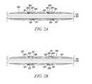
- FIG. 2Ashows a cross sectional view, taken from FIG. 1B , of a suture sleeve secured to an implantable by radial projections.
- FIG. 2Bshows an enlarged cross sectional view, taken from FIG. 1B as an alternative embodiment to that of FIG. 2A , of an attachment mechanism having rivets for securing the suture sleeve to a lead.
- FIG. 2Cshows a cross sectional view, taken from FIG. 1B as an alternative embodiment to those of FIGS. 2A-B , of a suture sleeve secure to a lead by a snap-fit mechanism.
- FIG. 2Dshows a schematic illustration of a suture sleeve secured to a lead by a securement ring.
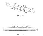
- FIG. 2Eshows a schematic illustration of a suture sleeve secure to a lead by radial projection having end portions.
- FIG. 2Fshows a cross sectional view, taken from FIG. 1B as an alternative embodiment to those of FIGS. 2A-C , of a suture sleeve secured to a lead by a plurality of radial projections for securing the suture sleeve to an implantable lead.
- FIG. 2Gshows a schematic illustration of a radial projection having a ring configuration.
- FIG. 2Hshows a schematic illustration of a radial projection having a spiral configuration.
- FIG. 2Ishows a cross sectional view, taken from FIG. 1B as an alternative embodiment to those of FIGS. 2A-C and FIG. 2F , of a suture sleeve secured to a lead by an adhesive layer.
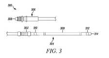
- FIG. 3shows a schematic illustration of an implantable medical lead having a suture sleeve mounted thereon.
- FIG. 1Ashows an implantable medical system 100 .
- the implanted medical system 100includes a pulse generator 104 implanted within a patient. As shown, the pulse generator 104 can be connected to an implantable lead 108 .
- FIG. 1Ashows the implantable medical system 100 arranged for delivering electrical stimulation to the heart 106 .
- the particular implantable medical system 100 shownis implanted subcutaneously along the patient's chest or abdomen, however other implant locations are possible.
- the pulse generator 104 and the implantable lead 108are implanted at an implant location that is outside of the ribcage.
- the pulse generator 104is a pacemaker, an implantable cardioverter/defibrillator (ICD), a cardiac resynchronization (CRT) device, a subcutaneous implantable cardioverter defibrillator, a neurostimulator, or any other implantable medical device for delivering a therapy, and may be configured to deliver one or more of pacing, CRT, defibrillation, and neurostimulation therapies, amongst other options.
- the pulse generator 104may additionally or alternatively be configured for sensing within the body, such as sensing bioelectrical signals and/or other physiological parameters.
- the entirety of the implantable lead 108is implanted subcutaneously, but outside of the ribcage. As such, in various embodiments, no part of the implantable lead 108 comes into contact with the heart. In some other embodiments, at least part of the implantable lead 108 may extend into the ribcage, such as to make contact with the heart.
- One or more portions of the implantable lead 108may be secured in place with a suture sleeve 102 .
- the suture sleeve 102can be secured to the implantable lead 108 prior to beginning surgery, such as in manufacturing of the implantable lead 108 without involvement of a surgeon or other medical professional. Securing the suture sleeve 102 to the implantable lead 108 during manufacturing may allow for a more efficient implantation procedure as a surgeon or trained medical professional would not have to position the suture sleeve 102 on the implantable lead 108 while operating. Further, securing the suture sleeve 102 to the implantable lead 108 in this manner may also provide for an accurate and defined arrangement of the suture sleeve 102 on the implantable lead 108 .
- the implantable lead 108can include an electrode 110 .
- the electrode 110 shown in FIG. 1Ais a defibrillation electrode having a large surface area. Additionally or alternatively, smaller pace and/or sense electrodes, such as ring electrodes, can be deposed on the implantable lead 108 . While a single electrode 110 is shown, it will be understood that a greater number of electrodes and/or different types of electrodes can be provided on the implantable lead 108 .
- the flexible lead bodycan be formed from a polymeric tube.
- the implantable lead 108is inserted into the patient through a first incision (entry site) formed in the side of the patient.
- a stiff tubee.g., an introducer, not shown
- a second incisioncan be made near an upper portion of the sternum of the patient.
- the second incisioncan allow for an access point for a physician to position the distal end of the implantable lead 108 .
- a third incisioncan be made near a lower portion of the sternum. The third incision allows for access to the suture sleeve 102 , which is provided to secure the implantable lead 108 in place.
- suture sleeve 102may be secured in place by tying sutures 112 , 113 , 114 , 115 to the suture sleeve 102 , and threading the sutures 112 , 113 , 114 , 115 within the body.
- FIG. 1Bshows an enlarged schematic illustration of the suture sleeve 102 of FIG. 1A .
- the suture sleeve 102includes a lumen (and other internal components) that defines an interior surface of the suture sleeve.
- the lumen and the implantable lead 108are sized relative to one another such that the implantable lead 108 can be received within the lumen of the suture sleeve 102 .
- An exterior surface of the suture sleeve 102can include one or more receiving tracks 118 , 122 , 126 , 130 .
- Each track 118 , 122 , 126 , 130can be defined by opposing sidewalls 120 , 124 , 128 , 132 .
- the sidewalls 120 , 124 , 128 , 132can hold a suture within the suture receiving track 118 , 122 , 126 , 130 to minimize movement between the suture and the suture sleeve 102 . While four tracks 118 , 122 , 126 , 130 are shown in the embodiment of FIG. 1B , it will be understood that no tracks, a single track, two tracks, three tracks, or any number of tracks can alternatively be provided.
- One or more suturescan be placed within each track 118 , 122 , 126 , 130 during an implantation procedure to secure the implantable lead 108 in place within the body. Each suture (as shown above with reference to FIG.
- the suture sleeve 102can also penetrate and/or loop around tissue to secure the suture sleeve 102 to the tissue.
- a knotcan be tied in each suture after the suture is wrapped around the suture sleeve 102 .
- the suture sleeve 102can prevent the sutures from contacting the lead 108 to prevent damaging the implantable lead 108 while also securing the lead 108 at an implant site.
- the suture sleeve 102can have a surface roughness of between 45 and 75 Ra to enhance securement of the suture with the suture sleeve 102 .
- the suture sleeve 102can be formed from polymeric material, such as silicone.
- the material of the suture sleeve 102may not include properties that allow for heat welding or chemical bonding of the suture sleeve 102 to the implantable lead 108 . Silicone, for example, may not readily adhere to other materials. However, it is advantageous to form the suture sleeve 102 of silicone, or like materials, due to the biocompatible and robust properties of silicone and similar materials.
- the suture sleeve 102may be non-removeably secured to the implantable lead 108 via one or more features as further discussed herein.
- FIG. 2Ashows an enlarged cross sectional view of a suture sleeve 202 secured to an implantable lead 214 by radial projections 204 , 206 .
- the cross sectional viewcan represent, for example, a cross-sectional view taken from the line A-A shown in FIG. 1B .
- the cross-sectional view in FIG. 2Ashows the cross-sectional aspects of the suture sleeve 202 and a lumen 212 of the implantable lead 214 , however, the other internal components (e.g., electrical components) of the implantable lead 214 are omitted.
- the suture sleeve 202is mounted on an implantable lead 214 .
- the suture sleeve 202is secured to the implantable lead 214 by one or more radial projections 204 , 206 .
- the radial projections 204 , 206may be a continuous ring around the implantable lead 214 (as is shown in FIG. 1B ), or, the radial projections 204 , 206 may be only on portions of the implantable lead 214 .
- the radial projection 204 , 206can have sidewalls 208 , 210 that bound an upper surface 207 , 209 of the radial projections 204 , 206 .
- the suture sleeve 202can also include one or more indentations 211 , 213 .
- the one or more indentations 211 , 213may be the opposite (e.g., mirror) of the structure of the radial projections 204 , 206 and interface therewith.
- the sidewalls 210can be curved such that differentiation between the upper surface 207 , 209 of the radial projections 204 , 206 are gradually formed. Further, the sidewalls 208 , 210 can be formed at a steeper angle (e.g., 90 degrees) with respect to the upper surface 207 , 209 .
- the indentations 211 , 213can be provided along the interior surface the suture sleeve 202 , and can be complementary to the radial projections 204 , 206 .
- the raised profile of the radial projections 204 , 206 shown in FIG. 2Aprovides a mechanical stop for the suture sleeve 202 , and the radial projections 204 , 206 engage the one or more indentations 211 , 213 to secure the suture sleeve 202 to an implantable lead 214 .
- the radial projections 204 , 206are provided on an implantable lead 214 .
- the suture sleeve 202can be secured thereto by sliding the suture sleeve 202 along the implantable lead 214 until the encountering the radial projections 204 , 206 .
- the suture sleeve 202is forced over the radial projections 204 , 206 , and slid further along the implantable lead 214 until the radial projections 204 , 206 engages the indentations 211 , 213 .
- the suture sleeve 202is forced further along the implantable lead 214 until each of the radial projections 204 , 206 is provided within the counterpart indentations 211 , 213 .
- the radial projections 204 , 206can be formed around the entire circumference of the implantable lead 214 . In this manner, during manufacturing, the suture sleeve 202 may be slid along the body of the implantable lead 214 , and the radial projections 204 , 206 will engage the indentations 211 , 213 regardless of the rotational positioning of the suture sleeve 202 .
- the indentations 211 , 213may be formed within the suture sleeve 202 prior to placing the suture sleeve 102 on the suture sleeve, or the indentations may be formed as a result of placing the suture sleeve 102 over the respective radial projections 204 , 206 .
- the indentations 211 , 213may be formed as a ring-like indentation along the entire interior circumference of the suture sleeve 202 .
- FIG. 2Bshows an enlarged cross sectional view of a fixation feature for securing a suture sleeve 222 to an implantable lead 221 .
- the cross sectional viewcan represent, for example, a cross-sectional view taken from the line A-A shown in FIG. 1B .
- the cross-sectional view in FIG. 2Bshows the cross-sectional aspects of the suture sleeve 222 and a lumen 220 of the implantable lead 221 , however, the other internal components (e.g., electrical components) of the implantable lead 221 are omitted.
- the suture sleeve 222can be secured to the implantable lead 221 by one or more radial projections 216 , 217 , 218 , 219 .
- Each radial projection 216 , 217 , 218 , 219can include a rivet 223 , 224 , 225 , 226 .
- An upper surface of the rivets 223 , 224 , 225 , 226can be substantially parallel with a top surface of the suture sleeve 222 .
- an upper surface of the rivets 223 , 224 , 225 , 226may be provided such that portions thereof on top of a top surface of the suture sleeve 222 .
- the rivet 223 , 224 , 225 , 226can project axially outward from the radial projections 216 , 217 , 218 , 219 such that a top surface of the rivets 223 , 224 , 225 , 226 are parallel (or substantially parallel and/or angled) relative to an upper surface of the suture sleeve 222 .
- the suture sleeve 222can wedge between the rivets 223 , 224 , 225 , 226 and a main body portion of the radial projections 216 , 217 , 218 , 219 .
- the suture sleeve 222can include indentations 231 , 232 , 233 , 233 (or cavity) that are formed in portions of or as a ring-like indentation/cavity along the entire interior circumference of the suture sleeve 222 .
- the suture sleeve 222may first be placed on the implantable lead 221 . Once the suture sleeve 222 is in the desired location along the implantable lead 221 , the radial projections 216 , 217 , 218 , 219 can be formed on the implantable lead 221 .
- the rivets 223 , 224 , 225 , 226can be provided along the outside surface of the suture sleeve 222 and hold the suture sleeve 222 against the implantable lead 221 .
- the suture sleeve 222includes a plurality of indentations 231 , 232 , 233 , 233
- an equal number of the radial projections 216 , 217 , 218 , 219will also be provided to secure the suture sleeve 222 to the implantable lead 221 .
- the suture sleeve 222may include suture one or more receiving tracks 227 , 228 , 229 , 230 that may hold a suture to secure the implantable lead 221 in place within the body
- FIG. 2Cshows a cross sectional view of a snap-fit mechanism for securing a suture sleeve 234 to an implantable lead 236 .
- the cross sectional viewcan represent, for example, a cross-sectional view taken from the line A-A shown in FIG. 1B .
- the cross-sectional view in FIG. 2Cshows the cross-sectional aspects of the suture sleeve 234 and a lumen 235 of the implantable lead 236 , however, the other internal components (e.g., electrical components) of the implantable lead 236 are omitted.
- the implantable lead 236can include one or more radial projections 237 , 238 that can be bonded to the implantable lead 236 .
- the radial projections 237 , 238are formed as a continuous ring around the circumference of the implantable lead 236 .
- Indentations 239 , 240 in the suture sleeve 234can be formed complementary to the radial projections 237 , 238 to receive the radial projections 237 , 238 .
- the indentations 239 , 240are formed as a continuous ring.
- the radial projections 237 , 238can be snap-fit with the indentations 239 , 240 in the inner surface of the implantable lead 236 as a mechanism to secure the suture sleeve 234 to the implantable lead 236 .
- the radial projections 237 , 238 and the indentations 239 , 240may be formed from the same material (e.g., polyurethane or polycarbonate).
- the suture sleeve 234may be formed as an upper and lower portion, and guided onto the rivets 226 .
- the suture sleeve 234is snapped onto the radial projections 237 , 238 such that the indentations 239 , 240 and the radial projections 237 , 238 are matched.
- the suture sleeve 234may include one or more receiving tracks 241 , 242 , 243 , 244 that may hold a suture to secure the implantable lead 236 in place within the body.
- the tracks 241 , 242 , 243 , 244may be formed as a continuous ring around the exterior surface of the suture sleeve 234 .
- FIG. 2Dshows a schematic illustration of a suture sleeve 246 and radial projection 247 having a securement ring 248 .
- the radial projection 247 shown in FIG. 2Dis a single structure arranged that includes the securement ring 248 .
- the suture sleeve 246includes two portions 254 , 255 on either side of the securement ring 248 .
- the securement ring 248can include an adhesive to secure the suture sleeve 246 to an implantable lead 249 .
- the securement ring 248can contact both portions 254 , 255 of the suture sleeve 246 via the securement ring 248 , and secure the suture sleeve 246 to the implantable lead 249 .
- the radial projection 247 and the securement ring 248may be bonded together.
- the radial projection 247may be secured to the implantable lead 249 , and secured to the securement ring 248 .
- the securement ring 248secures the suture sleeve 246 to the radial projection 247 .
- the radial projection 247may be secured to the implantable lead 249 by first plasma treating the implantable lead 2479 , and subsequently bonding the radial projection 247 thereto.
- the suture sleeve 246may include suture one or more receiving tracks 250 , 251 , 252 , 253 that may hold a suture to secure the implantable lead 249 in place within the body.
- the tracks 250 , 251 , 252 , 253may be formed as a continuous ring around the exterior surface of the suture sleeve 246 .
- FIG. 2Eshows a schematic illustration of a suture sleeve 256 and radial projection having end portions 259 .
- the end portions 259can be provided on either side of the suture sleeve 256 to secure the suture sleeve 256 to an implantable lead 258 .
- End edges 260 , 261 of the end portions 259can overlap portions of the suture sleeve 256 , or can be provided such that the end edges 260 , 261 of the end portions 259 contact the edges of the suture sleeve 256 .
- the suture sleeve 256may be positioned on the implantable lead 258 .
- the end portions 259may be secured on the implantable lead 258 and the edges 260 , 261 will engage portions of the suture sleeve 256 to secure the suture sleeve 256 to the implantable lead 258 .
- the suture sleeve 256may include suture one or more receiving tracks 262 , 263 , 264 , 265 that may hold a suture to secure the implantable lead 258 in place within the body.
- the tracks 262 , 263 , 264 , 265may be formed as a continuous ring around the exterior surface of the suture sleeve 256 .
- FIG. 2Fshows a cross sectional view, taken from FIG. 1B , of a suture sleeve 266 and a plurality of radial projections 268 for securing the suture sleeve 266 to an implantable lead 270 .
- the cross sectional viewcan represent, for example, a cross-sectional view taken from the line A-A shown in FIG. 1B .
- the cross-sectional view in FIG. 2Fshows the cross-sectional aspects of the suture sleeve 266 and a lumen 271 of the implantable lead 270 , however, the other internal components (e.g., electrical components) of the implantable lead 270 are omitted.
- the plurality of radial projections 268can be formed as part of a single material that is notched for flexibility.
- the plurality of radial projections 268are bonded to the implantable lead 270 , and the suture sleeve 266 can be provided over the plurality of radial projections 268 .
- the radial projections 268can be secured directly to the implantable lead 270 .
- the radial projections 268may be heat bonded to the implantable lead 270 , or secured by other methods of discussed herein.
- the suture sleeve 266may include suture one or more receiving tracks 272 , 273 , 274 , 275 that may hold a suture to secure the implantable lead 270 in place within the body.
- the tracks 272 , 273 , 274 , 275may be formed as a continuous ring around the exterior surface of the suture sleeve 266 .
- FIG. 2Gshows a schematic illustration of a radial projection 276 having a circular configuration.
- the radial projection 276 shown in FIG. 2Gcan also be formed of a single piece of material.
- a suture sleeve(not shown) can be secured to an implantable lead 278 by bonding or otherwise securing the suture sleeve over the radial projection 276 . Due to the circular configuration of the radial projection 276 , the suture sleeve can be provided with suture receiving tracks, such as those shown and discussed above with reference to FIG. 1B , via the securement of a suture sleeve over the radial projection 276 .
- the radial projection 276can have a notched configuration that can be used in relation to embodiments of the present invention.
- the circular shapecan be provided with a taper. The taper can occur from both ends of the radial projection 276 such that the centermost portion is raised apart from the implantable lead 278 as compared to the end portions of the radial projection 247 .
- FIG. 2Hshows a schematic illustration of radial projection 280 having a spiral configuration.
- the radial projection 280 shown in FIG. 2Hmay be formed of a single piece of material.
- a suture sleeve(not shown) can be secured to an implantable lead 282 by bonding or otherwise securing the suture sleeve over the radial projection 280 .
- the suture sleevecan be provided with suture receiving tracks, such as those shown and discussed above with reference to FIG. 1B , by way of the securement of a suture sleeve over the radial projection 280 .
- the radial projection 280can have a notched spiral configuration that can be used in relation to embodiments of the present invention.
- the spiral shapecan be provided with a taper. The taper can occur from both ends of the radial projection 280 such that the centermost portion is raised apart from the implantable lead 282 as compared to the end portions of the radial projection 276 .
- FIG. 2Ishows a cross sectional view, taken from FIG. 1B as an alternative embodiment to those of FIGS. 2A-F , of a suture sleeve 284 secured to a lead 288 by an adhesive layer 286 .
- the cross sectional viewcan represent, for example, a cross-sectional view taken from the line A-A shown in FIG. 1B .
- the cross-sectional view in FIG. 2Ishows the cross-sectional aspects of the suture sleeve 284 and a lumen 287 of the implantable lead 288 , however, the other internal components (e.g., electrical components) of the implantable lead 288 are omitted.
- the suture sleeve 284may be directly attached to the implantable lead 288 via the adhesive layer 286 .
- the suture sleeve 284may be positioned along the implantable lead 288 , and the adhesive layer 286 may be provided between the suture sleeve 284 and the implantable lead 288 .
- the adhesive layer 286may be provided along a portion of the suture sleeve 284 , as shown in FIG. 2I , or the adhesive layer 286 may be provided along the circumference of the suture sleeve 284 .
- the adhesive layer 286may be a medical adhesive.
- the outer surface of the implantable lead 288may be treated, prior to securing the suture sleeve 284 thereto, to increase the ability of the surface to non-removeably secure the suture sleeve 284 .
- the suture sleeve 284may then be bonded to the implantable lead 288 via the adhesive layer 286 .
- the outer surface of the implantable lead 288may be plasma treated (or otherwise cleaned), and the suture sleeve 284 may be bonded thereto via the adhesive layer 286 .
- the adhesive layer 286is as flexible or more flexible than the suture sleeve 284 .
- the adhesive layer 286may have a first durometer
- the suture sleeve 284may have a second durometer.
- the first durometermay be lower than the second durometer.
- the suture sleeve 284may include suture one or more receiving tracks 289 , 290 , 291 , 292 that may hold a suture to secure the implantable lead 288 in place within the body.
- the tracks 289 , 290 , 291 , 292may be formed as a continuous ring around the exterior surface of the suture sleeve 284 .
- the radial projectionsmay be attached to the implantable lead by over molding or pre-molding the radial projection, and subsequently bonding (e.g., heat bonding, polycin vorite bonding) the radial projection to the implantable lead.
- the suture sleevemay be molded and subsequently bonded to the implantable lead using a medical adhesive after priming the implantable lead with a bonding agent, and plasma treating the implantable lead.
- the radial projectioncan be the medical adhesive.
- the radial projectioncan be provided with a low profile, and not include raised portions described herein.
- the suture sleeve and the radial projectionscan be formed of various different materials.
- the suture sleeve and the radial projectionsare formed of different materials.
- the suture sleevecan be formed of silicone, and the radial projections can be formed of polycin vorite (PCV), polyurethane, or polycarbonate. Other suitable materials are also contemplated.
- FIG. 3shows a schematic illustration of an implantable medical lead 300 including a suture sleeve 302 .
- the implantable medical lead 300has a distal region 304 , a proximal region 306 , and an intermediate region therebetween.
- the intermediate regionis not shown in FIG. 3 (as is represented by the fragmented depiction of the lead 300 ).
- the proximal region 306includes a connector 308 for the implantable medical lead 300 to connect to a pulse generator (as described, for example, with reference to FIG. 1A ).
- the suture sleeve 302is arranged at the distal region 304 of the implantable medical lead 300 , along with an electrode 309 , and a first sense electrode 310 , and a second sense electrode 312 .
- the electrode 309is configured to provide a stimulation pulse to a patient's heart.
- the electrode 309can provide the stimulation in response to the first sense electrodes 310 and the second sense electrode 312 determining that the patient's heart has an irregular rhythm.
- the second sense electrode 312is provided nearer a distal end tip of the implantable medical lead 300 than the first sense electrodes 310 , which is provided between the suture sleeve 302 and the electrode 309 .
- the gap between the suture sleeve 302 and the first sense electrode 310is between 2 mm and 15 mm. In the embodiment shown in FIG. 3 , the gap between the suture sleeve 302 and the first sense electrode 310 is 7.5 mm.
- the suture sleeve 302is secured on the implantable medical lead 300 such that the suture sleeve 302 will not cover the first sense electrode 310 and thereby interfere with the function of the first sense electrode 310 .
- the suture sleeve 302is secured to the implantable medical lead 300 using radial projections, as shown and discussed above with reference to FIGS. 2A-2I .
- the suture sleeve 302is secured to the implantable medical lead 300 , for example, by sliding the suture sleeve 302 along the implantable medical lead 300 from the proximal region 306 to the distal region 304 .
- the suture sleeve 302has lumen that an interior surface of the suture sleeve 302 , and that is sized to receive the implantable medical lead 300 .
- the radial projection, used to secure the suture sleeve 302 to the implantable medical lead 300is bonded to the implantable medical lead 300 at a position nearer the proximal region 306 than the first sense electrode 310 .
- the suture sleeve 302is slid along the length of the implantable medical lead 300 until reaching the radial projection.
- the suture sleeve 302can be engaged with the radial projection by forcing the suture sleeve 302 over the structure.
- the suture sleeve 302can also be snap-fit to the secured to the implantable medical lead 300 by snap-fitting the suture sleeve 302 over the radial projection (as shown in FIG. 2C ), or the suture sleeve 302 can be directly molded to the implantable medical lead 300 .
- the rivet features, as described above with reference to FIG. 2B , or radial protrusionsmay be formed using a high durometer epoxy resin.
- the rivets or radial projectionsmay be formed by filling the voids in a suture sleeve with epoxy, and then allowing it to cure and harden to form the rivets or radial projections.
Landscapes
- Health & Medical Sciences (AREA)
- Heart & Thoracic Surgery (AREA)
- Cardiology (AREA)
- Animal Behavior & Ethology (AREA)
- Public Health (AREA)
- Nuclear Medicine, Radiotherapy & Molecular Imaging (AREA)
- Radiology & Medical Imaging (AREA)
- Life Sciences & Earth Sciences (AREA)
- Engineering & Computer Science (AREA)
- General Health & Medical Sciences (AREA)
- Biomedical Technology (AREA)
- Veterinary Medicine (AREA)
- Vascular Medicine (AREA)
- Neurology (AREA)
- Neurosurgery (AREA)
- Orthopedic Medicine & Surgery (AREA)
- Electrotherapy Devices (AREA)
- Prostheses (AREA)
Abstract
Description
Claims (2)
Priority Applications (1)
| Application Number | Priority Date | Filing Date | Title |
|---|---|---|---|
| US15/159,707US10286208B2 (en) | 2015-05-20 | 2016-05-19 | Fully integrated lead stabilizer for medical electrical leads and methods of attachment |
Applications Claiming Priority (2)
| Application Number | Priority Date | Filing Date | Title |
|---|---|---|---|
| US201562164023P | 2015-05-20 | 2015-05-20 | |
| US15/159,707US10286208B2 (en) | 2015-05-20 | 2016-05-19 | Fully integrated lead stabilizer for medical electrical leads and methods of attachment |
Publications (2)
| Publication Number | Publication Date |
|---|---|
| US20160339233A1 US20160339233A1 (en) | 2016-11-24 |
| US10286208B2true US10286208B2 (en) | 2019-05-14 |
Family
ID=56084436
Family Applications (1)
| Application Number | Title | Priority Date | Filing Date |
|---|---|---|---|
| US15/159,707Active2036-10-21US10286208B2 (en) | 2015-05-20 | 2016-05-19 | Fully integrated lead stabilizer for medical electrical leads and methods of attachment |
Country Status (6)
| Country | Link |
|---|---|
| US (1) | US10286208B2 (en) |
| EP (1) | EP3297718A1 (en) |
| JP (1) | JP6543721B2 (en) |
| CN (1) | CN107530541A (en) |
| AU (1) | AU2016264610B2 (en) |
| WO (1) | WO2016187473A1 (en) |
Families Citing this family (8)
| Publication number | Priority date | Publication date | Assignee | Title |
|---|---|---|---|---|
| WO2019036571A1 (en) | 2017-08-17 | 2019-02-21 | Cardiac Pacemakers, Inc. | Single incision subcutaneous implantable defibrillation system |
| US11116966B2 (en) | 2017-08-17 | 2021-09-14 | Cardiac Pacemakers, Inc. | Retention mechanism for an implantable lead |
| US10888697B2 (en) | 2017-08-18 | 2021-01-12 | Cardiac Pacemakers, Inc. | Fixation mechanism for an implantable lead |
| US10751526B2 (en) | 2017-10-25 | 2020-08-25 | Cardiac Pacemakers, Inc. | Subcutaneous lead implantation |
| US11147964B2 (en) | 2018-04-23 | 2021-10-19 | Cardiac Pacemakers, Inc. | Subcutaneous lead fixation member |
| US11219775B2 (en) | 2018-05-01 | 2022-01-11 | Cardiac Pacemakers, Inc. | Retention mechanism for an implantable lead |
| WO2020023487A1 (en) | 2018-07-23 | 2020-01-30 | Cardiac Pacemakers, Inc. | Retention mechanism for an implantable lead |
| US20210378574A1 (en)* | 2018-08-27 | 2021-12-09 | Verily Life Sciences Llc | Thin-film high-density sensing array, sub-scalp implantation tool and implant method |
Citations (129)
| Publication number | Priority date | Publication date | Assignee | Title |
|---|---|---|---|---|
| US4254774A (en) | 1979-02-14 | 1981-03-10 | The United States Of America As Represented By The Department Of Health, Education And Welfare | Balloon catheter and technique for the manufacture thereof |
| US4266552A (en) | 1979-11-13 | 1981-05-12 | Medtronic, Inc. | Lead anchoring bobbin |
| US4276882A (en) | 1979-05-18 | 1981-07-07 | Medtronic, Inc. | Lead anchoring device |
| US4287891A (en) | 1979-08-31 | 1981-09-08 | Peters Joseph L | Securing device for surgical tubes |
| US4301815A (en) | 1980-01-23 | 1981-11-24 | Telectronics Pty. Limited | Trailing tine electrode lead |
| US4387727A (en) | 1981-03-30 | 1983-06-14 | Medtronic, Inc. | Coaxial service kit |
| US4409994A (en) | 1981-06-02 | 1983-10-18 | Telectronics Pty., Ltd. | Lap joint molding member for a pacemaker electrode lead |
| US4437475A (en) | 1981-08-28 | 1984-03-20 | Medtronic, Inc. | Transvenous cardiovascular integrated lead anchoring sleeve, protector, and permanent lead introducer stop gap |
| US4442840A (en) | 1982-06-07 | 1984-04-17 | Wojciechowicz Jr Alexander | Electrical connector apparatus and method for a temporary cardiac pacing wire |
| US4516584A (en) | 1983-01-07 | 1985-05-14 | Cordis Corporation | Suture collar |
| US4517971A (en) | 1982-11-22 | 1985-05-21 | Sorbonne Robert L | Guard for venipuncture site and catheter retainer |
| US4519404A (en) | 1983-09-28 | 1985-05-28 | Fleischhacker John J | Endocardial electrode lead with conical fixation mechanism |
| US4538623A (en) | 1984-04-09 | 1985-09-03 | Medtronic, Inc. | Thread electrode assembly |
| US4550737A (en) | 1983-10-12 | 1985-11-05 | Peter Osypka | Intravenously implantable electrode lead for use with cardiac pacemakers |
| US4553961A (en) | 1984-04-18 | 1985-11-19 | Cordis Corporation | Suture sleeve with structure for enhancing pacing lead gripping |
| US4585013A (en) | 1981-04-20 | 1986-04-29 | Cordis Corporation | Lumenless pervenous electrical lead and method of implantation |
| US4613329A (en) | 1983-09-30 | 1986-09-23 | Sherwood Medical Company | Catheter placement device |
| US4615472A (en) | 1985-06-19 | 1986-10-07 | Intravascular Surgical Instruments, Inc. | Catheter placement device |
| US4672979A (en) | 1986-01-30 | 1987-06-16 | Cordis Corporation | Suture sleeve assembly |
| US4676782A (en) | 1984-09-21 | 1987-06-30 | Vitaphore Corporation | Positionable tissue interfacing device for the management of percutaneous conduits |
| US4683895A (en) | 1985-07-25 | 1987-08-04 | Cordis Corporation | Suture sleeve anchoring device |
| US4768523A (en) | 1981-04-29 | 1988-09-06 | Lifecore Biomedical, Inc. | Hydrogel adhesive |
| US4796643A (en) | 1986-09-30 | 1989-01-10 | Telectronics N.V. | Medical electrode leads |
| US4906233A (en) | 1986-05-29 | 1990-03-06 | Terumo Kabushiki Kaisha | Method of securing a catheter body to a human skin surface |
| US5036862A (en) | 1987-04-06 | 1991-08-06 | Cordis Corporation | Implantable, self-retaining lead |
| US5107856A (en) | 1991-01-10 | 1992-04-28 | Siemens-Pacesetter, Inc. | Multiple lead suture sleeve |
| US5129405A (en) | 1985-09-18 | 1992-07-14 | Telectronics N.V. | Vein suture collar |
| US5152298A (en) | 1991-04-16 | 1992-10-06 | Siemens Pacesetter, Inc. | Threaded suture sleeve |
| US5242431A (en) | 1992-06-11 | 1993-09-07 | Siemens Pacesetter, Inc. | Suture sleeve assembly with slidable compression collar |
| US5257975A (en) | 1992-08-14 | 1993-11-02 | Edward Weck Incorporated | Cannula retention device |
| US5273053A (en) | 1992-11-02 | 1993-12-28 | Medtronic, Inc. | Suture sleeve with lead locking device |
| JPH06505190A (en) | 1991-02-22 | 1994-06-16 | サミュエル・ストラッピング・システムズ | Fluidized bed and material processing method |
| US5366496A (en) | 1993-04-01 | 1994-11-22 | Cardiac Pacemakers, Inc. | Subcutaneous shunted coil electrode |
| EP0625359A2 (en) | 1993-05-19 | 1994-11-23 | Siemens Aktiengesellschaft | Implantable lead having self-locking suture sleeve |
| US5376108A (en) | 1993-05-20 | 1994-12-27 | Telectronics Pacing Systems, Inc. | Electrode lead anchoring apparatus and method employing dual suture collars |
| US5423763A (en) | 1993-06-17 | 1995-06-13 | Pacesetter, Inc. | Protective, visible suture sleeve for anchoring transvenous lead bodies |
| US5484445A (en) | 1993-10-12 | 1996-01-16 | Medtronic, Inc. | Sacral lead anchoring system |
| US5549619A (en) | 1991-06-04 | 1996-08-27 | Clinical Product Development Limited | Medical/surgical devices |
| US5583319A (en) | 1993-10-21 | 1996-12-10 | Lieurance; Dennis W. | Low resistance superconductor cable splice and splicing method |
| US5584874A (en) | 1995-04-28 | 1996-12-17 | Medtronic, Inc. | Medical electrical lead having improved anchoring sleeve |
| US5603730A (en) | 1995-07-19 | 1997-02-18 | Ventritex, Inc. | Suture sleeve for implantable lead |
| US5674273A (en) | 1995-10-17 | 1997-10-07 | Pacesetter, Inc. | Implantable pacing lead with crush resistant, protective sleeve |
| US5683446A (en) | 1995-05-25 | 1997-11-04 | Medtronic, Inc. | Medical electrical lead having an anchoring sleeve retaining device |
| US5683403A (en) | 1996-04-05 | 1997-11-04 | Incontrol, Inc. | Implantable lead suture sleeve |
| US5709644A (en) | 1996-06-14 | 1998-01-20 | Pacesetter, Inc. | Implantable suture sleeve modified to reduce tissue ingrowth |
| US5735891A (en) | 1996-12-02 | 1998-04-07 | Sulzer Intermedics Inc. | Self-clamping anchoring sleeve |
| US5746722A (en) | 1997-02-05 | 1998-05-05 | Medtronic, Inc. | Suture sleeve with circumferential lead locking device |
| US5800402A (en) | 1993-03-19 | 1998-09-01 | Venetec International, Inc. | Catheter anchoring system and method of use |
| US5824032A (en) | 1996-08-09 | 1998-10-20 | Medtronic Inc. | Medical electrical lead featuring a one piece lead anchoring sleeve with wrap-around locking arms |
| US5827296A (en) | 1996-09-06 | 1998-10-27 | Medtronic, Inc. | Medical electrical lead |
| WO1998048880A1 (en) | 1997-04-30 | 1998-11-05 | Medtronic, Inc. | Repositionable medical lead anchor with locking device |
| US5871528A (en) | 1996-06-28 | 1999-02-16 | Medtronic, Inc. | Temporary bipolar heart wire |
| US5876429A (en) | 1995-06-07 | 1999-03-02 | Intermedics, Inc. | Methods and devices for in vivo repair of cardiac stimulator leads |
| US5957968A (en) | 1997-09-26 | 1999-09-28 | Medtronic, Inc. | Suture sleeve with lead locking device |
| US6002969A (en) | 1998-08-05 | 1999-12-14 | Intermedics Inc. | Cardiac lead with shape-memory structure |
| US6134477A (en) | 1999-04-30 | 2000-10-17 | Medtronic, Inc. | Adjustable medical lead fixation system |
| US6173206B1 (en) | 1999-05-07 | 2001-01-09 | Ethicon, Inc. | Temporary pacing wire anchor |
| US6178356B1 (en) | 1998-02-20 | 2001-01-23 | Cardiac Pacemakers, Inc. | Coronary venous lead having fixation mechanism |
| US6188932B1 (en) | 1996-11-13 | 2001-02-13 | Pacesetter Ab | Implantable electrode lead |
| US6259953B1 (en) | 1998-07-28 | 2001-07-10 | Intermedics, Inc. | cardiac lead with active fixation and biocompatible lubricant |
| WO2002064206A2 (en) | 2001-02-09 | 2002-08-22 | Medtronic, Inc. | Implantable therapy delivery element adjustable anchor |
| US20020133121A1 (en) | 1993-03-19 | 2002-09-19 | Bierman Steven F. | Catheter anchoring system |
| US6463334B1 (en) | 1998-11-02 | 2002-10-08 | Cardiac Pacemakers, Inc. | Extendable and retractable lead |
| US6473654B1 (en) | 2000-03-08 | 2002-10-29 | Advanced Bionics Corporation | Lead anchor |
| JP2003047653A (en) | 2001-05-28 | 2003-02-18 | Terumo Corp | Medical composite material, medical tubular body and medical instrument |
| US20030050668A1 (en) | 2001-09-07 | 2003-03-13 | Jonathan Lee | Suture sleeve |
| US6554802B1 (en) | 1999-03-31 | 2003-04-29 | Medtronic, Inc. | Medical catheter anchor |
| EP1314449A2 (en) | 2001-11-26 | 2003-05-28 | Terumo Kabushiki Kaisha | Implantable electrode lead |
| US20030130616A1 (en) | 1999-06-03 | 2003-07-10 | Medtronic Minimed, Inc. | Closed loop system for controlling insulin infusion |
| US6592553B2 (en) | 2000-07-05 | 2003-07-15 | Cardiac Pacemakers, Inc. | Introducer assembly and method therefor |
| JP2003220148A (en) | 2001-11-26 | 2003-08-05 | Terumo Corp | Electrode lead for physiological implant |
| US20030195600A1 (en) | 2002-04-12 | 2003-10-16 | Carole Tronnes | Implantable medical device with captivation fixation |
| US6643550B2 (en) | 2000-12-15 | 2003-11-04 | Cardiac Pacemakers, Inc. | Multi-polar connector |
| US20030220678A1 (en) | 2002-05-21 | 2003-11-27 | Tronnes Carole A. | Adjustable implantable captivation fixation anchor-stop |
| US20040059403A1 (en) | 2002-09-24 | 2004-03-25 | Geriche, Inc. | Suture sleeve |
| US20040143216A1 (en) | 2002-08-30 | 2004-07-22 | Spectrx, Inc. | Adapter connector for an infusion set and inserter system |
| US20040199233A1 (en) | 2003-04-07 | 2004-10-07 | Cardiac Pacemakers, Inc. | Device and method for a self-attaching suture sleeve |
| US20040254623A1 (en) | 2003-06-12 | 2004-12-16 | Cardiac Pacemakers, Inc. | Star suture sleeve |
| US20050080470A1 (en) | 2003-10-09 | 2005-04-14 | Randy Westlund | Intramyocardial lead implantation system and method |
| US20050137664A1 (en) | 2003-12-18 | 2005-06-23 | Medtronic, Inc. | Suture sleeve |
| US6912423B2 (en) | 2000-12-15 | 2005-06-28 | Cardiac Pacemakers, Inc. | Terminal connector assembly for a medical device and method therefor |
| US6921295B2 (en) | 2001-04-19 | 2005-07-26 | Medtronic, Inc. | Medical lead extension and connection system |
| US20050177220A1 (en) | 2004-02-05 | 2005-08-11 | Medtronic, Inc. | Novel lead fixation means |
| US7090660B2 (en) | 2004-03-08 | 2006-08-15 | Tri-State Hospital Supply Corporation | Patient medical tubing and catheter anchor and support |
| US20060235484A1 (en) | 2005-03-14 | 2006-10-19 | Jaax Kristen N | Stimulation of a stimulation site within the neck or head |
| WO2006116454A2 (en) | 2005-04-26 | 2006-11-02 | Cook Vascular Incorporated | Suture collar |
| US7184841B1 (en)* | 2004-08-19 | 2007-02-27 | Cardiac Pacemakers, Inc. | Pacing lead stabilizer |
| WO2007024164A1 (en) | 2005-08-24 | 2007-03-01 | St. Jude Medical Ab | Suture sleeve with lead locking device |
| US20070078399A1 (en) | 2005-03-07 | 2007-04-05 | Medtronic, Inc. | Medical device anchor and method of manufacture thereof |
| US7218972B2 (en) | 2003-04-07 | 2007-05-15 | Cardiac Pacemakers, Inc. | Extra strength suture sleeve |
| US20070156216A1 (en) | 2004-03-30 | 2007-07-05 | Cardiac Pacemakers, Inc. | Electrode and insulation assembly for a lead and method therefor |
| US7248930B1 (en) | 1997-03-17 | 2007-07-24 | Medtronic, Inc. | Medical electrical lead |
| US20070225784A1 (en) | 2006-03-23 | 2007-09-27 | Cardiac Pacemakers, Inc. | Medical lead having a variable change in stiffness |
| US20070282414A1 (en) | 2006-06-02 | 2007-12-06 | Cardiac Pacemakers, Inc. | Medical electrical lead with expandable fixation features |
| US20070282412A1 (en) | 2006-06-02 | 2007-12-06 | Cardiac Pacemakers, Inc. | Medical electrical lead with deployable fixation features |
| US20070282415A1 (en) | 2006-06-02 | 2007-12-06 | Cardiac Pacemakers, Inc. | Cardiac lead having implantable stiffening structures for fixation |
| US20070293922A1 (en) | 2006-06-15 | 2007-12-20 | Cardiac Pacemakers, Inc. | Medical electrical lead with friction-enhancing fixation features |
| US7398125B2 (en) | 2005-04-09 | 2008-07-08 | Peter Osypka | Suture collar with a flexible constraining means |
| US20080262588A1 (en) | 2004-08-16 | 2008-10-23 | Cardiac Pacemakers, Inc. | Lead assembly and methods including a push tube |
| US20090125059A1 (en) | 2007-11-09 | 2009-05-14 | Verzal Kevin E | Compression member suture sleeve |
| US20090125058A1 (en) | 2007-11-09 | 2009-05-14 | Bodner Jeffrey P | Lead stabilizer with retention features |
| US20090326473A1 (en) | 2008-06-27 | 2009-12-31 | Interrad Medical, Inc. | System for anchoring medical devices |
| US20100016801A1 (en) | 2008-07-16 | 2010-01-21 | Interrad Medical, Inc. | Anchor Systems and Methods |
| US20100114034A1 (en) | 2007-03-20 | 2010-05-06 | Venetec International, Inc. | Securement device for catheters |
| US7747334B2 (en) | 2006-03-23 | 2010-06-29 | Cardiac Pacemakers, Inc. | Left ventricular lead shapes |
| US20100174240A1 (en)* | 2009-01-06 | 2010-07-08 | Medtronic, Inc. | Anchor having fill port for use with an implantable therapy delivery element |
| US7765015B2 (en) | 2007-01-12 | 2010-07-27 | Cardiac Pacemakers, Inc. | Lead with inflatable fixation mechanism |
| US7806886B2 (en) | 1999-06-03 | 2010-10-05 | Medtronic Minimed, Inc. | Apparatus and method for controlling insulin infusion with state variable feedback |
| US20110009935A1 (en) | 2009-07-10 | 2011-01-13 | Greatbatch Ltd. | Reinforced Suture Sleeve |
| US20110046669A1 (en) | 2008-02-21 | 2011-02-24 | Angiotech Pharmaceuticals, Inc. | Method and apparatus for elevating retainers on self-retaining sutures |
| US20110054581A1 (en) | 2009-09-02 | 2011-03-03 | Shrojalkumar Desai | Medical devices including polyisobutylene based polymers and derivatives thereof |
| US7914582B2 (en) | 2000-08-28 | 2011-03-29 | Vertebral Technologies, Inc. | Method and system for mammalian joint resurfacing |
| US7933661B2 (en) | 2004-02-04 | 2011-04-26 | Medtronic, Inc. | Lead retention means |
| US20120029335A1 (en) | 2010-07-29 | 2012-02-02 | Cameron Health, Inc. | Subcutaneous Leads and Methods of Implant and Explant |
| US20120071959A1 (en) | 2009-05-28 | 2012-03-22 | Marcus Helgesson | Suture sleeve and a method for manufacturing a suture sleeve |
| US20120150202A1 (en) | 2010-12-14 | 2012-06-14 | Boston Scientific Neuromodulation Corporation | Devices containing a suture sleeve and methods of making and using |
| US20120330355A1 (en) | 2011-06-21 | 2012-12-27 | Greatbatch Ltd | Multi-durometer reinforced suture sleeve |
| US20120330354A1 (en) | 2011-06-21 | 2012-12-27 | Greatbatch Ltd. | Multi durometer reinforced suture sleeve |
| US20130138200A1 (en) | 2008-04-11 | 2013-05-30 | Endologix, Inc. | Bifurcated graft deployment systems and methods |
| US20130158640A1 (en) | 2011-12-19 | 2013-06-20 | Brian D. Soltis | Lead anchoring system with limited movement of anchoring device along lead |
| JP2014506504A (en) | 2011-02-07 | 2014-03-17 | ボストン サイエンティフィック ニューロモデュレイション コーポレイション | Torque lock anchor and method and device using the anchor |
| US20140121739A1 (en) | 2012-10-29 | 2014-05-01 | Cardiac Pacemakers, Inc. | Suture sleeves having exterior surface tear resistance |
| US20140128948A1 (en) | 2012-11-08 | 2014-05-08 | Cardiac Pacemakers, Inc. | Fixation and strain relief element for temporary therapy delivery device |
| US8774942B2 (en) | 2007-07-10 | 2014-07-08 | Ams Research Corporation | Tissue anchor |
| US20150005856A1 (en) | 2013-06-27 | 2015-01-01 | Boston Scientific Neuromodulation Corporation | Lead anchors and systems and methods using the lead anchors |
| US8954165B2 (en) | 2012-01-25 | 2015-02-10 | Nevro Corporation | Lead anchors and associated systems and methods |
| US20150045865A1 (en) | 2013-08-07 | 2015-02-12 | Boston Scientific Neuromodulation Corporation | Systems and methods for making and using lead anchors for leads of electrical stimulation systems |
| US20150051675A1 (en) | 2013-08-19 | 2015-02-19 | Boston Scientific Neuromodulation Corporation | Lead anchor with adhesive and systems and methods using the lead anchor |
| US20150352352A1 (en) | 2014-06-05 | 2015-12-10 | Cardiac Pacemakers, Inc. | Flex safe suture sleeve |
Family Cites Families (7)
| Publication number | Priority date | Publication date | Assignee | Title |
|---|---|---|---|---|
| JPS55151964U (en)* | 1979-04-17 | 1980-11-01 | ||
| JPH04504818A (en)* | 1989-12-26 | 1992-08-27 | メドトロニック インコーポレーテッド | Surface treatment of silicon tube to improve sliding properties |
| EP1516156B1 (en)* | 2002-05-30 | 2019-10-23 | AMO Manufacturing USA, LLC | Tracking torsional eye orientation and position |
| DE102004036957B3 (en)* | 2004-07-30 | 2006-06-14 | Infineon Technologies Ag | Method for generating test signals and use of a test system for carrying out the method |
| US8600518B2 (en)* | 2008-04-30 | 2013-12-03 | Boston Scientific Neuromodulation Corporation | Electrodes for stimulation leads and methods of manufacture and use |
| US9220906B2 (en)* | 2012-03-26 | 2015-12-29 | Medtronic, Inc. | Tethered implantable medical device deployment |
| JP6151452B2 (en)* | 2013-08-16 | 2017-06-21 | カーディアック ペースメイカーズ, インコーポレイテッド | Delivery device and method for a leadless heart device |
- 2016
- 2016-05-19EPEP16725732.8Apatent/EP3297718A1/ennot_activeWithdrawn
- 2016-05-19AUAU2016264610Apatent/AU2016264610B2/ennot_activeCeased
- 2016-05-19USUS15/159,707patent/US10286208B2/enactiveActive
- 2016-05-19CNCN201680023324.4Apatent/CN107530541A/ennot_activeWithdrawn
- 2016-05-19JPJP2017548179Apatent/JP6543721B2/ennot_activeExpired - Fee Related
- 2016-05-19WOPCT/US2016/033364patent/WO2016187473A1/ennot_activeCeased
Patent Citations (158)
| Publication number | Priority date | Publication date | Assignee | Title |
|---|---|---|---|---|
| US4254774A (en) | 1979-02-14 | 1981-03-10 | The United States Of America As Represented By The Department Of Health, Education And Welfare | Balloon catheter and technique for the manufacture thereof |
| US4276882A (en) | 1979-05-18 | 1981-07-07 | Medtronic, Inc. | Lead anchoring device |
| US4287891A (en) | 1979-08-31 | 1981-09-08 | Peters Joseph L | Securing device for surgical tubes |
| US4266552A (en) | 1979-11-13 | 1981-05-12 | Medtronic, Inc. | Lead anchoring bobbin |
| US4301815A (en) | 1980-01-23 | 1981-11-24 | Telectronics Pty. Limited | Trailing tine electrode lead |
| US4387727A (en) | 1981-03-30 | 1983-06-14 | Medtronic, Inc. | Coaxial service kit |
| US4585013A (en) | 1981-04-20 | 1986-04-29 | Cordis Corporation | Lumenless pervenous electrical lead and method of implantation |
| US4768523A (en) | 1981-04-29 | 1988-09-06 | Lifecore Biomedical, Inc. | Hydrogel adhesive |
| US4409994A (en) | 1981-06-02 | 1983-10-18 | Telectronics Pty., Ltd. | Lap joint molding member for a pacemaker electrode lead |
| US4437475A (en) | 1981-08-28 | 1984-03-20 | Medtronic, Inc. | Transvenous cardiovascular integrated lead anchoring sleeve, protector, and permanent lead introducer stop gap |
| US4442840A (en) | 1982-06-07 | 1984-04-17 | Wojciechowicz Jr Alexander | Electrical connector apparatus and method for a temporary cardiac pacing wire |
| US4517971A (en) | 1982-11-22 | 1985-05-21 | Sorbonne Robert L | Guard for venipuncture site and catheter retainer |
| US4516584A (en) | 1983-01-07 | 1985-05-14 | Cordis Corporation | Suture collar |
| US4519404A (en) | 1983-09-28 | 1985-05-28 | Fleischhacker John J | Endocardial electrode lead with conical fixation mechanism |
| US4613329A (en) | 1983-09-30 | 1986-09-23 | Sherwood Medical Company | Catheter placement device |
| US4550737A (en) | 1983-10-12 | 1985-11-05 | Peter Osypka | Intravenously implantable electrode lead for use with cardiac pacemakers |
| US4538623A (en) | 1984-04-09 | 1985-09-03 | Medtronic, Inc. | Thread electrode assembly |
| US4553961A (en) | 1984-04-18 | 1985-11-19 | Cordis Corporation | Suture sleeve with structure for enhancing pacing lead gripping |
| US4676782A (en) | 1984-09-21 | 1987-06-30 | Vitaphore Corporation | Positionable tissue interfacing device for the management of percutaneous conduits |
| US4615472A (en) | 1985-06-19 | 1986-10-07 | Intravascular Surgical Instruments, Inc. | Catheter placement device |
| US4683895A (en) | 1985-07-25 | 1987-08-04 | Cordis Corporation | Suture sleeve anchoring device |
| US5129405A (en) | 1985-09-18 | 1992-07-14 | Telectronics N.V. | Vein suture collar |
| US4672979A (en) | 1986-01-30 | 1987-06-16 | Cordis Corporation | Suture sleeve assembly |
| US4906233A (en) | 1986-05-29 | 1990-03-06 | Terumo Kabushiki Kaisha | Method of securing a catheter body to a human skin surface |
| US4796643A (en) | 1986-09-30 | 1989-01-10 | Telectronics N.V. | Medical electrode leads |
| US5036862A (en) | 1987-04-06 | 1991-08-06 | Cordis Corporation | Implantable, self-retaining lead |
| US5107856A (en) | 1991-01-10 | 1992-04-28 | Siemens-Pacesetter, Inc. | Multiple lead suture sleeve |
| JPH06505190A (en) | 1991-02-22 | 1994-06-16 | サミュエル・ストラッピング・システムズ | Fluidized bed and material processing method |
| US5152298A (en) | 1991-04-16 | 1992-10-06 | Siemens Pacesetter, Inc. | Threaded suture sleeve |
| US5549619A (en) | 1991-06-04 | 1996-08-27 | Clinical Product Development Limited | Medical/surgical devices |
| US5242431A (en) | 1992-06-11 | 1993-09-07 | Siemens Pacesetter, Inc. | Suture sleeve assembly with slidable compression collar |
| US5257975A (en) | 1992-08-14 | 1993-11-02 | Edward Weck Incorporated | Cannula retention device |
| US5273053A (en) | 1992-11-02 | 1993-12-28 | Medtronic, Inc. | Suture sleeve with lead locking device |
| US20020133121A1 (en) | 1993-03-19 | 2002-09-19 | Bierman Steven F. | Catheter anchoring system |
| US5800402A (en) | 1993-03-19 | 1998-09-01 | Venetec International, Inc. | Catheter anchoring system and method of use |
| US5366496A (en) | 1993-04-01 | 1994-11-22 | Cardiac Pacemakers, Inc. | Subcutaneous shunted coil electrode |
| EP0625359A2 (en) | 1993-05-19 | 1994-11-23 | Siemens Aktiengesellschaft | Implantable lead having self-locking suture sleeve |
| US5476493A (en) | 1993-05-19 | 1995-12-19 | Pacesetter, Inc. | Implantable lead having self-locking suture sleeve |
| US5376108A (en) | 1993-05-20 | 1994-12-27 | Telectronics Pacing Systems, Inc. | Electrode lead anchoring apparatus and method employing dual suture collars |
| US5423763A (en) | 1993-06-17 | 1995-06-13 | Pacesetter, Inc. | Protective, visible suture sleeve for anchoring transvenous lead bodies |
| US5628780A (en) | 1993-06-17 | 1997-05-13 | Pacesetter, Inc. | Protective, visible suture sleeve for anchoring transvenous lead bodies |
| US5484445A (en) | 1993-10-12 | 1996-01-16 | Medtronic, Inc. | Sacral lead anchoring system |
| US5583319A (en) | 1993-10-21 | 1996-12-10 | Lieurance; Dennis W. | Low resistance superconductor cable splice and splicing method |
| US5584874A (en) | 1995-04-28 | 1996-12-17 | Medtronic, Inc. | Medical electrical lead having improved anchoring sleeve |
| US5683446A (en) | 1995-05-25 | 1997-11-04 | Medtronic, Inc. | Medical electrical lead having an anchoring sleeve retaining device |
| US5876429A (en) | 1995-06-07 | 1999-03-02 | Intermedics, Inc. | Methods and devices for in vivo repair of cardiac stimulator leads |
| US5603730A (en) | 1995-07-19 | 1997-02-18 | Ventritex, Inc. | Suture sleeve for implantable lead |
| US5674273A (en) | 1995-10-17 | 1997-10-07 | Pacesetter, Inc. | Implantable pacing lead with crush resistant, protective sleeve |
| US5683403A (en) | 1996-04-05 | 1997-11-04 | Incontrol, Inc. | Implantable lead suture sleeve |
| US5709644A (en) | 1996-06-14 | 1998-01-20 | Pacesetter, Inc. | Implantable suture sleeve modified to reduce tissue ingrowth |
| US5871528A (en) | 1996-06-28 | 1999-02-16 | Medtronic, Inc. | Temporary bipolar heart wire |
| US5824032A (en) | 1996-08-09 | 1998-10-20 | Medtronic Inc. | Medical electrical lead featuring a one piece lead anchoring sleeve with wrap-around locking arms |
| US5827296A (en) | 1996-09-06 | 1998-10-27 | Medtronic, Inc. | Medical electrical lead |
| US6188932B1 (en) | 1996-11-13 | 2001-02-13 | Pacesetter Ab | Implantable electrode lead |
| US5735891A (en) | 1996-12-02 | 1998-04-07 | Sulzer Intermedics Inc. | Self-clamping anchoring sleeve |
| US5746722A (en) | 1997-02-05 | 1998-05-05 | Medtronic, Inc. | Suture sleeve with circumferential lead locking device |
| WO1998033551A1 (en) | 1997-02-05 | 1998-08-06 | Medtronic, Inc. | Suture sleeve with circumferential lead locking device |
| US7248930B1 (en) | 1997-03-17 | 2007-07-24 | Medtronic, Inc. | Medical electrical lead |
| US5843146A (en) | 1997-04-30 | 1998-12-01 | Medtronic Incorporated | Adjustable medical lead anchor |
| WO1998048880A1 (en) | 1997-04-30 | 1998-11-05 | Medtronic, Inc. | Repositionable medical lead anchor with locking device |
| US5957968A (en) | 1997-09-26 | 1999-09-28 | Medtronic, Inc. | Suture sleeve with lead locking device |
| US6178356B1 (en) | 1998-02-20 | 2001-01-23 | Cardiac Pacemakers, Inc. | Coronary venous lead having fixation mechanism |
| US6915169B2 (en) | 1998-07-22 | 2005-07-05 | Cardiac Pacemakers, Inc. | Extendable and retractable lead having a snap-fit terminal connector |
| US20080262587A1 (en) | 1998-07-22 | 2008-10-23 | Cardiac Pacemakers, Inc | Extendable and retractable lead having a snap-fit terminal connector |
| US20050267557A1 (en) | 1998-07-22 | 2005-12-01 | Cardiac Pacemakers, Inc. | Extendable and retractable lead having a snap-fit terminal connector |
| US6259953B1 (en) | 1998-07-28 | 2001-07-10 | Intermedics, Inc. | cardiac lead with active fixation and biocompatible lubricant |
| US6002969A (en) | 1998-08-05 | 1999-12-14 | Intermedics Inc. | Cardiac lead with shape-memory structure |
| US6463334B1 (en) | 1998-11-02 | 2002-10-08 | Cardiac Pacemakers, Inc. | Extendable and retractable lead |
| US6554802B1 (en) | 1999-03-31 | 2003-04-29 | Medtronic, Inc. | Medical catheter anchor |
| US6134477A (en) | 1999-04-30 | 2000-10-17 | Medtronic, Inc. | Adjustable medical lead fixation system |
| US6173206B1 (en) | 1999-05-07 | 2001-01-09 | Ethicon, Inc. | Temporary pacing wire anchor |
| US7806886B2 (en) | 1999-06-03 | 2010-10-05 | Medtronic Minimed, Inc. | Apparatus and method for controlling insulin infusion with state variable feedback |
| US20030130616A1 (en) | 1999-06-03 | 2003-07-10 | Medtronic Minimed, Inc. | Closed loop system for controlling insulin infusion |
| US6473654B1 (en) | 2000-03-08 | 2002-10-29 | Advanced Bionics Corporation | Lead anchor |
| US6592553B2 (en) | 2000-07-05 | 2003-07-15 | Cardiac Pacemakers, Inc. | Introducer assembly and method therefor |
| US7914582B2 (en) | 2000-08-28 | 2011-03-29 | Vertebral Technologies, Inc. | Method and system for mammalian joint resurfacing |
| US6643550B2 (en) | 2000-12-15 | 2003-11-04 | Cardiac Pacemakers, Inc. | Multi-polar connector |
| US20040093052A1 (en) | 2000-12-15 | 2004-05-13 | Cardiac Pacemaker, Inc. | Multi-polar connector |
| US6895277B2 (en) | 2000-12-15 | 2005-05-17 | Cardiac Pacemakers, Inc. | Multi-polar connector |
| US6912423B2 (en) | 2000-12-15 | 2005-06-28 | Cardiac Pacemakers, Inc. | Terminal connector assembly for a medical device and method therefor |
| US20050202703A1 (en) | 2000-12-15 | 2005-09-15 | Cardiac Pacemakers, Inc. | Multi-polar connector |
| US6901287B2 (en) | 2001-02-09 | 2005-05-31 | Medtronic, Inc. | Implantable therapy delivery element adjustable anchor |
| WO2002064206A2 (en) | 2001-02-09 | 2002-08-22 | Medtronic, Inc. | Implantable therapy delivery element adjustable anchor |
| US6921295B2 (en) | 2001-04-19 | 2005-07-26 | Medtronic, Inc. | Medical lead extension and connection system |
| JP2003047653A (en) | 2001-05-28 | 2003-02-18 | Terumo Corp | Medical composite material, medical tubular body and medical instrument |
| US20030050668A1 (en) | 2001-09-07 | 2003-03-13 | Jonathan Lee | Suture sleeve |
| US6985777B2 (en) | 2001-11-26 | 2006-01-10 | Terumo Kabushiki Kaisha | Implantable electrode lead |
| EP1314449A2 (en) | 2001-11-26 | 2003-05-28 | Terumo Kabushiki Kaisha | Implantable electrode lead |
| US20030100937A1 (en) | 2001-11-26 | 2003-05-29 | Fuminori Tsuboi | Implantable electrode lead |
| JP2003220148A (en) | 2001-11-26 | 2003-08-05 | Terumo Corp | Electrode lead for physiological implant |
| WO2003086532A1 (en) | 2002-04-12 | 2003-10-23 | Medtronic, Inc. | Implantable medical lead with movable fixation |
| US20030195600A1 (en) | 2002-04-12 | 2003-10-16 | Carole Tronnes | Implantable medical device with captivation fixation |
| US20030220678A1 (en) | 2002-05-21 | 2003-11-27 | Tronnes Carole A. | Adjustable implantable captivation fixation anchor-stop |
| WO2003099375A2 (en) | 2002-05-21 | 2003-12-04 | Medtronic, Inc. | Adjustable implantable captivation fixation anchor-stop |
| US20040143216A1 (en) | 2002-08-30 | 2004-07-22 | Spectrx, Inc. | Adapter connector for an infusion set and inserter system |
| US20040059403A1 (en) | 2002-09-24 | 2004-03-25 | Geriche, Inc. | Suture sleeve |
| WO2004028345A2 (en) | 2002-09-24 | 2004-04-08 | Geriche, Inc. | Suture sleeve |
| US7242986B2 (en) | 2003-04-07 | 2007-07-10 | Cardiac Pacemakers, Inc. | Device and method for a self-attaching suture sleeve |
| US20040199233A1 (en) | 2003-04-07 | 2004-10-07 | Cardiac Pacemakers, Inc. | Device and method for a self-attaching suture sleeve |
| US7218972B2 (en) | 2003-04-07 | 2007-05-15 | Cardiac Pacemakers, Inc. | Extra strength suture sleeve |
| US20040254623A1 (en) | 2003-06-12 | 2004-12-16 | Cardiac Pacemakers, Inc. | Star suture sleeve |
| US20050080470A1 (en) | 2003-10-09 | 2005-04-14 | Randy Westlund | Intramyocardial lead implantation system and method |
| WO2005061047A1 (en) | 2003-12-18 | 2005-07-07 | Medtronic, Inc. | Improved suture sleeve |
| US20050137664A1 (en) | 2003-12-18 | 2005-06-23 | Medtronic, Inc. | Suture sleeve |
| US7082337B2 (en) | 2003-12-18 | 2006-07-25 | Medtronic, Inc. | Suture sleeve |
| US7933661B2 (en) | 2004-02-04 | 2011-04-26 | Medtronic, Inc. | Lead retention means |
| US20050177220A1 (en) | 2004-02-05 | 2005-08-11 | Medtronic, Inc. | Novel lead fixation means |
| US7090660B2 (en) | 2004-03-08 | 2006-08-15 | Tri-State Hospital Supply Corporation | Patient medical tubing and catheter anchor and support |
| US20070156216A1 (en) | 2004-03-30 | 2007-07-05 | Cardiac Pacemakers, Inc. | Electrode and insulation assembly for a lead and method therefor |
| US20080262588A1 (en) | 2004-08-16 | 2008-10-23 | Cardiac Pacemakers, Inc. | Lead assembly and methods including a push tube |
| US7184841B1 (en)* | 2004-08-19 | 2007-02-27 | Cardiac Pacemakers, Inc. | Pacing lead stabilizer |
| US20070078399A1 (en) | 2005-03-07 | 2007-04-05 | Medtronic, Inc. | Medical device anchor and method of manufacture thereof |
| US20060235484A1 (en) | 2005-03-14 | 2006-10-19 | Jaax Kristen N | Stimulation of a stimulation site within the neck or head |
| US7398125B2 (en) | 2005-04-09 | 2008-07-08 | Peter Osypka | Suture collar with a flexible constraining means |
| US20060264803A1 (en) | 2005-04-26 | 2006-11-23 | Cook Vascular Incorporated | Suture collar |
| WO2006116454A2 (en) | 2005-04-26 | 2006-11-02 | Cook Vascular Incorporated | Suture collar |
| WO2007024164A1 (en) | 2005-08-24 | 2007-03-01 | St. Jude Medical Ab | Suture sleeve with lead locking device |
| US20080228251A1 (en) | 2005-08-24 | 2008-09-18 | Rolf Hill | Suture Sleeve |
| US8000811B2 (en) | 2005-08-24 | 2011-08-16 | St. Jude Medical Ab | Suture sleeve |
| US20070225784A1 (en) | 2006-03-23 | 2007-09-27 | Cardiac Pacemakers, Inc. | Medical lead having a variable change in stiffness |
| US7747334B2 (en) | 2006-03-23 | 2010-06-29 | Cardiac Pacemakers, Inc. | Left ventricular lead shapes |
| US20070282415A1 (en) | 2006-06-02 | 2007-12-06 | Cardiac Pacemakers, Inc. | Cardiac lead having implantable stiffening structures for fixation |
| US20070282412A1 (en) | 2006-06-02 | 2007-12-06 | Cardiac Pacemakers, Inc. | Medical electrical lead with deployable fixation features |
| US20070282414A1 (en) | 2006-06-02 | 2007-12-06 | Cardiac Pacemakers, Inc. | Medical electrical lead with expandable fixation features |
| US20070293922A1 (en) | 2006-06-15 | 2007-12-20 | Cardiac Pacemakers, Inc. | Medical electrical lead with friction-enhancing fixation features |
| US7765015B2 (en) | 2007-01-12 | 2010-07-27 | Cardiac Pacemakers, Inc. | Lead with inflatable fixation mechanism |
| US20100114034A1 (en) | 2007-03-20 | 2010-05-06 | Venetec International, Inc. | Securement device for catheters |
| US8774942B2 (en) | 2007-07-10 | 2014-07-08 | Ams Research Corporation | Tissue anchor |
| US20090125060A1 (en) | 2007-11-09 | 2009-05-14 | Rivard Adam J | Compression control lead anchoring device |
| US20090125059A1 (en) | 2007-11-09 | 2009-05-14 | Verzal Kevin E | Compression member suture sleeve |
| US8271096B2 (en) | 2007-11-09 | 2012-09-18 | Cardiac Pacemakers, Inc. | Pre-selected compression lead anchoring device |
| US8126569B2 (en) | 2007-11-09 | 2012-02-28 | Cardiac Pacemakers, Inc. | Compression control lead anchoring device |
| US20090125058A1 (en) | 2007-11-09 | 2009-05-14 | Bodner Jeffrey P | Lead stabilizer with retention features |
| US20090125061A1 (en) | 2007-11-09 | 2009-05-14 | Rivard Adam J | Pre-selected compression lead anchoring device |
| US20110046669A1 (en) | 2008-02-21 | 2011-02-24 | Angiotech Pharmaceuticals, Inc. | Method and apparatus for elevating retainers on self-retaining sutures |
| US20130138200A1 (en) | 2008-04-11 | 2013-05-30 | Endologix, Inc. | Bifurcated graft deployment systems and methods |
| US20090326473A1 (en) | 2008-06-27 | 2009-12-31 | Interrad Medical, Inc. | System for anchoring medical devices |
| US20100016801A1 (en) | 2008-07-16 | 2010-01-21 | Interrad Medical, Inc. | Anchor Systems and Methods |
| US20100174240A1 (en)* | 2009-01-06 | 2010-07-08 | Medtronic, Inc. | Anchor having fill port for use with an implantable therapy delivery element |
| US20120071959A1 (en) | 2009-05-28 | 2012-03-22 | Marcus Helgesson | Suture sleeve and a method for manufacturing a suture sleeve |
| EP2275169A1 (en) | 2009-07-10 | 2011-01-19 | Greatbatch Ltd. | Reinforced suture sleeve |
| US20110009935A1 (en) | 2009-07-10 | 2011-01-13 | Greatbatch Ltd. | Reinforced Suture Sleeve |
| US20110054581A1 (en) | 2009-09-02 | 2011-03-03 | Shrojalkumar Desai | Medical devices including polyisobutylene based polymers and derivatives thereof |
| US20120029335A1 (en) | 2010-07-29 | 2012-02-02 | Cameron Health, Inc. | Subcutaneous Leads and Methods of Implant and Explant |
| US20120150202A1 (en) | 2010-12-14 | 2012-06-14 | Boston Scientific Neuromodulation Corporation | Devices containing a suture sleeve and methods of making and using |
| JP2014506504A (en) | 2011-02-07 | 2014-03-17 | ボストン サイエンティフィック ニューロモデュレイション コーポレイション | Torque lock anchor and method and device using the anchor |
| US20120330355A1 (en) | 2011-06-21 | 2012-12-27 | Greatbatch Ltd | Multi-durometer reinforced suture sleeve |
| US20120330354A1 (en) | 2011-06-21 | 2012-12-27 | Greatbatch Ltd. | Multi durometer reinforced suture sleeve |
| US20130158640A1 (en) | 2011-12-19 | 2013-06-20 | Brian D. Soltis | Lead anchoring system with limited movement of anchoring device along lead |
| US8954165B2 (en) | 2012-01-25 | 2015-02-10 | Nevro Corporation | Lead anchors and associated systems and methods |
| US20140121739A1 (en) | 2012-10-29 | 2014-05-01 | Cardiac Pacemakers, Inc. | Suture sleeves having exterior surface tear resistance |
| US20140128948A1 (en) | 2012-11-08 | 2014-05-08 | Cardiac Pacemakers, Inc. | Fixation and strain relief element for temporary therapy delivery device |
| US9486622B2 (en) | 2012-11-08 | 2016-11-08 | Cardiac Pacemakers, Inc. | Fixation and strain relief element for temporary therapy delivery device |
| US20150005856A1 (en) | 2013-06-27 | 2015-01-01 | Boston Scientific Neuromodulation Corporation | Lead anchors and systems and methods using the lead anchors |
| US20150045865A1 (en) | 2013-08-07 | 2015-02-12 | Boston Scientific Neuromodulation Corporation | Systems and methods for making and using lead anchors for leads of electrical stimulation systems |
| US20150051675A1 (en) | 2013-08-19 | 2015-02-19 | Boston Scientific Neuromodulation Corporation | Lead anchor with adhesive and systems and methods using the lead anchor |
| US9216563B2 (en)* | 2013-08-19 | 2015-12-22 | Boston Scientific Neuromodulation Corporation | Lead anchor with adhesive and systems and methods using the lead anchor |
| US20150352352A1 (en) | 2014-06-05 | 2015-12-10 | Cardiac Pacemakers, Inc. | Flex safe suture sleeve |
Non-Patent Citations (6)
| Title |
|---|
| International Search Report and Written Opinion issued in PCT/US2013/067138, dated Mar. 20, 2014, 13 pages. |
| International Search Report and Written Opinion issued in PCT/US2016/033364, dated Oct. 10, 2016, 14 pages. |
| Invitation to Pay Additional Fees and Partial international Search issued in PCT/US2016/033364, dated Aug. 10, 2016, 6 pages. |
| Pacing Lead Stabilizer with Modified Slit Geometry, Technical Disclosure from www.ip.com, No. IPCOM000130753D, published Nov. 3, 2005, full document available at http://www.ip.com/pubview/IPCOM000125732D,6 pages. |
| PCT Invitation to Pay Additional Fees and Partial Search Report issued in PCT/US2016/033364 dated Aug. 10, 2016, 6 pages. |
| Suture Sleeve with Removable Fins, Technical Disclosure from www.ip.com, No. IPCOM000125732D, published Jun. 15, 2005, full document available at http://www.ip.com/pubview/IPCOM000125732D, 4 pages. |
Also Published As
| Publication number | Publication date |
|---|---|
| EP3297718A1 (en) | 2018-03-28 |
| AU2016264610A1 (en) | 2017-08-31 |
| JP6543721B2 (en) | 2019-07-10 |
| JP2018507753A (en) | 2018-03-22 |
| AU2016264610B2 (en) | 2018-11-08 |
| CN107530541A (en) | 2018-01-02 |
| WO2016187473A1 (en) | 2016-11-24 |
| US20160339233A1 (en) | 2016-11-24 |
Similar Documents
| Publication | Publication Date | Title |
|---|---|---|
| US10286208B2 (en) | Fully integrated lead stabilizer for medical electrical leads and methods of attachment | |
| US11000683B2 (en) | Implantable medical devices, systems and components thereof | |
| US8688232B2 (en) | Multi-durometer reinforced suture sleeve | |
| US11013911B2 (en) | Lead positioning and finned fixation system | |
| US7328071B1 (en) | Lead placement device | |
| US8676341B2 (en) | Multi durometer reinforced suture sleeve | |
| US9026227B2 (en) | Anchor sleeve for implantable lead | |
| US5476499A (en) | Medical electrode lead with atrial electrode at the distal and ventricular electrode between the distal and proximal ends | |
| US20150088155A1 (en) | Mechanical configurations for a multi-site leadless pacemaker | |
| US9095700B2 (en) | Lead positioning and fixation system | |
| US11666749B2 (en) | Implantable devices and methods for control of bacterial infections | |
| JP4716516B2 (en) | Tachycardia lead system for septal placement | |
| US20030204234A1 (en) | Apparatus and method for fixedly engaging an electrical lead | |
| Motta et al. | Transient elevation of the ST segment during implantation of a ventricular pacemaker electrode for deep septal stimulation: A case report |
Legal Events
| Date | Code | Title | Description |
|---|---|---|---|
| AS | Assignment | Owner name:CARDIAC PACEMAKERS, INC., MINNESOTA Free format text:ASSIGNMENT OF ASSIGNORS INTEREST;ASSIGNORS:DE KOCK, ANDREW L.;COOKE, DANIEL L.;REDDY, G. SHANTANU;AND OTHERS;SIGNING DATES FROM 20160513 TO 20160517;REEL/FRAME:039477/0643 Owner name:CARDIAC PACEMAKERS, INC., MINNESOTA Free format text:ASSIGNMENT OF ASSIGNORS INTEREST;ASSIGNOR:DURAND, DAVID A.;REEL/FRAME:039478/0518 Effective date:20160726 | |
| AS | Assignment | Owner name:CARDIAC PACEMAKERS, INC., MINNESOTA Free format text:ASSIGNMENT OF ASSIGNORS INTEREST;ASSIGNOR:FUHS, CHRISTOPHER A.;REEL/FRAME:039771/0914 Effective date:20160513 | |
| STPP | Information on status: patent application and granting procedure in general | Free format text:NOTICE OF ALLOWANCE MAILED -- APPLICATION RECEIVED IN OFFICE OF PUBLICATIONS | |
| STPP | Information on status: patent application and granting procedure in general | Free format text:PUBLICATIONS -- ISSUE FEE PAYMENT VERIFIED | |
| STCF | Information on status: patent grant | Free format text:PATENTED CASE | |
| MAFP | Maintenance fee payment | Free format text:PAYMENT OF MAINTENANCE FEE, 4TH YEAR, LARGE ENTITY (ORIGINAL EVENT CODE: M1551); ENTITY STATUS OF PATENT OWNER: LARGE ENTITY Year of fee payment:4 |