US10285745B2 - Orthopedic screws - Google Patents
Orthopedic screwsDownload PDFInfo
- Publication number
- US10285745B2 US10285745B2US15/201,643US201615201643AUS10285745B2US 10285745 B2US10285745 B2US 10285745B2US 201615201643 AUS201615201643 AUS 201615201643AUS 10285745 B2US10285745 B2US 10285745B2
- Authority
- US
- United States
- Prior art keywords
- screw
- tip
- orthopedic
- distal
- main shaft
- Prior art date
- Legal status (The legal status is an assumption and is not a legal conclusion. Google has not performed a legal analysis and makes no representation as to the accuracy of the status listed.)
- Active, expires
Links
- 230000000399orthopedic effectEffects0.000titleclaimsabstractdescription66
- 238000005553drillingMethods0.000abstractdescription10
- 238000010079rubber tappingMethods0.000abstractdescription7
- 210000000988bone and boneAnatomy0.000description37
- 238000000034methodMethods0.000description6
- 238000003780insertionMethods0.000description5
- 230000037431insertionEffects0.000description5
- 238000012986modificationMethods0.000description2
- 230000004048modificationEffects0.000description2
- 239000002639bone cementSubstances0.000description1
- 230000001054cortical effectEffects0.000description1
- 230000003292diminished effectEffects0.000description1
- 239000012634fragmentSubstances0.000description1
- 238000002513implantationMethods0.000description1
- 210000003041ligamentAnatomy0.000description1
- 239000002184metalSubstances0.000description1
- 230000001009osteoporotic effectEffects0.000description1
- 210000003625skullAnatomy0.000description1
- 210000004872soft tissueAnatomy0.000description1
- 239000000126substanceSubstances0.000description1
- 238000001356surgical procedureMethods0.000description1
Images


Classifications
- A—HUMAN NECESSITIES
- A61—MEDICAL OR VETERINARY SCIENCE; HYGIENE
- A61B—DIAGNOSIS; SURGERY; IDENTIFICATION
- A61B17/00—Surgical instruments, devices or methods
- A61B17/56—Surgical instruments or methods for treatment of bones or joints; Devices specially adapted therefor
- A61B17/58—Surgical instruments or methods for treatment of bones or joints; Devices specially adapted therefor for osteosynthesis, e.g. bone plates, screws or setting implements
- A61B17/68—Internal fixation devices, including fasteners and spinal fixators, even if a part thereof projects from the skin
- A61B17/84—Fasteners therefor or fasteners being internal fixation devices
- A61B17/86—Pins or screws or threaded wires; nuts therefor
- A61B17/8625—Shanks, i.e. parts contacting bone tissue
- A61B17/8635—Tips of screws
- A—HUMAN NECESSITIES
- A61—MEDICAL OR VETERINARY SCIENCE; HYGIENE
- A61B—DIAGNOSIS; SURGERY; IDENTIFICATION
- A61B17/00—Surgical instruments, devices or methods
- A61B17/56—Surgical instruments or methods for treatment of bones or joints; Devices specially adapted therefor
- A61B17/58—Surgical instruments or methods for treatment of bones or joints; Devices specially adapted therefor for osteosynthesis, e.g. bone plates, screws or setting implements
- A61B17/68—Internal fixation devices, including fasteners and spinal fixators, even if a part thereof projects from the skin
- A61B17/70—Spinal positioners or stabilisers, e.g. stabilisers comprising fluid filler in an implant
- A61B17/7001—Screws or hooks combined with longitudinal elements which do not contact vertebrae
- A61B17/7035—Screws or hooks, wherein a rod-clamping part and a bone-anchoring part can pivot relative to each other
- F—MECHANICAL ENGINEERING; LIGHTING; HEATING; WEAPONS; BLASTING
- F16—ENGINEERING ELEMENTS AND UNITS; GENERAL MEASURES FOR PRODUCING AND MAINTAINING EFFECTIVE FUNCTIONING OF MACHINES OR INSTALLATIONS; THERMAL INSULATION IN GENERAL
- F16B—DEVICES FOR FASTENING OR SECURING CONSTRUCTIONAL ELEMENTS OR MACHINE PARTS TOGETHER, e.g. NAILS, BOLTS, CIRCLIPS, CLAMPS, CLIPS OR WEDGES; JOINTS OR JOINTING
- F16B25/00—Screws that cut thread in the body into which they are screwed, e.g. wood screws
- F16B25/10—Screws performing an additional function to thread-forming, e.g. drill screws or self-piercing screws
- F16B25/103—Screws performing an additional function to thread-forming, e.g. drill screws or self-piercing screws by means of a drilling screw-point, i.e. with a cutting and material removing action
- A—HUMAN NECESSITIES
- A61—MEDICAL OR VETERINARY SCIENCE; HYGIENE
- A61B—DIAGNOSIS; SURGERY; IDENTIFICATION
- A61B17/00—Surgical instruments, devices or methods
- A61B17/56—Surgical instruments or methods for treatment of bones or joints; Devices specially adapted therefor
- A61B17/58—Surgical instruments or methods for treatment of bones or joints; Devices specially adapted therefor for osteosynthesis, e.g. bone plates, screws or setting implements
- A61B17/68—Internal fixation devices, including fasteners and spinal fixators, even if a part thereof projects from the skin
- A61B17/84—Fasteners therefor or fasteners being internal fixation devices
- A61B17/86—Pins or screws or threaded wires; nuts therefor
- A61B17/864—Pins or screws or threaded wires; nuts therefor hollow, e.g. with socket or cannulated
Definitions
- the present disclosuregenerally relates to self-drilling, self-tapping and self-advancing orthopedic screws.
- a variety of fastenersare used in orthopedic surgical procedures to secure bone fragments, reattach ligaments or soft tissue to bones, or to stabilize bones in relative position to one another.
- cervical platesare typically secured to vertebrae with bone screws to stabilize the cervical spine
- occipital platesare typically secured to the back of the skull with bone screws for attaching spinal rods.
- Pedicle screwsare inserted into the pedicle of a vertebral body and are commonly used along with rods and screws to immobilize a portion of the spinal column.
- pedicle screwsare inserted into a series of vertebrae and one or more metal rods are secured to the heads of the screws, typically using set screws or some other securing means.
- Procedures which require multiple stepscan create the potential for the patient to experience complications with each step. Additionally, the chances for a surgeon to make a mistake due to fatigue during long procedures involving multiple screws increases with the number of steps required for placement of each screw. Thus, there is a need for an improved orthopedic screw that reduces the number of steps required for implanting the screw into bone.
- an orthopedic screwcomprising a main shaft extending along a central axis from a proximal end to a distal end.
- the main shaftcomprises a plurality of threads between the proximal end and the distal end of the main shaft.
- the orthopedic screwalso includes a tip that extends along the central axis from the distal end of the main shaft.
- the tiphas a minor diameter and a major diameter.
- the tipcomprises a tip shaft defining the minor diameter of the tip.
- the tipalso includes a distal-most thread that has a leading edge and defines the major diameter of the tip.
- the distal-most threadalso ends the tip.
- the tipfurther includes a relief cut having a leading end and a trailing end. The trailing end extends in a plane different than the leading edge of the distal-most thread. The leading end of the relief cut starts at the leading edge of the distal-most thread.
- FIG. 1is a perspective view of an orthopedic screw with a connector assembly attached to the head of the orthopedic screw according to an embodiment of the present disclosure.
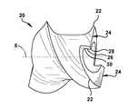
- FIG. 2is a perspective view of a screw tip of the orthopedic screw depicted in FIG. 1 .
- FIG. 3is a perspective view of the screw tip depicted in FIG. 2 rotated 180 degrees.
- FIG. 4is a cross-sectional view of an orthopedic screw according to an embodiment of the present disclosure.
- FIG. 5is a side view of an orthopedic screw according to an embodiment of the present disclosure.
- FIG. 6is a perspective view of the screw tip of an orthopedic screw depicting an exemplary angular orientation of the trailing end of a relief cut of the orthopedic screw tip relative to the leading edge of the distal-most thread of the screw tip relative to the central axis of the screw's main shaft according to an embodiment of the present disclosure.
- FIG. 7is a perspective view of a screw tip of an orthopedic screw depicting an exemplary angular orientation of the leading end of a relief cut relative to the trailing end of the relief cut relative to the central axis of the screw's main shaft according to an embodiment of the present disclosure.
- FIG. 8is a partial cross-section of the orthopedic screw of FIG. 1 identifying the major and minor diameter of the screw tip according to an embodiment of the present disclosure.
- the present disclosuregenerally related to orthopedic screws.
- aspects of the present disclosureprovide self-drilling and self-tapping orthopedic screws.
- Screws of the present disclosurecan be used to simultaneously form a pilot hole in bone and form threads for securing the screw in bone as the screw is secured into bone. Such a screw does not require the separate step of forming a pilot hole in the bone and then tapping the bone for insertion of the screw into the bone.
- the present disclosurerefers to the term “substantially” with respect to certain geometric shapes.
- substantiallyis meant that the shape of the element need not have the mathematically or geometrically exact described shape but can have a shape that is recognizable by one skilled in the art as generally or approximately having the described shape.
- the terms “a,” “an,” and “the”include at least one or more of the described element unless otherwise indicated.
- the term “or”refers to “and/or” unless otherwise indicated.
- an orthopedic screw 10comprises a main shaft 12 extending along a central axis X from a proximal end 14 to a distal end 16 .
- Shaft 12comprises a plurality of threads 18 between proximal end 14 and distal end 16 .
- the plurality of threadsextends the entire length of the main shaft between the proximal end and the distal end of the main shaft.
- the plurality of threadstaper from the proximal end to the distal end so that as the pilot hole is being created, the plurality of threads bites into the sides of the pilot hole advancing the orthopedic screw deeper into the bone.
- Orthopedic screw 10further includes a tip 20 extending along central axis X from distal end 16 of shaft 12 .
- Tip 20has a minor diameter M 1 and a major diameter M 2 as illustrated in FIG. 8 .
- Tip shaft 21 of tip 20defines minor diameter M 1 of tip 20 .
- Tip 20also includes a distal-most thread 22 have a leading edge 24 and defining major diameter M 2 of tip 20 .
- major diameter M 2is the maximum diameter of tip 20 and minor diameter M 1 is the minimum diameter of tip 20 .
- Leading edge 24 of distal-most thread 22is also referred to as the “cutting edge” of the orthopedic screw.
- the distal-most threadextends to the very end of tip 20 as illustrated in FIGS. 2 and 3 .
- the drilling diametere.g. the outer diameter of the pilot hole created when the orthopedic screw is inserted into bone
- the thread major diameterthereby improving the screw's ability to be advanced into bone.
- Tip 20further includes a relief cut 26 having a leading end 28 and a trailing end 30 .
- Trailing end 30extends in a plane different than leading edge 24 of distal-most thread 22 .
- Leading end 28 of relief cut 26starts at leading edge 24 of distal-most thread 22 .
- Leading end 28 of relief cut 26starts at leading edge 24 of distal-most thread 22 to create a wide cutting edge that can create a pilot hole for inserting the orthopedic screw into bone.
- the wide cutting edgeallows the orthopedic screw to cut bone away as the orthopedic screw is rotated clockwise with minimal axial force and provides the screw with a self-drilling feature to improve initial insertion of the screw into bone. Further, because the distal-most thread extends to the very tip of the screw, the relief cut does not reduce the screw purchase.
- the angular orientation A 1 of trailing end 30 of relief cut 26 relative to leading edge 24 of distal-most thread 22is between about 1 degree and about 30 degrees relative to central axis X. In certain embodiments, angular orientation A 1 is about 15 degrees.
- Such angular orientationcreates a sharp cutting edge to cut bone in a manner similar to a bone drill that is used to create a pilot hole.
- the aggressiveness of the cutting tipis significantly better than other self drilling screws in the art because the shallow angle of the cutting edge makes drilling into bone easier than other self drilling screws in the art.
- the shallow anglecreates a knife edge that will cut bone easier than a steep angle, which would scrape the bone instead of cutting into bone.
- the angular orientation A 2 of leading end 28 of relief cut 26 relative to trailing end 30 of relief cut 26is between about 0 degrees and about 17 degrees relative to central axis X. In certain embodiments, angular orientation A 2 is about 8.5 degrees.
- an orthopedic screw 40further includes blades 32 that extend radially outward from central axis X 1 along which main shaft 42 and the tip shaft of orthopedic screw 40 extend.
- the bladesare preferably located between the distal end of main shaft 43 and the tip 44 of screw 40 .
- the bladescan cut threads into the sides of the pilot hole as the screw is advanced into bone thus providing the screw with self-tapping features to improve insertion of the screw into bone.
- orthopedic screw 10can have a head from which the main shaft distally extends.
- the screw headcan have any suitable orthopedic screw head configuration.
- the figuresillustrate a polyaxial pedicle screw head that has a tulip-shaped configuration, the screw head can also be substantially round and define a socket for receiving a driver to install a pedicle screw or other types of orthopedic screws.
- orthopedic screw 10includes a screw head 36 from which shaft 12 extends distally.
- Screw head 36can include a ball-shaped spherical connector 34 and a driver receptacle 37 located along an upper end of spherical connector 34 configured to receive a driving tool to install orthopedic screw 10 .
- the driver receptaclemay be any shape, male or female, suitable for cooperation with a driving tool to rotate the orthopedic screw.
- an orthopedic screw assemblythat includes the orthopedic screw as described above and further includes a connector assembly 38 defining a pair of opposing openings 40 and a channel 42 extending through the opposing openings 40 .
- Channel 42is configured to receive an orthopedic rod.
- Connector assembly 38can have an upper threaded portion 44 configured to receive a set screw and a bottom socket portion 46 configured to cooperate with spherical connector 34 .
- the tip of the orthopedic screwis cannulated so as to define a hole 48 about the central axis X of main shaft 12 .
- Various different orthopedic instrumentationcan be inserted through hole 48 to aid in the insertion of the orthopedic screw.
- the orthopedic screws of the present disclosuremay be used in conjunction with bone cement that is injected into the bone structure into which the orthopedic screw is inserted so as to stabilize the bone structure and to increase the purchase of the orthopedic screw in bone structure having diminished or osteoporotic bone quality.
- the orthopedic screwcan be used for other orthopedic fixation procedures.
- the orthopedic screwcan be a cortical screw, a cancellous screw, a cannuled screw, a Herbert screw, and/or a malleolar screw.
Landscapes
- Health & Medical Sciences (AREA)
- Orthopedic Medicine & Surgery (AREA)
- Surgery (AREA)
- Life Sciences & Earth Sciences (AREA)
- Engineering & Computer Science (AREA)
- Neurology (AREA)
- Heart & Thoracic Surgery (AREA)
- Biomedical Technology (AREA)
- Nuclear Medicine, Radiotherapy & Molecular Imaging (AREA)
- Medical Informatics (AREA)
- Molecular Biology (AREA)
- Animal Behavior & Ethology (AREA)
- General Health & Medical Sciences (AREA)
- Public Health (AREA)
- Veterinary Medicine (AREA)
- General Engineering & Computer Science (AREA)
- Mechanical Engineering (AREA)
- Surgical Instruments (AREA)
Abstract
Description
Claims (12)
Priority Applications (1)
| Application Number | Priority Date | Filing Date | Title |
|---|---|---|---|
| US15/201,643US10285745B2 (en) | 2016-07-05 | 2016-07-05 | Orthopedic screws |
Applications Claiming Priority (1)
| Application Number | Priority Date | Filing Date | Title |
|---|---|---|---|
| US15/201,643US10285745B2 (en) | 2016-07-05 | 2016-07-05 | Orthopedic screws |
Publications (2)
| Publication Number | Publication Date |
|---|---|
| US20180008329A1 US20180008329A1 (en) | 2018-01-11 |
| US10285745B2true US10285745B2 (en) | 2019-05-14 |
Family
ID=60892863
Family Applications (1)
| Application Number | Title | Priority Date | Filing Date |
|---|---|---|---|
| US15/201,643Active2037-02-08US10285745B2 (en) | 2016-07-05 | 2016-07-05 | Orthopedic screws |
Country Status (1)
| Country | Link |
|---|---|
| US (1) | US10285745B2 (en) |
Cited By (11)
| Publication number | Priority date | Publication date | Assignee | Title |
|---|---|---|---|---|
| US20200367952A1 (en)* | 2017-12-22 | 2020-11-26 | Medos International Sarl | Bone screw with cutting tip |
| US11672664B2 (en) | 2012-03-09 | 2023-06-13 | Si-Bone Inc. | Systems, devices, and methods for joint fusion |
| US11678997B2 (en) | 2019-02-14 | 2023-06-20 | Si-Bone Inc. | Implants for spinal fixation and or fusion |
| US11752011B2 (en) | 2020-12-09 | 2023-09-12 | Si-Bone Inc. | Sacro-iliac joint stabilizing implants and methods of implantation |
| US11877756B2 (en) | 2017-09-26 | 2024-01-23 | Si-Bone Inc. | Systems and methods for decorticating the sacroiliac joint |
| US12083026B2 (en) | 2019-12-09 | 2024-09-10 | Si-Bone Inc. | Sacro-iliac joint stabilizing implants and methods of implantation |
| US12201330B2 (en) | 2019-11-27 | 2025-01-21 | Si-Bone Inc. | Bone stabilizing implants and methods of placement across si joints |
| US12220326B2 (en) | 2013-10-15 | 2025-02-11 | Si-Bone Inc. | Implant placement |
| US12419668B2 (en) | 2019-11-21 | 2025-09-23 | Si-Bone Inc. | Rod coupling assemblies for bone stabilization constructs |
| US12427028B2 (en) | 2018-03-28 | 2025-09-30 | Si-Bone Inc. | Threaded implants and methods of use across bone segments |
| US12433733B2 (en) | 2023-08-15 | 2025-10-07 | Si-Bone Inc. | Pelvic stabilization implants, methods of use and manufacture |
Citations (7)
| Publication number | Priority date | Publication date | Assignee | Title |
|---|---|---|---|---|
| US5098435A (en)* | 1990-11-21 | 1992-03-24 | Alphatec Manufacturing Inc. | Cannula |
| US20030055426A1 (en)* | 2001-09-14 | 2003-03-20 | John Carbone | Biased angulation bone fixation assembly |
| US20060149263A1 (en) | 2004-12-17 | 2006-07-06 | Zimmer Spine, Inc. | Self drilling bone screw |
| US7731738B2 (en)* | 2005-12-09 | 2010-06-08 | Orthopro, Llc | Cannulated screw |
| US20140277188A1 (en) | 2013-03-15 | 2014-09-18 | Nicholas Poulos | Self drilling, self-tapping bone screw and method of installing for bicortical purchase |
| US20160120583A1 (en) | 2014-11-04 | 2016-05-05 | DePuy Synthes Products, Inc. | Blunt Tip Bone Screw |
| US9358057B1 (en)* | 2015-02-25 | 2016-06-07 | Amendia, Inc. | Sacroiliac screw |
- 2016
- 2016-07-05USUS15/201,643patent/US10285745B2/enactiveActive
Patent Citations (7)
| Publication number | Priority date | Publication date | Assignee | Title |
|---|---|---|---|---|
| US5098435A (en)* | 1990-11-21 | 1992-03-24 | Alphatec Manufacturing Inc. | Cannula |
| US20030055426A1 (en)* | 2001-09-14 | 2003-03-20 | John Carbone | Biased angulation bone fixation assembly |
| US20060149263A1 (en) | 2004-12-17 | 2006-07-06 | Zimmer Spine, Inc. | Self drilling bone screw |
| US7731738B2 (en)* | 2005-12-09 | 2010-06-08 | Orthopro, Llc | Cannulated screw |
| US20140277188A1 (en) | 2013-03-15 | 2014-09-18 | Nicholas Poulos | Self drilling, self-tapping bone screw and method of installing for bicortical purchase |
| US20160120583A1 (en) | 2014-11-04 | 2016-05-05 | DePuy Synthes Products, Inc. | Blunt Tip Bone Screw |
| US9358057B1 (en)* | 2015-02-25 | 2016-06-07 | Amendia, Inc. | Sacroiliac screw |
Cited By (16)
| Publication number | Priority date | Publication date | Assignee | Title |
|---|---|---|---|---|
| US11672664B2 (en) | 2012-03-09 | 2023-06-13 | Si-Bone Inc. | Systems, devices, and methods for joint fusion |
| US12213886B2 (en) | 2012-03-09 | 2025-02-04 | Si-Bone Inc. | Systems, devices, and methods for joint fusion |
| US12220326B2 (en) | 2013-10-15 | 2025-02-11 | Si-Bone Inc. | Implant placement |
| US11877756B2 (en) | 2017-09-26 | 2024-01-23 | Si-Bone Inc. | Systems and methods for decorticating the sacroiliac joint |
| US11751925B2 (en)* | 2017-12-22 | 2023-09-12 | Medos International Sarl | Bone screw with cutting tip |
| US20200367952A1 (en)* | 2017-12-22 | 2020-11-26 | Medos International Sarl | Bone screw with cutting tip |
| US12427028B2 (en) | 2018-03-28 | 2025-09-30 | Si-Bone Inc. | Threaded implants and methods of use across bone segments |
| US11678997B2 (en) | 2019-02-14 | 2023-06-20 | Si-Bone Inc. | Implants for spinal fixation and or fusion |
| US12427034B2 (en) | 2019-02-14 | 2025-09-30 | Si-Bone Inc. | Implants for spinal fixation and or fusion |
| US12076251B2 (en) | 2019-02-14 | 2024-09-03 | Si-Bone Inc. | Implants for spinal fixation and or fusion |
| US12419668B2 (en) | 2019-11-21 | 2025-09-23 | Si-Bone Inc. | Rod coupling assemblies for bone stabilization constructs |
| US12201330B2 (en) | 2019-11-27 | 2025-01-21 | Si-Bone Inc. | Bone stabilizing implants and methods of placement across si joints |
| US12083026B2 (en) | 2019-12-09 | 2024-09-10 | Si-Bone Inc. | Sacro-iliac joint stabilizing implants and methods of implantation |
| US12042402B2 (en) | 2020-12-09 | 2024-07-23 | Si-Bone Inc. | Sacro-iliac joint stabilizing implants and methods of implantation |
| US11752011B2 (en) | 2020-12-09 | 2023-09-12 | Si-Bone Inc. | Sacro-iliac joint stabilizing implants and methods of implantation |
| US12433733B2 (en) | 2023-08-15 | 2025-10-07 | Si-Bone Inc. | Pelvic stabilization implants, methods of use and manufacture |
Also Published As
| Publication number | Publication date |
|---|---|
| US20180008329A1 (en) | 2018-01-11 |
Similar Documents
| Publication | Publication Date | Title |
|---|---|---|
| US10285745B2 (en) | Orthopedic screws | |
| US10966768B2 (en) | Method of installing self-drilling, self-tapping bone screw for bicortical purchase | |
| US9949776B2 (en) | Awl-tipped pedicle screw and method of implanting same | |
| US20220313331A1 (en) | Bone screw | |
| US20090198291A1 (en) | Bone screw | |
| US7396360B2 (en) | Minimally invasive method and apparatus for fusing adjacent vertebrae | |
| US8414628B2 (en) | Bone screw | |
| US20170296344A1 (en) | Implants and techniques for tissue fixation and fusion | |
| US20060149245A1 (en) | Bone fixation system | |
| US20120136398A1 (en) | Awl-tipped pedicle screw and method of implanting same | |
| US20090287257A1 (en) | Cervical plate | |
| US20120116459A1 (en) | Bone Fixation Device and Methods for Use Thereof | |
| US11576709B2 (en) | Bone fixation system and methods of use | |
| AU2018389599B2 (en) | Bone screw with cutting tip | |
| JP6864620B2 (en) | Bone screw | |
| JP2008515580A (en) | Trocar with obturator having a longitudinal hole for guiding the wire | |
| US9387026B2 (en) | Bone fastener and methods of use | |
| US20220330993A1 (en) | Improved cortico-cancello-cortical screw | |
| US20240108469A1 (en) | Extra Articular Stabilization Implant, Instrumentation, and Method | |
| US12232749B2 (en) | Drill guide for orthopedic device | |
| US12207855B2 (en) | Fixation device and method of using the same | |
| US10258381B2 (en) | Conical end cap for intramedullary nail | |
| WO2014142797A1 (en) | Awl-tipped pedicle screw and method of implanting same | |
| US11284928B2 (en) | Surgical implant and method of use |
Legal Events
| Date | Code | Title | Description |
|---|---|---|---|
| AS | Assignment | Owner name:ZAVATION, LLC, MISSISSIPPI Free format text:ASSIGNMENT OF ASSIGNORS INTEREST;ASSIGNORS:CUMMINS, JOHN FRANKLIN;WALKER, JOHN LAWRENCE;REEL/FRAME:039071/0736 Effective date:20160701 | |
| AS | Assignment | Owner name:ABACUS FINANCE GROUP, LLC, AS ADMINISTRATIVE AGENT Free format text:SECURITY INTEREST;ASSIGNOR:ZAVATION MEDICAL PRODUCTS, LLC;REEL/FRAME:042874/0931 Effective date:20170630 | |
| AS | Assignment | Owner name:ZAVATION MEDICAL PRODUCTS LLC, MISSOURI Free format text:ASSIGNMENT OF ASSIGNORS INTEREST;ASSIGNOR:ZAVATION LLC;REEL/FRAME:043342/0133 Effective date:20170817 | |
| STPP | Information on status: patent application and granting procedure in general | Free format text:NOTICE OF ALLOWANCE MAILED -- APPLICATION RECEIVED IN OFFICE OF PUBLICATIONS | |
| STPP | Information on status: patent application and granting procedure in general | Free format text:PUBLICATIONS -- ISSUE FEE PAYMENT VERIFIED | |
| STCF | Information on status: patent grant | Free format text:PATENTED CASE | |
| AS | Assignment | Owner name:VARAGON CAPITAL PARTNERS AGENT, LLC, AS ADMINISTRATIVE AGENT, ILLINOIS Free format text:SECURITY INTEREST;ASSIGNORS:ZAVATION MEDICAL PRODUCTS, LLC;PAN MEDICAL US CORPORATION;REEL/FRAME:056726/0881 Effective date:20210630 | |
| AS | Assignment | Owner name:ZAVATION MEDICAL PRODUCTS, LLC, MISSISSIPPI Free format text:RELEASE BY SECURED PARTY;ASSIGNOR:ABACUS FINANCE GROUP, LLC;REEL/FRAME:056743/0737 Effective date:20210629 | |
| MAFP | Maintenance fee payment | Free format text:PAYMENT OF MAINTENANCE FEE, 4TH YR, SMALL ENTITY (ORIGINAL EVENT CODE: M2551); ENTITY STATUS OF PATENT OWNER: SMALL ENTITY Year of fee payment:4 |