US10285637B1 - Apparatus for sensing strain on a spinal fusion rod - Google Patents
Apparatus for sensing strain on a spinal fusion rodDownload PDFInfo
- Publication number
- US10285637B1 US10285637B1US14/937,300US201514937300AUS10285637B1US 10285637 B1US10285637 B1US 10285637B1US 201514937300 AUS201514937300 AUS 201514937300AUS 10285637 B1US10285637 B1US 10285637B1
- Authority
- US
- United States
- Prior art keywords
- strain
- spinal fusion
- sensing system
- fusion rod
- clamps
- Prior art date
- Legal status (The legal status is an assumption and is not a legal conclusion. Google has not performed a legal analysis and makes no representation as to the accuracy of the status listed.)
- Active - Reinstated, expires
Links
- 230000004927fusionEffects0.000titleclaimsabstractdescription46
- 238000012546transferMethods0.000claimsabstractdescription7
- 230000007246mechanismEffects0.000claimsdescription7
- 238000000034methodMethods0.000abstractdescription8
- 238000005259measurementMethods0.000abstractdescription3
- 239000000463materialSubstances0.000description5
- 230000004308accommodationEffects0.000description3
- 230000008859changeEffects0.000description3
- 238000006073displacement reactionMethods0.000description3
- 230000004075alterationEffects0.000description1
- 230000009286beneficial effectEffects0.000description1
- 238000005538encapsulationMethods0.000description1
- 230000006870functionEffects0.000description1
- 238000003780insertionMethods0.000description1
- 230000037431insertionEffects0.000description1
- 238000012986modificationMethods0.000description1
- 230000004048modificationEffects0.000description1
- 238000001356surgical procedureMethods0.000description1
- 239000000725suspensionSubstances0.000description1
Images


Classifications
- A—HUMAN NECESSITIES
- A61—MEDICAL OR VETERINARY SCIENCE; HYGIENE
- A61B—DIAGNOSIS; SURGERY; IDENTIFICATION
- A61B17/00—Surgical instruments, devices or methods
- A61B17/56—Surgical instruments or methods for treatment of bones or joints; Devices specially adapted therefor
- A61B17/58—Surgical instruments or methods for treatment of bones or joints; Devices specially adapted therefor for osteosynthesis, e.g. bone plates, screws or setting implements
- A61B17/68—Internal fixation devices, including fasteners and spinal fixators, even if a part thereof projects from the skin
- A61B17/70—Spinal positioners or stabilisers, e.g. stabilisers comprising fluid filler in an implant
- A61B17/7049—Connectors, not bearing on the vertebrae, for linking longitudinal elements together
- A—HUMAN NECESSITIES
- A61—MEDICAL OR VETERINARY SCIENCE; HYGIENE
- A61B—DIAGNOSIS; SURGERY; IDENTIFICATION
- A61B5/00—Measuring for diagnostic purposes; Identification of persons
- A61B5/45—For evaluating or diagnosing the musculoskeletal system or teeth
- A61B5/4538—Evaluating a particular part of the muscoloskeletal system or a particular medical condition
- A61B5/4566—Evaluating the spine
- A—HUMAN NECESSITIES
- A61—MEDICAL OR VETERINARY SCIENCE; HYGIENE
- A61B—DIAGNOSIS; SURGERY; IDENTIFICATION
- A61B17/00—Surgical instruments, devices or methods
- A61B17/56—Surgical instruments or methods for treatment of bones or joints; Devices specially adapted therefor
- A61B17/58—Surgical instruments or methods for treatment of bones or joints; Devices specially adapted therefor for osteosynthesis, e.g. bone plates, screws or setting implements
- A61B17/68—Internal fixation devices, including fasteners and spinal fixators, even if a part thereof projects from the skin
- A61B17/685—Elements to be fitted on the end of screws or wires, e.g. protective caps
- A—HUMAN NECESSITIES
- A61—MEDICAL OR VETERINARY SCIENCE; HYGIENE
- A61B—DIAGNOSIS; SURGERY; IDENTIFICATION
- A61B17/00—Surgical instruments, devices or methods
- A61B17/56—Surgical instruments or methods for treatment of bones or joints; Devices specially adapted therefor
- A61B17/58—Surgical instruments or methods for treatment of bones or joints; Devices specially adapted therefor for osteosynthesis, e.g. bone plates, screws or setting implements
- A61B17/68—Internal fixation devices, including fasteners and spinal fixators, even if a part thereof projects from the skin
- A61B17/70—Spinal positioners or stabilisers, e.g. stabilisers comprising fluid filler in an implant
- A61B17/7001—Screws or hooks combined with longitudinal elements which do not contact vertebrae
- A61B17/7002—Longitudinal elements, e.g. rods
- A—HUMAN NECESSITIES
- A61—MEDICAL OR VETERINARY SCIENCE; HYGIENE
- A61B—DIAGNOSIS; SURGERY; IDENTIFICATION
- A61B5/00—Measuring for diagnostic purposes; Identification of persons
- A61B5/0002—Remote monitoring of patients using telemetry, e.g. transmission of vital signals via a communication network
- A61B5/0031—Implanted circuitry
- A—HUMAN NECESSITIES
- A61—MEDICAL OR VETERINARY SCIENCE; HYGIENE
- A61B—DIAGNOSIS; SURGERY; IDENTIFICATION
- A61B5/00—Measuring for diagnostic purposes; Identification of persons
- A61B5/68—Arrangements of detecting, measuring or recording means, e.g. sensors, in relation to patient
- A61B5/6846—Arrangements of detecting, measuring or recording means, e.g. sensors, in relation to patient specially adapted to be brought in contact with an internal body part, i.e. invasive
- A61B5/6847—Arrangements of detecting, measuring or recording means, e.g. sensors, in relation to patient specially adapted to be brought in contact with an internal body part, i.e. invasive mounted on an invasive device
- A61B5/686—Permanently implanted devices, e.g. pacemakers, other stimulators, biochips
- A—HUMAN NECESSITIES
- A61—MEDICAL OR VETERINARY SCIENCE; HYGIENE
- A61B—DIAGNOSIS; SURGERY; IDENTIFICATION
- A61B17/00—Surgical instruments, devices or methods
- A61B17/56—Surgical instruments or methods for treatment of bones or joints; Devices specially adapted therefor
- A61B17/58—Surgical instruments or methods for treatment of bones or joints; Devices specially adapted therefor for osteosynthesis, e.g. bone plates, screws or setting implements
- A61B17/68—Internal fixation devices, including fasteners and spinal fixators, even if a part thereof projects from the skin
- A61B17/70—Spinal positioners or stabilisers, e.g. stabilisers comprising fluid filler in an implant
- A61B17/7001—Screws or hooks combined with longitudinal elements which do not contact vertebrae
- A61B17/7041—Screws or hooks combined with longitudinal elements which do not contact vertebrae with single longitudinal rod offset laterally from single row of screws or hooks
- A—HUMAN NECESSITIES
- A61—MEDICAL OR VETERINARY SCIENCE; HYGIENE
- A61B—DIAGNOSIS; SURGERY; IDENTIFICATION
- A61B90/00—Instruments, implements or accessories specially adapted for surgery or diagnosis and not covered by any of the groups A61B1/00 - A61B50/00, e.g. for luxation treatment or for protecting wound edges
- A61B90/06—Measuring instruments not otherwise provided for
- A61B2090/064—Measuring instruments not otherwise provided for for measuring force, pressure or mechanical tension
- A—HUMAN NECESSITIES
- A61—MEDICAL OR VETERINARY SCIENCE; HYGIENE
- A61B—DIAGNOSIS; SURGERY; IDENTIFICATION
- A61B2562/00—Details of sensors; Constructional details of sensor housings or probes; Accessories for sensors
- A61B2562/02—Details of sensors specially adapted for in-vivo measurements
- A61B2562/0261—Strain gauges
Definitions
- Implanted sensorsmay measure, and make available to other devices using wireless technology, various medical diagnostic measurements such as strain readings, e.g., from body segments or joints in between. Often such measurements are obtained while visiting a doctor's office. The doctor may bring a device with a wireless reader (e.g., NFC, RFID, BlueTooth, etc.) into wireless range of one or more implanted sensors, e.g., in the patient's back, to wirelessly obtain medical diagnostic data from those sensors.
- a wireless readere.g., NFC, RFID, BlueTooth, etc.
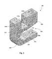
- FIG. 1is a perspective view of a first clamp, in accordance with various embodiments.
- FIG. 2is a perspective view of a second clamp, in accordance with various embodiments.
- FIG. 3is a perspective view of a third clamp, in accordance with various embodiments.
- FIG. 4schematically depicts an example strain-sensing system mounted on clamps configured with selected aspects of the present disclosure.
- a strain-sensing systemmay be employed to measure and/or monitor strain on a straight or curved spinal fusion rod that is implanted in a patient.
- Strain-sensing systemsmay be secured to a spinal fusion rod using various clamping mechanisms.
- Three examples of clamps that may be used to secure a strain-sensing system to a spinal fusion rodare depicted in FIGS. 1-3 .
- the clampsmay be configured to be rigidly secured to the spinal fusion rod at a distance from each other, while also being rotatable relative to each other to accommodate curved spinal fusion rods.
- the clampsmay facilitate attachment of one or more sensing elements to measure strain on the spinal fusion rod.
- the clampsmay be configured to transfer strain imparted on or by the spinal fusion rod to one or more sensing elements of the strain-sensing system. It may be beneficial (though not required) for the clamps to be relatively small, as well as easy to install on an existing spinal fusion rod already implanted in a patient.
- Clamp 100may include a first portion 102 and a second portion 104 . In between first portion 102 and second portion 104 may be a spinal fusion rod receiving area 106 .
- Spinal fusion rod receiving area 106may have a rounded portion 107 shaped to accommodate a spinal fusion rod (not depicted).
- Clamping apertures 108 a and 108 bmay be located on first and second portions 102 and 104 , respectively, and may be shaped to receive a screw or other fastening mechanism that may be used to move first and second portions 102 and 104 closer together, e.g., when a spinal fusion rod is inside of spinal fusion rod receiving area 106 .
- a spine 110 of clamp 100may include strain-sensing system accommodation apertures 112 a and 112 b .
- a screw, pin or other similar devicemay be inserted through strain-sensing system accommodation apertures 112 a and 112 b . This may hold one or more sensing elements (not depicted) of a strain-sensing system (also not depicted) in place, as well as transfer a force imparted on clamp 100 (e.g., by strain in a spinal fusion rod) to the strain-sensing system while clamp 100 remains rigidly secured to the spinal fusion rod.
- a channel 114may be formed in first portion 102 .
- Channel 114may be wide enough to accommodate a variety of sensing elements and/or strain-sensing systems.
- channel 114is wide enough to facilitate encapsulation of a strain-sensing system, e.g., to protect one or more sensing elements.
- the pins or screws that are inserted through strain-sensing system accommodation apertures 112 a and 112 bmay suspend the strain-sensing system (or one or more sensing elements thereof) within channel 114 .
- a notch 116may be formed within spinal fusion rod receiving area 106 . Notch 116 may allow for at least some flexibility between first portion 102 and second portion 104 when they are being clamped onto a spinal fusion rod, helping to avoid failure of clamp 100 . In some embodiments, notch 116 may include a rounded terminal portion that may allow for more flexibility than if the rounded terminal portion were not present.
- Clamp 200may include a first portion 220 and a second portion 222 . Between first portion 220 and second portion 222 may be an aperture 224 shaped to receive a spinal fusion rod (not depicted). Clamping apertures 226 a and 226 b may be shaped to receive a fastening mechanism (not depicted) such as a screw or pin, which may be inserted and/or operated through clamping apertures 226 a and 226 b into corresponding clamping apertures (not visible in FIG. 2 ) in a top surface of second portion 222 . In this manner, clamp first portion 220 and second portion 222 may be clamped together rigidly onto a spinal fusion rod.
- a fastening mechanismsuch as a screw or pin
- An opening 228may be formed in first portion 220 to accommodate one or more sensing elements (not depicted) of a strain-sensing system (also not depicted).
- the opening 228may be configured to reduce or prevent outside interference with the strain-sensing system, and may be shaped to accommodate an encapsulated stain-sensing system and/or sensing elements thereof.
- Side apertures 230 a and 230 bmay be configured to receive another fastening mechanism (not depicted) such as a pin or screw. Insertion of the pin or screw through side apertures 230 a and 230 b may facilitate suspension of the strain-sensing system or one or more sensing elements thereof within opening 228 . In some embodiments, this also may allow force to be applied to clamp 200 along the same axis as the pins that are inserted through side apertures 230 a and 230 b.
- a third embodiment of a clamp 300is depicted in FIG. 3 .
- a first portion 340 and a second portion 342may define a spinal fusion rod receiving area 344 in between them.
- First portion 340 and second portion 342may be clamped together by inserting a fastening mechanism (not depicted) such as a pin or screw through clamping apertures 346 a and 346 b .
- first clamping aperture 346 amay not be entirely closed, but instead may be partially open and may define a channel aligned with second clamping aperture 346 b . Having first clamping aperture 346 a partially open may allow the fastener to be more easily inserted into and/or aligned with the channel between first clamping aperture 346 a and second clamping aperture 346 b during surgery.
- a top aperture 348may be configured to receive a screw or pin associated with a strain-sensing system or one or more sensing elements thereof.
- the strain-sensing systemmay in some embodiments be contained in a housing that is removably attachable to clamp 300 at top aperture 348 .
- a side aperture 350may be formed on a side surface of first portion 340 . Side aperture 350 may provide an interface for a tool to be inserted to apply pre-tension to one or more sensing elements of a strain-sensing system, e.g., by separating clamp 300 from another, similar clamp (not depicted) with a selected force.
- a support member 352may be disposed on a spine 354 of clamp 300 to assist in supporting a strain-sensing system on clamp 300 .
- a peg 356may be disposed on first portion 340 of clamp 300 .
- Peg 356may be used, for instance, for mounting one or more sensing elements of a strain-sensing system.
- Peg 356may in some instances transfer force applied to clamp 300 , e.g., by a spinal fusion rod, into one or more sensing elements.
- clamp 300may include in spinal fusion rod receiving area 344 a notch 358 , which may permit additional flexibility between first portion 340 and second portion 342 .
- a strain-sensing systemmay be mounted to one or more clamps (e.g., 100 , 200 , 300 ), and may be configured to receive force transferred by the clamps from a spinal fusion rod, e.g., caused by displacement of one or more clamps along the spinal fusion rod.
- FIG. 4schematically depicts an example in which two clamps 400 a and 400 b , both configured with selected aspects of the present disclosure, have been secured to a curved spinal fusion rod 460 using fastening screws 462 a and 462 b , respectively. Because spinal fusion rod 460 is curved, clamps 400 a and 400 b are at slight angles to each other. If spinal fusion rod 460 were straight, which is also contemplated herein, clamps 400 a and 400 b would be at less (or no) angle relative to each other.
- a strain-sensing system 464may be mounted to clamps 400 a and 400 b to span a distance D between them, and may include one or more sensing elements that are not depicted. In some instances, strain-sensing system 464 may be referred to as a “bridge” because it spans clamps 400 a and 400 b . Clamps 400 a and 400 b may be configured to, by virtue of their rigid attachment to spinal fusion rod 460 , transmit any displacement of the surface of spinal fusion rod 460 to one or more sensing elements of strain-sensing system 464 .
- Various gaugesmay be employed in strain-sensing system 464 to measure strain on a surface of spinal fusion rod 460 .
- strain-sensing system 464may be shaped or otherwise designed to dampen the strain sensed at spinal fusion rod 460 . In other embodiments, strain-sensing system 464 may be shaped or otherwise designed to amplify the strain sensed at spinal fusion rod 460 . In some embodiments, structure of strain-sensing system 464 may include a frangible portion that may act as a predictable point of failure should too much force be imparted. This may prevent exposure of electronic components to a biological environment (or vice versa).
- a gaugesuch as a strain gauge may be mounted on a surface of strain-sensing system 464 , such that alteration of a shape of strain-sensing system 464 may likewise alter the gauge.
- changes in geometry of strain-sensing system 464 and how it is mounted to clamps 400 a and 400 bmay increase or decrease a percentage of the actual strain exhibited at spinal fusion rod 460 that is transferred to strain-sensing system 464 .
- a transfer of force from spinal fusion rod 460 to a strain gauge (or “sensor”) of strain-sensing system 464may be directly proportional to any change in a distance between axes of mounting pins (not depicted) that are used to mount strain-sensing system 464 to clamps 400 a and 400 b , a height of a center of these mounting pins from a center of spinal fusion rod 460 , and/or a thickness of strain-sensing system 464 .
- a transfer of force from spinal fusion rod 460 to a strain gauge of strain-sensing system 464may be inversely proportional to any change in a span length of strain-sensing system 464 across clamps 400 a and 400 b (e.g., a change in a span length such as that depicted by distance D), and/or an offset of strain-sensing system 464 from a center of axes of mounting pins (not depicted) that are used to mount strain-sensing system 464 to clamps 400 a and 400 b.
- a reference to “A and/or B”, when used in conjunction with open-ended language such as “comprising”can refer, in one embodiment, to A only (optionally including elements other than B); in another embodiment, to B only (optionally including elements other than A); in yet another embodiment, to both A and B (optionally including other elements); etc.
- the phrase “at least one,” in reference to a list of one or more elements,should be understood to mean at least one element selected from any one or more of the elements in the list of elements, but not necessarily including at least one of each and every element specifically listed within the list of elements and not excluding any combinations of elements in the list of elements.
- This definitionalso allows that elements may optionally be present other than the elements specifically identified within the list of elements to which the phrase “at least one” refers, whether related or unrelated to those elements specifically identified.
- “at least one of A and B”can refer, in one embodiment, to at least one, optionally including more than one, A, with no B present (and optionally including elements other than B); in another embodiment, to at least one, optionally including more than one, B, with no A present (and optionally including elements other than A); in yet another embodiment, to at least one, optionally including more than one, A, and at least one, optionally including more than one, B (and optionally including other elements); etc.
Landscapes
- Health & Medical Sciences (AREA)
- Life Sciences & Earth Sciences (AREA)
- Orthopedic Medicine & Surgery (AREA)
- Surgery (AREA)
- Engineering & Computer Science (AREA)
- Veterinary Medicine (AREA)
- Public Health (AREA)
- Biomedical Technology (AREA)
- Heart & Thoracic Surgery (AREA)
- Medical Informatics (AREA)
- Molecular Biology (AREA)
- Animal Behavior & Ethology (AREA)
- General Health & Medical Sciences (AREA)
- Neurology (AREA)
- Pathology (AREA)
- Biophysics (AREA)
- Physics & Mathematics (AREA)
- Nuclear Medicine, Radiotherapy & Molecular Imaging (AREA)
- Physical Education & Sports Medicine (AREA)
- Dentistry (AREA)
- Oral & Maxillofacial Surgery (AREA)
- Rheumatology (AREA)
- Computer Networks & Wireless Communication (AREA)
- Surgical Instruments (AREA)
Abstract
Description
Claims (5)
Priority Applications (1)
| Application Number | Priority Date | Filing Date | Title |
|---|---|---|---|
| US14/937,300US10285637B1 (en) | 2014-11-10 | 2015-11-10 | Apparatus for sensing strain on a spinal fusion rod |
Applications Claiming Priority (2)
| Application Number | Priority Date | Filing Date | Title |
|---|---|---|---|
| US201462077543P | 2014-11-10 | 2014-11-10 | |
| US14/937,300US10285637B1 (en) | 2014-11-10 | 2015-11-10 | Apparatus for sensing strain on a spinal fusion rod |
Publications (1)
| Publication Number | Publication Date |
|---|---|
| US10285637B1true US10285637B1 (en) | 2019-05-14 |
Family
ID=66439363
Family Applications (1)
| Application Number | Title | Priority Date | Filing Date |
|---|---|---|---|
| US14/937,300Active - Reinstated2036-11-11US10285637B1 (en) | 2014-11-10 | 2015-11-10 | Apparatus for sensing strain on a spinal fusion rod |
Country Status (1)
| Country | Link |
|---|---|
| US (1) | US10285637B1 (en) |
Cited By (11)
| Publication number | Priority date | Publication date | Assignee | Title |
|---|---|---|---|---|
| US20240164642A1 (en)* | 2014-09-17 | 2024-05-23 | Canary Medical Inc. | Devices, systems and methods for using and monitoring medical devices |
| US11998349B2 (en) | 2013-03-15 | 2024-06-04 | Canary Medical Inc. | Devices, systems and methods for monitoring hip replacements |
| US12097044B2 (en) | 2013-06-23 | 2024-09-24 | Canary Medical Inc. | Devices, systems and methods for monitoring knee replacements |
| US12142376B2 (en) | 2019-06-06 | 2024-11-12 | Canary Medical Inc. | Intelligent joint prosthesis |
| US12138029B2 (en) | 2014-06-25 | 2024-11-12 | Canary Medical Switzerland Ag | Devices, systems and methods for using and monitoring spinal implants |
| US12138181B2 (en) | 2019-06-06 | 2024-11-12 | Canary Medical Inc. | Intelligent joint prosthesis |
| US12213802B2 (en) | 2014-06-25 | 2025-02-04 | Canary Medical Switzerland Ag | Devices, systems and methods for using and monitoring implants |
| US12226228B2 (en) | 2016-03-23 | 2025-02-18 | Canary Medical Inc. | Implantable reporting processor for an alert implant |
| US12408963B2 (en) | 2020-02-20 | 2025-09-09 | Canary Medical Switzerland Ag | Medical device for implanting in boney tissue and characterization of bone fractures |
| US12419567B2 (en) | 2014-06-25 | 2025-09-23 | Canary Medical Switzerland Ag | Devices, systems and methods for using and monitoring orthopedic hardware |
| US12440153B2 (en) | 2021-12-06 | 2025-10-14 | Canary Medical Inc. | Implantable reporting processor for an alert implant |
Citations (22)
| Publication number | Priority date | Publication date | Assignee | Title |
|---|---|---|---|---|
| US3411348A (en)* | 1966-06-30 | 1968-11-19 | W C Dillon & Company Inc | Electronic dynamometer |
| US4653481A (en)* | 1985-07-24 | 1987-03-31 | Howland Robert S | Advanced spine fixation system and method |
| US5179942A (en) | 1991-12-17 | 1993-01-19 | Drulias Dean J | Lumbar support therapeutic heat/cooling/air pillow belt |
| US5709685A (en) | 1996-05-21 | 1998-01-20 | Sdgi Holdings, Inc. | Positionable clip for provisionally capturing a component on a spinal rod |
| US6083248A (en) | 1995-06-23 | 2000-07-04 | Medtronic, Inc. | World wide patient location and data telemetry system for implantable medical devices |
| US6123706A (en)* | 1997-12-17 | 2000-09-26 | Lange; Robert | Apparatus for stabilizing certain vertebrae of the spine |
| US6341504B1 (en) | 2001-01-31 | 2002-01-29 | Vivometrics, Inc. | Composite elastic and wire fabric for physiological monitoring apparel |
| US7302858B2 (en)* | 2004-09-24 | 2007-12-04 | Kevin Walsh | MEMS capacitive cantilever strain sensor, devices, and formation methods |
| US7357037B2 (en)* | 2002-07-10 | 2008-04-15 | Orthodata Technologies Llc | Strain sensing system |
| US20090275867A1 (en) | 2004-06-29 | 2009-11-05 | Rehabilitation Institute Of Chicago | Walking and balance exercise device |
| US20090299411A1 (en)* | 2008-05-30 | 2009-12-03 | Daniel Laskowitz | System and Method for Replacement of Spinal Motion Segment |
| US7632216B2 (en) | 2001-10-01 | 2009-12-15 | The Nemours Foundation | Brace compliance monitor |
| US20110125063A1 (en) | 2004-09-22 | 2011-05-26 | Tadmor Shalon | Systems and Methods for Monitoring and Modifying Behavior |
| US20110195666A1 (en) | 2008-10-10 | 2011-08-11 | Milux Holdings SA | Accessory for an implant |
| US8073548B2 (en) | 2004-08-24 | 2011-12-06 | Sensors For Medicine And Science, Inc. | Wristband or other type of band having an adjustable antenna for use with a sensor reader |
| US20120071793A1 (en) | 2004-09-21 | 2012-03-22 | Adidas Ag | Sensors for Inductive Plethysmographic Monitoring Applications and Apparel Using Same |
| US20120123232A1 (en) | 2008-12-16 | 2012-05-17 | Kayvan Najarian | Method and apparatus for determining heart rate variability using wavelet transformation |
| US20120184826A1 (en) | 2003-11-18 | 2012-07-19 | Adidas Ag | Method and System for Processing Data from Ambulatory Physiological Monitoring |
| US20130079693A1 (en) | 2011-09-26 | 2013-03-28 | Northeastern University | Customizable Embedded Sensors |
| WO2013066946A1 (en)* | 2011-11-01 | 2013-05-10 | Ellipse Technologies, Inc. | Adjustable magnetic devices and methods of using same |
| US20140046403A1 (en) | 2009-09-18 | 2014-02-13 | Boston Scientific Neuromodulation Corporation | External Charger Usable with an Implantable Medical Device Having a Programmable or Time-Varying Temperature Set Point |
| US20140062717A1 (en) | 2012-08-31 | 2014-03-06 | The University Of Iowa Research Foundation | Method for RFID Communication Using Inductive Orthogonal Coupling For Wireless Medical Implanted Sensors and Other Short-Range Communication Applications |
- 2015
- 2015-11-10USUS14/937,300patent/US10285637B1/enactiveActive - Reinstated
Patent Citations (22)
| Publication number | Priority date | Publication date | Assignee | Title |
|---|---|---|---|---|
| US3411348A (en)* | 1966-06-30 | 1968-11-19 | W C Dillon & Company Inc | Electronic dynamometer |
| US4653481A (en)* | 1985-07-24 | 1987-03-31 | Howland Robert S | Advanced spine fixation system and method |
| US5179942A (en) | 1991-12-17 | 1993-01-19 | Drulias Dean J | Lumbar support therapeutic heat/cooling/air pillow belt |
| US6083248A (en) | 1995-06-23 | 2000-07-04 | Medtronic, Inc. | World wide patient location and data telemetry system for implantable medical devices |
| US5709685A (en) | 1996-05-21 | 1998-01-20 | Sdgi Holdings, Inc. | Positionable clip for provisionally capturing a component on a spinal rod |
| US6123706A (en)* | 1997-12-17 | 2000-09-26 | Lange; Robert | Apparatus for stabilizing certain vertebrae of the spine |
| US6341504B1 (en) | 2001-01-31 | 2002-01-29 | Vivometrics, Inc. | Composite elastic and wire fabric for physiological monitoring apparel |
| US7632216B2 (en) | 2001-10-01 | 2009-12-15 | The Nemours Foundation | Brace compliance monitor |
| US7357037B2 (en)* | 2002-07-10 | 2008-04-15 | Orthodata Technologies Llc | Strain sensing system |
| US20120184826A1 (en) | 2003-11-18 | 2012-07-19 | Adidas Ag | Method and System for Processing Data from Ambulatory Physiological Monitoring |
| US20090275867A1 (en) | 2004-06-29 | 2009-11-05 | Rehabilitation Institute Of Chicago | Walking and balance exercise device |
| US8073548B2 (en) | 2004-08-24 | 2011-12-06 | Sensors For Medicine And Science, Inc. | Wristband or other type of band having an adjustable antenna for use with a sensor reader |
| US20120071793A1 (en) | 2004-09-21 | 2012-03-22 | Adidas Ag | Sensors for Inductive Plethysmographic Monitoring Applications and Apparel Using Same |
| US20110125063A1 (en) | 2004-09-22 | 2011-05-26 | Tadmor Shalon | Systems and Methods for Monitoring and Modifying Behavior |
| US7302858B2 (en)* | 2004-09-24 | 2007-12-04 | Kevin Walsh | MEMS capacitive cantilever strain sensor, devices, and formation methods |
| US20090299411A1 (en)* | 2008-05-30 | 2009-12-03 | Daniel Laskowitz | System and Method for Replacement of Spinal Motion Segment |
| US20110195666A1 (en) | 2008-10-10 | 2011-08-11 | Milux Holdings SA | Accessory for an implant |
| US20120123232A1 (en) | 2008-12-16 | 2012-05-17 | Kayvan Najarian | Method and apparatus for determining heart rate variability using wavelet transformation |
| US20140046403A1 (en) | 2009-09-18 | 2014-02-13 | Boston Scientific Neuromodulation Corporation | External Charger Usable with an Implantable Medical Device Having a Programmable or Time-Varying Temperature Set Point |
| US20130079693A1 (en) | 2011-09-26 | 2013-03-28 | Northeastern University | Customizable Embedded Sensors |
| WO2013066946A1 (en)* | 2011-11-01 | 2013-05-10 | Ellipse Technologies, Inc. | Adjustable magnetic devices and methods of using same |
| US20140062717A1 (en) | 2012-08-31 | 2014-03-06 | The University Of Iowa Research Foundation | Method for RFID Communication Using Inductive Orthogonal Coupling For Wireless Medical Implanted Sensors and Other Short-Range Communication Applications |
Cited By (21)
| Publication number | Priority date | Publication date | Assignee | Title |
|---|---|---|---|---|
| US11998349B2 (en) | 2013-03-15 | 2024-06-04 | Canary Medical Inc. | Devices, systems and methods for monitoring hip replacements |
| US12097044B2 (en) | 2013-06-23 | 2024-09-24 | Canary Medical Inc. | Devices, systems and methods for monitoring knee replacements |
| US12138029B2 (en) | 2014-06-25 | 2024-11-12 | Canary Medical Switzerland Ag | Devices, systems and methods for using and monitoring spinal implants |
| US12419567B2 (en) | 2014-06-25 | 2025-09-23 | Canary Medical Switzerland Ag | Devices, systems and methods for using and monitoring orthopedic hardware |
| US12213802B2 (en) | 2014-06-25 | 2025-02-04 | Canary Medical Switzerland Ag | Devices, systems and methods for using and monitoring implants |
| US12285234B2 (en) | 2014-09-17 | 2025-04-29 | Canary Medical Inc. | Devices, systems and methods for using and monitoring medical devices |
| US12426784B2 (en)* | 2014-09-17 | 2025-09-30 | Canary Medical Inc. | Devices, systems and methods for using and monitoring medical devices |
| US20240164642A1 (en)* | 2014-09-17 | 2024-05-23 | Canary Medical Inc. | Devices, systems and methods for using and monitoring medical devices |
| US12419574B2 (en) | 2016-03-23 | 2025-09-23 | Canary Medical Inc. | Implantable reporting processor for an alert implant |
| US12285267B2 (en) | 2016-03-23 | 2025-04-29 | Canary Medical Inc. | Implantable reporting processor for an alert implant |
| US12226228B2 (en) | 2016-03-23 | 2025-02-18 | Canary Medical Inc. | Implantable reporting processor for an alert implant |
| US12232985B2 (en) | 2019-06-06 | 2025-02-25 | Canary Medical Inc. | Intelligent joint prosthesis |
| US12239552B2 (en) | 2019-06-06 | 2025-03-04 | Canary Medical Inc. | Intelligent joint prosthesis |
| US12232984B2 (en) | 2019-06-06 | 2025-02-25 | Canary Medical Inc. | Intelligent joint prosthesis |
| US12176104B2 (en) | 2019-06-06 | 2024-12-24 | Canary Medical Inc. | Intelligent joint prosthesis |
| US12293828B2 (en) | 2019-06-06 | 2025-05-06 | Canary Medical Inc. | Intelligent joint prosthesis |
| US12159714B2 (en) | 2019-06-06 | 2024-12-03 | Canary Medical Inc. | Intelligent joint prosthesis |
| US12138181B2 (en) | 2019-06-06 | 2024-11-12 | Canary Medical Inc. | Intelligent joint prosthesis |
| US12142376B2 (en) | 2019-06-06 | 2024-11-12 | Canary Medical Inc. | Intelligent joint prosthesis |
| US12408963B2 (en) | 2020-02-20 | 2025-09-09 | Canary Medical Switzerland Ag | Medical device for implanting in boney tissue and characterization of bone fractures |
| US12440153B2 (en) | 2021-12-06 | 2025-10-14 | Canary Medical Inc. | Implantable reporting processor for an alert implant |
Similar Documents
| Publication | Publication Date | Title |
|---|---|---|
| US10285637B1 (en) | Apparatus for sensing strain on a spinal fusion rod | |
| US10219699B2 (en) | Implantable sensors and methods of use | |
| EP3688474B1 (en) | Sensor calibration considering subject-dependent variables and/or body positions | |
| US6362439B1 (en) | Load-cell mounting assembly | |
| JP2016515862A5 (en) | ||
| WO2016000034A9 (en) | Deformation measurement method and apparatus | |
| WO2008129356A3 (en) | Visual attention and emotional response detection and display system | |
| US20180055420A1 (en) | Tracking a dental movement | |
| EP4582071A3 (en) | Robotic system for interaction with an anatomy | |
| WO2011086432A3 (en) | Flexible instrument channel insert for scope with real-time position tracking | |
| EP2027815A3 (en) | Sleep state measuring apparatus and sleep state measuring method | |
| JP2010042235A (en) | Method and device for detecting parameter for characterization of kinetic sequence at human or animal body | |
| EP2127940A3 (en) | Vehicle, suspension system, suspended object, and method of use thereof | |
| WO2008124284A3 (en) | Tracker holder assembly | |
| EP3064968A3 (en) | Drag body with inertial navigation system and method for determining position | |
| US20130317408A1 (en) | Medical device for extracorporeal blood treatment comprising plural sensor units | |
| US20210145316A1 (en) | Dental caliper and method | |
| JPS60501973A (en) | Average axial and diametrical strain measurement extensometer | |
| JP2019523689A (en) | Fastening device for penis extension device with tension measuring instrument | |
| JP4027415B1 (en) | Human body measuring device | |
| WO2006118510A1 (en) | Device and method for fixation of equipment to the head of a patient during neurological diagnosis, therapy or surgery | |
| Miyashita et al. | Evaluation of implant screw loosening by resonance frequency analysis with triaxial piezoelectric pick-up: in vitro model and in vivo animal study | |
| EP2560041A3 (en) | Device and method for measuring pantoscopic tilt | |
| DE102008063844A1 (en) | Measuring device for determining e.g. elastic bend of intramedullary nails, during fracture in patient's body, has connectors attached to bar sides in longitudinal direction of fixing units so that bend is constant in bar between connectors | |
| JP2015222216A (en) | Force sensor testing device |
Legal Events
| Date | Code | Title | Description |
|---|---|---|---|
| STCF | Information on status: patent grant | Free format text:PATENTED CASE | |
| FEPP | Fee payment procedure | Free format text:MAINTENANCE FEE REMINDER MAILED (ORIGINAL EVENT CODE: REM.); ENTITY STATUS OF PATENT OWNER: LARGE ENTITY | |
| LAPS | Lapse for failure to pay maintenance fees | Free format text:PATENT EXPIRED FOR FAILURE TO PAY MAINTENANCE FEES (ORIGINAL EVENT CODE: EXP.); ENTITY STATUS OF PATENT OWNER: LARGE ENTITY | |
| STCH | Information on status: patent discontinuation | Free format text:PATENT EXPIRED DUE TO NONPAYMENT OF MAINTENANCE FEES UNDER 37 CFR 1.362 | |
| FP | Lapsed due to failure to pay maintenance fee | Effective date:20230514 | |
| PRDP | Patent reinstated due to the acceptance of a late maintenance fee | Effective date:20230901 | |
| FEPP | Fee payment procedure | Free format text:ENTITY STATUS SET TO SMALL (ORIGINAL EVENT CODE: SMAL); ENTITY STATUS OF PATENT OWNER: SMALL ENTITY | |
| FEPP | Fee payment procedure | Free format text:PETITION RELATED TO MAINTENANCE FEES FILED (ORIGINAL EVENT CODE: PMFP); ENTITY STATUS OF PATENT OWNER: SMALL ENTITY Free format text:PETITION RELATED TO MAINTENANCE FEES GRANTED (ORIGINAL EVENT CODE: PMFG); ENTITY STATUS OF PATENT OWNER: SMALL ENTITY Free format text:SURCHARGE, PETITION TO ACCEPT PYMT AFTER EXP, UNINTENTIONAL. (ORIGINAL EVENT CODE: M2558); ENTITY STATUS OF PATENT OWNER: SMALL ENTITY | |
| MAFP | Maintenance fee payment | Free format text:PAYMENT OF MAINTENANCE FEE, 4TH YR, SMALL ENTITY (ORIGINAL EVENT CODE: M2551); ENTITY STATUS OF PATENT OWNER: SMALL ENTITY Year of fee payment:4 | |
| STCF | Information on status: patent grant | Free format text:PATENTED CASE |