US10285157B2 - Receiver processor for adaptive windowing and high-resolution TOA determination in a multiple receiver target location system - Google Patents
Receiver processor for adaptive windowing and high-resolution TOA determination in a multiple receiver target location systemDownload PDFInfo
- Publication number
- US10285157B2 US10285157B2US15/803,713US201715803713AUS10285157B2US 10285157 B2US10285157 B2US 10285157B2US 201715803713 AUS201715803713 AUS 201715803713AUS 10285157 B2US10285157 B2US 10285157B2
- Authority
- US
- United States
- Prior art keywords
- toa
- tag
- receiver
- pulses
- pulse
- Prior art date
- Legal status (The legal status is an assumption and is not a legal conclusion. Google has not performed a legal analysis and makes no representation as to the accuracy of the status listed.)
- Active
Links
Images


Classifications
- H—ELECTRICITY
- H04—ELECTRIC COMMUNICATION TECHNIQUE
- H04W—WIRELESS COMMUNICATION NETWORKS
- H04W64/00—Locating users or terminals or network equipment for network management purposes, e.g. mobility management
- H04W64/006—Locating users or terminals or network equipment for network management purposes, e.g. mobility management with additional information processing, e.g. for direction or speed determination
- G—PHYSICS
- G01—MEASURING; TESTING
- G01S—RADIO DIRECTION-FINDING; RADIO NAVIGATION; DETERMINING DISTANCE OR VELOCITY BY USE OF RADIO WAVES; LOCATING OR PRESENCE-DETECTING BY USE OF THE REFLECTION OR RERADIATION OF RADIO WAVES; ANALOGOUS ARRANGEMENTS USING OTHER WAVES
- G01S5/00—Position-fixing by co-ordinating two or more direction or position line determinations; Position-fixing by co-ordinating two or more distance determinations
- G01S5/02—Position-fixing by co-ordinating two or more direction or position line determinations; Position-fixing by co-ordinating two or more distance determinations using radio waves
- G01S5/0205—Details
- G01S5/0218—Multipath in signal reception
- G—PHYSICS
- G01—MEASURING; TESTING
- G01S—RADIO DIRECTION-FINDING; RADIO NAVIGATION; DETERMINING DISTANCE OR VELOCITY BY USE OF RADIO WAVES; LOCATING OR PRESENCE-DETECTING BY USE OF THE REFLECTION OR RERADIATION OF RADIO WAVES; ANALOGOUS ARRANGEMENTS USING OTHER WAVES
- G01S5/00—Position-fixing by co-ordinating two or more direction or position line determinations; Position-fixing by co-ordinating two or more distance determinations
- G01S5/02—Position-fixing by co-ordinating two or more direction or position line determinations; Position-fixing by co-ordinating two or more distance determinations using radio waves
- G01S5/0205—Details
- G01S5/0221—Receivers
- G01S5/02213—Receivers arranged in a network for determining the position of a transmitter
- G01S5/02216—Timing or synchronisation of the receivers
- H—ELECTRICITY
- H04—ELECTRIC COMMUNICATION TECHNIQUE
- H04L—TRANSMISSION OF DIGITAL INFORMATION, e.g. TELEGRAPHIC COMMUNICATION
- H04L7/00—Arrangements for synchronising receiver with transmitter
- H04L7/02—Speed or phase control by the received code signals, the signals containing no special synchronisation information
- H04L7/033—Speed or phase control by the received code signals, the signals containing no special synchronisation information using the transitions of the received signal to control the phase of the synchronising-signal-generating means, e.g. using a phase-locked loop
- H04L7/0331—Speed or phase control by the received code signals, the signals containing no special synchronisation information using the transitions of the received signal to control the phase of the synchronising-signal-generating means, e.g. using a phase-locked loop with a digital phase-locked loop [PLL] processing binary samples, e.g. add/subtract logic for correction of receiver clock
- H—ELECTRICITY
- H04—ELECTRIC COMMUNICATION TECHNIQUE
- H04W—WIRELESS COMMUNICATION NETWORKS
- H04W24/00—Supervisory, monitoring or testing arrangements
- H04W24/10—Scheduling measurement reports ; Arrangements for measurement reports
- H—ELECTRICITY
- H04—ELECTRIC COMMUNICATION TECHNIQUE
- H04W—WIRELESS COMMUNICATION NETWORKS
- H04W4/00—Services specially adapted for wireless communication networks; Facilities therefor
- H04W4/02—Services making use of location information
- H04W4/023—Services making use of location information using mutual or relative location information between multiple location based services [LBS] targets or of distance thresholds
- G—PHYSICS
- G01—MEASURING; TESTING
- G01S—RADIO DIRECTION-FINDING; RADIO NAVIGATION; DETERMINING DISTANCE OR VELOCITY BY USE OF RADIO WAVES; LOCATING OR PRESENCE-DETECTING BY USE OF THE REFLECTION OR RERADIATION OF RADIO WAVES; ANALOGOUS ARRANGEMENTS USING OTHER WAVES
- G01S5/00—Position-fixing by co-ordinating two or more direction or position line determinations; Position-fixing by co-ordinating two or more distance determinations
- G01S5/02—Position-fixing by co-ordinating two or more direction or position line determinations; Position-fixing by co-ordinating two or more distance determinations using radio waves
- G01S5/0205—Details
- G01S5/0215—Interference
Definitions
- Embodiments discussed hereinare related to radio frequency locating and, more particularly, to systems, methods, apparatuses, computer readable media and other means for target location by high-resolution time-of-arrival (TOA) determination in a multiple receiver target location system.
- TOAtime-of-arrival
- a method, apparatus, and computer program product (CPP) for determining target location in a multiple receiver target location systemcomprising: determining a coarse estimate of a time-of-arrival (TOA) from at least two of a plurality of receivers based on a detection of a pulse in an adjustable coarse timing window, determining a fine estimate of the TOA from the at least two of the plurality of receivers based on a detection of the pulse in at least one of a set of fine timing windows, and determining a sub-window resolution of the TOA from the at least two of the plurality of receivers based on at least one detection transition between consecutive fine receiver windows of at least one of a plurality of pulses.
- TOAtime-of-arrival
- the method apparatus, and CPPfurther comprises: determining a first coarse timing window based on the detection of a pulse for at least two of the plurality of receivers, determining a plurality of coarse timing windows based on the detection of a plurality of pulses and a coarse timing window function for at least two of the plurality of receivers, and determining a parallel set of fine timing windows based on at least one of the plurality of coarse timing windows.
- determining the plurality of coarse timing windowsmay comprise an iterative, adaptive feedback loop.
- the feedback loopis driven by a detection pattern.
- determining the parallel set of fine timing windowsfurther comprises the determining of a set of fine timing windows synchronous to a receiver clock.
- the set of fine timing windows synchronous to the receiver clockare disjoint.
- the determining the sub-window resolution of the TOAcomprises an averaging.
- the determining the coarse estimate, the fine estimate, and the sub-window resolution of the TOAcomprises a plurality of parallel detectors.
- the plurality of parallel detectorscomprises distinct detection levels.
- TOAis an earliest detection of the detection of the pulse from the plurality of parallel detectors.
- the TOAis associated with a tag unique identifier.
- the tag unique identifieris decoded at each of the plurality of receivers from a data packet transmitted by the target.
- the tag unique identifier decodingcomprises one of an asynchronous and synchronous sampling.
- the synchronous samplingcomprises the receiver clock.
- the asynchronous samplingcomprises a target transmit clock recovery.
- the target transmit clock recoverycomprises a tracking of the plurality of pulses.
- the tracking of the plurality of pulsescomprises a phase-locked loop (PLL).
- PLLphase-locked loop
- FIG. 1shows a timing diagram for an RTLS tag transmission (TX) in an example high-resolution TOA determination system, in accordance with example embodiments of the present invention
- FIG. 2shows a timing diagram for an adjustable timing window function, in accordance with example embodiments of the present invention
- FIG. 3shows a timing diagram for a receiver (RX) fine timing window function, in accordance with example embodiments of the present invention
- FIG. 4shows a timing diagram for a receiver (RX) sub-window resolution function 400 , in accordance with example embodiments of the present invention
- FIG. 5illustrates an exemplary environment using a radio frequency locating system for providing performance analytics in accordance with some embodiments of the present invention
- FIG. 6illustrates an exemplary receiver in a RTLS system comprising a RTLS receiver that may be configured in accordance with some embodiments of the present invention
- FIG. 7illustrates an example TOA and recovery circuit function from the exemplary receiver in the RTLS system of FIG. 6 , in accordance with some embodiments of the present invention.
- FIGS. 8 a and 8 bare flowcharts illustrating example methods for determining a time of arrival with sub-window resolution.
- example embodiments described hereincomprise methods for an active RTLS tag target location system that provides for ⁇ 1 ns TOA accuracy and resolution and significantly reduces the channel effects of multipath interference, even in low SNR applications.
- the example embodimentsprovide for an iterative and adaptive windowing function in one or more of the receivers of the receiver grid that captures multiple reflections of multiple transmissions from one or more of the associated target RTLS tags.
- Example embodiments described hereincomprise methods, apparatus and computer program products for receiver adaptive windowing and for high-resolution TOA determination in a multiple receiver target location system.
- a targetmay be a person, animal, object, or the like, to which an RTLS location tag has been mounted for tracking a location associated with target.
- high-resolution TOA determinationis achieved even in an instance in which a communication channel suffers from multipath interference and the range requirements provide for a relatively low SNR.
- both issues of multipath interference and low SNRare addressed by an iterative, adaptive windowing function in each of the receivers included in the receiver grid.
- resolution for the TOA determinationis improved by increasing the resolution for the detection windows at one or more receivers in the receiver grid for one or more of the series of timing pulses from one or more of the transmitters associated with the target RTLS tags.
- Resolution for each series of timing pulses from each respective transmitter associated with an RTLS tagis effectively increased, in some examples, by using the aforementioned windows to detect a timestamp for a plurality of bits to generate or otherwise determine a high resolution timestamp.
- the systems, tags, receivers and methods for operating the same described hereinare configured to establish a timestamp for a received tag transmission signal.
- the tag transmission signalmay be refer to herein as “blink data” or “a blink data pulse” as it is transmitted at selected intervals comprising a blink (e.g., 72 pulses at a blink rate of 1 Mb/s).
- Blink datamay also comprise one or more data packets.
- tag data packetsmay include any data from the modular location tag that is intended for transmission such as, for example in the depicted embodiment, a tag unique identification number (tag UID), other identification information, a sequential burst count, stored tag data, or other desired information for object or personnel identification, inventory control, etc.
- the timestampmay be generated based on a particular timing bit in a transmission. While such a method may generate a timestamp, it is, in some examples, vulnerable to noise (e.g., noise that varies among receivers).
- noisee.g., noise that varies among receivers.
- the systems, tags, receivers and methods for operating the same described hereinare configured to dynamically adjust a window so as to more accurately generate a timestamp for a packet.
- the windowmay be established using a preamble of the data packet (e.g., the first 16-32 bits comprising a series of 1's or pulses) and then may be applied to synchronization pattern or code (e.g., 16-32 bits in a known pattern of 1's and 0's following the preamble) to generate a timestamp.
- a windowe.g. a 30 nanosecond (nsec) window
- a receivermay be configured to generate a timestamp (e.g., a timestamp with a 1 nsec resolution) for a given pulse.
- an adjustable time windowsuch as a 30 ns window
- a windowwhich in some cases may be asymmetric, may be established for the next pulse so as to enable the window to be re-centered.
- the window widthmay be adjusted (e.g., narrowed) as more pulses are detected without synchronous earlier echoes until the original first arrival is determined.
- a plurality of received pulsesmay be used to determine a timestamp.
- the windowmay be used to identify or otherwise determine multiple pulses (e.g., eight) within a synch pattern so as to generate time measurements (e.g., at a 1 nsec resolution) and to combine those time measurements by taking on average of the measurements, a rounded average of the time measurements or the like, to determine a high resolution timestamp for the packet.
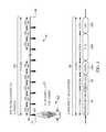
- FIG. 1shows a timing diagram 100 for an RTLS tag transmission (TX) in a high-resolution TOA determination system, in accordance with example embodiments of the present invention.
- the timing diagram 100comprises a TX clock 101 , a preamble 110 , and a data packet 120 , which as presented in FIG. 1 , includes the preamble 110 as a subset of the data packet 120 .
- the preamble 110is comprised of a transmit (TX) series of pulses 111 T, wherein the TX series of pulses 111 T are equally spaced in time, in accordance with a period associated with the TX clock 101 .
- the period associated with the TX clockis approximately 1 ⁇ sec, whereby the TX clock 101 operates at a frequency of 1 MHz.
- each individual TX pulse 111 T′ in the TX series of pulses 111 Tis identical.
- the TX pulse 111 T′comprises a 6 GHz carrier wave modulated by a 2.0 nsec pulse, or rectangle function (rect).
- the TX pulse 111 T′is additionally shaped at a receiver by a transmit and receive antenna and any electronics associated with an amplification or pre-amplification of the TX pulse 111 T′, in conjunction with the high-resolution TOA determination system.
- the TX pulse 111 T′ shape at the receiver, denoted RX pulse 111 R′may be consistent with a function ⁇ t e ⁇ t/ ⁇ .
- the TX series of pulses 111 Tis used to provide for an iterative windowing function, an adjustable timing window 200 , described in FIG. 2 .
- the data packet 120comprises at least the following data words: the aforementioned preamble 110 , a sync code 112 , a header 120 A, a transmit identification (TX ID) 120 B, and a CRC word 120 C.
- the sync code 112represents a known sequence of 1's and 0's. In other examples, the 1's and 0's may be distributed in other ways. In some examples, the sync code 112 may be 16 bits long.
- the sync code 112consists primarily of 1's, which represent the TX pulses 111 T′-rather than 0's, which represent ‘blanks,’ or no pulse.
- the sync code 112is used to provide for a registration code 350 in response to each of the TX pulses 111 T′ associated with the sync code 112 , whereby the registration code 350 provides for a record of a detection of the sync code 112 in a receiver (RX) fine timing window function 300 , described in FIG. 3 .
- the data packet 120is transmitted by the RTLS tag transmitter, in some examples, continually and periodically. In some examples, the transmission of the data packet 120 is initiated immediately at the end of the 1 ⁇ sec period associated with a final transmit bit, in this example the CRC 120 C least significant bit. In some examples, a waiting period between successive transmissions is established.
- the data packet 120is 112 bits long, wherein the bit distribution may be as follows: the preamble 110 (e.g., 32 bits), the sync code 112 (e.g., 16 bits), the header 120 A (e.g., 16 bits), the TX ID 120 B (e.g., 32 bits), and the CRC 120 C (e.g., 16 bits).
- a transmission time associated with the data packet 120 and the aforementioned 1 MHz data rateis 112 ⁇ sec.
- the data packet 120may consist of a plurality of data long words 120 B′, immediately following the TX ID 120 B and preceding the CRC 120 C, resulting in a longer data packet 120 .
- the plurality of data long words 120 B′are each 32 bits long.
- the plurality of data long words 120 B′may include one or more of a temperature, an acceleration, and an attitude of rotational displacement. In some embodiments, the plurality of data long words 120 B′ may include a ‘Query’ command to the receiver, wherein the RTLS tag transmitter, in this example, is equipped with a 125 KHz receiver and associated firmware to decode a response.
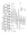
- FIG. 2shows a timing diagram for an adjustable timing window function 200 , in accordance with example embodiments of the present invention.
- FIG. 2comprises the TX clock 101 and the TX series of pulses 111 T associated with preamble 120 , as presented in for the RTLS tag transmission (TX) 100 , shown in FIG. 1 , and an RX clock 201 and an RX clock timing diagram 202 .
- a received (RX) pulse train 211 Ris comprised of a series of the RX pulses 111 R′, corresponding to the TX series of pulses 111 T, and is synchronized to the RX clock 201 , which is resident at an example receiver in the receiver grid.
- An RX pulse signature 212representing an earliest pulse 215 and a series of echoes 216 A-B and possible noise pulses 217 , as shown in FIG. 2 , is associated with the RX clock timing diagram 202 , and is also associated with the corresponding TX pulse 111 T′.
- the adjustable timing window function 200is comprised of a series of detection windows 220 , comprising wide detection windows 221 - 230 and narrow detection windows 231 - 233 , and an associated set of functions to adaptively position the series of wide and narrow detection windows 221 - 233 to center the RX pulse 111 R′ in the corresponding window.
- the last window in the series of fine and narrow detection windows 221 - 233is called a final detector window 233 .
- a first detection window 221may be centered at 480 nsec, for example, with a width of 150 nsec.
- the center of the first detector windowis a function of a first registered detection, wherein the present example registers a first registered detection at a second echo 216 B of the RX pulse 111 R′.
- the width of the first detection window 221may be a function of an expected distance from the RTLS tag transmitter to the receiver.
- the first detection window 221may be adaptively updated by a second detection window 222 as provided by evidence of a second registered detection, wherein the present example registers a second registered detection at a first echo 216 A of the RX pulse 111 R′.
- the second detection window 222may be centered at 460 nsec with a width of 150 nsec.
- the second detection window 222may be adaptively updated by a third detection window 223 as provided by evidence of a third registered detection, wherein the present example registers a third registered detection at an earliest pulse 215 of the RX pulse 111 R′.
- the third detection window 223may be centered at 415 nsec with a width of 150 nsec.
- the series of wide detection windows 221 - 230continue to be adaptively updated by the registered detections of RX pulses 111 R′ that comprise the RX pulse train 211 R corresponding to the TX series of pulses 111 T in the preamble 110 .
- a final wide detector window 230may be declared after a detection of ten RX pulses 111 R′. At which point a final wide detector window 230 is determined, the registered detections for the series of wide detection windows 221 - 230 ends, and the series of narrow detection windows 231 - 233 implemented.
- a first narrow detection window 231is centered at the center of the final wide detection window 230 , as shown in FIG. 2 .
- the width of the first narrow detection window 231is 30 nsec, in some examples. Note that, as FIG. 2 demonstrates, a timing shift may result with the registered detection of the RX pulse 111 R′ associated with the first narrow detection window 231 .
- the placement of the first narrow detection window 231centered at 425 nsec, graphically represents such a shift, as the earliest pulse 215 associated with the RX pulse 111 R′ appears to be registered along the RX clock timing diagram 202 closer to 415 nsec.
- Each of the series of narrow detection windows 231 - 233are comprised of three 10 nsec, disjoint timing windows 231 A-C, 232 A-C, and 233 A-C. Detections for the RX pulses 111 R′ that comprise the RX pulse train 211 R are registered in parallel in each of the three disjoint timing windows 231 A-C, for example, to determine to which of the three disjoint timing windows 231 A-C the detection should be assigned.
- the purpose of the series of narrow detection windows 231 - 233is to ensure that the final detection associated with the final RX pulse 111 R′ in the RX pulse train 211 R is registered in a final center disjoint timing window 233 B associated with the final detector window 233 .
- a slide narrow window function 235 to slide the series of narrow detection windows 231 - 233 left and right in 10 nsec increments, for example,is provided as a method to achieve the aforementioned requirement, and as such the final detection associated with the final RX pulse 111 R′ in the RX pulse train 211 R is registered in the center of the final detector window 233 .
- the adjustable timing window function 200may be implemented as a first feedback loop, wherein a pulse detector resides in the forward feed and the slide window function 235 may comprise the feedback.
- the pulse detectormay determine whether or not a pulse detection is registered in the currently prescribed disjoint timing windows 231 A-C, for example, for any of the series of narrow detection windows 231 - 233 .
- a feedback functionmay determine which direction a shift is to be made, and in some examples, what is the magnitude of the prescribed shift, if different from a default shift value of 10 nsec, for example.
- the default shift magnitudeis equal to the shift magnitude presented in the example given in FIG. 2 , that of 10 nsec, for example.
- a minimum shift magnitudemay also be given (e.g., 10 nsec).
- Larger shift magnitudesmay be incorporated, dependent on the detection algorithm.
- a detection algorithm that may determine multiple echoes 216 A-B as registered in a relatively wide detector windowmay include logic to ‘skip’ left over several reflections at once to expedite the capture of the earliest pulse 215 , the line-of-sight channel.
- a registration of multiple echoes 216 A-B in the relatively wide detector windowmay be determined by the relative amplitude of the registered detections.
- the detectorsthemselves may comprise several functions that may affect an improved detection resolution.
- the detectorsmay be assigned a detection level or a threshold level that may determine whether the magnitude of the earliest pulse 215 , one or more of the echoes 216 A-B, or a noise pulse 217 is in fact a signal, or just a low-level background noise interference.
- a signal-to-noise (SNR) levelmay be monitored dynamically, and the detection threshold level adjusted accordingly.
- a relative strength of the signalmay be monitored dynamically, whereby the strength of the signal, in conjunction with a TOA determination associated with the signal, may comprise two inputs to an automatic gain control (AGC) for either a pre-amplification or an amplification of the signal.
- AGCautomatic gain control
- FIG. 3shows a timing diagram for a receiver (RX) fine timing window function 300 , in accordance with example embodiments of the present invention.
- FIG. 3comprises the final detector window 233 and the three 10 nsec disjoint timing windows 233 A-C associated with the final detector window 233 , and a parallel set of fine detector windows 340 A-E.
- the final detector window 233 and the fine detector windows 340 A-Eare synchronized with the RX clock timing diagram 202 , as shown in FIG. 2 .
- the leading edge of a first fine detector window 340 Ais synchronous with the leading edge of the final center disjoint timing window 233 B associated with the final detector window 233 .
- the RX fine timing window function 300comprises registering a series of detections in the parallel set of fine detector windows 340 A-E, each associated with the final center disjoint timing window 233 B.
- the series of detections in the parallel set of fine detector windows 340 A-Eprovides for a detection record of the sync code 112 , the sequence of 1's and 0's TX pulses 111 T′ transmitted by the RTLS tag transmitter.
- the registering the series of detections in the parallel set of fine detector windows 340 , each associated with the final center disjoint timing window 233 B,comprises a generation of the registration code 350 which codifies the detections of the RX pluses 111 R′ associated with the sync code 112 TX pulses 111 T′.
- the registration code 350codifies the detections with respect to each of the fine detector windows 340 A-E, as shown in the example given in FIG. 3 .
- each successive fine detector window 340 A-Eoverlaps the previous fine detector window 340 A-E by 1 nsec, and each of the fine detector windows 340 A-E in the parallel set of fine detector windows 340 A-E is 5 nsec wide with a period of 10 nsec, as determined by the RX clock 201 , running at a frequency of 100 MHz.
- a detection of the RX pulse 111 R′ associated with the corresponding sync code 112 TX pulse 111 T′is registered in each of the fine detector windows 340 A-E.
- the TOA for the RX pulse 111 R′is 414 nsec after the leading edge of the RX clock 201 .
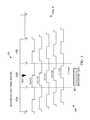
- FIG. 4shows a timing diagram for a receiver (RX) sub-window resolution function 400 , in accordance with example embodiments of the present invention.
- FIG. 4comprises the final center disjoint timing window 233 B and the parallel set of fine detector windows 340 A-E.
- the fine detector windows 340 A-Eare synchronized with the RX clock timing diagram 202 , as shown in FIG. 2 . That is, the leading edge of a first fine detector window 340 A is synchronous with the leading edge of the final center disjoint timing window 233 B and with the leading edge of the RX clock 201 .
- the series of detections in the parallel set of fine detector windows 340 A-Eprovides for a detection record of each of the RX pulses 111 R′ associated with the TX pulses 111 T′ that comprise the sync code 112 , the detections recorded in the registration codes 350 .
- FIG. 4presents a collection of RX pulses 111 R′ associated with the sync code 112 , wherein the collection of pulses are identified as RX pulses 1 - 8 .
- the associated registration codes 350one registration code for each pulse, which codifies the detections of the collection RX pluses 111 R′, RX pulses 1 - 8 , is also shown.
- the TX clock 101may be running at a slightly higher frequency than the RX clock 201 .
- each successive RX pulse 111 R′, RX pulses 1 - 8effectively ‘slips’ to the left with respect to the RX clock 201 , as shown in the RX sub-window resolution functional drawing 400 .
- the leading edge of the center disjoint timing window 233 B and the leading edge of the first fine detector window 340 A, and the RX clock 201 itselfeffectively shift to the right with respect to the successive pulses 1 - 8 .
- the results from the registration codes 350clearly demonstrate a detection of an RX pulse 6 , associated with a fourth sync code 112 TX pulse 111 T′, as the first RX pulse to change detection registration; that is, to be detected or undetected in a new window, namely the fine detector window 340 E.
- the TOAis determined for the RX pulse 6 nearest to the leading edge of the fine detector window 340 E.
- the RX pulse 6is designated with a TOA estimate to be 4 nsec greater than the leading edge of the final center disjoint timing window 233 B, which is registered at 410 nsec. Consequently, the RX pulse 6 is designated with a TOA estimate to be 414 nsec with respect to the RX clock 201 .
- a TOA averaging functionmay be used to further the sub-window resolution function 400 .
- the TOA averaging functionmay effectively take differences in the TOAs of successive RX pulses 1 - 8 , for example, whereby the TOA, as demonstrated previously, is a function of the leading edge registration of the final center disjoint window 233 B and an associated registration code 350 .
- the TOA differenceslike the TOAs themselves, will register a transition as successive RX pulses 1 - 8 exhibit a change in detection registration, just as was the case demonstrated previously.
- a TOA numerical averagemay be constructed to assign a TOA with sub-window resolution.
- a TOA averagemay be constructed whereby RX pulses 1 - 5 are assigned a weight equal to 4 nsec greater than the leading edge of the final center disjoint timing window 233 B, and RX pulses 6 - 8 are assigned a weight equal to 3 nsec greater than the leading edge of the final center disjoint timing window 233 B.
- the change in the relative position of the RX pulses 1 - 8 with respect to the RX clock 201is in some examples directly attributable to the asynchronous TX 101 and RX clocks 201 . That is, the TX clock 101 frequency and the RX clock 201 frequency are not equal. The frequency difference between the TX clock 101 and the RX clock 201 may be due to a clock drift of at least one or both of the TX clock 101 and the RX clock 201 .
- the TX clock 101 and the RX clock 201may be purposefully detuned in order to take advantage of the sub-window resolution function 400 presented in FIG. 4 . In the latter case, it may be possible, given very stable detuned TX 101 and RX clocks 201 that an error bound, the sub-window accuracy achieved by the sub-window resolution function 400 , is itself stable and predictable.
- FIG. 5illustrates an exemplary locating system 500 useful for calculating a location by an accumulation of location data or time of arrivals (TOAs) at a central processor/hub 11 , whereby the TOAs represent a relative time of flight (TOF) from RTLS tags 12 a - f as recorded at each receiver 13 a - l (e.g., UWB reader, etc.).
- TOFtime of flight
- a timing reference clockis used, in some examples, such that at least a subset of the receivers 13 a - l may be synchronized in frequency, whereby the relative TOA data associated with each of the RTLS tags 12 a - f may be registered by a counter associated with at least a subset of the receivers 13 a - l .
- a reference tag 14 a - bpreferably a UWB transmitter, positioned at known coordinates, is used to determine a phase offset between the counters associated with at least a subset of the of the receivers 13 a - l .
- the RTLS tags 12 a - f and the reference tags 14 a - breside in an active RTLS field 18 .
- the systems described hereinmay be referred to as either “multilateration” or “geolocation” systems, terms that refer to the process of locating a signal source by solving an error minimization function of a location estimate determined by the difference in time of arrival (DTOA) between TOA signals received at multiple receivers 13 a - l.
- DTOAdifference in time of arrival
- the systemcomprising at least the tags 12 a - f and the receivers 13 a - l is configured to provide two dimensional and/or three dimensional precision localization (e.g., subfoot resolutions), even in the presence of multipath interference, due in part to the use of short nanosecond duration pulses whose TOF can be accurately determined using detection circuitry, such as in the receivers 13 a - l , which can trigger on the leading edge of a received waveform.
- this short pulse characteristicallows necessary data to be conveyed by the system at a higher peak power, but lower average power levels, than a wireless system configured for high data rate communications, yet still operate within local regulatory requirements.
- the tags 12 a - fmay operate with an instantaneous ⁇ 3 dB bandwidth of approximately 400 MHz and an average transmission below 187 pulses in a 1 msec interval, provided that the packet rate is sufficiently low.
- the predicted maximum range of the systemoperating with a center frequency of 6.55 GHz, is roughly 200 meters in instances in which a 12 dbi directional antenna is used at the receiver, but the projected range will depend, in other examples, upon receiver antenna gain.
- the range of the systemallows for one or more tags 12 a - f to be detected with one or more receivers positioned throughout a football stadium used in a professional football context.
- Such a configurationadvantageously satisfies constraints applied by regulatory bodies related to peak and average power densities (e.g., effective isotropic radiated power density (“EIRP”)), while still optimizing system performance related to range and interference.
- EIRPeffective isotropic radiated power density
- tag transmissions with a ⁇ 3 dB bandwidth of approximately 400 MHzyields, in some examples, an instantaneous pulse width of roughly 2 nanoseconds that enables a location resolution to better than 30 centimeters.
- the object to be locatedhas an attached tag 12 a - f , preferably a tag having a UWB transmitter, that transmits a burst (e.g., multiple pulses at a 1 Mb/s burst rate, such as 112 bits of On-Off keying (OOK) at a rate of 1 Mb/s), and optionally, a burst comprising an information packet utilizing OOK that may include, but is not limited to, ID information, a sequential burst count or other desired information for object or personnel identification, inventory control, etc.
- a burste.g., multiple pulses at a 1 Mb/s burst rate, such as 112 bits of On-Off keying (OOK) at a rate of 1 Mb/s
- OOKOn-Off keying
- the sequential burst count(e.g., a packet sequence number) from each tag 12 a - f may be advantageously provided in order to permit, at a Central Processor/Hub 11 , correlation of TOA measurement data from various receivers 13 a - l.
- the tag 12 a - fmay employ UWB waveforms (e.g., low data rate waveforms) to achieve extremely fine resolution because of their extremely short pulse (i.e., sub-nanosecond to nanosecond, such as a 2 nsec (Insec up and Insec down)) durations.
- the information packetmay be of a short length (e.g. 112 bits of OOK at a rate of 1 Mb/sec, in some example embodiments), that advantageously enables a higher packet rate. If each information packet is unique, a higher packet rate results in a higher data rate; if each information packet is transmitted repeatedly, the higher packet rate results in a higher packet repetition rate.
- higher packet repetition ratee.g., 12 Hz
- higher data ratese.g., 1 Mb/sec, 2 Mb/sec or the like
- the shorter length of the information packetsin conjunction with other packet rate, data rates and other system requirements, may also result in a longer battery life (e.g., 7 years battery life at a transmission rate of 1 Hz with a 300 mAh cell, in some present embodiments).
- Tag signalsmay be received at a receiver directly from RTLS tags, or may be received after being reflected en route. Reflected signals travel a longer path from the RTLS tag to the receiver than would a direct signal, and are thus received later than the corresponding direct signal. This delay is known as an echo delay or multipath delay. If reflected signals are sufficiently strong enough to be detected by the receiver, they can corrupt a data transmission through inter-symbol interference.
- the tag 102may employ UWB waveforms to achieve extremely fine resolution because of their extremely short pulse (e.g., 2 nsec) durations.
- signalsmay comprise short information packets (e.g., 112 bits of OOK) at a somewhat high burst data rate (1 Mb/sec, in some example embodiments), that advantageously enable packet durations to be brief (e.g. 112 microsec) while allowing inter-pulse times (e.g., 998 nsec) sufficiently longer than expected echo delays, avoiding data corruption.
- short information packetse.g., 112 bits of OOK
- Reflected signalscan be expected to become weaker as delay increases due to more reflections and the longer distances traveled.
- inter-pulse timee.g. 998 nsec
- path length differencee.g. 299.4 m.
- minimization of packet durationallows the battery life of a tag to be maximized, since its digital circuitry need only be active for a brief time. It will be understood that different environments can have different expected echo delays, so that different burst data rates and, hence, packet durations, may be appropriate in different situations depending on the environment.
- Minimization of the packet durationalso allows a tag to transmit more packets in a given time period, although in practice, regulatory average EIRP limits may often provide an overriding constraint.
- brief packet durationalso reduces the likelihood of packets from multiple tags overlapping in time, causing a data collision.
- minimal packet durationallows multiple tags to transmit a higher aggregate number of packets per second, allowing for the largest number of tags to be tracked, or a given number of tags to be tracked at the highest rate.
- a data packet length of 112 bits(e.g., OOK encoded), transmitted at a data rate of 1 Mb/sec (1 MHz), may be implemented with a transmit tag repetition rate of 1 transmission per second (1 TX/sec).
- Such an implementationmay accommodate a battery life of up to seven years, wherein the battery itself may be, for example, a compact, 3-volt coin cell of the series no. BR2335 (Rayovac), with a battery charge rating of 300 mAhr.
- An alternate implementationmay be a generic compact, 3-volt coin cell, series no. CR2032, with a battery charge rating of 220 mAhr, whereby the latter generic coin cell, as can be appreciated, may provide for a shorter battery life.
- some applicationsmay require higher transmit tag repetition rates to track a dynamic environment.
- the transmit tag repetition ratemay be 12 transmissions per second (12 TX/sec). In such applications, it can be further appreciated that the battery life may be shorter.
- the high burst data transmission rate(e.g., 1 MHz), coupled with the short data packet length (e.g., 112 bits) and the relatively low repetition rates (e.g., 1 TX/sec), provide for two distinct advantages in some examples: (1) a greater number of tags may transmit independently from the field of tags with a lower collision probability, and/or (2) each independent tag transmit power may be increased, with proper consideration given to a battery life constraint, such that a total energy for a single data packet is less that a regulated average power for a given time interval (e.g., a 1 msec time interval for an FCC regulated transmission).
- a regulated average power for a given time intervale.g., a 1 msec time interval for an FCC regulated transmission.
- additional sensor telemetry datamay be transmitted from the tag 12 a - f to provide the receivers 13 a - l with information about the environment and/or operating conditions of the tag.
- the tagmay transmit a temperature to the receivers 13 a - l .
- Such informationmay be valuable, for example, in a system involving perishable goods or other refrigerant requirements.
- the temperaturemay be transmitted by the tag at a lower repetition rate than that of the rest of the data packet.
- the temperaturemay be transmitted from the tag to the receivers at a rate of one time per minute (e.g., 1 TX/min.), or in some examples, once every 720 times the data packet is transmitted, whereby the data packet in this example is transmitted at an example rate of 12 TX/sec.
- a rate of one time per minutee.g., 1 TX/min.
- the data packet in this exampleis transmitted at an example rate of 12 TX/sec.
- the tag 12 a - fmay be programmed to intermittently transmit data to the receivers 13 a - l in response to a signal from a magnetic command transmitter (not shown).
- the magnetic command transmittermay be a portable device, functioning to transmit a 125 kHz signal, in some example embodiments, with a range of approximately 15 feet or less, to one or more of the tags 12 a - f .
- the tags 12 a - fmay be equipped with at least a receiver tuned to the magnetic command transmitter transmit frequency (e.g., 125 kHz) and functional antenna to facilitate reception and decoding of the signal transmitted by the magnetic command transmitter.
- one or more other tagsmay be positioned within and/or about a monitored region.
- the reference tag 14 a - bmay be configured to transmit a signal that is used to measure the relative phase (e.g., the count of free-running counters) of non-resettable counters within the receivers 13 a - l.
- One or more (e.g., preferably four or more) receivers 13 a - lare also positioned at predetermined coordinates within and/or around the monitored region.
- the receivers 13 a - lmay be connected in a “daisy chain” 19 fashion to advantageously allow for a large number of receivers 13 a - l to be interconnected over a significant monitored region in order to reduce and simplify cabling, provide power, and/or the like.
- Each of the receivers 13 a - lincludes a receiver for receiving transmissions, such as UWB transmissions, and preferably, a packet decoding circuit that extracts a time of arrival (TOA) timing pulse train, transmitter ID, packet number, and/or other information that may have been encoded in the tag transmission signal (e.g., material description, personnel information, etc.) and is configured to sense signals transmitted by the tags 12 a - f and one or more reference tags 14 a - b.
- TOAtime of arrival
- Each receiver 13 a - lincludes a time measuring circuit that measures times of arrival (TOA) of tag bursts, with respect to its internal counter.
- the time measuring circuitis phase-locked (e.g., phase differences do not change and therefore respective frequencies are identical) with a common digital reference clock signal distributed via cable connection from a Central Processor/Hub 11 having a central timing reference clock generator.
- the reference clock signalestablishes a common timing reference for the receivers 13 a - l .
- multiple time measuring circuits of the respective receivers 13 a - lare synchronized in frequency, but not necessarily in phase.
- each receivermay be synchronized wirelessly via virtual synchronization without a dedicated physical timing channel.
- the receivers 13 a - lare configured to determine various attributes of the received signal. Since measurements are determined at each receiver 13 a - l , in a digital format, rather than analog in some examples, signals are transmittable to the Central Processor/Hub 11 .
- the receivers 13 a - lcan receive and process tag (and corresponding object) locating signals on a nearly continuous basis.
- the receiver memoryallows for a high burst rate of tag events (i.e., information packets) to be captured.
- Data cables or wireless transmissionsmay convey measurement data from the receivers 13 a - l to the Central Processor/Hub 11 (e.g., the data cables may enable a transfer speed of 2 Mbps). In some examples, measurement data is transferred to the Central Processor/Hub at regular polling intervals.
- the Central Processor/Hub 11determines or otherwise computes tag location (i.e., object location) by processing TOA measurements relative to multiple data packets detected by the receivers 13 a - l .
- the Central Processor/Hub 11may be configured to resolve the coordinates of a tag using nonlinear optimization techniques.
- TOA measurements from multiple receivers 13 a - lare processed by the Central Processor/Hub 11 to determine a location of the transmit tag 12 a - f by a differential time-of-arrival (DTOA) analysis of the multiple TOAs.
- the DTOA analysisincludes a determination of tag transmit time t 0 , whereby a time-of-flight (TOF), measured as the time elapsed from the estimated tag transmit time toto the respective TOA, represents graphically the radii of spheres centered at respective receivers 13 a - l .
- TOFtime-of-flight
- the distance between the surfaces of the respective spheres to the estimated location coordinates (x 0 , y 0 , z 0 ) of the transmit tag 12 a - frepresents the measurement error for each respective TOA, and the minimization of the sum of the squares of the TOA measurement errors from each receiver participating in the DTOA location estimate provides for the location coordinates (x 0 , y 0 , z 0 ) of the transmit tag and of that tag's transmit time to.
- the system described hereinmay be referred to as an “over-specified” or “over-determined” system.
- the Central Processor/Hub 11may calculate one or more valid (i.e., most correct) locations based on a set of measurements and/or one or more incorrect (i.e., less correct) locations. For example, a location may be calculated that is impossible due the laws of physics or may be an outlier when compared to other calculated locations. As such one or more algorithms or heuristics may be applied to minimize such error.
- the starting point for the minimizationmay be obtained by first doing an area search on a coarse grid of x, y and z over an area defined by the user and followed by a localized steepest descent search.
- the starting location for this algorithmis fixed, in some examples, at the mean position of all active receivers. No initial area search is needed, and optimization proceeds through the use of a Davidon-Fletcher-Powell (DFP) quasi-Newton algorithm in some examples. In other examples, a steepest descent algorithm may be used.
- DFPDavidon-Fletcher-Powell
- a steepest descent algorithmmay be used.
- Equation 1One such algorithm for error minimization, which may be referred to as a time error minimization algorithm, may be described in Equation 1:
- Nis the number of receivers
- cis the speed of light
- (x j , y j , z j )are the coordinates of the j th receiver
- t jis the arrival time at the j th receiver
- t 0is the tag transmit time.
- the variable t 0represents the time of transmission. Since t 0 is not initially known, the arrival times, t j , as well as t 0 , are related to a common time base, which in some examples, is derived from the arrival times. As a result, differences between the various arrival times have significance for determining location as well as t 0 .
- the optimization algorithm to minimize the error ⁇ in Equation 1may be the Davidon-Fletcher-Powell (DFP) quasi-Newton algorithm, for example.
- the optimization algorithm to minimize the error ⁇ in Equation 1may be a steepest descent algorithm.
- the algorithmsmay be seeded with an initial location estimate (x, y, z) that represents the two-dimensional (2D) or three-dimensional (3D) mean of the positions of the receivers 13 a - l that participate in the tag location determination.
- the RTLS systemcomprises a receiver grid, whereby each of the receivers 13 a - l in the receiver grid keeps a receiver clock that is synchronized, with an initially unknown phase offset, to the other receiver clocks.
- the phase offset between any receiversmay be determined by use of a reference tag that is positioned at a known coordinate position (x T , y T , z T ).
- the phase offsetserves to resolve the constant offset between counters within the various receivers 13 a - l , as described below.
- Each receiver R jutilizes, for example, a synchronous clock signal derived from a common frequency time base, such as clock generator. Because the receivers are not synchronously reset, an unknown, but constant offset O j exists for each receiver's internal free running counter. The value of the constant offset O j is measured in terms of the number of fine resolution count increments (e.g., a number of nanoseconds for a one nanosecond resolution system).
- the reference tagis used, in some examples, to calibrate the radio frequency locating system as follows:
- the reference tagemits a signal burst at an unknown time ⁇ R .
- Each arrival time, t jcan be referenced to a particular receiver (receiver “1”) as given in Equation 7:
- Equation 1The minimization, described in Equation 1, may then be performed over variables (x, y, z, t 0 ) to reach a solution (x′, y′, z′, t 0 ′).
- FIG. 6illustrates an exemplary receiver 13 a - l in a UWB receiver system 600 comprising a UWB receiver that may be configured in accordance with some embodiments of the present invention.
- data packets 120are transmitted to the receivers 13 a - l and intercepted by UWB antenna 21 .
- a UWB receiver 22is provided at each receiver 13 a - 1 .
- the UWB receivercan, for example, be designed in accordance with the system described in commonly-owned U.S. Pat. No. 5,901,172, which is incorporated by reference herein in its entirety.
- UWB receiver 22provided for at receivers 13 a - l , allows for an analog signal stream that is digitized, then processed by a UWB TOA and data recovery circuits 24 .
- the analog streamis digitized by up to three or more parallel, concurrent, independent analog-to-digital converters (ADCs) functioning with three distinct threshold levels, resulting in up to three or more digital data streams 23 A-C that are sent to the UWB TOA and data recovery circuits 24 .
- the threshold levels applied to the analog signal stream in the UWB receiver 22are a function of a signal-to-noise ratio (SNR) present in the communication channel.
- the threshold levelsare set dynamically as a function of one or more of an antenna preamp gain and an estimated RTLS tag range.
- the UWB TOA and data recovery circuits 24perform as many as three or more parallel, concurrent, identical signal processing functions on the three or more digital data streams 23 A-C.
- the three or more UWB TOA and data recovery circuits 24may be configured to receive data packets 120 that correspond to RTLS tags 12 a - f .
- the UWB TOA and data recovery circuits 24may provide for a packet framing and extraction function as part of the data recovery circuit, whereby an RTLS tag 12 a - f identification may be extracted.
- the RTLS identificationmay be extracted by the TX identification field 120 B of the data packet 120 , as described previously.
- the UWB TOA and data recovery circuits 24are implemented by field programmable gate arrays (FPGAs).
- the TOA and extracted data packetis sent by TOA line 25 to an arbitrate/buffer function 26 .
- the arbitrate/buffer function 26effectively selects the TOA line 25 data provided by the UWB TOA and data recovery circuits 24 .
- the arbitrate/buffer function 26selects the TOA line 25 that converges to the earliest TOA from the up to three or more TOA and data recovery circuits 24 driven by the digital data stream 23 A-C.
- the arbitrate/buffer function 26provides for a series of serial messages, or tag message 27 , to send to a tag queue function 28 , whereby each of the tag messages 27 is identified by an RTLS tag 12 a - f and an associated TOA.
- the tag queue function 28provides for a formatting and ordering of the collection of RTLS tag identifiers and TOAs, effectively a first-in first-out (FIFO) memory buffer awaiting a transmission to the central processor/hub 11 .
- a tag data packet 29is sent to a formatting and data coding/decoding function 30 that, in turn, repackages the tag data packet 29 and transmits a synchronous tag data packet 30 B to the central processor/hub 11 .
- the synchronous tag data packet 30 B transmitted by the formatting and data coding/decoding function 30 to the central processor/hub 11is synchronized by a 10 MHz receiver clock 40 , received from the previous receiver clock in the “daisy chain” 19 , and transmitted to the next receiver clock in the “daisy chain” 19 following a synchronous frequency up/down convert.
- the receiver clock 40drives a phase-locked loop (PLL) 41 , whereby a frequency divider in a feedback loop in conjunction with a voltage-controlled oscillator (VCO) provides for a 100 MHz receiver clock 42 - 43 that is synchronized in phase to the 10 MHz receiver clock 40 .
- PLLphase-locked loop
- VCOvoltage-controlled oscillator
- the 100 MHz receiver clock 42is provided to synchronize all logic blocks in the UWB receiver 13 a - l and to provide for a TOA coarse time 45 , sent by line 46 to the TOA and data recovery circuits 24 to be used in the TOA determination.
- the 100 MHz receiver clock 43provides for the parallel set of fine detector windows 340 , a basis of a set of receiver timing windows used to capture and register pulses transmitted by RTLS tags 12 a - f in the TOA determination, as described previously with respect to FIG. 3 .
- a second function of the formatting and data coding/decoding function 30is a buffering, reformatting, and repeating of a central processor data 30 A-B received and transmitted between the receiver 13 a - l and the central processor/hub 11 via the “daisy chain” 19 receiver network.
- the central processor data 30 A-B received and transmitted from and to the formatting and data coding/decoding function 30may provide for a series of commands that are decoded at a command decoder 44 to trigger receiver functions.
- a non-exhaustive list of such functionsmay include the following: an auto/manual control function 20 , a series of telemetry functions 60 , and the arbitrate/buffer function 26 to prune a data queue and to manage, delete, and reorder the data queue.
- the auto/manual control function 20may be commanded—from manual mode- to report sensor information such as temperature and other telemetry data recorded in the telemetry function 60 , and may be commanded to manually adjust one or more of an antenna preamp gain and the previously described threshold levels at the UWB receiver 22 .
- a power supply 50may be configured to power the receiver 13 a - l by way of an AC-DC convertor, whereby the AC power may be provided as an input from the central processor/hub 11 , shown in FIG. 5 .
- the power supply 50may be accompanied, in some embodiments, by a power delay circuit 51 to allow for an orderly ‘power up’ of sequential receivers 13 a - l , thus avoiding a power surge and over-current event in the central processor data 30 A-B transmission lines.
- An advantage, in some examples, to the present embodiment of the UWB receiver system 600is that packet data and measurement results can be transferred at high speeds to TOA measurement buffers, the arbitrate/buffer function 26 , such that the receivers 13 a - l can receive and process tag 12 a - f (and corresponding object) locating signals on a nearly continuous basis. That is, multiple UWB data packets 120 can be processed in close succession, thereby allowing the use of hundreds to thousands of tag transmitters.
- data stored in TOA measurement buffers, the arbitrate/buffer function 26is sent to a central processor/hub 11 , shown in FIG. 5 , over the central processor data transmission lines 30 A-B in response to a specific request from the central processor/hub 11 .
- the collection of the central processor data 30 A-B transmission lines, connecting a “daisy chain” 19 network of receiversis comprised of two bi-directional data links.
- these data linksmay be RS422 differential serial links.
- a network interfacemay receive command signals from a central processor/hub 11 on one link, for example, to instruct a transfer of the TOA measurement buffer, the arbitrate/buffer function 26 , to the central processor/hub 11 . Additional commands may include those to adjust UWB receiver 22 operating characteristics such as gain and detection thresholds.
- the bi-directional data linksmay also provide for a buffer for data signals linked between “daisy chain” 19 receivers, buffering sequential transmissions between the present and next receiver 13 a - l in a communications chain.
- the synchronous frequency up/down convert performed on the 10 MHz receiver clock 40provides for a driver for the receiver clock 40 transmitted to the next receiver in the “daisy chain” 19 .
- An advantage of this approachis that the 10 MHz receiver clock 40 transmitted to the next receiver—as with the original 10 MHz receiver clock 40 —may be made low enough in frequency so that it can be transmitted over low-cost cables (e.g., twisted pair wires). Since timing jitter of the local timing reference signal degrades as the PLL multiplier coefficient is increased, there is a necessary trade-off between frequency and jitter of the local timing reference signal and the frequency of the timing reference clock.
- a plurality of local timing reference signals(one in each receiver) can be precisely matched in frequency.
- additional receiverscan be connected without concern for clock loading. Buffer delay is also not an issue since the timing reference clock is used for frequency only, and not phase reference.
- the 10 MHz receiver clock 40may comprise differential signals.
- the use of differential clock signalsis advantageous since they avoid clock duty cycle distortion which can occur with the transmission of relatively high-speed clocks (e.g., >10 MHz) on long cables (e.g., >100 feet).
- FIG. 7illustrates an exemplary embodiment of the UWB TOA and data recovery circuits 700 , presented in the UWB receiver system 600 as TOA and data recovery circuits 24 , shown in FIG. 6 , in accordance with some embodiments of the present invention.
- the UWB TOA data and recovery circuits 700comprise a windowing/gating function 71 , a TOA function 72 , a window control clock and data recovery (PLL) function 73 , a TOA averaging function 74 , a data sync and extract function (1 MHz-2 MHz) 75 - 76 , and a tag data recovery and processing function 77 .
- the UWB TOA and data recovery circuits 700process the digital data stream 23 , shown in FIG. 6 , to provide an unpacked data packet and the TOA associated with the RTLS tag to the arbitrate/buffer function 26 .
- the windowing/gating function 71 and the window control clock and data recovery (PLL) function 73work as a feedback loop to recover the TX clock 101 and provide for the adjustable timing window function 200 , as presented in FIG. 2 , by tracking the RX pulses 111 R′ that comprise the RX pulse train 211 R corresponding to the TX pulses 111 T′ in the series of TX pulses 111 in the preamble 110 .
- the TOA function 72works in conjunction with the 100 MHz receiver clocks 42 - 43 .
- the RX clock 42 ( 201 )provides for the TOA coarse time 46 .
- the parallel set of fine detector windows 43 ( 340 )provides for a TOA fine time associated with the RX fine timing window function 300 , shown in FIG.
- the TOA fine time—the registration code 350 , the disjoint timing windows 231 A-C, as determined by the adjustable timing window function 200 , and the coarse time 46are sent to the TOA averaging function 74 , along with a latch TOA control signal indicating the end of a TOA determination.
- the TOA averaging function 74is activated by a calculate TOA trigger 78 , whereby the sub-window resolution function 400 , as previously described with regard to FIG. 4 , is initiated to determine the TOA with sub-window accuracy; that is, with resolution less than 1 nsec.
- the averaged TOA 80is then sent to the tag data recovery and processing function 77 .
- the data sync and extract functions (1 MHz-2 MHz) 75 - 76are triggered upon phase lock of the PLL associated with the window control clock and data recovery (PLL) function 73 .
- Phase lock of the PLLis determined by the previously described feedback loop comprising the windowing/gating function 71 and the window control clock and data recovery (PLL) function 73 , whereby the feedback loop effectively recovers the TX clock 101 by tracking the RX pulses 111 R′ corresponding to the preamble 110 .
- the data packet 120Upon phase lock, whereby the preamble 110 is synchronized to a recovered TX clock, the data packet 120 , beginning with the remainder of the preamble 110 , is extracted and unpacked by the data sync and extract function 75 ( 76 ) at a sampling rate of 1 Mhz (2 MHz), and sent to the tag data recovery and processing function 77 .
- the data sync and extract functions 75 - 76are both set to sample the data packet 120 with a sampling rate of 2 MHz, but the two functions may differ by a data format.
- the data extracted by function 75may follow a non-IOS format, where the data extracted by function 76 may follow an IOS format.
- the tag data recovery and processing function 77serves as a data processor for the data extracted by the data sync and extract functions 75 - 76 and as a communications control function, and also provides for data exchange associated with the arbitrate/buffer function 26 , shown in FIG. 6 .
- the data tag recovery and processing function 77sends the TOA and data packet 120 information from the TOA averaging function 74 and the data sync and extract functions 75 , 76 , respectively, on TOA line 25 to the arbitrate/buffer function 26 , which selects the earliest TOA from the three TOA functions running concurrently in the UWB TOA and data recovery circuits 700 , and combines the TOA with the data packet 120 data into a tag message 27 to send to the tag data queue 28 .
- the tag message 27comprises at least the average TOA 80 and TX ID 120 B extracted from the data packet 120 associated with the given tag transmission.
- the tag data queue 28as described previously with respect to FIG. 6 , effectively functions as a FIFO buffer for data transmission to the central processor/hub 11 .
- the tag data recovery and processing function 77also serves as a controller for the timing of a triggering of the TOA averaging function 74 and a locking/unlocking 79 of the PLL in the window control clock and data recovery (PLL) function 73 .
- the TOA averaging function 74is initiated by the calculate TOA trigger 78 set by the tag data memory and processing controller 77 , whereby the TOA trigger 78 is a function of a sync code 112 detection and a waiting interval associated with the data sync and extract function 75 - 76 .
- the locking/unlocking 79 of the PLLis a function of a PLL lock indication initiated at the window control clock and data recovery (PLL) function 73 , as described previously. And the locking/unlocking 79 of the PLL is reset to unlock the PLL upon detection in the sync and data extract functions 75 - 76 that the end of the data packet 120 has been reached, that the sampling of the data packet for the given tag transmission is complete.
- the TOA averaging function 74is elucidated by the sub-window resolution function 400 , as described with regard to FIGS. 4, 8 a , and 8 b , and is initiated by the calculate TOA trigger 78 .
- the TOA averaging function 74may, in some examples, register a transition as successive RX pulses exhibit a change in detection registration, as demonstrated in FIG. 4 .
- a TOA numerical averagemay be constructed to assign a TOA with sub-window resolution.
- a TOA numerical averagemay be constructed, according to FIG.
- RX pulses 1 - 5are assigned a weight equal to 4 nsec greater than the leading edge of the final center disjoint timing window 233 B
- RX pulses 6 - 8are assigned a weight equal to 3 nsec greater than the leading edge of the final center disjoint timing window 233 B.
- FIG. 8 aillustrates an example method for determining a time of arrival with sub-window resolution that includes receiving blink data from a tag at a receiver, wherein the blink data comprises a series of pulses (block 802 ); determining a coarse estimate of a time-of-arrival (TOA) of blink data from at least two of a plurality of receivers based on a detection of a pulse that is part the series of pulses in an adjustable coarse timing window (block 804 ), wherein the coarse estimate is based on a plurality of coarse timing windows; determining a fine estimate of the TOA from the at least two of the plurality of receivers based on a detection of the pulse in at least one of a parallel set of fine timing windows (block 806 ); and determining a sub-window resolution of the TOA from the at least two of the plurality of receivers based on the at least one detection transition between consecutive fine receiver windows of at least one of a plurality of pulses (block 808 ), wherein the sub-window resolution
- FIG. 8 billustrates an additional example method for determining a time of arrival with sub-window resolution that includes determining a first coarse timing window based on the detection of a pulse for at least two of the plurality of receivers (block 850 ); determining the plurality of coarse timing windows based on the detection of a plurality of pulses and a coarse timing window function for at least two of the plurality of receivers (block 852 ); and determining the parallel set of fine timing windows based on at least one of the plurality of coarse timing windows (block 854 ).
Landscapes
- Engineering & Computer Science (AREA)
- Computer Networks & Wireless Communication (AREA)
- Signal Processing (AREA)
- Physics & Mathematics (AREA)
- General Physics & Mathematics (AREA)
- Radar, Positioning & Navigation (AREA)
- Remote Sensing (AREA)
- Radar Systems Or Details Thereof (AREA)
- Mobile Radio Communication Systems (AREA)
Abstract
Description
dR
NR
Ni
Claims (24)
Priority Applications (1)
| Application Number | Priority Date | Filing Date | Title |
|---|---|---|---|
| US15/803,713US10285157B2 (en) | 2014-06-05 | 2017-11-03 | Receiver processor for adaptive windowing and high-resolution TOA determination in a multiple receiver target location system |
Applications Claiming Priority (6)
| Application Number | Priority Date | Filing Date | Title |
|---|---|---|---|
| US201462008234P | 2014-06-05 | 2014-06-05 | |
| IBPCT/IB15/54103 | 2015-05-29 | ||
| WOPCT/IB15/54103 | 2015-05-29 | ||
| PCT/IB2015/054103WO2015186044A1 (en) | 2014-06-05 | 2015-05-29 | Receiver processor for adaptive windowing and high-resolution toa determination in a multiple receiver target location system |
| US14/729,669US9854558B2 (en) | 2014-06-05 | 2015-06-03 | Receiver processor for adaptive windowing and high-resolution TOA determination in a multiple receiver target location system |
| US15/803,713US10285157B2 (en) | 2014-06-05 | 2017-11-03 | Receiver processor for adaptive windowing and high-resolution TOA determination in a multiple receiver target location system |
Related Parent Applications (1)
| Application Number | Title | Priority Date | Filing Date |
|---|---|---|---|
| US14/729,669ContinuationUS9854558B2 (en) | 2014-06-05 | 2015-06-03 | Receiver processor for adaptive windowing and high-resolution TOA determination in a multiple receiver target location system |
Publications (2)
| Publication Number | Publication Date |
|---|---|
| US20180063811A1 US20180063811A1 (en) | 2018-03-01 |
| US10285157B2true US10285157B2 (en) | 2019-05-07 |
Family
ID=53276952
Family Applications (2)
| Application Number | Title | Priority Date | Filing Date |
|---|---|---|---|
| US14/729,669Active2035-08-05US9854558B2 (en) | 2014-06-05 | 2015-06-03 | Receiver processor for adaptive windowing and high-resolution TOA determination in a multiple receiver target location system |
| US15/803,713ActiveUS10285157B2 (en) | 2014-06-05 | 2017-11-03 | Receiver processor for adaptive windowing and high-resolution TOA determination in a multiple receiver target location system |
Family Applications Before (1)
| Application Number | Title | Priority Date | Filing Date |
|---|---|---|---|
| US14/729,669Active2035-08-05US9854558B2 (en) | 2014-06-05 | 2015-06-03 | Receiver processor for adaptive windowing and high-resolution TOA determination in a multiple receiver target location system |
Country Status (5)
| Country | Link |
|---|---|
| US (2) | US9854558B2 (en) |
| CN (1) | CN106461754B (en) |
| DE (1) | DE112015002629T5 (en) |
| GB (1) | GB2541834B (en) |
| WO (1) | WO2015186044A1 (en) |
Families Citing this family (18)
| Publication number | Priority date | Publication date | Assignee | Title |
|---|---|---|---|---|
| US10437658B2 (en) | 2013-06-06 | 2019-10-08 | Zebra Technologies Corporation | Method, apparatus, and computer program product for collecting and displaying sporting event data based on real time data for proximity and movement of objects |
| CN106461754B (en)* | 2014-06-05 | 2019-10-11 | 斑马技术公司 | For the receiver processor determined with high-resolution TOA that adaptively opens a window |
| US10757675B2 (en) | 2016-06-03 | 2020-08-25 | Locix, Inc. | Systems and methods for precise radio frequency localization in the presence of multiple communication paths |
| US10470156B2 (en) | 2016-06-03 | 2019-11-05 | Locix, Inc. | Systems and methods for coarse and fine time of flight estimates for precise radio frequency localization in the presence of multiple communication paths |
| US10455350B2 (en) | 2016-07-10 | 2019-10-22 | ZaiNar, Inc. | Method and system for radiolocation asset tracking via a mesh network |
| WO2018028795A1 (en)* | 2016-08-12 | 2018-02-15 | Fastree3D Sa | Method and device for measuring a distance to a target in a multi-user environment by means of at least one detector |
| US10103975B2 (en) | 2016-08-25 | 2018-10-16 | Zih Corp. | Methods and apparatus to mitigate interference and to extend field of view in ultra-wideband systems |
| US10419884B2 (en) | 2016-09-15 | 2019-09-17 | Zebra Technologies Corporation | Methods and apparatus for reference regeneration in real time location systems |
| WO2018082762A1 (en) | 2016-11-01 | 2018-05-11 | Fastree3D Sa | Method and device for measuring a distance to a target in a multi-user environment using at least two wavelengths |
| CN108413981B (en)* | 2017-12-15 | 2021-11-09 | 中国船舶重工集团公司第七0七研究所 | High-precision time sequence measurement method for inertial navigation equipment |
| RU2691947C1 (en)* | 2018-08-03 | 2019-06-19 | Максим Борисович ЕФИМОВ | Local system for monitoring location and parameters of movement of athletes and sports equipment |
| US10802104B2 (en) | 2018-12-26 | 2020-10-13 | Locix, Inc. | Systems and methods for using ranging and triangulation to determine locations of wireless sensor nodes based on radio frequency communications between the nodes and various RF-enabled devices |
| US11044581B2 (en)* | 2019-01-21 | 2021-06-22 | Qualcomm Incorporated | Signaling for round trip time (RTT) based positioning using stronger path tracking |
| WO2020160589A1 (en)* | 2019-02-08 | 2020-08-13 | Allflex Australia Pty Ltd | Electronic animal identification tag reader synchronisation |
| CN113965871B (en)* | 2020-07-01 | 2022-11-08 | 大唐移动通信设备有限公司 | Positioning method, positioning device, electronic equipment and storage medium |
| CN111880200B (en)* | 2020-08-18 | 2022-06-17 | 南京航空航天大学 | Multi-path inhibition method based on steepest descent method |
| US11791925B2 (en)* | 2021-11-08 | 2023-10-17 | Huawei Technologies Co., Ltd. | Method, apparatus and system for determining multipath interference (MPI) on an optical link |
| CN119171938A (en)* | 2023-06-20 | 2024-12-20 | 莱特普茵特公司 | Determine the delay in signal transmission along a wired transmission medium |
Citations (194)
| Publication number | Priority date | Publication date | Assignee | Title |
|---|---|---|---|---|
| US3732500A (en) | 1968-09-27 | 1973-05-08 | Itt | Selection and processing system for signals, including frequency discriminator |
| US4270145A (en) | 1978-05-22 | 1981-05-26 | Indesit Industria Elettrodomestici Italiana S.P.A. | Television set which displays analog data relevant to the operation of the television set on its video display |
| US5046133A (en) | 1988-02-29 | 1991-09-03 | Nippon Telegraph And Telephone Corporation | Interference cancellation circuit |
| US5119104A (en) | 1990-05-04 | 1992-06-02 | Heller Alan C | Location system adapted for use in multipath environments |
| US5469409A (en) | 1994-03-14 | 1995-11-21 | Motorola, Inc. | Method for clock calibration in a position determination system |
| US5513854A (en) | 1993-04-19 | 1996-05-07 | Daver; Gil J. G. | System used for real time acquistion of data pertaining to persons in motion |
| US5645077A (en) | 1994-06-16 | 1997-07-08 | Massachusetts Institute Of Technology | Inertial orientation tracker apparatus having automatic drift compensation for tracking human head and other similarly sized body |
| US5699244A (en) | 1994-03-07 | 1997-12-16 | Monsanto Company | Hand-held GUI PDA with GPS/DGPS receiver for collecting agronomic and GPS position data |
| WO1998005977A1 (en) | 1996-08-01 | 1998-02-12 | Era A.S. | A process for location of objects, mainly aircraft, and a system for carrying out this process |
| US5793630A (en) | 1996-06-14 | 1998-08-11 | Xerox Corporation | High precision spatially defined data transfer system |
| US5901172A (en) | 1997-06-11 | 1999-05-04 | Multispectral Solutions, Inc. | Ultra wideband receiver with high speed noise and interference tracking threshold |
| US5920287A (en) | 1997-01-21 | 1999-07-06 | Widata Corporation | Radio location system for precisely tracking objects by RF transceiver tags which randomly and repetitively emit wideband identification signals |
| US5930741A (en) | 1995-02-28 | 1999-07-27 | Virtual Technologies, Inc. | Accurate, rapid, reliable position sensing using multiple sensing technologies |
| US5995046A (en) | 1998-01-30 | 1999-11-30 | Widata Corporation | Radio geo-location system with advanced first received wavefront arrival determination |
| WO1999061936A1 (en) | 1998-05-26 | 1999-12-02 | Time Domain Corporation | System and method for distance measurement by inphase and quadrature signals in a radio system |
| US6028626A (en) | 1995-01-03 | 2000-02-22 | Arc Incorporated | Abnormality detection and surveillance system |
| US6176837B1 (en) | 1998-04-17 | 2001-01-23 | Massachusetts Institute Of Technology | Motion tracking system |
| WO2001008417A1 (en) | 1999-07-26 | 2001-02-01 | Joseph Charles Bok | System, apparatus, and method for telemetry and monitoring of desired targets |
| US6204813B1 (en) | 1998-02-20 | 2001-03-20 | Trakus, Inc. | Local area multiple object tracking system |
| US20010010541A1 (en) | 1998-03-19 | 2001-08-02 | Fernandez Dennis Sunga | Integrated network for monitoring remote objects |
| US20010030625A1 (en) | 2000-01-12 | 2001-10-18 | Doles Daniel T. | Local clock-referenced DTOA geolocation system with wireless infrastructure |
| US6313789B1 (en) | 1998-06-10 | 2001-11-06 | Topcon Positioning Systems, Inc. | Joint tracking of the carrier phases of the signals received from different satellites |
| US20020004398A1 (en) | 2000-07-10 | 2002-01-10 | Hitachi, Ltd. | Method of providing location service using CDMA-based cellular phone system, a method of measuring location and location system |
| US6366242B1 (en) | 1997-01-21 | 2002-04-02 | Wherenet Corporation | Computer workstation tool for displaying performance estimate of tagged object geo-location system for proposed geometry layout of tag transmission readers |
| US20020041284A1 (en) | 1999-01-29 | 2002-04-11 | Scale Inc. | Time-series data processing device and method |
| US6380894B1 (en) | 1999-08-30 | 2002-04-30 | Wherenet Corporation | Multi-lateration system with automatic calibration and error removal |
| US20020116147A1 (en) | 1994-11-21 | 2002-08-22 | Vock Curtis A. | Methods and systems for assessing athletic performance |
| US20020114493A1 (en) | 2001-02-16 | 2002-08-22 | Golftec, Inc. | Method and system for physical motion analysis |
| EP1235077A2 (en) | 2001-02-27 | 2002-08-28 | Pioneer Corporation | Apparatus, method and system for positioning |
| EP1241616A2 (en) | 2001-03-16 | 2002-09-18 | Agilent Technologies, Inc. (a Delaware corporation) | Portable electronic device with mouse-like capabilities |
| US20020135479A1 (en) | 2000-03-07 | 2002-09-26 | Wherenet Corp | Ultra-sensitive magnetic field receiver capable of operating in high noise environments |
| EP1253438A2 (en) | 2001-04-23 | 2002-10-30 | Itt Manufacturing Enterprises, Inc. | Methods and apparatus for estimating accuracy of range measurement signals |
| US20030090387A1 (en) | 2001-07-20 | 2003-05-15 | James Lestienne | Badge for a locating and tracking system |
| US20030095186A1 (en) | 1998-11-20 | 2003-05-22 | Aman James A. | Optimizations for live event, real-time, 3D object tracking |
| US20030128100A1 (en) | 2001-11-26 | 2003-07-10 | Aero-Vision Technologies, Inc. | System and method for monitoring individuals and objects associated with wireless identification tags |
| US6593885B2 (en) | 2000-04-27 | 2003-07-15 | Wherenet Corp | Low cost DTOA location processing system based on multiple readers-to-single processor architecture |
| US20030163287A1 (en) | 2000-12-15 | 2003-08-28 | Vock Curtis A. | Movement and event systems and associated methods related applications |
| US6655582B2 (en) | 2001-01-02 | 2003-12-02 | Wherenet Corp | System and method for identifying objects using single connection line |
| US20030227453A1 (en) | 2002-04-09 | 2003-12-11 | Klaus-Peter Beier | Method, system and computer program product for automatically creating an animated 3-D scenario from human position and path data |
| US20040022227A1 (en) | 2002-08-02 | 2004-02-05 | Lynch Randall Gene | System and method for asset tracking |
| US6710713B1 (en) | 2002-05-17 | 2004-03-23 | Tom Russo | Method and apparatus for evaluating athletes in competition |
| US20040062216A1 (en) | 2002-09-30 | 2004-04-01 | Nicholls Charles T. | Reducing narrowband interference in a wideband signal |
| US20040108954A1 (en) | 2001-10-18 | 2004-06-10 | Richley Edward A. | Object location system and method |
| US20040178960A1 (en) | 2002-12-09 | 2004-09-16 | Huei-Hsin Sun | Wide-band antenna |
| US20040189521A1 (en) | 1999-03-05 | 2004-09-30 | Smith Alexander E. | Method and apparatus for accurate aircraft and vehicle tracking |
| US6812884B2 (en) | 2003-03-12 | 2004-11-02 | Multispectral Solutions, Inc. | Transceiver system and method utilizing nanosecond pulses |
| US20040249969A1 (en) | 2000-09-12 | 2004-12-09 | Price Harold Edward | Streaming media buffering system |
| US20040260828A1 (en) | 2000-09-12 | 2004-12-23 | Sn Acquisition Inc. | Streaming media buffering system |
| US20040260470A1 (en) | 2003-06-14 | 2004-12-23 | Rast Rodger H. | Conveyance scheduling and logistics system |
| US6836744B1 (en) | 2000-08-18 | 2004-12-28 | Fareid A. Asphahani | Portable system for analyzing human gait |
| EP1503513A1 (en) | 2003-07-30 | 2005-02-02 | Mitsubishi Electric Information Technology Centre Europe B.V. | Method for identifying the beginning of a UWB pulse sequence |
| US20050026563A1 (en) | 2003-08-01 | 2005-02-03 | Leeper David G. | Apparatus and associated methods for precision ranging measurements in a wireless communication environment |
| US20050059998A1 (en) | 2003-09-12 | 2005-03-17 | Norte David A. | Ultra-high-frequency notch filter |
| US20050075079A1 (en) | 2003-10-07 | 2005-04-07 | Samsung Electronics Co., Ltd. | Mobile terminal circuit including an RFID tag and wireless identification method using the same |
| US20050093976A1 (en) | 2003-11-04 | 2005-05-05 | Eastman Kodak Company | Correlating captured images and timed 3D event data |
| US20050148281A1 (en) | 2003-11-17 | 2005-07-07 | Jorge Sanchez-Castro | Toy vehicles and play sets with contactless identification |
| US20050207617A1 (en) | 2004-03-03 | 2005-09-22 | Tim Sarnoff | Digital representation of a live event |
| WO2006022548A1 (en) | 2004-08-27 | 2006-03-02 | Nedap Agri B.V. | Ultra wide band system for animal location |
| US7009638B2 (en) | 2001-05-04 | 2006-03-07 | Vexcel Imaging Gmbh | Self-calibrating, digital, large format camera with single or multiple detector arrays and single or multiple optical systems |
| US20060067324A1 (en) | 2004-09-30 | 2006-03-30 | Samsung Electronics Co., Ltd. | Method and apparatus for supporting voice service through radio channel in mobile telecommunication system |
| US20060139167A1 (en) | 2002-12-19 | 2006-06-29 | Davie Alan J | Object positioning system, object positioning apparatus and object positioning method |
| US20060164213A1 (en) | 2005-01-26 | 2006-07-27 | Battelle Memorial Institute | Method for autonomous establishment and utilization of an active-RF tag network |
| US20060252476A1 (en) | 2005-05-09 | 2006-11-09 | Tarek Bahou | Fantasy sports system and method thereof |
| US20060271912A1 (en) | 2005-04-18 | 2006-11-30 | University Of Pittsburgh-Of The Commonwealth System Of Higher Education | Method and software tool for automatic generation of software for integrated circuit processors |
| US20060281061A1 (en) | 2005-06-13 | 2006-12-14 | Tgds, Inc. | Sports Training Simulation System and Associated Methods |
| US7190271B2 (en) | 2003-11-07 | 2007-03-13 | Wherenet Corp | Location system and method that achieves time synchronized network performance using unsynchronized receiver clocks |
| US20070091292A1 (en) | 2005-09-15 | 2007-04-26 | Samsung Electronics Co., Ltd. | System, medium, and method controlling operation according to instructional movement |
| US20070176749A1 (en) | 2006-02-01 | 2007-08-02 | Wherenet Corp, Corporation Of The State Of California | System and method for determining signal source location in wireless local area network |
| US7263133B1 (en) | 2003-09-02 | 2007-08-28 | Miao George J | MIMO-based multiuser OFDM multiband for ultra wideband communications |
| US20070296723A1 (en) | 2006-06-26 | 2007-12-27 | Electronic Arts Inc. | Electronic simulation of events via computer-based gaming technologies |
| US20080065684A1 (en) | 2006-09-10 | 2008-03-13 | Zilberman Avraham | Method and a system for analyzing plays of sports teams |
| US20080106381A1 (en) | 2006-11-08 | 2008-05-08 | Adamec Andrew J | Method and system for tuning an rfid interrogator |
| US20080113787A1 (en) | 2006-11-15 | 2008-05-15 | Alderucci Dean P | Biometric access sensitivity |
| US20080129825A1 (en) | 2006-12-04 | 2008-06-05 | Lynx System Developers, Inc. | Autonomous Systems And Methods For Still And Moving Picture Production |
| US20080140233A1 (en) | 2006-12-12 | 2008-06-12 | International Business Machines Corporation | Determining team effectiveness through sporting events |
| US20080186231A1 (en) | 2007-02-05 | 2008-08-07 | Daniel Aljadeff | Dual bandwidth time difference of arrival (tdoa) system |
| US20080204248A1 (en) | 2007-02-23 | 2008-08-28 | Nancy Cam Winget | Rfid tag management and operation |
| US20080262885A1 (en) | 2007-04-17 | 2008-10-23 | Wherenet Corp | Flow metering of vehicles using rtls tracking |
| US20080266131A1 (en) | 2007-02-13 | 2008-10-30 | Wherenet Corp. | System, apparatus and method for locating and/or tracking assets |
| US20080269016A1 (en) | 2007-04-30 | 2008-10-30 | Joseph Ungari | Adaptive Training System with Aerial Mobility |
| US20080281443A1 (en) | 2007-05-13 | 2008-11-13 | James Neil Rodgers | Chip Referee |
| US20080285805A1 (en) | 2007-03-15 | 2008-11-20 | Xsens Technologies B.V. | Motion Tracking System |
| US20080291024A1 (en) | 2007-05-25 | 2008-11-27 | Ying Zhang | Method and system for locating devices with embedded location tags |
| US20090048044A1 (en) | 2007-08-17 | 2009-02-19 | Adidas International Marketing B.V. | Sports electronic training system with sport ball, and applications thereof |
| US20090110134A1 (en) | 2007-10-24 | 2009-04-30 | Xiang Yuan | Noise Floor Independent Delay-Locked Loop Discriminator |
| US20090141736A1 (en) | 2007-11-30 | 2009-06-04 | Viasat, Inc. | Contention-based communications |
| US20090231198A1 (en) | 2008-03-17 | 2009-09-17 | Disney Enterprises, Inc. | Active player tracking |
| US20100026809A1 (en) | 2008-07-29 | 2010-02-04 | Gerald Curry | Camera-based tracking and position determination for sporting events |
| US7667604B2 (en) | 2002-01-11 | 2010-02-23 | Sap Ag | Context-aware and real-time item tracking system architecture and scenarios |
| US20100045508A1 (en) | 2008-08-20 | 2010-02-25 | Qualcomm Incorporated | Two-way ranging with inter-pulse transmission and reception |
| US20100054304A1 (en) | 2007-05-08 | 2010-03-04 | Time Domain Corporation | Enhanced system and method for detecting the leading edge of a waveform |
| US20100060452A1 (en) | 2008-09-05 | 2010-03-11 | DearlerMesh, Inc. | Using a mesh of radio frequency identification tags for tracking entities at a site |
| US20100080163A1 (en) | 2008-09-30 | 2010-04-01 | Qualcomm Incorporated | Apparatus and methods of providing and receiving venue level transmissions and services |
| US7710322B1 (en) | 2005-05-10 | 2010-05-04 | Multispectral Solutions, Inc. | Extensible object location system and method using multiple references |
| US7739076B1 (en) | 1999-06-30 | 2010-06-15 | Nike, Inc. | Event and sport performance methods and systems |
| US20100150117A1 (en) | 2008-12-17 | 2010-06-17 | Nortel Networks Limited | Method and system for wireless lan-based indoor position location |
| US20100174506A1 (en) | 2009-01-07 | 2010-07-08 | Joseph Benjamin E | System and Method for Determining an Attitude of a Device Undergoing Dynamic Acceleration Using a Kalman Filter |
| US7755541B2 (en) | 2007-02-13 | 2010-07-13 | Wherenet Corp. | System and method for tracking vehicles and containers |
| WO2010083943A1 (en) | 2009-01-22 | 2010-07-29 | Arieso Limited | Determining differences between base station timing offset for pairs of base stations in asynchronous networks using location estimates |
| US20100228314A1 (en) | 2007-10-24 | 2010-09-09 | Medtronic, Inc. | Remote titration of therapy delivered by an implantable medical device |
| US20100250305A1 (en) | 2009-03-31 | 2010-09-30 | Morris Lee | Methods and apparatus to monitor shoppers in a retail environment |
| US20100278386A1 (en) | 2007-07-11 | 2010-11-04 | Cairos Technologies Ag | Videotracking |
| US20100283630A1 (en) | 2009-05-05 | 2010-11-11 | Advanced Technologies Group, LLC | Sports telemetry system for collecting performance metrics and data |
| US20100328073A1 (en) | 2009-06-30 | 2010-12-30 | Intermec Ip Corp. | Method and system to determine the position, orientation, size, and movement of rfid tagged objects |
| US20110002223A1 (en) | 2008-02-29 | 2011-01-06 | Koninklijke Philips Electronics N.V. | Optimizing physiologic monitoring based on available but variable signal quality |
| US20110025847A1 (en) | 2009-07-31 | 2011-02-03 | Johnson Controls Technology Company | Service management using video processing |
| US7899006B2 (en) | 2006-12-05 | 2011-03-01 | Zebra Enterprise Solutions Corp. | Location system for wireless local area network (WLAN) using RSSI and time difference of arrival (TDOA) processing |
| US20110054782A1 (en) | 2009-08-27 | 2011-03-03 | Kaahui Keaka K A | Method and apparatus of measuring and analyzing user movement |
| US20110063114A1 (en) | 2009-09-15 | 2011-03-17 | Dikran Ikoyan | Posture training device |
| US20110064023A1 (en) | 2009-09-16 | 2011-03-17 | Akio Yamamoto | Wireless communication system |
| US20110084806A1 (en) | 2009-10-08 | 2011-04-14 | Awarepoint Corporation | Wireless Tracking System And Method For Backhaul Of Information |
| US20110134240A1 (en) | 2009-12-08 | 2011-06-09 | Trueposition, Inc. | Multi-Sensor Location and Identification |
| US20110140970A1 (en) | 2008-10-09 | 2011-06-16 | Panasonic Corporation | Base station device and distance measuring method |
| US7969348B2 (en) | 2007-11-02 | 2011-06-28 | Recon Dynamics, Llc | Systems and methods for obtaining and using data from a localized location and telemetry system in a wide area location and telemetry system |
| US20110169959A1 (en) | 2010-01-05 | 2011-07-14 | Isolynx, Llc | Systems And Methods For Analyzing Event Data |
| US20110188513A1 (en) | 2008-09-24 | 2011-08-04 | Telefonaktiebolaget Lm Ericsson (Publ) | Apparatus for Reduced Mode Transmission of DPCCH Signaling and Method Thereof |
| US20110195701A1 (en) | 2010-02-09 | 2011-08-11 | Joel Powell Cook | System and method for mobile monitoring of non-associated tags |
| US8009727B2 (en) | 2007-02-20 | 2011-08-30 | Telefonaktiebolaget Lm Ericsson (Publ) | Equalizer for single carrier FDMA receiver |
| US8023917B2 (en) | 2006-01-20 | 2011-09-20 | Cambridge Silicon Radio Limited | FM tone rejection |
| US20110261195A1 (en) | 2010-04-26 | 2011-10-27 | Sensormatic Electronics, LLC | Method and system for security system tampering detection |
| US20110285585A1 (en) | 2010-05-14 | 2011-11-24 | Marcos Antonio Bergamo | Position Location Using Opportunistic Analog and Digital Radio-Frequency Signals |
| US20110300905A1 (en) | 2010-06-04 | 2011-12-08 | Rami Levi | System and Method for Locating an Object Using a Mobile Device |
| US8077981B2 (en) | 2007-07-27 | 2011-12-13 | Sportvision, Inc. | Providing virtual inserts using image tracking with camera and position sensors |
| US20110320322A1 (en) | 2010-06-25 | 2011-12-29 | Symbol Technologies, Inc. | Inventory monitoring using complementary modes for item identification |
| US20120015665A1 (en) | 2010-07-16 | 2012-01-19 | Qualcomm Incorporated | Sensor node positioning for location determination |
| US20120014278A1 (en) | 2010-07-15 | 2012-01-19 | Aitan Ameti | Method and apparatus for determining system node positions |
| US20120024516A1 (en) | 2009-02-16 | 2012-02-02 | Tata Steel Limited | Method and Apparatus for Achieving Higher Cooling Rates of a Gas During Bypass Cooling in a Batch Annealing Furnace of Cold Rolling Mills |
| US20120042326A1 (en) | 2010-08-16 | 2012-02-16 | Fujitsu Limited | Identifying An Event Occurrence From Sensor Data Streams |
| US20120057634A1 (en) | 2010-09-02 | 2012-03-08 | Fang Shi | Systems and Methods for Video Content Analysis |
| US20120065483A1 (en) | 2010-09-10 | 2012-03-15 | Lg Innotek Co., Ltd. | Rtls tag, rtls reader and livestock management system using the same |
| US20120081531A1 (en) | 2009-03-13 | 2012-04-05 | Isolynx, Llc | System And Methods For Providing Performance Feedback |
| US20120112904A1 (en) | 2010-11-08 | 2012-05-10 | Hammel Companies, Inc. | System and Method for Tracking, Monitoring and Deriving the Location of Transient Objects by Monitoring the Location of Equipment Used to Move the Objects |
| US20120126973A1 (en) | 2010-11-19 | 2012-05-24 | Deangelis Douglas J | Associative object tracking systems and methods |
| US20120139708A1 (en) | 2010-12-06 | 2012-06-07 | Massachusetts Institute Of Technology | Wireless Hand Gesture Capture |
| EP2474939A1 (en) | 2010-09-15 | 2012-07-11 | Omron Corporation | Rfid tag and rfid system |
| US20120184878A1 (en) | 2011-01-13 | 2012-07-19 | Bijan Najafi | Intelligent device to monitor and remind patients with footwear, walking aids, braces, or orthotics |
| US20120212505A1 (en) | 2011-02-17 | 2012-08-23 | Nike, Inc. | Selecting And Correlating Physical Activity Data With Image Data |
| US20120218301A1 (en) | 2010-02-28 | 2012-08-30 | Osterhout Group, Inc. | See-through display with an optical assembly including a wedge-shaped illumination system |
| US20120225676A1 (en) | 2011-03-04 | 2012-09-06 | Zebra Enterprise Solutions Llc | Method, apparatus, and computer program product for processing received signals for locating |
| US20120231739A1 (en) | 2009-11-23 | 2012-09-13 | Yu Chen | Cooperative communications in cellular networks |
| US8269835B2 (en) | 2007-12-07 | 2012-09-18 | International Business Machines Corporation | Modification of turf TV participant decorations based on multiple real-time factors |
| US8279051B2 (en) | 2008-04-14 | 2012-10-02 | Naser Mohammed Khan | Realtime coaching system |
| US20120246795A1 (en) | 2011-03-31 | 2012-10-04 | Adidas Ag | Sensor Garment |
| US20120256745A1 (en) | 2011-04-08 | 2012-10-11 | Rave Wireless, Inc. | Public safety analysis system |
| US20120268239A1 (en) | 2011-04-20 | 2012-10-25 | Peter Ljung | Methods, systems and computer program products for registration of and anonymous communications related to tagged objects |
| US20130003860A1 (en) | 2011-06-28 | 2013-01-03 | Hisao Sasai | Image decoding method, image coding method, image decoding apparatus, image coding apparatus, and image coding and decoding apparatus |
| US20130021206A1 (en) | 2011-05-16 | 2013-01-24 | Nanotron Technologies Gmbh | Method and System for Multipath Reduction for Wireless Synchronizing and/or Locating |
| US20130041590A1 (en) | 2011-03-31 | 2013-02-14 | Adidas Ag | Group Performance Monitoring System and Method |
| US20130040574A1 (en) | 2011-08-12 | 2013-02-14 | Jason Edward Robert Hillyard | Systems and Methods for Low Power Short Range Wireless Device Communication Scanning |
| US20130066448A1 (en) | 2009-05-05 | 2013-03-14 | Advanced Technologies Group, LLC | Sports telemetry system for collecting performance metrics and data |
| US20130076645A1 (en) | 2011-09-23 | 2013-03-28 | Motorola Solutions, Inc. | Fixed display system interaction with a communication device |
| US20130096704A1 (en) | 2006-04-20 | 2013-04-18 | Nike, Inc. | Systems for Activating Electronic Devices for Operation with Athletic Equipment |
| US20130115904A1 (en) | 2010-07-13 | 2013-05-09 | St-Ericsson Sa | Synchronizing and Detecting Interference in Wireless Receiver |
| US20130138386A1 (en) | 2011-11-30 | 2013-05-30 | Arbitron Inc. | Movement/position monitoring and linking to media consumption |
| US20130142384A1 (en) | 2011-12-06 | 2013-06-06 | Microsoft Corporation | Enhanced navigation through multi-sensor positioning |
| US20130147608A1 (en) | 2005-10-28 | 2013-06-13 | Mojix, Inc. | Rfid receiver |
| US20130202062A1 (en) | 2011-03-07 | 2013-08-08 | Mojix, Inc. | Collision detection using a multiple symbol noncoherent soft output detector |
| US20130257598A1 (en) | 2012-03-29 | 2013-10-03 | Intelleflex Corporation | Interference detection and mitigation in rfid readers and systems |
| US20130268185A1 (en) | 2012-04-05 | 2013-10-10 | Her Majesty The Queen In Right Of Canada, As Represented By The Minister Of National Defence | Automated multi-vehicle position, orientation and identification system and method |
| US8568278B2 (en) | 2006-09-07 | 2013-10-29 | Nike, Inc. | Athletic performance sensing and/or tracking systems and methods |
| US20130339156A1 (en) | 2012-04-05 | 2013-12-19 | Addicam V. Sanjay | Method and Apparatus for Selecting an Advertisement for Display on a Digital Sign According to an Approaching Object |
| US20140055588A1 (en) | 2012-08-24 | 2014-02-27 | Elwha LLC, a limited liability company of the State of Delaware | Computational systems and methods for monitoring medication events |
| US8665152B1 (en) | 2008-01-14 | 2014-03-04 | Moog Inc. | Enhancing reception of signals in global positioning system (GPS) receiver module |
| US8696458B2 (en) | 2008-02-15 | 2014-04-15 | Thales Visionix, Inc. | Motion tracking system and method using camera and non-camera sensors |
| US20140145828A1 (en) | 2012-11-25 | 2014-05-29 | Amir Bassan-Eskenazi | Managing a sphere of wireless tags |
| US20140156036A1 (en) | 2012-11-30 | 2014-06-05 | Jung-Tang Huang | Sports competition application system |
| US20140170607A1 (en) | 2012-12-14 | 2014-06-19 | International Business Machines Corporation | Personalized compliance feedback via model-driven sensor data assessment |
| US8775916B2 (en) | 2010-12-17 | 2014-07-08 | Microsoft Corporation | Validation analysis of human target |
| US8795045B2 (en) | 2008-04-23 | 2014-08-05 | Four O'Clock Fantasy Sports Concepts LLC | “Old school” fantasy sports system and method |
| US20140221137A1 (en) | 2012-11-09 | 2014-08-07 | Wilson Sporting Goods Co. | Ball lighting |
| US8842002B2 (en) | 2006-01-31 | 2014-09-23 | Zih Corp. | System and method for tracking assets within a monitored environment |
| US20140301427A1 (en) | 2013-04-03 | 2014-10-09 | Umm Al-Qura University | Differential ultra-wideband indoor positioning method |
| US20140361906A1 (en) | 2013-06-06 | 2014-12-11 | Zih Corp. | Method, apparatus, and computer program product improving backhaul of sensor and other data to real time location system network |
| US20140364141A1 (en) | 2013-06-06 | 2014-12-11 | Zih Corp. | Method, Apparatus, and Computer Program Product Improving Registration With Real Time Location Services |
| WO2014197600A1 (en) | 2013-06-04 | 2014-12-11 | Isolynx, Llc | Object tracking system optimization and tools |
| US20150057981A1 (en) | 2013-08-26 | 2015-02-26 | Specialty Electrical, Llc | Method and apparatus for multi-mode tracking and display of personnel locations in a graphical model |
| US20150085111A1 (en) | 2013-09-25 | 2015-03-26 | Symbol Technologies, Inc. | Identification using video analytics together with inertial sensor data |
| US20150097653A1 (en) | 2013-10-04 | 2015-04-09 | Cambridge Silicon Radio Limited | Determination of proximity using a plurality of transponders |
| WO2015051813A1 (en) | 2013-10-13 | 2015-04-16 | Mylaps B.V. | A wearable sports timing tag assembly |
| US20150148129A1 (en) | 2013-06-06 | 2015-05-28 | Zih Corp. | Method, apparatus, and computer program product for performance analytics determining participant statistical data and game status data |
| US9081076B2 (en) | 2012-11-12 | 2015-07-14 | Isolynx, Llc | System and method for object tracking anti-jitter filtering |
| US20150355311A1 (en) | 2014-06-06 | 2015-12-10 | Zih Corp. | Method, Apparatus, and Computer Program Product for Employing a Spatial Association Model in a Real Time Location System |
| US20150356332A1 (en) | 2014-06-05 | 2015-12-10 | Zih Corp | Systems, apparatus and methods for variable rate ultra-wideband communications |
| US20150358771A1 (en) | 2014-06-05 | 2015-12-10 | Zih Corp. | Method, apparatus, and computer program product for real time location system referencing in physically and radio frequency challenged environments |
| US20150358938A1 (en)* | 2014-06-05 | 2015-12-10 | Zih Corp. | Receiver Processor For Adaptive Windowing And High-Resolution TOA Determination In A Multiple Receiver Target Location System |
| US20150358852A1 (en) | 2014-06-05 | 2015-12-10 | Zih Corp. | Receiver processor for bandwidth management of a multiple receiver real-time location system (rtls) |
| US20150360133A1 (en) | 2014-06-12 | 2015-12-17 | Michael Neil MACCALLUM | Fantasy sports manager for various devices |
| US20150375041A1 (en) | 2013-06-06 | 2015-12-31 | Zih Corp. | Modular location tag for a real time location system network |
| US20150379387A1 (en) | 2014-06-05 | 2015-12-31 | Zih Corp. | Low-profile real-time location system tag |
| US20150378002A1 (en) | 2013-06-06 | 2015-12-31 | Zih Corp. | Method, Apparatus And Computer Program Product Improving Real Time Location Systems With Multiple Location Technologies |
| US20150375083A1 (en) | 2014-06-05 | 2015-12-31 | Zih Corp. | Method, Apparatus, And Computer Program Product For Enhancement Of Event Visualizations Based On Location Data |
| US20160097837A1 (en) | 2014-06-05 | 2016-04-07 | Zih Corp. | Method for Iterative Target Location in a Multiple Receiver Target Location System |
| US9381645B1 (en) | 2014-12-08 | 2016-07-05 | Amazon Technologies, Inc. | System for automating manipulation of items |
| US9404998B2 (en) | 2012-03-21 | 2016-08-02 | Secure Care Products, Llc | Computerized device for object locating system and method thereof |
- 2015
- 2015-05-29CNCN201580035767.0Apatent/CN106461754B/enactiveActive
- 2015-05-29DEDE112015002629.0Tpatent/DE112015002629T5/enactivePending
- 2015-05-29WOPCT/IB2015/054103patent/WO2015186044A1/enactiveApplication Filing
- 2015-05-29GBGB1621432.2Apatent/GB2541834B/enactiveActive
- 2015-06-03USUS14/729,669patent/US9854558B2/enactiveActive
- 2017
- 2017-11-03USUS15/803,713patent/US10285157B2/enactiveActive
Patent Citations (215)
| Publication number | Priority date | Publication date | Assignee | Title |
|---|---|---|---|---|
| US3732500A (en) | 1968-09-27 | 1973-05-08 | Itt | Selection and processing system for signals, including frequency discriminator |
| US4270145A (en) | 1978-05-22 | 1981-05-26 | Indesit Industria Elettrodomestici Italiana S.P.A. | Television set which displays analog data relevant to the operation of the television set on its video display |
| US5046133A (en) | 1988-02-29 | 1991-09-03 | Nippon Telegraph And Telephone Corporation | Interference cancellation circuit |
| US5119104A (en) | 1990-05-04 | 1992-06-02 | Heller Alan C | Location system adapted for use in multipath environments |
| US5513854A (en) | 1993-04-19 | 1996-05-07 | Daver; Gil J. G. | System used for real time acquistion of data pertaining to persons in motion |
| US5699244A (en) | 1994-03-07 | 1997-12-16 | Monsanto Company | Hand-held GUI PDA with GPS/DGPS receiver for collecting agronomic and GPS position data |
| US5469409A (en) | 1994-03-14 | 1995-11-21 | Motorola, Inc. | Method for clock calibration in a position determination system |
| US5645077A (en) | 1994-06-16 | 1997-07-08 | Massachusetts Institute Of Technology | Inertial orientation tracker apparatus having automatic drift compensation for tracking human head and other similarly sized body |
| US20020116147A1 (en) | 1994-11-21 | 2002-08-22 | Vock Curtis A. | Methods and systems for assessing athletic performance |
| US6028626A (en) | 1995-01-03 | 2000-02-22 | Arc Incorporated | Abnormality detection and surveillance system |
| US5930741A (en) | 1995-02-28 | 1999-07-27 | Virtual Technologies, Inc. | Accurate, rapid, reliable position sensing using multiple sensing technologies |
| US5793630A (en) | 1996-06-14 | 1998-08-11 | Xerox Corporation | High precision spatially defined data transfer system |
| WO1998005977A1 (en) | 1996-08-01 | 1998-02-12 | Era A.S. | A process for location of objects, mainly aircraft, and a system for carrying out this process |
| US6121926A (en) | 1997-01-21 | 2000-09-19 | Wherenet | Radio geo-location system with advanced first received wavefront arrival determination |
| US6366242B1 (en) | 1997-01-21 | 2002-04-02 | Wherenet Corporation | Computer workstation tool for displaying performance estimate of tagged object geo-location system for proposed geometry layout of tag transmission readers |
| US5920287A (en) | 1997-01-21 | 1999-07-06 | Widata Corporation | Radio location system for precisely tracking objects by RF transceiver tags which randomly and repetitively emit wideband identification signals |
| US5901172A (en) | 1997-06-11 | 1999-05-04 | Multispectral Solutions, Inc. | Ultra wideband receiver with high speed noise and interference tracking threshold |
| US5995046A (en) | 1998-01-30 | 1999-11-30 | Widata Corporation | Radio geo-location system with advanced first received wavefront arrival determination |
| US6204813B1 (en) | 1998-02-20 | 2001-03-20 | Trakus, Inc. | Local area multiple object tracking system |
| US20010010541A1 (en) | 1998-03-19 | 2001-08-02 | Fernandez Dennis Sunga | Integrated network for monitoring remote objects |
| US6176837B1 (en) | 1998-04-17 | 2001-01-23 | Massachusetts Institute Of Technology | Motion tracking system |
| WO1999061936A1 (en) | 1998-05-26 | 1999-12-02 | Time Domain Corporation | System and method for distance measurement by inphase and quadrature signals in a radio system |
| US6313789B1 (en) | 1998-06-10 | 2001-11-06 | Topcon Positioning Systems, Inc. | Joint tracking of the carrier phases of the signals received from different satellites |
| US20030095186A1 (en) | 1998-11-20 | 2003-05-22 | Aman James A. | Optimizations for live event, real-time, 3D object tracking |
| US20020041284A1 (en) | 1999-01-29 | 2002-04-11 | Scale Inc. | Time-series data processing device and method |
| US20040189521A1 (en) | 1999-03-05 | 2004-09-30 | Smith Alexander E. | Method and apparatus for accurate aircraft and vehicle tracking |
| US7739076B1 (en) | 1999-06-30 | 2010-06-15 | Nike, Inc. | Event and sport performance methods and systems |
| WO2001008417A1 (en) | 1999-07-26 | 2001-02-01 | Joseph Charles Bok | System, apparatus, and method for telemetry and monitoring of desired targets |
| US6380894B1 (en) | 1999-08-30 | 2002-04-30 | Wherenet Corporation | Multi-lateration system with automatic calibration and error removal |
| US20010030625A1 (en) | 2000-01-12 | 2001-10-18 | Doles Daniel T. | Local clock-referenced DTOA geolocation system with wireless infrastructure |
| US20020135479A1 (en) | 2000-03-07 | 2002-09-26 | Wherenet Corp | Ultra-sensitive magnetic field receiver capable of operating in high noise environments |
| US6593885B2 (en) | 2000-04-27 | 2003-07-15 | Wherenet Corp | Low cost DTOA location processing system based on multiple readers-to-single processor architecture |
| US20020004398A1 (en) | 2000-07-10 | 2002-01-10 | Hitachi, Ltd. | Method of providing location service using CDMA-based cellular phone system, a method of measuring location and location system |
| US6836744B1 (en) | 2000-08-18 | 2004-12-28 | Fareid A. Asphahani | Portable system for analyzing human gait |
| US20040260828A1 (en) | 2000-09-12 | 2004-12-23 | Sn Acquisition Inc. | Streaming media buffering system |
| US20040249969A1 (en) | 2000-09-12 | 2004-12-09 | Price Harold Edward | Streaming media buffering system |
| US20030163287A1 (en) | 2000-12-15 | 2003-08-28 | Vock Curtis A. | Movement and event systems and associated methods related applications |
| US6655582B2 (en) | 2001-01-02 | 2003-12-02 | Wherenet Corp | System and method for identifying objects using single connection line |
| US20020114493A1 (en) | 2001-02-16 | 2002-08-22 | Golftec, Inc. | Method and system for physical motion analysis |
| EP1235077A2 (en) | 2001-02-27 | 2002-08-28 | Pioneer Corporation | Apparatus, method and system for positioning |
| EP1241616A2 (en) | 2001-03-16 | 2002-09-18 | Agilent Technologies, Inc. (a Delaware corporation) | Portable electronic device with mouse-like capabilities |
| US20020130835A1 (en) | 2001-03-16 | 2002-09-19 | Brosnan Michael John | Portable electronic device with mouse-like capabilities |
| EP1253438A2 (en) | 2001-04-23 | 2002-10-30 | Itt Manufacturing Enterprises, Inc. | Methods and apparatus for estimating accuracy of range measurement signals |
| US7009638B2 (en) | 2001-05-04 | 2006-03-07 | Vexcel Imaging Gmbh | Self-calibrating, digital, large format camera with single or multiple detector arrays and single or multiple optical systems |
| US20030090387A1 (en) | 2001-07-20 | 2003-05-15 | James Lestienne | Badge for a locating and tracking system |
| US20040108954A1 (en) | 2001-10-18 | 2004-06-10 | Richley Edward A. | Object location system and method |
| US6882315B2 (en) | 2001-10-18 | 2005-04-19 | Multispectral Solutions, Inc. | Object location system and method |
| US20030128100A1 (en) | 2001-11-26 | 2003-07-10 | Aero-Vision Technologies, Inc. | System and method for monitoring individuals and objects associated with wireless identification tags |
| US7667604B2 (en) | 2002-01-11 | 2010-02-23 | Sap Ag | Context-aware and real-time item tracking system architecture and scenarios |
| US20030227453A1 (en) | 2002-04-09 | 2003-12-11 | Klaus-Peter Beier | Method, system and computer program product for automatically creating an animated 3-D scenario from human position and path data |
| US6710713B1 (en) | 2002-05-17 | 2004-03-23 | Tom Russo | Method and apparatus for evaluating athletes in competition |
| US20040022227A1 (en) | 2002-08-02 | 2004-02-05 | Lynch Randall Gene | System and method for asset tracking |
| US20040062216A1 (en) | 2002-09-30 | 2004-04-01 | Nicholls Charles T. | Reducing narrowband interference in a wideband signal |
| US20040178960A1 (en) | 2002-12-09 | 2004-09-16 | Huei-Hsin Sun | Wide-band antenna |
| US20060139167A1 (en) | 2002-12-19 | 2006-06-29 | Davie Alan J | Object positioning system, object positioning apparatus and object positioning method |
| US6812884B2 (en) | 2003-03-12 | 2004-11-02 | Multispectral Solutions, Inc. | Transceiver system and method utilizing nanosecond pulses |
| US20040260470A1 (en) | 2003-06-14 | 2004-12-23 | Rast Rodger H. | Conveyance scheduling and logistics system |
| US20050031043A1 (en) | 2003-07-30 | 2005-02-10 | Mitsubishi Denki Kabushiki Kaisha | Method for identifying the beginning of a UWB pulse sequence |
| EP1503513A1 (en) | 2003-07-30 | 2005-02-02 | Mitsubishi Electric Information Technology Centre Europe B.V. | Method for identifying the beginning of a UWB pulse sequence |
| US20050026563A1 (en) | 2003-08-01 | 2005-02-03 | Leeper David G. | Apparatus and associated methods for precision ranging measurements in a wireless communication environment |
| US7263133B1 (en) | 2003-09-02 | 2007-08-28 | Miao George J | MIMO-based multiuser OFDM multiband for ultra wideband communications |
| US20050059998A1 (en) | 2003-09-12 | 2005-03-17 | Norte David A. | Ultra-high-frequency notch filter |
| US20050075079A1 (en) | 2003-10-07 | 2005-04-07 | Samsung Electronics Co., Ltd. | Mobile terminal circuit including an RFID tag and wireless identification method using the same |
| US20050093976A1 (en) | 2003-11-04 | 2005-05-05 | Eastman Kodak Company | Correlating captured images and timed 3D event data |
| US7190271B2 (en) | 2003-11-07 | 2007-03-13 | Wherenet Corp | Location system and method that achieves time synchronized network performance using unsynchronized receiver clocks |
| US20050148281A1 (en) | 2003-11-17 | 2005-07-07 | Jorge Sanchez-Castro | Toy vehicles and play sets with contactless identification |
| US20050207617A1 (en) | 2004-03-03 | 2005-09-22 | Tim Sarnoff | Digital representation of a live event |
| WO2006022548A1 (en) | 2004-08-27 | 2006-03-02 | Nedap Agri B.V. | Ultra wide band system for animal location |
| US20060067324A1 (en) | 2004-09-30 | 2006-03-30 | Samsung Electronics Co., Ltd. | Method and apparatus for supporting voice service through radio channel in mobile telecommunication system |
| US20060164213A1 (en) | 2005-01-26 | 2006-07-27 | Battelle Memorial Institute | Method for autonomous establishment and utilization of an active-RF tag network |
| US20060271912A1 (en) | 2005-04-18 | 2006-11-30 | University Of Pittsburgh-Of The Commonwealth System Of Higher Education | Method and software tool for automatic generation of software for integrated circuit processors |
| US20060252476A1 (en) | 2005-05-09 | 2006-11-09 | Tarek Bahou | Fantasy sports system and method thereof |
| US7710322B1 (en) | 2005-05-10 | 2010-05-04 | Multispectral Solutions, Inc. | Extensible object location system and method using multiple references |
| US20060281061A1 (en) | 2005-06-13 | 2006-12-14 | Tgds, Inc. | Sports Training Simulation System and Associated Methods |
| US20070091292A1 (en) | 2005-09-15 | 2007-04-26 | Samsung Electronics Co., Ltd. | System, medium, and method controlling operation according to instructional movement |
| US20130147608A1 (en) | 2005-10-28 | 2013-06-13 | Mojix, Inc. | Rfid receiver |
| US8023917B2 (en) | 2006-01-20 | 2011-09-20 | Cambridge Silicon Radio Limited | FM tone rejection |
| US8842002B2 (en) | 2006-01-31 | 2014-09-23 | Zih Corp. | System and method for tracking assets within a monitored environment |
| US20070176749A1 (en) | 2006-02-01 | 2007-08-02 | Wherenet Corp, Corporation Of The State Of California | System and method for determining signal source location in wireless local area network |
| US20130096704A1 (en) | 2006-04-20 | 2013-04-18 | Nike, Inc. | Systems for Activating Electronic Devices for Operation with Athletic Equipment |
| US20070296723A1 (en) | 2006-06-26 | 2007-12-27 | Electronic Arts Inc. | Electronic simulation of events via computer-based gaming technologies |
| US8568278B2 (en) | 2006-09-07 | 2013-10-29 | Nike, Inc. | Athletic performance sensing and/or tracking systems and methods |
| US20080065684A1 (en) | 2006-09-10 | 2008-03-13 | Zilberman Avraham | Method and a system for analyzing plays of sports teams |
| US20080106381A1 (en) | 2006-11-08 | 2008-05-08 | Adamec Andrew J | Method and system for tuning an rfid interrogator |
| US20080113787A1 (en) | 2006-11-15 | 2008-05-15 | Alderucci Dean P | Biometric access sensitivity |
| US20080129825A1 (en) | 2006-12-04 | 2008-06-05 | Lynx System Developers, Inc. | Autonomous Systems And Methods For Still And Moving Picture Production |
| US7899006B2 (en) | 2006-12-05 | 2011-03-01 | Zebra Enterprise Solutions Corp. | Location system for wireless local area network (WLAN) using RSSI and time difference of arrival (TDOA) processing |
| US20080140233A1 (en) | 2006-12-12 | 2008-06-12 | International Business Machines Corporation | Determining team effectiveness through sporting events |
| US20080186231A1 (en) | 2007-02-05 | 2008-08-07 | Daniel Aljadeff | Dual bandwidth time difference of arrival (tdoa) system |
| US7755541B2 (en) | 2007-02-13 | 2010-07-13 | Wherenet Corp. | System and method for tracking vehicles and containers |
| US20080266131A1 (en) | 2007-02-13 | 2008-10-30 | Wherenet Corp. | System, apparatus and method for locating and/or tracking assets |
| US8009727B2 (en) | 2007-02-20 | 2011-08-30 | Telefonaktiebolaget Lm Ericsson (Publ) | Equalizer for single carrier FDMA receiver |
| US20080204248A1 (en) | 2007-02-23 | 2008-08-28 | Nancy Cam Winget | Rfid tag management and operation |
| US20080285805A1 (en) | 2007-03-15 | 2008-11-20 | Xsens Technologies B.V. | Motion Tracking System |
| US20080262885A1 (en) | 2007-04-17 | 2008-10-23 | Wherenet Corp | Flow metering of vehicles using rtls tracking |
| US20080269016A1 (en) | 2007-04-30 | 2008-10-30 | Joseph Ungari | Adaptive Training System with Aerial Mobility |
| US20100054304A1 (en) | 2007-05-08 | 2010-03-04 | Time Domain Corporation | Enhanced system and method for detecting the leading edge of a waveform |
| US20080281443A1 (en) | 2007-05-13 | 2008-11-13 | James Neil Rodgers | Chip Referee |
| US20080291024A1 (en) | 2007-05-25 | 2008-11-27 | Ying Zhang | Method and system for locating devices with embedded location tags |
| US20100278386A1 (en) | 2007-07-11 | 2010-11-04 | Cairos Technologies Ag | Videotracking |
| US8457392B2 (en) | 2007-07-27 | 2013-06-04 | Sportvision, Inc. | Identifying an object in an image using color profiles |
| US8077981B2 (en) | 2007-07-27 | 2011-12-13 | Sportvision, Inc. | Providing virtual inserts using image tracking with camera and position sensors |
| US20090048044A1 (en) | 2007-08-17 | 2009-02-19 | Adidas International Marketing B.V. | Sports electronic training system with sport ball, and applications thereof |
| US20100228314A1 (en) | 2007-10-24 | 2010-09-09 | Medtronic, Inc. | Remote titration of therapy delivered by an implantable medical device |
| US20090110134A1 (en) | 2007-10-24 | 2009-04-30 | Xiang Yuan | Noise Floor Independent Delay-Locked Loop Discriminator |
| US7969348B2 (en) | 2007-11-02 | 2011-06-28 | Recon Dynamics, Llc | Systems and methods for obtaining and using data from a localized location and telemetry system in a wide area location and telemetry system |
| US20090141736A1 (en) | 2007-11-30 | 2009-06-04 | Viasat, Inc. | Contention-based communications |
| US8269835B2 (en) | 2007-12-07 | 2012-09-18 | International Business Machines Corporation | Modification of turf TV participant decorations based on multiple real-time factors |
| US8665152B1 (en) | 2008-01-14 | 2014-03-04 | Moog Inc. | Enhancing reception of signals in global positioning system (GPS) receiver module |
| US8696458B2 (en) | 2008-02-15 | 2014-04-15 | Thales Visionix, Inc. | Motion tracking system and method using camera and non-camera sensors |
| US20110002223A1 (en) | 2008-02-29 | 2011-01-06 | Koninklijke Philips Electronics N.V. | Optimizing physiologic monitoring based on available but variable signal quality |
| US7671802B2 (en) | 2008-03-17 | 2010-03-02 | Disney Enterprises, Inc. | Active player tracking |
| US20090231198A1 (en) | 2008-03-17 | 2009-09-17 | Disney Enterprises, Inc. | Active player tracking |
| US8279051B2 (en) | 2008-04-14 | 2012-10-02 | Naser Mohammed Khan | Realtime coaching system |
| US8795045B2 (en) | 2008-04-23 | 2014-08-05 | Four O'Clock Fantasy Sports Concepts LLC | “Old school” fantasy sports system and method |
| US20100026809A1 (en) | 2008-07-29 | 2010-02-04 | Gerald Curry | Camera-based tracking and position determination for sporting events |
| US20100045508A1 (en) | 2008-08-20 | 2010-02-25 | Qualcomm Incorporated | Two-way ranging with inter-pulse transmission and reception |
| US20100060452A1 (en) | 2008-09-05 | 2010-03-11 | DearlerMesh, Inc. | Using a mesh of radio frequency identification tags for tracking entities at a site |
| US20110188513A1 (en) | 2008-09-24 | 2011-08-04 | Telefonaktiebolaget Lm Ericsson (Publ) | Apparatus for Reduced Mode Transmission of DPCCH Signaling and Method Thereof |
| US20100080163A1 (en) | 2008-09-30 | 2010-04-01 | Qualcomm Incorporated | Apparatus and methods of providing and receiving venue level transmissions and services |
| US20110140970A1 (en) | 2008-10-09 | 2011-06-16 | Panasonic Corporation | Base station device and distance measuring method |
| US20100150117A1 (en) | 2008-12-17 | 2010-06-17 | Nortel Networks Limited | Method and system for wireless lan-based indoor position location |
| US20100174506A1 (en) | 2009-01-07 | 2010-07-08 | Joseph Benjamin E | System and Method for Determining an Attitude of a Device Undergoing Dynamic Acceleration Using a Kalman Filter |
| WO2010083943A1 (en) | 2009-01-22 | 2010-07-29 | Arieso Limited | Determining differences between base station timing offset for pairs of base stations in asynchronous networks using location estimates |
| US20120024516A1 (en) | 2009-02-16 | 2012-02-02 | Tata Steel Limited | Method and Apparatus for Achieving Higher Cooling Rates of a Gas During Bypass Cooling in a Batch Annealing Furnace of Cold Rolling Mills |
| US20120081531A1 (en) | 2009-03-13 | 2012-04-05 | Isolynx, Llc | System And Methods For Providing Performance Feedback |
| US20100250305A1 (en) | 2009-03-31 | 2010-09-30 | Morris Lee | Methods and apparatus to monitor shoppers in a retail environment |
| US8477046B2 (en) | 2009-05-05 | 2013-07-02 | Advanced Technologies Group, LLC | Sports telemetry system for collecting performance metrics and data |
| US20130066448A1 (en) | 2009-05-05 | 2013-03-14 | Advanced Technologies Group, LLC | Sports telemetry system for collecting performance metrics and data |
| US20100283630A1 (en) | 2009-05-05 | 2010-11-11 | Advanced Technologies Group, LLC | Sports telemetry system for collecting performance metrics and data |
| US8289185B2 (en) | 2009-05-05 | 2012-10-16 | Advanced Technologies Group, LLC | Sports telemetry system for collecting performance metrics and data |
| US20100328073A1 (en) | 2009-06-30 | 2010-12-30 | Intermec Ip Corp. | Method and system to determine the position, orientation, size, and movement of rfid tagged objects |
| US20110025847A1 (en) | 2009-07-31 | 2011-02-03 | Johnson Controls Technology Company | Service management using video processing |
| US20110054782A1 (en) | 2009-08-27 | 2011-03-03 | Kaahui Keaka K A | Method and apparatus of measuring and analyzing user movement |
| US20110063114A1 (en) | 2009-09-15 | 2011-03-17 | Dikran Ikoyan | Posture training device |
| US20110064023A1 (en) | 2009-09-16 | 2011-03-17 | Akio Yamamoto | Wireless communication system |
| US20110084806A1 (en) | 2009-10-08 | 2011-04-14 | Awarepoint Corporation | Wireless Tracking System And Method For Backhaul Of Information |
| US20120231739A1 (en) | 2009-11-23 | 2012-09-13 | Yu Chen | Cooperative communications in cellular networks |
| US20110134240A1 (en) | 2009-12-08 | 2011-06-09 | Trueposition, Inc. | Multi-Sensor Location and Identification |
| US20140320660A1 (en) | 2010-01-05 | 2014-10-30 | Isolynx, Llc | Systems and methods for analyzing event data |
| US8780204B2 (en) | 2010-01-05 | 2014-07-15 | Isolynx, Llc | Systems and methods for analyzing event data |
| US20110169959A1 (en) | 2010-01-05 | 2011-07-14 | Isolynx, Llc | Systems And Methods For Analyzing Event Data |
| US20110195701A1 (en) | 2010-02-09 | 2011-08-11 | Joel Powell Cook | System and method for mobile monitoring of non-associated tags |
| US20120218301A1 (en) | 2010-02-28 | 2012-08-30 | Osterhout Group, Inc. | See-through display with an optical assembly including a wedge-shaped illumination system |
| US20110261195A1 (en) | 2010-04-26 | 2011-10-27 | Sensormatic Electronics, LLC | Method and system for security system tampering detection |
| US20110285585A1 (en) | 2010-05-14 | 2011-11-24 | Marcos Antonio Bergamo | Position Location Using Opportunistic Analog and Digital Radio-Frequency Signals |
| US20110300905A1 (en) | 2010-06-04 | 2011-12-08 | Rami Levi | System and Method for Locating an Object Using a Mobile Device |
| US20110320322A1 (en) | 2010-06-25 | 2011-12-29 | Symbol Technologies, Inc. | Inventory monitoring using complementary modes for item identification |
| US20130115904A1 (en) | 2010-07-13 | 2013-05-09 | St-Ericsson Sa | Synchronizing and Detecting Interference in Wireless Receiver |
| US8705671B2 (en) | 2010-07-15 | 2014-04-22 | Zebra Enterprise Solutions Corp. | Method and apparatus for performing temperature compensation |
| US20120014278A1 (en) | 2010-07-15 | 2012-01-19 | Aitan Ameti | Method and apparatus for determining system node positions |
| US20120015665A1 (en) | 2010-07-16 | 2012-01-19 | Qualcomm Incorporated | Sensor node positioning for location determination |
| US20120042326A1 (en) | 2010-08-16 | 2012-02-16 | Fujitsu Limited | Identifying An Event Occurrence From Sensor Data Streams |
| US20120057640A1 (en) | 2010-09-02 | 2012-03-08 | Fang Shi | Video Analytics for Security Systems and Methods |
| US20120057634A1 (en) | 2010-09-02 | 2012-03-08 | Fang Shi | Systems and Methods for Video Content Analysis |
| US20120065483A1 (en) | 2010-09-10 | 2012-03-15 | Lg Innotek Co., Ltd. | Rtls tag, rtls reader and livestock management system using the same |
| EP2474939A1 (en) | 2010-09-15 | 2012-07-11 | Omron Corporation | Rfid tag and rfid system |
| US20130021142A1 (en) | 2010-09-15 | 2013-01-24 | Omron Corporation | Rfid tag and rfid system |
| US20120112904A1 (en) | 2010-11-08 | 2012-05-10 | Hammel Companies, Inc. | System and Method for Tracking, Monitoring and Deriving the Location of Transient Objects by Monitoring the Location of Equipment Used to Move the Objects |
| US20120126973A1 (en) | 2010-11-19 | 2012-05-24 | Deangelis Douglas J | Associative object tracking systems and methods |
| US20120139708A1 (en) | 2010-12-06 | 2012-06-07 | Massachusetts Institute Of Technology | Wireless Hand Gesture Capture |
| US8775916B2 (en) | 2010-12-17 | 2014-07-08 | Microsoft Corporation | Validation analysis of human target |
| US20120184878A1 (en) | 2011-01-13 | 2012-07-19 | Bijan Najafi | Intelligent device to monitor and remind patients with footwear, walking aids, braces, or orthotics |
| US20120212505A1 (en) | 2011-02-17 | 2012-08-23 | Nike, Inc. | Selecting And Correlating Physical Activity Data With Image Data |
| US20120225676A1 (en) | 2011-03-04 | 2012-09-06 | Zebra Enterprise Solutions Llc | Method, apparatus, and computer program product for processing received signals for locating |
| US20130202062A1 (en) | 2011-03-07 | 2013-08-08 | Mojix, Inc. | Collision detection using a multiple symbol noncoherent soft output detector |
| US20120246795A1 (en) | 2011-03-31 | 2012-10-04 | Adidas Ag | Sensor Garment |
| US20130041590A1 (en) | 2011-03-31 | 2013-02-14 | Adidas Ag | Group Performance Monitoring System and Method |
| US20120256745A1 (en) | 2011-04-08 | 2012-10-11 | Rave Wireless, Inc. | Public safety analysis system |
| US20120268239A1 (en) | 2011-04-20 | 2012-10-25 | Peter Ljung | Methods, systems and computer program products for registration of and anonymous communications related to tagged objects |
| US20130021206A1 (en) | 2011-05-16 | 2013-01-24 | Nanotron Technologies Gmbh | Method and System for Multipath Reduction for Wireless Synchronizing and/or Locating |
| US20130003860A1 (en) | 2011-06-28 | 2013-01-03 | Hisao Sasai | Image decoding method, image coding method, image decoding apparatus, image coding apparatus, and image coding and decoding apparatus |
| US20130040574A1 (en) | 2011-08-12 | 2013-02-14 | Jason Edward Robert Hillyard | Systems and Methods for Low Power Short Range Wireless Device Communication Scanning |
| US20130076645A1 (en) | 2011-09-23 | 2013-03-28 | Motorola Solutions, Inc. | Fixed display system interaction with a communication device |
| US20130138386A1 (en) | 2011-11-30 | 2013-05-30 | Arbitron Inc. | Movement/position monitoring and linking to media consumption |
| US20130142384A1 (en) | 2011-12-06 | 2013-06-06 | Microsoft Corporation | Enhanced navigation through multi-sensor positioning |
| US9404998B2 (en) | 2012-03-21 | 2016-08-02 | Secure Care Products, Llc | Computerized device for object locating system and method thereof |
| US20130257598A1 (en) | 2012-03-29 | 2013-10-03 | Intelleflex Corporation | Interference detection and mitigation in rfid readers and systems |
| US20130339156A1 (en) | 2012-04-05 | 2013-12-19 | Addicam V. Sanjay | Method and Apparatus for Selecting an Advertisement for Display on a Digital Sign According to an Approaching Object |
| US20130268185A1 (en) | 2012-04-05 | 2013-10-10 | Her Majesty The Queen In Right Of Canada, As Represented By The Minister Of National Defence | Automated multi-vehicle position, orientation and identification system and method |
| US20140055588A1 (en) | 2012-08-24 | 2014-02-27 | Elwha LLC, a limited liability company of the State of Delaware | Computational systems and methods for monitoring medication events |
| US20140221137A1 (en) | 2012-11-09 | 2014-08-07 | Wilson Sporting Goods Co. | Ball lighting |
| US9081076B2 (en) | 2012-11-12 | 2015-07-14 | Isolynx, Llc | System and method for object tracking anti-jitter filtering |
| US20140145828A1 (en) | 2012-11-25 | 2014-05-29 | Amir Bassan-Eskenazi | Managing a sphere of wireless tags |
| US20140156036A1 (en) | 2012-11-30 | 2014-06-05 | Jung-Tang Huang | Sports competition application system |
| US20140170607A1 (en) | 2012-12-14 | 2014-06-19 | International Business Machines Corporation | Personalized compliance feedback via model-driven sensor data assessment |
| US20140301427A1 (en) | 2013-04-03 | 2014-10-09 | Umm Al-Qura University | Differential ultra-wideband indoor positioning method |
| WO2014197600A1 (en) | 2013-06-04 | 2014-12-11 | Isolynx, Llc | Object tracking system optimization and tools |
| US20150148129A1 (en) | 2013-06-06 | 2015-05-28 | Zih Corp. | Method, apparatus, and computer program product for performance analytics determining participant statistical data and game status data |
| US20150375041A1 (en) | 2013-06-06 | 2015-12-31 | Zih Corp. | Modular location tag for a real time location system network |
| US20140365415A1 (en) | 2013-06-06 | 2014-12-11 | Zih Corp. | System and method for predicting a criteria of interest |
| US20150002272A1 (en) | 2013-06-06 | 2015-01-01 | Zih Corp. | Method and apparatus for associating radio frequency identification tags with participants |
| US8989880B2 (en) | 2013-06-06 | 2015-03-24 | Zih Corp. | Performance analytics based on real-time data for proximity and movement of objects |
| US20140361875A1 (en) | 2013-06-06 | 2014-12-11 | Zih Corp. | Method, apparatus, and computer program product for tag and individual correlation |
| US20140361906A1 (en) | 2013-06-06 | 2014-12-11 | Zih Corp. | Method, apparatus, and computer program product improving backhaul of sensor and other data to real time location system network |
| US20140361909A1 (en) | 2013-06-06 | 2014-12-11 | Zih Corp. | Systems and methods for activity determination based on human frame |
| US20140364141A1 (en) | 2013-06-06 | 2014-12-11 | Zih Corp. | Method, Apparatus, and Computer Program Product Improving Registration With Real Time Location Services |
| US20160126989A1 (en) | 2013-06-06 | 2016-05-05 | Zih Corp. | Multiple antenna interference rejection in ultra-wideband real time locating systems |
| US20150378002A1 (en) | 2013-06-06 | 2015-12-31 | Zih Corp. | Method, Apparatus And Computer Program Product Improving Real Time Location Systems With Multiple Location Technologies |
| US20150057981A1 (en) | 2013-08-26 | 2015-02-26 | Specialty Electrical, Llc | Method and apparatus for multi-mode tracking and display of personnel locations in a graphical model |
| US20150085111A1 (en) | 2013-09-25 | 2015-03-26 | Symbol Technologies, Inc. | Identification using video analytics together with inertial sensor data |
| US20150097653A1 (en) | 2013-10-04 | 2015-04-09 | Cambridge Silicon Radio Limited | Determination of proximity using a plurality of transponders |
| WO2015051813A1 (en) | 2013-10-13 | 2015-04-16 | Mylaps B.V. | A wearable sports timing tag assembly |
| US20150375083A1 (en) | 2014-06-05 | 2015-12-31 | Zih Corp. | Method, Apparatus, And Computer Program Product For Enhancement Of Event Visualizations Based On Location Data |
| US20150358771A1 (en) | 2014-06-05 | 2015-12-10 | Zih Corp. | Method, apparatus, and computer program product for real time location system referencing in physically and radio frequency challenged environments |
| US20150379387A1 (en) | 2014-06-05 | 2015-12-31 | Zih Corp. | Low-profile real-time location system tag |
| US20150356332A1 (en) | 2014-06-05 | 2015-12-10 | Zih Corp | Systems, apparatus and methods for variable rate ultra-wideband communications |
| US20150358938A1 (en)* | 2014-06-05 | 2015-12-10 | Zih Corp. | Receiver Processor For Adaptive Windowing And High-Resolution TOA Determination In A Multiple Receiver Target Location System |
| US20160097837A1 (en) | 2014-06-05 | 2016-04-07 | Zih Corp. | Method for Iterative Target Location in a Multiple Receiver Target Location System |
| US20150358852A1 (en) | 2014-06-05 | 2015-12-10 | Zih Corp. | Receiver processor for bandwidth management of a multiple receiver real-time location system (rtls) |
| US9854558B2 (en)* | 2014-06-05 | 2017-12-26 | Zih Corp. | Receiver processor for adaptive windowing and high-resolution TOA determination in a multiple receiver target location system |
| US20180063811A1 (en)* | 2014-06-05 | 2018-03-01 | Zih Corp. | Receiver Processor For Adaptive Windowing And High-Resolution TOA Determination In A Multiple Receiver Target Location System |
| US20150355311A1 (en) | 2014-06-06 | 2015-12-10 | Zih Corp. | Method, Apparatus, and Computer Program Product for Employing a Spatial Association Model in a Real Time Location System |
| US20150360133A1 (en) | 2014-06-12 | 2015-12-17 | Michael Neil MACCALLUM | Fantasy sports manager for various devices |
| US9381645B1 (en) | 2014-12-08 | 2016-07-05 | Amazon Technologies, Inc. | System for automating manipulation of items |
Non-Patent Citations (37)
| Title |
|---|
| "A Guide to Using NLIS Approved Ear Tags and Rumen Boluses", National Livestock Identification Scheme, Meat & Livestock Australia Limited, North Sydney, Australia, May 2003. |
| "RFID in the Australian Meat and Livestock Industry", Allflex Australia Pty Ltd, Capalaba, QLD (AU), Data Capture Suppliers Guide, 2003-2004. |
| "Seattleite wins top prize in Microsoft's Super Bowl tech Contest", San Francisco AP, Komonews.com, Feb. 6, 2016. [http://komonews.com/news/local/seattleite-wins-top-prize-in-microsofts-super-bowl-tech-contest]. |
| Bahle et al., "I See You: How to Improve Wearable Activity Recognition by Leveraging Information from Environmental Cameras," Pervasive Computing and Communications Workshops, IEEE International Conference, (Mar. 18-22, 2013). |
| CattleLog Pro, eMerge Interactive, Inc., Sebastian, FL, 2004. |
| Cheong, P. et al., "Synchronization, TOA and Position Estimation for Low-Complexity LDR UWB Devices", Ultra-Wideband, 2005 IEEE International Conference, Zurich, Switzerland Sep. 5-8, 2005, Piscataway, NJ, USA, IEEE, Sep. 5, 2005, pp. 480-484. |
| Complaint before the United States District Court of Massachusetts, Civil Action No. 1:15-cv-12297, Lynx System Developers, Inc. et al. v. Zebra Enterprise Solutions Corporation et al., filed Jun. 10, 2015. |
| Complaint before the United States District Court of Massachusetts, Civil Action No. 1:15-cv-12297, Lynx System Developers, Inc. et al. V. Zebra Enterprise Solutions Corporation et al., filed Mar. 23, 2016. |
| Defendant's Answer to Complaint before the United States District Court of Massachusetts, Civil Action No. 1:15-cv-12297, Lynx System Developers, Inc. et al. V- Zebra Enterprise Solutions Corporation et al., filed Apr. 6, 2016. |
| Extended European Search Report for European Patent Application No. 14806811.7 dated Dec. 9, 2016. |
| Fontana et al., "Commercialization of an Ultra Wideband Precision Asset Location System", 2003 IEEE Conference on Ultra Wideband Systems and Technologies, Nov. 16-19, 2003. |
| Guéziec, "Tracking a Baseball Pitch for Broadcast Television," Computer, Mar. 2002, pp. 38-43 [http://www.trianglesoftware.com/pitch_tracking.htm]. |
| Guvenc et al., "A Survey on TOA Based Wireless Localization and NLOA Mitigation Techniques", IEEE Communications Surveys, IEEE, New York, NY, US, vol. 11, No. 3, Oct. 1, 2009, pp. 107-124. |
| International Search Report and Written Opinion for International Application No. PCT/IB2015/054099 dated Dec. 9, 2015. |
| International Search Report and Written Opinion for International Application No. PCT/IB2015/054103 dated Aug. 14, 2015. |
| International Search Report and Written Opinion for International Application No. PCT/IB2015/054213 dated Aug. 6, 2015. |
| International Search Report and Written Opinion for International Application No. PCT/IB2015/059264 dated Feb. 10, 2016. |
| International Search Report and Written Opinion for International Application No. PCT/US2014/040881 dated Nov. 4, 2014. |
| International Search Report and Written Opinion for International Application No. PCT/US2014/040947 dated Oct. 9, 2014. |
| International Search Report and Written Opinion for International Application No. PCT/US2014/041062 dated Oct. 1, 2014. |
| International Search Report and Written Opinion for International Application No. PCT/US2014/049040 dated Dec. 17, 2014. |
| International Search Report and Written Opinion for International Application No. PCT/US2014/053647 dated Dec. 19, 2014. |
| International Search Report and Written Opinion for International Application No. PCT/US2015/034267 dated Sep. 25, 2015. |
| International Search Report and Written Opinion for International Application PCT/IB2015/054102 dated Nov. 4, 2015. |
| International Search Report for International Application No. PCT/US2016/035614 dated Sep. 15, 2016. |
| Invitation to Pay Additional Fees/Partial International Search Report for PCT/IB2015/054099 dated Oct. 6, 2015. |
| King, "NAIS Cattle ID Pilot Projects Not Needed, Since Proven Advanced Technology Already Exists", ScoringSystem, Inc., Sarasota, FL, Dec. 27, 2005. [owstw.prweb.com/releases/2005/12prweb325888.htm]. |
| Marchant, "Secure Animal Identification and Source Verification", JM Communications, UK, 2002. |
| Swedberg, "N.J. Company Seeks to Market Passive Sensor RFID Tags," RFID Journal, Jun. 14, 2011, pp. 1-2 [http://www.rfidjoumal.com/articles/pdf?85271]. |
| Swedberg, "USDA Researchers Develop System to Track Livestock Feeding Behavior Unobtrusively", RFID Journal, Jul. 18, 2013. |
| Teixeira et al., "Tasking Networked CCTV Cameras and Mobile Phones to Identify and Localize Multiple People," Ubicomp '10 Proceedings of the 12th ACM International Conference on Ubiquitous Computing, pp. 213-222 (Sep. 26-29, 2010). |
| The State Intellectual Property Office, "First Office Action" issued in connection with Chinese Patent Application No. 201580035767.0 dated Jun. 1, 2018. |
| U.S. Appl. No. 14/296,703, filed Jun. 5, 2014; In re: Alonso et al., entitled "Method and Apparatus for Associating Radio Frequency Identification Tags with Participants". |
| U.S. Appl. No. 61/895,548, filed Oct. 25, 2013, In re: Alonso et al., entitled "Method, Apparatus, and Computer Program Product for Collecting Sporting Event Data Based on Real Time Data for Proximity and Movement of Objects." |
| Wang, Y. et al., "An Algorithmic and Systematic Approach from Improving Robustness of TOA-Based Localization", 2013 IEEE 10th International Conference on High Performance Computing and Communications & 2013 IEEE, Nov. 13, 2013, pp. 2066-2073. |
| Zhang et al., "UWB Systems for Wireless Sensor Networks", Proceedings of the IEEE, IEEE. New York, US, vol. 97, No. 2, Feb. 1, 2009 (Feb. 1, 2009), pp. 313-331. |
| Zhu et al., "A Real Time Articulated Human Motion Tracking Using Tri-Axis Inertial/Magnetic Sensors Package," IEEE Transactions on Neural Systems and Rehabilitation Engineering, vol. 12, No. 2, Jun. 2004, pp. 295-302. |
Also Published As
| Publication number | Publication date |
|---|---|
| US9854558B2 (en) | 2017-12-26 |
| CN106461754A (en) | 2017-02-22 |
| WO2015186044A1 (en) | 2015-12-10 |
| DE112015002629T5 (en) | 2017-03-09 |
| CN106461754B (en) | 2019-10-11 |
| GB2541834B (en) | 2020-12-23 |
| GB201621432D0 (en) | 2017-02-01 |
| GB2541834A (en) | 2017-03-01 |
| US20180063811A1 (en) | 2018-03-01 |
| US20150358938A1 (en) | 2015-12-10 |
Similar Documents
| Publication | Publication Date | Title |
|---|---|---|
| US10285157B2 (en) | Receiver processor for adaptive windowing and high-resolution TOA determination in a multiple receiver target location system | |
| US10520582B2 (en) | Method for iterative target location in a multiple receiver target location system | |
| US9668164B2 (en) | Receiver processor for bandwidth management of a multiple receiver real-time location system (RTLS) | |
| US6882315B2 (en) | Object location system and method | |
| US10673746B2 (en) | Methods and apparatus to mitigate interference and to extend field of view in ultra-wideband systems | |
| US9864946B2 (en) | Low-profile real-time location system tag | |
| US8203910B2 (en) | Autonomous ultrasonic indoor location system, apparatus and method | |
| US10942248B2 (en) | Method, apparatus, and computer program product for real time location system referencing in physically and radio frequency challenged environments | |
| CN207835830U (en) | Positioning system | |
| US7492316B1 (en) | Wireless time reference system and method | |
| US6812884B2 (en) | Transceiver system and method utilizing nanosecond pulses | |
| US20160266234A1 (en) | Method, Apparatus, and Computer Program Product for Determining an Object Position based on Range Data and Determined Location Data | |
| US10419884B2 (en) | Methods and apparatus for reference regeneration in real time location systems |
Legal Events
| Date | Code | Title | Description |
|---|---|---|---|
| FEPP | Fee payment procedure | Free format text:ENTITY STATUS SET TO UNDISCOUNTED (ORIGINAL EVENT CODE: BIG.); ENTITY STATUS OF PATENT OWNER: LARGE ENTITY | |
| AS | Assignment | Owner name:ZIH CORP., ILLINOIS Free format text:ASSIGNMENT OF ASSIGNORS INTEREST;ASSIGNORS:RICHLEY, EDWARD A.;TURNER, BELINDA;WANG, CHANG;AND OTHERS;REEL/FRAME:046938/0264 Effective date:20170202 | |
| AS | Assignment | Owner name:ZEBRA TECHNOLOGIES CORPORATION, ILLINOIS Free format text:MERGER;ASSIGNOR:ZIH CORP.;REEL/FRAME:048470/0848 Effective date:20181220 | |
| STPP | Information on status: patent application and granting procedure in general | Free format text:PUBLICATIONS -- ISSUE FEE PAYMENT VERIFIED | |
| STCF | Information on status: patent grant | Free format text:PATENTED CASE | |
| AS | Assignment | Owner name:JPMORGAN CHASE BANK, N.A., AS COLLATERAL AGENT, NE Free format text:SECURITY INTEREST;ASSIGNOR:ZEBRA TECHNOLOGIES CORPORATION;REEL/FRAME:049674/0916 Effective date:20190701 Owner name:JPMORGAN CHASE BANK, N.A., AS COLLATERAL AGENT, NEW YORK Free format text:SECURITY INTEREST;ASSIGNOR:ZEBRA TECHNOLOGIES CORPORATION;REEL/FRAME:049674/0916 Effective date:20190701 | |
| AS | Assignment | Owner name:JPMORGAN CHASE BANK, N.A., NEW YORK Free format text:SECURITY INTEREST;ASSIGNORS:ZEBRA TECHNOLOGIES CORPORATION;LASER BAND, LLC;TEMPTIME CORPORATION;REEL/FRAME:053841/0212 Effective date:20200901 | |
| AS | Assignment | Owner name:LASER BAND, LLC, ILLINOIS Free format text:RELEASE OF SECURITY INTEREST - 364 - DAY;ASSIGNOR:JPMORGAN CHASE BANK, N.A.;REEL/FRAME:056036/0590 Effective date:20210225 Owner name:TEMPTIME CORPORATION, NEW JERSEY Free format text:RELEASE OF SECURITY INTEREST - 364 - DAY;ASSIGNOR:JPMORGAN CHASE BANK, N.A.;REEL/FRAME:056036/0590 Effective date:20210225 Owner name:ZEBRA TECHNOLOGIES CORPORATION, ILLINOIS Free format text:RELEASE OF SECURITY INTEREST - 364 - DAY;ASSIGNOR:JPMORGAN CHASE BANK, N.A.;REEL/FRAME:056036/0590 Effective date:20210225 | |
| MAFP | Maintenance fee payment | Free format text:PAYMENT OF MAINTENANCE FEE, 4TH YEAR, LARGE ENTITY (ORIGINAL EVENT CODE: M1551); ENTITY STATUS OF PATENT OWNER: LARGE ENTITY Year of fee payment:4 |