US10284136B1 - Narrow flashing for waterproof mounting of solar panels to a roof - Google Patents
Narrow flashing for waterproof mounting of solar panels to a roofDownload PDFInfo
- Publication number
- US10284136B1 US10284136B1US15/785,492US201715785492AUS10284136B1US 10284136 B1US10284136 B1US 10284136B1US 201715785492 AUS201715785492 AUS 201715785492AUS 10284136 B1US10284136 B1US 10284136B1
- Authority
- US
- United States
- Prior art keywords
- flashing
- disposed
- aperture
- pair
- flat
- Prior art date
- Legal status (The legal status is an assumption and is not a legal conclusion. Google has not performed a legal analysis and makes no representation as to the accuracy of the status listed.)
- Active
Links
Images


Classifications
- H—ELECTRICITY
- H02—GENERATION; CONVERSION OR DISTRIBUTION OF ELECTRIC POWER
- H02S—GENERATION OF ELECTRIC POWER BY CONVERSION OF INFRARED RADIATION, VISIBLE LIGHT OR ULTRAVIOLET LIGHT, e.g. USING PHOTOVOLTAIC [PV] MODULES
- H02S20/00—Supporting structures for PV modules
- H02S20/20—Supporting structures directly fixed to an immovable object
- H02S20/22—Supporting structures directly fixed to an immovable object specially adapted for buildings
- H02S20/23—Supporting structures directly fixed to an immovable object specially adapted for buildings specially adapted for roof structures
- E—FIXED CONSTRUCTIONS
- E04—BUILDING
- E04B—GENERAL BUILDING CONSTRUCTIONS; WALLS, e.g. PARTITIONS; ROOFS; FLOORS; CEILINGS; INSULATION OR OTHER PROTECTION OF BUILDINGS
- E04B1/00—Constructions in general; Structures which are not restricted either to walls, e.g. partitions, or floors or ceilings or roofs
- E04B1/38—Connections for building structures in general
- E04B1/388—Separate connecting elements
- E04B1/40—
- E—FIXED CONSTRUCTIONS
- E04—BUILDING
- E04B—GENERAL BUILDING CONSTRUCTIONS; WALLS, e.g. PARTITIONS; ROOFS; FLOORS; CEILINGS; INSULATION OR OTHER PROTECTION OF BUILDINGS
- E04B1/00—Constructions in general; Structures which are not restricted either to walls, e.g. partitions, or floors or ceilings or roofs
- E04B1/62—Insulation or other protection; Elements or use of specified material therefor
- E04B1/66—Sealings
- E—FIXED CONSTRUCTIONS
- E04—BUILDING
- E04D—ROOF COVERINGS; SKY-LIGHTS; GUTTERS; ROOF-WORKING TOOLS
- E04D13/00—Special arrangements or devices in connection with roof coverings; Protection against birds; Roof drainage ; Sky-lights
- F—MECHANICAL ENGINEERING; LIGHTING; HEATING; WEAPONS; BLASTING
- F24—HEATING; RANGES; VENTILATING
- F24S—SOLAR HEAT COLLECTORS; SOLAR HEAT SYSTEMS
- F24S25/00—Arrangement of stationary mountings or supports for solar heat collector modules
- F24S25/60—Fixation means, e.g. fasteners, specially adapted for supporting solar heat collector modules
- F24S25/61—Fixation means, e.g. fasteners, specially adapted for supporting solar heat collector modules for fixing to the ground or to building structures
- F—MECHANICAL ENGINEERING; LIGHTING; HEATING; WEAPONS; BLASTING
- F24—HEATING; RANGES; VENTILATING
- F24S—SOLAR HEAT COLLECTORS; SOLAR HEAT SYSTEMS
- F24S25/00—Arrangement of stationary mountings or supports for solar heat collector modules
- F24S25/60—Fixation means, e.g. fasteners, specially adapted for supporting solar heat collector modules
- F24S25/63—Fixation means, e.g. fasteners, specially adapted for supporting solar heat collector modules for fixing modules or their peripheral frames to supporting elements
- F24S25/634—Clamps; Clips
- F24S25/636—Clamps; Clips clamping by screw-threaded elements
- E—FIXED CONSTRUCTIONS
- E04—BUILDING
- E04B—GENERAL BUILDING CONSTRUCTIONS; WALLS, e.g. PARTITIONS; ROOFS; FLOORS; CEILINGS; INSULATION OR OTHER PROTECTION OF BUILDINGS
- E04B1/00—Constructions in general; Structures which are not restricted either to walls, e.g. partitions, or floors or ceilings or roofs
- E04B1/38—Connections for building structures in general
- E04B1/388—Separate connecting elements
- E04B2001/389—Brackets
- E04B2001/405—
- F—MECHANICAL ENGINEERING; LIGHTING; HEATING; WEAPONS; BLASTING
- F24—HEATING; RANGES; VENTILATING
- F24S—SOLAR HEAT COLLECTORS; SOLAR HEAT SYSTEMS
- F24S25/00—Arrangement of stationary mountings or supports for solar heat collector modules
- F24S2025/01—Special support components; Methods of use
- F24S2025/021—Sealing means between support elements and mounting surface
- F—MECHANICAL ENGINEERING; LIGHTING; HEATING; WEAPONS; BLASTING
- F24—HEATING; RANGES; VENTILATING
- F24S—SOLAR HEAT COLLECTORS; SOLAR HEAT SYSTEMS
- F24S25/00—Arrangement of stationary mountings or supports for solar heat collector modules
- F24S25/60—Fixation means, e.g. fasteners, specially adapted for supporting solar heat collector modules
- F24S2025/6005—Fixation means, e.g. fasteners, specially adapted for supporting solar heat collector modules by screwed connection
- F—MECHANICAL ENGINEERING; LIGHTING; HEATING; WEAPONS; BLASTING
- F24—HEATING; RANGES; VENTILATING
- F24S—SOLAR HEAT COLLECTORS; SOLAR HEAT SYSTEMS
- F24S25/00—Arrangement of stationary mountings or supports for solar heat collector modules
- F24S25/60—Fixation means, e.g. fasteners, specially adapted for supporting solar heat collector modules
- F24S2025/6006—Fixation means, e.g. fasteners, specially adapted for supporting solar heat collector modules by using threaded elements, e.g. stud bolts
- Y—GENERAL TAGGING OF NEW TECHNOLOGICAL DEVELOPMENTS; GENERAL TAGGING OF CROSS-SECTIONAL TECHNOLOGIES SPANNING OVER SEVERAL SECTIONS OF THE IPC; TECHNICAL SUBJECTS COVERED BY FORMER USPC CROSS-REFERENCE ART COLLECTIONS [XRACs] AND DIGESTS
- Y02—TECHNOLOGIES OR APPLICATIONS FOR MITIGATION OR ADAPTATION AGAINST CLIMATE CHANGE
- Y02B—CLIMATE CHANGE MITIGATION TECHNOLOGIES RELATED TO BUILDINGS, e.g. HOUSING, HOUSE APPLIANCES OR RELATED END-USER APPLICATIONS
- Y02B10/00—Integration of renewable energy sources in buildings
- Y02B10/10—Photovoltaic [PV]
- Y—GENERAL TAGGING OF NEW TECHNOLOGICAL DEVELOPMENTS; GENERAL TAGGING OF CROSS-SECTIONAL TECHNOLOGIES SPANNING OVER SEVERAL SECTIONS OF THE IPC; TECHNICAL SUBJECTS COVERED BY FORMER USPC CROSS-REFERENCE ART COLLECTIONS [XRACs] AND DIGESTS
- Y02—TECHNOLOGIES OR APPLICATIONS FOR MITIGATION OR ADAPTATION AGAINST CLIMATE CHANGE
- Y02B—CLIMATE CHANGE MITIGATION TECHNOLOGIES RELATED TO BUILDINGS, e.g. HOUSING, HOUSE APPLIANCES OR RELATED END-USER APPLICATIONS
- Y02B10/00—Integration of renewable energy sources in buildings
- Y02B10/20—Solar thermal
- Y—GENERAL TAGGING OF NEW TECHNOLOGICAL DEVELOPMENTS; GENERAL TAGGING OF CROSS-SECTIONAL TECHNOLOGIES SPANNING OVER SEVERAL SECTIONS OF THE IPC; TECHNICAL SUBJECTS COVERED BY FORMER USPC CROSS-REFERENCE ART COLLECTIONS [XRACs] AND DIGESTS
- Y02—TECHNOLOGIES OR APPLICATIONS FOR MITIGATION OR ADAPTATION AGAINST CLIMATE CHANGE
- Y02E—REDUCTION OF GREENHOUSE GAS [GHG] EMISSIONS, RELATED TO ENERGY GENERATION, TRANSMISSION OR DISTRIBUTION
- Y02E10/00—Energy generation through renewable energy sources
- Y02E10/40—Solar thermal energy, e.g. solar towers
- Y02E10/47—Mountings or tracking
- Y—GENERAL TAGGING OF NEW TECHNOLOGICAL DEVELOPMENTS; GENERAL TAGGING OF CROSS-SECTIONAL TECHNOLOGIES SPANNING OVER SEVERAL SECTIONS OF THE IPC; TECHNICAL SUBJECTS COVERED BY FORMER USPC CROSS-REFERENCE ART COLLECTIONS [XRACs] AND DIGESTS
- Y02—TECHNOLOGIES OR APPLICATIONS FOR MITIGATION OR ADAPTATION AGAINST CLIMATE CHANGE
- Y02E—REDUCTION OF GREENHOUSE GAS [GHG] EMISSIONS, RELATED TO ENERGY GENERATION, TRANSMISSION OR DISTRIBUTION
- Y02E10/00—Energy generation through renewable energy sources
- Y02E10/50—Photovoltaic [PV] energy
Definitions
- This inventionpertains to structures for mounting and attaching photovoltaic solar panels on roofs.
- flashingrefers to a thin, generally flat sheet of metal or plastic or composite material that serves as part of an integrated system that waterproofs the mounting structures that hold photovoltaic solar panels on a roof, typically a pitched, composition shingle roof.
- the flashingserves as a replacement shingle that drains water off of the roof during a rainstorm.
- the flashingslips underneath the existing shingles at the point where a solar panel is mounted to the roof, typically above an underlying structural beam (rafter).
- Pipe vent flashingsexisted before solar attachment flashings, and were the basis for solar flashings. Flashing widths for pipe vent flashings were designed to provide water shedding for roof penetrations due to pipe vents.
- Pipe ventsand thus roof penetrations due to pipe vents, range in diameter typically from one to four inches. Flashing widths for solar flashings should be designed to provide water shedding for roof penetrations due to lag bolts (solar system attachment purposes). Lag bolts are typically 5/16 inch in diameter. Since the diameters of lag bolts are significantly less than pipe vents, “solar” flashing used to flash lag bolts should be significantly narrower than pipe vent flashings. The length of a flashing is somewhat fixed due to the need for a flashing to extend into the third course of composition shingles.
- the aspect ratio of a solar flashingcan be as high as 2.0, or more.
- the distance from the flashing aperture to the downslope edge of a typical solar flashingis 3 inches. Exposure of the roof penetration, at the attachment fastener, to rain, snow, snow melt, etc., is then 3 inches from the downslope edge of the flashing. In the present invention, one embodiment is to apply the 3 inch distance to the downslope edge to the edge distance to the sides of the flashing, resulting in a 6 inch wide flashing.
- flashingsare typically made of stamped sheet metal, flashings can result in at least two problems: (1) dropping a flashing with a sharp corner onto a roof surface can result in the sharp corner penetrating or lancing an element of the roofing system/water sealing system, and (2) sharp corners can result in cuts to installers' hands, especially in retrofit applications (installation of flashing onto existing roofing systems), since an installer must forcefully insert a flashing under adhered and nailed composition shingles.
- the use of butyl tapehas long been used in the roofing industry (attachment directly to composition shingles, interleaf on corrugated metal roofs, etc.).
- Flashing patentshave also been granted to D-Three Enterprises (Zilla) for flashings with raised protrusions, including U.S. Pat. Nos. 8,661,765, 8,869,490, 8,479,455, 8,448,405, 9,068,339, 8,707,654, 8,707,655, 8,752,338, 8,833,032, 8,689,517, and 8,833,033.
- Improved versions of flat flashingsare used for waterproofing mounting hardware that holds photovoltaic solar panels on a roof; typically, such a roof would be a pitched, composition shingle roof.
- the flashingsare narrow in width and have chamfered and/or rounded corners, and a variety of alignment marks printed on the flashing for aligning the flashing with adjacent shingles.
- the height/width (H/W) aspect ratio of the flashingcan range from 1.4 to 2.0, or more.
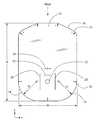
- FIG. 1shows a top plan view of a first example of a flashing, according to the present invention.
- FIG. 2shows a bottom plan view of the first example of a flashing, according to the present invention.
- FIG. 3shows a side view of the first example of a flashing, according to the present invention.
- FIG. 4shows a perspective view of the first example of a flashing, according to the present invention.
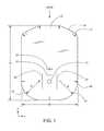
- FIG. 5shows a top plan view of a second example of a narrow flashing, according to the present invention.
- FIG. 6shows a bottom plan view of the second example of a narrow flashing, according to the present invention.
- FIG. 7shows a side view of the second example of a narrow flashing, according to the present invention.
- FIG. 8shows a perspective view of the second example of a narrow flashing, according to the present invention.
- FIG. 9shows a perspective exploded view of a first example of a narrow flashing assembly, according to the present invention.
- FIG. 10shows a perspective exploded view of a second example of a narrow flashing assembly, according to the present invention.
- the present inventionrelates to narrow flashings that are improved versions of flashings and are used for waterproofing mounting hardware that holds photovoltaic solar panels on a roof; typically, such a roof is a pitched, composition shingle roof.
- These narrow flashingsare flat and have no raised protrusions. As such, they are less expensive to manufacture.
- Water sealingis accomplished through the use of a rubber, butyl, adhesive, or an EDPM washer, which is compressed underneath the head of a lag screw that screws through the roofing layers into an underlying rafter, and which is also used as a sealing pad disposed underneath a bracket (L-foot, slider bar, etc.) that is attached by the lag screw.
- the y-axis directionaligns with the long dimension of the flashing
- the x-axisaligns with the short dimension of the flashing, as indicated in the figures.
- the direction of a sloped roofis indicated in the figures as “slope”, and is parallel to the y-axis direction.
- the “downslope end” of the flashingrefers to the bottom of the flashing when applied to a sloped roof
- the “upslope end”refers to the top of the flashing.
- FIG. 1shows a top plan view of a first example of a flashing, according to the present invention.
- metale.g., aluminum or aluminum alloy
- plastice.g., polyethylene or polypropylene
- compositee.g., fiberglass, carbon fiber reinforced, or resin/sawdust mixture
- a minimum radius of the small rounded corner sections 17 of the chamfered and small rounded cornerscan be 0.1 inch.
- the corner radius, Rcan equal W/3, in this first example.
- a through-hole (aperture) 12is located midway across flashing 10 , in the east-west direction, and approximately 1 ⁇ 4 of the way up from the Southern edge.
- a variety of alignment marksare printed on the surface of flashing 10 , including a pair of parallel alignment marks or bars 20 and 20 ′; a horizontal alignment mark or bar 22 located midway across flashing 10 in the east-west direction and located above the aperture 12 ; horizontal alignment marks or bars 26 located at opposite sides of the flashing 10 ; and a “cross” symbol 24 forming an alignment mark located midway across flashing 10 in the x-axis direction and located above the horizontal bar 22 .
- the use of cross symbol 24aids in aligning the placement of a slider bar (not shown).
- the four marks that correspond with the center of the aperture 12are used to aid in alignment with adjacent flashings both north/south and east/west.
- Horizontal alignment marks 20 , 20 ′, and 22outline a square shape that matches the shape of a square elastomeric sealing pad (see FIG. 9 ).
- Cross symbol 24is used to align the lower edge of composition tiles (shingles), which flashing 10 slides underneath when installed. The reason that these alignment marks are needed is that when a sealing pad (see FIG. 9 ) is applied to the bottom of a L-foot bracket (see FIG. 9 ), the aperture 12 in the flashing cannot be seen. If the marks align with the aperture in the L-foot or slider, the flashing aperture 12 will line up adequately with the aperture in the bracket.
- the height/width ratio (H/W) of flashing 10is approximately equal to 1.4 for this first example. In other examples, the height/width ratio (H/W) of flashing 10 can be greater than or equal to 1.4. Flashing 10 is left/right symmetrical across a line drawn through the center of the flashing parallel to the y-axis. The radius, R, of the large rounded corners 14 is at least 5 times greater than the radius, r, of the small rounded corner sections 17 . The width, W, can be equal to or less than 7 inches.
- FIG. 2shows a bottom plan view of a first example of a narrow flashing, according to the present invention.
- Flashing 10has a printed feature 18 comprising an upside-down “U”-shape that encompasses the aperture 12 .
- the purpose of this printed feature 18is to provide a printed mark that an installer can follow when applying liquid sealant/caulk (e.g., silicone caulk) to the bottom side of flashing 10 .
- liquid sealant/caulke.g., silicone caulk
- the use of an upside-down “U”-shapeis to provide a water dam (barrier) to deflect any flow of water from entering aperture 12 .
- One large rounded corner 14 and one chamfered section 16are also indicated in FIG. 2 .
- FIG. 3shows a side view of a first example of a narrow flashing, according to the present invention.
- the flashing 10is flat in this view.
- FIG. 4shows a perspective view of a first example of a narrow flashing, according to the present invention.
- Aperture 12 , and alignment marks 20 , 20 ′, 22 , 24 , and 26 , printed on flashing 10can be seen.
- Chamfered section 16 and rounded corner 14can be seen as well.
- FIG. 5shows a top plan view of a second example of a narrow flashing, according to the present invention.
- the use of chamfered and/or rounded cornerseliminates any problems associated with sharp corners.
- a through-hole (aperture) 12is located midway across flashing 10 , in the east-west direction, and approximately 1 ⁇ 4 of the way up from the downslope edge.
- the diameter of aperture 12can be oversized to allow for some misalignment of the lag screw.
- a variety of alignment marksare printed on the surface of flashing 10 , including a pair of parallel bars 20 and 20 ′, a horizontal alignment bar 22 located midway across flashing 10 in the east-west direction and located above the aperture 12 , and a “cross” symbol 24 located midway across flashing 10 in the east-west direction and above the horizontal bar 22 .
- the height/width ratio (H/W) of flashing 10is approximately equal to 2.0 for this second example.
- the height/width ratio (H/W) of flashing 10can be greater than or equal to 2.0.
- Rthe width of flashing 10
- the downslope end of flashing 10contains two rounded corners 14 , 14 ′ that meet in the middle to form the semicircular shaped end.
- the radius, R, of the large rounded corners 14 , 14 ′is at least 5 times greater than the radius, r, of the small rounded corner sections 17 .
- FIG. 6shows a bottom plan view of the second example of a narrow flashing, according to the present invention.
- Flashing 10has a printed feature 18 comprising an upside-down “U”-shape that encompasses the aperture 12 .
- the purpose of this printed feature 18is to provide a printed mark that an installer can follow when applying liquid sealant/caulk (e.g., silicone caulk) to the bottom side of flashing 10 .
- the use of an upside-down “U”-shape for the sealant/caulkis to provide a water dam (barrier) to deflect any flow of water from entering aperture 12 .
- One chamfered section 16is also indicated in FIG. 6 .
- FIG. 7shows a side view of the second example of a narrow flashing 10 according to the present invention.
- the flashing 10is flat in this view.
- FIG. 8shows a perspective view of the second example of a narrow flashing 10 according to the present invention.
- Aperture 12 , and alignment marks 20 , 20 ′, 22 , 24 , and 26 , printed on flashing 10can be seen.
- Chamfered section 16 and rounded corner 14can be seen as well.
- FIG. 9shows a perspective exploded view of a first example of a narrow flashing assembly, according to the present invention.
- Flashing 10comprises an aperture 12 through which a lag screw 32 is mounted into an underlying structural support (not shown), which is used to mount an L-foot bracket 30 to the roof (not shown).
- An elastomeric (e.g., butyl) sealing pad 36 in the shape of a square that matches the bottom of L-foot 30is disposed in-between the bottom of L-foot 30 and the upper surface of flashing 10 , which waterproofs the aperture 12 .
- An elastomeric (e.g., butyl) sealing pad 36in the shape of a square that matches the bottom of L-foot 30 is disposed in-between the bottom of L-foot 30 and the upper surface of flashing 10 , which waterproofs the aperture 12 .
- EDPMEDPM
- Flashing 10comprises a semi-circular, downslope end 14 .
- elastomeric sealing pad 36can be made of a structural adhesive material, such as a DOW-321 adhesive, or 3M-2110, 2204, or 4110 adhesive tapes (which have been used to attach structural rails to dual-glass PV modules).
- An adhesion promotersuch as Isopropyl Alcohol (IPA), can be used to promote robustness of the adhesive bond.
- IPAIsopropyl Alcohol
- FIG. 10shows a perspective exploded view of a second example of a narrow flashing assembly, according to the present invention.
- Flashing 10comprises an aperture 12 through which a lag screw 32 is mounted into an underlying structural support (not shown), which is used to mount a slider bar 40 to the roof (not shown).
- a rectangular, elastomeric (e.g., butyl) sealing pad 36is disposed between the bottom of slider bar 40 and the upper surface of flashing 10 , which waterproofs the aperture 12 .
- An elastomeric (e.g. EDPM) washer 34 with a circular steel capis disposed between the head of lag screw 32 and slider bar 40 through a second aperture 38 .
- Flashing 10comprises a semi-circular, downslope end 14 .
- elastomeric sealing pad 36can be made of a structural adhesive material, such as a DOW-321 adhesive, or 3M-2110, 2204, or 4110 adhesive tapes (which have been used to attach structural rails to dual-glass PV modules).
- An adhesion promotersuch as Isopropyl Alcohol (IPA), can be used to promote robustness of the adhesive bond.
- a semi-circular downslope end 14 of the flashingis also indicated in FIG. 10 .
Landscapes
- Engineering & Computer Science (AREA)
- Architecture (AREA)
- Structural Engineering (AREA)
- Civil Engineering (AREA)
- Physics & Mathematics (AREA)
- Chemical & Material Sciences (AREA)
- Thermal Sciences (AREA)
- Combustion & Propulsion (AREA)
- Mechanical Engineering (AREA)
- General Engineering & Computer Science (AREA)
- Sustainable Energy (AREA)
- Sustainable Development (AREA)
- Life Sciences & Earth Sciences (AREA)
- Electromagnetism (AREA)
- Roof Covering Using Slabs Or Stiff Sheets (AREA)
Abstract
Description
Claims (23)
Priority Applications (1)
| Application Number | Priority Date | Filing Date | Title |
|---|---|---|---|
| US15/785,492US10284136B1 (en) | 2017-10-17 | 2017-10-17 | Narrow flashing for waterproof mounting of solar panels to a roof |
Applications Claiming Priority (1)
| Application Number | Priority Date | Filing Date | Title |
|---|---|---|---|
| US15/785,492US10284136B1 (en) | 2017-10-17 | 2017-10-17 | Narrow flashing for waterproof mounting of solar panels to a roof |
Publications (2)
| Publication Number | Publication Date |
|---|---|
| US20190115866A1 US20190115866A1 (en) | 2019-04-18 |
| US10284136B1true US10284136B1 (en) | 2019-05-07 |
Family
ID=66096220
Family Applications (1)
| Application Number | Title | Priority Date | Filing Date |
|---|---|---|---|
| US15/785,492ActiveUS10284136B1 (en) | 2017-10-17 | 2017-10-17 | Narrow flashing for waterproof mounting of solar panels to a roof |
Country Status (1)
| Country | Link |
|---|---|
| US (1) | US10284136B1 (en) |
Cited By (45)
| Publication number | Priority date | Publication date | Assignee | Title |
|---|---|---|---|---|
| US20230283225A1 (en)* | 2020-10-14 | 2023-09-07 | GAF Energy LLC | Mounting apparatus for photovoltaic modules |
| US11811361B1 (en) | 2022-12-14 | 2023-11-07 | GAF Energy LLC | Rapid shutdown device for photovoltaic modules |
| US11824487B2 (en) | 2020-11-13 | 2023-11-21 | GAF Energy LLC | Photovoltaic module systems and methods |
| US11824486B2 (en) | 2022-01-20 | 2023-11-21 | GAF Energy LLC | Roofing shingles for mimicking the appearance of photovoltaic modules |
| US11843067B2 (en) | 2020-07-22 | 2023-12-12 | GAF Energy LLC | Photovoltaic modules |
| US11869997B2 (en) | 2021-05-06 | 2024-01-09 | GAF Energy LLC | Photovoltaic module with transparent perimeter edges |
| US11870227B2 (en) | 2020-09-03 | 2024-01-09 | GAF Energy LLC | Building integrated photovoltaic system |
| US11876480B2 (en) | 2020-06-04 | 2024-01-16 | GAF Energy LLC | Photovoltaic shingles and methods of installing same |
| US11929704B1 (en) | 2023-09-27 | 2024-03-12 | Sunmodo Corporation | Method and system for securing a solar panel to a tile roof |
| US11961928B2 (en) | 2020-02-27 | 2024-04-16 | GAF Energy LLC | Photovoltaic module with light-scattering encapsulant providing shingle-mimicking appearance |
| US11965335B2 (en) | 2021-01-19 | 2024-04-23 | GAF Energy LLC | Watershedding features for roofing shingles |
| US11984521B2 (en) | 2022-03-10 | 2024-05-14 | GAF Energy LLC | Combined encapsulant and backsheet for photovoltaic modules |
| US11996797B2 (en) | 2020-12-02 | 2024-05-28 | GAF Energy LLC | Step flaps for photovoltaic and roofing shingles |
| US12009781B2 (en) | 2021-07-06 | 2024-06-11 | GAF Energy LLC | Jumper module for photovoltaic systems |
| US12009773B2 (en) | 2021-09-01 | 2024-06-11 | GAF Energy LLC | Photovoltaic modules for commercial roofing |
| US12009782B1 (en) | 2023-04-04 | 2024-06-11 | GAF Energy LLC | Photovoltaic systems with wireways |
| US12013153B2 (en) | 2022-02-08 | 2024-06-18 | GAF Energy LLC | Building integrated photovoltaic system |
| US12015374B2 (en) | 2022-09-26 | 2024-06-18 | GAF Energy LLC | Photovoltaic modules integrated with building siding and fencing |
| US12031332B2 (en) | 2022-10-25 | 2024-07-09 | GAF Energy LLC | Roofing materials and related methods |
| US12034089B2 (en) | 2022-09-01 | 2024-07-09 | GAF Energy LLC | Anti-reflective photovoltaic shingles and related methods |
| US12051990B2 (en) | 2020-01-22 | 2024-07-30 | GAF Energy LLC | Integrated photovoltaic roofing shingles, methods, systems, and kits thereof |
| US12051996B2 (en) | 2022-09-13 | 2024-07-30 | GAF Energy LLC | Sensing roofing system and method thereof |
| US12095415B2 (en) | 2021-03-29 | 2024-09-17 | GAF Energy LLC | Electrical components for photovoltaic systems |
| US12100775B2 (en) | 2021-06-02 | 2024-09-24 | GAF Energy LLC | Photovoltaic module with light-scattering encapsulant providing shingle-mimicking appearance |
| US12126301B2 (en) | 2020-08-11 | 2024-10-22 | GAF Energy LLC | Roof mounted photovoltaic system and method for wireless transfer of electrical energy |
| US12123194B2 (en) | 2020-10-29 | 2024-10-22 | GAF Energy LLC | System of roofing and photovoltaic shingles and methods of installing same |
| US12143064B2 (en) | 2022-09-29 | 2024-11-12 | GAF Energy LLC | Jumper module with sleeve |
| US12145348B2 (en) | 2022-08-24 | 2024-11-19 | GAF Energy LLC | System for forming a roofing membrane, and associated method |
| US12176849B2 (en) | 2023-02-23 | 2024-12-24 | GAF Energy LLC | Photovoltaic shingles with multi-module power electronics |
| US12191797B2 (en) | 2021-02-19 | 2025-01-07 | GAF Energy LLC | Photovoltaic module for a roof with continuous fiber tape |
| US12191796B2 (en) | 2019-12-20 | 2025-01-07 | GAF Energy LLC | Roof integrated photovoltaic system |
| US12199550B2 (en) | 2022-04-08 | 2025-01-14 | GAF Energy LLC | Low profile connector for solar roofing systems |
| US12209414B2 (en) | 2022-02-23 | 2025-01-28 | GAF Energy LLC | Roofing shingle and method of manufacturing same |
| US12231075B2 (en) | 2022-10-27 | 2025-02-18 | GAF Energy LLC | Building integrated photovoltaic systems |
| US12237809B2 (en) | 2022-06-06 | 2025-02-25 | GAF Energy LLC | Active component indicators for photovoltaic systems |
| US12316268B2 (en) | 2023-10-26 | 2025-05-27 | GAF Energy LLC | Roofing systems with water ingress protection |
| US12325996B2 (en) | 2022-07-15 | 2025-06-10 | GAF Energy LLC | Solar roofing system with fiber composite roofing shingles |
| US12355390B1 (en) | 2023-02-03 | 2025-07-08 | GAF Energy LLC | Solar shingle and associated roofing system and method |
| US12413177B2 (en) | 2023-08-31 | 2025-09-09 | GAF Energy LLC | Photovoltaic modules and roofing shingles with nail zones |
| US12414385B2 (en) | 2022-08-29 | 2025-09-09 | GAF Energy LLC | Photovoltaic modules with offset layers |
| US12413174B2 (en) | 2023-02-21 | 2025-09-09 | GAF Energy LLC | Roofing system including photovoltaic module wireway cover, and associated method |
| US12413175B2 (en) | 2020-10-13 | 2025-09-09 | GAF Energy LLC | Solar roofing system |
| US12413183B2 (en) | 2022-11-15 | 2025-09-09 | GAF Energy LLC | Electrical cable passthrough for photovoltaic systems |
| US12438495B2 (en) | 2023-12-05 | 2025-10-07 | GAF Energy LLC | Roofing system for prevention of roofing shingle deformation |
| US12445089B2 (en) | 2024-02-02 | 2025-10-14 | GAF Energy LLC | Photovoltaic module, and associated kit, system, and method |
Families Citing this family (2)
| Publication number | Priority date | Publication date | Assignee | Title |
|---|---|---|---|---|
| USD900594S1 (en)* | 2019-08-20 | 2020-11-03 | Newpower, Inc. | Photovoltaic mounting tile hook |
| US11515829B1 (en)* | 2019-11-30 | 2022-11-29 | David Katz | Flashing and L-bracket assembly for rack mounting of solar panels on roof |
Citations (37)
| Publication number | Priority date | Publication date | Assignee | Title |
|---|---|---|---|---|
| US7762027B1 (en) | 2006-09-28 | 2010-07-27 | Wentworth Stuart H | System for attaching an article to a roof and method of use |
| US7921607B2 (en) | 2005-01-04 | 2011-04-12 | Thompson Technology Industries, Inc. | Apparatus for mounting a solar panel or other article to a roof or other structure |
| US20110120047A1 (en)* | 2010-01-25 | 2011-05-26 | Brian Cecil Stearns | Roofing grommet forming a seal between a roof-mounted structure and a roof |
| US8122648B1 (en) | 2010-02-02 | 2012-02-28 | Jun Liu | Roof mounting system |
| US8153700B2 (en) | 2010-03-19 | 2012-04-10 | Vermont Slate & Copper Services, Inc. | Roofing system and method |
| US20120144760A1 (en)* | 2009-02-05 | 2012-06-14 | D Three Enterprises, Llc | Roof mount sealing assembly |
| US8250829B2 (en) | 2008-05-22 | 2012-08-28 | Mainstream Energy Corporation | Module attachment apparatus |
| US8316592B2 (en) | 2009-03-21 | 2012-11-27 | Carlo John Lanza | Protective covering for roof mounted systems |
| US20130133270A1 (en)* | 2011-11-09 | 2013-05-30 | Zep Solar, Inc. | Solar Panel Attachment System |
| US20130167455A1 (en)* | 2012-01-03 | 2013-07-04 | Robert L. Jenkins | Roofing Flashing and Uses Thereof |
| US8479455B2 (en) | 2010-10-14 | 2013-07-09 | D Three Enterprises | Flashing assembly |
| US8661765B2 (en) | 2009-02-05 | 2014-03-04 | D Three Enterprises, Llc | Interlocking shape for use in construction members |
| US8713858B1 (en) | 2011-12-22 | 2014-05-06 | Jason Sen Xie | Roof attachment flashing system |
| US8752338B2 (en) | 2012-05-04 | 2014-06-17 | D Three Enterprises, Llc | Adjustable roof mounting system |
| US8869470B2 (en) | 2009-03-21 | 2014-10-28 | Carlo John Lanza | Protective covering for roof device |
| US20140353435A1 (en)* | 2013-05-31 | 2014-12-04 | Sunmodo Corporation | Direct Rooftop Mounting Apparatus for Solar Panels |
| US8938932B1 (en) | 2013-12-13 | 2015-01-27 | Quality Product Llc | Rail-less roof mounting system |
| US20150129517A1 (en) | 2013-11-14 | 2015-05-14 | Ecolibrium Solar, Inc. | Modular Sloped Roof Solar Mounting System |
| US9134044B2 (en) | 2010-01-25 | 2015-09-15 | Vermont Slate & Copper Services, Inc. | Roof mount assembly |
| US20150270802A1 (en)* | 2014-01-29 | 2015-09-24 | D Three Enterprises, Llc | Adjustable combined flashing and mounting apparatus and method of mounting to be used therewith |
| US9151315B2 (en) | 2013-07-03 | 2015-10-06 | Sunrun South Llc | Devices, systems, and methods for securing a component to a surface |
| US20150330082A1 (en)* | 2014-03-24 | 2015-11-19 | Ronald Newman Roseveare, JR. | Asphalt roof shingle sealing device |
| US20160043689A1 (en) | 2014-08-05 | 2016-02-11 | Sunrun South Llc | Solar panel installation systems and methods |
| US20160087576A1 (en) | 2014-09-23 | 2016-03-24 | Solarcity Corporation | Photovoltaic mounting system for tiled roofs |
| US20160102460A1 (en) | 2014-10-10 | 2016-04-14 | Solarcity Corporation | Replacement flashing for exhaust gas vents beneath roof-mounted photovoltaic systems |
| US20160134230A1 (en)* | 2014-11-06 | 2016-05-12 | Ironridge, Inc. | Roof Attachment Flashing Assembly |
| US20160142006A1 (en)* | 2014-11-19 | 2016-05-19 | Ironridge, Inc. | Roof Attachment Assembly for Solar Panels and Installation Method |
| US9350289B1 (en)* | 2013-12-19 | 2016-05-24 | MAJI Enterprises, Inc | Solar panel mounting assembly |
| US9422720B2 (en)* | 2014-07-31 | 2016-08-23 | Renewable Elements, Llc | Non-penetrating roof mount for a membrane roof |
| US9447988B2 (en) | 2010-01-25 | 2016-09-20 | Rillito Rive Solar, LLC | Roof mount assembly |
| US20170058532A1 (en)* | 2015-08-28 | 2017-03-02 | Solarcity Corporation | Tile and slate roof flashing systems |
| USD788951S1 (en)* | 2016-03-16 | 2017-06-06 | Werner Co. | Roof anchor |
| US20170299102A1 (en)* | 2016-04-14 | 2017-10-19 | Ironridge, Inc. | Conduit Mount Assembly |
| US20180062560A1 (en)* | 2016-08-23 | 2018-03-01 | Pegasus Solar Inc. | Solar mounting assemblies |
| US20180076756A1 (en)* | 2016-09-09 | 2018-03-15 | Pegasus Solar Inc. | Tile replacement solar mounting system |
| US20180167020A1 (en)* | 2016-12-14 | 2018-06-14 | Tecsi Solar, Inc. | Systems and methods for mounting roof-mounted photovoltaic arrays including flashing and adhesive pads |
| US20180347196A1 (en)* | 2010-01-25 | 2018-12-06 | Rillito River Solar, Llc | Roof mounting system |
- 2017
- 2017-10-17USUS15/785,492patent/US10284136B1/enactiveActive
Patent Citations (80)
| Publication number | Priority date | Publication date | Assignee | Title |
|---|---|---|---|---|
| US7921607B2 (en) | 2005-01-04 | 2011-04-12 | Thompson Technology Industries, Inc. | Apparatus for mounting a solar panel or other article to a roof or other structure |
| US7895808B1 (en) | 2006-09-28 | 2011-03-01 | Wentworth Stuart H | System for attaching an article to a roof and method of use |
| US7905064B1 (en) | 2006-09-28 | 2011-03-15 | Wentworth Stuart H | System for attaching an article to a roof and method of use |
| US7762027B1 (en) | 2006-09-28 | 2010-07-27 | Wentworth Stuart H | System for attaching an article to a roof and method of use |
| US8739471B2 (en) | 2008-05-22 | 2014-06-03 | Sunrun Soutii LLC | Assembly for securing a component to a roof |
| US8250829B2 (en) | 2008-05-22 | 2012-08-28 | Mainstream Energy Corporation | Module attachment apparatus |
| US8539719B2 (en)* | 2008-05-22 | 2013-09-24 | Mainstream Energy Corporation | Module attachment apparatus |
| US9068339B2 (en) | 2009-02-05 | 2015-06-30 | D Three Enterprises, Llc | Roof standoff device |
| US8689517B2 (en) | 2009-02-05 | 2014-04-08 | D Three Enterprises, Llc | Roof mount sealing assembly |
| US8833032B2 (en) | 2009-02-05 | 2014-09-16 | D Three Enterprises, Llc | Roof mount sealing assembly |
| US8833033B2 (en) | 2009-02-05 | 2014-09-16 | D Three Enterprises, Llc | Roof mount sealing assembly |
| US20120144760A1 (en)* | 2009-02-05 | 2012-06-14 | D Three Enterprises, Llc | Roof mount sealing assembly |
| US8869490B2 (en) | 2009-02-05 | 2014-10-28 | D Three Enterprises, Llc | Interlocking shape for use in construction members |
| US8707655B2 (en) | 2009-02-05 | 2014-04-29 | D Three Enterprises, Llc | Roof mount sealing assembly |
| US8661765B2 (en) | 2009-02-05 | 2014-03-04 | D Three Enterprises, Llc | Interlocking shape for use in construction members |
| US8448405B2 (en)* | 2009-02-05 | 2013-05-28 | D Three Enterprises, Llc | Roof mount sealing assembly |
| US8707654B2 (en) | 2009-02-05 | 2014-04-29 | D Three Enterprises, Llc | Roof mount sealing assembly |
| US20160087574A1 (en) | 2009-03-21 | 2016-03-24 | Carlo John Lanza | Protective covering for roof mounted systems |
| US8316592B2 (en) | 2009-03-21 | 2012-11-27 | Carlo John Lanza | Protective covering for roof mounted systems |
| US9181705B2 (en) | 2009-03-21 | 2015-11-10 | Carlo John Lanza | Protective covering for roof mounted systems |
| US8869470B2 (en) | 2009-03-21 | 2014-10-28 | Carlo John Lanza | Protective covering for roof device |
| US8245454B2 (en) | 2010-01-25 | 2012-08-21 | Vermont Slate & Copper Services, Inc. | Roofing grommet forming a seal between a roof-mounted structure and a roof |
| US9134044B2 (en) | 2010-01-25 | 2015-09-15 | Vermont Slate & Copper Services, Inc. | Roof mount assembly |
| US20110120047A1 (en)* | 2010-01-25 | 2011-05-26 | Brian Cecil Stearns | Roofing grommet forming a seal between a roof-mounted structure and a roof |
| US9422723B2 (en) | 2010-01-25 | 2016-08-23 | Vermont Slate & Copper Services Company, Inc. | Roofing grommet forming a seal between a roof-mounted structure and a roof |
| US9422721B2 (en) | 2010-01-25 | 2016-08-23 | Vermont Slate & Copper Services, Inc. | Roofing grommet forming a seal between a roof-mounted structure and a roof |
| US8701354B2 (en) | 2010-01-25 | 2014-04-22 | Vermont Slate & Copper Services, Inc. | Roofing grommet forming a seal between a roof-mounted structure and a roof |
| US8272174B2 (en) | 2010-01-25 | 2012-09-25 | Vermont Slate & Copper Services, Inc. | Roofing grommet forming a seal between a roof-mounted structure and a roof |
| US20180347196A1 (en)* | 2010-01-25 | 2018-12-06 | Rillito River Solar, Llc | Roof mounting system |
| US9127464B2 (en) | 2010-01-25 | 2015-09-08 | Vermont Slate & Copper Services, Inc. | Roofing grommet forming a seal between a roof-mounted structure and a roof |
| US8209914B2 (en)* | 2010-01-25 | 2012-07-03 | Vermont Slate & Copper Services, Inc. | Roofing grommet forming a seal between a roof-mounted structure and a roof |
| US8146299B2 (en)* | 2010-01-25 | 2012-04-03 | Vermont Slate & Copper Services, Inc. | Roofing grommet forming a seal between a roof-mounted structure and a roof |
| US9447988B2 (en) | 2010-01-25 | 2016-09-20 | Rillito Rive Solar, LLC | Roof mount assembly |
| US20160344333A1 (en) | 2010-01-25 | 2016-11-24 | Rillito River Solar, Llc | Roofing grommet forming a seal between a roof-mounted structure and a roof |
| US20160344332A1 (en) | 2010-01-25 | 2016-11-24 | Rillito River Solar, Llc | Roofing grommet forming a seal between a roof-mounted structure and a roof |
| US8122648B1 (en) | 2010-02-02 | 2012-02-28 | Jun Liu | Roof mounting system |
| US8151522B2 (en) | 2010-03-19 | 2012-04-10 | Vermont Slate & Copper Services, Inc. | Roofing system and method |
| US8153700B2 (en) | 2010-03-19 | 2012-04-10 | Vermont Slate & Copper Services, Inc. | Roofing system and method |
| US8166713B2 (en) | 2010-03-19 | 2012-05-01 | Vermont Slate & Copper Services, Inc. | Roofing system and method |
| US8181398B2 (en) | 2010-03-19 | 2012-05-22 | Vermont Slate & Copper Services, Inc. | Roofing system and method |
| US8413388B2 (en) | 2010-03-19 | 2013-04-09 | Vermont Slate & Copper Services, Inc. | Roofing system and method |
| US8225557B2 (en) | 2010-03-19 | 2012-07-24 | Vermont Slate & Copper Services, Inc. | Roofing system and method |
| US8479455B2 (en) | 2010-10-14 | 2013-07-09 | D Three Enterprises | Flashing assembly |
| US8756881B2 (en)* | 2011-11-09 | 2014-06-24 | Zep Solar, Llc | Solar panel attachment system |
| US9062897B2 (en)* | 2011-11-09 | 2015-06-23 | Zep Solar, Llc | Solar panel attachment system |
| US9097441B2 (en)* | 2011-11-09 | 2015-08-04 | Zep Solar, Llc | Solar panel attachment system |
| US20140223838A1 (en)* | 2011-11-09 | 2014-08-14 | Zep Solar, Llc | Solar Panel Attachment System |
| US20150069198A1 (en)* | 2011-11-09 | 2015-03-12 | Zep Solar Llc | Solar panel attachment system |
| US20130133270A1 (en)* | 2011-11-09 | 2013-05-30 | Zep Solar, Inc. | Solar Panel Attachment System |
| US8713858B1 (en) | 2011-12-22 | 2014-05-06 | Jason Sen Xie | Roof attachment flashing system |
| US20130167455A1 (en)* | 2012-01-03 | 2013-07-04 | Robert L. Jenkins | Roofing Flashing and Uses Thereof |
| US8752338B2 (en) | 2012-05-04 | 2014-06-17 | D Three Enterprises, Llc | Adjustable roof mounting system |
| US8935893B2 (en)* | 2013-05-31 | 2015-01-20 | Sunmodo Corporation | Direct rooftop mounting apparatus for solar panels |
| US20140353435A1 (en)* | 2013-05-31 | 2014-12-04 | Sunmodo Corporation | Direct Rooftop Mounting Apparatus for Solar Panels |
| US9151315B2 (en) | 2013-07-03 | 2015-10-06 | Sunrun South Llc | Devices, systems, and methods for securing a component to a surface |
| US20150129517A1 (en) | 2013-11-14 | 2015-05-14 | Ecolibrium Solar, Inc. | Modular Sloped Roof Solar Mounting System |
| US8938932B1 (en) | 2013-12-13 | 2015-01-27 | Quality Product Llc | Rail-less roof mounting system |
| US20150168021A1 (en) | 2013-12-13 | 2015-06-18 | Quality Product Llc | Rail-less roof mounting clamp assembly |
| US20160164452A1 (en) | 2013-12-13 | 2016-06-09 | Claudia Wentworth | Rail-Less Roof Mounting Clamp Assembly Components |
| US9350289B1 (en)* | 2013-12-19 | 2016-05-24 | MAJI Enterprises, Inc | Solar panel mounting assembly |
| US9680409B2 (en)* | 2014-01-29 | 2017-06-13 | D Three Enterprises, Llc | Adjustable combined flashing and mounting apparatus and method of mounting to be used therewith |
| US20150270802A1 (en)* | 2014-01-29 | 2015-09-24 | D Three Enterprises, Llc | Adjustable combined flashing and mounting apparatus and method of mounting to be used therewith |
| US20180152133A1 (en)* | 2014-01-29 | 2018-05-31 | D Three Enterprises Llc | Adjustable combined flashing and mounting apparatus and method of mounting to be used therewith |
| US20150330082A1 (en)* | 2014-03-24 | 2015-11-19 | Ronald Newman Roseveare, JR. | Asphalt roof shingle sealing device |
| US9422720B2 (en)* | 2014-07-31 | 2016-08-23 | Renewable Elements, Llc | Non-penetrating roof mount for a membrane roof |
| US20160043687A1 (en) | 2014-08-05 | 2016-02-11 | Sunrun South Llc | Solar panel installation systems and methods |
| US20160043688A1 (en) | 2014-08-05 | 2016-02-11 | Sunrun South Llc | Solar panel installation systems and methods |
| US20160043689A1 (en) | 2014-08-05 | 2016-02-11 | Sunrun South Llc | Solar panel installation systems and methods |
| US20160087576A1 (en) | 2014-09-23 | 2016-03-24 | Solarcity Corporation | Photovoltaic mounting system for tiled roofs |
| US20160102460A1 (en) | 2014-10-10 | 2016-04-14 | Solarcity Corporation | Replacement flashing for exhaust gas vents beneath roof-mounted photovoltaic systems |
| US20170288602A1 (en)* | 2014-11-06 | 2017-10-05 | Ironridge, Inc. | Roof Attachment Flashing Assembly |
| US20160134230A1 (en)* | 2014-11-06 | 2016-05-12 | Ironridge, Inc. | Roof Attachment Flashing Assembly |
| US20160142006A1 (en)* | 2014-11-19 | 2016-05-19 | Ironridge, Inc. | Roof Attachment Assembly for Solar Panels and Installation Method |
| US9800199B2 (en)* | 2014-11-19 | 2017-10-24 | Ironridge, Inc. | Roof attachment assembly for solar panels and installation method |
| US20170058532A1 (en)* | 2015-08-28 | 2017-03-02 | Solarcity Corporation | Tile and slate roof flashing systems |
| USD788951S1 (en)* | 2016-03-16 | 2017-06-06 | Werner Co. | Roof anchor |
| US20170299102A1 (en)* | 2016-04-14 | 2017-10-19 | Ironridge, Inc. | Conduit Mount Assembly |
| US20180062560A1 (en)* | 2016-08-23 | 2018-03-01 | Pegasus Solar Inc. | Solar mounting assemblies |
| US20180076756A1 (en)* | 2016-09-09 | 2018-03-15 | Pegasus Solar Inc. | Tile replacement solar mounting system |
| US20180167020A1 (en)* | 2016-12-14 | 2018-06-14 | Tecsi Solar, Inc. | Systems and methods for mounting roof-mounted photovoltaic arrays including flashing and adhesive pads |
Cited By (53)
| Publication number | Priority date | Publication date | Assignee | Title |
|---|---|---|---|---|
| US12191796B2 (en) | 2019-12-20 | 2025-01-07 | GAF Energy LLC | Roof integrated photovoltaic system |
| US12051990B2 (en) | 2020-01-22 | 2024-07-30 | GAF Energy LLC | Integrated photovoltaic roofing shingles, methods, systems, and kits thereof |
| US12413176B2 (en) | 2020-01-22 | 2025-09-09 | GAF Energy LLC | Integrated photovoltaic roofing shingles, methods, systems, and kits thereof |
| US11961928B2 (en) | 2020-02-27 | 2024-04-16 | GAF Energy LLC | Photovoltaic module with light-scattering encapsulant providing shingle-mimicking appearance |
| US11876480B2 (en) | 2020-06-04 | 2024-01-16 | GAF Energy LLC | Photovoltaic shingles and methods of installing same |
| US11843067B2 (en) | 2020-07-22 | 2023-12-12 | GAF Energy LLC | Photovoltaic modules |
| US12126301B2 (en) | 2020-08-11 | 2024-10-22 | GAF Energy LLC | Roof mounted photovoltaic system and method for wireless transfer of electrical energy |
| US11870227B2 (en) | 2020-09-03 | 2024-01-09 | GAF Energy LLC | Building integrated photovoltaic system |
| US12413175B2 (en) | 2020-10-13 | 2025-09-09 | GAF Energy LLC | Solar roofing system |
| US12255575B2 (en)* | 2020-10-14 | 2025-03-18 | GAF Energy LLC | Mounting apparatus for photovoltaic modules |
| US20230283225A1 (en)* | 2020-10-14 | 2023-09-07 | GAF Energy LLC | Mounting apparatus for photovoltaic modules |
| US12123194B2 (en) | 2020-10-29 | 2024-10-22 | GAF Energy LLC | System of roofing and photovoltaic shingles and methods of installing same |
| US11824487B2 (en) | 2020-11-13 | 2023-11-21 | GAF Energy LLC | Photovoltaic module systems and methods |
| US11996797B2 (en) | 2020-12-02 | 2024-05-28 | GAF Energy LLC | Step flaps for photovoltaic and roofing shingles |
| US11965335B2 (en) | 2021-01-19 | 2024-04-23 | GAF Energy LLC | Watershedding features for roofing shingles |
| US12191797B2 (en) | 2021-02-19 | 2025-01-07 | GAF Energy LLC | Photovoltaic module for a roof with continuous fiber tape |
| US12095415B2 (en) | 2021-03-29 | 2024-09-17 | GAF Energy LLC | Electrical components for photovoltaic systems |
| US11869997B2 (en) | 2021-05-06 | 2024-01-09 | GAF Energy LLC | Photovoltaic module with transparent perimeter edges |
| US12100775B2 (en) | 2021-06-02 | 2024-09-24 | GAF Energy LLC | Photovoltaic module with light-scattering encapsulant providing shingle-mimicking appearance |
| US12009781B2 (en) | 2021-07-06 | 2024-06-11 | GAF Energy LLC | Jumper module for photovoltaic systems |
| US12009773B2 (en) | 2021-09-01 | 2024-06-11 | GAF Energy LLC | Photovoltaic modules for commercial roofing |
| US12278591B2 (en) | 2022-01-20 | 2025-04-15 | GAF Energy LLC | Roofing shingles for mimicking the appearance of photovoltaic modules |
| US11824486B2 (en) | 2022-01-20 | 2023-11-21 | GAF Energy LLC | Roofing shingles for mimicking the appearance of photovoltaic modules |
| US12013153B2 (en) | 2022-02-08 | 2024-06-18 | GAF Energy LLC | Building integrated photovoltaic system |
| US12209414B2 (en) | 2022-02-23 | 2025-01-28 | GAF Energy LLC | Roofing shingle and method of manufacturing same |
| US11984521B2 (en) | 2022-03-10 | 2024-05-14 | GAF Energy LLC | Combined encapsulant and backsheet for photovoltaic modules |
| US12199550B2 (en) | 2022-04-08 | 2025-01-14 | GAF Energy LLC | Low profile connector for solar roofing systems |
| US12237809B2 (en) | 2022-06-06 | 2025-02-25 | GAF Energy LLC | Active component indicators for photovoltaic systems |
| US12325996B2 (en) | 2022-07-15 | 2025-06-10 | GAF Energy LLC | Solar roofing system with fiber composite roofing shingles |
| US12145348B2 (en) | 2022-08-24 | 2024-11-19 | GAF Energy LLC | System for forming a roofing membrane, and associated method |
| US12414385B2 (en) | 2022-08-29 | 2025-09-09 | GAF Energy LLC | Photovoltaic modules with offset layers |
| US12034089B2 (en) | 2022-09-01 | 2024-07-09 | GAF Energy LLC | Anti-reflective photovoltaic shingles and related methods |
| US12051996B2 (en) | 2022-09-13 | 2024-07-30 | GAF Energy LLC | Sensing roofing system and method thereof |
| US12015374B2 (en) | 2022-09-26 | 2024-06-18 | GAF Energy LLC | Photovoltaic modules integrated with building siding and fencing |
| US12143064B2 (en) | 2022-09-29 | 2024-11-12 | GAF Energy LLC | Jumper module with sleeve |
| US12031332B2 (en) | 2022-10-25 | 2024-07-09 | GAF Energy LLC | Roofing materials and related methods |
| US12231075B2 (en) | 2022-10-27 | 2025-02-18 | GAF Energy LLC | Building integrated photovoltaic systems |
| US12413183B2 (en) | 2022-11-15 | 2025-09-09 | GAF Energy LLC | Electrical cable passthrough for photovoltaic systems |
| US11811361B1 (en) | 2022-12-14 | 2023-11-07 | GAF Energy LLC | Rapid shutdown device for photovoltaic modules |
| US12255581B2 (en) | 2022-12-14 | 2025-03-18 | GAF Energy LLC | Rapid shutdown device for photovoltaic modules |
| US12255580B2 (en) | 2022-12-14 | 2025-03-18 | GAF Energy LLC | Rapid shutdown device for photovoltaic modules |
| US12355390B1 (en) | 2023-02-03 | 2025-07-08 | GAF Energy LLC | Solar shingle and associated roofing system and method |
| US12413174B2 (en) | 2023-02-21 | 2025-09-09 | GAF Energy LLC | Roofing system including photovoltaic module wireway cover, and associated method |
| US12407296B2 (en) | 2023-02-23 | 2025-09-02 | GAF Energy LLC | Photovoltaic shingles with multi-module power electronics |
| US12176849B2 (en) | 2023-02-23 | 2024-12-24 | GAF Energy LLC | Photovoltaic shingles with multi-module power electronics |
| US12009782B1 (en) | 2023-04-04 | 2024-06-11 | GAF Energy LLC | Photovoltaic systems with wireways |
| US12424973B2 (en) | 2023-04-04 | 2025-09-23 | GAF Energy LLC | Photovoltaic systems with wireways |
| US12446329B2 (en) | 2023-06-01 | 2025-10-14 | GAF Energy LLC | Photovoltaic module frontsheet and backsheet |
| US12413177B2 (en) | 2023-08-31 | 2025-09-09 | GAF Energy LLC | Photovoltaic modules and roofing shingles with nail zones |
| US11929704B1 (en) | 2023-09-27 | 2024-03-12 | Sunmodo Corporation | Method and system for securing a solar panel to a tile roof |
| US12316268B2 (en) | 2023-10-26 | 2025-05-27 | GAF Energy LLC | Roofing systems with water ingress protection |
| US12438495B2 (en) | 2023-12-05 | 2025-10-07 | GAF Energy LLC | Roofing system for prevention of roofing shingle deformation |
| US12445089B2 (en) | 2024-02-02 | 2025-10-14 | GAF Energy LLC | Photovoltaic module, and associated kit, system, and method |
Also Published As
| Publication number | Publication date |
|---|---|
| US20190115866A1 (en) | 2019-04-18 |
Similar Documents
| Publication | Publication Date | Title |
|---|---|---|
| US10284136B1 (en) | Narrow flashing for waterproof mounting of solar panels to a roof | |
| US20230198460A1 (en) | Solar Panel Racking System and Devices for the Same | |
| US7861485B1 (en) | Method for installing a stanchion on a tile roof and system therefor | |
| US7465873B2 (en) | Solar cell module, method of laying solar cell modules, and apparatus for preventing solar cell modules from being blown off | |
| US9819302B2 (en) | Module attachment apparatus and method | |
| US20100236155A1 (en) | Protective covering for roof mounted systems | |
| US20130167455A1 (en) | Roofing Flashing and Uses Thereof | |
| US20220224280A1 (en) | Rail and Splice Foot Mounting System for Photovoltaic Panels | |
| GB2466003A (en) | Securing A Solar Energy Collection Device As Part Of A Roof | |
| WO2018061645A1 (en) | Photovoltaic power generation device | |
| US10432135B2 (en) | Solar roof tile system | |
| JP2013256802A (en) | Solar module mounting structure, solar module mounting method, and roof | |
| US11121667B2 (en) | Mounting system for roof mounted solar panels | |
| EP2886973A1 (en) | Photovoltaic system and installation method thereof | |
| US20190222170A1 (en) | Photovoltaic power generation device | |
| JP5173304B2 (en) | Installation device for photoelectric conversion module | |
| CN211499531U (en) | Roof structure | |
| JP3177929U (en) | Solar module mounting structure and roof | |
| EP2757592A1 (en) | Mounting system for photovoltaic modules and plate-shaped components | |
| JP7033189B2 (en) | Solar cell module and photovoltaic system | |
| US9806666B2 (en) | System and method for mounting solar panel frames on corrugated roofing | |
| JP4577805B2 (en) | roof | |
| JP5458408B2 (en) | Installation structure of the take-out member, construction method, mounting structure of the external member, and repair structure | |
| CA3130941A1 (en) | Mounting system for roof mounted solar panels | |
| JPS6139250Y2 (en) |
Legal Events
| Date | Code | Title | Description |
|---|---|---|---|
| AS | Assignment | Owner name:UNIRAC INC., NEW MEXICO Free format text:ASSIGNMENT OF ASSIGNORS INTEREST;ASSIGNORS:MAYFIELD, JASON;SCHUIT, NATHAN;REEL/FRAME:043878/0533 Effective date:20171010 | |
| FEPP | Fee payment procedure | Free format text:ENTITY STATUS SET TO UNDISCOUNTED (ORIGINAL EVENT CODE: BIG.); ENTITY STATUS OF PATENT OWNER: SMALL ENTITY | |
| FEPP | Fee payment procedure | Free format text:ENTITY STATUS SET TO SMALL (ORIGINAL EVENT CODE: SMAL); ENTITY STATUS OF PATENT OWNER: SMALL ENTITY | |
| AS | Assignment | Owner name:PNC BANK, NATIONAL ASSOCIATION, AS AGENT, NEW JERS Free format text:ASSIGNMENT OF ASSIGNORS INTEREST;ASSIGNOR:UNIRAC, INC., AS GRANTOR;REEL/FRAME:046267/0330 Effective date:20180629 Owner name:PNC BANK, NATIONAL ASSOCIATION, AS AGENT, NEW JERSEY Free format text:ASSIGNMENT OF ASSIGNORS INTEREST;ASSIGNOR:UNIRAC, INC., AS GRANTOR;REEL/FRAME:046267/0330 Effective date:20180629 | |
| STCF | Information on status: patent grant | Free format text:PATENTED CASE | |
| AS | Assignment | Owner name:LBC CREDIT AGENCY SERVICES, LLC, AS AGENT, PENNSYLVANIA Free format text:SECURITY INTEREST;ASSIGNOR:UNIRAC, INC.;REEL/FRAME:056684/0333 Effective date:20210625 Owner name:UNIRAC, INC., NEW MEXICO Free format text:RELEASE BY SECURED PARTY;ASSIGNOR:PNC BANK, NATIONAL ASSOCIATION, AS AGENT;REEL/FRAME:056684/0379 Effective date:20210625 Owner name:ECOUNI, LLC, NEW MEXICO Free format text:RELEASE BY SECURED PARTY;ASSIGNOR:PNC BANK, NATIONAL ASSOCIATION, AS AGENT;REEL/FRAME:056684/0379 Effective date:20210625 | |
| MAFP | Maintenance fee payment | Free format text:PAYMENT OF MAINTENANCE FEE, 4TH YR, SMALL ENTITY (ORIGINAL EVENT CODE: M2551); ENTITY STATUS OF PATENT OWNER: SMALL ENTITY Year of fee payment:4 | |
| AS | Assignment | Owner name:LBC CREDIT AGENCY SERVICES, LLC, AS AGENT, PENNSYLVANIA Free format text:SECURITY INTEREST;ASSIGNOR:UNIRAC, INC.;REEL/FRAME:061587/0852 Effective date:20220930 | |
| AS | Assignment | Owner name:UNIRAC, INC., NEW MEXICO Free format text:RELEASE BY SECURED PARTY;ASSIGNOR:LBC CREDIT AGENCY SERVICES, LLC, AS AGENT;REEL/FRAME:061605/0949 Effective date:20220930 |