US10281915B2 - Multi-purposed self-propelled device - Google Patents
Multi-purposed self-propelled deviceDownload PDFInfo
- Publication number
- US10281915B2 US10281915B2US14/271,203US201414271203AUS10281915B2US 10281915 B2US10281915 B2US 10281915B2US 201414271203 AUS201414271203 AUS 201414271203AUS 10281915 B2US10281915 B2US 10281915B2
- Authority
- US
- United States
- Prior art keywords
- self
- propelled device
- propelled
- spherical housing
- drive system
- Prior art date
- Legal status (The legal status is an assumption and is not a legal conclusion. Google has not performed a legal analysis and makes no representation as to the accuracy of the status listed.)
- Active
Links
Images


Classifications
- G—PHYSICS
- G05—CONTROLLING; REGULATING
- G05D—SYSTEMS FOR CONTROLLING OR REGULATING NON-ELECTRIC VARIABLES
- G05D1/00—Control of position, course, altitude or attitude of land, water, air or space vehicles, e.g. using automatic pilots
- G05D1/0088—Control of position, course, altitude or attitude of land, water, air or space vehicles, e.g. using automatic pilots characterized by the autonomous decision making process, e.g. artificial intelligence, predefined behaviours
- A—HUMAN NECESSITIES
- A63—SPORTS; GAMES; AMUSEMENTS
- A63H—TOYS, e.g. TOPS, DOLLS, HOOPS OR BUILDING BLOCKS
- A63H30/00—Remote-control arrangements specially adapted for toys, e.g. for toy vehicles
- A63H30/02—Electrical arrangements
- A63H30/04—Electrical arrangements using wireless transmission
- A—HUMAN NECESSITIES
- A63—SPORTS; GAMES; AMUSEMENTS
- A63H—TOYS, e.g. TOPS, DOLLS, HOOPS OR BUILDING BLOCKS
- A63H33/00—Other toys
- A63H33/005—Motorised rolling toys
- B—PERFORMING OPERATIONS; TRANSPORTING
- B62—LAND VEHICLES FOR TRAVELLING OTHERWISE THAN ON RAILS
- B62D—MOTOR VEHICLES; TRAILERS
- B62D61/00—Motor vehicles or trailers, characterised by the arrangement or number of wheels, not otherwise provided for, e.g. four wheels in diamond pattern
- G—PHYSICS
- G01—MEASURING; TESTING
- G01S—RADIO DIRECTION-FINDING; RADIO NAVIGATION; DETERMINING DISTANCE OR VELOCITY BY USE OF RADIO WAVES; LOCATING OR PRESENCE-DETECTING BY USE OF THE REFLECTION OR RERADIATION OF RADIO WAVES; ANALOGOUS ARRANGEMENTS USING OTHER WAVES
- G01S19/00—Satellite radio beacon positioning systems; Determining position, velocity or attitude using signals transmitted by such systems
- G01S19/01—Satellite radio beacon positioning systems transmitting time-stamped messages, e.g. GPS [Global Positioning System], GLONASS [Global Orbiting Navigation Satellite System] or GALILEO
- G01S19/13—Receivers
- G—PHYSICS
- G05—CONTROLLING; REGULATING
- G05D—SYSTEMS FOR CONTROLLING OR REGULATING NON-ELECTRIC VARIABLES
- G05D1/00—Control of position, course, altitude or attitude of land, water, air or space vehicles, e.g. using automatic pilots
- G05D1/0011—Control of position, course, altitude or attitude of land, water, air or space vehicles, e.g. using automatic pilots associated with a remote control arrangement
- G05D1/0022—Control of position, course, altitude or attitude of land, water, air or space vehicles, e.g. using automatic pilots associated with a remote control arrangement characterised by the communication link
- G—PHYSICS
- G05—CONTROLLING; REGULATING
- G05D—SYSTEMS FOR CONTROLLING OR REGULATING NON-ELECTRIC VARIABLES
- G05D1/00—Control of position, course, altitude or attitude of land, water, air or space vehicles, e.g. using automatic pilots
- G05D1/0011—Control of position, course, altitude or attitude of land, water, air or space vehicles, e.g. using automatic pilots associated with a remote control arrangement
- G05D1/0038—Control of position, course, altitude or attitude of land, water, air or space vehicles, e.g. using automatic pilots associated with a remote control arrangement by providing the operator with simple or augmented images from one or more cameras located onboard the vehicle, e.g. tele-operation
- G—PHYSICS
- G05—CONTROLLING; REGULATING
- G05D—SYSTEMS FOR CONTROLLING OR REGULATING NON-ELECTRIC VARIABLES
- G05D1/00—Control of position, course, altitude or attitude of land, water, air or space vehicles, e.g. using automatic pilots
- G05D1/02—Control of position or course in two dimensions
- G05D1/021—Control of position or course in two dimensions specially adapted to land vehicles
- G05D1/0268—Control of position or course in two dimensions specially adapted to land vehicles using internal positioning means
- G05D1/027—Control of position or course in two dimensions specially adapted to land vehicles using internal positioning means comprising intertial navigation means, e.g. azimuth detector
- G—PHYSICS
- G05—CONTROLLING; REGULATING
- G05D—SYSTEMS FOR CONTROLLING OR REGULATING NON-ELECTRIC VARIABLES
- G05D1/00—Control of position, course, altitude or attitude of land, water, air or space vehicles, e.g. using automatic pilots
- G05D1/02—Control of position or course in two dimensions
- G05D1/021—Control of position or course in two dimensions specially adapted to land vehicles
- G05D1/0276—Control of position or course in two dimensions specially adapted to land vehicles using signals provided by a source external to the vehicle
- G05D1/0278—Control of position or course in two dimensions specially adapted to land vehicles using signals provided by a source external to the vehicle using satellite positioning signals, e.g. GPS
- G—PHYSICS
- G05—CONTROLLING; REGULATING
- G05D—SYSTEMS FOR CONTROLLING OR REGULATING NON-ELECTRIC VARIABLES
- G05D1/00—Control of position, course, altitude or attitude of land, water, air or space vehicles, e.g. using automatic pilots
- G05D1/02—Control of position or course in two dimensions
- G05D1/021—Control of position or course in two dimensions specially adapted to land vehicles
- G05D1/0259—Control of position or course in two dimensions specially adapted to land vehicles using magnetic or electromagnetic means
- G05D2201/0214—
- Y—GENERAL TAGGING OF NEW TECHNOLOGICAL DEVELOPMENTS; GENERAL TAGGING OF CROSS-SECTIONAL TECHNOLOGIES SPANNING OVER SEVERAL SECTIONS OF THE IPC; TECHNICAL SUBJECTS COVERED BY FORMER USPC CROSS-REFERENCE ART COLLECTIONS [XRACs] AND DIGESTS
- Y10—TECHNICAL SUBJECTS COVERED BY FORMER USPC
- Y10S—TECHNICAL SUBJECTS COVERED BY FORMER USPC CROSS-REFERENCE ART COLLECTIONS [XRACs] AND DIGESTS
- Y10S901/00—Robots
- Y10S901/01—Mobile robot
Definitions
- Examples described hereinrelate to a multi-purpose remotely controllable self-propelled device.
- remotely controllable devicesexist. For example hobbyists often operate remote controlled devices in the form of cars, trucks, airplanes and helicopters. Such devices typically receive commands from a controller device, and after movement (e.g., direction or velocity) based on the input. Some devices use software-based controllers, which can be implemented in the form of an application running on a device such as a smart phone or a tablet.
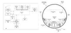
- FIG. 1is an example block diagram illustrating the components of a self-propelled device that is in the form of a spherical ball;
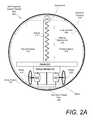
- FIG. 2Ais an example block diagram illustrating a self-propelled device
- FIG. 2Bis an example block diagram illustrating a self-propelled device with an alternative biasing mechanism
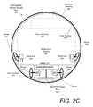
- FIG. 2Cis an example block diagram illustrating a self-propelled device with another alternative biasing mechanism to improve payload space
- FIG. 3is an example block diagram illustrating a self-propelled device including an attached camera therein;
- FIG. 4is an example block diagram illustrating a self-propelled device including a payload
- FIG. 5is an example schematic depiction of a self-propelled device and a controller device
- FIG. 6illustrates an example technique for causing motion of a self-propelled spherical device
- FIG. 7is an example block diagram depicting a sensor array and data flow
- FIG. 8illustrates an example system including a self-propelled device and a controller device to control and interact with the self-propelled device
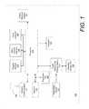
- FIG. 9is an example flow chart illustrating a method of operating a self-propelled device.
- a multi-purposed self-propelled devicewhich includes a drive system, a spherical housing, a biasing mechanism, and a payload space within the spherical housing.
- the biasing mechanismcan include single extended spring to engage an inner surface of the spherical housing diametrically opposed to a contact surface engaged by the drive system.
- the biasing mechanismcan include one or more (e.g., a pair) of portal axles each having a spring and contact element to push against a respective contact point in the inner surface of the spherical housing.
- the portal axlescan produce a vertical force that similarly actively forces the drive system to continuously engage the inner surface of the spherical housing in order to cause the spherical housing to move.
- the self-propelled devicecan be implemented to carry a payload or multiple payloads for various uses and activities.
- the payload spacecan be utilized to carry any payload.
- the payloadcan include a camera, which can send images and/or a video stream from the self-propelled device to a controller device.
- the controller devicecan be in the form of a smartphone, tablet, or any other suitable operating device.
- the spherical housingcan be transparent to allow the camera to take images or real time video, thereby allowing a user of the controller device (e.g. smartphone) to control the self-propelled device by viewing the video stream.
- the payload spaceincludes a single payload or multiple payloads for civilian or military use.
- payloadscan include one or more of: a camera, an infrared sensor, a chemical sensor, a biological sensor, one or more explosives, a listening device, or any other payload that can fit within the payload space.
- a touch a drive methodthat provides the user with the ability to dynamically control the self-propelled device by touching location points on a live image or video feed.
- the methodincludes receiving an image or live video feed from the self-propelled device that provides a field of view of the camera mounted within the self-propelled device. This video feed can be displayed on a touch-sensitive display of the controlled or mobile computing device.
- the methodfurther includes receiving, on the touch-sensitive display, a user selection of a location point within the field of view of the camera, and based on the user selection, generating a command signal to be transmitted to the self-propelled device instructing the self-propelled device to maneuver to the location point.
- the methodcan include determining a position of the location point in the field of view based on a first reference frame of the field of view as displayed on the controller device, and mapping the position of the location point on a second reference frame corresponding to the location point relative to the self-propelled device.
- the command signalis generated to include instructions for maneuvering the self-propelled device based solely on the second reference frame.
- the controller devicecan generate the command signal dynamically in conjunction with receiving the live video feed.
- FIG. 1is an example block diagram illustrating the components of a self-propelled device that is in the form of a spherical ball.
- a multi-purposed self-propelled device 100can be operated to move under control of another device, such as a computing device (e.g. a smartphone, tablet, and/or remote control) operated by a user.
- a computing devicee.g. a smartphone, tablet, and/or remote control
- the self-propelled device 100can be configured with resources that enable one or more of the following: (i) maintain self-awareness of orientation and/or position relative to an initial reference frame after the device initiates movement; (ii) process control input programmatically, so as to enable a diverse range of program-specific responses to different control inputs; (iii) enable another device to control its movement using software or programming logic that is communicative with programming logic on the self-propelled device; and/or (iv) generate an output response for its movement and state that it is software interpretable by the control device.
- the multi-purposed self-propelled device 100can include several interconnected subsystems and modules.
- a processor 114executes programmatic instructions from a program memory 104 .
- the instructions stored in the program memory 104can be changed, for example to add features, correct flaws, or modify behavior.
- the program memory 104stores programming instructions that are communicative or otherwise operable with software executing on a computing device.
- the processor 114can be configured to execute different programs of programming instructions, in order to after the manner in which the self-propelled device 100 interprets or otherwise responds to control input from another computing device.
- a wireless communication module 110in conjunction with a communication transducer 102 , can serve to exchange data between processor 114 and other external devices.
- the data exchangescan provide communications, provide control, provide logical instructions, state information, and/or provide updates for the program memory 104 .
- the processor 114can generate output corresponding to state and/or position information, that can then be communicated to the controller device via a wireless communication port.
- the mobility of the devicemakes wired connections undesirable. Therefore, the term “connection” can be understood to describe a logical link made without a physical attachment to the self-propelled device 100 .
- the wireless communication module 110can implement a BLUETOOTH communications protocol and the transducer 102 can be an antenna suitable for transmission and reception of BLUETOOTH signals.
- the wireless communication module 110can implement a Wi-Fi communications protocol and the transducer can be an antenna suitable for transmission and reception of Wi-Fi signals.
- the self-propelled device 100can be controlled by a controller device via BLUETOOTH and/or Wi-Fi signals.
- Other wireless communication mediums and protocolscan also be used in alternative implementations.
- Sensors 112can provide information about the surrounding environment and condition to the processor 114 .
- the sensors 112include inertial measurement devices, including a three-axis gyroscope, a three-axis accelerometer, and a three-axis magnetometer.
- the sensors 112can provide input to enable the processor 114 to maintain awareness of the device's orientation and/or position relative to the initial reference frame after the device initiates movement.
- the sensors 112can include instruments for detecting light, temperature, humidity, or measuring chemical concentrations or radioactivity.
- State/variable memory 106can store information about the state of the device, including, for example, position, orientation, rates of rotation and translation in each axis.
- the state/variable memory 106can also store information corresponding to an initial reference frame of the device upon, for example, the device being put in use (e.g., the device being activated), as well as position and orientation information once the device is in use.
- the self-propelled device 100can utilize information of the state/variable memory 106 in order to maintain position and orientation information of the self-propelled device 100 once the device is in operation.
- a clock 108can provide timing information to the processor 114 .
- the clock 108can provide a time base for measuring intervals and rates of change.
- the clock 108can provide day, date, year, time, and alarm functions. Further still, the clock 108 can allow the self-propelled device 100 to provide an alarm or alert at pre-set times.
- An expansion port 120can provide a connection for addition of accessories or devices. Expansion port 120 provides for future expansion, as well as flexibility to add options or enhancements. For example, expansion port 120 can be used to add peripherals, sensors, processing hardware, storage, displays, or actuators to the self-propelled device 100 .
- the expansion port 120can provide an interface capable of communicating with a suitably configured component using analog or digital signals.
- the expansion port 120can provide electrical interfaces and protocols that are standard or well-known.
- the expansion port 120can further implement an optical interface.
- interfaces appropriate for expansion port 120include a Universal Serial Bus (USB), Inter-Integrated Circuit Bus (I2C), Serial Peripheral Interface (SPI), or ETHERNET.
- a display 118presents information to outside devices or persons.
- the display 118can present information in a variety of forms.
- the display 118can produce light in colors and patterns, sound, vibration, or combinations of sensory stimuli.
- the display 118can operate in conjunction with actuators 126 to communicate information by physical movements of the self-propelled device 100 .
- the self-propelled device 100can be made to emulate a human head nod or shake to communicate “yes” or “no.”
- the display 118can be configured to emit light, either in the visible or invisible range. Invisible light in the infrared or ultraviolet range can be useful, for example, to send information invisible to human senses but available to specialized detectors.
- the display 118can include an array of Light Emitting Diodes (LEDs) emitting various light frequencies, arranged such that their relative intensity can be variable and the light emitted can be blended to form color mixtures.
- LEDsLight Emitting Diodes
- the display 118includes an LED array comprising several LEDs, each emitting a human-visible primary color.
- the processor 114can vary the relative intensity of each LED to produce a wide range of colors.
- Primary colors of lightare those wherein a few colors can be blended in different amounts to produce a wide gamut of apparent colors.
- Many sets of primary colors of lightare known, including for example red/green/blue, red/green/blue/white, and red/green/blue/amber.
- red, green, and blue LEDstogether comprise a usable set of three available primary-color devices comprising the display 118 .
- other sets of primary colors and white LEDscan be used.
- the display 118can include one or more LEDs used to indicate a reference point on the self-propelled device 100 for alignment.
- An energy storage unit 124stores energy for operating the electronics and electromechanical components of the self-propelled device 100 .
- the energy storage unit 124can be a rechargeable battery.
- An inductive charge port 128can allow for recharging the energy storage unit 124 without a wired electrical connection.
- inductive charge port 128can receive magnetic energy and convert it to electrical energy to recharge the energy storage unit 124 .
- the inductive charge port 128can provide a wireless communication interface with an external charging device.
- a plug in charging meanscan be included as an addition or alternative to the inductive charge port 128 .
- a deep sleep sensor 122can be included to place the self-propelled device 100 into a very low power or “deep sleep” mode where most of the electronic devices use no power. This may useful for long-term storage, shipping, and/or certain implementations of the self-propelled device 100 that require such a state.
- the self-propelled device 100can be implemented to carry a payload, such as a camera, a motion sensor, an infrared sensor and/or a chemical or biological sensor.
- the self-propelled device 100can sit dormant in the deep sleep mode until a trigger, such as an event setting off the camera or one or more sensors, automatically activates the self-propelled device 100 .
- the sensors 122can sense objects, events, incidents, matter, and/or phenomena through the spherical housing of self-propelled device 100 without a wired connection.
- the deep sleep sensor 122may be a Hall Effect sensor mounted in a manner such that an external magnet can be applied on the self-propelled device 100 to activate the deep sleep mode.
- the drive system actuators 126can convert electrical energy into mechanical energy for various uses.
- a primary use of the actuators 126can be to propel and steer the self-propelled device 100 .
- Movement and steering actuatorscan also be referred to as a drive system or traction system.
- the drive systemcauses rotational and translational movement of the self-propelled device 100 under control of the processor 114 .
- Examples of the actuators 126can include, for example, wheels, motors, solenoids, propellers, paddle wheels, and pendulums.
- the drive system actuators 126can include a set of two parallel wheels, each mounted to an axle connected to independently variable-speed motors through a reduction gear system.
- the operation of the two independently operated drive motorscan be controlled by processor 114 .
- the actuators 126may produce a variety of movements in addition to rotating and translating self-propelled device 100 .
- the actuators 126can cause self-propelled device 100 to execute communicative movements, including emulation of human gestures, for example, head nodding, shaking, trembling, spinning or flipping.
- the processorcoordinates the actuators 126 with the display 118 .
- the processor 114can provide signals to the actuators 126 and the display 118 to cause the self-propelled device 100 to spin or tremble and simultaneously emit patterns of colored light.
- the self-propelled device 100can emit light or sound patterns synchronized with movements.
- the self-propelled device 100can be used as a controller for other network-connected devices.
- the self-propelled device 100can contain sensors and wireless communication capabilities, so that it may perform a controller role for other devices.
- the self-propelled device 100may be held in the hand and used to sense gestures, movements, rotations, combination inputs and the like.
- FIG. 2Ais an example block diagram illustrating a self-propelled device.
- the self-propelled device 200can be multi-purposed and can include a spherical housing 202 , a drive system 201 , a biasing mechanism 215 , and a payload space 228 .
- the self-propelled device 200may be in the form of a robotic, spherical ball.
- the self-propelled device 200can be of a size and weight allowing it to be easily grasped, lifted, and carried in an adult human hand. In variations, the self-propelled device 200 may be larger or smaller, and/or customized for a particular payload.
- the self-propelled device 200may be manufactured to include a transparent spherical housing, and a camera may be included within the payload space to provide a video stream to the controller device, such as for example as smartphone or tablet, as shown by an example of FIG. 3 .
- the controller devicesuch as for example as smartphone or tablet, as shown by an example of FIG. 3 .
- the self-propelled device 200includes an outer spherical shell (or housing) 202 that makes contact with an external surface as the device rolls.
- the self-propelled device 200includes an inner surface 204 of the spherical housing 202 , wherein wheels 218 and 220 included as components of the drive system 201 make contact with the inner surface 204 to cause the self-propelled device 200 to move.
- the self-propelled device 200can include several mechanical and electronic components enclosed within the spherical housing 202 .
- the spherical housing 202can be at least partially composed of one or more materials that allow for the transmission of signals used for wireless communication, and yet can be impervious to moisture and dirt.
- the spherical housing 202 materialcan be durable, washable, and/or shatter resistant.
- the spherical housing 202can also be structured to enable transmission of light and can be textured to diffuse the light.
- the spherical housing 202can be made of a sealed polycarbonate plastic. In similar variations, at least one of the spherical housing 202 , or the inner surface 204 , can be textured to diffuse light. As an addition or an alternative, the spherical housing 202 can comprise two hemispherical shells with an associated attachment mechanism, such that the spherical housing 202 can be opened to allow access to the internal electronic and mechanical components. In similar variations, the spherical housing 202 can include automatic opening means configured to open the housing upon a command prompt by a user using the controller device.
- the spherical housing 202can be opened to deposit a payload placed in a payload space 228 , and then subsequently closed such that the user can continue maneuvering the self-propelled device 200 .
- the spherical housing 202can further include a treaded outer surface, or an outer surface that includes knobs and/or nodules for traction.
- a drive system 201can be included to enable the device to propel itself.
- the drive system 201can be coupled to processing resources and other control mechanisms as described above with reference to FIG. 1 .
- a carrier 214can be included to serve as an attachment point and support for electronic components of the self-propelled device 200 .
- the drive system 201 , energy storage unit 216 , carrier 214 , biasing mechanism 215 , other componentssuch as described above with reference to FIG.
- wheels 218 , 220 included in the drive system 201can be in frictional contact with the inner surface 204 of the spherical housing 202 , and can function to drive the spherical housing 202 by the action of the actuators.
- the carrier 214can be in mechanical and electrical contact with the energy storage unit 216 .
- the energy storage unit 216can provide a reservoir of energy to power the device and electronics and can be replenished via the inductive charge port 226 .
- the energy storage unit 216can a rechargeable battery and can be composed of lithium-polymer cells.
- the carrier 214can provide a mounting location for most of the internal components, including printed circuit boards for electronic assemblies, the sensor array, one or more antenna, and one or more connectors, as well as providing a mechanical attachment point for internal components. Further, the carrier 214 can provide a base for payloads being placed within the self-propelled device 200 . In this manner, the top surface of the carrier 214 can also be the floor of the payload space 228 . However, other configurations of the payload space 228 are contemplated, such as for example, a payload space 228 specially formed for a camera, or one that includes compartments for carrying multiple items.
- the drive system 201includes motors 222 , 224 and the wheels 218 , 220 .
- the motors 222 , 224connect to the wheels 218 , 220 independently through an associated shaft, axle, and gear drive (not shown).
- the wheels 218 , 220can be in physical contact with inner surface 204 .
- the points where wheels 218 , 220 contact the inner surface 204are an essential part of the drive mechanism of the self-propelled device 200 , and so are preferably coated with a material to increase friction and reduce slippage.
- the circumference of the wheels 218 , 220can be coated with silicone rubber tires.
- the biasing mechanism 215can be included to actively force the wheels 218 , 220 against the inner surface 204 .
- a spring 212 and spring end 210can comprise the biasing mechanism 215 . More specifically, the spring 212 and the spring end 210 can be positioned to contact the inner surface 204 at a point diametrically opposed to the wheels 218 , 220 . The spring 212 and the spring end 210 can provide contact force to reduce or substantially eliminate slippage of the wheels 218 , 220 .
- the spring 212is selected to provide a small force pushing wheels 218 , 220 , and the spring end 210 evenly against inner surface 204 .
- the spring end 210provides near-frictionless contact with the inner surface 204 .
- the spring end 210comprises a rounded or quasi-rounded surface configured to slide along the inner surface 204 as the self-propelled device 200 is driven by the drive system 201 . Additional means of providing near-frictionless contact can be included.
- the spring end 210can include one or more bearings to further reduce friction at the contact point where the spring end 210 moves along the inner surface 204 .
- the spring 212 and the spring end 210can be composed of a non-magnetic material to avoid interference with sensitive magnetic sensors.
- the payload space 228can be incorporated to carry a single payload or multiple payloads for civilian and/or military activities.
- the payload space 228can be arranged to carry any number of payloads, including, for example, one or more of: a camera for surveillance or remote video stream, an infrared sensor, a chemical or biological sensor to detect harmful agents, an explosive or flash bang that can be maneuvered into place and detonated, and/or a listening device.
- FIG. 2Bis an example block diagram illustrating a self-propelled device with an alternative biasing mechanism 217 .
- the biasing mechanism 217can incorporate a chassis 237 which can include one or more additional wheels 234 , 236 to increase or reconfigure the payload space 228 .
- the biasing mechanism 217can include a center post 238 configured to exert a force against the chassis 237 which can, in turn, press the additional wheels 234 , 236 against inner surface 204 of the spherical housing 202 .
- the center post 238may or may not include a spring 240 to aid in the biasing.
- the chassis 237may be placed proximate to the drive system 201 such that the wheels 218 , 220 , 234 , and 236 contact the inner surface 204 in the same hemisphere, as opposed to being diametrically opposite.
- the chassis 237may be positioned such that the center post 238 forms an angle, wherein the additional wheels 234 , 236 contact the inner surface 204 slightly above the equator (in a reference frame where the drive system 201 is positioned at the very bottom of the self-propelled device 200 ).
- These arrangements, and similar arrangementsmay be included to, for example, maximize or optimize the payload space 228 .
- FIG. 2Cis an example block diagram illustrating a self-propelled device with another alternative biasing mechanism to improve payload space 250 .
- an independent biasing mechanism 252can be included configured to actively force the drive system wheels 218 , 220 against the inner surface 204 , similar to the biasing mechanisms discussed above with respect to FIGS. 2A and 2B .
- the independent biasing mechanism 252is comprised of two or more separate portal axles 258 , 260 .
- the portal axles 258 , 260may include springs to press respective wheels 254 , 256 against the inner surface 204 with a force vector having a vertical value.
- the vertical force from the wheels 254 , 256 pressing against the inner surface 204in turn, actively forces the drive system 201 and its respective wheels 254 , 256 against the inner surface 204 as well, thereby providing sufficient force for the drive system 201 to cause the self-propelled device 200 to move.
- the independent biasing mechanism 252 with its two or more portal axles 258 , 260allows for significantly increased payload space 250 , whereby any number of different types or sizes of payload (e.g. a camera, infrared sensor, chemical or biological sensor, one or more explosives, a listening device, etc.) can be positioned within the space 250 .
- payloade.g. a camera, infrared sensor, chemical or biological sensor, one or more explosives, a listening device, etc.
- the interior of the self-propelled device 200can be cleared to provide a spacious interior.
- the portal axles 258 , 260 comprising the independent biasing mechanism 252can be mounted directly onto the carrier 214 .
- the springs corresponding to the portal axles 258 , 260may be in the form of torsion springs which force the wheels 254 , 256 against the inner surface 204 .
- the springsmay be comprised of one or more of a compression spring, clock spring, or tension spring.
- the portal axles 258 , 260can be mounted in such a manner in which no springs are included to maintain a force pressing the drive system 201 and wheels 218 , 220 against the inner surface 204 , allowing sufficient traction to cause the self-propelled device 200 to move.
- FIG. 3is an example block diagram illustrating a self-propelled device including a camera.
- the multi-purpose self-propelled device 300can include a camera 302 mounted within the payload space 310 .
- the spherical housing 304is transparent to allow the camera 302 to view outside the self-propelled device 300 .
- the camera 302can be mounted on the biasing mechanism, or otherwise mounted within the self-propelled device 300 in order to maintain a substantially level orientation.
- the camera 302can be mounted to the carrier 314 to achieve the same.
- the camera 302can be mounted on a gyroscope or other stabilizing means so that the camera's orientation can be more substantially level with an outside reference frame.
- the stabilizing means(not shown) can be mounted on the biasing mechanism 315 and/or the carrier 314 in order to achieve further stability and to further maintain orientation.
- the camera 302can be mounted to the carrier 314 .
- the camera 302can further be coupled to the wireless communication module.
- the camera 302can provide photographs and/or a video stream to the controller device 306 by way of a wireless link 308 .
- the self-propelled devicecan be remotely controlled by a user using the controller device 306 via the wireless link 308 .
- the self-propelled device 300can be controlled utilizing the video stream, and therefore, the user need not be in visual sight of the self-propelled device 300 in order to maintain effective operation.
- the camera 302can be any photo or video recording device.
- the camera 302can itself contain wireless communication means, such that it may directly link with the controller device 306 .
- the camera 302can be coupled to the processor and the video stream may be fed to the controller device 306 via the wireless module included in the system as described above with respect to FIG. 1 .
- the controller device 306can be a remote control, smartphone, tablet, or a customized device capable of storing and executing applications or instructions to operate the self-propelled device 300 .
- the controller device 306can be in the form of a smartphone or tablet, and operation of the self-propelled device can be executed by way of an application stored in the smartphone or tablet.
- the controller device 306 and self-propelled device 300can be manufactured as a combined system specially manufactured for one or more purposes.
- the combined system of the self-propelled device 300 and the controller device 306can be used specifically for surveillance.
- an application of the controller device 306can include a “touch and drive” feature, wherein the user can touch the display of the controller device 306 corresponding to a selected location, and caused the self-propelled device 300 to maneuver to that location.
- the “touch and drive” featurecan further allow the user to select a location on the display of the controller device 306 , where the selected location corresponds to the same location on the video stream. In other words, the user can “touch” a location on the video stream from the self-propelled device 300 , and the self-propelled device 300 will automatically maneuver itself to that location.
- FIG. 4is an example block diagram illustrating a self-propelled device including a payload.
- the self-propelled deviceincludes a payload space 406 to carry and transport specific items or payload 404 for various activities.
- Such itemscan include one or more of: an infrared sensor, a chemical or biological sensor, an explosive or flash bang, a listening device, other mechanical devices, and the like. Any one or more of these items can further be included in variations including a camera as described above with reference to FIG. 3 .
- the self-propelled device 400includes a payload space 406 for carrying a payload 404 .
- the self-propelled device 400can be constructed in manner in which it can be thrown by a user, and then controlled via the controller device 412 .
- a protective cover 402can be included to dampen shock when, for example, the self-propelled device 400 is thrown by a user.
- the protective cover 402can be removable and/or can be configured to break away from the self-propelled device 400 during periods of extreme shock. In such examples, the self-propelled device 400 can break free of the protective cover 402 and proceed with its intended purpose.
- the protective cover 402can be included to seal or waterproof the self-propelled device 400 .
- the self-propelled device 400can be further configured to float or sink depending on its intended application.
- the self-propelled device 400can float when deposited into water in order to be easily retrievable.
- Examples as shown in FIG. 4can be manufactured for a singular purpose, or can be configured to be loaded and unloaded multiple times.
- the lattercan include a spherical housing 408 and/or a protective cover 402 that can be readily opened or closed by a user.
- Single purpose examplescan be manufactured to be permanently sealed, and the payload 404 of such arrangements can be selected for the singular purpose.
- the payload 404can be an explosive, where the self-propelled device 400 is utilized for a single use. As implemented, the self-propelled device 400 can be maneuvered to a selected location and then detonated, effectively destroying the self-propelled device 400 .
- the self-propelled device 400can be configured to open upon a command prompt by a user and deposit its payload 404 at a selected location. The user can then cause the spherical housing 408 to close using the controller device 412 and proceed to continue maneuvering the self-propelled device 400 .
- the self-propelled device 400 and controller device 412can include the “touch and drive” feature as described above with respect to FIG. 4 .
- FIG. 5is an example schematic depiction of a self-propelled device 514 and a controller device 508 . More specifically, the self-propelled device 514 can be controlled in its movement by programming logic and/or controls that can originate from the controller device 508 . The self-propelled device 514 is capable of movement under control of the controller device 508 , which can be operated by a user 502 . The controller device 508 can wirelessly communicate control data to the self-propelled device 514 using a standard or proprietary wireless communication protocol. In variations, the self-propelled device 514 can be at least partially self-controlled, utilizing sensors and internal programming logic to control the parameters of its movement (e.g., velocity, direction, etc.).
- the parameters of its movemente.g., velocity, direction, etc.
- the self-propelled device 514can communicate data relating to the device's position and/or movement parameters for the purpose of generating or alternating content on the controller device 508 .
- self-propelled device 514can control aspects of the controller device 508 by way of its movements and/or internal programming logic.
- the self-propelled device 514can have multiple modes of operation, including those of operation in which the device is controlled by the controller device 508 , is a controller for another device (e.g., another self-propelled device or the controller device 508 ), and/or is partially or wholly self-autonomous.
- the self-propelled device 514 and the controller device 508can share a computing platform on which programming logic is shared, in order to enable, among other features, functionality that includes: (i) enabling the user 502 to operate the controller device 508 to generate multiple inputs, including simple directional input, command input, gesture input, motion or other sensory input, voice input or combinations thereof; (ii) enabling the self-propelled device 514 to interpret inputs received from the controller device 508 as a command or set of commands; and/or (iii) enabling the self-propelled device 514 to communicate data regarding that device's position, movement and/or state in order to effect a state on the controller device 508 (e.g., display state, such as content corresponding to a controller-user interface).
- the self-propelled device 514can include a programmatic interface that facilitates additional programming logic and/or instructions to use the device.
- the controller device 508can execute programming that is communicative with the programming logic on the self-propelled device 514 .
- the self-propelled device 514can include an actuator or drive mechanism causing motion or directional movement.
- the self-propelled device 514can be referred to by a number of related terms and phrases, including controlled device, robot, robotic device, remote device, autonomous device, and remote-controlled device.
- the self-propelled device 514can be structured to move and be controlled in various media.
- the self-propelled device 514can be configured for movement in media such as on flat surfaces, sandy surfaces, or rocky surfaces.
- the self-propelled device 514can be implemented in various forms.
- the self-propelled device 514can correspond to a spherical object that can roll and/or perform other movements such as spinning.
- the self-propelled device 514can correspond to a radio-controlled aircraft, such as an airplane, helicopter, hovercraft or balloon.
- the self-propelled device 514can correspond to a radio controlled watercraft, such as a boat or submarine. Numerous other variations can also be implemented, such as those in which the self-propelled device 514 is a robot.
- the self-propelled device 514can include a sealed hollow housing, roughly spherical in shape, capable of directional movement by action of actuators inside the enclosing envelope.
- the self-propelled device 514can be configured to communicate with the controller device 508 using network communication links 510 and 512 .
- Link 510can transfer data from the controller device 508 to the self-propelled device 514 .
- Link 512can transfer data from the self-propelled device 514 to the controller device 508 .
- Links 510 and 512are shown as separate unidirectional links for illustration. As an example, a single bi-directional communication link performs communication in both directions.
- Link 510 and link 512are not necessarily identical in type, bandwidth or capability.
- communication link 510 from controller device 508 to self-propelled device 514is often capable of a higher communication rate and bandwidth compared to link 512 . In some situations, only one link 510 or 512 is established. In such examples, communication is unidirectional.
- the controller device 508can correspond to any device comprising at least a processor and communication capability suitable for establishing at least unidirectional communications with the self-propelled device 514 .
- Examples of such devicesinclude, without limitation: mobile computing devices (e.g., multifunctional messaging/voice communication devices such as smart phones), tablet computers, portable communication devices and personal computers.
- the controller device 508is an IPHONE available from APPLE COMPUTER, INC. of Cupertino, Calif.
- the controller device 508is an IPAD tablet computer, also from APPLE COMPUTER.
- the controller device 508is any of the handheld computing and communication appliances executing the ANDROID operating system from GOOGLE, INC.
- the controller device 508can be a personal computer, in either a laptop or desktop configuration.
- the controller device 508can be a multi-purpose computing platform running the MICROSOFT WINDOWS operating system, or the LINUX operating system, or the APPLE OS/X operating system, configured with an appropriate application program to communicate with the self-propelled device 514 .
- controller device 508can be a specialized device dedicated for enabling the user 502 to control and interact with the self-propelled device 514 .
- controller devices 508can be used interchangeably to communicate with the self-propelled device 514 .
- the self-propelled device 514can be capable of communicating and/or being controlled by multiple devices (e.g., concurrently or one at a time).
- the self-propelled device 514can be capable of being linked with an IPHONE in one session and with an ANDROID device in a later session, without modification of the device 514 .
- the user 502can interact with the self-propelled device 514 via the controller device 508 , in order to control the self-propelled device 514 and/or to receive feedback or interaction on the controller device 508 from the self-propelled device 514 .
- the user 502can specify a user input 504 through various mechanisms that are provided with the controller device 508 . Examples of such inputs include text entry, voice command, touching a sensing surface or screen, physical manipulations, gestures, taps, shaking and combinations of the above.
- the user 502can interact with the controller device 508 in order to receive feedback 506 .
- the feedback 506can be generated on the controller device 508 in response to user input.
- the feedback 506can also be based on data communicated from the self-propelled device 514 to the controller device 508 , regarding, for example, the self-propelled device's 514 position or state.
- examples of feedback 506include text display, graphical display, sound, music, tonal patterns, modulation of color or intensity of light, haptic, vibrational or tactile stimulation.
- the feedback 506can be combined with input that is generated on the controller device 508 .
- the controller device 508can output content that can be modified to reflect position or state information communicated from the self-propelled device 514 .
- controller device 508 and/or the self-propelled device 514can be configured such that user input 504 and feedback 506 maximize usability and accessibility for the user 502 , who has limited sensing, thinking, perception, motor or other abilities. This allows users with handicaps or special needs to operate the system 500 as described.
- a configuration as illustrated in FIG. 5can be only one of an almost unlimited number of possible configurations of networks including a self-propelled device 514 with communication connections.
- numerous variations described hereinprovide for a user to operate or otherwise directly interface with the controller device 508 in order to control and/or interact with a self-propelled device, variations described encompass enabling the user to directly control or interact with the self-propelled device 514 without use of an intermediary device such as the controller device 508 .
- FIG. 6illustrates an example technique for causing motion of a self-propelled spherical device 600 .
- the device 600has a center of rotation 602 and a center of mass 606 , the device 600 being contact with planar surface 612 .
- the drive mechanism for the robotic device 600comprises two independently-controlled wheeled actuators 608 in contact with the inner surface of the enclosing spherical envelope of device 600 . Also shown is sensor platform 604 .
- sensor platform 604Also shown in sensor platform 604 .
- the displacement of center of mass 606 relative to center of rotation 602can be maintained by action of wheeled actuators 608 .
- the displacement of the center of mass 606 relative to the center of rotation 602is difficult to measure, thus it is difficult to obtain feedback for a closed-loop controller to maintain constant velocity.
- the displacementis proportional to the angle 610 between sensor platform 604 and surface 612 .
- the angle 610can be sensed or estimated from a variety of sensor inputs, as described herein. Therefore, the speed controller for robotic device 600 can be implemented to use angle 610 to regulate speed for wheeled actuators 608 causing the device 600 to move at a constant speed across the surface 612 .
- the speed controllercan determine the desired angle 610 to produce the desired speed, and the desired angle set point can be provided as an input to a closed loop controller regulating the drive mechanism.
- FIG. 6illustrates use of angle measurement for speed control.
- the techniquecan further be extended to provide control of turns and rotations, with feedback of appropriate sensed angles and angular rates.
- FIG. 7is an example block diagram depicting a sensor array and data flow.
- the sensor array 712can include a set of sensors for providing information to the self-propelled device, including for example, its position, orientation, rates of translation, rotation, and acceleration. Many other sensors can be included to meet requirements in various examples.
- the sensor array 712can include a three-axis gyroscopic sensor 702 , a three-axis accelerometer sensor 704 , and a three-axis magnetometer sensor 706 .
- a receiver for a Global Positioning System (GPS)is included 710 .
- GPSGlobal Positioning System
- GPS signalsare typically unavailable indoors, so the GPS receiver can be omitted.
- the sensors in sensor array 712can be miniaturized devices employing micro-electro-mechanical (MEMS) technology.
- MEMSmicro-electro-mechanical
- the data from these sensorscan require filtering and processing to produce accurate state estimates 716 .
- Various algorithmscan be employed in sensor fusion and state estimator 714 . These algorithms can be executed by the processor on the self-propelled device.
- the signals from sensor in sensor array 712can be imperfect and distorted by noise, interference, and the limited capability of inexpensive sensors.
- the sensorscan also provide redundant information, so that application of a suitable sensor fusion and state estimator process 714 can provide an adequate state estimation 716 of the true state of the self-propelled device.
- magnetometer datais distorted by stray magnetic fields and ferrous metals in the vicinity.
- Sensor fusion and state estimator 714can be configured to reject bad or suspect magnetometer data and rely on the remaining sensors in estimating the state 716 of the self-propelled device.
- particular movements of the self-propelled devicecan be used to improve sensor data for desired purposes. For example, it can be useful to rotate self-propelled device through an entire 360 degree heading sweep while monitoring magnetometer data, to map local magnetic fields. Since the fields are usually relatively invariant over a short period of time, the local field measurement is repeatable and therefore useful, even if distorted.
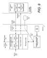
- FIG. 8illustrates an example system including a self-propelled device 810 and a controller device 850 that controls and interacts with the self-propelled device 810 .
- the self-propelled device 810can be constructed using hardware resources such as described by examples of FIG. 1 . Accordingly, the self-propelled device 810 can be a spherical object such as described by examples with respect to FIGS. 2-4 .
- the controller device 850can be a multifunctional device, such as a mobile computing device (e.g., smart phone), tablet, or personal computer. Alternatively, the controller device 850 can correspond to a specialized device that is dedicated to controlling and communicating with the self-propelled device 810 .
- the self-propelled device 810can execute one or more programs 816 stored in a program library 820 .
- Each program 816 in the program library 820can include instructions or rules for operating the device, including instructions for how the device is to respond to specific conditions, how the device is to respond to a control input 813 (e.g., user input entered on the controller device 850 ), and/or the mode of operation that the device is to implement (e.g., controlled mode, versus autonomous, etc.).
- the program library 820can also maintain an instruction set that can be shared by multiple programs, including instructions that enable some user inputs to be interpreted in a common manner.
- An application program interface (API) 830can be implemented on the device 810 to enable programs to access a library of functions and resources of the device.
- the API 830can include functions that can be used with programs to implement motor control (e.g., speed or direction), state transition, sensor device interpretation, and/or wireless communications.
- the device 810can receive programs and programming instructions wirelessly through the use of a wireless communication port 812 .
- the device 810can receive programs and programming instructions 882 from external sources 880 via other ports, such as an expansion port 120 (see FIG. 1 ).
- the programming resourcescan originate from, for example, a media provided to the user of the device (e.g., SD card), a network resource or website where programs can be downloaded, and/or programs and/or instruction sets communicated via the wireless communication port 812 from the controller device 850 .
- the controller device 850can be programmatically configured to interact and/or control the self-propelled device 810 with software.
- the controller device 850can communicate instructions coinciding with its programmatic configuration to the self-propelled device 810 .
- the controller device 850can download an application for controlling or interacting with the self-propelled device 810 .
- the applicationcan be downloaded from, for example, a network (e.g., from an App Store), or from a website, using wireless communication capabilities inherent in the controller device 850 (e.g., cellular capabilities, Wi-Fi capabilities, etc.).
- the application that is downloaded by the controller device 850can include an instruction set that can be communicated to the self-propelled device 810 .
- the controller device 850can execute a program 856 that is specialized or otherwise specific to communicating or interacting with, and/or controlling the self-propelled device 810 .
- the program 856 that executes on the controller device 850can include a counterpart program 816 A that can execute on the self-propelled device 810 .
- the programs 856 , 816 Acan execute as a shared platform or system.
- the program 856 operating on the controller device 850can cooperate with the counterpart runtime program 816 A to generate input for the self-propelled device 810 , and to generate output on the controller device 850 based on a data signal from the self-propelled device 810 .
- the program 856can generate a user interface 860 that (i) prompts or provides guidance for the user to provide input that is interpretable on the self-propelled device 810 as a result of the counterpart runtime program 816 A, resulting in some expected outcome from the self-propelled device 810 ; and (ii) receives feedback 818 from the self-propelled device 810 in a manner that affects the content that is output by the program 856 operating on the controller device 850 .
- computer-generated contentcan be altered based on positioning or movement of the self-propelled device 810 .
- the program 856can provide a user interface 860 , including logic 862 for prompting and/or interpreting user input on the controller device.
- Various forms of inputcan be entered on the controller device 850 , including, for example, user interaction with mechanical switches or buttons, touchscreen input, audio input, gesture input, or movements of the device in a particular manner.
- the program 856can be configured to utilize an inherent application program interface on the controller device 850 , to utilize the various resources of the device to receive and process input.
- Many existing multifunctional or general purpose computing devicese.g., smart phones or tablets
- touchscreen inpute.g., multi-touch input or gesture input
- optical inpute.g., camera image sensing input
- audio input and device movement inpute.g., shaking or moving the entire device.
- the user interface 860can include logic 862 to prompt the user for specific kinds of input (e.g., include visual markers where a user should place fingers, instruct the user or provide the user with the visual and/or audio prompt to move the device, etc.), and to interpret the input into control information that is signaled to the self-propelled device 810 .
- specific kinds of inpute.g., include visual markers where a user should place fingers, instruct the user or provide the user with the visual and/or audio prompt to move the device, etc.
- the input generated on the controller device 850can be interpreted as a command and then signaled to the self-propelled device 810 .
- the input entered on the controller device 850can be interpreted as a command by programmatic resources on the self-propelled device 810 .
- the self-propelled device 810can respond to user input in a manner that is intelligent and configurable.
- the self-propelled device 810can interpret user input that is otherwise directional in nature in a manner that is not directional.
- a usercan enter gesture input corresponding to a direction, in order to have the self-propelled device 810 move in a manner that is different than the inherent direction in the user input.
- a usercan enter a leftward gesture, which the device can interpret (based on the runtime program 816 A) as a command to stop, spin, return home, or alter illumination output, etc.
- the user interface 860can also include output logic 864 for interpreting data received from the self-propelled device 810 .
- the self-propelled device 810can communicate information, such as state information and/or position information (e.g., such as after when the device moves) to the controller device 850 .
- the communication from the self-propelled device 810 to the controller device 850can be in response to a command interpreted from user input on the controller device 850 .
- the communication from the self-propelled device 810can be in the form of continuous feedback generated as result of the device's continuous movement over a duration of time.
- the output onto device 850can correspond to a controller device having one of various possible form factors.
- the program 856can configure the interface to graphically provide gaming context and/or different user-interface paradigms for controlling the self-propelled device 810 .
- the program 856can operate to directly affect the content generated in these implementations based on movement, position, or state of the self-propelled device 810 .
- the self-propelled device 810can implement the programmatic runtime 816 A using one or more sets of program instructions stored in its program library 820 .
- the program runtime 816 Acan correspond to, for example, a program selected by the user, or one that is run by default or in response to some other condition or trigger.
- the program runtime 816 Acan execute a set of program-specific instructions that utilizes device functions and/or resources in order to: (i) interpret control input from the controller device 850 ; (ii) control and/or state device movement based on the interpretation of the input; and/or (iii) communicate information from the self-propelled device 810 to the controller device 850 .
- the program runtime 816 Acan implement drive control logic 831 , including sensor control logic 821 and input control logic 823 .
- the sensor control logic 821can interpret device sensor input 811 for controlling speed, direction, or other movement of the self-propelled device's drive system or assembly.
- the sensor input 811can correspond to data such as provided from the accelerometer(s), magnetometer(s), and/or gyroscope(s) of the self-propelled device 810 .
- the sensor datacan also include other information obtained on a device regarding the device's movement, position, state or operating conditions, including GPS data, temperature data, etc.
- the program 816 Acan implement parameters, rules or instructions for interpreting sensor input 811 as drive assembly control parameters 825 .
- the input control logic 823can interpret control input 813 received from the controller device 850 .
- the logic 823can interpret the input as a command, in outputting drive assembly control parameters 825 that are determined from the input 813 .
- the input drive logic 823can also be program specific, so that the control input 813 and/or its interpretation are specific to the runtime program 816 A.
- the drive assembly control logiccan use the parameters, as generated through sensor/input control logic 821 , 823 to implement drive assembly controls.
- the sensor/input control logic 821 , 823can be used to control other aspects of the self-propelled device 810 .
- the sensor/input control logic 821 , 823can execute runtime program 816 A instructions to generate a state output 827 that can control a state of the device in response to some condition, such as user input or device operation condition (e.g., the device comes to stop).
- a state output 827can control a state of the device in response to some condition, such as user input or device operation condition (e.g., the device comes to stop).
- an illumination outpute.g., LED display out
- audio outpute.g., audio output
- device operational statuse.g., mode of operation and/or power state
- the run time program 816 Acan generate an output interface 826 for the self-propelled device program 856 running on the controller device 850 .
- the output interface 826can generate the data that comprises feedback 818 .
- the output interface 826can generate data that is based on position, movement (e.g., velocity, rotation), state (e.g., state of output devices), and/or orientation information (e.g., position and orientation of the device relative to the initial reference frame).
- the output interface 826can also generate data that, for example, identifies events that are relevant to the runtime program 816 A.
- the output interface 826can identify events such as the device being disrupted in its motion or otherwise encountering a disruptive event.
- the output interface 826can also generate program specific output, based on, for example, instructions of the runtime program 816 A.
- the run-time program 816 Acan require a sensor reading that another program would not require.
- the output interface 826can implement instructions for obtaining the sensor reading in connection with other operations performed through implementation of the runtime program 816 A.
- the self-propelled device 810can be operable in multiple modes relative to the controller device 850 .
- the self-propelled device 810can be controlled in its movement and/or state by control input 813 via control signals communicated from the controller device 850 .
- the self-propelled device 810can pair with the controller device 850 in a manner that affects operations on the controller device 850 as to control or feedback.
- the self-propelled device 810can also be operable in an autonomous mode, where control parameters 825 are generated programmatically on the device in response to, for example, sensor input 811 and without need for control input 813 .
- the self-propelled device 810can be operated along with the controller device 850 in a “touch and drive” mode, wherein the user can touch a selected location on a video stream of the self-propelled device 810 , and the self-propelled device 810 can autonomously maneuver to the corresponding location. Still further, in variations, the self-propelled device 810 can act as a controller, either for the controller device 850 or for another self-propelled device 810 . For example, the device can move to affect a state of the controller device 850 . The device can operate in multiple modes during one operating session. The mode of operation can be determined by the runtime program 816 A.
- the self-propelled device 810can include a library of instruction sets for interpreting control input 813 from the controller device 850 .
- the self-propelled devicecan store instructions for multiple programs, and the instructions for at least some of the programs can include counterpart programs that execute on the controller device 850 .
- the library maintained on the self-propelled devicecan be dynamic, in that the instructions stored can be added, deleted or modified. For example, a program stored on the self-propelled device can be added, or another program can be modified.
- each programWhen executed on the controller device 850 , each program includes instructions to recognize a particular set of inputs, and different programs can recognize different inputs. For example, a golf program can recognize a swing motion on the controller device 850 as an input, while the same motion can be ignored by another program that is dedicated to providing a virtual steering mechanism.
- each programWhen executed on the self-propelled device 810 , each program can include instructions to interpret or map the control input 813 associated with a particular recognized input to a command and control parameter.
- the self-propelled devicecan be able to dynamically reconfigure its program library. For example a program can be modified (e.g., through instructions received by the controller device 810 ) to process control input 813 that corresponds to a new recognized input.
- the self-propelled device 810can be able to switch programs while the self-propelled device 810 is in use. When programs are switched, a different set of inputs can be recognized, and/or each input can be interpreted differently on the self-propelled device 810 .
- FIG. 9is a flow chart illustrating an example method of operating a self-propelled device.
- a user of a controller devicee.g., a smart phone, table, remote control, or other mobile computing device
- the self-propelled deviceneed not be spherical in nature, but rather can be any device capable of being controlled by a controller device as described herein.
- the self-propelled devicecan be configured to include, among other features, a transparent spherical housing, a camera positioned within the housing, and a wireless link which can stream the video feed to the controller device.
- the controller devicecan receive the feed from the camera positioned within the self-propelled device ( 900 ). Further, the controller device can include a display screen, such that the feed can be displayed on the controller device ( 902 ). The controller device can include touch screen features that allow the user to interact directly with the displayed feed.
- the usercan then select an object or location point on the displayed video feed. Accordingly, the user selection of the location point is received by the controller device ( 904 ). The user can select the location point by touching an object on the screen corresponding to the physical object in the self-propelled device's frame of reference. Additionally or alternatively, the user can provide voice commands that identify the object being displayed. Upon receiving the selection by the user, the controller device can then generate a command signal based on position information to the self-propelled device, causing it to traverse to the physical location point ( 908 ). The self-propelled device can traverse directly to the object, or perform maneuvers around obstacles to ultimately arrive at the object's location.
- the controller devicecan be further configured to determine a position of the object depicted on the display screen based on the user's and/or controller device's reference frame.
- the controller devicecan also map the relative position of the location point displayed on the controller device with a position of the location point in the self-propelled device's reference frame ( 906 ).
- the self-propelled devicecan be directed by the controller device to traverse to the location of the object based on the mapped relative positions via the image/video feed, wherein the controller device can include processing means to calculate the relative positions.
- One or more examples described hereinprovide that methods, techniques and actions performed by a computing device are performed programmatically, or as a computer-implemented method. Programmatically means through the use of code, or computer-executable instructions. A programmatically performed step may or may not be automatic.
- a programmatic module or componentmay include a program, a subroutine, a portion of a program, or a software component or a hardware component capable of performing one or more stated tasks or functions.
- a module or componentcan exist on a hardware component independently of other modules or components. Alternatively, a module or component can be a shared element or process of other modules, programs or machines.
- one or more examples described hereinmay be implemented through the use of instructions that are executable by one or more processors. These instructions may be carried on a computer-readable medium.
- Machines shown or described with FIGs belowprovide examples of processing resources and computer-readable mediums on which instructions for implementing examples of the invention can be carried and/or executed.
- the numerous machines shown with examples of the inventioninclude processor(s) and various forms of memory for holding data and instructions.
- Examples of computer-readable mediumsinclude permanent memory storage devices, such as hard drives on personal computers or servers.
- Other examples of computer storage mediumsinclude portable storage units (such as CD or DVD units), flash memory (such as carried on many cell phones and tablets)), and magnetic memory.
- Computers, terminals, network enabled devicesare all examples of machines and devices that utilize processors, memory and instructions stored on computer-readable mediums. Additionally, examples may be implemented in the form of computer-programs, or a computer usable carrier medium capable of carrying such a program.
Landscapes
- Engineering & Computer Science (AREA)
- Radar, Positioning & Navigation (AREA)
- Remote Sensing (AREA)
- Physics & Mathematics (AREA)
- General Physics & Mathematics (AREA)
- Automation & Control Theory (AREA)
- Aviation & Aerospace Engineering (AREA)
- Computer Networks & Wireless Communication (AREA)
- Transportation (AREA)
- Mechanical Engineering (AREA)
- Combustion & Propulsion (AREA)
- Chemical & Material Sciences (AREA)
- Business, Economics & Management (AREA)
- Health & Medical Sciences (AREA)
- Artificial Intelligence (AREA)
- Evolutionary Computation (AREA)
- Game Theory and Decision Science (AREA)
- Medical Informatics (AREA)
- Control Of Position, Course, Altitude, Or Attitude Of Moving Bodies (AREA)
Abstract
Description
This application claims priority to U.S. Provisional Patent Application Ser. No. 61/820,109, entitled, “MULTI-PURPOSED SELF-PROPELLED DEVICE,” filed May 6, 2013; the aforementioned application being hereby incorporated by reference in its entirety.
This application is a Continuation-in-Part of U.S. patent application Ser. No. 14/035,841, entitled “SELF-PROPELLED DEVICE WITH ACTIVELY ENGAGED DRIVE SYSTEM”, filed Sep. 24, 2013; which is a Continuation of Ser. No. 13/342,853, entitled “SELF-PROPELLED DEVICE WITH ACTIVELY ENGAGED DRIVE SYSTEM”, filed Jan. 3, 2012, now U.S. Pat. No. 8,571,781, issued Oct. 29, 2013; which claims benefit of priority to the following: U.S. Provisional Application No. 61/430,023, entitled “METHOD AND SYSTEM FOR CONTROLLING A ROBOTIC DEVICE, filed Jan. 5, 2011; U.S. Provisional Application No. 61/430,083, entitled “SYSTEM AND METHOD FOR ESTABLISHING 2-WAY COMMUNICATION FOR CONTROLLING A ROBOTIC DEVICE”, filed Jan. 5, 2011 and U.S. Provisional Application No. 61/553,923, entitled “A SELF-PROPELLED DEVICE AND SYSTEM FOR CONTROLLING SAME”, filed Oct. 31, 2011; all of the aforementioned priority applications being hereby incorporated by reference in their respective entirety for all purposes.
Examples described herein relate to a multi-purpose remotely controllable self-propelled device.
Various types of remotely controllable devices exist. For example hobbyists often operate remote controlled devices in the form of cars, trucks, airplanes and helicopters. Such devices typically receive commands from a controller device, and after movement (e.g., direction or velocity) based on the input. Some devices use software-based controllers, which can be implemented in the form of an application running on a device such as a smart phone or a tablet.
The disclosure herein is illustrated by way of example, and not by way of limitation, in the figures of the accompanying drawings in which like reference numerals refer to similar elements, and in which:
A multi-purposed self-propelled device is provided which includes a drive system, a spherical housing, a biasing mechanism, and a payload space within the spherical housing. The biasing mechanism can include single extended spring to engage an inner surface of the spherical housing diametrically opposed to a contact surface engaged by the drive system. Alternatively, the biasing mechanism can include one or more (e.g., a pair) of portal axles each having a spring and contact element to push against a respective contact point in the inner surface of the spherical housing. As such, the portal axles can produce a vertical force that similarly actively forces the drive system to continuously engage the inner surface of the spherical housing in order to cause the spherical housing to move. The self-propelled device can be implemented to carry a payload or multiple payloads for various uses and activities.
The payload space can be utilized to carry any payload. For example, the payload can include a camera, which can send images and/or a video stream from the self-propelled device to a controller device. The controller device can be in the form of a smartphone, tablet, or any other suitable operating device. Further, the spherical housing can be transparent to allow the camera to take images or real time video, thereby allowing a user of the controller device (e.g. smartphone) to control the self-propelled device by viewing the video stream.
In still other variations, the payload space includes a single payload or multiple payloads for civilian or military use. Such payloads can include one or more of: a camera, an infrared sensor, a chemical sensor, a biological sensor, one or more explosives, a listening device, or any other payload that can fit within the payload space.
For variations including a camera or other image capturing device, a touch a drive method is disclosed that provides the user with the ability to dynamically control the self-propelled device by touching location points on a live image or video feed. The method includes receiving an image or live video feed from the self-propelled device that provides a field of view of the camera mounted within the self-propelled device. This video feed can be displayed on a touch-sensitive display of the controlled or mobile computing device. The method further includes receiving, on the touch-sensitive display, a user selection of a location point within the field of view of the camera, and based on the user selection, generating a command signal to be transmitted to the self-propelled device instructing the self-propelled device to maneuver to the location point.
Furthermore, the method can include determining a position of the location point in the field of view based on a first reference frame of the field of view as displayed on the controller device, and mapping the position of the location point on a second reference frame corresponding to the location point relative to the self-propelled device. In such arrangements, the command signal is generated to include instructions for maneuvering the self-propelled device based solely on the second reference frame. Further still, for live video feed implementations, the controller device can generate the command signal dynamically in conjunction with receiving the live video feed.
System Overview
Referring to the drawings,FIG. 1 is an example block diagram illustrating the components of a self-propelled device that is in the form of a spherical ball. A multi-purposed self-propelleddevice 100 can be operated to move under control of another device, such as a computing device (e.g. a smartphone, tablet, and/or remote control) operated by a user. The self-propelled device 100 can be configured with resources that enable one or more of the following: (i) maintain self-awareness of orientation and/or position relative to an initial reference frame after the device initiates movement; (ii) process control input programmatically, so as to enable a diverse range of program-specific responses to different control inputs; (iii) enable another device to control its movement using software or programming logic that is communicative with programming logic on the self-propelled device; and/or (iv) generate an output response for its movement and state that it is software interpretable by the control device.
For example, the multi-purposed self-propelleddevice 100 can include several interconnected subsystems and modules. Aprocessor 114 executes programmatic instructions from aprogram memory 104. The instructions stored in theprogram memory 104 can be changed, for example to add features, correct flaws, or modify behavior. In some examples, theprogram memory 104 stores programming instructions that are communicative or otherwise operable with software executing on a computing device. Theprocessor 114 can be configured to execute different programs of programming instructions, in order to after the manner in which the self-propelled device 100 interprets or otherwise responds to control input from another computing device.
Awireless communication module 110, in conjunction with acommunication transducer 102, can serve to exchange data betweenprocessor 114 and other external devices. The data exchanges, for example, can provide communications, provide control, provide logical instructions, state information, and/or provide updates for theprogram memory 104. In some examples, theprocessor 114 can generate output corresponding to state and/or position information, that can then be communicated to the controller device via a wireless communication port. The mobility of the device makes wired connections undesirable. Therefore, the term “connection” can be understood to describe a logical link made without a physical attachment to the self-propelleddevice 100.
In some examples, thewireless communication module 110 can implement a BLUETOOTH communications protocol and thetransducer 102 can be an antenna suitable for transmission and reception of BLUETOOTH signals. As an addition or alternative, thewireless communication module 110 can implement a Wi-Fi communications protocol and the transducer can be an antenna suitable for transmission and reception of Wi-Fi signals. In such examples, the self-propelleddevice 100 can be controlled by a controller device via BLUETOOTH and/or Wi-Fi signals. Other wireless communication mediums and protocols can also be used in alternative implementations.
State/variable memory 106 can store information about the state of the device, including, for example, position, orientation, rates of rotation and translation in each axis. The state/variable memory 106 can also store information corresponding to an initial reference frame of the device upon, for example, the device being put in use (e.g., the device being activated), as well as position and orientation information once the device is in use. In this manner, the self-propelleddevice 100 can utilize information of the state/variable memory 106 in order to maintain position and orientation information of the self-propelleddevice 100 once the device is in operation.
Aclock 108 can provide timing information to theprocessor 114. For example, theclock 108 can provide a time base for measuring intervals and rates of change. Furthermore, theclock 108 can provide day, date, year, time, and alarm functions. Further still, theclock 108 can allow the self-propelleddevice 100 to provide an alarm or alert at pre-set times.
Anexpansion port 120 can provide a connection for addition of accessories or devices.Expansion port 120 provides for future expansion, as well as flexibility to add options or enhancements. For example,expansion port 120 can be used to add peripherals, sensors, processing hardware, storage, displays, or actuators to the self-propelleddevice 100.
As an addition or alternative, theexpansion port 120 can provide an interface capable of communicating with a suitably configured component using analog or digital signals. Theexpansion port 120 can provide electrical interfaces and protocols that are standard or well-known. Theexpansion port 120 can further implement an optical interface. For example, interfaces appropriate forexpansion port 120 include a Universal Serial Bus (USB), Inter-Integrated Circuit Bus (I2C), Serial Peripheral Interface (SPI), or ETHERNET.
Adisplay 118 presents information to outside devices or persons. Thedisplay 118 can present information in a variety of forms. In various examples, thedisplay 118 can produce light in colors and patterns, sound, vibration, or combinations of sensory stimuli. In some examples, thedisplay 118 can operate in conjunction withactuators 126 to communicate information by physical movements of the self-propelleddevice 100. For example, the self-propelleddevice 100 can be made to emulate a human head nod or shake to communicate “yes” or “no.”
As an addition or alternative, thedisplay 118 can be configured to emit light, either in the visible or invisible range. Invisible light in the infrared or ultraviolet range can be useful, for example, to send information invisible to human senses but available to specialized detectors. Furthermore, thedisplay 118 can include an array of Light Emitting Diodes (LEDs) emitting various light frequencies, arranged such that their relative intensity can be variable and the light emitted can be blended to form color mixtures.
As an addition or alternative, thedisplay 118 includes an LED array comprising several LEDs, each emitting a human-visible primary color. Theprocessor 114 can vary the relative intensity of each LED to produce a wide range of colors. Primary colors of light are those wherein a few colors can be blended in different amounts to produce a wide gamut of apparent colors. Many sets of primary colors of light are known, including for example red/green/blue, red/green/blue/white, and red/green/blue/amber. For example, red, green, and blue LEDs together comprise a usable set of three available primary-color devices comprising thedisplay 118. In variations, other sets of primary colors and white LEDs can be used. In many implementations, thedisplay 118 can include one or more LEDs used to indicate a reference point on the self-propelleddevice 100 for alignment.
Anenergy storage unit 124 stores energy for operating the electronics and electromechanical components of the self-propelleddevice 100. For example, theenergy storage unit 124 can be a rechargeable battery. Aninductive charge port 128 can allow for recharging theenergy storage unit 124 without a wired electrical connection. Furthermore,inductive charge port 128 can receive magnetic energy and convert it to electrical energy to recharge theenergy storage unit 124. As an addition or alternative, theinductive charge port 128 can provide a wireless communication interface with an external charging device. Further, a plug in charging means can be included as an addition or alternative to theinductive charge port 128.
Adeep sleep sensor 122 can be included to place the self-propelleddevice 100 into a very low power or “deep sleep” mode where most of the electronic devices use no power. This may useful for long-term storage, shipping, and/or certain implementations of the self-propelleddevice 100 that require such a state. For example, the self-propelleddevice 100 can be implemented to carry a payload, such as a camera, a motion sensor, an infrared sensor and/or a chemical or biological sensor. In such variations, the self-propelleddevice 100 can sit dormant in the deep sleep mode until a trigger, such as an event setting off the camera or one or more sensors, automatically activates the self-propelleddevice 100.
In variations, thesensors 122 can sense objects, events, incidents, matter, and/or phenomena through the spherical housing of self-propelleddevice 100 without a wired connection. As an addition or alternative, thedeep sleep sensor 122 may be a Hall Effect sensor mounted in a manner such that an external magnet can be applied on the self-propelleddevice 100 to activate the deep sleep mode.
The drive system actuators126 can convert electrical energy into mechanical energy for various uses. A primary use of theactuators 126 can be to propel and steer the self-propelleddevice 100. Movement and steering actuators can also be referred to as a drive system or traction system. The drive system causes rotational and translational movement of the self-propelleddevice 100 under control of theprocessor 114. Examples of theactuators 126 can include, for example, wheels, motors, solenoids, propellers, paddle wheels, and pendulums.
For example, the drive system actuators126 can include a set of two parallel wheels, each mounted to an axle connected to independently variable-speed motors through a reduction gear system. In such examples, the operation of the two independently operated drive motors can be controlled byprocessor 114.
However, theactuators 126 may produce a variety of movements in addition to rotating and translating self-propelleddevice 100. For example, theactuators 126 can cause self-propelleddevice 100 to execute communicative movements, including emulation of human gestures, for example, head nodding, shaking, trembling, spinning or flipping. In variations, the processor coordinates theactuators 126 with thedisplay 118. Similarly, theprocessor 114 can provide signals to theactuators 126 and thedisplay 118 to cause the self-propelleddevice 100 to spin or tremble and simultaneously emit patterns of colored light. As an addition or alternative, the self-propelleddevice 100 can emit light or sound patterns synchronized with movements.
The self-propelleddevice 100 can be used as a controller for other network-connected devices. The self-propelleddevice 100 can contain sensors and wireless communication capabilities, so that it may perform a controller role for other devices. For example, the self-propelleddevice 100 may be held in the hand and used to sense gestures, movements, rotations, combination inputs and the like.
Mechanical Design
Referring still toFIG. 2A , the self-propelleddevice 200 includes an outer spherical shell (or housing)202 that makes contact with an external surface as the device rolls. In addition, the self-propelleddevice 200 includes aninner surface 204 of thespherical housing 202, whereinwheels drive system 201 make contact with theinner surface 204 to cause the self-propelleddevice 200 to move. Additionally, the self-propelleddevice 200 can include several mechanical and electronic components enclosed within thespherical housing 202.
Thespherical housing 202 can be at least partially composed of one or more materials that allow for the transmission of signals used for wireless communication, and yet can be impervious to moisture and dirt. Thespherical housing 202 material can be durable, washable, and/or shatter resistant. Thespherical housing 202 can also be structured to enable transmission of light and can be textured to diffuse the light.
In variations, thespherical housing 202 can be made of a sealed polycarbonate plastic. In similar variations, at least one of thespherical housing 202, or theinner surface 204, can be textured to diffuse light. As an addition or an alternative, thespherical housing 202 can comprise two hemispherical shells with an associated attachment mechanism, such that thespherical housing 202 can be opened to allow access to the internal electronic and mechanical components. In similar variations, thespherical housing 202 can include automatic opening means configured to open the housing upon a command prompt by a user using the controller device. As an addition or alternative, thespherical housing 202 can be opened to deposit a payload placed in apayload space 228, and then subsequently closed such that the user can continue maneuvering the self-propelleddevice 200. Thespherical housing 202 can further include a treaded outer surface, or an outer surface that includes knobs and/or nodules for traction.
Several electronic and mechanical components can be positioned inside thespherical housing 202 for enabling processing, wireless communication, propulsion, and other functions. Among the components, adrive system 201 can be included to enable the device to propel itself. Thedrive system 201 can be coupled to processing resources and other control mechanisms as described above with reference toFIG. 1 . Referring still toFIG. 2A , acarrier 214 can be included to serve as an attachment point and support for electronic components of the self-propelleddevice 200. Thedrive system 201,energy storage unit 216,carrier 214,biasing mechanism 215, other components such as described above with reference toFIG. 1 , and any payload items that can ultimately occupy apayload space 228, cannot be rigidly mounted to thespherical housing 202. Instead,wheels drive system 201 can be in frictional contact with theinner surface 204 of thespherical housing 202, and can function to drive thespherical housing 202 by the action of the actuators.
Thecarrier 214 can be in mechanical and electrical contact with theenergy storage unit 216. Theenergy storage unit 216 can provide a reservoir of energy to power the device and electronics and can be replenished via theinductive charge port 226. For example, theenergy storage unit 216 can a rechargeable battery and can be composed of lithium-polymer cells.
Thecarrier 214 can provide a mounting location for most of the internal components, including printed circuit boards for electronic assemblies, the sensor array, one or more antenna, and one or more connectors, as well as providing a mechanical attachment point for internal components. Further, thecarrier 214 can provide a base for payloads being placed within the self-propelleddevice 200. In this manner, the top surface of thecarrier 214 can also be the floor of thepayload space 228. However, other configurations of thepayload space 228 are contemplated, such as for example, apayload space 228 specially formed for a camera, or one that includes compartments for carrying multiple items.
Thedrive system 201 includesmotors wheels motors wheels wheels inner surface 204. The points wherewheels inner surface 204 are an essential part of the drive mechanism of the self-propelleddevice 200, and so are preferably coated with a material to increase friction and reduce slippage. For example, the circumference of thewheels
Thebiasing mechanism 215 can be included to actively force thewheels inner surface 204. As an example, aspring 212 andspring end 210 can comprise thebiasing mechanism 215. More specifically, thespring 212 and thespring end 210 can be positioned to contact theinner surface 204 at a point diametrically opposed to thewheels spring 212 and thespring end 210 can provide contact force to reduce or substantially eliminate slippage of thewheels spring 212 is selected to provide a smallforce pushing wheels spring end 210 evenly againstinner surface 204.
Thespring end 210 provides near-frictionless contact with theinner surface 204. As such, thespring end 210 comprises a rounded or quasi-rounded surface configured to slide along theinner surface 204 as the self-propelleddevice 200 is driven by thedrive system 201. Additional means of providing near-frictionless contact can be included. In some implementations, thespring end 210 can include one or more bearings to further reduce friction at the contact point where thespring end 210 moves along theinner surface 204. Furthermore, thespring 212 and thespring end 210 can be composed of a non-magnetic material to avoid interference with sensitive magnetic sensors.
Thepayload space 228 can be incorporated to carry a single payload or multiple payloads for civilian and/or military activities. Thepayload space 228 can be arranged to carry any number of payloads, including, for example, one or more of: a camera for surveillance or remote video stream, an infrared sensor, a chemical or biological sensor to detect harmful agents, an explosive or flash bang that can be maneuvered into place and detonated, and/or a listening device.
As shown, theindependent biasing mechanism 252 with its two or moreportal axles payload space 250, whereby any number of different types or sizes of payload (e.g. a camera, infrared sensor, chemical or biological sensor, one or more explosives, a listening device, etc.) can be positioned within thespace 250. By removing the biasing mechanism configurations as shown by examples ofFIGS. 2A and 2B , and replacing them with anindependent biasing mechanism 252 with independentportal axles device 200 can be cleared to provide a spacious interior. Theportal axles independent biasing mechanism 252 can be mounted directly onto thecarrier 214. The springs corresponding to theportal axles wheels inner surface 204. As an addition or alternative, the springs may be comprised of one or more of a compression spring, clock spring, or tension spring. Alternatively, theportal axles drive system 201 andwheels inner surface 204, allowing sufficient traction to cause the self-propelleddevice 200 to move.
Thecamera 302 can be mounted on a gyroscope or other stabilizing means so that the camera's orientation can be more substantially level with an outside reference frame. For example, the stabilizing means (not shown) can be mounted on thebiasing mechanism 315 and/or thecarrier 314 in order to achieve further stability and to further maintain orientation. For self-propelleddevices 300 having an independent biasing mechanism using portal axles as discussed with respect toFIG. 2C , thecamera 302 can be mounted to thecarrier 314.
As an addition or alternative, thecamera 302 can further be coupled to the wireless communication module. Thecamera 302 can provide photographs and/or a video stream to the controller device306 by way of awireless link 308. In similar arrangements, the self-propelled device can be remotely controlled by a user using the controller device306 via thewireless link 308. As implemented, the self-propelleddevice 300 can be controlled utilizing the video stream, and therefore, the user need not be in visual sight of the self-propelleddevice 300 in order to maintain effective operation.
Thecamera 302 can be any photo or video recording device. Thecamera 302 can itself contain wireless communication means, such that it may directly link with the controller device306. Alternatively, thecamera 302 can be coupled to the processor and the video stream may be fed to the controller device306 via the wireless module included in the system as described above with respect toFIG. 1 .
The controller device306 can be a remote control, smartphone, tablet, or a customized device capable of storing and executing applications or instructions to operate the self-propelleddevice 300. For example, the controller device306 can be in the form of a smartphone or tablet, and operation of the self-propelled device can be executed by way of an application stored in the smartphone or tablet. Alternatively, the controller device306 and self-propelleddevice 300 can be manufactured as a combined system specially manufactured for one or more purposes. For example, the combined system of the self-propelleddevice 300 and the controller device306 can be used specifically for surveillance. Further, an application of the controller device306 can include a “touch and drive” feature, wherein the user can touch the display of the controller device306 corresponding to a selected location, and caused the self-propelleddevice 300 to maneuver to that location. The “touch and drive” feature can further allow the user to select a location on the display of the controller device306, where the selected location corresponds to the same location on the video stream. In other words, the user can “touch” a location on the video stream from the self-propelleddevice 300, and the self-propelleddevice 300 will automatically maneuver itself to that location.
As shown in an example ofFIG. 4 , the self-propelleddevice 400 includes apayload space 406 for carrying apayload 404. The self-propelleddevice 400 can be constructed in manner in which it can be thrown by a user, and then controlled via thecontroller device 412. Aprotective cover 402 can be included to dampen shock when, for example, the self-propelleddevice 400 is thrown by a user. Theprotective cover 402 can be removable and/or can be configured to break away from the self-propelleddevice 400 during periods of extreme shock. In such examples, the self-propelleddevice 400 can break free of theprotective cover 402 and proceed with its intended purpose.
Theprotective cover 402 can be included to seal or waterproof the self-propelleddevice 400. For example, the self-propelleddevice 400 can be further configured to float or sink depending on its intended application. Furthermore, the self-propelleddevice 400 can float when deposited into water in order to be easily retrievable.
Examples as shown inFIG. 4 can be manufactured for a singular purpose, or can be configured to be loaded and unloaded multiple times. The latter can include a spherical housing408 and/or aprotective cover 402 that can be readily opened or closed by a user. Single purpose examples can be manufactured to be permanently sealed, and thepayload 404 of such arrangements can be selected for the singular purpose. For example, thepayload 404 can be an explosive, where the self-propelleddevice 400 is utilized for a single use. As implemented, the self-propelleddevice 400 can be maneuvered to a selected location and then detonated, effectively destroying the self-propelleddevice 400.
Alternatively, the self-propelleddevice 400 can be configured to open upon a command prompt by a user and deposit itspayload 404 at a selected location. The user can then cause the spherical housing408 to close using thecontroller device 412 and proceed to continue maneuvering the self-propelleddevice 400. Furthermore, the self-propelleddevice 400 andcontroller device 412 can include the “touch and drive” feature as described above with respect toFIG. 4 .
As described herein, the self-propelleddevice 514 can have multiple modes of operation, including those of operation in which the device is controlled by thecontroller device 508, is a controller for another device (e.g., another self-propelled device or the controller device508), and/or is partially or wholly self-autonomous.
Additionally, the self-propelleddevice 514 and thecontroller device 508 can share a computing platform on which programming logic is shared, in order to enable, among other features, functionality that includes: (i) enabling theuser 502 to operate thecontroller device 508 to generate multiple inputs, including simple directional input, command input, gesture input, motion or other sensory input, voice input or combinations thereof; (ii) enabling the self-propelleddevice 514 to interpret inputs received from thecontroller device 508 as a command or set of commands; and/or (iii) enabling the self-propelleddevice 514 to communicate data regarding that device's position, movement and/or state in order to effect a state on the controller device508 (e.g., display state, such as content corresponding to a controller-user interface). Furthermore, the self-propelleddevice 514 can include a programmatic interface that facilitates additional programming logic and/or instructions to use the device. Thecontroller device 508 can execute programming that is communicative with the programming logic on the self-propelleddevice 514.
Accordingly, the self-propelleddevice 514 can include an actuator or drive mechanism causing motion or directional movement. The self-propelleddevice 514 can be referred to by a number of related terms and phrases, including controlled device, robot, robotic device, remote device, autonomous device, and remote-controlled device. In variations, the self-propelleddevice 514 can be structured to move and be controlled in various media. For example, the self-propelleddevice 514 can be configured for movement in media such as on flat surfaces, sandy surfaces, or rocky surfaces.
The self-propelleddevice 514 can be implemented in various forms. For example, the self-propelleddevice 514 can correspond to a spherical object that can roll and/or perform other movements such as spinning. In variations, the self-propelleddevice 514 can correspond to a radio-controlled aircraft, such as an airplane, helicopter, hovercraft or balloon. In other variations, the self-propelleddevice 514 can correspond to a radio controlled watercraft, such as a boat or submarine. Numerous other variations can also be implemented, such as those in which the self-propelleddevice 514 is a robot.
Furthermore, the self-propelleddevice 514 can include a sealed hollow housing, roughly spherical in shape, capable of directional movement by action of actuators inside the enclosing envelope.
Referring still toFIG. 5 , the self-propelleddevice 514 can be configured to communicate with thecontroller device 508 usingnetwork communication links Link 510 can transfer data from thecontroller device 508 to the self-propelleddevice 514.Link 512 can transfer data from the self-propelleddevice 514 to thecontroller device 508.Links Link 510 and link512 are not necessarily identical in type, bandwidth or capability. For example, communication link510 fromcontroller device 508 to self-propelleddevice 514 is often capable of a higher communication rate and bandwidth compared to link512. In some situations, only onelink
Thecontroller device 508 can correspond to any device comprising at least a processor and communication capability suitable for establishing at least unidirectional communications with the self-propelleddevice 514. Examples of such devices include, without limitation: mobile computing devices (e.g., multifunctional messaging/voice communication devices such as smart phones), tablet computers, portable communication devices and personal computers. For example, thecontroller device 508 is an IPHONE available from APPLE COMPUTER, INC. of Cupertino, Calif. In another example, thecontroller device 508 is an IPAD tablet computer, also from APPLE COMPUTER. In still other examples, thecontroller device 508 is any of the handheld computing and communication appliances executing the ANDROID operating system from GOOGLE, INC.
Elsewise, thecontroller device 508 can be a personal computer, in either a laptop or desktop configuration. For example, thecontroller device 508 can be a multi-purpose computing platform running the MICROSOFT WINDOWS operating system, or the LINUX operating system, or the APPLE OS/X operating system, configured with an appropriate application program to communicate with the self-propelleddevice 514.
In variations, thecontroller device 508 can be a specialized device dedicated for enabling theuser 502 to control and interact with the self-propelleddevice 514.
Furthermore, multiple types ofcontroller devices 508 can be used interchangeably to communicate with the self-propelleddevice 514. Additionally or as an alternative, the self-propelleddevice 514 can be capable of communicating and/or being controlled by multiple devices (e.g., concurrently or one at a time). For example, the self-propelleddevice 514 can be capable of being linked with an IPHONE in one session and with an ANDROID device in a later session, without modification of thedevice 514.
Accordingly, theuser 502 can interact with the self-propelleddevice 514 via thecontroller device 508, in order to control the self-propelleddevice 514 and/or to receive feedback or interaction on thecontroller device 508 from the self-propelleddevice 514. Furthermore, theuser 502 can specify auser input 504 through various mechanisms that are provided with thecontroller device 508. Examples of such inputs include text entry, voice command, touching a sensing surface or screen, physical manipulations, gestures, taps, shaking and combinations of the above.
Theuser 502 can interact with thecontroller device 508 in order to receivefeedback 506. Thefeedback 506 can be generated on thecontroller device 508 in response to user input. As an alternative or addition, thefeedback 506 can also be based on data communicated from the self-propelleddevice 514 to thecontroller device 508, regarding, for example, the self-propelled device's514 position or state. Without limitation, examples offeedback 506 include text display, graphical display, sound, music, tonal patterns, modulation of color or intensity of light, haptic, vibrational or tactile stimulation. Thefeedback 506 can be combined with input that is generated on thecontroller device 508. For example, thecontroller device 508 can output content that can be modified to reflect position or state information communicated from the self-propelleddevice 514.
As an example, thecontroller device 508 and/or the self-propelleddevice 514 can be configured such thatuser input 504 andfeedback 506 maximize usability and accessibility for theuser 502, who has limited sensing, thinking, perception, motor or other abilities. This allows users with handicaps or special needs to operate thesystem 500 as described.
A configuration as illustrated inFIG. 5 , can be only one of an almost unlimited number of possible configurations of networks including a self-propelleddevice 514 with communication connections. Furthermore, while numerous variations described herein provide for a user to operate or otherwise directly interface with thecontroller device 508 in order to control and/or interact with a self-propelled device, variations described encompass enabling the user to directly control or interact with the self-propelleddevice 514 without use of an intermediary device such as thecontroller device 508.
To achieve continuous motion at a constant velocity, the displacement of center ofmass 606 relative to center ofrotation 602 can be maintained by action ofwheeled actuators 608. The displacement of the center ofmass 606 relative to the center ofrotation 602 is difficult to measure, thus it is difficult to obtain feedback for a closed-loop controller to maintain constant velocity. However, the displacement is proportional to theangle 610 betweensensor platform 604 andsurface 612. Theangle 610 can be sensed or estimated from a variety of sensor inputs, as described herein. Therefore, the speed controller forrobotic device 600 can be implemented to useangle 610 to regulate speed forwheeled actuators 608 causing thedevice 600 to move at a constant speed across thesurface 612. The speed controller can determine the desiredangle 610 to produce the desired speed, and the desired angle set point can be provided as an input to a closed loop controller regulating the drive mechanism.
It can be seen from the foregoing discussion that knowledge of the orientation angles is useful, in variations, for control of the self-propelleddevice 600. Measuring the orientation of the device can also be useful for navigation and alignment with other devices.
In variations, thesensor array 712 can include a three-axis gyroscopic sensor 702, a three-axis accelerometer sensor 704, and a three-axis magnetometer sensor 706. In certain variations, a receiver for a Global Positioning System (GPS) is included710. However, GPS signals are typically unavailable indoors, so the GPS receiver can be omitted.
Due to limitations in size and cost, the sensors insensor array 712 can be miniaturized devices employing micro-electro-mechanical (MEMS) technology. The data from these sensors can require filtering and processing to produce accurate state estimates716. Various algorithms can be employed in sensor fusion and state estimator714. These algorithms can be executed by the processor on the self-propelled device.
Those familiar with the art will understand that the signals from sensor insensor array 712 can be imperfect and distorted by noise, interference, and the limited capability of inexpensive sensors. However, the sensors can also provide redundant information, so that application of a suitable sensor fusion and state estimator process714 can provide an adequate state estimation716 of the true state of the self-propelled device.
For example, in many situations, magnetometer data is distorted by stray magnetic fields and ferrous metals in the vicinity. Sensor fusion and state estimator714 can be configured to reject bad or suspect magnetometer data and rely on the remaining sensors in estimating the state716 of the self-propelled device. In some examples, particular movements of the self-propelled device can be used to improve sensor data for desired purposes. For example, it can be useful to rotate self-propelled device through an entire 360 degree heading sweep while monitoring magnetometer data, to map local magnetic fields. Since the fields are usually relatively invariant over a short period of time, the local field measurement is repeatable and therefore useful, even if distorted.
Architecture
The self-propelleddevice 810 can execute one ormore programs 816 stored in aprogram library 820. Eachprogram 816 in theprogram library 820 can include instructions or rules for operating the device, including instructions for how the device is to respond to specific conditions, how the device is to respond to a control input813 (e.g., user input entered on the controller device850), and/or the mode of operation that the device is to implement (e.g., controlled mode, versus autonomous, etc.).
Theprogram library 820 can also maintain an instruction set that can be shared by multiple programs, including instructions that enable some user inputs to be interpreted in a common manner. An application program interface (API)830 can be implemented on thedevice 810 to enable programs to access a library of functions and resources of the device. For example, theAPI 830 can include functions that can be used with programs to implement motor control (e.g., speed or direction), state transition, sensor device interpretation, and/or wireless communications.
In certain implementations, thedevice 810 can receive programs and programming instructions wirelessly through the use of awireless communication port 812. In variations, thedevice 810 can receive programs andprogramming instructions 882 fromexternal sources 880 via other ports, such as an expansion port120 (seeFIG. 1 ). The programming resources can originate from, for example, a media provided to the user of the device (e.g., SD card), a network resource or website where programs can be downloaded, and/or programs and/or instruction sets communicated via thewireless communication port 812 from thecontroller device 850. In several implementations, thecontroller device 850 can be programmatically configured to interact and/or control the self-propelleddevice 810 with software. Once configured, thecontroller device 850 can communicate instructions coinciding with its programmatic configuration to the self-propelleddevice 810. For example, thecontroller device 850 can download an application for controlling or interacting with the self-propelleddevice 810. The application can be downloaded from, for example, a network (e.g., from an App Store), or from a website, using wireless communication capabilities inherent in the controller device850 (e.g., cellular capabilities, Wi-Fi capabilities, etc.). The application that is downloaded by thecontroller device 850 can include an instruction set that can be communicated to the self-propelleddevice 810.
Thecontroller device 850 can execute aprogram 856 that is specialized or otherwise specific to communicating or interacting with, and/or controlling the self-propelleddevice 810. In variations, theprogram 856 that executes on thecontroller device 850 can include acounterpart program 816A that can execute on the self-propelleddevice 810. Theprograms program 856 operating on thecontroller device 850 can cooperate with thecounterpart runtime program 816A to generate input for the self-propelleddevice 810, and to generate output on thecontroller device 850 based on a data signal from the self-propelleddevice 810. For example, theprogram 856 can generate auser interface 860 that (i) prompts or provides guidance for the user to provide input that is interpretable on the self-propelleddevice 810 as a result of thecounterpart runtime program 816A, resulting in some expected outcome from the self-propelleddevice 810; and (ii) receivesfeedback 818 from the self-propelleddevice 810 in a manner that affects the content that is output by theprogram 856 operating on thecontroller device 850. In the latter case, for example, computer-generated content can be altered based on positioning or movement of the self-propelleddevice 810.
More specifically, on thecontroller device 850, theprogram 856 can provide auser interface 860, includinglogic 862 for prompting and/or interpreting user input on the controller device. Various forms of input can be entered on thecontroller device 850, including, for example, user interaction with mechanical switches or buttons, touchscreen input, audio input, gesture input, or movements of the device in a particular manner.
Accordingly, theprogram 856 can be configured to utilize an inherent application program interface on thecontroller device 850, to utilize the various resources of the device to receive and process input. Many existing multifunctional or general purpose computing devices (e.g., smart phones or tablets) can be configured to detect various kinds of input, including touchscreen input (e.g., multi-touch input or gesture input), optical input (e.g., camera image sensing input), audio input and device movement input (e.g., shaking or moving the entire device). Theuser interface 860 can includelogic 862 to prompt the user for specific kinds of input (e.g., include visual markers where a user should place fingers, instruct the user or provide the user with the visual and/or audio prompt to move the device, etc.), and to interpret the input into control information that is signaled to the self-propelleddevice 810.
In some implementations, the input generated on thecontroller device 850 can be interpreted as a command and then signaled to the self-propelleddevice 810. In other implementations, the input entered on thecontroller device 850 can be interpreted as a command by programmatic resources on the self-propelleddevice 810. By interpreting user input in the form of commands, the self-propelleddevice 810 can respond to user input in a manner that is intelligent and configurable. For example, the self-propelleddevice 810 can interpret user input that is otherwise directional in nature in a manner that is not directional. For example, a user can enter gesture input corresponding to a direction, in order to have the self-propelleddevice 810 move in a manner that is different than the inherent direction in the user input. For example, a user can enter a leftward gesture, which the device can interpret (based on theruntime program 816A) as a command to stop, spin, return home, or alter illumination output, etc.
Theuser interface 860 can also includeoutput logic 864 for interpreting data received from the self-propelleddevice 810. As such, the self-propelleddevice 810 can communicate information, such as state information and/or position information (e.g., such as after when the device moves) to thecontroller device 850. In one implementation, the communication from the self-propelleddevice 810 to thecontroller device 850 can be in response to a command interpreted from user input on thecontroller device 850. In another implementation, the communication from the self-propelleddevice 810 can be in the form of continuous feedback generated as result of the device's continuous movement over a duration of time. In variations, the output ontodevice 850 can correspond to a controller device having one of various possible form factors. Theprogram 856 can configure the interface to graphically provide gaming context and/or different user-interface paradigms for controlling the self-propelleddevice 810. Theprogram 856 can operate to directly affect the content generated in these implementations based on movement, position, or state of the self-propelleddevice 810.
In operation, the self-propelleddevice 810 can implement theprogrammatic runtime 816A using one or more sets of program instructions stored in itsprogram library 820. Theprogram runtime 816A can correspond to, for example, a program selected by the user, or one that is run by default or in response to some other condition or trigger. Among other functionality, theprogram runtime 816A can execute a set of program-specific instructions that utilizes device functions and/or resources in order to: (i) interpret control input from thecontroller device 850; (ii) control and/or state device movement based on the interpretation of the input; and/or (iii) communicate information from the self-propelleddevice 810 to thecontroller device 850.
Theprogram runtime 816A can implementdrive control logic 831, includingsensor control logic 821 andinput control logic 823. Thesensor control logic 821 can interpretdevice sensor input 811 for controlling speed, direction, or other movement of the self-propelled device's drive system or assembly. Thesensor input 811 can correspond to data such as provided from the accelerometer(s), magnetometer(s), and/or gyroscope(s) of the self-propelleddevice 810. The sensor data can also include other information obtained on a device regarding the device's movement, position, state or operating conditions, including GPS data, temperature data, etc. Theprogram 816A can implement parameters, rules or instructions for interpretingsensor input 811 as driveassembly control parameters 825. Theinput control logic 823 can interpretcontrol input 813 received from thecontroller device 850. In some implementations, thelogic 823 can interpret the input as a command, in outputting driveassembly control parameters 825 that are determined from theinput 813. Theinput drive logic 823 can also be program specific, so that thecontrol input 813 and/or its interpretation are specific to theruntime program 816A. The drive assembly control logic can use the parameters, as generated through sensor/input control logic
In variations, the sensor/input control logic device 810. In variations, the sensor/input control logic runtime program 816A instructions to generate astate output 827 that can control a state of the device in response to some condition, such as user input or device operation condition (e.g., the device comes to stop). For example, an illumination output (e.g., LED display out), audio output, or device operational status (e.g., mode of operation and/or power state) can be affected by thestate output 827.
Additionally, therun time program 816A can generate anoutput interface 826 for the self-propelleddevice program 856 running on thecontroller device 850. Theoutput interface 826 can generate the data that comprisesfeedback 818. For example, theoutput interface 826 can generate data that is based on position, movement (e.g., velocity, rotation), state (e.g., state of output devices), and/or orientation information (e.g., position and orientation of the device relative to the initial reference frame). Theoutput interface 826 can also generate data that, for example, identifies events that are relevant to theruntime program 816A. For example, theoutput interface 826 can identify events such as the device being disrupted in its motion or otherwise encountering a disruptive event. Theoutput interface 826 can also generate program specific output, based on, for example, instructions of theruntime program 816A. For example, the run-time program 816A can require a sensor reading that another program would not require. Theoutput interface 826 can implement instructions for obtaining the sensor reading in connection with other operations performed through implementation of theruntime program 816A.
Furthermore, the self-propelleddevice 810 can be operable in multiple modes relative to thecontroller device 850. In a controlled mode, the self-propelleddevice 810 can be controlled in its movement and/or state bycontrol input 813 via control signals communicated from thecontroller device 850. In some implementations, the self-propelleddevice 810 can pair with thecontroller device 850 in a manner that affects operations on thecontroller device 850 as to control or feedback. The self-propelleddevice 810 can also be operable in an autonomous mode, wherecontrol parameters 825 are generated programmatically on the device in response to, for example,sensor input 811 and without need forcontrol input 813. Further, the self-propelleddevice 810 can be operated along with thecontroller device 850 in a “touch and drive” mode, wherein the user can touch a selected location on a video stream of the self-propelleddevice 810, and the self-propelleddevice 810 can autonomously maneuver to the corresponding location. Still further, in variations, the self-propelleddevice 810 can act as a controller, either for thecontroller device 850 or for another self-propelleddevice 810. For example, the device can move to affect a state of thecontroller device 850. The device can operate in multiple modes during one operating session. The mode of operation can be determined by theruntime program 816A.
The self-propelleddevice 810 can include a library of instruction sets for interpretingcontrol input 813 from thecontroller device 850. For example, the self-propelled device can store instructions for multiple programs, and the instructions for at least some of the programs can include counterpart programs that execute on thecontroller device 850. The library maintained on the self-propelled device can be dynamic, in that the instructions stored can be added, deleted or modified. For example, a program stored on the self-propelled device can be added, or another program can be modified.
When executed on thecontroller device 850, each program includes instructions to recognize a particular set of inputs, and different programs can recognize different inputs. For example, a golf program can recognize a swing motion on thecontroller device 850 as an input, while the same motion can be ignored by another program that is dedicated to providing a virtual steering mechanism. When executed on the self-propelleddevice 810, each program can include instructions to interpret or map thecontrol input 813 associated with a particular recognized input to a command and control parameter.
In variations, the self-propelled device can be able to dynamically reconfigure its program library. For example a program can be modified (e.g., through instructions received by the controller device810) to processcontrol input 813 that corresponds to a new recognized input. As another example, the self-propelleddevice 810 can be able to switch programs while the self-propelleddevice 810 is in use. When programs are switched, a different set of inputs can be recognized, and/or each input can be interpreted differently on the self-propelleddevice 810.
Touch and Drive Method
The user can then select an object or location point on the displayed video feed. Accordingly, the user selection of the location point is received by the controller device (904). The user can select the location point by touching an object on the screen corresponding to the physical object in the self-propelled device's frame of reference. Additionally or alternatively, the user can provide voice commands that identify the object being displayed. Upon receiving the selection by the user, the controller device can then generate a command signal based on position information to the self-propelled device, causing it to traverse to the physical location point (908). The self-propelled device can traverse directly to the object, or perform maneuvers around obstacles to ultimately arrive at the object's location.
As an addition or alternative, the controller device can be further configured to determine a position of the object depicted on the display screen based on the user's and/or controller device's reference frame. The controller device can also map the relative position of the location point displayed on the controller device with a position of the location point in the self-propelled device's reference frame (906). In this manner, the self-propelled device can be directed by the controller device to traverse to the location of the object based on the mapped relative positions via the image/video feed, wherein the controller device can include processing means to calculate the relative positions.
One or more examples described herein provide that methods, techniques and actions performed by a computing device are performed programmatically, or as a computer-implemented method. Programmatically means through the use of code, or computer-executable instructions. A programmatically performed step may or may not be automatic.
One or more examples described herein can be implemented using programmatic modules or components. A programmatic module or component may include a program, a subroutine, a portion of a program, or a software component or a hardware component capable of performing one or more stated tasks or functions. As used herein, a module or component can exist on a hardware component independently of other modules or components. Alternatively, a module or component can be a shared element or process of other modules, programs or machines.
Furthermore, one or more examples described herein may be implemented through the use of instructions that are executable by one or more processors. These instructions may be carried on a computer-readable medium. Machines shown or described with FIGs below provide examples of processing resources and computer-readable mediums on which instructions for implementing examples of the invention can be carried and/or executed. In particular, the numerous machines shown with examples of the invention include processor(s) and various forms of memory for holding data and instructions. Examples of computer-readable mediums include permanent memory storage devices, such as hard drives on personal computers or servers. Other examples of computer storage mediums include portable storage units (such as CD or DVD units), flash memory (such as carried on many cell phones and tablets)), and magnetic memory. Computers, terminals, network enabled devices (e.g., mobile devices such as cell phones) are all examples of machines and devices that utilize processors, memory and instructions stored on computer-readable mediums. Additionally, examples may be implemented in the form of computer-programs, or a computer usable carrier medium capable of carrying such a program.
Although illustrative examples have been described in detail herein with reference to the accompanying drawings, variations to specific examples and details are encompassed by this disclosure. It is intended that the scope of the invention is defined by the following claims and their equivalents. Furthermore, it is contemplated that a particular feature described, either individually or as part of an example, can be combined with other individually described features, or parts of other examples. Thus, absence of describing combinations should not preclude the inventor(s) from claiming rights to such combinations.
While certain examples of the inventions have been described above, it will be understood that the examples described are by way of example only. Accordingly, the inventions should not be limited based on the described examples. Rather, the scope of the inventions described herein should only be limited in light of the claims that follow when taken in conjunction with the above description and accompanying drawings.
Claims (14)
1. A self-propelled device comprising:
a spherical housing;
a drive system disposed within the spherical housing, the drive system comprising a pair of motors and a pair of wheels, the pair of motors providing independent power to the pair of wheels;
a carrier mounted atop the drive system and including a top surface; and
a biasing mechanism comprising: a left portal axle and a right portal axle axially aligned with the left portal axle, the left portal axle and the right portal axle each being mounted to and extending from the top surface at opposing ends of the carrier, the biasing mechanism including at least one spring causing each of the left portal axle and the right portal axle to exert a continuous force against an inner surface of the spherical housing to actively force the drive system to continuously engage the inner surface of the spherical housing in order to cause the spherical housing to roll.
2. The self-propelled device ofclaim 1 , further comprising a protective cover encasing the spherical housing, the protective cover configured to break away during periods of intense shock.
3. The self-propelled device ofclaim 1 , further comprising:
one or more batteries coupled to the drive system; and
an inductive charge port coupled to the one or more batteries, the inductive charge port to enable inductive charging of the one or more batteries.
4. The self-propelled device ofclaim 1 , further comprising a charging port coupled to one or more batteries disposed within the self-propelled device and coupled to the drive system, the charging port configured for plug-in charging of the one or more batteries.
5. The self-propelled device ofclaim 1 , further comprising one or more of: a chemical sensor, an infrared sensor, a motion sensor, a listening device, or a biological sensor positioned within the spherical housing.
6. The self-propelled device ofclaim 1 , further comprising one or more explosives positioned within the spherical housing.
7. The self-propelled device ofclaim 1 , wherein the spherical housing is sealable to permit the self-propelled device to be substantially waterproof.
8. The self-propelled device ofclaim 1 , further comprising a receiver coupled with a processor operating the drive system, the receiver to receive an instruction signal from an external controller and transmit the instruction signal to the processor, the processor to execute the instruction signal as a command to the drive system to maneuver the self-propelled device.
9. The self-propelled device ofclaim 8 , wherein the processor operates a door mechanism on the spherical housing, and wherein the spherical housing mechanically opens via the door mechanism upon opening instructions received by the processor from the external controller.
10. The self-propelled device ofclaim 1 , further comprising a stabilizer mounted to the carrier, the stabilizer including a gyroscope to maintain a substantially constant orientation for the carrier when the self-propelled device is in motion.
11. The self-propelled device ofclaim 10 , wherein the stabilizer further includes a dampening system to reduce impact force on the carrier during impacts on the self-propelled device.
12. The self-propelled device ofclaim 1 , wherein each of the left portal axle and the right portal axle comprise a wheel rotation axis parallel to the top surface of the carrier.
13. The self-propelled device ofclaim 12 , wherein the pair of wheels of the drive system rotate about an axis parallel to the top surface of the carrier.
14. The self-propelled device ofclaim 1 , wherein the at least one spring comprises a left spring associated with the left portal axle and a right spring associated with the right portal axle.
Priority Applications (10)
| Application Number | Priority Date | Filing Date | Title |
|---|---|---|---|
| JP2016513028AJP2016525973A (en) | 2013-05-06 | 2014-05-06 | Multipurpose self-propelled device |
| KR1020157034449AKR20160016830A (en) | 2013-05-06 | 2014-05-06 | Multi-purposed self-propelled device |
| PCT/US2014/037013WO2014182730A1 (en) | 2013-05-06 | 2014-05-06 | Multi-purposed self-propelled device |
| CN201480029695.4ACN105264452B (en) | 2013-05-06 | 2014-05-06 | Multipurpose self-advancing device |
| US14/271,203US10281915B2 (en) | 2011-01-05 | 2014-05-06 | Multi-purposed self-propelled device |
| HK16108160.9AHK1220263B (en) | 2013-05-06 | 2014-05-06 | Multi-purposed self-propelled device |
| US15/146,631US10168701B2 (en) | 2011-01-05 | 2016-05-04 | Multi-purposed self-propelled device |
| US16/223,220US10809724B2 (en) | 2011-01-05 | 2018-12-18 | Multi-purposed self-propelled device |
| US17/074,207US11630457B2 (en) | 2011-01-05 | 2020-10-19 | Multi-purposed self-propelled device |
| US18/301,689US20230251660A1 (en) | 2011-01-05 | 2023-04-17 | Multi-purposed self-propelled device |
Applications Claiming Priority (7)
| Application Number | Priority Date | Filing Date | Title |
|---|---|---|---|
| US201161430023P | 2011-01-05 | 2011-01-05 | |
| US201161430083P | 2011-01-05 | 2011-01-05 | |
| US201161553923P | 2011-10-31 | 2011-10-31 | |
| US13/342,853US8571781B2 (en) | 2011-01-05 | 2012-01-03 | Self-propelled device with actively engaged drive system |
| US201361820109P | 2013-05-06 | 2013-05-06 | |
| US14/035,841US9193404B2 (en) | 2011-01-05 | 2013-09-24 | Self-propelled device with actively engaged drive system |
| US14/271,203US10281915B2 (en) | 2011-01-05 | 2014-05-06 | Multi-purposed self-propelled device |
Related Parent Applications (1)
| Application Number | Title | Priority Date | Filing Date |
|---|---|---|---|
| US14/035,841Continuation-In-PartUS9193404B2 (en) | 2011-01-05 | 2013-09-24 | Self-propelled device with actively engaged drive system |
Related Child Applications (1)
| Application Number | Title | Priority Date | Filing Date |
|---|---|---|---|
| US15/146,631DivisionUS10168701B2 (en) | 2011-01-05 | 2016-05-04 | Multi-purposed self-propelled device |
Publications (2)
| Publication Number | Publication Date |
|---|---|
| US20140238762A1 US20140238762A1 (en) | 2014-08-28 |
| US10281915B2true US10281915B2 (en) | 2019-05-07 |
Family
ID=51387007
Family Applications (5)
| Application Number | Title | Priority Date | Filing Date |
|---|---|---|---|
| US14/271,203ActiveUS10281915B2 (en) | 2011-01-05 | 2014-05-06 | Multi-purposed self-propelled device |
| US15/146,631ActiveUS10168701B2 (en) | 2011-01-05 | 2016-05-04 | Multi-purposed self-propelled device |
| US16/223,220ActiveUS10809724B2 (en) | 2011-01-05 | 2018-12-18 | Multi-purposed self-propelled device |
| US17/074,207ActiveUS11630457B2 (en) | 2011-01-05 | 2020-10-19 | Multi-purposed self-propelled device |
| US18/301,689PendingUS20230251660A1 (en) | 2011-01-05 | 2023-04-17 | Multi-purposed self-propelled device |
Family Applications After (4)
| Application Number | Title | Priority Date | Filing Date |
|---|---|---|---|
| US15/146,631ActiveUS10168701B2 (en) | 2011-01-05 | 2016-05-04 | Multi-purposed self-propelled device |
| US16/223,220ActiveUS10809724B2 (en) | 2011-01-05 | 2018-12-18 | Multi-purposed self-propelled device |
| US17/074,207ActiveUS11630457B2 (en) | 2011-01-05 | 2020-10-19 | Multi-purposed self-propelled device |
| US18/301,689PendingUS20230251660A1 (en) | 2011-01-05 | 2023-04-17 | Multi-purposed self-propelled device |
Country Status (1)
| Country | Link |
|---|---|
| US (5) | US10281915B2 (en) |
Cited By (2)
| Publication number | Priority date | Publication date | Assignee | Title |
|---|---|---|---|---|
| US11767129B2 (en) | 2020-01-31 | 2023-09-26 | Southeastern Pennsylvania Unmanned Aircraft Systems, Llc | Drone delivery system |
| US12252945B2 (en) | 2023-05-26 | 2025-03-18 | Saudi Arabian Oil Company | System and method for pressure activation of a tool in a wellbore |
Families Citing this family (47)
| Publication number | Priority date | Publication date | Assignee | Title |
|---|---|---|---|---|
| US9429940B2 (en) | 2011-01-05 | 2016-08-30 | Sphero, Inc. | Self propelled device with magnetic coupling |
| US9836046B2 (en) | 2011-01-05 | 2017-12-05 | Adam Wilson | System and method for controlling a self-propelled device using a dynamically configurable instruction library |
| US10281915B2 (en) | 2011-01-05 | 2019-05-07 | Sphero, Inc. | Multi-purposed self-propelled device |
| US9090214B2 (en) | 2011-01-05 | 2015-07-28 | Orbotix, Inc. | Magnetically coupled accessory for a self-propelled device |
| US9218316B2 (en) | 2011-01-05 | 2015-12-22 | Sphero, Inc. | Remotely controlling a self-propelled device in a virtualized environment |
| US9280717B2 (en) | 2012-05-14 | 2016-03-08 | Sphero, Inc. | Operating a computing device by detecting rounded objects in an image |
| US9827487B2 (en) | 2012-05-14 | 2017-11-28 | Sphero, Inc. | Interactive augmented reality using a self-propelled device |
| US10056791B2 (en) | 2012-07-13 | 2018-08-21 | Sphero, Inc. | Self-optimizing power transfer |
| US9829882B2 (en) | 2013-12-20 | 2017-11-28 | Sphero, Inc. | Self-propelled device with center of mass drive system |
| US10149099B2 (en)* | 2014-01-05 | 2018-12-04 | Lg Electronics Inc. | Method and user equipment for relaying proximity service-based group communication |
| WO2015149000A1 (en)* | 2014-03-27 | 2015-10-01 | The Board Of Regents For Oklahoma State University | Spherical vtol aerial vehicle |
| US9760095B2 (en) | 2015-04-02 | 2017-09-12 | Sphero, Inc. | Utilizing asymmetrical radiation pattern to determine relative orientation |
| US10397527B2 (en)* | 2015-07-08 | 2019-08-27 | Omar Barlas | Remotely controlled robotic sensor ball |
| CN105561544B (en)* | 2015-12-31 | 2018-01-02 | 青岛歌尔声学科技有限公司 | A kind of toy ball and its control method |
| JP7156944B2 (en)* | 2016-01-06 | 2022-10-19 | エヴォルヴ・インコーポレーテッド | Robots with changeable properties |
| CN108781247A (en)* | 2016-02-22 | 2018-11-09 | 凯特切普恩股份有限公司 | Self-propelling instrument |
| US10101739B2 (en) | 2016-03-21 | 2018-10-16 | Sphero, Inc. | Multi-body self propelled device with induction interface power transfer |
| DE112016006481T5 (en) | 2016-03-22 | 2018-11-08 | Ford Global Technologies, Llc | MICRO TRANSPORTER |
| JP2017196691A (en)* | 2016-04-27 | 2017-11-02 | パナソニックIpマネジメント株式会社 | robot |
| JP6653446B2 (en)* | 2016-05-06 | 2020-02-26 | パナソニックIpマネジメント株式会社 | robot |
| JP2017205313A (en)* | 2016-05-19 | 2017-11-24 | パナソニックIpマネジメント株式会社 | robot |
| JP2017205324A (en)* | 2016-05-19 | 2017-11-24 | パナソニックIpマネジメント株式会社 | robot |
| JP2018005810A (en)* | 2016-07-08 | 2018-01-11 | パナソニックIpマネジメント株式会社 | Robot |
| CH712752A1 (en)* | 2016-07-28 | 2018-01-31 | Wrh Walter Reist Holding Ag | Rolling body for temporarily receiving goods or goods for the purpose of storage and / or transport and method for operating such a rolling body. |
| IT201600083187A1 (en)* | 2016-08-05 | 2018-02-05 | Lym S R L | LIGHTING SYSTEM |
| US10399616B2 (en) | 2016-08-12 | 2019-09-03 | Spin Master Ltd. | Spherical mobile robot with pivoting head |
| US10683171B2 (en) | 2016-09-30 | 2020-06-16 | Staples, Inc. | Hybrid modular storage fetching system |
| US10589931B2 (en) | 2016-09-30 | 2020-03-17 | Staples, Inc. | Hybrid modular storage fetching system |
| WO2018064639A1 (en) | 2016-09-30 | 2018-04-05 | Staples, Inc. | Hybrid modular storage fetching system |
| KR101927185B1 (en)* | 2016-10-06 | 2018-12-10 | 현대자동차 주식회사 | Multipurpose Rollable moving device |
| CN106249668A (en)* | 2016-10-08 | 2016-12-21 | 北京航空航天大学 | Device parameter for miniature array propulsion plant regulates and controls method and apparatus |
| CN106338985A (en)* | 2016-10-26 | 2017-01-18 | 李露青 | Controller parameter adjusting method and apparatus |
| CN107128380B (en)* | 2017-03-21 | 2020-04-14 | 坎德拉(深圳)科技创新有限公司 | Spherical robot |
| US10562580B2 (en)* | 2017-04-29 | 2020-02-18 | HangZhou HaiCun Information Technology Co., Ltd. | Shared infrared (IR) bicycle and methods |
| WO2018196878A1 (en)* | 2017-04-29 | 2018-11-01 | 成都海存艾匹科技有限公司 | Infrared sensor-based shared bike |
| JP7199071B2 (en)* | 2017-07-06 | 2023-01-05 | 国立研究開発法人宇宙航空研究開発機構 | Mobile imaging device |
| US10589940B2 (en)* | 2017-12-05 | 2020-03-17 | Metal Industries Research & Development Centre | Power wheel and cooperative carrying method thereof |
| CN108044633A (en)* | 2017-12-15 | 2018-05-18 | 华南理工大学 | A kind of turnover robot traveling chassis |
| US20220178692A1 (en)* | 2017-12-21 | 2022-06-09 | Mindmaze Holding Sa | System, method and apparatus of a motion sensing stack with a camera system |
| AT521087B1 (en)* | 2018-03-20 | 2020-02-15 | Univ Wien Tech | Mobile system |
| US11712637B1 (en) | 2018-03-23 | 2023-08-01 | Steven M. Hoffberg | Steerable disk or ball |
| US11543819B2 (en)* | 2019-02-25 | 2023-01-03 | Textron Innovations Inc. | Remote control unit having active feedback |
| US11324375B2 (en) | 2019-07-25 | 2022-05-10 | Jeffrey L. Koebrick | Automated floor maintenance system |
| CN110834682A (en)* | 2019-12-13 | 2020-02-25 | 中国科学院沈阳自动化研究所 | An Internal Friction Omnidirectional Mobile Spherical Robot |
| CN111332378A (en)* | 2020-02-03 | 2020-06-26 | 北京交通大学 | Heavy-duty spherical robot with dual-power four-wheel drive and five omnidirectional wheels |
| GB202005181D0 (en) | 2020-04-08 | 2020-05-20 | Harnell Mark peter | Gaming apparatus |
| US12162434B2 (en)* | 2022-03-17 | 2024-12-10 | Toyota Motor Engineering & Manufacturing North America, Inc. | System and method for motorized lowering of a tube-step or running board |
Citations (404)
| Publication number | Priority date | Publication date | Assignee | Title |
|---|---|---|---|---|
| US90546A (en) | 1869-05-25 | Improvement in velocipedes | ||
| GB189703727A (en) | 1897-02-11 | 1898-01-15 | Joachim Heinrich Homeister | An Improved Magnetic Toy. |
| US933623A (en) | 1909-03-15 | 1909-09-07 | Brown Paul W | Mechanical toy. |
| US1263262A (en) | 1917-03-19 | 1918-04-16 | Mytic Ball Company | Toy. |
| US2796601A (en) | 1954-06-25 | 1957-06-18 | Zenith Radio Corp | Television receiver control arrangement |
| US2949696A (en) | 1957-05-21 | 1960-08-23 | Marvin I Glass | Toy |
| US2977714A (en) | 1958-12-02 | 1961-04-04 | Blair W Gibson | Self propelled toy |
| US3313365A (en) | 1965-05-07 | 1967-04-11 | Harold A Jackson | Two-wheeled motor vehicle |
| US3667156A (en) | 1970-12-02 | 1972-06-06 | Eijiro Tomiyama | Motor-driven rolling toy |
| US3683216A (en) | 1971-02-24 | 1972-08-08 | Richard F Post | Inertial energy storage apparatus and system for utilizing the same |
| US3821995A (en) | 1971-10-15 | 1974-07-02 | E Aghnides | Vehicle with composite wheel |
| US4310987A (en) | 1980-04-24 | 1982-01-19 | Chieffo Joseph M | Amusement device |
| US4519466A (en) | 1982-03-30 | 1985-05-28 | Eiko Shiraishi | Omnidirectional drive system |
| US4541814A (en) | 1983-12-23 | 1985-09-17 | Martin John E | Radio controlled vehicle within a sphere |
| US4601675A (en)* | 1984-05-25 | 1986-07-22 | Robinson Donald E | Mechanized toy ball |
| US4733737A (en)* | 1985-08-29 | 1988-03-29 | Reza Falamak | Drivable steerable platform for industrial, domestic, entertainment and like uses |
| US4893182A (en) | 1988-03-18 | 1990-01-09 | Micronyx, Inc. | Video tracking and display system |
| EP0371149A1 (en) | 1988-11-18 | 1990-06-06 | Posch, Stefan jun. | Rollable toy or art object |
| US4996468A (en) | 1987-09-28 | 1991-02-26 | Tennant Company | Automated guided vehicle |
| JPH03182290A (en) | 1989-12-08 | 1991-08-08 | Masatoshi Ikeda | Magic ball |
| US5087000A (en) | 1990-04-20 | 1992-02-11 | Taiyo Kogyo Co., Ltd. | Toy airplane |
| US5213176A (en) | 1989-12-08 | 1993-05-25 | Hitachi, Ltd. | Self-propelled vehicle |
| US5297981A (en) | 1993-02-04 | 1994-03-29 | The Ertl Company, Inc. | Self-propelled bouncing ball |
| US5297951A (en) | 1992-05-13 | 1994-03-29 | Kabushiki Kaisha Meiki Seisakusho | Mold for producing molded discs |
| US5342051A (en) | 1992-10-30 | 1994-08-30 | Accu-Sport International, Inc. | Apparatus and method for tracking the flight of a golf ball |
| US5413345A (en) | 1993-02-19 | 1995-05-09 | Nauck; George S. | Golf shot tracking and analysis system |
| US5439408A (en) | 1994-04-26 | 1995-08-08 | Wilkinson; William T. | Remote controlled movable ball amusement device |
| JPH07308462A (en) | 1994-05-17 | 1995-11-28 | Jii K Tec:Kk | Spherical mobile object and rolling device therefor |
| US5513854A (en) | 1993-04-19 | 1996-05-07 | Daver; Gil J. G. | System used for real time acquistion of data pertaining to persons in motion |
| US5595121A (en)* | 1994-04-15 | 1997-01-21 | The Walt Disney Company | Amusement ride and self-propelled vehicle therefor |
| US5628232A (en) | 1994-01-14 | 1997-05-13 | Rosen Motors Lp | Flywheel rotor with conical hub and methods of manufacture therefor |
| US5644139A (en) | 1995-03-02 | 1997-07-01 | Allen; Ross R. | Navigation technique for detecting movement of navigation sensors relative to an object |
| WO1997025239A1 (en) | 1996-01-09 | 1997-07-17 | Teknillinen Korkeakoulu | Ball robot and method for determining position thereof |
| GB2309650A (en) | 1996-01-11 | 1997-08-06 | Ku Wang Mine | Spherical steering toy |
| JPH09254838A (en) | 1996-03-19 | 1997-09-30 | Sony Corp | Spherical moving device |
| US5676582A (en) | 1996-02-14 | 1997-10-14 | Lin; Kuo Jung | Rolling toy |
| US5739657A (en) | 1995-05-10 | 1998-04-14 | Fujitsu Limited | Apparatus for controlling motion of normal wheeled omni-directional vehicle and method thereof |
| US5759083A (en)* | 1997-01-24 | 1998-06-02 | Soma International Ltd. | Toy vehicle with integral ball playing apparatus |
| GB2319756A (en) | 1996-11-28 | 1998-06-03 | Leif Levon | Spherical vehicle |
| US5780826A (en) | 1995-03-27 | 1998-07-14 | Toyo Umpanki Co., Ltd. | Container handling apparatus and management system |
| US5793142A (en) | 1996-05-02 | 1998-08-11 | Chrysler Corporation | Solid rotor assembly |
| US5871386A (en) | 1997-07-25 | 1999-02-16 | William T. Wilkinson | Remote controlled movable ball amusement device |
| DE19809168A1 (en) | 1998-02-26 | 1999-09-09 | Riesen | Ball-shaped hollow toy |
| US5953056A (en) | 1996-12-20 | 1999-09-14 | Whack & Track, Inc. | System and method for enhancing display of a sporting event |
| US5952796A (en) | 1996-02-23 | 1999-09-14 | Colgate; James E. | Cobots |
| US6017272A (en) | 1996-05-15 | 2000-01-25 | Rieder; William R. | Video game apparatus, method and medium readable by a computer stored with video game program |
| US6021222A (en) | 1994-08-16 | 2000-02-01 | Ricoh Co., Ltd. | System and method for the detection of a circle image for pattern recognition |
| JP2000218578A (en) | 1999-02-03 | 2000-08-08 | Sony Corp | Spherical robot |
| US6144128A (en) | 1993-11-08 | 2000-11-07 | Rosen Motors, L.P. | Safety system for flywheel system for mobile energy storage |
| US6227933B1 (en) | 1999-06-15 | 2001-05-08 | Universite De Sherbrooke | Robot ball |
| JP2001153650A (en) | 1999-11-30 | 2001-06-08 | Japan Aviation Electronics Industry Ltd | Tilt sensor |
| US6246927B1 (en) | 1997-05-05 | 2001-06-12 | Ralph Dratman | Inter-cooperating toys |
| CN1302717A (en) | 2001-02-15 | 2001-07-11 | 上海交通大学 | Movable spherical robot |
| US6267673B1 (en) | 1996-09-20 | 2001-07-31 | Nintendo Co., Ltd. | Video game system with state of next world dependent upon manner of entry from previous world via a portal |
| US6315667B1 (en) | 2000-03-28 | 2001-11-13 | Robert Steinhart | System for remote control of a model airplane |
| US6320352B2 (en) | 1999-12-06 | 2001-11-20 | Kabushiki Kaisha Toyoda Jidoshokki Seisakusho | Electric coupling apparatus for charging device |
| US20020011368A1 (en) | 1999-10-20 | 2002-01-31 | Lely Research Holding A.G., A Swiss Limited Liability Company | Self-propelled drive wheel |
| US20020036104A1 (en) | 2000-09-22 | 2002-03-28 | Kerrebrock Peter A. | Transformable vehicle |
| DE10146862A1 (en) | 2000-10-17 | 2002-05-02 | Richard Eckl | Fully movable vehicle in shape of ball has drive system possessing only two drive wheels which are installed opposite and parallel to one another at same height |
| JP2002126373A (en) | 2000-10-23 | 2002-05-08 | Izumi Toda | Running-on-ball toy |
| US6390213B1 (en)* | 1998-11-16 | 2002-05-21 | Joel N. Bleicher | Maneuverable self-propelled cart |
| US6430471B1 (en) | 1998-12-17 | 2002-08-06 | Minolta Co., Ltd. | Control system for controlling a mobile robot via communications line |
| US6439956B1 (en) | 2000-11-13 | 2002-08-27 | Interact Accessories, Inc. | RC car device |
| US6449010B1 (en) | 1996-12-20 | 2002-09-10 | Forsum Digital Effects | System and method for enhancing display of a sporting event |
| US6456938B1 (en) | 1999-07-23 | 2002-09-24 | Kent Deon Barnard | Personal dGPS golf course cartographer, navigator and internet web site with map exchange and tutor |
| US6458008B1 (en) | 2000-09-05 | 2002-10-01 | Jamie Hyneman | Remote control device with gyroscopic stabilization and directional control |
| US6459955B1 (en) | 1999-11-18 | 2002-10-01 | The Procter & Gamble Company | Home cleaning robot |
| US20020142701A1 (en) | 2001-03-30 | 2002-10-03 | Rosenberg Louis B. | Haptic remote control for toys |
| JP2002345706A (en) | 2001-05-25 | 2002-12-03 | Toshiba Corp | Rechargeable vacuum cleaner |
| US6535793B2 (en) | 2000-05-01 | 2003-03-18 | Irobot Corporation | Method and system for remote control of mobile robot |
| US20030093182A1 (en) | 1999-12-28 | 2003-05-15 | Taku Yokoyama | Information transmission system, information transmission method, robot, information recording medium, online sales system, online sales method and sales server |
| US6573883B1 (en) | 1998-06-24 | 2003-06-03 | Hewlett Packard Development Company, L.P. | Method and apparatus for controlling a computing device with gestures |
| US6584376B1 (en) | 1999-08-31 | 2003-06-24 | Swisscom Ltd. | Mobile robot and method for controlling a mobile robot |
| US20030118217A1 (en) | 2000-08-09 | 2003-06-26 | Kenji Kondo | Eye position detection method and device |
| US6604181B1 (en) | 1998-10-30 | 2003-08-05 | Kabushiki Kaisha Square Enix | Computer readable medium, optical disk and information processing apparatus |
| US6615109B1 (en) | 2000-02-10 | 2003-09-02 | Sony Corporation | System and method for generating an action of an automatic apparatus |
| US20030179176A1 (en) | 2002-03-21 | 2003-09-25 | International Business Machines Corporation | Model controller computer interface |
| US20030216835A1 (en) | 2002-05-17 | 2003-11-20 | Yoshiaki Wakui | Movable robot |
| US20030216834A1 (en) | 2000-05-01 | 2003-11-20 | Allard James R. | Method and system for remote control of mobile robot |
| US20040002843A1 (en) | 2002-05-13 | 2004-01-01 | Consolidated Global Fun Unlimited, Llc | Method and system for interacting with simulated phenomena |
| US20040013295A1 (en) | 2002-03-15 | 2004-01-22 | Kohtaro Sabe | Obstacle recognition apparatus and method, obstacle recognition program, and mobile robot apparatus |
| US20040015266A1 (en) | 2000-12-04 | 2004-01-22 | Hans Skoog | Robot system |
| JP2004148439A (en) | 2002-10-30 | 2004-05-27 | Sony Corp | Spherical robot and spherical robot control method |
| US6764373B1 (en) | 1999-10-29 | 2004-07-20 | Sony Corporation | Charging system for mobile robot, method for searching charging station, mobile robot, connector, and electrical connection structure |
| US20040158357A1 (en) | 2003-02-06 | 2004-08-12 | Samsung Gwangju Electronics Co., Ltd | Robot cleaner system having external recharging apparatus and method for docking robot cleaner with external recharging apparatus |
| US6785590B2 (en) | 2000-02-09 | 2004-08-31 | Sony Corporation | Robotic device management system and method, and information management apparatus |
| US20040168837A1 (en) | 2002-11-27 | 2004-09-02 | Universite De Sherbrooke | Modular robotic platform |
| US6786795B1 (en) | 2002-02-07 | 2004-09-07 | Bang Zoom Design Ltd. | Remote-controlled tractor trailer toy |
| US6789768B1 (en) | 1999-05-27 | 2004-09-14 | Steadicopter Ltd | Bordered flying tool |
| JP2004260917A (en) | 2003-02-26 | 2004-09-16 | Sony Corp | Non-contact power transmission apparatus |
| US20040182614A1 (en) | 2003-01-31 | 2004-09-23 | Yoshiaki Wakui | Movable robot |
| US20040186623A1 (en) | 2001-05-25 | 2004-09-23 | Mike Dooley | Toy robot programming |
| US20040192163A1 (en) | 2003-03-29 | 2004-09-30 | Siegel Robert Paul | Remotely controlled steerable ball |
| US20040198159A1 (en) | 2003-01-06 | 2004-10-07 | Yang-Sheng Xu | Mobile roly-poly-type apparatus and method |
| US20050004723A1 (en) | 2003-06-20 | 2005-01-06 | Geneva Aerospace | Vehicle control system including related methods and components |
| US6856696B1 (en) | 1998-09-10 | 2005-02-15 | Ecchandes Inc | Visual device |
| US6859555B1 (en) | 2000-09-19 | 2005-02-22 | Siemens Corporate Research, Inc. | Fast dominant circle detection through horizontal and vertical scanning |
| US20050041839A1 (en) | 2003-08-18 | 2005-02-24 | Honda Motor Co., Ltd. | Picture taking mobile robot |
| US20050091684A1 (en) | 2003-09-29 | 2005-04-28 | Shunichi Kawabata | Robot apparatus for supporting user's actions |
| US6901110B1 (en) | 2000-03-10 | 2005-05-31 | Obvious Technology | Systems and methods for tracking objects in video sequences |
| US6902464B1 (en) | 2004-05-19 | 2005-06-07 | Silver Manufactory Holdings Company Limited | Rolling toy |
| JP2005165692A (en) | 2003-12-02 | 2005-06-23 | Canon System Solutions Inc | Image processor and image processing method |
| US20050186884A1 (en) | 2004-02-19 | 2005-08-25 | Evans Janet E. | Remote control game system with selective component disablement |
| US6945843B1 (en) | 2004-04-28 | 2005-09-20 | Motosko Stephen J | Toy lowrider model vehicle |
| US20050216186A1 (en) | 2004-03-24 | 2005-09-29 | Dorfman Barnaby M | System and method for displaying images in an online directory |
| US20050226192A1 (en) | 2004-04-13 | 2005-10-13 | Red Walter E | Systems and methods for controlling and monitoring multiple electronic devices |
| US20050264472A1 (en) | 2002-09-23 | 2005-12-01 | Rast Rodger H | Display methods and systems |
| US6980956B1 (en) | 1999-01-07 | 2005-12-27 | Sony Corporation | Machine apparatus and its driving method, and recorded medium |
| US20060080802A1 (en) | 2004-10-18 | 2006-04-20 | Funai Electric Co., Ltd. | Self-propelled cleaner charging-type travel system and charging-type travel system |
| CN1765595A (en) | 2004-10-29 | 2006-05-03 | 三星光州电子株式会社 | Robot control system and robot control method |
| WO2006049559A1 (en) | 2004-11-02 | 2006-05-11 | Viktor Kaznov | Ball robot |
| US20060101465A1 (en) | 2004-11-09 | 2006-05-11 | Hitachi, Ltd. | Distributed control system |
| US7058205B2 (en) | 2001-12-07 | 2006-06-06 | Xerox Corporation | Robust, on-line, view-based appearance models for visual motion analysis and visual tracking |
| US20060132318A1 (en) | 2004-10-27 | 2006-06-22 | Funai Electric Co., Ltd. | Self-propelled cleaner and self-propelled traveling apparatus |
| US20060241812A1 (en) | 2005-04-25 | 2006-10-26 | Lg Electronics Inc. | Robot system capable of specifying moving area |
| US7130741B2 (en) | 2003-10-23 | 2006-10-31 | International Business Machines Corporation | Navigating a UAV with a remote control device |
| US20060271251A1 (en) | 2005-02-17 | 2006-11-30 | Hopkins Jeffrey A | Unmanned vehicle control |
| US7170047B2 (en) | 2004-07-19 | 2007-01-30 | Anadish Kumar Pal | Opto-electronic encoder with three-dimensional scales |
| US7173604B2 (en) | 2004-03-23 | 2007-02-06 | Fujitsu Limited | Gesture identification of controlled devices |
| US20070034734A1 (en) | 2005-04-15 | 2007-02-15 | Urban Aeronautics Ltd. | Flight control system especially suited for VTOL vehicles |
| JP2007072802A (en) | 2005-09-07 | 2007-03-22 | Akebono Brake Ind Co Ltd | Information communication system using helmet with camera |
| US20070078004A1 (en) | 2005-10-04 | 2007-04-05 | Nintendo Co., Ltd., | Video game system and storage medium storing video game program |
| US20070085706A1 (en) | 2005-10-13 | 2007-04-19 | Honeywell International Inc. | Intuitive wind velocity and direction presentation |
| US20070112462A1 (en) | 2005-11-10 | 2007-05-17 | Jong-Myeong Kim | Method for detecting if command implementation was completed on robot common framework, method for transmitting and receiving signals and device thereof |
| US20070150103A1 (en) | 2005-12-08 | 2007-06-28 | Electronics And Telecommunications Research Institute | Positioning method and system for indoor moving robot |
| US20070162862A1 (en) | 2005-07-06 | 2007-07-12 | Gemini Mobile Technologies, Inc. | Selective user monitoring in an online environment |
| US20070192910A1 (en) | 2005-09-30 | 2007-08-16 | Clara Vu | Companion robot for personal interaction |
| JP2007213353A (en) | 2006-02-09 | 2007-08-23 | Honda Motor Co Ltd | Apparatus for detecting three-dimensional object |
| US20070215394A1 (en) | 2006-03-15 | 2007-09-20 | Sun Hanxu | Spherical walking robot |
| US7283647B2 (en) | 2003-07-16 | 2007-10-16 | Mcnitt Michael J | Method and system for physical motion analysis and training of a golf club swing motion using image analysis techniques |
| US20070249422A1 (en) | 2005-10-11 | 2007-10-25 | Zeetoo, Inc. | Universal Controller For Toys And Games |
| US7292711B2 (en) | 2002-06-06 | 2007-11-06 | Wintriss Engineering Corporation | Flight parameter measurement system |
| US20070259592A1 (en) | 2006-05-04 | 2007-11-08 | Jun Imai | Thermochromic toy for revealing hidden codes |
| US7298869B1 (en) | 2003-07-21 | 2007-11-20 | Abernathy Donald A | Multispectral data acquisition system and method |
| US20070282484A1 (en) | 2006-06-01 | 2007-12-06 | Samsung Electronics Co., Ltd. | Method, medium and apparatus classifying and collecting area feature information according to a robot's moving path, and a robot controlled by the area features |
| US20080009965A1 (en) | 2006-07-05 | 2008-01-10 | Battelle Energy Alliance, Llc | Autonomous Navigation System and Method |
| WO2008008847A2 (en) | 2006-07-11 | 2008-01-17 | Sony Corporation | Using quantum nanodots in motion pictures or video games |
| US20080012518A1 (en) | 2006-03-30 | 2008-01-17 | Kabushiki Kaisha Toshiba | Docking system |
| US7324663B2 (en) | 2002-06-06 | 2008-01-29 | Wintriss Engineering Corporation | Flight parameter measurement system |
| US20080033641A1 (en) | 2006-07-25 | 2008-02-07 | Medalia Michael J | Method of generating a three-dimensional interactive tour of a geographic location |
| US7328671B2 (en) | 2004-07-15 | 2008-02-12 | Lawrence Kates | System and method for computer-controlled animal toy |
| JP2008040725A (en) | 2006-08-04 | 2008-02-21 | Funai Electric Co Ltd | Charging system for self-propelled device |
| US7340344B2 (en) | 2004-09-10 | 2008-03-04 | Honeywell International Inc. | Spherical position monitoring system |
| US7340077B2 (en) | 2002-02-15 | 2008-03-04 | Canesta, Inc. | Gesture recognition system using depth perceptive sensors |
| US7344430B2 (en) | 2005-05-12 | 2008-03-18 | Hasty Christopher M | Remote/occupant controlled toy vehicle |
| US20080077284A1 (en) | 2006-04-19 | 2008-03-27 | Swope John M | System for position and velocity sense of an aircraft |
| CN101154110A (en) | 2006-09-29 | 2008-04-02 | 三星电子株式会社 | Method, device and medium for controlling mobile device based on image in real space |
| US20080086241A1 (en) | 2006-10-06 | 2008-04-10 | Irobot Corporation | Autonomous Behaviors for a Remove Vehicle |
| US20080086236A1 (en) | 2006-10-02 | 2008-04-10 | Honda Motor Co., Ltd. | Mobile robot and controller for same |
| KR20080040725A (en) | 2005-07-25 | 2008-05-08 | 에프씨아이 | Electrical connecting device having mating state indication means |
| US20080121097A1 (en) | 2001-12-14 | 2008-05-29 | Irobot Corporation | Remote digital firing system |
| EP1944573A2 (en) | 2007-01-11 | 2008-07-16 | Honeywell International Inc. | Method and system for wireless power transfers through multiple ports |
| US20080174268A1 (en) | 2006-12-27 | 2008-07-24 | Keun Mo Koo | Automatic charging apparatus of autonomous mobile robot and automatic charging method using the same |
| US20080174448A1 (en) | 2006-10-31 | 2008-07-24 | Edison Hudson | Modular Controller |
| US20080182479A1 (en) | 2007-01-26 | 2008-07-31 | Ellihay Corp. | Items With Stretchable Members And/Or Magnetic Action |
| KR20080073626A (en) | 2007-02-06 | 2008-08-11 | 성균관대학교산학협력단 | Automatic charging system for mobile robot and its charging method |
| US7424867B2 (en) | 2004-07-15 | 2008-09-16 | Lawrence Kates | Camera system for canines, felines, or other animals |
| US20080240507A1 (en) | 2007-03-30 | 2008-10-02 | Denso Corporation | Information device operation apparatus |
| US7432718B2 (en) | 2005-11-10 | 2008-10-07 | Sony Corporation | Electronic device and method of controlling same |
| KR20080092595A (en) | 2007-04-12 | 2008-10-16 | (주)한국로보틱스 | Mobile Robot Charging System and Method |
| US20080263628A1 (en) | 2007-04-20 | 2008-10-23 | Innovation First, Inc. | Managing communications between robots and controllers |
| US20080267450A1 (en) | 2005-06-14 | 2008-10-30 | Maki Sugimoto | Position Tracking Device, Position Tracking Method, Position Tracking Program and Mixed Reality Providing System |
| CN201147642Y (en) | 2007-09-28 | 2008-11-12 | 骆毅斯 | Deformed structure of deformation bullet toy |
| US7463001B2 (en) | 2001-09-21 | 2008-12-09 | Fumiaki Tsurukawa | Soccer and fighting robot, and driving and operating device of the robot |
| KR20090000013A (en) | 2006-12-14 | 2009-01-07 | 주식회사 케이티 | Gaming system of walking robot for network games |
| US20090016583A1 (en) | 2007-07-10 | 2009-01-15 | Siemens Medical Solutions Usa, Inc. | System and Method for Detecting Spherical and Ellipsoidal Objects Using Cutting Planes |
| US20090018712A1 (en) | 2007-07-13 | 2009-01-15 | Jerry Richard Duncan | Method and system for remotely monitoring and controlling a vehicle via a virtual environment |
| US20090028439A1 (en) | 2007-07-27 | 2009-01-29 | Sportvision, Inc. | Providing virtual inserts using image tracking with camera and position sensors |
| US20090033623A1 (en) | 2007-08-01 | 2009-02-05 | Ming-Yen Lin | Three-dimensional virtual input and simulation apparatus |
| US20090055019A1 (en) | 2007-05-08 | 2009-02-26 | Massachusetts Institute Of Technology | Interactive systems employing robotic companions |
| US7499077B2 (en) | 2001-06-04 | 2009-03-03 | Sharp Laboratories Of America, Inc. | Summarization of football video content |
| US20090057238A1 (en) | 2007-09-04 | 2009-03-05 | Efraim Garti | Pool cleaning robot |
| US20090069084A1 (en) | 2007-09-12 | 2009-03-12 | Reece Alex D | System and Methods for Monitoring and Controlling the Actions of an Avatar in a Virtual Environment |
| US20090073034A1 (en) | 2007-05-19 | 2009-03-19 | Ching-Fang Lin | 4D GIS virtual reality for controlling, monitoring and prediction of manned/unmanned system |
| US20090081923A1 (en) | 2007-09-20 | 2009-03-26 | Evolution Robotics | Robotic game systems and methods |
| US20090078484A1 (en) | 2006-03-13 | 2009-03-26 | Matswitch Technology Worldwide Pty Ltd | Magnetic wheel |
| CN201220111Y (en) | 2008-05-20 | 2009-04-15 | 夏洪刚 | Toy ball |
| US7526362B2 (en) | 2004-03-12 | 2009-04-28 | Samsung Electronics Co., Ltd. | Remote robot control method using three-dimensional pointing procedure and robot control system using the remote robot control method |
| US20090118020A1 (en) | 2005-08-25 | 2009-05-07 | Koivisto Ari M | Method and device for sending and receiving game content including download thereof |
| US7538764B2 (en) | 2001-01-05 | 2009-05-26 | Interuniversitair Micro-Elektronica Centrum (Imec) | System and method to obtain surface structures of multi-dimensional objects, and to represent those surface structures for animation, transmission and display |
| US20090138232A1 (en) | 2006-10-05 | 2009-05-28 | Toshio Fuwa | Moving body with tilt angle estimating mechanism |
| US20090133467A1 (en) | 2005-08-01 | 2009-05-28 | Toyota Jidosha Kabushiki Kaisha | Robot Equipped with a Gyro and Gyro Calibration Apparatus, Program, and Method |
| US7542597B2 (en) | 2002-04-19 | 2009-06-02 | Visiongate, Inc. | Method for correction of relative object-detector motion between successive views |
| US20090153349A1 (en) | 2007-12-17 | 2009-06-18 | Omni Motion Technology Corporation | Handheld controller and method of controlling a controlled object by detecting a movement of a handheld controller |
| US20090157221A1 (en) | 2007-12-14 | 2009-06-18 | Hon Hai Precision Industry Co., Ltd. | Robotic system, robot and mobile phone |
| US20090161983A1 (en) | 2007-12-21 | 2009-06-25 | Sony Corporation And Sony Electronics, Inc. | Method for automatic detection and correction of halo artifacts in images |
| US20090164638A1 (en) | 2007-12-24 | 2009-06-25 | Electronics And Telecommunications Research Institute | System and method for uplink resource allocation in mobile internet |
| KR20090069873A (en) | 2007-12-26 | 2009-07-01 | 주식회사 포스코 | High-strength resistive ratio structural steel with excellent low temperature toughness and tensile strength at welded heat affected zone and its manufacturing method |
| US20090171516A1 (en) | 2005-10-27 | 2009-07-02 | Stefan Reich | Method and Apparatus For Remotely Controlling and Stabilizing Unmanned Aircraft |
| US20090187299A1 (en) | 2008-01-23 | 2009-07-23 | Fregene Kingsley Oc | Method and System for Autonomous Tracking of a Mobile Target by an Unmanned Aerial Vehicle |
| US20090198371A1 (en) | 2008-02-01 | 2009-08-06 | Emanuel David C | Apparatus and method for asset tracking |
| US20090204261A1 (en) | 2006-02-17 | 2009-08-13 | Abb Research Ltd. | Industrial robot system |
| US20090222148A1 (en) | 2006-06-21 | 2009-09-03 | Calspan Corporation | Autonomous Outer Loop Control of Man-Rated Fly-By-Wire Aircraft |
| US20090245656A1 (en) | 2008-03-25 | 2009-10-01 | Fujifilm Corporation | Similar semicircle detecting apparatus and computer-readable storage medium storing similar semicircle detecting program |
| US20090257741A1 (en) | 2008-04-10 | 2009-10-15 | Camera Motion Research, Llc | Stabilizer Device for Optical Equipment |
| US20090256822A1 (en) | 2008-04-15 | 2009-10-15 | Nicholas Amireh | Touch screen remote control device for use with a toy |
| US20090265671A1 (en) | 2008-04-21 | 2009-10-22 | Invensense | Mobile devices with motion gesture recognition |
| US20090262074A1 (en) | 2007-01-05 | 2009-10-22 | Invensense Inc. | Controlling and accessing content using motion processing on mobile devices |
| US20090278932A1 (en) | 2008-05-09 | 2009-11-12 | Steven Yi | System and Method of Optical Sensing in an Aerial Vehicle |
| US20090284553A1 (en) | 2006-11-09 | 2009-11-19 | Parrot | Method of defining a game zone for a video game system |
| US20090316012A1 (en) | 2008-06-21 | 2009-12-24 | Matos Jeffrey A | Method of processing multiple video images |
| US7639874B2 (en) | 2006-08-03 | 2009-12-29 | Tandent Vision Science, Inc. | Methods for discriminating moving objects in motion image sequences |
| KR20100001408A (en) | 2008-06-27 | 2010-01-06 | 가톨릭대학교 산학협력단 | Robot game system and robot game method relating virtual space to real space |
| US20100004798A1 (en) | 2005-01-25 | 2010-01-07 | William Kress Bodin | Navigating a UAV to a next waypoint |
| US20100002909A1 (en) | 2008-06-30 | 2010-01-07 | Total Immersion | Method and device for detecting in real time interactions between a user and an augmented reality scene |
| US20100010669A1 (en) | 2008-07-14 | 2010-01-14 | Samsung Electronics Co. Ltd. | Event execution method and system for robot synchronized with mobile terminal |
| US20100010672A1 (en) | 2008-07-10 | 2010-01-14 | Yulun Wang | Docking system for a tele-presence robot |
| TW201005393A (en) | 2004-11-19 | 2010-02-01 | Mitsubishi Plastics Inc | Light reflecting body and manufacturing method of light reflecting body |
| US20100032224A1 (en) | 2008-08-06 | 2010-02-11 | Hong Fu Jin Precision Industry (Shenzhen) Co., Ltd. | Robot and moving mechanism therefor |
| US20100057059A1 (en) | 2006-11-29 | 2010-03-04 | Nidek Co., Ltd. | Corneal surgery apparatus |
| US20100063652A1 (en) | 2008-09-11 | 2010-03-11 | Noel Wayne Anderson | Garment for Use Near Autonomous Machines |
| US20100066676A1 (en) | 2006-02-08 | 2010-03-18 | Oblong Industries, Inc. | Gestural Control of Autonomous and Semi-Autonomous Systems |
| US20100084513A1 (en) | 2008-09-09 | 2010-04-08 | Aeryon Labs Inc. | Method and system for directing unmanned vehicles |
| US20100090661A1 (en) | 2008-10-15 | 2010-04-15 | Primax Electronics Ltd. | Automatic mouse charging system |
| US7699683B2 (en) | 2005-06-22 | 2010-04-20 | Mga Entertainment, Inc. | Remote control paintball gun |
| US7702131B2 (en) | 2005-10-13 | 2010-04-20 | Fujifilm Corporation | Segmenting images and simulating motion blur using an image sequence |
| US20100106344A1 (en) | 2008-10-27 | 2010-04-29 | Edwards Dean B | Unmanned land vehicle having universal interfaces for attachments and autonomous operation capabilities and method of operation thereof |
| US7714880B2 (en) | 2001-11-16 | 2010-05-11 | Honeywell International Inc. | Method and apparatus for displaying images on a display |
| US7714895B2 (en) | 2002-12-30 | 2010-05-11 | Abb Research Ltd. | Interactive and shared augmented reality system and method having local and remote access |
| US7729537B2 (en) | 2005-08-01 | 2010-06-01 | Siemens Medical Solutions Usa, Inc. | Editing of presegemented images/volumes with the multilabel random walker or graph cut segmentations |
| US20100145236A1 (en) | 2008-12-07 | 2010-06-10 | Apdm, Inc. | System and Apparatus for Continuous Monitoring of Movement Disorders |
| US20100169098A1 (en) | 2007-05-17 | 2010-07-01 | Kimberly Patch | System and method of a list commands utility for a speech recognition command system |
| US20100172287A1 (en) | 2007-10-25 | 2010-07-08 | Krieter Marcus | Temporal network server connected devices with off-line ad hoc update and interaction capability |
| US7755660B2 (en) | 2003-05-02 | 2010-07-13 | Ensco, Inc. | Video inspection system for inspection of rail components and method thereof |
| US20100178982A1 (en) | 2009-01-13 | 2010-07-15 | Meimadtek Ltd. | Method and system for operating a self-propelled vehicle according to scene images |
| US20100183195A1 (en) | 2009-01-21 | 2010-07-22 | Texas Instruments Incorporated | Method and Apparatus for Object Detection in an Image |
| US7773773B2 (en) | 2006-10-18 | 2010-08-10 | Ut-Battelle, Llc | Method and system for determining a volume of an object from two-dimensional images |
| US20100234993A1 (en) | 2008-06-19 | 2010-09-16 | Seelinger Michael J | Method and System for Providing Autonomous Control of a Platform |
| US20100241289A1 (en) | 2006-06-22 | 2010-09-23 | Roy Sandberg | Method and apparatus for path planning, selection, and visualization |
| US20100261526A1 (en) | 2005-05-13 | 2010-10-14 | Anderson Thomas G | Human-computer user interaction |
| US20100264756A1 (en) | 2008-10-29 | 2010-10-21 | Georgia Tech Research Corporation | Multiple-Degree Of Freedom System And Method Of Using Same |
| US7822507B2 (en) | 2005-08-31 | 2010-10-26 | Sony Corporation | Input device and inputting method |
| US20100283988A1 (en) | 2009-05-08 | 2010-11-11 | Raytheon Company | Semi-active optical tracking system |
| US20100305781A1 (en) | 2007-09-21 | 2010-12-02 | The Boeing Company | Predicting aircraft trajectory |
| US20100305778A1 (en) | 2009-05-27 | 2010-12-02 | Honeywell International Inc. | Adaptive user interface for semi-automatic operation |
| US20100302247A1 (en) | 2009-05-29 | 2010-12-02 | Microsoft Corporation | Target digitization, extraction, and tracking |
| US20100302359A1 (en) | 2009-06-01 | 2010-12-02 | Honeywell International Inc. | Unmanned Aerial Vehicle Communication |
| US7847504B2 (en) | 2006-10-10 | 2010-12-07 | Carnegie Mellon University | Dynamic balancing mobile robot |
| US20100312917A1 (en) | 2009-06-04 | 2010-12-09 | Defense Technologies, Inc. | Open architecture command system |
| US7853357B2 (en) | 2003-03-11 | 2010-12-14 | Sony Corporation | Robot behavior control based on current and predictive internal, external condition and states with levels of activations |
| US20100324753A1 (en) | 2009-06-17 | 2010-12-23 | Toyota Jidosha Kabushiki Kaisha | Vehicle, system including the same, vehicle motion producing method |
| US20110018731A1 (en) | 2009-07-23 | 2011-01-27 | Qualcomm Incorporated | Method and apparatus for communicating control information by a wearable device to control mobile and consumer electronic devices |
| US20110035054A1 (en) | 2007-08-08 | 2011-02-10 | Wave Group Ltd. | System for Extending The Observation, Surveillance, and Navigational Capabilities of a Robot |
| US7889226B2 (en) | 2006-11-20 | 2011-02-15 | Codian Ltd | Hardware architecture for video conferencing |
| US20110050940A1 (en) | 2009-09-01 | 2011-03-03 | Oswald Lanz | Method for efficient target detection from images robust to occlusion |
| US20110060492A1 (en) | 2008-05-09 | 2011-03-10 | Rotundus Ab | Unitary rolling vehicle |
| US20110065488A1 (en) | 2009-09-15 | 2011-03-17 | Nintendo Co., Ltd. | Storage medium having stored thereon information processing program and information processing apparatus |
| US20110071702A1 (en) | 2003-12-09 | 2011-03-24 | Yulun Wang | Protocol for a remotely controlled videoconferencing robot |
| US20110071652A1 (en) | 2001-02-09 | 2011-03-24 | Roy-G-Biv Corporation | Event Management Systems and Methods for Motion Control Systems |
| US20110082566A1 (en) | 2008-09-04 | 2011-04-07 | Herr Hugh M | Implementing a stand-up sequence using a lower-extremity prosthesis or orthosis |
| US20110087371A1 (en) | 2008-06-05 | 2011-04-14 | Roy Benjamin Sandberg | Responsive control method and system for a telepresence robot |
| CN102060060A (en) | 2010-12-30 | 2011-05-18 | 泰山学院 | Electromagnetically-driven spherical robot |
| US20110132671A1 (en) | 2008-08-01 | 2011-06-09 | So-Young Lee | Small mobile robot with built-in auxiliary wheel for overcoming topography |
| US20110138416A1 (en) | 2009-12-04 | 2011-06-09 | Lg Electronics Inc. | Augmented remote controller and method for operating the same |
| US20110153885A1 (en) | 2009-12-20 | 2011-06-23 | Mak Tony K | Plug-in Peripheral Device for Enabling Smart Portable Device to be Universal Remote Control |
| US20110156943A1 (en) | 2009-12-24 | 2011-06-30 | Silverlit Limited | Remote controller |
| US7979162B2 (en) | 2002-10-07 | 2011-07-12 | Abb Research Ltd. | Wireless controller and a method for wireless control of a device mounted on a robot |
| US20110174565A1 (en) | 2009-11-27 | 2011-07-21 | Alstom Technology Ltd | Vehicle and method for the independent inspection of hard-to-reach inner spaces |
| US20110183732A1 (en) | 2008-03-25 | 2011-07-28 | WSM Gaming, Inc. | Generating casino floor maps |
| US20110201362A1 (en) | 2010-02-12 | 2011-08-18 | Samsung Electronics Co., Ltd. | Augmented Media Message |
| US20110213278A1 (en) | 2010-02-26 | 2011-09-01 | Apdm, Inc. | Movement monitoring system and apparatus for objective assessment of movement disorders |
| US20110231013A1 (en) | 2010-03-17 | 2011-09-22 | Disney Enterprises, Inc. | Magnetic spherical balancing robot drive |
| US8025551B2 (en) | 2006-09-20 | 2011-09-27 | Mattel, Inc. | Multi-mode three wheeled toy vehicle |
| US20110237324A1 (en) | 2010-03-29 | 2011-09-29 | Microsoft Corporation | Parental control settings based on body dimensions |
| US20110234488A1 (en) | 2008-12-01 | 2011-09-29 | National University Of Singapore | Portable engine for entertainment, education, or communication |
| US20110246904A1 (en) | 2010-04-01 | 2011-10-06 | Gus Pinto | Interacting with Remote Applications Displayed Within a Virtual Desktop of a Tablet Computing Device |
| US20110249074A1 (en) | 2010-04-07 | 2011-10-13 | Cranfill Elizabeth C | In Conference Display Adjustments |
| US20110250967A1 (en) | 2010-04-13 | 2011-10-13 | Kulas Charles J | Gamepiece controller using a movable position-sensing display device |
| US20110249869A1 (en) | 2009-01-05 | 2011-10-13 | Freescale Semiconductor, Inc. | System and method for efficient image feature extraction |
| US8038504B1 (en) | 2010-12-10 | 2011-10-18 | Silverlit Limited | Toy vehicle |
| US20110273379A1 (en) | 2010-05-05 | 2011-11-10 | Google Inc. | Directional pad on touchscreen |
| US20110283223A1 (en) | 2010-05-16 | 2011-11-17 | Nokia Corporation | Method and apparatus for rendering user interface for location-based service having main view portion and preview portion |
| US20110285349A1 (en) | 2010-05-19 | 2011-11-24 | Qualcomm Incorporated | Adaptive wireless energy transfer system |
| US20110286631A1 (en) | 2010-05-21 | 2011-11-24 | Qualcomm Incorporated | Real time tracking/detection of multiple targets |
| US20110294397A1 (en) | 2010-05-25 | 2011-12-01 | Fun Tram Corporation | Remote control ball assembly |
| US20110291926A1 (en) | 2002-02-15 | 2011-12-01 | Canesta, Inc. | Gesture recognition system using depth perceptive sensors |
| US20110301901A1 (en) | 2010-06-04 | 2011-12-08 | Apple Inc. | Calibration for three dimensional motion sensor |
| US8077914B1 (en) | 2006-08-07 | 2011-12-13 | Arkady Kaplan | Optical tracking apparatus using six degrees of freedom |
| US20110304633A1 (en) | 2010-06-09 | 2011-12-15 | Paul Beardsley | display with robotic pixels |
| US20110308873A1 (en) | 2010-06-22 | 2011-12-22 | Duksan Mecasys Inc. | Throw type compact reconnaissance robot |
| US20110313568A1 (en) | 2009-01-07 | 2011-12-22 | Trevor Blackwell | Robot Including Electrically Activated Joints |
| JP2011530756A (en) | 2008-08-12 | 2011-12-22 | コーニンクレッカ フィリップス エレクトロニクス エヌ ヴィ | Motion detection system |
| US20110320830A1 (en) | 2010-06-25 | 2011-12-29 | Kabushiki Kaisha Toshiba | System for controlling apparatus driven by battery |
| US20110320153A1 (en) | 2010-06-23 | 2011-12-29 | Mako Surgical Corp. | Inertially Tracked Objects |
| US20120009845A1 (en) | 2010-07-07 | 2012-01-12 | Juniper Holding Corp. | Configurable location-aware toy capable of communicating with like toys and associated system infrastructure for communicating with such toys |
| JP2012022457A (en) | 2010-07-13 | 2012-02-02 | Japan Science & Technology Agency | Task instruction system |
| US20120035799A1 (en) | 2010-01-13 | 2012-02-09 | Meimadtek Ltd. | Method and system for operating a self-propelled vehicle according to scene images |
| US20120043172A1 (en) | 2009-05-14 | 2012-02-23 | Toyota Jidosha Kabushiki Kaisha | Non-contact power receiving apparatus and vehicle having the same |
| US20120043149A1 (en)* | 2010-08-19 | 2012-02-23 | Duksan Mecasys Inc. | Launchable remote-control attack device |
| US8128450B2 (en) | 2006-05-04 | 2012-03-06 | Mattel, Inc. | Thermochromic transformable toy |
| US8128500B1 (en) | 2007-07-13 | 2012-03-06 | Ganz | System and method for generating a virtual environment for land-based and underwater virtual characters |
| JP4893862B1 (en) | 2011-03-11 | 2012-03-07 | オムロン株式会社 | Image processing apparatus and image processing method |
| US20120059520A1 (en)* | 2010-09-03 | 2012-03-08 | Kossett Alex J | Systems and methods to robotize payload equipment |
| US20120065747A1 (en) | 2003-09-25 | 2012-03-15 | Roy-G-Biv Corporation | Database Event Driven Motion Systems |
| US20120072023A1 (en) | 2010-09-22 | 2012-03-22 | Toyota Motor Engineering & Manufacturing North America, Inc. | Human-Robot Interface Apparatuses and Methods of Controlling Robots |
| US8144118B2 (en) | 2005-01-21 | 2012-03-27 | Qualcomm Incorporated | Motion-based tracking |
| US20120083962A1 (en) | 2010-09-30 | 2012-04-05 | Honda Motor Co., Ltd. | Control apparatus for autonomous operating vehicle |
| US20120083945A1 (en) | 2010-08-26 | 2012-04-05 | John Robert Oakley | Helicopter with multi-rotors and wireless capability |
| DE102010042395A1 (en) | 2010-10-13 | 2012-04-19 | Continental Automotive Gmbh | Method for inductive charging of battery in vehicle e.g. electric car, involves performing the inductive coupling of primary coil in loading station and secondary coil of vehicle while maintaining preset gap between coils |
| US20120100915A1 (en) | 2009-06-25 | 2012-04-26 | Tictacti Ltd. | System and method for ad placement in video game content |
| US20120099756A1 (en) | 2010-10-20 | 2012-04-26 | Faiz Feisal Sherman | Product Identification |
| DE102011108689A1 (en) | 2011-07-27 | 2012-04-26 | Daimler Ag | Electrical charging system for inductive charging battery of e.g. electrical vehicle, has steering and/or brake of vehicle transmitting control instructions to drive so that energy reception point is automatically aligned at output station |
| US20120106783A1 (en) | 2010-10-29 | 2012-05-03 | Altek Corporation | Object tracking method |
| US20120112553A1 (en) | 2010-11-04 | 2012-05-10 | Access Business Group International Llc | Wireless power system and method with improved alignment |
| US8180436B2 (en) | 2006-04-12 | 2012-05-15 | The Invention Science Fund I, Llc | Systems for autofluorescent imaging and target ablation |
| US20120129605A1 (en) | 2010-11-19 | 2012-05-24 | Total Immersion | Method and device for detecting and tracking non-rigid objects in movement, in real time, in a video stream, enabling a user to interact with a computer system |
| US8190295B1 (en) | 2008-05-14 | 2012-05-29 | Sandia Corporation | Apparatus and method for modifying the operation of a robotic vehicle in a real environment, to emulate the operation of the robotic vehicle operating in a mixed reality environment |
| US8197298B2 (en) | 2006-05-04 | 2012-06-12 | Mattel, Inc. | Transformable toy vehicle |
| US20120149359A1 (en) | 2010-12-09 | 2012-06-14 | Huang jun-sheng | Wireless remote control device using mobile phone |
| US20120146775A1 (en) | 2009-07-31 | 2012-06-14 | Sony Computer Entertainment Inc. | Remote Control System |
| US20120155724A1 (en) | 2010-12-16 | 2012-06-21 | Olympus Corporation | Image processing apparatus, image processing method and computer-readable recording device |
| US20120167014A1 (en) | 2010-12-23 | 2012-06-28 | Electronics And Telecommunications Research Institute | Visual surrogate for indirect experience and apparatus and method for providing the same |
| US8210289B1 (en)* | 2010-01-12 | 2012-07-03 | The United States Of America, As Represented By The Secretary Of The Navy | High velocity microbot |
| US20120173018A1 (en) | 2010-12-30 | 2012-07-05 | Irobot Corporation | Mobile Human Interface Robot |
| US20120173047A1 (en) | 2011-01-05 | 2012-07-05 | Bernstein Ian H | Self-propelled device with actively engaged drive system |
| US20120185115A1 (en) | 2007-10-05 | 2012-07-19 | Jason Dean | Laserbot: programmable robotic apparatus with laser |
| WO2012103525A2 (en) | 2011-01-28 | 2012-08-02 | Intouch Technologies, Inc. | Interfacing with a mobile telepresence robot |
| US20120193154A1 (en) | 2011-01-29 | 2012-08-02 | GM Global Technology Operations LLC | Semi-autonomous vehicle providing cargo space |
| US20120215355A1 (en) | 2009-08-06 | 2012-08-23 | The Regents Of The University Of California | Multimodal Dynamic Robotic Systems |
| US8258917B2 (en) | 2010-03-03 | 2012-09-04 | Measurement Systems, Inc. | Intuitive multiple degrees of freedom portable control device |
| US20120233015A1 (en) | 2011-03-08 | 2012-09-13 | Bank Of America Corporation | Populating budgets and/or wish lists using real-time video image analysis |
| US20120229647A1 (en) | 2011-03-08 | 2012-09-13 | Bank Of America Corporation | Real-time video image analysis for providing security |
| US20120232977A1 (en) | 2011-03-08 | 2012-09-13 | Bank Of America Corporation | Real-time video image analysis for providing targeted offers |
| US20120240077A1 (en) | 2011-03-16 | 2012-09-20 | Nokia Corporation | Method and apparatus for displaying interactive preview information in a location-based user interface |
| US8275544B1 (en) | 2005-11-21 | 2012-09-25 | Miltec Missiles & Space | Magnetically stabilized forward observation platform |
| US8274406B2 (en) | 2002-12-17 | 2012-09-25 | Evolution Robotics, Inc. | Systems and methods for using multiple hypotheses in a visual simultaneous localization and mapping system |
| US20120244969A1 (en) | 2011-03-25 | 2012-09-27 | May Patents Ltd. | System and Method for a Motion Sensing Device |
| US20120258645A1 (en) | 2011-04-11 | 2012-10-11 | Randy Cheng | Shooting device for RC helicopter |
| US20120262002A1 (en) | 2011-04-13 | 2012-10-18 | Qualcomm Incorporated | Antenna alignment and vehicle guidance for wireless charging of electric vehicles |
| US20120263154A1 (en) | 2011-04-13 | 2012-10-18 | Autonomy Corporation Ltd | Methods and systems for generating and joining shared experience |
| US20120291926A1 (en) | 2011-05-21 | 2012-11-22 | Abhijeet Misra | Aluminum alloys |
| US20120293548A1 (en) | 2011-05-20 | 2012-11-22 | Microsoft Corporation | Event augmentation with real-time information |
| US20120298430A1 (en) | 2011-05-26 | 2012-11-29 | Schroll Gregory C | Internal means for rotating an object between gravitationally stable states |
| US20120298049A1 (en) | 2008-10-16 | 2012-11-29 | Lucky Litter Llc | Light projecting pet toy |
| US20120302129A1 (en) | 2011-05-23 | 2012-11-29 | Qualcomm Incorporated | Method and apparatus for remote controlled object gaming with proximity-based augmented reality enhancement |
| US8326469B2 (en) | 2006-07-14 | 2012-12-04 | Irobot Corporation | Autonomous behaviors for a remote vehicle |
| US20120307001A1 (en) | 2011-06-03 | 2012-12-06 | Nintendo Co., Ltd. | Information processing system, information processing device, storage medium storing information processing program, and moving image reproduction control method |
| US20120306850A1 (en) | 2011-06-02 | 2012-12-06 | Microsoft Corporation | Distributed asynchronous localization and mapping for augmented reality |
| US20120309261A1 (en) | 2011-06-01 | 2012-12-06 | Nintendo Of America Inc. | Remotely controlled mobile device control system |
| US20120311810A1 (en) | 2011-01-03 | 2012-12-13 | Irobot Corporation | Autonomous coverage robot |
| US8352643B2 (en) | 2010-09-30 | 2013-01-08 | Immersion Corporation | Haptically enhanced interactivity with interactive content |
| US8355818B2 (en) | 2009-09-03 | 2013-01-15 | Battelle Energy Alliance, Llc | Robots, systems, and methods for hazard evaluation and visualization |
| US20130022274A1 (en) | 2011-07-22 | 2013-01-24 | Qualcomm Incorporated | Specifying values by occluding a pattern on a target |
| US8364136B2 (en) | 1999-02-01 | 2013-01-29 | Steven M Hoffberg | Mobile system, a method of operating mobile system and a non-transitory computer readable medium for a programmable control of a mobile system |
| US20130040533A1 (en) | 2011-08-12 | 2013-02-14 | Andrew Kevin Miller | Miniature vehicle and set |
| US8376756B2 (en) | 2007-12-14 | 2013-02-19 | John R. Robb | Multi-contact universally jointed power and/or signal connector devices constructed utilizing deformed printed circuit boards |
| US20130050069A1 (en) | 2011-08-23 | 2013-02-28 | Sony Corporation, A Japanese Corporation | Method and system for use in providing three dimensional user interface |
| US8392065B2 (en) | 2008-09-11 | 2013-03-05 | Deere & Company | Leader-follower semi-autonomous vehicle with operator on side |
| US8396611B2 (en) | 2006-07-14 | 2013-03-12 | Irobot Corporation | Autonomous behaviors for a remote vehicle |
| US20130065482A1 (en) | 2009-11-12 | 2013-03-14 | Liberation Consulting Limited | Toy systems and position systems |
| US8400619B1 (en) | 2008-08-22 | 2013-03-19 | Intelligent Automation, Inc. | Systems and methods for automatic target tracking and beam steering |
| US8417384B2 (en) | 2007-06-29 | 2013-04-09 | Sony Corporation | Information processing system, robot apparatus, and control method therefor |
| US8430192B2 (en) | 2010-01-04 | 2013-04-30 | Carla R. Gillett | Robotic omniwheel vehicle |
| US20130109272A1 (en) | 2011-10-31 | 2013-05-02 | Stephen M. RINDLISBACHER | Method of Controlling a Vehicle or Toy via a Motion-Sensing Device and/or Touch Screen |
| US20130105239A1 (en) | 2011-10-30 | 2013-05-02 | Hei Tao Fung | Telerobot for Facilitating Interaction between Users |
| US20130113307A1 (en) | 2011-11-09 | 2013-05-09 | Electronics And Telecommunications Research Institute | Spherical Wheel Motor |
| US8442661B1 (en) | 2008-11-25 | 2013-05-14 | Anybots 2.0, Inc. | Remotely controlled self-balancing robot including a stabilized laser pointer |
| US8456298B2 (en) | 2010-11-02 | 2013-06-04 | Timo Valtonen | Apparatus and method for portable tracking |
| US20130143482A1 (en) | 2010-06-10 | 2013-06-06 | Jason Regler | Media Delivery System and a Portable Communications Module for Audio and Remote Control of Interactive Toys or Devices |
| US8459383B1 (en) | 2010-07-09 | 2013-06-11 | Daniel Burget | Spherical drive system |
| US20130178257A1 (en) | 2012-01-06 | 2013-07-11 | Augaroo, Inc. | System and method for interacting with virtual objects in augmented realities |
| US20130200207A1 (en) | 2012-02-03 | 2013-08-08 | Eads Deutschland Gmbh | Air-to-Surface Surveillance and/or Weapons System and Method for Air-Based Inspection and/or Engagement of Objects on Land or Sea |
| US8522902B2 (en) | 2009-09-18 | 2013-09-03 | Honda Motor Co., Ltd. | Inverted pendulum type vehicle |
| US8540038B1 (en) | 2009-01-09 | 2013-09-24 | The United States Of America As Represented By The Secretary Of The Navy | Low profile omnidirectional vehicle |
| US20130259386A1 (en) | 2012-03-30 | 2013-10-03 | MindTree Limited | Circular Object Identification System |
| US20130265225A1 (en) | 2007-01-05 | 2013-10-10 | Invensense, Inc. | Controlling and accessing content using motion processing on mobile devices |
| US8577595B2 (en) | 2008-07-17 | 2013-11-05 | Memsic, Inc. | Location and path-map generation data acquisition and analysis systems |
| US20130293584A1 (en) | 2011-12-20 | 2013-11-07 | Glen J. Anderson | User-to-user communication enhancement with augmented reality |
| US20130307875A1 (en) | 2012-02-08 | 2013-11-21 | Glen J. Anderson | Augmented reality creation using a real scene |
| US8600600B2 (en) | 2011-12-08 | 2013-12-03 | Hyundai Motor Company | System for driving spherical wheel |
| US20130335301A1 (en) | 2011-10-07 | 2013-12-19 | Google Inc. | Wearable Computer with Nearby Object Response |
| US20140008496A1 (en) | 2012-07-05 | 2014-01-09 | Zhou Ye | Using handheld device to control flying object |
| US20140015493A1 (en) | 2012-07-13 | 2014-01-16 | Ben WIRZ | Self-optimizing power transfer |
| US20140051513A1 (en) | 2012-05-14 | 2014-02-20 | Fabrizio Polo | Interactive augmented reality using a self-propelled device |
| US20140120887A1 (en) | 2011-06-24 | 2014-05-01 | Zte Corporation | Method, system, terminal, and server for implementing mobile augmented reality service |
| US20140176487A1 (en) | 2011-09-09 | 2014-06-26 | Daisuke Kikuchi | Communication terminal, image displaying system, processing method in a communication terminal, and computer program |
| US8766983B2 (en) | 2006-05-07 | 2014-07-01 | Sony Computer Entertainment Inc. | Methods and systems for processing an interchange of real time effects during video communication |
| US8788130B1 (en) | 2012-05-29 | 2014-07-22 | The United States Of America As Represented By The Secretary Of The Navy | Electromagnet-based rolling robot |
| US20140207280A1 (en) | 2013-01-18 | 2014-07-24 | Irobot Corporation | Environmental management systems including mobile robots and methods using same |
| US8805947B1 (en) | 2008-02-27 | 2014-08-12 | Parallels IP Holdings GmbH | Method and system for remote device access in virtual environment |
| US20140249697A1 (en) | 2012-11-14 | 2014-09-04 | Lars-Berno Fredriksson | Model vehicle remote control system |
| US8838273B2 (en) | 2008-12-10 | 2014-09-16 | Southwest Research Institute | System for autonomously dispensing media on large scale surfaces |
| US8854392B2 (en) | 2011-12-06 | 2014-10-07 | Pixar | Circular scratch shader |
| US8862301B2 (en) | 2012-05-14 | 2014-10-14 | Honda Motor Co., Ltd. | Inverted pendulum type vehicle |
| US8885882B1 (en) | 2011-07-14 | 2014-11-11 | The Research Foundation For The State University Of New York | Real time eye tracking for human computer interaction |
| US8882559B2 (en) | 2012-08-27 | 2014-11-11 | Bergen E. Fessenmaier | Mixed reality remote control toy and methods therfor |
| US20140371954A1 (en) | 2011-12-21 | 2014-12-18 | Kt Corporation | Method and system for remote control, and remote-controlled user interface |
| US20150091697A1 (en) | 2013-09-30 | 2015-04-02 | Futaba Corporation | Radio Control Transmitter |
| US9008860B2 (en) | 2009-02-06 | 2015-04-14 | Bae Systems Plc | Touch-screen vehicle remote control |
| US9011197B2 (en) | 2009-03-04 | 2015-04-21 | Disney Enterprises, Inc. | Robotic marionettes on magnetically-supported and highly mobile puppeteer platforms |
| US9014848B2 (en) | 2010-05-20 | 2015-04-21 | Irobot Corporation | Mobile robot system |
| US9041622B2 (en) | 2012-06-12 | 2015-05-26 | Microsoft Technology Licensing, Llc | Controlling a virtual object with a real controller device |
| US20150175202A1 (en) | 2013-12-20 | 2015-06-25 | Orbotix, Inc. | Self-propelled device with center of mass drive system |
| US9090214B2 (en) | 2011-01-05 | 2015-07-28 | Orbotix, Inc. | Magnetically coupled accessory for a self-propelled device |
| US20150209664A1 (en) | 2012-10-04 | 2015-07-30 | Disney Enterprises, Inc. | Making physical objects appear to be moving from the physical world into the virtual world |
| US20150268666A1 (en) | 2013-07-31 | 2015-09-24 | SZ DJI Technology Co., Ltd | Remote control method and terminal |
| US9171211B2 (en) | 2013-09-20 | 2015-10-27 | Rapsodo Pte. Ltd. | Image processing for launch parameters measurement of objects in flight |
| US9218316B2 (en) | 2011-01-05 | 2015-12-22 | Sphero, Inc. | Remotely controlling a self-propelled device in a virtualized environment |
| US9280717B2 (en) | 2012-05-14 | 2016-03-08 | Sphero, Inc. | Operating a computing device by detecting rounded objects in an image |
| US9292758B2 (en) | 2012-05-14 | 2016-03-22 | Sphero, Inc. | Augmentation of elements in data content |
| US20160246299A1 (en) | 2011-01-05 | 2016-08-25 | Sphero, Inc. | Multi-purposed self-propelled device |
| US9429940B2 (en) | 2011-01-05 | 2016-08-30 | Sphero, Inc. | Self propelled device with magnetic coupling |
| US20160291595A1 (en) | 2005-12-02 | 2016-10-06 | Irobot Corporation | Robot System |
| US9558612B2 (en) | 2010-11-15 | 2017-01-31 | Bally Gaming, Inc. | System and method for augmented reality gaming |
Family Cites Families (17)
| Publication number | Priority date | Publication date | Assignee | Title |
|---|---|---|---|---|
| GB191503727A (en) | 1915-03-09 | 1915-11-18 | Lewis William Goold | Improvements in Tire Wrapping Machines. |
| US3400619A (en) | 1965-05-15 | 1968-09-10 | Schiess Ag | Drive for the face plate of vertical lathes |
| US4752791A (en)* | 1987-07-28 | 1988-06-21 | Allred Charles N | Camera mount |
| US5103146A (en)* | 1991-02-11 | 1992-04-07 | Hoffman Ronald J | Control for a remote, radio operated device |
| US5522983A (en)* | 1992-02-06 | 1996-06-04 | Chevron Research And Technology Company | Hydrocarbon hydroconversion process |
| DE9314366U1 (en)* | 1993-09-23 | 1993-12-02 | Volz, Michael, 60323 Frankfurt | Housing for the rowing machine of a vehicle model assigned to the radio receiver of a radio remote control device |
| US6064335A (en)* | 1997-07-21 | 2000-05-16 | Trimble Navigation Limited | GPS based augmented reality collision avoidance system |
| US7483049B2 (en) | 1998-11-20 | 2009-01-27 | Aman James A | Optimizations for live event, real-time, 3D object tracking |
| CA2563478A1 (en) | 2004-04-16 | 2005-10-27 | James A. Aman | Automatic event videoing, tracking and content generation system |
| IL190776A (en) | 2008-04-10 | 2015-02-26 | Pro Track Ltd | Method and system for false alarm reduction in motion detection by scanning cameras |
| US20100014825A1 (en) | 2008-07-18 | 2010-01-21 | Porto Technology, Llc | Use of a secondary device to overlay disassociated media elements onto video content |
| US9111287B2 (en) | 2009-09-30 | 2015-08-18 | Microsoft Technology Licensing, Llc | Video content-aware advertisement placement |
| US9082278B2 (en) | 2010-03-19 | 2015-07-14 | University-Industry Cooperation Group Of Kyung Hee University | Surveillance system |
| US9317133B2 (en) | 2010-10-08 | 2016-04-19 | Nokia Technologies Oy | Method and apparatus for generating augmented reality content |
| EP2466872B1 (en) | 2010-12-14 | 2018-06-06 | Axis AB | Method and digital video camera for improving the image quality of images in a video image stream |
| US9002057B2 (en) | 2011-03-22 | 2015-04-07 | Alcatel Lucent | Collaborative camera services for distributed real-time object analysis |
| US9069356B2 (en)* | 2011-06-12 | 2015-06-30 | Microsoft Technology Licensing, Llc | Nomadic security device with patrol alerts |
- 2014
- 2014-05-06USUS14/271,203patent/US10281915B2/enactiveActive
- 2016
- 2016-05-04USUS15/146,631patent/US10168701B2/enactiveActive
- 2018
- 2018-12-18USUS16/223,220patent/US10809724B2/enactiveActive
- 2020
- 2020-10-19USUS17/074,207patent/US11630457B2/enactiveActive
- 2023
- 2023-04-17USUS18/301,689patent/US20230251660A1/enactivePending
Patent Citations (464)
| Publication number | Priority date | Publication date | Assignee | Title |
|---|---|---|---|---|
| US90546A (en) | 1869-05-25 | Improvement in velocipedes | ||
| GB189703727A (en) | 1897-02-11 | 1898-01-15 | Joachim Heinrich Homeister | An Improved Magnetic Toy. |
| US933623A (en) | 1909-03-15 | 1909-09-07 | Brown Paul W | Mechanical toy. |
| US1263262A (en) | 1917-03-19 | 1918-04-16 | Mytic Ball Company | Toy. |
| US2796601A (en) | 1954-06-25 | 1957-06-18 | Zenith Radio Corp | Television receiver control arrangement |
| US2949696A (en) | 1957-05-21 | 1960-08-23 | Marvin I Glass | Toy |
| US2977714A (en) | 1958-12-02 | 1961-04-04 | Blair W Gibson | Self propelled toy |
| US3313365A (en) | 1965-05-07 | 1967-04-11 | Harold A Jackson | Two-wheeled motor vehicle |
| US3667156A (en) | 1970-12-02 | 1972-06-06 | Eijiro Tomiyama | Motor-driven rolling toy |
| US3683216A (en) | 1971-02-24 | 1972-08-08 | Richard F Post | Inertial energy storage apparatus and system for utilizing the same |
| US3821995A (en) | 1971-10-15 | 1974-07-02 | E Aghnides | Vehicle with composite wheel |
| US4310987A (en) | 1980-04-24 | 1982-01-19 | Chieffo Joseph M | Amusement device |
| US4519466A (en) | 1982-03-30 | 1985-05-28 | Eiko Shiraishi | Omnidirectional drive system |
| US4541814A (en) | 1983-12-23 | 1985-09-17 | Martin John E | Radio controlled vehicle within a sphere |
| US4601675A (en)* | 1984-05-25 | 1986-07-22 | Robinson Donald E | Mechanized toy ball |
| US4733737A (en)* | 1985-08-29 | 1988-03-29 | Reza Falamak | Drivable steerable platform for industrial, domestic, entertainment and like uses |
| US4996468A (en) | 1987-09-28 | 1991-02-26 | Tennant Company | Automated guided vehicle |
| US4893182A (en) | 1988-03-18 | 1990-01-09 | Micronyx, Inc. | Video tracking and display system |
| EP0371149A1 (en) | 1988-11-18 | 1990-06-06 | Posch, Stefan jun. | Rollable toy or art object |
| JPH03182290A (en) | 1989-12-08 | 1991-08-08 | Masatoshi Ikeda | Magic ball |
| US5213176A (en) | 1989-12-08 | 1993-05-25 | Hitachi, Ltd. | Self-propelled vehicle |
| US5087000A (en) | 1990-04-20 | 1992-02-11 | Taiyo Kogyo Co., Ltd. | Toy airplane |
| US5297951A (en) | 1992-05-13 | 1994-03-29 | Kabushiki Kaisha Meiki Seisakusho | Mold for producing molded discs |
| US5342051A (en) | 1992-10-30 | 1994-08-30 | Accu-Sport International, Inc. | Apparatus and method for tracking the flight of a golf ball |
| US5489099A (en) | 1992-10-30 | 1996-02-06 | Accu-Sport International, Inc. | Apparatus and method for tracking the flight of a golf ball |
| US5297981A (en) | 1993-02-04 | 1994-03-29 | The Ertl Company, Inc. | Self-propelled bouncing ball |
| US5413345A (en) | 1993-02-19 | 1995-05-09 | Nauck; George S. | Golf shot tracking and analysis system |
| US5513854A (en) | 1993-04-19 | 1996-05-07 | Daver; Gil J. G. | System used for real time acquistion of data pertaining to persons in motion |
| US6144128A (en) | 1993-11-08 | 2000-11-07 | Rosen Motors, L.P. | Safety system for flywheel system for mobile energy storage |
| US5628232A (en) | 1994-01-14 | 1997-05-13 | Rosen Motors Lp | Flywheel rotor with conical hub and methods of manufacture therefor |
| US5595121A (en)* | 1994-04-15 | 1997-01-21 | The Walt Disney Company | Amusement ride and self-propelled vehicle therefor |
| US5439408A (en) | 1994-04-26 | 1995-08-08 | Wilkinson; William T. | Remote controlled movable ball amusement device |
| JPH07308462A (en) | 1994-05-17 | 1995-11-28 | Jii K Tec:Kk | Spherical mobile object and rolling device therefor |
| US6021222A (en) | 1994-08-16 | 2000-02-01 | Ricoh Co., Ltd. | System and method for the detection of a circle image for pattern recognition |
| US5644139A (en) | 1995-03-02 | 1997-07-01 | Allen; Ross R. | Navigation technique for detecting movement of navigation sensors relative to an object |
| US5780826A (en) | 1995-03-27 | 1998-07-14 | Toyo Umpanki Co., Ltd. | Container handling apparatus and management system |
| US5739657A (en) | 1995-05-10 | 1998-04-14 | Fujitsu Limited | Apparatus for controlling motion of normal wheeled omni-directional vehicle and method thereof |
| WO1997025239A1 (en) | 1996-01-09 | 1997-07-17 | Teknillinen Korkeakoulu | Ball robot and method for determining position thereof |
| GB2309650A (en) | 1996-01-11 | 1997-08-06 | Ku Wang Mine | Spherical steering toy |
| US5676582A (en) | 1996-02-14 | 1997-10-14 | Lin; Kuo Jung | Rolling toy |
| US5952796A (en) | 1996-02-23 | 1999-09-14 | Colgate; James E. | Cobots |
| JPH09254838A (en) | 1996-03-19 | 1997-09-30 | Sony Corp | Spherical moving device |
| US5793142A (en) | 1996-05-02 | 1998-08-11 | Chrysler Corporation | Solid rotor assembly |
| US6017272A (en) | 1996-05-15 | 2000-01-25 | Rieder; William R. | Video game apparatus, method and medium readable by a computer stored with video game program |
| US6267673B1 (en) | 1996-09-20 | 2001-07-31 | Nintendo Co., Ltd. | Video game system with state of next world dependent upon manner of entry from previous world via a portal |
| GB2319756A (en) | 1996-11-28 | 1998-06-03 | Leif Levon | Spherical vehicle |
| US6449010B1 (en) | 1996-12-20 | 2002-09-10 | Forsum Digital Effects | System and method for enhancing display of a sporting event |
| US5953056A (en) | 1996-12-20 | 1999-09-14 | Whack & Track, Inc. | System and method for enhancing display of a sporting event |
| US5759083A (en)* | 1997-01-24 | 1998-06-02 | Soma International Ltd. | Toy vehicle with integral ball playing apparatus |
| US6246927B1 (en) | 1997-05-05 | 2001-06-12 | Ralph Dratman | Inter-cooperating toys |
| US5871386A (en) | 1997-07-25 | 1999-02-16 | William T. Wilkinson | Remote controlled movable ball amusement device |
| DE19809168A1 (en) | 1998-02-26 | 1999-09-09 | Riesen | Ball-shaped hollow toy |
| US6573883B1 (en) | 1998-06-24 | 2003-06-03 | Hewlett Packard Development Company, L.P. | Method and apparatus for controlling a computing device with gestures |
| US6856696B1 (en) | 1998-09-10 | 2005-02-15 | Ecchandes Inc | Visual device |
| US6604181B1 (en) | 1998-10-30 | 2003-08-05 | Kabushiki Kaisha Square Enix | Computer readable medium, optical disk and information processing apparatus |
| US6390213B1 (en)* | 1998-11-16 | 2002-05-21 | Joel N. Bleicher | Maneuverable self-propelled cart |
| US6430471B1 (en) | 1998-12-17 | 2002-08-06 | Minolta Co., Ltd. | Control system for controlling a mobile robot via communications line |
| US6980956B1 (en) | 1999-01-07 | 2005-12-27 | Sony Corporation | Machine apparatus and its driving method, and recorded medium |
| US8364136B2 (en) | 1999-02-01 | 2013-01-29 | Steven M Hoffberg | Mobile system, a method of operating mobile system and a non-transitory computer readable medium for a programmable control of a mobile system |
| JP2000218578A (en) | 1999-02-03 | 2000-08-08 | Sony Corp | Spherical robot |
| US6789768B1 (en) | 1999-05-27 | 2004-09-14 | Steadicopter Ltd | Bordered flying tool |
| US6227933B1 (en) | 1999-06-15 | 2001-05-08 | Universite De Sherbrooke | Robot ball |
| US6456938B1 (en) | 1999-07-23 | 2002-09-24 | Kent Deon Barnard | Personal dGPS golf course cartographer, navigator and internet web site with map exchange and tutor |
| US6584376B1 (en) | 1999-08-31 | 2003-06-24 | Swisscom Ltd. | Mobile robot and method for controlling a mobile robot |
| US20020011368A1 (en) | 1999-10-20 | 2002-01-31 | Lely Research Holding A.G., A Swiss Limited Liability Company | Self-propelled drive wheel |
| US6764373B1 (en) | 1999-10-29 | 2004-07-20 | Sony Corporation | Charging system for mobile robot, method for searching charging station, mobile robot, connector, and electrical connection structure |
| US6459955B1 (en) | 1999-11-18 | 2002-10-01 | The Procter & Gamble Company | Home cleaning robot |
| JP2001153650A (en) | 1999-11-30 | 2001-06-08 | Japan Aviation Electronics Industry Ltd | Tilt sensor |
| US6320352B2 (en) | 1999-12-06 | 2001-11-20 | Kabushiki Kaisha Toyoda Jidoshokki Seisakusho | Electric coupling apparatus for charging device |
| US20030093182A1 (en) | 1999-12-28 | 2003-05-15 | Taku Yokoyama | Information transmission system, information transmission method, robot, information recording medium, online sales system, online sales method and sales server |
| US6785590B2 (en) | 2000-02-09 | 2004-08-31 | Sony Corporation | Robotic device management system and method, and information management apparatus |
| US6615109B1 (en) | 2000-02-10 | 2003-09-02 | Sony Corporation | System and method for generating an action of an automatic apparatus |
| US7069113B2 (en) | 2000-02-10 | 2006-06-27 | Sony Corporation | Automatic apparatus, information server, robotic apparatus and commercial transaction method for performing an action based on information |
| US6901110B1 (en) | 2000-03-10 | 2005-05-31 | Obvious Technology | Systems and methods for tracking objects in video sequences |
| US6315667B1 (en) | 2000-03-28 | 2001-11-13 | Robert Steinhart | System for remote control of a model airplane |
| US20030216834A1 (en) | 2000-05-01 | 2003-11-20 | Allard James R. | Method and system for remote control of mobile robot |
| US6535793B2 (en) | 2000-05-01 | 2003-03-18 | Irobot Corporation | Method and system for remote control of mobile robot |
| US20030118217A1 (en) | 2000-08-09 | 2003-06-26 | Kenji Kondo | Eye position detection method and device |
| US6458008B1 (en) | 2000-09-05 | 2002-10-01 | Jamie Hyneman | Remote control device with gyroscopic stabilization and directional control |
| US6859555B1 (en) | 2000-09-19 | 2005-02-22 | Siemens Corporate Research, Inc. | Fast dominant circle detection through horizontal and vertical scanning |
| US20020036104A1 (en) | 2000-09-22 | 2002-03-28 | Kerrebrock Peter A. | Transformable vehicle |
| US6502657B2 (en)* | 2000-09-22 | 2003-01-07 | The Charles Stark Draper Laboratory, Inc. | Transformable vehicle |
| DE10146862A1 (en) | 2000-10-17 | 2002-05-02 | Richard Eckl | Fully movable vehicle in shape of ball has drive system possessing only two drive wheels which are installed opposite and parallel to one another at same height |
| JP2002126373A (en) | 2000-10-23 | 2002-05-08 | Izumi Toda | Running-on-ball toy |
| US6439956B1 (en) | 2000-11-13 | 2002-08-27 | Interact Accessories, Inc. | RC car device |
| US20040015266A1 (en) | 2000-12-04 | 2004-01-22 | Hans Skoog | Robot system |
| US7538764B2 (en) | 2001-01-05 | 2009-05-26 | Interuniversitair Micro-Elektronica Centrum (Imec) | System and method to obtain surface structures of multi-dimensional objects, and to represent those surface structures for animation, transmission and display |
| US20110071652A1 (en) | 2001-02-09 | 2011-03-24 | Roy-G-Biv Corporation | Event Management Systems and Methods for Motion Control Systems |
| CN1302717A (en) | 2001-02-15 | 2001-07-11 | 上海交通大学 | Movable spherical robot |
| US20020142701A1 (en) | 2001-03-30 | 2002-10-03 | Rosenberg Louis B. | Haptic remote control for toys |
| JP2002345706A (en) | 2001-05-25 | 2002-12-03 | Toshiba Corp | Rechargeable vacuum cleaner |
| US20040186623A1 (en) | 2001-05-25 | 2004-09-23 | Mike Dooley | Toy robot programming |
| US7499077B2 (en) | 2001-06-04 | 2009-03-03 | Sharp Laboratories Of America, Inc. | Summarization of football video content |
| US7463001B2 (en) | 2001-09-21 | 2008-12-09 | Fumiaki Tsurukawa | Soccer and fighting robot, and driving and operating device of the robot |
| US7714880B2 (en) | 2001-11-16 | 2010-05-11 | Honeywell International Inc. | Method and apparatus for displaying images on a display |
| US7058205B2 (en) | 2001-12-07 | 2006-06-06 | Xerox Corporation | Robust, on-line, view-based appearance models for visual motion analysis and visual tracking |
| US20080121097A1 (en) | 2001-12-14 | 2008-05-29 | Irobot Corporation | Remote digital firing system |
| US6786795B1 (en) | 2002-02-07 | 2004-09-07 | Bang Zoom Design Ltd. | Remote-controlled tractor trailer toy |
| US20110291926A1 (en) | 2002-02-15 | 2011-12-01 | Canesta, Inc. | Gesture recognition system using depth perceptive sensors |
| US7340077B2 (en) | 2002-02-15 | 2008-03-04 | Canesta, Inc. | Gesture recognition system using depth perceptive sensors |
| US20040013295A1 (en) | 2002-03-15 | 2004-01-22 | Kohtaro Sabe | Obstacle recognition apparatus and method, obstacle recognition program, and mobile robot apparatus |
| US20030179176A1 (en) | 2002-03-21 | 2003-09-25 | International Business Machines Corporation | Model controller computer interface |
| US7542597B2 (en) | 2002-04-19 | 2009-06-02 | Visiongate, Inc. | Method for correction of relative object-detector motion between successive views |
| US20040002843A1 (en) | 2002-05-13 | 2004-01-01 | Consolidated Global Fun Unlimited, Llc | Method and system for interacting with simulated phenomena |
| US20030216835A1 (en) | 2002-05-17 | 2003-11-20 | Yoshiaki Wakui | Movable robot |
| JP2004042246A (en) | 2002-05-17 | 2004-02-12 | Victor Co Of Japan Ltd | Moving robot |
| US7292711B2 (en) | 2002-06-06 | 2007-11-06 | Wintriss Engineering Corporation | Flight parameter measurement system |
| US7324663B2 (en) | 2002-06-06 | 2008-01-29 | Wintriss Engineering Corporation | Flight parameter measurement system |
| US20050264472A1 (en) | 2002-09-23 | 2005-12-01 | Rast Rodger H | Display methods and systems |
| US7979162B2 (en) | 2002-10-07 | 2011-07-12 | Abb Research Ltd. | Wireless controller and a method for wireless control of a device mounted on a robot |
| JP2004148439A (en) | 2002-10-30 | 2004-05-27 | Sony Corp | Spherical robot and spherical robot control method |
| US20040168837A1 (en) | 2002-11-27 | 2004-09-02 | Universite De Sherbrooke | Modular robotic platform |
| US8274406B2 (en) | 2002-12-17 | 2012-09-25 | Evolution Robotics, Inc. | Systems and methods for using multiple hypotheses in a visual simultaneous localization and mapping system |
| US7714895B2 (en) | 2002-12-30 | 2010-05-11 | Abb Research Ltd. | Interactive and shared augmented reality system and method having local and remote access |
| US20040198159A1 (en) | 2003-01-06 | 2004-10-07 | Yang-Sheng Xu | Mobile roly-poly-type apparatus and method |
| US7258591B2 (en) | 2003-01-06 | 2007-08-21 | The Chinese University Of Hong Kong | Mobile roly-poly-type apparatus and method |
| US20040182614A1 (en) | 2003-01-31 | 2004-09-23 | Yoshiaki Wakui | Movable robot |
| US20040158357A1 (en) | 2003-02-06 | 2004-08-12 | Samsung Gwangju Electronics Co., Ltd | Robot cleaner system having external recharging apparatus and method for docking robot cleaner with external recharging apparatus |
| JP2004260917A (en) | 2003-02-26 | 2004-09-16 | Sony Corp | Non-contact power transmission apparatus |
| US7853357B2 (en) | 2003-03-11 | 2010-12-14 | Sony Corporation | Robot behavior control based on current and predictive internal, external condition and states with levels of activations |
| US20040192163A1 (en) | 2003-03-29 | 2004-09-30 | Siegel Robert Paul | Remotely controlled steerable ball |
| US7755660B2 (en) | 2003-05-02 | 2010-07-13 | Ensco, Inc. | Video inspection system for inspection of rail components and method thereof |
| US20110184590A1 (en) | 2003-06-20 | 2011-07-28 | Geneva Aerospace | Unmanned aerial vehicle take-off and landing systems |
| US20050004723A1 (en) | 2003-06-20 | 2005-01-06 | Geneva Aerospace | Vehicle control system including related methods and components |
| US7283647B2 (en) | 2003-07-16 | 2007-10-16 | Mcnitt Michael J | Method and system for physical motion analysis and training of a golf club swing motion using image analysis techniques |
| US7298869B1 (en) | 2003-07-21 | 2007-11-20 | Abernathy Donald A | Multispectral data acquisition system and method |
| US20050041839A1 (en) | 2003-08-18 | 2005-02-24 | Honda Motor Co., Ltd. | Picture taking mobile robot |
| US20120065747A1 (en) | 2003-09-25 | 2012-03-15 | Roy-G-Biv Corporation | Database Event Driven Motion Systems |
| US20050091684A1 (en) | 2003-09-29 | 2005-04-28 | Shunichi Kawabata | Robot apparatus for supporting user's actions |
| US7130741B2 (en) | 2003-10-23 | 2006-10-31 | International Business Machines Corporation | Navigating a UAV with a remote control device |
| JP2005165692A (en) | 2003-12-02 | 2005-06-23 | Canon System Solutions Inc | Image processor and image processing method |
| US20110071702A1 (en) | 2003-12-09 | 2011-03-24 | Yulun Wang | Protocol for a remotely controlled videoconferencing robot |
| US20050186884A1 (en) | 2004-02-19 | 2005-08-25 | Evans Janet E. | Remote control game system with selective component disablement |
| US7526362B2 (en) | 2004-03-12 | 2009-04-28 | Samsung Electronics Co., Ltd. | Remote robot control method using three-dimensional pointing procedure and robot control system using the remote robot control method |
| US7173604B2 (en) | 2004-03-23 | 2007-02-06 | Fujitsu Limited | Gesture identification of controlled devices |
| US20050216186A1 (en) | 2004-03-24 | 2005-09-29 | Dorfman Barnaby M | System and method for displaying images in an online directory |
| US20050226192A1 (en) | 2004-04-13 | 2005-10-13 | Red Walter E | Systems and methods for controlling and monitoring multiple electronic devices |
| US6945843B1 (en) | 2004-04-28 | 2005-09-20 | Motosko Stephen J | Toy lowrider model vehicle |
| US6902464B1 (en) | 2004-05-19 | 2005-06-07 | Silver Manufactory Holdings Company Limited | Rolling toy |
| US7424867B2 (en) | 2004-07-15 | 2008-09-16 | Lawrence Kates | Camera system for canines, felines, or other animals |
| US7409924B2 (en) | 2004-07-15 | 2008-08-12 | Lawrence Kates | Training, management, and/or entertainment system for canines, felines, or other animals |
| US7328671B2 (en) | 2004-07-15 | 2008-02-12 | Lawrence Kates | System and method for computer-controlled animal toy |
| US7170047B2 (en) | 2004-07-19 | 2007-01-30 | Anadish Kumar Pal | Opto-electronic encoder with three-dimensional scales |
| US7340344B2 (en) | 2004-09-10 | 2008-03-04 | Honeywell International Inc. | Spherical position monitoring system |
| US20060080802A1 (en) | 2004-10-18 | 2006-04-20 | Funai Electric Co., Ltd. | Self-propelled cleaner charging-type travel system and charging-type travel system |
| US20060132318A1 (en) | 2004-10-27 | 2006-06-22 | Funai Electric Co., Ltd. | Self-propelled cleaner and self-propelled traveling apparatus |
| US20060095158A1 (en) | 2004-10-29 | 2006-05-04 | Samsung Gwangju Electronics Co., Ltd | Robot control system and robot control method thereof |
| CN1765595A (en) | 2004-10-29 | 2006-05-03 | 三星光州电子株式会社 | Robot control system and robot control method |
| US8099189B2 (en) | 2004-11-02 | 2012-01-17 | Rotundus Ab | Ball robot |
| WO2006049559A1 (en) | 2004-11-02 | 2006-05-11 | Viktor Kaznov | Ball robot |
| US20060101465A1 (en) | 2004-11-09 | 2006-05-11 | Hitachi, Ltd. | Distributed control system |
| TW201005393A (en) | 2004-11-19 | 2010-02-01 | Mitsubishi Plastics Inc | Light reflecting body and manufacturing method of light reflecting body |
| US8144118B2 (en) | 2005-01-21 | 2012-03-27 | Qualcomm Incorporated | Motion-based tracking |
| US20100004798A1 (en) | 2005-01-25 | 2010-01-07 | William Kress Bodin | Navigating a UAV to a next waypoint |
| US20060271251A1 (en) | 2005-02-17 | 2006-11-30 | Hopkins Jeffrey A | Unmanned vehicle control |
| US20070034734A1 (en) | 2005-04-15 | 2007-02-15 | Urban Aeronautics Ltd. | Flight control system especially suited for VTOL vehicles |
| US20060241812A1 (en) | 2005-04-25 | 2006-10-26 | Lg Electronics Inc. | Robot system capable of specifying moving area |
| US7344430B2 (en) | 2005-05-12 | 2008-03-18 | Hasty Christopher M | Remote/occupant controlled toy vehicle |
| US20100261526A1 (en) | 2005-05-13 | 2010-10-14 | Anderson Thomas G | Human-computer user interaction |
| US20080267450A1 (en) | 2005-06-14 | 2008-10-30 | Maki Sugimoto | Position Tracking Device, Position Tracking Method, Position Tracking Program and Mixed Reality Providing System |
| US7699683B2 (en) | 2005-06-22 | 2010-04-20 | Mga Entertainment, Inc. | Remote control paintball gun |
| US20070162862A1 (en) | 2005-07-06 | 2007-07-12 | Gemini Mobile Technologies, Inc. | Selective user monitoring in an online environment |
| KR20080040725A (en) | 2005-07-25 | 2008-05-08 | 에프씨아이 | Electrical connecting device having mating state indication means |
| US20090133467A1 (en) | 2005-08-01 | 2009-05-28 | Toyota Jidosha Kabushiki Kaisha | Robot Equipped with a Gyro and Gyro Calibration Apparatus, Program, and Method |
| US7729537B2 (en) | 2005-08-01 | 2010-06-01 | Siemens Medical Solutions Usa, Inc. | Editing of presegemented images/volumes with the multilabel random walker or graph cut segmentations |
| US20090118020A1 (en) | 2005-08-25 | 2009-05-07 | Koivisto Ari M | Method and device for sending and receiving game content including download thereof |
| US7822507B2 (en) | 2005-08-31 | 2010-10-26 | Sony Corporation | Input device and inputting method |
| JP2007072802A (en) | 2005-09-07 | 2007-03-22 | Akebono Brake Ind Co Ltd | Information communication system using helmet with camera |
| US8195333B2 (en) | 2005-09-30 | 2012-06-05 | Irobot Corporation | Companion robot for personal interaction |
| US7957837B2 (en) | 2005-09-30 | 2011-06-07 | Irobot Corporation | Companion robot for personal interaction |
| US20070192910A1 (en) | 2005-09-30 | 2007-08-16 | Clara Vu | Companion robot for personal interaction |
| US20070078004A1 (en) | 2005-10-04 | 2007-04-05 | Nintendo Co., Ltd., | Video game system and storage medium storing video game program |
| US20070249422A1 (en) | 2005-10-11 | 2007-10-25 | Zeetoo, Inc. | Universal Controller For Toys And Games |
| US8142287B2 (en) | 2005-10-11 | 2012-03-27 | Zeemote Technology Inc. | Universal controller for toys and games |
| US20070085706A1 (en) | 2005-10-13 | 2007-04-19 | Honeywell International Inc. | Intuitive wind velocity and direction presentation |
| US7702131B2 (en) | 2005-10-13 | 2010-04-20 | Fujifilm Corporation | Segmenting images and simulating motion blur using an image sequence |
| US20090171516A1 (en) | 2005-10-27 | 2009-07-02 | Stefan Reich | Method and Apparatus For Remotely Controlling and Stabilizing Unmanned Aircraft |
| US20070112462A1 (en) | 2005-11-10 | 2007-05-17 | Jong-Myeong Kim | Method for detecting if command implementation was completed on robot common framework, method for transmitting and receiving signals and device thereof |
| US7432718B2 (en) | 2005-11-10 | 2008-10-07 | Sony Corporation | Electronic device and method of controlling same |
| US8275544B1 (en) | 2005-11-21 | 2012-09-25 | Miltec Missiles & Space | Magnetically stabilized forward observation platform |
| US20160291595A1 (en) | 2005-12-02 | 2016-10-06 | Irobot Corporation | Robot System |
| US20070150103A1 (en) | 2005-12-08 | 2007-06-28 | Electronics And Telecommunications Research Institute | Positioning method and system for indoor moving robot |
| US20100066676A1 (en) | 2006-02-08 | 2010-03-18 | Oblong Industries, Inc. | Gestural Control of Autonomous and Semi-Autonomous Systems |
| US20090226035A1 (en) | 2006-02-09 | 2009-09-10 | Honda Motor Co., Ltd | Three-Dimensional Object Detecting Device |
| JP2007213353A (en) | 2006-02-09 | 2007-08-23 | Honda Motor Co Ltd | Apparatus for detecting three-dimensional object |
| US20090204261A1 (en) | 2006-02-17 | 2009-08-13 | Abb Research Ltd. | Industrial robot system |
| US20090078484A1 (en) | 2006-03-13 | 2009-03-26 | Matswitch Technology Worldwide Pty Ltd | Magnetic wheel |
| US20120200380A1 (en) | 2006-03-13 | 2012-08-09 | Magswitch Technology Worldwide Pty Ltd | Magnetic wheel |
| CN101426664A (en) | 2006-03-13 | 2009-05-06 | 磁转换技术全球控股有限公司 | Magnetic wheel |
| US7726422B2 (en) | 2006-03-15 | 2010-06-01 | Beijing University Of Posts & Telecommunications | Spherical walking robot |
| US20070215394A1 (en) | 2006-03-15 | 2007-09-20 | Sun Hanxu | Spherical walking robot |
| US7501780B2 (en) | 2006-03-30 | 2009-03-10 | Kabushiki Kaisha Toshiba | Docking system |
| US20080012518A1 (en) | 2006-03-30 | 2008-01-17 | Kabushiki Kaisha Toshiba | Docking system |
| US8180436B2 (en) | 2006-04-12 | 2012-05-15 | The Invention Science Fund I, Llc | Systems for autofluorescent imaging and target ablation |
| US20080077284A1 (en) | 2006-04-19 | 2008-03-27 | Swope John M | System for position and velocity sense of an aircraft |
| US20070259592A1 (en) | 2006-05-04 | 2007-11-08 | Jun Imai | Thermochromic toy for revealing hidden codes |
| US8197298B2 (en) | 2006-05-04 | 2012-06-12 | Mattel, Inc. | Transformable toy vehicle |
| US8128450B2 (en) | 2006-05-04 | 2012-03-06 | Mattel, Inc. | Thermochromic transformable toy |
| US8766983B2 (en) | 2006-05-07 | 2014-07-01 | Sony Computer Entertainment Inc. | Methods and systems for processing an interchange of real time effects during video communication |
| US20070282484A1 (en) | 2006-06-01 | 2007-12-06 | Samsung Electronics Co., Ltd. | Method, medium and apparatus classifying and collecting area feature information according to a robot's moving path, and a robot controlled by the area features |
| US20090222148A1 (en) | 2006-06-21 | 2009-09-03 | Calspan Corporation | Autonomous Outer Loop Control of Man-Rated Fly-By-Wire Aircraft |
| US20100241289A1 (en) | 2006-06-22 | 2010-09-23 | Roy Sandberg | Method and apparatus for path planning, selection, and visualization |
| US20080009965A1 (en) | 2006-07-05 | 2008-01-10 | Battelle Energy Alliance, Llc | Autonomous Navigation System and Method |
| WO2008008847A2 (en) | 2006-07-11 | 2008-01-17 | Sony Corporation | Using quantum nanodots in motion pictures or video games |
| US8326469B2 (en) | 2006-07-14 | 2012-12-04 | Irobot Corporation | Autonomous behaviors for a remote vehicle |
| US8396611B2 (en) | 2006-07-14 | 2013-03-12 | Irobot Corporation | Autonomous behaviors for a remote vehicle |
| US20080033641A1 (en) | 2006-07-25 | 2008-02-07 | Medalia Michael J | Method of generating a three-dimensional interactive tour of a geographic location |
| US7639874B2 (en) | 2006-08-03 | 2009-12-29 | Tandent Vision Science, Inc. | Methods for discriminating moving objects in motion image sequences |
| JP2008040725A (en) | 2006-08-04 | 2008-02-21 | Funai Electric Co Ltd | Charging system for self-propelled device |
| US8077914B1 (en) | 2006-08-07 | 2011-12-13 | Arkady Kaplan | Optical tracking apparatus using six degrees of freedom |
| US8025551B2 (en) | 2006-09-20 | 2011-09-27 | Mattel, Inc. | Multi-mode three wheeled toy vehicle |
| US20080082208A1 (en) | 2006-09-29 | 2008-04-03 | Samsung Electronics Co., Ltd. | Method, apparatus, and medium for controlling mobile device based on image of real space including the mobile device |
| CN101154110A (en) | 2006-09-29 | 2008-04-02 | 三星电子株式会社 | Method, device and medium for controlling mobile device based on image in real space |
| US20080086236A1 (en) | 2006-10-02 | 2008-04-10 | Honda Motor Co., Ltd. | Mobile robot and controller for same |
| US20090138232A1 (en) | 2006-10-05 | 2009-05-28 | Toshio Fuwa | Moving body with tilt angle estimating mechanism |
| US20080086241A1 (en) | 2006-10-06 | 2008-04-10 | Irobot Corporation | Autonomous Behaviors for a Remove Vehicle |
| US7847504B2 (en) | 2006-10-10 | 2010-12-07 | Carnegie Mellon University | Dynamic balancing mobile robot |
| US7773773B2 (en) | 2006-10-18 | 2010-08-10 | Ut-Battelle, Llc | Method and system for determining a volume of an object from two-dimensional images |
| US20080174448A1 (en) | 2006-10-31 | 2008-07-24 | Edison Hudson | Modular Controller |
| US20090284553A1 (en) | 2006-11-09 | 2009-11-19 | Parrot | Method of defining a game zone for a video game system |
| US7889226B2 (en) | 2006-11-20 | 2011-02-15 | Codian Ltd | Hardware architecture for video conferencing |
| US8523846B2 (en) | 2006-11-29 | 2013-09-03 | Nidek Co., Ltd. | Corneal surgery apparatus |
| US20100057059A1 (en) | 2006-11-29 | 2010-03-04 | Nidek Co., Ltd. | Corneal surgery apparatus |
| KR20090000013A (en) | 2006-12-14 | 2009-01-07 | 주식회사 케이티 | Gaming system of walking robot for network games |
| US20080174268A1 (en) | 2006-12-27 | 2008-07-24 | Keun Mo Koo | Automatic charging apparatus of autonomous mobile robot and automatic charging method using the same |
| US20090262074A1 (en) | 2007-01-05 | 2009-10-22 | Invensense Inc. | Controlling and accessing content using motion processing on mobile devices |
| US20130265225A1 (en) | 2007-01-05 | 2013-10-10 | Invensense, Inc. | Controlling and accessing content using motion processing on mobile devices |
| EP1944573A2 (en) | 2007-01-11 | 2008-07-16 | Honeywell International Inc. | Method and system for wireless power transfers through multiple ports |
| US20080182479A1 (en) | 2007-01-26 | 2008-07-31 | Ellihay Corp. | Items With Stretchable Members And/Or Magnetic Action |
| KR20080073626A (en) | 2007-02-06 | 2008-08-11 | 성균관대학교산학협력단 | Automatic charging system for mobile robot and its charging method |
| US20080240507A1 (en) | 2007-03-30 | 2008-10-02 | Denso Corporation | Information device operation apparatus |
| KR20080092595A (en) | 2007-04-12 | 2008-10-16 | (주)한국로보틱스 | Mobile Robot Charging System and Method |
| US20080269949A1 (en) | 2007-04-20 | 2008-10-30 | Innovation First, Inc. | Securing communications with robots |
| US20080263628A1 (en) | 2007-04-20 | 2008-10-23 | Innovation First, Inc. | Managing communications between robots and controllers |
| US20090055019A1 (en) | 2007-05-08 | 2009-02-26 | Massachusetts Institute Of Technology | Interactive systems employing robotic companions |
| US20100169098A1 (en) | 2007-05-17 | 2010-07-01 | Kimberly Patch | System and method of a list commands utility for a speech recognition command system |
| US20090073034A1 (en) | 2007-05-19 | 2009-03-19 | Ching-Fang Lin | 4D GIS virtual reality for controlling, monitoring and prediction of manned/unmanned system |
| US8417384B2 (en) | 2007-06-29 | 2013-04-09 | Sony Corporation | Information processing system, robot apparatus, and control method therefor |
| US20090016583A1 (en) | 2007-07-10 | 2009-01-15 | Siemens Medical Solutions Usa, Inc. | System and Method for Detecting Spherical and Ellipsoidal Objects Using Cutting Planes |
| US8128500B1 (en) | 2007-07-13 | 2012-03-06 | Ganz | System and method for generating a virtual environment for land-based and underwater virtual characters |
| US20090018712A1 (en) | 2007-07-13 | 2009-01-15 | Jerry Richard Duncan | Method and system for remotely monitoring and controlling a vehicle via a virtual environment |
| US8077981B2 (en) | 2007-07-27 | 2011-12-13 | Sportvision, Inc. | Providing virtual inserts using image tracking with camera and position sensors |
| US20090028439A1 (en) | 2007-07-27 | 2009-01-29 | Sportvision, Inc. | Providing virtual inserts using image tracking with camera and position sensors |
| US20090033623A1 (en) | 2007-08-01 | 2009-02-05 | Ming-Yen Lin | Three-dimensional virtual input and simulation apparatus |
| US20110035054A1 (en) | 2007-08-08 | 2011-02-10 | Wave Group Ltd. | System for Extending The Observation, Surveillance, and Navigational Capabilities of a Robot |
| US20090057238A1 (en) | 2007-09-04 | 2009-03-05 | Efraim Garti | Pool cleaning robot |
| US20090069084A1 (en) | 2007-09-12 | 2009-03-12 | Reece Alex D | System and Methods for Monitoring and Controlling the Actions of an Avatar in a Virtual Environment |
| US20090081923A1 (en) | 2007-09-20 | 2009-03-26 | Evolution Robotics | Robotic game systems and methods |
| US20100305781A1 (en) | 2007-09-21 | 2010-12-02 | The Boeing Company | Predicting aircraft trajectory |
| CN201147642Y (en) | 2007-09-28 | 2008-11-12 | 骆毅斯 | Deformed structure of deformation bullet toy |
| US20120185115A1 (en) | 2007-10-05 | 2012-07-19 | Jason Dean | Laserbot: programmable robotic apparatus with laser |
| US20100172287A1 (en) | 2007-10-25 | 2010-07-08 | Krieter Marcus | Temporal network server connected devices with off-line ad hoc update and interaction capability |
| US8376756B2 (en) | 2007-12-14 | 2013-02-19 | John R. Robb | Multi-contact universally jointed power and/or signal connector devices constructed utilizing deformed printed circuit boards |
| US20090157221A1 (en) | 2007-12-14 | 2009-06-18 | Hon Hai Precision Industry Co., Ltd. | Robotic system, robot and mobile phone |
| US20090153349A1 (en) | 2007-12-17 | 2009-06-18 | Omni Motion Technology Corporation | Handheld controller and method of controlling a controlled object by detecting a movement of a handheld controller |
| US20090161983A1 (en) | 2007-12-21 | 2009-06-25 | Sony Corporation And Sony Electronics, Inc. | Method for automatic detection and correction of halo artifacts in images |
| US20090164638A1 (en) | 2007-12-24 | 2009-06-25 | Electronics And Telecommunications Research Institute | System and method for uplink resource allocation in mobile internet |
| KR20090069873A (en) | 2007-12-26 | 2009-07-01 | 주식회사 포스코 | High-strength resistive ratio structural steel with excellent low temperature toughness and tensile strength at welded heat affected zone and its manufacturing method |
| US20090187299A1 (en) | 2008-01-23 | 2009-07-23 | Fregene Kingsley Oc | Method and System for Autonomous Tracking of a Mobile Target by an Unmanned Aerial Vehicle |
| US20090198371A1 (en) | 2008-02-01 | 2009-08-06 | Emanuel David C | Apparatus and method for asset tracking |
| US8805947B1 (en) | 2008-02-27 | 2014-08-12 | Parallels IP Holdings GmbH | Method and system for remote device access in virtual environment |
| US20090245656A1 (en) | 2008-03-25 | 2009-10-01 | Fujifilm Corporation | Similar semicircle detecting apparatus and computer-readable storage medium storing similar semicircle detecting program |
| US20110183732A1 (en) | 2008-03-25 | 2011-07-28 | WSM Gaming, Inc. | Generating casino floor maps |
| US20090257741A1 (en) | 2008-04-10 | 2009-10-15 | Camera Motion Research, Llc | Stabilizer Device for Optical Equipment |
| US20090256822A1 (en) | 2008-04-15 | 2009-10-15 | Nicholas Amireh | Touch screen remote control device for use with a toy |
| US20090265671A1 (en) | 2008-04-21 | 2009-10-22 | Invensense | Mobile devices with motion gesture recognition |
| US20110060492A1 (en) | 2008-05-09 | 2011-03-10 | Rotundus Ab | Unitary rolling vehicle |
| US20090278932A1 (en) | 2008-05-09 | 2009-11-12 | Steven Yi | System and Method of Optical Sensing in an Aerial Vehicle |
| US8670889B2 (en) | 2008-05-09 | 2014-03-11 | Rotundus Ab | Unitary rolling vehicle |
| US8190295B1 (en) | 2008-05-14 | 2012-05-29 | Sandia Corporation | Apparatus and method for modifying the operation of a robotic vehicle in a real environment, to emulate the operation of the robotic vehicle operating in a mixed reality environment |
| CN201220111Y (en) | 2008-05-20 | 2009-04-15 | 夏洪刚 | Toy ball |
| US20110087371A1 (en) | 2008-06-05 | 2011-04-14 | Roy Benjamin Sandberg | Responsive control method and system for a telepresence robot |
| US20100234993A1 (en) | 2008-06-19 | 2010-09-16 | Seelinger Michael J | Method and System for Providing Autonomous Control of a Platform |
| US20090316012A1 (en) | 2008-06-21 | 2009-12-24 | Matos Jeffrey A | Method of processing multiple video images |
| KR20100001408A (en) | 2008-06-27 | 2010-01-06 | 가톨릭대학교 산학협력단 | Robot game system and robot game method relating virtual space to real space |
| US20100002909A1 (en) | 2008-06-30 | 2010-01-07 | Total Immersion | Method and device for detecting in real time interactions between a user and an augmented reality scene |
| US20100010672A1 (en) | 2008-07-10 | 2010-01-14 | Yulun Wang | Docking system for a tele-presence robot |
| US20100010669A1 (en) | 2008-07-14 | 2010-01-14 | Samsung Electronics Co. Ltd. | Event execution method and system for robot synchronized with mobile terminal |
| US8577595B2 (en) | 2008-07-17 | 2013-11-05 | Memsic, Inc. | Location and path-map generation data acquisition and analysis systems |
| US20110132671A1 (en) | 2008-08-01 | 2011-06-09 | So-Young Lee | Small mobile robot with built-in auxiliary wheel for overcoming topography |
| US20100032224A1 (en) | 2008-08-06 | 2010-02-11 | Hong Fu Jin Precision Industry (Shenzhen) Co., Ltd. | Robot and moving mechanism therefor |
| JP2011530756A (en) | 2008-08-12 | 2011-12-22 | コーニンクレッカ フィリップス エレクトロニクス エヌ ヴィ | Motion detection system |
| US8400619B1 (en) | 2008-08-22 | 2013-03-19 | Intelligent Automation, Inc. | Systems and methods for automatic target tracking and beam steering |
| US20110082566A1 (en) | 2008-09-04 | 2011-04-07 | Herr Hugh M | Implementing a stand-up sequence using a lower-extremity prosthesis or orthosis |
| US20100084513A1 (en) | 2008-09-09 | 2010-04-08 | Aeryon Labs Inc. | Method and system for directing unmanned vehicles |
| US20100063652A1 (en) | 2008-09-11 | 2010-03-11 | Noel Wayne Anderson | Garment for Use Near Autonomous Machines |
| US8392065B2 (en) | 2008-09-11 | 2013-03-05 | Deere & Company | Leader-follower semi-autonomous vehicle with operator on side |
| US20100090661A1 (en) | 2008-10-15 | 2010-04-15 | Primax Electronics Ltd. | Automatic mouse charging system |
| US20120298049A1 (en) | 2008-10-16 | 2012-11-29 | Lucky Litter Llc | Light projecting pet toy |
| US20100106344A1 (en) | 2008-10-27 | 2010-04-29 | Edwards Dean B | Unmanned land vehicle having universal interfaces for attachments and autonomous operation capabilities and method of operation thereof |
| US20100264756A1 (en) | 2008-10-29 | 2010-10-21 | Georgia Tech Research Corporation | Multiple-Degree Of Freedom System And Method Of Using Same |
| US8442661B1 (en) | 2008-11-25 | 2013-05-14 | Anybots 2.0, Inc. | Remotely controlled self-balancing robot including a stabilized laser pointer |
| US20110234488A1 (en) | 2008-12-01 | 2011-09-29 | National University Of Singapore | Portable engine for entertainment, education, or communication |
| US20100145236A1 (en) | 2008-12-07 | 2010-06-10 | Apdm, Inc. | System and Apparatus for Continuous Monitoring of Movement Disorders |
| US8838273B2 (en) | 2008-12-10 | 2014-09-16 | Southwest Research Institute | System for autonomously dispensing media on large scale surfaces |
| US20110249869A1 (en) | 2009-01-05 | 2011-10-13 | Freescale Semiconductor, Inc. | System and method for efficient image feature extraction |
| US20110313568A1 (en) | 2009-01-07 | 2011-12-22 | Trevor Blackwell | Robot Including Electrically Activated Joints |
| US8540038B1 (en) | 2009-01-09 | 2013-09-24 | The United States Of America As Represented By The Secretary Of The Navy | Low profile omnidirectional vehicle |
| US20100178982A1 (en) | 2009-01-13 | 2010-07-15 | Meimadtek Ltd. | Method and system for operating a self-propelled vehicle according to scene images |
| US20110003640A9 (en) | 2009-01-13 | 2011-01-06 | Meimadtek Ltd. | Method and system for operating a self-propelled vehicle according to scene images |
| US20100183195A1 (en) | 2009-01-21 | 2010-07-22 | Texas Instruments Incorporated | Method and Apparatus for Object Detection in an Image |
| US9008860B2 (en) | 2009-02-06 | 2015-04-14 | Bae Systems Plc | Touch-screen vehicle remote control |
| US9011197B2 (en) | 2009-03-04 | 2015-04-21 | Disney Enterprises, Inc. | Robotic marionettes on magnetically-supported and highly mobile puppeteer platforms |
| US20100283988A1 (en) | 2009-05-08 | 2010-11-11 | Raytheon Company | Semi-active optical tracking system |
| US20120043172A1 (en) | 2009-05-14 | 2012-02-23 | Toyota Jidosha Kabushiki Kaisha | Non-contact power receiving apparatus and vehicle having the same |
| CN102421629A (en) | 2009-05-14 | 2012-04-18 | 丰田自动车株式会社 | Non-contact power reception device and vehicle equipped with same |
| US20100305778A1 (en) | 2009-05-27 | 2010-12-02 | Honeywell International Inc. | Adaptive user interface for semi-automatic operation |
| US20100302247A1 (en) | 2009-05-29 | 2010-12-02 | Microsoft Corporation | Target digitization, extraction, and tracking |
| US20100302359A1 (en) | 2009-06-01 | 2010-12-02 | Honeywell International Inc. | Unmanned Aerial Vehicle Communication |
| US20100312917A1 (en) | 2009-06-04 | 2010-12-09 | Defense Technologies, Inc. | Open architecture command system |
| US20100324753A1 (en) | 2009-06-17 | 2010-12-23 | Toyota Jidosha Kabushiki Kaisha | Vehicle, system including the same, vehicle motion producing method |
| US20120100915A1 (en) | 2009-06-25 | 2012-04-26 | Tictacti Ltd. | System and method for ad placement in video game content |
| US20110018731A1 (en) | 2009-07-23 | 2011-01-27 | Qualcomm Incorporated | Method and apparatus for communicating control information by a wearable device to control mobile and consumer electronic devices |
| US20110022196A1 (en) | 2009-07-23 | 2011-01-27 | Qualcomm Incorporated | Method and apparatus for distributed user interfaces using wearable devices to control mobile and consumer electronic devices |
| US20110018794A1 (en) | 2009-07-23 | 2011-01-27 | Qualcomm Incorporated | Method and apparatus for controlling mobile and consumer electronic devices |
| US20120146775A1 (en) | 2009-07-31 | 2012-06-14 | Sony Computer Entertainment Inc. | Remote Control System |
| US20120215355A1 (en) | 2009-08-06 | 2012-08-23 | The Regents Of The University Of California | Multimodal Dynamic Robotic Systems |
| US20110050940A1 (en) | 2009-09-01 | 2011-03-03 | Oswald Lanz | Method for efficient target detection from images robust to occlusion |
| US8355818B2 (en) | 2009-09-03 | 2013-01-15 | Battelle Energy Alliance, Llc | Robots, systems, and methods for hazard evaluation and visualization |
| US20110065488A1 (en) | 2009-09-15 | 2011-03-17 | Nintendo Co., Ltd. | Storage medium having stored thereon information processing program and information processing apparatus |
| US8522902B2 (en) | 2009-09-18 | 2013-09-03 | Honda Motor Co., Ltd. | Inverted pendulum type vehicle |
| US20130065482A1 (en) | 2009-11-12 | 2013-03-14 | Liberation Consulting Limited | Toy systems and position systems |
| US20110174565A1 (en) | 2009-11-27 | 2011-07-21 | Alstom Technology Ltd | Vehicle and method for the independent inspection of hard-to-reach inner spaces |
| US20110138416A1 (en) | 2009-12-04 | 2011-06-09 | Lg Electronics Inc. | Augmented remote controller and method for operating the same |
| US20110153885A1 (en) | 2009-12-20 | 2011-06-23 | Mak Tony K | Plug-in Peripheral Device for Enabling Smart Portable Device to be Universal Remote Control |
| US8330639B2 (en) | 2009-12-24 | 2012-12-11 | Silverlit Limited | Remote controller |
| US20110156943A1 (en) | 2009-12-24 | 2011-06-30 | Silverlit Limited | Remote controller |
| US8430192B2 (en) | 2010-01-04 | 2013-04-30 | Carla R. Gillett | Robotic omniwheel vehicle |
| US8210289B1 (en)* | 2010-01-12 | 2012-07-03 | The United States Of America, As Represented By The Secretary Of The Navy | High velocity microbot |
| US20120035799A1 (en) | 2010-01-13 | 2012-02-09 | Meimadtek Ltd. | Method and system for operating a self-propelled vehicle according to scene images |
| US20110201362A1 (en) | 2010-02-12 | 2011-08-18 | Samsung Electronics Co., Ltd. | Augmented Media Message |
| US20110213278A1 (en) | 2010-02-26 | 2011-09-01 | Apdm, Inc. | Movement monitoring system and apparatus for objective assessment of movement disorders |
| US8258917B2 (en) | 2010-03-03 | 2012-09-04 | Measurement Systems, Inc. | Intuitive multiple degrees of freedom portable control device |
| US20110231013A1 (en) | 2010-03-17 | 2011-09-22 | Disney Enterprises, Inc. | Magnetic spherical balancing robot drive |
| US8269447B2 (en) | 2010-03-17 | 2012-09-18 | Disney Enterprises, Inc. | Magnetic spherical balancing robot drive |
| US20110237324A1 (en) | 2010-03-29 | 2011-09-29 | Microsoft Corporation | Parental control settings based on body dimensions |
| US20110246904A1 (en) | 2010-04-01 | 2011-10-06 | Gus Pinto | Interacting with Remote Applications Displayed Within a Virtual Desktop of a Tablet Computing Device |
| US20110249074A1 (en) | 2010-04-07 | 2011-10-13 | Cranfill Elizabeth C | In Conference Display Adjustments |
| US20110250967A1 (en) | 2010-04-13 | 2011-10-13 | Kulas Charles J | Gamepiece controller using a movable position-sensing display device |
| US20110273379A1 (en) | 2010-05-05 | 2011-11-10 | Google Inc. | Directional pad on touchscreen |
| US20110283223A1 (en) | 2010-05-16 | 2011-11-17 | Nokia Corporation | Method and apparatus for rendering user interface for location-based service having main view portion and preview portion |
| US20110285349A1 (en) | 2010-05-19 | 2011-11-24 | Qualcomm Incorporated | Adaptive wireless energy transfer system |
| US9014848B2 (en) | 2010-05-20 | 2015-04-21 | Irobot Corporation | Mobile robot system |
| US20110286631A1 (en) | 2010-05-21 | 2011-11-24 | Qualcomm Incorporated | Real time tracking/detection of multiple targets |
| US20110294397A1 (en) | 2010-05-25 | 2011-12-01 | Fun Tram Corporation | Remote control ball assembly |
| US20110301901A1 (en) | 2010-06-04 | 2011-12-08 | Apple Inc. | Calibration for three dimensional motion sensor |
| US20110304633A1 (en) | 2010-06-09 | 2011-12-15 | Paul Beardsley | display with robotic pixels |
| US20130143482A1 (en) | 2010-06-10 | 2013-06-06 | Jason Regler | Media Delivery System and a Portable Communications Module for Audio and Remote Control of Interactive Toys or Devices |
| US20110308873A1 (en) | 2010-06-22 | 2011-12-22 | Duksan Mecasys Inc. | Throw type compact reconnaissance robot |
| US20110320153A1 (en) | 2010-06-23 | 2011-12-29 | Mako Surgical Corp. | Inertially Tracked Objects |
| US20110320830A1 (en) | 2010-06-25 | 2011-12-29 | Kabushiki Kaisha Toshiba | System for controlling apparatus driven by battery |
| US20120009845A1 (en) | 2010-07-07 | 2012-01-12 | Juniper Holding Corp. | Configurable location-aware toy capable of communicating with like toys and associated system infrastructure for communicating with such toys |
| US8459383B1 (en) | 2010-07-09 | 2013-06-11 | Daniel Burget | Spherical drive system |
| JP2012022457A (en) | 2010-07-13 | 2012-02-02 | Japan Science & Technology Agency | Task instruction system |
| US20120043149A1 (en)* | 2010-08-19 | 2012-02-23 | Duksan Mecasys Inc. | Launchable remote-control attack device |
| US20120083945A1 (en) | 2010-08-26 | 2012-04-05 | John Robert Oakley | Helicopter with multi-rotors and wireless capability |
| US20120059520A1 (en)* | 2010-09-03 | 2012-03-08 | Kossett Alex J | Systems and methods to robotize payload equipment |
| US20120072023A1 (en) | 2010-09-22 | 2012-03-22 | Toyota Motor Engineering & Manufacturing North America, Inc. | Human-Robot Interface Apparatuses and Methods of Controlling Robots |
| US20120083962A1 (en) | 2010-09-30 | 2012-04-05 | Honda Motor Co., Ltd. | Control apparatus for autonomous operating vehicle |
| US8352643B2 (en) | 2010-09-30 | 2013-01-08 | Immersion Corporation | Haptically enhanced interactivity with interactive content |
| DE102010042395A1 (en) | 2010-10-13 | 2012-04-19 | Continental Automotive Gmbh | Method for inductive charging of battery in vehicle e.g. electric car, involves performing the inductive coupling of primary coil in loading station and secondary coil of vehicle while maintaining preset gap between coils |
| US20120099756A1 (en) | 2010-10-20 | 2012-04-26 | Faiz Feisal Sherman | Product Identification |
| US20120106783A1 (en) | 2010-10-29 | 2012-05-03 | Altek Corporation | Object tracking method |
| US8456298B2 (en) | 2010-11-02 | 2013-06-04 | Timo Valtonen | Apparatus and method for portable tracking |
| US20120112553A1 (en) | 2010-11-04 | 2012-05-10 | Access Business Group International Llc | Wireless power system and method with improved alignment |
| US9558612B2 (en) | 2010-11-15 | 2017-01-31 | Bally Gaming, Inc. | System and method for augmented reality gaming |
| US20120129605A1 (en) | 2010-11-19 | 2012-05-24 | Total Immersion | Method and device for detecting and tracking non-rigid objects in movement, in real time, in a video stream, enabling a user to interact with a computer system |
| US20120149359A1 (en) | 2010-12-09 | 2012-06-14 | Huang jun-sheng | Wireless remote control device using mobile phone |
| US8038504B1 (en) | 2010-12-10 | 2011-10-18 | Silverlit Limited | Toy vehicle |
| US20120155724A1 (en) | 2010-12-16 | 2012-06-21 | Olympus Corporation | Image processing apparatus, image processing method and computer-readable recording device |
| US20120167014A1 (en) | 2010-12-23 | 2012-06-28 | Electronics And Telecommunications Research Institute | Visual surrogate for indirect experience and apparatus and method for providing the same |
| CN102060060A (en) | 2010-12-30 | 2011-05-18 | 泰山学院 | Electromagnetically-driven spherical robot |
| US20120173018A1 (en) | 2010-12-30 | 2012-07-05 | Irobot Corporation | Mobile Human Interface Robot |
| US20120311810A1 (en) | 2011-01-03 | 2012-12-13 | Irobot Corporation | Autonomous coverage robot |
| US20160090133A1 (en) | 2011-01-05 | 2016-03-31 | Sphero, Inc. | Magnetically coupled accessory for a self-propelled device |
| US9193404B2 (en) | 2011-01-05 | 2015-11-24 | Sphero, Inc. | Self-propelled device with actively engaged drive system |
| US9395725B2 (en) | 2011-01-05 | 2016-07-19 | Sphero, Inc. | Self-propelled device implementing three-dimensional control |
| US9429940B2 (en) | 2011-01-05 | 2016-08-30 | Sphero, Inc. | Self propelled device with magnetic coupling |
| US20160282871A1 (en) | 2011-01-05 | 2016-09-29 | Sphero, Inc. | Self-propelled device for interpreting input from a controller device |
| US9457730B2 (en) | 2011-01-05 | 2016-10-04 | Sphero, Inc. | Self propelled device with magnetic coupling |
| US20160291591A1 (en) | 2011-01-05 | 2016-10-06 | Sphero, Inc. | Self-propelled device implementing three-dimensional control |
| US9481410B2 (en) | 2011-01-05 | 2016-11-01 | Sphero, Inc. | Magnetically coupled accessory for a self-propelled device |
| US20160349748A1 (en) | 2011-01-05 | 2016-12-01 | Sphero, Inc. | Self propelled device with magnetic coupling |
| US9394016B2 (en) | 2011-01-05 | 2016-07-19 | Sphero, Inc. | Self-propelled device for interpreting input from a controller device |
| US20160202696A1 (en) | 2011-01-05 | 2016-07-14 | Sphero, Inc. | Orienting a user interface of a controller for operating a self-propelled device |
| US9389612B2 (en) | 2011-01-05 | 2016-07-12 | Sphero, Inc. | Self-propelled device implementing three-dimensional control |
| US20170080352A1 (en) | 2011-01-05 | 2017-03-23 | Sphero, Inc. | Magnetically coupled accessory for a self-propelled device |
| US20180224845A1 (en) | 2011-01-05 | 2018-08-09 | Sphero, Inc. | Self-propelled device with actively engaged drive system |
| US20180364699A1 (en) | 2011-01-05 | 2018-12-20 | Sphero, Inc. | Self propelled device with magnetic coupling |
| US20120173047A1 (en) | 2011-01-05 | 2012-07-05 | Bernstein Ian H | Self-propelled device with actively engaged drive system |
| US8751063B2 (en) | 2011-01-05 | 2014-06-10 | Orbotix, Inc. | Orienting a user interface of a controller for operating a self-propelled device |
| US9290220B2 (en) | 2011-01-05 | 2016-03-22 | Sphero, Inc. | Orienting a user interface of a controller for operating a self-propelled device |
| US20120168240A1 (en) | 2011-01-05 | 2012-07-05 | Adam Wilson | System and method for controlling a self-propelled device using a dynamically configurable instruction library |
| US20120173050A1 (en) | 2011-01-05 | 2012-07-05 | Bernstein Ian H | System and method for controlling a self-propelled device in connection with a virtual environment |
| WO2012094349A2 (en) | 2011-01-05 | 2012-07-12 | Orbotix, Inc. | Self-propelled device with actively engaged drive system |
| US20160054734A1 (en) | 2011-01-05 | 2016-02-25 | Sphero, Inc. | Remotely controlling a self-propelled device in a virtualized environment |
| US9090214B2 (en) | 2011-01-05 | 2015-07-28 | Orbotix, Inc. | Magnetically coupled accessory for a self-propelled device |
| US8571781B2 (en) | 2011-01-05 | 2013-10-29 | Orbotix, Inc. | Self-propelled device with actively engaged drive system |
| US9114838B2 (en) | 2011-01-05 | 2015-08-25 | Sphero, Inc. | Self-propelled device for interpreting input from a controller device |
| US20160033967A1 (en) | 2011-01-05 | 2016-02-04 | Sphero, Inc. | Self-propelled device with actively engaged drive system |
| US9218316B2 (en) | 2011-01-05 | 2015-12-22 | Sphero, Inc. | Remotely controlling a self-propelled device in a virtualized environment |
| US9211920B1 (en) | 2011-01-05 | 2015-12-15 | Sphero, Inc. | Magnetically coupled accessory for a self-propelled device |
| US20160246299A1 (en) | 2011-01-05 | 2016-08-25 | Sphero, Inc. | Multi-purposed self-propelled device |
| US9150263B2 (en) | 2011-01-05 | 2015-10-06 | Sphero, Inc. | Self-propelled device implementing three-dimensional control |
| WO2012103525A2 (en) | 2011-01-28 | 2012-08-02 | Intouch Technologies, Inc. | Interfacing with a mobile telepresence robot |
| US20120197439A1 (en) | 2011-01-28 | 2012-08-02 | Intouch Health | Interfacing with a mobile telepresence robot |
| US20120193154A1 (en) | 2011-01-29 | 2012-08-02 | GM Global Technology Operations LLC | Semi-autonomous vehicle providing cargo space |
| US20120233015A1 (en) | 2011-03-08 | 2012-09-13 | Bank Of America Corporation | Populating budgets and/or wish lists using real-time video image analysis |
| US20120229647A1 (en) | 2011-03-08 | 2012-09-13 | Bank Of America Corporation | Real-time video image analysis for providing security |
| US20120232977A1 (en) | 2011-03-08 | 2012-09-13 | Bank Of America Corporation | Real-time video image analysis for providing targeted offers |
| JP4893862B1 (en) | 2011-03-11 | 2012-03-07 | オムロン株式会社 | Image processing apparatus and image processing method |
| US20120240077A1 (en) | 2011-03-16 | 2012-09-20 | Nokia Corporation | Method and apparatus for displaying interactive preview information in a location-based user interface |
| US20120244969A1 (en) | 2011-03-25 | 2012-09-27 | May Patents Ltd. | System and Method for a Motion Sensing Device |
| US20120258645A1 (en) | 2011-04-11 | 2012-10-11 | Randy Cheng | Shooting device for RC helicopter |
| US20120262002A1 (en) | 2011-04-13 | 2012-10-18 | Qualcomm Incorporated | Antenna alignment and vehicle guidance for wireless charging of electric vehicles |
| US20120263154A1 (en) | 2011-04-13 | 2012-10-18 | Autonomy Corporation Ltd | Methods and systems for generating and joining shared experience |
| US20120293548A1 (en) | 2011-05-20 | 2012-11-22 | Microsoft Corporation | Event augmentation with real-time information |
| US20120291926A1 (en) | 2011-05-21 | 2012-11-22 | Abhijeet Misra | Aluminum alloys |
| US20120302129A1 (en) | 2011-05-23 | 2012-11-29 | Qualcomm Incorporated | Method and apparatus for remote controlled object gaming with proximity-based augmented reality enhancement |
| US8672062B2 (en) | 2011-05-26 | 2014-03-18 | Gregory C Schroll | Internal means for rotating an object between gravitationally stable states |
| US20120298430A1 (en) | 2011-05-26 | 2012-11-29 | Schroll Gregory C | Internal means for rotating an object between gravitationally stable states |
| US20120309261A1 (en) | 2011-06-01 | 2012-12-06 | Nintendo Of America Inc. | Remotely controlled mobile device control system |
| US20120306850A1 (en) | 2011-06-02 | 2012-12-06 | Microsoft Corporation | Distributed asynchronous localization and mapping for augmented reality |
| US20120307001A1 (en) | 2011-06-03 | 2012-12-06 | Nintendo Co., Ltd. | Information processing system, information processing device, storage medium storing information processing program, and moving image reproduction control method |
| US20140120887A1 (en) | 2011-06-24 | 2014-05-01 | Zte Corporation | Method, system, terminal, and server for implementing mobile augmented reality service |
| US8885882B1 (en) | 2011-07-14 | 2014-11-11 | The Research Foundation For The State University Of New York | Real time eye tracking for human computer interaction |
| US20130022274A1 (en) | 2011-07-22 | 2013-01-24 | Qualcomm Incorporated | Specifying values by occluding a pattern on a target |
| DE102011108689A1 (en) | 2011-07-27 | 2012-04-26 | Daimler Ag | Electrical charging system for inductive charging battery of e.g. electrical vehicle, has steering and/or brake of vehicle transmitting control instructions to drive so that energy reception point is automatically aligned at output station |
| US20130040533A1 (en) | 2011-08-12 | 2013-02-14 | Andrew Kevin Miller | Miniature vehicle and set |
| US20130050069A1 (en) | 2011-08-23 | 2013-02-28 | Sony Corporation, A Japanese Corporation | Method and system for use in providing three dimensional user interface |
| US20140176487A1 (en) | 2011-09-09 | 2014-06-26 | Daisuke Kikuchi | Communication terminal, image displaying system, processing method in a communication terminal, and computer program |
| US20130335301A1 (en) | 2011-10-07 | 2013-12-19 | Google Inc. | Wearable Computer with Nearby Object Response |
| US20130105239A1 (en) | 2011-10-30 | 2013-05-02 | Hei Tao Fung | Telerobot for Facilitating Interaction between Users |
| US20130109272A1 (en) | 2011-10-31 | 2013-05-02 | Stephen M. RINDLISBACHER | Method of Controlling a Vehicle or Toy via a Motion-Sensing Device and/or Touch Screen |
| US20130113307A1 (en) | 2011-11-09 | 2013-05-09 | Electronics And Telecommunications Research Institute | Spherical Wheel Motor |
| US8854392B2 (en) | 2011-12-06 | 2014-10-07 | Pixar | Circular scratch shader |
| US8600600B2 (en) | 2011-12-08 | 2013-12-03 | Hyundai Motor Company | System for driving spherical wheel |
| US20130293584A1 (en) | 2011-12-20 | 2013-11-07 | Glen J. Anderson | User-to-user communication enhancement with augmented reality |
| US20140371954A1 (en) | 2011-12-21 | 2014-12-18 | Kt Corporation | Method and system for remote control, and remote-controlled user interface |
| US20130178257A1 (en) | 2012-01-06 | 2013-07-11 | Augaroo, Inc. | System and method for interacting with virtual objects in augmented realities |
| US20130200207A1 (en) | 2012-02-03 | 2013-08-08 | Eads Deutschland Gmbh | Air-to-Surface Surveillance and/or Weapons System and Method for Air-Based Inspection and/or Engagement of Objects on Land or Sea |
| US20130307875A1 (en) | 2012-02-08 | 2013-11-21 | Glen J. Anderson | Augmented reality creation using a real scene |
| US20130259386A1 (en) | 2012-03-30 | 2013-10-03 | MindTree Limited | Circular Object Identification System |
| US8811675B2 (en) | 2012-03-30 | 2014-08-19 | MindTree Limited | Circular object identification system |
| US8862301B2 (en) | 2012-05-14 | 2014-10-14 | Honda Motor Co., Ltd. | Inverted pendulum type vehicle |
| US20140051513A1 (en) | 2012-05-14 | 2014-02-20 | Fabrizio Polo | Interactive augmented reality using a self-propelled device |
| US20180296911A1 (en) | 2012-05-14 | 2018-10-18 | Sphero, Inc. | Interactive augmented reality using a self-propelled device |
| US9280717B2 (en) | 2012-05-14 | 2016-03-08 | Sphero, Inc. | Operating a computing device by detecting rounded objects in an image |
| US20170092009A1 (en) | 2012-05-14 | 2017-03-30 | Sphero, Inc. | Augmentation of elements in a data content |
| US9483876B2 (en) | 2012-05-14 | 2016-11-01 | Sphero, Inc. | Augmentation of elements in a data content |
| US9292758B2 (en) | 2012-05-14 | 2016-03-22 | Sphero, Inc. | Augmentation of elements in data content |
| US20160148367A1 (en) | 2012-05-14 | 2016-05-26 | Sphero, Inc. | Operating a computing device by detecting rounded objects in an image |
| US8788130B1 (en) | 2012-05-29 | 2014-07-22 | The United States Of America As Represented By The Secretary Of The Navy | Electromagnet-based rolling robot |
| US9041622B2 (en) | 2012-06-12 | 2015-05-26 | Microsoft Technology Licensing, Llc | Controlling a virtual object with a real controller device |
| US20140008496A1 (en) | 2012-07-05 | 2014-01-09 | Zhou Ye | Using handheld device to control flying object |
| US20140015493A1 (en) | 2012-07-13 | 2014-01-16 | Ben WIRZ | Self-optimizing power transfer |
| US8882559B2 (en) | 2012-08-27 | 2014-11-11 | Bergen E. Fessenmaier | Mixed reality remote control toy and methods therfor |
| US20150209664A1 (en) | 2012-10-04 | 2015-07-30 | Disney Enterprises, Inc. | Making physical objects appear to be moving from the physical world into the virtual world |
| US20140249697A1 (en) | 2012-11-14 | 2014-09-04 | Lars-Berno Fredriksson | Model vehicle remote control system |
| US20140207280A1 (en) | 2013-01-18 | 2014-07-24 | Irobot Corporation | Environmental management systems including mobile robots and methods using same |
| US20150268666A1 (en) | 2013-07-31 | 2015-09-24 | SZ DJI Technology Co., Ltd | Remote control method and terminal |
| US9171211B2 (en) | 2013-09-20 | 2015-10-27 | Rapsodo Pte. Ltd. | Image processing for launch parameters measurement of objects in flight |
| US20150091697A1 (en) | 2013-09-30 | 2015-04-02 | Futaba Corporation | Radio Control Transmitter |
| US20150175202A1 (en) | 2013-12-20 | 2015-06-25 | Orbotix, Inc. | Self-propelled device with center of mass drive system |
Non-Patent Citations (263)
| Title |
|---|
| "Roll, Pitch, and Yaw, How Things Fly", How Things Fly website, https://howthingsfly.si.edu/flight-dynamics/roll-pitch-and-yaw. |
| A. Milelle et al., "Model-Based Relative Localization for Cooperative Robots Using Stero Vision", Dec. 3, 2005, https://infoscience.epfi.ch/record/97591/files/Model-Based_Relative_Localization_MILELLA05.pdf. |
| Airplane Flying Handbook (FAA-H-8083-3B) Chapter 10, Figure, 10-2, https://www.faa.gov/regulations_policies/handbooks_manuals/aviation/airplane_handbook/media/12_afh_ch10.pdf, 10 pages, 2004, 10 pages. |
| Arioiu, "Force Feedback Stabilization for Remote Control of an Assistive Mobile Robot", AACC Publication, 2011, pp. 4898-4903. |
| Chinese Notice of Allowance in 201480029695.4, dated Jan. 15, 2019, 4 pages. |
| Chinese Notice of Allowance in Application 201380036857.2, dated Aug. 1, 2017, 4 pages. |
| Chinese Notice of Allowance in Application 201510463007.1, dated Mar. 5, 2018, 6 pages. |
| Chinese Notice of Allowance in Application 201510463336.6, dated Nov. 17, 2017, 4 pages. |
| Chinese Office Action in 201580055348.3, dated Dec. 5, 2018, 17 pages. |
| Chinese Office Action in Application 201380036857.2, dated Jun. 29, 2016, 10 pages. |
| Chinese Office Action in Application 201380036857.2, dated Mar. 22, 2017, 11 pages. |
| Chinese Office Action in Application 201480029695.4, dated Feb. 23, 2018, 14 pages. |
| Chinese Office Action in Application 201480029695.4, dated May 27, 2017, 22 pages. |
| Chinese Office Action in Application 201510463007.1, dated May 31, 2017, 8 pages. |
| Chinese Office Action in Application 201510463336.6, dated Jul. 17, 2017, 5 pages. (No English Translation). |
| Chinese Office Action in Application 201620300686, dated May 2, 2017, 2 pages. (No English Translation). |
| Chinese Office Action in Application 201620300686, dated Sep. 9, 2016, 3 pages. |
| Chinese Office Action in Application 201620300686.0, dated Feb. 3, 2016, 5 pages. |
| Chinese Office Action in Application 201702030180700, dated Feb. 7, 2017, 8 pages. |
| Curriculum of Dr. Jason Janet cited in IPR2017-01272, filed Apr. 20, 2017, 6 pages. |
| Declaration of Dr. Jason Janet cited in IPR2017-01272, filed Apr. 20, 2017, 79 pages. |
| Diolaiti et al., "Tele-operation of a Mobile Robot Through Haptic Feedback", IEEE, 2002, p. 1-6. |
| European Extended Search Report in Application 14795148.7, dated Apr. 5, 2017, 12 pages. |
| European Extended Search Report in Application 14853882.0, dated Jun. 22, 2017, 6 pages. |
| European Extended Search Report in Application 15831882.4, dated Jun. 13, 2018, 13 pages. |
| European Office Action in Application 12731845.7, dated Oct. 25, 2017, 6 pages. |
| European Office Action in Application 13790911.5, dated Jan. 26, 2018, 7 pages. |
| European Office Action in Application 13817382.8, dated Aug. 3, 2018, 4 pages. |
| European Office Action in Application 13817382.8, dated Nov. 14, 2017, 5 pages. |
| European Office Action in Application 13817383.8, dated Apr. 20, 2017, 6 pages. |
| European Office Action in Application 14795148.7, dated Oct. 4, 2018, 7 pages. |
| European Search Report and European Search Opinion dated Nov. 6, 2014, for related EP Application No. 12731945.7 filed Jul. 26, 2013. 7 pages. |
| European Search Report in Application 13790911.5, dated Oct. 14, 2016, 10 pages. |
| European Search Report in Application 13817382.2, dated Mar. 11, 2016, 8 pages. |
| European Search Report in Application 14795148.7, dated Dec. 7, 2016, 7 pages. |
| European Search Report in Application 15831882.4, dated Mar. 1, 2018, 16 pages. |
| Final Office Action dated Jun. 6, 2014, for related U.S. Appl. No. 13/342,908, filed Jan. 3, 2012, 32 pages. |
| Final Office Action dated Nov. 13, 2013, for related U.S. Appl. No. 13/342,914, filed Jan. 3, 2012, 30 pages. |
| Final Office Action dated Nov. 15, 2013, for related U.S. Appl. No. 13/342,892, filed Jan. 3, 2013, 21 pages. |
| Final Office Action dated Nov. 18, 2013, for related U.S. Appl. No. 13/342,874, filed Jan. 3, 2012, 21 pages. |
| Final Office Action dated Nov. 18, 2013, for related U.S. Appl. No. 13/342,884, filed Jan. 3, 2013, 19 pages. |
| GearBox Ball Prototype Jun. 29, 2010, Pictures from Video [online]. Orbotix, Inc., Jun. 30, 2010, 91 pages. Retrieved from the internet:<URL: http://www.youtube.com/watch?v=qRBM7bAaXpU>. |
| Gene F. Franklin, J. David Powell, Abbas Emami-Naeini, Feedback Control of Dynamic Systems, Fourth Edition, Prentice Hall, 2002, 28 pages. |
| Halme, Aarne, et al., "Motion Control of a Spherical Mobile Robot", Helsinki, IEEE AMC '1996, pp. 259-264. 6 pages. |
| Harmo, Panu et al., "Moving Eye-Interactive Telepresence over Internet with a Ball Shaped Mobile Robot," Automation TechLab, Finland, Oct. 2, 2001. 6 pages. http://automation.tkk.fi/files/tervetaas/MovingEye4.pdf. |
| Harmo, Panu et al., "Moving Eye—Interactive Telepresence over Internet with a Ball Shaped Mobile Robot," Automation TechLab, Finland, Oct. 2, 2001. 6 pages. http://automation.tkk.fi/files/tervetaas/MovingEye4.pdf. |
| Hashem Ghariblu and Hadi Mohammadi, Structure and Dynamic Modeling of a Spherical Robot, 8th International Symposium on Mechatronics and its Applications, 2012, 5 pages. |
| Hashimoto et al., "TouchMe: An Augmented Reality Based Remote Robot Manipulation", Nov. 2011, pp. 61-66. |
| Hiroyuki Fujita, A Decade of MEMS and its Future, Proceedings IEEE The Tenth Annual International Workshop on Micro Electro Mechanical Systems, 1997, 8 pages. |
| How a Small Robotics Startup Helped Disney Bring BB-8 to Life, US Chamber of Commerce (https://www.uschamber.com/above-thefold/how-small-robotics-startup-helped-disney-bring-bb-8-life), Retrieved on Mar. 31, 2017, 6 pages. |
| International Search Report and the Written Opinion of the International Searching Authority dated Mar. 2, 2015, for related PCT Application No. PCT/US2014/068606 filed Dec. 4, 2014, 9 pages. |
| Japanese Office Action in 2015-512768, dated Sep. 26, 2017,10 pages. |
| Japanese Office Action in Application 2015-512768, dated Dec. 6, 2016, 9 pages. |
| Japanese Office Action in Application 2015-521853, dated Feb. 14, 2017, 6 pages. |
| Japanese Office Action in Application 2015-521853, dated Oct. 31, 2017, 6 pages. |
| Joshi, Vrunda et al., "Design, modeling and controllability of a spherical mobile robot", 13th Natl Conf on Mechanisms & Machines (NaCoMM07) IISc, Bangalore, India, Dec. 13, 2007, pp. 1-6. |
| Korean Notice of Allowance in Application 10-2015-7003642, dated Jul. 25, 2017, 4 pages. |
| Korean Office Action in Application 10-2014-7034020, dated Dec. 23, 2016, 11 pages. |
| Korean Office Action in Application 10-2014-7034020, dated Jun. 30, 2017, 11 pages. |
| Korean Office Action in Application 10-2015-7003642, dated Nov. 28, 2016, 13 pages. |
| Koshiyama et al., Machine Translation for JP 2000-218578, Aug. 8, 2000, 11 Pages. |
| Liu, Dalian et al., "Motion Control of a Spherical Mobile Robot by Feedback Linearization," 7th WC on IC&A, Jun. 27, 2008, Chongqing, China, pp. 965-970. 6 pages. |
| Loy et al., "Fast Radial Symmetry for Detecing Points of Interest", IEEE Transactions on Pattern Analysis and Machine Intelligence, IEEE Computer Society, USA, vol. 25, No. 8, Aug. 1, 2003, 15 pages. |
| Martyn Williams, Sony unwraps high-tech ‘healing’ ball, CNN.com, published Mar. 28, 2002, http://edition.cnn.com/2002/TECH/ptech/03/28/robodex.healing.ball.idg/?related, retreived on Apr. 4, 2017, 1 page. |
| Martyn Williams, Sony unwraps high-tech 'healing' ball, CNN.com, published Mar. 28, 2002, http://edition.cnn.com/2002/TECH/ptech/03/28/robodex.healing.ball.idg/?related, retreived on Apr. 4, 2017, 1 page. |
| Masato Ishikawa, Ryohei Kitayoshi, and Toshiharu Sugie, Dynamic rolling locomotion by spherical mobile robots considering its generalized momentum, Proceedings of SICE Annual Conference 2010 2311 (2010), 6 pages. |
| Meet BB-8: The New Droid in the Lives of Star Wars Buffs, Wharton School of the University of Pennsylvania (Nov. 13, 2015) (http://knowledge.wharton.upenn.edu/article/meet-bb-8-the-newdroid- in-the-lives-of-star-wars-buffs/), Retrieved on Mar. 31, 2017, 3 pages. |
| Non-Final Office Action dated Apr. 16, 2013, for related U.S. Appl. No. 13/342,884, filed Jan. 3, 2013, 20 pages. |
| Non-Final Office Action dated Apr. 29, 2013, for related U.S. Appl. No. 13/342,874, filed Jan. 3, 2012, 47 pages. |
| Non-Final Office Action dated Apr. 9, 2013, for related U.S. Appl. No. 13/342,892, filed Jan. 3, 2013, 19 pages. |
| Non-Final Office Action dated Dec. 20, 2013, for related U.S. Appl. No. 13/342,908, filed Jan. 3, 2012, 28 pages. |
| Non-Final Office Action dated Jun. 13, 2013, for related U.S. Appl. No. 13/342,908, filed Jan. 3, 2012, 36 pages. |
| Non-Final Office Action dated Jun. 3, 2013, for related U.S. Appl. No. 13/342,914, filed Jan. 3, 2012, 32 pages. |
| Non-Final Office Action dated May 13, 2013, for related U.S. Appl. No. 13/342,874, filed Jan. 3, 2012, 17 pages. |
| Non-Final Office Action dated Oct. 16, 2012, for related U.S. Appl. No. 13/342,853, filed Feb. 19, 2013, 10 pages. |
| Notice of Allowance dated Apr. 19, 2013, for related U.S. Appl. No. 13/342,853, filed Feb. 19, 2013, 11 pages. |
| Notification of Transmittal of International Search Report and the Written Opinion of the International Searching Authority dated Aug. 26, 2014, for related PCT Application No. PCT/US2014/037013 filed May 6, 2014, 10 pages. |
| Notification of Transmittal of International Search Report and the Written Opinion of the International Searching Authority dated Aug. 28, 2013, for related PCT Application No. PCT/US2013/041023 filed May 14, 2013, 11 pages. |
| Notification of Transmittal of International Search Report and the Written Opinion of the International Searching Authority dated Dec. 3, 2012, for related PCT Application No. PCT/US2012/020115 filed Jan. 3, 2012, 11 pages. |
| Osorio et al., "Mobile Robots Design and Implementation: From Virtual Simulation to Real Robots", IDME Publication, 2010, 6 pages. |
| PCT International Preliminary Report on Patentability in PCT/US2015/030877, dated Feb. 23, 2017, 5 pages. |
| PCT International Preliminary Report on Patentability in PCT/US2015/044885, dated Feb. 23, 2017, 5 pages. |
| PCT International Search Report in PCT/US2013/050327, dated Oct. 15, 2013, 11 pages. |
| PCT International Search Report in PCT/US2014/037013, dated Aug. 26, 2014, 8 pages. |
| PCT International Search Report in PCT/US2014/059973, dated Dec. 17, 2014, 11 pages. |
| PCT International Search Report in PCT/US2015/030877, dated Aug. 13, 2015, 5 pages. |
| PCT International Search Report in PCT/US2015/044885, dated Oct. 29, 2015, 7 pages. |
| Petition for Inter Parties Review of U.S. Pat. No. 9,211,920, filed Apr. 20, 2017, 75 pages. |
| Provisional U.S. Appl. No. 61/362,005, Schmelzer, effective filing date Jul. 7, 2010, 10 pages. |
| Qiang Zhan, Yao Cai, and Caixia Yan, Design, Analysis and Experiments of an Omni-Directional Spherical Robot, IEEE International Conference on Robotics and Automation 4921, 2011, 6 pages. |
| Randall Munroe, New Pet, http://xkcd.com/413/, Retrieved from Internet Archive (http://web.archive.org/web/20080701080435/http://xkcd.com/413/) (2008), Retrieved on Apr. 13, 2017, 3 pages. |
| Shu, Guanghui et al., "Motion Control of Spherical Robot Based on Conservation of Angular Momentum," IEEE Intl Conf on Mechatronics & Automation, Aug. 12, Changchun, China, pp. 599-604. 6 pages. |
| Simsarian et al., "Achieving Virtual Presence with a Semi-autonomous Robot through a Multi-reality and speech control interface", 1996, pp. 50-63. |
| U.S. Appl. No. 13/342,853, Amendment and Response filed Feb. 19, 2013, 7 pages. |
| U.S. Appl. No. 13/342,853, Notice of Allowance dated Jun. 20, 2013, 6 pages. |
| U.S. Appl. No. 13/342,874, Amendment and Response filed Jan. 21, 2014, 13 pages. |
| U.S. Appl. No. 13/342,874, Amendment and Response filed Jul. 14, 2014, 13 pages. |
| U.S. Appl. No. 13/342,874, Amendment and Response filed Jul. 7, 2015, 9 pages. |
| U.S. Appl. No. 13/342,874, Amendment and Response filed Mar. 5, 2015, 11 pages. |
| U.S. Appl. No. 13/342,874, Amendment and Response filed Sep. 13, 2013, 21 pages. |
| U.S. Appl. No. 13/342,874, Notice of Allowance dated Aug. 11, 2015, 3 pages. |
| U.S. Appl. No. 13/342,874, Notice of Allowance dated Jul. 24, 2015, 18 pages. |
| U.S. Appl. No. 13/342,874, Office Action dated Apr. 7, 2015, 8 pages. |
| U.S. Appl. No. 13/342,874, Office Action dated Sep. 4, 2014, 16 pages. |
| U.S. Appl. No. 13/342,884, Amendment and Response filed Jan. 21, 2014, 11 pages. |
| U.S. Appl. No. 13/342,884, Amendment and Response filed Sep. 16, 2013, 32 pages. |
| U.S. Appl. No. 13/342,884, Notice of Allowance dated Feb. 19, 2014, 14 pages. |
| U.S. Appl. No. 13/342,892, Amendment and Response filed Feb. 18, 2014, 12 pages. |
| U.S. Appl. No. 13/342,892, Amendment and Response filed Sep. 9, 2013, 27 pages. |
| U.S. Appl. No. 13/342,892, Appeal Brief filed Jul. 17, 2014, 30 pages. |
| U.S. Appl. No. 13/342,892, Board Decision dated May 5, 2017, 8 pages. |
| U.S. Appl. No. 13/342,892, Notice of Allowance dated Jun. 7, 2017, 7 pages. |
| U.S. Appl. No. 13/342,892, Response to Appeal Brief dated Aug. 6, 2014, 16 pages. |
| U.S. Appl. No. 13/342,892, Supplemental Notice of Allowance dated Jul. 26, 2017, 2 pages. |
| U.S. Appl. No. 13/342,892, Supplemental Notice of Allowance dated Jun. 29, 2017, 2 pages. |
| U.S. Appl. No. 13/342,908, Advisory Action dated Aug. 11, 2014, 3 pages. |
| U.S. Appl. No. 13/342,908, Advisory Action dated Sep. 18, 2014, 4 pages. |
| U.S. Appl. No. 13/342,908, Amendment and Response filed Apr. 6, 2015, 12 pages. |
| U.S. Appl. No. 13/342,908, Amendment and Response filed Aug. 4, 2014, 13 pages. |
| U.S. Appl. No. 13/342,908, Amendment and Response filed Mar. 20, 2014, 21 pages. |
| U.S. Appl. No. 13/342,908, Amendment and Response filed Oct. 15, 2013, 32 pages. |
| U.S. Appl. No. 13/342,908, Amendment and Response filed Sep. 5, 2014, 18 pages. |
| U.S. Appl. No. 13/342,908, Notice of Allowance dated Apr. 29, 2015, 12 pages. |
| U.S. Appl. No. 13/342,908, Supplemental Amendment and Response filed Apr. 17, 2015, 10 pages. |
| U.S. Appl. No. 13/342,914, Advisory Action dated Feb. 13, 2014, 3 pages. |
| U.S. Appl. No. 13/342,914, Amendment and Response filed Feb. 3, 2014, 12 pages. |
| U.S. Appl. No. 13/342,914, Amendment and Response filed Sep. 3, 2013, 24 pages. |
| U.S. Appl. No. 13/342,914, Appeal Brief filed Jul. 3, 2014, 27 pages. |
| U.S. Appl. No. 13/342,914, Decision on Appeal dated Feb. 1, 2017, 8 pages. |
| U.S. Appl. No. 13/342,914, Response to Appeal Brief dated Jul. 29, 2014, 10 pages. |
| U.S. Appl. No. 13/549,097, Advisory Action dated Sep. 22, 2017, 2 pages. |
| U.S. Appl. No. 13/549,097, Amendment and Response filed Aug. 25, 2017, 11 pages. |
| U.S. Appl. No. 13/549,097, Amendment and Response filed Jan. 22, 2016, 16 pages. |
| U.S. Appl. No. 13/549,097, Amendment and Response filed Mar. 14, 2017, 13 pages. |
| U.S. Appl. No. 13/549,097, Amendment and Response filed Mar. 24, 2015, 14 pages. |
| U.S. Appl. No. 13/549,097, Amendment and Response filed Oct. 24, 2017, 11 pages. |
| U.S. Appl. No. 13/549,097, Notice of Allowance dated Apr. 18, 2018, 12 pages. |
| U.S. Appl. No. 13/549,097, Office Action dated Dec. 26, 2014, 20 pages. |
| U.S. Appl. No. 13/549,097, Office Action dated Jun. 26, 2017, 30 pages. |
| U.S. Appl. No. 13/549,097, Office Action dated Oct. 22, 2015, 20 pages. |
| U.S. Appl. No. 13/549,097, Office Action dated Oct. 4, 2016, 22 pages. |
| U.S. Appl. No. 13/766,455, Amendment and Response filed Jul. 15, 2015, 11 pages. |
| U.S. Appl. No. 13/766,455, Notice of Allowance dated Aug. 20, 2015, 15 pages. |
| U.S. Appl. No. 13/766,455, Office Action dated Apr. 15, 2015, 9 pages. |
| U.S. Appl. No. 13/894,247, Amendment and Response filed Aug. 13, 2015, 9 pages. |
| U.S. Appl. No. 13/894,247, Notice of Allowance dated Oct. 29, 2015, 7 pages. |
| U.S. Appl. No. 13/894,247, Office Action dated Jun. 12, 2015, 14 pages. |
| U.S. Appl. No. 14/035,841 Amendment and Response filed Sep. 14, 2015, 12 pages. |
| U.S. Appl. No. 14/035,841, Notice of Allowance dated Oct. 16, 2016, 2 pages. |
| U.S. Appl. No. 14/035,841, Notice of Allowance dated Oct. 7, 2016, 2 pages. |
| U.S. Appl. No. 14/035,841, Notice of Allowance dated Sep. 25, 2015, 5 pages. |
| U.S. Appl. No. 14/035,841, Office Action dated May 13, 2015, 12 pages. |
| U.S. Appl. No. 14/054,636, Amendment and Response filed Mar. 17, 2016, 13 pages. |
| U.S. Appl. No. 14/054,636, Amendment and Response filed Sep. 23, 2016, 14 pages. |
| U.S. Appl. No. 14/054,636, Notice of Allowance dated Dec. 21, 2016, 8 pages. |
| U.S. Appl. No. 14/054,636, Notice of Allowance dated Jul. 7, 2017, 7 pages. |
| U.S. Appl. No. 14/054,636, Notice of Allowance dated Mar. 1, 2017, 7 pages. |
| U.S. Appl. No. 14/054,636, Office Action dated Jan. 20, 2016, 14 pages. |
| U.S. Appl. No. 14/054,636, Office Action dated Jun. 24, 2016, 23 pages. |
| U.S. Appl. No. 14/054,636, Supplemental Notice of Allowance dated Aug. 2, 2017, 4 pages. |
| U.S. Appl. No. 14/137,954, Amendment and Response filed Aug. 3, 2015, 14 pages. |
| U.S. Appl. No. 14/137,954, Amendment and Response filed Feb. 5, 2016, 11 pages. |
| U.S. Appl. No. 14/137,954, Amendment and Response filed Jun. 6, 2016, 12 pages. |
| U.S. Appl. No. 14/137,954, Notice of Allowance dated Jun. 29, 2017, 8 pages. |
| U.S. Appl. No. 14/137,954, Notice of Allowance dated Mar. 8, 2017, 8 pages. |
| U.S. Appl. No. 14/137,954, Notice of Allowance dated Sep. 26, 2016, 8 pages. |
| U.S. Appl. No. 14/137,954, Office Action dated Apr. 12, 2016, 27 pages. |
| U.S. Appl. No. 14/137,954, Office Action dated May 4, 2015, 26 pages. |
| U.S. Appl. No. 14/137,954, Office Action dated Nov. 5, 2015, 31 pages. |
| U.S. Appl. No. 14/137,954, Supplemental Notice of Allowance dated Jul. 27, 2017, 2 pages. |
| U.S. Appl. No. 14/148,541, Amendment and Response filed Sep. 4, 2015, 14 pages. |
| U.S. Appl. No. 14/148,541, Notice of Allowance dated Nov. 18, 2015, 11 pages. |
| U.S. Appl. No. 14/148,541, Office Action dated Jun. 4, 2015, 18 pages. |
| U.S. Appl. No. 14/261,288, Amendment and Response filed Nov. 5, 2015, 12 pages. |
| U.S. Appl. No. 14/261,288, Notice of Allowance dated Nov. 23, 2015, 10 pages. |
| U.S. Appl. No. 14/261,288, Office Action dated Jul. 7, 2015, 13 pages. |
| U.S. Appl. No. 14/271,203, Office Action dated Oct. 18, 2017, 13 pages. |
| U.S. Appl. No. 14/459,235, Notice of Allowance dated Jun. 25, 2015, 7 pages. |
| U.S. Appl. No. 14/459,235, Notice of Allowance dated Mar. 6, 2015, 9 pages. |
| U.S. Appl. No. 14/663,446, Notice of Allowance dated Sep. 25, 2015, 9 pages. |
| U.S. Appl. No. 14/691,349, Amendment and Response filed Aug. 28, 2015, 11 pages. |
| U.S. Appl. No. 14/691,349, Amendment and Response filed Jan. 26, 2016, 6 pages. |
| U.S. Appl. No. 14/691,349, Notice of Allowance dated Jun. 6, 2016, 5 pages. |
| U.S. Appl. No. 14/691,349, Notice of Allowance dated Mar. 4, 2016, 5 pages. |
| U.S. Appl. No. 14/691,349, Office Action dated Jul. 17, 2015, 9 pages. |
| U.S. Appl. No. 14/832,801, Amendment and Response filed Feb. 12, 2016, 8 pages. |
| U.S. Appl. No. 14/832,801, Amendment and Response filed Feb. 5, 2016, 10 pages. |
| U.S. Appl. No. 14/832,801, Notice of Allowance dated Mar. 22, 2016, 10 pages. |
| U.S. Appl. No. 14/832,801, Notice of Allowance dated May 11, 2016, 5 pages. |
| U.S. Appl. No. 14/832,801, Office Action dated Nov. 6, 2015, 6 pages. |
| U.S. Appl. No. 14/839,610, Amendment and Response filed Feb. 18, 2016, 11 pages. |
| U.S. Appl. No. 14/839,610, Notice of Allowance dated Mar. 23, 2016, 16 pages. |
| U.S. Appl. No. 14/839,610, Office Action dated Nov. 18, 2015, 7 pages. |
| U.S. Appl. No. 14/850,910, Amendment and Response filed Feb. 18, 2016, 7 pages. |
| U.S. Appl. No. 14/850,910, Notice of Allowance dated Mar. 17, 2016, 11 pages. |
| U.S. Appl. No. 14/850,910, Office Action dated Nov. 25, 2015, 8 pages. |
| U.S. Appl. No. 14/884,632, Amendment and Response filed Apr. 19, 2017, 3 pages. |
| U.S. Appl. No. 14/884,632, Notice of Allowance dated May 15, 2017, 8 pages. |
| U.S. Appl. No. 14/884,632, Office Action dated Jan. 25, 2017, 7 pages. |
| U.S. Appl. No. 14/884,632, Supplemental Notice of Allowance dated Jul. 28, 2017, 2 pages. |
| U.S. Appl. No. 14/884,632, Supplemental Notice of Allowance dated Jun. 1, 2017, 2 pages. |
| U.S. Appl. No. 14/933,827, Amendment and Response filed Dec. 18, 2017, 6 pages. |
| U.S. Appl. No. 14/933,827, Amendment and Response filed Mar. 29, 2018, 6 pages. |
| U.S. Appl. No. 14/933,827, Amendment and Response filed Oct. 20, 2017, 6 pages. |
| U.S. Appl. No. 14/933,827, Amendment and Response filed Sep. 10, 2018, 7 pages. |
| U.S. Appl. No. 14/933,827, Notice of Allowance dated Dec. 18, 2018, 2 pages. |
| U.S. Appl. No. 14/933,827, Notice of Allowance dated Nov. 16, 2018, 6 pages. |
| U.S. Appl. No. 14/933,827, Office Action dated Apr. 21, 2017, 7 pages. |
| U.S. Appl. No. 14/933,827, Office Action dated May 10, 2018, 7 pages. |
| U.S. Appl. No. 14/933,827, Office Action dated Nov. 22, 2017, 8 pages. |
| U.S. Appl. No. 14/968,594, Amendment and Response filed Apr. 5, 2016, 7 pages. |
| U.S. Appl. No. 14/968,594, Notice of Allowance dated Jul. 19, 2016, 6 pages. |
| U.S. Appl. No. 14/968,594, Office Action dated Feb. 3, 2016, 5 pages. |
| U.S. Appl. No. 14/975,510, Amendment and Response filed May 12, 2016, 8 pages. |
| U.S. Appl. No. 14/975,510, Notice of Allowance dated Jul. 7, 2016, 5 pages. |
| U.S. Appl. No. 14/975,510, Office Action dated Feb. 12, 2016, 6 pages. |
| U.S. Appl. No. 145146,631, Office Action dated Feb. 2, 2018, 12 pages. |
| U.S. Appl. No. 15/010,337, Amendment and Response filed May 22, 2018, 10 pages. |
| U.S. Appl. No. 15/010,337, Notice of Allowance dated Sep. 11, 2018, 17 pages. |
| U.S. Appl. No. 15/010,337, Office Action dated Dec. 22, 2017, 12 pages. |
| U.S. Appl. No. 15/017,211, Notice of Allowance dated Aug. 8, 2016, 4 pages. |
| U.S. Appl. No. 15/017,211, Notice of Allowance dated Jul. 5, 2016, 10 pages. |
| U.S. Appl. No. 15/040,331, Amendment and Response filed Jul. 10, 2017, 10 pages. |
| U.S. Appl. No. 15/040,331, Notice of Allowance dated Aug. 1, 2017, 9 pages. |
| U.S. Appl. No. 15/040,331, Office Action dated Apr. 13, 2017, 10 pages. |
| U.S. Appl. No. 15/146,631, Advisory Action dated Apr. 23, 2018, 2 pages. |
| U.S. Appl. No. 15/146,631, Amendment and Response filed Aug. 18, 2017, 10 pages. |
| U.S. Appl. No. 15/146,631, Amendment and Response filed Dec. 18, 2017, 9 pages. |
| U.S. Appl. No. 15/146,631, Notice of Allowance dated Aug. 15, 2018, 5 pages. |
| U.S. Appl. No. 15/146,631, Notice of Allowance dated Oct. 11, 2018, 2 pages. |
| U.S. Appl. No. 15/146,631, Office Action dated May 16, 2017, 11 pages. |
| U.S. Appl. No. 15/146,631, Office Action dated Sep. 21, 2017, 14 pages. |
| U.S. Appl. No. 15/177,809, Amendment and Response filed Nov. 17, 2017, 7 pages. |
| U.S. Appl. No. 15/177,809, Notice of Allowance dated Dec. 12, 2017, 8 pages. |
| U.S. Appl. No. 15/177,809, Office Action dated Aug. 16, 2017, 6 pages. |
| U.S. Appl. No. 15/177,809, Supplemental Notice of Allowance dated Mar. 15, 2018, 2 pages. |
| U.S. Appl. No. 15/177,809, Supplemental Notice of Allowance dated Mar. 21, 2018, 2 pages. |
| U.S. Appl. No. 15/180,485 Supplemental Notice of Allowance dated Mar. 15, 2018, 2 pages. |
| U.S. Appl. No. 15/180,485, Amendment and Response filed Dec. 22, 2017, 8 pages. |
| U.S. Appl. No. 15/180,485, Amendment and Response filed Nov. 17, 2017, 11 pages. |
| U.S. Appl. No. 15/180,485, Notice of Allowance dated Jan. 26, 2018, 10 pages. |
| U.S. Appl. No. 15/180,485, Notice of Allowance dated Jun. 4, 2018, 2 pages. |
| U.S. Appl. No. 15/180,485, Office Action dated Aug. 17, 2017, 9 pages. |
| U.S. Appl. No. 15/180,485, Office Action dated Dec. 7, 2017, 9 pages. |
| U.S. Appl. No. 15/232,490, Amendment and Response filed Feb. 22, 2017, 3 pages. |
| U.S. Appl. No. 15/232,490, Amendment and Response filed Jul. 10, 2017, 3 pages. |
| U.S. Appl. No. 15/232,490, Notice of Allowance dated Aug. 10, 2017, 5 pages. |
| U.S. Appl. No. 15/232,490, Notice of Allowance dated Sep. 21, 2017, 7 pages. |
| U.S. Appl. No. 15/232,490, Office Action dated Mar. 17, 2017, 4 pages. |
| U.S. Appl. No. 15/232,490, Office Action dated Sep. 23, 2016, 5 pages. |
| U.S. Appl. No. 15/281,409, Amendment and Response filed Jan. 7, 2019, 16 pages. |
| U.S. Appl. No. 15/281,409, Office Action dated Jul. 6, 2018, 19 pages. |
| U.S. Appl. No. 15/281,478, Amendment and Response filed Jan. 29, 2018, 8 pages. |
| U.S. Appl. No. 15/281,478, Amendment and Response filed Sep. 5, 2017, 8 pages. |
| U.S. Appl. No. 15/281,478, Notice of Allowance dated Feb. 22, 2018, 8 pages. |
| U.S. Appl. No. 15/281,478, Office Action dated Dec. 15, 2017, 6 pages. |
| U.S. Appl. No. 15/281,478, Office Action dated May 5, 2017, 5 pages. |
| U.S. Appl. No. 15/822,676, Office Action dated Nov. 30, 2018, 27 pages. |
| U.S. Appl. No. 15/888,354, Amendment and Response filed Jan. 4, 2019, 6 pages. |
| U.S. Appl. No. 15/888,354, Office Action dated Oct. 5, 2018, 13 pages. |
| US 9,342,073 B2, 05/2016, Berstein et al. (withdrawn) |
| Wright's Brothers Propulsion System, Smithsonian national Air and Museum, retrieved , retreived Aug. 17, 2017, https://airandspace.si.edu/exhibitions/wright-brothers/online/fly/1903/propulsion.cfm, 5 pages. |
| Xialing Lv and Minglu Zhang, Robot Control Based on Voice Command, IEEE International Conference on Automation and Logistics 2490, 2008, 5 pages. |
Cited By (2)
| Publication number | Priority date | Publication date | Assignee | Title |
|---|---|---|---|---|
| US11767129B2 (en) | 2020-01-31 | 2023-09-26 | Southeastern Pennsylvania Unmanned Aircraft Systems, Llc | Drone delivery system |
| US12252945B2 (en) | 2023-05-26 | 2025-03-18 | Saudi Arabian Oil Company | System and method for pressure activation of a tool in a wellbore |
Also Published As
| Publication number | Publication date |
|---|---|
| US10168701B2 (en) | 2019-01-01 |
| US20140238762A1 (en) | 2014-08-28 |
| US20190369617A1 (en) | 2019-12-05 |
| US20160246299A1 (en) | 2016-08-25 |
| US10809724B2 (en) | 2020-10-20 |
| US20230251660A1 (en) | 2023-08-10 |
| US11630457B2 (en) | 2023-04-18 |
| US20210294325A1 (en) | 2021-09-23 |
Similar Documents
| Publication | Publication Date | Title |
|---|---|---|
| US11630457B2 (en) | Multi-purposed self-propelled device | |
| US11460837B2 (en) | Self-propelled device with actively engaged drive system | |
| WO2014182730A1 (en) | Multi-purposed self-propelled device | |
| EP2994804B1 (en) | Multi-purposed self-propelled device | |
| HK1220263B (en) | Multi-purposed self-propelled device |
Legal Events
| Date | Code | Title | Description |
|---|---|---|---|
| AS | Assignment | Owner name:ORBOTIX, INC., COLORADO Free format text:ASSIGNMENT OF ASSIGNORS INTEREST;ASSIGNORS:BERBERIAN, PAUL;BERNSTEIN, IAN;WILSON, ADAM;AND OTHERS;REEL/FRAME:032979/0130 Effective date:20140515 | |
| AS | Assignment | Owner name:SPHERO, INC., COLORADO Free format text:CHANGE OF NAME;ASSIGNOR:ORBOTIX, INC.;REEL/FRAME:036074/0382 Effective date:20150630 | |
| STPP | Information on status: patent application and granting procedure in general | Free format text:PUBLICATIONS -- ISSUE FEE PAYMENT VERIFIED | |
| STCF | Information on status: patent grant | Free format text:PATENTED CASE | |
| AS | Assignment | Owner name:SILICON VALLEY BANK, ILLINOIS Free format text:SECURITY INTEREST;ASSIGNOR:SPHERO, INC.;REEL/FRAME:052623/0705 Effective date:20200501 | |
| MAFP | Maintenance fee payment | Free format text:PAYMENT OF MAINTENANCE FEE, 4TH YR, SMALL ENTITY (ORIGINAL EVENT CODE: M2551); ENTITY STATUS OF PATENT OWNER: SMALL ENTITY Year of fee payment:4 |