US10280108B2 - Device and method for cutting out contours from planar substrates by means of laser - Google Patents
Device and method for cutting out contours from planar substrates by means of laserDownload PDFInfo
- Publication number
- US10280108B2 US10280108B2US15/032,252US201415032252AUS10280108B2US 10280108 B2US10280108 B2US 10280108B2US 201415032252 AUS201415032252 AUS 201415032252AUS 10280108 B2US10280108 B2US 10280108B2
- Authority
- US
- United States
- Prior art keywords
- substrate
- contour
- laser
- line
- crack
- Prior art date
- Legal status (The legal status is an assumption and is not a legal conclusion. Google has not performed a legal analysis and makes no representation as to the accuracy of the status listed.)
- Active, expires
Links
Images


Classifications
- C—CHEMISTRY; METALLURGY
- C03—GLASS; MINERAL OR SLAG WOOL
- C03B—MANUFACTURE, SHAPING, OR SUPPLEMENTARY PROCESSES
- C03B33/00—Severing cooled glass
- C03B33/02—Cutting or splitting sheet glass or ribbons; Apparatus or machines therefor
- C03B33/04—Cutting or splitting in curves, especially for making spectacle lenses
- B—PERFORMING OPERATIONS; TRANSPORTING
- B23—MACHINE TOOLS; METAL-WORKING NOT OTHERWISE PROVIDED FOR
- B23K—SOLDERING OR UNSOLDERING; WELDING; CLADDING OR PLATING BY SOLDERING OR WELDING; CUTTING BY APPLYING HEAT LOCALLY, e.g. FLAME CUTTING; WORKING BY LASER BEAM
- B23K26/00—Working by laser beam, e.g. welding, cutting or boring
- B23K26/0006—Working by laser beam, e.g. welding, cutting or boring taking account of the properties of the material involved
- B—PERFORMING OPERATIONS; TRANSPORTING
- B23—MACHINE TOOLS; METAL-WORKING NOT OTHERWISE PROVIDED FOR
- B23K—SOLDERING OR UNSOLDERING; WELDING; CLADDING OR PLATING BY SOLDERING OR WELDING; CUTTING BY APPLYING HEAT LOCALLY, e.g. FLAME CUTTING; WORKING BY LASER BEAM
- B23K26/00—Working by laser beam, e.g. welding, cutting or boring
- B23K26/36—Removing material
- B23K26/38—Removing material by boring or cutting
- B—PERFORMING OPERATIONS; TRANSPORTING
- B23—MACHINE TOOLS; METAL-WORKING NOT OTHERWISE PROVIDED FOR
- B23K—SOLDERING OR UNSOLDERING; WELDING; CLADDING OR PLATING BY SOLDERING OR WELDING; CUTTING BY APPLYING HEAT LOCALLY, e.g. FLAME CUTTING; WORKING BY LASER BEAM
- B23K26/00—Working by laser beam, e.g. welding, cutting or boring
- B23K26/36—Removing material
- B23K26/40—Removing material taking account of the properties of the material involved
- B—PERFORMING OPERATIONS; TRANSPORTING
- B23—MACHINE TOOLS; METAL-WORKING NOT OTHERWISE PROVIDED FOR
- B23K—SOLDERING OR UNSOLDERING; WELDING; CLADDING OR PLATING BY SOLDERING OR WELDING; CUTTING BY APPLYING HEAT LOCALLY, e.g. FLAME CUTTING; WORKING BY LASER BEAM
- B23K26/00—Working by laser beam, e.g. welding, cutting or boring
- B23K26/50—Working by transmitting the laser beam through or within the workpiece
- B23K26/53—Working by transmitting the laser beam through or within the workpiece for modifying or reforming the material inside the workpiece, e.g. for producing break initiation cracks
- C—CHEMISTRY; METALLURGY
- C03—GLASS; MINERAL OR SLAG WOOL
- C03B—MANUFACTURE, SHAPING, OR SUPPLEMENTARY PROCESSES
- C03B33/00—Severing cooled glass
- C03B33/02—Cutting or splitting sheet glass or ribbons; Apparatus or machines therefor
- C03B33/0222—Scoring using a focussed radiation beam, e.g. laser
- C—CHEMISTRY; METALLURGY
- C03—GLASS; MINERAL OR SLAG WOOL
- C03B—MANUFACTURE, SHAPING, OR SUPPLEMENTARY PROCESSES
- C03B33/00—Severing cooled glass
- C03B33/09—Severing cooled glass by thermal shock
- C03B33/091—Severing cooled glass by thermal shock using at least one focussed radiation beam, e.g. laser beam
- B—PERFORMING OPERATIONS; TRANSPORTING
- B23—MACHINE TOOLS; METAL-WORKING NOT OTHERWISE PROVIDED FOR
- B23K—SOLDERING OR UNSOLDERING; WELDING; CLADDING OR PLATING BY SOLDERING OR WELDING; CUTTING BY APPLYING HEAT LOCALLY, e.g. FLAME CUTTING; WORKING BY LASER BEAM
- B23K2103/00—Materials to be soldered, welded or cut
- B23K2103/50—Inorganic material, e.g. metals, not provided for in B23K2103/02 – B23K2103/26
- B23K2103/54—Glass
- B—PERFORMING OPERATIONS; TRANSPORTING
- B23—MACHINE TOOLS; METAL-WORKING NOT OTHERWISE PROVIDED FOR
- B23K—SOLDERING OR UNSOLDERING; WELDING; CLADDING OR PLATING BY SOLDERING OR WELDING; CUTTING BY APPLYING HEAT LOCALLY, e.g. FLAME CUTTING; WORKING BY LASER BEAM
- B23K2103/00—Materials to be soldered, welded or cut
- B23K2103/50—Inorganic material, e.g. metals, not provided for in B23K2103/02 – B23K2103/26
- B23K2103/56—Inorganic material, e.g. metals, not provided for in B23K2103/02 – B23K2103/26 semiconducting
- C—CHEMISTRY; METALLURGY
- C03—GLASS; MINERAL OR SLAG WOOL
- C03B—MANUFACTURE, SHAPING, OR SUPPLEMENTARY PROCESSES
- C03B25/00—Annealing glass products
- C03B25/02—Annealing glass products in a discontinuous way
- C03B25/025—Glass sheets
- C—CHEMISTRY; METALLURGY
- C03—GLASS; MINERAL OR SLAG WOOL
- C03B—MANUFACTURE, SHAPING, OR SUPPLEMENTARY PROCESSES
- C03B33/00—Severing cooled glass
- C03B33/08—Severing cooled glass by fusing, i.e. by melting through the glass
- C03B33/082—Severing cooled glass by fusing, i.e. by melting through the glass using a focussed radiation beam, e.g. laser
Definitions
- the present inventionrelates to a device and to a method for cutting out contours from planar substrates (in particular: from glass substrates or crystal substrates) by means of laser.
- DE 10 2011 00768 A1describes how, with the help of a laser, semiconductor wafers, glass elements and other substrates can be divided into various parts by the wavelength of the laser being greatly absorbed by the material. As a result, material removal which leads finally to division of the substrate into a plurality of parts is effected.
- this methodhas disadvantages in the case of many materials, such as for example impurities due to particle formation during ablation or cut edges which have undesired microcracks or melted edges so that a cut gap which is not uniform over the thickness of the material is produced. Since in addition material must be vaporised or liquefied, a high average laser power must be provided.
- the object of the present inventionto make available a method (and also a corresponding device) with which planar substrates, in particular made of brittle materials, can be machined with minimum crack formation at the edges, with as straight as possible cut edges and at a high process speed such that contours can be machined out from these substrates (and finally separated) without the result being undesired cracks, flaking or other disruptions which extend in the substrate plane remaining in the substrate after separation of the contours.
- the aim of the present inventionis exact, clean separation of a contour from a substrate, in particular clean, precise removal of internal contours from the substrate.
- the operationtakes place, according to the invention, generally with a pulsed laser at a wavelength for which the substrate material is essentially transparent.
- a pulsed laserat a wavelength for which the substrate material is essentially transparent.
- the laser beamcan be switched rapidly on and off again during guidance thereof over the substrate surface (e.g. by means of an optical modulator) in order to produce zones of internal damage situated one behind the other (see subsequently).
- the object according to the inventionis achieved by a method according to claim 1 and also by a device according to claim 16 , advantageous variants being described in the dependent claims.
- the contouris thereby understood as a two-dimensional surface in the substrate plane in the form of a partial surface of the substrate.
- the portions of the substrate corresponding to this partial surfaceare intended to be removed from the substrate, the remaining portions of the substrate being intended to be further processed in subsequent processes.
- the contour to be separated from the substrateforms an undesired surface which can also be destroyed, the remaining substrate portions are intended to survive the separation process of the contour without internal damage and also with as ideal cut edges as possible according to the contour line. This is achieved according to the invention.
- there is/are thereby understood by the substrateboth the still unmachined substrate before separation of the contour and the remaining substrate remains after the separation of the contour. From the context respectively, the person skilled in the art knows what is intended.
- the contour definition stepis effected such that, after implementation thereof, the contour course of the contour is inscribed into the substrate material, however the contour is still connected to the substrate so that complete separation of the contour from the substrate is still not effected: the step-wise complete separation of the undesired contour from the substrate is effected by the contour definition step, the optional crack definition step, the optional stress-relieving step and the material removal- and/or material deformation step and, provided still required (i.e. if the contour remains do not independently already fall off by means of intrinsic stresses in the material after implementing steps (a) to (d)), by an optional aftertreatment step. Also the introduction of the individual zones of internal damage in the optional crack definition step (cf. claim 4 ) and in the optional stress-relieving step is effected such that complete separation of the consequently produced partial portions in the substrate is still not effected.
- Implementation of the optional crack definition stepis effected preferably after conclusion of the contour definition step but this is not necessary: thus for example also partial portions of the contour line can be produced firstly by introducing the zones of internal damage before the crack definition step for producing the crack line portions is implemented and, after conclusion of the same, the remaining contour line portions of the contour definition step are introduced into the substrate material.
- the laser irradiation in steps (a), (b) and (d)need not be effected perpendicular to the substrate plane, i.e. the individual zones of internal damage need not extend perpendicular to the substrate plane (and also need not definitely pass through the entire substrate thickness perpendicular to the substrate plane).
- the laser irradiationcan be effected also at an angle>0° (for example between 0° and 20°) relative to the substrate normal (inclined introduction of the zones of internal damage).
- the internal contours machined preferably within the scope of the inventioni.e. to be introduced and removed
- the internal contours to be removed therefromcan thereby have almost any shapes. In particular, circular shapes, ellipse shapes, pin-cushion shapes, oblong shapes (with rounded corners) etc. are possible for the internal contours, by the laser beam being moved on the substrate surface along a correspondingly shaped contour line.
- the substrateis disposed thereby in a stationary manner within the world coordinate system and the laser beam is moved over the substrate surface by a suitable beam-guiding optical unit (which can have for example an F-theta lens followed by a galvanometer scanner).
- a beam-guiding optical unitwhich can have for example an F-theta lens followed by a galvanometer scanner.
- a beam-guiding lens systemwhich is stationary relative to the world coordinate system is possible, the substrate then requiring to be moved in the world coordinate system relative to the beam-guiding lens system and to the laser beam.
- substrate thicknessthe extension of the substrate perpendicular to the substrate plane, i.e. between substrate front-side and the substrate rear-side.
- the substrate front-sideis thereby that surface of the substrate which is orientated towards the radiated laser light.
- the first preferably achieved features of the method according to the inventioncan be deduced from claim 2 .
- This material removalcan be applied in particular to large and small radii of internal contours to be separated and is suitable in particular for smaller contours, such as e.g. sections of a circle with a diameter ⁇ 2.5 mm and for oblong holes.
- a CO 2 laserwith a beam diameter of in the range between approx. 0.05 mm and 0.5 mm, when impinging on the substrate (achieved by focusing) can be used.
- the CO 2 lasercan be pulsed or applied continuously.
- pulses in the range of 100 ⁇ s to 4,000 ⁇ sare used with pulse train frequencies of 0.1 kHz to 100 kHz.
- the pulse durationis in the range between 300 ⁇ s and 4,000 ⁇ s with 0.1 kHz to 3 kHz pulse train frequency.
- the laser powercan be in the range of 10 to 200 W, preferably however in the range of 10 to 100 W.
- the travel path of the laser beamis along the contour line, at a spacing from this and in the contour to be separated, for example therefore on a (parallel) trajectory symmetrical to the target contour. For example with a circular contour to be removed (hole section), a circular movement.
- the travel pathcan be performed either once or with multiple repetition.
- the substrate materialDue to the small focus diameter and the high laser powers, the substrate material is primarily melted (material removal). Together with laser pulses in the upper microsecond range, the entire substrate material thickness (e.g. 0.7 mm) can thus be heated through completely with one pulse.
- the material removal stepcan be assisted by the use of a gas nozzle with process gas (e.g. CDA).
- a gas nozzle with process gase.g. CDA
- process gase.g. CDA
- nozzle diameter2 mm
- gas pressures1.5 to 4 bar
- material removalcan be produced particularly well even for small contours and radii.
- toughened glasses(DOL 40 ⁇ m) can be supplied for material removal without the result being damaging crack formation.
- the removal contourshould be removed sufficiently far from the contour line (target contour cut) (generally, spacings here of approx. 0.1 to 0.3 mm suffice, according to the substrate material): for example with a circular glass disc of 2 mm diameter which is to be removed, the minimum spacing of the removal line from the contour line should be 0.1 mm (deformation diameter or diameter of the circular removal line at most 1.8 mm). In the case of a glass sheet diameter of 1.5 mm, the deformation diameter should be at most 1.3 mm. In the case of a glass disc diameter of 1.0 mm, the deformation diameter should be at most 0.8 mm.
- the crack line portions(e.g. V-cuts) which are described subsequently in more detail have an assisting effect for the complete separation of the contour.
- a CO 2 laser or the laser beam thereof for extraction of substrate material in a manner which does not remove substrate materiali.e can be used in a purely thermally deforming manner in substrate material (in particular of the contour to be separated) (this is effected preferably in the case of fairly large contours to be separated, e.g. in the case of circular sections with a diameter ⁇ 2.5 mm, preferably ⁇ 5-10 mm, to be separated).
- the procedure with such a material deformation stepcan be as follows:
- the substrateBy means of CO 2 laser irradiation of the substrate, e.g. by means of movement of the laser beam along the contour line but at a spacing therefrom and also in the contour to be separated (for example along a circle or a spiral in the centre of the contour to be separated), at least portions of the contour to be separated are heated such that the result is a plastic deformation of at least portions of the contour to be separated.
- the diameter of the CO 2 laser spot impinging on the substrate materialcan cover a wide range: 0.1 mm to 10 mm. A diameter of 0.2 mm to 3 mm is preferred.
- the CO 2 lasercan be operated both pulsed and continuously.
- pulses in the range of 6 ⁇ s to 4,000 ⁇ sare used with pulse train frequencies in the range of 0.1 kHz to 100 kHz.
- the laser powercan be in the range between 10 and 300 W, preferably in the range between 10 and 50 W.
- the travel path of the laseris preferably a trajectory which is symmetrical (e.g. parallel, but at a spacing) relative to the contour to be separated (target contour).
- a trajectorywhich is symmetrical (e.g. parallel, but at a spacing) relative to the contour to be separated (target contour).
- target contourFor example in the case of a hole section as internal contour to be separated, a circular movement.
- a spiral movementcan also have a favourable effect on the thermoplastic deformation of such an internal contour (e.g. glass disc).
- the travel pathcan be covered either once or with multiple repetition which can have a favourable effect on the thermoplastic deformation of the contour to be separated.
- the plastic deformation in the centreleads to shrinkage of the contour to be separated (e.g. glass disc) due to a thermally-induced flow of the substrate material (e.g. glass material) in the irradiated region in the centre and towards the centre.
- the contour to be separatede.g. glass disc
- the substrate materiale.g. glass material
- thermoplastic deformation variantshave in common is that substrate material of the contour to be separated flows (e.g. in the case of an internal contour to be removed flows towards the centre of the same) and consequently a gap relative to the remaining substrate material is formed (e.g. externally situated material of an internal contour to be removed).
- a gapcan have dimensions of approx. 10 ⁇ m to 50 ⁇ m.
- the contour to be separatedfalls out purely due to the forming gap.
- the CO 2 -induced thermoplastic deformation or the regions irradiated by the lasershould be removed sufficiently far (generally spacings of approx. 1 to 3 mm suffice according to the substrate material) from the already introduced contour line (contour cut): for example with a glass disc of 10 mm diameter to be removed, the region irradiated centrally in this glass disc (deformation diameter) should have a diameter of 8 mm at most. In the case of a glass disc diameter of 5 mm, this region should be 3.4 mm at most. In the case of a glass disc diameter of 2.5 mm, this region should be 1.5 mm at most.
- contour linetarget contour cut
- the already introduced contour lineforms a sufficient thermal insulation relative to the surrounding material of the residual, remaining substrate so that, with suitable thermoplastic deformation diameter, no disadvantageous thermal effect on the cut edge or on the surrounding material in the form of chipping or parasitic crack formation can be effected.
- the material removal- and/or material deformation step as material removal stepis effected by means a material-removing laser beam which is not illustrated in more detail.
- the ultrasonic treatment according to claim 6can be effected as follows: frequency range between 1 kHz and 50 kHz (particularly preferred: 5 kHz-40 kHz).
- the surface in the interior of the cut contouri.e. in the contour to be separated
- the contact surfacecan thereby correspond to the dimensions and the shape of an internal contour to be separated.
- the contactcan be implemented over the entire surface or as a ring.
- substrate regions situated outside the contour to be separatedcan be treated with ultrasound (also simultaneous ultrasound treatment of the contour to be separated and such remaining substrate regions is possible).
- a corresponding aftertreatment stepis however frequently not required at all since the zones of internal damage, which are introduced in step (b) (and in the possibly implemented optional step (d)) already have internal stresses introduced into the substrate material which suffice for the undesired contour remains to be detached by themselves from the remaining substrate (self-removal of the contour remains) in the course of the material removal- and/or material deformation step or after the same.
- step (a), (b) and (d)is now described subsequently in detail.
- the wavelength of the irradiating laseris chosen in coordination with the substrate to be machined such that the substrate material is essentially transparent for this laser wavelength (see also claim 11 ).
- the method for steps (a), (b) and (d)produces a laser focal line per laser pulse (in contrast to a focal point) by means of a laser lens system which is suitable for this purpose (subsequently also termed alternatively beam-guiding optical unit or optical arrangement).
- the focal linedetermines the zone of interaction between laser and material of the substrate. If the focal line falls into the material to be separated, then the laser parameters can be chosen such that an interaction with the material takes place and produces a crack zone along the focal line.
- Important laser parametershere are the wavelength of the laser, the pulse duration of the laser, the pulse energy of the laser and possibly also the polarisation of the laser.
- the pulse duration of the laseris preferably chosen such that, within the interaction time, no substantial heat transport (heat diffusion) from the interaction zone can take place (for example in concrete terms: ⁇ d 2 / ⁇ , d: focal diameter, ⁇ laser pulse duration, ⁇ : heat diffusion constant of the material).
- the pulse energy of the laseris chosen preferably such that the intensity in the interaction zone, i.e. in the focal line, produces an induced absorption which leads to local heating of the material along the focal line, which in turn leads to crack formation along the focal line as a result of the thermal stress introduced into the material.
- the polarisation of the laserinfluences both the interaction on the surface (reflectivity) and the type of interaction within the material during the induced absorption.
- the induced absorptioncan take place via induced, free charge carriers (typically electrons), either after thermal excitation or via multiphoton absorption and internal photoionisation or via direct field ionisation (field strength of the light breaks the electron bond directly).
- the type of production of the charge carrierscan be assessed for example via the so-called Keldysh parameter (reference) which however plays no role in the application of the method according to the invention.
- Keldysh parameterreference
- the substrate materialis therefore not optically isotropic but for example double-refracting, then also the propagation of the laser light in the material is influenced by the polarisation. Therefore the polarisation and the orientation of the polarisation vector can be chosen such that, as desired, only one focal line and not two thereof are formed (ordinary and exraordinary beams). This is of no importance in the case of optically isotropic materials.
- the intensityshould be chosen via the pulse duration, the pulse energy and the focal line diameter such that no ablation or melting but only crack formation in the structure of the solid body is effected.
- This requirementcan be fulfilled for typical materials, such as glass or transparent crystals, most easily with pulsed lasers in the sub-nanosecond range, in particular therefore with pulse durations of e.g. between 10 and 100 ps.
- pulse durationse.g. between 10 and 100 ps.
- the heat conduction for poor heat conductorsacts into the sub-microsecond range, whilst, for good heat conductors, such as crystals and semiconductors, the heat conduction is effective even from nanoseconds onwards.
- the essential process for forming the zones of internal damagei.e. the crack formation in the material which extends vertically relative to the substrate plane, is mechanical stress which exceeds the structural strength of the material (compression strength in MPa).
- the mechanical stressis achieved here by rapid, non-homogeneous heating (thermally induced stress) due to the laser energy.
- This argumentalso applies for materials with toughened or prestressed surfaces as long as the thickness of the toughened or prestressed layer is large relative to the diameter of the suddenly heated material along the focal line (see, in this respect, also FIG. 1 which is also described subsequently).
- the type of interactioncan be adjusted via the fluence (energy density in joules per cm 2 ) and the laser pulse duration with the chosen focal line diameter such that firstly no melting takes place on the surface or in the volume and secondly no ablation takes place with particle formation on the surface.
- step (a)the production of the contour line of a desired separation surface (relative movement between laser beam and substrate along the contour line on the substrate surface), i.e. step (a), is described.
- step (b) and (d)the production of the contour line of a desired separation surface
- the interaction with the materialproduces, per laser pulse, an individual, continuous (viewed in the direction perpendicular to the substrate surface) crack zone in the material along a focal line.
- a sequence of these crack zones per laser pulseis placed so closely to each other along the desired separation line that a lateral connection of the cracks to form a desired crack surface/contour is produced in the material.
- the laseris pulsed at a specific train frequency. Spot size and spacing are chosen such that, on the surface along the line of the laser spots, a desired, directed crack formation begins.
- the spacing of the individual crack zones along the desired separation surfaceis produced from the movement of the focal line relative to the material within the timespan of laser pulse to laser pulse. See in this respect also FIG. 4 which is also described subsequently.
- either the pulsed laser lightcan be moved with an optical arrangement which is moveable parallel to the substrate plane (and possibly also perpendicular thereto) over the stationary material or the material itself is moved past the stationary optical arrangement with a moveable receiving means such that the desired separation line is formed.
- the orientation of the focal line relative to the surface of the materialcan be chosen either to be fixed or it can be changed via a rotatable optical normal arrangement (subsequently also termed lens system for simplification) and/or via a rotatable beam path of the laser along the desired contour line or separation surface or-line.
- the focal line for forming the desired separation linecan be guided in up to five separately moveable axes through the material: two spatial axes (x, y) which fix the penetration point of the focal line into the material, two angular axes (theta, phi), which fix the orientation of the focal line from the penetration point into the material, and a further spatial axis (z′, not necessarily orthogonal to x, y), which fixes how deeply the focal line extends from the penetration point on the surface into the material.
- two spatial axesx, y
- phitwo angular axes
- z′not necessarily orthogonal to x, y
- the final separation of the material (separation of the contour) along the produced contour lineis effected either by inherent stress of the material or by introduced forces, e.g. mechanically (tension) or thermally (non-uniform heating/cooling). Since in steps (a), (b) and (d) no material is ablated, there is generally initially no continuous gap in the material but only a highly disrupted fracture surface (microcracks) which are interlocked per se and possibly also connected by bridges. As a result of the forces introduced subsequently in the aftertreatment step, the remaining bridges are separated via lateral (effected parallel to the substrate plane) crack growth and the interlocking is overridden so that the material can be separated along the separation surface.
- forcese.g. mechanically (tension) or thermally (non-uniform heating/cooling
- the laser beam focal line which can be used in (a), (b) and (d)is termed, for simplification previously and subsequently, also focal line of the laser beam.
- the substrateis prepared by the crack formation (induced absorption along the focal line which extends perpendicular to the substrate plane) with the contour line, the crackline portions and the stress-relieving line portion(s) for separation of the contour from the substrate.
- the crack formationis effected preferably perpendicular to the substrate plane into the substrate or into the interior of the substrate (longitudinal crack formation).
- generally a large number of individual laser beam focal linesmust be introduced into the substrate along one line (e.g.
- the substratecan be moved parallel to the substrate plane relative to the laser beam or to the optical arrangement or, conversely, the optical arrangement can be moved parallel to the substrate plane relative to the substrate which is disposed in a stationary manner.
- the induced absorption of steps (a), (b) and (d)is advantageously produced such that the crack formation in the substrate structure is effected without ablation and without melting of the substrate material. This takes place by means of adjusting the already described laser parameters, explained subsequently also in the scope of examples, and also the features and parameters of the optical arrangement.
- the extension 1 of the laser focal line and/or the extension of the portion of the induced absorption in the substrate material (in the substrate interior) respectively, viewed in the beam longitudinal direction,can thereby be between 0.1 mm, preferably between 0.3 mm and 10 mm.
- the layer thickness of the substrateis preferably between 30 and 3,000 ⁇ m, particularly preferred between 100 and 1,000 ⁇ m.
- the ratio 1/d of this extension 1 of the laser beam focal line and the layer thickness d of the substrateis preferably between 10 and 0.5, particularly preferred between 5 and 2.
- the ratio L/D of the extension 1 of the portion of the induced absorption in the substrate material, viewed in the beam longitudinal direction, and of the average extension D of the portion of the induced absorption in the material, i.e. in the interior of the substrate,is preferably, viewed transversely relative to the beam longitudinal direction, between 5 and 5,000, particularly preferred between 50 and 5,000.
- the average diameter ⁇ (spot diameter) of the laser beam focal lineis preferably between 0.5 ⁇ m and 5 ⁇ m, particularly preferred between 1 ⁇ m and 3 ⁇ m (e.g. at 2 ⁇ m).
- the pulse duration of the lasershould be chosen such that, within the interaction time with the substrate material, the heat diffusion in this material is negligible (preferably no heat diffusion is effected). If the pulse duration of the laser is characterised with ⁇ , then there applies preferably for ⁇ , ⁇ and the heat diffusion constant ⁇ of the material of the substrate, ⁇ 2 / ⁇ . This means that ⁇ is less than 1%, preferably less than 1% of ⁇ 2 / ⁇ . For example, the pulse duration ⁇ at 10 ps (or even below that) can be between 10 and 100 ps or even above 100 ps.
- the pulse repetition frequency of the laseris preferably between 10 and 1,000 kHz, preferably at 100 kHz.
- the lasercan thereby be operated as a single pulse laser or as burst pulse laser.
- the average laser power(measured on the beam output side of the laser) is preferably between 10 watts and 100 watts, preferably between 30 watts and 50 watts for steps (a), (b) and (d).
- a laser beamis hence moved relative to the substrate surface along a line, along which a large number of individual zones of internal damage are to be introduced into the substrate (also termed extended portions of induced absorption in the interior of the substrate along the respective line).
- the ratio a/ ⁇ of the average spacing a of the centres of immediately adjacent zones of internal damage, i.e. produced directly after each other (portions of induced absorption) and the average diameter ⁇ of the laser beam focal line (spot diameter)is preferably between 0.5 and 3.0, preferably between 1.0 and 2.0 (see in this respect also FIG. 4 ).
- the final separation of the contour from the substratecan be effected by, after steps (a) to (d) (possibly also already during implementation of one of these steps), mechanical forces being exerted on the substrate (for example by means of a mechanical stamp) and/or thermal stresses being introduced into the substrate (for example by means of a CO 2 laser) in order to heat and cool again the substrate non-uniformly.
- mechanical forces being exerted on the substratefor example by means of a mechanical stamp
- thermal stresses being introduced into the substratefor example by means of a CO 2 laser
- This crack formationshould thereby be understood (in contrast to the depth crack formation induced in the direction of the substrate depth or that in steps (a), (b) and (d), as transverse crack formation, i.e. as a lateral crack formation in the substrate plane (corresponding to the course of the contour line, along which the contour is to be separated from the substrate).
- a laser beam focal line(and not merely a focal point which is not extended or only very locally) is produced.
- the focal linethus determines the zone of interaction between laser and substrate. If the focal line falls at least in portions (viewed in the depth direction) into the substrate material to be separated, then the laser parameters can be chosen such that an interaction with the material takes place, which produces a crack zone along the entire focal line (or along the entire extended portion of the laser beam focal line which falls into the substrate).
- Selectable laser parametersare for example the wavelength of the laser, the pulse duration of the laser, the pulse energy of the laser and also possibly the polarisation of the laser.
- Claim 11describes further advantageous features of the invention. Any features can thereby be produced in any combination with each other.
- the laser properties described in claim 11apply (provided nothing different is mentioned) likewise for the production and the beam guidance of the material-removing laser beam in the material removal step. With respect to the specific laser parameters in the material removal step which are produced advantageously, see however claim 12 .
- Nd:YAG laser with 532 nm/515 nm wavelengthNd:YAG laser with 532 nm/515 nm wavelength.
- CO 2 laser with 9 to 11 ⁇ m wavelength together with a gas nozzleis very suitable.
- step(s) (b) and/or (d)e.g. increasing this spacing in step(s) (b) and/or (d) is advantageous compared with step (a) since a favourable crack formation and hence damage in the internal region of an internal contour thus takes place.
- beams of all lasers mentioned in the present inventioncan be used as laser beams, with the exception of a CO 2 laser.
- a laser wavelength of 532 nmcan be used.
- Polyoxymethylene (POM)can be used as precipitation material.
- the mounting of the substratecan be ensured for example with the help of a clamping device with a depression as cavity.
- a clamping devicewith a depression as cavity.
- Claim 15advantageously describes materials which can be machined with the method according to the invention.
- a laser which is capable, according to claim 18 , of generating both the laser beam in steps (a), (b) and (d) and the material-removing laser beam for the material removal stepis for example a 50 W picosecond laser.
- the final separation of the contourcan supply moisture to the substrate material after introduction of the large number of zones of internal damage.
- wateris drawn into the damage zones and can induce stresses by means of linking up with open bonds in the glass structure (caused by the laser), which stresses help finally to form a crack.
- controlled supply of the cut contours (internal and external contour) with wateris possible, the impingement being able to be effected during or after the laser machining.
- Use of an evaporator in the device for producing a moist airflow and/or use of a moist substrate mounting or receiving meansis possible.
- a water reservoircan be provided in the region of the contour line to be introduced.
- the material removal- and/or material deformation step which is implemented here as material removal stepis designated here in brief with (c). There are shown:
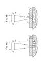
- FIG. 1The principle of positioning according to the invention of a focal line, i.e. the machining of the substrate material which is transparent for the laser wavelength based on induced absorption along the focal line in steps (a), (b) and (d).
- FIG. 2An optical arrangement which can be used according to the invention for steps (a), (b) and (d).
- FIGS. 3A and 3BA further optical arrangement which can be used according to the invention for steps (a), (b) and (d).
- FIG. 4A microscope image of the substrate surface (plan view on the substrate plane) of a glass disc machined according to step (a).
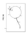
- FIGS. 5A to 5DSteps (a) to (d) which lead to removal of a circular internal contour from a substrate according to the invention.
- FIG. 6An example of step (d) according to the invention in which a stress-relieving spiral is produced as stress-relieving line portion.
- FIG. 7An example of separation according to the invention of an external contour from a substrate.
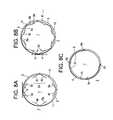
- FIGS. 8A to 8CExamples of different cut guidances for removing a circular internal contour.
- FIGS. 9A and 9BAn example for implementing a material removal step.
- FIG. 10A sketch of a device according to the invention for producing and separating contours.
- FIGS. 1A and 1Boutline the basic procedure of steps (a), (b) and (d).
- a laser beam 3which is emitted by the laser 12 ( FIG. 10 ), not shown here, and which is designated on the beam input side of the optical arrangement 20 with the reference number 3 a , is beamed onto the optical arrangement 20 of the invention.
- the optical arrangement 20forms, from the radiated laser beam, on the beam output side over a defined extension region along the beam direction (length l of the focal line), an extended laser beam focal line 3 b . Covering the laser beam focal line 3 b of the laser radiation 3 at least in portions, the planar substrate 2 to be machined is positioned in the beam path after the optical arrangement.
- the reference number 4 vdesignates the surface of the planar substrate orientated towards the optical arrangement 20 or the laser
- the reference number 4 rdesignates the rear-side surface of the substrate 2 which is normally parallel hereto and at a spacing therefrom.
- the substrate thickness(perpendicular to the surfaces 4 v and 4 r , i.e. measured relative to the substrate plane) is designated here with the reference number 10 .
- the substrate 2here is orientated perpendicular to the beam longitudinal axis and hence to the focal line 3 b which is produced in space by the optical arrangement 20 behind the same (the substrate is perpendicular to the drawing plane) and, viewed along the beam direction, is positioned relative to the focal line 3 b such that the focal line 3 b , viewed in the beam direction, begins in front of the surface 4 v of the substrate and ends in front of the surface 4 r of the substrate, i.e. still inside the substrate.
- the extended laser beam focal line 3 bhence produces (with suitable laser intensity along the laser beam focal line 3 b which is ensured by the focusing of the laser beam 3 on a portion of the length l, i.e.
- an extended portion 3 cviewed along the beam longitudinal direction, along which an induced absorption in the material of the substrate is produced, which induces a crack formation in the material of the substrate along the portion 3 c .
- the crack formationis thereby effected not only locally but over the entire length of the extended portion 3 c of the induced absorption (i.e. the zone of internal damage).
- the length of this portion 3 c(i.e. ultimately the length of the overlapping of the laser beam focal line 3 b with the substrate 2 ) is provided here with the reference number L.
- the average diameter or the average extension of the portion of the induced absorption (or of the regions in the material of the substrate 2 which are subjected to the crack formation)is designated here with the reference number D.
- This average extension Dcorresponds essentially here to the average diameter ⁇ of the laser beam focal line 3 b.
- FIG. 1Ashows, substrate material which is transparent for the wavelength ⁇ of the laser beam 3 is hence heated according to the invention by induced absorption along the focal line 3 b .
- FIG. 1Bshows that the heated material ultimately expands so that a correspondingly induced stress leads to the microcrack formation according to the invention, the stress being greatest on the surface 4 v.
- the individual focal lines 5 - 1 , 5 - 2 , . . .which are to be positioned along for example the contour line 5 on the surface of the substrate are produced as described with the subsequent optical arrangements (the optical arrangement is subsequently also termed alternatively laser lens system).
- the roughnessis thereby produced in particular from the spot size or from the spot diameter of the focal line.
- the laser beammust illuminate the lens system up to the required opening, which is effected typically by beam expansion by means of expanding telescopes between laser and focusing lens system.
- the spot sizeshould thereby not vary too greatly for a uniform interaction along the focal line. This can be ensured for example (see embodiment below) by the focusing lens system being illuminated only in a narrow, annular region by the beam then opening and hence the numerical aperture of course changing only slightly as a percentage.
- the laser radiation 3 a emitted by the laser 3is directed firstly onto a circular diaphragm 20 a which is completely non-transparent for the laser radiation used.
- the diaphragm 20 ais thereby orientated perpendicular to the beam longitudinal axis and centred on the central beam of the illustrated beam bundle 3 a .
- the diameter of the diaphragm 20 ais chosen such that the beam bundles (designated here with 3 a Z) which are situated close to the centre of the beam bundle 3 a or of the central beam impinge on the diaphragm and are absorbed completely by the latter.
- the beam bundlesdesignated here with 3 a Z
- 3 a RMerely beams situated in the external circumferential region of the beam bundle 3 a (edge beams, designated here with 3 a R) are not absorbed on the basis of the diaphragm size which is reduced in comparison with the beam diameter but rather pass through the diaphragm 20 a at the side and impinge on the edge regions of the focusing optical element of the optical arrangement 20 which is configured here as a spherically ground, bi-convex lens 20 b.
- the lens 20 b centred on the central beamis configured here deliberately as uncorrected, bi-convex focusing lens in the form of a normally spherically ground lens.
- the spherical aberration of such a lensis deliberately made use of.
- aspherical lenses or multilenseswhich deviate from ideally corrected systems and have in fact no ideal focal point but rather form a pronounced longitudinally extended focal line of a defined length can be used (i.e. lenses or systems which have in fact no longer any individual focal point).
- the zones of the lenshence focus precisely as a function of the spacing from the centre of the lens along a focal line 3 b .
- the diameter of the diaphragm 20 a transversely relative to the beam directionis here approx. 90% of the diameter of the beam bundle (beam bundle diameter defined by the extension up to reduction to 1/e) and approx. 75% of the diameter of the lens of the optical arrangement 20 .
- the focal line 3 b of a non-aberration-corrected spherical lens 20is used and was produced by stopping down the beam bundles in the centre.
- the sectionis represented in a plane through the central beam, the complete three-dimensional bundle is produced if the represented beams are rotated about the focal line 3 b.
- An improved optical arrangement 20which can be used according to the invention is produced if this comprises both an axicon and a focusing lens.
- FIG. 3Ashows such an optical arrangement 20 in which, viewed in the beam path of the laser 12 along the beam direction, firstly a first optical element with a non-spherical free surface which is shaped to form an extended laser beam focal line 3 b is positioned.
- this first optical elementis an axicon 20 c with 5° cone angle which is positioned perpendicular to the beam direction and centred on the laser beam 3 .
- An axicon or cone prismis a special, conically ground lens which forms a point source on a line along the optical axis (or even annularly transforms a laser beam).
- the construction of such an axiconis basically known to the person skilled in the art; the cone angle here is for example 10°.
- the cone tip of the axiconthereby points in the opposite direction to the beam direction.
- a second, focusing optical elementhere a plano-convex lens 20 b (the curvature of which points towards the axicon) is positioned.
- the spacing 21 at approx. 300 mmis chosen here such that the laser radiation formed by the axicon 20 c impinges annularly on the externally situated regions of the lens 20 d .
- the lens 20 dfocuses the annularly impinging radiation, on the beam output-side, at a spacing 22 of here approx. 20 mm from the lens 20 d onto a focal line 3 b of a defined length of here 1.5 mm.
- the effective focal distance of the lens 20 dis here 25 mm.
- the annular transformation of the laser beam due to the axicon 20 cis provided here with the reference number SR.
- FIG. 3Bshows the configuration of the focal line 3 b or of the induced absorption 3 c in the material of the substrate 2 according to FIG. 3A in detail.
- the optical properties of the two elements 20 c , 20 d and also the positioning of the sameis effected here such that the extension I of the focal line 3 b in the beam direction corresponds exactly to the thickness 10 of the substrate 2 .
- exact positioning of the substrate 2 along the beam directionis necessary in order, as shown in FIG. 3B , to position the focal line 3 b exactly between the two surfaces 4 v and 4 r of the substrate 2 .
- the focal lineis formed at a specific spacing of the laser lens system and if the large part of the laser radiation is focused up to a desired end of the focal line.
- Thiscan be achieved, as described, by a mainly focusing element 20 d (lens) being illuminated only annularly on a desired zone, as a result of which the desired numerical aperture, on the one hand, and hence the desired spot size is produced, however, on the other hand, loses intensity after the desired focal line 3 b of the dispersing circle over a very short distance in the centre of the spot since an essentially annular spot is formed.
- the crack formationin the sense of the invention, is stopped inside a short distance at the desired depth of the substrate.
- a combination of axicon 20 c and focusing lens 20 dfulfils this requirement.
- the axicon 20 chereby acts in two ways: by means of the axicon 20 c , a usually round laser spot is transmitted annularly towards the focusing lens 20 d and the asphericality of the axicon 20 c has the effect that, instead of a focal point in the focal plane of the lens, a focal line outside the focal plane is formed.
- the length l of the focal line 3 bcan be adjusted via the beam diameter on the axicon 20 c .
- the numerical aperture along the focal linecan be adjusted in turn via the spacing 21 between the axicon 20 c and the lens 20 d and via the cone angle of the axicon 20 c . In this way, the entire laser energy can hence be concentrated in the focal line 3 b.
- the annular illuminationstill continues to have the advantage that, on the one hand, the laser power is used as well as possible since a large part of the laser light remains concentrated at the desired length of the focal line and, on the other hand, by means of the annular illuminated zone together with the desired aberration adjusted by the other optical functions, a uniform spot size along the focal line can be achieved and hence a uniform separation process according to the invention along the focal line.
- a focusing meniscus lens or another more highly corrected focusing lenscan be used instead of the plano-convex lens 20 b illustrated in FIG. 3A .
- a focusing meniscus lens or another more highly corrected focusing lenscan be used instead of the plano-convex lens 20 b illustrated in FIG. 3A .
- Borosilicate- or soda lime glasses 2 without other colourationare optically transparent from approx. 350 nm to approx. 2.5 ⁇ m. Glasses are generally poor heat conductors, for which reason laser pulse durations of a few nanoseconds do not in fact allow any substantial heat diffusion out of a focal line 3 b . Nevertheless, even shorter laser pulse durations are advantageous since, with sub-nanosecond- or picosecond pulses, a desired induced absorption can be achieved more easily via non-linear effects (intensity substantially higher).
- a commercially available picosecond laser 12which has the following parameters is suitable: wavelength 1,064 nm, pulse duration of 10 ps, pulse repetition frequency of 100 kHz, average power (measured directly after the laser) of up to 50 W.
- the laser beamfirstly has a beam diameter (measured at 13% of the peak intensity, i.e. 1/e 2 diameter of a Gaussian beam bundle) of approx. 2 mm, the beam quality is at least M 2 ⁇ 1.2 (determined according to DIN/ISO 11146).
- the beam diametercan be increased by the factor 10 to approx. 20-22 mm.
- annular diaphragm 20 aWith a so-called annular diaphragm 20 a of 9 mm diameter, the inner part of the beam bundle is stopped down so that an annular beam is formed.
- annular beame.g. a plano-convex lens 20 b with 28 mm focal distance (quartz glass with radius 13 mm) is illuminated.
- the focal line according to the inventionis produced.
- the theoretical diameter ⁇ of the focal linevaries along the beam axis, for this reason it is advantageous for the production of a homogeneous crack surface if the substrate thickness 10 is less here than approx. 1 mm (typical thicknesses for display glasses are 0.5 mm to 0.7 mm). With a spot size of approx. 2 ⁇ m and a spacing of spot to spot of 5 ⁇ m, a speed of 0.5 m/sec is produced, with which the focal line can be guided over the substrate 2 along the contour line 5 (cf. FIG. 4 ).
- Untoughened glassesessentially have no internal stresses, for which reason the disruption zone which is still interlocked and connected by unseparated bridges still at first holds the parts together without external effect. If however a thermal stress is introduced, the contour 1 is finally completely separated and without further external introduction of force from the substrate 2 .
- a CO 2 laser with up to 250 W average poweris focused on a spot size of approx. 1 mm and this spot is guided at up to 0.5 m/s over the contour line 5 , the crack lines 6 and possibly also the stress-relieving line 11 (cf. FIGS. 5A to 5D ).
- the local thermal stress due to the introduced laser energy(5 J per cm of the lines) separates the contour 1 completely.
- the threshold intensity for the process(induced absorption and formation of a disruption zone by thermal shock) must of course be achieved via a longer focal line 3 b .
- higher required pulse energiesfollow and higher average powers.
- Sodium-containing glassesare toughened by sodium being exchanged for potassium on the glass surface by immersion in liquid potassium salt baths. This leads to a considerable internal stress (compression stress) in a 5-50 ⁇ m thick layer on the surfaces, which in turn leads to higher stability.
- the process parameters during separation of toughened glassesare similar to those with untoughened glasses of a comparable dimension and composition.
- the toughened glasscan shatter very much more easily as a result of the internal stress and in fact as a result of undesired crack growth which is effected not along the lasered intended fracture surface 5 but into the material.
- the parameter field for successful separation of a specific toughened glassis specified more tightly.
- the average laser power and the associated cutting speedmust be maintained very exactly and in fact as a function of the thickness of the toughened layer.
- step sequence (a) to (c) (preferably with (d)) for such glassesis particularly crucial in order to prevent undesired cracks and destruction in the remaining substrate 2 .
- Very thin toughened glassesconsist predominantly of tempered material, i.e. front- and rear-side are for example respectively 30 ⁇ m sodium-depleted and hence toughened and only 40 ⁇ m in the interior are untoughened. This material shatters very easily and completely if one of the surfaces is damaged.
- Such toughened glass filmshave to date not been machinable in the state of the art but are with the presented method.
- the diameter of the focal lineis very small, e.g. less than 1 ⁇ m
- the spacing from spot to spotis low, e.g. between 1 and 2 ⁇ m
- the separation speedis high enough so that the crack growth cannot run ahead of the laser process (high laser pulse repetition frequency, e.g. 200 kHz at 0.2 to 0.5 m/s).
- FIG. 4shows a microscopic image of the surface of a glass disc machined according to the invention according to step (a).
- the individual focal lines or extended portions of induced absorption 3 c along the contour line 5which are provided here with the reference numbers 5 - 1 , 5 - 2 , . . . (into the depth of the substrate perpendicular to the illustrated surface) are connected along the line 5 , along which the laser beam was guided over the surface 4 v of the substrate, to form a separation surface by crack formation for separation of the substrate parts which is effected via the further steps according to the invention.
- Readily seenis the large number of individual extended portions of induced absorption 5 - 1 , 5 - 2 , . . .
- the pulse repetition frequency of the laserin the illustrated case, having been coordinated to the feed speed for moving the laser beam over the surface 4 v such that the ratio a/ ⁇ of the average spacing a of immediately adjacent portions 5 - 1 , 5 - 2 , . . . and of the average diameter ⁇ of the laser beam focal line is approx. 2.0.
- FIGS. 5A-5Dshow, by way of example, the machining according to the invention of a 0.7 mm thick glass substrate 2 in plan view on the substrate plane.
- the laser beam 3 of a Nd:YAG laser with a wavelength lambda of 1,064 ⁇ m(the laser 12 is not shown here) is radiated vertically onto the substrate plane and guided along the contour line 5 which characterises the contour 1 to be produced.
- the contour 1 to be producedis here a circular internal contour which is intended to be removed from the substrate 2 .
- the aim of the machiningis hence the production of an exactly circular hole in the substrate 2 .
- the circular internal contour 1 or the substrate material of the samecan be destroyed during method steps (a) to (d) since the remaining substrate portions 2 represent the desired production product.
- FIG. 5Ashows, due to the pulse operation of the laser 12 by means of the laser beam 3 along the contour line 5 , a large number of individual zones 5 - 1 , 5 - 2 , . . . of internal damage is produced in the substrate material (portions of induced absorption along a portion which is extended, viewed in the beam direction, of the laser beam focal line produced by means of the laser 12 ).
- the individual zones 5 - 1 , 5 - 2 , . . . of internal damageare thereby produced as described for FIG. 4 (this applies also to the steps (d) and (b) which are also described subsequently).
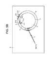
- a stress-relieving line portion 11which approximates to the course of the contour line 5 (here by a constant spacing from the latter), is introduced concentrically within the contour line 5 and at a spacing from the latter, i.e. in the material of the internal contour 1 .
- This step (d)serves to produce a stress reduction, i.e. latent stresses in the substrate material introduced during introduction of the contour line could otherwise lead to tearing of the entire substrate in the case of small contour radii and highly tempered glasses.
- Thiscan be prevented by the additional cut of step (d) which is not however an absolute necessity.
- This stepcan have a spiral as shape but can also be configured as “circle-within-circle” which approximates to the contour line.
- the aim of this cutis to minimise the spacing of the stress-relieving line portion 11 relative to the target contour in order to leave behind as little material as possible and therefore to enable or to promote self-detachment.
- values for the maximum approximation of the stress-relieving line portion 11 to the contour line 5are here approx. 20 ⁇ m to 50 ⁇ m.
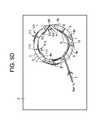
- FIG. 5Cshows the crack definition step (b) implemented according to the invention after the stress-relieving step (d).
- the laser beam 3 of the laser 12is guided, just as in steps (a) and (d), over the substrate surface or the internal contour surface so that, here also, a large number of individual zones 6 - 1 , 6 - 2 , . . . of internal damage is introduced, as shown in FIG. 4 , along the structures 6 inscribed into the internal contour 1 .
- FIG. 5shows, there are produced, in addition, a plurality of linear crack line portions 6 a , 6 b , . . . which begin at a place on the contour line 5 , lead away from the contour line 5 respectively at an angle ⁇ of here 25° and lead into the contour 1 to be separated.
- Respectively exactly two crack line portions(for example the crack line portions 6 a and 6 b ) thereby begin at one and the same place on the contour line 5 and extend in oppositely situated directions respectively at the angle ⁇ into the inner contour 1 until they cut the previously introduced stress-relieving line portion 11 .
- the angle ⁇is here the angle between the tangent to the contour line 5 at that place at which the two crack line portions, which lead from this place, in essentially opposite directions, into the material of the internal contour 1 (for example the portions 6 a and 6 b or also the portions 6 c and 6 d ), begin, and the tangent to the respective crack line portion at this place (or the crack line portion itself since this coincides with the tangent thereof).
- the crack line portions 6 a , 6 b , . . .need not thereby definitely, even if this is preferred, begin immediately at one place on the contour line 5 but rather can begin also slightly at a spacing from the contour line 5 at a place situated within the internal contour material 1 and can be guided beyond the stress-relieving line portion 11 into the material portion situated within the same (the angle ⁇ between the imaginary continued cut line of the respective crack line portion with the contour line 5 , on the one hand, and the tangent to the contour line 5 , on the other hand, is then calculated).
- the crack lines 6 V or the crack line portions 6 a , 6 b , . . . of the sameare thereby placed and orientated preferably such that the detachment behaviour is improved during and/or after the material-removing laser step (c).
- the material ring remaining after the material-removing laser step (c)is specifically segmented such that individual segments of the circular ring can be detached more easily. It is attempted to build up an internally directed stress into the V cuts so that the partial segments after the material-removing laser step (c) are pressed inwards as far as possible by themselves.
- These V cutsare not however not an absolute necessity since the method according to the invention can also function without these.
- FIG. 5Dfinally shows the material removal step (c) after the crack definition step (b). (In FIG. 5D , merely three of the V-shaped crack lines introduced in step (b) are illustrated for reasons of clarity).
- a material-removing laser beam 7 produced by a laser 14is directed towards the substrate surface.
- the parameters of the material-removing laser beam 7differ from the laser beam 3 as follows: a point focus or point damage with accompanying material removal is applied.
- Wavelengthbetween 300 nm and 11,000 nm; particularly suitable 532 nm or 10,600 nm.
- Pulse durations10 ps, 20 ns or even 3,000 ⁇ s.
- a removal line 9which extends here likewise annularly and along the entire circumference of the contour circle 5 or of the stress-relieving line circle 11 (shown here merely in sections) is inscribed into the material of the internal contour 1 .
- the spacing of the removal line 9 from the stress-relieving line 11is here approx. 25% of the spacing of the stress-relieving line 11 from the outwardly situated contour line 5 .
- the spacing 8 of the removal line 9 from the contour line 5is hence 1.25 times the spacing of the stress-relieving line 11 from the contour line 5 .
- the removal line 9is thereby introduced such that it still cuts (viewed from the centre of the internal contour 1 ) the inwardly situated ends of the crack line portions 6 a , 6 b, . . . .
- the material portions situated inside the removal line 9 in the centre of the internal contour 1are detached from the substrate 2 since, along the removal line 9 , the substrate material is removed over the entire substrate thickness 10 (cf. FIG. 9 ). Hence there remain of the internal contour material 1 to be separated merely the ring portions situated between the removal line 9 and the contour line 5 .
- approximately triangular ring portionsare produced between the two legs of each V-shaped crack line (see reference number 1 ′) which are in fact interlocked still with the material of adjacent ring portions (and are characterised here as contour remains still to be separated and have the reference number 1 r ) but are able to be removed inwards without introducing stresses which possibly damage the material of the remaining substrate 2 .
- the remaining undesired contour remains 1 r(which also comprise the stress-relieving portions 1 ′) are separated from the remaining substrate 2 by means of a mechanical stamp which is moveable perpendicular to the substrate plane.
- FIG. 6shows an alternative form of introducing a stress-relieving line portion 11 into the substrate material of the internal contour 1 of FIG. 5A to be separated.
- a stress-relieving spiral 11 Swhich approximates to the course of the contour line 5 , is guided from the centre of the internal contour 1 , viewed radially outwards, wound within itself and turning approx. 3.5 times here can be inscribed into the material of the internal contour 2 to be separated.
- the present inventioncan be used not only for separating closed internal contours 1 from a substrate 2 but also for separating complexly-shaped external contours 1 , the shape of which (cf. for example the dovetail-shaped portion of the contour line 5 in FIG. 7 ) is such that the external contour 1 of the substrate 2 cannot be produced with methods known from the state of the art without introducing stress cracks into the remaining substrate material 2 .
- the angle ⁇ of the two oppositely situated legs of the V-shaped crack lines 6 V- 1 , 6 V- 2 , . . . which are situated between the contour line 5 , on the one hand, and the removal line 9 , on the other hand,is here 10°.
- the substrate thickness perpendicular to the substrate planeis characterised with the reference number 10 .
- the substrate surfaceorientated towards the incident laser radiation 3 , 7 with the reference number 4 v (substrate front-side), the oppositely situated substrate surface (substrate rear-side) with the reference number 4 r.
- FIG. 7shows, introduction of a stress-relieving line portion 11 which approximates to the course of the contour line 5 is hence not absolutely necessary.
- the inventioncan hence be used in particular also for separating contours with undercuts.
- FIGS. 8A-8Cshow several different possibilities of how crack line portions 6 a , 6 b , . . . , which differ along the course of the contour line 5 , begin respectively essentially at the contour line 5 and lead into the material of the contour 1 to be separated, can be produced:
- FIG. 8Ashows V-shaped standard crack lines (see also FIG. 5C ).
- FIG. 8Bshows V-shaped multiple crack lines along the contour line course 5 in which respectively adjacent V-shaped crack lines intersect at the legs orientated towards each other.
- FIG. 8Cshows open crack lines due to introduction respectively of only one leg of a V-shaped crack line.
- FIGS. 9A and 9Bshow how, with an additional precipitation material 18 (here: polyoxymethylene), the inwardly situated material portion of an internal contour 1 to be separated, which is completely separated from the substrate 2 or from the contour remains 1 r after introducing the removal line 9 (possibly also with parts of the contour remains 1 r still adhering undesirably to the substrate 2 ), can be expelled.
- an additional precipitation material 18here: polyoxymethylene
- the beam power, which is high compared with the laser beam 3 , of the material-removing laser beam 7is coupled via a (second, cf. FIG. 10 ) beam-guiding optical unit 21 onto the substrate 2 .
- the substrate 2is mounted in a clamping device 16 (e.g. so-called chuck) such that, in a region below the internal contour 1 to be separated, a gas-sealed cavity 17 is configured on the substrate rear-side 4 r.
- a clamping device 16e.g. so-called chuck
- the precipitation material 18was introduced in advance and now is vaporised at the beginning of the illustrated material removal step (c) by focusing the laser beam 7 by means of the optical unit 21 through the substrate 2 into the cavity 17 ( FIG. 9A ).
- the vaporised precipitation materialprecipitates on the portion of the substrate rear-side 4 r which is situated in the cavity 17 and forms ( FIG. 9B ) on at least one surface of the substrate rear-side 4 r which corresponds to the internal contour 1 to be separated, a coupling layer 18 ′ which improves coupling of the laser beam 7 into the substrate material.
- Vaporisation of the material 18 for precipitation on the rear-side surface 4 ris implemented. Since the material of the substrate 2 is transparent for the laser radiation ⁇ , the material of the layer 18 ′ is however opaque for ⁇ , coupling of the beam 7 into the substrate material is thus improved.
- the laser radiation 7is focused 15 by the optical unit 21 and through the substrate onto the rear-side surface 4 r (cf. FIG. 9B ).
- the focal point 15 of the laser radiation 7is guided by multiple passage of the beam 7 along the line 9 successively from the substrate rear-side 4 r towards the substrate front-side 4 v in order to remove in succession the substrate material along the removal line 9 , viewed over the entire substrate thickness 10 , or to vaporise it as a result of the high laser energy which is introduced.
- the large numbere.g.
- FIG. 10illustrates a device according to the invention for implementing the method according to the invention, which is provided with a beam producing- and beam-forming arrangement 19 configured in a common laser head.
- the unit 19comprises the two lasers 12 (for production of the laser beam 3 which produces the individual zones of internal damage with lower laser intensity) and 14 (for producing the material-removing laser beam 7 of higher intensity) and also two beam-guiding optical units 20 and 21 which have respectively a galvanometer scanner connected subsequent to an F-theta lens for beam deflection (the construction of such optical units is known to the person skilled in the art).
- the laser radiation 3 of the laser 12focused via the F-theta lens and the galvanometer scanner of the unit 20 , is hence guided towards the surface of the substrate 2 and, for producing the contour line 5 , is suitably deflected by means of the galvanometer scanner.
- the laser radiation 7 of the laser 14focused via the F-theta lens and the galvanometer scanner of the unit 21 , is imaged on the surface of the substrate 2 and is deflected in order to produce the removal line 9 by the galvanometer scanner of the unit 21 .
- stationary lens systemscan be used instead of using moving lens systems (then the substrate is moved).
- a central control unitwhich is configured here in the form of a PC 22 with suitable memories, programmes etc. controls the beam production, beam focusing and beam deflection by means of the unit 19 via a bidirectional data- and control line 23 .
- Differences in the beam-guiding lens systems 20 and 21 for producing the two different laser beams 3 and 7are as follows: the laser beam 7 is guided towards the surface in comparison to the beam 3 , e.g. with a corrected F-theta lens, which leads to the formation of a point focus.
- the focal distance of the lens for the beam 7is significantly greater than for the beam 3 , e.g. 120 mm in comparison with 40 mm.
Landscapes
- Engineering & Computer Science (AREA)
- Chemical & Material Sciences (AREA)
- Physics & Mathematics (AREA)
- Optics & Photonics (AREA)
- Materials Engineering (AREA)
- Organic Chemistry (AREA)
- Mechanical Engineering (AREA)
- Plasma & Fusion (AREA)
- Health & Medical Sciences (AREA)
- Toxicology (AREA)
- Thermal Sciences (AREA)
- Chemical Kinetics & Catalysis (AREA)
- General Chemical & Material Sciences (AREA)
- Oil, Petroleum & Natural Gas (AREA)
- Laser Beam Processing (AREA)
- Re-Forming, After-Treatment, Cutting And Transporting Of Glass Products (AREA)
- Processing Of Stones Or Stones Resemblance Materials (AREA)
Abstract
Description
This application claims the benefit of priority under 35 U.S.C. § 371 of International Application Serial No. PCT/EP14/055364, filed on Mar. 18, 2014, which, in turn, claims the benefit of priority of European Application Serial No. 13160420.9, filed on Mar. 21, 2013, the contents of which is relied upon and incorporated herein by reference in its entirety.
The present invention relates to a device and to a method for cutting out contours from planar substrates (in particular: from glass substrates or crystal substrates) by means of laser.
DE 10 2011 00768 A1 describes how, with the help of a laser, semiconductor wafers, glass elements and other substrates can be divided into various parts by the wavelength of the laser being greatly absorbed by the material. As a result, material removal which leads finally to division of the substrate into a plurality of parts is effected. However, this method has disadvantages in the case of many materials, such as for example impurities due to particle formation during ablation or cut edges which have undesired microcracks or melted edges so that a cut gap which is not uniform over the thickness of the material is produced. Since in addition material must be vaporised or liquefied, a high average laser power must be provided.
Starting from the state of the art, it is therefore the object of the present invention to make available a method (and also a corresponding device) with which planar substrates, in particular made of brittle materials, can be machined with minimum crack formation at the edges, with as straight as possible cut edges and at a high process speed such that contours can be machined out from these substrates (and finally separated) without the result being undesired cracks, flaking or other disruptions which extend in the substrate plane remaining in the substrate after separation of the contours. Hence the aim of the present invention is exact, clean separation of a contour from a substrate, in particular clean, precise removal of internal contours from the substrate.
As is described subsequently in detail also, the operation takes place, according to the invention, generally with a pulsed laser at a wavelength for which the substrate material is essentially transparent. However, basically also the use of a continuous-wave laser is possible provided that the laser beam can be switched rapidly on and off again during guidance thereof over the substrate surface (e.g. by means of an optical modulator) in order to produce zones of internal damage situated one behind the other (see subsequently).
The object according to the invention is achieved by a method according toclaim 1 and also by a device according toclaim 16, advantageous variants being described in the dependent claims.
Subsequently, the invention is first described in general, then with reference to embodiments. The features according to the invention produced within the scope of the embodiments need not thereby be produced precisely in the illustrated combinations within the scope of the invention but rather individual features can also be omitted or combined with other features in a different way. In particular, also features of different embodiments can be combined with each other or individual ones of the illustrated features can also be omitted.
The essential features of the method according to the invention are described inclaim 1. The contour is thereby understood as a two-dimensional surface in the substrate plane in the form of a partial surface of the substrate. The portions of the substrate corresponding to this partial surface are intended to be removed from the substrate, the remaining portions of the substrate being intended to be further processed in subsequent processes. In other words: the contour to be separated from the substrate forms an undesired surface which can also be destroyed, the remaining substrate portions are intended to survive the separation process of the contour without internal damage and also with as ideal cut edges as possible according to the contour line. This is achieved according to the invention. Subsequently, there is/are thereby understood by the substrate, both the still unmachined substrate before separation of the contour and the remaining substrate remains after the separation of the contour. From the context respectively, the person skilled in the art knows what is intended.
According to the invention, the contour definition step is effected such that, after implementation thereof, the contour course of the contour is inscribed into the substrate material, however the contour is still connected to the substrate so that complete separation of the contour from the substrate is still not effected: the step-wise complete separation of the undesired contour from the substrate is effected by the contour definition step, the optional crack definition step, the optional stress-relieving step and the material removal- and/or material deformation step and, provided still required (i.e. if the contour remains do not independently already fall off by means of intrinsic stresses in the material after implementing steps (a) to (d)), by an optional aftertreatment step. Also the introduction of the individual zones of internal damage in the optional crack definition step (cf. claim4) and in the optional stress-relieving step is effected such that complete separation of the consequently produced partial portions in the substrate is still not effected.
Implementation of the optional crack definition step is effected preferably after conclusion of the contour definition step but this is not necessary: thus for example also partial portions of the contour line can be produced firstly by introducing the zones of internal damage before the crack definition step for producing the crack line portions is implemented and, after conclusion of the same, the remaining contour line portions of the contour definition step are introduced into the substrate material.
There is understood by the term of a crack line portion leading away from the contour line at an angle α>0°, that the angle α between the local tangent to the contour line at that place where the mentioned (possibly continued towards the contour line) crack line portion leads away from the contour line, and the local tangent at that end of the crack line portion, which is orientated towards the contour line, is greater than 0°.
According to the invention, the laser irradiation in steps (a), (b) and (d) (i.e. in the contour definition step, in the crack definition step and in the stress-relieving step—subsequently these terms (a) to (d) are also used alternatively for the steps according to the invention) need not be effected perpendicular to the substrate plane, i.e. the individual zones of internal damage need not extend perpendicular to the substrate plane (and also need not definitely pass through the entire substrate thickness perpendicular to the substrate plane). The laser irradiation can be effected also at an angle>0° (for example between 0° and 20°) relative to the substrate normal (inclined introduction of the zones of internal damage).
There are understood by the internal contours machined preferably within the scope of the invention (i.e. to be introduced and removed) simply coherent quantities of the two-dimensional space (plane of the substrate) or corresponding partial portions in the substrate, from a mathematical point of view. The internal contours to be removed therefrom can thereby have almost any shapes. In particular, circular shapes, ellipse shapes, pin-cushion shapes, oblong shapes (with rounded corners) etc. are possible for the internal contours, by the laser beam being moved on the substrate surface along a correspondingly shaped contour line. Preferably, the substrate is disposed thereby in a stationary manner within the world coordinate system and the laser beam is moved over the substrate surface by a suitable beam-guiding optical unit (which can have for example an F-theta lens followed by a galvanometer scanner). Alternatively, also a beam-guiding lens system which is stationary relative to the world coordinate system is possible, the substrate then requiring to be moved in the world coordinate system relative to the beam-guiding lens system and to the laser beam.
There is understood subsequently by substrate thickness, the extension of the substrate perpendicular to the substrate plane, i.e. between substrate front-side and the substrate rear-side. The substrate front-side is thereby that surface of the substrate which is orientated towards the radiated laser light.
The first preferably achieved features of the method according to the invention (material removal for introduction of a removal line) can be deduced fromclaim 2.
This material removal can be applied in particular to large and small radii of internal contours to be separated and is suitable in particular for smaller contours, such as e.g. sections of a circle with a diameter<2.5 mm and for oblong holes.
For the material removal, a CO2laser with a beam diameter of in the range between approx. 0.05 mm and 0.5 mm, when impinging on the substrate (achieved by focusing) can be used. The CO2laser can be pulsed or applied continuously. Preferably, pulses in the range of 100 μs to 4,000 μs are used with pulse train frequencies of 0.1 kHz to 100 kHz. For particular preference, the pulse duration is in the range between 300 μs and 4,000 μs with 0.1 kHz to 3 kHz pulse train frequency. The laser power can be in the range of 10 to 200 W, preferably however in the range of 10 to 100 W.
The travel path of the laser beam is along the contour line, at a spacing from this and in the contour to be separated, for example therefore on a (parallel) trajectory symmetrical to the target contour. For example with a circular contour to be removed (hole section), a circular movement. The travel path can be performed either once or with multiple repetition.
Due to the small focus diameter and the high laser powers, the substrate material is primarily melted (material removal). Together with laser pulses in the upper microsecond range, the entire substrate material thickness (e.g. 0.7 mm) can thus be heated through completely with one pulse.
The material removal step can be assisted by the use of a gas nozzle with process gas (e.g. CDA). With for example a nozzle diameter of 2 mm and gas pressures of 1.5 to 4 bar, material removal can be produced particularly well even for small contours and radii. By means of the gas flow, the material melted by the laser is expelled in the beam direction.
With the above-described parameters, for example also toughened glasses (DOL 40 μm) can be supplied for material removal without the result being damaging crack formation.
The removal contour (removal line) should be removed sufficiently far from the contour line (target contour cut) (generally, spacings here of approx. 0.1 to 0.3 mm suffice, according to the substrate material): for example with a circular glass disc of 2 mm diameter which is to be removed, the minimum spacing of the removal line from the contour line should be 0.1 mm (deformation diameter or diameter of the circular removal line at most 1.8 mm). In the case of a glass sheet diameter of 1.5 mm, the deformation diameter should be at most 1.3 mm. In the case of a glass disc diameter of 1.0 mm, the deformation diameter should be at most 0.8 mm.
The crack line portions (e.g. V-cuts) which are described subsequently in more detail have an assisting effect for the complete separation of the contour.
According to the advantageous features ofclaim 3, instead of one, or in addition to a material removal according toclaim 2, also removal of material portions of the contour to be separated is possible by means of thermal deformation.
A CO2laser or the laser beam thereof for extraction of substrate material in a manner which does not remove substrate material, i.e can be used in a purely thermally deforming manner in substrate material (in particular of the contour to be separated) (this is effected preferably in the case of fairly large contours to be separated, e.g. in the case of circular sections with a diameter≥2.5 mm, preferably ≥5-10 mm, to be separated).
The procedure with such a material deformation step can be as follows:
By means of CO2laser irradiation of the substrate, e.g. by means of movement of the laser beam along the contour line but at a spacing therefrom and also in the contour to be separated (for example along a circle or a spiral in the centre of the contour to be separated), at least portions of the contour to be separated are heated such that the result is a plastic deformation of at least portions of the contour to be separated. The diameter of the CO2laser spot impinging on the substrate material can cover a wide range: 0.1 mm to 10 mm. A diameter of 0.2 mm to 3 mm is preferred. The CO2laser can be operated both pulsed and continuously. Preferably, however, pulses in the range of 6 μs to 4,000 μs are used with pulse train frequencies in the range of 0.1 kHz to 100 kHz. The laser power can be in the range between 10 and 300 W, preferably in the range between 10 and 50 W.
The travel path of the laser is preferably a trajectory which is symmetrical (e.g. parallel, but at a spacing) relative to the contour to be separated (target contour). For example in the case of a hole section as internal contour to be separated, a circular movement. However a spiral movement can also have a favourable effect on the thermoplastic deformation of such an internal contour (e.g. glass disc). In certain cases, it can prove to be favourable if the laser beam remains stationary over a defined time interval of for example 0.5 s simply in the centre of the contour to be separated and heats through and thus deforms the contour to be separated. The travel path can be covered either once or with multiple repetition which can have a favourable effect on the thermoplastic deformation of the contour to be separated.
The plastic deformation in the centre leads to shrinkage of the contour to be separated (e.g. glass disc) due to a thermally-induced flow of the substrate material (e.g. glass material) in the irradiated region in the centre and towards the centre. For example in the case of a circular disc as contour to be separated, this can be seen as follows:
- The deformation generally forms, as a result of gravity, a bulge away from the laser in the direction of the centre of the earth. This bulge possibly can adopt a drop shape. The surface topography can be compared with that of a convex lens.
- Under specific laser conditions, a bulge is also formed towards the laser. The surface topography is then that of a biconvex lens.
- Under specific laser conditions, a dent (concave) is formed on one side and, on the opposite surface, a bulge.
- If the irradiated surface is subjected to a flow of process gas (commercial air, CDA) in parallel and contemporaneously via a gas nozzle, the formation of the bulge and/or dent can be controlled very precisely. As a result, even contours with very small radii (<2.5 mm to 1.2 mm) can be introduced for the removal. In the case of for example a nozzle diameter of 2 mm and gas pressures in the range of 1.5 to −3 bar, relatively small contours can be particularly readily removed.
What the described thermoplastic deformation variants have in common is that substrate material of the contour to be separated flows (e.g. in the case of an internal contour to be removed flows towards the centre of the same) and consequently a gap relative to the remaining substrate material is formed (e.g. externally situated material of an internal contour to be removed). Such a gap can have dimensions of approx. 10 μm to 50 μm.
After a short thermal relaxation time (cooling and shrinkage of the contour to be separated), the contour to be separated falls out purely due to the forming gap.
In the case of the material deformation step, hence no substrate material is removed, no removal products are produced.
The CO2-induced thermoplastic deformation or the regions irradiated by the laser should be removed sufficiently far (generally spacings of approx. 1 to 3 mm suffice according to the substrate material) from the already introduced contour line (contour cut): for example with a glass disc of 10 mm diameter to be removed, the region irradiated centrally in this glass disc (deformation diameter) should have a diameter of 8 mm at most. In the case of a glass disc diameter of 5 mm, this region should be 3.4 mm at most. In the case of a glass disc diameter of 2.5 mm, this region should be 1.5 mm at most.
The already introduced contour line (target contour cut) forms a sufficient thermal insulation relative to the surrounding material of the residual, remaining substrate so that, with suitable thermoplastic deformation diameter, no disadvantageous thermal effect on the cut edge or on the surrounding material in the form of chipping or parasitic crack formation can be effected.
In the subsequent embodiments, the material removal- and/or material deformation step as material removal step is effected by means a material-removing laser beam which is not illustrated in more detail.
Further preferably produced features can be deduced from claims4 to6.
The ultrasonic treatment according to claim6 can be effected as follows: frequency range between 1 kHz and 50 kHz (particularly preferred: 5 kHz-40 kHz). The surface in the interior of the cut contour (i.e. in the contour to be separated) is thereby preferably contacted with an ultrasonic actuator. The contact surface can thereby correspond to the dimensions and the shape of an internal contour to be separated. The contact can be implemented over the entire surface or as a ring. In a particular embodiment, substrate regions situated outside the contour to be separated can be treated with ultrasound (also simultaneous ultrasound treatment of the contour to be separated and such remaining substrate regions is possible).
A corresponding aftertreatment step is however frequently not required at all since the zones of internal damage, which are introduced in step (b) (and in the possibly implemented optional step (d)) already have internal stresses introduced into the substrate material which suffice for the undesired contour remains to be detached by themselves from the remaining substrate (self-removal of the contour remains) in the course of the material removal- and/or material deformation step or after the same.
Further advantageous achievable method features can be deduced fromclaim 7 and claim8.
All of the already described advantageous features and of the subsequently also described advantageous features can be produced thereby, within the scope of the invention, respectively individually or also in any combinations with each other.
The point focusing described in claim8 can thereby be implemented as described in U.S. Pat. No. 6,992,026 B2 or in WO 2012/006736 A2.
According to the invention, it is however particularly preferred to introduce the individual zones of internal damage along the contour line, the crack-line portions and possibly also the stress-relieving line portions by means of the laser beam focal line described in claim8 (i.e. by induced absorption in the substrate material along an extended portion in the thickness direction of the material).
This preferred embodiment of step (a), (b) and (d) is now described subsequently in detail.
Firstly, it is thereby essential that the wavelength of the irradiating laser is chosen in coordination with the substrate to be machined such that the substrate material is essentially transparent for this laser wavelength (see also claim11).
The method for steps (a), (b) and (d) produces a laser focal line per laser pulse (in contrast to a focal point) by means of a laser lens system which is suitable for this purpose (subsequently also termed alternatively beam-guiding optical unit or optical arrangement). The focal line determines the zone of interaction between laser and material of the substrate. If the focal line falls into the material to be separated, then the laser parameters can be chosen such that an interaction with the material takes place and produces a crack zone along the focal line. Important laser parameters here are the wavelength of the laser, the pulse duration of the laser, the pulse energy of the laser and possibly also the polarisation of the laser.
For the interaction of the laser light with the material in steps (a), (b) and (d), there should preferably be the following:
1) The wavelength λ of the laser is preferably chosen such that the material is essentially transparent at this wavelength (for example in concrete terms: absorption<<10% per mm material depth=>γ<<1/cm; γ: Lambert-Beer absorption coefficient).
2) The pulse duration of the laser is preferably chosen such that, within the interaction time, no substantial heat transport (heat diffusion) from the interaction zone can take place (for example in concrete terms: τ<<d2/α, d: focal diameter, τ laser pulse duration, α: heat diffusion constant of the material).
3) The pulse energy of the laser is chosen preferably such that the intensity in the interaction zone, i.e. in the focal line, produces an induced absorption which leads to local heating of the material along the focal line, which in turn leads to crack formation along the focal line as a result of the thermal stress introduced into the material.
4) The polarisation of the laser influences both the interaction on the surface (reflectivity) and the type of interaction within the material during the induced absorption. The induced absorption can take place via induced, free charge carriers (typically electrons), either after thermal excitation or via multiphoton absorption and internal photoionisation or via direct field ionisation (field strength of the light breaks the electron bond directly). The type of production of the charge carriers can be assessed for example via the so-called Keldysh parameter (reference) which however plays no role in the application of the method according to the invention. In the case of specific (e.g. double-refracting materials), it can be important merely that the further absorption/transmission of the laser light depends upon the polarisation and hence the polarisation should be chosen favourably via suitable lens systems (phase plates) by the user for separation of the respective material, e.g. simply in a heuristic manner. If the substrate material is therefore not optically isotropic but for example double-refracting, then also the propagation of the laser light in the material is influenced by the polarisation. Therefore the polarisation and the orientation of the polarisation vector can be chosen such that, as desired, only one focal line and not two thereof are formed (ordinary and exraordinary beams). This is of no importance in the case of optically isotropic materials.
5) Furthermore, the intensity should be chosen via the pulse duration, the pulse energy and the focal line diameter such that no ablation or melting but only crack formation in the structure of the solid body is effected. This requirement can be fulfilled for typical materials, such as glass or transparent crystals, most easily with pulsed lasers in the sub-nanosecond range, in particular therefore with pulse durations of e.g. between 10 and 100 ps. Above scale lengths of approx. one micrometer (0.5 to 5.0 micrometers), the heat conduction for poor heat conductors, such as for example glasses, acts into the sub-microsecond range, whilst, for good heat conductors, such as crystals and semiconductors, the heat conduction is effective even from nanoseconds onwards.
The essential process for forming the zones of internal damage, i.e. the crack formation in the material which extends vertically relative to the substrate plane, is mechanical stress which exceeds the structural strength of the material (compression strength in MPa). The mechanical stress is achieved here by rapid, non-homogeneous heating (thermally induced stress) due to the laser energy. The crack formation in steps (a), (b) and (d), provided there is corresponding positioning of the substrate relative to the focal line (see subsequently), of course starts on the surface of the substrate since the deformation is greatest there. This is because, in the half-space above the surface, there is no material which can absorb forces. This argument also applies for materials with toughened or prestressed surfaces as long as the thickness of the toughened or prestressed layer is large relative to the diameter of the suddenly heated material along the focal line (see, in this respect, alsoFIG. 1 which is also described subsequently).
The type of interaction can be adjusted via the fluence (energy density in joules per cm2) and the laser pulse duration with the chosen focal line diameter such that firstly no melting takes place on the surface or in the volume and secondly no ablation takes place with particle formation on the surface.
Subsequently, the production of the contour line of a desired separation surface (relative movement between laser beam and substrate along the contour line on the substrate surface), i.e. step (a), is described. The same applies to (b) and (d).
The interaction with the material produces, per laser pulse, an individual, continuous (viewed in the direction perpendicular to the substrate surface) crack zone in the material along a focal line. For complete separation of the material, a sequence of these crack zones per laser pulse is placed so closely to each other along the desired separation line that a lateral connection of the cracks to form a desired crack surface/contour is produced in the material. For this, the laser is pulsed at a specific train frequency. Spot size and spacing are chosen such that, on the surface along the line of the laser spots, a desired, directed crack formation begins. The spacing of the individual crack zones along the desired separation surface is produced from the movement of the focal line relative to the material within the timespan of laser pulse to laser pulse. See in this respect alsoFIG. 4 which is also described subsequently.
In order to produce the desired contour line or separation surface in the material, either the pulsed laser light can be moved with an optical arrangement which is moveable parallel to the substrate plane (and possibly also perpendicular thereto) over the stationary material or the material itself is moved past the stationary optical arrangement with a moveable receiving means such that the desired separation line is formed. The orientation of the focal line relative to the surface of the material, whether perpendicular or at an angle>0° relative to the surface normal, can be chosen either to be fixed or it can be changed via a rotatable optical normal arrangement (subsequently also termed lens system for simplification) and/or via a rotatable beam path of the laser along the desired contour line or separation surface or-line.
In total, the focal line for forming the desired separation line can be guided in up to five separately moveable axes through the material: two spatial axes (x, y) which fix the penetration point of the focal line into the material, two angular axes (theta, phi), which fix the orientation of the focal line from the penetration point into the material, and a further spatial axis (z′, not necessarily orthogonal to x, y), which fixes how deeply the focal line extends from the penetration point on the surface into the material. For the geometry in the Cartesian coordinate system (x, y, z), see also for example the subsequently describedFIG. 3a . In the case of the perpendicular incidence of the laser beam on the substrate surface, z=z′ applies.
The final separation of the material (separation of the contour) along the produced contour line is effected either by inherent stress of the material or by introduced forces, e.g. mechanically (tension) or thermally (non-uniform heating/cooling). Since in steps (a), (b) and (d) no material is ablated, there is generally initially no continuous gap in the material but only a highly disrupted fracture surface (microcracks) which are interlocked per se and possibly also connected by bridges. As a result of the forces introduced subsequently in the aftertreatment step, the remaining bridges are separated via lateral (effected parallel to the substrate plane) crack growth and the interlocking is overridden so that the material can be separated along the separation surface.
The laser beam focal line which can be used in (a), (b) and (d) is termed, for simplification previously and subsequently, also focal line of the laser beam. In (a), (b) and (d), the substrate is prepared by the crack formation (induced absorption along the focal line which extends perpendicular to the substrate plane) with the contour line, the crackline portions and the stress-relieving line portion(s) for separation of the contour from the substrate. The crack formation is effected preferably perpendicular to the substrate plane into the substrate or into the interior of the substrate (longitudinal crack formation). As described already, generally a large number of individual laser beam focal lines must be introduced into the substrate along one line (e.g. contour line) on the substrate surface in order that the individual parts of the substrate can be separated from each other. For this purpose, either the substrate can be moved parallel to the substrate plane relative to the laser beam or to the optical arrangement or, conversely, the optical arrangement can be moved parallel to the substrate plane relative to the substrate which is disposed in a stationary manner.
The induced absorption of steps (a), (b) and (d) is advantageously produced such that the crack formation in the substrate structure is effected without ablation and without melting of the substrate material. This takes place by means of adjusting the already described laser parameters, explained subsequently also in the scope of examples, and also the features and parameters of the optical arrangement. Theextension 1 of the laser focal line and/or the extension of the portion of the induced absorption in the substrate material (in the substrate interior) respectively, viewed in the beam longitudinal direction, can thereby be between 0.1 mm, preferably between 0.3 mm and 10 mm. The layer thickness of the substrate is preferably between 30 and 3,000 μm, particularly preferred between 100 and 1,000 μm. Theratio 1/d of thisextension 1 of the laser beam focal line and the layer thickness d of the substrate is preferably between 10 and 0.5, particularly preferred between 5 and 2. The ratio L/D of theextension 1 of the portion of the induced absorption in the substrate material, viewed in the beam longitudinal direction, and of the average extension D of the portion of the induced absorption in the material, i.e. in the interior of the substrate, is preferably, viewed transversely relative to the beam longitudinal direction, between 5 and 5,000, particularly preferred between 50 and 5,000. The average diameter δ (spot diameter) of the laser beam focal line is preferably between 0.5 μm and 5 μm, particularly preferred between 1 μm and 3 μm (e.g. at 2 μm). The pulse duration of the laser should be chosen such that, within the interaction time with the substrate material, the heat diffusion in this material is negligible (preferably no heat diffusion is effected). If the pulse duration of the laser is characterised with τ, then there applies preferably for τ, δ and the heat diffusion constant β of the material of the substrate, τ<<δ2/β. This means that τ is less than 1%, preferably less than 1% of δ2/β. For example, the pulse duration τ at 10 ps (or even below that) can be between 10 and 100 ps or even above 100 ps. The pulse repetition frequency of the laser is preferably between 10 and 1,000 kHz, preferably at 100 kHz. The laser can thereby be operated as a single pulse laser or as burst pulse laser. The average laser power (measured on the beam output side of the laser) is preferably between 10 watts and 100 watts, preferably between 30 watts and 50 watts for steps (a), (b) and (d).
In steps (a), (b) and (d), a laser beam is hence moved relative to the substrate surface along a line, along which a large number of individual zones of internal damage are to be introduced into the substrate (also termed extended portions of induced absorption in the interior of the substrate along the respective line). The ratio a/δ of the average spacing a of the centres of immediately adjacent zones of internal damage, i.e. produced directly after each other (portions of induced absorption) and the average diameter δ of the laser beam focal line (spot diameter) is preferably between 0.5 and 3.0, preferably between 1.0 and 2.0 (see in this respect alsoFIG. 4 ).
The final separation of the contour from the substrate can be effected by, after steps (a) to (d) (possibly also already during implementation of one of these steps), mechanical forces being exerted on the substrate (for example by means of a mechanical stamp) and/or thermal stresses being introduced into the substrate (for example by means of a CO2laser) in order to heat and cool again the substrate non-uniformly. As a result, between immediately adjacent extended portions of induced absorption or between immediately adjacent zones of internal damage, a crack formation in order to divide the substrate into a plurality of parts, i.e. for separating the contour can be effected. This crack formation should thereby be understood (in contrast to the depth crack formation induced in the direction of the substrate depth or that in steps (a), (b) and (d), as transverse crack formation, i.e. as a lateral crack formation in the substrate plane (corresponding to the course of the contour line, along which the contour is to be separated from the substrate).
It is thereby essential, in the case of this preferred procedure in steps (a), (b) and (d) that, per laser pulse (or per burst pulse), a laser beam focal line (and not merely a focal point which is not extended or only very locally) is produced. For this purpose, the laser lens systems illustrated also in detail subsequently are used. The focal line thus determines the zone of interaction between laser and substrate. If the focal line falls at least in portions (viewed in the depth direction) into the substrate material to be separated, then the laser parameters can be chosen such that an interaction with the material takes place, which produces a crack zone along the entire focal line (or along the entire extended portion of the laser beam focal line which falls into the substrate). Selectable laser parameters are for example the wavelength of the laser, the pulse duration of the laser, the pulse energy of the laser and also possibly the polarisation of the laser.
As a result of this preparation of the contour separation in steps (a), (b) and (d), it is made possible according to the invention to separate contours made of very thin glass substrates (glass substrates with thicknesses<300 μm, <100 μm or even <50 μm. This is effected without edges, damage, cracks, flaking or the like on the substrate (remains) which are left after separation of the contour so that complex aftertreatments are not required according to the invention. The zones of internal damage along the lines can thereby be introduced at high speeds (>1 m/s).
Further advantageously achievable features of the method according to the invention are described inclaims
It is possible to use the types of laser mentioned inclaims
Further possible lasers: Nd:YAG laser with 532 nm/515 nm wavelength. However, also a CO2laser with 9 to 11 μm wavelength together with a gas nozzle is very suitable.
It can prove to be favourable to vary, between step (a), on the one hand, and step(s) (b) and/or (d), on the other hand, e.g. the spacing between adjacent zones of internal damage. In particular increasing this spacing in step(s) (b) and/or (d) is advantageous compared with step (a) since a favourable crack formation and hence damage in the internal region of an internal contour thus takes place.
Parameters by way of example can be as follows:
- For toughened glass (0.7 mm; DOL 40 μm): burst 2 pulses; 200 kHz repetition rate; 3.5 μm pulse spacing; 25 W laser power; numerical aperture lens system 0.1; focal line length 1.8 mm.
- For untoughened glass (2.8 mm): burst 5 pulses, 100 kHz repetition rate; 5 μm pulse spacing, 50 W laser power; numerical aperture lens system 0.08; focal line length 2.8 mm.
Advantageous procedures for implementing the material removal step are described inclaims 13 and14. For example a 20-times passage of the removal line for a glass substrate of thickness 0.7 mm is thereby effected in order to cut the removal line into the substrate material over the entire thickness of the substrate material.
In the procedure according toclaim 14, beams of all lasers mentioned in the present invention can be used as laser beams, with the exception of a CO2laser. In particular, a laser wavelength of 532 nm can be used. Polyoxymethylene (POM) can be used as precipitation material.
The mounting of the substrate can be ensured for example with the help of a clamping device with a depression as cavity. By means of the vapour pressure in the gas-sealed cavity, expulsion of the substrate piece separated by means of the separation line and possibly even expulsion of the thereafter still remaining remains of the contour still connected to the substrate is possible.
Devices according to the invention which are capable of implementing the methods according to the invention are described inclaims 16 to18.
A laser which is capable, according toclaim 18, of generating both the laser beam in steps (a), (b) and (d) and the material-removing laser beam for the material removal step is for example a 50 W picosecond laser.
According to the invention, it can be advantageous for the final separation of the contour to supply moisture to the substrate material after introduction of the large number of zones of internal damage. As a result of capillary forces, water is drawn into the damage zones and can induce stresses by means of linking up with open bonds in the glass structure (caused by the laser), which stresses help finally to form a crack. Hence controlled supply of the cut contours (internal and external contour) with water is possible, the impingement being able to be effected during or after the laser machining. Use of an evaporator in the device for producing a moist airflow and/or use of a moist substrate mounting or receiving means is possible. A water reservoir can be provided in the region of the contour line to be introduced.
The present invention of producing and separating a contour in or from a planar substrate has the following advantages in particular relative to the contour cutting methods known from the state of the art:
- By combining the introduction of zones of internal damage, on the one hand (steps (a), (b) and possibly also (d)), and the material removal- and/or material deformation step (c), on the other hand, a very high separation quality can be achieved for contours: practically no break-outs occur, the cut edges on the substrate, after removal of the contour, have very low roughness and also high precision.
- Internal contours shaped in almost any way (circular internal contours, oblong hole-shaped internal contours or any free form surfaces) can be separated with great precision according to the invention. A high resolution of structures of the internal contour is thereby possible.
- The formation of stress cracks outside the internal contour (i.e. in the remaining substrate) is avoided.
- The method is suitable not only for removing internal contours but also for separating external contours, which have very small radii or corners, with very good quality of the produced external edges on the remaining substrate. In particular, external contours which have undercuts (e.g. dovetail-shaped external contours) can be produced and separated with high quality.
Subsequently, the present invention is described with reference to embodiments. The material removal- and/or material deformation step which is implemented here as material removal step is designated here in brief with (c). There are shown:
AsFIG. 1A shows, thesubstrate 2 here is orientated perpendicular to the beam longitudinal axis and hence to thefocal line 3bwhich is produced in space by theoptical arrangement 20 behind the same (the substrate is perpendicular to the drawing plane) and, viewed along the beam direction, is positioned relative to thefocal line 3bsuch that thefocal line 3b, viewed in the beam direction, begins in front of thesurface 4vof the substrate and ends in front of thesurface 4rof the substrate, i.e. still inside the substrate. The extended laser beamfocal line 3bhence produces (with suitable laser intensity along the laser beamfocal line 3bwhich is ensured by the focusing of thelaser beam 3 on a portion of the length l, i.e. through a line focus of length l) in the overlapping region of the laser beamfocal line 3bwith thesubstrate 2, i.e. in the material of the substrate which is covered by thefocal line 3b, anextended portion 3c, viewed along the beam longitudinal direction, along which an induced absorption in the material of the substrate is produced, which induces a crack formation in the material of the substrate along theportion 3c. The crack formation is thereby effected not only locally but over the entire length of theextended portion 3cof the induced absorption (i.e. the zone of internal damage). The length of thisportion 3c(i.e. ultimately the length of the overlapping of the laser beamfocal line 3bwith the substrate2) is provided here with the reference number L. The average diameter or the average extension of the portion of the induced absorption (or of the regions in the material of thesubstrate 2 which are subjected to the crack formation) is designated here with the reference number D. This average extension D corresponds essentially here to the average diameter δ of the laser beamfocal line 3b.
AsFIG. 1A shows, substrate material which is transparent for the wavelength λ of thelaser beam 3 is hence heated according to the invention by induced absorption along thefocal line 3b.FIG. 1B shows that the heated material ultimately expands so that a correspondingly induced stress leads to the microcrack formation according to the invention, the stress being greatest on thesurface 4v.
Subsequently, concreteoptical arrangements 20 which can be used for producing thefocal line 3band also a concrete optical construction (FIG. 10 ) in which these optical arrangements can be used are described. All arrangements or constructions are thereby based on the above-described ones so that respectively identical reference numbers are used for components or features which are identical or correspond in their function. Subsequently, respectively only the differences are therefore described.
Since the separation surface leading ultimately to the separation is or should be of high quality according to the invention (with respect to breaking strength, geometric precision, roughness and avoidance of aftertreatment requirements), the individual focal lines5-1,5-2, . . . which are to be positioned along for example thecontour line 5 on the surface of the substrate are produced as described with the subsequent optical arrangements (the optical arrangement is subsequently also termed alternatively laser lens system). The roughness is thereby produced in particular from the spot size or from the spot diameter of the focal line. In order to be able to achieve, with a given wavelength λ of the laser12 (interaction with the material of the substrate2), a low spot size of for example 0.5 μm to 2 μm, generally specific requirements are placed on the numerical aperture of thelaser lens system 20. These requirements are fulfilled by the subsequently describedlaser lens systems 20.
In order to achieve the desired numerical aperture, the lens system must have, on the one hand, the required opening at a given focal distance, according to the known formulae of Abbé (N.A.=n sin (theta), n: refractive index of the glass to be machined, theta: half the opening angle; and theta=arctan (D/2f); D: opening, f: focal distance). On the other hand, the laser beam must illuminate the lens system up to the required opening, which is effected typically by beam expansion by means of expanding telescopes between laser and focusing lens system.
The spot size should thereby not vary too greatly for a uniform interaction along the focal line. This can be ensured for example (see embodiment below) by the focusing lens system being illuminated only in a narrow, annular region by the beam then opening and hence the numerical aperture of course changing only slightly as a percentage.
According toFIG. 2 (cut perpendicular to the substrate plane at the level of the central beam in the laser beam bundle of thelaser radiation 12; here also, radiation of thelaser beam 3 is effected perpendicular to the substrate plane so that thefocal line 3bor the extended portion of the inducedabsorption 3cis parallel to the substrate normal), thelaser radiation 3aemitted by thelaser 3 is directed firstly onto acircular diaphragm 20awhich is completely non-transparent for the laser radiation used. Thediaphragm 20ais thereby orientated perpendicular to the beam longitudinal axis and centred on the central beam of the illustratedbeam bundle 3a. The diameter of thediaphragm 20ais chosen such that the beam bundles (designated here with3aZ) which are situated close to the centre of thebeam bundle 3aor of the central beam impinge on the diaphragm and are absorbed completely by the latter. Merely beams situated in the external circumferential region of thebeam bundle 3a(edge beams, designated here with3aR) are not absorbed on the basis of the diaphragm size which is reduced in comparison with the beam diameter but rather pass through thediaphragm 20aat the side and impinge on the edge regions of the focusing optical element of theoptical arrangement 20 which is configured here as a spherically ground,bi-convex lens 20b.
Thelens 20bcentred on the central beam is configured here deliberately as uncorrected, bi-convex focusing lens in the form of a normally spherically ground lens. In other words, the spherical aberration of such a lens is deliberately made use of. As an alternative thereto, aspherical lenses or multilenses which deviate from ideally corrected systems and have in fact no ideal focal point but rather form a pronounced longitudinally extended focal line of a defined length can be used (i.e. lenses or systems which have in fact no longer any individual focal point). The zones of the lens hence focus precisely as a function of the spacing from the centre of the lens along afocal line 3b. The diameter of thediaphragm 20atransversely relative to the beam direction is here approx. 90% of the diameter of the beam bundle (beam bundle diameter defined by the extension up to reduction to 1/e) and approx. 75% of the diameter of the lens of theoptical arrangement 20. According to the invention, hence thefocal line 3bof a non-aberration-correctedspherical lens 20 is used and was produced by stopping down the beam bundles in the centre. The section is represented in a plane through the central beam, the complete three-dimensional bundle is produced if the represented beams are rotated about thefocal line 3b.
An improvedoptical arrangement 20 which can be used according to the invention is produced if this comprises both an axicon and a focusing lens.
According to the invention, it is hence advantageous if the focal line is formed at a specific spacing of the laser lens system and if the large part of the laser radiation is focused up to a desired end of the focal line. This can be achieved, as described, by a mainly focusingelement 20d(lens) being illuminated only annularly on a desired zone, as a result of which the desired numerical aperture, on the one hand, and hence the desired spot size is produced, however, on the other hand, loses intensity after the desiredfocal line 3bof the dispersing circle over a very short distance in the centre of the spot since an essentially annular spot is formed. Hence the crack formation, in the sense of the invention, is stopped inside a short distance at the desired depth of the substrate. A combination ofaxicon 20cand focusinglens 20dfulfils this requirement. Theaxicon 20chereby acts in two ways: by means of theaxicon 20c, a usually round laser spot is transmitted annularly towards the focusinglens 20dand the asphericality of theaxicon 20chas the effect that, instead of a focal point in the focal plane of the lens, a focal line outside the focal plane is formed. The length l of thefocal line 3bcan be adjusted via the beam diameter on theaxicon 20c. The numerical aperture along the focal line can be adjusted in turn via thespacing 21 between theaxicon 20cand thelens 20dand via the cone angle of theaxicon 20c. In this way, the entire laser energy can hence be concentrated in thefocal line 3b.
Should the crack formation (in the zone of internal damage) stop, in the sense of the invention, apart from the exit side of the substrate, then the annular illumination still continues to have the advantage that, on the one hand, the laser power is used as well as possible since a large part of the laser light remains concentrated at the desired length of the focal line and, on the other hand, by means of the annular illuminated zone together with the desired aberration adjusted by the other optical functions, a uniform spot size along the focal line can be achieved and hence a uniform separation process according to the invention along the focal line.
Instead of the plano-convex lens 20billustrated inFIG. 3A , also a focusing meniscus lens or another more highly corrected focusing lens (aspherical, multilenses) can be used.
Borosilicate- orsoda lime glasses 2 without other colouration (in particular with a low iron content) are optically transparent from approx. 350 nm to approx. 2.5 μm. Glasses are generally poor heat conductors, for which reason laser pulse durations of a few nanoseconds do not in fact allow any substantial heat diffusion out of afocal line 3b. Nevertheless, even shorter laser pulse durations are advantageous since, with sub-nanosecond- or picosecond pulses, a desired induced absorption can be achieved more easily via non-linear effects (intensity substantially higher).
For separation of planar glasses according to the invention, for example a commerciallyavailable picosecond laser 12 which has the following parameters is suitable: wavelength 1,064 nm, pulse duration of 10 ps, pulse repetition frequency of 100 kHz, average power (measured directly after the laser) of up to 50 W. The laser beam firstly has a beam diameter (measured at 13% of the peak intensity, i.e. 1/e2diameter of a Gaussian beam bundle) of approx. 2 mm, the beam quality is at least M2<1.2 (determined according to DIN/ISO 11146). With a beam expanding lens system (commercially available beam telescope according to Kepler), the beam diameter can be increased by thefactor 10 to approx. 20-22 mm. With a so-calledannular diaphragm 20aof 9 mm diameter, the inner part of the beam bundle is stopped down so that an annular beam is formed. With this annular beam, e.g. a plano-convex lens 20bwith 28 mm focal distance (quartz glass with radius 13 mm) is illuminated. By means of the strong (desired) spherical aberration of thelens 20b, the focal line according to the invention is produced.
The theoretical diameter δ of the focal line varies along the beam axis, for this reason it is advantageous for the production of a homogeneous crack surface if thesubstrate thickness 10 is less here than approx. 1 mm (typical thicknesses for display glasses are 0.5 mm to 0.7 mm). With a spot size of approx. 2 μm and a spacing of spot to spot of 5 μm, a speed of 0.5 m/sec is produced, with which the focal line can be guided over thesubstrate 2 along the contour line5 (cf.FIG. 4 ). With 25 W average power on the substrate (measured following the focusing line7), there results from the pulse train frequency of 100 kHz, a pulse energy of 250 μJ which can also be effected in a structured pulse (rapid train of individual pulses at a spacing of only 20 ns, so-called burst pulse) of 2 to 5 sub-pulses.
Untoughened glasses essentially have no internal stresses, for which reason the disruption zone which is still interlocked and connected by unseparated bridges still at first holds the parts together without external effect. If however a thermal stress is introduced, thecontour 1 is finally completely separated and without further external introduction of force from thesubstrate 2. For this purpose, a CO2laser with up to 250 W average power is focused on a spot size of approx. 1 mm and this spot is guided at up to 0.5 m/s over thecontour line 5, the crack lines6 and possibly also the stress-relieving line11 (cf.FIGS. 5A to 5D ). The local thermal stress due to the introduced laser energy (5 J per cm of the lines) separates thecontour 1 completely.
For separation in thicker glasses, the threshold intensity for the process (induced absorption and formation of a disruption zone by thermal shock) must of course be achieved via a longerfocal line 3b. Hence higher required pulse energies follow and higher average powers. With the above-described lens system construction and the maximum available laser power (after losses due to the lens system) of 39 W on thesubstrate 2, the separation of approx. 3 mm thick glass is achieved. On the one hand, theannular diaphragm 20ais thereby removed and, on the other hand, the spacing oflens 20btosubstrate 2 is corrected (nominal focal spacing increases in direction) such that a longerfocal line 3bis produced in thesubstrate 2.
Subsequently, a further embodiment for separating toughened glass is presented.
Sodium-containing glasses are toughened by sodium being exchanged for potassium on the glass surface by immersion in liquid potassium salt baths. This leads to a considerable internal stress (compression stress) in a 5-50 μm thick layer on the surfaces, which in turn leads to higher stability.
Basically, the process parameters during separation of toughened glasses are similar to those with untoughened glasses of a comparable dimension and composition. However, the toughened glass can shatter very much more easily as a result of the internal stress and in fact as a result of undesired crack growth which is effected not along the lasered intendedfracture surface 5 but into the material. For this reason, the parameter field for successful separation of a specific toughened glass is specified more tightly. In particular the average laser power and the associated cutting speed must be maintained very exactly and in fact as a function of the thickness of the toughened layer. For a glass with 40 μm thick toughened layer and 0.7 mm total thickness, there results with the above-mentioned construction for example the following parameters: cutting speed of 1 m/s at 100 kHz pulse train frequency, therefore a spot spacing of 10 μm, with an average power of 14 W. In addition, the step sequence (a) to (c) (preferably with (d)) for such glasses is particularly crucial in order to prevent undesired cracks and destruction in the remainingsubstrate 2.
Very thin toughened glasses (<100 μm) consist predominantly of tempered material, i.e. front- and rear-side are for example respectively 30 μm sodium-depleted and hence toughened and only 40 μm in the interior are untoughened. This material shatters very easily and completely if one of the surfaces is damaged. Such toughened glass films have to date not been machinable in the state of the art but are with the presented method.
Separation of this material according to the method of the invention is successful if a) the diameter of the focal line is very small, e.g. less than 1 μm, b) the spacing from spot to spot is low, e.g. between 1 and 2 μm, and c) the separation speed is high enough so that the crack growth cannot run ahead of the laser process (high laser pulse repetition frequency, e.g. 200 kHz at 0.2 to 0.5 m/s).
AsFIG. 5A shows, in the contour definition step (a), thelaser beam 3 of a Nd:YAG laser with a wavelength lambda of 1,064 μm (thelaser 12 is not shown here) is radiated vertically onto the substrate plane and guided along thecontour line 5 which characterises thecontour 1 to be produced. Thecontour 1 to be produced is here a circular internal contour which is intended to be removed from thesubstrate 2. The aim of the machining is hence the production of an exactly circular hole in thesubstrate 2. The circularinternal contour 1 or the substrate material of the same can be destroyed during method steps (a) to (d) since the remainingsubstrate portions 2 represent the desired production product.
AsFIG. 5A shows, due to the pulse operation of thelaser 12 by means of thelaser beam 3 along thecontour line 5, a large number of individual zones5-1,5-2, . . . of internal damage is produced in the substrate material (portions of induced absorption along a portion which is extended, viewed in the beam direction, of the laser beam focal line produced by means of the laser12). The individual zones5-1,5-2, . . . of internal damage are thereby produced as described forFIG. 4 (this applies also to the steps (d) and (b) which are also described subsequently).
After such zones of internal damage5-1,5-2, . . . have been produced over theentire circle circumference 5, a fracture line corresponding to theinternal contour 1 to be separated has in fact been produced in the substrate, however the material of theinternal contour 1, as described already, is not yet completely separated from the material of the remainingsubstrate portion 2. The further steps (b) to (d) now serve to separate completely the material of theinternal contour 1 from thesubstrate 2 such that any damage (such as cracks, flaking and the like) in the remaining substrate material are avoided.
In order to achieve this, there is introduced firstly, in a stress-relieving step (d) subsequent to step (a), cf.FIG. 5B (in which the features already described inFIG. 5A are provided with identical reference numbers; this then also applies to the subsequentFIGS. 5C and 5D ), a stress-relievingline portion 11 which approximates to the course of the contour line5 (here by a constant spacing from the latter), is introduced concentrically within thecontour line 5 and at a spacing from the latter, i.e. in the material of theinternal contour 1. Introduction of the stress-relievingline portion 11 which is likewise circular here is thereby effected by means of thelaser 12 with the same laser parameters as for thecontour line 5 so that, along the complete circular circumference of theportion 11, respectively a large number of individual zones11-1,11-2, . . . of internal damage is produced in the substrate material. The introduction of these zones11-1,11-2, . . . is also effected as described forFIG. 4 .
This step (d) serves to produce a stress reduction, i.e. latent stresses in the substrate material introduced during introduction of the contour line could otherwise lead to tearing of the entire substrate in the case of small contour radii and highly tempered glasses. This can be prevented by the additional cut of step (d) which is not however an absolute necessity. This step can have a spiral as shape but can also be configured as “circle-within-circle” which approximates to the contour line. The aim of this cut is to minimise the spacing of the stress-relievingline portion 11 relative to the target contour in order to leave behind as little material as possible and therefore to enable or to promote self-detachment. For example, values for the maximum approximation of the stress-relievingline portion 11 to thecontour line 5 are here approx. 20 μm to 50 μm.
AsFIG. 5 shows, there are produced, in addition, a plurality of linearcrack line portions contour line 5, lead away from thecontour line 5 respectively at an angle α of here 25° and lead into thecontour 1 to be separated. Respectively exactly two crack line portions (for example thecrack line portions contour line 5 and extend in oppositely situated directions respectively at the angle α into theinner contour 1 until they cut the previously introduced stress-relievingline portion 11. The angle α is here the angle between the tangent to thecontour line 5 at that place at which the two crack line portions, which lead from this place, in essentially opposite directions, into the material of the internal contour1 (for example theportions portions
In the above-described way, there is produced, along the entire circumference of thecontour line 5, a plurality of V-shapedcrack lines 6V which consist respectively of precisely two crack line portions which begin at one and the same place on thecontour line 5, lead away from thecontour line 5 over the surface portions of theinternal contour 1 which are situated between said contour line and the stress-relievingline portion 11, cut the stress-relievingline portion 11 and lead into the region of theinternal contour 1 situated within the stress-relievingline portion 11. Both legs of one and the same V-shapedcrack line 6V thereby lead along the tangent to thecontour line 5 at the place of the tip of the respective crack line, viewed symmetrically to the normal, towards this tangent, i.e. on both sides of the normal, into theinternal contour 1. Smaller angles α of for example α=10° or even larger angles of for example a α=35° are possible according to the circular circumference of thelines
Thecrack line portions contour line 5 but rather can begin also slightly at a spacing from thecontour line 5 at a place situated within theinternal contour material 1 and can be guided beyond the stress-relievingline portion 11 into the material portion situated within the same (the angle α between the imaginary continued cut line of the respective crack line portion with thecontour line 5, on the one hand, and the tangent to thecontour line 5, on the other hand, is then calculated).
In the above-described way, preferably five to ten V-shaped crack lines along the circumference of thecircular lines
The crack lines6V or thecrack line portions
It is hence essential that some of the ring material portions which are inscribed with the V-shaped crack lines into the material of the circular ring portion between the twostructures 5 and11 (here: the approximately triangular portions between the two legs of one and the same V-shaped crack line) could move towards the centre of the internal contour1 (if they were already completely detached by means of the zones6-1,6-2, . . . ) without interlocking with adjacent ring material portions.
In step (c), a material-removinglaser beam 7 produced by alaser 14, not shown here, is directed towards the substrate surface. In comparison with introduction of the large number of zones of internal damage in steps (a), (b), (d), as described forFIG. 4 , the parameters of the material-removinglaser beam 7 differ from thelaser beam 3 as follows: a point focus or point damage with accompanying material removal is applied. Wavelength: between 300 nm and 11,000 nm; particularly suitable 532 nm or 10,600 nm. Pulse durations: 10 ps, 20 ns or even 3,000 μs.
AsFIG. 5D shows, with thelaser beam 7 within the stress-relievingline portion 11, aremoval line 9 which extends here likewise annularly and along the entire circumference of thecontour circle 5 or of the stress-relieving line circle11 (shown here merely in sections) is inscribed into the material of theinternal contour 1. In the radial direction (viewed towards the centre of the internal contour1), the spacing of theremoval line 9 from the stress-relievingline 11 is here approx. 25% of the spacing of the stress-relievingline 11 from the outwardly situatedcontour line 5. The spacing8 of theremoval line 9 from thecontour line 5 is hence 1.25 times the spacing of the stress-relievingline 11 from thecontour line 5. Theremoval line 9 is thereby introduced such that it still cuts (viewed from the centre of the internal contour1) the inwardly situated ends of thecrack line portions
After introducing the removal line along the entire circumference of thecontour line 5 or of the stress-relievingline 11, the material portions situated inside theremoval line 9 in the centre of theinternal contour 1 are detached from thesubstrate 2 since, along theremoval line 9, the substrate material is removed over the entire substrate thickness10 (cf.FIG. 9 ). Hence there remain of theinternal contour material 1 to be separated merely the ring portions situated between theremoval line 9 and thecontour line 5.
Between the edge at theremoval line 9, on the one hand, and thecontour line 5, on the other hand, approximately triangular ring portions are produced between the two legs of each V-shaped crack line (seereference number 1′) which are in fact interlocked still with the material of adjacent ring portions (and are characterised here as contour remains still to be separated and have thereference number 1r) but are able to be removed inwards without introducing stresses which possibly damage the material of the remainingsubstrate 2.
In the aftertreatment step which is not shown here (implemented after steps (a) to (d)), the remaining undesired contour remains1r(which also comprise the stress-relievingportions 1′) are separated from the remainingsubstrate 2 by means of a mechanical stamp which is moveable perpendicular to the substrate plane.
AsFIG. 7 shows, the present invention can be used not only for separating closedinternal contours 1 from asubstrate 2 but also for separating complexly-shapedexternal contours 1, the shape of which (cf. for example the dovetail-shaped portion of thecontour line 5 inFIG. 7 ) is such that theexternal contour 1 of thesubstrate 2 cannot be produced with methods known from the state of the art without introducing stress cracks into the remainingsubstrate material 2. The angle α of the two oppositely situated legs of the V-shapedcrack lines 6V-1,6V-2, . . . which are situated between thecontour line 5, on the one hand, and theremoval line 9, on the other hand, is here 10°. InFIG. 7 , identical or corresponding features designate otherwise identical reference numbers as inFIGS. 5A and 5B . The substrate thickness perpendicular to the substrate plane is characterised with thereference number 10. The substrate surface orientated towards theincident laser radiation reference number 4v(substrate front-side), the oppositely situated substrate surface (substrate rear-side) with thereference number 4r.
AsFIG. 7 shows, introduction of a stress-relievingline portion 11 which approximates to the course of thecontour line 5 is hence not absolutely necessary.
The invention can hence be used in particular also for separating contours with undercuts.
AsFIGS. 9A and 9B show, the beam power, which is high compared with thelaser beam 3, of the material-removinglaser beam 7 is coupled via a (second, cf.FIG. 10 ) beam-guidingoptical unit 21 onto thesubstrate 2. Thesubstrate 2 is mounted in a clamping device16 (e.g. so-called chuck) such that, in a region below theinternal contour 1 to be separated, a gas-sealedcavity 17 is configured on the substrate rear-side 4r.
(“Above” is here the substrate front-side 4vwhich is orientated towards the incident laser beam). Into thiscavity 17, theprecipitation material 18 was introduced in advance and now is vaporised at the beginning of the illustrated material removal step (c) by focusing thelaser beam 7 by means of theoptical unit 21 through thesubstrate 2 into the cavity17 (FIG. 9A ). As a result of the laser beam-caused vaporisation, the vaporised precipitation material precipitates on the portion of the substrate rear-side 4rwhich is situated in thecavity 17 and forms (FIG. 9B ) on at least one surface of the substrate rear-side 4rwhich corresponds to theinternal contour 1 to be separated, acoupling layer 18′ which improves coupling of thelaser beam 7 into the substrate material. Vaporisation of thematerial 18 for precipitation on the rear-side surface 4ris implemented. Since the material of thesubstrate 2 is transparent for the laser radiation λ, the material of thelayer 18′ is however opaque for λ, coupling of thebeam 7 into the substrate material is thus improved.
Subsequently, thelaser radiation 7 is focused15 by theoptical unit 21 and through the substrate onto the rear-side surface 4r(cf.FIG. 9B ). Corresponding to the geometry characterising theremoval line 9, thefocal point 15 of thelaser radiation 7 is guided by multiple passage of thebeam 7 along theline 9 successively from the substrate rear-side 4rtowards the substrate front-side 4vin order to remove in succession the substrate material along theremoval line 9, viewed over theentire substrate thickness 10, or to vaporise it as a result of the high laser energy which is introduced. After the large number (e.g. 15 times) of passages guided along the contour of theremoval line 9 with thefocal point 15 moving increasingly from the rear-side 4rto the front-side 4v, finally the material of theinternal contour 1 which is situated inside the removal line9 (which is illustrated here for simplified representation merely once and in the centre above the cavity17) is detached and expelled upwards by the vapour pressure prevailing in thecavity 17. With sufficiently high vapour pressure in thecavity 17, also the separation of the undesired contour remainslIr can be assisted by this (cf.FIG. 5D ).
Alternatively, also stationary lens systems can be used instead of using moving lens systems (then the substrate is moved).
A central control unit which is configured here in the form of aPC 22 with suitable memories, programmes etc. controls the beam production, beam focusing and beam deflection by means of theunit 19 via a bidirectional data- andcontrol line 23.
Differences in the beam-guidinglens systems different laser beams laser beam 7 is guided towards the surface in comparison to thebeam 3, e.g. with a corrected F-theta lens, which leads to the formation of a point focus. The focal distance of the lens for thebeam 7 is significantly greater than for thebeam 3, e.g. 120 mm in comparison with 40 mm.
Claims (16)
1. A method for producing an internal contour (1) in a planar substrate (2) and for removing the internal contour (1) from the substrate (2), the method comprising:
a contour definition step (a) wherein a laser beam (3) is guided over the substrate (2) along a contour line (5) defining the contour (1) to be produced, and producing a plurality of individual zones (5-1,5-2, . . . ) of internal damage in the substrate material, and
a material removal- and/or material deformation step (c) performed after the contour definition step (a),
wherein, the material removal step comprises a laser beam (7) directed towards the substrate (2) surface that inscribes a removal line (9) through a thickness (10) of the substrate (2) and within the contour (1) allowing for a portion of the substrate (2) to become detached, and
wherein, the material deformation step comprises a laser beam impinging the substrate (2) to thermally deform portions of the substrate (2) within the contour (1) thus causing the contour (1) to detach from the substrate (2); and
a crack definition step (b) which is performed before the material removal- and/or material deformation step (c) and after the contour definition step (a), wherein a laser beam (3) is guided over the substrate (2) and produces a plurality of individual zones (6-1,6-2, . . . ) of internal damage in the substrate material to form a plurality of crack line portions (6a,6b, . . . ) that lead away from the contour line (5) at an angle α>0° and into the contour (1) to be separated.
2. The method according toclaim 1 ,
wherein
the material removal- and/or material deformation step (c) is performed after the contour definition step (a) and wherein a material-removing laser beam (7) is guided over the substrate (2) along a removal line (9) which extends along the contour line (5) but at a spacing (8) from the latter and also in the contour (1) to be separated, and the substrate material is removed over the entire substrate thickness (10).
3. The method according toclaim 2 ,
wherein
the removal line (9) is crossing the crack line portions (6a,6b, . . . ).
4. The method according toclaim 3 ,
wherein, the crack definition step (b) produces a plurality of V-shaped crack lines (6V-1,6V-2, . . . );
wherein, the crack definition step (b) produces each of the plurality of V-shaped crack lines (6V-1,6V-2, . . . ) by producing a plurality of individual zones (6-1,6-2, . . . ) of internal damage in the substrate material along two crack line portions (6a,6b), each of which lead from the same place on the contour line (5) and at the same angle α>0° away from the contour line (5), but, viewed along the contour line (5), in opposite directions into the contour (1) to be separated, thus forming a tip of the V-shaped crack line;
(i) viewed along the contour line (5), the tip of each of the plurality of V-shaped crack lines (6V-1,6V-2, . . . ) are spaced apart over the entire length of the closed contour line (5),
and/or
(ii) the angle α being between 20° and 40.
5. The method according toclaim 2 ,
wherein
in the material removal step, an Nd:YAG laser (14) with a wavelength λ of 1,064 nm, or a Y:YAG laser (14) with a wavelength λ of 1,030 nm is used for producing the material-removing laser beam (7),
and/or
the average diameter of the material-removing laser beam (7), when impinging on the irradiated surface of the substrate (2), i.e. its spot diameter, is between 5 μm and 200 μm,
and/or
the pulse repetition frequency of the laser (14) producing the material-removing laser beam (7) is between 0.1 kHz and 200 kHz,
and/or
the laser (14) producing the material-removing laser beam (7) is operated as single pulse laser or as burst impulse laser,
and/or
the average laser power, measured directly at the beam output side of the laser (14) producing the material-removing laser beam (7), is between 10 watts and 200 watts.
6. The method according toclaim 2 ,
wherein
the material removal step is implemented as follows:
the wavelength of the material-removing laser beam (7) is chosen such that the substrate material is transparent or essentially transparent for this,
the material-removing laser beam (7) is focused through the substrate (2) into a focal point (15) situated on the substrate rear-side (4r) which is orientated away from the beam incidence side substrate surface (substrate front-side4v) and
the material-removing laser radiation (7) is guided several times along the removal line (9) with successive displacement of the focal point (15) from the substrate rear-side (4r) towards the substrate front-side (4v) in order to remove the substrate material over the entire substrate thickness (10).
7. The method according toclaim 6 ,
wherein
the following is performed before beginning the material removal step:
firstly, the substrate (2) is mounted via a mounting (16) such that, in the region of the contour (1) to be separated between the substrate rear-side (4r) and the mounting (16), a gas-sealed cavity (17) is formed, and
subsequently, a precipitation material (18), which has been positioned before mounting of the substrate (2) such that it is situated in the cavity (17) after mounting of the substrate (2), is vaporised, by a laser beam (3,7) being focused into the cavity (17).
8. The method according toclaim 1 ,
such that
the material removal- and/or material deformation step (c) is performed after the contour definition step (a) and comprises a material deformation step in which a CO2 laser beam is radiated onto the substrate (2) in the contour (1) to be separated thus plastically deforming at least portions of the contour (1) to be separated.
9. The method according toclaim 1 ,
wherein
a stress-relieving step (d) is performed before the material removal- and/or material deformation step (c) and between the contour definition step (a) and the crack definition step (b);
wherein, in the stress-relieving step (d) a laser beam (3) is guided over the substrate (2) to produce individual zones (11-1,11-2, . . . ) of internal damage in the substrate material, which are different than the individual zones (5-1,5-2, . . . ) of internal damage formed during the contour definition step (a) and the individual zones (6-1,6-2, . . . ) of internal damage formed during the crack definition step (b), to form at least one stress-relieving line portion (11), which is a crack in the substrate (2) that extends in the contour (1) to be separated and approximates to the course of the contour line (5) by maintaining constant spacing from the contour line (5).
10. The method according toclaim 9 ,
wherein
the stress-relieving line portion (11) is a stress-relieving spiral (11S) which, instead of approximating the course of the contour line (5) by maintaining constant spacing from the contour line (5), approaches, in a spiral, the closed contour line (5) of the internal contour (1) to be removed, viewed from the centre of the internal contour (1) to be removed to the external edge of this internal contour (1).
11. The method according toclaim 1 further comprising:
an after treatment step that is performed after the material removal- and/or material deformation step (c), to remove remains (1r) of the contour (1) from the substrate (2);
wherein, the after treatment step comprises one of a thermal treatment of the contour remains (1r), an ultrasonic treatment of the contour remains (1r), or the exertion of mechanical forces upon the contour remains (1r); and
wherein, the thermal treatment includes local non-homogeneous heating by guidance of a CO2laser beam, at least in portions, over the contour line (5) and/or the crack line portions (6a,6b, . . . ).
12. The method according toclaim 1 ,
wherein
the zones (5-1,5-2, . . .6-1,6-2, . . . ,11-1,11-2, . . . ) of internal damage are produced without ablation and without melting of substrate material.
13. The method according toclaim 1 ,
wherein
at least some of the zones (5-1,5-2, . . . ,6-1,6-2, . . . ,11-1,11-2, . . . ) of internal damage are produced by an induced absorption being produced in the substrate material along, viewed in the beam direction of the laser beam (3), an extended portion (3c) of a laser beam focal line (3b), such that the absorption induces a crack formation along this extended portion (3c) in the substrate material.
14. The method according toclaim 1 ,
wherein
in the contour definition step (a) and/or in the crack definition step (b), laser beams (3) of identical beam properties are guided over the substrate (2) and/or in that these laser beams (3) are produced by one and the same laser (12) and are radiated onto the substrate (2) by the same beam-forming lens system (20),
and/or
the wavelength λ of a laser (12) producing at least one of these laser beams (3) is chosen such that the substrate material is transparent or is essentially transparent for this wavelength, there being understood by the latter that the substrate material absorbs 10% or less of the intensity of the laser beam (3) at the wavelength λ per millimeter of depth of the substrate material,
and/or
the average diameter δ of at least one of these laser beams (3), when impinging on the irradiated surface of the substrate (2), i.e. the spot diameter δ, is between 0.5 μm and 5 μm,
and/or
the pulse duration t of a laser (12) producing at least one of these laser beams (3) is chosen such that, within the interaction time with the substrate material, the heat diffusion in the substrate material is negligible,
and/or
the pulse repetition frequency of a laser (12) producing at least one of these laser beams (3) is between 10 kHz and 1,000 kHz,
and/or
a laser (12) producing at least one of these laser beams (3) is operated as single pulse laser or as burst pulse laser,
and/or
the average laser power, measured directly at the beam output side of a laser (12) producing at least one of these laser beams (3), is between 10 watts and 100 watts.
15. The method according toclaim 1 ,
wherein
the contour (1) is produced in a planar glass substrate (2) and is separated therefrom.
16. The method according toclaim 1 ,
wherein
the following is performed before beginning the material removal step:
firstly, the substrate (2) is mounted via a mounting (16) such that, in the region of the contour (1) to be separated between the substrate rear-side (4r) and the mounting (16), a gas-sealed cavity (17) is formed, and
subsequently, a precipitation material (18), which has been positioned before mounting of the substrate (2) such that it is situated in the cavity (17) after mounting of the substrate (2), is vaporised, by a laser beam (3,7) being focused into the cavity (17).
Applications Claiming Priority (4)
| Application Number | Priority Date | Filing Date | Title |
|---|---|---|---|
| EP13160420.9AEP2781296B1 (en) | 2013-03-21 | 2013-03-21 | Device and method for cutting out contours from flat substrates using a laser |
| EP13160420 | 2013-03-21 | ||
| EP13160420.9 | 2013-03-21 | ||
| PCT/EP2014/055364WO2014147048A2 (en) | 2013-03-21 | 2014-03-18 | Device and method for cutting out contours from planar substrates by means of a laser |
Related Parent Applications (1)
| Application Number | Title | Priority Date | Filing Date |
|---|---|---|---|
| PCT/EP2014/055364A-371-Of-InternationalWO2014147048A2 (en) | 2013-03-21 | 2014-03-18 | Device and method for cutting out contours from planar substrates by means of a laser |
Related Child Applications (1)
| Application Number | Title | Priority Date | Filing Date |
|---|---|---|---|
| US16/375,349DivisionUS11713271B2 (en) | 2013-03-21 | 2019-04-04 | Device and method for cutting out contours from planar substrates by means of laser |
Publications (2)
| Publication Number | Publication Date |
|---|---|
| US20160280580A1 US20160280580A1 (en) | 2016-09-29 |
| US10280108B2true US10280108B2 (en) | 2019-05-07 |
Family
ID=47901871
Family Applications (2)
| Application Number | Title | Priority Date | Filing Date |
|---|---|---|---|
| US15/032,252Active2035-12-12US10280108B2 (en) | 2013-03-21 | 2014-03-18 | Device and method for cutting out contours from planar substrates by means of laser |
| US16/375,349Active2034-08-07US11713271B2 (en) | 2013-03-21 | 2019-04-04 | Device and method for cutting out contours from planar substrates by means of laser |
Family Applications After (1)
| Application Number | Title | Priority Date | Filing Date |
|---|---|---|---|
| US16/375,349Active2034-08-07US11713271B2 (en) | 2013-03-21 | 2019-04-04 | Device and method for cutting out contours from planar substrates by means of laser |
Country Status (8)
| Country | Link |
|---|---|
| US (2) | US10280108B2 (en) |
| EP (1) | EP2781296B1 (en) |
| JP (1) | JP6465859B2 (en) |
| KR (1) | KR102217082B1 (en) |
| CN (2) | CN105392593B (en) |
| CA (1) | CA2907757A1 (en) |
| TW (1) | TWI672187B (en) |
| WO (1) | WO2014147048A2 (en) |
Cited By (6)
| Publication number | Priority date | Publication date | Assignee | Title |
|---|---|---|---|---|
| EP2252148B1 (en) | 2008-02-26 | 2019-03-20 | Salix Pharmaceuticals, Ltd. | Methods for treating irritable bowel syndrome |
| US20190210909A1 (en)* | 2018-01-10 | 2019-07-11 | Schott Ag | Method and apparatus for producing glass precursors and glass products |
| US20200203671A1 (en)* | 2018-12-24 | 2020-06-25 | Samsung Display Co., Ltd. | Method of manufacturing display apparatus |
| US11059131B2 (en) | 2018-06-22 | 2021-07-13 | Corning Incorporated | Methods for laser processing a substrate stack having one or more transparent workpieces and a black matrix layer |
| US20210269350A1 (en)* | 2020-02-28 | 2021-09-02 | Schott Ag | Method for separating a glass element and glass sub-element |
| US11148231B2 (en)* | 2015-10-05 | 2021-10-19 | Schott Ag | Method and apparatus for filamentation of workpieces not having a plan-parallel shape, and workpiece produced by filamentation |
Families Citing this family (106)
| Publication number | Priority date | Publication date | Assignee | Title |
|---|---|---|---|---|
| JP6121901B2 (en) | 2010-07-12 | 2017-04-26 | ロフィン−シナー テクノロジーズ インコーポレーテッド | Material processing by laser filament formation |
| WO2014079478A1 (en) | 2012-11-20 | 2014-05-30 | Light In Light Srl | High speed laser processing of transparent materials |
| EP2754524B1 (en) | 2013-01-15 | 2015-11-25 | Corning Laser Technologies GmbH | Method of and apparatus for laser based processing of flat substrates being wafer or glass element using a laser beam line |
| EP2781296B1 (en) | 2013-03-21 | 2020-10-21 | Corning Laser Technologies GmbH | Device and method for cutting out contours from flat substrates using a laser |
| KR101857335B1 (en)* | 2013-04-04 | 2018-05-11 | 엘피케이에프 레이저 앤드 일렉트로닉스 악티엔게젤샤프트 | Method and device for providing through-openings in a substrate and a substrate produced in said manner |
| CN105189024B (en) | 2013-04-04 | 2018-01-30 | Lpkf激光电子股份公司 | Method and apparatus for separating substrates |
| US9102011B2 (en) | 2013-08-02 | 2015-08-11 | Rofin-Sinar Technologies Inc. | Method and apparatus for non-ablative, photoacoustic compression machining in transparent materials using filamentation by burst ultrafast laser pulses |
| US10017410B2 (en) | 2013-10-25 | 2018-07-10 | Rofin-Sinar Technologies Llc | Method of fabricating a glass magnetic hard drive disk platter using filamentation by burst ultrafast laser pulses |
| US10005152B2 (en) | 2013-11-19 | 2018-06-26 | Rofin-Sinar Technologies Llc | Method and apparatus for spiral cutting a glass tube using filamentation by burst ultrafast laser pulses |
| US11053156B2 (en) | 2013-11-19 | 2021-07-06 | Rofin-Sinar Technologies Llc | Method of closed form release for brittle materials using burst ultrafast laser pulses |
| US10252507B2 (en) | 2013-11-19 | 2019-04-09 | Rofin-Sinar Technologies Llc | Method and apparatus for forward deposition of material onto a substrate using burst ultrafast laser pulse energy |
| US9517929B2 (en) | 2013-11-19 | 2016-12-13 | Rofin-Sinar Technologies Inc. | Method of fabricating electromechanical microchips with a burst ultrafast laser pulses |
| US10144088B2 (en) | 2013-12-03 | 2018-12-04 | Rofin-Sinar Technologies Llc | Method and apparatus for laser processing of silicon by filamentation of burst ultrafast laser pulses |
| US11556039B2 (en) | 2013-12-17 | 2023-01-17 | Corning Incorporated | Electrochromic coated glass articles and methods for laser processing the same |
| US9676167B2 (en) | 2013-12-17 | 2017-06-13 | Corning Incorporated | Laser processing of sapphire substrate and related applications |
| US9815730B2 (en) | 2013-12-17 | 2017-11-14 | Corning Incorporated | Processing 3D shaped transparent brittle substrate |
| US20150165560A1 (en) | 2013-12-17 | 2015-06-18 | Corning Incorporated | Laser processing of slots and holes |
| US10442719B2 (en) | 2013-12-17 | 2019-10-15 | Corning Incorporated | Edge chamfering methods |
| US9850160B2 (en) | 2013-12-17 | 2017-12-26 | Corning Incorporated | Laser cutting of display glass compositions |
| US9701563B2 (en) | 2013-12-17 | 2017-07-11 | Corning Incorporated | Laser cut composite glass article and method of cutting |
| US10293436B2 (en) | 2013-12-17 | 2019-05-21 | Corning Incorporated | Method for rapid laser drilling of holes in glass and products made therefrom |
| CN103831539B (en)* | 2014-01-10 | 2016-01-20 | 合肥鑫晟光电科技有限公司 | Laser boring method and laser drilling system |
| US9938187B2 (en) | 2014-02-28 | 2018-04-10 | Rofin-Sinar Technologies Llc | Method and apparatus for material processing using multiple filamentation of burst ultrafast laser pulses |
| DE102014106427A1 (en)* | 2014-05-08 | 2015-11-12 | Technische Universität Dresden | Method and device for producing molded parts from a fiber material web |
| CN106687419A (en) | 2014-07-08 | 2017-05-17 | 康宁股份有限公司 | Methods and apparatuses for laser processing materials |
| KR20170028943A (en) | 2014-07-14 | 2017-03-14 | 코닝 인코포레이티드 | System for and method of processing transparent materials using laser beam focal lines adjustable in length and diameter |
| CN208586209U (en) | 2014-07-14 | 2019-03-08 | 康宁股份有限公司 | A system for forming contoured multiple defects in a workpiece |
| JP6788571B2 (en) | 2014-07-14 | 2020-11-25 | コーニング インコーポレイテッド | Interface blocks, systems and methods for cutting transparent substrates within a wavelength range using such interface blocks. |
| EP3169479B1 (en) | 2014-07-14 | 2019-10-02 | Corning Incorporated | Method of and system for arresting incident crack propagation in a transparent material |
| US9757815B2 (en) | 2014-07-21 | 2017-09-12 | Rofin-Sinar Technologies Inc. | Method and apparatus for performing laser curved filamentation within transparent materials |
| CN104310779A (en)* | 2014-09-29 | 2015-01-28 | 合肥鑫晟光电科技有限公司 | Method for cutting base plate by laser and laser cutting equipment |
| US10047001B2 (en) | 2014-12-04 | 2018-08-14 | Corning Incorporated | Glass cutting systems and methods using non-diffracting laser beams |
| CN107406293A (en) | 2015-01-12 | 2017-11-28 | 康宁股份有限公司 | The substrate through heat tempering is cut by laser using Multiphoton Absorbtion method |
| EP3102358A4 (en) | 2015-01-13 | 2017-10-25 | Rofin-Sinar Technologies, Inc. | Method and system for scribing brittle material followed by chemical etching |
| WO2016138054A1 (en) | 2015-02-27 | 2016-09-01 | Corning Incorporated | Optical assembly having microlouvers |
| HUE055461T2 (en) | 2015-03-24 | 2021-11-29 | Corning Inc | Laser cutting and processing of display glass compositions |
| JP2018516215A (en) | 2015-03-27 | 2018-06-21 | コーニング インコーポレイテッド | Gas permeable window and manufacturing method thereof |
| EP3295226A1 (en) | 2015-05-13 | 2018-03-21 | Corning Incorporated | Light guides with reduced hot spots and methods for making the same |
| WO2016205117A1 (en)* | 2015-06-16 | 2016-12-22 | Electro Scientific Industries, Inc. | Methods and apparatus for processing transparent materials |
| DE102015211999A1 (en)* | 2015-06-29 | 2016-12-29 | Trumpf Werkzeugmaschinen Gmbh + Co. Kg | Laser processing head and laser processing machine with it |
| JP7082042B2 (en) | 2015-07-10 | 2022-06-07 | コーニング インコーポレイテッド | A method for continuously forming holes in a flexible substrate sheet and related products. |
| DE102015111490A1 (en) | 2015-07-15 | 2017-01-19 | Schott Ag | Method and device for laser-assisted separation of a section from a flat glass element |
| DE102015111491A1 (en)* | 2015-07-15 | 2017-01-19 | Schott Ag | Method and device for separating glass or glass ceramic parts |
| DE102015120950B4 (en) | 2015-12-02 | 2022-03-03 | Schott Ag | Method for laser-assisted detachment of a section from a flat glass or glass-ceramic element, flat at least partially ceramized glass element or glass-ceramic element and cooking surface comprising a flat glass or glass-ceramic element |
| DE102016102768A1 (en)* | 2016-02-17 | 2017-08-17 | Schott Ag | Method for processing edges of glass elements and glass element processed according to the method |
| US11123822B2 (en)* | 2016-03-31 | 2021-09-21 | AGC Inc. | Manufacturing method for glass substrate, method for forming hole in glass substrate, and apparatus for forming hole in glass substrate |
| SG11201809797PA (en)* | 2016-05-06 | 2018-12-28 | Corning Inc | Laser cutting and removal of contoured shapes from transparent substrates |
| US10410883B2 (en) | 2016-06-01 | 2019-09-10 | Corning Incorporated | Articles and methods of forming vias in substrates |
| US10794679B2 (en) | 2016-06-29 | 2020-10-06 | Corning Incorporated | Method and system for measuring geometric parameters of through holes |
| KR20190035805A (en) | 2016-07-29 | 2019-04-03 | 코닝 인코포레이티드 | Apparatus and method for laser processing |
| EP3507057A1 (en) | 2016-08-30 | 2019-07-10 | Corning Incorporated | Laser processing of transparent materials |
| JP6775822B2 (en)* | 2016-09-28 | 2020-10-28 | 三星ダイヤモンド工業株式会社 | Brittle material substrate fragmentation method and fragmentation device |
| JP6944703B2 (en)* | 2016-09-28 | 2021-10-06 | 三星ダイヤモンド工業株式会社 | Method for forming a modified layer of a brittle material substrate |
| US10730783B2 (en) | 2016-09-30 | 2020-08-04 | Corning Incorporated | Apparatuses and methods for laser processing transparent workpieces using non-axisymmetric beam spots |
| WO2018071617A1 (en)* | 2016-10-13 | 2018-04-19 | Corning Incorporated | Creation of holes and slots in glass substrates |
| EP3529214B1 (en) | 2016-10-24 | 2020-12-23 | Corning Incorporated | Substrate processing station for laser-based machining of sheet-like glass substrates |
| US10752534B2 (en) | 2016-11-01 | 2020-08-25 | Corning Incorporated | Apparatuses and methods for laser processing laminate workpiece stacks |
| CN106392341B (en)* | 2016-11-07 | 2019-06-11 | 武汉华工激光工程有限责任公司 | A kind of fragile material drilling method |
| DE102017100015A1 (en)* | 2017-01-02 | 2018-07-05 | Schott Ag | Method for separating substrates |
| DE102017100755A1 (en) | 2017-01-16 | 2018-07-19 | Schott Ag | Apparatus and method for processing glass or glass ceramic elements by means of a laser |
| US10688599B2 (en) | 2017-02-09 | 2020-06-23 | Corning Incorporated | Apparatus and methods for laser processing transparent workpieces using phase shifted focal lines |
| US20180257170A1 (en) | 2017-03-13 | 2018-09-13 | Coherent Lasersystems Gmbh & Co. Kg | Controlled separation of laser processed brittle material |
| KR20190129914A (en)* | 2017-03-31 | 2019-11-20 | 미쓰보시 다이야몬도 고교 가부시키가이샤 | Scribe processing method and scribe processing equipment |
| WO2018189296A1 (en) | 2017-04-12 | 2018-10-18 | Saint-Gobain Glass France | Electrochromic structure and method of separating electrochromic structure |
| CN106994564B (en)* | 2017-04-27 | 2019-11-26 | 东莞市盛雄激光先进装备股份有限公司 | A kind of laser cutting device and its cutting method |
| CN106891096B (en)* | 2017-04-27 | 2019-11-26 | 东莞市盛雄激光先进装备股份有限公司 | A kind of laser cutting device and cutting method |
| CN107030397A (en)* | 2017-05-19 | 2017-08-11 | 东莞市盛雄激光设备有限公司 | The cutter device and cutting method of a kind of composite substrate |
| US10580725B2 (en) | 2017-05-25 | 2020-03-03 | Corning Incorporated | Articles having vias with geometry attributes and methods for fabricating the same |
| US11078112B2 (en) | 2017-05-25 | 2021-08-03 | Corning Incorporated | Silica-containing substrates with vias having an axially variable sidewall taper and methods for forming the same |
| US10626040B2 (en) | 2017-06-15 | 2020-04-21 | Corning Incorporated | Articles capable of individual singulation |
| KR102076790B1 (en) | 2017-06-16 | 2020-02-13 | (주)하드램 | Apparatus for 3D laser cutting |
| CN107150179B (en)* | 2017-07-14 | 2019-09-10 | 东莞市盛雄激光设备有限公司 | A kind of zero draft laser cutting device and its cutting method |
| EP3672755A1 (en)* | 2017-08-25 | 2020-07-01 | Corning Incorporated | Apparatus and method for laser processing transparent workpieces using an afocal beam adjustment assembly |
| US12180108B2 (en) | 2017-12-19 | 2024-12-31 | Corning Incorporated | Methods for etching vias in glass-based articles employing positive charge organic molecules |
| MY204661A (en)* | 2018-01-31 | 2024-09-07 | Hoya Corp | Method for producing glass substrate for magnetic disk |
| US11554984B2 (en) | 2018-02-22 | 2023-01-17 | Corning Incorporated | Alkali-free borosilicate glasses with low post-HF etch roughness |
| US11401195B2 (en) | 2018-03-29 | 2022-08-02 | Corning Incorporated | Selective laser processing of transparent workpiece stacks |
| JP2021521767A (en)* | 2018-04-13 | 2021-08-26 | アイピージー フォトニクス コーポレーション | Laser-assisted machining of electric motor cores |
| US11537098B2 (en)* | 2018-07-06 | 2022-12-27 | Amada Co., Ltd. | Cutting machine and cutting method including tool radius compensation relative to a laser path |
| US11524366B2 (en)* | 2018-07-26 | 2022-12-13 | Coherent Munich GmbH & Co. KG | Separation and release of laser-processed brittle material |
| KR102209714B1 (en) | 2018-12-13 | 2021-01-29 | (주)미래컴퍼니 | A method of cutting a structure having brittle materials and its apparatus |
| JP7319044B2 (en)* | 2018-12-14 | 2023-08-01 | Tdk株式会社 | Device array manufacturing equipment and specific device removal equipment |
| DE102019203946A1 (en)* | 2019-03-22 | 2020-09-24 | Trumpf Werkzeugmaschinen Gmbh + Co. Kg | Process for laser cutting as well as the associated laser processing machine and computer program product |
| TWI684491B (en)* | 2019-05-02 | 2020-02-11 | 雷科股份有限公司 | Laser etching method for thin copper coil |
| CN110183101B (en)* | 2019-06-04 | 2022-02-01 | 蓝思科技(长沙)有限公司 | Processing method of glass product |
| EP3983168A1 (en)* | 2019-07-29 | 2022-04-20 | WSoptics technologies GmbH | Process for beam machining a plate-like or tubular workpiece |
| JP7391583B2 (en)* | 2019-09-18 | 2023-12-05 | 浜松ホトニクス株式会社 | Inspection equipment and inspection method |
| JP7305495B2 (en)* | 2019-09-18 | 2023-07-10 | 浜松ホトニクス株式会社 | Inspection device and inspection method |
| US20220402816A1 (en)* | 2019-09-26 | 2022-12-22 | Saverglass | Method for decoratively marking glass articles at high temperature by laser |
| DE102019217577A1 (en)* | 2019-11-14 | 2021-05-20 | Trumpf Laser- Und Systemtechnik Gmbh | Process for laser processing of a workpiece, processing optics and laser processing device |
| CN111014981B (en)* | 2019-12-26 | 2021-07-20 | 中山市品尚激光科技有限公司 | A processing method of laser equipment |
| JP7528454B2 (en)* | 2020-02-03 | 2024-08-06 | 日本電気硝子株式会社 | Glass plate manufacturing method |
| CN113698086A (en)* | 2020-05-19 | 2021-11-26 | 大族激光科技产业集团股份有限公司 | Glass panel splitting method and device |
| TWI733604B (en) | 2020-06-10 | 2021-07-11 | 財團法人工業技術研究院 | Laser processing system and method for glass workpiece |
| CN111823419A (en)* | 2020-07-03 | 2020-10-27 | 武汉华星光电半导体显示技术有限公司 | Display screen and cutting method thereof |
| JP7723753B2 (en)* | 2021-03-10 | 2025-08-14 | アプライド マテリアルズ イタリア エス. アール. エル. | Apparatus and method for laser processing of substrates |
| KR20220137219A (en)* | 2021-04-01 | 2022-10-12 | 삼성디스플레이 주식회사 | Method of manufacturing a window and manufacturing apparatus of the same |
| KR102771296B1 (en)* | 2021-04-08 | 2025-02-25 | 삼성디스플레이 주식회사 | Cutting method of mother substrate for display panel |
| CN113814578B (en)* | 2021-09-30 | 2022-06-14 | 深圳市吉祥云科技有限公司 | Method for processing brittle material |
| CN114131213A (en)* | 2021-11-10 | 2022-03-04 | 江苏大学 | Laser modification cutting and automatic separation method for transparent material closed graph hollow structure |
| DE102021131812A1 (en) | 2021-12-02 | 2023-06-07 | Trumpf Laser- Und Systemtechnik Gmbh | Device and method for separating a transparent workpiece |
| WO2024010689A1 (en)* | 2022-07-07 | 2024-01-11 | Corning Incorporated | Methods for drilling features in a substrate using laser perforation and laser ablation |
| DE202022105478U1 (en) | 2022-09-28 | 2022-11-04 | 4Jet Microtech Gmbh | separator |
| US20240174544A1 (en)* | 2022-11-30 | 2024-05-30 | Corning Incorporated | Methods of laser cutting material |
| CN115647575B (en)* | 2022-12-28 | 2023-03-31 | 歌尔股份有限公司 | Laser processing control method, device, equipment and storage medium |
| US20240336512A1 (en)* | 2023-04-06 | 2024-10-10 | Western Digital Technologies, Inc. | Methods and apparatus for fabricating glass substrates for use in magnetic recording media |
Citations (395)
| Publication number | Priority date | Publication date | Assignee | Title |
|---|---|---|---|---|
| US1790397A (en) | 1931-01-27 | Glass workins machine | ||
| US2682134A (en) | 1951-08-17 | 1954-06-29 | Corning Glass Works | Glass sheet containing translucent linear strips |
| US2749794A (en) | 1953-04-24 | 1956-06-12 | Corning Glass Works | Illuminating glassware and method of making it |
| GB1242172A (en) | 1968-02-23 | 1971-08-11 | Ford Motor Co | A process for chemically cutting glass |
| US3647410A (en) | 1969-09-09 | 1972-03-07 | Owens Illinois Inc | Glass ribbon machine blow head mechanism |
| US3695497A (en) | 1970-08-26 | 1972-10-03 | Ppg Industries Inc | Method of severing glass |
| US3695498A (en) | 1970-08-26 | 1972-10-03 | Ppg Industries Inc | Non-contact thermal cutting |
| US3729302A (en) | 1970-01-02 | 1973-04-24 | Owens Illinois Inc | Removal of glass article from ribbon forming machine by vibrating force |
| US3775084A (en) | 1970-01-02 | 1973-11-27 | Owens Illinois Inc | Pressurizer apparatus for glass ribbon machine |
| DE2231330A1 (en) | 1972-06-27 | 1974-01-10 | Agfa Gevaert Ag | METHOD AND DEVICE FOR GENERATING A SHARP FOCUS |
| US4226607A (en) | 1977-12-24 | 1980-10-07 | Firma Karl Lutz | Method for the manufacture of ampules from glass tubes |
| US4441008A (en) | 1981-09-14 | 1984-04-03 | Ford Motor Company | Method of drilling ultrafine channels through glass |
| US4546231A (en) | 1983-11-14 | 1985-10-08 | Group Ii Manufacturing Ltd. | Creation of a parting zone in a crystal structure |
| US4646308A (en) | 1985-09-30 | 1987-02-24 | Spectra-Physics, Inc. | Synchronously pumped dye laser using ultrashort pump pulses |
| EP0270897A1 (en) | 1986-12-12 | 1988-06-15 | Ppg Industries, Inc. | Method and apparatus for shearing glass along a selected line of cut |
| US4764930A (en) | 1988-01-27 | 1988-08-16 | Intelligent Surgical Lasers | Multiwavelength laser source |
| JPH01179770A (en) | 1988-01-12 | 1989-07-17 | Hiroshima Denki Gakuen | How to join metal and ceramics |
| US4891054A (en) | 1988-12-30 | 1990-01-02 | Ppg Industries, Inc. | Method for cutting hot glass |
| US4907586A (en) | 1988-03-31 | 1990-03-13 | Intelligent Surgical Lasers | Method for reshaping the eye |
| US4918751A (en) | 1987-10-05 | 1990-04-17 | The University Of Rochester | Method for optical pulse transmission through optical fibers which increases the pulse power handling capacity of the fibers |
| US4929065A (en) | 1988-11-03 | 1990-05-29 | Isotec Partners, Ltd. | Glass plate fusion for macro-gradient refractive index materials |
| US5035918A (en) | 1989-04-26 | 1991-07-30 | Amp Incorporated | Non-flammable and strippable plating resist and method of using same |
| US5040182A (en) | 1990-04-24 | 1991-08-13 | Coherent, Inc. | Mode-locked laser |
| US5104210A (en) | 1989-04-24 | 1992-04-14 | Monsanto Company | Light control films and method of making |
| US5108857A (en) | 1986-12-18 | 1992-04-28 | Sumitomo Chemical Company, Limited | Light control sheets |
| US5112722A (en) | 1989-04-12 | 1992-05-12 | Nippon Sheet Glass Co., Ltd. | Method of producing light control plate which induces scattering of light at different angles |
| US5114834A (en) | 1987-10-23 | 1992-05-19 | Yehuda Nachshon | Photoresist removal |
| US5265107A (en) | 1992-02-05 | 1993-11-23 | Bell Communications Research, Inc. | Broadband absorber having multiple quantum wells of different thicknesses |
| EP0609978A1 (en) | 1993-02-04 | 1994-08-10 | Intelligent Surgical Lasers, Inc. | Variable repetition rate picosecond laser |
| JPH06318756A (en) | 1993-05-06 | 1994-11-15 | Toshiba Corp | Laser device |
| US5400350A (en) | 1994-03-31 | 1995-03-21 | Imra America, Inc. | Method and apparatus for generating high energy ultrashort pulses |
| US5434875A (en) | 1994-08-24 | 1995-07-18 | Tamar Technology Co. | Low cost, high average power, high brightness solid state laser |
| US5436925A (en) | 1994-03-01 | 1995-07-25 | Hewlett-Packard Company | Colliding pulse mode-locked fiber ring laser using a semiconductor saturable absorber |
| US5553093A (en) | 1994-05-09 | 1996-09-03 | Massachusetts Institute Of Technology | Dispersion-compensated laser using prismatic end elements |
| US5574597A (en) | 1992-05-22 | 1996-11-12 | Hitachi Koki Co., Ltd. | Light scanner and multi-beam generator using the same |
| US5586138A (en) | 1994-04-26 | 1996-12-17 | Nec Corporation | Multiple-cavity semiconductor laser capable of generating ultrashort light pulse train with ultrahigh repetition rate |
| JPH09106243A (en) | 1995-10-12 | 1997-04-22 | Dainippon Printing Co Ltd | Hologram duplication method |
| US5656186A (en) | 1994-04-08 | 1997-08-12 | The Regents Of The University Of Michigan | Method for controlling configuration of laser induced breakdown and ablation |
| US5676866A (en) | 1994-01-01 | 1997-10-14 | Carl-Zeiss Stiftung | Apparatus for laser machining with a plurality of beams |
| US5684642A (en) | 1994-02-22 | 1997-11-04 | Mitsubishi Denki Kabushiki Kaisha | Optical transmission system and light radiating method |
| US5696782A (en) | 1995-05-19 | 1997-12-09 | Imra America, Inc. | High power fiber chirped pulse amplification systems based on cladding pumped rare-earth doped fibers |
| US5736709A (en) | 1996-08-12 | 1998-04-07 | Armco Inc. | Descaling metal with a laser having a very short pulse width and high average power |
| US5776220A (en) | 1994-09-19 | 1998-07-07 | Corning Incorporated | Method and apparatus for breaking brittle materials |
| EP0656241B1 (en) | 1993-06-04 | 1998-12-23 | Seiko Epson Corporation | Apparatus and method for laser machining |
| WO1999029243A1 (en) | 1997-12-05 | 1999-06-17 | Thermolase Corporation | Skin enhancement using laser light |
| JPH11197498A (en) | 1998-01-13 | 1999-07-27 | Japan Science & Technology Corp | Method for selectively modifying the inside of inorganic material and inorganic material in which the inside is selectively modified |
| EP0938946A1 (en) | 1998-02-27 | 1999-09-01 | Nec Corporation | Method of cleaving a brittle material using a point heat source for providing a thermal stress |
| JPH11269683A (en) | 1998-03-18 | 1999-10-05 | Armco Inc | Method and apparatus for removing oxide from metal surface |
| EP0949541A2 (en) | 1998-04-08 | 1999-10-13 | Asm Lithography B.V. | Lithography apparatus |
| JPH11330597A (en) | 1998-04-09 | 1999-11-30 | Jmar Technol Co | Short-pulse laser system |
| WO1999063900A1 (en) | 1998-06-12 | 1999-12-16 | Photogen, Inc. | Improved methods and apparatus for multi-photon photo-activation of therapeutic agents |
| JPH11347758A (en) | 1998-06-10 | 1999-12-21 | Mitsubishi Heavy Ind Ltd | Super precision machining device |
| US6016223A (en) | 1992-08-31 | 2000-01-18 | Canon Kabushiki Kaisha | Double bessel beam producing method and apparatus |
| US6033583A (en) | 1997-05-05 | 2000-03-07 | The Regents Of The University Of California | Vapor etching of nuclear tracks in dielectric materials |
| US6038055A (en) | 1997-11-13 | 2000-03-14 | Max-Planck-Gesellschaft Zur Forderung Der Wissenschaften E.V. | Method and device for generating phase-coherent light pulses |
| US6055829A (en) | 1997-07-07 | 2000-05-02 | Schott Glas | Process for producing a desired breaking point on a glass body |
| US6078599A (en) | 1997-07-22 | 2000-06-20 | Cymer, Inc. | Wavelength shift correction technique for a laser |
| CN2388062Y (en) | 1999-06-21 | 2000-07-19 | 郭广宗 | Double-glazing window for vehicle and ship |
| US6156030A (en) | 1997-06-04 | 2000-12-05 | Y-Beam Technologies, Inc. | Method and apparatus for high precision variable rate material removal and modification |
| US6160835A (en) | 1998-03-20 | 2000-12-12 | Rocky Mountain Instrument Co. | Hand-held marker with dual output laser |
| US6210401B1 (en) | 1991-08-02 | 2001-04-03 | Shui T. Lai | Method of, and apparatus for, surgery of the cornea |
| JP2001138083A (en) | 1999-11-18 | 2001-05-22 | Seiko Epson Corp | Laser processing apparatus and laser irradiation method |
| US6256328B1 (en) | 1998-05-15 | 2001-07-03 | University Of Central Florida | Multiwavelength modelocked semiconductor diode laser |
| US6259512B1 (en) | 1997-08-04 | 2001-07-10 | Canon Kabushiki Kaisha | Illumination system and exposure apparatus having the same |
| US6259151B1 (en) | 1999-07-21 | 2001-07-10 | Intersil Corporation | Use of barrier refractive or anti-reflective layer to improve laser trim characteristics of thin film resistors |
| US6272156B1 (en) | 1998-01-28 | 2001-08-07 | Coherent, Inc. | Apparatus for ultrashort pulse transportation and delivery |
| US6301932B1 (en) | 1996-11-13 | 2001-10-16 | Corning Incorporated | Method for forming an internally channeled glass article |
| US6322958B1 (en) | 1998-11-26 | 2001-11-27 | Sumitomo Heavy Industries Ltd. | Laser marking method and apparatus, and marked member |
| US6339208B1 (en) | 2000-01-19 | 2002-01-15 | General Electric Company | Method of forming cooling holes |
| US6373565B1 (en) | 1999-05-27 | 2002-04-16 | Spectra Physics Lasers, Inc. | Method and apparatus to detect a flaw in a surface of an article |
| US20020046997A1 (en) | 2000-10-21 | 2002-04-25 | Hyung-Woo Nam | Method and apparatus for cutting a non-metal substrate by using a laser beam |
| US6381391B1 (en) | 1999-02-19 | 2002-04-30 | The Regents Of The University Of Michigan | Method and system for generating a broadband spectral continuum and continuous wave-generating system utilizing same |
| US6396856B1 (en) | 1994-04-01 | 2002-05-28 | Irma America, Inc. | Scanning temporal ultrafast delay methods and apparatuses therefor |
| US6407360B1 (en) | 1998-08-26 | 2002-06-18 | Samsung Electronics, Co., Ltd. | Laser cutting apparatus and method |
| US20020082466A1 (en) | 2000-12-22 | 2002-06-27 | Jeongho Han | Laser surgical system with light source and video scope |
| US20020097486A1 (en) | 2000-07-25 | 2002-07-25 | Olympus Optical Co., Ltd. | Optical element change-over control apparatus and microscope using the same |
| JP2002210730A (en) | 2001-01-19 | 2002-07-30 | Tokyo Instruments Inc | Laser assisted processing method |
| JP2002228818A (en) | 2001-02-05 | 2002-08-14 | Taiyo Yuden Co Ltd | Diffraction optical device for laser beam machining and device and method for laser beam machining |
| US20020110639A1 (en) | 2000-11-27 | 2002-08-15 | Donald Bruns | Epoxy coating for optical surfaces |
| US6438996B1 (en) | 1997-06-11 | 2002-08-27 | Georges Cuvelier | Method for cracking off glassware |
| US6445491B2 (en) | 1999-01-29 | 2002-09-03 | Irma America, Inc. | Method and apparatus for optical sectioning and imaging using time-gated parametric image amplification |
| US6449301B1 (en) | 1999-06-22 | 2002-09-10 | The Regents Of The University Of California | Method and apparatus for mode locking of external cavity semiconductor lasers with saturable Bragg reflectors |
| US6484052B1 (en) | 1999-03-30 | 2002-11-19 | The Regents Of The University Of California | Optically generated ultrasound for enhanced drug delivery |
| US6489589B1 (en) | 1994-02-07 | 2002-12-03 | Board Of Regents, University Of Nebraska-Lincoln | Femtosecond laser utilization methods and apparatus and method for producing nanoparticles |
| US6501578B1 (en) | 1997-12-19 | 2002-12-31 | Electric Power Research Institute, Inc. | Apparatus and method for line of sight laser communications |
| US20030006221A1 (en) | 2001-07-06 | 2003-01-09 | Minghui Hong | Method and apparatus for cutting a multi-layer substrate by dual laser irradiation |
| US20030007773A1 (en) | 2001-07-04 | 2003-01-09 | Mitsubishi Cable Industries, Ltd. | Fiber-wired sheet and method for manufacturing the same |
| JP2003025085A (en) | 2001-07-12 | 2003-01-28 | Seiko Epson Corp | Laser processing method and laser processing apparatus |
| JP2003062756A (en) | 2001-08-24 | 2003-03-05 | Noritake Co Ltd | Resinoid grinding wheel using hydrogenerated bisphenol a type epoxy resin |
| JP2003114400A (en) | 2001-10-04 | 2003-04-18 | Sumitomo Electric Ind Ltd | Laser optical system and laser processing method |
| US6552301B2 (en) | 2000-01-25 | 2003-04-22 | Peter R. Herman | Burst-ultrafast laser machining method |
| JP2003154517A (en) | 2001-11-21 | 2003-05-27 | Seiko Epson Corp | Method and apparatus for cleaving brittle material, and method for manufacturing electronic component |
| US6573026B1 (en) | 1999-07-29 | 2003-06-03 | Corning Incorporated | Femtosecond laser writing of glass, including borosilicate, sulfide, and lead glasses |
| JP2003181668A (en) | 2001-11-30 | 2003-07-02 | Matsushita Electric Ind Co Ltd | Picosecond laser fine processing device, beam light intensity control device, laser milling method, beam light intensity distribution control method, microfilter design method, reflection angle correction method, hysteresis effect correction method, and scanning mirror operation method |
| US6592703B1 (en) | 1998-11-06 | 2003-07-15 | Schott Glas | Method and apparatus for cutting a laminate made of a brittle material and a plastic |
| JP2003238178A (en) | 2002-02-21 | 2003-08-27 | Toshiba Ceramics Co Ltd | Gas introducing shower plate and method of manufacturing the same |
| US6635849B1 (en) | 1999-03-05 | 2003-10-21 | Mitsubishi Denki Kabushiki Kaisha | Laser beam machine for micro-hole machining |
| US6744009B1 (en) | 2002-04-02 | 2004-06-01 | Seagate Technology Llc | Combined laser-scribing and laser-breaking for shaping of brittle substrates |
| JP2004209675A (en) | 2002-12-26 | 2004-07-29 | Kashifuji:Kk | Press cutting device and press cutting method |
| US20040144231A1 (en)* | 2003-01-17 | 2004-07-29 | Murakami Corporation | Method for manufacturing glass blank |
| EP1159104B1 (en) | 1999-02-27 | 2004-08-11 | Robert Bosch Gmbh | Shielding against laser beams |
| US6787732B1 (en) | 2002-04-02 | 2004-09-07 | Seagate Technology Llc | Method for laser-scribing brittle substrates and apparatus therefor |
| US6800237B1 (en) | 1999-04-02 | 2004-10-05 | Murata Manufacturing Co., Ltd. | Method for machining ceramic green sheet |
| US6800831B1 (en) | 1999-10-29 | 2004-10-05 | Schott Glas | Method and device for rapid cutting of a workpiece from a brittle material |
| US20040221615A1 (en) | 2003-04-22 | 2004-11-11 | Dennis Postupack | Method and apparatus for strengthening glass |
| WO2004110693A1 (en) | 2003-06-12 | 2004-12-23 | Nippon Sheet Glass Co., Ltd. | Laser beam machining method and laser beam machining device |
| US20050024743A1 (en) | 2003-05-22 | 2005-02-03 | Frederic Camy-Peyret | Focusing optic for laser cutting |
| JP2005104819A (en) | 2003-09-10 | 2005-04-21 | Nippon Sheet Glass Co Ltd | Method and apparatus for cutting laminated glass |
| US20050098548A1 (en) | 2003-11-06 | 2005-05-12 | Satoshi Kobayashi | Processing apparatus using laser beam |
| US20050115938A1 (en) | 2003-11-13 | 2005-06-02 | Kazushige Sawaki | Laser processing apparatus and laser processing method |
| JP2005205440A (en) | 2004-01-22 | 2005-08-04 | Tdk Corp | Device and method for laser beam machining |
| JP2005288503A (en) | 2004-03-31 | 2005-10-20 | Laser System:Kk | Laser beam machining method |
| US6958094B2 (en) | 2000-07-11 | 2005-10-25 | Shin-Etsu Handotai Co., Ltd. | Single crystal cutting method |
| US20050274702A1 (en) | 2004-06-15 | 2005-12-15 | Laserfacturing Inc. | Method and apparatus for dicing of thin and ultra thin semiconductor wafer using ultrafast pulse laser |
| US20050277270A1 (en) | 2004-06-14 | 2005-12-15 | Disco Corporation | Wafer processing method |
| EP1609559A1 (en) | 2003-03-12 | 2005-12-28 | Hamamatsu Photonics K. K. | Laser beam machining method |
| US20060011593A1 (en) | 2002-03-12 | 2006-01-19 | Fumitsugu Fukuyo | Method of cutting processed object |
| US6992026B2 (en) | 2000-09-13 | 2006-01-31 | Hamamatsu Photonics K.K. | Laser processing method and laser processing apparatus |
| US20060028728A1 (en) | 2004-08-06 | 2006-02-09 | Ming Li | Fresnel zone plate based on elastic materials |
| US7009138B2 (en) | 2003-02-03 | 2006-03-07 | Seiko Epson Corporation | Laser processing method, laser welding method, and laser processing apparatus |
| US20060109874A1 (en) | 2004-11-22 | 2006-05-25 | Sumitomo Electric Industries, Ltd. | Laser processing method and laser processing apparatus |
| JP2006130691A (en) | 2004-11-02 | 2006-05-25 | Shibuya Kogyo Co Ltd | Method and apparatus for dividing and cutting fragile material |
| US20060127679A1 (en) | 2004-12-13 | 2006-06-15 | Gulati Suresh T | Glass laminate substrate having enhanced impact and static loading resistance |
| US20060151450A1 (en) | 2003-01-06 | 2006-07-13 | Ki-Yong You | Glass-plate cutting machine |
| WO2006073098A1 (en) | 2005-01-05 | 2006-07-13 | Thk Co., Ltd. | Method and device for breaking work, method for scribing and breaking work, and scribing device with breaking function |
| JP2006248885A (en) | 2005-02-08 | 2006-09-21 | Takeji Arai | Cutting method of quartz by ultrashort pulse laser |
| US20060227440A1 (en) | 2003-06-26 | 2006-10-12 | Jesper Gluckstad | Generation of a desired wavefront with a plurality of phase contrast filters |
| CN1283409C (en) | 2001-08-10 | 2006-11-08 | 三星钻石工业股份有限公司 | Brittle material substrate chamfering method and chamfering device |
| US20060266744A1 (en) | 2005-05-24 | 2006-11-30 | Disco Corporation | Laser beam processing machine |
| US20060289410A1 (en) | 2004-03-05 | 2006-12-28 | Terumasa Morita | Laser machining apparatus |
| JP2007021548A (en) | 2005-07-19 | 2007-02-01 | Laser System:Kk | Laser processing apparatus and laser processing method |
| US20070091977A1 (en) | 2005-10-12 | 2007-04-26 | Research And Industrial Corporation Group | Method and system for forming periodic pulse patterns |
| US20070111390A1 (en) | 2005-11-16 | 2007-05-17 | Denso Corporation | Semiconductor device and method for processing wafer |
| US20070111480A1 (en) | 2005-11-16 | 2007-05-17 | Denso Corporation | Wafer product and processing method therefor |
| US20070119831A1 (en) | 2005-11-28 | 2007-05-31 | Electro Scientific Industries, Inc. | X & Y orthogonal cut direction processing with set beam separation using 45 degree beam split orientation apparatus and method |
| US20070132977A1 (en) | 2005-02-03 | 2007-06-14 | Nikon Corporation | Optical integrator, illumination optical device, exposure device, and exposure method |
| US20070138151A1 (en) | 2005-12-16 | 2007-06-21 | Semiconductor Energy Laboratory Co., Ltd. | Laser irradiation apparatus, laser irradiation method, and manufacturing method of semiconductor device |
| US20070177116A1 (en) | 2006-01-27 | 2007-08-02 | Seiko Epson Corporation | Method and apparatus for manufacturing microstructure and device manufactured thereby |
| WO2007094160A1 (en) | 2006-02-15 | 2007-08-23 | Asahi Glass Company, Limited | Method and apparatus for chamfering glass substrate |
| US20070202619A1 (en) | 2005-11-16 | 2007-08-30 | Denso Corporation | Laser processing apparatus and laser processing method |
| JP2007253203A (en) | 2006-03-24 | 2007-10-04 | Sumitomo Electric Ind Ltd | Optical device for laser processing |
| US20070298529A1 (en) | 2006-05-31 | 2007-12-27 | Toyoda Gosei, Co., Ltd. | Semiconductor light-emitting device and method for separating semiconductor light-emitting devices |
| US20080000884A1 (en) | 2006-07-03 | 2008-01-03 | Hamamatsu Photonics K.K. | Laser processing method and chip |
| DE102006035555A1 (en) | 2006-07-27 | 2008-01-31 | Eliog-Kelvitherm Industrieofenbau Gmbh | Arrangement and method for the deformation of glass panes |
| US20080079940A1 (en) | 2002-08-02 | 2008-04-03 | Omur Sezerman | Microstructuring optical wave guide devices with femtosecond optical pulses |
| US20080099444A1 (en) | 2004-01-16 | 2008-05-01 | Hiroaki Misawa | Micro-Fabrication Method |
| WO2008049389A1 (en) | 2006-10-25 | 2008-05-02 | Lpkf Laser & Electronics Ag | Device for machining a workpiece by means of laser radiation |
| WO2008080182A1 (en) | 2007-01-05 | 2008-07-10 | Lisec Maschinenbau Gmbh | Method and device for the production of a dividing gap in a glass pane |
| WO2008128612A1 (en) | 2007-04-18 | 2008-10-30 | Lzh Laserzentrum Hannover E.V. | Method for forming through-holes in glass components |
| US20090013724A1 (en) | 2006-02-22 | 2009-01-15 | Nippon Sheet Glass Company, Limited | Glass Processing Method Using Laser and Processing Device |
| CN101386466A (en) | 2007-09-12 | 2009-03-18 | 三星钻石工业股份有限公司 | Chamfering method for brittle substrate |
| US7511886B2 (en) | 2003-05-13 | 2009-03-31 | Carl Zeiss Smt Ag | Optical beam transformation system and illumination system comprising an optical beam transformation system |
| US7535634B1 (en) | 2006-02-16 | 2009-05-19 | The United States Of America As Represented By The National Aeronautics And Space Administration | Optical device, system, and method of generating high angular momentum beams |
| KR20090057161A (en) | 2007-12-01 | 2009-06-04 | 주식회사 이엔팩 | Super Water Repellent Toilet Seat |
| US20090176034A1 (en) | 2006-02-23 | 2009-07-09 | Picodeon Ltd. Oy | Surface Treatment Technique and Surface Treatment Apparatus Associated With Ablation Technology |
| US20090183764A1 (en) | 2008-01-18 | 2009-07-23 | Tenksolar, Inc | Detachable Louver System |
| JP2009172633A (en) | 2008-01-23 | 2009-08-06 | Tokyo Seimitsu Co Ltd | Laser beam machining apparatus and laser beam machining method |
| CN101502914A (en) | 2009-03-06 | 2009-08-12 | 苏州德龙激光有限公司 | Picosecond laser machining apparatus for processing nozzle micropore |
| WO2009114375A2 (en) | 2008-03-07 | 2009-09-17 | Imra America, Inc. | Transparent material processing with an ultrashort pulse laser |
| US20090242528A1 (en) | 2008-03-27 | 2009-10-01 | Electro Scientific Industries, Inc. | Method and apparatus for laser drilling holes with gaussian pulses |
| US20090250446A1 (en) | 2006-09-19 | 2009-10-08 | Hamamatsu Photonics K.K. | Laser processing method and laser processing apparatus |
| US20090294419A1 (en) | 2008-05-27 | 2009-12-03 | Corning Incorporated | Scoring of non-flat materials |
| US20090294422A1 (en) | 2005-08-22 | 2009-12-03 | Holger Lubatschowski | Method and device for the removal of material by means of laser pulses |
| CN201357287Y (en) | 2009-03-06 | 2009-12-09 | 苏州德龙激光有限公司 | Novel picosecond laser processing device |
| US7633033B2 (en) | 2004-01-09 | 2009-12-15 | General Lasertronics Corporation | Color sensing for laser decoating |
| EP2133170A1 (en) | 2008-06-11 | 2009-12-16 | Nitto Denko Corporation | Pressure-sensitive adhesive sheet for UV laser processing and UV laser processing method |
| US20090324899A1 (en) | 2008-06-30 | 2009-12-31 | Feinstein Casey J | Full perimeter chemical strengthening of substrates |
| US7649153B2 (en) | 1998-12-11 | 2010-01-19 | International Business Machines Corporation | Method for minimizing sample damage during the ablation of material using a focused ultrashort pulsed laser beam |
| JP2010017990A (en) | 2008-07-14 | 2010-01-28 | Seiko Epson Corp | Substrate dividing method |
| CN101637849A (en) | 2009-08-07 | 2010-02-03 | 苏州德龙激光有限公司 | High-precision Z-axis carrier platform of picosecond laser process equipment |
| US20100029460A1 (en) | 2007-02-22 | 2010-02-04 | Nippon Sheet Glass Company, Limited | Glass for anodic bonding |
| JP2010046761A (en) | 2008-08-21 | 2010-03-04 | Noritake Co Ltd | Resinoid super abrasive grain grinding wheel for working plateau surface |
| WO2010035736A1 (en) | 2008-09-29 | 2010-04-01 | 富士フイルム株式会社 | Laser machining device |
| US20100086741A1 (en) | 2005-09-08 | 2010-04-08 | Imra America, Inc. | Transparent material processing with an ultrashort pulse laser |
| US20100089882A1 (en) | 2008-04-08 | 2010-04-15 | Lemi Co., Ltd. | High speed laser scribing method of fragile material |
| US20100089631A1 (en) | 2008-10-09 | 2010-04-15 | Shinko Electric Industries Co., Ltd. | Wiring board and manufacturing method of the same |
| US20100102042A1 (en) | 2008-10-23 | 2010-04-29 | Sean Matthew Garner | Non-contact glass shearing device and method for scribing or cutting a moving glass sheet |
| CN201471092U (en) | 2009-08-07 | 2010-05-19 | 苏州德龙激光有限公司 | High-precision Z-axis objective table of picosecond laser machining equipment |
| US20100129603A1 (en) | 2008-11-25 | 2010-05-27 | Blick Robert H | Retro-percussive technique for creating nanoscale holes |
| US7726532B2 (en) | 2004-10-25 | 2010-06-01 | Mitsuboshi Diamond Industrial Co., Ltd. | Method and apparatus for forming cracks |
| US20100147813A1 (en) | 2008-12-17 | 2010-06-17 | Electro Scientific Industries, Inc. | Method for laser processing glass with a chamfered edge |
| EP2202545A1 (en) | 2008-12-23 | 2010-06-30 | Karlsruher Institut für Technologie | Beam transformation module with an axicon in a double-pass mode |
| WO2010111609A2 (en) | 2009-03-27 | 2010-09-30 | Electro Scientific Industries, Inc. | Method for improved brittle materials processing |
| US20100276505A1 (en) | 2007-09-26 | 2010-11-04 | Roger Earl Smith | Drilling in stretched substrates |
| US20100279067A1 (en) | 2009-04-30 | 2010-11-04 | Robert Sabia | Glass sheet having enhanced edge strength |
| WO2010129459A2 (en) | 2009-05-06 | 2010-11-11 | Corning Incorporated | Carrier for glass substrates |
| US20100287991A1 (en) | 2009-05-15 | 2010-11-18 | James William Brown | Preventing gas from occupying a spray nozzle used in a process of scoring a hot glass sheet |
| JP4592855B2 (en) | 1999-12-24 | 2010-12-08 | 株式会社半導体エネルギー研究所 | Method for manufacturing semiconductor device |
| US20100320179A1 (en) | 2007-10-16 | 2010-12-23 | Hideki Morita | Method for Creating Trench in U Shape in Brittle Material Substrate, Method for Removing Process, Method for Hollowing Process and Chamfering Method Using Same |
| US20100326138A1 (en) | 2009-06-30 | 2010-12-30 | Mitsuboshi Diamond Industrial Co., Ltd. | Glass substrate processing device using laser beam |
| US20110049764A1 (en) | 2009-09-02 | 2011-03-03 | Lee Hyun-Chul | Substrate cutting apparatus and method for cutting substrate using the same |
| WO2011025908A1 (en) | 2009-08-28 | 2011-03-03 | Corning Incorporated | Methods for laser cutting articles from chemically strengthened glass substrates |
| US20110049765A1 (en) | 2009-08-28 | 2011-03-03 | Xinghua Li | Methods for Laser Cutting Glass Substrates |
| KR101020621B1 (en) | 2009-01-15 | 2011-03-09 | 연세대학교 산학협력단 | Optical device manufacturing method using optical fiber, optical device using optical fiber and optical tweezer using same |
| JP2011049398A (en) | 2009-08-27 | 2011-03-10 | Semiconductor Energy Lab Co Ltd | Laser irradiation device and manufacturing method of semiconductor substrate |
| JP4672689B2 (en) | 2006-02-22 | 2011-04-20 | 日本板硝子株式会社 | Glass processing method and processing apparatus using laser |
| US20110088324A1 (en) | 2009-10-20 | 2011-04-21 | Wessel Robert B | Apparatus and method for solar heat gain reduction in a window assembly |
| US20110100401A1 (en) | 2008-05-14 | 2011-05-05 | Gerresheimer Pisa S.P.A | Method and device for removing contaminating particles from containers |
| WO2011056781A1 (en) | 2009-11-03 | 2011-05-12 | Corning Incorporated | Laser scoring of a moving glass ribbon having a non-constant speed |
| CN102060437A (en) | 2009-10-06 | 2011-05-18 | 株式会社莱奥 | Brittle material thermal stress cutting method based on large-area uneven temperature distribution and thermal stress cutting device |
| US20110132881A1 (en) | 2009-12-07 | 2011-06-09 | Xinbing Liu | Apparatus and methods for drilling holes with no taper or reverse taper |
| US20110139760A1 (en) | 2004-03-31 | 2011-06-16 | Imra America, Inc. | Femtosecond laser processing system with process parameters controls and feedback |
| US20110183116A1 (en) | 2010-01-27 | 2011-07-28 | Jeng-Jye Hung | Method for cutting tempered glass and preparatory tempered glass structure |
| US20110210105A1 (en) | 2009-12-30 | 2011-09-01 | Gsi Group Corporation | Link processing with high speed beam deflection |
| US20110240611A1 (en) | 2010-03-05 | 2011-10-06 | Micronic MyData Systems AB | Methods and Device for Laser Processing |
| TW201139025A (en) | 2010-03-18 | 2011-11-16 | Mitsuboshi Diamond Ind Co Ltd | Processing method for brittle material substrate and laser processing apparatus used therein |
| US20110277507A1 (en) | 2010-05-13 | 2011-11-17 | Hung Cheng Lu | Methods of producing glass sheets |
| US20110318555A1 (en) | 2010-06-29 | 2011-12-29 | Dana Craig Bookbinder | Glass Sheets With Improved Mechanical Strength |
| WO2012006736A2 (en) | 2010-07-12 | 2012-01-19 | Filaser Inc. | Method of material processing by laser filamentation |
| US20120017642A1 (en) | 2010-07-22 | 2012-01-26 | Yasuo Teranishi | Cleaving method for a glass film, manufacturing method for a glass roll, and cleaving apparatus for a glass film |
| US8104385B2 (en) | 2004-10-08 | 2012-01-31 | Shibaura Mechatronics Corporation | Brittle workpiece splitting system and brittle workpiece splitting method |
| CN102343631A (en) | 2010-07-21 | 2012-02-08 | 澁谷工业株式会社 | Brittle material chamfering method and device thereof |
| JP2012024782A (en) | 2010-07-20 | 2012-02-09 | Amada Co Ltd | Solid-state laser machining device |
| JP2012031018A (en) | 2010-07-30 | 2012-02-16 | Asahi Glass Co Ltd | Tempered glass substrate, method for grooving tempered glass substrate, and method for cutting tempered glass substrate |
| US8118971B2 (en) | 2005-09-12 | 2012-02-21 | Nippon Sheet Glass Company, Limited | Interlayer film separation method |
| KR20120015366A (en) | 2010-07-19 | 2012-02-21 | 엘지디스플레이 주식회사 | Tempered glass cutting method and cutting device |
| US20120047951A1 (en) | 2009-05-13 | 2012-03-01 | Thierry Luc Alain Dannoux | Methods and systems for forming continuous glass sheets |
| US20120048604A1 (en) | 2010-08-26 | 2012-03-01 | Cornejo Ivan A | Glass Interposer Panels And Methods For Making The Same |
| KR101120471B1 (en) | 2011-08-05 | 2012-03-05 | (주)지엘코어 | Apparatus for cleaving brittle materials by using the pulse laser of multi-focusing method |
| US20120064306A1 (en) | 2010-09-15 | 2012-03-15 | Hen-Ta Kang | Method for cutting tempered glass, preparatory structure used in cutting tempered glass, and glass block cut from tempered glass substrate |
| US20120061440A1 (en) | 2009-06-02 | 2012-03-15 | Grenzebach Maschinenbau Gmbh | Method and aparatus for producing an elastically deformable glass plate |
| US20120067858A1 (en) | 2009-06-04 | 2012-03-22 | Corelase Oy | Method and apparatus for processing substrates using a laser |
| US8168514B2 (en) | 2006-08-24 | 2012-05-01 | Corning Incorporated | Laser separation of thin laminated glass substrates for flexible display applications |
| US20120103018A1 (en) | 2010-10-29 | 2012-05-03 | Lu Hung Cheng Henry | Method and apparatus for cutting glass ribbon |
| US20120131962A1 (en) | 2010-11-22 | 2012-05-31 | Kaoru Mitsugi | Cleaving apparatus for a band-like glass film and cleaving method for a band-like glass film |
| US20120135195A1 (en) | 2010-11-30 | 2012-05-31 | Gregory Scott Glaesemann | Methods for separating glass articles from strengthened glass substrate sheets |
| US20120135608A1 (en) | 2010-07-26 | 2012-05-31 | Hamamatsu Photonics K.K. | Substrate processing method |
| US20120135607A1 (en) | 2010-07-26 | 2012-05-31 | Hamamatsu Photonics K.K. | Substrate processing method |
| WO2012075072A2 (en) | 2010-11-30 | 2012-06-07 | Corning Incorporated | Methods of forming high-density arrays of holes in glass |
| TW201226345A (en) | 2010-12-27 | 2012-07-01 | Liefco Optical Inc | Method of cutting tempered glass |
| KR20120074508A (en) | 2010-12-28 | 2012-07-06 | (주)큐엠씨 | Laser processing equipment |
| US20120196071A1 (en) | 2011-02-01 | 2012-08-02 | Cornejo Ivan A | Strengthened glass substrate sheets and methods for fabricating glass panels from glass substrate sheets |
| WO2012108052A1 (en) | 2011-02-10 | 2012-08-16 | 信越ポリマー株式会社 | Monocrystalline substrate production method and monocrystalline member with modified layer formed therein |
| US8245540B2 (en) | 2009-02-24 | 2012-08-21 | Corning Incorporated | Method for scoring a sheet of brittle material |
| JP2012159749A (en) | 2011-02-01 | 2012-08-23 | Nichia Chem Ind Ltd | Bessel beam generator |
| US8269138B2 (en) | 2009-05-21 | 2012-09-18 | Corning Incorporated | Method for separating a sheet of brittle material |
| CN102672355A (en) | 2012-05-18 | 2012-09-19 | 杭州士兰明芯科技有限公司 | Scribing method of LED (light-emitting diode) substrate |
| US20120234049A1 (en) | 2007-08-16 | 2012-09-20 | Brian Bolton | Methods and Systems for Strengthening LCD Modules |
| US20120234807A1 (en) | 2009-12-07 | 2012-09-20 | J.P. Sercel Associates Inc. | Laser scribing with extended depth affectation into a workplace |
| JP2012187618A (en) | 2011-03-11 | 2012-10-04 | V Technology Co Ltd | Laser machining apparatus for glass substrate |
| US20120255935A1 (en) | 2011-02-09 | 2012-10-11 | National University Corporation Okayama University | Laser processing method |
| US8292141B2 (en) | 2005-05-17 | 2012-10-23 | Corning Incorporated | Method for separating a pane of brittle material from a moving ribbon of material |
| US8296066B2 (en) | 2001-12-06 | 2012-10-23 | At&T Intellectual Property I, L.P. | Automated location-intelligent traffic notification service systems and methods |
| US20120302139A1 (en) | 2011-05-26 | 2012-11-29 | Darcangelo Charles M | Methods of finishing an edge of a glass sheet |
| US20120299219A1 (en) | 2011-05-27 | 2012-11-29 | Hamamatsu Photonics K.K. | Laser processing method |
| WO2012166753A1 (en) | 2011-05-31 | 2012-12-06 | Corning Incorporated | High-speed micro-hole fabrication in glass |
| US8327666B2 (en) | 2009-02-19 | 2012-12-11 | Corning Incorporated | Method of separating strengthened glass |
| US8341976B2 (en) | 2009-02-19 | 2013-01-01 | Corning Incorporated | Method of separating strengthened glass |
| US8347651B2 (en) | 2009-02-19 | 2013-01-08 | Corning Incorporated | Method of separating strengthened glass |
| JP2013007842A (en) | 2011-06-23 | 2013-01-10 | Toyo Seikan Kaisha Ltd | Structure forming device, structure forming method, and structure |
| US8358888B2 (en) | 2008-04-10 | 2013-01-22 | Ofs Fitel, Llc | Systems and techniques for generating Bessel beams |
| US20130019637A1 (en) | 2007-06-06 | 2013-01-24 | Guardian Industries Corp. | Method of making coated glass article, and intermediate product used in same |
| CN102898014A (en) | 2012-09-29 | 2013-01-30 | 江苏太平洋石英股份有限公司 | Method for non-contact laser cutting of quartz glass product and device thereof |
| US20130034688A1 (en) | 2010-04-20 | 2013-02-07 | Asahi Glass Company, Limited | Glass substrate for forming through-substrate via of semiconductor device |
| CN102923939A (en) | 2012-09-17 | 2013-02-13 | 江西沃格光电科技有限公司 | Method for cutting tempered glass |
| JP2013031879A (en) | 2012-09-04 | 2013-02-14 | Imra America Inc | Processing of transparent material by ultra-short pulse laser |
| US20130044371A1 (en) | 2010-04-22 | 2013-02-21 | Trumpf Werkzeugmaschinen Gmbh + Co. Kg | Beam Shaping Unit For Focusing a Laser Beam |
| JP2013043808A (en) | 2011-08-25 | 2013-03-04 | Asahi Glass Co Ltd | Holder for tempered glass plate cutting, and method for cutting tempered glass plate |
| US20130056450A1 (en) | 2010-03-24 | 2013-03-07 | Limo Patentverwaltung Gmbh & Co. Kg | Device For Applying Laser Radiation And Device For Reproducing A Linear Light Distribution |
| US20130061636A1 (en) | 2011-09-09 | 2013-03-14 | Hoya Corporation | Method of manufacturing an ion-exchanged glass article |
| US20130068736A1 (en) | 2011-09-21 | 2013-03-21 | Michael Mielke | Systems and processes that singulate materials |
| WO2013043173A1 (en) | 2011-09-21 | 2013-03-28 | Raydiance, Inc. | Systems and processes that singulate materials |
| US20130075480A1 (en) | 2010-05-19 | 2013-03-28 | Masashi Yokogi | Sheet for card, and card |
| KR20130031380A (en) | 2010-07-08 | 2013-03-28 | 텔 쏠라 아게 | Laser processing with multiple beams and respective suitable laser optics head |
| CN103013374A (en) | 2012-12-28 | 2013-04-03 | 吉林大学 | Bionic anti-sticking lyophobic and oleophobic pasting film |
| EP2574983A1 (en) | 2011-09-30 | 2013-04-03 | Commissariat A L'energie Atomique Et Aux Energies Alternatives | Lithography device and method |
| US20130091897A1 (en) | 2011-09-15 | 2013-04-18 | Takahide Fujii | Glass sheet cutting method |
| JP2013075802A (en) | 2011-09-30 | 2013-04-25 | Hamamatsu Photonics Kk | Method for cutting tempered glass plate |
| JP2013091578A (en) | 2011-10-25 | 2013-05-16 | Mitsuboshi Diamond Industrial Co Ltd | Scribing method for glass substrate |
| US20130122264A1 (en) | 2011-09-15 | 2013-05-16 | Takahide Fujii | Cutting method for glass sheet and glass sheet cutting apparatus |
| US8444906B2 (en) | 2009-03-25 | 2013-05-21 | Samsung Display Co., Ltd. | Method of cutting substrate |
| US20130129947A1 (en) | 2011-11-18 | 2013-05-23 | Daniel Ralph Harvey | Glass article having high damage resistance |
| US20130133367A1 (en) | 2011-11-28 | 2013-05-30 | Anatoli A. Abramov | Method for low energy separation of a glass ribbon |
| KR101269474B1 (en) | 2011-11-09 | 2013-05-30 | 주식회사 모린스 | Method for cutting tempered glass |
| US20130143416A1 (en) | 2010-06-04 | 2013-06-06 | Plastic Logic Limited | Laser ablation with extraction of the ablated material |
| CN103143841A (en) | 2013-03-08 | 2013-06-12 | 西北工业大学 | Method for hole machining with picosecond laser |
| US20130149434A1 (en) | 2011-12-09 | 2013-06-13 | Samsung Corning Precision Materials Co., Ltd. | Method of cutting tempered glass and method of fabricating touchscreen using the same |
| US20130149494A1 (en) | 2010-07-12 | 2013-06-13 | Asahi Glass Company, Limited | TiO2-CONTAINING QUARTZ-GLASS SUBSTRATE FOR AN IMPRINT MOLD AND MANUFACTURING METHOD THEREFOR |
| CN203021443U (en) | 2012-12-24 | 2013-06-26 | 深圳大宇精雕科技有限公司 | Water jet cutter for glass plate |
| US20130167590A1 (en) | 2011-12-12 | 2013-07-04 | Nippon Electric Glass Co., Ltd. | Method of cleaving and separating a glass sheet and apparatus for cleaving and separating a glass sheet |
| US20130174607A1 (en) | 2011-07-29 | 2013-07-11 | Ats Automation Tooling Systems Inc. | Systems and methods for producing silicon slim rods |
| US20130174610A1 (en) | 2011-12-12 | 2013-07-11 | Nippon Electric Glass Co., Ltd. | Method of cleaving and separating a glass sheet |
| US20130180285A1 (en) | 2011-03-31 | 2013-07-18 | Hiroyuki Kariya | Glass-plate manufacturing method |
| US20130189806A1 (en) | 2012-01-24 | 2013-07-25 | Disco Corporation | Processing method for wafer |
| US20130192305A1 (en) | 2011-08-10 | 2013-08-01 | Matthew L. Black | Methods for separating glass substrate sheets by laser-formed grooves |
| US20130209731A1 (en) | 2010-07-02 | 2013-08-15 | Schott Ag | Method and devices for creating a multiplicity of holes in workpieces |
| US20130216573A1 (en) | 2010-05-21 | 2013-08-22 | Novartis Ag | Influenza virus reassortment |
| US8518280B2 (en) | 2007-12-21 | 2013-08-27 | Hon Hai Precision Industry Co., Ltd. | Brittle non-metallic workpiece with through hole and method for making same |
| JP5274085B2 (en) | 2008-04-09 | 2013-08-28 | 株式会社アルバック | Laser processing apparatus, laser beam pitch variable method, and laser processing method |
| US20130224439A1 (en) | 2012-02-28 | 2013-08-29 | Electro Scientific Industries, Inc. | Method and apparatus for separation of strengthened glass and articles produced thereby |
| US20130221053A1 (en) | 2012-02-28 | 2013-08-29 | Electro Scientific Industries, Inc. | Method and apparatus for separation of strengthened glass and articles produced thereby |
| US20130220982A1 (en) | 2012-02-28 | 2013-08-29 | James W. Thomas | Laser ablation for the environmentally beneficial removal of surface coatings |
| CN103273195A (en) | 2013-05-28 | 2013-09-04 | 江苏大学 | Micro-blanking automation device and method of sheet metal under indirect impact of laser |
| US20130228918A1 (en) | 2012-03-05 | 2013-09-05 | Yi-An Chen | Three-dimensional integrated circuit which incorporates a glass interposer and method for fabricating the same |
| JP2013187247A (en) | 2012-03-06 | 2013-09-19 | Nippon Hoso Kyokai <Nhk> | Interposer and method for manufacturing the same |
| WO2013138802A1 (en) | 2012-03-16 | 2013-09-19 | Ipg Microsystems Llc | Laser scribing with extended depth affectation into a workpiece |
| JP5300544B2 (en) | 2009-03-17 | 2013-09-25 | 株式会社ディスコ | Optical system and laser processing apparatus |
| CN103316990A (en) | 2013-05-28 | 2013-09-25 | 江苏大学 | Micro-blanking automation device of pulsed laser driven flying sheet loading plate and method thereof |
| JP2013203630A (en) | 2012-03-29 | 2013-10-07 | Asahi Glass Co Ltd | Method for cutting tempered glass plate |
| JP2013203631A (en) | 2012-03-29 | 2013-10-07 | Asahi Glass Co Ltd | Method for cutting tempered glass plate and apparatus for cutting tempered glass plate |
| WO2013150990A1 (en) | 2012-04-06 | 2013-10-10 | 旭硝子株式会社 | Reinforced glass sheet-cutting method and reinforced glass sheet-cutting system |
| US20130266757A1 (en) | 2012-04-05 | 2013-10-10 | Sage Electrochromics, Inc. | Thermal laser scribe cutting for electrochromic device production |
| WO2013153195A1 (en) | 2012-04-13 | 2013-10-17 | Centre National De La Recherche Scientifique - Cnrs | Laser nanomachining device and method |
| US20130270240A1 (en) | 2011-01-05 | 2013-10-17 | Kiyoyuki Kondo | Beam processor |
| CN103359947A (en) | 2012-03-29 | 2013-10-23 | 技迪科技股份有限公司 | Cutting method of tempered glass |
| CN103359948A (en) | 2013-07-12 | 2013-10-23 | 深圳南玻伟光导电膜有限公司 | Method for cutting tempered glass |
| US20130280495A1 (en) | 2012-04-05 | 2013-10-24 | Nippon Electric Glass Co., Ltd. | Glass film cutting method and glass film laminate |
| US20130288010A1 (en) | 2012-04-27 | 2013-10-31 | Ravindra Kumar Akarapu | Strengthened glass article having shaped edge and method of making |
| JP2013223886A (en) | 2007-04-05 | 2013-10-31 | Charm Engineering Co Ltd | Laser machining method, laser cutting method, and method for dividing structure having multilayer substrate |
| US20130291598A1 (en) | 2011-01-11 | 2013-11-07 | Asahi Glass Company, Limited | Method of cutting strengthened glass plate |
| KR20130124646A (en) | 2012-05-07 | 2013-11-15 | 주식회사 엠엠테크 | Method for cutting tempered glass |
| US8584490B2 (en) | 2011-02-18 | 2013-11-19 | Corning Incorporated | Laser cutting method |
| DE102012010635A1 (en) | 2012-05-18 | 2013-11-21 | Leibniz-Institut für Oberflächenmodifizierung e.V. | Three dimensional structuring or shaping of hard, brittle, and optical materials, comprises patterning surface of a hard, brittle and optical material with an ultra-short pulse laser, where surface of structure is smoothed by plasma jet |
| US8592716B2 (en) | 2009-07-22 | 2013-11-26 | Corning Incorporated | Methods and apparatus for initiating scoring |
| US20130312460A1 (en) | 2011-02-10 | 2013-11-28 | National University Corporation Saitama University | Manufacturing method of single crystal substrate and manufacturing method of internal modified layer-forming single crystal member |
| US20130323469A1 (en) | 2012-06-05 | 2013-12-05 | Corning Incorporated | Methods of cutting glass using a laser |
| US8604380B2 (en) | 2010-08-19 | 2013-12-10 | Electro Scientific Industries, Inc. | Method and apparatus for optimally laser marking articles |
| US20130334185A1 (en) | 2012-06-14 | 2013-12-19 | Disco Corporation | Laser processing apparatus |
| KR101344368B1 (en) | 2013-07-08 | 2013-12-24 | 정우라이팅 주식회사 | Cutting device for glass tube using laser |
| US20130340480A1 (en) | 2010-07-02 | 2013-12-26 | Schott Ag | Method for producing perforated workpieces in a stress-relieving manner |
| US8616024B2 (en) | 2010-11-30 | 2013-12-31 | Corning Incorporated | Methods for forming grooves and separating strengthened glass substrate sheets |
| CN103531414A (en) | 2013-10-14 | 2014-01-22 | 南京三乐电子信息产业集团有限公司 | Picosecond pulse laser cutting preparation method for grid-control traveling wave tube grid mesh |
| US20140027951A1 (en) | 2012-07-30 | 2014-01-30 | Raydiance, Inc. | Cutting of brittle materials with tailored edge shape and roughness |
| US20140034730A1 (en) | 2011-04-07 | 2014-02-06 | Nethom | Wireless identification tag, electronic product pcb having same, and system for managing electronic products |
| US20140042202A1 (en) | 2012-08-08 | 2014-02-13 | Samsung Corning Precision Materials Co., Ltd. | Cutting Method And Cutting Stage Of Toughened Glass |
| WO2014028022A1 (en) | 2012-08-16 | 2014-02-20 | Hewlett-Packard Development Company, L.P. | Diagonal openings in photodefinable glass |
| US20140047957A1 (en) | 2012-08-17 | 2014-02-20 | Jih Chun Wu | Robust Torque-Indicating Wrench |
| KR20140022980A (en) | 2012-08-14 | 2014-02-26 | (주)하드램 | Laser cutting apparatus for tempered glass and method for cutting tempered glass |
| KR20140022981A (en) | 2012-08-14 | 2014-02-26 | (주)하드램 | Laser cutting apparatus for tempered glass comprising substrate edge protection unit and method for cutting tempered glass |
| CN203509350U (en) | 2013-09-27 | 2014-04-02 | 东莞市盛雄激光设备有限公司 | Picosecond laser processing device |
| US20140102146A1 (en) | 2011-06-15 | 2014-04-17 | Asahi Glass Company, Limited | Method for cutting glass plate |
| CN103746027A (en) | 2013-12-11 | 2014-04-23 | 西安交通大学 | A method for etching extremely-thin electrical isolation grooves on the surface of an ITO conductive thin film |
| US20140113797A1 (en) | 2011-06-28 | 2014-04-24 | Ihi Corporation | Device and method for cutting brittle member and cut-out brittle member |
| US20140110040A1 (en) | 2012-10-23 | 2014-04-24 | Ronald Steven Cok | Imprinted micro-louver structure method |
| WO2014064492A1 (en) | 2012-10-22 | 2014-05-01 | Lidaris, Uab | Change-over device for adjustable optical mounts and a system comprising such devices |
| US8720228B2 (en) | 2010-08-31 | 2014-05-13 | Corning Incorporated | Methods of separating strengthened glass substrates |
| US20140133119A1 (en) | 2010-03-30 | 2014-05-15 | Ibiden Co., Ltd. | Wiring board and method for manufacturing the same |
| DE102012110971A1 (en) | 2012-11-14 | 2014-05-15 | Schott Ag | Separating transparent workpieces |
| US20140141217A1 (en) | 2011-07-25 | 2014-05-22 | Corning Incorporated | Laminated and ion-exchanged strengthened glass laminates |
| KR20140064220A (en) | 2012-11-20 | 2014-05-28 | 에스케이씨 주식회사 | Process for the preparation of film for security |
| US20140147624A1 (en) | 2012-11-29 | 2014-05-29 | Corning Incorporated | Methods of Fabricating Glass Articles by Laser Damage and Etching |
| US20140147623A1 (en) | 2012-11-29 | 2014-05-29 | Corning Incorporated | Sacrificial Cover Layers for Laser Drilling Substrates and Methods Thereof |
| WO2014079478A1 (en) | 2012-11-20 | 2014-05-30 | Light In Light Srl | High speed laser processing of transparent materials |
| US20140165652A1 (en) | 2011-08-29 | 2014-06-19 | Asahi Glass Company, Limited | Cutting method for reinforced glass plate and reinforced glass plate cutting device |
| US20140174131A1 (en) | 2011-08-31 | 2014-06-26 | Asahi Glass Company, Limited | Cutting method for reinforced glass plate and reinforced glass plate cutting device |
| EP2754524A1 (en) | 2013-01-15 | 2014-07-16 | Corning Laser Technologies GmbH | Method and apparatus for laser based processing of flat substrates using a laser beam line |
| US20140216108A1 (en) | 2011-10-07 | 2014-08-07 | Schott Ag | Method for cutting thin glass with special edge formation |
| EP2781296A1 (en) | 2013-03-21 | 2014-09-24 | Corning Laser Technologies GmbH | Device and method for cutting out contours from flat substrates using a laser |
| EP2783784A2 (en) | 2013-03-13 | 2014-10-01 | Samsung Display Co., Ltd. | Picosecond laser processing device |
| US20140290310A1 (en) | 2012-05-14 | 2014-10-02 | Richard Green | Systems and methods for altering stress profiles of glass |
| US8852698B2 (en) | 2003-07-18 | 2014-10-07 | Hamamatsu Photonics K.K. | Laser beam machining method, laser beam machining apparatus, and laser beam machining product |
| WO2014161534A2 (en) | 2013-04-04 | 2014-10-09 | Lpkf Laser & Electronics Ag | Method and device for providing through-openings in a substrate and a substrate produced in said manner |
| WO2014161535A2 (en) | 2013-04-04 | 2014-10-09 | Lpkf Laser & Electronics Ag | Method and device for separating a substrate |
| US20140320947A1 (en) | 2008-06-25 | 2014-10-30 | View, Inc. | Multi-pane dynamic window and method for making same |
| US20140333929A1 (en) | 2013-02-05 | 2014-11-13 | Yongjin Sung | 3-d holographic imaging flow cytometry |
| US20140361463A1 (en) | 2013-02-12 | 2014-12-11 | Eipi Systems, Inc. | Method and apparatus for three-dimensional fabrication |
| US8916798B2 (en) | 2011-02-16 | 2014-12-23 | Ewag Ag | Laser machining apparatus with switchable laser system and laser machining method |
| US20150038313A1 (en) | 2013-08-02 | 2015-02-05 | Rofin-Sinar Technologies Inc. | Method and apparatus for performing laser filamentation within transparent materials |
| US20150034612A1 (en) | 2013-08-02 | 2015-02-05 | Rofin-Sinar Technologies Inc. | Method and apparatus for non-abaltive, photoaccoustic compression machining in transparent materials using filamentation by burst ultrafast laser pulses |
| CN104344202A (en) | 2014-09-26 | 2015-02-11 | 张玉芬 | Porous glass |
| US20150075221A1 (en) | 2012-05-29 | 2015-03-19 | Hamamatsu Photonics K.K. | Method for cutting toughened glass plate |
| US20150075222A1 (en) | 2012-07-17 | 2015-03-19 | Lisec Austria Gmbh | Method and arrangement for creating bevels on the edges of flat glass |
| US20150110442A1 (en) | 2006-02-13 | 2015-04-23 | Adc Telecommunications, Inc. | Fiber optic splitter module |
| US20150118522A1 (en) | 2013-10-25 | 2015-04-30 | Rofin-Sinar Technologies Inc. | Method of fabricating a glass magnetic hard drive disk platter using filamentation by burst ultrafast laser pulses |
| US20150140735A1 (en) | 2013-11-19 | 2015-05-21 | Rofin-Sinar Technologies Inc. | Electro/mechanical microchips and method of making with burst ultrafast laser pulses |
| DE102013223637A1 (en) | 2013-11-20 | 2015-05-21 | Trumpf Laser- Und Systemtechnik Gmbh | A method of treating a laser transparent substrate for subsequently separating the substrate |
| US20150136743A1 (en) | 2013-11-19 | 2015-05-21 | Rofin-Sinar Technologies Inc. | Method of closed form release for brittle materials using burst ultrafast laser pulses |
| US20150140241A1 (en) | 2013-11-19 | 2015-05-21 | Rofin-Sinar Technologies Inc. | Method and apparatus for spiral cutting a glass tube using filamentation by burst ultrafast laser pulses |
| WO2015077113A1 (en) | 2013-11-25 | 2015-05-28 | Corning Incorporated | Methods for determining a shape of a substantially cylindrical specular reflective surface |
| US20150151380A1 (en) | 2013-12-03 | 2015-06-04 | Rofin-Sinar Technologies Inc. | Method and apparatus for laser processing of silicon by filamentation of burst ultrafast laser pulses |
| US20150166395A1 (en) | 2013-12-17 | 2015-06-18 | Corning Incorporated | Method for Rapid Laser Drilling of Holes in Glass and Products Made Therefrom |
| US20150165562A1 (en) | 2013-12-17 | 2015-06-18 | Corning Incorporated | Laser processing of sapphire substrate and related applications |
| US20150166393A1 (en) | 2013-12-17 | 2015-06-18 | Corning Incorporated | Laser cutting of ion-exchangeable glass substrates |
| US20150166391A1 (en) | 2013-12-17 | 2015-06-18 | Corning Incorporated | Laser cut composite glass article and method of cutting |
| US20150166397A1 (en) | 2013-12-17 | 2015-06-18 | Corning Incorporated | Transparent material cutting with ultrafast laser & beam optics |
| US20150165560A1 (en) | 2013-12-17 | 2015-06-18 | Corning Incorporated | Laser processing of slots and holes |
| US20150165548A1 (en) | 2013-12-17 | 2015-06-18 | Corning Incorporated | Edge chamfering methods |
| US20150165563A1 (en) | 2013-12-17 | 2015-06-18 | Corning Incorporated | Stacked transparent material cutting with ultrafast laser beam optics, disruptive layers and other layers |
| US20150166394A1 (en) | 2013-12-17 | 2015-06-18 | Corning Incorporated | Processing 3d shaped transparent brittle substrate |
| WO2015095088A1 (en) | 2013-12-17 | 2015-06-25 | Corning Incorporated | Laser cutting of display glass compositions |
| US20150183679A1 (en) | 2012-07-09 | 2015-07-02 | Asahi Glass Company, Limited | Method for cutting tempered glass plate |
| WO2015127583A1 (en) | 2014-02-25 | 2015-09-03 | Schott Ag | Chemically toughened glass article with low coefficient of thermal expansion |
| US20150367442A1 (en) | 2013-02-04 | 2015-12-24 | Newport Corporation | Method and Apparatus for Laser Cutting Transparent and Semitransparent Substrates |
| US9227868B2 (en) | 2012-02-29 | 2016-01-05 | Electro Scientific Industries, Inc. | Method and apparatus for machining strengthened glass and articles produced thereby |
| US20160008927A1 (en) | 2014-07-08 | 2016-01-14 | Corning Incorporated | Methods and apparatuses for laser processing materials |
| US20160009066A1 (en) | 2014-07-14 | 2016-01-14 | Corning Incorporated | System and method for cutting laminated structures |
| WO2016005455A1 (en) | 2014-07-09 | 2016-01-14 | High Q Laser Gmbh | Processing of material using non-circular laser beams |
| WO2016010954A2 (en) | 2014-07-14 | 2016-01-21 | Corning Incorporated | Systems and methods for processing transparent materials using adjustable laser beam focal lines |
| US20160023922A1 (en) | 2013-06-26 | 2016-01-28 | Corning Incorporated | Filter and methods for heavy metal remediation of water |
| US9324791B2 (en) | 2009-02-25 | 2016-04-26 | Nichia Corporation | Semiconductor element |
| US9327381B2 (en) | 2010-04-21 | 2016-05-03 | Lg Chem, Ltd. | Device for cutting of glass sheet |
| US20160279895A1 (en) | 2015-03-27 | 2016-09-29 | Corning Incorporated | Gas permeable window and method of fabricating the same |
| WO2016154284A1 (en) | 2015-03-24 | 2016-09-29 | Corning Incorporated | Laser cutting and processing of display glass compositions |
| US9481598B2 (en) | 2013-03-15 | 2016-11-01 | Kinestral Technologies, Inc. | Laser cutting strengthened glass |
| US20170169847A1 (en) | 2012-12-29 | 2017-06-15 | Hoya Corporation | Glass substrate for magnetic disk and magnetic disk |
Family Cites Families (379)
| Publication number | Priority date | Publication date | Assignee | Title |
|---|---|---|---|---|
| US1529243A (en) | 1924-01-30 | 1925-03-10 | Libbey Owens Sheet Glass Co | Flattening table for continuous sheet glass |
| US1626396A (en) | 1926-08-02 | 1927-04-26 | Libbey Owens Sheet Glass Co | Sheet-glass-drawing apparatus |
| US2754956A (en) | 1951-05-02 | 1956-07-17 | Sommer & Maca Glass Machinery | Conveyor structure for flat glass edging beveling and polishing apparatus |
| US2932087A (en) | 1954-05-10 | 1960-04-12 | Libbey Owens Ford Glass Co | Template cutting apparatus for bent sheets of glass or the like |
| US3673900A (en) | 1970-08-10 | 1972-07-04 | Shatterproof Glass Corp | Glass cutting apparatus |
| US3947093A (en) | 1973-06-28 | 1976-03-30 | Canon Kabushiki Kaisha | Optical device for producing a minute light beam |
| GB1500207A (en) | 1975-10-29 | 1978-02-08 | Pilkington Brothers Ltd | Breaking flat glass into cullet |
| JPS5920033B2 (en) | 1975-12-15 | 1984-05-10 | カブシキガイシヤ サンドウテツコウシヨ | 1:2 How to detect the porcelain with a porcelain composite film |
| JPS53544A (en) | 1976-06-25 | 1978-01-06 | Toshiba Corp | Control system for elevator |
| JPS5318756A (en) | 1976-07-31 | 1978-02-21 | Izawa Seimen Koujiyou Yuugen | Production of boiled noodle with long preservetivity |
| JPS6061193A (en)* | 1983-09-14 | 1985-04-08 | Fuji Electric Corp Res & Dev Ltd | Laser engraving method |
| US4618056A (en) | 1984-03-23 | 1986-10-21 | Omega Castings, Inc. | Link conveyor belt for heat treating apparatus |
| JPS6127212A (en) | 1984-07-19 | 1986-02-06 | Sumitomo Bakelite Co Ltd | Mold for synthetic resin |
| JPS6174794A (en) | 1984-09-17 | 1986-04-17 | Mitsubishi Electric Corp | Processing head of laser processing equipment |
| US4623776A (en) | 1985-01-03 | 1986-11-18 | Dow Corning Corporation | Ring of light laser optics system |
| US4642439A (en) | 1985-01-03 | 1987-02-10 | Dow Corning Corporation | Method and apparatus for edge contouring lenses |
| JPS6246930A (en) | 1985-08-21 | 1987-02-28 | Bandou Kiko Kk | Apparatus for dividing glass plate |
| JPS6318756A (en) | 1986-07-09 | 1988-01-26 | Fujiwara Jiyouki Sangyo Kk | Method and device for supervising controlled temperature in organism rearing and microorganism cultivation |
| JP2691543B2 (en) | 1986-12-18 | 1997-12-17 | 住友化学工業株式会社 | Light control plate and method of manufacturing the same |
| JPS63192561A (en) | 1987-02-04 | 1988-08-09 | Nkk Corp | multi cutting device |
| US5104523A (en) | 1987-05-29 | 1992-04-14 | Nippon Sheet Glass Co., Ltd. | Glass-plate sorting system |
| US4951457A (en) | 1989-11-08 | 1990-08-28 | Deal Douglas O | Narrow pitch articulated chain and links therefor |
| US4997250A (en) | 1989-11-17 | 1991-03-05 | General Electric Company | Fiber output coupler with beam shaping optics for laser materials processing system |
| ES2090308T3 (en) | 1990-01-31 | 1996-10-16 | Bando Kiko Co | MACHINE FOR WORKING GLASS PLATE. |
| IE912667A1 (en) | 1991-07-29 | 1993-02-10 | Trinity College Dublin | Laser Profiling of Lens Edge |
| US5256853A (en) | 1991-07-31 | 1993-10-26 | Bausch & Lomb Incorporated | Method for shaping contact lens surfaces |
| US5410567A (en) | 1992-03-05 | 1995-04-25 | Corning Incorporated | Optical fiber draw furnace |
| JPH05274085A (en) | 1992-03-26 | 1993-10-22 | Sanyo Electric Co Ltd | Input and display device |
| JPH05300544A (en) | 1992-04-23 | 1993-11-12 | Sony Corp | Video display device |
| US5475197A (en) | 1992-06-17 | 1995-12-12 | Carl-Zeiss-Stiftung | Process and apparatus for the ablation of a surface |
| JP3553986B2 (en) | 1992-08-31 | 2004-08-11 | キヤノン株式会社 | Double vessel beam generation method and apparatus |
| EP0627643B1 (en) | 1993-06-03 | 1999-05-06 | Hamamatsu Photonics K.K. | Laser scanning optical system using axicon |
| US5521352A (en) | 1993-09-23 | 1996-05-28 | Laser Machining, Inc. | Laser cutting apparatus |
| US5418803A (en) | 1994-01-11 | 1995-05-23 | American Biogenetic Sciences, Inc. | White light laser technology |
| US5638396A (en) | 1994-09-19 | 1997-06-10 | Textron Systems Corporation | Laser ultrasonics-based material analysis system and method |
| US5578229A (en) | 1994-10-18 | 1996-11-26 | Michigan State University | Method and apparatus for cutting boards using opposing convergent laser beams |
| US5541774A (en) | 1995-02-27 | 1996-07-30 | Blankenbecler; Richard | Segmented axial gradient lens |
| AT402195B (en) | 1995-05-29 | 1997-02-25 | Lisec Peter | DEVICE FOR CONVEYING GLASS PANELS |
| JP3319912B2 (en) | 1995-06-29 | 2002-09-03 | 株式会社デンソー | Pedestal for semiconductor sensor and processing method thereof |
| DE19535392A1 (en) | 1995-09-23 | 1997-03-27 | Zeiss Carl Fa | Radial polarization-rotating optical arrangement and microlithography projection exposure system with it |
| US5854490A (en) | 1995-10-03 | 1998-12-29 | Fujitsu Limited | Charged-particle-beam exposure device and charged-particle-beam exposure method |
| JP3125180B2 (en) | 1995-10-20 | 2001-01-15 | 新東工業株式会社 | Sheet resin molding equipment |
| US5715346A (en) | 1995-12-15 | 1998-02-03 | Corning Incorporated | Large effective area single mode optical waveguide |
| US5692703A (en) | 1996-05-10 | 1997-12-02 | Mcdonnell Douglas Corporation | Multiple application wheel well design |
| US5854751A (en) | 1996-10-15 | 1998-12-29 | The Trustees Of Columbia University In The City Of New York | Simulator and optimizer of laser cutting process |
| US5781684A (en) | 1996-12-20 | 1998-07-14 | Corning Incorporated | Single mode optical waveguide having large effective area |
| US6003418A (en) | 1997-07-31 | 1999-12-21 | International Business Machines Corporation | Punched slug removal system |
| US6520057B1 (en) | 1997-09-30 | 2003-02-18 | Eastman Machine Company | Continuous system and method for cutting sheet material |
| JP3185869B2 (en) | 1997-10-21 | 2001-07-11 | 日本電気株式会社 | Laser processing method |
| DE69931690T2 (en) | 1998-04-08 | 2007-06-14 | Asml Netherlands B.V. | Lithographic apparatus |
| US6308055B1 (en) | 1998-05-29 | 2001-10-23 | Silicon Laboratories, Inc. | Method and apparatus for operating a PLL for synthesizing high-frequency signals for wireless communications |
| JPH11347861A (en) | 1998-06-03 | 1999-12-21 | Amada Co Ltd | Compound machining method and system in laser beam machine |
| US6259058B1 (en) | 1998-12-01 | 2001-07-10 | Accudyne Display And Semiconductor Systems, Inc. | Apparatus for separating non-metallic substrates |
| JP2000225485A (en) | 1999-02-04 | 2000-08-15 | Fine Machining Kk | Stage for laser beam machining device |
| JP2000247668A (en) | 1999-02-25 | 2000-09-12 | Bando Kiko Kk | Processing machine for glass sheet |
| US6501576B1 (en) | 1999-03-24 | 2002-12-31 | Intel Corporation | Wireless data transfer using a remote media interface |
| US6137632A (en) | 1999-04-19 | 2000-10-24 | Iomega Corporation | Method and apparatus for lossless beam shaping to obtain high-contrast imaging in photon tunneling methods |
| JP2000311377A (en) | 1999-04-28 | 2000-11-07 | Sharp Corp | Optical pickup device |
| JP2000327349A (en) | 1999-05-24 | 2000-11-28 | China Glaze Co Ltd | Method for bending crystallized glass plate |
| US6185051B1 (en) | 1999-06-23 | 2001-02-06 | Read-Rite Corporation | High numerical aperture optical focusing device for use in data storage systems |
| CN1100494C (en) | 1999-07-06 | 2003-02-05 | 王仁丁 | Process for preparing homogenized soybean milk with scorch flavour |
| US6452117B2 (en) | 1999-08-26 | 2002-09-17 | International Business Machines Corporation | Method for filling high aspect ratio via holes in electronic substrates and the resulting holes |
| AU768964B2 (en) | 1999-09-24 | 2004-01-08 | Peter Forrest Thompson | Heat pump fluid heating system |
| JP2001130921A (en) | 1999-10-29 | 2001-05-15 | Mitsuboshi Diamond Industrial Co Ltd | Method and device for processing brittle substrate |
| JP2001236673A (en) | 2000-02-17 | 2001-08-31 | Minolta Co Ltd | Optical head and optical recording and reproducing device |
| DE10010131A1 (en) | 2000-03-03 | 2001-09-06 | Zeiss Carl | Microlithography projection exposure with tangential polarization involves using light with preferred direction of polarization oriented perpendicularly with respect to plane of incidence |
| WO2001084230A1 (en) | 2000-05-04 | 2001-11-08 | Schott Donnelly Llc | Chromogenic glazing |
| US20020006765A1 (en)* | 2000-05-11 | 2002-01-17 | Thomas Michel | System for cutting brittle materials |
| DE10030388A1 (en) | 2000-06-21 | 2002-01-03 | Schott Glas | Process for the production of glass substrates for electronic storage media |
| JP2002045985A (en) | 2000-08-07 | 2002-02-12 | Matsushita Electric Ind Co Ltd | Laser elliptical hole drilling method and laser elliptical hole drilling device |
| JP4964376B2 (en) | 2000-09-13 | 2012-06-27 | 浜松ホトニクス株式会社 | Laser processing apparatus and laser processing method |
| SE0004096D0 (en) | 2000-11-08 | 2000-11-08 | Nira Automotive Ab | Positioning system |
| DE10103256A1 (en) | 2001-01-25 | 2002-08-08 | Leica Microsystems | Safety device for microscopes with a laser beam as the illumination source |
| JP3445250B2 (en) | 2001-02-20 | 2003-09-08 | ゼット株式会社 | Shoe sole |
| EA004167B1 (en) | 2001-03-01 | 2004-02-26 | Общество С Ограниченной Ответственностью "Лазтекс" | Method for glass cutting |
| US7027155B2 (en) | 2001-03-29 | 2006-04-11 | Gsi Lumonics Corporation | Methods and systems for precisely relatively positioning a waist of a pulsed laser beam and method and system for controlling energy delivered to a target structure |
| JP2002321081A (en) | 2001-04-27 | 2002-11-05 | Ishikawajima Harima Heavy Ind Co Ltd | Laser irradiation device and laser irradiation method |
| DE10124803A1 (en) | 2001-05-22 | 2002-11-28 | Zeiss Carl | Polarizer and microlithography projection system with polarizer |
| KR100576746B1 (en) | 2001-06-01 | 2006-05-03 | 에이에스엠엘 네델란즈 비.브이. | Lithographic apparatus, device manufacturing method, device manufactured thereby, control system, computer program, and computer program product |
| US7015491B2 (en) | 2001-06-01 | 2006-03-21 | Asml Netherlands B.V. | Lithographic apparatus, device manufacturing method and device manufactured thereby, control system |
| US6754429B2 (en) | 2001-07-06 | 2004-06-22 | Corning Incorporated | Method of making optical fiber devices and devices thereof |
| SE0202159D0 (en) | 2001-07-10 | 2002-07-09 | Coding Technologies Sweden Ab | Efficientand scalable parametric stereo coding for low bitrate applications |
| US7183650B2 (en) | 2001-07-12 | 2007-02-27 | Renesas Technology Corp. | Wiring glass substrate for connecting a semiconductor chip to a printed wiring substrate and a semiconductor module having the wiring glass substrate |
| JP4294239B2 (en) | 2001-09-17 | 2009-07-08 | 日立ビアメカニクス株式会社 | Laser processing apparatus and transmissive half-wave plate |
| JP2003124491A (en) | 2001-10-15 | 2003-04-25 | Sharp Corp | Thin film solar cell module |
| EP1306196A1 (en) | 2001-10-24 | 2003-05-02 | Telsonic AG | Holding device, device for welding of parts and process for providing a holding device |
| DE10219514A1 (en) | 2002-04-30 | 2003-11-13 | Zeiss Carl Smt Ag | Lighting system, especially for EUV lithography |
| FR2839508B1 (en) | 2002-05-07 | 2005-03-04 | Saint Gobain | GLAZING CUTTING WITHOUT RIPPING |
| US7773972B2 (en)* | 2002-05-15 | 2010-08-10 | Socket Mobile, Inc. | Functionality and policies based on wireless device dynamic associations |
| JP3559827B2 (en) | 2002-05-24 | 2004-09-02 | 独立行政法人理化学研究所 | Method and apparatus for processing inside transparent material |
| US7116283B2 (en) | 2002-07-30 | 2006-10-03 | Ncr Corporation | Methods and apparatus for improved display of visual data for point of sale terminals |
| DE10240033B4 (en) | 2002-08-28 | 2005-03-10 | Jenoptik Automatisierungstech | Arrangement for introducing radiant energy into a workpiece made of a weakly absorbing material |
| US6737345B1 (en) | 2002-09-10 | 2004-05-18 | Taiwan Semiconductor Manufacturing Company | Scheme to define laser fuse in dual damascene CU process |
| US20040051982A1 (en) | 2002-09-13 | 2004-03-18 | Perchak Robert M. | Wide angle surface generator & target |
| US20040075717A1 (en)* | 2002-10-16 | 2004-04-22 | O'brien Seamus | Wafer processing apparatus and method |
| JP3929393B2 (en) | 2002-12-03 | 2007-06-13 | 株式会社日本エミック | Cutting device |
| TWI319412B (en) | 2003-01-15 | 2010-01-11 | Sumitomo Rubber Ind | Polymeric-type antistatic agent and antistatic polymer composition and fabricating method thereof |
| US20060118529A1 (en) | 2003-01-21 | 2006-06-08 | Tatsuhiko Aoki | Laser cutting device, laser cutting method, and laser cutting system |
| US7617167B2 (en) | 2003-04-09 | 2009-11-10 | Avisere, Inc. | Machine vision system for enterprise management |
| DE10322376A1 (en) | 2003-05-13 | 2004-12-02 | Carl Zeiss Smt Ag | Axicon system and lighting system with it |
| WO2005024516A2 (en) | 2003-08-14 | 2005-03-17 | Carl Zeiss Smt Ag | Illuminating device for a microlithographic projection illumination system |
| US7408616B2 (en) | 2003-09-26 | 2008-08-05 | Carl Zeiss Smt Ag | Microlithographic exposure method as well as a projection exposure system for carrying out the method |
| US20050205778A1 (en) | 2003-10-17 | 2005-09-22 | Gsi Lumonics Corporation | Laser trim motion, calibration, imaging, and fixturing techniques |
| JP2005135964A (en) | 2003-10-28 | 2005-05-26 | Disco Abrasive Syst Ltd | Wafer division method |
| US7172067B2 (en) | 2003-11-10 | 2007-02-06 | Johnson Level & Tool Mfg. Co., Inc. | Level case with positioning indentations |
| JP3962718B2 (en) | 2003-12-01 | 2007-08-22 | キヤノン株式会社 | Information processing apparatus, control method therefor, and program |
| US7057709B2 (en) | 2003-12-04 | 2006-06-06 | International Business Machines Corporation | Printing a mask with maximum possible process window through adjustment of the source distribution |
| EP1690660A1 (en) | 2003-12-04 | 2006-08-16 | Mitsuboshi Diamond Industrial Co., Ltd. | Substrate machining method, substrate machining device, substrate carrying method, and substrate carrying mechanism |
| JP2005179154A (en)* | 2003-12-22 | 2005-07-07 | Shibuya Kogyo Co Ltd | Method and apparatus for fracturing brittle material |
| US8270077B2 (en) | 2004-01-16 | 2012-09-18 | Carl Zeiss Smt Gmbh | Polarization-modulating optical element |
| US20070019179A1 (en) | 2004-01-16 | 2007-01-25 | Damian Fiolka | Polarization-modulating optical element |
| KR101165862B1 (en) | 2004-01-16 | 2012-07-17 | 칼 짜이스 에스엠티 게엠베하 | Polarization-modulating optical element |
| TWI395068B (en) | 2004-01-27 | 2013-05-01 | 尼康股份有限公司 | Optical system, exposure device and method of exposure |
| JP2005219960A (en) | 2004-02-05 | 2005-08-18 | Nishiyama Stainless Chem Kk | Glass cutting and separation method, glass substrate for flat panel display, flat panel display |
| DE102004012402B3 (en) | 2004-03-13 | 2005-08-25 | Schott Ag | Laser-cutting process to manufacture a three-dimensionally curved automotive windscreen |
| JP5074658B2 (en) | 2004-03-15 | 2012-11-14 | キヤノン株式会社 | Optimization method, optimization device, and program |
| WO2011123205A1 (en) | 2010-03-30 | 2011-10-06 | Imra America, Inc. | Laser-based material processing apparatus and methods |
| US20050231651A1 (en) | 2004-04-14 | 2005-10-20 | Myers Timothy F | Scanning display system |
| KR100626554B1 (en) | 2004-05-11 | 2006-09-21 | 주식회사 탑 엔지니어링 | Non-metal cutting device and cutting depth control method when cutting |
| US7123348B2 (en) | 2004-06-08 | 2006-10-17 | Asml Netherlands B.V | Lithographic apparatus and method utilizing dose control |
| GB0412974D0 (en) | 2004-06-10 | 2004-07-14 | Syngenta Participations Ag | Method of applying active ingredients |
| DE102005030543A1 (en) | 2004-07-08 | 2006-02-02 | Carl Zeiss Smt Ag | Polarizer device for illumination system, has interference device converting light beam with angular distribution to another beam, and decoupling device receiving latter beam and emitting beam with another angular distribution |
| US7283209B2 (en) | 2004-07-09 | 2007-10-16 | Carl Zeiss Smt Ag | Illumination system for microlithography |
| US7231786B2 (en) | 2004-07-29 | 2007-06-19 | Corning Incorporated | Process and device for manufacturing glass sheet |
| US7259354B2 (en)* | 2004-08-04 | 2007-08-21 | Electro Scientific Industries, Inc. | Methods for processing holes by moving precisely timed laser pulses in circular and spiral trajectories |
| KR100462359B1 (en) | 2004-08-18 | 2004-12-17 | 주식회사 이오테크닉스 | Laser Processing Apparatus and Method Using Polygon Mirror |
| EP1796147A4 (en) | 2004-09-22 | 2008-12-17 | Nikon Corp | Lighting apparatus, exposure apparatus and maicrodevice manufacturing method |
| JP4527488B2 (en) | 2004-10-07 | 2010-08-18 | 株式会社ディスコ | Laser processing equipment |
| JP3723201B1 (en) | 2004-10-18 | 2005-12-07 | 独立行政法人食品総合研究所 | Method for producing microsphere using metal substrate having through hole |
| JP4564343B2 (en) | 2004-11-24 | 2010-10-20 | 大日本印刷株式会社 | Manufacturing method of through hole substrate filled with conductive material |
| JP2006150385A (en) | 2004-11-26 | 2006-06-15 | Canon Inc | Laser cleaving method |
| KR101096733B1 (en) | 2004-12-27 | 2011-12-21 | 엘지디스플레이 주식회사 | Cutting device for substrate and cutting method using the same |
| US7542013B2 (en) | 2005-01-31 | 2009-06-02 | Asml Holding N.V. | System and method for imaging enhancement via calculation of a customized optimal pupil field and illumination mode |
| JP2006240948A (en) | 2005-03-07 | 2006-09-14 | Nippon Sheet Glass Co Ltd | Method of manufacturing glass plate product by cutting out |
| DE102005013783B4 (en) | 2005-03-22 | 2007-08-16 | Jenoptik Automatisierungstechnik Gmbh | Method for separating brittle materials by means of laser with unsymmetrical radiation density distribution |
| US20070228616A1 (en) | 2005-05-11 | 2007-10-04 | Kyu-Yong Bang | Device and method for cutting nonmetalic substrate |
| JP4173151B2 (en) | 2005-05-23 | 2008-10-29 | 株式会社椿本チエイン | Conveyor chain |
| KR100915273B1 (en) | 2005-06-01 | 2009-09-03 | 페톤 가부시끼가이샤 | Laser processing apparatus and laser processing method |
| DE102005042072A1 (en) | 2005-06-01 | 2006-12-14 | Forschungsverbund Berlin E.V. | Vertical electrical contact connections e.g. micro-vias, producing method for silicon carbide-wafer, involves laser boring of passage holes through wafer and active layers and applying antiwetting layer in area of openings of holes |
| JP2008544531A (en) | 2005-06-21 | 2008-12-04 | カール ツァイス エスエムテー アーゲー | Double faceted illumination optical system with attenuating element on pupil facet mirror |
| JP4841873B2 (en) | 2005-06-23 | 2011-12-21 | 大日本スクリーン製造株式会社 | Heat treatment susceptor and heat treatment apparatus |
| US7566914B2 (en) | 2005-07-07 | 2009-07-28 | Intersil Americas Inc. | Devices with adjustable dual-polarity trigger- and holding-voltage/current for high level of electrostatic discharge protection in sub-micron mixed signal CMOS/BiCMOS integrated circuits |
| US7934172B2 (en) | 2005-08-08 | 2011-04-26 | Micronic Laser Systems Ab | SLM lithography: printing to below K1=.30 without previous OPC processing |
| KR20070023958A (en) | 2005-08-25 | 2007-03-02 | 삼성전자주식회사 | Substrate cutting system for liquid crystal display device and Substrate cutting method for liquid crystal display device using the system |
| US7244906B2 (en) | 2005-08-30 | 2007-07-17 | Electro Scientific Industries, Inc. | Energy monitoring or control of individual vias formed during laser micromachining |
| US7373041B2 (en) | 2005-08-31 | 2008-05-13 | Schleifring Und Apparatebau Gmbh | Optical rotary coupling |
| JP4736660B2 (en) | 2005-09-16 | 2011-07-27 | 富士ゼロックス株式会社 | Optical scanning device |
| US20070068648A1 (en) | 2005-09-28 | 2007-03-29 | Honeywell International, Inc. | Method for repairing die cast dies |
| US20070111119A1 (en) | 2005-11-15 | 2007-05-17 | Honeywell International, Inc. | Method for repairing gas turbine engine compressor components |
| KR100858983B1 (en) | 2005-11-16 | 2008-09-17 | 가부시키가이샤 덴소 | Semiconductor device and dicing method for semiconductor substrate |
| GB0600022D0 (en) | 2006-01-03 | 2006-02-08 | Pilkington Plc | Glazings |
| DE102006012034A1 (en) | 2006-03-14 | 2007-09-20 | Carl Zeiss Smt Ag | Optical system e.g. lighting device, for use in microlithographic projection lighting system, has light-conductance-increasing unit with set of diffractive or refractive beam deflecting structures extending in common direction |
| KR100588459B1 (en) | 2006-03-20 | 2006-06-12 | (주)큐엠씨 | Laser beam delivery system and its formation method |
| JP2009530222A (en) | 2006-03-24 | 2009-08-27 | ケー−エング カンパニー リミテッド | Glass cutting device having bending section and glass cutting method using the same |
| JPWO2007119740A1 (en) | 2006-04-13 | 2009-08-27 | 東レエンジニアリング株式会社 | Scribing method, scribing apparatus, and cleaved substrate cleaved using this method or apparatus |
| US7794904B2 (en) | 2006-04-24 | 2010-09-14 | Stc.Unm | Method and apparatus for producing interferometric lithography patterns with circular symmetry |
| GB2439962B (en) | 2006-06-14 | 2008-09-24 | Exitech Ltd | Process and apparatus for laser scribing |
| JP2008018547A (en) | 2006-07-11 | 2008-01-31 | Seiko Epson Corp | Substrate manufacturing method, TFT substrate manufacturing method, multilayer structure substrate manufacturing method, display device manufacturing method |
| FR2904437B1 (en) | 2006-07-28 | 2008-10-24 | Saint Gobain | ACTIVE DEVICE HAVING VARIABLE ENERGY / OPTICAL PROPERTIES |
| JP2008037943A (en) | 2006-08-03 | 2008-02-21 | Nitto Denko Corp | Shock absorbing adhesive sheet and method for producing the same |
| TWI362370B (en) | 2006-08-18 | 2012-04-21 | Foxsemicon Integrated Tech Inc | Method for cutting a brittle substrate |
| US8035803B2 (en) | 2006-09-06 | 2011-10-11 | Carl Zeiss Smt Gmbh | Subsystem of an illumination system of a microlithographic projection exposure apparatus |
| US7867907B2 (en) | 2006-10-17 | 2011-01-11 | Semiconductor Energy Laboratory Co., Ltd. | Method for manufacturing semiconductor device |
| GB0622232D0 (en) | 2006-11-08 | 2006-12-20 | Rumsby Philip T | Method and apparatus for laser beam alignment for solar panel scribing |
| GB0623511D0 (en) | 2006-11-24 | 2007-01-03 | Council Cent Lab Res Councils | Raman detection of container contents |
| JP2008132616A (en) | 2006-11-27 | 2008-06-12 | Shibuya Kogyo Co Ltd | Method and apparatus for cutting brittle material |
| WO2008069099A1 (en) | 2006-11-30 | 2008-06-12 | Sumitomo Electric Industries, Ltd. | Light condensing optical system, laser processing method and apparatus, and method of manufacturing fragile material |
| US20080158529A1 (en) | 2006-12-28 | 2008-07-03 | Asml Netherlands B.V. | Lithographic apparatus and device manufacturing method |
| US8952832B2 (en) | 2008-01-18 | 2015-02-10 | Invensense, Inc. | Interfacing application programs and motion sensors of a device |
| JP2008168327A (en) | 2007-01-15 | 2008-07-24 | Shinko Seisakusho:Kk | Laser beam cutting apparatus |
| US7566657B2 (en) | 2007-01-17 | 2009-07-28 | Hewlett-Packard Development Company, L.P. | Methods of forming through-substrate interconnects |
| CN103345128B (en) | 2007-02-06 | 2017-04-12 | 卡尔蔡司Smt有限责任公司 | Illumination system of microlithographic projection exposure apparatus |
| CN101622722B (en) | 2007-02-27 | 2012-11-21 | 卡尔蔡司激光器材有限责任公司 | Continuous coating installation and methods for producing crystalline thin films and solar cells |
| WO2008108332A1 (en) | 2007-03-02 | 2008-09-12 | Nippon Electric Glass Co., Ltd. | Reinforced plate glass and method for manufacturing the same |
| ITMI20070528A1 (en) | 2007-03-16 | 2008-09-17 | Piaggio & C Spa | HYBRID PROPULSION AND TRANSMISSION SYSTEM FOR MOTOR VEHICLES |
| US9250536B2 (en) | 2007-03-30 | 2016-02-02 | Asml Netherlands B.V. | Lithographic apparatus and method |
| US8937706B2 (en) | 2007-03-30 | 2015-01-20 | Asml Netherlands B.V. | Lithographic apparatus and method |
| KR101450362B1 (en) | 2007-04-03 | 2014-10-14 | 칼 짜이스 에스엠티 게엠베하 | An optical system, in particular a lighting device or projection objective of a microlithographic projection exposure apparatus, |
| EP1983154B1 (en) | 2007-04-17 | 2013-12-25 | Services Pétroliers Schlumberger | In-situ correction of triaxial accelerometer and magnetometer measurements made in a well |
| JP4863168B2 (en) | 2007-04-17 | 2012-01-25 | 日本電気硝子株式会社 | Glass substrate for flat panel display and manufacturing method thereof |
| JP2008288577A (en) | 2007-04-18 | 2008-11-27 | Fujikura Ltd | Substrate processing method, through wiring substrate and method for manufacturing the same, and electronic component |
| US20080310465A1 (en) | 2007-06-14 | 2008-12-18 | Martin Achtenhagen | Method and Laser Device for Stabilized Frequency Doubling |
| US8076605B2 (en) | 2007-06-25 | 2011-12-13 | Electro Scientific Industries, Inc. | Systems and methods for adapting parameters to increase throughput during laser-based wafer processing |
| DE112008001873A5 (en) | 2007-07-21 | 2010-06-10 | Du, Keming, Dr. | Optical arrangement for generating multi-beams |
| JP2009056482A (en) | 2007-08-31 | 2009-03-19 | Seiko Epson Corp | Substrate dividing method and display device manufacturing method |
| JP2009082958A (en) | 2007-09-28 | 2009-04-23 | Sunx Ltd | Laser beam machining apparatus and axicon lens |
| JP2009084089A (en)* | 2007-09-28 | 2009-04-23 | Omron Laserfront Inc | Method and apparatus for cutting glass |
| DE102008041593A1 (en) | 2007-10-09 | 2009-04-16 | Carl Zeiss Smt Ag | Illumination optics for microlithography |
| CN101821071B (en) | 2007-10-11 | 2012-10-03 | 三星钻石工业股份有限公司 | Fragile material substrate, laser scribe method for the fragile material substrate, and laser scribe apparatus |
| KR20090041316A (en)* | 2007-10-23 | 2009-04-28 | 가부시키가이샤 한도오따이 에네루기 켄큐쇼 | Film formation method and manufacturing method of light emitting device |
| JP5326259B2 (en) | 2007-11-08 | 2013-10-30 | 株式会社ニコン | Illumination optical apparatus, exposure apparatus, and device manufacturing method |
| DE102007055567A1 (en) | 2007-11-20 | 2009-05-28 | Carl Zeiss Smt Ag | Optical system |
| KR100949152B1 (en) | 2007-11-23 | 2010-03-25 | 삼성코닝정밀유리 주식회사 | Glass substrate laser cutting device |
| JP4710897B2 (en) | 2007-11-28 | 2011-06-29 | セイコーエプソン株式会社 | Separation method of joined body |
| JP2009142886A (en) | 2007-12-18 | 2009-07-02 | Agt:Kk | Laser drilling method |
| CN101911112B (en) | 2007-12-25 | 2012-06-13 | 日本电气株式会社 | Image processing device,image decompressing device, image transmission system |
| US7842583B2 (en) | 2007-12-27 | 2010-11-30 | Semiconductor Energy Laboratory Co., Ltd. | Method for manufacturing semiconductor substrate and method for manufacturing semiconductor device |
| JP2009178725A (en) | 2008-01-29 | 2009-08-13 | Sunx Ltd | Laser processing apparatus and laser processing method |
| KR101303542B1 (en) | 2008-02-11 | 2013-09-03 | 엘지디스플레이 주식회사 | Plat Display Panel Cutting Apparatus |
| GB0802944D0 (en) | 2008-02-19 | 2008-03-26 | Rumsby Philip T | Apparatus for laser processing the opposite sides of thin panels |
| PT2285521T (en) | 2008-02-20 | 2019-09-20 | Lasercoil Tech Llc | Progressive laser blanking device for high speed cutting |
| US20100319898A1 (en) | 2008-03-13 | 2010-12-23 | Underwood Patrick K | Thermal interconnect and integrated interface systems, methods of production and uses thereof |
| WO2009117451A1 (en) | 2008-03-21 | 2009-09-24 | Imra America, Inc. | Laser-based material processing methods and systems |
| JP5333816B2 (en) | 2008-03-26 | 2013-11-06 | 旭硝子株式会社 | Glass plate cutting apparatus and method |
| JP2009255114A (en) | 2008-04-15 | 2009-11-05 | Linkstar Japan Co Ltd | Brittle material substrate processing apparatus and brittle material substrate cutting method |
| US8035901B2 (en) | 2008-04-30 | 2011-10-11 | Corning Incorporated | Laser scoring with curved trajectory |
| JP5539625B2 (en)* | 2008-05-08 | 2014-07-02 | ミヤチテクノス株式会社 | Laser processing method |
| TWI414502B (en) | 2008-05-13 | 2013-11-11 | Corning Inc | Rare-earth-containing glass material and substrate and device comprising such substrate |
| US8061128B2 (en) | 2008-05-15 | 2011-11-22 | Ford Global Technologies, Llc | Diesel particulate filter overstress mitigation |
| GB2460648A (en) | 2008-06-03 | 2009-12-09 | M Solv Ltd | Method and apparatus for laser focal spot size control |
| US8268913B2 (en) | 2008-06-30 | 2012-09-18 | Fina Technology, Inc. | Polymeric blends and methods of using same |
| EP2326990B1 (en) | 2008-07-11 | 2013-03-13 | ASML Netherlands BV | Spectral purity filter, radiation source, lithographic apparatus, and device manufacturing method |
| KR101499651B1 (en) | 2008-08-01 | 2015-03-06 | 주식회사 무한 | Method and apparatus for febrication of thin film transistor array substrate |
| TWI484563B (en) | 2008-08-01 | 2015-05-11 | Moohan Co Ltd | Method and device for manufacturing thin film transistor |
| JP5071868B2 (en) | 2008-08-11 | 2012-11-14 | オムロン株式会社 | Laser processing method, laser processing apparatus, optical element manufacturing method, and optical element |
| TW201009525A (en) | 2008-08-18 | 2010-03-01 | Ind Tech Res Inst | Laser marking method and laser marking system |
| JP5435267B2 (en) | 2008-10-01 | 2014-03-05 | 日本電気硝子株式会社 | Glass roll, glass roll manufacturing apparatus, and glass roll manufacturing method |
| US8123515B2 (en) | 2008-10-02 | 2012-02-28 | Robert Frank Schleelein | System and method for producing composite materials with variable shapes |
| US7869210B2 (en) | 2008-10-08 | 2011-01-11 | Dell Products L.P. | Temperature control for an information handling system rack |
| US8131494B2 (en) | 2008-12-04 | 2012-03-06 | Baker Hughes Incorporated | Rotatable orientation independent gravity sensor and methods for correcting systematic errors |
| WO2010065989A1 (en) | 2008-12-08 | 2010-06-17 | University Of South Australia | Formation of nanoporous materials |
| JP2010134328A (en) | 2008-12-08 | 2010-06-17 | Disco Abrasive Syst Ltd | Polarization element and laser unit |
| CN102300802A (en) | 2008-12-17 | 2011-12-28 | 3M创新有限公司 | Fabrication Of Conductive Nanostructures On A Flexible Substrate |
| SG172796A1 (en) | 2009-02-02 | 2011-08-29 | Asahi Glass Co Ltd | Glass substrate for semiconductor device member, and process for producing glass substrate for semiconductor device member |
| KR101757937B1 (en) | 2009-02-09 | 2017-07-13 | 하마마츠 포토닉스 가부시키가이샤 | Workpiece cutting method |
| US9723723B2 (en) | 2009-03-31 | 2017-08-01 | View, Inc. | Temperable electrochromic devices |
| CN102378664B (en) | 2009-04-07 | 2015-07-01 | 通快公司 | Cutting machine with a cutting head using a beam and a suction duct coupled to the motion unit moving the cutting head |
| KR200448519Y1 (en) | 2009-04-28 | 2010-04-21 | 남동진 | Heat Sink for Protruding IC Packages |
| US8539795B2 (en) | 2009-05-13 | 2013-09-24 | Corning Incorporated | Methods for cutting a fragile material |
| US8194170B2 (en) | 2009-06-02 | 2012-06-05 | Algonquin College | Axicon lens array |
| US20100332087A1 (en) | 2009-06-24 | 2010-12-30 | Mark Robert Claffee | Remote Vehicle Controller |
| JP5416492B2 (en)* | 2009-06-30 | 2014-02-12 | 三星ダイヤモンド工業株式会社 | Glass substrate processing equipment using laser light |
| KR20120098623A (en) | 2009-09-24 | 2012-09-05 | 이에스아이-파이로포토닉스 레이저스, 인코포레이티드 | Method and apparatus to scribe a line in a thin film material using a burst of laser pulses with beneficial pulse shape |
| US20110094267A1 (en) | 2009-10-28 | 2011-04-28 | Kenneth William Aniolek | Methods of producing glass sheets |
| US8623496B2 (en) | 2009-11-06 | 2014-01-07 | Wisconsin Alumni Research Foundation | Laser drilling technique for creating nanoscale holes |
| CN102612667B (en) | 2009-11-18 | 2015-06-17 | Asml荷兰有限公司 | Lithographic apparatus and device manufacturing method |
| EP2336823A1 (en) | 2009-12-18 | 2011-06-22 | Boegli-Gravures S.A. | Method and device for producing masks for a laser assembly for generating microstructures |
| CN102695988B (en) | 2009-12-23 | 2015-09-02 | Asml荷兰有限公司 | Photolithography apparatus and device manufacturing method |
| JP5747355B2 (en) | 2009-12-30 | 2015-07-15 | 国立大学法人 千葉大学 | External cavity laser |
| JP5405324B2 (en) | 2010-01-04 | 2014-02-05 | 富士フイルム株式会社 | Imaging lens and imaging apparatus |
| JP5461205B2 (en) | 2010-01-19 | 2014-04-02 | 日立造船株式会社 | Laser processing method and apparatus |
| US9234760B2 (en) | 2010-01-29 | 2016-01-12 | Blackberry Limited | Portable mobile transceiver for GPS navigation and vehicle data input for dead reckoning mode |
| ITMO20100020A1 (en) | 2010-02-02 | 2011-08-03 | Keraglass Engineering S R L | ROLLER CLEANING DEVICE. |
| WO2011096353A1 (en) | 2010-02-05 | 2011-08-11 | 株式会社フジクラ | Formation method for microstructure, and substrate having microstructure |
| EP2539750B1 (en) | 2010-02-25 | 2018-10-24 | The U.S.A. As Represented By The Secretary, Department Of Health And Human Services | Axicon beam polarization devices |
| KR20130010899A (en) | 2010-03-05 | 2013-01-29 | 세이지 일렉트로크로믹스, 인크. | Lamination of electrochromic device to glass substrates |
| US20110238308A1 (en) | 2010-03-26 | 2011-09-29 | Isaac Thomas Miller | Pedal navigation using leo signals and body-mounted sensors |
| TWI433745B (en) | 2010-04-16 | 2014-04-11 | Qmc Co Ltd | Laser processing method and laser processing apparatus |
| JP2013144613A (en) | 2010-04-20 | 2013-07-25 | Asahi Glass Co Ltd | Method for manufacturing glass substrate used for forming through-electrode of semiconductor device |
| KR100984727B1 (en) | 2010-04-30 | 2010-10-01 | 유병소 | Method and apparatus for processing workpiece |
| JP5488907B2 (en) | 2010-05-20 | 2014-05-14 | 日本電気硝子株式会社 | Glass film recovery device and recovery method |
| DE102010025966B4 (en) | 2010-07-02 | 2012-03-08 | Schott Ag | Interposer and method for making holes in an interposer |
| FR2962818B1 (en) | 2010-07-13 | 2013-03-08 | Saint Gobain | ELECTROCHEMICAL DEVICE HAVING ELECTRO - CONTROLLABLE OPTICAL AND / OR ENERGY TRANSMISSION PROPERTIES. |
| US9167694B2 (en) | 2010-11-02 | 2015-10-20 | Georgia Tech Research Corporation | Ultra-thin interposer assemblies with through vias |
| US9958750B2 (en) | 2010-11-08 | 2018-05-01 | View, Inc. | Electrochromic window fabrication methods |
| US8164818B2 (en) | 2010-11-08 | 2012-04-24 | Soladigm, Inc. | Electrochromic window fabrication methods |
| JP2012119098A (en) | 2010-11-29 | 2012-06-21 | Gigaphoton Inc | Optical device, laser device, and extreme ultraviolet light generation apparatus |
| EP2457881B1 (en) | 2010-11-30 | 2019-05-08 | Corning Incorporated | Method and apparatus for bending a sheet of material into a shaped article |
| WO2012078634A2 (en) | 2010-12-08 | 2012-06-14 | Soladigm, Inc. | Improved spacers for insulated glass units |
| CN103329035B (en) | 2010-12-28 | 2016-01-20 | 日东电工株式会社 | Porous electrode sheet and manufacture method thereof and display device |
| CN102248302A (en) | 2011-01-13 | 2011-11-23 | 苏州德龙激光有限公司 | Device and method for abnormally cutting toughened glass by ultra-short pulse laser |
| US8475507B2 (en) | 2011-02-01 | 2013-07-02 | Solta Medical, Inc. | Handheld apparatus for use by a non-physician consumer to fractionally resurface the skin of the consumer |
| JP5649592B2 (en) | 2011-02-17 | 2015-01-07 | Hoya株式会社 | Manufacturing method of glass substrate of cover glass for portable electronic device, glass substrate of cover glass for portable electronic device, and portable electronic device |
| JP5193326B2 (en) | 2011-02-25 | 2013-05-08 | 三星ダイヤモンド工業株式会社 | Substrate processing apparatus and substrate processing method |
| US8776547B2 (en) | 2011-02-28 | 2014-07-15 | Corning Incorporated | Local strengthening of glass by ion exchange |
| NL2006418C2 (en) | 2011-03-18 | 2012-09-19 | Rexnord Flattop Europe Bv | TRANSPORT SYSTEM, AND THE USE OF A ROOM IN A TRANSPORT SYSTEM RELATED TO A PLASTIC MODULE. |
| CN103459283B (en)* | 2011-03-30 | 2016-07-06 | 东丽株式会社 | The manufacture method of cellular plastic film roll |
| US8857215B2 (en) | 2011-05-18 | 2014-10-14 | Corning Incorporated | Apparatus and method for heat treating glass sheets |
| JP5712824B2 (en)* | 2011-07-06 | 2015-05-07 | 富士ゼロックス株式会社 | Silica particles and method for producing the same |
| JP5729873B2 (en) | 2011-08-05 | 2015-06-03 | 株式会社マキタ | Dust collector |
| US20130047671A1 (en) | 2011-08-29 | 2013-02-28 | Jeffrey T. Kohli | Apparatus and method for forming glass sheets |
| JP5861864B2 (en) | 2011-09-15 | 2016-02-16 | 日本電気硝子株式会社 | Glass plate cutting method and glass plate cutting device |
| JP6063670B2 (en) | 2011-09-16 | 2017-01-18 | 株式会社アマダホールディングス | Laser cutting method and apparatus |
| JP5931389B2 (en) | 2011-09-29 | 2016-06-08 | 川崎重工業株式会社 | Transport system |
| KR20130049080A (en) | 2011-11-03 | 2013-05-13 | 삼성디스플레이 주식회사 | Rotating type thin film depositing apparatus and the thin film depositing method using the same |
| CN103086591A (en) | 2011-11-08 | 2013-05-08 | 雅士晶业股份有限公司 | Glass surface with curvature change pattern and manufacturing method thereof |
| JP5963038B2 (en) | 2011-12-05 | 2016-08-03 | 株式会社リコー | Punching device, paper processing device, and image forming device |
| WO2013084879A1 (en) | 2011-12-07 | 2013-06-13 | 旭硝子株式会社 | Method for cutting toughened glass plates and device for cutting toughened glass plates |
| WO2013084877A1 (en) | 2011-12-07 | 2013-06-13 | 旭硝子株式会社 | Method for cutting toughened glass plates and device for cutting toughened glass plates |
| JP5910075B2 (en) | 2011-12-27 | 2016-04-27 | 三星ダイヤモンド工業株式会社 | Workpiece processing method |
| JP5887929B2 (en) | 2011-12-28 | 2016-03-16 | 三星ダイヤモンド工業株式会社 | Method for dividing workpiece and method for dividing substrate with optical element pattern |
| CN103182894A (en) | 2011-12-29 | 2013-07-03 | 深圳富泰宏精密工业有限公司 | Glass component and manufacturing method thereof |
| JP5685208B2 (en) | 2012-01-24 | 2015-03-18 | 株式会社日立製作所 | Control device for hot rolling mill for thin plate and control method for hot rolling mill for thin plate |
| JP5964607B2 (en) | 2012-02-14 | 2016-08-03 | 株式会社カネカ | Support with release layer, substrate structure, and method for manufacturing electronic device |
| US10357850B2 (en) | 2012-09-24 | 2019-07-23 | Electro Scientific Industries, Inc. | Method and apparatus for machining a workpiece |
| US20130222877A1 (en) | 2012-02-28 | 2013-08-29 | Sage Electrochromics, Inc. | Multi-zone electrochromic devices |
| US9341912B2 (en) | 2012-03-13 | 2016-05-17 | View, Inc. | Multi-zone EC windows |
| JP5964626B2 (en) | 2012-03-22 | 2016-08-03 | 株式会社Screenホールディングス | Heat treatment equipment |
| CN102642092B (en) | 2012-04-13 | 2015-06-10 | 北京信息科技大学 | Laser beam based micropore machining device and method |
| TWI468354B (en) | 2012-05-23 | 2015-01-11 | Taiwan Mitsuboshi Diamond Ind Co Ltd | Cutting method and cutting apparatus for a glass substrate |
| FR2991214B1 (en) | 2012-06-01 | 2014-06-13 | Snecma | METHOD FOR DRILLING A PIECE BY LASER PULSES |
| JP5991860B2 (en)* | 2012-06-19 | 2016-09-14 | 三星ダイヤモンド工業株式会社 | Glass substrate processing method |
| US20130344684A1 (en) | 2012-06-20 | 2013-12-26 | Stuart Bowden | Methods and systems for using subsurface laser engraving (ssle) to create one or more wafers from a material |
| US9462632B2 (en) | 2012-07-17 | 2016-10-04 | Qualcomm Incorporated | Concurrent data streaming using various parameters from the same sensor |
| KR20140036593A (en) | 2012-09-17 | 2014-03-26 | 삼성디스플레이 주식회사 | Laser processing apparatus |
| US20140084040A1 (en) | 2012-09-24 | 2014-03-27 | Electro Scientific Industries, Inc. | Method and apparatus for separating workpieces |
| US9227886B2 (en) | 2012-10-12 | 2016-01-05 | Exxonmobil Chemical Patents Inc. | Polymerization process |
| CN102916081B (en) | 2012-10-19 | 2015-07-08 | 张立国 | Edge deletion method for thin-film solar cells |
| US9991090B2 (en) | 2012-11-15 | 2018-06-05 | Fei Company | Dual laser beam system used with an electron microscope and FIB |
| JP2016506534A (en) | 2012-11-21 | 2016-03-03 | ネクセオン エナジー ソリューションズ エルエルシー | Energy efficient thin film |
| JP2014104484A (en) | 2012-11-27 | 2014-06-09 | Disco Abrasive Syst Ltd | Laser processing apparatus |
| CN102962583A (en) | 2012-11-28 | 2013-03-13 | 江苏大学 | Method and device for forming plastic part microstructure based on laser heating |
| JP6054161B2 (en) | 2012-12-13 | 2016-12-27 | 株式会社ディスコ | Laser processing method |
| RU2539970C2 (en) | 2012-12-17 | 2015-01-27 | Общество с ограниченной ответственностью "РнД-ИСАН" | Laser-pumped light source and method for generation of light emission |
| EP2750447A1 (en) | 2012-12-28 | 2014-07-02 | Alcatel Lucent | Neighboring cell selection for an user equipment using a content delivery service in a mobile network |
| JP2014156289A (en) | 2013-02-14 | 2014-08-28 | Mitsubishi Electric Building Techno Service Co Ltd | Main rope inspection method of elevator |
| US9919380B2 (en) | 2013-02-23 | 2018-03-20 | Coherent, Inc. | Shaping of brittle materials with controlled surface and bulk properties |
| DE102013003118B4 (en) | 2013-02-25 | 2015-03-26 | Jenoptik Automatisierungstechnik Gmbh | A method for disposing of a Bußens incurred in a perforation process of a hollow section |
| WO2014130522A1 (en) | 2013-02-25 | 2014-08-28 | Corning Incorporated | Methods of manufacturing a thin glass pane |
| JP2014162682A (en) | 2013-02-26 | 2014-09-08 | Nippon Electric Glass Co Ltd | Cutting method of glass film, glass film cutting apparatus and glass film |
| US10179952B2 (en) | 2013-03-08 | 2019-01-15 | Rutgers, The State University Of New Jersey | Patterned thin films by thermally induced mass displacement |
| CN105164581B (en) | 2013-03-08 | 2020-05-01 | Sage电致变色显示有限公司 | Electrochromic device with multiple independently controllable zones and internal bus bars |
| JP6061193B2 (en) | 2013-03-18 | 2017-01-18 | 大日本印刷株式会社 | Blank stripper mechanism |
| WO2014156289A1 (en) | 2013-03-27 | 2014-10-02 | 住友精化株式会社 | Water-absorbent resin composition production method |
| JP6059059B2 (en) | 2013-03-28 | 2017-01-11 | 浜松ホトニクス株式会社 | Laser processing method |
| DE102013103370A1 (en) | 2013-04-04 | 2014-10-09 | Lpkf Laser & Electronics Ag | Method for introducing perforations into a glass substrate and a glass substrate produced in this way |
| EP2984517B1 (en) | 2013-04-10 | 2018-05-30 | Saint-Gobain Glass France | Multilayer film with electrically switchable optical properties |
| CN104108870A (en) | 2013-04-16 | 2014-10-22 | 安徽华强玻璃科技有限公司 | Glass cutter cleaning apparatus |
| CN103224117B (en) | 2013-05-10 | 2016-02-03 | 深圳市华星光电技术有限公司 | A kind of automatic feedback regulates cullet to transmit the system of tension force |
| US9365413B2 (en) | 2013-05-29 | 2016-06-14 | Freescale Semiconductor, Inc. | Transducer-including devices, and methods and apparatus for their calibration |
| TWI685706B (en) | 2013-06-18 | 2020-02-21 | 唯景公司 | Electrochromic devices on non-rectangular shapes |
| KR20150009153A (en) | 2013-07-16 | 2015-01-26 | 동우 화인켐 주식회사 | Method for hole making of strengthened glass |
| US9790128B2 (en) | 2013-08-07 | 2017-10-17 | Corning Incorporated | Laser controlled ion exchange process and glass articles formed therefrom |
| US9296646B2 (en) | 2013-08-29 | 2016-03-29 | Corning Incorporated | Methods for forming vias in glass substrates |
| TWI618131B (en) | 2013-08-30 | 2018-03-11 | 半導體能源研究所股份有限公司 | Device for forming separation starting point, stack manufacturing apparatus, and method for forming separation starting point |
| WO2015032535A1 (en) | 2013-09-04 | 2015-03-12 | Saint-Gobain Glass France | Method for producing a pane having an electrically conductive coating with electrically insulated defects |
| JP2015076115A (en) | 2013-10-11 | 2015-04-20 | 旭硝子株式会社 | Disk-shaped glass substrate for magnetic recording medium and method for manufacturing disk-shaped glass substrate for magnetic recording medium |
| US20150122656A1 (en) | 2013-11-04 | 2015-05-07 | Rofin-Sinar Technologies Inc. | Mass based filtration devices and method of fabrication using bursts of ultrafast laser pulses |
| US20150121960A1 (en) | 2013-11-04 | 2015-05-07 | Rofin-Sinar Technologies Inc. | Method and apparatus for machining diamonds and gemstones using filamentation by burst ultrafast laser pulses |
| US9841540B2 (en) | 2013-11-29 | 2017-12-12 | Panasonic Intellectual Property Management Co., Ltd. | Coating material composition, and light-diffusing member manufactured using said coating material composition |
| CA2931984A1 (en) | 2013-12-17 | 2015-06-25 | Bayer Cropscience Lp | Mixing systems, methods, and devices with extendible impellers |
| CN107241904B (en) | 2013-12-17 | 2019-08-30 | 康宁股份有限公司 | The 3D of glass shapes |
| CN103831539B (en) | 2014-01-10 | 2016-01-20 | 合肥鑫晟光电科技有限公司 | Laser boring method and laser drilling system |
| JP6390961B2 (en) | 2014-01-28 | 2018-09-19 | 株式会社リコー | Write head unit assembly apparatus and write head unit assembly method |
| DE102014201739B4 (en) | 2014-01-31 | 2021-08-12 | Trumpf Laser- Und Systemtechnik Gmbh | Laser processing device and method for generating two partial beams |
| EP2913137A1 (en) | 2014-02-26 | 2015-09-02 | Bystronic Laser AG | Laser machining device and method |
| EA032743B1 (en) | 2014-03-04 | 2019-07-31 | Сэн-Гобэн Гласс Франс | METHOD FOR CUTTING A LAMINATED ULTRA THIN GLASS LAYER |
| US11780029B2 (en) | 2014-03-05 | 2023-10-10 | Panasonic Connect North America, division of Panasonic Corporation of North America | Material processing utilizing a laser having a variable beam shape |
| US11204506B2 (en) | 2014-03-05 | 2021-12-21 | TeraDiode, Inc. | Polarization-adjusted and shape-adjusted beam operation for materials processing |
| JP6318756B2 (en) | 2014-03-24 | 2018-05-09 | 東レ株式会社 | Polyester film |
| US20150352671A1 (en) | 2014-06-09 | 2015-12-10 | GM Global Technology Operations LLC | Laser cutting same side slug removal |
| EP3158390B1 (en) | 2014-06-17 | 2023-01-18 | Sage Electrochromics, Inc. | Moisture resistant electrochromic device |
| US9939702B2 (en) | 2014-06-17 | 2018-04-10 | Sage Electrochromics, Inc. | Controlled switching for electrochromic devices |
| WO2015195712A1 (en) | 2014-06-17 | 2015-12-23 | Sage Electrochromics, Inc. | Controlled switching for electrochromic devices |
| MX2017000440A (en) | 2014-07-11 | 2017-08-16 | Corning Inc | Systems and methods of glass cutting by inducing pulsed laser perforations into glass articles. |
| JP6788571B2 (en) | 2014-07-14 | 2020-11-25 | コーニング インコーポレイテッド | Interface blocks, systems and methods for cutting transparent substrates within a wavelength range using such interface blocks. |
| US9617180B2 (en) | 2014-07-14 | 2017-04-11 | Corning Incorporated | Methods and apparatuses for fabricating glass articles |
| DE102014213775B4 (en) | 2014-07-15 | 2018-02-15 | Innolas Solutions Gmbh | Method and device for laser-based processing of flat, crystalline substrates, in particular of semiconductor substrates |
| US9757815B2 (en) | 2014-07-21 | 2017-09-12 | Rofin-Sinar Technologies Inc. | Method and apparatus for performing laser curved filamentation within transparent materials |
| DE102014110920C5 (en) | 2014-07-31 | 2023-08-03 | Schott Ag | Shaped glass article with predetermined geometry |
| CN204211638U (en) | 2014-09-29 | 2015-03-18 | 江西省平波电子有限公司 | A kind of glass substrate cutting machine with water jet standpipe |
| KR102138964B1 (en) | 2014-11-19 | 2020-07-28 | 트룸프 레이저-운트 시스템테크닉 게엠베하 | System for asymmetric optical beam shaping |
| DE102014116958B9 (en) | 2014-11-19 | 2017-10-05 | Trumpf Laser- Und Systemtechnik Gmbh | Optical system for beam shaping of a laser beam, laser processing system, method for material processing and use of a common elongated focus zone for laser material processing |
| US9740063B2 (en) | 2014-11-28 | 2017-08-22 | Japan Display Inc. | Reflective type liquid crystal display device |
| US9873628B1 (en) | 2014-12-02 | 2018-01-23 | Coherent Kaiserslautern GmbH | Filamentary cutting of brittle materials using a picosecond pulsed laser |
| US10047001B2 (en) | 2014-12-04 | 2018-08-14 | Corning Incorporated | Glass cutting systems and methods using non-diffracting laser beams |
| US10900885B2 (en) | 2014-12-19 | 2021-01-26 | Captl Llc | Flow cytometry using hydrodynamically planar flow |
| JP6005125B2 (en) | 2014-12-22 | 2016-10-12 | イムラ アメリカ インコーポレイテッド | Transparent material processing with ultrashort pulse laser |
| FR3031102B1 (en) | 2014-12-31 | 2017-01-27 | Saint Gobain | PROCESS FOR RIPPING AN INNER SHAPE IN A GLASS SHEET |
| KR20170006900A (en) | 2015-07-10 | 2017-01-18 | 삼성전자주식회사 | Method and Apparatus For Forming Glass Curve By Laser Local Heating |
| DE102015111490A1 (en) | 2015-07-15 | 2017-01-19 | Schott Ag | Method and device for laser-assisted separation of a section from a flat glass element |
| HUE057430T2 (en) | 2015-08-10 | 2022-05-28 | Saint Gobain | Method for cutting a thin glass layer |
| CN105081564B (en) | 2015-08-31 | 2017-03-29 | 大族激光科技产业集团股份有限公司 | The processing method in shape hole in a kind of strengthens glass |
| CN107922259B (en) | 2015-09-04 | 2021-05-07 | Agc株式会社 | Method for producing glass plate, method for producing glass article, and apparatus for producing glass article |
| JP6066384B2 (en) | 2015-10-23 | 2017-01-25 | 大日本印刷株式会社 | Projection device and projection-type image display device |
| WO2017079570A2 (en) | 2015-11-04 | 2017-05-11 | Duke University | Splise-switching oligonucleotides and methods of use |
| CN108290766B (en) | 2015-11-25 | 2021-04-27 | 康宁股份有限公司 | Method of separating glass mesh |
| DE102015120950B4 (en) | 2015-12-02 | 2022-03-03 | Schott Ag | Method for laser-assisted detachment of a section from a flat glass or glass-ceramic element, flat at least partially ceramized glass element or glass-ceramic element and cooking surface comprising a flat glass or glass-ceramic element |
| CN205328860U (en) | 2015-12-07 | 2016-06-22 | 临泉县强钢钢化玻璃有限公司 | Novel glass -cutting sediment clearance mechanism |
| US20170197868A1 (en) | 2016-01-08 | 2017-07-13 | Apple Inc. | Laser Processing of Electronic Device Structures |
| DE102016102768A1 (en) | 2016-02-17 | 2017-08-17 | Schott Ag | Method for processing edges of glass elements and glass element processed according to the method |
| CN106007349A (en) | 2016-06-27 | 2016-10-12 | 浙江飞越洁具制造有限公司 | Automatic glass processing device |
| KR20190035805A (en) | 2016-07-29 | 2019-04-03 | 코닝 인코포레이티드 | Apparatus and method for laser processing |
| EP3507057A1 (en) | 2016-08-30 | 2019-07-10 | Corning Incorporated | Laser processing of transparent materials |
| EP3311947B1 (en) | 2016-09-30 | 2019-11-20 | Corning Incorporated | Methods for laser processing transparent workpieces using non-axisymmetric beam spots |
| NL2017998B1 (en) | 2016-12-14 | 2018-06-26 | Corning Inc | Apparatuses and methods for laser processing transparent workpieces using non-axisymmetric beam spots |
| US10730783B2 (en) | 2016-09-30 | 2020-08-04 | Corning Incorporated | Apparatuses and methods for laser processing transparent workpieces using non-axisymmetric beam spots |
| US20180118602A1 (en) | 2016-11-01 | 2018-05-03 | Corning Incorporated | Glass sheet transfer apparatuses for laser-based machining of sheet-like glass substrates |
| US10668561B2 (en) | 2016-11-15 | 2020-06-02 | Coherent, Inc. | Laser apparatus for cutting brittle material |
- 2013
- 2013-03-21EPEP13160420.9Apatent/EP2781296B1/enactiveActive
- 2014
- 2014-03-18CACA2907757Apatent/CA2907757A1/ennot_activeAbandoned
- 2014-03-18CNCN201480029468.1Apatent/CN105392593B/enactiveActive
- 2014-03-18CNCN201711145980.4Apatent/CN107755904B/enactiveActive
- 2014-03-18USUS15/032,252patent/US10280108B2/enactiveActive
- 2014-03-18WOPCT/EP2014/055364patent/WO2014147048A2/enactiveApplication Filing
- 2014-03-18KRKR1020157030256Apatent/KR102217082B1/enactiveActive
- 2014-03-18JPJP2016504564Apatent/JP6465859B2/enactiveActive
- 2014-03-19TWTW103110217Apatent/TWI672187B/enactive
- 2019
- 2019-04-04USUS16/375,349patent/US11713271B2/enactiveActive
Patent Citations (458)
| Publication number | Priority date | Publication date | Assignee | Title |
|---|---|---|---|---|
| US1790397A (en) | 1931-01-27 | Glass workins machine | ||
| US2682134A (en) | 1951-08-17 | 1954-06-29 | Corning Glass Works | Glass sheet containing translucent linear strips |
| US2749794A (en) | 1953-04-24 | 1956-06-12 | Corning Glass Works | Illuminating glassware and method of making it |
| GB1242172A (en) | 1968-02-23 | 1971-08-11 | Ford Motor Co | A process for chemically cutting glass |
| US3647410A (en) | 1969-09-09 | 1972-03-07 | Owens Illinois Inc | Glass ribbon machine blow head mechanism |
| US3729302A (en) | 1970-01-02 | 1973-04-24 | Owens Illinois Inc | Removal of glass article from ribbon forming machine by vibrating force |
| US3775084A (en) | 1970-01-02 | 1973-11-27 | Owens Illinois Inc | Pressurizer apparatus for glass ribbon machine |
| US3695497A (en) | 1970-08-26 | 1972-10-03 | Ppg Industries Inc | Method of severing glass |
| US3695498A (en) | 1970-08-26 | 1972-10-03 | Ppg Industries Inc | Non-contact thermal cutting |
| DE2231330A1 (en) | 1972-06-27 | 1974-01-10 | Agfa Gevaert Ag | METHOD AND DEVICE FOR GENERATING A SHARP FOCUS |
| US4226607A (en) | 1977-12-24 | 1980-10-07 | Firma Karl Lutz | Method for the manufacture of ampules from glass tubes |
| US4441008A (en) | 1981-09-14 | 1984-04-03 | Ford Motor Company | Method of drilling ultrafine channels through glass |
| US4546231A (en) | 1983-11-14 | 1985-10-08 | Group Ii Manufacturing Ltd. | Creation of a parting zone in a crystal structure |
| US4646308A (en) | 1985-09-30 | 1987-02-24 | Spectra-Physics, Inc. | Synchronously pumped dye laser using ultrashort pump pulses |
| EP0270897A1 (en) | 1986-12-12 | 1988-06-15 | Ppg Industries, Inc. | Method and apparatus for shearing glass along a selected line of cut |
| EP0270897B1 (en) | 1986-12-12 | 1992-02-26 | Ppg Industries, Inc. | Method and apparatus for shearing glass along a selected line of cut |
| US5108857A (en) | 1986-12-18 | 1992-04-28 | Sumitomo Chemical Company, Limited | Light control sheets |
| US4918751A (en) | 1987-10-05 | 1990-04-17 | The University Of Rochester | Method for optical pulse transmission through optical fibers which increases the pulse power handling capacity of the fibers |
| US5114834A (en) | 1987-10-23 | 1992-05-19 | Yehuda Nachshon | Photoresist removal |
| JPH01179770A (en) | 1988-01-12 | 1989-07-17 | Hiroshima Denki Gakuen | How to join metal and ceramics |
| US4764930A (en) | 1988-01-27 | 1988-08-16 | Intelligent Surgical Lasers | Multiwavelength laser source |
| US4907586A (en) | 1988-03-31 | 1990-03-13 | Intelligent Surgical Lasers | Method for reshaping the eye |
| US4929065A (en) | 1988-11-03 | 1990-05-29 | Isotec Partners, Ltd. | Glass plate fusion for macro-gradient refractive index materials |
| US4891054A (en) | 1988-12-30 | 1990-01-02 | Ppg Industries, Inc. | Method for cutting hot glass |
| US5112722A (en) | 1989-04-12 | 1992-05-12 | Nippon Sheet Glass Co., Ltd. | Method of producing light control plate which induces scattering of light at different angles |
| US5104210A (en) | 1989-04-24 | 1992-04-14 | Monsanto Company | Light control films and method of making |
| US5035918A (en) | 1989-04-26 | 1991-07-30 | Amp Incorporated | Non-flammable and strippable plating resist and method of using same |
| US5040182A (en) | 1990-04-24 | 1991-08-13 | Coherent, Inc. | Mode-locked laser |
| US6210401B1 (en) | 1991-08-02 | 2001-04-03 | Shui T. Lai | Method of, and apparatus for, surgery of the cornea |
| US5265107A (en) | 1992-02-05 | 1993-11-23 | Bell Communications Research, Inc. | Broadband absorber having multiple quantum wells of different thicknesses |
| US5574597A (en) | 1992-05-22 | 1996-11-12 | Hitachi Koki Co., Ltd. | Light scanner and multi-beam generator using the same |
| US6016223A (en) | 1992-08-31 | 2000-01-18 | Canon Kabushiki Kaisha | Double bessel beam producing method and apparatus |
| EP0609978A1 (en) | 1993-02-04 | 1994-08-10 | Intelligent Surgical Lasers, Inc. | Variable repetition rate picosecond laser |
| JPH06318756A (en) | 1993-05-06 | 1994-11-15 | Toshiba Corp | Laser device |
| EP0656241B1 (en) | 1993-06-04 | 1998-12-23 | Seiko Epson Corporation | Apparatus and method for laser machining |
| US6635850B2 (en) | 1993-06-04 | 2003-10-21 | Seiko Epson Corporation | Laser machining method for precision machining |
| US5676866A (en) | 1994-01-01 | 1997-10-14 | Carl-Zeiss Stiftung | Apparatus for laser machining with a plurality of beams |
| US6489589B1 (en) | 1994-02-07 | 2002-12-03 | Board Of Regents, University Of Nebraska-Lincoln | Femtosecond laser utilization methods and apparatus and method for producing nanoparticles |
| US5684642A (en) | 1994-02-22 | 1997-11-04 | Mitsubishi Denki Kabushiki Kaisha | Optical transmission system and light radiating method |
| US5436925A (en) | 1994-03-01 | 1995-07-25 | Hewlett-Packard Company | Colliding pulse mode-locked fiber ring laser using a semiconductor saturable absorber |
| US5400350A (en) | 1994-03-31 | 1995-03-21 | Imra America, Inc. | Method and apparatus for generating high energy ultrashort pulses |
| US6396856B1 (en) | 1994-04-01 | 2002-05-28 | Irma America, Inc. | Scanning temporal ultrafast delay methods and apparatuses therefor |
| US5656186A (en) | 1994-04-08 | 1997-08-12 | The Regents Of The University Of Michigan | Method for controlling configuration of laser induced breakdown and ablation |
| US5586138A (en) | 1994-04-26 | 1996-12-17 | Nec Corporation | Multiple-cavity semiconductor laser capable of generating ultrashort light pulse train with ultrahigh repetition rate |
| US5553093A (en) | 1994-05-09 | 1996-09-03 | Massachusetts Institute Of Technology | Dispersion-compensated laser using prismatic end elements |
| US6016324A (en) | 1994-08-24 | 2000-01-18 | Jmar Research, Inc. | Short pulse laser system |
| US5434875A (en) | 1994-08-24 | 1995-07-18 | Tamar Technology Co. | Low cost, high average power, high brightness solid state laser |
| US5776220A (en) | 1994-09-19 | 1998-07-07 | Corning Incorporated | Method and apparatus for breaking brittle materials |
| US5696782A (en) | 1995-05-19 | 1997-12-09 | Imra America, Inc. | High power fiber chirped pulse amplification systems based on cladding pumped rare-earth doped fibers |
| JPH09106243A (en) | 1995-10-12 | 1997-04-22 | Dainippon Printing Co Ltd | Hologram duplication method |
| US5736709A (en) | 1996-08-12 | 1998-04-07 | Armco Inc. | Descaling metal with a laser having a very short pulse width and high average power |
| US7353829B1 (en) | 1996-10-30 | 2008-04-08 | Provectus Devicetech, Inc. | Methods and apparatus for multi-photon photo-activation of therapeutic agents |
| US6301932B1 (en) | 1996-11-13 | 2001-10-16 | Corning Incorporated | Method for forming an internally channeled glass article |
| US6033583A (en) | 1997-05-05 | 2000-03-07 | The Regents Of The University Of California | Vapor etching of nuclear tracks in dielectric materials |
| US6156030A (en) | 1997-06-04 | 2000-12-05 | Y-Beam Technologies, Inc. | Method and apparatus for high precision variable rate material removal and modification |
| US6438996B1 (en) | 1997-06-11 | 2002-08-27 | Georges Cuvelier | Method for cracking off glassware |
| US6055829A (en) | 1997-07-07 | 2000-05-02 | Schott Glas | Process for producing a desired breaking point on a glass body |
| US6078599A (en) | 1997-07-22 | 2000-06-20 | Cymer, Inc. | Wavelength shift correction technique for a laser |
| US6259512B1 (en) | 1997-08-04 | 2001-07-10 | Canon Kabushiki Kaisha | Illumination system and exposure apparatus having the same |
| US6038055A (en) | 1997-11-13 | 2000-03-14 | Max-Planck-Gesellschaft Zur Forderung Der Wissenschaften E.V. | Method and device for generating phase-coherent light pulses |
| WO1999029243A1 (en) | 1997-12-05 | 1999-06-17 | Thermolase Corporation | Skin enhancement using laser light |
| US6501578B1 (en) | 1997-12-19 | 2002-12-31 | Electric Power Research Institute, Inc. | Apparatus and method for line of sight laser communications |
| US6729161B1 (en) | 1998-01-13 | 2004-05-04 | Japan Science And Technology, Corporation | Method of selectively reforming an inner part of an inorganic body |
| JPH11197498A (en) | 1998-01-13 | 1999-07-27 | Japan Science & Technology Corp | Method for selectively modifying the inside of inorganic material and inorganic material in which the inside is selectively modified |
| US6272156B1 (en) | 1998-01-28 | 2001-08-07 | Coherent, Inc. | Apparatus for ultrashort pulse transportation and delivery |
| US6186384B1 (en) | 1998-02-27 | 2001-02-13 | Nec Corporation | Method of cleaving a brittle material using a point heat source for providing a thermal stress |
| EP0938946A1 (en) | 1998-02-27 | 1999-09-01 | Nec Corporation | Method of cleaving a brittle material using a point heat source for providing a thermal stress |
| JPH11269683A (en) | 1998-03-18 | 1999-10-05 | Armco Inc | Method and apparatus for removing oxide from metal surface |
| US6160835A (en) | 1998-03-20 | 2000-12-12 | Rocky Mountain Instrument Co. | Hand-held marker with dual output laser |
| EP0949541A2 (en) | 1998-04-08 | 1999-10-13 | Asm Lithography B.V. | Lithography apparatus |
| JPH11330597A (en) | 1998-04-09 | 1999-11-30 | Jmar Technol Co | Short-pulse laser system |
| US6256328B1 (en) | 1998-05-15 | 2001-07-03 | University Of Central Florida | Multiwavelength modelocked semiconductor diode laser |
| JPH11347758A (en) | 1998-06-10 | 1999-12-21 | Mitsubishi Heavy Ind Ltd | Super precision machining device |
| WO1999063900A1 (en) | 1998-06-12 | 1999-12-16 | Photogen, Inc. | Improved methods and apparatus for multi-photon photo-activation of therapeutic agents |
| US6407360B1 (en) | 1998-08-26 | 2002-06-18 | Samsung Electronics, Co., Ltd. | Laser cutting apparatus and method |
| US6592703B1 (en) | 1998-11-06 | 2003-07-15 | Schott Glas | Method and apparatus for cutting a laminate made of a brittle material and a plastic |
| US6322958B1 (en) | 1998-11-26 | 2001-11-27 | Sumitomo Heavy Industries Ltd. | Laser marking method and apparatus, and marked member |
| US7649153B2 (en) | 1998-12-11 | 2010-01-19 | International Business Machines Corporation | Method for minimizing sample damage during the ablation of material using a focused ultrashort pulsed laser beam |
| US6445491B2 (en) | 1999-01-29 | 2002-09-03 | Irma America, Inc. | Method and apparatus for optical sectioning and imaging using time-gated parametric image amplification |
| US6381391B1 (en) | 1999-02-19 | 2002-04-30 | The Regents Of The University Of Michigan | Method and system for generating a broadband spectral continuum and continuous wave-generating system utilizing same |
| EP1159104B1 (en) | 1999-02-27 | 2004-08-11 | Robert Bosch Gmbh | Shielding against laser beams |
| US6635849B1 (en) | 1999-03-05 | 2003-10-21 | Mitsubishi Denki Kabushiki Kaisha | Laser beam machine for micro-hole machining |
| US6484052B1 (en) | 1999-03-30 | 2002-11-19 | The Regents Of The University Of California | Optically generated ultrasound for enhanced drug delivery |
| US6800237B1 (en) | 1999-04-02 | 2004-10-05 | Murata Manufacturing Co., Ltd. | Method for machining ceramic green sheet |
| EP1043110B1 (en) | 1999-04-02 | 2006-08-23 | Murata Manufacturing Co., Ltd. | Laser method for machining through holes in a ceramic green sheet |
| US6373565B1 (en) | 1999-05-27 | 2002-04-16 | Spectra Physics Lasers, Inc. | Method and apparatus to detect a flaw in a surface of an article |
| CN2388062Y (en) | 1999-06-21 | 2000-07-19 | 郭广宗 | Double-glazing window for vehicle and ship |
| US6449301B1 (en) | 1999-06-22 | 2002-09-10 | The Regents Of The University Of California | Method and apparatus for mode locking of external cavity semiconductor lasers with saturable Bragg reflectors |
| US6259151B1 (en) | 1999-07-21 | 2001-07-10 | Intersil Corporation | Use of barrier refractive or anti-reflective layer to improve laser trim characteristics of thin film resistors |
| US6573026B1 (en) | 1999-07-29 | 2003-06-03 | Corning Incorporated | Femtosecond laser writing of glass, including borosilicate, sulfide, and lead glasses |
| US6800831B1 (en) | 1999-10-29 | 2004-10-05 | Schott Glas | Method and device for rapid cutting of a workpiece from a brittle material |
| JP2001138083A (en) | 1999-11-18 | 2001-05-22 | Seiko Epson Corp | Laser processing apparatus and laser irradiation method |
| JP4592855B2 (en) | 1999-12-24 | 2010-12-08 | 株式会社半導体エネルギー研究所 | Method for manufacturing semiconductor device |
| US6339208B1 (en) | 2000-01-19 | 2002-01-15 | General Electric Company | Method of forming cooling holes |
| US6552301B2 (en) | 2000-01-25 | 2003-04-22 | Peter R. Herman | Burst-ultrafast laser machining method |
| US6958094B2 (en) | 2000-07-11 | 2005-10-25 | Shin-Etsu Handotai Co., Ltd. | Single crystal cutting method |
| US20020097486A1 (en) | 2000-07-25 | 2002-07-25 | Olympus Optical Co., Ltd. | Optical element change-over control apparatus and microscope using the same |
| US8283595B2 (en) | 2000-09-13 | 2012-10-09 | Hamamatsu Photonics K.K. | Laser processing method and laser processing apparatus |
| US6992026B2 (en) | 2000-09-13 | 2006-01-31 | Hamamatsu Photonics K.K. | Laser processing method and laser processing apparatus |
| US20020046997A1 (en) | 2000-10-21 | 2002-04-25 | Hyung-Woo Nam | Method and apparatus for cutting a non-metal substrate by using a laser beam |
| US20020110639A1 (en) | 2000-11-27 | 2002-08-15 | Donald Bruns | Epoxy coating for optical surfaces |
| US20020082466A1 (en) | 2000-12-22 | 2002-06-27 | Jeongho Han | Laser surgical system with light source and video scope |
| JP2002210730A (en) | 2001-01-19 | 2002-07-30 | Tokyo Instruments Inc | Laser assisted processing method |
| JP4880820B2 (en) | 2001-01-19 | 2012-02-22 | 株式会社レーザーシステム | Laser assisted machining method |
| JP2002228818A (en) | 2001-02-05 | 2002-08-14 | Taiyo Yuden Co Ltd | Diffraction optical device for laser beam machining and device and method for laser beam machining |
| US20030007773A1 (en) | 2001-07-04 | 2003-01-09 | Mitsubishi Cable Industries, Ltd. | Fiber-wired sheet and method for manufacturing the same |
| US20030006221A1 (en) | 2001-07-06 | 2003-01-09 | Minghui Hong | Method and apparatus for cutting a multi-layer substrate by dual laser irradiation |
| JP2003025085A (en) | 2001-07-12 | 2003-01-28 | Seiko Epson Corp | Laser processing method and laser processing apparatus |
| JP3775250B2 (en) | 2001-07-12 | 2006-05-17 | セイコーエプソン株式会社 | Laser processing method and laser processing apparatus |
| CN1283409C (en) | 2001-08-10 | 2006-11-08 | 三星钻石工业股份有限公司 | Brittle material substrate chamfering method and chamfering device |
| JP2003062756A (en) | 2001-08-24 | 2003-03-05 | Noritake Co Ltd | Resinoid grinding wheel using hydrogenerated bisphenol a type epoxy resin |
| JP2003114400A (en) | 2001-10-04 | 2003-04-18 | Sumitomo Electric Ind Ltd | Laser optical system and laser processing method |
| JP2003154517A (en) | 2001-11-21 | 2003-05-27 | Seiko Epson Corp | Method and apparatus for cleaving brittle material, and method for manufacturing electronic component |
| JP2003181668A (en) | 2001-11-30 | 2003-07-02 | Matsushita Electric Ind Co Ltd | Picosecond laser fine processing device, beam light intensity control device, laser milling method, beam light intensity distribution control method, microfilter design method, reflection angle correction method, hysteresis effect correction method, and scanning mirror operation method |
| US6720519B2 (en) | 2001-11-30 | 2004-04-13 | Matsushita Electric Industrial Co., Ltd. | System and method of laser drilling |
| US8296066B2 (en) | 2001-12-06 | 2012-10-23 | At&T Intellectual Property I, L.P. | Automated location-intelligent traffic notification service systems and methods |
| JP2003238178A (en) | 2002-02-21 | 2003-08-27 | Toshiba Ceramics Co Ltd | Gas introducing shower plate and method of manufacturing the same |
| US20060011593A1 (en) | 2002-03-12 | 2006-01-19 | Fumitsugu Fukuyo | Method of cutting processed object |
| US6744009B1 (en) | 2002-04-02 | 2004-06-01 | Seagate Technology Llc | Combined laser-scribing and laser-breaking for shaping of brittle substrates |
| US6787732B1 (en) | 2002-04-02 | 2004-09-07 | Seagate Technology Llc | Method for laser-scribing brittle substrates and apparatus therefor |
| US20080079940A1 (en) | 2002-08-02 | 2008-04-03 | Omur Sezerman | Microstructuring optical wave guide devices with femtosecond optical pulses |
| JP2004209675A (en) | 2002-12-26 | 2004-07-29 | Kashifuji:Kk | Press cutting device and press cutting method |
| US20060151450A1 (en) | 2003-01-06 | 2006-07-13 | Ki-Yong You | Glass-plate cutting machine |
| US7642483B2 (en) | 2003-01-06 | 2010-01-05 | Rorze Systems Corporation | Glass-plate cutting machine |
| US20040144231A1 (en)* | 2003-01-17 | 2004-07-29 | Murakami Corporation | Method for manufacturing glass blank |
| US7009138B2 (en) | 2003-02-03 | 2006-03-07 | Seiko Epson Corporation | Laser processing method, laser welding method, and laser processing apparatus |
| JP3775410B2 (en) | 2003-02-03 | 2006-05-17 | セイコーエプソン株式会社 | Laser processing method, laser welding method and laser processing apparatus |
| EP1609559A1 (en) | 2003-03-12 | 2005-12-28 | Hamamatsu Photonics K. K. | Laser beam machining method |
| US8685838B2 (en) | 2003-03-12 | 2014-04-01 | Hamamatsu Photonics K.K. | Laser beam machining method |
| US20040221615A1 (en) | 2003-04-22 | 2004-11-11 | Dennis Postupack | Method and apparatus for strengthening glass |
| US7511886B2 (en) | 2003-05-13 | 2009-03-31 | Carl Zeiss Smt Ag | Optical beam transformation system and illumination system comprising an optical beam transformation system |
| US20050024743A1 (en) | 2003-05-22 | 2005-02-03 | Frederic Camy-Peyret | Focusing optic for laser cutting |
| WO2004110693A1 (en) | 2003-06-12 | 2004-12-23 | Nippon Sheet Glass Co., Ltd. | Laser beam machining method and laser beam machining device |
| US20060227440A1 (en) | 2003-06-26 | 2006-10-12 | Jesper Gluckstad | Generation of a desired wavefront with a plurality of phase contrast filters |
| US8852698B2 (en) | 2003-07-18 | 2014-10-07 | Hamamatsu Photonics K.K. | Laser beam machining method, laser beam machining apparatus, and laser beam machining product |
| JP2005104819A (en) | 2003-09-10 | 2005-04-21 | Nippon Sheet Glass Co Ltd | Method and apparatus for cutting laminated glass |
| US20050098548A1 (en) | 2003-11-06 | 2005-05-12 | Satoshi Kobayashi | Processing apparatus using laser beam |
| US20050115938A1 (en) | 2003-11-13 | 2005-06-02 | Kazushige Sawaki | Laser processing apparatus and laser processing method |
| US7633033B2 (en) | 2004-01-09 | 2009-12-15 | General Lasertronics Corporation | Color sensing for laser decoating |
| US20080099444A1 (en) | 2004-01-16 | 2008-05-01 | Hiroaki Misawa | Micro-Fabrication Method |
| JP2005205440A (en) | 2004-01-22 | 2005-08-04 | Tdk Corp | Device and method for laser beam machining |
| US20060289410A1 (en) | 2004-03-05 | 2006-12-28 | Terumasa Morita | Laser machining apparatus |
| US20110139760A1 (en) | 2004-03-31 | 2011-06-16 | Imra America, Inc. | Femtosecond laser processing system with process parameters controls and feedback |
| JP2005288503A (en) | 2004-03-31 | 2005-10-20 | Laser System:Kk | Laser beam machining method |
| US20050277270A1 (en) | 2004-06-14 | 2005-12-15 | Disco Corporation | Wafer processing method |
| US20050274702A1 (en) | 2004-06-15 | 2005-12-15 | Laserfacturing Inc. | Method and apparatus for dicing of thin and ultra thin semiconductor wafer using ultrafast pulse laser |
| US20060028728A1 (en) | 2004-08-06 | 2006-02-09 | Ming Li | Fresnel zone plate based on elastic materials |
| US8104385B2 (en) | 2004-10-08 | 2012-01-31 | Shibaura Mechatronics Corporation | Brittle workpiece splitting system and brittle workpiece splitting method |
| US7726532B2 (en) | 2004-10-25 | 2010-06-01 | Mitsuboshi Diamond Industrial Co., Ltd. | Method and apparatus for forming cracks |
| JP2006130691A (en) | 2004-11-02 | 2006-05-25 | Shibuya Kogyo Co Ltd | Method and apparatus for dividing and cutting fragile material |
| US20060109874A1 (en) | 2004-11-22 | 2006-05-25 | Sumitomo Electric Industries, Ltd. | Laser processing method and laser processing apparatus |
| US20060127679A1 (en) | 2004-12-13 | 2006-06-15 | Gulati Suresh T | Glass laminate substrate having enhanced impact and static loading resistance |
| WO2006073098A1 (en) | 2005-01-05 | 2006-07-13 | Thk Co., Ltd. | Method and device for breaking work, method for scribing and breaking work, and scribing device with breaking function |
| US20070132977A1 (en) | 2005-02-03 | 2007-06-14 | Nikon Corporation | Optical integrator, illumination optical device, exposure device, and exposure method |
| JP2006248885A (en) | 2005-02-08 | 2006-09-21 | Takeji Arai | Cutting method of quartz by ultrashort pulse laser |
| US8292141B2 (en) | 2005-05-17 | 2012-10-23 | Corning Incorporated | Method for separating a pane of brittle material from a moving ribbon of material |
| US20060266744A1 (en) | 2005-05-24 | 2006-11-30 | Disco Corporation | Laser beam processing machine |
| US7402773B2 (en) | 2005-05-24 | 2008-07-22 | Disco Corporation | Laser beam processing machine |
| JP2007021548A (en) | 2005-07-19 | 2007-02-01 | Laser System:Kk | Laser processing apparatus and laser processing method |
| US20090294422A1 (en) | 2005-08-22 | 2009-12-03 | Holger Lubatschowski | Method and device for the removal of material by means of laser pulses |
| US20100086741A1 (en) | 2005-09-08 | 2010-04-08 | Imra America, Inc. | Transparent material processing with an ultrashort pulse laser |
| US20100025387A1 (en) | 2005-09-08 | 2010-02-04 | Imra America, Inc. | Transparent material processing with an ultrashort pulse laser |
| US9138913B2 (en) | 2005-09-08 | 2015-09-22 | Imra America, Inc. | Transparent material processing with an ultrashort pulse laser |
| US8118971B2 (en) | 2005-09-12 | 2012-02-21 | Nippon Sheet Glass Company, Limited | Interlayer film separation method |
| US20070091977A1 (en) | 2005-10-12 | 2007-04-26 | Research And Industrial Corporation Group | Method and system for forming periodic pulse patterns |
| US20070111480A1 (en) | 2005-11-16 | 2007-05-17 | Denso Corporation | Wafer product and processing method therefor |
| US20070111390A1 (en) | 2005-11-16 | 2007-05-17 | Denso Corporation | Semiconductor device and method for processing wafer |
| US20070202619A1 (en) | 2005-11-16 | 2007-08-30 | Denso Corporation | Laser processing apparatus and laser processing method |
| US20070119831A1 (en) | 2005-11-28 | 2007-05-31 | Electro Scientific Industries, Inc. | X & Y orthogonal cut direction processing with set beam separation using 45 degree beam split orientation apparatus and method |
| US20070138151A1 (en) | 2005-12-16 | 2007-06-21 | Semiconductor Energy Laboratory Co., Ltd. | Laser irradiation apparatus, laser irradiation method, and manufacturing method of semiconductor device |
| US20070177116A1 (en) | 2006-01-27 | 2007-08-02 | Seiko Epson Corporation | Method and apparatus for manufacturing microstructure and device manufactured thereby |
| JP2007196277A (en) | 2006-01-27 | 2007-08-09 | Seiko Epson Corp | Microstructure manufacturing method, manufacturing apparatus, and device |
| US20150110442A1 (en) | 2006-02-13 | 2015-04-23 | Adc Telecommunications, Inc. | Fiber optic splitter module |
| WO2007094160A1 (en) | 2006-02-15 | 2007-08-23 | Asahi Glass Company, Limited | Method and apparatus for chamfering glass substrate |
| US7535634B1 (en) | 2006-02-16 | 2009-05-19 | The United States Of America As Represented By The National Aeronautics And Space Administration | Optical device, system, and method of generating high angular momentum beams |
| JP4672689B2 (en) | 2006-02-22 | 2011-04-20 | 日本板硝子株式会社 | Glass processing method and processing apparatus using laser |
| US20090013724A1 (en) | 2006-02-22 | 2009-01-15 | Nippon Sheet Glass Company, Limited | Glass Processing Method Using Laser and Processing Device |
| US20090176034A1 (en) | 2006-02-23 | 2009-07-09 | Picodeon Ltd. Oy | Surface Treatment Technique and Surface Treatment Apparatus Associated With Ablation Technology |
| JP2007253203A (en) | 2006-03-24 | 2007-10-04 | Sumitomo Electric Ind Ltd | Optical device for laser processing |
| US20070298529A1 (en) | 2006-05-31 | 2007-12-27 | Toyoda Gosei, Co., Ltd. | Semiconductor light-emitting device and method for separating semiconductor light-emitting devices |
| US20080000884A1 (en) | 2006-07-03 | 2008-01-03 | Hamamatsu Photonics K.K. | Laser processing method and chip |
| DE102006035555A1 (en) | 2006-07-27 | 2008-01-31 | Eliog-Kelvitherm Industrieofenbau Gmbh | Arrangement and method for the deformation of glass panes |
| US8168514B2 (en) | 2006-08-24 | 2012-05-01 | Corning Incorporated | Laser separation of thin laminated glass substrates for flexible display applications |
| US20090250446A1 (en) | 2006-09-19 | 2009-10-08 | Hamamatsu Photonics K.K. | Laser processing method and laser processing apparatus |
| WO2008049389A1 (en) | 2006-10-25 | 2008-05-02 | Lpkf Laser & Electronics Ag | Device for machining a workpiece by means of laser radiation |
| WO2008080182A1 (en) | 2007-01-05 | 2008-07-10 | Lisec Maschinenbau Gmbh | Method and device for the production of a dividing gap in a glass pane |
| US20100029460A1 (en) | 2007-02-22 | 2010-02-04 | Nippon Sheet Glass Company, Limited | Glass for anodic bonding |
| JP2013223886A (en) | 2007-04-05 | 2013-10-31 | Charm Engineering Co Ltd | Laser machining method, laser cutting method, and method for dividing structure having multilayer substrate |
| WO2008128612A1 (en) | 2007-04-18 | 2008-10-30 | Lzh Laserzentrum Hannover E.V. | Method for forming through-holes in glass components |
| US20130019637A1 (en) | 2007-06-06 | 2013-01-24 | Guardian Industries Corp. | Method of making coated glass article, and intermediate product used in same |
| US20120234049A1 (en) | 2007-08-16 | 2012-09-20 | Brian Bolton | Methods and Systems for Strengthening LCD Modules |
| CN101386466A (en) | 2007-09-12 | 2009-03-18 | 三星钻石工业股份有限公司 | Chamfering method for brittle substrate |
| US20100276505A1 (en) | 2007-09-26 | 2010-11-04 | Roger Earl Smith | Drilling in stretched substrates |
| US20100320179A1 (en) | 2007-10-16 | 2010-12-23 | Hideki Morita | Method for Creating Trench in U Shape in Brittle Material Substrate, Method for Removing Process, Method for Hollowing Process and Chamfering Method Using Same |
| KR20090057161A (en) | 2007-12-01 | 2009-06-04 | 주식회사 이엔팩 | Super Water Repellent Toilet Seat |
| US8518280B2 (en) | 2007-12-21 | 2013-08-27 | Hon Hai Precision Industry Co., Ltd. | Brittle non-metallic workpiece with through hole and method for making same |
| US20090183764A1 (en) | 2008-01-18 | 2009-07-23 | Tenksolar, Inc | Detachable Louver System |
| JP2009172633A (en) | 2008-01-23 | 2009-08-06 | Tokyo Seimitsu Co Ltd | Laser beam machining apparatus and laser beam machining method |
| JP2011517299A (en) | 2008-03-07 | 2011-06-02 | イムラ アメリカ インコーポレイテッド | Transparent material processing with ultrashort pulse laser |
| WO2009114375A2 (en) | 2008-03-07 | 2009-09-17 | Imra America, Inc. | Transparent material processing with an ultrashort pulse laser |
| US20090242528A1 (en) | 2008-03-27 | 2009-10-01 | Electro Scientific Industries, Inc. | Method and apparatus for laser drilling holes with gaussian pulses |
| US20100089882A1 (en) | 2008-04-08 | 2010-04-15 | Lemi Co., Ltd. | High speed laser scribing method of fragile material |
| JP5274085B2 (en) | 2008-04-09 | 2013-08-28 | 株式会社アルバック | Laser processing apparatus, laser beam pitch variable method, and laser processing method |
| US8358888B2 (en) | 2008-04-10 | 2013-01-22 | Ofs Fitel, Llc | Systems and techniques for generating Bessel beams |
| US20110100401A1 (en) | 2008-05-14 | 2011-05-05 | Gerresheimer Pisa S.P.A | Method and device for removing contaminating particles from containers |
| US20090294419A1 (en) | 2008-05-27 | 2009-12-03 | Corning Incorporated | Scoring of non-flat materials |
| US20100032087A1 (en) | 2008-06-11 | 2010-02-11 | Nitto Denko Corporation | Pressure-sensitive adhesive sheet for laser processing and laser processing method |
| EP2133170A1 (en) | 2008-06-11 | 2009-12-16 | Nitto Denko Corporation | Pressure-sensitive adhesive sheet for UV laser processing and UV laser processing method |
| US20140320947A1 (en) | 2008-06-25 | 2014-10-30 | View, Inc. | Multi-pane dynamic window and method for making same |
| US20090324899A1 (en) | 2008-06-30 | 2009-12-31 | Feinstein Casey J | Full perimeter chemical strengthening of substrates |
| JP2010017990A (en) | 2008-07-14 | 2010-01-28 | Seiko Epson Corp | Substrate dividing method |
| JP2010046761A (en) | 2008-08-21 | 2010-03-04 | Noritake Co Ltd | Resinoid super abrasive grain grinding wheel for working plateau surface |
| WO2010035736A1 (en) | 2008-09-29 | 2010-04-01 | 富士フイルム株式会社 | Laser machining device |
| US20100089631A1 (en) | 2008-10-09 | 2010-04-15 | Shinko Electric Industries Co., Ltd. | Wiring board and manufacturing method of the same |
| US20100102042A1 (en) | 2008-10-23 | 2010-04-29 | Sean Matthew Garner | Non-contact glass shearing device and method for scribing or cutting a moving glass sheet |
| US20100129603A1 (en) | 2008-11-25 | 2010-05-27 | Blick Robert H | Retro-percussive technique for creating nanoscale holes |
| US20100147813A1 (en) | 2008-12-17 | 2010-06-17 | Electro Scientific Industries, Inc. | Method for laser processing glass with a chamfered edge |
| EP2202545A1 (en) | 2008-12-23 | 2010-06-30 | Karlsruher Institut für Technologie | Beam transformation module with an axicon in a double-pass mode |
| KR101020621B1 (en) | 2009-01-15 | 2011-03-09 | 연세대학교 산학협력단 | Optical device manufacturing method using optical fiber, optical device using optical fiber and optical tweezer using same |
| US8347651B2 (en) | 2009-02-19 | 2013-01-08 | Corning Incorporated | Method of separating strengthened glass |
| US8341976B2 (en) | 2009-02-19 | 2013-01-01 | Corning Incorporated | Method of separating strengthened glass |
| US8327666B2 (en) | 2009-02-19 | 2012-12-11 | Corning Incorporated | Method of separating strengthened glass |
| US8245540B2 (en) | 2009-02-24 | 2012-08-21 | Corning Incorporated | Method for scoring a sheet of brittle material |
| US9324791B2 (en) | 2009-02-25 | 2016-04-26 | Nichia Corporation | Semiconductor element |
| CN201357287Y (en) | 2009-03-06 | 2009-12-09 | 苏州德龙激光有限公司 | Novel picosecond laser processing device |
| CN101502914A (en) | 2009-03-06 | 2009-08-12 | 苏州德龙激光有限公司 | Picosecond laser machining apparatus for processing nozzle micropore |
| JP5300544B2 (en) | 2009-03-17 | 2013-09-25 | 株式会社ディスコ | Optical system and laser processing apparatus |
| US8444906B2 (en) | 2009-03-25 | 2013-05-21 | Samsung Display Co., Ltd. | Method of cutting substrate |
| US20100252959A1 (en) | 2009-03-27 | 2010-10-07 | Electro Scientific Industries, Inc. | Method for improved brittle materials processing |
| US20100252540A1 (en) | 2009-03-27 | 2010-10-07 | Electro Scientific Industries, Inc. | Method and apparatus for brittle materials processing |
| WO2010111609A2 (en) | 2009-03-27 | 2010-09-30 | Electro Scientific Industries, Inc. | Method for improved brittle materials processing |
| US20100279067A1 (en) | 2009-04-30 | 2010-11-04 | Robert Sabia | Glass sheet having enhanced edge strength |
| US8697228B2 (en) | 2009-05-06 | 2014-04-15 | Corning Incorporated | Carrier for glass substrates |
| WO2010129459A2 (en) | 2009-05-06 | 2010-11-11 | Corning Incorporated | Carrier for glass substrates |
| US20120047951A1 (en) | 2009-05-13 | 2012-03-01 | Thierry Luc Alain Dannoux | Methods and systems for forming continuous glass sheets |
| US8826696B2 (en) | 2009-05-15 | 2014-09-09 | Corning Incorporated | Preventing gas from occupying a spray nozzle used in a process of scoring a hot glass sheet |
| US8549881B2 (en) | 2009-05-15 | 2013-10-08 | Corning Incorporated | Preventing gas from occupying a spray nozzle used in a process of scoring a hot glass sheet |
| US8132427B2 (en) | 2009-05-15 | 2012-03-13 | Corning Incorporated | Preventing gas from occupying a spray nozzle used in a process of scoring a hot glass sheet |
| US20100287991A1 (en) | 2009-05-15 | 2010-11-18 | James William Brown | Preventing gas from occupying a spray nozzle used in a process of scoring a hot glass sheet |
| US8269138B2 (en) | 2009-05-21 | 2012-09-18 | Corning Incorporated | Method for separating a sheet of brittle material |
| US20120061440A1 (en) | 2009-06-02 | 2012-03-15 | Grenzebach Maschinenbau Gmbh | Method and aparatus for producing an elastically deformable glass plate |
| US20120067858A1 (en) | 2009-06-04 | 2012-03-22 | Corelase Oy | Method and apparatus for processing substrates using a laser |
| US8448471B2 (en) | 2009-06-30 | 2013-05-28 | Mitsuboshi Diamond Industrial Co., Ltd. | Glass substrate processing device using laser beam |
| US20100326138A1 (en) | 2009-06-30 | 2010-12-30 | Mitsuboshi Diamond Industrial Co., Ltd. | Glass substrate processing device using laser beam |
| US8592716B2 (en) | 2009-07-22 | 2013-11-26 | Corning Incorporated | Methods and apparatus for initiating scoring |
| CN201471092U (en) | 2009-08-07 | 2010-05-19 | 苏州德龙激光有限公司 | High-precision Z-axis objective table of picosecond laser machining equipment |
| CN101637849A (en) | 2009-08-07 | 2010-02-03 | 苏州德龙激光有限公司 | High-precision Z-axis carrier platform of picosecond laser process equipment |
| US9290407B2 (en) | 2009-08-21 | 2016-03-22 | Corning Incorporated | Crack and scratch resistant glass and enclosures made therefrom |
| JP2011049398A (en) | 2009-08-27 | 2011-03-10 | Semiconductor Energy Lab Co Ltd | Laser irradiation device and manufacturing method of semiconductor substrate |
| US20120145331A1 (en) | 2009-08-28 | 2012-06-14 | Kior, Inc, | Methods for laser cutting articles from ion exchanged glass substrates |
| US20110049765A1 (en) | 2009-08-28 | 2011-03-03 | Xinghua Li | Methods for Laser Cutting Glass Substrates |
| WO2011025908A1 (en) | 2009-08-28 | 2011-03-03 | Corning Incorporated | Methods for laser cutting articles from chemically strengthened glass substrates |
| US8943855B2 (en) | 2009-08-28 | 2015-02-03 | Corning Incorporated | Methods for laser cutting articles from ion exchanged glass substrates |
| US20110049764A1 (en) | 2009-09-02 | 2011-03-03 | Lee Hyun-Chul | Substrate cutting apparatus and method for cutting substrate using the same |
| CN102060437A (en) | 2009-10-06 | 2011-05-18 | 株式会社莱奥 | Brittle material thermal stress cutting method based on large-area uneven temperature distribution and thermal stress cutting device |
| US20110088324A1 (en) | 2009-10-20 | 2011-04-21 | Wessel Robert B | Apparatus and method for solar heat gain reduction in a window assembly |
| WO2011056781A1 (en) | 2009-11-03 | 2011-05-12 | Corning Incorporated | Laser scoring of a moving glass ribbon having a non-constant speed |
| US20110132881A1 (en) | 2009-12-07 | 2011-06-09 | Xinbing Liu | Apparatus and methods for drilling holes with no taper or reverse taper |
| US20120234807A1 (en) | 2009-12-07 | 2012-09-20 | J.P. Sercel Associates Inc. | Laser scribing with extended depth affectation into a workplace |
| US20110210105A1 (en) | 2009-12-30 | 2011-09-01 | Gsi Group Corporation | Link processing with high speed beam deflection |
| US20110183116A1 (en) | 2010-01-27 | 2011-07-28 | Jeng-Jye Hung | Method for cutting tempered glass and preparatory tempered glass structure |
| US20110240611A1 (en) | 2010-03-05 | 2011-10-06 | Micronic MyData Systems AB | Methods and Device for Laser Processing |
| TW201139025A (en) | 2010-03-18 | 2011-11-16 | Mitsuboshi Diamond Ind Co Ltd | Processing method for brittle material substrate and laser processing apparatus used therein |
| US20130056450A1 (en) | 2010-03-24 | 2013-03-07 | Limo Patentverwaltung Gmbh & Co. Kg | Device For Applying Laser Radiation And Device For Reproducing A Linear Light Distribution |
| US20140133119A1 (en) | 2010-03-30 | 2014-05-15 | Ibiden Co., Ltd. | Wiring board and method for manufacturing the same |
| US8971053B2 (en) | 2010-03-30 | 2015-03-03 | Ibiden Co., Ltd. | Wiring board and method for manufacturing the same |
| US20130034688A1 (en) | 2010-04-20 | 2013-02-07 | Asahi Glass Company, Limited | Glass substrate for forming through-substrate via of semiconductor device |
| US9327381B2 (en) | 2010-04-21 | 2016-05-03 | Lg Chem, Ltd. | Device for cutting of glass sheet |
| US20130044371A1 (en) | 2010-04-22 | 2013-02-21 | Trumpf Werkzeugmaschinen Gmbh + Co. Kg | Beam Shaping Unit For Focusing a Laser Beam |
| US20110277507A1 (en) | 2010-05-13 | 2011-11-17 | Hung Cheng Lu | Methods of producing glass sheets |
| US8245539B2 (en) | 2010-05-13 | 2012-08-21 | Corning Incorporated | Methods of producing glass sheets |
| US20130075480A1 (en) | 2010-05-19 | 2013-03-28 | Masashi Yokogi | Sheet for card, and card |
| US20130216573A1 (en) | 2010-05-21 | 2013-08-22 | Novartis Ag | Influenza virus reassortment |
| US20130143416A1 (en) | 2010-06-04 | 2013-06-06 | Plastic Logic Limited | Laser ablation with extraction of the ablated material |
| GB2481190B (en) | 2010-06-04 | 2015-01-14 | Plastic Logic Ltd | Laser ablation |
| US20110318555A1 (en) | 2010-06-29 | 2011-12-29 | Dana Craig Bookbinder | Glass Sheets With Improved Mechanical Strength |
| US20130209731A1 (en) | 2010-07-02 | 2013-08-15 | Schott Ag | Method and devices for creating a multiplicity of holes in workpieces |
| US20130340480A1 (en) | 2010-07-02 | 2013-12-26 | Schott Ag | Method for producing perforated workpieces in a stress-relieving manner |
| KR20130031380A (en) | 2010-07-08 | 2013-03-28 | 텔 쏠라 아게 | Laser processing with multiple beams and respective suitable laser optics head |
| US20130149494A1 (en) | 2010-07-12 | 2013-06-13 | Asahi Glass Company, Limited | TiO2-CONTAINING QUARTZ-GLASS SUBSTRATE FOR AN IMPRINT MOLD AND MANUFACTURING METHOD THEREFOR |
| US9296066B2 (en) | 2010-07-12 | 2016-03-29 | Rofin-Sinar Technologies Inc. | Method of material processing by laser filamentation |
| WO2012006736A2 (en) | 2010-07-12 | 2012-01-19 | Filaser Inc. | Method of material processing by laser filamentation |
| US20130126573A1 (en) | 2010-07-12 | 2013-05-23 | Filaser Inc. | Method of material processing by laser filamentation |
| KR20120015366A (en) | 2010-07-19 | 2012-02-21 | 엘지디스플레이 주식회사 | Tempered glass cutting method and cutting device |
| JP2012024782A (en) | 2010-07-20 | 2012-02-09 | Amada Co Ltd | Solid-state laser machining device |
| CN102343631A (en) | 2010-07-21 | 2012-02-08 | 澁谷工业株式会社 | Brittle material chamfering method and device thereof |
| US20120017642A1 (en) | 2010-07-22 | 2012-01-26 | Yasuo Teranishi | Cleaving method for a glass film, manufacturing method for a glass roll, and cleaving apparatus for a glass film |
| US20120135608A1 (en) | 2010-07-26 | 2012-05-31 | Hamamatsu Photonics K.K. | Substrate processing method |
| US20120135607A1 (en) | 2010-07-26 | 2012-05-31 | Hamamatsu Photonics K.K. | Substrate processing method |
| JP2012031018A (en) | 2010-07-30 | 2012-02-16 | Asahi Glass Co Ltd | Tempered glass substrate, method for grooving tempered glass substrate, and method for cutting tempered glass substrate |
| US8604380B2 (en) | 2010-08-19 | 2013-12-10 | Electro Scientific Industries, Inc. | Method and apparatus for optimally laser marking articles |
| US20120048604A1 (en) | 2010-08-26 | 2012-03-01 | Cornejo Ivan A | Glass Interposer Panels And Methods For Making The Same |
| US8584354B2 (en) | 2010-08-26 | 2013-11-19 | Corning Incorporated | Method for making glass interposer panels |
| US8720228B2 (en) | 2010-08-31 | 2014-05-13 | Corning Incorporated | Methods of separating strengthened glass substrates |
| US20120064306A1 (en) | 2010-09-15 | 2012-03-15 | Hen-Ta Kang | Method for cutting tempered glass, preparatory structure used in cutting tempered glass, and glass block cut from tempered glass substrate |
| US8887529B2 (en) | 2010-10-29 | 2014-11-18 | Corning Incorporated | Method and apparatus for cutting glass ribbon |
| US20120103018A1 (en) | 2010-10-29 | 2012-05-03 | Lu Hung Cheng Henry | Method and apparatus for cutting glass ribbon |
| US20120131962A1 (en) | 2010-11-22 | 2012-05-31 | Kaoru Mitsugi | Cleaving apparatus for a band-like glass film and cleaving method for a band-like glass film |
| US8616024B2 (en) | 2010-11-30 | 2013-12-31 | Corning Incorporated | Methods for forming grooves and separating strengthened glass substrate sheets |
| WO2012075072A2 (en) | 2010-11-30 | 2012-06-07 | Corning Incorporated | Methods of forming high-density arrays of holes in glass |
| US20130247615A1 (en) | 2010-11-30 | 2013-09-26 | Corning Incorporated | Methods of forming high-density arrays of holes in glass |
| US20120135195A1 (en) | 2010-11-30 | 2012-05-31 | Gregory Scott Glaesemann | Methods for separating glass articles from strengthened glass substrate sheets |
| US8607590B2 (en) | 2010-11-30 | 2013-12-17 | Corning Incorporated | Methods for separating glass articles from strengthened glass substrate sheets |
| TW201226345A (en) | 2010-12-27 | 2012-07-01 | Liefco Optical Inc | Method of cutting tempered glass |
| KR20120074508A (en) | 2010-12-28 | 2012-07-06 | (주)큐엠씨 | Laser processing equipment |
| US20130270240A1 (en) | 2011-01-05 | 2013-10-17 | Kiyoyuki Kondo | Beam processor |
| US20130291598A1 (en) | 2011-01-11 | 2013-11-07 | Asahi Glass Company, Limited | Method of cutting strengthened glass plate |
| JP2012159749A (en) | 2011-02-01 | 2012-08-23 | Nichia Chem Ind Ltd | Bessel beam generator |
| US20120196071A1 (en) | 2011-02-01 | 2012-08-02 | Cornejo Ivan A | Strengthened glass substrate sheets and methods for fabricating glass panels from glass substrate sheets |
| US20120255935A1 (en) | 2011-02-09 | 2012-10-11 | National University Corporation Okayama University | Laser processing method |
| US20130312460A1 (en) | 2011-02-10 | 2013-11-28 | National University Corporation Saitama University | Manufacturing method of single crystal substrate and manufacturing method of internal modified layer-forming single crystal member |
| WO2012108052A1 (en) | 2011-02-10 | 2012-08-16 | 信越ポリマー株式会社 | Monocrystalline substrate production method and monocrystalline member with modified layer formed therein |
| US8916798B2 (en) | 2011-02-16 | 2014-12-23 | Ewag Ag | Laser machining apparatus with switchable laser system and laser machining method |
| US8584490B2 (en) | 2011-02-18 | 2013-11-19 | Corning Incorporated | Laser cutting method |
| JP2012187618A (en) | 2011-03-11 | 2012-10-04 | V Technology Co Ltd | Laser machining apparatus for glass substrate |
| US20130180285A1 (en) | 2011-03-31 | 2013-07-18 | Hiroyuki Kariya | Glass-plate manufacturing method |
| US20140034730A1 (en) | 2011-04-07 | 2014-02-06 | Nethom | Wireless identification tag, electronic product pcb having same, and system for managing electronic products |
| US20120302139A1 (en) | 2011-05-26 | 2012-11-29 | Darcangelo Charles M | Methods of finishing an edge of a glass sheet |
| US20120299219A1 (en) | 2011-05-27 | 2012-11-29 | Hamamatsu Photonics K.K. | Laser processing method |
| WO2012166753A1 (en) | 2011-05-31 | 2012-12-06 | Corning Incorporated | High-speed micro-hole fabrication in glass |
| US20140102146A1 (en) | 2011-06-15 | 2014-04-17 | Asahi Glass Company, Limited | Method for cutting glass plate |
| JP2013007842A (en) | 2011-06-23 | 2013-01-10 | Toyo Seikan Kaisha Ltd | Structure forming device, structure forming method, and structure |
| US20140113797A1 (en) | 2011-06-28 | 2014-04-24 | Ihi Corporation | Device and method for cutting brittle member and cut-out brittle member |
| US20140141217A1 (en) | 2011-07-25 | 2014-05-22 | Corning Incorporated | Laminated and ion-exchanged strengthened glass laminates |
| US20130174607A1 (en) | 2011-07-29 | 2013-07-11 | Ats Automation Tooling Systems Inc. | Systems and methods for producing silicon slim rods |
| KR101120471B1 (en) | 2011-08-05 | 2012-03-05 | (주)지엘코어 | Apparatus for cleaving brittle materials by using the pulse laser of multi-focusing method |
| WO2013022148A1 (en) | 2011-08-05 | 2013-02-14 | (주)엘투케이플러스 | Apparatus for cutting brittle materials using a multifocusing-type pulse laser |
| US8635887B2 (en) | 2011-08-10 | 2014-01-28 | Corning Incorporated | Methods for separating glass substrate sheets by laser-formed grooves |
| US20130192305A1 (en) | 2011-08-10 | 2013-08-01 | Matthew L. Black | Methods for separating glass substrate sheets by laser-formed grooves |
| JP2013043808A (en) | 2011-08-25 | 2013-03-04 | Asahi Glass Co Ltd | Holder for tempered glass plate cutting, and method for cutting tempered glass plate |
| US20140165652A1 (en) | 2011-08-29 | 2014-06-19 | Asahi Glass Company, Limited | Cutting method for reinforced glass plate and reinforced glass plate cutting device |
| US20140174131A1 (en) | 2011-08-31 | 2014-06-26 | Asahi Glass Company, Limited | Cutting method for reinforced glass plate and reinforced glass plate cutting device |
| US20130061636A1 (en) | 2011-09-09 | 2013-03-14 | Hoya Corporation | Method of manufacturing an ion-exchanged glass article |
| US20130122264A1 (en) | 2011-09-15 | 2013-05-16 | Takahide Fujii | Cutting method for glass sheet and glass sheet cutting apparatus |
| US20130091897A1 (en) | 2011-09-15 | 2013-04-18 | Takahide Fujii | Glass sheet cutting method |
| WO2013043173A1 (en) | 2011-09-21 | 2013-03-28 | Raydiance, Inc. | Systems and processes that singulate materials |
| US20130068736A1 (en) | 2011-09-21 | 2013-03-21 | Michael Mielke | Systems and processes that singulate materials |
| JP2013075802A (en) | 2011-09-30 | 2013-04-25 | Hamamatsu Photonics Kk | Method for cutting tempered glass plate |
| EP2574983A1 (en) | 2011-09-30 | 2013-04-03 | Commissariat A L'energie Atomique Et Aux Energies Alternatives | Lithography device and method |
| US8680489B2 (en) | 2011-09-30 | 2014-03-25 | Commissariat à l'énergie atomique et aux énergies alternatives | Lithography method and device |
| US20140216108A1 (en) | 2011-10-07 | 2014-08-07 | Schott Ag | Method for cutting thin glass with special edge formation |
| JP2013091578A (en) | 2011-10-25 | 2013-05-16 | Mitsuboshi Diamond Industrial Co Ltd | Scribing method for glass substrate |
| KR101269474B1 (en) | 2011-11-09 | 2013-05-30 | 주식회사 모린스 | Method for cutting tempered glass |
| US20130129947A1 (en) | 2011-11-18 | 2013-05-23 | Daniel Ralph Harvey | Glass article having high damage resistance |
| US20130133367A1 (en) | 2011-11-28 | 2013-05-30 | Anatoli A. Abramov | Method for low energy separation of a glass ribbon |
| US20130149434A1 (en) | 2011-12-09 | 2013-06-13 | Samsung Corning Precision Materials Co., Ltd. | Method of cutting tempered glass and method of fabricating touchscreen using the same |
| US20130167590A1 (en) | 2011-12-12 | 2013-07-04 | Nippon Electric Glass Co., Ltd. | Method of cleaving and separating a glass sheet and apparatus for cleaving and separating a glass sheet |
| US20130174610A1 (en) | 2011-12-12 | 2013-07-11 | Nippon Electric Glass Co., Ltd. | Method of cleaving and separating a glass sheet |
| US20130189806A1 (en) | 2012-01-24 | 2013-07-25 | Disco Corporation | Processing method for wafer |
| US20130220982A1 (en) | 2012-02-28 | 2013-08-29 | James W. Thomas | Laser ablation for the environmentally beneficial removal of surface coatings |
| US20130224439A1 (en) | 2012-02-28 | 2013-08-29 | Electro Scientific Industries, Inc. | Method and apparatus for separation of strengthened glass and articles produced thereby |
| US20130221053A1 (en) | 2012-02-28 | 2013-08-29 | Electro Scientific Industries, Inc. | Method and apparatus for separation of strengthened glass and articles produced thereby |
| US9227868B2 (en) | 2012-02-29 | 2016-01-05 | Electro Scientific Industries, Inc. | Method and apparatus for machining strengthened glass and articles produced thereby |
| US20130228918A1 (en) | 2012-03-05 | 2013-09-05 | Yi-An Chen | Three-dimensional integrated circuit which incorporates a glass interposer and method for fabricating the same |
| JP2013187247A (en) | 2012-03-06 | 2013-09-19 | Nippon Hoso Kyokai <Nhk> | Interposer and method for manufacturing the same |
| WO2013138802A1 (en) | 2012-03-16 | 2013-09-19 | Ipg Microsystems Llc | Laser scribing with extended depth affectation into a workpiece |
| JP2013203630A (en) | 2012-03-29 | 2013-10-07 | Asahi Glass Co Ltd | Method for cutting tempered glass plate |
| JP2013203631A (en) | 2012-03-29 | 2013-10-07 | Asahi Glass Co Ltd | Method for cutting tempered glass plate and apparatus for cutting tempered glass plate |
| CN103359947A (en) | 2012-03-29 | 2013-10-23 | 技迪科技股份有限公司 | Cutting method of tempered glass |
| US20130266757A1 (en) | 2012-04-05 | 2013-10-10 | Sage Electrochromics, Inc. | Thermal laser scribe cutting for electrochromic device production |
| US20130280495A1 (en) | 2012-04-05 | 2013-10-24 | Nippon Electric Glass Co., Ltd. | Glass film cutting method and glass film laminate |
| WO2013150990A1 (en) | 2012-04-06 | 2013-10-10 | 旭硝子株式会社 | Reinforced glass sheet-cutting method and reinforced glass sheet-cutting system |
| FR2989294A1 (en) | 2012-04-13 | 2013-10-18 | Centre Nat Rech Scient | DEVICE AND METHOD FOR LASER NANO-MACHINING |
| WO2013153195A1 (en) | 2012-04-13 | 2013-10-17 | Centre National De La Recherche Scientifique - Cnrs | Laser nanomachining device and method |
| US20150158120A1 (en) | 2012-04-13 | 2015-06-11 | Université de Franche-Comté | Laser nanomachining device and method |
| US20130288010A1 (en) | 2012-04-27 | 2013-10-31 | Ravindra Kumar Akarapu | Strengthened glass article having shaped edge and method of making |
| KR20130124646A (en) | 2012-05-07 | 2013-11-15 | 주식회사 엠엠테크 | Method for cutting tempered glass |
| US20140290310A1 (en) | 2012-05-14 | 2014-10-02 | Richard Green | Systems and methods for altering stress profiles of glass |
| CN102672355B (en) | 2012-05-18 | 2015-05-13 | 杭州士兰明芯科技有限公司 | Scribing method of LED (light-emitting diode) substrate |
| DE102012010635A1 (en) | 2012-05-18 | 2013-11-21 | Leibniz-Institut für Oberflächenmodifizierung e.V. | Three dimensional structuring or shaping of hard, brittle, and optical materials, comprises patterning surface of a hard, brittle and optical material with an ultra-short pulse laser, where surface of structure is smoothed by plasma jet |
| CN102672355A (en) | 2012-05-18 | 2012-09-19 | 杭州士兰明芯科技有限公司 | Scribing method of LED (light-emitting diode) substrate |
| US20150075221A1 (en) | 2012-05-29 | 2015-03-19 | Hamamatsu Photonics K.K. | Method for cutting toughened glass plate |
| US20130323469A1 (en) | 2012-06-05 | 2013-12-05 | Corning Incorporated | Methods of cutting glass using a laser |
| US20130334185A1 (en) | 2012-06-14 | 2013-12-19 | Disco Corporation | Laser processing apparatus |
| US20150183679A1 (en) | 2012-07-09 | 2015-07-02 | Asahi Glass Company, Limited | Method for cutting tempered glass plate |
| US20150075222A1 (en) | 2012-07-17 | 2015-03-19 | Lisec Austria Gmbh | Method and arrangement for creating bevels on the edges of flat glass |
| US20140027951A1 (en) | 2012-07-30 | 2014-01-30 | Raydiance, Inc. | Cutting of brittle materials with tailored edge shape and roughness |
| US20140042202A1 (en) | 2012-08-08 | 2014-02-13 | Samsung Corning Precision Materials Co., Ltd. | Cutting Method And Cutting Stage Of Toughened Glass |
| KR20140022981A (en) | 2012-08-14 | 2014-02-26 | (주)하드램 | Laser cutting apparatus for tempered glass comprising substrate edge protection unit and method for cutting tempered glass |
| KR20140022980A (en) | 2012-08-14 | 2014-02-26 | (주)하드램 | Laser cutting apparatus for tempered glass and method for cutting tempered glass |
| WO2014028022A1 (en) | 2012-08-16 | 2014-02-20 | Hewlett-Packard Development Company, L.P. | Diagonal openings in photodefinable glass |
| US9446590B2 (en) | 2012-08-16 | 2016-09-20 | Hewlett-Packard Development Company, L.P. | Diagonal openings in photodefinable glass |
| US20140047957A1 (en) | 2012-08-17 | 2014-02-20 | Jih Chun Wu | Robust Torque-Indicating Wrench |
| JP2013031879A (en) | 2012-09-04 | 2013-02-14 | Imra America Inc | Processing of transparent material by ultra-short pulse laser |
| CN102923939A (en) | 2012-09-17 | 2013-02-13 | 江西沃格光电科技有限公司 | Method for cutting tempered glass |
| CN102898014A (en) | 2012-09-29 | 2013-01-30 | 江苏太平洋石英股份有限公司 | Method for non-contact laser cutting of quartz glass product and device thereof |
| WO2014064492A1 (en) | 2012-10-22 | 2014-05-01 | Lidaris, Uab | Change-over device for adjustable optical mounts and a system comprising such devices |
| US20140110040A1 (en) | 2012-10-23 | 2014-04-24 | Ronald Steven Cok | Imprinted micro-louver structure method |
| US20160031745A1 (en) | 2012-11-14 | 2016-02-04 | Schott Ag | Separation of transparent workpieces |
| DE102012110971A1 (en) | 2012-11-14 | 2014-05-15 | Schott Ag | Separating transparent workpieces |
| US20150299018A1 (en) | 2012-11-20 | 2015-10-22 | Uab Altechna R&D | High Speed Laser Processing of Transparent Materials |
| WO2014079570A1 (en) | 2012-11-20 | 2014-05-30 | Light In Light Srl | High speed laser processing of transparent materials |
| KR20140064220A (en) | 2012-11-20 | 2014-05-28 | 에스케이씨 주식회사 | Process for the preparation of film for security |
| WO2014079478A1 (en) | 2012-11-20 | 2014-05-30 | Light In Light Srl | High speed laser processing of transparent materials |
| US20140147623A1 (en) | 2012-11-29 | 2014-05-29 | Corning Incorporated | Sacrificial Cover Layers for Laser Drilling Substrates and Methods Thereof |
| US20140147624A1 (en) | 2012-11-29 | 2014-05-29 | Corning Incorporated | Methods of Fabricating Glass Articles by Laser Damage and Etching |
| WO2014085663A1 (en) | 2012-11-29 | 2014-06-05 | Corning Incorporated | Methods of fabricating glass articles by laser damage and etching |
| CN203021443U (en) | 2012-12-24 | 2013-06-26 | 深圳大宇精雕科技有限公司 | Water jet cutter for glass plate |
| CN103013374A (en) | 2012-12-28 | 2013-04-03 | 吉林大学 | Bionic anti-sticking lyophobic and oleophobic pasting film |
| US20170169847A1 (en) | 2012-12-29 | 2017-06-15 | Hoya Corporation | Glass substrate for magnetic disk and magnetic disk |
| EP2754524A1 (en) | 2013-01-15 | 2014-07-16 | Corning Laser Technologies GmbH | Method and apparatus for laser based processing of flat substrates using a laser beam line |
| WO2014111794A1 (en) | 2013-01-15 | 2014-07-24 | Corning Laser Technologies GmbH | Method of and device for the laser-based machining of sheet-like substrates using a laser beam focal line |
| EP2754524B1 (en) | 2013-01-15 | 2015-11-25 | Corning Laser Technologies GmbH | Method of and apparatus for laser based processing of flat substrates being wafer or glass element using a laser beam line |
| US20140199519A1 (en) | 2013-01-15 | 2014-07-17 | Corning Laser Technologies GmbH | Method and device for the laser-based machining of sheet-like substrates |
| US20150360991A1 (en) | 2013-01-15 | 2015-12-17 | Corning Laser Technologies GmbH | Method and device for laser-based machining of flat substrates |
| WO2014111385A1 (en) | 2013-01-15 | 2014-07-24 | Corning Laser Technologies GmbH | Method and device for laser-based machining of flat substrates |
| US20150367442A1 (en) | 2013-02-04 | 2015-12-24 | Newport Corporation | Method and Apparatus for Laser Cutting Transparent and Semitransparent Substrates |
| US20140333929A1 (en) | 2013-02-05 | 2014-11-13 | Yongjin Sung | 3-d holographic imaging flow cytometry |
| US20140361463A1 (en) | 2013-02-12 | 2014-12-11 | Eipi Systems, Inc. | Method and apparatus for three-dimensional fabrication |
| CN103143841A (en) | 2013-03-08 | 2013-06-12 | 西北工业大学 | Method for hole machining with picosecond laser |
| EP2783784A2 (en) | 2013-03-13 | 2014-10-01 | Samsung Display Co., Ltd. | Picosecond laser processing device |
| US9481598B2 (en) | 2013-03-15 | 2016-11-01 | Kinestral Technologies, Inc. | Laser cutting strengthened glass |
| US20160280580A1 (en) | 2013-03-21 | 2016-09-29 | Corning Laser Technologies GmbH | Device and method for cutting out contours from planar substrates by means of laser |
| EP2781296A1 (en) | 2013-03-21 | 2014-09-24 | Corning Laser Technologies GmbH | Device and method for cutting out contours from flat substrates using a laser |
| US20160060156A1 (en) | 2013-04-04 | 2016-03-03 | Lpkf Laser & Electronics Ag | Method and device for separating a substrate |
| WO2014161535A2 (en) | 2013-04-04 | 2014-10-09 | Lpkf Laser & Electronics Ag | Method and device for separating a substrate |
| WO2014161534A2 (en) | 2013-04-04 | 2014-10-09 | Lpkf Laser & Electronics Ag | Method and device for providing through-openings in a substrate and a substrate produced in said manner |
| CN103273195A (en) | 2013-05-28 | 2013-09-04 | 江苏大学 | Micro-blanking automation device and method of sheet metal under indirect impact of laser |
| CN103316990A (en) | 2013-05-28 | 2013-09-25 | 江苏大学 | Micro-blanking automation device of pulsed laser driven flying sheet loading plate and method thereof |
| US20160023922A1 (en) | 2013-06-26 | 2016-01-28 | Corning Incorporated | Filter and methods for heavy metal remediation of water |
| KR101344368B1 (en) | 2013-07-08 | 2013-12-24 | 정우라이팅 주식회사 | Cutting device for glass tube using laser |
| CN103359948A (en) | 2013-07-12 | 2013-10-23 | 深圳南玻伟光导电膜有限公司 | Method for cutting tempered glass |
| US20150038313A1 (en) | 2013-08-02 | 2015-02-05 | Rofin-Sinar Technologies Inc. | Method and apparatus for performing laser filamentation within transparent materials |
| US20150034612A1 (en) | 2013-08-02 | 2015-02-05 | Rofin-Sinar Technologies Inc. | Method and apparatus for non-abaltive, photoaccoustic compression machining in transparent materials using filamentation by burst ultrafast laser pulses |
| EP2859984A2 (en) | 2013-08-02 | 2015-04-15 | Rofin-Sinar Technologies, Inc. | A method of laser processing a transparent material |
| CN203509350U (en) | 2013-09-27 | 2014-04-02 | 东莞市盛雄激光设备有限公司 | Picosecond laser processing device |
| CN103531414A (en) | 2013-10-14 | 2014-01-22 | 南京三乐电子信息产业集团有限公司 | Picosecond pulse laser cutting preparation method for grid-control traveling wave tube grid mesh |
| US20150118522A1 (en) | 2013-10-25 | 2015-04-30 | Rofin-Sinar Technologies Inc. | Method of fabricating a glass magnetic hard drive disk platter using filamentation by burst ultrafast laser pulses |
| US20150136743A1 (en) | 2013-11-19 | 2015-05-21 | Rofin-Sinar Technologies Inc. | Method of closed form release for brittle materials using burst ultrafast laser pulses |
| US20150140735A1 (en) | 2013-11-19 | 2015-05-21 | Rofin-Sinar Technologies Inc. | Electro/mechanical microchips and method of making with burst ultrafast laser pulses |
| US20150140241A1 (en) | 2013-11-19 | 2015-05-21 | Rofin-Sinar Technologies Inc. | Method and apparatus for spiral cutting a glass tube using filamentation by burst ultrafast laser pulses |
| DE102013223637A1 (en) | 2013-11-20 | 2015-05-21 | Trumpf Laser- Und Systemtechnik Gmbh | A method of treating a laser transparent substrate for subsequently separating the substrate |
| US20160290791A1 (en) | 2013-11-25 | 2016-10-06 | Corning Incorporated | Methods for determining a shape of a substantially cylindrical specular reflective surface |
| WO2015077113A1 (en) | 2013-11-25 | 2015-05-28 | Corning Incorporated | Methods for determining a shape of a substantially cylindrical specular reflective surface |
| US20150151380A1 (en) | 2013-12-03 | 2015-06-04 | Rofin-Sinar Technologies Inc. | Method and apparatus for laser processing of silicon by filamentation of burst ultrafast laser pulses |
| CN103746027A (en) | 2013-12-11 | 2014-04-23 | 西安交通大学 | A method for etching extremely-thin electrical isolation grooves on the surface of an ITO conductive thin film |
| US20150166397A1 (en) | 2013-12-17 | 2015-06-18 | Corning Incorporated | Transparent material cutting with ultrafast laser & beam optics |
| WO2015095088A1 (en) | 2013-12-17 | 2015-06-25 | Corning Incorporated | Laser cutting of display glass compositions |
| US20150165562A1 (en) | 2013-12-17 | 2015-06-18 | Corning Incorporated | Laser processing of sapphire substrate and related applications |
| US20150166391A1 (en) | 2013-12-17 | 2015-06-18 | Corning Incorporated | Laser cut composite glass article and method of cutting |
| US20150166396A1 (en) | 2013-12-17 | 2015-06-18 | Corning Incorporated | Method for rapid laser drilling of holes in glass and products made therefrom |
| US20150165548A1 (en) | 2013-12-17 | 2015-06-18 | Corning Incorporated | Edge chamfering methods |
| US20150165560A1 (en) | 2013-12-17 | 2015-06-18 | Corning Incorporated | Laser processing of slots and holes |
| WO2015095146A1 (en) | 2013-12-17 | 2015-06-25 | Corning Incorporated | Laser cutting of ion-exchangeable glass substrates |
| US20150232369A1 (en) | 2013-12-17 | 2015-08-20 | Corning Incorporated | Laser cutting of display glass compositions |
| US20150166393A1 (en) | 2013-12-17 | 2015-06-18 | Corning Incorporated | Laser cutting of ion-exchangeable glass substrates |
| WO2015095090A1 (en) | 2013-12-17 | 2015-06-25 | Corning Incorporated | Method of laser cutting a sapphire substrate by lasers and an article comprising sapphire with edge having series of defects |
| US20150166394A1 (en) | 2013-12-17 | 2015-06-18 | Corning Incorporated | Processing 3d shaped transparent brittle substrate |
| US20150165563A1 (en) | 2013-12-17 | 2015-06-18 | Corning Incorporated | Stacked transparent material cutting with ultrafast laser beam optics, disruptive layers and other layers |
| US20150166395A1 (en) | 2013-12-17 | 2015-06-18 | Corning Incorporated | Method for Rapid Laser Drilling of Holes in Glass and Products Made Therefrom |
| WO2015127583A1 (en) | 2014-02-25 | 2015-09-03 | Schott Ag | Chemically toughened glass article with low coefficient of thermal expansion |
| US20160008927A1 (en) | 2014-07-08 | 2016-01-14 | Corning Incorporated | Methods and apparatuses for laser processing materials |
| WO2016005455A1 (en) | 2014-07-09 | 2016-01-14 | High Q Laser Gmbh | Processing of material using non-circular laser beams |
| WO2016010954A2 (en) | 2014-07-14 | 2016-01-21 | Corning Incorporated | Systems and methods for processing transparent materials using adjustable laser beam focal lines |
| US20160009066A1 (en) | 2014-07-14 | 2016-01-14 | Corning Incorporated | System and method for cutting laminated structures |
| CN104344202A (en) | 2014-09-26 | 2015-02-11 | 张玉芬 | Porous glass |
| WO2016154284A1 (en) | 2015-03-24 | 2016-09-29 | Corning Incorporated | Laser cutting and processing of display glass compositions |
| US20160279895A1 (en) | 2015-03-27 | 2016-09-29 | Corning Incorporated | Gas permeable window and method of fabricating the same |
Non-Patent Citations (78)
| Title |
|---|
| "EagleEtch" Product Brochure, EuropeTec USA Inc., pp. 1-8, Aug. 1, 2014. |
| "Pharos High-power femtosecond laser system" product brochure; Light Conversion, Vilnius, LT; Apr. 18, 2011, pp. 1-2. |
| "TruMicro 5000" Product Manual, Trumpf Laser GmbH + Co. KG, pp. 1-4, Aug. 2011. |
| Abakians, H. et al.; Evaporative Cutting of a Semitransparent Body With a Moving CW Laser; Journal of Heat Transfer; Nov. 1988; pp. 924-930; vol. 110; ASME. |
| Abramov et al., "Laser separation of chemically strengthened glass"; Physics Procedia 5 (2010) 285-290, Elsevier.; doi: 10.1016/j.phpro.2010.08.054. |
| Ahmed, F. et al.; Display glass cutting by femtosecond laser induced single shot periodic void array; Applied Physics A Material Science & Processing; Jun. 3, 2008; pp. 189-192; vol. 93; Springer-Verlag. |
| Arimoto et al., "Imaging properties of axicon in a scanning optical system"; Applied Optics, Nov. 1, 1992, vol. 31, No. 31, pp. 6653-6657. |
| Bagchi, S. et al.; Fast ion beams from intense, femtosecond laser irradiated nanostructured surfaces; Applied Physics B Lasers and Optics; Jun. 27, 2007; pp. 167-173; vol. 88; Springer-Verlag. |
| Bhuyan et al., "High aspect ratio nanochannel machining using single shot femtosecond Bessel beams"; Applied Physics Letters 97, 081102 (2010); doi: 10.1063/1.3479419. |
| Bhuyan et al., "High aspect ratio taper-free microchannel fabrication using femtosecond Bessel beams"; Optics Express (2010) vol. 18, No. 2, pp. 566-574. |
| Bhuyan, M.K. et al.; Femtosecond non-diffracting Bessel beams and controlled nanoscale ablation; ResearchGate Conference Paper; Sep. 2011; pp. 1-4. |
| Bhuyan, M.K. et al.; Laser micro- and nanostructuring using femtosecond Bessel beams; The European Physical Journal Special Topics; Dec. 7, 2011; pp. 101-110; vol. 1999; EDP Sciences, Springer-Verlag. |
| Bhuyan, M.K. et al.; Single-shot high aspect ratio bulk nanostructuring of fused silica using chirp-controlled ultrafast laser Bessel beams; Applied Physics Letters; Jan. 14, 2014; pp. 021107-1-021107-4; vol. 104; AIP Publishing LLC. |
| Bhuyan, M.K. et al.; Ultrafast Bessel beams for high aspect ratio taper free micromachining of glass; Nonlinear Optics and Applications IV; 2010; pp. 77281V-1-77281V-8; vol. 7728; SPIE. |
| Case Design Guidelines for Apple Devices; Sep. 13, 2013; pp. 1-58; Apple Inc. |
| Chiao, R. Y. et al.; Self-Trapping of Optical Beams; Physical Review Letters; Oct. 12, 1964; pp. 479-482; vol. 13, No. 15. |
| Corning 1737 AMLCD Glass Substrates Material Information; Aug. 2002; pp. MIE 101-1-MIE 101-3; Corning Incorporated. |
| Corning Eagle AMLCD Glass Substrates Material Information; Apr. 2005; pp. MIE 201-1-MIE 201-3; Corning Incorporated. |
| Couairon, A. et al.; Femtosecond filamentation in transparent media; ScienceDirect Physical Reports; Feb. 6, 2007; pp. 47-189; vol. 441; Elsevier B.V. |
| Courvoisier, F. et al.; Applications of femtosecond Bessel beams to laser ablation; Applied Physics A Materials Science & Processing; Sep. 6, 2012; pp. 29-34; vol. 112; Springer-Verlag. |
| Courvoisier, F. et al.; Surface nanoprocessing with nondiffracting femtosecond Bessel beams; Optics Letters; Oct. 15, 2009; pp. 3163-3165; vol. 34, No. 20; Optical Society of America. |
| Cubeddu et al., "A compact time-resolved reflectance system for dual-wavelength multichannel assessment of tissue absorption and scattering"; Part of the SPIE Conference on Optical Tomography and Spectroscopy of Tissue III, San Jose, CA (Jan. 1999), SPIE vol. 3597, 0277-786X/99, pp. 450-455. |
| Cubeddu et al., "Compact tissue oximeter based on dual-wavelength multichannel time-resolved reflectance"; Applied Optics, vol. 38, No. 16, Jun. 1, 1999, pp. 3670-3680. |
| Ding et al., "High-resolution optical coherence tomography over a large depth range with an axicon lens"; Optic Letters, vol. 27, No. 4, pp. 243-245, Feb. 15, 2002, Optical Society of America. |
| Dong, M. et al.; On-axis irradiance distribution of axicons illuminated by spherical wave; ScienceDirect Optics & Laser Technology; Sep. 2007; pp. 1258-1261; vol. 39; Elsevier Ltd. |
| Duocastella, M. et al.; Bessel and annular beams for materials processing; Laser & Photonics Reviews; 2012; pp. 607-621; vol. 6, No. 5. |
| Durnin, J.; Exact solutions for nondiffracting beams. I. The scalar theory; J. Opt. Soc. Am. A; Apr. 1987; pp. 651-654; vol. 4, No. 4; Optical Society of America. |
| Eaton, S. et al.; Heat accumulation effects in femtosecond laser-written waveguides with variable repetition rate; Optics Express; Jun. 13, 2005; pp. 4708-4716; vol. 13, No. 12; Optical Society of America. |
| Gattass, R. et al.; Micromachining of bulk glass with bursts of femtosecond laser pulses at variable repetition rates; Optics Express; Jun. 12, 2006; pp. 5279-5284; vol. 14, No. 12; Optical Society of America. |
| Girkin et al., "Macroscopic multiphoton biomedical imaging using semiconductor saturable Bragg reflector modelocked Lasers"; Part of the SPIE Conference on Commercial and Biomedical Applications of Ultrafast Lasers, San Jose, CA (Jan. 1999), SPIE vol. 3616, 0277-786X/99, pp. 92-98. |
| Glezer et al., "Ultrafast-laser driven micro-explosions in transparent materials"; Applied Physics Letters, vol. 71 (1997), pp. 882-884. |
| Golub, I., "Fresnel axicon"; Optic Letters, vol. 31, No. 12, Jun. 15, 2006, Optical Society of America, pp. 1890-1892. |
| Gori, F. et al.; Analytical derivation of the optimum triplicator; Optics Communications; Dec. 1, 1998; pp. 13-16; vol. 157; Elsevier B.V. |
| GT ASF Grown Sapphire Cover and Touch Screen Material; www.gtat.com; 2012; pp. 1-2; GTAT Corporation. |
| Herman et al., "Laser micromachining of ‘transparent’ fused silica with 1-ps pulses and pulse trains"; Part of the SPIE Conference on Commercial and Biomedical Applications of Ultrafast Lasers, San Jose, CA (Jan. 1999), SPIE vol. 3616, 0277-786X/99, pp. 148-155. |
| Honda, M. et al.; A Novel Polymer Film that Controls Light Transmission; Progress in Pacific Polymer Science 3; 1994; pp. 159-169; Springer-Verlag Berlin Heidelberg. |
| Hu, Z. et al.; 5-Axis Laser Cutting Interference Detection and Correction Based on STL Model; Chinese Journal of Lasers; Dec. 2009; pp. 3313-3317; vol. 36, No. 12. |
| Huang, Z. et al.; Laser etching of glass substrates by 1064 nm laser irradiation; Applied Physics A Materials Science & Processing; Jun. 6, 2008; pp. 159-163; vol. 93; Springer-Verlag. |
| Juodkazis, S. et al.; Laser-Induced Microexplosion Confined in the Bulk of a Sapphire Crystal: Evidence of Multimegabar Pressures; Physical Review Letters; Apr. 28, 2006; pp. 166101-1-166101-4; vol. 96; The American Physical Society. |
| Karlsson, S. et al.; The Technology of Chemical Glass Strengthening—A Review; Glass Technology—European Journal of Glass Science and Technology Part A; Apr. 2010; pp. 41-54; vol. 51, No. 2. |
| Kerr. "Filamentary tracks formed in transparent optical glass by laser beam self-focusing. II. Theoretical Analysis" Physical Review A. 4(3) 1971, pp. 1196-1218. |
| Kosareva et al., "Formation of extended plasma channels in a condensed medium upon axicon focusing of a femtosecond laser pulse"; Quantum Electronics 35 (11) 1013-1014 (2005), Kvantovaya Elektronika and Turpion Ltd.; doi: 10.1070/QE2005v035n11ABEH013031. |
| Krüger et al., "Femtosecond-pulse visible laser processing of transparent materials"; Applied Surface Science 96-98 (1996) 430-438. |
| Krüger et al., "Laser micromachining of barium aluminium borosilicate glass with pluse durations between 20 fs and 3 ps"; Applied Surface Science 127-129 (1998) 892-898. |
| Krüger et al., "Structuring of dielectric and metallic materials with ultrashort laser pulses between 20 fs and 3 ps"; SPIE vol. 2991, 0277-786X/97, pp. 40-47. |
| Lapczyna et al., "Ultra high repetition rate (133 MHz) laser ablation of aluminum with 1.2-ps pulses"; Applied Physics A 69 [Suppl.], S883-S886, Springer-Verlag (1999); doi: 10.1007/s003399900300. |
| Levy, U. et al.; Design, fabrication, and characterization of circular Dammann gratings based on grayscale lithography; Optics Letters; Mar. 15, 2010; pp. 880-882; vol. 35, No. 6; Optical Society of America. |
| Liu, X. et al.; Laser Ablation and Micromachining with Ultrashort Laser Pulses; IEEE Journal of Quantum Electronics; Oct. 1997; p. 1706-1716; vol. 33, No. 10; IEEE. |
| Maeda, K. et al.; Optical performance of angle dependent light control glass; Optical Materials Technology for Energy Efficiency and Solar Energy Conversion X; 1991; pp. 138-148; vol. 1536; SPIE. |
| Mbise, G. et al.; Angular selective window coatings; theory and experiments; J. Phys. D: Appl. Phys.; 1997; pp. 2103-2122; vol. 30; IOP Publishing Ltd. |
| McGloin, D. et al.; Bessel beams: diffraction in a new light; Contemporary Physics; Jan.-Feb. 2005; pp. 15-28; vol. 46; Taylor & Francis Ltd. |
| Merola, F. et al.; Characterization of Bessel beams generated by polymeric microaxicons; Measurement Science and Technology; May 15, 2012; pp. 1-10; vol. 23; IOP Publishing Ltd. |
| Mirkhalaf, M. et al.; Overcoming the brittleness of glass through bio-inspiration and micro-architecture; Nature Communications; Jan. 28, 2014; pp. 1-9; Macmillan Publishers Limited. |
| Perry et al., "Ultrashort-pulse laser machining of dielectric materials"; Journal of Applied Physics, vol. 85, No. 9, May 1, 1999, American Institute of Physics, pp. 6803-6810. |
| Perry et al., "Ultrashort-pulse laser machining"; UCRL-ID-132159, Sep. 1998, pp. 1-38. |
| Perry et al., "Ultrashort-pulse laser machining"; UCRL-JC-132159 Rev 1., Jan. 22, 1999, pp. 1-24. |
| Polynkin et al., "Extended filamentation with temporally chirped femtosecond Bessel-Gauss beams in air"; Optics Express, vol. 17, No. 2, Jan. 19, 2009, OSA, pp. 575-584. |
| Ra & RMS: Calculating Surface Roughness; Harrison Eelectropolishing; 2012. |
| Romero, L. et al.; Theory of optimal beam splitting by phase gratings. II. Square and hexagonal gratings; J. Opt. Soc. Am. A; Aug. 2007; pp. 2296-2312; vol. 24, No. 8; Optical Society of America. |
| Salleo, A. et al.; Machining of transparent materials using an IR and UV nanosecond pulsed laser; Applied Physics A Materials Science & Processing; Sep. 20, 2000; pp. 601-608; vol. 71; Springer-Verlag. |
| Serafetinides et al., "Ultra-short pulsed laser ablation of polymers"; Applied Surface Science 180 (2001) 42-56. |
| Serafetinides, A. et al.; Polymer Ablation by Ultra-Short Pulsed Lasers; Proceedings of SPIE; 2000; pp. 409-415. |
| Shah, L. et al.; Micromachining with a High Repetition Rate Femtosecond Fiber Laser; JLMN—Journal of Laser Micro/Nanoengineering; Nov. 2008; pp. 157-162; vol. 3, No. 3. |
| Shealy, D. et al.; Geometric optics-based design of laser beam shapers; Opt. Eng.; Nov. 2003; pp. 3123-3138; vol. 42, No. 11; Society of Photo-Optical Instrumentation Engineers. |
| Stoian, R. et al.; Spatial and temporal laser pulse design for material processing on ultrafast scales; Applied Physics A Materials Science & Processing; Jan. 1, 2014; pp. 119-127; vol. 114; Springer-Verlag Berlin Heidelberg. |
| Sundaram et al., "Inducing and probing non-thermal transitions in semiconductors using femtosecond laser pulses"; Nature Miracles, vol. 1, Dec. 2002, Nature Publishing Group (2002), pp. 217-224. |
| Thiele, E.; Relation between Catalytic Activity and Size of Particle; Industrial and Engineering Chemistry; Jul. 1939; pp. 916-920; vol. 31, No. 7. |
| Toytman, I. et al.; Optical breakdown in transparent media with adjustable axial length and location; Optic Express; Nov. 22, 2010; pp. 24688-24698; vol. 18, No. 24; Optical Society of America. |
| Vanagas et al., "Glass cutting by femtosecond pulsed irradiation"; J. Micro/Nanolith. MEMS MOEMS. 3(2), 358-363 (Apr. 1, 2004); doi: 10.1117/1.1668274. |
| Varel et al., "Micromachining of quartz with ultrashort laser pulses"; Applied Physics A 65, 367-373, Springer-Verlag (1997). |
| Velpula, P. et al.; Ultrafast imaging of free carriers: controlled excitation with chirped ultrafast laser Bessel beams; Laser Applications in Microelectronic and Optoelectronic Manufacturing (LAMOM) XIX; Proc. of SPIE; 2014; pp. 896711-1-896711-8; vol. 8967; SPIE. |
| Wang, Z. et al.; Investigation on CO2 laser irradiation inducing glass strip peeling for microchannel formation; Biomicrofluidics; Mar. 12, 2012; pp. 012820-1-012820-12; vol. 6; American Institute of Physics. |
| Wu, W. et al.; Optimal Orientation of the Cutting Head for Enhancing Smoothness Movement in Three-Dimensional Laser Cutting; Chinese Journal of Lasers; Jan. 2013; pp. 0103005-1-0103005-7, vol. 10, No. 1. |
| Xu, H. et al.; Optimization of 3D laser cutting head orientation based on minimum energy consumption; Int J Adv Manuf Technol; Jun. 28 2014; pp. 1283-1291; vol. 74; Springer-Verlag London. |
| Yan, Y. et al.; Fiber structure to convert a Gaussian beam to higher-order optical orbital angular momentum modes; Optics Letters; Aug. 15, 2012; pp. 3294-3296; vol. 37, No. 16; Optical Society of America. |
| Yoshino et al., "Micromachining with a high repetition rate femtosecond fiber laser"; JLMN—Journal of Laser Micro/Nanoengineering vol. 3, No. 3 (2008), pp. 157-162. |
| Zeng et al. "Characteristic analysis of a refractive axicon system for optical trepanning"; Optical Engineering 45(9), 094302 (Sep. 2006), pp. 094302-1-094302-10. |
| Zhang et al., "Design of diffractive-phase axicon illuminated by a Gaussian-profile beam"; Acta Physica Sinica (overseas edition), vol. 5, No. 5 (May 1996) Chin. Phys. Soc., 1004-423X/96/05050354-11, pp. 354-364. |
Cited By (9)
| Publication number | Priority date | Publication date | Assignee | Title |
|---|---|---|---|---|
| EP2252148B1 (en) | 2008-02-26 | 2019-03-20 | Salix Pharmaceuticals, Ltd. | Methods for treating irritable bowel syndrome |
| US11148231B2 (en)* | 2015-10-05 | 2021-10-19 | Schott Ag | Method and apparatus for filamentation of workpieces not having a plan-parallel shape, and workpiece produced by filamentation |
| US20190210909A1 (en)* | 2018-01-10 | 2019-07-11 | Schott Ag | Method and apparatus for producing glass precursors and glass products |
| US11919797B2 (en)* | 2018-01-10 | 2024-03-05 | Schott Ag | Method and apparatus for producing glass precursors and glass products |
| US11059131B2 (en) | 2018-06-22 | 2021-07-13 | Corning Incorporated | Methods for laser processing a substrate stack having one or more transparent workpieces and a black matrix layer |
| US20200203671A1 (en)* | 2018-12-24 | 2020-06-25 | Samsung Display Co., Ltd. | Method of manufacturing display apparatus |
| US11672161B2 (en)* | 2018-12-24 | 2023-06-06 | Samsung Display Co., Ltd. | Method of manufacturing display apparatus |
| US20210269350A1 (en)* | 2020-02-28 | 2021-09-02 | Schott Ag | Method for separating a glass element and glass sub-element |
| US12110247B2 (en)* | 2020-02-28 | 2024-10-08 | Schott Ag | Method for separating a glass element and glass sub-element |
Also Published As
| Publication number | Publication date |
|---|---|
| JP6465859B2 (en) | 2019-02-06 |
| KR102217082B1 (en) | 2021-02-19 |
| TWI672187B (en) | 2019-09-21 |
| US11713271B2 (en) | 2023-08-01 |
| CN107755904A (en) | 2018-03-06 |
| CN105392593B (en) | 2017-11-17 |
| KR20160020406A (en) | 2016-02-23 |
| EP2781296A1 (en) | 2014-09-24 |
| EP2781296B1 (en) | 2020-10-21 |
| WO2014147048A2 (en) | 2014-09-25 |
| TW201446383A (en) | 2014-12-16 |
| WO2014147048A3 (en) | 2014-12-24 |
| CA2907757A1 (en) | 2014-09-25 |
| JP2016515944A (en) | 2016-06-02 |
| CN105392593A (en) | 2016-03-09 |
| US20190225530A1 (en) | 2019-07-25 |
| US20160280580A1 (en) | 2016-09-29 |
| CN107755904B (en) | 2020-03-13 |
Similar Documents
| Publication | Publication Date | Title |
|---|---|---|
| US11713271B2 (en) | Device and method for cutting out contours from planar substrates by means of laser | |
| US11345625B2 (en) | Method and device for the laser-based machining of sheet-like substrates | |
| US10179748B2 (en) | Laser processing of sapphire substrate and related applications | |
| TWI632975B (en) | Methods for laser drilling materials and glass articles | |
| JP6678586B2 (en) | Processing of 3D molded transparent brittle substrate | |
| CN106029285B (en) | Edge chamfers method | |
| TW201601900A (en) | Laser cutting composite glass product and cutting method | |
| CN107073641A (en) | Interface block;System and method for cutting substrate transparent in wave-length coverage using this interface block | |
| KR20150058068A (en) | Method of closed form release for brittle materials using burst ultrafast laser pulses | |
| CN106457476A (en) | Stacked transparent material cutting with ultrafast laser beam optics, disruptive layers and other layers | |
| CN112839908B (en) | Laser processing of brittle material separation and release | |
| CN115849698B (en) | Controllable separation of brittle materials by laser processing |
Legal Events
| Date | Code | Title | Description |
|---|---|---|---|
| AS | Assignment | Owner name:CORNING INCORPORATED, NEW YORK Free format text:ASSIGNMENT OF ASSIGNORS INTEREST;ASSIGNOR:BOEHME, RICO;REEL/FRAME:048458/0016 Effective date:20190211 | |
| STPP | Information on status: patent application and granting procedure in general | Free format text:PUBLICATIONS -- ISSUE FEE PAYMENT VERIFIED | |
| STCF | Information on status: patent grant | Free format text:PATENTED CASE | |
| CC | Certificate of correction | ||
| MAFP | Maintenance fee payment | Free format text:PAYMENT OF MAINTENANCE FEE, 4TH YEAR, LARGE ENTITY (ORIGINAL EVENT CODE: M1551); ENTITY STATUS OF PATENT OWNER: LARGE ENTITY Year of fee payment:4 |