US10278848B1 - Stent delivery with expansion assisting delivery wire - Google Patents
Stent delivery with expansion assisting delivery wireDownload PDFInfo
- Publication number
- US10278848B1 US10278848B1US16/056,065US201816056065AUS10278848B1US 10278848 B1US10278848 B1US 10278848B1US 201816056065 AUS201816056065 AUS 201816056065AUS 10278848 B1US10278848 B1US 10278848B1
- Authority
- US
- United States
- Prior art keywords
- configuration
- catheter
- distal
- proximal
- expandable element
- Prior art date
- Legal status (The legal status is an assumption and is not a legal conclusion. Google has not performed a legal analysis and makes no representation as to the accuracy of the status listed.)
- Active
Links
- 238000011282treatmentMethods0.000claimsabstractdescription22
- 230000002792vascularEffects0.000claimsdescription4
- 239000007943implantSubstances0.000description24
- 238000000034methodMethods0.000description14
- 238000002513implantationMethods0.000description12
- 239000000463materialSubstances0.000description6
- 210000005166vasculatureAnatomy0.000description4
- 210000004204blood vesselAnatomy0.000description3
- 230000004044responseEffects0.000description3
- 238000010586diagramMethods0.000description2
- 239000002184metalSubstances0.000description2
- 238000012986modificationMethods0.000description2
- 230000004048modificationEffects0.000description2
- 230000002250progressing effectEffects0.000description2
- 235000014443Pyrus communisNutrition0.000description1
- 238000002399angioplastyMethods0.000description1
- 210000001124body fluidAnatomy0.000description1
- 238000010276constructionMethods0.000description1
- 230000007547defectEffects0.000description1
- 239000003550markerSubstances0.000description1
- HLXZNVUGXRDIFK-UHFFFAOYSA-Nnickel titaniumChemical compound[Ti].[Ti].[Ti].[Ti].[Ti].[Ti].[Ti].[Ti].[Ti].[Ti].[Ti].[Ni].[Ni].[Ni].[Ni].[Ni].[Ni].[Ni].[Ni].[Ni].[Ni].[Ni].[Ni].[Ni].[Ni]HLXZNVUGXRDIFK-UHFFFAOYSA-N0.000description1
- 229910001000nickel titaniumInorganic materials0.000description1
- 238000007493shaping processMethods0.000description1
- 229910001220stainless steelInorganic materials0.000description1
- 239000010935stainless steelSubstances0.000description1
- 230000001225therapeutic effectEffects0.000description1
- 238000007631vascular surgeryMethods0.000description1
- 238000012800visualizationMethods0.000description1
- 238000009941weavingMethods0.000description1
Images


Classifications
- A—HUMAN NECESSITIES
- A61—MEDICAL OR VETERINARY SCIENCE; HYGIENE
- A61F—FILTERS IMPLANTABLE INTO BLOOD VESSELS; PROSTHESES; DEVICES PROVIDING PATENCY TO, OR PREVENTING COLLAPSING OF, TUBULAR STRUCTURES OF THE BODY, e.g. STENTS; ORTHOPAEDIC, NURSING OR CONTRACEPTIVE DEVICES; FOMENTATION; TREATMENT OR PROTECTION OF EYES OR EARS; BANDAGES, DRESSINGS OR ABSORBENT PADS; FIRST-AID KITS
- A61F2/00—Filters implantable into blood vessels; Prostheses, i.e. artificial substitutes or replacements for parts of the body; Appliances for connecting them with the body; Devices providing patency to, or preventing collapsing of, tubular structures of the body, e.g. stents
- A61F2/95—Instruments specially adapted for placement or removal of stents or stent-grafts
- A—HUMAN NECESSITIES
- A61—MEDICAL OR VETERINARY SCIENCE; HYGIENE
- A61F—FILTERS IMPLANTABLE INTO BLOOD VESSELS; PROSTHESES; DEVICES PROVIDING PATENCY TO, OR PREVENTING COLLAPSING OF, TUBULAR STRUCTURES OF THE BODY, e.g. STENTS; ORTHOPAEDIC, NURSING OR CONTRACEPTIVE DEVICES; FOMENTATION; TREATMENT OR PROTECTION OF EYES OR EARS; BANDAGES, DRESSINGS OR ABSORBENT PADS; FIRST-AID KITS
- A61F2/00—Filters implantable into blood vessels; Prostheses, i.e. artificial substitutes or replacements for parts of the body; Appliances for connecting them with the body; Devices providing patency to, or preventing collapsing of, tubular structures of the body, e.g. stents
- A61F2/02—Prostheses implantable into the body
- A61F2/04—Hollow or tubular parts of organs, e.g. bladders, tracheae, bronchi or bile ducts
- A61F2/06—Blood vessels
- A—HUMAN NECESSITIES
- A61—MEDICAL OR VETERINARY SCIENCE; HYGIENE
- A61F—FILTERS IMPLANTABLE INTO BLOOD VESSELS; PROSTHESES; DEVICES PROVIDING PATENCY TO, OR PREVENTING COLLAPSING OF, TUBULAR STRUCTURES OF THE BODY, e.g. STENTS; ORTHOPAEDIC, NURSING OR CONTRACEPTIVE DEVICES; FOMENTATION; TREATMENT OR PROTECTION OF EYES OR EARS; BANDAGES, DRESSINGS OR ABSORBENT PADS; FIRST-AID KITS
- A61F2/00—Filters implantable into blood vessels; Prostheses, i.e. artificial substitutes or replacements for parts of the body; Appliances for connecting them with the body; Devices providing patency to, or preventing collapsing of, tubular structures of the body, e.g. stents
- A61F2/02—Prostheses implantable into the body
- A61F2/24—Heart valves ; Vascular valves, e.g. venous valves; Heart implants, e.g. passive devices for improving the function of the native valve or the heart muscle; Transmyocardial revascularisation [TMR] devices; Valves implantable in the body
- A61F2/2427—Devices for manipulating or deploying heart valves during implantation
- A61F2/243—Deployment by mechanical expansion
- A—HUMAN NECESSITIES
- A61—MEDICAL OR VETERINARY SCIENCE; HYGIENE
- A61F—FILTERS IMPLANTABLE INTO BLOOD VESSELS; PROSTHESES; DEVICES PROVIDING PATENCY TO, OR PREVENTING COLLAPSING OF, TUBULAR STRUCTURES OF THE BODY, e.g. STENTS; ORTHOPAEDIC, NURSING OR CONTRACEPTIVE DEVICES; FOMENTATION; TREATMENT OR PROTECTION OF EYES OR EARS; BANDAGES, DRESSINGS OR ABSORBENT PADS; FIRST-AID KITS
- A61F2/00—Filters implantable into blood vessels; Prostheses, i.e. artificial substitutes or replacements for parts of the body; Appliances for connecting them with the body; Devices providing patency to, or preventing collapsing of, tubular structures of the body, e.g. stents
- A61F2/02—Prostheses implantable into the body
- A61F2/24—Heart valves ; Vascular valves, e.g. venous valves; Heart implants, e.g. passive devices for improving the function of the native valve or the heart muscle; Transmyocardial revascularisation [TMR] devices; Valves implantable in the body
- A61F2/2427—Devices for manipulating or deploying heart valves during implantation
- A61F2/2436—Deployment by retracting a sheath
- A—HUMAN NECESSITIES
- A61—MEDICAL OR VETERINARY SCIENCE; HYGIENE
- A61F—FILTERS IMPLANTABLE INTO BLOOD VESSELS; PROSTHESES; DEVICES PROVIDING PATENCY TO, OR PREVENTING COLLAPSING OF, TUBULAR STRUCTURES OF THE BODY, e.g. STENTS; ORTHOPAEDIC, NURSING OR CONTRACEPTIVE DEVICES; FOMENTATION; TREATMENT OR PROTECTION OF EYES OR EARS; BANDAGES, DRESSINGS OR ABSORBENT PADS; FIRST-AID KITS
- A61F2/00—Filters implantable into blood vessels; Prostheses, i.e. artificial substitutes or replacements for parts of the body; Appliances for connecting them with the body; Devices providing patency to, or preventing collapsing of, tubular structures of the body, e.g. stents
- A61F2/82—Devices providing patency to, or preventing collapsing of, tubular structures of the body, e.g. stents
- A61F2/844—Devices providing patency to, or preventing collapsing of, tubular structures of the body, e.g. stents folded prior to deployment
- A—HUMAN NECESSITIES
- A61—MEDICAL OR VETERINARY SCIENCE; HYGIENE
- A61F—FILTERS IMPLANTABLE INTO BLOOD VESSELS; PROSTHESES; DEVICES PROVIDING PATENCY TO, OR PREVENTING COLLAPSING OF, TUBULAR STRUCTURES OF THE BODY, e.g. STENTS; ORTHOPAEDIC, NURSING OR CONTRACEPTIVE DEVICES; FOMENTATION; TREATMENT OR PROTECTION OF EYES OR EARS; BANDAGES, DRESSINGS OR ABSORBENT PADS; FIRST-AID KITS
- A61F2/00—Filters implantable into blood vessels; Prostheses, i.e. artificial substitutes or replacements for parts of the body; Appliances for connecting them with the body; Devices providing patency to, or preventing collapsing of, tubular structures of the body, e.g. stents
- A61F2/82—Devices providing patency to, or preventing collapsing of, tubular structures of the body, e.g. stents
- A61F2/86—Stents in a form characterised by the wire-like elements; Stents in the form characterised by a net-like or mesh-like structure
- A61F2/90—Stents in a form characterised by the wire-like elements; Stents in the form characterised by a net-like or mesh-like structure characterised by a net-like or mesh-like structure
- A—HUMAN NECESSITIES
- A61—MEDICAL OR VETERINARY SCIENCE; HYGIENE
- A61F—FILTERS IMPLANTABLE INTO BLOOD VESSELS; PROSTHESES; DEVICES PROVIDING PATENCY TO, OR PREVENTING COLLAPSING OF, TUBULAR STRUCTURES OF THE BODY, e.g. STENTS; ORTHOPAEDIC, NURSING OR CONTRACEPTIVE DEVICES; FOMENTATION; TREATMENT OR PROTECTION OF EYES OR EARS; BANDAGES, DRESSINGS OR ABSORBENT PADS; FIRST-AID KITS
- A61F2/00—Filters implantable into blood vessels; Prostheses, i.e. artificial substitutes or replacements for parts of the body; Appliances for connecting them with the body; Devices providing patency to, or preventing collapsing of, tubular structures of the body, e.g. stents
- A61F2/95—Instruments specially adapted for placement or removal of stents or stent-grafts
- A61F2/962—Instruments specially adapted for placement or removal of stents or stent-grafts having an outer sleeve
- A61F2/966—Instruments specially adapted for placement or removal of stents or stent-grafts having an outer sleeve with relative longitudinal movement between outer sleeve and prosthesis, e.g. using a push rod
- A—HUMAN NECESSITIES
- A61—MEDICAL OR VETERINARY SCIENCE; HYGIENE
- A61L—METHODS OR APPARATUS FOR STERILISING MATERIALS OR OBJECTS IN GENERAL; DISINFECTION, STERILISATION OR DEODORISATION OF AIR; CHEMICAL ASPECTS OF BANDAGES, DRESSINGS, ABSORBENT PADS OR SURGICAL ARTICLES; MATERIALS FOR BANDAGES, DRESSINGS, ABSORBENT PADS OR SURGICAL ARTICLES
- A61L31/00—Materials for other surgical articles, e.g. stents, stent-grafts, shunts, surgical drapes, guide wires, materials for adhesion prevention, occluding devices, surgical gloves, tissue fixation devices
- A61L31/14—Materials characterised by their function or physical properties, e.g. injectable or lubricating compositions, shape-memory materials, surface modified materials
- A—HUMAN NECESSITIES
- A61—MEDICAL OR VETERINARY SCIENCE; HYGIENE
- A61F—FILTERS IMPLANTABLE INTO BLOOD VESSELS; PROSTHESES; DEVICES PROVIDING PATENCY TO, OR PREVENTING COLLAPSING OF, TUBULAR STRUCTURES OF THE BODY, e.g. STENTS; ORTHOPAEDIC, NURSING OR CONTRACEPTIVE DEVICES; FOMENTATION; TREATMENT OR PROTECTION OF EYES OR EARS; BANDAGES, DRESSINGS OR ABSORBENT PADS; FIRST-AID KITS
- A61F2/00—Filters implantable into blood vessels; Prostheses, i.e. artificial substitutes or replacements for parts of the body; Appliances for connecting them with the body; Devices providing patency to, or preventing collapsing of, tubular structures of the body, e.g. stents
- A61F2/82—Devices providing patency to, or preventing collapsing of, tubular structures of the body, e.g. stents
- A61F2/848—Devices providing patency to, or preventing collapsing of, tubular structures of the body, e.g. stents having means for fixation to the vessel wall, e.g. barbs
- A—HUMAN NECESSITIES
- A61—MEDICAL OR VETERINARY SCIENCE; HYGIENE
- A61F—FILTERS IMPLANTABLE INTO BLOOD VESSELS; PROSTHESES; DEVICES PROVIDING PATENCY TO, OR PREVENTING COLLAPSING OF, TUBULAR STRUCTURES OF THE BODY, e.g. STENTS; ORTHOPAEDIC, NURSING OR CONTRACEPTIVE DEVICES; FOMENTATION; TREATMENT OR PROTECTION OF EYES OR EARS; BANDAGES, DRESSINGS OR ABSORBENT PADS; FIRST-AID KITS
- A61F2/00—Filters implantable into blood vessels; Prostheses, i.e. artificial substitutes or replacements for parts of the body; Appliances for connecting them with the body; Devices providing patency to, or preventing collapsing of, tubular structures of the body, e.g. stents
- A61F2/82—Devices providing patency to, or preventing collapsing of, tubular structures of the body, e.g. stents
- A61F2002/823—Stents, different from stent-grafts, adapted to cover an aneurysm
- A—HUMAN NECESSITIES
- A61—MEDICAL OR VETERINARY SCIENCE; HYGIENE
- A61F—FILTERS IMPLANTABLE INTO BLOOD VESSELS; PROSTHESES; DEVICES PROVIDING PATENCY TO, OR PREVENTING COLLAPSING OF, TUBULAR STRUCTURES OF THE BODY, e.g. STENTS; ORTHOPAEDIC, NURSING OR CONTRACEPTIVE DEVICES; FOMENTATION; TREATMENT OR PROTECTION OF EYES OR EARS; BANDAGES, DRESSINGS OR ABSORBENT PADS; FIRST-AID KITS
- A61F2/00—Filters implantable into blood vessels; Prostheses, i.e. artificial substitutes or replacements for parts of the body; Appliances for connecting them with the body; Devices providing patency to, or preventing collapsing of, tubular structures of the body, e.g. stents
- A61F2/82—Devices providing patency to, or preventing collapsing of, tubular structures of the body, e.g. stents
- A61F2/848—Devices providing patency to, or preventing collapsing of, tubular structures of the body, e.g. stents having means for fixation to the vessel wall, e.g. barbs
- A61F2002/8486—Devices providing patency to, or preventing collapsing of, tubular structures of the body, e.g. stents having means for fixation to the vessel wall, e.g. barbs provided on at least one of the ends
- A—HUMAN NECESSITIES
- A61—MEDICAL OR VETERINARY SCIENCE; HYGIENE
- A61F—FILTERS IMPLANTABLE INTO BLOOD VESSELS; PROSTHESES; DEVICES PROVIDING PATENCY TO, OR PREVENTING COLLAPSING OF, TUBULAR STRUCTURES OF THE BODY, e.g. STENTS; ORTHOPAEDIC, NURSING OR CONTRACEPTIVE DEVICES; FOMENTATION; TREATMENT OR PROTECTION OF EYES OR EARS; BANDAGES, DRESSINGS OR ABSORBENT PADS; FIRST-AID KITS
- A61F2/00—Filters implantable into blood vessels; Prostheses, i.e. artificial substitutes or replacements for parts of the body; Appliances for connecting them with the body; Devices providing patency to, or preventing collapsing of, tubular structures of the body, e.g. stents
- A61F2/95—Instruments specially adapted for placement or removal of stents or stent-grafts
- A61F2002/9505—Instruments specially adapted for placement or removal of stents or stent-grafts having retaining means other than an outer sleeve, e.g. male-female connector between stent and instrument
- A61F2002/9511—Instruments specially adapted for placement or removal of stents or stent-grafts having retaining means other than an outer sleeve, e.g. male-female connector between stent and instrument the retaining means being filaments or wires
- A—HUMAN NECESSITIES
- A61—MEDICAL OR VETERINARY SCIENCE; HYGIENE
- A61F—FILTERS IMPLANTABLE INTO BLOOD VESSELS; PROSTHESES; DEVICES PROVIDING PATENCY TO, OR PREVENTING COLLAPSING OF, TUBULAR STRUCTURES OF THE BODY, e.g. STENTS; ORTHOPAEDIC, NURSING OR CONTRACEPTIVE DEVICES; FOMENTATION; TREATMENT OR PROTECTION OF EYES OR EARS; BANDAGES, DRESSINGS OR ABSORBENT PADS; FIRST-AID KITS
- A61F2/00—Filters implantable into blood vessels; Prostheses, i.e. artificial substitutes or replacements for parts of the body; Appliances for connecting them with the body; Devices providing patency to, or preventing collapsing of, tubular structures of the body, e.g. stents
- A61F2/95—Instruments specially adapted for placement or removal of stents or stent-grafts
- A61F2002/9534—Instruments specially adapted for placement or removal of stents or stent-grafts for repositioning of stents
- A—HUMAN NECESSITIES
- A61—MEDICAL OR VETERINARY SCIENCE; HYGIENE
- A61F—FILTERS IMPLANTABLE INTO BLOOD VESSELS; PROSTHESES; DEVICES PROVIDING PATENCY TO, OR PREVENTING COLLAPSING OF, TUBULAR STRUCTURES OF THE BODY, e.g. STENTS; ORTHOPAEDIC, NURSING OR CONTRACEPTIVE DEVICES; FOMENTATION; TREATMENT OR PROTECTION OF EYES OR EARS; BANDAGES, DRESSINGS OR ABSORBENT PADS; FIRST-AID KITS
- A61F2/00—Filters implantable into blood vessels; Prostheses, i.e. artificial substitutes or replacements for parts of the body; Appliances for connecting them with the body; Devices providing patency to, or preventing collapsing of, tubular structures of the body, e.g. stents
- A61F2/95—Instruments specially adapted for placement or removal of stents or stent-grafts
- A61F2/962—Instruments specially adapted for placement or removal of stents or stent-grafts having an outer sleeve
- A61F2/966—Instruments specially adapted for placement or removal of stents or stent-grafts having an outer sleeve with relative longitudinal movement between outer sleeve and prosthesis, e.g. using a push rod
- A61F2002/9665—Instruments specially adapted for placement or removal of stents or stent-grafts having an outer sleeve with relative longitudinal movement between outer sleeve and prosthesis, e.g. using a push rod with additional retaining means
- A—HUMAN NECESSITIES
- A61—MEDICAL OR VETERINARY SCIENCE; HYGIENE
- A61F—FILTERS IMPLANTABLE INTO BLOOD VESSELS; PROSTHESES; DEVICES PROVIDING PATENCY TO, OR PREVENTING COLLAPSING OF, TUBULAR STRUCTURES OF THE BODY, e.g. STENTS; ORTHOPAEDIC, NURSING OR CONTRACEPTIVE DEVICES; FOMENTATION; TREATMENT OR PROTECTION OF EYES OR EARS; BANDAGES, DRESSINGS OR ABSORBENT PADS; FIRST-AID KITS
- A61F2210/00—Particular material properties of prostheses classified in groups A61F2/00 - A61F2/26 or A61F2/82 or A61F9/00 or A61F11/00 or subgroups thereof
- A61F2210/0014—Particular material properties of prostheses classified in groups A61F2/00 - A61F2/26 or A61F2/82 or A61F9/00 or A61F11/00 or subgroups thereof using shape memory or superelastic materials, e.g. nitinol
- A—HUMAN NECESSITIES
- A61—MEDICAL OR VETERINARY SCIENCE; HYGIENE
- A61F—FILTERS IMPLANTABLE INTO BLOOD VESSELS; PROSTHESES; DEVICES PROVIDING PATENCY TO, OR PREVENTING COLLAPSING OF, TUBULAR STRUCTURES OF THE BODY, e.g. STENTS; ORTHOPAEDIC, NURSING OR CONTRACEPTIVE DEVICES; FOMENTATION; TREATMENT OR PROTECTION OF EYES OR EARS; BANDAGES, DRESSINGS OR ABSORBENT PADS; FIRST-AID KITS
- A61F2250/00—Special features of prostheses classified in groups A61F2/00 - A61F2/26 or A61F2/82 or A61F9/00 or A61F11/00 or subgroups thereof
- A61F2250/0058—Additional features; Implant or prostheses properties not otherwise provided for
- A61F2250/0096—Markers and sensors for detecting a position or changes of a position of an implant, e.g. RF sensors, ultrasound markers
- A61F2250/0098—Markers and sensors for detecting a position or changes of a position of an implant, e.g. RF sensors, ultrasound markers radio-opaque, e.g. radio-opaque markers
Definitions
- the present inventiongenerally relates to devices for interventional therapeutic treatment or vascular surgery for treatment of defects in the vasculature, and more particularly to delivering a stent to a treatment site in a body lumen of a patient and opening the stent at the treatment site.
- Stentsare inserted into a blood vessel to provide an open path within the blood vessel, and they have been widely used intravascular angioplasty treatment of occluded blood vessels and other applications. Stents can be self-expanding or can be expanded by a radial force applied from inside the stent, for example when the stent is fitted with a balloon.
- a braided stentcan be characterized by a tube of metal wires woven together with a plain weaving technique.
- a braided stentcan travel through a catheter in an elongated, collapsed configuration, having a small diameter, and the braided stent can enlarge in diameter at a treatment site.
- Proper treatment with a braided stentcan require that the stent extend radially to the walls of the body lumen in which the stent is implanted.
- braided stentscan be self-expanding, such implants typically open with low opening forces, and therefore may not fully open to conform to a vessel wall.
- ancillary devicessuch as guidewires, catheters, balloons, etc. can be used to cross the braid and attempt to further expand the braided stent to improve vessel wall conformity. Issues such as unintentional braid movement or inability to fully open the braid commonly occur. Further, a braided implant that is separated from a delivery wire cannot be recovered for repositioning.
- an expandable element having a distal anchor member at a distal end, a proximal anchor member at a proximal end, and a braided intermediate portioncan be delivered to a treatment site through a catheter by a delivery wire having a first, distal bump that can be translated distally to push the distal anchor distally and release the distal anchor upon exiting a distal end of the catheter, a shaped segment that can be moved to apply a radial force from within the braided intermediate portion to expand the braided intermediate portion, and a second, proximal bump that can be translated distally to push the proximal anchor distally and expel the expandable element from the catheter.
- the delivery wirecan also have a third, recapture bump positioned proximal the distal bump and distal the proximal bump that can be translated proximally to push the proximal anchor proximally.
- a partially implanted expandable elementhaving a distal portion expelled from the catheter and released from the delivery wire and a proximal anchor positioned within the catheter can be retracted by translating the delivery wire proximally to push the proximal anchor proximally, thereby pulling the braided portion and distal anchor proximally into the catheter.
- An example vascular treatment apparatuscan include a catheter, an expandable element, and a delivery wire.
- the cathetercan have an inner lumen through which the expandable element can be delivered by the delivery wire to a treatment site.
- the expandable elementcan have a proximal end, a distal end, a braided portion located between the proximal end and the distal end, a proximal anchor member disposed at the proximal end, and a distal anchor member disposed at the distal end.
- the expandable elementcan have a compressed configuration dimensioned to fit within the inner lumen of the catheter for delivery to the treatment site and a partially implanted configuration when the expandable element is not fully implanted at the treatment site.
- the proximal end of the expandable elementcan be dimensioned to fit within the inner lumen of the catheter, and the distal end can be dimensioned larger than the catheter.
- the delivery wirecan be disposed within and extend through the inner lumen of the catheter and the expandable element, the expandable element having a substantially tubular shape.
- the delivery wirecan have a proximal portion, a proximal bump member located at a distal end of the proximal portion, a distal portion, a distal bump member located at a proximal end of the distal portion, and a shapeable portion located between the proximal bump member and the distal bump.
- the shapeable portioncan be movable from a substantially straight configuration to a curved configuration upon exiting the inner lumen of the catheter.
- the expandable elementcan be movable from the compressed configuration to the partially implanted configuration by a distal movement of the delivery wire which can cause the distal bump member of the delivery wire to engage with the distal anchor member of the expandable element and push the distal anchor member distally.
- the distal anchor membercan be expelled from the catheter pushing the distal anchor member out of the catheter with the distal bump member.
- the delivery wirecan be moved distally, proximally, and rotationally in relation to the expandable element in the partially implanted configuration, and the shapeable portion of the delivery wire can be moved to provide a radial force from within the braided portion of the expandable element when the expandable element is in the partially implanted configuration.
- the shapeable portioncan be movable to at least one of a symmetrical arc shape, an asymmetrical arc shape, or an approximate “S” shape in the curved configuration.
- the expandable elementcan be in the compressed configuration and positioned entirely within the inner lumen of the catheter.
- the shaped portioncan be in the substantially straight configuration and can be positioned within a lumen of the braided portion of the expandable element
- the distal bump membercan be positioned within the lumen of the braided portion of the expandable element
- the proximal bump membercan be positioned proximal the proximal anchor member.
- the expandable elementcan be in the partially implanted configuration such that the distal end of the expandable element is positioned outside the catheter and the proximal end and the proximal anchor of the expandable element are positioned within the inner lumen of the catheter.
- the shapeable portion of the delivery wirecan be in the curved configuration and positioned outside the catheter, and a rotation of the delivery wire in relation to the expandable element can expand a radius of the expandable element.
- An example method for implanting a stentcan include the steps of: providing an implantation system comprising a catheter, an expandable element, and a delivery wire; moving a first portion of the expandable element to exit the catheter; maintaining a second portion of the expandable element within the catheter to establish a partially implanted configuration; moving the delivery wire independent of the expandable element in the partially implanted configuration; and enlarging a circumference of the expandable element in response to the moving the delivery wire.
- the methodcan further include the steps of positioning a proximal anchor at a proximal end of the expandable element; positioning a distal anchor at a distal end of the expandable element; positioning a distal bump on the delivery wire; positioning a proximal bump on the delivery wire proximal to the distal bump; positioning the distal bump within a lumen of the expandable element; positioning the proximal bump proximal to the expandable element; positioning the expandable element and at least a portion of the delivery wire within a lumen of the catheter; and moving the distal anchor and the expandable element distally through the lumen of the catheter by pushing the delivery wire distally thereby pushing the distal bump against the distal anchor; expelling the proximal anchor from the distal end of the catheter by pushing the delivery wire distally thereby pushing the proximal bump against the proximal anchor; and expanding the expelled proximal anchor.
- the step of moving a first portion of the expandable element to exit the cathetercan include the steps of expelling the distal anchor from a distal end of the catheter by pushing the delivery wire distally thereby pushing the distal bump against the distal anchor; and expanding the expelled distal anchor.
- the step of moving the delivery wire independent of the expandable element in the partially implanted configurationcan include the step of maintaining the proximal anchor within the lumen of the catheter.
- the step of enlarging a circumference of the expandable element in response to the moving the delivery wirecan include the step of providing a radial force from the delivery wire against the expandable element from within the lumen of the expandable element.
- the methodcan further include the steps of shaping a portion of the delivery wire from a substantially straight configuration to a curved configuration upon a distal movement of the portion from within the lumen of the catheter to a position outside the lumen of the catheter; sliding the shaped portion of the delivery wire against the expandable element from within the lumen of the expandable element; extending a portion of the expandable element to a wall of a vascular by moving the shaped portion against the expandable element; and moving the second portion of the expandable element to exit the catheter and become implanted by pushing the expandable element distally with a distal movement of the delivery wire.
- An example system for implanting a stent or other such expandable elementcan include a catheter, a braided stent, and a delivery wire.
- the braided stentcan be movable to a partially implanted configuration characterized by a portion of the braided stent exterior to the catheter and a portion of the braided stent within the catheter, and the delivery wire can be movable independent of the braided stent and movable to provide a force to open the braided stent when the braided stent is in a partially implanted configuration.
- the braided stentcan be moved in a compressed configuration through the catheter and can be movable from the compressed configuration to the partially implanted configuration.
- the braided stent of the systemcan have a first expandable anchor at a distal end and a second expandable anchor at a proximal end, such that, in the partially implanted configuration, the first expandable anchor is expanded in an implanted position distal to the catheter and the second expandable anchor is compressed within the catheter.
- the delivery wirecan be movable in a distal direction, a proximal direction, and in a rotational direction independent of the braided stent when the braided stent is in the partially implanted configuration.
- the delivery wirecan extend through the braided stent when the braided stent is in the compressed configuration and when the braided stent is in the partially implanted configuration.
- the delivery wirecan include a pusher bump that can be positioned proximal the second expandable anchor when the braided stent is in the compressed configuration and when the braided stent is in the partially implanted configuration.
- the pusher bumpcan be movable to push the second expandable anchor distally thereby pushing the braided stent distally when the braided stent is in the partially implanted configuration.
- the delivery wirecan include a shapeable segment that can be positioned within the braided stent when the braided stent is in the compressed configuration and when the braided stent is in the partially implanted configuration.
- the shapeable segmentcan be movable from a substantially straight configuration when the braided stent is in the compressed configuration to a curved configuration when the braided stent is in the partially implanted configuration, and the shapeable segment can be movable independent of the braided stent when the braided stent is in the partially implanted configuration.
- the shapeable segmentcan be movable to form an arc shape, an undulating shape, or other atraumatic shape when in the curved configuration.
- the delivery wirecan include a puller bump positioned distal the pusher bump and the shapeable segment and also positioned proximal the first expandable anchor when the braided stent is in the compressed configuration.
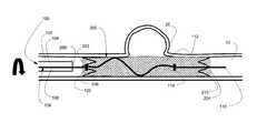
- FIG. 1is a drawing depicting an implantation system in a delivery configuration according to the present invention
- FIGS. 2A to 2Hare drawings illustrating steps for use of an implantation system according to the present invention.
- FIGS. 3A to 3Care drawings depicting shapes of a delivery wire portion according to the present invention.
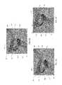
- FIG. 4is an image depicting a braided implant having a segment poorly apposed to a vessel wall as known in the art
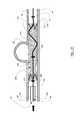
- FIG. 5is an image depicting an implantation system during implantation according to the present invention.
- FIGS. 6A to 6Care images illustrating steps for use of an implantation system according to the present invention.
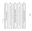
- FIG. 7is a flow diagram outlining example method steps for use of an apparatus or system for deploying an implant according to the present invention.
- An example of an implantation system 100can have a catheter 102 , an expandable element 200 , and a delivery wire 106 .
- the catheter 102can have an inner lumen 104
- the expandable element 200can be formed into a compressed configuration that is dimensioned to fit within the inner lumen 104 of the catheter 102 .
- the expandable element 200can have a proximal end 202 , a distal end 204 , a braided portion 206 located between the proximal end 202 and the distal end 204 , a proximal anchor member 208 disposed at the proximal end 202 , and a distal anchor member 210 disposed at the distal end 204 .
- the delivery wire 106can be disposed within and extend through the inner lumen 104 of the catheter 102 and the expandable element 200 and can be used to deliver the expandable element 200 to a treatment site and position the expandable element 200 at the treatment site.
- the delivery wire 106can have a proximal portion 108 , a distal portion 110 , a proximal bump member 114 located at a distal end of the proximal portion 108 , a distal bump member 114 located at a proximal end of the distal portion 110 , and a shapeable portion 112 located between the proximal bump member 116 and the distal bump member 114 .
- the shapeable portion 112can have a substantially straight shape that has flexibility to navigate through a catheter 102 to a treatment site.
- the delivery wire 106can further include a recapture bump 120 positioned between the distal bump 114 and the proximal bump 116 .
- Delivery, positioning, retraction of an expandable element such as a stent within a body lumen utilizing a delivery wire having a distal bump member, proximal bump member, and a recapture bumpis the subject of another patent application filed concurrently with this application.
- One or all of the bump members 114 , 116 , 120can include a radiopaque material to allow the location of the bumps 144 , 116 , 120 to be readily visible during an implanting procedure.
- the one or more anchor members 208 , 210can be projections which extend generally parallel to a longitudinal axis of the expandable element 200 and extend downward toward the longitudinal axis of the expandable element 200 .
- the anchor members 208 , 210can serve as a radiopaque marker for improved visualization during the deployment of the expandable element 200 within the body lumen 10 .
- the anchor members 208 , 210can be used to align the expandable element 200 so it can be pushed and pulled through the catheter 102 without damage or deformation.
- the anchor members 208 , 210can also be used to move the braided portion 206 into an expanded/implanted configuration.
- An example of the anchor member 208 , 210can be found in U.S. Ser. No. 15/299,918, the entirety of which is incorporated herein by reference.
- the expandable element 200can have a compressed configuration and an expanded, implanted, configuration. In the compressed configuration the expandable element 200 can be dimensioned to fit within the inner lumen 104 of the catheter 102 . In certain examples, the catheter 102 can aid in constraining the expandable element 200 so it does not expand when contained within the catheter 102 . Other elements can be used to constrain the expandable element 200 as are known in the art.
- the expandable element 200can also have a partially implanted configuration where the proximal end 202 is dimensioned to fit within the inner lumen 104 of the catheter 102 and the distal end 204 is dimensioned larger than the catheter 102 .
- FIGS. 2A to 2Hare drawings illustrating steps for use of an implantation system.
- the distal bump 114can be positioned inside the expandable element 200 such that a distal movement of the delivery wire 106 can cause the distal bump 114 to push against the distal anchor 210 , pulling the expandable anchor 200 through the catheter 102 to a treatment site.
- the distal bump member 114can push the distal anchor member 210 to expel the distal anchor member 210 from the catheter 102 , thereby moving the expandable element 200 to a partially implanted configuration as illustrated in FIG. 2A .
- the shapeable portion 112 of the delivery wire 106can move from a straight shape to a curved shape as illustrated in FIGS. 2A to 2H .
- the shapeable portion 112can provide a radial force from within the braided portion 206 of the expandable element 200 when the expandable element is in the partially implanted configuration.
- the entire delivery wire 106can be made of stainless steel.
- the delivery wire 106 and/or the shapeable portion 112can be made of a memory shape material including a memory shape metal such as Nitinol or a polymeric memory shape material.
- the shapeable portion 112can move from a substantially straight flexible configuration while in the catheter 102 to a curved configuration upon contacting bodily fluid when exiting the catheter 102 .
- the shapeable portion 112can curve to conform to the shape of a curved bodily lumen such that distal and proximal movements of the expandable element 200 , delivery wire 106 , and catheter 102 can cause the delivery wire 106 to move to provide a radial force from within the braided portion 206 .
- the intermediate portion 206 of the expandable element 200may not fully conform to the walls of a body lumen 10 .
- the delivery wire 106can be rotatable in relation to the expandable element 200 , and the rotation can cause the shaped portion 112 of the delivery wire 106 to provide a force against the expandable element 200 , pushing portions of the expandable element to conform to the walls of the body lumen 10 .
- the delivery wire 106can be movable in a distal and a proximal direction in relation to the expandable element 200 without disturbing the placement of the partially implanted expandable element 200 .
- the distal and proximal movementcan also cause the shaped portion 112 of the delivery wire 106 to move against the expandable element 200 , causing portions of the expandable element 200 to better conform to the walls of the body lumen 10 .
- the delivery wire 106can be subsequently rotated to improve conformity of the expandable element 200 to the walls of the body lumen 10 .
- the delivery wire 106can further be moved distally to engage the proximal, pusher bump 116 with the proximal anchor 208 .
- proximal anchor 208can expand to engage the walls of the body lumen 10 .
- the expandable element 200can be disengaged from the delivery wire 106 . As illustrated in FIG. 2F , portions of the expandable element 200 may remain not completely conforming to the walls of the body lumen 10 .
- the delivery wire 106can subsequently be moved proximally to side against portions of the braid, resulting in better conformity to the walls of the body lumen 10 .
- the delivery wire 106can subsequently be rotated, and the shaped portion 112 can slide against portions of the braid, resulting in better conformity to the walls of the body lumen 10 .
- the expandable element 200can be expanded to conform to the dimensions of the patient's body lumen 10 .
- the expanded dimension of the expandable element 200allows the apparatus 100 to pass therethrough, to either advance to a second location or be withdrawn.
- the expandable element 200can be expandable at least in part under its inherent proprieties, based at least on its original shape and the nature of the materials that make up the element, and further expanded by movement of the delivery wire 106 as described herein.
- Examples of the expandable element 200can be one of pear shaped, ovoid, and elliptical when at its expanded diameter.
- the construction of the expandable element 200is known to those of skill in the art. Other embodiments are contemplated for expandable elements 200 of this disclosure and can also be observed in U.S. Pat. Pub. 2016/0058524, a reference that is incorporated in its entirety herein.
- FIGS. 3A to 3Cillustrate some potential shapes that a shapeable portion 112 of the delivery wire 106 can have when the expandable element is in a partially implanted configuration.
- Arced, curved, “S” and “C” shapedare some examples.
- the shapeable portion 112presents an atraumatic section 113 to contact both the braided implant 200 and possibly the wall of the body lumen 10 .
- This atraumatic section 113minimizes damage to one or both of the implant 200 and lumen 10 .
- Another example of an atraumatic section 113is to minimize the amount of radial force applied once the shapeable portion 112 deforms from the straight to curved shape. Too much force, even applied by an atraumatic shape 113 , can still damage the implant/lumen. Too little force or shape and the implant will not open to its full potential shape.
- FIG. 4depicts a braided implant having a segment poorly apposed to a vessel wall as known in the art. It is an object of the present invention to provide devices, systems, and methods of treatment for improving conformity of an implant to a vessel wall.
- FIG. 5depicts a partially implanted expandable element that is a braided implant 200 having a distal end 204 positioned outside a catheter 102 and a delivery wire 106 positioned inside the implant 200 , the delivery wire 106 having a distal coil 220 positioned distal the implant 200 , a distal bump 114 positioned inside the implant, a recapture bump 120 positioned inside the implant 200 proximal the distal bump 114 , and proximal bump 116 positioned proximal the implant 200 inside the catheter 102 .
- the implant 200 as depicted in FIG. 5has a poorly apposed portion 201 that is not extended to conform to the vasculature 10 .
- FIGS. 6A to 6Cillustrate movement of the delivery wire 106 within the system illustrated in FIG. 5 to provide an outward radial force from within the poorly apposed portion 201 and other portions of the implant 200 not fully apposed to the walls to move those portions closer to the walls of the vascular 10 .
- the delivery wire 106can be moved distally to extend against an outer curved portion of the implant 200 and/or to provide a pushing force by the proximal bump 116 against a proximal anchor (not shown) of the implant 200 .
- the delivery wire 106can be pulled proximally to press against an inner curved portion of the implant 200 and/or to retract at least a portion of the implant 200 into the catheter 102 .
- the shaped portion 112 of the delivery wire 106can be flexible to curve to the shape of a curved vasculature 10 and need not reshape as a result of being made from a memory shape material.
- the shapeable portion 112can solely curve to conform to the shape of a curved bodily lumen such that distal and proximal movements of the expandable element 200 , delivery wire 106 , and catheter 102 can cause the delivery wire to move to provide a radial force from within the braided portion 206 .
- the non-preshaped shapeable portion 112can curve based on bringing the deliver wire 106 through the inside of the curve and the outside of a curve of a vasculature where the braided portion 206 is to be implanted.
- FIG. 7is a flow diagram outlining example method steps for use of an apparatus or system for deploying an implant.
- the method stepscan be implemented by an of the example means described herein or by any means that would be known to one of ordinary skill in the art.
- an implantation delivery system having a catheter, an expandable element, and a delivery wirecan be provided.
- the implantation delivery systemcan be any of the delivery systems described herein having any combination of the features described here, as well as any features that would be known to one skilled in the art.
- a first portion of the expandable elementcan be moved to exit the catheter.
- a second portion of the expandable elementcan be maintained within the catheter to establish a partially implanted configuration.
- the delivery wirecan be moved independent of the expandable element in the partially implanted configuration.
- a circumference of the expandable elementcan be enlarged in response to the movement of the delivery wire in step 740 .
Landscapes
- Health & Medical Sciences (AREA)
- Engineering & Computer Science (AREA)
- Biomedical Technology (AREA)
- Cardiology (AREA)
- Public Health (AREA)
- Veterinary Medicine (AREA)
- Heart & Thoracic Surgery (AREA)
- Vascular Medicine (AREA)
- Life Sciences & Earth Sciences (AREA)
- Animal Behavior & Ethology (AREA)
- General Health & Medical Sciences (AREA)
- Transplantation (AREA)
- Oral & Maxillofacial Surgery (AREA)
- Mechanical Engineering (AREA)
- Surgery (AREA)
- Epidemiology (AREA)
- Gastroenterology & Hepatology (AREA)
- Pulmonology (AREA)
- Media Introduction/Drainage Providing Device (AREA)
- Prostheses (AREA)
Abstract
Description
The present invention generally relates to devices for interventional therapeutic treatment or vascular surgery for treatment of defects in the vasculature, and more particularly to delivering a stent to a treatment site in a body lumen of a patient and opening the stent at the treatment site.
Stents are inserted into a blood vessel to provide an open path within the blood vessel, and they have been widely used intravascular angioplasty treatment of occluded blood vessels and other applications. Stents can be self-expanding or can be expanded by a radial force applied from inside the stent, for example when the stent is fitted with a balloon.
A braided stent can be characterized by a tube of metal wires woven together with a plain weaving technique. During delivery to a treatment site, a braided stent can travel through a catheter in an elongated, collapsed configuration, having a small diameter, and the braided stent can enlarge in diameter at a treatment site. Proper treatment with a braided stent can require that the stent extend radially to the walls of the body lumen in which the stent is implanted. Although braided stents can be self-expanding, such implants typically open with low opening forces, and therefore may not fully open to conform to a vessel wall. Post deployment, ancillary devices such as guidewires, catheters, balloons, etc. can be used to cross the braid and attempt to further expand the braided stent to improve vessel wall conformity. Issues such as unintentional braid movement or inability to fully open the braid commonly occur. Further, a braided implant that is separated from a delivery wire cannot be recovered for repositioning.
It is an object of the present invention to provide systems, devices, and methods for improving vessel wall conformity of a braided stent. Generally, an expandable element having a distal anchor member at a distal end, a proximal anchor member at a proximal end, and a braided intermediate portion can be delivered to a treatment site through a catheter by a delivery wire having a first, distal bump that can be translated distally to push the distal anchor distally and release the distal anchor upon exiting a distal end of the catheter, a shaped segment that can be moved to apply a radial force from within the braided intermediate portion to expand the braided intermediate portion, and a second, proximal bump that can be translated distally to push the proximal anchor distally and expel the expandable element from the catheter.
The delivery wire can also have a third, recapture bump positioned proximal the distal bump and distal the proximal bump that can be translated proximally to push the proximal anchor proximally. A partially implanted expandable element having a distal portion expelled from the catheter and released from the delivery wire and a proximal anchor positioned within the catheter can be retracted by translating the delivery wire proximally to push the proximal anchor proximally, thereby pulling the braided portion and distal anchor proximally into the catheter.
An example vascular treatment apparatus can include a catheter, an expandable element, and a delivery wire. The catheter can have an inner lumen through which the expandable element can be delivered by the delivery wire to a treatment site. The expandable element can have a proximal end, a distal end, a braided portion located between the proximal end and the distal end, a proximal anchor member disposed at the proximal end, and a distal anchor member disposed at the distal end.
The expandable element can have a compressed configuration dimensioned to fit within the inner lumen of the catheter for delivery to the treatment site and a partially implanted configuration when the expandable element is not fully implanted at the treatment site. In the partially implanted configuration, the proximal end of the expandable element can be dimensioned to fit within the inner lumen of the catheter, and the distal end can be dimensioned larger than the catheter.
The delivery wire can be disposed within and extend through the inner lumen of the catheter and the expandable element, the expandable element having a substantially tubular shape. The delivery wire can have a proximal portion, a proximal bump member located at a distal end of the proximal portion, a distal portion, a distal bump member located at a proximal end of the distal portion, and a shapeable portion located between the proximal bump member and the distal bump. The shapeable portion can be movable from a substantially straight configuration to a curved configuration upon exiting the inner lumen of the catheter.
The expandable element can be movable from the compressed configuration to the partially implanted configuration by a distal movement of the delivery wire which can cause the distal bump member of the delivery wire to engage with the distal anchor member of the expandable element and push the distal anchor member distally. The distal anchor member can be expelled from the catheter pushing the distal anchor member out of the catheter with the distal bump member.
The delivery wire can be moved distally, proximally, and rotationally in relation to the expandable element in the partially implanted configuration, and the shapeable portion of the delivery wire can be moved to provide a radial force from within the braided portion of the expandable element when the expandable element is in the partially implanted configuration.
The shapeable portion can be movable to at least one of a symmetrical arc shape, an asymmetrical arc shape, or an approximate “S” shape in the curved configuration.
The expandable element can be in the compressed configuration and positioned entirely within the inner lumen of the catheter. When the expandable element is in the compressed configuration and positioned entirely within the inner lumen of the catheter, the shaped portion can be in the substantially straight configuration and can be positioned within a lumen of the braided portion of the expandable element, the distal bump member can be positioned within the lumen of the braided portion of the expandable element, and the proximal bump member can be positioned proximal the proximal anchor member.
The expandable element can be in the partially implanted configuration such that the distal end of the expandable element is positioned outside the catheter and the proximal end and the proximal anchor of the expandable element are positioned within the inner lumen of the catheter. When the expandable element is in the partially implanted configuration, the shapeable portion of the delivery wire can be in the curved configuration and positioned outside the catheter, and a rotation of the delivery wire in relation to the expandable element can expand a radius of the expandable element.
An example method for implanting a stent can include the steps of: providing an implantation system comprising a catheter, an expandable element, and a delivery wire; moving a first portion of the expandable element to exit the catheter; maintaining a second portion of the expandable element within the catheter to establish a partially implanted configuration; moving the delivery wire independent of the expandable element in the partially implanted configuration; and enlarging a circumference of the expandable element in response to the moving the delivery wire. The method can further include the steps of positioning a proximal anchor at a proximal end of the expandable element; positioning a distal anchor at a distal end of the expandable element; positioning a distal bump on the delivery wire; positioning a proximal bump on the delivery wire proximal to the distal bump; positioning the distal bump within a lumen of the expandable element; positioning the proximal bump proximal to the expandable element; positioning the expandable element and at least a portion of the delivery wire within a lumen of the catheter; and moving the distal anchor and the expandable element distally through the lumen of the catheter by pushing the delivery wire distally thereby pushing the distal bump against the distal anchor; expelling the proximal anchor from the distal end of the catheter by pushing the delivery wire distally thereby pushing the proximal bump against the proximal anchor; and expanding the expelled proximal anchor.
The step of moving a first portion of the expandable element to exit the catheter can include the steps of expelling the distal anchor from a distal end of the catheter by pushing the delivery wire distally thereby pushing the distal bump against the distal anchor; and expanding the expelled distal anchor.
The step of moving the delivery wire independent of the expandable element in the partially implanted configuration can include the step of maintaining the proximal anchor within the lumen of the catheter.
The step of enlarging a circumference of the expandable element in response to the moving the delivery wire can include the step of providing a radial force from the delivery wire against the expandable element from within the lumen of the expandable element.
The method can further include the steps of shaping a portion of the delivery wire from a substantially straight configuration to a curved configuration upon a distal movement of the portion from within the lumen of the catheter to a position outside the lumen of the catheter; sliding the shaped portion of the delivery wire against the expandable element from within the lumen of the expandable element; extending a portion of the expandable element to a wall of a vascular by moving the shaped portion against the expandable element; and moving the second portion of the expandable element to exit the catheter and become implanted by pushing the expandable element distally with a distal movement of the delivery wire.
An example system for implanting a stent or other such expandable element can include a catheter, a braided stent, and a delivery wire. The braided stent can be movable to a partially implanted configuration characterized by a portion of the braided stent exterior to the catheter and a portion of the braided stent within the catheter, and the delivery wire can be movable independent of the braided stent and movable to provide a force to open the braided stent when the braided stent is in a partially implanted configuration.
The braided stent can be moved in a compressed configuration through the catheter and can be movable from the compressed configuration to the partially implanted configuration. The braided stent of the system can have a first expandable anchor at a distal end and a second expandable anchor at a proximal end, such that, in the partially implanted configuration, the first expandable anchor is expanded in an implanted position distal to the catheter and the second expandable anchor is compressed within the catheter.
The delivery wire can be movable in a distal direction, a proximal direction, and in a rotational direction independent of the braided stent when the braided stent is in the partially implanted configuration. The delivery wire can extend through the braided stent when the braided stent is in the compressed configuration and when the braided stent is in the partially implanted configuration.
The delivery wire can include a pusher bump that can be positioned proximal the second expandable anchor when the braided stent is in the compressed configuration and when the braided stent is in the partially implanted configuration. The pusher bump can be movable to push the second expandable anchor distally thereby pushing the braided stent distally when the braided stent is in the partially implanted configuration.
The delivery wire can include a shapeable segment that can be positioned within the braided stent when the braided stent is in the compressed configuration and when the braided stent is in the partially implanted configuration. The shapeable segment can be movable from a substantially straight configuration when the braided stent is in the compressed configuration to a curved configuration when the braided stent is in the partially implanted configuration, and the shapeable segment can be movable independent of the braided stent when the braided stent is in the partially implanted configuration. The shapeable segment can be movable to form an arc shape, an undulating shape, or other atraumatic shape when in the curved configuration.
The delivery wire can include a puller bump positioned distal the pusher bump and the shapeable segment and also positioned proximal the first expandable anchor when the braided stent is in the compressed configuration.
The above and further aspects of this invention are further discussed with reference to the following description in conjunction with the accompanying Figures, in which like numerals indicate like structural elements and features in various Figures. Images and drawings in the Figures are not necessarily to scale, emphasis instead being placed upon illustrating principles of the invention. As indicated, the Figures depict one or more implementations of the inventive devices, by way of example only, not by way of limitation.
In the following detailed description, numerous specific details are set forth by way of examples in order to provide a thorough understanding of the relevant teachings. However, it should be apparent to those skilled in the art that the present teachings may be practiced without such details. In other instances, well known methods, procedures, components, and/or circuitry have been described at a relatively high-level, without detail, in order to avoid unnecessarily obscuring aspects of the present teachings.
An example of animplantation system 100, as illustrated inFIG. 1 can have acatheter 102, anexpandable element 200, and adelivery wire 106. Thecatheter 102 can have aninner lumen 104, and theexpandable element 200 can be formed into a compressed configuration that is dimensioned to fit within theinner lumen 104 of thecatheter 102. Theexpandable element 200 can have aproximal end 202, adistal end 204, abraided portion 206 located between theproximal end 202 and thedistal end 204, aproximal anchor member 208 disposed at theproximal end 202, and adistal anchor member 210 disposed at thedistal end 204. Thedelivery wire 106 can be disposed within and extend through theinner lumen 104 of thecatheter 102 and theexpandable element 200 and can be used to deliver theexpandable element 200 to a treatment site and position theexpandable element 200 at the treatment site. Thedelivery wire 106 can have aproximal portion 108, adistal portion 110, aproximal bump member 114 located at a distal end of theproximal portion 108, adistal bump member 114 located at a proximal end of thedistal portion 110, and ashapeable portion 112 located between theproximal bump member 116 and thedistal bump member 114. When theexpandable element 200 is in the compressed configuration for delivery through thecatheter 102, theshapeable portion 112 can have a substantially straight shape that has flexibility to navigate through acatheter 102 to a treatment site.
Thedelivery wire 106 can further include a recapturebump 120 positioned between thedistal bump 114 and theproximal bump 116. Delivery, positioning, retraction of an expandable element such as a stent within a body lumen utilizing a delivery wire having a distal bump member, proximal bump member, and a recapture bump is the subject of another patent application filed concurrently with this application.
One or all of thebump members bumps
The one ormore anchor members expandable element 200 and extend downward toward the longitudinal axis of theexpandable element 200. Theanchor members expandable element 200 within thebody lumen 10. Theanchor members expandable element 200 so it can be pushed and pulled through thecatheter 102 without damage or deformation. Theanchor members portion 206 into an expanded/implanted configuration. An example of theanchor member
Typically, theexpandable element 200 can have a compressed configuration and an expanded, implanted, configuration. In the compressed configuration theexpandable element 200 can be dimensioned to fit within theinner lumen 104 of thecatheter 102. In certain examples, thecatheter 102 can aid in constraining theexpandable element 200 so it does not expand when contained within thecatheter 102. Other elements can be used to constrain theexpandable element 200 as are known in the art.
Theexpandable element 200 can also have a partially implanted configuration where theproximal end 202 is dimensioned to fit within theinner lumen 104 of thecatheter 102 and thedistal end 204 is dimensioned larger than thecatheter 102.
Upon exiting the catheter, theshapeable portion 112 of thedelivery wire 106 can move from a straight shape to a curved shape as illustrated inFIGS. 2A to 2H . Theshapeable portion 112 can provide a radial force from within the braidedportion 206 of theexpandable element 200 when the expandable element is in the partially implanted configuration.
In an example, theentire delivery wire 106, including theshapeable portion 112, can be made of stainless steel. In other examples, thedelivery wire 106 and/or theshapeable portion 112 can be made of a memory shape material including a memory shape metal such as Nitinol or a polymeric memory shape material. Theshapeable portion 112 can move from a substantially straight flexible configuration while in thecatheter 102 to a curved configuration upon contacting bodily fluid when exiting thecatheter 102. Additionally or alternatively, theshapeable portion 112 can curve to conform to the shape of a curved bodily lumen such that distal and proximal movements of theexpandable element 200,delivery wire 106, andcatheter 102 can cause thedelivery wire 106 to move to provide a radial force from within the braidedportion 206.
As illustrated inFIG. 2A , during treatment, because self-expanding braided implants may provide a low radial force during implantation, at least some of theintermediate portion 206 of theexpandable element 200 may not fully conform to the walls of abody lumen 10.
As illustrated inFIG. 2B , thedelivery wire 106 can be rotatable in relation to theexpandable element 200, and the rotation can cause the shapedportion 112 of thedelivery wire 106 to provide a force against theexpandable element 200, pushing portions of the expandable element to conform to the walls of thebody lumen 10.
As illustrated inFIG. 2C , thedelivery wire 106 can be movable in a distal and a proximal direction in relation to theexpandable element 200 without disturbing the placement of the partially implantedexpandable element 200. The distal and proximal movement can also cause the shapedportion 112 of thedelivery wire 106 to move against theexpandable element 200, causing portions of theexpandable element 200 to better conform to the walls of thebody lumen 10.
As illustrated inFIG. 2D , thedelivery wire 106 can be subsequently rotated to improve conformity of theexpandable element 200 to the walls of thebody lumen 10.
As illustrated inFIG. 2E , when theexpandable element 200 is in the partially implanted configuration, thedelivery wire 106 can further be moved distally to engage the proximal,pusher bump 116 with theproximal anchor 208.
As illustrated inFIG. 2F , further distal movement of thedelivery wire 106 can expel theproximal anchor 208 from thecatheter 102. Once theproximal anchor 208 is expelled from thecatheter 102, the proximal anchor can expand to engage the walls of thebody lumen 10. Once theproximal anchor 208 is expanded, theexpandable element 200 can be disengaged from thedelivery wire 106. As illustrated inFIG. 2F , portions of theexpandable element 200 may remain not completely conforming to the walls of thebody lumen 10.
As illustrated inFIG. 2G , thedelivery wire 106 can subsequently be moved proximally to side against portions of the braid, resulting in better conformity to the walls of thebody lumen 10.
As illustrated inFIG. 2H , thedelivery wire 106 can subsequently be rotated, and the shapedportion 112 can slide against portions of the braid, resulting in better conformity to the walls of thebody lumen 10.
In the expanded configuration, as illustrated inFIG. 2H , theexpandable element 200 can be expanded to conform to the dimensions of the patient'sbody lumen 10. The expanded dimension of theexpandable element 200 allows theapparatus 100 to pass therethrough, to either advance to a second location or be withdrawn. Theexpandable element 200 can be expandable at least in part under its inherent proprieties, based at least on its original shape and the nature of the materials that make up the element, and further expanded by movement of thedelivery wire 106 as described herein. Examples of theexpandable element 200 can be one of pear shaped, ovoid, and elliptical when at its expanded diameter. The construction of theexpandable element 200 is known to those of skill in the art. Other embodiments are contemplated forexpandable elements 200 of this disclosure and can also be observed in U.S. Pat. Pub. 2016/0058524, a reference that is incorporated in its entirety herein.
In the example illustrated inFIGS. 6A to 6C , the shapedportion 112 of thedelivery wire 106 can be flexible to curve to the shape of acurved vasculature 10 and need not reshape as a result of being made from a memory shape material. Theshapeable portion 112 can solely curve to conform to the shape of a curved bodily lumen such that distal and proximal movements of theexpandable element 200,delivery wire 106, andcatheter 102 can cause the delivery wire to move to provide a radial force from within the braidedportion 206. In this example, the non-preshapedshapeable portion 112 can curve based on bringing the deliverwire 106 through the inside of the curve and the outside of a curve of a vasculature where the braidedportion 206 is to be implanted.
Referring tomethod 700 illustrated inFIG. 7 , instep 710 an implantation delivery system having a catheter, an expandable element, and a delivery wire can be provided. The implantation delivery system can be any of the delivery systems described herein having any combination of the features described here, as well as any features that would be known to one skilled in the art. In step720 a first portion of the expandable element can be moved to exit the catheter. In step730 a second portion of the expandable element can be maintained within the catheter to establish a partially implanted configuration. Instep 740 the delivery wire can be moved independent of the expandable element in the partially implanted configuration. In step750 a circumference of the expandable element can be enlarged in response to the movement of the delivery wire instep 740.
The descriptions contained herein are examples of embodiments of the invention and are not intended in any way to limit the scope of the invention. As described herein, the invention contemplates many variations and modifications of the implantation system and methods of use thereof, including various shapes of the shapeable portion of the delivery wire, various materials, various treatments, and various stent geometries. These modifications would be apparent to those having ordinary skill in the art to which this invention relates and are intended to be within the scope of the claims which follow.
Claims (11)
1. A vascular treatment apparatus, comprising:
a catheter comprising an inner lumen;
an expandable element comprising:
a proximal end;
a distal end;
a braided portion located between the proximal end and the distal end;
a proximal anchor member disposed at the proximal end;
a distal anchor member disposed at the distal end;
a compressed configuration dimensioned to fit within the inner lumen of the catheter; and
a partially implanted configuration wherein the proximal end is dimensioned to fit within the inner lumen of the catheter and the distal end is dimensioned larger than the catheter; and
a delivery wire disposed within and extending through the inner lumen and the expandable element, comprising:
a proximal portion;
a proximal bump member located at a distal end of the proximal portion;
a distal portion;
a distal bump member located at a proximal end of the distal portion; and
a shapeable portion located between the proximal bump member and the distal bump member, the shapeable portion movable from a substantially straight configuration to a curved configuration upon exiting the inner lumen of the catheter,
wherein the expandable element is movable from the compressed configuration to the partially implanted configuration by a distal movement of the delivery wire causing the distal bump member of the delivery wire to engage with the distal anchor member of the expandable element and push the distal anchor member distally, thereby expelling the distal anchor member from the catheter,
wherein the delivery wire is movable distally, proximally, and rotationally in relation to the expandable element in the partially implanted configuration, and
wherein the shapeable portion of the delivery wire is movable to provide a radial force from within the braided portion of the expandable element when the expandable element is in the partially implanted configuration.
2. The apparatus ofclaim 1 wherein the shapeable portion is movable to at least one of a symmetrical arc shape, an asymmetrical arc shape, an approximate “S” shape and an atraumatic shape in the curved configuration.
3. The apparatus ofclaim 1 wherein the apparatus is configurable as follows:
the expandable element is in the compressed configuration and is positioned entirely within the inner lumen of the catheter,
the shaped portion is in the substantially straight configuration and is positioned within a lumen of the braided portion of the expandable element,
the distal bump member is positioned within the lumen of the braided portion of the expandable element, and
the proximal bump member is positioned proximal the proximal anchor member.
4. The apparatus ofclaim 1 wherein the apparatus is configurable as follows:
the expandable element is in the partially implanted configuration,
the distal end of the expandable element is positioned outside the catheter,
the proximal end and the proximal anchor of the expandable element are positioned within the inner lumen of the catheter, and
the shapeable portion of the delivery wire is in the curved configuration and is positioned outside the catheter.
5. The apparatus ofclaim 4 wherein a rotation of the delivery wire in relation to the expandable element expands a radius of the expandable element.
6. A system for implanting a stent comprising:
a catheter;
a braided stent movable to a partially implanted configuration wherein a portion of the braided stent is exterior to the catheter and a portion of the braided stent is within the catheter; and
a delivery wire movable independent of the braided stent and movable to provide a force to open the braided stent when the braided stent is in a partially implanted configuration;
wherein the braided stent comprises a first expandable anchor at a distal end and a second expandable anchor at a proximal end,
wherein the braided stent is movable in a compressed configuration through the catheter,
wherein the braided stent is movable from the compressed configuration to the partially implanted configuration such that first expandable anchor is expanded in an implanted position distal to the catheter and the second expandable anchor is compressed within the catheter,
wherein the delivery wire comprises a pusher bump and a shapeable segment,
wherein the delivery wire is movable to extend through the braided stent when the braided stent is in the compressed configuration and when the braided stent is in the partially implanted configuration,
wherein the pusher bump is movable to a position proximal the second expandable anchor when the braided stent is in the compressed configuration and when the braided stent is in the partially implanted configuration,
wherein the shapeable segment is movable to a position within the braided stent when the braided stent is in the compressed configuration and when the braided stent is in the partially implanted configuration,
wherein the shapeable segment is movable from a substantially straight configuration when the braided stent is in the compressed configuration to a curved configuration when the braided stent is in the partially implanted configuration, and
wherein the shapeable segment is movable independent of the braided stent when the braided stent is in the partially implanted configuration.
7. The system ofclaim 6 wherein the pusher bump is movable to push the second expandable anchor distally thereby pushing the braided stent distally when the braided stent is in the partially implanted configuration.
8. The system ofclaim 6 wherein the delivery wire further comprises a puller bump movable to a position distal the pusher bump and the shapeable segment and positioned proximal the first expandable anchor when the braided stent is in the compressed configuration.
9. The system ofclaim 6 wherein the shapeable segment is movable to an arc shape in the curved configuration.
10. The system ofclaim 6 wherein the shapeable segment is movable to an undulating shape in the curved configuration.
11. The system ofclaim 6 wherein the delivery wire is movable in a distal direction, a proximal direction, and in a rotational direction independent of the braided stent when the braided stent is in the partially implanted configuration.
Priority Applications (14)
| Application Number | Priority Date | Filing Date | Title |
|---|---|---|---|
| US16/056,065US10278848B1 (en) | 2018-08-06 | 2018-08-06 | Stent delivery with expansion assisting delivery wire |
| US16/152,035US10893963B2 (en) | 2018-08-06 | 2018-10-04 | Stent delivery with expansion assisting delivery wire |
| AU2019210669AAU2019210669A1 (en) | 2018-08-06 | 2019-08-02 | Stent delivery with expansion assisting delivery wire |
| CA3051084ACA3051084A1 (en) | 2018-08-06 | 2019-08-02 | Stent delivery with expansion assisting delivery wire |
| IL268461AIL268461A (en) | 2018-08-06 | 2019-08-04 | Stent delivery with expansion assisting delivery wire |
| BR102019016190-6ABR102019016190A2 (en) | 2018-08-06 | 2019-08-05 | STENT APPLICATION WITH EXPANSION ASSISTANCE APPLICATION WIRE |
| EP19190059.6AEP3607916A1 (en) | 2018-08-06 | 2019-08-05 | Stent delivery with expansion assisting delivery wire |
| RU2019124720ARU2019124720A (en) | 2018-08-06 | 2019-08-05 | STENT DELIVERY WITH EXPANDING WIRE CONDUCTOR |
| JP2019143581AJP2020022752A (en) | 2018-08-06 | 2019-08-05 | Stent delivery with expansion assisting delivery wire |
| CN201910721574.0ACN110859690A (en) | 2018-08-06 | 2019-08-06 | Stent delivery by expansion-assisted delivery wire |
| CONC2019/0008555ACO2019008555A1 (en) | 2018-08-06 | 2019-08-06 | Delivery of stents with delivery wire that aids expansion |
| MX2019009379AMX2019009379A (en) | 2018-08-06 | 2019-08-06 | Stent delivery with expansion assisting delivery wire. |
| KR1020190095576AKR20200016190A (en) | 2018-08-06 | 2019-08-06 | Stent delivery with expansion assisting delivery wire |
| US17/097,194US20210059846A1 (en) | 2018-08-06 | 2020-11-13 | Stent delivery with expansion assisting delivery wire |
Applications Claiming Priority (1)
| Application Number | Priority Date | Filing Date | Title |
|---|---|---|---|
| US16/056,065US10278848B1 (en) | 2018-08-06 | 2018-08-06 | Stent delivery with expansion assisting delivery wire |
Related Child Applications (1)
| Application Number | Title | Priority Date | Filing Date |
|---|---|---|---|
| US16/152,035DivisionUS10893963B2 (en) | 2018-08-06 | 2018-10-04 | Stent delivery with expansion assisting delivery wire |
Publications (1)
| Publication Number | Publication Date |
|---|---|
| US10278848B1true US10278848B1 (en) | 2019-05-07 |
Family
ID=66333686
Family Applications (3)
| Application Number | Title | Priority Date | Filing Date |
|---|---|---|---|
| US16/056,065ActiveUS10278848B1 (en) | 2018-08-06 | 2018-08-06 | Stent delivery with expansion assisting delivery wire |
| US16/152,035Active2038-10-15US10893963B2 (en) | 2018-08-06 | 2018-10-04 | Stent delivery with expansion assisting delivery wire |
| US17/097,194AbandonedUS20210059846A1 (en) | 2018-08-06 | 2020-11-13 | Stent delivery with expansion assisting delivery wire |
Family Applications After (2)
| Application Number | Title | Priority Date | Filing Date |
|---|---|---|---|
| US16/152,035Active2038-10-15US10893963B2 (en) | 2018-08-06 | 2018-10-04 | Stent delivery with expansion assisting delivery wire |
| US17/097,194AbandonedUS20210059846A1 (en) | 2018-08-06 | 2020-11-13 | Stent delivery with expansion assisting delivery wire |
Country Status (12)
| Country | Link |
|---|---|
| US (3) | US10278848B1 (en) |
| EP (1) | EP3607916A1 (en) |
| JP (1) | JP2020022752A (en) |
| KR (1) | KR20200016190A (en) |
| CN (1) | CN110859690A (en) |
| AU (1) | AU2019210669A1 (en) |
| BR (1) | BR102019016190A2 (en) |
| CA (1) | CA3051084A1 (en) |
| CO (1) | CO2019008555A1 (en) |
| IL (1) | IL268461A (en) |
| MX (1) | MX2019009379A (en) |
| RU (1) | RU2019124720A (en) |
Cited By (2)
| Publication number | Priority date | Publication date | Assignee | Title |
|---|---|---|---|---|
| WO2020249928A1 (en)* | 2019-06-14 | 2020-12-17 | Oxford Endovascular Ltd. | Delivery system for deploying a self-expanding tube, and method of deploying a self-expanding tube |
| CN115844491A (en)* | 2022-12-06 | 2023-03-28 | 杭州亿科医疗科技有限公司 | Get controllable device of getting of bolt net shrink expansion |
Families Citing this family (5)
| Publication number | Priority date | Publication date | Assignee | Title |
|---|---|---|---|---|
| EP4120964A4 (en)* | 2020-03-17 | 2024-03-27 | Ka Medical, LLC | Expanding medical device with support |
| CN115245413A (en)* | 2021-12-24 | 2022-10-28 | 湖南瑞康通科技发展有限公司 | Cerebral artery stent conveying system |
| EP4482439A1 (en)* | 2022-02-23 | 2025-01-01 | Elum Technologies, Inc. | Neurovascular flow diverter and delivery systems |
| CN114432016A (en)* | 2022-04-07 | 2022-05-06 | 北京市神经外科研究所 | Conveying guide wire |
| CN115670763B (en)* | 2022-12-30 | 2023-04-07 | 艾柯医疗器械(北京)股份有限公司 | Stent delivery member, stent delivery system, and stent system |
Citations (107)
| Publication number | Priority date | Publication date | Assignee | Title |
|---|---|---|---|---|
| US8048139B2 (en)* | 2006-07-24 | 2011-11-01 | Cardiatis, S.A. | Reversible applicator for an intraluminal endoprosthesis |
| US9532792B2 (en) | 2008-07-14 | 2017-01-03 | Medtronic, Inc. | Aspiration catheters for thrombus removal |
| US9532873B2 (en) | 2008-09-17 | 2017-01-03 | Medtronic CV Luxembourg S.a.r.l. | Methods for deployment of medical devices |
| US9533344B2 (en) | 2005-11-17 | 2017-01-03 | Microvention, Inc. | Three-dimensional complex coil |
| US9539382B2 (en) | 2013-03-12 | 2017-01-10 | Medtronic, Inc. | Stepped catheters with flow restrictors and infusion systems using the same |
| US9539122B2 (en) | 2001-07-20 | 2017-01-10 | Microvention, Inc. | Aneurysm treatment device and method of use |
| US9539022B2 (en) | 2012-11-28 | 2017-01-10 | Microvention, Inc. | Matter conveyance system |
| US9539011B2 (en) | 2013-03-14 | 2017-01-10 | Stryker Corporation | Vaso-occlusive device delivery system |
| US20170007265A1 (en) | 2013-03-14 | 2017-01-12 | Stryker Corporation | Vaso-occlusive device delivery system |
| US20170007264A1 (en) | 2007-12-21 | 2017-01-12 | Microvention, Inc. | Implantation devices including hydrogel filaments |
| US9549830B2 (en) | 2008-03-25 | 2017-01-24 | Medtronic Vascular, Inc. | Eversible branch stent-graft and deployment method |
| US20170020700A1 (en) | 2010-09-17 | 2017-01-26 | Medtronic Vascular, Inc. | Method of Forming a Drug-Eluting Medical Device |
| US20170020670A1 (en) | 2011-05-12 | 2017-01-26 | Medtronic, Inc. | Delivery Catheter System With Micro and Macro Movement Control |
| US9554805B2 (en) | 2008-07-15 | 2017-01-31 | Penumbra, Inc. | Embolic coil implant system and implantation method |
| US20170027640A1 (en) | 2005-06-20 | 2017-02-02 | Medtronic Ablation Frontiers Llc | Ablation catheter |
| US20170027725A1 (en) | 2013-05-30 | 2017-02-02 | Medtronic Vascular, Inc. | Delivery System Having a Single Handed Deployment Handle for a Retractable Outer Sheath |
| US20170027692A1 (en) | 2004-11-19 | 2017-02-02 | Medtronic, Inc. | Apparatus for treatment of cardiac valves and method of its manufacture |
| US9561125B2 (en) | 2010-04-14 | 2017-02-07 | Microvention, Inc. | Implant delivery device |
| US20170035436A1 (en) | 2015-08-07 | 2017-02-09 | Microvention, Inc. | Complex Coil And Manufacturing Techniques |
| US20170035567A1 (en) | 2015-08-07 | 2017-02-09 | Medtronic Vascular, Inc. | System and method for deflecting a delivery catheter |
| US20170042548A1 (en) | 2015-08-11 | 2017-02-16 | Microvention, Inc. | System And Method For Implant Delivery |
| US9572982B2 (en) | 2008-04-30 | 2017-02-21 | Medtronic, Inc. | Techniques for placing medical leads for electrical stimulation of nerve tissue |
| US20170049596A1 (en) | 2014-04-30 | 2017-02-23 | Stryker Corporation | Implant delivery system and method of use |
| US9579484B2 (en) | 2014-09-19 | 2017-02-28 | Medtronic Vascular, Inc. | Sterile molded dispenser |
| US9585642B2 (en) | 2012-12-07 | 2017-03-07 | Medtronic, Inc. | Minimally invasive implantable neurostimulation system |
| US20170079812A1 (en) | 2015-09-18 | 2017-03-23 | Microvention, Inc. | Vessel Prosthesis |
| US20170079817A1 (en) | 2015-09-18 | 2017-03-23 | Microvention, Inc. | Implant Retention, Detachment, And Delivery System |
| US20170079766A1 (en) | 2015-09-21 | 2017-03-23 | Stryker Corporation | Embolectomy devices |
| US20170079819A1 (en) | 2015-09-18 | 2017-03-23 | Microvention, Inc. | Releasable Delivery System |
| US20170079767A1 (en) | 2015-09-21 | 2017-03-23 | Stryker Corporation | Embolectomy devices |
| US20170079671A1 (en) | 2015-09-22 | 2017-03-23 | Medtronic Vascular, Inc. | Occlusion Bypassing Apparatus With a Re-Entry Needle and a Stabilization Tube |
| US20170079820A1 (en) | 2015-09-18 | 2017-03-23 | Microvention, Inc. | Pushable Implant Delivery System |
| US20170086851A1 (en) | 2014-05-28 | 2017-03-30 | Stryker European Holdings I, Llc | Vaso-occlusive devices and methods of use |
| US20170086996A1 (en) | 2012-04-26 | 2017-03-30 | Medtronic Vascular, Inc. | Apparatus and methods for filling a drug eluting medical device via capillary action |
| US9615832B2 (en) | 2006-04-07 | 2017-04-11 | Penumbra, Inc. | Aneurysm occlusion system and method |
| US9615951B2 (en) | 2009-09-22 | 2017-04-11 | Penumbra, Inc. | Manual actuation system for deployment of implant |
| US20170100183A1 (en) | 2015-10-09 | 2017-04-13 | Medtronic, Inc. | Method for closure and ablation of atrial appendage |
| US20170100141A1 (en) | 2015-10-07 | 2017-04-13 | Medtronic Vascular, Inc. | Occlusion Bypassing Apparatus With A Re-Entry Needle and a Distal Stabilization Balloon |
| US20170100143A1 (en) | 2015-10-07 | 2017-04-13 | Stryker Corporation | Multiple barrel clot removal devices |
| US9622753B2 (en) | 2001-07-20 | 2017-04-18 | Microvention, Inc. | Aneurysm treatment device and method of use |
| US20170113023A1 (en) | 2015-10-26 | 2017-04-27 | Medtronic Vascular, Inc. | Sheathless Guide Catheter Assembly |
| US9636115B2 (en) | 2005-06-14 | 2017-05-02 | Stryker Corporation | Vaso-occlusive delivery device with kink resistant, flexible distal end |
| US9636439B2 (en) | 2003-09-19 | 2017-05-02 | Medtronic Vascular, Inc. | Delivery of therapeutics to treat aneurysms |
| US9642675B2 (en) | 2004-10-14 | 2017-05-09 | Medtronic Ablation Frontiers Llc | Ablation catheter |
| US9655989B2 (en) | 2012-10-15 | 2017-05-23 | Microvention, Inc. | Polymeric treatment compositions |
| US9655645B2 (en) | 2011-05-27 | 2017-05-23 | Stryker Corporation | Assembly for percutaneously inserting an implantable medical device, steering the device to a target location and deploying the device |
| US9655633B2 (en) | 2004-09-10 | 2017-05-23 | Penumbra, Inc. | System and method for treating ischemic stroke |
| US20170147765A1 (en) | 2015-11-19 | 2017-05-25 | Penumbra, Inc. | Systems and methods for treatment of stroke |
| US9662425B2 (en) | 2013-04-22 | 2017-05-30 | Stryker European Holdings I, Llc | Method for drug loading hydroxyapatite coated implant surfaces |
| US9662238B2 (en) | 2010-07-23 | 2017-05-30 | Medtronic, Inc. | Attachment mechanism for stent release |
| US20170151032A1 (en) | 2015-11-30 | 2017-06-01 | Penumbra, Inc. | System for endoscopic intracranial procedures |
| US9668898B2 (en) | 2014-07-24 | 2017-06-06 | Medtronic Vascular, Inc. | Stent delivery system having dynamic deployment and methods of manufacturing same |
| US9675477B2 (en) | 2013-03-15 | 2017-06-13 | Medtronic Vascular, Inc. | Welded stent having a welded soluble core |
| US9676022B2 (en) | 2012-04-03 | 2017-06-13 | Medtronic Vascular, Inc. | Apparatus for creating formed elements used to make wound stents |
| US9675782B2 (en) | 2013-10-10 | 2017-06-13 | Medtronic Vascular, Inc. | Catheter pull wire actuation mechanism |
| US20170165065A1 (en) | 2015-12-14 | 2017-06-15 | Medtronic, Inc. | Delivery system having retractable wires as a coupling mechanism and a deployment mechanism for a self-expanding prosthesis |
| US20170165062A1 (en) | 2015-12-14 | 2017-06-15 | Medtronic, Inc. | Delivery system having retractable wires as a coupling mechanism and a deployment mechanism for a self-expanding prosthesis |
| US20170165454A1 (en) | 2015-12-09 | 2017-06-15 | Medtronic Vascular, Inc. | Catheter with a lumen shaped as an identification symbol |
| US20170172772A1 (en) | 2014-04-08 | 2017-06-22 | Stryker Corporation | Implant delivery system and method of use |
| US20170172766A1 (en) | 2012-03-16 | 2017-06-22 | Microvention, Inc. | Stent And Stent Delivery Device |
| US9692557B2 (en) | 2015-02-04 | 2017-06-27 | Stryker European Holdings I, Llc | Apparatus and methods for administering treatment within a bodily duct of a patient |
| US9693852B2 (en) | 2013-03-15 | 2017-07-04 | Microvention, Inc. | Embolic protection device |
| US20170189033A1 (en) | 2016-01-06 | 2017-07-06 | Microvention, Inc. | Occlusive Embolic Coil |
| US20170189035A1 (en) | 2015-12-30 | 2017-07-06 | Stryker Corporation | Embolic devices and methods of manufacturing same |
| US9700399B2 (en) | 2012-04-26 | 2017-07-11 | Medtronic Vascular, Inc. | Stopper to prevent graft material slippage in a closed web stent-graft |
| US9700262B2 (en) | 2011-05-17 | 2017-07-11 | Stryker Corporation | Method of fabricating implantable medical devices from a polymer coupon that is bonded to rigid substrate |
| US9717500B2 (en) | 2009-04-15 | 2017-08-01 | Microvention, Inc. | Implant delivery system |
| US9717421B2 (en) | 2012-03-26 | 2017-08-01 | Medtronic, Inc. | Implantable medical device delivery catheter with tether |
| US9717502B2 (en) | 2013-03-14 | 2017-08-01 | Stryker Corporation | Vaso-occlusive device delivery system |
| US9724526B2 (en) | 2004-06-10 | 2017-08-08 | Medtronic Urinary Solutions, Inc. | Implantable pulse generator systems and methods for operating the same |
| US9724103B2 (en) | 2006-06-15 | 2017-08-08 | Microvention, Inc. | Embolization device constructed from expansile polymer |
| US20170224350A1 (en) | 2016-02-10 | 2017-08-10 | Microvention, Inc. | Devices for Vascular Occlusion |
| US20170224953A1 (en) | 2016-02-10 | 2017-08-10 | Microvention, Inc. | Intravascular Treatment Site Access |
| US20170224467A1 (en) | 2016-02-09 | 2017-08-10 | Medtronic Vascular, Inc. | Endoluminal prosthetic assemblies, and associated systems and methods for percutaneous repair of a vascular tissue defect |
| US20170231749A1 (en) | 2016-02-12 | 2017-08-17 | Medtronic Vascular, Inc. | Stent graft with external scaffolding and method |
| US9750565B2 (en) | 2011-09-30 | 2017-09-05 | Medtronic Advanced Energy Llc | Electrosurgical balloons |
| US9757260B2 (en) | 2006-03-30 | 2017-09-12 | Medtronic Vascular, Inc. | Prosthesis with guide lumen |
| US9764111B2 (en) | 2012-10-01 | 2017-09-19 | Microvention, Inc. | Catheter markers |
| US9770577B2 (en) | 2014-09-15 | 2017-09-26 | Medtronic Xomed, Inc. | Pressure relief for a catheter balloon device |
| US9770251B2 (en) | 2012-08-13 | 2017-09-26 | Microvention, Inc. | Shaped removal device |
| US9775706B2 (en) | 2010-04-20 | 2017-10-03 | Medtronic Vascular, Inc. | Controlled tip release stent graft delivery system and method |
| US20170281909A1 (en) | 2016-04-05 | 2017-10-05 | Stryker Corporation | Medical devices and methods of manufacturing same |
| US20170281344A1 (en) | 2016-03-31 | 2017-10-05 | Medtronic Vascular, Inc. | Expandable introducer sheath having a steering mechanism |
| US20170281912A1 (en) | 2016-04-04 | 2017-10-05 | Medtronic Vascular, Inc. | Drug coated balloon |
| US20170281331A1 (en) | 2016-03-31 | 2017-10-05 | Medtronic Vascular, Inc. | Endoluminal prosthetic devices having fluid-absorbable compositions for repair of a vascular tissue defect |
| US20170290654A1 (en) | 2016-04-12 | 2017-10-12 | Medtronic Vascular, Inc. | Gutter filling stent-graft and method |
| US9788800B2 (en) | 2012-07-17 | 2017-10-17 | Stryker Corporation | Notification system of deviation from predefined conditions |
| US20170296324A1 (en) | 2016-04-13 | 2017-10-19 | Medtronic Vascular, Inc. | Iliac branch device and method |
| US20170296325A1 (en) | 2016-04-18 | 2017-10-19 | Medtronic Vascular, Inc. | Stent-graft prosthesis and method of manufacture |
| US9795391B2 (en) | 2013-10-25 | 2017-10-24 | Medtronic Vascular, Inc. | Tissue compression device with tension limiting strap retainer |
| US20170303947A1 (en) | 2016-04-25 | 2017-10-26 | Stryker Corporation | Clot-engulfing mechanical thrombectomy apparatuses |
| US20170304041A1 (en) | 2016-04-25 | 2017-10-26 | Medtronic Vascular, Inc. | Dissection prosthesis system and method |
| US20170304595A1 (en) | 2016-04-25 | 2017-10-26 | Medtronic Vascular, Inc. | Balloon catheter including a drug delivery sheath |
| US20170304097A1 (en) | 2016-04-21 | 2017-10-26 | Medtronic Vascular, Inc. | Stent-graft delivery system having an inner shaft component with a loading pad or covering on a distal segment thereof for stent retention |
| US20170303948A1 (en) | 2016-04-25 | 2017-10-26 | Stryker Corporation | Anti-jamming and macerating thrombectomy apparatuses and methods |
| US20170303939A1 (en) | 2016-04-25 | 2017-10-26 | Stryker Corporation | Methods for advancing inverting mechanical thrombectomy apparatuses in the vasculature |
| US9801980B2 (en) | 2010-12-20 | 2017-10-31 | Microvention, Inc. | Polymer stents and methods of manufacture |
| US20170312109A1 (en) | 2016-04-28 | 2017-11-02 | Medtronic Vascular, Inc. | Implantable medical device delivery system |
| US20170312484A1 (en) | 2016-04-28 | 2017-11-02 | Medtronic Vascular, Inc. | Drug coated inflatable balloon having a thermal dependent release layer |
| US20170316561A1 (en) | 2016-04-28 | 2017-11-02 | Medtronic Navigation, Inc. | Method and Apparatus for Image-Based Navigation |
| US9808599B2 (en) | 2013-12-20 | 2017-11-07 | Microvention, Inc. | Device delivery system |
| US20170333228A1 (en) | 2016-05-17 | 2017-11-23 | Medtronic Vascular, Inc. | Tool and method for compressing a stented prosthesis |
| US9833604B2 (en) | 2013-12-20 | 2017-12-05 | Microvention, Inc. | Delivery adapter |
| US9833625B2 (en) | 2012-03-26 | 2017-12-05 | Medtronic, Inc. | Implantable medical device delivery with inner and outer sheaths |
| US9833252B2 (en) | 2013-03-15 | 2017-12-05 | Microvention, Inc. | Multi-component obstruction removal system and method |
| US20170348514A1 (en) | 2016-06-01 | 2017-12-07 | Microvention, Inc. | Reinforced Balloon Catheter |
| US20170348014A1 (en) | 2016-06-03 | 2017-12-07 | Stryker Corporation | Inverting thrombectomy apparatuses and methods |
Family Cites Families (223)
| Publication number | Priority date | Publication date | Assignee | Title |
|---|---|---|---|---|
| US4332278A (en) | 1976-04-14 | 1982-06-01 | Titeflex Corporation | Braided-wire sheathing having bundled strands twisted to equalize tension |
| US4610688A (en) | 1983-04-04 | 1986-09-09 | Pfizer Hospital Products Group, Inc. | Triaxially-braided fabric prosthesis |
| US5104399A (en) | 1986-12-10 | 1992-04-14 | Endovascular Technologies, Inc. | Artificial graft and implantation method |
| US4754685A (en) | 1986-05-12 | 1988-07-05 | Raychem Corporation | Abrasion resistant braided sleeve |
| US5545208A (en) | 1990-02-28 | 1996-08-13 | Medtronic, Inc. | Intralumenal drug eluting prosthesis |
| US5064435A (en) | 1990-06-28 | 1991-11-12 | Schneider (Usa) Inc. | Self-expanding prosthesis having stable axial length |
| DE9117152U1 (en) | 1990-10-09 | 1996-07-11 | Cook Inc., Bloomington, Ind. | Stent |
| US5330500A (en) | 1990-10-18 | 1994-07-19 | Song Ho Y | Self-expanding endovascular stent with silicone coating |
| US5387235A (en) | 1991-10-25 | 1995-02-07 | Cook Incorporated | Expandable transluminal graft prosthesis for repair of aneurysm |
| US5382259A (en) | 1992-10-26 | 1995-01-17 | Target Therapeutics, Inc. | Vasoocclusion coil with attached tubular woven or braided fibrous covering |
| US5423849A (en) | 1993-01-15 | 1995-06-13 | Target Therapeutics, Inc. | Vasoocclusion device containing radiopaque fibers |
| US5843167A (en) | 1993-04-22 | 1998-12-01 | C. R. Bard, Inc. | Method and apparatus for recapture of hooked endoprosthesis |
| DE69330132T2 (en) | 1993-07-23 | 2001-11-15 | Cook Inc., Bloomington | FLEXIBLE STENT WITH A CONFIGURATION MOLDED FROM A MATERIAL SHEET |
| US5609627A (en) | 1994-02-09 | 1997-03-11 | Boston Scientific Technology, Inc. | Method for delivering a bifurcated endoluminal prosthesis |
| US6051020A (en) | 1994-02-09 | 2000-04-18 | Boston Scientific Technology, Inc. | Bifurcated endoluminal prosthesis |
| US6165213A (en) | 1994-02-09 | 2000-12-26 | Boston Scientific Technology, Inc. | System and method for assembling an endoluminal prosthesis |
| US5556413A (en) | 1994-03-11 | 1996-09-17 | Advanced Cardiovascular Systems, Inc. | Coiled stent with locking ends |
| US5476508A (en) | 1994-05-26 | 1995-12-19 | Tfx Medical | Stent with mutually interlocking filaments |
| US5522881A (en) | 1994-06-28 | 1996-06-04 | Meadox Medicals, Inc. | Implantable tubular prosthesis having integral cuffs |
| US5549662A (en) | 1994-11-07 | 1996-08-27 | Scimed Life Systems, Inc. | Expandable stent using sliding members |
| EP0790810B1 (en) | 1994-11-09 | 2004-04-28 | Endotex Interventional Systems, Inc. | Kit of delivery catheter and graft for aneurysm repair |
| DE19508805C2 (en) | 1995-03-06 | 2000-03-30 | Lutz Freitag | Stent for placement in a body tube with a flexible support structure made of at least two wires with different shape memory functions |
| US5709713A (en) | 1995-03-31 | 1998-01-20 | Cardiovascular Concepts, Inc. | Radially expansible vascular prosthesis having reversible and other locking structures |
| US5662622A (en) | 1995-04-04 | 1997-09-02 | Cordis Corporation | Intravascular catheter |
| BE1009277A3 (en) | 1995-04-12 | 1997-01-07 | Corvita Europ | Guardian self-expandable medical device introduced in cavite body, and method of preparation. |
| US5645558A (en) | 1995-04-20 | 1997-07-08 | Medical University Of South Carolina | Anatomically shaped vasoocclusive device and method of making the same |
| US5728131A (en) | 1995-06-12 | 1998-03-17 | Endotex Interventional Systems, Inc. | Coupling device and method of use |
| US5702418A (en) | 1995-09-12 | 1997-12-30 | Boston Scientific Corporation | Stent delivery system |
| US6193745B1 (en) | 1995-10-03 | 2001-02-27 | Medtronic, Inc. | Modular intraluminal prosteheses construction and methods |
| US5776161A (en) | 1995-10-16 | 1998-07-07 | Instent, Inc. | Medical stents, apparatus and method for making same |
| US6929659B2 (en) | 1995-11-07 | 2005-08-16 | Scimed Life Systems, Inc. | Method of preventing the dislodgment of a stent-graft |
| US6348066B1 (en) | 1995-11-07 | 2002-02-19 | Corvita Corporation | Modular endoluminal stent-grafts and methods for their use |
| ATE290832T1 (en) | 1996-01-05 | 2005-04-15 | Medtronic Inc | EXPANDABLE ENDOLUMINAL PROSTHESES |
| US6010529A (en) | 1996-12-03 | 2000-01-04 | Atrium Medical Corporation | Expandable shielded vessel support |
| ATE306873T1 (en) | 1997-01-24 | 2005-11-15 | Kentucky Oil N V | BISTABLE SPRING STRUCTURE FOR A STENT |
| US6152956A (en) | 1997-01-28 | 2000-11-28 | Pierce; George E. | Prosthesis for endovascular repair of abdominal aortic aneurysms |
| US5817126A (en) | 1997-03-17 | 1998-10-06 | Surface Genesis, Inc. | Compound stent |
| DE19720115C2 (en) | 1997-05-14 | 1999-05-20 | Jomed Implantate Gmbh | Stent graft |
| US6409755B1 (en) | 1997-05-29 | 2002-06-25 | Scimed Life Systems, Inc. | Balloon expandable stent with a self-expanding portion |
| US6635080B1 (en) | 1997-06-19 | 2003-10-21 | Vascutek Limited | Prosthesis for repair of body passages |
| US6174330B1 (en) | 1997-08-01 | 2001-01-16 | Schneider (Usa) Inc | Bioabsorbable marker having radiopaque constituents |
| US6245103B1 (en) | 1997-08-01 | 2001-06-12 | Schneider (Usa) Inc | Bioabsorbable self-expanding stent |
| US5899935A (en) | 1997-08-04 | 1999-05-04 | Schneider (Usa) Inc. | Balloon expandable braided stent with restraint |
| US5916235A (en) | 1997-08-13 | 1999-06-29 | The Regents Of The University Of California | Apparatus and method for the use of detachable coils in vascular aneurysms and body cavities |
| JPH1157010A (en) | 1997-08-19 | 1999-03-02 | Pola Chem Ind Inc | Sleep differentiation |
| US6161399A (en) | 1997-10-24 | 2000-12-19 | Iowa-India Investments Company Limited | Process for manufacturing a wire reinforced monolayer fabric stent |
| US6033436A (en) | 1998-02-17 | 2000-03-07 | Md3, Inc. | Expandable stent |
| US6015432A (en) | 1998-02-25 | 2000-01-18 | Cordis Corporation | Wire reinforced vascular prosthesis |
| US6280467B1 (en) | 1998-02-26 | 2001-08-28 | World Medical Manufacturing Corporation | Delivery system for deployment and endovascular assembly of a multi-stage stented graft |
| US6099559A (en) | 1998-05-28 | 2000-08-08 | Medtronic Ave, Inc. | Endoluminal support assembly with capped ends |
| US6168621B1 (en) | 1998-05-29 | 2001-01-02 | Scimed Life Systems, Inc. | Balloon expandable stent with a self-expanding portion |
| US6740113B2 (en) | 1998-05-29 | 2004-05-25 | Scimed Life Systems, Inc. | Balloon expandable stent with a self-expanding portion |
| US6036725A (en) | 1998-06-10 | 2000-03-14 | General Science And Technology | Expandable endovascular support device |
| US20010049554A1 (en) | 1998-11-18 | 2001-12-06 | Carlos E. Ruiz | Endovascular prosthesis and method of making |
| WO2000033769A1 (en) | 1998-12-11 | 2000-06-15 | Endologix, Inc. | Endoluminal vascular prosthesis |
| US6730116B1 (en) | 1999-04-16 | 2004-05-04 | Medtronic, Inc. | Medical device for intraluminal endovascular stenting |
| US6540774B1 (en) | 1999-08-31 | 2003-04-01 | Advanced Cardiovascular Systems, Inc. | Stent design with end rings having enhanced strength and radiopacity |
| US6325823B1 (en) | 1999-10-29 | 2001-12-04 | Revasc Corporation | Endovascular prosthesis accommodating torsional and longitudinal displacements and methods of use |
| US6585758B1 (en) | 1999-11-16 | 2003-07-01 | Scimed Life Systems, Inc. | Multi-section filamentary endoluminal stent |
| US6673107B1 (en) | 1999-12-06 | 2004-01-06 | Advanced Cardiovascular Systems, Inc. | Bifurcated stent and method of making |
| US6280465B1 (en) | 1999-12-30 | 2001-08-28 | Advanced Cardiovascular Systems, Inc. | Apparatus and method for delivering a self-expanding stent on a guide wire |
| GB0003387D0 (en) | 2000-02-14 | 2000-04-05 | Angiomed Ag | Stent matrix |
| US6319278B1 (en) | 2000-03-03 | 2001-11-20 | Stephen F. Quinn | Low profile device for the treatment of vascular abnormalities |
| US6929658B1 (en) | 2000-03-09 | 2005-08-16 | Design & Performance-Cyprus Limited | Stent with cover connectors |
| US6264683B1 (en) | 2000-03-17 | 2001-07-24 | Advanced Cardiovascular Systems, Inc. | Stent delivery catheter with bumpers for improved retention of balloon expandable stents |
| US6468301B1 (en) | 2000-03-27 | 2002-10-22 | Aga Medical Corporation | Repositionable and recapturable vascular stent/graft |
| IL137326A0 (en) | 2000-07-17 | 2001-07-24 | Mind Guard Ltd | Implantable braided stroke preventing device and method of manufacturing |
| GB0020491D0 (en) | 2000-08-18 | 2000-10-11 | Angiomed Ag | Stent with attached element and method of making such a stent |
| WO2003061502A1 (en) | 2000-10-26 | 2003-07-31 | Scimed Life Systems, Inc. | Stent having radiopaque markers and method of fabricating the same |
| US7267685B2 (en) | 2000-11-16 | 2007-09-11 | Cordis Corporation | Bilateral extension prosthesis and method of delivery |
| DE10064596A1 (en) | 2000-12-18 | 2002-06-20 | Biotronik Mess & Therapieg | Application of a marker element to an implant, especially a stent, comprises introducing a solidifiable material into a recess and solidifying the material in the recess |
| US6565599B1 (en) | 2000-12-28 | 2003-05-20 | Advanced Cardiovascular Systems, Inc. | Hybrid stent |
| US20020095205A1 (en) | 2001-01-12 | 2002-07-18 | Edwin Tarun J. | Encapsulated radiopaque markers |
| US6540777B2 (en) | 2001-02-15 | 2003-04-01 | Scimed Life Systems, Inc. | Locking stent |
| EP1372534B1 (en) | 2001-03-28 | 2006-11-29 | Cook Incorporated | Set of sections for a modular stent graft assembly |
| US6761733B2 (en) | 2001-04-11 | 2004-07-13 | Trivascular, Inc. | Delivery system and method for bifurcated endovascular graft |
| US6733521B2 (en) | 2001-04-11 | 2004-05-11 | Trivascular, Inc. | Delivery system and method for endovascular graft |
| US6821291B2 (en) | 2001-06-01 | 2004-11-23 | Ams Research Corporation | Retrievable stent and method of use thereof |
| US6612012B2 (en) | 2001-06-11 | 2003-09-02 | Cordis Neurovascular, Inc. | Method of manufacturing small profile medical devices |
| US6818013B2 (en) | 2001-06-14 | 2004-11-16 | Cordis Corporation | Intravascular stent device |
| US6673106B2 (en) | 2001-06-14 | 2004-01-06 | Cordis Neurovascular, Inc. | Intravascular stent device |
| US6994722B2 (en) | 2001-07-03 | 2006-02-07 | Scimed Life Systems, Inc. | Implant having improved fixation to a body lumen and method for implanting the same |
| US20030100945A1 (en) | 2001-11-23 | 2003-05-29 | Mindguard Ltd. | Implantable intraluminal device and method of using same in treating aneurysms |
| US20030055493A1 (en) | 2001-09-19 | 2003-03-20 | Erin Carpenter | Enhancement of stent radiopacity using anchors and tags |
| JP4043216B2 (en) | 2001-10-30 | 2008-02-06 | オリンパス株式会社 | Stent |
| US6945994B2 (en) | 2001-12-05 | 2005-09-20 | Boston Scientific Scimed, Inc. | Combined balloon-expanding and self-expanding stent |
| US7147661B2 (en) | 2001-12-20 | 2006-12-12 | Boston Scientific Santa Rosa Corp. | Radially expandable stent |
| US6911040B2 (en) | 2002-01-24 | 2005-06-28 | Cordis Corporation | Covered segmented stent |
| US7708771B2 (en) | 2002-02-26 | 2010-05-04 | Endovascular Technologies, Inc. | Endovascular graft device and methods for attaching components thereof |
| US6989024B2 (en) | 2002-02-28 | 2006-01-24 | Counter Clockwise, Inc. | Guidewire loaded stent for delivery through a catheter |
| US7288111B1 (en) | 2002-03-26 | 2007-10-30 | Thoratec Corporation | Flexible stent and method of making the same |
| US20030225448A1 (en) | 2002-05-28 | 2003-12-04 | Scimed Life Systems, Inc. | Polar radiopaque marker for stent |
| US6833003B2 (en) | 2002-06-24 | 2004-12-21 | Cordis Neurovascular | Expandable stent and delivery system |
| US20040015229A1 (en) | 2002-07-22 | 2004-01-22 | Syntheon, Llc | Vascular stent with radiopaque markers |
| US20040044399A1 (en) | 2002-09-04 | 2004-03-04 | Ventura Joseph A. | Radiopaque links for self-expanding stents |
| US7001422B2 (en) | 2002-09-23 | 2006-02-21 | Cordis Neurovascular, Inc | Expandable stent and delivery system |
| US7331986B2 (en) | 2002-10-09 | 2008-02-19 | Boston Scientific Scimed, Inc. | Intraluminal medical device having improved visibility |
| US6970734B2 (en) | 2002-12-02 | 2005-11-29 | Boston Scientific Scimed, Inc. | Flexible marker bands |
| WO2004075789A2 (en) | 2003-02-26 | 2004-09-10 | Cook Incorporated | PROTHESIS ADAPTED FOR PLACEDd UNDER EXTERNAL IMAGING |
| JP4566988B2 (en) | 2003-04-02 | 2010-10-20 | ボストン サイエンティフィック リミテッド | Separable and recoverable stent assembly |
| DE602004016310D1 (en) | 2003-04-25 | 2008-10-16 | Cook Inc | SUPPLY CATHETER |
| US7625401B2 (en) | 2003-05-06 | 2009-12-01 | Abbott Laboratories | Endoprosthesis having foot extensions |
| US7235093B2 (en) | 2003-05-20 | 2007-06-26 | Boston Scientific Scimed, Inc. | Mechanism to improve stent securement |
| US20040254637A1 (en) | 2003-06-16 | 2004-12-16 | Endotex Interventional Systems, Inc. | Sleeve stent marker |
| US8021418B2 (en) | 2003-06-19 | 2011-09-20 | Boston Scientific Scimed, Inc. | Sandwiched radiopaque marker on covered stent |
| US20050033406A1 (en) | 2003-07-15 | 2005-02-10 | Barnhart William H. | Branch vessel stent and graft |
| US7628806B2 (en) | 2003-08-20 | 2009-12-08 | Boston Scientific Scimed, Inc. | Stent with improved resistance to migration |
| US20050049482A1 (en) | 2003-08-25 | 2005-03-03 | Biophan Technologies, Inc. | Electromagnetic radiation transparent device and method of making thereof |
| US20050049668A1 (en) | 2003-08-29 | 2005-03-03 | Jones Donald K. | Self-expanding stent and stent delivery system for treatment of vascular stenosis |
| US20050049669A1 (en) | 2003-08-29 | 2005-03-03 | Jones Donald K. | Self-expanding stent and stent delivery system with distal protection |
| US20050049670A1 (en) | 2003-08-29 | 2005-03-03 | Jones Donald K. | Self-expanding stent and stent delivery system for treatment of vascular disease |
| US7122052B2 (en) | 2003-09-29 | 2006-10-17 | Stout Medical Group Lp | Integral support stent graft assembly |
| US7208008B2 (en) | 2003-10-02 | 2007-04-24 | Medtronic Vascular, Inc. | Balloonless direct stenting device |
| US20070219613A1 (en) | 2003-10-06 | 2007-09-20 | Xtent, Inc. | Apparatus and methods for interlocking stent segments |
| US8043357B2 (en) | 2003-10-10 | 2011-10-25 | Cook Medical Technologies Llc | Ring stent |
| WO2005034807A1 (en) | 2003-10-10 | 2005-04-21 | William A. Cook Australia Pty. Ltd | Composite stent graft |
| US8157855B2 (en) | 2003-12-05 | 2012-04-17 | Boston Scientific Scimed, Inc. | Detachable segment stent |
| US7641647B2 (en) | 2003-12-29 | 2010-01-05 | Boston Scientific Scimed, Inc. | Medical device with modified marker band |
| US7275471B2 (en) | 2003-12-29 | 2007-10-02 | Surpass Medical Ltd. | Mixed wire braided device with structural integrity |
| FR2865926B1 (en) | 2004-02-11 | 2006-05-12 | Perouse Laboratoires | TUBULAR PROSTHESIS. |
| US7480973B2 (en) | 2004-03-01 | 2009-01-27 | Boston Scientific Scimed, Inc. | Automated marker band nest placement crimper |
| US7497872B2 (en) | 2004-03-08 | 2009-03-03 | Cook Incorporated | Retainer for a stent-graft |
| US7761138B2 (en) | 2004-03-12 | 2010-07-20 | Boston Scientific Scimed, Inc. | MRI and X-ray visualization |
| US8267985B2 (en)* | 2005-05-25 | 2012-09-18 | Tyco Healthcare Group Lp | System and method for delivering and deploying an occluding device within a vessel |
| US20050283220A1 (en) | 2004-06-22 | 2005-12-22 | Gobran Riad H | Blood flow diverters for the treatment of intracranial aneurysms |
| US20050288775A1 (en) | 2004-06-24 | 2005-12-29 | Scimed Life Systems, Inc. | Metallic fibers reinforced textile prosthesis |
| DE602005023033D1 (en) | 2004-09-21 | 2010-09-30 | Cook Inc | STENT GRAFT CONNECTION ARRANGEMENT |
| US20060069424A1 (en) | 2004-09-27 | 2006-03-30 | Xtent, Inc. | Self-constrained segmented stents and methods for their deployment |
| WO2006065665A1 (en) | 2004-12-13 | 2006-06-22 | Robert Hunt Carpenter, Dvm, Pc | Multi-wall expandable device capable of drug delivery |
| US8128680B2 (en) | 2005-01-10 | 2012-03-06 | Taheri Laduca Llc | Apparatus and method for deploying an implantable device within the body |
| EP1838242A2 (en) | 2005-01-21 | 2007-10-03 | Gen 4, LLC | Modular stent graft employing bifurcated graft and leg locking stent elements |
| US20060212113A1 (en) | 2005-02-24 | 2006-09-21 | Shaolian Samuel M | Externally adjustable endovascular graft implant |
| US8002818B2 (en) | 2005-02-25 | 2011-08-23 | Abbott Laboratories Vascular Enterprises Limited | Modular vascular prosthesis having axially variable properties and improved flexibility and methods of use |
| US8025694B2 (en) | 2005-02-25 | 2011-09-27 | Abbott Laboratories Vascular Enterprises Limited | Modular vascular prosthesis and methods of use |
| US20070213810A1 (en) | 2005-03-14 | 2007-09-13 | Richard Newhauser | Segmented endoprosthesis |
| DE102005020785A1 (en) | 2005-05-04 | 2006-11-09 | Jotec Gmbh | Delivery system with a self-expanding braid stent |
| EP3266414B1 (en) | 2005-05-12 | 2024-07-17 | Covidien LP | Implant delivery system with interlocked rx port orientation |
| JP4912395B2 (en) | 2005-05-24 | 2012-04-11 | エドワーズ ライフサイエンシーズ コーポレイション | Rapid placement prosthetic heart valve |
| US20070005127A1 (en) | 2005-06-17 | 2007-01-04 | Peter Boekstegers | Hinged tissue implant and related methods and devices for delivering such an implant |
| US9149378B2 (en) | 2005-08-02 | 2015-10-06 | Reva Medical, Inc. | Axially nested slide and lock expandable device |
| US20070060994A1 (en) | 2005-09-12 | 2007-03-15 | Gobran Riad H | Blood flow diverters for the treatment of intracranial aneurysms |
| US8562666B2 (en) | 2005-09-28 | 2013-10-22 | Nitinol Development Corporation | Intraluminal medical device with nested interlocking segments |
| US7632302B2 (en) | 2005-11-14 | 2009-12-15 | Ev3 Inc. | Stent and stent delivery system for ostial locations in a conduit |
| FR2894131B1 (en) | 2005-12-02 | 2008-12-05 | Perouse Soc Par Actions Simpli | DEVICE FOR TREATING A BLOOD VESSEL, AND ASSOCIATED TREATMENT NECESSARY. |
| US20070156230A1 (en) | 2006-01-04 | 2007-07-05 | Dugan Stephen R | Stents with radiopaque markers |
| US8778008B2 (en) | 2006-01-13 | 2014-07-15 | Aga Medical Corporation | Intravascular deliverable stent for reinforcement of vascular abnormalities |
| WO2007084537A2 (en) | 2006-01-18 | 2007-07-26 | William A. Cook Australia Pty. Ltd. | Self expanding stent |
| EP1988851A2 (en) | 2006-02-14 | 2008-11-12 | Sadra Medical, Inc. | Systems and methods for delivering a medical implant |
| US8152833B2 (en) | 2006-02-22 | 2012-04-10 | Tyco Healthcare Group Lp | Embolic protection systems having radiopaque filter mesh |
| US20100010622A1 (en) | 2006-03-13 | 2010-01-14 | Abbott Laboratories | Hybrid segmented endoprosthesis |
| WO2007105067A1 (en) | 2006-03-14 | 2007-09-20 | Arterial Remodeling Technologies, S.A. | Method of monitoring positioning of polymeric stents |
| US8357194B2 (en) | 2006-03-15 | 2013-01-22 | Cordis Corporation | Stent graft device |
| WO2007109621A2 (en) | 2006-03-20 | 2007-09-27 | Xtent, Inc. | Apparatus and methods for deployment of linked prosthetic segments |
| US20070238979A1 (en) | 2006-03-23 | 2007-10-11 | Medtronic Vascular, Inc. | Reference Devices for Placement in Heart Structures for Visualization During Heart Valve Procedures |
| US8092508B2 (en) | 2006-03-30 | 2012-01-10 | Stryker Corporation | Implantable medical endoprosthesis delivery system |
| FR2899096B1 (en) | 2006-04-04 | 2008-12-05 | Perouse Soc Par Actions Simpli | DEVICE FOR TREATING A CIRCULATION CIRCULATION OF THE BLOOD AND METHOD OF PREPARING SAID DEVICE |
| US7655031B2 (en) | 2006-04-28 | 2010-02-02 | Codman & Shurtleff, Inc. | Stent delivery system with improved retraction member |
| EP1849440A1 (en) | 2006-04-28 | 2007-10-31 | Younes Boudjemline | Vascular stents with varying diameter |
| CN101495069A (en) | 2006-07-07 | 2009-07-29 | 波士顿科学有限公司 | Endoprosthesis delivery system with stent holder |
| US20080009938A1 (en) | 2006-07-07 | 2008-01-10 | Bin Huang | Stent with a radiopaque marker and method for making the same |
| WO2008021556A1 (en) | 2006-08-18 | 2008-02-21 | William A. Cook Australia Pty. Ltd. | Stent graft extension |
| US20080071307A1 (en) | 2006-09-19 | 2008-03-20 | Cook Incorporated | Apparatus and methods for in situ embolic protection |
| US8052732B2 (en) | 2006-11-14 | 2011-11-08 | Medtronic Vascular, Inc. | Delivery system for stent-graft with anchoring pins |
| EP2116213B1 (en) | 2007-02-01 | 2017-03-29 | Kaneka Corporation | Medical device for body cavity and method of producing the same |
| US20080221670A1 (en) | 2007-03-07 | 2008-09-11 | Claude Clerc | Radiopaque polymeric stent |
| US8623070B2 (en) | 2007-03-08 | 2014-01-07 | Thomas O. Bales | Tapered helical stent and method for manufacturing the stent |
| US8545548B2 (en) | 2007-03-30 | 2013-10-01 | DePuy Synthes Products, LLC | Radiopaque markers for implantable stents and methods for manufacturing the same |
| US8409270B2 (en) | 2007-04-16 | 2013-04-02 | Boston Scientific Scimed, Inc. | Radiopaque compositions, stents and methods of preparation |
| US7810223B2 (en) | 2007-05-16 | 2010-10-12 | Boston Scientific Scimed, Inc. | Method of attaching radiopaque markers to intraluminal medical devices, and devices formed using the same |
| WO2009002819A2 (en) | 2007-06-22 | 2008-12-31 | Cr Bard Inc. | Locked segments pushable stent-graft |
| DE102007034041A1 (en) | 2007-07-20 | 2009-01-22 | Biotronik Vi Patent Ag | Medication depots for medical implants |
| US8092510B2 (en) | 2007-07-25 | 2012-01-10 | Cook Medical Technologies Llc | Retention wire for self-expanding stent |
| US8066755B2 (en) | 2007-09-26 | 2011-11-29 | Trivascular, Inc. | System and method of pivoted stent deployment |
| US20090082847A1 (en) | 2007-09-26 | 2009-03-26 | Boston Scientific Corporation | System and method of securing stent barbs |
| US20090082845A1 (en) | 2007-09-26 | 2009-03-26 | Boston Scientific Corporation | Alignment stent apparatus and method |
| DE102007053070B4 (en) | 2007-11-07 | 2011-08-25 | Acandis GmbH & Co. KG, 76327 | Medical implant and method of making such an implant |
| US20090143815A1 (en) | 2007-11-30 | 2009-06-04 | Boston Scientific Scimed, Inc. | Apparatus and Method for Sealing a Vessel Puncture Opening |
| US20090163951A1 (en) | 2007-12-19 | 2009-06-25 | Sara Simmons | Medical devices including sutures with filaments comprising naturally derived collagenous material |
| US8187316B2 (en) | 2007-12-27 | 2012-05-29 | Cook Medical Technologies Llc | Implantable graft device having treated yarn and method for making same |
| US20090192588A1 (en) | 2008-01-29 | 2009-07-30 | Taeoong Medical Co., Ltd | Biodegradable double stent |
| US7815673B2 (en) | 2008-04-01 | 2010-10-19 | Medtronic Vascular, Inc. | Double-walled stent system |
| US7806923B2 (en) | 2008-04-11 | 2010-10-05 | Medtronic Vascular, Inc. | Side branch stent having a proximal split ring |
| EP2633823B1 (en) | 2008-04-21 | 2016-06-01 | Covidien LP | Braid-ball embolic devices and delivery systems |
| US20090287145A1 (en) | 2008-05-15 | 2009-11-19 | Altura Interventional, Inc. | Devices and methods for treatment of abdominal aortic aneurysms |
| US8414639B2 (en) | 2008-07-08 | 2013-04-09 | Boston Scientific Scimed, Inc. | Closed-cell flexible stent hybrid |
| US20100069948A1 (en) | 2008-09-12 | 2010-03-18 | Micrus Endovascular Corporation | Self-expandable aneurysm filling device, system and method of placement |
| WO2010030370A1 (en) | 2008-09-12 | 2010-03-18 | William A. Cook Australia Pty. Ltd. | Radiopaque reinforcing member |
| RU2568095C2 (en) | 2008-12-15 | 2015-11-10 | Аллерган, Инк. | Knitted surgical mesh implant |
| FR2939637B1 (en) | 2008-12-17 | 2012-01-13 | Newco | DEVICE FOR DELIVERING STENT AND METHOD FOR MANUFACTURING THE SAME |
| WO2010080427A1 (en) | 2008-12-18 | 2010-07-15 | Med Institute, Inc. | Stents and stent grafts |
| US8308798B2 (en) | 2008-12-19 | 2012-11-13 | Edwards Lifesciences Corporation | Quick-connect prosthetic heart valve and methods |
| CA2988667C (en) | 2009-04-27 | 2020-09-22 | Teleflex Medical Incorporated | Colored suture construction |
| US8372133B2 (en) | 2009-10-05 | 2013-02-12 | 480 Biomedical, Inc. | Polymeric implant delivery system |
| WO2011122444A1 (en) | 2010-03-30 | 2011-10-06 | テルモ株式会社 | Stent delivery system |
| US9301864B2 (en) | 2010-06-08 | 2016-04-05 | Veniti, Inc. | Bi-directional stent delivery system |
| US8864811B2 (en) | 2010-06-08 | 2014-10-21 | Veniti, Inc. | Bi-directional stent delivery system |
| EP2651347B1 (en) | 2010-12-13 | 2021-06-30 | Microvention, Inc. | Stent |
| SG191921A1 (en) | 2011-01-14 | 2013-08-30 | Idev Technologies Inc | Stent delivery system with pusher assembly |
| DE102011015995B4 (en) | 2011-04-04 | 2021-08-05 | Acandis Gmbh | Medical device and method of making such a device |
| AU2013204617B2 (en) | 2012-02-23 | 2015-03-19 | Covidien Lp | Methods and apparatus for luminal stenting |
| WO2013151793A1 (en) | 2012-04-06 | 2013-10-10 | Trivascular, Inc. | Low profile stent graft and delivery system |
| US9295571B2 (en) | 2013-01-17 | 2016-03-29 | Covidien Lp | Methods and apparatus for luminal stenting |
| US10561509B2 (en) | 2013-03-13 | 2020-02-18 | DePuy Synthes Products, Inc. | Braided stent with expansion ring and method of delivery |
| US20140277360A1 (en) | 2013-03-13 | 2014-09-18 | DePuy Synthes Products, LLC | Delivery system for expandable stents |
| US9034028B2 (en) | 2013-03-13 | 2015-05-19 | DePuy Synthes Products, Inc. | Braid expansion ring with markers |
| US8715314B1 (en) | 2013-03-15 | 2014-05-06 | Insera Therapeutics, Inc. | Vascular treatment measurement methods |
| US9861474B2 (en) | 2013-07-18 | 2018-01-09 | The Trustees Of The University Of Pennsylvania | Cardiac repair prosthesis sets and methods |
| US9668890B2 (en) | 2013-11-22 | 2017-06-06 | Covidien Lp | Anti-thrombogenic medical devices and methods |
| EP2915509A1 (en) | 2014-03-05 | 2015-09-09 | Cardiatis S.A. | Stent assembly for thoracoabdominal bifurcated aneurysm repair |
| US10206796B2 (en) | 2014-08-27 | 2019-02-19 | DePuy Synthes Products, Inc. | Multi-strand implant with enhanced radiopacity |
| DE102014113836B4 (en) | 2014-09-24 | 2021-05-06 | Acandis Gmbh | Method for producing a patient-specific, endovascular implant |
| KR102579277B1 (en) | 2015-02-15 | 2023-09-14 | 스카이워크스 솔루션즈, 인코포레이티드 | Power amplifier with staggered cascode layout for enhanced thermal robustness |
| WO2017004598A1 (en) | 2015-07-02 | 2017-01-05 | Nsvascular, Inc. | Thin-film micromesh medical devices and related methods |
| WO2017126620A1 (en) | 2016-01-19 | 2017-07-27 | 株式会社ジェイ・エム・エス | Synthetic resin stent |
| US10758381B2 (en) | 2016-03-31 | 2020-09-01 | Vesper Medical, Inc. | Intravascular implants |
| US10426592B2 (en) | 2016-04-11 | 2019-10-01 | Boston Scientific Scimed, Inc. | Implantable medical device with reduced migration capabilities |
| JP6963566B2 (en) | 2016-05-16 | 2021-11-10 | エリクシアー メディカル コーポレイション | Uncaging stent |
| US10076428B2 (en) | 2016-08-25 | 2018-09-18 | DePuy Synthes Products, Inc. | Expansion ring for a braided stent |
| US10292851B2 (en) | 2016-09-30 | 2019-05-21 | DePuy Synthes Products, Inc. | Self-expanding device delivery apparatus with dual function bump |
| GB201616777D0 (en) | 2016-10-03 | 2016-11-16 | Univ Southampton | A frame for an implantable medical device and a method of manufacturing a frame for an implantable medical device |
| US10182927B2 (en) | 2016-10-21 | 2019-01-22 | DePuy Synthes Products, Inc. | Expansion ring for a braided stent |
| CN106709778A (en) | 2016-11-07 | 2017-05-24 | 深圳正品创想科技有限公司 | Clothing customization method and device |
| US10722353B2 (en) | 2017-08-21 | 2020-07-28 | Edwards Lifesciences Corporation | Sealing member for prosthetic heart valve |
- 2018
- 2018-08-06USUS16/056,065patent/US10278848B1/enactiveActive
- 2018-10-04USUS16/152,035patent/US10893963B2/enactiveActive
- 2019
- 2019-08-02CACA3051084Apatent/CA3051084A1/ennot_activeAbandoned
- 2019-08-02AUAU2019210669Apatent/AU2019210669A1/ennot_activeAbandoned
- 2019-08-04ILIL268461Apatent/IL268461A/enunknown
- 2019-08-05JPJP2019143581Apatent/JP2020022752A/ennot_activeAbandoned
- 2019-08-05RURU2019124720Apatent/RU2019124720A/enunknown
- 2019-08-05EPEP19190059.6Apatent/EP3607916A1/ennot_activeWithdrawn
- 2019-08-05BRBR102019016190-6Apatent/BR102019016190A2/ennot_activeIP Right Cessation
- 2019-08-06MXMX2019009379Apatent/MX2019009379A/enunknown
- 2019-08-06COCONC2019/0008555Apatent/CO2019008555A1/enunknown
- 2019-08-06KRKR1020190095576Apatent/KR20200016190A/ennot_activeWithdrawn
- 2019-08-06CNCN201910721574.0Apatent/CN110859690A/ennot_activeWithdrawn
- 2020
- 2020-11-13USUS17/097,194patent/US20210059846A1/ennot_activeAbandoned
Patent Citations (129)
| Publication number | Priority date | Publication date | Assignee | Title |
|---|---|---|---|---|
| US9539122B2 (en) | 2001-07-20 | 2017-01-10 | Microvention, Inc. | Aneurysm treatment device and method of use |
| US9622753B2 (en) | 2001-07-20 | 2017-04-18 | Microvention, Inc. | Aneurysm treatment device and method of use |
| US9636439B2 (en) | 2003-09-19 | 2017-05-02 | Medtronic Vascular, Inc. | Delivery of therapeutics to treat aneurysms |
| US9724526B2 (en) | 2004-06-10 | 2017-08-08 | Medtronic Urinary Solutions, Inc. | Implantable pulse generator systems and methods for operating the same |
| US9655633B2 (en) | 2004-09-10 | 2017-05-23 | Penumbra, Inc. | System and method for treating ischemic stroke |
| US9642675B2 (en) | 2004-10-14 | 2017-05-09 | Medtronic Ablation Frontiers Llc | Ablation catheter |
| US20170027692A1 (en) | 2004-11-19 | 2017-02-02 | Medtronic, Inc. | Apparatus for treatment of cardiac valves and method of its manufacture |
| US9636115B2 (en) | 2005-06-14 | 2017-05-02 | Stryker Corporation | Vaso-occlusive delivery device with kink resistant, flexible distal end |
| US20170027640A1 (en) | 2005-06-20 | 2017-02-02 | Medtronic Ablation Frontiers Llc | Ablation catheter |
| US20170072452A1 (en) | 2005-11-17 | 2017-03-16 | Microvention, Inc. | Three-dimensional complex coil |
| US9533344B2 (en) | 2005-11-17 | 2017-01-03 | Microvention, Inc. | Three-dimensional complex coil |
| US20170333236A1 (en) | 2006-03-30 | 2017-11-23 | Medtronic Vascular, Inc. | Prosthesis with guide lumen |
| US9757260B2 (en) | 2006-03-30 | 2017-09-12 | Medtronic Vascular, Inc. | Prosthesis with guide lumen |
| US20170172581A1 (en) | 2006-04-07 | 2017-06-22 | Penumbra, Inc. | Aneursym occlusion system and method |
| US9615832B2 (en) | 2006-04-07 | 2017-04-11 | Penumbra, Inc. | Aneurysm occlusion system and method |
| US20170290593A1 (en) | 2006-06-15 | 2017-10-12 | Microvention, Inc. | Embolization device constructed from expansile polymer |
| US9724103B2 (en) | 2006-06-15 | 2017-08-08 | Microvention, Inc. | Embolization device constructed from expansile polymer |
| US8048139B2 (en)* | 2006-07-24 | 2011-11-01 | Cardiatis, S.A. | Reversible applicator for an intraluminal endoprosthesis |
| US20170007264A1 (en) | 2007-12-21 | 2017-01-12 | Microvention, Inc. | Implantation devices including hydrogel filaments |
| US9549830B2 (en) | 2008-03-25 | 2017-01-24 | Medtronic Vascular, Inc. | Eversible branch stent-graft and deployment method |
| US9572982B2 (en) | 2008-04-30 | 2017-02-21 | Medtronic, Inc. | Techniques for placing medical leads for electrical stimulation of nerve tissue |
| US9662129B2 (en) | 2008-07-14 | 2017-05-30 | Medtronic Inc. | Aspiration catheters for thrombus removal |
| US9532792B2 (en) | 2008-07-14 | 2017-01-03 | Medtronic, Inc. | Aspiration catheters for thrombus removal |
| US9775621B2 (en) | 2008-07-15 | 2017-10-03 | Penumbra, Inc. | Embolic coil implant system and implantation method |
| US9554805B2 (en) | 2008-07-15 | 2017-01-31 | Penumbra, Inc. | Embolic coil implant system and implantation method |
| US20170095259A1 (en) | 2008-07-15 | 2017-04-06 | Penumbra, Inc. | Embolic coil implant system and implantation method |
| US9532873B2 (en) | 2008-09-17 | 2017-01-03 | Medtronic CV Luxembourg S.a.r.l. | Methods for deployment of medical devices |
| US20170071737A1 (en) | 2008-09-17 | 2017-03-16 | Medtronic CV Luxembourg S.a.r.l. | Delivery system for deployment of medical devices |
| US20170281192A1 (en) | 2009-04-15 | 2017-10-05 | Microvention, Inc. | Implant delivery system |
| US9717500B2 (en) | 2009-04-15 | 2017-08-01 | Microvention, Inc. | Implant delivery system |
| US9615951B2 (en) | 2009-09-22 | 2017-04-11 | Penumbra, Inc. | Manual actuation system for deployment of implant |
| US20170100126A1 (en) | 2010-04-14 | 2017-04-13 | Microvention, Inc. | Implant delivery device |
| US9561125B2 (en) | 2010-04-14 | 2017-02-07 | Microvention, Inc. | Implant delivery device |
| US9775706B2 (en) | 2010-04-20 | 2017-10-03 | Medtronic Vascular, Inc. | Controlled tip release stent graft delivery system and method |
| US20170224511A1 (en) | 2010-07-23 | 2017-08-10 | Medtronic, Inc. | Attachment mechanism for stent release |
| US9662238B2 (en) | 2010-07-23 | 2017-05-30 | Medtronic, Inc. | Attachment mechanism for stent release |
| US20170020700A1 (en) | 2010-09-17 | 2017-01-26 | Medtronic Vascular, Inc. | Method of Forming a Drug-Eluting Medical Device |
| US9801980B2 (en) | 2010-12-20 | 2017-10-31 | Microvention, Inc. | Polymer stents and methods of manufacture |
| US20170020670A1 (en) | 2011-05-12 | 2017-01-26 | Medtronic, Inc. | Delivery Catheter System With Micro and Macro Movement Control |
| US9700262B2 (en) | 2011-05-17 | 2017-07-11 | Stryker Corporation | Method of fabricating implantable medical devices from a polymer coupon that is bonded to rigid substrate |
| US9655645B2 (en) | 2011-05-27 | 2017-05-23 | Stryker Corporation | Assembly for percutaneously inserting an implantable medical device, steering the device to a target location and deploying the device |
| US20170252064A1 (en) | 2011-05-27 | 2017-09-07 | Stryker Corporation | Steerable introducer assembly for first percutaneously identifying target tissue and then defining a percutaneous path to the target tissue for an implantable medical device |
| US20170340383A1 (en) | 2011-09-30 | 2017-11-30 | Medtronic Advanced Energy Llc | Electrosurgical balloons |
| US9750565B2 (en) | 2011-09-30 | 2017-09-05 | Medtronic Advanced Energy Llc | Electrosurgical balloons |
| US20170215902A1 (en) | 2011-10-05 | 2017-08-03 | Penumbra, Inc. | System and method for treating ischemic stroke |
| US20170172766A1 (en) | 2012-03-16 | 2017-06-22 | Microvention, Inc. | Stent And Stent Delivery Device |
| US9833625B2 (en) | 2012-03-26 | 2017-12-05 | Medtronic, Inc. | Implantable medical device delivery with inner and outer sheaths |
| US9717421B2 (en) | 2012-03-26 | 2017-08-01 | Medtronic, Inc. | Implantable medical device delivery catheter with tether |
| US9676022B2 (en) | 2012-04-03 | 2017-06-13 | Medtronic Vascular, Inc. | Apparatus for creating formed elements used to make wound stents |
| US20170086996A1 (en) | 2012-04-26 | 2017-03-30 | Medtronic Vascular, Inc. | Apparatus and methods for filling a drug eluting medical device via capillary action |
| US9700399B2 (en) | 2012-04-26 | 2017-07-11 | Medtronic Vascular, Inc. | Stopper to prevent graft material slippage in a closed web stent-graft |
| US9788800B2 (en) | 2012-07-17 | 2017-10-17 | Stryker Corporation | Notification system of deviation from predefined conditions |
| US9770251B2 (en) | 2012-08-13 | 2017-09-26 | Microvention, Inc. | Shaped removal device |
| US9764111B2 (en) | 2012-10-01 | 2017-09-19 | Microvention, Inc. | Catheter markers |
| US9655989B2 (en) | 2012-10-15 | 2017-05-23 | Microvention, Inc. | Polymeric treatment compositions |
| US20170216484A1 (en) | 2012-10-15 | 2017-08-03 | Microvention, Inc. | Polymeric treatment compositions |
| US9539022B2 (en) | 2012-11-28 | 2017-01-10 | Microvention, Inc. | Matter conveyance system |
| US20170079680A1 (en) | 2012-11-28 | 2017-03-23 | Microvention, Inc. | Matter conveyance system |
| US9585642B2 (en) | 2012-12-07 | 2017-03-07 | Medtronic, Inc. | Minimally invasive implantable neurostimulation system |
| US9539382B2 (en) | 2013-03-12 | 2017-01-10 | Medtronic, Inc. | Stepped catheters with flow restrictors and infusion systems using the same |
| US20170007265A1 (en) | 2013-03-14 | 2017-01-12 | Stryker Corporation | Vaso-occlusive device delivery system |
| US9717502B2 (en) | 2013-03-14 | 2017-08-01 | Stryker Corporation | Vaso-occlusive device delivery system |
| US9539011B2 (en) | 2013-03-14 | 2017-01-10 | Stryker Corporation | Vaso-occlusive device delivery system |
| US9693852B2 (en) | 2013-03-15 | 2017-07-04 | Microvention, Inc. | Embolic protection device |
| US20170265983A1 (en) | 2013-03-15 | 2017-09-21 | Microvention, Inc. | Embolic Protection Device |
| US9833252B2 (en) | 2013-03-15 | 2017-12-05 | Microvention, Inc. | Multi-component obstruction removal system and method |
| US9675477B2 (en) | 2013-03-15 | 2017-06-13 | Medtronic Vascular, Inc. | Welded stent having a welded soluble core |
| US9662425B2 (en) | 2013-04-22 | 2017-05-30 | Stryker European Holdings I, Llc | Method for drug loading hydroxyapatite coated implant surfaces |
| US20170027725A1 (en) | 2013-05-30 | 2017-02-02 | Medtronic Vascular, Inc. | Delivery System Having a Single Handed Deployment Handle for a Retractable Outer Sheath |
| US9675782B2 (en) | 2013-10-10 | 2017-06-13 | Medtronic Vascular, Inc. | Catheter pull wire actuation mechanism |
| US9795391B2 (en) | 2013-10-25 | 2017-10-24 | Medtronic Vascular, Inc. | Tissue compression device with tension limiting strap retainer |
| US20170319826A1 (en) | 2013-12-20 | 2017-11-09 | Microvention, Inc. | Steerable guidewire system |
| US20170333678A1 (en) | 2013-12-20 | 2017-11-23 | Microvention, Inc. | Segmented embolic system |
| US9833604B2 (en) | 2013-12-20 | 2017-12-05 | Microvention, Inc. | Delivery adapter |
| US9808599B2 (en) | 2013-12-20 | 2017-11-07 | Microvention, Inc. | Device delivery system |
| US20170172772A1 (en) | 2014-04-08 | 2017-06-22 | Stryker Corporation | Implant delivery system and method of use |
| US9775732B2 (en) | 2014-04-08 | 2017-10-03 | Stryker Corporation | Implant delivery system and method of use |
| US20170049596A1 (en) | 2014-04-30 | 2017-02-23 | Stryker Corporation | Implant delivery system and method of use |
| US20170086851A1 (en) | 2014-05-28 | 2017-03-30 | Stryker European Holdings I, Llc | Vaso-occlusive devices and methods of use |
| US9668898B2 (en) | 2014-07-24 | 2017-06-06 | Medtronic Vascular, Inc. | Stent delivery system having dynamic deployment and methods of manufacturing same |
| US9770577B2 (en) | 2014-09-15 | 2017-09-26 | Medtronic Xomed, Inc. | Pressure relief for a catheter balloon device |
| US9579484B2 (en) | 2014-09-19 | 2017-02-28 | Medtronic Vascular, Inc. | Sterile molded dispenser |
| US9692557B2 (en) | 2015-02-04 | 2017-06-27 | Stryker European Holdings I, Llc | Apparatus and methods for administering treatment within a bodily duct of a patient |
| US20170035436A1 (en) | 2015-08-07 | 2017-02-09 | Microvention, Inc. | Complex Coil And Manufacturing Techniques |
| US20170035567A1 (en) | 2015-08-07 | 2017-02-09 | Medtronic Vascular, Inc. | System and method for deflecting a delivery catheter |
| US20170042548A1 (en) | 2015-08-11 | 2017-02-16 | Microvention, Inc. | System And Method For Implant Delivery |
| US20170079812A1 (en) | 2015-09-18 | 2017-03-23 | Microvention, Inc. | Vessel Prosthesis |
| US20170079817A1 (en) | 2015-09-18 | 2017-03-23 | Microvention, Inc. | Implant Retention, Detachment, And Delivery System |
| US20170079819A1 (en) | 2015-09-18 | 2017-03-23 | Microvention, Inc. | Releasable Delivery System |
| US20170079820A1 (en) | 2015-09-18 | 2017-03-23 | Microvention, Inc. | Pushable Implant Delivery System |
| US20170079767A1 (en) | 2015-09-21 | 2017-03-23 | Stryker Corporation | Embolectomy devices |
| US20170079766A1 (en) | 2015-09-21 | 2017-03-23 | Stryker Corporation | Embolectomy devices |
| US20170079671A1 (en) | 2015-09-22 | 2017-03-23 | Medtronic Vascular, Inc. | Occlusion Bypassing Apparatus With a Re-Entry Needle and a Stabilization Tube |
| US20170100141A1 (en) | 2015-10-07 | 2017-04-13 | Medtronic Vascular, Inc. | Occlusion Bypassing Apparatus With A Re-Entry Needle and a Distal Stabilization Balloon |
| US20170100143A1 (en) | 2015-10-07 | 2017-04-13 | Stryker Corporation | Multiple barrel clot removal devices |
| US20170100183A1 (en) | 2015-10-09 | 2017-04-13 | Medtronic, Inc. | Method for closure and ablation of atrial appendage |
| US20170113023A1 (en) | 2015-10-26 | 2017-04-27 | Medtronic Vascular, Inc. | Sheathless Guide Catheter Assembly |
| US20170147765A1 (en) | 2015-11-19 | 2017-05-25 | Penumbra, Inc. | Systems and methods for treatment of stroke |
| US20170151032A1 (en) | 2015-11-30 | 2017-06-01 | Penumbra, Inc. | System for endoscopic intracranial procedures |
| US20170165454A1 (en) | 2015-12-09 | 2017-06-15 | Medtronic Vascular, Inc. | Catheter with a lumen shaped as an identification symbol |
| US20170165062A1 (en) | 2015-12-14 | 2017-06-15 | Medtronic, Inc. | Delivery system having retractable wires as a coupling mechanism and a deployment mechanism for a self-expanding prosthesis |
| US20170165065A1 (en) | 2015-12-14 | 2017-06-15 | Medtronic, Inc. | Delivery system having retractable wires as a coupling mechanism and a deployment mechanism for a self-expanding prosthesis |
| US20170189035A1 (en) | 2015-12-30 | 2017-07-06 | Stryker Corporation | Embolic devices and methods of manufacturing same |
| US20170189033A1 (en) | 2016-01-06 | 2017-07-06 | Microvention, Inc. | Occlusive Embolic Coil |
| US20170224467A1 (en) | 2016-02-09 | 2017-08-10 | Medtronic Vascular, Inc. | Endoluminal prosthetic assemblies, and associated systems and methods for percutaneous repair of a vascular tissue defect |
| US20170224350A1 (en) | 2016-02-10 | 2017-08-10 | Microvention, Inc. | Devices for Vascular Occlusion |
| US20170224355A1 (en) | 2016-02-10 | 2017-08-10 | Microvention, Inc. | Devices for Vascular Occlusion |
| US20170224953A1 (en) | 2016-02-10 | 2017-08-10 | Microvention, Inc. | Intravascular Treatment Site Access |
| US20170231749A1 (en) | 2016-02-12 | 2017-08-17 | Medtronic Vascular, Inc. | Stent graft with external scaffolding and method |
| US20170281331A1 (en) | 2016-03-31 | 2017-10-05 | Medtronic Vascular, Inc. | Endoluminal prosthetic devices having fluid-absorbable compositions for repair of a vascular tissue defect |
| US20170281344A1 (en) | 2016-03-31 | 2017-10-05 | Medtronic Vascular, Inc. | Expandable introducer sheath having a steering mechanism |
| US20170281912A1 (en) | 2016-04-04 | 2017-10-05 | Medtronic Vascular, Inc. | Drug coated balloon |
| US20170281909A1 (en) | 2016-04-05 | 2017-10-05 | Stryker Corporation | Medical devices and methods of manufacturing same |
| US20170290654A1 (en) | 2016-04-12 | 2017-10-12 | Medtronic Vascular, Inc. | Gutter filling stent-graft and method |
| US20170296324A1 (en) | 2016-04-13 | 2017-10-19 | Medtronic Vascular, Inc. | Iliac branch device and method |
| US20170296325A1 (en) | 2016-04-18 | 2017-10-19 | Medtronic Vascular, Inc. | Stent-graft prosthesis and method of manufacture |
| US20170304097A1 (en) | 2016-04-21 | 2017-10-26 | Medtronic Vascular, Inc. | Stent-graft delivery system having an inner shaft component with a loading pad or covering on a distal segment thereof for stent retention |
| US20170304041A1 (en) | 2016-04-25 | 2017-10-26 | Medtronic Vascular, Inc. | Dissection prosthesis system and method |
| US20170303942A1 (en) | 2016-04-25 | 2017-10-26 | Stryker Corporation | Pre-loaded inverting tractor thrombectomy apparatuses and methods |
| US20170303947A1 (en) | 2016-04-25 | 2017-10-26 | Stryker Corporation | Clot-engulfing mechanical thrombectomy apparatuses |
| US20170304595A1 (en) | 2016-04-25 | 2017-10-26 | Medtronic Vascular, Inc. | Balloon catheter including a drug delivery sheath |
| US20170303939A1 (en) | 2016-04-25 | 2017-10-26 | Stryker Corporation | Methods for advancing inverting mechanical thrombectomy apparatuses in the vasculature |
| US20170303948A1 (en) | 2016-04-25 | 2017-10-26 | Stryker Corporation | Anti-jamming and macerating thrombectomy apparatuses and methods |
| US20170316561A1 (en) | 2016-04-28 | 2017-11-02 | Medtronic Navigation, Inc. | Method and Apparatus for Image-Based Navigation |
| US20170312484A1 (en) | 2016-04-28 | 2017-11-02 | Medtronic Vascular, Inc. | Drug coated inflatable balloon having a thermal dependent release layer |
| US20170312109A1 (en) | 2016-04-28 | 2017-11-02 | Medtronic Vascular, Inc. | Implantable medical device delivery system |
| US20170333228A1 (en) | 2016-05-17 | 2017-11-23 | Medtronic Vascular, Inc. | Tool and method for compressing a stented prosthesis |
| US20170348514A1 (en) | 2016-06-01 | 2017-12-07 | Microvention, Inc. | Reinforced Balloon Catheter |
| US20170348014A1 (en) | 2016-06-03 | 2017-12-07 | Stryker Corporation | Inverting thrombectomy apparatuses and methods |
Cited By (6)
| Publication number | Priority date | Publication date | Assignee | Title |
|---|---|---|---|---|
| WO2020249928A1 (en)* | 2019-06-14 | 2020-12-17 | Oxford Endovascular Ltd. | Delivery system for deploying a self-expanding tube, and method of deploying a self-expanding tube |
| CN113966197A (en)* | 2019-06-14 | 2022-01-21 | 牛津内血管有限公司 | Delivery system for deploying a self-expanding tube and method of deploying a self-expanding tube |
| US20220087843A1 (en)* | 2019-06-14 | 2022-03-24 | Oxford Endovascular Ltd. | Delivery system for deploying a self-expanding tube, and method of deploying a self-expanding tube |
| CN113966197B (en)* | 2019-06-14 | 2025-05-23 | 牛津内血管有限公司 | Delivery system for deploying self-expanding tubing and method of deploying self-expanding tubing |
| CN115844491A (en)* | 2022-12-06 | 2023-03-28 | 杭州亿科医疗科技有限公司 | Get controllable device of getting of bolt net shrink expansion |
| CN115844491B (en)* | 2022-12-06 | 2023-05-16 | 杭州亿科医疗科技有限公司 | Thrombolysis device with controllable retraction and expansion of thrombolysis net |
Also Published As
| Publication number | Publication date |
|---|---|
| CN110859690A (en) | 2020-03-06 |
| KR20200016190A (en) | 2020-02-14 |
| CO2019008555A1 (en) | 2021-02-08 |
| BR102019016190A2 (en) | 2020-03-24 |
| MX2019009379A (en) | 2020-02-07 |
| EP3607916A1 (en) | 2020-02-12 |
| US20200038209A1 (en) | 2020-02-06 |
| RU2019124720A (en) | 2021-02-05 |
| JP2020022752A (en) | 2020-02-13 |
| AU2019210669A1 (en) | 2020-02-20 |
| US20210059846A1 (en) | 2021-03-04 |
| US10893963B2 (en) | 2021-01-19 |
| CA3051084A1 (en) | 2020-02-06 |
| IL268461A (en) | 2020-02-27 |
Similar Documents
| Publication | Publication Date | Title |
|---|---|---|
| US10278848B1 (en) | Stent delivery with expansion assisting delivery wire | |
| US11129738B2 (en) | Self-expanding device delivery apparatus with dual function bump | |
| US12186509B2 (en) | Intravascular delivery system and method for percutaneous coronary intervention | |
| EP3245985B1 (en) | Implantable medical device delivery system | |
| JP4574131B2 (en) | Expandable stent and delivery system | |
| AU766325B2 (en) | Stent delivery system for prevention of kinking, and method of loading and using same | |
| US7963987B2 (en) | Sequential implant delivery system | |
| US6319275B1 (en) | Endolumenal prosthesis delivery assembly and method of use | |
| US20050209670A1 (en) | Stent delivery system with diameter adaptive restraint | |
| JP2004522496A (en) | System and corresponding method for deploying an implantable intraluminal device | |
| US10932932B2 (en) | Delivery device with an expandable positioner for positioning a prosthesis | |
| US9468548B2 (en) | Systems and methods for delivering a stent to a body lumen | |
| US20240407936A1 (en) | Delivery system for delivering an endovascular graft within a blood vessel | |
| TW202120041A (en) | Stent delivery with expansion assisting delivery wire | |
| TW202108092A (en) | Stent delivery with expansion assisting delivery wire | |
| CN120322211A (en) | Stent pusher device, system and method |
Legal Events
| Date | Code | Title | Description |
|---|---|---|---|
| FEPP | Fee payment procedure | Free format text:ENTITY STATUS SET TO UNDISCOUNTED (ORIGINAL EVENT CODE: BIG.); ENTITY STATUS OF PATENT OWNER: LARGE ENTITY | |
| STCF | Information on status: patent grant | Free format text:PATENTED CASE | |
| MAFP | Maintenance fee payment | Free format text:PAYMENT OF MAINTENANCE FEE, 4TH YEAR, LARGE ENTITY (ORIGINAL EVENT CODE: M1551); ENTITY STATUS OF PATENT OWNER: LARGE ENTITY Year of fee payment:4 |