US10277130B2 - Primary-side start-up method and circuit arrangement for a series-parallel resonant power converter - Google Patents
Primary-side start-up method and circuit arrangement for a series-parallel resonant power converterDownload PDFInfo
- Publication number
- US10277130B2 US10277130B2US15/168,569US201615168569AUS10277130B2US 10277130 B2US10277130 B2US 10277130B2US 201615168569 AUS201615168569 AUS 201615168569AUS 10277130 B2US10277130 B2US 10277130B2
- Authority
- US
- United States
- Prior art keywords
- controller
- voltage
- primary
- power switch
- transformer
- Prior art date
- Legal status (The legal status is an assumption and is not a legal conclusion. Google has not performed a legal analysis and makes no representation as to the accuracy of the status listed.)
- Active, expires
Links
- 238000000034methodMethods0.000titleclaimsabstractdescription72
- 239000003990capacitorSubstances0.000claimsabstractdescription35
- 238000004804windingMethods0.000claimsdescription44
- 238000002955isolationMethods0.000claimsdescription18
- 230000001360synchronised effectEffects0.000claimsdescription9
- 238000001514detection methodMethods0.000claimsdescription7
- 230000005669field effectEffects0.000claimsdescription5
- 229910044991metal oxideInorganic materials0.000claimsdescription5
- 150000004706metal oxidesChemical class0.000claimsdescription5
- 230000003287optical effectEffects0.000claimsdescription5
- 239000004065semiconductorSubstances0.000claimsdescription5
- 230000033228biological regulationEffects0.000claimsdescription3
- 230000001105regulatory effectEffects0.000claimsdescription3
- 230000001276controlling effectEffects0.000claimsdescription2
- 230000002401inhibitory effectEffects0.000claimsdescription2
- 238000005259measurementMethods0.000claimsdescription2
- 238000010586diagramMethods0.000description4
- 230000000694effectsEffects0.000description4
- 230000005415magnetizationEffects0.000description4
- 238000013459approachMethods0.000description3
- 230000008901benefitEffects0.000description3
- 238000013461designMethods0.000description3
- 230000007423decreaseEffects0.000description2
- 238000006243chemical reactionMethods0.000description1
- 238000006880cross-coupling reactionMethods0.000description1
- 230000001419dependent effectEffects0.000description1
- 230000008030eliminationEffects0.000description1
- 238000003379elimination reactionMethods0.000description1
- 238000012986modificationMethods0.000description1
- 230000004048modificationEffects0.000description1
- 238000012544monitoring processMethods0.000description1
- 230000007704transitionEffects0.000description1
Images


Classifications
- H—ELECTRICITY
- H02—GENERATION; CONVERSION OR DISTRIBUTION OF ELECTRIC POWER
- H02M—APPARATUS FOR CONVERSION BETWEEN AC AND AC, BETWEEN AC AND DC, OR BETWEEN DC AND DC, AND FOR USE WITH MAINS OR SIMILAR POWER SUPPLY SYSTEMS; CONVERSION OF DC OR AC INPUT POWER INTO SURGE OUTPUT POWER; CONTROL OR REGULATION THEREOF
- H02M3/00—Conversion of DC power input into DC power output
- H02M3/22—Conversion of DC power input into DC power output with intermediate conversion into AC
- H02M3/24—Conversion of DC power input into DC power output with intermediate conversion into AC by static converters
- H02M3/28—Conversion of DC power input into DC power output with intermediate conversion into AC by static converters using discharge tubes with control electrode or semiconductor devices with control electrode to produce the intermediate AC
- H02M3/325—Conversion of DC power input into DC power output with intermediate conversion into AC by static converters using discharge tubes with control electrode or semiconductor devices with control electrode to produce the intermediate AC using devices of a triode or a transistor type requiring continuous application of a control signal
- H02M3/335—Conversion of DC power input into DC power output with intermediate conversion into AC by static converters using discharge tubes with control electrode or semiconductor devices with control electrode to produce the intermediate AC using devices of a triode or a transistor type requiring continuous application of a control signal using semiconductor devices only
- H02M3/33507—Conversion of DC power input into DC power output with intermediate conversion into AC by static converters using discharge tubes with control electrode or semiconductor devices with control electrode to produce the intermediate AC using devices of a triode or a transistor type requiring continuous application of a control signal using semiconductor devices only with automatic control of the output voltage or current, e.g. flyback converters
- H—ELECTRICITY
- H02—GENERATION; CONVERSION OR DISTRIBUTION OF ELECTRIC POWER
- H02M—APPARATUS FOR CONVERSION BETWEEN AC AND AC, BETWEEN AC AND DC, OR BETWEEN DC AND DC, AND FOR USE WITH MAINS OR SIMILAR POWER SUPPLY SYSTEMS; CONVERSION OF DC OR AC INPUT POWER INTO SURGE OUTPUT POWER; CONTROL OR REGULATION THEREOF
- H02M1/00—Details of apparatus for conversion
- H02M1/0003—Details of control, feedback or regulation circuits
- H02M1/0006—Arrangements for supplying an adequate voltage to the control circuit of converters
- H—ELECTRICITY
- H02—GENERATION; CONVERSION OR DISTRIBUTION OF ELECTRIC POWER
- H02M—APPARATUS FOR CONVERSION BETWEEN AC AND AC, BETWEEN AC AND DC, OR BETWEEN DC AND DC, AND FOR USE WITH MAINS OR SIMILAR POWER SUPPLY SYSTEMS; CONVERSION OF DC OR AC INPUT POWER INTO SURGE OUTPUT POWER; CONTROL OR REGULATION THEREOF
- H02M1/00—Details of apparatus for conversion
- H02M1/0003—Details of control, feedback or regulation circuits
- H02M1/0009—Devices or circuits for detecting current in a converter
- H—ELECTRICITY
- H02—GENERATION; CONVERSION OR DISTRIBUTION OF ELECTRIC POWER
- H02M—APPARATUS FOR CONVERSION BETWEEN AC AND AC, BETWEEN AC AND DC, OR BETWEEN DC AND DC, AND FOR USE WITH MAINS OR SIMILAR POWER SUPPLY SYSTEMS; CONVERSION OF DC OR AC INPUT POWER INTO SURGE OUTPUT POWER; CONTROL OR REGULATION THEREOF
- H02M1/00—Details of apparatus for conversion
- H02M1/0003—Details of control, feedback or regulation circuits
- H02M1/0032—Control circuits allowing low power mode operation, e.g. in standby mode
- H02M1/0035—Control circuits allowing low power mode operation, e.g. in standby mode using burst mode control
- H—ELECTRICITY
- H02—GENERATION; CONVERSION OR DISTRIBUTION OF ELECTRIC POWER
- H02M—APPARATUS FOR CONVERSION BETWEEN AC AND AC, BETWEEN AC AND DC, OR BETWEEN DC AND DC, AND FOR USE WITH MAINS OR SIMILAR POWER SUPPLY SYSTEMS; CONVERSION OF DC OR AC INPUT POWER INTO SURGE OUTPUT POWER; CONTROL OR REGULATION THEREOF
- H02M1/00—Details of apparatus for conversion
- H02M1/0048—Circuits or arrangements for reducing losses
- H02M1/0054—Transistor switching losses
- H02M1/0058—Transistor switching losses by employing soft switching techniques, i.e. commutation of transistors when applied voltage is zero or when current flow is zero
- H—ELECTRICITY
- H02—GENERATION; CONVERSION OR DISTRIBUTION OF ELECTRIC POWER
- H02M—APPARATUS FOR CONVERSION BETWEEN AC AND AC, BETWEEN AC AND DC, OR BETWEEN DC AND DC, AND FOR USE WITH MAINS OR SIMILAR POWER SUPPLY SYSTEMS; CONVERSION OF DC OR AC INPUT POWER INTO SURGE OUTPUT POWER; CONTROL OR REGULATION THEREOF
- H02M1/00—Details of apparatus for conversion
- H02M1/32—Means for protecting converters other than automatic disconnection
- H—ELECTRICITY
- H02—GENERATION; CONVERSION OR DISTRIBUTION OF ELECTRIC POWER
- H02M—APPARATUS FOR CONVERSION BETWEEN AC AND AC, BETWEEN AC AND DC, OR BETWEEN DC AND DC, AND FOR USE WITH MAINS OR SIMILAR POWER SUPPLY SYSTEMS; CONVERSION OF DC OR AC INPUT POWER INTO SURGE OUTPUT POWER; CONTROL OR REGULATION THEREOF
- H02M1/00—Details of apparatus for conversion
- H02M1/36—Means for starting or stopping converters
- H—ELECTRICITY
- H02—GENERATION; CONVERSION OR DISTRIBUTION OF ELECTRIC POWER
- H02M—APPARATUS FOR CONVERSION BETWEEN AC AND AC, BETWEEN AC AND DC, OR BETWEEN DC AND DC, AND FOR USE WITH MAINS OR SIMILAR POWER SUPPLY SYSTEMS; CONVERSION OF DC OR AC INPUT POWER INTO SURGE OUTPUT POWER; CONTROL OR REGULATION THEREOF
- H02M3/00—Conversion of DC power input into DC power output
- H02M3/01—Resonant DC/DC converters
- H—ELECTRICITY
- H02—GENERATION; CONVERSION OR DISTRIBUTION OF ELECTRIC POWER
- H02M—APPARATUS FOR CONVERSION BETWEEN AC AND AC, BETWEEN AC AND DC, OR BETWEEN DC AND DC, AND FOR USE WITH MAINS OR SIMILAR POWER SUPPLY SYSTEMS; CONVERSION OF DC OR AC INPUT POWER INTO SURGE OUTPUT POWER; CONTROL OR REGULATION THEREOF
- H02M3/00—Conversion of DC power input into DC power output
- H02M3/22—Conversion of DC power input into DC power output with intermediate conversion into AC
- H02M3/24—Conversion of DC power input into DC power output with intermediate conversion into AC by static converters
- H02M3/28—Conversion of DC power input into DC power output with intermediate conversion into AC by static converters using discharge tubes with control electrode or semiconductor devices with control electrode to produce the intermediate AC
- H02M3/325—Conversion of DC power input into DC power output with intermediate conversion into AC by static converters using discharge tubes with control electrode or semiconductor devices with control electrode to produce the intermediate AC using devices of a triode or a transistor type requiring continuous application of a control signal
- H02M3/335—Conversion of DC power input into DC power output with intermediate conversion into AC by static converters using discharge tubes with control electrode or semiconductor devices with control electrode to produce the intermediate AC using devices of a triode or a transistor type requiring continuous application of a control signal using semiconductor devices only
- H02M3/33569—Conversion of DC power input into DC power output with intermediate conversion into AC by static converters using discharge tubes with control electrode or semiconductor devices with control electrode to produce the intermediate AC using devices of a triode or a transistor type requiring continuous application of a control signal using semiconductor devices only having several active switching elements
- H02M3/33571—Half-bridge at primary side of an isolation transformer
- H—ELECTRICITY
- H02—GENERATION; CONVERSION OR DISTRIBUTION OF ELECTRIC POWER
- H02M—APPARATUS FOR CONVERSION BETWEEN AC AND AC, BETWEEN AC AND DC, OR BETWEEN DC AND DC, AND FOR USE WITH MAINS OR SIMILAR POWER SUPPLY SYSTEMS; CONVERSION OF DC OR AC INPUT POWER INTO SURGE OUTPUT POWER; CONTROL OR REGULATION THEREOF
- H02M3/00—Conversion of DC power input into DC power output
- H02M3/22—Conversion of DC power input into DC power output with intermediate conversion into AC
- H02M3/24—Conversion of DC power input into DC power output with intermediate conversion into AC by static converters
- H02M3/28—Conversion of DC power input into DC power output with intermediate conversion into AC by static converters using discharge tubes with control electrode or semiconductor devices with control electrode to produce the intermediate AC
- H02M3/325—Conversion of DC power input into DC power output with intermediate conversion into AC by static converters using discharge tubes with control electrode or semiconductor devices with control electrode to produce the intermediate AC using devices of a triode or a transistor type requiring continuous application of a control signal
- H02M3/335—Conversion of DC power input into DC power output with intermediate conversion into AC by static converters using discharge tubes with control electrode or semiconductor devices with control electrode to produce the intermediate AC using devices of a triode or a transistor type requiring continuous application of a control signal using semiconductor devices only
- H02M3/33569—Conversion of DC power input into DC power output with intermediate conversion into AC by static converters using discharge tubes with control electrode or semiconductor devices with control electrode to produce the intermediate AC using devices of a triode or a transistor type requiring continuous application of a control signal using semiconductor devices only having several active switching elements
- H02M3/33576—Conversion of DC power input into DC power output with intermediate conversion into AC by static converters using discharge tubes with control electrode or semiconductor devices with control electrode to produce the intermediate AC using devices of a triode or a transistor type requiring continuous application of a control signal using semiconductor devices only having several active switching elements having at least one active switching element at the secondary side of an isolation transformer
- H02M3/33592—Conversion of DC power input into DC power output with intermediate conversion into AC by static converters using discharge tubes with control electrode or semiconductor devices with control electrode to produce the intermediate AC using devices of a triode or a transistor type requiring continuous application of a control signal using semiconductor devices only having several active switching elements having at least one active switching element at the secondary side of an isolation transformer having a synchronous rectifier circuit or a synchronous freewheeling circuit at the secondary side of an isolation transformer
- H—ELECTRICITY
- H02—GENERATION; CONVERSION OR DISTRIBUTION OF ELECTRIC POWER
- H02M—APPARATUS FOR CONVERSION BETWEEN AC AND AC, BETWEEN AC AND DC, OR BETWEEN DC AND DC, AND FOR USE WITH MAINS OR SIMILAR POWER SUPPLY SYSTEMS; CONVERSION OF DC OR AC INPUT POWER INTO SURGE OUTPUT POWER; CONTROL OR REGULATION THEREOF
- H02M3/00—Conversion of DC power input into DC power output
- H02M3/22—Conversion of DC power input into DC power output with intermediate conversion into AC
- H02M3/24—Conversion of DC power input into DC power output with intermediate conversion into AC by static converters
- H02M3/28—Conversion of DC power input into DC power output with intermediate conversion into AC by static converters using discharge tubes with control electrode or semiconductor devices with control electrode to produce the intermediate AC
- H02M3/325—Conversion of DC power input into DC power output with intermediate conversion into AC by static converters using discharge tubes with control electrode or semiconductor devices with control electrode to produce the intermediate AC using devices of a triode or a transistor type requiring continuous application of a control signal
- H02M3/335—Conversion of DC power input into DC power output with intermediate conversion into AC by static converters using discharge tubes with control electrode or semiconductor devices with control electrode to produce the intermediate AC using devices of a triode or a transistor type requiring continuous application of a control signal using semiconductor devices only
- H02M3/337—Conversion of DC power input into DC power output with intermediate conversion into AC by static converters using discharge tubes with control electrode or semiconductor devices with control electrode to produce the intermediate AC using devices of a triode or a transistor type requiring continuous application of a control signal using semiconductor devices only in push-pull configuration
- H02M2001/0006—
- H02M2001/0009—
- H02M2001/0035—
- H02M2001/0058—
- Y—GENERAL TAGGING OF NEW TECHNOLOGICAL DEVELOPMENTS; GENERAL TAGGING OF CROSS-SECTIONAL TECHNOLOGIES SPANNING OVER SEVERAL SECTIONS OF THE IPC; TECHNICAL SUBJECTS COVERED BY FORMER USPC CROSS-REFERENCE ART COLLECTIONS [XRACs] AND DIGESTS
- Y02—TECHNOLOGIES OR APPLICATIONS FOR MITIGATION OR ADAPTATION AGAINST CLIMATE CHANGE
- Y02B—CLIMATE CHANGE MITIGATION TECHNOLOGIES RELATED TO BUILDINGS, e.g. HOUSING, HOUSE APPLIANCES OR RELATED END-USER APPLICATIONS
- Y02B70/00—Technologies for an efficient end-user side electric power management and consumption
- Y02B70/10—Technologies improving the efficiency by using switched-mode power supplies [SMPS], i.e. efficient power electronics conversion e.g. power factor correction or reduction of losses in power supplies or efficient standby modes
- Y02B70/1433—
- Y02B70/1475—
- Y02B70/1491—
- Y02B70/16—
Definitions
- the present disclosurerelates to power converters, and, in particular to start-up controller methods and apparatus for DC-to-DC and AC-to-DC series-parallel resonant power converters.
- Series-parallel resonant power convertersare converters where the load can be in series with a resonant “tank” circuit or in parallel with one of the tank circuit components.
- a series-parallel power convertercomprising two inductors (where one of the inductors is the magnetization inductance of a transformer) and a single resonant capacitor is called an “LLC resonant” power converter.
- the loadis in parallel with the magnetization inductance.
- An “LCC resonant” power converteradds an additional capacitance in parallel with the magnetization inductance and the load.
- Advantages of the LLC and LCC power convertersare when operating above resonance at nominal input voltage the ability to operate at no load to short circuit conditions, operate over a wide input voltage ranges, and achieve zero voltage switching (ZVS) and zero current switching (ZCS) over the entire power converter operating range.
- Power converterse.g., DC-to-DC and AC-to-DC, typically have unique circuitry for a proper graceful start-up (soft start) and to develop correct operating voltage biases. This unique circuitry may require custom integrated circuits and/or proprietary designs which may increase the cost and delivery schedule of such power converters.
- a method for starting up a series-parallel resonant power convertermay comprise the steps of: applying a first DC voltage to a primary-side start-up controller; turning on and off at least one power switch with the start-up controller at a frequency higher than a resonant frequency of a series-parallel resonant circuit that includes a primary winding of a transformer that may be coupled to at least one power switch; reducing the on and off frequency of the at least one power switch toward the resonant frequency of the series-parallel resonant circuit, whereby an AC voltage may be produced on a secondary winding of the transformer; rectifying the AC voltage from the secondary winding of the transformer with second rectifiers to provide a second DC voltage for powering a secondary-side controller and a load; and transferring control of the at least one power switch from the primary-side start-up controller to the secondary-side controller when the second DC voltage may be at a desired voltage value.
- the step of turning on and off the at least one power switch with the start-up controllermay be at a fixed higher frequency. According to a further embodiment of the method, the step of turning on and off the at least one power switch with the start-up controller may be at a fixed lower frequency. According to a further embodiment of the method, the step of turning on and off the at least one power switch with the start-up controller may start at a fixed higher frequency and may change to a lower frequency. According to a further embodiment of the method, the step of turning on and off the at least one power switch with the start-up controller may start at a fixed lower frequency and may change to a higher frequency.
- the step of transferring control of the at least one power switch from the primary-side start-up controller to the secondary-side controllermay comprise the steps of: sending signals from the secondary-side controller to the primary-side start-up controller when the second DC voltage may be at the desired voltage value; detecting the signals from the secondary-side controller with the primary-side start-up controller; and controlling the at least one power switch with the detected signals from the secondary-side controller.
- the second DC voltagemay be regulated by the secondary-side controller after the primary-side start-up controller detects the signals from the secondary-side controller.
- the step of sending signals from the secondary-side controller to the primary-side start-up controllermay further comprise the step of sending signals through an isolation circuit.
- the isolation circuitmay comprise an optical coupler.
- the isolation circuitmay comprise a pulse transformer.
- the second rectifiersmay be synchronous rectifiers.
- the synchronous rectifiersmay switch at zero voltage.
- the synchronous rectifiersmay switch at zero current.
- the at least one power switchmay be at least one power metal oxide semiconductor field effect transistor (MOSFET).
- MOSFETpower metal oxide semiconductor field effect transistor
- the series-parallel resonant circuitmay comprise one inductor, one capacitor and the primary winding of the transformer in a LLC power converter configuration.
- the series-parallel resonant circuitmay comprise two capacitors, one inductor and the primary winding of the transformer in a LCC power converter configuration.
- the methodmay comprise the steps of: sending a disable signal from the secondary-side controller to the primary-side start-up controller for inhibiting operation of the power switch when the series-parallel resonant power converter may be entering a standby mode; and sending an enable signal from the secondary-side controller to the primary-side start-up controller for enabling operation of the power switch when the series-parallel resonant power may return to an operating mode.
- the disable signalmay comprise a first coded signal and the enable signal may comprise a second coded signal, wherein the primary-side start-up controller may comprise decoding logic for decoding the first and second coded signals.
- the enable and disable signalsmay be at higher frequencies than the pulse control frequencies from the secondary-side controller.
- the step of turning on and off the at the least one power switch with the start-up controllermay comprise the step of generating a bias voltage from a bias winding of the transformer.
- the step of transferring control of the at least one power switch from the primary-side start-up controller to the secondary-side controllermay comprise the step of the start-up controller accepting switching commands from the secondary-side controller so that the secondary-side controller may control the at least one power switch using the start-up controller in order to achieve substantially linear voltage regulation.
- the step of turning on and off at the least one power switch with the start-up controllermay comprise the step of turning on and off the at least one power switch when the start-up controller may be in an open loop mode.
- the start-up controllermay provide over-voltage and under-voltage protection, and a maximum current limit through the transformer primary.
- a tertiary winding voltage from the transformermay be coupled to the start-up controller and may enable the start-up controller to regulate the secondary-side voltage in the event the secondary-side controller fails to operate correctly
- a series-parallel resonant power convertermay comprise: a primary-side start-up controller coupled to a first DC voltage; at least one power switch coupled to the primary-side start-up controller; a transformer having primary and secondary windings; a series-parallel resonant circuit that includes a primary winding of a transformer that may be coupled to the at least one power switch; a current measurement circuit for measuring current through the primary winding of the transformer and providing the measured primary winding current to the primary-side start-up controller; a secondary-side rectifier coupled to the transformer secondary winding for providing a second DC voltage; a secondary-side controller coupled to the primary-side start-up controller and the secondary-side rectifier; wherein when the primary-side start-up controller may receive the first DC voltage it may start to control the at least one power switch on and off at a frequency higher than a resonant frequency of the series-parallel resonant circuit that may include the primary winding of a transformer; whereby a current may flow
- the at least one power switchmay be at least one power metal oxide semiconductor field effect transistor (MOSFET).
- the secondary-side controllermay be coupled to and may control the primary-side start-up controller through an isolation circuit.
- the isolation circuitmay be an optical coupler.
- the isolation circuitmay be a pulse transformer.
- the start-up controllermay comprise: a voltage regulator having an input and an output; internal bias voltage circuits that may be coupled to the voltage regulator output; an under voltage lockout circuit coupled to the voltage regulator output; an over voltage lockout circuit that may be coupled to the voltage regulator output; a voltage controlled oscillator (VCO) and logic circuits that may generate a variable frequency control signal; a fixed off-time circuit may be coupled to the VCO and logic circuits; a power driver may be coupled to the VCO and logic circuits and may provide the variable frequency control signal to the at least one power switch; an external gate command detection circuit may be adapted to receive an external control signal, wherein when the external control signal may be detected the external gate command detection circuit may cause control of the at least one power switch to change from the logic circuits to the external PWM control signal; and a voltage comparator may have an output coupled to the VCO and logic circuits for detecting over current through the transformer primary winding.
- VCOvoltage controlled oscillator
- a blanking circuitmay be coupled between the current sense input and the voltage comparator input.
- a start-up frequencymay be determined by a capacitance value of a capacitor.
- a slew rate of the start-up frequencymay be determined by a resistance value of a resistor.
- the primary-side start-up controllermay comprise an open-loop voltage controlled oscillator (VCO) and power switch driver.
- the secondary-side controllermay comprise a microcontroller.
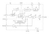
- FIG. 1illustrates a schematic block diagram of a start-up controller for a series-parallel resonant power converter, according to specific example embodiments of this disclosure
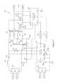
- FIG. 2illustrates a schematic block diagram of a series-parallel resonant power converter that uses the start-up controller shown in FIG. 1 , according to specific example embodiments of this disclosure.
- FIG. 3illustrates schematic frequency-impedance graphs of the operation of a series-parallel resonant power converter, according to specific example embodiments of this disclosure.
- a series-parallel resonant power convertermay comprise a primary-side start-up controller and a secondary-side controller, wherein the primary-side start-up controller is utilized to send power to the secondary-side controller when power (voltage) is first applied to the primary side of the series-parallel resonant power converter.
- the primary-side start-up controllermay be used for starting up the series-parallel resonant power converter using an open-loop start-up technique wherein the secondary-side closed-loop controller takes over linear, closed-loop control of the series-parallel resonant power converter once it becomes powered and activated.
- Series-parallel resonant power converterscomprise topologies that have become quite popular recently. These series-parallel resonant power converter topologies provide low-cost conversion of medium range power (e.g., 150 watt to 300 watt power converters) with inherent zero-voltage switching (ZVS) and/or zero-current switching (ZCS) of the power switching metal oxide semiconductor field effect transistors (MOSFETs) SFETs) used therewith.
- Series-parallel resonant power convertersrequire a control method that is different from the techniques used in pulse width modulation (PWM) controlled power converters, e.g., U.S. patent application Ser. No. 14/945,729 referenced hereinabove.
- PWMpulse width modulation
- the controller for a series-parallel resonant power converterproduces a nearly-fixed duty cycle waveform with a dead time that is short and remains fixed as the switching period varies. This switching waveform varies in frequency in order to regulate the output of the series-parallel resonant power converter.
- the “LLC” designation of the series-parallel resonant power converterdescribes the resonant “tank” circuit configuration, it being a series circuit consisting of a resonant inductors (LR), a resonant capacitor (CR), and the output transformer's magnetization inductance (LMAG).
- the loadis essentially in parallel with LMAG. As the load approaches a short circuit the resonant frequency of the tank circuit is a function of LR and CR. As the load approaches an open circuit the resonant frequency of the tank circuit is a function of (LR+LMAG) and CR.
- the controllerdrives the series-parallel resonant power converter at a frequency greater than the resonant frequency of the tank.
- the tank circuitoffers lower impedance allowing greater power to be delivered to the load. At the higher frequencies of that range the tank circuit offers higher impedance allowing less power to be delivered to the load.
- the LCC power converteris similar in operation to the LLC power converter but uses an additional capacitor in parallel with LMAG and the load.
- a start-up method for a series-parallel resonant power converterutilizes a primary-side controller that becomes active upon application of the AC or DC line voltage, provides the MOSFET gate driving waveforms starting at a selected switching frequency above the resonant frequency of the series-parallel resonant power converter that allows low power to the secondary to establish secondary-side bias.
- the start-up methodcould slowly, in an open-loop manner, reduce the initially selected switching frequency toward the resonant frequency thereof. This allows the initial low power to the secondary to increase, in a soft-start manner, until a secondary-side controller can become active and assume control of the MOSFET power switch(es).
- the start-up controller 106may comprise a high voltage (HV) voltage regulator 130 , under and over voltage lockout (UVLO/OVLO) circuits 132 , a voltage comparator 134 , a fixed blanking time circuit 140 , an external gate command detection logic 142 (with optional enable/disable detection), a voltage controlled oscillator (VCO) and control/standby logic circuits 144 , a three input AND gate 146 , an OR gate 148 , a MOSFET gate driver 150 , and a signal buffer 154 .
- HVhigh voltage
- UVLO/OVLOunder and over voltage lockout
- VCOvoltage controlled oscillator
- a capacitor 248may be coupled between the PROG node (pin) of the start-up controller 106 and ground may be used to determine the initial start-up frequency.
- the resistor value 208FIG. 2 ) coupled between the MODE node (pin) of the start-up controller 106 and ground may determine the rate that the initial start-up frequency decreases (no resistor, no decrease in frequency).
- the primary current of transformer 230( FIG. 2 ) is monitored at the input node C/S (current sense) (C/S monitors the voltage drop across resistor 214 ) of the start-up controller 106 for peak current protection using the voltage comparator 134 and a fixed voltage reference, V REF .
- the fixed blanking time circuit 140preventing false over current tripping due to turn-on current spikes during power switching.
- a series-parallel resonant power convertermay comprise a primary side bridge rectifier 202 (coupled to an AC line power source (not shown)), filter inductor 204 and filter capacitor 210 (with filter dampening resistor 206 ), resonant inductor 226 and resonant capacitor 228 , capacitors 218 , 236 , 246 and 248 ; resistors 208 , 214 and 244 ; transformers 220 and 230 (and current transformer 216 ), MOSFET power switches 222 , 224 , 232 and 234 ; a bridge rectifier 250 coupled to the T 1 winding of transformer 230 for primary-side bias; a primary-side start-up controller 106 , a secondary-side controller 238
- the series-parallel resonant power converter 200provides regulated voltage to an application load (not shown, but located across V_OUT and RTN) after start-up.
- the AC line power sourcemay be in a universal range of from about 85 to 265 volts alternating current (AC) at a frequency of from about 47 Hz to about 63 Hz. It is contemplated and within the scope of this disclosure that the embodiment disclosed herein may be adapted for other voltages and frequencies.
- a DC sourcemay be used instead of using the primary side bridge rectifier 202 coupled to an AC source.
- the logic of the VCO and control/standby logic circuits 144determines that when the UVLO/OVLO circuit 132 indicates that VDD is within a proper operating voltage range the VCO of the VCO and control/standby logic circuits 144 produces drive waveforms starting at the frequency determined by the capacitor 248 coupled to the PROG node (pin) of the primary-side start-up controller 106 , and, if a resistor 208 is coupled to the MODE node (pin) thereof, slowly (rate determined by resistance value of the resistor 208 ) reduces the drive waveform frequency. When the secondary-side controller 238 becomes active it monitors the secondary-side voltage at the V/S node (pin) thereof.
- the secondary-side controller 238may command the start-up controller 106 to stop switching by pulling down the PWMD node (pin) via the isolation circuit 242 , e.g., optical coupler, pulse transformer, etc. If the secondary-side controller 238 decides to again apply power to the secondary of the transformer 230 , it releases the logic low at the PWMD node. This release is detected by the VCO and control/standby logic circuits 144 and the VCO ( 144 ) thereof drives the gate driver 150 , again starting from the highest frequency.
- the secondary-side controller 238decides to apply power to the load, it can take control of the gate drive 150 by providing drive waveforms to the gate driver 150 via the PULSE node of the primary-side controller 106 .
- the gate driver 150receives pulse commands from the buffer 154 coupled to the PULSE node (instead of from the VCO of circuits 144 ) as long as the ULVO/OVLO circuit 132 determines that V DD is within the valid voltage levels.
- the VCO and control/standby logic circuits 144also monitors the state of the current sense comparator 134 .
- the over-current trip level set pointis a function of the internal voltage reference V REF and the choice of current sense resistor 214 value. If an over-current is detected, whether the gate drive 150 is being commanded internally or externally, the logic circuit 144 will momentarily interrupt commands to the gate driver 150 . After the interrupt time interval, the gate drive 150 will either resume being commanded externally, or the VCO and control/standby circuits 144 will then start providing a drive waveform beginning at the frequency determined by the programming capacitor 248 .
- start-up sequencemay be as follows:
- the secondary-side controller 238may contain an internal VCO generator (not shown) to generate the variable frequency gating signal sent to the start-up controller 106 via the isolation circuit 240 .
- This signalmaintains a nearly 50 percent duty cycle with a programmable fixed dead-time period.
- This signalvaries in frequency (over the valid frequency range) in order to control the impedance of the resonant tank circuit in order to regulate the output voltage when under load (linear control of the output voltage).
- the MOSFET power switches 222 , 224 , 232 and 234commanded by the VCO of secondary-side controller 238 , may turn on and off at zero voltage switching (ZVS) and/or zero current switching (ZCS) which is inherent to resonant converter topologies.
- ZVSzero voltage switching
- ZCSzero current switching
- “burst mode”means the PWM signals occur for brief moments of time between times of no switching activity. If the “time of no switching activity” is too long the start-up controller 106 will think the secondary-side controller 238 has become inactive and it will switch to a start-up mode. Therefore the secondary-side controller 238 uses the PWMD node of the start-up controller 106 (via driving Isolator 242 ) to control the duration of the “time of no switching activity”. When the secondary-side controller 238 releases the PWMD port it can decide whether the PWM signals are produced by the secondary-side controller 238 (delivered via Isolator 240 ) or generated by the start-up controller 106 .
- “Sleep” modeis also a “burst mode” type of operation.
- a differenceis that in “sleep” mode the controllers go into an internal lower-power state, where there is an advantage not to continuously drive Isolator 242 to maintain “sleep” (for the purpose of much longer periods of times with no switching activity, resulting in extremely low power drawn from the input source).
- Another differenceis that in “sleep” mode the secondary-side controller 238 is no longer trying to accurately regulate the voltage on the V/S node of the secondary-side controller 238 , and instead only loosely regulates the voltages on its V/S node and on the VDD node of the start-up controller 106 such that the two controllers 106 and 238 can maintain their internal lower-power states.
- the secondary-side controller 238either internally decides to enter “sleep” mode, or it is externally commanded by a higher level system controller. In order for the secondary-side controller 238 to command the start-up controller 106 to “sleep” it sends a coded message via isolator 242 which latches start-up controller 106 into sleep and thereby makes it possible to remain in “sleep” without continuously driving isolator 242 , reducing power consumption. There are three methods to exit the “sleep” state (to wake the power converter 200 ). The first is for the secondary-side controller 238 to start sending PWM commands to the start-up controller 106 via isolator 240 .
- the secondis for the secondary-side controller 238 to send a single PWM pulse to the start-up controller 106 via isolator 240 which commands the start-up controller 106 into start-up mode.
- the thirdis caused by the voltage on the VDD node of start-up controller 106 decaying below the UVLO threshold causing the start-up controller 106 to enter the start-up mode.
- “Sleep” modeis fully described in commonly owned and co-pending U.S. patent application Ser. No. 15/168,390, filed May 31, 2016, entitled “Reducing Power in a Power Converter When in a Standby Mode,” by Thomas Quigley, and is hereby incorporated by reference herein for all purposes.
- FIG. 3depicted are schematic frequency-impedance graphs of the operation of a series-parallel resonant power converter, according to specific example embodiments of this disclosure.
- FIG. 3( a )shows a fixed start-up frequency at a high impedance point of the power converter 200 impedance curve.
- FIG. 3( b )shows a start-up frequency at a high impedance point of the power converter 200 impedance curve while drifting lower in frequency in an open-loop fashion.
- These graphsare representative of a family of frequency-impedance graphs, as the resonant frequency transitions from a function of “CR and LR” (heavy loading) to a function of “CR and (LR+LMAG) (light loading).
- the impedanceis lowest at the resonant frequency f 0 .
- Both the LLC Converter and the LCC Converterare able to operate in a frequency range higher than f 0 . It is desirable to operate in a frequency range higher than f 0 in order to achieve Zero Voltage Switching (ZVS).
- ZVSZero Voltage Switching
- the higher frequencies in the rangeare most suitable for start-up because it provides low power (higher impedance) to the output.
- the start-up frequencymay be determined by the capacitance value of capacitor 248 coupled to the ‘PROG” node of the start-up controller 106 . MODE allows for two methods of start-up, one being where the start-up frequency remains fixed as shown in FIG.
- the LLC Converter and the LCC Converterboth can either work in a frequency range lower than the resonant frequency f 0 or higher than f 0 .
- the benefit of working at a range higher than f 0is ZVS.
- the PROG feature of start-up controller 106which sets the start-up frequency, can be used whether the converter operates in a frequency range above f 0 or below f 0 .
- start-up controller 106would be needed for a converter operating in a frequency range below f 0 if the MODE feature was desired.
- the MODE featurewould, in an open loop fashion, slowly raise the switching frequency which increases the power (by lowering the impedance) delivered to the secondary during start-up.
- inductor 226 and capacitor 228make up the resonant tank circuit which is the frequency-dependent impedance described in FIG. 3 .
- This resonant tank circuitprovides impedance between the input source to power converter 200 and the load on the converter's output.
- This tank circuitis essentially in series with transformer 230 . Therefore whenever MOSFETs 222 or 224 (and their respective synchronous rectifier MOSFETs 232 and 234 ) are ON the voltage across transformer 200 's primary winding is a reflection of power converter 200 's output voltage as is the voltage across transformer 200 's tertiary winding (designated by terminals T 1 -X and T 1 -Y).
- the voltage on the tertiary windingis rectified by bridge rectifier 250 to provide bias to the start-up controller 106 at its VDD port.
- FIG. 1it is shown that the voltage at the VDD port is monitored by the start-up controller 106 's UVLO/OVLO 132 circuit block. Therefore it is possible for the start-up controller 106 to monitor the output voltage of the power converter 200 for overvoltage and provide protection. This is an important feature.
- the start-up controller 106is an open-loop method of starting up a series-parallel converter and depends on the secondary-side controller 238 becoming active during start-up and gaining linear control of power converter 200 's output voltage before an output overvoltage occurs.
- the start-up controller 106can provide overvoltage protection by monitoring the output voltage via transformer 230 cross-coupling and provide hysteretic regulation of the output voltage using the UVLO/OVLO 132 circuit block.
- This overvoltage protection methodis similar to the method more fully described in co-pending U.S. patent application Ser. No. 14/945,729; previously incorporated herein by reference above.
Landscapes
- Engineering & Computer Science (AREA)
- Power Engineering (AREA)
- Dc-Dc Converters (AREA)
Abstract
Description
- 1) AC line voltage is applied developing a DC voltage across
capacitor 210. - 2)
Capacitor 246 is charged via theHV regulator 130. When the voltage at the VDDnode of the start-upcontroller 106 meets the UVLO threshold of the ULVO/OVLO circuit 132 it becomes active. - 3) The MOSFET gate driver150 drives MOSFET power switches222 and224 via
gate drive transformer 220 based on commands from theVCO 144. The drive frequency may be based on the value of the frequency programming capacitor248 coupled to the PROG node and the resistance of theresistor 208 coupled to the MODE pin of the start-upcontroller 106. The drive waveform starts at a frequency selected by the capacitor248 and slowly start reducing in frequency based on the resistance value of theresistor 208. - 4) The MOSFET power switches222 and224 drive the resonant tank
circuit comprising inductor 226,capacitor 228 and the output transformer230 (which contains LMAG), chargingcapacitor 236. No load, other than the secondary-side controller 238 is present acrosscapacitor 236. - 5) When the voltage on
capacitor 236 reaches a sufficient level the secondary-side controller 238 becomes active. The secondary-side controller 238 may be entirely analog, or entirely digital, or a combination of both. - 6) The secondary-
side controller 238 regulates the voltage acrosscapacitor 236, sensed at its V/S node, in this low-power standby mode (no load applied) using hysteresis. Hysteretic control is accomplished by turning on and off The DOUToutput from the secondary-side controller 238 which is coupled to theisolation circuit 242 to the PWMD input of the start-upcontroller 106. When DOUToutput is turned on it causes the PWMD node to go to a low level, which inhibits signals from theVCO 144 of the start-upcontroller 106 to its gate driver150. When DOUTis turned off, the PWMD node no longer is pulled down to a low logic level, whereby the gate driver150 resumes accepting commands from the VCO ofcircuits 144, wherein the VCO ofcircuits 144 is reset to the frequency selected by the capacitor248 and begins to slew lower in frequency at a rate determined by the resistance of theresistor 208. Ifresistor 208 is not utilized (present), then the frequency remains fixed and does not slew lower. - 7) When the secondary-
side controller 238 couples the load to the output of thepower converter 200, the secondary-side controller 238 takes command of the gate driver150 from theVCO 144. This is accomplished by providing the gate drive command to the PULSE input node of the start-upcontroller 106 from the Gate primary output of the secondary-side controller 238 via the isolation circuit240. - 8) The secondary-
side controller 238 may have the following features:- a. The VW/S input node may be used to monitor the secondary winding voltage of
transformer 230. This feature may be used so that the secondary-side controller 238 can synchronize driving thesynchronous rectifiers 232 and234 in the correct phase with the waveform polarity from the gate driver150 of the start-upcontroller 106. - b. The secondary-
side controller 238 may drive both of the primary-side MOSFETs synchronous rectifiers 232 and234 on the secondary side of thetransformer 230. - c. The secondary-
side controller 238 may monitor the primary current through transformer230 (as well as any cross-conduction throughpower switches 222 and224) via current transformer216 monitored at its C/S node.
- a. The VW/S input node may be used to monitor the secondary winding voltage of
- 1) AC line voltage is applied developing a DC voltage across
Claims (42)
Priority Applications (7)
| Application Number | Priority Date | Filing Date | Title |
|---|---|---|---|
| US15/168,569US10277130B2 (en) | 2015-06-01 | 2016-05-31 | Primary-side start-up method and circuit arrangement for a series-parallel resonant power converter |
| CN201680030226.3ACN107660324B (en) | 2015-06-01 | 2016-06-01 | Primary side start-up method and circuit arrangement for series-parallel resonant power converters |
| KR1020177034605AKR20180013941A (en) | 2015-06-01 | 2016-06-01 | Primary side starting method and circuit device for recto-parallel resonance type power converter |
| EP16732045.6AEP3304712B1 (en) | 2015-06-01 | 2016-06-01 | Primary-side start-up method and circuit arrangement for a series-parallel resonant power converter |
| PCT/US2016/035149WO2016196545A1 (en) | 2015-06-01 | 2016-06-01 | Primary-side start-up method and circuit arrangement for a series-parallel resonant power converter |
| JP2017562034AJP2018516530A (en) | 2015-06-01 | 2016-06-01 | Primary side startup method and circuit arrangement for series-parallel resonant power converter |
| TW105117245ATW201707360A (en) | 2015-06-01 | 2016-06-01 | Primary-side start-up method and circuit arrangement for a series-parallel resonant power converter |
Applications Claiming Priority (2)
| Application Number | Priority Date | Filing Date | Title |
|---|---|---|---|
| US201562169382P | 2015-06-01 | 2015-06-01 | |
| US15/168,569US10277130B2 (en) | 2015-06-01 | 2016-05-31 | Primary-side start-up method and circuit arrangement for a series-parallel resonant power converter |
Publications (2)
| Publication Number | Publication Date |
|---|---|
| US20160352231A1 US20160352231A1 (en) | 2016-12-01 |
| US10277130B2true US10277130B2 (en) | 2019-04-30 |
Family
ID=57399050
Family Applications (1)
| Application Number | Title | Priority Date | Filing Date |
|---|---|---|---|
| US15/168,569Active2037-05-13US10277130B2 (en) | 2015-06-01 | 2016-05-31 | Primary-side start-up method and circuit arrangement for a series-parallel resonant power converter |
Country Status (7)
| Country | Link |
|---|---|
| US (1) | US10277130B2 (en) |
| EP (1) | EP3304712B1 (en) |
| JP (1) | JP2018516530A (en) |
| KR (1) | KR20180013941A (en) |
| CN (1) | CN107660324B (en) |
| TW (1) | TW201707360A (en) |
| WO (1) | WO2016196545A1 (en) |
Cited By (3)
| Publication number | Priority date | Publication date | Assignee | Title |
|---|---|---|---|---|
| US20210344267A1 (en)* | 2019-06-27 | 2021-11-04 | Cypress Semiconductor Corporation | Communicating fault indications between primary and secondary controllers in a secondary-controlled flyback converter |
| US20230179104A1 (en)* | 2021-12-03 | 2023-06-08 | Chengdu Monolithic Power Systems Co., Ltd. | Isolated switching regulators with smart power supply and the method thereof |
| US12445043B1 (en) | 2023-07-24 | 2025-10-14 | Waymo Llc | Frequency soft-start for rotary power transformer |
Families Citing this family (46)
| Publication number | Priority date | Publication date | Assignee | Title |
|---|---|---|---|---|
| US9712045B2 (en)* | 2014-11-17 | 2017-07-18 | Infineon Technologies Austria Ag | System and method for a startup cell circuit |
| US9819274B2 (en)* | 2014-11-20 | 2017-11-14 | Microchip Technology Incorporated | Start-up controller for a power converter |
| US10277130B2 (en) | 2015-06-01 | 2019-04-30 | Microchip Technolgoy Incorporated | Primary-side start-up method and circuit arrangement for a series-parallel resonant power converter |
| US9912243B2 (en) | 2015-06-01 | 2018-03-06 | Microchip Technology Incorporated | Reducing power in a power converter when in a standby mode |
| US9705408B2 (en) | 2015-08-21 | 2017-07-11 | Microchip Technology Incorporated | Power converter with sleep/wake mode |
| US20170117813A1 (en)* | 2015-10-21 | 2017-04-27 | Quanta Computer Inc. | Method and system for testing a power supply unit |
| US10333415B2 (en)* | 2016-07-01 | 2019-06-25 | Rohm Co., Ltd. | Insulated synchronous rectification DC/DC converter including synchronous rectification controller controlling synchronous rectification transistor |
| US10763755B2 (en)* | 2016-12-16 | 2020-09-01 | Toyota Motor Engineering & Manufacturing North America, Inc. | Symmetrical isolated DC-DC power conversion circuit |
| IT201700050638A1 (en)* | 2017-05-10 | 2018-11-10 | St Microelectronics Srl | PROCEDURE FOR OPERATING DEVICES POWERED BY RADIO FREQUENCY, CIRCUIT AND THE CORRESPONDING DEVICE |
| CN107317491B (en)* | 2017-07-10 | 2019-08-13 | 昂宝电子(上海)有限公司 | Switching power source chip and switching power circuit including it |
| US10256744B2 (en)* | 2017-09-12 | 2019-04-09 | Infineon Technologies Austria Ag | Controller device with adaptive synchronous rectification |
| US10193457B1 (en) | 2017-09-15 | 2019-01-29 | Abb Schweiz Ag | System and method for starting up a high density isolated DC-to-DC power converter |
| JP6844509B2 (en)* | 2017-11-16 | 2021-03-17 | オムロン株式会社 | Power supply and control device |
| CN108365766B (en)* | 2018-02-02 | 2020-06-12 | 昂宝电子(上海)有限公司 | LLC quasi-resonant switching power supply |
| US10622883B2 (en)* | 2018-06-18 | 2020-04-14 | Semiconductor Components Industries, Llc | Method and system of a resonant power converter |
| US10601333B2 (en) | 2018-08-22 | 2020-03-24 | Infineon Technologies Austria Ag | Feedforward enhanced feedback control in isolated switched-mode power converters with secondary-side rectified voltage sensing |
| US11502595B2 (en)* | 2018-09-06 | 2022-11-15 | Infineon Technologies Austria Ag | Voltage and current protection in isolated switched-mode power converters with secondary-side rectified voltage sensing |
| US10615694B2 (en)* | 2018-09-07 | 2020-04-07 | Dialog Semiconductor (Uk) Limited | Circuit and method for suppressing audio noise in DC-DC converters |
| US10666156B2 (en)* | 2018-10-08 | 2020-05-26 | Schweitzer Engineering Laboratories, Inc. | Method to dynamically configure and control a power converter for wide input range operation |
| US10666147B1 (en)* | 2018-11-14 | 2020-05-26 | Navitas Semiconductor, Inc. | Resonant converter control based on zero current detection |
| US10770983B2 (en) | 2018-12-06 | 2020-09-08 | Infineon Technologies Austria Ag | Circuits and methods for secondary-side rectified voltage sensing in isolated switched-mode power converters |
| US11990842B2 (en)* | 2019-01-24 | 2024-05-21 | Magna powertrain gmbh & co kg | Method and system for balancing multi-phase LLC power converter with switch-controlled capacitors |
| US11114945B2 (en)* | 2019-08-22 | 2021-09-07 | Cypress Semiconductor Corporation | Secondary-controlled active clamp implementation for improved efficiency |
| US10938309B1 (en)* | 2019-10-18 | 2021-03-02 | Raytheon Company | Controlling operation of a voltage converter based on inductor current |
| US10985664B1 (en) | 2019-10-18 | 2021-04-20 | Raytheon Company | Controlling operation of a voltage converter based on transistor drain voltages |
| US10931204B1 (en)* | 2019-11-12 | 2021-02-23 | Monolithic Power Systems, Inc. | Isolated resonant converter with fixed output ripple |
| US10944330B1 (en)* | 2019-12-19 | 2021-03-09 | Cypress Semiconductor Corporation | Self-biased gate driver architecture |
| US10938310B1 (en)* | 2020-01-02 | 2021-03-02 | Hong Kong Applied Science and Technology Research Institute Company, Limited | Seamless switching of resonant tanks in power converters by matching voltage gains at tank switchover |
| CN111555629B (en)* | 2020-05-14 | 2022-12-20 | 成都芯源系统有限公司 | Resonant converter and control circuit and control method thereof |
| US11594973B2 (en)* | 2020-08-04 | 2023-02-28 | Delta Electronics Inc. | Multiple-port bidirectional converter and control method thereof |
| CN112134453B (en)* | 2020-09-08 | 2021-10-29 | 台达电子企业管理(上海)有限公司 | Startup control method and system, peak voltage detection circuit and method |
| CN112332650B (en)* | 2020-10-14 | 2022-08-19 | 广州金升阳科技有限公司 | Open loop starting circuit clock signal control method and control circuit thereof |
| US11496037B2 (en)* | 2021-03-19 | 2022-11-08 | Acbel Polytech Inc. | Power supply having bidirectional gate driving impulse transformer and control method thereof |
| US11711023B2 (en)* | 2021-05-14 | 2023-07-25 | Queen's University At Kingston | Methods and circuits for sensing isolated power converter output voltage across the isolation barrier |
| US12081131B2 (en) | 2021-08-02 | 2024-09-03 | Transient Plasma Systems, Inc. | Power converter comprising series resonant converter(s) having a full-bridge series resonant topology and methods of operating same |
| KR102719824B1 (en)* | 2021-10-08 | 2024-10-21 | 주식회사 파워엘에스아이 | Synchronous rectifier control method for power supply unit and apparatus therefor |
| TWI796013B (en)* | 2021-11-26 | 2023-03-11 | 通嘉科技股份有限公司 | Power controller and control method for power converter |
| US20250025703A1 (en)* | 2021-12-03 | 2025-01-23 | Zoll Medical Corporation | Electrotherapeutic waveform and pulse generation |
| TWI796201B (en)* | 2021-12-08 | 2023-03-11 | 通嘉科技股份有限公司 | Method of switching operational modes of a power converter |
| TWI790956B (en)* | 2022-03-31 | 2023-01-21 | 宏碁股份有限公司 | Power supply device for suppressing noise |
| US12143023B2 (en)* | 2022-05-19 | 2024-11-12 | Cypress Semiconductor Corporation | Drive scheme for secondary-controlled active clamp flyback (ACF) mode |
| CN115473415A (en)* | 2022-09-29 | 2022-12-13 | 杭州茂力半导体技术有限公司 | Isolated switch converter and controller and control method thereof |
| CN115995986B (en)* | 2023-03-24 | 2023-06-09 | 安徽微伏特电源科技有限公司 | Series-parallel flyback boost circuit topology with triangular structure |
| KR20240157410A (en)* | 2023-04-25 | 2024-11-01 | 삼성전자주식회사 | Llc resonant converter and electronic device including the same |
| WO2025053978A1 (en)* | 2023-09-05 | 2025-03-13 | Enphase Energy, Inc. | Methods and apparatus for controlling switching in power converters |
| EP4601175A1 (en)* | 2024-02-06 | 2025-08-13 | ABB E-mobility B.V. | Method of of bidirectional dc conversion, and series resonant converter |
Citations (75)
| Publication number | Priority date | Publication date | Assignee | Title |
|---|---|---|---|---|
| US4967332A (en) | 1990-02-26 | 1990-10-30 | General Electric Company | HVIC primary side power supply controller including full-bridge/half-bridge driver |
| US5301095A (en)* | 1991-10-01 | 1994-04-05 | Origin Electric Company, Limited | High power factor AC/DC converter |
| EP0618665A2 (en) | 1993-03-31 | 1994-10-05 | Thomson Consumer Electronics, Inc. | Feedback limited duty cycle switched mode power supply |
| US5498995A (en) | 1993-03-17 | 1996-03-12 | National Semiconductor Corporation | Short circuit frequency shift circuit for switching regulators |
| US5757627A (en) | 1996-05-01 | 1998-05-26 | Compaq Computer Corporation | Isolated power conversion with master controller in secondary |
| US6188276B1 (en) | 1998-09-21 | 2001-02-13 | Anastasios V. Simopoulos | Power amplifier |
| US20010043479A1 (en) | 2000-03-27 | 2001-11-22 | Tamiji Nagai | Power supply apparatus |
| US20020006045A1 (en) | 1999-07-27 | 2002-01-17 | Toshihito Shirai | Power supply unit |
| US20020125867A1 (en) | 2001-03-09 | 2002-09-12 | Samsung Electronics Co., Ltd. | Power supply control apparatus and method thereof |
| US6456511B1 (en) | 2000-02-17 | 2002-09-24 | Tyco Electronics Corporation | Start-up circuit for flyback converter having secondary pulse width modulation |
| US6490177B1 (en)* | 1998-10-05 | 2002-12-03 | Salvador Figueroa | Resonant power converter with primary-side tuning and zero-current switching |
| US6504267B1 (en) | 2001-12-14 | 2003-01-07 | Koninklijke Philips Electronics N.V. | Flyback power converter with secondary-side control and primary-side soft switching |
| US20070133234A1 (en) | 2005-12-07 | 2007-06-14 | Active-Semi International Inc. | System and method for a primary feedback switched mode power supply |
| US20070252563A1 (en) | 2006-04-26 | 2007-11-01 | Mitsumi Electric Co. Ltd. | Multi-ouput type DC/DC converter |
| US20080259655A1 (en) | 2007-04-19 | 2008-10-23 | Da-Chun Wei | Switching-mode power converter and pulse-width-modulation control circuit with primary-side feedback control |
| US20080265133A1 (en) | 2007-04-30 | 2008-10-30 | Sawtell Carl K | Power Supply Control Circuit with Optical Feedback |
| DE102008027054A1 (en) | 2007-07-02 | 2009-01-08 | Fuji Electric Device Technology Co., Ltd. | Switching power supply device |
| US20090261790A1 (en) | 2008-04-22 | 2009-10-22 | Douglas Paul Arduini | Synchronous rectifier post regulator |
| US20090273324A1 (en) | 2004-12-21 | 2009-11-05 | Rohm Co., Ltd. | Switching regulator |
| US20090295346A1 (en) | 2008-05-29 | 2009-12-03 | Power Integrations, Inc. | Method and apparatus for implementing an unregulated dormant mode in a power converter |
| US20090295349A1 (en) | 2008-05-30 | 2009-12-03 | Active-Semi, Inc. | Constant current and voltage controller in a three-pin package with dual-use switch pin |
| US20100194198A1 (en) | 2009-02-05 | 2010-08-05 | Power Integrations, Inc. | Method and apparatus for implementing an unregulated dormant mode with an event counter in a power converter |
| US20100208500A1 (en) | 2009-02-19 | 2010-08-19 | Iwatt Inc. | Detecting Light Load Conditions and Improving Light Load Efficiency in a Switching Power Converter |
| US20100308875A1 (en) | 2008-03-03 | 2010-12-09 | Thomson Licensing | Switchable load for initializing an output voltage of a power supply |
| US20100327761A1 (en) | 2009-06-30 | 2010-12-30 | Microsemi Corporation | Integrated backlight control system |
| US20110019446A1 (en) | 2009-07-22 | 2011-01-27 | Bcd Semiconductor Manufacturing Limited | Method and apparatus for a switching mode power supply |
| US20110032732A1 (en) | 2009-08-04 | 2011-02-10 | Ta-Ching Hsu | Secondary side post regulator of flyback power converter with multile outputs |
| US20110075448A1 (en) | 2009-09-30 | 2011-03-31 | Melanson John L | Switching power converter controller with direct current transformer sensing |
| US20110103104A1 (en) | 2009-10-30 | 2011-05-05 | Intersil Americas Inc. | Bias and discharge system for low power loss start up and input capacitance discharge |
| US20110164437A1 (en) | 2010-01-07 | 2011-07-07 | Texas Instruments Incorporated | LLC Soft Start By Operation Mode Switching |
| US20110211370A1 (en)* | 2010-03-01 | 2011-09-01 | Texas Instruments Incorporated | Systems and Methods of Resonant DC/DC Conversion |
| US20110305043A1 (en) | 2010-06-11 | 2011-12-15 | Murata Manufacturing Co., Ltd. | Isolated switching power supply apparatus |
| US20120099345A1 (en) | 2010-10-25 | 2012-04-26 | Analog Devices, Inc. | Soft-start control system and method for an isolated dc-dc converter with secondary controller |
| US20120139477A1 (en) | 2010-12-03 | 2012-06-07 | Motorola, Inc. | Power supply circuit having lowidle power dissipation |
| US20120139342A1 (en) | 2010-12-06 | 2012-06-07 | Power Integrations, Inc. | Method and apparatus for implementing an unregulated dormant mode with output reset in a power converter |
| US20120230069A1 (en) | 2011-03-11 | 2012-09-13 | Ren-Huei Tzeng | Startup control circuit with acceleration startup function and method for operating the same |
| US20120243271A1 (en) | 2011-03-25 | 2012-09-27 | Berghegger Ralf Schroeder Genannt | Power Converter with Reduced Power Dissipation |
| US20120262953A1 (en)* | 2011-04-12 | 2012-10-18 | Flextronics Ap, Llc | Multi-phase resonant converter |
| US20120280642A1 (en) | 2011-05-04 | 2012-11-08 | Ying-Chen Lin | Start-up Circuit and Motor Driving IC |
| US20120294048A1 (en) | 2009-06-17 | 2012-11-22 | Power Systems Technologies, Ltd. | Start-Up Circuit for a Power Adapter |
| US20130016535A1 (en) | 2011-07-12 | 2013-01-17 | Power Systems Technologies, Ltd. | Controller for a Power Converter and Method of Operating the Same |
| US20130155728A1 (en) | 2011-12-14 | 2013-06-20 | Cirrus Logic, Inc. | Isolation of Secondary Transformer Winding Current During Auxiliary Power Supply Generation |
| US20130194020A1 (en) | 2012-01-31 | 2013-08-01 | Macronix International Co., Ltd. | Level shifting circuit |
| US20130223108A1 (en) | 2012-02-28 | 2013-08-29 | Silergy Semiconductor Technology (Hangzhou) Ltd | Constant voltage constant current controller and control method thereof |
| US20130229829A1 (en) | 2012-03-01 | 2013-09-05 | Infineon Technologies Ag | Multi-Mode Operation and Control of a Resonant Converter |
| US20130236203A1 (en) | 2012-03-09 | 2013-09-12 | Canon Kabushiki Kaisha | Power supply device and image forming apparatus |
| US20130301308A1 (en)* | 2011-01-26 | 2013-11-14 | Murata Manufacturing Co., Ltd. | Switching power supply device |
| US20130300384A1 (en) | 2012-05-08 | 2013-11-14 | Chengdu Monolithic Power Systems Co., Ltd. | Isolated switching mode power supply and the method thereof |
| US20140028095A1 (en) | 2012-07-25 | 2014-01-30 | Cirrus Logic, Inc. | Acceleration of output energy provision for a load during start-up of a switching power converter |
| US20140140107A1 (en) | 2012-11-16 | 2014-05-22 | Noveltek Semiconductor Corp. | Isolated power converter, inverting type shunt regulator, and operating method thereof |
| US20140160810A1 (en) | 2012-12-11 | 2014-06-12 | Iwatt Inc. | Digital Communication Link Between Secondary Side and Primary Side of Switching Power Converter |
| EP2775602A2 (en) | 2013-03-08 | 2014-09-10 | Power Integrations, Inc. | Techniques for controlling a power converter using multiple controllers |
| US20140253227A1 (en) | 2013-03-10 | 2014-09-11 | Microchip Technology Incorporated | Integrated High Voltage Isolation Using Low Value Capacitors |
| US20140254215A1 (en) | 2011-08-29 | 2014-09-11 | Power Systems Technologies Ltd. | Controller for a power converter and method of operating the same |
| US20140253225A1 (en) | 2013-03-10 | 2014-09-11 | Microchip Technology Incorporated | Method and Apparatus for Generating Regulated Isolation Supply Voltage |
| US20140313790A1 (en) | 2013-04-23 | 2014-10-23 | Virginia Tech Intellectual Properties, Inc. | Optimal Trajectory Control for LLC Resonant Converter for Soft Start-Up |
| US20140313794A1 (en) | 2013-02-25 | 2014-10-23 | Rohm Co., Ltd. | Power delivery device and start-up method, ac adapter and electronic apparatus |
| US20140321170A1 (en) | 2013-04-30 | 2014-10-30 | Texas Instruments Incorporated | Integrated primary startup bias and mosfet driver |
| US20140369086A1 (en) | 2013-06-14 | 2014-12-18 | Canon Kabushiki Kaisha | Power supply apparatus and image forming apparatus |
| US20150016152A1 (en) | 2013-07-12 | 2015-01-15 | Canon Kabushiki Kaisha | Power supply apparatus and image forming apparatus |
| US20150023063A1 (en)* | 2012-03-08 | 2015-01-22 | Massachusetts Institute Of Technology | Resonant Power Converters Using Impedance Control Networks And Related Techniques |
| US20150091544A1 (en) | 2013-09-30 | 2015-04-02 | Micrel, Inc. | Timer based pfm exit control method for a boost regulator |
| US20150124488A1 (en) | 2013-11-07 | 2015-05-07 | Futurewei Technologies, Inc. | Startup Method and System for Resonant Converters |
| US20150280584A1 (en) | 2014-04-01 | 2015-10-01 | Infineon Technologies Austria Ag | System and Method for a Switched-Mode Power Supply |
| US20150280573A1 (en) | 2014-04-01 | 2015-10-01 | Infineon Technologies Austria Ag | System and Method for a Switched-Mode Power Supply |
| US20160079878A1 (en) | 2014-09-12 | 2016-03-17 | Alpha And Omega Semiconductor (Cayman) Ltd. | Constant on time (cot) control in isolated converter |
| US20160087541A1 (en) | 2014-09-23 | 2016-03-24 | Analog Devices Global | Minimum duty cycle control for active snubber |
| US9331583B2 (en) | 2012-12-24 | 2016-05-03 | Chengdu Monolithic Power Systems Co., Ltd. | Switch mode power supply, control circuit and associated control method |
| US20160141951A1 (en) | 2014-11-17 | 2016-05-19 | Infineon Technologies Austria Ag | System and Method for a Startup Cell Circuit |
| US20160149504A1 (en) | 2014-11-20 | 2016-05-26 | Microchip Technology Incorporated | Start-up controller for a power converter |
| US20160190938A1 (en) | 2014-12-31 | 2016-06-30 | Bcd Semiconductor Manufacturing Co., Ltd. | Switching mode power supply with selectable constant-voltage cpmstamt-current control |
| US20160226239A1 (en) | 2015-02-02 | 2016-08-04 | On-Bright Electronics (Shanghai) Co., Ltd. | System and Method Providing Reliable Over Current Protection for Power Converter |
| US20160352237A1 (en) | 2015-06-01 | 2016-12-01 | Microchip Technology Incorporated | Reducing power in a power converter when in a standby mode |
| US20160352231A1 (en) | 2015-06-01 | 2016-12-01 | Microchip Technology Incorporated | Primary-Side Start-Up Method And Circuit Arrangement For A Series-Parallel Resonant Power Converter |
| US20170054376A1 (en) | 2015-08-21 | 2017-02-23 | Microchip Technology Incorporated | Power Converter With Sleep/Wake Mode |
Family Cites Families (1)
| Publication number | Priority date | Publication date | Assignee | Title |
|---|---|---|---|---|
| JP2005198430A (en)* | 2004-01-08 | 2005-07-21 | Fiderikkusu:Kk | Switching power supply |
- 2016
- 2016-05-31USUS15/168,569patent/US10277130B2/enactiveActive
- 2016-06-01TWTW105117245Apatent/TW201707360A/enunknown
- 2016-06-01KRKR1020177034605Apatent/KR20180013941A/ennot_activeWithdrawn
- 2016-06-01EPEP16732045.6Apatent/EP3304712B1/enactiveActive
- 2016-06-01WOPCT/US2016/035149patent/WO2016196545A1/ennot_activeCeased
- 2016-06-01JPJP2017562034Apatent/JP2018516530A/enactivePending
- 2016-06-01CNCN201680030226.3Apatent/CN107660324B/enactiveActive
Patent Citations (78)
| Publication number | Priority date | Publication date | Assignee | Title |
|---|---|---|---|---|
| US4967332A (en) | 1990-02-26 | 1990-10-30 | General Electric Company | HVIC primary side power supply controller including full-bridge/half-bridge driver |
| US5301095A (en)* | 1991-10-01 | 1994-04-05 | Origin Electric Company, Limited | High power factor AC/DC converter |
| US5498995A (en) | 1993-03-17 | 1996-03-12 | National Semiconductor Corporation | Short circuit frequency shift circuit for switching regulators |
| EP0618665A2 (en) | 1993-03-31 | 1994-10-05 | Thomson Consumer Electronics, Inc. | Feedback limited duty cycle switched mode power supply |
| US5757627A (en) | 1996-05-01 | 1998-05-26 | Compaq Computer Corporation | Isolated power conversion with master controller in secondary |
| US6188276B1 (en) | 1998-09-21 | 2001-02-13 | Anastasios V. Simopoulos | Power amplifier |
| US6490177B1 (en)* | 1998-10-05 | 2002-12-03 | Salvador Figueroa | Resonant power converter with primary-side tuning and zero-current switching |
| US20020006045A1 (en) | 1999-07-27 | 2002-01-17 | Toshihito Shirai | Power supply unit |
| US6456511B1 (en) | 2000-02-17 | 2002-09-24 | Tyco Electronics Corporation | Start-up circuit for flyback converter having secondary pulse width modulation |
| US20010043479A1 (en) | 2000-03-27 | 2001-11-22 | Tamiji Nagai | Power supply apparatus |
| US20020125867A1 (en) | 2001-03-09 | 2002-09-12 | Samsung Electronics Co., Ltd. | Power supply control apparatus and method thereof |
| US6504267B1 (en) | 2001-12-14 | 2003-01-07 | Koninklijke Philips Electronics N.V. | Flyback power converter with secondary-side control and primary-side soft switching |
| US20090273324A1 (en) | 2004-12-21 | 2009-11-05 | Rohm Co., Ltd. | Switching regulator |
| US20070133234A1 (en) | 2005-12-07 | 2007-06-14 | Active-Semi International Inc. | System and method for a primary feedback switched mode power supply |
| US20070252563A1 (en) | 2006-04-26 | 2007-11-01 | Mitsumi Electric Co. Ltd. | Multi-ouput type DC/DC converter |
| US20080259655A1 (en) | 2007-04-19 | 2008-10-23 | Da-Chun Wei | Switching-mode power converter and pulse-width-modulation control circuit with primary-side feedback control |
| US20080265133A1 (en) | 2007-04-30 | 2008-10-30 | Sawtell Carl K | Power Supply Control Circuit with Optical Feedback |
| US7746672B2 (en) | 2007-07-02 | 2010-06-29 | Fuji Electric Device Technology Co., Ltd. | Switching power supply apparatus |
| US20090010027A1 (en) | 2007-07-02 | 2009-01-08 | Fuji Electric Device Technology Co., Ltd. | Switching power supply apparatus |
| DE102008027054A1 (en) | 2007-07-02 | 2009-01-08 | Fuji Electric Device Technology Co., Ltd. | Switching power supply device |
| US20100308875A1 (en) | 2008-03-03 | 2010-12-09 | Thomson Licensing | Switchable load for initializing an output voltage of a power supply |
| US20090261790A1 (en) | 2008-04-22 | 2009-10-22 | Douglas Paul Arduini | Synchronous rectifier post regulator |
| US20090295346A1 (en) | 2008-05-29 | 2009-12-03 | Power Integrations, Inc. | Method and apparatus for implementing an unregulated dormant mode in a power converter |
| US20090295349A1 (en) | 2008-05-30 | 2009-12-03 | Active-Semi, Inc. | Constant current and voltage controller in a three-pin package with dual-use switch pin |
| US20100194198A1 (en) | 2009-02-05 | 2010-08-05 | Power Integrations, Inc. | Method and apparatus for implementing an unregulated dormant mode with an event counter in a power converter |
| US20100208500A1 (en) | 2009-02-19 | 2010-08-19 | Iwatt Inc. | Detecting Light Load Conditions and Improving Light Load Efficiency in a Switching Power Converter |
| US20120294048A1 (en) | 2009-06-17 | 2012-11-22 | Power Systems Technologies, Ltd. | Start-Up Circuit for a Power Adapter |
| US20100327761A1 (en) | 2009-06-30 | 2010-12-30 | Microsemi Corporation | Integrated backlight control system |
| US20110019446A1 (en) | 2009-07-22 | 2011-01-27 | Bcd Semiconductor Manufacturing Limited | Method and apparatus for a switching mode power supply |
| US20110032732A1 (en) | 2009-08-04 | 2011-02-10 | Ta-Ching Hsu | Secondary side post regulator of flyback power converter with multile outputs |
| US20110075448A1 (en) | 2009-09-30 | 2011-03-31 | Melanson John L | Switching power converter controller with direct current transformer sensing |
| US20110103104A1 (en) | 2009-10-30 | 2011-05-05 | Intersil Americas Inc. | Bias and discharge system for low power loss start up and input capacitance discharge |
| US20110164437A1 (en) | 2010-01-07 | 2011-07-07 | Texas Instruments Incorporated | LLC Soft Start By Operation Mode Switching |
| US20110211370A1 (en)* | 2010-03-01 | 2011-09-01 | Texas Instruments Incorporated | Systems and Methods of Resonant DC/DC Conversion |
| US20110305043A1 (en) | 2010-06-11 | 2011-12-15 | Murata Manufacturing Co., Ltd. | Isolated switching power supply apparatus |
| US20120099345A1 (en) | 2010-10-25 | 2012-04-26 | Analog Devices, Inc. | Soft-start control system and method for an isolated dc-dc converter with secondary controller |
| US20120139477A1 (en) | 2010-12-03 | 2012-06-07 | Motorola, Inc. | Power supply circuit having lowidle power dissipation |
| US20120139342A1 (en) | 2010-12-06 | 2012-06-07 | Power Integrations, Inc. | Method and apparatus for implementing an unregulated dormant mode with output reset in a power converter |
| US20130301308A1 (en)* | 2011-01-26 | 2013-11-14 | Murata Manufacturing Co., Ltd. | Switching power supply device |
| US20120230069A1 (en) | 2011-03-11 | 2012-09-13 | Ren-Huei Tzeng | Startup control circuit with acceleration startup function and method for operating the same |
| US20120243271A1 (en) | 2011-03-25 | 2012-09-27 | Berghegger Ralf Schroeder Genannt | Power Converter with Reduced Power Dissipation |
| US20120262953A1 (en)* | 2011-04-12 | 2012-10-18 | Flextronics Ap, Llc | Multi-phase resonant converter |
| US20120280642A1 (en) | 2011-05-04 | 2012-11-08 | Ying-Chen Lin | Start-up Circuit and Motor Driving IC |
| US20130016535A1 (en) | 2011-07-12 | 2013-01-17 | Power Systems Technologies, Ltd. | Controller for a Power Converter and Method of Operating the Same |
| US20140254215A1 (en) | 2011-08-29 | 2014-09-11 | Power Systems Technologies Ltd. | Controller for a power converter and method of operating the same |
| US20130155728A1 (en) | 2011-12-14 | 2013-06-20 | Cirrus Logic, Inc. | Isolation of Secondary Transformer Winding Current During Auxiliary Power Supply Generation |
| US20130194020A1 (en) | 2012-01-31 | 2013-08-01 | Macronix International Co., Ltd. | Level shifting circuit |
| US20130223108A1 (en) | 2012-02-28 | 2013-08-29 | Silergy Semiconductor Technology (Hangzhou) Ltd | Constant voltage constant current controller and control method thereof |
| US20130229829A1 (en) | 2012-03-01 | 2013-09-05 | Infineon Technologies Ag | Multi-Mode Operation and Control of a Resonant Converter |
| US20150023063A1 (en)* | 2012-03-08 | 2015-01-22 | Massachusetts Institute Of Technology | Resonant Power Converters Using Impedance Control Networks And Related Techniques |
| US20130236203A1 (en) | 2012-03-09 | 2013-09-12 | Canon Kabushiki Kaisha | Power supply device and image forming apparatus |
| US20130300384A1 (en) | 2012-05-08 | 2013-11-14 | Chengdu Monolithic Power Systems Co., Ltd. | Isolated switching mode power supply and the method thereof |
| US20140028095A1 (en) | 2012-07-25 | 2014-01-30 | Cirrus Logic, Inc. | Acceleration of output energy provision for a load during start-up of a switching power converter |
| US20140140107A1 (en) | 2012-11-16 | 2014-05-22 | Noveltek Semiconductor Corp. | Isolated power converter, inverting type shunt regulator, and operating method thereof |
| US20140160810A1 (en) | 2012-12-11 | 2014-06-12 | Iwatt Inc. | Digital Communication Link Between Secondary Side and Primary Side of Switching Power Converter |
| US9331583B2 (en) | 2012-12-24 | 2016-05-03 | Chengdu Monolithic Power Systems Co., Ltd. | Switch mode power supply, control circuit and associated control method |
| US20140313794A1 (en) | 2013-02-25 | 2014-10-23 | Rohm Co., Ltd. | Power delivery device and start-up method, ac adapter and electronic apparatus |
| US20140254214A1 (en) | 2013-03-08 | 2014-09-11 | Power Integrations, Inc. | Techniques for controlling a power converter using multiple controllers |
| EP2775602A2 (en) | 2013-03-08 | 2014-09-10 | Power Integrations, Inc. | Techniques for controlling a power converter using multiple controllers |
| US20140253225A1 (en) | 2013-03-10 | 2014-09-11 | Microchip Technology Incorporated | Method and Apparatus for Generating Regulated Isolation Supply Voltage |
| US20140253227A1 (en) | 2013-03-10 | 2014-09-11 | Microchip Technology Incorporated | Integrated High Voltage Isolation Using Low Value Capacitors |
| US20140313790A1 (en) | 2013-04-23 | 2014-10-23 | Virginia Tech Intellectual Properties, Inc. | Optimal Trajectory Control for LLC Resonant Converter for Soft Start-Up |
| US20140321170A1 (en) | 2013-04-30 | 2014-10-30 | Texas Instruments Incorporated | Integrated primary startup bias and mosfet driver |
| US20140369086A1 (en) | 2013-06-14 | 2014-12-18 | Canon Kabushiki Kaisha | Power supply apparatus and image forming apparatus |
| US20150016152A1 (en) | 2013-07-12 | 2015-01-15 | Canon Kabushiki Kaisha | Power supply apparatus and image forming apparatus |
| US20150091544A1 (en) | 2013-09-30 | 2015-04-02 | Micrel, Inc. | Timer based pfm exit control method for a boost regulator |
| US20150124488A1 (en) | 2013-11-07 | 2015-05-07 | Futurewei Technologies, Inc. | Startup Method and System for Resonant Converters |
| US20150280573A1 (en) | 2014-04-01 | 2015-10-01 | Infineon Technologies Austria Ag | System and Method for a Switched-Mode Power Supply |
| US20150280584A1 (en) | 2014-04-01 | 2015-10-01 | Infineon Technologies Austria Ag | System and Method for a Switched-Mode Power Supply |
| US20160079878A1 (en) | 2014-09-12 | 2016-03-17 | Alpha And Omega Semiconductor (Cayman) Ltd. | Constant on time (cot) control in isolated converter |
| US20160087541A1 (en) | 2014-09-23 | 2016-03-24 | Analog Devices Global | Minimum duty cycle control for active snubber |
| US20160141951A1 (en) | 2014-11-17 | 2016-05-19 | Infineon Technologies Austria Ag | System and Method for a Startup Cell Circuit |
| US20160149504A1 (en) | 2014-11-20 | 2016-05-26 | Microchip Technology Incorporated | Start-up controller for a power converter |
| US20160190938A1 (en) | 2014-12-31 | 2016-06-30 | Bcd Semiconductor Manufacturing Co., Ltd. | Switching mode power supply with selectable constant-voltage cpmstamt-current control |
| US20160226239A1 (en) | 2015-02-02 | 2016-08-04 | On-Bright Electronics (Shanghai) Co., Ltd. | System and Method Providing Reliable Over Current Protection for Power Converter |
| US20160352237A1 (en) | 2015-06-01 | 2016-12-01 | Microchip Technology Incorporated | Reducing power in a power converter when in a standby mode |
| US20160352231A1 (en) | 2015-06-01 | 2016-12-01 | Microchip Technology Incorporated | Primary-Side Start-Up Method And Circuit Arrangement For A Series-Parallel Resonant Power Converter |
| US20170054376A1 (en) | 2015-08-21 | 2017-02-23 | Microchip Technology Incorporated | Power Converter With Sleep/Wake Mode |
Non-Patent Citations (13)
| Title |
|---|
| "IEEE 802.3af PD with Current Mode Switching Regulator," Freescale Semiconductor, Document No. MC34670, URL: http://www.nxp.com/files/analog/doc/data_sheet/MC34670.pdf, 24 pages, Dec. 31, 2006. |
| European Office Action, Application No. 16732045.6, 7 pages, dated Oct. 2, 2018. |
| International Search Report and Written Opinion, Application No. PCT/US2015/061769, 13 pages, dated Mar. 11, 2016. |
| International Search Report and Written Opinion, Application No. PCT/US2016/035139, 13 pages, dated Aug. 30, 2016. |
| International Search Report and Written Opinion, Application No. PCT/US2016/035149, 13 pages, dated Sep. 9, 2016. |
| International Search Report and Written Opinion, Application No. PCT/US2016/047949, 15 pages, dated Nov. 8, 2016. |
| Microchip Technology Incorporated, "HV9910C: Universal High-Brightness LED Driver," URL: http://ww1.microchip.com/downloads/en/DeviceDoc/20005323A.pdf, 18 pages, Mar. 25, 2014. |
| On Semiconductor, "NCP1249A/B + NCP4355B: Very Low No-Load Power Consumption Flyback Converter with Peak Power Excursion Evaluation Board User's Manual," XP055312861, URL: http://www.onsemi.com/pub/Collateral/EVBUM2221-D.pdf, 30 pages, Apr. 30, 2014. |
| U.S. Appl. No. 15/168,390, 23 pages, filed May 31, 2016. |
| U.S. Non-Final Office Action, U.S. Appl. No. 14/945,729, 36 pages, dated Mar. 29, 2017. |
| U.S. Non-Final Office Action, U.S. Appl. No. 15/168,390, 32 pages, dated Jul. 27, 2017. |
| U.S. Notice of Allowance, U.S. Appl. No. 15/241,993, 22 pages, dated Apr. 5, 2017. |
| U.S. Notice of Allowance, U.S. Appl. No. 15/812,850, 28 pages, dated Sep. 12, 2018. |
Cited By (5)
| Publication number | Priority date | Publication date | Assignee | Title |
|---|---|---|---|---|
| US20210344267A1 (en)* | 2019-06-27 | 2021-11-04 | Cypress Semiconductor Corporation | Communicating fault indications between primary and secondary controllers in a secondary-controlled flyback converter |
| US11736023B2 (en)* | 2019-06-27 | 2023-08-22 | Cypress Semiconductor Corporation | Communicating fault indications between primary and secondary controllers in a secondary-controlled flyback converter |
| US20230179104A1 (en)* | 2021-12-03 | 2023-06-08 | Chengdu Monolithic Power Systems Co., Ltd. | Isolated switching regulators with smart power supply and the method thereof |
| US12301119B2 (en)* | 2021-12-03 | 2025-05-13 | Chengdu Monolithic Power Systems Co., Ltd. | Isolated switching regulators with smart power supply and the method thereof |
| US12445043B1 (en) | 2023-07-24 | 2025-10-14 | Waymo Llc | Frequency soft-start for rotary power transformer |
Also Published As
| Publication number | Publication date |
|---|---|
| US20160352231A1 (en) | 2016-12-01 |
| JP2018516530A (en) | 2018-06-21 |
| TW201707360A (en) | 2017-02-16 |
| WO2016196545A1 (en) | 2016-12-08 |
| KR20180013941A (en) | 2018-02-07 |
| EP3304712A1 (en) | 2018-04-11 |
| CN107660324B (en) | 2020-11-06 |
| EP3304712B1 (en) | 2021-08-11 |
| CN107660324A (en) | 2018-02-02 |
Similar Documents
| Publication | Publication Date | Title |
|---|---|---|
| US10277130B2 (en) | Primary-side start-up method and circuit arrangement for a series-parallel resonant power converter | |
| US12081134B2 (en) | Flyback converter with secondary side regulation | |
| US9912243B2 (en) | Reducing power in a power converter when in a standby mode | |
| EP3338352B1 (en) | Power converter with sleep/wake mode | |
| US10658934B2 (en) | Quasi-resonant converter with efficient light-load operation and method therefor | |
| US9960686B2 (en) | System and method for detecting a loss of AC power in a switched-mode power supply | |
| US7492619B2 (en) | System and method for providing control for switch-mode power supply | |
| US9531279B2 (en) | Power supply controller with minimum-sum multi-cycle modulation | |
| US8174851B2 (en) | Method for operating a resonant power converter | |
| US20140254215A1 (en) | Controller for a power converter and method of operating the same | |
| US20090201705A1 (en) | Energy converting apparatus, and semiconductor device and switching control method used therein | |
| CN103227568A (en) | Flyback converter with primary side voltage sensing and overvoltage protection during low load operation | |
| EP2190109B1 (en) | Control device for rectifiers of switching converters. | |
| US10742125B1 (en) | Direct feedback for isolated switching converters |
Legal Events
| Date | Code | Title | Description |
|---|---|---|---|
| AS | Assignment | Owner name:JPMORGAN CHASE BANK, N.A., AS ADMINISTRATIVE AGENT, ILLINOIS Free format text:SECURITY INTEREST;ASSIGNOR:MICROCHIP TECHNOLOGY INCORPORATED;REEL/FRAME:041675/0617 Effective date:20170208 Owner name:JPMORGAN CHASE BANK, N.A., AS ADMINISTRATIVE AGENT Free format text:SECURITY INTEREST;ASSIGNOR:MICROCHIP TECHNOLOGY INCORPORATED;REEL/FRAME:041675/0617 Effective date:20170208 | |
| AS | Assignment | Owner name:JPMORGAN CHASE BANK, N.A., AS ADMINISTRATIVE AGENT, ILLINOIS Free format text:SECURITY INTEREST;ASSIGNORS:MICROCHIP TECHNOLOGY INCORPORATED;SILICON STORAGE TECHNOLOGY, INC.;ATMEL CORPORATION;AND OTHERS;REEL/FRAME:046426/0001 Effective date:20180529 Owner name:JPMORGAN CHASE BANK, N.A., AS ADMINISTRATIVE AGENT Free format text:SECURITY INTEREST;ASSIGNORS:MICROCHIP TECHNOLOGY INCORPORATED;SILICON STORAGE TECHNOLOGY, INC.;ATMEL CORPORATION;AND OTHERS;REEL/FRAME:046426/0001 Effective date:20180529 | |
| AS | Assignment | Owner name:MICROCHIP TECHNOLOGY INCORPORATED, ARIZONA Free format text:ASSIGNMENT OF ASSIGNORS INTEREST;ASSIGNOR:QUIGLEY, THOMAS;REEL/FRAME:046887/0495 Effective date:20160531 | |
| AS | Assignment | Owner name:WELLS FARGO BANK, NATIONAL ASSOCIATION, AS NOTES COLLATERAL AGENT, CALIFORNIA Free format text:SECURITY INTEREST;ASSIGNORS:MICROCHIP TECHNOLOGY INCORPORATED;SILICON STORAGE TECHNOLOGY, INC.;ATMEL CORPORATION;AND OTHERS;REEL/FRAME:047103/0206 Effective date:20180914 Owner name:WELLS FARGO BANK, NATIONAL ASSOCIATION, AS NOTES C Free format text:SECURITY INTEREST;ASSIGNORS:MICROCHIP TECHNOLOGY INCORPORATED;SILICON STORAGE TECHNOLOGY, INC.;ATMEL CORPORATION;AND OTHERS;REEL/FRAME:047103/0206 Effective date:20180914 | |
| STPP | Information on status: patent application and granting procedure in general | Free format text:PUBLICATIONS -- ISSUE FEE PAYMENT VERIFIED | |
| STCF | Information on status: patent grant | Free format text:PATENTED CASE | |
| CC | Certificate of correction | ||
| AS | Assignment | Owner name:JPMORGAN CHASE BANK, N.A., AS ADMINISTRATIVE AGENT, DELAWARE Free format text:SECURITY INTEREST;ASSIGNORS:MICROCHIP TECHNOLOGY INC.;SILICON STORAGE TECHNOLOGY, INC.;ATMEL CORPORATION;AND OTHERS;REEL/FRAME:053311/0305 Effective date:20200327 | |
| AS | Assignment | Owner name:SILICON STORAGE TECHNOLOGY, INC., ARIZONA Free format text:RELEASE BY SECURED PARTY;ASSIGNOR:JPMORGAN CHASE BANK, N.A, AS ADMINISTRATIVE AGENT;REEL/FRAME:053466/0011 Effective date:20200529 Owner name:ATMEL CORPORATION, ARIZONA Free format text:RELEASE BY SECURED PARTY;ASSIGNOR:JPMORGAN CHASE BANK, N.A, AS ADMINISTRATIVE AGENT;REEL/FRAME:053466/0011 Effective date:20200529 Owner name:MICROSEMI CORPORATION, CALIFORNIA Free format text:RELEASE BY SECURED PARTY;ASSIGNOR:JPMORGAN CHASE BANK, N.A, AS ADMINISTRATIVE AGENT;REEL/FRAME:053466/0011 Effective date:20200529 Owner name:MICROSEMI STORAGE SOLUTIONS, INC., ARIZONA Free format text:RELEASE BY SECURED PARTY;ASSIGNOR:JPMORGAN CHASE BANK, N.A, AS ADMINISTRATIVE AGENT;REEL/FRAME:053466/0011 Effective date:20200529 Owner name:MICROCHIP TECHNOLOGY INC., ARIZONA Free format text:RELEASE BY SECURED PARTY;ASSIGNOR:JPMORGAN CHASE BANK, N.A, AS ADMINISTRATIVE AGENT;REEL/FRAME:053466/0011 Effective date:20200529 | |
| AS | Assignment | Owner name:WELLS FARGO BANK, NATIONAL ASSOCIATION, MINNESOTA Free format text:SECURITY INTEREST;ASSIGNORS:MICROCHIP TECHNOLOGY INC.;SILICON STORAGE TECHNOLOGY, INC.;ATMEL CORPORATION;AND OTHERS;REEL/FRAME:053468/0705 Effective date:20200529 | |
| AS | Assignment | Owner name:WELLS FARGO BANK, NATIONAL ASSOCIATION, AS COLLATERAL AGENT, MINNESOTA Free format text:SECURITY INTEREST;ASSIGNORS:MICROCHIP TECHNOLOGY INCORPORATED;SILICON STORAGE TECHNOLOGY, INC.;ATMEL CORPORATION;AND OTHERS;REEL/FRAME:055671/0612 Effective date:20201217 | |
| AS | Assignment | Owner name:WELLS FARGO BANK, NATIONAL ASSOCIATION, AS NOTES COLLATERAL AGENT, MINNESOTA Free format text:SECURITY INTEREST;ASSIGNORS:MICROCHIP TECHNOLOGY INCORPORATED;SILICON STORAGE TECHNOLOGY, INC.;ATMEL CORPORATION;AND OTHERS;REEL/FRAME:057935/0474 Effective date:20210528 | |
| AS | Assignment | Owner name:MICROSEMI STORAGE SOLUTIONS, INC., ARIZONA Free format text:RELEASE BY SECURED PARTY;ASSIGNOR:JPMORGAN CHASE BANK, N.A., AS ADMINISTRATIVE AGENT;REEL/FRAME:059333/0222 Effective date:20220218 Owner name:MICROSEMI CORPORATION, ARIZONA Free format text:RELEASE BY SECURED PARTY;ASSIGNOR:JPMORGAN CHASE BANK, N.A., AS ADMINISTRATIVE AGENT;REEL/FRAME:059333/0222 Effective date:20220218 Owner name:ATMEL CORPORATION, ARIZONA Free format text:RELEASE BY SECURED PARTY;ASSIGNOR:JPMORGAN CHASE BANK, N.A., AS ADMINISTRATIVE AGENT;REEL/FRAME:059333/0222 Effective date:20220218 Owner name:SILICON STORAGE TECHNOLOGY, INC., ARIZONA Free format text:RELEASE BY SECURED PARTY;ASSIGNOR:JPMORGAN CHASE BANK, N.A., AS ADMINISTRATIVE AGENT;REEL/FRAME:059333/0222 Effective date:20220218 Owner name:MICROCHIP TECHNOLOGY INCORPORATED, ARIZONA Free format text:RELEASE BY SECURED PARTY;ASSIGNOR:JPMORGAN CHASE BANK, N.A., AS ADMINISTRATIVE AGENT;REEL/FRAME:059333/0222 Effective date:20220218 | |
| AS | Assignment | Owner name:MICROCHIP TECHNOLOGY INCORPORATED, ARIZONA Free format text:RELEASE BY SECURED PARTY;ASSIGNOR:JPMORGAN CHASE BANK, N.A., AS ADMINISTRATIVE AGENT;REEL/FRAME:059666/0545 Effective date:20220218 | |
| AS | Assignment | Owner name:MICROSEMI STORAGE SOLUTIONS, INC., ARIZONA Free format text:RELEASE BY SECURED PARTY;ASSIGNOR:WELLS FARGO BANK, NATIONAL ASSOCIATION, AS NOTES COLLATERAL AGENT;REEL/FRAME:059358/0001 Effective date:20220228 Owner name:MICROSEMI CORPORATION, ARIZONA Free format text:RELEASE BY SECURED PARTY;ASSIGNOR:WELLS FARGO BANK, NATIONAL ASSOCIATION, AS NOTES COLLATERAL AGENT;REEL/FRAME:059358/0001 Effective date:20220228 Owner name:ATMEL CORPORATION, ARIZONA Free format text:RELEASE BY SECURED PARTY;ASSIGNOR:WELLS FARGO BANK, NATIONAL ASSOCIATION, AS NOTES COLLATERAL AGENT;REEL/FRAME:059358/0001 Effective date:20220228 Owner name:SILICON STORAGE TECHNOLOGY, INC., ARIZONA Free format text:RELEASE BY SECURED PARTY;ASSIGNOR:WELLS FARGO BANK, NATIONAL ASSOCIATION, AS NOTES COLLATERAL AGENT;REEL/FRAME:059358/0001 Effective date:20220228 Owner name:MICROCHIP TECHNOLOGY INCORPORATED, ARIZONA Free format text:RELEASE BY SECURED PARTY;ASSIGNOR:WELLS FARGO BANK, NATIONAL ASSOCIATION, AS NOTES COLLATERAL AGENT;REEL/FRAME:059358/0001 Effective date:20220228 | |
| AS | Assignment | Owner name:MICROSEMI STORAGE SOLUTIONS, INC., ARIZONA Free format text:RELEASE BY SECURED PARTY;ASSIGNOR:WELLS FARGO BANK, NATIONAL ASSOCIATION, AS NOTES COLLATERAL AGENT;REEL/FRAME:059863/0400 Effective date:20220228 Owner name:MICROSEMI CORPORATION, ARIZONA Free format text:RELEASE BY SECURED PARTY;ASSIGNOR:WELLS FARGO BANK, NATIONAL ASSOCIATION, AS NOTES COLLATERAL AGENT;REEL/FRAME:059863/0400 Effective date:20220228 Owner name:ATMEL CORPORATION, ARIZONA Free format text:RELEASE BY SECURED PARTY;ASSIGNOR:WELLS FARGO BANK, NATIONAL ASSOCIATION, AS NOTES COLLATERAL AGENT;REEL/FRAME:059863/0400 Effective date:20220228 Owner name:SILICON STORAGE TECHNOLOGY, INC., ARIZONA Free format text:RELEASE BY SECURED PARTY;ASSIGNOR:WELLS FARGO BANK, NATIONAL ASSOCIATION, AS NOTES COLLATERAL AGENT;REEL/FRAME:059863/0400 Effective date:20220228 Owner name:MICROCHIP TECHNOLOGY INCORPORATED, ARIZONA Free format text:RELEASE BY SECURED PARTY;ASSIGNOR:WELLS FARGO BANK, NATIONAL ASSOCIATION, AS NOTES COLLATERAL AGENT;REEL/FRAME:059863/0400 Effective date:20220228 | |
| AS | Assignment | Owner name:MICROSEMI STORAGE SOLUTIONS, INC., ARIZONA Free format text:RELEASE BY SECURED PARTY;ASSIGNOR:WELLS FARGO BANK, NATIONAL ASSOCIATION, AS NOTES COLLATERAL AGENT;REEL/FRAME:059363/0001 Effective date:20220228 Owner name:MICROSEMI CORPORATION, ARIZONA Free format text:RELEASE BY SECURED PARTY;ASSIGNOR:WELLS FARGO BANK, NATIONAL ASSOCIATION, AS NOTES COLLATERAL AGENT;REEL/FRAME:059363/0001 Effective date:20220228 Owner name:ATMEL CORPORATION, ARIZONA Free format text:RELEASE BY SECURED PARTY;ASSIGNOR:WELLS FARGO BANK, NATIONAL ASSOCIATION, AS NOTES COLLATERAL AGENT;REEL/FRAME:059363/0001 Effective date:20220228 Owner name:SILICON STORAGE TECHNOLOGY, INC., ARIZONA Free format text:RELEASE BY SECURED PARTY;ASSIGNOR:WELLS FARGO BANK, NATIONAL ASSOCIATION, AS NOTES COLLATERAL AGENT;REEL/FRAME:059363/0001 Effective date:20220228 Owner name:MICROCHIP TECHNOLOGY INCORPORATED, ARIZONA Free format text:RELEASE BY SECURED PARTY;ASSIGNOR:WELLS FARGO BANK, NATIONAL ASSOCIATION, AS NOTES COLLATERAL AGENT;REEL/FRAME:059363/0001 Effective date:20220228 | |
| AS | Assignment | Owner name:MICROSEMI STORAGE SOLUTIONS, INC., ARIZONA Free format text:RELEASE BY SECURED PARTY;ASSIGNOR:WELLS FARGO BANK, NATIONAL ASSOCIATION, AS NOTES COLLATERAL AGENT;REEL/FRAME:060894/0437 Effective date:20220228 Owner name:MICROSEMI CORPORATION, ARIZONA Free format text:RELEASE BY SECURED PARTY;ASSIGNOR:WELLS FARGO BANK, NATIONAL ASSOCIATION, AS NOTES COLLATERAL AGENT;REEL/FRAME:060894/0437 Effective date:20220228 Owner name:ATMEL CORPORATION, ARIZONA Free format text:RELEASE BY SECURED PARTY;ASSIGNOR:WELLS FARGO BANK, NATIONAL ASSOCIATION, AS NOTES COLLATERAL AGENT;REEL/FRAME:060894/0437 Effective date:20220228 Owner name:SILICON STORAGE TECHNOLOGY, INC., ARIZONA Free format text:RELEASE BY SECURED PARTY;ASSIGNOR:WELLS FARGO BANK, NATIONAL ASSOCIATION, AS NOTES COLLATERAL AGENT;REEL/FRAME:060894/0437 Effective date:20220228 Owner name:MICROCHIP TECHNOLOGY INCORPORATED, ARIZONA Free format text:RELEASE BY SECURED PARTY;ASSIGNOR:WELLS FARGO BANK, NATIONAL ASSOCIATION, AS NOTES COLLATERAL AGENT;REEL/FRAME:060894/0437 Effective date:20220228 | |
| MAFP | Maintenance fee payment | Free format text:PAYMENT OF MAINTENANCE FEE, 4TH YEAR, LARGE ENTITY (ORIGINAL EVENT CODE: M1551); ENTITY STATUS OF PATENT OWNER: LARGE ENTITY Year of fee payment:4 |