US10276049B2 - Camera based trailer identification and blind zone adjustment - Google Patents
Camera based trailer identification and blind zone adjustmentDownload PDFInfo
- Publication number
- US10276049B2 US10276049B2US15/250,072US201615250072AUS10276049B2US 10276049 B2US10276049 B2US 10276049B2US 201615250072 AUS201615250072 AUS 201615250072AUS 10276049 B2US10276049 B2US 10276049B2
- Authority
- US
- United States
- Prior art keywords
- trailer
- vehicle
- host
- angle
- controller
- Prior art date
- Legal status (The legal status is an assumption and is not a legal conclusion. Google has not performed a legal analysis and makes no representation as to the accuracy of the status listed.)
- Active, expires
Links
Images


Classifications
- G—PHYSICS
- G08—SIGNALLING
- G08G—TRAFFIC CONTROL SYSTEMS
- G08G1/00—Traffic control systems for road vehicles
- G08G1/16—Anti-collision systems
- G08G1/167—Driving aids for lane monitoring, lane changing, e.g. blind spot detection
- G—PHYSICS
- G01—MEASURING; TESTING
- G01S—RADIO DIRECTION-FINDING; RADIO NAVIGATION; DETERMINING DISTANCE OR VELOCITY BY USE OF RADIO WAVES; LOCATING OR PRESENCE-DETECTING BY USE OF THE REFLECTION OR RERADIATION OF RADIO WAVES; ANALOGOUS ARRANGEMENTS USING OTHER WAVES
- G01S17/00—Systems using the reflection or reradiation of electromagnetic waves other than radio waves, e.g. lidar systems
- G01S17/02—Systems using the reflection of electromagnetic waves other than radio waves
- G01S17/50—Systems of measurement based on relative movement of target
- G—PHYSICS
- G01—MEASURING; TESTING
- G01C—MEASURING DISTANCES, LEVELS OR BEARINGS; SURVEYING; NAVIGATION; GYROSCOPIC INSTRUMENTS; PHOTOGRAMMETRY OR VIDEOGRAMMETRY
- G01C11/00—Photogrammetry or videogrammetry, e.g. stereogrammetry; Photographic surveying
- G—PHYSICS
- G01—MEASURING; TESTING
- G01S—RADIO DIRECTION-FINDING; RADIO NAVIGATION; DETERMINING DISTANCE OR VELOCITY BY USE OF RADIO WAVES; LOCATING OR PRESENCE-DETECTING BY USE OF THE REFLECTION OR RERADIATION OF RADIO WAVES; ANALOGOUS ARRANGEMENTS USING OTHER WAVES
- G01S13/00—Systems using the reflection or reradiation of radio waves, e.g. radar systems; Analogous systems using reflection or reradiation of waves whose nature or wavelength is irrelevant or unspecified
- G01S13/86—Combinations of radar systems with non-radar systems, e.g. sonar, direction finder
- G01S13/867—Combination of radar systems with cameras
- G—PHYSICS
- G01—MEASURING; TESTING
- G01S—RADIO DIRECTION-FINDING; RADIO NAVIGATION; DETERMINING DISTANCE OR VELOCITY BY USE OF RADIO WAVES; LOCATING OR PRESENCE-DETECTING BY USE OF THE REFLECTION OR RERADIATION OF RADIO WAVES; ANALOGOUS ARRANGEMENTS USING OTHER WAVES
- G01S13/00—Systems using the reflection or reradiation of radio waves, e.g. radar systems; Analogous systems using reflection or reradiation of waves whose nature or wavelength is irrelevant or unspecified
- G01S13/87—Combinations of radar systems, e.g. primary radar and secondary radar
- G—PHYSICS
- G01—MEASURING; TESTING
- G01S—RADIO DIRECTION-FINDING; RADIO NAVIGATION; DETERMINING DISTANCE OR VELOCITY BY USE OF RADIO WAVES; LOCATING OR PRESENCE-DETECTING BY USE OF THE REFLECTION OR RERADIATION OF RADIO WAVES; ANALOGOUS ARRANGEMENTS USING OTHER WAVES
- G01S13/00—Systems using the reflection or reradiation of radio waves, e.g. radar systems; Analogous systems using reflection or reradiation of waves whose nature or wavelength is irrelevant or unspecified
- G01S13/88—Radar or analogous systems specially adapted for specific applications
- G—PHYSICS
- G06—COMPUTING OR CALCULATING; COUNTING
- G06F—ELECTRIC DIGITAL DATA PROCESSING
- G06F18/00—Pattern recognition
- G06K9/00791—
- G06K9/00798—
- G06K9/00805—
- G—PHYSICS
- G06—COMPUTING OR CALCULATING; COUNTING
- G06V—IMAGE OR VIDEO RECOGNITION OR UNDERSTANDING
- G06V20/00—Scenes; Scene-specific elements
- G06V20/50—Context or environment of the image
- G06V20/56—Context or environment of the image exterior to a vehicle by using sensors mounted on the vehicle
- G06V20/58—Recognition of moving objects or obstacles, e.g. vehicles or pedestrians; Recognition of traffic objects, e.g. traffic signs, traffic lights or roads
- G—PHYSICS
- G06—COMPUTING OR CALCULATING; COUNTING
- G06V—IMAGE OR VIDEO RECOGNITION OR UNDERSTANDING
- G06V20/00—Scenes; Scene-specific elements
- G06V20/50—Context or environment of the image
- G06V20/56—Context or environment of the image exterior to a vehicle by using sensors mounted on the vehicle
- G06V20/588—Recognition of the road, e.g. of lane markings; Recognition of the vehicle driving pattern in relation to the road
- H—ELECTRICITY
- H04—ELECTRIC COMMUNICATION TECHNIQUE
- H04N—PICTORIAL COMMUNICATION, e.g. TELEVISION
- H04N7/00—Television systems
- H04N7/18—Closed-circuit television [CCTV] systems, i.e. systems in which the video signal is not broadcast
- H04N7/183—Closed-circuit television [CCTV] systems, i.e. systems in which the video signal is not broadcast for receiving images from a single remote source
- B—PERFORMING OPERATIONS; TRANSPORTING
- B60—VEHICLES IN GENERAL
- B60W—CONJOINT CONTROL OF VEHICLE SUB-UNITS OF DIFFERENT TYPE OR DIFFERENT FUNCTION; CONTROL SYSTEMS SPECIALLY ADAPTED FOR HYBRID VEHICLES; ROAD VEHICLE DRIVE CONTROL SYSTEMS FOR PURPOSES NOT RELATED TO THE CONTROL OF A PARTICULAR SUB-UNIT
- B60W2300/00—Indexing codes relating to the type of vehicle
- B60W2300/14—Tractor-trailers, i.e. combinations of a towing vehicle and one or more towed vehicles, e.g. caravans; Road trains
- G—PHYSICS
- G01—MEASURING; TESTING
- G01S—RADIO DIRECTION-FINDING; RADIO NAVIGATION; DETERMINING DISTANCE OR VELOCITY BY USE OF RADIO WAVES; LOCATING OR PRESENCE-DETECTING BY USE OF THE REFLECTION OR RERADIATION OF RADIO WAVES; ANALOGOUS ARRANGEMENTS USING OTHER WAVES
- G01S13/00—Systems using the reflection or reradiation of radio waves, e.g. radar systems; Analogous systems using reflection or reradiation of waves whose nature or wavelength is irrelevant or unspecified
- G01S13/88—Radar or analogous systems specially adapted for specific applications
- G01S13/93—Radar or analogous systems specially adapted for specific applications for anti-collision purposes
- G01S13/931—Radar or analogous systems specially adapted for specific applications for anti-collision purposes of land vehicles
- G01S2013/9315—Monitoring blind spots
- G—PHYSICS
- G01—MEASURING; TESTING
- G01S—RADIO DIRECTION-FINDING; RADIO NAVIGATION; DETERMINING DISTANCE OR VELOCITY BY USE OF RADIO WAVES; LOCATING OR PRESENCE-DETECTING BY USE OF THE REFLECTION OR RERADIATION OF RADIO WAVES; ANALOGOUS ARRANGEMENTS USING OTHER WAVES
- G01S13/00—Systems using the reflection or reradiation of radio waves, e.g. radar systems; Analogous systems using reflection or reradiation of waves whose nature or wavelength is irrelevant or unspecified
- G01S13/88—Radar or analogous systems specially adapted for specific applications
- G01S13/93—Radar or analogous systems specially adapted for specific applications for anti-collision purposes
- G01S13/931—Radar or analogous systems specially adapted for specific applications for anti-collision purposes of land vehicles
- G01S2013/9327—Sensor installation details
- G01S2013/93272—Sensor installation details in the back of the vehicles
- G—PHYSICS
- G01—MEASURING; TESTING
- G01S—RADIO DIRECTION-FINDING; RADIO NAVIGATION; DETERMINING DISTANCE OR VELOCITY BY USE OF RADIO WAVES; LOCATING OR PRESENCE-DETECTING BY USE OF THE REFLECTION OR RERADIATION OF RADIO WAVES; ANALOGOUS ARRANGEMENTS USING OTHER WAVES
- G01S13/00—Systems using the reflection or reradiation of radio waves, e.g. radar systems; Analogous systems using reflection or reradiation of waves whose nature or wavelength is irrelevant or unspecified
- G01S13/88—Radar or analogous systems specially adapted for specific applications
- G01S13/93—Radar or analogous systems specially adapted for specific applications for anti-collision purposes
- G01S13/931—Radar or analogous systems specially adapted for specific applications for anti-collision purposes of land vehicles
- G01S2013/9327—Sensor installation details
- G01S2013/93274—Sensor installation details on the side of the vehicles
- G01S2013/9332—
- G01S2013/9378—
- G01S2013/9385—
Definitions
- This disclosuregenerally relates to a trailer-identification system, and more particularly relates to a trailer-identification system that adjusts a blind-zone proximate to a host-vehicle.
- Typical methods of trailer-detectioninclude proximity-sensors, radar-sensors, cameras and direct operator input.
- a type of trailer being towed by a host-vehicle and the technical specifications of the trailer that may affect the safe operation of the combined host-vehicle and trailerare not typically included in the trailer-detection system.
- a trailer-identification systemconfigured to identify a trailer towed by a host-vehicle.
- the trailer-identification systemincludes a camera and a controller.
- the camerais used to capture an image of a trailer towed by a host-vehicle.
- the controlleris in communication with the camera.
- the controlleris configured to detect a character on the trailer, identify a trailer-model of the trailer based on the character, and adjust a blind-zone proximate to the host-vehicle based on the trailer-model.
- FIG. 1is a top-view of a host-vehicle equipped with a trailer-identification system and towing a trailer in accordance with one embodiment
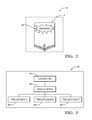
- FIG. 2is an image of a trailer captured by a camera of the trailer-identification system of FIG. 1 in accordance with one embodiment
- FIG. 3is a diagram of a structure of a database of the trailer-identification system of FIG. 1 in accordance with one embodiment
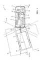
- FIG. 4is a top view of the same host-vehicle equipped with a trailer-identification system and towing a trailer of FIG. 1 in accordance with one embodiment
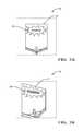
- FIG. 5Ais an image of a trailer captured by a camera of the trailer-identification system of FIG. 1 in accordance with one embodiment
- FIG. 5Bis an image of a trailer captured by a camera of the trailer-identification system of FIG. 4 in accordance with one embodiment
- FIG. 6is a side-view of the host-vehicle of FIG. 1 equipped with a trailer-detection system and towing a trailer in accordance with one embodiment
- FIG. 7is a top-view of a host-vehicle equipped with a trailer-identification system and towing a trailer that is not as wide as the host-vehicle in accordance with one embodiment
- FIG. 8is a top-view of the same host-vehicle in FIG. 7 equipped with a trailer-identification system and towing a trailer that is not as wide as the host-vehicle and in accordance with one embodiment.
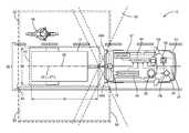
- FIG. 1illustrates a non-limiting example of a trailer-identification system 10 , hereafter referred to as the system 10 , configured to identify a trailer 12 towed by a host-vehicle 14 .
- the system 10includes a camera 16 used to capture an image 18 ( FIG. 2 ) of the area behind the host-vehicle 14 that may include the trailer 12 towed by the host-vehicle 14 .
- Examples of the camera 16 suitable for use on the host-vehicle 14are commercially available as will be recognized by those in the art, one such being the ASX340AT from ON Semiconductor® of Phoenix, Ariz., USA.
- the camera 16may be mounted on the rear of the host-vehicle 14 to have a view directed behind the host-vehicle 14 .
- the camera 16is typically a rear-facing video-type camera 16 or camera 16 that can capture the image 18 of the roadway and surrounding area at a sufficient frame-rate, of ten frames per second, for example.
- the system 10includes an angle-detector 20 used to determine a trailer-angle 22 of the trailer 12 relative to the host-vehicle 14 .
- the trailer-angle 22is defined as the angle between a host-vehicle-longitudinal-axis 24 and a trailer-longitudinal-axis 26 , and is shown to be zero degrees (0°) in FIG. 1 (i.e. the trailer 12 is directly behind the host-vehicle 14 ).
- FIG. 4shows an example when the trailer-angle 22 is not zero.
- the angle-detector 20may be a device (not shown) mounted on a trailer-hitch (not shown) of the host-vehicle 14 or on the trailer 12 , that is configured to provide a measurement of the angle that exists between the host-vehicle-longitudinal-axis 24 and the trailer-longitudinal-axis 26 .
- the angle-detector 20may be a Lidar-sensor (not shown), or any other suitable method to detect the trailer-angle 22 .
- the function of the angle-detector 20may be provided by a yaw-sensor 28 that may already exist on most vehicles, such as the 6DF-1N6-C2-HWL from Honeywell Sensing and Control, Golden Valley, Minn., USA, and is used to determine a yaw-rate 30 of the host-vehicle 14 from which the trailer-angle 22 may be determined. It is advantageous to use the yaw-sensor 28 of the host-vehicle 14 to determine the trailer-angle 22 to eliminate a separate component of the system 10 , thereby reducing cost and complexity.
- the system 10includes a database 32 ( FIG. 3 ) that associates a character 34 with a trailer-model 36 .
- the character 34may be an illustration or a lettering or a combination of the illustration and the lettering that is unique to the trailer-model 36 and may be applied to the front of the trailer 12 by the manufacturer of the trailer 12 .
- the information in the database 32 related to the trailer-model 36may include one of a trailer-width 38 ( FIG. 1 ), a trailer-length 40 ( FIG. 1 ), and a trailer-height 42 ( FIG. 6 ).
- Other specifications of the trailer 12may be contained in the database 32 and include, but are not limited to, a trailer-weight, a brake-type, an axle-distance to a hitch-coupler, a tongue-weight, and a trailer-manufacturer, for example.
- the contents of the database 32may reside on the host-vehicle 14 in a controller 44 or may reside remotely and may be accessible via wireless communication protocols known in the industry.
- the database 32may be periodically updated with information for new models of trailers 12 as they are released into production. Updates to the database 32 may occur locally (i.e. directly downloaded to the host-vehicle 14 ) or may occur remotely via wireless transmission.
- the system 10includes the controller 44 in electrical communication with the camera 16 , the angle-detector 20 , and the database 32 .
- the controller 44may include a processor (not shown) such as a microprocessor or other control circuitry such as analog and/or digital control circuitry including an application specific integrated circuit (ASIC) for processing data as should be evident to those skilled in the art.
- the controller 44may include a memory (not shown), including non-volatile memory, such as electrically erasable programmable read-only memory (EEPROM) for storing one or more routines, thresholds and captured data.
- the one or more routinesmay be executed by the processor to perform steps for determining if signals received by the controller 44 indicate the presence of objects as described herein.
- the controller 44is configured to receive the image 18 from the camera 16 and detect the character 34 ( FIG. 2 ) on the trailer 12 in order to identify the trailer-model 36 .
- the controller 44may use known optical-character-recognition (OCR) methods to match the characters 34 in the image 18 captured by the camera 16 with the characters 34 in the database 32 .
- OCRoptical-character-recognition
- OCRoptical-word-recognition
- ICRintelligent-character-recognition
- IWRintelligent-word-recognition
- the OCR methodsmay include pre-processing of the image 18 to improve the success rate of recognition of the characters 34 , matrix-matching, feature extraction, and application-specific optimizations, and will be recognized by those skilled in the art of OCR.
- the controller 44is further configured to identify the trailer-model 36 based on the trailer-angle 22 .
- FIG. 5Aillustrates the image 18 of the trailer 12 with the trailer-angle 22 equal to zero degrees and
- FIG. 5Billustrates the image 18 of the trailer 12 where the trailer-angle 22 is greater than zero degrees.
- the orientation of the trailer 12 relative to the host-vehicle 14is the same in FIG. 5B and FIG. 4 .
- FIG. 5Balso illustrates how the character 34 in the image 18 may be skewed due to the trailer-angle 22 . That is, the characters 34 on the right-half of the front of the trailer 12 in FIG. 5B appear larger than the characters 34 on the left-half of the front of the trailer 12 .
- the controller 44compensates for the skewing of the character 34 in the image 18 of FIG. 5B by using the trailer-angle 22 as input to a rotation-matrix (not shown) to create a compensated-image (not shown).
- the compensated-imageis translated to the expected appearance of the image 18 with the trailer-angle 22 at zero degrees ( FIG. 5A ).
- the compensated-imagemay then be pattern-matched to the database 32 by the known OCR methods.
- the system 10also includes a radar-sensor 46 used to detect an other-vehicle 48 present in a blind-zone 50 proximate to the host-vehicle 14 .
- the radar-sensor 46is configured to emit a radar-signal (not shown) toward a defined-area 52 proximate to the host-vehicle 14 , and detect a reflected-signal (not shown) arising from the radar-signal being reflected by detected-targets.
- Reflected-signals from the weak-targetsmay be, for example, a multi-path reflection from under the trailer 12 as the signal bounces between the trailer 12 and ground, or by multi-path reflections traveling through a grated open-trailer or cross-frame members of the frame of the trailer 12 .
- the radar-sensor 46includes a left-sensor 46 A and a right-sensor 46 B.
- a radar sensor-system with a similarly configured radar-sensor 46is available from Delphi Inc. of Troy, Mich., USA and marketed as an Electronically Scanning Radar (ESR) or a Rear-Side-Detection-System (RSDS). It is contemplated that the teachings presented herein are applicable to radar-systems with one or more sensor devices.
- the radar-sensor 46is generally configured to output a reflection-signal that may include data indicative of a detected-target present in the defined-area 52 .
- Data that corresponds to the strong-targetswill generally be from consistent, non-intermittent signals. However, data that corresponds to the weak-targets may be intermittent or have some substantial variability due to a low signal-to-noise ratio.
- the radar-sensor 46may be configured to output a continuous or periodic data stream that includes a variety of signal characteristics associated with each target detected.
- the signal characteristicsmay include, but are not limited to a range (not shown) to the detected-target from the host-vehicle 14 , a target-angle (not shown) to the detected-target relative to the host-vehicle-longitudinal-axis 24 , an amplitude (not shown) of the reflected-signal, and a relative-velocity (not shown) of closure relative to the detected-target.
- a targetis generally detected because the reflected-signal from the detected-target has sufficient signal strength to meet some predetermined threshold. That is, there may be targets that reflect the radar-signal, but the strength of the reflected-signal is insufficient to be characterized as one of the detected-targets.
- the controller 44is generally configured to determine if the reflection-signal arising from the detected-target corresponds to (i.e. is associated with) the trailer 12 being towed by the host-vehicle 14 . That is, the controller 44 determines if the trailer 12 is present, so is actually being towed by the host-vehicle 14 .
- the controller 44is also generally configured to define a trailer-boundary 54 characterized as occupied by the trailer 12 and thereby excluded from the defined-area 52 where objects can be detected in the blind-zone 50 .
- the controller 44can more readily determine if what seems to be a new target indicated by the reflected-signal is likely from the trailer 12 , or is likely from something other than the trailer 12 , such as the other-vehicle 48 .
- the controller 44may also be configured to activate an alert-device 56 to warn an operator 58 of the host-vehicle 14 if the other-vehicle 48 is detected in the blind-zone 50 .
- the blind-zone 50preferably extends for a distance of four meters (4-meters) beyond the rear of the trailer 12 and may be calibrated to any distance desired.
- the blind-zone 50preferably extends for a distance of 4-meters perpendicular to the left-side and right side of the host-vehicle 14 to sense objects in an adjoining roadway lane and may be calibrated to any distance desired.
- the boundaries of the defined-area 52extend to the limits of the radar-signal and are considered to be infinite for the purposes of this example.
- the trailer-boundary 54 and the blind-zone 50are both subsets of a sensing-boundary 60 .
- the reflection-signalmay be analyzed to categorize the data from each detected-target with respect to a list of previously detected-targets having established tracks.
- a trackrefers to one or more data sets that have been associated with a particular one of the detected-targets.
- the controller 44determines if the data corresponds to a previously detected-target or if a new-target has been detected. If the data corresponds to a previously detected-target, the data is added to or combined with prior data to update the track of the previously detected-target.
- the datamay be characterized as a new-target and assigned a unique track identification number.
- the identification numbermay be assigned according to the order that data for a new detected-target is received, or may be assigned an identification number according to a grid location in the defined-area 52 .
- a detected-target or a track that corresponds to (i.e. is associated with) the trailer 12would have a relative-velocity near zero, and that this condition would persist for an extended period of time. That is, the detected-target corresponds to the trailer 12 if a range to the detected-target varies less than a variation threshold (e.g. less than 0.25 meters) for greater than a time threshold (e.g. greater than 5 seconds). It is noted that characterizing a target as having a relative-velocity near zero and having a variation in range less than a variation threshold are effectively the same characterization. As such, references to the term ‘range-rate’ in the discussion that follows are directly comparable to the terms ‘relative-velocity’, ‘relative-rate’ and ‘variation-in-range’.
- the controller 44is further configured to adjust the blind-zone 50 proximate to the host-vehicle 14 based on the trailer-model 36 .
- the controller 44may use the trailer-width 38 from the database 32 to adjust the inboard-boundaries of the blind-zone 50 to be collinear with the sides of the trailer 12 .
- FIG. 7illustrates the adjustment of the inboard-boundaries of the blind-zone 50 to be collinear with the sides of the trailer 12 where the trailer 12 is not as wide as the host-vehicle 14 . Note that, in contrast to FIG.
- the inboard-boundaries of the blind-zone 50encroach on a lane-marking 62 of a roadway that may be detected by the camera 16 .
- This adjusted blind-zone 50is useful to detect a smaller other-vehicle 48 that may be traveling in a same travel-lane 64 (e.g. lane-splitting) as the host-vehicle 14 and trailer 12 , such as a motorcycle for example.
- the controller 44is further configured to modify the blind-zone 50 based on the trailer-angle 22 .
- FIG. 4illustrates the same system 10 from FIG. 1 when the host-vehicle 14 is turning while towing the trailer 12 .
- the controller 44is further configured to adjust the sensing-boundary 60 based on the trailer-angle 22 .
- the controller 44is further configured to adjust the trailer-boundary 54 based on the adjusted sensing-boundary 60 such that the detected-target, or a track that corresponds to the trailer 12 , may continue to be tracked by the system 10 as described previously.
- the controller 44is further configured to adjust the blind-zone 50 based on the adjusted trailer-boundary 54 to maintain the blind-zone 50 proximate to the trailer-boundary 54 .
- the controller 44may be further configured to use the radar-sensor 46 to determine the relative-velocity of the tracked-target associated with the trailer 12 , and determine the trailer-angle 22 based on a longitudinal-velocity and a lateral-velocity of the detected-target.
- An additional benefit to adjusting the trailer-boundary 54 based on the trailer-angle 22may be realized in other autonomous-vehicle or semi-autonomous-vehicle applications where the controller 44 may be configured to determine whether a current path of the host-vehicle 14 and trailer 12 may collide with an object or other-vehicle 48 , based on the turning path of the combination of the host-vehicle 14 and the trailer 12 . In such a situation, the controller 44 may also be configured to activate the alert-device 56 to warn the operator 58 of the impending collision.
- the image 18may also include, but is not limited to, the lane-marking 62 on the left side and on the right side of the travel-lane 64 of the roadway.
- the lane-marking 62may include a solid-line, as is typically used to indicate the boundary of the travel-lane 64 of the roadway.
- the lane-marking 62may also include a dashed-line, as is also typically used to indicate the boundary of the travel-lane 64 of the roadway.
- the controller 44is further configured to determine a centerline (not shown) on the roadway for the trailer 12 based on the lane-marking 62 of the roadway detected by the camera 16 .
- the image 18 detected or captured by the camera 16is processed by the controller 44 using known techniques for image-analysis to determine where along the roadway the trailer 12 should be centered.
- Vision processing technologiessuch as the EYE Q® platform from Mobileye Vision Technologies, Ltd. of Jerusalem, Israel, or other suitable devices may be used.
- the centerlineis preferably in the middle of the travel-lane 64 defined by the lane-marking 62 of the roadway.
- the controller 44is also configured to determine a lane-width 66 of the travel-lane 64 using the known vision processing technologies described above.
- the controller 44is further configured to determine when the trailer 12 is departing from the travel-lane 64 based on the trailer-angle 22 and the trailer-model 36 , and may activate the alert-device 56 to warn the operator 58 of the host-vehicle 14 that the trailer 12 is making an unintentional departure from the travel-lane 64 , i.e. issue a lane-departure-warning 67 ( FIG. 8 ).
- the controller 44may consider the departure of the trailer 12 from the travel-lane 64 unintentional when a turn-signal of the host-vehicle 14 is not activated prior to the departure of the trailer 12 from the travel-lane 64 , for example.
- the controller 44is configured to determine the position of the rear corners of the trailer 12 relative to the lane-markings 62 , based on the trailer-width 38 , the trailer-length 40 , and the trailer-angle 22 , as will be understood by one skilled in the art of geometry.
- the controller 44may then activate the alert-device 56 to warn the operator 58 of the host-vehicle 14 that the trailer-angle 22 exceeds an angle-threshold 68 indicative of the trailer 12 making an unintentional departure from the travel-lane 64 .
- the angle-threshold 68is determined by the controller 44 and is dependent on the trailer-width 38 and the trailer-length 40 of the trailer-model 36 , as will be recognized by one skilled in the art of geometry.
- FIG. 8illustrates the angle-threshold 68 being exceeded for the trailer 12 shown in FIG. 7 . Note that the trailer 12 is departing the travel-lane 64 as illustrated by the right-rear corner of the trailer 12 crossing the solid lane-marking 62 on the right-side of the travel-lane 64 .
- a trailer-identification system 10and a controller 44 for the trailer-identification system 10 is provided.
- the trailer-identification system 10is an improvement over previous systems because it uses the database 32 of trailer-models 36 that includes specifications of the trailer 12 that may be used to determine and adjust the blind-zone 50 proximate to the host-vehicle 14 and the trailer 12 .
Landscapes
- Engineering & Computer Science (AREA)
- Remote Sensing (AREA)
- Radar, Positioning & Navigation (AREA)
- Physics & Mathematics (AREA)
- General Physics & Mathematics (AREA)
- Computer Networks & Wireless Communication (AREA)
- Multimedia (AREA)
- Theoretical Computer Science (AREA)
- Electromagnetism (AREA)
- Signal Processing (AREA)
- Computer Vision & Pattern Recognition (AREA)
- General Engineering & Computer Science (AREA)
- Evolutionary Computation (AREA)
- Evolutionary Biology (AREA)
- Data Mining & Analysis (AREA)
- Life Sciences & Earth Sciences (AREA)
- Bioinformatics & Computational Biology (AREA)
- Bioinformatics & Cheminformatics (AREA)
- Artificial Intelligence (AREA)
- Traffic Control Systems (AREA)
Abstract
Description
Claims (6)
Priority Applications (4)
| Application Number | Priority Date | Filing Date | Title |
|---|---|---|---|
| US15/250,072US10276049B2 (en) | 2016-08-29 | 2016-08-29 | Camera based trailer identification and blind zone adjustment |
| EP17186999.3AEP3291205A1 (en) | 2016-08-29 | 2017-08-21 | Camera based trailer identification and blind zone adjustment |
| CN201710749404.4ACN107797118B (en) | 2016-08-29 | 2017-08-28 | Camera-based trailer identification and blind spot adjustment |
| CN202210373408.8ACN114721000A (en) | 2016-08-29 | 2017-08-28 | Camera-based trailer identification and blind spot adjustment |
Applications Claiming Priority (1)
| Application Number | Priority Date | Filing Date | Title |
|---|---|---|---|
| US15/250,072US10276049B2 (en) | 2016-08-29 | 2016-08-29 | Camera based trailer identification and blind zone adjustment |
Publications (2)
| Publication Number | Publication Date |
|---|---|
| US20180061239A1 US20180061239A1 (en) | 2018-03-01 |
| US10276049B2true US10276049B2 (en) | 2019-04-30 |
Family
ID=59772386
Family Applications (1)
| Application Number | Title | Priority Date | Filing Date |
|---|---|---|---|
| US15/250,072Active2036-10-25US10276049B2 (en) | 2016-08-29 | 2016-08-29 | Camera based trailer identification and blind zone adjustment |
Country Status (3)
| Country | Link |
|---|---|
| US (1) | US10276049B2 (en) |
| EP (1) | EP3291205A1 (en) |
| CN (2) | CN107797118B (en) |
Cited By (6)
| Publication number | Priority date | Publication date | Assignee | Title |
|---|---|---|---|---|
| US10955540B2 (en) | 2017-12-01 | 2021-03-23 | Aptiv Technologies Limited | Detection system |
| US20210149044A1 (en)* | 2019-11-14 | 2021-05-20 | GM Global Technology Operations LLC | Radar system control to perform cross-traffic mangement in a vehicle with a trailer |
| US11092668B2 (en) | 2019-02-07 | 2021-08-17 | Aptiv Technologies Limited | Trailer detection system and method |
| US11408995B2 (en) | 2020-02-24 | 2022-08-09 | Aptiv Technologies Limited | Lateral-bin monitoring for radar target detection |
| US20220258766A1 (en)* | 2021-02-17 | 2022-08-18 | Robert Bosch Gmbh | Method for ascertaining a spatial orientation of a trailer |
| US11435466B2 (en) | 2018-10-08 | 2022-09-06 | Aptiv Technologies Limited | Detection system and method |
Families Citing this family (20)
| Publication number | Priority date | Publication date | Assignee | Title |
|---|---|---|---|---|
| US10276049B2 (en)* | 2016-08-29 | 2019-04-30 | Aptiv Technologies Limited | Camera based trailer identification and blind zone adjustment |
| DE102017203129A1 (en)* | 2017-02-27 | 2018-08-30 | Robert Bosch Gmbh | Method for monitoring an environment of a vehicle |
| US11465680B2 (en)* | 2017-06-06 | 2022-10-11 | Daniel Robert Shepard | Multiple stored configuration sensors |
| US10363874B2 (en)* | 2017-09-19 | 2019-07-30 | Ford Global Technologies, Llc | Hitch assist system with hitch coupler identification feature and hitch coupler height estimation |
| US11364885B2 (en) | 2018-01-18 | 2022-06-21 | Vieletech Inc. | Smart trailer controller |
| US10635933B2 (en)* | 2018-01-23 | 2020-04-28 | Ford Global Technologies, Llc | Vision-based methods and systems for determining trailer presence |
| US11420695B2 (en) | 2018-01-31 | 2022-08-23 | Vieletech Inc. | Semi-autonomous trailer hauler |
| CN111886518A (en)* | 2018-03-29 | 2020-11-03 | 洋马动力科技有限公司 | Obstacle detection system and work vehicle |
| US10748295B2 (en) | 2018-06-08 | 2020-08-18 | Ford Global Technologies, Llc | Object tracking in blind-spot |
| US10884119B2 (en)* | 2018-06-08 | 2021-01-05 | Ford Global Technologies, Llc | Object tracking in blind-spot |
| US11274937B2 (en)* | 2019-08-16 | 2022-03-15 | Toyota Motor North America, Inc. | Methods, systems, and vehicles for providing wind alerts to a driver of a vehicle |
| CN110705445A (en)* | 2019-09-27 | 2020-01-17 | 长城汽车股份有限公司 | Trailer and blind area target detection method and device |
| US11176827B2 (en)* | 2020-01-24 | 2021-11-16 | Ford Global Technologies, Llc | Extendable blind spot sensors and methods of use |
| CN111746395B (en)* | 2020-06-12 | 2021-08-13 | 东风商用车有限公司 | Blind area detection method for preventing self-trailer from being mistakenly identified |
| EP4305460A1 (en)* | 2021-03-08 | 2024-01-17 | Continental Autonomous Mobility US, LLC | Trailer merge warning method and system for a motor vehicle |
| CN113607203B (en)* | 2021-07-30 | 2024-05-28 | 宁波路特斯机器人有限公司 | Control method and system of vehicle sensor and vehicle |
| US12043175B2 (en)* | 2021-11-03 | 2024-07-23 | GM Global Technology Operations LLC | Trailer rear camera sensing mechanisms and methods |
| WO2023228668A1 (en)* | 2022-05-25 | 2023-11-30 | 株式会社デンソー | Surroundings monitoring device and program |
| CN114966673B (en)* | 2022-05-31 | 2024-12-17 | 上海海拉电子有限公司 | Radar-based trailer detection method and system and vehicle |
| US12307778B1 (en)* | 2022-08-27 | 2025-05-20 | Ambarella International Lp | Dynamic adjustment of sensor range using computer vision |
Citations (6)
| Publication number | Priority date | Publication date | Assignee | Title |
|---|---|---|---|---|
| US20140267688A1 (en)* | 2011-04-19 | 2014-09-18 | Ford Global Technologies, Llc | Display system utilizing vehicle and trailer dynamics |
| GB2518857A (en) | 2013-10-02 | 2015-04-08 | Jaguar Land Rover Ltd | Vehicle towing configuration system and method |
| US20150120141A1 (en)* | 2013-10-31 | 2015-04-30 | Ford Global Technologies, Llc | Methods and systems for configuring of a trailer maneuvering system |
| US20160041258A1 (en) | 2014-08-08 | 2016-02-11 | Delphi Technologies, Inc. | Vehicle radar system with trailer detection |
| US20160101811A1 (en)* | 2014-10-13 | 2016-04-14 | Ford Global Technologies, Llc | Trailer sensor module and associated method of wireless trailer identification and motion estimation |
| US9373044B2 (en)* | 2011-07-25 | 2016-06-21 | Ford Global Technologies, Llc | Trailer lane departure warning system |
Family Cites Families (12)
| Publication number | Priority date | Publication date | Assignee | Title |
|---|---|---|---|---|
| GB2447672B (en)* | 2007-03-21 | 2011-12-14 | Ford Global Tech Llc | Vehicle manoeuvring aids |
| JP2009060499A (en)* | 2007-09-03 | 2009-03-19 | Sanyo Electric Co Ltd | Driving support system, and combination vehicle |
| US7932835B2 (en)* | 2008-01-25 | 2011-04-26 | Delphi Technologies, Inc. | Vehicle zone detection system and method |
| KR200442841Y1 (en)* | 2008-07-08 | 2008-12-17 | 강무영 | Front blind spot display device for vehicle |
| DE102009007990A1 (en)* | 2009-02-07 | 2010-08-12 | Hella Kgaa Hueck & Co. | Trailer data determining method, involves utilizing distance sensors provided in rear region of towing vehicle, for determining trailer data, and determining and processing different distances between vehicle and trailer |
| US9434414B2 (en)* | 2011-04-19 | 2016-09-06 | Ford Global Technologies, Llc | System and method for determining a hitch angle offset |
| US9861040B2 (en)* | 2012-02-10 | 2018-01-09 | Deere & Company | Method and stereo vision system for facilitating the unloading of agricultural material from a vehicle |
| CN103673977B (en)* | 2013-11-07 | 2016-07-27 | 沈阳师范大学 | The method and apparatus of rear dead zone of vehicle detection |
| DE112014004384B4 (en)* | 2013-11-18 | 2024-01-11 | Robert Bosch Gmbh | Vector-based driver assistance for towing vehicles |
| US9517668B2 (en)* | 2014-07-28 | 2016-12-13 | Ford Global Technologies, Llc | Hitch angle warning system and method |
| US9493117B2 (en)* | 2014-10-08 | 2016-11-15 | Ford Global Technologies, Llc | Vehicle blind spot system operation with trailer tow |
| US10276049B2 (en)* | 2016-08-29 | 2019-04-30 | Aptiv Technologies Limited | Camera based trailer identification and blind zone adjustment |
- 2016
- 2016-08-29USUS15/250,072patent/US10276049B2/enactiveActive
- 2017
- 2017-08-21EPEP17186999.3Apatent/EP3291205A1/ennot_activeWithdrawn
- 2017-08-28CNCN201710749404.4Apatent/CN107797118B/enactiveActive
- 2017-08-28CNCN202210373408.8Apatent/CN114721000A/enactivePending
Patent Citations (6)
| Publication number | Priority date | Publication date | Assignee | Title |
|---|---|---|---|---|
| US20140267688A1 (en)* | 2011-04-19 | 2014-09-18 | Ford Global Technologies, Llc | Display system utilizing vehicle and trailer dynamics |
| US9373044B2 (en)* | 2011-07-25 | 2016-06-21 | Ford Global Technologies, Llc | Trailer lane departure warning system |
| GB2518857A (en) | 2013-10-02 | 2015-04-08 | Jaguar Land Rover Ltd | Vehicle towing configuration system and method |
| US20150120141A1 (en)* | 2013-10-31 | 2015-04-30 | Ford Global Technologies, Llc | Methods and systems for configuring of a trailer maneuvering system |
| US20160041258A1 (en) | 2014-08-08 | 2016-02-11 | Delphi Technologies, Inc. | Vehicle radar system with trailer detection |
| US20160101811A1 (en)* | 2014-10-13 | 2016-04-14 | Ford Global Technologies, Llc | Trailer sensor module and associated method of wireless trailer identification and motion estimation |
Cited By (11)
| Publication number | Priority date | Publication date | Assignee | Title |
|---|---|---|---|---|
| US10955540B2 (en) | 2017-12-01 | 2021-03-23 | Aptiv Technologies Limited | Detection system |
| US11474224B2 (en) | 2017-12-01 | 2022-10-18 | Aptiv Technologies Limited | Detection system |
| US11435466B2 (en) | 2018-10-08 | 2022-09-06 | Aptiv Technologies Limited | Detection system and method |
| US11768284B2 (en) | 2018-10-08 | 2023-09-26 | Aptiv Technologies Limited | Detection system and method |
| US11092668B2 (en) | 2019-02-07 | 2021-08-17 | Aptiv Technologies Limited | Trailer detection system and method |
| US20210149044A1 (en)* | 2019-11-14 | 2021-05-20 | GM Global Technology Operations LLC | Radar system control to perform cross-traffic mangement in a vehicle with a trailer |
| US11525911B2 (en)* | 2019-11-14 | 2022-12-13 | GM Global Technology Operations LLC | Radar system control to perform cross-traffic management in a vehicle with a trailer |
| US11408995B2 (en) | 2020-02-24 | 2022-08-09 | Aptiv Technologies Limited | Lateral-bin monitoring for radar target detection |
| US11802961B2 (en) | 2020-02-24 | 2023-10-31 | Aptiv Technologies Limited | Lateral-bin monitoring for radar target detection |
| US20220258766A1 (en)* | 2021-02-17 | 2022-08-18 | Robert Bosch Gmbh | Method for ascertaining a spatial orientation of a trailer |
| US12391280B2 (en)* | 2021-02-17 | 2025-08-19 | Robert Bosch Gmbh | Method for ascertaining a spatial orientation of a trailer |
Also Published As
| Publication number | Publication date |
|---|---|
| CN107797118A (en) | 2018-03-13 |
| CN107797118B (en) | 2022-04-29 |
| US20180061239A1 (en) | 2018-03-01 |
| CN114721000A (en) | 2022-07-08 |
| EP3291205A1 (en) | 2018-03-07 |
Similar Documents
| Publication | Publication Date | Title |
|---|---|---|
| US10276049B2 (en) | Camera based trailer identification and blind zone adjustment | |
| US11275175B2 (en) | Method for detecting objects via a vehicular sensing system | |
| US10286916B2 (en) | Trailer estimation and blind spot information system performance improvement | |
| US10351146B2 (en) | Trailer estimation improvement | |
| US20180068566A1 (en) | Trailer lane departure warning and sway alert | |
| EP3282284B1 (en) | Trailer dimension estimation with radar and camera | |
| US11014566B2 (en) | Object detection apparatus | |
| US10559205B2 (en) | Object existence determination method and apparatus | |
| US9753130B2 (en) | Target detection apparatus | |
| US10393862B2 (en) | Trailer estimation with elevation enhanced sensing | |
| US20190064837A1 (en) | Automated parking for virtual parking spot | |
| EP3410146A1 (en) | Determining objects of interest for active cruise control | |
| AU2017337223A1 (en) | A method for determining the presence of a trailer | |
| US20230040994A1 (en) | Information processing apparatus, information processing system, information processing program, and information processing method | |
| US20160247030A1 (en) | Obstacle detection apparatus | |
| KR102012572B1 (en) | Method for detecting shading of a sensor device of a motor vehicle by an object, computing device, driver assistance system and motor vehicle | |
| US20250061726A1 (en) | Obstacle detection for trailer turns | |
| US11410427B2 (en) | Vision system and method for a motor vehicle |
Legal Events
| Date | Code | Title | Description |
|---|---|---|---|
| AS | Assignment | Owner name:DELPHI TECHNOLOGIES, INC., MICHIGAN Free format text:ASSIGNMENT OF ASSIGNORS INTEREST;ASSIGNORS:PRASAD, PREMCHAND KRISHNA;CASHLER, ROBERT J.;REEL/FRAME:039566/0046 Effective date:20160829 | |
| AS | Assignment | Owner name:APTIV TECHNOLOGIES LIMITED, BARBADOS Free format text:ASSIGNMENT OF ASSIGNORS INTEREST;ASSIGNOR:DELPHI TECHNOLOGIES INC.;REEL/FRAME:047153/0902 Effective date:20180101 | |
| STPP | Information on status: patent application and granting procedure in general | Free format text:PUBLICATIONS -- ISSUE FEE PAYMENT VERIFIED | |
| STCF | Information on status: patent grant | Free format text:PATENTED CASE | |
| MAFP | Maintenance fee payment | Free format text:PAYMENT OF MAINTENANCE FEE, 4TH YEAR, LARGE ENTITY (ORIGINAL EVENT CODE: M1551); ENTITY STATUS OF PATENT OWNER: LARGE ENTITY Year of fee payment:4 | |
| AS | Assignment | Owner name:APTIV TECHNOLOGIES (2) S.A R.L., LUXEMBOURG Free format text:ENTITY CONVERSION;ASSIGNOR:APTIV TECHNOLOGIES LIMITED;REEL/FRAME:066746/0001 Effective date:20230818 Owner name:APTIV MANUFACTURING MANAGEMENT SERVICES S.A R.L., LUXEMBOURG Free format text:MERGER;ASSIGNOR:APTIV TECHNOLOGIES (2) S.A R.L.;REEL/FRAME:066566/0173 Effective date:20231005 Owner name:APTIV TECHNOLOGIES AG, SWITZERLAND Free format text:ASSIGNMENT OF ASSIGNORS INTEREST;ASSIGNOR:APTIV MANUFACTURING MANAGEMENT SERVICES S.A R.L.;REEL/FRAME:066551/0219 Effective date:20231006 |