US10275402B2 - Systems and methods to provide pipeline damage alerts - Google Patents
Systems and methods to provide pipeline damage alertsDownload PDFInfo
- Publication number
- US10275402B2 US10275402B2US14/854,828US201514854828AUS10275402B2US 10275402 B2US10275402 B2US 10275402B2US 201514854828 AUS201514854828 AUS 201514854828AUS 10275402 B2US10275402 B2US 10275402B2
- Authority
- US
- United States
- Prior art keywords
- pipeline
- information
- data
- processing unit
- signal processing
- Prior art date
- Legal status (The legal status is an assumption and is not a legal conclusion. Google has not performed a legal analysis and makes no representation as to the accuracy of the status listed.)
- Active, expires
Links
Images


Classifications
- G—PHYSICS
- G06—COMPUTING OR CALCULATING; COUNTING
- G06F—ELECTRIC DIGITAL DATA PROCESSING
- G06F16/00—Information retrieval; Database structures therefor; File system structures therefor
- G06F16/20—Information retrieval; Database structures therefor; File system structures therefor of structured data, e.g. relational data
- G06F16/24—Querying
- G06F16/245—Query processing
- F—MECHANICAL ENGINEERING; LIGHTING; HEATING; WEAPONS; BLASTING
- F17—STORING OR DISTRIBUTING GASES OR LIQUIDS
- F17D—PIPE-LINE SYSTEMS; PIPE-LINES
- F17D5/00—Protection or supervision of installations
- F17D5/02—Preventing, monitoring, or locating loss
- F17D5/06—Preventing, monitoring, or locating loss using electric or acoustic means
- G—PHYSICS
- G01—MEASURING; TESTING
- G01M—TESTING STATIC OR DYNAMIC BALANCE OF MACHINES OR STRUCTURES; TESTING OF STRUCTURES OR APPARATUS, NOT OTHERWISE PROVIDED FOR
- G01M3/00—Investigating fluid-tightness of structures
- G01M3/002—Investigating fluid-tightness of structures by using thermal means
- G—PHYSICS
- G01—MEASURING; TESTING
- G01M—TESTING STATIC OR DYNAMIC BALANCE OF MACHINES OR STRUCTURES; TESTING OF STRUCTURES OR APPARATUS, NOT OTHERWISE PROVIDED FOR
- G01M3/00—Investigating fluid-tightness of structures
- G01M3/02—Investigating fluid-tightness of structures by using fluid or vacuum
- G01M3/04—Investigating fluid-tightness of structures by using fluid or vacuum by detecting the presence of fluid at the leakage point
- G01M3/24—Investigating fluid-tightness of structures by using fluid or vacuum by detecting the presence of fluid at the leakage point using infrasonic, sonic, or ultrasonic vibrations
- G01M3/243—Investigating fluid-tightness of structures by using fluid or vacuum by detecting the presence of fluid at the leakage point using infrasonic, sonic, or ultrasonic vibrations for pipes
- G—PHYSICS
- G01—MEASURING; TESTING
- G01M—TESTING STATIC OR DYNAMIC BALANCE OF MACHINES OR STRUCTURES; TESTING OF STRUCTURES OR APPARATUS, NOT OTHERWISE PROVIDED FOR
- G01M3/00—Investigating fluid-tightness of structures
- G01M3/02—Investigating fluid-tightness of structures by using fluid or vacuum
- G01M3/26—Investigating fluid-tightness of structures by using fluid or vacuum by measuring rate of loss or gain of fluid, e.g. by pressure-responsive devices, by flow detectors
- G01M3/28—Investigating fluid-tightness of structures by using fluid or vacuum by measuring rate of loss or gain of fluid, e.g. by pressure-responsive devices, by flow detectors for pipes, cables or tubes; for pipe joints or seals; for valves ; for welds
- G01M3/2807—Investigating fluid-tightness of structures by using fluid or vacuum by measuring rate of loss or gain of fluid, e.g. by pressure-responsive devices, by flow detectors for pipes, cables or tubes; for pipe joints or seals; for valves ; for welds for pipes
Definitions
- Pipelinesmay be used to transport a substance from one location to another.
- a pipelinemay be used to transport propane gas from one location to another location hundreds of miles away.
- various portions of a pipelinemay be at risk of malfunctioning, either due to corrosion, mechanical damage, equipment failures, etc.
- an enterprise operating a pipelinemay need to manage the pipeline to fix anomalies as they arise and/or prevent problems before they occur. For example, an enterprise might notice a construction crew has begun working near the pipeline and dispatch a person to the site to ensure that the construction does not damage the pipeline.
- FIG. 1is a high-level architecture of a system in accordance with some embodiments.
- FIG. 2illustrates a method that might be performed according to some embodiments.
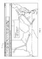
- FIG. 3illustrates an intelligent pipeline management graphical user interface display according to some embodiments.
- FIG. 4illustrates a physical characteristic of a substance method in accordance with some embodiments.
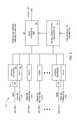
- FIG. 5illustrates a data network system according to some embodiments.
- FIG. 6illustrates a system incorporating a fusion algorithm in accordance with some embodiments.
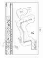
- FIG. 7illustrates a pipeline alert or alarm on a display according to some embodiments.
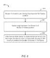
- FIG. 8illustrates an image data method that might be performed in accordance with some embodiments.
- FIG. 9illustrates a pipeline system according to some embodiments.
- FIG. 10illustrates an adaptable probabilistic framework in accordance with some embodiments.
- FIG. 11illustrates an intelligent pipeline management display according to some embodiments.
- FIG. 12illustrates an intelligent pipeline management system in accordance with some embodiments.
- FIG. 13is block diagram of an intelligent pipeline management platform according to some embodiments of the present invention.
- FIG. 14is a tabular portion of a pipeline segment database according to some embodiments.
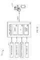
- FIG. 1is a high-level architecture of a system 100 in accordance with some embodiments.
- the system 100includes data sources 110 , 120 that provide information to a signal processing unit 150 .
- the data sources 110 , 120might include, distributed acoustic sensing data and collected physical data about the pipeline and/or a substance being transported via the pipeline.
- a pipeline databasemay store current and/or historical information about one or more pipelines and/or segments of a pipeline.
- a data sourcemay include information about subsystem assets, such as pipeline compressor station conditions, main line valve states, temperature, pressure, and flows, etc.
- Various data sourcesmay further include geographic information, such as map data, topographical data, etc.
- the geographic informationmay be associated with satellite data and/or a Geographic Information System (“GIS”) that captures, stores, manipulates, analyzes, manages, and/or presents various types of spatial or geographical data.
- GISGeographic Information System
- Various data sourcesmay also include risk parameter information, including weather and seismic related risk parameters.
- the signal processing unit 150may, according to some embodiments, access the data sources 110 , 120 , and utilize a pipeline model to automatically create an alert (e.g., associated with risk prediction, leak detection, or excavation damage threat) that may be transmitted to various user platforms 160 as appropriate.
- an alerte.g., associated with risk prediction, leak detection, or excavation damage threat
- the term “automatically”may refer to, for example, actions that can be performed with little or no human intervention.
- devicesmay exchange information via any communication network which may be one or more of a Local Area Network (LAN), a Metropolitan Area Network (MAN), a Wide Area Network (WAN), a proprietary network, a Public Switched Telephone Network (PSTN), a Wireless Application Protocol (WAP) network, a Bluetooth network, a wireless LAN network, and/or an Internet Protocol (IP) network such as the Internet, an intranet, or an extranet.
- LANLocal Area Network
- MANMetropolitan Area Network
- WANWide Area Network
- PSTNPublic Switched Telephone Network
- WAPWireless Application Protocol
- Bluetootha Bluetooth network
- wireless LAN networka wireless LAN network
- IPInternet Protocol
- any devices described hereinmay communicate via one or more such communication networks.
- the signal processing unit 150may store information into and/or retrieve information from various data sources and/or user platforms 160 .
- the various data sourcesmay be locally stored or reside remote from the signal processing unit 150 .
- FIG. 1a single signal processing unit 150 is shown in FIG. 1 , any number of such devices may be included.
- various devices described hereinmight be combined according to embodiments of the present invention.
- the signal processing unit 150 and one or more data sourcesmight comprise a single apparatus.
- the signal processing unit 150 functionmay be performed by a constellation of networked apparatuses, in a distributed processing or cloud-based architecture.
- FIG. 2illustrates a method 200 that might be performed by some or all of the elements of the system 100 described with respect to FIG. 1 .
- the flow charts described hereindo not imply a fixed order to the steps, and embodiments of the present invention may be practiced in any order that is practicable. Note that any of the methods described herein may be performed by hardware, software, or any combination of these approaches.
- a computer-readable storage mediummay store thereon instructions that when executed by a machine result in performance according to any of the embodiments described herein.
- a signal processing unitmay receive distributed acoustic sensing data associated with a first set of a plurality of pipeline locations.
- the pipelinemight transport, for example, a gas (such as methane, propane, or butane), a liquid (such as crude or refined oil), or a combination of liquids, gases, and/or solids (such as is produced from a production well).
- a gassuch as methane, propane, or butane
- a liquidsuch as crude or refined oil
- solidssuch as is produced from a production well.
- the phrase “pipeline location”may refer to, for example, an actual pipe or anything associated with a pipeline, such as a compressor station, a main line valve, a fiber sensing cable buried near the pipeline, and/or a pipeline meter.
- the distributed acoustic sensing datamay be, for example, based on signals received via optical fibers or geophones and processed by an edge processing device.
- the signal processing unitmay receive collected physical data representing a physical characteristic of a second set of a plurality of pipeline locations.
- the second set of locationsmay be a subset of the first set of locations, a superset of the first set of locations, or a portion of locations in common with the first set of locations.
- the signal processing unitmay utilize a pipeline model (having the distributed acoustic sensing data and collected physical data as inputs) to automatically generate at least one alert indicating an increased probability of damage to the pipeline and/or a leak.
- the alertmay include a likelihood of damage and/or a predicted pipeline location associated with damage.
- the pipeline modelmight comprise, for example a predictive model and may include one or more neural networks, Bayesian networks (such as Hidden Markov models), expert systems, decision trees, collections of decision trees, support vector machines, or other systems known in the art for addressing problems with large numbers of variables.
- the model(s)are trained on prior data and outcomes known to the pipeline enterprise.
- the specific data and outcomes analyzedmay vary depending on the desired inputs and/or functionality of the particular predictive model.
- the particular data parameters selected for analysis in the training processmight be determined using regression analysis and/or other statistical techniques known in the art for identifying relevant variables in multivariable systems.
- a mapping modulemay automatically determine location information associated with each of the plurality of pipeline location.
- location informationmight refer to, for example, pixels (e.g., a location on a display monitor), coordinates, latitudes and longitudes, Global Positioning System (“GPS”) information, distances (e.g., along the pipeline), and/or GIS data.
- GPSGlobal Positioning System
- an analytic modulehaving access to historical pipeline information, may generate predictive risk information associated with at least one of the pipeline locations.
- the predictive risk valuemight be, for example, based at least in part on a volume of substance transported via the at least one pipeline portion. For example, if prior compressor stations have typically failed after transported a certain amount of gas the analytic module might predict that a compressor station in a pipeline is likely to fail in the near future.
- the predictive risk informationmight be output as a value, a category (e.g., “high” or “low” risk), a percentage (representing a likelihood of failure), and/or a color (e.g., with “green” indicating low risk, “yellow” indicating moderate risk, and “red” indicating high risk).
- a risk parametermight be associated with, for example, a corrosion pipeline wall thickness loss, a pressure change, weather and flood risk, earthquake risk, mechanical damage, and/or pipeline dent risk.
- the analytic modulehaving access to historical pipeline information, may generate alerts indication probable leaks or bursts in the pipeline, or the threat of imminent damage due to construction activity near a pipeline.
- a Graphical User Interface (“GUI”) modulehaving access to real world map information may arrange to transmit information creating for a user a visual representation of the pipeline, including information about the current status of at least one pipeline location and/or and alert, on a GUI map display in accordance with the location information.
- FIG. 3illustrates a GUI map display 300 including pipeline subsystems 310 , segments 320 and a pipeline alert 330 .
- the GUI map display 300may further include, for example, topographical information, a geographic feature (e.g., a mountain, ravine, or lake), street information, population information, weather information, seismic information, building information, and/or predicted impact radius information.
- the information generated by the GUI modulemay be adapted to create the visual representation in accordance with a number of different display platforms, including different types of hardware configurations, Operating Systems (“OS”), etc.
- OSOperating Systems
- a pipelinemay be adapted to transport a liquid or a gas.
- a physical characteristic of the substancemight be used as the collected physical data input to the pipeline model.
- FIG. 4illustrates a physical characteristic of a substance method in accordance with some embodiments.
- a signal processing unitmay receive distributed acoustic sensing data associated with a first set of a plurality of pipeline locations.
- the pipelinemight transport, for example, a gas (such as methane) or a liquid (such as crude or refined oil).
- the signal processing unitmay receive collected physical data representing pressure, temperature, and/or flow associated with the substance being transported.
- the signal processing unitmay utilize a Bayesian model (having the distributed acoustic sensing data and pressure, temperature, and/or flow data as inputs) to automatically generate at least one alert indicating an increased probability of damage to the pipeline.
- the alertmay include a likelihood of damage and/or a predicted pipeline location associated with damage.
- the physical datais processed by a Supervisory Control And Data Acquisition (“SCADA”) device prior to being received by the signal processing unit.
- SCADASupervisory Control And Data Acquisition
- the term SCADAmay refer to, for example, a system operating with coded signals over communication channels so as to provide control of remote equipment (e.g., using one communication channel per remote station).
- the control systemmay be combined with a data acquisition and storage system, according to some embodiments, by adding the use of coded signals over communication channels to acquire information about the status of the remote equipment
- the physical datais analyzed based at least in part on geospatial information describing the pipeline and a substance simulation algorithm associated with an internal leak detection system.
- FIG. 5which illustrates a data network system 500 according to some embodiments.
- the system 500includes a distributed acoustic sensing device 510 that collects acoustic information from locations via fibers.
- a digital acoustic sensing edge device 520may transmit information to a remote signal processing unit 550 (which may also receive internal and external pipeline information).
- SCADA devices 530may process pressure, temperature, and/or flow parameters to be received at an Internal Leak Detection (“ILD”) processing unit 560 .
- ILDInternal Leak Detection
- locations 1 through Nmight each be associated with acoustic information, collected physical data, or both acoustic information and collected physical data.
- the ILD processing unit 560might also receive pipeline geospatial information, such as data describing the physical location, elevation, and/or characteristics of the pipeline structure, and transmit information to the signal processing unit 550 .
- the signal processing unit 560may then generate one or more alerts and/or alarms indicating an increased likelihood of damage to the pipeline or a leak in the pipeline.
- the signal processing unit 550may utilize a fusion algorithm to generate alerts based on the acoustic data and collected physical data.
- FIG. 6illustrates a system 600 incorporating a fusion algorithm in accordance with some embodiments.
- a signal processing unit 650receives acoustic data, collected physical data, and information from an ILD processing unit 660 .
- a Bayesian network diagrammay provide one or more bins (e.g., bins 1 through M) for the acoustic measurements and the ILD data. Similar bins may be provided for time t+1, etc.
- the hidden states in the Bayesian networkrepresent the binary variable (leak/no leak) and the leak location, respectively.
- the relationships between the states and the measurementsare specified by the underlying statistical model which can be tuned using the training data. Once armed with the Bayesian network one can then run a Bayesian Network propagation algorithm to calculate the probability distributions of the nodes representing the hidden states to be estimated. In this way, the signal processing unit 650 may generate a leak/no leak indication along with a leak location to be included in an alert.
- FIG. 7illustrates a display 700 according to some embodiments.
- the display 700includes a region 710 around the pipeline, such as a region associated with a Right Of Way (“ROW”) high consequence area or danger zone.
- the display 700further shows locations of interest, such as a school 720 and hospital 730 , along with one or more alerts 740 .
- the display 700 illustrated in FIG. 7includes a map overlaid with graphical representations of a pipeline that include actual pipe segments along with other pipeline assets.
- risk information about various segments of the pipelinesmay also be included on the display 700 (e.g., low risk segments may be displayed as green or high risk segments may be displayed with crosshatching as illustrated in FIG. 7 .
- the display 700further includes information about population centers (e.g., cities and towns), geographic features, highways, weather patterns, wildfires, etc.
- embodiments described hereinmay provide a system for pipeline leak detection that may include a distributed acoustic sensing component, an edge processing unit responsible for extracting features from the acoustic raw data which will be suitable for data fusion, a data network to transfer data to a control station, a SCADA system for gathering pressure, temperature, and flow data, and/or an ILD system for estimating leak probabilities based on pressure, temperature, and/or flow data, and a signal processing unit which processes and fuses the data from the acoustic and ILD systems to generate leak alarms.
- the analyticmay fuse data streams (test statistics) from the distributed acoustic sensing edge processors and ILD systems to determine if a leak alarm should be announced. By fusing data prior to applying thresholds in either the acoustic or ILD systems, leak detection may have more sensitivity and/or reduced false alarms.
- a SCADA systemmay gather pressure, temperature, and flow data from sensors positioned along the entire pipeline network and provide this an ILD processing unit.
- Multiple distributed acoustic sensing edge processing unitsmay pre-process the acoustic measurements and convert them into information suitable for data fusion (which is done at a different stage).
- An ILD processing unitmay measure the deviation between the measured internal pipeline parameters and the expected ones derived using a computational fluid dynamic model together with pipeline geospatial information.
- a data networkmay pass data from the distributed systems to the central units (ILD and Signal Processing unit), and a signal processing unit may fuse the data from the distributed acoustic sensing edge processing units and the ILD system.
- the fusion methodmay, according to some embodiments, comprise the following steps:
- the hidden nodes in the networkmay indicate the leak/no leak hypothesis the system wants to test and the leak location, respectively.
- the observable nodesmay denote the test statistics from both systems in each bin or zone the pipe is partitioned into.
- the probabilistic and causal relationships among the nodesare represented and executed as graphs and can thus be easily visualized and extended, making model building and verification easier and faster.
- the proposed algorithmmay adapt to changing operating conditions, environments, etc. associated with the pipeline. By continuously estimating and learning the statistical distribution of the test statistics under the different hypothesis (leak vs no leak), one ensures that the detector performance (e.g. false alarms) stays under pre-designed limits by adaptively changing the decision threshold.
- Bayesian modelmay be used, for example, to make improved pipeline leak detection decisions; it may utilize both sensor features and domain expertise and incorporate prior knowledge of the status of the pipeline from historical records or other information known to the pipeline enterprise (e.g., wall thickness using internal corrosion data).
- the flexible structure of a Bayesian modelmay help ensure that the contextual information (e.g., operating conditions of the pipeline) can be integrated in the Bayesian network seamlessly.
- Some benefits of embodiments described hereinmay include reduced false alarms, increased response time, and/or improved sensitivity.
- image informationmay be fused with the acoustic data.
- FIG. 8illustrates an image data method 800 that might be performed in accordance with some embodiments.
- a signal processing unitmay receive distributed acoustic sensing data associated with a first set of a plurality of pipeline locations.
- the pipelinemight transport, for example, a gas (such as propane), a liquid (such as crude or refined oil), or a combination of liquids and solids (e.g., an output of a Stream Assisted Gravity Drainage (“SAGD”) production operation).
- a gassuch as propane
- a liquidsuch as crude or refined oil
- SAGDStream Assisted Gravity Drainage
- the signal processing unitmay receive collected physical data representing image information (e.g., pictures and/or video data) collected by drones.
- the signal processing unitmay utilize a Bayesian model (having the distributed acoustic sensing data and image information as inputs) to automatically generate at least one alert indicating an increased probability of damage to the pipeline.
- the alertmay include a likelihood of damage and/or a predicted pipeline location associated with damage.
- image informationmight instead be collected using a satellite and/or a manned flying vehicle. The image information may be used, according to some embodiments, to detect the presence of a vehicle, a person, and/or construction equipment (e.g., which might inadvertently damage the pipeline).
- FIG. 9illustrates a pipeline system 900 according to some embodiments.
- the system 900includes a pipeline 910 and at least one flying vehicle 920 that captures image information within a field of view 922 .
- one or more additional flying vehicles 930may take pictures of the pipeline 910 within a field of view 932 . The images may then be automatically reviewed to detect the presence of, for example, construction equipment 940 , leaked oil spills, etc.
- FIG. 10illustrates an adaptable probabilistic framework 1000 in accordance with some embodiments.
- the framework 1000includes a condition layer 1010 and an observation layer 1020 .
- the condition layer 1010includes nodes representing the mode of intrusion and relevant conditions of the pipeline and vicinity, such as ROW incursion, incursion mode (e.g., whether the incursion is by a car, person, etc.), pipeline context (e.g., pipeline elevation, nearby roads, etc.), and weather information. Additional nodes representing other relevant conditions may be added to this layer 1010 .
- the nodes of the condition layer 1010represent the state of these conditions or a probabilistic representation of the state of these conditions.
- the observation layer 1020includes nodes for the different measurement systems, such as drone video, fiber optic distributed acoustic sensing, seismic activing, etc. to provide heterogeneous monitoring data 1030 .
- the nodes of the observation layer 1020represent the probabilistic outputs of the measurement systems, given the conditions from the condition layer 1010 .
- the layer 1020models the behavior of the measurement systems under different conditions. Note that traversing the framework 1000 from left to right may be associated with a simulation operation while traversing the framework from right to left may be associated with an interference operation.
- FIG. 11illustrates an intelligent pipeline management street view display 1100 in accordance with some embodiments.
- the display 1100includes a street 1110 level map overlaid with a graphical representation of a pipeline 1120 , including actual pipe segments and other pipeline assets.
- risk information about various segments of the pipeline 1120may also be included on the display 1100 (e.g., high risk segments may be displayed as red or with crosshatching as illustrated in FIG. 11 ).
- the display 1100further includes information about geographic features, current traffic data, and other specific areas that may be of concern, such as a school, a hospital, a playground, etc. along with at least one alert 1130 associated with possible damage to the pipeline 1120 .
- Various risk factors associated with the alert 1130might include, for example, various categories and types of risk, such as mechanical damage, weather/outside force risks, equipment failure, external corrosion, internal corrosion, construction threats, manufacturing material risk, Stress Corrosion Cracking (“SCC”), etc.
- SCCStress Corrosion Cracking
- FIG. 12is a high-level architecture of a system 1200 in accordance with some embodiments.
- the system 1200includes data sources 1210 that provide information to an intelligent pipeline management platform 1250 .
- the data sources 1210might include, for example a pipeline database storing current and/or historical information about one or more pipeline and/or segments of a pipeline.
- the data sources 1210include information about subsystem assets, such as pipeline compressor stations, main line valves, meters, etc.
- the data sources 1210may further include geographic information, such as map data, topographical data, etc.
- the geographic informationmay be associated with satellite data and/or a GIS that captures, stores, manipulates, analyzes, manages, and/or presents various types of spatial or geographical data.
- the data sources 1210may also include risk parameter information, including acoustic, image information, weather and seismic related risk parameters.
- the intelligent pipeline management platform 1250may, according to some embodiments, access the data sources 1210 , execute a mapping module 1252 , a graphical user interface module 1254 , and/or a pipeline module 1256 (e.g., associated with a fuse algorithm, hydraulic model, and/or risk prediction), and automatically generate displays for various user platforms 1220 as appropriate (including alerts as appropriate).
- a mapping module 1252e.g., associated with a fuse algorithm, hydraulic model, and/or risk prediction
- a pipeline module 1256e.g., associated with a fuse algorithm, hydraulic model, and/or risk prediction
- the intelligent pipeline management platform 1250may store information into and/or retrieve information from the data sources 1210 and/or user platforms 1220 .
- the data sources 1210may be locally stored or reside remote from the intelligent pipeline management platform 1250 .
- FIG. 12Although a single intelligent pipeline management platform 1250 is shown in FIG. 12 , any number of such devices may be included.
- various devices described hereinmight be combined according to embodiments of the present invention.
- the intelligent pipeline management platform 1250 and data sources 1210might comprise a single apparatus.
- Such a system 1200may be used to implement a tool to combine real-time and off-line data using a probabilistic model. This may improve threat detection through use of multiple heterogeneous data sources.
- the system 1200may let a pipeline enterprise make informed decisions about which system defense tool or tools will make measurable improvements in safety and environmental protection for pipelines.
- the system 1200may combine data from multiple sources, such as video (the “eyes” of the system 1200 ) and acoustic (the “ears” of the system 1200 ), although other data may be included to improve performance—such as historical and geographic data.
- excavation damage to gas and hazardous liquid pipelineshas, and continues to be, one of the largest sources of fatalities, injuries, and releases compared to other causes. Damage continues to occur despite extensive mapping, damage prevention, and surveillance processes and procedures put into place by pipeline operators.
- Distributed acoustic sensing, video surveillance, satellite imagery, and/or geophonesmay all be able to provide information to the system 1200 .
- the system 1200may consume substantial quantities of such data to maximize detectability while minimizing false alarms.
- the first approachis based on object detectors to detect specific objects of interest such as backhoes, trucks and large trailers.
- the system 1200may input video captured by an aerial drone and scan images using a sliding window detector on a frame by frame basis.
- Training datamight be used to construct object detectors. This data is composed of two types: positive images which contain objects of interest and negative images which do not contain such objects. Given this data, discriminative machine learning methods, such as region moments, can be used to construct the required image classifier.
- the second approachutilizes change detection and classification for the purposes of identifying activity which could be a precursor to damage such as a Bayesian object-level change detection. Given multiple video sequences of the same site taken over different periods of time, the following steps may be performed:
- video datathat is representative of the expected terrain as well as the possible incursion objects/sites of interest may be required.
- Optical fibersare passive and can be deployed many tens of miles with active electronics and optics only at the end points. Compared to patrols and video-surveillance, the distributed fiber can remain on all the time for continuous protection.
- a distributed acoustic sensing (DAS) instrumentsends light pulses into a fiber cable deployed along a pipeline. Light scattered back from the fiber is recombined and processed to detect acoustics and dynamic strain. When a disturbance occurs above ground such as a backhoe nearing, the acoustic sensing can detect the disturbance, and because the round trip speed of light is known, the disturbance can be located to a distance within a few meters. According to some embodiments, a spectral change detection analytic for subsea and/or land-based pipeline leak detection using acoustic sensing may be employed.
- a spectral change detection methodmight, for example, measure the acoustic energy spectrum at each location (e.g., every 5 m) and builds a statistical model of the normal background acoustic spectrum for that region. When the acoustic signal deviates from the background model with both statistical and practical significance, an alert is generated.
- the systemcan be enhanced to respond strongly to specific known signatures such as engines, ground impact, and back-up beepers.
- some embodiments described hereinmay incorporate multiple sensing technologies and optimally utilize all available information.
- the systemmay integrate a wide variety of data sources, from real-time acoustic sensing to scheduled drone fly-overs, to geographic data.
- Some embodimentsmay utilize a probabilistic system model to evaluate excavation damage threat detection performance (sensitivity, repeatability, false alarms) of such multi-technology systems.
- the modelmay capture threat detection performance across all pipeline deployment environments (terrain, local development conditions) and modes of incursion (active excavation, imminent excavation).
- the system-level modelmay join individual sensor probabilistic models into a single framework.
- the probabilistic model for pipeline protectionmay be associated with two modes of use:
- the modelmay be used to make improved pipeline threat detection decisions given heterogeneous and ambiguous data and information. This is inference of threat.
- the system-level modelmay estimate threat detection performance. This may allow for “what if” analysis. Moreover, the model may acts as a design tool to help improve threat detection performance and cost.
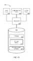
- FIG. 13is block diagram of an intelligent pipeline management platform 1300 that may be, for example, associated with the system 100 of FIG. 1 and/or the system 1200 of FIG. 12 .
- the intelligent pipeline management platform 1300comprises a processor 1310 , such as one or more commercially available Central Processing Units (CPUs) in the form of one-chip microprocessors, coupled to a communication device 1320 configured to communicate via a communication network (not shown in FIG. 13 ).
- the communication device 1320may be used to communicate, for example, with one or more remote user platforms.
- the intelligent pipeline management platform 1300further includes an input device 1340 (e.g., a computer mouse and/or keyboard to input adaptive and/or predictive modeling information) and an output device 1350 (e.g., a computer monitor to display alerts and/or reports).
- an input device 1340e.g., a computer mouse and/or keyboard to input adaptive and/or predictive modeling information
- an output device 1350e.g., a computer monitor to display alerts and/or reports.
- a mobile device and/or voice activated messagesmay be used to exchange information with the intelligent pipeline management platform 1300 .
- the processor 1310also communicates with a storage device 1330 .
- the storage device 1330may comprise any appropriate information storage device, including combinations of magnetic storage devices (e.g., a hard disk drive), optical storage devices, mobile telephones, and/or semiconductor memory devices.
- the storage device 1330stores a program 1312 and/or a pipeline model 1314 for controlling the processor 1310 .
- the processor 1310performs instructions of the programs 1312 , 1314 , and thereby operates in accordance with any of the embodiments described herein.
- the processor 1310may receive distributed acoustic sensing data associated with a first set of a plurality of pipeline locations.
- the processor 1310may also receive collected physical data representing a physical characteristic of a second set of a plurality of pipeline locations.
- the processor 1310may then utilize a pipeline model having the distributed acoustic sensing data and collected physical data as inputs to automatically generate at least one alert indicating an increased probability of damage to the pipeline.
- the programs 1312 , 1314may be stored in a compressed, uncompiled and/or encrypted format.
- the programs 1312 , 1314may furthermore include other program elements, such as an operating system, clipboard application a database management system, and/or device drivers used by the processor 1310 to interface with peripheral devices.
- informationmay be “received” by or “transmitted” to, for example: (i) the intelligent pipeline management platform 1300 from another device; or (ii) a software application or module within the intelligent pipeline management platform 1300 from another software application, module, or any other source.
- the storage device 1330stores a pipeline segment database 1400 .
- a databasethat may be used in connection with the intelligent pipeline management platform 1300 will now be described in detail with respect to FIG. 14 .
- the database described hereinis only one example, and additional and/or different information may be stored therein.
- various databasesmight be split or combined in accordance with any of the embodiments described herein.
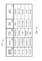
- a tableis shown that represents the pipeline segment database 1400 that may be stored at the intelligent pipeline management platform 1300 according to some embodiments.
- the tablemay include, for example, entries identifying pipes and other pipeline assets associated with one or more pipelines.
- the tablemay also define fields 1402 , 1404 , 1406 , 1408 , 1410 for each of the entries.
- the fields 1402 , 1404 , 1406 , 1408 , 1410may, according to some embodiments, specify: a pipeline segment identifier 1402 , distributed acoustic sensing data 1404 , physical data 1406 , image data 1408 , and alert status 1410 .
- the component database 1400may be created and updated, for example, when an intelligent pipeline management platform is created and/or as information is received from a sensor, etc.
- the pipeline identifier 1402may be, for example, a unique alphanumeric code identifying a particular pipeline along with a particular portion of pipe or other pipeline asset.
- the distributed acoustic sensing data 1404might be collected via fibers and/or edge processors.
- the physical data 1406might be collected via SCADA devices, and the image data 1408 may be collect by drones carrying cameras.
- the acoustic sensing data 1404 , physical data 1406 , and image data 1408might be processed via a fusion algorithm to create the alert stats 1410 for each pipeline segment.
- some embodimentsmay provide an automatic and efficient way of predicting and/or displaying pipeline location and/or risk information to a user.
- Embodimentsmay provide a unique interface consolidating functionality and view data on different display and/or platforms to make user interaction simple and efficient.
- integrate modal (or “popup”) windowsmay provide alert data, enabling users to view both the location/street environment of pipeline assets and/or a three dimensional visualization of anomalies and structural risks within a pipeline segment.
- a geospatial view of a pipeline network and associated assetsmay enable convergence of disparate data sets (e.g., compressor stations, valves, and critical local structures such as schools) in one location for network awareness and understanding.
Landscapes
- Physics & Mathematics (AREA)
- Engineering & Computer Science (AREA)
- General Physics & Mathematics (AREA)
- General Engineering & Computer Science (AREA)
- Theoretical Computer Science (AREA)
- Acoustics & Sound (AREA)
- Mechanical Engineering (AREA)
- Computational Linguistics (AREA)
- Data Mining & Analysis (AREA)
- Databases & Information Systems (AREA)
- Examining Or Testing Airtightness (AREA)
- Business, Economics & Management (AREA)
- Electromagnetism (AREA)
- Emergency Management (AREA)
Abstract
Description
Claims (23)
Priority Applications (1)
| Application Number | Priority Date | Filing Date | Title |
|---|---|---|---|
| US14/854,828US10275402B2 (en) | 2015-09-15 | 2015-09-15 | Systems and methods to provide pipeline damage alerts |
Applications Claiming Priority (1)
| Application Number | Priority Date | Filing Date | Title |
|---|---|---|---|
| US14/854,828US10275402B2 (en) | 2015-09-15 | 2015-09-15 | Systems and methods to provide pipeline damage alerts |
Publications (2)
| Publication Number | Publication Date |
|---|---|
| US20170076563A1 US20170076563A1 (en) | 2017-03-16 |
| US10275402B2true US10275402B2 (en) | 2019-04-30 |
Family
ID=58257536
Family Applications (1)
| Application Number | Title | Priority Date | Filing Date |
|---|---|---|---|
| US14/854,828Active2035-12-23US10275402B2 (en) | 2015-09-15 | 2015-09-15 | Systems and methods to provide pipeline damage alerts |
Country Status (1)
| Country | Link |
|---|---|
| US (1) | US10275402B2 (en) |
Cited By (14)
| Publication number | Priority date | Publication date | Assignee | Title |
|---|---|---|---|---|
| US10975687B2 (en) | 2017-03-31 | 2021-04-13 | Bp Exploration Operating Company Limited | Well and overburden monitoring using distributed acoustic sensors |
| US11053791B2 (en) | 2016-04-07 | 2021-07-06 | Bp Exploration Operating Company Limited | Detecting downhole sand ingress locations |
| US11098576B2 (en) | 2019-10-17 | 2021-08-24 | Lytt Limited | Inflow detection using DTS features |
| US11162353B2 (en) | 2019-11-15 | 2021-11-02 | Lytt Limited | Systems and methods for draw down improvements across wellbores |
| US11199085B2 (en) | 2017-08-23 | 2021-12-14 | Bp Exploration Operating Company Limited | Detecting downhole sand ingress locations |
| US11199084B2 (en) | 2016-04-07 | 2021-12-14 | Bp Exploration Operating Company Limited | Detecting downhole events using acoustic frequency domain features |
| US11333636B2 (en) | 2017-10-11 | 2022-05-17 | Bp Exploration Operating Company Limited | Detecting events using acoustic frequency domain features |
| US11466563B2 (en) | 2020-06-11 | 2022-10-11 | Lytt Limited | Systems and methods for subterranean fluid flow characterization |
| US11473424B2 (en) | 2019-10-17 | 2022-10-18 | Lytt Limited | Fluid inflow characterization using hybrid DAS/DTS measurements |
| US11593683B2 (en) | 2020-06-18 | 2023-02-28 | Lytt Limited | Event model training using in situ data |
| US11643923B2 (en) | 2018-12-13 | 2023-05-09 | Bp Exploration Operating Company Limited | Distributed acoustic sensing autocalibration |
| US11859488B2 (en) | 2018-11-29 | 2024-01-02 | Bp Exploration Operating Company Limited | DAS data processing to identify fluid inflow locations and fluid type |
| US12196074B2 (en) | 2019-09-20 | 2025-01-14 | Lytt Limited | Systems and methods for sand ingress prediction for subterranean wellbores |
| US12241596B1 (en) | 2024-06-26 | 2025-03-04 | George Okotako Okoyo | Pipeline intruder locator system |
Families Citing this family (45)
| Publication number | Priority date | Publication date | Assignee | Title |
|---|---|---|---|---|
| US10996203B2 (en) | 2015-08-12 | 2021-05-04 | Triad National Security, Llc | Detection, monitoring, and determination of location of changes in metallic structures using multimode acoustic signals |
| US11620553B2 (en)* | 2016-04-21 | 2023-04-04 | Utopus Insights, Inc. | System and method for forecasting leaks in a fluid-delivery pipeline network |
| US10060578B2 (en)* | 2016-05-16 | 2018-08-28 | International Business Machines Corporation | Automated gas detection and reporting system |
| US10473270B2 (en)* | 2016-09-30 | 2019-11-12 | General Electric Company | Leak detection user interfaces |
| US10895556B2 (en)* | 2017-03-21 | 2021-01-19 | Baker Hughes Oilfield Operations Llc | Predictive integrity analysis |
| US11373105B2 (en)* | 2017-04-13 | 2022-06-28 | Oracle International Corporation | Autonomous artificially intelligent system to predict pipe leaks |
| CA3060419C (en)* | 2017-04-20 | 2024-01-02 | Schlumberger Canada Limited | Detecting and correcting for discrepancy events in fluid pipelines |
| US20180347763A1 (en)* | 2017-05-31 | 2018-12-06 | Schneider Electric Software, Llc | Machine learning detection of pipeline ruptures |
| GB2571540B (en) | 2018-02-28 | 2020-10-28 | Craley Group Ltd | Improvements in or relating to the monitoring of fluid pipes |
| JP6945478B2 (en)* | 2018-03-05 | 2021-10-06 | 株式会社日立製作所 | Structure information management system and method |
| US11720816B2 (en)* | 2018-03-28 | 2023-08-08 | Fracta | Predicting pipe failure |
| US10876919B2 (en)* | 2018-04-30 | 2020-12-29 | International Business Machines Corporation | In-pipeline optical interference-based cognitive system for leak and defect detection |
| JP7036209B2 (en)* | 2018-06-05 | 2022-03-15 | 日本電気株式会社 | Diagnostic equipment, diagnostic methods, and programs |
| GB2576358B (en)* | 2018-08-16 | 2022-12-28 | Centrica Plc | Sensing fluid flow for estimating fluid flow state |
| CN109284777B (en)* | 2018-08-28 | 2021-09-28 | 内蒙古大学 | Water supply pipeline leakage identification method based on signal time-frequency characteristics and support vector machine |
| EP3628993A1 (en) | 2018-09-27 | 2020-04-01 | Siemens Aktiengesellschaft | Method for determining the occurrence of interference on a pipeline by means of estimation |
| CA3115457A1 (en)* | 2018-10-09 | 2020-04-16 | Fracta | Automated asset mangement and planning |
| US10697806B2 (en) | 2018-11-16 | 2020-06-30 | General Electric Company | Integrated fiber-optic perturbation sensor |
| CN109630905A (en)* | 2019-01-25 | 2019-04-16 | 电子科技大学 | A kind of full intelligent inspection system of oil-gas pipeline based on unmanned aerial vehicle remote sensing and deep learning |
| EP3942271A1 (en)* | 2019-03-12 | 2022-01-26 | Siemens Aktiengesellschaft | Method and device for operating a distribution network |
| US11593538B2 (en)* | 2019-04-02 | 2023-02-28 | Accenture Global Solutions Limited | Verification, modification, and/or validation of an infrastructure design document via improved collaboration between on site devices and remote devices |
| US20200320650A1 (en)* | 2019-04-05 | 2020-10-08 | I D Technologies Inc. | Multi-utility integrity monitoring and display system |
| CN110145695B (en)* | 2019-06-03 | 2021-01-15 | 大连理工大学 | A heating pipeline leak detection method based on deep belief network information fusion |
| WO2020256707A1 (en)* | 2019-06-18 | 2020-12-24 | Chevron U.S.A. Inc. | Combined analytic technique for differentiating changes to structures using acoustic signals |
| CN110195823A (en)* | 2019-07-16 | 2019-09-03 | 重庆科技学院 | A kind of micro- leakage detection method of pipeline based on deep neural network |
| GB2600297B (en)* | 2019-07-23 | 2023-07-19 | Landmark Graphics Corp | Stochastic realization of parameter inversion in physics-based empirical models |
| US11359989B2 (en) | 2019-08-05 | 2022-06-14 | Professional Flexible Technologies, Inc. | Pipeline leak detection apparatus and methods thereof |
| CN110514366B (en)* | 2019-08-22 | 2021-03-05 | 东北大学 | Method for detecting weak leakage of pipeline under small sample condition |
| CN112527928B (en)* | 2019-09-19 | 2024-05-31 | 中国石油天然气股份有限公司 | Pipeline protection area division method and device and readable storage medium |
| CN113203049B (en)* | 2020-05-28 | 2023-07-25 | 中国石油天然气股份有限公司 | Intelligent monitoring and early warning system and method for pipeline safety |
| GB2595660A (en)* | 2020-06-01 | 2021-12-08 | Homeserve Plc | Flow event classification |
| CN113989629A (en)* | 2020-07-13 | 2022-01-28 | 中国石油化工股份有限公司 | Memory, high consequence area determination method, apparatus and device |
| US11651119B2 (en)* | 2020-09-23 | 2023-05-16 | International Business Machines Corporation | Detection of defects within physical infrastructure by leveraging AI |
| CN112181935B (en)* | 2020-09-27 | 2024-11-15 | 江西小马机器人有限公司 | System architecture of a power inspection robot |
| CN112866605B (en)* | 2021-01-13 | 2023-12-01 | 深圳市正杰智能工程有限公司 | 5G-based pipe gallery monitoring method, device, terminal and storage medium |
| CN112923245B (en)* | 2021-02-03 | 2024-02-13 | 宁波水表(集团)股份有限公司 | Method for exploring leakage of water supply network |
| CN113609198B (en)* | 2021-07-26 | 2023-08-25 | 三峡大学 | Method for reconstructing concrete temperature field in pouring warehouse based on optical fiber measured temperature data |
| CN114783142A (en)* | 2022-03-31 | 2022-07-22 | 中化学交通建设集团有限公司 | Comprehensive monitoring system for health state of pipe gallery |
| CN114857507B (en)* | 2022-05-07 | 2023-06-16 | 河南驰诚电气股份有限公司 | Domestic gas alarm system of table alert linkage |
| US12436003B2 (en)* | 2022-05-13 | 2025-10-07 | Nec Corporation | System to measure coil locations and lengths on aerial fiber cables by distributed fiber sensing for decision making |
| CN115597679B (en)* | 2022-08-22 | 2024-11-15 | 华能澜沧江水电股份有限公司 | Hydropower station water flooding prevention protection system and irrigation water intake pipe monitoring system |
| CN116817192B (en)* | 2023-08-30 | 2023-11-17 | 南通金芸流体设备有限公司 | Corrosion monitoring and alarming method and system for pipeline conveying equipment |
| CN117275209B (en)* | 2023-11-22 | 2024-02-02 | 广东力创信息技术有限公司 | Monitoring and early warning method based on distributed optical fiber acoustic wave sensing and related device |
| CN118194142B (en)* | 2024-05-17 | 2024-08-23 | 中电科大数据研究院有限公司 | A post-earthquake repair engineering analysis method and system for smart pipe networks |
| CN118365969B (en)* | 2024-06-18 | 2024-09-03 | 广州市运通水务有限公司 | Intelligent robot-based all-condition urban underground pipe culvert detection method and system |
Citations (35)
| Publication number | Priority date | Publication date | Assignee | Title |
|---|---|---|---|---|
| US5355324A (en) | 1991-11-06 | 1994-10-11 | Shell Oil Company | Detecting leakage of fluid from a conduit |
| US6725705B1 (en) | 2003-05-15 | 2004-04-27 | Gas Technology Institute | Enhanced acoustic detection of gas leaks in underground gas pipelines |
| US20050038825A1 (en)* | 2003-08-15 | 2005-02-17 | Tarabzouni Thamer K. | System to facilitate pipeline management, software, and related methods |
| US6970808B2 (en) | 2004-04-29 | 2005-11-29 | Kingsley E. Abhulimen | Realtime computer assisted leak detection/location reporting and inventory loss monitoring system of pipeline network systems |
| US20060225507A1 (en)* | 2003-01-13 | 2006-10-12 | Paulson Peter O | Pipeline monitoring system |
| US20070041333A1 (en)* | 2005-08-18 | 2007-02-22 | Terahop Networks, Inc. | Sensor networks for monitoring pipelines and power lines |
| US20070043807A1 (en)* | 2005-08-18 | 2007-02-22 | Terahop Networks, Inc. | All WEATHER HOUSING ASSEMBLY FOR ELECTRONIC COMPONENTS |
| US20070183604A1 (en)* | 2006-02-09 | 2007-08-09 | St-Infonox | Response to anomalous acoustic environments |
| US20070236343A1 (en)* | 2004-09-23 | 2007-10-11 | Becksted Albert M | Surveillance network for unattended ground sensors |
| US20080036593A1 (en) | 2006-08-04 | 2008-02-14 | The Government Of The Us, As Represented By The Secretary Of The Navy | Volume sensor: data fusion-based, multi-sensor system for advanced damage control |
| US20080210024A1 (en)* | 2007-02-28 | 2008-09-04 | Merlo Stephen A | Remote pipe inspection |
| US20090105969A1 (en)* | 2007-10-23 | 2009-04-23 | Saylor David J | Method and Device for the Assessment of Fluid Collection Networks |
| US7526944B2 (en) | 2004-01-07 | 2009-05-05 | Ashok Sabata | Remote monitoring of pipelines using wireless sensor network |
| US20100027235A1 (en)* | 2007-08-10 | 2010-02-04 | Josef Samuelson | Distributed system with shielded sensors |
| US20110069302A1 (en)* | 2009-09-18 | 2011-03-24 | Qinetiq Limited | Wide Area Seismic Detection |
| US20110178726A1 (en)* | 2008-09-19 | 2011-07-21 | John Dobbs | Pipeline inspection |
| EP2352002A1 (en) | 2010-01-29 | 2011-08-03 | Politecnico Di Torino | A system for remote leak detection and/or path tracking for underground fluid transportation pipelines |
| US20120185184A1 (en)* | 2011-01-18 | 2012-07-19 | TaKaDu Ltd. | System and method for identifying likely geographical locations of anomalies in a water utility network |
| US20120209653A1 (en)* | 2011-02-15 | 2012-08-16 | General Electric Company | Gas pipeline network configuration system |
| JP5297951B2 (en) | 2009-09-04 | 2013-09-25 | 株式会社日立製作所 | Anticorrosion data analysis system |
| WO2013169239A1 (en) | 2012-05-09 | 2013-11-14 | Bp Corporation North America Inc. | Use of survival modeling methods with pipeline inspection data for determining causal factors for corrosion under insulation |
| US20140000348A1 (en)* | 2012-06-28 | 2014-01-02 | Commissariat A L'energie Atomique Et Aux Energies Alternatives | Location of a leak in a pipe |
| US20140139841A1 (en) | 2012-11-16 | 2014-05-22 | General Electric Company | Fiber optic sensing apparatus including fiber gratings and method for sensing parameters involving different parameter modalities |
| US20140207430A1 (en) | 2013-01-24 | 2014-07-24 | Schlumberger Technology Corporation | Analysis of surface networks for fluids |
| WO2014115399A1 (en) | 2013-01-28 | 2014-07-31 | 株式会社日立製作所 | Water leak estimating device, system, and method |
| WO2014142825A1 (en) | 2013-03-13 | 2014-09-18 | Bp Corporation North America Inc. | Virtual in-line inspection of wall loss due to corrosion in a pipeline |
| US20150054650A1 (en) | 2013-08-21 | 2015-02-26 | Physical Sciences, Inc. | Systems and Methods for Sensitive Open-Path Gas Leak and Detection Alarm |
| US20150112647A1 (en)* | 2013-03-14 | 2015-04-23 | Trifecta Global Infrastructure Solutions Ltd. | Systems and methods for advanced sanitary sewer infrastructure management |
| US20150192488A1 (en)* | 2012-08-10 | 2015-07-09 | Bin Xu | Method and System for Subsea Leak Detection Using Autonomous Underwater Vehicle (AUV) |
| US20150199846A1 (en)* | 2014-01-15 | 2015-07-16 | Wildlife Conservation Society | Systems, Methods and Computer Program Products for Developing and Sharing an Ecological Vision For A Geographical Location |
| US20160098037A1 (en)* | 2014-10-06 | 2016-04-07 | Fisher-Rosemount Systems, Inc. | Data pipeline for process control system anaytics |
| US20160144959A1 (en)* | 2014-11-21 | 2016-05-26 | Oil & Gas IT, LLC | Systems, Methods and Devices for Collecting Data at Remote Oil and Natural Gas Sites |
| US20160252481A1 (en)* | 2013-10-03 | 2016-09-01 | Schlumberger Technology Corporation | Pipe Damage Assessment System and Method |
| US20160356665A1 (en)* | 2015-06-02 | 2016-12-08 | Umm Al-Qura University | Pipeline monitoring systems and methods |
| US20160356666A1 (en)* | 2015-06-02 | 2016-12-08 | Umm Al-Qura University | Intelligent leakage detection system for pipelines |
- 2015
- 2015-09-15USUS14/854,828patent/US10275402B2/enactiveActive
Patent Citations (36)
| Publication number | Priority date | Publication date | Assignee | Title |
|---|---|---|---|---|
| NZ245007A (en) | 1991-11-06 | 1996-05-28 | Shell Int Research | Leak detection in pipeline using statistical analysis of pressure and flow variations |
| US5355324A (en) | 1991-11-06 | 1994-10-11 | Shell Oil Company | Detecting leakage of fluid from a conduit |
| US20060225507A1 (en)* | 2003-01-13 | 2006-10-12 | Paulson Peter O | Pipeline monitoring system |
| US6725705B1 (en) | 2003-05-15 | 2004-04-27 | Gas Technology Institute | Enhanced acoustic detection of gas leaks in underground gas pipelines |
| US20050038825A1 (en)* | 2003-08-15 | 2005-02-17 | Tarabzouni Thamer K. | System to facilitate pipeline management, software, and related methods |
| US7526944B2 (en) | 2004-01-07 | 2009-05-05 | Ashok Sabata | Remote monitoring of pipelines using wireless sensor network |
| US6970808B2 (en) | 2004-04-29 | 2005-11-29 | Kingsley E. Abhulimen | Realtime computer assisted leak detection/location reporting and inventory loss monitoring system of pipeline network systems |
| US20070236343A1 (en)* | 2004-09-23 | 2007-10-11 | Becksted Albert M | Surveillance network for unattended ground sensors |
| US20070041333A1 (en)* | 2005-08-18 | 2007-02-22 | Terahop Networks, Inc. | Sensor networks for monitoring pipelines and power lines |
| US20070043807A1 (en)* | 2005-08-18 | 2007-02-22 | Terahop Networks, Inc. | All WEATHER HOUSING ASSEMBLY FOR ELECTRONIC COMPONENTS |
| US20070183604A1 (en)* | 2006-02-09 | 2007-08-09 | St-Infonox | Response to anomalous acoustic environments |
| US20080036593A1 (en) | 2006-08-04 | 2008-02-14 | The Government Of The Us, As Represented By The Secretary Of The Navy | Volume sensor: data fusion-based, multi-sensor system for advanced damage control |
| US20080210024A1 (en)* | 2007-02-28 | 2008-09-04 | Merlo Stephen A | Remote pipe inspection |
| US20100027235A1 (en)* | 2007-08-10 | 2010-02-04 | Josef Samuelson | Distributed system with shielded sensors |
| US20090105969A1 (en)* | 2007-10-23 | 2009-04-23 | Saylor David J | Method and Device for the Assessment of Fluid Collection Networks |
| US20110178726A1 (en)* | 2008-09-19 | 2011-07-21 | John Dobbs | Pipeline inspection |
| JP5297951B2 (en) | 2009-09-04 | 2013-09-25 | 株式会社日立製作所 | Anticorrosion data analysis system |
| US20110069302A1 (en)* | 2009-09-18 | 2011-03-24 | Qinetiq Limited | Wide Area Seismic Detection |
| EP2352002A1 (en) | 2010-01-29 | 2011-08-03 | Politecnico Di Torino | A system for remote leak detection and/or path tracking for underground fluid transportation pipelines |
| US20120185184A1 (en)* | 2011-01-18 | 2012-07-19 | TaKaDu Ltd. | System and method for identifying likely geographical locations of anomalies in a water utility network |
| US20120209653A1 (en)* | 2011-02-15 | 2012-08-16 | General Electric Company | Gas pipeline network configuration system |
| WO2013169239A1 (en) | 2012-05-09 | 2013-11-14 | Bp Corporation North America Inc. | Use of survival modeling methods with pipeline inspection data for determining causal factors for corrosion under insulation |
| US20140000348A1 (en)* | 2012-06-28 | 2014-01-02 | Commissariat A L'energie Atomique Et Aux Energies Alternatives | Location of a leak in a pipe |
| US20150192488A1 (en)* | 2012-08-10 | 2015-07-09 | Bin Xu | Method and System for Subsea Leak Detection Using Autonomous Underwater Vehicle (AUV) |
| US20140139841A1 (en) | 2012-11-16 | 2014-05-22 | General Electric Company | Fiber optic sensing apparatus including fiber gratings and method for sensing parameters involving different parameter modalities |
| US20140207430A1 (en) | 2013-01-24 | 2014-07-24 | Schlumberger Technology Corporation | Analysis of surface networks for fluids |
| WO2014115399A1 (en) | 2013-01-28 | 2014-07-31 | 株式会社日立製作所 | Water leak estimating device, system, and method |
| WO2014142825A1 (en) | 2013-03-13 | 2014-09-18 | Bp Corporation North America Inc. | Virtual in-line inspection of wall loss due to corrosion in a pipeline |
| US20150112647A1 (en)* | 2013-03-14 | 2015-04-23 | Trifecta Global Infrastructure Solutions Ltd. | Systems and methods for advanced sanitary sewer infrastructure management |
| US20150054650A1 (en) | 2013-08-21 | 2015-02-26 | Physical Sciences, Inc. | Systems and Methods for Sensitive Open-Path Gas Leak and Detection Alarm |
| US20160252481A1 (en)* | 2013-10-03 | 2016-09-01 | Schlumberger Technology Corporation | Pipe Damage Assessment System and Method |
| US20150199846A1 (en)* | 2014-01-15 | 2015-07-16 | Wildlife Conservation Society | Systems, Methods and Computer Program Products for Developing and Sharing an Ecological Vision For A Geographical Location |
| US20160098037A1 (en)* | 2014-10-06 | 2016-04-07 | Fisher-Rosemount Systems, Inc. | Data pipeline for process control system anaytics |
| US20160144959A1 (en)* | 2014-11-21 | 2016-05-26 | Oil & Gas IT, LLC | Systems, Methods and Devices for Collecting Data at Remote Oil and Natural Gas Sites |
| US20160356665A1 (en)* | 2015-06-02 | 2016-12-08 | Umm Al-Qura University | Pipeline monitoring systems and methods |
| US20160356666A1 (en)* | 2015-06-02 | 2016-12-08 | Umm Al-Qura University | Intelligent leakage detection system for pipelines |
Non-Patent Citations (7)
| Title |
|---|
| "Leak Detection Study-DTPH56-11-D-000001", US Department of Transportation Pipeline and Hazardous Materials Safety Administration, 281 pages, Dec. 10, 2012. |
| "Leak Detection Study—DTPH56-11-D-000001", US Department of Transportation Pipeline and Hazardous Materials Safety Administration, 281 pages, Dec. 10, 2012. |
| Doretto et al., "Region Moments: Fast Invariant Descriptors for Detecting Small Image Structures", Computer Vision and Pattern Recognition (CVPR), IEEE Conference, San Francisco, pp. 3019-3026, Jun. 13-18, 2010. |
| Godfrey, Alastair et al., "Pipeline Leak Detection Using Four Mode Fibre-Optic Based Distributed Sensing", Proceedings of the 2014 10th International Pipeline Conference, IPC 2014-33083, Sep. 29-Oct. 3, 2014, Calgary, Alberta, Canada, Downloaded from: http://proceedings.asmedigitalcollection.asme.org/ on Sep. 15, 2015, (pp. 1-10, 10 total pages). |
| Moustakides et al., "Joint Detection and Estimation: Optimum Tests and Applications", IEEE Transactions on Information Theory, vol. No. 58, Issue No. 7, pp. 4215-4229, Jul. 2012. |
| Perera, A. G. Amitha et al., "Bayesian Object-Level Change Detection in Grayscale Imagery", Proceedings of the 17th International Conference on Pattern Recognition (ICPR'04), vol. 1, Aug. 23-26, 2014, IEEE Computer Society, 5pages). |
| Williams, "Distributed Acoustic Sensing for Pipeline Monitoring", Pipeline and Gas Journal, vol. No. 239, Issue No. 7, 6 pages, Jul. 2012. |
Cited By (16)
| Publication number | Priority date | Publication date | Assignee | Title |
|---|---|---|---|---|
| US11530606B2 (en) | 2016-04-07 | 2022-12-20 | Bp Exploration Operating Company Limited | Detecting downhole sand ingress locations |
| US11053791B2 (en) | 2016-04-07 | 2021-07-06 | Bp Exploration Operating Company Limited | Detecting downhole sand ingress locations |
| US11199084B2 (en) | 2016-04-07 | 2021-12-14 | Bp Exploration Operating Company Limited | Detecting downhole events using acoustic frequency domain features |
| US11215049B2 (en) | 2016-04-07 | 2022-01-04 | Bp Exploration Operating Company Limited | Detecting downhole events using acoustic frequency domain features |
| US10975687B2 (en) | 2017-03-31 | 2021-04-13 | Bp Exploration Operating Company Limited | Well and overburden monitoring using distributed acoustic sensors |
| US11199085B2 (en) | 2017-08-23 | 2021-12-14 | Bp Exploration Operating Company Limited | Detecting downhole sand ingress locations |
| US11333636B2 (en) | 2017-10-11 | 2022-05-17 | Bp Exploration Operating Company Limited | Detecting events using acoustic frequency domain features |
| US11859488B2 (en) | 2018-11-29 | 2024-01-02 | Bp Exploration Operating Company Limited | DAS data processing to identify fluid inflow locations and fluid type |
| US11643923B2 (en) | 2018-12-13 | 2023-05-09 | Bp Exploration Operating Company Limited | Distributed acoustic sensing autocalibration |
| US12196074B2 (en) | 2019-09-20 | 2025-01-14 | Lytt Limited | Systems and methods for sand ingress prediction for subterranean wellbores |
| US11473424B2 (en) | 2019-10-17 | 2022-10-18 | Lytt Limited | Fluid inflow characterization using hybrid DAS/DTS measurements |
| US11098576B2 (en) | 2019-10-17 | 2021-08-24 | Lytt Limited | Inflow detection using DTS features |
| US11162353B2 (en) | 2019-11-15 | 2021-11-02 | Lytt Limited | Systems and methods for draw down improvements across wellbores |
| US11466563B2 (en) | 2020-06-11 | 2022-10-11 | Lytt Limited | Systems and methods for subterranean fluid flow characterization |
| US11593683B2 (en) | 2020-06-18 | 2023-02-28 | Lytt Limited | Event model training using in situ data |
| US12241596B1 (en) | 2024-06-26 | 2025-03-04 | George Okotako Okoyo | Pipeline intruder locator system |
Also Published As
| Publication number | Publication date |
|---|---|
| US20170076563A1 (en) | 2017-03-16 |
Similar Documents
| Publication | Publication Date | Title |
|---|---|---|
| US10275402B2 (en) | Systems and methods to provide pipeline damage alerts | |
| CN119207018B (en) | A slope disaster early warning method and system | |
| KR102269192B1 (en) | Method And Apparatus for Providing Fault Prevention of Underground Utility Tunnel | |
| US20250277693A1 (en) | Infrastructure monitoring systems and methods | |
| WO2023287276A1 (en) | Geographic data processing methods and systems for detecting encroachment by objects into a geographic corridor | |
| CN118212747A (en) | Intelligent monitoring and early warning system and method for slope disasters based on multi-source information fusion | |
| CN116305699B (en) | Pipeline supervision system based on omnibearing sensing | |
| CN118247965A (en) | Intelligent monitoring and early warning system and method for expressway infrastructure group | |
| CN114458967A (en) | Storage, oil and gas pipeline monitoring and early warning method, device and equipment | |
| CN119782876A (en) | A method and system for dynamic monitoring and early warning of mine environment | |
| US20170193414A1 (en) | Global management for oil gas assets | |
| Felix et al. | Flood detection using gradient boost machine learning approach | |
| CN119832691A (en) | Land-air collaborative monitoring and early warning method and system for buried gas pipeline in landslide hidden danger area | |
| CN118918685A (en) | Distributed optical fiber sensing geological disaster monitoring and early warning method and system | |
| Tillihal et al. | River flood monitoring and management: a review | |
| CN119846387A (en) | Submarine cable detection method and device and nonvolatile storage medium | |
| KR20230143444A (en) | System and method for estimating drift path of marine floating body | |
| Subburaj et al. | Catastropheguard: A guard against natural catastrophes through advances in ai and deep learning technologies | |
| Hayouni et al. | Towards Cognitive Vehicles: GNSS-free Localization using Visual Anchors | |
| Rahmes et al. | Continuous environmentally efficient pipeline leak detection | |
| França et al. | An overview of the Internet of Things technologies focusing on disaster response | |
| Turner | Practical lessons from implementing a top-down, drone-based methane emissions quantification technology into global oil and gas operations | |
| US20240135797A1 (en) | Data-driven street flood warning system | |
| CN119882803B (en) | Intelligent control method and system for self-walking platform | |
| Idachaba | Multiple Surface Pipeline Leak Detection Using Real-Time Sensor Data Analysis |
Legal Events
| Date | Code | Title | Description |
|---|---|---|---|
| AS | Assignment | Owner name:GENERAL ELECTRIC COMPANY, NEW YORK Free format text:ASSIGNMENT OF ASSIGNORS INTEREST;ASSIGNORS:GUERRIERO, MARCO;WHEELER, FREDERICK WILSON;KOSTE, GLEN PETER;AND OTHERS;SIGNING DATES FROM 20150914 TO 20150916;REEL/FRAME:036921/0132 | |
| STPP | Information on status: patent application and granting procedure in general | Free format text:PUBLICATIONS -- ISSUE FEE PAYMENT VERIFIED | |
| STCF | Information on status: patent grant | Free format text:PATENTED CASE | |
| AS | Assignment | Owner name:BAKER HUGHES, A GE COMPANY, LLC, TEXAS Free format text:ASSIGNMENT OF ASSIGNORS INTEREST;ASSIGNOR:GENERAL ELECTRIC COMPANY;REEL/FRAME:051699/0158 Effective date:20170703 | |
| MAFP | Maintenance fee payment | Free format text:PAYMENT OF MAINTENANCE FEE, 4TH YEAR, LARGE ENTITY (ORIGINAL EVENT CODE: M1551); ENTITY STATUS OF PATENT OWNER: LARGE ENTITY Year of fee payment:4 | |
| AS | Assignment | Owner name:MANTHEY, DIANE, MANT, TEXAS Free format text:CHANGE OF NAME;ASSIGNOR:BAKER HUGHES, A GE COMPANY, LLC;REEL/FRAME:063102/0879 Effective date:20200413 | |
| AS | Assignment | Owner name:BAKER HUGHES HOLDINGS LLC, TEXAS Free format text:CHANGE OF NAME;ASSIGNOR:BAKER HUGHES, A GE COMPANY, LLC;REEL/FRAME:063705/0437 Effective date:20200413 |