US10272014B2 - Systems and methods for providing network connectivity and remote monitoring, optimization, and control of pool/spa equipment - Google Patents
Systems and methods for providing network connectivity and remote monitoring, optimization, and control of pool/spa equipmentDownload PDFInfo
- Publication number
- US10272014B2 US10272014B2US15/413,074US201715413074AUS10272014B2US 10272014 B2US10272014 B2US 10272014B2US 201715413074 AUS201715413074 AUS 201715413074AUS 10272014 B2US10272014 B2US 10272014B2
- Authority
- US
- United States
- Prior art keywords
- control logic
- pump
- pool
- data
- pump control
- Prior art date
- Legal status (The legal status is an assumption and is not a legal conclusion. Google has not performed a legal analysis and makes no representation as to the accuracy of the status listed.)
- Active
Links
Images


Classifications
- A—HUMAN NECESSITIES
- A61—MEDICAL OR VETERINARY SCIENCE; HYGIENE
- A61H—PHYSICAL THERAPY APPARATUS, e.g. DEVICES FOR LOCATING OR STIMULATING REFLEX POINTS IN THE BODY; ARTIFICIAL RESPIRATION; MASSAGE; BATHING DEVICES FOR SPECIAL THERAPEUTIC OR HYGIENIC PURPOSES OR SPECIFIC PARTS OF THE BODY
- A61H33/00—Bathing devices for special therapeutic or hygienic purposes
- A61H33/005—Electrical circuits therefor
- H—ELECTRICITY
- H05—ELECTRIC TECHNIQUES NOT OTHERWISE PROVIDED FOR
- H05B—ELECTRIC HEATING; ELECTRIC LIGHT SOURCES NOT OTHERWISE PROVIDED FOR; CIRCUIT ARRANGEMENTS FOR ELECTRIC LIGHT SOURCES, IN GENERAL
- H05B47/00—Circuit arrangements for operating light sources in general, i.e. where the type of light source is not relevant
- H05B47/10—Controlling the light source
- H05B47/105—Controlling the light source in response to determined parameters
- A—HUMAN NECESSITIES
- A61—MEDICAL OR VETERINARY SCIENCE; HYGIENE
- A61H—PHYSICAL THERAPY APPARATUS, e.g. DEVICES FOR LOCATING OR STIMULATING REFLEX POINTS IN THE BODY; ARTIFICIAL RESPIRATION; MASSAGE; BATHING DEVICES FOR SPECIAL THERAPEUTIC OR HYGIENIC PURPOSES OR SPECIFIC PARTS OF THE BODY
- A61H33/00—Bathing devices for special therapeutic or hygienic purposes
- A61H33/0087—Therapeutic baths with agitated or circulated water
- A—HUMAN NECESSITIES
- A61—MEDICAL OR VETERINARY SCIENCE; HYGIENE
- A61H—PHYSICAL THERAPY APPARATUS, e.g. DEVICES FOR LOCATING OR STIMULATING REFLEX POINTS IN THE BODY; ARTIFICIAL RESPIRATION; MASSAGE; BATHING DEVICES FOR SPECIAL THERAPEUTIC OR HYGIENIC PURPOSES OR SPECIFIC PARTS OF THE BODY
- A61H33/00—Bathing devices for special therapeutic or hygienic purposes
- A61H33/0095—Arrangements for varying the temperature of the liquid
- B—PERFORMING OPERATIONS; TRANSPORTING
- B25—HAND TOOLS; PORTABLE POWER-DRIVEN TOOLS; MANIPULATORS
- B25J—MANIPULATORS; CHAMBERS PROVIDED WITH MANIPULATION DEVICES
- B25J9/00—Programme-controlled manipulators
- B25J9/16—Programme controls
- B25J9/1602—Programme controls characterised by the control system, structure, architecture
- B25J9/161—Hardware, e.g. neural networks, fuzzy logic, interfaces, processor
- B—PERFORMING OPERATIONS; TRANSPORTING
- B25—HAND TOOLS; PORTABLE POWER-DRIVEN TOOLS; MANIPULATORS
- B25J—MANIPULATORS; CHAMBERS PROVIDED WITH MANIPULATION DEVICES
- B25J9/00—Programme-controlled manipulators
- B25J9/16—Programme controls
- B25J9/1694—Programme controls characterised by use of sensors other than normal servo-feedback from position, speed or acceleration sensors, perception control, multi-sensor controlled systems, sensor fusion
- E—FIXED CONSTRUCTIONS
- E04—BUILDING
- E04H—BUILDINGS OR LIKE STRUCTURES FOR PARTICULAR PURPOSES; SWIMMING OR SPLASH BATHS OR POOLS; MASTS; FENCING; TENTS OR CANOPIES, IN GENERAL
- E04H4/00—Swimming or splash baths or pools
- E04H4/06—Safety devices; Coverings for baths
- E04H4/10—Coverings of flexible material
- E—FIXED CONSTRUCTIONS
- E04—BUILDING
- E04H—BUILDINGS OR LIKE STRUCTURES FOR PARTICULAR PURPOSES; SWIMMING OR SPLASH BATHS OR POOLS; MASTS; FENCING; TENTS OR CANOPIES, IN GENERAL
- E04H4/00—Swimming or splash baths or pools
- E04H4/12—Devices or arrangements for circulating water, i.e. devices for removal of polluted water, cleaning baths or for water treatment
- E04H4/1209—Treatment of water for swimming pools
- E04H4/1245—Recirculating pumps for swimming pool water
- E—FIXED CONSTRUCTIONS
- E04—BUILDING
- E04H—BUILDINGS OR LIKE STRUCTURES FOR PARTICULAR PURPOSES; SWIMMING OR SPLASH BATHS OR POOLS; MASTS; FENCING; TENTS OR CANOPIES, IN GENERAL
- E04H4/00—Swimming or splash baths or pools
- E04H4/12—Devices or arrangements for circulating water, i.e. devices for removal of polluted water, cleaning baths or for water treatment
- E04H4/1209—Treatment of water for swimming pools
- E04H4/1272—Skimmers integrated in the pool wall
- E—FIXED CONSTRUCTIONS
- E04—BUILDING
- E04H—BUILDINGS OR LIKE STRUCTURES FOR PARTICULAR PURPOSES; SWIMMING OR SPLASH BATHS OR POOLS; MASTS; FENCING; TENTS OR CANOPIES, IN GENERAL
- E04H4/00—Swimming or splash baths or pools
- E04H4/12—Devices or arrangements for circulating water, i.e. devices for removal of polluted water, cleaning baths or for water treatment
- E04H4/1281—Devices for distributing chemical products in the water of swimming pools
- E—FIXED CONSTRUCTIONS
- E04—BUILDING
- E04H—BUILDINGS OR LIKE STRUCTURES FOR PARTICULAR PURPOSES; SWIMMING OR SPLASH BATHS OR POOLS; MASTS; FENCING; TENTS OR CANOPIES, IN GENERAL
- E04H4/00—Swimming or splash baths or pools
- E04H4/12—Devices or arrangements for circulating water, i.e. devices for removal of polluted water, cleaning baths or for water treatment
- E04H4/129—Systems for heating the water content of swimming pools
- E—FIXED CONSTRUCTIONS
- E04—BUILDING
- E04H—BUILDINGS OR LIKE STRUCTURES FOR PARTICULAR PURPOSES; SWIMMING OR SPLASH BATHS OR POOLS; MASTS; FENCING; TENTS OR CANOPIES, IN GENERAL
- E04H4/00—Swimming or splash baths or pools
- E04H4/14—Parts, details or accessories not otherwise provided for
- E04H4/148—Lighting means
- E—FIXED CONSTRUCTIONS
- E04—BUILDING
- E04H—BUILDINGS OR LIKE STRUCTURES FOR PARTICULAR PURPOSES; SWIMMING OR SPLASH BATHS OR POOLS; MASTS; FENCING; TENTS OR CANOPIES, IN GENERAL
- E04H4/00—Swimming or splash baths or pools
- E04H4/14—Parts, details or accessories not otherwise provided for
- E04H4/16—Parts, details or accessories not otherwise provided for specially adapted for cleaning
- E04H4/1654—Self-propelled cleaners
- F—MECHANICAL ENGINEERING; LIGHTING; HEATING; WEAPONS; BLASTING
- F04—POSITIVE - DISPLACEMENT MACHINES FOR LIQUIDS; PUMPS FOR LIQUIDS OR ELASTIC FLUIDS
- F04D—NON-POSITIVE-DISPLACEMENT PUMPS
- F04D15/00—Control, e.g. regulation, of pumps, pumping installations or systems
- F04D15/0066—Control, e.g. regulation, of pumps, pumping installations or systems by changing the speed, e.g. of the driving engine
- F—MECHANICAL ENGINEERING; LIGHTING; HEATING; WEAPONS; BLASTING
- F04—POSITIVE - DISPLACEMENT MACHINES FOR LIQUIDS; PUMPS FOR LIQUIDS OR ELASTIC FLUIDS
- F04D—NON-POSITIVE-DISPLACEMENT PUMPS
- F04D15/00—Control, e.g. regulation, of pumps, pumping installations or systems
- F04D15/0077—Safety measures
- F—MECHANICAL ENGINEERING; LIGHTING; HEATING; WEAPONS; BLASTING
- F04—POSITIVE - DISPLACEMENT MACHINES FOR LIQUIDS; PUMPS FOR LIQUIDS OR ELASTIC FLUIDS
- F04D—NON-POSITIVE-DISPLACEMENT PUMPS
- F04D15/00—Control, e.g. regulation, of pumps, pumping installations or systems
- F04D15/0088—Testing machines
- F—MECHANICAL ENGINEERING; LIGHTING; HEATING; WEAPONS; BLASTING
- F04—POSITIVE - DISPLACEMENT MACHINES FOR LIQUIDS; PUMPS FOR LIQUIDS OR ELASTIC FLUIDS
- F04D—NON-POSITIVE-DISPLACEMENT PUMPS
- F04D15/00—Control, e.g. regulation, of pumps, pumping installations or systems
- F04D15/02—Stopping of pumps, or operating valves, on occurrence of unwanted conditions
- F04D15/0209—Stopping of pumps, or operating valves, on occurrence of unwanted conditions responsive to a condition of the working fluid
- F04D15/0218—Stopping of pumps, or operating valves, on occurrence of unwanted conditions responsive to a condition of the working fluid the condition being a liquid level or a lack of liquid supply
- F—MECHANICAL ENGINEERING; LIGHTING; HEATING; WEAPONS; BLASTING
- F04—POSITIVE - DISPLACEMENT MACHINES FOR LIQUIDS; PUMPS FOR LIQUIDS OR ELASTIC FLUIDS
- F04D—NON-POSITIVE-DISPLACEMENT PUMPS
- F04D15/00—Control, e.g. regulation, of pumps, pumping installations or systems
- F04D15/02—Stopping of pumps, or operating valves, on occurrence of unwanted conditions
- F04D15/0281—Stopping of pumps, or operating valves, on occurrence of unwanted conditions responsive to a condition not otherwise provided for
- F—MECHANICAL ENGINEERING; LIGHTING; HEATING; WEAPONS; BLASTING
- F04—POSITIVE - DISPLACEMENT MACHINES FOR LIQUIDS; PUMPS FOR LIQUIDS OR ELASTIC FLUIDS
- F04D—NON-POSITIVE-DISPLACEMENT PUMPS
- F04D29/00—Details, component parts, or accessories
- F04D29/70—Suction grids; Strainers; Dust separation; Cleaning
- F04D29/708—Suction grids; Strainers; Dust separation; Cleaning specially for liquid pumps
- F—MECHANICAL ENGINEERING; LIGHTING; HEATING; WEAPONS; BLASTING
- F16—ENGINEERING ELEMENTS AND UNITS; GENERAL MEASURES FOR PRODUCING AND MAINTAINING EFFECTIVE FUNCTIONING OF MACHINES OR INSTALLATIONS; THERMAL INSULATION IN GENERAL
- F16K—VALVES; TAPS; COCKS; ACTUATING-FLOATS; DEVICES FOR VENTING OR AERATING
- F16K37/00—Special means in or on valves or other cut-off apparatus for indicating or recording operation thereof, or for enabling an alarm to be given
- F16K37/0025—Electrical or magnetic means
- F16K37/0041—Electrical or magnetic means for measuring valve parameters
- F—MECHANICAL ENGINEERING; LIGHTING; HEATING; WEAPONS; BLASTING
- F16—ENGINEERING ELEMENTS AND UNITS; GENERAL MEASURES FOR PRODUCING AND MAINTAINING EFFECTIVE FUNCTIONING OF MACHINES OR INSTALLATIONS; THERMAL INSULATION IN GENERAL
- F16K—VALVES; TAPS; COCKS; ACTUATING-FLOATS; DEVICES FOR VENTING OR AERATING
- F16K37/00—Special means in or on valves or other cut-off apparatus for indicating or recording operation thereof, or for enabling an alarm to be given
- F16K37/0025—Electrical or magnetic means
- F16K37/005—Electrical or magnetic means for measuring fluid parameters
- G—PHYSICS
- G05—CONTROLLING; REGULATING
- G05B—CONTROL OR REGULATING SYSTEMS IN GENERAL; FUNCTIONAL ELEMENTS OF SUCH SYSTEMS; MONITORING OR TESTING ARRANGEMENTS FOR SUCH SYSTEMS OR ELEMENTS
- G05B15/00—Systems controlled by a computer
- G05B15/02—Systems controlled by a computer electric
- G—PHYSICS
- G05—CONTROLLING; REGULATING
- G05B—CONTROL OR REGULATING SYSTEMS IN GENERAL; FUNCTIONAL ELEMENTS OF SUCH SYSTEMS; MONITORING OR TESTING ARRANGEMENTS FOR SUCH SYSTEMS OR ELEMENTS
- G05B19/00—Programme-control systems
- G05B19/02—Programme-control systems electric
- G05B19/04—Programme control other than numerical control, i.e. in sequence controllers or logic controllers
- G05B19/042—Programme control other than numerical control, i.e. in sequence controllers or logic controllers using digital processors
- G05B19/0423—Input/output
- G—PHYSICS
- G05—CONTROLLING; REGULATING
- G05B—CONTROL OR REGULATING SYSTEMS IN GENERAL; FUNCTIONAL ELEMENTS OF SUCH SYSTEMS; MONITORING OR TESTING ARRANGEMENTS FOR SUCH SYSTEMS OR ELEMENTS
- G05B21/00—Systems involving sampling of the variable controlled
- G05B21/02—Systems involving sampling of the variable controlled electric
- G—PHYSICS
- G05—CONTROLLING; REGULATING
- G05D—SYSTEMS FOR CONTROLLING OR REGULATING NON-ELECTRIC VARIABLES
- G05D21/00—Control of chemical or physico-chemical variables, e.g. pH value
- G05D21/02—Control of chemical or physico-chemical variables, e.g. pH value characterised by the use of electric means
- G—PHYSICS
- G05—CONTROLLING; REGULATING
- G05D—SYSTEMS FOR CONTROLLING OR REGULATING NON-ELECTRIC VARIABLES
- G05D7/00—Control of flow
- G05D7/06—Control of flow characterised by the use of electric means
- G05D7/0617—Control of flow characterised by the use of electric means specially adapted for fluid materials
- G05D7/0629—Control of flow characterised by the use of electric means specially adapted for fluid materials characterised by the type of regulator means
- G05D7/0635—Control of flow characterised by the use of electric means specially adapted for fluid materials characterised by the type of regulator means by action on throttling means
- G—PHYSICS
- G08—SIGNALLING
- G08B—SIGNALLING OR CALLING SYSTEMS; ORDER TELEGRAPHS; ALARM SYSTEMS
- G08B21/00—Alarms responsive to a single specified undesired or abnormal condition and not otherwise provided for
- G08B21/18—Status alarms
- G08B21/182—Level alarms, e.g. alarms responsive to variables exceeding a threshold
- G—PHYSICS
- G08—SIGNALLING
- G08B—SIGNALLING OR CALLING SYSTEMS; ORDER TELEGRAPHS; ALARM SYSTEMS
- G08B25/00—Alarm systems in which the location of the alarm condition is signalled to a central station, e.g. fire or police telegraphic systems
- G08B25/01—Alarm systems in which the location of the alarm condition is signalled to a central station, e.g. fire or police telegraphic systems characterised by the transmission medium
- G08B25/08—Alarm systems in which the location of the alarm condition is signalled to a central station, e.g. fire or police telegraphic systems characterised by the transmission medium using communication transmission lines
- G—PHYSICS
- G08—SIGNALLING
- G08C—TRANSMISSION SYSTEMS FOR MEASURED VALUES, CONTROL OR SIMILAR SIGNALS
- G08C17/00—Arrangements for transmitting signals characterised by the use of a wireless electrical link
- G08C17/02—Arrangements for transmitting signals characterised by the use of a wireless electrical link using a radio link
- H—ELECTRICITY
- H02—GENERATION; CONVERSION OR DISTRIBUTION OF ELECTRIC POWER
- H02J—CIRCUIT ARRANGEMENTS OR SYSTEMS FOR SUPPLYING OR DISTRIBUTING ELECTRIC POWER; SYSTEMS FOR STORING ELECTRIC ENERGY
- H02J13/00—Circuit arrangements for providing remote indication of network conditions, e.g. an instantaneous record of the open or closed condition of each circuitbreaker in the network; Circuit arrangements for providing remote control of switching means in a power distribution network, e.g. switching in and out of current consumers by using a pulse code signal carried by the network
- H02J13/00006—Circuit arrangements for providing remote indication of network conditions, e.g. an instantaneous record of the open or closed condition of each circuitbreaker in the network; Circuit arrangements for providing remote control of switching means in a power distribution network, e.g. switching in and out of current consumers by using a pulse code signal carried by the network characterised by information or instructions transport means between the monitoring, controlling or managing units and monitored, controlled or operated power network element or electrical equipment
- H02J13/00007—Circuit arrangements for providing remote indication of network conditions, e.g. an instantaneous record of the open or closed condition of each circuitbreaker in the network; Circuit arrangements for providing remote control of switching means in a power distribution network, e.g. switching in and out of current consumers by using a pulse code signal carried by the network characterised by information or instructions transport means between the monitoring, controlling or managing units and monitored, controlled or operated power network element or electrical equipment using the power network as support for the transmission
- H02J13/0017—
- H—ELECTRICITY
- H04—ELECTRIC COMMUNICATION TECHNIQUE
- H04L—TRANSMISSION OF DIGITAL INFORMATION, e.g. TELEGRAPHIC COMMUNICATION
- H04L43/00—Arrangements for monitoring or testing data switching networks
- H04L43/08—Monitoring or testing based on specific metrics, e.g. QoS, energy consumption or environmental parameters
- H04L43/0805—Monitoring or testing based on specific metrics, e.g. QoS, energy consumption or environmental parameters by checking availability
- H04L43/0817—Monitoring or testing based on specific metrics, e.g. QoS, energy consumption or environmental parameters by checking availability by checking functioning
- H04L61/2007—
- H—ELECTRICITY
- H04—ELECTRIC COMMUNICATION TECHNIQUE
- H04L—TRANSMISSION OF DIGITAL INFORMATION, e.g. TELEGRAPHIC COMMUNICATION
- H04L61/00—Network arrangements, protocols or services for addressing or naming
- H04L61/50—Address allocation
- H04L61/5007—Internet protocol [IP] addresses
- H—ELECTRICITY
- H04—ELECTRIC COMMUNICATION TECHNIQUE
- H04L—TRANSMISSION OF DIGITAL INFORMATION, e.g. TELEGRAPHIC COMMUNICATION
- H04L67/00—Network arrangements or protocols for supporting network services or applications
- H04L67/01—Protocols
- H04L67/02—Protocols based on web technology, e.g. hypertext transfer protocol [HTTP]
- H04L67/025—Protocols based on web technology, e.g. hypertext transfer protocol [HTTP] for remote control or remote monitoring of applications
- H—ELECTRICITY
- H04—ELECTRIC COMMUNICATION TECHNIQUE
- H04L—TRANSMISSION OF DIGITAL INFORMATION, e.g. TELEGRAPHIC COMMUNICATION
- H04L67/00—Network arrangements or protocols for supporting network services or applications
- H04L67/01—Protocols
- H04L67/04—Protocols specially adapted for terminals or networks with limited capabilities; specially adapted for terminal portability
- H—ELECTRICITY
- H04—ELECTRIC COMMUNICATION TECHNIQUE
- H04L—TRANSMISSION OF DIGITAL INFORMATION, e.g. TELEGRAPHIC COMMUNICATION
- H04L67/00—Network arrangements or protocols for supporting network services or applications
- H04L67/01—Protocols
- H04L67/10—Protocols in which an application is distributed across nodes in the network
- H—ELECTRICITY
- H04—ELECTRIC COMMUNICATION TECHNIQUE
- H04L—TRANSMISSION OF DIGITAL INFORMATION, e.g. TELEGRAPHIC COMMUNICATION
- H04L67/00—Network arrangements or protocols for supporting network services or applications
- H04L67/01—Protocols
- H04L67/12—Protocols specially adapted for proprietary or special-purpose networking environments, e.g. medical networks, sensor networks, networks in vehicles or remote metering networks
- H04L67/125—Protocols specially adapted for proprietary or special-purpose networking environments, e.g. medical networks, sensor networks, networks in vehicles or remote metering networks involving control of end-device applications over a network
- H04L67/20—
- H—ELECTRICITY
- H04—ELECTRIC COMMUNICATION TECHNIQUE
- H04L—TRANSMISSION OF DIGITAL INFORMATION, e.g. TELEGRAPHIC COMMUNICATION
- H04L67/00—Network arrangements or protocols for supporting network services or applications
- H04L67/50—Network services
- H04L67/53—Network services using third party service providers
- H—ELECTRICITY
- H04—ELECTRIC COMMUNICATION TECHNIQUE
- H04Q—SELECTING
- H04Q9/00—Arrangements in telecontrol or telemetry systems for selectively calling a substation from a main station, in which substation desired apparatus is selected for applying a control signal thereto or for obtaining measured values therefrom
- H05B37/0218—
- H05B37/0227—
- H05B37/0272—
- H—ELECTRICITY
- H05—ELECTRIC TECHNIQUES NOT OTHERWISE PROVIDED FOR
- H05B—ELECTRIC HEATING; ELECTRIC LIGHT SOURCES NOT OTHERWISE PROVIDED FOR; CIRCUIT ARRANGEMENTS FOR ELECTRIC LIGHT SOURCES, IN GENERAL
- H05B47/00—Circuit arrangements for operating light sources in general, i.e. where the type of light source is not relevant
- H05B47/10—Controlling the light source
- H05B47/105—Controlling the light source in response to determined parameters
- H05B47/11—Controlling the light source in response to determined parameters by determining the brightness or colour temperature of ambient light
- H—ELECTRICITY
- H05—ELECTRIC TECHNIQUES NOT OTHERWISE PROVIDED FOR
- H05B—ELECTRIC HEATING; ELECTRIC LIGHT SOURCES NOT OTHERWISE PROVIDED FOR; CIRCUIT ARRANGEMENTS FOR ELECTRIC LIGHT SOURCES, IN GENERAL
- H05B47/00—Circuit arrangements for operating light sources in general, i.e. where the type of light source is not relevant
- H05B47/10—Controlling the light source
- H05B47/175—Controlling the light source by remote control
- H05B47/19—Controlling the light source by remote control via wireless transmission
- H—ELECTRICITY
- H05—ELECTRIC TECHNIQUES NOT OTHERWISE PROVIDED FOR
- H05B—ELECTRIC HEATING; ELECTRIC LIGHT SOURCES NOT OTHERWISE PROVIDED FOR; CIRCUIT ARRANGEMENTS FOR ELECTRIC LIGHT SOURCES, IN GENERAL
- H05B47/00—Circuit arrangements for operating light sources in general, i.e. where the type of light source is not relevant
- H05B47/10—Controlling the light source
- H05B47/175—Controlling the light source by remote control
- H05B47/196—Controlling the light source by remote control characterised by user interface arrangements
- H05B47/1965—Controlling the light source by remote control characterised by user interface arrangements using handheld communication devices
- A—HUMAN NECESSITIES
- A61—MEDICAL OR VETERINARY SCIENCE; HYGIENE
- A61H—PHYSICAL THERAPY APPARATUS, e.g. DEVICES FOR LOCATING OR STIMULATING REFLEX POINTS IN THE BODY; ARTIFICIAL RESPIRATION; MASSAGE; BATHING DEVICES FOR SPECIAL THERAPEUTIC OR HYGIENIC PURPOSES OR SPECIFIC PARTS OF THE BODY
- A61H33/00—Bathing devices for special therapeutic or hygienic purposes
- A61H2033/0008—Arrangement for cleaning the installation before or after use
- A—HUMAN NECESSITIES
- A61—MEDICAL OR VETERINARY SCIENCE; HYGIENE
- A61H—PHYSICAL THERAPY APPARATUS, e.g. DEVICES FOR LOCATING OR STIMULATING REFLEX POINTS IN THE BODY; ARTIFICIAL RESPIRATION; MASSAGE; BATHING DEVICES FOR SPECIAL THERAPEUTIC OR HYGIENIC PURPOSES OR SPECIFIC PARTS OF THE BODY
- A61H33/00—Bathing devices for special therapeutic or hygienic purposes
- A61H33/005—Electrical circuits therefor
- A61H2033/0083—Illumination
- A—HUMAN NECESSITIES
- A61—MEDICAL OR VETERINARY SCIENCE; HYGIENE
- A61H—PHYSICAL THERAPY APPARATUS, e.g. DEVICES FOR LOCATING OR STIMULATING REFLEX POINTS IN THE BODY; ARTIFICIAL RESPIRATION; MASSAGE; BATHING DEVICES FOR SPECIAL THERAPEUTIC OR HYGIENIC PURPOSES OR SPECIFIC PARTS OF THE BODY
- A61H2201/00—Characteristics of apparatus not provided for in the preceding codes
- A61H2201/50—Control means thereof
- A61H2201/5007—Control means thereof computer controlled
- A61H2201/501—Control means thereof computer controlled connected to external computer devices or networks
- A61H2201/5012—Control means thereof computer controlled connected to external computer devices or networks using the internet
- A—HUMAN NECESSITIES
- A61—MEDICAL OR VETERINARY SCIENCE; HYGIENE
- A61H—PHYSICAL THERAPY APPARATUS, e.g. DEVICES FOR LOCATING OR STIMULATING REFLEX POINTS IN THE BODY; ARTIFICIAL RESPIRATION; MASSAGE; BATHING DEVICES FOR SPECIAL THERAPEUTIC OR HYGIENIC PURPOSES OR SPECIFIC PARTS OF THE BODY
- A61H2201/00—Characteristics of apparatus not provided for in the preceding codes
- A61H2201/50—Control means thereof
- A61H2201/5023—Interfaces to the user
- A61H2201/5048—Audio interfaces, e.g. voice or music controlled
- A—HUMAN NECESSITIES
- A61—MEDICAL OR VETERINARY SCIENCE; HYGIENE
- A61H—PHYSICAL THERAPY APPARATUS, e.g. DEVICES FOR LOCATING OR STIMULATING REFLEX POINTS IN THE BODY; ARTIFICIAL RESPIRATION; MASSAGE; BATHING DEVICES FOR SPECIAL THERAPEUTIC OR HYGIENIC PURPOSES OR SPECIFIC PARTS OF THE BODY
- A61H2201/00—Characteristics of apparatus not provided for in the preceding codes
- A61H2201/50—Control means thereof
- A61H2201/5058—Sensors or detectors
- A61H2201/5061—Force sensors
- A—HUMAN NECESSITIES
- A61—MEDICAL OR VETERINARY SCIENCE; HYGIENE
- A61H—PHYSICAL THERAPY APPARATUS, e.g. DEVICES FOR LOCATING OR STIMULATING REFLEX POINTS IN THE BODY; ARTIFICIAL RESPIRATION; MASSAGE; BATHING DEVICES FOR SPECIAL THERAPEUTIC OR HYGIENIC PURPOSES OR SPECIFIC PARTS OF THE BODY
- A61H2201/00—Characteristics of apparatus not provided for in the preceding codes
- A61H2201/50—Control means thereof
- A61H2201/5058—Sensors or detectors
- A61H2201/5071—Pressure sensors
- A—HUMAN NECESSITIES
- A61—MEDICAL OR VETERINARY SCIENCE; HYGIENE
- A61H—PHYSICAL THERAPY APPARATUS, e.g. DEVICES FOR LOCATING OR STIMULATING REFLEX POINTS IN THE BODY; ARTIFICIAL RESPIRATION; MASSAGE; BATHING DEVICES FOR SPECIAL THERAPEUTIC OR HYGIENIC PURPOSES OR SPECIFIC PARTS OF THE BODY
- A61H2201/00—Characteristics of apparatus not provided for in the preceding codes
- A61H2201/50—Control means thereof
- A61H2201/5058—Sensors or detectors
- A61H2201/5079—Velocity sensors
- A—HUMAN NECESSITIES
- A61—MEDICAL OR VETERINARY SCIENCE; HYGIENE
- A61H—PHYSICAL THERAPY APPARATUS, e.g. DEVICES FOR LOCATING OR STIMULATING REFLEX POINTS IN THE BODY; ARTIFICIAL RESPIRATION; MASSAGE; BATHING DEVICES FOR SPECIAL THERAPEUTIC OR HYGIENIC PURPOSES OR SPECIFIC PARTS OF THE BODY
- A61H2201/00—Characteristics of apparatus not provided for in the preceding codes
- A61H2201/50—Control means thereof
- A61H2201/5058—Sensors or detectors
- A61H2201/5082—Temperature sensors
- A—HUMAN NECESSITIES
- A61—MEDICAL OR VETERINARY SCIENCE; HYGIENE
- A61H—PHYSICAL THERAPY APPARATUS, e.g. DEVICES FOR LOCATING OR STIMULATING REFLEX POINTS IN THE BODY; ARTIFICIAL RESPIRATION; MASSAGE; BATHING DEVICES FOR SPECIAL THERAPEUTIC OR HYGIENIC PURPOSES OR SPECIFIC PARTS OF THE BODY
- A61H2201/00—Characteristics of apparatus not provided for in the preceding codes
- A61H2201/50—Control means thereof
- A61H2201/5058—Sensors or detectors
- A61H2201/5087—Flow rate sensors
- A—HUMAN NECESSITIES
- A61—MEDICAL OR VETERINARY SCIENCE; HYGIENE
- A61H—PHYSICAL THERAPY APPARATUS, e.g. DEVICES FOR LOCATING OR STIMULATING REFLEX POINTS IN THE BODY; ARTIFICIAL RESPIRATION; MASSAGE; BATHING DEVICES FOR SPECIAL THERAPEUTIC OR HYGIENIC PURPOSES OR SPECIFIC PARTS OF THE BODY
- A61H2201/00—Characteristics of apparatus not provided for in the preceding codes
- A61H2201/50—Control means thereof
- A61H2201/5097—Control means thereof wireless
- B—PERFORMING OPERATIONS; TRANSPORTING
- B05—SPRAYING OR ATOMISING IN GENERAL; APPLYING FLUENT MATERIALS TO SURFACES, IN GENERAL
- B05B—SPRAYING APPARATUS; ATOMISING APPARATUS; NOZZLES
- B05B17/00—Apparatus for spraying or atomising liquids or other fluent materials, not covered by the preceding groups
- B05B17/08—Fountains
- G—PHYSICS
- G05—CONTROLLING; REGULATING
- G05B—CONTROL OR REGULATING SYSTEMS IN GENERAL; FUNCTIONAL ELEMENTS OF SUCH SYSTEMS; MONITORING OR TESTING ARRANGEMENTS FOR SUCH SYSTEMS OR ELEMENTS
- G05B2219/00—Program-control systems
- G05B2219/10—Plc systems
- G05B2219/13—Plc programming
- G—PHYSICS
- G05—CONTROLLING; REGULATING
- G05B—CONTROL OR REGULATING SYSTEMS IN GENERAL; FUNCTIONAL ELEMENTS OF SUCH SYSTEMS; MONITORING OR TESTING ARRANGEMENTS FOR SUCH SYSTEMS OR ELEMENTS
- G05B2219/00—Program-control systems
- G05B2219/20—Pc systems
- G05B2219/25—Pc structure of the system
- G05B2219/25022—LAN local area network for controllers
- G—PHYSICS
- G05—CONTROLLING; REGULATING
- G05B—CONTROL OR REGULATING SYSTEMS IN GENERAL; FUNCTIONAL ELEMENTS OF SUCH SYSTEMS; MONITORING OR TESTING ARRANGEMENTS FOR SUCH SYSTEMS OR ELEMENTS
- G05B2219/00—Program-control systems
- G05B2219/20—Pc systems
- G05B2219/25—Pc structure of the system
- G05B2219/25032—CAN, canbus, controller area network bus
- G—PHYSICS
- G05—CONTROLLING; REGULATING
- G05B—CONTROL OR REGULATING SYSTEMS IN GENERAL; FUNCTIONAL ELEMENTS OF SUCH SYSTEMS; MONITORING OR TESTING ARRANGEMENTS FOR SUCH SYSTEMS OR ELEMENTS
- G05B2219/00—Program-control systems
- G05B2219/20—Pc systems
- G05B2219/25—Pc structure of the system
- G05B2219/25268—PLD programmable logic device
- G—PHYSICS
- G05—CONTROLLING; REGULATING
- G05B—CONTROL OR REGULATING SYSTEMS IN GENERAL; FUNCTIONAL ELEMENTS OF SUCH SYSTEMS; MONITORING OR TESTING ARRANGEMENTS FOR SUCH SYSTEMS OR ELEMENTS
- G05B2219/00—Program-control systems
- G05B2219/20—Pc systems
- G05B2219/26—Pc applications
- G05B2219/2642—Domotique, domestic, home control, automation, smart house
- G—PHYSICS
- G05—CONTROLLING; REGULATING
- G05B—CONTROL OR REGULATING SYSTEMS IN GENERAL; FUNCTIONAL ELEMENTS OF SUCH SYSTEMS; MONITORING OR TESTING ARRANGEMENTS FOR SUCH SYSTEMS OR ELEMENTS
- G05B2223/00—Indexing scheme associated with group G05B23/00
- G05B2223/06—Remote monitoring
- H—ELECTRICITY
- H04—ELECTRIC COMMUNICATION TECHNIQUE
- H04L—TRANSMISSION OF DIGITAL INFORMATION, e.g. TELEGRAPHIC COMMUNICATION
- H04L2101/00—Indexing scheme associated with group H04L61/00
- H04L2101/60—Types of network addresses
- H04L2101/69—Types of network addresses using geographic information, e.g. room number
- H04L61/609—
- H—ELECTRICITY
- H04—ELECTRIC COMMUNICATION TECHNIQUE
- H04Q—SELECTING
- H04Q2209/00—Arrangements in telecontrol or telemetry systems
- H04Q2209/40—Arrangements in telecontrol or telemetry systems using a wireless architecture
- H—ELECTRICITY
- H04—ELECTRIC COMMUNICATION TECHNIQUE
- H04Q—SELECTING
- H04Q2209/00—Arrangements in telecontrol or telemetry systems
- H04Q2209/80—Arrangements in the sub-station, i.e. sensing device
- H04Q2209/84—Measuring functions
- H—ELECTRICITY
- H05—ELECTRIC TECHNIQUES NOT OTHERWISE PROVIDED FOR
- H05B—ELECTRIC HEATING; ELECTRIC LIGHT SOURCES NOT OTHERWISE PROVIDED FOR; CIRCUIT ARRANGEMENTS FOR ELECTRIC LIGHT SOURCES, IN GENERAL
- H05B47/00—Circuit arrangements for operating light sources in general, i.e. where the type of light source is not relevant
- H05B47/10—Controlling the light source
- H05B47/175—Controlling the light source by remote control
- H05B47/196—Controlling the light source by remote control characterised by user interface arrangements
- H05B47/197—Sound control or voice control
- Y—GENERAL TAGGING OF NEW TECHNOLOGICAL DEVELOPMENTS; GENERAL TAGGING OF CROSS-SECTIONAL TECHNOLOGIES SPANNING OVER SEVERAL SECTIONS OF THE IPC; TECHNICAL SUBJECTS COVERED BY FORMER USPC CROSS-REFERENCE ART COLLECTIONS [XRACs] AND DIGESTS
- Y02—TECHNOLOGIES OR APPLICATIONS FOR MITIGATION OR ADAPTATION AGAINST CLIMATE CHANGE
- Y02B—CLIMATE CHANGE MITIGATION TECHNOLOGIES RELATED TO BUILDINGS, e.g. HOUSING, HOUSE APPLIANCES OR RELATED END-USER APPLICATIONS
- Y02B20/00—Energy efficient lighting technologies, e.g. halogen lamps or gas discharge lamps
- Y02B20/40—Control techniques providing energy savings, e.g. smart controller or presence detection
- Y—GENERAL TAGGING OF NEW TECHNOLOGICAL DEVELOPMENTS; GENERAL TAGGING OF CROSS-SECTIONAL TECHNOLOGIES SPANNING OVER SEVERAL SECTIONS OF THE IPC; TECHNICAL SUBJECTS COVERED BY FORMER USPC CROSS-REFERENCE ART COLLECTIONS [XRACs] AND DIGESTS
- Y04—INFORMATION OR COMMUNICATION TECHNOLOGIES HAVING AN IMPACT ON OTHER TECHNOLOGY AREAS
- Y04S—SYSTEMS INTEGRATING TECHNOLOGIES RELATED TO POWER NETWORK OPERATION, COMMUNICATION OR INFORMATION TECHNOLOGIES FOR IMPROVING THE ELECTRICAL POWER GENERATION, TRANSMISSION, DISTRIBUTION, MANAGEMENT OR USAGE, i.e. SMART GRIDS
- Y04S40/00—Systems for electrical power generation, transmission, distribution or end-user application management characterised by the use of communication or information technologies, or communication or information technology specific aspects supporting them
- Y04S40/18—Network protocols supporting networked applications, e.g. including control of end-device applications over a network
Definitions
- the present disclosurerelates to systems and methods for providing network connectivity and remote monitoring, optimization and control of pool/spa equipment.
- swimming pool equipmentis conventionally controlled by an electronic pool controller at an equipment pad. Power is supplied from the controller and electrical subpanel to the pool equipment through an electrical conduit (e.g., hardwire). Alternatively, swimming pool equipment can be controlled by electrical circuit breakers in a subpanel at an equipment pad. Power is supplied from the subpanel to the pool equipment through an electrical conduit (e.g., hardwire). Without an electronic pool controller, any time-based control is typically an electro-mechanical clock wired in series between the subpanel and the pool equipment, thereby breaking one or both legs of the power supply to the pool equipment. To monitor or maintain conditions of pool equipment, the pool, pool water, or the pool environment, sensors or other data collection means typically reside at the equipment pad or the pool.
- Remote control of the pool and related equipmenttypically requires hard-wired communication between the pool controller (at the pad) and pool equipment, as well as wired or wireless communication between the pool controller and user interface. More recent remote control systems feature communication between the controller at the pad and a cloud server (e.g., via a home router), as well as communication between the user interface and the cloud server by cell or wifi router.
- the present disclosurerelates to systems and methods for providing network connectivity and remote monitoring, optimization, and control of pool/spa equipment.
- “Internet-of-Things” functionalityis provided for pool and spa equipment in a flexible and cost-effective manner, in various embodiments.
- network connectivity and remote monitoring/control of pool and spa equipmentis provided by a network communication and local control subsystem installed in pool/spa equipment.
- network connectivity and remote monitoring/control of pool and spa equipmentis provided by a pool/spa system controller interconnected with pool/spa equipment operating in conjunction with local and/or remote pool/spa control logic.
- network connectivity and remote monitoring and control of pool and spa equipmentis provided by way of a pool “hub” interconnected with pool/spa equipment operating in conjunction with remote pool/spa control logic.
- network connectivity and remote monitoring and control of pool and spa equipmentis provided by way of a pool “translator” interconnected with pool/spa equipment operating in conjunction with local and/or remote pool/spa control logic.
- network connectivity and remote monitoring and control of pool and spa equipmentis provided by way of a plurality of pool connectivity modules that communicate with pool/spa equipment, operating in conjunction with remote pool/spa control logic.
- network connectivity and remote monitoring and control of pool and spa equipmentis provided by way of wireless communications provided directly in the pool/spa equipment and operating in conjunction with remote pool/spa control logic.
- network connectivity and remote monitoring and control of pool and spa equipmentis provided by way of a reduced-size “hub” interconnected with pool/spa equipment operating in conjunction with remote pool/spa control logic.
- network connectivity and remote monitoring and control of pool and spa equipmentis provided by way of pool/spa chlorination system and controller that is interconnected with pool/spa equipment operating in conjunction with remote pool/spa control logic.
- pool logicwhich can be embodied as software code installed in any of the various embodiments of the present disclosure.
- Communication between devices, the controller, the router, the cloud, and/or the user interfacescan use a number of technologies, where each technology could provide an advantage in cost or reliability for each communication segment.
- Data for managing the pool and pool equipmente.g., relating to wind, time, temperature, humidity to manage heating, water features, skimmer operation, approaching storms, sunrise, sunset, etc.
- Sensors dedicated to specific pool equipmente.g., pressure sensors, flow sensors or temp sensors in the heater used to manage pump speed, control valve positions, etc.
- Smart switchescould be installed between an existing conduit and the subpanel or device by a user (e.g., pool owner or pool professional), because installation of a new hard conduit is unnecessary (reducing the need for an electrician), or smart switches could be integrated into pool or spa equipment.
- a heater with an integrated smart switchcould act as a hub for connectivity to the home router.
- the system of the present disclosureprovides a modular relay, a wiring hub, and/or a control module that can be conveniently installed near pool/spa equipment, and which provides Internet-enabled remote control and connectivity of pool/spa components without requiring installation of complete (e.g., pad-mounted) pool/spa system controller.
- the modular relay, wiring hub, and/or control moduleallow owners of existing pool/spa equipment who do not currently own a pool/spa control system to enjoy the benefits of such a control system without requiring the installation, equipment, and expense associated with conventional pool/spa control systems.
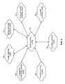
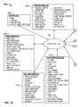
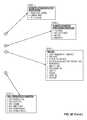
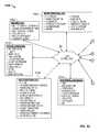
- FIG. 1is a diagram illustrating the system of the present disclosure
- FIG. 2is a block diagram illustrating components of the subsystems of FIG. 1 ;
- FIG. 3is a diagram illustrating various types of control logic in accordance with the present disclosure
- FIG. 4is a diagram illustrating processing steps carried out by the system of FIGS. 1-2 ;
- FIG. 5is a diagram illustrating another embodiment of the present disclosure.
- FIG. 6is a flowchart illustrating processing steps carried out by the system of FIG. 5 ;
- FIG. 7is a diagram illustrating another embodiment of the system of the present disclosure.
- FIG. 8is a flowchart illustrating processing steps carried out by the system of FIG. 7 ;
- FIG. 9is a diagram illustrating another embodiment of the system of the present disclosure.
- FIG. 10is a flowchart showing processing steps carried out by the system of FIG. 9 ;
- FIG. 11is a diagram illustrating another embodiment of the system of the present disclosure.
- FIG. 12is a diagram illustrating processing steps carried out by the system of FIG. 11 ;
- FIG. 13is a diagram illustrating another embodiment of the system of the present disclosure.
- FIG. 14is a flowchart illustrating processing steps carried out by the system of FIG. 13 ;
- FIG. 15is a diagram illustrating another embodiment of the system of the present disclosure.
- FIGS. 16A-16Bare diagram illustrating another embodiment of the system of the present disclosure.
- FIG. 17is a diagram illustrating another embodiment of the system of the present disclosure.
- FIG. 18is a diagram illustrating the pump control logic of FIG. 3 ;
- FIGS. 19A-19AUare flowcharts illustrating processing steps of the pump control logic of FIG. 3 ;
- FIG. 20is a diagram illustrating chemistry automation control logic of FIG. 3 ;
- FIGS. 21A-21Iare flowcharts illustrating processing steps of the chemistry automation control logic of FIG. 3 ;
- FIG. 22is a diagram illustrating the heater control logic of FIG. 3 ;
- FIGS. 23A-23Jare flowcharts illustrating processing steps of the heater control logic of FIG. 3 ;
- FIG. 24is a diagram illustrating the lighting control logic of FIG. 3 ;
- FIGS. 25A-25ABare flowcharts illustrating processing steps of the lighting control logic of FIG. 3 ;
- FIG. 26is a diagram illustrating the pool cleaner control logic of FIG. 3 ;
- FIGS. 27A-27Oare flowcharts illustrating processing steps of the pool cleaner control logic of FIG. 3 ;
- FIG. 28is a diagram illustrating the valve actuator control logic of FIG. 3 ;
- FIGS. 29A-29Iare flowcharts illustrating processing steps of the valve actuator control logic of FIG. 3 ;
- FIG. 30is a diagram illustrating water feature control logic of FIG. 3 ;
- FIGS. 31A-31Fare flowcharts illustrating processing steps of the water feature control logic of FIG. 3 ;
- FIG. 32is a diagram illustrating pool control logic of FIG. 3 ;
- FIGS. 33A-33AHare flowcharts illustrating processing steps of the pool control logic of FIG. 3 ;
- FIGS. 34A-34Jare diagrams illustrating another embodiment of the system of the present disclosure.
- FIG. 35is a diagram illustrating another embodiment of the system of the present disclosure.
- FIGS. 36-40are diagrams illustrating further embodiments of the system of the present disclosure.
- the present disclosurerelates to systems and methods for providing network connectivity and remote monitoring, optimization and control of pool/spa equipment, as discussed in detail below in connection with FIGS. 1-40 .
- FIG. 1is a diagram illustrating the system 10 of the present disclosure.
- the system 10includes, but is not limited to, a plurality of network communication and local control subsystems 12 a - 12 h which could be installed in or connected to a plurality of pool and spa equipment 14 a - 14 h , so as to provide network connectivity and remote monitoring and control of the pool and spa equipment 14 a - 14 h .
- the subsystems 12 a - 12 hcould communicate with each other over a network 16 , which could include, but is not limited to, the Internet.
- the subsystems 12 a - 12 hprovide “Internet-of-Things” functionality for the plurality of pool and spa equipment 14 a - 14 h .
- subsystems 12 a - 12 hcould further include a “big data” subsystem, subsystems for receiving input from manufacturers/factories, subsystems for receiving external data/input (e.g., data from the Internet), and subsystems for receiving input from customers.
- a “big data” subsystemsubsystems for receiving input from manufacturers/factories
- subsystems for receiving external data/inpute.g., data from the Internet
- subsystems for receiving input from customerse.g., data from the Internet
- the subsystems 12 a - 12 hcould include control logic for allowing each of the devices 14 a - 14 h to interact with each other (e.g., to exchange data and commands for controlling each other), as well as to be remotely controlled by another system such as a remote server, a “cloud” based control system, a remote computer system, a smart device (e.g., smart phone, smart speaker, smart chip embedded in the body), etc., and combinations thereof as will be discussed in greater detail below.
- a remote servere.g., a “cloud” based control system
- a remote computer systeme.g., a smart device, smart phone, smart speaker, smart chip embedded in the body
- the pool and spa equipment 14 a - 14 hcould include various types of pool and spa equipment, such as a pump 14 a , a heating/cooling system 14 b , a sanitization system 14 c , a water feature or miscellaneous subsystem 14 d , a valve actuator 14 e , a pool/spa control system 14 f , a pool cleaner 14 g , and/or a lighting system 14 h .
- the heating/cooling system 14 bmay also describe, or be described as, a heating system, heater, cooling system, cooler, or any combination thereof. Additionally, as can be seen in FIG.
- the subsystems 12 a - 12 hcould also communicate with one or more servers 18 , and/or with one or more smart devices 20 (e.g., phone, tablet, computer systems, etc.), via the network 16 .
- an on-site control processor 19could be in communication with the various systems shown in FIG. 1 .
- the on-site control processor 19could be a pool/spa control system installed at the location of a pool or spa, a reduced-functionality pool/spa control system, or another type of control system. Examples of such systems will be described in detail below.
- FIG. 2is a block diagram illustrating components of the subsystems 12 a - 12 h in greater detail.
- a variety of subsystem componentscould be provided for providing network connectivity for pool and spa equipment via a multitude of wired and wireless means.
- the subsystems 12 a - 12 hcould be installed in pool/spa equipment (e.g., within the physical housings of the equipment 14 a - 14 h ), or connected thereto, to provide network connectivity to each device.
- the subsystems 12 a - 12 hcan be provided as “after-market” components that provide network connectivity and remote monitoring and control for pool/spa equipment that does not ordinarily include such connectivity.
- the subsystems 12 a - 12 hallow for a wide variety of wired and wireless connections to the pool/spa equipment.
- a smart telephonecould directly connect with pool or spa equipment via a Bluetooth, WiFi, RF mesh (e.g., ZWave, Zigbee, Thread, Weave, etc.), or satellite connection, via the subsystems 12 a - 12 h .
- a home computercould connect to pool/spa equipment using a home WiFi network, via the subsystems 12 a - 12 h or by way of a wired Ethernet connection to the pool/spa equipment.
- a remote server or “cloud” platformcould connect to the pool/spa equipment via the subsystems 12 a - 12 h , to allow for remote and/or web-based control.
- a processor 22provides local processing capability for each of the subsystems 12 a - 12 h .
- the processor 22is in communication with a random access memory 24 , and one or more non-volatile memories 28 .
- the non-volatile memory 28could store one or more local control programs 30 for providing local control of the pool or spa equipment in which the subsystem is installed.
- a TCP/IP stack 26is provided for allowing each of the subsystems to obtain an Internet protocol address, and to provide Internet connectivity for each of the subsystems.
- the processor 22could communicate with a wired communication subsystem 36 , a wireless communication subsystem 34 , a sensor interface subsystem 38 , and an actuator interface subsystem 40 via a bus 32 .
- the wired communication subsystem 36could include an Ethernet transceiver 42 , and a serial transceiver 44 .
- the serial transceivercould support one or more suitable serial communication protocols, such as RS-485, RS-232, USB, etc.
- the wireless communication subsystem 34could include a Wi-Fi transceiver 46 , a Bluetooth (or Bluetooth LE) transceiver 48 , a cellular data transceiver 50 , a satellite transceiver 52 , and infrared transceiver 54 , and a radiofrequency/RF mesh transceiver 56 .
- the cellular data transceiver 50could support one or more cellular data communications protocols, such as 4G, LTE, 5G, etc.
- the radiofrequency/RF mesh transceiver 56could support one or more RF mesh network protocols, such as ZWave, Zigbee, Thread, Weave, etc.
- the sensor interface subsystem 38could include analog connection interfaces, digital connection interfaces, and one or more analog-to-digital converters 58 .
- the actuator interface subsystem 40could include analog connection interfaces, digital connection interfaces, and one or more digital-to-analog converters 60 .
- the sensor interface subsystemallows the network communication and local control subsystem to obtain information from a wide variety of sensors associated with pool/spa equipment, as well as other types of sensors.
- the actuator interface subsystem 40allows the network communication and local control subsystem to control one or more pieces of pool/spa equipment connected to the subsystem.
- the wired and wireless communication subsystems 34 , 36allow the network communication and local control subsystem to connect via various wired and wireless communication means to the Internet. This allows a piece of pool or spa equipment to transmit operational and status information to one or more remote devices, as well as to be remotely controlled by such devices.
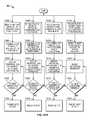
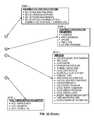
- FIG. 3is a diagram illustrating various types of control logic in accordance with the present disclosure, for controlling various types of pool and spa equipment.
- the control logicindicated generally as pool control logic 70 , could be embodied as programmed instructions (software code) stored on a non-transitory computer-readable medium, and could include water feature control logic 72 , valve actuator control logic 74 , cleaner control logic 76 , lighting control logic 78 , heater control logic 80 , chemistry automation control logic 82 , and pump control logic 84 .
- Such logiccould be installed locally (e.g., in one or more of the subsystems 12 a - 12 h ), on a remote server or computer system (e.g., in the server 18 or the smart phone/computer system 20 ), in the “cloud,” or in any combination of such systems.
- the functions provided by the logic 70 - 84is described in greater detail below.
- the various logic operations disclosed hereincould be trigged by (e.g., receive and a signal from) various sensors and/or inputs to the system, as needed. Such inputs could be periodically monitored by the pool control logic 70 of the system 10 .
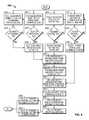
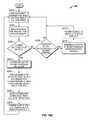
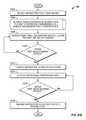
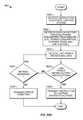
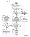
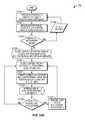
- FIG. 4is a diagram illustrating processing steps, indicated generally at 90 , carried out by the system of FIGS. 1-2 .
- IoT devicesrefers to pool/spa equipment having Internet-of-Things functionality provided in accordance with the present disclosure, such as the equipment 14 a - 14 h of FIG. 1 .
- the systemmonitors IoT devices for incoming operational data.
- step 94a decision is made as to whether incoming operational data has been received. If a negative determination has been made, control returns to step 92 . Otherwise, step 96 occurs, wherein the system receives incoming operational data.
- step 98the system processes instructions, operational data, and external data, discussed hereinbelow. Then, in step 100 , the system optimizes operational set points. In step 102 , the system transmits setpoints to one or more devices (one or more of the pool/spa equipment 14 a - 14 h ) for use thereby.
- step 104the system also monitors for incoming instructions. A determination is made in step 105 as to whether an incoming instruction has been received. If a negative determination has been made, control returns to step 104 . Otherwise, in step 106 , the system receives one or more incoming instructions. Then, control proceeds to step 98 , discussed above. Additionally, in step 107 , the system also monitors for updated external data (e.g., web data). In step 108 , a decision has been made as to whether updated external data is available. If a negative determination has been made, control returns to step 107 . Otherwise, step 109 occurs, wherein the system receives the updated external data. Then, control proceeds to step 98 , discussed above.
- updated external datae.g., web data
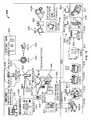
- FIG. 5is a diagram illustrating another embodiment of the present disclosure, indicated generally at 110 .
- network connectivity and remote monitoring/control of pool and spa componentsis provided by way of a central pool/spa system controller 114 f .
- the pool/spa system controller 114 fcould be the OMNILOGIC pool/spa system controller manufactured and sold by Hayward Industries Inc.
- the pool/spa system controller 114 fcould communicate with one or more valve actuators 114 e , a single speed pump 113 , a variable speed pump 114 a , pool/spa lighting systems 114 h , a pool/spa heating or cooling system 114 b , and/or a pool/spa chlorination system 114 c , such as a salt chlorinator.
- the pool/spa control system 114 fcould receive input from one or more external sensors 126 and could provide “personality” by way of remotely provisioned logic for the devices.
- the pool/spa control system 114 fcommunicates with a remote server, such as the server 118 , via a Wi-Fi router 122 and the Internet.
- the server 118could communicate with one or more remote control systems 120 , such as a smart device (e.g., smart phone, smart speaker, smart TV, embedded device), a computer system, a tablet computer, etc.
- the control system 114 fcould also receive external web data 131 via the Internet and Wi-Fi router 122 (e.g., time & date, sunrise/sunset data, regional and local weather forecasts, wind, UV, sunlight) for use by pool control logic 170 , described hereinbelow. Additionally, the Wi-Fi router 122 could communicate with a home management system 125 in a peer-to-peer arrangement, if desired. The server 118 could also access big data 127 and perform analytics 129 in connection with various types of information relating to the pool/spa equipment, usage thereof, and status information relating thereto. Further, the server 118 communicate with one or more third-party smart devices 124 via a suitable cloud application programming interface (API).
- APIcloud application programming interface
- the third-party smart devices 124could also remotely communicate with and control the pool/spa equipment shown in FIG. 5 .
- the pool/spa control system 114 fcould include pool logic 170 stored therein for allowing central control and monitoring of pool/spa equipment at the pool/spa site.
- the pool logic 170could include any of the various pool control logic described herein. Additionally, such logic 170 could also be stored in the server 118 , or at another location.
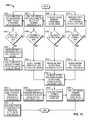
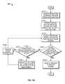
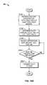
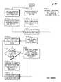
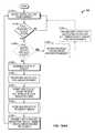
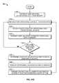
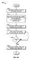
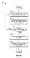
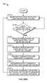
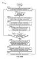
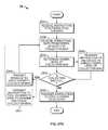
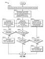
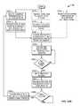
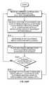
- FIG. 6is a flowchart, indicated generally at 130 , illustrating processing steps carried out by the system of FIG. 5 .
- the pool/spa system controller 114 f of FIG. 5monitors connected devices for incoming operational data. Then, in step 134 , a decision is made as to whether incoming operational data has been received. If not, control returns to step 132 . Otherwise, step 136 occurs, wherein the pool/spa system controller receives incoming operational data. Then, in step 138 , the pool/spa system controller 114 f processes instructions, operational data, and external data, discussed hereinbelow. Then, in step 140 , the pool/spa system controller 114 f optimizes operational set points.
- the pool/spa system controllertransmits set points to the connected devices, such as the pool/spa equipment 113 , 114 a , 114 h , 114 b , and 114 c shown in FIG. 5 .
- the pool/spa system controller 114 fcould also transmit such setpoint information to other devices, such as the smart devices 124 illustrated in FIG. 5 .
- step 150the pool/spa system controller monitors for incoming instructions.
- step 152a determination is made as to whether an incoming instruction has been received. If not, control returns to step 150 . Otherwise, step 150 occurs, wherein the pool/spa system controller 114 f receives incoming instructions. Then, processing proceeds to step 138 , discussed above.
- step 156the pool/spa system controller 114 f monitors for updated external data (e.g., web-supplied data, such as weather information and other information from remote data sources).
- step 158the system determines whether updated external data is available. If not, control returns to step 156 . Otherwise step 160 occurs, wherein the pool/spa system controller receives the updated external data. Then, control proceeds to step 138 , discussed above.
- updated external datae.g., web-supplied data, such as weather information and other information from remote data sources.
- step 158the system determines whether updated external data is available. If not, control returns to step 156 . Otherwise step 160 occurs, wherein the
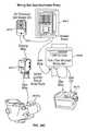
- FIG. 7is a diagram illustrating another embodiment of the system of the present disclosure, wherein remote connectivity is provided by way of a pool “hub” component 230 .
- the pool hub component 230includes a subset of the functional features of the pool/spa system controller 114 f of FIG. 5 , such as basic on/off control relays, the ability to select a pump speed, the ability to select heater temperature, the ability to control pool light colors and shows, the ability to set equipment schedules, and the ability to interlock one pool/spa component with another pool/spa component.
- the pool hubcommunicates with and controls a number of pool/spa components, such as a single speed pump 213 , a variable speed pump 214 a , pool/spa lighting systems 214 h , a pool/spa heating system 214 b , and a pool/spa chlorination system 214 c .
- the pool hub 230can control a valve actuator 214 e and can receive various sensor inputs 226 and 228 , such as temperature sensors, wind speed sensors, runtime sensors, current/voltage usage sensors, flow sensors, heater pressure sensors, water temperature sensors, chlorine sensors, pH/ORP sensors, etc.
- sensor inputs 226 and 228such as temperature sensors, wind speed sensors, runtime sensors, current/voltage usage sensors, flow sensors, heater pressure sensors, water temperature sensors, chlorine sensors, pH/ORP sensors, etc.
- Such sensorscould be positioned internally within the hub, external thereto, or a combination thereof.
- the pool hub 230could be powered by electrical current supplied by a breaker panel 217 or by photovoltaic (e.g., solar) cells and/or systems.
- Breaker panel 217could also be a smart circuit breaker (e.g., a circuit breaker that can be controlled via wired or wireless communication) used to provide and/or to interrupt power to the devices disclosed herein.
- the pool hub 230could communicate with a remote server 218 via a Wi-Fi router 222 and a network connection such as the Internet.
- the server to 218could include pool logic 270 which can be used to remotely monitor and control operation of the devices to 213 , 214 a , 214 h , 214 b , and 214 c .
- the pool logic 270could include any of the pool logic discussed herein. Additionally, the server 218 could communicate with one or more remote control devices 220 , such as a smart cellular telephone, a remote computer, a tablet computer, etc. The server 218 could also receive external web data 231 via the Internet (e.g., time & date, sunrise/sunset data, regional and local weather forecasts, wind, UV, sunlight) for use by pool logic 270 . Further, the server 218 could communicate with one or more third-party devices 224 via an appropriate cloud API. Further, the server 218 could process big data 232 and perform analytics 234 on various pool/spa data. Still further, the server 218 could communicate with a home management system 225 , if desired.
- the server 218could communicate with a home management system 225 , if desired.
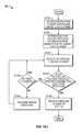
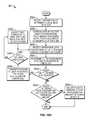
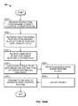
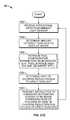
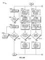
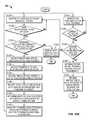
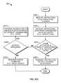
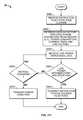
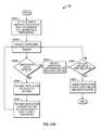
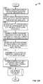
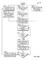
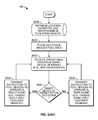
- FIG. 8is a flowchart illustrating processing steps, indicated generally at 240 , carried out by the system of FIG. 7 .
- the pool hub 230monitors connected devices for incoming operational data.
- a determinationis made as to whether an incoming operational data has been received. If not, control returns to step 242 . Otherwise, step 246 occurs, wherein the pool hub 230 receives incoming operational data.
- the pool 230transmits incoming instructions and operational data to the server 218 .
- the server 218receives the incoming instructions and operational data from the pool hub 230 .
- step 252the server 218 processes the incoming instructions, operational data, and external data, discussed hereinbelow.
- step 254the server 218 optimizes operational set points.
- step 256the server 218 transmits operational setpoints to the pool hub 230 .
- step 258the pool hub 230 receives the operational set points.
- step 260the pool hub 230 transmits the operational setpoints to the connected devices.
- step 262the pool hub 230 optionally transmits the operational setpoints to one or more smart devices, such as the third-party smart devices 224 of FIG. 7 .
- step 263the pool hub 230 monitors smart devices for incoming operational data.
- step 265a decision is made as to whether incoming operational data has been received. If not, control returns to step 263 . Otherwise, step 246 occurs, where in the incoming operational data is received at the pool hub 230 . Then, control passes to step 248 , discussed above.
- step 264the pool hub 230 monitors for incoming instructions. Then, in step 266 , a determination is made as to whether an incoming instruction has been received. If a negative determination has been made, control returns to step 264 . Otherwise, step 268 occurs, wherein the pool hub 230 receives the incoming instructions. Then, control passes to step 248 , discussed above.
- step 272the server 218 monitors for updated external data, such as web-supplied data including weather data and other data.
- updated external datasuch as web-supplied data including weather data and other data.
- step 274a determination is made as to whether updated external data is available. If not, control returns to step 272 . Otherwise, step 276 occurs, wherein the updated external data is received at the server 218 . Then, control passes to step 252 , discussed above.
- FIG. 9is a diagram illustrating another embodiment of the system of the present disclosure, indicated generally at 310 .
- a pool command “translator” module 330is provided, which includes a complete set of pool logic 370 .
- the pool logic 370could include any of the pool logic discussed herein.
- the translator 330could communicate with one or more external relays 329 . Additionally, the translator 330 could communicate with a plurality of pool/spa components, including valve actuators 314 e , a single speed pump 313 , a variable speed pump 314 a , pool/spa lighting systems 314 h , a pool/spa heating system 314 b , and a pool/spa chlorination system 314 c .
- the translator 330could receive electrical power from a breaker panel 317 or from photovoltaic (e.g., solar) cells and/or systems.
- Breaker panel 317could also be a smart circuit breaker (e.g., a circuit breaker that can be controlled via wired or wireless communication) used to provide and/or to interrupt power to the devices disclosed herein.
- the translator 330could receive information from various sensors such as external sensors 326 and internal sensors 328 . Such sensors could include, but are not limited to, temperature sensors, wind speed sensors, runtime sensors, current/voltage usage sensors, flow sensors, heat pressure sensors, water temperature sensors, chlorine sensors, PH/ORP sensors, etc.
- the translator 330could also receive external web data 331 via the Internet and Wi-Fi router 322 (e.g., time & date, sunrise/sunset data, regional and local weather forecasts, wind, UV, sunlight) for use by pool logic 370 .
- the translator 330could communicate with the remote server 318 via a Wi-Fi router 322 and a network connection such as the Internet.
- the server 318could communicate with the remote control system 320 , such as a smart cellular telephone, a remote computer, a tablet computer, etc. Additionally, the server 318 could process big data 332 and perform analytics 334 on pool/spa data, using a suitable API. Further, the server 318 could communicate with one or more third-party smart devices 324 , using a suitable cloud API. Still further, the server 318 could communicate with a home management system 325 , if desired.
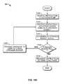
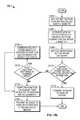
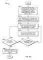
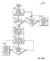
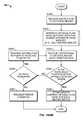
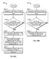
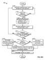
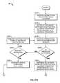
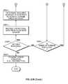
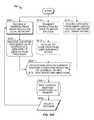
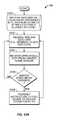
- FIG. 10is a flowchart showing processing steps, indicated generally at 340 , carried out by the system of FIG. 9 .
- the translator 330monitors connected devices for incoming operational data.
- step 334a decision is made as to whether incoming operational data has been received. If not, control returns to step 342 . Otherwise, step 346 occurs, wherein the translator 330 receives the incoming operational data. Then, step 360 occurs, wherein the translator processes instructions, operational data, and external data, discussed hereinbelow.
- step 362the translator optimizes operational set points.
- step 364the translator transmits the setpoints to the connect devices (e.g., to the components 313 , 314 a , 314 e , 314 h , 314 b , and 314 c ).
- the translatorcould transmit the setpoints to one or more smart devices, such as the third-party smart devices 324 .
- step 348the translator 330 monitors smart devices for incoming operational data.
- step 350a decision is made as to whether incoming operational data has been received. If not, control returns to step 348 . Otherwise, step 352 occurs, wherein the translator 330 receives incoming operational data. Then, control passes to step 360 , discussed above.
- step 354the translator 330 monitors for incoming instructions.
- step 356a decision is made as to whether incoming instructions have been received. If not, control returns to step 354 . Otherwise, step 358 occurs, wherein the translator 330 receives incoming instructions. Then, control passes to step 360 , discussed above.
- step 368the translator 330 monitors for updated external data, such as web data. Such data could include, but is not limited to, remote weather data, etc.
- step 372a decision is made as to whether updated external data is available. If not, control returns to step 368 . Otherwise, step 374 occurs, wherein the translator 330 receives the updated external data. Then, control passes to step 360 , discussed above.
- FIG. 11is a diagram illustrating another embodiment of the system, indicated generally at 410 .
- remote connectivityis provided by way of a plurality of connectivity modules 430 a - 430 e .
- Each of these modulescould include a combination of high and/or low voltage relays for connection to various pool and spa equipment, such as valve actuators 414 e , a single speed pump 413 , a variable speed pump 414 a , pool/spa lighting systems 414 h , pool/spa heating system 414 b , and/or pool/spa chlorination system 414 C.
- Connectivitycould be provided to the pool/spa equipment additionally using Wi-Fi, Bluetooth, or RF mesh (e.g., ZWave, Zigbee, Thread, Weave, etc.) connectivity.
- the connectivity modulescould provide Wi-Fi for every unit, could adapt for usage with legacy devices, could provide “personality” by way of remotely provisioned logic for the devices, could remember limp mode schedules during a Wi-Fi outage, and could also include start/stop buttons and an LS bus gate way, if desired.
- the modulescould be powered by a breaker panel 427 or by photovoltaic (e.g., solar) cells and/or systems.
- Breaker panel 427could also be a smart circuit breaker (e.g., a circuit breaker that can be controlled via wired or wireless communication) used to provide and/or to interrupt power to the devices disclosed herein. Additionally, each of the modules could communicate with a remote server 418 by a Wi-Fi router 422 and a network connection, such as the Internet.
- the pool/spa control logic 470could be provided in the server 418 for remotely controlling and monitoring the pool/spa equipment.
- the pool logic 470could include any of the pool logic discussed herein.
- the server 418could also receive external web data 431 via the Internet (e.g., time & date, sunrise/sunset data, regional and local weather forecasts, wind, UV, sunlight) for use by pool logic 470 .
- the server 418could communicate with one or more remote control devices 420 , such as a smart phone, a remote computer, a tablet computer, etc.
- the server 418could access big data 432 and perform analytics 434 on pool/spa data, if desired.
- the server 418could also communicate with one or more third-party smart devices 424 , via a suitable cloud API.
- the server 418could communicate with a home management system 425 , if desired.
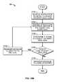
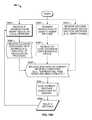
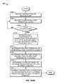
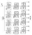
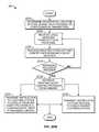
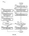
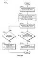
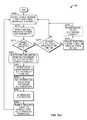
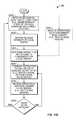
- FIG. 12is a diagram illustrating processing steps, indicated generally at 440 , carried out by the system of FIG. 11 .
- the pool connectivity modules 430 a - 430 emonitor smart devices for incoming operational data.
- step 444a determination is made as to whether incoming operational data has been received. If not, control returns to step 442 . Otherwise, step 446 occurs, wherein the pool connectivity modules each receive the incoming operational data. Then, and step 448 , the pool conductivity modules 430 a - 430 e transmit operational data to the server 418 .
- step 450the operational data is received at the server 418 .
- step 452the server 418 processes the incoming instructions, operational data, and external data, discussed hereinbelow. Then, in step 454 , the server 418 optimizes operational support. In step 456 , the server 418 transmits the operational set points to the connected devices (e.g., to the devices 413 , 414 a , 414 e , 414 h , 414 b , and 414 c ). In step 458 , the server transmits operational set points for the smart devices to the pool connectivity modules 430 a - 430 e . In step 460 , the pool conductivity modules 430 a - 430 e receive the operational setpoints for the smart devices. Then, in step 462 , the modules transmit the operational set points to the smart devices.
- the connected devicese.g., to the devices 413 , 414 a , 414 e , 414 h , 414 b , and 414 c .
- step 458the server transmits operational
- step 464the server for 18 monitors connected devices for incoming operational data.
- step 466a determination is made as to whether incoming operational data has been received. If not, control returns to step 464 . Otherwise, step 450 occurs, wherein the server 418 receives the operational data. Control then passes to step 452 , discussed above.
- step 468the server 418 monitors for incoming instructions.
- step 470a determination is made as to whether the incoming instructions have been received. If not, control returns to step 468 . Otherwise, step 472 occurs, wherein the server 418 receives the incoming instructions. Then, control passes to step 452 , discussed above.
- step 474the server 418 monitors for updated external data, such as web data including, but not limited to, remote weather information, etc. Then, in step 476 , a determination is made as to whether updated external data is available. If not, control passes to step 474 . Otherwise, step 478 occurs, wherein the updated external data is received at the server 418 . Then, control passes to step 452 , discussed above.
- updated external datasuch as web data including, but not limited to, remote weather information, etc.
- FIG. 13is a diagram illustrating another embodiment of the system of the present disclosure, indicated generally at 510 .
- wireless connectivityis provided directly within pool/spa equipment, allowing such equipment to communicate directly to the Internet.
- pool spa equipmentsuch as a single speed pump 513 , a variable speed pump 5148 , pool/spa lighting system 514 h , heater 514 b , and/or chlorinator 514 c , in addition to valve actuators 514 e , each have built-in wireless communications subsystems, such as Wi-Fi, Bluetooth, radiofrequency/RF mesh (e.g., ZWave, Zigbee, Thread, Weave, etc.), and or cellular wireless communication subsystems.
- Wi-FiWireless Fidelity
- Each of these devicescan communicate directly with the Internet via a Wi-Fi router 522 .
- external sensors 526could also communicate with the Wi-Fi router 522 , and could also include built-in wireless communications such as Wi-Fi, Bluetooth, radiofrequency/RF mesh (e.g., ZWave, Zigbee, Thread, Weave, etc.), and cellular communications.
- the sensors 526could include, but are not limited to, heater pressure sensors, water temperature sensors, chlorine sensors, pH/aware pressure sensors, etc. It is noted that each of the pool/spa components could include the ability to remember schedules during a Wi-Fi outage (limp mode) as provisioned by remote pool logic. Additionally, each of these devices could include start/stop buttons, if desired, for stand-alone operation.
- a breaker panel 527could provide electrical power to each of the pool/spa components.
- Breaker panel 527could also be a smart circuit breaker (e.g., a circuit breaker that can be controlled via wired or wireless communication) used to provide and/or to interrupt power to the devices disclosed herein.
- photovoltaic (e.g., solar) cells and/or systemscould provide electrical power to one or more of the pool/spa components.
- the server 518could include pool logic 570 for remotely controlling and/or monitoring the pool/spa equipment.
- the pool logic 570could be any of the pool logic discussed herein.
- the server 518could receive external web data 531 via the Internet (e.g., time & date, sunrise/sunset data, regional and local weather forecasts, wind, UV, sunlight) for use by pool logic 570 .
- the server 518could also communicate with one or more remote control devices 520 , such as smart telephones, remote computer systems, tablet computers, etc.
- the server 518could also access big data 532 and perform analytics 534 on pool/spa data, if desired.
- the server 518could communicate with one or more third-party smart devices 524 , via a suitable cloud API. Still further, the server 518 could communicate with a home management system 525 , if desired.
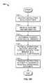
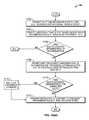
- FIG. 14is a flowchart illustrating processing steps, indicated generally at 540 , carried out by the system of FIG. 13 .
- the server 518monitors connected devices for incoming operational data. Then, in step 544 , a determination is made as to whether incoming operational data has been received. If not, control returns to step 542 . Otherwise, step 546 occurs, wherein the server 518 receives incoming operational data. Then, in step 548 , the server 518 processes the instructions, the operational data, and external data, discussed hereinbelow.
- the server 518optimizes operational set points. Then, in step 552 , the server transmits the setpoints to the connected pool/spa devices, such as those devices shown in FIG. 13 .
- step 554the server 518 monitors for incoming instructions. Then, in step 556 , a determination is made as to whether incoming instructions have been received. If not, control returns to step 554 . Otherwise, step 558 occurs, wherein the server 518 receives incoming instructions. Then, step 548 , discussed above, is invoked.
- step 560the server 518 monitors for updated external data, such as web data including, but not limited to remote weather data, etc.
- updated external datasuch as web data including, but not limited to remote weather data, etc.
- step 562a decision is made as to whether updated external data is available. If not, control returns to step 560 . Otherwise, step 564 occurs, wherein the server 518 receives the updated external data. Then, control passes to step 548 , discussed above.
- FIG. 15is a diagram illustrating another embodiment of the system of the present disclosure, indicated generally at 610 .
- network connectivity and remote monitoring/controlis provided by way of a reduced-size hub 646 which can be easily wall-mounted.
- the hub 646provides wired and wireless connections for various pool and spa equipment, such as a variable speed pump 614 a , a single-speed pump 613 , a smart heater 614 b , a legacy heater 615 , a chlorination system 617 , any other type of chlorinator 614 c , a booster pump 619 , and a third-party pump 621 .
- Various relays 648 , 650 , 652 , and 654could also be provided for controlling the pumps, if desired.
- the hub 646could communicate with and control a smart valve actuator 614 e , and/or lighting system 614 h .
- Optional control relays 656 and power supplies 658could also be in communication with the hub 646 .
- the hub 646could provide a WiFi hotspot for allowing a homeowner's cellular telephone, tablet computer, or personal computer 644 to communicate with the hub 646 , and to control the pool/spa equipment shown in FIG. 15 .
- a breaker panel 627provides electrical power to the various devices shown in FIG. 15 .
- Breaker panel 627could also be a smart circuit breaker (e.g., a circuit breaker that can be controlled via wired or wireless communication) used to provide and/or to interrupt power to the devices disclosed herein.
- photovoltaic (e.g., solar) cells and/or systemscould provide electrical power to one or more of the various devices shown in FIG. 15 .
- a wall-mounted light controller 640could communicate by Bluetooth and/or RF mesh (e.g., ZWave, Zigbee, Thread, Weave, etc.) to the hub 646 for remotely controlling the lights 614 h .
- RF meshe.g., ZWave, Zigbee, Thread, Weave, etc.
- a third-party Bluetooth and/or RF mesh-enabled switch 642could also communicate with the hub 646 .
- the hub 646could also communicate with the homeowner's WiFi router 622 for providing an Internet connection to the pool/spa components.
- a remote pool/spa server 618could communicate with the router 622 via the Internet, to provide remote monitoring and control of the pool/spa equipment, if desired.
- the server 618could communicate with one or more remote computer systems 620 such as a smart phone, a tablet computer, a remote computer system, etc., if desired.
- the pool/spa control logic discussed hereincould be installed in the server 618 , in the remote computer 620 , and/or in the smart phone 644 (e.g., by way of a pool control “app”), if desired.
- the server 618could communicate with one or more third-party smart devices 624 by a suitable cloud API, and the server 618 could access big data 632 and perform analytics 634 on pool/spa data, if desired.
- the server 618could also communicate with a home management system 638 , if desired.
- FIG. 16Ais a diagram illustrating another embodiment of the system of the present disclosure, indicated generally at 710 .
- network connectivity and remote monitoring/controlis provided by way of a Wi-Fi-enabled pool/spa chlorination system and controller 717 .
- the controller 717provides connections for various pool and spa equipment, such as a variable speed pump 714 a , a single-speed pump 713 , a smart heater 714 b , a legacy heater 715 , a chlorination system 717 c , a booster pump 719 , and a third-party pump 721 .
- Various relays 749 , 750 , and 754could also be provided for controlling the pumps, if desired.
- the controller 717could communicate with and control a smart valve actuator 714 e , and/or lighting system 714 h .
- Optional control relays 756 and power supplies 758could also be in communication with the controller 717 .
- a breaker panel 727provides electrical power to the various devices shown in FIG. 16A .
- Breaker panel 727could also be a smart circuit breaker (e.g., a circuit breaker that can be controlled via wired or wireless communication) used to provide and/or to interrupt power to the devices disclosed herein.
- photovoltaic (e.g., solar) cells and/or systemscould provide electrical power to one or more of the various devices shown in FIG. 16A .
- the controller 717could also communicate with the homeowner's WiFi router 722 for providing an Internet connection to the pool/spa components.
- a remote pool/spa server 718could communicate with the router 722 via the Internet, to provide remote monitoring and control of the pool/spa equipment, if desired.
- the server 718could communicate with one or more remote computer systems 720 such as a smart phone, a tablet computer, a remote computer system, etc., if desired.
- the pool/spa control logic discussed hereincould be installed in the server 718 , in the remote computer 720 , or elsewhere, if desired.
- the server 718could communicate with one or more third-party smart devices 724 by a suitable cloud API, and the server 718 could access big data 732 and perform analytics 734 on pool/spa data, if desired.
- the server 718could communicate with a home management system 738 if desired.
- FIG. 16Bis a diagram illustrating another embodiment of the system of the present disclosure, indicated generally at 4510 .
- network connectivity and remote monitoring/controlis provided by way of a Wi-Fi-enabled pool/spa variable speed pumping system and controller (also referred to herein in connection with FIG. 16B as “variable speed pumping system,” “pumping system,” or “controller”), indicated generally at 4514 a .
- a variable speed pumping systemcan include a variable speed pump, a possessor/controller, memory, communications interface(s), and an input device, so that the variable speed pumping system can communicate with and/or control additional installed pool/spa equipment.
- pump control logic 84could be installed/reside in variable speed pumping system 4514 a .
- any of the various processes in the embodiments described herein in connection with FIGS. 19A-19AUcould be incorporated into pump control logic 84 and installed in variable speed pumping system 4514 a , either alone or in any combination.
- any additional processes disclosed herein in connection with pool control logic 70e.g., water feature control logic 72 , valve actuator control logic 74 , cleaner control logic 76 , lighting control logic 78 , heater control logic 80 , chemistry automation control logic 82
- the controller 4514 aprovides connections for various pool and spa equipment, such as a pool/spa chlorination system 4517 , a single-speed pump 4513 , a smart heater 4514 b , a legacy heater 4515 , a chlorination system 4514 c , a booster pump 4519 , and a third-party pump 4521 .
- Various relays 4549 , 4550 , and 4554could also be provided for controlling the pumps, if desired.
- Variable speed pumping system and controller 4514 acould include on-board or modularly upgradeable pool control components (e.g., communication modules, relays, temperature sensors, pressure sensors, flow sensors, etc.).
- variable speed pumping system 4514 acould control existing heaters (or heat pumps) using on-board or modularly upgradeable relays and temperature sensors.
- Pump control logic 84discussed in greater detail hereinbelow, could also utilize multiple sensors for parallel plumbing circuits (e.g., branch plumbing).
- the controller 4514 acould communicate with and control a smart valve actuator 4514 e , and/or lighting system 4514 h .
- Optional control relays 4556 and power supplies 4558could also be in communication with the controller 4514 a .
- variable speed pumping system and controller 4514 acould use the modularly upgradeable smart relays to control a variety of existing installed pool/spa equipment including single speed pumps, pressure cleaner booster pumps, LED and incandescent pool lights, and landscape lights.
- the modularly upgradeable control componentscan be used by pump control logic 84 to provide pump or system performance reporting and diagnostic functions (present and historical) including, but not limited to, phase current, torque, speed, horsepower, run time, and ramp rate.
- Pump control logic 84could provide the system performance and diagnostic information to the cloud, or to a smart to a smart device via a Bluetooth or any of the other communication protocols disclosed herein.
- a breaker panel 4527provides electrical power to the various devices shown in FIG. 16B .
- Breaker panel 4527could include one or more smart circuit breakers (e.g., a circuit breaker that can be controlled via wired or wireless communication) used to provide and/or to interrupt power to the devices disclosed herein, and/or conventional circuit breakers.
- photovoltaic (e.g., solar) cells and/or systemscould provide electrical power to one or more of the various devices shown in FIG. 16B .
- the controller 4514 acould also communicate with the homeowner's WiFi router 4522 for providing an Internet connection to the pool/spa components.
- a remote pool/spa server 4518could communicate with the router 4522 via the Internet, to provide remote monitoring and control of the pool/spa equipment, if desired.
- the server 4518could communicate with one or more remote computer systems 4520 such as a smart phone, a tablet computer, a remote computer system, etc., if desired.
- the pool/spa control logic discussed hereincould be installed in the variable speed pumping system and controller 4514 a , in the server 4518 , in the remote computer 4520 , or elsewhere, if desired.
- the server 4518could communicate with one or more third-party smart devices 4524 by a suitable cloud API, and the server 4518 could access big data 4532 and perform analytics 4534 on pool/spa data, if desired.
- the server 4518could communicate with a home management system 4538 if desired. It is also further complicated that any of the functions described herein could also be performed by the variable speed pumping system and controller 4514 a.
- the pumping system and controller 4514 acan be provided with a human machine interface or user interface device, indicated generally at 4560 .
- the user interfacecould include physical keys, a digital display, and/or a touchscreen 4562 , as shown in FIG. 16B , any other suitable input technologies, or any combination thereof. It is also contemplated that any of the pool/spa equipment described herein could be provided with a similar user interface device.
- Providing a user interface device 4562 on pumping system and controller 4514 aenables the delivery of existing or enhanced features of local pool/spa equipment control and control of remote devices (e.g., beyond the pool area) to the pool owner via the pool pump, while also reducing costs to the pool owner (e.g., reducing hardware costs, installation expenses, etc.). Because every pool/spa must include at least one pump, providing control of and communication with additional equipment, connectivity, and monitoring (e.g., status and condition of pool and equipment) functionality of the pool environment via the pool pump can further reduce pool owner cost and significantly improve usability. By leveraging information obtained at the equipment pad, from remote/external devices, and/or via a connection to the internet, operation of the pumping system 4514 a and other devices can be further optimized.
- FIG. 17is a diagram illustrating another embodiment of the system of the present disclosure, indicated generally at 810 .
- network connectivity and remote monitoring/controlis provided by way of a reduced-size hub 860 which can be easily wall-mounted.
- the hub 860provides wired and wireless connections for various pool and spa equipment, such as a variable speed pump 814 a , a single-speed pump 813 , a smart heater 814 b , a legacy heater 815 , a chlorination system 817 c , and other equipment (e.g., lighting equipment).
- the hub 860could provide a WiFi hotspot for allowing a homeowner's cellular telephone, tablet computer, or personal computer 844 to communicate with the hub 846 , and to control the pool/spa equipment shown in FIG. 17 .
- a breaker panel 827provides electrical power to the various devices shown in FIG. 17 .
- Breaker panel 827could also be a smart circuit breaker (e.g., a circuit breaker that can be controlled via wired or wireless communication) used to provide and/or to interrupt power to the devices disclosed herein.
- photovoltaic (e.g., solar) cells and/or systemscould provide electrical power to one or more of the various devices shown in FIG. 17 .
- a wall-mounted light controller 840could communicate by Bluetooth and/or RF mesh (e.g., ZWave, Zigbee, Thread, Weave, etc.) to the hub 860 for remotely controlling lights. Additionally, a third-party Bluetooth and/or RF mesh-enabled switch 842 could also communicate with the hub 860 .
- the hub 860could also communicate with the homeowner's WiFi router 822 for providing an Internet connection to the pool/spa components.
- a remote pool/spa server 818could communicate with the router 822 via the Internet, to provide remote monitoring and control of the pool/spa equipment, if desired. Additionally, the server 818 could communicate with one or more remote computer systems 820 such as a smart phone, a tablet computer, a remote computer system, etc., if desired.
- the server 818is a cloud-based, virtual server, and the pool/spa control logic discussed herein is installed in the server 818 .
- the pool logiccould be any of the pool logic discussed herein.
- the server 818could communicate with one or more third-party smart devices 824 by a suitable cloud API, and the server 818 could access big data 832 and perform analytics 834 on pool/spa data, if desired.
- the server 818could also communicate with a home management system 838 , if desired.
- FIG. 18is a diagram 900 illustrating pump control logic 84 .
- Pump control logic 84could incorporate and/or be in communication with a variety of types of data and/or data sources. More specifically, pump control logic 84 can communicate with, or receive, user input data 902 , pump operational data 904 , pump factory specifications 906 , pump configuration parameters 908 , web data 910 , pool configuration parameters 912 , data from related devices 914 , health monitoring data 916 and/or external sensor data 918 .
- Pump control logic 84can control variable speed pumps, designed for residential and commercial pool applications (as well as additional installed pool/spa equipment), providing flow and pressure for water circulation and operation of pool equipment.
- Variable speed pumpsas described herein, could include a pump wet end, a motor, a variable frequency/speed drive, and a user interface (see FIG. 16B ).
- the variable speed pumpis used anytime a pool is in operation, which may be year-round and/or all-day based on a particular application (e.g. residential vs. commercial) or location.
- the pump control logic 84can control the variable speed drive to operate in stand-alone mode, relay control mode, or via communication with Hayward automation, described hereinbelow.
- the pumpIn stand-alone mode, the pump operates independently of the pool control logic 70 . Stand-alone mode is programmable with respect to functions such as timers and preset speeds. In relay control mode, the pump operates according to inputs received from third party systems and devices using low voltage digital inputs. For example, the digital inputs could be used to select discrete timer speeds set in the pump user interface.
- the pumpWhen communicating with Hayward automation, the pump is controlled by a variety of Hayward automation systems such as, but not limited to: OmniLogic®, ProLogic®, and OnCommand®. The pump could communicate with Hayward automation systems using RS485 and associated Hayward automation communication protocols, or any other suitable communication protocol disclosed herein.
- the pumpcan also serve as a pool control system.
- the user interfacecould utilize a color LCD touch screen with resistive and/or capacitive touch capability, or any other suitable input technology.
- the user interfacecould provide a user with information such as ambient air and pool water temperatures, providing true freeze protection capability, as well as thermostat control of a pool heater or heat pump.
- the user interfacecould also be used to communicate with and to control one or more smart relays and smart actuators, allowing the pump to coordinate operation of other pieces of pool equipment.
- the user interfacecan be used for interlock control of other installed pool/spa equipment.
- the pumpcould also be provided with a communication module (e.g., Wi-Fi, ethernet, Bluetooth, ZWave, Zigbee, Thread, Weave, etc.) allowing remote application control of the pump and/or pool pad equipment, and to allow remote data collection of site specific information.
- a communication modulee.g., Wi-Fi, ethernet, Bluetooth, ZWave, Zigbee, Thread, Weave, etc.
- Pump control logic 84can be controlled remotely with a personal computer, smart phone, tablet, or other device via wired or wireless communication, including but not limited to, Bluetooth, Wi-Fi, powerline transmission, etc. Accordingly, the pump can have a full-featured local interface (see FIG. 16B ), minimal local user interface, or no local user interface at all. Nevertheless, all aspects of the pump operational data and pump control logic 84 can be available for review and adjustment if necessary.
- the pump control logic 84can report multiple pieces of information to a user, the system, or a central server for data collection, storage and analysis.
- the informationcan include, but is not limited to, date of installation, warranty registration, warranty possible claims, feedback of problems daily operating conditions, usage statistics, feedback of power supply conditions or quality, detailed profiles of pool pad setups, and information related to other equipment the pump may be controlling.
- the pump control logic 84can also automatically register warranties and submit warranty claims should there be an issue with any piece of equipment in the system.
- User input data 902could include timers, schedules (e.g., on/off, speed, duration of operation, how much flow should be provided), turnover goals, turbidity/water clarity goals, etc.
- Pump operational data 904could include power consumption, current draw, input voltage, flow (rate), flow (yes/no), temperature, water pressure, air cavitation, water detection, debris sensor, etc.
- Pump factory specifications 906could include power consumption current draw, input voltage, life expectancy, etc.
- Pump configuration parameters 908could include IP address, GPS coordinates, zip code, time and date, etc.
- Web data 910could include location (based on IP address), time and date, sunrise/sunset data, regional and local weather forecast data, ambient temperature, ambient light, humidity, season, elevation, dew point, etc.
- Pool configuration parameters 912could include pool surface area, pool geometry, pool liner color, pool cover (yes/no), pool volume, etc.
- Data from related devices 914could include data relating to at least the following: strainer(s), pool cover(s), filter(s), chlorinator(s), skimmer(s), pool cleaner(s), water features (e.g., laminar, bubbler, sheer fall, deck jet, fountains, scuppers, waterfall, etc.), heater(s) (gas/heat pump), heat (solar), chemical dispenser(s), disinfectant system(s) (ultraviolet ozone), secondary pump(s), tablet/liquid chlorine feeder(s), valves, controller(s), spa(s), water slide(s), etc.
- the pump control logic 84could receive input from an external device to identify an operating profile. In another example, the pump control logic 84 could determine the most efficient turn-over rate based on the volume of the body of water. In yet another example the pump control logic could lower the speed of the pump to prevent a water feature from flooding a closed pool cover. Health monitoring data 916 could include line-to-line balance, grounding, bonding, leak current, runtime, operating temperature, power consumption, predictive failure, operating noise, power cycles, airflow sensor, temperature of cooling, efficiency, settings, troubleshooting data, etc.
- External sensor data 918could include water level, water temperature, water flow speed, suction/vacuum pressure, strainer basket load, airflow sensor or temperature of cooling, pool cover detection, turbidity, valve position, etc. Additionally, the pump control logic can receive heater and pump data trends, learning data, time and speeds used per month, time and duration that a pool cover is open, and various characteristics of pump use. While it may be desirable for external sensors to monitor/provide data on as many system parameters as possible (thereby providing greater optimization, automation, and user/operator comfort), it is contemplated that some systems need not utilize an external sensor to monitor every system parameter.
- the user/operatorcan provide this information by first determining the temperature (e.g., by checking a thermometer, a thermocouple, a weather forecast, the Internet, etc.) and then entering the temperature into the system via a user interface.
- determining the temperaturee.g., by checking a thermometer, a thermocouple, a weather forecast, the Internet, etc.
- the pump control logic 84could optimize the operation of the pump by, for example, running based on whether conditions (e.g., windy conditions produce more leaves and thus a need for more skimming), maximizing energy factor (or best efficiency point), communicating errors to the user/dealer/manufacturer, communicating performance to the manufacturer (e.g., usage stats) to calculate system curve to profile pools, providing feedback (e.g., basket is full, bearings going bad, seal starting to leak, etc.), and responding to needs of other equipment (e.g., pump/pump control logic could control actuators or other devices for pool pads with limited equipment (Low voltage control), lighting system, cleaner, high voltage control for booster pump, and hub through direct control or bridge to cloud for pool pad).
- conditionse.g., windy conditions produce more leaves and thus a need for more skimming
- energy factoror best efficiency point
- communicating errors to the user/dealer/manufacturercommunicating performance to the manufacturer (e.g., usage stats) to calculate system curve to profile pools
- the pumpcould include a software application (accessible via user interface 4562 or on a remote device having a similar user interface), described in greater detail hereinbelow, that delivers enhanced features to the user.
- the applicationcould define a pool owner's usage and target modes for the user to select from including but not limited to efficiency mode, spa mode, or party mode. Selecting a mode will automatically adjust pump speed or flow accordingly.
- the applicationcan also allow for seasonal adjustability which will adjust operation of the pump based on the time of year.
- the applicationcan also monitor the pump and send a signal or message if the pump has been inoperative for a defined period of time. Sending this message can remind a user to resume operation of a pump if he/she manually stopped it.
- the applicationcan also report the energy consumption of the pump instantly or in monthly or yearly reports.
- the applicationcan also provide a single push for pre-loaded programs for the pump.
- the applicationcan also allow for quick access dynamic language translation.
- the applicationcan also monitor pump usage, and display a number of “favorite” speeds by the user. The amount of speeds shown can be dependent on the user and does not have to show the maximum number of possible preset speeds.
- the applicationcan also allow for the quick and easy ability to switch to the last selected program or “last known good” program which is the last program that ran without any errors.
- the applicationcan send notifications of all activities within the system via Wi-Fi, Bluetooth or similar means.
- the notificationscan include but is not limited to a blocked filter, increase in RPM of the pump, or reporting of loss of prime-protects system.
- the applicationcan include a page for frequently asked questions for service and troubleshooting of all components in the system 10 .
- the applicationcan further include links to service and troubleshooting videos.
- the pumping system or applicationcan also certify that installation is correct and reliable.
- the applicationcan provide a “certification checklist” and wizard that guides the installer to verify the entire pool pad after configuration. Some items on the checklist can include, but is not limited to, checking whether the correct pump is on the correct relay, verify simulated schedule execution, confirm all equipment is working, confirm user preferences, etc. Once the checklist is completed, the pool is “certified” to be configured and tested and is now ready for use.
- FIGS. 19A-19Gare flowcharts illustrating processing steps of the pump control logic 84 .
- FIG. 19Ais a flowchart illustrating processing logic of the pump control logic 84 communicating with a pump.
- the pump control logic 84receives an instruction to activate the pump.
- the pump logic 84retrieves data pertaining to factory specified power parameters from memory, e.g., parameters relating to power consumption, current draw, and line voltage.
- the pump logic 84receives line power operational data.
- the pump logic 84determines whether the line power operational data is within factory specified operation parameters. If a positive determination is made, the process proceeds to step 1012 .
- step 1008the pump control logic 84 transmits an instruction to the pump to activate, and the process ends.
- step 1008the pump control logic 84 determines if there are any retries remaining. If a positive determination is made, then the pump control logic 84 proceeds to step 1004 and continues the process from that step. If a negative determination is made, then the pump control logic 84 proceeds to step 1010 and transmits an error condition signal, and then returns to step 1004 to continue the process from that step.
- the line voltagecan be measured, including but not limited to, L1-L2, L1-GND, L2-GND, and in step 1010 , pump control logic 84 can report associated issues to the user.
- pump control logic 84can measure the line current in step 1002 , and in step 1010 , pump control logic 84 can report associated issues to the user.
- pump control logic 84can measure the ground leakage current in step 1002 , monitor for proper grounding in steps 1006 and 1008 , and report associated issues to the user in step 1010 .
- the pump control logic 84can also check and verify proper bonding connection (e.g., checking for electrical continuity between the pump and a known good bonding point using a voltage measurement circuit or other known means) in the aforementioned steps.
- FIG. 19Bis another flowchart illustrating processing logic of the pump control logic 84 communicating with a pump in connection with priming.
- the pump control logic 84receives an instruction to activate the pump.
- the pump logic 84receives operational data from a pump water detection sensor.
- the pump logic 84determines whether water is detected. If a positive determination is made, the process proceeds to step 1029 . If a negative determination is made, the process proceeds to step 1025 .
- step 1029the pump control logic 84 clears the priming period timer, and the process ends. As referenced above, if a negative determination is made at step 1024 , then the process proceeds to step 1025 .
- step 1025the pump control logic 84 starts or continues the priming period timer and then proceeds to step 1026 where it determines if there is any time remaining. If a positive determination is made, then the pump control logic 84 proceeds to step 1027 where it decrements the priming timer and then continues to step 1022 to continue the process from that step. If a negative determination is made, then the pump control logic 84 proceeds to step 1028 and transmits an error condition signal indicating that prime has failed, and the process ends.
- FIG. 19Cis another flowchart illustrating processing logic of the pump control logic 84 communicating with a pump.
- the pump control logic 84receives an instruction to activate the pump.
- the pump logic 84receives operational data from a debris sensor in a strainer basket.
- the pump logic 84determines whether the strainer basket is full. If a positive determination is made, the process proceeds to step 1038 where the pump control logic 84 transmits a message to the user to clean the strainer basket and then returns to step 1032 . If a negative determination is made in step 1036 , then the pump control logic 84 proceeds to step 1039 and transmits an instruction to the pump to activate, and the process ends.
- FIG. 19Dis a flowchart illustrating processing logic of the pump control logic 84 determining alert conditions of a pump and subsequently notifying a user or pool professional (e.g., service technician, builders, installers, etc.) of the alert condition.
- the pump control logic 84proceeds with four parallel routine sequences that respectively begin with steps 1040 , 1050 , 1060 , and 1070 . Each routine sequence is discussed sequentially, though it should be understood that the routine loops could operate in parallel, or alternatively, in series with each other.
- the sequence beginning with step 1040monitors the health of the pump (as well as other installed pool equipment, discussed hereinbelow) by monitoring the runtime of the pump and comparing the runtime of the pump with life expectancy data.
- the pump control logic 84retrieves factory specified life expectancy data from memory.
- the factory specified life expectancy datacould be provided by the manufacturer as a specified number of hour, days, years, etc. for which the entire pump unit is expected to maintain optimal performance.
- factory specified life expectancy datacould be provided for individual components of the pump unit (e.g., motor bearings, other motor components, etc.) in addition to, or in place of, the entire pump unit, thereby providing users and service providers greater granularity and predictability for maintenance protocols.
- the pump control logic 84determines an alert threshold, e.g., less than 90% of pump life expectancy remaining or runtime value.
- the alert thresholdcould be provided by the user, by a pool professional (e.g., service technician, builders, installers, etc.), or by the manufacturer.
- the pump control logic 84receives operational data on pump runtime and proceeds to step 1045 where it displays an odometer indicating pump runtime. It is noted that the odometer could also be configured to display the remaining life expectancy of the pump and/or individual components.
- the pump control logic 84determines if the pump runtime is greater than the threshold. If a negative determination is made, then the process returns to step 1044 and continues to receive operational data on pump runtime.
- an alertis transmitted to a user, and the process ends.
- the alertcould be a visual and/or audio notification that could be displayed on a user's smart device (e.g., phone, text, or email based). For example, if a user's smartphone is in communication with pump control logic 84 , the alerts could be delivered via pop-up notification, text, etc. In addition to describing the problem, the alerts could also suggest possible remedies (e.g., “Excessive Motor Heating-Reduce Speed”).
- the second sequencebegins in step 1050 where the pump control logic 84 retrieves factory specified operating temperature data from memory. The process then proceeds to step 1051 and step 1052 .
- the pump control logic 84stores the temperature rise (ambient to equipment) in the histogram counters, and proceeds to step 1053 .
- the histogram counterscan be bands that indicate temperature rise values, e.g., a first counter band can be a temperature rise of 0-10 degrees, a second counter band can be a temperature rise of 10-20 degrees, a third counter band can be a temperature rise of 20-30 degrees, and a fourth counter band can be a temperature rise of greater than 30 degrees.
- the pump control logic 84determines if the temperature rise is too high.
- step 1052the pump control logic 84 determines an alert threshold, e.g., a temperature value that is 10% above or below operating temperature.
- step 1054the pump control logic 84 receives operational data on pump operating temperature.
- step 1056the pump control logic 84 determines if the pump operating temperature exceeds the threshold, or is outside of a threshold range. If a negative determination is made, then the process returns to step 1054 and continues to receive operational data on pump operating temperature. If a positive determination is made, then the process proceeds to step 1058 where an alert is transmitted to a user, and the process ends.
- the third sequencebegins in step 1060 where the pump control logic 84 retrieves factory specified power consumption data from memory.
- the pump control logic 84determines an alert threshold, e.g., a power value that is 110% of specified power consumption.
- the pump control logic 84receives operational data on pump power consumption.
- the pump control logic 84determines if the pump power consumption is greater than the threshold. If a negative determination is made, then the process returns to step 1064 and continues to receive operational data on pump power consumption. If a positive determination is made, then the process proceeds to step 1068 where an alert is transmitted to a user, and the process ends.
- the fourth sequencebegins in step 1070 where the pump control logic 84 retrieves factory warranty data from memory, e.g., a warranty expiration date.
- the pump control logic 84determines an alert threshold, e.g., days left on factory warranty.
- the pump control logic 84receives current date information.
- the pump control logic 84determines if the current date is beyond the threshold date or the number of days remaining is below the threshold date. If a negative determination is made, then the process returns to step 1074 and continues to receive current date information. If a positive determination is made, then the process proceeds to step 1076 where an alert is transmitted to a user, and the process ends.
- the pump control logic 84could also report additional information to the user, pool professional (e.g., service technician, builders, installers, etc.), or manufacturer including runtime, operating temperatures/profile, power consumption, operating noise, number of power cycles, temperature of cooling air (from a pump cooling fan), and degradation of efficiency.
- pool professionale.g., service technician, builders, installers, etc.
- manufacturerincluding runtime, operating temperatures/profile, power consumption, operating noise, number of power cycles, temperature of cooling air (from a pump cooling fan), and degradation of efficiency.
- FIG. 19Eis another flowchart illustrating processing logic of the pump control logic 84 communicating with a pump.
- the pump control logic 84receives an instruction to activate the pump.
- the pump logic 84retrieves maximum power consumption setpoint data from pool devices from memory, e.g., maximum combined power consumption for all active devices.
- the pump logic 84receives operational data on power consumption from all active devices.
- the pump logic 84determines the combined power consumption for active devices.
- the pump logic 84determines whether the combined power consumption is below a setpoint. If a positive determination is made, the process proceeds to step 1094 . If a negative determination is made, the process proceeds to step 1090 .
- step 1094the pump control logic 84 transmits an instruction to the pump to activate, and the process ends.
- step 1090the pump control logic 84 determines if there are any retries remaining. If a positive determination is made, then the pump control logic 84 proceeds to step 1084 and continues the process from that step. If a negative determination is made, then the pump control logic 84 proceeds to step 1092 and transmits a power save notification, and the process ends.
- FIG. 19Fis another flowchart illustrating processing logic of the pump control logic 84 communicating with a pump.
- the pump control logic 84receives an instruction to activate the pump.
- the pump control logic 84receives date and time information.
- the pump control logic 84determines the current season, e.g., summer.
- the pump control logic 84retrieves operational setpoint data for the current season from memory, e.g., schedule, pump power, etc.
- the pump control logic 84transmits an instruction to the pump to operate at seasonal operational setpoints.
- FIG. 19Gis another flowchart illustrating processing logic of the pump control logic 84 communicating with the pump.
- the pump control logic 84retrieves setpoint data on the desired pool turnover rate from the memory (e.g., the desired turnovers in a twenty-four hour period). While the desired pool turnover rate can be specified by the user and stored in the memory, it is noted that the turnover rate setpoint data it could also be retrieved from the web based on the size, geometry, location of the pool, or any combination thereof.
- the pump control logic 84retrieves pool configuration data on the volume of the pool from the memory. The pump control logic 84 then, in step 1114 , receives operational data on flow rate from external sensors.
- step 1116the pump control logic 84 , using the turnover rate setpoint data, the pool configuration data, and the external sensor data, calculates the minimum flow rate to achieve the desired pool turnover rate.
- step 1118the pump control logic 84 transmits an instruction to the pump to operate at a minimum speed to achieve the desired turnover rate, and the process then returns to step 1114 . It is noted that by this process, the pump control logic 84 could continuously adjust the speed of the pump throughout the twenty-four hour period based on repeated minimum flow rate calculations.
- FIG. 19His another flowchart illustrating processing logic of the pump control logic 84 communicating with the pump.
- the pump control logic 84receives an instruction to activate the pump.
- the pump control logic 84retrieves data on factory specified power parameters from memory. Some examples of power parameters include, but is not limited to, power consumption, current draw, line voltage, line current, ground leakage current, proper bonding, etc.
- the pump control logic 84received operational data of the pump, including but not limited to, L1-L2, L1-GND, and L2-GND.
- the pump control logic 84compares whether the operational data is within the specified operating parameters of the pump.
- step 3708the pump control logic 84 transmits an instruction to activate the pump and the process ends. If a negative determination is made, the pump control logic 84 proceeds to step 3710 where it decides whether retries are remaining. If a positive determination is made, the pump control logic 84 proceeds back to step 3704 where it receives operational data on the pump. If a negative determination is made, the pump control logic 84 proceeds to step 3712 where an error condition is transmitted and the process proceeds back to step 3704 .
- the above processcan measure all parameters related to electrical power of the pump and can indicate any type of issue to the user.
- FIG. 19Iis another flowchart illustrating processing logic of the pump control logic 84 .
- the pump control logic 84receives an instruction to monitor or measure the water level in a pump.
- the pump control logic 84retrieves data on factory specified parameters from memory for the water level in a pump.
- the pump control logic 84receives operational water level data in the pump and in the strainer housing.
- the pump control logic 84decides whether the water level data is within the factory specified operating parameters. If a positive determination is made, the pump control logic 84 proceeds to step 3722 . If a negative determination is made, the pump control logic 84 proceeds to step 3728 .
- step 3722the pump control logic 84 determines whether the water level has been an issue for a set amount of time. If a negative determination is made, the pump control logic 84 will proceed to step 3724 where the speed of the pump is increased periodically. If a positive determination is made, the pump control logic 84 will proceed to step 3726 where it will indicate to the user that there is an air leak in the suction side plumbing. In step 3728 , the pump control logic 84 will transmit a message to the user or system that the water level data is within the factory specified parameters.
- FIG. 19Jis another flowchart illustrating processing logic of the pump control logic 84 .
- the pump control logic 84receives an instruction to monitor or measure water flow in the pump.
- the pump control logic 84retrieves data on the factory specified parameters from memory for the water flow in the pump.
- the pump control logic 84receives operational flow data in the pump.
- the pump control logic 84determines whether the flow data is within the range for the factory specified operational parameters. Step 3742 can further be associated with cavitation detection. If a negative determination is made, the pump control logic 84 proceeds to steps 3744 , and if a positive determination is made, the pump control logic 84 proceeds to step 3746 .
- step 3744the pump control logic 84 determines whether retries are remaining. If there are no retries remaining, the pump control logic 84 proceeds to step 3748 to transmit an error condition and if there are retries remaining, the pump control logic 84 proceeds back to step 3740 . In step 3746 , the pump control logic 84 transmits a message to the user or the system that the flow data is within the factory specified parameters.
- FIG. 19Kis another flowchart illustrating processing logic of the pump control logic 84 .
- the pump control logic 84receives an instruction to monitor or measure the water temperature.
- the pump control logic 84retrieves data on the factory specified parameters from memory for the water temperature.
- the pump control logic 84receives operational data of water temperature and set point temperature data.
- the pump control logic 84determines whether the water temperature is within the set point and/or factory parameters. If a positive determination is made, the pump control logic 84 proceeds to step 3758 where the pump control logic 84 transmits a message to the user that the water temperature is within the factory specified or set point parameters and the process would end thereafter.
- step 3760the pump control logic 84 performs a function or changes the pump operation to maintain a factory or set point water temperature.
- step 3762the pump control logic 84 transmits a message to the user or the system that the pump control logic 84 has performed some function or changed the pump operation to maintain a factory or set point water temperature.
- FIG. 19Lis another flowchart illustrating the processing logic of the pump control logic 84 .
- the pump control logic 84receives an instruction to monitor or measure the water chemistry.
- the pump control logic 84retrieves data on factory specified parameters from memory for the water chemistry.
- the pump control logic 84receives operation data regarding the water chemistry.
- the pump control logic 84determines whether the water chemistry is within factory specified operating parameters. If a positive determination is made, the pump control logic 84 proceeds to step 3772 where the pump control logic 84 transmits a message to the user that the water chemistry is within the specified operating parameters.
- step 3774the pump control logic 84 determines whether the pool chemistry is maintained by a separate device. If a positive determination is made, the pump control logic 84 proceeds to step 3776 where the pump control logic 84 communicates with the other device to determine what the device needs for proper operation. If a negative determination is made, the pump control logic 84 proceeds to step 3778 directly or after step 3776 . In step 3778 , the pump control logic 84 performs a function or changes operation of the pump to maintain the proper water chemistry based on the step 3776 or the set point parameters retrieved from memory. In step 3780 , the pump control logic 84 transmits a message to the user or the system that attention may be needed regarding the water chemistry.
- FIG. 19Mis another flowchart illustrating the processing logic of the pump control logic 84 .
- the pump control logic 84receives an instruction to detect a gasket leak or a shaft seal leak.
- the pump control logic 84receives operational data from a sensor in the gasket or shaft seal.
- the pump control logic 84determines if there is a gasket or shaft seal leak.
- the determinationis made whether there is in fact a gasket or shaft seal leak. If a negative determination is made, the pump control logic 84 proceeds to step 3790 and will transmit a message to the user or system that there is no leak. If a positive determination is made, the pump control logic 84 will transmit a message in step 3792 that the user should fix the leak.
- FIG. 19Nis another flowchart illustrating the processing logic of the pump control logic 84 .
- the pump control logic 84retrieves factory specified life expectancy data of the shaft seal from memory.
- the pump control logic 84determines the alert threshold for the life expectancy of the shaft seal. For example, a 90% threshold will alert the user when 90% of the life expectancy of the shaft seal is reached.
- the pump control logic 84will receive operational data on the shaft seal runtime.
- the pump control logic 84will determine whether the runtime is greater than the threshold with regard to the life expectancy data. If a negative determination is made, the pump control logic 84 will go back to step 3798 . If a positive determination is made, the pump control logic 84 will proceed to step 3882 and transmit a message to the user regarding the remaining shaft seal shelf life so that the user can proactively address the shaft seal before a leak occurs.
- FIG. 19Ois another flowchart illustrating the processing logic of the pump control logic 84 .
- the pump control logic 84receives an instruction to determine the cleanliness of the filter.
- the pump control logic 84retrieves data on the factory specified parameters from memory for debris in the filter and energy consumption of the pump.
- the pump control logic 84receives operational data from the sensors in the filter and energy consumption in the pump.
- the pump control logic 84determines the cleanliness of the filter based on the debris in the filter.
- the pump control logic 84makes a determination as to whether the filter needs to be serviced.
- the pump control logic 84 in step 3894will determine if the energy consumption of the pump exceeds a factory or user set threshold, and if it does, the process ends and if it does not, then in step 3896 , the pump control logic 84 can adjust the flow to maintain a flow rate based on the amount of debris in the filter. If a positive determination is made in step 3892 , the pump control logic 84 in step 3898 will transmit a message to the user or system to service the filter (e.g., clean the cartridge). In step 3900 , the pump control logic 84 will determine whether the user took action to service the filter.
- step 3902the pump control logic 84 will proceed to step 3902 to adjust the pump operation to maintain a flow rate needed by the rest of the system 10 . If a positive determination is made, the pump control logic 84 will skip step 3902 and will proceed directly back to step 3888 .
- FIG. 19Pis a flowchart illustrating processing steps carried out by the pump control logic 84 for periodically testing and advising the user of the variance from a “clean filter” state.
- pump control logic 84can periodically enter a “test” filter system state where the pool/spa equipment go to predetermined positions/states/speeds for testing the filter.
- pump control logic 84monitors for a “clean filter” condition (e.g., operational data from filter or input from a user, servicer, or installer, etc.).
- a “clean filter” conditione.g., operational data from filter or input from a user, servicer, or installer, etc.
- a skimmercould communicate (using and of the data communication protocols disclosed herein) to pump control logic 84 that the filter has been cleaned or replaced, or the user could utilize an input device to indicate to pump control logic 84 that the filter has been cleaned or replaced.
- pump control logic 84determines if a “clean filter” condition has been received. If a negative determination is made in step 3906 , pump control logic 84 returns to step 3904 . If a positive determination is made in step 3906 , pump control logic 84 proceeds to step 3908 , where pump control logic 84 retrieves “test” filter system state setpoints (e.g., valve position, pump speed, etc.) from the memory.
- test filter system state setpointse.g., valve position, pump speed, etc.
- pump control logic 84transmits an instruction to the installed pool/spa equipment to operate at the “test” setpoints.
- pump control logic 84receives current operational date from the filter.
- pump control logic 84determines if there are (1) retries remaining. If a positive determination is made in step 3914 , pump control logic 84 proceeds to step 3916 and saved the “clean filter” operational data to the memory. Thus, after pump control logic 84 receives a “clean filter” condition, the pool/spa equipment enters a “test” system state and records the current operational data from the filter to the memory as a baseline measurement for future comparison.
- pump control logic 84proceeds to step 3918 , where pump control logic 84 computes the variance from the “clean filter” operational data.
- pump control logic 84could transmit a message to (e.g., advise) the user (e.g., “Filter Health ## %).
- pump control logic 84transmits instructions to the installed pool/spa equipment to resume normal operation.
- the logicis delayed for X seconds, wherein X is any suitable integer (e.g., 5, 10, 3600, etc.), and the process then reverts to step 3908 .
- FIG. 19Qis a flowchart illustrating processing steps carried out by the pump control logic 84 for determining if debris is interfering with operation of the pump. For example, in step 3926 , pump control logic 84 retrieves setpoint data on the acceptable debris level at a pump component(s) from memory. This setpoint data could be provided by the pump manufacturer, or alternatively, could be set by the user. In step 3928 , pump control logic 84 receives operational data on debris at the pump component(s).
- the pump control logiccould monitor one or more individual components (e.g., the impeller, shaft seal, and motor shaft) of the pump and could further monitor one or more parameters associated with each component (e.g., the level of debris in the impeller and/or rotational speed of the impeller). For example, pump control logic 84 could determiner if there is debris trapped in the impeller by monitoring motor current, motor power consumption, or by using an accelerometer to determine an increase in motor vibration. In step 3930 , pump control logic 84 determines if the level of debris at the pump component(s) is below the setpoint. If a positive determination is made in step 3930 , pump control logic 84 returns to step 3928 .
- the level of debris at the pump component(s)is below the setpoint. If a positive determination is made in step 3930 , pump control logic 84 returns to step 3928 .
- pump control logic 84proceeds to step 3932 , where pump control logic 84 determines if there are retries remaining. If a positive determination is made in step 3932 , pump control logic 84 returns to step 3928 . If a negative determination is made in step 3932 , pump control logic 84 proceeds to step 3934 , where pump control logic 84 transmits an instruction to the user (e.g., “Clean Impeller”). While the foregoing process has been discussed in terms of monitoring debris, it is also contemplated that pump control logic 84 can monitor additional parameters and alert the user when these parameters have exceeded their respective setpoints using similar processing steps.
- an instruction to the usere.g., “Clean Impeller”. While the foregoing process has been discussed in terms of monitoring debris, it is also contemplated that pump control logic 84 can monitor additional parameters and alert the user when these parameters have exceeded their respective setpoints using similar processing steps.
- pump control logic 84could also monitor rotational speeds of the components, determine whether debris is causing physical interference with the rotation of the impeller, shaft seal, or motor shaft, and then transmit an instruction to the user to address the issue (e.g., “Binding in Impeller—Clear Debris”). For example, pump control logic 84 could monitor motor current, power consumption, and receive operational data from an accelerometer to determine an increase in motor vibration (thereby indicating physical interference/binding of the impeller). Further still, instead of alerting the user when an operational parameter has exceeded its respective operational setpoint, pump control logic 84 could alter the operation of the pump to restore normal operation.
- pump control logic 84could monitor the humidity of the air inside the variable speed drive enclosure and adjust its operating condition to minimize humidity, thereby increasing reliability.
- pump control logic 84could receive operational data from a humidity sensor located within the variable speed drive enclosure. If pump control logic 84 determines that the humidity within the variable speed drive enclosure is above a maximum setpoint value, pump control logic 84 could transmit an instruction to the variable speed drive to increase the speed of operation, thereby drying out the air within the enclosure (due to increased temperature of certain electrical components within the enclosure precipitated by the increase in operating speed).
- FIGS. 19R and 19Sare flowcharts illustrating processing steps carried out by the pump control logic 84 for assisting the user in determining the pump setpoints that should be used based on the user's installed equipment and preferences.
- pump control logic 84could include a wizard-based application that is accessible by the user via a human machine interface installed on the pump, centralized pool/spa control system, smartphone/device, web browser, or any other means for communicating with the system, disclosed herein.
- pump control logic 84prompts the user to specify installed pool/spa equipment and operational parameters therefore (e.g., minimum skimmer speed/flow, number of skimmers, minimum heater speed/flow, has heater, heat pump, solar, etc.).
- the applicationcould utilize widely-known bar scanning technology (e.g., utilizing/in combination with a camera of smart device), enabling the user to simply scan the barcode of each piece of installed equipment thereby avoiding the necessity of manual entry.
- Pump control logic 84could then retrieve additional information (e.g., specifications, setpoints, warranty information, etc.) on the scanned equipment from a remote location (e.g., a remote server) using any suitable communication protocol described herein (e.g., accessing the internet vial a home Wi-Fi router).
- pump control logic 84prompts the user to specify the desired pool/spa activities (e.g., bathing, swimming, water sports, etc.).
- pump control logic 84could present the user with a list of pre-programmed activities from which to choose, the user could search a database of pre-programmed activities, or the user could program custom activities and save the same to memory for later retrieval and use.
- pump control logic 84determines an acceptable range of speed setpoints for the pump (e.g., speed/flow for all pump related features).
- pump control logic 84presents the acceptable speed presets to the user and then prompts the user to select desired/optimal setpoints for the pump and in step 3944 , pump control logic 84 stores the user selected pump setpoints to memory and the process then ends.
- the wizardcould assist the user in selecting the desired/optimal pump setpoints by stepping through multiple actual pump speeds/flows so that the user can “choose” a desired speed/flow while observing the effect of the different speeds/flows on the actual pool/spa environment.
- pump control logic 84could then proceed to step 3950 , where an instruction is transmitted to the pump to operate at an (acceptable) first (1 st ) speed.
- pump control logic 84transmits an instruction to the pump to operate at an (acceptable) second (2 nd ) speed.
- step 3954pump control logic 84 transmits an instruction to operate the pump at another (acceptable) speed. Pump control logic 84 then proceeds to step 3942 , described hereinabove. It is noted that any number of acceptable speeds can be presented to the user. Accordingly, because the application could be run, viewed, or accessed on a mobile device (e.g., not tethered to a specific location) the wizard/application enables the user to stand poolside, watching features as speeds/flows are automatically displayed by pump control logic 84 or selected by the user/installer for each prompt. The wizard/application also enables the user/installer to stand at the equipment pad, watching equipment function (e.g., heater ignition) as the pump steps through various speeds/flows.
- equipment functione.g., heater ignition
- pump control logic 84could sense and/or advise of a maximum speed/flow beyond which the pump cavitates or reaches an undesirable inflection point in energy consumption/efficiency. For example, pump control logic 84 could determine the maximum speed/flow beyond which the pump cavitates using operational data received from an accelerometer, optical sensor, or other means.
- pump control logic 84determines if the user selected setpoints are causing pump cavitation. If a negative determination is made in step 3946 , pump control logic 84 proceeds to step 3944 , discussed hereinabove. If a positive determination is made in step 3946 , pump control logic 84 proceeds to step 3948 , where an alert is transmitted to the user.
- the systemcould determine speeds at which the pump cavitates beforehand and remove the speeds at which the pump cavitates from the acceptable setpoints that are presented to the user in step 3942 .
- pump control logic 84could suggest to the user alternative modes of operation (e.g., other than that selected by the user) that either improve the reliability of one or more pieces of installed pool/spa equipment, or improve the efficiency of one or more pieces of installed pool/spa equipment, individually, or as a whole system.
- other pieces of installed pool/spa equipmentcould communicate with the pump control logic 84 and advise of optimum performance criteria. This logic could reside in other installed pool/spa equipment and be communicated to the pump, or the logic could be contained within the pump itself.
- FIG. 19Sis a flowchart illustrating processing steps carried out by the pump control logic 84 for automatically determining the pump setpoints that should be used based on the user's installed equipment and preferences.
- pump control logic 84is able to “auto detect” equipment that is installed and automatically determine how the system should be run based on a variety of optimization choices (e.g., energy consumption, water feature performance, heating preferences, etc.).
- pump control logic 84prompts the user to specify desired pool/spa activities (e.g., bathing, swimming, water sports, etc.).
- pump control logic 84could present the user with a list of pre-programmed activities from which to choose, the user could search a database of pre-programmed activities, or the user could program custom activities and save the same to memory for later retrieval and use.
- pump control logic 84receives operational data from pool/spa equipment.
- pump control logic 84determines what pool/equipment has been installed, using the received operational data therefrom.
- pump control logic 84retrieves the installed equipment setpoints (e.g., minimum flow and/or pressure for heater operation) from memory.
- pump control logic 84determines the optimal speed setpoints for the pump based on all of the installed equipment. For example, pump control logic 84 could estimate the necessary pump speed. Alternatively, pump control logic 84 could step through various speeds/flows and receive operational data from the installed equipment (e.g., heaters, water features, valves, etc.) when there is sufficient flow and/or pressure for operation. Pump control logic 84 then proceeds to step 3966 , where pump control logic 84 stores the pump setpoint data to memory, and then the process ends. It is also contemplated that, in addition to pump speed, pump control logic 84 could capture the correct valve positions for delivering the required flow and/or pressure.
- operational datae.g., heaters, water features, valves, etc.
- Pump control logic 84could also search for signals from any smart utility, radio frequency, Wi-Fi, cellular, Bluetooth, geo-positioning, etc. that provides data for energy costs, energy discount periods, peak demand, etc. (see FIG. 33T ). Pump control logic 84 could then use this data to optimize performance and/or energy costs.
- the application/wizardcould walk the user through multiple steps for different installation modes, such as relay control or connection to pool/spa automation controllers (e.g., Hayward automation), and could indicate supported software levels of the pool/spa automation controllers.
- the applicationcould also access dealer-defined programs/schedules via the cloud and then download the programs/scheduled to the pump for local installation.
- pump control logic 84could operate according to a dealer-defined or user-defined schedule, pump control logic 84 is capable of determining when pool/spa equipment requires a flow that deviates from the normal schedule (e.g., due to user interaction, weather patterns, addition of pool/spa equipment, etc.) and automatically adjusting the pump flow/speed therefore.
- the applicationcould further provide the user/installer with answers to frequently asked questions (i.e., FAQs) for the installation process as well as for individual pieces of pool/spa equipment, installation videos (either stored locally or as links accessible through communication protocols discussed herein), and can serve as a dynamic “quick start guide.”
- Pump control logic 84could also serve as an Automated Engineered pool system solution for areas having regulations, such as in Florida (e.g., reports and/or calculates total dynamic head and/or flow).
- an “Automated Engineered” pool system solutionis one that automatically derives Total Dynamic Head (“TDH”) by measuring key metrics.
- TSH vs. flowan overall System Curve (TDH vs. flow) could be estimated or calculated from a single point or generated when measured at multiple speeds when using a multi-speed pump.
- FIG. 19Tis a flowchart illustrating processing steps carried out by the pump control logic 84 for recording baseline performance data for future reference. More specifically, once the initial installation of the pool equipment is complete (see FIGS. 19R and 19S ), pump control logic 84 can record initial operational data from the installed equipment. For example, in step 3968 , pump control logic 84 determines if the user has completed the installation wizard (see FIGS. 19R and 19S ). If a negative determination is made in step 3968 , pump control logic 84 repeats step 3968 .
- pump control logic 84proceeds to step 3970 , where pump control logic 84 receives operational data from installed pool/spa equipment (e.g., pump performance, motor performance, sound levels, etc.).
- pump control logic 84saves the operational data to the memory as baseline performance data. This baseline performance data could be used, for example, in combination with the health monitoring pump control logic 84 processing steps shown in FIG. 19D or as illustrated in FIG. 19U , discussed hereinbelow.
- FIG. 19Uis a flowchart illustrating processing steps carried out by the pump control logic 84 for determining pump health by comparing baseline performance data and current operational data.
- pump control logic 84retrieves baseline performance data (e.g., pump performance, motor performance, sound levels, etc.) from the memory.
- pump control logic 84determines an alert threshold (e.g., performance down 10%, sound level increase 10%, etc.).
- an alert thresholde.g., performance down 10%, sound level increase 10%, etc.
- pump control logic 84receives current operational data from the installed pool/spa equipment and/or other connected devices (e.g., sound level from microphone located at the pump).
- pump control logic 84calculates the change (e.g., delta) from the baseline performance data.
- step 3982pump control logic 84 determines if the change from baseline performance is greater than the threshold. If a negative determination is made in step 3982 , pump control logic 84 returns to step 3978 . If a positive determination is made in step 3982 , pump control logic 84 proceeds to step 3984 , where pump control logic 84 determines if there are retries remaining. If a positive determination is made in step 3984 , pump control logic 84 returns to step 3978 . If a negative determination is made in step 3984 , pump control logic 84 proceeds to step 3986 , where an alert is transmitted to the user (e.g., “Service Pump”). The process then ends.
- an alertis transmitted to the user (e.g., “Service Pump”). The process then ends.
- FIG. 19Vis a flowchart illustrating processing steps carried out by the pump control logic 84 for determining current weather conditions.
- pump control logic 84receives an IP address from a smart device on a local network.
- pump control logic 84receives location data based on the IP address (e.g., web data/geolocation provider).
- pump control logic 84receives web data on current weather conditions (based on ZIP code, location/address, or GPS coordinates, discussed hereinbelow). It is noted that pump control logic 84 can receive web data through any wired and/or wireless communication protocols disclosed herein.
- Current weather conditionscan include, for example, temperature, precipitation, wind speed, wind direction, etc.
- Web data on current weather conditionscould also include live 3 rd party data, for example, live weather maps of precipitation and cloud cover.
- pool pump control logic 84saves the current weather conditions to the memory for later retrieval.
- pump control logic 84is delayed by X seconds, wherein X is any suitable integer (e.g., 5, 10, 3600, etc.) and then the process returns to step 3988 .
- pump control logic 84could transmit an instruction to the user to enter a ZIP code via a user interface device and in step 4000 , pump control logic 84 could receive the ZIP code data from the user interface device.
- pump control logic 84could also/alternatively receive GPS data from a smart device on the local network (e.g., smart phone connected to home Wi-Fi). While the foregoing is discussed in connection with pump control logic 84 obtaining current weather information from a remote source (e.g., the internet), it is contemplated that pump control logic 84 could obtain current weather information from local sources as well (e.g., receive operational data from local temperature sensors/thermocouples, wind meters/anemometers, rain gauges/ombrometers, etc.).
- Pump control logic 84can receive web data on future/forecasted weather conditions (e.g., 7-day forecasts, almanacs, etc.), in addition to current weather forecasts.
- FIG. 19Wis a flowchart illustrating processing steps carried out by the pump control logic 84 for determining forecasted weather conditions. Although the processing steps shown in FIGS. 19V and 19W are discussed sequentially, it should be understood that the processing steps carried out by pump control logic 84 in FIGS. 19V and 19W could operate in parallel, or alternatively, in series with each other.
- pump control logic 84receives an IP address from a smart device on a local network.
- pump control logic 84receives location data based on the IP address (e.g., web data/geolocation provider).
- pump control logic 84receives web data on forecasted weather conditions (based on ZIP code, location/address, or GPS coordinates, discussed hereinbelow). It is noted that pump control logic 84 can access receive web data through any wired and/or wireless communication protocols disclosed herein. Forecasted weather conditions can include, for example, temperature, precipitation, wind speed, wind direction, etc. Web data on forecasted weather conditions could also include live 3 rd party data, for example, live weather maps of precipitation and cloud cover.
- pool pump control logic 84saves the forecasted weather conditions to the memory for later retrieval.
- pump control logic 84is delayed by X seconds, wherein X is any suitable integer (e.g., 5, 10, 3600, etc.) and then the process returns to step 4004 .
- pump control logic 84could transmit an instruction to the user to enter a ZIP code via a user interface device and in step 4016 , pump control logic 84 could receive the ZIP code data from the user interface device.
- pump control logic 84could also/alternatively receive GPS data from a smart device on the local network (e.g., smart phone connected to home Wi-Fi).
- FIG. 19Xis a flowchart illustrating processing steps carried out by pump control logic 84 for instructing the pump to run higher load operating modes during cooler times of the day if higher than normal temperatures are expected.
- pump control logic 84receives current date and time data (e.g., from internal clock, as web data, etc.).
- pump control logic 84retrieves forecasted weather conditions (e.g., hourly forecast) for the current date. The forecasted weather conditions can be obtained by way of the process described herein, in connection with FIG. 19W .
- pump control logic 84retrieves the pump schedule for the current date from the memory.
- pump control logic 84identifies periods (e.g., times of day) of high load operating conditions in the pump schedule.
- pump control logic 84identifies periods of forecasted high temperatures (e.g., times of day above 80° F.).
- pump control logic 84determines if the periods of forecasted high temperatures and high load conditions coincide. If a negative determination is made (e.g., the pump will not be running at a high-load during periods of high temperature) in step 4030 , pump control logic 84 returns to step 4020 .
- pump control logic 84proceeds to step 4032 , where periods of forecasted low temperatures (e.g., times of day below 70° F.) are identified. Pump control logic 84 then proceeds to step 4034 , where the pump schedule is modified so that the higher load operating modes run during periods of forecasted low temperatures. In step 4036 , pump control logic 84 saves the modified pump schedule to the memory. Pump control logic 84 then returns to step 4020 .
- periods of forecasted low temperaturese.g., times of day below 70° F.
- FIG. 19Yis a flowchart illustrating processing steps carried out by pump control logic 84 for automated operation of pool devices based on current weather conditions (e.g., periods of heavy rain).
- pump control logic 84retrieves current weather conditions (e.g., precipitation, wind speed, etc.) data from the memory. The current weather conditions can be obtained by way of the process described herein, in connection with FIG. 19V .
- pump control logic 84retrieves maximum precipitation setpoint data from memory.
- pump control logic 84determines if the current amount of precipitation is above the maximum precipitation setpoint.
- step 4044pump control logic 84 transmits an instruction to the pump to suspend operation (e.g., preventing damage due to water ingress).
- step 4046pump control logic 84 could transmit an instruction to disconnect power to high voltage circuits.
- step 4048pump control logic 84 determines if the operation of any pool devices (e.g., pump, smart relays, smart circuit breaker, etc.) has been altered due to the weather condition (e.g., heavy precipitation). If a negative determination is made, the process reverts to step 4038 .
- any pool devicese.g., pump, smart relays, smart circuit breaker, etc.
- step 4050pump control logic 84 transmits an instruction to revert to regular operation of the pool device(s).
- pump control logic 84could transmit a message to the user (e.g., “precipitation subsided”). The process then reverts to step 4038 .
- pump control logic 84could suspend operation in advance of periods of heavy precipitation by monitoring the forecasted weather conditions and suspending operation before the precipitation begins.
- FIG. 19Zis a flowchart illustrating processing steps carried out by the pump control logic 84 for automated operation of pool devices based on current weather conditions (e.g., high winds).
- pump control logic 84retrieves current weather conditions (e.g., wind speed) data from the memory. The current weather conditions can be obtained by way of the process described herein, in connection with FIG. 19V .
- pump control logic 84retrieves maximum wind speed setpoint data from memory.
- pump control logic 84determines if the current wind speed is above the maximum wind speed setpoint.
- step 4060pump control logic 84 transmits an instruction to the pump to increase circulation, thereby providing better skimmer performance.
- pump control logic 84could transmit an instruction to actuate a smart valve(s).
- smart valvesinclude an actuator which rotates valves in response to a control signal from pool control logic 70 (e.g., water feature control logic 72 , valve actuator control logic 74 , cleaner control logic 76 , lighting control logic 78 , heater control logic 80 , chemistry automation control logic 82 ).
- smart valvescould be utilized in any application that requires the automated operation of valves in a pool/spa environment.
- pump control logic 84could thereby automatically engage pool/spa operation, solar heating, pool cleaners, water features, provide additional flow to the skimmer(s), and/or decrease flow from the suction outlets during periods of high winds.
- pump control logic 84could further detect accumulated debris at pool/spa equipment (e.g., motor fan inlet) and in step 4066 , pump control logic 84 could transmit an alert to the user (e.g., “Remove Debris from Motor Fan Inlet”). The process then reverts to step 4054 .
- step 4058the process proceeds to step 4068 , where pump control logic 84 determines if the operation of any pool devices has been altered due to the weather condition (e.g., high winds). If a negative determination is made, the process reverts to step 4054 . If a positive determination is made, the process proceeds to step 4070 , where pump control logic 84 transmits an instruction to revert to regular operation of the pool device(s). Optionally, in step 4072 , pump control logic 84 could transmit a message to the user (e.g., “Wind Has Subsided”). The process then reverts to step 4054 .
- the weather conditione.g., high winds
- FIG. 19AAis a flowchart illustrating processing steps carried out by pump control logic 84 for automatically adjusting pump speed/flow for cleaning a pool/spa in response to a weather condition (e.g., high winds). More specifically, pump control logic 84 can manage and/or respond to heavy debris/particulate sources (e.g., trees, vegetation, dust, etc.) up-wind of the pool/spa area by adjusting the pump speed or flow, based on wind speed and/or direction. For example, in step 4074 , pump control logic 84 retrieves current weather conditions (e.g., wind speed, direction) data from the memory. The current weather conditions can be obtained by way of the process described herein, in connection with FIG. 19V .
- a weather conditione.g., high winds.
- pump control logic 84can manage and/or respond to heavy debris/particulate sources (e.g., trees, vegetation, dust, etc.) up-wind of the pool/spa area by adjusting the pump speed or flow, based on wind speed and/
- step 4076pump control logic 84 retrieves maximum wind speed setpoint data from memory.
- step 4078pump control logic 84 determines if the current wind speed is above the maximum wind speed setpoint. If a positive determination is made, the process proceeds to step 4080 , where pump control logic 84 retrieves skimmer location data from the memory. The skimmer location data can be obtained by way of the process described herein, in connection with FIG. 33A .
- step 4082pump control logic 84 determines the most downwind skimmer(s).
- step 4084pump control logic 84 transmits an instruction to increase the flow to the downwind skimmer(s) and the process then reverts to step 4074 .
- the flow to the downwind skimmer(s)can be increased in various ways, including, but not limited to, transmitting an instruction to the pump to increase the pump speed, and transmitting an instruction to a smart valve to actuate, thereby adjusting to a position that optimizes flow to the skimmer.
- pump control logic 84could transmit an instruction to deactivate or reduce water features (e.g., decrease pump speed, adjust valve positions to reduce flow, etc.), thereby preventing splash-out.
- step 4078the process proceeds to step 4088 , where pump control logic 84 determines if the operation of any pool devices (e.g., pump, smart valves, etc.) have been altered due to the weather condition (e.g., high winds). If a negative determination is made in step 4088 , the process reverts to step 4074 . If a positive determination is made in step 4088 , pump control logic 84 proceeds to step 4090 , where pump control logic 84 transmits an instruction to revert to regular operation of the pool device(s). Optionally, in step 4092 , pump control logic 84 could transmit a message to the user (e.g., “Wind Has Subsided”). The process then reverts to step 4074 .
- any pool devicese.g., pump, smart valves, etc.
- the processreverts to step 4074 .
- FIG. 19ABis a flowchart illustrating processing steps carried out by pump control logic 84 for automatically adjusting operation of the pump in response to weather conditions (e.g., ambient temperature, wind speed, and/or wind chill) to provide freeze protection.
- weather conditionse.g., ambient temperature, wind speed, and/or wind chill
- step 4094pump control logic 84 retrieves current weather conditions data from memory (e.g., ambient temperature, wind speed, and/or wind chill). The current weather conditions can be obtained by way of the process described herein, in connection with FIG. 19V .
- pump control logic 84receives operational data from the pump (e.g., pump speed/flow).
- step 4098pump control logic 84 determines if there is a freeze risk based on the current weather conditions and the speed/flow of the pump. If a negative determination is made (e.g., there is no freeze risk) in step 4098 , pump control logic 84 returns to step 4094 . If a positive determination is made (e.g., there is a freeze risk) in step 4098 , pump control logic 84 transmits an instruction to the pump to increase speed/flow. Pump control logic 84 then reverts to step 4094 .
- FIG. 19ACis a flowchart illustrating processing steps carried out by pump control logic 84 for adjusting the operation of the pump to meet the needs of other pool/spa equipment.
- pump control logic 84could increase the speed/flow of the pump in response to an increase in the output of the heater, necessitated by a drop in ambient temperature (e.g., heater output increased to maintain desired pool/spa temperature).
- the heater outputis increased (e.g., due to a drop in ambient temperature).
- pump control logic 84receives operational data from the heater (e.g., current or requested BTU output).
- pump control logic 84determines if an increase in pump speed/flow is required based on the operational data received from the heater.
- pump control logic 84returns to step 4104 . If a positive determination is made in step 4106 , pump control logic 84 proceeds to step 4108 , where an instruction is transmitted to the pump to increase speed/flow. Pump control logic 84 then returns to step 4104 . While the foregoing process steps are discussed in connection with the pump control logic 84 adjusting the operation of the pump in response to the needs of the heater during a drop in ambient temperature, it is contemplated that pump control logic 84 can adjust the operation of the pump in response to the needs of any of the installed pool/spa equipment disclosed herein.
- FIG. 19ADis a flowchart illustrating processing steps carried out by the pump control logic 84 for determining and running a mode of operation based on the time of day (e.g., daytime or evening) or time of year (e.g., season).
- pump control logic 84receives an IP address from a smart device on a local network.
- pump control logic 84receives location data based on the IP address (e.g., web data/geolocation provider).
- pump control logic 84receives web data on sunrise/sunset times (based on ZIP code, location/address, or GPS coordinates, discussed hereinbelow).
- pump control logic 84can receive web data through any wired and/or wireless communication protocols disclosed herein.
- pump control logic 84saves the sunrise/sunset data to the memory for later retrieval.
- pump control logic 84receives current time and date data (e.g., from web or internal clock).
- pump control logic 84determines if the current time is between sunrise and sunset (e.g., daytime). If a positive determination is made in step 4120 , pump control logic 84 proceeds to step 4122 , where pump control logic 84 retrieves equipment setpoints for a daytime operation mode (e.g., pump speed/flow during the day).
- a daytime operation modee.g., pump speed/flow during the day.
- pump control logic 84transmits instructions to installed pool/spa equipment to operate at the retrieved setpoints and then pump control logic 84 returns to step 4118 . If a negative determination is made in step 4120 , pump control logic 84 proceeds to step 4126 , where pump control logic 84 retrieves equipment setpoints for an evening operation mode (e.g., pump speed/flow during the evening) and then pump control logic 84 proceeds to step 4124 , discussed hereinabove. While the foregoing process steps have been discussed in terms of selecting a mode of operation based on the time of day, it is also contemplated that pump control logic 84 could select the mode of operation based on the time of year (e.g., season).
- pump control logic 84could transmit an instruction to the user to enter a ZIP code via a user interface device and in step 4130 , pump control logic 84 could receive the ZIP code data from the user interface device.
- pump control logic 84could also/alternatively receive GPS data from a smart device on the local network (e.g., smart phone connected to home Wi-Fi).
- FIG. 19AEis a flowchart illustrating processing steps carried out by the pump control logic 84 for determining and running a mode of operation based on the amount of sun exposure.
- pump control logic 84receives operational data from an ambient light sensor (e.g., sun exposure).
- pump control logic 84retrieves ambient light setpoints (e.g., minimum and/or maximum sun exposure for modes of operation) from the memory.
- ambient light setpointse.g., minimum and/or maximum sun exposure for modes of operation
- pump control logic 84determines if the current ambient light is above the minimum setpoint. Conversely, pump control logic 84 could also determine if the current ambient light is below the below the minimum setpoint or above or below the maximum setpoint, thereby determining high or low sun exposure.
- pump control logic 84proceeds to step 4140 , where pump control logic 84 retrieves equipment setpoints (e.g., pump speed/flow) for a high sun exposure operation mode. If a negative determination is made in step 4138 , pump control logic 84 proceeds to step 4144 , where pump control logic 84 retrieves equipment setpoints (e.g., pump speed/flow) for a low sun exposure operation mode. In step 4142 , pump control logic 84 transmits an instruction(s) to installed pool/spa equipment to operate at the retrieved setpoints for the current operation mode and then the process reverts to step 4134 .
- equipment setpointse.g., pump speed/flow
- FIG. 19AFis a flowchart illustrating processing steps carried out by pump control logic 84 for minimizing sound pressure when pool occupants are in close proximity to a pumping system.
- pump control logic 84receives operational data from a proximity sensor.
- pump control logic 84determines if there are pool occupants in close proximity. If a positive determination is made in step 4148 , pump control logic 84 proceeds to step 4150 , where pump control logic 84 retrieves maximum ambient noise setpoint data for pump operation from the memory (e.g., maximum allowable decibels when occupants are in close proximity to the pump).
- pump control logic 84receives ambient noise operational data (e.g., measured decibels from a microphone positioned at or near the pump).
- ambient noise operational datae.g., measured decibels from a microphone positioned at or near the pump.
- pump control logic 84determined if the measured ambient noise is above the maximum ambient noise setpoint. If a positive determination is made at step 4154 , pump control logic 84 proceeds to step 4156 , where pump control logic 84 transmits an instruction to the pump to decrease output (e.g., reduce speed by 5%), thereby reducing the decibels generated by the pump. Pump control logic 84 then reverts to step 4152 . If a negative determination is made at step 4154 , pump control logic 84 reverts to step 4152 .
- pump control logic 84proceeds to step 4158 , where pump control logic 84 determines if the operation of the pumping system has been altered (e.g., the output of the pump was previously reduced from normal operating levels). If a negative determination is made in step 4158 , pump control logic 84 reverts to step 4146 . If a positive determination is made in step 4158 , pump control logic 84 proceeds to step 4160 , where pump control logic 84 transmits an instruction to the pump system equipment to resume normal operation. Thus, pump control logic 84 could reduce the output of the pumping system to reduce decibel levels when pool occupants are detected, but resume normal operation when pool occupants are no longer present.
- FIG. 19AGis a flowchart illustrating processing steps carried out by pump control logic 84 for addressing alert conditions. More specifically, pump control logic 84 could ask the user if it should automatically address the issue and if it should automatically address the issue in the future.
- pump control logic 84transmits an alert and recommendation to the user (e.g., “Excessive Motor Heating—Reduce Speed”). The alert and recommendation can be generated as described herein, in connection with FIG. 19D .
- pump control logic 84prompts the user for automatic system implementation of the recommendation (e.g., “Reduce Motor Speed?—YIN”).
- pump control logic 84determines if the user elects automatic implementation of the recommendation.
- step 4166If a negative determination is made in step 4166 , the process ends. If a positive determination is made in step 4166 , pump control logic 84 proceeds to step 4168 , where pump control logic 84 prompts the user for automatic implementation of the recommendation for subsequent similar alerts (e.g., “Automatically Address This Alert From Now On?”). In step 4170 , pump control logic 84 determines if the user elects automatic implementation for subsequent alerts. If a positive determination is made in step 4170 , pump control logic 84 saves the user preference to memory. In step 4174 , pump control logic 84 transmits an instruction to the installed pool/spa equipment to implement the recommendation (e.g., reduce motor speed). If a negative determination is made in step 4170 , pump control logic 84 proceeds to step 7174 and the process then ends.
- step 4168pump control logic 84 prompts the user for automatic implementation of the recommendation for subsequent similar alerts (e.g., “Automatically Address This Alert From Now On?”).
- step 4170pump control logic 84
- FIG. 19AHis a flowchart illustrating processing steps carried out by pump control logic 84 for automatically advising the user of nearby pool service companies when the pumping system, or any other installed pool/spa equipment, needs attention. It is contemplated that pump control logic 84 could notify the user by way of an on-board indicator provided on the pumping system and/or by way of a notification “pushed” out to other devices (e.g., smart devices) via any of the communication protocols disclosed herein. Pump control logic 84 could also automatically notify a user's preferred pool service provider when the pumping system, or any other installed pool/spa equipment, needs attention. In step 4176 , pump control logic 84 receives operational data from the installed pool/spa equipment (e.g., temperature of pump motor).
- operational datae.g., temperature of pump motor
- pump control logic 84determines if any of the installed pool/spa equipment is in need of service. Pump control logic 84 can determine if any of the pool/spa equipment is in need of service by way of a similar process as described herein, in connection with FIG. 19D . If a negative determination is made in step 4178 , pump control logic 84 returns to step 4176 . If a positive determination is made in step 4178 , pump control logic 84 proceeds to step 4186 , where pump control logic 84 determines the location of the pool/spa. The location of the pool/spa can be determined by way of a similar process as described herein, in connection with FIG. 19V .
- pump control logic 84receives web data on local pool service providers (e.g., pool service providers in close proximity to the pool/spa location).
- pump control logic 84prompts the user to select a preferred service provider (e.g., from a list of the local pool service providers.
- pump control logic 84stores the selected service provider to memory.
- pump control logic 84transmits an alert to the selected service provider (e.g., skimmer filter at [address] requires replacement).
- pump control logic 84could automatically notify a previously selected preferred service provider when any of the pool/spa equipment needs attention.
- pump control logic 84could determine if a pool service provider was previously selected. If a negative determination is made in step 4180 , pump control logic 84 proceeds to step 4186 . If a positive determination is made in step 4180 , pump control logic 84 proceeds to step 4182 , where pump control logic 84 retrieves the previously selected service provider data from the memory. In step 4184 , pump control logic 84 transmits an alert to the previously selected service provider (e.g., skimmer filter at [address] requires replacement). Pump control logic 84 then returns to step 4176 .
- FIG. 19AIis another flowchart illustrating the processing logic of the pump control logic 84 .
- the pump control logic 84receives an instruction to monitor the status of the filter.
- the pump control logic 84retrieves data on the factory specified parameters from memory for flow and/or pressure drop in the pump.
- the pump control logic 84receives operational data from a sensor regarding the flow and/or pressure drop in the pump.
- the pump control logic 84determines the pressure drop and/or flow rate in the pump.
- the pump control logic 84determines whether the pressure and/or flow rate is within the factory specified parameters. If a positive determination is made, the process ends, and if a negative determination is made, the pump control logic 84 proceeds to step 4310 where the appropriate valves are actuated to initiate backwash filtering.
- FIG. 19AJis another flowchart illustrating the processing logic of the pump control logic 84 .
- the pump control logic 84receives an instruction to monitor the debris on the surface of the pool.
- the pump control logic 84receives operational data from the vision system which provides the location and amount of debris in locations of the pool surface.
- the pump control logic 84determines the location of high debris area on the pool surface.
- the pump control logic 84alters the position of return fittings and the skimmers to remove debris from the pool surface in an efficient and effective manner.
- FIG. 19AKis another flowchart illustrating the processing logic of the pump control logic 84 .
- pump control logic 84could determine the correct water flow for water features by communicating with other pieces of installed pool/spa equipment which advise pump control logic 84 of optimum performance criteria. This logic could reside in other installed pool/spa equipment and be communicated to the pump, or the logic could be contained within the pump itself.
- the pump control logic 84receives an instruction to determine the correct flow for a water feature.
- the pump control logic 84retrieves data for the water features from memory. The data retrieved can include, but is not limited to, type of water feature, size, capacity, water flow capacity, water flow levels, etc.
- the pump control logic 84receives user input, if any, for water feature customization to achieve a custom appearance. For example, a manual mode could be provided to allow the user to specify the desired water feature performance. If there is no user input, then the pump control logic 84 can use the data retrieved in step 4322 . In step 4326 , the pump control logic 84 can calculate the optimal flow rate based on the characteristics of the water feature. Such characteristics, include but is not limited to, water feature, size, capacity, water flow capacity, water flow levels, etc. In step 4328 , the pump control logic 84 receives a schedule for the water features, if any.
- step 4330the pump control logic 84 adjusts the valves of the water feature so that the their operation can be schedule based.
- the pump control logic 84transmits the flow rate needed for the water feature.
- the type of water featurescan include, but is not limited to, laminars, bubblers, waterfalls, deck jets, fountains, and skuppers.
- FIG. 19ALis another flowchart illustrating the processing logic of the pump control logic 84 .
- the pump control logic 84receives an instruction to provide flow to a heater.
- the pump control logic 84retrieves water temperature set point data for heater operation from memory. This data could include minimum and maximum water temperatures set by a user or set by factory specified operating parameters.
- the pump control logic 84receives operational temperature data.
- the pump control logic 84determines whether the water temperature is below a minimum set point. If a positive determination is made, the pump control logic 84 proceeds to step 4342 to transmit an instruction to provide flow to the heater.
- step 4344determines whether the water temperature is above a maximum set point. If a negative determination is made, the process ends. If a positive determination is made, the pump control logic 84 actuates valves to bypass the heater to improve hydraulic efficiency in step 4346 .
- FIG. 19AMis another flowchart illustrating the processing logic of the pump control logic 84 .
- the pump control logic 84receives an instruction to activate a heater or monitor or address heating controls.
- the pump control logic 84retrieves an optimum flow rate set point data for heater operation from memory.
- the pump control logic 84receives operational flow rate and/or valve position data.
- the pump control logic 84receives data from the heat source identifying when the heat source has adequate flow and/or pressure to operate.
- the pump control logic 84determines whether the operational data is within the optimal set point range.
- step 4356the pump control logic 84 proceeds to step 4356 to store and/or update current optimal flow rate for each heater device.
- the pump control logic 84can store a history of this data. If a negative determination is made, the pump control logic 84 proceeds to step 4358 where a determination is made regarding whether retries are remaining. If a positive determination is made, the pump control logic 84 proceeds to step 4360 , to transmit an instruction to increase flow to the heater by five percent. Any other percentage increase could be used. If a negative determination is made, the pump control logic 84 proceeds to step 4362 to transmit an error condition and the process would then end.
- FIG. 19ANis another flowchart illustrating the processing logic of the pump control logic 84 .
- the pump control logic 84receives an instruction to manage a pump.
- the pump control logic 84receives operational data from a pool cover.
- the pump control logic 84determines whether the pool cover is closed. If a negative determination is made, the pump control logic 84 reverts back to step 4366 . If a positive determination is made, the pump control logic 84 proceeds to step 4370 where it retrieves pool configuration parameters from memory such as pool surface area, volume, geometry, water features, etc. in step 4372 , the pump control logic 84 determines proper operation of the pump when the pool cover is closed based on the factors retrieved above.
- step 4374the pump control logic 84 determines proper pump speed to ensure the pool cover is not damaged by flooding.
- step 4376the pump control logic 84 can determine the decreased rate of chlorine reduction due to lack of direct sunlight or less solar loading.
- step 4378the pump control logic 84 transmits instructions to pump of the foregoing calculations such as proper pump speed.
- FIG. 19AOis another flowchart illustrating the processing logic of the pump control logic 84 .
- the pump control logic 84receives an instruction to manage the water level in the pool.
- the pump control logic 84retrieves pool water level settings from memory. This setting can be user set or set by factory default parameters.
- the pump control logic 84receives operational data from a sensor monitoring the water level in a pool.
- the pump control logic 84determines whether the water level is within the set point parameters. If a positive determination is made, the pump control logic 84 proceeds to step 4388 to transmit an appropriate message to the user or the system.
- step 4390the pump control logic 84 transmits an appropriate message to the user or the system that the water level is not in set point range and that the pump operation has been adjusted to remedy the water level situation.
- FIG. 19APis another flowchart illustrating the processing logic of the pump control logic 84 .
- the pump control logic 84receives an instruction to manage the operation of the pump based on the number of bathers in the pool.
- the pump control logic 84receives operational data from motion sensors.
- the pump control logic 84determines the number of bathers in the pool based on the data from the motion sensors.
- the pump control logic 84retrieves pool configuration parameters from memory. Such parameters could include, but is not limited to, pool surface area, volume, geometry, etc. The parameters will assist the pump control logic 84 in step 4402 to determine proper pump speed based on the number of bathers in the pool.
- the pump in step 4402can adjust its operation based on the number of bathers.
- the pump control logic 84could also control other equipment that needs to be deactivated or activated based on the presence and/or number of bathers in the pool. For example, in step 4404 , the pump control logic 84 determines whether to activate or deactivate other pool equipment based on the number of bathers in the pool. In step 4406 , the pump control logic 84 transmits the deactivation or activation signal to the other equipment.
- FIG. 19AQis another flowchart illustrating the processing logic of the pump control logic 84 .
- the pump control logic 84receives an instruction to monitor system curve of the pump which is the summation of the dynamic head.
- the pump control logic 84retrieves data regarding the pump from memory.
- the pump control logic 84receives operational data from sensors monitoring the pump.
- the pump control logic 84estimates or calculates the system curve based on the multiple speeds of the pump. Alternatively, pump control logic 84 could estimate or calculate the overall system curve based on a single point.
- the pump control logic 84provides an indication of system efficiency rating and alerts trade and/or consumers based on factory defined or selectable changes.
- the pump control logic 84provides an indication of system efficiency such as “efficiency mode,” “performance mode” etc. and assigns a push button to go to a selected mode with one push of a button.
- the pump control logic 84calculates periods of hydraulic inefficiencies and in step 4422 , it recommends ways to improve hydraulic efficiency.
- the pump control logic 84auto-delivers the correct flow or speed to make the equipment more efficient. For example, pump control logic 84 could measure suction head (negative pressure) on the vacuum side of the pump and measure pressure head on the pressure side of pump, both measurement devices being integral or adjacent to the pump, to derive Total Dynamic Head (“TDH”).
- TDHTotal Dynamic Head
- pump control logic 84could compare the calculated system curve to known industry system curves (e.g., “Curve A”, “Curve C”, etc.) and determine a hydraulic efficiency “score.” Pump control logic 84 could then determine how to improve the efficiency score and then either provide general suggestions to the user to improve said score, or automatically implement the suggestions. In one example, pump control logic 84 could monitor the typical operating flow of the pool/pump and suggest alternate schedules that would achieve the same number of turnovers in a day with lower power consumption.
- FIG. 19ARis another flowchart illustrating the processing logic of the pump control logic 84 .
- the pump control logic 84receives an instruction to monitor demand based operation from local utility companies.
- the pump control logic 84retrieves data on factory specified parameters from memory for the utility company.
- the pump control logic 84receives operation data of the pump flow.
- the pump control logic 84determines whether the pump operational data is within the set point parameters set by the utility company. If a positive determination is made, the pump control logic 84 proceeds to step 4434 where a message is transmitted to the user regarding the pump operational data being within the set point parameters of the utility company and the process ends.
- step 4436the pump control logic 84 performs a function or changes the pump operation to conform to the utility company set point parameters. Then in step 4438 , the pump control logic 84 transmits a message that the pump operation has changed to conform to the utility company standards.
- FIG. 19ASis another flowchart illustrating the processing logic of the pump control logic 84 .
- the pump control logic 84receives an instruction to provide flow to a selected pool equipment.
- the pump control logic 84retrieves data on factory specified parameters from memory for the pumping needs of a selected pool equipment.
- the pump control logic 84determines whether the flow data is being defined by the selected pool equipment. If a negative determination is made, the pump control logic 84 proceeds to step 4446 where the pump itself defines the flow parameters for the selected pool equipment based on the flow provided by the pump. If a positive determination is and after step 4446 , the pump control logic 84 proceeds to step 4448 where it receives operational data for the flow of the pool equipment.
- step 4450the pump control logic 84 determines whether the flow data is within the set point parameters either defined by the equipment or the pump. If a positive determination is made, a message is transmitted to the user or the system that the flow data is within operating parameters. If a negative determination is made, the pump control logic 84 proceeds to step 4454 where the speed of the pump is increased periodically to meet the demand of the pool equipment and the process again reverts to step 4448 to receiver operational data and make the same determination in step 4450 .
- FIG. 19ATis another flowchart illustrating the processing logic of the pump control logic 84 .
- the pump control logic 84receives an instruction to measure the turbidity of the water.
- the pump control logic 84retrieves data on factory specified parameters from memory regarding the turbidity of the water.
- the pump control logic 84receives operational turbidity data.
- the pump control logic 84determines whether the turbidity data is within the specified operating parameters. If a positive determination is made, the pump control logic 84 proceeds to step 4464 where a message is transmitted regarding the turbidity data being within the operating range.
- step 4466a determination is made as to whether the user wants to set a blackout time instead of a filter time. If a negative determination is made, the pump control logic 84 proceeds to step 4468 where the pump control logic 84 automatically sets the filter schedule based on turbidity level. If a positive determination is made, the pump control logic 84 sets a blackout time period based on the user input in step 4470 . Then in step 4472 , the pump control logic 84 adjusts the pump to pump only what is needed to save energy and meet turbidity levels.
- FIG. 19AUis another flowchart illustrating the processing logic of the pump control logic 84 .
- the pump control logic 84receives an instruction to prime the pump.
- the pump control logic 84can start the pump at the desired speed, not the prime speed.
- the pump control logic 84receives operation data from the pump regarding water detection.
- the pump control logic 84determines whether water is detected. If a positive determination is made, the pump control logic 84 proceeds to step 4480 where the priming period timer is cleared and the process ends. If a negative determination is made, the pump control logic 84 proceeds to step 4482 where a timer is started or continued.
- step 4484the pump control logic 84 make a determination as to whether there is time remaining in the timer that was started. If a positive determination is made, the pump control logic 84 decrements the timer and proceeds back to step 4476 . If a negative determination is made, the pump control logic 84 proceeds to step 4484 where a determination is made as to whether if the current try is a retry. If a positive determination is made, the pump control logic 84 proceeds to step 4490 where an error condition is transmitted alerting the system or user that the priming failed and the process ends. If a negative determination is made and the current try is the first try, then the pump control logic 84 proceeds to step 4492 where the pump is stopped and allowed to cool. Then in step 4494 , the pump control logic 84 reprimes at the maximum rotations per minute until flow return, then immediately the pump control logic 84 will return to the user or firmware desired speed.
- the above processes for the pump control logic 84can also be applied to a pumping system that is able to manage auxiliary pumps used at any given site. Some of the management features can include, but is not limited to, turning auxiliary pumps on/off according to specific schedules, as well as changing the pump speed for a variable speed pump. Indeed, all of the processes for the pump control logic 84 as shown with respect to FIGS. 18-19AU can be applied to auxiliary pumps.
- Auxiliary pumpscan include, but are not limited to, pressure cleaner booster pumps, waterfall pumps, and pumps used for water features or spas.
- any of the various processes in the embodiments described herein in connection with FIGS. 19A-19AUcould be incorporated into pump control logic 84 either alone or in any combination.
- any additional processes disclosed herein in connection with pool control logic 70e.g., water feature control logic 72 , valve actuator control logic 74 , cleaner control logic 76 , lighting control logic 78 , heater control logic 80 , chemistry automation control logic 82
- pump control logic 84either alone or in any combination.
- the pumpcould include or be modularly upgradeable to include any of the various processes in the embodiments described herein in connection with FIGS. 19A-19AU .
- pool control logic 70e.g., water feature control logic 72 , valve actuator control logic 74 , cleaner control logic 76 , lighting control logic 78 , heater control logic 80 , chemistry automation control logic 82 ).
- embodimentsmay provide smart valves/smart valve actuators that include an actuator which rotates valves in response to a control signal.
- the smart valve actuatormay function as a stand-alone control for its associated valve or valves.
- the smart valve actuatormay operate in conjunction with a control automation system as described herein.
- the smart valve actuatorcan operate according to a preset, preconfigured, and/or modifiable schedule.
- the smart valve actuator as described further belowmay provide for an easier installation and use by untrained installers and users. Further, the smart valve actuator may reduce the time and cost required when needing multiple pumps and ball valves to attain a perfect balance of distributed or shared water features. Additionally the smart valve actuator gives the pool owner control over his water features, the ability to articulate and balance them remotely, and the possibility of providing varied effects on demand.
- valve actuatorshave been used to electrify a valve to enable remote control.
- Existing valve actuatorshave internal or software driven limit switches that the installer can use to program the valve actuator to stop turning the valve at the desired point. This allows a valve to turn to a desired point and deliver a desired effect on a water feature, and prevents the actuator motor from turning the valve to inappropriate positions that may ‘dead-head’ the plumbing, blocking all water flow.
- the installer of such a valve actuatormust carefully mount the valve actuator in one of four orientations on top of the valve in order to place the existing 180 degrees of control in the needed orientation with the valve. Then the installer must disassemble the actuator body and carefully re-position two cams so that when the shaft position reaches the desired limit, the cam depresses an internal limit switch and disconnects power to the motor. This installation procedure is time consuming and requires skill.
- Traditional (non-smart) valve actuatorshave also required an AC low-volt power supply to power the actuator's motor. This power source may require additional circuitry or power transformers to generate this power source dedicated only for use to power the actuator motor.
- traditional valve actuatorshave only one programmable limit for clockwise and one for counterclockwise actuation. These programmable limits may be set to achieve a particular effect on a water feature, for example causing a pleasing flow on a fountain or a desired height on a deck jet. However, if the water flow or pressure changes at the input port of the valve, the desired effect is lost. Similarly, water flow will change due to pump speed changes, filter media condition, and interaction with the valve position of additional valves in the system or booster pumps that may divert water.
- Embodimentsprovide a smart valve actuator that addresses many of the drawbacks of traditional valve actuators.
- a smart valve actuatorhas the ability to be controlled directly at the device or from the pool automation system in the same manner as one would control a variable speed pump, for example, by providing control of intermediate positions via software control.
- the smart valve actuatormay be addressed automatically from the control.
- the controlmay be given an address of the smart valve actuator that enables the control to transmit fixed and variable commands to the smart valve actuator.
- Embodimentsmay provide a number of additional features such as the ability to set minimum and maximum settings for each smart valve actuator to allow for minimum and maximum allowed flow and to set protection limits to prevent the valve from turning to potentially damaging positions.
- Additional featuresmay enable the configuration/setting of high, medium and low default flow settings and the ability to control positions variably by using, as non-limiting examples, digital or analog + and ⁇ buttons, a digital or analog slider, or a rotary knob on the controller or on the actuator to control the flow.
- LEDsmay be provided that allow the pool owner or servicer to identify settings, set points and flow at a glance.
- an added flow, temperature or pressure sensorcan monitor the water properties of the output flow and automatically adjust the valve position to seek a programmed setpoint and/or an absolute position sensor can allow manual valve actuation without requiring re-synchronization after the motor is re-connected to the shaft, thereby eliminating the need to mount the smart valve actuator in a particular orientation because the device can manage the valve angle over the entire 360 degree rotation of the valve.
- the smart valve actuatorcan be used manually or through automation.
- the smart valve actuatormay sit on an existing valve, may have a valve integral to it on pool equipment plumbing or may be located at a location in the backyard to control a flow of water between one to many plumbed water ports.
- the smart valve actuatoris capable of receiving from, or giving to, a pool controller, a unique address that enables communication of specific commands and settings between the actuator and its controlling entity.
- the smart valve actuatorwhen controlled by the pool automation system, may communicate by communication protocols, including without limitation, RS485, Ethernet, Wi-Fi, BluetoothTM, zwave, ZigBeeTM, thread, cellular or another communication protocol.
- Wireless control of the smart valve actuator from a web-enabled device or the pool controllermay occur in the following embodiments: when the Wi-Fi chip is on main (intelligence) pcb, is attached/plugged into main pcb, is modularly upgraded on the main pcb or in the pcb enclosure, is modularly upgraded on/external to the main pcb enclosure, or is remote to the main pcb enclosure.
- An antennamay be mounted with, or located remote to, the Wi-Fi chip for all prescribed locations/methods described above.
- the smart valve actuatormay also allow pool controlling devices to communicate directly with web-enabled devices (e.g.: phone, tablets, phones, thermostats, voice enabled devices, etc. . . . ) without the need to go through a home router.
- the smart valve actuatorcan be configured to set specific open and close valve settings, and it can be defaulted or configured with default settings for low flow, medium flow, high flow, or programmable flow at varied angles. These flow rates can be used to dial in settings when a pump is powering the water associated with water features. In some cases these flow rates can be used to achieve the desired outcome at the lowest flow increasing the pool's energy efficiency.
- the smart valve actuator's positionmay be variably controlled in a number of ways, such as without limitation, by using push and hold digital or analog buttons, digital or analog + and ⁇ buttons, a digital or analog slider, and/or a rotary knob on the controller or on the actuator to control the flow.
- the smart valve actuatormay be used to automate filter valves and their associated positions such as, for example, filter, backwash, rinse, waste, closed, recirculate, and winterize.
- An additional benefit of the smart valve actuatoris that it may allow filters and valves to be bypassed when not required for certain applications, such as when operating an attached spa, thereby improving flow and energy efficiency.
- the smart valve actuatorcould be used in connection with the addition of chemicals (e.g., ORP, pH, free chlorine, etc.) to the pool/spa.
- the smart valve actuatorcould be used to integrate the automation of various positions for tablet feeding automation.
- the smart valve actuatormay be used to automatically manage water flow needed for operation of suction and pressure cleaners.
- the pumpWhen a smart valve actuator is used in conjunction with a variable speed pump, the pump may be able to increase its speed to deliver the flow necessary for proper operation of a suction or pressure cleaner, thereby maximizing energy savings when compared to running the variable speed pump at a higher speed throughout the day.
- the smart valve actuator controlmay set angles via commands. The commands may be stored in the controller or the actuator processor. The change in settings may be done automatically; may be done through power interruption to move to the next setting, may be done through time duration of the power interruption; and may be done with a manual setting on the actuator.
- the smart valve actuatormay have 1 to many increments with increments set at 0.5 degrees for 180 degrees, or other resolution or range.
- the smart valve actuatormay measure the angle set manually and store that position in memory for use as one of its default settings.
- the smart valve actuatormay include sensor capabilities to measure the temperature, flow rates and/or pressure of the input water or output water when the valve is diverted and be able to use the measured parameters to turn the motor to achieve a desired setpoint.
- the flow sensing or pressure sensingmay be built into the smart valve actuator or may be attained by a secondary flow sensor.
- a stored setpoint flow/pressure levelmay be used by a PID loop (or other control algorithm) to turn the valve to a needed position to achieve the flow and the smart valve actuator may update the position if conditions (pressure, flow, etc.) changes.
- the smart valve actuatorprovides a number of improvements over traditional (non-smart) valve actuators.
- the smart valve actuatormay manage a fluid level in a spa with a sensor or may manage return valves from a spa to prevent the spa from emptying or overfilling via level sensing.
- the smart valve actuatormay block a water feature flow if ambient temperatures are too low thus providing a valve-controlled freeze protection.
- the smart valve actuatormay be operated by a bi-metallic switch as an input that reverses the motor at low temperatures (no circuit board needed).
- the smart valve actuatormay communicate with a pool cover sensor input that prevents activation of a water feature if the pool cover is closed.
- the smart valve actuatormay open a solar panel return if the solar panel temperature has reached a desired setpoint.
- the smart valve actuatormay include a wind sensor and block a water feature flow if forecasted wind (retrieved from the web) is too high. For example, the smart valve actuator may reverse the motor at higher wind speeds to stop water features from dumping water out of the pool. The smart valve actuator may also block a water feature if flooding is sensed by float or conductivity sensing.
- the smart valve actuatormay include a dual input power capability that can accept either AC power inputs or DC power input to power the motor.
- the smart valve actuatorcan include a handle, or the like, to provide for manual operation of the smart valve actuator, if necessary, during loss of power (e.g., power cable being cut) or loss of communication (e.g., communications cable being cut, electronics failure, etc.) to the smart valve actuator.
- loss of powere.g., power cable being cut
- loss of communicatione.g., communications cable being cut, electronics failure, etc.
- the smart valve actuatormay monitor energy saving interactions with a pump to support a minimum required speed to achieve requested flows in all of the active water features. This approach may enable all water to go through the water features and none through the return jets because of 100% efficiency.
- the smart valve actuatormay request a higher RPM if the desired flow cannot be achieved (a pump runs only at filtration speed, but if a water feature is turned on, the smart valve actuator controller can request increased speed if the flow setpoint cannot be achieved).
- the smart valve actuator positionmay also be adjusted to see if a desired flow rate can be achieved at the filtration flow rate.
- Calculationsmay be performed to determine the most efficient pump speed to achieve the desired results by algorithm or by communication from the pump of the power draw.
- the use of the smart valve actuatormay facilitate measuring and reporting excess flow by comparing the controlled quantity to the valve position and computing the margin available; i.e. determining if the pump speed is higher than needed to achieve the requested water feature flow.
- the computationmay indicate what reduction in pump speed may be implemented.
- Embodimentsmay perform flow sensing and pressure sensing. For example, flow may be measured with a paddle wheel or a turbine and interpreted by a co-located processor or remotely located processor. Flow may also be measured with ultrasonic doppler methods, thermal mass/dispersion methods, magnetic/induction methods, optical methods, etc. Pressure sensing may be performed with a flow sensor mounted on a pipe, or a tube run from the pipe to a sensor mounted on the circuit board. Methods for pressure sensing include strain gage piezoresistive methods, capacitive methods, magnetic diaphragm displacement methods, optical methods, resonant frequency methods, etc. The smart valve actuator may also utilize a temperature sensor. For example, temperature sensing can determine ambient temperature, remote solar panel temperature, or water temperature at the input or output ports.
- the smart valve actuatormay include protection features for the pool system.
- the protection featuresmay include stored limits of damaging valve positions and undesired valve positions along with software to automatically restore permitted valve positions after manual actuation of the valve or understand its position upon power-up to assure that the valve is in the correct position.
- the smart valve actuatormay facilitate motor current monitoring and input voltage monitoring to initiate scale-back or shutdown to protect life and prevent internal damage to pool system components.
- the pool systemmay have a ‘legacy’ mode that can accept travel limit settings via pushbutton or power interrupt signaling from the controller.
- This legacy modecan be implemented by disconnecting the motor from the drive shaft and signaling the software by timed direction reversals, wireless communication, or a physical or magnetic pushbutton.
- softwarecan learn the relationship between valve angle and measured parameters and predict if a requested setting is possible based on a simulation of what valve angle will be needed to achieve the desired effect.
- the softwaremay contain methods to prevent ‘hunting’ or needless motor activation for minor fluctuations of the measured parameters.
- the motor drive softwaremay generate stepper motor signals to drive the motor faster or slower than current products based on synchronous motors.
- FIG. 20is a diagram 1200 illustrating chemistry automation control logic 82 .
- Chemistry automation control logic 82could incorporate and/or be in communication with a variety of types of data and/or data sources. More specifically, chemistry automation control logic 82 can communicate with, or receive, user input data 1202 , chemistry automation operational data 1204 , chemistry automation factory specifications 1206 , chemistry automation configuration parameters 1208 , web data 1210 , pool configuration parameters 1212 , data from related devices 124 , health monitoring data 1216 , and/or external sensor data 1218 .
- User input data 1202could include timers, schedules (e.g., on/off, what speed, operation duration, etc.), chlorination levels, alternative sanitizers (e.g., liquid, chlorine, tablets, etc.), etc.
- Chemistry automation operational data 1204could include water chemistry, water temperature, air temperature, water detection, water flow (rate), water flow (yes/no), water pressure, air cavitation, salt concentration, chemistry dispense rate, power consumption, current draw, water conductivity, salinity, applied voltage, water hardness, etc.
- Chemistry automation factory specifications 1206could include power consumption, current draw, input voltage, etc.
- Chemistry automation configuration parameters 1208could include IP address, GPS coordinates, zip code, time and date, etc.
- Web data 1210could include location (based on IP address), time and date, sunrise/sunset data, regional and local weather forecast data, temperature, ambient light, solar radiation, humidity, season, elevation, dew point, etc.
- the chemistry automation logic 82could shift operation based on weather input.
- Pool configuration parameters 1212could include pool surface area, pool geometry, pool liner color, pool cover (yes/no), volume, etc.
- Data from related devices 1214could include data relating to at least the following: pump(s), heater(s) (gas/heat pump), heat (solar), pool covers, controller(s), spa(s), water feature(s), secondary pump(s), valves/actuators/bypasses, alternative sanitizers (agent, fill level, weight, feed rate, etc.), etc.
- the chemistry automation control logic 82could receive input from an external device to identify an operating profile.
- Health monitoring data 1216could include power consumption, current monitoring, line-to-line balance, grounding, bonding, leak current, runtime, operating temperatures, number of power cycles, efficiency, pressure drop of scaling cell (chlorinator), presence of gas pockets (chlorinator), ultraviolet output (UV sanitizer), ozone suction (UV sanitizer), lamp temperature (UV sanitizer), time to clean (chemistry dispenser), age of dispense medium (chemistry dispenser), born on date (chemistry dispenser), etc.
- chlorinatorchlorinator
- UV sanitizerultraviolet output
- UV sanitizerozone suction
- lamp temperatureUV sanitizer
- time to cleanchemistry dispenser
- age of dispense mediumchemistry dispenser
- born on datechemistry dispenser
- External sensor data 1218could include water temperature, water flow rate, air temperature, suction/vacuum pressure, water chemistry, turnover rate of pool, ambient light, pool cover detection, motion sensors, bather detection, salt concentration, pH, water hardness, cyanuric acid levels, turbidity, ozone concentrations, algae, microbial populations, phosphate levels, nitrate levels, water level, bather load, etc. It is noted that, the chemistry automation control logic 82 could sample the water from various locations, including ports, as well as offline sensing equipment.
- the external sensor data 1218(as well as external sensor data received by any and/or all of the control logic systems 72 - 83 ) can be received from sensors in a plurality of locations, including but not limited to, the pool pad, in the pool itself, or remote from the pool. Additionally, the chemistry automation control logic 82 can receive learned information and a pool cover schedule. While it may be desirable for external sensors to monitor/provide data on as many system parameters as possible (thereby providing greater optimization, automation, and user/operator comfort), it is contemplated that some systems need not utilize an external sensor to monitor every system parameter.
- the user/operatorcan provide this information by first determining the pool chemistry (e.g., by manually testing the pool chemistry by conventional means that are well known to the art) and then entering the pool chemistry information into the system via a user interface.
- FIGS. 21A-21Iare flowcharts illustrating processing steps of the chemistry automation control logic 82 .
- FIG. 21Ais a flowchart illustrating processing logic of the chemistry automation control logic 82 communicating with a chemistry automation system.
- the chemistry automation control logic 82receives an instruction to activate the chemistry automation system.
- the chemistry automation control logic 82receives operational data from the chemistry automation system water detection sensor.
- the chemistry automation system water detection sensorcan be, for example, a flow switch, flow meter, current flow (“gas sensor”), etc.
- the chemistry automation control logic 82determines if water is detected.
- step 1306the chemistry automation control logic 82 transmits an instruction to the chemistry automation system to activate, and the process ends.
- the chemistry automation control logic 82proceeds to step 1308 where it determines if there are any retries remaining. For example, in step 1308 the chemistry automation control logic 82 could determines if there are any retries remaining for a timer (e.g., 1 hour, 6 hours, 24 hours, or any other suitable time interval), or if there has been no flow detected over the same period of time. If a positive determination is made, e.g., the twenty-four hour timer has not expired, then the process returns to step 1302 and continues from there. If a negative determination is made, e.g., the twenty-four hour timer has expired indicating that there has been no flow over a twenty-four hour period, then the process proceeds to step 1310 where an error condition is transmitted, and the process ends.
- a timere.g., 1 hour, 6 hours, 24 hours, or any other suitable time interval
- FIG. 21Bis another flowchart illustrating processing logic of the chemistry automation control logic 82 communicating with a chemistry automation system.
- the chemistry automation control logic 82receives an instruction to activate the chemistry automation system.
- the chemistry automation control logic 82retrieves data on factory specified power parameters from memory (e.g., power consumption, current draw, and line voltage).
- the chemistry automation control logic 82receives line power operational data.
- the chemistry automation control logic 82determines if the line power is within factory specifications. If a positive determination is made, then the chemistry automation control logic 82 proceeds to step 1320 where it transmits an instruction to the chemistry automation system to activate, and the process ends.
- step 1322determines if there are any retries remaining. If a positive determination is made, then the process returns to step 1316 and continues from there. If a negative determination is made, then the process proceeds to step 1324 where an error condition is transmitted, and the process ends.
- FIG. 21Cis another flowchart illustrating processing logic of the chemistry automation control logic 82 communicating with a chemistry automation system.
- the chemistry automation control logic 82retrieves user-specified chlorination levels from memory.
- the chemistry automation control logic 82retrieves pool configuration parameters from memory, e.g., pool surface area, volume, geometry, etc.
- the chemistry automation control logic 82receives operational data from the chemistry automation system, e.g., chlorination rate.
- chemistry automation control logic 82determines the length of chlorination time to reach the user-specified level.
- chemistry automation control logic 82transmits an instruction to the chemistry automation system to run for the determined length of time, and then returns to step 1330 .
- FIG. 21Dis another flowchart illustrating processing logic of the chemistry automation control logic 82 communicating with a chemistry automation system.
- the chemistry automation control logic 82retrieves user-specified chlorination levels from memory.
- the chemistry automation control logic 82receives pump operational data, e.g., turnover rate.
- the chemistry automation control logic 82receives water chemistry operational data from external sensors.
- chemistry automation control logic 82transmits pump and water chemistry operational data to memory.
- the chemistry automation control logic 82determines if the chlorine level is below the user-specified level.
- step 1338determines whether a negative determination is made, then the chemistry automation control logic 82 returns to step 1338 and continues from there. If a positive determination is made, then the chemistry automation control logic 82 proceeds to step 1346 where it determines the length of chlorination time required to reach the user-specified chlorine level. In step 1348 , the chemistry automation control logic 82 transmits the determined chlorination time to memory. In step 1350 , the chemistry automation control logic 82 transmits an instruction to the chemistry automation system to run for the determined length of time, and then returns to step 1338 .
- FIG. 21Eis another flowchart illustrating processing logic of the chemistry automation control logic 82 communicating with a chemistry automation system.
- the chemistry automation control logic 82receives operational data from ambient light sensors.
- the chemistry automation control logic 82determines the amount of direct sunlight to a body of water.
- the chemistry automation control logic 82retrieves pool configuration parameters from memory, e.g., pool surface area, volume, geometry, etc.
- the chemistry automation control logic 82determines the rate of chlorine reduction due to direct sunlight.
- the chemistry automation control logic 82transmits an instruction to the chemistry automation system to increase dispensing rate of chlorine by rate of chlorine reduction due to direct sunlight, and then returns to step 1352 .
- FIG. 21Fis another flowchart illustrating processing logic of the chemistry automation control logic 82 communicating with a chemistry automation system.
- the chemistry automation control logic 82receives an instruction to activate the chemistry automation system.
- the chemistry automation control logic 82receives operational data from the pool cover.
- the chemistry automation control logic 82determines if the pool cover is closed. If a negative determination is made, then the chemistry automation control logic 82 returns to step 1364 and continues from there. If a positive determination is made, then the chemistry automation control logic 82 proceeds to step 1368 where it retrieves pool configuration parameters from memory, e.g., pool surface area, volume, geometry, etc.
- step 1370the chemistry automation control logic 82 determines the decreased rate of chlorine reduction due to lack of direct sunlight.
- step 1372the chemistry automation control logic 82 transmits an instruction to the chemistry automation system to decrease the dispensing rate of chlorine by the decreased rate of chlorine reduction due to lack of direct sunlight, and then returns to step 1364 .
- FIG. 21Gis another flowchart illustrating processing logic of the chemistry automation control logic 82 communicating with a chemistry automation system.
- the chemistry automation control logic 82receives an instruction to activate the chemistry automation system.
- the chemistry automation control logic 82receives operational data from the motion sensors.
- the chemistry automation control logic 82determines the number of bathers in the pool.
- the chemistry automation control logic 82retrieves pool configuration parameters from memory, e.g., pool surface area, volume, geometry, etc.
- the chemistry automation control logic 82determines an increased chlorine demand based on the number of bathers.
- the chemistry automation control logic 82transmits an instruction to the chemistry automation system to increase the dispensing rate of chlorine by the increased chlorine demand based on the number of bathers, and then returns to step 1376 .
- FIG. 21His a flowchart illustrating processing logic of the chemistry automation control logic 82 determining alert conditions of a chemistry automation system.
- the chemistry automation control logic 82proceeds with four parallel routine sequences that respectively begin with steps 1386 , 1396 , 1406 , 1416 . Each routine sequence is discussed sequentially, though it should be understood that the routine loops could operate in parallel, or alternatively, in series with each other.
- the first sequencebegins in step 1386 where the chemistry automation control logic 82 retrieves factory specified life expectancy data from memory.
- the chemistry automation control logic 82determines an alert threshold, e.g., less than 90% of chemistry automation life expectancy remaining or runtime value.
- step 1390the chemistry automation control logic 82 receives operational data on chemistry automation runtime.
- step 1392the chemistry automation control logic 82 determines if the chemistry automation runtime is greater than the threshold. If a negative determination is made, then the process returns to step 1390 and continues to receive operational data on chemistry automation runtime. If a positive determination is made, then the process proceeds to step 1394 where an alert is transmitted to a user, and the process ends.
- the second sequencebegins in step 1396 where the chemistry automation control logic 82 retrieves factory specified operating temperature data from memory.
- the chemistry automation control logic 82determines an alert threshold, e.g., a temperature value that is 10% above or below operating temperature.
- the chemistry automation control logic 82receives operational data on chemistry automation system operating temperature.
- the chemistry automation control logic 82determines if the chemistry automation system operating temperature exceeds the threshold, or is outside of a threshold range. If a negative determination is made, then the process returns to step 1400 and continues to receive operational data on chemistry automation system operating temperature. If a positive determination is made, then the process proceeds to step 1404 where the chemistry automation control logic 82 reduces the output of the chemistry automation system.
- the third sequencebegins in step 1406 where the chemistry automation control logic 82 retrieves factory specified power consumption data from memory.
- the chemistry automation control logic 82determines an alert threshold, e.g., power value that is 110% of specified power consumption.
- the chemistry automation control logic 82receives operational data on chemistry automation system power consumption.
- the chemistry automation control logic 82determines if the chemistry automation system power consumption is greater than the threshold. If a negative determination is made, then the process returns to step 1410 and continues to receive operational data on chemistry automation system power consumption. If a positive determination is made, then the process proceeds to step 1414 where the chemistry automation control logic 82 reduces the output of the chemistry automation system.
- the fourth sequencebegins in step 1416 where the chemistry automation control logic 82 retrieves factory warranty data from memory, e.g., a warranty expiration date.
- the chemistry automation control logic 82determines an alert threshold, e.g., days left on factory warranty.
- the chemistry automation control logic 82receives current date information.
- the chemistry automation control logic 82determines if the current date is beyond the threshold date or the number of days remaining is below the threshold date. If a negative determination is made, then the process returns to step 1420 and continues to receive current date information. If a positive determination is made, then the process proceeds to step 1424 where an alert is transmitted to a user, and the process ends.
- FIG. 21Iis another flowchart illustrating processing logic of the chemistry automation control logic 82 communicating with a chemistry automation system.
- the chemistry automation control logic 82retrieves factory specified servicing data from memory, e.g., service intervals.
- the chemistry automation control logic 82retrieves date of previous service from memory.
- the chemistry automation control logic 82determines the time to the next service and then proceeds to steps 1432 and 1438 .
- the chemistry automation control logic 82transmits an instruction to the human-machine interface device to display the time to the next service.
- the chemistry automation control logic 82determines the alert threshold, e.g., 30 days to next service.
- step 1434the chemistry automation control logic 82 determines if the time to the next service is less than the threshold. If a negative determination is made, then the process returns to step 1428 and continues to receive the date of pervious service from memory. If a positive determination is made, then the process proceeds to step 1436 where the chemistry automation control logic 82 transmits an alert to the user.
- FIG. 22is a diagram 1500 illustrating heater control logic 80 .
- Heater control logic 80could incorporate and/or be in communication with a variety of types of data and/or data sources. More specifically, heater control logic 80 can communicate with, or receive, user input data 1502 , heater operational data 1504 , heater factory specifications 1506 , heater configuration parameters 1508 , web data 1510 , pool configuration parameters 1512 , data from related devices 1514 , health monitoring data 1516 , and/or external sensor data 1518 .
- User input data 1502could include heating and/or cooling temperature set points, heating or cooling mode, pool/spa mode, heater x or cooler x, where “x” is an index referring to one or more heating and/or cooling devices, countdown to heat, etc.
- Heater operational data 1504could include line voltage, power consumption, gas pressure, air pressure or vacuum, air temperature, humidity, other environmental conditions, flow rate, water level, state (e.g., on/off), temperature setpoint, duration setpoint, operating noise, etc.
- Heater factory specifications 1506could include gas heater input rating, gas heater thermal efficiency, heat pump output & COP (coefficient of performance) at T1 (reference test temperature 1), RH1 (reference test relative humidity 1), heat pump output & COP at T1, RH2 (reference test relative humidity 2), heat pump output & COP at T2 (reference test temperature 2), RH1, heat pump output & COP at T2, RH2, power consumption, current draw, input voltage, etc.
- Heater configuration parameters 1508could include IP address, GPS coordinates, zip code, etc.
- Web data 1510could include regional solar irradiance data, regional weather forecast data, regional fuel cost data, direct solar irradiance—modeled clear-sky, diffuse solar irradiance—modeled clear-sky, air temperature, relative humidity, wind speed, cloud cover, cost of natural gas, cost of propane gas, cost of electricity, etc.
- Pool configuration parameters 1512could include pool surface area, pool volume, emissivity of pool, absorptivity of pool, pool solar exposure, fraction of weather station wind speed at pool surface, desired water temperature, pump schedule, type of pool cover (solar transmittance, thermal conductivity, emissivity, absorptivity), pool cover use schedule, etc.
- Data from related devices 1514could include data relating to at least the following: pump(s), secondary pump(s), filter bypass, water feature(s), chemical dispensers, valves/actuators/bypass, pool cover(s), controller(s), spa(s), etc.
- the following relationshipscould exist between the heater control logic 80 the related devices: water features (used to assist loss of heat/coolers), chemical dispensers (logic 80 could open bypass to prevent off balance chemistry from entering the heater), secondary pump (affects overall system flow), tablet/liquid chlorine feeder (if present in system should not be used on the same loop as the heater), and external sensors (could have shared flow switch and water temperature sensors).
- Health monitoring data 1516could include runtime, operating temperatures/profile, power consumption, predictive failure, number of cycles, degradation of efficiency, pool chemistry, fuel gas pressure, refrigerant pressures, refrigerant temperatures, exhaust temperature, carbon monoxide, freeze and condensation warnings, motor speed (RPM), other operating conditions, settings, troubleshooting data, etc.
- External sensor data 1518could include air temperature, humidity, ambient noise, pool chemistry, fuel gas pressure, exhaust temperature, carbon monoxide, carbon dioxide, oxygen, vibration, bather detection, etc.
- the heater control logic 80can receive information pertaining to time limits on setting block heater schedules, maximum allowable temperatures, password protection, scheduled heating, and setback schedules.
- the temperaturee.g., by checking a thermometer, a thermocouple, a weather forecast, the internet, etc.
- FIGS. 23A-23Jare flowcharts illustrating processing steps of the heater control logic 80 .
- FIG. 23Ais a flowchart illustrating processing logic of the heater control logic 80 communicating with a heater.
- the heater control logic 80receives an instruction to activate the heater.
- the heater logic 80retrieves data pertaining to factory specified power parameters from memory, e.g., parameters relating to power consumption, current draw, and line voltage.
- the heater logic 80receives line power operational data.
- the heater logic 80determines whether the line power operational data is within factory specifications. If a positive determination is made, the process proceeds to step 1528 . If a negative determination is made, the process proceeds to step 1530 .
- step 1528the heater control logic 80 transmits an instruction to the heater to activate, and the process ends.
- the processproceeds to step 1530 .
- step 1530the heater control logic 80 determines if there are any retries remaining. If a positive determination is made, then the heater control logic 80 proceeds to step 1524 and continues the process from that step. If a negative determination is made, then the heater control logic 80 proceeds to step 1532 and transmits an error condition signal, and then ends the process.
- FIG. 23Bis another flowchart illustrating processing logic of the heater control logic 80 communicating with a heater.
- the heater control logic 80receives an instruction to activate the heater.
- the heater logic 80retrieves minimum fuel setpoint data for heater operation from memory, e.g., minimum gas pressure.
- the heater logic 80receives operational data on fuel, e.g., current gas pressure.
- the heater logic 80determines whether the gas pressure is above a minimum setpoint. If a positive determination is made, the process proceeds to step 1542 . If a negative determination is made, the process proceeds to step 1541 .
- the heater control logic 80transmits an instruction to the heater to activate, and the process ends.
- step 1541the heater control logic 80 logs the error timestamp.
- step 1543the heater control logic 80 determines if the number of error logs for the week exceeds the allowable amount. If a positive determination is made, the process proceeds to step 1545 . If a negative determination is made, the process proceeds to step 1544 . In step 1545 , the heater control logic 80 transmits an alert to the user, and the process ends. As referenced above, if a negative determination is made at step 1543 , then the process proceeds to step 1544 where the heater control logic 80 determines if there are any retries remaining. If a positive determination is made, then the heater control logic 80 proceeds to step 1538 and continues the process from that step. If a negative determination is made, then the heater control logic 80 proceeds to step 1546 and transmits an error condition signal, and then ends the process.
- FIG. 23Cis another flowchart illustrating processing logic of the heater control logic 80 communicating with a heater.
- the heater control logic 80receives an instruction to activate the heater.
- the heater logic 80retrieves blower setpoint data for heater operation from memory, e.g., minimum air pressure.
- the heater logic 80receives blower operational data, e.g., air pressure.
- the heater logic 80determines whether the air pressure is above the minimum setpoint. If a positive determination is made, the process proceeds to step 1556 . If a negative determination is made, the process proceeds to step 1558 .
- the heater control logic 80transmits an instruction to the heater to activate, and the process ends.
- step 1558the heater control logic 80 determines if there are any retries remaining. If a positive determination is made, then the heater control logic 80 proceeds to step 1560 and transmits an instruction to the blower to increase the air pressure by 5%, and proceeds to step 1552 and continues the process from that step. It is noted that while the blower could increase air pressure in 5% increments it is contemplated that any satisfactory incremental value could be chosen for optimization of the system (e.g., 1%, 2%, 5%, 10%, etc.). If a negative determination is made, then the heater control logic 80 proceeds to step 1562 and transmits an error condition signal, and then ends the process.
- FIG. 23Dis another flowchart illustrating processing logic of the heater control logic 80 communicating with a heater.
- the heater control logic 80receives an instruction to activate the heater.
- the heater logic 80retrieves water temperature setpoint data for heater operation from memory, e.g., minimum and maximum water temperatures.
- the heater logic 80receives operational temperature data, e.g., water temperature read by a sensor.
- the heater logic 80determines whether the water temperature is below the minimum setpoint. If a positive determination is made, the process proceeds to step 1572 . If a negative determination is made, the process returns to step 1568 .
- the heater control logic 80transmits an instruction to the heater to activate.
- step 1574the heater control logic 80 receives operational temperature data.
- step 1576the heater control logic 80 determines if the water temperature is above a maximum setpoint. If a positive determination is made, then the heater control logic 80 proceeds to step 1578 and transmits an instruction to the heater to switch to standby mode, and the process ends. If a negative determination is made, then the heater control logic 80 returns to step 1574 .
- FIG. 23Eis another flowchart illustrating processing logic of the heater control logic 80 communicating with a heater.
- the heater control logic 80receives an instruction to activate the heater.
- the heater logic 80retrieves minimum flow rate setpoint data for heater operation from memory, e.g., gallons per minute.
- the heater logic 80receives operational flow rate data.
- the heater logic 80determines whether the flow rate is above the minimum setpoint. If a positive determination is made, the process proceeds to step 1590 . If a negative determination is made, the process proceeds to step 1592 .
- the heater control logic 80transmits an instruction to the heater to activate, and the process ends.
- step 1592the heater control logic 80 determines if there are any retries remaining. If a positive determination is made, then the heater control logic 80 proceeds to step 1594 and transmits an instruction to the pump to increase the flow by 5%, and proceeds to step 1586 and continues the process from that step. It is noted that while the pump could increase flow in 5% increments it is contemplated that any satisfactory incremental value could be chosen for optimization of the system (e.g., 1%, 2%, 5%, 10%, etc.). If a negative determination is made, then the heater control logic 80 proceeds to step 1596 and transmits an error condition signal, and then ends the process.
- FIG. 23Fis another flowchart illustrating processing logic of the heater control logic 80 communicating with a heater.
- the heater control logic 80receives an instruction to activate the heater.
- the heater logic 80retrieves runtime setpoint data for heater operation from memory, e.g., duration of operation.
- the heater logic 80transmits an instruction to the heater to activate.
- the heater logic 80sets a countdown timer for a predefined number (“x”) of seconds, where “x” is the desired runtime of the heater, and activates the timer.
- the heater logic 80determines if the timer has reached “0.” If a positive determination is made, the process proceeds to step 1608 . If a negative determination is made, the process returns to step 1604 .
- the heater control logic 80transmits an instruction to deactivate the heater, and the process ends.
- FIG. 23Gis another flowchart illustrating processing logic of the heater control logic 80 communicating with a heater.
- the heater control logic 80retrieves maximum ambient noise setpoint data for heater operation from memory.
- the heater logic 80receives ambient noise operational data.
- step 1614determines if the ambient noise is above the maximum allowed value. If a positive determination is made, the process proceeds to step 1616 . If a negative determination is made, the process returns to step 1612 .
- the heater control logic 80determines if there are any retries remaining.
- step 1618the heater control logic 80 proceeds to step 1618 and transmits an instruction to the heater to decrease the output by 5%, and proceeds to step 1612 and continues the process from that step. It is noted that while the heater could decrease output in 5% increments it is contemplated that any satisfactory incremental value could be chosen for optimization of the system (e.g., 1%, 2%, 5%, 10%, etc.). If a negative determination is made, then the heater control logic 80 proceeds to step 1620 and transmits an error condition signal, and then ends the process.
- FIG. 23His another flowchart illustrating processing logic of the heater control logic 80 communicating with a heater.
- the heater logic 80receives operational data from ambient noise sensors.
- the heater logic 80transmits operational data from ambient noise sensors to memory.
- the heater logic 80determines the average ambient noise setpoint based on operational data from the sensors.
- the heater logic 80receives operational data from heater noise sensors.
- the heater logic 80determines if the decibel level is above the average ambient setpoint. If a positive determination is made, the process proceeds to step 1632 . If a negative determination is made, the process returns to step 1628 .
- step 1632the heater control logic 80 determines if there are any retries remaining. If a positive determination is made, then the heater control logic 80 proceeds to step 1634 and transmits an instruction to the heater to decrease performance by 5%, and proceeds to step 1628 and continues the process from that step. It is noted that while the heater could decrease performance in 5% increments it is contemplated that any satisfactory incremental value could be chosen for optimization of the system (e.g., 1%, 2%, 5%, 10%, etc.). If a negative determination is made, then the heater control logic 80 proceeds to step 1636 and transmits an error condition signal, and then ends the process.
- processing logic of the heater control logic 80 shown in FIGS. 23G and 23Hcould be combined into a process that determines the average ambient noise level over a given period of time and then saves the average ambient noise level to the memory for later retrieval as the maximum ambient noise setpoint data for heater operation, illustrated in step 1610 of FIG. 23G .
- the processcould then proceed according to the steps as illustrated in FIG. 23G as described above.
- FIG. 23Iis a flowchart illustrating processing logic of the heater control logic 80 determining alert conditions of a heater.
- the heater control logic 80proceeds with four parallel routine sequences that respectively begin with steps 1638 , 1648 , 1658 , and 1668 . Each routine sequence is discussed sequentially, though it should be understood that the routine loops could operate in parallel, or alternatively, in series with each other.
- the first sequencebegins in step 1638 where the heater control logic 80 retrieves factory specified life expectancy data from memory.
- the heater control logic 80determines an alert threshold, e.g., less than 90% of heater life expectancy remaining or runtime value.
- the heater control logic 80receives operational data on heater runtime.
- step 1642the heater control logic 80 determines if the heater runtime is greater than the threshold. If a negative determination is made, then the process returns to step 1642 and continues to receive operational data on heater runtime. If a positive determination is made, then the process proceeds to step 1646 where an alert is transmitted to a user, and the process ends.
- the second sequencebegins in step 1648 where the heater control logic 80 retrieves factory specified operating temperature data from memory.
- the heater control logic 80determines an alert threshold, e.g., a temperature value that is 10% above or below operating temperature.
- the heater control logic 80receives operational data on heater system operating temperature.
- the heater control logic 80determines if the heater system operating temperature exceeds the threshold, or is outside of a threshold range. If a negative determination is made, then the process returns to step 1652 and continues to receive operational data on heater system operating temperature. If a positive determination is made, then the process proceeds to step 1656 where an alert is transmitted to a user, and the process ends.
- step 1658the heater control logic 80 retrieves factory specified power consumption data from memory.
- step 1660the heater control logic 80 determines an alert threshold, e.g., power value that is 110% of specified power consumption.
- step 1662the heater control logic 80 receives operational data on heater system power consumption.
- step 1664the heater control logic 80 determines if the heater system power consumption is greater than the threshold. If a negative determination is made, then the process returns to step 1662 and continues to receive operational data on heater system power consumption. If a positive determination is made, then the process proceeds to step 1666 where an alert is transmitted to a user, and the process ends.
- the fourth sequencebegins in step 1668 where the heater control logic 80 retrieves maximum carbon monoxide output setpoint from memory, e.g., the maximum permitted carbon monoxide output for the heater.
- the heater control logic 80determines an alert threshold, e.g., 905 of maximum carbon monoxide output.
- the heater control logic 80receives operational data on heater system carbon monoxide output.
- the heater control logic 80determines if the heater system carbon monoxide output is greater than the threshold. If a negative determination is made, then the process returns to step 1672 and continues to receive operational data on heater system carbon monoxide output. If a positive determination is made, then the process proceeds to step 1676 where it transmits an instruction to the heater to deactivate. The process then proceeds to step 1678 and transmits an alert to a user, and the process ends.
- FIG. 23Jis a flowchart illustrating the procedure implemented when heat is being requested by a user.
- the heater control logic 80receives an instruction that heat is called for.
- the heater control logic 80proceeds to check if the heater has power.
- the heater control logicdetermines if the heater has power. If a negative determination is made, then the process proceeds to step 1714 . If a positive determination is made, then the process proceeds to step 1686 .
- the heater control logic 80determines if there are any retries remaining.
- step 1684the heater control logic 80 indicates an error condition and the process ends.
- step 1686the heater control logic 80 checks the gas pressure.
- step 1688the heater control logic 80 determines if the pressure is within the specified range. If a positive determination is made, then the process proceeds to step 1690 . If a negative determination is made, then the process proceeds to step 1718 . In step 1718 , the heater control logic 80 determines if there are any retries remaining.
- step 1690the heater control logic 80 checks the blower operation.
- step 1692the heater control logic 80 determines if the air pressure is within the specified range. If a positive determination is made, then the process proceeds to step 1694 . If a negative determination is made, then the process proceeds to step 1722 . In step 1722 , the heater control logic 80 determines if there are any retries remaining. If a positive determination is made then the process returns to step 1690 .
- step 1724the heater control logic 80 indicates an error condition and the process ends.
- step 1694the heater control logic 80 checks the water flow.
- step 1696the heater control logic 80 determines if the flow rate (GPM) is within the specified range. If a positive determination is made, then the process proceeds to step 1698 . If a negative determination is made, then the process proceeds to step 1726 . In step 1726 , the heater control logic 80 determines if there are any retries remaining.
- step 1728If a positive determination is made then the process proceeds to step 1728 where it sends an electronic signal to the pump to increase or decrease the flow by 5%, and then returns to step 1694 . It is noted that while the pump could increase or decrease flow in 5% increments it is contemplated that any satisfactory incremental value could be chosen for optimization of the system (e.g., 1%, 2%, 5%, 10%, etc.). If a negative determination is made in step 1726 then the process proceeds to step 1730 where the heater control logic 80 indicates an error condition and the process ends. As referenced above if a positive determination is made in step 1696 , then the process proceeds to step 1698 . In step 1698 , the heater control logic 80 queries for an operation temperature setpoint.
- step 1700the heater control logic 80 determines if the operation temperature setpoint has been received. If a positive determination is made, then the process proceeds to step 1702 . If a negative determination is made, then the process proceeds to step 1732 . In step 1732 , the heater control logic 80 determines if there are any retries remaining. If a positive determination is made then the process proceeds to step 1734 where it prompts the heater for a desired water temperature, and then returns to step 1698 . If a negative determination is made in step 1732 then the process proceeds to step 1736 where the heater control logic 80 indicates an error condition and the process ends. As referenced above if a positive determination is made in step 1700 , then the process proceeds to step 1702 .
- step 1702the heater control logic 80 electronically receives data relating to the water temperature.
- step 1704the heater control logic 80 determines if the operation temperature setpoint is greater than the water temperature. If a positive determination is made, then the process proceeds to step 1706 . If a negative determination is made, then the process proceeds to step 1740 .
- step 1740the heater control logic 80 places the heater in standby and returns to step 1702 . As referenced above if a positive determination is made in step 1704 , then the process proceeds to step 1706 .
- step 1706the heater control logic 80 engages the heater.
- step 1708the heater control logic 80 starts a timer.
- step 1710the heater control logic 80 determines if the temperature setpoint is lower than the water temperature. If a positive determination is made, then the process proceeds to step 1712 where it deactivates the heater and the process ends. If a negative determination is made, then the process proceeds to step 1742 . In step 1742 , the heater control logic 80 determines if the operation duration has exceeded the threshold. If a positive determination is made, then the process proceeds to step 1712 where it deactivates the heater and the process ends. If a negative determination is made then the process returns to step 1706 .
- FIG. 24is a diagram 1800 illustrating lighting control logic 78 .
- Lighting control logic 78could incorporate and/or be in communication with a variety of types of data and/or data sources. More specifically, lighting control logic 78 can communicate with, or receive, user input data 1802 , lighting operational data 1804 , lighting factory specifications 1806 , lighting configuration parameters 1808 , web data 1810 , pool configuration parameters 1812 , data from related devices 1814 , health monitoring data 1816 and/or external sensor data 1818 .
- User input data 1802could include lighting color, lighting intensity, lighting duration, timers, schedule, default program(s), pool temperature setpoint(s), etc.
- Lighting operational data 1804could include status (on/off), cycles (on/off), line voltage, current draw, power consumption, environment (water/air), temperature (lights), ambient light, light color, light intensity, etc.
- Lighting factory specifications 1806could include lumen output, life expectancy, current draw, input voltage, power consumption, operating environment, etc.
- Lighting configuration parameters 1808could include IP address, GPS coordinates, zip code, time and date, etc.
- Web data 1810could include location (based on IP address), time and date, sunrise/sunset data, local lighting code, regional and local weather forecast data, etc.
- Pool configuration parameters 1812could include pool surface area, pool geometry, pool liner color, pool cover (yes/no), pool cover schedule, etc.
- Data from related devices 1814could include data relating to at least the following: additional lights/systems, chlorinator(s), pump(s), cleaner(s), water feature(s), heater (gas), heater (solar), chemical dispenser, valve(s), pool cover (various), controller, spa, water slide, etc.
- the following relationshipscould exist between the lighting control logic 78 the related devices: valves (activate water features, solenoid, dancing waters, etc.), and water slide (shows path, auto-on).
- Health monitoring data 1816could include errors, runtime, estimated lumen output, average power consumption, line voltage, line current, percent of light output, operating environment, warranty countdown, water pressure, etc.
- External sensor data 1818could include ambient light, lighting output, motion/occupancy, bather detection, temperature (pool), moisture, chlorine content, pH level, etc. While it may be desirable for external sensors to monitor/provide data on as many system parameters as possible (thereby providing greater optimization, automation, and user/operator comfort), it is contemplated that some systems need not utilize an external sensor to monitor every system parameter.
- FIGS. 25A-25ABare flowcharts illustrating processing steps of the lighting control logic 78 .
- FIG. 25Ais a flowchart illustrating processing logic of the lighting control logic 78 communicating with a lighting system.
- the lighting control logic 78receives an instruction to activate the lighting system.
- the lighting control logic 78retrieves data pertaining to factory specified power parameters from memory, e.g., parameters relating to power consumption, current draw, and line voltage.
- step 1824the lighting control logic 78 receives line power operational data.
- step 1826the lighting logic 78 determines whether the line power operational data is within factory specifications. If a positive determination is made, the process proceeds to step 1828 . If a negative determination is made, the process proceeds to step 1830 .
- step 1828the lighting control logic 78 transmits an instruction to the lighting system to activate, and the process ends. As referenced above, if a negative determination is made at step 1826 , then the process proceeds to step 1830 . In step 1830 , the lighting control logic 78 determines if there are any retries remaining. If a positive determination is made, then the lighting control logic 78 proceeds to step 1824 and continues the process from that step. If a negative determination is made, then the lighting control logic 78 proceeds to step 1832 and transmits an error condition signal, and the process ends.
- FIG. 25Bis another flowchart illustrating processing logic of the lighting control logic 78 communicating with a lighting system.
- the lighting control logic 78receives an instruction to activate the lighting system.
- the lighting control logic 78retrieves factory specified operating environment data from memory, e.g., is the light in air or water.
- the lighting control logic 78receives data from lighting fixture moisture sensor.
- the lighting control logic 78determines the environment of the lighting fixture, e.g., is the fixture in air or water.
- the lighting control logic 78determines if the lighting fixture is in the environment specified by the factory specified operating environment. If a positive determination is made, the process proceeds to step 1842 .
- step 1844the lighting control logic 78 transmits an instruction to the lighting system to activate, and the process ends.
- step 1844the lighting control logic 78 determines if there are any retries remaining. If a positive determination is made, then the lighting control logic 78 proceeds to step 1836 and continues the process from that step. If a negative determination is made, then the lighting control logic 78 proceeds to step 1846 and transmits an error condition signal, and the process ends.
- FIG. 25Cis a flowchart illustrating a process for a user to define a light show.
- the lighting control logic 78prompts the user for a desired lighting color.
- the lighting control logic 78receives the desired lighting color data from the user.
- the lighting control logic 78prompts the user for a desired lighting speed.
- the lighting control logic 78receives the desired lighting speed data from the user.
- the lighting control logic 78prompts the user for a desired lighting motion profile.
- the lighting control logic 78receives desired lighting motion profile data from the user.
- the lighting control logic 78retrieves pool geometry data from memory.
- step 1862the lighting control logic 78 processes the data received from the user and the pool geometry data.
- step 1864the lighting control logic 78 generates a virtual preview of a light show from the user data and pool geometry data.
- step 1866the lighting control logic 78 transmits the virtual preview of the light show to the user.
- step 1868the lighting control logic 78 prompts the user to save virtual preview parameters to the memory.
- step 1870the lighting control logic 78 determines if the user has saved the parameters. If a positive determination is made then the process proceeds to step 1872 where the lighting control logic 78 transmits the parameters to memory as a stored light show, and the process ends.
- step 1874the lighting control logic 78 prompts the user to enter new parameters, and then proceeds to step 1876 .
- step 1876the lighting control logic 78 determines if the user has elected to enter new parameters. If a positive determination is made then the process returns to step 1848 . If a negative determination is made then the process ends.
- FIG. 25Dis another flowchart illustrating processing logic of the lighting control logic 78 communicating with a lighting system.
- the lighting control logic 78determines the geographic location of the pool, e.g., based on IP address or configuration parameters.
- the lighting control logic 78receives sunrise/sunset data from the web based on the geographic location.
- the lighting control logic 78receives current time data.
- the lighting control logic 78determines if the current time is after sunset. If a positive determination is made, the process proceeds to step 1888 .
- step 1884the lighting control logic 78 delays operation for a predetermined period of time, and after the expiration of the predetermined period of time returns to step 1882 .
- step 1886the process proceeds to step 1888 .
- step 1888the lighting control logic 78 determines if the current time is before sunrise. If a positive determination is made, then the lighting control logic 78 proceeds to step 1890 where it transmits an instruction to activate the lighting system, and the process ends. If a negative determination is made, then the lighting control logic 78 proceeds to step 1892 where it delays operation for a predetermined period of time, and after the expiration of the predetermined period of time returns to step 1882 .
- FIG. 25Eis another flowchart illustrating processing logic of the lighting control logic 78 communicating with a lighting system.
- the lighting control logic 78determines the geographic location of the pool, e.g., based on IP address or configuration parameters.
- the lighting control logic 78receives sunrise/sunset data from the web based on the geographic location.
- the lighting control logic 78receives current time data.
- the lighting control logic 78determines if the current time is after sunset. If a positive determination is made, the process proceeds to step 1902 .
- step 1910the lighting control logic 78 delays operation for a predetermined period of time, and after the expiration of the predetermined period of time returns to step 1898 .
- step 1902the lighting control logic 78 determines if the current time is before sunrise. If a positive determination is made, then the lighting control logic 78 proceeds to step 1904 . If a negative determination is made, then the lighting control logic 78 proceeds to step 1892 where it delays operation for a predetermined period of time, and after the expiration of the predetermined period of time returns to step 1898 .
- step 1904the lighting control logic 78 receives operational data from a pool cleaner.
- step 1906the lighting control logic 78 determines if the pool cleaner is running. If a negative determination is made, then the process returns to step 1898 . If a positive determination is made, then the process proceeds to step 1908 where the lighting control logic 78 transmits an instruction to activate the lighting system.
- FIG. 25Fis another flowchart illustrating processing logic of the lighting control logic 78 communicating with a lighting system.
- the lighting control logic 78receives operational data from a water feature.
- the lighting control logic 78determines the operational status of the water feature.
- the lighting control logic 78determines if the water feature is running. If a negative determination is made, then the process returns to step 1914 . If a positive determination is made, then the process proceeds to step 1920 where the lighting control logic 78 interlocks with the water feature.
- the lighting control logic 78transmits an instruction to the lighting system to activate.
- FIG. 25Gis another flowchart illustrating processing logic of the lighting control logic 78 communicating with a lighting system.
- the lighting control logic 78receives operational data from a pool cover.
- the lighting control logic 78determines the operational status of the pool cover, e.g., is the pool cover open or closed.
- the lighting control logic 78determines if the pool cover is open. If a positive determination is made, then the process returns to step 1924 . If a negative determination is made, then the process proceeds to step 1930 where the lighting control logic 78 transmits an instruction to the lighting system to deactivate, and then returns to step 1924 .
- FIG. 25His another flowchart illustrating processing logic of the lighting control logic 78 communicating with a lighting system.
- the lighting control logic 78receives an instruction to activate the lighting system.
- the lighting control logic 78receives operational data from a pool cover.
- the lighting control logic 78determines the operational state of the pool cover, e.g., is the pool cover open or closed.
- the lighting control logic 78determines if the pool cover is open. If a positive determination is made, then the process proceeds to step 1940 where the lighting control logic 78 transmits an instruction to the lighting system to activate and then returns to step 1934 .
- step 1942the lighting control logic 78 determines if there are any retries remaining. If a positive determination is made, then the process returns to step 1934 . If a negative determination is made, then the process proceeds to step 1944 where an error condition is transmitted, and the process ends.
- FIG. 25Iis another flowchart illustrating processing logic of the lighting control logic 78 communicating with a lighting system.
- the lighting control logic 78receives an instruction to activate the lighting system.
- the lighting control logic 78receives operational data from a pool cover.
- the lighting control logic 78determines the operational state of the pool cover, e.g., is the pool cover open or closed.
- the lighting control logic 78determines if the pool cover is open. If a positive determination is made, then the process proceeds to step 1960 where the lighting control logic 78 transmits an instruction to the lighting system to activate, and the process ends.
- step 1954the lighting control logic 78 prompts a user to open the pool cover.
- step 1956the lighting control logic 78 determines if the user has issued an instruction to open the pool cover. If a negative determination is made, then the process returns to step 1948 . If a positive determination is made, then the process proceeds to step 1958 where the lighting control logic 78 transmits an instruction to the pool cover to open, and the process ends.
- FIG. 25Jis another flowchart illustrating processing logic of the lighting control logic 78 communicating with a lighting system.
- the lighting control logic 78receives a minimum ambient light setpoint value.
- the lighting control logic 78receives a maximum ambient light setpoint value.
- the lighting control logic 78receives a current ambient light value from an external sensor.
- the lighting control logic 78determines if the current ambient light value is below the minimum ambient light setpoint. If a negative determination is made, then the process returns to step 1966 . If a positive determination is made, then the process proceeds to step 1970 where the lighting control logic 78 transmits an instruction to the lighting system to activate the lights.
- step 1972the lighting control logic 78 receives a current ambient light value from an external sensor.
- step 1974the lighting control logic 78 determines if the current ambient light value is below a minimum ambient light setpoint. If a positive determination is made, then the process proceeds to step 1980 where the lighting control logic 78 transmits an instruction to the lighting system to increase the lumen output by 5% and then returns to step 1972 . It is noted that while the lighting system could increase lumen output in 5% increments it is contemplated that any satisfactory incremental value could be chosen for optimization of the system (e.g., 1%, 2%, 5%, 10%, etc.). If a negative determination is made, then the process proceeds to step 1976 .
- step 1976the lighting control logic 78 determines if the current ambient light value is above the maximum ambient light setpoint. If a negative determination is made (e.g., the ambient light is in the acceptable range—above the minimum setpoint and below the maximum setpoint), then the process proceeds to step 1978 where it delays for a predetermined time period and then returns to step 1972 . If a positive determination is made, then the process proceeds to step 1984 where the lighting control logic 78 determines if there are any retries remaining. If a negative determination is made, then the process proceeds to step 1986 where the lighting control logic 78 transmits an instruction to the lighting system to deactivate the lights and then returns to step 1966 .
- a negative determinatione.g., the ambient light is in the acceptable range—above the minimum setpoint and below the maximum setpoint
- step 1982the lighting control logic 78 transmits an instruction to the lighting system to decrease lumen output by 5% and then returns to step 1972 . It is noted that while the lighting system could increase lumen output in 5% increments it is contemplated that any satisfactory incremental value could be chosen for optimization of the system (e.g., 1%, 2%, 5%, 10%, etc.).
- FIG. 23Kis a flowchart illustrating processing logic of the lighting control logic 78 determining an error condition and preventative maintenance reminders for a lighting system.
- the lighting control logic 78proceeds with six parallel routine sequences that respectively begin with steps 1988 , 1994 , 2004 , 2014 , 2024 , 2034 . Each routine sequence is discussed sequentially, though it should be understood that the routine loops could operate in parallel, or alternatively, in series with each other.
- the first sequencebegins in step 1988 where the lighting control logic 78 monitors for an error condition.
- step 1990the lighting control logic 78 determines if there is an error condition. If a negative determination is made, then the process returns to step 1988 .
- step 1992the lighting control logic 78 transmits an error condition.
- step 1993the lighting control logic 78 determines if the user has snoozed the error condition. If a negative determination is made, then the process ends. If a positive determination is made, then the process proceeds to step 1995 where it delays for a predetermined period of time and then returns to step 1992 .
- the second sequencebegins at step 1994 , where the lighting control logic 78 retrieves factory specified life expectancy data from memory.
- the lighting control logic 78determines a preventative maintenance threshold, e.g., less than 90% of light life expectancy remaining or runtime value.
- the lighting control logic 78receives operational data on lighting system runtime.
- the lighting control logic 78determines if the lighting system runtime is greater than the threshold. If a negative determination is made, then the process returns to step 1998 and continues to receive operational data on lighting system runtime. If a positive determination is made, then the process proceeds to step 2002 where a preventative maintenance reminder is transmitted to a user, and the process ends.
- the third sequencebegins in step 2004 where the lighting control logic 78 retrieves factory specified lumen output data from memory.
- the lighting control logic 78determines a maintenance threshold, e.g., a lumen output value that is 90% of a specified lumen output.
- the lighting control logic 78receives operational data on lighting system lumen output.
- the lighting control logic 78determines if the lighting system operating lumen output is less than the threshold. If a negative determination is made, then the process returns to step 2008 and continues to receive operational lumen output data for the lighting system. If a positive determination is made, then the process proceeds to step 2012 where a preventative maintenance reminder is transmitted to a user, and the process ends.
- the fourth sequencebegins in step 2014 where the lighting control logic 78 retrieves factory specified power consumption data from memory.
- the lighting control logic 78determines a maintenance threshold, e.g., power value that is 110% of specified power consumption.
- the lighting control logic 78receives operational data on lighting system power consumption.
- the lighting control logic 78determines if the lighting system power consumption is greater than the threshold. If a negative determination is made, then the process returns to step 2018 and continues to receive operational data on lighting system power consumption. If a positive determination is made, then the process proceeds to step 2022 where a preventative maintenance reminder is transmitted to a user, and the process ends.
- the fifth sequencebegins in step 2024 where the lighting control logic 78 retrieves factory specified input voltage data from memory.
- the lighting control logic 78determines a maintenance threshold, e.g., an input voltage value that is +/ ⁇ 10% of specified line voltage.
- the lighting control logic 78receives operational data on lighting system line voltage.
- the lighting control logic 78determines if the lighting system line voltage is greater than the threshold. If a negative determination is made, then the process returns to step 2028 and continues to receive operational data on lighting system line voltage. If a positive determination is made, then the process proceeds to step 2032 where a preventative maintenance reminder is transmitted to a user, and the process ends.
- step 2034the lighting control logic 78 retrieves factory warranty data from memory.
- step 2036the lighting control logic 78 determines a maintenance threshold, e.g., 90% of the time period of the factory warranty has expired.
- step 2038the lighting control logic 78 receives operational data on lighting system runtime.
- step 2040the lighting control logic 78 determines if the lighting system runtime is greater than the threshold. If a negative determination is made, then the process returns to step 2038 and continues to receive operational data on lighting system runtime. If a positive determination is made, then the process proceeds to step 2042 where a preventative maintenance reminder is transmitted to a user, and the process ends.
- FIG. 25Lis another flowchart illustrating processing logic of the lighting control logic 78 communicating with a lighting system.
- the lighting control logic 78receives lighting system temperature operational data.
- the lighting control logic 78determines if the lighting system needs to scale back lumen output due to temperature. If a negative determination is made, then the process returns to step 2044 . If a positive determination is made, then the process proceeds to step 2048 where the lighting control logic 78 receives pool temperature operational data.
- the lighting control logic 78determines the required reduction in pool temperature to return the lighting system to full lumen output.
- the lighting control logic 78transmits an instruction to the heater to reduce the temperature by the required amount, and then returns to step 2044 .
- FIG. 25Mis another flowchart illustrating processing logic of the lighting control logic 78 communicating with a lighting system.
- the lighting control logic 78receives lighting system temperature operational data.
- the lighting control logic 78determines if the lighting system needs to scale back lumen output due to temperature. If a negative determination is made, then the process returns to step 2054 . If a positive determination is made, then the process proceeds to step 2058 where the lighting control logic 78 transmits an instruction to the heater instructing it to decrease output by 5%, and then returns to step 2054 . It is noted that while the heater could decrease output in 5% increments it is contemplated that any satisfactory incremental value could be chosen for optimization of the system (e.g., 1%, 2%, 5%, 10%, etc.).
- FIG. 25Nis another flowchart illustrating processing logic of the lighting control logic 78 communicating with a lighting system.
- the lighting control logic 78retrieves pool temperature setpoint data from memory.
- the lighting control logic 78receives pool temperature operational data.
- the lighting control logic 78determines the range between temperature setpoint and temperature operational data.
- the lighting control logic 78retrieves RGB color table from memory.
- the lighting control logic 78generates a lookup table including desired RGB color spectrum and associated temperature range (e.g., from blue at measured temperature to white at setpoint).
- the lighting control logic 78receives pool temperature operational data.
- the lighting control logic 78determines the RGB color associated with temperature operational data.
- the lighting control logic 78transmits an instruction to the lighting system to display the RGB color associated with the pool temperature, and then returns to step 2070 .
- FIG. 25Ois another flowchart illustrating processing logic of the lighting control logic 78 communicating with a lighting system.
- the lighting control logic 78retrieves chlorine level setpoint data from memory.
- the lighting control logic 78receives chlorine level operational data.
- the lighting control logic 78determines the range between chlorine level setpoint and chlorine level operational data.
- the lighting control logic 78retrieves RGB color table from memory.
- the lighting control logic 78generates a lookup table including desired RGB color spectrum and associated chlorine level range (e.g., from green at measured temperature to purple at setpoint).
- the lighting control logic 78receives chlorine level operational data.
- step 2088the lighting control logic 78 determines the RGB color associated with chlorine level operational data.
- step 2090the lighting control logic 78 transmits an instruction to the lighting system to display the RGB color associated with the chlorine level.
- step 2092the lighting control logic 78 determines if the chlorine level operational data is equal to the chlorine level setpoint. If a positive determination is made, then the process proceeds to step 2094 where the lighting control logic 78 transmits a message stating that the pool chemistry is “OK,” and the process ends. If a negative determination is made, then the process proceeds to step 2096 where the lighting control logic 78 transmits a message stating that chlorine should be added to the pool. The process then proceeds to step 2098 where it delays for a predetermined period of time before returning to step 2086 .
- FIG. 25Pis another flowchart illustrating processing logic of the lighting control logic 78 communicating with a lighting system.
- the lighting control logic 78retrieves chlorine level setpoint data from memory.
- the lighting control logic 78receives chlorine level operational data.
- the lighting control logic 78determines if the chlorine level operational data is equal to the chlorine level setpoint. If a positive determination is made, then the process returns to step 2102 . If a negative determination is made then the process proceeds to step 2106 where it retrieves a lighting program associated with a chlorine imbalance from memory, e.g., activate yellow or flashing yellow light to alert a user to a chlorine imbalance.
- the lighting control logic 78transmits an instruction to the lighting system to display the program associated with a chlorine imbalance, and then returns to step 2102 .
- FIG. 25Qis another flowchart illustrating processing logic of the lighting control logic 78 communicating with a lighting system.
- the lighting control logic 78monitors for user-selected light shows and colors.
- the lighting control logic 78determines if the user has selected a light show or colors. If a negative determination is made, then the process returns to step 2110 . If a positive determination is made, then the process proceeds to step 2114 where the lighting control logic 78 receives parameters of the user-selected light show or color.
- the lighting control logic 78receives a timestamp for the user-selected light show or colors.
- the lighting control logic 78transmits the parameters and timestamp to memory.
- the lighting control logic 78determines the most commonly selected light show or colors.
- the lighting control logic 78saves the most commonly selected light show or colors to memory as a default lighting program, and then returns to step 2110 .
- FIG. 25Ris another flowchart illustrating processing logic of the lighting control logic 78 communicating with a lighting system.
- This processincludes two parallel branches for defining a lighting program for pool features and displaying a lighting program for a specific pool features.
- the processbegins at steps 2124 and 2144 .
- the lighting control logic 78monitors for user-selected light shows and colors.
- the lighting control logic 78determines if the user has selected a light show or colors. If a negative determination is made, then the process returns to step 2124 . If a positive determination is made, then the process proceeds to step 2128 where the lighting control logic 78 determines if additional pool features are currently active, e.g., pool/spa spillover features.
- step 2142the lighting control logic 78 displays the user-selected light show or colors, and the process ends. If a positive determination is made, then the process proceeds to step 2130 where it receives operational data of the currently active pool features.
- step 2132the lighting control logic 78 receives parameters of the user-selected light show or color.
- step 2134the lighting control logic 78 receives a timestamp for the currently active pool features and lightshow.
- step 2136the lighting control logic 78 transmits the pool feature operational data, light show parameters, and timestamp to memory.
- step 2138the lighting control logic 78 determines the most commonly selected light show or colors associated with the additional pool feature.
- step 2140the lighting control logic 78 saves the most commonly selected light show or colors to memory as a default lighting program for the additional pool features, and then returns to step 2124 .
- step 2144the lighting control logic 78 monitors for currently active pool features.
- step 2146the lighting control logic 78 determines if there are any currently active pool features. If a negative determination is made, then the process returns to step 2144 . If a positive determination is made, then the process proceeds to step 2148 where the lighting control logic 78 determines if there is a stored default lighting program for the pool feature. If a negative determination is made, then the process proceeds to step 2124 , where it goes through the process of having a user define a light show for that pool feature. If a positive determination is made, then the process proceeds to step 2150 , where the lighting control logic 78 retrieves the stored default program for the pool feature from memory. In step 2152 , the lighting control logic 78 transmits an instruction to the lighting system to display the default program for the pool feature, and the process ends.
- FIG. 25Sis another flowchart illustrating processing logic of the lighting control logic 78 communicating with a lighting system.
- the lighting control logic 78receives operational data from a motion sensor.
- the lighting control logic 78determines if the motion sensor has been triggered. If a negative determination is made, then the process returns to step 2154 . If a positive determination is made, then the process proceeds to step 2158 where the lighting control logic 78 receives sunrise/sunset data from the Internet.
- step 2160the lighting control logic 78 receives the current time data.
- the lighting control logic 78determines if the current time is after sunset. If a negative determination is made, then the process returns to step 2154 .
- step 2164the lighting control logic 78 determines if the current time is before sunrise. If a negative determination is made, then the process returns to step 2154 . If a positive determination is made then the process proceeds to steps 2166 and 2168 , where the lighting control logic 78 transmits a signal to activate the lighting system, transmits an alert to the user, and then ends the process.
- FIG. 25Tis another flowchart illustrating processing logic of the lighting control logic 78 communicating with a lighting system.
- the lighting control logic 78receives operational data from a motion sensor.
- the lighting control logic 78determines if the motion sensor has been triggered. If a negative determination is made, then the process returns to step 2170 . If a positive determination is made, then the process proceeds to step 2174 where the lighting control logic 78 retrieves a minimum ambient light setpoint value from memory.
- the lighting control logic 78receives ambient light operational data.
- the lighting control logic 78determines if the ambient light operational data is below the minimum setpoint. If a negative determination is made, then the process returns to step 2170 . If a positive determination is made, then the process proceeds to steps 2180 and 2182 , where the lighting control logic 78 transmits a signal to activate the lighting system, transmits an alert to the user, and then ends the process.
- FIG. 25Uis another flowchart illustrating processing logic of the lighting control logic 78 communicating with a lighting system.
- the lighting control logic 78receives operational data from a motion sensor.
- the lighting control logic 78determines if the motion sensor has been triggered. If a negative determination is made, then the process returns to step 2184 . If a positive determination is made, then the process proceeds to step 2188 where the lighting control logic 78 retrieves a minimum ambient light setpoint value from memory.
- the lighting control logic 78receives ambient light operational data.
- the lighting control logic 78determines if the ambient light operational data is below the minimum setpoint. If a negative determination is made, then the process returns to step 2184 .
- step 2194determines if a light show is in progress. If a negative determination is made, then the process proceeds to step 2202 . If a positive determination is made then the process proceeds to step 2196 .
- step 2196the lighting control logic 78 transmits an instruction to the lighting system to discontinue showing the current show. As referenced above, if a negative determination is made in step 2194 , then the process proceeds to step 2202 .
- step 2202the lighting control logic 78 transmits an instruction to activate the lighting system. Step 2196 and 2202 both proceed to step 2198 where the lighting control logic 78 transmits an instruction to the lighting system to display white light at the maximum lumen value.
- step 2200the lighting control logic 78 transmits an alert to the user, and the process ends.
- FIG. 25Vis another flowchart illustrating processing logic of the lighting control logic 78 communicating with a lighting system.
- the lighting control logic 78receives operational data from light sensors.
- the lighting control logic 78saves operational data from the light sensors to memory.
- the lighting control logic 78determines the average setpoint based on operational data from the light sensors.
- the lighting control logic 78determines if there is remaining time to establish the setpoint. If a positive determination is made, then the process returns to step 2204 and the setpoint continues to be established.
- step 2212the lighting control logic 78 determines the acceptable deviation from the setpoint, e.g., 90% of the setpoint.
- step 2214the lighting control logic 78 receives operational data from the light sensors.
- step 2216the lighting control logic 78 determines if the operational data from the light sensors is within the acceptable deviation. If a positive determination is made, then the process returns to step 2214 . If a negative determination is made, then the process proceeds to step 2218 where the lighting control logic 78 transmits an instruction to the pump to activate.
- step 2220the lighting control logic 78 transmits an instruction to the chlorinator to activate and then proceeds to step 2222 where it delays for a predetermined period of time before returning to step 2204 .
- FIG. 25Wis another flowchart illustrating processing logic of the lighting control logic 78 communicating with a lighting system.
- the lighting control logic 78determines the geographic location of the pool, e.g., based on IP address or configuration parameters.
- the lighting control logic 78receives local weather forecast data from the Internet/Web.
- the lighting control logic 78processes the weather forecast and identifies impending inclement weather.
- the lighting control logic 78determines if there is any impending inclement weather. If a negative determination is made, then the process returns to step 2226 .
- step 2232the lighting control logic 78 retrieves a weather alert lighting program from memory and then proceeds to steps 2234 and 2236 .
- step 2234the lighting control logic 78 transmits an instruction to the lighting system to display the weather alert program, e.g., a flashing white light at maximum lumen output.
- step 2236the lighting control logic 78 transmits an instruction to the pool devices to shield against lightning strike.
- FIG. 25Xis another flowchart illustrating processing logic of the lighting control logic 78 communicating with a lighting system.
- the lighting control logic 78receives operational data from external moisture sensors.
- the lighting control logic 78determines the presence of precipitation, e.g., versus a splash of water, for example.
- the lighting control logic 78determines if there is precipitation. If a negative determination is made, then the process proceeds to step 2246 . If a positive determination is made, then the process proceeds to step 2244 where the lighting control logic 78 transmits an instruction to the lighting system to activate, and then returns to step 2238 .
- the lighting control logic 78receives operational data from the lighting system.
- step 2248the lighting control logic 78 determines if the lighting system is active. If a negative determination is made, then the process returns to step 2238 . If a positive determination is made, then the process proceeds to step 2250 where the lighting control logic 78 transmits an instruction to the lighting system to deactivate, and returns to step 2238 .
- FIG. 25Yis another flowchart illustrating processing logic of the lighting control logic 78 communicating with a lighting system.
- the lighting control logic 78monitors safety alarms for incoming operational data.
- the lighting control logic 78receives incoming operational data from the safety alarms.
- the lighting control logic 78determines if a safety alarm has been triggered. If a negative determination is made, then the process returns to step 2252 . If a positive determination is made, then the process proceeds to step 2258 where the lighting control logic 78 receives parameters of the user-selected light show or color.
- the lighting control logic 78retrieves a safety alarm lighting program from the memory.
- the lighting control logic 78transmits an instruction to the lighting system to display the safety alarm program, e.g., a flashing red light at maximum lumen output, and the process ends.
- FIG. 25Zis another flowchart illustrating processing logic of the lighting control logic 78 communicating with a lighting system.
- the lighting control logic 78determines the geographic location of the pool, e.g., based on IP address or configuration parameters.
- the lighting control logic 78receives regional sea turtle migratory and nesting data from the Internet/Web.
- the lighting control logic 78determines the proximity of the pool to sea turtle nesting areas.
- the lighting control logic 78determines if the pool is located in a sea turtle nesting area. If a negative determination is made, then the process returns to step 2264 .
- step 2270the lighting control logic 78 receives the current data.
- the lighting control logic 78determines if the current date is during the sea turtle nesting season. If a negative determination is made then the process returns to step 2270 . If a positive determination is made, then the process proceeds to step 2276 where the lighting control logic 78 transmits an instruction to the lighting system to lock out all colors other than amber, and the process ends.
- FIG. 25AAis a flowchart illustrating processing logic of the lighting control logic 78 for controlling multiple light sources.
- the lighting control logic 78proceeds with four parallel routine sequences that respectively begin with steps 2278 , 2288 , 2298 , 2308 . Each routine sequence is discussed sequentially, though it should be understood that the routine loops could operate in parallel, or alternatively, in series with each other.
- the first sequencebegins in step 2278 where the lighting control logic 78 transmits an instruction to a first light source to display a color.
- the lighting control logic 78monitors a first motion sensor for incoming operational data.
- the lighting control logic 78receives incoming operational data from the first motion sensor.
- step 2284the lighting control logic 78 determines if motion has been detected. If a negative determination is made then the process returns to step 2280 . If a positive determination is made then the process proceeds to step 2286 where the lighting control logic 78 transmits an instruction to the first light source to change the color, and then returns to step 2284 .
- the second sequencebegins in step 2288 where the lighting control logic 78 transmits an instruction to a second light source to display a color.
- the lighting control logic 78monitors a second motion sensor for incoming operational data.
- the lighting control logic 78receives incoming operational data from the second motion sensor.
- the lighting control logic 78determines if motion has been detected. If a negative determination is made then the process returns to step 2290 . If a positive determination is made then the process proceeds to step 2296 where the lighting control logic 78 transmits an instruction to the second light source to change the color, and then returns to step 2294 .
- the third sequencebegins in step 2298 where the lighting control logic 78 transmits an instruction to a third light source to display a color.
- the lighting control logic 78monitors a third motion sensor for incoming operational data.
- the lighting control logic 78receives incoming operational data from the third motion sensor.
- the lighting control logic 78determines if motion has been detected. If a negative determination is made then the process returns to step 2300 . If a positive determination is made then the process proceeds to step 2306 where the lighting control logic 78 transmits an instruction to the third light source to change the color, and then returns to step 2304 .
- the n th sequencebegins in step 2308 where the lighting control logic 78 transmits an instruction to an n th light source to display a color.
- the lighting control logic 78monitors an n th motion sensor for incoming operational data.
- the lighting control logic 78receives incoming operational data from the n th motion sensor.
- the lighting control logic 78determines if motion has been detected. If a negative determination is made then the process returns to step 2310 . If a positive determination is made then the process proceeds to step 2316 where the lighting control logic 78 transmits an instruction to the n th light source to change the color, and then returns to step 2314 .
- FIG. 25ABis another flowchart illustrating processing steps of the lighting control logic 78 communicating with the lighting system 14 h .
- the lighting control logic 78receives water pressure operational data from external sensor(s) at a first time.
- the lighting control logic 78delays for x seconds, where “x” refers to any suitable integral value (e.g., 30, 60, 3600, 7200, etc.).
- the lighting control logic 78receives water pressure operational data from external sensor(s) at a second time.
- the lighting control logic 78determines the change (e.g., delta ( ⁇ )) in water pressure.
- step 2326the lighting control logic 78 retrieves setpoint data for the acceptable drop, or increase, in water pressure from the memory.
- the lighting control logic 78determines if the change in water pressure is acceptable (e.g., by comparing the actual change in water pressure to the acceptable change in water pressure). If a positive determination is made, then the process returns to step 2318 . If a negative determination is made, then the process proceeds to step 2230 where the lighting control logic 78 retrieves a lighting program associated with a drop, or increase, in water pressure from the memory (e.g., red lights, red flashing lights, fast pulsing lights for pressure increase, slow pulsing lights for pressure decrease, etc.).
- a lighting program associated with a drop, or increase, in water pressure from the memorye.g., red lights, red flashing lights, fast pulsing lights for pressure increase, slow pulsing lights for pressure decrease, etc.
- step 2332the lighting control logic 78 transmits instructions the lighting system 14 h to display the lighting program associated with the drop, or increase, in pressure.
- step 2334the lighting control system 78 could also for example, transmit a “Backwash” message to the user/operator. The processing control logic 78 then returns to step 2318 .
- the lighting control logic 78can also manage and/or control the brightness of a plurality of lights in response to noise or sound.
- An ambient noise or sound sensorcan be used to detect a plurality of bathers ingress and egress from the swimming pool and even the bathers voices.
- the ambient noise sensorcan detect voice commands and/or noise levels and control the lights based such voice commands and noise levels.
- the lighting control logic 78can modulate the plurality of lights color, tempo, etc. if the control logic senses music, games, voices, etc. Further, the noise sensor could also sense for games being played by bathers, for example, “Marco Polo,” and adjust output of the lights accordingly.
- the lighting control logic 78can also receive input from a pressure sensor for effectively determining depth of the water above the sensor. This sensor can be located in a light or any other suitable location in a pool or spa environment. The lighting control logic 78 can trigger an automatic water fill routine or draining routine to adjust the water level based on any set level in the system.
- FIG. 26is a diagram 2400 illustrating pool cleaner control logic 76 .
- Pool cleaner control logic 76could incorporate a variety of types of data and/or data sources. More specifically, pool cleaner control logic 76 could incorporate user input data 2402 , pool cleaner operational data 2404 , pool cleaner factory specifications 2406 , pool cleaner configuration parameters 2408 , web data 2410 , pool configuration parameters 2412 , data from related devices 2414 , health monitoring data 2416 , and/or external sensor data 2418 . While it may be desirable for external sensors to monitor/provide data on as many system parameters as possible (thereby providing greater optimization, automation, and user/operator comfort), it is contemplated that some systems need not utilize an external sensor to monitor every system parameter.
- the user/operatorcan provide this information by first determining if the pool cover has been deployed (e.g., by visual inspection) and then entering the pool cover deployment status into the system via a user interface.
- User input data 2402could include timers, schedules (e.g., on/off and what speed), cleaning patterns (e.g., orientation of cleaner), etc.
- Pool cleaner operational data 2404could include submersion (e.g., float switch and/or moisture sensor), debris level (e.g., collection bag), debris weight, power consumption, current draw, speed of motor (RPM), speed of turbine (RPM), speed of cleaner, orientation of cleaner, etc.
- the pool cleaner control logic 76could make a determination as to whether energy can be supplied to the cleaner via an integral turbine.
- Pool cleaner factor specifications 2406could include motor speed, power consumption, current draw, input voltage, life expectancy, etc.
- Pool cleaner configuration parameters 2408could include IP address, GPS coordinates, zipcode, time and date, etc.
- Web data 2410could include location (e.g., based on IP address), time and date, sunrise/sunset data, ambient light, season, etc.
- Pool configuration parameters 2412could include connected pool devices, pool surface area, pool geometry, pool liner color, pool cover (e.g., yes or no), pool cover schedule, etc.
- Data from related devices 2414could include the pump, booster pump, changeover valve, valve actuator, vision system, pool cover, controller, power supply, etc.
- Health monitoring data 2416could include line-to-line balance, grounding, bonding, leak current, runtime, operating temperature, power consumption, etc.
- External sensor data 2418could include water circulation, water flow rate, water pressure water turbidity, power consumption, current draw, line voltage, valve actuation, ambient light, debris location, pool cover detection, etc.
- the pool cleaner control logic 76could optimize the operation of the pool cleaner. Examples include, anti-kink/hose un-tangle, adjust performance based on internal sensors, cleaner and/or cleaner circuit pressure sensing, time of day sensing, and send cleaner to dirty/high debris area of the pool.
- FIGS. 27A-27Oare flowcharts illustrating processing steps of the pool cleaner control logic 76 .
- FIG. 27Ais a flowchart illustrating processing logic of the pool cleaner control logic 76 communicating with a pump.
- the pool cleaner control logic 76receives instruction to activate a pool cleaner.
- the pool cleaner control logic 76receives operation data from a pump.
- the pool cleaner control logic 76determines whether the pump is on. If a positive determination is made, the process proceeds to step 2426 . If a negative determination is made, then in step 2425 the pool cleaner control logic 76 transmits instructions to the pump to activate, and then proceeds to step 2426 .
- step 2426the pool cleaner control logic 76 retrieves minimum flow rate setpoint data for the pool cleaner operation from a memory (e.g., gallons per minute.
- step 2428the pool cleaner control logic 76 receives operational flow rate data 2428 .
- step 2430the pool cleaner control logic 76 determines whether the flow rate is above a minimum setpoint. If a positive determination is made, then the process proceeds to step 2432 , where the pool cleaner control logic 76 transmits instructions to the pool cleaner to activate, and then the process ends. If a negative determination is made in step 2430 , then the process proceeds to step 2434 , where the pool cleaner control logic 76 determines whether there are retries remaining.
- step 2436the pool cleaner control logic 76 transmits instructions to the pump to increase the flow rate (e.g., by 5%), and the process reverts back to step 2428 . If instead, a negative determination is made in step 2434 , then in step 2438 , the pool cleaner control logic 76 transmits an error condition, and the process ends.
- FIG. 27Bis a flowchart illustrating processing steps of the pool cleaner control logic 76 communicating with a booster pump.
- the pool cleaner control logic 76receives instructions to activate the pool cleaner.
- the pool cleaner control logic 76retrieves pool configuration data from memory (e.g., connected pool devices).
- the pool cleaner control logic 76receives operational data from a pump.
- the pool cleaner control logic 76determines whether the pump is on. If a positive determination is made, the process proceeds to step 2448 . If a negative determination is made, in step 2456 , the pool cleaner control logic 76 transmits instructions to the pump to activate, and the proceeds to step 2448 .
- step 2448the pool cleaner control logic 76 determines whether there is a booster pump. If a positive determination is made, then in step 2450 the pool cleaner control logic 76 receives operational data from the booster pump. In step 2452 , the pool cleaner control logic 76 determines whether the booster pump is on. If a positive determination is made in step 2452 , then in step 2454 , the pool cleaner control logic 76 transmits instructions to the pool cleaner to activate. If a negative determination is made in step 2452 , then in step 2458 the pool cleaner control logic 76 transmits instructions to the booster pump to activate, and then proceeds to step 2454 . If a negative determination is made in step 2448 , then the process proceeds to step 2454 (as discussed above).
- FIG. 27Cis a flowchart illustrating processing steps of the pool cleaner control logic 76 communicating with a valve actuator.
- the pool cleaner control logic 76receives instructions to activate a pool cleaner.
- the pool cleaner control logic 76receives operational data from a changeover valve actuator (e.g., orientation).
- the pool cleaner control logic 76determines whether the valve actuator is in the correct orientation (e.g., valve is open). If a positive determination is made, then the process proceeds to step 2466 , where the pool cleaner control logic 76 transmits instructions to the pool cleaner to activate, and then the process ends.
- step 2464the process proceeds to step 2468 , where the pool cleaner control logic 76 determines whether there are retries remaining. If a positive determination is made, then in step 2470 , the pool cleaner control logic 76 transmits instructions to the valve actuator to move to the correct orientation (e.g., open), and the process reverts to step 2462 . If instead, a negative determination is made in step 2468 , then in step 2472 , the pool cleaner control logic 76 transmits an error condition (e.g., valve seized), and the process ends.
- an error conditione.g., valve seized
- FIG. 27Dis a flowchart illustrating processing steps of the pool cleaner control logic 76 communicating with a pressure sensor.
- the pool cleaner control logic 76receives instructions to activate a pool cleaner.
- the pool cleaner control logic 76retrieves pressure setpoint data for pool cleaner operation from memory (e.g., minimum pressure).
- the pool cleaner control logic 76receives operational data from a pressure sensor.
- the pool cleaner control logic 76determines whether the pressure is sufficient. If a negative determination is made in step 2480 , then in step 2490 , the pool cleaner control logic 76 determines whether there are any retries remaining.
- step 2490the pool cleaner control logic 76 transmits instructions to the pump to increase output (e.g., by 5%), and the process reverts back to step 2478 . If a negative determination is made in step 2490 , then in step 2494 , the pool cleaner control logic 76 transmits an error condition (e.g., leak), and the process ends. If a positive determination is made in step 2480 , then in step 2482 , the pool cleaner control logic 76 retrieves flow rate setpoint data for pool cleaner operation from a memory (e.g., minimum flow rate). In step 2484 , the pool cleaner control logic 76 receives operational data from a flow sensor.
- a memorye.g., minimum flow rate
- step 2486the pool cleaner control logic 76 determines whether the flow rate is sufficient. If a positive determination is made in step 2486 , then in step 2488 , the pool cleaner control logic 76 transmits instructions to the pool cleaner to activate, and then the process ends. If a negative determination is made in step 2486 , then in step 2496 , the pool cleaner control logic 76 determines whether there are any retries remaining. If a positive determination is made, then in step 2498 , the pool cleaner control logic 76 transmits instructions to the pump to increase output (e.g., by 5%), and the process reverts to step 2484 .
- the pool cleaner control logic 76determines whether the flow rate is sufficient. If a positive determination is made in step 2486 , then in step 2488 , the pool cleaner control logic 76 transmits instructions to the pool cleaner to activate, and then the process ends. If a negative determination is made in step 2486 , then in step 2496 , the pool cleaner control logic 76 determines whether there are any retries remaining. If
- step 2496the pool cleaner control logic 76 transmits an error condition (e.g., blockage), and the process ends.
- error conditione.g., blockage
- FIG. 27Eis a flowchart illustrating processing steps of the pool cleaner control logic 76 communicating with a valve.
- the pool cleaner control logic 76receives instructions to activate a pool cleaner.
- the pool cleaner control logic 76retrieves pressure setpoint data for a pool cleaner operation from a memory (e.g., minimum circuit pressure).
- the pool cleaner control logic 76receives operational data from a pressure sensor.
- the pool cleaner control logic 76determines whether the circuit pressure is sufficient. If a positive determination is made, then in step 2510 , the pool cleaner control logic 76 transmits instructions to the pool cleaner to activate, and the process ends.
- step 2508determines whether there are any retries remaining. If a positive determination is made, then in step 2514 , the pool cleaner control logic 76 receives operational data from an input valve (e.g., valve position). In step 2516 , the pool cleaner control logic 76 determines required valve actuation to achieve pressure setpoint (e.g., open 90%). In step 2518 , the pool cleaner control logic 76 transmits instructions to the valve to actuate by a determined amount. If a negative determination is made in step 2512 , then in step 2520 , the pool cleaner control logic 76 transmits an error condition (e.g., valve seized), and the process ends.
- an error conditione.g., valve seized
- FIG. 27Fis a flowchart illustrating processing steps of the pool cleaner control logic 76 communicating with a pool cleaner submersion sensor.
- the pool cleaner control logic 76receives instruction to activate a pool cleaner.
- the pool cleaner control logic 76receives operational data from the pool cleaner submersion sensor (e.g., float switch or moisture sensor).
- the pool cleaner control logic 76determines whether the pool cleaner is submerged. If a positive determination is made, then in step 2528 , the pool cleaner control logic 76 transmits instructions to the pool cleaner to activate. If a negative determination is made in step 2526 , then in step 2530 , the pool cleaner control logic 76 determines whether there are any retries remaining. If a positive determination is made, then the process reverts to step 2524 . If a negative determination is made, then the process proceeds to step 2532 , where the pool cleaner control logic 76 transmits an error condition, and the process ends.
- the pool cleaner control logic 76transmits an error condition, and the process ends.
- FIG. 27Gis a flowchart illustrating processing steps of the pool cleaner control logic 76 communicating with a debris sensor of the pool cleaner collection bag.
- the pool cleaner control logic 76receives instructions to activate a pool cleaner.
- the pool cleaner control logic 76receives operational data from a debris sensor for a collection bag.
- the pool cleaner control logic 76determines the debris level of the collection bag.
- the pool cleaner control logic 76could optionally transmit instruction to an HMI device to display the debris level of the collection bag.
- the pool cleaner control logic 76determines whether the collection bag is full.
- step 2544the pool cleaner control logic 76 transmits a message to the user to empty the collection bag, and the process reverts to step 2536 .
- the pool cleaner logic 76could transmit an instruction to the pool cleaner to swim to a pool skimmer and purge the collection bag so that the debris from the collection bag is emptied without user intervention and quickly removed from the pool via the skimmer. If a negative determination is made in step 2540 , then in step 2542 , the pool cleaner control logic 76 transmits instructions to the pool cleaner to activate, and the process ends.
- FIG. 27His a flowchart illustrating processing steps of the pool cleaner control logic 76 communicating with a pool cleaner regarding a motor speed threshold.
- the pool cleaner control logic 76retrieves factory specified pool cleaner motor speed data from memory.
- the pool cleaner control logic 76determines the motor speed threshold for a full collection bag (e.g., 95% of factory specified speed).
- the pool cleaner control logic 76receives operational data from the pool cleaner (e.g., motor speed).
- the pool cleaner control logic 76determines whether the motor speed is below a threshold. If a negative determination is made, the process reverts to step 2552 . If a positive determination is made, the process proceeds to step 2556 , where the pool cleaner control logic 76 transmits a message to the user to empty the collection bag, and the process reverts to step 2552 .
- FIG. 27Iis a flowchart illustrating processing steps of the pool cleaner control logic 76 communicating regarding line power operational data.
- the pool cleaner control logic 76receives instructions to activate a pool cleaner.
- the pool cleaner control logic 76retrieves data on factory specified power parameters from a memory (e.g., power consumption, current draw, and/or line voltage).
- the pool cleaner control logic 76receives line power operational data.
- the pool cleaner control logic 76determines whether the line power is within factory specifications. If a positive determination is made, then in step 2566 , the pool cleaner control logic 76 transmits instructions to the pool cleaner to activate.
- step 2564determines whether there are any retries remaining. If a positive determination is made in step 2568 , then the process reverts to step 2562 . If a negative determination is made in step 2570 , then in step 2570 , the pool cleaner control logic 76 transmits an error condition, and the process ends.
- FIG. 27Jis a flowchart illustrating processing steps of the pool cleaner control logic 76 communicating with an internal tachometer.
- the pool cleaner control logic 76receives instructions to activate a pool cleaner.
- the pool cleaner control logic 76transmits instructions to the pool cleaner to activate.
- the pool cleaner control logic 76retrieves turbine setpoint data for a pool cleaner operation from memory (e.g., minimum RPMs).
- the pool cleaner control logic 76receives operational data from an internal tachometer.
- the pool cleaner control logic 76determines whether the speed of the turbine is sufficient. If a positive determination is made in step 2578 , the process reverts to step 2576 .
- step 2578determines whether there are any retries remaining. If a positive determination is made in step 2582 , then in step 2584 , the pool cleaner control logic 76 transmits instructions to the pump to increase output (e.g., by 5%), and the process reverts to step 2576 . If a negative determination is made in step 2582 , then in step 2586 , the pool cleaner control logic 76 transmits an error condition (e.g., obstruction), and the process ends.
- an error conditione.g., obstruction
- FIG. 27Kis a flowchart illustrating processing steps of the pool cleaner control logic 76 communicating with an internal tachometer.
- the pool cleaner control logic 76receives instructions to activate a pool cleaner.
- the pool cleaner control logic 76transmits instructions to the pool cleaner to activate.
- the pool cleaner control logic 76retrieves turbine setpoint data for a pool cleaner operation from a memory (e.g., minimum RPMs).
- the pool cleaner control logic 76receives operational data from an internal tachometer.
- the pool cleaner control logic 76determines whether the speed of the turbine is sufficient. If a positive determination is made, the process reverts to step 2592 .
- step 2594the pool cleaner control logic 76 determines whether there are any retries remaining. If a positive determination is made in step 2598 , then in step 2600 , the pool cleaner control logic 76 receives operational data from a flow rate sensor. In step 2602 , the pool cleaner control logic 76 determines the required increase in flow rate to achieve the turbine speed setpoint. In step 2604 , the pool cleaner control logic 76 determines the required increase in pump speed to achieve a required flow rate. In step 2606 , the pool cleaner control logic 76 transmits the instruction to the pump to increase output by the determined amount, and the process reverts to step 2592 . If a negative determination is made in step 2598 , then in step 2608 , the pool cleaner control logic 76 transmits an error condition (e.g., obstruction), and the process ends.
- an error conditione.g., obstruction
- FIG. 27Lis a flowchart illustrating processing steps of the pool cleaner control logic 76 communicating with a pump.
- the pool cleaner control logic 76retrieves scheduling data for a pool cleaner operation from a memory (e.g., operating hours, duration, schedule, weather conditions, upcoming events at the site, etc.).
- the pool cleaner control logic 76receives time data from a clock (e.g., current time).
- the pool cleaner control logic 76determines whether the current time is within hours of operation. If a negative determination is made, then the process reverts to step 2612 . If a positive determination is made, then in step 2616 , the pool cleaner control logic 76 receives operational data from a pump.
- step 2618the pool cleaner control logic 76 determines whether the pump is on. If a positive determination is made in step 2618 , then in step 2620 , the pool cleaner control logic 76 transmits instructions to the pool cleaner to activate. If a negative determination is made in step 2618 , then in step 2622 , the pool cleaner control logic 76 transmits instructions to the pump to activate, and the process proceeds to step 2620 .
- FIG. 27Mis a flowchart illustrating processing steps of the pool cleaner control logic 76 communicating with an ambient light sensor.
- the pool cleaner control logic 76receives operational data from an ambient light sensor.
- the pool cleaner control logic 76determines the time of day (e.g., day, night, etc.).
- the pool cleaner control logic 76determines whether it is nighttime. If a negative determination is made, the process reverts to step 2624 . If a positive determination is made, then in step 2630 , the pool cleaner control logic 76 receives operational data from a pump. In step 2632 , the pool cleaner control logic 76 determines whether the pump is on.
- step 2634the pool cleaner control logic 76 transmits instructions to the pool cleaner to activate, and the process ends. If a negative determination is made in step 2632 , then in step 2636 , the pool cleaner control logic 76 transmits instructions to the pump to activate, and the process proceeds to step 2634 .
- FIG. 27Nis a flowchart illustrating processing steps of the pool cleaner control logic 76 communicating with a vision system.
- the pool cleaner control logic 76receives instructions to activate a pool cleaner.
- the pool cleaner control logic 76receives operational data from a vision system (e.g., location of debris).
- the pool cleaner control logic 76determines the location of a high debris area.
- the pool cleaner control logic 76determines the location and orientation of the pool cleaner.
- the pool cleaner control logic 76transmits instructions to the pool cleaner to traverse the high debris area. The process then reverts to step 2640 .
- FIG. 27Ois a flowchart illustrating processing steps of the pool cleaner control logic 76 communicating with a software application.
- the applicationdisplays a graphical representation or image of the pool on the device on which the software application is installed. While step 2639 shows the software application installed on a smartphone, it is to be appreciated that the software application can be installed on various devices of the system 10 , including but not limited to, the computer system 20 or the pool/spa control system 14 f .
- the userindicates (e.g., by touching the smartphone screen in the appropriate location) where debris is observed in the pool.
- the software applicationmarks each spot that the user has indicated with a graphical overlay (e.g., a box is placed around each indicated debris area).
- the software applicationtransmits an instruction to the cleaner 14 g to navigate to the debris areas indicated by the user and clean the same. The process then ends.
- pool cleaner control logic illustrated in FIGS. 27A-27O and discussed abovecould be used to control a pool/spa cleaner that does not have on-board electronic controls, such as, for example, a conventional suction or pressure cleaner.
- control of the cleanercould be implemented by way of a valve actuator that has an associated processor and network connectivity, such as the valve actuator discussed herein in connection with FIGS. 28-29I .
- the valve actuatorwould be in fluid communication with the cleaner, and the control logic discussed in connection with FIGS. 27A-27O would be applied to control the valve actuator to correspondingly control operation of the cleaner.
- FIG. 28is a diagram 2700 illustrating valve actuator control logic 74 .
- Valve actuator control logic 74could incorporate a variety of types of data and/or data sources. More specifically, valve actuator control logic 76 could incorporate user input data 2702 , valve actuator operational data 2704 , valve actuator factory specifications 2706 , valve actuator configuration parameters 2708 , web data 2710 , pool configuration parameters 2712 , data from related devices 2714 , health monitoring data 2716 , and/or external sensor data 2718 .
- User input data 2702could include schedule information (e.g., on/off and what orientation, duration of power on/off for specific orientation, open/close), etc.
- Valve actuator operational data 2704could include line voltage, operation (e.g., on, off, etc.), orientation (e.g., open, close, etc.), power duration, etc.
- Valve actuator factor specification 2706could include source voltage, power consumption, current draw, etc.
- Valve actuator configuration parameters 2708could include IP address, GPS coordinates, zipcode, time and date, etc.
- Web data 2710could include location (e.g., based on IP address), time and date, sunrise/sunset data, temperature, ambient light, season, etc.
- Pool configuration parameters 2712could include pool surface area, pool geometry, pool line color, pool cover (e.g., yes, no, etc.), pool cover schedule, etc.
- Data from related devices 2714could include additional valves, pump, heater (e.g., gas, heat pump, etc.), heat (e.g., solar), spa, UV ozone, cleaner, controller, chlorinator, water features, water slide, skimmer, filter, etc.
- Health monitoring data 2716could include power consumption, current monitoring, source voltage, etc.
- External sensor data 2718could include water flow rate, water pressure, etc.
- FIGS. 29A-29Iare flowcharts illustrating processing steps of the valve actuator control logic 74 .
- FIG. 29Ais a flowchart illustrating processing steps of the valve actuator control logic 74 communicating with a valve actuator.
- the valve actuator control logic 74receives instructions to actuate a valve.
- the valve actuator control logic 74retrieves data on factory specified power parameters from a memory (e.g., line voltage).
- the valve actuator control logic 74receives line voltage operational data.
- the valve actuator control logic 74determines whether the line voltage is within the factory specifications.
- step 2728the valve actuator control logic 74 transmits instructions to the valve actuator to actuate. If a negative determination is made in step 2726 , then in step 2730 , the valve actuator control logic 74 determines whether there are any retries remaining. If a positive determination is made in step 2730 , then the process reverts to step 2724 . If a negative determination is made in step 2730 , then in step 2732 , the valve actuator control logic 74 transmits an error condition (e.g., undervoltage, overvoltage, etc.), and the process ends.
- an error conditione.g., undervoltage, overvoltage, etc.
- FIG. 29Bis a flowchart illustrating processing steps of the valve actuator control logic 74 communicating with a heater.
- the valve actuator control logic 74receives instructions to activate a heater.
- the valve actuator control logic 74receives operational data from a pump.
- the valve actuator control logic 74receives operational data from a heater valve actuator (e.g., orientation) 14 e .
- the valve actuator control logic 74determines whether the heater valve actuator 14 e is in the correct orientation (e.g., valve is open). If a positive determination is made in step 2742 , then in step 2750 a determination is made as to whether the pump 14 a is on.
- step 2744the valve actuator control logic 74 transmits instructions to the heater 14 b to activate, and the process ends. If a negative determination is made in step 2750 the valve actuator control logic 74 transmits an instruction to the pump 14 a to activate and the process then proceeds to step 2744 . If a negative determination is made in step 2742 , then in step 2738 , a determination is made as to whether the pump 14 a is on. If a positive determination is made in step 2738 , the valve actuator control logic 74 transmits an instruction to the pump 14 a to deactivate. If a negative determination is made in step 2738 , the process proceeds to step 2754 .
- step 2752the valve actuator control logic 74 determines whether there are any retries remaining. If a positive determination is made in step 2752 , then in step 2754 , the valve actuator control logic 74 transmits instructions to the heater valve actuator 14 e to move to the correct orientation (e.g., open) and the process then reverts to step 2736 . If a negative determination is made in step 2752 , then in step 2756 , the valve actuator control logic 74 transmits an error condition (e.g., valve seized), and the process ends.
- an error conditione.g., valve seized
- FIG. 29Cis a flowchart illustrating processing steps of the valve actuator control logic 74 communicating with a heater.
- the valve actuator control logic 74receives instructions to activate a heater.
- the valve actuator control logic 74receives operational data from a pump.
- the valve actuator control logic 74determines whether the pump is active. If a negative determination is made in step 2762 , then in step 2776 , the valve actuator control logic 74 determines whether there are any retries remaining. If a positive determination is made in step 2776 , then the process reverts to step 2760 .
- step 2776If a negative determination is made in step 2776 , then in step 2778 , the valve actuator control logic 74 transmits an error condition (e.g., interlock), and the process ends. If a positive determination is made in step 2762 , then in step 2764 , the valve actuator control logic 74 receives operational data from a heater valve actuator (e.g., orientation). In step 2766 , the valve actuator control logic 74 determines whether the heater valve actuator is in the correct orientation (e.g., valve is open). If a positive determination is made in step 2766 , then in step 2768 , the valve actuator control logic 74 transmits instructions to the heater to activate, and the process ends.
- a heater valve actuatore.g., orientation
- step 2768the valve actuator control logic 74 transmits instructions to the heater to activate, and the process ends.
- step 2770the valve actuator control logic 74 determines whether there are any retries remaining. If a positive determination is made in step 2770 , then in step 2772 , the valve actuator control logic 74 transmits instructions to the heater valve actuator to move to the correct orientation (e.g., open). If a negative determination is made in step 2770 , then in step 2774 , the valve actuator control logic 74 transmits an error condition (e.g., valve seized), and the process ends.
- an error conditione.g., valve seized
- FIG. 29Dis a flowchart illustrating processing steps of the valve actuator control logic 74 communicating with a water feature valve actuator.
- the valve actuator control logic 74receives instructions to increase the output of the water stream feature (e.g., new flow rate setpoint).
- the valve actuator control logic 74receives operational data from a water feature (e.g., flow rate).
- the valve actuator control logic 74determines whether the water feature is active. If a positive determination is made in step 2784 , then in step 2786 , the valve actuator control logic 74 determines whether the flow rate is sufficient. If a positive determination is made in step 2786 , then the process ends.
- step 2786determines whether there are any retries remaining. If a positive determination is made in step 2794 , then in step 2796 , the valve actuator control logic 74 transmits instructions to the water feature valve actuator to increase throughput (e.g., by 5%), and the process reverts to step 2782 . If a negative determination is made in step 2794 , then in step 2798 , the valve actuator control logic 74 transmits an error condition (e.g., blockage), and the process ends. If a negative determination is made in step 2784 , then in step 2788 , the valve actuator control logic 74 determines whether there are any retries remaining.
- an error conditione.g., blockage
- step 2790the valve actuator control logic 74 transmits instructions to the water feature valve actuator to open, and the process reverts to step 2782 . If a negative determination is made in step 2788 , then in step 2792 , the valve actuator control logic 74 transmits an error condition (e.g., blockage), and the process ends.
- an error conditione.g., blockage
- FIG. 29Eis a flowchart illustrating processing steps of the valve actuator control logic 74 communicating with a water feature valve actuator.
- the valve actuator control logic 74receives instructions to activate a water feature.
- the valve actuator control logic 74retrieves flow rate setpoint data for water feature operation from a memory (e.g., minimum flow rate).
- the valve actuator control logic 74receives operational data from a water feature (e.g., flow rate).
- the valve actuator control logic 74determines whether the water feature is active. If a positive determination is made in step 2806 , then in step 2808 , the valve actuator control logic 74 determines whether the flow rate is sufficient.
- step 2808determines whether a positive determination is made in step 2808 , then the process ends. If a negative determination is made in step 2808 , then in step 2816 , the valve actuator control logic 74 determines whether there are any retries remaining. If a positive determination is made in step 2816 , then in step 2818 , the valve actuator control logic 74 transmits instructions to the water feature valve actuator to increase throughput (e.g., by 5%), and the process reverts to step 2804 . If a negative determination is made in step 2816 , then in step 2820 the valve actuator control logic 74 transmits an error condition (e.g., blockage), and the process ends.
- an error conditione.g., blockage
- step 2810the valve actuator control logic 74 determines whether there are any retries remaining. If a positive determination is made in step 2810 , then in step 2812 , the valve actuator control logic 74 transmits instructions to the water feature valve actuator to open, and the process reverts to step 2802 . If a negative determination is made in step 2810 , then in step 2814 , the valve actuator control logic 74 transmits an error condition (e.g., blockage), and the process ends.
- an error conditione.g., blockage
- FIG. 29Fis a flowchart illustrating processing steps of the valve actuator control logic 74 communicating with a heater valve actuator.
- the valve actuator control logic 74receives instructions to activate the heater.
- the valve actuator control logic 74receives operational data from a heater valve actuator (e.g., orientation).
- the valve actuator control logic 74determines whether the heater valve actuator is in the correct orientation (e.g., valve is open). If a negative determination is made in step 2826 , then in step 2834 , the valve actuator control logic 74 determines whether there are any retries remaining.
- step 2834If a positive determination is made in step 2834 , then in step 2836 , the valve actuator control logic 74 transmits instructions to the heater valve actuator to move to the correct orientation (e.g., open), and the process reverts to step 2824 . If a negative determination is made in step 2834 , then in step 2838 , the valve actuator control logic 74 transmits an error condition (e.g., valve seized), and the process ends. If a positive determination is made in step 2826 , then in step 2828 , the valve actuator control logic 74 receives operational data from a pump valve actuator (e.g., orientation). In step 2830 , the valve actuator control logic 74 determines whether the pump valve actuator is in the correct orientation (e.g., valve is open).
- a pump valve actuatore.g., orientation
- step 2830If a positive determination is made in step 2830 , then in step 2832 , the valve actuator control logic 74 transmits instructions to the heater to activate. If a negative determination is made in step 2830 , then in step 2840 , the valve actuator control logic 74 determines whether there are any retries remaining. If a positive determination is made in step 2840 , then in step 2842 , the valve actuator control logic 74 transmits instructions to the pump valve actuator to move to the correct orientation (e.g., open), and the process reverts to step 2828 . If a negative determination is made in step 2840 , then in step 2844 , the valve actuator control logic 74 transmits an error condition (e.g., valve seized), and the process ends.
- an error conditione.g., valve seized
- FIG. 29Gis a flowchart illustrating processing steps of the valve actuator control logic 74 .
- the heater valve actuatorreceives instructions to open.
- the heater valve actuatorsends instructions to the pump valve actuator to open.
- the heater valve actuatorreceives operating data from the pump valve actuator.
- the heater valve actuatordetermines if the pump valve actuator is open.
- the heater valve actuatormoves to the open orientation.
- FIG. 29His a flowchart illustrating processing steps of the valve actuator control logic 74 .
- the valve actuator control logic 74receives instructions to actuate a valve.
- the valve actuator control logic 74receives an input from a timer for x seconds.
- the valve actuator control logic 74transmits instructions to the valve actuator to move to a desired orientation.
- FIG. 29Iis a flowchart illustrating processing steps of the valve actuator control logic 74 communicating with a pump.
- the valve actuator control logic 74retrieves operational setpoint data on valve actuator orientation for a given pump speed (e.g., actuate valve at a given speed).
- the valve actuator control logic 74receives operational data from a pump (e.g., RPMs).
- the valve actuator control logic 74determines the correct valve actuator orientation for a speed of the pump.
- the valve actuator control logic 74receives operational data from a valve actuator (e.g., orientation).
- the valve actuator control logic 74determines whether the valve actuator is in the correct orientation.
- step 2870If a positive determination is made in step 2870 , then the process reverts to step 2864 . If a negative determination is made in step 2870 , then in step 2872 , the valve actuator control logic 74 determines whether there are any retries remaining. If a positive determination is made in step 2872 , then in step 2874 , the valve actuator control logic 74 transmits instructions to the valve actuator to move to the correct orientation, and the process reverts to step 2868 . If a negative determination is made in step 2872 , then in step 2876 , the valve actuator control logic 74 transmits an error condition (e.g., valve seized), and the process ends.
- an error conditione.g., valve seized
- FIG. 30is a diagram 2900 illustrating water feature control logic 72 .
- Water feature control logic 72could incorporate a variety of types of data and/or data sources. More specifically, water feature control logic 72 could incorporate user input data 2902 , water feature operational data 2904 , water feature factory specifications 2906 , water feature configuration parameters 2908 , web data 2910 , pool configuration parameters 2912 , data from related devices 2914 , health monitoring data 2916 , and/or external sensor data 2918 .
- User input data 2902could include timers, schedules, feature parameters (e.g., how high, how much flow for effect), etc.
- Water feature operational data 2904could include pressure, water flow rate, debris sensing, actuator position, etc.
- Water feature configuration parameters 2908could include IP address, GPS coordinates, zipcode, time and date, etc.
- Web data 2910could include location (e.g., based on IP address), time and date, sunrise/sunset data, regional/local weather forecast, wind speed, wind direction, etc.
- Pool configuration parameters 2912could include connected pool devices, pool surface area, pool geometry, pool line color, pool cover (e.g., yes, no, etc.), pool cover schedule, etc.
- Data from related devices 2914could include additional water features, pump, chemistry dispenser, heater (e.g., gas pump, heat pump, etc.), heat (e.g., solar), chiller, spa, UV sanitizer, pool cleaner, controller, chlorinator, water slide, skimmer, filter, voice recognition/activation system, etc.
- External sensor data 2918could include debris sensor, water temperature, motion sensor, ambient noise, etc. While it may be desirable for external sensors to monitor/provide data on as many system parameters as possible (thereby providing greater optimization, automation, and user/operator comfort), it is contemplated that some systems need not utilize an external sensor to monitor every system parameter.
- the user/operatorcan provide this information by first determining the water temperature (e.g., by checking a thermometer, thermocouple, etc.) and then entering the water temperature into the system via a user interface.
- the water feature control logic 76could optimize the operation of the water features by, for example, determining if the feature has been degraded due to debris by receiving data from a pressure sensor in the unit, determining appropriate operation by receiving weather data (e.g., wind location, direction, and speed) and modifying operating parameters, not running the water feature or altering the operation thereof if users are present (e.g., auto-home, or auto-away), enhance turn-over and make pH adjustments, varying the height of water from a water feature by using a variable position actuator, self-leveling the water feature using an actuator and level sensor.
- weather datae.g., wind location, direction, and speed
- modifying operating parametersnot running the water feature or altering the operation thereof if users are present (e.g., auto-home, or auto-away)
- enhance turn-over and make pH adjustmentsvarying the height of water from a water feature by using a variable position actuator, self-leveling the water feature using an actuator and level sensor.
- FIGS. 31A-31Fare flowcharts illustrating processing steps of the water feature control logic 72 .
- FIG. 31Ais a flowchart illustrating processing steps of the water feature control logic 72 .
- the water feature control logic 72receives instructions to activate a water feature.
- the water feature control logic 72retrieves minimum flow rate setpoint data for water feature operation from a memory (e.g., gallons per minute).
- the water feature control logic 72receives operational flow rate data.
- the water feature control logic 72determines whether the flow rate is above a minimum setpoint.
- step 2926If a positive determination is made in step 2926 , then in step 2928 , the water feature control logic 72 transmits instructions to the water feature actuator valve to move to an open orientation, and the process ends. If a negative determination is made in step 2926 , then in step 2930 , the water feature control logic 72 determines whether there are any retries remaining. If a positive determination is made in step 2930 , then in step 2932 , the water feature control logic 72 transmits instructions to the pump to increase flow (e.g., by 5%), and the process reverts to step 2924 . If a negative determination is made in step 2930 , then in step 2934 , the water feature control logic 72 transmits an error condition, and the process ends.
- FIG. 31Bis a flowchart illustrating processing steps of the water feature control logic 72 .
- the water feature control logic 72receives instructions to activate a water feature.
- the water feature control logic 72receives operational data from connected pool devices (e.g., additional water features).
- the water feature control logic 72determines whether there are additional water features. If a positive determination is made in step 2940 , then in step 2942 , the water feature control logic 72 determines whether additional water features are active. If a positive determination is made in step 2942 , then in step 2944 , the water feature control logic 72 transmits instructions to the water feature actuator valve to move to an open orientation, and the process ends.
- step 2942If a negative determination is made in step 2942 , then in step 2946 , the water feature control logic 72 transmits instruction to additional water feature actuator valves to move to the open orientation, and the process ends. If a negative determination is made in step 2940 , then the process proceeds to step 2944 (as discussed above).
- FIG. 31Cis a flowchart illustrating processing steps of the water feature control logic 72 .
- the water feature control logic 72receives operational data from chemistry automation system.
- the water feature control logic 72determines if the chemistry automation system is active. If a negative determination is made in step 2950 , then the process reverts to step 2948 . If a positive determination is made in step 2950 , then in step 2952 , the water feature control logic 72 transmits instructions to the water feature actuation valve to move to the open orientation.
- FIG. 31Dis a flowchart illustrating processing steps of the water feature control logic 72 .
- the water feature control logic 72retrieves water temperature setpoint data from memory (e.g., desired pool temperature).
- the water feature control logic 72receives operational data from a temperature sensor.
- the water feature control logic 72determines whether the temperature is above a setpoint. If a positive determination is made in step 2958 , then in step 2960 , the water feature control logic 72 transmits instructions to the chiller to activate.
- step 2962the water feature control logic 72 transmits instructions to the water feature actuation valve to move to the open orientation, and the process reverts to step 2956 .
- step 2958the water feature control logic 72 receives operational data from chiller and water feature.
- step 2966the water feature control logic 72 determines whether the chiller and water feature are active. If a negative determination is made in step 2966 , then the process reverts to step 2956 . If a positive determination is made in step 2966 , then in step 2968 , the water feature control logic 72 transmits instruction to deactivate the chiller and water feature.
- FIG. 31Eis a flowchart illustrating processing steps of the water feature control logic 72 .
- the water feature control logic 72receives operational data from a motion sensor.
- the water feature control logic 72determines whether the motion sensor is triggered. If a positive determination is made in step 2972 , then in step 2980 , the water feature control logic 72 transmits instruction to the water feature valve actuator to move to the open position, and the process reverts to step 2970 . If a negative determination is made in step 2972 , then in step 2974 , the water feature control logic 72 receives operational data from a water feature valve actuator (e.g., orientation). In step 2976 , the water feature control logic 72 determines whether the valve actuator is in the open orientation.
- a water feature valve actuatore.g., orientation
- step 2976If a negative determination is made in step 2976 , the process reverts to step 2970 . If a positive determination is made in step 2976 , then in step 2978 , the water feature control logic 72 transmits instruction to the water feature valve actuator to move to the closed position, and the process reverts to step 2970 .
- FIG. 31Fis a flowchart illustrating processing steps of the water feature control logic 72 .
- the water feature control logic 72retrieves ambient noise setpoint data from memory (e.g., maximum ambient noise value).
- the water feature control logic 72receives operational data from an ambient noise sensor.
- the water feature control logic 72determines whether the ambient noise is above a maximum setpoint. If a positive determination is made in step 2986 , then in step 2988 , the water feature control logic 72 transmits instruction to water feature valve actuator to decrease throughput (e.g., by 5%), and the process reverts to step 2984 . If a negative determination is made in step 2986 , then in step 2990 , the water feature control logic 72 transmits instruction to the water feature valve actuator to increase throughput (e.g., by 5%), and the process reverts to step 2984 .
- control logic illustrated in FIGS. 31A-31F and discussed abovecould be used to control a pool/spa water feature that does not have on-board electronic controls, such as, for example, a conventional water feature.
- control of the water featurecould be implemented by way of a valve actuator that has an associated processor and network connectivity, such as the valve actuator discussed herein in connection with FIGS. 28-29I .
- the valve actuatorwould be in fluid communication with the water feature, and the control logic discussed in connection with FIGS. 27A-27O would be applied to control the valve actuator to correspondingly control operation of the water feature.
- FIG. 32is a diagram 3000 illustrating another embodiment of pool control logic 70 .
- Pool control logic 70could incorporate a variety of types of data and/or data sources in addition to those discussed hereinabove. More specifically, pool control logic 70 could process user input data 3002 , operational data 3004 , equipment factory specifications 3006 , equipment configuration parameters 3008 , web data 3010 , pool configuration parameters 3012 , data from related devices 3014 , health monitoring data 3016 , and/or external sensor data 3018 .
- User input data 3002could include maximum sun exposure (e.g., UV, intensity, etc.), minimum sun exposure, device operation setpoints, preferred pool/spa area, contact means (e.g., SMS/text), user profiles, zip code, maximum wind speed setpoint, lighting programs, mode selection, override code, and desired actions (e.g., pump speed up, spa on, lights on, etc.).
- Operational data 3004could include GPS coordinates, compass bearing, accelerometer information, image data, IP address, timers, energy usage, and video monitoring data.
- Equipment factory specifications 3006could include device maximum wind speed, device operation setpoints, device power requirements, and device critical requirements (e.g., plumbing size, flow rate, clearance, etc.).
- Equipment configuration parameters 3008could include IP address, GPS coordinates, ZIP code, time and date, lighting programs, etc.
- Web data 3010could include location (based on IP address), time & date, sun position, maximum sun exposure, sunrise/sunset data, local lighting code, regional & local weather, forecast data, wind speed and direction, historic weather conditions, live weather maps, local noise ordinance, local traffic conditions, local energy providers, local energy costs, energy rebates and discounts, video monitoring data, device/equipment information, etc.
- Pool configuration parameters 3012could include, pool surface area, pool geometry, pool cover (e.g., yes, no), etc.
- Related devices/systems 3014could include smart devices, user interface devices, shading devices, skimmers, pumps, water features, fire features, pool covers, lighting systems, heaters or coolers, pool cleaners, sanitization systems, chemical dispensing systems, alarm systems, garage doors, interior (home) lights, maintenance system/application, etc.
- Health monitoring data 3016could include ambient temperature, water temperature, wind speed, warranty countdown, maintenance schedule, past equipment issues, service history, etc.
- External sensor data 3018could include motion sensors (e.g., bather detection), ambient temperature sensors, water temperature sensors, ambient noise sensors, light sensors (home/interior), video (home/interior), bar code scanners, etc.
- the temperaturee.g., by checking a thermometer, a thermocouple, a weather forecast, the internet, etc.
- FIGS. 33A-33AHare flowcharts illustrating additional processing steps of the pool control logic 70 carried out with respect to related devices, systems, and applications.
- FIG. 33Ais a flowchart illustrating processing steps of the pool control logic 70 for determining locations of skimmers and/or the pool/spa to account for wind, sun, or other external factors.
- the pool control logic 70transmits an instruction to the user to traverse the perimeter of the pool while holding the smart device.
- the pool control logic 70receives positioning data (e.g., GPS coordinates, compass bearing, etc.) from the smart device as the user traverses the pool.
- positioning datae.g., GPS coordinates, compass bearing, etc.
- the pool control logic 70transmits an instruction to the user to place the smart device at a skimmer location.
- the pool control logic 70receives positioning data (e.g., GPS coordinates, compass bearing, accelerometer information, etc.) from the smart device placed at the skimmer location.
- positioning datae.g., GPS coordinates, compass bearing, accelerometer information, etc.
- the pool control logic 70transmits an instruction to the user to photograph the skimmer and pool using the smart device and in step 3110 , the pool control logic 70 receives image data from the smart device.
- the pool control logic 70determines the location of the skimmer relative to the pool (e.g., using GPS, compass, accelerometer information, and/or image data provided by the smart device). In step 3114 , pool control logic 70 saves the location of the skimmer to memory for later retrieval, described hereinbelow in connection with FIG. 33G .
- pool control logiccan also determine the location, geometry, and orientation of the pool/spa (e.g., using GPS, compass, accelerometer information, and/or image data from the smart device) and in step 3118 , pool control logic 70 could save the location, geometry, and orientation of the pool/spa to memory for later retrieval, described hereinbelow in connection with FIG. 33L .
- FIG. 33Bis a flowchart illustrating processing steps carried out by the pool control logic 70 for estimating sun exposure and alerting the user to the same.
- pool control logic 70transmits an instruction to the user to photograph the pool/spa using a smart device.
- pool control logic 70receives data from the smart device (e.g., GPS, compass, image, date and time data, etc.).
- pool control logic 70determines if additional photographs are needed (e.g., multiple photographs could be taken at various times during the day).
- pool control logic 70proceeds to step 3126 , where the logic is delayed for X seconds, wherein X is any suitable integer (e.g., 5, 10, 3600, etc.), and the process then reverts to step 3120 . If a negative determination is made, the process proceeds to step 3128 , where pool control logic 70 receives data on sun position (e.g., from sun tracking application or web data) based on location data from the smart device. In step 3130 , pool control logic 70 receives current date and time data (e.g., from internal clock or as web data). In step 3132 , pool control logic estimates the current sun exposure (e.g., ultraviolet “UV” index) based on location, image, sun position, and date and time data.
- sun positione.g., from sun tracking application or web data
- current date and time datae.g., from internal clock or as web data.
- pool control logicestimates the current sun exposure (e.g., ultraviolet “UV” index) based on location, image, sun position, and date
- pool control logic 70retrieves a maximum UV exposure setpoint from the memory.
- the maximum UV exposure setpointcould be provided by the user, or retrieved as web data provided by a recognized health organization.
- pool control logic 70determines if the current sun exposure is above the maximum UV exposure setpoint. If a positive determination is made, the process proceeds to step 3138 , where pool control logic 70 transmits an alert to the user (e.g., “Caution—High UV Index”). If a negative determination is made, the process reverts to step 3130 .
- FIG. 33Cis a flowchart illustrating processing steps carried out by the pool control logic 70 for automatically deploying shading devices (e.g., umbrellas, awnings, shades, etc.) based on estimated sun exposure.
- pool control logic 70transmits an instruction to the user to photograph the pool/spa using a smart device.
- pool control logic 70receives data from the smart device (e.g., GPS, compass, image, date and time data, etc.).
- step 3144pool control logic 70 determines if additional photographs are needed (e.g., multiple photographs could be taken at various times during the day).
- pool control logic 70proceeds to step 3146 , where the logic is delayed for X seconds, wherein X is any suitable integer (e.g., 5, 10, 3600, etc.), and the process then reverts to step 3140 . If a negative determination is made, the process proceeds to step 3148 , where pool control logic 70 receives data on sun position (e.g., from sun tracking application or web data) based on location data from the smart device. In step 3150 , pool control logic 70 receives current date and time data (e.g., from internal clock or as web data).
- sun positione.g., from sun tracking application or web data
- current date and time datae.g., from internal clock or as web data.
- pool control logic 70estimates the current sun exposure (e.g., ultraviolet “UV” index, sun intensity, etc.) based on location, image, sun position, and date and time data.
- pool control logic 70retrieves a shading device setpoint from the memory.
- the shading device setpointis a sun exposure value for triggering operation of the shading devices, and could be provided by the user, as a configuration parameter, or retrieved as web data.
- pool control logic 70determines if the current estimated sun exposure is above the shading device setpoint. If a positive determination is made, the process proceeds to step 3158 , where pool control logic 70 transmits an instruction to the shading devices to deploy and then reverts to step 3150 .
- step 3160pool control logic 70 determines if the shading devices are deployed. If a negative determination is made, the process reverts to step 3150 . If a positive determination is made, the process proceeds to step 3162 , where pool control logic 70 transmits an instruction to the shading devices to retract and then reverts to step 3150 .
- FIG. 33Dis a flowchart illustrating processing steps carried out by the pool control logic 70 for notifying a user of sun conditions at a preferred area of the pool (e.g., lounging area).
- pool control logic 70transmits an instruction to the user to photograph the pool/spa using a smart device.
- pool control logic 70receives data from the smart device (e.g., GPS, compass, image, date and time data, etc.).
- pool control logic 70determines if additional photographs are needed (e.g., multiple photographs could be taken at various times during the day).
- pool control logic 70proceeds to step 3170 , where the logic is delayed for X seconds, wherein X is any suitable integer (e.g., 5, 10, 3600, etc.), and the process then reverts to step 3164 . If a negative determination is made, the process proceeds to step 3172 , where pool control logic 70 receives data on sun position (e.g., from sun tracking application or web data) based on location data from the smart device. In step 3174 , pool control logic 70 retrieves location data of a preferred area of the pool from the memory. The location data of the preferred area of the pool can be obtained by way of a similar process, as described herein, in connection with FIG. 33A (e.g., process for determining skimmer location).
- sun positione.g., from sun tracking application or web data
- the pool control logic 70receives current date and time data (e.g., from internal clock, or as web data). In step 3178 , pool control logic 70 estimates the current sun exposure at the preferred area (e.g., using GPS, compass, image, and sun positioning data). In step 3180 , pool control logic 70 retrieves a minimum sun exposure setpoint (e.g., minimum UV index or sun intensity) from the memory. In step 3182 , pool control logic 70 determines if the current estimated sun exposure is above the minimum sun exposure setpoint. If a negative determination is made, the process reverts to step 3176 .
- a minimum sun exposure setpointe.g., minimum UV index or sun intensity
- pool control logic 70transmits an alert to the user (e.g., “Lounge Area is Sunny”).
- an alerte.g., “Lounge Area is Sunny”.
- multiple userscan create profiles containing their preferred areas of the pool and a means for receiving alerts. For example, a user could create a profile with two preferred areas of the pool, name the preferred areas of the pool (e.g., “lounge area,” “spa area,” etc.) and pool control logic 70 could sent the user a SMS/text message when either of the preferred areas are sunny. It is also noted that pool control logic 70 could collect historical usage data for each user and save the data (e.g., to the memory) to individual user profiles for later retrieval and use.
- FIG. 33Eis a flowchart illustrating processing steps carried out by the pool control logic 70 for planning the optimal placement of a pool/spa prior to installation.
- pool control logic 70transmits an instruction to the user to photograph a desired pool/spa location using a smart device.
- pool control logic 70receives desired location data from the smart device (e.g., GPS coordinates, compass bearing, image data, etc.).
- desired location datae.g., GPS coordinates, compass bearing, image data, etc.
- pool control logic 70receives data on sun position (e.g., data from sun tracking application or as web data), based on the location data from the smart device.
- sun positione.g., data from sun tracking application or as web data
- pool control logic 70determines the optimal location and orientation of the pool/spa for ideal sun exposure (e.g., using GPS, compass, and image data from smart device).
- pool control logic 70receives data on historic weather conditions (e.g., prevailing winds, speed, direction, etc.) based on the location data from the smart device and in step 3196 , pool control logic 70 determines the optimal location of a skimmer (e.g., based on historic wind conditions/direction).
- pool control logic 70transmits the optimized location and orientation data to the user (e.g., in the form of architectural drawings, renderings, etc.).
- pool control logic 70saves the optimized location data to the memory for later retrieval.
- FIG. 33Fis a flowchart illustrating processing steps carried out by the pool control logic 70 for determining current weather conditions.
- pool control logic 70receives an IP address from a smart device on a local network.
- pool control logic 70receives location data based on the IP address (e.g., web data/geolocation provider).
- pool control logic 70receives web data on current weather conditions (based on ZIP code, location/address, or GPS coordinates, discussed hereinbelow).
- Current weather conditionscan include, for example, temperature, precipitation, wind speed, wind direction, etc.
- Web data on current weather conditionscould also include live 3 rd party data, for example, live weather maps of precipitation and cloud cover.
- pool control logic 70saves the current weather conditions to the memory for later retrieval.
- pool control logic 70is delayed by X seconds, wherein X is any suitable integer (e.g., 5, 10, 3600, etc.) and then the process returns to step 3200 .
- pool control logic 70could transmit an instruction to the user to enter a ZIP code via a user interface device and in step 3212 , pool control logic 70 could receive the ZIP code data from the user interface device.
- pool control logic 70could also/alternatively receive GPS data from a smart device on the local network (e.g., smart phone connected to home Wi-Fi.
- FIG. 33Gis a flowchart illustrating processing steps carried out by the pool control logic 70 for selecting a skimmer based on current weather conditions.
- pool control logic 70retrieves current weather conditions (e.g., wind direction) data from the memory. The current weather conditions can be obtained by way of the process described herein, in connection with FIG. 33F .
- pool control logic 70retrieves skimmer location data from the memory. The skimmer location data can be obtained by way of the process described herein, in connection with FIG. 33A .
- pool control logic 70determines if there are multiple skimmers. If a negative determination is made, the process ends.
- pool control logic 70determines the most downwind skimmer (using the location data).
- pool control logic 70transmits an instruction to the most downwind skimmer to activate. Pool control logic 70 could also sent an instruction to all other skimmers to deactivate. The process then reverts to step 3216 .
- pool control logic 70could transmit an instruction to increase the suction of an upwind skimmer to compensate for the wind conditions or pool control logic 70 could transmit an instruction to decrease the suction of a downwind skimmer to compensate for the increased debris flowing therethrough due to the wind condition.
- pool control logic 70could transmit an instruction to alter the skimmer suction relative to main drain suction.
- FIG. 33His a flowchart illustrating processing steps carried out by the pool control logic 70 for automated operation of pool devices based on current weather conditions.
- pool control logic 70retrieves current weather conditions (e.g., wind speed, up-wind debris source direction) data from the memory. The current weather conditions can be obtained by way of the process described herein, in connection with FIG. 33F .
- pool control logic 70retrieves maximum wind speed setpoint data from memory.
- pool control logic 70determines if the current wind speed is above the maximum wind speed setpoint. If a positive determination is made, the process proceeds to step 3238 , where pool control logic 70 transmits an instruction to the pump to increase circulation.
- pool control logic 70could transmit an instruction to deactivate or reduce water features (e.g., fountains).
- pool control logic 70could transmit an instruction to deactivate or reduce fire features.
- pool control logic 70could transmit an instruction to retract shading devices (e.g., umbrellas, awnings, shades, etc.).
- step 3246pool control logic 70 could transmit a message to the user (e.g., “Caution—High Winds”). The process then reverts to step 3226 .
- step 3230the process proceeds to step 3232 , where pool control logic 70 determines if the operation of any pool devices has been altered due to the weather condition (e.g., high winds). If a negative determination is made, the process reverts to step 3226 . If a positive determination is made, the process proceeds to step 3234 , where pool control logic 70 transmits an instruction to revert to regular operation of the pool device(s). Optionally, in step 3236 , pool control logic 70 could transmit a message to the user (e.g., “Wind Has Subsided”). The process then reverts to step 3226 .
- the above processcan also be used to configure the skimmer locations with respect to the up-wind debris direction.
- FIG. 33Iis a flowchart illustrating processing steps carried out by the pool control logic 70 for automated operation of a pool cover based on current weather conditions.
- pool control logic 70retrieves current weather conditions (e.g., wind speed) data from the memory. The current weather conditions can be obtained by way of the process described herein, in connection with FIG. 33F .
- step 3250pool control logic 70 retrieves maximum wind speed setpoint data from memory.
- step 3252pool control logic 70 determines if the current wind speed is above the maximum wind speed setpoint. If a positive determination is made, the process proceeds to step 3260 , where pool control logic 70 receives operational data from a pool motion sensor (e.g., bather detection, as described hereinabove).
- a pool motion sensore.g., bather detection, as described hereinabove.
- pool control logic 70determines if an active bather has been detected. If a positive determination is made, the process could optionally proceed to step 3264 , where pool control logic 70 transmits an instruction to the lighting system to display a weather alert program (e.g., flashing white lights) and the process then reverts to step 3248 . If a negative determination is made, the process proceeds to step 3266 , where pool control logic 70 transmits an instruction to close the pool cover (e.g., 90% closed, allowing for safety egress).
- a weather alert programe.g., flashing white lights
- step 3252the process proceeds to step 3254 , where pool control logic 70 determines if the operation of any pool devices (e.g., pool cover, lighting system) has been altered due to the weather condition (e.g., high winds). If a negative determination is made, the process reverts to step 3248 . If a positive determination is made, the process proceeds to step 3256 , where pool control logic 70 transmits an instruction to revert to regular operation of the pool device(s). Optionally, in step 3258 , pool control logic 70 could transmit a message to the user (e.g., “Wind Has Subsided”). The process then reverts to step 3248 .
- any pool devicese.g., pool cover, lighting system
- FIG. 33Jis a flowchart illustrating processing steps carried out by the pool control logic 70 for compensating heat loss due to current weather conditions.
- pool control logic 70retrieves current weather conditions (e.g., wind speed) data from the memory. The current weather conditions can be obtained by way of the process described herein, in connection with FIG. 33F .
- step 3270pool control logic 70 retrieves maximum wind speed setpoint data from memory.
- step 3272pool control logic 70 determines if the current wind speed is above the maximum wind speed setpoint. If a positive determination is made, the process proceeds to step 3280 , where pool control logic 70 retrieves pool configuration parameters from memory (e.g., pool surface area, geometry, volume, etc.).
- pool control logic 70receives data on the ambient temperature (e.g., from sensor or web data). In step 3284 , pool control logic 70 receives operational data on water temperature (e.g., from sensor). In step 3286 , pool control logic 70 determines heat loss due to the current weather condition (e.g., prevailing winds). In step 3288 , pool control logic 70 transmits an instruction to the heater to increase output (e.g., compensating for the heat loss) and the process reverts to step 3268 .
- the current weather conditione.g., prevailing winds
- step 3272the process proceeds to step 3274 , where pool control logic 70 determines if the operation of any pool devices (e.g., heater) has been altered due to the weather condition (e.g., high winds). If a negative determination is made, the process reverts to step 3268 . If a positive determination is made, the process proceeds to step 3276 , where pool control logic 70 transmits an instruction to revert to regular operation of the pool device(s). Optionally, in step 3278 , pool control logic 70 could transmit a message to the user (e.g., “Wind Has Subsided”). The process then reverts to step 3268 .
- any pool devicese.g., heater
- the processreverts to step 3268 .
- FIG. 33Kis a flowchart illustrating processing steps carried out by the pool control logic 70 for determining if a freeze risk exists and if so, taking appropriate action.
- pool control logic 70retrieves current weather conditions (e.g., wind speed) data from the memory. The current weather conditions can be obtained by way of the process described herein, in connection with FIG. 33F .
- step 3292pool control logic 70 retrieves maximum wind speed setpoint data from memory.
- step 3294pool control logic 70 determines if the current wind speed is above the maximum wind speed setpoint. If a positive determination is made, the process proceeds to step 3302 , where pool control logic 70 receives data on the ambient temperature (e.g., from sensor or web data).
- pool control logic 70determines heat loss due to the current weather condition (e.g., prevailing winds). Heat loss due to the weather conditions (e.g., wind) can be obtained by way of the process described herein, in connection with FIG. 33J .
- step 3306pool control logic 70 determines if a freeze risk exists (e.g., due to ambient temperature, heat loss, wind chill, etc.). If a negative determination is made, the process reverts to step 3290 . If a positive determination is made, the process proceeds to step 3308 , where pool control logic 70 transmits an instruction to the pump to increase speed.
- pool control logic 70could transmit an instruction to the heater to increase output
- pool control logic 70could transmit an instruction to the lighting system to display a freeze risk program (e.g., flashing blue lights)
- pool control logic 70could transmit a message to the user (e.g., “Freeze Risk”). The process then reverts to step 3290 . If a negative determination is made in step 3294 , the process proceeds to step 3296 , where pool control logic 70 determines if the operation of any pool devices (e.g., pump, heater, lighting system, etc.) has been altered due to the weather condition (e.g., high winds).
- any pool devicese.g., pump, heater, lighting system, etc.
- step 3290If a negative determination is made, the process reverts to step 3290 . If a positive determination is made, the process proceeds to step 3298 , where pool control logic 70 transmits an instruction to revert to regular operation of the pool device(s). Optionally, in step 3300 , pool control logic 70 could transmit a message to the user (e.g., “Wind Has Subsided”). The process then reverts to step 3290 .
- FIG. 33Lis a flowchart illustrating processing steps carried out by the pool control logic 70 for cleaning a pool/spa in response to a weather condition (e.g., high winds).
- pool control logic 70retrieves current weather conditions (e.g., wind speed, direction) data from the memory. The current weather conditions can be obtained by way of the process described herein, in connection with FIG. 33F .
- step 3318pool control logic 70 retrieves maximum wind speed setpoint data from memory.
- step 3320pool control logic 70 determines if the current wind speed is above the maximum wind speed setpoint. If a positive determination is made, the process proceeds to step 3328 , where pool control logic 70 retrieves pool geometry and orientation data from the memory.
- pool control logic 70determines the downwind area of the pool/spa.
- pool control logic 70transmits an instruction to a pool cleaner to traverse the downwind area of the pool and the process then reverts to step 3316 . If a negative determination is made in step 3320 , the process proceeds to step 3322 , where pool control logic 70 determines if the operation of any pool devices (e.g., pool cleaner) has been altered due to the weather condition (e.g., high winds). If a negative determination is made, the process reverts to step 3316 .
- any pool devicese.g., pool cleaner
- step 3324pool control logic 70 transmits an instruction to revert to regular operation of the pool device(s).
- step 3326pool control logic 70 could transmit a message to the user (e.g., “Wind Has Subsided”). The process then reverts to step 3316 .
- FIG. 33Mis a flowchart illustrating processing steps carried out by the pool control logic 70 for sanitizing a pool/spa in response to a weather condition (e.g., high winds).
- pool control logic 70retrieves current weather conditions (e.g., wind speed) data from the memory. The current weather conditions can be obtained by way of the process described herein, in connection with FIG. 33F .
- step 3336pool control logic 70 retrieves maximum wind speed setpoint data from memory.
- pool control logic 70determines if the current wind speed is above the maximum wind speed setpoint.
- pool control logic 70retrieves pool configuration parameters (e.g., pool surface area, geometry, volume, etc.) from the memory.
- pool control logic 70determines the increased sanitization needs of the pool due to the weather condition (e.g., high winds causing increased debris in pool).
- pool control logic 70transmits an instruction to a sanitization system to increase operation by the determined amount and the process then reverts to step 3334 .
- step 3338the process proceeds to step 3340 , where pool control logic 70 determines if the operation of any pool devices (e.g., sanitization system) has been altered due to the weather condition (e.g., high winds). If a negative determination is made, the process reverts to step 3334 . If a positive determination is made, the process proceeds to step 3342 , where pool control logic 70 transmits an instruction to revert to regular operation of the pool device(s). Optionally, in step 3344 , pool control logic 70 could transmit a message to the user (e.g., “Wind Has Subsided”). The process then reverts to step 3334 .
- any pool devicese.g., sanitization system
- FIG. 33Nis a flowchart illustrating processing steps carried out by the pool control logic 70 for operating pool devices based on timers triggered by sunrise/sunset times.
- pool control logic 70receives an IP address from a smart device on a local network.
- pool control logic 70receives location data based on the IP address (e.g., web data/geolocation provider).
- location datae.g., web data/geolocation provider.
- pool control logic 70receives web data on sunrise/sunset times (based on ZIP code, location/address, or GPS coordinates, discussed hereinbelow).
- pool control logic 70receives time and date data (e.g., via an internal clock or as web data).
- pool control logic 70determines if the current time is the sunrise or sunset time. If a negative determination is made, the process reverts to step 3358 . If a positive determination is made, the process proceeds to step 3362 , where pool control logic 70 begins a timer for X seconds, wherein X is any suitable integer (e.g., 5, 10, 3600, etc.).
- step 3364pool control logic 70 transmits an instruction to a pool device to activate/alter operation. For example, pool control logic 70 could transmit an instruction to the pump 14 a to increase speed upon sunrise, for a specified duration of time, or pool control logic 70 could transmit an instruction to display a countdown to sundown.
- step 3366pool control logic 70 determines if the timer has reached zero (0) seconds. If a negative determination is made, the process repeats step 3366 . If a positive determination is made, the process proceeds to step 3368 , where pool control logic 70 transmits an instruction to the pool device to deactivate/resume normal operation. The process then reverts to step 3352 .
- step 3370pool control logic 70 could transmit an instruction to the user to enter a ZIP code via a user interface device and in step 3372 , pool control logic 70 could receive the ZIP code data from the user interface device and then the process could proceed to step 3356 .
- step 3374pool control logic 70 could also/alternatively receive GPS data from a smart device on the local network (e.g., smart phone connected to home Wi-Fi) and then the process could proceed to step 3356 .
- FIG. 33Ois a flowchart illustrating processing steps carried out by the pool control logic 70 for operating pool devices based on sunrise/sunset times (e.g., activate at sunrise, deactivate at sunset).
- the pool control logic 70could transmit an instruction to the pump 14 a to increase speed upon sunrise and decrease speed upon sunset, the pool control logic 70 could transmit an instruction to increase the filtration rate or hours based on sunlight hours, or the pool control logic 70 could transmit an instruction to the lighting system 14 h to activate upon sundown and deactivate upon sunrise.
- pool control logic 70receives an IP address from a smart device on a local network.
- pool control logic 70receives location data based on the IP address (e.g., web data/geolocation provider).
- pool control logic 70receives web data on sunrise/sunset times (based on ZIP code, location/address, or GPS coordinates, discussed hereinbelow).
- pool control logic 70receives time and date data (e.g., via an internal clock or as web data).
- step 3384pool control logic 70 determines if the current time is the sunrise or sunset time. If a negative determination is made, the process reverts to step 3382 . If a positive determination is made, the process proceeds to step 3386 , where pool control logic 70 transmits an instruction to a pool device to activate/alter operation.
- pool control logic 70receives time and date data (e.g., via an internal clock or as web data).
- step 3390pool control logic 70 determines if the current time is the sunrise or sunset time. If a negative determination is made, the process reverts to step 3388 . If a positive determination is made, the process proceeds to step 3392 , where pool control logic 70 transmits an instruction to the pool device to deactivate/resume normal operation. The process then reverts to step 3376 .
- step 3394pool control logic 70 could transmit an instruction to the user to enter a ZIP code via a user interface device and in step 3396 , pool control logic 70 could receive the ZIP code data from the user interface device and then the process could proceed to step 3380 .
- step 3398pool control logic 70 could also/alternatively receive GPS data from a smart device on the local network (e.g., smart phone connected to home Wi-Fi) and then the process could proceed to step 3380 .
- FIG. 33Pis a flowchart illustrating processing steps carried out by the pool control logic 70 for operating pool devices at different setpoints during the daytime and evening.
- pool control logic 70could operate a sanitization system at a first setpoint during the daytime and operate at a second setpoint during the evening.
- pool control logic 70receives web data on sunrise/sunset times. The web data on sunrise/sunset times can be obtained by way of the process described herein, in connection with FIG. 33N .
- step 3402pool control logic 70 receives time and date data (e.g., via an internal clock or as web data).
- pool control logic 70determines if the current time is the sunrise or sunset time.
- step 3402If a negative determination is made, the process reverts to step 3402 . If a positive determination is made, the process proceeds to step 3406 , where pool control logic 70 retrieves setpoint data for a daylight sanitization rate from the memory. In step 3408 , pool control logic 70 transmits an instruction to a sanitization system to operate at the daylight sanitization rate. In step 3410 , pool control logic 70 receives time and date data (e.g., via an internal clock or as web data). In step 3412 , pool control logic 70 determines if the current time is the sunrise or sunset time. If a negative determination is made, the process reverts to step 3410 .
- time and date datae.g., via an internal clock or as web data
- step 3414pool control logic 70 retrieves setpoint data on an evening sanitization rate from the memory.
- step 3416pool control logic 70 transmits an instruction to the sanitization system to operate at the evening sanitization rate. The process then reverts to step 3400 .
- FIG. 33Qis a flowchart illustrating processing steps carried out by the pool control logic 70 for operating a sanitization system based on the current weather conditions.
- pool control logic 70retrieves current weather conditions data from the memory.
- Current weather conditions datacan be obtained by way of the process described herein, in connection with FIG. 33F .
- Current weather conditionscould include air temperature, humidity, heat/cold index, wind-chill, etc.
- pool control logic 70could receive water temperature operational data from a sensor.
- pool control logic 70retrieves pool configuration parameters from the memory.
- pool control logic 70determines the sanitization rate based on the current weather conditions.
- pool control logic 70could determine the sanitization rate based on the water temperature.
- pool control logic 70transmits an instruction to the sanitization system to operate at the determined rate. The process then reverts to step 3418 .
- FIG. 33Ris a flowchart illustrating processing steps carried out by the pool control logic 70 for operating the system 10 based on maximum ambient noise.
- pool control logic 70receives web data on the local noise ordinance (e.g., maximum decibels at specified times allowed by code). The web data on the local noise ordinance can be obtained by way of a similar process as described herein, in connection with FIG. 33N (e.g., by determining the location of the system 10 and then receiving web data based on that location).
- step 3432pool control logic 70 receives time and date data (e.g., internal clock or web data).
- step 3434pool control logic 70 receives operational data from an ambient noise sensor.
- step 3436pool control logic 70 determines if the current ambient noise is above the maximum ambient noise (set by ordinance) at the current time. If a negative determination is made, the process reverts to step 3432 . If a positive determination is made, the process proceeds to step 3438 , where pool control logic 70 transmits an instruction to a pool device (e.g., water feature, pump, heater, blower, etc.) to reduce operation by X %, wherein X is any suitable integer between one (1) and one hundred (100) (e.g., 1, 2, 5, 10, etc.). The process then reverts to step 3432 .
- a pool devicee.g., water feature, pump, heater, blower, etc.
- FIG. 33Sis a flowchart illustrating processing steps carried out by the pool control logic 70 for compensating for ambient noise.
- pool control logic 70receives web data (e.g., Google maps) on local traffic conditions (e.g., number/density/speed of vehicles surrounding current location). The web data on the local traffic conditions can be obtained by way of a similar process as described herein, in connection with FIG. 33N (e.g., by determining the location of the system 10 and then receiving web data based on that location).
- step 3442pool control logic 70 determines/estimates the noise intensity of the local traffic.
- pool control logic 70could receive operational data from an ambient noise sensor that is positioned to sense the noise produced by the local traffic.
- pool control logic 70determines the intensity of white noise needed to compensate for the noise intensity of the local traffic.
- pool control logic 70transmits an instruction to a pool device (e.g., water feature or other device capable of producing white noise) to increase output by X %, wherein X is any suitable integer (e.g., 5, 10, 50, etc.).
- a pool devicee.g., water feature or other device capable of producing white noise
- Xis any suitable integer (e.g., 5, 10, 50, etc.).
- pool control logic 70receives operational data from an ambient noise sensor (e.g., white noise sensor).
- step 3450pool control logic 70 determines if the white noise being produced is sufficient to compensate for the noise being produced by the local traffic. If a negative determination is made, the process reverts to step 3446 . If a positive determination is made, the process reverts to step 3440 .
- FIG. 33Tis a flowchart illustrating processing steps carried out by the pool control logic 70 for determining the local cost of energy.
- pool control logic 70receives an IP address from a smart device on a local network.
- pool control logic 70receives location data based on the IP address (e.g., web data/geolocation provider).
- location datae.g., web data/geolocation provider.
- pool control logic 70receives web data (e.g., a listing) of local energy providers (based on ZIP code, location/address, or GPS coordinates, discussed hereinbelow).
- step 3460pool control logic 70 transmits an instruction to the user to select their local energy provider (e.g., from a list of local energy providers).
- the local energy providers/vendorscan also be determined by way of the user entering, scanning, or selecting the vendor from a drop-down menu.
- pool control logic 70receives web data on local energy cost (e.g., as provided by the selected energy vendor).
- the local energy costscould include both current energy costs and/or forecasted energy costs.
- pool control logic 70could transmit a rebate/discount message to the user (e.g., government and/or power company energy and/or energy-based equipment rebates and discounts).
- pool control logic 70saves the local energy cost data to the memory for later retrieval.
- pool control logic 70is delayed for X seconds, wherein X is any suitable integer (e.g., 5, 10, 3600, etc.) and the process then reverts to step 3454 .
- pool control logic 70could transmit an instruction to the user to enter a ZIP code via a user interface device and in step 3470 , pool control logic 70 could receive the ZIP code data from the user interface device and then the process could proceed to step 3458 .
- pool control logic 70could also/alternatively receive GPS data from a smart device on the local network (e.g., smart phone connected to home Wi-Fi) and then the process could proceed to step 3458 .
- FIG. 33Uis a flowchart illustrating processing steps carried out by the pool control logic 70 for informing the user of the cost of a desired action.
- pool control logic 70retrieves local energy cost data from the memory.
- the web data on the local energy costscan be obtained by way of the process as described herein, in connection with FIG. 33T (e.g., by determining the location of the system 10 and then receiving web data based on that location).
- pool control logic 70receives user input on a desired action (e.g., pump speed up, spa on, lights on, etc.).
- a desired actione.g., pump speed up, spa on, lights on, etc.
- the desired actioncould also include bringing a pool feature to a desired state, over time (e.g., bringing the pool water temperature to 80 degrees Fahrenheit by Friday at 5:00 pm and maintaining the temperature for a specified duration of time).
- pool control logic 70determines the predicted cost of the desired action.
- pool control logic 70transmits a message to the user (e.g., cost per minute, hour, day, etc.).
- FIG. 33Vis a flowchart illustrating processing steps carried out by the pool control logic 70 for optimizing the operation of pool devices based on energy cost (peak and off-peak hours).
- pool control logic 70retrieves local energy cost data from the memory (e.g., peak/off-peak cost of electricity).
- the web data on the local energy costscan be obtained by way of the process as described herein, in connection with FIG. 33T (e.g., by determining the location of the system 10 and then receiving web data based on that location).
- pool control logic 70receives user input on pool device operating schedules (e.g., filtering, pool cleaning, etc.).
- pool control logic 70determines an optimized schedule for the lowest energy cost.
- pool control logic 70transmits an instruction to the pool devices to operate according to the optimized schedule.
- energy-based commandscould be capable of auto-overriding other system commands, and vice-versa, based on weather/environmental demands (e.g., optimized energy settings vs. weather vs. basic pool requirements—clean, sanitized, etc.). The process then returns to step 3484 .
- FIG. 33Wis a flowchart illustrating processing steps carried out by the pool control logic 70 for warning the user of pool device operation during peak energy cost hours.
- pool control logic 70retrieves local energy cost data from the memory (e.g., peak/off-peak cost of electricity).
- the web data on the local energy costscan be obtained by way of the process as described herein, in connection with FIG. 33T (e.g., by determining the location of the system 10 and then receiving web data based on that location).
- pool control logic 70retrieves user input on a desired action (e.g., pump speed up, spa on, lights on, etc.).
- pool control logic 70receives time and date data (e.g., internal clock, or as web data).
- pool control logic 70determines whether the current time corresponds to peak hours for electricity costs. If a positive determination is made, the process proceeds to step 3500 , where pool control logic 70 transmits a message to the user (e.g., “Warning—Peak hours. Do you wish to proceed?”). In step 3502 , pool control logic 70 receives user input (e.g., yes/no). In step 3504 , pool control logic 70 determines if the user wishes to proceed with the desired action. If a negative determination is made, the process ends.
- step 3506pool control logic 70 transmits an instruction to the pool device to perform the desired action (e.g., pump speed up, spa on, lights on, etc.) and the process ends. If a negative determination is made at step 3498 , the process proceeds to step 3506 .
- the desired actione.g., pump speed up, spa on, lights on, etc.
- FIG. 33Xis a flowchart illustrating processing steps carried out by the pool control logic 70 for preventing use of the system 10 during peak electrical cost hours.
- pool control logic 70retrieves local energy cost data from the memory (e.g., peak/off-peak cost of electricity).
- the web data on the local energy costscan be obtained by way of the process as described herein, in connection with FIG. 33T (e.g., by determining the location of the system 10 and then receiving web data based on that location).
- pool control logic 70retrieves user input on a desired action (e.g., pump speed up, spa on, lights on, etc.).
- pool control logic 70receives time and date data (e.g., internal clock, or as web data).
- pool control logic 70determines if it is currently peak hours for electricity costs. If a positive determination is made, the process proceeds to step 3516 , where pool control logic 70 transmits a message to the user (e.g., “Warning—Peak hours. Please enter Priority User override code.”). In step 3518 , pool control logic 70 receives user input (e.g., Priority User override code). In step 3520 , pool control logic 70 determines if the Priority User override code is correct. If a positive determination is made, the process proceeds to step 3522 , where pool control logic 70 transmits an instruction to the pool device to perform the desired action (e.g., pump speed up, spa on, lights on, etc.) and the process ends.
- the desired actione.g., pump speed up, spa on, lights on, etc.
- step 3524pool control logic 70 determines if there are retries remaining (e.g., remaining attempts to enter the correct code). If a negative determination is made at step 3524 , the process ends. If a positive determination is made at step 3524 , the process reverts to step 3518 . If a negative determination is made at step 3514 , the process proceeds to step 3522 .
- FIG. 33Yis a flowchart illustrating processing steps carried out by the pool control logic 70 for deactivating high-powered systems/devices/components to reduce electrical costs.
- pool control logic 70receives an instruction to activate “Energy Save Mode.”
- pool control logic 70identifies high-powered lighting devices in the lighting system. The high-powered lighting devices could be identified at the time of installation (e.g., manually or scanned) or by pool control logic 70 (e.g., macro or sensed).
- pool control logic 70transmits an instruction to the high-powered lighting to deactivate (e.g., deactivate non-LED lighting devices).
- “Energy Save Mode”could also identify and deactivate any device using an amount power that exceeds a predefined setpoint. Additionally, pool control logic 70 could transmit an instruction to a device to reduce operation until the device is only consuming power at low, predefined setpoint.
- web datae.g., 3rd party Web advised conditions, energy cost, weather, environmental, etc.
- prompt/trigger pool control logic 70e.g., pump control, valve control, lighting control, cleaner control, etc.
- FIG. 33Zis a flowchart illustrating processing steps carried out by the pool control logic 70 for alerting the user to pool/spa area ingress and egress.
- pool control logic 70receives live or historical video of the pool/yard (e.g., from 3 rd party application/source).
- pool control logic 70analyzes the video of the pool/yard for occupant ingress/egress.
- pool control logic 70determines if there has been an ingress/egress (e.g., unwanted intrusion, monitoring the whereabouts of children, etc.) in connection with a body of water. If a negative determination is made, the process reverts to step 3532 . If a positive determination is made, the process proceeds to step 3538 , where pool control logic 70 transmits a message to the user (e.g., “Alert—pool ingress/egress”). The process then reverts to step 3532 .
- an ingress/egresse.g., unwanted intrusion, monitoring the whereabouts of children, etc.
- pool control logic 70could transmit instructions to an alarm system to activate (e.g., 3 rd party alarm system/security provider) and then revert to step 3532 .
- the pool control logic 70could also communicate with 3rd party security systems (e.g., front-door systems with video, audio, door unlock/lock, etc.) and in-home lighting systems and receive data from 3rd party live satellite image/video feeds.
- 3rd party security systemse.g., front-door systems with video, audio, door unlock/lock, etc.
- in-home lighting systemsreceive data from 3rd party live satellite image/video feeds.
- FIG. 33AAis a flowchart illustrating processing steps carried out by the pool control logic 70 for leveraging video data from a 3 rd party to maintain the cleanliness of a pool/spa.
- pool control logic 70receives live or historical video of the pool/yard (e.g., from 3 rd party application/source).
- pool control logic 70analyzes the video of the pool/yard for debris (e.g., presence of debris in pool, debris movement in pool, debris concentration in pool, etc.).
- step 3546pool control logic 70 determines if there is debris in the pool. If a negative determination is made, the process reverts to step 3542 .
- step 3548pool control logic 70 transmits an instruction to a pool device to activate (e.g., cleaner, skimmer, filter, etc.). The process then reverts to step 3542 .
- pool control logic 70could transmit an instruction to a pool cleaner to traverse the area of the pool having the highest concentration of debris, and then revert to step 3542 .
- FIG. 33ABis a flowchart illustrating processing steps carried out by the pool control logic 70 for operation of the lighting system 14 h based on operational data from an external source.
- pool control logic 70receives operational data from an external source (e.g., a signal that the garage door is opening).
- pool control logic 70could receive operational data from another external device (e.g., a signal that the indoor lighting devices are turned on).
- pool control logic 70receives web data on sunrise/sunset times (e.g., based on ZIP code, address, or GPS coordinates). The web data on the sunrise/sunset times can be obtained by way of the process as described herein, in connection with FIG.
- pool control logic 70receives current time and date data (e.g., from an internal clock, or as web data).
- pool control logic 70determines if the current time is after sunset. If a negative determination is made, the process reverts to step 3552 . If a positive determination is made, the process proceeds to step 3560 , where pool control logic 70 transmits an instruction to the lighting system to activate (e.g., a selection, pool zone, yard zone, or all outdoor lights). The process then reverts to step 3552 .
- pool control logic 70could also synchronize/trigger the outdoor/pool lighting system to an “all on” command for the indoor lights. This is particularly useful for emergency lighting scenarios.
- the indoor lightscould receive an “all on” command in response to a triggered smoke detector and pool control logic 70 could transmit an instruction to the lighting system 14 h to activate all lights at maximum intensity.
- Pool control logic 70could determine that an “all on” command has been sent to the indoor lights directly, by receiving the same command (e.g., direct communication or network communication between the indoor lights and/or smoke detector and pool control logic 70 ), or indirectly, by monitoring the indoor lighting and/or smoke detector (e.g., light sensors or video monitoring for the indoor lighting, noise sensor for the smoke detector, etc.).
- FIG. 33ACis a flowchart illustrating processing steps carried out by the pool control logic 70 for matching or synchronizing the operation of the lighting system 14 h to interior mood lighting in a home.
- pool control logic 70receives operational data from an external device (e.g., mood/color lighting selected in a home).
- pool control logic 70could receive operational data from a sensor positioned for sensing the lighting conditions (e.g., intensity or color) in the home, or pool control logic 70 could receive operational data from a third party application or video feed showing the lighting conditions in the house.
- step 3566pool control logic 70 determines the RGB color spectrum of the mood lighting.
- pool control logic 70transmits an instruction to the lighting system to operate the lights at the determined RGB color spectrum (e.g., matching the mood lighting to a selection, pool zone, yard zone, or all outdoor lights).
- FIG. 33ADis a flowchart illustrating processing steps carried out by the pool control logic 70 for communicating with a smart device in the possession of a servicer/installer.
- the smart devicescans an equipment bar code (e.g., at time of service, installation, etc.).
- pool control logic 70could receive the equipment bar code data scanned by the smart device.
- the smart deviceidentifies the location of the scanned equipment (e.g., via GPS, geo-positioning application, etc.).
- the smart devicetransmits the location of the equipment and the date of service/installation to the cloud.
- the location of the equipment and date of service/installationcould be used for warranty registration, as well as other purposes, as described hereinbelow.
- the cloudcould be accessed by pool control logic 70 , or a third party system (e.g., smart device/maintenance system used by servicer/installer).
- pool control logic 70could save the location of the equipment and the date of service/installation to the memory for later retrieval.
- pool control logic 70receives information on existing equipment installed at the same location/site (e.g., from the cloud or from the memory).
- pool control logic 70determines if it is at or near time to service/replace any of the existing installed equipment.
- step 3580pool control logic 70 transmits a notification to the servicer/installer (e.g., “Device due for maintenance in X days”) and the process ends.
- the processcould proceed to step 3584 , where pool control logic 70 transmits information to the servicer/installer regarding past issues with the equipment at the location/site and the process ends. If a negative determination is made in step 3578 , the process ends. This service information could also be accessed through the cloud and viewed by the servicer/installer, original equipment manufacturer, or authorized service center.
- the service informationcould also be provided to the servicer/installer before arrival at the site through a smart device and/or application utilizing geo-fencing and global positioning systems (e.g., a geo-fence is placed around the site and the service information is provided to the servicer/installer upon crossing the geo-fence threshold), discussed hereinbelow.
- geo-fencing and global positioning systemse.g., a geo-fence is placed around the site and the service information is provided to the servicer/installer upon crossing the geo-fence threshold
- FIG. 33AEis a flowchart illustrating processing steps carried out by the pool control logic 70 for communicating with an application used by a servicer/installer.
- a smart devicescans an equipment bar code (e.g., at the time of service, installation, etc.).
- pool control logic 70could receive the equipment bar code data scanned by the smart device.
- an application on the smart devicereceives equipment information (e.g., web data from the equipment manufacturer).
- the applicationdisplays critical equipment requirements (e.g., plumbing size, flow, clearance, etc.).
- the applicationreceives information on existing equipment at the same location/site (e.g., from the cloud or from memory).
- the applicationcan receive information on existing equipment by way of a similar process as to that described herein, in connection with FIG. 33AD .
- any preexisting equipmentcould be scanned, and data on the preexisting equipment could be received from the cloud or from memory.
- the applicationanalyzes the information for any potential adverse interactions with other equipment installed at the same location/site.
- the applicationdetermines if there are any potential adverse interactions. If a positive determination is made, the process proceeds to step 3598 , where the application displays a notification to the servicer/installer (e.g., “Caution—incompatible equipment”).
- step 3600the application receives known pool parameters (e.g., location, regional weather/environmental conditions, pool geometry, connected pool devices, energy costs, user preferences, etc.).
- step 3602the application determines optimal settings for the newly serviced/installed equipment.
- the applicationcan recommend programming based on regional preferences, including seasonal programming (summer, winter, etc.). Further, the application can estimate energy costs based on location weather data and other locational factors. The price estimation can take into account local currency.
- step 3604the application displays the optimal settings for the newly serviced/installed equipment. While the process described hereinabove, in connection with FIG. 33AE , makes reference to an application that could be used by a servicer/installer, pool control logic 70 could also accomplish these same steps.
- FIG. 33AFis a flowchart illustrating processing steps carried out by notifying a servicer of servicing opportunities around his/her current location.
- an applicationreceives current location data (e.g., GPS coordinates) from a smart device.
- the applicationcould run on the smart device, a laptop, a remote server having a web-accessible user interface, or any other suitable mobile device that can accompany the servicer/installer.
- the applicationreceives the location of equipment and date of service/installation from the cloud within a specified range (e.g., location and service/installation dates of equipment within 50 miles.
- the applicationdetermines if any of the equipment within the specified range needs servicing/replacement.
- the applicationplaces a geo-fence around sites with equipment needing servicing/replacement.
- the applicationdetermines if the current location of the smart device (e.g., mobile device running application and carried by the servicer) is within a geo-fenced area.
- step 3608If a negative determination is made, the process reverts to step 3608 . If a positive determination is made, the process proceeds to step 3618 , where the application transmits a notification to the servicer/installer (e.g., location of site, equipment needing service/replacement, past issues, etc.) and the process reverts to step 3608 . While the process described hereinabove, in connection with FIG. 33AE , makes reference to an application that could be used by a servicer/installer, pool control logic 70 could also accomplish/be used in connection with these same steps.
- the servicer/installere.g., location of site, equipment needing service/replacement, past issues, etc.
- pool control logic 70could transmit the location and service date of the equipment to the cloud or same the data to memory, where the data is later accessed by the application, or pool control logic 70 could determine if any of the equipment needs servicing/replacing and transmit a notification to the application regarding same.
- FIG. 33AGis a flowchart illustrating processing steps of a maintenance/targeted marketing system in accordance with the system of the present disclosure for notifying a pool/spa owner that equipment is in need of service.
- the maintenance systemreceives (e.g., from pool control logic, cloud, servicer, etc.) data on the location of equipment and date of service/installation.
- the maintenance systemdetermines if any equipment needs servicing/replacement.
- the maintenance systemcross-references the location of the equipment needing servicing/replacement with a customer information database (e.g., house phone, cellular phone, home address, email address, etc.).
- the maintenance systemtransmits a notifications to owners/users with equipment needing servicing/replacement (e.g., robo-calls, SMS messaging, letters, emails, etc.).
- FIG. 33AHis a flowchart illustrating processing steps carried out by the pool control logic 70 for limiting the operation of pool devices when the an adult is not present.
- pool control logic 70retrieves pool location, geometry, and orientation data from memory. The pool location, geometry, and orientation data can be obtained by way of the process described herein, in connection with FIG. 33A .
- pool control logic 70places a geo-fence around the pool/spa area.
- pool control logic 70receives operational data from a smart device of an adult/parent (e.g., GPS coordinates).
- pool control logic 70determines if the smart device is within the geo-fenced area.
- step 3636pool control logic 70 transmits an instruction to the pool devices to operate in “Adult Mode” (e.g., parent, adult-only, features enabled) and the process reverts to step 3632 .
- step 3638pool control logic 70 transmits an instruction to the pool devices to operate in “Safe Mode” (e.g., parent, adult-only, features disabled) and the process reverts to step 3632 .
- FIGS. 34A-34Jare diagrams showing additional embodiments of the pool and/or spa control system of the present disclosure, indicated generally at 4610 . More specifically, FIGS. 34A-34J illustrate modular relays 4670 , a wiring hub 4646 , and a control module 4661 provided in accordance with the present disclosure.
- FIG. 34Ais a diagram illustrating another embodiment of the system of the present disclosure, indicated generally at 4610 .
- network connectivity and remote monitoring/controlis provided by way of a wiring hub 4646 which can be easily mounted to a variety of surfaces (discussed hereinbelow in connection with FIGS. 34F-34I .
- the wiring hub 4646provides connections for various pool and spa equipment, such as a variable speed pump 4614 a , a single-speed pump 4613 , and a legacy heater 4615 , as well as other equipment.
- the hub 4646could communicate with and control a smart valve actuator 4614 e , and/or lighting system 4614 h .
- Optional smart control relays 4670could also be in communication with the hub 4646 , or could communicate with any other HUA (e.g., a unique addressing system, digital, analog or mechanical switches or dip switches) enabled pool/spa component capable of receiving or assigning a network address.
- HUAe.g., a unique addressing system, digital, analog or mechanical switches or dip switches
- the hub 4646could be in communication (e.g., using any of the wired or wireless connections and associated communication protocols discussed hereinabove) with a control module 4661 having a user interface 4660 .
- the user interface device 4660could include physical keys, a digital display, and/or a touchscreen 4662 , as shown in FIG. 34A . Any other suitable input technologies, or any combination thereof, could also be utilized, thereby enabling a user to interact with the pool and/or spa control system 10 .
- the control module 4661could provide a WiFi hotspot for allowing a service provider's cellular telephone, tablet computer, or other mobile computing device 4644 to communicate with the system 10 , and to control the pool/spa equipment shown in FIG. 34A .
- a breaker panel 4627provides electrical power to the various devices shown in FIG. 34A .
- Breaker panel 4627could also be a smart circuit breaker (e.g., a circuit breaker that can be controlled via wired or wireless communication) used to provide and/or to interrupt power to the devices disclosed herein.
- photovoltaic (e.g., solar) cells and/or systemscould provide electrical power to one or more of the various devices shown in FIG. 34A .
- the hub 4646could also communicate with the homeowner's WiFi router 4622 via the control module 4661 , thereby providing an Internet connection to the pool/spa components in communication with the wiring hub 4646 .
- a remote pool/spa server 4618could communicate with the router 4622 via the Internet, to provide remote monitoring and control of the pool/spa equipment, if desired.
- the server 4618could communicate with one or more remote computer systems 4620 such as a smart phone, a tablet computer, a remote computer system, home automation, etc., if desired.
- the pool/spa control logic discussed hereincould be installed in the server 4618 , in one or more of the remote computers 4620 , and/or in the control module 4661 , if desired.
- the systemcould include a control/UI/Wifi module 4661 which includes an external controlling unit 4660 having a user interface (“UI”) display 4662 , a control board with processor and memory (not shown), and which is able to communicate with a home router 4622 by way of a wired or wireless connection (e.g., integral Wifi/cellular/RF, wired Ethernet, and/or an external wifi/cellular antenna).
- UIuser interface
- a control board with processor and memorynot shown
- Control/UI/Wifi module 4661could include a printed circuit board (not shown), a control module having a processor and memory, a graphical user interface display 4662 (e.g., LCD, LED, buttons, knobs, capacitive plastic, etc.), a wifi module, ethernet jack, USB port, LEDs, a sealed enclosure, a mounting bracket (e.g., for mounting the module 4661 to a wall, post, pole, plumbing, etc.), and a means for communication with a wiring hub 4646 .
- a printed circuit boardnot shown
- a control module having a processor and memorye.g., LCD, LED, buttons, knobs, capacitive plastic, etc.
- a wifi modulee.g., ethernet jack, USB port
- a sealed enclosuree.g., for mounting the module 4661 to a wall, post, pole, plumbing, etc.
- a mounting brackete.g., for mounting the module 4661 to a wall, post, pole, plumbing,
- control module 4661could be mounted on or inside another piece of equipment such as, for example, a pump, heater, chlorinator, control, timeclock, etc.
- the control module 4661could communicate with the wiring hub 4646 by way of either wired (e.g., RS485, ethernet, USB, serial, etc.) or wireless (e.g., Wifi, Bluetooth, ZigBee, ZWave, cellular, thread, etc.) communication protocols.
- the wiring hub 4646includes an enclosure, provisions for wire routing (meeting or exceeding IPxx ingress protection standards), a printed circuit board, and a power cord “whip” (cable).
- the wiring hubcould be provided with communication interfaces for receiving and transmitting data to one or more devices.
- the wiring hubcould communicate with, temperature sensors, external sensor, flow sensors, pressure sensors, chemical and physical property sensors, valve actuator ports, RS485 bus connections (for smart devices, smart relay(s), smart (firmware assisted) valves, smart sensors, and other smart devices) chlorination connections, lighting connections, power connectors, low voltage relays, etc.
- the communication interfacescould also be used to expand the functionality of the wiring hub such as, for example, by being used to interface with wireless communication chips (e.g., Wifi, Bluetooth, Zigbee, ZWave, cellular, thread, etc.), and additional communication modules.
- wireless communication chipse.g., Wifi, Bluetooth, Zigbee, ZWave, cellular, thread, etc.
- the Control/UI/Wifi module 4661is used to monitor, activate, and operate installed pool equipment.
- the control module 4661could operate the equipment as needed with people present or absent, in the pool or around the backyard, which may be year-round and/or all-day based on application (e.g. residential vs. commercial) or location.
- the control module 4661also monitors, detects, informs, and initiates protective action through a heuristic capability (using one or more algorithms) by accumulating and analyzing raw sensor data and external data to automatically develop ‘normal’ and ‘abnormal’ operating ranges, then taking action or alerting operators when the algorithm detects that operation is out of normal or safe operating range.
- the heuristic algorithmscan also learn from operator response to a condition, and therefore account for factors not anticipated or sensed by the equipment. Such algorithms could be implemented in any of the embodiments discussed in the present disclosure, and need not be limited to the control module 4661 .
- the control module 4661provides for distributed (e.g., the control module can be moved throughout the pool/spa environment based on the particular needs of the pool/spa environment and needs/wants of the pool/spa user) control of pool equipment and conditions that can be moved according to the specific needs of a particular pool/spa environment and/or user. For example, the control module 4661 could be moved away from the power switching or pool equipment to a remote location, closer to the wireless network, or closer to the home, or closer to wherever the user is (e.g., poolside). In addition, the control module 4661 could also allow for full pool control capability to be moved, or transferred, to a remote location from the pool pad, such as for example, to a cloud server 4618 or to a remote office.
- distributede.g., the control module can be moved throughout the pool/spa environment based on the particular needs of the pool/spa environment and needs/wants of the pool/spa user
- the control module 4661could be moved away from the power switching or pool equipment to a remote location, closer to the
- the connection to the wiring hubcan be extended or virtualized via communications protocol over other mediums.
- the wiring hub 4646could locally switch power or the wiring hub 4646 could command smart relays 4670 (discussed hereinbelow) to switch power or control signals.
- the wiring hub 4646could further be provided with “limp mode” behaviors (discussed in greater detail hereinbelow) if communication to the controller is severed or impaired. These behaviors could include, but are not limited to, maintaining interlocks between relays, schedules, or other special behaviors that are intended to keep the pool system functional at a reduced level until normal operation is restored.
- the wiring hub 4646could also integrate safety control functions needed for heating or other appliances, or the wiring hub 4646 could directly communicate with such safety controls.
- the control module 4661 and wiring hub 4646could be mounted on a wall, on a post, on a stake (e.g., rebar), on a piece of plumbing, inside or on a piece of existing pool/spa equipment (e.g., pump, heater, chlorinator, existing automation, etc.). Further the control module 4661 and wiring hub 4646 may be mounted together in a single location or mounted separately.
- the wiring hub 4646could provide power to the control system by tapping existing power connections at the load end of the conduit coming from a sub panel, timeclock, control, junction box or other electrical connection to the powered equipment. After turning off the power at breaker 4627 , a pool installer or service professional could remove the power whip from the existing equipment, and then reconnect the power whip to the wiring hub, thereby providing power to the wiring hub and control module 4661 without having to access the line voltage compartment of an electrical panel. Further, a new whip could then be connected to the wiring hub 4646 which could, in turn, deliver power from the wiring hub 4646 to additional powered equipment (see FIGS. 34B and 34C ).
- an existing power conduit from a variable speed pump 4614 a or a single speed pump 4613could be disconnected from the variable speed pump 4614 a and then plugged back into, or otherwise connected to, the wiring hub 4646 .
- a new power whipcould then be used to connect the wiring hub 4646 to the variable speed pump 4614 a .
- a communication cablee.g., RS485
- the installed power conduit from a heater 4615could be disconnected from the heater 4615 and then plugged into, or otherwise connected to, the wiring hub 4646 .
- a new power conduitcould then be used to connect the wiring hub 4646 to the heater 4615 and a communication cable (e.g., RS485) could be connected between the wiring hub 4646 and the heater 4615 to provide communication therebetween.
- a communication cablee.g., RS485
- the installed power conduit from a powered devicee.g., pump, heater, chlorinator, cleaner, transformer, etc.
- a new power conduit cableis then used to connect the wiring hub 4646 to a smart relay 4670 and an additional power conduit cable is used to connect the smart relay 4670 to the powered device (e.g., pump, heater, chrorinator, cleaner, transformer, etc.).
- the powered devicee.g., pump, heater, chrorinator, cleaner, transformer, etc.
- the wiring hub 4646 and/or control/UI/wifi module 4661could also be powered directly from a 120V/240V NEMA style plug, thereby qualifying as a cord-connected appliance. Because safety codes allow for increased flexibility in the location and mounting of cord-connected appliances, the labor to install or retrofit the devices is reduced, and the accessibility to the user, installer, or site wiring technician is improved.
- the modular nature of the wiring hub 4646 and control module 4661provides for configurations thereof that are tailored for integration with the installed pool/spa equipment (e.g., such as a pump, heater, chlorinator, etc.) or that can remain in stand-alone configurations, thereby providing flexible communication to the controlled devices (e.g., via a wired or wireless connection). It is within the scope of the present disclosure that any and all of the pool control logic described herein could be located in and run from the wiring hub 4646 and/or the control module 4661 .
- the modular relays of the present disclosurecould be used in connection with both residential and some commercial applications.
- the modular relaysprovide control (e.g., activation and deactivation) of a piece of pool equipment based on a control signal received from a controller (e.g., control module 4661 ) or local manual input (discussed hereinbelow).
- a controllere.g., control module 4661
- the modular relay 4670could be used to control a pump, cleaner booster, spa booster, heater, pool lights, spa lights, landscape lights, post lights, accent lights, other types of lights, fans, chlorinators, water feature pumps, pond pumps, and cleaners, as well as additional pieces of electrically powered/controlled pool/spa equipment and yard equipment/devices.
- the modular relay 4670could include a printed circuit board, a processor, an HUA (e.g., a unique addressing system, digital, analog or mechanical switches or dip switches), activation and/or deactivation button, status LEDs, a relay (s), an enclosure with multiple power entries, a power cord whip, and wired (e.g., RS485, USB, ethernet, etc.) and/or wireless communication (e.g., Wi-Fi, Bluetooth, Bluetooth LE, zwave, ZigBee, cellular, thread, mesh, etc.) interfaces for communicating with the controlling hardware.
- HUAe.g., a unique addressing system, digital, analog or mechanical switches or dip switches
- activation and/or deactivation buttone.g., a relay (s)
- an enclosure with multiple power entriese.g., RS485, USB, ethernet, etc.
- wireless communicatione.g., Wi-Fi, Bluetooth, Bluetooth LE, zwave, ZigBee, cellular, thread,
- the modular relay 4670can be controlled by a variety of controlling devices.
- the relay 4670could be controlled on schedule (e.g., existing timeclocks 4672 ), using an algorithm (e.g., controller/pool control logic 70 ), through user input (e.g., a button on the modular relay), from a web enabled device (e.g., through the cloud, the router or direct) or in stand-alone manual mode.
- the controlling devicescould include, but are not limited to, a pump, a heater, a cleaner, a salt chlorinator, a lighting controller, a chemical automation system, a hub or an existing controller, a smart phone, tablet, computer, or smartwatch, or a voice enabled device (e.g., Amazon Echo).
- the modular relay of the present disclosurecould be capable of detecting when there is no communication from a controlling system/device, if the modular relay has not yet been configured, or if the modular relay has been improperly operated or installed, and in response, placing itself in stand-alone manual or ‘limp’ modes.
- the relaycan operate independently of the pool/spa control system. For example, in the event that communication with the control system could not be established, the modular relay could automatically enter standalone mode. In standalone mode, the modular relay could provide a visual indication (e.g., a flashing or steadily illuminated multicolor LED status indicator) that communication with the control system could not be established, or that communication has been severed. The modular relay could then implement a limp mode for the relay. In limp mode the modular relay could still be activated in response to timed events/schedules.
- a visual indicatione.g., a flashing or steadily illuminated multicolor LED status indicator
- the behaviors of the modular relay when in manual or limp modescould be defined by firmware or set by user preference, thus providing the ability to maintain a schedule, always turn off, always turn on, switch to a special schedule, or other actions intended to maintain the water body while the pool/spa control system is in a state of reduced functionality.
- the relaycould also enter service mode in response to motion or other proximity detection (e.g., when a service provider is in close proximity to a piece of pool/spa equipment), geofencing (e.g., when a service provider enters the vicinity of the pool/spa area), voice command (e.g., in response to audible request to “enter service mode”) or a button press (e.g., a physical “service” button located on the relay).
- Service modecould also allow a technician to temporarily operate the relay and then pass control back (e.g., manually or via a timer) to the controller.
- the modular relay devicecould also allow local control (e.g., by touch or voice) at the smart relay without disabling remote control.
- the relaycould enter service mode in response to a service provider being in close proximity to the relay.
- an application running on the service provider's mobile devicecould communicate with the relay using any of the communication protocols heretofore described and grant the service provider access to configuration parameters for the relay and/or the pool control system 10 .
- additional security measurescould be implemented for preventing unauthorized access to the configuration parameters.
- a passwordcould be required for access to the configuration parameters.
- the passwordcould be stored within the application so as to auto-populate and unlock the system parameters when the service provider is in close proximity to the relay.
- the service providercould be prompted for a password when in close proximity to the relay.
- Multiple passwordscould be set so as to unlock various system parameters associated with individual passwords. For example, a service provider password could be used to unlock all of the system parameters, whereas a pool user password could only unlock a subset of the system parameters.
- the modular relaycould indicate the status of the modular relay through LEDs (e.g., integrated into the modular relay), text, graphics, or sound (e.g., provided on a user interface device), or directly to web, wifi, Bluetooth, Zigbee enabled devices (e.g., smartphones and other mobile devices).
- the status indicationscould include, but are not limited to, power, Internet connection, communicating with the system, no communication with the system, wifi connected, no wifi, controlled mode, service mode, enabled or disabled, current, voltage, runtime history, actuation history, etc.
- the smart relaycan identify itself to a controller (e.g., by providing a physical or network address, or by asking for an address to be provided by the controller automatically), thereby allowing the modular relay to communicate with, and be controlled by the controller.
- the modular relaycould also be manually given a particular network address.
- the controllercould control one or a plurality of relays independently, in a timed sequence, or simultaneously.
- the modular relay devicecould be provided with its own proprietary/dedicated electrical/junction box (“enclosure”) for one (e.g., relay 4670 ) or a plurality of relays (e.g., wiring hub 4646 ), but could also be installed in an existing single gang, dual gang, timeclock, or non-traditional electrical/junction box.
- the proprietary/dedicated enclosure of the modular relay devicecould be provided with a multitude of means for mounting the enclosure to the pool pad.
- the means for mounting the enclosurecould include, but are not limited to, hose clamps, screw holes, rebar mounts, zip-tie holes, etc.
- FIG. 34Fillustrates the modular relay 4670 with integral means for mounting to a plumbing pipe (e.g., rounded back).
- FIG. 34Gillustrates the modular relay 4670 with integral means for mounting to a pole (e.g., rounded back).
- FIG. 34Hillustrates the modular relay 4670 with integral means for mounting to a post or wall (e.g., screw bosses).
- FIG. 34Iillustrates the modular relay 4670 with integral means for mounting to rebar inserts (e.g., rebar holders).
- a secondary structurecould also be provided and could include one or more of the means for mounting the enclosure.
- the modular relay devicecould include an incoming (power) whip/connection (including conduit connection hardware) for conducting power from the supply (e.g., breaker panel).
- the connectioncould be built in, attached, supplied or purchased separately.
- incoming whip(s)could connect to an existing sub-panel, timeclock enclosure, or junction box with conductors connecting to existing equipment's power connection and the opposite end of the incoming whip(s) could connect to the relay connection in the modular relay system inside the enclosure.
- Whipscan enter and exit the enclosure from the same side (e.g., both entering and exiting the bottom of the enclosure as shown in FIG. 34B ) or from opposite sides (e.g., from a side to the top or bottom, from the top or bottom to the side, or from the top to the bottom or bottom to the top, etc.).
- the whipscould be coupled to the enclosure using straight connections, using 45 degree or 90 degree conduit connectors, or low profile connectors. Standard conduit connectors could be used or proprietary connections could be added to improve simplicity of connections.
- the threading of the conduit connectorscould be male or female, or alternatively, the conduit connectors and the enclosure need not use threading at all. Additionally, there can be a conduit entry and/or exit in the cover of the relay or relay enclosure.
- the modular relay device enclosureis designed such that it readily accepts incoming whips from existing equipment (e.g., sub-panel, timeclock or junction box, etc), and exiting whips to the powered and controlled device.
- the enclosure of the modular relay devicecould have relays that are detachable, that are integral, or that are integral and fully potted. Further, the relays could be permanently installed, mounted by way of screws, or could be mounted by way of a hinged connection (inside or outside) with one or more screws.
- the modular relay devicecould have a ground fault circuit interrupter (“GFCI”), arc fault, or other protective circuit built into the relay.
- GFCIground fault circuit interrupter
- the modular relay devicecould also measure load power, supply voltage, contact closure, contact resistance, or general contact health.
- the modular relay devicecould measure circuit or ambient temperature, or sense water flow or temperature via an attached sensor. The inclusion of GFCI or other safety functions could satisfy wiring requirements without needing an additional (and expensive) GFCI breaker.
- the relaycould be encased/over molded into a line cord, thereby allowing a servicer/installer to remove the existing whip from the power supply (e.g., breaker panel) to the piece of equipment and replace it with a new line cord having an integral relay. It is desirable to utilize the existing whip to connect the breaker panel to the wiring hub so as to avoid entering/accessing the “hot” section of the breaker panel or subpanel, and use the new over molded line cord with integral relay to connect the wiring hub and piece of pool/spa equipment. However, the new over molded line cord with integral relay could be used to connect breaker panel and the wiring hub, and the existing whip could be used to connect the piece of pool/spa equipment and the wiring hub.
- the new line cordcould further include a means to communicate with the controller (e.g., RS485, USB, Ethernet, Bluetooth, Wifi, Zigbee, Cellular, Thread, LE Bluetooth, any mesh type network, etc.).
- the relaycould also include a number of additional smart relay capabilities that could allow for the addition of other circuitry, inputs, or external communication modules.
- the modular relay devicecould accept sensor inputs (e.g., temp, light, wind, etc.) or external data (e.g., storm detection, web servers, GPS inputs for geo fencing, etc.). It is within the scope of the current disclosure that any and all of the pool control logic described herein could be locate in and run from the relay 4670 .
- FIG. 35is a diagram illustrating another embodiment of the system of the present disclosure, wherein a wireless communication device, indicated generally at 4800 , provides communication between pool/spa components or equipment, a home router, and the internet.
- the wireless communication interface 4800allows pool controlling devices (e.g., pump, heater, chlorinator, cleaner, hub, automation, etc.) to communicate with the home router and thereby communicate with the Internet.
- the wireless communication devicecould be located directly on the main (intelligence) printed circuit board (“PCB”), could be attached/plugged into the main PCB, could be provided as a modular upgrade to the main PCB or PCB enclosure, could be a modular upgrade to/external to the main PCB enclosure, or could be located remotely to the main PCB enclosure.
- PCBmain (intelligence) printed circuit board
- an antennacould be mounted with (internal antenna 4804 ) or remote to (external antenna 4816 ) a wireless transceiver module 4802 in the embodiments described herein.
- the wireless communication interface 4800could also allow pool controlling devices to directly communicate with web enabled devices (e.g., smartphones, tablets, thermostats, voice enabled devices, etc.) without the need to go through a home router. Additionally, the wireless communication interface 4800 could provide communication between the pool/spa components or equipment and the web/cloud server, thereby providing tools and indicators to assist a user in solving connectivity problems with the controller through the server/cloud and to the consumer and apps.
- the wireless communication interface 4800includes a protocol processor 4808 , a radio circuit 4810 , and an antenna 4804 and could be installed directly on the circuit board of the controlling equipment.
- the wireless communication interface 4800could have a secondary external antenna 4816 that could be installed for better connectivity (e.g., signal strength) or for placement at a location closer to the home router.
- the wireless communication interface 4800could also include a printed circuit board, a protocol processor 4808 , an HUA module 4812 (e.g., for providing a unique hardware address), a radio circuit 4810 , an antenna 4804 , status LEDs 4814 , an ethernet/USB/RS485/Bluetooth connection 4806 , and an enclosure that could be mounted using the enclosure itself or using a secondary mount.
- a secondary mountcould be provided for mounting the wireless communication interface 4800 without (or with) the use of tools (e.g., by snapping the antenna to the mount or other suitable methods).
- the wireless communication interface 4800could include any wired or wireless communication protocol disclosed herein for communicating with the controller hardware.
- An antenna(internal antenna 4802 or external antenna 4816 ) is used to communicate commands from remote web enabled devices (e.g., wireless devices) to a controller unit, which activate equipment as needed with people present or absent, in the pool or around the backyard, which may be year-round and/or all-day based on application (e.g. residential vs. commercial) or location.
- the wireless communication interface 4800could communicate with the controlling devices by way of RS485, USB, Bluetooth, ethernet, cellular, Wi-Fi, ZigBee or other communication protocols.
- the antenna 4802could facilitate communication with the home router through Wi-Fi, Cellular, Bluetooth, ethernet, or other communication protocols.
- the wireless communication interface 4800could also be provided with a button to activate service/troubleshooting indicators (e.g., LEDs 4814 ) to provide information relating to the status/connectivity problems of the wireless communication interface 4800 .
- the wireless communication interface 4800could be provided with LED indicators 4814 which could be illuminated in various colors (e.g., black, green, orange, red, etc.) and activation patterns (e.g., solid, blinking, etc.) based on the status of the wireless communication interface 4800 .
- a green LEDcould indicate normal operation
- a yellow LEDcould indicate an issue that can be addressed by the user
- a red LEDcould indicate an issue that needs to be addressed by a service provider.
- the status LEDscould further include a power icon LED (indicating bad cable, no power, power ok, WPS activation), a router icon LED (indicating router not present, incorrect password, no IP address assigned, router DHCP error, incompatible router/black listed firmware or model), a web icon LED (indicating web not present, no UDP connection allowed, no remote server found, connected to web server), an Internet icon LED (indicating no internet/no google, high error rate, connected to the internet), a signal strength LED (indicating not configured, out of range, weak signal, 75% or greater signal), a quality of signal LED (indicating error rates via a bar graph, high error rate, strong connection/low error rate), and a connection speed LED (indicating reduced connection speed/sufficient connection speed). Additionally, the LEDs could indicate the status of the connection as illustrated in Table 1 below.
- connection statuscould also be communicated through the controller user interface (e.g., a status page) to help installers/users identify communication problems with the cloud and/or application using similar multicolor status indicators as described above. For example, all faults could be provided in a list with one color (e.g., green) or another color (e.g., red) indicators to identify a connection problem area.
- the status pagecould also provide a solution to a particular connection problem associated with a color. Further, the system could prompt the user to contact the manufacturer in the event that a problem is not known or that the problem is known to not be resolvable through a troubleshooting manual.
- the status pagecould be activated through a service button (e.g., provided on the control device, pool/spa equipment, or in an application) to allow a web-enabled device to obtain the status of the wireless communication interface via an application.
- a service buttone.g., provided on the control device, pool/spa equipment, or in an application
- the application status pagecould provide all of the faults in a list with green or red indicators to easily identify problem areas, a description of the solutions to particular problems, a walk-through presentation on how to address/fix the problem, and/or a video illustrating how to address/fix the problem.
- the applicationcould also provide a configuration walk-through page to instruct a user on how to configure the wireless communication interface.
- the configuration walk-through pagecould be activated through a service button.
- the applicationcould also connect to a service to provide remote customer service via a web-enabled controller which could allow the service provider to remotely troubleshoot and fix the problem with minimum user interaction.
- the pool “hub” disclosed herein, as well as the various embodiments disclosed herein,allows for wired and wireless communication (e.g., wireless methods 802.11 protocols, Zigbee, Zwave), with pool pad components. Communication could include product status, product health, energy use (e.g., individual and/or system), errors, preventative maintenance, etc.
- the hubcould incorporate all of the types of communication to the hub and from the hub to the home router.
- the pool hubcould be upgraded through the web, push updates to connected equipment at the pad, etc.
- the hubcould be fully configured (e.g., through an app), which includes schedules, names, temperatures, possible chemical dosage, percentage output, etc.
- the hubcould have web based cloud connectivity to other cloud based devices or systems to allow for enhanced communication and/or enhanced external inputs.
- the hubcould have a communication antenna for RF mesh (e.g., ZWave, Zigbee, Thread, Weave), BlueTooth, etc to connect to pool and non-pool equipment.
- the connectivitycould be done at the pool pad, the processing could be done on the cloud (e.g., with one app built based on activated features).
- the hubcould connect thermal imaging to relay pool, pad, spa, and/or weather information to the hub.
- the hubcould enable virtual interlocks between devices based on predetermined rules and relationships.
- the system of the present disclosureis modular and can grow with the addition and/or replacement of equipment. More specifically, the system consolidates all products as they are added (e.g., pump, heater, chemistry automation systems), and could only show the ones currently installed. App updates (e.g., for accessing the system from a local device) could come from new compiled code and/or a profile held in the device and transferred to the app. The system could store the operating profile and/or environment of the devices captured by the hub or in the devices and relayed to the hub (which could support the predictive failure ability as well as supports warranty analysis claims).
- App updatese.g., for accessing the system from a local device
- the systemcould store the operating profile and/or environment of the devices captured by the hub or in the devices and relayed to the hub (which could support the predictive failure ability as well as supports warranty analysis claims).
- the systemcould store standard profiles for heater/pump (e.g., Northeast region by zipcode) and/or heater/pump/lights (e.g., Southwest region by zipcode) for easy configuration (e.g., start with standard configurations based on the geography).
- heater/pumpe.g., Northeast region by zipcode
- heater/pump/lightse.g., Southwest region by zipcode
- the systemcould monitor a variety of types of plug in and/or wireless sensors (e.g., air, pool, spa, solar, temperature, etc.) for a variety of types of measurements (e.g., presence of flow, measurement of flow, line pressure, water levels, UV levels, wind speeds, light presence, etc.).
- types of sensorse.g., presence of flow, measurement of flow, line pressure, water levels, UV levels, wind speeds, light presence, etc.
- Other types of sensorsthat could be used include turbidity sensors, bacteria sensors, alkalinity sensors, hardness sensors, RF sensors, sound wave sensors, different light spectrum sensors, reflectors, magnetic sensors, radar, infrared, humidity, evaporation, moisture, motion, galvanic corrosion, chemical corrosion, electrolysis, electrical storm sensors, etc.
- the sensorscould analyze and/or process raw data (e.g., locally sensed parameters, from a third party source, etc.) with an integrated processor or communicate the raw data (e.g., locally sensed parameters, from a third party source, etc.) for processing in a co-located or remote processor.
- the sensor analysiscould incorporate trigger points, trend monitoring, manual correlation analysis, automatic correlation analysis, etc.
- the sensorscould be individual or grouped (e.g., for more efficient connection and/or pairing).
- the hubcould function as a router for data, relay for data, or analyze the data.
- the hubcould have one or many different electrical and protocol data communication interfaces to support connection to legacy and future protocols and devices.
- the hubcould have built in Ethernet (e.g., wired, wifi, cellular, and/or other), as well as communication with home router and/or direct to cloud (e.g., cellular).
- the hubcould connect through wired (e.g., RS485) and/or wireless communication (e.g., wifi, Bluetooth, zwave, zigbee, etc.) with a pump (e.g., for full variable speed pump (“VSP”) capabilities), heater or heat pump (e.g., for heat control), etc. (i.e., low voltage and/or high voltage applications).
- VSPvariable speed pump
- the hubcould have one or more modular relays or relay banks (e.g., four relays or relay banks).
- the hubcould connect to the relay bank for relay control through wired (e.g., RS485) and/or wireless communication.
- the relayscould be used to control any electrical devices (e.g., high or low voltage), such as pumps, lights, etc.
- the hubcould control wired or wireless valves with transformation at plug or 120V (e.g., to provide power to valve based on hub architecture).
- the hubcould connect to a light controller through wired and/or wireless (e.g., Bluetooth and/or RF mesh such as ZWave, Zigbee, Thread, Weave, etc.) communication, such as to give relay control to a pool, spa, backyard lighting, etc.
- wired and/or wirelesse.g., Bluetooth and/or RF mesh such as ZWave, Zigbee, Thread, Weave, etc.
- the systemcan perform a variety of types of analytics.
- the systemcould analyze electrical, gas, and/or propane usage for one or more pool devices, sites, and/or geographies (e.g., based on data from the hub or device).
- the systemcould analyze consolidated site information to facilitate creation of algorithms (e.g., to increase efficiency for all users).
- the systemcould use historical data trends to predict future trends, future costs, utility budgets, warnings, efficiency change, as well as to offer preventative maintenance, predictive failure, and/or potential downtime risks.
- the systemcould communicate with utilities via a web-based API or some other suitable mechanism.
- the systemcould use data trends and/or external data to minimize energy usage and/or facilitate energy consumption decisions.
- the systemcould analyze data to predict a budget for requested outcomes to give consumers better visibility in their choices.
- the systemcould use external web based data to automate decisions based on learned or imputed data or trends.
- the systemcould use historical and/or external data to predict outcomes heating or filtering events to increase autonomy and reduce energy usage for these outcomes.
- the systemcould use failures, predictive failures or preventative maintenance alerts to automatically assign or request service from a customer or partner.
- the systemcould use external data from partners to increase the efficiency, potential decisions, functionality of the hub in the IoT world.
- the systemcould use data to adjust automated decisions based on sensors, decision information, inputs from other devices, etc.
- the systemcould use flow, pool temperature, air temperature, wind data, etc.
- the systemcould use data communicated to the hub from a water leveling sensor to predict leaks and/or water bills, and/or to automatically alert leak repair company that customer has an issue with his or her pool.
- the systemcould use web based data (e.g., time of year, sunrise and sunset, time, etc.) to predict light availability and automate changes in device schedules.
- the systemcould use consolidated site information to help notify the user of a devices operation through the actions of an alternate device.
- the systemcould provide an installer with a step by step interface for product installation when a product is selected.
- web datacan also include, but is not limited to: environmental conditions such as ambient temperature, humidity, wind speed and direction, rain, lightning, snow, cloud coverage, forecasts (e.g., 5 day, 10 day, etc.), pollen, visibility, fog, pollution, smog, road conditions, travel delays, UV index, location, zip code, GPS coordinates, IP address, sunrise, sunset, sun location, wind chill, public water costs, public water availability, public water quality, drought or flood alerts, average chemical costs (e.g., internet costs of chlorine, etc.), tornado/hurricane alerts, etc.; local energy data such as electricity costs, fuel costs, peak hours and cost fluctuation, sun location, available energy rebates, etc.; personal data produced in conjunction with web or web enabled device (e.g., nest, phone, hub, etc.) such as location (e.g., home, away, on the way home, etc.), data usage, amount of web enabled devices used or connected (e.g.,
- Pool control logic 70could interface with the voice interaction devices directly (e.g., Bluetooth), locally (e.g., through network router or mesh network), or via the cloud.
- the user commands, inputs, actions, etc., described herein,could be provided to pool control logic 70 via the voice interaction device and notifications, messages, alerts, etc., described herein, could be transmitted to the user via the voice interaction device (e.g., verbal notification, messages, alerts, etc.).
- a usercould simply say, “Alexa, turn on the pool lights.”
- power line carriere.g., power-line digital subscriber line (PDSL), mains communication, power-line telecommunications, or power-line networking (PLN)
- PDSLpower-line digital subscriber line
- PDNpower-line networking
- site datacould be replaced with cloud data, or data at the site could be combined with data in the cloud, and the system could intelligently combine disparate data from different cloud servers.
- North-South-East-Weste.g., phone compass
- pool control logic 70could receive operational data from one or more pieces of pool equipment having enhanced sensing capabilities.
- the system 10could include lighting system 14 h (see, e.g., FIG. 1 ) having a smart light 5014 h . More specifically, as shown in FIG.
- smart light 5014 hcould include temperature sensor 5000 (e.g., for temperature sensing of air, water, etc.), microphone 5001 , chemistry sensor 5002 (e.g., for sensing salinity, pH, ORP, TDS, chlorine, etc.), light output sensor 5004 (e.g.
- the smart light 5014 hcould further include the ability to measure for stray current.
- the user input modulecould include touch-based inputs (e.g., capacitive, inductive, fear field RF, etc.).
- the smart light 5014 hcould further include a display 5019 provided as a separate component or integrally provided with user input module 5018 .
- the smart light 5014 hcould accordingly be used to display an error message for a fault condition or warning message regarding pool chemistry, or could be used to display any other kind of visual media.
- the network communication and local control subsystem 12 hcould communicate with pool control logic 70 , located in one or more of the pool/spa components discussed herein, using any of the communication protocols discussed herein, including but not limited to, power line carrier, ethernet, RF, Bluetooth, Wi-Fi, and ZigBee.
- Smart light 5014 hcould also record hours of operation, light output, voltage, and current as well as corresponding operating and environmental conditions during use.
- temperature sensor 5000microphone 5001 , chemistry sensor 5002 , light output sensor 5004 , occupancy sensor 5006 , water clarity sensor 5008 , water level sensor, 5010 , water pressure sensor 5012 , flow sensor 5014 , turbidity sensor 5016 , user input module 5018 , and network communication and local control subsystem 12 h could be incorporated into the a lighting device, or could be provided as an additional attachment to the lighting device body.
- pool control logic 70could reside or be run within the smart light 5014 h , in another piece of pool/spa equipment, remotely, or distributed amongst one or more of these locations.
- FIG. 37is a flowchart illustrating processing steps of the pool control logic 70 for controlling a heater based on operational data received from the smart lights 5014 h described above. More specifically, multiple smart lights provided in and around the pool/spa could act as a mesh array of temperature sensor inputs for determining the average temperature of the pool/spa and controlling the heater accordingly.
- the pool control logic 70receives operational data, e.g., temperature, from a first smart light.
- the pool control logic 70receives operational data, e.g., temperature, from a second smart light.
- the pool control logic 70receives operational data, e.g., temperature, from the nth smart light.
- the pool control logic 70receives operational data for all smart lights in addition to the first and second smart lights discussed in connection with steps 5022 and 5024 .
- the pool control logic 70determines the average temperature off the pool/spa based on the operational data received from the smart lights.
- the pool control logic 70retrieves temperature setpoint data from memory.
- the pool control logic 70determines if the average temperature (determined in step 5026 ) is below the temperature setpoint. If a positive determination is made, e.g., the average temperature is below the temperature setpoint, then the process proceeds to step 5032 , where the pool control logic 70 transmits an instruction to activate a heater and the process reverts to step 5020 .
- pool control logic 70transmits an instruction to deactivate a heater and the process reverts to step 5020 . It is also contemplated that instead of determining the average temperature of the pool/spa, pool control logic 70 could determine the warmest or coolest area of the pool/spa and control the heater accordingly (e.g., warming the coolest area of the pool to a temperature setpoint, or cease warming of the pool when the warmest area of the pool reaches a temperature setpoint).
- FIG. 38is a flowchart illustrating processing steps of the pool control logic 70 for controlling a heater by determining a predicted temperature setpoint based on previous user specified temperature setpoints.
- the pool control logic 70receives an instruction to activate a heater.
- the pool control logic 70retrieves a first previous user temperature setpoint from memory.
- the pool control logic 70retrieves a second previous user temperature setpoint from memory.
- the pool control logic 70retrieves the nth previous user temperature setpoint from memory. That is, in step 5042 the pool control logic 70 retrieves all other previous user temperature setpoints from memory that are desired.
- the systemcan be set-up so that the three (3), four (4), five (5), ten (10), or twenty (20), etc., most recent previous user temperature setpoints are utilized in this process.
- the pool control logic 70determines a predicted user temperature setpoint based on the previous user temperature setpoints retrieved from memory in steps 5038 , 5040 , and 5042 . This determination can be based on, for example, the mean, median, mode, etc., of the previous user temperature setpoints retrieved from memory.
- the pool control logic 70transmits an instruction to a heater to operate, e.g., until the predicted setpoint determined in step 5044 is reached.
- FIG. 39is a flowchart illustrating processing steps of the pool control logic 70 for controlling the pool/spa water chemistry by operating sanitization equipment based on operational data received from water chemistry sensors in one or more smart lights 5014 h .
- the pool control logic 70receives water chemistry setpoints, e.g., relating to salinity, pH, ORP, TDS, chlorine levels, etc., from memory.
- the pool control logic 70receives water chemistry operational data, e.g., salinity, pH, ORP, TDS, chlorine levels, etc., from smart light sensors.
- step 5052the pool control logic 70 determines if the water chemistry operational data (determined in step 5050 ) is within specific levels, e.g., which are based on the setpoints retrieved in step 5048 . If a positive determination is made, then the process returns to step 5050 , where the pool control logic 70 continues to receive water chemistry operational data from the smart light sensors. If a negative determination is made, then the process proceeds to step 5054 , where the pool control logic 70 determines an action to correct the water chemistry, e.g., increase chlorination rate by X %.
- step 5056the pool control logic transmits an instruction to the chemistry automation system to take corrective action in accordance with the action determined in step 5054 , e.g., increase the chlorination rate by X %, and the process reverts to step 5050 .
- pool control logic 70could also use operational data received from the smart light 5014 h sensors to control a robotic cleaner based on operational data received from water clarity sensor 5008 or occupancy sensor 5006 , activate the pump and/or filter based on operational data received from water clarity sensor 5009 , activate water features, actuate valves, or activate the pump based on operational data received from flow sensor 5014 , trigger a house alarm (if armed) based on operational data received from occupancy sensor 5006 , activate the lighting system based on operational data received from occupancy sensor 5006 (e.g., turn on the lights, increase the intensity of the lights, switch light color based on an unplanned occupancy or turn lights on based on time of day, automatically turn off after a period of time if no occupant detected, “follow the swimmer” by only activating the light when an occupant is detected proximate thereto), adjust the water temperature based on operational data received from occupancy sensor 5006 , adjust light output
- FIG. 40is a flowchart illustrating processing steps of the pool control logic 70 for predicatively displaying the most popular light show based on previously selected light shows.
- the pool control logic 70receives an instruction to activate a light show.
- the pool control logic 70retrieves a first previously selected light show from memory.
- the pool control logic 70retrieves a second previously selected light show from memory.
- the pool control logic 70retrieves the nth previously selected light show from memory. That is, in step 5064 the pool control logic 70 retrieves all other previously selected light shows from memory.
- the systemcan be set-up so that the three (3), four (4), five (5), ten (10), or twenty (20), etc., most recent previously selected light shows are utilized in this process.
- the pool control logic 70determines the most common light show based on the previously selected light shows retrieved from memory in steps 5060 , 5062 , and 5064 .
- the pool control logic 70transmits an instruction to a lighting system to display the most common light show as determined in step 5066 .
- pool control logic 70could instead retrieve a set number of most recent light shows (e.g., most recent 10 light shows), or pool control logic 70 could retrieve light shows that were selected within a specified period of time (e.g., light shows selected within the last year).
- the smart light 5014 hcould communicate with music and speaker systems to provide a coordinated music and lighting show (e.g., lights change color and intensity, pulse, move, etc. based on a particular musical selection).
- smart light 5014 hcould provide for user interaction with the pool/spa control system 10 and pool control logic 70 .
- the smart lightcould include a user input module 5018 having touch-based inputs and a display 5019 .
- the usercould use the touch-based controls to adjust the water temperature at the smart light 5014 h , or to modify or change a light show or light color.
- the touch-based controls and display 5019could be used to virtually configure custom light shows.
- the usercould interact with the pool/spa control system 10 using the microphone 5001 (e.g., using voice commands either above or below water).
- the pool control logic 70could receive operational data from a plurality of smart lights 5014 h disposed about a pool/spa. More specifically, pool control logic 70 could receive operational data from occupancy sensors 5006 in the plurality of smart lights 5014 h . Using the plurality of lights 5014 h and sensors 5006 as nodes in a mesh array, pool control logic 70 could determine the location of the occupant in the pool/spa.
- the smart light 5014 hcould further perform an optical comparison with a camera to identify when the pool is dirty or contains debris or other particulate.
- a plurality of smart lights 5014 hcould be used as an array to provide directional input for a robotic cleaner.
- pool control logic 70could determine areas of the pool having high concentrations of dirt or debris.
- a plurality of smart lights 5014 hcould be disposed about a pool/spa. Pool control logic 70 could then determine the smart light 5014 h in closest proximity to the debris and send an instruction to activate the smart light 5014 h .
- the pool cleanerwould then detect the light from the smart light 5014 , proceed towards the same, and accordingly proceed towards the area having a high concentration of debris.
- smart lights 5014 hcould independently illuminate if they determine they are proximate to an area of high debris. The pool cleaner could then proceed to each area of high debris, in turn.
- smart lights 5014 hcould be used to provide light catalyzed chemistry for sanitization by adjusting their light output wavelength.
- pool control logic 70could receive an instruction to sanitize the pool/spa. Pool control logic 70 could then retrieve light wavelength sanitization setpoint data from the memory (e.g., sanitization wavelength is 254 nm). Pool control logic 70 could then transmit an instruction to the lighting system 14 h and/or smart light 5014 h to operate at the sanitization setpoint (e.g., 254 nm).
Landscapes
- Engineering & Computer Science (AREA)
- Architecture (AREA)
- Health & Medical Sciences (AREA)
- Computer Networks & Wireless Communication (AREA)
- Physics & Mathematics (AREA)
- General Physics & Mathematics (AREA)
- Signal Processing (AREA)
- General Engineering & Computer Science (AREA)
- Automation & Control Theory (AREA)
- Structural Engineering (AREA)
- Mechanical Engineering (AREA)
- Civil Engineering (AREA)
- Public Health (AREA)
- General Health & Medical Sciences (AREA)
- Water Supply & Treatment (AREA)
- Life Sciences & Earth Sciences (AREA)
- Veterinary Medicine (AREA)
- Rehabilitation Therapy (AREA)
- Animal Behavior & Ethology (AREA)
- Epidemiology (AREA)
- Pain & Pain Management (AREA)
- Physical Education & Sports Medicine (AREA)
- Business, Economics & Management (AREA)
- Emergency Management (AREA)
- Computing Systems (AREA)
- Medical Informatics (AREA)
- Robotics (AREA)
- Sustainable Development (AREA)
- Evolutionary Computation (AREA)
- Artificial Intelligence (AREA)
- Mathematical Physics (AREA)
- Fuzzy Systems (AREA)
- Software Systems (AREA)
- Environmental & Geological Engineering (AREA)
- Power Engineering (AREA)
- Selective Calling Equipment (AREA)
- Telephonic Communication Services (AREA)
- Control Of Positive-Displacement Pumps (AREA)
Abstract
Description
| TABLE 1 | |
| LED State | Connection Status |
| Power: Off | No Power, USB/Wire Corruption |
| Power: Off | No SSID Password |
| Router: Blinking | No IP Address |
| Internet: Off | No Internet Access (No Google) |
| Router: Blinking | No DHCP Server Response (Static Only) |
| Router Config: Blinking | No IP Path -> Remote Server |
| (Internet is OK) | |
| Router Config: Blinking | No UDP to Remote Server (Firewall) |
| Radio Link: Blinking | High Error Rate |
| (Break Out) | No Network Connection |
| Internet: Blinking | Frequent Internet Response Delays |
| Slow Flicker on High | Past Issue Not Currently Happening |
| Trending Issue | |
| Power: Slow Flicker | Firmware Needs Update |
| - radio, host, optional, urgent | |
| Power: Slow Flicker | WPS for Unknown Password |
Claims (15)
Priority Applications (1)
| Application Number | Priority Date | Filing Date | Title |
|---|---|---|---|
| US15/413,074US10272014B2 (en) | 2016-01-22 | 2017-01-23 | Systems and methods for providing network connectivity and remote monitoring, optimization, and control of pool/spa equipment |
Applications Claiming Priority (6)
| Application Number | Priority Date | Filing Date | Title |
|---|---|---|---|
| US201662286272P | 2016-01-22 | 2016-01-22 | |
| US201662310510P | 2016-03-18 | 2016-03-18 | |
| US201662381903P | 2016-08-31 | 2016-08-31 | |
| US201662412504P | 2016-10-25 | 2016-10-25 | |
| US201662414545P | 2016-10-28 | 2016-10-28 | |
| US15/413,074US10272014B2 (en) | 2016-01-22 | 2017-01-23 | Systems and methods for providing network connectivity and remote monitoring, optimization, and control of pool/spa equipment |
Publications (2)
| Publication Number | Publication Date |
|---|---|
| US20170212530A1 US20170212530A1 (en) | 2017-07-27 |
| US10272014B2true US10272014B2 (en) | 2019-04-30 |
Family
ID=59358840
Family Applications (14)
| Application Number | Title | Priority Date | Filing Date |
|---|---|---|---|
| US15/413,217AbandonedUS20170211285A1 (en) | 2016-01-22 | 2017-01-23 | Systems and Methods for Providing Network Connectivity and Remote Monitoring, Optimization, and Control of Pool/Spa Equipment |
| US15/413,117ActiveUS10363197B2 (en) | 2016-01-22 | 2017-01-23 | Systems and methods for providing network connectivity and remote monitoring, optimization, and control of pool/spa equipment |
| US15/413,111AbandonedUS20170212536A1 (en) | 2016-01-22 | 2017-01-23 | Systems and Methods for Providing Network Connectivity and Remote Monitoring, Optimization, and Control of Pool/Spa Equipment |
| US15/413,128ActiveUS11129256B2 (en) | 2016-01-22 | 2017-01-23 | Systems and methods for providing network connectivity and remote monitoring, optimization, and control of pool/spa equipment |
| US15/413,224ActiveUS11000449B2 (en) | 2016-01-22 | 2017-01-23 | Systems and methods for providing network connectivity and remote monitoring, optimization, and control of pool/spa equipment |
| US15/413,145ActiveUS11122669B2 (en) | 2016-01-22 | 2017-01-23 | Systems and methods for providing network connectivity and remote monitoring, optimization, and control of pool/spa equipment |
| US15/413,141ActiveUS11096862B2 (en) | 2016-01-22 | 2017-01-23 | Systems and methods for providing network connectivity and remote monitoring, optimization, and control of pool/spa equipment |
| US15/413,020AbandonedUS20170209338A1 (en) | 2016-01-22 | 2017-01-23 | Systems and Methods for Providing Network Connectivity and Remote Monitoring, Optimization, and Control of Pool/Spa Equipment |
| US15/413,199AbandonedUS20170212484A1 (en) | 2016-01-22 | 2017-01-23 | Systems and Methods for Providing Network Connectivity and Remote Monitoring, Optimization, and Control of Pool/Spa Equipment |
| US15/413,074ActiveUS10272014B2 (en) | 2016-01-22 | 2017-01-23 | Systems and methods for providing network connectivity and remote monitoring, optimization, and control of pool/spa equipment |
| US15/413,095ActiveUS10219975B2 (en) | 2016-01-22 | 2017-01-23 | Systems and methods for providing network connectivity and remote monitoring, optimization, and control of pool/spa equipment |
| US15/413,174AbandonedUS20170212532A1 (en) | 2016-01-22 | 2017-01-23 | Systems and Methods for Providing Network Connectivity and Remote Monitoring, Optimization, and Control of Pool/Spa Equipment |
| US16/208,458AbandonedUS20190105226A1 (en) | 2016-01-22 | 2018-12-03 | Systems and Methods for Providing Network Connectivity and Remote Monitoring, Optimization, and Control of Pool/Spa Equipment |
| US16/239,048AbandonedUS20190133880A1 (en) | 2016-01-22 | 2019-01-03 | Systems and Methods for Providing Network Connectivity and Remote Monitoring, Optimization, and Control of Pool/Spa Equipment |
Family Applications Before (9)
| Application Number | Title | Priority Date | Filing Date |
|---|---|---|---|
| US15/413,217AbandonedUS20170211285A1 (en) | 2016-01-22 | 2017-01-23 | Systems and Methods for Providing Network Connectivity and Remote Monitoring, Optimization, and Control of Pool/Spa Equipment |
| US15/413,117ActiveUS10363197B2 (en) | 2016-01-22 | 2017-01-23 | Systems and methods for providing network connectivity and remote monitoring, optimization, and control of pool/spa equipment |
| US15/413,111AbandonedUS20170212536A1 (en) | 2016-01-22 | 2017-01-23 | Systems and Methods for Providing Network Connectivity and Remote Monitoring, Optimization, and Control of Pool/Spa Equipment |
| US15/413,128ActiveUS11129256B2 (en) | 2016-01-22 | 2017-01-23 | Systems and methods for providing network connectivity and remote monitoring, optimization, and control of pool/spa equipment |
| US15/413,224ActiveUS11000449B2 (en) | 2016-01-22 | 2017-01-23 | Systems and methods for providing network connectivity and remote monitoring, optimization, and control of pool/spa equipment |
| US15/413,145ActiveUS11122669B2 (en) | 2016-01-22 | 2017-01-23 | Systems and methods for providing network connectivity and remote monitoring, optimization, and control of pool/spa equipment |
| US15/413,141ActiveUS11096862B2 (en) | 2016-01-22 | 2017-01-23 | Systems and methods for providing network connectivity and remote monitoring, optimization, and control of pool/spa equipment |
| US15/413,020AbandonedUS20170209338A1 (en) | 2016-01-22 | 2017-01-23 | Systems and Methods for Providing Network Connectivity and Remote Monitoring, Optimization, and Control of Pool/Spa Equipment |
| US15/413,199AbandonedUS20170212484A1 (en) | 2016-01-22 | 2017-01-23 | Systems and Methods for Providing Network Connectivity and Remote Monitoring, Optimization, and Control of Pool/Spa Equipment |
Family Applications After (4)
| Application Number | Title | Priority Date | Filing Date |
|---|---|---|---|
| US15/413,095ActiveUS10219975B2 (en) | 2016-01-22 | 2017-01-23 | Systems and methods for providing network connectivity and remote monitoring, optimization, and control of pool/spa equipment |
| US15/413,174AbandonedUS20170212532A1 (en) | 2016-01-22 | 2017-01-23 | Systems and Methods for Providing Network Connectivity and Remote Monitoring, Optimization, and Control of Pool/Spa Equipment |
| US16/208,458AbandonedUS20190105226A1 (en) | 2016-01-22 | 2018-12-03 | Systems and Methods for Providing Network Connectivity and Remote Monitoring, Optimization, and Control of Pool/Spa Equipment |
| US16/239,048AbandonedUS20190133880A1 (en) | 2016-01-22 | 2019-01-03 | Systems and Methods for Providing Network Connectivity and Remote Monitoring, Optimization, and Control of Pool/Spa Equipment |
Country Status (5)
| Country | Link |
|---|---|
| US (14) | US20170211285A1 (en) |
| EP (2) | EP3405629A4 (en) |
| AU (3) | AU2017210106B2 (en) |
| CA (1) | CA3012183A1 (en) |
| WO (1) | WO2017127802A1 (en) |
Cited By (2)
| Publication number | Priority date | Publication date | Assignee | Title |
|---|---|---|---|---|
| US20190159411A1 (en)* | 2016-04-08 | 2019-05-30 | Husqvarna Ab | Intelligent watering pump |
| US11038910B1 (en) | 2019-01-25 | 2021-06-15 | Trend Micro Incorporated | Cybersecurity for a smart home |
Families Citing this family (193)
| Publication number | Priority date | Publication date | Assignee | Title |
|---|---|---|---|---|
| US8644960B2 (en) | 2010-10-22 | 2014-02-04 | Gecko Alliance Group Inc. | Method and system for providing ambiance settings in a bathing system |
| US9363304B2 (en)* | 2012-06-06 | 2016-06-07 | Google Inc. | Synchronizing action execution across networked nodes using relative time |
| EP2972902B1 (en) | 2013-03-15 | 2019-10-02 | Hayward Industries, Inc. | Modular pool/spa control system |
| WO2015107928A1 (en)* | 2014-01-17 | 2015-07-23 | ソニー株式会社 | Imaging system, warning generating device and method, imaging device and method, and program |
| CN103876744B (en)* | 2014-03-26 | 2016-08-24 | 深圳市理邦精密仪器股份有限公司 | Water trap, method and system for gas sampling |
| US11521475B1 (en)* | 2015-08-31 | 2022-12-06 | Hitek Aqua Systems | System for and method remotely monitoring chemistry of recreational water facilities |
| CA2940668C (en)* | 2015-08-31 | 2022-11-22 | John Jong Suk Lee | Connected device-triggered failure analysis |
| US10159624B2 (en) | 2015-09-11 | 2018-12-25 | Gecko Alliance Group Inc. | Method for facilitating control of a bathing unit system and control panel implementing same |
| EP4235155A3 (en)* | 2015-09-20 | 2023-10-11 | Maytronics Ltd. | Method and robot for multi parameter swimming pool fluid analysis |
| US10062259B2 (en)* | 2015-10-01 | 2018-08-28 | Superior Communications, Inc. | Pool floatation device with sonar |
| US10711788B2 (en) | 2015-12-17 | 2020-07-14 | Wayne/Scott Fetzer Company | Integrated sump pump controller with status notifications |
| US11720085B2 (en) | 2016-01-22 | 2023-08-08 | Hayward Industries, Inc. | Systems and methods for providing network connectivity and remote monitoring, optimization, and control of pool/spa equipment |
| FR3047261B1 (en)* | 2016-01-29 | 2020-06-12 | Zodiac Pool Care Europe | POOL CLEANER ROBOT AND METHOD OF USING SUCH A ROBOT |
| US10271404B1 (en)* | 2016-03-10 | 2019-04-23 | Heathco Llc | Linked security lighting system and methods |
| EP3217601B1 (en)* | 2016-03-11 | 2021-05-05 | Tridonic GmbH & Co KG | Iot communication module for a building technology device, a building technology device for iot-networks, building technology communication system and building technology management system |
| US9834451B2 (en) | 2016-03-18 | 2017-12-05 | ConnectedYard, Inc. | Chemical monitoring devices and methods |
| US10039113B2 (en) | 2016-03-28 | 2018-07-31 | Bank Of America Corporation | Intelligent resource procurement system based on physical proximity to related resources |
| US10246892B1 (en)* | 2016-04-26 | 2019-04-02 | Waterway Plastics | Filter booster pump combination |
| WO2017190069A1 (en)* | 2016-04-28 | 2017-11-02 | Gorr Bryan | Automated fluid condition monitoring multi-sensor, transceiver and status display hub |
| US10983507B2 (en) | 2016-05-09 | 2021-04-20 | Strong Force Iot Portfolio 2016, Llc | Method for data collection and frequency analysis with self-organization functionality |
| US11774944B2 (en) | 2016-05-09 | 2023-10-03 | Strong Force Iot Portfolio 2016, Llc | Methods and systems for the industrial internet of things |
| US11327475B2 (en) | 2016-05-09 | 2022-05-10 | Strong Force Iot Portfolio 2016, Llc | Methods and systems for intelligent collection and analysis of vehicle data |
| US11507064B2 (en) | 2016-05-09 | 2022-11-22 | Strong Force Iot Portfolio 2016, Llc | Methods and systems for industrial internet of things data collection in downstream oil and gas environment |
| US20170346688A1 (en)* | 2016-05-26 | 2017-11-30 | Pentair Water Pool And Spa, Inc. | Installation Devices for Connecting Pool or Spa Devices to a Local Area Network |
| US10796253B2 (en) | 2016-06-17 | 2020-10-06 | Bank Of America Corporation | System for resource use allocation and distribution |
| US10439913B2 (en)* | 2016-07-01 | 2019-10-08 | Bank Of America Corporation | Dynamic replacement and upgrade of existing resources based on resource utilization |
| US10527295B2 (en)* | 2016-08-24 | 2020-01-07 | Iot Cloud Technologies Inc. | Hydronic boiler control system with weather anticipation |
| US10126284B1 (en)* | 2016-09-15 | 2018-11-13 | Jentek Water Treatment, Inc. | System and method for monitoring water treatment systems |
| US11286177B2 (en)* | 2016-12-29 | 2022-03-29 | Maytronics Ltd. | System and a method for comprehensive monitoring, analysis and maintenance of water and equipment in swimming pools |
| JP6624092B2 (en)* | 2017-01-27 | 2019-12-25 | 京セラドキュメントソリューションズ株式会社 | Data transmission system and data transmission method |
| US11024064B2 (en) | 2017-02-24 | 2021-06-01 | Masimo Corporation | Augmented reality system for displaying patient data |
| EP3585254B1 (en) | 2017-02-24 | 2024-03-20 | Masimo Corporation | Medical device cable and method of sharing data between connected medical devices |
| US20180251993A1 (en)* | 2017-03-02 | 2018-09-06 | Eruptech Llc | Leaf removal conveyor device for pool skimmer |
| WO2018170317A1 (en)* | 2017-03-15 | 2018-09-20 | Lutron Electronics Co., Inc. | Configuring a load control system |
| US10934184B2 (en) | 2017-03-21 | 2021-03-02 | Hayward Industries, Inc. | Systems and methods for sanitizing pool and spa water |
| US10317306B2 (en)* | 2017-03-23 | 2019-06-11 | Ali Saidi | Systems and methods for detecting and controlling leaks |
| US10326497B2 (en)* | 2017-04-11 | 2019-06-18 | Honeywell International Inc. | Expansion modules with switches and external communication |
| CN117373636A (en) | 2017-05-08 | 2024-01-09 | 梅西莫股份有限公司 | System for pairing a medical system with a network controller using an adapter |
| CN207178230U (en)* | 2017-05-23 | 2018-04-03 | 苏州优德通力科技有限公司 | A kind of detachable jet pump of intelligent control self-diagnosable failure |
| USD893552S1 (en) | 2017-06-21 | 2020-08-18 | Wayne/Scott Fetzer Company | Pump components |
| US20190010062A1 (en)* | 2017-07-05 | 2019-01-10 | Pool Agency, LLC | Systems and methods for monitoring swimming pool maintenance activities |
| EP3651824A1 (en)* | 2017-07-13 | 2020-05-20 | Heartware, Inc. | Pump homeostasis indicator (phi) |
| US10561774B2 (en)* | 2017-07-13 | 2020-02-18 | Heartware, Inc. | HVAD circadian tracker (PHI+) |
| US10801225B1 (en)* | 2017-08-15 | 2020-10-13 | Aquacal Autopilot, Inc. | Heat pump or water pump for a swimming pool having an integral water purifier |
| US11427484B1 (en)* | 2017-08-15 | 2022-08-30 | Aquacal Autopilot, Inc. | Salt water chlorine generator having an integral multifunctional flow sensor |
| CN115475088A (en)* | 2017-08-16 | 2022-12-16 | 约克·西科拉 | Alternative methods and systems for thermal management of spa systems |
| CN107517270A (en)* | 2017-09-07 | 2017-12-26 | 广东美的暖通设备有限公司 | Data monitoring system, method and its relevant device |
| CA3075653A1 (en) | 2017-09-13 | 2019-03-21 | Nymet Innovations Pty Ltd | Pump control devices, applications and systems |
| US10880624B2 (en) | 2017-09-13 | 2020-12-29 | Regal Beloit America, Inc. | Systems and methods for wirelessly communicating within electric motor systems |
| US11921479B2 (en)* | 2017-09-30 | 2024-03-05 | David Valin | Aerial solar agricultural irrigation, energy generation, hydro conservation with beneficiary sharing for relieving poverty, protecting animals, wildlife and the environment autonomous apparatus |
| US10339931B2 (en) | 2017-10-04 | 2019-07-02 | The Toronto-Dominion Bank | Persona-based conversational interface personalization using social network preferences |
| US10925804B2 (en)* | 2017-10-04 | 2021-02-23 | Sundance Spas, Inc. | Remote spa control system |
| US10460748B2 (en) | 2017-10-04 | 2019-10-29 | The Toronto-Dominion Bank | Conversational interface determining lexical personality score for response generation with synonym replacement |
| AU2018345417B2 (en) | 2017-10-04 | 2024-04-18 | Zodiac Pool Systems Llc | A method and system of cleaning a pool with use of an automated pool cleaner and a device for mapping the pool |
| CN107479454B (en)* | 2017-10-13 | 2020-04-24 | 山西农业大学 | Comb-threshing type control circuit of field calcium fruit harvester |
| TWI638264B (en)* | 2017-11-03 | 2018-10-11 | 隆宸星股份有限公司 | Boot system and boot method applied to intelligent robot |
| WO2019090275A2 (en) | 2017-11-06 | 2019-05-09 | Jensen Jeffery S | Smart pool skimmer with cloud-based pool monitoring system |
| EP3483449B1 (en)* | 2017-11-13 | 2023-11-08 | Wilo Se | Method for monitoring an electronically controlled centrifugal pump |
| WO2019099963A1 (en)* | 2017-11-18 | 2019-05-23 | Christopher Dunbar | End user controlled load management system |
| US10811901B2 (en)* | 2017-11-30 | 2020-10-20 | International Business Machines Corporation | System and method to determining efficiency of a smart appliance and providing feedback based of efficiencies of similar smart appliances in a smart grid network |
| IL256138A (en) | 2017-12-05 | 2018-01-31 | Sosense Ltd | System and method for drowning detection |
| US11055371B2 (en) | 2017-12-06 | 2021-07-06 | Bank Of America Corporation | Using smart data filters to create multi-threaded profiles |
| US11199823B2 (en)* | 2017-12-22 | 2021-12-14 | Schneider Electric Buildings, Llc | Modular room control interface and sensors |
| CN108181849A (en)* | 2017-12-27 | 2018-06-19 | 河海大学常州校区 | A kind of pumping plant information intelligent monitors system |
| CN110021156A (en)* | 2018-01-10 | 2019-07-16 | 金宝电子工业股份有限公司 | Remote control system and remote control method |
| USD890211S1 (en) | 2018-01-11 | 2020-07-14 | Wayne/Scott Fetzer Company | Pump components |
| CN108333953B (en)* | 2018-01-17 | 2021-03-23 | 深圳市麦驰物联股份有限公司 | Multi-network integrated intelligent home system and control method of air box (sensor) |
| WO2019152665A2 (en)* | 2018-02-01 | 2019-08-08 | Hayward Industries, Inc. | Systems and methods for providing network connectivity and remote monitoring, optimization, and control of pool/spa equipment |
| KR102103143B1 (en)* | 2018-03-14 | 2020-04-22 | (주)아이티공간 | Predictive maintenance method of driving device |
| US11781673B2 (en)* | 2018-04-30 | 2023-10-10 | Keto A.I., Inc. | Water level control system |
| EP3793780A4 (en)* | 2018-05-18 | 2022-10-05 | Corindus, Inc. | COMMUNICATION AND REMOTE CONTROL SYSTEM FOR ROBOTIC INTERVENTION OPERATIONS |
| US11116692B2 (en) | 2018-06-07 | 2021-09-14 | Gecko Alliance Group Inc. | Method, system, computer program product and device for facilitating centralized control and monitoring over a network of a set of remote bathing unit systems |
| US10866006B2 (en)* | 2018-06-25 | 2020-12-15 | Dell Products L.P. | Systems and methods for fan typing and anomaly detection |
| CN108628224B (en)* | 2018-06-27 | 2021-12-21 | 江苏大学 | Electrically-driven reel type sprinkling machine wireless interconnection control system and method for improving sprinkling uniformity |
| US11994035B2 (en)* | 2018-07-03 | 2024-05-28 | Pentair Residential Filtration, Llc | Valve controller system and method |
| US10938245B1 (en) | 2018-07-06 | 2021-03-02 | Bellson Electric Pty Ltd | Universal resonant induction coupling for luminaire in a high-moisture environment |
| US10925805B2 (en) | 2018-07-11 | 2021-02-23 | Bullfrog International, L.C. | Heating system for spa |
| US11028561B2 (en)* | 2018-07-17 | 2021-06-08 | Saudi Arabian Oil Company | Managing storage of water |
| US10576839B2 (en)* | 2018-08-01 | 2020-03-03 | Toyota Motor Engineering & Manufacturing North America, Inc. | Motor lock overheat mitigation control for autonomous vehicles |
| US11109425B2 (en)* | 2018-08-24 | 2021-08-31 | Ledvance Llc | Bluetooth low energy backed smart lighting system |
| US20200077497A1 (en)* | 2018-08-28 | 2020-03-05 | J & J Electronics, Llc | Controller and power supply for controlling outdoor led lighting |
| CN109717731B (en)* | 2018-11-09 | 2021-04-13 | 安徽新大陆特种涂料有限责任公司 | Electric sucker driving mechanism |
| CN109363586A (en)* | 2018-12-26 | 2019-02-22 | 江苏美的清洁电器股份有限公司 | Sweeping robot and its communication means, device and system and mobile terminal |
| WO2020157068A1 (en)* | 2019-01-28 | 2020-08-06 | Starship Technologies Oü | Device, system and method for assisting mobile robot operations |
| EP3702776A3 (en)* | 2019-02-26 | 2020-09-16 | Pentair Water Pool and Spa, Inc. | Water quality monitor system and method |
| US10934729B2 (en)* | 2019-02-27 | 2021-03-02 | Bullfrog International, Lc | Spa cover with sensor |
| CA3211560A1 (en)* | 2019-02-27 | 2020-09-03 | Bullfrog International, Lc | Spa cover with sensor |
| CN109922147A (en)* | 2019-03-04 | 2019-06-21 | 上海卓易科技股份有限公司 | A kind of long-range control method, device, server and storage medium |
| KR102667986B1 (en)* | 2019-03-04 | 2024-05-23 | 삼성전자주식회사 | Home appliance and method for controlling thereof |
| CN109769238B (en)* | 2019-03-06 | 2022-05-20 | 乐鑫信息科技(上海)股份有限公司 | A method for starting and configuring multiple devices to be distributed in a Bluetooth Mesh network |
| CA3139065A1 (en)* | 2019-05-03 | 2020-11-12 | Hayward Industries, Inc. | Systems and methods for providing monitoring, optimization, and control of pool/spa equipment using video analytics |
| US11646492B2 (en)* | 2019-05-07 | 2023-05-09 | Bao Tran | Cellular system |
| US11041650B2 (en)* | 2019-05-20 | 2021-06-22 | Honeywell International Inc. | Cloud and edge integrated energy optimizer |
| GB2584431B (en)* | 2019-05-30 | 2021-10-13 | Aspen Pumps Ltd | Vacuum pump for use during maintenance or commissioning of an HVAC-R system, adapter for a vacuum pump, and a method of performing a vacuum test on an HVAC-R |
| CN110209062B (en)* | 2019-06-04 | 2022-11-04 | 三一重机有限公司 | Excavator loading and unloading control method and device |
| US11341836B2 (en) | 2019-06-07 | 2022-05-24 | Field Intelligence, Inc. | Persistent monitoring and real time low latency local control of centrifugal hydraulic pump, remote monitoring and control, and collecting data to produce performance profiles |
| KR20190086631A (en)* | 2019-07-02 | 2019-07-23 | 엘지전자 주식회사 | An artificial intelligence apparatus for cleaning in consideration of user's action and method for the same |
| FR3099014B1 (en)* | 2019-07-15 | 2021-07-09 | Somfy Activites Sa | Method of configuring the communication between at least one actuator and a remote control |
| FR3098971B1 (en)* | 2019-07-15 | 2021-07-09 | Somfy Activites Sa | Wireless control method and device for actuators coupled to a wired network. |
| US11828079B2 (en)* | 2019-07-15 | 2023-11-28 | Texas Tiny Pools | Convertible pool cover system and apparatus |
| CN110224495A (en)* | 2019-07-19 | 2019-09-10 | 国网山东省电力公司临沂供电公司 | Power distribution station intelligent fault reports and submits system |
| US10681793B1 (en) | 2019-08-16 | 2020-06-09 | Pal Lighting, Llc | Direct wireless control of lighting systems for use in a high-moisture environment |
| CN110456711A (en)* | 2019-08-20 | 2019-11-15 | 安徽迈浪照明科技有限公司 | A kind of hardened structure of circuit for remotely controlling and its system |
| US11231198B2 (en) | 2019-09-05 | 2022-01-25 | Trane International Inc. | Systems and methods for refrigerant leak detection in a climate control system |
| US12392152B2 (en) | 2019-09-11 | 2025-08-19 | Hayward Industries, Inc. | Swimming pool pressure and flow control pumping and water distribution systems and methods |
| US20240212495A1 (en) | 2019-09-12 | 2024-06-27 | State Farm Mutual Automobile Insurance Company | Systems and methods for enhancing water safety using sensor and unmanned vehicle technologies |
| FR3101135B1 (en)* | 2019-09-24 | 2021-11-19 | Hibou | EQUIPMENT MANAGEMENT SYSTEM |
| US10725438B1 (en)* | 2019-10-01 | 2020-07-28 | 11114140 Canada Inc. | System and method for automated water operations for aquatic facilities using image-based machine learning |
| CN110739770B (en)* | 2019-10-15 | 2023-03-24 | 云南电网有限责任公司 | Relay protection tube control system based on information fusion |
| US11266019B2 (en)* | 2019-10-22 | 2022-03-01 | Hayward Industries, Inc. | Modular wiring system for actuators |
| US11852148B2 (en) | 2019-10-29 | 2023-12-26 | Gpm, Inc. | Real-time pump monitoring with prescriptive analytics |
| CA3160157A1 (en)* | 2019-11-04 | 2021-05-14 | Hayward Industries, Inc. | Inline pool/spa monitoring device and system including pool/spa pump operation determination and associated methods |
| WO2021097188A1 (en) | 2019-11-15 | 2021-05-20 | Sundance Spas, Inc. | Water testing systems and devices |
| BE1027898B1 (en)* | 2019-12-19 | 2021-07-26 | Beniferro Bv | CONTROL SYSTEM FOR POOLS |
| US11522326B2 (en) | 2020-01-29 | 2022-12-06 | Balboa Water Group, Llc | Whirlpool bath controller with intelligent load control to reduce power requirements |
| US11129308B1 (en)* | 2020-04-10 | 2021-09-21 | Ablecom Technology Inc. | Server with a vibration sensing function |
| US11215175B2 (en) | 2020-04-17 | 2022-01-04 | Poolside Tech, LLC | Systems and methods for maintaining pool systems |
| US11307600B2 (en) | 2020-05-01 | 2022-04-19 | Poolside Tech, LLC | Systems and methods for regulating temperatures of pool systems |
| US11853922B2 (en)* | 2020-05-01 | 2023-12-26 | International Business Machines Corporation | Usage metric-based warranty for internet-of-things devices |
| US11208822B2 (en)* | 2020-05-01 | 2021-12-28 | Poolside Tech, LLC | Systems and methods for maintaining pool systems |
| US10904986B1 (en)* | 2020-05-12 | 2021-01-26 | Light Power Technologies, LLC | Circuit interface |
| CN111740960A (en)* | 2020-05-25 | 2020-10-02 | 杭州涂鸦信息技术有限公司 | Communication method of Internet of things equipment, Internet of things equipment and storage medium |
| US12359456B2 (en)* | 2020-06-15 | 2025-07-15 | Pentair Water Pool And Spa, Inc. | Monitoring and controlling connected pool devices |
| US11706864B1 (en)* | 2020-07-24 | 2023-07-18 | Synapse Wireless, Inc. | Systems and methods for verifying operation and configuration of a lighting network |
| US12085072B2 (en) | 2020-07-29 | 2024-09-10 | Regal Beloit America, Inc. | Systems and methods for a pump having an onboard user interface |
| US11932080B2 (en) | 2020-08-20 | 2024-03-19 | Denso International America, Inc. | Diagnostic and recirculation control systems and methods |
| US11760169B2 (en) | 2020-08-20 | 2023-09-19 | Denso International America, Inc. | Particulate control systems and methods for olfaction sensors |
| US12017506B2 (en) | 2020-08-20 | 2024-06-25 | Denso International America, Inc. | Passenger cabin air control systems and methods |
| US11760170B2 (en) | 2020-08-20 | 2023-09-19 | Denso International America, Inc. | Olfaction sensor preservation systems and methods |
| US12377711B2 (en) | 2020-08-20 | 2025-08-05 | Denso International America, Inc. | Vehicle feature control systems and methods based on smoking |
| US11813926B2 (en) | 2020-08-20 | 2023-11-14 | Denso International America, Inc. | Binding agent and olfaction sensor |
| US12251991B2 (en) | 2020-08-20 | 2025-03-18 | Denso International America, Inc. | Humidity control for olfaction sensors |
| US11828210B2 (en) | 2020-08-20 | 2023-11-28 | Denso International America, Inc. | Diagnostic systems and methods of vehicles using olfaction |
| US11881093B2 (en) | 2020-08-20 | 2024-01-23 | Denso International America, Inc. | Systems and methods for identifying smoking in vehicles |
| US11636870B2 (en) | 2020-08-20 | 2023-04-25 | Denso International America, Inc. | Smoking cessation systems and methods |
| US12269315B2 (en) | 2020-08-20 | 2025-04-08 | Denso International America, Inc. | Systems and methods for measuring and managing odor brought into rental vehicles |
| US11342741B2 (en) | 2020-09-04 | 2022-05-24 | James M. Bennett | Equipment control based on environmental monitoring system |
| US11331616B2 (en)* | 2020-09-25 | 2022-05-17 | Mark Henderson | Pool filter assembly |
| EP3978693A1 (en)* | 2020-09-30 | 2022-04-06 | Axel Sacharowitz | Mobile device and method for operating an underground fitting as well as a retrofit item and mobile rotary key |
| US11523968B2 (en) | 2020-10-27 | 2022-12-13 | Poolside Tech, LLC | Methods for determining fluidic flow configurations in a pool system |
| US11959494B2 (en) | 2020-11-04 | 2024-04-16 | Gecko Alliance Group Inc. | Water-cooled pump assembly for bathing unit system and pump assembly for bathing unit system with mounting brackets |
| CN112383605B (en)* | 2020-11-09 | 2023-04-18 | 广西信路威科技发展有限公司 | Remote maintenance system and maintenance method for expressway monitoring equipment |
| CN112327744B (en)* | 2020-11-20 | 2021-10-22 | 深圳市海浦蒙特科技有限公司 | Method for interconverting ladder diagram and instruction list for programmable logic controller |
| CN112245267A (en)* | 2020-11-27 | 2021-01-22 | 沈阳天仁合一科技有限公司 | Universal robotic arm |
| DE102020132638A1 (en) | 2020-12-08 | 2022-06-09 | Halstrup-Walcher Gmbh | NETWORK DISTRIBUTOR OR HUB TO CONTROL MULTIPLE DRIVES |
| US11221637B1 (en) | 2021-01-14 | 2022-01-11 | Poolside Tech, LLC | Intelligent control of simple actuators |
| CN112665035B (en)* | 2021-01-19 | 2022-06-24 | 青岛海信日立空调系统有限公司 | Multi-connected air conditioning system and control method thereof |
| FR3119186A1 (en)* | 2021-01-22 | 2022-07-29 | Acwa Developpement | Electrical system dedicated to the power supply and control of electrical equipment in a swimming pool |
| US12385270B2 (en)* | 2021-02-10 | 2025-08-12 | Pentair Water Pool & Spa, Inc. | Connected pool and spa heater system |
| US11946565B2 (en) | 2021-02-25 | 2024-04-02 | Hayward Industries, Inc. | Valve assembly |
| US11137780B1 (en) | 2021-02-25 | 2021-10-05 | Valve Technologies, LLC | Fluid distribution manifold |
| US11700063B2 (en)* | 2021-03-04 | 2023-07-11 | Volley Base, Inc. | Appliance remote control |
| US11579636B2 (en) | 2021-04-22 | 2023-02-14 | Hayward Industries, Inc. | Systems and methods for controlling operations of multi-manifold fluid distribution systems |
| CA3216259A1 (en) | 2021-04-22 | 2022-10-27 | Horace C. Ho | Configuration and control of load control systems |
| US20220350321A1 (en)* | 2021-04-29 | 2022-11-03 | Salt & Light Energy Equipment, LLC | Maintenance Monitoring System and Method |
| DE102021112179A1 (en)* | 2021-05-10 | 2022-11-10 | retesol GmbH | Monitoring device for a data router and method for monitoring a data router |
| CN113359552B (en)* | 2021-06-03 | 2022-01-04 | 湖南柒丰智能科技有限公司 | Water supply pump room automatic control system and method based on big data analysis |
| US12222702B2 (en)* | 2021-06-03 | 2025-02-11 | Hayward Industries, Inc. | Modulating pool or spa heater systems and associated methods |
| EP4105611A1 (en)* | 2021-06-14 | 2022-12-21 | Siemens Schweiz AG | Device for emitting, in particular, a chaser light corresponding to a rotational angle and / or direction of rotation detected about its axis of symmetry and suitable actuator |
| US11575536B2 (en) | 2021-06-17 | 2023-02-07 | Bank Of America Corporation | System and method using one or more smart devices to determine individual consumption through network monitoring |
| US20230042259A1 (en)* | 2021-08-04 | 2023-02-09 | Pentair Water Pool & Spa, Inc. | System and a method for changing color of pool lights |
| US11821232B2 (en)* | 2021-08-05 | 2023-11-21 | James Bolen, JR. | Inflatable cover device |
| CN113617580A (en)* | 2021-08-24 | 2021-11-09 | 杭州西湖喷泉设备成套有限公司 | Control system of multifunctional art fountain |
| US12227961B2 (en)* | 2021-09-28 | 2025-02-18 | Norma Hackney | Skimmer |
| IT202100028031A1 (en)* | 2021-11-08 | 2023-05-08 | Avvocato | MODULATING VALVE FOR CLEANING POOL FILTERS |
| US20230145631A1 (en)* | 2021-11-11 | 2023-05-11 | SmartPoolSaver Inc. | System and method to monitor and control pool equipment |
| CN114427238A (en)* | 2021-12-24 | 2022-05-03 | 广东粤海水务投资有限公司 | Intelligent control system for secondary water supply |
| US11635192B1 (en) | 2021-12-27 | 2023-04-25 | Bellson Electric Pty Ltd | Adjustable underwater light fixture adapter |
| WO2023150783A1 (en) | 2022-02-07 | 2023-08-10 | Warren Rupp, Inc. | Leak detection for air operated double diaphragm pump |
| IT202200011156A1 (en)* | 2022-05-27 | 2023-11-27 | Piusi Spa | ACCESSORY DEVICE FOR PUMPS. |
| US20230410121A1 (en)* | 2022-06-20 | 2023-12-21 | Integrated Illumination Systems, Inc. | Fault resolution for lighting fixtures |
| US12117191B2 (en) | 2022-06-24 | 2024-10-15 | Trane International Inc. | Climate control system with improved leak detector |
| CN115182628A (en)* | 2022-08-05 | 2022-10-14 | 智橙动力(北京)科技有限公司 | Method for detecting blockage of swimming pool cleaning robot and swimming pool cleaning robot |
| US20240044162A1 (en)* | 2022-08-08 | 2024-02-08 | Zodiac Pool Systems Llc | Debris control systems and methods for swimming pools and spas |
| EP4569186A1 (en)* | 2022-08-08 | 2025-06-18 | Zodiac Pool Systems LLC | Water quality control systems and methods for swimming pools and spas |
| CN115306700B (en)* | 2022-08-16 | 2023-08-22 | 江苏汉华热管理科技有限公司 | Online monitoring system for working condition of vacuum pump for exhaust emission of carbonization furnace |
| US11709479B1 (en)* | 2022-08-23 | 2023-07-25 | Swim Sense, LLC | Systems and methods for dynamic chlorinator operation |
| WO2024073777A2 (en)* | 2022-09-30 | 2024-04-04 | Pentair, Inc. | Systems and methods for operating a device using a variable speed pumping timer |
| US11674942B1 (en) | 2022-10-11 | 2023-06-13 | Swim Sense, LLC | Sensor assembly |
| USD1064467S1 (en)* | 2023-01-13 | 2025-02-25 | Kokido Development Limited | Vacuum cleaner for swimming pools and spas |
| USD1066839S1 (en)* | 2023-01-13 | 2025-03-11 | Kokido Development Limited | Vacuum cleaner for swimming pools |
| IT202300008454A1 (en) | 2023-04-28 | 2024-10-28 | Leucum System Srl | POOL CLEANING SYSTEM AND A PROCEDURE TO MAKE IT WORK. |
| US12314210B2 (en) | 2023-05-18 | 2025-05-27 | Toyota Motor North America, Inc. | Virtual can bus |
| US20250034011A1 (en)* | 2023-07-25 | 2025-01-30 | Innovative Water Care, Llc | Devices, systems, and methods for water treatment |
| WO2025038432A2 (en)* | 2023-08-11 | 2025-02-20 | Frio Controls, Inc. | Automatic verification of field installed systems |
| WO2025042715A2 (en)* | 2023-08-24 | 2025-02-27 | Hayward Industries, Inc. | Thermal energy storage heaters for swimming pools/spas and methods of operating same |
| WO2025106349A1 (en)* | 2023-11-15 | 2025-05-22 | Zodiac Pool Systems Llc | Control device detection for pool or spa systems |
| CN117365973B (en)* | 2023-12-07 | 2024-02-09 | 四川省农业机械科学研究院 | Solar water lifting method and system for weak light and weak signal area |
| US20250214008A1 (en)* | 2023-12-28 | 2025-07-03 | Pentair Water Pool And Spa, Inc. | Swimming pool filter detection system and method |
| WO2025159987A1 (en)* | 2024-01-25 | 2025-07-31 | Zodiac Pool Systems Llc | Two-way wireless control of digitally controlled valve actuators in a pool or spa system |
| US12349098B1 (en)* | 2024-07-10 | 2025-07-01 | Relay, Inc. | Techniques for identifying wireless connectivity deadspots in a geofenced area |
| CN118889695A (en)* | 2024-09-29 | 2024-11-01 | 深圳供电局有限公司 | A method and system for visualizing power transmission network alarms based on video capture |
| CN120333699B (en)* | 2025-06-20 | 2025-09-12 | 宁波东海集团有限公司 | Automatic analysis system and method for abnormal state of pressure gauge |
Citations (808)
| Publication number | Priority date | Publication date | Assignee | Title |
|---|---|---|---|---|
| US1874513A (en) | 1929-06-18 | 1932-08-30 | Gen Electric | Traffic signal controller |
| US1991775A (en) | 1932-01-08 | 1935-02-19 | Raytheon Mfg Co | Variable color luminous device |
| US2057186A (en) | 1934-02-07 | 1936-10-13 | Eagle Signal Corp | Signaling system and mechanism therefor |
| US2096595A (en) | 1936-08-10 | 1937-10-19 | Jack C Sanford | Automatic relief valve for suction pipes |
| US2250021A (en) | 1938-02-25 | 1941-07-22 | David L Hofer | Relief valve control |
| US2323793A (en) | 1941-04-16 | 1943-07-06 | Charles W Clark | Traffic signaling mechanism |
| US2355607A (en) | 1940-03-25 | 1944-08-15 | Shepherd Judson O'd | Control system |
| US2498818A (en) | 1947-10-03 | 1950-02-28 | Theodore Lawrence | Evaporative air cooler and conditioner |
| US2509031A (en) | 1946-03-01 | 1950-05-23 | Bockmeyer Eldon | Apparatus for cooling fluids |
| US2572263A (en) | 1949-05-02 | 1951-10-23 | David L Hofer | Suction dredge relief valve system |
| US2603234A (en) | 1952-07-15 | Relief valve operating and control | ||
| US2644400A (en) | 1950-06-24 | 1953-07-07 | David L Hofer | Control circuit for emergency relief valve of a dredge |
| US2680168A (en) | 1952-07-07 | 1954-06-01 | Frank W Murphy | Safety switch |
| US2767277A (en) | 1952-12-04 | 1956-10-16 | James F Wirth | Control system for power operated fluid pumps |
| US2881409A (en) | 1955-09-07 | 1959-04-07 | Em Tec Inc | Signalling system |
| US2889779A (en) | 1957-06-24 | 1959-06-09 | Hofer David Louis | Relief valve system for suction dredges |
| US2903674A (en) | 1954-08-30 | 1959-09-08 | North American Aviation Inc | Remote emergency traffic control system |
| US3020522A (en) | 1959-05-22 | 1962-02-06 | Rad O Lite Inc | Remote control system |
| US3086715A (en) | 1960-10-31 | 1963-04-23 | Paul J Mineau | Aerator pump |
| US3114127A (en) | 1962-03-05 | 1963-12-10 | Electronic Traffic Control Inc | Traffic light controller |
| US3145724A (en) | 1960-11-14 | 1964-08-25 | Harry Karp | Vacuum breaking device |
| US3195556A (en) | 1962-12-26 | 1965-07-20 | Britt Tech Corp | Pressure relief valve for controlling pump |
| US3213377A (en) | 1962-05-04 | 1965-10-19 | Ilford Ltd | Light modulation system using phase controlled synchronous motors |
| US3252479A (en) | 1963-06-14 | 1966-05-24 | Socony Mobil Oil Co Inc | Apparatus for automatically shutting down a fluid distribution system |
| US3255433A (en) | 1962-01-03 | 1966-06-07 | Rad O Lite Inc | Traffic light controller |
| US3257641A (en) | 1963-05-31 | 1966-06-21 | Chrys Camp Controller Inc | Emergency traffic control system |
| US3271734A (en) | 1964-03-16 | 1966-09-06 | Tamar Electronics Ind Inc | Traffic signal controller |
| US3320160A (en) | 1965-08-24 | 1967-05-16 | Welles Products Inc | Method and apparatus for aerating a body of liquid |
| US3416729A (en) | 1966-08-12 | 1968-12-17 | Richards Of Rockford Inc | Liquid aerator |
| US3424090A (en) | 1967-06-26 | 1969-01-28 | Flomatcher Co Inc | Pneumatic control system and vent valve therefor |
| US3435213A (en) | 1965-07-19 | 1969-03-25 | Bell Telephone Labor Inc | Light modulator using light choppers |
| US3497185A (en) | 1968-11-20 | 1970-02-24 | Sydnor Hydrodynamics Inc | Aerating and cooling apparatus |
| US3515375A (en) | 1968-05-22 | 1970-06-02 | Bird Machine Co | Aeration apparatus |
| US3524629A (en) | 1968-07-29 | 1970-08-18 | Don A Culwell | Apparatus for and method of aerating liquids |
| US3528548A (en) | 1967-04-26 | 1970-09-15 | K & L Electronics Inc | Electrical circuit for temperature control of swimming pool water |
| US3572658A (en) | 1968-01-15 | 1971-03-30 | Richards Of Rockford Inc | Floating aerator |
| US3594720A (en) | 1968-01-31 | 1971-07-20 | Marbelite Co | Solid-state traffic controller |
| US3735926A (en) | 1971-05-27 | 1973-05-29 | Richards Of Rockford Inc | Liquid spray device with fixed and rotatable diffusers |
| US3739986A (en) | 1971-08-17 | 1973-06-19 | Richards Of Rockford Inc | Axial flow liquid aerator |
| US3771724A (en) | 1972-07-19 | 1973-11-13 | Richards Of Rockford Inc | Apparatus and process for spraying liquids |
| US3781925A (en) | 1971-11-26 | 1974-01-01 | G Curtis | Pool water temperature control |
| US3804049A (en) | 1973-02-12 | 1974-04-16 | R Greer | Wave force absorbing device |
| US3809116A (en) | 1965-05-18 | 1974-05-07 | Santron Corp | Fluid flow control systems |
| US3823767A (en) | 1972-02-29 | 1974-07-16 | Economic Development Corp | Process for treating water |
| US3837016A (en) | 1973-04-11 | 1974-09-24 | Mms Ltd | Plural temperature level fluid heating system |
| US3926008A (en) | 1974-08-15 | 1975-12-16 | Robert C Webber | Building cooling and pool heating system |
| US3949782A (en) | 1973-04-05 | 1976-04-13 | Hobart Corporation | Control circuit for dishwasher |
| US3953551A (en) | 1973-01-22 | 1976-04-27 | Dorall Arthur G | Air cooling apparatus |
| US3957395A (en) | 1974-11-25 | 1976-05-18 | Cla-Val Co. | Method and apparatus for controlling a pump |
| US3966358A (en) | 1973-11-09 | 1976-06-29 | Medac Gesellschaft Fur Klinische Spezialpraparate Mbh | Pump assembly |
| US3970069A (en) | 1975-02-24 | 1976-07-20 | John Pickett | Solar heater/cooler assembly |
| US4053758A (en) | 1974-06-06 | 1977-10-11 | Swan Recreational Products Limited | Underwater swimming pool illumination systems |
| US4107492A (en) | 1976-05-05 | 1978-08-15 | Robertshaw Controls Company | Pneumatic operated switch having movable flag, switch actuator mounted thereon, and switch in chamber displaced from measured flow path |
| US4116577A (en) | 1977-03-21 | 1978-09-26 | National Machine Company, Inc. | Flow sensing auxiliary pump by-pass valve |
| US4115878A (en) | 1977-03-14 | 1978-09-26 | South Pacific Industries | Spa safety drain |
| US4135144A (en) | 1977-03-07 | 1979-01-16 | David L. Kirk | Traffic light radio control system |
| US4153955A (en) | 1976-04-01 | 1979-05-15 | Henry Hinterberger | Solar energy converter |
| US4180374A (en) | 1978-03-07 | 1979-12-25 | Bristow Elliott R | Well pump protection system |
| US4189791A (en) | 1979-01-05 | 1980-02-26 | Dundas Gifford W | Swimming pool heating and cooling system |
| US4226815A (en) | 1979-11-19 | 1980-10-07 | Cockman Haggie I | Cooling apparatus |
| US4233694A (en) | 1979-01-22 | 1980-11-18 | Jacuzzi Whirlpool Bath, Inc. | Spa construction and isolated controls therefor |
| US4278403A (en) | 1979-09-06 | 1981-07-14 | Shafer Jon L | Control for hydraulic accumulator system |
| US4286303A (en) | 1979-03-19 | 1981-08-25 | Franklin Electric Co., Inc. | Protection system for an electric motor |
| US4298868A (en) | 1980-04-11 | 1981-11-03 | Spurgeon John R | Electronic display apparatus |
| US4322297A (en) | 1980-08-18 | 1982-03-30 | Peter Bajka | Controller and control method for a pool system |
| US4329120A (en) | 1980-04-24 | 1982-05-11 | William Walters | Pump protector apparatus |
| US4350589A (en) | 1980-07-12 | 1982-09-21 | Wsw Stahl- Und Wasserbau Gmbh | Floating jet aerator |
| US4368549A (en) | 1980-12-29 | 1983-01-18 | Teledyne Industries, Inc. | Swimming pool heater temperature control system |
| US4381031A (en) | 1980-10-27 | 1983-04-26 | Whitaker Larry D | Spa-domestic hot water heat exchanger |
| US4385724A (en) | 1981-04-09 | 1983-05-31 | Ramco Manufacturing, Inc. | Apparatus for controlling the water temperature of a spa |
| US4392187A (en) | 1981-03-02 | 1983-07-05 | Vari-Lite, Ltd. | Computer controlled lighting system having automatically variable position, color, intensity and beam divergence |
| US4393527A (en) | 1980-12-29 | 1983-07-19 | Teledyne Industries, Inc. | Method of controlling non-solar swimming pool heater |
| US4402094A (en) | 1982-03-18 | 1983-09-06 | Sanders John T | Safety circulation system |
| US4404697A (en) | 1978-08-14 | 1983-09-20 | Intermatic Incorporated | Remote control system for spas |
| US4409694A (en) | 1982-09-30 | 1983-10-18 | John P. Barrett, Sr. | Electronic control device for liquids |
| US4421643A (en) | 1975-10-30 | 1983-12-20 | International Telephone And Telegraph Corporation | Swimming pool filtering system |
| US4424438A (en) | 1981-11-05 | 1984-01-03 | Stanmar Technology | Remote actuator system |
| US4444546A (en) | 1980-09-19 | 1984-04-24 | Oximetrix, Inc. | Occlusion detection apparatus and method |
| US4456432A (en) | 1980-10-27 | 1984-06-26 | Jennings Pump Company | Emergency sump pump and alarm warning system |
| US4467183A (en) | 1980-12-19 | 1984-08-21 | Ricoh Company, Ltd. | Liquid temperature control apparatus comprising initial temperature dependent high power heater drive |
| US4505643A (en) | 1983-03-18 | 1985-03-19 | North Coast Systems, Inc. | Liquid pump control |
| US4525125A (en) | 1982-12-10 | 1985-06-25 | Mitsubishi Denki Kabushiki Kaisha | Pressure responsive pump control system having an alarm lamp |
| US4541029A (en) | 1982-10-06 | 1985-09-10 | Tsubakimoto Chain Co. | Over-load and light-load protection for electric machinery |
| US4541413A (en) | 1982-07-09 | 1985-09-17 | Compagnie Francaise De Raffinage | Pump and control unit for a solar heating installation for a water tank, and particularly for a swimming pool |
| US4556807A (en) | 1982-08-16 | 1985-12-03 | Hitachi, Ltd. | Pressure transducer with temperature compensation circuit |
| US4558238A (en) | 1982-10-01 | 1985-12-10 | Hitachi, Ltd. | Pressure transducer using integrated circuit elements |
| US4564141A (en) | 1984-11-05 | 1986-01-14 | Doleer Electronics, Inc. | Apparatus and method for domestic hot water control |
| US4563780A (en) | 1983-06-29 | 1986-01-14 | Pollack Simcha Z | Automated bathroom |
| US4593177A (en) | 1984-05-18 | 1986-06-03 | Purex Pool Products, Inc. | Reduced differential, high limit thermostat system |
| US4602391A (en) | 1985-10-17 | 1986-07-29 | Pearl Baths Inc. | Dynamically balanced suction relief for hydrotherapy tubs and spas |
| US4616215A (en) | 1984-07-31 | 1986-10-07 | Maddalena's, Inc. | Vacuum monitoring and signaling apparatus |
| US4620835A (en) | 1983-06-02 | 1986-11-04 | American Standard Inc. | Pump protection system |
| US4621613A (en) | 1979-01-25 | 1986-11-11 | Krumhansl Mark U | Pool and spa heating and cooling |
| US4636036A (en) | 1981-09-17 | 1987-01-13 | Sasib S.P.A. | Multi-color traffic signal |
| US4647825A (en) | 1985-02-25 | 1987-03-03 | Square D Company | Up-to-speed enable for jam under load and phase loss |
| US4659235A (en) | 1985-04-16 | 1987-04-21 | Borg-Warner Automotive, Inc. | Fluid pressure sensor with temperature indication |
| US4663613A (en) | 1985-07-22 | 1987-05-05 | Teledyne Industries, Inc. | Protective system for hot tub water and power supply |
| US4676914A (en) | 1983-03-18 | 1987-06-30 | North Coast Systems, Inc. | Microprocessor based pump controller for backwashable filter |
| US4686439A (en) | 1985-09-10 | 1987-08-11 | A. T. Hunn Company | Multiple speed pump electronic control system |
| US4703387A (en) | 1986-05-22 | 1987-10-27 | Franklin Electric Co., Inc. | Electric motor underload protection system |
| US4724074A (en) | 1985-10-07 | 1988-02-09 | Parker Hannifin Corporation | Self-venting drain assembly |
| US4742456A (en) | 1983-03-18 | 1988-05-03 | American Standard Inc. | Sound responsive tube control circuit |
| US4749377A (en) | 1985-05-08 | 1988-06-07 | Mendizabal Federico M | Eardrum pressure equalizer |
| US4780917A (en) | 1987-01-05 | 1988-11-01 | Hancock James W | Spa construction with integrated spa side and inside control system |
| US4781536A (en) | 1986-09-10 | 1988-11-01 | Hicks Russell R | Low-flow pump-off control |
| US4797958A (en) | 1985-09-17 | 1989-01-17 | Teuco Guzzini S.R.L. | Bathtub with improved hydromassage system |
| US4799048A (en) | 1984-09-28 | 1989-01-17 | Nippondenso Co., Ltd. | Accumulator |
| US4814800A (en) | 1988-03-16 | 1989-03-21 | Joshua F. Lavinsky | Light show projector |
| US4861231A (en) | 1988-11-10 | 1989-08-29 | Howard Herbert H | Liquid level sensing device |
| US4867645A (en) | 1988-09-12 | 1989-09-19 | Foster Bailey G | Double diaphragm pressure switch for a well water system |
| US4890208A (en) | 1986-09-19 | 1989-12-26 | Lehigh University | Stage lighting apparatus |
| US4913625A (en) | 1987-12-18 | 1990-04-03 | Westinghouse Electric Corp. | Automatic pump protection system |
| US4920465A (en) | 1988-11-15 | 1990-04-24 | Alopex Industries, Inc. | Floating fountain device |
| US4930229A (en) | 1989-02-23 | 1990-06-05 | Sentry Technologies, Inc. | Method and apparatus for aeration of stored grain with proactive cooling |
| US4936506A (en) | 1988-11-14 | 1990-06-26 | Ryan James E | Swimming pool fountain |
| US4974133A (en) | 1989-08-25 | 1990-11-27 | Iskra Industry Co., Ltd. | Lighting apparatus |
| US5006044A (en) | 1987-08-19 | 1991-04-09 | Walker Sr Frank J | Method and system for controlling a mechanical pump to monitor and optimize both reservoir and equipment performance |
| GB2239306A (en) | 1989-12-01 | 1991-06-26 | George Alan Limpkin | Solid state display light |
| US5045983A (en) | 1989-04-26 | 1991-09-03 | Shields Gary A | Computer controlled light with continuously variable color temperature, color, magnification, focus, and position |
| US5064347A (en) | 1990-11-26 | 1991-11-12 | Lavalley Sr Ronnie L | Pressure responsive fluid pump shut off and alarm system |
| US5076763A (en) | 1984-12-31 | 1991-12-31 | Rule Industries, Inc. | Pump control responsive to timer, delay circuit and motor current |
| US5076761A (en) | 1990-06-26 | 1991-12-31 | Graco Inc. | Safety drive circuit for pump motor |
| US5086385A (en) | 1989-01-31 | 1992-02-04 | Custom Command Systems | Expandable home automation system |
| US5120198A (en) | 1991-07-22 | 1992-06-09 | Clark Fayette M | Pump motor control responsive to conductive flow switch and dual timers |
| WO1992013195A1 (en) | 1991-01-22 | 1992-08-06 | Jedray Pty. Ltd. | Safety device |
| US5146943A (en) | 1992-01-27 | 1992-09-15 | Mobil Oil Corporation | Apparatus for controlling the flow of a process fluid into a process vessel |
| US5158436A (en) | 1990-03-29 | 1992-10-27 | Grundfos International A/S | Pump with speed controller responsive to temperature |
| US5167041A (en) | 1990-06-20 | 1992-12-01 | Kdi American Products, Inc. | Suction fitting with pump control device |
| US5184472A (en) | 1991-01-08 | 1993-02-09 | Pierre Guilbault | Add on heat pump swimming pool heater control |
| US5190442A (en) | 1991-09-06 | 1993-03-02 | Jorritsma Johannes N | Electronic pumpcontrol system |
| US5220464A (en) | 1992-05-22 | 1993-06-15 | Bob Lin | Color filter assembly driver for scanners |
| US5221189A (en) | 1992-08-10 | 1993-06-22 | Firetrol, Inc. | Soft start fire pump controller |
| US5240379A (en) | 1991-07-19 | 1993-08-31 | Zexel Corporation | Hydraulic power unit |
| US5244351A (en) | 1992-09-30 | 1993-09-14 | Textron Inc. | System for protecting a liquid pump |
| US5245221A (en) | 1989-10-23 | 1993-09-14 | American Standard Inc. | System for jetted tubs and apparatus therefor |
| US5256948A (en) | 1992-04-03 | 1993-10-26 | Boldin Charles D | Tri-color flasher for strings of dual polarity light emitting diodes |
| US5259733A (en) | 1991-10-21 | 1993-11-09 | Watertech S.R.L. | Pump in a water distribution network |
| US5278455A (en) | 1990-10-18 | 1994-01-11 | Teledyne Industries, Inc. | Spa and pool pump and heater control |
| US5347664A (en) | 1990-06-20 | 1994-09-20 | Kdi American Products, Inc. | Suction fitting with pump control device |
| US5361215A (en) | 1987-05-27 | 1994-11-01 | Siege Industries, Inc. | Spa control system |
| US5365964A (en) | 1990-06-01 | 1994-11-22 | Sorensen; Emil A. | Vacuum valve to be used in an emergency system to reduce the risk of escape of liquid from tankers due to injuries under the waterline |
| US5408222A (en) | 1993-09-10 | 1995-04-18 | Yaffe; Yacob | Device for warning when a person is submerged beneath water |
| US5410150A (en) | 1993-01-21 | 1995-04-25 | A. J. Leisure Group Ltd. | Fiber optic controller with an interface having an emitting diode and a photodetector |
| US5415221A (en) | 1993-12-09 | 1995-05-16 | Zakryk; John M. | Auto switching swimming pool/spa heater system |
| US5422014A (en) | 1993-03-18 | 1995-06-06 | Allen; Ross R. | Automatic chemical monitor and control system |
| US5435031A (en) | 1993-07-09 | 1995-07-25 | H-Tech, Inc. | Automatic pool cleaning apparatus |
| US5450334A (en) | 1993-11-01 | 1995-09-12 | Pulizzi Engineering, Inc. | One time programmable switched-output controller |
| US5464327A (en) | 1993-12-01 | 1995-11-07 | Itt Corporation | Water pressure control system |
| US5475619A (en) | 1991-02-22 | 1995-12-12 | Smc Kabushiki Kaisha | Method of and apparatus for processing vacuum pressure information |
| US5477111A (en) | 1994-03-28 | 1995-12-19 | The Whitaker Corporation | Triac drive for lighting and for inductive load control |
| US5499406A (en) | 1994-12-12 | 1996-03-19 | Hydrabaths, Inc. | Safety suction assembly for use in whirlpool baths and the like |
| US5526538A (en) | 1995-05-04 | 1996-06-18 | Hurrican Products Incorporated | Water circulation and heating system for spas |
| US5540555A (en) | 1994-10-04 | 1996-07-30 | Unosource Controls, Inc. | Real time remote sensing pressure control system using periodically sampled remote sensors |
| US5545012A (en) | 1993-10-04 | 1996-08-13 | Rule Industries, Inc. | Soft-start pump control system |
| US5550753A (en) | 1987-05-27 | 1996-08-27 | Irving C. Siegel | Microcomputer SPA control system |
| US5560210A (en) | 1990-12-31 | 1996-10-01 | Ormat Turbines (1965) Ltd. | Rankine cycle power plant utilizing an organ fluid and method for using the same |
| US5570481A (en) | 1994-11-09 | 1996-11-05 | Vico Products Manufacturing Co., Inc. | Suction-actuated control system for whirlpool bath/spa installations |
| US5572438A (en) | 1995-01-05 | 1996-11-05 | Teco Energy Management Services | Engery management and building automation system |
| US5580221A (en) | 1994-10-05 | 1996-12-03 | Franklin Electric Co., Inc. | Motor drive circuit for pressure control of a pumping system |
| US5582509A (en) | 1995-08-17 | 1996-12-10 | Bio-Rad Laboratories, Inc. | Circulating aspirator with improved temperature control |
| US5585025A (en) | 1993-09-13 | 1996-12-17 | Softub, Inc. | SPA control circuit |
| US5589068A (en) | 1991-10-01 | 1996-12-31 | I. Kruger Systems A/S | Method of controlling waste water purification plants using multiple control functions |
| US5602670A (en) | 1994-10-26 | 1997-02-11 | Rheem Manufacturing Company | Optical data receiver employing a solar cell resonant circuit and method for remote optical data communication |
| US5601413A (en) | 1996-02-23 | 1997-02-11 | Great Plains Industries, Inc. | Automatic low fluid shut-off method for a pumping system |
| WO1997011448A1 (en) | 1995-09-18 | 1997-03-27 | Intellinet | User interface for home automation system |
| US5616239A (en) | 1995-03-10 | 1997-04-01 | Wendell; Kenneth | Swimming pool control system having central processing unit and remote communication |
| US5624237A (en) | 1994-03-29 | 1997-04-29 | Prescott; Russell E. | Pump overload control assembly |
| US5649242A (en) | 1996-05-02 | 1997-07-15 | Eastman Kodak Company | Multi-lamp flash wheel and camera |
| US5658131A (en) | 1994-03-16 | 1997-08-19 | Honda Giken Kogyo Kabushiki Kaisha | Electric pump control system |
| US5672050A (en) | 1995-08-04 | 1997-09-30 | Lynx Electronics, Inc. | Apparatus and method for monitoring a sump pump |
| US5672049A (en) | 1993-04-28 | 1997-09-30 | Ciurlo; Ugo | Electromechanical device for the protection of a pump in waterworks of various types, in the absence of water |
| US5682624A (en) | 1995-06-07 | 1997-11-04 | Ciochetti; Michael James | Vacuum relief safety valve for a swimming pool filter pump system |
| US5682684A (en) | 1994-12-30 | 1997-11-04 | Bosch-Siemens Hausgeraete Gmbh | Method for controlling drying processes in household washer-dryers |
| US5690476A (en) | 1996-10-25 | 1997-11-25 | Miller; Bernard J. | Safety device for avoiding entrapment at a water reservoir drain |
| US5706191A (en) | 1995-01-19 | 1998-01-06 | Gas Research Institute | Appliance interface apparatus and automated residence management system |
| US5706539A (en) | 1995-08-07 | 1998-01-13 | Fukuda; Kakutaro | Water tank cleaning machine |
| US5708548A (en) | 1996-05-24 | 1998-01-13 | Cascade Systems Inc. | Protection device for a spa pack |
| US5707211A (en) | 1995-04-25 | 1998-01-13 | Metropolitan Industries, Inc. | Variable speed pump system with a hydropneumatic buffer/pressure tank |
| US5725359A (en) | 1996-10-16 | 1998-03-10 | B&S Plastics, Inc. | Pool pump controller |
| US5730861A (en) | 1996-05-06 | 1998-03-24 | Sterghos; Peter M. | Swimming pool control system |
| US5759414A (en) | 1996-11-07 | 1998-06-02 | Essef Corporation | Swimming pool main drain assembly |
| EP0847008A2 (en) | 1996-12-03 | 1998-06-10 | Hewlett-Packard Company | Device access and control using embedded web access functionality |
| US5772403A (en) | 1996-03-27 | 1998-06-30 | Butterworth Jetting Systems, Inc. | Programmable pump monitoring and shutdown system |
| US5787519A (en) | 1994-05-31 | 1998-08-04 | Smith; Robert Leslie | Compact swimming pool for restrained swimming |
| US5795328A (en) | 1994-10-28 | 1998-08-18 | Iolab Corporation | Vacuum system and a method of operating a vacuum system |
| US5796184A (en) | 1992-07-29 | 1998-08-18 | J. Wagner Gmbh | Method and an apparatus for stopping a motor-driven pressure generating pump of a system for coating workpieces with atomized liquid coating material |
| WO1998036339A1 (en) | 1997-02-13 | 1998-08-20 | Hydroservice S.R.L. | A self-regulating computerized proportional control device for a water pump |
| EP0863278A2 (en) | 1997-03-05 | 1998-09-09 | Plasteral, S.A. | System for controlling pump operation |
| US5809796A (en) | 1994-03-15 | 1998-09-22 | Zakryk; John M. | Self regulating pool heater unit |
| US5822807A (en) | 1997-03-24 | 1998-10-20 | Gallagher; Patrick J. | Suction relief apparatus |
| US5828200A (en) | 1995-11-21 | 1998-10-27 | Phase Iii | Motor control system for variable speed induction motors |
| US5842771A (en) | 1995-11-03 | 1998-12-01 | American Products, Inc. | Submersible light fixture |
| US5846056A (en) | 1995-04-07 | 1998-12-08 | Dhindsa; Jasbir S. | Reciprocating pump system and method for operating same |
| WO1998059174A1 (en) | 1997-06-20 | 1998-12-30 | Arçelik A.S. | Electronic control method for drain pumps used in electrical home appliances |
| US5865601A (en) | 1998-02-06 | 1999-02-02 | Miller; Bernard J. | Safety device for avoiding entrapment at a water reservoir drain having a secondary blowing pump |
| US5889684A (en) | 1996-10-18 | 1999-03-30 | Waterlogic International Ltd. | Computer-controlled heated and/or cooled liquid dispenser |
| US5893626A (en) | 1993-04-05 | 1999-04-13 | Poling; Thurman Quentin | Safety light with colorful rotating illumination pattern |
| US5894609A (en) | 1997-03-05 | 1999-04-20 | Barnett; Ralph L. | Safety system for multiple drain pools |
| US5895565A (en) | 1996-10-04 | 1999-04-20 | Santa Barbara Control Systems | Integrated water treatment control system with probe failure detection |
| US5898958A (en) | 1997-10-27 | 1999-05-04 | Quad Cities Automatic Pools, Inc. | Control circuit for delivering water and air to outlet jets in a water-filled pool |
| WO1999031560A2 (en) | 1997-12-17 | 1999-06-24 | Color Kinetics Incorporated | Digitally controlled illumination methods and systems |
| US5932127A (en) | 1998-01-15 | 1999-08-03 | Maddox; Harold D. | Heater control for spa |
| US5947689A (en) | 1997-05-07 | 1999-09-07 | Scilog, Inc. | Automated, quantitative, system for filtration of liquids having a pump controller |
| US5947700A (en) | 1997-07-28 | 1999-09-07 | Mckain; Paul C. | Fluid vacuum safety device for fluid transfer systems in swimming pools |
| US5971712A (en) | 1996-05-22 | 1999-10-26 | Ingersoll-Rand Company | Method for detecting the occurrence of surge in a centrifugal compressor |
| US5985155A (en) | 1997-11-14 | 1999-11-16 | Autopilot Systems, Inc. | Method and apparatus for automatic adjustment of halogen production in a water treatment system |
| US5984513A (en) | 1997-07-03 | 1999-11-16 | Hubbell Incorporated | Very low current microcontroller operated motion sensor |
| US5988516A (en) | 1994-04-08 | 1999-11-23 | Sola-Kleen Pty. Ltd. | Solar hot water heating system |
| US5991939A (en) | 1997-08-21 | 1999-11-30 | Vac-Alert Industries, Inc. | Pool safety valve |
| US5996977A (en) | 1998-07-09 | 1999-12-07 | Burgess; Harry L. | Temperature adjusted water aerator and circulation system |
| US6002216A (en) | 1998-06-26 | 1999-12-14 | Cedars-Sinai Medical Center | Pool lighting system, illuminator, and method therefore |
| US6003164A (en) | 1998-07-31 | 1999-12-21 | Leaders; Homer G. | Pool monitor and controller |
| US6003165A (en) | 1997-11-10 | 1999-12-21 | Loyd; Casey | Portable spa with safety suction shut-off |
| WO2000001067A2 (en) | 1998-06-26 | 2000-01-06 | Color Kinetics Incorporated | Method for software driven generation of multiple simultaneous high speed pulse width modulated signals |
| US6016038A (en) | 1997-08-26 | 2000-01-18 | Color Kinetics, Inc. | Multicolored LED lighting method and apparatus |
| US6039543A (en) | 1998-05-14 | 2000-03-21 | Littleton; Jerry W. | Pump shut off system |
| US6038712A (en) | 1997-10-08 | 2000-03-21 | Hydrabaths, Inc. | Safety suction assembly for use in whirlpool baths and the like |
| US6041801A (en) | 1998-07-01 | 2000-03-28 | Deka Products Limited Partnership | System and method for measuring when fluid has stopped flowing within a line |
| US6044901A (en) | 1998-07-31 | 2000-04-04 | Basala; Donald C. | Live well temperature management apparatus |
| US6045331A (en) | 1998-08-10 | 2000-04-04 | Gehm; William | Fluid pump speed controller |
| US6053193A (en) | 1997-08-25 | 2000-04-25 | Baker, Jr.; G. Paul | Cycling, self checking pressure sensing system |
| US6059536A (en) | 1996-01-22 | 2000-05-09 | O.I.A. Llc | Emergency shutdown system for a water-circulating pump |
| US6081191A (en) | 1998-07-31 | 2000-06-27 | Code 3, Inc. | Light bar having multiple levels and multiple rows of lights and having end extensions |
| US6080927A (en) | 1994-09-15 | 2000-06-27 | Johnson; Colin Francis | Solar concentrator for heat and electricity |
| US6079950A (en) | 1998-01-25 | 2000-06-27 | Seneff; William | Pool recirculation control system |
| US6084218A (en) | 1999-05-25 | 2000-07-04 | Itt Manufacturing Enterprises, Inc. | Spa heater temperature control circuit |
| US6081944A (en) | 1998-09-09 | 2000-07-04 | Edwards; Hugh A. | Swimming pool screen enclosure supported water misting and cooling apparatus |
| US6090484A (en) | 1995-05-19 | 2000-07-18 | The Bergquist Company | Thermally conductive filled polymer composites for mounting electronic devices and method of application |
| USRE36790E (en) | 1988-08-01 | 2000-07-25 | Jincks; Danny C. | Multicolor emergency vehicle light |
| US6099264A (en) | 1998-08-27 | 2000-08-08 | Itt Manufacturing Enterprises, Inc. | Pump controller |
| US6098654A (en) | 1999-01-22 | 2000-08-08 | Fail-Safe, Llc | Flow blockage suction interrupt valve |
| US6100791A (en) | 1990-10-04 | 2000-08-08 | Federal Signal Corporation | Programmable emergency signalling device and system |
| US6098648A (en) | 1997-09-25 | 2000-08-08 | Domino S.P.A. | Intake for whirlpool-type bathtub |
| US6109050A (en) | 1994-03-15 | 2000-08-29 | Zakryk; John M. | Self regulating pool heater unit |
| US6116040A (en) | 1999-03-15 | 2000-09-12 | Carrier Corporation | Apparatus for cooling the power electronics of a refrigeration compressor drive |
| US6123510A (en) | 1998-01-30 | 2000-09-26 | Ingersoll-Rand Company | Method for controlling fluid flow through a compressed fluid system |
| US6125481A (en) | 1999-03-11 | 2000-10-03 | Sicilano; Edward N. | Swimming pool management system |
| US6137776A (en) | 1996-07-29 | 2000-10-24 | Siemens Aktiengesellschaft | Switching station |
| US6140987A (en) | 1996-09-18 | 2000-10-31 | Intellinet, Inc. | User interface for home automation system |
| US6145139A (en) | 1998-01-31 | 2000-11-14 | Bonn; Stephen P. | Supplementary water heater system for swimming pools and spa |
| US6152577A (en) | 1998-10-05 | 2000-11-28 | Physical Optics Corporation | Remote illumination system having a light output modifying apparatus |
| US6157093A (en) | 1999-09-27 | 2000-12-05 | Philips Electronics North America Corporation | Modular master-slave power supply controller |
| US6171073B1 (en) | 1997-07-28 | 2001-01-09 | Mckain Paul C. | Fluid vacuum safety device for fluid transfer and circulation systems |
| US6175354B1 (en) | 1996-10-09 | 2001-01-16 | Frontline Display International Limited | Image display apparatus |
| WO2001005195A1 (en) | 1999-07-14 | 2001-01-18 | Color Kinetics Incorporated | Systems and methods for authoring lighting sequences |
| US6184628B1 (en) | 1999-11-30 | 2001-02-06 | Douglas Ruthenberg | Multicolor led lamp bulb for underwater pool lights |
| US6186167B1 (en) | 1999-03-04 | 2001-02-13 | Fisher Controls International Inc. | Emergency shutdown test system |
| US6192282B1 (en) | 1996-10-01 | 2001-02-20 | Intelihome, Inc. | Method and apparatus for improved building automation |
| US6190544B1 (en) | 1998-01-30 | 2001-02-20 | Flucon Pumps Limited | Aerator with float chamber and turnable inlet |
| US6196471B1 (en) | 1999-11-30 | 2001-03-06 | Douglas Ruthenberg | Apparatus for creating a multi-colored illuminated waterfall or water fountain |
| US6211626B1 (en) | 1997-08-26 | 2001-04-03 | Color Kinetics, Incorporated | Illumination components |
| WO2001024584A1 (en) | 1999-09-29 | 2001-04-05 | Color Kinetics, Inc. | Systems and methods for calibrating light output by light-emitting diodes |
| US6227808B1 (en) | 1999-07-15 | 2001-05-08 | Hydroair A Unit Of Itt Industries | Spa pressure sensing system capable of entrapment detection |
| WO2001036864A2 (en) | 1999-11-18 | 2001-05-25 | Color Kinetics | Systems and methods for generating and modulating illumination conditions |
| US6241362B1 (en) | 1999-07-19 | 2001-06-05 | David J. Morrison | Lighted display emitting variable colors |
| US6249435B1 (en) | 1999-08-16 | 2001-06-19 | General Electric Company | Thermally efficient motor controller assembly |
| US6253121B1 (en) | 1998-09-03 | 2001-06-26 | Balboa Instruments, Inc. | Control system for bathers with ground continuity and ground fault detection |
| US6251285B1 (en) | 1998-09-17 | 2001-06-26 | Michael James Ciochetti | Method for preventing an obstruction from being trapped by suction to an inlet of a pool filter pump system, and lint trap cover therefor |
| US6253391B1 (en) | 1999-09-06 | 2001-07-03 | Nichigi Engineering Co., Ltd. | Safety system at a discharge port in a pool |
| US6259978B1 (en) | 1996-12-06 | 2001-07-10 | Union Switch & Signal, Inc. | Programmable relay driver |
| US6260004B1 (en) | 1997-12-31 | 2001-07-10 | Innovation Management Group, Inc. | Method and apparatus for diagnosing a pump system |
| US6261065B1 (en) | 1999-09-03 | 2001-07-17 | Baxter International Inc. | System and methods for control of pumps employing electrical field sensing |
| US6269493B2 (en) | 1999-10-12 | 2001-08-07 | Edwin C. Sorensen | Breakaway drain cover |
| US6273686B1 (en) | 1999-01-29 | 2001-08-14 | A. Roemheld Gmbh & Co Kg | Apparatus and method for controlling a rated system pressure |
| US6282370B1 (en) | 1998-09-03 | 2001-08-28 | Balboa Instruments, Inc. | Control system for bathers |
| US6285140B1 (en) | 1999-04-21 | 2001-09-04 | Pharos Innovations Inc. | Variable-effect lighting system |
| US6292901B1 (en) | 1997-08-26 | 2001-09-18 | Color Kinetics Incorporated | Power/data protocol |
| US6295662B1 (en) | 1996-11-22 | 2001-10-02 | Softub, Inc. | Porous solenoid structure |
| US6295661B1 (en) | 2000-04-21 | 2001-10-02 | Arthur J. Bromley | Automatic shut-off valve |
| US20010028227A1 (en) | 1997-08-26 | 2001-10-11 | Ihor Lys | Data delivery track |
| WO2001082657A1 (en) | 2000-04-24 | 2001-11-01 | Color Kinetics Incorporated | Light-emitting diode based products |
| US20010041139A1 (en) | 1999-03-24 | 2001-11-15 | Eugene P. Sabini | Apparatus and method for controlling a pump system |
| US20010047539A1 (en) | 2000-03-16 | 2001-12-06 | Lynn John M | Method and apparatus to either heat or cool a pool |
| US6332110B1 (en) | 1998-12-17 | 2001-12-18 | Perlorica, Inc. | Method for monitoring advanced separation and/or ion exchange processes |
| WO2001099475A1 (en) | 2000-06-21 | 2001-12-27 | Color Kinetics Incorporated | Method and apparatus for controlling a lighting system in response to an audio input |
| US6341387B1 (en) | 1999-11-12 | 2002-01-29 | Leif Alexander Zars | Safety device and method for swimming pool drain protection |
| US6342841B1 (en) | 1998-04-10 | 2002-01-29 | O.I.A. Llc | Influent blockage detection system |
| WO2002010847A2 (en) | 2000-07-28 | 2002-02-07 | Color Kinetics Incorporated | Method for changing color |
| WO2002011497A1 (en) | 2000-07-27 | 2002-02-07 | Color Kinetics Incorporated | Lighting control using speech recognition |
| WO2002012127A2 (en) | 2000-08-04 | 2002-02-14 | Color Kinetics Incorporated | Ultraviolet light emitting diode systems and methods |
| WO2002013490A2 (en) | 2000-08-07 | 2002-02-14 | Color Kinetics Incorporated | Automatic configuration systems and methods for lighting and other applications |
| US6348766B1 (en) | 1999-11-05 | 2002-02-19 | Avix Inc. | Led Lamp |
| US6351079B1 (en) | 1999-08-19 | 2002-02-26 | Schott Fibre Optics (Uk) Limited | Lighting control device |
| WO2002018913A2 (en) | 2000-09-01 | 2002-03-07 | Color Kinetics Incorporated | Systems and methods for providing illumination in machine vision systems |
| US6354573B1 (en) | 2000-09-25 | 2002-03-12 | Jorge A. Morando | Swimming pool high velocity heating system |
| US6357889B1 (en) | 1999-12-01 | 2002-03-19 | General Electric Company | Color tunable light source |
| US20020035403A1 (en)* | 2000-09-18 | 2002-03-21 | Tim Clark | Method and apparatus for remotely monitoring and controlling a pool or spa |
| WO2002025842A2 (en) | 2000-09-19 | 2002-03-28 | Color Kinetics Incorporated | Universal lighting network method and system |
| US6367541B2 (en) | 1999-05-06 | 2002-04-09 | Cool Options, Inc. | Conforming heat sink assembly |
| US6374854B1 (en) | 2000-07-29 | 2002-04-23 | Enrique Acosta | Device for preventing permanent entrapment |
| US6379025B1 (en) | 2000-03-31 | 2002-04-30 | Pacfab, Inc. | Submersible lighting fixture with color wheel |
| WO2002040921A2 (en) | 2000-10-23 | 2002-05-23 | Color Kinetics Incorporated | Systems and methods for digital entertainement |
| US20020065583A1 (en) | 2000-11-30 | 2002-05-30 | Matsushita Electric Works, Ltd. | Setting apparatus and setting method each for setting setting information in electric power line carrier communication terminal apparatus |
| WO2002045467A2 (en) | 2000-11-20 | 2002-06-06 | Color Kinetics Incorporated | Information systems |
| US20020069460A1 (en) | 2000-09-01 | 2002-06-13 | Ranco Incorporated Of Delaware | Flexible spa control system and method of using same |
| US20020070611A1 (en) | 1999-11-30 | 2002-06-13 | Cline David J. | Controller system for pool and/or spa |
| US20020074559A1 (en) | 1997-08-26 | 2002-06-20 | Dowling Kevin J. | Ultraviolet light emitting diode systems and methods |
| US20020082727A1 (en) | 2000-11-07 | 2002-06-27 | Benoit Laflamme | SPA controller computer interface |
| WO2002061330A2 (en) | 2000-10-25 | 2002-08-08 | Color Kinetics Incorporated | Methods and apparatus for illumination of liquids |
| US20020108913A1 (en) | 2001-02-09 | 2002-08-15 | Collins Jeffrey W. | Timing of spa water treatment |
| US6435691B1 (en) | 1999-11-29 | 2002-08-20 | Watkins Manufacturing Corporation | Lighting apparatus for portable spas and the like |
| US20020113555A1 (en) | 1997-08-26 | 2002-08-22 | Color Kinetics, Inc. | Lighting entertainment system |
| US6441558B1 (en) | 2000-12-07 | 2002-08-27 | Koninklijke Philips Electronics N.V. | White LED luminary light control system |
| US20020120369A1 (en) | 2001-02-20 | 2002-08-29 | International Business Machines Corporation | System and method to monitor datamining power usage |
| WO2002069306A2 (en) | 2001-02-21 | 2002-09-06 | Color Kinetics Incorporated | Systems and methods for programming illumination devices |
| US20020135476A1 (en) | 2001-01-31 | 2002-09-26 | Mckinney Edward C. | Sound and motion activated light controller |
| US6459919B1 (en) | 1997-08-26 | 2002-10-01 | Color Kinetics, Incorporated | Precision illumination methods and systems |
| US6461113B1 (en) | 1988-09-13 | 2002-10-08 | Helix Technology Corporation | Electronically controlled vacuum pump |
| US20020149933A1 (en) | 2001-03-21 | 2002-10-17 | Roy Archer | Flexible circuit board with LED lighting |
| US20020152045A1 (en) | 1997-08-26 | 2002-10-17 | Kevin Dowling | Information systems |
| US6468052B2 (en) | 1997-07-28 | 2002-10-22 | Robert M. Downey | Vacuum relief device for fluid transfer and circulation systems |
| US20020163316A1 (en) | 1997-08-26 | 2002-11-07 | Lys Ihor A. | Methods and apparatus for sensor responsive illumination of liquids |
| WO2002091805A2 (en) | 2001-05-10 | 2002-11-14 | Color Kinetics Incorporated | Systems and methods for synchronizing lighting effects |
| US6481973B1 (en) | 1999-10-27 | 2002-11-19 | Little Giant Pump Company | Method of operating variable-speed submersible pump unit |
| US20020171365A1 (en) | 1997-08-26 | 2002-11-21 | Morgan Frederick M. | Light fixtures for illumination of liquids |
| US6487073B2 (en) | 1999-12-01 | 2002-11-26 | Cool Options, Inc. | Thermally conductive electronic device case |
| US20020176259A1 (en) | 1999-11-18 | 2002-11-28 | Ducharme Alfred D. | Systems and methods for converting illumination |
| US6488408B1 (en) | 2000-10-06 | 2002-12-03 | Gecko Electronique, Inc. | Temperature probe mounting device for hot tub spa |
| WO2002098182A2 (en) | 2001-05-30 | 2002-12-05 | Color Kinetics Incorporated | Methods and apparatus for controlling devices in a networked lighting system |
| WO2002098183A1 (en) | 2001-05-30 | 2002-12-05 | Color Kinetics Incorporated | Methods and apparatus for controlling devices in a networked lighting system |
| WO2002099780A2 (en) | 2001-06-06 | 2002-12-12 | Color Kinetics Incorporated | System and methods of generating control signals |
| WO2002101702A2 (en) | 2001-06-13 | 2002-12-19 | Color Kinetics Incorporated | Systems and methods of controlling light systems |
| US6497554B2 (en) | 2000-12-20 | 2002-12-24 | Carrier Corporation | Fail safe electronic pressure switch for compressor motor |
| US20030006891A1 (en) | 2001-07-03 | 2003-01-09 | Ernst Wild | Method, computer program and device for monitoring a vacuum device |
| US20030034284A1 (en) | 2001-08-17 | 2003-02-20 | Wolfe Michael Lawrence | Modular integrated multifunction pool safety controller (MIMPSC) |
| US20030040813A1 (en) | 1999-12-30 | 2003-02-27 | C-Smart Corporation | Method and apparatus for providing distributed control of a home automation system |
| US6528954B1 (en) | 1997-08-26 | 2003-03-04 | Color Kinetics Incorporated | Smart light bulb |
| WO2003026358A1 (en) | 2001-09-17 | 2003-03-27 | Color Kinetics Incorporated | Light emitting diode based products |
| WO2003024269A1 (en) | 2001-09-17 | 2003-03-27 | Color Kinetics Incorporated | Methods and apparatus for generating and modulating white light illumination conditions |
| US20030061004A1 (en) | 2001-08-10 | 2003-03-27 | Discenzo Frederick M. | System and method for dynamic multi-objective optimization of machine selection, integration and utilization |
| US20030057884A1 (en) | 1997-12-17 | 2003-03-27 | Dowling Kevin J. | Systems and methods for digital entertainment |
| US20030063900A1 (en) | 2001-12-13 | 2003-04-03 | Carter Group, Inc. | Linear electric motor controller and system for providing linear speed control |
| US6547529B2 (en) | 2001-08-24 | 2003-04-15 | Donald Gross | Dry tank shutdown system for pumps |
| US6549855B2 (en) | 2000-02-15 | 2003-04-15 | Endress & Hauser Conducta Gesellschaft Fur Mess-Und Regeltechnik Mbh & Co. | Measuring device for evaluation of physical and/or chemical properties of gases, fluids and/or solid materials |
| US6554454B1 (en) | 1999-06-28 | 2003-04-29 | Minolta Co., Ltd. | Filter, illumination device and illumination method |
| US6560543B2 (en) | 1998-12-17 | 2003-05-06 | Perlorica, Inc. | Method for monitoring a public water treatment system |
| US20030085183A1 (en) | 2001-05-14 | 2003-05-08 | Caretaker Systems, Inc. | Cleaning system for swimming pools and the like |
| US6570493B1 (en) | 2000-05-03 | 2003-05-27 | Eliahu Lames | Method and apparatus for operating an electrical device |
| US6568416B2 (en) | 2001-02-28 | 2003-05-27 | Brian L. Andersen | Fluid flow control system, fluid delivery and control system for a fluid delivery line, and method for controlling pressure oscillations within fluid of a fluid delivery line |
| US6574581B1 (en) | 1994-10-25 | 2003-06-03 | Honeywell International Inc. | Profile based method for deriving a temperature setpoint using a ‘delta’ based on cross-indexing a received price-point level signal |
| US20030106147A1 (en) | 2001-12-10 | 2003-06-12 | Cohen Joseph D. | Propulsion-Release Safety Vacuum Release System |
| US6585399B2 (en) | 1998-11-02 | 2003-07-01 | Code 3, Inc. | Vehicular warning light having a dichroic element |
| WO2003055273A2 (en) | 2001-12-19 | 2003-07-03 | Color Kinetics Incorporated | Controlled lighting methods and apparatus |
| US6591863B2 (en) | 2001-03-12 | 2003-07-15 | Vac-Alert Ip Holdings, Llc | Adjustable pool safety valve |
| US20030133292A1 (en) | 1999-11-18 | 2003-07-17 | Mueller George G. | Methods and apparatus for generating and modulating white light illumination conditions |
| US6603488B2 (en) | 1997-06-25 | 2003-08-05 | Samsung Electronics Co., Ltd. | Browser based command and control home network |
| WO2003067934A2 (en) | 2002-02-06 | 2003-08-14 | Color Kinetics Incorporated | Controlled lighting methods and apparatus |
| US20030150394A1 (en) | 2002-02-12 | 2003-08-14 | Jared Wolfe | Self-contained tropical rainforest vivarium system |
| US6616291B1 (en) | 1999-12-23 | 2003-09-09 | Rosstech Signals, Inc. | Underwater lighting assembly |
| US6615594B2 (en) | 2001-03-27 | 2003-09-09 | Copeland Corporation | Compressor diagnostic system |
| US20030168516A1 (en) | 2002-03-06 | 2003-09-11 | Cline David J. | Integrated pool heater control system |
| US20030171111A1 (en) | 2002-01-29 | 2003-09-11 | Tim Clark | Cellular telephone interface apparatus and methods |
| US6622115B1 (en) | 2000-04-28 | 2003-09-16 | International Business Machines Corporation | Managing an environment according to environmental preferences retrieved from a personal storage device |
| US6622053B1 (en) | 1997-05-12 | 2003-09-16 | Light And Sound Design Ltd. | Electronically controlled stage lighting system |
| US6624597B2 (en) | 1997-08-26 | 2003-09-23 | Color Kinetics, Inc. | Systems and methods for providing illumination in machine vision systems |
| US6623245B2 (en) | 2001-11-26 | 2003-09-23 | Shurflo Pump Manufacturing Company, Inc. | Pump and pump control circuit apparatus and method |
| US6627858B2 (en) | 2000-12-01 | 2003-09-30 | Denso Corporation | Hot-water supply system |
| US6636808B1 (en) | 2000-04-28 | 2003-10-21 | International Business Machines Corporation | Managing an environment via a universally accessible server system |
| US20030196942A1 (en) | 2002-04-18 | 2003-10-23 | Jones Larry Wayne | Energy reduction process and interface for open or closed loop fluid systems with or without filters |
| WO2003096761A1 (en) | 2002-05-09 | 2003-11-20 | Color Kinetics Incorporated | Led diming controller |
| US6657546B2 (en) | 1996-10-04 | 2003-12-02 | Pablo F. Navarro | Integrated water treatment control system with probe failure detection |
| US20030222782A1 (en) | 2002-06-04 | 2003-12-04 | Sylvain Gaudreau | Method and apparatus for pool alarm system |
| WO2003099705A2 (en) | 2002-05-28 | 2003-12-04 | Giacaman Miguel S | Multi-device control and data communication system for fuel dispensing equipment |
| US6659980B2 (en) | 2000-03-29 | 2003-12-09 | Medtronic Minimed Inc | Methods, apparatuses, and uses for infusion pump fluid pressure and force detection |
| US6663349B1 (en) | 2001-03-02 | 2003-12-16 | Reliance Electric Technologies, Llc | System and method for controlling pump cavitation and blockage |
| US6670584B1 (en) | 2002-04-10 | 2003-12-30 | Kareem I. Azizeh | Spa electric heater system using multiple spa heaters |
| US6672386B2 (en) | 2002-06-06 | 2004-01-06 | Baker Hughes Incorporated | Method for in-situ analysis of formation parameters |
| US6676382B2 (en) | 1999-11-19 | 2004-01-13 | Campbell Hausfeld/Scott Fetzer Company | Sump pump monitoring and control system |
| US20040017158A1 (en) | 2002-07-26 | 2004-01-29 | Svt Technologies Private Limited, | Smart dimmer switch for maintaining constant luminance in a lighting environment |
| US20040016241A1 (en) | 2000-03-14 | 2004-01-29 | Hussmann Corporation | Refrigeration system and method of operating the same |
| US6687923B2 (en) | 2000-08-31 | 2004-02-10 | Poolside International Pty Ltd. | Vacuum release valve and method |
| WO2004021747A2 (en) | 2002-08-28 | 2004-03-11 | Color Kinetics, Inc | Methods and systems for illuminating environments |
| US20040047145A1 (en) | 2002-09-09 | 2004-03-11 | Koren Pinhas Paul | Detachable pool light |
| WO2004023850A2 (en) | 2002-09-05 | 2004-03-18 | Color Kinetics, Inc. | Methods and systems for illuminating household products |
| US20040052076A1 (en) | 1997-08-26 | 2004-03-18 | Mueller George G. | Controlled lighting methods and apparatus |
| WO2004023034A1 (en) | 2002-09-09 | 2004-03-18 | Frank Tsao | Condition responsive lighting fixture for construction junction box |
| US6718213B1 (en) | 2000-06-19 | 2004-04-06 | Electric City Corporation | Variable base load energy management system and method |
| US6717376B2 (en) | 1997-08-26 | 2004-04-06 | Color Kinetics, Incorporated | Automotive information systems |
| WO2004032572A2 (en) | 2002-10-03 | 2004-04-15 | Color Kinetics Incorporated | Methods and apparatus for illuminating environments |
| US6744223B2 (en) | 2002-10-30 | 2004-06-01 | Quebec, Inc. | Multicolor lamp system |
| US20040105261A1 (en) | 1997-12-17 | 2004-06-03 | Color Kinetics, Incorporated | Methods and apparatus for generating and modulating illumination conditions |
| US20040117330A1 (en)* | 2002-03-28 | 2004-06-17 | Ehlers Gregory A. | System and method for controlling usage of a commodity |
| US20040141321A1 (en) | 2002-11-20 | 2004-07-22 | Color Kinetics, Incorporated | Lighting and other perceivable effects for toys and other consumer products |
| US6777891B2 (en) | 1997-08-26 | 2004-08-17 | Color Kinetics, Incorporated | Methods and apparatus for controlling devices in a networked lighting system |
| CN2634785Y (en) | 2003-06-07 | 2004-08-18 | 金以城 | Intelligent light regulator |
| US6781329B2 (en) | 1997-08-26 | 2004-08-24 | Color Kinetics Incorporated | Methods and apparatus for illumination of liquids |
| US6779205B2 (en) | 2001-10-18 | 2004-08-24 | Kevin Mulvey | Vacuum surge suppressor for pool safety valve |
| US6782294B2 (en) | 2002-03-22 | 2004-08-24 | Arecont Intellectual Property Holdings, Llc | Internet based distributed control system |
| US6783328B2 (en) | 1996-09-30 | 2004-08-31 | Terumo Cardiovascular Systems Corporation | Method and apparatus for controlling fluid pumps |
| US6788011B2 (en) | 1997-08-26 | 2004-09-07 | Color Kinetics, Incorporated | Multicolored LED lighting method and apparatus |
| US6796776B2 (en) | 2002-10-23 | 2004-09-28 | Dimension One Spas | Pumping system and method with improved screen |
| US6801003B2 (en) | 2001-03-13 | 2004-10-05 | Color Kinetics, Incorporated | Systems and methods for synchronizing lighting effects |
| US6799950B2 (en) | 2001-04-24 | 2004-10-05 | Wabco Gmbh & Co. Ohg | Method and apparatus for controlling a compressor |
| US6810915B2 (en) | 2001-12-04 | 2004-11-02 | Nhk Spring Co., Ltd. | Accumulator having a safety valve |
| WO2004094896A2 (en) | 2003-04-21 | 2004-11-04 | Color Kinetics, Inc. | Tile lighting methods and systems |
| US20040219025A1 (en) | 2003-02-05 | 2004-11-04 | Asdrubal Garcia-Ortiz | Digital pressure controller for pump assembly |
| WO2004100624A2 (en) | 2003-05-05 | 2004-11-18 | Color Kinetics, Inc. | Lighting methods and systems |
| US20040230344A1 (en) | 2002-12-31 | 2004-11-18 | Gallupe Gary W. | Swimming pool and spa heater control system and method |
| US6827464B2 (en) | 2002-10-31 | 2004-12-07 | Supervision International, Inc. | Pool light controller |
| US6831679B1 (en) | 2000-02-17 | 2004-12-14 | Deepsea Power & Light Company | Video camera head with thermal feedback lighting control |
| US20040260427A1 (en) | 2003-04-08 | 2004-12-23 | William Wimsatt | Home automation contextual user interface |
| US6837688B2 (en) | 2002-02-28 | 2005-01-04 | Standex International Corp. | Overheat protection for fluid pump |
| US6853867B1 (en) | 1998-12-30 | 2005-02-08 | Schneider Automation Inc. | Interface to a programmable logic controller |
| WO2005012997A2 (en) | 2003-07-25 | 2005-02-10 | Color Kinetics, Inc. | Photography methods and systems |
| US20050038529A1 (en) | 2002-10-15 | 2005-02-17 | Sergio Perez | Open architecture modularity for irrigation controllers |
| US20050047772A1 (en) | 2003-08-28 | 2005-03-03 | Tdk Corporation | Lighting apparatus |
| US6868295B2 (en) | 2000-02-28 | 2005-03-15 | Geng Huang | Intelligent home control bus |
| WO2005024898A2 (en) | 2003-09-09 | 2005-03-17 | Koninklijke Philips Electronics, N.V. | Integrated lamp with feedback and wireless control |
| US20050066434A1 (en) | 2003-09-25 | 2005-03-31 | Phillips Keith A. | System and method of heating swimming pools and spas with steam |
| US20050066433A1 (en) | 2003-09-25 | 2005-03-31 | Phillips Keith A. | System and method of heating swimming pools and spas with steam |
| US6875961B1 (en) | 2003-03-06 | 2005-04-05 | Thornbury Investments, Inc. | Method and means for controlling electrical distribution |
| US20050072850A1 (en) | 2003-01-09 | 2005-04-07 | Cornwall Michael Anthony | Automatic water temperature control system and method |
| US6883929B2 (en) | 2001-04-04 | 2005-04-26 | Color Kinetics, Inc. | Indication systems and methods |
| CA2486045A1 (en) | 2003-10-28 | 2005-04-28 | Pentair Pool Products, Inc., A Corporation Of The State Of Delaware | Microprocessor controlled time domain switching of color-changing lights |
| US20050088434A1 (en) | 2003-10-28 | 2005-04-28 | Pentair Pool Products, Inc. | Color changing image with backlighting |
| US6888322B2 (en) | 1997-08-26 | 2005-05-03 | Color Kinetics Incorporated | Systems and methods for color changing device and enclosure |
| US6886625B1 (en) | 2001-08-23 | 2005-05-03 | Cool Options, Inc. | Elastomeric heat sink with a pressure sensitive adhesive backing |
| US20050099824A1 (en) | 2000-08-04 | 2005-05-12 | Color Kinetics, Inc. | Methods and systems for medical lighting |
| US6895307B2 (en) | 1999-10-28 | 2005-05-17 | Ecolab Inc. | Data processing system for managing chemical product usage |
| US6896204B1 (en) | 2000-06-29 | 2005-05-24 | The United States Of America As Represented By The Secretary Of The Navy | Water pressured destruct enhancer |
| US6896045B2 (en) | 2001-10-24 | 2005-05-24 | Cool Shield, Inc. | Structure and method of attaching a heat transfer part having a compressible interface |
| US6897624B2 (en) | 1997-08-26 | 2005-05-24 | Color Kinetics, Incorporated | Packaged information systems |
| US6900742B2 (en) | 2002-02-19 | 2005-05-31 | Little Circuits, Inc. | Light control module for aviation obstruction marking |
| US6902378B2 (en) | 1993-07-16 | 2005-06-07 | Helix Technology Corporation | Electronically controlled vacuum pump |
| US20050123408A1 (en)* | 2003-12-08 | 2005-06-09 | Koehl Robert M. | Pump control system and method |
| US20050125718A1 (en) | 2002-01-08 | 2005-06-09 | Koninklijke Philips Electronics N. V | Controlling application devices simultaneously |
| WO2005060309A2 (en) | 2003-12-11 | 2005-06-30 | Color Kinetics Incorporated | Thermal management methods and apparatus for lighting devices |
| US6918692B2 (en) | 2003-03-31 | 2005-07-19 | Chao Tai Electron Co., Ltd. | Decorative optical fiber artificial plant |
| US20050168902A1 (en) | 2004-02-02 | 2005-08-04 | Benoit Laflamme | Bathing unit system controller having abnormal operational condition identification capabilities |
| US20050174473A1 (en) | 1999-11-18 | 2005-08-11 | Color Kinetics, Inc. | Photography methods and systems |
| US20050184681A1 (en) | 2004-02-24 | 2005-08-25 | Musco Corporation | Apparatus and method for compensating for reduced light output of a light source having a lumen depreciation characteristic over its operational life |
| US6936978B2 (en) | 1997-08-26 | 2005-08-30 | Color Kinetics Incorporated | Methods and apparatus for remotely controlled illumination of liquids |
| US20050191184A1 (en) | 2004-03-01 | 2005-09-01 | Vinson James W.Jr. | Process flow control circuit |
| US6939109B2 (en) | 2001-09-28 | 2005-09-06 | Yokogawa Electric Corporation | Pump control system |
| US20050198063A1 (en) | 1997-07-01 | 2005-09-08 | Thomas C. D. | Methods for remote monitoring and control of appliances over a computer network |
| US20050193485A1 (en) | 2004-03-02 | 2005-09-08 | Wolfe Michael L. | Machine for anticipatory sensing and intervention to avoid swimmer entrapment |
| US6943325B2 (en) | 2000-06-30 | 2005-09-13 | Balboa Instruments, Inc. | Water heater |
| US6943654B2 (en) | 2003-02-28 | 2005-09-13 | Eaton Corporation | Method and apparatus to control modular asynchronous contactors |
| WO2005084339A2 (en) | 2004-03-02 | 2005-09-15 | Color Kinetics Incorporated | Entertainment lighting system |
| US6950725B2 (en) | 2001-12-07 | 2005-09-27 | General Electric Company | Home latch-key web based automation system |
| US6949894B1 (en) | 2001-09-24 | 2005-09-27 | Challen Sullivan | Digital pool light |
| WO2005089293A2 (en) | 2004-03-15 | 2005-09-29 | Color Kinetics Incorporated | Methods and systems for providing lighting systems |
| WO2005089309A2 (en) | 2004-03-15 | 2005-09-29 | Color Kinetics Incorporated | Power control methods and apparatus |
| US6954701B2 (en) | 1998-12-17 | 2005-10-11 | Watereye, Inc. | Method for remote monitoring of water treatment systems |
| US20050226731A1 (en) | 2004-04-09 | 2005-10-13 | A.O. Smith Corporation | Controller for a motor and a method of controlling the motor |
| US6957742B1 (en) | 2002-04-04 | 2005-10-25 | Pillart Paul T | Vented trap |
| US20050236594A1 (en) | 2004-04-23 | 2005-10-27 | Lilly David J | Wireless remotely-operable utility flow-control valve and method |
| US20050248299A1 (en) | 2003-11-20 | 2005-11-10 | Color Kinetics Incorporated | Light system manager |
| US6965205B2 (en) | 1997-08-26 | 2005-11-15 | Color Kinetics Incorporated | Light emitting diode based products |
| US6965815B1 (en) | 1987-05-27 | 2005-11-15 | Bilboa Instruments, Inc. | Spa control system |
| US6967448B2 (en) | 1997-08-26 | 2005-11-22 | Color Kinetics, Incorporated | Methods and apparatus for controlling illumination |
| US6971760B2 (en) | 2001-09-07 | 2005-12-06 | Super Vision International, Inc. | Nicheless pool light system |
| US6975079B2 (en) | 1997-08-26 | 2005-12-13 | Color Kinetics Incorporated | Systems and methods for controlling illumination sources |
| US20050288821A1 (en) | 2000-11-07 | 2005-12-29 | Benoit Laflamme | Spa controller computer interface for spas |
| US6981805B2 (en) | 2000-08-04 | 2006-01-03 | Cool Options, Inc. | Molded electronic connector formed from a thermally conductive polymer composition and method of making the same |
| US20060009861A1 (en) | 1999-01-22 | 2006-01-12 | Gaetano Bonasia | Method of adding a device to a network |
| US20060022214A1 (en) | 2004-07-08 | 2006-02-02 | Color Kinetics, Incorporated | LED package methods and systems |
| US20060023454A1 (en) | 2004-07-29 | 2006-02-02 | Pinhas Paul Koren | Modular light-emitting diode lighting system |
| US20060038661A1 (en) | 2004-05-29 | 2006-02-23 | Daimlerchrysler Ag | Data transfer on a current supply line |
| US20060045751A1 (en) | 2004-08-30 | 2006-03-02 | Powermate Corporation | Air compressor with variable speed motor |
| US7010363B2 (en) | 2003-06-13 | 2006-03-07 | Battelle Memorial Institute | Electrical appliance energy consumption control methods and electrical energy consumption systems |
| US20060059922A1 (en) | 2004-09-03 | 2006-03-23 | Anderson Rae T | Water producing method and apparatus |
| WO2006031810A2 (en) | 2004-09-10 | 2006-03-23 | Color Kinetics Incorporated | Power control methods and apparatus for variable loads |
| WO2006031753A2 (en) | 2004-09-10 | 2006-03-23 | Color Kinetics Incorporated | Lighting zone control methods and apparatus |
| US7023147B2 (en) | 2003-09-09 | 2006-04-04 | Pentair Pool Products, Inc. | Controller circuit |
| US7030565B2 (en) | 2004-07-27 | 2006-04-18 | Jerrell Penn Hollaway | Lamp control circuit with selectable color signals |
| US7030343B2 (en) | 2002-10-03 | 2006-04-18 | Balboa Instruments, Inc. | Controller system for bathing installation |
| US7038398B1 (en) | 1997-08-26 | 2006-05-02 | Color Kinetics, Incorporated | Kinetic illumination system and methods |
| US7038399B2 (en) | 2001-03-13 | 2006-05-02 | Color Kinetics Incorporated | Methods and apparatus for providing power to lighting devices |
| US20060090255A1 (en) | 2004-11-01 | 2006-05-04 | Fail-Safe Llc | Load Sensor Safety Vacuum Release System |
| US20060112480A1 (en) | 2004-11-29 | 2006-06-01 | Masco Corporation | Vacuum relief valve |
| US7057140B2 (en) | 2000-06-30 | 2006-06-06 | Balboa Instruments, Inc. | Water heater |
| US20060127227A1 (en) | 2004-04-09 | 2006-06-15 | A.O. Smith Corporation | Controller for a motor and a method of controlling the motor |
| US7064498B2 (en) | 1997-08-26 | 2006-06-20 | Color Kinetics Incorporated | Light-emitting diode based products |
| US7076813B2 (en) | 2003-07-02 | 2006-07-18 | Stetson Michael A | Pool skimmer |
| US20060168611A1 (en) | 2002-09-23 | 2006-07-27 | Fima R G | Systems and methods for monitoring and controlling water consumption |
| US20060176693A1 (en) | 2005-01-06 | 2006-08-10 | S.C. Johnson & Son, Inc. | Method and apparatus for storing and defining light shows |
| CN1829404A (en) | 2006-03-24 | 2006-09-06 | 谭建文 | Color-changing rainbow lamp |
| US20060198128A1 (en) | 2005-02-28 | 2006-09-07 | Color Kinetics Incorporated | Configurations and methods for embedding electronics or light emitters in manufactured materials |
| US20060204367A1 (en) | 2001-11-26 | 2006-09-14 | Meza Humberto V | Pump and pump control circuit apparatus and method |
| US7110832B2 (en) | 2002-03-22 | 2006-09-19 | Whirlpool Corporation | Energy management system for an appliance |
| US7112768B2 (en) | 2004-02-02 | 2006-09-26 | 9090-3493 Quebec Inc. | Temperature control system for a bathing unit |
| US7113541B1 (en) | 1997-08-26 | 2006-09-26 | Color Kinetics Incorporated | Method for software driven generation of multiple simultaneous high speed pulse width modulated signals |
| US7114581B2 (en) | 1998-07-15 | 2006-10-03 | Deep Vision Llc | Active controlled bottomhole pressure system & method |
| US7124819B2 (en) | 2003-12-01 | 2006-10-24 | Schlumberger Technology Corporation | Downhole fluid pumping apparatus and method |
| US20060238130A1 (en) | 2004-04-22 | 2006-10-26 | Nec Corporation | Light source controlling circuit and portable electronic apparatus |
| US7132954B2 (en) | 2003-07-07 | 2006-11-07 | Automatic Pool Covers, Inc. | Self monitoring pool cover system |
| US7132635B2 (en) | 2002-02-19 | 2006-11-07 | Color Kinetics Incorporated | Methods and apparatus for camouflaging objects |
| US7139617B1 (en) | 1999-07-14 | 2006-11-21 | Color Kinetics Incorporated | Systems and methods for authoring lighting sequences |
| US7142128B2 (en) | 2000-09-18 | 2006-11-28 | Sony Corporation | Portable information device, access device for portable information device, home network system, and home network access method |
| US7146408B1 (en) | 1996-05-30 | 2006-12-05 | Schneider Automation Inc. | Method and system for monitoring a controller and displaying data from the controller in a format provided by the controller |
| US7158909B2 (en) | 2004-03-31 | 2007-01-02 | Balboa Instruments, Inc. | Method and system for testing spas |
| US7161556B2 (en) | 2000-08-07 | 2007-01-09 | Color Kinetics Incorporated | Systems and methods for programming illumination devices |
| US7167087B2 (en) | 2004-10-20 | 2007-01-23 | Balboa Instruments, Inc. | Remote SPA monitor |
| US7180252B2 (en) | 1997-12-17 | 2007-02-20 | Color Kinetics Incorporated | Geometric panel lighting apparatus and methods |
| US7178392B2 (en) | 2003-08-20 | 2007-02-20 | Schlumberger Technology Corporation | Determining the pressure of formation fluid in earth formations surrounding a borehole |
| US7186003B2 (en) | 1997-08-26 | 2007-03-06 | Color Kinetics Incorporated | Light-emitting diode based products |
| US7202613B2 (en) | 2001-05-30 | 2007-04-10 | Color Kinetics Incorporated | Controlled lighting methods and apparatus |
| US20070096134A1 (en) | 2005-11-01 | 2007-05-03 | Super Vision International, Inc. | Light emitting diode fixture and heat sink |
| US20070094784A1 (en) | 2005-09-07 | 2007-05-03 | Trong Tran | Spa air system |
| US7216188B2 (en) | 2003-03-29 | 2007-05-08 | Emc Corporation | Techniques for accessing devices through a set of serial buses automatically setting unique enclosure addresses and detecting non-unique enclosure addresses upon initialization |
| AU2002356357B2 (en) | 2002-02-04 | 2007-05-10 | Uvion Gmbh | Management arrangement |
| US20070106403A1 (en) | 2005-11-10 | 2007-05-10 | Kevin Emery | Swimming pool, spa, and other recreational environment controller systems, equipment, and simulators |
| US20070114162A1 (en) | 2004-08-26 | 2007-05-24 | Pentair Water Pool And Spa, Inc. | Control algorithm of variable speed pumping system |
| US7225058B1 (en) | 2006-01-25 | 2007-05-29 | Hunter Industries, Inc. | Modular irrigation controller with indirectly powered station modules |
| US7231060B2 (en) | 1997-08-26 | 2007-06-12 | Color Kinetics Incorporated | Systems and methods of generating control signals |
| KR20070062669A (en) | 2005-12-13 | 2007-06-18 | 이성재 | Light socket with remote dimming |
| US7233831B2 (en) | 1999-07-14 | 2007-06-19 | Color Kinetics Incorporated | Systems and methods for controlling programmable lighting systems |
| US7234521B2 (en) | 2003-03-10 | 2007-06-26 | Baker Hughes Incorporated | Method and apparatus for pumping quality control through formation rate analysis techniques |
| US7236692B2 (en) | 2004-12-01 | 2007-06-26 | Balboa Instruments, Inc. | Spa heater system and methods for controlling |
| US20070154322A1 (en) | 2004-08-26 | 2007-07-05 | Stiles Robert W Jr | Pumping system with two way communication |
| US20070154321A1 (en) | 2004-08-26 | 2007-07-05 | Stiles Robert W Jr | Priming protection |
| US7242152B2 (en) | 1997-08-26 | 2007-07-10 | Color Kinetics Incorporated | Systems and methods of controlling light systems |
| US20070163929A1 (en) | 2004-08-26 | 2007-07-19 | Pentair Water Pool And Spa, Inc. | Filter loading |
| US20070183902A1 (en) | 2004-08-26 | 2007-08-09 | Pentair Water Pool And Spa, Inc. | Anti-entrapment and anti-dead head function |
| WO2007092619A2 (en) | 2006-02-09 | 2007-08-16 | Hayward Industries, Inc. | Programmable aerator cooling system |
| US7258463B2 (en) | 2003-05-19 | 2007-08-21 | Sloanled, Inc. | Multiple LED control apparatus and method |
| US7266983B2 (en) | 2002-09-12 | 2007-09-11 | Baker Hughes Incorporated | Methods to detect formation pressure |
| US20070216318A1 (en) | 2006-03-17 | 2007-09-20 | Lutron Electronics Co., Inc. | Traditional-opening dimmer switch having a multi-functional button |
| US20070233509A1 (en) | 2006-01-23 | 2007-10-04 | Buchman Jeffrey A | Testing method and system |
| US7278762B2 (en) | 2002-04-05 | 2007-10-09 | General Electric Company | Automotive headlamps with improved beam chromaticity |
| US7289343B2 (en) | 2003-12-17 | 2007-10-30 | Siemens Vdo Automotive Corporation | Architecture for power modules such as power inverters |
| US20070251461A1 (en) | 2006-04-28 | 2007-11-01 | Biomatix Systems | Remote Aquatic Environment Control And Monitoring Systems, Processes, and Methods of Use Thereof |
| US20070263378A1 (en) | 2002-11-12 | 2007-11-15 | Nexxus Lighting, Inc. | Detachable Pool Light |
| US7300192B2 (en) | 2002-10-03 | 2007-11-27 | Color Kinetics Incorporated | Methods and apparatus for illuminating environments |
| US7303300B2 (en) | 2000-09-27 | 2007-12-04 | Color Kinetics Incorporated | Methods and systems for illuminating household products |
| US7303301B2 (en) | 2005-11-01 | 2007-12-04 | Nexxus Lighting, Inc. | Submersible LED light fixture |
| US7309216B1 (en) | 2004-01-23 | 2007-12-18 | Spadola Jr Joseph | Pump control and management system |
| US20070294443A1 (en) | 2006-05-03 | 2007-12-20 | Standard Microsystems Corporation | Address assignment through device ID broadcast |
| US20070299562A1 (en) | 2006-06-26 | 2007-12-27 | Lawrence Kates | Method and apparatus for temperature-based load management metering in an electric power system |
| US7317264B2 (en) | 2003-11-25 | 2008-01-08 | Eaton Corporation | Method and apparatus to independently control contactors in a multiple contactor configuration |
| US20080039977A1 (en) | 2001-06-01 | 2008-02-14 | Tim Clark | Method and apparatus for remotely monitoring and controlling a pool or spa |
| US7332093B2 (en) | 2004-11-29 | 2008-02-19 | Kruger Off-Shore A/S | Method for water purification |
| US7353071B2 (en) | 1999-07-14 | 2008-04-01 | Philips Solid-State Lighting Solutions, Inc. | Method and apparatus for authoring and playing back lighting sequences |
| US7352339B2 (en) | 1997-08-26 | 2008-04-01 | Philips Solid-State Lighting Solutions | Diffuse illumination systems and methods |
| US20080082661A1 (en) | 2006-10-02 | 2008-04-03 | Siemens Medical Solutions Usa, Inc. | Method and Apparatus for Network Monitoring of Communications Networks |
| US7356011B1 (en) | 2002-12-18 | 2008-04-08 | Mayfield Xi | Simplified configuration and security for networked wireless devices |
| US7358961B2 (en) | 2003-05-07 | 2008-04-15 | Koninklijke Philips Electronics N.V. | User interface for controlling light emitting diodes |
| US7357525B2 (en) | 2005-02-22 | 2008-04-15 | Kevin Doyle | LED pool or spa light having unitary lens body |
| US7358929B2 (en) | 2001-09-17 | 2008-04-15 | Philips Solid-State Lighting Solutions, Inc. | Tile lighting methods and systems |
| US7358679B2 (en) | 2002-05-09 | 2008-04-15 | Philips Solid-State Lighting Solutions, Inc. | Dimmable LED-based MR16 lighting apparatus and methods |
| US20080095639A1 (en) | 2006-10-13 | 2008-04-24 | A.O. Smith Corporation | Controller for a motor and a method of controlling the motor |
| US20080095638A1 (en) | 2006-10-13 | 2008-04-24 | A.O. Smith Corporation | Controller for a motor and a method of controlling the motor |
| US7364488B2 (en) | 2002-04-26 | 2008-04-29 | Philips Solid State Lighting Solutions, Inc. | Methods and apparatus for enhancing inflatable devices |
| US20080106422A1 (en) | 2006-10-19 | 2008-05-08 | Travis Sparks | Pool light with safety alarm and sensor array |
| WO2008067402A2 (en) | 2006-11-28 | 2008-06-05 | Hayward Industries, Inc. | Programmable underwater lighting system |
| US20080144678A1 (en) | 2006-12-14 | 2008-06-19 | Jds Uniphase Corporation | Circuit And Method For Lessening Noise In A Laser System Having A Frequency Converting Element |
| US7393450B2 (en) | 2003-11-26 | 2008-07-01 | Silveri Michael A | System for maintaining pH and sanitizing agent levels of water in a water feature |
| US7396139B2 (en) | 2004-05-07 | 2008-07-08 | Savage Nigel C | Underwater lighting apparatus |
| US20080167756A1 (en) | 2007-01-03 | 2008-07-10 | Gridpoint, Inc. | Utility console for controlling energy resources |
| US20080165527A1 (en) | 2003-01-13 | 2008-07-10 | Vanderschuit Carl R | Mood-enhancing illumination apparatus |
| US20080167931A1 (en) | 2007-01-04 | 2008-07-10 | Richard Allen Gerstemeier | Community resource management systems and methods |
| US20080168599A1 (en) | 2007-01-12 | 2008-07-17 | Caudill Dirk A | Spa system with flow control feature |
| US20080186202A1 (en) | 2007-02-02 | 2008-08-07 | Raj Vaswani | Method and system of providing IP-based packet communications with in-premisis devices in a utility network |
| US7417834B2 (en) | 2005-04-22 | 2008-08-26 | Balboa Instruments, Inc. | Shutoff system for pool or spa |
| US7419406B2 (en) | 2003-10-28 | 2008-09-02 | Gecko Alliance Group Inc. | Bathing unit controller |
| US20080221737A1 (en) | 2007-03-08 | 2008-09-11 | Kurt Josephson | Networked electrical interface |
| US20080218002A1 (en) | 2007-02-27 | 2008-09-11 | Delta Systems, Inc. | Control system |
| US7427840B2 (en) | 1997-08-26 | 2008-09-23 | Philips Solid-State Lighting Solutions, Inc. | Methods and apparatus for controlling illumination |
| US20080237148A1 (en) | 2004-12-21 | 2008-10-02 | Richard Dennis | Water treatment control systems and methods of use |
| US20080251602A1 (en) | 2006-10-10 | 2008-10-16 | Curtis Stephen Leggett | Wireless Irrigation and Trespasser Deterrent Control System (WITDCS) |
| US20080250581A1 (en) | 2005-08-02 | 2008-10-16 | Henkin-Laby, Llc | Method and apparatus for improving the performance of suction powered pool cleaning systems |
| US7440820B2 (en) | 2004-11-30 | 2008-10-21 | Gecko Alliance Group Inc. | Water flow detection system for a bathing unit |
| US20080288115A1 (en) | 2007-05-14 | 2008-11-20 | Flowserve Management Company | Intelligent pump system |
| US20080297068A1 (en) | 2007-06-01 | 2008-12-04 | Nexxus Lighting, Inc. | Method and System for Lighting Control |
| US20080311898A1 (en) | 2007-06-13 | 2008-12-18 | Benco David S | Network support for swimming pool monitoring and control |
| US20090016901A1 (en) | 2007-07-11 | 2009-01-15 | Morris Iii Harry E | Self-priming electronic metering pump and priming methodology |
| US20090013570A1 (en) | 2007-04-10 | 2009-01-15 | Zdenko Grajcar | Apparatus and methods for the thermal regulation of light emitting diodes in signage |
| US7482764B2 (en) | 1997-08-26 | 2009-01-27 | Philips Solid-State Lighting Solutions, Inc. | Light sources for illumination of liquids |
| US7484938B2 (en) | 2004-05-21 | 2009-02-03 | Stephen D Allen | Electronic control for pool pump |
| US7488084B2 (en) | 2004-10-29 | 2009-02-10 | Pentair Water Pool And Spa, Inc. | Selectable beam lens for underwater light |
| US20090038696A1 (en) | 2006-06-29 | 2009-02-12 | Levin Alan R | Drain Safety and Pump Control Device with Verification |
| US20090055029A1 (en) | 2007-04-09 | 2009-02-26 | Lufkin Industries, Inc. | Real-time onsite internet communication with well manager for constant well optimization |
| US20090057425A1 (en) | 2007-08-27 | 2009-03-05 | Honeywell International Inc. | Remote hvac control with building floor plan tool |
| US20090094173A1 (en) | 2007-10-05 | 2009-04-09 | Adaptive Logic Control, Llc | Intelligent Power Unit, and Applications Thereof |
| US7520628B1 (en) | 2003-10-23 | 2009-04-21 | Sloanled, Inc. | High flux led lamp |
| US20090109617A1 (en) | 2007-10-25 | 2009-04-30 | Zdenko Grajcar | Apparatus and methods for thermal management of electronic devices |
| US20090138131A1 (en) | 2007-10-22 | 2009-05-28 | Zodiac Pool Systems, Inc. | Residential Environmental Management control System with Sprinkler Control Module |
| US7542251B2 (en) | 2003-05-09 | 2009-06-02 | Carter Group, Inc. | Auto-protected power modules and methods |
| US20090143917A1 (en) | 2007-10-22 | 2009-06-04 | Zodiac Pool Systems, Inc. | Residential Environmental Management Control System Interlink |
| US20090151801A1 (en) | 2007-12-12 | 2009-06-18 | John Gorman | Method, system and apparatus for an efficient design and operation of a pump motor |
| US7550935B2 (en) | 2000-04-24 | 2009-06-23 | Philips Solid-State Lighting Solutions, Inc | Methods and apparatus for downloading lighting programs |
| US20090164049A1 (en)* | 2007-12-20 | 2009-06-25 | Zodiac Pool Systems, Inc. | Residential Environmental Management Control System with Automatic Adjustment |
| US7553040B2 (en) | 2006-11-14 | 2009-06-30 | Pentair Water Pool And Spa, Inc. | Underwater pool light |
| US20090180281A1 (en) | 2008-01-16 | 2009-07-16 | Ahland Iii Walter W | Submersible High Illumination LED Light Source |
| US20090180290A1 (en) | 2007-11-19 | 2009-07-16 | Zdenko Grajcar | Apparatus for housing a light assembly |
| US20090185914A1 (en) | 2005-11-16 | 2009-07-23 | Elnar Joseph G | Spa with Circuit for Detecting and Responding to Excessive Changes in Pump Current |
| US20090185350A1 (en) | 2007-11-19 | 2009-07-23 | Zdenko Grajcar | Apparatus and methods for thermal management of light emitting diodes |
| US7569150B2 (en) | 2005-06-20 | 2009-08-04 | Ecolab Inc. | Dual generator single power source for tandem pool and spa |
| US20090204263A1 (en) | 2008-02-08 | 2009-08-13 | Chris Love | Pool temperature controller |
| US20090202250A1 (en) | 2008-02-12 | 2009-08-13 | Smk Manufacturing | Universal remote controller having home automation function |
| US20090200245A1 (en) | 2008-02-08 | 2009-08-13 | Steinbrueck Brett D | System for Controlling Water in an Aquatic Facility |
| US20090206769A1 (en) | 2008-02-19 | 2009-08-20 | Lutron Electronics Co., Inc. | Smart Load Control Device Having a Rotary Actuator |
| US20090211986A1 (en) | 2008-02-22 | 2009-08-27 | Lawrence Kates | Method and apparatus for energy-efficient temperature-based systems management |
| US7584897B2 (en) | 2005-03-31 | 2009-09-08 | Honeywell International Inc. | Controller system user interface |
| US7598681B2 (en) | 2001-05-30 | 2009-10-06 | Philips Solid-State Lighting Solutions, Inc. | Methods and apparatus for controlling devices in a networked lighting system |
| US7606639B2 (en) | 2005-09-07 | 2009-10-20 | Comverge, Inc. | Local power consumption load control |
| US20090271042A1 (en) | 2008-02-19 | 2009-10-29 | Keith Voysey | Building optimization system and lighting switch with adaptive blind, window and air quality controls |
| US20090278479A1 (en) | 2008-05-06 | 2009-11-12 | Platner Brian P | Networked, wireless lighting control system with distributed intelligence |
| US7619181B2 (en) | 2005-07-12 | 2009-11-17 | Gecko Alliance Group Inc. | Heating system for bathing unit |
| US20090282627A1 (en) | 2004-09-15 | 2009-11-19 | Aquatron, Inc. | Method and appartus for operation of pool cleaner with integral chlorine generator |
| US7628512B2 (en) | 2005-10-26 | 2009-12-08 | Pentair Water Pool And Spa, Inc. | LED pool and spa light |
| US20090301522A1 (en) | 2005-10-18 | 2009-12-10 | Aquatron Inc. | Customized Programmable Pool Cleaner Method and Apparatus |
| US7632402B2 (en) | 2007-05-13 | 2009-12-15 | King Technology, Inc. | Control system |
| US7636615B2 (en) | 2004-09-03 | 2009-12-22 | Watlow Electric Manufacturing Company | Power control system |
| US20090327931A1 (en) | 2008-06-03 | 2009-12-31 | Whirlpool Corporation | Appliance with theme selection |
| US20090322346A1 (en) | 2008-06-25 | 2009-12-31 | Hong Fu Jin Precision Industry (Shenzhen) Co., Ltd. | Motherboard test system and test method thereof |
| US7643823B2 (en) | 2004-11-18 | 2010-01-05 | Shamoon Charles G | Ubiquitous connectivity and control system for remote locations |
| US7653443B2 (en) | 2007-03-01 | 2010-01-26 | Daniel Flohr | Methods, systems, circuits and computer program products for electrical service demand management |
| US20100017954A1 (en) | 2008-07-24 | 2010-01-28 | Emerson Electric Co. | Variable motor drive system for a reservoir with circulating fluid |
| US20100026102A1 (en) | 2008-07-31 | 2010-02-04 | Robert Bosch Gmbh | Apparatus And Method For Reducing The Energy Consumption Of A Machine Or System |
| US20100025483A1 (en) | 2008-07-31 | 2010-02-04 | Michael Hoeynck | Sensor-Based Occupancy and Behavior Prediction Method for Intelligently Controlling Energy Consumption Within a Building |
| US20100033277A1 (en) | 2008-08-11 | 2010-02-11 | Davis Edward L | Peakpower energy management and control system method and apparatus |
| US20100046133A1 (en) | 2008-08-20 | 2010-02-25 | Anden Co., Ltd. | Relay device |
| US20100066260A1 (en) | 2008-09-05 | 2010-03-18 | Lutron Electronics Co., Inc. | Hybrid light source |
| US20100070059A1 (en) | 2007-02-26 | 2010-03-18 | Gecko Alliance Group Inc. | Bathing unit control system providing multimedia functionality, telephone functionality and/or data network access functionality and bathing unit system including same |
| WO2010030332A1 (en) | 2008-09-11 | 2010-03-18 | Superbulbs, Inc. | End-of-life bulb circuitry |
| US7686589B2 (en) | 2004-08-26 | 2010-03-30 | Pentair Water Pool And Spa, Inc. | Pumping system with power optimization |
| US20100092308A1 (en) | 2008-10-06 | 2010-04-15 | Stiles Jr Robert W | Method of Operating a Safety Vacuum Release System |
| US7705240B2 (en) | 2005-10-27 | 2010-04-27 | Pentair Water Pool And Spa, Inc. | Cord seal for swimming pool and spa light niches |
| US20100118511A1 (en) | 2008-11-07 | 2010-05-13 | James Wegat | Lighting systems |
| US7723868B2 (en) | 2005-04-25 | 2010-05-25 | Panasonic Electric Works Co., Ltd. | Operating switch wiring device and handle member therefor |
| US7722216B2 (en) | 2005-03-08 | 2010-05-25 | Grant Harold Amor | LED lighting apparatus in a plastic housing |
| US7726869B2 (en) | 2004-07-06 | 2010-06-01 | Tseng-Lu Chien | LED track light device |
| US20100138007A1 (en) | 2008-11-21 | 2010-06-03 | Qwebl, Inc. | Apparatus and method for integration and setup of home automation |
| US20100157599A1 (en) | 2008-12-24 | 2010-06-24 | Hayward Industries, Inc. | Method and Apparatus for Forming a Thermal Interface for an Electronic Assembly |
| US7745959B2 (en) | 2006-09-22 | 2010-06-29 | Siemens Industry, Inc. | Integrated lighting control panel with analog inputs/outputs |
| US7756556B2 (en) | 2006-11-14 | 2010-07-13 | Leviton Manufacturing Company, Inc. | RF antenna integrated into a control device installed into a wall switch box |
| US20100179704A1 (en) | 2009-01-14 | 2010-07-15 | Integral Analytics, Inc. | Optimization of microgrid energy use and distribution |
| US20100185972A1 (en) | 2009-01-21 | 2010-07-22 | Sherwood Ii Trevor | Portable device for pool operation management |
| US20100200074A1 (en) | 2009-01-23 | 2010-08-12 | Weatherbee Jamil J | Fluid Control Platform and System |
| US20100211509A1 (en) | 2009-02-17 | 2010-08-19 | Jacobs Richard B | Resource monitoring device |
| US7781910B2 (en) | 2006-07-20 | 2010-08-24 | Panduit Corp. | Building automation system |
| US20100222934A1 (en) | 2009-03-02 | 2010-09-02 | Yutaka Iino | System for managing energy at loads |
| US20100232981A1 (en) | 2006-10-13 | 2010-09-16 | Brian Thomas Branecky | Controller for a motor and a method of controlling the motor |
| US20100262313A1 (en) | 2009-04-09 | 2010-10-14 | E3 Greentech Enterprises, Inc. | System and method for energy consumption management |
| US7838803B1 (en) | 2007-09-07 | 2010-11-23 | Howard Rosen | Electric baseboard heater control |
| US20100294751A1 (en) | 2009-05-22 | 2010-11-25 | Innovative Engineering & Product Development, Inc. | Variable frequency heating controller |
| US20100299401A1 (en) | 2009-05-20 | 2010-11-25 | Lloyd Chad A | Automated configuration of device communication settings |
| US20100300548A1 (en) | 2009-06-01 | 2010-12-02 | Deverse Richard | Automated system for monitoring and maintenance of fluid level in swimming pools and other contained bodies of water |
| US7847486B2 (en) | 2004-08-04 | 2010-12-07 | Dr. LED (Holdings), Inc | LED lighting system |
| US7845913B2 (en) | 2004-08-26 | 2010-12-07 | Pentair Water Pool And Spa, Inc. | Flow control |
| US20100310382A1 (en)* | 2009-06-09 | 2010-12-09 | Melissa Drechsel Kidd | Method of Controlling a Pump and Motor |
| US20100313169A1 (en) | 2001-11-20 | 2010-12-09 | Universal Electronics Inc. | User interface for a remote control application |
| US20100328314A1 (en) | 2009-06-26 | 2010-12-30 | Donald B. Ellingham | Methods, apparatus and system for energy conservation |
| US20110001436A1 (en) | 2008-04-14 | 2011-01-06 | Digital Lumens, Inc. | Power Management Unit with Light Module Identification |
| US20110002261A1 (en) | 2009-07-02 | 2011-01-06 | Iulian Mocanu | System and method for connection to a wireless network |
| US20110002792A1 (en) | 2004-04-09 | 2011-01-06 | Bartos Ronald P | Controller for a motor and a method of controlling the motor |
| US20110015797A1 (en) | 2009-07-14 | 2011-01-20 | Daniel Gilstrap | Method and apparatus for home automation and energy conservation |
| US7874808B2 (en) | 2004-08-26 | 2011-01-25 | Pentair Water Pool And Spa, Inc. | Variable speed pumping system and method |
| US20110040415A1 (en) | 2003-12-23 | 2011-02-17 | Rain Bird Corporation | Code replacement for irrigation controllers |
| US20110046796A1 (en) | 2007-02-26 | 2011-02-24 | Gecko Alliance Group Inc. | Method, device and system for use in configuring a bathing unit controller |
| US20110046806A1 (en) | 2009-08-18 | 2011-02-24 | Control4 Corporation | Systems and methods for estimating the effects of a request to change power usage |
| US20110082599A1 (en) | 2009-10-06 | 2011-04-07 | Makarand Shinde | Optimizing Utility Usage by Smart Monitoring |
| US20110093099A1 (en) | 2009-10-16 | 2011-04-21 | Newport Controls | Controller system adapted for spa |
| US7931447B2 (en) | 2006-06-29 | 2011-04-26 | Hayward Industries, Inc. | Drain safety and pump control device |
| US20110101868A1 (en) | 2009-11-03 | 2011-05-05 | Weiss William J | Replaceable lighting unit with adjustable output intensity and optional capability for reporting usage information, and method of operating same |
| US7953518B2 (en) | 2008-09-08 | 2011-05-31 | Microsoft Corporation | Energy cost reduction and ad delivery |
| US20110178650A1 (en) | 2010-04-01 | 2011-07-21 | Picco Michael L | Computerized Light Control System with Light Level Profiling and Method |
| US7991513B2 (en) | 2007-05-08 | 2011-08-02 | Ecodog, Inc. | Electric energy bill reduction in dynamic pricing environments |
| US20110195664A1 (en) | 2010-02-05 | 2011-08-11 | Global Spa Components Inc., A Division Of Blue Falls Manufacturing Ltd. | Wireless control system for a spa |
| US20110196990A1 (en) | 2010-02-09 | 2011-08-11 | Honeywell International Inc. | Systems and methods for auto addressing in a control network |
| US20110202910A1 (en) | 2010-02-15 | 2011-08-18 | General Electric Company | Low cost and flexible energy management system |
| US20110197977A1 (en) | 2010-02-12 | 2011-08-18 | Haven Limited | Valve system for fluid fuel |
| WO2011106557A1 (en) | 2010-02-25 | 2011-09-01 | Hayward Industries, Inc. | Pump controller with external device control capability |
| US20110231028A1 (en) | 2009-01-14 | 2011-09-22 | Ozog Michael T | Optimization of microgrid energy use and distribution |
| US20110253638A1 (en)* | 2010-06-24 | 2011-10-20 | Breakpoint Commercial Pool Systems Inc. | Systems and methods for reducing electric power by optimizing water turbidity, suspended solids, circulation and filtration in pools, spas, water features, and other closed bodies of water |
| US20110267834A1 (en) | 2010-04-28 | 2011-11-03 | Hayward Industries, Inc. | Underwater Light Having A Sealed Polymer Housing and Method of Manufacture Therefor |
| WO2011143736A1 (en) | 2010-05-21 | 2011-11-24 | Gecko Alliance Group Inc. | Method and system for sanitizing water in a bathing unit providing diagnostic capabilities and control interface for use in connection with same |
| US20110299068A1 (en) | 2010-08-04 | 2011-12-08 | Glandt Christopher M | Luminous Flux Depreciation Notification System for Light Fixtures Incorporating Light Emitting Diode Sources |
| US20120006730A1 (en) | 2010-07-08 | 2012-01-12 | Frank Tesauro | Vented alarm apparatus for use with a pool skimmer basket |
| US20120029705A1 (en) | 2011-01-06 | 2012-02-02 | General Electric Company | Home energy management system incorporating a pool pump |
| US8112164B2 (en) | 2007-09-27 | 2012-02-07 | Balboa Instruments, Inc. | Low maintenance spa control system |
| US8121737B2 (en) | 2008-07-07 | 2012-02-21 | Control4 Corporation | Systems and methods for presenting saving opportunities for electronic edvices |
| US20120053737A1 (en)* | 2011-01-06 | 2012-03-01 | General Electric Company | Home energy management system incorporating a pool pump |
| US20120065798A1 (en) | 2010-12-29 | 2012-03-15 | General Electric Company | Demand response of devices when different devices are being signaled to shed load |
| US8143811B2 (en) | 2008-06-25 | 2012-03-27 | Lumetric, Inc. | Lighting control system and method |
| US20120078426A1 (en) | 2010-08-30 | 2012-03-29 | Macey Stephen S | Internet Based Spa Networking System Having Wireless Spa Nodes |
| US8148357B2 (en) | 2004-12-07 | 2012-04-03 | Daicel-Evonik Ltd. | Method for the production of resin particles |
| US20120089269A1 (en) | 2007-10-02 | 2012-04-12 | Weaver Jason C | Managing energy usage |
| US20120093508A1 (en) | 2010-10-18 | 2012-04-19 | Calix, Inc. | Provisioning network devices in ethernet-based access networks |
| US20120101647A1 (en) | 2010-10-22 | 2012-04-26 | Benoit Laflamme | Method and system for controlling a bathing system in accordance with an energy savings mode |
| US20120106149A1 (en) | 2010-11-02 | 2012-05-03 | Fusion Pool Products Inc. | Underwater and landscape lighting system |
| US8178997B2 (en) | 2009-06-15 | 2012-05-15 | Google Inc. | Supplying grid ancillary services using controllable loads |
| US8200373B2 (en) | 2009-04-23 | 2012-06-12 | Pentair Water Pool And Spa, Inc. | Energy production and consumption matching system |
| US20120158336A1 (en) | 2009-07-10 | 2012-06-21 | KIereo | Management of a number of swimming pools |
| US8209794B1 (en) | 2011-03-15 | 2012-07-03 | Charles Harrison | Automatic pool level |
| US20120185571A1 (en) | 2011-01-18 | 2012-07-19 | Dindo Uy | Remotely controlling aspects of pools and spas |
| US8239073B2 (en) | 2008-04-17 | 2012-08-07 | Asoka Usa Corporation | Systems and methods for controlling energy consumption |
| US20120209444A1 (en) | 2009-10-26 | 2012-08-16 | Daegeun Seo | Device and method for controlling electric product |
| US8246189B2 (en) | 2009-03-26 | 2012-08-21 | Whitemike, Llc | Underwater light system |
| US20120215370A1 (en) | 2009-10-26 | 2012-08-23 | Lg Electronics Inc. | Network system and method of controlling the same |
| US8255090B2 (en) | 2008-02-01 | 2012-08-28 | Energyhub | System and method for home energy monitor and control |
| US20120221746A1 (en) | 2011-02-28 | 2012-08-30 | Honeywell International Inc. | Approach for discovering devices on a common bus without direct communication |
| US20120219428A1 (en) | 2011-02-25 | 2012-08-30 | Christopher Cantolino | Pool timer |
| US8259456B2 (en) | 2009-06-23 | 2012-09-04 | Balboa Water Group, Inc. | Environmentally sealed inductive sensor assembly |
| US20120222997A1 (en) | 2010-12-10 | 2012-09-06 | Potucek Kevin L | Power Supplies for Pool and Spa Equipment |
| US20120239206A1 (en) | 2011-03-18 | 2012-09-20 | Thomas Sauer | Method for assigning network addresses for fans |
| US8280535B2 (en) | 2008-12-24 | 2012-10-02 | Dartpoint Tech Co., Ltd. | Massage bathtub automatic control system and method for controlling the same |
| US20120295456A1 (en) | 2011-05-16 | 2012-11-22 | Schneider Electric Industries Sas | Socket, a plug, and an assembly |
| US20120296447A1 (en) | 2011-05-20 | 2012-11-22 | Ecolab Usa Inc. | Controller |
| US8332055B2 (en) | 2007-11-25 | 2012-12-11 | Trilliant Networks, Inc. | Energy use control system and method |
| US8335842B2 (en) | 2004-03-16 | 2012-12-18 | Icontrol Networks, Inc. | Premises management networking |
| US20120323385A1 (en) | 2011-06-17 | 2012-12-20 | Honeywell International Inc. | Providing energy management recommendations with an energy management device |
| US20130010018A1 (en) | 2011-06-30 | 2013-01-10 | Lutron Electronics Co., Inc. | Method Of Optically Transmitting Digital Information From A Smart Phone To A Control Device |
| US20130024306A1 (en) | 2010-04-07 | 2013-01-24 | Silver Spring Networks, Inc. | Systems and methods for charging electric vehicles |
| US20130026947A1 (en) | 2011-06-30 | 2013-01-31 | Lutron Electronics Co., Inc. | Method Of Programming A Load Control Device Using A Smart Phone |
| US20130030589A1 (en) | 2011-06-30 | 2013-01-31 | Lutron Electronics Co., Inc. | Load Control Device Having Internet Connectivity |
| US20130027176A1 (en) | 2007-02-08 | 2013-01-31 | Lutron Electronics Co., Inc. | Communication protocol for a lighting control system |
| US20130030729A1 (en) | 2011-07-29 | 2013-01-31 | Hon Hai Precision Industry Co., Ltd. | Motherboard alarm system test circuit |
| US20130068631A1 (en) | 2010-05-21 | 2013-03-21 | Gecko Alliance Group Inc. | Method and apparatus for sanitizing water in a bathing unit and control interface for use in connection with same |
| US20130085620A1 (en) | 2011-10-04 | 2013-04-04 | Advanergy, Inc. | Power Control System and Method |
| US20130088152A1 (en) | 2011-03-31 | 2013-04-11 | B-K Lighting, Inc. | Dimming apparatus for solid state lighting fixtures |
| US20130096726A1 (en) | 2011-10-15 | 2013-04-18 | Philip Scott Lyren | Home Appliance That Can Operate In A Time Range |
| US20130124763A1 (en) | 2011-10-05 | 2013-05-16 | Analog Devices, Inc. | Methods for Discovery, Configuration, and Coordinating Data Communications Between Master and Slave Devices in a Communication System |
| US20130129536A1 (en)* | 2011-11-01 | 2013-05-23 | Ronald B. Robol | Flow Locking System and Method |
| AU2013100126B4 (en) | 2012-03-19 | 2013-06-13 | Fluidra Group Australia Pty Ltd | Chlorination |
| US8468165B2 (en) | 2007-12-02 | 2013-06-18 | Leviton Manufacturing Company, Inc. | Method for discovering network of home or building control devices |
| US20130166965A1 (en) | 2011-12-23 | 2013-06-27 | Christian Brochu | Method and system for providing remote monitoring and control of a bathing system |
| AU2008319307B2 (en) | 2007-10-29 | 2013-07-11 | Pentair Water Pool And Spa, Inc. | LED light controller system and method |
| US20130201316A1 (en) | 2012-01-09 | 2013-08-08 | May Patents Ltd. | System and method for server based control |
| AU2013200894A1 (en) | 2012-02-18 | 2013-09-05 | Pentair Water Pool And Spa, Inc. | Underwater image projection display system, lighting control system and device and method of operating same |
| AU2010274095B2 (en) | 2009-07-16 | 2013-09-26 | Watkins Manufacturing Corporation | Drop-in chlorinator for portable spas |
| US8600566B1 (en) | 2011-02-04 | 2013-12-03 | The United States Of America As Represented By The Secretary Of The Navy | Thermal management smart valve with rupture detection and isolation |
| US20130319535A1 (en) | 2012-06-05 | 2013-12-05 | Dresser, Inc. | Process fluid actuated pilot operated control valve |
| US20130320858A1 (en) | 2012-06-04 | 2013-12-05 | Brian Deery | Pool Cleaner Light Module |
| US20130331087A1 (en) | 2012-06-11 | 2013-12-12 | Apple Inc. | Location-Based Device Automation |
| US8649909B1 (en) | 2012-12-07 | 2014-02-11 | Amplisine Labs, LLC | Remote control of fluid-handling devices |
| US20140058567A1 (en) | 2010-11-19 | 2014-02-27 | Nest Labs, Inc. | Hvac schedule establishment in an intelligent, network-connected thermostat |
| US20140064139A1 (en) | 2012-08-31 | 2014-03-06 | E. Keith Mcqueen | Remotely controlling aspects of pools and spas |
| US20140091923A1 (en) | 2012-09-28 | 2014-04-03 | Google Inc. | Device event notification registration through direct interaction with mobile device |
| US8699462B2 (en) | 2007-10-25 | 2014-04-15 | Cisco Technology, Inc. | Interworking gateway for mobile nodes |
| US20140119077A1 (en) | 2012-10-31 | 2014-05-01 | Cree, Inc. | Power Converter with Bias Voltage Regulation Circuit |
| US8725202B2 (en) | 2012-05-29 | 2014-05-13 | Newport Media, Inc. | Single transceiver for wireless peer-to-peer connections |
| US20140130878A1 (en) | 2012-10-11 | 2014-05-15 | Luis Marinez | Intelligent valve network |
| US8736193B2 (en) | 2011-12-22 | 2014-05-27 | Leviton Manufacturing Company, Inc. | Threshold-based zero-crossing detection in an electrical dimmer |
| US20140145644A1 (en) | 2007-10-29 | 2014-05-29 | Robert J. Netzel, SR. | Led light controller system and method |
| US20140180487A1 (en) | 2012-12-21 | 2014-06-26 | Lutron Electronics Co., Inc. | Operational coordination of load control devices |
| US20140175875A1 (en) | 2012-12-21 | 2014-06-26 | Lutron Electronics Co., Inc. | Multiple network access load control devices |
| US20140177469A1 (en)* | 2012-12-21 | 2014-06-26 | Lutron Electronics Co., Inc. | Network access coordination of load control devices |
| US20140210373A1 (en) | 2011-04-06 | 2014-07-31 | Emmanuel Baret | Programmable led lighting device and method |
| US20140225511A1 (en) | 2013-02-08 | 2014-08-14 | Cree, Inc. | Light emitting device (led) light fixture control systems and related methods |
| US20140224350A1 (en) | 2012-08-13 | 2014-08-14 | Jitendra Patel | Water Shut Off Device |
| US20140265875A1 (en) | 2013-03-14 | 2014-09-18 | Honeywell International Inc. | System for integrated lighting control, configuration, and metric tracking from multiple locations |
| WO2014144445A1 (en) | 2013-03-15 | 2014-09-18 | Hayward Industries, Inc. | System and method for dynamic device discovery and address assignment |
| US20140277777A1 (en) | 2013-03-13 | 2014-09-18 | Hayward Industries, Inc. | Local Feature Controller For Pool and Spa Equipment |
| US20140262998A1 (en) | 2013-03-15 | 2014-09-18 | Chris Wagner | Water System |
| US20140265842A1 (en) | 2013-03-15 | 2014-09-18 | Hayward Industries, Inc. | Underwater Lighting System With Bather Detection Circuitry |
| WO2014143779A2 (en) | 2013-03-15 | 2014-09-18 | Hayward Industries, Inc | Modular pool/spa control system |
| US20140268678A1 (en) | 2013-03-15 | 2014-09-18 | Hayward Industries, Inc. | Underwater Lighting System With Bather Detection Circuitry |
| US20140264111A1 (en) | 2013-03-15 | 2014-09-18 | Designport, Inc. | Automatic valve actuator systems |
| US20140266788A1 (en)* | 2013-03-13 | 2014-09-18 | Zodiac Pool Systems, Inc. | Methods, systems, and devices for providing communications capabilities to equipment of swimming pools and spas |
| WO2014151520A1 (en) | 2013-03-15 | 2014-09-25 | Hayward Industries, Inc. | Underwater led light with replacement indicator |
| AU2010302872B2 (en) | 2009-09-30 | 2014-10-16 | Wybotics Co., Ltd. | Hydraulic driven jaw-type clutch impeller combination and swimming pool bottom hydraulic pushed automatic cleaner comprising same |
| US20140314062A1 (en) | 2013-04-19 | 2014-10-23 | Dennis Loebs | Aquatic-Based Automation Systems |
| US20140343734A1 (en) | 2012-01-26 | 2014-11-20 | Timothy Meyer | Substance control system |
| AU2014200963A1 (en) | 2013-02-22 | 2014-12-18 | Wangra Pty Ltd | Remote Control System |
| US8953117B2 (en) | 2010-03-19 | 2015-02-10 | Balboa Water Group, Inc. | Vented waterproof touch screen panel |
| US20150049750A1 (en) | 2013-08-16 | 2015-02-19 | Zodiac Pool Systems, Inc. | Remotely controlling aspects of pools and spas |
| AU2014203608A1 (en) | 2013-08-30 | 2015-03-19 | Fluidra Group Australia Pty Ltd | Swimming pool operation |
| WO2015048412A1 (en) | 2013-09-27 | 2015-04-02 | Transvoyant Llc | Computer-implemented methods of analyzing spatial, temporal and contextual data for predictive decision-making |
| AU2015100298A4 (en) | 2012-08-31 | 2015-04-09 | Zodiac Pool Systems, Inc. | Methods for remotely controlling pools and spas and modifying water contained therein |
| US20150112492A1 (en) | 2013-10-22 | 2015-04-23 | Fisher Controls International Llc | System and method for controlling a valve |
| AU2013270529B2 (en) | 2006-11-28 | 2015-05-07 | Hayward Industries, Inc. | Programmable underwater lighting system |
| US20150156031A1 (en) | 2012-09-21 | 2015-06-04 | Google Inc. | Environmental sensing with a doorbell at a smart-home |
| US20150161870A1 (en) | 2012-08-30 | 2015-06-11 | Stanislav Podlisker | Pool alarm system |
| US9069201B2 (en) | 2010-03-19 | 2015-06-30 | Balboa Wter Group, Inc. | Waterproof user interface display panels |
| WO2015116035A1 (en) | 2014-01-28 | 2015-08-06 | Hayward Industries, Inc. | Systems and methods for interrelated control of chlorinators and pumps |
| US20150335525A1 (en) | 2012-01-05 | 2015-11-26 | Kenneth William Breau | Powered apparatus for fluid applications |
| AU2012244365B2 (en) | 2006-12-11 | 2015-11-26 | Danfoss Low Power Drives | Speed control |
| US20150362925A1 (en) | 2011-01-18 | 2015-12-17 | Zodiac Pool Systems, Inc. | Controlling aspects of pools and spas |
| US20160002942A1 (en) | 2014-07-07 | 2016-01-07 | Paul Harvey Orlando | Pump Controller |
| AU2010101532A4 (en) | 2010-03-04 | 2016-01-28 | Astral Pool Australia Pty Ltd | Underwater lamp |
| US20160069048A1 (en) | 2014-09-10 | 2016-03-10 | Michael J. Colbert | Water flow control and supply system |
| US20160077530A1 (en) | 2014-09-12 | 2016-03-17 | Michael T. Moran | Smart valve for controlling a plumbing fixture |
| US20160143115A1 (en) | 2014-11-17 | 2016-05-19 | Kanghong Zhang | Power supply double switch controller |
| WO2016074749A1 (en) | 2014-11-14 | 2016-05-19 | Fluidra S.A. | Controlling water installations by a remote server through a network access point |
| WO2016102022A1 (en) | 2014-12-23 | 2016-06-30 | Fluidra, S.A. | Updating software packets in water installation controlling apparatus |
| WO2016102021A1 (en) | 2014-12-23 | 2016-06-30 | Fluidra, S.A. | Controlling a water installation device |
| WO2016107658A1 (en) | 2014-12-31 | 2016-07-07 | Fluidra, S.A. | Controlling water installation devices |
| US20160227981A1 (en) | 2015-02-09 | 2016-08-11 | Electrolux Home Products, Inc. | Motor control based on vibration sensing |
| US20160238668A1 (en) | 2015-02-12 | 2016-08-18 | Tri-Tec Manufacturing, LLC | Power Detection System For Valve Actuators |
| US20160244988A1 (en) | 2015-02-24 | 2016-08-25 | Hayward Industries, Inc. | Pool Cleaner With Optical Out-Of-Water And Debris Detection |
| US20160249287A1 (en) | 2014-09-15 | 2016-08-25 | Zhejiang Shenghui Lighting Co., Ltd | Method and system for automatically adapting to wi-fi network with hidden ssid |
| US20160269194A1 (en) | 2015-03-10 | 2016-09-15 | Zodiac Pool Systems, Inc. | Automatic addressing scheme for pool system controllers and compatible remote devices |
| US20160286633A1 (en) | 2013-03-18 | 2016-09-29 | Helvar Oy Ab | A Driver for a Light Source |
| US20160281719A1 (en) | 2015-03-27 | 2016-09-29 | Regal Beloit America, Inc. | Motor, controller and associated method |
| US20160284206A1 (en) | 2015-03-27 | 2016-09-29 | Google Inc. | Configuring a Smart Home Controller |
| US20160319559A1 (en) | 2012-07-10 | 2016-11-03 | Aqua Products, Inc. | Pool cleaning system and method to automatically clean surfaces of a pool using images from a camera |
| AU2016202400A1 (en) | 2015-04-15 | 2016-11-03 | Appycentre Pty Ltd | Interactive display system with swimming pools |
| AU2012328263B2 (en) | 2011-10-27 | 2016-11-17 | Zodiac Pool Care Europe | Apparatus for cleaning a submerged surface with semi-automatic return command |
| US20170017315A1 (en) | 2015-07-14 | 2017-01-19 | Gecko Alliance Group Inc. | Topside control panel for bathing unit system |
| US20170027410A1 (en) | 2015-07-29 | 2017-02-02 | Cm2W Jsc | Adaptive dosing system |
| US20170038123A1 (en) | 2014-04-17 | 2017-02-09 | Victoria Link Ltd | Cryogenic fluid circuit design for effective cooling of an elongated thermally conductive structure extending from a component to be cooled to a cryogenic temperature |
| US20170053360A1 (en) | 2015-08-18 | 2017-02-23 | Michael R. Loeb | System and method to dynamically allocate water savings amounts for remote water devices |
| US20170134171A1 (en) | 2015-11-11 | 2017-05-11 | At&T Mobility Ii Llc | System and method for wireless network management |
| AU2014251158B2 (en) | 2013-04-08 | 2017-06-01 | Zodiac Pool Systems, Inc. | Systems and methods for wirelessly communicating with automatic swimming pool cleaners |
| AU2017203145A1 (en) | 2011-07-29 | 2017-06-01 | Hayward Industries, Inc. | Systems and methods for controlling chlorinators |
| US20170164452A1 (en) | 2015-12-07 | 2017-06-08 | Pentair Water Pool And Spa, Inc. | Systems and Methods for Controlling Aquatic Lighting Using Power Line Communication |
| US20170160710A1 (en) | 2015-12-08 | 2017-06-08 | Dartpoint Tech. Co., Ltd. | Voice control type bath system and operating method thereof |
| US20170161463A1 (en) | 2015-12-08 | 2017-06-08 | Dartpoint Tech. Co., Ltd. | Remote diagnosis management system and method for operating the same |
| US20170160732A1 (en) | 2015-12-08 | 2017-06-08 | Dartpoint Tech. Co., Ltd. | Remote diagnosis system and method for operating the same |
| US20170170979A1 (en) | 2015-12-15 | 2017-06-15 | Pentair Flow Technologies, Llc | Systems and Methods for Wireless Control and Monitoring of Residential Devices |
| US20170175746A1 (en) | 2015-12-17 | 2017-06-22 | Wayne/Scott Fetzer Company | Integrated sump pump controller with status notifications |
| US9858792B2 (en) | 2015-09-28 | 2018-01-02 | Cec, Sa | Smart swimming pool or hot tub monitor |
| US9971348B1 (en) | 2015-09-29 | 2018-05-15 | Amazon Technologies, Inc. | Passenger profiles for autonomous vehicles |
| US20180148912A1 (en) | 2015-04-21 | 2018-05-31 | Lg Electronics Inc. | Smart water supply valve system and method for controlling same |
| US10127362B2 (en) | 2016-06-15 | 2018-11-13 | James Duane Bennett | Pool mobile units |
Family Cites Families (38)
| Publication number | Priority date | Publication date | Assignee | Title |
|---|---|---|---|---|
| US3584261A (en) | 1968-08-16 | 1971-06-08 | Texas Instruments Inc | Remote control circuit breaker |
| US6236359B1 (en)* | 1998-05-14 | 2001-05-22 | Nortel Networks Limited | Cellular terminal location using GPS signals in the cellular band |
| EP1035117A1 (en)* | 1999-03-08 | 2000-09-13 | Dsm N.V. | Method for preparing melamine from urea |
| SE518881C2 (en)* | 2000-01-20 | 2002-12-03 | Tomas Dalstroem | Device and computer program to support reading of a text |
| EP1162564B1 (en)* | 2000-06-08 | 2006-12-13 | Nippon Telegraph and Telephone Corporation | Small shape recognizing capacitive sensor device |
| EP1292307A2 (en)* | 2000-06-09 | 2003-03-19 | The Regents of The University of California | Method of treating pain using nalbuphine and opioid antagonists |
| US6551001B2 (en) | 2001-09-14 | 2003-04-22 | S. C. Johnson & Son, Inc. | Cleaning device with a trigger-actuated spray canister |
| US20070222295A1 (en) | 2002-09-05 | 2007-09-27 | Paul Wareham | System and method for power load management |
| US20050012875A1 (en)* | 2003-07-16 | 2005-01-20 | Joong-Hyun Kim | Surface light source, method of manufacturing the same and liquid crystal display apparatus having the same |
| FR2868861B3 (en) | 2004-04-07 | 2007-07-27 | Azur Integration Sarl | DEVICE FOR DETECTING THE FALL OF A BODY IN A SWIMMING POOL |
| US7471051B1 (en) | 2004-09-24 | 2008-12-30 | Avatar Systems Llc | Advanced low voltage lighting system |
| CA2490858A1 (en)* | 2004-12-07 | 2006-06-07 | Ignis Innovation Inc. | Driving method for compensated voltage-programming of amoled displays |
| US7283884B2 (en) | 2005-07-27 | 2007-10-16 | Pool Power Llc | Methods providing for remote system design of retrofit circulation system for a pool |
| US20090016404A1 (en)* | 2007-07-13 | 2009-01-15 | International Business Machines Corporation | Intelligent thermometer |
| US8805552B2 (en) | 2007-08-28 | 2014-08-12 | Causam Energy, Inc. | Method and apparatus for actively managing consumption of electric power over an electric power grid |
| US10006214B2 (en) | 2009-01-28 | 2018-06-26 | Pentair Water Pool And Spa, Inc. | pH balancing dispenser and system with piercing opener |
| US8367007B2 (en) | 2009-07-31 | 2013-02-05 | Otero Edward R | Feedback stabilized ozone generator circuit |
| US9007186B1 (en) | 2010-07-03 | 2015-04-14 | Best Energy Reduction Technologies, Llc | Method and apparatus for controlling power to a device |
| US8746548B2 (en) | 2011-09-15 | 2014-06-10 | Dell Products L.P. | Dynamic multidimensional barcodes for information handling system service information |
| EP2573403B1 (en) | 2011-09-20 | 2017-12-06 | Grundfos Holding A/S | Pump |
| US10354345B2 (en) | 2012-01-23 | 2019-07-16 | Whisker Labs, Inc. | Optimizing and controlling the energy consumption of a building |
| CN202954952U (en) | 2012-12-04 | 2013-05-29 | 苏州捷奥瑞康物联科技有限公司 | Remote water pump monitoring and anti-theft system |
| EP2971989A4 (en) | 2013-03-15 | 2016-11-30 | Emerson Electric Co | DIAGNOSTICS AND SYSTEM FOR HEATING, VENTILATION AND AIR CONDITIONING REMOTE MONITORING |
| US9637941B2 (en)* | 2013-05-17 | 2017-05-02 | Eugene Bright | Method of monitoring a low water volume within a water circulation system |
| FR3009612B1 (en) | 2013-08-09 | 2018-12-07 | Zodiac Pool Care Europe | SYSTEM AND METHOD FOR CONTROLLING HEAT PUMP FOR SWIMMING POOL |
| US9216654B2 (en) | 2013-08-12 | 2015-12-22 | Siemens Industry, Inc. | Electric vehicle charging station with reconfigurable electrical installation options and methods |
| US10055793B1 (en) | 2014-04-25 | 2018-08-21 | State Farm Mutual Automobile Insurance Company | Systems and methods for managing insurance for devices located within a property based on insurance-related events |
| US20160335272A1 (en) | 2014-12-13 | 2016-11-17 | Velvet Ropes, Inc. | Methods and systems for rating celebrities for generating a digital celebrity map tour guide |
| US20160275633A1 (en) | 2015-03-20 | 2016-09-22 | Bki Software Solutions | Utility monitoring and database correlation system, including user interface generation for utility assessment |
| WO2017004681A1 (en) | 2015-07-09 | 2017-01-12 | Kortek Industries Pty Ltd | Configurable wireless power control and management |
| US9860360B2 (en) | 2015-11-17 | 2018-01-02 | Olibra Llc | System, device, and method of wirelessly controlling electronic devices and appliances |
| EP3440519B1 (en) | 2016-04-06 | 2021-06-09 | Fluidra, S.A. | Operating protean water installation devices |
| US20170346688A1 (en) | 2016-05-26 | 2017-11-30 | Pentair Water Pool And Spa, Inc. | Installation Devices for Connecting Pool or Spa Devices to a Local Area Network |
| US10942990B2 (en) | 2016-06-15 | 2021-03-09 | James Duane Bennett | Safety monitoring system with in-water and above water monitoring devices |
| US10529029B2 (en) | 2016-09-23 | 2020-01-07 | Aon Benfield Inc. | Platform, systems, and methods for identifying property characteristics and property feature maintenance through aerial imagery analysis |
| US20190206048A1 (en) | 2017-12-30 | 2019-07-04 | Galen Crabtree | Method and system for analysis of residential pool condition to evaluate quality of ownership of a swimming facility |
| US20190314243A1 (en) | 2018-04-17 | 2019-10-17 | Pentair Water Pool And Spa, Inc. | Systems and Methods for Controlling Pool/Spa Devices |
| AU2019380358B2 (en) | 2018-11-12 | 2025-04-03 | Zodiac Pool Systems Llc | Sensor systems principally for swimming pools and spas |
- 2017
- 2017-01-23USUS15/413,217patent/US20170211285A1/ennot_activeAbandoned
- 2017-01-23USUS15/413,117patent/US10363197B2/enactiveActive
- 2017-01-23USUS15/413,111patent/US20170212536A1/ennot_activeAbandoned
- 2017-01-23USUS15/413,128patent/US11129256B2/enactiveActive
- 2017-01-23USUS15/413,224patent/US11000449B2/enactiveActive
- 2017-01-23USUS15/413,145patent/US11122669B2/enactiveActive
- 2017-01-23USUS15/413,141patent/US11096862B2/enactiveActive
- 2017-01-23USUS15/413,020patent/US20170209338A1/ennot_activeAbandoned
- 2017-01-23USUS15/413,199patent/US20170212484A1/ennot_activeAbandoned
- 2017-01-23USUS15/413,074patent/US10272014B2/enactiveActive
- 2017-01-23EPEP17742102.1Apatent/EP3405629A4/ennot_activeCeased
- 2017-01-23USUS15/413,095patent/US10219975B2/enactiveActive
- 2017-01-23USUS15/413,174patent/US20170212532A1/ennot_activeAbandoned
- 2017-01-23AUAU2017210106Apatent/AU2017210106B2/enactiveActive
- 2017-01-23WOPCT/US2017/014560patent/WO2017127802A1/ennot_activeCeased
- 2017-01-23CACA3012183Apatent/CA3012183A1/enactivePending
- 2017-01-23EPEP24157045.6Apatent/EP4343457A3/enactivePending
- 2018
- 2018-12-03USUS16/208,458patent/US20190105226A1/ennot_activeAbandoned
- 2019
- 2019-01-03USUS16/239,048patent/US20190133880A1/ennot_activeAbandoned
- 2022
- 2022-11-29AUAU2022279418Apatent/AU2022279418B2/enactiveActive
- 2025
- 2025-07-10AUAU2025205328Apatent/AU2025205328A1/enactivePending
Patent Citations (953)
| Publication number | Priority date | Publication date | Assignee | Title |
|---|---|---|---|---|
| US2603234A (en) | 1952-07-15 | Relief valve operating and control | ||
| US1874513A (en) | 1929-06-18 | 1932-08-30 | Gen Electric | Traffic signal controller |
| US1991775A (en) | 1932-01-08 | 1935-02-19 | Raytheon Mfg Co | Variable color luminous device |
| US2057186A (en) | 1934-02-07 | 1936-10-13 | Eagle Signal Corp | Signaling system and mechanism therefor |
| US2096595A (en) | 1936-08-10 | 1937-10-19 | Jack C Sanford | Automatic relief valve for suction pipes |
| US2250021A (en) | 1938-02-25 | 1941-07-22 | David L Hofer | Relief valve control |
| US2355607A (en) | 1940-03-25 | 1944-08-15 | Shepherd Judson O'd | Control system |
| US2323793A (en) | 1941-04-16 | 1943-07-06 | Charles W Clark | Traffic signaling mechanism |
| US2509031A (en) | 1946-03-01 | 1950-05-23 | Bockmeyer Eldon | Apparatus for cooling fluids |
| US2498818A (en) | 1947-10-03 | 1950-02-28 | Theodore Lawrence | Evaporative air cooler and conditioner |
| US2572263A (en) | 1949-05-02 | 1951-10-23 | David L Hofer | Suction dredge relief valve system |
| US2644400A (en) | 1950-06-24 | 1953-07-07 | David L Hofer | Control circuit for emergency relief valve of a dredge |
| US2680168A (en) | 1952-07-07 | 1954-06-01 | Frank W Murphy | Safety switch |
| US2767277A (en) | 1952-12-04 | 1956-10-16 | James F Wirth | Control system for power operated fluid pumps |
| US2903674A (en) | 1954-08-30 | 1959-09-08 | North American Aviation Inc | Remote emergency traffic control system |
| US2881409A (en) | 1955-09-07 | 1959-04-07 | Em Tec Inc | Signalling system |
| US2889779A (en) | 1957-06-24 | 1959-06-09 | Hofer David Louis | Relief valve system for suction dredges |
| US3020522A (en) | 1959-05-22 | 1962-02-06 | Rad O Lite Inc | Remote control system |
| US3086715A (en) | 1960-10-31 | 1963-04-23 | Paul J Mineau | Aerator pump |
| US3145724A (en) | 1960-11-14 | 1964-08-25 | Harry Karp | Vacuum breaking device |
| US3255433A (en) | 1962-01-03 | 1966-06-07 | Rad O Lite Inc | Traffic light controller |
| US3114127A (en) | 1962-03-05 | 1963-12-10 | Electronic Traffic Control Inc | Traffic light controller |
| US3213377A (en) | 1962-05-04 | 1965-10-19 | Ilford Ltd | Light modulation system using phase controlled synchronous motors |
| US3195556A (en) | 1962-12-26 | 1965-07-20 | Britt Tech Corp | Pressure relief valve for controlling pump |
| US3257641A (en) | 1963-05-31 | 1966-06-21 | Chrys Camp Controller Inc | Emergency traffic control system |
| US3252479A (en) | 1963-06-14 | 1966-05-24 | Socony Mobil Oil Co Inc | Apparatus for automatically shutting down a fluid distribution system |
| US3271734A (en) | 1964-03-16 | 1966-09-06 | Tamar Electronics Ind Inc | Traffic signal controller |
| US3809116A (en) | 1965-05-18 | 1974-05-07 | Santron Corp | Fluid flow control systems |
| US3435213A (en) | 1965-07-19 | 1969-03-25 | Bell Telephone Labor Inc | Light modulator using light choppers |
| US3320160A (en) | 1965-08-24 | 1967-05-16 | Welles Products Inc | Method and apparatus for aerating a body of liquid |
| US3416729A (en) | 1966-08-12 | 1968-12-17 | Richards Of Rockford Inc | Liquid aerator |
| US3528548A (en) | 1967-04-26 | 1970-09-15 | K & L Electronics Inc | Electrical circuit for temperature control of swimming pool water |
| US3424090A (en) | 1967-06-26 | 1969-01-28 | Flomatcher Co Inc | Pneumatic control system and vent valve therefor |
| US3572658A (en) | 1968-01-15 | 1971-03-30 | Richards Of Rockford Inc | Floating aerator |
| US3594720A (en) | 1968-01-31 | 1971-07-20 | Marbelite Co | Solid-state traffic controller |
| US3515375A (en) | 1968-05-22 | 1970-06-02 | Bird Machine Co | Aeration apparatus |
| US3524629A (en) | 1968-07-29 | 1970-08-18 | Don A Culwell | Apparatus for and method of aerating liquids |
| US3497185A (en) | 1968-11-20 | 1970-02-24 | Sydnor Hydrodynamics Inc | Aerating and cooling apparatus |
| US3735926A (en) | 1971-05-27 | 1973-05-29 | Richards Of Rockford Inc | Liquid spray device with fixed and rotatable diffusers |
| US3739986A (en) | 1971-08-17 | 1973-06-19 | Richards Of Rockford Inc | Axial flow liquid aerator |
| US3781925A (en) | 1971-11-26 | 1974-01-01 | G Curtis | Pool water temperature control |
| US3823767A (en) | 1972-02-29 | 1974-07-16 | Economic Development Corp | Process for treating water |
| US3771724A (en) | 1972-07-19 | 1973-11-13 | Richards Of Rockford Inc | Apparatus and process for spraying liquids |
| US3953551A (en) | 1973-01-22 | 1976-04-27 | Dorall Arthur G | Air cooling apparatus |
| US3804049A (en) | 1973-02-12 | 1974-04-16 | R Greer | Wave force absorbing device |
| US3949782A (en) | 1973-04-05 | 1976-04-13 | Hobart Corporation | Control circuit for dishwasher |
| US3837016A (en) | 1973-04-11 | 1974-09-24 | Mms Ltd | Plural temperature level fluid heating system |
| US3966358A (en) | 1973-11-09 | 1976-06-29 | Medac Gesellschaft Fur Klinische Spezialpraparate Mbh | Pump assembly |
| US4053758A (en) | 1974-06-06 | 1977-10-11 | Swan Recreational Products Limited | Underwater swimming pool illumination systems |
| US3926008A (en) | 1974-08-15 | 1975-12-16 | Robert C Webber | Building cooling and pool heating system |
| US3957395A (en) | 1974-11-25 | 1976-05-18 | Cla-Val Co. | Method and apparatus for controlling a pump |
| US3970069A (en) | 1975-02-24 | 1976-07-20 | John Pickett | Solar heater/cooler assembly |
| US4421643A (en) | 1975-10-30 | 1983-12-20 | International Telephone And Telegraph Corporation | Swimming pool filtering system |
| US4421643B1 (en) | 1975-10-30 | 1988-09-20 | ||
| US4153955A (en) | 1976-04-01 | 1979-05-15 | Henry Hinterberger | Solar energy converter |
| US4107492A (en) | 1976-05-05 | 1978-08-15 | Robertshaw Controls Company | Pneumatic operated switch having movable flag, switch actuator mounted thereon, and switch in chamber displaced from measured flow path |
| US4135144A (en) | 1977-03-07 | 1979-01-16 | David L. Kirk | Traffic light radio control system |
| US4115878A (en) | 1977-03-14 | 1978-09-26 | South Pacific Industries | Spa safety drain |
| US4116577A (en) | 1977-03-21 | 1978-09-26 | National Machine Company, Inc. | Flow sensing auxiliary pump by-pass valve |
| US4180374A (en) | 1978-03-07 | 1979-12-25 | Bristow Elliott R | Well pump protection system |
| US4404697A (en) | 1978-08-14 | 1983-09-20 | Intermatic Incorporated | Remote control system for spas |
| US4189791A (en) | 1979-01-05 | 1980-02-26 | Dundas Gifford W | Swimming pool heating and cooling system |
| US4233694A (en) | 1979-01-22 | 1980-11-18 | Jacuzzi Whirlpool Bath, Inc. | Spa construction and isolated controls therefor |
| US4621613A (en) | 1979-01-25 | 1986-11-11 | Krumhansl Mark U | Pool and spa heating and cooling |
| US4286303A (en) | 1979-03-19 | 1981-08-25 | Franklin Electric Co., Inc. | Protection system for an electric motor |
| US4278403A (en) | 1979-09-06 | 1981-07-14 | Shafer Jon L | Control for hydraulic accumulator system |
| US4226815A (en) | 1979-11-19 | 1980-10-07 | Cockman Haggie I | Cooling apparatus |
| US4298868A (en) | 1980-04-11 | 1981-11-03 | Spurgeon John R | Electronic display apparatus |
| US4329120A (en) | 1980-04-24 | 1982-05-11 | William Walters | Pump protector apparatus |
| US4350589A (en) | 1980-07-12 | 1982-09-21 | Wsw Stahl- Und Wasserbau Gmbh | Floating jet aerator |
| US4322297A (en) | 1980-08-18 | 1982-03-30 | Peter Bajka | Controller and control method for a pool system |
| US4444546A (en) | 1980-09-19 | 1984-04-24 | Oximetrix, Inc. | Occlusion detection apparatus and method |
| US4381031A (en) | 1980-10-27 | 1983-04-26 | Whitaker Larry D | Spa-domestic hot water heat exchanger |
| US4456432A (en) | 1980-10-27 | 1984-06-26 | Jennings Pump Company | Emergency sump pump and alarm warning system |
| US4467183A (en) | 1980-12-19 | 1984-08-21 | Ricoh Company, Ltd. | Liquid temperature control apparatus comprising initial temperature dependent high power heater drive |
| US4393527A (en) | 1980-12-29 | 1983-07-19 | Teledyne Industries, Inc. | Method of controlling non-solar swimming pool heater |
| US4368549A (en) | 1980-12-29 | 1983-01-18 | Teledyne Industries, Inc. | Swimming pool heater temperature control system |
| US4392187A (en) | 1981-03-02 | 1983-07-05 | Vari-Lite, Ltd. | Computer controlled lighting system having automatically variable position, color, intensity and beam divergence |
| US4385724A (en) | 1981-04-09 | 1983-05-31 | Ramco Manufacturing, Inc. | Apparatus for controlling the water temperature of a spa |
| US4636036A (en) | 1981-09-17 | 1987-01-13 | Sasib S.P.A. | Multi-color traffic signal |
| US4424438A (en) | 1981-11-05 | 1984-01-03 | Stanmar Technology | Remote actuator system |
| US4402094A (en) | 1982-03-18 | 1983-09-06 | Sanders John T | Safety circulation system |
| US4541413A (en) | 1982-07-09 | 1985-09-17 | Compagnie Francaise De Raffinage | Pump and control unit for a solar heating installation for a water tank, and particularly for a swimming pool |
| US4556807A (en) | 1982-08-16 | 1985-12-03 | Hitachi, Ltd. | Pressure transducer with temperature compensation circuit |
| US4409694A (en) | 1982-09-30 | 1983-10-18 | John P. Barrett, Sr. | Electronic control device for liquids |
| US4558238A (en) | 1982-10-01 | 1985-12-10 | Hitachi, Ltd. | Pressure transducer using integrated circuit elements |
| US4541029A (en) | 1982-10-06 | 1985-09-10 | Tsubakimoto Chain Co. | Over-load and light-load protection for electric machinery |
| US4525125A (en) | 1982-12-10 | 1985-06-25 | Mitsubishi Denki Kabushiki Kaisha | Pressure responsive pump control system having an alarm lamp |
| US4676914A (en) | 1983-03-18 | 1987-06-30 | North Coast Systems, Inc. | Microprocessor based pump controller for backwashable filter |
| US4742456A (en) | 1983-03-18 | 1988-05-03 | American Standard Inc. | Sound responsive tube control circuit |
| US4505643A (en) | 1983-03-18 | 1985-03-19 | North Coast Systems, Inc. | Liquid pump control |
| US4620835A (en) | 1983-06-02 | 1986-11-04 | American Standard Inc. | Pump protection system |
| US4563780A (en) | 1983-06-29 | 1986-01-14 | Pollack Simcha Z | Automated bathroom |
| US4593177A (en) | 1984-05-18 | 1986-06-03 | Purex Pool Products, Inc. | Reduced differential, high limit thermostat system |
| US4616215A (en) | 1984-07-31 | 1986-10-07 | Maddalena's, Inc. | Vacuum monitoring and signaling apparatus |
| US4799048A (en) | 1984-09-28 | 1989-01-17 | Nippondenso Co., Ltd. | Accumulator |
| US4564141A (en) | 1984-11-05 | 1986-01-14 | Doleer Electronics, Inc. | Apparatus and method for domestic hot water control |
| US5076763A (en) | 1984-12-31 | 1991-12-31 | Rule Industries, Inc. | Pump control responsive to timer, delay circuit and motor current |
| US4647825A (en) | 1985-02-25 | 1987-03-03 | Square D Company | Up-to-speed enable for jam under load and phase loss |
| US4659235A (en) | 1985-04-16 | 1987-04-21 | Borg-Warner Automotive, Inc. | Fluid pressure sensor with temperature indication |
| US4749377A (en) | 1985-05-08 | 1988-06-07 | Mendizabal Federico M | Eardrum pressure equalizer |
| US4663613A (en) | 1985-07-22 | 1987-05-05 | Teledyne Industries, Inc. | Protective system for hot tub water and power supply |
| US4686439A (en) | 1985-09-10 | 1987-08-11 | A. T. Hunn Company | Multiple speed pump electronic control system |
| US4797958A (en) | 1985-09-17 | 1989-01-17 | Teuco Guzzini S.R.L. | Bathtub with improved hydromassage system |
| US4724074A (en) | 1985-10-07 | 1988-02-09 | Parker Hannifin Corporation | Self-venting drain assembly |
| US4602391A (en) | 1985-10-17 | 1986-07-29 | Pearl Baths Inc. | Dynamically balanced suction relief for hydrotherapy tubs and spas |
| US4703387A (en) | 1986-05-22 | 1987-10-27 | Franklin Electric Co., Inc. | Electric motor underload protection system |
| US4781536A (en) | 1986-09-10 | 1988-11-01 | Hicks Russell R | Low-flow pump-off control |
| US4890208A (en) | 1986-09-19 | 1989-12-26 | Lehigh University | Stage lighting apparatus |
| US4780917A (en) | 1987-01-05 | 1988-11-01 | Hancock James W | Spa construction with integrated spa side and inside control system |
| US6976052B2 (en) | 1987-05-27 | 2005-12-13 | Balboa Instruments, Inc. | Spa control system |
| US5361215A (en) | 1987-05-27 | 1994-11-01 | Siege Industries, Inc. | Spa control system |
| US6253227B1 (en) | 1987-05-27 | 2001-06-26 | Balboa Instruments, Inc. | Spa control system |
| US6965815B1 (en) | 1987-05-27 | 2005-11-15 | Bilboa Instruments, Inc. | Spa control system |
| US5559720A (en) | 1987-05-27 | 1996-09-24 | Irving C. Siegel | Spa control system |
| US5550753A (en) | 1987-05-27 | 1996-08-27 | Irving C. Siegel | Microcomputer SPA control system |
| US5006044A (en) | 1987-08-19 | 1991-04-09 | Walker Sr Frank J | Method and system for controlling a mechanical pump to monitor and optimize both reservoir and equipment performance |
| US4913625A (en) | 1987-12-18 | 1990-04-03 | Westinghouse Electric Corp. | Automatic pump protection system |
| US4814800A (en) | 1988-03-16 | 1989-03-21 | Joshua F. Lavinsky | Light show projector |
| USRE36790E (en) | 1988-08-01 | 2000-07-25 | Jincks; Danny C. | Multicolor emergency vehicle light |
| US4867645A (en) | 1988-09-12 | 1989-09-19 | Foster Bailey G | Double diaphragm pressure switch for a well water system |
| US6461113B1 (en) | 1988-09-13 | 2002-10-08 | Helix Technology Corporation | Electronically controlled vacuum pump |
| US4861231A (en) | 1988-11-10 | 1989-08-29 | Howard Herbert H | Liquid level sensing device |
| US4936506A (en) | 1988-11-14 | 1990-06-26 | Ryan James E | Swimming pool fountain |
| US4920465A (en) | 1988-11-15 | 1990-04-24 | Alopex Industries, Inc. | Floating fountain device |
| US5086385A (en) | 1989-01-31 | 1992-02-04 | Custom Command Systems | Expandable home automation system |
| US4930229A (en) | 1989-02-23 | 1990-06-05 | Sentry Technologies, Inc. | Method and apparatus for aeration of stored grain with proactive cooling |
| US5045983A (en) | 1989-04-26 | 1991-09-03 | Shields Gary A | Computer controlled light with continuously variable color temperature, color, magnification, focus, and position |
| US4974133A (en) | 1989-08-25 | 1990-11-27 | Iskra Industry Co., Ltd. | Lighting apparatus |
| US5245221A (en) | 1989-10-23 | 1993-09-14 | American Standard Inc. | System for jetted tubs and apparatus therefor |
| GB2239306A (en) | 1989-12-01 | 1991-06-26 | George Alan Limpkin | Solid state display light |
| US5158436A (en) | 1990-03-29 | 1992-10-27 | Grundfos International A/S | Pump with speed controller responsive to temperature |
| US5365964A (en) | 1990-06-01 | 1994-11-22 | Sorensen; Emil A. | Vacuum valve to be used in an emergency system to reduce the risk of escape of liquid from tankers due to injuries under the waterline |
| US5167041A (en) | 1990-06-20 | 1992-12-01 | Kdi American Products, Inc. | Suction fitting with pump control device |
| US5347664A (en) | 1990-06-20 | 1994-09-20 | Kdi American Products, Inc. | Suction fitting with pump control device |
| US5076761A (en) | 1990-06-26 | 1991-12-31 | Graco Inc. | Safety drive circuit for pump motor |
| US6100791A (en) | 1990-10-04 | 2000-08-08 | Federal Signal Corporation | Programmable emergency signalling device and system |
| US5278455A (en) | 1990-10-18 | 1994-01-11 | Teledyne Industries, Inc. | Spa and pool pump and heater control |
| US5064347A (en) | 1990-11-26 | 1991-11-12 | Lavalley Sr Ronnie L | Pressure responsive fluid pump shut off and alarm system |
| US5560210A (en) | 1990-12-31 | 1996-10-01 | Ormat Turbines (1965) Ltd. | Rankine cycle power plant utilizing an organ fluid and method for using the same |
| US5184472A (en) | 1991-01-08 | 1993-02-09 | Pierre Guilbault | Add on heat pump swimming pool heater control |
| WO1992013195A1 (en) | 1991-01-22 | 1992-08-06 | Jedray Pty. Ltd. | Safety device |
| US5475619A (en) | 1991-02-22 | 1995-12-12 | Smc Kabushiki Kaisha | Method of and apparatus for processing vacuum pressure information |
| US5240379A (en) | 1991-07-19 | 1993-08-31 | Zexel Corporation | Hydraulic power unit |
| US5120198A (en) | 1991-07-22 | 1992-06-09 | Clark Fayette M | Pump motor control responsive to conductive flow switch and dual timers |
| US5190442A (en) | 1991-09-06 | 1993-03-02 | Jorritsma Johannes N | Electronic pumpcontrol system |
| US5589068A (en) | 1991-10-01 | 1996-12-31 | I. Kruger Systems A/S | Method of controlling waste water purification plants using multiple control functions |
| US5259733A (en) | 1991-10-21 | 1993-11-09 | Watertech S.R.L. | Pump in a water distribution network |
| US5146943A (en) | 1992-01-27 | 1992-09-15 | Mobil Oil Corporation | Apparatus for controlling the flow of a process fluid into a process vessel |
| US5256948A (en) | 1992-04-03 | 1993-10-26 | Boldin Charles D | Tri-color flasher for strings of dual polarity light emitting diodes |
| US5220464A (en) | 1992-05-22 | 1993-06-15 | Bob Lin | Color filter assembly driver for scanners |
| US5796184A (en) | 1992-07-29 | 1998-08-18 | J. Wagner Gmbh | Method and an apparatus for stopping a motor-driven pressure generating pump of a system for coating workpieces with atomized liquid coating material |
| US5221189A (en) | 1992-08-10 | 1993-06-22 | Firetrol, Inc. | Soft start fire pump controller |
| US5244351A (en) | 1992-09-30 | 1993-09-14 | Textron Inc. | System for protecting a liquid pump |
| US5410150A (en) | 1993-01-21 | 1995-04-25 | A. J. Leisure Group Ltd. | Fiber optic controller with an interface having an emitting diode and a photodetector |
| US5422014A (en) | 1993-03-18 | 1995-06-06 | Allen; Ross R. | Automatic chemical monitor and control system |
| US5893626A (en) | 1993-04-05 | 1999-04-13 | Poling; Thurman Quentin | Safety light with colorful rotating illumination pattern |
| US5672049A (en) | 1993-04-28 | 1997-09-30 | Ciurlo; Ugo | Electromechanical device for the protection of a pump in waterworks of various types, in the absence of water |
| US5435031A (en) | 1993-07-09 | 1995-07-25 | H-Tech, Inc. | Automatic pool cleaning apparatus |
| US6902378B2 (en) | 1993-07-16 | 2005-06-07 | Helix Technology Corporation | Electronically controlled vacuum pump |
| US5408222A (en) | 1993-09-10 | 1995-04-18 | Yaffe; Yacob | Device for warning when a person is submerged beneath water |
| US5585025A (en) | 1993-09-13 | 1996-12-17 | Softub, Inc. | SPA control circuit |
| US5545012A (en) | 1993-10-04 | 1996-08-13 | Rule Industries, Inc. | Soft-start pump control system |
| US5450334A (en) | 1993-11-01 | 1995-09-12 | Pulizzi Engineering, Inc. | One time programmable switched-output controller |
| US5464327A (en) | 1993-12-01 | 1995-11-07 | Itt Corporation | Water pressure control system |
| US5415221A (en) | 1993-12-09 | 1995-05-16 | Zakryk; John M. | Auto switching swimming pool/spa heater system |
| US5809796A (en) | 1994-03-15 | 1998-09-22 | Zakryk; John M. | Self regulating pool heater unit |
| US6109050A (en) | 1994-03-15 | 2000-08-29 | Zakryk; John M. | Self regulating pool heater unit |
| US5658131A (en) | 1994-03-16 | 1997-08-19 | Honda Giken Kogyo Kabushiki Kaisha | Electric pump control system |
| US5477111A (en) | 1994-03-28 | 1995-12-19 | The Whitaker Corporation | Triac drive for lighting and for inductive load control |
| US5624237A (en) | 1994-03-29 | 1997-04-29 | Prescott; Russell E. | Pump overload control assembly |
| US5988516A (en) | 1994-04-08 | 1999-11-23 | Sola-Kleen Pty. Ltd. | Solar hot water heating system |
| US5787519A (en) | 1994-05-31 | 1998-08-04 | Smith; Robert Leslie | Compact swimming pool for restrained swimming |
| US6080927A (en) | 1994-09-15 | 2000-06-27 | Johnson; Colin Francis | Solar concentrator for heat and electricity |
| US5540555A (en) | 1994-10-04 | 1996-07-30 | Unosource Controls, Inc. | Real time remote sensing pressure control system using periodically sampled remote sensors |
| US5580221A (en) | 1994-10-05 | 1996-12-03 | Franklin Electric Co., Inc. | Motor drive circuit for pressure control of a pumping system |
| US6574581B1 (en) | 1994-10-25 | 2003-06-03 | Honeywell International Inc. | Profile based method for deriving a temperature setpoint using a ‘delta’ based on cross-indexing a received price-point level signal |
| US5602670A (en) | 1994-10-26 | 1997-02-11 | Rheem Manufacturing Company | Optical data receiver employing a solar cell resonant circuit and method for remote optical data communication |
| US5795328A (en) | 1994-10-28 | 1998-08-18 | Iolab Corporation | Vacuum system and a method of operating a vacuum system |
| US5570481A (en) | 1994-11-09 | 1996-11-05 | Vico Products Manufacturing Co., Inc. | Suction-actuated control system for whirlpool bath/spa installations |
| US5499406A (en) | 1994-12-12 | 1996-03-19 | Hydrabaths, Inc. | Safety suction assembly for use in whirlpool baths and the like |
| US5682684A (en) | 1994-12-30 | 1997-11-04 | Bosch-Siemens Hausgeraete Gmbh | Method for controlling drying processes in household washer-dryers |
| US5572438A (en) | 1995-01-05 | 1996-11-05 | Teco Energy Management Services | Engery management and building automation system |
| US5706191A (en) | 1995-01-19 | 1998-01-06 | Gas Research Institute | Appliance interface apparatus and automated residence management system |
| US5616239A (en) | 1995-03-10 | 1997-04-01 | Wendell; Kenneth | Swimming pool control system having central processing unit and remote communication |
| US5846056A (en) | 1995-04-07 | 1998-12-08 | Dhindsa; Jasbir S. | Reciprocating pump system and method for operating same |
| US5707211A (en) | 1995-04-25 | 1998-01-13 | Metropolitan Industries, Inc. | Variable speed pump system with a hydropneumatic buffer/pressure tank |
| US5526538A (en) | 1995-05-04 | 1996-06-18 | Hurrican Products Incorporated | Water circulation and heating system for spas |
| US6090484A (en) | 1995-05-19 | 2000-07-18 | The Bergquist Company | Thermally conductive filled polymer composites for mounting electronic devices and method of application |
| US5682624A (en) | 1995-06-07 | 1997-11-04 | Ciochetti; Michael James | Vacuum relief safety valve for a swimming pool filter pump system |
| US5672050A (en) | 1995-08-04 | 1997-09-30 | Lynx Electronics, Inc. | Apparatus and method for monitoring a sump pump |
| US5706539A (en) | 1995-08-07 | 1998-01-13 | Fukuda; Kakutaro | Water tank cleaning machine |
| US5582509A (en) | 1995-08-17 | 1996-12-10 | Bio-Rad Laboratories, Inc. | Circulating aspirator with improved temperature control |
| WO1997011448A1 (en) | 1995-09-18 | 1997-03-27 | Intellinet | User interface for home automation system |
| US5842771A (en) | 1995-11-03 | 1998-12-01 | American Products, Inc. | Submersible light fixture |
| US6241361B1 (en) | 1995-11-03 | 2001-06-05 | Laurence E. Thrasher | Submersible light fixture |
| US5828200A (en) | 1995-11-21 | 1998-10-27 | Phase Iii | Motor control system for variable speed induction motors |
| US6059536A (en) | 1996-01-22 | 2000-05-09 | O.I.A. Llc | Emergency shutdown system for a water-circulating pump |
| US5601413A (en) | 1996-02-23 | 1997-02-11 | Great Plains Industries, Inc. | Automatic low fluid shut-off method for a pumping system |
| US5772403A (en) | 1996-03-27 | 1998-06-30 | Butterworth Jetting Systems, Inc. | Programmable pump monitoring and shutdown system |
| US5649242A (en) | 1996-05-02 | 1997-07-15 | Eastman Kodak Company | Multi-lamp flash wheel and camera |
| US5730861A (en) | 1996-05-06 | 1998-03-24 | Sterghos; Peter M. | Swimming pool control system |
| US5971712A (en) | 1996-05-22 | 1999-10-26 | Ingersoll-Rand Company | Method for detecting the occurrence of surge in a centrifugal compressor |
| US5708548A (en) | 1996-05-24 | 1998-01-13 | Cascade Systems Inc. | Protection device for a spa pack |
| US7146408B1 (en) | 1996-05-30 | 2006-12-05 | Schneider Automation Inc. | Method and system for monitoring a controller and displaying data from the controller in a format provided by the controller |
| US6137776A (en) | 1996-07-29 | 2000-10-24 | Siemens Aktiengesellschaft | Switching station |
| US6140987A (en) | 1996-09-18 | 2000-10-31 | Intellinet, Inc. | User interface for home automation system |
| US6783328B2 (en) | 1996-09-30 | 2004-08-31 | Terumo Cardiovascular Systems Corporation | Method and apparatus for controlling fluid pumps |
| US6192282B1 (en) | 1996-10-01 | 2001-02-20 | Intelihome, Inc. | Method and apparatus for improved building automation |
| US5895565A (en) | 1996-10-04 | 1999-04-20 | Santa Barbara Control Systems | Integrated water treatment control system with probe failure detection |
| US6657546B2 (en) | 1996-10-04 | 2003-12-02 | Pablo F. Navarro | Integrated water treatment control system with probe failure detection |
| US6175354B1 (en) | 1996-10-09 | 2001-01-16 | Frontline Display International Limited | Image display apparatus |
| US5725359A (en) | 1996-10-16 | 1998-03-10 | B&S Plastics, Inc. | Pool pump controller |
| US5889684A (en) | 1996-10-18 | 1999-03-30 | Waterlogic International Ltd. | Computer-controlled heated and/or cooled liquid dispenser |
| US5690476A (en) | 1996-10-25 | 1997-11-25 | Miller; Bernard J. | Safety device for avoiding entrapment at a water reservoir drain |
| US5759414A (en) | 1996-11-07 | 1998-06-02 | Essef Corporation | Swimming pool main drain assembly |
| US6295662B1 (en) | 1996-11-22 | 2001-10-02 | Softub, Inc. | Porous solenoid structure |
| EP0847008A2 (en) | 1996-12-03 | 1998-06-10 | Hewlett-Packard Company | Device access and control using embedded web access functionality |
| US6259978B1 (en) | 1996-12-06 | 2001-07-10 | Union Switch & Signal, Inc. | Programmable relay driver |
| WO1998036339A1 (en) | 1997-02-13 | 1998-08-20 | Hydroservice S.R.L. | A self-regulating computerized proportional control device for a water pump |
| EP0863278A2 (en) | 1997-03-05 | 1998-09-09 | Plasteral, S.A. | System for controlling pump operation |
| US5894609A (en) | 1997-03-05 | 1999-04-20 | Barnett; Ralph L. | Safety system for multiple drain pools |
| US5822807A (en) | 1997-03-24 | 1998-10-20 | Gallagher; Patrick J. | Suction relief apparatus |
| US5947689A (en) | 1997-05-07 | 1999-09-07 | Scilog, Inc. | Automated, quantitative, system for filtration of liquids having a pump controller |
| US6622053B1 (en) | 1997-05-12 | 2003-09-16 | Light And Sound Design Ltd. | Electronically controlled stage lighting system |
| WO1998059174A1 (en) | 1997-06-20 | 1998-12-30 | Arçelik A.S. | Electronic control method for drain pumps used in electrical home appliances |
| US6603488B2 (en) | 1997-06-25 | 2003-08-05 | Samsung Electronics Co., Ltd. | Browser based command and control home network |
| US20050198063A1 (en) | 1997-07-01 | 2005-09-08 | Thomas C. D. | Methods for remote monitoring and control of appliances over a computer network |
| US5984513A (en) | 1997-07-03 | 1999-11-16 | Hubbell Incorporated | Very low current microcontroller operated motion sensor |
| US6468052B2 (en) | 1997-07-28 | 2002-10-22 | Robert M. Downey | Vacuum relief device for fluid transfer and circulation systems |
| US6171073B1 (en) | 1997-07-28 | 2001-01-09 | Mckain Paul C. | Fluid vacuum safety device for fluid transfer and circulation systems |
| US5947700A (en) | 1997-07-28 | 1999-09-07 | Mckain; Paul C. | Fluid vacuum safety device for fluid transfer systems in swimming pools |
| US5991939A (en) | 1997-08-21 | 1999-11-30 | Vac-Alert Industries, Inc. | Pool safety valve |
| US6053193A (en) | 1997-08-25 | 2000-04-25 | Baker, Jr.; G. Paul | Cycling, self checking pressure sensing system |
| US20020113555A1 (en) | 1997-08-26 | 2002-08-22 | Color Kinetics, Inc. | Lighting entertainment system |
| US7186003B2 (en) | 1997-08-26 | 2007-03-06 | Color Kinetics Incorporated | Light-emitting diode based products |
| US6975079B2 (en) | 1997-08-26 | 2005-12-13 | Color Kinetics Incorporated | Systems and methods for controlling illumination sources |
| US6577080B2 (en) | 1997-08-26 | 2003-06-10 | Color Kinetics Incorporated | Lighting entertainment system |
| US6967448B2 (en) | 1997-08-26 | 2005-11-22 | Color Kinetics, Incorporated | Methods and apparatus for controlling illumination |
| US7845823B2 (en) | 1997-08-26 | 2010-12-07 | Philips Solid-State Lighting Solutions, Inc. | Controlled lighting methods and apparatus |
| US7038398B1 (en) | 1997-08-26 | 2006-05-02 | Color Kinetics, Incorporated | Kinetic illumination system and methods |
| EP1016062A1 (en) | 1997-08-26 | 2000-07-05 | Color Kinetics Incorporated | Multicolored led lighting method and apparatus |
| US6608453B2 (en) | 1997-08-26 | 2003-08-19 | Color Kinetics Incorporated | Methods and apparatus for controlling devices in a networked lighting system |
| US7064498B2 (en) | 1997-08-26 | 2006-06-20 | Color Kinetics Incorporated | Light-emitting diode based products |
| US7482764B2 (en) | 1997-08-26 | 2009-01-27 | Philips Solid-State Lighting Solutions, Inc. | Light sources for illumination of liquids |
| US6548967B1 (en) | 1997-08-26 | 2003-04-15 | Color Kinetics, Inc. | Universal lighting network methods and systems |
| US6166496A (en) | 1997-08-26 | 2000-12-26 | Color Kinetics Incorporated | Lighting entertainment system |
| US6624597B2 (en) | 1997-08-26 | 2003-09-23 | Color Kinetics, Inc. | Systems and methods for providing illumination in machine vision systems |
| US7427840B2 (en) | 1997-08-26 | 2008-09-23 | Philips Solid-State Lighting Solutions, Inc. | Methods and apparatus for controlling illumination |
| US6965205B2 (en) | 1997-08-26 | 2005-11-15 | Color Kinetics Incorporated | Light emitting diode based products |
| US7253566B2 (en) | 1997-08-26 | 2007-08-07 | Color Kinetics Incorporated | Methods and apparatus for controlling devices in a networked lighting system |
| US7113541B1 (en) | 1997-08-26 | 2006-09-26 | Color Kinetics Incorporated | Method for software driven generation of multiple simultaneous high speed pulse width modulated signals |
| US20040052076A1 (en) | 1997-08-26 | 2004-03-18 | Mueller George G. | Controlled lighting methods and apparatus |
| US6016038A (en) | 1997-08-26 | 2000-01-18 | Color Kinetics, Inc. | Multicolored LED lighting method and apparatus |
| US7248239B2 (en) | 1997-08-26 | 2007-07-24 | Color Kinetics Incorporated | Systems and methods for color changing device and enclosure |
| US6211626B1 (en) | 1997-08-26 | 2001-04-03 | Color Kinetics, Incorporated | Illumination components |
| US6528954B1 (en) | 1997-08-26 | 2003-03-04 | Color Kinetics Incorporated | Smart light bulb |
| US6717376B2 (en) | 1997-08-26 | 2004-04-06 | Color Kinetics, Incorporated | Automotive information systems |
| US7242152B2 (en) | 1997-08-26 | 2007-07-10 | Color Kinetics Incorporated | Systems and methods of controlling light systems |
| US6720745B2 (en) | 1997-08-26 | 2004-04-13 | Color Kinetics, Incorporated | Data delivery track |
| US7135824B2 (en) | 1997-08-26 | 2006-11-14 | Color Kinetics Incorporated | Systems and methods for controlling illumination sources |
| US6936978B2 (en) | 1997-08-26 | 2005-08-30 | Color Kinetics Incorporated | Methods and apparatus for remotely controlled illumination of liquids |
| US6774584B2 (en) | 1997-08-26 | 2004-08-10 | Color Kinetics, Incorporated | Methods and apparatus for sensor responsive illumination of liquids |
| US6777891B2 (en) | 1997-08-26 | 2004-08-17 | Color Kinetics, Incorporated | Methods and apparatus for controlling devices in a networked lighting system |
| US6781329B2 (en) | 1997-08-26 | 2004-08-24 | Color Kinetics Incorporated | Methods and apparatus for illumination of liquids |
| US7161311B2 (en) | 1997-08-26 | 2007-01-09 | Color Kinetics Incorporated | Multicolored LED lighting method and apparatus |
| US6788011B2 (en) | 1997-08-26 | 2004-09-07 | Color Kinetics, Incorporated | Multicolored LED lighting method and apparatus |
| US20020074559A1 (en) | 1997-08-26 | 2002-06-20 | Dowling Kevin J. | Ultraviolet light emitting diode systems and methods |
| US7231060B2 (en) | 1997-08-26 | 2007-06-12 | Color Kinetics Incorporated | Systems and methods of generating control signals |
| US6869204B2 (en) | 1997-08-26 | 2005-03-22 | Color Kinetics Incorporated | Light fixtures for illumination of liquids |
| US20020171365A1 (en) | 1997-08-26 | 2002-11-21 | Morgan Frederick M. | Light fixtures for illumination of liquids |
| US6888322B2 (en) | 1997-08-26 | 2005-05-03 | Color Kinetics Incorporated | Systems and methods for color changing device and enclosure |
| US20020163316A1 (en) | 1997-08-26 | 2002-11-07 | Lys Ihor A. | Methods and apparatus for sensor responsive illumination of liquids |
| US6292901B1 (en) | 1997-08-26 | 2001-09-18 | Color Kinetics Incorporated | Power/data protocol |
| US6897624B2 (en) | 1997-08-26 | 2005-05-24 | Color Kinetics, Incorporated | Packaged information systems |
| US7309965B2 (en) | 1997-08-26 | 2007-12-18 | Color Kinetics Incorporated | Universal lighting network methods and systems |
| US20010028227A1 (en) | 1997-08-26 | 2001-10-11 | Ihor Lys | Data delivery track |
| US7352339B2 (en) | 1997-08-26 | 2008-04-01 | Philips Solid-State Lighting Solutions | Diffuse illumination systems and methods |
| US20020152045A1 (en) | 1997-08-26 | 2002-10-17 | Kevin Dowling | Information systems |
| US6459919B1 (en) | 1997-08-26 | 2002-10-01 | Color Kinetics, Incorporated | Precision illumination methods and systems |
| US6098648A (en) | 1997-09-25 | 2000-08-08 | Domino S.P.A. | Intake for whirlpool-type bathtub |
| US6038712A (en) | 1997-10-08 | 2000-03-21 | Hydrabaths, Inc. | Safety suction assembly for use in whirlpool baths and the like |
| US5898958A (en) | 1997-10-27 | 1999-05-04 | Quad Cities Automatic Pools, Inc. | Control circuit for delivering water and air to outlet jets in a water-filled pool |
| US6003165A (en) | 1997-11-10 | 1999-12-21 | Loyd; Casey | Portable spa with safety suction shut-off |
| US5985155A (en) | 1997-11-14 | 1999-11-16 | Autopilot Systems, Inc. | Method and apparatus for automatic adjustment of halogen production in a water treatment system |
| US20060012987A9 (en) | 1997-12-17 | 2006-01-19 | Color Kinetics, Incorporated | Methods and apparatus for generating and modulating illumination conditions |
| WO1999031560A2 (en) | 1997-12-17 | 1999-06-24 | Color Kinetics Incorporated | Digitally controlled illumination methods and systems |
| US20050041161A1 (en) | 1997-12-17 | 2005-02-24 | Color Kinetics, Incorporated | Systems and methods for digital entertainment |
| US20030057884A1 (en) | 1997-12-17 | 2003-03-27 | Dowling Kevin J. | Systems and methods for digital entertainment |
| US7180252B2 (en) | 1997-12-17 | 2007-02-20 | Color Kinetics Incorporated | Geometric panel lighting apparatus and methods |
| US20040105261A1 (en) | 1997-12-17 | 2004-06-03 | Color Kinetics, Incorporated | Methods and apparatus for generating and modulating illumination conditions |
| US6260004B1 (en) | 1997-12-31 | 2001-07-10 | Innovation Management Group, Inc. | Method and apparatus for diagnosing a pump system |
| US6330525B1 (en) | 1997-12-31 | 2001-12-11 | Innovation Management Group, Inc. | Method and apparatus for diagnosing a pump system |
| US5932127A (en) | 1998-01-15 | 1999-08-03 | Maddox; Harold D. | Heater control for spa |
| US6079950A (en) | 1998-01-25 | 2000-06-27 | Seneff; William | Pool recirculation control system |
| US6190544B1 (en) | 1998-01-30 | 2001-02-20 | Flucon Pumps Limited | Aerator with float chamber and turnable inlet |
| US6123510A (en) | 1998-01-30 | 2000-09-26 | Ingersoll-Rand Company | Method for controlling fluid flow through a compressed fluid system |
| US6145139A (en) | 1998-01-31 | 2000-11-14 | Bonn; Stephen P. | Supplementary water heater system for swimming pools and spa |
| US5865601A (en) | 1998-02-06 | 1999-02-02 | Miller; Bernard J. | Safety device for avoiding entrapment at a water reservoir drain having a secondary blowing pump |
| US6342841B1 (en) | 1998-04-10 | 2002-01-29 | O.I.A. Llc | Influent blockage detection system |
| US6039543A (en) | 1998-05-14 | 2000-03-21 | Littleton; Jerry W. | Pump shut off system |
| WO2000001067A2 (en) | 1998-06-26 | 2000-01-06 | Color Kinetics Incorporated | Method for software driven generation of multiple simultaneous high speed pulse width modulated signals |
| US6002216A (en) | 1998-06-26 | 1999-12-14 | Cedars-Sinai Medical Center | Pool lighting system, illuminator, and method therefore |
| US6041801A (en) | 1998-07-01 | 2000-03-28 | Deka Products Limited Partnership | System and method for measuring when fluid has stopped flowing within a line |
| US6065941A (en) | 1998-07-01 | 2000-05-23 | Deka Products Limited Partnership | System for measuring when fluid has stopped flowing within a line |
| US5996977A (en) | 1998-07-09 | 1999-12-07 | Burgess; Harry L. | Temperature adjusted water aerator and circulation system |
| US7114581B2 (en) | 1998-07-15 | 2006-10-03 | Deep Vision Llc | Active controlled bottomhole pressure system & method |
| US6003164A (en) | 1998-07-31 | 1999-12-21 | Leaders; Homer G. | Pool monitor and controller |
| US6081191A (en) | 1998-07-31 | 2000-06-27 | Code 3, Inc. | Light bar having multiple levels and multiple rows of lights and having end extensions |
| US6044901A (en) | 1998-07-31 | 2000-04-04 | Basala; Donald C. | Live well temperature management apparatus |
| US6045331A (en) | 1998-08-10 | 2000-04-04 | Gehm; William | Fluid pump speed controller |
| US6099264A (en) | 1998-08-27 | 2000-08-08 | Itt Manufacturing Enterprises, Inc. | Pump controller |
| US6253121B1 (en) | 1998-09-03 | 2001-06-26 | Balboa Instruments, Inc. | Control system for bathers with ground continuity and ground fault detection |
| US6590188B2 (en) | 1998-09-03 | 2003-07-08 | Balboa Instruments, Inc. | Control system for bathers |
| US6629021B2 (en) | 1998-09-03 | 2003-09-30 | Balboa Instruments, Inc. | Techniques for detecting ground failures in bathing installations |
| US6282370B1 (en) | 1998-09-03 | 2001-08-28 | Balboa Instruments, Inc. | Control system for bathers |
| US6081944A (en) | 1998-09-09 | 2000-07-04 | Edwards; Hugh A. | Swimming pool screen enclosure supported water misting and cooling apparatus |
| US6251285B1 (en) | 1998-09-17 | 2001-06-26 | Michael James Ciochetti | Method for preventing an obstruction from being trapped by suction to an inlet of a pool filter pump system, and lint trap cover therefor |
| US6152577A (en) | 1998-10-05 | 2000-11-28 | Physical Optics Corporation | Remote illumination system having a light output modifying apparatus |
| US6585399B2 (en) | 1998-11-02 | 2003-07-01 | Code 3, Inc. | Vehicular warning light having a dichroic element |
| US6560543B2 (en) | 1998-12-17 | 2003-05-06 | Perlorica, Inc. | Method for monitoring a public water treatment system |
| US6954701B2 (en) | 1998-12-17 | 2005-10-11 | Watereye, Inc. | Method for remote monitoring of water treatment systems |
| US6332110B1 (en) | 1998-12-17 | 2001-12-18 | Perlorica, Inc. | Method for monitoring advanced separation and/or ion exchange processes |
| US6853867B1 (en) | 1998-12-30 | 2005-02-08 | Schneider Automation Inc. | Interface to a programmable logic controller |
| US20060009861A1 (en) | 1999-01-22 | 2006-01-12 | Gaetano Bonasia | Method of adding a device to a network |
| US6098654A (en) | 1999-01-22 | 2000-08-08 | Fail-Safe, Llc | Flow blockage suction interrupt valve |
| US6273686B1 (en) | 1999-01-29 | 2001-08-14 | A. Roemheld Gmbh & Co Kg | Apparatus and method for controlling a rated system pressure |
| US6186167B1 (en) | 1999-03-04 | 2001-02-13 | Fisher Controls International Inc. | Emergency shutdown test system |
| US6125481A (en) | 1999-03-11 | 2000-10-03 | Sicilano; Edward N. | Swimming pool management system |
| US6116040A (en) | 1999-03-15 | 2000-09-12 | Carrier Corporation | Apparatus for cooling the power electronics of a refrigeration compressor drive |
| US6709241B2 (en) | 1999-03-24 | 2004-03-23 | Itt Manufacturing Enterprises, Inc. | Apparatus and method for controlling a pump system |
| US6464464B2 (en) | 1999-03-24 | 2002-10-15 | Itt Manufacturing Enterprises, Inc. | Apparatus and method for controlling a pump system |
| US20010041139A1 (en) | 1999-03-24 | 2001-11-15 | Eugene P. Sabini | Apparatus and method for controlling a pump system |
| US6285140B1 (en) | 1999-04-21 | 2001-09-04 | Pharos Innovations Inc. | Variable-effect lighting system |
| US6367541B2 (en) | 1999-05-06 | 2002-04-09 | Cool Options, Inc. | Conforming heat sink assembly |
| US6084218A (en) | 1999-05-25 | 2000-07-04 | Itt Manufacturing Enterprises, Inc. | Spa heater temperature control circuit |
| US6554454B1 (en) | 1999-06-28 | 2003-04-29 | Minolta Co., Ltd. | Filter, illumination device and illumination method |
| US7353071B2 (en) | 1999-07-14 | 2008-04-01 | Philips Solid-State Lighting Solutions, Inc. | Method and apparatus for authoring and playing back lighting sequences |
| US7233831B2 (en) | 1999-07-14 | 2007-06-19 | Color Kinetics Incorporated | Systems and methods for controlling programmable lighting systems |
| WO2001005195A1 (en) | 1999-07-14 | 2001-01-18 | Color Kinetics Incorporated | Systems and methods for authoring lighting sequences |
| US7139617B1 (en) | 1999-07-14 | 2006-11-21 | Color Kinetics Incorporated | Systems and methods for authoring lighting sequences |
| US6390781B1 (en) | 1999-07-15 | 2002-05-21 | Itt Manufacturing Enterprises, Inc. | Spa pressure sensing system capable of entrapment detection |
| US6227808B1 (en) | 1999-07-15 | 2001-05-08 | Hydroair A Unit Of Itt Industries | Spa pressure sensing system capable of entrapment detection |
| US6241362B1 (en) | 1999-07-19 | 2001-06-05 | David J. Morrison | Lighted display emitting variable colors |
| US6249435B1 (en) | 1999-08-16 | 2001-06-19 | General Electric Company | Thermally efficient motor controller assembly |
| US6351079B1 (en) | 1999-08-19 | 2002-02-26 | Schott Fibre Optics (Uk) Limited | Lighting control device |
| US6261065B1 (en) | 1999-09-03 | 2001-07-17 | Baxter International Inc. | System and methods for control of pumps employing electrical field sensing |
| US6253391B1 (en) | 1999-09-06 | 2001-07-03 | Nichigi Engineering Co., Ltd. | Safety system at a discharge port in a pool |
| US6157093A (en) | 1999-09-27 | 2000-12-05 | Philips Electronics North America Corporation | Modular master-slave power supply controller |
| WO2001024584A1 (en) | 1999-09-29 | 2001-04-05 | Color Kinetics, Inc. | Systems and methods for calibrating light output by light-emitting diodes |
| US6269493B2 (en) | 1999-10-12 | 2001-08-07 | Edwin C. Sorensen | Breakaway drain cover |
| US6481973B1 (en) | 1999-10-27 | 2002-11-19 | Little Giant Pump Company | Method of operating variable-speed submersible pump unit |
| US6895307B2 (en) | 1999-10-28 | 2005-05-17 | Ecolab Inc. | Data processing system for managing chemical product usage |
| US6348766B1 (en) | 1999-11-05 | 2002-02-19 | Avix Inc. | Led Lamp |
| US6341387B1 (en) | 1999-11-12 | 2002-01-29 | Leif Alexander Zars | Safety device and method for swimming pool drain protection |
| US20050040774A1 (en) | 1999-11-18 | 2005-02-24 | Color Kinetics, Inc. | Methods and apparatus for generating and modulating white light illumination conditions |
| US20050174473A1 (en) | 1999-11-18 | 2005-08-11 | Color Kinetics, Inc. | Photography methods and systems |
| WO2001036864A2 (en) | 1999-11-18 | 2001-05-25 | Color Kinetics | Systems and methods for generating and modulating illumination conditions |
| US20020176259A1 (en) | 1999-11-18 | 2002-11-28 | Ducharme Alfred D. | Systems and methods for converting illumination |
| US20030133292A1 (en) | 1999-11-18 | 2003-07-17 | Mueller George G. | Methods and apparatus for generating and modulating white light illumination conditions |
| US7132785B2 (en) | 1999-11-18 | 2006-11-07 | Color Kinetics Incorporated | Illumination system housing multiple LEDs and provided with corresponding conversion material |
| US7255457B2 (en) | 1999-11-18 | 2007-08-14 | Color Kinetics Incorporated | Methods and apparatus for generating and modulating illumination conditions |
| US6676382B2 (en) | 1999-11-19 | 2004-01-13 | Campbell Hausfeld/Scott Fetzer Company | Sump pump monitoring and control system |
| US6435691B1 (en) | 1999-11-29 | 2002-08-20 | Watkins Manufacturing Corporation | Lighting apparatus for portable spas and the like |
| US6407469B1 (en) | 1999-11-30 | 2002-06-18 | Balboa Instruments, Inc. | Controller system for pool and/or spa |
| US20020070611A1 (en) | 1999-11-30 | 2002-06-13 | Cline David J. | Controller system for pool and/or spa |
| US6643108B2 (en) | 1999-11-30 | 2003-11-04 | Balboa Instruments, Inc. | Controller system for pool and/or spa |
| US6184628B1 (en) | 1999-11-30 | 2001-02-06 | Douglas Ruthenberg | Multicolor led lamp bulb for underwater pool lights |
| US6196471B1 (en) | 1999-11-30 | 2001-03-06 | Douglas Ruthenberg | Apparatus for creating a multi-colored illuminated waterfall or water fountain |
| US6747367B2 (en) | 1999-11-30 | 2004-06-08 | Balboa Instruments, Inc. | Controller system for pool and/or spa |
| US7440864B2 (en) | 1999-11-30 | 2008-10-21 | Balboa Instruments, Inc. | Controller system for pool and/or spa |
| US20050063123A1 (en) | 1999-11-30 | 2005-03-24 | Cline David J. | Controller system for pool and/or spa |
| US6357889B1 (en) | 1999-12-01 | 2002-03-19 | General Electric Company | Color tunable light source |
| US6487073B2 (en) | 1999-12-01 | 2002-11-26 | Cool Options, Inc. | Thermally conductive electronic device case |
| US6616291B1 (en) | 1999-12-23 | 2003-09-09 | Rosstech Signals, Inc. | Underwater lighting assembly |
| US20030040813A1 (en) | 1999-12-30 | 2003-02-27 | C-Smart Corporation | Method and apparatus for providing distributed control of a home automation system |
| US6549855B2 (en) | 2000-02-15 | 2003-04-15 | Endress & Hauser Conducta Gesellschaft Fur Mess-Und Regeltechnik Mbh & Co. | Measuring device for evaluation of physical and/or chemical properties of gases, fluids and/or solid materials |
| US6831679B1 (en) | 2000-02-17 | 2004-12-14 | Deepsea Power & Light Company | Video camera head with thermal feedback lighting control |
| US6868295B2 (en) | 2000-02-28 | 2005-03-15 | Geng Huang | Intelligent home control bus |
| US20040016241A1 (en) | 2000-03-14 | 2004-01-29 | Hussmann Corporation | Refrigeration system and method of operating the same |
| US20010047539A1 (en) | 2000-03-16 | 2001-12-06 | Lynn John M | Method and apparatus to either heat or cool a pool |
| US6659980B2 (en) | 2000-03-29 | 2003-12-09 | Medtronic Minimed Inc | Methods, apparatuses, and uses for infusion pump fluid pressure and force detection |
| US6811286B2 (en) | 2000-03-31 | 2004-11-02 | Pentair Pool Products, Inc. | Underwater lighting fixture with color wheel and method of control |
| US7055988B2 (en) | 2000-03-31 | 2006-06-06 | Pentair Pool Products, Inc. | Submersible lighting fixture with color wheel |
| US6379025B1 (en) | 2000-03-31 | 2002-04-30 | Pacfab, Inc. | Submersible lighting fixture with color wheel |
| US7097329B2 (en) | 2000-03-31 | 2006-08-29 | Pentair Pool Products, Inc. | Underwater lighting fixture with color changing electric light assembly |
| US7497595B2 (en) | 2000-03-31 | 2009-03-03 | Pentair Water Pool And Spa, Inc. | Lighting fixture having two-speed color-changing mechanism |
| US7128440B2 (en) | 2000-03-31 | 2006-10-31 | Pentair Pool Products, Inc. | Color-changing submersible lighting fixture with control circuit responsive to timed interruptions of the power source |
| US6295661B1 (en) | 2000-04-21 | 2001-10-02 | Arthur J. Bromley | Automatic shut-off valve |
| WO2001082657A1 (en) | 2000-04-24 | 2001-11-01 | Color Kinetics Incorporated | Light-emitting diode based products |
| US7550935B2 (en) | 2000-04-24 | 2009-06-23 | Philips Solid-State Lighting Solutions, Inc | Methods and apparatus for downloading lighting programs |
| US6622115B1 (en) | 2000-04-28 | 2003-09-16 | International Business Machines Corporation | Managing an environment according to environmental preferences retrieved from a personal storage device |
| US6636808B1 (en) | 2000-04-28 | 2003-10-21 | International Business Machines Corporation | Managing an environment via a universally accessible server system |
| US6570493B1 (en) | 2000-05-03 | 2003-05-27 | Eliahu Lames | Method and apparatus for operating an electrical device |
| US6718213B1 (en) | 2000-06-19 | 2004-04-06 | Electric City Corporation | Variable base load energy management system and method |
| WO2001099475A1 (en) | 2000-06-21 | 2001-12-27 | Color Kinetics Incorporated | Method and apparatus for controlling a lighting system in response to an audio input |
| US7228190B2 (en) | 2000-06-21 | 2007-06-05 | Color Kinetics Incorporated | Method and apparatus for controlling a lighting system in response to an audio input |
| US6896204B1 (en) | 2000-06-29 | 2005-05-24 | The United States Of America As Represented By The Secretary Of The Navy | Water pressured destruct enhancer |
| US6943325B2 (en) | 2000-06-30 | 2005-09-13 | Balboa Instruments, Inc. | Water heater |
| US7057140B2 (en) | 2000-06-30 | 2006-06-06 | Balboa Instruments, Inc. | Water heater |
| WO2002011497A1 (en) | 2000-07-27 | 2002-02-07 | Color Kinetics Incorporated | Lighting control using speech recognition |
| US7031920B2 (en) | 2000-07-27 | 2006-04-18 | Color Kinetics Incorporated | Lighting control using speech recognition |
| WO2002010847A2 (en) | 2000-07-28 | 2002-02-07 | Color Kinetics Incorporated | Method for changing color |
| US6374854B1 (en) | 2000-07-29 | 2002-04-23 | Enrique Acosta | Device for preventing permanent entrapment |
| US6981805B2 (en) | 2000-08-04 | 2006-01-03 | Cool Options, Inc. | Molded electronic connector formed from a thermally conductive polymer composition and method of making the same |
| US20050099824A1 (en) | 2000-08-04 | 2005-05-12 | Color Kinetics, Inc. | Methods and systems for medical lighting |
| WO2002012127A2 (en) | 2000-08-04 | 2002-02-14 | Color Kinetics Incorporated | Ultraviolet light emitting diode systems and methods |
| WO2002013490A2 (en) | 2000-08-07 | 2002-02-14 | Color Kinetics Incorporated | Automatic configuration systems and methods for lighting and other applications |
| US20020043938A1 (en) | 2000-08-07 | 2002-04-18 | Lys Ihor A. | Automatic configuration systems and methods for lighting and other applications |
| US6969954B2 (en) | 2000-08-07 | 2005-11-29 | Color Kinetics, Inc. | Automatic configuration systems and methods for lighting and other applications |
| US7161556B2 (en) | 2000-08-07 | 2007-01-09 | Color Kinetics Incorporated | Systems and methods for programming illumination devices |
| US6687923B2 (en) | 2000-08-31 | 2004-02-10 | Poolside International Pty Ltd. | Vacuum release valve and method |
| US20020069460A1 (en) | 2000-09-01 | 2002-06-13 | Ranco Incorporated Of Delaware | Flexible spa control system and method of using same |
| WO2002018913A2 (en) | 2000-09-01 | 2002-03-07 | Color Kinetics Incorporated | Systems and methods for providing illumination in machine vision systems |
| US7142128B2 (en) | 2000-09-18 | 2006-11-28 | Sony Corporation | Portable information device, access device for portable information device, home network system, and home network access method |
| US7292898B2 (en) | 2000-09-18 | 2007-11-06 | Balboa Instruments, Inc. | Method and apparatus for remotely monitoring and controlling a pool or spa |
| US20020035403A1 (en)* | 2000-09-18 | 2002-03-21 | Tim Clark | Method and apparatus for remotely monitoring and controlling a pool or spa |
| WO2002025842A2 (en) | 2000-09-19 | 2002-03-28 | Color Kinetics Incorporated | Universal lighting network method and system |
| US6354573B1 (en) | 2000-09-25 | 2002-03-12 | Jorge A. Morando | Swimming pool high velocity heating system |
| US7303300B2 (en) | 2000-09-27 | 2007-12-04 | Color Kinetics Incorporated | Methods and systems for illuminating household products |
| US6488408B1 (en) | 2000-10-06 | 2002-12-03 | Gecko Electronique, Inc. | Temperature probe mounting device for hot tub spa |
| WO2002040921A2 (en) | 2000-10-23 | 2002-05-23 | Color Kinetics Incorporated | Systems and methods for digital entertainement |
| WO2002061330A2 (en) | 2000-10-25 | 2002-08-08 | Color Kinetics Incorporated | Methods and apparatus for illumination of liquids |
| US20050288821A1 (en) | 2000-11-07 | 2005-12-29 | Benoit Laflamme | Spa controller computer interface for spas |
| US7489986B1 (en) | 2000-11-07 | 2009-02-10 | Gecko Alliance Group Inc. | Spa controller computer interface for spas |
| US20020082727A1 (en) | 2000-11-07 | 2002-06-27 | Benoit Laflamme | SPA controller computer interface |
| US6782309B2 (en) | 2000-11-07 | 2004-08-24 | 9090-3493 Quebec, Inc. | SPA controller computer interface |
| WO2002045467A2 (en) | 2000-11-20 | 2002-06-06 | Color Kinetics Incorporated | Information systems |
| US20020065583A1 (en) | 2000-11-30 | 2002-05-30 | Matsushita Electric Works, Ltd. | Setting apparatus and setting method each for setting setting information in electric power line carrier communication terminal apparatus |
| US6627858B2 (en) | 2000-12-01 | 2003-09-30 | Denso Corporation | Hot-water supply system |
| US6441558B1 (en) | 2000-12-07 | 2002-08-27 | Koninklijke Philips Electronics N.V. | White LED luminary light control system |
| US6497554B2 (en) | 2000-12-20 | 2002-12-24 | Carrier Corporation | Fail safe electronic pressure switch for compressor motor |
| US20020135476A1 (en) | 2001-01-31 | 2002-09-26 | Mckinney Edward C. | Sound and motion activated light controller |
| US20020108913A1 (en) | 2001-02-09 | 2002-08-15 | Collins Jeffrey W. | Timing of spa water treatment |
| US6444129B1 (en) | 2001-02-09 | 2002-09-03 | Softub, Inc. | Timing of spa water treatment |
| US20020120369A1 (en) | 2001-02-20 | 2002-08-29 | International Business Machines Corporation | System and method to monitor datamining power usage |
| WO2002069306A2 (en) | 2001-02-21 | 2002-09-06 | Color Kinetics Incorporated | Systems and methods for programming illumination devices |
| US6568416B2 (en) | 2001-02-28 | 2003-05-27 | Brian L. Andersen | Fluid flow control system, fluid delivery and control system for a fluid delivery line, and method for controlling pressure oscillations within fluid of a fluid delivery line |
| US6663349B1 (en) | 2001-03-02 | 2003-12-16 | Reliance Electric Technologies, Llc | System and method for controlling pump cavitation and blockage |
| US6591863B2 (en) | 2001-03-12 | 2003-07-15 | Vac-Alert Ip Holdings, Llc | Adjustable pool safety valve |
| US7449847B2 (en) | 2001-03-13 | 2008-11-11 | Philips Solid-State Lighting Solutions, Inc. | Systems and methods for synchronizing lighting effects |
| US6801003B2 (en) | 2001-03-13 | 2004-10-05 | Color Kinetics, Incorporated | Systems and methods for synchronizing lighting effects |
| US7038399B2 (en) | 2001-03-13 | 2006-05-02 | Color Kinetics Incorporated | Methods and apparatus for providing power to lighting devices |
| US20020149933A1 (en) | 2001-03-21 | 2002-10-17 | Roy Archer | Flexible circuit board with LED lighting |
| US6615594B2 (en) | 2001-03-27 | 2003-09-09 | Copeland Corporation | Compressor diagnostic system |
| US6883929B2 (en) | 2001-04-04 | 2005-04-26 | Color Kinetics, Inc. | Indication systems and methods |
| US6799950B2 (en) | 2001-04-24 | 2004-10-05 | Wabco Gmbh & Co. Ohg | Method and apparatus for controlling a compressor |
| WO2002091805A2 (en) | 2001-05-10 | 2002-11-14 | Color Kinetics Incorporated | Systems and methods for synchronizing lighting effects |
| US20030085183A1 (en) | 2001-05-14 | 2003-05-08 | Caretaker Systems, Inc. | Cleaning system for swimming pools and the like |
| US6592752B2 (en) | 2001-05-14 | 2003-07-15 | Caretaker Systems, Inc. | Cleaning system for swimming pools and the like |
| US7598681B2 (en) | 2001-05-30 | 2009-10-06 | Philips Solid-State Lighting Solutions, Inc. | Methods and apparatus for controlling devices in a networked lighting system |
| WO2002098182A2 (en) | 2001-05-30 | 2002-12-05 | Color Kinetics Incorporated | Methods and apparatus for controlling devices in a networked lighting system |
| WO2002098183A1 (en) | 2001-05-30 | 2002-12-05 | Color Kinetics Incorporated | Methods and apparatus for controlling devices in a networked lighting system |
| US7202613B2 (en) | 2001-05-30 | 2007-04-10 | Color Kinetics Incorporated | Controlled lighting methods and apparatus |
| US20080039977A1 (en) | 2001-06-01 | 2008-02-14 | Tim Clark | Method and apparatus for remotely monitoring and controlling a pool or spa |
| WO2002099780A2 (en) | 2001-06-06 | 2002-12-12 | Color Kinetics Incorporated | System and methods of generating control signals |
| WO2002101702A2 (en) | 2001-06-13 | 2002-12-19 | Color Kinetics Incorporated | Systems and methods of controlling light systems |
| US20030006891A1 (en) | 2001-07-03 | 2003-01-09 | Ernst Wild | Method, computer program and device for monitoring a vacuum device |
| US20030061004A1 (en) | 2001-08-10 | 2003-03-27 | Discenzo Frederick M. | System and method for dynamic multi-objective optimization of machine selection, integration and utilization |
| US20030034284A1 (en) | 2001-08-17 | 2003-02-20 | Wolfe Michael Lawrence | Modular integrated multifunction pool safety controller (MIMPSC) |
| US6676831B2 (en) | 2001-08-17 | 2004-01-13 | Michael Lawrence Wolfe | Modular integrated multifunction pool safety controller (MIMPSC) |
| US6886625B1 (en) | 2001-08-23 | 2005-05-03 | Cool Options, Inc. | Elastomeric heat sink with a pressure sensitive adhesive backing |
| US6547529B2 (en) | 2001-08-24 | 2003-04-15 | Donald Gross | Dry tank shutdown system for pumps |
| US7410268B2 (en) | 2001-09-07 | 2008-08-12 | Nexxus Lighting, Inc. | Light emitting diode pool assembly |
| US7204602B2 (en) | 2001-09-07 | 2007-04-17 | Super Vision International, Inc. | Light emitting diode pool assembly |
| US6971760B2 (en) | 2001-09-07 | 2005-12-06 | Super Vision International, Inc. | Nicheless pool light system |
| WO2003026358A1 (en) | 2001-09-17 | 2003-03-27 | Color Kinetics Incorporated | Light emitting diode based products |
| WO2003024269A1 (en) | 2001-09-17 | 2003-03-27 | Color Kinetics Incorporated | Methods and apparatus for generating and modulating white light illumination conditions |
| US7358929B2 (en) | 2001-09-17 | 2008-04-15 | Philips Solid-State Lighting Solutions, Inc. | Tile lighting methods and systems |
| US6949894B1 (en) | 2001-09-24 | 2005-09-27 | Challen Sullivan | Digital pool light |
| US6939109B2 (en) | 2001-09-28 | 2005-09-06 | Yokogawa Electric Corporation | Pump control system |
| US6779205B2 (en) | 2001-10-18 | 2004-08-24 | Kevin Mulvey | Vacuum surge suppressor for pool safety valve |
| US6896045B2 (en) | 2001-10-24 | 2005-05-24 | Cool Shield, Inc. | Structure and method of attaching a heat transfer part having a compressible interface |
| US20100313169A1 (en) | 2001-11-20 | 2010-12-09 | Universal Electronics Inc. | User interface for a remote control application |
| US20100321201A1 (en) | 2001-11-20 | 2010-12-23 | Universal Electronics Inc. | User interface for a remote control application |
| US7895532B2 (en) | 2001-11-20 | 2011-02-22 | Universal Electronics, Inc. | User interface for a remote control application |
| US6623245B2 (en) | 2001-11-26 | 2003-09-23 | Shurflo Pump Manufacturing Company, Inc. | Pump and pump control circuit apparatus and method |
| US20060204367A1 (en) | 2001-11-26 | 2006-09-14 | Meza Humberto V | Pump and pump control circuit apparatus and method |
| US6810915B2 (en) | 2001-12-04 | 2004-11-02 | Nhk Spring Co., Ltd. | Accumulator having a safety valve |
| US6950725B2 (en) | 2001-12-07 | 2005-09-27 | General Electric Company | Home latch-key web based automation system |
| US20030106147A1 (en) | 2001-12-10 | 2003-06-12 | Cohen Joseph D. | Propulsion-Release Safety Vacuum Release System |
| US20030063900A1 (en) | 2001-12-13 | 2003-04-03 | Carter Group, Inc. | Linear electric motor controller and system for providing linear speed control |
| WO2003055273A2 (en) | 2001-12-19 | 2003-07-03 | Color Kinetics Incorporated | Controlled lighting methods and apparatus |
| US20050125718A1 (en) | 2002-01-08 | 2005-06-09 | Koninklijke Philips Electronics N. V | Controlling application devices simultaneously |
| US20030171111A1 (en) | 2002-01-29 | 2003-09-11 | Tim Clark | Cellular telephone interface apparatus and methods |
| AU2002356357B2 (en) | 2002-02-04 | 2007-05-10 | Uvion Gmbh | Management arrangement |
| WO2003067934A2 (en) | 2002-02-06 | 2003-08-14 | Color Kinetics Incorporated | Controlled lighting methods and apparatus |
| US20030150394A1 (en) | 2002-02-12 | 2003-08-14 | Jared Wolfe | Self-contained tropical rainforest vivarium system |
| US7132635B2 (en) | 2002-02-19 | 2006-11-07 | Color Kinetics Incorporated | Methods and apparatus for camouflaging objects |
| US6900742B2 (en) | 2002-02-19 | 2005-05-31 | Little Circuits, Inc. | Light control module for aviation obstruction marking |
| US6837688B2 (en) | 2002-02-28 | 2005-01-04 | Standex International Corp. | Overheat protection for fluid pump |
| US20030168516A1 (en) | 2002-03-06 | 2003-09-11 | Cline David J. | Integrated pool heater control system |
| US7110832B2 (en) | 2002-03-22 | 2006-09-19 | Whirlpool Corporation | Energy management system for an appliance |
| US6782294B2 (en) | 2002-03-22 | 2004-08-24 | Arecont Intellectual Property Holdings, Llc | Internet based distributed control system |
| US7949615B2 (en) | 2002-03-28 | 2011-05-24 | Robertshaw Controls .Company | System and method of controlling delivery and/or usage of a commodity |
| US20040117330A1 (en)* | 2002-03-28 | 2004-06-17 | Ehlers Gregory A. | System and method for controlling usage of a commodity |
| US6957742B1 (en) | 2002-04-04 | 2005-10-25 | Pillart Paul T | Vented trap |
| US7278762B2 (en) | 2002-04-05 | 2007-10-09 | General Electric Company | Automotive headlamps with improved beam chromaticity |
| US6670584B1 (en) | 2002-04-10 | 2003-12-30 | Kareem I. Azizeh | Spa electric heater system using multiple spa heaters |
| US20030196942A1 (en) | 2002-04-18 | 2003-10-23 | Jones Larry Wayne | Energy reduction process and interface for open or closed loop fluid systems with or without filters |
| US7364488B2 (en) | 2002-04-26 | 2008-04-29 | Philips Solid State Lighting Solutions, Inc. | Methods and apparatus for enhancing inflatable devices |
| US7358679B2 (en) | 2002-05-09 | 2008-04-15 | Philips Solid-State Lighting Solutions, Inc. | Dimmable LED-based MR16 lighting apparatus and methods |
| WO2003096761A1 (en) | 2002-05-09 | 2003-11-20 | Color Kinetics Incorporated | Led diming controller |
| WO2003099705A2 (en) | 2002-05-28 | 2003-12-04 | Giacaman Miguel S | Multi-device control and data communication system for fuel dispensing equipment |
| US20030222782A1 (en) | 2002-06-04 | 2003-12-04 | Sylvain Gaudreau | Method and apparatus for pool alarm system |
| US6672386B2 (en) | 2002-06-06 | 2004-01-06 | Baker Hughes Incorporated | Method for in-situ analysis of formation parameters |
| US20040017158A1 (en) | 2002-07-26 | 2004-01-29 | Svt Technologies Private Limited, | Smart dimmer switch for maintaining constant luminance in a lighting environment |
| WO2004021747A2 (en) | 2002-08-28 | 2004-03-11 | Color Kinetics, Inc | Methods and systems for illuminating environments |
| US7204622B2 (en) | 2002-08-28 | 2007-04-17 | Color Kinetics Incorporated | Methods and systems for illuminating environments |
| WO2004023850A2 (en) | 2002-09-05 | 2004-03-18 | Color Kinetics, Inc. | Methods and systems for illuminating household products |
| WO2004023034A1 (en) | 2002-09-09 | 2004-03-18 | Frank Tsao | Condition responsive lighting fixture for construction junction box |
| US20040047145A1 (en) | 2002-09-09 | 2004-03-11 | Koren Pinhas Paul | Detachable pool light |
| US7266983B2 (en) | 2002-09-12 | 2007-09-11 | Baker Hughes Incorporated | Methods to detect formation pressure |
| US20060168611A1 (en) | 2002-09-23 | 2006-07-27 | Fima R G | Systems and methods for monitoring and controlling water consumption |
| US7300192B2 (en) | 2002-10-03 | 2007-11-27 | Color Kinetics Incorporated | Methods and apparatus for illuminating environments |
| US7030343B2 (en) | 2002-10-03 | 2006-04-18 | Balboa Instruments, Inc. | Controller system for bathing installation |
| WO2004032572A2 (en) | 2002-10-03 | 2004-04-15 | Color Kinetics Incorporated | Methods and apparatus for illuminating environments |
| US20050038529A1 (en) | 2002-10-15 | 2005-02-17 | Sergio Perez | Open architecture modularity for irrigation controllers |
| US6796776B2 (en) | 2002-10-23 | 2004-09-28 | Dimension One Spas | Pumping system and method with improved screen |
| US6744223B2 (en) | 2002-10-30 | 2004-06-01 | Quebec, Inc. | Multicolor lamp system |
| US6827464B2 (en) | 2002-10-31 | 2004-12-07 | Supervision International, Inc. | Pool light controller |
| US20070263378A1 (en) | 2002-11-12 | 2007-11-15 | Nexxus Lighting, Inc. | Detachable Pool Light |
| US20040141321A1 (en) | 2002-11-20 | 2004-07-22 | Color Kinetics, Incorporated | Lighting and other perceivable effects for toys and other consumer products |
| US7356011B1 (en) | 2002-12-18 | 2008-04-08 | Mayfield Xi | Simplified configuration and security for networked wireless devices |
| US20040230344A1 (en) | 2002-12-31 | 2004-11-18 | Gallupe Gary W. | Swimming pool and spa heater control system and method |
| US20050072850A1 (en) | 2003-01-09 | 2005-04-07 | Cornwall Michael Anthony | Automatic water temperature control system and method |
| US20080165527A1 (en) | 2003-01-13 | 2008-07-10 | Vanderschuit Carl R | Mood-enhancing illumination apparatus |
| US20040219025A1 (en) | 2003-02-05 | 2004-11-04 | Asdrubal Garcia-Ortiz | Digital pressure controller for pump assembly |
| US6943654B2 (en) | 2003-02-28 | 2005-09-13 | Eaton Corporation | Method and apparatus to control modular asynchronous contactors |
| US6875961B1 (en) | 2003-03-06 | 2005-04-05 | Thornbury Investments, Inc. | Method and means for controlling electrical distribution |
| US7234521B2 (en) | 2003-03-10 | 2007-06-26 | Baker Hughes Incorporated | Method and apparatus for pumping quality control through formation rate analysis techniques |
| US7216188B2 (en) | 2003-03-29 | 2007-05-08 | Emc Corporation | Techniques for accessing devices through a set of serial buses automatically setting unique enclosure addresses and detecting non-unique enclosure addresses upon initialization |
| US6918692B2 (en) | 2003-03-31 | 2005-07-19 | Chao Tai Electron Co., Ltd. | Decorative optical fiber artificial plant |
| US20040260427A1 (en) | 2003-04-08 | 2004-12-23 | William Wimsatt | Home automation contextual user interface |
| WO2004094896A2 (en) | 2003-04-21 | 2004-11-04 | Color Kinetics, Inc. | Tile lighting methods and systems |
| WO2004100624A2 (en) | 2003-05-05 | 2004-11-18 | Color Kinetics, Inc. | Lighting methods and systems |
| US7178941B2 (en) | 2003-05-05 | 2007-02-20 | Color Kinetics Incorporated | Lighting methods and systems |
| US20050128751A1 (en) | 2003-05-05 | 2005-06-16 | Color Kinetics, Incorporated | Lighting methods and systems |
| US7358961B2 (en) | 2003-05-07 | 2008-04-15 | Koninklijke Philips Electronics N.V. | User interface for controlling light emitting diodes |
| US7542251B2 (en) | 2003-05-09 | 2009-06-02 | Carter Group, Inc. | Auto-protected power modules and methods |
| US7258463B2 (en) | 2003-05-19 | 2007-08-21 | Sloanled, Inc. | Multiple LED control apparatus and method |
| CN2634785Y (en) | 2003-06-07 | 2004-08-18 | 金以城 | Intelligent light regulator |
| US7010363B2 (en) | 2003-06-13 | 2006-03-07 | Battelle Memorial Institute | Electrical appliance energy consumption control methods and electrical energy consumption systems |
| US7076813B2 (en) | 2003-07-02 | 2006-07-18 | Stetson Michael A | Pool skimmer |
| US7132954B2 (en) | 2003-07-07 | 2006-11-07 | Automatic Pool Covers, Inc. | Self monitoring pool cover system |
| WO2005012997A2 (en) | 2003-07-25 | 2005-02-10 | Color Kinetics, Inc. | Photography methods and systems |
| US7178392B2 (en) | 2003-08-20 | 2007-02-20 | Schlumberger Technology Corporation | Determining the pressure of formation fluid in earth formations surrounding a borehole |
| US20050047772A1 (en) | 2003-08-28 | 2005-03-03 | Tdk Corporation | Lighting apparatus |
| US7521872B2 (en) | 2003-09-09 | 2009-04-21 | Koninklijke Philips Electronics, N.V. | Integrated lamp with feedback and wireless control |
| WO2005024898A2 (en) | 2003-09-09 | 2005-03-17 | Koninklijke Philips Electronics, N.V. | Integrated lamp with feedback and wireless control |
| US7023147B2 (en) | 2003-09-09 | 2006-04-04 | Pentair Pool Products, Inc. | Controller circuit |
| US20050066434A1 (en) | 2003-09-25 | 2005-03-31 | Phillips Keith A. | System and method of heating swimming pools and spas with steam |
| US20050066433A1 (en) | 2003-09-25 | 2005-03-31 | Phillips Keith A. | System and method of heating swimming pools and spas with steam |
| US7520628B1 (en) | 2003-10-23 | 2009-04-21 | Sloanled, Inc. | High flux led lamp |
| CA2486045A1 (en) | 2003-10-28 | 2005-04-28 | Pentair Pool Products, Inc., A Corporation Of The State Of Delaware | Microprocessor controlled time domain switching of color-changing lights |
| US7514884B2 (en) | 2003-10-28 | 2009-04-07 | Pentair Water Pool And Spa, Inc. | Microprocessor controlled time domain switching of color-changing lights |
| US20050088434A1 (en) | 2003-10-28 | 2005-04-28 | Pentair Pool Products, Inc. | Color changing image with backlighting |
| US7419406B2 (en) | 2003-10-28 | 2008-09-02 | Gecko Alliance Group Inc. | Bathing unit controller |
| US20050248299A1 (en) | 2003-11-20 | 2005-11-10 | Color Kinetics Incorporated | Light system manager |
| US7317264B2 (en) | 2003-11-25 | 2008-01-08 | Eaton Corporation | Method and apparatus to independently control contactors in a multiple contactor configuration |
| US7393450B2 (en) | 2003-11-26 | 2008-07-01 | Silveri Michael A | System for maintaining pH and sanitizing agent levels of water in a water feature |
| US7124819B2 (en) | 2003-12-01 | 2006-10-24 | Schlumberger Technology Corporation | Downhole fluid pumping apparatus and method |
| US20050123408A1 (en)* | 2003-12-08 | 2005-06-09 | Koehl Robert M. | Pump control system and method |
| US7815420B2 (en) | 2003-12-08 | 2010-10-19 | Sta-Rite Industries, Llc | Pump controller system and method |
| US7686587B2 (en) | 2003-12-08 | 2010-03-30 | Sta-Rite Industries, Llc | Pump controller system and method |
| WO2005060309A2 (en) | 2003-12-11 | 2005-06-30 | Color Kinetics Incorporated | Thermal management methods and apparatus for lighting devices |
| US7289343B2 (en) | 2003-12-17 | 2007-10-30 | Siemens Vdo Automotive Corporation | Architecture for power modules such as power inverters |
| US20110040415A1 (en) | 2003-12-23 | 2011-02-17 | Rain Bird Corporation | Code replacement for irrigation controllers |
| US7309216B1 (en) | 2004-01-23 | 2007-12-18 | Spadola Jr Joseph | Pump control and management system |
| US7112768B2 (en) | 2004-02-02 | 2006-09-26 | 9090-3493 Quebec Inc. | Temperature control system for a bathing unit |
| US20050168902A1 (en) | 2004-02-02 | 2005-08-04 | Benoit Laflamme | Bathing unit system controller having abnormal operational condition identification capabilities |
| US20100219962A1 (en) | 2004-02-02 | 2010-09-02 | Christian Brochu | Bathing system controller having abnormal operational condition identification capabilities |
| US7843357B2 (en) | 2004-02-02 | 2010-11-30 | Gecko Alliance Group Inc. | Bathing system controller having abnormal operational condition identification capabilities |
| US7982625B2 (en) | 2004-02-02 | 2011-07-19 | Gecko Alliance Group Inc. | Bathing system controller having abnormal operational condition identification capabilities |
| US20050184681A1 (en) | 2004-02-24 | 2005-08-25 | Musco Corporation | Apparatus and method for compensating for reduced light output of a light source having a lumen depreciation characteristic over its operational life |
| US20050191184A1 (en) | 2004-03-01 | 2005-09-01 | Vinson James W.Jr. | Process flow control circuit |
| WO2005084339A2 (en) | 2004-03-02 | 2005-09-15 | Color Kinetics Incorporated | Entertainment lighting system |
| US20050193485A1 (en) | 2004-03-02 | 2005-09-08 | Wolfe Michael L. | Machine for anticipatory sensing and intervention to avoid swimmer entrapment |
| US20050213353A1 (en) | 2004-03-15 | 2005-09-29 | Color Kinetics Incorporated | LED power control methods and apparatus |
| WO2005089309A2 (en) | 2004-03-15 | 2005-09-29 | Color Kinetics Incorporated | Power control methods and apparatus |
| US7358706B2 (en) | 2004-03-15 | 2008-04-15 | Philips Solid-State Lighting Solutions, Inc. | Power factor correction control methods and apparatus |
| US7233115B2 (en) | 2004-03-15 | 2007-06-19 | Color Kinetics Incorporated | LED-based lighting network power control methods and apparatus |
| US20050218870A1 (en) | 2004-03-15 | 2005-10-06 | Color Kinetics Incorporated | Power control methods and apparatus |
| US7256554B2 (en) | 2004-03-15 | 2007-08-14 | Color Kinetics Incorporated | LED power control methods and apparatus |
| WO2005089293A2 (en) | 2004-03-15 | 2005-09-29 | Color Kinetics Incorporated | Methods and systems for providing lighting systems |
| US20050213352A1 (en) | 2004-03-15 | 2005-09-29 | Color Kinetics Incorporated | Power control methods and apparatus |
| US8335842B2 (en) | 2004-03-16 | 2012-12-18 | Icontrol Networks, Inc. | Premises management networking |
| US7158909B2 (en) | 2004-03-31 | 2007-01-02 | Balboa Instruments, Inc. | Method and system for testing spas |
| US20070093920A1 (en) | 2004-03-31 | 2007-04-26 | Tarpo James L | Method and system for testing spas |
| US20090290989A1 (en) | 2004-04-09 | 2009-11-26 | William Louis Mehlhorn | Controller for a motor and a method of controlling the motor |
| US20100068073A1 (en) | 2004-04-09 | 2010-03-18 | A. O. Smith Corporation | Controller for a motor and a method of controlling the motor |
| US20110002792A1 (en) | 2004-04-09 | 2011-01-06 | Bartos Ronald P | Controller for a motor and a method of controlling the motor |
| US20060127227A1 (en) | 2004-04-09 | 2006-06-15 | A.O. Smith Corporation | Controller for a motor and a method of controlling the motor |
| US20050226731A1 (en) | 2004-04-09 | 2005-10-13 | A.O. Smith Corporation | Controller for a motor and a method of controlling the motor |
| US20060238130A1 (en) | 2004-04-22 | 2006-10-26 | Nec Corporation | Light source controlling circuit and portable electronic apparatus |
| US20050236594A1 (en) | 2004-04-23 | 2005-10-27 | Lilly David J | Wireless remotely-operable utility flow-control valve and method |
| US7396139B2 (en) | 2004-05-07 | 2008-07-08 | Savage Nigel C | Underwater lighting apparatus |
| US7484938B2 (en) | 2004-05-21 | 2009-02-03 | Stephen D Allen | Electronic control for pool pump |
| US20060038661A1 (en) | 2004-05-29 | 2006-02-23 | Daimlerchrysler Ag | Data transfer on a current supply line |
| US7726869B2 (en) | 2004-07-06 | 2010-06-01 | Tseng-Lu Chien | LED track light device |
| US20060022214A1 (en) | 2004-07-08 | 2006-02-02 | Color Kinetics, Incorporated | LED package methods and systems |
| WO2006023149A2 (en) | 2004-07-08 | 2006-03-02 | Color Kinetics Incorporated | Led package methods and systems |
| US7030565B2 (en) | 2004-07-27 | 2006-04-18 | Jerrell Penn Hollaway | Lamp control circuit with selectable color signals |
| US20060023454A1 (en) | 2004-07-29 | 2006-02-02 | Pinhas Paul Koren | Modular light-emitting diode lighting system |
| US7847486B2 (en) | 2004-08-04 | 2010-12-07 | Dr. LED (Holdings), Inc | LED lighting system |
| US20070183902A1 (en) | 2004-08-26 | 2007-08-09 | Pentair Water Pool And Spa, Inc. | Anti-entrapment and anti-dead head function |
| US20100254825A1 (en) | 2004-08-26 | 2010-10-07 | Stiles Jr Robert W | Pumping System with Power Optimization |
| US20110091329A1 (en) | 2004-08-26 | 2011-04-21 | Stiles Jr Robert W | Pumping System with Two Way Communication |
| US20070154322A1 (en) | 2004-08-26 | 2007-07-05 | Stiles Robert W Jr | Pumping system with two way communication |
| US7845913B2 (en) | 2004-08-26 | 2010-12-07 | Pentair Water Pool And Spa, Inc. | Flow control |
| US20120020810A1 (en)* | 2004-08-26 | 2012-01-26 | Stiles Jr Robert W | Priming Protection |
| US20070154321A1 (en) | 2004-08-26 | 2007-07-05 | Stiles Robert W Jr | Priming protection |
| US20070163929A1 (en) | 2004-08-26 | 2007-07-19 | Pentair Water Pool And Spa, Inc. | Filter loading |
| US8019479B2 (en) | 2004-08-26 | 2011-09-13 | Pentair Water Pool And Spa, Inc. | Control algorithm of variable speed pumping system |
| US8043070B2 (en) | 2004-08-26 | 2011-10-25 | Pentair Water Pool And Spa, Inc. | Speed control |
| US7686589B2 (en) | 2004-08-26 | 2010-03-30 | Pentair Water Pool And Spa, Inc. | Pumping system with power optimization |
| US20120063921A1 (en)* | 2004-08-26 | 2012-03-15 | Stiles Jr Robert W | Control Algorithm of Variable Speed Pumping System |
| US20070114162A1 (en) | 2004-08-26 | 2007-05-24 | Pentair Water Pool And Spa, Inc. | Control algorithm of variable speed pumping system |
| US7874808B2 (en) | 2004-08-26 | 2011-01-25 | Pentair Water Pool And Spa, Inc. | Variable speed pumping system and method |
| US20140322030A1 (en) | 2004-08-26 | 2014-10-30 | Robert W. Stiles, Jr. | Control Algorithm of Variable Speed Pumping System |
| US7854597B2 (en) | 2004-08-26 | 2010-12-21 | Pentair Water Pool And Spa, Inc. | Pumping system with two way communication |
| US20060045751A1 (en) | 2004-08-30 | 2006-03-02 | Powermate Corporation | Air compressor with variable speed motor |
| US7636615B2 (en) | 2004-09-03 | 2009-12-22 | Watlow Electric Manufacturing Company | Power control system |
| US20060059922A1 (en) | 2004-09-03 | 2006-03-23 | Anderson Rae T | Water producing method and apparatus |
| US7652395B2 (en) | 2004-09-03 | 2010-01-26 | Watlow Electric Manufacturing Company | Integrally coupled power control system having a solid state relay |
| WO2006031753A2 (en) | 2004-09-10 | 2006-03-23 | Color Kinetics Incorporated | Lighting zone control methods and apparatus |
| WO2006031810A2 (en) | 2004-09-10 | 2006-03-23 | Color Kinetics Incorporated | Power control methods and apparatus for variable loads |
| US20060076908A1 (en) | 2004-09-10 | 2006-04-13 | Color Kinetics Incorporated | Lighting zone control methods and apparatus |
| US20110290707A1 (en) | 2004-09-15 | 2011-12-01 | Joseph Porat | Method and apparatus for operation of pool cleaner with integral chlorine generator |
| US20090282627A1 (en) | 2004-09-15 | 2009-11-19 | Aquatron, Inc. | Method and appartus for operation of pool cleaner with integral chlorine generator |
| US7167087B2 (en) | 2004-10-20 | 2007-01-23 | Balboa Instruments, Inc. | Remote SPA monitor |
| US7397360B2 (en) | 2004-10-20 | 2008-07-08 | Balboa Instruments, Inc. | Remote spa monitor |
| US7488084B2 (en) | 2004-10-29 | 2009-02-10 | Pentair Water Pool And Spa, Inc. | Selectable beam lens for underwater light |
| US7744237B2 (en) | 2004-10-29 | 2010-06-29 | Pentair Water Pool And Spa, Inc. | Selectable beam lens for underwater light |
| US20060090255A1 (en) | 2004-11-01 | 2006-05-04 | Fail-Safe Llc | Load Sensor Safety Vacuum Release System |
| US7643823B2 (en) | 2004-11-18 | 2010-01-05 | Shamoon Charles G | Ubiquitous connectivity and control system for remote locations |
| US7332093B2 (en) | 2004-11-29 | 2008-02-19 | Kruger Off-Shore A/S | Method for water purification |
| US20060112480A1 (en) | 2004-11-29 | 2006-06-01 | Masco Corporation | Vacuum relief valve |
| US7440820B2 (en) | 2004-11-30 | 2008-10-21 | Gecko Alliance Group Inc. | Water flow detection system for a bathing unit |
| US7236692B2 (en) | 2004-12-01 | 2007-06-26 | Balboa Instruments, Inc. | Spa heater system and methods for controlling |
| US20080041839A1 (en) | 2004-12-01 | 2008-02-21 | Trong Tran | Spa heater system |
| US8148357B2 (en) | 2004-12-07 | 2012-04-03 | Daicel-Evonik Ltd. | Method for the production of resin particles |
| US20080237148A1 (en) | 2004-12-21 | 2008-10-02 | Richard Dennis | Water treatment control systems and methods of use |
| US20060176693A1 (en) | 2005-01-06 | 2006-08-10 | S.C. Johnson & Son, Inc. | Method and apparatus for storing and defining light shows |
| US7357525B2 (en) | 2005-02-22 | 2008-04-15 | Kevin Doyle | LED pool or spa light having unitary lens body |
| US20060198128A1 (en) | 2005-02-28 | 2006-09-07 | Color Kinetics Incorporated | Configurations and methods for embedding electronics or light emitters in manufactured materials |
| WO2006093889A2 (en) | 2005-02-28 | 2006-09-08 | Color Kinetics Incorporated | Configurations and methods for embedding electronics or light emitters in manufactured materials |
| US7722216B2 (en) | 2005-03-08 | 2010-05-25 | Grant Harold Amor | LED lighting apparatus in a plastic housing |
| US7584897B2 (en) | 2005-03-31 | 2009-09-08 | Honeywell International Inc. | Controller system user interface |
| US7626789B2 (en) | 2005-04-22 | 2009-12-01 | Balboa Instruments, Inc. | Shutoff system for pool or spa |
| US7417834B2 (en) | 2005-04-22 | 2008-08-26 | Balboa Instruments, Inc. | Shutoff system for pool or spa |
| US7723868B2 (en) | 2005-04-25 | 2010-05-25 | Panasonic Electric Works Co., Ltd. | Operating switch wiring device and handle member therefor |
| US20090261045A1 (en) | 2005-06-20 | 2009-10-22 | Ecolab Inc. | Dual generator single power source for tandem pool and spa |
| US7569150B2 (en) | 2005-06-20 | 2009-08-04 | Ecolab Inc. | Dual generator single power source for tandem pool and spa |
| US7619181B2 (en) | 2005-07-12 | 2009-11-17 | Gecko Alliance Group Inc. | Heating system for bathing unit |
| US20080250581A1 (en) | 2005-08-02 | 2008-10-16 | Henkin-Laby, Llc | Method and apparatus for improving the performance of suction powered pool cleaning systems |
| US7606639B2 (en) | 2005-09-07 | 2009-10-20 | Comverge, Inc. | Local power consumption load control |
| US20070094784A1 (en) | 2005-09-07 | 2007-05-03 | Trong Tran | Spa air system |
| US20090301522A1 (en) | 2005-10-18 | 2009-12-10 | Aquatron Inc. | Customized Programmable Pool Cleaner Method and Apparatus |
| US7628512B2 (en) | 2005-10-26 | 2009-12-08 | Pentair Water Pool And Spa, Inc. | LED pool and spa light |
| US7705240B2 (en) | 2005-10-27 | 2010-04-27 | Pentair Water Pool And Spa, Inc. | Cord seal for swimming pool and spa light niches |
| US7303301B2 (en) | 2005-11-01 | 2007-12-04 | Nexxus Lighting, Inc. | Submersible LED light fixture |
| US20070096134A1 (en) | 2005-11-01 | 2007-05-03 | Super Vision International, Inc. | Light emitting diode fixture and heat sink |
| US20080021685A1 (en) | 2005-11-10 | 2008-01-24 | Kevin Emery | Swimming pool, spa, and other recreational environment controller systems, equipment, and simulators |
| US20070106403A1 (en) | 2005-11-10 | 2007-05-10 | Kevin Emery | Swimming pool, spa, and other recreational environment controller systems, equipment, and simulators |
| US20090185914A1 (en) | 2005-11-16 | 2009-07-23 | Elnar Joseph G | Spa with Circuit for Detecting and Responding to Excessive Changes in Pump Current |
| KR20070062669A (en) | 2005-12-13 | 2007-06-18 | 이성재 | Light socket with remote dimming |
| US20070233509A1 (en) | 2006-01-23 | 2007-10-04 | Buchman Jeffrey A | Testing method and system |
| US7225058B1 (en) | 2006-01-25 | 2007-05-29 | Hunter Industries, Inc. | Modular irrigation controller with indirectly powered station modules |
| US9501072B2 (en) | 2006-02-09 | 2016-11-22 | Hayward Industries, Inc. | Programmable temperature control system for pools and spas |
| US20070233420A1 (en) | 2006-02-09 | 2007-10-04 | Potucek Kevin L | Programmable aerator cooling system |
| WO2007092619A2 (en) | 2006-02-09 | 2007-08-16 | Hayward Industries, Inc. | Programmable aerator cooling system |
| WO2007095087A2 (en) | 2006-02-09 | 2007-08-23 | Hayward Industries, Inc. | Programmable temperature control system for pools and spas |
| US20070216318A1 (en) | 2006-03-17 | 2007-09-20 | Lutron Electronics Co., Inc. | Traditional-opening dimmer switch having a multi-functional button |
| CN1829404A (en) | 2006-03-24 | 2006-09-06 | 谭建文 | Color-changing rainbow lamp |
| US20070251461A1 (en) | 2006-04-28 | 2007-11-01 | Biomatix Systems | Remote Aquatic Environment Control And Monitoring Systems, Processes, and Methods of Use Thereof |
| US20070294443A1 (en) | 2006-05-03 | 2007-12-20 | Standard Microsystems Corporation | Address assignment through device ID broadcast |
| US20070299562A1 (en) | 2006-06-26 | 2007-12-27 | Lawrence Kates | Method and apparatus for temperature-based load management metering in an electric power system |
| US20090038696A1 (en) | 2006-06-29 | 2009-02-12 | Levin Alan R | Drain Safety and Pump Control Device with Verification |
| US20110286859A1 (en) | 2006-06-29 | 2011-11-24 | Gary Ortiz | Pump Controller With External Device Control Capability |
| US7931447B2 (en) | 2006-06-29 | 2011-04-26 | Hayward Industries, Inc. | Drain safety and pump control device |
| US20110106276A1 (en) | 2006-07-20 | 2011-05-05 | Panduit Corp. | Building Automation System |
| US7781910B2 (en) | 2006-07-20 | 2010-08-24 | Panduit Corp. | Building automation system |
| US7745959B2 (en) | 2006-09-22 | 2010-06-29 | Siemens Industry, Inc. | Integrated lighting control panel with analog inputs/outputs |
| US20080082661A1 (en) | 2006-10-02 | 2008-04-03 | Siemens Medical Solutions Usa, Inc. | Method and Apparatus for Network Monitoring of Communications Networks |
| US20080251602A1 (en) | 2006-10-10 | 2008-10-16 | Curtis Stephen Leggett | Wireless Irrigation and Trespasser Deterrent Control System (WITDCS) |
| US20100232981A1 (en) | 2006-10-13 | 2010-09-16 | Brian Thomas Branecky | Controller for a motor and a method of controlling the motor |
| US20080095638A1 (en) | 2006-10-13 | 2008-04-24 | A.O. Smith Corporation | Controller for a motor and a method of controlling the motor |
| US20080095639A1 (en) | 2006-10-13 | 2008-04-24 | A.O. Smith Corporation | Controller for a motor and a method of controlling the motor |
| US20080106422A1 (en) | 2006-10-19 | 2008-05-08 | Travis Sparks | Pool light with safety alarm and sensor array |
| US7553040B2 (en) | 2006-11-14 | 2009-06-30 | Pentair Water Pool And Spa, Inc. | Underwater pool light |
| US7756556B2 (en) | 2006-11-14 | 2010-07-13 | Leviton Manufacturing Company, Inc. | RF antenna integrated into a control device installed into a wall switch box |
| WO2008067402A2 (en) | 2006-11-28 | 2008-06-05 | Hayward Industries, Inc. | Programmable underwater lighting system |
| CA2670557C (en) | 2006-11-28 | 2016-10-18 | Hayward Industries, Inc. | Programmable underwater lighting system |
| US9084314B2 (en) | 2006-11-28 | 2015-07-14 | Hayward Industries, Inc. | Programmable underwater lighting system |
| AU2013270529B2 (en) | 2006-11-28 | 2015-05-07 | Hayward Industries, Inc. | Programmable underwater lighting system |
| US20080197788A1 (en) | 2006-11-28 | 2008-08-21 | Hayward Industries, Inc. | Programmable Underwater Lighting System |
| AU2012244365B2 (en) | 2006-12-11 | 2015-11-26 | Danfoss Low Power Drives | Speed control |
| US20080144678A1 (en) | 2006-12-14 | 2008-06-19 | Jds Uniphase Corporation | Circuit And Method For Lessening Noise In A Laser System Having A Frequency Converting Element |
| US20080167756A1 (en) | 2007-01-03 | 2008-07-10 | Gridpoint, Inc. | Utility console for controlling energy resources |
| US20080167931A1 (en) | 2007-01-04 | 2008-07-10 | Richard Allen Gerstemeier | Community resource management systems and methods |
| US20080168599A1 (en) | 2007-01-12 | 2008-07-17 | Caudill Dirk A | Spa system with flow control feature |
| US20120117724A1 (en) | 2007-01-12 | 2012-05-17 | Gecko Alliance Group Inc. | Spa system with flow control feature |
| US20080186202A1 (en) | 2007-02-02 | 2008-08-07 | Raj Vaswani | Method and system of providing IP-based packet communications with in-premisis devices in a utility network |
| US20130027176A1 (en) | 2007-02-08 | 2013-01-31 | Lutron Electronics Co., Inc. | Communication protocol for a lighting control system |
| US20120130550A1 (en) | 2007-02-26 | 2012-05-24 | Christian Brochu | Method, device and system for use in configuring a bathing unit controller |
| US20110046796A1 (en) | 2007-02-26 | 2011-02-24 | Gecko Alliance Group Inc. | Method, device and system for use in configuring a bathing unit controller |
| US20100070059A1 (en) | 2007-02-26 | 2010-03-18 | Gecko Alliance Group Inc. | Bathing unit control system providing multimedia functionality, telephone functionality and/or data network access functionality and bathing unit system including same |
| US20080218002A1 (en) | 2007-02-27 | 2008-09-11 | Delta Systems, Inc. | Control system |
| US7653443B2 (en) | 2007-03-01 | 2010-01-26 | Daniel Flohr | Methods, systems, circuits and computer program products for electrical service demand management |
| US20080221737A1 (en) | 2007-03-08 | 2008-09-11 | Kurt Josephson | Networked electrical interface |
| US20090055029A1 (en) | 2007-04-09 | 2009-02-26 | Lufkin Industries, Inc. | Real-time onsite internet communication with well manager for constant well optimization |
| US20090013570A1 (en) | 2007-04-10 | 2009-01-15 | Zdenko Grajcar | Apparatus and methods for the thermal regulation of light emitting diodes in signage |
| US7991513B2 (en) | 2007-05-08 | 2011-08-02 | Ecodog, Inc. | Electric energy bill reduction in dynamic pricing environments |
| US7632402B2 (en) | 2007-05-13 | 2009-12-15 | King Technology, Inc. | Control system |
| US20100018930A1 (en) | 2007-05-13 | 2010-01-28 | King Technology, Inc. | Control system |
| US20080288115A1 (en) | 2007-05-14 | 2008-11-20 | Flowserve Management Company | Intelligent pump system |
| US20080297068A1 (en) | 2007-06-01 | 2008-12-04 | Nexxus Lighting, Inc. | Method and System for Lighting Control |
| US20080311898A1 (en) | 2007-06-13 | 2008-12-18 | Benco David S | Network support for swimming pool monitoring and control |
| US20090016901A1 (en) | 2007-07-11 | 2009-01-15 | Morris Iii Harry E | Self-priming electronic metering pump and priming methodology |
| US20090057425A1 (en) | 2007-08-27 | 2009-03-05 | Honeywell International Inc. | Remote hvac control with building floor plan tool |
| US7838803B1 (en) | 2007-09-07 | 2010-11-23 | Howard Rosen | Electric baseboard heater control |
| US8112164B2 (en) | 2007-09-27 | 2012-02-07 | Balboa Instruments, Inc. | Low maintenance spa control system |
| US20120089269A1 (en) | 2007-10-02 | 2012-04-12 | Weaver Jason C | Managing energy usage |
| US20090094173A1 (en) | 2007-10-05 | 2009-04-09 | Adaptive Logic Control, Llc | Intelligent Power Unit, and Applications Thereof |
| US20090138131A1 (en) | 2007-10-22 | 2009-05-28 | Zodiac Pool Systems, Inc. | Residential Environmental Management control System with Sprinkler Control Module |
| US20090143917A1 (en) | 2007-10-22 | 2009-06-04 | Zodiac Pool Systems, Inc. | Residential Environmental Management Control System Interlink |
| US20090109617A1 (en) | 2007-10-25 | 2009-04-30 | Zdenko Grajcar | Apparatus and methods for thermal management of electronic devices |
| US8699462B2 (en) | 2007-10-25 | 2014-04-15 | Cisco Technology, Inc. | Interworking gateway for mobile nodes |
| US8818530B2 (en) | 2007-10-29 | 2014-08-26 | Pentair Water Pool And Spa, Inc. | LED light controller system and method |
| AU2008319307B2 (en) | 2007-10-29 | 2013-07-11 | Pentair Water Pool And Spa, Inc. | LED light controller system and method |
| US20140145644A1 (en) | 2007-10-29 | 2014-05-29 | Robert J. Netzel, SR. | Led light controller system and method |
| US20090185373A1 (en) | 2007-11-19 | 2009-07-23 | Zdenko Grajcar | Apparatus and method for thermal dissipation in a light |
| US20090185350A1 (en) | 2007-11-19 | 2009-07-23 | Zdenko Grajcar | Apparatus and methods for thermal management of light emitting diodes |
| US20090180290A1 (en) | 2007-11-19 | 2009-07-16 | Zdenko Grajcar | Apparatus for housing a light assembly |
| US8332055B2 (en) | 2007-11-25 | 2012-12-11 | Trilliant Networks, Inc. | Energy use control system and method |
| US8468165B2 (en) | 2007-12-02 | 2013-06-18 | Leviton Manufacturing Company, Inc. | Method for discovering network of home or building control devices |
| US20090151801A1 (en) | 2007-12-12 | 2009-06-18 | John Gorman | Method, system and apparatus for an efficient design and operation of a pump motor |
| US8145357B2 (en) | 2007-12-20 | 2012-03-27 | Zodiac Pool Systems, Inc. | Residential environmental management control system with automatic adjustment |
| US8649908B2 (en) | 2007-12-20 | 2014-02-11 | Zodiac Pool Systems, Inc. | Pool or spa equipment control system and method with automatic adjustment |
| US20090164049A1 (en)* | 2007-12-20 | 2009-06-25 | Zodiac Pool Systems, Inc. | Residential Environmental Management Control System with Automatic Adjustment |
| US20090180281A1 (en) | 2008-01-16 | 2009-07-16 | Ahland Iii Walter W | Submersible High Illumination LED Light Source |
| US20120316808A1 (en) | 2008-02-01 | 2012-12-13 | Energyhub | System and method for home energy monitor and control |
| US8255090B2 (en) | 2008-02-01 | 2012-08-28 | Energyhub | System and method for home energy monitor and control |
| US20130075311A1 (en) | 2008-02-08 | 2013-03-28 | Becs Technology, Inc. | System for controlling water in an aquatic facility |
| US20090200245A1 (en) | 2008-02-08 | 2009-08-13 | Steinbrueck Brett D | System for Controlling Water in an Aquatic Facility |
| US20090204263A1 (en) | 2008-02-08 | 2009-08-13 | Chris Love | Pool temperature controller |
| US20090202250A1 (en) | 2008-02-12 | 2009-08-13 | Smk Manufacturing | Universal remote controller having home automation function |
| US20090271042A1 (en) | 2008-02-19 | 2009-10-29 | Keith Voysey | Building optimization system and lighting switch with adaptive blind, window and air quality controls |
| US20090206769A1 (en) | 2008-02-19 | 2009-08-20 | Lutron Electronics Co., Inc. | Smart Load Control Device Having a Rotary Actuator |
| US8014902B2 (en) | 2008-02-22 | 2011-09-06 | Lawrence Kates | Method and apparatus for energy-efficient temperature-based systems management |
| US20090211986A1 (en) | 2008-02-22 | 2009-08-27 | Lawrence Kates | Method and apparatus for energy-efficient temperature-based systems management |
| US20110001436A1 (en) | 2008-04-14 | 2011-01-06 | Digital Lumens, Inc. | Power Management Unit with Light Module Identification |
| US8239073B2 (en) | 2008-04-17 | 2012-08-07 | Asoka Usa Corporation | Systems and methods for controlling energy consumption |
| US20090278479A1 (en) | 2008-05-06 | 2009-11-12 | Platner Brian P | Networked, wireless lighting control system with distributed intelligence |
| US20090327931A1 (en) | 2008-06-03 | 2009-12-31 | Whirlpool Corporation | Appliance with theme selection |
| US20100004764A1 (en) | 2008-06-03 | 2010-01-07 | Whirlpool Corporation | Appliance with animation framework |
| US20090322346A1 (en) | 2008-06-25 | 2009-12-31 | Hong Fu Jin Precision Industry (Shenzhen) Co., Ltd. | Motherboard test system and test method thereof |
| US8143811B2 (en) | 2008-06-25 | 2012-03-27 | Lumetric, Inc. | Lighting control system and method |
| US8121737B2 (en) | 2008-07-07 | 2012-02-21 | Control4 Corporation | Systems and methods for presenting saving opportunities for electronic edvices |
| US20100017954A1 (en) | 2008-07-24 | 2010-01-28 | Emerson Electric Co. | Variable motor drive system for a reservoir with circulating fluid |
| US20100025483A1 (en) | 2008-07-31 | 2010-02-04 | Michael Hoeynck | Sensor-Based Occupancy and Behavior Prediction Method for Intelligently Controlling Energy Consumption Within a Building |
| US20100026102A1 (en) | 2008-07-31 | 2010-02-04 | Robert Bosch Gmbh | Apparatus And Method For Reducing The Energy Consumption Of A Machine Or System |
| US20100033277A1 (en) | 2008-08-11 | 2010-02-11 | Davis Edward L | Peakpower energy management and control system method and apparatus |
| US20100046133A1 (en) | 2008-08-20 | 2010-02-25 | Anden Co., Ltd. | Relay device |
| US20100066260A1 (en) | 2008-09-05 | 2010-03-18 | Lutron Electronics Co., Inc. | Hybrid light source |
| US7953518B2 (en) | 2008-09-08 | 2011-05-31 | Microsoft Corporation | Energy cost reduction and ad delivery |
| WO2010030332A1 (en) | 2008-09-11 | 2010-03-18 | Superbulbs, Inc. | End-of-life bulb circuitry |
| US8160752B2 (en) | 2008-09-30 | 2012-04-17 | Zome Networks, Inc. | Managing energy usage |
| US20100092308A1 (en) | 2008-10-06 | 2010-04-15 | Stiles Jr Robert W | Method of Operating a Safety Vacuum Release System |
| US20100118511A1 (en) | 2008-11-07 | 2010-05-13 | James Wegat | Lighting systems |
| US20100138007A1 (en) | 2008-11-21 | 2010-06-03 | Qwebl, Inc. | Apparatus and method for integration and setup of home automation |
| US8682458B2 (en) | 2008-12-12 | 2014-03-25 | Balboa Water Group, Inc. | Low maintenance spa control system |
| US20100157599A1 (en) | 2008-12-24 | 2010-06-24 | Hayward Industries, Inc. | Method and Apparatus for Forming a Thermal Interface for an Electronic Assembly |
| US8280535B2 (en) | 2008-12-24 | 2012-10-02 | Dartpoint Tech Co., Ltd. | Massage bathtub automatic control system and method for controlling the same |
| US20110231028A1 (en) | 2009-01-14 | 2011-09-22 | Ozog Michael T | Optimization of microgrid energy use and distribution |
| US20100179704A1 (en) | 2009-01-14 | 2010-07-15 | Integral Analytics, Inc. | Optimization of microgrid energy use and distribution |
| US20100185972A1 (en) | 2009-01-21 | 2010-07-22 | Sherwood Ii Trevor | Portable device for pool operation management |
| US20100200074A1 (en) | 2009-01-23 | 2010-08-12 | Weatherbee Jamil J | Fluid Control Platform and System |
| US20100211509A1 (en) | 2009-02-17 | 2010-08-19 | Jacobs Richard B | Resource monitoring device |
| US20100222934A1 (en) | 2009-03-02 | 2010-09-02 | Yutaka Iino | System for managing energy at loads |
| US8246189B2 (en) | 2009-03-26 | 2012-08-21 | Whitemike, Llc | Underwater light system |
| AU2010235166B2 (en) | 2009-04-08 | 2015-08-13 | Aqua Products, Inc. | Method and apparatus for operation of pool cleaner with integral chlorine generator |
| US20100262313A1 (en) | 2009-04-09 | 2010-10-14 | E3 Greentech Enterprises, Inc. | System and method for energy consumption management |
| US8200373B2 (en) | 2009-04-23 | 2012-06-12 | Pentair Water Pool And Spa, Inc. | Energy production and consumption matching system |
| US20100299401A1 (en) | 2009-05-20 | 2010-11-25 | Lloyd Chad A | Automated configuration of device communication settings |
| US20100294751A1 (en) | 2009-05-22 | 2010-11-25 | Innovative Engineering & Product Development, Inc. | Variable frequency heating controller |
| US20100300548A1 (en) | 2009-06-01 | 2010-12-02 | Deverse Richard | Automated system for monitoring and maintenance of fluid level in swimming pools and other contained bodies of water |
| US20100310382A1 (en)* | 2009-06-09 | 2010-12-09 | Melissa Drechsel Kidd | Method of Controlling a Pump and Motor |
| US8178997B2 (en) | 2009-06-15 | 2012-05-15 | Google Inc. | Supplying grid ancillary services using controllable loads |
| US8259456B2 (en) | 2009-06-23 | 2012-09-04 | Balboa Water Group, Inc. | Environmentally sealed inductive sensor assembly |
| US20100328314A1 (en) | 2009-06-26 | 2010-12-30 | Donald B. Ellingham | Methods, apparatus and system for energy conservation |
| US20110002261A1 (en) | 2009-07-02 | 2011-01-06 | Iulian Mocanu | System and method for connection to a wireless network |
| US20120158336A1 (en) | 2009-07-10 | 2012-06-21 | KIereo | Management of a number of swimming pools |
| US20110015797A1 (en) | 2009-07-14 | 2011-01-20 | Daniel Gilstrap | Method and apparatus for home automation and energy conservation |
| AU2010274095B2 (en) | 2009-07-16 | 2013-09-26 | Watkins Manufacturing Corporation | Drop-in chlorinator for portable spas |
| US20110046806A1 (en) | 2009-08-18 | 2011-02-24 | Control4 Corporation | Systems and methods for estimating the effects of a request to change power usage |
| AU2010302872B2 (en) | 2009-09-30 | 2014-10-16 | Wybotics Co., Ltd. | Hydraulic driven jaw-type clutch impeller combination and swimming pool bottom hydraulic pushed automatic cleaner comprising same |
| US20110082599A1 (en) | 2009-10-06 | 2011-04-07 | Makarand Shinde | Optimizing Utility Usage by Smart Monitoring |
| US20110093099A1 (en) | 2009-10-16 | 2011-04-21 | Newport Controls | Controller system adapted for spa |
| US20120209444A1 (en) | 2009-10-26 | 2012-08-16 | Daegeun Seo | Device and method for controlling electric product |
| US20120215370A1 (en) | 2009-10-26 | 2012-08-23 | Lg Electronics Inc. | Network system and method of controlling the same |
| US20110101868A1 (en) | 2009-11-03 | 2011-05-05 | Weiss William J | Replaceable lighting unit with adjustable output intensity and optional capability for reporting usage information, and method of operating same |
| US20110195664A1 (en) | 2010-02-05 | 2011-08-11 | Global Spa Components Inc., A Division Of Blue Falls Manufacturing Ltd. | Wireless control system for a spa |
| US20110196990A1 (en) | 2010-02-09 | 2011-08-11 | Honeywell International Inc. | Systems and methods for auto addressing in a control network |
| US20110197977A1 (en) | 2010-02-12 | 2011-08-18 | Haven Limited | Valve system for fluid fuel |
| US20110202195A1 (en) | 2010-02-15 | 2011-08-18 | General Electric Company | Low cost home energy manager adaptor |
| US20110202189A1 (en) | 2010-02-15 | 2011-08-18 | General Electric Company | Low cost and flexible energy management system providing user control arrangement in a plurality of modes |
| US20110202194A1 (en) | 2010-02-15 | 2011-08-18 | General Electric Company | Sub-metering hardware for measuring energy data of an energy consuming device |
| US20110202910A1 (en) | 2010-02-15 | 2011-08-18 | General Electric Company | Low cost and flexible energy management system |
| US8295990B2 (en) | 2010-02-15 | 2012-10-23 | General Electric Company | Low cost and flexible energy management system with a scheduling capability |
| US20110202190A1 (en) | 2010-02-15 | 2011-08-18 | General Electric Company | Low cost and flexible energy management system defined in a single unitary housing |
| US20110202196A1 (en) | 2010-02-15 | 2011-08-18 | General Electric Company | Low cost and flexible energy management system and method for transmitting messages among a plurality of communication networks |
| WO2011106557A1 (en) | 2010-02-25 | 2011-09-01 | Hayward Industries, Inc. | Pump controller with external device control capability |
| AU2010101532A4 (en) | 2010-03-04 | 2016-01-28 | Astral Pool Australia Pty Ltd | Underwater lamp |
| US8953117B2 (en) | 2010-03-19 | 2015-02-10 | Balboa Water Group, Inc. | Vented waterproof touch screen panel |
| US9069201B2 (en) | 2010-03-19 | 2015-06-30 | Balboa Wter Group, Inc. | Waterproof user interface display panels |
| US20110178650A1 (en) | 2010-04-01 | 2011-07-21 | Picco Michael L | Computerized Light Control System with Light Level Profiling and Method |
| US20130024306A1 (en) | 2010-04-07 | 2013-01-24 | Silver Spring Networks, Inc. | Systems and methods for charging electric vehicles |
| US20110267834A1 (en) | 2010-04-28 | 2011-11-03 | Hayward Industries, Inc. | Underwater Light Having A Sealed Polymer Housing and Method of Manufacture Therefor |
| WO2011143736A1 (en) | 2010-05-21 | 2011-11-24 | Gecko Alliance Group Inc. | Method and system for sanitizing water in a bathing unit providing diagnostic capabilities and control interface for use in connection with same |
| US20130068631A1 (en) | 2010-05-21 | 2013-03-21 | Gecko Alliance Group Inc. | Method and apparatus for sanitizing water in a bathing unit and control interface for use in connection with same |
| US20110253638A1 (en)* | 2010-06-24 | 2011-10-20 | Breakpoint Commercial Pool Systems Inc. | Systems and methods for reducing electric power by optimizing water turbidity, suspended solids, circulation and filtration in pools, spas, water features, and other closed bodies of water |
| US20120006730A1 (en) | 2010-07-08 | 2012-01-12 | Frank Tesauro | Vented alarm apparatus for use with a pool skimmer basket |
| US20110299068A1 (en) | 2010-08-04 | 2011-12-08 | Glandt Christopher M | Luminous Flux Depreciation Notification System for Light Fixtures Incorporating Light Emitting Diode Sources |
| US20120078426A1 (en) | 2010-08-30 | 2012-03-29 | Macey Stephen S | Internet Based Spa Networking System Having Wireless Spa Nodes |
| US20150238384A1 (en) | 2010-08-30 | 2015-08-27 | Watkins Manufacturing Corporation | Internet Based Spa Networking System Having Wireless Spa Nodes |
| AU2011296098B2 (en) | 2010-08-30 | 2016-07-07 | Watkins Manufacturing Corporation | Internet based spa networking system having wireless spa nodes |
| US8688280B2 (en) | 2010-08-30 | 2014-04-01 | Watkins Manufacturing Corporation | Internet based spa networking system having wireless spa nodes |
| US20120093508A1 (en) | 2010-10-18 | 2012-04-19 | Calix, Inc. | Provisioning network devices in ethernet-based access networks |
| US20120101647A1 (en) | 2010-10-22 | 2012-04-26 | Benoit Laflamme | Method and system for controlling a bathing system in accordance with an energy savings mode |
| US20120106149A1 (en) | 2010-11-02 | 2012-05-03 | Fusion Pool Products Inc. | Underwater and landscape lighting system |
| US20140058567A1 (en) | 2010-11-19 | 2014-02-27 | Nest Labs, Inc. | Hvac schedule establishment in an intelligent, network-connected thermostat |
| US20120222997A1 (en) | 2010-12-10 | 2012-09-06 | Potucek Kevin L | Power Supplies for Pool and Spa Equipment |
| US20120065798A1 (en) | 2010-12-29 | 2012-03-15 | General Electric Company | Demand response of devices when different devices are being signaled to shed load |
| US20120053737A1 (en)* | 2011-01-06 | 2012-03-01 | General Electric Company | Home energy management system incorporating a pool pump |
| US20120029705A1 (en) | 2011-01-06 | 2012-02-02 | General Electric Company | Home energy management system incorporating a pool pump |
| US20180012478A1 (en) | 2011-01-18 | 2018-01-11 | Zodiac Pool Systems, Inc. | Remotely controlling aspects of pools and spas |
| US20120185571A1 (en) | 2011-01-18 | 2012-07-19 | Dindo Uy | Remotely controlling aspects of pools and spas |
| US20150362925A1 (en) | 2011-01-18 | 2015-12-17 | Zodiac Pool Systems, Inc. | Controlling aspects of pools and spas |
| US20150243154A1 (en) | 2011-01-18 | 2015-08-27 | Zodiac Pool Systems, Inc. | Remotely controlling aspects of pools and spas |
| US8600566B1 (en) | 2011-02-04 | 2013-12-03 | The United States Of America As Represented By The Secretary Of The Navy | Thermal management smart valve with rupture detection and isolation |
| US20120219428A1 (en) | 2011-02-25 | 2012-08-30 | Christopher Cantolino | Pool timer |
| US20120221746A1 (en) | 2011-02-28 | 2012-08-30 | Honeywell International Inc. | Approach for discovering devices on a common bus without direct communication |
| US8209794B1 (en) | 2011-03-15 | 2012-07-03 | Charles Harrison | Automatic pool level |
| US20120239206A1 (en) | 2011-03-18 | 2012-09-20 | Thomas Sauer | Method for assigning network addresses for fans |
| US20130088152A1 (en) | 2011-03-31 | 2013-04-11 | B-K Lighting, Inc. | Dimming apparatus for solid state lighting fixtures |
| US20140210373A1 (en) | 2011-04-06 | 2014-07-31 | Emmanuel Baret | Programmable led lighting device and method |
| US20120295456A1 (en) | 2011-05-16 | 2012-11-22 | Schneider Electric Industries Sas | Socket, a plug, and an assembly |
| US20120296447A1 (en) | 2011-05-20 | 2012-11-22 | Ecolab Usa Inc. | Controller |
| US20120323385A1 (en) | 2011-06-17 | 2012-12-20 | Honeywell International Inc. | Providing energy management recommendations with an energy management device |
| US20130010018A1 (en) | 2011-06-30 | 2013-01-10 | Lutron Electronics Co., Inc. | Method Of Optically Transmitting Digital Information From A Smart Phone To A Control Device |
| US20130030589A1 (en) | 2011-06-30 | 2013-01-31 | Lutron Electronics Co., Inc. | Load Control Device Having Internet Connectivity |
| US20130026947A1 (en) | 2011-06-30 | 2013-01-31 | Lutron Electronics Co., Inc. | Method Of Programming A Load Control Device Using A Smart Phone |
| US20130030729A1 (en) | 2011-07-29 | 2013-01-31 | Hon Hai Precision Industry Co., Ltd. | Motherboard alarm system test circuit |
| AU2017203145A1 (en) | 2011-07-29 | 2017-06-01 | Hayward Industries, Inc. | Systems and methods for controlling chlorinators |
| US20130085620A1 (en) | 2011-10-04 | 2013-04-04 | Advanergy, Inc. | Power Control System and Method |
| US20130124763A1 (en) | 2011-10-05 | 2013-05-16 | Analog Devices, Inc. | Methods for Discovery, Configuration, and Coordinating Data Communications Between Master and Slave Devices in a Communication System |
| US20130096726A1 (en) | 2011-10-15 | 2013-04-18 | Philip Scott Lyren | Home Appliance That Can Operate In A Time Range |
| AU2012328263B2 (en) | 2011-10-27 | 2016-11-17 | Zodiac Pool Care Europe | Apparatus for cleaning a submerged surface with semi-automatic return command |
| US20130129536A1 (en)* | 2011-11-01 | 2013-05-23 | Ronald B. Robol | Flow Locking System and Method |
| US8736193B2 (en) | 2011-12-22 | 2014-05-27 | Leviton Manufacturing Company, Inc. | Threshold-based zero-crossing detection in an electrical dimmer |
| US20150381795A1 (en) | 2011-12-23 | 2015-12-31 | Gecko Alliance Group Inc. | Method and system for providing remote monitoring and control of a bathing system |
| US20130166965A1 (en) | 2011-12-23 | 2013-06-27 | Christian Brochu | Method and system for providing remote monitoring and control of a bathing system |
| US20150335525A1 (en) | 2012-01-05 | 2015-11-26 | Kenneth William Breau | Powered apparatus for fluid applications |
| US20130201316A1 (en) | 2012-01-09 | 2013-08-08 | May Patents Ltd. | System and method for server based control |
| US20140343734A1 (en) | 2012-01-26 | 2014-11-20 | Timothy Meyer | Substance control system |
| AU2013200894A1 (en) | 2012-02-18 | 2013-09-05 | Pentair Water Pool And Spa, Inc. | Underwater image projection display system, lighting control system and device and method of operating same |
| US20140034562A1 (en) | 2012-03-19 | 2014-02-06 | Astral Pool Australia Pty Ltd | Electrolytic chlorinator control |
| AU2013100126B4 (en) | 2012-03-19 | 2013-06-13 | Fluidra Group Australia Pty Ltd | Chlorination |
| US8725202B2 (en) | 2012-05-29 | 2014-05-13 | Newport Media, Inc. | Single transceiver for wireless peer-to-peer connections |
| US20130320858A1 (en) | 2012-06-04 | 2013-12-05 | Brian Deery | Pool Cleaner Light Module |
| US20130319535A1 (en) | 2012-06-05 | 2013-12-05 | Dresser, Inc. | Process fluid actuated pilot operated control valve |
| US20130331087A1 (en) | 2012-06-11 | 2013-12-12 | Apple Inc. | Location-Based Device Automation |
| US20160319559A1 (en) | 2012-07-10 | 2016-11-03 | Aqua Products, Inc. | Pool cleaning system and method to automatically clean surfaces of a pool using images from a camera |
| AU2013206751B2 (en) | 2012-07-10 | 2016-12-15 | Aqua Products, Inc. | Pool cleaning system and method |
| US20140224350A1 (en) | 2012-08-13 | 2014-08-14 | Jitendra Patel | Water Shut Off Device |
| US20150161870A1 (en) | 2012-08-30 | 2015-06-11 | Stanislav Podlisker | Pool alarm system |
| US20140064139A1 (en) | 2012-08-31 | 2014-03-06 | E. Keith Mcqueen | Remotely controlling aspects of pools and spas |
| AU2015100298A4 (en) | 2012-08-31 | 2015-04-09 | Zodiac Pool Systems, Inc. | Methods for remotely controlling pools and spas and modifying water contained therein |
| US20150156031A1 (en) | 2012-09-21 | 2015-06-04 | Google Inc. | Environmental sensing with a doorbell at a smart-home |
| US20140091923A1 (en) | 2012-09-28 | 2014-04-03 | Google Inc. | Device event notification registration through direct interaction with mobile device |
| US20140130878A1 (en) | 2012-10-11 | 2014-05-15 | Luis Marinez | Intelligent valve network |
| US20140119077A1 (en) | 2012-10-31 | 2014-05-01 | Cree, Inc. | Power Converter with Bias Voltage Regulation Circuit |
| US8649909B1 (en) | 2012-12-07 | 2014-02-11 | Amplisine Labs, LLC | Remote control of fluid-handling devices |
| US20140180487A1 (en) | 2012-12-21 | 2014-06-26 | Lutron Electronics Co., Inc. | Operational coordination of load control devices |
| US20140175875A1 (en) | 2012-12-21 | 2014-06-26 | Lutron Electronics Co., Inc. | Multiple network access load control devices |
| US20140177469A1 (en)* | 2012-12-21 | 2014-06-26 | Lutron Electronics Co., Inc. | Network access coordination of load control devices |
| US20140225511A1 (en) | 2013-02-08 | 2014-08-14 | Cree, Inc. | Light emitting device (led) light fixture control systems and related methods |
| AU2014200963A1 (en) | 2013-02-22 | 2014-12-18 | Wangra Pty Ltd | Remote Control System |
| US20140266788A1 (en)* | 2013-03-13 | 2014-09-18 | Zodiac Pool Systems, Inc. | Methods, systems, and devices for providing communications capabilities to equipment of swimming pools and spas |
| WO2014164721A1 (en) | 2013-03-13 | 2014-10-09 | Hayward Industries, Inc. | Local feature controller for pool and spa equipment |
| AU2014248819A1 (en) | 2013-03-13 | 2015-11-05 | Zodiac Pool Systems, Inc. | Methods, systems, and devices for providing communications capabilities to equipment of swimming pools and spas |
| US20140277777A1 (en) | 2013-03-13 | 2014-09-18 | Hayward Industries, Inc. | Local Feature Controller For Pool and Spa Equipment |
| US20140265875A1 (en) | 2013-03-14 | 2014-09-18 | Honeywell International Inc. | System for integrated lighting control, configuration, and metric tracking from multiple locations |
| AU2014228186A1 (en) | 2013-03-15 | 2015-10-01 | Hayward Industries, Inc. | Modular pool/spa control system |
| US20140303781A1 (en) | 2013-03-15 | 2014-10-09 | Hayward Industries, Inc. | Modular pool/spa control system |
| US20140265842A1 (en) | 2013-03-15 | 2014-09-18 | Hayward Industries, Inc. | Underwater Lighting System With Bather Detection Circuitry |
| US20140336821A1 (en) | 2013-03-15 | 2014-11-13 | Hayward Industries, Inc. | System And Method For Dynamic Device Discovery And Address Assignment |
| US20140262998A1 (en) | 2013-03-15 | 2014-09-18 | Chris Wagner | Water System |
| US9031702B2 (en) | 2013-03-15 | 2015-05-12 | Hayward Industries, Inc. | Modular pool/spa control system |
| WO2014144445A1 (en) | 2013-03-15 | 2014-09-18 | Hayward Industries, Inc. | System and method for dynamic device discovery and address assignment |
| US20140264111A1 (en) | 2013-03-15 | 2014-09-18 | Designport, Inc. | Automatic valve actuator systems |
| WO2014143779A2 (en) | 2013-03-15 | 2014-09-18 | Hayward Industries, Inc | Modular pool/spa control system |
| WO2014151520A1 (en) | 2013-03-15 | 2014-09-25 | Hayward Industries, Inc. | Underwater led light with replacement indicator |
| WO2014150919A1 (en) | 2013-03-15 | 2014-09-25 | Hayward Industries, Inc. | Underwater lighting system with bather detection circuitry |
| US20140268678A1 (en) | 2013-03-15 | 2014-09-18 | Hayward Industries, Inc. | Underwater Lighting System With Bather Detection Circuitry |
| US20140303782A1 (en)* | 2013-03-15 | 2014-10-09 | Hayward Industries, Inc. | Modular pool/spa control system |
| US20140292204A1 (en) | 2013-03-15 | 2014-10-02 | Hayward Industries, Inc. | Underwater LED Light With Replacement Indicator |
| US9285790B2 (en) | 2013-03-15 | 2016-03-15 | Hayward Industries, Inc. | Modular pool/spa control system |
| US20160286633A1 (en) | 2013-03-18 | 2016-09-29 | Helvar Oy Ab | A Driver for a Light Source |
| AU2014251158B2 (en) | 2013-04-08 | 2017-06-01 | Zodiac Pool Systems, Inc. | Systems and methods for wirelessly communicating with automatic swimming pool cleaners |
| US20140314062A1 (en) | 2013-04-19 | 2014-10-23 | Dennis Loebs | Aquatic-Based Automation Systems |
| US20150049750A1 (en) | 2013-08-16 | 2015-02-19 | Zodiac Pool Systems, Inc. | Remotely controlling aspects of pools and spas |
| AU2014203608A1 (en) | 2013-08-30 | 2015-03-19 | Fluidra Group Australia Pty Ltd | Swimming pool operation |
| WO2015048412A1 (en) | 2013-09-27 | 2015-04-02 | Transvoyant Llc | Computer-implemented methods of analyzing spatial, temporal and contextual data for predictive decision-making |
| US20150112492A1 (en) | 2013-10-22 | 2015-04-23 | Fisher Controls International Llc | System and method for controlling a valve |
| US20160340205A1 (en) | 2014-01-28 | 2016-11-24 | Hayward Industries, Inc. | Systems and Methods for Interrelated Control of Chlorinators and Pumps |
| AU2014380388A1 (en) | 2014-01-28 | 2016-08-18 | Hayward Industries, Inc. | Systems and methods for interrelated control of chlorinators and pumps |
| WO2015116035A1 (en) | 2014-01-28 | 2015-08-06 | Hayward Industries, Inc. | Systems and methods for interrelated control of chlorinators and pumps |
| US20170038123A1 (en) | 2014-04-17 | 2017-02-09 | Victoria Link Ltd | Cryogenic fluid circuit design for effective cooling of an elongated thermally conductive structure extending from a component to be cooled to a cryogenic temperature |
| AU2015275057A1 (en) | 2014-06-13 | 2017-02-02 | Zodiac Pool Systems, Inc. | Controlling aspects of pools and spas |
| US20160002942A1 (en) | 2014-07-07 | 2016-01-07 | Paul Harvey Orlando | Pump Controller |
| US20160069048A1 (en) | 2014-09-10 | 2016-03-10 | Michael J. Colbert | Water flow control and supply system |
| US20160077530A1 (en) | 2014-09-12 | 2016-03-17 | Michael T. Moran | Smart valve for controlling a plumbing fixture |
| US20160249287A1 (en) | 2014-09-15 | 2016-08-25 | Zhejiang Shenghui Lighting Co., Ltd | Method and system for automatically adapting to wi-fi network with hidden ssid |
| WO2016074749A1 (en) | 2014-11-14 | 2016-05-19 | Fluidra S.A. | Controlling water installations by a remote server through a network access point |
| US20160143115A1 (en) | 2014-11-17 | 2016-05-19 | Kanghong Zhang | Power supply double switch controller |
| WO2016102021A1 (en) | 2014-12-23 | 2016-06-30 | Fluidra, S.A. | Controlling a water installation device |
| WO2016102022A1 (en) | 2014-12-23 | 2016-06-30 | Fluidra, S.A. | Updating software packets in water installation controlling apparatus |
| WO2016107658A1 (en) | 2014-12-31 | 2016-07-07 | Fluidra, S.A. | Controlling water installation devices |
| US20160227981A1 (en) | 2015-02-09 | 2016-08-11 | Electrolux Home Products, Inc. | Motor control based on vibration sensing |
| US20160238668A1 (en) | 2015-02-12 | 2016-08-18 | Tri-Tec Manufacturing, LLC | Power Detection System For Valve Actuators |
| US20160244988A1 (en) | 2015-02-24 | 2016-08-25 | Hayward Industries, Inc. | Pool Cleaner With Optical Out-Of-Water And Debris Detection |
| US20160269194A1 (en) | 2015-03-10 | 2016-09-15 | Zodiac Pool Systems, Inc. | Automatic addressing scheme for pool system controllers and compatible remote devices |
| US20160284206A1 (en) | 2015-03-27 | 2016-09-29 | Google Inc. | Configuring a Smart Home Controller |
| US20160281719A1 (en) | 2015-03-27 | 2016-09-29 | Regal Beloit America, Inc. | Motor, controller and associated method |
| AU2016202400A1 (en) | 2015-04-15 | 2016-11-03 | Appycentre Pty Ltd | Interactive display system with swimming pools |
| US20180148912A1 (en) | 2015-04-21 | 2018-05-31 | Lg Electronics Inc. | Smart water supply valve system and method for controlling same |
| US20170017315A1 (en) | 2015-07-14 | 2017-01-19 | Gecko Alliance Group Inc. | Topside control panel for bathing unit system |
| US20170027410A1 (en) | 2015-07-29 | 2017-02-02 | Cm2W Jsc | Adaptive dosing system |
| US20170053360A1 (en) | 2015-08-18 | 2017-02-23 | Michael R. Loeb | System and method to dynamically allocate water savings amounts for remote water devices |
| US9858792B2 (en) | 2015-09-28 | 2018-01-02 | Cec, Sa | Smart swimming pool or hot tub monitor |
| US9971348B1 (en) | 2015-09-29 | 2018-05-15 | Amazon Technologies, Inc. | Passenger profiles for autonomous vehicles |
| US20170134171A1 (en) | 2015-11-11 | 2017-05-11 | At&T Mobility Ii Llc | System and method for wireless network management |
| US20170164452A1 (en) | 2015-12-07 | 2017-06-08 | Pentair Water Pool And Spa, Inc. | Systems and Methods for Controlling Aquatic Lighting Using Power Line Communication |
| AU2016269466A1 (en) | 2015-12-07 | 2017-06-22 | Pentair Water Pool And Spa, Inc. | Systems and methods for controlling aquatic lighting using power line communication |
| US20170160710A1 (en) | 2015-12-08 | 2017-06-08 | Dartpoint Tech. Co., Ltd. | Voice control type bath system and operating method thereof |
| US20170161463A1 (en) | 2015-12-08 | 2017-06-08 | Dartpoint Tech. Co., Ltd. | Remote diagnosis management system and method for operating the same |
| US20170160732A1 (en) | 2015-12-08 | 2017-06-08 | Dartpoint Tech. Co., Ltd. | Remote diagnosis system and method for operating the same |
| US20170170979A1 (en) | 2015-12-15 | 2017-06-15 | Pentair Flow Technologies, Llc | Systems and Methods for Wireless Control and Monitoring of Residential Devices |
| US20170175746A1 (en) | 2015-12-17 | 2017-06-22 | Wayne/Scott Fetzer Company | Integrated sump pump controller with status notifications |
| US10127362B2 (en) | 2016-06-15 | 2018-11-13 | James Duane Bennett | Pool mobile units |
Non-Patent Citations (95)
| Title |
|---|
| "Important Points to Know About CalSpas", brochure, date unkown (10 pages). |
| "New AC Drive Series Targets Water, Wastewater Applications," Product Focus, WaterWorld Magazine, vol. 8 No. 7 (Jul. 2002) (5 pages). |
| A.O. Smith eMod Motors brochure (2 pages) and eMod Load Sensing Module Specification and Instruction Guide (13 pages), both dated 2006. |
| American/Pentair Niche w/1.0 in. Hub, Vinyl/Fbgls (10 Hole) (78232500), printed from Internet website http://www.poolplaza.com/P-PEN-78210400-2282.html (Oct. 19, 2010) (1 page). |
| American/Pentair Niche w/3/4 in. Side Hub, Concrete (78210400), printed from Internet website http://www.poolplaza.com/P-PEN-78210400-2282.html (Oct. 19, 2010) (1 page). |
| Applicant-Initiated Interview Summary dated Dec. 12, 2018, issued in connection with U.S. Appl. No. 15/413,141 (3 pages). |
| Aqua Logic Automation and Chlorination Installation Manual for Model AQL-P-4, Goldline Controls, Inc. (2004) (33 pages). |
| Aqua Logic Automation and Chlorination Installation Manual for Models AQ-LOGIC-P-4, AQ-LOGIC-PS-4, Goldline Controls, Inc., known about at least as early as Mar. 15, 2012 (30 pages). |
| Aqua Logic Automation and Chlorination Installation Manual for Models AQ-LOGIC-PS-4, AQ-LOGIC-PS-8, Goldline Controls, Inc., known about at least as early as Mar. 15, 2012 (32 pages). |
| Aqua Logic Automation and Chlorination Operation Manual for Models AQ-LOGIC-PS-4, AQ-LOGIC-P-4, Goldline Controls, Inc., known about at least as early as Mar. 15, 2012 (28 pages). |
| Aqua Logic Automation and Chlorination Operation Manual for Models AQ-LOGIC-PS-4, AQ-LOGIC-PS-8, Goldline Controls, Inc., known about at least as early as Mar. 15, 2012 (36 pages). |
| Aqua Logic Automation and Chlorination Operation Manual for Models AQL-PS-4, AQL-PS-8, AQL-PS-16, Goldline Controls, Inc. (2004) (40 pages). |
| Aqua Rite Electronic Chlorine Generator Manual, Goldline Controls, Inc., 2005 (20 pages). |
| Baldor Motors and Drives, Series 10 Inverter Control Installation and Operating Instructions (Feb. 2000) (74 pages). |
| Bergquist Bond-Ply 100/400/660B Thermally Conductive Pressure Sensitive Adhesive Tape, datasheets retrieved from http://www.bergquistcompany.com, publicly available prior to Dec. 24, 2008 (3 pages). |
| Brochure by Fluidra entitled "Fluidra Connect Internet of Pools" and distributed at tradeshow in Barcelona, Spain, Oct. 2015 (4 pages). |
| Compool (Pentair) CP3800 Pool-Spa Control System Installation and Operating Instructions (Nov. 7, 1997) (45 pages). |
| Control Techniques, Commander SE Advanced User Guide, "Variable speed drive for 3 phase induction motors from 0.25kW to 37kW", Nov. 2002 (194 pages). |
| Control Techniques, Dinverter 2B User Guide, "Variable Speed Drive for three-phase induction motors 0.75kW to 4.0 kW, 1.0 HP to 5.3 HP", Nov. 1998 (94 pages). |
| Cool Polymers CoolPoly D5108 Thermally Conductive Polyphenylene Sulfide (PPS), Product Data Sheet dated Aug. 8, 2007 (2 pages). |
| Danfoss VLT 6000 Series Adjustable Frequency Drive Installation, Operation, and Maintenance Manual, Rev. G (Mar. 2000) (118 pages). |
| Danfoss VLT 8000 AQUA Instruction Manual (Apr. 16, 2004) (210 pages). |
| Fluidra Connect-Internet of Pools, archived website on Aug. 6, 2015, https://web.archive.org/web/20150806194325/http://www.fluidraconnect.com:80/ (English translation) (8 pages). |
| Fluidra Connect—Internet of Pools, archived website on Aug. 6, 2015, https://web.archive.org/web/20150806194325/http://www.fluidraconnect.com:80/ (English translation) (8 pages). |
| Hayward Underwater ColorLogic LED Lighting Fixtures for Swimming Pools and Spas (Generation 2.5), SP0524(S) / SP0525(S) / SP0532(S) / SP0533(S) Owner's Guide (2004) (12 pages). |
| Hayward Underwater ColorLogic LED Lighting Fixtures for Swimming Pools and Spas, SP0522(S) / SP0523(S) / SP0530(S) / SP0531(S) Owner's Guide (2004) (12 pages). |
| Hayward Underwater ColorLogic LED Lighting Fixtures for Swimming Pools and Spas, SP0524(S) / SP0525(S) / SP0527(S) / SP0532(S) / SP0533(S) / SP0535(S) Owner's Guide (2004) (12 pages). |
| International Search Report of the International Searching Authority dated Jun. 12, 2008, issued in connection with International Patent Appl. No. PCT/US07/85793 (3 pages). |
| International Search Report of the International Searching Authority dated Jun. 6, 2017, issued in connection with International Application No. PCT/US2017/014560 (4 pages). |
| Interview Summary dated Oct. 16, 2018, issued in connection with U.S. Appl. No. 15/413,128 (3 pages). |
| Jandy Installation Manual "Jandy Housing for Wet Niche Fixtures" (2007) (8 pages). |
| Jandy ProNiche Pool & Spa Light Niches, product description (2007) (2 pages). |
| Levin, Alan P, P.E., "Design and Development of a Safety Vacuum Release System", Proceedings of the 2007 ASME International Mechanical Engineering Congress and Exposition, Nov. 11-15, 2007, Seattle, Washington (8 pages). |
| Notice of Allowance dated Aug. 29, 2018, issued in connection with U.S. Appl. No. 15/413,117 (9 pages). |
| Notice of Allowance dated Oct. 4, 2018, issued in connection U.S. Appl. No. 15/413,095 (10 pages). |
| Office Action dated Aug. 17, 2017, issued in connection with U.S. Appl. No. 15/413,224 (33 pages). |
| Office Action dated Aug. 3, 2017, issued in connection with U.S. Appl. No. 15/413,095 (12 pages). |
| Office Action dated Aug. 31, 2018, issued in connection with U.S. Appl. No. 15/413,224 (31 pages). |
| Office Action dated Aug. 4, 2017, issued in connection with U.S. Appl. No. 15/413,128 (29 pages). |
| Office Action dated Dec. 13, 2018, issued in connection with U.S. Appl. No. 15/413,174 (23 pages). |
| Office Action dated Dec. 4, 2017, issued in connection with U.S. Appl. No. 15/413,128 (28 pages). |
| Office Action dated Feb. 13, 2019, issued in connection with U.S. Appl. No. 16/208,458 (18 pages). |
| Office Action dated Feb. 25, 2019, issued in connection with U.S. Appl. No. 15/413,145 (17 pages). |
| Office Action dated Jan. 23, 2019, issued in connection with U.S. Appl. No. 15/413,020 (22 pages). |
| Office Action dated Jan. 29, 2019, issued in connection with U.S. Appl. No. 15/413,128 (28 pages). |
| Office Action dated Jan. 9, 2019, issued in connection with U.S. Appl. No. 15/413,141 (34 pages). |
| Office Action dated Jul. 6, 2017, issued in connection with U.S. Appl. No. 15/413,117 (11 pages). |
| Office Action dated Jun. 12, 2018, issued in connection with U.S. Appl. No. 15/413,095 (5 pages). |
| Office Action dated Jun. 15, 2018, issued in connection with U.S. Appl. No. 15/413,145 (15 pages). |
| Office Action dated Jun. 15, 2018, issued in connection with U.S. Appl. No. 15/413,174 (15 pages). |
| Office Action dated Jun. 28, 2018, issued in connection with U.S. Appl. No. 15/413,128 (29 pages). |
| Office Action dated Jun. 8, 2018, issued in connection with U.S. Appl. No. 15/413,020 (16 pages). |
| Office Action dated May 24, 2018, issued in connection with U.S. Appl. No. 15/413,117 (5 pages). |
| Owner's Guide, Hayward Pro-Series High-Rate Sand Filter (2002) (4 pages). |
| Patent Examination Report No. 1 issued by the Australian Intellectual Property Office dated Jun. 26, 2014, in connection with Australian Patent Application No. 2013270529 (4 pages). |
| Pentair 620004 AmerLite Quick Niche, printed from Internet website http://www.aqua-man.com/row.sub.-num.asp?lc=1892 (Oct. 19, 2010) (2 pages). |
| Pentair 79206700 AmerLite Large Plastic Niche, printed from Internet website http://www.aqua-man.com/row.sub.-num.asp?lc=1895 (Oct. 19, 2010) (2 pages). |
| Pentair IntelliBrite Underwater Color-Changing Lights, product description (2006) (4 pages). |
| Pentair IntelliComm Communication Center Installation Guide, Rev. B, Sep. 2008 (16 pages). |
| Pentair IntelliFlo 4×160 High Performance Pump brochure (4 pages) and "IntelliFlo vs. IntelliFlo 4×160 Pump Comparison" printed from Internet website http://www.pentairpool.com/intelliflo_comparison.htm on Jun. 7, 2006 (1 page). |
| Pentair IntelliTouch Owner's Manual, Rev. C (May 22, 2003) (60 pages). |
| Pentair QuickNiche Vinyl Pool Lighting Niche, product description (2006) (2 pages). |
| Pentair RS-485 Pool Controller Adapter Published Advertisement from Pool and Spa News (Mar. 22, 2002) (2 pages). |
| Pollock, Elissa Sard, "Unrecognized Peril? The Industry Responds to Spa and Pool Drain-Related Drownings", Aqua-The Business Magazine for Spa & Pool Professionals, Jul. 1996, pp. 63-64 (2 pages). |
| Pollock, Elissa Sard, "Unrecognized Peril? The Industry Responds to Spa and Pool Drain-Related Drownings", Aqua—The Business Magazine for Spa & Pool Professionals, Jul. 1996, pp. 63-64 (2 pages). |
| Pro Logic Automation and Chlorination Installation Manual for Model PL-P-4, Goldline Controls, Inc., (2008) (18 pages). |
| Pro Logic Automation and Chlorination Installation Manual for Models PL-PS-4, PL-PS-8, PL-PS-16, PL-PS-8-V, PL-PS-16-V, Goldline Controls, Inc. (2008) (24 pages). |
| Pro Logic Automation and Chlorination Operation Manual for Model PL-P-4, Goldline Controls, Inc. (2008) (20 pages). |
| Pro Logic Automation and Chlorination Operation Manual for Models PL-PS-4, PL-PS-8, PL-PS-16, PL-PS-8-V, PL-PS-16-V, Goldline Controls, Inc. (2007) (26 pages). |
| Product Specifications for Jandy ProNiche Pool and Spa Light Niches, printed from Internet website http://www.jandy.com/html/products/lights/proniche/specs.php (Oct. 19, 2010) (2 pages). |
| Requisition issued by the Canadian Intellectual Property Office dated Jul. 24, 2014, in connection with Canadian Patent Application No. 2,670,557 (2 pages). |
| Restriction Requirement dated Aug. 13, 2018, issued in connection with U.S. Appl. No. 15/413,141 (15 pages). |
| Restriction Requirement dated Nov. 30, 2018, issued in connection with U.S. Appl. No. 15/413,217 (7 pages). |
| Robert S. Carrow, Electrician's Technical Reference-Variable Frequency Drives (published by Delmar) (2001) (187 pages). |
| Robert S. Carrow, Electrician's Technical Reference—Variable Frequency Drives (published by Delmar) (2001) (187 pages). |
| Sanderfoot, Alan E., "Too Late, But Not Too Little", Aqua-The Business Magazine for Spa & Pool Professionals, Jul. 1996, vol. 21, No. 7, p. 8. (1 page). |
| Sanderfoot, Alan E., "Too Late, But Not Too Little", Aqua—The Business Magazine for Spa & Pool Professionals, Jul. 1996, vol. 21, No. 7, p. 8. (1 page). |
| Sta-Rite Large Underwater Light Niche Owner's Manual (2004) (8 pages). |
| Supplementary European Search Report dated Jan. 27, 2014, issued in connection with European Patent Appln. No. 07871628 (7 pages). |
| Teel "Rotary Gear Pumps and Vacuum-On Switch" brochure, date unknown (1 page). |
| Teel Vacuum Switch Operating Instructions and Parts Manual, 1995, W.W. Granger, Inc. (4 pages). |
| U.S. Appl. No. 60/068,792 entitled "Multi-Color Intelligent Lighting" filed Dec. 24, 1997, Inventors: George G. Mueller and Ihor Lys (coversheet and 1 page). |
| U.S. Appl. No. 60/071,281 entitled "Digitally Controlled Light Emitting Diode Systems and Methods" filed Dec. 17, 1997, Inventors: George G. Mueller and Ihor A. Lys (coversheet and 23 pages). |
| U.S. Appl. No. 60/078,861 entitled "Digital Lighting Systems" filed Mar. 20, 1998, Inventors: Ihor Lys (coversheet and 1 page). |
| U.S. Appl. No. 60/079,285 entitled "Systems and Methods for Controlled Illumination" filed Mar. 25, 1998, Inventors: George G. Mueller and Ihor Lys (coversheet and 33 pages). |
| U.S. Appl. No. 60/090,920 entitled "Method for Software Driven Generation of Multiple Simultaneous High Speed Pulse Width Modulated Signals" filed Jun. 26, 1998, Inventors: Ihor Lys (coversheet and 7 pages). |
| U.S. Appl. No. 60/199,333 entitled "Autonomous Color Changing Accessory" filed Apr. 24, 2000, Inventors: Al Ducharme, Ihor Lys and Kevin Dowling (coversheet and 18 pages). |
| U.S. Appl. No. 60/243,250 entitled "Illumination of Liquids" filed Oct. 25, 2000, Inventors: Frederick Morgan, Timothy Holmes, Chris Cantone, Ihor Lys and George Mueller (coversheet and 23 pages). |
| U.S. Appl. No. 60/290,101 entitled "Systems and Methods for Synchronizing Illumination Systems" filed May 10, 2001, Inventors: Kevin Dowling and Eric K. Schanberger (coversheet and 26 pages). |
| U.S. Appl. No. 60/296,377 entitled "Systems and Methods for Controlling Lighting Systems" filed Jun. 6, 2001, Inventors: Mike Blackwell (coversheet and 10 pages). |
| U.S. Appl. No. 60/297,828 entitled "Systems and Methods for Controlling Lighting Systems" filed Jun. 13, 2001, Inventors: George Mueller, Frederick Morgan, Ihor Lys and Kevin Dowling (coversheet and 12 pages). |
| U.S. Appl. No. 60/515,090 entitled "Color Changing Image with Backlighting and Combination Localized Gray-Scale and Color Image" filed Oct. 28, 2003, Inventors: Kevin Potucek and Kevin Murphy (coversheet and 12 pages). |
| Written Opinion of the International Searching Authority dated Jun. 12, 2008, issued in connection with International Patent Appl. No. PCT/US07/85793 (5 pages). |
| Written Opinion of the International Searching Authority dated Jun. 6, 2017, issued in connection with International Application No. PCT/US2017/014560 (11 pages). |
| Yu, et al., "AC Induction Motor Control Using Constant V/Hz Principle and Space Vector PWM Technique with TMS320C240," Texas Instruments (Apr. 1998) (131 pages). |
Cited By (4)
| Publication number | Priority date | Publication date | Assignee | Title |
|---|---|---|---|---|
| US20190159411A1 (en)* | 2016-04-08 | 2019-05-30 | Husqvarna Ab | Intelligent watering pump |
| US10973183B2 (en)* | 2016-04-08 | 2021-04-13 | Husqvarna Ab | Intelligent watering pump |
| US11622513B2 (en) | 2016-04-08 | 2023-04-11 | Husqvarna Ab | Intelligent watering pump |
| US11038910B1 (en) | 2019-01-25 | 2021-06-15 | Trend Micro Incorporated | Cybersecurity for a smart home |
Also Published As
| Publication number | Publication date |
|---|---|
| AU2017210106B2 (en) | 2022-09-22 |
| EP3405629A4 (en) | 2020-01-22 |
| EP4343457A3 (en) | 2024-07-31 |
| US11122669B2 (en) | 2021-09-14 |
| US11000449B2 (en) | 2021-05-11 |
| US11096862B2 (en) | 2021-08-24 |
| US10363197B2 (en) | 2019-07-30 |
| CA3012183A1 (en) | 2017-07-27 |
| US20170212530A1 (en) | 2017-07-27 |
| US20170212484A1 (en) | 2017-07-27 |
| AU2017210106A1 (en) | 2018-08-09 |
| US20170212536A1 (en) | 2017-07-27 |
| US20170212532A1 (en) | 2017-07-27 |
| WO2017127802A1 (en) | 2017-07-27 |
| US11129256B2 (en) | 2021-09-21 |
| EP4343457A2 (en) | 2024-03-27 |
| US20170213451A1 (en) | 2017-07-27 |
| US20170209341A1 (en) | 2017-07-27 |
| EP3405629A1 (en) | 2018-11-28 |
| US20170211285A1 (en) | 2017-07-27 |
| US20170209338A1 (en) | 2017-07-27 |
| US10219975B2 (en) | 2019-03-05 |
| US20170209340A1 (en) | 2017-07-27 |
| US20190133880A1 (en) | 2019-05-09 |
| AU2025205328A1 (en) | 2025-07-31 |
| US20170212489A1 (en) | 2017-07-27 |
| US20170209339A1 (en) | 2017-07-27 |
| US20170215261A1 (en) | 2017-07-27 |
| US20190105226A1 (en) | 2019-04-11 |
| AU2022279418B2 (en) | 2025-04-10 |
| AU2022279418A1 (en) | 2023-01-19 |
Similar Documents
| Publication | Publication Date | Title |
|---|---|---|
| AU2022279418B2 (en) | Systems and methods for providing network connectivity and remote monitoring, optimization, and control of pool/spa equipment | |
| US11720085B2 (en) | Systems and methods for providing network connectivity and remote monitoring, optimization, and control of pool/spa equipment | |
| US20180224822A1 (en) | Systems and methods for providing network connectivity and remote monitoring, optimization, and control of pool/spa equipment | |
| AU2019215036B2 (en) | Systems and methods for providing network connectivity and remote monitoring, optimization, and control of pool/spa equipment | |
| US20180174207A1 (en) | Systems and methods for providing network connectivity and remote monitoring, optimization, and control of pool/spa equipment | |
| US20180240322A1 (en) | Systems and methods for providing network connectivity and remote monitoring, optimization, and control of pool/spa equipment | |
| US20230144546A1 (en) | Systems and Methods for Providing Network Connectivity and Remote Monitoring, Optimization, and Control of Pool/Spa Equipment | |
| US20220042504A1 (en) | Home flood prevention appliance system |
Legal Events
| Date | Code | Title | Description |
|---|---|---|---|
| AS | Assignment | Owner name:HAYWARD INDUSTRIES, INC., NEW JERSEY Free format text:ASSIGNMENT OF ASSIGNORS INTEREST;ASSIGNORS:POTUCEK, KEVIN;MURDOCK, JAMES;CARTER, JAMES;AND OTHERS;SIGNING DATES FROM 20170602 TO 20170605;REEL/FRAME:043173/0449 | |
| AS | Assignment | Owner name:BANK OF AMERICA, N.A., AS COLLATERAL AGENT, ILLINOIS Free format text:FIRST LIEN PATENT SECURITY AGREEMENT;ASSIGNOR:HAYWARD INDUSTRIES, INC.;REEL/FRAME:043796/0407 Effective date:20170804 Owner name:BANK OF AMERICA, N.A., AS COLLATERAL AGENT, ILLINO Free format text:FIRST LIEN PATENT SECURITY AGREEMENT;ASSIGNOR:HAYWARD INDUSTRIES, INC.;REEL/FRAME:043796/0407 Effective date:20170804 | |
| AS | Assignment | Owner name:BANK OF AMERICA, N.A., AS COLLATERAL AGENT, ILLINOIS Free format text:SECOND LIEN PATENT SECURITY AGREEMENT;ASSIGNOR:HAYWARD INDUSTRIES, INC.;REEL/FRAME:043790/0558 Effective date:20170804 Owner name:BANK OF AMERICA, N.A., AS COLLATERAL AGENT, ILLINO Free format text:SECOND LIEN PATENT SECURITY AGREEMENT;ASSIGNOR:HAYWARD INDUSTRIES, INC.;REEL/FRAME:043790/0558 Effective date:20170804 | |
| AS | Assignment | Owner name:BANK OF AMERICA, N.A., AS COLLATERAL AGENT, PENNSYLVANIA Free format text:SECURITY INTEREST;ASSIGNOR:HAYWARD INDUSTRIES, INC.;REEL/FRAME:043812/0694 Effective date:20170804 Owner name:BANK OF AMERICA, N.A., AS COLLATERAL AGENT, PENNSY Free format text:SECURITY INTEREST;ASSIGNOR:HAYWARD INDUSTRIES, INC.;REEL/FRAME:043812/0694 Effective date:20170804 | |
| STPP | Information on status: patent application and granting procedure in general | Free format text:PUBLICATIONS -- ISSUE FEE PAYMENT VERIFIED | |
| STCF | Information on status: patent grant | Free format text:PATENTED CASE | |
| AS | Assignment | Owner name:HAYWARD INDUSTRIES, INC., NEW JERSEY Free format text:ASSIGNMENT OF ASSIGNORS INTEREST;ASSIGNOR:HORROCKS, CRAIG;REEL/FRAME:049873/0623 Effective date:20190724 | |
| AS | Assignment | Owner name:GSG HOLDINGS, INC., ARIZONA Free format text:RELEASE OF PATENT SECURITY INTEREST (SECOND LIEN);ASSIGNOR:BANK OF AMERICA, N.A., AS COLLATERAL AGENT;REEL/FRAME:056122/0218 Effective date:20210319 Owner name:HAYWARD INDUSTRIES, INC., NEW JERSEY Free format text:RELEASE OF PATENT SECURITY INTEREST (SECOND LIEN);ASSIGNOR:BANK OF AMERICA, N.A., AS COLLATERAL AGENT;REEL/FRAME:056122/0218 Effective date:20210319 | |
| MAFP | Maintenance fee payment | Free format text:PAYMENT OF MAINTENANCE FEE, 4TH YEAR, LARGE ENTITY (ORIGINAL EVENT CODE: M1551); ENTITY STATUS OF PATENT OWNER: LARGE ENTITY Year of fee payment:4 |