US10270630B2 - Demodulation of on-off-key modulated signals in signal isolator systems - Google Patents
Demodulation of on-off-key modulated signals in signal isolator systemsDownload PDFInfo
- Publication number
- US10270630B2 US10270630B2US14/486,951US201414486951AUS10270630B2US 10270630 B2US10270630 B2US 10270630B2US 201414486951 AUS201414486951 AUS 201414486951AUS 10270630 B2US10270630 B2US 10270630B2
- Authority
- US
- United States
- Prior art keywords
- current
- signal
- transistors
- output driver
- coupled
- Prior art date
- Legal status (The legal status is an assumption and is not a legal conclusion. Google has not performed a legal analysis and makes no representation as to the accuracy of the status listed.)
- Active
Links
- 238000000034methodMethods0.000claimsdescription9
- 230000004044responseEffects0.000claimsdescription8
- 230000000295complement effectEffects0.000claimsdescription5
- 230000037361pathwayEffects0.000claims8
- 230000004931aggregating effectEffects0.000claims1
- 230000001419dependent effectEffects0.000claims1
- 230000007704transitionEffects0.000abstractdescription4
- 238000012545processingMethods0.000abstractdescription2
- 238000002955isolationMethods0.000description11
- 230000004888barrier functionEffects0.000description5
- 238000013461designMethods0.000description5
- 230000008569processEffects0.000description4
- 230000000694effectsEffects0.000description3
- 230000000737periodic effectEffects0.000description3
- 238000004891communicationMethods0.000description2
- 238000005516engineering processMethods0.000description2
- 238000004513sizingMethods0.000description2
- 230000005355Hall effectEffects0.000description1
- 230000009471actionEffects0.000description1
- 230000005540biological transmissionEffects0.000description1
- 239000003990capacitorSubstances0.000description1
- 230000003750conditioning effectEffects0.000description1
- 230000005669field effectEffects0.000description1
- 230000036039immunityEffects0.000description1
- 238000012986modificationMethods0.000description1
- 230000004048modificationEffects0.000description1
- 230000003287optical effectEffects0.000description1
- 230000005693optoelectronicsEffects0.000description1
- 230000004043responsivenessEffects0.000description1
- 230000035945sensitivityEffects0.000description1
- 230000011664signalingEffects0.000description1
- 230000002123temporal effectEffects0.000description1
Images


Classifications
- H—ELECTRICITY
- H04—ELECTRIC COMMUNICATION TECHNIQUE
- H04L—TRANSMISSION OF DIGITAL INFORMATION, e.g. TELEGRAPHIC COMMUNICATION
- H04L27/00—Modulated-carrier systems
- H04L27/02—Amplitude-modulated carrier systems, e.g. using on-off keying; Single sideband or vestigial sideband modulation
- H04L27/06—Demodulator circuits; Receiver circuits
- H—ELECTRICITY
- H03—ELECTRONIC CIRCUITRY
- H03K—PULSE TECHNIQUE
- H03K5/00—Manipulating of pulses not covered by one of the other main groups of this subclass
- H03K5/22—Circuits having more than one input and one output for comparing pulses or pulse trains with each other according to input signal characteristics, e.g. slope, integral
- H03K5/24—Circuits having more than one input and one output for comparing pulses or pulse trains with each other according to input signal characteristics, e.g. slope, integral the characteristic being amplitude
- H03K5/2472—Circuits having more than one input and one output for comparing pulses or pulse trains with each other according to input signal characteristics, e.g. slope, integral the characteristic being amplitude using field effect transistors
- H03K5/2481—Circuits having more than one input and one output for comparing pulses or pulse trains with each other according to input signal characteristics, e.g. slope, integral the characteristic being amplitude using field effect transistors with at least one differential stage
- H—ELECTRICITY
- H04—ELECTRIC COMMUNICATION TECHNIQUE
- H04L—TRANSMISSION OF DIGITAL INFORMATION, e.g. TELEGRAPHIC COMMUNICATION
- H04L25/00—Baseband systems
- H04L25/02—Details ; arrangements for supplying electrical power along data transmission lines
- H04L25/08—Modifications for reducing interference; Modifications for reducing effects due to line faults ; Receiver end arrangements for detecting or overcoming line faults
Definitions
- the present inventionrelates to signal isolators and, particularly, signal isolators that operate according to an on-off keyed signal protocol.
- Isolatorsare devices that exchange data signals between two galvanically isolated circuit systems.
- the two circuit systemseach operate in different voltage domains, which may include different supply voltages and different ground references.
- Isolation devicesmay provide data exchange across an isolation barrier, which maintains the galvanic isolation.
- Typical isolation devicesinclude micro-transformers, capacitors, magneto-resistors/giant magneto-resistors and opto-electronic devices.
- On-off keyingis a signaling protocol that identifies a digital state of input data based on the type of signal that is transmitted through the isolation barrier.
- a first digital data state(say, a digital “1”) might be signaled by transmitting a periodic signal across the isolation barrier.
- a second digital data state(a digital “0”) might be signaled by transmitting no signal across the isolation barrier.
- a receiver circuitwould detect the presence or absence of the periodic signal and decode a digital output signal therefrom.
- OOK-based signal isolatorstypically have inefficient designs.
- isolator receiversmay include a multiplier (or mixer) and an integrator as an energy detector for OOK demodulation.
- a mixerhowever, has a limited ability to handle common mode noise. Integrators typically are very slow for applications that require high data rate transmission across the isolation barrier.
- FIG. 1illustrates an isolator system according to an embodiment of the present invention.
- FIG. 2illustrates a receiver according to an embodiment of the present invention.
- FIG. 3illustrates exemplary signals that may be processed by the receiver of FIG. 2 .
- FIG. 4illustrates a current comparator according to an embodiment of the present invention.
- FIG. 5illustrates exemplary signals that may be processed by the comparator of FIG. 4 .
- FIG. 6illustrates a receiver according to another embodiment of the present invention.
- FIG. 7illustrates output driver according to another embodiment of the present invention.
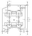
- FIG. 8illustrates a receiver according to another embodiment of the present invention.
- Embodiments of the present inventionprovide a receiver system for an on-off key isolator system.
- the systemmay include a receiver that generates an intermediate current signal based on an OOK input signal.
- the intermediate currentmay be provided at a first current level when the input signal has a first OOK state and a second current level when the input signal has a second OOK state.
- the systemalso may include an output driver to generate a voltage representation of the intermediate current signal. Performing signal processing in a current domain permits fast transitions between OOK states.
- FIG. 1illustrates an isolator system 100 according to an embodiment of the present invention.
- the system 100may include a transmitter 110 , an isolator 120 , a receiver 130 and an output driver 140 .
- the isolator 120may span an isolation boundary 150 , which galvanically isolates two voltage domains from each other.
- the transmitter 110may belong to a first voltage domain, which possesses its own voltage and ground supplies (shown as V DD1 , GND 1 ).
- the receiver 130 and output driver 140may belong to a second voltage domain, which possesses voltage and ground supplies (V DD2 , GND 2 ) separate from the supplies of the first voltage domain.
- the isolation boundary 150may prevent communication of voltages from one domain to the other.
- the system 100may be provided for communication of digital data from the first voltage domain to the second voltage domain by on-off keying (“OOK” for short).
- the transmitter 110may receive an input signal that takes one of two binary voltage levels.
- the transmitter 110may generate an output signal having a state that is determined from the state of the input signal. For example, if the input signal corresponds to a binary value of “1,” the transmitter 110 may generate a periodic signal as its output but, if the input signal corresponds to a binary value of “0,” the transmitter 110 may output an inert signal (no activity). This action of toggling between an active state and an inactive state based on the state of the input signal represents one example of an on-off keyed output.
- the isolator 120may be provided as a micro-transformer (shown in FIG. 1 ), capacitive isolators, magneto-resistive sensors, an optical signal isolator or as Hall effect devices.
- the isolator 120may receive the output from the transmitter 110 in the first voltage domain and pass a received signal to the receiver 130 in the second voltage domain.
- the received signalis illustrated as a copy of the OOK output that the isolator 120 receives from the transmitter 110
- the received signalmay include perturbations (not illustrated) that are induced into the signal by the isolator 120 , for example, shifts in voltage, distortions induced by the isolator's temporal response and noise effects.
- the received signalmay be provided to the receiver 130 as a voltage.
- the receiver 130 and output driver 140may form an OOK receiver system in aggregate.
- the receiver 130may generate a current signal from the OOK signal supplied to it by the isolator 120 .
- the output driver 140may generate a voltage signal from the current signal supplied to it by the receiver 130 .
- the receiver 130 and output driver 140may exchange current domain signals to provide a low latency output in response to OOK signals provided by the isolator 120 .
- FIG. 2illustrates a receiver 200 according to an embodiment of the present invention, which may be employed as a receiver in the system of FIG. 1 .
- the receiver 200may include a current source 210 , two differential pair circuits 220 , 230 and a pair of current mirrors 240 , 250 .
- the differential pair circuits 220 , 230each may include a pair of mismatched transistors 222 , 224 for pair 220 and 232 , 234 for pair 230 .
- the transistors in each pair 220 , 230may be mismatched according to a predetermined sizing ratio, shown as N to 1.
- transistors 222 and 232may be N times larger than their counterpart transistors 224 and 234 .
- the transistors 222 , 232may pass N times more current than the counterpart transistors 224 and 234 .
- the input signal V INmay be a differential signal represented by component signals V INN and V INP .
- Gates of transistors 222 and 234may receive a first input voltage V INP and gates of the other transistors 224 and 232 may receive a second input voltage V INN .
- Sources of the transistors 222 , 224 in the first differential pair 220may be connected to a common node, which may be coupled to a transistor 244 within the current mirror 240 .
- Sources of the transistors 232 , 234 in the second differential pair 230may be connected to a second node, which may be coupled to another transistor 246 within the current mirror 240 .
- Drains of the unit-sized transistors 224 , 234 of the two differential pairs 220 , 230may be connected together and connected to a first transistor 252 in the second current mirror 250 . Drains of the N-sized transistors 222 , 232 of the two differential pairs 220 , 230 may be connected to voltage supplies V DD .
- the first current mirror 240may include a plurality of transistors 242 - 248 whose gates are connected together.
- the first transistor 242may be connected to the current source 210 at its drain.
- the first transistor 242also may be configured in a diode-connected configuration.
- an amount of current that passes through the first transistor 242(which is defined by the current source 210 ) defines the amount of current that passes through the remaining transistors 244 - 248 of the current mirror 240 .
- the transistors 244 - 248may be sized so that twice as much current passes through transistors 244 and 246 as passes through transistor 248 (shown as I B and 1 ⁇ 2I B , respectively).
- the second current mirror 250may include a pair of transistors 252 and 254 .
- a first transistor 252may be connected to the unit-sized transistors 224 and 234 of the differential pairs 220 , 230 .
- the second transistor 254may be connected to the transistor 248 in the first current mirror 240 .
- the first transistor 252may be provided in a diode-connected configuration. Thus, the current that passes through transistor 252 defines an amount of current that passes through transistor 254 .
- An output terminal I OUT of the receiver 200may be provided at the connection between transistors 254 and 248 .
- the transistors 254 and 248perform a current comparison at the output terminal I OUT .
- the transistor 248may sink an amount of current from the output terminal equal to 1 ⁇ 2I B .
- the transistor 254may source an amount of current I SIG to the output terminal in an amount that is determined by the differential pairs 220 , 230 , which in turn is determined by the input signals V INP and V INN .
- I SIG ⁇ 1 ⁇ 2I Ba residual current is either sourced to or sunk from the output terminal I OUT .
- the transistorsare illustrated as MOSFET transistors and, specifically, transistors 222 - 224 , 232 - 234 and 242 - 248 are illustrated as NMOS transistors and transistors 252 - 254 are illustrated as PMOS transistors.
- the principles of the present inventionapply to transistors of other process technologies, such as BJT transistors and the like.
- process typesmay be inverted (e.g., PMOS transistors may be provided where NMOS transistors are illustrated and NMOS transistors may be provided where PMOS transistors are illustrated) with appropriate inversion of supply voltages.
- Such variationsare immaterial to the principles of the present invention unless mentioned herein.
- FIG. 3illustrates exemplary input and output signals that may be processed by the receiver of FIG. 2 .
- the input signals V INP and V INNmay toggle between two phases of operation according to the OOK signal structure of the system.
- the OOK signalIn a first phase of operation, the OOK signal may be in an “OFF” state in which V INP and V INN are inactive signals.
- V INP and V INNeach have voltages of 1 ⁇ 2V DD .
- the OOK signalmay be in an “ON” state in which V INP and V INN are active signals.
- the V INP and V INN signalsoscillate between V DD and ground, centered about 1 ⁇ 2V DD .
- V INP and V INNmay not be full rail signals (e.g., transitioning fully to ground or to V DD ) owing to losses within the circuit system.
- the transistors 222 , 224 , 232 , 234 of the differential pairs 220 , 230may become partially conductive.
- the transistors 222 , 232may source N times as much current to their respective transistors 244 , 246 in the current mirror 240 than the transistors 224 , 234 do.
- the current mirror transistors 244 , 246each govern current through the differential pairs 220 , 230 , limiting the total current through each pair 220 , 230 to I B .
- transistors 224 and 234each pass current in the amount of
- the transistor 252may source the current that passes through the unit-sized transistors 224 , 234 .
- transistor 252may pass current in an amount of
- the I SIG currentmay be compared to the current (1 ⁇ 2I B ) that is drained from the output terminal by transistor 248 .
- the output currentmay be represented as
- I OUT2 N + 1 ⁇ I B - 1 2 ⁇ I B .
- Nsufficiently large (e.g., N ⁇ 10), these equations may simplify to:
- V INP and V INNmay oscillate between V DD and ground. Conductivity of the transistors 222 , 224 , 232 , 234 of the differential pairs 220 , 230 may vary according to these signals.
- V INPWhen V INP is at its maximum level, for example, transistors 222 and 234 may be nearly fully conductive. At this same time, V INN will be at its minimum level, which may render transistors 224 and 232 minimally conductive. Thus, transistors 222 and 234 each may pass nearly all of the current (I B ) that their associated current mirror transistors 244 and 246 sink.
- the current passed by transistor 224may be sourced by transistor 252 in the second current mirror.
- the second transistor 254 in the second current mirror 250may generate a current I SIG at I B .
- transistors 232 and 224may be nearly fully conductive.
- V INPwill be at its minimum level, which may render transistors 222 and 234 minimally conductive.
- transistors 224 and 232each may pass nearly all of the current (I B ) that their associated current mirror transistors 244 and 246 sink.
- the current passed by transistor 234may be sourced by transistor 252 in the second current mirror.
- the second transistor 254 in the second current mirror 250may generate a current I SIG at I B .
- the I SIG currentmay vary in response to the V INP and V INN input signals as shown in FIG. 3 .
- the I SIG currentmay be compared to the 1 ⁇ 2I B current that is sunk from the output terminal by the current mirror transistor 248 .
- the receiver of FIG. 2may generate an output current I OUT having the form illustrated in FIG. 3 .
- FIG. 4illustrates a current comparator 400 according to an embodiment of the present invention.
- the comparator 400may include an inverter 410 , a pair of pulling transistors 420 , 430 , current sources 440 and 450 and one or more inverters 460 .
- the inverter 410may accept a current input I IN on an input terminal.
- the input currentmay be an output current I OUT generated by a receiver such as those described in FIGS. 1, 2, 6 and 8 of this disclosure.
- the input terminal I INalso may be connected to a first supply voltage V DD by a first transistor 420 and to a second supply voltage (shown as ground) by a second transistor 430 .
- Gates of the transistors 420 , 430may be coupled to an output of the inverter 410 .
- the transistors 420 , 430may provide a positive feedback control within the comparator 400 to pull an input signal in the direction of one of the supplies V DD or ground as the input current I IN drives the inverter's input in that direction.
- the inverter 410may be connected to the supply voltages V DD and ground by respective current sources 440 , 450 .
- the current sources 440 , 450may limit responsiveness of the inverter 410 to transitions in the input current signal I IN , which helps to filter signal glitches and other transients that otherwise might by introduced by noise within the system.
- the inverter(s) 460may buffer a voltage output provided by the inverter 410 .
- the inverters 460may include filters or other signal conditioning circuits (not shown) to filter transients from the inverter's output.
- a voltage V OUT output from the inverters 460may be output from the isolator system as a digital output signal.
- FIG. 5illustrates exemplary input and output signals that may be processed by the comparator 400 of FIG. 4 .
- the input current I INis shown as the output current signal I OUT in FIG. 3 .
- the output signal generated from the input current I INis shown as V OUT .
- FIG. 6illustrates a receiver 600 according to another embodiment of the present invention.
- the receiver 600may include a plurality of current sources 610 , 612 , 614 , two differential pair circuits 620 , 630 and a current mirror 640 .
- the current sources 610 and 612may supply currents to an associated differential pair circuit 620 or 630 at a first level I B .
- the current source 614may source current to an output terminal I OUT at a level that is half the level of current sources 610 and 620 (e.g., 1 ⁇ 2I B ).
- the differential pair circuits 620 , 630each may include a pair of mismatched transistors 622 , 624 for differential pair circuit 620 and 632 , 634 for differential pair circuit 630 .
- the transistors in each pair 620 , 630may be mismatched according to a predetermined sizing ratio, shown as N to 1.
- transistors 622 and 632may be N times larger than their counterpart transistors 624 and 634 .
- the transistors 622 , 632may pass N times more current than the counterpart transistors 624 and 634 .
- the input signal V INmay be a differential signal represented by component signals V INN and V INP .
- Gates of transistors 622 and 634may receive a first input voltage V INP and gates of the other transistors 624 and 632 may receive a second input voltage V INN .
- Sources of the transistors 622 , 624 in the first differential pair circuit 620may be connected to a common node, which may be coupled to current source 610 .
- Sources of the transistors 632 , 634 in the second differential pair 630may be connected to a second node, which may be coupled to another current source 620 .
- Drains of the unit-sized transistors 624 , 634 of the two differential pair circuits 620 , 630may be connected together and connected to a first transistor 642 in the second current mirror 640 . Drains of the N-sized transistors 622 , 632 of the two differential pair circuits 620 , 630 may be connected to a voltage supply (ground, in this case).
- the current mirror 640may include a pair of transistors 642 and 644 .
- a first transistor 642may be connected to the unit-sized transistors 624 and 634 of the differential pairs 620 , 630 .
- the second transistor 644may be connected to the current source 614 .
- the first transistor 642may be provided in a diode-connected configuration. Thus, the current that passes through transistor 642 defines an amount of current that passes through transistor 644 .
- An output terminal I OUT of the receiver 600may be provided at the connection between transistors 644 and current source 614 .
- the transistor 644 and current source 614perform a current comparison at the output terminal I OUT .
- the current source 614may source an amount of current to the output terminal equal to 1 ⁇ 2I B .
- the transistor 644may sink an amount of current I SIG from the output terminal I OUT in an amount that is determined by the differential pair circuits 620 , 630 , which in turn is determined by the input signals V INP and V INN .
- I SIG ⁇ 1 ⁇ 2I Ba residual current is either sourced to or sunk from the output terminal I OUT .
- the circuit of FIG. 6may operate in accordance with the principles discussed above with respect to FIG. 3 .
- the transistors 622 - 624 , 632 - 634 of the differential pairs 620 , 630are illustrated as PMOS transistors rather than NMOS transistors as illustrated in FIG. 2 and, therefore, the conductivity of the transistors will be inverted from that of the FIG. 2 circuit during the ON phase.
- the circuit of FIG. 6may generate a signal current I SIG as illustrated in FIG. 3 , which may be compared to the current 1 ⁇ 2I B of the current source 614 to generate the I OUT signal, also illustrated in FIG. 3 .
- FIG. 7illustrates an output driver 700 according to another embodiment of the present invention.
- the output driver 700may include an inverter 710 , a pair of pulling transistors 715 , 720 , a pair of gating transistors 725 , 730 , a pair of current sources 735 , 740 and one or more output inverters 745 .
- An input current signal I INmay be input to an input of the inverter 710 .
- the pulling transistors 715 , 720may couple the input terminal I IN to respective high and low voltage supplies V DD and ground. Gates of the pulling transistors 715 , 720 may be coupled to an output of the inverter 710 .
- the gating transistors 725 and 730 and current sources 735 , 740may be provided in pairs.
- a first transistor-current source pair 725 , 735may provide a second circuit path between the input terminal I IN and the high voltage supply V DD in parallel to a circuit path provided by the first pulling transistor 715 .
- a second transistor-current source pair 730 , 740may provide a circuit path between the input terminal I IN and the low voltage supply (ground) in parallel to a circuit path that is provided by the second pulling transistor 720 .
- the gating transistors and pulling transistorsmay be provided as complementary device types. In the example illustrated in FIG. 7 , the first pulling transistor 715 is illustrated as an NMOS transistor and the first gating transistor 725 is illustrated as a PMOS transistor.
- the second pulling transistor 720is illustrated as a PMOS transistor and the second gating transistor 730 is illustrated as an NMOS transistor.
- a buffer 755may be provided in a circuit path from the inverter output chain to a gate of transistor 715 .
- current sources 735 , 740are illustrated as ideal current sources, their operation may be gated by their associated transistors 725 and 730 . Thus, current source 735 will not supply current when its associated transistor 725 is rendered non-conductive. Similarly, current source 740 will not drive current when its associated transistor 730 is non-conductive. Gates of the gating transistors 725 , 730 may be coupled to a node after one of the inverters 745 . The provision of current sources 735 and 740 adds a hysteresis effect to operation of the output driver 700 which reduces its sensitivity to noise and other short term transients in the input current I IN .
- the output driver 700may include one or more output inverters 745 .
- Two output inverters 745 . 1 , 745 . 2are illustrated in FIG. 7 although different implementations may include other numbers of inverters as may be desired. Increasing the number of inverters may increase the driver's resistance to transients in the input current signal but also may increase the latency of the driver's response to key changes in the input signal.
- an input current I INmay be presented to the inverter 710 , in the form illustrated in FIG. 3 .
- the inverter 710may generate an output voltage at one of two levels, V DD or ground.
- the inverter's outputmay be input to the transistors 715 - 730 .
- the transistor 715may become conductive, which allows the input current to pass to V DD .
- the transistor 715may be sized to weakly pull the input node to V DD as compared to pulls exerted by the inverter 710 .
- the transistor 720When the inverter's output is set to ground, the transistor 720 may become conductive, which allows the input current to pass to ground.
- the transistor 720also may be sized to weakly pull the input node to ground as compared to pulls exerted by the inverter 710 .
- FIG. 8illustrates a receiver circuit 800 according to another embodiment of the present invention.
- the receiver 800may include four differential pair circuits 810 - 840 , several current mirrors 850 - 880 , and a plurality of current sources 890 - 896 .
- the differential pair circuits 810 - 840each may include a pair of mismatched transistors, shown as having a ratio of N to 1.
- Two differential pair circuits 810 , 820may have transistors 812 , 814 , 822 and 824 of a first doping type (NMOS transistors, in the example illustrated in FIG.
- NMOS transistorsa first doping type
- each of the differential pair circuits 810 - 840may be connected to respective current sources 890 - 896 .
- the current mirrors 850 - 880may be arranged to sum currents that pass through the N-sized transistors 812 , 822 , 832 and 842 and those that pass through the unit-sized transistors 814 , 824 , 834 , 844 .
- Current mirror 850may have a first leg, provided by transistor 852 , that is coupled to the unit-sized transistors 814 , 824 of differential pairs 810 and 820 and a second leg, provided by transistor 854 for an output current ISIG N .
- the transistor 852may be provided in a diode-connected configuration. Thus, an amount of current passed by the unit-sized transistors 814 , 824 of the two differential pairs may be output to the second leg of the current mirror, also shown as ISIG N .
- the current mirror 860may have a first leg, provided by transistor 862 , that is coupled to the unit-sized transistors 834 , 844 of differential pairs 830 and 840 and also to the output leg of current mirror 850 .
- a second leg of the current mirror 860provided by transistor 864 , may be coupled to the output terminal I OUT .
- the transistor 862may be provided in a diode-connected configuration.
- the current mirror 860may generate a current signal ISIG representing a sum between ISIG N and the current passed by the unit-sized transistors 834 , 844 of the second pair of differential pair circuits 830 , 840 .
- current mirror 870may have a first leg, provided by transistor 872 , that is coupled to the N-sized transistors 832 , 842 of differential pairs 830 and 840 and a second leg, provided by transistor 874 for an output current IREF p .
- the transistor 874may be provided in a diode-connected configuration.
- an amount of current passed by the N-sized transistors 832 , 842 of the differential pairs 830 and 840may be output to the second leg of the current mirror, also shown as IREF p .
- the current mirror 880may have a first leg, provided by transistor 862 , that is coupled to the N-sized transistors 812 , 824 of differential pairs 810 and 820 and also to the output leg of current mirror 870 .
- a second leg of the current mirror 880provided by transistor 884 , may be coupled to the output terminal I OUT .
- the transistor 882may be provided in a diode-connected configuration.
- the current mirror 880may generate a current signal IREF representing a sum between IREF p and the current passed by the N-sized transistors 812 , 822 of the second pair of differential pair circuits 810 , 820 .
- the transistors 882 , 884 of current mirror 880may be mismatched transistors with transistor 882 being larger than transistor 884 (shown as being M times larger). In such an embodiment, the transistor 882 would pass M times the current that transistor 884 passes. In other words, the current I REF would be to 1/M th the current that passes through the N-sized transistors 812 , 822 , 832 and 842 of the differential pair circuits 810 , 820 , 830 and 840 .
- the output terminal I OUT of the receiver 800may be provided at the connection between transistors 884 and 864 .
- the current mirrors 860 and 880may perform a current comparison at the output terminal I OUT .
- the transistor 864may sink an amount of current I SIG from the output terminal I OUT based on the amount of current sunk by the unit-sized transistors 814 , 824 , 834 , 844 of the differential pair circuits 810 , 820 , 830 and 840 .
- the transistor 884may source an amount of current I REF to the output terminal I OUT based on the amount of current sunk by the N-sized transistors 812 , 822 , 832 and 842 of the differential pair circuits 810 , 820 , 830 and 840 .
- I REFI SIG
- a residual amount of currenteither would be sourced output from the receiver 800 or sunk by the receiver 800 through the I OUT terminal.
- the input signals V INP and V INNmay toggle between two phases of operation according to the OOK signal structure of the system.
- the OOK signalmay be in an “OFF” state in which V INP and V INN are inactive signals.
- V INP and V INNeach may have voltages of 1 ⁇ 2V DD which may render all transistors of the differential pair circuits 810 , 820 , 830 and 840 partially conductive.
- the N-sized transistors 812 , 822 , 832 and 842may induce a reference current through the current mirror 880 as
- I REF4 M ⁇ I B .
- the unit-sized transitors 814 , 824 , 834 , 844may induce a current through the current mirror 860 as
- I SIG4 N ⁇ I B .
- I REFI SIG in the OFF state.
- the OOK signalmay be in an “ON” state in which V INP and V INN are active signals.
- the V INP and V INN signalsmay oscillate between V DD and ground, centered about 1 ⁇ 2V DD . Again, V INP and V INN may not be full rail signals owing to losses within the circuit system.
- Conductivity of the transistors in the differential pair circuits 810 , 820 , 830 and 840may vary according to these signals.
- the N-sized transistors 812 , 822 , 832 and 842may induce a reference current as 4I B , which may be scaled down at the output node as
- I REF4 M ⁇ I B .
- I SIGI REF in the ON state.
- N and Mmay be tuned to suit individual application needs. They should be set so that the current comparison at the output terminal (I OUT ) generates a first detectable state when the OOK signal is in an “OFF” state and another state when the OOK signal is in an “ON” state. Typically, M will be larger than 2.
- FIG. 8provides several advantages over the design shown in, for example, FIG. 2 .
- the receiver 800will remain responsive to input signals at both extremes of an input voltage (V DD and ground).
- Transistors of each typemay be non-responsive when a difference of voltages between their gates and their sources fail to overcome a V GS threshold inherent to those transistors.
- the gate voltagemust exceed the source voltage by the V GS thresholds and, when such transistors connect their sources to ground, the transistors may not be responsive to an input voltage that differs from ground by less than the transistor's V GS threshold.
- the gate voltagemust be less than the source voltage by the V GS threshold and, when such transistors connect their sources to V DD , the transistors may not be responsive to an input voltage that differs from V DD by less than the transistor's V GS threshold.
- the differential pairs of one doping typesay, those having the PMOS transistors
- the differential pairs of the complementary doping typemay continue operation.
- the design of FIG. 8may provide for rail-to-rail operation.
- FIG. 8may conserve resources as compared to the design of FIG. 2 .
- current that passes through the N-sized transistorswas sourced to the supplies (V DD and ground)
- the currents that are used in both the N-sized transistors and the unit-sized transistorsare used to drive their respective current mirrors.
- the FIG. 8 embodimentmay provide for more efficient use of resources.
- the receivers of the foregoing embodimentsmay be used cooperatively with a transmitter 110 that operates in a separate voltage domain that is isolated from a voltage domain of the receiver by an isolation boundary 150 .
- Exemplary transmittersare illustrated in a co-pending application, filed on even date herewith, entitled “Methods and Structures to Generate On/Off Keyed Carrier Signals for Signal Isolators,” Ser. No. 14/486,937, the disclosure of which is incorporated herein by reference.
Landscapes
- Engineering & Computer Science (AREA)
- Computer Networks & Wireless Communication (AREA)
- Signal Processing (AREA)
- Physics & Mathematics (AREA)
- Nonlinear Science (AREA)
- Power Engineering (AREA)
- Logic Circuits (AREA)
- Amplifiers (AREA)
- Electronic Switches (AREA)
Abstract
Description
The present invention relates to signal isolators and, particularly, signal isolators that operate according to an on-off keyed signal protocol.
Isolators are devices that exchange data signals between two galvanically isolated circuit systems. The two circuit systems each operate in different voltage domains, which may include different supply voltages and different ground references. Isolation devices may provide data exchange across an isolation barrier, which maintains the galvanic isolation. Typical isolation devices include micro-transformers, capacitors, magneto-resistors/giant magneto-resistors and opto-electronic devices.
On-off keying (“OOK”) is a signaling protocol that identifies a digital state of input data based on the type of signal that is transmitted through the isolation barrier. A first digital data state (say, a digital “1”) might be signaled by transmitting a periodic signal across the isolation barrier. A second digital data state (a digital “0”) might be signaled by transmitting no signal across the isolation barrier. A receiver circuit would detect the presence or absence of the periodic signal and decode a digital output signal therefrom.
OOK-based signal isolators typically have inefficient designs. For example, isolator receivers may include a multiplier (or mixer) and an integrator as an energy detector for OOK demodulation. A mixer, however, has a limited ability to handle common mode noise. Integrators typically are very slow for applications that require high data rate transmission across the isolation barrier.
Accordingly, the inventors perceive a need in the art for an improved receiver that provides improved speed and improved noise immunity.
Embodiments of the present invention provide a receiver system for an on-off key isolator system. The system may include a receiver that generates an intermediate current signal based on an OOK input signal. The intermediate current may be provided at a first current level when the input signal has a first OOK state and a second current level when the input signal has a second OOK state. The system also may include an output driver to generate a voltage representation of the intermediate current signal. Performing signal processing in a current domain permits fast transitions between OOK states.
Thesystem 100 may be provided for communication of digital data from the first voltage domain to the second voltage domain by on-off keying (“OOK” for short). In such an embodiment, thetransmitter 110 may receive an input signal that takes one of two binary voltage levels. Thetransmitter 110 may generate an output signal having a state that is determined from the state of the input signal. For example, if the input signal corresponds to a binary value of “1,” thetransmitter 110 may generate a periodic signal as its output but, if the input signal corresponds to a binary value of “0,” thetransmitter 110 may output an inert signal (no activity). This action of toggling between an active state and an inactive state based on the state of the input signal represents one example of an on-off keyed output.
Theisolator 120 may be provided as a micro-transformer (shown inFIG. 1 ), capacitive isolators, magneto-resistive sensors, an optical signal isolator or as Hall effect devices. Theisolator 120 may receive the output from thetransmitter 110 in the first voltage domain and pass a received signal to thereceiver 130 in the second voltage domain. Although the received signal is illustrated as a copy of the OOK output that theisolator 120 receives from thetransmitter 110, the received signal may include perturbations (not illustrated) that are induced into the signal by theisolator 120, for example, shifts in voltage, distortions induced by the isolator's temporal response and noise effects. The received signal may be provided to thereceiver 130 as a voltage.
Thereceiver 130 andoutput driver 140 may form an OOK receiver system in aggregate. Thereceiver 130 may generate a current signal from the OOK signal supplied to it by theisolator 120. Theoutput driver 140 may generate a voltage signal from the current signal supplied to it by thereceiver 130. In an embodiment, thereceiver 130 andoutput driver 140 may exchange current domain signals to provide a low latency output in response to OOK signals provided by theisolator 120.
Thedifferential pair circuits mismatched transistors pair pair 230. The transistors in eachpair transistors counterpart transistors transistors counterpart transistors
The input signal VINmay be a differential signal represented by component signals VINNand VINP. Gates oftransistors other transistors transistors differential pair 220 may be connected to a common node, which may be coupled to atransistor 244 within thecurrent mirror 240. Sources of thetransistors differential pair 230 may be connected to a second node, which may be coupled to anothertransistor 246 within thecurrent mirror 240. Drains of the unit-sizedtransistors differential pairs first transistor 252 in the second current mirror250. Drains of the N-sizedtransistors differential pairs
The firstcurrent mirror 240 may include a plurality of transistors242-248 whose gates are connected together. Thefirst transistor 242 may be connected to thecurrent source 210 at its drain. Thefirst transistor 242 also may be configured in a diode-connected configuration. Thus, an amount of current that passes through the first transistor242 (which is defined by the current source210) defines the amount of current that passes through the remaining transistors244-248 of thecurrent mirror 240. The transistors244-248 may be sized so that twice as much current passes throughtransistors
The second current mirror250 may include a pair oftransistors first transistor 252 may be connected to the unit-sized transistors second transistor 254 may be connected to thetransistor 248 in the firstcurrent mirror 240. Thefirst transistor 252 may be provided in a diode-connected configuration. Thus, the current that passes throughtransistor 252 defines an amount of current that passes throughtransistor 254.
An output terminal IOUTof thereceiver 200 may be provided at the connection betweentransistors transistors transistor 248 may sink an amount of current from the output terminal equal to ½IB. Thetransistor 254 may source an amount of current ISIGto the output terminal in an amount that is determined by the differential pairs220,230, which in turn is determined by the input signals VINPand VINN. When ISIG≠½IB, a residual current is either sourced to or sunk from the output terminal IOUT.
In the embodiment illustrated inFIG. 2 , the transistors are illustrated as MOSFET transistors and, specifically, transistors222-224,232-234 and242-248 are illustrated as NMOS transistors and transistors252-254 are illustrated as PMOS transistors. The principles of the present invention apply to transistors of other process technologies, such as BJT transistors and the like. Moreover, as discussed hereinbelow, process types may be inverted (e.g., PMOS transistors may be provided where NMOS transistors are illustrated and NMOS transistors may be provided where PMOS transistors are illustrated) with appropriate inversion of supply voltages. Such variations are immaterial to the principles of the present invention unless mentioned herein.
During the OFF state, when VINPand VINNare set to ½VDD, thetransistors transistors respective transistors current mirror 240 than thetransistors current mirror transistors pair transistors
and the
In the second current mirror250, thetransistor 252 may source the current that passes through the unit-sized transistors transistor 252 may pass current in an amount of
This current may be replicated in
The ISIGcurrent may be compared to the current (½IB) that is drained from the output terminal by
When N is sufficiently large (e.g., N≥10), these equations may simplify to:
During the ON state, VINPand VINNmay oscillate between VDDand ground. Conductivity of thetransistors transistors transistors transistors current mirror transistors transistor 224 may be sourced bytransistor 252 in the second current mirror. Thus, thesecond transistor 254 in the second current mirror250 may generate a current ISIGat IB.
Similarly, when VINNis at its maximum level, for example, thentransistors transistors transistors current mirror transistors transistor 234 may be sourced bytransistor 252 in the second current mirror. Thus, thesecond transistor 254 in the second current mirror250 may generate a current ISIGat IB.
Overall, during the ON phase, the ISIGcurrent may vary in response to the VINPand VINNinput signals as shown inFIG. 3 . The ISIGcurrent may be compared to the ½IBcurrent that is sunk from the output terminal by thecurrent mirror transistor 248. Thus, the receiver ofFIG. 2 may generate an output current IOUThaving the form illustrated inFIG. 3 .
The input terminal IINalso may be connected to a first supply voltage VDDby afirst transistor 420 and to a second supply voltage (shown as ground) by asecond transistor 430. Gates of thetransistors inverter 410. Thetransistors comparator 400 to pull an input signal in the direction of one of the supplies VDDor ground as the input current IINdrives the inverter's input in that direction.
Theinverter 410 may be connected to the supply voltages VDDand ground by respectivecurrent sources current sources inverter 410 to transitions in the input current signal IIN, which helps to filter signal glitches and other transients that otherwise might by introduced by noise within the system.
The inverter(s)460 may buffer a voltage output provided by theinverter 410. Theinverters 460 may include filters or other signal conditioning circuits (not shown) to filter transients from the inverter's output. A voltage VOUToutput from theinverters 460 may be output from the isolator system as a digital output signal.
Thedifferential pair circuits 620,630 each may include a pair ofmismatched transistors 622,624 fordifferential pair circuit differential pair circuit 630. The transistors in eachpair 620,630 may be mismatched according to a predetermined sizing ratio, shown as N to 1. Thus,transistors 622 and632 may be N times larger than theircounterpart transistors transistors 622,632 may pass N times more current than thecounterpart transistors
The input signal VINmay be a differential signal represented by component signals VINNand VINP. Gates oftransistors 622 and634 may receive a first input voltage VINPand gates of theother transistors transistors 622,624 in the first differential pair circuit620 may be connected to a common node, which may be coupled tocurrent source 610. Sources of thetransistors differential pair 630 may be connected to a second node, which may be coupled to another current source620. Drains of the unit-sized transistors differential pair circuits 620,630 may be connected together and connected to afirst transistor 642 in the secondcurrent mirror 640. Drains of the N-sized transistors 622,632 of the twodifferential pair circuits 620,630 may be connected to a voltage supply (ground, in this case).
Thecurrent mirror 640 may include a pair oftransistors first transistor 642 may be connected to the unit-sized transistors second transistor 644 may be connected to thecurrent source 614. Thefirst transistor 642 may be provided in a diode-connected configuration. Thus, the current that passes throughtransistor 642 defines an amount of current that passes throughtransistor 644.
An output terminal IOUTof thereceiver 600 may be provided at the connection betweentransistors 644 andcurrent source 614. During operation, thetransistor 644 andcurrent source 614 perform a current comparison at the output terminal IOUT. Thecurrent source 614 may source an amount of current to the output terminal equal to ½IB. Thetransistor 644 may sink an amount of current ISIGfrom the output terminal IOUTin an amount that is determined by thedifferential pair circuits 620,630, which in turn is determined by the input signals VINPand VINN. When ISIG≠½IB, a residual current is either sourced to or sunk from the output terminal IOUT.
The circuit ofFIG. 6 may operate in accordance with the principles discussed above with respect toFIG. 3 . Here, the transistors622-624,632-634 of the differential pairs620,630 are illustrated as PMOS transistors rather than NMOS transistors as illustrated inFIG. 2 and, therefore, the conductivity of the transistors will be inverted from that of theFIG. 2 circuit during the ON phase. Nevertheless, the circuit ofFIG. 6 may generate a signal current ISIGas illustrated inFIG. 3 , which may be compared to the current ½IBof thecurrent source 614 to generate the IOUTsignal, also illustrated inFIG. 3 .
The pullingtransistors transistors inverter 710.
Thegating transistors current sources current source pair transistor 715. A second transistor-current source pair transistor 720. The gating transistors and pulling transistors may be provided as complementary device types. In the example illustrated inFIG. 7 , the first pullingtransistor 715 is illustrated as an NMOS transistor and thefirst gating transistor 725 is illustrated as a PMOS transistor. Further, the second pullingtransistor 720 is illustrated as a PMOS transistor and thesecond gating transistor 730 is illustrated as an NMOS transistor. Optionally, abuffer 755 may be provided in a circuit path from the inverter output chain to a gate oftransistor 715.
Although thecurrent sources transistors current source 735 will not supply current when its associatedtransistor 725 is rendered non-conductive. Similarly,current source 740 will not drive current when its associatedtransistor 730 is non-conductive. Gates of thegating transistors inverters 745. The provision ofcurrent sources output driver 700 which reduces its sensitivity to noise and other short term transients in the input current IIN.
Theoutput driver 700 may include one ormore output inverters 745. Two output inverters745.1,745.2 are illustrated inFIG. 7 although different implementations may include other numbers of inverters as may be desired. Increasing the number of inverters may increase the driver's resistance to transients in the input current signal but also may increase the latency of the driver's response to key changes in the input signal.
During operation, an input current IINmay be presented to theinverter 710, in the form illustrated inFIG. 3 . Responsive to the input voltage, theinverter 710 may generate an output voltage at one of two levels, VDDor ground. The inverter's output may be input to the transistors715-730. When the inverter's output is set to VDD, thetransistor 715 may become conductive, which allows the input current to pass to VDD. Thetransistor 715 may be sized to weakly pull the input node to VDDas compared to pulls exerted by theinverter 710. When the inverter's output is set to ground, thetransistor 720 may become conductive, which allows the input current to pass to ground. Thetransistor 720 also may be sized to weakly pull the input node to ground as compared to pulls exerted by theinverter 710.
The current mirrors850-880 may be arranged to sum currents that pass through the N-sized transistors sized transistors Current mirror 850, for example, may have a first leg, provided bytransistor 852, that is coupled to the unit-sized transistors differential pairs transistor 854 for an output current ISIGN. Thetransistor 852 may be provided in a diode-connected configuration. Thus, an amount of current passed by the unit-sized transistors
Thecurrent mirror 860 may have a first leg, provided bytransistor 862, that is coupled to the unit-sized transistors differential pairs current mirror 850. A second leg of thecurrent mirror 860, provided bytransistor 864, may be coupled to the output terminal IOUT. Thetransistor 862 may be provided in a diode-connected configuration. Thus, thecurrent mirror 860 may generate a current signal ISIG representing a sum between ISIGNand the current passed by the unit-sized transistors differential pair circuits
Similarly,current mirror 870 may have a first leg, provided bytransistor 872, that is coupled to the N-sized transistors differential pairs transistor 874 for an output current IREFp. Thetransistor 874 may be provided in a diode-connected configuration. Thus, an amount of current passed by the N-sized transistors
Thecurrent mirror 880 may have a first leg, provided bytransistor 862, that is coupled to the N-sized transistors differential pairs current mirror 870. A second leg of thecurrent mirror 880, provided bytransistor 884, may be coupled to the output terminal IOUT. Thetransistor 882 may be provided in a diode-connected configuration. Thus, thecurrent mirror 880 may generate a current signal IREF representing a sum between IREFpand the current passed by the N-sized transistors differential pair circuits
In an embodiment, thetransistors current mirror 880 may be mismatched transistors withtransistor 882 being larger than transistor884 (shown as being M times larger). In such an embodiment, thetransistor 882 would pass M times the current thattransistor 884 passes. In other words, the current IREFwould be to 1/Mththe current that passes through the N-sized transistors differential pair circuits
The output terminal IOUTof thereceiver 800 may be provided at the connection betweentransistors current mirrors transistor 864 may sink an amount of current ISIGfrom the output terminal IOUTbased on the amount of current sunk by the unit-sized transistors differential pair circuits transistor 884 may source an amount of current IREFto the output terminal IOUTbased on the amount of current sunk by the N-sized transistors differential pair circuits receiver 800 or sunk by thereceiver 800 through the IOUTterminal.
During operation, the input signals VINPand VINNmay toggle between two phases of operation according to the OOK signal structure of the system. In a first phase of operation, the OOK signal may be in an “OFF” state in which VINPand VINNare inactive signals. During this time, VINPand VINNeach may have voltages of ½VDDwhich may render all transistors of thedifferential pair circuits sized transistors current mirror 880 as
The unit-
When N>M, then IREF>ISIGin the OFF state.
In the second phase of operation, the OOK signal may be in an “ON” state in which VINPand VINNare active signals. The VINPand VINNsignals may oscillate between VDDand ground, centered about ½VDD. Again, VINPand VINNmay not be full rail signals owing to losses within the circuit system. Conductivity of the transistors in thedifferential pair circuits sized transistors
The unit-
The parameters of N and M may be tuned to suit individual application needs. They should be set so that the current comparison at the output terminal (IOUT) generates a first detectable state when the OOK signal is in an “OFF” state and another state when the OOK signal is in an “ON” state. Typically, M will be larger than 2.
The embodiment ofFIG. 8 provides several advantages over the design shown in, for example,FIG. 2 . First, by providing differential pair circuits of two process types (e.g., both PMOS and NMOS), thereceiver 800 will remain responsive to input signals at both extremes of an input voltage (VDDand ground). Transistors of each type may be non-responsive when a difference of voltages between their gates and their sources fail to overcome a VGSthreshold inherent to those transistors. For NMOS transistors, the gate voltage must exceed the source voltage by the VGSthresholds and, when such transistors connect their sources to ground, the transistors may not be responsive to an input voltage that differs from ground by less than the transistor's VGSthreshold. Similarly, for PMOS transistors, the gate voltage must be less than the source voltage by the VGSthreshold and, when such transistors connect their sources to VDD, the transistors may not be responsive to an input voltage that differs from VDDby less than the transistor's VGSthreshold. In the circuit ofFIG. 8 , however, if the differential pairs of one doping type (say, those having the PMOS transistors) are non-responsive, the differential pairs of the complementary doping type may continue operation. Thus, the design ofFIG. 8 may provide for rail-to-rail operation.
Further, the design ofFIG. 8 may conserve resources as compared to the design ofFIG. 2 . Whereas, in theFIG. 2 embodiment, current that passes through the N-sized transistors was sourced to the supplies (VDDand ground), in theFIG. 8 embodiment the currents that are used in both the N-sized transistors and the unit-sized transistors are used to drive their respective current mirrors. Thus, theFIG. 8 embodiment may provide for more efficient use of resources.
As illustrated inFIG. 1 , the receivers of the foregoing embodiments may be used cooperatively with atransmitter 110 that operates in a separate voltage domain that is isolated from a voltage domain of the receiver by anisolation boundary 150. Exemplary transmitters are illustrated in a co-pending application, filed on even date herewith, entitled “Methods and Structures to Generate On/Off Keyed Carrier Signals for Signal Isolators,” Ser. No. 14/486,937, the disclosure of which is incorporated herein by reference.
The foregoing description has presented a receiver circuit for an on-off keyed signal isolator that provides fast transitions between ON and OFF states. Although the foregoing embodiments have illustrated the transmitter in the context of exemplary operations and signal protocols, the principles of the present invention are not limited to the embodiments described. For example, while MOS transistors have been illustrated herein, the principles of the present invention find application with other process technologies, for example, bipolar junction transistors and junction field effect transistors.
Several embodiments of the invention are specifically illustrated and/or described herein. However, it will be appreciated that modifications and variations of the invention are covered by the above teachings and within the purview of the appended claims without departing from the spirit and intended scope of the invention. Further variations are permissible that are consistent with the principles described above.
Claims (25)
1. An on-off key (“OOK”) receiver system, comprising:
an isolator having a first side and a second side;
a receiver, coupled to the second side of the isolator, configured to, responsive to an OOK voltage input signal, generate a current signal based on the input signal, the current signal comprising a first current level when the input signal has a first OOK state and a second current level different than the first current level when the input signal has a second OOK state different than the first OOK state, and
an output driver configured to generate a voltage representation of the current signal.
2. The system ofclaim 1 , wherein the receiver comprises:
a pair of first and second mismatched differential pair circuits having inputs for a differential input signal, each differential pair circuit comprising a pair of transistors one of which is smaller than the other,
a current mirror having a pair of current paths, a first current path coupled to the smaller transistors of the two differential pair circuits and a second current path coupled to an output terminal of the receiver, and
a plurality of current sources, a first current source coupled to the first differential pair circuit, a second current source coupled to the second differential pair circuit and a third current source coupled to the output terminal.
3. The system ofclaim 1 , wherein the receiver comprises:
two pairs of mismatched differential pair circuits having inputs for a differential input signal, each differential pair circuit comprising a pair of transistors one of which is smaller than the other, wherein a device type of transistors in a first two of the differential pair circuits are complementary to a device type of transistors in the other two of the differential pair circuits,
a current mirror having a pair of current paths, a first current path coupled to the smaller transistors of the four differential pair circuits and a second current path coupled to an output terminal of the receiver,
current sources coupled to each of the differential pair circuits, and
an additional current source coupled to the output terminal.
4. The system ofclaim 1 , wherein the output driver comprises an inverter.
5. The system ofclaim 1 , wherein the output driver comprises:
an inverter and
means for applying positive feedback to an input of the output driver.
6. The system ofclaim 1 , wherein the output driver comprises a plurality of inverters in cascade.
7. The system ofclaim 1 , wherein the output driver comprises a current-limited inverter.
8. The system ofclaim 1 , wherein the output driver comprises
an inverter, and
a filter coupled to an output of the inverter.
9. An on-off key (“OOK”) receiver system, comprising:
a pair of current sources,
a pair of current routers, each coupled to a respective current source of the pair of current sources, the current routers having a first conductivity pathway and a second conductivity pathway of lower conductivity than the first conductivity pathway, the first conductivity pathway of a first current router and the second conductivity pathway of a second current router having control inputs coupled to a first differential signal representing an OOK input signal and the first conductivity pathway of the second current router and the second conductivity pathway of the first current router having control inputs coupled to a second differential signal representing the OOK input signal,
a current output system to generate a current signal representing an aggregate amount of current passing through second conductivity pathways of the current routers; and
an output driver to generate a voltage representation of the current signal.
10. The system ofclaim 9 , wherein the current routers comprise a differential pair of transistors having mismatched sizes.
11. The system ofclaim 9 , wherein the output driver comprises an inverter.
12. The system ofclaim 9 , wherein the output driver comprises:
an inverter and
means for applying positive feedback to an input of the output driver.
13. The system ofclaim 9 , wherein the output driver comprises a plurality of inverters in cascade.
14. The system ofclaim 9 , wherein the output driver comprises a current-limited inverter.
15. The system ofclaim 9 , wherein the output driver comprises
an inverter, and
a filter coupled to an output of the inverter.
16. An on-off key (“OOK”) receiver system, comprising:
a pair of current mirrors, each having first and second legs, first legs of the two current mirrors coupled to an intermediate output node;
four differential pair circuits, each comprising a pair of mismatched transistors coupled to a respective current source, the transistors of the first two differential pair circuits having a different doping type than the transistors of the second two differential pair circuits, wherein
a larger transistor of each differential pair circuit is coupled to a second leg a first current mirror of the pair of current mirrors, and
a smaller transistor of each differential pair circuit is coupled to a second leg of a second current mirror of the pair of current mirrors; and
an output driver to generate an output voltage based on a current present at the intermediate output node.
17. The system ofclaim 16 , wherein the output driver comprises an inverter.
18. The system ofclaim 16 , wherein the output driver comprises:
an inverter, and
means for applying positive feedback to an input of the output driver.
19. The system ofclaim 16 , wherein the output driver comprises a plurality of inverters in cascade.
20. The system ofclaim 16 , wherein the output driver comprises a current-limited inverter.
21. The system ofclaim 16 , wherein the output driver comprises
an inverter, and
a filter coupled to an output of the inverter.
22. A method of generating a digital voltage signal representing a differential on-off keyed input signal, comprising:
generating a current signal from an on-off key (OOK) signal received by an isolator device,
comparing the current signal to a reference current signal, and
generating a binary voltage signal having a value dependent on a result of the comparison of the current signal to the reference current signal.
23. The method ofclaim 22 , wherein generating the current signal comprises using a plurality of voltage comparison circuits having complementary transistor types.
24. The method ofclaim 22 , wherein generating the current signal comprises using a plurality of mismatched voltage comparison circuits to steer current based on whether the OOK signal is in an ON or OFF stage.
25. The method ofclaim 22 , wherein the current signal is generated by:
routing a first instance of a predetermined amount of current between a first high permittivity current path and a first low permittivity current path in response to the input signal where, when the input signal is at a common mode level, a larger share of current passes through the first high permittivity current path than the first low permittivity current path but when the input signal is at a first limit, a larger share of the current passes through the first low permittivity current path than the first high permittivity current path,
routing a second instance of a predetermined amount of current between a second high permittivity current path and a second low permittivity current path in response to the input signal wherein, when the input signal is at a common mode level, a larger share of current passes through the second high permittivity current path than the second low permittivity current path but when the input signal is at a second limit, a larger share of the current passes through the second low permittivity current path than the second high permittivity current path, and
aggregating currents passed through the two low permittivity current paths.
Priority Applications (6)
| Application Number | Priority Date | Filing Date | Title |
|---|---|---|---|
| US14/486,951US10270630B2 (en) | 2014-09-15 | 2014-09-15 | Demodulation of on-off-key modulated signals in signal isolator systems |
| EP20160893.2AEP3683964B1 (en) | 2014-09-15 | 2015-09-04 | Methods and structures to generate on/off keyed carrier signals for signal isolators |
| EP15183914.9AEP2996247B1 (en) | 2014-09-15 | 2015-09-04 | Demodulation of on-off-key modulated signals in signal isolator systems |
| EP15183918.0AEP2996246B1 (en) | 2014-09-15 | 2015-09-04 | Methods and structures to generate on/off keyed carrier signals for signal isolators |
| CN201510581650.4ACN105429624B (en) | 2014-09-15 | 2015-09-14 | The demodulation of on & off switch modulated signal in signal isolator system |
| US14/883,342US10536309B2 (en) | 2014-09-15 | 2015-10-14 | Demodulation of on-off-key modulated signals in signal isolator systems |
Applications Claiming Priority (1)
| Application Number | Priority Date | Filing Date | Title |
|---|---|---|---|
| US14/486,951US10270630B2 (en) | 2014-09-15 | 2014-09-15 | Demodulation of on-off-key modulated signals in signal isolator systems |
Related Child Applications (1)
| Application Number | Title | Priority Date | Filing Date |
|---|---|---|---|
| US14/883,342Continuation-In-PartUS10536309B2 (en) | 2014-09-15 | 2015-10-14 | Demodulation of on-off-key modulated signals in signal isolator systems |
Publications (2)
| Publication Number | Publication Date |
|---|---|
| US20160080182A1 US20160080182A1 (en) | 2016-03-17 |
| US10270630B2true US10270630B2 (en) | 2019-04-23 |
Family
ID=54150239
Family Applications (1)
| Application Number | Title | Priority Date | Filing Date |
|---|---|---|---|
| US14/486,951ActiveUS10270630B2 (en) | 2014-09-15 | 2014-09-15 | Demodulation of on-off-key modulated signals in signal isolator systems |
Country Status (3)
| Country | Link |
|---|---|
| US (1) | US10270630B2 (en) |
| EP (1) | EP2996247B1 (en) |
| CN (1) | CN105429624B (en) |
Cited By (5)
| Publication number | Priority date | Publication date | Assignee | Title |
|---|---|---|---|---|
| US10833653B1 (en) | 2019-09-23 | 2020-11-10 | International Business Machines Corporation | Voltage sensitive delay |
| US11152920B2 (en)* | 2019-09-23 | 2021-10-19 | International Business Machines Corporation | Voltage starved passgate with IR drop |
| US11204635B2 (en) | 2019-09-23 | 2021-12-21 | International Business Machines Corporation | Droop detection using power supply sensitive delay |
| US11281249B2 (en) | 2019-09-23 | 2022-03-22 | International Business Machines Corporation | Voltage sensitive current circuit |
| US12348342B2 (en) | 2022-10-31 | 2025-07-01 | Kabushiki Kaisha Toshiba | Communication device |
Families Citing this family (8)
| Publication number | Priority date | Publication date | Assignee | Title |
|---|---|---|---|---|
| US10270630B2 (en)* | 2014-09-15 | 2019-04-23 | Analog Devices, Inc. | Demodulation of on-off-key modulated signals in signal isolator systems |
| US10536309B2 (en)* | 2014-09-15 | 2020-01-14 | Analog Devices, Inc. | Demodulation of on-off-key modulated signals in signal isolator systems |
| JP6773902B2 (en) | 2016-10-13 | 2020-10-21 | アナログ・ディヴァイシス・グローバル・アンリミテッド・カンパニー | Systems and methods for transmitting power across insulation barriers |
| DE102018204782A1 (en) | 2018-03-28 | 2019-10-02 | Robert Bosch Gmbh | Detector circuit and system for galvanically isolated transmission of digital signals |
| US11018660B2 (en) | 2018-09-07 | 2021-05-25 | Analog Devices Global Unlimited Company | Multi-mode feedback control through digital isolator |
| US11533027B2 (en) | 2019-10-18 | 2022-12-20 | Analog Devices, Inc. | Low power receiver circuit for isolated data communications |
| CN111817709B (en)* | 2020-09-04 | 2020-12-15 | 上海川土微电子有限公司 | A digital isolator circuit and digital isolator based on Efficient-OOK |
| TWI737529B (en)* | 2020-10-30 | 2021-08-21 | 精拓科技股份有限公司 | Digital isolator |
Citations (321)
| Publication number | Priority date | Publication date | Assignee | Title |
|---|---|---|---|---|
| US3058078A (en) | 1956-02-21 | 1962-10-09 | Siegfried R Hoh | Low capacitance transformer |
| US3537022A (en) | 1968-01-10 | 1970-10-27 | Hewlett Packard Co | Signal translating circuit |
| US3714540A (en) | 1970-11-10 | 1973-01-30 | Oxy Metal Finishing Corp | Isolation and transforming circuit |
| US3760198A (en) | 1970-11-06 | 1973-09-18 | Yokogawa Electric Works Ltd | Circuitry for transmitting pulses with ground isolation but without pulse waveform distortion |
| US3798608A (en) | 1972-12-15 | 1974-03-19 | Johnson Service Co | Digital signal transmission apparatus |
| US3808673A (en) | 1971-03-17 | 1974-05-07 | Monsanto Co | Opto-isolator devices and method for the fabrication thereof |
| DE2529296A1 (en) | 1975-07-01 | 1977-01-20 | Ferranti Ltd | Isolating transformer used as pulse transformer - is for use with high speed pulses and has two annular cores covered in windings |
| US4024452A (en) | 1976-03-10 | 1977-05-17 | Bell Telephone Laboratories, Incorporated | Integrated solid state isolator circuit |
| US4027152A (en)* | 1975-11-28 | 1977-05-31 | Hewlett-Packard Company | Apparatus and method for transmitting binary-coded information |
| US4035710A (en) | 1975-10-20 | 1977-07-12 | International Business Machines Corporation | Pulse width modulated voltage regulator-converter/power converter having means for improving the static stability characteristics thereof |
| US4065713A (en) | 1974-09-13 | 1977-12-27 | Nixdorf Computer Ag | Voltage stabilizer |
| US4118603A (en) | 1977-05-31 | 1978-10-03 | Noramco, Inc. | DC signaling circuit for use in conjunction with isolation transformers |
| US4159431A (en) | 1977-02-18 | 1979-06-26 | Robert Bosch Gmbh | Electronic switch maintaining a predetermined state independent of supply voltage variation |
| US4227045A (en) | 1978-06-28 | 1980-10-07 | Honeywell Inc. | Data processing protocol system |
| WO1981000658A1 (en) | 1979-08-31 | 1981-03-05 | Electro Med Eng Pty Ltd | Telephone line data isolator |
| US4275404A (en) | 1979-10-05 | 1981-06-23 | Bell Telephone Laboratories, Incorporated | Monolithic opto-isolator |
| US4302807A (en) | 1980-08-04 | 1981-11-24 | Burroughs Corporation | Controlled current base drive circuit |
| US4318170A (en) | 1981-01-12 | 1982-03-02 | Cabalfin Rolando V | Power inverter oscillator circuit |
| US4321487A (en) | 1980-04-07 | 1982-03-23 | Reliance Electric Company | Common mode rejection coupler |
| JPS57132460A (en) | 1981-02-10 | 1982-08-16 | Yokogawa Hokushin Electric Corp | Insulation system |
| US4352998A (en) | 1980-04-07 | 1982-10-05 | Reliance Electric Company | Common mode rejection coupler |
| US4415820A (en) | 1980-03-19 | 1983-11-15 | Willi Studer, Fabrik Fuer Elektronische Apparate | Transistor differential circuit with exponential transfer characteristic |
| JPS58215833A (en) | 1982-06-10 | 1983-12-15 | Yamatake Honeywell Co Ltd | magnetic signal transmission device |
| US4443839A (en) | 1980-12-23 | 1984-04-17 | Tokyo Shibaura Denki Kabushiki Kaisha | Single ended, separately driven, resonant DC-DC converter |
| US4475149A (en) | 1982-09-13 | 1984-10-02 | Venus Scientific Inc. | Resonant current-driven power source |
| US4538136A (en) | 1981-03-30 | 1985-08-27 | Amtel Systems Corporation | Power line communication system utilizing a local oscillator |
| US4547961A (en) | 1980-11-14 | 1985-10-22 | Analog Devices, Incorporated | Method of manufacture of miniaturized transformer |
| US4554462A (en) | 1982-03-16 | 1985-11-19 | Fanuc Limited | Non-polarized contactless relay |
| US4564768A (en) | 1982-04-27 | 1986-01-14 | Fanuc Ltd. | Contactless relay |
| GB2173956A (en) | 1985-03-29 | 1986-10-22 | Plessey Co Plc | Integrated electrical transformer |
| US4660014A (en) | 1985-06-19 | 1987-04-21 | Jaycor | Electromagnetic pulse isolation transformer |
| US4703283A (en) | 1986-02-24 | 1987-10-27 | Howard Samuels | Isolation amplifier with T-type modulator |
| US4712170A (en) | 1985-04-25 | 1987-12-08 | Power Modifications Incorporated | Power supply having tuned radio frequency circuit |
| US4720667A (en) | 1986-06-20 | 1988-01-19 | Lee Fred C | Zero-current switching quasi-resonant converters operating in a full-wave mode |
| US4737851A (en) | 1987-04-24 | 1988-04-12 | Rca Corporation | On/off control circuitry for television |
| US4748419A (en) | 1986-04-28 | 1988-05-31 | Burr-Brown Corporation | Isolation amplifier with precise timing of signals coupled across isolation barrier |
| EP0282102A2 (en) | 1987-03-12 | 1988-09-14 | The Boeing Company | Binary data communication system |
| US4780795A (en) | 1986-04-28 | 1988-10-25 | Burr-Brown Corporation | Packages for hybrid integrated circuit high voltage isolation amplifiers and method of manufacture |
| US4785345A (en) | 1986-05-08 | 1988-11-15 | American Telephone And Telegraph Co., At&T Bell Labs. | Integrated transformer structure with primary winding in substrate |
| EP0307345A1 (en) | 1987-09-11 | 1989-03-15 | Siemens Aktiengesellschaft | Circuit arrangement for the transmission of pulses between two galvanically separated circuits |
| US4818855A (en) | 1985-01-11 | 1989-04-04 | Indala Corporation | Identification system |
| US4817865A (en) | 1988-03-17 | 1989-04-04 | Racal Data Communications Inc. | Ventilation system for modular electronic housing |
| US4835486A (en) | 1986-04-28 | 1989-05-30 | Burr-Brown Corporation | Isolation amplifier with precise timing of signals coupled across isolation barrier |
| US4845466A (en) | 1987-08-17 | 1989-07-04 | Signetics Corporation | System for high speed digital transmission in repetitive noise environment |
| US4859877A (en) | 1988-01-04 | 1989-08-22 | Gte Laboratories Incorporated | Bidirectional digital signal transmission system |
| US4864589A (en) | 1985-07-24 | 1989-09-05 | Nec Home Electronics Ltd. | Spread spectrum power line communications |
| US4879505A (en) | 1986-12-23 | 1989-11-07 | Analog Devices, Inc. | Temperature and power supply compensation circuit for integrated circuits |
| US4885582A (en) | 1987-09-28 | 1989-12-05 | The Grass Valley Group, Inc. | "Simple code" encoder/decoder |
| US4899152A (en) | 1986-12-23 | 1990-02-06 | Analog Devices, Inc. | Method and apparatus for temperature compensating a digital to analog converter |
| US4912617A (en) | 1987-09-19 | 1990-03-27 | Deutsche Thomson-Brandt Gmbh | Switch mode power supply with separately regulated secondary voltage |
| US4920474A (en) | 1989-03-23 | 1990-04-24 | North American Philips Corporation | High frequency high voltage power supply with controlled output power |
| US4924210A (en) | 1987-03-17 | 1990-05-08 | Omron Tateisi Electronics Company | Method of controlling communication in an ID system |
| US4922883A (en) | 1987-10-29 | 1990-05-08 | Aisin Seiki Kabushiki Kaisha | Multi spark ignition system |
| US4937468A (en) | 1989-01-09 | 1990-06-26 | Sundstrand Corporation | Isolation circuit for pulse waveforms |
| US4945264A (en) | 1989-01-05 | 1990-07-31 | Acer Incorporated | Interface control circuit with active circuit charge or discharge |
| US4959631A (en) | 1987-09-29 | 1990-09-25 | Kabushiki Kaisha Toshiba | Planar inductor |
| US5041780A (en) | 1988-09-13 | 1991-08-20 | California Institute Of Technology | Integrable current sensors |
| US5057968A (en) | 1989-10-16 | 1991-10-15 | Lockheed Corporation | Cooling system for electronic modules |
| US5095357A (en) | 1989-08-18 | 1992-03-10 | Mitsubishi Denki Kabushiki Kaisha | Inductive structures for semiconductor integrated circuits |
| US5102040A (en) | 1991-03-28 | 1992-04-07 | At&T Bell Laboratories | Method and apparatus for fan control to achieve enhanced cooling |
| US5128729A (en) | 1990-11-13 | 1992-07-07 | Motorola, Inc. | Complex opto-isolator with improved stand-off voltage stability |
| US5136455A (en) | 1990-03-16 | 1992-08-04 | Esp Electronic Systems Protection, Inc. | Electromagnetic interference suppression device |
| US5142432A (en) | 1991-10-21 | 1992-08-25 | General Motors Corporation | Fault detection apparatus for a transformer isolated transistor drive circuit for a power device |
| US5164621A (en) | 1990-11-06 | 1992-11-17 | Mitsubishi Denki Kabushiki Kaisha | Delay device including generator compensating for power supply fluctuations |
| FR2679670A1 (en) | 1991-07-23 | 1993-01-29 | Serbanescu Dan | System of contactless two-way communication for microprocessor-based credit cards |
| US5204551A (en) | 1991-07-01 | 1993-04-20 | Motorola, Inc. | Method and apparatus for high power pulse modulation |
| US5235425A (en)* | 1991-07-15 | 1993-08-10 | Samsung Electronics Co., Ltd. | Automatic tuning method and device thereof |
| US5260967A (en) | 1992-01-13 | 1993-11-09 | Interdigital Technology Corporation | CDMA/TDMA spread-spectrum communications system and method |
| US5270882A (en) | 1992-07-15 | 1993-12-14 | International Business Machines Corporation | Low-voltage, low-power amplifier for magnetoresistive sensor |
| US5293400A (en) | 1990-05-18 | 1994-03-08 | Centre National Du Machinisme Agricole, Du Genie Rural, Des Eaux Et Des Forets | Contactless linking device for interconnecting data bus sections |
| US5300896A (en) | 1992-10-16 | 1994-04-05 | Suesserman Michael F | Bootstrapped, AC-coupled differential amplifier |
| US5325355A (en)* | 1993-03-19 | 1994-06-28 | Apple Computer, Inc. | Method and apparatus for implementing a common mode level shift in a bus transceiver incorporating a high speed binary data transfer mode with a ternary control transfer mode |
| US5327030A (en) | 1987-11-13 | 1994-07-05 | Analog Devices, Inc. | Decoder and monolithic integrated circuit incorporating same |
| US5329225A (en) | 1992-11-02 | 1994-07-12 | General Electric Co. | Thin film superconductor inductor with shield for high frequency resonant circuit |
| US5334882A (en) | 1992-12-14 | 1994-08-02 | National Semiconductor | Driver for backplane transceiver logic bus |
| US5339061A (en) | 1993-06-01 | 1994-08-16 | Michael Ebert | Iron-free transformer |
| US5353001A (en) | 1991-01-24 | 1994-10-04 | Burr-Brown Corporation | Hybrid integrated circuit planar transformer |
| US5369666A (en) | 1992-06-09 | 1994-11-29 | Rockwell International Corporation | Modem with digital isolation |
| US5384808A (en) | 1992-12-31 | 1995-01-24 | Apple Computer, Inc. | Method and apparatus for transmitting NRZ data signals across an isolation barrier disposed in an interface between adjacent devices on a bus |
| WO1995005033A1 (en) | 1993-08-10 | 1995-02-16 | Microunity Systems Engineering, Inc. | BiCMOS CURRENT MODE DRIVER AND RECEIVER |
| US5394319A (en) | 1990-10-18 | 1995-02-28 | Attwood; Brian E. | Non-coupled integrated magnetic structure |
| US5396394A (en) | 1990-02-06 | 1995-03-07 | International Business Machines Corp. | ISDN device line protection circuit |
| JPH07115768A (en) | 1993-10-14 | 1995-05-02 | Japan Storage Battery Co Ltd | Resonance type converter |
| US5430641A (en) | 1992-04-27 | 1995-07-04 | Dell Usa, L.P. | Synchronously switching inverter and regulator |
| WO1995020768A1 (en) | 1994-01-31 | 1995-08-03 | Fraunhofer-Gesellschaft zur Förderung der angewandten Forschung e.V. | Miniaturized planar-design coil assembly for the detection of ferromagnetic materials |
| US5450305A (en) | 1991-08-12 | 1995-09-12 | Auckland Uniservices Limited | Resonant power supplies |
| US5469098A (en) | 1993-03-29 | 1995-11-21 | Exide Electronics Corporation | Isolated gate drive |
| US5467607A (en) | 1994-02-22 | 1995-11-21 | At&T Corp. | Air conditioning control system |
| US5475579A (en) | 1993-12-20 | 1995-12-12 | At&T Corp. | Pulse width modulator for switching power supply |
| US5484012A (en) | 1994-03-15 | 1996-01-16 | Fujitsu Limited | Electronic apparatus having cooling system |
| US5488627A (en) | 1993-11-29 | 1996-01-30 | Lexmark International, Inc. | Spread spectrum clock generator and associated method |
| EP0708529A2 (en) | 1994-10-21 | 1996-04-24 | Plessey Semiconductors Limited | Power switch driver arrangements |
| US5533054A (en) | 1993-07-09 | 1996-07-02 | Technitrol, Inc. | Multi-level data transmitter |
| US5539241A (en) | 1993-01-29 | 1996-07-23 | The Regents Of The University Of California | Monolithic passive component |
| US5539598A (en) | 1994-12-08 | 1996-07-23 | International Business Machines Corporation | Electrostatic protection for a shielded MR sensor |
| US5572179A (en) | 1992-05-27 | 1996-11-05 | Fuji Electric Co., Ltd. | Thin film transformer |
| US5588021A (en) | 1992-09-25 | 1996-12-24 | Light & Sound Design Limited | Repeater for use in a control network |
| US5596466A (en) | 1995-01-13 | 1997-01-21 | Ixys Corporation | Intelligent, isolated half-bridge power module |
| JPH0937558A (en) | 1995-07-14 | 1997-02-07 | Yokogawa Electric Corp | Inverter device |
| WO1997017763A2 (en) | 1995-11-10 | 1997-05-15 | Telefonaktiebolaget Lm Ericsson (Publ) | Universal receiver device |
| US5631920A (en) | 1993-11-29 | 1997-05-20 | Lexmark International, Inc. | Spread spectrum clock generator |
| US5636110A (en) | 1994-04-26 | 1997-06-03 | Comarco Wireless Technologies, Inc. | Small form factor power supply |
| US5650357A (en) | 1992-12-03 | 1997-07-22 | Linear Technology Corporation | Process for manufacturing a lead frame capacitor and capacitively-coupled isolator circuit using same |
| US5663768A (en)* | 1994-06-09 | 1997-09-02 | Samsung Electronics Co., Ltd. | Multi-television broadcasting signal receiving apparatus and control method thereof |
| US5701037A (en) | 1994-11-15 | 1997-12-23 | Siemens Aktiengesellschaft | Arrangement for inductive signal transmission between the chip layers of a vertically integrated circuit |
| US5714938A (en) | 1996-11-19 | 1998-02-03 | Cae Electronics Ltd. | Temperature protection device for air cooled electronics housing |
| US5716323A (en) | 1995-04-05 | 1998-02-10 | Karl Storz Imaging | Electrical isolation of endoscopic video camera |
| US5731954A (en) | 1996-08-22 | 1998-03-24 | Cheon; Kioan | Cooling system for computer |
| US5757338A (en) | 1996-08-21 | 1998-05-26 | Neomagic Corp. | EMI reduction for a flat-panel display controller using horizontal-line based spread spectrum |
| US5774791A (en) | 1993-07-02 | 1998-06-30 | Phonic Ear Incorporated | Low power wireless communication system employing magnetic control zones |
| US5774350A (en) | 1995-04-07 | 1998-06-30 | Sgs-Thomson Microelectronics S.A. | Integrated low dissipation power controller |
| JPH10178398A (en) | 1996-12-17 | 1998-06-30 | K D D Technol:Kk | Potential insulation device between input and output |
| US5781071A (en) | 1994-12-17 | 1998-07-14 | Sony Corporation | Transformers and amplifiers |
| US5781077A (en) | 1997-01-28 | 1998-07-14 | Burr-Brown Corporation | Reducing transformer interwinding capacitance |
| JPH10191654A (en) | 1996-12-24 | 1998-07-21 | Harumi Suzuki | Inverter circuit, and illumination device using the circuit |
| US5786979A (en) | 1995-12-18 | 1998-07-28 | Douglass; Barry G. | High density inter-chip connections by electromagnetic coupling |
| WO1998037672A1 (en) | 1997-02-21 | 1998-08-27 | Analog Devices, Inc. | Logic isolator with high transient immunity |
| US5801602A (en) | 1996-04-30 | 1998-09-01 | 3Com Corporation | Isolation and signal filter transformer |
| US5812598A (en) | 1993-07-02 | 1998-09-22 | Phonic Ear Incorporated | Hearing assist system employing time variant modulation transmission to hearing aid |
| US5825259A (en) | 1994-08-03 | 1998-10-20 | Madge Networks Limited | Electromagnetic interference isolator with common mode choke |
| WO1998048541A2 (en) | 1997-04-22 | 1998-10-29 | Silicon Laboratories, Inc. | Direct digital access arrangement circuitry and method for connecting to phone lines |
| US5831426A (en) | 1996-08-16 | 1998-11-03 | Nonvolatile Electronics, Incorporated | Magnetic current sensor |
| US5831525A (en) | 1997-09-18 | 1998-11-03 | Harvey; James C. | Filtered air, temperature controlled removable computer cartridge devices |
| DE19718420A1 (en) | 1997-04-30 | 1998-11-12 | Siemens Ag | Integrated data transmission circuit with electrical isolation between input and output circuit |
| US5877667A (en) | 1996-08-01 | 1999-03-02 | Advanced Micro Devices, Inc. | On-chip transformers |
| WO1999021332A1 (en) | 1997-10-23 | 1999-04-29 | Analog Devices, Inc. | Magnetically coupled signal isolator using a faraday shielded mr or gmr receiving element |
| US5900764A (en) | 1994-12-14 | 1999-05-04 | Micron Technology, Inc. | Efficient Vccp supply with regulation for voltage control |
| US5900683A (en) | 1997-12-23 | 1999-05-04 | Ford Global Technologies, Inc. | Isolated gate driver for power switching device and method for carrying out same |
| EP0913947A2 (en)* | 1997-10-31 | 1999-05-06 | Texas Instruments Incorporated | Phase-locked loop |
| EP0917309A2 (en) | 1997-10-17 | 1999-05-19 | Schweitzer Engineering Laboratories, Inc. | Fiber-optic transceiver for long distance data communications |
| US5907481A (en) | 1997-10-31 | 1999-05-25 | Telefonaktiebolaget Lm Ericsson | Double ended isolated D.C.--D.C. converter |
| US5910780A (en) | 1996-11-13 | 1999-06-08 | Analog Devices, Inc. | Switched-transconductance multiplexer circuit with integrated T-switches |
| US5913817A (en) | 1995-04-05 | 1999-06-22 | Karl Storz Imaging | Electrical isolation of endoscopic video camera |
| US5942937A (en) | 1997-11-19 | 1999-08-24 | Advanced Micro Devices, Inc. | Signal detection circuit using a plurality of delay stages with edge detection logic |
| US5959482A (en)* | 1994-08-31 | 1999-09-28 | Texas Instruments Incorporated | Controlled slew rate bus driver circuit having a high impedance state |
| US5969590A (en) | 1997-08-05 | 1999-10-19 | Applied Micro Circuits Corporation | Integrated circuit transformer with inductor-substrate isolation |
| US5990753A (en) | 1996-01-29 | 1999-11-23 | Stmicroelectronics, Inc. | Precision oscillator circuit having a controllable duty cycle and related methods |
| US5998979A (en) | 1997-10-28 | 1999-12-07 | Telefonaktiebolaget Lm Ericsson | Regulator |
| US6000128A (en) | 1994-06-21 | 1999-12-14 | Sumitomo Special Metals Co., Ltd. | Process of producing a multi-layered printed-coil substrate |
| US6016050A (en) | 1998-07-07 | 2000-01-18 | Analog Devices, Inc. | Start-up and bias circuit |
| EP0977406A1 (en) | 1998-07-17 | 2000-02-02 | Endress + Hauser Wetzer GmbH + Co. KG | Circuit for transmission of galvanically isolated digital signals |
| US6025705A (en) | 1997-12-24 | 2000-02-15 | Intel Corporation | DC-to-DC converter |
| US6038276A (en)* | 1997-08-26 | 2000-03-14 | Dinh; Truong T. | Digital phase lock loop for non-continuous reference signal |
| US6040986A (en) | 1997-12-09 | 2000-03-21 | Matsushita Electric Works, Ltd. | Non-contact power transmitting device having simplified self-oscillation feedback loop which interrupts power transmission when no load is present |
| US6069802A (en) | 1998-07-31 | 2000-05-30 | Priegnitz; Robert A. | Transformer isolated driver and isolated forward converter |
| US6087882A (en) | 1998-12-04 | 2000-07-11 | Analog Devices, Inc. | Ultra-low power magnetically coupled digital isolator using spin valve resistors |
| US6104003A (en) | 1998-10-09 | 2000-08-15 | Ericsson, Inc. | Electronics cabinet cooling system |
| US6124756A (en) | 1996-04-08 | 2000-09-26 | Texas Instruments Incorporated | Method and apparatus for galvanically isolating two integrated circuits from each other |
| DE19922129C1 (en) | 1999-05-12 | 2000-09-28 | Siemens Ag | Logical combination method for signals |
| DE19922123A1 (en) | 1999-05-12 | 2000-11-23 | Siemens Ag | Bus interface implemented as integrated circuit |
| DE19922127A1 (en) | 1999-05-12 | 2000-11-23 | Siemens Ag | Integrated circuit with an A / D or D / A converter with electrical isolation |
| DE19922128C1 (en) | 1999-05-12 | 2001-01-25 | Siemens Ag | Integrated circuit for generating a drive signal for an isolated gate bipolar transistor (IGBT) |
| US6208174B1 (en)* | 1999-12-14 | 2001-03-27 | Analog Devices, Inc. | High-speed comparator systems and methods with enhanced noise rejection |
| US6208531B1 (en) | 1993-06-14 | 2001-03-27 | Vlt Corporation | Power converter having magnetically coupled control |
| WO2001028094A1 (en) | 1999-10-08 | 2001-04-19 | Cirrus Logic, Inc. | Open loop supply independent digital/logic delay circuit and method |
| US6229346B1 (en) | 1999-02-22 | 2001-05-08 | Stmicroelectronics S.R.L. | High frequency supply compatible hysteresis comparator with low dynamics differential input |
| US6255863B1 (en)* | 1999-05-20 | 2001-07-03 | Matsushita Electric Industrial Co., Ltd. | Circuit and method for determining level of differential signal |
| US6262600B1 (en) | 2000-02-14 | 2001-07-17 | Analog Devices, Inc. | Isolator for transmitting logic signals across an isolation barrier |
| US6266254B1 (en) | 1999-09-07 | 2001-07-24 | Toko, Inc. | Switching power circuit |
| US6300617B1 (en) | 1998-03-04 | 2001-10-09 | Nonvolatile Electronics, Incorporated | Magnetic digital signal coupler having selected/reversal directions of magnetization |
| US6304109B1 (en) | 2000-12-05 | 2001-10-16 | Analog Devices, Inc. | High gain CMOS amplifier |
| US6317338B1 (en) | 1997-05-06 | 2001-11-13 | Auckland Uniservices Limited | Power supply for an electroluminescent display |
| EP1168804A2 (en) | 2000-06-28 | 2002-01-02 | Agere Systems Guardian Corporation | Inductive coupling for silicon data access arrangement |
| US6344979B1 (en) | 2001-02-09 | 2002-02-05 | Delta Electronics, Inc. | LLC series resonant DC-to-DC converter |
| US20020017935A1 (en) | 2000-07-28 | 2002-02-14 | Nec Corporation | Semiconductor device, a charge pump circuit and a PLL circuit that can suppress a switching noise |
| US6359983B1 (en) | 1997-04-22 | 2002-03-19 | Silicon Laboratories, Inc. | Digital isolation system with data scrambling |
| US6377646B1 (en) | 1997-07-21 | 2002-04-23 | Cypress Semiconductor Corp. | Spread spectrum at phase lock loop (PLL) feedback path |
| US6377313B1 (en)* | 1999-09-02 | 2002-04-23 | Techwell, Inc. | Sharpness enhancement circuit for video signals |
| US6389063B1 (en) | 1997-10-31 | 2002-05-14 | Hitachi, Ltd. | Signal transmission apparatus using an isolator, modem, and information processor |
| US20020060587A1 (en) | 1998-04-24 | 2002-05-23 | Eric Kimball | Output driver for a 10baset/100basetx ethernet physical layer line interface |
| US6396329B1 (en) | 1999-10-19 | 2002-05-28 | Rambus, Inc | Method and apparatus for receiving high speed signals with low latency |
| EP1209791A2 (en) | 2000-11-14 | 2002-05-29 | Salcomp OY | Power supply arrangement and inductively coupled battery charger with wirelessly coupled control, and relative method |
| US6400227B1 (en) | 2001-05-31 | 2002-06-04 | Analog Devices, Inc. | Stepped gain controlled RF driver amplifier in CMOS |
| US6420992B1 (en) | 1975-08-26 | 2002-07-16 | Martin R. Richmond | On board jammer |
| DE10100282A1 (en) | 2001-01-04 | 2002-07-18 | Infineon Technologies Ag | Transformer comprises a first coil and a second coil formed in displaced surfaces of a semiconductor device |
| US6449318B1 (en)* | 2000-08-28 | 2002-09-10 | Telenetwork, Inc. | Variable low frequency offset, differential, OOK, high-speed twisted pair communication |
| JP2002262545A (en) | 2001-02-28 | 2002-09-13 | Toshiba Corp | Semiconductor device |
| WO2002073914A1 (en) | 2001-03-13 | 2002-09-19 | The National University Of Singapore | Method and apparatus to recover data from pulses |
| WO2002086969A2 (en) | 2001-04-19 | 2002-10-31 | Analog Devices, Inc. | Non-optical signal isolator |
| US6501363B1 (en) | 1999-11-03 | 2002-12-31 | Innosys, Inc. | Vertical transformer |
| US6504732B2 (en) | 2000-02-24 | 2003-01-07 | Matsushita Electric Works, Ltd. | Non-contact electrical power transmission system having function of making load voltage constant |
| US20030042571A1 (en)* | 1997-10-23 | 2003-03-06 | Baoxing Chen | Chip-scale coils and isolators based thereon |
| US20030052712A1 (en) | 2001-07-05 | 2003-03-20 | Comer Alan Elbert | Electrically-programmable interconnect architecture for easily-configurable stacked circuit arrangements |
| US6538532B2 (en) | 1998-03-16 | 2003-03-25 | Broadband Innovations, Inc. | Magnetically coupled series-tuned air coil resonators having very low C/L ratios to achieve higher QL, lower insertion loss and improved out-of-band rejection |
| US6542385B1 (en) | 2000-11-22 | 2003-04-01 | Teradyne, Inc. | DUT power supply having improved switching DC-DC converter |
| US6553057B1 (en) | 1999-11-09 | 2003-04-22 | Cypress Semiconductor Corp. | Circuit and method for linear control of a spread spectrum transition |
| US20030075990A1 (en) | 2000-12-21 | 2003-04-24 | Fabrice Guitton | Integrated switch with rf transformer control |
| US6556075B1 (en) | 2001-08-24 | 2003-04-29 | Analog Devices, Inc. | Amplifier system and method that approximate constant impedance and quiescent outputs during forward and reverse modes |
| US6570522B1 (en)* | 2002-01-11 | 2003-05-27 | International Business Machines Corporation | Differential interpolated analog to digital converter |
| US6573940B1 (en)* | 1999-09-02 | 2003-06-03 | Techwell, Inc | Sample rate converters for video signals |
| US20030107411A1 (en)* | 2001-12-10 | 2003-06-12 | Intel Corporation | Low power NRZ interconnect for pulsed signaling |
| US6603807B1 (en) | 1998-02-27 | 2003-08-05 | Hitachi, Ltd. | Isolator and a modem device using the isolator |
| US6603383B2 (en) | 2000-12-22 | 2003-08-05 | Telefonaktiebolaget Lm Ericsson (Publ) | Multilayer balun transformer structure |
| US6606260B2 (en) | 2001-10-29 | 2003-08-12 | The Chamberlain Group, Inc. | Switch mode power supply for a telephone entry system or the like |
| US6611051B2 (en) | 2001-03-08 | 2003-08-26 | Hitachi, Ltd. | Semiconductor device and communication terminal using thereof |
| US20030163748A1 (en) | 2002-02-14 | 2003-08-28 | The Boeing Company | System having a spread-spectrum clock for further suppression of electromagnetic emissions in network devices communicating via a network bus |
| US6621365B1 (en) | 2002-04-03 | 2003-09-16 | Nokia Corporation | Method and apparatus providing a dual mode VCO for an adaptive receiver |
| US6693458B1 (en)* | 2002-09-19 | 2004-02-17 | National Semiconductor Corporation | Apparatus for an optimized high speed comparator |
| US6720816B2 (en) | 2002-02-12 | 2004-04-13 | Infineon Technologies Ag | Integratable circuit configuration for potential-free signal transmission |
| US20040076221A1 (en) | 2000-03-20 | 2004-04-22 | Moshe Refaeli | Adjustable spread spectrum clock generator and a method thereof |
| US6728320B1 (en) | 1999-09-23 | 2004-04-27 | Texas Instruments Incorporated | Capacitive data and clock transmission between isolated ICs |
| US6738240B1 (en) | 1999-12-10 | 2004-05-18 | Micron Technology, Inc. | Microtransformer for system-on-chip power supply |
| US6747421B2 (en) | 2002-02-14 | 2004-06-08 | Kazuo Kohn | Self oscillation circuits |
| US6765809B2 (en) | 2001-10-09 | 2004-07-20 | Samsung Electronics Co., Ltd. | Power source circuit having regulated primary current |
| US6774683B2 (en) | 2002-08-13 | 2004-08-10 | Analog Devices, Inc. | Control loop for minimal tailnode excursion of differential switches |
| US20040184289A1 (en) | 2002-01-31 | 2004-09-23 | Vlt Corporation, A Texas Corporation | Output resistance modulation in power converters |
| US6807070B2 (en) | 2001-12-12 | 2004-10-19 | International Rectifier Corporation | Resonant converter with phase delay control |
| US20040207763A1 (en)* | 2003-04-01 | 2004-10-21 | Ciardi John Joseph | Digital synchronizing generator |
| US6819169B1 (en) | 2003-01-06 | 2004-11-16 | Vinko Kunc | Isolation interface with capacitive barrier and method for transmitting a signal by means of such isolation interface |
| WO2004100473A2 (en)* | 2003-04-30 | 2004-11-18 | Analog Devices, Inc. | Signal isolators using micro-transformers |
| US6833875B1 (en)* | 1999-09-02 | 2004-12-21 | Techwell, Inc. | Multi-standard video decoder |
| US20050008113A1 (en) | 2003-07-09 | 2005-01-13 | Masaru Kokubo | Spread spectrum clock generator and integrated circuit device using the spread spectrum clock generators |
| US20050033902A1 (en)* | 1999-07-14 | 2005-02-10 | Fujitsu Limited | Receiver, transceiver circuit, signal transmission method, and signal transmission system |
| US20050047511A1 (en)* | 2003-08-28 | 2005-03-03 | Matsushita Electric Industrial Co., Ltd | Data receiver and data transmission system |
| US6911860B1 (en) | 2001-11-09 | 2005-06-28 | Altera Corporation | On/off reference voltage switch for multiple I/O standards |
| US6927662B2 (en) | 2002-07-18 | 2005-08-09 | Infineon Technologies Ag | Integrated transformer configuration |
| WO2005086062A2 (en) | 2004-03-05 | 2005-09-15 | Depuy International Limited | Registration methods and apparatus |
| US6970022B1 (en) | 2003-09-18 | 2005-11-29 | Lattice Semiconductor Corporation | Controlled hysteresis comparator with rail-to-rail input |
| US6972803B2 (en)* | 2003-09-10 | 2005-12-06 | Gennum Corporation | Video signal format detector and generator system and method |
| US20050272378A1 (en)* | 2004-06-03 | 2005-12-08 | Timothy Dupuis | Spread spectrum isolator |
| US6977522B1 (en) | 1999-12-15 | 2005-12-20 | Hitachi, Ltd. | Interface device and information processing system |
| US20050288739A1 (en) | 2004-06-24 | 2005-12-29 | Ethicon, Inc. | Medical implant having closed loop transcutaneous energy transfer (TET) power transfer regulation circuitry |
| US6993087B2 (en) | 2001-06-29 | 2006-01-31 | Nokia Mobile Phones Ltd. | Switching mode power amplifier using PWM and PPM for bandpass signals |
| US20060039169A1 (en)* | 2004-08-20 | 2006-02-23 | Analog Devices | Power and information signal transfer using micro-transformers |
| US7016490B2 (en) | 2001-05-21 | 2006-03-21 | Conexant Systems, Inc. | Circuit board capacitor structure for forming a high voltage isolation barrier |
| US20060109918A1 (en) | 2004-11-19 | 2006-05-25 | Dave Brown | Transformer data coupler with high common mode immunity |
| US20060120115A1 (en)* | 2004-08-20 | 2006-06-08 | Baoxing Chen | Power converter system |
| US20060119399A1 (en) | 2003-08-04 | 2006-06-08 | Simon Tam | Differential circuits |
| US7061189B2 (en) | 2001-06-22 | 2006-06-13 | Lutron Electronics Co., Inc. | Electronic ballast |
| US7098766B2 (en) | 2004-01-21 | 2006-08-29 | Intel Corporation | Magnetic material for transformers and/or inductors |
| US20060202721A1 (en)* | 2005-03-14 | 2006-09-14 | Texas Instruments Incorporated | Differential comparator with extended common mode voltage range |
| US7113750B2 (en) | 2002-12-16 | 2006-09-26 | Tektronix, Inc. | Apparatus and method for input channel isolation within an electronic test instrument |
| TW200635245A (en) | 2005-03-16 | 2006-10-01 | Winbond Electronics Corp | Super-regenerative receiver with a damping resistance |
| US7116183B2 (en) | 2004-02-05 | 2006-10-03 | Qualcomm Incorporated | Temperature compensated voltage controlled oscillator |
| US7167213B1 (en)* | 2003-12-30 | 2007-01-23 | Conexant Systems, Inc. | Comb filter design for separating luminance and chrominance in video signals |
| US7171739B2 (en) | 2002-01-23 | 2007-02-06 | Broadcom Corporation | Method of manufacturing an on-chip transformer balun |
| EP1753129A1 (en) | 2005-08-10 | 2007-02-14 | AMI Semiconductor Belgium BVBA | Receiver with high input range |
| US7199562B2 (en) | 2002-04-04 | 2007-04-03 | Thomson Licensing | Line frequency switching regulator |
| US20070097263A1 (en)* | 2005-10-31 | 2007-05-03 | Samsung Electronics Co., Ltd. | Video signal receiver including display synchronizing signal generation device and control method thereof |
| US20070116015A1 (en) | 2005-11-03 | 2007-05-24 | Analog Devices, Inc. | Switching circuit, and a modulator, demodulator or mixer including such a circuit |
| US7227585B1 (en)* | 2003-12-30 | 2007-06-05 | Conexant Systems, Inc. | Luminance and chrominance separation system |
| US20070133144A1 (en) | 2001-12-31 | 2007-06-14 | Lewis James M | Driver system for MOSFET based, high voltage electronic relays for AC power switching and inductive loads |
| US7253565B2 (en) | 2002-08-26 | 2007-08-07 | Samsung Electronics Co., Ltd. | Apparatus for supplying power, backlight assembly and liquid crystal display apparatus having the same |
| US7277491B2 (en) | 2002-05-14 | 2007-10-02 | Ess Technology, Inc. | Data access arrangement using a high frequency transformer for electrical isolation |
| US20070258513A1 (en)* | 2002-09-18 | 2007-11-08 | Bernhard Strzalkowski | Digital signal transfer using integrated transformers with electrical isolation |
| US7334417B2 (en) | 2004-01-15 | 2008-02-26 | Hitachi Appliances, Inc. | Air conditioner and power line communication system |
| US20080055190A1 (en)* | 2006-09-04 | 2008-03-06 | Samsung Electronics Co., Ltd. | Signal receiving apparatus, display apparatus and control method thereof |
| US7376212B2 (en) | 2004-06-03 | 2008-05-20 | Silicon Laboratories Inc. | RF isolator with differential input/output |
| EP1990914A2 (en) | 2007-05-11 | 2008-11-12 | STMicroelectronics S.r.l. | Integrated galvanic isolator using wireless transmission |
| US20080279288A1 (en) | 2007-05-11 | 2008-11-13 | Philip John Crawley | Digital Isolator Interface with Process Tracking |
| US20080315925A1 (en)* | 2007-06-25 | 2008-12-25 | Alfano Donald E | Isolator circuit including a voltage regulator |
| US20090168462A1 (en) | 2007-12-26 | 2009-07-02 | Silicon Laboratories Inc. | Circuit device and method of providing feedback across an isolation barrier |
| US20090184754A1 (en) | 2008-01-22 | 2009-07-23 | Baoxing Chen | Signal amplifier |
| US20090195082A1 (en) | 2008-02-04 | 2009-08-06 | Baoxing Chen | Solid state relay |
| US20090206960A1 (en) | 2008-02-15 | 2009-08-20 | Avago Technologies Ecbu (Singapore) Pte Ltd. | High Voltage Isolation Dual Capacitor Communication System |
| US7659775B2 (en) | 2006-09-26 | 2010-02-09 | Analog Devices, Inc. | Output differential stage |
| US7671372B2 (en) | 2004-09-01 | 2010-03-02 | Kabushiki Kaisha Toshiba | Digital signal transfer device |
| US20100052430A1 (en)* | 2006-11-30 | 2010-03-04 | Aska Electron Corporation | Noncontact transmission device |
| DE102009039414A1 (en) | 2008-09-01 | 2010-03-04 | Avago Technologies Ecbu Ip (Singapore) Pte. Ltd. | High Speed Digital Electroplating Isolator with Integrated Low Voltage Differential Signal Interface |
| CN101681901A (en) | 2007-05-11 | 2010-03-24 | 英特赛尔美国股份有限公司 | rf-coupled digital isolator |
| US7701375B1 (en)* | 2008-10-30 | 2010-04-20 | Hrl Laboratories, Llc | Current steering series-gated quantizer encoder and encoding method |
| US20100106041A1 (en)* | 2008-10-28 | 2010-04-29 | Georgia Tech Research Corporation | Systems and methods for multichannel wireless implantable neural recording |
| US20100111218A1 (en)* | 2008-10-30 | 2010-05-06 | Analog Devices, Inc. | Noise reduction circuit in a digital isolator system |
| US7719305B2 (en) | 2006-07-06 | 2010-05-18 | Analog Devices, Inc. | Signal isolator using micro-transformers |
| US7741896B2 (en) | 2008-02-15 | 2010-06-22 | Avago Technologies Ecbu Ip (Singapore) Pte. Ltd. | High voltage drive circuit employing capacitive signal coupling and associated devices and methods |
| US20100220828A1 (en)* | 2007-02-12 | 2010-09-02 | Rambus Inc. | Edge-based sampler offset correction |
| US20100329364A1 (en)* | 2009-06-30 | 2010-12-30 | Stmicroelectronics S.R.L. | Transmission and reception apparatus for digital signals |
| US7881461B2 (en) | 2003-10-31 | 2011-02-01 | Conexant Systems, Inc. | Method and apparatus for conveying bidirectional data, power and timing signals using a single transformer |
| US20110028104A1 (en) | 2009-07-31 | 2011-02-03 | Stmicroelectronics S.R.L. | Receiver for signal communication system with disturbance rejection circuit |
| EP2282405A2 (en) | 2009-07-31 | 2011-02-09 | STMicroelectronics S.r.l. | Signal communication apparatus and related receiver |
| US7902627B2 (en) | 2004-06-03 | 2011-03-08 | Silicon Laboratories Inc. | Capacitive isolation circuitry with improved common mode detector |
| US7919781B2 (en) | 2007-06-12 | 2011-04-05 | Avago Technologies Ecbu Ip (Singapore) Pte. Ltd. | Galvanic isolator having improved high voltage common mode transient immunity |
| US7923710B2 (en)* | 2007-03-08 | 2011-04-12 | Akros Silicon Inc. | Digital isolator with communication across an isolation barrier |
| JP2011134347A (en) | 2011-03-11 | 2011-07-07 | Toshiba Microelectronics Corp | Low-power consumption circuit |
| CN201976007U (en) | 2011-04-03 | 2011-09-14 | 张妙娟 | Solar power supply double-push-pull oscillator electronic transformer |
| US20110248787A1 (en) | 2010-04-13 | 2011-10-13 | Xilinx, Inc. | Varactor circuit and voltage-controlled oscillation |
| US20110316629A1 (en) | 2010-06-24 | 2011-12-29 | Broadcom Corporation | Offset cancellation for differential circuits |
| CN102307003A (en) | 2011-09-14 | 2012-01-04 | 深圳航天科技创新研究院 | Insulation driving circuit of power switching tube |
| US20120025921A1 (en)* | 2010-07-31 | 2012-02-02 | Quintic Holdings | Low Noise VCO Circuit Having Low Noise Bias |
| US8116055B2 (en) | 2007-06-21 | 2012-02-14 | Avago Technologies Ecbu Ip (Singapore) Pte. Ltd. | Methods and apparatuses for performing common mode pulse compensation in an opto-isolator |
| WO2012036014A1 (en)* | 2010-09-15 | 2012-03-22 | ミツミ電機株式会社 | Differential circuit |
| US20120074990A1 (en) | 2010-09-24 | 2012-03-29 | Cambridge Silicon Radio Limited | Injection-Locked Oscillator |
| US8169108B2 (en)* | 2004-06-03 | 2012-05-01 | Silicon Laboratories Inc. | Capacitive isolator |
| US20120112822A1 (en)* | 2010-11-10 | 2012-05-10 | Texas Instruments Incorporated | Differential input for ambipolar devices |
| CN102484449A (en) | 2009-09-03 | 2012-05-30 | 高通股份有限公司 | Divide-by-two injection-locked ring oscillator circuit |
| WO2012085951A1 (en) | 2010-12-23 | 2012-06-28 | Stmicroelectronics S.R.L. | Low voltage isolation switch, in particular for a transmission channel for ultrasound applications |
| US20120212251A1 (en)* | 2009-11-05 | 2012-08-23 | Rohm Co., Ltd. | Signal transmission circuit device, semiconductor device, method and apparatus for inspecting semiconductor device, signal transmission device, and motor drive apparatus using signal transmission device |
| US20120280732A1 (en) | 2011-05-04 | 2012-11-08 | Eduard Roytman | Apparatus, system, and method for voltage swing and duty cycle adjustment |
| EP1550194B1 (en) | 2002-10-08 | 2012-11-28 | Fultec Semiconductor Inc. | A protection device for preventing the flow of undesirable differential mode transients |
| US20130002366A1 (en) | 2011-06-30 | 2013-01-03 | Stmicroelectronics (Grenoble 2) Sas | Comparator-less pulse-width modulation |
| US20130049839A1 (en) | 2011-08-23 | 2013-02-28 | Agency For Science, Technology And Research | Circuit Arrangement and Receiver Including the Circuit Arrangement |
| US20130106515A1 (en)* | 2011-10-26 | 2013-05-02 | Realtek Semiconductor Corp. | Method and apparatus of common mode compensation for voltage controlled delay circuits |
| US20130142522A1 (en) | 2011-12-02 | 2013-06-06 | Sumitomo Electric Industries, Ltd. | Differential circuit compensated with self-heating effect of active device |
| US8502584B1 (en)* | 2012-03-30 | 2013-08-06 | Silicon Laboratories Inc | Capacitive isolation receiver circuitry |
| EP2645589A1 (en) | 2012-03-30 | 2013-10-02 | Renesas Electronics Corporation | Receiver and semiconductor integrated circuit having the same |
| US20130285465A1 (en)* | 2012-04-26 | 2013-10-31 | Renesas Electronics Corporation | Transmitter circuit and semiconductor integrated circuit having the same |
| US20130301690A1 (en)* | 2012-05-09 | 2013-11-14 | Rameswor Shrestha | Capacitive isolated voltage domains |
| US8618787B1 (en)* | 2010-12-16 | 2013-12-31 | Xilinx, Inc. | Current mirror and high-compliance single-stage amplifier |
| CN103580607A (en) | 2013-11-15 | 2014-02-12 | 盛云科技有限公司 | Voltage-controlled oscillator circuit |
| CN103607201A (en) | 2013-11-27 | 2014-02-26 | 中国科学院微电子研究所 | Injection locking frequency divider with wide locking range |
| US20140062527A1 (en)* | 2012-09-04 | 2014-03-06 | Michael Mills | Isolation receiver |
| WO2014036594A1 (en) | 2012-09-07 | 2014-03-13 | The Silanna Group Pty Ltd | Digital isolator with improved cmti |
| US20140091954A1 (en) | 2012-09-28 | 2014-04-03 | Analog Devices, Inc. | Sub-gate delay adjustment using digital locked-loop |
| US8693528B1 (en)* | 2012-11-30 | 2014-04-08 | Nxp B.V. | Common mode suppression circuit |
| US8693557B1 (en) | 2009-07-02 | 2014-04-08 | Integrated Device Technology Inc. | AC coupled clock receiver with common-mode noise rejection |
| US8724355B1 (en)* | 2011-03-11 | 2014-05-13 | Anadigics, Inc. | Multistage amplification and high dynamic range rectification circuit |
| US20140153325A1 (en) | 2011-09-19 | 2014-06-05 | The Regents Of The University Of California | Body voltage sensing based short pulse reading circuit |
| US20140169038A1 (en)* | 2012-12-13 | 2014-06-19 | Texas Instruments Incorporated | Digital isolator |
| CN101877683B (en) | 2009-03-30 | 2014-08-13 | 硅谷实验室公司 | Capacitive isolation circuitry |
| US20150110224A1 (en)* | 2013-10-17 | 2015-04-23 | Electronics And Telecommunications Research Institute | Interface device for performing on-off keying modulation and transmitter using same |
| US9083232B1 (en) | 2014-01-23 | 2015-07-14 | Texas Instruments Incorporated | Input offset control |
| US20150222241A1 (en) | 2012-08-24 | 2015-08-06 | Endress + Hauser Flowtec Ag | Circuit for Signal Transfer and Galvanic Isolation |
| CN104852727A (en) | 2014-02-19 | 2015-08-19 | 阿尔特拉公司 | Stability-enhanced physically unclonable function circuitry |
| US20150256369A1 (en)* | 2012-11-01 | 2015-09-10 | Korea Advanced Institute Of Science And Technology | Ook modulation device and wireless transmitting device including the same |
| US20160080183A1 (en)* | 2014-09-15 | 2016-03-17 | Analog Devices, Inc. | Demodulation of on-off-key modulated signals in signal isolator systems |
| US20160080181A1 (en)* | 2014-09-15 | 2016-03-17 | Analog Devices Technology | Methods and structures to generate on/off keyed carrier signals for signal isolators |
| US20160080182A1 (en)* | 2014-09-15 | 2016-03-17 | Analog Devices, Inc. | Demodulation of on-off-key modulated signals in signal isolator systems |
| US20160087914A1 (en) | 2014-09-24 | 2016-03-24 | Analog Devices, Inc. | Circuits and systems for multiplexed isolator communication |
| EP3002875A1 (en)* | 2014-09-29 | 2016-04-06 | Samsung Electronics Co., Ltd. | Error detector and method for detecting error of an oscillator |
| US20160126724A1 (en) | 2014-11-03 | 2016-05-05 | Analog Devices, Inc. | Signal isolator system with protection for common mode transients |
| US9473329B1 (en) | 2015-01-21 | 2016-10-18 | Holt Integrated Circuits | Analog front-end with galvanically isolated differential bus |
- 2014
- 2014-09-15USUS14/486,951patent/US10270630B2/enactiveActive
- 2015
- 2015-09-04EPEP15183914.9Apatent/EP2996247B1/enactiveActive
- 2015-09-14CNCN201510581650.4Apatent/CN105429624B/enactiveActive
Patent Citations (372)
| Publication number | Priority date | Publication date | Assignee | Title |
|---|---|---|---|---|
| US3058078A (en) | 1956-02-21 | 1962-10-09 | Siegfried R Hoh | Low capacitance transformer |
| US3537022A (en) | 1968-01-10 | 1970-10-27 | Hewlett Packard Co | Signal translating circuit |
| US3760198A (en) | 1970-11-06 | 1973-09-18 | Yokogawa Electric Works Ltd | Circuitry for transmitting pulses with ground isolation but without pulse waveform distortion |
| US3714540A (en) | 1970-11-10 | 1973-01-30 | Oxy Metal Finishing Corp | Isolation and transforming circuit |
| US3808673A (en) | 1971-03-17 | 1974-05-07 | Monsanto Co | Opto-isolator devices and method for the fabrication thereof |
| US3798608A (en) | 1972-12-15 | 1974-03-19 | Johnson Service Co | Digital signal transmission apparatus |
| US4065713A (en) | 1974-09-13 | 1977-12-27 | Nixdorf Computer Ag | Voltage stabilizer |
| DE2529296A1 (en) | 1975-07-01 | 1977-01-20 | Ferranti Ltd | Isolating transformer used as pulse transformer - is for use with high speed pulses and has two annular cores covered in windings |
| US6420992B1 (en) | 1975-08-26 | 2002-07-16 | Martin R. Richmond | On board jammer |
| US4035710A (en) | 1975-10-20 | 1977-07-12 | International Business Machines Corporation | Pulse width modulated voltage regulator-converter/power converter having means for improving the static stability characteristics thereof |
| US4027152A (en)* | 1975-11-28 | 1977-05-31 | Hewlett-Packard Company | Apparatus and method for transmitting binary-coded information |
| US4024452A (en) | 1976-03-10 | 1977-05-17 | Bell Telephone Laboratories, Incorporated | Integrated solid state isolator circuit |
| US4159431A (en) | 1977-02-18 | 1979-06-26 | Robert Bosch Gmbh | Electronic switch maintaining a predetermined state independent of supply voltage variation |
| US4118603A (en) | 1977-05-31 | 1978-10-03 | Noramco, Inc. | DC signaling circuit for use in conjunction with isolation transformers |
| US4227045A (en) | 1978-06-28 | 1980-10-07 | Honeywell Inc. | Data processing protocol system |
| WO1981000658A1 (en) | 1979-08-31 | 1981-03-05 | Electro Med Eng Pty Ltd | Telephone line data isolator |
| US4275404A (en) | 1979-10-05 | 1981-06-23 | Bell Telephone Laboratories, Incorporated | Monolithic opto-isolator |
| US4415820A (en) | 1980-03-19 | 1983-11-15 | Willi Studer, Fabrik Fuer Elektronische Apparate | Transistor differential circuit with exponential transfer characteristic |
| US4321487A (en) | 1980-04-07 | 1982-03-23 | Reliance Electric Company | Common mode rejection coupler |
| US4352998A (en) | 1980-04-07 | 1982-10-05 | Reliance Electric Company | Common mode rejection coupler |
| US4302807A (en) | 1980-08-04 | 1981-11-24 | Burroughs Corporation | Controlled current base drive circuit |
| US4547961A (en) | 1980-11-14 | 1985-10-22 | Analog Devices, Incorporated | Method of manufacture of miniaturized transformer |
| US4443839A (en) | 1980-12-23 | 1984-04-17 | Tokyo Shibaura Denki Kabushiki Kaisha | Single ended, separately driven, resonant DC-DC converter |
| US4318170A (en) | 1981-01-12 | 1982-03-02 | Cabalfin Rolando V | Power inverter oscillator circuit |
| JPS57132460A (en) | 1981-02-10 | 1982-08-16 | Yokogawa Hokushin Electric Corp | Insulation system |
| US4538136A (en) | 1981-03-30 | 1985-08-27 | Amtel Systems Corporation | Power line communication system utilizing a local oscillator |
| US4554462A (en) | 1982-03-16 | 1985-11-19 | Fanuc Limited | Non-polarized contactless relay |
| US4564768A (en) | 1982-04-27 | 1986-01-14 | Fanuc Ltd. | Contactless relay |
| JPS58215833A (en) | 1982-06-10 | 1983-12-15 | Yamatake Honeywell Co Ltd | magnetic signal transmission device |
| US4475149A (en) | 1982-09-13 | 1984-10-02 | Venus Scientific Inc. | Resonant current-driven power source |
| US4818855A (en) | 1985-01-11 | 1989-04-04 | Indala Corporation | Identification system |
| GB2173956A (en) | 1985-03-29 | 1986-10-22 | Plessey Co Plc | Integrated electrical transformer |
| US4712170A (en) | 1985-04-25 | 1987-12-08 | Power Modifications Incorporated | Power supply having tuned radio frequency circuit |
| US4660014A (en) | 1985-06-19 | 1987-04-21 | Jaycor | Electromagnetic pulse isolation transformer |
| US4864589A (en) | 1985-07-24 | 1989-09-05 | Nec Home Electronics Ltd. | Spread spectrum power line communications |
| US4703283A (en) | 1986-02-24 | 1987-10-27 | Howard Samuels | Isolation amplifier with T-type modulator |
| US4748419A (en) | 1986-04-28 | 1988-05-31 | Burr-Brown Corporation | Isolation amplifier with precise timing of signals coupled across isolation barrier |
| US4835486A (en) | 1986-04-28 | 1989-05-30 | Burr-Brown Corporation | Isolation amplifier with precise timing of signals coupled across isolation barrier |
| US4780795A (en) | 1986-04-28 | 1988-10-25 | Burr-Brown Corporation | Packages for hybrid integrated circuit high voltage isolation amplifiers and method of manufacture |
| US4785345A (en) | 1986-05-08 | 1988-11-15 | American Telephone And Telegraph Co., At&T Bell Labs. | Integrated transformer structure with primary winding in substrate |
| US4720667A (en) | 1986-06-20 | 1988-01-19 | Lee Fred C | Zero-current switching quasi-resonant converters operating in a full-wave mode |
| US4879505A (en) | 1986-12-23 | 1989-11-07 | Analog Devices, Inc. | Temperature and power supply compensation circuit for integrated circuits |
| US4899152A (en) | 1986-12-23 | 1990-02-06 | Analog Devices, Inc. | Method and apparatus for temperature compensating a digital to analog converter |
| US4825450A (en) | 1987-03-12 | 1989-04-25 | The Boeing Company | Binary data communication system |
| EP0282102A2 (en) | 1987-03-12 | 1988-09-14 | The Boeing Company | Binary data communication system |
| US4924210A (en) | 1987-03-17 | 1990-05-08 | Omron Tateisi Electronics Company | Method of controlling communication in an ID system |
| US4737851A (en) | 1987-04-24 | 1988-04-12 | Rca Corporation | On/off control circuitry for television |
| US4845466A (en) | 1987-08-17 | 1989-07-04 | Signetics Corporation | System for high speed digital transmission in repetitive noise environment |
| EP0307345A1 (en) | 1987-09-11 | 1989-03-15 | Siemens Aktiengesellschaft | Circuit arrangement for the transmission of pulses between two galvanically separated circuits |
| US4912617A (en) | 1987-09-19 | 1990-03-27 | Deutsche Thomson-Brandt Gmbh | Switch mode power supply with separately regulated secondary voltage |
| US4885582A (en) | 1987-09-28 | 1989-12-05 | The Grass Valley Group, Inc. | "Simple code" encoder/decoder |
| US4959631A (en) | 1987-09-29 | 1990-09-25 | Kabushiki Kaisha Toshiba | Planar inductor |
| US4922883A (en) | 1987-10-29 | 1990-05-08 | Aisin Seiki Kabushiki Kaisha | Multi spark ignition system |
| US5327030A (en) | 1987-11-13 | 1994-07-05 | Analog Devices, Inc. | Decoder and monolithic integrated circuit incorporating same |
| US4859877A (en) | 1988-01-04 | 1989-08-22 | Gte Laboratories Incorporated | Bidirectional digital signal transmission system |
| US4817865A (en) | 1988-03-17 | 1989-04-04 | Racal Data Communications Inc. | Ventilation system for modular electronic housing |
| US5041780A (en) | 1988-09-13 | 1991-08-20 | California Institute Of Technology | Integrable current sensors |
| US4945264A (en) | 1989-01-05 | 1990-07-31 | Acer Incorporated | Interface control circuit with active circuit charge or discharge |
| US4937468A (en) | 1989-01-09 | 1990-06-26 | Sundstrand Corporation | Isolation circuit for pulse waveforms |
| US4920474A (en) | 1989-03-23 | 1990-04-24 | North American Philips Corporation | High frequency high voltage power supply with controlled output power |
| US5095357A (en) | 1989-08-18 | 1992-03-10 | Mitsubishi Denki Kabushiki Kaisha | Inductive structures for semiconductor integrated circuits |
| US5057968A (en) | 1989-10-16 | 1991-10-15 | Lockheed Corporation | Cooling system for electronic modules |
| US5396394A (en) | 1990-02-06 | 1995-03-07 | International Business Machines Corp. | ISDN device line protection circuit |
| US5136455A (en) | 1990-03-16 | 1992-08-04 | Esp Electronic Systems Protection, Inc. | Electromagnetic interference suppression device |
| US5293400A (en) | 1990-05-18 | 1994-03-08 | Centre National Du Machinisme Agricole, Du Genie Rural, Des Eaux Et Des Forets | Contactless linking device for interconnecting data bus sections |
| US5394319A (en) | 1990-10-18 | 1995-02-28 | Attwood; Brian E. | Non-coupled integrated magnetic structure |
| US5164621A (en) | 1990-11-06 | 1992-11-17 | Mitsubishi Denki Kabushiki Kaisha | Delay device including generator compensating for power supply fluctuations |
| US5128729A (en) | 1990-11-13 | 1992-07-07 | Motorola, Inc. | Complex opto-isolator with improved stand-off voltage stability |
| US5353001A (en) | 1991-01-24 | 1994-10-04 | Burr-Brown Corporation | Hybrid integrated circuit planar transformer |
| US5102040A (en) | 1991-03-28 | 1992-04-07 | At&T Bell Laboratories | Method and apparatus for fan control to achieve enhanced cooling |
| US5204551A (en) | 1991-07-01 | 1993-04-20 | Motorola, Inc. | Method and apparatus for high power pulse modulation |
| US5235425A (en)* | 1991-07-15 | 1993-08-10 | Samsung Electronics Co., Ltd. | Automatic tuning method and device thereof |
| FR2679670A1 (en) | 1991-07-23 | 1993-01-29 | Serbanescu Dan | System of contactless two-way communication for microprocessor-based credit cards |
| US5450305A (en) | 1991-08-12 | 1995-09-12 | Auckland Uniservices Limited | Resonant power supplies |
| US5142432A (en) | 1991-10-21 | 1992-08-25 | General Motors Corporation | Fault detection apparatus for a transformer isolated transistor drive circuit for a power device |
| US5260967A (en) | 1992-01-13 | 1993-11-09 | Interdigital Technology Corporation | CDMA/TDMA spread-spectrum communications system and method |
| US5430641A (en) | 1992-04-27 | 1995-07-04 | Dell Usa, L.P. | Synchronously switching inverter and regulator |
| US5572179A (en) | 1992-05-27 | 1996-11-05 | Fuji Electric Co., Ltd. | Thin film transformer |
| US5369666A (en) | 1992-06-09 | 1994-11-29 | Rockwell International Corporation | Modem with digital isolation |
| US5270882A (en) | 1992-07-15 | 1993-12-14 | International Business Machines Corporation | Low-voltage, low-power amplifier for magnetoresistive sensor |
| EP0586062A1 (en) | 1992-07-15 | 1994-03-09 | International Business Machines Corporation | Amplifier for magnetoresistive sensor |
| US5588021A (en) | 1992-09-25 | 1996-12-24 | Light & Sound Design Limited | Repeater for use in a control network |
| US5300896A (en) | 1992-10-16 | 1994-04-05 | Suesserman Michael F | Bootstrapped, AC-coupled differential amplifier |
| US5329225A (en) | 1992-11-02 | 1994-07-12 | General Electric Co. | Thin film superconductor inductor with shield for high frequency resonant circuit |
| US5650357A (en) | 1992-12-03 | 1997-07-22 | Linear Technology Corporation | Process for manufacturing a lead frame capacitor and capacitively-coupled isolator circuit using same |
| US5926358A (en) | 1992-12-03 | 1999-07-20 | Linear Technology Corporation | Lead frame capacitor and capacitively-coupled isolator circuit using same |
| US5334882A (en) | 1992-12-14 | 1994-08-02 | National Semiconductor | Driver for backplane transceiver logic bus |
| US5384808A (en) | 1992-12-31 | 1995-01-24 | Apple Computer, Inc. | Method and apparatus for transmitting NRZ data signals across an isolation barrier disposed in an interface between adjacent devices on a bus |
| US5539241A (en) | 1993-01-29 | 1996-07-23 | The Regents Of The University Of California | Monolithic passive component |
| US5325355A (en)* | 1993-03-19 | 1994-06-28 | Apple Computer, Inc. | Method and apparatus for implementing a common mode level shift in a bus transceiver incorporating a high speed binary data transfer mode with a ternary control transfer mode |
| US5469098A (en) | 1993-03-29 | 1995-11-21 | Exide Electronics Corporation | Isolated gate drive |
| US5339061A (en) | 1993-06-01 | 1994-08-16 | Michael Ebert | Iron-free transformer |
| US6208531B1 (en) | 1993-06-14 | 2001-03-27 | Vlt Corporation | Power converter having magnetically coupled control |
| US5812598A (en) | 1993-07-02 | 1998-09-22 | Phonic Ear Incorporated | Hearing assist system employing time variant modulation transmission to hearing aid |
| US5774791A (en) | 1993-07-02 | 1998-06-30 | Phonic Ear Incorporated | Low power wireless communication system employing magnetic control zones |
| US5533054A (en) | 1993-07-09 | 1996-07-02 | Technitrol, Inc. | Multi-level data transmitter |
| WO1995005033A1 (en) | 1993-08-10 | 1995-02-16 | Microunity Systems Engineering, Inc. | BiCMOS CURRENT MODE DRIVER AND RECEIVER |
| JPH07115768A (en) | 1993-10-14 | 1995-05-02 | Japan Storage Battery Co Ltd | Resonance type converter |
| US5488627A (en) | 1993-11-29 | 1996-01-30 | Lexmark International, Inc. | Spread spectrum clock generator and associated method |
| US5631920A (en) | 1993-11-29 | 1997-05-20 | Lexmark International, Inc. | Spread spectrum clock generator |
| US5475579A (en) | 1993-12-20 | 1995-12-12 | At&T Corp. | Pulse width modulator for switching power supply |
| WO1995020768A1 (en) | 1994-01-31 | 1995-08-03 | Fraunhofer-Gesellschaft zur Förderung der angewandten Forschung e.V. | Miniaturized planar-design coil assembly for the detection of ferromagnetic materials |
| US5467607A (en) | 1994-02-22 | 1995-11-21 | At&T Corp. | Air conditioning control system |
| US5484012A (en) | 1994-03-15 | 1996-01-16 | Fujitsu Limited | Electronic apparatus having cooling system |
| US5636110A (en) | 1994-04-26 | 1997-06-03 | Comarco Wireless Technologies, Inc. | Small form factor power supply |
| US5663768A (en)* | 1994-06-09 | 1997-09-02 | Samsung Electronics Co., Ltd. | Multi-television broadcasting signal receiving apparatus and control method thereof |
| US6000128A (en) | 1994-06-21 | 1999-12-14 | Sumitomo Special Metals Co., Ltd. | Process of producing a multi-layered printed-coil substrate |
| US5825259A (en) | 1994-08-03 | 1998-10-20 | Madge Networks Limited | Electromagnetic interference isolator with common mode choke |
| US5959482A (en)* | 1994-08-31 | 1999-09-28 | Texas Instruments Incorporated | Controlled slew rate bus driver circuit having a high impedance state |
| EP0708529A2 (en) | 1994-10-21 | 1996-04-24 | Plessey Semiconductors Limited | Power switch driver arrangements |
| US5701037A (en) | 1994-11-15 | 1997-12-23 | Siemens Aktiengesellschaft | Arrangement for inductive signal transmission between the chip layers of a vertically integrated circuit |
| US5539598A (en) | 1994-12-08 | 1996-07-23 | International Business Machines Corporation | Electrostatic protection for a shielded MR sensor |
| US5900764A (en) | 1994-12-14 | 1999-05-04 | Micron Technology, Inc. | Efficient Vccp supply with regulation for voltage control |
| US5781071A (en) | 1994-12-17 | 1998-07-14 | Sony Corporation | Transformers and amplifiers |
| US5596466A (en) | 1995-01-13 | 1997-01-21 | Ixys Corporation | Intelligent, isolated half-bridge power module |
| US5913817A (en) | 1995-04-05 | 1999-06-22 | Karl Storz Imaging | Electrical isolation of endoscopic video camera |
| US5716323A (en) | 1995-04-05 | 1998-02-10 | Karl Storz Imaging | Electrical isolation of endoscopic video camera |
| US5774350A (en) | 1995-04-07 | 1998-06-30 | Sgs-Thomson Microelectronics S.A. | Integrated low dissipation power controller |
| JPH0937558A (en) | 1995-07-14 | 1997-02-07 | Yokogawa Electric Corp | Inverter device |
| WO1997017763A2 (en) | 1995-11-10 | 1997-05-15 | Telefonaktiebolaget Lm Ericsson (Publ) | Universal receiver device |
| US5786979A (en) | 1995-12-18 | 1998-07-28 | Douglass; Barry G. | High density inter-chip connections by electromagnetic coupling |
| US5990753A (en) | 1996-01-29 | 1999-11-23 | Stmicroelectronics, Inc. | Precision oscillator circuit having a controllable duty cycle and related methods |
| US6124756A (en) | 1996-04-08 | 2000-09-26 | Texas Instruments Incorporated | Method and apparatus for galvanically isolating two integrated circuits from each other |
| US6249171B1 (en) | 1996-04-08 | 2001-06-19 | Texas Instruments Incorporated | Method and apparatus for galvanically isolating two integrated circuits from each other |
| US5801602A (en) | 1996-04-30 | 1998-09-01 | 3Com Corporation | Isolation and signal filter transformer |
| US6049258A (en) | 1996-04-30 | 2000-04-11 | 3Com Corporation | Isolation and signal filter transformer |
| US5877667A (en) | 1996-08-01 | 1999-03-02 | Advanced Micro Devices, Inc. | On-chip transformers |
| US5831426A (en) | 1996-08-16 | 1998-11-03 | Nonvolatile Electronics, Incorporated | Magnetic current sensor |
| US5757338A (en) | 1996-08-21 | 1998-05-26 | Neomagic Corp. | EMI reduction for a flat-panel display controller using horizontal-line based spread spectrum |
| US5731954A (en) | 1996-08-22 | 1998-03-24 | Cheon; Kioan | Cooling system for computer |
| US5910780A (en) | 1996-11-13 | 1999-06-08 | Analog Devices, Inc. | Switched-transconductance multiplexer circuit with integrated T-switches |
| US5714938A (en) | 1996-11-19 | 1998-02-03 | Cae Electronics Ltd. | Temperature protection device for air cooled electronics housing |
| JPH10178398A (en) | 1996-12-17 | 1998-06-30 | K D D Technol:Kk | Potential insulation device between input and output |
| JPH10191654A (en) | 1996-12-24 | 1998-07-21 | Harumi Suzuki | Inverter circuit, and illumination device using the circuit |
| US5781077A (en) | 1997-01-28 | 1998-07-14 | Burr-Brown Corporation | Reducing transformer interwinding capacitance |
| US5952849A (en) | 1997-02-21 | 1999-09-14 | Analog Devices, Inc. | Logic isolator with high transient immunity |
| WO1998037672A1 (en) | 1997-02-21 | 1998-08-27 | Analog Devices, Inc. | Logic isolator with high transient immunity |
| WO1998048541A2 (en) | 1997-04-22 | 1998-10-29 | Silicon Laboratories, Inc. | Direct digital access arrangement circuitry and method for connecting to phone lines |
| US6359983B1 (en) | 1997-04-22 | 2002-03-19 | Silicon Laboratories, Inc. | Digital isolation system with data scrambling |
| DE19718420A1 (en) | 1997-04-30 | 1998-11-12 | Siemens Ag | Integrated data transmission circuit with electrical isolation between input and output circuit |
| US6317338B1 (en) | 1997-05-06 | 2001-11-13 | Auckland Uniservices Limited | Power supply for an electroluminescent display |
| JP2002508916A (en) | 1997-05-06 | 2002-03-19 | オークランド ユニサービシズ リミテッド | Induction power transfer across the widening gap |
| US6377646B1 (en) | 1997-07-21 | 2002-04-23 | Cypress Semiconductor Corp. | Spread spectrum at phase lock loop (PLL) feedback path |
| US5969590A (en) | 1997-08-05 | 1999-10-19 | Applied Micro Circuits Corporation | Integrated circuit transformer with inductor-substrate isolation |
| US6038276A (en)* | 1997-08-26 | 2000-03-14 | Dinh; Truong T. | Digital phase lock loop for non-continuous reference signal |
| US5831525A (en) | 1997-09-18 | 1998-11-03 | Harvey; James C. | Filtered air, temperature controlled removable computer cartridge devices |
| EP0917309A2 (en) | 1997-10-17 | 1999-05-19 | Schweitzer Engineering Laboratories, Inc. | Fiber-optic transceiver for long distance data communications |
| US7545059B2 (en) | 1997-10-23 | 2009-06-09 | Analog Devices, Inc. | Chip-scale coils and isolators based thereon |
| WO1999021332A1 (en) | 1997-10-23 | 1999-04-29 | Analog Devices, Inc. | Magnetically coupled signal isolator using a faraday shielded mr or gmr receiving element |
| US6054780A (en) | 1997-10-23 | 2000-04-25 | Analog Devices, Inc. | Magnetically coupled signal isolator using a Faraday shielded MR or GMR receiving element |
| US20030042571A1 (en)* | 1997-10-23 | 2003-03-06 | Baoxing Chen | Chip-scale coils and isolators based thereon |
| US6291907B1 (en) | 1997-10-23 | 2001-09-18 | Analog Devices, Inc. | Magnetically coupled signal isolator using a faraday shielded MR or GMR receiving element |
| US6873065B2 (en) | 1997-10-23 | 2005-03-29 | Analog Devices, Inc. | Non-optical signal isolator |
| US5998979A (en) | 1997-10-28 | 1999-12-07 | Telefonaktiebolaget Lm Ericsson | Regulator |
| US6389063B1 (en) | 1997-10-31 | 2002-05-14 | Hitachi, Ltd. | Signal transmission apparatus using an isolator, modem, and information processor |
| EP0913947A2 (en)* | 1997-10-31 | 1999-05-06 | Texas Instruments Incorporated | Phase-locked loop |
| US5907481A (en) | 1997-10-31 | 1999-05-25 | Telefonaktiebolaget Lm Ericsson | Double ended isolated D.C.--D.C. converter |
| US5942937A (en) | 1997-11-19 | 1999-08-24 | Advanced Micro Devices, Inc. | Signal detection circuit using a plurality of delay stages with edge detection logic |
| US6040986A (en) | 1997-12-09 | 2000-03-21 | Matsushita Electric Works, Ltd. | Non-contact power transmitting device having simplified self-oscillation feedback loop which interrupts power transmission when no load is present |
| US5900683A (en) | 1997-12-23 | 1999-05-04 | Ford Global Technologies, Inc. | Isolated gate driver for power switching device and method for carrying out same |
| US6025705A (en) | 1997-12-24 | 2000-02-15 | Intel Corporation | DC-to-DC converter |
| US6603807B1 (en) | 1998-02-27 | 2003-08-05 | Hitachi, Ltd. | Isolator and a modem device using the isolator |
| US6300617B1 (en) | 1998-03-04 | 2001-10-09 | Nonvolatile Electronics, Incorporated | Magnetic digital signal coupler having selected/reversal directions of magnetization |
| US6538532B2 (en) | 1998-03-16 | 2003-03-25 | Broadband Innovations, Inc. | Magnetically coupled series-tuned air coil resonators having very low C/L ratios to achieve higher QL, lower insertion loss and improved out-of-band rejection |
| US20020060587A1 (en) | 1998-04-24 | 2002-05-23 | Eric Kimball | Output driver for a 10baset/100basetx ethernet physical layer line interface |
| US6016050A (en) | 1998-07-07 | 2000-01-18 | Analog Devices, Inc. | Start-up and bias circuit |
| EP0977406A1 (en) | 1998-07-17 | 2000-02-02 | Endress + Hauser Wetzer GmbH + Co. KG | Circuit for transmission of galvanically isolated digital signals |
| US6069802A (en) | 1998-07-31 | 2000-05-30 | Priegnitz; Robert A. | Transformer isolated driver and isolated forward converter |
| US6104003A (en) | 1998-10-09 | 2000-08-15 | Ericsson, Inc. | Electronics cabinet cooling system |
| US6087882A (en) | 1998-12-04 | 2000-07-11 | Analog Devices, Inc. | Ultra-low power magnetically coupled digital isolator using spin valve resistors |
| US6229346B1 (en) | 1999-02-22 | 2001-05-08 | Stmicroelectronics S.R.L. | High frequency supply compatible hysteresis comparator with low dynamics differential input |
| DE19922123A1 (en) | 1999-05-12 | 2000-11-23 | Siemens Ag | Bus interface implemented as integrated circuit |
| DE19922129C1 (en) | 1999-05-12 | 2000-09-28 | Siemens Ag | Logical combination method for signals |
| DE19922128C1 (en) | 1999-05-12 | 2001-01-25 | Siemens Ag | Integrated circuit for generating a drive signal for an isolated gate bipolar transistor (IGBT) |
| DE19922127A1 (en) | 1999-05-12 | 2000-11-23 | Siemens Ag | Integrated circuit with an A / D or D / A converter with electrical isolation |
| US6255863B1 (en)* | 1999-05-20 | 2001-07-03 | Matsushita Electric Industrial Co., Ltd. | Circuit and method for determining level of differential signal |
| US20050033902A1 (en)* | 1999-07-14 | 2005-02-10 | Fujitsu Limited | Receiver, transceiver circuit, signal transmission method, and signal transmission system |
| US6833875B1 (en)* | 1999-09-02 | 2004-12-21 | Techwell, Inc. | Multi-standard video decoder |
| US6573940B1 (en)* | 1999-09-02 | 2003-06-03 | Techwell, Inc | Sample rate converters for video signals |
| US6377313B1 (en)* | 1999-09-02 | 2002-04-23 | Techwell, Inc. | Sharpness enhancement circuit for video signals |
| US6266254B1 (en) | 1999-09-07 | 2001-07-24 | Toko, Inc. | Switching power circuit |
| US6728320B1 (en) | 1999-09-23 | 2004-04-27 | Texas Instruments Incorporated | Capacitive data and clock transmission between isolated ICs |
| WO2001028094A1 (en) | 1999-10-08 | 2001-04-19 | Cirrus Logic, Inc. | Open loop supply independent digital/logic delay circuit and method |
| US6396329B1 (en) | 1999-10-19 | 2002-05-28 | Rambus, Inc | Method and apparatus for receiving high speed signals with low latency |
| US6501363B1 (en) | 1999-11-03 | 2002-12-31 | Innosys, Inc. | Vertical transformer |
| US6553057B1 (en) | 1999-11-09 | 2003-04-22 | Cypress Semiconductor Corp. | Circuit and method for linear control of a spread spectrum transition |
| US6738240B1 (en) | 1999-12-10 | 2004-05-18 | Micron Technology, Inc. | Microtransformer for system-on-chip power supply |
| US6208174B1 (en)* | 1999-12-14 | 2001-03-27 | Analog Devices, Inc. | High-speed comparator systems and methods with enhanced noise rejection |
| US6977522B1 (en) | 1999-12-15 | 2005-12-20 | Hitachi, Ltd. | Interface device and information processing system |
| US7102388B2 (en) | 1999-12-15 | 2006-09-05 | Hitachi, Ltd. | Interface device and information processing system |
| US6903578B2 (en) | 2000-02-14 | 2005-06-07 | Analog Devices, Inc. | Logic isolator |
| US6525566B2 (en) | 2000-02-14 | 2003-02-25 | Analog Devices, Inc. | Isolator for transmitting logic signals across an isolation barrier |
| EP1171980B1 (en) | 2000-02-14 | 2011-11-30 | Analog Devices, Inc. | Isolator for transmitting logic signals across an isolation barrier |
| US6922080B2 (en) | 2000-02-14 | 2005-07-26 | Analog Devices, Inc. | Logic isolator for transmitting periodic signals across an isolation barrier |
| US6262600B1 (en) | 2000-02-14 | 2001-07-17 | Analog Devices, Inc. | Isolator for transmitting logic signals across an isolation barrier |
| WO2001061951A1 (en) | 2000-02-14 | 2001-08-23 | Analog Devices, Inc. | Isolator for transmitting logic signals across an isolation barrier |
| US6504732B2 (en) | 2000-02-24 | 2003-01-07 | Matsushita Electric Works, Ltd. | Non-contact electrical power transmission system having function of making load voltage constant |
| US20040076221A1 (en) | 2000-03-20 | 2004-04-22 | Moshe Refaeli | Adjustable spread spectrum clock generator and a method thereof |
| US20090028320A1 (en) | 2000-06-28 | 2009-01-29 | Agere Systems Inc. | Inductive coupling for communications equipment interface circuitry |
| EP1168804A2 (en) | 2000-06-28 | 2002-01-02 | Agere Systems Guardian Corporation | Inductive coupling for silicon data access arrangement |
| JP2002118605A (en) | 2000-06-28 | 2002-04-19 | Agere Systems Guardian Corp | Inductive coupling for silicon data access constitution |
| US20020017935A1 (en) | 2000-07-28 | 2002-02-14 | Nec Corporation | Semiconductor device, a charge pump circuit and a PLL circuit that can suppress a switching noise |
| US6449318B1 (en)* | 2000-08-28 | 2002-09-10 | Telenetwork, Inc. | Variable low frequency offset, differential, OOK, high-speed twisted pair communication |
| EP1209791A2 (en) | 2000-11-14 | 2002-05-29 | Salcomp OY | Power supply arrangement and inductively coupled battery charger with wirelessly coupled control, and relative method |
| US6542385B1 (en) | 2000-11-22 | 2003-04-01 | Teradyne, Inc. | DUT power supply having improved switching DC-DC converter |
| US6304109B1 (en) | 2000-12-05 | 2001-10-16 | Analog Devices, Inc. | High gain CMOS amplifier |
| US20030075990A1 (en) | 2000-12-21 | 2003-04-24 | Fabrice Guitton | Integrated switch with rf transformer control |
| US6603383B2 (en) | 2000-12-22 | 2003-08-05 | Telefonaktiebolaget Lm Ericsson (Publ) | Multilayer balun transformer structure |
| DE10100282A1 (en) | 2001-01-04 | 2002-07-18 | Infineon Technologies Ag | Transformer comprises a first coil and a second coil formed in displaced surfaces of a semiconductor device |
| US6344979B1 (en) | 2001-02-09 | 2002-02-05 | Delta Electronics, Inc. | LLC series resonant DC-to-DC converter |
| JP2002262545A (en) | 2001-02-28 | 2002-09-13 | Toshiba Corp | Semiconductor device |
| US6611051B2 (en) | 2001-03-08 | 2003-08-26 | Hitachi, Ltd. | Semiconductor device and communication terminal using thereof |
| WO2002073914A1 (en) | 2001-03-13 | 2002-09-19 | The National University Of Singapore | Method and apparatus to recover data from pulses |
| WO2002086969A2 (en) | 2001-04-19 | 2002-10-31 | Analog Devices, Inc. | Non-optical signal isolator |
| US7016490B2 (en) | 2001-05-21 | 2006-03-21 | Conexant Systems, Inc. | Circuit board capacitor structure for forming a high voltage isolation barrier |
| US6400227B1 (en) | 2001-05-31 | 2002-06-04 | Analog Devices, Inc. | Stepped gain controlled RF driver amplifier in CMOS |
| US7061189B2 (en) | 2001-06-22 | 2006-06-13 | Lutron Electronics Co., Inc. | Electronic ballast |
| US6993087B2 (en) | 2001-06-29 | 2006-01-31 | Nokia Mobile Phones Ltd. | Switching mode power amplifier using PWM and PPM for bandpass signals |
| US20030052712A1 (en) | 2001-07-05 | 2003-03-20 | Comer Alan Elbert | Electrically-programmable interconnect architecture for easily-configurable stacked circuit arrangements |
| US6686768B2 (en) | 2001-07-05 | 2004-02-03 | Alan Elbert Comer | Electrically-programmable interconnect architecture for easily-configurable stacked circuit arrangements |
| US6556075B1 (en) | 2001-08-24 | 2003-04-29 | Analog Devices, Inc. | Amplifier system and method that approximate constant impedance and quiescent outputs during forward and reverse modes |
| US6765809B2 (en) | 2001-10-09 | 2004-07-20 | Samsung Electronics Co., Ltd. | Power source circuit having regulated primary current |
| US6606260B2 (en) | 2001-10-29 | 2003-08-12 | The Chamberlain Group, Inc. | Switch mode power supply for a telephone entry system or the like |
| US6911860B1 (en) | 2001-11-09 | 2005-06-28 | Altera Corporation | On/off reference voltage switch for multiple I/O standards |
| US20030107411A1 (en)* | 2001-12-10 | 2003-06-12 | Intel Corporation | Low power NRZ interconnect for pulsed signaling |
| US6807070B2 (en) | 2001-12-12 | 2004-10-19 | International Rectifier Corporation | Resonant converter with phase delay control |
| US20070133144A1 (en) | 2001-12-31 | 2007-06-14 | Lewis James M | Driver system for MOSFET based, high voltage electronic relays for AC power switching and inductive loads |
| US6570522B1 (en)* | 2002-01-11 | 2003-05-27 | International Business Machines Corporation | Differential interpolated analog to digital converter |
| US7171739B2 (en) | 2002-01-23 | 2007-02-06 | Broadcom Corporation | Method of manufacturing an on-chip transformer balun |
| US20040184289A1 (en) | 2002-01-31 | 2004-09-23 | Vlt Corporation, A Texas Corporation | Output resistance modulation in power converters |
| US6911848B2 (en) | 2002-01-31 | 2005-06-28 | Vlt, Inc. | Low-loss transformer-coupled gate driver |
| US6720816B2 (en) | 2002-02-12 | 2004-04-13 | Infineon Technologies Ag | Integratable circuit configuration for potential-free signal transmission |
| US20030163748A1 (en) | 2002-02-14 | 2003-08-28 | The Boeing Company | System having a spread-spectrum clock for further suppression of electromagnetic emissions in network devices communicating via a network bus |
| US6747421B2 (en) | 2002-02-14 | 2004-06-08 | Kazuo Kohn | Self oscillation circuits |
| US7010621B2 (en) | 2002-02-14 | 2006-03-07 | The Boeing Company | System having a spread-spectrum clock for further suppression of electromagnetic emissions in network devices communicating via a network bus |
| US6621365B1 (en) | 2002-04-03 | 2003-09-16 | Nokia Corporation | Method and apparatus providing a dual mode VCO for an adaptive receiver |
| US7199562B2 (en) | 2002-04-04 | 2007-04-03 | Thomson Licensing | Line frequency switching regulator |
| US7277491B2 (en) | 2002-05-14 | 2007-10-02 | Ess Technology, Inc. | Data access arrangement using a high frequency transformer for electrical isolation |
| US6927662B2 (en) | 2002-07-18 | 2005-08-09 | Infineon Technologies Ag | Integrated transformer configuration |
| US6774683B2 (en) | 2002-08-13 | 2004-08-10 | Analog Devices, Inc. | Control loop for minimal tailnode excursion of differential switches |
| US7253565B2 (en) | 2002-08-26 | 2007-08-07 | Samsung Electronics Co., Ltd. | Apparatus for supplying power, backlight assembly and liquid crystal display apparatus having the same |
| US20070258513A1 (en)* | 2002-09-18 | 2007-11-08 | Bernhard Strzalkowski | Digital signal transfer using integrated transformers with electrical isolation |
| US6693458B1 (en)* | 2002-09-19 | 2004-02-17 | National Semiconductor Corporation | Apparatus for an optimized high speed comparator |
| EP1550194B1 (en) | 2002-10-08 | 2012-11-28 | Fultec Semiconductor Inc. | A protection device for preventing the flow of undesirable differential mode transients |
| US7113750B2 (en) | 2002-12-16 | 2006-09-26 | Tektronix, Inc. | Apparatus and method for input channel isolation within an electronic test instrument |
| US6819169B1 (en) | 2003-01-06 | 2004-11-16 | Vinko Kunc | Isolation interface with capacitive barrier and method for transmitting a signal by means of such isolation interface |
| US20040207763A1 (en)* | 2003-04-01 | 2004-10-21 | Ciardi John Joseph | Digital synchronizing generator |
| US7075329B2 (en)* | 2003-04-30 | 2006-07-11 | Analog Devices, Inc. | Signal isolators using micro-transformers |
| US7920010B2 (en) | 2003-04-30 | 2011-04-05 | Analog Devices, Inc. | Signal isolators using micro-transformers |
| US7692444B2 (en) | 2003-04-30 | 2010-04-06 | Analog Devices, Inc. | Signal isolators using micro-transformers |
| US8736343B2 (en) | 2003-04-30 | 2014-05-27 | Analog Devices, Inc. | Signal isolators using micro-transformers |
| WO2004100473A2 (en)* | 2003-04-30 | 2004-11-18 | Analog Devices, Inc. | Signal isolators using micro-transformers |
| US7683654B2 (en) | 2003-04-30 | 2010-03-23 | Analog Devices, Inc. | Signal isolators using micro-transformers |
| US20050008113A1 (en) | 2003-07-09 | 2005-01-13 | Masaru Kokubo | Spread spectrum clock generator and integrated circuit device using the spread spectrum clock generators |
| US7477676B2 (en) | 2003-07-09 | 2009-01-13 | Renesas Technology Corp. | Spread spectrum clock generator and integrated circuit device using the spread spectrum clock generators |
| US20060119399A1 (en) | 2003-08-04 | 2006-06-08 | Simon Tam | Differential circuits |
| US20050047511A1 (en)* | 2003-08-28 | 2005-03-03 | Matsushita Electric Industrial Co., Ltd | Data receiver and data transmission system |
| US6972803B2 (en)* | 2003-09-10 | 2005-12-06 | Gennum Corporation | Video signal format detector and generator system and method |
| US6970022B1 (en) | 2003-09-18 | 2005-11-29 | Lattice Semiconductor Corporation | Controlled hysteresis comparator with rail-to-rail input |
| US7881461B2 (en) | 2003-10-31 | 2011-02-01 | Conexant Systems, Inc. | Method and apparatus for conveying bidirectional data, power and timing signals using a single transformer |
| US7167213B1 (en)* | 2003-12-30 | 2007-01-23 | Conexant Systems, Inc. | Comb filter design for separating luminance and chrominance in video signals |
| US7227585B1 (en)* | 2003-12-30 | 2007-06-05 | Conexant Systems, Inc. | Luminance and chrominance separation system |
| US7334417B2 (en) | 2004-01-15 | 2008-02-26 | Hitachi Appliances, Inc. | Air conditioner and power line communication system |
| US7098766B2 (en) | 2004-01-21 | 2006-08-29 | Intel Corporation | Magnetic material for transformers and/or inductors |
| US7116183B2 (en) | 2004-02-05 | 2006-10-03 | Qualcomm Incorporated | Temperature compensated voltage controlled oscillator |
| WO2005086062A2 (en) | 2004-03-05 | 2005-09-15 | Depuy International Limited | Registration methods and apparatus |
| US8428539B2 (en) | 2004-06-03 | 2013-04-23 | Silicon Laboratories Inc. | Spread spectrum isolator |
| US20050272378A1 (en)* | 2004-06-03 | 2005-12-08 | Timothy Dupuis | Spread spectrum isolator |
| US7902627B2 (en) | 2004-06-03 | 2011-03-08 | Silicon Laboratories Inc. | Capacitive isolation circuitry with improved common mode detector |
| US8169108B2 (en)* | 2004-06-03 | 2012-05-01 | Silicon Laboratories Inc. | Capacitive isolator |
| US7376212B2 (en) | 2004-06-03 | 2008-05-20 | Silicon Laboratories Inc. | RF isolator with differential input/output |
| US20050288739A1 (en) | 2004-06-24 | 2005-12-29 | Ethicon, Inc. | Medical implant having closed loop transcutaneous energy transfer (TET) power transfer regulation circuitry |
| US7613016B2 (en) | 2004-08-20 | 2009-11-03 | Analog Devices, Inc. | Power and information signal transfer using micro-transformers |
| US7558080B2 (en) | 2004-08-20 | 2009-07-07 | Analog Devices, Inc. | Power converter system |
| US20080094046A1 (en) | 2004-08-20 | 2008-04-24 | Baoxing Chen | Power and information signal transfer using micro-transformers |
| US7706154B2 (en) | 2004-08-20 | 2010-04-27 | Analog Devices, Inc. | Power and information signal transfer using micro-transformers |
| US20070052399A1 (en) | 2004-08-20 | 2007-03-08 | Baoxing Chen | Power and information signal transfer using micro-transformers |
| US7489526B2 (en) | 2004-08-20 | 2009-02-10 | Analog Devices, Inc. | Power and information signal transfer using micro-transformers |
| US20060120115A1 (en)* | 2004-08-20 | 2006-06-08 | Baoxing Chen | Power converter system |
| US7548440B2 (en) | 2004-08-20 | 2009-06-16 | Analog Devices, Inc. | Power and information signal transfer using micro-transformers |
| US20070052514A1 (en) | 2004-08-20 | 2007-03-08 | Baoxing Chen | Power and information signal transfer using micro-transformers |
| US20060039169A1 (en)* | 2004-08-20 | 2006-02-23 | Analog Devices | Power and information signal transfer using micro-transformers |
| US7671372B2 (en) | 2004-09-01 | 2010-03-02 | Kabushiki Kaisha Toshiba | Digital signal transfer device |
| US20060109918A1 (en) | 2004-11-19 | 2006-05-25 | Dave Brown | Transformer data coupler with high common mode immunity |
| US20060202721A1 (en)* | 2005-03-14 | 2006-09-14 | Texas Instruments Incorporated | Differential comparator with extended common mode voltage range |
| TW200635245A (en) | 2005-03-16 | 2006-10-01 | Winbond Electronics Corp | Super-regenerative receiver with a damping resistance |
| EP1753129A1 (en) | 2005-08-10 | 2007-02-14 | AMI Semiconductor Belgium BVBA | Receiver with high input range |
| US20070097263A1 (en)* | 2005-10-31 | 2007-05-03 | Samsung Electronics Co., Ltd. | Video signal receiver including display synchronizing signal generation device and control method thereof |
| US20070116015A1 (en) | 2005-11-03 | 2007-05-24 | Analog Devices, Inc. | Switching circuit, and a modulator, demodulator or mixer including such a circuit |
| US7719305B2 (en) | 2006-07-06 | 2010-05-18 | Analog Devices, Inc. | Signal isolator using micro-transformers |
| US20080055190A1 (en)* | 2006-09-04 | 2008-03-06 | Samsung Electronics Co., Ltd. | Signal receiving apparatus, display apparatus and control method thereof |
| US7659775B2 (en) | 2006-09-26 | 2010-02-09 | Analog Devices, Inc. | Output differential stage |
| US20100052430A1 (en)* | 2006-11-30 | 2010-03-04 | Aska Electron Corporation | Noncontact transmission device |
| US20100220828A1 (en)* | 2007-02-12 | 2010-09-02 | Rambus Inc. | Edge-based sampler offset correction |
| US7923710B2 (en)* | 2007-03-08 | 2011-04-12 | Akros Silicon Inc. | Digital isolator with communication across an isolation barrier |
| EP1990914A2 (en) | 2007-05-11 | 2008-11-12 | STMicroelectronics S.r.l. | Integrated galvanic isolator using wireless transmission |
| US20080279288A1 (en) | 2007-05-11 | 2008-11-13 | Philip John Crawley | Digital Isolator Interface with Process Tracking |
| US20080311862A1 (en)* | 2007-05-11 | 2008-12-18 | Stmicroelectronics S.R.L. | Integrated galvanic isolator using wireless transmission |
| CN101681901A (en) | 2007-05-11 | 2010-03-24 | 英特赛尔美国股份有限公司 | rf-coupled digital isolator |
| US8364195B2 (en)* | 2007-05-11 | 2013-01-29 | Stmicroelectronics S.R.L. | Integrated galvanic isolator using wireless transmission |
| US7919781B2 (en) | 2007-06-12 | 2011-04-05 | Avago Technologies Ecbu Ip (Singapore) Pte. Ltd. | Galvanic isolator having improved high voltage common mode transient immunity |
| US8116055B2 (en) | 2007-06-21 | 2012-02-14 | Avago Technologies Ecbu Ip (Singapore) Pte. Ltd. | Methods and apparatuses for performing common mode pulse compensation in an opto-isolator |
| US20080315925A1 (en)* | 2007-06-25 | 2008-12-25 | Alfano Donald E | Isolator circuit including a voltage regulator |
| US20090168462A1 (en) | 2007-12-26 | 2009-07-02 | Silicon Laboratories Inc. | Circuit device and method of providing feedback across an isolation barrier |
| US20090184754A1 (en) | 2008-01-22 | 2009-07-23 | Baoxing Chen | Signal amplifier |
| US8084894B2 (en) | 2008-02-04 | 2011-12-27 | Analog Devices, Inc. | Solid state relay |
| US20090195082A1 (en) | 2008-02-04 | 2009-08-06 | Baoxing Chen | Solid state relay |
| US7741896B2 (en) | 2008-02-15 | 2010-06-22 | Avago Technologies Ecbu Ip (Singapore) Pte. Ltd. | High voltage drive circuit employing capacitive signal coupling and associated devices and methods |
| US20090206960A1 (en) | 2008-02-15 | 2009-08-20 | Avago Technologies Ecbu (Singapore) Pte Ltd. | High Voltage Isolation Dual Capacitor Communication System |
| US8175172B2 (en) | 2008-09-01 | 2012-05-08 | Avago Technologies Ecbu Ip (Singapore) Pte. Ltd. | High speed digital galvanic isolator with integrated low-voltage differential signal interface |
| JP2010088112A (en) | 2008-09-01 | 2010-04-15 | Avago Technologies Ecbu Ip (Singapore) Pte Ltd | High-speed digital galvanic isolator with integrated low-voltage differential signal interface |
| DE102009039414A1 (en) | 2008-09-01 | 2010-03-04 | Avago Technologies Ecbu Ip (Singapore) Pte. Ltd. | High Speed Digital Electroplating Isolator with Integrated Low Voltage Differential Signal Interface |
| US20100106041A1 (en)* | 2008-10-28 | 2010-04-29 | Georgia Tech Research Corporation | Systems and methods for multichannel wireless implantable neural recording |
| US7701375B1 (en)* | 2008-10-30 | 2010-04-20 | Hrl Laboratories, Llc | Current steering series-gated quantizer encoder and encoding method |
| US20100111218A1 (en)* | 2008-10-30 | 2010-05-06 | Analog Devices, Inc. | Noise reduction circuit in a digital isolator system |
| CN101877683B (en) | 2009-03-30 | 2014-08-13 | 硅谷实验室公司 | Capacitive isolation circuitry |
| EP2280488A1 (en) | 2009-06-30 | 2011-02-02 | STMicroelectronics S.r.l. | Transmission and reception apparatus for digital signals |
| US20100329364A1 (en)* | 2009-06-30 | 2010-12-30 | Stmicroelectronics S.R.L. | Transmission and reception apparatus for digital signals |
| US8693557B1 (en) | 2009-07-02 | 2014-04-08 | Integrated Device Technology Inc. | AC coupled clock receiver with common-mode noise rejection |
| US20110028104A1 (en) | 2009-07-31 | 2011-02-03 | Stmicroelectronics S.R.L. | Receiver for signal communication system with disturbance rejection circuit |
| EP2282405A2 (en) | 2009-07-31 | 2011-02-09 | STMicroelectronics S.r.l. | Signal communication apparatus and related receiver |
| CN102484449A (en) | 2009-09-03 | 2012-05-30 | 高通股份有限公司 | Divide-by-two injection-locked ring oscillator circuit |
| US20120212251A1 (en)* | 2009-11-05 | 2012-08-23 | Rohm Co., Ltd. | Signal transmission circuit device, semiconductor device, method and apparatus for inspecting semiconductor device, signal transmission device, and motor drive apparatus using signal transmission device |
| US20110248787A1 (en) | 2010-04-13 | 2011-10-13 | Xilinx, Inc. | Varactor circuit and voltage-controlled oscillation |
| US20110316629A1 (en) | 2010-06-24 | 2011-12-29 | Broadcom Corporation | Offset cancellation for differential circuits |
| US20120025921A1 (en)* | 2010-07-31 | 2012-02-02 | Quintic Holdings | Low Noise VCO Circuit Having Low Noise Bias |
| WO2012036014A1 (en)* | 2010-09-15 | 2012-03-22 | ミツミ電機株式会社 | Differential circuit |
| JPWO2012036014A1 (en)* | 2010-09-15 | 2014-02-03 | ミツミ電機株式会社 | Differential circuit |
| CN102437849A (en) | 2010-09-24 | 2012-05-02 | 剑桥硅无线电有限公司 | Injection-locked oscillator |
| US20120074990A1 (en) | 2010-09-24 | 2012-03-29 | Cambridge Silicon Radio Limited | Injection-Locked Oscillator |
| US20120112822A1 (en)* | 2010-11-10 | 2012-05-10 | Texas Instruments Incorporated | Differential input for ambipolar devices |
| US8618787B1 (en)* | 2010-12-16 | 2013-12-31 | Xilinx, Inc. | Current mirror and high-compliance single-stage amplifier |
| WO2012085951A1 (en) | 2010-12-23 | 2012-06-28 | Stmicroelectronics S.R.L. | Low voltage isolation switch, in particular for a transmission channel for ultrasound applications |
| US8724355B1 (en)* | 2011-03-11 | 2014-05-13 | Anadigics, Inc. | Multistage amplification and high dynamic range rectification circuit |
| JP2011134347A (en) | 2011-03-11 | 2011-07-07 | Toshiba Microelectronics Corp | Low-power consumption circuit |
| CN201976007U (en) | 2011-04-03 | 2011-09-14 | 张妙娟 | Solar power supply double-push-pull oscillator electronic transformer |
| US20120280732A1 (en) | 2011-05-04 | 2012-11-08 | Eduard Roytman | Apparatus, system, and method for voltage swing and duty cycle adjustment |
| US20130002366A1 (en) | 2011-06-30 | 2013-01-03 | Stmicroelectronics (Grenoble 2) Sas | Comparator-less pulse-width modulation |
| US20130049839A1 (en) | 2011-08-23 | 2013-02-28 | Agency For Science, Technology And Research | Circuit Arrangement and Receiver Including the Circuit Arrangement |
| CN102307003A (en) | 2011-09-14 | 2012-01-04 | 深圳航天科技创新研究院 | Insulation driving circuit of power switching tube |
| US20140153325A1 (en) | 2011-09-19 | 2014-06-05 | The Regents Of The University Of California | Body voltage sensing based short pulse reading circuit |
| US20130106515A1 (en)* | 2011-10-26 | 2013-05-02 | Realtek Semiconductor Corp. | Method and apparatus of common mode compensation for voltage controlled delay circuits |
| US20130142522A1 (en) | 2011-12-02 | 2013-06-06 | Sumitomo Electric Industries, Ltd. | Differential circuit compensated with self-heating effect of active device |
| US20140286446A1 (en)* | 2012-03-30 | 2014-09-25 | Renesas Electronics Corporation | Receiver and semiconductor integrated circuit having the same |
| EP2645589A1 (en) | 2012-03-30 | 2013-10-02 | Renesas Electronics Corporation | Receiver and semiconductor integrated circuit having the same |
| US8502584B1 (en)* | 2012-03-30 | 2013-08-06 | Silicon Laboratories Inc | Capacitive isolation receiver circuitry |
| US20130285465A1 (en)* | 2012-04-26 | 2013-10-31 | Renesas Electronics Corporation | Transmitter circuit and semiconductor integrated circuit having the same |
| US20130301690A1 (en)* | 2012-05-09 | 2013-11-14 | Rameswor Shrestha | Capacitive isolated voltage domains |
| US8867592B2 (en)* | 2012-05-09 | 2014-10-21 | Nxp B.V. | Capacitive isolated voltage domains |
| US20150222241A1 (en) | 2012-08-24 | 2015-08-06 | Endress + Hauser Flowtec Ag | Circuit for Signal Transfer and Galvanic Isolation |
| US20140062527A1 (en)* | 2012-09-04 | 2014-03-06 | Michael Mills | Isolation receiver |
| WO2014036594A1 (en) | 2012-09-07 | 2014-03-13 | The Silanna Group Pty Ltd | Digital isolator with improved cmti |
| US20140091954A1 (en) | 2012-09-28 | 2014-04-03 | Analog Devices, Inc. | Sub-gate delay adjustment using digital locked-loop |
| US20150256369A1 (en)* | 2012-11-01 | 2015-09-10 | Korea Advanced Institute Of Science And Technology | Ook modulation device and wireless transmitting device including the same |
| US9319256B2 (en)* | 2012-11-01 | 2016-04-19 | Korea Advanced Institute Of Science And Technology | OOK modulation device and wireless transmitting device including the same |
| US8693528B1 (en)* | 2012-11-30 | 2014-04-08 | Nxp B.V. | Common mode suppression circuit |
| US20140169038A1 (en)* | 2012-12-13 | 2014-06-19 | Texas Instruments Incorporated | Digital isolator |
| US20150110224A1 (en)* | 2013-10-17 | 2015-04-23 | Electronics And Telecommunications Research Institute | Interface device for performing on-off keying modulation and transmitter using same |
| CN103580607A (en) | 2013-11-15 | 2014-02-12 | 盛云科技有限公司 | Voltage-controlled oscillator circuit |
| CN103607201A (en) | 2013-11-27 | 2014-02-26 | 中国科学院微电子研究所 | Injection locking frequency divider with wide locking range |
| US9083232B1 (en) | 2014-01-23 | 2015-07-14 | Texas Instruments Incorporated | Input offset control |
| CN104852727A (en) | 2014-02-19 | 2015-08-19 | 阿尔特拉公司 | Stability-enhanced physically unclonable function circuitry |
| US20150236698A1 (en) | 2014-02-19 | 2015-08-20 | Altera Corporation | Stability-enhanced physically unclonable function circuitry |
| US20160080181A1 (en)* | 2014-09-15 | 2016-03-17 | Analog Devices Technology | Methods and structures to generate on/off keyed carrier signals for signal isolators |
| US20160080182A1 (en)* | 2014-09-15 | 2016-03-17 | Analog Devices, Inc. | Demodulation of on-off-key modulated signals in signal isolator systems |
| US20160080183A1 (en)* | 2014-09-15 | 2016-03-17 | Analog Devices, Inc. | Demodulation of on-off-key modulated signals in signal isolator systems |
| US9660848B2 (en)* | 2014-09-15 | 2017-05-23 | Analog Devices Global | Methods and structures to generate on/off keyed carrier signals for signal isolators |
| US20160087914A1 (en) | 2014-09-24 | 2016-03-24 | Analog Devices, Inc. | Circuits and systems for multiplexed isolator communication |
| EP3002875A1 (en)* | 2014-09-29 | 2016-04-06 | Samsung Electronics Co., Ltd. | Error detector and method for detecting error of an oscillator |
| US20160126724A1 (en) | 2014-11-03 | 2016-05-05 | Analog Devices, Inc. | Signal isolator system with protection for common mode transients |
| US9998301B2 (en) | 2014-11-03 | 2018-06-12 | Analog Devices, Inc. | Signal isolator system with protection for common mode transients |
| US9473329B1 (en) | 2015-01-21 | 2016-10-18 | Holt Integrated Circuits | Analog front-end with galvanically isolated differential bus |
Non-Patent Citations (121)
| Title |
|---|
| "IEEE Standard for a High Performance Serial Bus", IEEE Std 1394-1995, Microprocessor and Microcomputer Standards Committee, 1996, pp. i-viii, pp. 1-384. |
| A. K. Gupta and N. Bhat, "Asymmetric cross-coupled differential pair configuration to realize neuron activation function and its derivative," in IEEE Transactions on Circuits and Systems II: Express Briefs, vol. 52, No. 1, pp. 10-13, Jan. 2005.* |
| Akiyama et al., "A High-Voltage Monolithic Isolator for a Communication Network Interface," IEEE Transactions on Electron Devices, vol. 49, No. 5, May 2002, pp. 895-901. |
| All About Circuits, "An Electric Pendulum", Textbook, vol. II-Alternating Circuit (Ac), Chapter 6: Resonance, allaboutcircuits.com, Jul. 12, 2004, 5 pages. |
| All About Circuits, "An Electric Pendulum", Textbook, vol. II—Alternating Circuit (Ac), Chapter 6: Resonance, allaboutcircuits.com, Jul. 12, 2004, 5 pages. |
| Analog Devices, "Frequently Asked Questions: Isolation, iCoupler Technology, and iCoupler Products", Mar. 2006, 10 pages. |
| Analog Devices, "High Precision, Low Offset, mV Input Isolation Amplifier", AD208 datasheet, 16 pages. |
| Analog Devices, "High Speed Digital Isolators", ADuM1100AR / ADuM1100BR datasheet, Rev. 0, 2001, 12 pages. |
| Analog Devices, "High Speed, Logic Isolator With Power Transformer", AD260 datasheet, Rev. 0, Sep. 1998, 8 pages. |
| Analog Devices, "iCoupler Digital Isolation Products", 2005, 12 pages. |
| Analog Devices, "iCoupler Isolation in RS-232 Applications", Application Note AN-740, Rev. 0, Jul. 2004, 8 pages. |
| Analog Devices, "iCoupler Isolation in RS-485 Applications", Application Note AN-727, Rev. 0, Jun. 2004, 12 pages. |
| Analog Devices, "Low Cost, Miniature Isolation Amplifiers", AD202 / AD204 datasheet, Rev. B, 1994, 12 pages. |
| Analog Devices, "Precision, Wide Bandwidth 3-Port Isolation Amplifier", AD210 datasheet, Rev. A, 8 pages. |
| Analog Devices, "Rugged, Military Temperature Range, 10 kHz Bandwidth Isolation Amplifier", AD203SN datasheet, Rev. A, 12 pages. |
| Avago Technologies, "Dual-Channel High Speed 15 MBd CMOS Optocoupler", QCPL-073H datasheet, Jul. 2007, 10 pages. |
| Avago Technologies, "Single-Channel High Speed 15 MBd CMOS Optocoupler" QCPL-070H datasheet, Jul. 2007, 10 pages. |
| Banerjee and Kliger, "Micromachined Magnetics: a New Step in the Evolution of Isolation Technology", Electronic Engineering, Jun. 2000, pp. 27-32. |
| Baumann, "Free-Running Bridge Inverter", IBM Technical Disclosure Bulletin, vol. 9, No. 10, Mar. 1967, p. 1462. |
| Bourgeois, "PCB Based Transformer for Power MOSFET Drive", IEEE, 1994, pp. 238-244. |
| Burr-Brown, "Dual, Isolated, Bi-Directional Digital Coupler", ISO150 datasheet, 3 versions, 1993-2007, 38 pages. |
| Business Wire, "Emerson Selects Analog Devices' Digital Isolation Technology for Industrial Systems; ADI's iCoupler Technology Enables Low-Cost Signal Isolation in High-Temperature Environments", Sep. 24, 2003, 2 pages. |
| Business Wire, "Pulse's New Miniature Transformers are Optimized for Wideband RF Applications", Jul. 26, 2000, 2 pages. |
| Chang et al., "A Spread-Spectrum Clock Generator with Triangular Modulation", IEEE Journal of Solid-State Circuits, vol. 38, No. 4, Apr. 2003, pp. 673-676. |
| Chen et al., "High Speed Digital Isolators Using Microscale On-Chip Transformers", Elektronik, Jul. 22, 2003, English version, 6 pages. |
| Chiu et al., "Thin-Film Inductive Heads", IBM J. Res. Develop., vol. 40, No. 3, May 1996, pp. 283-300. |
| Christiansen, "Pulse-Code Modulation (PCM)", Electronics Engineers' Handbook, Fourth Edition, McGraw-Hill, Inc., 1996, 3 pages (unnumbered). |
| Chu et al., "High-Voltage CMOS Decoder/Driver for Plasma Displays", 1976 IEEE International Solid-State Circuits Conference (ISSCC 76), Digest of Technical Papers, vol. XIX, Feb. 1976, pp. 212-213. |
| Cypress Semiconductor, "Spread Spectrum Clock Generator", SM560 datasheet, Rev. E, Jun. 2004, 8 pages. |
| Cypress Semiconductor, "Spread Spectrum Clock Generator", SM561 datasheet, Rev. C, Dec. 2002, 8 pages. |
| Der, L. et al. "A Switched-Capacitor Differencing Circuit With Common-Mode Rejection for Fully Differential Comparators," in Circuits and Systems, 1993., Proceedings of the 36th Midwest Symposium on , vol., No., pp. 911-914 vol. 2, Aug. 16-18, 1993.* |
| Dotter et al., "Implementation of an Adaptive Balancing Hybrid", IEEE Transactions on Communications, vol. 28, No. 8, Aug. 1980, pp. 1408-1416. |
| EDN Network, "Welcome to the 17th Annual EDN Innovation Awards: EDN's 2006 Innovation Awards Nominees-Nominee Detail-ADuM125xI2C Digital Isolators (Analog Devices)", Reed Business Information, 2007, 2 pages. |
| EDN Network, "Welcome to the 17th Annual EDN Innovation Awards: EDN's 2006 Innovation Awards Nominees—Nominee Detail—ADuM125xI2C Digital Isolators (Analog Devices)", Reed Business Information, 2007, 2 pages. |
| EE Times Asia, "ADI Digital Isolators Reduce Per-Channel Costs", New Products, Jun. 19, 2003, 1 page. |
| EE Times Online, "EE Times Names ACE Finalists", Latest News, Jan. 15, 2007, 3 pages. |
| El-Hammanmsy, "Design of High-Efficiency RF Class-D Power Amplifier", IEEE Transactions on Power Electronics, vol. 9, No. 3, May 1994, pp. 297-308. |
| EP 15183914.9, May 23, 2016, Extended European Search Report. |
| EP 15183918.0, Jul. 1, 2016, Extended European Search Report. |
| EP 16154322.8, Feb. 16, 2017, Extended European Search Report. |
| Extended European Search Report dated Feb. 16, 2017 in connection with European Application No. 16154322.8. |
| Extended European Search Report dated Jul. 1, 2016 in connection with European Application No. 15183918.0. |
| Extended European Search Report dated May 23, 2016 for Application No. EP 15183914.9. |
| Fleming, "Isolation Amplifiers Break Ground Loops and Achieve High CMRR", EDN, vol. 32, No. 26, Dec. 24, 1987, pp. 97-102, and p. 5. |
| Gallo et al., "An Unity High Power Factor Power Supply Rectifier Using a PWM AC/DC Full Bridge Soft-Switching", 17th Annual IEEE Applied Power Electronics Conference and Exposition (APEC 2002), Mar. 2002, pp. 1190-1194. |
| Geen et al., "Miniature Multilayer Spiral Inductors for GaAs MMICs", 11th Annual IEEE Gallium Arsenide Integrated Circuit (GaAs IC) Symposium, Oct. 22-25, 1989, Technical Digest, pp. 303-306. |
| German Examination Report dated Jun. 21, 2017 and partial English translation thereof in connection with German Application No. 102015118514.8. |
| Ghiorse and Ranta, "Isolation in Medical Applications", Power Electronics Europe, Jul. 2005, 2 pages. |
| Greenhouse, "Design of Planar Rectangular Microelectronic Inductors", IEEE Transactions on Parts, Hybrids, and Packaging, vol. 10, No. 2, Jun. 1974, pp. 101-109. |
| Gupta et al., "Asymmetric Cross-Coupled Differential Pair Confirguration to Realize Neuron Activation Function and Its Derivative", IEEE Transactions on Circuits and Systems II: Express Briefs, vol. 52, No. 1, Jan. 2005, pp. 10-13. |
| Hermann et al., "Magnetically Coupled Linear Isolator", IEEE Transactions on Magnetics, vol. 33, No. 5, Sep. 1997, pp. 4029-4031. |
| Hewlett Packard, "40 ns Prop. Delay, SO-8 Optocoupler", HCPL-0710 Technical Data, 16 pages. |
| International Microcircuits, "Low EMI Spectrum Spread Clock", SM530 datasheet, Rev. 1.6, Jan. 1999, 16 pages. |
| Irvine, "Early Digital Computers at Bell Telephone Laboratories", IEEE Annals of the History of Computing, Jul.-Sep. 2001, pp. 22-42. |
| Japanese Office Action dated Oct. 7, 2016 and English translation thereof for Japanese Application No. 2015-215569. |
| Jaycar Electronics, "DC-DC Converters: A Primer", DCDCONV Reference Data Sheet, 2001, 5 pages. |
| Kehrer, "Design of Monolithic Integrated Lumped Transformers in Silicon-based Technologies up to 20 GHz", Master's thesis, Technical University of Vienna, Institute of Communications and Radio-Frequency Engineering, Dec. 2000, 85 pages. |
| Kester, "Digital Isolation Techniques", Practical Design Techniques for Sensor Signal Conditioning, Section 10: Hardware Design Techniques, Analog Devices, Inc., 1999, pp. 10.55-10.57. |
| Kester, "Origins of Real-World Signals and Their Units of Measurement", Mixed Signal and DSP Design Techniques, Section 1: Introduction, Newnes, 2003, pp. 1.1-1.10. |
| Kliger et al., "Isolation with Waferscale Transformers", Digital Isolation, Power Electronics Europe, Issue 6, 2005, pp. 40-43. |
| Kliger, "Integrated Transformer-Coupled Isolation", IEEE Instrumentation & Measurement Magazine, Mar. 2003, pp. 16-19. |
| Knoedl, Jr., et al., "A Monolithic Signal Isolator", 4th Annual IEEE Applied Power Electronics Conference and Exposition (APEC '89), Mar. 13-17, 1989, Conference Proceedings, pp. 165-170. |
| Kojima et al., "2.3 kVac 100 MHz Multi-Channel Monolithic Isolator IC," 12th International Symposium on Power Semiconductor Devices and ICs (ISPSD'2000), May 2000, pp. 309-312. |
| Kojima et al., "A Novel Monolithic Isolator for a Communications Network Interface IC", 11th Annual IEEE International ASIC Conference, Sep. 1998, pp. 255-258. |
| Kuhn et al., "An RF-Based IEEE 1394 Ground Isolator Designed in a Silicon-on-Insulator Process", 44th IEEE Midwest Symposium on Circuits and Systems (MWSCAS 2001), Aug. 2001, pp. 764-767. |
| Kuisma, "Variable Frequency Switching in Power Supply EMI-Control: An Overview", IEEE AES Systems Magazine, Dec. 2003, pp. 18-22. |
| Lam et al., "High-Isolation Bonding Pad Design for Silicon RFIC up to 20 GHz", IEEE Electron Device Letters, vol. 24, No. 9, Sep. 2003, pp. 601-603. |
| Laughton et al., "Digital Control Systems", Electrical Engineer's Reference Book, Sixteenth Edition, Chapter 14, Newnes, 2003, 3 cover sheets (unnumbered), pp. 14/6-14/9. |
| Ledwich, "DC-DC Converter Basics", Power Designers, 1998, www.powerdesigners.com, 11 pages. |
| Long et al., "A 1.9 GHz Low-Voltage Silicon Bipolar Receiver Front-End for Wireless Personal Communications Systems", IEEE Journal of Solid-State Circuits, vol. 30, No. 12, Dec. 1995, pp. 1438-1448. |
| Lu et al., A Rail-To-Rail Class-AB Amplifier an Offset Cancellation for LCD Drivers. IEEE J Solid-State Circ. Feb. 2009;44(2):525-37. |
| Moss et al., "Integrated Circuit D-MOS Telephone Crosspoint Array," 1976 IEEE International Solid-State Circuits Conference (ISSCC 76), Digest of Technical Papers, vol. XIX, Feb. 1976, pp. 32-33, 226. |
| National Instruments, "Isolation Technologies for Reliable Industrial Measurements", Whitepaper, 2006, 11 pages. |
| National Instruments, "Technologies behind NI Industrial M and S Series Data Acquisition Devices with Isolation", NI Developer Zone, Oct. 3, 2007, 5 pages. |
| Ng et al., "Optimized Geometrical Features of Monolithic Spiral RF Transformers on Silicon", Safe ProRISC SeSens 2001, Conference Proceedings, Nov. 2001, pp. 132-135. |
| Nihtianov, "Magnetogalvanic Approach to Isolation of Analog Circuits", IEEE Transactions On Instrumentation and Measurement, vol. 43, No. 4, Aug. 1994, pp. 677-680. |
| Niknejad et al., "Analysis, Design, and Optimization of Spiral Inductors and Transformers for Si RF ICs", IEEE Journal of Solid-State Circuits, vol. 33, No. 10, Oct. 1998, pp. 1470-1481. |
| NVE Corporation, "High Speed Digital Coupler", IL710 datasheet, Jul. 2002, 8 pages. |
| NVE Corporation, "High Speed Five-Channel Digital Isolators", IL260/1L261 datasheet, Rev. E, Apr. 2007, 11 pages. |
| Park et al., "Packaging Compatible Microtransformers on a Silicon Substrate", IEEE Transactions on Advanced Packaging, vol. 26, No. 2, May 2003, pp. 160-164. |
| Partial European Search Report dated Feb. 9, 2016, in European Application No. 15183914.9 (9 pages). |
| Partial European Search Report dated Feb. 9, 2016, in European Application No. 15183918.0 (8 pages). |
| Pickering, "A System Designer's Guide to Isolation Devices", Sensors, Jan. 1999, pp. 14-26 (7 pages). |
| PICO Electronics, "Audio Transformers: 2 Ohm to 40K Ohm; 400 Hz to 100 KHz, 400 miliwatt at 1KHz", datasheet, 8 pages. |
| PowerZONE, "ADuM1300/01/1400/01/02: Multi-Channel Digital Isolators for High-Voltage Industrial Applications", powerZONE Products for the week of May 26, 2003, 2 pages. |
| PR Newswire, "Electronics Technology Elite Compete for Industry's Highest Honors as EE Times Announces Finalists for 2007 EE Times ACE Awards", Jan. 15, 2007, 5 pages. |
| Premier Devices, "Surface Mount Transformer", XFA-0401-1U datasheet, 1 page. |
| Pulse Engineering, "RF Transformers, Transformers for Wideband RF Applications", C244.A datasheet, Oct. 2004, 2 pages. |
| Ronkainen et al., "IC Compatible Planar Inductors on Silicon", IEE Proceedings-Circuits Devices Systems, vol. 144, No. 1, Feb. 1997, pp. 29-35. |
| Ronkainen et al., "IC Compatible Planar Inductors on Silicon", IEE Proceedings—Circuits Devices Systems, vol. 144, No. 1, Feb. 1997, pp. 29-35. |
| Roth, Jr., "Clocked Flip-Flops with Clear and Preset Inputs", Fundamentals of Logic Design, Third Edition, 1985, 2 Cover Sheets (unnumbered), pp. 254-256. |
| Roth, Jr., "MOS and CMOS Logic", Fundamentals of Logic Design, Third Edition, 1985, 2 Cover Sheets (unnumbered), pp. 613-616. |
| Sayani et al., "Isolated Feedback for Off-Line Switching Power Supplies with Primary-Side Control", 3rd Annual IEEE Applied Power Electronics Conference and Exposition (APEC '88), Feb. 1988, pp. 203-211 (5 pages). |
| Shin et al., "A 250-Mbit/s CMOS Crosspoint Switch", IEEE Journal of Solid-State Circuits, vol. 24, No. 2, Apr. 1989, pp. 478-486. |
| Silicon Laboratories, "Global Line-Side DAA for Embedded System-Side Module," Si306x datasheet, Rev. 0.9, Jan. 2005, 62 pages. |
| Silicon Laboratories, "Highlights of the Si844x Quad Digital Isolators", date unknown, 1 page. |
| Silicon Laboratories, "Quad-Channel Digital Isolator", Si8440/41/42/45 datasheet, Rev. 0.6, Aug. 2007, 30 pages. |
| Silicon Laboratories, "Silicon Laboratories Announces Industry's Fastest, Most Integrated Four Channel Digital Isolators", News Release, Mar. 20, 2006, 3 pages. |
| Silicon Laboratories, "Triple-Channel Digital Isolator", Si8430/31/35 datasheet, Rev. 0.3, Aug. 2007, 30 pages. |
| Simburger et al., "A Monolithic Transformer Coupled 5-W Silicon Power Amplifier with 59% PAE at 0.9 GHz", IEEE Journal of Solid-State Circuits, vol. 34, No. 12, Dec. 1999, pp. 1881-1892. |
| Small, "Medical Devices Demand Stringent Isolation Techniques", EDN, Sep. 28, 2006, pp. 41-49. |
| Standard Handbook for Electrical Engineers, "Carrier Communication, Tone Multiplex Equipment", Tenth Edition, McGraw-Hill, 1968, 2 Cover Sheets (unnumbered), pp. 15-75 and 15-84, 15-85. |
| Streetman, "Monolithic Device Elements", Solid State Electronic Devices, Second Edition, Prentice-Hall, 1980, 2 Cover Sheets (unnumbered), pp. 346-347. |
| Streetman, "Semiconductor Materials" and "Monolithic Device Elements", Solid State Electronic Devices, Third Edition, Prentice Hall, 1990, pp. 1-2 and p. 355. |
| Sugawara et al., "1.5 Gbps, 5150 ppm Spread Spectrum SerDes PHY with a 0.3 mW, 1.5 Gbps Level Detector for Serial ATA", IEEE 2002 Symposium on VLSI Circuits, Digest of Technical Papers, Jun. 2002, pp. 60-63. |
| Sze, "Physics and Properties of Semiconductors-A Resume", Physics of Semiconductor Devices, Second Edition, John Wiley & Sons, 1981, 2 Cover Sheets (unnumbered), and p. 7. |
| Sze, "Physics and Properties of Semiconductors—A Resume", Physics of Semiconductor Devices, Second Edition, John Wiley & Sons, 1981, 2 Cover Sheets (unnumbered), and p. 7. |
| Tabisz et al., "Zero-Voltage-Switched Quasi-Resonant Buck and Flyback Converters-Experimental Results at 10MHz", IEEE Transactions on Power Electronics, vol. 4, No. 2, Apr. 1989, pp. 194-204. |
| Tabisz et al., "Zero-Voltage-Switched Quasi-Resonant Buck and Flyback Converters—Experimental Results at 10MHz", IEEE Transactions on Power Electronics, vol. 4, No. 2, Apr. 1989, pp. 194-204. |
| Tang, et al., "A Low-Profile Low-Power Converter with Coreless PCB Isolation Transformer", IEEE Transactions on Power Electronics, vol. 16, No. 3, May 2001, pp. 311-315. |
| Tang, et al., "A Low-Profile Wide-Band Three-Port Isolation Amplifier with Coreless Printed-Circuit-Board (PCB) Transformers", IEEE Transactions on Industrial Electronics, vol. 48, No. 6, Dec. 2001, pp. 1180-1187. |
| Texas Instruments, "3.3-V / 5-V High-Speed Digital Isolators", ISO721 / ISO722 datasheet, Jan. 2006 (revised Feb. 2007), 24 pages. |
| Texas Instruments, "Dual Digital Isolators", ISO7220 / ISO7221 datasheet, Jul. 2006 (revised Aug. 2007), 25 pages. |
| Texas Instruments, "Quad Digital Isolators", ISO7240 / ISO7241 / ISO7242 datasheet, Sep. 2007 (revised Dec. 2007), 25 pages. |
| Tsang et al., "Design, Fabrication, and Performance of Spin-Valve Read Heads for Magnetic Recording Applications", IBM J. Res. Develop, vol. 42, No. 1, Jan. 1998, pp. 103-116. |
| Tse et al., "Analysis and Spectral Characteristics of a Spread-Spectrum Technique for Conducted EMI Suppression", IEEE Transactions on Power Electronics, vol. 15, No. 2, Mar. 2000, pp. 399-410. |
| Walker et al., "An Isolated MOSFET Gate Driver", Australasian Universities Power Engineering Conference (AUPEC '96), Oct. 1996, pp. 175-180. |
| Wedlock et al., "Capacitors", Electronic Components and Measurements, Prentice-Hall, 1969, 4 Cover Sheets (unnumbered), and p. 89. |
| Wolf, "Silicon Processing for the VLSI Era, vol. 2: Process Integration", Lattice Press, 1990, 2 Cover Sheets (unnumbered), pp. 66-69. |
| Zhou et al., "A Fully Integrated CMOS 900MHz LNA Utilizing Monolithic Transformers", IEEE International Conference on Solid-State Circuits, Feb. 5-7, 1998, Digest of Technical Papers, pp. 132-133. |
| Zhou et al., "Monolithic Transformers and Their Application in a Differential CMOS RF Low-Noise Amplifier", IEEE Journal of Solid State Circuits, vol. 33, No. 12, Dec. 1998, pp. 2020-2027. |
Cited By (5)
| Publication number | Priority date | Publication date | Assignee | Title |
|---|---|---|---|---|
| US10833653B1 (en) | 2019-09-23 | 2020-11-10 | International Business Machines Corporation | Voltage sensitive delay |
| US11152920B2 (en)* | 2019-09-23 | 2021-10-19 | International Business Machines Corporation | Voltage starved passgate with IR drop |
| US11204635B2 (en) | 2019-09-23 | 2021-12-21 | International Business Machines Corporation | Droop detection using power supply sensitive delay |
| US11281249B2 (en) | 2019-09-23 | 2022-03-22 | International Business Machines Corporation | Voltage sensitive current circuit |
| US12348342B2 (en) | 2022-10-31 | 2025-07-01 | Kabushiki Kaisha Toshiba | Communication device |
Also Published As
| Publication number | Publication date |
|---|---|
| CN105429624B (en) | 2019-07-26 |
| EP2996247A3 (en) | 2016-06-22 |
| EP2996247A2 (en) | 2016-03-16 |
| US20160080182A1 (en) | 2016-03-17 |
| EP2996247B1 (en) | 2018-04-25 |
| CN105429624A (en) | 2016-03-23 |
Similar Documents
| Publication | Publication Date | Title |
|---|---|---|
| US10270630B2 (en) | Demodulation of on-off-key modulated signals in signal isolator systems | |
| US10536309B2 (en) | Demodulation of on-off-key modulated signals in signal isolator systems | |
| US9396155B2 (en) | Envelope detection device and related communication device | |
| EP2996246B1 (en) | Methods and structures to generate on/off keyed carrier signals for signal isolators | |
| KR102444465B1 (en) | Continuously charged isolated supply network for secure logic applications | |
| JP4026593B2 (en) | Receiver | |
| US8581639B2 (en) | Differential output circuit | |
| KR102240295B1 (en) | Mismatched differential circuit | |
| US9203381B2 (en) | Current mode logic latch | |
| US6348817B2 (en) | Complementary current mode driver for high speed data communications | |
| EP3157219B1 (en) | Demodulation of on-off modulated signals in signal isolator systems | |
| US7256652B1 (en) | Differential input receiver having over-voltage protection | |
| KR100780942B1 (en) | Signal transmission device and method thereof | |
| US7477077B1 (en) | Apparatus and method for loss of signal detection in a receiver | |
| US20190204368A1 (en) | Core power detection circuit and associated input/output control system | |
| US8754673B1 (en) | Adaptive reference voltage generators that support high speed signal detection | |
| US9270507B2 (en) | Stacked comparator topology for multi-level signaling | |
| US7567628B2 (en) | Symmetric differential slicer | |
| EP1847902A2 (en) | Signal coincidence detection circuit | |
| KR101633471B1 (en) | Method for equalizing output data signal of voltage mode driver and driver circuit using the same | |
| CN110912541B (en) | Comparator circuit system | |
| US8653859B2 (en) | Electronic comparison circuit | |
| US7279975B2 (en) | Differential circuit with offset control | |
| Kim | Design of a low-power CMOS LVDS I/O interface circuit | |
| WO2025025262A1 (en) | Signal detection apparatus, and redriver |
Legal Events
| Date | Code | Title | Description |
|---|---|---|---|
| AS | Assignment | Owner name:ANALOG DEVICES, INC., MASSACHUSETTS Free format text:ASSIGNMENT OF ASSIGNORS INTEREST;ASSIGNORS:YUN, RUIDA;GAALAAS, ERIC C.;CHEN, BAOXING;REEL/FRAME:033743/0378 Effective date:20140912 | |
| STPP | Information on status: patent application and granting procedure in general | Free format text:PUBLICATIONS -- ISSUE FEE PAYMENT VERIFIED | |
| STCF | Information on status: patent grant | Free format text:PATENTED CASE | |
| MAFP | Maintenance fee payment | Free format text:PAYMENT OF MAINTENANCE FEE, 4TH YEAR, LARGE ENTITY (ORIGINAL EVENT CODE: M1551); ENTITY STATUS OF PATENT OWNER: LARGE ENTITY Year of fee payment:4 |