US10265648B2 - Water and debris recovery system - Google Patents
Water and debris recovery systemDownload PDFInfo
- Publication number
- US10265648B2 US10265648B2US15/911,266US201815911266AUS10265648B2US 10265648 B2US10265648 B2US 10265648B2US 201815911266 AUS201815911266 AUS 201815911266AUS 10265648 B2US10265648 B2US 10265648B2
- Authority
- US
- United States
- Prior art keywords
- debris
- water
- recovery system
- tank
- liquid
- Prior art date
- Legal status (The legal status is an assumption and is not a legal conclusion. Google has not performed a legal analysis and makes no representation as to the accuracy of the status listed.)
- Expired - Fee Related
Links
Images


Classifications
- B—PERFORMING OPERATIONS; TRANSPORTING
- B01—PHYSICAL OR CHEMICAL PROCESSES OR APPARATUS IN GENERAL
- B01D—SEPARATION
- B01D29/00—Filters with filtering elements stationary during filtration, e.g. pressure or suction filters, not covered by groups B01D24/00 - B01D27/00; Filtering elements therefor
- B01D29/11—Filters with filtering elements stationary during filtration, e.g. pressure or suction filters, not covered by groups B01D24/00 - B01D27/00; Filtering elements therefor with bag, cage, hose, tube, sleeve or like filtering elements
- B01D29/117—Filters with filtering elements stationary during filtration, e.g. pressure or suction filters, not covered by groups B01D24/00 - B01D27/00; Filtering elements therefor with bag, cage, hose, tube, sleeve or like filtering elements arranged for outward flow filtration
- B—PERFORMING OPERATIONS; TRANSPORTING
- B01—PHYSICAL OR CHEMICAL PROCESSES OR APPARATUS IN GENERAL
- B01D—SEPARATION
- B01D21/00—Separation of suspended solid particles from liquids by sedimentation
- B01D21/26—Separation of sediment aided by centrifugal force or centripetal force
- B01D21/267—Separation of sediment aided by centrifugal force or centripetal force by using a cyclone
- B—PERFORMING OPERATIONS; TRANSPORTING
- B08—CLEANING
- B08B—CLEANING IN GENERAL; PREVENTION OF FOULING IN GENERAL
- B08B3/00—Cleaning by methods involving the use or presence of liquid or steam
- B08B3/02—Cleaning by the force of jets or sprays
- B—PERFORMING OPERATIONS; TRANSPORTING
- B08—CLEANING
- B08B—CLEANING IN GENERAL; PREVENTION OF FOULING IN GENERAL
- B08B3/00—Cleaning by methods involving the use or presence of liquid or steam
- B08B3/04—Cleaning involving contact with liquid
- B08B3/10—Cleaning involving contact with liquid with additional treatment of the liquid or of the object being cleaned, e.g. by heat, by electricity or by vibration
- B08B3/14—Removing waste, e.g. labels, from cleaning liquid
- B—PERFORMING OPERATIONS; TRANSPORTING
- B08—CLEANING
- B08B—CLEANING IN GENERAL; PREVENTION OF FOULING IN GENERAL
- B08B2203/00—Details of cleaning machines or methods involving the use or presence of liquid or steam
- B08B2203/02—Details of machines or methods for cleaning by the force of jets or sprays
- B08B2203/0229—Suction chambers for aspirating the sprayed liquid
Definitions
- This inventionrelates to the field of high pressure water cleaning devices for highways, airport runways, parking decks, subway stations, ships and other hard surfaces.
- Surface cleaning apparatussuch as pressure washers, are useful for cleaning a variety of objects. Such devices require a clean supply of water for proper operation, hut create wastewater by entraining solids from the cleaned surface into the used source water.
- a typical systemutilizes an engine that powers a pump.
- the inlet side of the pumpis connected to a low pressure water source such as a tank or a municipal water supply, while the high pressure side of the pump is connected to a high pressure hose and wand for controlling the flow of high pressure water generated by the pump.
- the high pressure wateris directed at a surface to dislodge dirt, paint and the like, and the water is generally allowed to drain into the storm sewer.
- Ultra-high pressure washerssupplying more than 25,000 P.S.I. are also known. These systems include a large engine, typically diesel, which operates a large multi-cylinder pump to generate high volumes of water at ultra-high pressures.
- the ultra-high pressure wateris directed through piping and/or hoses to various types of blast heads suitable for controlling the flow and direction of the ultra-high pressure water.
- One particular use for ultra-high pressure water devicesis the removal of stripes or other markings from road surfaces. When polymers such as paint or plastic are used for roadway marking, the surface of the pavement s penetrated from 1 ⁇ 8-3 ⁇ 8 inch; whereby water blasting is the only known method of removing the stripe material from below the surface without removing a portion of the roadway surface.
- Ultra-high pressure water washersare also utilized for removing paint from ships, cleaning industrial facilities, removing graffiti, removing rubber from aircraft runways and demolition.
- the problem of hauling sufficient water to a job site with the truckis exacerbated by the vacuum tanks used to recover the water and debris.
- the vacuum tanksare large, and therefore must be made incredibly strong to stand up to the vacuum pressure applied over the large internal surface area.
- the required strengthadds significant weight to the assembly, and thus to the vehicle carrying the tank, reducing the amount of clean water than can be carried by the same vehicle for blasting the surface.
- the systemshould utilize vacuum for recovery of the water and debris, which can then be pumped to an open top tank for dewatering or disposal.
- the debris tankshould double as a fresh water tank whereby the clean and dirty water are maintained separately.
- the tankshould also be equipped with a filter bag for dewatering the debris from the dirty water for improved disposal of the waste.
- the recovery systemshould be compact for mounting on various types of vehicles, trailer and skids.
- a water and debris recovery systemfor a water blasting device, water demolition system, vacuum truck or the like; the system being suitable for mounting upon the frame of a mobile vehicle for easy transport and use.
- the systemincludes a liquid reservoir connected to a high pressure fluid pump for directing ultra-high pressure water through a blast head to remove the coatings or markings from a surface.
- the blast headis mounted on a vehicle and includes a shroud which surrounds the blasting area to at least partially contain the water and debris dislodged from the surface.
- a vacuum pumpis secured to the shroud, with the vacuum passing through a cyclone type separator, allowing the water and debris to settle to the bottom portion of the cyclone while the air is allowed to vent to the atmosphere.
- a unique debris pump containing a rotary valveis then utilized to transfer the collected water and debris into an open top tank or other tank not containing vacuum for transport or dewatering.
- the water tankdoubles as a debris tank to conserve space and reduce weight of the vehicle while also providing increased run time for the device.
- Still yet another objective of the present inventionis to provide a debris tank with a floating floor supported by a bladder filled with a first type of water.
- Yet another objective of the present inventionis to provide a debris tank that contains two types of separated water wherein one type of the water may be dumped by tilting the debris tank without dumping the second type of water.
- Still yet another objective of the present inventionis to provide a debris tank that contain clean water and dirty water and dewatered sludge.
- An even further objective of the present inventionis to provide a debris tank that includes a bladder for clean water and a filter bag for dewatering a dirty which is also stored in the same tank as the bladder.
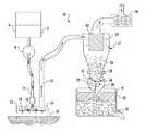
- FIG. 1is a schematic representation of the water and debris recovery system of the present invention, illustrated with a rotary valve type pump;
- FIG. 2is a top perspective view of one embodiment of the debris pump and vacuum separator of the present invention.
- FIG. 3is a bottom perspective view of one embodiment of the debris pump and vacuum separator of the present invention.
- FIG. 4is an end view of one embodiment of the debris pump and vacuum separator of the present invention.
- FIG. 5is a section view taken along lines 5 - 5 of FIG. 4 ;
- FIG. 6is a bottom view of one embodiment of the debris pump and vacuum separator of the present invention.
- FIG. 7is a side view of one embodiment of the debris pump and vacuum separator of the present invention.
- FIG. 8is a section view taken along lines 8 - 8 of FIG. 7 ;
- FIG. 9is a perspective view taken along lines 8 - 8 of FIG. 7 ;
- FIG. 10is a side view of one embodiment of the present invention illustrated in use on a road marking removal truck
- FIG. 11is a side view of one embodiment of the present invention illustrated in use on vacuum tank truck;
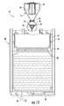
- FIG. 12is a section view of the preferred embodiment of the debris tank, illustrated full of clean water
- FIG. 13is a section view of the embodiment illustrated in FIG. 12 , illustrated with clean water dirty water and dewatered debris;
- FIG. 14is a section view of the embodiment illustrated in FIG. 12 , illustrated with clean water dirty water and dewatered debris.
- FIG. 1one embodiment of the water and debris recovery system 10 is illustrated.
- the systembegins at the blast head 12 where fresh water 4 from debris tank 6 is directed through ultra-high pressure pump 8 to create high pressure water 15 which is directed through nozzles 14 secured to rotationally mounted spray bar 16 .
- the high pressure water 15impinges on the surface 18 , removing surface markings as well as any loose debris which is trapped within the shroud 19 .
- Vacuum pump 20provides a negative air flow through the shroud 19 to draw the water and debris into tube 22 .
- the vacuum pump 20is preferably a roots type blower, however, any pump or fan suitable for creating sufficient vacuum, e.g. negative air pressure, to transfer the water and debris is suitable.
- vacuummay be developed by the rotating spray bar 16 which may include airfoils or the like which develop negative air pressure during rotation of the spray bar.
- devicessuch as centrifugal blowers may be positioned close to the blast head to provide positive pressure through the tube 22 for forcing the water and debris through the tube.
- Water and debris from tube 22is directed into a separation assembly 11 including a separator, which is preferably a one or two stage cyclonic separator 24 , which allows the water and debris to fall out of the vacuum air flow into the bottom portion 26 of the separator 24 .
- An air filter 43may be provided to prevent small particles from entering the vacuum pump 20 .
- Rotary valve 36 of the debris pump 28then draws or allows the water and debris mix to pass, via gravity, through debris port 30 into a transfer cavity 29 of the debris pump 28 .
- the rotary valve 36rotates at a predetermined speed to seal along the barrel 31 of the debris pump to prevent vacuum from being applied to the debris tank 42 while transferring the water and debris from the cyclonic separator 24 to the debris tank 42 . This cycle continues until the water and debris mix is transferred into the open or non-vacuum debris tank 42 .
- the debris pump 28preferably includes at least rotary valve 36 which allows vacuum to be maintained within the cyclonic separator while preventing the vacuum from being applied to the debris tank 42 .
- the rotary valveis preferably secured to a fluid or electrically driven motor which includes a variable speed controller to control the rotational speed of the rotary valve to regulate the speed and volume of fluid and debris transferred to the debris tank 42 .
- the debris tank 42is preferably an open top tank that may be constructed from any material suitable in the art for constructing tanks. The system may be mounted on a vehicle, skid, trailer or any other suitable means for supporting the system.
- the debris tank 42may also include a filter bag 41 or the like suitably secured within the debris tank 42 to allow the solid debris to be dewatered through a valve 45 .
- the debris tank 42may also include tilting or other dumping mechanisms 60 ( FIG. 12 ) which allow the tank to be easily emptied without departing from the scope of the invention.
- the cyclonic separator 24includes an inlet 44 for the traversal of air, water and debris into the cyclonic separator, a vacuum port 46 for application of vacuum and a debris port 30 for transfer of fluid and debris out of the cyclonic separator.
- the inlet 44is fluidly connected to the shroud 19 of the blast head 12 via tube 22 .
- Tube 22is sized to allow for the transfer of fluid and debris from the blast head 12 without significant restriction.
- Vacuum port 46is preferably positioned at the top portion of the cyclonic separator 24 , and is sized to allow transfer of a suitable volume of air to allow the fluid and debris to be drawn through tube 22 .
- a filter 43Positioned within the cyclonic separator is a filter 43 .
- the filteris removable and replaceable to allow cleaning and replacement thereof.
- the filteris a paper element that may include pre-filter covers and the like to prevent small particles from entering the vacuum pump 20 . Cloth, gauze, foam or the like may be utilized in place of the paper element without departing from the scope of the invention.
- the bottom portion 26 of the separator 24is suitably sized to retain a portion of the fluid and debris until the rotary valve can transfer the fluid and debris to the debris tank 42 .
- the debris pump 28generally includes a barrel 31 , rotary valve 36 and motor 50 .
- the barrel 31may be any size and length suitable to transfer the volume of fluid and debris being removed and collected to a debris tank 42 .
- the debris pump 28is secured directly to the top of the debris tank 42 to allow fluid and debris transferred by the debris pump 28 to be transferred directly into the debris tank 42 .
- the rotary valve 36 of the preferred embodimentssized to fit into the barrel and create a substantial seal between the edges of the rotary valve and the diameter and end plates of the barrel to maintain vacuum in the cyclonic separator.
- the rotary valve 36includes three chambers 29 separated by three vanes 52 .
- the vanespreferably include polymeric wipers 54 which engage the inner diameter and ends of the barrel to maintain a substantial seal therebetween.
- Metal or polymeric plates 56retain and position the polymeric wipers to allow for repair and replacement as needed due to abrasion or damage.
- the vanesare positioned so that debris may enter the top positioned one or two chambers while the remaining chamber(s) is/are releasing the debris and fluid into the debris tank through the discharge port 58 .
- the wipers and retaining platestherefore are preferably constructed from a material that resists adhesion to sticky polymers and the like which may be found on the surfaces being cleaned.
- the motor 50is preferably a fluid drive motor having suitable size to rotate the rotary valve 36 while loaded with debris and fluid.
- the motoris a hydraulic motor that includes a flow control or the like to allow control of the speed of rotation of the rotary valve. In this manner, the operator can cause the rotary valve to operate at a sufficient speed to keep debris from over accumulating in the bottom portion of the cyclonic separator.
- a hydraulic motoris illustrated, an air or electric motor along with suitable speed controls may be substituted without departing from the scope of the invention.
- FIGS. 10-14various embodiments of the water and debris recovery system 10 are illustrated in combination with a mark removal truck 62 ( FIG. 10 ) and vacuum truck 64 ( FIG. 11 ),
- the trucksgenerally include an elongated chassis 66 for mounting the debris and recovery system and a cabin area 68 for an operator of the truck. Wheels 70 , a driveline and a prime mover are secured to the chassis for portability of the system.
- a crane 72is secured to the separator 24 which allows the separator to be moved for transport of the vehicle or dumping of the debris tank 42 .
- a ramp 74may be secured to the elongated frame to allow a tractor or the like having a blast head secured thereto to be loaded onto the frame between the cabin and the debris tank 42 in a transverse direction with respect to the longitudinal axis of the elongated frame 66 .
- the debris tank assembly 42 or combination debris and water tank 142is secured to rear portion of the elongated frame for convenience of loading fresh clean water and offloading the dirty water and dewatered debris from the truck.
- FIG. 11also illustrates an alternative embodiment wherein the vacuum pump 20 is replaced with a centrifugal blower assembly 78 .
- the centrifugal blowershould be mounted closer to the point of suction 80 , illustrated herein as the open end of tube 22 , due to the lower amount of vacuum but higher positive pressure delivered by the centrifugal fan 78 .
- This embodimentis useful for situations where a vacuum tank truck would normally be utilized such as a municipality cleaning leaves from the roadside etc.
- the combination debris tank assemblyincludes the tank 82 , bladder 84 , floating floor 86 , filter bag 41 , separator assembly 11 and tilt assembly 60 .
- the tank 82generally includes four side panels 84 , a bottom panel 87 and a top panel 88 secured together to be substantially watertight.
- One panelis constructed and arranged to pivot away from the other panels to allow the water and debris inside to be dumped. The pivoting panel may only be a portion of one of the panels so long as the aperture created is large enough to dump the dewatered waste.
- the top panel of the tank 82includes hooks 90 sized to hold a filter bag 41 in an open position inside the tank. In this manner the recovered water and debris is directed into the filter bag whereby the solids are trapped in the bag while the dirty water is free to fall farther into the tank.
- an expanded metal inner cage 92may be supported in a spaced arrangement from the side panels to allow the filter bag to press against the perforations allowing the dirty liquid to separate from the solids in a more efficient manner.
- the bottom panel 87includes a valve 45 sized to allow the dirty water to be drained from the tank 82 .
- the bottom panelalso includes the tilt assembly 60 , illustrated herein as a hydraulic cylinder.
- a bladder 84is provided in the bottom portion of the tank for containing clean water.
- the bladder 84is constructed from polymeric material such as rubber and may contain internal strengthening cords or supports which allow the bladder to be filled with water.
- Resting on the upper portion of the bladder 84is a floating floor 86 .
- the floating floormoves up and down within the tank as the bladder is filled or drained respectively.
- Guides in the form of rails, tracks, bearings or the likeare preferably utilized to maintain the floating floor substantially perpendicular with respect to the side walls. In this manner the tank, e.g.
- FIG. 12illustrates the bladder in a substantially empty condition whereby the floating floor and filter bag are in an expanded condition.
- the dirty water that is separated from the solid debrisis thus free to flow around the empty bladder.
Landscapes
- Chemical & Material Sciences (AREA)
- Chemical Kinetics & Catalysis (AREA)
- Cyclones (AREA)
- Cleaning In General (AREA)
Abstract
Description
Claims (14)
Priority Applications (1)
| Application Number | Priority Date | Filing Date | Title |
|---|---|---|---|
| US15/911,266US10265648B2 (en) | 2012-02-14 | 2018-03-05 | Water and debris recovery system |
Applications Claiming Priority (5)
| Application Number | Priority Date | Filing Date | Title |
|---|---|---|---|
| US201261598763P | 2012-02-14 | 2012-02-14 | |
| US13/767,442US20130220387A1 (en) | 2012-02-14 | 2013-02-14 | Water and debris recovery system |
| US201461984540P | 2014-04-25 | 2014-04-25 | |
| US14/696,188US9908068B2 (en) | 2012-02-14 | 2015-04-24 | Water and debris recovery system |
| US15/911,266US10265648B2 (en) | 2012-02-14 | 2018-03-05 | Water and debris recovery system |
Related Parent Applications (1)
| Application Number | Title | Priority Date | Filing Date |
|---|---|---|---|
| US14/696,188ContinuationUS9908068B2 (en) | 2012-02-14 | 2015-04-24 | Water and debris recovery system |
Publications (2)
| Publication Number | Publication Date |
|---|---|
| US20180193777A1 US20180193777A1 (en) | 2018-07-12 |
| US10265648B2true US10265648B2 (en) | 2019-04-23 |
Family
ID=54321161
Family Applications (2)
| Application Number | Title | Priority Date | Filing Date |
|---|---|---|---|
| US14/696,188Expired - Fee RelatedUS9908068B2 (en) | 2012-02-14 | 2015-04-24 | Water and debris recovery system |
| US15/911,266Expired - Fee RelatedUS10265648B2 (en) | 2012-02-14 | 2018-03-05 | Water and debris recovery system |
Family Applications Before (1)
| Application Number | Title | Priority Date | Filing Date |
|---|---|---|---|
| US14/696,188Expired - Fee RelatedUS9908068B2 (en) | 2012-02-14 | 2015-04-24 | Water and debris recovery system |
Country Status (1)
| Country | Link |
|---|---|
| US (2) | US9908068B2 (en) |
Families Citing this family (4)
| Publication number | Priority date | Publication date | Assignee | Title |
|---|---|---|---|---|
| US20200232170A1 (en) | 2019-01-19 | 2020-07-23 | Waterblasting, Llc | Grinder head |
| US11794133B2 (en)* | 2019-09-16 | 2023-10-24 | PEX Energy Services, LLC | Sand eliminator measurement tank |
| JP2022068575A (en)* | 2020-10-22 | 2022-05-10 | 株式会社ディスコ | Cleaning equipment |
| US11725352B2 (en) | 2020-12-29 | 2023-08-15 | Waterblasting Llc | Hydro demolition unit |
Citations (104)
| Publication number | Priority date | Publication date | Assignee | Title |
|---|---|---|---|---|
| US2074623A (en) | 1936-04-22 | 1937-03-23 | Elmer T Schroth | Highway striper |
| US2444586A (en) | 1944-03-20 | 1948-07-06 | Wuensch Charles Erb | Pump |
| US2926835A (en) | 1955-02-24 | 1960-03-01 | Heraeus Gmbh W C | Vacuum pump control apparatus |
| US3043200A (en) | 1958-06-20 | 1962-07-10 | Harry J Huttash | Self-propelled concrete joint treating machine and method |
| US3060484A (en) | 1958-09-11 | 1962-10-30 | Hoover Co | Floor scrubber |
| US3151348A (en) | 1961-02-01 | 1964-10-06 | Woma Appbau Wolfgang Maasberg | Device for cleaning roadways and similar surfaces |
| US3166773A (en) | 1962-11-02 | 1965-01-26 | Gen Motors Corp | Sonic surface cleaner |
| US3303895A (en) | 1962-03-28 | 1967-02-14 | Ison G Fontenot | Degasification of drilling mud |
| US3407005A (en) | 1967-02-13 | 1968-10-22 | Concut Inc | Pavement leveling or grooving machine |
| US3489679A (en) | 1967-08-15 | 1970-01-13 | Fmc Corp | Ultrasonic clarification of liquids |
| US3532070A (en) | 1968-09-30 | 1970-10-06 | Pierre A Lamarque | Treatment vehicle for highway guard structures |
| US3540073A (en) | 1969-02-19 | 1970-11-17 | Us Air Force | Mobile dust and debris collection and inertial dust separator for airport runways and/or street cleaning |
| US3619632A (en) | 1969-06-02 | 1971-11-09 | Raymond A Labombarde | Outboard generator unit for sailboats |
| US3639936A (en) | 1970-06-08 | 1972-02-08 | Star Ind Inc | Self-propelled floor scrubber |
| US3658589A (en) | 1969-09-12 | 1972-04-25 | Myers Sherman Co | Catch basin and sewer pipe cleaner |
| US3667487A (en) | 1970-12-11 | 1972-06-06 | Richardson Chem Cleaning Servi | Integrated chemical cleaning apparatus |
| US3694033A (en) | 1970-11-09 | 1972-09-26 | Christensen Diamond Prod Co | Roadway paint stripe grooving machine |
| US3701426A (en) | 1971-11-18 | 1972-10-31 | Robert D Wetzel | Compact sewage treatment apparatus |
| US3753777A (en) | 1971-10-13 | 1973-08-21 | Tennant Co | Surface cleaning method |
| US3787916A (en) | 1971-08-13 | 1974-01-29 | Daihatsu Motor Co Ltd | Floor surface cleaning and dressing apparatus |
| US3812379A (en) | 1972-08-04 | 1974-05-21 | B Kaufman | Gasoline engine and electric motor system for boats or the like |
| US3900969A (en) | 1974-02-19 | 1975-08-26 | Wheelabrator Frye Inc | Portable apparatus for blast cleaning |
| US3929377A (en) | 1974-01-18 | 1975-12-30 | Cement And Concrete Ass | Vehicle-mounted hardened concrete grooving machine |
| US3959010A (en) | 1974-09-30 | 1976-05-25 | Thompson Tank Manufacturing Company | Vortex cleaner and method of cleaning |
| US3977128A (en) | 1975-04-21 | 1976-08-31 | Goff James R | Surface treating apparatus |
| US4007026A (en) | 1975-08-13 | 1977-02-08 | Fmc Corporation | Compact dust filter system |
| US4158248A (en) | 1977-02-14 | 1979-06-19 | Palmer Michael C | Mobile cleaning unit |
| US4158575A (en) | 1977-04-11 | 1979-06-19 | Purex Corporation | Cleaning and disinfecting hard surfaces |
| US4199837A (en) | 1978-02-13 | 1980-04-29 | Aquatech, Inc. | Apparatus for sewer cleaning and the like |
| US4227893A (en) | 1978-09-01 | 1980-10-14 | Peabody-Myers Corporation | Mobile vacuum loader |
| US4241803A (en) | 1978-02-22 | 1980-12-30 | Willy Habegger | Wheel-support assembly for rolling and stepping vehicles, especially cranes, excavating machinery and the like |
| US4290820A (en) | 1979-02-07 | 1981-09-22 | Cmi Corporation | Method and apparatus for collecting particulate material on a roadway |
| US4336671A (en) | 1980-04-25 | 1982-06-29 | Nelson Robert T | Surface cleaning apparatus |
| US4376358A (en) | 1976-12-20 | 1983-03-15 | Robert T. Nelson | Surface treating apparatus |
| US4377924A (en) | 1976-03-01 | 1983-03-29 | Wheelabrator-Frye Inc. | Portable device for treating surfaces |
| US4509963A (en) | 1982-04-01 | 1985-04-09 | Wm. W. Meyer & Sons, Inc. | Industrial vacuum cleaner |
| US4530131A (en) | 1983-10-28 | 1985-07-23 | The United States Of America As Represented By The Secretary Of The Navy | Automatic vacuum recyclable system for chemical-thermo cleaning of ship tanks and bilges |
| US4578840A (en) | 1984-06-04 | 1986-04-01 | General Resource Corp. | Mobile vacuum machine |
| US4683684A (en) | 1985-10-22 | 1987-08-04 | Electric Power Research Institute, Inc. | High pressure fluid jet apparatus for cutting and removing pavement |
| US4753052A (en) | 1985-05-01 | 1988-06-28 | Dickson Industries, Inc. | Surface blasting apparatus |
| US4793734A (en) | 1987-10-22 | 1988-12-27 | Nlb | Apparatus for removing structural concrete |
| US4801376A (en) | 1984-03-23 | 1989-01-31 | Esta Apparatebau Gmbh & Co. Kg | Cleaner for swimming pools and the like |
| US4806172A (en) | 1985-04-02 | 1989-02-21 | Jse Corporation | Method and apparatus for removing substances adhering to surface |
| US4819676A (en) | 1986-01-16 | 1989-04-11 | Tennant Company | Combination sweeping and scrubbing system and method |
| US4839061A (en) | 1988-06-13 | 1989-06-13 | Manchak Frank | Method and apparatus for treatment of hazardous material spills |
| US4854770A (en) | 1984-04-16 | 1989-08-08 | Indescor Hydrodynamics Inc. | Method and apparatus for removal of surface material |
| US4935984A (en) | 1989-02-09 | 1990-06-26 | Guzzler Manufactureing, Inc. | Vacuum refuse collecting vehicle |
| US5002595A (en) | 1989-01-09 | 1991-03-26 | Samson Metal & Machine, Inc. | Debris and water vacuum system |
| US5022809A (en) | 1990-02-07 | 1991-06-11 | Solite Corporation | Truck for alternately handling bulk and palletized cargo |
| US5041165A (en) | 1984-10-02 | 1991-08-20 | Urbani William G | Dirty surface cleaning method |
| US5060334A (en) | 1988-09-07 | 1991-10-29 | Elgin Sweeper Company | Street sweeper |
| US5076919A (en) | 1990-05-04 | 1991-12-31 | Fraser Environmental Systems, Inc. | Self-cleaning vacuum filter with relatively moveable surfaces for recovering oil from beaches |
| US5078161A (en) | 1989-05-31 | 1992-01-07 | Flow International Corporation | Airport runway cleaning method |
| US5082065A (en) | 1990-08-15 | 1992-01-21 | Support Services International, Inc. | Quick attach implement coupler |
| US5108471A (en) | 1991-05-17 | 1992-04-28 | Poborsky Gary A | Single mode wet and dry vacuum vehicle |
| US5224236A (en) | 1991-08-16 | 1993-07-06 | Sallquist Robert V | Machine for cleaning paved surfaces |
| US5236278A (en) | 1990-07-02 | 1993-08-17 | Dickson Industries, Inc. | Road surface treating apparatus |
| US5589080A (en) | 1995-04-04 | 1996-12-31 | Cfr Corporation | Liquid recycling system with moving concentrated counterflow for filter clearance |
| US5600995A (en) | 1995-06-07 | 1997-02-11 | Sherman; Alden O. | Useful improvements in press apparatus |
| US5605381A (en) | 1994-10-17 | 1997-02-25 | Stimsonite Corporation | Pavement marking eradicator |
| USH1660H (en) | 1996-02-26 | 1997-07-01 | The United States Of America As Represented By The Secretary Of The Army | Process for autonomously locating and retrieving toxic heavy metal and radioactive contaminants |
| US5704989A (en) | 1993-11-04 | 1998-01-06 | Pro Earth, L.L.C. | Closed loop surface cleaning system |
| US5709242A (en) | 1993-09-01 | 1998-01-20 | Metalo Monti V.O.F. | Device for blocking a liquid flow through a pipe in one direction |
| US5708989A (en) | 1995-03-23 | 1998-01-20 | Gordon Ellis And Company | Toilet seat assemblies |
| US5772497A (en) | 1995-09-15 | 1998-06-30 | Pamag Ag | Movable surface treatment device |
| US5826460A (en) | 1995-07-03 | 1998-10-27 | Omsi Trasmissioni S.P.A. | Intermediate total power takeoff for trucks and self-propelled machines for various operations |
| US5965020A (en) | 1997-05-06 | 1999-10-12 | D & C Limited | Endless belt filter |
| US5979012A (en) | 1996-12-16 | 1999-11-09 | Parker West International, L.L.C. | Mobile apparatus for dispensing and recovering water and removing waste therefrom |
| US6042726A (en) | 1998-07-28 | 2000-03-28 | H.R. Black Co., Inc. | Apparatus for filtering industrial liquids |
| US6042656A (en) | 1997-10-17 | 2000-03-28 | Nilfisk-Advance, Inc. | Shutoff control methods for surface treating machines |
| US6073720A (en) | 1998-09-24 | 2000-06-13 | Vanderlinden; Roger P. | Single engine street cleaning vehicle |
| US6082630A (en) | 1997-12-01 | 2000-07-04 | Bohrer; Lee A. | Vehicle mounted high pressure cleaning apparatus |
| US6113800A (en) | 1996-01-23 | 2000-09-05 | Novus International, Inc. | Treatment process for recovering components of a float material from waste water |
| US6129094A (en) | 1997-07-11 | 2000-10-10 | Valley Systems, Inc. | Method of high pressure cleaning |
| US6152674A (en) | 1999-02-01 | 2000-11-28 | Ogrodnick; Clarence | Truck deck mounted cargo handling apparatus with ground level loading and unloading position |
| US6224317B1 (en) | 1997-12-31 | 2001-05-01 | Kann Manufacturing Corporation | Front end loader adapter |
| US6258268B1 (en) | 2000-11-09 | 2001-07-10 | John W. Lake | Container filter box for de-watering solids |
| US6302967B1 (en) | 1993-09-08 | 2001-10-16 | Cyclone Surface Cleaning, Inc. | Mobile cyclonic power wash system with water reclamation and rotary union |
| US6358406B1 (en) | 2000-09-08 | 2002-03-19 | Gene Hirs | Vacuum fluid filter |
| US6394033B1 (en) | 1999-02-08 | 2002-05-28 | Steris Inc. | Bedding removal and refilling system for animal cages |
| US6393944B1 (en) | 2000-04-05 | 2002-05-28 | Omsi Trasmissioni S.P.A. | Intermediate total power takeoff for trucks and self-propelled machines for various operations |
| US6402822B1 (en) | 2000-02-15 | 2002-06-11 | Hmi Industries, Inc. | Furnace filter system |
| US20020178529A1 (en) | 2001-05-31 | 2002-12-05 | Geyer Robert A. | Brushless scrub head for surface maintenance |
| US6495031B1 (en) | 2001-07-16 | 2002-12-17 | Jack R. Bratten | Enclosed belt filter apparatus |
| US20030205242A1 (en) | 2000-12-01 | 2003-11-06 | Gerber Douglas E. | Random motion cleaner |
| US6653265B2 (en) | 2001-06-20 | 2003-11-25 | Cornell Research Foundation, Inc. | Removable marking system |
| US20040070172A1 (en) | 2002-10-02 | 2004-04-15 | Schulte Industries Ltd. | Offset arm for towing rotary mowers and the like |
| US20040237247A1 (en) | 2003-05-30 | 2004-12-02 | Minuteman International, Inc. | Ground cleaning machine |
| US6835315B2 (en) | 2000-10-19 | 2004-12-28 | Jorgensen Conveyors, Inc. | Media vacuum filter |
| US20050268949A1 (en) | 2004-06-03 | 2005-12-08 | Rosauto S.R.L. | Washing device for spray guns and their components equipped with separate automatic and manual washing zones |
| US20060000491A1 (en) | 2004-07-02 | 2006-01-05 | Crocker James P | Stripe removal system |
| US7029579B2 (en) | 2002-12-26 | 2006-04-18 | Tapp Floyd G | System for solid-liquid separation |
| US7204365B2 (en) | 2002-12-04 | 2007-04-17 | 3M Innovative Properties Company | Conveyor belt cleaning system |
| US7216397B1 (en) | 2003-08-13 | 2007-05-15 | Paul Tanner | Collection tank and associated cleaning system |
| US7240681B2 (en) | 2002-11-06 | 2007-07-10 | Larry Saik | Trailer mounted mobile apparatus for dewatering and recovering formation sand |
| US20070169797A1 (en) | 2006-01-26 | 2007-07-26 | Crocker James P | Mobile mark removal system |
| US20070207711A1 (en) | 2006-03-03 | 2007-09-06 | Crocker James P | Combined grinder and water blaster for stripe removal system |
| US20070204889A1 (en) | 2006-03-03 | 2007-09-06 | Crocker James P | Articulable arm for a mobile mark removal system |
| US7290307B1 (en) | 2004-05-27 | 2007-11-06 | Victor Chao | Implement for removing pavement cleaner |
| US7325588B2 (en) | 2004-04-29 | 2008-02-05 | Hewlett-Packard Development Company, L.P. | High serviceability liquid cooling loop using flexible bellows |
| US20090241999A1 (en) | 2008-02-28 | 2009-10-01 | Crocker James P | Modular Stripe Removal System |
| US20090242003A1 (en) | 2008-02-28 | 2009-10-01 | Crocker James P | Water Blasting Head With Through Feeding Hydraulic Motor |
| US20100192980A1 (en) | 2009-02-05 | 2010-08-05 | Turner John C | Modular recycling cleaning system |
| US20110192771A1 (en) | 2010-02-09 | 2011-08-11 | World Chemical Co., Ltd. | Solid-liquid separator with self-priming pump |
- 2015
- 2015-04-24USUS14/696,188patent/US9908068B2/ennot_activeExpired - Fee Related
- 2018
- 2018-03-05USUS15/911,266patent/US10265648B2/ennot_activeExpired - Fee Related
Patent Citations (109)
| Publication number | Priority date | Publication date | Assignee | Title |
|---|---|---|---|---|
| US2074623A (en) | 1936-04-22 | 1937-03-23 | Elmer T Schroth | Highway striper |
| US2444586A (en) | 1944-03-20 | 1948-07-06 | Wuensch Charles Erb | Pump |
| US2926835A (en) | 1955-02-24 | 1960-03-01 | Heraeus Gmbh W C | Vacuum pump control apparatus |
| US3043200A (en) | 1958-06-20 | 1962-07-10 | Harry J Huttash | Self-propelled concrete joint treating machine and method |
| US3060484A (en) | 1958-09-11 | 1962-10-30 | Hoover Co | Floor scrubber |
| US3151348A (en) | 1961-02-01 | 1964-10-06 | Woma Appbau Wolfgang Maasberg | Device for cleaning roadways and similar surfaces |
| US3303895A (en) | 1962-03-28 | 1967-02-14 | Ison G Fontenot | Degasification of drilling mud |
| US3166773A (en) | 1962-11-02 | 1965-01-26 | Gen Motors Corp | Sonic surface cleaner |
| US3407005A (en) | 1967-02-13 | 1968-10-22 | Concut Inc | Pavement leveling or grooving machine |
| US3489679A (en) | 1967-08-15 | 1970-01-13 | Fmc Corp | Ultrasonic clarification of liquids |
| US3532070A (en) | 1968-09-30 | 1970-10-06 | Pierre A Lamarque | Treatment vehicle for highway guard structures |
| US3540073A (en) | 1969-02-19 | 1970-11-17 | Us Air Force | Mobile dust and debris collection and inertial dust separator for airport runways and/or street cleaning |
| US3619632A (en) | 1969-06-02 | 1971-11-09 | Raymond A Labombarde | Outboard generator unit for sailboats |
| US3658589A (en) | 1969-09-12 | 1972-04-25 | Myers Sherman Co | Catch basin and sewer pipe cleaner |
| US3639936A (en) | 1970-06-08 | 1972-02-08 | Star Ind Inc | Self-propelled floor scrubber |
| US3694033A (en) | 1970-11-09 | 1972-09-26 | Christensen Diamond Prod Co | Roadway paint stripe grooving machine |
| US3667487A (en) | 1970-12-11 | 1972-06-06 | Richardson Chem Cleaning Servi | Integrated chemical cleaning apparatus |
| US3787916A (en) | 1971-08-13 | 1974-01-29 | Daihatsu Motor Co Ltd | Floor surface cleaning and dressing apparatus |
| US3753777A (en) | 1971-10-13 | 1973-08-21 | Tennant Co | Surface cleaning method |
| US3701426A (en) | 1971-11-18 | 1972-10-31 | Robert D Wetzel | Compact sewage treatment apparatus |
| US3812379A (en) | 1972-08-04 | 1974-05-21 | B Kaufman | Gasoline engine and electric motor system for boats or the like |
| US3929377A (en) | 1974-01-18 | 1975-12-30 | Cement And Concrete Ass | Vehicle-mounted hardened concrete grooving machine |
| US3900969A (en) | 1974-02-19 | 1975-08-26 | Wheelabrator Frye Inc | Portable apparatus for blast cleaning |
| US3959010A (en) | 1974-09-30 | 1976-05-25 | Thompson Tank Manufacturing Company | Vortex cleaner and method of cleaning |
| US3977128A (en) | 1975-04-21 | 1976-08-31 | Goff James R | Surface treating apparatus |
| US4007026A (en) | 1975-08-13 | 1977-02-08 | Fmc Corporation | Compact dust filter system |
| US4377924A (en) | 1976-03-01 | 1983-03-29 | Wheelabrator-Frye Inc. | Portable device for treating surfaces |
| US4376358A (en) | 1976-12-20 | 1983-03-15 | Robert T. Nelson | Surface treating apparatus |
| US4158248A (en) | 1977-02-14 | 1979-06-19 | Palmer Michael C | Mobile cleaning unit |
| US4158575A (en) | 1977-04-11 | 1979-06-19 | Purex Corporation | Cleaning and disinfecting hard surfaces |
| US4199837A (en) | 1978-02-13 | 1980-04-29 | Aquatech, Inc. | Apparatus for sewer cleaning and the like |
| US4241803A (en) | 1978-02-22 | 1980-12-30 | Willy Habegger | Wheel-support assembly for rolling and stepping vehicles, especially cranes, excavating machinery and the like |
| US4227893A (en) | 1978-09-01 | 1980-10-14 | Peabody-Myers Corporation | Mobile vacuum loader |
| US4290820A (en) | 1979-02-07 | 1981-09-22 | Cmi Corporation | Method and apparatus for collecting particulate material on a roadway |
| US4336671A (en) | 1980-04-25 | 1982-06-29 | Nelson Robert T | Surface cleaning apparatus |
| US4509963A (en) | 1982-04-01 | 1985-04-09 | Wm. W. Meyer & Sons, Inc. | Industrial vacuum cleaner |
| US4530131A (en) | 1983-10-28 | 1985-07-23 | The United States Of America As Represented By The Secretary Of The Navy | Automatic vacuum recyclable system for chemical-thermo cleaning of ship tanks and bilges |
| US4801376A (en) | 1984-03-23 | 1989-01-31 | Esta Apparatebau Gmbh & Co. Kg | Cleaner for swimming pools and the like |
| US4854770A (en) | 1984-04-16 | 1989-08-08 | Indescor Hydrodynamics Inc. | Method and apparatus for removal of surface material |
| US4578840A (en) | 1984-06-04 | 1986-04-01 | General Resource Corp. | Mobile vacuum machine |
| US5041165A (en) | 1984-10-02 | 1991-08-20 | Urbani William G | Dirty surface cleaning method |
| US4806172A (en) | 1985-04-02 | 1989-02-21 | Jse Corporation | Method and apparatus for removing substances adhering to surface |
| US4753052A (en) | 1985-05-01 | 1988-06-28 | Dickson Industries, Inc. | Surface blasting apparatus |
| US4683684A (en) | 1985-10-22 | 1987-08-04 | Electric Power Research Institute, Inc. | High pressure fluid jet apparatus for cutting and removing pavement |
| US4819676A (en) | 1986-01-16 | 1989-04-11 | Tennant Company | Combination sweeping and scrubbing system and method |
| US4793734A (en) | 1987-10-22 | 1988-12-27 | Nlb | Apparatus for removing structural concrete |
| US4839061A (en) | 1988-06-13 | 1989-06-13 | Manchak Frank | Method and apparatus for treatment of hazardous material spills |
| US5060334A (en) | 1988-09-07 | 1991-10-29 | Elgin Sweeper Company | Street sweeper |
| US5002595A (en) | 1989-01-09 | 1991-03-26 | Samson Metal & Machine, Inc. | Debris and water vacuum system |
| US4935984A (en) | 1989-02-09 | 1990-06-26 | Guzzler Manufactureing, Inc. | Vacuum refuse collecting vehicle |
| US5078161A (en) | 1989-05-31 | 1992-01-07 | Flow International Corporation | Airport runway cleaning method |
| US5022809A (en) | 1990-02-07 | 1991-06-11 | Solite Corporation | Truck for alternately handling bulk and palletized cargo |
| US5076919A (en) | 1990-05-04 | 1991-12-31 | Fraser Environmental Systems, Inc. | Self-cleaning vacuum filter with relatively moveable surfaces for recovering oil from beaches |
| US5236278A (en) | 1990-07-02 | 1993-08-17 | Dickson Industries, Inc. | Road surface treating apparatus |
| US5082065A (en) | 1990-08-15 | 1992-01-21 | Support Services International, Inc. | Quick attach implement coupler |
| US5108471A (en) | 1991-05-17 | 1992-04-28 | Poborsky Gary A | Single mode wet and dry vacuum vehicle |
| US5224236A (en) | 1991-08-16 | 1993-07-06 | Sallquist Robert V | Machine for cleaning paved surfaces |
| US5709242A (en) | 1993-09-01 | 1998-01-20 | Metalo Monti V.O.F. | Device for blocking a liquid flow through a pipe in one direction |
| US6302967B1 (en) | 1993-09-08 | 2001-10-16 | Cyclone Surface Cleaning, Inc. | Mobile cyclonic power wash system with water reclamation and rotary union |
| US5704989A (en) | 1993-11-04 | 1998-01-06 | Pro Earth, L.L.C. | Closed loop surface cleaning system |
| US5605381A (en) | 1994-10-17 | 1997-02-25 | Stimsonite Corporation | Pavement marking eradicator |
| US5708989A (en) | 1995-03-23 | 1998-01-20 | Gordon Ellis And Company | Toilet seat assemblies |
| US5589080A (en) | 1995-04-04 | 1996-12-31 | Cfr Corporation | Liquid recycling system with moving concentrated counterflow for filter clearance |
| US5600995A (en) | 1995-06-07 | 1997-02-11 | Sherman; Alden O. | Useful improvements in press apparatus |
| US5826460A (en) | 1995-07-03 | 1998-10-27 | Omsi Trasmissioni S.P.A. | Intermediate total power takeoff for trucks and self-propelled machines for various operations |
| US5772497A (en) | 1995-09-15 | 1998-06-30 | Pamag Ag | Movable surface treatment device |
| US6113800A (en) | 1996-01-23 | 2000-09-05 | Novus International, Inc. | Treatment process for recovering components of a float material from waste water |
| USH1660H (en) | 1996-02-26 | 1997-07-01 | The United States Of America As Represented By The Secretary Of The Army | Process for autonomously locating and retrieving toxic heavy metal and radioactive contaminants |
| US5979012A (en) | 1996-12-16 | 1999-11-09 | Parker West International, L.L.C. | Mobile apparatus for dispensing and recovering water and removing waste therefrom |
| US5965020A (en) | 1997-05-06 | 1999-10-12 | D & C Limited | Endless belt filter |
| US6129094A (en) | 1997-07-11 | 2000-10-10 | Valley Systems, Inc. | Method of high pressure cleaning |
| US6042656A (en) | 1997-10-17 | 2000-03-28 | Nilfisk-Advance, Inc. | Shutoff control methods for surface treating machines |
| US6082630A (en) | 1997-12-01 | 2000-07-04 | Bohrer; Lee A. | Vehicle mounted high pressure cleaning apparatus |
| US6224317B1 (en) | 1997-12-31 | 2001-05-01 | Kann Manufacturing Corporation | Front end loader adapter |
| US6042726A (en) | 1998-07-28 | 2000-03-28 | H.R. Black Co., Inc. | Apparatus for filtering industrial liquids |
| US6073720A (en) | 1998-09-24 | 2000-06-13 | Vanderlinden; Roger P. | Single engine street cleaning vehicle |
| US6152674A (en) | 1999-02-01 | 2000-11-28 | Ogrodnick; Clarence | Truck deck mounted cargo handling apparatus with ground level loading and unloading position |
| US6394033B1 (en) | 1999-02-08 | 2002-05-28 | Steris Inc. | Bedding removal and refilling system for animal cages |
| US6402822B1 (en) | 2000-02-15 | 2002-06-11 | Hmi Industries, Inc. | Furnace filter system |
| US6393944B1 (en) | 2000-04-05 | 2002-05-28 | Omsi Trasmissioni S.P.A. | Intermediate total power takeoff for trucks and self-propelled machines for various operations |
| US6358406B1 (en) | 2000-09-08 | 2002-03-19 | Gene Hirs | Vacuum fluid filter |
| US6835315B2 (en) | 2000-10-19 | 2004-12-28 | Jorgensen Conveyors, Inc. | Media vacuum filter |
| US6258268B1 (en) | 2000-11-09 | 2001-07-10 | John W. Lake | Container filter box for de-watering solids |
| US20030205242A1 (en) | 2000-12-01 | 2003-11-06 | Gerber Douglas E. | Random motion cleaner |
| US20020178529A1 (en) | 2001-05-31 | 2002-12-05 | Geyer Robert A. | Brushless scrub head for surface maintenance |
| US6896742B2 (en) | 2001-05-31 | 2005-05-24 | Tennant Company | Brushless scrub head for surface maintenance |
| US6653265B2 (en) | 2001-06-20 | 2003-11-25 | Cornell Research Foundation, Inc. | Removable marking system |
| US6495031B1 (en) | 2001-07-16 | 2002-12-17 | Jack R. Bratten | Enclosed belt filter apparatus |
| US20040070172A1 (en) | 2002-10-02 | 2004-04-15 | Schulte Industries Ltd. | Offset arm for towing rotary mowers and the like |
| US7240681B2 (en) | 2002-11-06 | 2007-07-10 | Larry Saik | Trailer mounted mobile apparatus for dewatering and recovering formation sand |
| US7204365B2 (en) | 2002-12-04 | 2007-04-17 | 3M Innovative Properties Company | Conveyor belt cleaning system |
| US7029579B2 (en) | 2002-12-26 | 2006-04-18 | Tapp Floyd G | System for solid-liquid separation |
| US20040237247A1 (en) | 2003-05-30 | 2004-12-02 | Minuteman International, Inc. | Ground cleaning machine |
| US7216397B1 (en) | 2003-08-13 | 2007-05-15 | Paul Tanner | Collection tank and associated cleaning system |
| US7325588B2 (en) | 2004-04-29 | 2008-02-05 | Hewlett-Packard Development Company, L.P. | High serviceability liquid cooling loop using flexible bellows |
| US7290307B1 (en) | 2004-05-27 | 2007-11-06 | Victor Chao | Implement for removing pavement cleaner |
| US20050268949A1 (en) | 2004-06-03 | 2005-12-08 | Rosauto S.R.L. | Washing device for spray guns and their components equipped with separate automatic and manual washing zones |
| US20080066781A1 (en) | 2004-07-02 | 2008-03-20 | Crocker James P | Stripe removal system |
| US7255116B2 (en) | 2004-07-02 | 2007-08-14 | Crocker James P | Stripe removal system |
| US20060185689A1 (en) | 2004-07-02 | 2006-08-24 | Crocker James P | Transportable holding tank for stripe removal system |
| US20060000491A1 (en) | 2004-07-02 | 2006-01-05 | Crocker James P | Stripe removal system |
| US20070169797A1 (en) | 2006-01-26 | 2007-07-26 | Crocker James P | Mobile mark removal system |
| US7798158B2 (en) | 2006-01-26 | 2010-09-21 | Crocker James P | Mobile mark removal system |
| US20070207711A1 (en) | 2006-03-03 | 2007-09-06 | Crocker James P | Combined grinder and water blaster for stripe removal system |
| US20070204889A1 (en) | 2006-03-03 | 2007-09-06 | Crocker James P | Articulable arm for a mobile mark removal system |
| US20090241999A1 (en) | 2008-02-28 | 2009-10-01 | Crocker James P | Modular Stripe Removal System |
| US20090242003A1 (en) | 2008-02-28 | 2009-10-01 | Crocker James P | Water Blasting Head With Through Feeding Hydraulic Motor |
| US20100192980A1 (en) | 2009-02-05 | 2010-08-05 | Turner John C | Modular recycling cleaning system |
| US20110192771A1 (en) | 2010-02-09 | 2011-08-11 | World Chemical Co., Ltd. | Solid-liquid separator with self-priming pump |
Non-Patent Citations (3)
| Title |
|---|
| Johnson, B. et al, Committee report: Characterization of inorganic coagulant/polymer blends using refractive index and specific gravity measurements, Cat.INIST, 2004, vol. 96, pp. 170-173, American Water Works Association, Denver, CO, Internet article: http://cat.inist.fr/?aModele=afficheN&cpsidt=15694785, (Retrieved Jan. 21, 2009). |
| Potable and Process Water Chemical Applications, Internet article: http://www.coynechemical.com/environmental_app.php, 2000 George S. Coyne Chemical Co., Inc., (Retrieved Jan. 21, 2009). |
| Specialty Chemicals/Coagulants & Flocculants, Ecologix Environmental Systems, Internet article: http://www.dcologixsystems.com/ch_coag_floc.php, (Retrieved Jan. 21, 2009). |
Also Published As
| Publication number | Publication date |
|---|---|
| US20180193777A1 (en) | 2018-07-12 |
| US20150298031A1 (en) | 2015-10-22 |
| US9908068B2 (en) | 2018-03-06 |
Similar Documents
| Publication | Publication Date | Title |
|---|---|---|
| US10265648B2 (en) | Water and debris recovery system | |
| US20060185689A1 (en) | Transportable holding tank for stripe removal system | |
| US4322868A (en) | Sewer and catch basin cleaner | |
| US6854157B2 (en) | Debris collection systems and vehicles | |
| US6013138A (en) | Method for cleaning a pipe with a vehicle | |
| US5826298A (en) | Surface cleaner, sprayer and retrieval unit | |
| US20090241999A1 (en) | Modular Stripe Removal System | |
| US8012265B2 (en) | Concrete/asphalt wet washing system | |
| WO2015164809A1 (en) | Water and debris recovery system | |
| US20130149089A1 (en) | Systems and devices for removing materials from vacuum truck tanks | |
| US20130220387A1 (en) | Water and debris recovery system | |
| JP3932411B2 (en) | Tunnel wall cleaning equipment | |
| US7578885B2 (en) | Concrete/asphalt wet washing system | |
| US20160250669A1 (en) | Water and debris recovery system | |
| JP3738285B2 (en) | Tunnel wall cleaning equipment | |
| US12214482B2 (en) | Dry filtration system | |
| JP2010127015A (en) | Road maintenance vehicle | |
| US20110139179A1 (en) | Concrete/Asphalt Wet Washing System | |
| KR200297285Y1 (en) | a | |
| JPH0657920U (en) | Cleaning equipment | |
| CA2817499A1 (en) | Portable materials storage tank for use with vacuum truck pneumatic transfer system |
Legal Events
| Date | Code | Title | Description |
|---|---|---|---|
| AS | Assignment | Owner name:WATERBLASTING, LLC, FLORIDA Free format text:ASSIGNMENT OF ASSIGNORS INTEREST;ASSIGNOR:CROCKER, JAMES P.;REEL/FRAME:045102/0902 Effective date:20150616 | |
| FEPP | Fee payment procedure | Free format text:ENTITY STATUS SET TO UNDISCOUNTED (ORIGINAL EVENT CODE: BIG.); ENTITY STATUS OF PATENT OWNER: SMALL ENTITY | |
| FEPP | Fee payment procedure | Free format text:ENTITY STATUS SET TO SMALL (ORIGINAL EVENT CODE: SMAL); ENTITY STATUS OF PATENT OWNER: SMALL ENTITY | |
| STPP | Information on status: patent application and granting procedure in general | Free format text:PUBLICATIONS -- ISSUE FEE PAYMENT VERIFIED | |
| STCF | Information on status: patent grant | Free format text:PATENTED CASE | |
| AS | Assignment | Owner name:BANK OF AMERICA, N.A., NORTH CAROLINA Free format text:NOTICE OF GRANT OF SECURITY INTEREST IN PATENTS;ASSIGNOR:WATERBLASTING, LLC;REEL/FRAME:052333/0940 Effective date:20200406 | |
| FEPP | Fee payment procedure | Free format text:MAINTENANCE FEE REMINDER MAILED (ORIGINAL EVENT CODE: REM.); ENTITY STATUS OF PATENT OWNER: SMALL ENTITY | |
| LAPS | Lapse for failure to pay maintenance fees | Free format text:PATENT EXPIRED FOR FAILURE TO PAY MAINTENANCE FEES (ORIGINAL EVENT CODE: EXP.); ENTITY STATUS OF PATENT OWNER: SMALL ENTITY | |
| STCH | Information on status: patent discontinuation | Free format text:PATENT EXPIRED DUE TO NONPAYMENT OF MAINTENANCE FEES UNDER 37 CFR 1.362 | |
| FP | Lapsed due to failure to pay maintenance fee | Effective date:20230423 |