US10260351B2 - Fan blade and method of manufacturing same - Google Patents
Fan blade and method of manufacturing sameDownload PDFInfo
- Publication number
- US10260351B2 US10260351B2US13/422,541US201213422541AUS10260351B2US 10260351 B2US10260351 B2US 10260351B2US 201213422541 AUS201213422541 AUS 201213422541AUS 10260351 B2US10260351 B2US 10260351B2
- Authority
- US
- United States
- Prior art keywords
- sheath
- edge
- substrate
- adhesive
- section
- Prior art date
- Legal status (The legal status is an assumption and is not a legal conclusion. Google has not performed a legal analysis and makes no representation as to the accuracy of the status listed.)
- Active, expires
Links
Images


Classifications
- F—MECHANICAL ENGINEERING; LIGHTING; HEATING; WEAPONS; BLASTING
- F01—MACHINES OR ENGINES IN GENERAL; ENGINE PLANTS IN GENERAL; STEAM ENGINES
- F01D—NON-POSITIVE DISPLACEMENT MACHINES OR ENGINES, e.g. STEAM TURBINES
- F01D5/00—Blades; Blade-carrying members; Heating, heat-insulating, cooling or antivibration means on the blades or the members
- F01D5/12—Blades
- F01D5/14—Form or construction
- F01D5/147—Construction, i.e. structural features, e.g. of weight-saving hollow blades
- F—MECHANICAL ENGINEERING; LIGHTING; HEATING; WEAPONS; BLASTING
- F01—MACHINES OR ENGINES IN GENERAL; ENGINE PLANTS IN GENERAL; STEAM ENGINES
- F01D—NON-POSITIVE DISPLACEMENT MACHINES OR ENGINES, e.g. STEAM TURBINES
- F01D5/00—Blades; Blade-carrying members; Heating, heat-insulating, cooling or antivibration means on the blades or the members
- F01D5/12—Blades
- F01D5/28—Selecting particular materials; Particular measures relating thereto; Measures against erosion or corrosion
- F01D5/282—Selecting composite materials, e.g. blades with reinforcing filaments
- F—MECHANICAL ENGINEERING; LIGHTING; HEATING; WEAPONS; BLASTING
- F04—POSITIVE - DISPLACEMENT MACHINES FOR LIQUIDS; PUMPS FOR LIQUIDS OR ELASTIC FLUIDS
- F04D—NON-POSITIVE-DISPLACEMENT PUMPS
- F04D29/00—Details, component parts, or accessories
- F04D29/26—Rotors specially for elastic fluids
- F04D29/32—Rotors specially for elastic fluids for axial flow pumps
- F04D29/321—Rotors specially for elastic fluids for axial flow pumps for axial flow compressors
- F04D29/324—Blades
- F—MECHANICAL ENGINEERING; LIGHTING; HEATING; WEAPONS; BLASTING
- F05—INDEXING SCHEMES RELATING TO ENGINES OR PUMPS IN VARIOUS SUBCLASSES OF CLASSES F01-F04
- F05D—INDEXING SCHEME FOR ASPECTS RELATING TO NON-POSITIVE-DISPLACEMENT MACHINES OR ENGINES, GAS-TURBINES OR JET-PROPULSION PLANTS
- F05D2220/00—Application
- F05D2220/30—Application in turbines
- F05D2220/36—Application in turbines specially adapted for the fan of turbofan engines
- F—MECHANICAL ENGINEERING; LIGHTING; HEATING; WEAPONS; BLASTING
- F05—INDEXING SCHEMES RELATING TO ENGINES OR PUMPS IN VARIOUS SUBCLASSES OF CLASSES F01-F04
- F05D—INDEXING SCHEME FOR ASPECTS RELATING TO NON-POSITIVE-DISPLACEMENT MACHINES OR ENGINES, GAS-TURBINES OR JET-PROPULSION PLANTS
- F05D2240/00—Components
- F05D2240/20—Rotors
- F05D2240/30—Characteristics of rotor blades, i.e. of any element transforming dynamic fluid energy to or from rotational energy and being attached to a rotor
- F05D2240/303—Characteristics of rotor blades, i.e. of any element transforming dynamic fluid energy to or from rotational energy and being attached to a rotor related to the leading edge of a rotor blade
- Y—GENERAL TAGGING OF NEW TECHNOLOGICAL DEVELOPMENTS; GENERAL TAGGING OF CROSS-SECTIONAL TECHNOLOGIES SPANNING OVER SEVERAL SECTIONS OF THE IPC; TECHNICAL SUBJECTS COVERED BY FORMER USPC CROSS-REFERENCE ART COLLECTIONS [XRACs] AND DIGESTS
- Y10—TECHNICAL SUBJECTS COVERED BY FORMER USPC
- Y10T—TECHNICAL SUBJECTS COVERED BY FORMER US CLASSIFICATION
- Y10T156/00—Adhesive bonding and miscellaneous chemical manufacture
- Y10T156/10—Methods of surface bonding and/or assembly therefor
Definitions
- This disclosurerelates to an airfoil for a gas turbine engine.
- Hybrid metal fan bladeshave been proposed in which a metallic sheath is secured to an aluminum substrate.
- metallic sheathis a titanium structure, which provides for a lightweight airfoil.
- the sheathis typically secured to a leading edge of the substrate to provide resistance to damage from debris.
- One approachhas been to secure the sheath to the substrate using an adhesive. Unfortunately, in such conventional blades, when a corrosion preventative film adhesive layer was used, it often left a fillet of adhesive at the sheath edge, which inhibited proper urethane coating.
- an airfoil for a gas turbine engineincludes a substrate and a sheath providing an edge.
- An adhesivesecures the sheath to the substrate.
- the adhesivehas a fillet that extends beyond the edge that includes a finished surface.
- the substrateis a first metal and the sheath is a second metal different than the first metal.
- the adhesiveis configured to provide a barrier between the first and second metals to prevent galvanic corrosion.
- the adhesiveincludes a scrim embedded in resin.
- the scrimis provided beneath the sheath and inboard of the edge.
- the finished surfaceincludes a scraped contour.
- the airfoilincludes a coating arranged over the substrate and the finished surface. The coating abuts the edge.
- the airfoilis a fan blade and the sheath provides a leading edge of the airfoil.
- the sheathincludes a flank providing the edge.
- the airfoilin another embodiment, includes a body having first, second, and third surfaces.
- the first and second surfacesare adjacent to one another and are generally at a right angle to one another.
- the third surfaceadjoins the second surface at an obtuse angle and provides a sharp edge configured to scrape a cured adhesive.
- the first and second surfacesare configured to follow an airfoil sheath contour.
- a relief apertureadjoins the first and second surfaces to one another and is configured to accommodate a corner of the airfoil sheath contour.
- a method of manufacturing an airfoil for a gas turbine engineincludes the steps of securing a sheath to a substrate with adhesive, curing the adhesive, and mechanically removing a portion of the adhesive extending beyond the sheath.
- the securing stepincludes providing a resin-saturated scrim between the sheath and substrate.
- the curing stepincludes providing a fillet of adhesive adjoining the sheath and the substrate.
- the removing stepincludes scraping the fillet with a tool to provide a finished surface on the adhesive.
- the method of manufacturingincludes the step of applying a coating over the substrate and the finished surface and adjoining the sheath. The coating provides a fan blade contour along with the sheath.
- a gas turbine enginein another embodiment, includes a fan section.
- the fan sectionincludes a plurality of fan blades, at least one of said fan blades includes a substrate, a sheath providing an edge, and a cured adhesive that secures the sheath to the substrate.
- the cured adhesivehas a fillet that extends beyond the edge that includes a mechanically worked finished surface.
- the gas turbine engineincludes a compressor section, a combustor section in fluid communication with the compressor section, and a turbine section in fluid communication with the combustor section.
- the compressor sectionincludes a high pressure compressor section and a low pressure compressor section.
- the turbine sectionincludes a high pressure turbine section and a low pressure turbine section. The high pressure turbine section is engaged with the high pressure compressor section via a first spool and the low pressure turbine section is engaged with the low pressure compressor section via a second spool.
- the gas turbine engineincludes a geared architecture that engages both the low spool and the fan section.
- FIG. 1is a schematic, cross-sectional side view of an embodiment of a gas turbine engine.
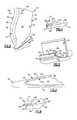
- FIG. 2is a perspective view of an embodiment of a fan blade of the engine shown in FIG. 1 .
- FIG. 3is a cross-sectional view of the fan blade shown in FIG. 2 taken along line 3 - 3 .
- FIG. 4is an enlarged cross-sectional view of the fan blade shown in FIG. 2 illustrating an adhesive fillet provided between a sheath and a substrate subsequent to curing.
- FIG. 5is a perspective view of a tool used to remove a portion of the fillet shown in FIG. 4 to provide a finished surface on the adhesive.
- FIG. 6is a cross-sectional view of a portion of the fan blade shown in FIG. 2 with a coating applied over the substrate and the finished surface.
- FIG. 1schematically illustrates a gas turbine engine 20 .
- the gas turbine engine 20is disclosed herein as a two-spool turbofan that generally incorporates a fan section 22 , a compressor section 24 , a combustor section 26 and a turbine section 28 .
- Alternative enginesmight include an augmentor section (not shown) among other systems or features.
- the fan section 22drives air along a bypass flowpath B while the compressor section 24 drives air along a core flowpath C for compression and communication into the combustor section 26 then expansion through the turbine section 28 .
- FIG. 1schematically illustrates a gas turbine engine 20 .
- the gas turbine engine 20is disclosed herein as a two-spool turbofan that generally incorporates a fan section 22 , a compressor section 24 , a combustor section 26 and a turbine section 28 .
- Alternative enginesmight include an augmentor section (not shown) among other systems or features.
- the fan section 22drives air along a bypass flowpath B while the compressor section 24 drives air along
- the engine 20generally includes a low speed spool 30 and a high speed spool 32 mounted for rotation about an engine central longitudinal axis A relative to an engine static structure 36 via several bearing systems 38 . It should be understood that various bearing systems 38 at various locations may alternatively or additionally be provided.
- the low speed spool 30generally includes an inner shaft 40 that interconnects a fan 42 , a low pressure (or first) compressor section 44 and a low pressure (or first) turbine section 46 .
- the inner shaft 40is connected to the fan 42 through a geared architecture 48 to drive the fan 42 at a lower speed than the low speed spool 30 .
- the high speed spool 32includes an outer shaft 50 that interconnects a high pressure (or second) compressor section 52 and high pressure (or second) turbine section 54 .
- a combustor 56is arranged between the high pressure compressor 52 and the high pressure turbine 54 .
- a mid-turbine frame 57 of the engine static structure 36is arranged generally between the high pressure turbine 54 and the low pressure turbine 46 .
- the mid-turbine frame 57supports one or more bearing systems 38 in the turbine section 28 .
- the inner shaft 40 and the outer shaft 50are concentric and rotate via bearing systems 38 about the engine central longitudinal axis A, which is collinear with their longitudinal axes.
- a “high pressure” compressor or turbineexperiences a higher pressure than a corresponding “low pressure” compressor or turbine.
- the core airflow Cis compressed by the low pressure compressor 44 then the high pressure compressor 52 , mixed and burned with fuel in the combustor 56 , then expanded over the high pressure turbine 54 and low pressure turbine 46 .
- the mid-turbine frame 57includes airfoils 59 which are in the core airflow path.
- the turbines 46 , 54rotationally drive the respective low speed spool 30 and high speed spool 32 in response to the expansion.
- the engine 20 in one exampleis a high-bypass geared aircraft engine.
- the engine 20 bypass ratiois greater than about six (6), with an example embodiment being greater than ten (10)
- the geared architecture 48is an epicyclic gear train, such as a star gear system or other gear system, with a gear reduction ratio of greater than about 2.3
- the low pressure turbine 46has a pressure ratio that is greater than about 5.
- the engine 20 bypass ratiois greater than about ten (10:1)
- the fan diameteris significantly larger than that of the low pressure compressor 44
- the low pressure turbine 46has a pressure ratio that is greater than about 5:1.
- Low pressure turbine 46 pressure ratiois pressure measured prior to inlet of low pressure turbine 46 as related to the pressure at the outlet of the low pressure turbine 46 prior to an exhaust nozzle. It should be understood, however, that the above parameters are only exemplary of one embodiment of a geared architecture engine and that the present invention is applicable to other gas turbine engines including direct drive turbofans.
- the fan section 22 of the engine 20is designed for a particular flight condition—typically cruise at about 0.8 Mach and about 35,000 feet.
- TSFCThrust Specific Fuel Consumption
- Fan pressure ratiois the pressure ratio across the fan blade alone, without a Fan Exit Guide Vane (“FEGV”) system.
- the low fan pressure ratio as disclosed herein according to one non-limiting embodimentis less than about 1.45.
- Low corrected fan tip speedis the actual fan tip speed in ft/sec divided by an industry standard temperature correction of [(Tambient deg R)/518.7) ⁇ 0.5].
- the “Low corrected fan tip speed” as disclosed herein according to one non-limiting embodimentis less than about 1150 ft/second.
- a fan blade 27 of the fan 42includes a root 31 supporting a platform 34 .
- An airfoil 35extends from the platform 34 to a tip 39 .
- the airfoil 35includes spaced apart leading and trailing edges 39 , 41 .
- Pressure and suction sides 43 , 45adjoin the leading and trailing edges 39 , 41 to provide a fan blade contour 61 .
- the fan blade 27includes a substrate 53 with an edge 49 .
- a sheath 47is secured to the substrate 53 over the edge 49 with adhesive 55 .
- the sheath 47 and the substrate 53are constructed from first and second metals that are different from one another.
- the substrate 53is constructed from an aluminum alloy, and the sheath 47 is constructed from a titanium alloy. It should be understood that other metals or materials may be used.
- the adhesive 55provides a barrier between the substrate 53 and the sheath 47 to prevent galvanic corrosion.
- the adhesive 55includes a scrim 62 (e.g., a glass scrim) that carries a resin 64 .
- the adhesive 55include a variety of commercially available aerospace-quality metal-bonding adhesives are suitable, including several epoxy- and polyurethane-based adhesive films.
- the adhesive 55is heat-cured via autoclave or other similar means.
- suitable bonding agentsinclude type EA9628 epoxy adhesive available from Henkel Corporation, Hysol Division, Bay Point, Calif. and type AF163K epoxy adhesive available from 3M Adhesives, Coatings & Sealers Division, St. Paul, Minn.
- the adhesive 55is a film, which also contributes a minute amount of thickness of blade 27 proximate the sheath 47 .
- a layer of adhesive filmis about 0.005-0.010 inch (1.2-2.5 mm) thick.
- a film-based adhesiveallows for generally uniform application, leading to a predictable thickness of airfoil 35 proximate forward airfoil edge 39 .
- Certain adhesives 55are compatible with scrim 62 .
- Scrim 62provides dielectric separation between airfoil 35 and sheath 47 , preventing galvanic corrosion between the two different metal surfaces of airfoil 35 and sheath 47 .
- the material forming scrim 62is often determined by its compatibility with adhesive 55 .
- One example scrim 62is a flexible nylon-based layer with a thickness between about 0.005 inch (0.12 mm) and about 0.010 inch (0.25 mm) thick.
- Other examples of the adhesive 55 and other aspects of the fan blade 27are set forth in U.S. Patent Application Publication 2011/0211967 to the Applicant, which is incorporated herein by reference in its entirety.
- the sheath 47includes first and second flanks 51 , 91 that are arranged on either side of the edge 49 .
- the adhesive 55when cured, flows beyond the sheath edge and creates a fillet 68 bridging an edge 66 of the sheath 47 and a surface 58 of the substrate 53 .
- the sheath 47provides spaced apart interior and exterior surfaces 70 , 72 adjoined by the edge 66 .
- a corner 74is provided at the intersection of the edge 66 and the exterior surface 72 , which may be provided at a generally right angle relative to one another.
- the scrim 62is provided beneath the sheath 47 and arranged inboard of the edge 66 .
- the fillet 68is larger than desired and is of variable size, which prevents the desired surface profile of an applied coating 60 over the adhesive 55 , the edge 66 and the surface 58 , as illustrated in FIGS. 3 and 6 .
- the coating 60which may be urethane, for example, provides the desired fan blade contour 61 .
- a tool 76is used to mechanically remove a portion of the fillet 68 to provide a mechanically worked finished surface 88 .
- the adhesive 55may be cured using a vacuum bag and autoclave, which provides a cured exterior surface having visible attributes such as a relatively smooth texture and/or a glossy or matte surface finish.
- the mechanically worked surface finish 88by way of contrast, will have, for example, striations and/or machining marks left by a tool. The structural characteristics and difference between the cured exterior surface and the mechanically worked surface finish 88 may be appreciated based upon a visual inspection of the part.
- the mechanically worked finished surface 88is provided at or below the interior surface 70 to sufficiently expose the edge 66 and provide a desired and consistent bonding surface for the coating 60 between the edge 66 and the surface 58 .
- the tool 76which is illustrated in FIG. 5 , includes first, second, third and fourth surfaces 78 , 80 , 82 , 84 .
- the first and second surfaces 78 , 80are adjacent to one another and arranged at generally a right angle relative to one another.
- the first and second surfaces 78 , 80are respectively configured to follow the exterior surface 72 and the edge 66 .
- the third surface 82adjoins the second surface 80 at an obtuse angle.
- the third surface 82provides a sharp edge that is configured to scrape the fillet 68 and provide the mechanically worked finished surface 88 .
- the mechanically worked finished surface 88includes a scraped contour in the example embodiment.
- the fourth surface 84adjoins the third surface 82 and is configured to follow the surface 58 of the substrate 53 without damaging the substrate.
- Tool surfaces 78 and 84preferably have rounded edges to preclude damaging the sheath substrate (exterior surface 72 ) or the airfoil substrate (surface 58 ) during the scraping procedure.
- a relief aperture 86which may be a generally circular hole in one example, adjoins the first and second surfaces 78 , 80 to one another to accommodate the corner 74 of the sheath 47 .
Landscapes
- Engineering & Computer Science (AREA)
- Mechanical Engineering (AREA)
- General Engineering & Computer Science (AREA)
- Chemical & Material Sciences (AREA)
- Materials Engineering (AREA)
- Composite Materials (AREA)
- Architecture (AREA)
- Structures Of Non-Positive Displacement Pumps (AREA)
Abstract
Description
Claims (16)
Priority Applications (1)
| Application Number | Priority Date | Filing Date | Title |
|---|---|---|---|
| US13/422,541US10260351B2 (en) | 2012-03-16 | 2012-03-16 | Fan blade and method of manufacturing same |
Applications Claiming Priority (1)
| Application Number | Priority Date | Filing Date | Title |
|---|---|---|---|
| US13/422,541US10260351B2 (en) | 2012-03-16 | 2012-03-16 | Fan blade and method of manufacturing same |
Publications (2)
| Publication Number | Publication Date |
|---|---|
| US20130239586A1 US20130239586A1 (en) | 2013-09-19 |
| US10260351B2true US10260351B2 (en) | 2019-04-16 |
Family
ID=49156392
Family Applications (1)
| Application Number | Title | Priority Date | Filing Date |
|---|---|---|---|
| US13/422,541Active2036-05-08US10260351B2 (en) | 2012-03-16 | 2012-03-16 | Fan blade and method of manufacturing same |
Country Status (1)
| Country | Link |
|---|---|
| US (1) | US10260351B2 (en) |
Cited By (3)
| Publication number | Priority date | Publication date | Assignee | Title |
|---|---|---|---|---|
| US11242155B2 (en)* | 2019-03-11 | 2022-02-08 | Rolls-Royce Plc | Gas turbine engine compression system |
| US11346287B2 (en) | 2019-03-11 | 2022-05-31 | Rolls-Royce Plc | Geared gas turbine engine |
| US11459893B2 (en) | 2019-03-11 | 2022-10-04 | Rolls-Royce Plc | Efficient gas turbine engine installation and operation |
Families Citing this family (17)
| Publication number | Priority date | Publication date | Assignee | Title |
|---|---|---|---|---|
| US10294797B2 (en) | 2013-09-27 | 2019-05-21 | United Technologies Corporation | Fan blade assembly |
| US20160230774A1 (en)* | 2013-09-27 | 2016-08-11 | United Technologies Corporation | Fan blade assembly |
| US9403350B2 (en)* | 2013-12-16 | 2016-08-02 | The Nordam Group, Inc. | Flash control metal bonding |
| EP3090127B1 (en)* | 2013-12-23 | 2020-05-06 | United Technologies Corporation | Fan blade with adhesive fabric stackup |
| US20160177732A1 (en)* | 2014-07-22 | 2016-06-23 | United Technologies Corporation | Hollow fan blade for a gas turbine engine |
| EP3034785B1 (en) | 2014-12-19 | 2019-01-30 | Rolls-Royce plc | A gas turbine fan blade with varying fracture resistance |
| US10030522B2 (en) | 2014-12-19 | 2018-07-24 | Rolls-Royce Plc | Blade with metallic leading edge and angled shear zones |
| US10107136B2 (en)* | 2014-12-19 | 2018-10-23 | Rolls-Royce Plc | Blade |
| AU2016423471B2 (en) | 2016-09-13 | 2019-04-18 | Polytech A/S | Wind turbine blade including protective cover |
| US10822969B2 (en) | 2018-10-18 | 2020-11-03 | Raytheon Technologies Corporation | Hybrid airfoil for gas turbine engines |
| US10774653B2 (en) | 2018-12-11 | 2020-09-15 | Raytheon Technologies Corporation | Composite gas turbine engine component with lattice structure |
| EP3986706B1 (en)* | 2019-06-19 | 2023-07-26 | Safran Aircraft Engines | An adhesive assembly method and an adhesive assembly obtained by the method |
| US11215054B2 (en)* | 2019-10-30 | 2022-01-04 | Raytheon Technologies Corporation | Airfoil with encapsulating sheath |
| US11466576B2 (en) | 2019-11-04 | 2022-10-11 | Raytheon Technologies Corporation | Airfoil with continuous stiffness joint |
| FR3103731B1 (en)* | 2019-11-29 | 2021-11-26 | Safran | COMPOSITE AUBE FOR AN AIRCRAFT ENGINE AND ITS MANUFACTURING AND REPAIR METHODS |
| US11073030B1 (en) | 2020-05-21 | 2021-07-27 | Raytheon Technologies Corporation | Airfoil attachment for gas turbine engines |
| US20230234248A1 (en)* | 2022-01-27 | 2023-07-27 | Williams-Sonoma, Inc. | Food Chopping Device |
Citations (10)
| Publication number | Priority date | Publication date | Assignee | Title |
|---|---|---|---|---|
| GB121420A (en) | 1918-04-13 | 1918-12-19 | Henry Francis Mullis | An Improved Tool or Appliance for Removing Superfluous Glue from Glued Joints and the like. |
| US3739745A (en) | 1971-06-21 | 1973-06-19 | Owens Illinois Inc | Glue reclaiming system |
| US3762835A (en)* | 1971-07-02 | 1973-10-02 | Gen Electric | Foreign object damage protection for compressor blades and other structures and related methods |
| US20070231156A1 (en) | 2005-12-14 | 2007-10-04 | Hontek Corporation | Method and coating for protecting and repairing an airfoil surface |
| US20070286706A1 (en) | 2006-05-02 | 2007-12-13 | Nisca Corporation | Adhesive applicator and bookmaking apparatus using the same |
| US20100028160A1 (en)* | 2008-07-31 | 2010-02-04 | General Electric Company | Compressor blade leading edge shim and related method |
| US7955054B2 (en)* | 2009-09-21 | 2011-06-07 | Pratt & Whitney Rocketdyne, Inc. | Internally damped blade |
| US20110206534A1 (en) | 2010-12-15 | 2011-08-25 | General Electric Company | Wind turbine blade with modular leading edge |
| US20110211967A1 (en)* | 2010-02-26 | 2011-09-01 | United Technologies Corporation | Hybrid metal fan blade |
| US8047799B2 (en)* | 2010-12-13 | 2011-11-01 | General Electric Company | Wind turbine blades with improved bond line and associated method |
- 2012
- 2012-03-16USUS13/422,541patent/US10260351B2/enactiveActive
Patent Citations (10)
| Publication number | Priority date | Publication date | Assignee | Title |
|---|---|---|---|---|
| GB121420A (en) | 1918-04-13 | 1918-12-19 | Henry Francis Mullis | An Improved Tool or Appliance for Removing Superfluous Glue from Glued Joints and the like. |
| US3739745A (en) | 1971-06-21 | 1973-06-19 | Owens Illinois Inc | Glue reclaiming system |
| US3762835A (en)* | 1971-07-02 | 1973-10-02 | Gen Electric | Foreign object damage protection for compressor blades and other structures and related methods |
| US20070231156A1 (en) | 2005-12-14 | 2007-10-04 | Hontek Corporation | Method and coating for protecting and repairing an airfoil surface |
| US20070286706A1 (en) | 2006-05-02 | 2007-12-13 | Nisca Corporation | Adhesive applicator and bookmaking apparatus using the same |
| US20100028160A1 (en)* | 2008-07-31 | 2010-02-04 | General Electric Company | Compressor blade leading edge shim and related method |
| US7955054B2 (en)* | 2009-09-21 | 2011-06-07 | Pratt & Whitney Rocketdyne, Inc. | Internally damped blade |
| US20110211967A1 (en)* | 2010-02-26 | 2011-09-01 | United Technologies Corporation | Hybrid metal fan blade |
| US8047799B2 (en)* | 2010-12-13 | 2011-11-01 | General Electric Company | Wind turbine blades with improved bond line and associated method |
| US20110206534A1 (en) | 2010-12-15 | 2011-08-25 | General Electric Company | Wind turbine blade with modular leading edge |
Cited By (11)
| Publication number | Priority date | Publication date | Assignee | Title |
|---|---|---|---|---|
| US11242155B2 (en)* | 2019-03-11 | 2022-02-08 | Rolls-Royce Plc | Gas turbine engine compression system |
| US11346287B2 (en) | 2019-03-11 | 2022-05-31 | Rolls-Royce Plc | Geared gas turbine engine |
| US11459893B2 (en) | 2019-03-11 | 2022-10-04 | Rolls-Royce Plc | Efficient gas turbine engine installation and operation |
| US11584532B2 (en) | 2019-03-11 | 2023-02-21 | Rolls-Royce Plc | Gas turbine engine compression system with core compressor pressure ratio |
| US11698030B2 (en) | 2019-03-11 | 2023-07-11 | Rolls-Royce Plc | Geared gas turbine engine |
| US11781491B2 (en) | 2019-03-11 | 2023-10-10 | Rolls-Royce Plc | Geared gas turbine engine |
| US12006835B2 (en) | 2019-03-11 | 2024-06-11 | Rolls-Royce Plc | Efficient gas turbine engine installation and operation |
| US12024301B2 (en) | 2019-03-11 | 2024-07-02 | Rolls-Royce Plc | Gas turbine engine compression system with core compressor pressure ratio |
| US12071901B2 (en) | 2019-03-11 | 2024-08-27 | Rolls-Royce Plc | Geared gas turbine engine |
| US12397917B2 (en) | 2019-03-11 | 2025-08-26 | Rolls-Royce Plc | Gas turbine engine compression system with core compressor pressure ratio |
| US12421903B2 (en) | 2019-03-11 | 2025-09-23 | Rolls-Royce Plc | Geared gas turbine engine |
Also Published As
| Publication number | Publication date |
|---|---|
| US20130239586A1 (en) | 2013-09-19 |
Similar Documents
| Publication | Publication Date | Title |
|---|---|---|
| US10260351B2 (en) | Fan blade and method of manufacturing same | |
| EP2855849B1 (en) | Airfoil cover system | |
| EP3480429B1 (en) | Composite fan blade with leading edge sheath and energy absorbing insert | |
| EP2634368A2 (en) | Method of bonding a leading edge sheath to a blade body of a fan blade | |
| EP3480430B1 (en) | Integrally bladed rotor for a gas turbine engine and method of fabricating an integrally bladed rotor for a gas turbine engine | |
| US20140010663A1 (en) | Gas turbine engine fan blade tip treatment | |
| EP3282087A1 (en) | Fan, gas turbine engine with a fan, and method for creating a gas turbine engine fan | |
| US20160017719A1 (en) | Gas turbine engine blade squealer pockets | |
| EP3114321B1 (en) | Gas turbine engine airfoil | |
| US10563666B2 (en) | Fan blade with cover and method for cover retention | |
| US10330111B2 (en) | Gas turbine engine airfoil | |
| EP3409888B1 (en) | Method of manufacturing a fan blade for a gas turbine engine | |
| WO2015126454A1 (en) | Gas turbine engine airfoil | |
| EP3428394B1 (en) | Gas turbine engine fan blade and method of designing a fan blade | |
| EP2993303A1 (en) | Gas turbine engine component with film cooling hole with pocket | |
| EP3772567B1 (en) | Gas turbine engine and corresponding method of designing a fan blade | |
| US10273816B2 (en) | Wear pad to prevent cracking of fan blade | |
| US10458255B2 (en) | Removable film for airfoil surfaces | |
| US11306600B2 (en) | Enhanced adhesion thermal barrier coating | |
| EP2993300A1 (en) | Gas turbine engine airfoil structure | |
| EP2929955A1 (en) | Rib bumper system | |
| EP4480672A1 (en) | Repair process using plasma etching | |
| WO2015126450A1 (en) | Gas turbine engine airfoil | |
| EP2942486A1 (en) | Gas turbine engine airfoil cooling passage configuration | |
| US20190039167A1 (en) | Method of making integrally bladed rotor |
Legal Events
| Date | Code | Title | Description |
|---|---|---|---|
| AS | Assignment | Owner name:UNITED TECHNOLOGIES CORPORATION, CONNECTICUT Free format text:ASSIGNMENT OF ASSIGNORS INTEREST;ASSIGNORS:PARKIN, MICHAEL;HANSEN, JAMES O.;HERTEL, CHRISTOPHER J.;AND OTHERS;REEL/FRAME:027884/0122 Effective date:20120316 | |
| STCF | Information on status: patent grant | Free format text:PATENTED CASE | |
| AS | Assignment | Owner name:RAYTHEON TECHNOLOGIES CORPORATION, MASSACHUSETTS Free format text:CHANGE OF NAME;ASSIGNOR:UNITED TECHNOLOGIES CORPORATION;REEL/FRAME:054062/0001 Effective date:20200403 | |
| AS | Assignment | Owner name:RAYTHEON TECHNOLOGIES CORPORATION, CONNECTICUT Free format text:CORRECTIVE ASSIGNMENT TO CORRECT THE AND REMOVE PATENT APPLICATION NUMBER 11886281 AND ADD PATENT APPLICATION NUMBER 14846874. TO CORRECT THE RECEIVING PARTY ADDRESS PREVIOUSLY RECORDED AT REEL: 054062 FRAME: 0001. ASSIGNOR(S) HEREBY CONFIRMS THE CHANGE OF ADDRESS;ASSIGNOR:UNITED TECHNOLOGIES CORPORATION;REEL/FRAME:055659/0001 Effective date:20200403 | |
| MAFP | Maintenance fee payment | Free format text:PAYMENT OF MAINTENANCE FEE, 4TH YEAR, LARGE ENTITY (ORIGINAL EVENT CODE: M1551); ENTITY STATUS OF PATENT OWNER: LARGE ENTITY Year of fee payment:4 | |
| AS | Assignment | Owner name:RTX CORPORATION, CONNECTICUT Free format text:CHANGE OF NAME;ASSIGNOR:RAYTHEON TECHNOLOGIES CORPORATION;REEL/FRAME:064714/0001 Effective date:20230714 |