US10259658B2 - Conveyor with accumulation table - Google Patents
Conveyor with accumulation tableDownload PDFInfo
- Publication number
- US10259658B2 US10259658B2US15/796,963US201715796963AUS10259658B2US 10259658 B2US10259658 B2US 10259658B2US 201715796963 AUS201715796963 AUS 201715796963AUS 10259658 B2US10259658 B2US 10259658B2
- Authority
- US
- United States
- Prior art keywords
- conveyor
- buffer table
- latch
- conveying system
- lateral side
- Prior art date
- Legal status (The legal status is an assumption and is not a legal conclusion. Google has not performed a legal analysis and makes no representation as to the accuracy of the status listed.)
- Active
Links
- 238000009825accumulationMethods0.000titledescription11
- 238000004519manufacturing processMethods0.000description3
- 230000013011matingEffects0.000description3
- 230000007246mechanismEffects0.000description3
- 238000011144upstream manufacturingMethods0.000description3
- 238000007689inspectionMethods0.000description2
- 239000002184metalSubstances0.000description2
- 230000003287optical effectEffects0.000description2
- 238000012546transferMethods0.000description2
- 239000003795chemical substances by applicationSubstances0.000description1
- 238000004140cleaningMethods0.000description1
- 238000004891communicationMethods0.000description1
- 238000003780insertionMethods0.000description1
- 230000037431insertionEffects0.000description1
- 230000003993interactionEffects0.000description1
- 238000012423maintenanceMethods0.000description1
- 239000000463materialSubstances0.000description1
- 238000012986modificationMethods0.000description1
- 230000004048modificationEffects0.000description1
- 238000012544monitoring processMethods0.000description1
- 238000004806packaging method and processMethods0.000description1
- 239000006187pillSubstances0.000description1
- 239000007787solidSubstances0.000description1
Images


Classifications
- B—PERFORMING OPERATIONS; TRANSPORTING
- B65—CONVEYING; PACKING; STORING; HANDLING THIN OR FILAMENTARY MATERIAL
- B65G—TRANSPORT OR STORAGE DEVICES, e.g. CONVEYORS FOR LOADING OR TIPPING, SHOP CONVEYOR SYSTEMS OR PNEUMATIC TUBE CONVEYORS
- B65G41/00—Supporting frames or bases for conveyors as a whole, e.g. transportable conveyor frames
- B65G41/007—Means for moving conveyor frames and control arrangements therefor
- B65G41/008—Means for moving conveyor frames and control arrangements therefor frames mounted on wheels or caterpillar
- B—PERFORMING OPERATIONS; TRANSPORTING
- B65—CONVEYING; PACKING; STORING; HANDLING THIN OR FILAMENTARY MATERIAL
- B65G—TRANSPORT OR STORAGE DEVICES, e.g. CONVEYORS FOR LOADING OR TIPPING, SHOP CONVEYOR SYSTEMS OR PNEUMATIC TUBE CONVEYORS
- B65G21/00—Supporting or protective framework or housings for endless load-carriers or traction elements of belt or chain conveyors
- B65G21/02—Supporting or protective framework or housings for endless load-carriers or traction elements of belt or chain conveyors consisting essentially of struts, ties, or like structural elements
- B65G21/06—Supporting or protective framework or housings for endless load-carriers or traction elements of belt or chain conveyors consisting essentially of struts, ties, or like structural elements constructed to facilitate rapid assembly or dismantling
- B—PERFORMING OPERATIONS; TRANSPORTING
- B65—CONVEYING; PACKING; STORING; HANDLING THIN OR FILAMENTARY MATERIAL
- B65G—TRANSPORT OR STORAGE DEVICES, e.g. CONVEYORS FOR LOADING OR TIPPING, SHOP CONVEYOR SYSTEMS OR PNEUMATIC TUBE CONVEYORS
- B65G41/00—Supporting frames or bases for conveyors as a whole, e.g. transportable conveyor frames
- B65G41/006—Supporting frames or bases for conveyors as a whole, e.g. transportable conveyor frames with the conveyor not adjustably mounted on the supporting frame or base
- B—PERFORMING OPERATIONS; TRANSPORTING
- B65—CONVEYING; PACKING; STORING; HANDLING THIN OR FILAMENTARY MATERIAL
- B65G—TRANSPORT OR STORAGE DEVICES, e.g. CONVEYORS FOR LOADING OR TIPPING, SHOP CONVEYOR SYSTEMS OR PNEUMATIC TUBE CONVEYORS
- B65G47/00—Article or material-handling devices associated with conveyors; Methods employing such devices
- B65G47/34—Devices for discharging articles or materials from conveyor
- B65G47/46—Devices for discharging articles or materials from conveyor and distributing, e.g. automatically, to desired points
- B65G47/51—Devices for discharging articles or materials from conveyor and distributing, e.g. automatically, to desired points according to unprogrammed signals, e.g. influenced by supply situation at destination
- B65G47/5104—Devices for discharging articles or materials from conveyor and distributing, e.g. automatically, to desired points according to unprogrammed signals, e.g. influenced by supply situation at destination for articles
- B65G47/5109—Devices for discharging articles or materials from conveyor and distributing, e.g. automatically, to desired points according to unprogrammed signals, e.g. influenced by supply situation at destination for articles first In - First Out systems: FIFO
- B65G47/5145—Devices for discharging articles or materials from conveyor and distributing, e.g. automatically, to desired points according to unprogrammed signals, e.g. influenced by supply situation at destination for articles first In - First Out systems: FIFO with recirculation means
- B—PERFORMING OPERATIONS; TRANSPORTING
- B65—CONVEYING; PACKING; STORING; HANDLING THIN OR FILAMENTARY MATERIAL
- B65G—TRANSPORT OR STORAGE DEVICES, e.g. CONVEYORS FOR LOADING OR TIPPING, SHOP CONVEYOR SYSTEMS OR PNEUMATIC TUBE CONVEYORS
- B65G47/00—Article or material-handling devices associated with conveyors; Methods employing such devices
- B65G47/52—Devices for transferring articles or materials between conveyors i.e. discharging or feeding devices
- B65G47/68—Devices for transferring articles or materials between conveyors i.e. discharging or feeding devices adapted to receive articles arriving in one layer from one conveyor lane and to transfer them in individual layers to more than one conveyor lane or to one broader conveyor lane, or vice versa, e.g. combining the flows of articles conveyed by more than one conveyor
- B65G47/682—Devices for transferring articles or materials between conveyors i.e. discharging or feeding devices adapted to receive articles arriving in one layer from one conveyor lane and to transfer them in individual layers to more than one conveyor lane or to one broader conveyor lane, or vice versa, e.g. combining the flows of articles conveyed by more than one conveyor from a single conveyor lane consisting of one conveyor or several adjacent conveyors
- B65G47/684—Devices for transferring articles or materials between conveyors i.e. discharging or feeding devices adapted to receive articles arriving in one layer from one conveyor lane and to transfer them in individual layers to more than one conveyor lane or to one broader conveyor lane, or vice versa, e.g. combining the flows of articles conveyed by more than one conveyor from a single conveyor lane consisting of one conveyor or several adjacent conveyors with recirculation of articles forming a buffer
- B—PERFORMING OPERATIONS; TRANSPORTING
- B65—CONVEYING; PACKING; STORING; HANDLING THIN OR FILAMENTARY MATERIAL
- B65G—TRANSPORT OR STORAGE DEVICES, e.g. CONVEYORS FOR LOADING OR TIPPING, SHOP CONVEYOR SYSTEMS OR PNEUMATIC TUBE CONVEYORS
- B65G17/00—Conveyors having an endless traction element, e.g. a chain, transmitting movement to a continuous or substantially-continuous load-carrying surface or to a series of individual load-carriers; Endless-chain conveyors in which the chains form the load-carrying surface
- B65G17/06—Conveyors having an endless traction element, e.g. a chain, transmitting movement to a continuous or substantially-continuous load-carrying surface or to a series of individual load-carriers; Endless-chain conveyors in which the chains form the load-carrying surface having a load-carrying surface formed by a series of interconnected, e.g. longitudinal, links, plates, or platforms
- B65G17/08—Conveyors having an endless traction element, e.g. a chain, transmitting movement to a continuous or substantially-continuous load-carrying surface or to a series of individual load-carriers; Endless-chain conveyors in which the chains form the load-carrying surface having a load-carrying surface formed by a series of interconnected, e.g. longitudinal, links, plates, or platforms the surface being formed by the traction element
- B—PERFORMING OPERATIONS; TRANSPORTING
- B65—CONVEYING; PACKING; STORING; HANDLING THIN OR FILAMENTARY MATERIAL
- B65G—TRANSPORT OR STORAGE DEVICES, e.g. CONVEYORS FOR LOADING OR TIPPING, SHOP CONVEYOR SYSTEMS OR PNEUMATIC TUBE CONVEYORS
- B65G2201/00—Indexing codes relating to handling devices, e.g. conveyors, characterised by the type of product or load being conveyed or handled
- B65G2201/02—Articles
- B65G2201/0235—Containers
- B65G2201/0244—Bottles
- B—PERFORMING OPERATIONS; TRANSPORTING
- B65—CONVEYING; PACKING; STORING; HANDLING THIN OR FILAMENTARY MATERIAL
- B65G—TRANSPORT OR STORAGE DEVICES, e.g. CONVEYORS FOR LOADING OR TIPPING, SHOP CONVEYOR SYSTEMS OR PNEUMATIC TUBE CONVEYORS
- B65G2203/00—Indexing code relating to control or detection of the articles or the load carriers during conveying
- B65G2203/02—Control or detection
- B65G2203/0208—Control or detection relating to the transported articles
- B65G2203/0241—Quantity of articles
- B—PERFORMING OPERATIONS; TRANSPORTING
- B65—CONVEYING; PACKING; STORING; HANDLING THIN OR FILAMENTARY MATERIAL
- B65G—TRANSPORT OR STORAGE DEVICES, e.g. CONVEYORS FOR LOADING OR TIPPING, SHOP CONVEYOR SYSTEMS OR PNEUMATIC TUBE CONVEYORS
- B65G2207/00—Indexing codes relating to constructional details, configuration and additional features of a handling device, e.g. Conveyors
- B65G2207/30—Modular constructions
Definitions
- This applicationrelates generally to conveying systems used in the packaging industry and, more specifically, to a conveying system and accumulation table arrangement.
- Accumulators and accumulation tablesare well known in the art of conveyors. Indeed, in production lines where the unfinished products are moved on conveyors from one production machine to another, devices for accumulating the products between consecutive machines must often be installed since the production machines commonly operate at different speeds or may have to be momentarily stopped for maintenance.
- a conveying systemincludes a conveyor for moving items along a primary conveyance path.
- a first buffer tableis releasably connected at a first lateral side of the conveyor, and a second buffer table is releasably connected at a second lateral side of the conveyor.
- a conveying systemin another aspect, includes a conveyor for moving items along a primary conveyance path.
- a first buffer tableis releasably connected at a first side of the conveyor via a first releasable latch arrangement that includes at least one latch part mounted on the first buffer table and at least one latch part mounted on the conveyor, and at least one electrical connector arrangement that includes at least one connector part mounted on the first buffer table and at least one connector part mounted on the conveyor.
- a second buffer tableis releasably connected at a second side of the conveyor via a second releasable latch arrangement that includes at least one latch part mounted on the second buffer table and at least one latch part mounted on the conveyor, and at least one electrical connector arrangement that includes at least one connector part mounted on the second buffer table and at least one connector part mounted on the conveyor.
- a conveying systemincludes a conveyor for moving items along a primary conveyance path.
- a buffer tableis releasably connectable at a first side of the conveyor via a releasable latch arrangement that includes a first latch part mounted on the buffer table and second latch part mounted on the conveyor, and at least one electrical connector arrangement that includes a first connector part mounted on the buffer table and a second connector part mounted on the conveyor.
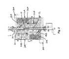
- FIG. 1shows a perspective view of a conveying system
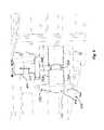
- FIG. 2shows a top plan view of the accumulation portion of the conveying system
- FIG. 3shows a perspective view of the accumulation portion with buffer tables separated from the primary conveyor
- FIG. 4shows a perspective view of one buffer table at one side of the primary conveyor
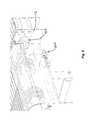
- FIG. 5shows an enlarged view of one end of the buffer table of FIG. 4 ;
- FIGS. 6-8show enlarged views of the opposite end of the buffer table of FIG. 4 ;
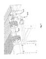
- FIG. 9shows an enlarged view of a latch arrangement between the buffer table and the primary conveyor
- FIG. 10shows an enlarged view of the electrical connection arrangement between the buffer table and the primary conveyor
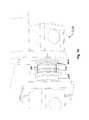
- FIGS. 11-17depict movement of a buffer table into engagement with a side of the primary conveyor.
- a conveying system 10includes a primary conveyor 12 for moving items along a primary conveyance path (e.g., in the direction of arrow 14 ).
- Buffer tables 16 A and 16 Bare releasably connected at opposite sides of the conveyor 12 .
- the systemincludes a downstream section 18 as well.
- the conveying system 10may be used for conveying bottles (e.g., pill bottles), though other items could likewise be conveyed.
- the buffer tables 16 A, 16 Bcreate an accumulation table arrangement for this purpose.
- a transfer wheel 20 mounted on a transfer arm 22is moved into the main conveyance path to block downstream flow and kick product onto the buffer table 16 B, where the conveyor of buffer table 16 B flows the product in the direction of arrow 24 B back toward the upstream end of the accumulation zone.
- a guide rail 26 B on the buffer table 16 Bdirects the product flow back toward the primary conveyor per arrow 28 B.
- any product that is bumped onto the buffer table 16 Ais moved by the conveyor of buffer table 16 A in the direction of arrow 24 A toward the downstream end of the accumulation zone and a guide rail 26 A directs the product flow back toward the primary conveyor per arrow 28 A.
- the systemcreates a generally counterclockwise accumulation flow when viewed from the top as in FIG. 2 , but other item flow/travel patterns are possible.
- Each buffer tableincludes a conveyor drive arrangement 30 A, 30 B, such as a motor with associated components (e.g., gearing) to rotate a drive shaft linked the conveyor at one end of the table (e.g., per drive shaft 32 B in FIG. 3 and drive shaft 32 A in FIG. 7 ).
- Each buffer tablemay also include one or more sensors for various purposes. For example, one or more sensors (e.g., mechanical, optical or electromagnetic) may be included on each buffer table for detecting when the buffer table is full. In such cases, the controller for the system (e.g., shown schematically in FIG. 1 as component 100 ) may shut down both the buffer tables and the primary conveyor.
- one or more sensorsmay be included on the buffer table for detecting when one or more portions of the table is not in an operating position (e.g., in implementation sin which the buffer table includes a mechanism for lowering down the conveyor for inspection, such lowering could be detected).
- the controller for the systemmay prevent operation of the buffer table(s) and/or cease operation of the primary conveyor (e.g., acting as an interlock).
- one or more motor sensorsmay also be provided on each buffer table for monitoring operation of the table.
- controlleris intended to broadly encompass any circuit (e.g., solid state, application specific integrated circuit (ASIC), an electronic circuit, a combinational logic circuit, a field programmable gate array (FPGA)), processor(s) (e.g., shared, dedicated, or group—including hardware or software that executes code), software, firmware and/or other components, or a combination of some or all of the above, that carries out the control functions of the conveying system or the control functions of any component thereof.
- ASICapplication specific integrated circuit
- FPGAfield programmable gate array
- each buffer tableis releasably connected to the central conveyor 12 .
- each buffer tableis supported by a respective set of wheels 34 A, 34 B that enables the buffer table to be easily pulled away from the conveyor (e.g., per arrows 36 A, 36 B in FIG. 3 ) when desired and then easily pushed back toward (e.g., per arrows 38 A, 38 B in FIG. 3 ) into engagement with the conveyor 12 when desired.
- caster wheelsare utilized, but other variations are possible.
- one or more of the wheels of each buffer tablecould include a manual locking mechanism (e.g., a foot actuated lock) for added stability when the buffer table is engaged with the conveyor 12 .
- a latch arrangementreleasably connects each buffer table to its respective side of the conveyor 12 .
- the latch arrangementincludes two sets of mating latch components 42 A at the upstream and downstream ends of the buffer table.
- Each set of mating latch componentsincludes a male latch part 44 A and a female latch part 46 A, where the male latch parts 44 A are fixed to the side of the conveyor 12 and the female latch parts 46 A are fixed to the buffer table.
- the spacing between the male latch parts 44 A on the conveyor and the female latch parts on the buffer tableis matched to allow mating of the parts when the buffer table 16 A is slid toward the side of the conveyor.
- the male latch part 44 Amay be configured as an elongated member such as a rod member 50 A with an external groove 52 A.
- the female latch part 46 Amay include a housing 54 A with a through opening 56 A to receive the rod member 50 A.
- the female latch part 46 Aalso includes a pin member 58 A movable radially into and out of the through opening 56 A and biased into the illustrated latching position within the opening 56 A for engaging with the external groove 52 A, forming the latched connection of the two components.
- An external handle mechanism 60 Aprovides the ability to pull the pin member 58 A radially outward (e.g., per arrow 62 A) from the groove 52 A in order to enable release of the two latch parts.
- the free end of the rod member 50 Amay be curved, tapered or otherwise contoured such that when the rod member 50 A moves into the opening 56 A the interaction between the end of the rod member 50 A and the pin member 58 A automatically moves the pin member radially outward until the pin member aligns with the groove 52 A and snaps into the latched position within the groove.
- the latch parts 44 A and 46 Aare more easily engaged with each other without requiring manual pulling of the handle 60 A.
- an electrical connection(e.g., 64 A in FIGS. 6-8 and 10 ) may be provided between each buffer table and the conveyor.
- Each electrical connectionmay be formed by an electrical connector component 66 A located on the side of the conveyor 12 and an electrical connector 68 A component located on the buffer table, wherein the two electrical connector components releasably mate with each other.
- Component 66 Amay include a free end with a recessed opening 70 A that receives a nose 72 A at the free end of component 68 A.
- the positioning of the nose and openingcould be reversed as between the buffer table and the conveyor. Pin and socket electrical contacts engage each other for electrical connection when the nose 72 A is seated in the opening 70 A.
- the electrical connections madeinclude a power delivery path (e.g., to provide electrical power to the buffer table drive motor), one or more sensor signal paths (e.g., to enable communication of a conveying system controller and the sensor(s) on the buffer table) and/or one or more control signal paths as needed for selective control of any components of the buffer table.
- a power delivery pathe.g., to provide electrical power to the buffer table drive motor
- sensor signal pathse.g., to enable communication of a conveying system controller and the sensor(s) on the buffer table
- control signal pathse.g., to enable communication of a conveying system controller and the sensor(s) on the buffer table
- the electrical connection componentsmay be Part Nos. 18.0211 & 18.0210 (also referred to by the MGK2VB10-14+MGK2R-M25 Type code) available from Multi-Contact AG (www.multi-contac.ocm), though many other variations are possible.
- the above noted componentsprovide fully insulated socket and pin plastic housings of high-impact material. Each housing may be formed by front and rear parts that are screwed or otherwise secured together. The cylindrical front part of each housing serves for the positioning of the contact carrier and the square rear part for the insertion and mounting of the leads.
- FIGS. 11-17show a sequence of engaging a buffer table with a conveyor by moving the buffer table 16 A laterally toward the conveyor with respective latch parts 44 A and 46 A aligned for engagement.
- the latch parts 44 A, 46 Aare configured to assure alignment between the electrical connector parts 66 A, 68 A when the buffer table is being engaged with the side of the conveyor 12 .
- the latch parts 44 A and 46 Aare sized and positioned to at least initially engage each other before the connector parts 66 A and 68 A make any engagement with each other. This guiding helps avoid damage of the electrical connector parts that might occur if they are misaligned (e.g., where the electrical connector parts are formed of plastic housings that are more easily damaged than metal and female latch parts of metal).
- the buffer tables 16 A and 16 Bmay be of identical configuration and the latch parts and electrical connector parts on opposite sides of the tables similarly positioned such that either table may be releasably connected at either side of the conveyor (e.g., buffer table 16 A could be releasably connected at the opposite side of the conveyor where buffer table 16 B is located by simply moving buffer table 16 A to the opposite side of the table and rotating the buffer table 16 A one-hundred eighty degrees to enable engagement with the opposite side of the conveyor).
Landscapes
- Engineering & Computer Science (AREA)
- Mechanical Engineering (AREA)
- Control Of Conveyors (AREA)
Abstract
Description
Claims (19)
Priority Applications (1)
| Application Number | Priority Date | Filing Date | Title |
|---|---|---|---|
| US15/796,963US10259658B2 (en) | 2016-11-02 | 2017-10-30 | Conveyor with accumulation table |
Applications Claiming Priority (2)
| Application Number | Priority Date | Filing Date | Title |
|---|---|---|---|
| US201662416460P | 2016-11-02 | 2016-11-02 | |
| US15/796,963US10259658B2 (en) | 2016-11-02 | 2017-10-30 | Conveyor with accumulation table |
Publications (2)
| Publication Number | Publication Date |
|---|---|
| US20180118464A1 US20180118464A1 (en) | 2018-05-03 |
| US10259658B2true US10259658B2 (en) | 2019-04-16 |
Family
ID=62020988
Family Applications (1)
| Application Number | Title | Priority Date | Filing Date |
|---|---|---|---|
| US15/796,963ActiveUS10259658B2 (en) | 2016-11-02 | 2017-10-30 | Conveyor with accumulation table |
Country Status (2)
| Country | Link |
|---|---|
| US (1) | US10259658B2 (en) |
| CA (1) | CA2984217C (en) |
Cited By (1)
| Publication number | Priority date | Publication date | Assignee | Title |
|---|---|---|---|---|
| US20220088789A1 (en)* | 2019-02-28 | 2022-03-24 | Universite De Bretagne Sud | System for the temporary storage of objects |
Families Citing this family (3)
| Publication number | Priority date | Publication date | Assignee | Title |
|---|---|---|---|---|
| CN109499887B (en)* | 2018-10-25 | 2021-01-05 | 中邮科技有限责任公司 | Single piece separating system for mixed articles |
| CN112678561B (en)* | 2021-03-11 | 2021-06-01 | 苏州澳昆智能机器人技术有限公司 | Automatic loading method |
| CN115140506B (en)* | 2021-03-31 | 2024-01-09 | 宝山钢铁股份有限公司 | Method for matching track trolley to bear impact load |
Citations (60)
| Publication number | Priority date | Publication date | Assignee | Title |
|---|---|---|---|---|
| US995379A (en) | 1909-12-27 | 1911-06-13 | Martin C Schwab | System for collecting and distributing parcels. |
| US1852322A (en) | 1928-03-01 | 1932-04-05 | Liquid Carbonic Corp | System and apparatus for handling bottles |
| US2303755A (en) | 1940-05-20 | 1942-12-01 | California Packing Corp | Pineapple handling apparatus |
| US2763359A (en)* | 1951-08-07 | 1956-09-18 | Allen S Rose | Arranging apparatus for cans and similar containers |
| US3102630A (en) | 1959-12-14 | 1963-09-03 | Fmc Corp | Apparatus for handling articles |
| US3176821A (en) | 1963-09-23 | 1965-04-06 | Eldred Company | Article conveying and transferring mechanism |
| US3232411A (en) | 1963-09-17 | 1966-02-01 | Emhart Corp | Container enlining machine |
| US3339700A (en) | 1965-09-24 | 1967-09-05 | Armstrong Cork Co | Sampling apparatus |
| US3342012A (en) | 1964-02-12 | 1967-09-19 | Barker Poultry Equipment Compa | Egg packer |
| US3604551A (en) | 1969-10-13 | 1971-09-14 | Anchor Hocking Corp | Article conveyor flow control and unscrambling apparatus |
| US3650371A (en) | 1969-11-05 | 1972-03-21 | Schlitz Brewing Co J | Accumulator table for a conveying system |
| US4058217A (en) | 1973-05-01 | 1977-11-15 | Unisearch Limited | Automatic article sorting system |
| US4252232A (en) | 1980-01-07 | 1981-02-24 | Kaiser Aluminum & Chemical Corporation | Conveyor system |
| US4356908A (en) | 1979-05-25 | 1982-11-02 | The Mead Corporation | Method and apparatus for aligning and separating containers of diverse shapes |
| US4397384A (en) | 1981-03-06 | 1983-08-09 | Nohren Jr John E | Manufacturing system and transport assembly |
| US4401207A (en)* | 1978-12-18 | 1983-08-30 | Garvey Corporation | Product accumulator |
| US4413724A (en) | 1981-05-18 | 1983-11-08 | Mapatent, N.V. | Horizontal accumulator |
| US4446670A (en) | 1980-03-03 | 1984-05-08 | Felice Compagnoni | System to uniformly fill cases with fruit and vegetables |
| US4513858A (en) | 1981-05-18 | 1985-04-30 | Mapatent, N.V. | Horizontal accumulator |
| US4690751A (en) | 1983-08-08 | 1987-09-01 | Alexander Schoeller & Co. Ag | Method for sorting out certain containers, such as industrial containers, bottle crates etc. from a stock of containers and a device on a container for the identification of a to be sorted out container |
| US5079896A (en) | 1989-05-25 | 1992-01-14 | H. J. Langen & Sons Inc. | Carton loading machine |
| US5282525A (en) | 1992-11-06 | 1994-02-01 | Covert William J | Product accumulator |
| US5348061A (en) | 1992-12-01 | 1994-09-20 | Baxter International Inc. | Tablet accumulator for an automated prescription vial filling system |
| US5372238A (en) | 1993-09-13 | 1994-12-13 | United Parcel Service Of America, Inc. | Method and apparatus for singularizing objects |
| US5414974A (en) | 1993-08-17 | 1995-05-16 | Moore Business Forms, Inc. | Automated document handling system |
| US5551551A (en) | 1995-07-25 | 1996-09-03 | Simplimatic Engineering Company | Article combiner with multiple conveying surfaces and moving guides |
| US5673783A (en) | 1996-11-08 | 1997-10-07 | Stainless Specialist Inc. | Conveyor system |
| US5769204A (en) | 1995-12-21 | 1998-06-23 | Sandvik Sorting Systems, Inc. | Singulator conveyor system having package-return conveyors |
| US5771657A (en) | 1996-05-07 | 1998-06-30 | Merck Medco Managed Care, Inc. | Automatic prescription filling, sorting and packaging system |
| US6056107A (en) | 1996-03-15 | 2000-05-02 | Mannesmann Dematic Rapistan Corp. | Compact article singulation conveyor |
| US6076683A (en) | 1997-10-29 | 2000-06-20 | Sandvik Sorting Systems, Inc. | Sorter mechanism |
| US6168005B1 (en) | 1999-01-18 | 2001-01-02 | Gebo Conveyors Consultants & Systems Inc. | Low pressure dynamic accumulation table |
| US6206174B1 (en) | 1996-10-24 | 2001-03-27 | Vcs Control Systems, Inc. | Pressureless multi-lane dividing apparatus |
| US6401936B1 (en) | 1999-04-30 | 2002-06-11 | Siemens Electrocom, L.P. | Divert apparatus for conveyor system |
| US6412621B1 (en) | 1999-10-21 | 2002-07-02 | Rapistan Systems Advertising Corp. | Conveyors system with volume sharing |
| US6575287B2 (en) | 2001-10-25 | 2003-06-10 | Mark C. Garvey | Product conveying and accumulation system and method |
| US6612417B2 (en) | 2001-12-07 | 2003-09-02 | Garvey Corporation | Product conveying and accumulation system and method |
| US6612425B1 (en) | 2002-06-18 | 2003-09-02 | Garvey Corporation | Multiple drive conveyor system |
| US6648124B1 (en) | 2002-09-19 | 2003-11-18 | Garvey Corporation | Product path splitting and merging conveyor system |
| US20050167239A1 (en) | 2004-02-02 | 2005-08-04 | Tarlton Curtis S. | Accumulating conveyor system |
| US6959802B1 (en) | 2004-06-24 | 2005-11-01 | Garvey Corporation | Dual conveyor product conveying and accumulation system |
| US6964329B1 (en) | 2004-06-25 | 2005-11-15 | Garvey Corporation | Step down product accumulation system |
| US7111723B2 (en) | 2004-07-19 | 2006-09-26 | Sidel | Conveying unit with container accumulation |
| US7198147B2 (en) | 2002-04-12 | 2007-04-03 | Gebo Industries, Societe Anonyme | Conveyor unit with accumulation of receptacles such as bottles |
| US7252186B2 (en) | 2004-12-29 | 2007-08-07 | Garvey Corporation | Accumulation table |
| US7322459B2 (en) | 2006-05-01 | 2008-01-29 | Garvey Corporation | Differential speed conveyor accumulation system and method |
| US20100133069A1 (en)* | 2007-12-13 | 2010-06-03 | Eta Sa Manufacture Horlogère Suisse | Conveyor belt module |
| US7926642B2 (en) | 2004-10-16 | 2011-04-19 | Krones Ag | Device for the buffering of objects |
| DE102012201641A1 (en)* | 2012-02-03 | 2013-08-08 | Dücker Group GmbH | Conveying device e.g. trolley for transporting sheet or plate-like goods such as corrugated board, has drive motor that is arranged in support frames and is connected with conveying elements supported in support construction |
| US8573380B2 (en) | 2009-07-29 | 2013-11-05 | Sidel Participations | Article accumulation table for a conveyor installation |
| US8770377B2 (en) | 2010-07-30 | 2014-07-08 | Krones Ag | Buffer means for containers and method for buffering containers |
| US9090406B2 (en)* | 2010-09-17 | 2015-07-28 | Gebo Packaging Solutions France | Modular accumulation conveyor |
| US9212008B2 (en) | 2010-12-06 | 2015-12-15 | Barry-Wehmiller Container Systems, Inc. | Conveyor accumulator for controlling the flow of articles being conveyed |
| US9248982B2 (en) | 2011-05-13 | 2016-02-02 | Beckman Coulter, Inc. | System and method including laboratory product transport element |
| US9382076B1 (en) | 2015-07-02 | 2016-07-05 | Garvey Corporation | Conveying and accumulating system with product alignment wheel |
| US9394117B2 (en) | 2013-06-07 | 2016-07-19 | Polyketting Holding B.V. | Gripping element suitable for use with an accumulator table, accumulator table provided with such a gripping element and conveyor system comprising such an accumulator table |
| US9505562B2 (en) | 2012-11-16 | 2016-11-29 | Gebo Packaging Solutions France | Device and method for accumulating and transferring |
| US9670007B2 (en)* | 2015-05-20 | 2017-06-06 | Illinois Tool Works Inc. | Accumulating device |
| US9688482B2 (en) | 2015-03-17 | 2017-06-27 | Illinois Tool Works Inc. | Apparatus for buffering the flow of articles |
| US9714144B2 (en) | 2014-12-30 | 2017-07-25 | Garvey Corporation | Product conveying and accumulation system |
- 2017
- 2017-10-30USUS15/796,963patent/US10259658B2/enactiveActive
- 2017-10-30CACA2984217Apatent/CA2984217C/enactiveActive
Patent Citations (63)
| Publication number | Priority date | Publication date | Assignee | Title |
|---|---|---|---|---|
| US995379A (en) | 1909-12-27 | 1911-06-13 | Martin C Schwab | System for collecting and distributing parcels. |
| US1852322A (en) | 1928-03-01 | 1932-04-05 | Liquid Carbonic Corp | System and apparatus for handling bottles |
| US2303755A (en) | 1940-05-20 | 1942-12-01 | California Packing Corp | Pineapple handling apparatus |
| US2763359A (en)* | 1951-08-07 | 1956-09-18 | Allen S Rose | Arranging apparatus for cans and similar containers |
| US3102630A (en) | 1959-12-14 | 1963-09-03 | Fmc Corp | Apparatus for handling articles |
| US3232411A (en) | 1963-09-17 | 1966-02-01 | Emhart Corp | Container enlining machine |
| US3176821A (en) | 1963-09-23 | 1965-04-06 | Eldred Company | Article conveying and transferring mechanism |
| US3342012A (en) | 1964-02-12 | 1967-09-19 | Barker Poultry Equipment Compa | Egg packer |
| US3339700A (en) | 1965-09-24 | 1967-09-05 | Armstrong Cork Co | Sampling apparatus |
| US3604551A (en) | 1969-10-13 | 1971-09-14 | Anchor Hocking Corp | Article conveyor flow control and unscrambling apparatus |
| US3650371A (en) | 1969-11-05 | 1972-03-21 | Schlitz Brewing Co J | Accumulator table for a conveying system |
| US4058217A (en) | 1973-05-01 | 1977-11-15 | Unisearch Limited | Automatic article sorting system |
| US4401207A (en)* | 1978-12-18 | 1983-08-30 | Garvey Corporation | Product accumulator |
| US4356908A (en) | 1979-05-25 | 1982-11-02 | The Mead Corporation | Method and apparatus for aligning and separating containers of diverse shapes |
| US4252232A (en) | 1980-01-07 | 1981-02-24 | Kaiser Aluminum & Chemical Corporation | Conveyor system |
| US4446670A (en) | 1980-03-03 | 1984-05-08 | Felice Compagnoni | System to uniformly fill cases with fruit and vegetables |
| US4397384A (en) | 1981-03-06 | 1983-08-09 | Nohren Jr John E | Manufacturing system and transport assembly |
| US4413724A (en) | 1981-05-18 | 1983-11-08 | Mapatent, N.V. | Horizontal accumulator |
| US4513858A (en) | 1981-05-18 | 1985-04-30 | Mapatent, N.V. | Horizontal accumulator |
| US4690751A (en) | 1983-08-08 | 1987-09-01 | Alexander Schoeller & Co. Ag | Method for sorting out certain containers, such as industrial containers, bottle crates etc. from a stock of containers and a device on a container for the identification of a to be sorted out container |
| US5079896A (en) | 1989-05-25 | 1992-01-14 | H. J. Langen & Sons Inc. | Carton loading machine |
| US5282525A (en) | 1992-11-06 | 1994-02-01 | Covert William J | Product accumulator |
| US5348061A (en) | 1992-12-01 | 1994-09-20 | Baxter International Inc. | Tablet accumulator for an automated prescription vial filling system |
| US5348061B1 (en) | 1992-12-01 | 1999-10-12 | Baxter Int | Tablet accumulator for an automated prescription vial filling system |
| US5414974A (en) | 1993-08-17 | 1995-05-16 | Moore Business Forms, Inc. | Automated document handling system |
| US5372238A (en) | 1993-09-13 | 1994-12-13 | United Parcel Service Of America, Inc. | Method and apparatus for singularizing objects |
| US5551551A (en) | 1995-07-25 | 1996-09-03 | Simplimatic Engineering Company | Article combiner with multiple conveying surfaces and moving guides |
| US5769204A (en) | 1995-12-21 | 1998-06-23 | Sandvik Sorting Systems, Inc. | Singulator conveyor system having package-return conveyors |
| US6056107A (en) | 1996-03-15 | 2000-05-02 | Mannesmann Dematic Rapistan Corp. | Compact article singulation conveyor |
| US5771657A (en) | 1996-05-07 | 1998-06-30 | Merck Medco Managed Care, Inc. | Automatic prescription filling, sorting and packaging system |
| US6206174B1 (en) | 1996-10-24 | 2001-03-27 | Vcs Control Systems, Inc. | Pressureless multi-lane dividing apparatus |
| US5673783A (en) | 1996-11-08 | 1997-10-07 | Stainless Specialist Inc. | Conveyor system |
| US6076683A (en) | 1997-10-29 | 2000-06-20 | Sandvik Sorting Systems, Inc. | Sorter mechanism |
| US6168005B1 (en) | 1999-01-18 | 2001-01-02 | Gebo Conveyors Consultants & Systems Inc. | Low pressure dynamic accumulation table |
| US6401936B1 (en) | 1999-04-30 | 2002-06-11 | Siemens Electrocom, L.P. | Divert apparatus for conveyor system |
| US6412621B1 (en) | 1999-10-21 | 2002-07-02 | Rapistan Systems Advertising Corp. | Conveyors system with volume sharing |
| US6575287B2 (en) | 2001-10-25 | 2003-06-10 | Mark C. Garvey | Product conveying and accumulation system and method |
| US6612417B2 (en) | 2001-12-07 | 2003-09-02 | Garvey Corporation | Product conveying and accumulation system and method |
| US7198147B2 (en) | 2002-04-12 | 2007-04-03 | Gebo Industries, Societe Anonyme | Conveyor unit with accumulation of receptacles such as bottles |
| US6612425B1 (en) | 2002-06-18 | 2003-09-02 | Garvey Corporation | Multiple drive conveyor system |
| US6648124B1 (en) | 2002-09-19 | 2003-11-18 | Garvey Corporation | Product path splitting and merging conveyor system |
| US7222718B2 (en) | 2004-02-02 | 2007-05-29 | Nedco Conveyor Company | Accumulating conveyor system |
| US20050167239A1 (en) | 2004-02-02 | 2005-08-04 | Tarlton Curtis S. | Accumulating conveyor system |
| US6959802B1 (en) | 2004-06-24 | 2005-11-01 | Garvey Corporation | Dual conveyor product conveying and accumulation system |
| US6964329B1 (en) | 2004-06-25 | 2005-11-15 | Garvey Corporation | Step down product accumulation system |
| US7111723B2 (en) | 2004-07-19 | 2006-09-26 | Sidel | Conveying unit with container accumulation |
| US7926642B2 (en) | 2004-10-16 | 2011-04-19 | Krones Ag | Device for the buffering of objects |
| US7252186B2 (en) | 2004-12-29 | 2007-08-07 | Garvey Corporation | Accumulation table |
| US7441645B2 (en) | 2004-12-29 | 2008-10-28 | Garvey Corporation | Accumulation table |
| US7322459B2 (en) | 2006-05-01 | 2008-01-29 | Garvey Corporation | Differential speed conveyor accumulation system and method |
| US20100133069A1 (en)* | 2007-12-13 | 2010-06-03 | Eta Sa Manufacture Horlogère Suisse | Conveyor belt module |
| US8573380B2 (en) | 2009-07-29 | 2013-11-05 | Sidel Participations | Article accumulation table for a conveyor installation |
| US8770377B2 (en) | 2010-07-30 | 2014-07-08 | Krones Ag | Buffer means for containers and method for buffering containers |
| US9090406B2 (en)* | 2010-09-17 | 2015-07-28 | Gebo Packaging Solutions France | Modular accumulation conveyor |
| US9212008B2 (en) | 2010-12-06 | 2015-12-15 | Barry-Wehmiller Container Systems, Inc. | Conveyor accumulator for controlling the flow of articles being conveyed |
| US9248982B2 (en) | 2011-05-13 | 2016-02-02 | Beckman Coulter, Inc. | System and method including laboratory product transport element |
| DE102012201641A1 (en)* | 2012-02-03 | 2013-08-08 | Dücker Group GmbH | Conveying device e.g. trolley for transporting sheet or plate-like goods such as corrugated board, has drive motor that is arranged in support frames and is connected with conveying elements supported in support construction |
| US9505562B2 (en) | 2012-11-16 | 2016-11-29 | Gebo Packaging Solutions France | Device and method for accumulating and transferring |
| US9394117B2 (en) | 2013-06-07 | 2016-07-19 | Polyketting Holding B.V. | Gripping element suitable for use with an accumulator table, accumulator table provided with such a gripping element and conveyor system comprising such an accumulator table |
| US9714144B2 (en) | 2014-12-30 | 2017-07-25 | Garvey Corporation | Product conveying and accumulation system |
| US9688482B2 (en) | 2015-03-17 | 2017-06-27 | Illinois Tool Works Inc. | Apparatus for buffering the flow of articles |
| US9670007B2 (en)* | 2015-05-20 | 2017-06-06 | Illinois Tool Works Inc. | Accumulating device |
| US9382076B1 (en) | 2015-07-02 | 2016-07-05 | Garvey Corporation | Conveying and accumulating system with product alignment wheel |
Cited By (2)
| Publication number | Priority date | Publication date | Assignee | Title |
|---|---|---|---|---|
| US20220088789A1 (en)* | 2019-02-28 | 2022-03-24 | Universite De Bretagne Sud | System for the temporary storage of objects |
| US11911920B2 (en)* | 2019-02-28 | 2024-02-27 | Universite De Bretagne Sud | System for the temporary storage of objects |
Also Published As
| Publication number | Publication date |
|---|---|
| CA2984217C (en) | 2020-01-14 |
| CA2984217A1 (en) | 2018-05-02 |
| US20180118464A1 (en) | 2018-05-03 |
Similar Documents
| Publication | Publication Date | Title |
|---|---|---|
| US10259658B2 (en) | Conveyor with accumulation table | |
| US8789678B2 (en) | Multi-mode and multi-pitch conveyor system | |
| CN104128794B (en) | Assembly line type screw locking and adhesive dispensing double-station operating device | |
| CN110035965B (en) | Conveyor system | |
| CN112566856A (en) | Conveying system for conveying and/or positioning objects along a conveying path, and conveying body for such a conveying system | |
| CN106128991A (en) | A kind of silicon chip transporter | |
| CN218402413U (en) | Conveying device | |
| KR101211105B1 (en) | Conveyor system | |
| KR101346912B1 (en) | Auto moving vehicle of gear reduction type | |
| CN106315125A (en) | Chain-plate conveying device | |
| CN213201347U (en) | A bottle unscrambler buffer device for a linear filling machine | |
| CN212672025U (en) | Gas receiving system | |
| CN115676331A (en) | Conveyor and conveying system | |
| CN221115588U (en) | Material conveying mechanism and material conveying system | |
| US9475097B2 (en) | Sorting apparatus for sorting piece goods | |
| CN108100606A (en) | A kind of mini belt conveyor being easily installed | |
| CN115924445B (en) | A horizontal transfer device with a spare workstation | |
| CN207242669U (en) | A kind of material pipeline | |
| JP6168298B2 (en) | Article delivery device | |
| CN209338573U (en) | Scheduling device and gene sequencing system | |
| CN115258558A (en) | Wheel assembly, transport vehicle and sorting equipment | |
| CN109436685A (en) | It can left and right upon conveyor transport | |
| WO2024127286A1 (en) | Movement system of stretched cheese ropes and related machine for the production of stretched cheese sticks | |
| SI3154879T1 (en) | Transport system | |
| KR100757970B1 (en) | Chain transfer device |
Legal Events
| Date | Code | Title | Description |
|---|---|---|---|
| AS | Assignment | Owner name:NJM PACKAGING LLC, KENTUCKY Free format text:ASSIGNMENT OF ASSIGNORS INTEREST;ASSIGNOR:ANCA, DAN-CONSTANTIN;REEL/FRAME:043978/0777 Effective date:20171027 | |
| FEPP | Fee payment procedure | Free format text:ENTITY STATUS SET TO UNDISCOUNTED (ORIGINAL EVENT CODE: BIG.); ENTITY STATUS OF PATENT OWNER: LARGE ENTITY | |
| AS | Assignment | Owner name:WEILER LABELING SYSTEMS, LLC, NEW JERSEY Free format text:MERGER;ASSIGNOR:NJM PACKAGING LLC;REEL/FRAME:044563/0231 Effective date:20171231 | |
| AS | Assignment | Owner name:U.S. BANK NATIONAL ASSOCIATION, AS COLLATERAL AGENT, MINNESOTA Free format text:SECURITY INTEREST;ASSIGNORS:ALLPAX PRODUCTS LLC;AXON LLC;BRENTON LLC;AND OTHERS;REEL/FRAME:045531/0936 Effective date:20180307 Owner name:MORGAN STANLEY SENIOR FUNDING, INC., MARYLAND Free format text:FIRST LIEN PATENT SECURITY AGREEMENT;ASSIGNORS:ALLPAX PRODUCTS LLC;AXON LLC;BRENTON LLC;AND OTHERS;REEL/FRAME:045531/0479 Effective date:20180307 Owner name:U.S. BANK NATIONAL ASSOCIATION, AS COLLATERAL AGEN Free format text:SECURITY INTEREST;ASSIGNORS:ALLPAX PRODUCTS LLC;AXON LLC;BRENTON LLC;AND OTHERS;REEL/FRAME:045531/0936 Effective date:20180307 | |
| AS | Assignment | Owner name:NJM PACKAGING INC., CANADA Free format text:ASSIGNMENT OF ASSIGNORS INTEREST;ASSIGNOR:WEILER LABELING SYSTEMS, LLC;REEL/FRAME:047866/0102 Effective date:20180101 | |
| STCF | Information on status: patent grant | Free format text:PATENTED CASE | |
| MAFP | Maintenance fee payment | Free format text:PAYMENT OF MAINTENANCE FEE, 4TH YEAR, LARGE ENTITY (ORIGINAL EVENT CODE: M1551); ENTITY STATUS OF PATENT OWNER: LARGE ENTITY Year of fee payment:4 | |
| AS | Assignment | Owner name:ZALKIN AMERICAS LLC, GEORGIA Free format text:RELEASE OF SECOND LIEN PATENT SECURITY AGREEMENT RECORDED AT R/F 045531/0936;ASSIGNOR:U.S. BANK TRUST COMPANY, NATIONAL ASSOCIATION, AS SUCCESSOR TO U.S. BANK NATIONAL ASSOCIATION;REEL/FRAME:068826/0315 Effective date:20240903 Owner name:TEXWRAP PACKAGING SYSTEMS LLC, KENTUCKY Free format text:RELEASE OF SECOND LIEN PATENT SECURITY AGREEMENT RECORDED AT R/F 045531/0936;ASSIGNOR:U.S. BANK TRUST COMPANY, NATIONAL ASSOCIATION, AS SUCCESSOR TO U.S. BANK NATIONAL ASSOCIATION;REEL/FRAME:068826/0315 Effective date:20240903 Owner name:SHUTTLEWORTH LLC, KENTUCKY Free format text:RELEASE OF SECOND LIEN PATENT SECURITY AGREEMENT RECORDED AT R/F 045531/0936;ASSIGNOR:U.S. BANK TRUST COMPANY, NATIONAL ASSOCIATION, AS SUCCESSOR TO U.S. BANK NATIONAL ASSOCIATION;REEL/FRAME:068826/0315 Effective date:20240903 Owner name:ROBERTS POLYPRO INC., NORTH CAROLINA Free format text:RELEASE OF SECOND LIEN PATENT SECURITY AGREEMENT RECORDED AT R/F 045531/0936;ASSIGNOR:U.S. BANK TRUST COMPANY, NATIONAL ASSOCIATION, AS SUCCESSOR TO U.S. BANK NATIONAL ASSOCIATION;REEL/FRAME:068826/0315 Effective date:20240903 Owner name:RENNCO LLC, MICHIGAN Free format text:RELEASE OF SECOND LIEN PATENT SECURITY AGREEMENT RECORDED AT R/F 045531/0936;ASSIGNOR:U.S. BANK TRUST COMPANY, NATIONAL ASSOCIATION, AS SUCCESSOR TO U.S. BANK NATIONAL ASSOCIATION;REEL/FRAME:068826/0315 Effective date:20240903 Owner name:PACE PACKAGING LLC, NEW JERSEY Free format text:RELEASE OF SECOND LIEN PATENT SECURITY AGREEMENT RECORDED AT R/F 045531/0936;ASSIGNOR:U.S. BANK TRUST COMPANY, NATIONAL ASSOCIATION, AS SUCCESSOR TO U.S. BANK NATIONAL ASSOCIATION;REEL/FRAME:068826/0315 Effective date:20240903 Owner name:OSSID LLC, NORTH CAROLINA Free format text:RELEASE OF SECOND LIEN PATENT SECURITY AGREEMENT RECORDED AT R/F 045531/0936;ASSIGNOR:U.S. BANK TRUST COMPANY, NATIONAL ASSOCIATION, AS SUCCESSOR TO U.S. BANK NATIONAL ASSOCIATION;REEL/FRAME:068826/0315 Effective date:20240903 Owner name:WEILER LABELING SYSTEMS, LLC, NEW JERSEY Free format text:RELEASE OF SECOND LIEN PATENT SECURITY AGREEMENT RECORDED AT R/F 045531/0936;ASSIGNOR:U.S. BANK TRUST COMPANY, NATIONAL ASSOCIATION, AS SUCCESSOR TO U.S. BANK NATIONAL ASSOCIATION;REEL/FRAME:068826/0315 Effective date:20240903 Owner name:MATRIX PACKAGING MACHINERY LLC, WISCONSIN Free format text:RELEASE OF SECOND LIEN PATENT SECURITY AGREEMENT RECORDED AT R/F 045531/0936;ASSIGNOR:U.S. BANK TRUST COMPANY, NATIONAL ASSOCIATION, AS SUCCESSOR TO U.S. BANK NATIONAL ASSOCIATION;REEL/FRAME:068826/0315 Effective date:20240903 Owner name:KLEENLINE LLC, KENTUCKY Free format text:RELEASE OF SECOND LIEN PATENT SECURITY AGREEMENT RECORDED AT R/F 045531/0936;ASSIGNOR:U.S. BANK TRUST COMPANY, NATIONAL ASSOCIATION, AS SUCCESSOR TO U.S. BANK NATIONAL ASSOCIATION;REEL/FRAME:068826/0315 Effective date:20240903 Owner name:ID TECHNOLOGY LLC, TEXAS Free format text:RELEASE OF SECOND LIEN PATENT SECURITY AGREEMENT RECORDED AT R/F 045531/0936;ASSIGNOR:U.S. BANK TRUST COMPANY, NATIONAL ASSOCIATION, AS SUCCESSOR TO U.S. BANK NATIONAL ASSOCIATION;REEL/FRAME:068826/0315 Effective date:20240903 Owner name:BRENTON LLC, MINNESOTA Free format text:RELEASE OF SECOND LIEN PATENT SECURITY AGREEMENT RECORDED AT R/F 045531/0936;ASSIGNOR:U.S. BANK TRUST COMPANY, NATIONAL ASSOCIATION, AS SUCCESSOR TO U.S. BANK NATIONAL ASSOCIATION;REEL/FRAME:068826/0315 Effective date:20240903 Owner name:AXON LLC, NORTH CAROLINA Free format text:RELEASE OF SECOND LIEN PATENT SECURITY AGREEMENT RECORDED AT R/F 045531/0936;ASSIGNOR:U.S. BANK TRUST COMPANY, NATIONAL ASSOCIATION, AS SUCCESSOR TO U.S. BANK NATIONAL ASSOCIATION;REEL/FRAME:068826/0315 Effective date:20240903 Owner name:ALLPAX PRODUCTS LLC, LOUISIANA Free format text:RELEASE OF SECOND LIEN PATENT SECURITY AGREEMENT RECORDED AT R/F 045531/0936;ASSIGNOR:U.S. BANK TRUST COMPANY, NATIONAL ASSOCIATION, AS SUCCESSOR TO U.S. BANK NATIONAL ASSOCIATION;REEL/FRAME:068826/0315 Effective date:20240903 |