US10259642B2 - Blade dispenser - Google Patents
Blade dispenserDownload PDFInfo
- Publication number
- US10259642B2 US10259642B2US15/380,773US201615380773AUS10259642B2US 10259642 B2US10259642 B2US 10259642B2US 201615380773 AUS201615380773 AUS 201615380773AUS 10259642 B2US10259642 B2US 10259642B2
- Authority
- US
- United States
- Prior art keywords
- blade
- carrier
- housing
- button
- disposed
- Prior art date
- Legal status (The legal status is an assumption and is not a legal conclusion. Google has not performed a legal analysis and makes no representation as to the accuracy of the status listed.)
- Active
Links
Images


Classifications
- B—PERFORMING OPERATIONS; TRANSPORTING
- B65—CONVEYING; PACKING; STORING; HANDLING THIN OR FILAMENTARY MATERIAL
- B65D—CONTAINERS FOR STORAGE OR TRANSPORT OF ARTICLES OR MATERIALS, e.g. BAGS, BARRELS, BOTTLES, BOXES, CANS, CARTONS, CRATES, DRUMS, JARS, TANKS, HOPPERS, FORWARDING CONTAINERS; ACCESSORIES, CLOSURES, OR FITTINGS THEREFOR; PACKAGING ELEMENTS; PACKAGES
- B65D83/00—Containers or packages with special means for dispensing contents
- B65D83/08—Containers or packages with special means for dispensing contents for dispensing thin flat articles in succession
- B65D83/10—Containers or packages with special means for dispensing contents for dispensing thin flat articles in succession for razor blades or razor cartridges
Definitions
- the present inventionrelates to blade dispensers in general, and to blade dispensers for safely handling blades in particular.
- Blade dispensersare used to conveniently store and dispense a number of blades, such as standard, single-edge razor blades. Some of these blades have one sharp blade edge at the bottom, and an opposed, safe top edge with a folded-over protective cap that can be metal. These blades are typically used for scraping and cutting. Conventional blade dispensers require the user to catch a small protruding portion of the blade with the edge of a finger or fingernail, and push the blade slightly out through a slot in the front of the dispenser. Typically, at this point the blade to be dispensed is slightly extended sideways from the dispenser, exposing both a portion of the safe top edge and the sharp blade edge. The blade is then grasped with the thumb and forefinger and removed from the dispenser.
- a blade dispenserin an embodiment, includes a housing defining a carrier cavity having an open end.
- the housingincludes a blade loading mechanism; wherein the blade loading mechanism includes a sled, a flexible member, a pivotable member, and a biasing element.
- the sledcomprises a cam.
- the blade dispenserfurther includes a carrier.
- the carrieris operable to hold a plurality of blades and which carrier is selectively disposable within the carrier cavity of the housing.
- the carriercomprises a dog capable of being selectively positioned at lengthwise positions within the carrier.
- the camis capable of contacting a follower latch disposed on the dog.
- the blade dispenserfurther includes a blade eject assembly having a button biased in a normal position relative to a base.
- the buttonis operable to be moved relative to the base and engage a blade disposed within the carrier and move the blade to a position where at least a part of the blade may be accessible from an exterior of the housing.
- present blade dispensermay include one or more of the following features individually or in combination:
- the contact of the cam and the follower latchmay induce the follower latch to be moved away from the position it had prior to the contact with the cam.
- the housingmay further comprise a row of teeth positioned lengthwise along the bottom of the carrier cavity.
- the row of teethmay be configured to engage a pawl disposed on the follower latch.
- the sledmay be capable of being biased against the dog such that a ramped portion of the cam contacts the follower latch of the dog.
- the contact of the ramped portion of the cam with the follower latchmay induce the disengagement of the pawl with the row of teeth.
- the housingmay further comprise a first carrier button disposed on a first side of the housing, and a second carrier button disposed on a second side of the housing, each of which carrier buttons is operable to engage the carrier disposed within the carrier cavity to selectively secure the carrier within the carrier cavity.
- the blade eject assemblymay be selectively positionable relative to the housing in an open position and in a closed position.
- the blade eject assemblymay be pivotally mounted to the housing, and the housing may include at least one blade eject assembly latch button, which button is operable to secure the blade eject assembly relative to the housing.
- the carriermay include one or more panels that define a blade cavity sized to contain a plurality of blades.
- the blade cavitymay have a cross-sectional geometry that accommodates the blades held within the carrier.
- the one or more panelsmay include a top panel and a front panel configured to receive a portion of the blade eject assembly button.
- the top panelmay engage the front panel and wherein such engagement produces a slot between the top panel and the front panel.
- the front panelmay comprise ribs disposed on the interior of the front panel such that the ribs control the size and shape of the slot when engaged with the top panel.
- the housingmay have a floor panel that includes a carrier surface and a bottom surface.
- the bottom surfacemay be disposed opposite the carrier surface.
- the floor panelmay include a lengthwise extending slot, which slot extends through the floor panel between the carrier surface and the bottom surface.
- the sledmay be configured for travel along the lengthwise extending slot disposed in the floor panel.
- the sledmay include a slot member extending between a bottom surface flange and a blade flange.
- the slot membermay be received within the lengthwise extending slot disposed in the housing floor panel.
- the bottom surface flangemay be disposed adjacent the bottom surface of the housing floor panel.
- the blade flangemay be disposed adjacent the carrier surface of the housing floor panel.
- the cammay be disposed extending outwardly from the blade flange.
- the flexible membermay be attached to the bottom surface flange of the sled, and extends around at least a portion of the pivotable member.
- the biasing elementmay be operable to bias the sled toward the open end of the carrier cavity of the housing.
- the pivotable membermay comprise at least two sides.
- the pivotable membermay further comprise a biasing element coupled to the pivotable member on each of the two sides.
- the carriermay be a unitary structure that includes a plurality of panels and each panel is connected to another panel by a hinge.
- the panelsmay be configured to assemble and define a blade cavity sized to contain a plurality of blades, which blade cavity has a cross-sectional geometry that accommodates the blades held within the carrier.
- the housingmay further comprise a cap and a base.
- the cap and the basemay at least partially define the carrier cavity.
- the basemay comprise posts.
- the capmay comprise holes.
- the postsmay be capable of engaging the holes to align the cap with the base.
- the blade eject assemblymay include a blade engagement structure attached to the blade eject assembly button.
- the blade engagement structuremay be configured to engage one of the plurality of blades which the carrier is operable to hold.
- the blade engagement structuremay extend outwardly from the blade eject assembly button and include a widthwise extending member having a length substantially equal to a width of the plurality of blades which the carrier is operable to hold.
- the widthwise extending membermay include a slot disposed in a top surface of the member.
- the blade dispensermay further comprise a selectively removable insert having at least one contactor, wherein the insert is attached to the blade engagement structure and the contactor extends outwardly from the slot.
- the sledmay comprise a blade flange and a cam.
- the cammay comprise a contact surface having a ramped portion at a joinder portion.
- the ramped portionmay be angled toward the flexible member.
- the cammay further comprise a web member coupled to the blade flange and the joinder portion.
- the carriermay comprise a row of teeth disposed lengthwise along an interior of the carrier.
- the carriermay further comprise a dog capable of being selectively positioned at lengthwise positions within the carrier.
- the dogmay comprise a follower latch.
- the follower latchmay comprise a pawl.
- the follower latchmay be angled on the dog such that the pawl of the follower latch is engaged with the row of teeth.
- the row of teethmay comprise a feed pitch greater than the thickness of one blade.
- the overlap of the length of the tip of the pawl and the length of the tip of a tooth within the row of teethmay be less than the thickness of one blade.
- the row of teethmay comprise a feed pitch greater than the thickness of one blade, and the overlap of the length of the tip of the pawl and the length of the tip of a tooth within the row of teeth may be less than the thickness of one blade.
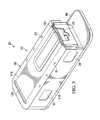
- FIG. 1is a isometric view of a blade dispenser embodiment, illustrating the blade eject assembly in a closed position.
- FIG. 2is a cross-sectional view of the blade dispenser.
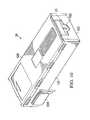
- FIG. 3is an isometric view of the blade dispenser with the blade eject assembly removed.
- FIG. 4is an isometric view of the housing base.
- FIGS. 5A and 5Bare isometric views of the carrier buttons.
- FIG. 6is a isometric view of the blade eject assembly latch button.
- FIG. 7is a isometric bottom view of the blade dispenser, illustrating aspects of the blade loading mechanism.
- FIG. 8is an isometric view of elements of the blade loading mechanism.
- FIG. 9is an enlarged isometric view of the blade loading mechanism sled taken at Detail A of FIG. 8 .
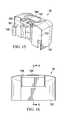
- FIG. 10is an isometric view of the carrier with the carrier buttons positioned aside.
- FIG. 11is an isometric bottom view of the carrier with the carrier buttons positioned aside.
- FIG. 12is an enlarged isometric view of a carrier button engaged with the carrier taken at Detail B of FIG. 11 .
- FIG. 13is an isometric view of the top of the carrier.
- FIG. 14Ais a cross-sectional view of the carrier along line A-A.
- FIG. 14Bis an enlarged isometric view of the detent mechanism of FIG. 14A .
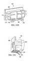
- FIG. 15is an isometric view of the blade eject assembly.
- FIG. 16is an isometric view of the blade eject assembly.
- FIG. 17is a cross-sectional view of the blade eject assembly along line B-B.
- FIG. 18is an isometric view of a blade dispenser embodiment, illustrating the blade eject assembly in an open position.
- FIG. 19is a sectional view of a blade dispenser embodiment, illustrating the blade eject assembly in an open position.
- FIG. 20is a view of a blade carrier embodiment having a unitary body, shown in unassembled form.
- FIG. 21is a rear isometric view of a blade carrier embodiment having a unitary body, shown in partially assembled form, including razor blades.
- FIG. 22is a bottom isometric view of a blade carrier embodiment having a unitary body, shown in assembled form, including razor blades and a sled.
- FIG. 23is a top isometric view of a blade carrier embodiment having a unitary body, shown in assembled form.
- FIG. 24is a partial sectional view of a blade carrier embodiment.
- FIGS. 25A, 25B, and 25Care isometric views of a position adjustable dog.
- FIG. 26is a cross-sectional view of the disengaged detent mechanism.
- FIG. 27is a cross-sectional view of the detent mechanism.
- FIG. 28is an isometric view of a blade eject assembly button embodiment.
- FIG. 29is an isometric view of a blade eject assembly button embodiment.
- FIG. 30Ais a partial sectional view of a blade dispenser embodiment, illustrating the blade eject assembly button in a depressed position.
- FIG. 30Bis a partial sectional view of a blade dispenser embodiment, illustrating the blade eject assembly button in a non-depressed position.
- a blade dispenser 20(for dispensing individual blades 21 ) is provided that includes a housing 22 , a blade carrier 24 (shown on FIG. 10 ) disposed within the housing 22 , and a blade eject assembly 26 .
- the housing 22includes a base 28 (shown on FIG. 4 ), a cap 30 , at least one carrier button 32 , a blade eject assembly latch button 34 , and a blade loading mechanism 36 .
- the base 28includes a first side wall panel 38 , a second side wall panel 40 , an end wall panel 42 , a floor panel 44 , and a front flange 46 .
- Each side wall panel 38 , 40extends lengthwise between an opening edge 48 and an interior edge 50 .
- the terms “lengthwise”, “widthwise”, and “heightwise”refer to, respectively, directions along the x-axis, y-axis, and z-axis; e.g., see orthogonal axes disposed adjacent FIG. 1 .
- the interior edges 50 of each side wall panel 38 , 40are disposed proximate the end wall panel 42 .
- each side wall panel 38 , 40 and the end wall panel 42extend outwardly from the floor panel 44 , and define a slot-shaped carrier cavity 52 with an open end 54 .
- each side wall panel 38 , 40is configured as a single panel that extends lengthwise substantially the length of the floor panel 44
- the end wall panel 42includes a widthwise extending portion 42 A, and two lengthwise extending portions 42 B, 42 C.
- the end wall panel 42extends substantially between the interior edges 50 of the side wall panels 38 , 40 , separated from the interior edges 50 on each side by a slot 56 .
- the housing base 28is not limited to this particular embodiment and may include other configurations that define the slot-shaped carrier cavity 52 .
- each side wall panel 38 , 40may include a plurality of wall sections generally coplanar with one another, and the end wall panel 42 may extend less than substantially between the side wall panels 38 , 40 , or may not be included at all.
- the side wall panels 38 and 40each include a plurality of posts 49 proximate the side wall panels 38 and 40 and which outwardly extend heightwise along the exterior of the side wall panels 38 and 40 away from the floor panel 44 .
- the posts 49extend beyond the height of side walls 38 and 40 such that the uppermost portion of the posts 49 (i.e., the portion furthest from the floor panel 44 ) is no longer proximate the side wall panels 38 and 40 as can be seen in FIG. 4 .
- This uppermost portion of the posts 49may be used to engage corresponding holes 51 (visible in FIG. 3 ) disposed lengthwise along the outermost lateral portions of the top panel 118 of cap 30 as will be explained below.
- FIG. 4illustrates six posts 49 , but any number of posts may be used as desired.
- Posts 49may be placed at any desired distance from each other.
- posts 49may be affixed to side wall panels 38 and 40 .
- posts 49 and side walls 38 and/or 40may comprise one continuous piece.
- the first side wall panel 38includes a carrier button biasing mechanism 58 and a blade eject assembly latch button biasing mechanism 60
- the second side wall panel 40includes a carrier button biasing mechanism 58
- the carrier button biasing mechanisms 58 and the blade eject assembly latch button biasing mechanism 60are shown as outwardly extending cantilever tabs that are engaged by buttons as will be described below.
- the carrier button biasing mechanisms 58 and the blade eject assembly latch button biasing mechanism 60are not limited to a cantilever embodiment.
- one or more than two carrier button biasing mechanisms 58may be used; e.g., if one or more carrier buttons 32 are used as will be described below.
- the front flange 46extends outwardly from the floor panel 44 , proximate the open end 54 of the carrier cavity 52 .
- a blade eject assembly pivot post 62is fixed to the front flange 46 , adjacent the opening edge 48 of the second side wall panel 40 .
- the floor panel 44includes a carrier surface 64 and a bottom surface 66 (see FIG. 7 ), which bottom surface 66 is disposed opposite the carrier surface 64 .
- a slot 68extends through the floor panel 44 between the carrier surface 64 and the bottom surface 66 .
- the slot 68has a width and a length.
- a cap ledge 70extends around the outer periphery of the floor panel 44 , including a first portion 72 that extends away from the wall panels 38 , 40 , and a second portion 74 that extends away from the floor panel bottom surface 66 .
- the second portion 74 of the cap ledge 70 and the floor panel bottom surface 66define a mechanism cavity 76 there between.
- a plurality of slots 78is disposed in the first portion of the cap ledge 70 .
- the slots 78are configured to receive tabs extending out from the cap 30 as will be explained below.
- the pairincludes a first carrier button 32 A and a second carrier button 32 B that are mirror versions (i.e., left and right hand) of the same structure. Since the buttons 32 A, 32 B share the same features (albeit left and right hand configurations), only one button is described hereinafter.
- the button 32includes a pivot axle 80 , a latch 82 , and a contact surface 84 disposed between a first end and a second end.
- the pivot axle 80is disposed proximate the first end of the button 32 and the latch 82 extends outwardly from the second end of the button 32 .
- the latch 82is configured to engage the carrier 24 as will be described below.
- the first carrier button 32 Ais pivotally mounted to the cap ledge 70 adjacent the first side wall panel 38 (see FIGS. 10 and 11 ), and the second carrier button 32 B is pivotally mounted to the cap ledge 70 adjacent the second side wall panel 40 .
- the present blade dispenser 20is not limited to this particular carrier button 32 embodiment. In addition as indicated above, one or more than two carrier buttons 32 may be used.
- the blade eject assembly latch button 34includes a pivot axle 86 , a latch 88 , and a contact surface 90 disposed between a first end and a second end.
- the pivot axle 86is disposed proximate the first end of the button 34 and the latch 88 extends outwardly from the second end of the button 34 .
- the latch 88is configured to engage the blade eject assembly 26 as will be described below.
- the blade eject assembly latch button 34is pivotally mounted to the cap ledge 70 adjacent the first side wall panel 38 .
- the blade loading mechanism 36includes a sled 92 , a flexible member 94 , a pivotable member 96 (e.g., a gear, etc.), and at least one biasing element 98 .
- the sled 92includes a slot member 100 extending between a bottom surface flange 102 and a blade flange 104 .
- the slot member 100has a width that is less than the width of the floor panel slot 68 .
- the blade flange 104 and the bottom surface flange 102each have a width that is greater that the width of the floor panel slot 68 .
- the relative widthsallow the sled slot member 100 to be received within the floor panel slot 68 and to slidably travel lengthwise within the floor panel slot 68 , and the widths of the blade flange 104 and the bottom surface flange 102 prevent the sled 92 from passing through the floor panel 44 .
- the blade flange 104comprises a cam 105 which extends outwardly from the blade flange 104 to form a generally L-shaped profile with the blade flange 104 .
- the cam 105includes a contact surface 107 having a ramped portion 109 at a joinder portion 110 .
- the joinder portion 110 of the contact surface 107may be substantially planar and/or substantially perpendicular to an adjoining surface of the blade flange 104 .
- One or more web members 111may be coupled to or integrally attached to the blade flange 104 and joinder portion 110 to provide structural rigidity between the components.
- the ramped portion 109 of the contact surface 107is angled in a direction toward the flexible member 94 such that when the sled 92 is induced towards the carrier 24 the cam 105 is enabled to engage a dog 132 (shown on FIG. 26 ).
- the engagement between the cam 105 and the dog 132induces the disengagement of a detent mechanism 134 (shown on FIG. 26 ) used to secure the dog 132 within the carrier 24 such that the dog 132 is unable to move backwards within the carrier 24 .
- the flexible member 94has a first end 106 and a second end 108 .
- the flexible member 94may be in the form of a linked element construction (e.g., the linked teeth construction shown in FIGS. 7 and 8 , a chain type structure, etc.) or a uniform cross-section profile configuration (e.g., a cable, a wire, a cord, a string, etc.) or other type flexible member, or combinations thereof.
- the pivotable member 96is mounted to the floor panel bottom surface 66 for pivotable movement around a pivot axis.
- the pivotable member 96is configured to retain the flexible member 94 around at least a portion of the pivotable member 96 .
- the pivotable member 96may include teeth (e.g., a sprocket) that mesh with the linked element construction.
- the blade loading mechanism 36may include a chute 112 attached to the bottom surface of the floor panel 44 configured to receive the flexible member 94 .
- the blade loading mechanism 36is arranged such that the first end 106 of the flexible member 94 is attached to the bottom surface flange 102 of the sled 92 , and extends lengthwise to and around the pivotable member 96 , engaging the teeth of the pivotable member 96 .
- the flexible member 94is either aligned to enter into the chute 112 or is at least partially disposed within the chute 112 . The amount of the flexible member 94 that is disposed in the chute 112 depends on the lengthwise position of the sled 92 .
- the blade loading mechanism biasing member 98is operable to bias the sled 92 toward the open end 54 of the carrier cavity 52 .
- the biasing member 98comprises a torsion spring engaged with the pivotable member 96 on one side of the pivotable member 96 and operable to cause the pivotable member 96 to rotate about its pivot axis.
- a second biasing member 98e.g., a second torsion spring
- an additional biasing member 98may be attached to the second end 108 of the flexible member 94 to bias the sled 92 (attached to the opposite end of the flexible member 94 ) toward the open end 54 of the carrier cavity 52 .
- the blade loading mechanism 36is not limited to these embodiments, however.
- the cap 30includes one or more side panels 116 and a top panel 118 , and structure for attaching the cap 30 to the base 28 .
- the side panels 116 and top panel 118collectively enclose the carrier cavity 52 , except for the open end 54 of the carrier cavity 52 which is not enclosed.
- the top panel 118may include a window to permit visual inspection of the blades 21 disposed within the carrier 24 when the carrier 24 is disposed within the carrier cavity 52 as will be described below.
- the top panel 118includes holes disposed lengthwise along the outermost lateral portions of the top panel 118 of cap 30 as described above. The holes 51 align with posts 49 of side panels 38 and 40 which are illustrated on FIG. 4 .
- the holes 51may be any size and shape sufficient for insertion of the uppermost portion of posts 49 such that once engaged the inserted uppermost portion of posts 49 aligns and secures the cap 30 with the side panels 38 and 40 of base 28 as desired.
- the structure for attaching the cap 30 to the base 28includes a plurality of tabs (not shown) configured to engage the slots 78 disposed in the cap ledge 70 .
- the cap 30may alternatively be attached to the base 28 by other structure.
- the housing 22may include a slot 120 (see FIGS. 1-3 ) for placing used blades 21 for safe storage and eventual disposal or to safely hold a blade that is in use.
- the carrier 24includes a front panel 122 , a pair of side panels 124 , a base panel 126 , a top panel 128 , a back panel 130 , a position adjustable dog 132 , and a detent mechanism 134 operable to positionally secure the dog 132 .
- the base panel 126includes a lengthwise extending slot 136 having a width that is greater than the width of the sled 92 to permit the sled 92 to pass through base panel slot 136 .
- the base panel 126further includes a pair of latch slots 138 which (as will be described below) are configured to engage the respective carrier button latch 82 .
- the latch slots 138each include a ramped tooth 140 extending into the respective slot 138 .
- the carrier 24is not limited to the described latch slots 138 disposed in the base panel 126 .
- a latch slot 138may be disposed in a side panel 124 , top panel 128 , or base panel 126 , and the latch slot 138 may assume alternative configurations operable to engage a carrier button latch 82 .
- the front panel 122is configured to receive structure extending out from the blade eject assembly 26 as will be described below; e.g., the carrier front panel 122 shown in FIGS. 10 and 11 includes a U-shaped opening 142 .
- the side panels 124 , base panel 126 , and top panel 128extend lengthwise between the front panel 122 and the back panel 130 and define a blade cavity 144 there between.
- the cross-sectional geometry of the blade cavity 144is selected to accommodate the blades 21 stored within the carrier 24 ; e.g., the carrier 24 shown in FIGS. 10, 11, and 13 has a rectangular cross-section blade cavity 144 which accommodates the rectangular shape of the blades 21 .
- the carrier 24is not limited to a rectangular cross-section configuration.
- the top panel 128is selectively removable to permit blades 21 to be loaded into the blade cavity 144 .
- the top panel 128may include a window to permit visual inspection of the blades 21 disposed within the carrier 24 .
- the top panel 128is configured to include a cutout 141 disposed at the forward end of the top panel 128 .
- the cutout 141 and the front panel 122combine to form a slot.
- the slotis configured to allow the passage a razor blade there through
- the dog 132which is disposed and adjustably positioned in the blade cavity 144 , includes a blade contact face 146 (also shown in FIG. 25A ) that extends widthwise between the side panels 124 , a front flange 147 (also shown in FIG. 25B ) that extends widthwise between the side panels 124 , and a follower latch 149 which extends outwardly away from the front flange 147 in a direction towards the back panel 130 of the carrier 24 .
- the follower latch 149comprises a pair of pawls 148 (the pair is shown in FIG.
- the follower latch 149may extend away from the front flange 147 at an angle sufficient for the pawls 148 to engage the mating rows of teeth 150 .
- the pawls 148form the first portion of the detent mechanism 134 that is operable to positionally secure the dog 132 .
- the pawls 148are positioned to engage the mating rows of teeth 150 disposed on the interior of the base panel 126 of the carrier 24 such that when the pawls 148 are engaged with the mating rows of teeth 150 , backwards movement of the dog 132 towards the back panel 130 is resisted.
- the mating rows of teeth 150form the second portion of the detent mechanism 134 .
- the detent mechanism 134may position and/or secure the dog 132 such that the dog 132 is able to be moved towards the front panel 122 to engage and secure a plurality of blades 21 , but movement of the dog 132 towards the back panel 130 and away from the plurality of blades 21 is resisted.
- the detent mechanism 134is not limited to the described embodiment. For example, in alternative embodiments, there may be one or more than two pawls 148 , one or more than two rows of teeth 150 , or the pawls 148 and rows of teeth 150 may be positioned alternatively in the carrier 24 .
- the blade eject assembly 26includes base 152 , a button 154 , and a button biasing member 156 .
- the housing side surface 162includes a pivot member 158 disposed on a widthwise side configured to engage the blade eject assembly pivot post 62 fixed to the front flange 46 .
- the pivot member 158 and blade eject assembly pivot post 62cooperate to allow the blade eject assembly 26 to rotate about a pivot axis toward and away from the housing 22 , and toward and away from carrier 24 when the carrier 24 is disposed in the carrier cavity 52 .
- FIG. 15illustrates the pivot member 158 having an additional pivot post which cooperates with the cap 30 to facilitate the aforesaid pivot motion.
- the button 154includes a blade engagement structure 160 configured to engage a blade 21 disposed in the carrier 24 as will be described below; e.g., the engagement structure 160 can be configured to engage the edge of a protective metal cap attached to the blade 21 .
- the blade engagement structure 160extends outwardly from a housing side surface 162 of the button 154 .
- the blade engagement structure 160may include a magnet 161 , which magnet 161 facilitates blade handling/movement.
- the blade engagement structuremay further comprise an insert 180 which may be mechanically attached to the blade engagement structure 160 (e.g., by screw 184 ) to allow for replacement as described below.
- the button 154is configured to allow heightwise translation (e.g., vertical translation) of the button 154 relative to the assembly base 152 .
- the button biasing member 156e.g., a coil spring
- FIGS. 1 and 2show the button 154 biased in the normal position.
- the button 154 and base 152include features (e.g., tabs) that limit the relative travel there between and maintain the base 152 and button 154 coupled together.
- the base 152further includes structure (e.g., a slot) for engaging the latch 88 of the blade eject assembly latch button 34 .
- the blade eject assembly 26is not limited to the above-described embodiment; e.g., the assembly may assume a configuration that is selectively attached to and removable from the housing 22 rather than the pivotable arrangement described above.
- FIGS. 18 and 19illustrate embodiments of the present disclosure. Features of the present disclosure described below may be included in any of embodiments described herein. Embodiments are described below in the context of a blade dispenser 20 (for dispensing individual blades 21 ) that includes a housing 22 , a blade carrier 24 , and a blade eject assembly 26 .
- the blade carrier 24includes a front panel 122 , a pair of side panels 124 , a base panel 126 , a top panel 128 , a back panel 130 , a position adjustable dog 132 (e.g., see FIG. 21 ), and a detent mechanism 134 operable to positionally secure the dog 132 .
- the base panel 126includes a lengthwise extending slot 136 having a width that is greater than the width of the sled 92 (e.g., see FIG. 20 ); e.g., to permit the sled 92 to pass through base panel slot 136 .
- the base panel 126may include a pair of latch slots 138 (e.g., see FIGS.
- the front panel 122is configured to receive structure extending out from the blade eject assembly 26 ; e.g., the carrier front panel 122 shown in FIGS. 20 and 23 includes an opening 142 configured to receive a blade engagement structure portion of a blade eject assembly button 154 .
- the top panel 128includes a cutout 141 disposed at the forward end of the top panel 128 .
- the cutout 141 and the front panel 122combine to form a slot 143 (e.g., see FIG. 23 ).
- the slot 143is configured to allow the passage of a razor blade 21 there through.
- the side panels 124 , base panel 126 , and top panel 128extend lengthwise between the front panel 122 and the back panel 130 to define a blade cavity 144 there between.
- the blade carrier 24includes a one or more features disposed adjacent the front panel 122 to position the blades disposed there at.
- the top panel 128may include one or more tabs 145 adjacent the edge of the cutout 141 that are configured to separate the forward most razor blade 21 from the next razor blade 21 within the blade carrier 24 as the forward most razor blade is moved vertically upward as it is being dispensed from the blade carrier 24 .
- the tabs 64are shaped to complement the geometry of the razor blade protective cap, but still allow forward travel of the blade 21 once the forward most blade is removed.
- the blade carrier 24may include one or more blade guide features disposed on one or more interior surfaces (i.e., surfaces facing blades disposed within the carrier).
- a guide rib 166extends outwardly from the interior surface of each side panel 124 .
- Each guide rib 166extends lengthwise and is configured to mate with (e.g., be received in) a cutout disposed on the respective side of each razor blade 21 disposed within the blade carrier 24 .
- the guide ribs 166may be disposed to support the blades 21 and allow the blades to slide lengthwise along the guide ribs 166 , thereby providing clearance between the cutting edges of the blades 21 and the base panel 126 of the blade carrier 24 .
- ribs 167extending outwardly from the interior of the front panel 122 and placed on the edges of the front panel 122 may be used to control the slot 143 that allows blades 21 to pass through.
- the ribs 167may engage the cutout 141 portion of the top panel 128 when folded, such that the ribs 167 , when engaged with the cutout 141 , define the desired size of the slot 143 for passage of blades 21 therethrough.
- the ribs 167may be any size and shape desired for controlling the slot 143 .
- ribs 167may be affixed to front panel 122 such that ribs 167 may be interchangeable or adjustable.
- ribs 167 and front panel 122may comprise one continuous piece.
- the present disclosureis not limited to the guide features described above.
- the guide featuresmay be configured to mate with guide features (or other blade geometry aspects) present in the type of razor blade.
- the blade carrier 24is constructed to allow assembly of the blade carrier 24 from a unitary body.
- the unitary bodymay be a body (e.g., manufactured by molding, stamping, etc.) with respective panels (i.e., side panels 124 , base panel 126 , top panel 128 , and back panel 130 ) connected to one another by integral hinges 168 .
- the unitary bodymay further include attachment features 170 (e.g., mechanical features, etc.) that allow the respective panels to attach to one another to form the assembled blade carrier 24 .
- the unitary bodyfacilitates manufacturing of the blade carrier 24 .
- the detent mechanism 134is operable to positionally secure the dog 132 , and may include a first portion (e.g., pawls 148 ) extending from a surface on the follower latch 149 away from the follower latch 149 and a second portion (e.g., rows of teeth 150 ) disposed on the interior of the base panel 126 of the blade carrier 24 .
- the pawls 148contact the rows of teeth 150 to form the detent mechanism 134 .
- 14A, 14B, 20, and 21includes a pair of pawls 148 disposed on a follower latch 149 affixed to the underside of the dog 132 and a corresponding pair of rows of teeth 150 disposed on the interior surface of the base panel 126 .
- Each pawl 148may engage with a mating row of 150 on the interior of the base panel 126 positioned relative thereto.
- the dog 132may be pushed forward towards the front panel 122 to secure the blades 21 within the blade carrier 24 if desired (e.g., while shipping the blade carrier 24 ).
- the follower latch 149extends away from the front flange 147 of the dog 132 at an angle sufficient to allow the pawls 148 to engage the rows of teeth 150 .
- the pawls 148extend away from the follower latch 149 to engage the corresponding rows of teeth 150 disposed on the interior surface of the base panel 126 to form the detent mechanism 134 . This engagement latches and secures the dog 132 in place, such that the dog 132 resists movement towards the back panel 130 of the carrier 24 .
- FIG. 26With reference to FIG. 26 , when the blade dispenser 20 (shown on FIG.
- the cam 105 on sled 92may be biased towards the dog 132 to engage the follower latch 149 disposed on the dog 132 such that the pawls 148 disposed on the follower latch 149 of the dog 132 are disengaged from the corresponding teeth rows 150 disposed on the interior surface of the base panel 126 ; thus disengaging the detent mechanism 134 described above.
- the referenced disengagementoccurs because the ramped portion 109 of the contact surface 107 of the cam 105 engages the flower latch 149 to induce movement of the follower latch 149 (and consequently pawls 148 ) away from the rows of teeth 150 .
- the cam 105may be used to unlatch the dog 132 so that it is no longer secured by the detent mechanism 134 .
- the row of teeth 150comprises a feed pitch 151 .
- the feed pitch 151is the distance between the outermost edge of the plateau of the peak of an individual tooth within a row of teeth 150 and the outermost edge of the valley adjacent to the next tooth in the series as illustrated in FIG. 27 .
- the feed pitch 151may be a distance greater than the thickness of one blade 21 .
- the overlap between the length of a pawl 148 at its tip 153 and the length of an individual tooth in a row of teeth 150 at its tip 155is such that the overlap of the respective tip lengths 153 and 155 may be less than the thickness of one blade 21 .
- having an overlap of tip lengths 153 and 155 less than the thickness of one bade 21may allow the pawl 148 to return to the valley portion of the feed pitch 151 and not rest on the tip 155 of an individual tooth within the row of teeth 150 . As such, the pawl 148 may always rest in the valley of the feed pitch 151 when not engaged with the cam 105 .
- the present disclosureis not limited to this particular detent mechanism 134 embodiment.
- the dog 132may include guide features 174 that mate with the guide ribs 166 extending outwardly from the interior surfaces of the blade carrier 24 .
- the respective mating guide features 166 , 174 of the blade carrier 24 and the dog 132facilitate relative movement.
- the blade eject assembly 26may include a blade eject assembly button 154 with a blade engagement structure 160 configured to engage a blade 21 disposed in the carrier 124 .
- the blade engagement structure 160is configured to engage the edge of the protective metal cap attached to a razor blade 21 .
- the blade engagement structure 160extends outwardly from a housing side surface 162 of the button 154 , and includes a widthwise extending member 176 and a magnet 161 .
- the widthwise extending member 176has a length substantially equal to the width of a razor blade 21 . In the embodiments shown in FIGS.
- the member 176includes a slot 178 (e.g., V-shaped) disposed in a top surface of the member 176 .
- the blade engagement structure 160further includes an insert 180 with at least one contactor 182 (two contactors are shown in FIG. 28 ) extending outwardly from the slot 178 .
- the insert 180may be comprised of a material that has a greater wear-resistance (e.g., greater hardness) than the material of the blade engagement structure 160 .
- the insert 180is comprised of a hardened material (e.g., steel) that is wear-resistant.
- the insert 180may be mechanically attached to the blade engagement structure 160 (e.g., by screw 184 ) to allow for replacement.
- the present disclosureis not limited to a blade engagement structure 160 having the configuration described above.
- the blade engagement structure 160may not include an insert, or may include an insert 180 a that provides a wear resistant edge (e.g., greater hardness material as described above) as shown in FIG. 29 .
- FIGS. 1-30Bthe general operation of the blade dispenser 20 in terms of one or more of the embodiments described above will now be described to further illustrate the utility of the present disclosure.
- the following descriptiondoes not specifically refer to each embodiment described above but is applicable to all embodiments unless specifically stated otherwise.
- the order of operation provided hereinafteris for description purposes only and is not limiting.
- the dog 132is moved within the carrier 24 toward the back panel 130 , away from the front panel 122 .
- a plurality of blades 21is loaded into the carrier blade cavity 144 between the dog 132 and the front panel 122 , with the sharp edges of the blades 21 proximate the base panel 126 of the carrier 24 .
- the carrier 24is not limited to any particular blade capacity, and the same blade dispenser 20 may be used with different capacity carriers 24 for different applications.
- a carrier 24 with a blade capacity of “N” blades(where “N” is an integer) may be loaded with less than “N” blades.
- FIG. 1shows the blade eject assembly 26 in a “closed” position; i.e., rotated to enclose the carrier cavity 52 .
- the blade eject assembly latch button latch 88is normally biased into engagement with slot disposed in the blade eject assembly base 152 by the blade eject latch button biasing mechanism 60 of the housing 22 .
- the blade eject assembly latch button 34When a user depresses the blade eject assembly latch button 34 , the button pivots, the biasing mechanism 60 deflects, and the latch 88 disengages with the slot in the button base 152 .
- the blade eject assembly 26can be rotated away from the housing 22 causing the carrier cavity 52 to be exposed. This position of the blade eject assembly 26 relative to the housing 22 may be referred to as the “open position”.
- the loaded carrier 24is subsequently slid into the carrier cavity 52 .
- the blade loading mechanism sled 92Prior to sliding the carrier 24 into the carrier cavity 52 , the blade loading mechanism sled 92 is biased forward, toward the open end 54 of the carrier cavity 52 .
- the sled 92is received within the carrier base panel slot 136 (i.e., extending at least partially into the blade cavity) until the sled 92 contacts the dog 132 .
- the sled 92 and carrier 24are moved lengthwise aft toward the endwall panel 42 of the housing 22 .
- the blade loading mechanism 36biases the sled 92 against the dog 132 . More specifically, the flexible member 94 rotates around the pivotable member 96 , which movement is resisted by the biasing element 98 thereby providing the force that biases the sled 92 against the dog 132 . As the sled 92 is biased against the dog 132 , the detent mechanism 134 used to secure dog 132 may be disengaged by the engagement of the cam 105 of the sled 92 with the follower latch 149 of the dog 132 .
- the latches of the carrier buttons 32 A, 32 Bengage the latch slots 138 disposed in the carrier 24 . Further lengthwise movement of the carrier 24 causes the carrier button latches 82 to encounter the ramped tooth 140 in each slot 138 . Once the carrier button latches 82 pass the ramped teeth 140 , the carrier latch biasing mechanisms 58 (e.g., the cantilevered tabs) attached to the housing 22 force the latches 82 widthwise outwardly and the carrier 24 is then secured in the carrier cavity 52 by the latches 82 . The blade eject assembly 26 can then be rotated toward the housing 22 to enclose the carrier cavity 52 .
- the carrier latch biasing mechanisms 58e.g., the cantilevered tabs
- the assemblyengages the blade eject assembly latch button 34 which subsequently prevents the assembly 26 from rotating away from the housing 22 .
- a gap 164(through which blades may be dispensed; see FIG. 1 ) remains between the top panel 118 of the cap 30 and the housing side surface 162 of the blade eject assembly button 154 .
- the blade engagement structure 160 of the button 154(which extends out from the housing side surface) contacts a portion of the forward most blade 21 in the carrier 24 .
- the blade engagement structure 160engages a feature (e.g., the protective metal cap attached to the blade) on the forward most blade 21 in the carrier 24 .
- the blade engagement structure 160travels upwardly with the button 154 and causes the engaged blade 21 to also travel upwardly and enter the gap 164 between the top panel of the housing 22 and the housing side surface 162 of the blade eject assembly button 154 .
- the userWhen the user desires to remove the carrier 24 (e.g., because it is empty or to change the type of blade 21 being dispensed), the user depresses the blade eject assembly latch button 34 which causes the blade eject assembly latch button latch 88 to disengage with the blade eject assembly 26 . Once disengaged, the blade eject assembly 26 can be rotated away into the open position, thereby exposing the carrier 24 . The user may then depress the carrier buttons 32 A, 32 B. When the carrier buttons 32 A, 32 B are sufficiently depressed, the carrier button latches 82 disengage with the ramped teeth 140 in slots 138 disposed in the carrier 24 and the carrier 24 can be removed from the blade dispenser housing 22 .
- the disclosureincludes embodiments of the blade dispenser 20 wherein the carrier 24 is inserted and removed from a forward portion of the device.
- the carrier 24may alternatively be accessed from a side vantage.
- a blade eject assembly latch button 34 portion of the housingincludes structure that engages blade eject assembly 26 to hold the blade eject assembly 26 relative to the housing 22 .
- the blade eject assembly 26may include structure that engages the housing 22 to hold the blade eject assembly 26 relative to the housing 22 .
Landscapes
- Engineering & Computer Science (AREA)
- Mechanical Engineering (AREA)
- Packaging Of Annular Or Rod-Shaped Articles, Wearing Apparel, Cassettes, Or The Like (AREA)
- Knives (AREA)
Abstract
Description
Claims (18)
Priority Applications (1)
| Application Number | Priority Date | Filing Date | Title |
|---|---|---|---|
| US15/380,773US10259642B2 (en) | 2015-12-17 | 2016-12-15 | Blade dispenser |
Applications Claiming Priority (2)
| Application Number | Priority Date | Filing Date | Title |
|---|---|---|---|
| US201562269023P | 2015-12-17 | 2015-12-17 | |
| US15/380,773US10259642B2 (en) | 2015-12-17 | 2016-12-15 | Blade dispenser |
Publications (2)
| Publication Number | Publication Date |
|---|---|
| US20170174412A1 US20170174412A1 (en) | 2017-06-22 |
| US10259642B2true US10259642B2 (en) | 2019-04-16 |
Family
ID=59057676
Family Applications (1)
| Application Number | Title | Priority Date | Filing Date |
|---|---|---|---|
| US15/380,773ActiveUS10259642B2 (en) | 2015-12-17 | 2016-12-15 | Blade dispenser |
Country Status (2)
| Country | Link |
|---|---|
| US (1) | US10259642B2 (en) |
| WO (1) | WO2017106543A1 (en) |
Cited By (1)
| Publication number | Priority date | Publication date | Assignee | Title |
|---|---|---|---|---|
| US20180290281A1 (en)* | 2017-04-07 | 2018-10-11 | Chad A. French | Fastener holder and dispenser |
Families Citing this family (12)
| Publication number | Priority date | Publication date | Assignee | Title |
|---|---|---|---|---|
| US10315833B2 (en)* | 2013-11-07 | 2019-06-11 | Accutec Blades, Inc. | Blade dispenser |
| US10259642B2 (en)* | 2015-12-17 | 2019-04-16 | Accutec Blades, Inc. | Blade dispenser |
| US10413378B2 (en)* | 2016-05-04 | 2019-09-17 | Startbox, Llc | Safety-blade dispenser and related methods |
| USD840774S1 (en) | 2017-05-05 | 2019-02-19 | Fiskars Finland Oy Ab | Folding utility knife |
| USD840781S1 (en) | 2017-05-05 | 2019-02-19 | Fiskars Finland Oy Ab | Retractable utility knife |
| USD863813S1 (en)* | 2017-05-05 | 2019-10-22 | Fiskars Finland Oy Ab | Utility knife blade dispenser |
| USD849556S1 (en) | 2017-05-05 | 2019-05-28 | Fiskars Finland Oy Ab | Utility knife blade storage pack |
| USD847601S1 (en) | 2017-05-16 | 2019-05-07 | Fiskars Finland Oy Ab | Drywaller's utility knife |
| USD848235S1 (en) | 2017-05-16 | 2019-05-14 | Fiskars Finland Oy Ab | Painter's utility knife |
| USD844407S1 (en) | 2017-05-16 | 2019-04-02 | Fiskars Finland Oy Ab | Snap-off utility knife |
| USD847603S1 (en) | 2017-05-16 | 2019-05-07 | Fiskars Finland Oy Ab | Utility knife with a folding guard |
| JP7123379B2 (en)* | 2018-06-04 | 2022-08-23 | 株式会社荻野精機製作所 | Spare blade jig |
Citations (147)
| Publication number | Priority date | Publication date | Assignee | Title |
|---|---|---|---|---|
| US1350886A (en) | 1918-02-14 | 1920-08-24 | Raymond Wendel Scholz | Single-delivery match-box |
| US1654554A (en) | 1926-05-31 | 1928-01-03 | Pasch Hugo | Underlayer for safety-razor blades to be wrapped therewith in an envelope |
| US2094722A (en) | 1934-10-10 | 1937-10-05 | Sandford William Herbert | Receptacle for razor blades |
| US2272444A (en) | 1940-10-18 | 1942-02-10 | Gillette Safety Razor Co | Blade dispensing device |
| US2295464A (en) | 1939-08-23 | 1942-09-08 | Garbaty Maurice | Package attachment |
| US2303764A (en) | 1938-12-19 | 1942-12-01 | John G Roberts | Packaging and dispensing razor blades |
| US2309780A (en) | 1941-09-18 | 1943-02-02 | Gillette Safety Razor Co | Magazine for safety razors |
| US2321570A (en) | 1940-02-01 | 1943-06-15 | Billing Noel Pemberton | Packaging of razor blades |
| US2344962A (en) | 1941-07-22 | 1944-03-28 | Sidney H Benjamin | Unitary blade magazine and blade magazine holder |
| US2431523A (en)* | 1945-04-10 | 1947-11-25 | Tuerff Arthur | Razor blade magazine |
| US2439243A (en) | 1943-03-04 | 1948-04-06 | American Safety Rasor Corp | Blade container |
| US2458020A (en) | 1945-12-29 | 1949-01-04 | Donald E Olsen | Combined cosmetic holder and mirror or the like |
| US2522896A (en) | 1946-12-02 | 1950-09-19 | Frez O Mat Corp | Merchandise dispensing device |
| US2564712A (en) | 1946-09-30 | 1951-08-21 | Gillette Safety Razor Co | Razor blade dispensing container |
| DE815829C (en) | 1950-05-31 | 1951-10-04 | Karl Potthoff Fa | Stand for razor blades |
| US2624453A (en) | 1948-04-09 | 1953-01-06 | Gillette Co | Blade dispensing magazine with feed slide |
| US2637900A (en) | 1947-10-17 | 1953-05-12 | Marcus C Thompson | Razor blade cartridge unit |
| US2641358A (en) | 1950-03-14 | 1953-06-09 | Worcester Moulded Plastics Com | Razor blade dispenser |
| US2653704A (en) | 1948-08-06 | 1953-09-29 | American Safety Razor Corp | Single-edge blade dispenser |
| US2684151A (en) | 1951-08-21 | 1954-07-20 | American Stafety Razor Corp | Combination blade dispenser and used blade receiver |
| US2685364A (en) | 1951-10-05 | 1954-08-03 | American Safety Razor Corp | Used blade receiver |
| US2792933A (en) | 1951-01-05 | 1957-05-21 | American Safety Razor Corp | Dispenser for safety razor blades |
| US2829764A (en) | 1955-11-09 | 1958-04-08 | Silverman Isadore Jerome | Razor blade dispenser |
| US2889076A (en) | 1955-10-03 | 1959-06-02 | Robert J Van Schie | Dispensing container for razor blades |
| US2946482A (en) | 1957-07-02 | 1960-07-26 | Stanley R Johnson | Dispenser for article-containing envelopes |
| US2971676A (en) | 1958-07-03 | 1961-02-14 | Honcharenko Peter | Cigarette case |
| US3037664A (en) | 1959-12-15 | 1962-06-05 | Eversharp Inc | Safety razor blade dispenser |
| US3040929A (en) | 1958-09-22 | 1962-06-26 | Tapper Samuel | Tablet dispensing packages |
| US3070260A (en) | 1958-01-17 | 1962-12-25 | Blu Strike Blade Company | Dispensing magazine for razor blades |
| US3080998A (en) | 1961-04-04 | 1963-03-12 | Philip Morris Inc | Razor blade dispenser |
| US3093266A (en) | 1959-10-14 | 1963-06-11 | Eversharp Inc | Safety razor blade dispenser |
| US3115991A (en) | 1958-03-03 | 1963-12-31 | American Can Co | Cutting blade magazine and dispenser |
| US3373862A (en) | 1964-08-08 | 1968-03-19 | Minchin Marjorie Doreen | Razor blade dispenser |
| US3460712A (en) | 1968-01-15 | 1969-08-12 | Gillette Co | Blade dispenser with used blade compartment |
| US3542245A (en) | 1968-04-19 | 1970-11-24 | Philip Morris Inc | Blade dispenser and mounting for same |
| US3543918A (en) | 1969-02-17 | 1970-12-01 | Perma Sharp Mfg Corp | Dispensing package container for new and used razor blades |
| US3549046A (en) | 1968-07-16 | 1970-12-22 | Philip Morris Inc | Molded plastic razor blade dispenser |
| US3563412A (en) | 1967-11-08 | 1971-02-16 | Wilkinson Sword Ltd | Razor blade dispensers |
| US3612348A (en) | 1969-11-17 | 1971-10-12 | Michael D Thomas | Pill dispenser with disposable magazine and indicia |
| US3667122A (en) | 1971-05-12 | 1972-06-06 | Pacific Handy Cutter Inc | Safety razor blade holder |
| US3767083A (en) | 1969-01-28 | 1973-10-23 | Wilkinson Sword Ltd | Dispenser for shaving units |
| US3827597A (en) | 1973-03-05 | 1974-08-06 | Philip Morris Inc | Blade dispenser |
| US3850343A (en) | 1973-06-04 | 1974-11-26 | Gillette Co | Molded plastic razor blade dispenser |
| US3869066A (en) | 1973-02-07 | 1975-03-04 | Warner Lambert Co | Razor blade dispenser |
| US4114780A (en) | 1976-12-02 | 1978-09-19 | Shaul Sharon | Combination industrial razor blade dispenser and used blade receiver |
| US4151931A (en) | 1978-06-05 | 1979-05-01 | Eastman Kodak Company | Article dispenser apparatus for use in an automated chemical analyzer |
| USD252558S (en) | 1976-09-09 | 1979-08-07 | Larry Beck | Cigarette troche holder |
| USD252853S (en) | 1977-05-11 | 1979-09-11 | Perkins Martin B | Display box |
| GB2033344A (en) | 1978-09-28 | 1980-05-21 | Wan To Poon | Apparatus for dispensing elongate objects from a container |
| US4207790A (en) | 1977-12-06 | 1980-06-17 | Feather Kogyo Kabushiki Kaisha | Knife holder for microtomes |
| FR2460643A1 (en) | 1979-07-12 | 1981-01-30 | Ferrandez Michel | Case for holding and distributing razor blades - is open at top with magnet fixed inside back wall and magnets on front wall to hold blade |
| USD260054S (en) | 1979-06-26 | 1981-08-04 | Morgan Robert L | Combined carrier and dispenser for business cards |
| USD260489S (en) | 1979-02-05 | 1981-09-01 | Pritchard William F | Soap dispenser |
| US4316554A (en) | 1980-02-22 | 1982-02-23 | Pacific Paper Products, Inc. | Aerial marker launcher |
| US4379514A (en) | 1981-03-26 | 1983-04-12 | Howard Strauss | Blade holder and dispenser |
| US4430012A (en) | 1981-04-06 | 1984-02-07 | Zenith Radio Corporation | Paper guide for line printer |
| US4730376A (en) | 1986-11-20 | 1988-03-15 | Feather Kogyo Kabushiki Kaisha | Blade removal apparatus for changeable blade scalpel |
| US4789080A (en) | 1986-04-23 | 1988-12-06 | American Safety Razor Company | Utility blade dispenser |
| US4792058A (en) | 1987-05-04 | 1988-12-20 | Parker Robert J | Business card dispenser |
| USD299288S (en) | 1985-12-09 | 1989-01-10 | Stafford David A | Business card dispenser |
| US4826042A (en) | 1987-05-13 | 1989-05-02 | Le-Jo Enterprises, Inc. | Blade holder and automatic dispenser |
| US4850512A (en) | 1987-05-13 | 1989-07-25 | Le-Jo Enterprises, Inc. | Blade holder and automatic dispenser |
| US4852379A (en) | 1988-07-15 | 1989-08-01 | Nat Levenberg | Metal forming methods and products formed thereby |
| USD303082S (en) | 1986-04-24 | 1989-08-29 | American Safety Razor Company | Utility blade dispenser or similar article |
| USD307670S (en) | 1986-01-17 | 1990-05-08 | Nava Milano S.P.A. | Card dispenser |
| USD317985S (en) | 1987-06-04 | 1991-07-09 | Sandvik Aktiebolag | Saw blade container |
| US5139167A (en) | 1990-08-17 | 1992-08-18 | Mccarthy William C | Blade dispenser |
| US5148916A (en) | 1991-09-25 | 1992-09-22 | Tillyer Sr John N | Razor blade carrier |
| DE4117356A1 (en) | 1991-05-28 | 1992-12-03 | Steinbrueck & Drucks Gmbh | Refillable blade dispenser with vertical ratchet groove - has two sliders each with blade spring |
| US5251783A (en) | 1992-10-30 | 1993-10-12 | Allway Tools, Inc. | Utility blade dispenser |
| USD341568S (en) | 1991-03-27 | 1993-11-23 | Carlingswitch, Inc. | Electrical switch rocker |
| US5305913A (en) | 1992-06-19 | 1994-04-26 | Shade Michael W | Apparatus for dispensing articles |
| FR2723725A1 (en) | 1994-08-22 | 1996-02-23 | Preposreve Sarl | Storage and distribution box for razor blades |
| USD390103S (en) | 1997-03-31 | 1998-02-03 | Gerson Howard J | Bandage case |
| USD392157S (en) | 1996-07-03 | 1998-03-17 | Von Traumer Co., Ltd. | Chewing gum dispenser |
| USD403954S (en) | 1997-05-29 | 1999-01-12 | Tajima Tool Corp. | Dispenser for replacement cutter blades |
| USD407972S (en) | 1997-09-09 | 1999-04-13 | Optoplast Manufacturing Company, Ltd. | Sliding case |
| FR2772349A1 (en)* | 1997-11-06 | 1999-06-18 | Alain Baumann | Method of recycling solid waste |
| JP2000062869A (en) | 1998-08-11 | 2000-02-29 | Muto Kagaku Kk | Spare blade dispenser for microtome |
| US6082581A (en) | 1998-04-28 | 2000-07-04 | Ross Anderson | Business card dispenser |
| US6102098A (en) | 1998-10-19 | 2000-08-15 | Anthony J. Randazzo | Hand held postage stamp applicator |
| USD432911S (en) | 2000-03-31 | 2000-10-31 | The Gillette Company | Battery package |
| USD433940S (en) | 1999-12-23 | 2000-11-21 | Lindsay Dean R | Flip top box |
| US6158616A (en) | 1999-08-26 | 2000-12-12 | Huang; Yin-Hae | Cutter blade dispenser and disposer with slide biasing means and side located dispensing slot |
| US6382460B1 (en) | 1999-03-09 | 2002-05-07 | Fischer Iberica, S.A. | Flat article dispensing device |
| US20020162849A1 (en) | 2001-05-04 | 2002-11-07 | Chen Fang Yeh | Structure art design knife blade container |
| US6508380B1 (en)* | 1999-12-23 | 2003-01-21 | Alfred Von Schuckmann | Dispenser for the dispensing elements in strips |
| USD474402S1 (en) | 2001-03-09 | 2003-05-13 | J. L. Clark, Inc. | Rectangular container with lid |
| US6598761B1 (en) | 2002-02-04 | 2003-07-29 | Chi Tsun Chou | Blade holder and dispenser |
| US20040099682A1 (en) | 2002-11-27 | 2004-05-27 | Huang Yin Han | Utility blade dispenser |
| US6763972B2 (en) | 2001-07-11 | 2004-07-20 | Leica Microsystems Nussloch Gmbh | Dispenser for thin knives, in particular for thin replaceable microtome knives |
| US20040178216A1 (en) | 2003-01-14 | 2004-09-16 | David Brickwood | Sensor dispensing device |
| US20040178214A1 (en) | 2003-01-02 | 2004-09-16 | Wei Wu Yue | Blade dispenser |
| US6796455B2 (en) | 2001-11-08 | 2004-09-28 | Pacific Handy Cutter, Inc. | Blade dispenser assembly |
| US20040200080A1 (en) | 2003-01-07 | 2004-10-14 | Lauri Aaron P | Single edge razor blade holder |
| US20050230411A1 (en)* | 2003-11-12 | 2005-10-20 | Veo Justin K | Firearm magazine retention and delivery system |
| US20050281706A1 (en) | 2004-06-18 | 2005-12-22 | Tom Funke | Dispenser for flattened articles |
| US20060049201A1 (en) | 2002-04-10 | 2006-03-09 | Lanz Klaus H | Dispensers particularly but not exclusively for cigarette packets |
| USD519469S1 (en) | 2004-10-22 | 2006-04-25 | Carling Technologies, Inc. | Electrical switch rocker actuator |
| USD522855S1 (en) | 2005-01-24 | 2006-06-13 | Hoffman Neopac Ag | Slide lid container |
| USD527995S1 (en) | 2005-09-14 | 2006-09-12 | Crown Packaging Technology, Inc. | Container |
| US7140650B2 (en) | 1999-07-21 | 2006-11-28 | Southco, Inc. | Slide latch |
| EP1731447A1 (en) | 2005-06-07 | 2006-12-13 | Sasan Danechi | Container for cotton swabs |
| USD536624S1 (en) | 2005-01-12 | 2007-02-13 | Irwin Industrial Tool Company | Blade dispenser |
| US20070034640A1 (en) | 2005-08-11 | 2007-02-15 | Casale Joseph N | Article dispenser |
| USD540539S1 (en) | 2005-06-13 | 2007-04-17 | Griffin Technology, Inc. | Protective case for a memory storage device which is connectable to a computer or an MP3 player device |
| USD546671S1 (en) | 2006-01-03 | 2007-07-17 | J.L. Clark Inc. | Container |
| US20070185449A1 (en) | 2005-04-06 | 2007-08-09 | Morten Mernoe | Actuator with string drive #1 |
| USD550632S1 (en) | 2005-11-17 | 2007-09-11 | Lutron Electronics Co., Inc. | Fan speed control module |
| USD554468S1 (en) | 2005-01-21 | 2007-11-06 | Kone Cargotec Patenter Hb | Crank handle |
| USD555512S1 (en) | 2006-07-10 | 2007-11-20 | Samy Hak Tang Lam | Candy container |
| USD561047S1 (en) | 2006-07-27 | 2008-02-05 | Michael Peter Shields | Dispenser |
| US20080217353A1 (en) | 2007-03-06 | 2008-09-11 | Michael John Newman | Method of Dispensing A Test Strip |
| USD595152S1 (en) | 2008-01-29 | 2009-06-30 | American Safety Razor | Blade dispenser |
| USD596046S1 (en) | 2008-01-29 | 2009-07-14 | American Safety Razor | Blade dispenser |
| CA127032S (en) | 2008-01-29 | 2009-07-29 | American Safety Razor | Blade dispenser |
| US20090194557A1 (en)* | 2008-01-30 | 2009-08-06 | Van Deursen Gary E | Blade dispenser |
| US7641072B1 (en) | 2003-10-17 | 2010-01-05 | Rock-Tenn Shared Services, Llc | Theft deterrent system |
| USD613147S1 (en) | 2008-02-13 | 2010-04-06 | Yamaha Corporation | Slider knob |
| US20110042406A1 (en)* | 2008-05-08 | 2011-02-24 | Shinkokiki Co., Ltd. | Magazine for spot welding chip |
| EP2301861A1 (en) | 2009-09-29 | 2011-03-30 | Martor Kg | Blade container |
| USD650986S1 (en) | 2010-12-02 | 2011-12-27 | Daya Medicals, Inc. | Medication storage and delivery device |
| US20110315706A1 (en) | 2009-09-25 | 2011-12-29 | Lockwood Thomas A | Secure Merchandising Display With Blocker Mechanisms |
| US20120006844A1 (en) | 2010-07-07 | 2012-01-12 | Shinichi Kobayashi | Business card case |
| US20120024881A1 (en) | 2009-01-29 | 2012-02-02 | Antoni Papaloizou | Smoking Article Dispenser |
| US20130015198A1 (en)* | 2009-05-19 | 2013-01-17 | Matthias Bollmus | Beverage container dispensing apparatus |
| US20130126550A1 (en) | 2011-11-17 | 2013-05-23 | Milwaukee Electric Tool Corporation | Knife blade dispenser |
| TWM462608U (en) | 2009-04-02 | 2013-10-01 | Mackay Memorial Hospital | Vehicle of radiation dosimeter |
| US20130291955A1 (en) | 2012-05-07 | 2013-11-07 | Rodney Laible | Hand-held dispenser |
| US20140034665A1 (en) | 2012-08-03 | 2014-02-06 | Leica Biosystems Nussloch Gmbh | Blade dispenser |
| US20140086796A1 (en)* | 2011-04-08 | 2014-03-27 | Jean-Pierre Giraud | Strip dispenser and strips for use with the same |
| USD702649S1 (en) | 2011-07-05 | 2014-04-15 | Sumitomo Wiring Systems, Ltd. | Charging connector for an automobile |
| US8809726B2 (en)* | 2007-09-10 | 2014-08-19 | Shinkokiki Co., Ltd. | Electrode tip magazine for spot welder |
| USD720628S1 (en) | 2013-11-07 | 2015-01-06 | Eveready Battery Company, Inc | Blade dispenser |
| USD727272S1 (en) | 2013-03-14 | 2015-04-21 | Caterpillar Inc. | Rocker switch cover |
| US20150114997A1 (en) | 2012-04-24 | 2015-04-30 | Socorex Isba S.A. | Variable-Volume Dispenser for Accurately Dispensing of an Adjusted Amount of Liquid |
| WO2015069992A1 (en) | 2013-11-07 | 2015-05-14 | Energizer Battery Company, Inc | Blade dispenser |
| US9039977B2 (en)* | 2006-05-09 | 2015-05-26 | Becton, Dickinson And Company | Method and apparatus for dispensing diagnostic test strips |
| USD742760S1 (en) | 2013-03-15 | 2015-11-10 | Pacific Handy Cutter, Inc. | Pocket blade dispenser |
| US20160016778A1 (en) | 2009-06-03 | 2016-01-21 | Magic Tap, LLC | Liquid Dispenser for a Cooler and Detergent Bottle |
| US9248949B2 (en)* | 2008-11-26 | 2016-02-02 | Bayer Intellectual Property Gmbh | Cartridge, a pharmaceutical dispenser containing the cartridge, and applications of said cartridge and said pharmaceutical dispenser |
| US20160069859A1 (en)* | 2012-05-31 | 2016-03-10 | Bayer Healthcare Llc | Multistrip cartridge |
| US20160242765A1 (en) | 2013-09-23 | 2016-08-25 | William R. George | Arthroscopic knot pusher and suture cutter |
| US9505544B2 (en)* | 2008-11-26 | 2016-11-29 | Bayer Intellectual Property Gmbh | Cartridge, medicament dispenser for solid medicament portions, and uses of the cartridge and of the medicament dispenser |
| US9522774B2 (en)* | 2015-03-03 | 2016-12-20 | Allway Tools, Inc. | Blade dispenser |
| USD779338S1 (en) | 2014-05-22 | 2017-02-21 | Accutec Blades, Inc. | Blade dispenser |
| US20170174412A1 (en)* | 2015-12-17 | 2017-06-22 | AccuTec Blades Inc. | Blade dispenser |
- 2016
- 2016-12-15USUS15/380,773patent/US10259642B2/enactiveActive
- 2016-12-15WOPCT/US2016/067000patent/WO2017106543A1/ennot_activeCeased
Patent Citations (160)
| Publication number | Priority date | Publication date | Assignee | Title |
|---|---|---|---|---|
| US1350886A (en) | 1918-02-14 | 1920-08-24 | Raymond Wendel Scholz | Single-delivery match-box |
| US1654554A (en) | 1926-05-31 | 1928-01-03 | Pasch Hugo | Underlayer for safety-razor blades to be wrapped therewith in an envelope |
| US2094722A (en) | 1934-10-10 | 1937-10-05 | Sandford William Herbert | Receptacle for razor blades |
| US2303764A (en) | 1938-12-19 | 1942-12-01 | John G Roberts | Packaging and dispensing razor blades |
| US2295464A (en) | 1939-08-23 | 1942-09-08 | Garbaty Maurice | Package attachment |
| US2321570A (en) | 1940-02-01 | 1943-06-15 | Billing Noel Pemberton | Packaging of razor blades |
| US2272444A (en) | 1940-10-18 | 1942-02-10 | Gillette Safety Razor Co | Blade dispensing device |
| US2344962A (en) | 1941-07-22 | 1944-03-28 | Sidney H Benjamin | Unitary blade magazine and blade magazine holder |
| US2309780A (en) | 1941-09-18 | 1943-02-02 | Gillette Safety Razor Co | Magazine for safety razors |
| US2439243A (en) | 1943-03-04 | 1948-04-06 | American Safety Rasor Corp | Blade container |
| US2431523A (en)* | 1945-04-10 | 1947-11-25 | Tuerff Arthur | Razor blade magazine |
| US2458020A (en) | 1945-12-29 | 1949-01-04 | Donald E Olsen | Combined cosmetic holder and mirror or the like |
| US2564712A (en) | 1946-09-30 | 1951-08-21 | Gillette Safety Razor Co | Razor blade dispensing container |
| US2522896A (en) | 1946-12-02 | 1950-09-19 | Frez O Mat Corp | Merchandise dispensing device |
| US2637900A (en) | 1947-10-17 | 1953-05-12 | Marcus C Thompson | Razor blade cartridge unit |
| US2624453A (en) | 1948-04-09 | 1953-01-06 | Gillette Co | Blade dispensing magazine with feed slide |
| US2653704A (en) | 1948-08-06 | 1953-09-29 | American Safety Razor Corp | Single-edge blade dispenser |
| US2641358A (en) | 1950-03-14 | 1953-06-09 | Worcester Moulded Plastics Com | Razor blade dispenser |
| DE815829C (en) | 1950-05-31 | 1951-10-04 | Karl Potthoff Fa | Stand for razor blades |
| US2792933A (en) | 1951-01-05 | 1957-05-21 | American Safety Razor Corp | Dispenser for safety razor blades |
| US2684151A (en) | 1951-08-21 | 1954-07-20 | American Stafety Razor Corp | Combination blade dispenser and used blade receiver |
| US2685364A (en) | 1951-10-05 | 1954-08-03 | American Safety Razor Corp | Used blade receiver |
| US2889076A (en) | 1955-10-03 | 1959-06-02 | Robert J Van Schie | Dispensing container for razor blades |
| US2829764A (en) | 1955-11-09 | 1958-04-08 | Silverman Isadore Jerome | Razor blade dispenser |
| US2946482A (en) | 1957-07-02 | 1960-07-26 | Stanley R Johnson | Dispenser for article-containing envelopes |
| US3070260A (en) | 1958-01-17 | 1962-12-25 | Blu Strike Blade Company | Dispensing magazine for razor blades |
| US3115991A (en) | 1958-03-03 | 1963-12-31 | American Can Co | Cutting blade magazine and dispenser |
| US2971676A (en) | 1958-07-03 | 1961-02-14 | Honcharenko Peter | Cigarette case |
| US3040929A (en) | 1958-09-22 | 1962-06-26 | Tapper Samuel | Tablet dispensing packages |
| US3093266A (en) | 1959-10-14 | 1963-06-11 | Eversharp Inc | Safety razor blade dispenser |
| US3037664A (en) | 1959-12-15 | 1962-06-05 | Eversharp Inc | Safety razor blade dispenser |
| US3080998A (en) | 1961-04-04 | 1963-03-12 | Philip Morris Inc | Razor blade dispenser |
| US3373862A (en) | 1964-08-08 | 1968-03-19 | Minchin Marjorie Doreen | Razor blade dispenser |
| US3563412A (en) | 1967-11-08 | 1971-02-16 | Wilkinson Sword Ltd | Razor blade dispensers |
| US3460712A (en) | 1968-01-15 | 1969-08-12 | Gillette Co | Blade dispenser with used blade compartment |
| US3542245A (en) | 1968-04-19 | 1970-11-24 | Philip Morris Inc | Blade dispenser and mounting for same |
| US3549046A (en) | 1968-07-16 | 1970-12-22 | Philip Morris Inc | Molded plastic razor blade dispenser |
| US3767083A (en) | 1969-01-28 | 1973-10-23 | Wilkinson Sword Ltd | Dispenser for shaving units |
| US3543918A (en) | 1969-02-17 | 1970-12-01 | Perma Sharp Mfg Corp | Dispensing package container for new and used razor blades |
| US3612348A (en) | 1969-11-17 | 1971-10-12 | Michael D Thomas | Pill dispenser with disposable magazine and indicia |
| US3667122A (en) | 1971-05-12 | 1972-06-06 | Pacific Handy Cutter Inc | Safety razor blade holder |
| US3869066A (en) | 1973-02-07 | 1975-03-04 | Warner Lambert Co | Razor blade dispenser |
| US3827597A (en) | 1973-03-05 | 1974-08-06 | Philip Morris Inc | Blade dispenser |
| US3850343A (en) | 1973-06-04 | 1974-11-26 | Gillette Co | Molded plastic razor blade dispenser |
| USD252558S (en) | 1976-09-09 | 1979-08-07 | Larry Beck | Cigarette troche holder |
| US4114780A (en) | 1976-12-02 | 1978-09-19 | Shaul Sharon | Combination industrial razor blade dispenser and used blade receiver |
| USD252853S (en) | 1977-05-11 | 1979-09-11 | Perkins Martin B | Display box |
| US4207790A (en) | 1977-12-06 | 1980-06-17 | Feather Kogyo Kabushiki Kaisha | Knife holder for microtomes |
| US4151931A (en) | 1978-06-05 | 1979-05-01 | Eastman Kodak Company | Article dispenser apparatus for use in an automated chemical analyzer |
| GB2033344A (en) | 1978-09-28 | 1980-05-21 | Wan To Poon | Apparatus for dispensing elongate objects from a container |
| USD260489S (en) | 1979-02-05 | 1981-09-01 | Pritchard William F | Soap dispenser |
| USD260054S (en) | 1979-06-26 | 1981-08-04 | Morgan Robert L | Combined carrier and dispenser for business cards |
| FR2460643A1 (en) | 1979-07-12 | 1981-01-30 | Ferrandez Michel | Case for holding and distributing razor blades - is open at top with magnet fixed inside back wall and magnets on front wall to hold blade |
| US4316554A (en) | 1980-02-22 | 1982-02-23 | Pacific Paper Products, Inc. | Aerial marker launcher |
| US4379514A (en) | 1981-03-26 | 1983-04-12 | Howard Strauss | Blade holder and dispenser |
| US4430012A (en) | 1981-04-06 | 1984-02-07 | Zenith Radio Corporation | Paper guide for line printer |
| USD299288S (en) | 1985-12-09 | 1989-01-10 | Stafford David A | Business card dispenser |
| USD307670S (en) | 1986-01-17 | 1990-05-08 | Nava Milano S.P.A. | Card dispenser |
| US4789080A (en) | 1986-04-23 | 1988-12-06 | American Safety Razor Company | Utility blade dispenser |
| USD303082S (en) | 1986-04-24 | 1989-08-29 | American Safety Razor Company | Utility blade dispenser or similar article |
| US4730376A (en) | 1986-11-20 | 1988-03-15 | Feather Kogyo Kabushiki Kaisha | Blade removal apparatus for changeable blade scalpel |
| US4792058A (en) | 1987-05-04 | 1988-12-20 | Parker Robert J | Business card dispenser |
| US4826042A (en) | 1987-05-13 | 1989-05-02 | Le-Jo Enterprises, Inc. | Blade holder and automatic dispenser |
| US4850512A (en) | 1987-05-13 | 1989-07-25 | Le-Jo Enterprises, Inc. | Blade holder and automatic dispenser |
| USD317985S (en) | 1987-06-04 | 1991-07-09 | Sandvik Aktiebolag | Saw blade container |
| US4852379A (en) | 1988-07-15 | 1989-08-01 | Nat Levenberg | Metal forming methods and products formed thereby |
| US5139167A (en) | 1990-08-17 | 1992-08-18 | Mccarthy William C | Blade dispenser |
| USD341568S (en) | 1991-03-27 | 1993-11-23 | Carlingswitch, Inc. | Electrical switch rocker |
| DE4117356A1 (en) | 1991-05-28 | 1992-12-03 | Steinbrueck & Drucks Gmbh | Refillable blade dispenser with vertical ratchet groove - has two sliders each with blade spring |
| US5148916A (en) | 1991-09-25 | 1992-09-22 | Tillyer Sr John N | Razor blade carrier |
| US5305913A (en) | 1992-06-19 | 1994-04-26 | Shade Michael W | Apparatus for dispensing articles |
| US5251783A (en) | 1992-10-30 | 1993-10-12 | Allway Tools, Inc. | Utility blade dispenser |
| FR2723725A1 (en) | 1994-08-22 | 1996-02-23 | Preposreve Sarl | Storage and distribution box for razor blades |
| USD392157S (en) | 1996-07-03 | 1998-03-17 | Von Traumer Co., Ltd. | Chewing gum dispenser |
| USD390103S (en) | 1997-03-31 | 1998-02-03 | Gerson Howard J | Bandage case |
| USD403954S (en) | 1997-05-29 | 1999-01-12 | Tajima Tool Corp. | Dispenser for replacement cutter blades |
| USD407972S (en) | 1997-09-09 | 1999-04-13 | Optoplast Manufacturing Company, Ltd. | Sliding case |
| FR2772349A1 (en)* | 1997-11-06 | 1999-06-18 | Alain Baumann | Method of recycling solid waste |
| US6082581A (en) | 1998-04-28 | 2000-07-04 | Ross Anderson | Business card dispenser |
| JP2000062869A (en) | 1998-08-11 | 2000-02-29 | Muto Kagaku Kk | Spare blade dispenser for microtome |
| US6102098A (en) | 1998-10-19 | 2000-08-15 | Anthony J. Randazzo | Hand held postage stamp applicator |
| US6382460B1 (en) | 1999-03-09 | 2002-05-07 | Fischer Iberica, S.A. | Flat article dispensing device |
| US7140650B2 (en) | 1999-07-21 | 2006-11-28 | Southco, Inc. | Slide latch |
| US6158616A (en) | 1999-08-26 | 2000-12-12 | Huang; Yin-Hae | Cutter blade dispenser and disposer with slide biasing means and side located dispensing slot |
| USD433940S (en) | 1999-12-23 | 2000-11-21 | Lindsay Dean R | Flip top box |
| US6508380B1 (en)* | 1999-12-23 | 2003-01-21 | Alfred Von Schuckmann | Dispenser for the dispensing elements in strips |
| USD432911S (en) | 2000-03-31 | 2000-10-31 | The Gillette Company | Battery package |
| USD474402S1 (en) | 2001-03-09 | 2003-05-13 | J. L. Clark, Inc. | Rectangular container with lid |
| US20020162849A1 (en) | 2001-05-04 | 2002-11-07 | Chen Fang Yeh | Structure art design knife blade container |
| US6763972B2 (en) | 2001-07-11 | 2004-07-20 | Leica Microsystems Nussloch Gmbh | Dispenser for thin knives, in particular for thin replaceable microtome knives |
| US6796455B2 (en) | 2001-11-08 | 2004-09-28 | Pacific Handy Cutter, Inc. | Blade dispenser assembly |
| US6598761B1 (en) | 2002-02-04 | 2003-07-29 | Chi Tsun Chou | Blade holder and dispenser |
| US20030146236A1 (en) | 2002-02-04 | 2003-08-07 | Chou Chi Tsun | Blade holder and dispenser |
| US20060049201A1 (en) | 2002-04-10 | 2006-03-09 | Lanz Klaus H | Dispensers particularly but not exclusively for cigarette packets |
| US20040099682A1 (en) | 2002-11-27 | 2004-05-27 | Huang Yin Han | Utility blade dispenser |
| US20040178214A1 (en) | 2003-01-02 | 2004-09-16 | Wei Wu Yue | Blade dispenser |
| US20040200080A1 (en) | 2003-01-07 | 2004-10-14 | Lauri Aaron P | Single edge razor blade holder |
| US20040178216A1 (en) | 2003-01-14 | 2004-09-16 | David Brickwood | Sensor dispensing device |
| US7641072B1 (en) | 2003-10-17 | 2010-01-05 | Rock-Tenn Shared Services, Llc | Theft deterrent system |
| US20050230411A1 (en)* | 2003-11-12 | 2005-10-20 | Veo Justin K | Firearm magazine retention and delivery system |
| US20050281706A1 (en) | 2004-06-18 | 2005-12-22 | Tom Funke | Dispenser for flattened articles |
| USD519469S1 (en) | 2004-10-22 | 2006-04-25 | Carling Technologies, Inc. | Electrical switch rocker actuator |
| USD536624S1 (en) | 2005-01-12 | 2007-02-13 | Irwin Industrial Tool Company | Blade dispenser |
| USD554468S1 (en) | 2005-01-21 | 2007-11-06 | Kone Cargotec Patenter Hb | Crank handle |
| USD522855S1 (en) | 2005-01-24 | 2006-06-13 | Hoffman Neopac Ag | Slide lid container |
| US20070185449A1 (en) | 2005-04-06 | 2007-08-09 | Morten Mernoe | Actuator with string drive #1 |
| EP1731447A1 (en) | 2005-06-07 | 2006-12-13 | Sasan Danechi | Container for cotton swabs |
| USD540539S1 (en) | 2005-06-13 | 2007-04-17 | Griffin Technology, Inc. | Protective case for a memory storage device which is connectable to a computer or an MP3 player device |
| US20070034640A1 (en) | 2005-08-11 | 2007-02-15 | Casale Joseph N | Article dispenser |
| USD527995S1 (en) | 2005-09-14 | 2006-09-12 | Crown Packaging Technology, Inc. | Container |
| USD550632S1 (en) | 2005-11-17 | 2007-09-11 | Lutron Electronics Co., Inc. | Fan speed control module |
| USD546671S1 (en) | 2006-01-03 | 2007-07-17 | J.L. Clark Inc. | Container |
| US9039977B2 (en)* | 2006-05-09 | 2015-05-26 | Becton, Dickinson And Company | Method and apparatus for dispensing diagnostic test strips |
| USD555512S1 (en) | 2006-07-10 | 2007-11-20 | Samy Hak Tang Lam | Candy container |
| USD561047S1 (en) | 2006-07-27 | 2008-02-05 | Michael Peter Shields | Dispenser |
| US20080217353A1 (en) | 2007-03-06 | 2008-09-11 | Michael John Newman | Method of Dispensing A Test Strip |
| US8809726B2 (en)* | 2007-09-10 | 2014-08-19 | Shinkokiki Co., Ltd. | Electrode tip magazine for spot welder |
| CA127047S (en) | 2008-01-29 | 2009-07-29 | American Safety Razor | Blade dispenser |
| CA127032S (en) | 2008-01-29 | 2009-07-29 | American Safety Razor | Blade dispenser |
| CA127039S (en) | 2008-01-29 | 2009-07-29 | American Safety Razor | Blade dispenser |
| USD596046S1 (en) | 2008-01-29 | 2009-07-14 | American Safety Razor | Blade dispenser |
| USD595152S1 (en) | 2008-01-29 | 2009-06-30 | American Safety Razor | Blade dispenser |
| USD624833S1 (en) | 2008-01-29 | 2010-10-05 | American Safety Razor | Blade dispenser |
| US20090194557A1 (en)* | 2008-01-30 | 2009-08-06 | Van Deursen Gary E | Blade dispenser |
| EP2240388A1 (en) | 2008-01-30 | 2010-10-20 | American Safety Razor Company | Blade dispenser |
| MX2010008445A (en) | 2008-01-30 | 2011-01-14 | American Safety Razor | Blade dispenser. |
| CN101970312A (en) | 2008-01-30 | 2011-02-09 | 美国安全剃刀公司 | Blade dispenser |
| CA2713708A1 (en) | 2008-01-30 | 2009-08-06 | Gary E. Van Deursen | Blade dispenser |
| WO2009097521A1 (en) | 2008-01-30 | 2009-08-06 | American Safety Razor Company | Blade dispenser |
| USD613147S1 (en) | 2008-02-13 | 2010-04-06 | Yamaha Corporation | Slider knob |
| US20110042406A1 (en)* | 2008-05-08 | 2011-02-24 | Shinkokiki Co., Ltd. | Magazine for spot welding chip |
| US9248949B2 (en)* | 2008-11-26 | 2016-02-02 | Bayer Intellectual Property Gmbh | Cartridge, a pharmaceutical dispenser containing the cartridge, and applications of said cartridge and said pharmaceutical dispenser |
| US9505544B2 (en)* | 2008-11-26 | 2016-11-29 | Bayer Intellectual Property Gmbh | Cartridge, medicament dispenser for solid medicament portions, and uses of the cartridge and of the medicament dispenser |
| US20120024881A1 (en) | 2009-01-29 | 2012-02-02 | Antoni Papaloizou | Smoking Article Dispenser |
| TWM462608U (en) | 2009-04-02 | 2013-10-01 | Mackay Memorial Hospital | Vehicle of radiation dosimeter |
| US20130015198A1 (en)* | 2009-05-19 | 2013-01-17 | Matthias Bollmus | Beverage container dispensing apparatus |
| US20160016778A1 (en) | 2009-06-03 | 2016-01-21 | Magic Tap, LLC | Liquid Dispenser for a Cooler and Detergent Bottle |
| US20110315706A1 (en) | 2009-09-25 | 2011-12-29 | Lockwood Thomas A | Secure Merchandising Display With Blocker Mechanisms |
| US20110233229A1 (en) | 2009-09-29 | 2011-09-29 | Peter Schekalla | Utility-blade dispenser |
| EP2301861A1 (en) | 2009-09-29 | 2011-03-30 | Martor Kg | Blade container |
| US20120006844A1 (en) | 2010-07-07 | 2012-01-12 | Shinichi Kobayashi | Business card case |
| USD650986S1 (en) | 2010-12-02 | 2011-12-27 | Daya Medicals, Inc. | Medication storage and delivery device |
| US20140086796A1 (en)* | 2011-04-08 | 2014-03-27 | Jean-Pierre Giraud | Strip dispenser and strips for use with the same |
| USD702649S1 (en) | 2011-07-05 | 2014-04-15 | Sumitomo Wiring Systems, Ltd. | Charging connector for an automobile |
| US20130126550A1 (en) | 2011-11-17 | 2013-05-23 | Milwaukee Electric Tool Corporation | Knife blade dispenser |
| US20150114997A1 (en) | 2012-04-24 | 2015-04-30 | Socorex Isba S.A. | Variable-Volume Dispenser for Accurately Dispensing of an Adjusted Amount of Liquid |
| US20130291955A1 (en) | 2012-05-07 | 2013-11-07 | Rodney Laible | Hand-held dispenser |
| US20160069859A1 (en)* | 2012-05-31 | 2016-03-10 | Bayer Healthcare Llc | Multistrip cartridge |
| GB2504852A (en) | 2012-08-03 | 2014-02-12 | Leica Biosystems Nussloch Gmbh | Blade dispenser |
| US20140034665A1 (en) | 2012-08-03 | 2014-02-06 | Leica Biosystems Nussloch Gmbh | Blade dispenser |
| USD727272S1 (en) | 2013-03-14 | 2015-04-21 | Caterpillar Inc. | Rocker switch cover |
| USD742760S1 (en) | 2013-03-15 | 2015-11-10 | Pacific Handy Cutter, Inc. | Pocket blade dispenser |
| US20160242765A1 (en) | 2013-09-23 | 2016-08-25 | William R. George | Arthroscopic knot pusher and suture cutter |
| WO2015069992A1 (en) | 2013-11-07 | 2015-05-14 | Energizer Battery Company, Inc | Blade dispenser |
| EP3066031A1 (en) | 2013-11-07 | 2016-09-14 | Energizer Battery Company, Inc. | Blade dispenser |
| US20160304269A1 (en)* | 2013-11-07 | 2016-10-20 | Energizer Battery Company, Inc | Blade dispenser |
| USD720628S1 (en) | 2013-11-07 | 2015-01-06 | Eveready Battery Company, Inc | Blade dispenser |
| USD779338S1 (en) | 2014-05-22 | 2017-02-21 | Accutec Blades, Inc. | Blade dispenser |
| US9522774B2 (en)* | 2015-03-03 | 2016-12-20 | Allway Tools, Inc. | Blade dispenser |
| US20170174412A1 (en)* | 2015-12-17 | 2017-06-22 | AccuTec Blades Inc. | Blade dispenser |
Non-Patent Citations (13)
| Title |
|---|
| Communication pursuant to Article 94(3) EPC dated Nov. 21, 2017, issued in related co-pending European Application No. 14806127.8. |
| European Search Report issued in European Patent Application No. 09705689.9. Cited in U.S. Appl. No. 12/362,752. |
| http://packandseal.com/CuttersRazor.html, retrieved Feb. 11, 2008. Cited in U.S. Appl. No. 12/362,752. |
| http://www.artistcraft.com/Tools/Cups_Cutting_Caulking_Equip/193, retrieved Feb. 11, 2008. Cited in U.S. Appl. No. 12/362,752. |
| http://www.tool-up.co.uk/shop/diy/STA028510.html, retrieved Feb. 11, 2008. Cited in U.S. Appl. No. 12/362,752. |
| Imedger retrieved from http://www.imedger.com/pages/framedger.html. Retrieved Feb. 5, 2008. Cited in U.S. Appl. No. 12/362,752. |
| International Search Report issued in International Patent Application No. PCT/US2009/032631, dated Mar. 13, 2009 Cited in U.S. Appl. No. 12/362,752. |
| International Search Report issued in PCT/US2014/064510, dated Jan. 30, 2015. Cited in U.S. Appl. No. 15/035,177. |
| International Search Report issued in related co-pending PCT/US2016/67000 dated Mar. 31, 2017. |
| Office Action issued in related European Patent Application No. 14 806 127 dated Jun. 9, 2017. |
| Red Personna Precision ‘Zipak’ Dispenser and Razor Blades retrived from http://cgi.ebay.com/RED-PERSONNA-PRECISION-ZIPAK-DISPENSER-RAZOR-BLADES_W0QQitemZ110161800345QQihZ001QQcategoryZ35989QQrdZ1QQssPageNameZWD1VQQtrksidZp1638.m118.11247QQcmdZViewItem. Retrieved Feb. 11, 2008. Cited in U.S. Appl. No. 12/362,752. |
| Sectioning and Microtomy Supplies, retrieved from http://www.aname.es/microscopia/ems/histology/sectioning.html. Retrieved Feb. 5, 2008. Cited in U.S. Appl. No. 12/362,752. |
| Taiwanese Search Report issued in Taiwanese Design Application No. 097304388 date of Research Mar. 30, 2009. English Translation provided. Cited in U.S. Appl. No. 29/290,910. |
Cited By (2)
| Publication number | Priority date | Publication date | Assignee | Title |
|---|---|---|---|---|
| US20180290281A1 (en)* | 2017-04-07 | 2018-10-11 | Chad A. French | Fastener holder and dispenser |
| US10500705B2 (en)* | 2017-04-07 | 2019-12-10 | Chad A. French | Fastener holder and dispenser |
Also Published As
| Publication number | Publication date |
|---|---|
| US20170174412A1 (en) | 2017-06-22 |
| WO2017106543A1 (en) | 2017-06-22 |
Similar Documents
| Publication | Publication Date | Title |
|---|---|---|
| US10259642B2 (en) | Blade dispenser | |
| EP3066031B1 (en) | Blade dispenser | |
| US11358292B2 (en) | Ambidextrous utility knife | |
| US7395600B2 (en) | Utility knife | |
| US3577637A (en) | Retractable blade knife | |
| JP2521827Y2 (en) | Knife with replaceable blade | |
| US9676106B2 (en) | Safety cutter with guard-actuated blade deployment | |
| US20090194557A1 (en) | Blade dispenser | |
| US20050065541A1 (en) | Guarded surgical scalpel with blade stripper lock to prevent accidental or inadvertent ejection of the blade | |
| GB2050227A (en) | Knives | |
| US10093026B2 (en) | Safety cutter with blade depth selector/interlock mechanism | |
| US9840013B2 (en) | Safety cutter with blade change/storage mechanism | |
| US20130061478A1 (en) | Safety Cutter with Improved Blade Locking Mechanism | |
| US20130061479A1 (en) | Safety Cutter with Improved Blade Storage Mechanism | |
| US5867907A (en) | Shaving systems | |
| US20130061477A1 (en) | Safety Cutter with Improved Blade Depth Adjustment Mechanism | |
| US20130061475A1 (en) | Ergonomic Cutter | |
| US20130062374A1 (en) | Cutter and Safety Holster System | |
| US20180118458A1 (en) | Waste disposal device and cassette interface | |
| US3848770A (en) | Blade dispenser with used blade vault | |
| US20130061444A1 (en) | Safety Cutter with Improved Blade Change Mechanism | |
| US20130061476A1 (en) | Safety Cutter with Improved Blade Deployment Mechanism | |
| EP3213888B1 (en) | Snap-off blade dispenser system | |
| JPS6232519Y2 (en) | ||
| JP6383253B2 (en) | mouse |
Legal Events
| Date | Code | Title | Description |
|---|---|---|---|
| AS | Assignment | Owner name:ACCUTEC BLADES, INC., VIRGINIA Free format text:ASSIGNMENT OF ASSIGNORS INTEREST;ASSIGNOR:JEFFREY W. WONDERLEY;REEL/FRAME:048290/0833 Effective date:20170609 | |
| STCF | Information on status: patent grant | Free format text:PATENTED CASE | |
| AS | Assignment | Owner name:ACCUTEC BLADES, INC., VIRGINIA Free format text:RELEASE BY SECURED PARTY;ASSIGNOR:FIRST NATIONAL BANK OF PENNSYLVANIA;REEL/FRAME:051668/0275 Effective date:20200122 | |
| AS | Assignment | Owner name:JPMORGAN CHASE BANK, N.A., ILLINOIS Free format text:SECURITY INTEREST;ASSIGNOR:ACCUTEC BLADES, INC.;REEL/FRAME:051721/0920 Effective date:20200122 | |
| AS | Assignment | Owner name:ACCUTEC, INC., VIRGINIA Free format text:CHANGE OF NAME;ASSIGNOR:ACCUTEC BLADES, INC.;REEL/FRAME:056272/0240 Effective date:20200917 | |
| MAFP | Maintenance fee payment | Free format text:PAYMENT OF MAINTENANCE FEE, 4TH YR, SMALL ENTITY (ORIGINAL EVENT CODE: M2551); ENTITY STATUS OF PATENT OWNER: SMALL ENTITY Year of fee payment:4 |