US10259254B2 - Article with a dynamic frame formed with aligned pigment flakes - Google Patents
Article with a dynamic frame formed with aligned pigment flakesDownload PDFInfo
- Publication number
- US10259254B2 US10259254B2US13/737,836US201313737836AUS10259254B2US 10259254 B2US10259254 B2US 10259254B2US 201313737836 AUS201313737836 AUS 201313737836AUS 10259254 B2US10259254 B2US 10259254B2
- Authority
- US
- United States
- Prior art keywords
- substrate
- frame
- article
- pigment flakes
- ink
- Prior art date
- Legal status (The legal status is an assumption and is not a legal conclusion. Google has not performed a legal analysis and makes no representation as to the accuracy of the status listed.)
- Active, expires
Links
Images


Classifications
- B—PERFORMING OPERATIONS; TRANSPORTING
- B42—BOOKBINDING; ALBUMS; FILES; SPECIAL PRINTED MATTER
- B42D—BOOKS; BOOK COVERS; LOOSE LEAVES; PRINTED MATTER CHARACTERISED BY IDENTIFICATION OR SECURITY FEATURES; PRINTED MATTER OF SPECIAL FORMAT OR STYLE NOT OTHERWISE PROVIDED FOR; DEVICES FOR USE THEREWITH AND NOT OTHERWISE PROVIDED FOR; MOVABLE-STRIP WRITING OR READING APPARATUS
- B42D25/00—Information-bearing cards or sheet-like structures characterised by identification or security features; Manufacture thereof
- B42D25/30—Identification or security features, e.g. for preventing forgery
- B42D25/36—Identification or security features, e.g. for preventing forgery comprising special materials
- B42D25/369—Magnetised or magnetisable materials
- B—PERFORMING OPERATIONS; TRANSPORTING
- B05—SPRAYING OR ATOMISING IN GENERAL; APPLYING FLUENT MATERIALS TO SURFACES, IN GENERAL
- B05D—PROCESSES FOR APPLYING FLUENT MATERIALS TO SURFACES, IN GENERAL
- B05D3/00—Pretreatment of surfaces to which liquids or other fluent materials are to be applied; After-treatment of applied coatings, e.g. intermediate treating of an applied coating preparatory to subsequent applications of liquids or other fluent materials
- B05D3/20—Pretreatment of surfaces to which liquids or other fluent materials are to be applied; After-treatment of applied coatings, e.g. intermediate treating of an applied coating preparatory to subsequent applications of liquids or other fluent materials by magnetic fields
- B05D3/207—Pretreatment of surfaces to which liquids or other fluent materials are to be applied; After-treatment of applied coatings, e.g. intermediate treating of an applied coating preparatory to subsequent applications of liquids or other fluent materials by magnetic fields post-treatment by magnetic fields
- B—PERFORMING OPERATIONS; TRANSPORTING
- B05—SPRAYING OR ATOMISING IN GENERAL; APPLYING FLUENT MATERIALS TO SURFACES, IN GENERAL
- B05D—PROCESSES FOR APPLYING FLUENT MATERIALS TO SURFACES, IN GENERAL
- B05D5/00—Processes for applying liquids or other fluent materials to surfaces to obtain special surface effects, finishes or structures
- B05D5/06—Processes for applying liquids or other fluent materials to surfaces to obtain special surface effects, finishes or structures to obtain multicolour or other optical effects
- B05D5/061—Special surface effect
- B—PERFORMING OPERATIONS; TRANSPORTING
- B41—PRINTING; LINING MACHINES; TYPEWRITERS; STAMPS
- B41M—PRINTING, DUPLICATING, MARKING, OR COPYING PROCESSES; COLOUR PRINTING
- B41M1/00—Inking and printing with a printer's forme
- B—PERFORMING OPERATIONS; TRANSPORTING
- B41—PRINTING; LINING MACHINES; TYPEWRITERS; STAMPS
- B41M—PRINTING, DUPLICATING, MARKING, OR COPYING PROCESSES; COLOUR PRINTING
- B41M3/00—Printing processes to produce particular kinds of printed work, e.g. patterns
- B41M3/14—Security printing
- B—PERFORMING OPERATIONS; TRANSPORTING
- B41—PRINTING; LINING MACHINES; TYPEWRITERS; STAMPS
- B41M—PRINTING, DUPLICATING, MARKING, OR COPYING PROCESSES; COLOUR PRINTING
- B41M7/00—After-treatment of prints, e.g. heating, irradiating, setting of the ink, protection of the printed stock
- B41M7/0072—After-treatment of prints, e.g. heating, irradiating, setting of the ink, protection of the printed stock using mechanical wave energy, e.g. ultrasonics; using magnetic or electric fields, e.g. electric discharge, plasma
- B—PERFORMING OPERATIONS; TRANSPORTING
- B42—BOOKBINDING; ALBUMS; FILES; SPECIAL PRINTED MATTER
- B42D—BOOKS; BOOK COVERS; LOOSE LEAVES; PRINTED MATTER CHARACTERISED BY IDENTIFICATION OR SECURITY FEATURES; PRINTED MATTER OF SPECIAL FORMAT OR STYLE NOT OTHERWISE PROVIDED FOR; DEVICES FOR USE THEREWITH AND NOT OTHERWISE PROVIDED FOR; MOVABLE-STRIP WRITING OR READING APPARATUS
- B42D25/00—Information-bearing cards or sheet-like structures characterised by identification or security features; Manufacture thereof
- B42D25/20—Information-bearing cards or sheet-like structures characterised by identification or security features; Manufacture thereof characterised by a particular use or purpose
- B42D25/29—Securities; Bank notes
- B—PERFORMING OPERATIONS; TRANSPORTING
- B42—BOOKBINDING; ALBUMS; FILES; SPECIAL PRINTED MATTER
- B42D—BOOKS; BOOK COVERS; LOOSE LEAVES; PRINTED MATTER CHARACTERISED BY IDENTIFICATION OR SECURITY FEATURES; PRINTED MATTER OF SPECIAL FORMAT OR STYLE NOT OTHERWISE PROVIDED FOR; DEVICES FOR USE THEREWITH AND NOT OTHERWISE PROVIDED FOR; MOVABLE-STRIP WRITING OR READING APPARATUS
- B42D25/00—Information-bearing cards or sheet-like structures characterised by identification or security features; Manufacture thereof
- B42D25/30—Identification or security features, e.g. for preventing forgery
- B42D25/342—Moiré effects
- B—PERFORMING OPERATIONS; TRANSPORTING
- B42—BOOKBINDING; ALBUMS; FILES; SPECIAL PRINTED MATTER
- B42D—BOOKS; BOOK COVERS; LOOSE LEAVES; PRINTED MATTER CHARACTERISED BY IDENTIFICATION OR SECURITY FEATURES; PRINTED MATTER OF SPECIAL FORMAT OR STYLE NOT OTHERWISE PROVIDED FOR; DEVICES FOR USE THEREWITH AND NOT OTHERWISE PROVIDED FOR; MOVABLE-STRIP WRITING OR READING APPARATUS
- B42D25/00—Information-bearing cards or sheet-like structures characterised by identification or security features; Manufacture thereof
- B42D25/30—Identification or security features, e.g. for preventing forgery
- B42D25/36—Identification or security features, e.g. for preventing forgery comprising special materials
- B42D25/378—Special inks
- B—PERFORMING OPERATIONS; TRANSPORTING
- B42—BOOKBINDING; ALBUMS; FILES; SPECIAL PRINTED MATTER
- B42D—BOOKS; BOOK COVERS; LOOSE LEAVES; PRINTED MATTER CHARACTERISED BY IDENTIFICATION OR SECURITY FEATURES; PRINTED MATTER OF SPECIAL FORMAT OR STYLE NOT OTHERWISE PROVIDED FOR; DEVICES FOR USE THEREWITH AND NOT OTHERWISE PROVIDED FOR; MOVABLE-STRIP WRITING OR READING APPARATUS
- B42D25/00—Information-bearing cards or sheet-like structures characterised by identification or security features; Manufacture thereof
- B42D25/40—Manufacture
- B42D25/405—Marking
- B42D25/41—Marking using electromagnetic radiation
- B—PERFORMING OPERATIONS; TRANSPORTING
- B44—DECORATIVE ARTS
- B44F—SPECIAL DESIGNS OR PICTURES
- B44F1/00—Designs or pictures characterised by special or unusual light effects
- B44F1/02—Designs or pictures characterised by special or unusual light effects produced by reflected light, e.g. matt surfaces, lustrous surfaces
- B—PERFORMING OPERATIONS; TRANSPORTING
- B44—DECORATIVE ARTS
- B44F—SPECIAL DESIGNS OR PICTURES
- B44F1/00—Designs or pictures characterised by special or unusual light effects
- B44F1/08—Designs or pictures characterised by special or unusual light effects characterised by colour effects
- B44F1/10—Changing, amusing, or secret pictures
- C—CHEMISTRY; METALLURGY
- C09—DYES; PAINTS; POLISHES; NATURAL RESINS; ADHESIVES; COMPOSITIONS NOT OTHERWISE PROVIDED FOR; APPLICATIONS OF MATERIALS NOT OTHERWISE PROVIDED FOR
- C09D—COATING COMPOSITIONS, e.g. PAINTS, VARNISHES OR LACQUERS; FILLING PASTES; CHEMICAL PAINT OR INK REMOVERS; INKS; CORRECTING FLUIDS; WOODSTAINS; PASTES OR SOLIDS FOR COLOURING OR PRINTING; USE OF MATERIALS THEREFOR
- C09D11/00—Inks
- C—CHEMISTRY; METALLURGY
- C09—DYES; PAINTS; POLISHES; NATURAL RESINS; ADHESIVES; COMPOSITIONS NOT OTHERWISE PROVIDED FOR; APPLICATIONS OF MATERIALS NOT OTHERWISE PROVIDED FOR
- C09D—COATING COMPOSITIONS, e.g. PAINTS, VARNISHES OR LACQUERS; FILLING PASTES; CHEMICAL PAINT OR INK REMOVERS; INKS; CORRECTING FLUIDS; WOODSTAINS; PASTES OR SOLIDS FOR COLOURING OR PRINTING; USE OF MATERIALS THEREFOR
- C09D5/00—Coating compositions, e.g. paints, varnishes or lacquers, characterised by their physical nature or the effects produced; Filling pastes
- C09D5/29—Coating compositions, e.g. paints, varnishes or lacquers, characterised by their physical nature or the effects produced; Filling pastes for multicolour effects
- C—CHEMISTRY; METALLURGY
- C09—DYES; PAINTS; POLISHES; NATURAL RESINS; ADHESIVES; COMPOSITIONS NOT OTHERWISE PROVIDED FOR; APPLICATIONS OF MATERIALS NOT OTHERWISE PROVIDED FOR
- C09D—COATING COMPOSITIONS, e.g. PAINTS, VARNISHES OR LACQUERS; FILLING PASTES; CHEMICAL PAINT OR INK REMOVERS; INKS; CORRECTING FLUIDS; WOODSTAINS; PASTES OR SOLIDS FOR COLOURING OR PRINTING; USE OF MATERIALS THEREFOR
- C09D5/00—Coating compositions, e.g. paints, varnishes or lacquers, characterised by their physical nature or the effects produced; Filling pastes
- C09D5/36—Pearl essence, e.g. coatings containing platelet-like pigments for pearl lustre
- C—CHEMISTRY; METALLURGY
- C09—DYES; PAINTS; POLISHES; NATURAL RESINS; ADHESIVES; COMPOSITIONS NOT OTHERWISE PROVIDED FOR; APPLICATIONS OF MATERIALS NOT OTHERWISE PROVIDED FOR
- C09D—COATING COMPOSITIONS, e.g. PAINTS, VARNISHES OR LACQUERS; FILLING PASTES; CHEMICAL PAINT OR INK REMOVERS; INKS; CORRECTING FLUIDS; WOODSTAINS; PASTES OR SOLIDS FOR COLOURING OR PRINTING; USE OF MATERIALS THEREFOR
- C09D7/00—Features of coating compositions, not provided for in group C09D5/00; Processes for incorporating ingredients in coating compositions
- C09D7/40—Additives
- C09D7/60—Additives non-macromolecular
- C09D7/61—Additives non-macromolecular inorganic
- G—PHYSICS
- G02—OPTICS
- G02B—OPTICAL ELEMENTS, SYSTEMS OR APPARATUS
- G02B5/00—Optical elements other than lenses
- G02B5/08—Mirrors
- H—ELECTRICITY
- H01—ELECTRIC ELEMENTS
- H01F—MAGNETS; INDUCTANCES; TRANSFORMERS; SELECTION OF MATERIALS FOR THEIR MAGNETIC PROPERTIES
- H01F41/00—Apparatus or processes specially adapted for manufacturing or assembling magnets, inductances or transformers; Apparatus or processes specially adapted for manufacturing materials characterised by their magnetic properties
- H01F41/02—Apparatus or processes specially adapted for manufacturing or assembling magnets, inductances or transformers; Apparatus or processes specially adapted for manufacturing materials characterised by their magnetic properties for manufacturing cores, coils, or magnets
- H01F41/0253—Apparatus or processes specially adapted for manufacturing or assembling magnets, inductances or transformers; Apparatus or processes specially adapted for manufacturing materials characterised by their magnetic properties for manufacturing cores, coils, or magnets for manufacturing permanent magnets
Definitions
- the present inventionrelates generally to optically variable devices and, more particularly, to aligning or orienting magnetic flakes in a painting or printing process in order to obtain an illusive optical effect.
- Optically variable devicesare used in a wide variety of applications, both decorative and utilitarian; for example, such devices are used as security devices on commercial products. Optically variable devices can be made in numerous ways to achieve a variety of effects. Examples of optically variable devices include the holograms imprinted on credit cards and authentic software documentation, color-shifting images printed on banknotes and enhancing the surface appearance of items such as motorcycle helmets and wheel covers.
- Optically variable devicescan be made as a film or foil that is pressed, stamped, glued, or otherwise attached to an object, and can also be made using optically variable pigments.
- One type of optically variable pigmentsis commonly called color-shifting pigments because the apparent color of images appropriately printed with such pigments changes with the change of the angle of view and/or illumination.
- a common exampleis the numeral “20” printed with color-shifting pigments in the lower right-hand corner of a U.S. twenty-dollar bill, which serves as an anti-counterfeiting device.
- Optically variable devicescan also be made with magnetic pigments that are aligned with a magnetic field.
- a magnet with a magnetic field having a desirable configurationis placed on the underside of the substrate.
- Magnetically alignable flakes dispersed in a liquid organic mediumorient themselves parallel to the magnetic field lines, tilting from the original orientation. This tilt varies from normal to the surface of a substrate to the original orientation, which included flakes essentially parallel to the surface of the product.
- the planar oriented flakesreflect incident light back to the viewer, while the reoriented flakes do not.
- Some anti-counterfeiting devicesare covert, while others are intended to be noticed.
- some optically variable devices that are intended to be noticedare not widely known because the optically variable aspect of the device is not sufficiently dramatic.
- the color shift of an image printed with color-shifting pigmentsmight not be noticed under uniform fluorescent ceiling lights, but is more noticeable in direct sunlight or under single-point illumination. This can make it easier for a counterfeiter to pass counterfeit notes without the optically variable feature because the recipient might not be aware of the optically variable feature, or because the counterfeit note might look substantially similar to the authentic note under certain conditions.
- optical security devicesIn order to make optical security devices highly noticeable, relatively high concentrations of magnetic flakes are used for forming bright images which e.g. appear to be three-dimensional images. The resulting optical devices do not transmit light. Sometimes they are referred to as security patches, and there is a security risk associated with possible transfer of a patch to a forged document. Additionally, the opaque security devices formed of magnetic pigments may be undesirable because they essentially hide the background pattern whereas intrinsic Guilloché patterns are widely relied upon in banknote printing.
- An articleincludes a substrate and a graphical component supported by the substrate and forming an image and a background discernible from one another; the graphical component includes a first coating printed with a first ink having a plurality of first pigments in a first binder, e.g. printed on the substrate with conventional ink(s); the first pigments may be dye particles.
- the articlealso has an optical component supported by the substrate, possibly printed in close proximity or over of the graphical component; the optical component includes a second coating of a second ink which has a plurality of second pigments in a second binder.
- the second pigmentsare pigment flakes each including a magnetic or magnetizable material, aligned so as to form a frame pattern such that the frame pattern preferably surrounds at least a part of the image.
- angles which the pigment flakes form with the substratedecrease until a portion of the pigment flakes are parallel to the substrate and then the angles along those directions increase so that, when light is incident upon the pigment flakes from a light source, light reflected from the frame pattern forms a dynamic frame which surrounds the image and appears to move as the substrate is tilted with respect to the light source.
- the imageappears to be stationary, and the size and concentration of the pigment flakes in the second ink is such that a portion of the background adjacent to the dynamic frame is visible through the optical component which creates the illusion of floating, i.e. the image and/or dynamic frame may be perceived as floating above or below of the substrate, when the article is tilted and the dynamic frame appears to move.
- the concentration of the pigment flakes in the second inkmay be less than 14 wt %, and preferably between 4 and 10 wt % of the cured, dried ink.
- the second inkis different from the first ink, i.e. second pigments are different from the first pigments, or the concentration of the first pigments in the first ink is different from a concentration of the first pigments in the first ink.
- the articlemay be used as a security device, e.g. a banknote.
- an articlehas a substrate and a graphical component which includes a first coating made with a first ink; the first coating forms a central image.
- the articlealso has an optical component which includes a second coating made with a second ink different from the first ink, and contains pigment flakes in a concentration of less than 14 wt %.
- the graphical and optical componentsare supported by the substrate, and the magnetically alignable flakes are aligned so as to form a frame pattern surrounding the image.
- angles which flakes form with the substratedecrease to practically zero and then increase along a majority of radial directions originating at the image so that, when light is incident upon the magnetically alignable flakes from a light source, light reflected from the frame pattern forms a dynamic frame surrounding the image, wherein the first bright frame appears to move as the substrate is tilted with respect to the light source, and the central image appears to be stationary when the dynamic frame appears to move.
- the second coatingmay be printed over the first coating, or the first coating may be printed over the second coating so that the bright dynamic frame is only partially visible through gaps in the first coating.
- the optical componentmay be formed on a transparent plastic support and attached to the substrate supporting the graphical component.
- the pigment flakescontain a permanent magnetic or magnetizable material, and are dispersed in the ink in a concentration preferably in the range of 4-10 wt %.
- an articlein yet another aspect of the invention, includes a substrate and an optical component, e.g. a coating, including pigment flakes in a binder supported by the substrate.
- the optical componenthas a first curved region with a first plurality of pigment flakes aligned in a first arching pattern in cross sections of the first curved region so that light reflected from the first plurality of pigment flakes provides an image of a first frame.
- the optical componenthas a second curved region with a second plurality of pigment flakes different from the first plurality of pigment flakes, aligned in a second arching pattern in cross sections of the second curved region so that light reflected from the second plurality of pigment flakes provides an image of a second frame, wherein the first frame appears to move relative to the second frame when the substrate is tilted.
- the pigment flakesinclude a magnetic or magnetizable material for magnetic alignment of the flakes.
- the first and second arching patternsare maintained along the first and second curved regions, respectively.
- the first and second curved regionsmay be different regions, or may coincide.
- the pigment flakescontain a permanent magnetic or magnetizable material, and are dispersed in the ink in a concentration preferably in the range of 4-8 wt %.
- the articlemay be used as a security device, e.g. a banknote.
- the pigment flakes forming the optical componentare aligned within the binder using a magnetic assembly which includes one magnet or a plurality of magnets stacked one on the top of another.
- the magnet or stack of magnetshas North and South poles on the top and bottom surfaces thereof, and a tapered extruded cut (through funnel) or a countersink cut between the top and bottom surfaces.
- the top and bottom openings of the cutmay have a variety of shapes including circle, oval, square, hexagon, and other shapes, wherein the top and bottom openings of the cut are different in size, although, preferably, have similar shapes.
- the larger openingis preferably proximate to the substrate supporting the magnetically alignable pigment flakes, whereas the smaller opening is distal from the substrate.
- the magnetic assemblymay include a diverter with an opening smaller than the top opening of the magnet or stack of magnets.
- the optical componentincludes a binder with magnetically alignable pigment flakes dispersed therein; the pigment flakes are aligned using a magnetic field such that along the majority of radial directions, the minimal angles that the field lines form with the substrate decrease from 70 degrees to zero and then increase to 70 degrees, more preferably the angles change from 80° to zero and then again to 80°. Consequently, it is preferable that along at least one of the plurality of radial directions, angles that the magnetically alignable flakes form with the substrate decrease from 70 degrees to practically zero and then increase to 70 degrees; more preferably from 80° to practically zero and then again to 80°.
- an articlein yet another aspect of the invention, includes a substrate, a first coating of a solidified binder, e.g. first ink or paint, supported by the substrate, and a second coating of a solidified binder, e.g. second ink or paint including pigment flakes, supported by the substrate.
- the first and second coatingsform an image including an indicia, a background, and a frame region at least partially surrounding the indicia and covering a portion of the background pattern.
- a cross-section of the frame regionhas an arching pattern of aligned pigment flakes, and the arching pattern is maintained along the frame region so that, when irradiated by light from a light source, light reflected from the arching pattern forms a bright frame which at least partially surrounds the indicia, and moves relative to the background when the substrate is tilted relative to the light source.
- the concentration of the pigment flakes in the second inkis less than 14% by weight so that a portion of the background underlying the frame region outside of the bright frame is at least partially visible whereby the bright dynamic frame delimits an indicia-containing dynamic region from the background, and the dynamic region moves relative to the background when the substrate is tilted so that the dynamic frame or indicia appears floating above or below the substrate.
- the indiciamay include a symbol, a logo, or an image.
- the backgroundmay include a pattern so that the bright dynamic frame obscures different elements of the background pattern as the bright frame appears to move.
- an articleincludes a substrate and a multilayered image supported by the substrate, wherein the multilayered image includes an indicia, a background pattern, and a coating including pigment flakes each having a magnetic or magnetizable material.
- the coatingis supported by a frame region of the substrate, surrounding the indicia and covering a portion of the background pattern.
- a cross-section of the coating in the frame regionhas an arching pattern of pigment flakes, and the arching pattern is maintained along the frame region so that light reflected from the arching pattern forms a dynamic frame which surrounds the indicia and moves relative to the background when the substrate is tilted.
- the size and concentration of the pigment flakes in the second inkis such that a portion of the background adjacent to the dynamic frame is at least partially visible, whereby the dynamic frame delimits an indicia-containing dynamic region from the background, and the dynamic region moves relative to the background when the substrate is tilted so that the dynamic frame or indicia appears floating out of the plane of the substrate.
- the concentration of the pigment flakes in the coatingmay be less than 14% by weight of the dry ink.
- the objectIn regular light conditions, the object is irradiated with light of a different color from an additional light source, possibly a flashlight. Under the regular light conditions, the object exhibits one or more bright frames, and when irradiated with the light of different color from the additional light source—the object exhibits an additional frame of the color of the light from the additional light source.
- a method of manufacturing an article for providing a morphing effectincludes proving a coating having pigment flakes dispersed in a binder to a substrate, wherein the pigment flakes include a magnetic or magnetizable material, aligning the pigment flakes with a magnetic assembly including a magnet and a diverter, and fixing the binder.
- the magnethas top and bottom surfaces, and a through cut between the top and bottom surfaces whereby the top surface has a top opening and the bottom surface has a bottom opening.
- the magnetic axis of the magnetic assemblyis in a direction from one to another of the top and bottom surfaces.
- the diverteris adjacent to the top surface of the magnet, wherein the top opening is only partially covered by the diverter.
- an articlein another aspect of the invention, includes a substrate, a graphical component including a plurality of first pigments in a first ink supported by the substrate and forming an image, and an optical component including a plurality of second pigments in a second ink supported by the substrate.
- a concentration of the second pigments in the second inkis less than 14 wt %
- the second pigmentsare pigment flakes each including a magnetic or magnetizable material, aligned so as to form a frame pattern such that the frame pattern surrounds the image and, within the frame pattern, angles which pigment flakes form with the substrate decrease to zero and then increase along a plurality of radial directions originating at the image so that, when light is incident upon the pigment flakes from a light source, light reflected from the frame pattern forms a dynamic frame which surrounds the image and appears to move as the substrate is tilted with respect to the light source, and wherein the image appears to be stationary when the dynamic frame appears to move.
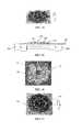
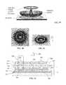
- FIG. 1is photographs of ring-shaped frames printed with magnetic inks having different concentrations of magnetically alignable flakes
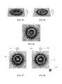
- FIG. 2is photographs of the frames shown in FIG. 1 , at a different angle of observation;
- FIG. 3is a schematic cross-section of an ink or paint coating
- FIGS. 4 and 5are photographs of an article
- FIG. 6is a schematic diagram of a magnet
- FIGS. 7-9are photographs of an article
- FIG. 10is a schematic diagram of the structure of an article
- FIGS. 11-14are photographs of an article
- FIG. 15illustrates a method of planarization of pigment flakes
- FIGS. 16-18are photographs of an article
- FIG. 19is an illustration of an article
- FIG. 20is a schematic diagram of a magnetic assembly
- FIG. 21is a schematic diagram of a magnetic field
- FIG. 22is a schematic diagram of a magnetic field
- FIG. 23is a schematic diagram of a cross section of an article
- FIG. 24is a plot of angles formed between flakes and a substrate
- FIG. 25is plots of head-to-tail connections of flakes
- FIG. 25Ais a schematic diagram of a field generated by a spherical magnet
- FIG. 26is an illustration of a convex reflective surface
- FIGS. 27 and 28are photographs of an article
- FIGS. 29 and 30illustrate a magnet
- FIG. 31is a schematic diagram of a magnetic field
- FIG. 32is a schematic diagram of flake alignment
- FIG. 33is a plot of angles formed by pigment flakes with a substrate
- FIG. 34is an illustration of a reflective surface
- FIGS. 35 and 36are photographs of an article
- FIG. 37is a schematic diagram of an article
- FIG. 38is a schematic diagram of an article
- FIG. 39is an illustration of a reflective surface
- FIGS. 40 and 41are photographs of an article
- FIG. 42is a schematic diagram of an article
- FIGS. 43 and 44are photographs of an article
- FIGS. 45 and 46illustrate magnets
- FIGS. 47 and 48are schematic diagrams of a magnetic assembly
- FIG. 49is a schematic diagram of a magnetic field
- FIG. 50is a photograph of an article
- FIGS. 51-58are photographs of articles
- FIG. 59is a photograph of an article
- FIG. 60illustrates a magnet
- FIG. 61is a schematic diagram of an article
- FIG. 62is a schematic diagram of an article
- FIGS. 63 and 64illustrate a magnet
- FIGS. 65 and 66are photographs of an article
- FIG. 67is a schematic diagram of a magnetic assembly
- FIG. 68is a schematic diagram of a magnetic assembly
- FIG. 69-71are photographs of a printed article
- FIG. 72is a schematic diagram of a magnetic field
- FIG. 73is a schematic diagram of a magnetic field
- FIG. 74is a schematic diagram of a magnetic assembly
- FIG. 75is a photograph of a printed article
- FIG. 76is a schematic diagram of a magnetic assembly
- FIGS. 77 and 78are photographs of a printed article
- FIG. 79is a schematic diagram of a magnetic assembly
- FIGS. 80 and 81are photographs of a printed article
- FIG. 82is a schematic diagram of a magnetic assembly
- FIGS. 83 and 84are photographs of a printed article.
- FIGS. 85 through 88are photographs of a printed article.
- the purpose of the experimentswas to combine optical effects generated by magnetically aligned flakes with conventional printed graphical images; the inventors were using optically variable images as frames surrounding printed images.
- the optically variable framessimultaneously serve as security features per se, because they are difficult to reproduce, as decorative elements for their spectacular optical effects, as well as for attracting a human eye to the image surrounded by the frame, the way guilloche patterns highlight denomination numerals on banknotes.
- optically variable imagesare printed with inks having around 20-30 wt % concentration of magnetically aligned flakes in a clear binder. Even higher concentrations have been considered in order to improve the visibility of a relatively narrow frame which surrounds an image.
- the inventorsunexpectedly found advantages in using a diluted magnetic ink.
- the magnetic reflective flakesare aligned in a frame pattern which may be characterized by the pattern's cross-section between the inner and outer imaginary contours of the frame.
- the frame patternmay surround an image, e.g. a numeral or logo printed with regular non-magnetic ink, the way a wooden frame surrounds a painting.
- the cross-section of the frame pattern formed of the aligned pigment flakesthen corresponds to the cross-section of a wooden plank of the painting's frame.
- a portion of the pigment flakesare aligned parallel to the substrate.
- the cross-section of the frame patternalso includes pigment flakes tilted so that the angles which the pigments flakes form with the substrate gradually increase on both sides of the central part of the cross-section.
- angles which flakes form with the substratedecrease from at least 70 degrees and preferably from 80 degrees to practically zero (the flakes are essentially parallel to the substrate) in the central part of the cross-section, and then again increase to at least 70 degrees and preferably to 80 degrees.
- the pigment flakes within the frame patternmay be thought of as forming a Fresnel reflector which to some degree focuses, or concentrates, reflected light into a bright image visible to an observer. It turned out that the diluted inks with the concentrations as low as 4 wt % provide adequately noticeable images formed by light reflected from the frame patterns of aligned reflective flakes.
- FIG. 1presents photographs of ring-shaped frames printed on a black background with a magnetic ink and aligned using the same magnetic field configuration.
- the difference between the two imagesis that the left image 200 is printed with an ink having 25 wt % of magnetically alignable flakes, whereas the right image 210 is printed with an ink having 7.5 wt % of magnetically alignable flakes; the weight percentage relates to in cured, dried inks.
- Both imagesshow bright rings 205 and 215 , respectively.
- the left image 200 having a higher concentration of magnetic flakesshows a shadow 220 which is practically absent in the right image 210 .
- the right ring 215may appear less bright than the left ring 205 , the right ring 215 is better delimited from the background and thus is more legible. Accordingly, the decrease of ink concentration unexpectedly improves the illusive image formed by focusing reflected light.
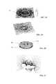
- FIG. 2shows the same printed images 200 and 210 tilted with their upper edge away from the observer; the bright rings 205 and 215 have moved into the positions 205 ′ and 215 ′, and the shade 200 has become an even more noticeable shade 220 ′.
- the illusive movement of the right ring 215is easier to recognize than the movement of the left ring 205 , because the left ring 205 leaves a wide trace of shadows 220 and 220 ′ when the ring moves.
- the focus of reflected lightappears to be out of the plane of the coating made of the magnetic ink. Consequently, the entire right ring 215 may appear to float above or below the surface of the substrate. It is our understanding that the left ring 205 printed with a high-concentration ink lacks the floating effect because the exact position of the bright ring 205 is obfuscated by the shadows 220 .
- the size and concentration of the pigment flakes in the magnetic inkshould be chosen so as to make a portion of the background overprinted with a low-concentration magnetic ink and adjacent to the moving ring visible through the magnetic ink. This delimits the ring from the background, making the ring appear as a separate illusive element, so that the shape and position of the ring are defined by the curved alignment of the flakes. It may be thought that the visibility of the background near the ring separates the ring from the substrate, whereas the alignment of the flakes concentrating the reflected light enables a distance between the ring and the substrate, and the visible background serves as a frame of reference for the movements of the ring. Thus the visibility of the background and the alignment of the flakes synergistically provide the floating effect.
- an articlewhich may be used as an optical security article, includes a substrate 301 , and a first coating supported by the substrate 301 .
- the first coatingforms a graphical component including a central image 304 and possibly a background pattern such as rosettes 302 and 303 ; the image 304 is clearly discernible from the background rosettes 302 and 303 .
- the first coatinghas first pigments in a first binder, and may be printed with a first ink which in this case is a regular, conventionally-tinted ink.
- the articlefurther includes a second coating also referred to as an optical component 305 , also supported by the substrate 301 .
- the second coatingis made with a plurality of second pigments in a second binder which form a second ink which is different from the first ink.
- the second coatingis shown as an opaque coating in FIG. 5 , as it was immediately after printing when magnetic ink has not been exposed to the magnetic field yet.
- the second pigmentsare pigment flakes each including a magnetic or magnetizable material so as to make the flakes magnetically alignable in a liquid binder.
- the pigment flakesare aligned so as to form, within the second coating 305 , a frame pattern surrounding the image.
- the frame pattern of flake alignmentis represented by two regions 515 .
- angles which flakes form with the substratedecrease to practically zero (the flakes are parallel to the substrate) and then increase along a plurality of radial directions originating at the image, such as directions 516 shown in FIG. 3 .
- light reflected from the frame patternforms a bright dynamic frame 306 surrounding the image 304 .
- Pigment flakes in the rest of the second coating 305are not visible because they have been aligned by the applied field at steep angles to the substrate that makes the coating 305 transparent and useful for viewing of the rosettes 302 and 303 .
- the term “surrounding”is understood as “at least partially surrounding” and possibly having gaps or openings if printed in patterns.
- the bright dynamic frame 306 in FIG. 7appears to move as the substrate is tilted with respect to the light source, and the image 304 of the numeral “10” appears to be stationary when the bright frame appears 306 to move.
- the “bright frame”is a dynamic frame formed by light reflected from the aligned pigment flakes, the dynamic frame is noticeable because it is brighter than the background and, preferably, brighter than the central image.
- the dynamic frame 306may be perceived as floating below or above the substrate 301 , which depends on the spatial imagination of the observer and the convex or concave alignment of the flakes in the frame pattern 615 ( FIG. 3 ).
- an observermay perceive an image formed by a concave reflector as moving toward the observer when the article is tilted with its upper edge away from the observer, and may perceive an image formed by a convex reflector as moving away from the observer when the article is tilted with its upper edge away from the observer.
- the pigment flakes within the frame patternmay be thought of as forming a convex Fresnel reflector which creates a virtual image of the light source behind the surface of the substrate.
- an observermay see the image of the light source in the form of the bright dynamic frame 306 which moves underneath the central image 304 creating the illusion of some space therebetween, and the central image 304 may be perceived as positioned above the bright frame 306 .
- the concentration of the pigment flakes in the second inkshould be chosen so as to make a portion of the background overprinted with a low-concentration magnetic ink and adjacent to the moving ring visible through the magnetic ink, or at least partially visible so that the background pattern is discernible with an unaided human eye. Accordingly, the concentration and size of the flakes should be chosen such as to provide the at least partial visibility of the background.
- a suitable concentration of the pigment flakes in the inkwhich is defined by the weight of the flakes in dry, cured ink, depends on the size and density of the flakes. A person skilled in the art, given particular magnetic flakes, would easily find a suitable ink concentration which provides the visibility of the background.
- the second inkmay have a concentration of the pigment flakes of less than 14 wt %, preferably in the range between 4 and 14 wt %, and more preferably between 5 and 12 wt %.
- the central image 304 and the background pattern 302 and 303may be printed in one or more colors, i.e. using one or more inks.
- a variety of background patternsmay be employed in place of the rosettes 302 and 303 , and a variety of images may be used in place of the numeral 304 .
- the second coating 305may be printed onto the substrate 301 over the first coating which provides the graphical component including printed elements 302 - 304 .
- the graphical componentmay be printed over the optical component so that the bright frame is visible through gaps in the graphical component as discussed further with reference to FIGS. 13 and 14 .
- the optical component 305( FIG. 5 ) formed of the magnetic ink may be printed onto a thin transparent plastic support sheet as illustrated in FIGS. 37 and 38 . After aligning the magnetic pigment particles in an external magnetic field, the transparent polymer-based support sheet is attached to the substrate 301 over the graphical component.
- the support sheetmay be adhesively laminated to the substrate 301 , e.g. with a printed side of the sheet adjacent to graphical component on the substrate 301 .
- the substrate 301( FIG. 4 ), possibly a fragment of a banknote, has a large Guilloche rosette 302 , a small six-pointed Guilloche rosette 303 , and a numeral 304 printed on the surface of the note with a conventional technique.
- Magnetic inkcontaining Gold-to-Green color-shifting magnetically alignable pigment flakes dispersed in clear UV-curable ink binder, was printed on the note in the shape of a circle 305 as shown in FIG. 5 .
- the concentration of the pigment flakes in the dry, cured inkwas 5 wt %.
- the circlewas opaque immediately after the printing procedure as shown in FIG.
- the second coating 305covers the image 304 , however, due to the low concentration of the second ink and the normal or near-normal orientation of the flakes the image 304 may be visible through the second coating; preferably, the flakes in the second coating above the image 304 are oriented normally to the substrate. Alternatively, the second coating 305 may have an aperture above the image 304 .
- the substrate 301 with the wet inkwas placed on the top of a hexagonal magnet with a tapered extruded cut (a through funnel cut) as illustrated in FIG. 6 .
- the magnethad a hexagonal funnel-like cavity (a through cut) in its center.
- the center of the magnetic printwas registered with the magnet so that their centers coincided.
- the inkwas cured with UV light after magnetic platelets completed their alignment in the field of the magnet forming an enclosed convex hexagonal rolling effect.
- the hexagon 306( FIG. 7 ) surrounds the numeral 304 close to periphery of the small Guilloche rosette 303 .
- the six-pointed shape of the rosette 303was specifically designed to match the size and the shape of the magnetically formed hexagon 306 .
- FIG. 7shows the resulting article at the normal angle of observation.
- a bright, narrow-lined gold hexagon 306has been formed by light reflected from the layer of magnetically oriented ink 305 above the cut of the magnet shown in FIG. 5 . All other regions of the magnetic ink 305 became transparent allowing observations of the Guilloche rosettes 302 and 303 in fine detail.
- the hexagon 306may be seen as it were located underneath the surface of the print below the dark green circle with the numeral.
- a corner of the bright hexagon 306appears to be in a position marked by a circle 307 , so that the hexagon obscures a portion of the rosette there.
- Nearest regions of the graphical image, marked by circles 308 and 309are not obscured and are clearly visible.
- the observermay see the bright hexagon 306 moving in the direction opposite to the tilt.
- the corner of the hexagon 306approaches the edge of the magnetic print 305 and obscures the place 308 leaving the place 307 , where the bright frame 306 was at the normal angle, unobscured. There is no shadow effects in the printed security feature.
- An observermay perceive the hexagon 306 as floating out of the plane of the rosette 303 because the hexagon obscures different portions of the rosette 303 .
- the image 304especially if it is of a light or bright color, may be perceived as being closer to the observer and thus floating with or above the hexagon.
- FIG. 9demonstrates the tilt of the printed image to the right.
- the thin bright frame 306obscures only a small portion of the printed image.
- An observerinitially focuses on familiar and recognizable features—the numeral 304 .
- the magnetically aligned featureis bright and dynamic because it moves when the sample is tilted that attracts attention to it.
- the eyes of observerare in different positions on the head, they present different views simultaneously. This is the basis of stereopsis, the process by which the brain exploits the parallax due to the different views from the eye to gain depth perception.
- the differences in the two retinal images of the hexagon 306may create the impression that the hexagon 306 floats above or below the numeral 304 .
- the obscuringenhances the illusion of flotation above or below the surface of the substrate.
- the pigment flakesare aligned on a transparent plastic support in a concave frame pattern, so that along a radius originating at the central image, a portion of the pigment flakes are aligned so that the angles they form with the substrate decrease from at least 70 degrees to practically zero and then increase again to 70 degrees, preferably from 80 to practically zero and to 80 degrees.
- the plastic supportis laminated to the substrate 301 so that the magnetic coating is adjacent to the graphical component which includes the printed elements 302 - 304 .
- the flakesmay be thought of a forming a concave Fresnel reflector, produced by this method, produces optically real image of the light source in the direction of the observer.
- the dynamic frame(that is the optical image of the light source) may appear to float above the surface of the print and above the small rosette and the numeral.
- the optical reflective front(the bright dynamic frame) may appear to move in the direction of the tilt.
- the central image 304may be printed using an ink with magnetically alignable flakes, wherein the concentration of the flakes in the dry ink is at least 20 wt % so as to ensure that the central image 304 is highly noticeable, and wherein the flakes are aligned parallel to the substrate in order to form a stationary image, e.g. using the method illustrated in FIG. 15 , wherein magnets 194 , 196 are arranged to produce magnetic field lines 198 essentially parallel to the surface of the substrate 29 , which causes the magnetic pigment flakes 26 in the fluid carrier 28 to flatten out.
- the concentration of the ink in the image 304can vary in a wide range, preferably being in the range of 15-25 wt %.
- the magnetically alignable pigment flakesmay be aligned using a variety of magnetic assemblies, including those discussed in this application with reference to FIGS. 20-26, 29-34, 45-49, 60, 63, and 64 .
- the dynamic frameis not necessarily a hexagon as the frame 306 shown in FIGS. 4-9 .
- the dynamic framemay have a variety of shapes such as a ring 306 ′ shown in FIG. 11 .
- the dynamic frame discussed abovemay be accompanied by an additional frame, either dynamic or stationary, wherein the first (dynamic) frame appears to move relative to the second (additional) frame when the substrate is tilted. Examples of such devices are shown in FIGS. 11, 43, 51, and 55 .
- FIG. 10illustrates a possible structure of the article formed on the substrate 301 .
- the optical componentin this case is formed of a transparent plastic support 324 coated with layers 322 and 323 of solidified binder containing magnetically aligned pigment flakes which include a magnetic or magnetizable material so as to enable the alignment.
- the two layersmay be printed with a same or different magnetic inks; however, the concentrations of the flakes in the binder has to be within the same interval as for the printed circle 305 , less than 14 wt %, preferably 4-8 wt %.
- An adhesive 325may be coated on the side of the optical component for laminating to the substrate 301 over the graphical component (not shown).
- the substrate 301has the Guilloche rosette 302 and the numeral 304 .
- the transparent support 324which may be a thin polyester sheet, was printed on one side with a transparent UV curable ink binder containing 5 wt % of Gold/Green interference magnetic pigment and aligned in magnetic field so that the aligned flakes formed a narrow gold-colored ring leaving the rest of the printed area transparent. After curing of the ink with UV light, the printed transparent support sheet was flipped upside down. The second side of the transparent sheet was also printed with a different ink containing 5 wt % of the Green/Blue magnetic interference pigment in the same binder.
- the ink on the second side of the transparent support sheetwas exposed to the field of the same magnet which was used for aligning the ink on the first side of the support.
- the sheetwas separated from the magnet by the distance of about 0.0625′′ thus reducing the size of the green ring that was formed by alignment of the flakes, and the ink of the second side was also cured in UV light.
- the configuration of the magnetic field used for aligning the ink on the first side of the supportwas different from the configuration of the magnetic field used for aligning the ink on the second side of the support.
- the adhesive 325was provided to the side with the Gold/Green ink and the sheet was laminated to the surface of the banknote 301 .
- the resulting article at the normal angle of observationis illustrated in FIG. 11 .
- the note 301 with the Guilloche rosette 302 and the numeral 304has a transparent polyester sheet 324 (invisible in the photographs and outlined by the dashed line for illustrative purposes) laminated to its surface over the rosette 302 and the numeral 304 .
- the transparent sheethas a convex Green/Blue ring 335 on the top of the surface that may produce a flotation effect underneath the numeral.
- the concave Gold/Green ring 306 ′ being physically underneath the sheet with the convex structuremay produce an effect of a bright ring illusively floating 0.125′′-0.25′′ above the graphical component which may be a multicolored graphical image printed on the substrate with conventional printing techniques
- the resulting articlehas two frame patterns formed of magnetically aligned flakes on the transparent support 324 .
- the flakesare aligned in a concave frame pattern, and in another layer—in a convex pattern. Accordingly, the observer may see two bright frames 306 ′ and 335 which move in opposite directions, whereas one bright frame may appear to float above the substrate, and another bright frame—below the surface of the article.
- the two bright ringsappear to float in two planes separated by a space close to 0.25′′.
- the presence of the second bright framecreates an illusion that the numeral 304 floats between the two bright frames, or on the top of an imaginary stem, or neck, which extends between the two bright frames 306 ′ and 335 . Additionally, having the smaller ring at the “bottom” of the stem creates the perspective customary used in paintings, which contributes to the illusion of depth in the image formed by the article when irradiated with light.
- the green ring 335 formed by a convex frame patternmay appear to be underneath the numeral 304 and floating toward the observer.
- the larger gold ring 306 ′, formed by a concave frame pattern,may appear to float in the direction of the tilt.
- the ringsmove in opposite directions and, with the tilt, come to the point when the large gold ring 306 ′ overlaps the green ring 335 .
- Overlapping of two objects, called “occlusion,”is one of the most important attributes of the depth perception.
- the sampleproduces an eye-catching effect of the numeral 304 apparently floating between two surrounding moving bright rings.
- the bright frame 306is not a contour of the central image 304 ; there may be a gap between the frame 306 and the image 304 , more so that the bright dynamic frame 306 appears to move whereas the image 304 appears to be stationary.
- the two prints made with the different inksare not required to be perfectly in register.
- the second coating 305may surround the central image 304 only partially, i.e. have gaps in some radial directions originating at the central image 304 , totaling to not more than in a quarter of the circle. Accordingly, the frame pattern formed of the magnetically alignable flakes and the dynamic frame 306 formed by reflected light may surround the image 304 only partially.
- the second bright framebeing stationary with respect to the substrate 301 and thus, to the numeral 304 .
- the relative movement of the two bright frames relative one anothermay also produce the effect of a stem supporting the image 304 so that the image 304 moves below or above the substrate supported by and attached to the substrate by the illusionary stem between the two bright frames.
- An articlemay include a substrate and an optical component supported by the substrate.
- the optical componente.g. a coating, contains magnetically alignable pigment flakes having a magnetic or magnetizable material, dispersed in a binder.
- the optical componenthas a first curved region with a first plurality of magnetically alignable pigment flakes; in cross sections of the first curved region, the pigment flakes are aligned in a first arching pattern so that light reflected from the first plurality of pigment flakes provides an image of a first bright frame.
- the optical componentalso has a second curved region, possibly different from the first curved region, with a second plurality of magnetically alignable pigment flakes providing an image of a second bright frame.
- the first bright frameis a dynamic frame which appears to move relative to the substrate and to the second bright frame when the substrate is tilted.
- the first and second pluralities of the flakesmay be in a same layer of an optical component, then the first curved region is different from the second curved region.
- the first and second pluralities of the flakesmay be in different layers of the optical component, e.g. layers deposited on the substrate and aligned in separate steps; then the first and second curved regions may be different or coincide i.e. be one above another.
- the first and second pluralities of the flakesmay be in a same layer or in different layers of an optical structure, as shown in FIGS. 62 and 61 .
- the optical structuremay or may not include a central image.
- the pigment flakesmay be aligned in arching patterns which arch in opposite directions so that the first and second bright frames appear to move with respect to the substrate and to each other when the substrate is tilted.
- An article shown in FIG. 62may have features described with reference to the article shown in FIGS. 4-9 .
- the articlehas first and second curved regions I the form of two rings with cross-sections 610 and 620 .
- pigment flakesare aligned in a first arching pattern 610 so that the first dynamic frame appears to move when the substrate is tilted.
- pigment flakesare aligned in a second arching pattern 620 so that the second bright frame may appear to move when the substrate is tilted.
- the first and second arching patternsmay arch in same or opposite directions.
- the article shown in FIG. 62has rotational symmetry, and the first and second curved regions are rings of different radii. However, the first and second curved regions can coincide as in the embodiment shown in FIG. 42 , wherein the first arching pattern 546 and the second arching pattern 548 are in the same curved region, possibly a ring, having a cross section 554 .
- the substratesupports a coating with aligned pigment flakes.
- the coatinghas the first and second curved regions which can be different or can coincide. In cross-sections of the first and second curved regions, first and second pluralities of pigment flakes are aligned in first and second arching patterns, respectively.
- the first and second arching patternsare maintained along the first and second curved regions, respectively, and arch in opposite directions.
- Light reflected from the first plurality of pigment flakesprovides an image of a first bright frame
- light reflected from the second plurality of pigment flakesprovides an image of a second frame, wherein the first frame appears to move relative to the second frame when the substrate is tilted, and preferably the first and second frames appear to move in opposite directions.
- magnetically alignable pigment flakes in the first curved regionare aligned in a first arching pattern
- magnetically alignable pigment flakes in the second curved regionare aligned in with the second arching pattern of the radius substantially smaller than the radius of the first arching pattern so that the motion of the second bright frame is so small that the second bright frame appears static when the substrate is tilted as discussed in more detail with reference to FIG. 49 .
- FIG. 13An article with a different kind of occlusion is shown in FIG. 13 .
- a round region 401(outlined with white dashed line for visibility) of the substrate 402 was coated with ink containing magnetically alignable interference Green/Blue pigment flakes dispersed in a binder.
- the wet ink having the low concentration as described with reference to FIG. 4was exposed to the field of a permanent magnet so that an arching pattern for producing a dynamic ring 403 was formed in the ink.
- the inkwas cured with UV-light.
- the round region 401was overprinted with a second ink containing non-magnetic, i.e. not alignable in the presence of the magnetic field used for the alignment of the optical component 401 , Gold/Green interference pigment.
- the second inkwas printed in the shape of the rosette pattern 404 .
- the patternhas openings in order to make the motion of the ring 403 at least partially visible. Because the ring 403 may be perceived as floating underneath the pattern 404 and the numeral 405 , the occlusion created by overlapping the green ring by the highly visible mesh-like pattern of the rosette 404 may enhance the illusion of depth.
- the second inkmay be any non-magnetic ink with a concentration of pigment particles of at least 20 wt %.
- the second inkmay contain magnetically alignable flakes in a concentration of at least 20 wt %; when the binder is solidified, the flakes lie parallel to the surface of the substrate 402 so that the image formed by the second ink be a stationary image having gaps wherein the movement of the bright frame 403 could be visible.
- the dynamic frame 403may be a square, hexagon, etc.
- FIG. 14shows the same article with its upper edge tilted away from an observer.
- the first and second inkcontained color shifting interference pigments; however, non-color shifting pigments may also be used in one or both inks.
- the optical component supported by the region 401 of substrate 402may be printed with a first ink containing a transparent binder with reflective silvery flakes having a magnetic or magnetizable layer.
- the second coating making the graphical component, which is supported by the optical component and the substrate 402may be printed with a conventional non-color shifting, non-magnetic ink.
- the moving frame 403is only partially visible and thus partially surrounds the central image, which is not necessarily a numeral, as shown, and may be a symbol, logo, or a localized image which preferably fits into the frame 403 .
- the visible sectors of the framecombine to measure at least 180 degrees, and better 270 degrees.
- a graphical component in the form of a pattern 422has been printed on a substrate 421 with a first ink, and contains a solidified binder and Gold/Green interference pigment particles in a concentration of 20-25 wt %; the first pigment particles may be non-magnetic pigments, or magnetically alignable pigments planarized as illustrated in FIG. 15 .
- a round region 423 (outlined with a black dashed line for visibility) of the pattern 422has been coated with a second ink so as to form an optical component supported by the substrate 421 .
- the second inkcontains a binder and second pigments in a concentration of 5 wt %.
- the second pigmentsare interference magnetic Gold/Green pigment flakes providing the same Gold/Green color shift as the pigments in the graphical component.
- the wet inkwas exposed to the magnetic field and the pigment particles were aligned along magnetic lines forming a narrow ring leaving the rest of the magnetic print transparent.
- the ringis not visible at the normal angle of observation as illustrated in FIG. 16 , because the pattern 422 and the ring 424 are printed with pigment having the same color characteristics.
- the Gold/Green pigment particles of the pattern 422start to change their color from Gold to Green while the gold ring 424 keeps the same color at the tilt.
- the pattern 422has dark-green color at high angles as shown in FIG.
- the moving frame 424may be a square, etc., and the central image is not necessarily a numeral, as shown, and may be a symbol, logo, or a localized image which fits into the frame 424 .
- the first and second pigmentsproduce the same Gold/Green color shifting effect.
- the second pigmentsare pigment flakes each including a magnetic or magnetizable material for aligning the flakes in the frame pattern which exhibits the ring 424 .
- the first pigmentsmay or may not include a magnetic or magnetizable material.
- the concentrations of first inkis different from the concentration of the second ink.
- the first ink used for printing the graphical componentmay have the concentration of first pigments in the first binder in the range of 5-30 wt % and preferably between 20 and 25 wt % for screen printing presses and 25 to 30 wt % for Intaglio printing presses.
- the second ink used for the optical componentmay have the concentration of second pigments in the second binder in the range of 4-14 wt % and preferably between 5 and 8 wt %.
- the article shown in FIGS. 16-18provides a metameric effect made with two prints of the same pigment.
- the observercan see the gold pattern 422 because it is larger than the ring 424 .
- the pattern 422changes its color to green, while the ring 424 keeps its gold appearance.
- the gold on the top of greenhas a high contrast that makes it very visible.
- the first and second pigments in the first and second inkmay have same color same color characteristics, e.g. produce a same color shifting effect.
- the bright dynamic framemay be in the form of a ring, oval, hexagon, square, or other polygonal shape.
- the dynamic frameis closed around the central image, e.g. a symbol, logo, etc.
- the dynamic framemay consist of one or more sectors divided by one or more gaps, so that the sectors combine to measure at least 180 degrees, and preferably not less than 270 degrees.
- the gapsmay result from the absence of magnetically alignable pigment flakes in a particular region or from magnetically alignable flakes being hidden, e.g. by a stationary element such as the graphical component.
- the dynamic framecan be surrounded by the graphical image.
- FIG. 19shows a ring formed by an arching alignment of pigment flakes, e.g. such as a pattern 524 ( FIG. 38 ), wherein the arching pattern is maintained in radial cross-sections along a circular path on a surface of a substrate.
- FIG. 19schematically shows an arching alignment that forms the ring and near vertical alignment in all other regions of the print.
- the article shown in FIG. 19may have features described with reference to the article shown in FIGS. 4-9 , with the exception that the dynamic frame has a different shape; in FIG. 19 the dynamic frame is a dynamic ring.
- a magnetic assembly for manufacturing the article shown in FIG. 19has two magnets mounted on the top of a base; the base is preferably made of [ferromagnetic metal preferably cold rolled steel.
- a ring-shaped magnet 441rests on a steel base 443 , and a cylindrical magnet 442 is located in the center opening of the magnet 441 .
- the magnetsgenerate the field illustrated in FIG. 21 .
- FIG. 22illustrates a cross-section of the field produced by the magnetic assembly in close proximity to the top of the magnet; the cross-section is taken along a diameter of the magnetic assembly.
- a box 451 in FIG. 22schematically representing a layer of liquid magnetic ink, indicates a portion of the field which has aligned the flakes as shown in FIG. 23 .
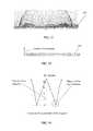
- FIG. 24is a plot of angles formed between the aligned pigment flakes ( FIG. 23 ) and the substrate supporting the optical component, along a diameter (from edge to edge) of the large magnet ( FIG. 20 ).
- a head-to-tail connection of flakes shown in FIG. 23produces a curve 461 illustrated in FIG. 25
- a curve 462represent flakes aligned in the field of a spherical magnet shown in FIG. 25A .
- the curve 461is more round than the curve 462
- the reflective surface produced by revolving the curve 461 around the center of the magnetgenerates a significantly better pronounced bright ring than the reflective surface produced by the curve 462 .
- the angles of the flakesincrease slowly at the periphery of the curve 462 and do not reach the near-normal values achieved by the angles in FIG. 24 and the curve 461 in FIG. 25A .
- the ring formed by flakes aligned in accordance with the curve 462has a shallowing-out effect which results in shadows and dilution of the bright ring, i.e. when the article is tilted with respect to the light source, the region that is closer to the observer becomes bright and the region on the opposite side of the article becomes dark.
- the shallowing-out effectproduces shadow regions which change their color when the object is tilted.
- a magnetic fieldsuch that, along the majority of radial directions, the minimal angles that the field lines form with the substrate decrease from 70 degrees to zero and then increase to 70 degrees, more preferably from at least 80° to zero and then again to 80°; ideally—from normal, to zero, and again to normal angles. Consequently, it is preferable that along at least one of the plurality of radial directions originating at the central image, angles that the pigment flakes form with the substrate decrease from 70 degrees to practically zero (the majority of flakes in a small area are parallel to the substrate) and then increase to 70 degrees; more preferably from 80° to practically zero and then again to 80°.
- the effectis explained with reference to a cylindrically-symmetric magnetic field and a ring-shaped bright dynamic frame, the same goes to any form of the dynamic frames, e.g. square, hexagonal, etc. frames and corresponding magnetic assemblies.
- FIG. 26illustrates a convex reflective surface reconstructed from the head-to-tail connection of particles shown in FIG. 23 by revolving the curve 461 ( FIG. 25A ) around the axis going through the center of the magnetic assembly.
- the surfaceproduces a virtual image of a light source in the shape of an oval or a ring below the substrate if the focal points of the reflector are located there; also see FIG. 34 .
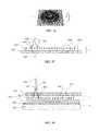
- FIG. 27shows an article with pigment flakes aligned with the magnetic assembly shown in FIG. 20 .
- the article shown in FIG. 27may have features as the article shown in FIGS. 4-9 , with the following differences.
- a graphical componentincludes a star-like pattern, which serves as a background pattern as the rosettes 302 and 303 in FIG. 4 .
- the graphical componentalso includes an Earth image in the middle, which serves as a central image as the numeral “10” in FIG. 4 .
- the graphical componentwas completely coated with a transparent ink vehicle containing 7.5 wt % of aluminum coated magnetic pigment aligned in the magnetic field illustrated in FIG. 21 . As shown in the plot ( FIG.
- the pigment flakesare vertical to the substrate (90°) in the center of the magnet that makes them invisible in the picture ( FIG. 27 ) because they are staying on their edges.
- the pigment flakes in the optical componentbecome visible in the picture when their orientation approaches the horizontal axis and the pigment flakes eventually become parallel to the substrate.
- the pictureshows a bright ring which is a dynamic ring appearing to move when the article is tilted relative to a light source. An observer may perceive that the dynamic ring moves underneath the Earth which creates the illusion of the Earth's flotation above the ring. Outside of the bright ring, the increase of the angles which the pigment flakes form with the substrate along the radius of the magnet (from the center to the outside) makes the flakes invisible again at the periphery of the bright ring when the article is observed at the normal angle.
- Tilting of the sample with its upper edge away from the cameramay generate the illusion of the dynamic ring floating underneath the globe ( FIG. 28 ).
- the graphical pattern printed underneath the magnetic inkcan be easily observed; it is not obfuscated with unwanted reflections.
- FIG. 60illustrates another magnetic assembly for aligning pigment flakes to produce the dynamic ring shown in FIG. 19 .
- the assemblyhas a ring-shaped magnet with radial magnetization. One pole of the magnet is inside of the ring and another pole is on the outer side. The lines of the magnetic field emerge from one pole to another.
- wet ink containing magnetic or magnetizable pigment particlesis placed either directly on the magnet or at some distance from it, the pigment particles align themselves in a convex annular arrangement schematically shown in FIGS. 21-23 .
- a magnet for manufacturing the article shown in FIG. 19has a through (extruded), tapered cut, and provides a remarkable motion effect, characterized by a long travel of the ring at the tilt of the article and by a significant illusive depth of the effect.
- the orthogonal view of the round magnetis shown in FIG. 30 .
- the angle of the cutmay vary in the range of from 30° to 120°.
- the wide opening of the cone cutis preferably facing the substrate, i.e. the preferable range of for the angle of the cut is between 30° to 90° and more preferable between 30 and 60°.
- the field generated by the magnet( FIGS. 29 and 30 ) is shown schematically in FIG. 31 , the alignment of the flakes—in FIG.
- FIG. 34A reflective surface calculated from the head-to-tail connection of particles in the layer of ink vehicle is shown in FIG. 34 ; the surface is an annual convex reflector which produces a virtual image of a light source in the form of a ring.
- FIG. 3A cross-section of an article formed with the magnet described with reference to FIGS. 29 and 30 , is schematically shown in FIG. 3 .
- the article illustrated in FIG. 3may have features described with reference to the article shown in FIGS. 4-9 , with the following differences.
- a substrate 501is printed with a graphical component including a background pattern 502 and an informative image 503 in a first ink printed with conventional techniques.
- the graphical component formed with the first inkmay be overprinted with an optical component printed with a second ink which includes a clear binder 504 with pigment flakes having a magnetic or magnetizable material; the pigment flakes are aligned in the magnetic field of the magnet illustrated in FIG. 31 .
- the flakes in regions 505 and 506are aligned normally to the substrate, and the flakes in annular region 507 are aligned as a Fresnel annular convex reflector.
- the optical componentmay be formed under the graphical component or on a transparent plastic support and attached to the substrate 501 .
- FIGS. 35 and 36are photographs of an optical device produced with the magnet shown in FIG. 30 .
- the deviceis shown at the normal angle of observation
- FIG. 36shows the device tilted with its upper edge away from the camera. Note, that when the upper edge of the device is tilted away, the ring moves toward the camera.
- a method for making an articleincludes providing a coating of a liquid binder having pigment flakes therein onto a substrate, exposing the pigment flakes to the field of a magnet having a tapered cut through the magnet in the form of a funnel or countersink cut ( FIGS. 29 and 64 ) between the top and bottom surfaces of the magnet, and solidifying the binder so as to form an optical component.
- the pigment flakesinclude a magnetic or magnetizable material.
- the substratePrior or after providing the optical component, the substrate may be provided with graphical component in the form of another coating, supporting or supported by the optical component.
- the substrate whereon the optical component is formedmay be a thin transparent support sheet. After forming the optical component, the support sheet is attached to another substrate, which receives the graphical component before or after attaching the support sheet.
- a concave optical document security devicemay be formed with the help of the magnet shown in FIG. 30 thus creating an annular convex reflector schematically shown in FIG. 37 .
- a transparent plastic substrate (a support sheet) 521is coated with the ink 522 containing magnetic platelets (pigment flakes) 523 oriented in an external magnetic field. Regions 524 of the structure are oriented as an annular convex Fresnel reflector. The rest of the platelets are oriented normally to the substrate in all other regions of the article.
- the ink 522is solidified after completion of the alignment with any suitable method (drying, UV or e-beam irradiation, microwave, etc.).
- the light rays 525 from the light source 526illuminate a convex flake pattern in the region 524 and form a virtual image 527 of a distant point light source.
- the virtual image 527is located underneath the substrate 521 .
- the next stepincludes flipping the printed transparent substrate 521 upside down and laminating it to a flexible substrate bearing a graphical image.
- the convex alignment of the flakes on the transparent plastic sheetbecomes a concave annular reflector after lamination to the substrate 528 .
- a cross-section of the resulting article which may be used as a concave security deviceis illustrated in FIG. 38 .
- a substrate 528which is preferably an opaque substrate, is printed with a graphical component containing a background 529 and a logo or the numeral 530 on the top of the background 529 .
- the region 524 of the magnetically oriented plateletshas formed a concave Fresnel annual reflector.
- the light rays 525 from a distant point sourceare reflected back forming now a real image 527 of the source 526 . Because the image 527 is a real image and is located above the reflector in the direction of the light source, the image may be perceived as floating above the surface of the substrate.
- a reconstructed reflecting surface producing concave reflectionis illustrated schematically in FIG. 39 .
- FIG. 40shows the resulting security device at the normal angle of observation; the device appears to be similar to the convex device shown in FIG. 35 .
- the dynamic ringmoves away from the camera.
- the motion effect of the concave optical deviceappears to be opposite to the motion effect of the convex device.
- the concentration of the magnetic pigment particles in the inkin the range 4-14%, preferably not higher than 10% by weight so as to eliminate dark regions between the background, bright dynamic ring, and symbol.
- the pigment flakes in these regionsare tilted at some “intermediate” angles between the directions normal and parallel to the substrate. While the horizontally (parallel to the substrate) and near-horizontally aligned flakes are bright in reflected light and produce the dynamic ring, and the vertical and near-vertical flakes reflect very little light and are practically invisible at relatively small tilt angles e.g. when an observed has a document in hand, the intermediately tilted flakes would be noticeable as a grey region, or a shadow, in the event the concentration of the flakes is sufficiently high, e.g. 15 wt % or higher.
- a combined concavo-convex devicehas two parts I and II assembled together.
- a first fabrication stepis manufacturing of an optical component (I): two layers of magnetic ink 541 and 542 have been printed separately on both sides of a thin transparent plastic substrate 543 in two separate printing steps, each printing step includes alignment of the pigment flakes using the magnet illustrated in FIG. 31 , and at least partially fixing the binder. In each of the ink layers the pigment flakes 544 have been aligned so as to form an annual convex reflector on each side of the substrate 543 .
- the layersconstitute a first optical structure 545 containing an annual convex reflector 546 and a second optical structure 547 containing an annual concave reflector 548 , wherein the “concave” and “convex” properties relate to the observation direction 549 .
- the rest of the magnetic flakes 544 in remaining areas of magnetic inkshad been aligned at steep angles (almost normal) to the substrate. The normal alignment has made these platelets almost invisible for observation when the concentration of the flakes in the binder is sufficiently low.
- the ink layers 541 and 542may contain same or different pigment flakes in a binder.
- the pigment flakes in both ink layersnecessarily include a magnetic or magnetizable material for alignment of the flakes. Magnets and magnetic assemblies other than one shown in FIG.
- a graphical component including a background security image 550 and a central image 552may be printed on a substrate 551 , e.g. a flexible web or paper, by any suitable printing technique; however, in the presence of two frames, the graphical component and thus the second fabrication step are optional.
- the optical componentis laminated to the substrate 551 using an adhesive.
- the adhesive 553may be printed on the top of the graphical image 552 .
- the resulting deviceprovides a remarkable illusion of depth.
- the resulting articlemay include features described with reference to FIGS. 4-9 , however it has two dynamic frames, which are dynamic rings in this particular example.
- the two frames moving relative to one another and with respect to the substratecreate a striking effect and may be used as a security feature without a central image surrounded by the frames; however using the image would further increase the effect of the article.
- FIGS. 43 and 44provide an example of an article formed as discussed above with reference to FIG. 42 .
- the article shown in FIGS. 43 and 44may include features described with reference to FIGS. 4-9 and FIGS. 11 and 12 .
- a note 571has a Guilloche rosette 550 and a central image 552 in the form of the numeral “10”.
- a thin transparent polyester sheet 543was printed on one side with transparent UV curable ink binder containing 5 wt % of Gold/Green interference magnetic pigment and aligned in magnetic field until the pigment had formed narrow gold-like ring leaving the rest of the printed area transparent.
- the printed transparent sheetwas flipped upside down after curing of the ink with UV light.
- the second side of the transparent sheethas also been printed with the same binder containing 5 wt % of the Green/Blue magnetic interference pigment. The sheet with the fresh ink was exposed to the field of the same magnet.
- the sheetwas separated from the magnet by the distance close to 0.0625′′ that has allowed reducing the size of the green ring that has been formed by alignment of the flakes, and the ink of the second side was also cured in UV light.
- the adhesivewas laminated to the side with the Gold/Green ink and the sheet was laminated to the surface of the banknote. Schematic structure of the device is illustrated in FIG. 42 .
- the transparent polyester sheet 543was coated with layers 541 and 542 of magnetic ink aligned in external field.
- the adhesive 553was coated on the side with the Gold/Green pigment and laminated to the substrate 551 over the background 550 and the central image 552 .
- Each of magnetic layerswas oriented as a convex reflector in the field of the same magnet.
- both of themwere printed on opposite sides of a transparent substrate 543 that has made the optical structure next to the surface of the banknote as a concave reflector.
- the convex structureproduces an optical effect as if the enclosed annular frame feature is floating underneath the surface of the print while the concave structure produces an effect as if the enclosed annular frame feature is floating above the surface. Having both these effects in the same device produces overall effect as if the numeral is floating between two rings separated from each other by a space close to 0.25′′.
- FIG. 43is a photograph of the article described with reference to FIG. 42 , at the normal angle of observation.
- the articleforms a convex Green/Blue ring 575 which appears to float underneath the numeral.
- the concave Gold/Green ring 576 printed on the reversed side of the polyester support and laminated adjacent to the substrategenerates a real image of the light source in the form of a larger ring which appears floating at some distance above the numeral.
- the size of the green ring 575was selected smaller with a particular purpose. Having the smaller ring at the “bottom” of the stem creates the perspective customary used in paintings which contributes to the illusion of depth in the image formed by the article when irradiated with light.
- the green ring 575When the sample is tilted with its upper edge away from the camera as shown in FIG. 44 , the green ring 575 , produced by a convex alignment of the pigment flakes, appears to float toward the camera visually underneath the numeral.
- the larger gold ring 576produced by a concave alignment of the pigment flakes, appears to float in the direction of the tilt, away from the camera and above the numeral.
- the ringsmove in opposite directions, and at a certain tilt the large gold ring may partially overlap the green ring.
- FIGS. 45 and 46A variety of magnet shapes including those shown in FIGS. 45 and 46 may be used for manufacturing of enclosed convex and concave optical devices such as the articles described above. It is advantageous to use magnets which have North and South poles on the top and bottom surfaces of the magnet, and a through cut between the top and bottom surfaces, as shown in FIGS. 30, 47, 45 and 46 . Preferably, the top and bottom openings of the cut are different in size. The difference is determined by the angle of the extruded cut. In operation, the larger opening is proximate to the substrate supporting the magnetically alignable flakes, whereas the smaller opening is distal from the substrate.
- the cutmay be a funnel cut, e.g.
- the openings in the stacked magnetsmay have a variety of forms wherein the higher magnet has an opening with a larger diameter than an opening in the lower magnet.
- the concave and convex reflectors formed by alignment of the flakesmay be produced in by sequential printing of two ink layers onto a transparent plastic support substrate 543 ( FIG. 42 ), aligning flakes in the first layer using a magnet shown in FIG. 30 , and, when the first layer is dry, aligning flakes in the second layer using another magnet shown in FIG. 30 placed at the other side of the substrate 543 .
- the entire length of the transparent substrate 543may be printed with magnetic ink, and magnetic flakes may be aligned in the field of the magnet shown in FIG. 30 . After that, the substrate may be flipped with its upper side down, and the process may be repeated with the same magnet.
- the prints on one side of the transparent supporthave to be in register with prints on another side of the support sheet.
- a graphical component including a central image such as a symbol or logo 640may be printed on a transparent plastic substrate 630 , and coated with a first layer 650 of an optical component wherein pigment flakes are magnetically aligned in a binder so as to produce a frame pattern having a cross-section 660 .
- the articlehas been manufactured as the article described with reference to FIGS. 4-9 and includes the features of the aforedescribed article.
- a second layer 670 of the optical componentmay be provided onto the second side of the substrate 630 , including magnetically alignable pigment flakes in a liquid binder. After the pigment flakes are aligned using a magnet, e.g. one shown in FIG.
- the resulting articlehas a two-layer optical component, wherein each layer reflects a dynamic frame surrounding the central image 640 .
- the optical component shown in FIG. 61is manufactured and has the same structure as the optical component I shown in FIG. 42 , with an addition of the graphical layer 640 , and the optical component shown in FIG. 61 provides the same dynamic effect as described above with reference to FIG. 42 .
- the article 680may be used e.g. as a substrate for plastic-based banknotes, or may be attached to a carrier/object 690 as shown in FIG. 61 .
- the substrate 630can bare a hologram.
- the hologramcan be partially de-metallized or coated with a high-index optical material to visualize holographic effect on the substrate.
- an articlemay include a main substrate and, optionally, one or more transparent substrates (support sheets) adhered to and supported by the main substrate.
- the articlehas an optical component and a graphical component.
- the optical componentmay include one or more layers of pigment flakes in a binder, the layers separately provided and aligned on surfaces of the main substrate and/or support sheets.
- the graphical componentincluding the central image, may be printed on surfaces of the main substrate and/or support sheets.
- the flakescontain a magnetic or magnetizable material, the concentration of the flakes in the binder is less than 14 wt % and preferably 4-8 wt %.
- the flakesare aligned so as to form one or more frame patterns, such that each frame pattern surrounds the image.
- angles which flakes form with the substratedecrease to practically zero and then increase along a plurality of radial directions originating at the image so that, when light is incident upon the pigment flakes from a light source, light reflected from the frame patterns forms one or more dynamic frames which at least partially surround the image and appear to move as the article is tilted with respect to the light source, whereas the central image appears to be stationary when the dynamic frames appears to move.
- An appealing optical device which has two curved frame regions with convex-oriented arching patternsmay be fabricated with a single aligning step, e.g. using the magnet schematically shown in FIGS. 47 and 48 .
- the arching patternproduces a dynamic frame as in the embodiments discussed above.
- the arching patternproduces a stationary frame which appears to not move at different observation angles. Surrounded by the two frames may be a central image. The difference between the two arching patterns is in their width.
- the arching pattern of the pigment flakesshould have a sufficient size.
- the width of the first arching pattern in the cross-sections between the two points with the 80 degrees tiltis preferably within the range of from 3 to 20 mm.
- the width of the second arching pattern resulting in a stationary frameshould be sufficiently low; e.g. the width of the second arching pattern in the cross-sections between the two points with the 80 degrees tilt is preferably less than 2 mm.
- the devicemay have features of the afore discussed embodiments.
- the graphical component including a security Guilloche patternmay be printed on the substrate with a conventional technique.
- a layer of a transparent UV-curable ink binder containing 5 wt % of magnetic pigment flakesmay be printed over the graphical component. The wet ink may be exposed to the field of the magnet shown in FIG. 47 , and the ink is cured after the pigment flakes have been aligned.
- FIG. 47a cylindrical magnet with a through conical opening in the center of the magnet ( FIG. 30 ) was equipped with a magnetic diverter (shown with a partial cut for illustrative purposes) made from a sheet of metal with high magnetic permeability in the range of thicknesses of from 0.004′′ to 0.1′′.
- the diverterhad a hole in the center. The hole can have any desirable shape.
- FIG. 48demonstrates a cross-section of the magnet and the diverter.
- FIG. 49A schematic profile of the magnetic field generated by the magnetic assembly shown in FIGS. 47-48 is presented in FIG. 49 wherein only a portion of magnetic lines are shown.
- Magnetic lines 601shown only above the magnet for illustrative purposes, emerge up from the bottom of the funnel cut in the magnet 602 , are disturbed near the diverter 603 bending there around the edges in the region 604 . The rest of the field penetrates through the diverter arching above it in the region 605 .
- FIG. 50illustrates an article formed using the magnetic assembly shown in FIG. 49 .
- Magnetically alignable pigment flakeswhich include a magnetic or magnetizable material are provided onto a substrate within a binder in a concentration of less than 14 wt % and preferably between 4 and 8 wt %.
- the pigment flakes in the inkalign simultaneously in two arching rings in two curved regions of the substrate.
- the arching ring pattern formed by aligned flakes around the edge of the diverterhas a small radius resulting in the formation of a round contour 621 ( FIG. 50 ).
- the cross section of the frame (ring) patternhas a arching pattern of the flakes with a small radius of arching, wherein angles which flakes form with the substrate decrease to practically zero and then increase along a plurality of radial directions.
- the ring-shaped frame 621appears to be stationary with the tilt of the sample.
- a larger ring 622is produced by the second arching pattern of the pigment flakes in the second curved region; the flakes may be thought of as forming a Fresnel parabolic annular reflector.
- the frame 622appears to move.
- the rings 621 and 622are concentric.
- the sampleis tilted to the left, as shown in FIG.
- the large dynamic ring 622moves to the right, that is characteristic motion of the convex reflector shown previously in FIGS. 35 and 36 , while the small stationary ring 621 keeps its position in the middle of the print.
- the purpose of the small stationary ring 621is to serve as a reference frame for the movements of the large dynamic ring 622 .
- the edge 623 of the printed areamay serve as a reference frame for the large dynamic ring 622 providing judgment about its motion.
- the introduction of the small static ring 621 in the middle of the large ringprovides an advantage: the small ring 621 in the middle of the large ring 622 , like a bull eye in a target, attracts attention first and therefore provides a higher level reference frame for the movements of the dynamic ring 622 .
- the observerstarts to judge the large ring travel relatively to the small ring.
- the two ringsmay create an illusion of s stem rooted in the substrate at the position of the ring 621 , and growing off the substrate to the position 622 .
- the two rings of a same sizemay be employed as well, it is preferable to have the stationary ring of a smaller size.
- the frames 621 and 622are not necessarily rings; the shapes of the flames 621 and 622 may vary with using magnets and diverters with variously-shaped cuts, see FIGS. 45 and 46 .
- the large ring produced by the annular convex reflectormay be thought of as a virtual image of the light source illusively located underneath the surface of the article.
- An observermay have the illusion of the large ring floating underneath the surface of the print and underneath the small ring.
- the small ring 621appears to be stationary, because the radius of the corresponding arching pattern is so small that the bright ring formed by reflected light, travels on a dismally short distance which is less than the width of the ring, thus providing only volume to the ring 621 and a “lens effect”.
- the large ring 622may appear to partially floating underneath the small ring; the occlusion results in the perception of depth as illustrated in FIGS.
- FIG. 51demonstrates the effect at the normal angle to the camera.
- the numeral “10”is printed inside the dark green circle of the graphical component.
- the magnet and diverterhave been designed and built with dimensions that would match the design of the graphical component.
- the first contour(the small static ring) has been formed around the dark green circle with the numeral.
- the second contourhas been formed around the first with the dimension providing a 2 to 3 millimeter gap between the rings because, if the gap is too small, the rings will appear as a single ring. A gap which is very wide will not provide the occlusion effect.
- the gap between the two ringsmay be up to the diameter of the small ring; preferably not more than 6 mm, and should be at least 2 mm.
- the gap between the two ringsis ensured by the difference in the size of the openings of the magnet and the diverter.
- the diameter of the upper opening in the magnetis at least 5 mm greater than the diameter of the opening in the diverter, and possibly is equal to three diameters of the opening in the diverter. Otherwise, the two rings would appear as a single ring at the normal angle of observation. With a tilt, the single ring would create two rings, a static ring and a dynamic ring.
- the small ringgives its own contribution to the effect. Surrounding the dark green circle with the numeral, the small narrow ring creates the “lens effect” as if the green circle within the ring and the numeral are embedded inside and on the bottom of a flat lens floating above the large ring and above the Guilloche pattern.
- a dual concavo-concave devicewas fabricated similarly to the device shown in FIG. 38 .
- a clear thin polyester sheetwas printed with 5 wt % magnetic ink, aligned as shown in FIG. 49 , the ink was cured, the printed polyester flipped up and laminated with adhesive to a corresponding place on the substrate.
- the deviceis shown in FIGS. 53 and 54 . Both rings are concentric in FIG. 53 . At the tilt away from the camera ( FIG. 54 ) the large ring floats away from the camera in the direction of the upper edge of the sample.
- a dual concavo-convex deviceis a combination of a dual convex device, fabricated on one side of a transparent substrate ( FIG. 48-52 ) and a single convex or a second dual convex device printed on another side of the substrate with their subsequent lamination to the graphical image.
- the deviceis shown in FIGS. 55 and 56 ; it has one small static ring, one larger dynamic and another even larger ring.
- the optical componentshows the color of the pigment that was used for its fabrication.
- the same device exhibiting a colored ring from the direction of the white sourceis additionally illuminated by a second light from a coherent light source (colored LEDs, for example) from a direction different than the white light source, the device demonstrates a second ring having a color of the coherent light.
- FIG. 57shows a device fabricated by alignment of Gold/Green magnetic pigment; at the normal angle of observation, the device exhibits a ring of a gold color.
- the light source 641generates appearance of the gold ring 642 in the layer of magnetic ink.
- FIG. 58the same device is illuminated at an angle with a red light 643 from the Smith & Wesson Galaxy 28 LED Flashlight (20 White, 4 Red & 4 Blue LEDs). Illumination of the print with the red light produces appearance of the red ring 644 in addition to the gold ring 642 that doesn't change its color at illumination of the device with a light of different color. As clearly seen, the red ring appeared in the scene in addition to the gold ring.
- the device illustrated in FIG. 59demonstrates the same effect.
- the devicewas fabricated by printing of a layer of ink containing particles of green magnetic pigment on a black card.
- the devicewas illuminated from different directions with the white light source 661 and with the red source 663 .
- the green ring 662was generated in the direction of the white light
- the red ring 664was generated in the direction of the red light.
- the ringshad a separation distance of 0.125′′.
- the tendency in FIG. 59is the same as in FIG. 58 : the red ring appears in addition to the green.
- the appearance in the lighting scene of a ring with the color corresponding to the light from a coherent light source in addition to the ring of the color of the pigmentcan be used for express authentication of optical security devices.
- a morphing effectis a smooth change from one image to another.
- a variety of morphing effectscan be produced with magnetic pigment flakes aligned in a magnetic field. It has been discovered that magnets having a countersink through cut ( FIGS. 63 and 64 ) align pigment flakes so as to produce a dynamic frame which changes its size when the frame appears to move; the shape of the frame essentially does not change.
- manufacturing of an articleincludes providing pigment flakes having a magnetic or magnetizable material in a preferably transparent binder, in a concentration of less than 14 wt %, preferably between 4 and 8 wt %.
- the magnet, shown in the FIGS. 29 and 30produces a ring that does not change its size with the tilt of the article as demonstrated in the FIGS. 35 and 36 .
- the funnel in the magnetends at the very bottom of the magnet, as it can be seen in FIG. 29 .
- the magnet illustrated in FIGS. 63 and 64has a countersink cut which is a through cut wherein a cylindrical opening connects to the smaller opening of a funnel.
- the magnet shown in FIGS. 63 and 64is different from the magnet shown in FIG. 30 in that the radius of the cut doesn't change in the lower part of the magnet shown in FIG. 64 .
- FIG. 66shows the dynamic frame as an oval, an observer perceives the frame as a tilted circle.
- FIGS. 63 and 64show a one-piece magnet, it can be replaced by a stack of magnets e.g. including the magnet shown in FIG. 29 complemented with a cylindrical magnet.
- the openings in the magnet shown in FIGS. 63 and 64are not necessarily round and can be of a variety of shapes.
- the angle of the cutmay vary in the range of from 30° to 120°.
- the wide opening of the cutis preferably facing the substrate, i.e. the preferable range of for the angle of the cut is between 30° to 90° and more preferable between 30 and 60°.
- FIGS. 65 and 66The morphing effect produced by this magnet is illustrated in FIGS. 65 and 66 .
- FIG. 65At the normal angle of observation ( FIG. 65 ), the article exhibits a bright ring around the numeral “10”.
- FIG. 66shows the article when the sample is tilted. The ring has moved and its size have changed; the ring diameter now is about 30% b larger than the diameter of the ring in FIG. 65 ; thus the article demonstrates the morphing effect: there is no change in the shape of the dynamic ring whereas the size of the frame (ring) changes as the ring appears to move. All other features of the article are the same as in the article described with reference to FIGS. 4-9 .
- the opening in the upper surface of the magnet or stack of magnetsis not necessarily round, but can be in a variety of shapes so as to produce variously-shaped dynamic frames which change their size as they appear to move.
- a divertermay be placed over the magnet or stack of magnets with a countersink through cut. The presence of the diverter results in an additional, stationary frame produced by light reflected from aligned pigment flakes.
- a magnetic assemblyincludes a diverter which may be a sheet of high or medium magnetic permeability placed on magnets.
- the purpose of a diverteris to deflect the field in a predetermined direction from its original direction.
- the diverter shown in FIG. 68is a thin sheet of a metal with high magnetic permeability (supermalloy, mu-metal, permalloy, etc.).
- the thickness of the divertermay vary in a wide range and is defined by configuration of the field and the grade of the magnet.
- the diverter with a square cut in the center, shown in FIG. 68was made from a 0.006′′ thick sheet of mu-metal.
- the diverterwas placed directly on the assembly of four magnets that has a pyramidal extruded cut through the center of the assembly as shown in FIG. 67 .
- the paper substratepreviously coated with wet ink containing dispersed magnetic flakes, was placed on the top of the diverter.
- a printed graphical componentincludes a Guilloche rosette, a dark colored rhomb, and a numeral in the center of the rosette.
- the rhombhas the same size as the cut in the diverter.
- the graphical componentwas overprinted with magnetic ink, and the magnetically alignable flakes within the ink were aligned using the magnetic assembly shown in FIG. 68 .
- FIG. 69Magnetic flakes, deflected around the edges of the diverter, created an outline for the graphical image.
- the graphical components of the article in the FIG. 69includes several guilloche patterns and a dark rhomb printed in the center of the graphical component and containing contrasting white numeral “10” in its center.
- FIG. 69demonstrates the article printed with both graphical and optical components at the normal angle of observation. The effect appears as a shiny rhomb with two points emerging from it in opposite directions.
- the magnetically aligned rhombappears to be opaque and obscures the graphical rhomb printed underneath the magnetically aligned optical component.
- the magnetically aligned effectchanges when the sample is tilted with its right edge away from the observer ( FIG. 70 ).
- FIGS. 69 through 71present the boomerang (or “swing”) effect which has a spindle-like appearance widest in the middle and tapering at the top and at the bottom.
- the bright imagegradually changes its shape and flips from the left side of a central vertical (with respect to the drawing) axis of the printed image to the right side of the axis.
- the effectis enabled by a curved alignment of the flakes, wherein flakes along the central vertical axis lie parallel to the substrate and, in cross-sections normal to the vertical axis, the flakes form arching patterns with radii of the arch increasing and then decreasing along the axis.
- the portion of the flakes located close to the edges of the cut through magnetic deflectorare locally distorted which results in the appearance of the arrowhead-like outline of the rhomb element of the graphical component.
- Magnetic properties of metalsdefine how these metals divert magnetic field when they in the sheet form are placed in the field. Metals or alloys with high magnetic permeability are usually used got this purpose. Mu-metal or permalloy are broadly used for shielding purposes; they typically have relative permeability values of 80,000-100,000 compared to several thousand for ordinary steel.
- Mu-metal and permalloyalso have very low saturation, the state where an increase in magnetizing force produces no further increase in magnetic induction in a magnetic material. So while it is extremely good as a conduit for very weak fields, it is essentially not much better than air when it comes to very strong magnetic fields. The field is diverted toward the magnetic pole located in the center of their print with magnetic ink reducing radius of magnetically aligned ring that looked as if the field was focused. However, the reality is that such shielding of the field almost twice reduces its flux magnitude.
- FIGS. 72 and 73are simulations which illustrate changes in a magnetic field when a sheet of a different materials is placed above a magnet. A mumetal sheet was placed on the magnet in FIG. 72 and a cold rolled sheet of 1018 steel was placed on the top of the same magnet.
- the Mumetal sheetdissipates the field along its volume.
- the steel sheethaving a lower permeability, attracts a lot of field near the magnet.
- the distance between the magnet and the sheethas also effect the field propagation through the metal and the field magnitude above the shield. A good demonstration of it can be seen in cartoons at http://www.coolmagnetman.com/motion10.htm.
- the purpose of the diverterswas in the deflection of the field in a predetermined direction from its original to change alignment of particles in predictable way.
- the divertersmay be Mumetal sheets and cold rolled steel sheets (cold rolling makes sheets with a larger grain size that improves magnetic permeability).
- the thickness of the sheetsmay vary in the range of from 0.004′′ to 0.1′′.
- the Mumetal sheetshave been selected with the thickness that allowed the field to penetrated the sheet.
- the divertershad a cut in the middle thereof.
- the cutshad different shapes for different magnets.
- the fieldcurved around the edges of the cut correspondingly aligning magnetic pigment in addition to the flakes aligned in the field penetrated through the magnets as illustrated in FIG. 68 .
- Optical effects, produced by introduction of a diverterare illustrated in FIGS. 69-71 .
- a magnet with a diverteris shown in FIG. 74 and the optical effect generated by this assembly is illustrated in FIG. 75 .
- the diverterswere cut in different pieces and put on the magnet to drive the field around the edges allowing it also penetrate through the plane of the diverter. Examples of such effects with corresponding magnets are demonstrated in FIGS. 76-84 .
- FIG. 77The optical effect in FIG. 77 has been photographed at the normal angle, while in FIG. 78 —at the tilt away from the camera.
- Magnetic assembly schematically illustrated in FIG. 79produces effects shown in photographs at normal angle ( FIG. 80 ) and at the tilt of the sample ( FIG. 81 ).
- FIG. 82produces effects demonstrated in photographs at normal angle ( FIG. 83 ) and at the tilt of the sample ( FIG. 84 ).
- the second methodincluded steel diverters completely blocking magnetic field. These diverters, also cut in pieced and put in particular places on the top of the magnet, blocked the field in these places and allowed the field to emerge from non-blocked places.
- FIG. 85exhibits the morphing effect that changes (or morphs) one image into another through a seamless transition, for example as shown in FIG. 86 : the upper part of the “bow” expands while the bottom part shrinks with the tilt of the sample away from the camera.
- the thickness and material selection for a diverterdepend on the strength of the magnet and its configuration. For example, neodymium boron iron sintered magnets are very strong. Placing a thick steel plate on the top of the magnet in FIG. 76 doesn't prevent the field from coming through the diverter in order to align the flakes and form the pattern demonstrated in FIGS. 77 and 78 . Replacement of the sintered magnet with a compression bonded neodymium boron iron magnet entirely converts the field through the volume of the diverter elimination its appearance on the surface of the diverter as shown in FIGS. 76 and 85-88 . The field comes up through the openings between diverters and curves around the edges of the diverters creating a volume effect.
- the articles exhibiting the morphing effectare manufactured by proving a coating having pigment flakes dispersed in a binder to a substrate, wherein the pigment flakes include a magnetic or magnetizable material, aligning the pigment flakes with a magnetic assembly comprising a magnet and a diverter, and fixing the binder.
- the substratemay or may not support a graphical component, and the morphing effect per se may be used as a security or highly decorative feature.
- the concentration of the magnetic pigments in the inkmay vary in the range of 4-25 wt %; however, when an underlying graphical component should be visible, the concentration of the pigment flakes in the ink should be less than 14 wt %.
- the magnetsuch as shown in FIGS. 67, 76 , 79 , and 82 has top and bottom surfaces, and a through cut between the top and bottom surfaces whereby the top surface has a top opening and the bottom surface has a bottom opening.
- the magnetic axis of the magnetic assemblyis in a direction from the top surface to bottom surface, or in the opposite direction.
- the diverteris adjacent to the top surface of the magnet, wherein the top opening is only partially covered by the diverter as shown in FIGS. 68, 74, 76, 79, and 82 .
- the divertermay be a metal sheet, preferably of high magnetic permeability. The thickness of the sheets may vary in the range of from 0.004′′ to 0.1′′.
- the described articlesmay have a graphical component and an optical component, both supported by a substrate, with the optical component possibly on the top of the graphical component.
- the graphical componentincludes one or more layers of ink, possibly printed onto the substrate or onto one or more plastic support sheets attached to the substrate.
- the optical componentincludes one or more layers possibly printed onto the substrate or onto one or more plastic support sheets attached to the substrate; the layer(s) of the optical component contain pigment flakes having a permanent magnetic or magnetizable material and are dispersed in a binder; some of the pigment flakes within the optical component are aligned so as to produce at least a dynamic frame around a symbol which is part of the graphical component.
- the articlemay be integrated into a banknote or a security label.
- the graphical componentcan include one of security patterns used in the document security industry and/or a picture or a symbol.
- the optical componentcan be made with color-shifting interference pigments or reflective metallic pigment flakes.
- the optical componentenhances appearance of the graphical component.
- the optical componentreflects light from a concave, convex, convexo-convex, or convexo-concave, etc. arrangement of magnetic pigment flakes (platelets) dispersed in a binder and aligned along the lines of applied magnetic field.
- the bindermay be a light transmissive, preferably clear, UV-curable binder.
- Concentration of the particles in the binderis preferably in the range of 4 wt %-14 wt %, and more preferably between 4 and 8 wt %.
- Weight percentageis defined as that portion of the cured, dried ink that results from the weight of the pigment flakes.
- inkssuch as ultraviolet-cured high solids silkscreen inks, there are essentially no solvents. So a first example UV-cure ink with 8 wt. percent pigment flakes would have 92% UV resin and curing agents/additives. But if a solvent-borne ink such as solvent-Intaglio or solvent-gravure is utilized, a calculation is required to take into account the effect of that fraction of volatile solvent.
- an uncured wet solvent-borne gravure ink starting with 50 wt % solvent, 45 wt % resin, and 5 wt % pigment flakeswould dry to become a dried cured ink layer having 10 wt % pigment flakes and 90 wt % resin.
- this second example inkwould represent the case of 10 wt % pigment flakes because the definition of weight percentage refers to dried cured ink.
- Both componentsmay be printed using conventional techniques. Graphics and the optical effect produced by the optical component should complement each other.
- the optical componentmay be provided either over or below the graphics.
- the optical componentcan be coated in patterns or can be coated as a continuous layer.
- the optical componentcan be in the form of a convex reflector (when the substrate printed with wet magnetic ink is placed on the top of the magnet) or concave reflector (when a thin transparent polymer sheet printed with wet magnetic ink is placed on the top of the magnet, flakes aligned in the field, ink cured and transparent sheet laminated with printed side to the graphical image) or a combination of concave and convex reflectors.
- the optical componentmay be printed with pigments of the same color or having the same color shift as the pigments in graphical component.
- the optical effect generated by the optical componentobscures only a small portion of entire region leaving the rest of the printed image available for observation.
- the substratemay have a transparent hologram, bearing a symbol or a pattern, which may graphically match the pattern of the substrate.
- the hologramis preferably coated with a layer of a material with high index of refraction in the range of between 1.65 and 4.0. The hologram provides an additional security feature to the device, because manufacturing of the device involves not only skills in security printing and magnetic alignment, but also skills in making of holograms.
- the graphical componentmay be formed of a non-magnetic ink that the pigments therein are not alignable in the presence of the magnetic field used for the alignment of the optical component.
- the central image surrounded by the framemay be a symbol or logo; it may be printed in one or more colors. i.e. by applying one or more inks
- the central imageis printed with non-magnetic ink(s).
- a magnetic ink with a concentration of between 20 and 30 wt %may be used; the pigments of that ink preferably are planarized so as to lie parallel to the surface of the substrate and thus form a static image.
- the substratemay be a paper, plastic, or cardboard substrate, etc.
- the resulting articlemay be a banknote, a credit card, or any other object thereto magnetically alignable flakes are applied as described herein.
- Magnetically alignable pigment flakesmay be formed of one or more thin film layers, including a layer of permanently magnetic or magnetizable material such as Nickel, Cobalt, and their alloys.
- the term “magnetic”is used to include permanently magnetic as well as magnetizable materials, pigment flakes, inks, etc.
- the magnetic layermay be hidden between two reflector layers, preferably made of Aluminum. Additionally, a dielectric layer may be provided on each reflector layer, and an absorber layer—on each dielectric layer, thus forming color-shifting flakes.
- Various thin-film flakes and methods of their manufacturingare disclosed e.g. in U.S. Pat. Nos.
- the pigment flakesare essentially planar, however may include symbols or gratings.
- the flakeshave a thickness of between 50 nm and 2,000 nm, and a length of between 2 microns and 200 microns.
- the length of the flakesis in the range of 5-500 microns, and the thickness in the range of 50 nm to 5 microns.
- the flakesmay have an irregular shape. Alternatively, shaped flakes such as square, hexagonal, or other selectively-shaped flakes may be used to promote coverage and enhanced optical performance.
- the pigment flakesare highly reflective flakes having at least 50%, and preferably 70%, reflectivity in the visible spectrum.
- the pigment flakesare conventionally manufactured using a layered thin film structure formed on a flexible web, also referred to as a deposition substrate.
- the various layersare deposited on the web by methods well known in the art of forming thin coating structures, such as Physical and Chemical vapor deposition and the like.
- the thin film structureis then removed from the web material and broken into thin film flakes, which can be added to a polymeric medium such as various pigment vehicles (binders) for use as ink, paint, or lacquer which are collectively referred herein as “ink,” and may be provided to a surface of a substrate by any conventional process referred herein as “printing.”
- a polymeric mediumsuch as various pigment vehicles (binders) for use as ink, paint, or lacquer which are collectively referred herein as “ink,” and may be provided to a surface of a substrate by any conventional process referred herein as “printing.”
- the term “ink”is used for a liquid or paste ink used for printing, as well as to indicate a dry coating resulting from the printing process.
- the binderis preferably a clear binder, but may be tinted with a low amount of conventional dye, and may include a low amount of admixtures, e.g. taggant non-magnetic flakes having a symbol thereon.
- the magnetically alignable flakesmay be oriented with application of a magnetic field produced by one or more permanent magnets or electromagnets. Generally, the flakes tend to align along the magnetic lines of the applied field while the ink is still wet. Preferably, the ink is solidified when the printed image is still in the magnetic field.
- Various methods of aligning magnetically alignable flakesare disclosed e.g. in U.S. Pat. No. 7,047,883 and U.S. Patent Application No. 20060198998, both incorporated herein by reference.
- the magnetic alignment of the flakesmay be performed as part of a high-speed printing process, wherein a printed image moves on a support, e.g. a belt or plate, in proximity of a permanent magnet at a speed of from 20 ft/min to 300 ft/min.
- the magnetmay be placed under or above the belt or plate, or embedded into a roller used in a rotational printing apparatus.
- the pigment flakesafter being magnetically aligned, form a frame pattern possibly surrounding the image provided by the graphical component.
- a cross-section of the frame patternincludes pigment flakes aligned parallel to the substrate in the central part of the cross section, as well as pigment flakes tilted with respect to the substrate. Angles which pigment flakes form with the substrate, i.e. the angle between the planes of the flakes and the substrate, decrease to practically zero and then increase along a plurality of radial directions originating at the center of the frame or the central image, if present.
- the cross section of the frame patternincludes pigment flakes oriented near normally on both sides of the central portion of the cross section where pigment flakes are parallel to the substrate. On both sides of the central portion of the cross section, the flakes form at least at 70 degrees, and preferably at least 80 degrees with the substrate, so as to reduce the shadow or “path” the dynamic frame might leave as it appears to move, see FIGS. 1 and 2 .
- the articles described in this applicationmay be used as security devices and/or for decorative purposes.
- the devices disclosed hereinare identifiable and easily recognizable, and thus may be used for providing security features. They are eye catching, visually attractive, and affordable because they are printable.
- Magnetically aligned pigment flakescreate the perception of floating and motion of a magnetically aligned bright frame and/or of a graphical image within the bright frame.
- the perception of illusive effectsdepends on a human brain, and a particular effect may appear differently to different people.
- the composite images produced by the aforedescribed optical devicesmay have one or two enclosing optical elements of in a variety of shapes (rings, diamonds, pentagons, etc.) surrounding a mono- or multicolored graphical image, e.g. defined by the brand owner or security printing specialist.
- the enclosing optical elements (frames)reflect incident light and produce the perception of depth and illusive motion of the multicolored graphical image. Illusive flotation takes place either underneath or above the surface of the security device. It may virtually appear to be underneath of the graphical image.
- the devicemay have a communicative effect if it bears a multi-colored graphical message (logo of a brand owner, product symbol, etc.) inside of a neutral silver floating optical enclosure.
- the graphical imageis a part of the composite imaging system and may be perceived as moving because a reference object around it (a magnetically aligned feature) moves in respond to external stimulus.
- Optical devices disclosed in this applicationmay cause illusory flotation of graphical elements of the device, as well as motion and morphing of optical elements.
- the graphics printed on a banknoteplays an important role in the note's appearance and its acceptance by the public.
- the dynamic optical componentenhances the appearance of the graphical component by managing the visual perception: stereopsis, reference frames and occlusion.
Landscapes
- Chemical & Material Sciences (AREA)
- Engineering & Computer Science (AREA)
- Life Sciences & Earth Sciences (AREA)
- Materials Engineering (AREA)
- Wood Science & Technology (AREA)
- Organic Chemistry (AREA)
- Physics & Mathematics (AREA)
- Manufacturing & Machinery (AREA)
- Finance (AREA)
- Accounting & Taxation (AREA)
- Business, Economics & Management (AREA)
- Mechanical Engineering (AREA)
- Plasma & Fusion (AREA)
- Electromagnetism (AREA)
- General Health & Medical Sciences (AREA)
- Toxicology (AREA)
- Inorganic Chemistry (AREA)
- Health & Medical Sciences (AREA)
- Power Engineering (AREA)
- General Physics & Mathematics (AREA)
- Optics & Photonics (AREA)
- Printing Methods (AREA)
- Credit Cards Or The Like (AREA)
- Cosmetics (AREA)
- Pigments, Carbon Blacks, Or Wood Stains (AREA)
- Plural Heterocyclic Compounds (AREA)
- Battery Mounting, Suspending (AREA)
- Inspection Of Paper Currency And Valuable Securities (AREA)
- Laminated Bodies (AREA)
- Inks, Pencil-Leads, Or Crayons (AREA)
Abstract
Description
Claims (27)
Priority Applications (2)
| Application Number | Priority Date | Filing Date | Title |
|---|---|---|---|
| US13/737,836US10259254B2 (en) | 2012-01-12 | 2013-01-09 | Article with a dynamic frame formed with aligned pigment flakes |
| US16/372,041US10752042B2 (en) | 2012-01-12 | 2019-04-01 | Article with dynamic frame formed with aligned pigment flakes |
Applications Claiming Priority (2)
| Application Number | Priority Date | Filing Date | Title |
|---|---|---|---|
| US201261585954P | 2012-01-12 | 2012-01-12 | |
| US13/737,836US10259254B2 (en) | 2012-01-12 | 2013-01-09 | Article with a dynamic frame formed with aligned pigment flakes |
Related Child Applications (1)
| Application Number | Title | Priority Date | Filing Date |
|---|---|---|---|
| US16/372,041DivisionUS10752042B2 (en) | 2012-01-12 | 2019-04-01 | Article with dynamic frame formed with aligned pigment flakes |
Publications (2)
| Publication Number | Publication Date |
|---|---|
| US20140077485A1 US20140077485A1 (en) | 2014-03-20 |
| US10259254B2true US10259254B2 (en) | 2019-04-16 |
Family
ID=48781869
Family Applications (7)
| Application Number | Title | Priority Date | Filing Date |
|---|---|---|---|
| US13/737,836Active2033-05-19US10259254B2 (en) | 2012-01-12 | 2013-01-09 | Article with a dynamic frame formed with aligned pigment flakes |
| US13/737,811Active2033-03-10US9102195B2 (en) | 2012-01-12 | 2013-01-09 | Article with curved patterns formed of aligned pigment flakes |
| US14/797,864Active2033-05-10US10232660B2 (en) | 2012-01-12 | 2015-07-13 | Article with curved patterns formed of aligned pigment flakes |
| US16/224,575Expired - Fee RelatedUS10562333B2 (en) | 2012-01-12 | 2018-12-18 | Article with curved patterns formed of aligned pigment flakes |
| US16/372,041ActiveUS10752042B2 (en) | 2012-01-12 | 2019-04-01 | Article with dynamic frame formed with aligned pigment flakes |
| US16/733,081ActiveUS11198315B2 (en) | 2012-01-12 | 2020-01-02 | Article with curved patterns formed of aligned pigment flakes |
| US17/523,660PendingUS20220063319A1 (en) | 2012-01-12 | 2021-11-10 | Article with curved patterns formed of aligned pigment flakes |
Family Applications After (6)
| Application Number | Title | Priority Date | Filing Date |
|---|---|---|---|
| US13/737,811Active2033-03-10US9102195B2 (en) | 2012-01-12 | 2013-01-09 | Article with curved patterns formed of aligned pigment flakes |
| US14/797,864Active2033-05-10US10232660B2 (en) | 2012-01-12 | 2015-07-13 | Article with curved patterns formed of aligned pigment flakes |
| US16/224,575Expired - Fee RelatedUS10562333B2 (en) | 2012-01-12 | 2018-12-18 | Article with curved patterns formed of aligned pigment flakes |
| US16/372,041ActiveUS10752042B2 (en) | 2012-01-12 | 2019-04-01 | Article with dynamic frame formed with aligned pigment flakes |
| US16/733,081ActiveUS11198315B2 (en) | 2012-01-12 | 2020-01-02 | Article with curved patterns formed of aligned pigment flakes |
| US17/523,660PendingUS20220063319A1 (en) | 2012-01-12 | 2021-11-10 | Article with curved patterns formed of aligned pigment flakes |
Country Status (11)
| Country | Link |
|---|---|
| US (7) | US10259254B2 (en) |
| EP (6) | EP3415340B1 (en) |
| CN (4) | CN104053552B (en) |
| AU (6) | AU2013208056B2 (en) |
| CA (4) | CA3217881A1 (en) |
| DK (1) | DK2802450T3 (en) |
| ES (1) | ES2703755T3 (en) |
| IN (2) | IN2014MN01369A (en) |
| MX (4) | MX362030B (en) |
| RU (4) | RU2711855C2 (en) |
| WO (2) | WO2013106470A1 (en) |
Cited By (2)
| Publication number | Priority date | Publication date | Assignee | Title |
|---|---|---|---|---|
| US11945255B2 (en) | 2021-06-14 | 2024-04-02 | Viavi Solutions Inc. | Optical security element |
| US12152152B2 (en) | 2020-06-05 | 2024-11-26 | Viavi Solutions Inc. | Security pigment |
Families Citing this family (53)
| Publication number | Priority date | Publication date | Assignee | Title |
|---|---|---|---|---|
| US9458324B2 (en)* | 2002-09-13 | 2016-10-04 | Viava Solutions Inc. | Flakes with undulate borders and method of forming thereof |
| GB201001603D0 (en)* | 2010-02-01 | 2010-03-17 | Rue De Int Ltd | Security elements, and methods and apparatus for their manufacture |
| CN104918715B (en)* | 2013-01-09 | 2018-06-05 | 锡克拜控股有限公司 | Optical effect layer, its production process and device, article with optical effect layer and its use of the display dependent on the optical effect at visual angle |
| AR094362A1 (en)* | 2013-01-09 | 2015-07-29 | Sicpa Holding Sa | LAYERS OF OPTICAL EFFECTS THAT SHOW AN OPTICAL EFFECT THAT DEPENDS ON THE VISION ANGLE; PROCESSES AND DEVICES FOR THE PRODUCTION OF THESE LAYERS, ITEMS THAT HAVE A LAYER OF OPTICAL EFFECTS AND USES OF THESE LAYERS |
| CN108790388B (en) | 2013-03-27 | 2021-06-04 | 唯亚威通讯技术有限公司 | Optical device with illusion optical effect and manufacturing method thereof |
| RU2649547C2 (en)* | 2013-05-02 | 2018-04-03 | Сикпа Холдинг Са | Methods of producing security threads or stripes |
| EP3058588A4 (en)* | 2013-10-15 | 2017-05-31 | Intel Corporation | Magnetic shielded integrated circuit package |
| FR3014017B1 (en) | 2013-12-03 | 2018-12-07 | Hid Global Cid Sas | SECURITY STRUCTURE |
| US10023000B2 (en)* | 2014-02-13 | 2018-07-17 | Sicpa Holding Sa | Security threads and stripes |
| GB2531782A (en)* | 2014-10-30 | 2016-05-04 | Roxar Flow Measurement As | Position indicator for determining the relative position and/or movement of downhole tool componenets and method thereof |
| US20170305184A1 (en)* | 2014-11-27 | 2017-10-26 | Sicpa Holdings Sa | Devices and methods for orienting platelet-shaped magnetic or magnetizable pigment particles |
| TW201703879A (en)* | 2015-06-02 | 2017-02-01 | 西克帕控股有限公司 | Processes for producing optical effects layers |
| CN106864014B (en)* | 2015-12-10 | 2020-02-28 | 惠州市华阳光学技术有限公司 | Magnet and magnetic orientation device |
| CN109130565B (en)* | 2015-12-11 | 2020-12-01 | 常德金鹏印务有限公司 | Magnetic fixed rolling pattern printed matter |
| DE102015121822A1 (en)* | 2015-12-15 | 2017-06-22 | Bogen Electronic Gmbh | Information object and method for applying and reading the information of the object |
| DE102015121812B4 (en) | 2015-12-15 | 2017-11-02 | Bogen Electronic Gmbh | An article, method of making the article, and method of determining a position of the article |
| MX2018013894A (en)* | 2016-05-11 | 2019-08-14 | Neenah Inc | Security document having enhanced foil durability. |
| CN105966055A (en)* | 2016-06-13 | 2016-09-28 | 惠州市华阳光学技术有限公司 | Magnetic printing equipment, magnetic orientation device and magnetic printing method |
| PL3490722T3 (en)* | 2016-07-29 | 2021-10-11 | Sicpa Holding Sa | Processes for producing effect layers |
| PT3500374T (en)* | 2016-08-16 | 2021-07-01 | Sicpa Holding Sa | Processes for producing effects layers |
| MX394581B (en) | 2016-08-31 | 2025-03-24 | Viavi Solutions Inc | ITEM WITH ANGLED REFLECTIVE SEGMENTS. |
| DE102016225813A1 (en)* | 2016-12-13 | 2018-06-14 | Continental Automotive Gmbh | Method for producing a transmittable three-dimensional motor vehicle interior element and motor vehicle interior element |
| US10357991B2 (en) | 2016-12-19 | 2019-07-23 | Viavi Solutions Inc. | Security ink based security feature |
| WO2018152100A1 (en) | 2017-02-14 | 2018-08-23 | Nike Innovate C.V. | Anti-odor compositions, structures having anti-odor characteristics, methods of making the anti-odor compositions and the structures |
| JP2018152449A (en)* | 2017-03-13 | 2018-09-27 | 株式会社東芝 | Plural flat magnetic metal particles, dust material and rotating electric machine |
| CN107415437B (en)* | 2017-07-24 | 2019-11-19 | 西安印钞有限公司 | Adjustable magnetic orientation module and purposes and its method for generating three-dimensional optically variable effect |
| WO2019067928A2 (en) | 2017-09-29 | 2019-04-04 | Nike Innovate C.V. | Structurally-colored articles and methods of making and using structurally-colored articles |
| CN109917626B (en)* | 2017-12-12 | 2022-04-05 | 株式会社爱睦悉缇 | Pattern forming method using magnetic ink and magnetic force and jig therefor |
| KR102684642B1 (en)* | 2018-05-08 | 2024-07-15 | 시크파 홀딩 에스에이 | Magnetic assemblies, devices and methods for producing optical effect layers comprising oriented non-spherical magnetic or magnetisable pigment particles |
| DE102018004062A1 (en)* | 2018-05-18 | 2019-11-21 | Giesecke+Devrient Currency Technology Gmbh | Security element with micro-reflectors |
| CN109094231B (en)* | 2018-06-27 | 2021-11-19 | 中山市三盛化工科技有限公司 | Magnetic three-dimensional printing process |
| CN108909228B (en)* | 2018-07-02 | 2020-01-21 | 南京造币有限公司 | Combined anti-counterfeiting printed matter and preparation method thereof |
| US10642214B2 (en) | 2018-08-13 | 2020-05-05 | Viavi Solutions Inc. | Optical security device based on a surface of revolution |
| CN110857003B (en)* | 2018-08-23 | 2020-12-25 | 中钞特种防伪科技有限公司 | Optical anti-counterfeiting element, design method thereof and anti-counterfeiting product |
| KR102062482B1 (en)* | 2019-01-24 | 2020-01-03 | 한국과학기술원 | Method for uniformly dispersing single layer nickel plated conductive particle in polymer film by applying megnetic field and method for producing anisotropic conductive file using the same |
| CN109919640A (en)* | 2019-04-12 | 2019-06-21 | 海南亚元防伪技术研究所(普通合伙) | Three-dimensional sawtooth anti-fake product |
| EP3959080B1 (en) | 2019-04-26 | 2025-08-20 | Viavi Solutions Inc. | Optical device with magnetic flakes and structured substrate |
| WO2020263362A1 (en) | 2019-06-26 | 2020-12-30 | Nike Innovate C.V. | Structurally-colored articles and methods for making and using structurally-colored articles |
| US20210022444A1 (en) | 2019-07-26 | 2021-01-28 | Nike, Inc. | Structurally-colored articles and methods for making and using structurally-colored articles |
| CN112570050B (en)* | 2019-09-27 | 2022-07-19 | 厦门大学 | Fluid transportation control system and method |
| US11986042B2 (en) | 2019-10-21 | 2024-05-21 | Nike, Inc. | Structurally-colored articles and methods for making and using structurally-colored articles |
| EP3842253B1 (en) | 2019-12-23 | 2024-03-20 | HID Global CID SAS | Uv curable and heat sealable ink |
| US20210373213A1 (en) | 2020-05-29 | 2021-12-02 | Nike, Inc. | Structurally-colored articles and methods for making and using structurally-colored articles |
| US11129444B1 (en) | 2020-08-07 | 2021-09-28 | Nike, Inc. | Footwear article having repurposed material with concealing layer |
| US11241062B1 (en) | 2020-08-07 | 2022-02-08 | Nike, Inc. | Footwear article having repurposed material with structural-color concealing layer |
| US11889894B2 (en) | 2020-08-07 | 2024-02-06 | Nike, Inc. | Footwear article having concealing layer |
| CN112542286B (en)* | 2020-10-30 | 2022-11-22 | 惠州市华阳光学技术有限公司 | Magnetic orientation device, printing apparatus, and method of manufacturing magnetic pattern |
| CN112959814B (en)* | 2021-02-20 | 2022-06-14 | 江西远大保险设备实业集团有限公司 | Manufacturing device of transverse moving target |
| CN113031141A (en)* | 2021-04-02 | 2021-06-25 | 中国科学院光电技术研究所 | Method for processing blazed grating based on gravity field |
| DE112022001566T5 (en)* | 2021-04-15 | 2024-01-11 | Ccl Secure Pty Ltd | Printed security feature |
| CN114633574A (en)* | 2022-03-24 | 2022-06-17 | 彭亮 | Safety line or strip with dynamic visual three-dimensional effect |
| CN116552109A (en)* | 2023-05-11 | 2023-08-08 | 惠州市华阳光学技术有限公司 | Magnetic Orientation Devices and Printing Equipment |
| CN116653464A (en)* | 2023-05-11 | 2023-08-29 | 惠州市华阳光学技术有限公司 | Magnetic alignment device, printing apparatus and method for manufacturing magnetic patterns |
Citations (181)
| Publication number | Priority date | Publication date | Assignee | Title |
|---|---|---|---|---|
| US2570856A (en) | 1947-03-25 | 1951-10-09 | Du Pont | Process for obtaining pigmented films |
| US3011383A (en) | 1957-04-30 | 1961-12-05 | Carpenter L E Co | Decorative optical material |
| US3123490A (en) | 1961-05-04 | 1964-03-03 | Nacreous pigment and method for preparing same | |
| US3338730A (en) | 1964-02-18 | 1967-08-29 | Little Inc A | Method of treating reflective surfaces to make them multihued and resulting product |
| GB1107395A (en) | 1964-06-05 | 1968-03-27 | Agfa Ag | Printing method and rotary duplicator for use therein |
| GB1131038A (en) | 1965-04-15 | 1968-10-16 | Tefal Sa | Procedure for producing a pattern of particles in a polytetrafluoroethylene matrix |
| US3610721A (en) | 1969-10-29 | 1971-10-05 | Du Pont | Magnetic holograms |
| US3627580A (en) | 1969-02-24 | 1971-12-14 | Eastman Kodak Co | Manufacture of magnetically sensitized webs |
| US3633720A (en) | 1969-09-25 | 1972-01-11 | Honeywell Inc | Alphanumeric printing device employing magnetically positionable particles |
| DE1696245A1 (en) | 1967-01-26 | 1972-01-13 | Portal Ltd | Process for the production of security |
| US3676273A (en) | 1970-07-30 | 1972-07-11 | Du Pont | Films containing superimposed curved configurations of magnetically orientated pigment |
| US3790407A (en) | 1970-12-28 | 1974-02-05 | Ibm | Recording media and method of making |
| US3791864A (en) | 1970-11-07 | 1974-02-12 | Magnetfab Bonn Gmbh | Method of ornamenting articles by means of magnetically oriented particles |
| US3845499A (en) | 1969-09-25 | 1974-10-29 | Honeywell Inc | Apparatus for orienting magnetic particles having a fixed and varying magnetic field component |
| US3853676A (en) | 1970-07-30 | 1974-12-10 | Du Pont | Reference points on films containing curved configurations of magnetically oriented pigment |
| US3873975A (en) | 1973-05-02 | 1975-03-25 | Minnesota Mining & Mfg | System and method for authenticating and interrogating a magnetic record medium |
| AU488652B2 (en) | 1973-09-26 | 1976-04-01 | Commonwealth Scientific And Industrial Research Organisation | Improvements in or relating to security tokens |
| US4011009A (en) | 1975-05-27 | 1977-03-08 | Xerox Corporation | Reflection diffraction grating having a controllable blaze angle |
| US4054992A (en) | 1974-05-30 | 1977-10-25 | Weed Eater, Inc. | Rotary cutting assembly |
| US4066280A (en) | 1976-06-08 | 1978-01-03 | American Bank Note Company | Documents of value printed to prevent counterfeiting |
| US4126373A (en) | 1975-12-22 | 1978-11-21 | Hoechst Aktiengesellschaft | Holographic identification elements and method and apparatus for manufacture thereof |
| US4155627A (en) | 1976-02-02 | 1979-05-22 | Rca Corporation | Color diffractive subtractive filter master recording comprising a plurality of superposed two-level relief patterns on the surface of a substrate |
| US4168983A (en) | 1978-04-13 | 1979-09-25 | Vittands Walter A | Phosphate coating composition |
| US4197563A (en) | 1977-11-10 | 1980-04-08 | Transac - Compagnie Pour Le Developpement Des Transactions Automatiques | Method and device for orientating and fixing in a determined direction magnetic particles contained in a polymerizable ink |
| US4244998A (en) | 1976-12-06 | 1981-01-13 | E M I Limited | Patterned layers including magnetizable material |
| US4271782A (en) | 1978-06-05 | 1981-06-09 | International Business Machines Corporation | Apparatus for disorienting magnetic particles |
| US4310584A (en) | 1979-12-26 | 1982-01-12 | The Mearl Corporation | Multilayer light-reflecting film |
| US4398798A (en) | 1980-12-18 | 1983-08-16 | Sperry Corporation | Image rotating diffraction grating |
| US4434010A (en) | 1979-12-28 | 1984-02-28 | Optical Coating Laboratory, Inc. | Article and method for forming thin film flakes and coatings |
| EP0138194A2 (en) | 1983-10-14 | 1985-04-24 | The Dow Chemical Company | Coextruded multi-layered articles |
| US4543551A (en) | 1984-07-02 | 1985-09-24 | Polaroid Corporation | Apparatus for orienting magnetic particles in recording media |
| EP0185396A2 (en) | 1984-12-21 | 1986-06-25 | GAO Gesellschaft für Automation und Organisation mbH | Security document incorporating a security thread, and process for manufacturing and checking the authenticity of the security document |
| US4705300A (en) | 1984-07-13 | 1987-11-10 | Optical Coating Laboratory, Inc. | Thin film optically variable article and method having gold to green color shift for currency authentication |
| US4705356A (en) | 1984-07-13 | 1987-11-10 | Optical Coating Laboratory, Inc. | Thin film optical variable article having substantial color shift with angle and method |
| US4721217A (en) | 1986-08-07 | 1988-01-26 | Optical Coating Laboratory, Inc. | Tamper evident optically variable device and article utilizing the same |
| US4756771A (en) | 1985-01-03 | 1988-07-12 | Henkel Kommanditgesellschaft Auf Aktien | Colorless sealing layers for anodized aluminum surfaces |
| JPS63172779A (en) | 1987-01-09 | 1988-07-16 | Mitsubishi Motors Corp | paint |
| WO1988007214A1 (en) | 1987-03-10 | 1988-09-22 | Precis (549) Limited | Light reflective materials |
| US4779898A (en) | 1986-11-21 | 1988-10-25 | Optical Coating Laboratory, Inc. | Thin film optically variable article and method having gold to green color shift for currency authentication |
| US4788116A (en) | 1986-03-31 | 1988-11-29 | Xerox Corporation | Full color images using multiple diffraction gratings and masking techniques |
| US4838648A (en) | 1988-05-03 | 1989-06-13 | Optical Coating Laboratory, Inc. | Thin film structure having magnetic and color shifting properties |
| US4867793A (en) | 1986-05-23 | 1989-09-19 | Merck Patent Gesellschaft Mit Beschrankter Haftung | Nacreous pigments |
| US4923533A (en) | 1987-07-31 | 1990-05-08 | Tdk Corporation | Magnetic shield-forming magnetically soft powder, composition thereof, and process of making |
| US4931309A (en) | 1988-01-18 | 1990-06-05 | Fuji Photo Film Co., Ltd. | Method and apparatus for producing magnetic recording medium |
| US4930866A (en) | 1986-11-21 | 1990-06-05 | Flex Products, Inc. | Thin film optical variable article and method having gold to green color shift for currency authentication |
| US5002312A (en) | 1988-05-03 | 1991-03-26 | Flex Products, Inc. | Pre-imaged high resolution hot stamp transfer foil, article and method |
| EP0420261A2 (en) | 1989-09-28 | 1991-04-03 | GAO Gesellschaft für Automation und Organisation mbH | Record carrier with an optical variable element and method of producing it |
| US5009486A (en) | 1984-06-08 | 1991-04-23 | Canadian Patents And Development Limited/Societe Canadienne Des Brevets Et D'exploitation Limitee | Form depicting, optical interference authenticating device |
| US5059245A (en) | 1979-12-28 | 1991-10-22 | Flex Products, Inc. | Ink incorporating optically variable thin film flakes |
| EP0453131A2 (en) | 1990-04-12 | 1991-10-23 | Crown Paper Co. | Security paper and method of manufacturing same |
| US5079085A (en) | 1988-10-05 | 1992-01-07 | Fuji Photo Film Co., Ltd. | Magnetic recording medium containing a binder which is chemically bonded to crosslinked resin fine particles contained in the magnetic layer |
| US5079058A (en) | 1989-03-03 | 1992-01-07 | Kansai Paint Co., Ltd. | Patterned film forming laminated sheet |
| US5084351A (en) | 1979-12-28 | 1992-01-28 | Flex Products, Inc. | Optically variable multilayer thin film interference stack on flexible insoluble web |
| US5106125A (en) | 1989-12-01 | 1992-04-21 | Landis & Gyr Betriebs Ag | Arrangement to improve forgery protection of credit documents |
| US5128779A (en) | 1988-02-12 | 1992-07-07 | American Banknote Holographics, Inc. | Non-continuous holograms, methods of making them and articles incorporating them |
| US5135812A (en) | 1979-12-28 | 1992-08-04 | Flex Products, Inc. | Optically variable thin film flake and collection of the same |
| US5142383A (en) | 1990-01-25 | 1992-08-25 | American Banknote Holographics, Inc. | Holograms with discontinuous metallization including alpha-numeric shapes |
| US5171363A (en) | 1979-12-28 | 1992-12-15 | Flex Products, Inc. | Optically variable printing ink |
| US5177344A (en) | 1990-10-05 | 1993-01-05 | Rand Mcnally & Company | Method and appparatus for enhancing a randomly varying security characteristic |
| US5186787A (en) | 1988-05-03 | 1993-02-16 | Phillips Roger W | Pre-imaged high resolution hot stamp transfer foil, article and method |
| US5192611A (en) | 1989-03-03 | 1993-03-09 | Kansai Paint Co., Ltd. | Patterned film forming laminated sheet |
| US5214530A (en) | 1990-08-16 | 1993-05-25 | Flex Products, Inc. | Optically variable interference device with peak suppression and method |
| DE4212290C1 (en) | 1992-02-29 | 1993-05-27 | Leonhard Kurz Gmbh & Co, 8510 Fuerth, De | Security element for e.g. credit card, identity card - consists of magnetic layer with dispersed magnetisable particles and security later for diffracted light e.g. hologram of computer generated diffraction structure |
| US5223360A (en) | 1989-11-16 | 1993-06-29 | Merck Patent Gesellschaft Mit Beschrankter Haftung | Materials coated with plate-like pigments |
| EP0556449A1 (en) | 1992-02-21 | 1993-08-25 | Hashimoto Forming Industry Co., Ltd. | Painting with magnetically formed pattern and painted product with magnetically formed pattern |
| US5254390A (en) | 1990-11-15 | 1993-10-19 | Minnesota Mining And Manufacturing Company | Plano-convex base sheet for retroreflective articles and method for making same |
| WO1993023251A1 (en) | 1992-05-11 | 1993-11-25 | Avery Dennison Corporation | Method of enhancing the visibility of diffraction pattern surface embossment |
| US5278590A (en) | 1989-04-26 | 1994-01-11 | Flex Products, Inc. | Transparent optically variable device |
| US5339737A (en) | 1992-07-20 | 1994-08-23 | Presstek, Inc. | Lithographic printing plates for use with laser-discharge imaging apparatus |
| US5364467A (en) | 1992-05-27 | 1994-11-15 | Basf Aktiengesellschaft | Luster pigments based on multiply coated plateletlike metalic substrates |
| US5368898A (en) | 1992-09-09 | 1994-11-29 | Agency Of Industrial Science & Technology | Method of generating micro-topography on a surface |
| EP0406667B1 (en) | 1989-06-27 | 1995-01-11 | Nippon Paint Co., Ltd. | Forming method of patterned coating |
| US5411296A (en) | 1988-02-12 | 1995-05-02 | American Banknote Holographics, Inc. | Non-continuous holograms, methods of making them and articles incorporating them |
| WO1995013569A1 (en) | 1993-11-08 | 1995-05-18 | E.I. Du Pont De Nemours And Company | Holographic flake pigment |
| US5424119A (en) | 1994-02-04 | 1995-06-13 | Flex Products, Inc. | Polymeric sheet having oriented multilayer interference thin film flakes therein, product using the same and method |
| EP0660262A2 (en) | 1993-12-27 | 1995-06-28 | Toppan Printing Co., Ltd. | Transparent hologram seal |
| DE4343387A1 (en) | 1993-12-18 | 1995-06-29 | Kurz Leonhard Fa | Visually identifiable, optical security element for documents of value |
| WO1995017475A1 (en) | 1993-12-23 | 1995-06-29 | Basf Corporation | Coating composition containing optically-variable dichroic pigment and interference mica pigment |
| US5437931A (en) | 1993-10-20 | 1995-08-01 | Industrial Technology Research Institute | Optically variable multilayer film and optically variable pigment obtained therefrom |
| US5447335A (en) | 1990-11-22 | 1995-09-05 | Thomas De La Rue Limited | Security device and authenticatable item |
| US5464710A (en) | 1993-12-10 | 1995-11-07 | Deposition Technologies, Inc. | Enhancement of optically variable images |
| US5474814A (en) | 1992-03-13 | 1995-12-12 | Fuji Photo Film Co., Ltd. | Magnetic recording medium and method for producing the same |
| EP0710508A1 (en) | 1994-11-04 | 1996-05-08 | Basf Aktiengesellschaft | Process for making coatings having three dimensional optical effects |
| US5549953A (en) | 1993-04-29 | 1996-08-27 | National Research Council Of Canada | Optical recording media having optically-variable security properties |
| US5571624A (en) | 1979-12-28 | 1996-11-05 | Flex Products, Inc. | High chroma multilayer interference platelets |
| US5591527A (en) | 1994-11-02 | 1997-01-07 | Minnesota Mining And Manufacturing Company | Optical security articles and methods for making same |
| EP0756945A1 (en) | 1995-07-31 | 1997-02-05 | National Bank Of Belgium | Colour copy protection of security documents |
| US5613022A (en) | 1993-07-16 | 1997-03-18 | Luckoff Display Corporation | Diffractive display and method utilizing reflective or transmissive light yielding single pixel full color capability |
| US5624076A (en) | 1992-05-11 | 1997-04-29 | Avery Dennison Corporation | Process for making embossed metallic leafing pigments |
| US5627663A (en) | 1993-08-31 | 1997-05-06 | Control Module Inc. | Secure optical identification method and means |
| USRE35512E (en) | 1992-07-20 | 1997-05-20 | Presstek, Inc. | Lithographic printing members for use with laser-discharge imaging |
| WO1997019820A1 (en) | 1995-11-28 | 1997-06-05 | Electrowatt Technology Innovation Ag | Optical information carrier |
| DE19611383A1 (en) | 1996-03-22 | 1997-09-25 | Giesecke & Devrient Gmbh | Data carrier with optically variable element |
| EP0698256B1 (en) | 1993-05-11 | 1997-10-22 | Thomas De La Rue Limited | Security device |
| WO1998012583A1 (en) | 1996-09-23 | 1998-03-26 | The Secretary Of State For Defence | Multi layer interference coatings |
| US5742411A (en) | 1996-04-23 | 1998-04-21 | Advanced Deposition Technologies, Inc. | Security hologram with covert messaging |
| US5744223A (en) | 1993-10-16 | 1998-04-28 | Mercedes Benz Ag | Marking of vehicles to hinder theft and/or unauthorized sale |
| US5763086A (en) | 1995-10-14 | 1998-06-09 | Basf Aktiengesellschaft | Goniochromatic luster pigments with silicon-containing coating |
| EP0741370B1 (en) | 1995-05-05 | 1998-08-19 | Landis & Gyr Technology Innovation AG | Method for applying a security element on a substrate |
| US5811775A (en) | 1993-04-06 | 1998-09-22 | Commonwealth Scientific And Industrial Research Organisation | Optical data element including a diffraction zone with a multiplicity of diffraction gratings |
| US5815292A (en) | 1996-02-21 | 1998-09-29 | Advanced Deposition Technologies, Inc. | Low cost diffraction images for high security application |
| US5856048A (en) | 1992-07-27 | 1999-01-05 | Dai Nippon Printing Co., Ltd. | Information-recorded media and methods for reading the information |
| US5858078A (en) | 1996-05-09 | 1999-01-12 | Merck Patent Gesellschaft Mit Beschrankter Haftung | Platelet-shaped titanium dioxide pigment |
| JPH1110771A (en) | 1997-06-20 | 1999-01-19 | Toppan Printing Co Ltd | Forgery prevention film and forgery prevention transfer foil |
| DE19731968A1 (en) | 1997-07-24 | 1999-01-28 | Giesecke & Devrient Gmbh | Security document |
| DE19744953A1 (en) | 1997-10-10 | 1999-04-15 | Giesecke & Devrient Gmbh | Security element with an auxiliary inorganic layer |
| EP0914261A1 (en) | 1995-06-06 | 1999-05-12 | Flex Products, Inc. | Paired optically variable device with optically variable pigments |
| US5907436A (en) | 1995-09-29 | 1999-05-25 | The Regents Of The University Of California | Multilayer dielectric diffraction gratings |
| US5912767A (en) | 1993-11-23 | 1999-06-15 | Commonwealth Scientific And Industrial Research Organisation | Diffractive indicia for a surface |
| EP0953937A1 (en) | 1998-04-30 | 1999-11-03 | Securency Pty. Ltd. | Security element to prevent counterfeiting of value documents |
| US5989626A (en) | 1995-05-09 | 1999-11-23 | Flex Products, Inc. | Mixed oxide high index optical coating material and method |
| US5991078A (en) | 1992-08-19 | 1999-11-23 | Dai Nippon Printing Co., Ltd. | Display medium employing diffraction grating and method of producing diffraction grating assembly |
| US6013370A (en) | 1998-01-09 | 2000-01-11 | Flex Products, Inc. | Bright metal flake |
| EP0978373A2 (en) | 1998-08-06 | 2000-02-09 | Sicpa Holding S.A. | Inorganic sheet for making pigments |
| US6031457A (en) | 1998-06-09 | 2000-02-29 | Flex Products, Inc. | Conductive security article and method of manufacture |
| US6033782A (en) | 1993-08-13 | 2000-03-07 | General Atomics | Low volume lightweight magnetodielectric materials |
| US6043936A (en) | 1995-12-06 | 2000-03-28 | De La Rue International Limited | Diffractive structure on inclined facets |
| US6045230A (en) | 1998-02-05 | 2000-04-04 | 3M Innovative Properties Company | Modulating retroreflective article |
| US6060143A (en) | 1996-11-14 | 2000-05-09 | Ovd Kinegram Ag | Optical information carrier |
| US6103361A (en) | 1997-09-08 | 2000-08-15 | E. I. Du Pont De Nemours And Company | Patterned release finish |
| US6112388A (en) | 1997-07-07 | 2000-09-05 | Toyota Jidosha Kabushiki Kaisha | Embossed metallic flakelets and method for producing the same |
| US6150022A (en) | 1998-12-07 | 2000-11-21 | Flex Products, Inc. | Bright metal flake based pigments |
| US6157489A (en) | 1998-11-24 | 2000-12-05 | Flex Products, Inc. | Color shifting thin film pigments |
| US6168100B1 (en) | 1997-10-23 | 2001-01-02 | Toyota Jidosha Kabushiki Kaisha | Method for producing embossed metallic flakelets |
| WO2001003945A1 (en) | 1999-07-08 | 2001-01-18 | Flex Products, Inc. | Diffractive surfaces with color shifting backgrounds |
| US6242510B1 (en) | 1999-04-02 | 2001-06-05 | Green Bay Packaging, Inc. | Label adhesive with dispersed refractive particles |
| US6241858B1 (en) | 1999-09-03 | 2001-06-05 | Flex Products, Inc. | Methods and apparatus for producing enhanced interference pigments |
| WO2001053113A1 (en) | 2000-01-21 | 2001-07-26 | Flex Products, Inc. | Optically variable security devices |
| WO2002000446A1 (en) | 2000-06-28 | 2002-01-03 | De La Rue International Limited | A security device |
| WO2002004234A1 (en) | 2000-07-10 | 2002-01-17 | De La Rue International Limited | Method of providing an image on a substrate, and an ink for use therein |
| EP1174278A1 (en) | 2000-07-11 | 2002-01-23 | Oji Paper Co., Ltd. | Antifalsification recording paper and paper support therefor |
| WO2002040599A1 (en) | 2000-11-17 | 2002-05-23 | Flex Products, Inc. | Luminescent pigments and foils with color-shifting properties |
| WO2002040600A1 (en) | 2000-11-17 | 2002-05-23 | Flex Products, Inc. | Color-shifting pigments and foils with luminescent coatings |
| US6403169B1 (en) | 1997-06-11 | 2002-06-11 | Securency Pty Ltd. | Method of producing a security document |
| WO2002053677A1 (en) | 2001-01-05 | 2002-07-11 | Biocrystal, Ltd. | Fluorescent ink compositions comprising functionalized fluorescent nanocrystals |
| EP1239307A1 (en) | 2001-03-09 | 2002-09-11 | Sicpa Holding S.A. | Magnetic thin film interference device |
| WO2002090002A2 (en) | 2001-05-07 | 2002-11-14 | Flex Products, Inc. | Methods for producing imaged coated articles by using magnetic pigments |
| WO2003011980A1 (en) | 2001-07-31 | 2003-02-13 | Flex Products, Inc. | Diffractive pigment flakes and compositions |
| US20030058491A1 (en) | 2000-06-28 | 2003-03-27 | Holmes Brian William | Optically variable security device |
| US6549131B1 (en) | 1999-10-07 | 2003-04-15 | Crane & Co., Inc. | Security device with foil camouflaged magnetic regions and methods of making same |
| US20030087070A1 (en) | 2000-05-03 | 2003-05-08 | Hologram Industries (S.A.) | Apparatus for maintaining the security of a substrate |
| US6586098B1 (en) | 2000-07-27 | 2003-07-01 | Flex Products, Inc. | Composite reflective flake based pigments comprising reflector layers on bothside of a support layer |
| US6589331B2 (en) | 2001-03-23 | 2003-07-08 | Eckart Gmbh & Co. Kg | Soft iron pigments |
| US20030190473A1 (en) | 2002-04-05 | 2003-10-09 | Flex Products, Inc. | Chromatic diffractive pigments and foils |
| DE19639165C2 (en) | 1996-09-24 | 2003-10-16 | Wacker Chemie Gmbh | Process for obtaining new color effects using pigments with a color that depends on the viewing angle |
| US6643001B1 (en) | 1998-11-20 | 2003-11-04 | Revco, Inc. | Patterned platelets |
| US6649256B1 (en) | 2000-01-24 | 2003-11-18 | General Electric Company | Article including particles oriented generally along an article surface and method for making |
| WO2003102084A1 (en) | 2002-05-31 | 2003-12-11 | Jds Uniphase Corporation | All-dielectric optical diffractive pigments |
| US20040009309A1 (en) | 2002-07-15 | 2004-01-15 | Flex Products, Inc., A Jds Uniphase Company | Magnetic planarization of pigment flakes |
| US6686027B1 (en) | 2000-09-25 | 2004-02-03 | Agra Vadeko Inc. | Security substrate for documents of value |
| US6692031B2 (en) | 1998-12-31 | 2004-02-17 | Mcgrew Stephen P. | Quantum dot security device and method |
| US20040051297A1 (en)* | 2002-07-15 | 2004-03-18 | Flex Products, Inc., A Jds Uniphase Company | Method and apparatus for orienting magnetic flakes |
| WO2004024836A2 (en) | 2002-09-13 | 2004-03-25 | Jds Uniphase Corporation | Alignable diffractive pigment flakes |
| US6712399B1 (en) | 1999-07-23 | 2004-03-30 | De La Rue International Limited | Security device |
| US6751022B2 (en) | 1999-10-20 | 2004-06-15 | Flex Products, Inc. | Color shifting carbon-containing interference pigments and foils |
| US6749936B2 (en) | 2001-12-20 | 2004-06-15 | Flex Products, Inc. | Achromatic multilayer diffractive pigments and foils |
| US20040151827A1 (en) | 2002-09-13 | 2004-08-05 | Flex Products, Inc., A Jds Uniphase Company | Opaque flake for covert security applications |
| US6818299B2 (en) | 2001-04-27 | 2004-11-16 | Flex Products, Inc. | Multi-layered magnetic pigments and foils |
| WO2005000585A1 (en) | 2003-06-30 | 2005-01-06 | Kba-Giori S.A. | Printing machine |
| EP1498545A1 (en) | 2003-07-14 | 2005-01-19 | Flex Products, Inc. a JDS Uniphase Company | Security thread comprising an optically variable structure |
| US20050037192A1 (en) | 2003-08-14 | 2005-02-17 | Flex Prodcuts, Inc., A Jds Uniphase Company | Flake for covert security applications |
| EP1516957A1 (en) | 2003-09-17 | 2005-03-23 | Hueck Folien Ges.m.b.H | Security element with colored indicia |
| US20050063067A1 (en) | 2003-09-18 | 2005-03-24 | Phillips Roger W. | Patterned reflective optical structures |
| EP1529653A1 (en) | 2003-11-07 | 2005-05-11 | Sicpa Holding S.A. | Security document, method for producing a security document and the use of a security document |
| US20050106367A1 (en) | 2002-07-15 | 2005-05-19 | Jds Uniphase Corporation | Method and apparatus for orienting magnetic flakes |
| US20050189060A1 (en) | 2004-02-26 | 2005-09-01 | Film Technologies International, Inc. | Method for manufacturing spandrel glass film with metal flakes |
| US20060035080A1 (en) | 2002-09-13 | 2006-02-16 | Jds Uniphase Corporation | Provision of frames or borders around opaque flakes for covert security applications |
| US20060077496A1 (en) | 1999-07-08 | 2006-04-13 | Jds Uniphase Corporation | Patterned structures with optically variable effects |
| US7029525B1 (en) | 2003-10-21 | 2006-04-18 | The Standard Register Company | Optically variable water-based inks |
| US20060097515A1 (en) | 2002-07-15 | 2006-05-11 | Jds Uniphase Corporation | Kinematic images formed by orienting alignable flakes |
| US20060198998A1 (en) | 2002-07-15 | 2006-09-07 | Jds Uniphase Corporation | Dynamic appearance-changing optical devices (dacod) printed in a shaped magnetic field including printable fresnel structures |
| US20060202469A1 (en)* | 2005-03-10 | 2006-09-14 | Neil Teitelbaum | Financial instrument having indicia related to a security feature thereon |
| EP1719636A1 (en) | 2005-05-04 | 2006-11-08 | Sicpa Holding S.A. | Black-to-color shifting security element |
| US20060263539A1 (en) | 2002-07-15 | 2006-11-23 | Jds Uniphase Corporation | Alignable Diffractive Pigment Flakes And Method And Apparatus For Alignment And Images Formed Therefrom |
| US20070058227A1 (en) | 1999-07-08 | 2007-03-15 | Jds Uniphase Corporation | Patterned Optical Structures With Enhanced Security Feature |
| US20080171144A1 (en) | 2002-09-13 | 2008-07-17 | Jds Uniphase Corporation | Printed Magnetic Ink Overt Security Image |
| US20100040799A1 (en) | 2008-08-18 | 2010-02-18 | Jds Uniphase Corporation | Two-axial alignment of magnetic platelets |
| EP2266710A2 (en) | 2006-01-17 | 2010-12-29 | JDS Uniphase Corporation | Apparatus for orienting magnetic flakes |
| US20110121556A1 (en) | 2009-11-24 | 2011-05-26 | Jds Uniphase Corporation | Mixture of magnetically orientable color shifting flakes and non-magnetically orientable color shifting flakes exhibiting a common color |
| US20110168088A1 (en) | 2002-07-15 | 2011-07-14 | Jds Uniphase Corporation | Apparatus for orienting magnetic flakes |
| WO2011092502A2 (en) | 2010-02-01 | 2011-08-04 | De La Rue International Limited | Security elements and methods and apparatus for their manufacture |
Family Cites Families (19)
| Publication number | Priority date | Publication date | Assignee | Title |
|---|---|---|---|---|
| US1500022A (en) | 1922-03-20 | 1924-07-01 | David J Woodward | Curtain fastener |
| DE1696245U (en) | 1955-02-14 | 1955-04-07 | Willy Bucke | LETTER CLIP. |
| DE2520581C3 (en) | 1975-05-09 | 1980-09-04 | Kienzle Apparate Gmbh, 7730 Villingen-Schwenningen | Arrangement for erasable recording of measured quantities |
| GB8418010D0 (en) | 1984-07-16 | 1984-08-22 | Automotive Prod Plc | Brake disc assembly |
| JPS63172779U (en) | 1987-05-01 | 1988-11-09 | ||
| US5624017A (en)* | 1994-04-06 | 1997-04-29 | Gap Technologies, Inc. | Multi-purpose currency validator with compact low power cassette stacker |
| US6376018B1 (en) | 1998-06-17 | 2002-04-23 | Wilfred C. Kittler, Jr. | Method for the production of unsupported thin film particles |
| US7550197B2 (en) | 2003-08-14 | 2009-06-23 | Jds Uniphase Corporation | Non-toxic flakes for authentication of pharmaceutical articles |
| JP4525072B2 (en)* | 2003-12-22 | 2010-08-18 | 日産自動車株式会社 | Rare earth magnet and manufacturing method thereof |
| DE102005019919A1 (en)* | 2005-04-27 | 2006-11-16 | Leonhard Kurz Gmbh & Co. Kg | Method of producing color effect images |
| JP5259946B2 (en)* | 2005-11-18 | 2013-08-07 | ジェイディーエス ユニフェイズ コーポレーション | Magnetic plate for optical effect printing |
| US20070120683A1 (en)* | 2005-11-25 | 2007-05-31 | Alexis Flippen | Implantable electronically-encoded critical health care instruction aka "the Terry" |
| CA2582010A1 (en)* | 2006-03-21 | 2007-09-21 | Jds Uniphase Corporation | Brand protection label with a tamper evident abrasion-removable magnetic ink |
| TWI330550B (en)* | 2006-04-05 | 2010-09-21 | Inoue Mtp Kk | Pattern forming apparatus and pattern forming method |
| CA2666650C (en)* | 2006-10-17 | 2015-04-28 | Sicpa Holding S.A. | Method and means for producing a magnetically induced indicia in a coating containing magnetic particles |
| WO2008080134A2 (en)* | 2006-12-22 | 2008-07-03 | Rigel Pharmaceuticals, Inc. | 4-amin0-2- (hetero) arylamino-5- (hetero) arylthiazoles useful as axl inhibitors |
| EP1990208A1 (en)* | 2007-05-10 | 2008-11-12 | Kba-Giori S.A. | Device and method for magnetically transferring indica to a coating composition applied to a substrate |
| AU2008348659B2 (en)* | 2008-01-23 | 2014-04-03 | Opsec Security Group Inc. | Optically variable magnetic stripe assembly |
| DE102009010248A1 (en)* | 2009-02-24 | 2010-09-02 | Dürr Systems GmbH | Coating device and coating method for coating a workpiece |
- 2013
- 2013-01-09AUAU2013208056Apatent/AU2013208056B2/enactiveActive
- 2013-01-09WOPCT/US2013/020885patent/WO2013106470A1/enactiveApplication Filing
- 2013-01-09MXMX2016008695Apatent/MX362030B/enunknown
- 2013-01-09AUAU2013208064Apatent/AU2013208064B2/enactiveActive
- 2013-01-09RURU2016130813Apatent/RU2711855C2/enactive
- 2013-01-09EPEP18180000.4Apatent/EP3415340B1/enactiveActive
- 2013-01-09CNCN201380005440.XApatent/CN104053552B/enactiveActive
- 2013-01-09MXMX2016008690Apatent/MX362029B/enunknown
- 2013-01-09CACA3217881Apatent/CA3217881A1/enactivePending
- 2013-01-09WOPCT/US2013/020873patent/WO2013106462A1/enactiveApplication Filing
- 2013-01-09DKDK13735802.4Tpatent/DK2802450T3/enactive
- 2013-01-09EPEP22165369.4Apatent/EP4043231B1/enactiveActive
- 2013-01-09CNCN201710523629.8Apatent/CN107377333B/enactiveActive
- 2013-01-09RURU2016130873Apatent/RU2728839C2/enactive
- 2013-01-09CACA3123564Apatent/CA3123564C/enactiveActive
- 2013-01-09RURU2014133031/12Apatent/RU2596942C2/enactive
- 2013-01-09MXMX2014008465Apatent/MX340220B/enactiveIP Right Grant
- 2013-01-09ESES13736068Tpatent/ES2703755T3/enactiveActive
- 2013-01-09CACA2860859Apatent/CA2860859C/enactiveActive
- 2013-01-09ININ1369MUN2014patent/IN2014MN01369A/enunknown
- 2013-01-09CNCN201380013512.5Apatent/CN104159732B/enactiveActive
- 2013-01-09USUS13/737,836patent/US10259254B2/enactiveActive
- 2013-01-09EPEP18194896.9Apatent/EP3434496B1/enactiveActive
- 2013-01-09USUS13/737,811patent/US9102195B2/enactiveActive
- 2013-01-09CNCN201710142056.4Apatent/CN106925493B/enactiveActive
- 2013-01-09CACA2862905Apatent/CA2862905C/enactiveActive
- 2013-01-09EPEP13736068.1Apatent/EP2802461B1/enactiveActive
- 2013-01-09RURU2014133034/12Apatent/RU2596736C2/enactive
- 2013-01-09EPEP22200949.0Apatent/EP4140761A1/enactivePending
- 2013-01-09EPEP13735802.4Apatent/EP2802450B1/enactiveActive
- 2013-01-09MXMX2014008467Apatent/MX340221B/enactiveIP Right Grant
- 2013-01-09ININ1816MUN2014patent/IN2014MN01816A/enunknown
- 2015
- 2015-07-13USUS14/797,864patent/US10232660B2/enactiveActive
- 2015-08-13AUAU2015213320Apatent/AU2015213320B2/enactiveActive
- 2016
- 2016-11-10AUAU2016256755Apatent/AU2016256755B2/enactiveActive
- 2017
- 2017-08-17AUAU2017216528Apatent/AU2017216528A1/ennot_activeAbandoned
- 2018
- 2018-12-18USUS16/224,575patent/US10562333B2/ennot_activeExpired - Fee Related
- 2019
- 2019-03-01AUAU2019201454Apatent/AU2019201454B2/enactiveActive
- 2019-04-01USUS16/372,041patent/US10752042B2/enactiveActive
- 2020
- 2020-01-02USUS16/733,081patent/US11198315B2/enactiveActive
- 2021
- 2021-11-10USUS17/523,660patent/US20220063319A1/enactivePending
Patent Citations (228)
| Publication number | Priority date | Publication date | Assignee | Title |
|---|---|---|---|---|
| US2570856A (en) | 1947-03-25 | 1951-10-09 | Du Pont | Process for obtaining pigmented films |
| US3011383A (en) | 1957-04-30 | 1961-12-05 | Carpenter L E Co | Decorative optical material |
| US3123490A (en) | 1961-05-04 | 1964-03-03 | Nacreous pigment and method for preparing same | |
| US3338730A (en) | 1964-02-18 | 1967-08-29 | Little Inc A | Method of treating reflective surfaces to make them multihued and resulting product |
| GB1107395A (en) | 1964-06-05 | 1968-03-27 | Agfa Ag | Printing method and rotary duplicator for use therein |
| GB1131038A (en) | 1965-04-15 | 1968-10-16 | Tefal Sa | Procedure for producing a pattern of particles in a polytetrafluoroethylene matrix |
| DE1696245A1 (en) | 1967-01-26 | 1972-01-13 | Portal Ltd | Process for the production of security |
| US3627580A (en) | 1969-02-24 | 1971-12-14 | Eastman Kodak Co | Manufacture of magnetically sensitized webs |
| US3633720A (en) | 1969-09-25 | 1972-01-11 | Honeywell Inc | Alphanumeric printing device employing magnetically positionable particles |
| US3845499A (en) | 1969-09-25 | 1974-10-29 | Honeywell Inc | Apparatus for orienting magnetic particles having a fixed and varying magnetic field component |
| US3610721A (en) | 1969-10-29 | 1971-10-05 | Du Pont | Magnetic holograms |
| US3676273A (en) | 1970-07-30 | 1972-07-11 | Du Pont | Films containing superimposed curved configurations of magnetically orientated pigment |
| US3853676A (en) | 1970-07-30 | 1974-12-10 | Du Pont | Reference points on films containing curved configurations of magnetically oriented pigment |
| US3791864A (en) | 1970-11-07 | 1974-02-12 | Magnetfab Bonn Gmbh | Method of ornamenting articles by means of magnetically oriented particles |
| US3790407A (en) | 1970-12-28 | 1974-02-05 | Ibm | Recording media and method of making |
| US3873975A (en) | 1973-05-02 | 1975-03-25 | Minnesota Mining & Mfg | System and method for authenticating and interrogating a magnetic record medium |
| AU488652B2 (en) | 1973-09-26 | 1976-04-01 | Commonwealth Scientific And Industrial Research Organisation | Improvements in or relating to security tokens |
| US4054992A (en) | 1974-05-30 | 1977-10-25 | Weed Eater, Inc. | Rotary cutting assembly |
| US4011009A (en) | 1975-05-27 | 1977-03-08 | Xerox Corporation | Reflection diffraction grating having a controllable blaze angle |
| US4126373A (en) | 1975-12-22 | 1978-11-21 | Hoechst Aktiengesellschaft | Holographic identification elements and method and apparatus for manufacture thereof |
| US4155627A (en) | 1976-02-02 | 1979-05-22 | Rca Corporation | Color diffractive subtractive filter master recording comprising a plurality of superposed two-level relief patterns on the surface of a substrate |
| US4066280A (en) | 1976-06-08 | 1978-01-03 | American Bank Note Company | Documents of value printed to prevent counterfeiting |
| US4244998A (en) | 1976-12-06 | 1981-01-13 | E M I Limited | Patterned layers including magnetizable material |
| US4197563A (en) | 1977-11-10 | 1980-04-08 | Transac - Compagnie Pour Le Developpement Des Transactions Automatiques | Method and device for orientating and fixing in a determined direction magnetic particles contained in a polymerizable ink |
| US4168983A (en) | 1978-04-13 | 1979-09-25 | Vittands Walter A | Phosphate coating composition |
| US4271782A (en) | 1978-06-05 | 1981-06-09 | International Business Machines Corporation | Apparatus for disorienting magnetic particles |
| US4310584A (en) | 1979-12-26 | 1982-01-12 | The Mearl Corporation | Multilayer light-reflecting film |
| US5571624A (en) | 1979-12-28 | 1996-11-05 | Flex Products, Inc. | High chroma multilayer interference platelets |
| US5279657A (en) | 1979-12-28 | 1994-01-18 | Flex Products, Inc. | Optically variable printing ink |
| US5084351A (en) | 1979-12-28 | 1992-01-28 | Flex Products, Inc. | Optically variable multilayer thin film interference stack on flexible insoluble web |
| US5059245A (en) | 1979-12-28 | 1991-10-22 | Flex Products, Inc. | Ink incorporating optically variable thin film flakes |
| US5648165A (en) | 1979-12-28 | 1997-07-15 | Flex Products, Inc. | Hot stamp article for applying optically variable coating to substrates |
| US5135812A (en) | 1979-12-28 | 1992-08-04 | Flex Products, Inc. | Optically variable thin film flake and collection of the same |
| US4434010A (en) | 1979-12-28 | 1984-02-28 | Optical Coating Laboratory, Inc. | Article and method for forming thin film flakes and coatings |
| US5171363A (en) | 1979-12-28 | 1992-12-15 | Flex Products, Inc. | Optically variable printing ink |
| US4398798A (en) | 1980-12-18 | 1983-08-16 | Sperry Corporation | Image rotating diffraction grating |
| EP0138194A2 (en) | 1983-10-14 | 1985-04-24 | The Dow Chemical Company | Coextruded multi-layered articles |
| US5009486A (en) | 1984-06-08 | 1991-04-23 | Canadian Patents And Development Limited/Societe Canadienne Des Brevets Et D'exploitation Limitee | Form depicting, optical interference authenticating device |
| US4543551A (en) | 1984-07-02 | 1985-09-24 | Polaroid Corporation | Apparatus for orienting magnetic particles in recording media |
| US4705356A (en) | 1984-07-13 | 1987-11-10 | Optical Coating Laboratory, Inc. | Thin film optical variable article having substantial color shift with angle and method |
| EP0170439B2 (en) | 1984-07-13 | 1995-04-05 | Flex Products, Inc. | Thin film optical variable article having substantial color shift with angle and method |
| US4705300A (en) | 1984-07-13 | 1987-11-10 | Optical Coating Laboratory, Inc. | Thin film optically variable article and method having gold to green color shift for currency authentication |
| EP0185396A2 (en) | 1984-12-21 | 1986-06-25 | GAO Gesellschaft für Automation und Organisation mbH | Security document incorporating a security thread, and process for manufacturing and checking the authenticity of the security document |
| US4756771A (en) | 1985-01-03 | 1988-07-12 | Henkel Kommanditgesellschaft Auf Aktien | Colorless sealing layers for anodized aluminum surfaces |
| US4788116A (en) | 1986-03-31 | 1988-11-29 | Xerox Corporation | Full color images using multiple diffraction gratings and masking techniques |
| US4867793A (en) | 1986-05-23 | 1989-09-19 | Merck Patent Gesellschaft Mit Beschrankter Haftung | Nacreous pigments |
| US4721217A (en) | 1986-08-07 | 1988-01-26 | Optical Coating Laboratory, Inc. | Tamper evident optically variable device and article utilizing the same |
| US4779898A (en) | 1986-11-21 | 1988-10-25 | Optical Coating Laboratory, Inc. | Thin film optically variable article and method having gold to green color shift for currency authentication |
| US4930866A (en) | 1986-11-21 | 1990-06-05 | Flex Products, Inc. | Thin film optical variable article and method having gold to green color shift for currency authentication |
| JPS63172779A (en) | 1987-01-09 | 1988-07-16 | Mitsubishi Motors Corp | paint |
| WO1988007214A1 (en) | 1987-03-10 | 1988-09-22 | Precis (549) Limited | Light reflective materials |
| US4923533A (en) | 1987-07-31 | 1990-05-08 | Tdk Corporation | Magnetic shield-forming magnetically soft powder, composition thereof, and process of making |
| US4931309A (en) | 1988-01-18 | 1990-06-05 | Fuji Photo Film Co., Ltd. | Method and apparatus for producing magnetic recording medium |
| US5411296A (en) | 1988-02-12 | 1995-05-02 | American Banknote Holographics, Inc. | Non-continuous holograms, methods of making them and articles incorporating them |
| US5128779A (en) | 1988-02-12 | 1992-07-07 | American Banknote Holographics, Inc. | Non-continuous holograms, methods of making them and articles incorporating them |
| US5002312A (en) | 1988-05-03 | 1991-03-26 | Flex Products, Inc. | Pre-imaged high resolution hot stamp transfer foil, article and method |
| EP0341002B2 (en) | 1988-05-03 | 1999-02-24 | Flex Products, Inc. | Thin film structure having magnetic and colour shifting properties |
| US5186787A (en) | 1988-05-03 | 1993-02-16 | Phillips Roger W | Pre-imaged high resolution hot stamp transfer foil, article and method |
| EP0341002A2 (en) | 1988-05-03 | 1989-11-08 | Flex Products, Inc. | Thin film structure having magnetic and colour shifting properties |
| US4838648A (en) | 1988-05-03 | 1989-06-13 | Optical Coating Laboratory, Inc. | Thin film structure having magnetic and color shifting properties |
| US5079085A (en) | 1988-10-05 | 1992-01-07 | Fuji Photo Film Co., Ltd. | Magnetic recording medium containing a binder which is chemically bonded to crosslinked resin fine particles contained in the magnetic layer |
| US5079058A (en) | 1989-03-03 | 1992-01-07 | Kansai Paint Co., Ltd. | Patterned film forming laminated sheet |
| US5192611A (en) | 1989-03-03 | 1993-03-09 | Kansai Paint Co., Ltd. | Patterned film forming laminated sheet |
| US5278590A (en) | 1989-04-26 | 1994-01-11 | Flex Products, Inc. | Transparent optically variable device |
| EP0395410B1 (en) | 1989-04-26 | 1997-08-13 | Flex Products, Inc. | Transparent optically variable device |
| EP0406667B1 (en) | 1989-06-27 | 1995-01-11 | Nippon Paint Co., Ltd. | Forming method of patterned coating |
| EP0420261A2 (en) | 1989-09-28 | 1991-04-03 | GAO Gesellschaft für Automation und Organisation mbH | Record carrier with an optical variable element and method of producing it |
| DE3932505A1 (en) | 1989-09-28 | 1991-04-11 | Gao Ges Automation Org | Machine readable data carrier with optically variable element |
| US5223360A (en) | 1989-11-16 | 1993-06-29 | Merck Patent Gesellschaft Mit Beschrankter Haftung | Materials coated with plate-like pigments |
| US5106125A (en) | 1989-12-01 | 1992-04-21 | Landis & Gyr Betriebs Ag | Arrangement to improve forgery protection of credit documents |
| US5142383A (en) | 1990-01-25 | 1992-08-25 | American Banknote Holographics, Inc. | Holograms with discontinuous metallization including alpha-numeric shapes |
| EP0453131A2 (en) | 1990-04-12 | 1991-10-23 | Crown Paper Co. | Security paper and method of manufacturing same |
| US5214530A (en) | 1990-08-16 | 1993-05-25 | Flex Products, Inc. | Optically variable interference device with peak suppression and method |
| US5177344A (en) | 1990-10-05 | 1993-01-05 | Rand Mcnally & Company | Method and appparatus for enhancing a randomly varying security characteristic |
| US5254390A (en) | 1990-11-15 | 1993-10-19 | Minnesota Mining And Manufacturing Company | Plano-convex base sheet for retroreflective articles and method for making same |
| US5254390B1 (en) | 1990-11-15 | 1999-05-18 | Minnesota Mining & Mfg | Plano-convex base sheet for retroreflective articles |
| US5447335A (en) | 1990-11-22 | 1995-09-05 | Thomas De La Rue Limited | Security device and authenticatable item |
| EP0556449A1 (en) | 1992-02-21 | 1993-08-25 | Hashimoto Forming Industry Co., Ltd. | Painting with magnetically formed pattern and painted product with magnetically formed pattern |
| EP0556449B1 (en) | 1992-02-21 | 1997-03-26 | Hashimoto Forming Industry Co., Ltd. | Painting with magnetically formed pattern and painted product with magnetically formed pattern |
| US5630877A (en) | 1992-02-21 | 1997-05-20 | Hashimoto Forming Industry Co., Ltd. | Painting with magnetically formed pattern and painted product with magnetically formed pattern |
| US5364689A (en) | 1992-02-21 | 1994-11-15 | Hashimoto Forming Industry Co., Ltd. | Painting with magnetically formed pattern and painted product with magnetically formed pattern |
| DE4212290C1 (en) | 1992-02-29 | 1993-05-27 | Leonhard Kurz Gmbh & Co, 8510 Fuerth, De | Security element for e.g. credit card, identity card - consists of magnetic layer with dispersed magnetisable particles and security later for diffracted light e.g. hologram of computer generated diffraction structure |
| US5474814A (en) | 1992-03-13 | 1995-12-12 | Fuji Photo Film Co., Ltd. | Magnetic recording medium and method for producing the same |
| US6068691A (en) | 1992-05-11 | 2000-05-30 | Avery Dennison Corporation | Process for making machine readable images |
| WO1993023251A1 (en) | 1992-05-11 | 1993-11-25 | Avery Dennison Corporation | Method of enhancing the visibility of diffraction pattern surface embossment |
| US5629068A (en) | 1992-05-11 | 1997-05-13 | Avery Dennison Corporation | Method of enhancing the visibility of diffraction pattern surface embossment |
| US5624076A (en) | 1992-05-11 | 1997-04-29 | Avery Dennison Corporation | Process for making embossed metallic leafing pigments |
| US5672410A (en) | 1992-05-11 | 1997-09-30 | Avery Dennison Corporation | Embossed metallic leafing pigments |
| US5650248A (en) | 1992-05-11 | 1997-07-22 | Avery Dennison Corporation | Process for making machine readable images |
| US5549774A (en) | 1992-05-11 | 1996-08-27 | Avery Dennison Corporation | Method of enhancing the visibility of diffraction pattern surface embossment |
| US5364467A (en) | 1992-05-27 | 1994-11-15 | Basf Aktiengesellschaft | Luster pigments based on multiply coated plateletlike metalic substrates |
| US5339737B1 (en) | 1992-07-20 | 1997-06-10 | Presstek Inc | Lithographic printing plates for use with laser-discharge imaging apparatus |
| US5339737A (en) | 1992-07-20 | 1994-08-23 | Presstek, Inc. | Lithographic printing plates for use with laser-discharge imaging apparatus |
| USRE35512E (en) | 1992-07-20 | 1997-05-20 | Presstek, Inc. | Lithographic printing members for use with laser-discharge imaging |
| USRE35512F1 (en) | 1992-07-20 | 1998-08-04 | Presstek Inc | Lithographic printing members for use with laser-discharge imaging |
| US5856048A (en) | 1992-07-27 | 1999-01-05 | Dai Nippon Printing Co., Ltd. | Information-recorded media and methods for reading the information |
| US5991078A (en) | 1992-08-19 | 1999-11-23 | Dai Nippon Printing Co., Ltd. | Display medium employing diffraction grating and method of producing diffraction grating assembly |
| US5368898A (en) | 1992-09-09 | 1994-11-29 | Agency Of Industrial Science & Technology | Method of generating micro-topography on a surface |
| US5811775A (en) | 1993-04-06 | 1998-09-22 | Commonwealth Scientific And Industrial Research Organisation | Optical data element including a diffraction zone with a multiplicity of diffraction gratings |
| US5549953A (en) | 1993-04-29 | 1996-08-27 | National Research Council Of Canada | Optical recording media having optically-variable security properties |
| EP0698256B1 (en) | 1993-05-11 | 1997-10-22 | Thomas De La Rue Limited | Security device |
| US5613022A (en) | 1993-07-16 | 1997-03-18 | Luckoff Display Corporation | Diffractive display and method utilizing reflective or transmissive light yielding single pixel full color capability |
| US6033782A (en) | 1993-08-13 | 2000-03-07 | General Atomics | Low volume lightweight magnetodielectric materials |
| US5627663A (en) | 1993-08-31 | 1997-05-06 | Control Module Inc. | Secure optical identification method and means |
| US5744223A (en) | 1993-10-16 | 1998-04-28 | Mercedes Benz Ag | Marking of vehicles to hinder theft and/or unauthorized sale |
| US5437931A (en) | 1993-10-20 | 1995-08-01 | Industrial Technology Research Institute | Optically variable multilayer film and optically variable pigment obtained therefrom |
| WO1995013569A1 (en) | 1993-11-08 | 1995-05-18 | E.I. Du Pont De Nemours And Company | Holographic flake pigment |
| US5912767A (en) | 1993-11-23 | 1999-06-15 | Commonwealth Scientific And Industrial Research Organisation | Diffractive indicia for a surface |
| US5464710A (en) | 1993-12-10 | 1995-11-07 | Deposition Technologies, Inc. | Enhancement of optically variable images |
| DE4343387A1 (en) | 1993-12-18 | 1995-06-29 | Kurz Leonhard Fa | Visually identifiable, optical security element for documents of value |
| WO1995017475A1 (en) | 1993-12-23 | 1995-06-29 | Basf Corporation | Coating composition containing optically-variable dichroic pigment and interference mica pigment |
| EP0660262A2 (en) | 1993-12-27 | 1995-06-28 | Toppan Printing Co., Ltd. | Transparent hologram seal |
| US5700550A (en) | 1993-12-27 | 1997-12-23 | Toppan Printing Co., Ltd. | Transparent hologram seal |
| US5424119A (en) | 1994-02-04 | 1995-06-13 | Flex Products, Inc. | Polymeric sheet having oriented multilayer interference thin film flakes therein, product using the same and method |
| US5591527A (en) | 1994-11-02 | 1997-01-07 | Minnesota Mining And Manufacturing Company | Optical security articles and methods for making same |
| EP0710508A1 (en) | 1994-11-04 | 1996-05-08 | Basf Aktiengesellschaft | Process for making coatings having three dimensional optical effects |
| EP0741370B1 (en) | 1995-05-05 | 1998-08-19 | Landis & Gyr Technology Innovation AG | Method for applying a security element on a substrate |
| US5989626A (en) | 1995-05-09 | 1999-11-23 | Flex Products, Inc. | Mixed oxide high index optical coating material and method |
| EP0914261A1 (en) | 1995-06-06 | 1999-05-12 | Flex Products, Inc. | Paired optically variable device with optically variable pigments |
| US6114018A (en) | 1995-06-06 | 2000-09-05 | Flex Products, Inc. | Paired optically variable article with paired optical structures and ink, paint and foil incorporating the same and method |
| EP0756945A1 (en) | 1995-07-31 | 1997-02-05 | National Bank Of Belgium | Colour copy protection of security documents |
| US5907436A (en) | 1995-09-29 | 1999-05-25 | The Regents Of The University Of California | Multilayer dielectric diffraction gratings |
| US5763086A (en) | 1995-10-14 | 1998-06-09 | Basf Aktiengesellschaft | Goniochromatic luster pigments with silicon-containing coating |
| WO1997019820A1 (en) | 1995-11-28 | 1997-06-05 | Electrowatt Technology Innovation Ag | Optical information carrier |
| US6043936A (en) | 1995-12-06 | 2000-03-28 | De La Rue International Limited | Diffractive structure on inclined facets |
| US5815292A (en) | 1996-02-21 | 1998-09-29 | Advanced Deposition Technologies, Inc. | Low cost diffraction images for high security application |
| DE19611383A1 (en) | 1996-03-22 | 1997-09-25 | Giesecke & Devrient Gmbh | Data carrier with optically variable element |
| US5742411A (en) | 1996-04-23 | 1998-04-21 | Advanced Deposition Technologies, Inc. | Security hologram with covert messaging |
| US5858078A (en) | 1996-05-09 | 1999-01-12 | Merck Patent Gesellschaft Mit Beschrankter Haftung | Platelet-shaped titanium dioxide pigment |
| WO1998012583A1 (en) | 1996-09-23 | 1998-03-26 | The Secretary Of State For Defence | Multi layer interference coatings |
| DE19639165C2 (en) | 1996-09-24 | 2003-10-16 | Wacker Chemie Gmbh | Process for obtaining new color effects using pigments with a color that depends on the viewing angle |
| US6060143A (en) | 1996-11-14 | 2000-05-09 | Ovd Kinegram Ag | Optical information carrier |
| US6403169B1 (en) | 1997-06-11 | 2002-06-11 | Securency Pty Ltd. | Method of producing a security document |
| JPH1110771A (en) | 1997-06-20 | 1999-01-19 | Toppan Printing Co Ltd | Forgery prevention film and forgery prevention transfer foil |
| US6112388A (en) | 1997-07-07 | 2000-09-05 | Toyota Jidosha Kabushiki Kaisha | Embossed metallic flakelets and method for producing the same |
| DE19731968A1 (en) | 1997-07-24 | 1999-01-28 | Giesecke & Devrient Gmbh | Security document |
| US6103361A (en) | 1997-09-08 | 2000-08-15 | E. I. Du Pont De Nemours And Company | Patterned release finish |
| DE19744953A1 (en) | 1997-10-10 | 1999-04-15 | Giesecke & Devrient Gmbh | Security element with an auxiliary inorganic layer |
| US6168100B1 (en) | 1997-10-23 | 2001-01-02 | Toyota Jidosha Kabushiki Kaisha | Method for producing embossed metallic flakelets |
| US6013370A (en) | 1998-01-09 | 2000-01-11 | Flex Products, Inc. | Bright metal flake |
| US6045230A (en) | 1998-02-05 | 2000-04-04 | 3M Innovative Properties Company | Modulating retroreflective article |
| EP0953937A1 (en) | 1998-04-30 | 1999-11-03 | Securency Pty. Ltd. | Security element to prevent counterfeiting of value documents |
| US6031457A (en) | 1998-06-09 | 2000-02-29 | Flex Products, Inc. | Conductive security article and method of manufacture |
| EP0978373A2 (en) | 1998-08-06 | 2000-02-09 | Sicpa Holding S.A. | Inorganic sheet for making pigments |
| WO2000008596A1 (en) | 1998-08-06 | 2000-02-17 | Sicpa Holding S.A. | Inorganic sheet carrying symbols for making pigments |
| US6643001B1 (en) | 1998-11-20 | 2003-11-04 | Revco, Inc. | Patterned platelets |
| US6243204B1 (en) | 1998-11-24 | 2001-06-05 | Flex Products, Inc. | Color shifting thin film pigments |
| US6157489A (en) | 1998-11-24 | 2000-12-05 | Flex Products, Inc. | Color shifting thin film pigments |
| US6150022A (en) | 1998-12-07 | 2000-11-21 | Flex Products, Inc. | Bright metal flake based pigments |
| US6692031B2 (en) | 1998-12-31 | 2004-02-17 | Mcgrew Stephen P. | Quantum dot security device and method |
| US6242510B1 (en) | 1999-04-02 | 2001-06-05 | Green Bay Packaging, Inc. | Label adhesive with dispersed refractive particles |
| US6761959B1 (en) | 1999-07-08 | 2004-07-13 | Flex Products, Inc. | Diffractive surfaces with color shifting backgrounds |
| WO2001003945A1 (en) | 1999-07-08 | 2001-01-18 | Flex Products, Inc. | Diffractive surfaces with color shifting backgrounds |
| US20060077496A1 (en) | 1999-07-08 | 2006-04-13 | Jds Uniphase Corporation | Patterned structures with optically variable effects |
| US20070058227A1 (en) | 1999-07-08 | 2007-03-15 | Jds Uniphase Corporation | Patterned Optical Structures With Enhanced Security Feature |
| US20040105963A1 (en) | 1999-07-08 | 2004-06-03 | Bonkowski Richard L. | Security articles having diffractive surfaces and color shifting backgrounds |
| US20040094850A1 (en) | 1999-07-08 | 2004-05-20 | Bonkowski Richard L. | Methods for forming security articles having diffractive surfaces and color shifting backgrounds |
| US20040081807A1 (en) | 1999-07-08 | 2004-04-29 | Bonkowski Richard L. | Security articles having diffractive surfaces and color shifting backgrounds |
| US6712399B1 (en) | 1999-07-23 | 2004-03-30 | De La Rue International Limited | Security device |
| US6241858B1 (en) | 1999-09-03 | 2001-06-05 | Flex Products, Inc. | Methods and apparatus for producing enhanced interference pigments |
| US6549131B1 (en) | 1999-10-07 | 2003-04-15 | Crane & Co., Inc. | Security device with foil camouflaged magnetic regions and methods of making same |
| US6751022B2 (en) | 1999-10-20 | 2004-06-15 | Flex Products, Inc. | Color shifting carbon-containing interference pigments and foils |
| US20050128543A1 (en) | 2000-01-21 | 2005-06-16 | Flex Products, Inc. | Optically variable security devices |
| WO2001053113A1 (en) | 2000-01-21 | 2001-07-26 | Flex Products, Inc. | Optically variable security devices |
| US6649256B1 (en) | 2000-01-24 | 2003-11-18 | General Electric Company | Article including particles oriented generally along an article surface and method for making |
| US20030087070A1 (en) | 2000-05-03 | 2003-05-08 | Hologram Industries (S.A.) | Apparatus for maintaining the security of a substrate |
| WO2002000446A1 (en) | 2000-06-28 | 2002-01-03 | De La Rue International Limited | A security device |
| US20040100707A1 (en) | 2000-06-28 | 2004-05-27 | Ralph Kay | Security device |
| US20030058491A1 (en) | 2000-06-28 | 2003-03-27 | Holmes Brian William | Optically variable security device |
| WO2002004234A1 (en) | 2000-07-10 | 2002-01-17 | De La Rue International Limited | Method of providing an image on a substrate, and an ink for use therein |
| EP1174278A1 (en) | 2000-07-11 | 2002-01-23 | Oji Paper Co., Ltd. | Antifalsification recording paper and paper support therefor |
| US6586098B1 (en) | 2000-07-27 | 2003-07-01 | Flex Products, Inc. | Composite reflective flake based pigments comprising reflector layers on bothside of a support layer |
| US6686027B1 (en) | 2000-09-25 | 2004-02-03 | Agra Vadeko Inc. | Security substrate for documents of value |
| WO2002040600A1 (en) | 2000-11-17 | 2002-05-23 | Flex Products, Inc. | Color-shifting pigments and foils with luminescent coatings |
| WO2002040599A1 (en) | 2000-11-17 | 2002-05-23 | Flex Products, Inc. | Luminescent pigments and foils with color-shifting properties |
| WO2002053677A1 (en) | 2001-01-05 | 2002-07-11 | Biocrystal, Ltd. | Fluorescent ink compositions comprising functionalized fluorescent nanocrystals |
| EP1239307A1 (en) | 2001-03-09 | 2002-09-11 | Sicpa Holding S.A. | Magnetic thin film interference device |
| US6589331B2 (en) | 2001-03-23 | 2003-07-08 | Eckart Gmbh & Co. Kg | Soft iron pigments |
| US6838166B2 (en) | 2001-04-27 | 2005-01-04 | Flex Products, Inc. | Multi-layered magnetic pigments and foils |
| US6818299B2 (en) | 2001-04-27 | 2004-11-16 | Flex Products, Inc. | Multi-layered magnetic pigments and foils |
| US20020182383A1 (en) | 2001-05-07 | 2002-12-05 | Flex Products, Inc. | Methods for producing imaged coated articles by using magnetic pigments |
| WO2002090002A2 (en) | 2001-05-07 | 2002-11-14 | Flex Products, Inc. | Methods for producing imaged coated articles by using magnetic pigments |
| US6808806B2 (en) | 2001-05-07 | 2004-10-26 | Flex Products, Inc. | Methods for producing imaged coated articles by using magnetic pigments |
| US6759097B2 (en) | 2001-05-07 | 2004-07-06 | Flex Products, Inc. | Methods for producing imaged coated articles by using magnetic pigments |
| US20030165637A1 (en) | 2001-05-07 | 2003-09-04 | Flex Products, Inc. | Methods for producing imaged coated articles by using magnetic pigments |
| US6749777B2 (en) | 2001-07-31 | 2004-06-15 | Flex Products, Inc. | Diffractive pigment flakes and compositions |
| WO2003011980A1 (en) | 2001-07-31 | 2003-02-13 | Flex Products, Inc. | Diffractive pigment flakes and compositions |
| US6692830B2 (en) | 2001-07-31 | 2004-02-17 | Flex Products, Inc. | Diffractive pigment flakes and compositions |
| US6749936B2 (en) | 2001-12-20 | 2004-06-15 | Flex Products, Inc. | Achromatic multilayer diffractive pigments and foils |
| EP1353197A2 (en) | 2002-04-05 | 2003-10-15 | Flexible Products Inc. | Chromatic diffractive pigments and foils |
| US6841238B2 (en) | 2002-04-05 | 2005-01-11 | Flex Products, Inc. | Chromatic diffractive pigments and foils |
| US20030190473A1 (en) | 2002-04-05 | 2003-10-09 | Flex Products, Inc. | Chromatic diffractive pigments and foils |
| WO2003102084A1 (en) | 2002-05-31 | 2003-12-11 | Jds Uniphase Corporation | All-dielectric optical diffractive pigments |
| US6815065B2 (en) | 2002-05-31 | 2004-11-09 | Flex Products, Inc. | All-dielectric optical diffractive pigments |
| US20060097515A1 (en) | 2002-07-15 | 2006-05-11 | Jds Uniphase Corporation | Kinematic images formed by orienting alignable flakes |
| US20040009309A1 (en) | 2002-07-15 | 2004-01-15 | Flex Products, Inc., A Jds Uniphase Company | Magnetic planarization of pigment flakes |
| US20110168088A1 (en) | 2002-07-15 | 2011-07-14 | Jds Uniphase Corporation | Apparatus for orienting magnetic flakes |
| US7625632B2 (en) | 2002-07-15 | 2009-12-01 | Jds Uniphase Corporation | Alignable diffractive pigment flakes and method and apparatus for alignment and images formed therefrom |
| US7604855B2 (en) | 2002-07-15 | 2009-10-20 | Jds Uniphase Corporation | Kinematic images formed by orienting alignable flakes |
| US20060263539A1 (en) | 2002-07-15 | 2006-11-23 | Jds Uniphase Corporation | Alignable Diffractive Pigment Flakes And Method And Apparatus For Alignment And Images Formed Therefrom |
| US20060198998A1 (en) | 2002-07-15 | 2006-09-07 | Jds Uniphase Corporation | Dynamic appearance-changing optical devices (dacod) printed in a shaped magnetic field including printable fresnel structures |
| US7047883B2 (en) | 2002-07-15 | 2006-05-23 | Jds Uniphase Corporation | Method and apparatus for orienting magnetic flakes |
| WO2004007096A2 (en) | 2002-07-15 | 2004-01-22 | Jds Uniphase Corporation | Magnetic planarization of pigment flakes |
| US20050106367A1 (en) | 2002-07-15 | 2005-05-19 | Jds Uniphase Corporation | Method and apparatus for orienting magnetic flakes |
| US20040051297A1 (en)* | 2002-07-15 | 2004-03-18 | Flex Products, Inc., A Jds Uniphase Company | Method and apparatus for orienting magnetic flakes |
| US20080171144A1 (en) | 2002-09-13 | 2008-07-17 | Jds Uniphase Corporation | Printed Magnetic Ink Overt Security Image |
| US20040151827A1 (en) | 2002-09-13 | 2004-08-05 | Flex Products, Inc., A Jds Uniphase Company | Opaque flake for covert security applications |
| US20060035080A1 (en) | 2002-09-13 | 2006-02-16 | Jds Uniphase Corporation | Provision of frames or borders around opaque flakes for covert security applications |
| US6902807B1 (en) | 2002-09-13 | 2005-06-07 | Flex Products, Inc. | Alignable diffractive pigment flakes |
| US20050123755A1 (en) | 2002-09-13 | 2005-06-09 | Flex Products Inc. | Alignable diffractive pigment flakes |
| WO2004024836A2 (en) | 2002-09-13 | 2004-03-25 | Jds Uniphase Corporation | Alignable diffractive pigment flakes |
| WO2005000585A1 (en) | 2003-06-30 | 2005-01-06 | Kba-Giori S.A. | Printing machine |
| EP1498545A1 (en) | 2003-07-14 | 2005-01-19 | Flex Products, Inc. a JDS Uniphase Company | Security thread comprising an optically variable structure |
| US20050037192A1 (en) | 2003-08-14 | 2005-02-17 | Flex Prodcuts, Inc., A Jds Uniphase Company | Flake for covert security applications |
| WO2005017048A2 (en) | 2003-08-14 | 2005-02-24 | Jds Uniphase Corporation | Flake for covert security applications |
| EP1516957A1 (en) | 2003-09-17 | 2005-03-23 | Hueck Folien Ges.m.b.H | Security element with colored indicia |
| US20050063067A1 (en) | 2003-09-18 | 2005-03-24 | Phillips Roger W. | Patterned reflective optical structures |
| US6987590B2 (en) | 2003-09-18 | 2006-01-17 | Jds Uniphase Corporation | Patterned reflective optical structures |
| US7029525B1 (en) | 2003-10-21 | 2006-04-18 | The Standard Register Company | Optically variable water-based inks |
| EP1529653A1 (en) | 2003-11-07 | 2005-05-11 | Sicpa Holding S.A. | Security document, method for producing a security document and the use of a security document |
| US20050189060A1 (en) | 2004-02-26 | 2005-09-01 | Film Technologies International, Inc. | Method for manufacturing spandrel glass film with metal flakes |
| US20060202469A1 (en)* | 2005-03-10 | 2006-09-14 | Neil Teitelbaum | Financial instrument having indicia related to a security feature thereon |
| EP1719636A1 (en) | 2005-05-04 | 2006-11-08 | Sicpa Holding S.A. | Black-to-color shifting security element |
| EP1741757A1 (en) | 2005-07-05 | 2007-01-10 | JDS Uniphase Corporation | Opaque pigment flakes containing symbols for covert security applications |
| EP2266710A2 (en) | 2006-01-17 | 2010-12-29 | JDS Uniphase Corporation | Apparatus for orienting magnetic flakes |
| US20100040799A1 (en) | 2008-08-18 | 2010-02-18 | Jds Uniphase Corporation | Two-axial alignment of magnetic platelets |
| US20110121556A1 (en) | 2009-11-24 | 2011-05-26 | Jds Uniphase Corporation | Mixture of magnetically orientable color shifting flakes and non-magnetically orientable color shifting flakes exhibiting a common color |
| WO2011092502A2 (en) | 2010-02-01 | 2011-08-04 | De La Rue International Limited | Security elements and methods and apparatus for their manufacture |
Non-Patent Citations (39)
| Title |
|---|
| A. Argoitia et al, "Pigments Exhibiting Diffractive Effects", Soc. of Vac. Coaters, 45th Annual Tech. Conf. Proceed. (2002). |
| A. Argoitia et al, "The concept of printable holograms through the alignment of diffractive pigments", Electronic Imaging Science and Technology Proceedings, SPIE vol. 5310, Jan. 2004. |
| A. Argoitia, "Pigments Exhibiting a Combination of Thin Film and Diffractive Light Interference", AIMCAL Fall Technical Conference, 16th International Vacuum Web Coating Conference, Jan. 2002, pp. 1-9. |
| D.W. Tomkins et al, "Transparent Overlays for Security Printing and Plastic ID Cards", pp. 1-8, Nov. 1997. |
| Definition of "directly" from Webster's Third New International Dictionary, 1993, p. 641. |
| F. Defilet, "Kinegrams ‘Optical Variable Devices’ (OVD's) for Banknotes, Security Documents and Plastic Cards", LGZ Landis & Gyr Zug Corporation, San Diego, Apr. 1-3, 1987. |
| Halliday et al, "Fundamental of Physics, Sixth Edition", p. 662, Jul. 2000. |
| Hardin "Optical tricks designed to foil counterfeiters" OE Reports, No. 191, Nov. 1999. |
| Himpsel et al, "Nanowires by Step Decoration", Mat. Research Soc. Bul., pp. 20-24 (Aug. 1999). |
| I.M. Boswarva et al., "Roll Coater System for the Production of Optically Variable Devices (OVD's) for Security Applications", Proceedings, 33rd Annual technical Conference, Society of Vacuum Coaters, pp. 103-109 (1990). |
| J. Rolfe, "Optically Variable Devices for use on Bank Notes" SPIE, vol. 1210 Optical Security and Anticounterfeiting Systems, pp. 14-19, 1990. |
| J.A. Dobrowolski et al, "Optical Interference Coatings for Inhibiting of Counterfeiting", Optica Acta, 1973, vol. 20, No. 12, 925-037. |
| J.A. Dobrowolski et al, "Research on Thin Film Anticounterfeiting Coatings at the National Research Council of Canada", Applied Optics, vol. 28, No. 14, pp. 2702-2717 (Jul. 15, 1989). |
| J.A. Dobrowolski, "Optical Thin-Film Security Devices", Optical Security Document, Rudolf van Renesse, Artech House, 1998, pp. 289-328. |
| J.I. Zink et al, "Optical Probes and Properties of Aluminosilicate Glasses Prepared by The Sol-Gel Method", Polym. Mater. Sci. Eng., pp. 204-208 (1989). |
| J.M. McKierman et al, "Luminescence and Laser Action of Coumarin Dyes Doped in Silicate and Aluminosilicate Glasses Prepared by Sol-Gel Technique", Journal of Inorganic and Organometallic Polymers, vol. 1, No. 1, 1991, pp. 87-103. |
| Llewellyn, "Dovids: Functional Beauty—discussion about holography", Paper, Film, and Foil Converter, Aug. 2002. |
| Lotz et al, Optical Layers on Large Area Plastic Films, Precision, Applied Films (Nov. 2001). |
| M.T. Gale, "Diffractive Microstructures for Security Applications", Paul Scherrer Institute, Zurich, IEEE Conference Publication London 1991, pp. 205-209, Sep. 16-18, 1991. |
| Minolta Manual for "Precise Color Communication, Color Control From Feeling to Instrumentation", pp. 18, 20, 22-3, 46-9. |
| OVD Kinegram Cor "OVD Kinegram Management of Light to Provide Security" Internet site www.kiknegram.com.shome.html, Dec. 17, 1999. |
| P. Coombs et al, "Integration of contrasting technologies into advanced optical security devices", SPIE Conference on Document Security, Jan. 2004. |
| PCT Search Report for corresponding PCT application No. PCT/US2013/020873. |
| PCT Search Report for corresponding PCT application No. PCT/US2013/020885. |
| Powell et al (Ed), "Vapor Deposition" John Wiley & Sons, p. 132 (1996). |
| Prokes et al (Ed.), Novel Methods of Nanoscale Wire Formation, Mat. Research Soc. Bul., pp. 13-14 (Aug. 1999). |
| R. Domnick et al, "Influence of Nanosized Metal Clusters on the Generation of Strong Colors and Controlling of their Properties through Physical Vapor Deposition (PVD)", 49th Annual Technical Conference Proceedings (2006), Society of vacuum Coasters. |
| R.L. van Renesse (Ed.), "Optical Document Security", 2nd Ed., Artech House, 254, 349-69 (1997). |
| R.L. van Renesse, "Paper Based Document Security—a Review", European Conference on Security and Detection, Apr. 28-30, 1997, Conference Publication No. 437, p. 75-80. |
| R.L. van Renesse, "Security Design of Valuable Documents and Products", SPIE, vol. 2659, Jun. 1996, pp. 10-20. |
| R.W. Phillips et al, "Optical Coatings for Document Security", Applied Optics, vol. 35, No. 28, Oct. 1, 1996 pp. 5529-5534. |
| R.W. Phillips et al, "Security Enhancement of Holograms with Interference Coatings", Optical Security and Counterfeit Deterrence Techniques III Proceedings of SPIE vol. 3973, pp. 304-316 (2000). |
| R.W. Phillips, "Optically Variable Films, Pigments, and Inks", SPIE vol. 1323 Optical Thin Films III: New Developments, 1990, pp. 98-109. |
| S.P. McGrew, "Hologram Counterfeiting: Problems and Solutions", SPIE, vol. 1210 Optical Security and Anticounterfeiting Systems, 1990, pp. 66-76. |
| Search report from corresponding EP application No. EP13735802. |
| Search report from related EP application No. EP13736068. |
| Steve McGrew, "Countermeasures Against Hologram Counterfeiting", Internet site www.iea.com/nli/publications/countermeasures.htm, Jan. 6, 2000. |
| The Mearl Corporation Brochure for "Mearl Iridescent Film", Peekskill, NY, 1986. |
| The R.D. Mathis Company Manual for "Thin Film Evaporation Source Reference", Long Beach, CA, Oct. 2001. |
Cited By (3)
| Publication number | Priority date | Publication date | Assignee | Title |
|---|---|---|---|---|
| US12152152B2 (en) | 2020-06-05 | 2024-11-26 | Viavi Solutions Inc. | Security pigment |
| US11945255B2 (en) | 2021-06-14 | 2024-04-02 | Viavi Solutions Inc. | Optical security element |
| US12344024B2 (en) | 2021-06-14 | 2025-07-01 | Viavi Solutions Inc. | Optical security element |
Also Published As
Similar Documents
| Publication | Publication Date | Title |
|---|---|---|
| US10752042B2 (en) | Article with dynamic frame formed with aligned pigment flakes | |
| HK1239613B (en) | Article with a dynamic frame formed with aligned pigment flakes | |
| HK1239613A1 (en) | Article with a dynamic frame formed with aligned pigment flakes | |
| HK1200147B (en) | Article with a dynamic frame formed with aligned pigment flakes |
Legal Events
| Date | Code | Title | Description |
|---|---|---|---|
| AS | Assignment | Owner name:JDS UNIPHASE CORPORATION, CALIFORNIA Free format text:ASSIGNMENT OF ASSIGNORS INTEREST;ASSIGNORS:RAKSHA, VLADIMIR P.;HYNES, JOHN;HOLDEN, LAURENCE;AND OTHERS;SIGNING DATES FROM 20130122 TO 20130403;REEL/FRAME:030217/0902 | |
| AS | Assignment | Owner name:VIAVI SOLUTIONS INC., CALIFORNIA Free format text:CHANGE OF NAME;ASSIGNOR:JDS UNIPHASE CORPORATION;REEL/FRAME:036866/0337 Effective date:20150731 | |
| AS | Assignment | Owner name:VIAVI SOLUTIONS INC., CALIFORNIA Free format text:CORRECTIVE ASSIGNMENT TO CORRECT TO REMOVE PATENT NOS. 7161738 AND 7396401 PREVIOUSLY RECORDED AT REEL: 036866 FRAME: 0337. ASSIGNOR(S) HEREBY CONFIRMS THE CHANGE OF NAME;ASSIGNOR:JDS UNIPHASE CORPORATION;REEL/FRAME:037151/0444 Effective date:20150731 | |
| STCF | Information on status: patent grant | Free format text:PATENTED CASE | |
| AS | Assignment | Owner name:WELLS FARGO BANK, NATIONAL ASSOCIATION, AS ADMINISTRATIVE AGENT, COLORADO Free format text:SECURITY INTEREST;ASSIGNORS:VIAVI SOLUTIONS INC.;3Z TELECOM, INC.;ACTERNA LLC;AND OTHERS;REEL/FRAME:052729/0321 Effective date:20200519 | |
| AS | Assignment | Owner name:RPC PHOTONICS, INC., NEW YORK Free format text:TERMINATIONS OF SECURITY INTEREST AT REEL 052729, FRAME 0321;ASSIGNOR:WELLS FARGO BANK, NATIONAL ASSOCIATION, AS ADMINISTRATIVE AGENT;REEL/FRAME:058666/0639 Effective date:20211229 Owner name:VIAVI SOLUTIONS INC., CALIFORNIA Free format text:TERMINATIONS OF SECURITY INTEREST AT REEL 052729, FRAME 0321;ASSIGNOR:WELLS FARGO BANK, NATIONAL ASSOCIATION, AS ADMINISTRATIVE AGENT;REEL/FRAME:058666/0639 Effective date:20211229 | |
| MAFP | Maintenance fee payment | Free format text:PAYMENT OF MAINTENANCE FEE, 4TH YEAR, LARGE ENTITY (ORIGINAL EVENT CODE: M1551); ENTITY STATUS OF PATENT OWNER: LARGE ENTITY Year of fee payment:4 |