US10254500B2 - Splice-on cable breakout assembly - Google Patents
Splice-on cable breakout assemblyDownload PDFInfo
- Publication number
- US10254500B2 US10254500B2US15/354,512US201615354512AUS10254500B2US 10254500 B2US10254500 B2US 10254500B2US 201615354512 AUS201615354512 AUS 201615354512AUS 10254500 B2US10254500 B2US 10254500B2
- Authority
- US
- United States
- Prior art keywords
- cable
- retaining region
- enclosure
- cable retaining
- base body
- Prior art date
- Legal status (The legal status is an assumption and is not a legal conclusion. Google has not performed a legal analysis and makes no representation as to the accuracy of the status listed.)
- Active
Links
Images


Classifications
- G—PHYSICS
- G02—OPTICS
- G02B—OPTICAL ELEMENTS, SYSTEMS OR APPARATUS
- G02B6/00—Light guides; Structural details of arrangements comprising light guides and other optical elements, e.g. couplings
- G02B6/44—Mechanical structures for providing tensile strength and external protection for fibres, e.g. optical transmission cables
- G02B6/4439—Auxiliary devices
- G02B6/4471—Terminating devices ; Cable clamps
- G—PHYSICS
- G02—OPTICS
- G02B—OPTICAL ELEMENTS, SYSTEMS OR APPARATUS
- G02B6/00—Light guides; Structural details of arrangements comprising light guides and other optical elements, e.g. couplings
- G02B6/24—Coupling light guides
- G02B6/255—Splicing of light guides, e.g. by fusion or bonding
- G02B6/2558—Reinforcement of splice joint
- G—PHYSICS
- G02—OPTICS
- G02B—OPTICAL ELEMENTS, SYSTEMS OR APPARATUS
- G02B6/00—Light guides; Structural details of arrangements comprising light guides and other optical elements, e.g. couplings
- G02B6/44—Mechanical structures for providing tensile strength and external protection for fibres, e.g. optical transmission cables
- G02B6/4439—Auxiliary devices
- G02B6/444—Systems or boxes with surplus lengths
- G02B6/4452—Distribution frames
- G02B6/44526—Panels or rackmounts covering a whole width of the frame or rack
- G—PHYSICS
- G02—OPTICS
- G02B—OPTICAL ELEMENTS, SYSTEMS OR APPARATUS
- G02B6/00—Light guides; Structural details of arrangements comprising light guides and other optical elements, e.g. couplings
- G02B6/44—Mechanical structures for providing tensile strength and external protection for fibres, e.g. optical transmission cables
- G02B6/4439—Auxiliary devices
- G02B6/444—Systems or boxes with surplus lengths
- G02B6/44528—Patch-cords; Connector arrangements in the system or in the box
- G—PHYSICS
- G02—OPTICS
- G02B—OPTICAL ELEMENTS, SYSTEMS OR APPARATUS
- G02B6/00—Light guides; Structural details of arrangements comprising light guides and other optical elements, e.g. couplings
- G02B6/44—Mechanical structures for providing tensile strength and external protection for fibres, e.g. optical transmission cables
- G02B6/4439—Auxiliary devices
- G02B6/4471—Terminating devices ; Cable clamps
- G02B6/4472—Manifolds
- G—PHYSICS
- G02—OPTICS
- G02B—OPTICAL ELEMENTS, SYSTEMS OR APPARATUS
- G02B6/00—Light guides; Structural details of arrangements comprising light guides and other optical elements, e.g. couplings
- G02B6/44—Mechanical structures for providing tensile strength and external protection for fibres, e.g. optical transmission cables
- G02B6/4479—Manufacturing methods of optical cables
- Y—GENERAL TAGGING OF NEW TECHNOLOGICAL DEVELOPMENTS; GENERAL TAGGING OF CROSS-SECTIONAL TECHNOLOGIES SPANNING OVER SEVERAL SECTIONS OF THE IPC; TECHNICAL SUBJECTS COVERED BY FORMER USPC CROSS-REFERENCE ART COLLECTIONS [XRACs] AND DIGESTS
- Y10—TECHNICAL SUBJECTS COVERED BY FORMER USPC
- Y10T—TECHNICAL SUBJECTS COVERED BY FORMER US CLASSIFICATION
- Y10T29/00—Metal working
- Y10T29/49—Method of mechanical manufacture
- Y10T29/49826—Assembling or joining
Definitions
- a break-out assemblyincludes an enclosure defining an interior, a first port at a first end, and a second port at the second end.
- a second cable retention regionis defined within the enclosure at the second end of the enclosure. The second cable retention region is configured to enable break-out cables to each secure to the enclosure at one of a plurality of axial locations.
- a splice retention regionis disposed between the first port and the second cable retention region. The splice retention region is configured to receive optical splices at which optical fibers of an optical cable are spliced to optical fibers of the break-out cables.
- a break-out assemblyincluding a base extending from a first end to a second end along a longitudinal axis.
- the basedefines an open top, a first port at the first end, and a second port at the second end.
- the basepartially defines a first cable retention region at the first end and a second cable retention region at the second end.
- An intermediate section of the baseat least partially defines a splice retention region.
- the baseincludes a stop surface, at least one retention member, and at least one tooth at the first cable retention region.
- the stop surfaceis sized so that a jacket of an optical cable extending through the first port engages the stop surface while optical fibers of the optical cable pass by the stop surface.
- the retention memberbites into the jacket to inhibit axial movement of the optical cable.
- the toothbites into the jacket to inhibit rotational movement of the optical cable.
- the baseincludes at least one wall at the second cable retention region that separates the second cable retention region into a plurality of passages. Each wall defines slots that are spaced longitudinally from each other along the wall. Each slot is configured to receive part of a crimp arrangement of a break-out cable.
- a coveris configured to mount to the base to cover the open top of the base. The cover cooperates with the base to define the first and second cable retention regions.
- a bracket for holding break-out assembliesincludes a mounting section, a first plurality of arms, and a second plurality of arms.
- the mounting sectionextends from a first end to a second end, and from a first side to a second side.
- the arms of the first pluralityextend from the first side of the mounting section.
- Each arm of the first pluralityincludes first and second retention fingers.
- the arms of the second pluralityextend from the second side of the mounting section.
- the arms of the second pluralityare laterally aligned with the arms of the first plurality to form lateral arm pairs.
- Each arm of the second pluralityalso includes first and second retention fingers.
- the first retention fingersare located at a distal end of the respective arm and the second retention fingers are located between the respective first retention finger and the mounting section.
- the first retention fingers of each lateral arm pairdefine a first mounting location between the first retention fingers and the mounting section.
- the second retention fingers of each lateral arm pairdefine a second mounting location between the first retention fingers and the second retention fingers.
- a method of mounting a break-out assembly at a bracketincludes positioning the break-out assembly so that a narrow section of the break-out assembly aligns with a gap between adjacent longitudinally spaced arms of the bracket; sliding the break-out assembly into the gap to a selected one of a first mounting location and a second mounting location that are each defined by retention fingers of the adjacent longitudinally spaced arms; and continuing to slide the break-out assembly into the selected one of the mounting locations as latch members of the break-out assembly deflect towards each other to cam over the retention fingers of the first mounting location until the latch members clear the retention fingers of the selected mounting location, deflect outwardly, and engage the retention fingers of the selected mounting location.
- inventive aspectscan relate to individual features and combinations of features. It is to be understood that both the foregoing general description and the following detailed description are exemplary and explanatory only and are not restrictive of the broad inventive concepts upon which the embodiments disclosed herein are based.
- FIG. 1is a front perspective view of an example rack at which one or more break-out assemblies can be mounted;
- FIG. 2is a rear perspective view the example rack of FIG. 1 ;
- FIG. 3is a top perspective view of an example break-out assembly
- FIG. 4is an exploded view of the break-out assembly of FIG. 3 ;
- FIG. 5is a side elevational view of the exploded break-out assembly of FIG. 4 ;
- FIG. 6is a side elevational view of a base of the break-out assembly of FIG. 3 ;
- FIG. 7is a bottom plan view of the base of FIG. 6 ;
- FIG. 8is a top plan view of the base of FIG. 6 ;
- FIG. 9is a first end view of the base of FIG. 6 ;
- FIG. 10is a second end view of the base of FIG. 6 ;
- FIG. 11is a bottom perspective view of a cover of the break-out assembly of FIG. 3 ;
- FIG. 12is a top plan view of the cover of FIG. 11 ;
- FIG. 13is a side elevational view of the cover of FIG. 11 ;
- FIG. 14is a bottom plan view of the cover of FIG. 11 ;
- FIG. 15is a first end view of the cover of FIG. 11 ;
- FIG. 16is a second end view of the cover of FIG. 11 ;
- FIG. 17is a side elevational view of the break-out assembly of FIG. 3 ;
- FIG. 18is a longitudinal cross-section of the break-out assembly of FIG. 17 taken along the 18 - 18 section line;
- FIG. 19is a transverse cross-section of the break-out assembly of FIG. 17 taken along the 19 - 19 section line;
- FIG. 20is a top plan view of the break-out assembly of FIG. 17 ;
- FIG. 21is a longitudinal cross-section of the break-out assembly of FIG. 20 taken along the 21 - 21 section line;
- FIG. 22A-22Care schematic diagrams that illustrate example stacking configurations for optical splices within a break-out assembly
- FIG. 23is a perspective view showing break-out assemblies mounted to a first bracket at a bracket frame and showing an empty second bracket mounted to the frame;
- FIG. 24is a perspective view of one of the brackets of FIG. 23 ;
- FIG. 25is a side elevational view of the bracket of FIG. 24 ;
- FIG. 26is an end view of the bracket of FIG. 24 ;
- FIG. 27shows two break-out assemblies exploded outwardly from a bracket
- FIG. 28is a perspective view of another example break-out assembly
- FIG. 29is a perspective view of the break-out assembly of FIG. 28 showing two enclosure bodies and an organizer exploded outwardly from each other;
- FIG. 30is a perspective view of the break-out assembly of FIG. 29 also showing the splices exploded from the enclosure bodies and showing break-out cables coupled to the organizer;
- FIG. 31is a perspective view of the organizer of FIG. 30 shown in isolation with one break-out cable exploded from the organizer;
- FIG. 32is a perspective view of the break-out assembly of FIG. 30 with the cables, organizer, and splices disposed in a first of the enclosure bodies and a second of the enclosure bodies exploded outwardly from the first enclosure body.
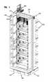
- FIGS. 1 and 2illustrate an example rack 100 at which optical fibers can be connected.
- the rack 100has a front 101 , a rear 102 , a first side 103 , a second side 104 , a top 105 , and a bottom 106 .
- the rack 100defines one or more termination regions 110 .
- the rack 100includes a vertical stack of termination regions 110 . Connection locations at the termination regions 110 are accessible from both the front 101 and rear 102 of the rack 100 .
- a trough system 140connects each termination region 110 of the rack 100 with other termination regions 110 of the rack 100 or with termination regions 110 of other racks 100 .
- termination modulesare mounted at the termination regions 110 .
- the termination modulescan define individually mounted adapters, blocks of integrally formed adapters, and/or cassettes that include optical adapters having either a multi-fiber connector or a multi-fiber cable extending outwardly therefrom.
- termination modulesare slidable relative to the rack 100 .
- Example slidable termination modulescan be found in U.S. Provisional Application No. 61/704,330, filed Sep. 21, 2012, and titled “Slidable Fiber Optic Connection Module with Cable Slack Management,” the disclosure of which is hereby incorporated herein by reference.
- the rack 100includes a transition region 130 at which one or more optical cables 150 (e.g., multi-fiber cables, such as IFC cables) are routed on/off the rack 100 .
- the transition region 130is located at the rear 102 of the rack 100 .
- the transition region 130is located at the top 105 of the rack 100 .
- the optical cables 150transition to break-out cables 160 (e.g., individual fibers or smaller groups of individual fibers) at the transition region 130 .
- Optical connectors and/or cassettes terminating the break-out cables 160are routed from the transition region 130 to connection locations at one or more of the termination regions 110 at the rear side 102 of the rack 100 .
- connection locations at the rear side 102 of the rack 100connect to the connection locations at the front side 101 of the rack 100 .
- Patch cordsare routed across the front of the rack 100 between connection locations at the front side 101 .
- a fiber of a first break-out cable 160 and a fiber of a second break-out cable 160can be optically coupled by connecting one end of a patch cord to the fiber of the first break-out cable 160 through the respective termination region 110 and connecting another end of the patch cord to the fiber of the second break-out cable 160 through the respective termination region 110 .
- the patch cordsmay be routed between connection locations at the same termination region 110 , different termination regions 110 at the same rack 100 , or termination regions 110 at different racks 100 .
- Slack length of the patch cordscan be wound around one or more spools 122 at a storage region 120 at the front 101 of the rack 100 .
- FIGS. 3-5illustrate one example break-out assembly 200 that is suitable for transitioning the optical cables 150 to one or more break-out cables 160 .
- fibers of the optical cable 150are optically spliced to fibers of the break-out cables 160 .
- the fibers of the optical cable 150are optically coupled to the fibers of the break-out cables 160 using mass-fusion splices.
- the optical splices 175are stored at the break-out assembly 200 .
- one or more of the break-out assemblies 200can be mounted to the rack 100 at the transition region 130 .
- An example mounting assembly for securing the break-out assemblies 200 to the rack 100is shown in more detail herein with reference to FIGS. 23-27 .
- the break-out assembly 200includes an enclosure 201 that defines a first port 202 and a second port 203 .
- An optical cable 150enters the enclosure 201 at the first port 202 and the break-out cables 160 exit the enclosure 201 at the second port 203 .
- the enclosure 201defines an interior at which the optical splices 175 can be stowed.
- the optical cable 150is axially and/or rotationally fixed to the enclosure 201 as will be described in more detail herein.
- the break-out cables 160are axially and/or rotationally fixed to the enclosure 201 as will be described in more detail herein.
- the enclosure 201includes a base 210 and a cover 220 that is separable from the base 210 .
- the base 210includes a body 211 that defines an interior 212 in which optical components (e.g., the optical splices 175 ) can be stowed.
- the base body 211defines an open top that provides access to the interior 212 .
- the base body 211extends from a first end 213 to a second end 214 .
- the first end 213defines a first opening or channel 215 that leads to the interior 212 and the second end 214 defines one or more openings or channels 216 that lead to the interior 212 .
- the cover 220is configured to releasably secure to the base 210 .
- the cover 220includes a cover member 221 from which sidewalls 222 extend downwardly.
- the cover member 221is sized to extend over at least a majority of the open top of the base body 211 to enclose the interior 212 of the base 210 .
- the cover 220extends between a first end 224 and a second end 225 .
- the first end 224 of the cover 220cooperates with the first end 213 of the base body 211 to define the first port 202 when the cover 220 is mounted to the base 210 .
- the second end 225 of the cover 220cooperates with the second end 214 of the base body 211 to define the second port 202 when the cover 220 is mounted to the base 210 .
- the interior of the enclosure 210defines three regions between the ports 201 , 202 : a first cable retaining region 230 , a splice retaining region 240 , and a second cable retaining region 250 .
- the optical cable 150is secured to the enclosure 201 at the first cable retaining region 230 .
- the break-out cables 160are secured to the enclosure 201 at the second cable retaining region 250 .
- the optical splicesare disposed in the splice retaining region 240 .
- FIGS. 6-10illustrate one example base 210 suitable for use in the break-out assembly 200 .
- the base body 211is elongated along a longitudinal axis L ( FIG. 7 ) between the first and second ends 213 , 214 .
- the first port 215leads into the first cable retaining region 230 .
- a stop surface 231is recessed inwardly from the first port 215 within the first cable retaining region 230 .
- the stop surface 231faces towards the first port 215 .
- the stop surface 231defines an opening or passage sufficiently large to enable at least a ribbon matrix 155 of the optical cable 150 to pass therethrough.
- the opening or passage in the stop surface 231is sufficiently small that an end of the jacket 157 of the optical cable 150 will engage the stop surface 231 when the optical cable 150 is mounted at the first cable retaining region 230 .
- the base body 211defines one or more support surfaces at the first cable retaining region 230 .
- the base body 211defines a first support surface 232 at the first end 213 and a second support surface 233 spaced inwardly from the first end 213 .
- the support surfaces 232 , 233inhibit wiggling or other such movement of the optical cable 150 when the optical cable 150 is mounted at the first cable retaining region 230 .
- the support surfaces 232 , 233are generally flat and extend between sidewalls of the base body 211 . In other implementations, the support surfaces 232 , 233 do not taper towards or away from the longitudinal axis L of the base body 211 .
- One or more retention members 234are disposed between the port 215 and the stop surface 231 .
- the retention members 234inhibit axial movement of the optical cable 150 .
- the retention members 234may taper to an edge that bites into the jacket 157 of the optical cable 150 .
- the retention members 234are disposed between the support surfaces 232 , 233 .
- the retention members 234extend upwardly from a bottom of the base body 211 .
- the retention members 234extend inwardly from the sidewalls of the base body 211 .
- the retention members 234define partial rings around the base body 211 .
- three retention members 234are disposed at the first cable retaining region 230 . In other implementations, however, a greater or lesser number of retention members 234 (e.g., one, two, four, etc.) can be provided.
- one or more teeth 235also can be disposed between the port 215 and the stop surface 231 .
- the teeth 235inhibit rotational (i.e., torsional) movement of the optical cable 150 .
- the teeth 235may taper to an edge that bites into the jacket 157 of the optical cable 150 .
- the teeth 235are disposed between the support surfaces 232 , 233 .
- the teeth 235are disposed between the retention members 234 .
- two teeth 235are each disposed between adjacent pairs of retention members 234 .
- a greater or lesser number of teeth 235(e.g., one, three, etc.) can be disposed at the first cable retention region 230 .
- Each tooth 235defines at least one ramped surface that faces towards one of the sidewalls of the base body 211 .
- the teeth 235face in a common direction.
- the first cable retention region 230defines a pocket 236 configured to hold epoxy or RTV that is applied on the ribbon matrix 155 of the optical cable 150 .
- the pocket 236is disposed at the stop surface 231 so that the epoxy can be applied adjacent the jacket 157 of the optical cable 150 .
- the pocket 236is defined by at least one barrier wall 237 that extends upwardly from the bottom of the base body 211 to inhibit overflow or leakage of the epoxy to the splice retaining region 240 of the base body 211 .
- the pocket 236is defined between two barrier walls 237 .
- the pocket 236is partially defined by a “necked in” section of the base body 211 having a reduced cross-dimension within the interior 212 of the base body 211 .
- the base 210is configured to be releasably coupled to a bracket 231 as will be described in more detail herein.
- the base body 211defines a narrow section 217 having a reduced cross-dimension relative to the rest of the base body 211 .
- a flexible latch suitable for coupling the enclosure 201 to the bracket 231can be mounted at the narrow section 217 .
- the latchincludes two latch members 218 disposed at opposite sides of the base body 211 .
- the reduced cross-dimension of the narrow section 217enables free ends of the latch members 218 to flex towards each other.
- Ramps 219are disposed at the free ends of the latch members 218 .
- the each latch member 218includes two ramps 219 at opposite ends of the latch members 218 (e.g., see FIG. 4 ).
- FIGS. 11-16illustrate one example cover 220 suitable for use in the break-out assembly 200 .
- the cover 220is elongated along a longitudinal axis between the first and second ends 224 , 225 .
- the cover member 221includes a narrow section 226 of reduced cross-dimension compared to the rest of the cover member 221 .
- the narrow section 226generally aligns with the narrow section 217 of the base body 211 so that the latch members 218 extend upwardly on opposite sides of the narrow section 226 .
- the reduced cross-dimensionprovides space for the latch members 218 to flex towards each other.
- ribs 248can be provided at the narrow section 226 for strength.
- the sidewalls 222 extending from the cover member 221are sized to extend over the sidewalls of the base body 211 .
- Latching hooks 223are provided at distal ends of the sidewalls 222 .
- the latching hooks 223are configured to latch to recesses 223 ′ defined in an exterior of the base body 211 .
- the recesses 223 ′may be defined at a bottom of the base body 211 (see FIGS. 4 and 5 ).
- the cover sidewalls 222define recesses or cutout sections that fit around exterior protrusions or other exterior structures on the base body 211 .
- the cover sidewalls 222define semi-circle shaped cutouts.
- the cover member 221 and the base body 211include alignment features that are configured to position the cover 220 relative to the base 210 to enclose the interior 212 of the base body 211 .
- one of the base body 211 and cover member 221includes tabs and the other of the base body 211 and the cover member 221 defines holes sized to receive the tabs.
- the cover member 221defines holes 227 and the base body 211 includes tabs 227 ′ that extend upwardly from the open top of the base body 211 (see FIG. 4 ).
- An interior surface of the cover member 221is configured to cooperate with the base body 211 to further define the first cable retention region 230 , splice retention region 240 , and second cable retention region 250 .
- the cover member 221can form one or more stop surfaces 232 ′, 233 ′ that align with stop surfaces 232 , 233 of the base body 211 to facilitate holding the optical cable 150 .
- the cover member 221also can include one or more retention members 234 ′ that cooperate with the retention members 234 of the base body 211 to inhibit axial movement of the optical cable 150 .
- One or more teeth 235 ′also can be disposed at the cover member 221 to cooperate with the teeth 235 of the base body 211 to inhibit rotational/torsional movement of the optical cable 150 .
- One or more channels 258are provided towards the second end 225 of the interior surface of the cover member 221 .
- the channels 258generally align with the passages between the walls 253 of the base body 211 . Accordingly, the channels 258 aid in routing the break-out cables 160 out of the enclosure 201 .
- the channels 258include raised sections 259 that partially define the ports 216 .
- the channels 258extend along only part of the length of the walls 253 of the base body 211 . In other implementations, the channels 258 can be the same length or a greater length than the walls 253 .
- FIGS. 17-21illustrate an assembled enclosure 201 holding a plurality of mass fusion splices 175 at the splice retention region 240 .
- the optical cable 150is shown held at the first cable retaining region 230 and break-out cables 160 are shown held at the second cable retaining region 250 .
- a longitudinal cross-section of the enclosure 201shows the cables 150 , 160 and splices 175 disposed within the base body 211 .
- FIG. 19is a transverse cross-section of the enclosure 201 showing the optical cable 150 at the first cable retention region 230 .
- FIG. 21is a longitudinal cross-section of the enclosure 201 showing the cables 150 , 160 and splices 175 disposed between the base 210 and cover 220 .
- first ribbonized portions 172 of the spliced fibersextend from a first end of the mass fusion splices 175 and second ribbonized portions 174 of the spliced fibers extend from a second end of the mass fusion splices 175 (see also FIG. 4 ).
- first ribbonized portions 172are formed from the optical fibers of the optical cable 150 and the second ribbonized portions 174 are formed from the optical fibers of the break-out cables 160 .
- the optical cable 150may include a ribbon matrix 155 that is separated into individual fiber ribbons 172 and optical fibers of the break-out cables 160 can be ribbonized before being spliced to the individual fiber ribbons 172 .
- the connecting portions between the ribbonized portions 172 , 174 and the cables 150 , 160are not shown.
- the optical cable 150is held at the first cable retention region 230 .
- the jacket 157extends through the port 215 and abuts against the stop surface 231 .
- a buffer tube 153 within the jacket 157also stops at the stop surface 23 .
- Retention members 234 , 234 ′are shown biting into the outer jacket 157 (see FIGS. 18 and 19 ).
- Teeth 235 , 235 ′also are shown biting into the jacket 157 to inhibit rotational/torsional movement of the cable 150 ( FIGS. 19 and 21 ).
- the ribbon matrix 155extends past the stop surface 231 , through a pocket 236 that is partially defined by inwardly tapered walls, and towards the splice retention region 240 ( FIGS. 18 and 21 ).
- Epoxy or other adhesivecan be applied to the ribbon matrix 155 at the pocket 236 to hold the ribbon matrix 155 in place.
- Barrier wall 237retains the epoxy within the pocket 236 .
- the break-out cables 160are held at the second cable retention region 250 ( FIGS. 18 and 21 ). Jacketed or buffered portions of the cables 160 extend into the enclosure 201 through ports 216 . Crimp arrangements 165 are disposed on each break-out cable 160 . In some implementations, the crimp arrangements 165 include a crimp ring 168 that mounts at least partially over a crimp base 166 . The optical fibers of each break-out cable 160 extend through a crimp base 166 . In some implementations, the optical fibers can include a fiber ribbon. In other implementations, only a portion of the optical fibers is ribbonized at the splice 175 . The jackets of the break-out cables secure between the respective crimp bases 166 and the crimp sleeves 168 .
- the crimp arrangements 165are configured to secure axially and rotationally to the enclosure 201 at the second cable retention region 250 .
- Each crimp arrangement 165includes wings or flanges 167 ( FIG. 4 ) that extend radially/laterally outwardly from the crimp arrangement 165 .
- the walls 253 at the second cable retention region 250define slots 256 at which the wings or flanges 167 can seat ( FIG. 4 ).
- the wings or flanges 167can slide into slots 256 defined in adjacent walls 253 ( FIG. 18 ).
- the wings or flanges 167define one or more flat sides to inhibit rotation of the crimp arrangements 165 within the slots 256 .
- the walls 253are sufficiently long that multiple slots 256 may be formed in each wall 253 .
- the second cable retention region 250provides securement locations for the crimp arrangements 165 at multiple axial locations along the walls 253 (compare the crimp arrangements of FIG. 18 ).
- the second cable retention region 250facilitates retention of break-out cables 160 having different slack lengths of fibers between the crimp arrangements 165 and the splices 175 .
- a splice 175can be redone/reworked by cutting of the spliced portion of the break-out cable fiber and re-splicing the shortened break-out cable fiber.
- the crimp arrangement 165can be moved to a more inwardly located pair of slots 256 .
- the walls 253 and slots 256are sufficiently high that the same slot 256 can receive multiple crimp arrangements 165 .
- two or more crimp arrangements 165may vertically stack at the same set of slots 256 .
- four crimp arrangements 167may be stacked between each adjacent pair of walls 253 .
- the walls 253 and slots 256can be sized to receive a greater or lesser number of crimp arrangements 165 (e.g., one, two, three, five, six, etc.).
- the axially spaced slots 256can located sufficiently close to each other that a crimp arrangement 165 mounted at one axial location can stack onto another crimp arrangement 165 mounted at another axial location between the same walls 253 .
- a crimp arrangement 165 mounted at an outward-most axial locationcan stack onto another crimp arrangement 165 mounted at an inward-most axial location.
- one or more splices 175are disposed at the splice retention region 240 of the enclosure 201 .
- at least a portion of at least one of the splices 175is located between the walls 253 ( FIG. 18 ).
- the walls 253define tapered sections 254 that taper inwardly as they extend into the enclosure 201 .
- the splices 175can be arranged in a stacked configuration 170 .
- two or more splices 175can be stacked between adjacent pairs of walls 253 .
- four splices 175can be stacked between each adjacent pairs of walls 253 .
- a greater or lesser number of splices 175can be stacked.
- the ribbon matrix 155 of the optical cable 150can be divided into multiple ribbons that extend to the splices 175 .
- the ribbons of the ribbon matrix 155can be routed to the splices 175 in different orders.
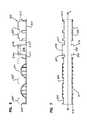
- FIGS. 22A-22Cschematically illustrate three example stacked configurations 171 - 173 for the splices 175 disposed at the splice retention region 240 .
- each splice 175is numbered “1” through “12” to identify corresponding consecutive ribbon in the ribbon matrix 155 that are optically coupled to break-out cable fiber ribbons at the splice 175 .
- Each stacked configuration 171 - 173provides a different possible arrangement of the fiber ribbons from the ribbon matrix 155 .
- a bottom-most fiber ribbonis positioned at a bottom, right side of the first stacked configuration 171 .
- the next fiber ribbon in the matrix 155is stacked above the bottom-most ribbon.
- the next two fiber ribbonsare disposed in an adjacent (e.g., central) passage between the walls 253 and the following two fiber ribbons are disposed in yet another adjacent (e.g., left) passage between a wall 253 and the base body 211 .
- the remaining six ribbonsare stacked on top of the first six ribbons in the same pattern (e.g., right, center, left) until the top-most ribbon is positioned at the top, left side of the first stacked configuration 171 .
- the last six ribbons of the second stacked configuration 172 of FIG. 22Bfollow the same pattern as the last six ribbons of the first stacked configuration 171 .
- the second stacked configuration 172differs from the first stacked configuration 171 in that the first six ribbons start at the bottom, left side of the configuration 172 .
- the ribbons of the matrix 155are stacked in one of the side passages until the passage is full. Subsequent ribbons in the matrix 155 are stacked in an adjacent passage. The pattern is repeated until the passages are full.
- FIGS. 23-27show how the splice assemblies 200 can be mounted to the frame 100 shown in FIGS. 1 and 2 .
- the splice assemblies 200can be mounted to one or more brackets 270 that are mounted to a bracket frame 131 .
- the bracket frame 131mounts to the frame 100 (e.g., at the top of the frame 100 ).
- multiple brackets 270mount to one bracket frame 131 .
- the bracket frame 131can include multiple arms and one bracket 270 can mount to each arm. In other implementations, however, a greater number of brackets 270 can mount to one arm.
- the bracket 270is configured to hold the splice assembly 200 in a vertical orientation so that one port 215 , 216 faces upwardly relative to the frame 100 and one port 215 , 216 faces downwardly relative to the frame 100 .
- the first port 215faces upwardly to receive optical cables 150 being routed downwardly towards the frame 100 (e.g., from ceiling mounted fiber tracks) and the second port 216 faces downwardly to facilitate routing the break-out cables 160 to the rest of the frame 100 (e.g., to the termination regions 110 ).
- the bracket 270defines a plurality of mounting locations 277 , 278 at which splice assemblies 200 can be mounted.
- the bracket 270defines a single row of mounting locations along a length of the bracket 270 .
- the bracket 270defines multiple rows of mounting locations.
- the bracketincludes an inner row of mounting locations 277 and an outer row of mounting locations 278 (see FIG. 26 ).
- the bracket 270may include a greater number of rows of mounting locations.
- a first splice assembly 200 Ais configured to mount at an inner mounting location 277 and a second splice assembly 200 B is configured to mount at an outer mounting location 278 .
- the bracket 270includes a mounting section 271 that defines mounting openings 279 or other mounting features with which the mounting section 271 can be secured to the bracket frame 131 .
- the mounting locationsare defined by arms 272 extending outwardly from opposite sides of the mounting section 271 and fingers 274 , 275 extending inwardly from the arms (see FIG. 26 ).
- a first row of arms 272extends from one side of the mounting section 271 and a second row of arms 272 extends from an opposite side of the mounting section 271 to define a U-shaped end view (e.g., see FIG. 26 ).
- the arms 272 of each roware longitudinally spaced from each other along the mounting section 271 .
- the arms 272 of the first rowlaterally align with the arms 272 of the second row to form lateral arm pairs.
- Each arm 272includes a first retaining finger 274 and a second retaining finger 275 that extend inwardly from the arm 272 towards the laterally adjacent arm 272 .
- the second retaining finger 275is disposed at a free end of the arm 272 .
- the first retaining finger 274is disposed between the mounting section 271 and the second retaining finger 275 (e.g., see FIG. 26 ).
- the first retaining fingers 274 of a pair of laterally adjacent arms 272cooperate to define a first mounting location 277 for a splice assembly 200 ( FIG. 26 ).
- the second retaining fingers 275 of a pair of laterally adjacent arms 272cooperate to define a second mounting location 278 for a splice assembly 200 ( FIG. 26 ).
- the splice assemblies 200mount to the bracket 270 in the gaps between the longitudinally spaced arms 272 .
- the narrow sections 217 , 226 of the assembly 200can be positioned between adjacent lateral pairs of arms 272 .
- the arms 272slide along an exterior of the enclosure 201 at the narrow sections 217 , 226 so that the latch members 218 are disposed between the arms 272 of a lateral pair.
- the first splice assembly 200 Ais configured to be inserted between a first lateral pair of arms 272 and a second lateral pair of arms 272 located adjacent the first lateral pair.
- Each latch member 218 of the first splice assembly 200 Ais disposed between the arms 272 of the corresponding lateral pair.
- the retention fingers 274 , 275 that correspond to the mounting location 277 , 278snap-over or otherwise secure to the latch members 218 .
- the latch members 218may flex inwardly as the ramps 219 cam past the respective retention fingers 274 , 275 .
- the latch members 218may unflex to their original positions, thereby moving ends of the ramps 219 into engagement with the respective retention fingers 274 , 275 . Accordingly, the arms 272 and retention fingers 274 , 275 cooperate to hold the splice assemblies 200 within the bracket 270 .
- the break-out assembly 200is held by the arms 272 of the bracket 270 before being secured to the bracket 270 by the retention fingers 274 , 275 .
- the fingers 274 , 275inhibit the break-out assembly 200 from being removed from the grasp of the arms 272 .
- a userpinches, squeezes, or otherwise deflects the latch members 218 of the splice assembly 200 towards each other.
- the deflection of the latch members 218moves the ramps 219 out of engagement with the retention fingers 274 , 275 (e.g., towards gaps 276 ), thereby enabling the user to pull the splice assembly 200 out from the bracket 270 .
- the retention fingers 274 , 275each have a width that is less than a width of the corresponding arm 272 . Accordingly, sides of the latch members 218 can still engage the arms 272 of the bracket 270 when the ramps 219 are moved out of engagement with the retention fingers 274 , 275 .
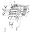
- FIGS. 28-32illustrate another example implementation of a splice assembly 300 for storing splices 175 (e.g., mass fusion splices) between fibers of the optical cable 150 and fibers of the break-out cables 160 .
- the splice assembly 300includes a first body 310 and a second body 320 that cooperates with the first body 310 to form an enclosure 301 defining an interior.
- the bodies 310 , 320are identical to each other.
- the splices 175 and unjacketed/unbuffered portions of the cables 150 , 160are stored within the interior of the enclosure 301 .
- the enclosure 301has a first port 302 for the optical cable 150 and a second port 303 for the break-out cables 160 .
- the first port 302is located at an opposite end of the enclosure 301 from the second port 303 .
- the bodies 310 , 320are configured to couple together to form the enclosure 301 .
- the bodies 310 , 320are configured to releasably couple together.
- the bodies 310 , 320are configured to fixedly couple together.
- the bodies 310 , 320include alignment features that aid in assembling the enclosure 301 .
- each body 310 , 320includes one or more pins 318 and one or more holes 319 .
- the pins 318 of each body 310 , 320align with the holes 319 of the other body 310 , 320 .
- the bodies 310 , 320are coupled together using latches, a friction-fit connection, screws or other fasteners, or other such coupling features.
- the enclosure 301defines a cable input passage 314 , a splice retention region 315 , and a cable retention region 316 .
- the cable input passage 314is sized to receive at least a ribbon matrix 155 of the optical cable 150 . In certain implementations, the input passage 314 is too narrow to receive the cable jacket 157 . In certain implementations, the input passage 314 is too narrow to receive the buffer tube 153 .
- the splice retention region 315is sized to receive one or more optical splices 175 between the optical cable 150 and the break-out cables 160 . In certain implementations, the splice retention region 315 is sized to receive one of the stacked configurations of the splices 175 .
- the cable retention region 316is sized to receive a cable organizer 330 to which one or more break-out cables 160 can be secured.
- the enclosure 301defines a first tube or body section having a first cross-dimension (e.g., diameter) coupled to a second tube or body section having a second cross-dimension by a tapered/conical body section.
- the first cross-dimensionis larger than the second cross-dimension.
- the first tube or body sectiondefines the cable input passage 314 and the second tube or body section defines the splice retention region 315 and cable retention region 316 .
- each body 310 , 320includes a first section 311 , 321 that partially defines the first tube or body section, a second section 312 , 322 that partially defines the tapered/conical body section, and a third section 313 , 323 that partially defines the second tube or body section.
- the first and second bodies 310 , 320define the same or similar internal features.
- each bodymay define one or more circumferential ribs 317 , 327 that extend radially into the interior of the enclosure 301 (see FIG. 30 ).
- the second cable retention region 316is bounded on opposite ends by circumferential ribs 317 , 327 .
- the circumferential ribs 317 , 327hold the cable organizer 330 in position within the enclosure 301 (see FIG. 32 ).
- the circumferential ribs 317 , 327are inwardly recessed from the second port 302 .
- the cable organizer 330includes a mounting plate 331 defining slots that extend inwardly from a circumferential edge of the mounting plate 331 .
- the slotsare sized to hold one or more crimp arrangements 180 that are coupled to the break-out cables 160 .
- each crimp arrangement 180secures to a jacket and/or strength layer of the break-out cable 160 .
- the crimp arrangement 180includes a forward portion 181 from which the optical fibers of the break-out cable 160 extend, a rearward portion 182 that secures to the jacket and/or strength layer, and a narrow portion 183 that fits within one of the slots in the mounting plate 331 .
- the cable organizer 330also includes routing extensions 334 that extend away from the mounting plate 331 along the longitudinal axis of the enclosure 301 .
- the routing extensions 334defines passages 335 along which fibers of the break-out cables 160 can extend between the mounting plate 331 and the splices 175 .
- Ribs 336can be provided in the passages 335 as positions axially spaced from the mounting plate 331 .
- the ribs 336are shaped and sized to receive the crimp arrangements 180 of the break-out cables 160 . Accordingly, the ribs 336 provide alternative mounting locations for the break-out cables 160 if rework is performed or the fibers of the break-out cables 160 are otherwise too short to be secured to the mounting plate 331 .
- the routing extensionsfurther aid in retaining the crimp arrangements 180 within the passages 335 .
- the mounting plate 331defines slots of different lengths. For example, in FIG. 29 , the mounting plate 331 defines long slots 332 that extend a first distance radially into the mounting plate 331 and short slots 333 that extend a second distance radially into the mounting plate 331 . The second distance is shorter than the first distance.
- the long slots 332are sized to hold two crimp arrangements 180 along the length of the slot 332 and the short slots 333 are sized to hold one crimp arrangement 180 (see FIG. 30 ).
- the mounting plate 331defines an alternating arrangement of slots 332 , 333 (see FIG. 29 ).
Landscapes
- Physics & Mathematics (AREA)
- General Physics & Mathematics (AREA)
- Optics & Photonics (AREA)
- Engineering & Computer Science (AREA)
- Manufacturing & Machinery (AREA)
- Plasma & Fusion (AREA)
- Light Guides In General And Applications Therefor (AREA)
Abstract
Description
Claims (26)
Priority Applications (3)
| Application Number | Priority Date | Filing Date | Title |
|---|---|---|---|
| US15/354,512US10254500B2 (en) | 2012-09-28 | 2016-11-17 | Splice-on cable breakout assembly |
| US16/378,034US10761287B2 (en) | 2012-09-28 | 2019-04-08 | Splice-on cable breakout assembly |
| US16/999,346US11630279B2 (en) | 2012-09-28 | 2020-08-21 | Splice-on cable breakout assembly |
Applications Claiming Priority (3)
| Application Number | Priority Date | Filing Date | Title |
|---|---|---|---|
| US201261707223P | 2012-09-28 | 2012-09-28 | |
| US14/036,628US9500830B2 (en) | 2012-09-28 | 2013-09-25 | Splice-on cable breakout assembly |
| US15/354,512US10254500B2 (en) | 2012-09-28 | 2016-11-17 | Splice-on cable breakout assembly |
Related Parent Applications (1)
| Application Number | Title | Priority Date | Filing Date |
|---|---|---|---|
| US14/036,628ContinuationUS9500830B2 (en) | 2012-09-28 | 2013-09-25 | Splice-on cable breakout assembly |
Related Child Applications (1)
| Application Number | Title | Priority Date | Filing Date |
|---|---|---|---|
| US16/378,034ContinuationUS10761287B2 (en) | 2012-09-28 | 2019-04-08 | Splice-on cable breakout assembly |
Publications (2)
| Publication Number | Publication Date |
|---|---|
| US20170199345A1 US20170199345A1 (en) | 2017-07-13 |
| US10254500B2true US10254500B2 (en) | 2019-04-09 |
Family
ID=50385306
Family Applications (4)
| Application Number | Title | Priority Date | Filing Date |
|---|---|---|---|
| US14/036,628Active2034-10-02US9500830B2 (en) | 2012-09-28 | 2013-09-25 | Splice-on cable breakout assembly |
| US15/354,512ActiveUS10254500B2 (en) | 2012-09-28 | 2016-11-17 | Splice-on cable breakout assembly |
| US16/378,034ActiveUS10761287B2 (en) | 2012-09-28 | 2019-04-08 | Splice-on cable breakout assembly |
| US16/999,346Active2034-04-10US11630279B2 (en) | 2012-09-28 | 2020-08-21 | Splice-on cable breakout assembly |
Family Applications Before (1)
| Application Number | Title | Priority Date | Filing Date |
|---|---|---|---|
| US14/036,628Active2034-10-02US9500830B2 (en) | 2012-09-28 | 2013-09-25 | Splice-on cable breakout assembly |
Family Applications After (2)
| Application Number | Title | Priority Date | Filing Date |
|---|---|---|---|
| US16/378,034ActiveUS10761287B2 (en) | 2012-09-28 | 2019-04-08 | Splice-on cable breakout assembly |
| US16/999,346Active2034-04-10US11630279B2 (en) | 2012-09-28 | 2020-08-21 | Splice-on cable breakout assembly |
Country Status (1)
| Country | Link |
|---|---|
| US (4) | US9500830B2 (en) |
Cited By (7)
| Publication number | Priority date | Publication date | Assignee | Title |
|---|---|---|---|---|
| US10761287B2 (en) | 2012-09-28 | 2020-09-01 | Commscope Technologies Llc | Splice-on cable breakout assembly |
| US11347014B2 (en) | 2018-09-07 | 2022-05-31 | Corning Incorporated | Optical fiber fan-out assembly with ribbonized interface for mass fusion splicing, and fabrication method |
| US11561344B2 (en) | 2017-03-21 | 2023-01-24 | Corning Research & Development Corporation | Fiber optic cable assembly with thermoplastically overcoated fusion splice, and related method and apparatus |
| US11681101B2 (en) | 2019-10-17 | 2023-06-20 | CommScope Technologies, LLC | Reworkable splice module |
| US11774677B2 (en) | 2019-07-31 | 2023-10-03 | Corning Research & Development Corporation | Fiber optic cable assembly with overlapping bundled strength members, and fabrication method and apparatus |
| US11867947B2 (en) | 2021-04-30 | 2024-01-09 | Corning Research & Development Corporation | Cable assembly having routable splice protectors |
| US11886009B2 (en) | 2020-10-01 | 2024-01-30 | Corning Research & Development Corporation | Coating fusion spliced optical fibers and subsequent processing methods thereof |
Families Citing this family (19)
| Publication number | Priority date | Publication date | Assignee | Title |
|---|---|---|---|---|
| US9690065B2 (en) | 2014-09-12 | 2017-06-27 | Panduit Corp. | High density fiber enclosure and method |
| US10054753B2 (en) | 2014-10-27 | 2018-08-21 | Commscope Technologies Llc | Fiber optic cable with flexible conduit |
| US9835816B2 (en)* | 2015-06-10 | 2017-12-05 | Telect, Inc. | Fiber blocking kits |
| AU2015207954C1 (en) | 2015-07-31 | 2022-05-05 | Adc Communications (Australia) Pty Limited | Cable breakout assembly |
| CN106655030B (en)* | 2015-10-29 | 2021-03-16 | 因特瓦产品有限责任公司 | Cable end fitting and cable adapter and method of securing same |
| EP3403125B1 (en) | 2016-03-18 | 2021-07-14 | Commscope Technologies LLC | Fiber-optic cable fanout conduit arrangement and method for organizing optical fibers |
| US10890730B2 (en) | 2016-08-31 | 2021-01-12 | Commscope Technologies Llc | Fiber optic cable clamp and clamp assembly |
| US10914909B2 (en) | 2016-10-13 | 2021-02-09 | Commscope Technologies Llc | Fiber optic breakout transition assembly incorporating epoxy plug and cable strain relief |
| CN110622051A (en) | 2017-05-08 | 2019-12-27 | 康普技术有限责任公司 | Optical fiber branch transition assembly |
| US10345538B2 (en) | 2017-06-28 | 2019-07-09 | Sumitomo Electric Lightwave Corp. | System and method for joining and distributing a single optical fiber cable to multiple rack shelves |
| US10261279B1 (en) | 2017-10-12 | 2019-04-16 | Sumitomo Electric Lightwave Corp. | System and method for distributing high fiber count optical cable to network racks |
| JP6914905B2 (en)* | 2018-11-29 | 2021-08-04 | 矢崎総業株式会社 | Bonder cap containment structure, electrical junction box, and wire harness |
| EP3997500A4 (en) | 2019-07-08 | 2023-07-26 | CommScope Technologies LLC | TERMINATION OF A CABLE ASSEMBLY WITH CONNECTORIZED PIGTAILS |
| MX2022000334A (en) | 2019-07-10 | 2022-04-26 | Preformed Line Products Co | UNITUBO TAPE CONNECTION. |
| US11243366B2 (en)* | 2019-12-16 | 2022-02-08 | Afl Telecommunications Llc | Rack routing guide |
| TWI766533B (en)* | 2020-11-03 | 2022-06-01 | 立佳興業股份有限公司 | Latch structure and optical receptacle thereof |
| CN114442235A (en)* | 2020-11-03 | 2022-05-06 | 台达电子工业股份有限公司 | Optical fiber signal adapter |
| CN113433643B (en)* | 2021-06-24 | 2022-10-25 | 烽火通信科技股份有限公司 | Clamping groove for wiring in building and using method thereof |
| JP7726045B2 (en)* | 2021-12-03 | 2025-08-20 | 住友電気工業株式会社 | Optical Communication Systems |
Citations (43)
| Publication number | Priority date | Publication date | Assignee | Title |
|---|---|---|---|---|
| US5185840A (en) | 1991-05-06 | 1993-02-09 | Computer Crafts, Inc. | Branching method for a multi-fiber fiberoptic cable |
| US5253315A (en) | 1990-12-24 | 1993-10-12 | Fentress Vernon A | Method and apparatus for installing a fiber optic cable by capture of a coupling nut or coupling nut assembly |
| US5491766A (en) | 1993-04-16 | 1996-02-13 | Raychem Corporation | Bonding assembly for fiber optic cable and associated method |
| US5588082A (en) | 1994-09-20 | 1996-12-24 | Whitesmith; Peter J. | Optical cable fusion splice |
| US5915055A (en) | 1997-06-30 | 1999-06-22 | Siecor Corporation | Method and apparatus for connectorizing fiber optic cable |
| US5925462A (en) | 1992-06-17 | 1999-07-20 | Ppg Industries Ohio, Inc. | Aqueous coating compositions for glass fibers, fiber strands coated with such compositions and optical fiber cable assemblies including such fiber strands |
| JP2001330765A (en) | 2000-05-24 | 2001-11-30 | Tsushin Kogyo Kk | Optical fiber cable |
| US6379054B2 (en) | 1998-07-01 | 2002-04-30 | Corning Cable Systems Llc | Field installable multifiber connector |
| US6389214B1 (en) | 2001-05-17 | 2002-05-14 | 3M Innovative Properties Company | Furcation apparatus for optical fibers |
| US6438300B1 (en) | 1999-09-21 | 2002-08-20 | Tycom (Us) Inc. | Fiber retaining system |
| US6439780B1 (en) | 2000-08-31 | 2002-08-27 | Corning Cable Systems Llc | Field-installable fiber optic ribbon connector and installation tool |
| US20030179980A1 (en) | 2002-03-19 | 2003-09-25 | Baechtle David R. | Optical circuit with ribbonization |
| US6771861B2 (en) | 2002-05-07 | 2004-08-03 | Corning Cable Systems Llc | High performance, flexible optical fiber furcation |
| US20050249475A1 (en) | 2004-05-06 | 2005-11-10 | Womack Wade J | Carrier for multiple splice trays |
| US7104702B2 (en) | 2004-03-24 | 2006-09-12 | Corning Cable Systems Llc | Field installable optical fiber connector |
| US7192194B2 (en) | 2005-01-13 | 2007-03-20 | Frank Giotto | Universal adapter for fiber optic connectors |
| US7216512B2 (en) | 2003-10-31 | 2007-05-15 | Corning Cable Systems, Llc | Method of making an optical fiber by laser cleaving |
| US7228047B1 (en) | 2006-06-16 | 2007-06-05 | Molex Incorporated | Breakout and connector assemblies for use with high count fiber optic cables |
| US7264401B2 (en) | 2004-05-28 | 2007-09-04 | Corning Cable Systems Llc | Panel-mountable optical fiber splice |
| US7264410B1 (en) | 2006-03-16 | 2007-09-04 | Corning Cable Systems Llc | Dual function splice component for mechanical splice connector |
| US20070212004A1 (en)* | 2006-03-09 | 2007-09-13 | Adc Telecommunications, Inc. | Fiber optic cable breakout configuration with excess fiber length |
| US7270487B2 (en) | 2004-04-30 | 2007-09-18 | Corning Cable Systems Llc | Field installable optical fiber connector |
| US7270485B1 (en) | 2006-06-23 | 2007-09-18 | Carlyle, Inc. | Device for furcating fiber optic cables |
| US7281859B2 (en) | 2004-11-29 | 2007-10-16 | Corning Cable Systems Llc | Optical fiber connector and method of assembly |
| US20080013888A1 (en)* | 2006-06-30 | 2008-01-17 | Barnes Brandon A | Optical fiber transition device |
| US7329049B2 (en) | 2005-12-27 | 2008-02-12 | Corning Cable Systems Llc | Splice connector for verifying an acceptable splice termination |
| US20080138026A1 (en) | 2006-12-08 | 2008-06-12 | Yow Charles A | Furcation tubing and fanout furcation kit |
| US20080170833A1 (en) | 2007-01-12 | 2008-07-17 | Guy Castonguay | Fiber optic local convergence points for multiple dwelling units |
| US7440667B2 (en) | 2006-08-31 | 2008-10-21 | Tyco Electronics Corporation | Duct closures and methods of sealing ducts using the same |
| US20090022457A1 (en) | 2007-07-16 | 2009-01-22 | De Jong Michael | Fusion-splice fiber optic connectors and related tools |
| US20090060421A1 (en) | 2007-03-16 | 2009-03-05 | 3M Innovative Properties Company | Optical fiber cable inlet device |
| US7572064B2 (en) | 2006-07-24 | 2009-08-11 | Corning Cable Systems Llc | Optical fiber mechanical splice connector |
| US7594764B2 (en) | 2004-03-29 | 2009-09-29 | Corning Cable Systems Llc | Field-installable fusion spliced fiber optic connector kits and methods therefor |
| KR20090116650A (en) | 2008-05-06 | 2009-11-11 | 드라카 콤텍 비.브이. | Single mode fiber |
| US7658553B2 (en) | 2006-03-14 | 2010-02-09 | Corning Cable Systems Llc | Mechanical splice connector with sequential splice and strain relief |
| US20100142905A1 (en) | 2006-01-26 | 2010-06-10 | Billman Bradley S | Installation tool with integrated visual fault indicator for field-installable mechanical splice connector |
| US20100183265A1 (en) | 2009-01-19 | 2010-07-22 | Barnes Brandon A | Termination system for fiber optic connection |
| US20100303416A1 (en) | 2009-05-29 | 2010-12-02 | Danley Jeffrey D | Laser-Shaped Optical Fibers Along with Optical Assemblies and Methods Therefor |
| US7945136B2 (en) | 2009-06-19 | 2011-05-17 | Corning Cable Systems Llc | Mounting of fiber optic cable assemblies within fiber optic shelf assemblies |
| US20110136353A1 (en) | 2009-12-03 | 2011-06-09 | Spitaels James S | Apparatus and method for scalable power distribution |
| US8333519B2 (en) | 2008-08-29 | 2012-12-18 | Adc Telecommunications, Inc. | Splice of fiber optic cables |
| US8457461B2 (en) | 2010-04-16 | 2013-06-04 | Adc Telecommunications, Inc. | Fiber optic cable assembly and method of making the same |
| US9500830B2 (en) | 2012-09-28 | 2016-11-22 | Commscope Technologies Llc | Splice-on cable breakout assembly |
Family Cites Families (4)
| Publication number | Priority date | Publication date | Assignee | Title |
|---|---|---|---|---|
| US5745633A (en)* | 1996-12-24 | 1998-04-28 | Siecor Corporation | Fiber optic cable assembly for securing a fiber optic cable within an input port of a splice closure |
| US6744962B2 (en)* | 2001-10-25 | 2004-06-01 | Uniseal, Inc. | Fiberoptic splice closure |
| GB2472014B (en)* | 2009-07-20 | 2011-10-05 | Fibrefab Ltd | Connector device and method for producing a furcated fibre optic cable |
| CN103975264B (en)* | 2011-10-07 | 2015-09-16 | Adc电信公司 | Slidable fiber optic connection module with cable slack management |
- 2013
- 2013-09-25USUS14/036,628patent/US9500830B2/enactiveActive
- 2016
- 2016-11-17USUS15/354,512patent/US10254500B2/enactiveActive
- 2019
- 2019-04-08USUS16/378,034patent/US10761287B2/enactiveActive
- 2020
- 2020-08-21USUS16/999,346patent/US11630279B2/enactiveActive
Patent Citations (44)
| Publication number | Priority date | Publication date | Assignee | Title |
|---|---|---|---|---|
| US5253315A (en) | 1990-12-24 | 1993-10-12 | Fentress Vernon A | Method and apparatus for installing a fiber optic cable by capture of a coupling nut or coupling nut assembly |
| US5185840A (en) | 1991-05-06 | 1993-02-09 | Computer Crafts, Inc. | Branching method for a multi-fiber fiberoptic cable |
| US5925462A (en) | 1992-06-17 | 1999-07-20 | Ppg Industries Ohio, Inc. | Aqueous coating compositions for glass fibers, fiber strands coated with such compositions and optical fiber cable assemblies including such fiber strands |
| US5491766A (en) | 1993-04-16 | 1996-02-13 | Raychem Corporation | Bonding assembly for fiber optic cable and associated method |
| US5588082A (en) | 1994-09-20 | 1996-12-24 | Whitesmith; Peter J. | Optical cable fusion splice |
| US5915055A (en) | 1997-06-30 | 1999-06-22 | Siecor Corporation | Method and apparatus for connectorizing fiber optic cable |
| US6379054B2 (en) | 1998-07-01 | 2002-04-30 | Corning Cable Systems Llc | Field installable multifiber connector |
| US6438300B1 (en) | 1999-09-21 | 2002-08-20 | Tycom (Us) Inc. | Fiber retaining system |
| JP2001330765A (en) | 2000-05-24 | 2001-11-30 | Tsushin Kogyo Kk | Optical fiber cable |
| US6439780B1 (en) | 2000-08-31 | 2002-08-27 | Corning Cable Systems Llc | Field-installable fiber optic ribbon connector and installation tool |
| US6389214B1 (en) | 2001-05-17 | 2002-05-14 | 3M Innovative Properties Company | Furcation apparatus for optical fibers |
| US20030179980A1 (en) | 2002-03-19 | 2003-09-25 | Baechtle David R. | Optical circuit with ribbonization |
| US6771861B2 (en) | 2002-05-07 | 2004-08-03 | Corning Cable Systems Llc | High performance, flexible optical fiber furcation |
| US7216512B2 (en) | 2003-10-31 | 2007-05-15 | Corning Cable Systems, Llc | Method of making an optical fiber by laser cleaving |
| US7104702B2 (en) | 2004-03-24 | 2006-09-12 | Corning Cable Systems Llc | Field installable optical fiber connector |
| US7594764B2 (en) | 2004-03-29 | 2009-09-29 | Corning Cable Systems Llc | Field-installable fusion spliced fiber optic connector kits and methods therefor |
| US7270487B2 (en) | 2004-04-30 | 2007-09-18 | Corning Cable Systems Llc | Field installable optical fiber connector |
| US20050249475A1 (en) | 2004-05-06 | 2005-11-10 | Womack Wade J | Carrier for multiple splice trays |
| US7264401B2 (en) | 2004-05-28 | 2007-09-04 | Corning Cable Systems Llc | Panel-mountable optical fiber splice |
| US7281859B2 (en) | 2004-11-29 | 2007-10-16 | Corning Cable Systems Llc | Optical fiber connector and method of assembly |
| US7192194B2 (en) | 2005-01-13 | 2007-03-20 | Frank Giotto | Universal adapter for fiber optic connectors |
| US7329049B2 (en) | 2005-12-27 | 2008-02-12 | Corning Cable Systems Llc | Splice connector for verifying an acceptable splice termination |
| US20100142905A1 (en) | 2006-01-26 | 2010-06-10 | Billman Bradley S | Installation tool with integrated visual fault indicator for field-installable mechanical splice connector |
| US20070212004A1 (en)* | 2006-03-09 | 2007-09-13 | Adc Telecommunications, Inc. | Fiber optic cable breakout configuration with excess fiber length |
| US7658553B2 (en) | 2006-03-14 | 2010-02-09 | Corning Cable Systems Llc | Mechanical splice connector with sequential splice and strain relief |
| US7264410B1 (en) | 2006-03-16 | 2007-09-04 | Corning Cable Systems Llc | Dual function splice component for mechanical splice connector |
| US7815377B2 (en) | 2006-03-16 | 2010-10-19 | Corning Cable Systems Llc | Dual function splice component for mechanical splice connector |
| US7228047B1 (en) | 2006-06-16 | 2007-06-05 | Molex Incorporated | Breakout and connector assemblies for use with high count fiber optic cables |
| US7270485B1 (en) | 2006-06-23 | 2007-09-18 | Carlyle, Inc. | Device for furcating fiber optic cables |
| US20080013888A1 (en)* | 2006-06-30 | 2008-01-17 | Barnes Brandon A | Optical fiber transition device |
| US7572064B2 (en) | 2006-07-24 | 2009-08-11 | Corning Cable Systems Llc | Optical fiber mechanical splice connector |
| US7440667B2 (en) | 2006-08-31 | 2008-10-21 | Tyco Electronics Corporation | Duct closures and methods of sealing ducts using the same |
| US20080138026A1 (en) | 2006-12-08 | 2008-06-12 | Yow Charles A | Furcation tubing and fanout furcation kit |
| US20080170833A1 (en) | 2007-01-12 | 2008-07-17 | Guy Castonguay | Fiber optic local convergence points for multiple dwelling units |
| US20090060421A1 (en) | 2007-03-16 | 2009-03-05 | 3M Innovative Properties Company | Optical fiber cable inlet device |
| US20090022457A1 (en) | 2007-07-16 | 2009-01-22 | De Jong Michael | Fusion-splice fiber optic connectors and related tools |
| KR20090116650A (en) | 2008-05-06 | 2009-11-11 | 드라카 콤텍 비.브이. | Single mode fiber |
| US8333519B2 (en) | 2008-08-29 | 2012-12-18 | Adc Telecommunications, Inc. | Splice of fiber optic cables |
| US20100183265A1 (en) | 2009-01-19 | 2010-07-22 | Barnes Brandon A | Termination system for fiber optic connection |
| US20100303416A1 (en) | 2009-05-29 | 2010-12-02 | Danley Jeffrey D | Laser-Shaped Optical Fibers Along with Optical Assemblies and Methods Therefor |
| US7945136B2 (en) | 2009-06-19 | 2011-05-17 | Corning Cable Systems Llc | Mounting of fiber optic cable assemblies within fiber optic shelf assemblies |
| US20110136353A1 (en) | 2009-12-03 | 2011-06-09 | Spitaels James S | Apparatus and method for scalable power distribution |
| US8457461B2 (en) | 2010-04-16 | 2013-06-04 | Adc Telecommunications, Inc. | Fiber optic cable assembly and method of making the same |
| US9500830B2 (en) | 2012-09-28 | 2016-11-22 | Commscope Technologies Llc | Splice-on cable breakout assembly |
Non-Patent Citations (1)
| Title |
|---|
| Celanex® thermoplastic polyester Short Term Properties Brochure, Ticona A business of Celanese AG, 10 pages (Copyright 2001). |
Cited By (8)
| Publication number | Priority date | Publication date | Assignee | Title |
|---|---|---|---|---|
| US10761287B2 (en) | 2012-09-28 | 2020-09-01 | Commscope Technologies Llc | Splice-on cable breakout assembly |
| US11630279B2 (en) | 2012-09-28 | 2023-04-18 | Commscope Technologies Llc | Splice-on cable breakout assembly |
| US11561344B2 (en) | 2017-03-21 | 2023-01-24 | Corning Research & Development Corporation | Fiber optic cable assembly with thermoplastically overcoated fusion splice, and related method and apparatus |
| US11347014B2 (en) | 2018-09-07 | 2022-05-31 | Corning Incorporated | Optical fiber fan-out assembly with ribbonized interface for mass fusion splicing, and fabrication method |
| US11774677B2 (en) | 2019-07-31 | 2023-10-03 | Corning Research & Development Corporation | Fiber optic cable assembly with overlapping bundled strength members, and fabrication method and apparatus |
| US11681101B2 (en) | 2019-10-17 | 2023-06-20 | CommScope Technologies, LLC | Reworkable splice module |
| US11886009B2 (en) | 2020-10-01 | 2024-01-30 | Corning Research & Development Corporation | Coating fusion spliced optical fibers and subsequent processing methods thereof |
| US11867947B2 (en) | 2021-04-30 | 2024-01-09 | Corning Research & Development Corporation | Cable assembly having routable splice protectors |
Also Published As
| Publication number | Publication date |
|---|---|
| US20210072485A1 (en) | 2021-03-11 |
| US11630279B2 (en) | 2023-04-18 |
| US9500830B2 (en) | 2016-11-22 |
| US20170199345A1 (en) | 2017-07-13 |
| US20190339474A1 (en) | 2019-11-07 |
| US10761287B2 (en) | 2020-09-01 |
| US20140093217A1 (en) | 2014-04-03 |
Similar Documents
| Publication | Publication Date | Title |
|---|---|---|
| US11630279B2 (en) | Splice-on cable breakout assembly | |
| US10345539B2 (en) | Telecommunications cabinet with connector storage | |
| US10948675B2 (en) | Slidable fiber optic connection module with cable slack management | |
| US11703652B2 (en) | Fiber optic cable assembly with integrated shuffle and fabrication method | |
| EP1949162B1 (en) | Optical fiber clips, random access management systems including clips and methods for using the same | |
| US20220260799A1 (en) | Communications panel system | |
| US11782230B2 (en) | Fiber optic connection cassette | |
| US11860433B2 (en) | Optical splice and termination module | |
| US9494758B2 (en) | Fiber optic distribution system | |
| US11249269B2 (en) | Multi-level optical cassette | |
| US20250147259A1 (en) | Fiber optic distribution module assembly | |
| AU2013267049B2 (en) | Multi-position fiber optic connector holder and method | |
| AU2018200034A1 (en) | Multi-position fiber optic connector holder and method | |
| AU2012201616A1 (en) | Multi-position fiber optic connector holder and method |
Legal Events
| Date | Code | Title | Description |
|---|---|---|---|
| STCF | Information on status: patent grant | Free format text:PATENTED CASE | |
| AS | Assignment | Owner name:JPMORGAN CHASE BANK, N.A., NEW YORK Free format text:ABL SECURITY AGREEMENT;ASSIGNORS:COMMSCOPE, INC. OF NORTH CAROLINA;COMMSCOPE TECHNOLOGIES LLC;ARRIS ENTERPRISES LLC;AND OTHERS;REEL/FRAME:049892/0396 Effective date:20190404 Owner name:JPMORGAN CHASE BANK, N.A., NEW YORK Free format text:TERM LOAN SECURITY AGREEMENT;ASSIGNORS:COMMSCOPE, INC. OF NORTH CAROLINA;COMMSCOPE TECHNOLOGIES LLC;ARRIS ENTERPRISES LLC;AND OTHERS;REEL/FRAME:049905/0504 Effective date:20190404 Owner name:WILMINGTON TRUST, NATIONAL ASSOCIATION, AS COLLATE Free format text:PATENT SECURITY AGREEMENT;ASSIGNOR:COMMSCOPE TECHNOLOGIES LLC;REEL/FRAME:049892/0051 Effective date:20190404 Owner name:WILMINGTON TRUST, NATIONAL ASSOCIATION, AS COLLATERAL AGENT, CONNECTICUT Free format text:PATENT SECURITY AGREEMENT;ASSIGNOR:COMMSCOPE TECHNOLOGIES LLC;REEL/FRAME:049892/0051 Effective date:20190404 | |
| AS | Assignment | Owner name:WILMINGTON TRUST, DELAWARE Free format text:SECURITY INTEREST;ASSIGNORS:ARRIS SOLUTIONS, INC.;ARRIS ENTERPRISES LLC;COMMSCOPE TECHNOLOGIES LLC;AND OTHERS;REEL/FRAME:060752/0001 Effective date:20211115 | |
| MAFP | Maintenance fee payment | Free format text:PAYMENT OF MAINTENANCE FEE, 4TH YEAR, LARGE ENTITY (ORIGINAL EVENT CODE: M1551); ENTITY STATUS OF PATENT OWNER: LARGE ENTITY Year of fee payment:4 | |
| AS | Assignment | Owner name:APOLLO ADMINISTRATIVE AGENCY LLC, NEW YORK Free format text:SECURITY INTEREST;ASSIGNORS:ARRIS ENTERPRISES LLC;COMMSCOPE TECHNOLOGIES LLC;COMMSCOPE INC., OF NORTH CAROLINA;AND OTHERS;REEL/FRAME:069889/0114 Effective date:20241217 | |
| AS | Assignment | Owner name:RUCKUS WIRELESS, LLC (F/K/A RUCKUS WIRELESS, INC.), NORTH CAROLINA Free format text:RELEASE OF SECURITY INTEREST AT REEL/FRAME 049905/0504;ASSIGNOR:JPMORGAN CHASE BANK, N.A., AS COLLATERAL AGENT;REEL/FRAME:071477/0255 Effective date:20241217 Owner name:COMMSCOPE TECHNOLOGIES LLC, NORTH CAROLINA Free format text:RELEASE OF SECURITY INTEREST AT REEL/FRAME 049905/0504;ASSIGNOR:JPMORGAN CHASE BANK, N.A., AS COLLATERAL AGENT;REEL/FRAME:071477/0255 Effective date:20241217 Owner name:COMMSCOPE, INC. OF NORTH CAROLINA, NORTH CAROLINA Free format text:RELEASE OF SECURITY INTEREST AT REEL/FRAME 049905/0504;ASSIGNOR:JPMORGAN CHASE BANK, N.A., AS COLLATERAL AGENT;REEL/FRAME:071477/0255 Effective date:20241217 Owner name:ARRIS SOLUTIONS, INC., NORTH CAROLINA Free format text:RELEASE OF SECURITY INTEREST AT REEL/FRAME 049905/0504;ASSIGNOR:JPMORGAN CHASE BANK, N.A., AS COLLATERAL AGENT;REEL/FRAME:071477/0255 Effective date:20241217 Owner name:ARRIS TECHNOLOGY, INC., NORTH CAROLINA Free format text:RELEASE OF SECURITY INTEREST AT REEL/FRAME 049905/0504;ASSIGNOR:JPMORGAN CHASE BANK, N.A., AS COLLATERAL AGENT;REEL/FRAME:071477/0255 Effective date:20241217 Owner name:ARRIS ENTERPRISES LLC (F/K/A ARRIS ENTERPRISES, INC.), NORTH CAROLINA Free format text:RELEASE OF SECURITY INTEREST AT REEL/FRAME 049905/0504;ASSIGNOR:JPMORGAN CHASE BANK, N.A., AS COLLATERAL AGENT;REEL/FRAME:071477/0255 Effective date:20241217 |