US10252024B2 - Medical devices and methods of manufacturing same - Google Patents
Medical devices and methods of manufacturing sameDownload PDFInfo
- Publication number
- US10252024B2 US10252024B2US15/091,443US201615091443AUS10252024B2US 10252024 B2US10252024 B2US 10252024B2US 201615091443 AUS201615091443 AUS 201615091443AUS 10252024 B2US10252024 B2US 10252024B2
- Authority
- US
- United States
- Prior art keywords
- section
- stiffness
- tubular member
- iso
- beams
- Prior art date
- Legal status (The legal status is an assumption and is not a legal conclusion. Google has not performed a legal analysis and makes no representation as to the accuracy of the status listed.)
- Active, expires
Links
Images


Classifications
- A—HUMAN NECESSITIES
- A61—MEDICAL OR VETERINARY SCIENCE; HYGIENE
- A61M—DEVICES FOR INTRODUCING MEDIA INTO, OR ONTO, THE BODY; DEVICES FOR TRANSDUCING BODY MEDIA OR FOR TAKING MEDIA FROM THE BODY; DEVICES FOR PRODUCING OR ENDING SLEEP OR STUPOR
- A61M25/00—Catheters; Hollow probes
- A61M25/0009—Making of catheters or other medical or surgical tubes
- A61M25/0013—Weakening parts of a catheter tubing, e.g. by making cuts in the tube or reducing thickness of a layer at one point to adjust the flexibility
- A—HUMAN NECESSITIES
- A61—MEDICAL OR VETERINARY SCIENCE; HYGIENE
- A61M—DEVICES FOR INTRODUCING MEDIA INTO, OR ONTO, THE BODY; DEVICES FOR TRANSDUCING BODY MEDIA OR FOR TAKING MEDIA FROM THE BODY; DEVICES FOR PRODUCING OR ENDING SLEEP OR STUPOR
- A61M25/00—Catheters; Hollow probes
- A61M25/01—Introducing, guiding, advancing, emplacing or holding catheters
- A61M25/09—Guide wires
- A61M2025/09108—Methods for making a guide wire
- A—HUMAN NECESSITIES
- A61—MEDICAL OR VETERINARY SCIENCE; HYGIENE
- A61M—DEVICES FOR INTRODUCING MEDIA INTO, OR ONTO, THE BODY; DEVICES FOR TRANSDUCING BODY MEDIA OR FOR TAKING MEDIA FROM THE BODY; DEVICES FOR PRODUCING OR ENDING SLEEP OR STUPOR
- A61M25/00—Catheters; Hollow probes
- A61M25/01—Introducing, guiding, advancing, emplacing or holding catheters
- A61M25/09—Guide wires
- A61M2025/09133—Guide wires having specific material compositions or coatings; Materials with specific mechanical behaviours, e.g. stiffness, strength to transmit torque
Definitions
- the present disclosurerelates generally to medical devices, such as maneuverable guidewires, catheters and other elongate flexible members, used to access target sites in a mammalian vasculature.
- medical devicessuch as maneuverable guidewires, catheters and other elongate flexible members, used to access target sites in a mammalian vasculature.
- the present disclosurerelates to fluid-sealed, slotted medical devices, such as guidewires, and methods for manufacturing same.
- intravascular guidewires, catheters and other types of elongate delivery membersfor accessing and treating various types of vascular disease is well-known.
- a suitable intravascular guidewire, catheter or other delivery memberinserted into the vascular system, e.g., via introduction through a femoral or jugular artery or vein, and navigated through the vasculature to a desired target site.
- an appropriately sized devicehaving the requisite performance characteristics, such as “pushability” “steerability”, “torquability” and most important, distal tip flexibility, virtually any target site in the vascular system may be accessed, including within the tortuous cerebral vasculature.
- balloon cathetersare used in a number of endovascular applications, including for temporarily or permanently occluding blood flow either distal or proximal of a treatment site during neurological examinations, delivering diagnostic agents such as contrast media, assisting in neurovascular embolic coiling of an aneurysm or arteriovenous malformation (AVM), and dilating narrowed blood vessels caused by vasospasm.
- diagnostic agentssuch as contrast media
- AVMarteriovenous malformation
- the distal ends of some balloon cathetersare substantially sealed by a guidewire inserted into the catheter lumen for inflation of a balloon portion by pressurized inflation fluid.
- the guidewireis preferably configured such that its outer diameter is substantially constant along its longitudinal axis.
- a “substantially constant” elongate member outer diameteris an outer diameter that varies less than about 20% from the average outer diameter along the elongate member's longitudinal axis.
- guidewiresmay include slotted metallic hypotubes.
- slotted hypotubesprovide superior performance characteristics (i.e., pushability, steerability, torquability, and flexibility/stiffness) for accessing cerebral blood vessels.
- slot patterns in guidewire tubular shaftscan be varied to modify or customize the stiffness of various portions of guidewires.
- distal portions of guidewire shaftsmay have a slot pattern (e.g., more slots per area, longer slots, and/or wider slots) that decreases the stiffness thereof.
- the slotted hypotubesare preferably substantially sealed to prevent inflation fluids from entering into the inner lumen of the tube, and also to enhance lubricity.
- Exemplary slotted hypotubesare disclosed and described in U.S. Pat. Nos. 8,858,643 and 9,162,040, the entire disclosures of which are incorporated herein by reference, as though set forth in full.
- Some medical devicesare also coated to improve their functionality. For instance, some medical devices are coated with a lubricious polymer to reduce friction when the devices are inserted into catheters and body lumens. Coating slotted medical devices can also close the slots therein, render at least portions of the slotted medical devices fluid-tight. Examples of coated medical devices are described in U.S. Pat. Nos. 5,443,455 and 6,488,637, the entire disclosures of which are incorporated herein by reference, as though set forth in full.
- Medical devicesare coated using various methods, such as spray coating, dip coating, extrusion and lamination.
- variations in the slot volumei.e., the total volume of slots formed in a longitudinal section per section length
- variations in the slot volumei.e., the total volume of slots formed in a longitudinal section per section length
- the slotsfunction as reservoirs or sinks for receiving a liquid coating material.
- varying slot patterns to modify the stiffness of various regions of guidewiresmay change the slot volume of those regions, and inadvertently vary the outer diameter of those regions. This can result in undesired effects, such as failure to substantially seal the distal ends of some balloon catheters and corresponding inflation fluid leakage and reduced balloon performance.
- a method of forming a fenestrated tubular support memberincludes determining a first iso-stiffness curve corresponding to a first function of beam length versus ring width for the first stiffness; determining a second iso-stiffness curve corresponding to a second function of beam length versus ring width for the second stiffness; determining an iso-volume curve corresponding to a third function of beam length versus ring width for a given fenestration volume; identifying a first intersection point where the iso-volume curve intersects the first iso-stiffness curve; and identifying a second intersection point where the iso-volume curve intersects the second iso-stiffness curve.
- the first section ring width and first section beam lengthare determined from the first intersection point, and the second section ring width and second section beam length are determined from the second intersection point.
- the formed fenestrated tubular support memberincludes a first section having a first pattern of successive first section annular rings connected by respective first section axial beams, and a second section having a second pattern of successive second section annular rings connected by respective second section axial beams.
- Each of the first section annular ringshas a first section ring width and each of the first section beams has a first section beam length.
- Each of the second section annular ringshas a second section ring width and each of the second section beams has a second section beam length.
- the first sectionhas a first stiffness and the second section has a second stiffness different than the first stiffness.
- a method of forming a fenestrated tubular support memberincludes determining a first iso-stiffness curve corresponding to a first function of beam length versus ring width for the first stiffness; determining a second iso-stiffness curve corresponding to a second function of beam length versus ring width for the second stiffness; determining a first iso-volume curve corresponding to a third function of beam length versus ring width for the first fenestration volume; determining a second iso-volume curve corresponding to a fourth function of beam length versus ring width for the second fenestration volume; identifying a first intersection point where the first iso-volume curve intersects the first iso-stiffness curve; and identifying a second intersection point where the second iso-volume curve intersects the second iso-stiffness curve.
- the first section ring width and first section beam lengthare determined from the first intersection point, and the second section ring width and second section beam length are determined from the second intersection point.
- the formed fenestrated tubular support memberincludes a first section having a first pattern of successive annular rings connected by respective axial beams, and a second section having a second pattern of successive annular rings connected by respective axial beams.
- Each of the first section annular ringshas a first section ring width and each of the first section beams has a first section beam length.
- Each of the second section annular ringshas a second section ring width and each of the second section beams has a second section beam length.
- the first sectionhas a first stiffness and the second section has a second stiffness different than the first stiffness.
- the first sectionhas a first fenestration volume
- the second sectionhas a second fenestration volume different than the first fenestration volume.
- the methodalso includes forming the first and second patterns in respective first and second sections of a tube.
- Forming the first and second patternscomprises processing the respective first and second sections of the tube, and may include using micro-machining, laser-cutting, saw-cutting, electron discharge machining, grinding, milling, casting, molding, chemically etching, 3D printing or other additive methods.
- the methodalso includes applying a coating material to the first and second sections of the tube to form respective first and second coated sections of the tube.
- Applying the coating materialcomprises treating the respective first and second sections of the tube, and may include using spray coating, dip coating, extrusion or lamination.
- Forming the first and second patternsmay include forming first fenestrations in the first section of the tube, and forming second fenestrations in the second section of the tube. Applying the coating material may include substantially filling the first and second fenestrations with the coating material.
- the coated first sectionhas a first outer diameter
- the coated second sectionhas a second outer diameter substantially the same as the first outer diameter.
- the coated first sectionhas a first outer diameter
- the coated second sectionhas a second outer diameter different from first outer diameter
- a fenestrated tubular support memberis formed by one of the above-described methods.
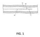
- FIG. 1is a plan view of a medical device constructed according to one embodiment and disposed in a vessel.
- FIG. 2Ais a detailed plan view of a medical device constructed according to another embodiment.
- FIG. 2Bis a detailed plan view of the tubular member of the medical device in FIG. 2A .
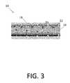
- FIG. 3is a side view of a tubular member section according to one embodiment.
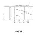
- FIG. 4is a detailed side view of a tubular member section according to another embodiment.
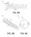
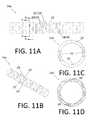
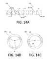
- FIGS. 5A, 6A, 7A, 8A, 9A, 10A, 11A, 12A, 13A and 14Aare detailed side views of tubular member sections according to various embodiments.
- FIGS. 5B, 6B, 7B, 8B, 9B, 10B, 11B, 12B and 13Bare detailed perspective views of the tubular member sections depicted in FIGS. 5A, 6A, 7A, 8A, 9A, 10A, 11A, 12A and 13A , respectively.
- FIGS. 5C, 6C, 7C, 8C, 9C, 10C, 11C, 12C, 13C and 14Bare axial cross-sectional views of the tubular member sections depicted in FIGS. 5A, 6A, 7A, 8A, 9A, 10A, 11A, 12A, 13A and 14A through respective lines labeled A-A in the corresponding side view (i.e., “A”) figures.
- FIGS. 11D, 13D and 14Care axial cross-sectional views of the tubular member sections depicted in FIGS. 11A, 13A and 14A through respective lines labeled B-B in the corresponding side view (i.e., “A”) figures.
- FIG. 15is a table summarizing characteristics of the tubular member sections depicted in FIGS. 5A to 14C .
- FIGS. 16, 18 and 19are flow charts depicting methods of manufacturing fenestrated tubular members according to various embodiments.
- FIG. 17is an exemplary plot for methods of manufacturing fenestrated tubular members according to various embodiments.
- a “tubular member”is any elongate device having a lumen.
- the lumenmay extend the entire length of the elongate device (i.e., from a first end to a second, opposite end), or the lumen may extend less than the entire length of the elongate device.
- a tubular membercan be formed from any material, including, but not limited to, metals and polymers.
- Tubular membersmay be fenestrated (not fluid-tight). While the tubular members described herein have substantially circular cross-sectional geometry, tubular members may have any cross-sectional geometry, including one that changes along the longitudinal axis of the device.
- a “cross-sectional plane” of a tubular memberincludes, but is not limited to, a plane normal to the longitudinal axis thereof.
- a “ring width” of an annular segment/ring of a tubular memberis the longitudinal (or axial) distance from a first side of the annular segment/ring along a longitudinal axis of the tubular member to a second, opposite side.
- a “beam length” of a beam of a tubular memberis the circumferential distance spanned by the beam between two slots or between two ends of one slot. In embodiments where the beam length changes along the radial thickness of the beam, the beam length is the circumferential distance spanned by the beam at the outer surface of the tubular member.
- an “opening” or a “fenestration” in a tubular memberis any space formed in or through the wall of the tubular member, including, but not limited to spaces that penetrate the tubular member from an outer surface to an inner surface thereof, and spaces that do not penetrate the tubular member.
- fenestrationsneed not be largely circumferential slots, but could take a variety of shapes, such as those described in U.S. Pat. No. 9,227,037, the entire disclosure of which is herein incorporated by reference, as though set forth in full.
- slot depth of a slot in a tubular memberis the radial distance a slot extends into a tubular member. Slot depth has a maximum determined by the radial thickness of the tubular member. In slots with constant slot depth along the slot, the slot depth is equal to the dimension (as measured from an outer surface of the tubular member to an inner surface of the slot) of each of the flat walls at opposite circumferential ends of the slot. The slot depth may also vary along the slot. For instance, slots formed by substantially circular blades with small radii may have variable slot depths along the slot.
- slot length of a slot in a tubular memberis the circumferential length of the slot, as measured along the outside diameter of the tubular member.
- the slot lengthmay be any value less than the outer circumference of the tubular member.
- slot width of a slotis the longitudinal (or axial) distance between the two longitudinal surfaces defining the slot.
- slot spacingof two longitudinally adjacent slots is the longitudinal (or axial) distance between the centerlines of the adjacent slots.
- slot spacingis equal to the ring width of the annular segment plus the slot width.
- beam centerline offsetof two beams that define a slot is the distance by which the centroid of the two beams is offset from the central axis of tubular member.
- the magnitude of the beam centerline offsetis the length of the perpendicular line connecting the line between the midpoints of the two beams and a diameter of the circular cross-section of the tubular member parallel thereto, as shown in FIG. 9C and described below.
- FIG. 1is a plan view of a guidewire 10 according to one embodiment disposed in a blood vessel 12 .
- Guidewire 10includes a tubular member 14 (e.g., a slotted hypotube 14 ) disposed at a distal end 16 of the guidewire 10 and configured to modify the stiffness of the distal end 16 of the guidewire 10 .
- the guidewire 10also includes a coating (not shown) over at least a portion of the tubular member 14 and configured to facilitate delivery of the guidewire 10 into the blood vessel 12 .
- Guidewire 10may be used for various intravascular procedures. For example, guidewire 10 may be used to seal the distal end of a balloon catheter (not shown). Alternatively, guidewire 10 may be used with a delivery catheter (not shown) to deliver a stent (not shown) to treat and/or diagnose a medical condition.
- FIG. 2Ais a detailed plan view of a guidewire 10 according to another embodiment.
- the guidewire 10includes a tubular member 14 (e.g., a slotted hypotube 14 ) at a distal end 16 thereof.
- the tubular member 14is covered by a coating 18 .
- the coatingcan be a polymer, such as polyurethane (e.g., a laminated TECOFLEX tube).
- FIG. 2Bis a detailed plan view of the tubular member 14 of the guidewire 10 depicted in FIG. 2A .
- the tubular member 14is shown in FIG. 2B without the coating 18 .
- FIG. 3is a side view of a tubular member 14 section, e.g., a slotted hypotube 14 section, according to still another embodiment.
- the slotted hypotube 14defines a plurality of openings 20 therein.
- the openings 20are elongated slots 20 that extend circumferentially and substantially perpendicular to the longitudinal axis of slotted hypotube 14 .
- the slotted hypotube 14is generally a stack of annular segments (i.e., rings) 22 connected by a plurality of beams 24 .
- annular segmentsi.e., rings
- the annular segments 22are substantially perpendicular to the longitudinal axis of the slotted hypotube 14 and the beams 24 are substantially parallel to the longitudinal axis of slotted hypotube 14 .
- the slotted hypotube 14also includes an optional coating 18 , as described above.
- the slots 20 depicted in FIG. 3penetrate the full radial thickness of the slotted hypotube 14 .
- All slots 20 formed in a hypotube 14 with a circular cross-section perpendicular to a longitudinal axis thereofwill be arcuate when viewed from an axial direction (as shown in e.g., FIG. 5C ) because the hypotube 14 forms a circle when viewed from an axial direction.
- Slotscan be formed in hypotubes by saw-cutting with circular blades.
- Other types of cutting systemsinclude, but are not limited to, laser cutting, electric discharge machining and plasma arc cutting systems.
- slotted hypotubesare manufactured using “additive” manufacturing (e.g., 3D printing) rather than the various “subtractive” techniques listed.
- the slotsalso have slot bases.
- Slot basesmay be flat or arcuate.
- slots made with circular blades having diameters substantially larger than the diameter of the hypotubemay have slot bases that are essentially flat.
- slots made using saw-cutting with circular blades having diameters about the same size as the diameter of the hypotubemay have arcuate slot bases.
- FIG. 4is a side view of a tubular member 14 (e.g., a slotted hypotube 14 ).
- Tubular member 14includes a plurality of annular segments 22 including annular segment 22 a , annular segment 22 b , and annular segment 22 c .
- segment 22 ais disposed longitudinally-adjacent (i.e., right next to) segment 22 b and segment 22 c is disposed longitudinally-adjacent segment 22 b (oppositely segment 22 a ).
- the number of annular segments 22 in a given tubular member 14may vary depending on the structure of tubular member 14 . For example, as the number of openings 20 increases, the number of annular segments 22 may similarly increase.
- Segments 22 a / 22 b / 22 ccan be understood to be generally circumferential or “round” portions of tubular member 14 that are defined between groups or sets 26 (in this case, pairs) of openings 20 that are generally aligned in a plane orthogonal to the longitudinal axis of the tubular member 14 .
- segment 22 ais defined between a first group 26 a of openings 20 a and a second group 26 b of openings 20 b .
- segment 22 bis defined between the second group 26 b of openings 20 b and a third group 26 c of openings 20 c .
- segment 22 cis defined between the third group 26 c of openings 20 c and a fourth group 26 d of openings 20 d .
- each group 26 a / 26 b / 26 c / 26 dincludes two openings 20 .
- any suitable number of openings 20may be utilized for any group 26 a / 26 b / 26 c / 26 d .
- the tubular member 14may include any number of openings 20 , groups 26 of openings 20 , or number of openings 20 per group 26 for any given tubular member 14 or device including a tubular member 14 with openings 20 .
- a portion of tubular member 14remains at the longitudinal location where openings 20 are formed and extends between longitudinally-adjacent annular segments 22 .
- This portionis called a “beam” 24 .
- beams 24are illustrated in FIG. 4 including beam 24 a , beam 24 a ′, beam 24 b , beam 24 b ′, beam 24 c , beam 24 c ′, beam 24 d , and beam 24 d ′.
- Beams 24 a / 24 a ′/ 24 b / 24 b ′/ 24 c / 24 c ′/ 24 d / 24 d ′can be understood to be portions of tubular member 14 that connects or attaches longitudinally-adjacent annular segments 22 .
- Each pair of longitudinally-adjacent annular segmentse.g., 22 a and 22 b
- segment 22 bis attached to segment 22 c by beams 24 c and 24 c ′.
- each group 26 a / 26 b / 26 c / 26 d of openings 20defines or leaves behind two, corresponding beams 24 a , 24 a ′/ 24 b , 24 b ′/ 24 c , 24 c ′/ 24 d , 24 d ′ at the respective longitudinal location.
- FIG. 1each group 26 a / 26 b / 26 c / 26 d of openings 20 defines or leaves behind two, corresponding beams 24 a , 24 a ′/ 24 b , 24 b ′/ 24 c , 24 c ′/ 24 d , 24 d ′ at the respective longitudinal location.
- one beam (e.g., 24 a , 24 b , 24 c , 24 d ) of each beam paircan be seen from the front and the other beam (e.g., 24 a ′, 24 b ′, 24 c ′, 24 d ′) of the beam pair can be seen from the back and is shaded for clarity. While the beams 24 depicted in FIG. 4 are not parallel to the longitudinal axis of the tubular device 14 , the beams 24 can be parallel to the longitudinal axis in other tubular devices 14 , as shown in e.g., FIG. 5A .
- tubular members 14different arrangements and configurations of openings 20 , annular segments 22 , and beams 24 are contemplated.
- at least some, if not all of the beams 24are disposed such that their respective longitudinal axes form a same angle or similar angles (e.g., 0 degrees or substantially parallel as shown in FIG. 5A ) with the longitudinal axis of the guidewire 10 .
- the beams 24are disposed such that their respective longitudinal axes form different angles with the longitudinal axis of the guidewire 10 .
- tubular members 14can be formed according to various embodiments such that some or all of the annular segments 22 and beams 24 have various geometries relative to the longitudinal axis of the guidewire 10 . Further, tubular members 14 according to these embodiments will have openings 20 with various geometries, because the openings 20 are defined by the annular segments 22 and beams 24 , i.e., the portions of the tubular member 14 remaining after openings 20 are formed therein.
- the distribution and/or configuration of the openings 20 , annular segments 22 , and beams 24can include, to the extent applicable, any of those disclosed in U.S. Pat. Nos. 7,878,984 and 9,227,037, the entire disclosures of which is herein incorporated by reference, as though set forth in full.
- Openings 20enhance the flexibility of the tubular member 14 while the beams 24 and annular segments 22 retain suitable torque transmission characteristics. Openings 20 are formed such that the annular segments 22 are interconnected by one or more beams 24 . Such an interconnected structure displays a relatively high degree of torsional stiffness, while retaining a desired level of lateral (i.e., orthogonal relative to the longitudinal axis) flexibility. In some embodiments, some adjacent openings 20 can be formed such that they include portions that overlap (when viewed axially) with each other to some degree about the circumference of tubular member 14 . In other embodiments, some adjacent openings 20 can be disposed such that they do not necessarily overlap with each other, but are disposed in a pattern that provides the desired degree of lateral flexibility.
- openings 20can be arranged along the length of, or about the circumference of, tubular member 14 to achieve desired properties.
- adjacent openings 20 , or groups of openings 20can be arranged in a symmetrical pattern, such as being disposed essentially equally on opposite sides about the circumference of tubular member 14 , or can be rotated by an angle relative to each other about the axis of tubular member 14 .
- adjacent openings 20 , or groups of openings 20may be equally spaced along the length of tubular member 14 , or can be arranged in an increasing or decreasing density pattern, or can be arranged in a non-symmetric or irregular pattern.
- opening size, opening shape and/or opening angle with respect to the longitudinal axis of tubular member 14can also be varied along the length of tubular member 14 in order to vary the flexibility/stiffness or other properties.
- the portions of the tubular membermay not include any such openings 20 .
- openings 20may be formed in groups of two, three, four, five, or more openings 20 , which may be located at substantially the same longitudinal location along the axis of tubular member 14 . Alternatively, a single opening 20 may be disposed at some or all of these longitudinal locations. Within the groups of openings 20 , there may be included openings 20 that are equal in size (i.e., span the same circumferential distance around tubular member 14 ). In some of these as well as other embodiments, at least some openings 20 in a group are unequal in size (i.e., span a different circumferential distance around tubular member 14 ). Longitudinally adjacent groups of openings 20 may have the same or different configurations.
- tubular members 14include openings 20 that are equal in size in a first group and then unequally sized in an adjacent group. It can be appreciated that in groups that have two openings 20 that are equal in size and are symmetrically disposed around the tube circumference, the centroid of the pair of beams 24 is coincident with the central axis of tubular member 14 . Conversely, in groups that have two openings 20 that are unequal in size and whose beams 24 are directly opposed on the tube circumference, the centroid of the pair of beams 24 is offset from the central axis of tubular member 14 .
- tubular member 14includes only slot groups with centroids that are coincident with the central axis of the tubular member 14 , only slot groups with centroids that are offset from the central axis of tubular member 14 , or slot groups with centroids that are coincident with the central axis of tubular member 14 in a first group and offset from the central axis of tubular member 14 in another group.
- the amount of offsetmay vary depending on the depth (or length) of openings 20 and can include essentially any suitable distance.
- Openings 20can be formed by methods such as micro-machining, laser-cutting, saw-cutting (e.g., using a diamond grit embedded semiconductor dicing blade), electron discharge machining, grinding, milling, casting, molding, chemically etching or treating, 3D printing, or other known methods, and the like.
- the structure of the tubular member 14is formed by cutting and/or removing portions of the tube to form openings 20 .
- openings 20may be formed in tubular members using a laser cutting process.
- the laser cutting processmay include essentially any suitable laser and/or laser cutting apparatus.
- the laser cutting processmay utilize a fiber laser. Utilizing processes like laser cutting may be desirable for a number of reasons.
- laser cutting processesmay allow tubular member 14 to be cut into a number of different cutting patterns in a precisely controlled manner. This may include variations in the slot width (which also may be termed “kerf”), annular segment width, beam height, beam width, beam length, etc. Further, changes to the cutting pattern can be made without the need to replace the cutting instrument (e.g., a blade).
- tubular members 20may be fabricated for use in neurological devices or other devices where a small size may be desired. Because of the precision and control that may be achieved by cutting openings 20 with a laser, numerous additional variations can be achieved in opening 20 , annular segment 22 , and beam 24 geometry, configuration, arrangement, etc.
- the tubular member 14includes a first section 14 a and a second section 14 b .
- the first section 14 ahas first features including, but not limited to, openings 20 , annular segments 22 , and beams 24 .
- the geometry of the first featuresresults in the first section 14 a having a first stiffness and a first “opening volume” or “fenestration volume.”
- the “slot volume,” “opening volume” or “fenestration volume” of a tubular member 14means the total volume of open spaces or fenestrations in the wall of a tubular member 14 per unit of length (e.g., in 3 /in).
- the second section 14 bhas second features including, but not limited to, openings 20 , annular segments 22 , and beams 24 .
- the geometry of the second featuresresults in the second section 14 b having a second stiffness and a second opening volume.
- First and second features of the first and second sections 14 a , 14 bcan also include, but are not limited to, ring width, beam length, slot length, slot width, slot depth, beam centerline offset, number of slots in a cross-sectional plane, and the presence/absence/number of recesses that do not fully penetrate the wall of the tubular member (all described below).
- the tubular member 14is configured to form part of a guidewire 10 such that the first section 14 a is proximal of the second section 14 b when the guidewire 10 is inserted into a body lumen.
- the first stiffnessmay be greater than the second stiffness, such that the second section 14 b , which is closer to the distal end of tubular member 14 and the guidewire 10 , is more flexible. This modifies the guidewire 10 so that its distal end is more flexible than its proximal end, thereby facilitating navigation through tortuous and narrowing body lumens.
- the first opening volume and the second opening volumeare substantially similar.
- substantially similar opening volumesvary from each other by less than about 10%. Because the first and second sections 14 a , 14 b have substantially similar opening volumes, when a coating 18 is applied to the first and second sections 14 a , 14 b of the tubular member 14 , the outer diameter of the coated tubular member 14 remains substantially constant.
- each longitudinal section of the tubular member 14e.g., first and second sections 14 a , 14 b .
- the coating materialflows into the openings in each section of the tubular member 14 . Therefore, the thickness of the coating 18 outside of each section of the tubular member 14 , which affects the outer diameter of each section of the coated tubular member 14 , is inversely related to the opening volume of each section of the tubular member 14 .
- maintaining substantially similar first and second opening volumes in the first and section tubular member sections 14 a , 14 balso maintains a substantially constant outer diameter in the first and tubular member section sections 14 a , 14 b , and the guidewire 10 in which they are incorporated. Having a substantially constant guidewire outer diameter improves the guidewire's ability to perform various functions, such as sealing a balloon catheter and insertion through tortuous vessels.
- FIGS. 5A-5Cdepict a section of a tubular member 14 according to one embodiment.
- the tubular member 14 sectionincludes a plurality of annular segments/rings 22 connected sequentially by a corresponding plurality of groups (i.e., pairs) 28 of beams 24 .
- FIGS. 5A and 5Bare side and perspective views, respectively.
- FIG. 5Cis an axial cross-sectional view along the line labeled A-A in FIG. 5A .
- the beams 24 of each pair 28are disposed in the same longitudinal/axial plane, and on opposite sides of the tubular member 14 from each other.
- Each beam 24 of each pair 28has flat walls at opposite circumferential ends of the beam 24 , because the beam 24 is formed using a method (e.g., saw-cutting using blades with large diameters) that results in flat walls.
- the wall of the two beams 24can be formed with two cuts.
- the annular segments 22 and pairs 28 of beams 24define a plurality of slots 20 along the length of the tubular member 14 segment. Longitudinally adjacent pairs 28 of beams 24 are rotated relative to each other (about the longitudinal axis) by about 85 degrees, such that a particular beam 24 of the pair 28 appears to make a complete (360 degree) rotation about the longitudinal axis of the tubular member 14 segment every approximately 72 pairs 28 of beams 24 . Because the structure is symmetrical about the longitudinal axis, the structure gives the appearance of a complete rotation every 36 beam pairs.
- each beam 24 in this exampleis approximately 0.0030 in.
- the longitudinal width of each slot 20is approximately 0.00157 in.
- the longitudinal spacing between each pair of adjacent slots 20is approximately 0.00557 in.
- the longitudinal width of each ring 22is equal to the longitudinal spacing of the slots minus the slot width, or 0.004 ins in this example.
- the resulting tubular member 14 sectionhas a flexural rigidity (“EI”) of 1.51 ⁇ 10 ⁇ 4 in 2 /lb.
- FIGS. 6A-6Cdepict a section of a tubular member 14 according to another embodiment.
- the tubular member 14 sectionincludes a plurality of annular segments/rings 22 connected sequentially by a corresponding plurality of groups (i.e., triplets) 28 of beams 24 .
- FIGS. 6A and 6Bare side and perspective views, respectively.
- FIG. 6Cis an axial cross-sectional view along the line labeled A-A in FIG. 6A .
- each triplet 28are disposed in the same longitudinal/axial plane, with the center of each beam 24 approximately 120 degrees displaced from the centers of the other beams 24 .
- Each beam 24 of each triplet 28has flat walls at opposite circumferential ends of the beam 24 , because the beam 24 is formed using a method (e.g., saw-cutting using blades with large diameters) that results in flat walls.
- the wall of the three beams 24can be formed with three cuts.
- the annular segments 22 and triplets 28 of beams 24define a plurality of slots 20 along the length of the tubular member 14 segment. Longitudinally adjacent triplets 28 of beams 24 are rotated relative to each other (about the longitudinal axis) by about 55 degrees, such that a particular beam 24 of the triplet 28 appears to make a complete (360 degree) rotation about the longitudinal axis of the tubular member 14 segment every approximately 72 triplets 28 of beams 24 .
- each beam 24is approximately 0.0025 in.
- the longitudinal width of each slot 20is approximately 0.00157 in.
- the longitudinal spacing between each triplet of adjacent slots 20is approximately 0.00557 in.
- the longitudinal width of each ring 22is equal to the longitudinal spacing of the slots minus the slot width, or 0.004 ins in this example.
- the resulting tubular member 14 sectionhas an EI of 9.52 ⁇ 10 4 in 2 /lb.
- EIcan be increased with a larger number (e.g., from two to three per group 28 ) of smaller beams 24 (e.g., beam length from approximately 0.0030 in to approximately 0.0025 in).
- a larger numbere.g., from two to three per group 28
- smaller beams 24e.g., beam length from approximately 0.0030 in to approximately 0.0025 in.
- FIGS. 7A-7Cdepict a section of a tubular member 14 according to still another embodiment.
- the tubular member 14 sectionincludes a plurality of annular segments/rings 22 connected sequentially by a corresponding plurality of groups (i.e., pairs) 28 of beams 24 .
- FIGS. 7A and 7Bare side and perspective views, respectively.
- FIG. 7Cis an axial cross-sectional view along the line labeled A-A in FIG. 7A .
- each beam 24 of each pair 28are disposed in the same longitudinal/axial plane, with the center of each beam 24 approximately 180 degrees displaced from the centers of the other beams 24 .
- Each beam 24 of each pair 28has flat walls at opposite circumferential ends of the beam 24 , because the beam 24 is formed using a method (e.g., saw-cutting using blades with large diameters) that results in flat walls.
- the walls of the two beams 24can be formed with two cuts.
- the annular segments 22 and pairs 28 of beams 24define a plurality of slots 20 along the length of the tubular member 14 segment. Longitudinally adjacent pairs 28 of beams 24 are rotated relative to each other (about the longitudinal axis) by about 85 degrees, such that a particular beam 24 of the pair 28 appears to make a complete (360 degree) rotation about the longitudinal axis of the tubular member 14 segment every approximately 72 pairs 28 of beams 24 .
- each beam 24is approximately 0.0050 in.
- the longitudinal width of each slot 20is approximately 0.00157 in.
- the longitudinal spacing between each pair of adjacent slots 20is approximately 0.00557 in.
- the longitudinal width of each ring 22is equal to the longitudinal spacing of the slots minus the slot width, or 0.004 ins in this example.
- the resulting tubular member 14 sectionhas an EI of 3.90 ⁇ 10 ⁇ 4 in 2 /lb.
- FIGS. 8A-8Cdepict a section of a tubular member 14 according to yet another embodiment.
- the tubular member 14 sectionincludes a plurality of annular segments/rings 22 connected sequentially by a corresponding plurality of groups (i.e., pairs) 28 of beams 24 .
- FIGS. 8A and 8Bare side and perspective views, respectively.
- FIG. 8Cis an axial cross-sectional view along the line labeled A-A in FIG. 8A .
- each beam 24 of each pair 28are disposed in the same longitudinal/axial plane, with the center of each beam 24 approximately 180 degrees displaced from the centers of the other beams 24 .
- Each beam 24 of each pair 28has flat walls at opposite circumferential ends of the beam 24 , because the beam 24 is formed using a method (e.g., saw-cutting using blades with large diameters) that results in flat walls.
- the wall of the two beams 24can be formed with two cuts.
- the annular segments 22 and pairs 28 of beams 24define a plurality of slots 20 along the length of the tubular member 14 segment. Longitudinally adjacent pairs 28 of beams 24 are rotated relative to each other (about the longitudinal axis) by about 85 degrees, such that a particular beam 24 of the pair 28 appears to make a complete (360 degree) rotation about the longitudinal axis of the tubular member 14 segment every approximately pairs 28 of beams 24 .
- each beam 24is approximately 0.0030 in.
- the longitudinal width of each slot 20is approximately 0.00157 in.
- the longitudinal spacing between each pair of adjacent slots 20is approximately 0.00327 in.
- the longitudinal width of each ring 22is equal to the longitudinal spacing of the slots minus the slot width, or 0.0017 ins in this example.
- the resulting tubular member 14 sectionhas an EI of 3.44 ⁇ 10 ⁇ 5 in 2 /lb.
- FIGS. 9A-9Cdepict a section of a tubular member 14 according to another embodiment.
- the tubular member 14 sectionincludes a plurality of annular segments/rings 22 connected sequentially by a corresponding plurality of groups (i.e., pairs) 28 of beams 24 .
- FIGS. 9A and 9Bare side and perspective views, respectively.
- FIG. 9Cis an axial cross-sectional view along the line labeled A-A in FIG. 9A .
- the beams 24 of each pair 28are disposed in the same longitudinal/axial plane, with the centers of the beams 24 forming a line 30 (“centerline”), which includes a centroid 32 of the beams 24 , and is displaced from a parallel diameter 34 of the circular cross-section of the tubular member 14 section by approximately 0.0035 in.
- centerlinewhich includes a centroid 32 of the beams 24 , and is displaced from a parallel diameter 34 of the circular cross-section of the tubular member 14 section by approximately 0.0035 in.
- Each beam 24 of each pair 28has flat walls at opposite circumferential ends of the beam 24 , because the beam 24 is formed using a method (e.g., saw-cutting using blades with large diameters) that results in flat walls.
- the wall of the two beams 24can be formed with two cuts.
- the annular segments 22 and pairs 28 of beams 24define a plurality of slots 20 along the length of the tubular member 14 segment. Longitudinally adjacent pairs 28 of beams 24 are rotated relative to each other (about the longitudinal axis) by about 85 degrees, such that a particular beam 24 of the pair 28 appears to make a complete (360 degree) rotation about the longitudinal axis of the tubular member 14 segment every approximately 72 pairs 28 of beams 24 .
- each beam 24is approximately 0.0030 in.
- the longitudinal width of each slot 20is approximately 0.00157 in.
- the longitudinal spacing between each pair of adjacent slots 20is approximately 0.00557 in.
- the longitudinal width of each ring 22is equal to the longitudinal spacing of the slots minus the slot width, or 0.004 ins in this example.
- the resulting tubular member 14 sectionhas an EI of 7.98 ⁇ 10 ⁇ 5 in 2 /lb.
- FIGS. 10A-10Cdepict a section of a tubular member 14 according to still another embodiment.
- the tubular member 14 sectionincludes a plurality of annular segments/rings 22 connected sequentially by a corresponding plurality of groups (i.e., pairs) 28 of beams 24 .
- FIGS. 10A and 10Bare side and perspective views, respectively.
- FIG. 10Cis an axial cross-sectional view along the line labeled A-A in FIG. 10A .
- each beam 24 of each pair 28are disposed in the same longitudinal/axial plane, with the center of each beam 24 approximately 180 degrees displaced from the centers of the other beams 24 .
- Each beam 24 of each pair 28has flat walls at opposite circumferential ends of the beam 24 , because the beam 24 is formed using a method (e.g., saw-cutting using blades with large diameters) that results in flat walls.
- the wall of the two beams 24can be formed with two cuts.
- the annular segments 22 and pairs 28 of beams 24define a plurality of slots 20 along the length of the tubular member 14 segment. Longitudinally adjacent pairs 28 of beams 24 are rotated relative to each other (about the longitudinal axis) by about 85 degrees, such that a particular beam 24 of the pair 28 appears to make a complete (360 degree) rotation about the longitudinal axis of the tubular member 14 segment every approximately 72 pairs 28 of beams 24 .
- each beam 24is approximately 0.0030 in.
- the longitudinal width of each slot 20is approximately 0.00070 in.
- the longitudinal spacing between each pair of adjacent slots 20is approximately 0.00557 in.
- the longitudinal width of each ring 22is equal to the longitudinal spacing of the slots minus the slot width, or 0.00487 ins in this example.
- the resulting tubular member 14 sectionhas an EI of 1.79 ⁇ 10 ⁇ 4 in 2 /lb.
- FIGS. 11A-11D and 12A-12Cdepict similar sections of tubular members 14 according to two embodiments.
- the tubular member 14 sectionseach include a plurality of annular segments/rings 22 connected sequentially by a corresponding plurality of groups (i.e., pairs) 28 of beams 24 .
- the tubular member section 14 a depicted in FIGS. 11A-11Dis almost identical to the tubular member section 14 b depicted in FIGS. 12A-12C , except that the tubular member section 14 a depicted in FIGS. 11A-11D includes additional non-penetrating slots 20 ′ disposed in the (longitudinal) middles of the rings 22 .
- FIGS. 11A-11Ddepict similar sections of tubular members 14 according to two embodiments.
- the tubular member 14 sectionseach include a plurality of annular segments/rings 22 connected sequentially by a corresponding plurality of groups (i.e., pairs) 28 of beams 24 .
- FIGS. 11A & 12A and 11B & 12Bare side and perspective views, respectively.
- FIGS. 11C and 12Care axial cross-sectional views along respective lines labeled A-A in FIGS. 11A and 12A .
- FIG. 11Dis an axial cross-sectional view along the line labeled B-B in FIG. 11A .
- each beam 24 of each pair 28are disposed in the same longitudinal/axial plane, with the center of each beam 24 approximately 180 degrees displaced from the centers of the other beams 24 .
- Each beam 24 of each pair 28has flat walls at opposite circumferential ends of the beam 24 , because the beam 24 is formed using a method (e.g., saw-cutting using blades with large diameters) that results in flat walls.
- the wall of the two beams 24can be formed with two cuts.
- the annular segments 22 and pairs 28 of beams 24 in FIGS. 11A-11D and 12A-12Cdefine respective pluralities of slots 20 along the lengths of respective tubular member 14 a , 14 b segments. These slots 20 pass completely through the walls of respective tubular member 14 a , 14 b segments. Longitudinally adjacent pairs 28 of beams 24 are rotated relative to each other (about the longitudinal axis) by about 85 degrees, such that a particular beam 24 of the pair 28 appears to make a complete (360 degree) rotation about the longitudinal axis of respective tubular member 14 a , 14 b segments every approximately 72 pairs 28 of beams 24 .
- each ring 22 in the tubular member section 14 a depicted in FIGS. 11A-11Dincludes four additional non-penetrating slots 20 ′ disposed in the (longitudinal) middles thereof. As shown in FIG. 11D , the non-penetrating slots 20 ′ do not penetrate the wall of the tubular member 14 a .
- Each non-penetrating slot 20 ′has a flat outer surface, because the non-penetrating slot 20 ′ is formed using a method (e.g., saw-cutting using blades with large diameters) that results in flat walls.
- the four non-penetrating slots 20 ′ in each ring 22can be formed with four cuts. Saw-cutting facilitates making non-penetrating slots.
- each beam 24 in FIGS. 11A-11D and 12A-12Cis approximately 0.0045 in.
- the longitudinal width of each slot 20is approximately 0.00157 in.
- the longitudinal spacing between each pair of adjacent slots 20is approximately 0.00757 in.
- the longitudinal width of each ring 22is equal to the longitudinal spacing of the slots minus the slot width, or 0.006 ins in this example.
- the resulting tubular member 14 a section depicted in FIGS. 11A-11Dhas an EI of 4.96 ⁇ 10 ⁇ 4 in 2 /lb.
- the resulting tubular member 14 a section depicted in FIGS. 12A-12Chas an EI of 5.25 ⁇ 10 ⁇ 4 in 2 /lb.
- the opening volume per ring and associated slot/beam of the tubular member 14 b section depicted in FIGS. 12A-12Ci.e., one set 26 of slots 20
- the opening volume per ring and associated slot/beam of the tubular member 14 a section depicted in FIGS. 11A-11Di.e., one set 26 of slots 20 and one set 26 ′ of non-penetrating slots 20 ′
- the opening volume per ring and associated slot/beam of the tubular member 14 a section depicted in FIGS. 11A-11Di.e., one set 26 of slots 20 and one set 26 ′ of non-penetrating slots 20 ′
- Comparing the characteristics and properties of the tubular member 14 a , 14 b sections depicted in FIGS. 11A-11D and 12A-12Cand summarized in FIG.
- opening volumecan be increased by about 36% while only decreasing EI by about 5.5%. Accordingly, adding non-penetrating slots to tubular member sections can significantly increase the opening volume without significantly decreasing EI.
- This tubular member section forming techniquecan be combined with others described herein to generate tubular member sections with different opening volumes and substantially similar EIs.
- the EI of the slotted tube with the extra non-penetrating slots(shown in FIGS. 11A-11D ) can be adjusted to be equal to that of the slotted tube without the extra non-penetrating slots (shown in FIGS. 12A-12C ) by a slightly increasing in the beam length in the slotted tube with the extra non-penetrating slots. This would result in a slightly reduced opening volume in the slotted tube with extra non-penetrating slots, while maintaining substantially identical EIs between the two tubes.
- FIGS. 13A-13Ddepict first and second sections 14 a , 14 b of a tubular member according to yet another embodiment.
- the first and second tubular member sections 14 a , 14 beach include a plurality of annular first and second section segments/rings 22 , 22 ′ connected sequentially by a corresponding plurality of groups (i.e., pairs) 28 , 28 ′ of first and second section beams 24 , 24 ′.
- the first tubular member section 14 ais similar to the second tubular member section 14 b , except that the first section beams 24 are circumferentially shorter than the second section beams 24 ′, and the first section rings 22 are axially wider than the second section rings 22 ′.
- FIGS. 13A and 13Bare side and perspective views, respectively.
- FIGS. 13C and 13Dare axial cross-sectional views along respective lines labeled A-A and B-B.
- first and second section beams 24 , 24 ′ of each pair 28 , 28 ′are each disposed in the same longitudinal/axial plane, with the center of each beam 24 approximately 180 degrees displaced from the centers of the other beams 24 .
- Each first and second section beam 24 , 24 ′ of each pair 28 , 28 ′has flat walls at opposite circumferential ends of the beam 24 , 24 ′, because the beams 24 , 24 ′ are formed using a method (e.g., saw-laser cutting using blades with large diameters) that results in flat walls.
- the wall of each pair 28 , 28 ′ of two beams 24 , 24 ′can be formed with two cuts.
- the first and second section annular segments 22 , 22 ′ and pairs 28 , 28 ′ of beams 24 , 24 ′ in FIGS. 13A-13Ddefine respective pluralities of first and second section slots 20 , 20 ′ along the lengths of respective first and second tubular member segments 14 a , 14 b .
- each first and second section beams 24 , 24 ′are approximately 1.05 ⁇ 10 ⁇ 3 in and approximately 4.81 ⁇ 10 ⁇ 3 in, respectively.
- the longitudinal widths of each first and second section slot 20 , 20 ′are approximately 0.00157 in.
- the longitudinal spacing between each pair of adjacent first and second section slots 20 , 20 ′are approximately 4.73 ⁇ 10 ⁇ 3 in and approximately 3.54 ⁇ 10 ⁇ 3 in, respectively.
- the longitudinal width of each first-section ring 22is equal to the longitudinal spacing of the slots minus the slot width, or 0.00316 ins in this example.
- the longitudinal width of each second-section ring 22 ′is equal to the longitudinal spacing of the slots minus the slot width, or 0.00197 ins in this example.
- first and second tubular member sections 14 a , 14 bhave EIs of 1.60 ⁇ 10 ⁇ 5 in 2 /lb and 8.68 ⁇ 10 ⁇ 5 in 2 /lb, respectively. These characteristics and properties are summarized in the table in FIG. 15 . Moreover, each of the first and second tubular member sections 14 a , 14 b have an opening volume of approximately 2.94 ⁇ 10 ⁇ 5 in 3 /in of tubular member. Comparing the characteristics and properties of the first and second tubular member sections 14 a , 14 b depicted in FIGS. 13A-13D , and summarized in FIG. 15 and above, demonstrates that tubular member sections can be formed such that they have significantly different EIs, but substantially similar opening volumes.
- FIGS. 14A-14Cdepict first and second sections 14 a , 14 b of a tubular member according to another embodiment.
- the first and second tubular member sections 14 a , 14 beach include a plurality of annular first and second section segments/rings 22 , 22 ′ connected sequentially by a corresponding plurality of groups (i.e., triplets and pairs) 28 , 28 ′ of first and second section beams 24 , 24 ′.
- the first tubular member section 14 ais similar to the second tubular member section 14 b , except that the first section beams 24 are grouped in triplets and circumferentially shorter than the second section beams 24 ′, which are grouped in pairs, and the second section rings 22 ′ are axially wider than the first section rings 22 .
- FIG. 14Ais a side view.
- FIGS. 14B and 14Care axial cross-sectional views along respective lines labeled A-A and B-B.
- the first section beams 24 of each triplet 28are disposed in the same longitudinal/axial plane, with the center of each beam 24 approximately 120 degrees displaced from the centers of the other beams 24 .
- Each first section beam 24 of the triplet 28has flat walls at opposite circumferential ends of the beam 24 , because the beams 24 are formed using a method (e.g., saw-cutting using blades with large diameters) that results in flat walls.
- the wall of each triplet 28 of three first section beams 24can be formed with three cuts.
- each second section beam 24 ′ of each pair 28 ′are disposed in the same longitudinal/axial plane, with the center of each beam 24 ′ approximately 180 degrees displaced from the centers of the other beams 24 ′.
- Each second section beam 24 ′ of the pair 28has flat walls at opposite circumferential ends of the beam 24 ′, because the beams 24 ′ are formed using a method (e.g., saw-cutting using blades with large diameters) that results in flat walls.
- the wall of each pair 28 ′ of two second section beams 24 ′can be formed with two cuts.
- the first and second section annular segments 22 , 22 ′ and groups 28 , 28 ′ of beams 24 , 24 ′ in FIGS. 14A-14Cdefine respective pluralities of first and second section slots 20 , 20 ′ along the lengths of respective first and second tubular member segments 14 a , 14 b .
- Longitudinally adjacent triplets 28 of first section beams 24are rotated relative to each other (about the longitudinal axis) by about 55 degrees, such that a particular beam 24 of a triplet 28 appears to make a complete (360 degree) rotation about the longitudinal axis of the first tubular member segment 14 a every approximately 72 triplets 28 of beams 24 .
- Longitudinally adjacent pairs 28 ′ of second section beams 24 ′are rotated relative to each other (about the longitudinal axis) by about 85 degrees, such that a particular beam 24 ′ of a pair 28 ′ makes a complete (360 degree) rotation about the longitudinal axis of the tubular member segment 14 b every approximately 72 pairs 28 ′ of beams 24 ′.
- each first and second section beams 24 , 24 ′are approximately 1.55 ⁇ 10 ⁇ 3 in and approximately 3.67 ⁇ 10 ⁇ 3 in, respectively.
- the longitudinal widths of each first and second section slot 20 , 20 ′are approximately 0.00157 in.
- the longitudinal spacing between each pair of adjacent first and second section slots 20 , 20 ′are approximately 3.12 ⁇ 10 ⁇ 3 in and approximately 5.24 ⁇ 10 ⁇ 3 in, respectively.
- the longitudinal width of each first-section ring 22is equal to the longitudinal spacing of the slots minus the slot width, or 0.00155 ins in this example.
- the longitudinal width of each second-section ring 22 ′is equal to the longitudinal spacing of the slots minus the slot width, or 0.00367 ins in this example.
- first and second tubular member sections 14 a , 14 bhave EIs of 2.3 ⁇ 10 ⁇ 4 in 2 /lb. These characteristics and properties are summarized in the table in FIG. 15 . Moreover, each of the first and second tubular member sections 14 a , 14 b have an opening volume of approximately 2.3 ⁇ 10 ⁇ 6 in 3 /in of tubular member and approximately 8.3 ⁇ 10 ⁇ 6 in 3 /in of tubular member, respectively. Comparing the characteristics and properties of the first and second tubular member sections 14 a , 14 b depicted in FIGS. 14A-14C , and summarized in FIG. 15 and above, demonstrates that tubular member sections can be formed such that they have different numbers of beams per group and opening volumes, but substantially similar EIs.
- FIG. 16is a flow chart depicting a method 100 of manufacturing a fenestrated tubular member 14 according to one embodiment.
- an iso-volume line 202 ais identified.
- An iso-volume line 202is a set of tubular member characteristics that result in tubular members having a particular opening volume, as shown in FIG. 17 and described below.
- Tubular member characteristicsinclude, but are not limited to, ring width, beam length, slot length, slot width, slot depth, beam centerline offset, number of slots in a cross-sectional plane, and the presence/absence/number of recesses that do not fully penetrate the wall of the tubular member.
- FIG. 17is ring width, beam length, slot length, slot width, slot depth, beam centerline offset, number of slots in a cross-sectional plane, and the presence/absence/number of recesses that do not fully penetrate the wall of the tubular member.
- the iso-volume line 202 ais identified on a plot 200 tracking the relations between ring width and beam length of tubular members 14 , as shown in FIG. 17 .
- the plot 200may be a graphical display as in FIG. 17 , the plot is not necessarily displayed in computer implemented embodiments.
- the plot 200 in FIG. 17tracks two tubular member characteristics (i.e., ring width and beam length), plots in other embodiments can track three or more tubular member characteristics simultaneously, resulting in analyses with three or more degrees of freedom.
- first and second iso-stiffness lines 204 a , 204 bare identified in the plot 200 .
- the tubular member characteristicsare ring width and beam length.
- An iso-stiffness line 204is a set of tubular member characteristics that result in tubular members 14 having a particular stiffness.
- the first and second iso-stiffness lines 204 a , 204 bcorrespond to different first and second stiffnesses.
- first and second intersection points 206 a , 206 bare identified in the plot 200 .
- the first and second intersection points 206 a , 206 brepresent the ring width and beam length where the iso-volume line 202 a intersects with the first and second iso-stiffness lines 204 a , 204 b , respectively.
- first and second ring widths and beam lengthsare identified.
- First and second ring widths and beam lengthsare the ring widths and beam lengths corresponding to the first and second intersection points 206 a , 206 b.
- first ring and first beamare formed in a first section 14 a of the tubular member 14 .
- the first ringhas the first ring width and the first beam has the first beam length.
- second ring and second beamare formed in a second section 14 b of the tubular member 14 .
- the second ringhas the second ring width and the second beam has the second beam length.
- the first and second rings and beamscan be formed in the tubular member 14 by mechanical blade cutting, laser cutting, electric discharge machining and plasma arc cutting.
- first and second rings and beamsare formed to have the first and second ring widths and beam lengths
- the first and second sections 14 a , 14 b of the tubular member 14 formed according the method 100 depicted in FIG. 16will have different first and second stiffness, but substantially similar first and second opening volumes.
- FIG. 18is a flow chart depicting a method 100 ′ of manufacturing a coated and fenestrated tubular member 14 according to another embodiment. Steps 102 to 112 of the method 100 ′ depicted in FIG. 18 are identical to corresponding steps in the method 100 depicted in FIG. 16 . After the first and second rings and beams are formed in steps 110 and 112 , the method 100 ′ depicted in FIG. 18 continues with the application of a coating 18 to the tubular member 14 at step 114 .
- the coating 18can be a polymer, such as polyurethane (e.g., a laminated TECOFLEX tube).
- the coating 18can be applied using various methods, including, but not limited to, spray coating, dip coating, extrusion and lamination.
- first and second sections 14 a , 14 b of the tubular member 14 formed according the method 100 ′ depicted in FIG. 18have substantially similar first and second opening volumes
- the first and second sections 14 a , 14 b of the coated tubular memberwill have substantially similar outer diameters.
- the substantially similar outer diametersis achieved in without having to vary the amount of coating 18 applied to the first and second sections 14 a , 14 b.
- FIG. 19is a flow chart depicting a method 100 ′′ of manufacturing a coated and fenestrated tubular member 14 according to still another embodiment. Steps 102 to 114 of the method 100 ′′ depicted in FIG. 19 are identical to corresponding steps in the method 100 ′ depicted in FIG. 18 . After the coating is applied in step 114 , the method 100 ′′ depicted in FIG. 19 continues with the incorporation of the tubular member 14 into a guidewire 10 . The tubular member 14 is incorporated such that the first section 14 a is proximal of the second section 14 b . Further, the first and second rings and beams are formed such that the first stiffness of the first section 14 a is greater than the second stiffness of the second section 14 b.
- first sections 14 a of the tubular member 14 formed according the method 100 ′′ depicted in FIG. 19is greater than the second section 14 b , a proximal section of the guidewire 10 will have a higher stiffness than a distal section of the guidewire 10 .
- first and second sections 14 a , 14 b of the coated tubular memberhave substantially similar outer diameters, so will the first and second sections of the guidewire.
- the substantially similar outer diametersimprove the guidewire's ability to perform various functions, such as sealing a balloon catheter and insertion through tortuous vessels.
- the followingis a method of manufacturing fenestrated tubular members 14 according to yet another embodiment.
- the followingis a method of manufacturing fenestrated tubular members 14 according to another embodiment. This method is more graphical.
- the followingis a method of creating the slotted tube design after the slotted tube characteristics are determined.
- fenestrated tube characteristicsother than beam length and ring width can be used in the mathematical models.
- different parameterscan be used to create the final fenestrated tube design (e.g., torsional stiffness rather than bending stiffness, etc.)
Landscapes
- Health & Medical Sciences (AREA)
- Life Sciences & Earth Sciences (AREA)
- Heart & Thoracic Surgery (AREA)
- Hematology (AREA)
- Engineering & Computer Science (AREA)
- Anesthesiology (AREA)
- Biomedical Technology (AREA)
- Pulmonology (AREA)
- Biophysics (AREA)
- Animal Behavior & Ethology (AREA)
- General Health & Medical Sciences (AREA)
- Public Health (AREA)
- Veterinary Medicine (AREA)
- Child & Adolescent Psychology (AREA)
- Materials For Medical Uses (AREA)
- Media Introduction/Drainage Providing Device (AREA)
Abstract
Description
- Outer Diameter=0.0122 in.
- Inner Diameter=0.0097 in.
- Young's Modulus (“E”) of Tube Material NiTi≈8.5E6 P.S.I.
Number of Beams Per Group
- 1. Select a raw material (e.g., Nitinol), and the outside and inside diameters of the tubing stock to be used.
- 2. Select a slot width.
- 3. Prepare a designed experiment (e.g., factorial) to create a mathematical model of slotted tube bending stiffness (“EI”) and volume per unit length (“V”) as functions of beam length (“BL”) and ring width (“RW”).
- 4. Generate EI data to populate the designed experiment by either creating solid models or physical specimens of slotted tubes with beam length and ring width values at each of the design points of the experiment.
- a. In the case of computer modeling, Finite Element Analysis (“FEA”) can be used to determine EI.
- b. In the case of physical specimens, the EI can be directly measured.
- 5. Directly calculate the slotted tube volume/unit length for each of the design points.
- 6. Generate a plot that overlays constant-volume (iso-volume) and constant-bending-stiffness (iso-EI) contours on ring width and beam length axes.
- 7. Determine the range of EIs for the desired slotted tube component.
- 8. Choose an iso-volume contour that intersects the desired range of iso-EI contours with the most “reasonable” beam and ring values. The “reasonableness” determination can include the following factors:
- a. Avoidance of feature dimensions that are too small to be reliably manufactured with the chosen method, due to expected process variation.
- b. Avoidance of feature dimensions that are too small to be reliably manufactured, due to expected process variation in subsequent processes. For example, a feature in a laser-cut tube can be so small that subsequent etching/slag removal processes may not have sufficient control to ensure that the feature would not be completely etched away.
- c. Avoidance of feature dimensions that would not provide adequate strength to remain intact in the intended application of the slotted tube component.
- d. Avoidance of ring widths that are so large as to inhibit flow of polymer from the ring center into the slots during the lamination stage.
- e. Avoidance of beam-length-to-ring-width ratios (BLRRs) that result in high-stress locations in bending, torsion, tension, or shear loading, or any combination of those loading conditions.
- f. Note that it may be necessary to allow the slotted tube volume/unit length to vary slightly, in order to create a slotted tube design that has “reasonable” dimensions over the full range of desired EI values.
- g. Note that it may be necessary to use a more complex mathematical model or to super-impose more than one mathematical model in order to create a slotted tube design that has “reasonable” dimensions over the full range of desired EI values.
- h. A more complex model may include variation in slot width.
- i. Super-imposition of multiple models may include, among other approaches, switching from 2-beam to 3-beam geometry, modifying slot widths, or adding slots that have minimal impact on the bending stiffness, while creating additional opening volume to contain polymer flow. Additional mathematical models can be produced (as described above) for slotted tubes with a different number of beams, or with different slot widths, and the various models employed in various sections of the slotted tube, in order to achieve the desired EI while minimizing volume variation along the length of the slotted tube.
- 9. Re-arrange the volume equation V=f(RW, BL) that was an output from the designed experiment to derive BL=f(V, RW).
- 10. Substitute this BL equation into the EI=f(RW, BL) equation from the designed experiment to derive EI as f(RW, V).
- 11. Rearrange this equation to derive RW=f(EI, V).
- 12. Enter the values of EI and V at the intersecting contours into the equation from
step 11 to calculate RWs at each of these contour intersection points. - 13. Enter the resultant RW values and the selected V value into the BL=f(V, RW) equation from
step 9 to calculate BLs for these points. - 14. Plot BL vs. EI with the above data points, then fit a curve to the data using known software, including MICROSOFT EXCEL (“TRENDLINE” function; the equation of the TRENDLINE function is BL=f (EI)).
- 15. Plot RW vs. BL using the above data points and fit a curve to this plot. This produces the equation RW=f(BL).
- 1. Choose an iso-volume contour.
- 2. Choose two iso-EI contours.
- 3. From the EI and Volume contour plots, pick the beam and ring values where the chosen iso-volume contour intersects the two iso-EI contours.
- 4. Plot BL vs. EI with the above data points, then fit a curve to the data using know software as described above.
- 5. Plot RW vs. BL using the above data points and fit a curve to this plot. This produces the equation RW=f(BL).
- 6. Note that it is also possible to choose one parameter (BL or RW) from the contour intersections, then re-arrange the EI=f(RW, BL) or V=f(RW, BL) equation to calculate the other parameter, using the V and EI values at each contour intersection point.
- 1. From the desired performance characteristics, determine the desired EI=f(x) for the slotted tube, as describes above, where x is position along the length of the slotted tube.
- 2. Use EI=f(x) and BL=f(EI) to calculate the function BL=f(x).
- 3. Use BL=f(x) and RW=f(BL) to calculate the function RW=f(x)
- 4. The above equations fully define the design of the slotted tube, given fixed tube stock dimensions and slot width.
Claims (14)
Priority Applications (1)
| Application Number | Priority Date | Filing Date | Title |
|---|---|---|---|
| US15/091,443US10252024B2 (en) | 2016-04-05 | 2016-04-05 | Medical devices and methods of manufacturing same |
Applications Claiming Priority (1)
| Application Number | Priority Date | Filing Date | Title |
|---|---|---|---|
| US15/091,443US10252024B2 (en) | 2016-04-05 | 2016-04-05 | Medical devices and methods of manufacturing same |
Publications (2)
| Publication Number | Publication Date |
|---|---|
| US20170281909A1 US20170281909A1 (en) | 2017-10-05 |
| US10252024B2true US10252024B2 (en) | 2019-04-09 |
Family
ID=59960581
Family Applications (1)
| Application Number | Title | Priority Date | Filing Date |
|---|---|---|---|
| US15/091,443Active2036-11-06US10252024B2 (en) | 2016-04-05 | 2016-04-05 | Medical devices and methods of manufacturing same |
Country Status (1)
| Country | Link |
|---|---|
| US (1) | US10252024B2 (en) |
Cited By (14)
| Publication number | Priority date | Publication date | Assignee | Title |
|---|---|---|---|---|
| US10953202B2 (en) | 2016-07-18 | 2021-03-23 | Scientia Vascular, Llc | Guidewire devices having distally extending coils and shapeable tips |
| US10980968B2 (en) | 2008-12-08 | 2021-04-20 | Scientia Vascular, Llc | Micro-cutting systems for forming cuts in products |
| US11052228B2 (en) | 2016-07-18 | 2021-07-06 | Scientia Vascular, Llc | Guidewire devices having shapeable tips and bypass cuts |
| US11305095B2 (en) | 2018-02-22 | 2022-04-19 | Scientia Vascular, Llc | Microfabricated catheter having an intermediate preferred bending section |
| US11369351B2 (en) | 2017-05-26 | 2022-06-28 | Scientia Vascular, Inc. | Micro-fabricated medical device having a non-helical cut arrangement |
| US11406791B2 (en) | 2009-04-03 | 2022-08-09 | Scientia Vascular, Inc. | Micro-fabricated guidewire devices having varying diameters |
| US11452541B2 (en) | 2016-12-22 | 2022-09-27 | Scientia Vascular, Inc. | Intravascular device having a selectively deflectable tip |
| US12011555B2 (en) | 2019-01-15 | 2024-06-18 | Scientia Vascular, Inc. | Guidewire with core centering mechanism |
| US12178975B2 (en) | 2020-01-23 | 2024-12-31 | Scientia Vascular, Inc. | Guidewire having enlarged, micro-fabricated distal section |
| US12220538B2 (en) | 2008-12-08 | 2025-02-11 | Scientia Vascular, Inc. | Micro-fabricated intravascular devices having varying diameters |
| US12296112B2 (en) | 2020-10-05 | 2025-05-13 | Scientia Vascular, Inc. | Microfabricated catheter devices with high axial strength |
| US12343485B2 (en) | 2020-01-23 | 2025-07-01 | Scientia Vascular, Inc. | High torque guidewire device |
| US12364840B2 (en) | 2016-07-29 | 2025-07-22 | Cephea Valve Technologies, Inc. | Mechanical interlock for catheters |
| US12440332B2 (en) | 2021-08-11 | 2025-10-14 | Cephea Valve Technologies, Inc. | Systems and methods for loading and deploying an intravascular device |
Families Citing this family (196)
| Publication number | Priority date | Publication date | Assignee | Title |
|---|---|---|---|---|
| DE10233085B4 (en) | 2002-07-19 | 2014-02-20 | Dendron Gmbh | Stent with guide wire |
| EP1951129B1 (en) | 2005-10-19 | 2012-11-21 | Pulsar Vascular, Inc. | Methods and systems for endovascularly clipping and repairing lumen and tissue defects |
| EP1986568B1 (en) | 2006-02-03 | 2017-04-05 | Covidien LP | Methods and devices for restoring blood flow within blocked vasculature |
| US10076346B2 (en) | 2007-04-17 | 2018-09-18 | Covidien Lp | Complex wire formed devices |
| US11202646B2 (en) | 2007-04-17 | 2021-12-21 | Covidien Lp | Articulating retrieval devices |
| US11337714B2 (en) | 2007-10-17 | 2022-05-24 | Covidien Lp | Restoring blood flow and clot removal during acute ischemic stroke |
| US10123803B2 (en) | 2007-10-17 | 2018-11-13 | Covidien Lp | Methods of managing neurovascular obstructions |
| US8545526B2 (en) | 2007-12-26 | 2013-10-01 | Lazarus Effect, Inc. | Retrieval systems and methods for use thereof |
| JP5457373B2 (en) | 2008-02-22 | 2014-04-02 | コヴィディエン リミテッド パートナーシップ | Device for blood flow recovery |
| US9402707B2 (en) | 2008-07-22 | 2016-08-02 | Neuravi Limited | Clot capture systems and associated methods |
| WO2010028314A1 (en) | 2008-09-05 | 2010-03-11 | Pulsar Vascular, Inc. | Systems and methods for supporting or occluding a physiological opening or cavity |
| WO2012009675A2 (en) | 2010-07-15 | 2012-01-19 | Lazarus Effect, Inc. | Retrieval systems and methods for use thereof |
| ES2683943T3 (en) | 2010-10-22 | 2018-09-28 | Neuravi Limited | Clot capture and removal system |
| EP4566553A3 (en) | 2011-03-09 | 2025-08-06 | Neuravi Limited | A clot retrieval device for removing occlusive clot from a blood vessel |
| US12076037B2 (en) | 2011-03-09 | 2024-09-03 | Neuravi Limited | Systems and methods to restore perfusion to a vessel |
| US11259824B2 (en) | 2011-03-09 | 2022-03-01 | Neuravi Limited | Clot retrieval device for removing occlusive clot from a blood vessel |
| ES2683178T3 (en) | 2011-05-23 | 2018-09-25 | Covidien Lp | Extraction systems |
| CN103582460B (en) | 2011-06-03 | 2019-03-19 | 帕尔萨维斯库勒公司 | Aneurysm devices and related systems and methods with additional anchoring mechanism |
| US9119625B2 (en) | 2011-10-05 | 2015-09-01 | Pulsar Vascular, Inc. | Devices, systems and methods for enclosing an anatomical opening |
| US9072624B2 (en) | 2012-02-23 | 2015-07-07 | Covidien Lp | Luminal stenting |
| US9314248B2 (en) | 2012-11-06 | 2016-04-19 | Covidien Lp | Multi-pivot thrombectomy device |
| US10561509B2 (en) | 2013-03-13 | 2020-02-18 | DePuy Synthes Products, Inc. | Braided stent with expansion ring and method of delivery |
| US10603157B2 (en) | 2013-03-13 | 2020-03-31 | DePuy Synthes Products, Inc. | Braid implant delivery and retraction device with distal engagement |
| US9433429B2 (en) | 2013-03-14 | 2016-09-06 | Neuravi Limited | Clot retrieval devices |
| ES2708786T3 (en) | 2013-03-14 | 2019-04-11 | Neuravi Ltd | Clot recovery device to remove occlusive clots from a blood vessel |
| WO2014140092A2 (en) | 2013-03-14 | 2014-09-18 | Neuravi Limited | Devices and methods for removal of acute blockages from blood vessels |
| US10076399B2 (en) | 2013-09-13 | 2018-09-18 | Covidien Lp | Endovascular device engagement |
| US9592139B2 (en) | 2013-10-04 | 2017-03-14 | Covidien Lp | Stents twisted prior to deployment and untwisted during deployment |
| WO2015073704A1 (en) | 2013-11-13 | 2015-05-21 | Covidien Lp | Galvanically assisted attachment of medical devices to thrombus |
| US10285720B2 (en) | 2014-03-11 | 2019-05-14 | Neuravi Limited | Clot retrieval system for removing occlusive clot from a blood vessel |
| US11154302B2 (en) | 2014-03-31 | 2021-10-26 | DePuy Synthes Products, Inc. | Aneurysm occlusion device |
| US11076860B2 (en) | 2014-03-31 | 2021-08-03 | DePuy Synthes Products, Inc. | Aneurysm occlusion device |
| JP6595513B2 (en) | 2014-06-13 | 2019-10-23 | ニューラヴィ・リミテッド | Device for removal of acute occlusions from blood vessels |
| US10265086B2 (en) | 2014-06-30 | 2019-04-23 | Neuravi Limited | System for removing a clot from a blood vessel |
| US9918718B2 (en) | 2014-08-08 | 2018-03-20 | DePuy Synthes Products, Inc. | Embolic coil delivery system with retractable mechanical release mechanism |
| US10206796B2 (en) | 2014-08-27 | 2019-02-19 | DePuy Synthes Products, Inc. | Multi-strand implant with enhanced radiopacity |
| US9782178B2 (en) | 2014-09-19 | 2017-10-10 | DePuy Synthes Products, Inc. | Vasculature occlusion device detachment system with tapered corewire and heater activated fiber detachment |
| US11253278B2 (en) | 2014-11-26 | 2022-02-22 | Neuravi Limited | Clot retrieval system for removing occlusive clot from a blood vessel |
| EP3682821B1 (en) | 2014-11-26 | 2022-05-11 | Neuravi Limited | A clot retrieval device for removing an occlusive clot from a blood vessel |
| US10617435B2 (en) | 2014-11-26 | 2020-04-14 | Neuravi Limited | Clot retrieval device for removing clot from a blood vessel |
| EP3256200A1 (en) | 2015-02-11 | 2017-12-20 | Covidien LP | Expandable tip medical devices and methods |
| EP3302311B1 (en) | 2015-06-03 | 2019-11-20 | Covidien LP | Flexible intravascular treatment devices |
| CN108135619B (en) | 2015-09-25 | 2021-08-13 | 柯惠有限合伙公司 | Medical Device Delivery System |
| US10537344B2 (en) | 2015-10-23 | 2020-01-21 | Covidien Lp | Rotatable connection between an intervention member and a manipulation member of an endovascular device |
| US10874410B2 (en) | 2015-11-04 | 2020-12-29 | Covidien Lp | Clot removal by adhesion |
| US10265089B2 (en) | 2016-02-12 | 2019-04-23 | Covidien Lp | Vascular device visibility |
| US10052185B2 (en) | 2016-02-12 | 2018-08-21 | Covidien Lp | Vascular device marker attachment |
| US10285710B2 (en) | 2016-06-01 | 2019-05-14 | DePuy Synthes Products, Inc. | Endovascular detachment system with flexible distal end and heater activated detachment |
| US20210330310A1 (en)* | 2016-07-07 | 2021-10-28 | Micronovus, Llc | Medical devices with distal control |
| EP3500191B1 (en) | 2016-08-17 | 2020-09-23 | Neuravi Limited | A clot retrieval system for removing occlusive clot from a blood vessel |
| US10076428B2 (en) | 2016-08-25 | 2018-09-18 | DePuy Synthes Products, Inc. | Expansion ring for a braided stent |
| EP3509509B1 (en) | 2016-09-06 | 2021-03-31 | Neuravi Limited | A clot retrieval device for removing occlusive clot from a blood vessel |
| US10292851B2 (en) | 2016-09-30 | 2019-05-21 | DePuy Synthes Products, Inc. | Self-expanding device delivery apparatus with dual function bump |
| US10517708B2 (en) | 2016-10-26 | 2019-12-31 | DePuy Synthes Products, Inc. | Multi-basket clot capturing device |
| US10905853B2 (en) | 2017-01-17 | 2021-02-02 | DePuy Synthes Products, Inc. | System and method for delivering a catheter |
| US10881497B2 (en) | 2017-01-26 | 2021-01-05 | DePuy Synthes Products, Inc. | Composite vascular flow diverter |
| CN110545739A (en) | 2017-02-23 | 2019-12-06 | 德普伊新特斯产品公司 | aneurysm devices and delivery systems |
| US11191555B2 (en) | 2017-05-12 | 2021-12-07 | Covidien Lp | Retrieval of material from vessel lumens |
| US10709464B2 (en) | 2017-05-12 | 2020-07-14 | Covidien Lp | Retrieval of material from vessel lumens |
| US10722257B2 (en) | 2017-05-12 | 2020-07-28 | Covidien Lp | Retrieval of material from vessel lumens |
| US11298145B2 (en) | 2017-05-12 | 2022-04-12 | Covidien Lp | Retrieval of material from vessel lumens |
| US11129630B2 (en) | 2017-05-12 | 2021-09-28 | Covidien Lp | Retrieval of material from vessel lumens |
| ES2983613T3 (en)* | 2017-05-26 | 2024-10-23 | Scientia Vascular Inc | Core-wire bonding with microfabricated sanitary devices |
| WO2018226809A1 (en) | 2017-06-07 | 2018-12-13 | Covidien Lp | Systems and methods for detecting strokes |
| WO2018232044A1 (en) | 2017-06-12 | 2018-12-20 | Covidien Lp | Tools for sheathing treatment devices and associated systems and methods |
| US10478322B2 (en) | 2017-06-19 | 2019-11-19 | Covidien Lp | Retractor device for transforming a retrieval device from a deployed position to a delivery position |
| US10575864B2 (en) | 2017-06-22 | 2020-03-03 | Covidien Lp | Securing element for resheathing an intravascular device and associated systems and methods |
| US10342686B2 (en) | 2017-08-10 | 2019-07-09 | Covidien Lp | Thin film mesh hybrid for treating vascular defects |
| US10835398B2 (en) | 2017-11-03 | 2020-11-17 | Covidien Lp | Meshes and devices for treating vascular defects |
| US10874411B2 (en) | 2018-06-22 | 2020-12-29 | Covidien Lp | Electrically enhanced retrieval of material from vessel lumens |
| US12318126B2 (en) | 2021-06-25 | 2025-06-03 | Covidien Lp | Current generator for a medical treatment system |
| US11058444B2 (en) | 2017-12-11 | 2021-07-13 | Covidien Lp | Electrically enhanced retrieval of material from vessel lumens |
| US10709463B2 (en) | 2017-12-11 | 2020-07-14 | Covidien Lp | Electrically enhanced retrieval of material from vessel lumens |
| US12004803B2 (en) | 2021-03-15 | 2024-06-11 | Covidien Lp | Thrombectomy treatment system |
| US11974752B2 (en) | 2019-12-12 | 2024-05-07 | Covidien Lp | Electrically enhanced retrieval of material from vessel lumens |
| US10806462B2 (en) | 2017-12-21 | 2020-10-20 | DePuy Synthes Products, Inc. | Implantable medical device detachment system with split tube and cylindrical coupling |
| US10751065B2 (en) | 2017-12-22 | 2020-08-25 | DePuy Synthes Products, Inc. | Aneurysm device and delivery system |
| US10905430B2 (en) | 2018-01-24 | 2021-02-02 | DePuy Synthes Products, Inc. | Aneurysm device and delivery system |
| US10786259B2 (en) | 2018-03-30 | 2020-09-29 | DePuy Synthes Products, Inc. | Split balloon assist device and method for using the same |
| US10918390B2 (en) | 2018-03-30 | 2021-02-16 | DePuy Synthes Products, Inc. | Helical balloon assist device and method for using the same |
| US10806461B2 (en) | 2018-04-27 | 2020-10-20 | DePuy Synthes Products, Inc. | Implantable medical device detachment system with split tube |
| US11058430B2 (en) | 2018-05-25 | 2021-07-13 | DePuy Synthes Products, Inc. | Aneurysm device and delivery system |
| US11596412B2 (en) | 2018-05-25 | 2023-03-07 | DePuy Synthes Products, Inc. | Aneurysm device and delivery system |
| US10939915B2 (en) | 2018-05-31 | 2021-03-09 | DePuy Synthes Products, Inc. | Aneurysm device and delivery system |
| US10667833B2 (en) | 2018-06-08 | 2020-06-02 | Neuravi Limited | Guidewire with an atraumatic clot-circumventing configured distal end for use in an endovascular medical system |
| US10898216B2 (en) | 2018-06-13 | 2021-01-26 | DePuy Synthes Products, Inc. | Vasculature obstruction capture device |
| AU2019204522A1 (en) | 2018-07-30 | 2020-02-13 | DePuy Synthes Products, Inc. | Systems and methods of manufacturing and using an expansion ring |
| US10905431B2 (en) | 2018-08-03 | 2021-02-02 | DePuy Synthes Products, Inc. | Spiral delivery system for embolic braid |
| US10456280B1 (en) | 2018-08-06 | 2019-10-29 | DePuy Synthes Products, Inc. | Systems and methods of using a braided implant |
| US10278848B1 (en) | 2018-08-06 | 2019-05-07 | DePuy Synthes Products, Inc. | Stent delivery with expansion assisting delivery wire |
| US10813780B2 (en) | 2018-08-08 | 2020-10-27 | DePuy Synthes Products, Inc. | Intraluminal implant delivery system and method |
| US11051825B2 (en) | 2018-08-08 | 2021-07-06 | DePuy Synthes Products, Inc. | Delivery system for embolic braid |
| US10842498B2 (en) | 2018-09-13 | 2020-11-24 | Neuravi Limited | Systems and methods of restoring perfusion to a vessel |
| EP3626212A3 (en) | 2018-09-20 | 2020-07-22 | DePuy Synthes Products, Inc. | Stent with shaped wires |
| US11123077B2 (en) | 2018-09-25 | 2021-09-21 | DePuy Synthes Products, Inc. | Intrasaccular device positioning and deployment system |
| US11406416B2 (en) | 2018-10-02 | 2022-08-09 | Neuravi Limited | Joint assembly for vasculature obstruction capture device |
| US11253287B2 (en) | 2018-10-04 | 2022-02-22 | Neuravi Limited | Retrograde blood flow occlusion flushing device |
| US11076861B2 (en) | 2018-10-12 | 2021-08-03 | DePuy Synthes Products, Inc. | Folded aneurysm treatment device and delivery method |
| US11406392B2 (en) | 2018-12-12 | 2022-08-09 | DePuy Synthes Products, Inc. | Aneurysm occluding device for use with coagulating agents |
| US11147562B2 (en) | 2018-12-12 | 2021-10-19 | DePuy Synthes Products, Inc. | Systems and methods for embolic implant detachment |
| US11272939B2 (en) | 2018-12-18 | 2022-03-15 | DePuy Synthes Products, Inc. | Intrasaccular flow diverter for treating cerebral aneurysms |
| US11039944B2 (en) | 2018-12-27 | 2021-06-22 | DePuy Synthes Products, Inc. | Braided stent system with one or more expansion rings |
| US11134953B2 (en) | 2019-02-06 | 2021-10-05 | DePuy Synthes Products, Inc. | Adhesive cover occluding device for aneurysm treatment |
| US11273285B2 (en) | 2019-02-07 | 2022-03-15 | DePuy Synthes Products, Inc. | Ancillary device for detaching implants |
| HUE064065T2 (en) | 2019-02-08 | 2024-02-28 | Coloplast As | Urinary catheter |
| ES2910600T3 (en) | 2019-03-04 | 2022-05-12 | Neuravi Ltd | Powered Clot Recovery Catheter |
| US11382633B2 (en) | 2019-03-06 | 2022-07-12 | DePuy Synthes Products, Inc. | Strut flow diverter for cerebral aneurysms and methods for preventing strut entanglement |
| US11612430B2 (en) | 2019-03-19 | 2023-03-28 | Covidien Lp | Electrically enhanced retrieval of material from vessel lumens |
| US11337706B2 (en) | 2019-03-27 | 2022-05-24 | DePuy Synthes Products, Inc. | Aneurysm treatment device |
| US11185334B2 (en) | 2019-03-28 | 2021-11-30 | DePuy Synthes Products, Inc. | Single lumen reduced profile occlusion balloon catheter |
| WO2020206101A1 (en) | 2019-04-05 | 2020-10-08 | Traverse Vascular, Inc. | Reentry catheters for traversing chronic total occlusions |
| US11051928B2 (en) | 2019-04-11 | 2021-07-06 | Neuravi Limited | Floating carotid filter |
| US11957855B2 (en) | 2019-05-09 | 2024-04-16 | Neuravi Limited | Balloon guide catheter with positive venting of residual air |
| US11931522B2 (en) | 2019-05-09 | 2024-03-19 | Neuravi Limited | Inflation lumen kink protection and balloon profile |
| US11607531B2 (en) | 2019-05-09 | 2023-03-21 | Neuravi Limited | Balloon catheter with venting of residual air in a proximal direction |
| US11571553B2 (en) | 2019-05-09 | 2023-02-07 | Neuravi Limited | Balloon guide catheter with thermally expandable material |
| USD959659S1 (en) | 2019-05-10 | 2022-08-02 | DePuy Synthes Products, Inc. | Implant release handle |
| US11497504B2 (en) | 2019-05-21 | 2022-11-15 | DePuy Synthes Products, Inc. | Aneurysm treatment with pushable implanted braid |
| US11413046B2 (en) | 2019-05-21 | 2022-08-16 | DePuy Synthes Products, Inc. | Layered braided aneurysm treatment device |
| US11672542B2 (en) | 2019-05-21 | 2023-06-13 | DePuy Synthes Products, Inc. | Aneurysm treatment with pushable ball segment |
| US11607226B2 (en) | 2019-05-21 | 2023-03-21 | DePuy Synthes Products, Inc. | Layered braided aneurysm treatment device with corrugations |
| US11278292B2 (en) | 2019-05-21 | 2022-03-22 | DePuy Synthes Products, Inc. | Inverting braided aneurysm treatment system and method |
| US10653425B1 (en) | 2019-05-21 | 2020-05-19 | DePuy Synthes Products, Inc. | Layered braided aneurysm treatment device |
| US11602350B2 (en) | 2019-12-05 | 2023-03-14 | DePuy Synthes Products, Inc. | Intrasaccular inverting braid with highly flexible fill material |
| US11191558B2 (en) | 2019-06-12 | 2021-12-07 | Covidien Lp | Retrieval of material from corporeal lumens |
| US11523838B2 (en) | 2019-06-12 | 2022-12-13 | Covidien Lp | Retrieval of material from corporeal lumens |
| US11109939B2 (en) | 2019-06-14 | 2021-09-07 | DePuy Synthes Products, Inc. | Intravascular devices with radiopaque body markers |
| US11406403B2 (en) | 2019-06-14 | 2022-08-09 | Neuravi Limited | Visibility of mechanical thrombectomy device during diagnostic imaging |
| US11253265B2 (en) | 2019-06-18 | 2022-02-22 | DePuy Synthes Products, Inc. | Pull wire detachment for intravascular devices |
| US11207494B2 (en) | 2019-07-03 | 2021-12-28 | DePuy Synthes Products, Inc. | Medical device delivery member with flexible stretch resistant distal portion |
| US11426174B2 (en) | 2019-10-03 | 2022-08-30 | DePuy Synthes Products, Inc. | Medical device delivery member with flexible stretch resistant mechanical release |
| US11266426B2 (en) | 2019-07-10 | 2022-03-08 | DePuy Synthes Products, Inc. | Streamlined treatment of clot removal, angioplasty and prevention of restenosis using a single integrated intravascular device |
| US11266427B2 (en) | 2019-07-10 | 2022-03-08 | Neuravi Limited | Self-expanding intravascular medical device |
| US11395675B2 (en) | 2019-07-11 | 2022-07-26 | DePuy Synthes Products, Inc. | Clot retriever cleaning for reinsertion |
| EP3791815B1 (en) | 2019-09-11 | 2024-06-26 | Neuravi Limited | Expandable mouth catheter |
| US11439403B2 (en) | 2019-09-17 | 2022-09-13 | DePuy Synthes Products, Inc. | Embolic coil proximal connecting element and stretch resistant fiber |
| US12376859B2 (en) | 2019-09-17 | 2025-08-05 | DePuy Synthes Products, Inc. | Embolic coil proximal connecting element and stretch resistant fiber |
| US11712231B2 (en) | 2019-10-29 | 2023-08-01 | Neuravi Limited | Proximal locking assembly design for dual stent mechanical thrombectomy device |
| US20210128183A1 (en) | 2019-10-31 | 2021-05-06 | Neuravi Limited | Thrombectomy and stenting system |
| US11376013B2 (en) | 2019-11-18 | 2022-07-05 | DePuy Synthes Products, Inc. | Implant delivery system with braid cup formation |
| US11628282B2 (en) | 2019-11-25 | 2023-04-18 | Neuravi Limited | No preparation balloon guide catheter |
| US11779364B2 (en) | 2019-11-27 | 2023-10-10 | Neuravi Limited | Actuated expandable mouth thrombectomy catheter |
| US11839725B2 (en) | 2019-11-27 | 2023-12-12 | Neuravi Limited | Clot retrieval device with outer sheath and inner catheter |
| US11517340B2 (en) | 2019-12-03 | 2022-12-06 | Neuravi Limited | Stentriever devices for removing an occlusive clot from a vessel and methods thereof |
| US11395668B2 (en) | 2019-12-12 | 2022-07-26 | Covidien Lp | Electrically enhanced retrieval of material from vessel lumens |
| US11457926B2 (en) | 2019-12-18 | 2022-10-04 | DePuy Synthes Products, Inc. | Implant having an intrasaccular section and intravascular section |
| US11457922B2 (en) | 2020-01-22 | 2022-10-04 | DePuy Synthes Products, Inc. | Medical device delivery member with flexible stretch resistant distal portion |
| US11992241B2 (en) | 2020-01-31 | 2024-05-28 | DePuy Synthes Products, Inc. | System to assist delivery of a mechanical intravascular treatment device |
| US11957354B2 (en) | 2020-02-10 | 2024-04-16 | DePuy Synthes Products, Inc. | Aneurysm implant support device |
| US11432822B2 (en) | 2020-02-14 | 2022-09-06 | DePuy Synthes Products, Inc. | Intravascular implant deployment system |
| US12364397B2 (en) | 2020-02-17 | 2025-07-22 | Covidien Lp | Systems and methods for detecting strokes |
| US12263020B2 (en) | 2020-02-17 | 2025-04-01 | Covidien Lp | Systems and methods for detecting strokes |
| US11944327B2 (en) | 2020-03-05 | 2024-04-02 | Neuravi Limited | Expandable mouth aspirating clot retrieval catheter |
| US11633198B2 (en) | 2020-03-05 | 2023-04-25 | Neuravi Limited | Catheter proximal joint |
| US11883043B2 (en) | 2020-03-31 | 2024-01-30 | DePuy Synthes Products, Inc. | Catheter funnel extension |
| US11759217B2 (en) | 2020-04-07 | 2023-09-19 | Neuravi Limited | Catheter tubular support |
| US11717308B2 (en) | 2020-04-17 | 2023-08-08 | Neuravi Limited | Clot retrieval device for removing heterogeneous clots from a blood vessel |
| US11730501B2 (en) | 2020-04-17 | 2023-08-22 | Neuravi Limited | Floating clot retrieval device for removing clots from a blood vessel |
| US11871946B2 (en) | 2020-04-17 | 2024-01-16 | Neuravi Limited | Clot retrieval device for removing clot from a blood vessel |
| US11523831B2 (en) | 2020-04-30 | 2022-12-13 | DePuy Synthes Products, Inc. | Intrasaccular flow diverter |
| US11737771B2 (en) | 2020-06-18 | 2023-08-29 | Neuravi Limited | Dual channel thrombectomy device |
| US11937836B2 (en) | 2020-06-22 | 2024-03-26 | Neuravi Limited | Clot retrieval system with expandable clot engaging framework |
| US11395669B2 (en) | 2020-06-23 | 2022-07-26 | Neuravi Limited | Clot retrieval device with flexible collapsible frame |
| US11439418B2 (en) | 2020-06-23 | 2022-09-13 | Neuravi Limited | Clot retrieval device for removing clot from a blood vessel |
| US11951026B2 (en) | 2020-06-30 | 2024-04-09 | DePuy Synthes Products, Inc. | Implantable medical device detachment system with flexible braid section |
| US20220031341A1 (en) | 2020-07-29 | 2022-02-03 | Neuravi Limited | Adhesive-Free Bonded Balloon for a Balloon Guide Catheter With Minimal Outer Profile |
| US20220039644A1 (en)* | 2020-08-05 | 2022-02-10 | Boston Scientific Scimed, Inc. | Devices and methods for treating a stricture along the biliary and/or pancreatic tract |
| EP4203770A1 (en) | 2020-08-28 | 2023-07-05 | Covidien LP | Detection of patient conditions using signals sensed on or near the head |
| US11864781B2 (en) | 2020-09-23 | 2024-01-09 | Neuravi Limited | Rotating frame thrombectomy device |
| US11826520B2 (en) | 2020-12-08 | 2023-11-28 | DePuy Synthes Products, Inc. | Catheter designs for enhanced column strength |
| US11786698B2 (en) | 2020-12-08 | 2023-10-17 | DePuy Synthes Products, Inc. | Catheter with textured surface |
| US11937837B2 (en) | 2020-12-29 | 2024-03-26 | Neuravi Limited | Fibrin rich / soft clot mechanical thrombectomy device |
| US12029442B2 (en) | 2021-01-14 | 2024-07-09 | Neuravi Limited | Systems and methods for a dual elongated member clot retrieval apparatus |
| US11872354B2 (en) | 2021-02-24 | 2024-01-16 | Neuravi Limited | Flexible catheter shaft frame with seam |
| US12064130B2 (en) | 2021-03-18 | 2024-08-20 | Neuravi Limited | Vascular obstruction retrieval device having sliding cages pinch mechanism |
| US11963713B2 (en) | 2021-06-02 | 2024-04-23 | Covidien Lp | Medical treatment system |
| US11974764B2 (en) | 2021-06-04 | 2024-05-07 | Neuravi Limited | Self-orienting rotating stentriever pinching cells |
| US11998213B2 (en) | 2021-07-14 | 2024-06-04 | DePuy Synthes Products, Inc. | Implant delivery with modified detachment feature and pull wire engagement |
| IL285744B2 (en)* | 2021-08-19 | 2023-08-01 | Inretio Ltd | Clot removal device |
| US11944374B2 (en) | 2021-08-30 | 2024-04-02 | Covidien Lp | Electrical signals for retrieval of material from vessel lumens |
| US20230071512A1 (en)* | 2021-09-03 | 2023-03-09 | Scientia Vascular, Inc. | Microcatheter device with non-linear bending stiffness |
| US12369920B2 (en) | 2021-09-22 | 2025-07-29 | DePuy Synthes Products, Inc. | Introducer sheath having an intentional friction zone to hold in position a delivery system suitable for implantable intravascular devices |
| US11937839B2 (en) | 2021-09-28 | 2024-03-26 | Neuravi Limited | Catheter with electrically actuated expandable mouth |
| US12011186B2 (en) | 2021-10-28 | 2024-06-18 | Neuravi Limited | Bevel tip expandable mouth catheter with reinforcing ring |
| US12076020B2 (en) | 2021-11-18 | 2024-09-03 | Covidien Lp | Retrieval of material from corporeal lumens |
| US11751881B2 (en) | 2021-11-26 | 2023-09-12 | DePuy Synthes Products, Inc. | Securement wire withstanding forces during deployment of implantable intravascular treatment device using a delivery and detachment system |
| US11937824B2 (en) | 2021-12-30 | 2024-03-26 | DePuy Synthes Products, Inc. | Implant detachment systems with a modified pull wire |
| US11844490B2 (en) | 2021-12-30 | 2023-12-19 | DePuy Synthes Products, Inc. | Suture linkage for inhibiting premature embolic implant deployment |
| US12220131B2 (en) | 2022-01-06 | 2025-02-11 | DePuy Synthes Products, Inc. | Delivery and detachment system imposing a friction force on a securement wire to minimize movement of an implantable intravascular device |
| US12011171B2 (en) | 2022-01-06 | 2024-06-18 | DePuy Synthes Products, Inc. | Systems and methods for inhibiting premature embolic implant deployment |
| US11937825B2 (en) | 2022-03-02 | 2024-03-26 | DePuy Synthes Products, Inc. | Hook wire for preventing premature embolic implant detachment |
| US12137915B2 (en) | 2022-03-03 | 2024-11-12 | DePuy Synthes Products, Inc. | Elongating wires for inhibiting premature implant detachment |
| US11937826B2 (en) | 2022-03-14 | 2024-03-26 | DePuy Synthes Products, Inc. | Proximal link wire for preventing premature implant detachment |
| US12402886B2 (en) | 2022-06-23 | 2025-09-02 | DePuy Synthes Products, Inc. | Detachment indicator for implant deployment |
| EP4302675A1 (en)* | 2022-07-07 | 2024-01-10 | Hoya Corporation | Bendable tube for use in a surgical device |
| US12396730B2 (en) | 2022-09-28 | 2025-08-26 | DePuy Synthes Products, Inc. | Braided implant with detachment mechanism |
Citations (42)
| Publication number | Priority date | Publication date | Assignee | Title |
|---|---|---|---|---|
| US5916177A (en) | 1995-04-18 | 1999-06-29 | Schneider (Europe) A.G. | Pressure measuring guide wire |
| US6001068A (en) | 1996-10-22 | 1999-12-14 | Terumo Kabushiki Kaisha | Guide wire having tubular connector with helical slits |
| US6004279A (en) | 1996-01-16 | 1999-12-21 | Boston Scientific Corporation | Medical guidewire |
| US6017319A (en) | 1996-05-24 | 2000-01-25 | Precision Vascular Systems, Inc. | Hybrid tubular guide wire for catheters |
| US6130406A (en) | 1998-01-08 | 2000-10-10 | Adam Spence Corporation | Method for forming a medical tubing device |
| US6203732B1 (en) | 1998-07-02 | 2001-03-20 | Intra Therapeutics, Inc. | Method for manufacturing intraluminal device |
| US6428489B1 (en)* | 1995-12-07 | 2002-08-06 | Precision Vascular Systems, Inc. | Guidewire system |
| US6440088B1 (en) | 1996-05-24 | 2002-08-27 | Precision Vascular Systems, Inc. | Hybrid catheter guide wire apparatus and method |
| US6500130B2 (en) | 2000-12-21 | 2002-12-31 | Scimed Life Systems, Inc. | Steerable guidewire |
| US20030069522A1 (en) | 1995-12-07 | 2003-04-10 | Jacobsen Stephen J. | Slotted medical device |
| US6579246B2 (en) | 1999-12-22 | 2003-06-17 | Sarcos, Lc | Coronary guidewire system |
| US6585719B2 (en) | 2001-01-04 | 2003-07-01 | Scimed Life Systems, Inc. | Low profile metal/polymer tubes |
| US6652508B2 (en) | 2001-11-09 | 2003-11-25 | Scimed Life Systems, Inc. | Intravascular microcatheter having hypotube proximal shaft with transition |
| US6685679B2 (en) | 2000-12-06 | 2004-02-03 | Scimed Life Systems, Inc. | Interlocking metal shaft |
| US6716207B2 (en) | 2001-05-22 | 2004-04-06 | Scimed Life Systems, Inc. | Torqueable and deflectable medical device shaft |
| US6786876B2 (en) | 2001-06-20 | 2004-09-07 | Microvention, Inc. | Medical devices having full or partial polymer coatings and their methods of manufacture |
| US20050124976A1 (en) | 2003-12-04 | 2005-06-09 | Devens Douglas A.Jr. | Medical devices |
| US7258753B2 (en) | 1990-12-18 | 2007-08-21 | Abbott Cardiovascular Systems Inc. | Superelastic guiding member |
| US20090177119A1 (en) | 2008-01-03 | 2009-07-09 | Boston Scientific Scimed, Inc. | Articulating intracorporeal medical device |
| US7682337B2 (en) | 2007-02-07 | 2010-03-23 | Cook Incorporated | Method and apparatus for gaining percutaneous access to a body |
| US7771410B2 (en) | 2002-11-25 | 2010-08-10 | Invatec S.R.L. | Pipe having at least a portion with a variable flexibility |
| US7785273B2 (en) | 2003-09-22 | 2010-08-31 | Boston Scientific Scimed, Inc. | Guidewire with reinforcing member |
| US7824443B2 (en) | 2003-12-23 | 2010-11-02 | Sadra Medical, Inc. | Medical implant delivery and deployment tool |
| US7828832B2 (en) | 2005-04-18 | 2010-11-09 | Medtronic Vascular, Inc. | Intravascular deployment device with improved deployment capability |
| US7857008B2 (en) | 2006-08-24 | 2010-12-28 | Boston Scientific Scimed, Inc. | Medical device coating configuration and method for improved lubricity and durability |
| US7878984B2 (en) | 2002-07-25 | 2011-02-01 | Boston Scientific Scimed, Inc. | Medical device for navigation through anatomy and method of making same |
| US7955272B2 (en) | 1998-05-14 | 2011-06-07 | Boston Scientific Scimed, Inc. | High performance coil wire |
| US7989042B2 (en) | 2004-11-24 | 2011-08-02 | Boston Scientific Scimed, Inc. | Medical devices with highly flexible coated hypotube |
| US8007434B2 (en) | 2006-03-06 | 2011-08-30 | Boston Scientific Scimed, Inc. | Variable stiffness medical device shaft |
| US8048060B2 (en) | 2003-03-27 | 2011-11-01 | Boston Scientific Scimed, Inc. | Medical device |
| US8157766B2 (en) | 2005-09-01 | 2012-04-17 | Medrad, Inc. | Torqueable kink-resistant guidewire |
| US8224417B2 (en) | 2007-10-17 | 2012-07-17 | Neuronexus Technologies, Inc. | Guide tube for an implantable device system |
| US8292827B2 (en) | 2005-12-12 | 2012-10-23 | Boston Scientific Scimed, Inc. | Micromachined medical devices |
| US8460213B2 (en)* | 2008-01-03 | 2013-06-11 | Boston Scientific Scimed, Inc. | Cut tubular members for a medical device and methods for making and using the same |
| US8468919B2 (en) | 2008-12-08 | 2013-06-25 | Next Vascular, Llc | Micro-cutting machine for forming cuts in products |
| US8485992B2 (en) | 2003-05-27 | 2013-07-16 | Boston Scientific Scimed, Inc. | Medical device having segmented construction |
| US8708953B2 (en) | 2009-06-24 | 2014-04-29 | Shifamed Holdings, Llc | Steerable medical delivery devices and methods of use |
| US8715315B1 (en) | 2013-03-15 | 2014-05-06 | Insera Therapeutics, Inc. | Vascular treatment systems |
| US8795320B2 (en) | 2006-04-17 | 2014-08-05 | Covidien Lp | System and method for mechanically positioning intravascular implants |
| US8816247B1 (en) | 2013-07-29 | 2014-08-26 | Insera Therapeutics, Inc. | Methods for modifying hypotubes |
| US8864789B2 (en) | 2007-04-27 | 2014-10-21 | DePuy Synthes Products, LLC | Interventional medical device system having a spiral section and radiopaque marker and method of making the same |
| US8968383B1 (en) | 2013-08-27 | 2015-03-03 | Covidien Lp | Delivery of medical devices |
- 2016
- 2016-04-05USUS15/091,443patent/US10252024B2/enactiveActive
Patent Citations (53)
| Publication number | Priority date | Publication date | Assignee | Title |
|---|---|---|---|---|
| US7258753B2 (en) | 1990-12-18 | 2007-08-21 | Abbott Cardiovascular Systems Inc. | Superelastic guiding member |
| US6183424B1 (en) | 1995-04-18 | 2001-02-06 | Schneider (Europe) A.G. | Pressure measuring guide wire |
| US5916177A (en) | 1995-04-18 | 1999-06-29 | Schneider (Europe) A.G. | Pressure measuring guide wire |
| US20030069522A1 (en) | 1995-12-07 | 2003-04-10 | Jacobsen Stephen J. | Slotted medical device |
| US6428489B1 (en)* | 1995-12-07 | 2002-08-06 | Precision Vascular Systems, Inc. | Guidewire system |
| US6004279A (en) | 1996-01-16 | 1999-12-21 | Boston Scientific Corporation | Medical guidewire |
| US6017319A (en) | 1996-05-24 | 2000-01-25 | Precision Vascular Systems, Inc. | Hybrid tubular guide wire for catheters |
| US6440088B1 (en) | 1996-05-24 | 2002-08-27 | Precision Vascular Systems, Inc. | Hybrid catheter guide wire apparatus and method |
| US6001068A (en) | 1996-10-22 | 1999-12-14 | Terumo Kabushiki Kaisha | Guide wire having tubular connector with helical slits |
| US6130406A (en) | 1998-01-08 | 2000-10-10 | Adam Spence Corporation | Method for forming a medical tubing device |
| US7955272B2 (en) | 1998-05-14 | 2011-06-07 | Boston Scientific Scimed, Inc. | High performance coil wire |
| US6203732B1 (en) | 1998-07-02 | 2001-03-20 | Intra Therapeutics, Inc. | Method for manufacturing intraluminal device |
| US6579246B2 (en) | 1999-12-22 | 2003-06-17 | Sarcos, Lc | Coronary guidewire system |
| US6685679B2 (en) | 2000-12-06 | 2004-02-03 | Scimed Life Systems, Inc. | Interlocking metal shaft |
| US6500130B2 (en) | 2000-12-21 | 2002-12-31 | Scimed Life Systems, Inc. | Steerable guidewire |
| US6585719B2 (en) | 2001-01-04 | 2003-07-01 | Scimed Life Systems, Inc. | Low profile metal/polymer tubes |
| US6719748B2 (en) | 2001-01-04 | 2004-04-13 | Scimed Life Systems, Inc. | Low profile metal/polymer tubes |
| US6716207B2 (en) | 2001-05-22 | 2004-04-06 | Scimed Life Systems, Inc. | Torqueable and deflectable medical device shaft |
| US8172829B2 (en) | 2001-05-22 | 2012-05-08 | Boston Scientific Scimed, Inc. | Torqueable and deflectable medical device shaft |
| US6786876B2 (en) | 2001-06-20 | 2004-09-07 | Microvention, Inc. | Medical devices having full or partial polymer coatings and their methods of manufacture |
| US7494687B2 (en) | 2001-06-20 | 2009-02-24 | Microvention, Inc. | Medical devices having full or partial polymer coatings and their methods of manufacture |
| US6652508B2 (en) | 2001-11-09 | 2003-11-25 | Scimed Life Systems, Inc. | Intravascular microcatheter having hypotube proximal shaft with transition |
| US7878984B2 (en) | 2002-07-25 | 2011-02-01 | Boston Scientific Scimed, Inc. | Medical device for navigation through anatomy and method of making same |
| US7771410B2 (en) | 2002-11-25 | 2010-08-10 | Invatec S.R.L. | Pipe having at least a portion with a variable flexibility |
| US8182465B2 (en) | 2003-03-27 | 2012-05-22 | Boston Scientific Scimed, Inc. | Medical device |
| US8048060B2 (en) | 2003-03-27 | 2011-11-01 | Boston Scientific Scimed, Inc. | Medical device |
| US8485992B2 (en) | 2003-05-27 | 2013-07-16 | Boston Scientific Scimed, Inc. | Medical device having segmented construction |
| US7785273B2 (en) | 2003-09-22 | 2010-08-31 | Boston Scientific Scimed, Inc. | Guidewire with reinforcing member |
| US20050124976A1 (en) | 2003-12-04 | 2005-06-09 | Devens Douglas A.Jr. | Medical devices |
| US7824443B2 (en) | 2003-12-23 | 2010-11-02 | Sadra Medical, Inc. | Medical implant delivery and deployment tool |
| US7989042B2 (en) | 2004-11-24 | 2011-08-02 | Boston Scientific Scimed, Inc. | Medical devices with highly flexible coated hypotube |
| US7828832B2 (en) | 2005-04-18 | 2010-11-09 | Medtronic Vascular, Inc. | Intravascular deployment device with improved deployment capability |
| US8157766B2 (en) | 2005-09-01 | 2012-04-17 | Medrad, Inc. | Torqueable kink-resistant guidewire |
| US8292827B2 (en) | 2005-12-12 | 2012-10-23 | Boston Scientific Scimed, Inc. | Micromachined medical devices |
| US8007434B2 (en) | 2006-03-06 | 2011-08-30 | Boston Scientific Scimed, Inc. | Variable stiffness medical device shaft |
| US8864790B2 (en) | 2006-04-17 | 2014-10-21 | Covidien Lp | System and method for mechanically positioning intravascular implants |
| US8795320B2 (en) | 2006-04-17 | 2014-08-05 | Covidien Lp | System and method for mechanically positioning intravascular implants |
| US8911814B2 (en) | 2006-08-24 | 2014-12-16 | Boston Scientific Scimed, Inc. | Medical device coating configuration and method for improved lubricity and durability |
| US7857008B2 (en) | 2006-08-24 | 2010-12-28 | Boston Scientific Scimed, Inc. | Medical device coating configuration and method for improved lubricity and durability |
| US7682337B2 (en) | 2007-02-07 | 2010-03-23 | Cook Incorporated | Method and apparatus for gaining percutaneous access to a body |
| US8864789B2 (en) | 2007-04-27 | 2014-10-21 | DePuy Synthes Products, LLC | Interventional medical device system having a spiral section and radiopaque marker and method of making the same |
| US8805468B2 (en) | 2007-10-17 | 2014-08-12 | Neuronexus Technologies, Inc. | Guide tube for an implantable device system |
| US8224417B2 (en) | 2007-10-17 | 2012-07-17 | Neuronexus Technologies, Inc. | Guide tube for an implantable device system |
| US20090177119A1 (en) | 2008-01-03 | 2009-07-09 | Boston Scientific Scimed, Inc. | Articulating intracorporeal medical device |
| US8460213B2 (en)* | 2008-01-03 | 2013-06-11 | Boston Scientific Scimed, Inc. | Cut tubular members for a medical device and methods for making and using the same |
| US8468919B2 (en) | 2008-12-08 | 2013-06-25 | Next Vascular, Llc | Micro-cutting machine for forming cuts in products |
| US8708953B2 (en) | 2009-06-24 | 2014-04-29 | Shifamed Holdings, Llc | Steerable medical delivery devices and methods of use |
| US8715315B1 (en) | 2013-03-15 | 2014-05-06 | Insera Therapeutics, Inc. | Vascular treatment systems |
| US8721676B1 (en) | 2013-03-15 | 2014-05-13 | Insera Therapeutics, Inc. | Slotted vascular treatment devices |
| US8895891B2 (en) | 2013-03-15 | 2014-11-25 | Insera Therapeutics, Inc. | Methods of cutting tubular devices |
| US8816247B1 (en) | 2013-07-29 | 2014-08-26 | Insera Therapeutics, Inc. | Methods for modifying hypotubes |
| US8872068B1 (en) | 2013-07-29 | 2014-10-28 | Insera Therapeutics, Inc. | Devices for modifying hypotubes |
| US8968383B1 (en) | 2013-08-27 | 2015-03-03 | Covidien Lp | Delivery of medical devices |
Cited By (21)
| Publication number | Priority date | Publication date | Assignee | Title |
|---|---|---|---|---|
| US12220538B2 (en) | 2008-12-08 | 2025-02-11 | Scientia Vascular, Inc. | Micro-fabricated intravascular devices having varying diameters |
| US10980968B2 (en) | 2008-12-08 | 2021-04-20 | Scientia Vascular, Llc | Micro-cutting systems for forming cuts in products |
| US11406791B2 (en) | 2009-04-03 | 2022-08-09 | Scientia Vascular, Inc. | Micro-fabricated guidewire devices having varying diameters |
| US11951267B2 (en) | 2016-07-18 | 2024-04-09 | Scientia Vascular, Inc. | Guidewire devices having shapeable tips and bypass cuts |
| US10953203B2 (en) | 2016-07-18 | 2021-03-23 | Scientia Vascular, Llc | Guidewire devices having shapeable polymer tips |
| US11052228B2 (en) | 2016-07-18 | 2021-07-06 | Scientia Vascular, Llc | Guidewire devices having shapeable tips and bypass cuts |
| US11890434B2 (en) | 2016-07-18 | 2024-02-06 | Scientia Vascular, Inc. | Guidewire devices having distally extending coils and shapeable tips |
| US10953202B2 (en) | 2016-07-18 | 2021-03-23 | Scientia Vascular, Llc | Guidewire devices having distally extending coils and shapeable tips |
| US11207502B2 (en) | 2016-07-18 | 2021-12-28 | Scientia Vascular, Llc | Guidewire devices having shapeable tips and bypass cuts |
| US12115324B2 (en) | 2016-07-18 | 2024-10-15 | Scientia Vascular, Inc. | Guidewire devices having shapeable polymer tips |
| US12364840B2 (en) | 2016-07-29 | 2025-07-22 | Cephea Valve Technologies, Inc. | Mechanical interlock for catheters |
| US11452541B2 (en) | 2016-12-22 | 2022-09-27 | Scientia Vascular, Inc. | Intravascular device having a selectively deflectable tip |
| US11369351B2 (en) | 2017-05-26 | 2022-06-28 | Scientia Vascular, Inc. | Micro-fabricated medical device having a non-helical cut arrangement |
| US12310567B2 (en) | 2017-05-26 | 2025-05-27 | Scientia Vascular, Inc. | Micro-fabricated medical device having a non-helical cut arrangement |
| US12053595B2 (en) | 2018-02-22 | 2024-08-06 | Scientia Vascular, Inc. | Microfabricated catheter having an intermediate preferred bending section |
| US11305095B2 (en) | 2018-02-22 | 2022-04-19 | Scientia Vascular, Llc | Microfabricated catheter having an intermediate preferred bending section |
| US12011555B2 (en) | 2019-01-15 | 2024-06-18 | Scientia Vascular, Inc. | Guidewire with core centering mechanism |
| US12178975B2 (en) | 2020-01-23 | 2024-12-31 | Scientia Vascular, Inc. | Guidewire having enlarged, micro-fabricated distal section |
| US12343485B2 (en) | 2020-01-23 | 2025-07-01 | Scientia Vascular, Inc. | High torque guidewire device |
| US12296112B2 (en) | 2020-10-05 | 2025-05-13 | Scientia Vascular, Inc. | Microfabricated catheter devices with high axial strength |
| US12440332B2 (en) | 2021-08-11 | 2025-10-14 | Cephea Valve Technologies, Inc. | Systems and methods for loading and deploying an intravascular device |
Also Published As
| Publication number | Publication date |
|---|---|
| US20170281909A1 (en) | 2017-10-05 |
Similar Documents
| Publication | Publication Date | Title |
|---|---|---|
| US10252024B2 (en) | Medical devices and methods of manufacturing same | |
| US20210252252A1 (en) | Slide Guide Catheter and Methods for Use Thereof | |
| US20250303112A1 (en) | Transcarotid neurovascular catheter | |
| US20230071512A1 (en) | Microcatheter device with non-linear bending stiffness | |
| AU774559B2 (en) | Torquable guiding member system | |
| JP2024532494A (en) | Intravascular Guidewire and Microcatheter Systems | |
| EP3603726B1 (en) | Catheter assembly | |
| US20250090806A1 (en) | Slotted medical devices with fillers | |
| US20030069522A1 (en) | Slotted medical device | |
| US10434289B2 (en) | Guide wire | |
| KR102149574B1 (en) | Balloon catheter | |
| CN106573126B (en) | Transcarotid neurovascular catheter | |
| EP3603728B1 (en) | Guide wire | |
| EP3288624B1 (en) | Delivery systems with medical cannulae and method | |
| CN117752919B (en) | Guide wire | |
| US20240261539A1 (en) | Hypotube with progressive bending stiffness and improved tensile strength | |
| US20240390638A1 (en) | Variable stiffness catheter liners | |
| JP2025157593A (en) | Medical Device with Filled Slots | |
| US20240269430A1 (en) | Patterned tie layer for catheter performance optimization | |
| WO2025064248A1 (en) | Catheter with marker device and polymeric tip | |
| CN118251253A (en) | Intravascular Guidewire and Microcatheter Systems |
Legal Events
| Date | Code | Title | Description |
|---|---|---|---|
| AS | Assignment | Owner name:STRYKER CORPORATION, MICHIGAN Free format text:ASSIGNMENT OF ASSIGNORS INTEREST;ASSIGNORS:NORTHROP, CLAY;LAYMAN, TED;PORTER, STEPHEN;AND OTHERS;REEL/FRAME:038198/0570 Effective date:20160314 Owner name:STRYKER EUROPEAN HOLDINGS I, LLC, MICHIGAN Free format text:ASSIGNMENT OF ASSIGNORS INTEREST;ASSIGNORS:NORTHROP, CLAY;LAYMAN, TED;PORTER, STEPHEN;AND OTHERS;REEL/FRAME:038198/0570 Effective date:20160314 | |
| STCF | Information on status: patent grant | Free format text:PATENTED CASE | |
| AS | Assignment | Owner name:STRYKER EUROPEAN HOLDINGS III, LLC, DELAWARE Free format text:NUNC PRO TUNC ASSIGNMENT;ASSIGNOR:STRYKER EUROPEAN HOLDINGS I, LLC;REEL/FRAME:056969/0771 Effective date:20210219 Owner name:STRYKER EUROPEAN OPERATIONS HOLDINGS LLC, MICHIGAN Free format text:CHANGE OF NAME;ASSIGNOR:STRYKER EUROPEAN HOLDINGS III, LLC;REEL/FRAME:056969/0893 Effective date:20190226 | |
| MAFP | Maintenance fee payment | Free format text:PAYMENT OF MAINTENANCE FEE, 4TH YEAR, LARGE ENTITY (ORIGINAL EVENT CODE: M1551); ENTITY STATUS OF PATENT OWNER: LARGE ENTITY Year of fee payment:4 | |
| AS | Assignment | Owner name:STRYKER CORPORATION, MICHIGAN Free format text:CHANGE OF ADDRESS;ASSIGNOR:STRYKER CORPORATION;REEL/FRAME:069737/0184 Effective date:20241217 Owner name:STRYKER EUROPEAN OPERATIONS HOLDINGS LLC, MICHIGAN Free format text:CHANGE OF ADDRESS;ASSIGNOR:STRYKER EUROPEAN OPERATIONS HOLDINGS LLC;REEL/FRAME:069730/0754 Effective date:20241217 |