US10251577B2 - Systems, articles, and methods for electromyography sensors - Google Patents
Systems, articles, and methods for electromyography sensorsDownload PDFInfo
- Publication number
- US10251577B2 US10251577B2US15/799,628US201715799628AUS10251577B2US 10251577 B2US10251577 B2US 10251577B2US 201715799628 AUS201715799628 AUS 201715799628AUS 10251577 B2US10251577 B2US 10251577B2
- Authority
- US
- United States
- Prior art keywords
- sensor
- electrically conductive
- emg
- substrate
- conductive pathway
- Prior art date
- Legal status (The legal status is an assumption and is not a legal conclusion. Google has not performed a legal analysis and makes no representation as to the accuracy of the status listed.)
- Active
Links
Images


Classifications
- A—HUMAN NECESSITIES
- A61—MEDICAL OR VETERINARY SCIENCE; HYGIENE
- A61B—DIAGNOSIS; SURGERY; IDENTIFICATION
- A61B5/00—Measuring for diagnostic purposes; Identification of persons
- A61B5/24—Detecting, measuring or recording bioelectric or biomagnetic signals of the body or parts thereof
- A61B5/25—Bioelectric electrodes therefor
- A61B5/279—Bioelectric electrodes therefor specially adapted for particular uses
- A61B5/296—Bioelectric electrodes therefor specially adapted for particular uses for electromyography [EMG]
- A61B5/0492—
- H—ELECTRICITY
- H05—ELECTRIC TECHNIQUES NOT OTHERWISE PROVIDED FOR
- H05K—PRINTED CIRCUITS; CASINGS OR CONSTRUCTIONAL DETAILS OF ELECTRIC APPARATUS; MANUFACTURE OF ASSEMBLAGES OF ELECTRICAL COMPONENTS
- H05K1/00—Printed circuits
- H05K1/16—Printed circuits incorporating printed electric components, e.g. printed resistor, capacitor, inductor
- H05K1/162—Printed circuits incorporating printed electric components, e.g. printed resistor, capacitor, inductor incorporating printed capacitors
- H—ELECTRICITY
- H05—ELECTRIC TECHNIQUES NOT OTHERWISE PROVIDED FOR
- H05K—PRINTED CIRCUITS; CASINGS OR CONSTRUCTIONAL DETAILS OF ELECTRIC APPARATUS; MANUFACTURE OF ASSEMBLAGES OF ELECTRICAL COMPONENTS
- H05K1/00—Printed circuits
- H05K1/16—Printed circuits incorporating printed electric components, e.g. printed resistor, capacitor, inductor
- H05K1/167—Printed circuits incorporating printed electric components, e.g. printed resistor, capacitor, inductor incorporating printed resistors
- H—ELECTRICITY
- H05—ELECTRIC TECHNIQUES NOT OTHERWISE PROVIDED FOR
- H05K—PRINTED CIRCUITS; CASINGS OR CONSTRUCTIONAL DETAILS OF ELECTRIC APPARATUS; MANUFACTURE OF ASSEMBLAGES OF ELECTRICAL COMPONENTS
- H05K2201/00—Indexing scheme relating to printed circuits covered by H05K1/00
- H05K2201/10—Details of components or other objects attached to or integrated in a printed circuit board
- H05K2201/10007—Types of components
- H05K2201/10151—Sensor
- H—ELECTRICITY
- H05—ELECTRIC TECHNIQUES NOT OTHERWISE PROVIDED FOR
- H05K—PRINTED CIRCUITS; CASINGS OR CONSTRUCTIONAL DETAILS OF ELECTRIC APPARATUS; MANUFACTURE OF ASSEMBLAGES OF ELECTRICAL COMPONENTS
- H05K2201/00—Indexing scheme relating to printed circuits covered by H05K1/00
- H05K2201/10—Details of components or other objects attached to or integrated in a printed circuit board
- H05K2201/10007—Types of components
- H05K2201/10166—Transistor
- Y—GENERAL TAGGING OF NEW TECHNOLOGICAL DEVELOPMENTS; GENERAL TAGGING OF CROSS-SECTIONAL TECHNOLOGIES SPANNING OVER SEVERAL SECTIONS OF THE IPC; TECHNICAL SUBJECTS COVERED BY FORMER USPC CROSS-REFERENCE ART COLLECTIONS [XRACs] AND DIGESTS
- Y10—TECHNICAL SUBJECTS COVERED BY FORMER USPC
- Y10T—TECHNICAL SUBJECTS COVERED BY FORMER US CLASSIFICATION
- Y10T29/00—Metal working
- Y10T29/49—Method of mechanical manufacture
- Y10T29/49002—Electrical device making
- Y10T29/49117—Conductor or circuit manufacturing
- Y10T29/49124—On flat or curved insulated base, e.g., printed circuit, etc.
- Y10T29/4913—Assembling to base an electrical component, e.g., capacitor, etc.
Definitions
- the present systems, articles, and methodsgenerally relate to electromyography and particularly relate to capacitive electromyography sensors that resistively couple to the user's body.
- Electronic devicesare commonplace throughout most of the world today. Advancements in integrated circuit technology have enabled the development of electronic devices that are sufficiently small and lightweight to be carried by the user. Such “portable” electronic devices may include on-board power supplies (such as batteries or other power storage systems) and may be designed to operate without any wire-connections to other electronic systems; however, a small and lightweight electronic device may still be considered portable even if it includes a wire-connection to another electronic system. For example, a microphone may be considered a portable electronic device whether it is operated wirelessly or through a wire-connection.
- on-board power suppliessuch as batteries or other power storage systems
- a wearable electronic deviceis any portable electronic device that a user can carry without physically grasping, clutching, or otherwise holding onto the device with their hands.
- a wearable electronic devicemay be attached or coupled to the user by a strap or straps, a band or bands, a clip or clips, an adhesive, a pin and clasp, an article of clothing, tension or elastic support, an interference fit, an ergonomic form, etc.
- Examples of wearable electronic devicesinclude digital wristwatches, electronic armbands, electronic rings, electronic ankle-bracelets or “anklets,” head-mounted electronic display units, hearing aids, and so on.
- a wearable electronic devicemay provide direct functionality for a user (such as audio playback, data display, computing functions, etc.) or it may provide electronics to interact with, communicate with, or control another electronic device.
- a wearable electronic devicemay include sensors that are responsive to (i.e., detect and provide one or more signal(s) in response to detecting) inputs effected by a user and transmit signals to another electronic device based on those inputs.
- Sensor-types and input-typesmay each take on a variety of forms, including but not limited to: tactile sensors (e.g., buttons, switches, touchpads, or keys) providing manual control, acoustic sensors providing voice-control, electromyography sensors providing gesture control, or accelerometers providing gesture control.
- HCIhuman-computer interface
- present systems, articles, and methodsmay be applied to HCIs, but may also be applied to any other form of human-electronics interface.
- Electromyographyis a process for detecting and processing the electrical signals generated by muscle activity.
- EMG devicesemploy EMG sensors that are responsive to the range of electrical potentials (typically ⁇ V-mV) involved in muscle activity.
- EMG signalsmay be used in a wide variety of applications, including: medical monitoring and diagnosis, muscle rehabilitation, exercise and training, prosthetic control, and even in controlling functions of electronic devices (i.e., in human-electronics interfaces).
- intramuscular EMG sensorsThere are two main types of EMG sensors: intramuscular EMG sensors and surface EMG sensors. As the names suggest, intramuscular EMG sensors are designed to penetrate the skin and measure EMG signals from within the muscle tissue, while surface EMG sensors are designed to rest on an exposed surface of the skin and measure EMG signals from there. Intramuscular EMG sensor measurements can be much more precise than surface EMG sensor measurements; however, intramuscular EMG sensors must be applied by a trained professional, are obviously more invasive, and are less desirable from the patient's point of view. The use of intramuscular EMG sensors is generally limited to clinical settings.
- Surface EMG sensorscan be applied with ease, are much more comfortable for the patient/user, and are therefore more appropriate for non-clinical settings and uses.
- human-electronics interfaces that employ EMGsuch as those proposed in U.S. Pat. Nos. 6,244,873 and 8,170,656, usually employ surface EMG sensors.
- Surface EMG sensorsare available in two forms: resistive EMG sensors and capacitive EMG sensors.
- the electrode of a resistive EMG sensoris typically directly electrically coupled to the user's skin while the electrode of a capacitive EMG sensor is typically capacitively coupled to the user's skin.
- the electrodetypically comprises a plate of electrically conductive material that is in direct physical contact with the user's skin
- the electrodetypically comprises a plate of electrically conductive material that is electrically insulated from the user's skin by at least one thin intervening layer of dielectric material or cloth.
- Resistive EMG sensors and capacitive EMG sensorsboth have relative advantages and disadvantages.
- the resistive coupling to the skin realized by a resistive EMG sensorprovides a relatively low impedance (compared to a capacitive coupling) between the skin and the sensor and this can greatly simplify the circuitry needed to amplify the detected EMG signals; however, because this resistive coupling is essentially galvanic and uninterrupted, it can also undesirably couple DC voltage to the amplification circuitry and/or result in a voltage applied to the skin of the user. Both of these effects potentially impact the quality of the EMG signals detected.
- the capacitive coupling to the skinrealized by a capacitive EMG sensor galvanically isolates the amplification circuitry from the skin and thereby prevents a DC voltage from coupling to the amplification circuitry and prevents a voltage from being applied to the skin; however, this capacitive coupling provides a relatively high impedance between the skin and the sensor and this can complicate the circuitry needed to amplify the detected EMG signals (thus making the amplification circuitry more expensive).
- the strength of the capacitive couplingcan also vary widely from user to user.
- neither type of surface EMG sensoris ideal and there is a need in the art for improved surface EMG sensor designs.
- An electromyography (“EMG”) sensormay be summarized as including a first sensor electrode formed of an electrically conductive material; an amplifier; a first electrically conductive pathway that communicatively couples the first sensor electrode and the amplifier; a first capacitor electrically coupled in series between the first sensor electrode and the amplifier in the first electrically conductive pathway; and a first resistor electrically coupled in series between the first sensor electrode and the amplifier in the first electrically conductive pathway.
- the first capacitor and the first resistormay be electrically coupled in series with one another in the first electrically conductive pathway.
- the EMG sensormay further include: a second electrically conductive pathway that communicatively couples to ground; a third electrically conductive pathway that communicatively couples the first electrically conductive pathway and the second electrically conductive pathway; a second capacitor electrically coupled in the third electrically conductive pathway in between the first electrically conductive pathway and the second electrically conductive pathway; a fourth electrically conductive pathway that communicatively couples the first electrically conductive pathway and the second electrically conductive pathway; and a second resistor electrically coupled in the fourth electrically conductive pathway in between the first electrically conductive pathway and the second electrically conductive pathway.
- the EMG sensormay be a differential EMG sensor that further includes: a second sensor electrode formed of an electrically conductive material; a fifth electrically conductive pathway that communicatively couples the second sensor electrode and the amplifier; a third capacitor electrically coupled in series between the second sensor electrode and the amplifier in the fifth electrically conductive pathway; and a third resistor electrically coupled in series between the second sensor electrode and the amplifier in the fifth electrically conductive pathway.
- the third capacitor and the third resistormay be electrically coupled in series with one another in the fifth electrically conductive pathway.
- the EMG sensormay further include: a sixth electrically conductive pathway that communicatively couples the fifth electrically conductive pathway and the second electrically conductive pathway; a fourth capacitor electrically coupled in the sixth electrically conductive pathway in between the fifth electrically conductive pathway and the second electrically conductive pathway; a seventh electrically conductive pathway that communicatively couples the fifth electrically conductive pathway and the second electrically conductive pathway; and a fourth resistor electrically coupled in the seventh electrically conductive pathway in between the fifth electrically conductive pathway and the second electrically conductive pathway.
- the EMG sensormay further include a ground electrode formed of an electrically conductive material and communicatively coupled to the second electrically conductive pathway.
- the first sensor electrodemay comprise a first layer formed of a first electrically conductive material and a second layer formed of a second electrically conductive material.
- the first electrically conductive materialmay include copper.
- the second electrically conductive materialmay include at least one material selected from the group consisting of: gold, steel, stainless steel, silver, titanium, electrically conductive rubber, and electrically conductive silicone.
- the EMG sensormay further include a housing, wherein the amplifier, the first electrically conductive pathway, the first capacitor, the first resistor, and the first layer of the first sensor electrode are all substantially contained within the housing, the housing including a hole, and wherein at least a portion of the second layer of the first sensor electrode extends out of the housing through the hole.
- the EMG sensormay further include a substrate having a first surface and a second surface, the second surface opposite the first surface across a thickness of the substrate, wherein the first sensor electrode is carried by the first surface of the substrate and the amplifier, the first capacitor, and the first resistor are all carried by the second surface of the substrate.
- the first electrically conductive pathwaymay include at least one via that extends through the substrate.
- the first electrically conductive pathwaymay include at least one electrically conductive trace carried by the second surface of the substrate.
- the first capacitor and the first resistormay include respective discrete electronic components.
- a method of fabricating an electromyography (“EMG”) sensormay be summarized as including: forming a first sensor electrode on a first surface of a substrate, wherein forming a first sensor electrode on a first surface of a substrate includes depositing at least a first layer of a first electrically conductive material on the first surface of the substrate; depositing an amplifier on a second surface of the substrate, the second surface opposite the first surface across a thickness of the substrate; depositing a first capacitor on the second surface of the substrate; depositing a first resistor on the second surface of the substrate; and forming a first electrically conductive pathway that communicatively couples the first sensor electrode and the amplifier through the first capacitor and the first resistor.
- EMGelectromyography
- Forming the first electrically conductive pathwaymay include forming a via through the substrate.
- Depositing at least a first layer of a first electrically conductive material on the first surface of the substratemay include depositing a first layer including copper on the first surface of the substrate, and forming the first sensor electrode may further include depositing a second layer of a second electrically conductive material on the first layer of the first electrically conductive material, the second electrically conductive material including a material selected from the group consisting of: gold, steel, stainless steel, silver, titanium, electrically conductive rubber, and electrically conductive silicone.
- the methodmay further include forming a ground electrode on the first surface of the substrate; forming a second electrically conductive pathway that communicatively couples to the ground electrode; depositing a second capacitor on the second surface of the substrate; forming a third electrically conductive pathway that communicatively couples the first electrically conductive pathway and the second electrically conductive pathway through the second capacitor; depositing a second resistor on the second surface of the substrate; and forming a fourth electrically conductive pathway that communicatively couples the first electrically conductive pathway and the second electrically conductive pathway through the second resistor.
- the EMG sensormay be a differential EMG sensor, and the method may further include: forming a second sensor electrode on the first surface of the substrate; depositing a third capacitor on the second surface of the substrate; depositing a third resistor on the second surface of the substrate; and forming a fifth electrically conductive pathway that communicatively couples the second sensor electrode and the amplifier through the third capacitor and the third resistor.
- the methodmay further include: depositing a fourth capacitor on the second surface of the substrate; forming a sixth electrically conductive pathway that communicatively couples the fifth electrically conductive pathway and the second electrically conductive pathway through the fourth capacitor; depositing a fourth resistor on the second surface of the substrate; and forming a seventh electrically conductive pathway that communicatively couples the fifth electrically conductive pathway and the second electrically conductive pathway through the fourth resistor.
- Depositing the amplifier on the second surface of the substratemay include soldering the amplifier on the second surface of the substrate; depositing the first capacitor on the second surface of the substrate may include soldering the first capacitor on the second surface of the substrate; and/or depositing the first resistor on the second surface of the substrate may include soldering the first resistor on the second surface of the substrate.
- a wearable electromyography (“EMG”) devicemay be summarized as including: at least one EMG sensor responsive to (i.e., to detect and provide at least one signal in response to) muscle activity corresponding to a gesture performed by a user of the wearable EMG device, wherein in response to muscle activity corresponding to a gesture performed by a user the at least one EMG sensor provides signals, and wherein the at least one EMG sensor includes: a first sensor electrode formed of an electrically conductive material; an amplifier; a first electrically conductive pathway that communicatively couples the first sensor electrode and the amplifier; a first capacitor electrically coupled in series between the first sensor electrode and the amplifier in the first electrically conductive pathway; and a first resistor electrically coupled in series between the first sensor electrode and the amplifier in the first electrically conductive pathway; a processor communicatively coupled to the at least one EMG sensor to in use process signals provided by the at least one EMG sensor; and an output terminal communicatively coupled to the processor to transmit signals output by the processor.
- EMGelectronic
- the at least one EMG sensormay further include: a second electrically conductive pathway that communicatively couples to ground; a third electrically conductive pathway that communicatively couples the first electrically conductive pathway and the second electrically conductive pathway; a second capacitor electrically coupled in between the first electrically conductive pathway and the second electrically conductive pathway in the third electrically conductive pathway; a fourth electrically conductive pathway that communicatively couples the first electrically conductive pathway and the second electrically conductive pathway; and a second resistor electrically coupled in between the first electrically conductive pathway and the second electrically conductive pathway in the fourth electrically conductive pathway.
- the at least one EMG sensormay include at least one differential EMG sensor, and the at least one differential EMG sensor may further include: a second sensor electrode formed of an electrically conductive material; a fifth electrically conductive pathway that communicatively couples the second sensor electrode and the amplifier; a third capacitor electrically coupled in between the second sensor electrode and the amplifier in the fifth electrically conductive pathway; and a third resistor electrically coupled in between the second sensor electrode and the amplifier in the fifth electrically conductive pathway.
- the at least one EMG sensormay further include a ground electrode formed of an electrically conductive material and communicatively coupled to the second electrically conductive pathway.
- the first sensor electrode of the at least one EMG sensormay comprise a first layer formed of a first electrically conductive material and a second layer formed of a second electrically conductive material.
- the first electrically conductive materialmay include copper.
- the second electrically conductive materialmay include at least one material selected from the group consisting of: gold, steel, stainless steel, silver, titanium, electrically conductive rubber, and electrically conductive silicone.
- the wearable EMG devicemay further include: at least one housing that at least partially contains the at least one EMG sensor, wherein the amplifier, the first electrically conductive pathway, the first capacitor, the first resistor, and the first layer of the first sensor electrode are all substantially contained within the at least one housing, the at least one housing including a hole, and wherein at least a portion of the second layer of the first sensor electrode extends out of the at least one housing through the hole.
- a capacitive electromyography (“EMG”) sensormay be summarized as including: a first sensor electrode to in use resistively couple to a user's skin, wherein the first sensor electrode includes a plate of electrically conductive material; circuitry communicatively coupled to the first sensor electrode of the capacitive EMG sensor; and a first capacitor to in use galvanically isolate the circuitry from the user's skin, the first capacitor electrically coupled in series between the first sensor electrode and the circuitry.
- EMGcapacitive electromyography
- Resistive coupling between the first sensor electrode and the user's skinmay include an impedance
- the capacitive EMG sensormay further include a first resistor to in use dominate the impedance of the resistive coupling between the first sensor electrode and the user's skin, wherein the first resistor is electrically coupled in series between the first sensor electrode and the circuitry and wherein the first resistor has a magnitude of at least 1 k ⁇ .
- the first resistormay have a magnitude of at least 10 k ⁇ .
- the circuitrymay include at least a portion of at least one circuit selected from the group consisting of: an amplification circuit, a filtering circuit, and an analog-to-digital conversion circuit.
- the capacitive EMG sensormay further include a ground electrode to in use resistively couple to the user's skin, wherein the ground electrode includes a plate of electrically conductive material, and wherein the ground electrode is communicatively coupled to the circuitry.
- the circuitrymay include: a high-pass filter that includes the first capacitor and a second resistor; and a low-pass filter that includes the first resistor and a second capacitor.
- the first sensor electrodemay comprise: a first layer of a first electrically conductive material; and a second layer of a second electrically conductive material.
- the first electrically conductive materialmay include copper.
- the second electrically conductive materialmay include at least one material selected from the group consisting of: gold, steel, stainless steel, silver, titanium, electrically conductive rubber, and electrically conductive silicone.
- the capacitive EMG sensormay further include a housing, wherein the circuitry, the first capacitor, and the first layer of the first sensor electrode are all substantially contained within the housing, the housing including a hole, and wherein at least a portion of the second layer of the first sensor electrode extends out of the housing through the hole.
- the capacitive EMG sensormay be a differential capacitive EMG sensor that further includes: a second sensor electrode to in use resistively couple to the user's skin, wherein the second sensor electrode includes a plate of electrically conductive material; and a second capacitor to in use galvanically isolate the circuitry from the user's skin, the second capacitor electrically coupled in series between the second sensor electrode and the circuitry.
- a wearable electromyography (“EMG”) devicemay be summarized as including: at least one capacitive EMG sensor responsive to (i.e., to detect and provide at least one signal in response to detecting) muscle activity corresponding to a gesture performed by a user of the wearable EMG device, wherein in response to muscle activity corresponding to a gesture performed by a user the at least one capacitive EMG sensor provides signals, and wherein the at least one capacitive EMG sensor includes: a first sensor electrode to in use resistively couple to the user's skin, wherein the first sensor electrode includes a plate of electrically conductive material; circuitry communicatively coupled to the first sensor electrode of the capacitive EMG sensor; and a first capacitor to in use galvanically isolate the circuitry from the user's skin, the first capacitor electrically coupled in series between the first sensor electrode and the circuitry; a processor communicatively coupled to the at least one capacitive EMG sensor to in use process signals provided by the at least one capacitive EMG sensor; and an output terminal commun
- FIG. 1is a schematic diagram of a capacitive EMG sensor that employs sensor electrodes that are configured to capacitively couple to the skin of a user.
- FIG. 2is a schematic diagram of a capacitive EMG sensor employing sensor electrodes that are adapted to, in use, resistively couple to the skin of a user in accordance with the present systems, articles, and methods.
- FIG. 4is a cross sectional view of a capacitive EMG sensor packaged in a housing and employing bi-layer sensor electrodes that protrude from the housing in order to physically contact and electrically couple to a user's skin in accordance with the present systems, articles, and methods.
- FIG. 5is a flow-diagram of a method of fabricating an EMG sensor in accordance with the present systems, articles, and methods.
- FIG. 6is a perspective view of an exemplary wearable EMG device that includes capacitive EMG sensors adapted to, in use, resistively couple to the user's skin in accordance with the present systems, articles, and methods.
- the various embodiments described hereinprovide systems, articles, and methods for surface EMG sensors that improve upon existing resistive and capacitive EMG sensor designs.
- the surface EMG sensors described hereinmay be understood as hybrid surface EMG sensors that incorporate elements from both resistive EMG sensors and capacitive EMG sensors.
- the present systems, articles, and methodsdescribe capacitive EMG sensors that employ at least one sensor electrode that resistively couples to the user's body (e.g., skin) and at least one discrete component capacitor that interrupts the signal path between the at least one sensor electrode and the sensor circuitry. In this way, the capacitive element of the capacitive EMG sensor remains but is essentially moved downstream in the sensor circuit, affording many benefits discussed in detail below.
- An example application in a wearable EMG device that forms part of a human-electronics interfaceis also described.
- the term “capacitive EMG sensor”is used to describe a surface EMG sensor in which communicative coupling between the user's body (e.g., skin) and the sensor circuitry is mediated by at least one capacitive element such that the sensor circuitry is galvanically isolated from the body of the user.
- this at least one capacitive elementis typically realized at the sensor electrode by configuring the sensor electrode to capacitively couple to the user's skin (e.g., by coating the electrically conductive plate of the sensor electrode with a thin layer of dielectric material).
- the at least one capacitive elementmay be moved downstream in the sensor such that the sensor electrode resistively/galvanically couples to the user's skin but at least one discrete component capacitor mediates communicative coupling between the sensor electrode and the sensor circuitry.
- FIG. 1is a schematic diagram of a capacitive EMG sensor 100 that employs sensor electrodes 101 a, 101 b that are configured to capacitively couple to the skin of a user.
- Sensor 100is a differential capacitive EMG sensor that employs two sensor electrodes 101 a, 101 b as described in, for example, U.S. Provisional Patent Application Ser. No. 61/771,500 (now U.S. Non-Provisional patent application Ser. No. 14/194,252) which is incorporated by reference herein in its entirety.
- U.S. Provisional Patent Application Ser. No. 61/771,500now U.S. Non-Provisional patent application Ser. No. 14/194,252
- the basic description of sensor 100 hereinis also applicable to single-ended sensor systems that employ only a single sensor electrode (i.e., one of sensor electrodes 101 a or 101 b ).
- Sensor electrodes 101 a and 101 beach comprise a respective electrically conductive plate 171 a, 171 b coated with a respective layer of dielectric material 172 a, 172 b.
- Sensor 100also includes a ground electrode 140 that comprises an electrically conductive plate that is exposed (i.e., not coated with dielectric material) so that ground electrode 140 resistively couples to the user's skin as described in U.S. Provisional Patent Application Ser. No. 61/903,238 (now U.S. Non-Provisional patent application Ser. No. 14/539,773), which is incorporated herein by reference in its entirety.
- Sensor 100includes circuitry that comprises, at least: electrically conductive pathways 111 a, 111 b, 112 , 113 a, 113 b; resistors 130 a, 130 b; and amplifier 150 .
- First sensor electrode 101 ais communicatively coupled to amplifier 150 through electrically conductive pathway 111 a and to ground electrode 140 through a path that comprises electrically conductive pathway 113 a, resistor 130 a, and electrically conductive pathway 112 .
- Second sensor electrode 101 bis communicatively coupled to amplifier 150 through electrically conductive pathway 111 b and to ground electrode 140 through a path that comprises electrically conductive pathway 113 b, resistor 130 b, and electrically conductive pathway 112 .
- Sensor 100is a capacitive EMG sensor in the traditional sense because it implements sensor electrodes 101 a, 101 b that are configured to capacitively couple to the skin of the user.
- Amplifier 150is galvanically isolated from the user's skin by the dielectric layers 172 a, 172 b that coat sensor electrodes 101 a, 101 b, respectively. As discussed previously, this galvanic isolation is advantageous, at least because it prevents DC voltage(s) from coupling to amplifier 150 and prevents voltage(s) from being applied to the user's skin.
- the capacitive coupling to the skin through sensor electrodes 101 a, 101 bintroduces a relatively large impedance between the user's skin and amplifier 150 .
- the benefits of galvanically isolating the amplifier (e.g., 150 ) from the user's skinmay be realized without the drawbacks of capacitively coupling the sensor electrode(s) to the user's skin by a capacitive EMG sensor design in which the capacitive interruption between the user's skin and the amplifier is moved downstream in the sensor circuit and realized by a discrete component capacitor coupled in between a resistive sensor electrode and an amplification circuit.
- FIG. 2is a schematic diagram of a capacitive EMG sensor 200 employing sensor electrodes 201 a, 201 b that are adapted to, in use, resistively couple to the body (e.g., skin) of a user in accordance with the present systems, articles, and methods.
- Each of sensor electrodes 201 a and 201 bcomprises a respective plate of electrically conductive material, but unlike electrodes 101 a and 101 b from sensor 100 , electrodes 201 a and 201 b are not coated with dielectric material. Instead, each of electrodes 201 a and 201 b includes a respective bare/exposed electrically conductive surface to directly physically contact the user's skin during use.
- capacitive EMG sensor 200implements sensor electrodes 201 a, 201 b that resemble the sensor electrodes that would typically be found in a resistive EMG sensor.
- sensor 200is still a capacitive EMG sensor because sensor 200 includes discrete component capacitors 221 a and 221 b that galvanically isolate the rest of the sensor circuitry from the user's body (e.g., skin).
- Sensor 200is illustrated as a differential capacitive EMG sensor that employs a first sensor electrode 201 a and a second sensor electrode 201 b, though a person of skill in the art will appreciate that the description of sensor 200 herein is also applicable to single-ended sensor systems that employ only a single sensor electrode (i.e., one of sensor electrodes 201 a or 201 b ).
- Sensor 200includes an amplification circuit (i.e., an amplifier) 250 .
- First sensor electrode 201 ais communicatively coupled to amplifier 250 by a first electrically conductive pathway 211 a.
- a first capacitor 221 ais electrically coupled in series between first sensor electrode 201 a and amplifier 250 in first electrically conductive pathway 211 a.
- First capacitor 221 agalvanically isolates amplifier 250 from the user's body (e.g., skin) and thereby affords some of the benefits typically associated with a capacitive EMG sensor (i.e., capacitor 221 a prevents DC voltage(s) from coupling to amplifier 250 and prevents voltage(s) from being applied to the user's skin).
- resistive coupling to the user's skin as per electrode 201 a from sensor 200provides a lower impedance between the user's skin and amplifier 250 than capacitive coupling to the user's skin as in electrode 101 a from sensor 100 , and this lower impedance simplifies and lowers the cost of amplifier 250 in sensor 200 compared to amplifier 150 in sensor 100 .
- capacitor 221 ais a discrete component, the magnitude of its capacitance can be selected and will remain essentially constant from user to user, regardless of variations such as skin conductance, moisture/sweat levels, hair density, and so on.
- An example implementationmay employ, as capacitors 221 a (and similarly as capacitor 221 b ), a discrete component capacitor having a magnitude of about 100 nF.
- Typical capacitive coupling between a dielectric-coated cEMG sensor and a user's skinis significantly less than this, thus 100 nF may dominate the range of variations in skin:electrode capacitance typically seen in cEMG across different users and/or use conditions.
- sensor 200also includes a first resistor 231 a that is electrically coupled in series between first sensor electrode 201 a and amplifier 250 in first electrically conductive pathway 211 a. Similar to first capacitor 221 a, first resistor 231 a may be a discrete electronic component with a magnitude that can be selected, accurately embodied, and held substantially constant during use. In the illustrated example of FIG. 2 , first capacitor 221 a and first resistor 231 a are electrically coupled in series with one another in first electrically conductive pathway 211 a.
- First resistor 231 ais included, at least in part, to dominate the impedance between electrode 201 a and the user's skin such that variations in the impedance between electrode 201 a and the user's skin due to fluctuations in skin and/or environmental conditions (e.g., skin conductance, moisture/sweat levels, hair density, etc.) are rendered essentially negligible.
- skin conductancee.g., skin conductance, moisture/sweat levels, hair density, etc.
- first resistor 231 amay be selected to have a resistance of on the order of at least 1 k ⁇ , at least 10 k ⁇ , at least 100 k ⁇ , or more such that the impedance of first resistor 231 a dominates the impedance (and, more specifically, dominates variations in the impedance) between sensor electrode 201 a and the user's skin.
- the sensor circuitryincluding amplifier 250 , may be tuned to accommodate the relatively large impedance of first resistor 231 a such that the relatively small variations in the impedance between sensor electrode 201 a and the user's skin from user to user (and/or under different use conditions for the same user) have a diminished effect on the performance of sensor 200 .
- First resistor 231 aalso serves to limit current into amplifier 250 and thereby improves the ESD protection of amplifier 250 .
- the amplifier(s) used in the capacitive EMG sensors described hereinmay include one or more of various types of amplifier(s), including one or more instrumentation amplifier(s) and/or one or more single or dual operational amplifier(s), depending, for example, on whether the EMG sensor is single-ended or differential.
- amplifier 250may include a dual operational amplifier (e.g., a “two-op-amp instrumentation amplifier”) such as the MAX9916 or the MAX9917, both available from Maxim Integrated, or any of various other amplifier configurations, including but not limited to amplifiers embodied in integrated circuits.
- a dual operational amplifiere.g., a “two-op-amp instrumentation amplifier”
- the output(s) and/or some of the inputs of amplifier 250may be connected through various resistor configurations for at least the purpose of determining the gain of amplifier 250 .
- Sensor 200includes a second electrically conductive pathway 212 that communicatively couples to ground through a ground electrode 240 .
- Ground electrode 240comprises a plate of electrically conductive material that resistively couples to the user's skin. As sensor 200 is differential, ground electrode 240 may not necessarily be used as a reference potential but may primarily provide a path for electrical currents to return to the user's body (e.g., skin).
- circuitry connected to first sensor electrode 201 aalso includes both a low-pass filtering configuration and a high-pass filtering configuration “in front of” or upstream of amplifier 250 in a direction in which signals pass.
- sensor 200includes a third electrically conductive pathway 213 a that communicatively couples first electrically conductive pathway 211 a and second electrically conductive pathway 212 .
- Third electrically conductive pathway 213 aincludes a second capacitor 222 a electrically coupled in between first electrically conductive pathway 211 a and second electrically conductive pathway 212 .
- the configuration of first resistor 231 a and second capacitor 222 a(with respect to sensor electrode 201 a, amplifier 250 , and ground electrode 240 ) forms a low-pass filtering circuit.
- first resistor 231 ahas a magnitude of about 100 k ⁇
- second capacitor 222 amay have a magnitude of about 10 pF in order to provide desirable low-pass filtering performance.
- sensor 200includes a fourth electrically conductive pathway 214 a that communicatively couples first electrically conductive pathway 211 a and second electrically conductive pathway 212 .
- Fourth electrically conductive pathway 214 aincludes a second resistor 232 a electrically coupled in between first electrically conductive pathway 211 a and second electrically conductive pathway 212 .
- the configuration of first capacitor 221 a and second resistor 232 a(with respect to sensor electrode 201 a, amplifier 250 , and ground electrode 240 ) forms a high-pass filtering circuit.
- second resistor 232 a in sensor 200is similar in position and function to resistor 130 a in sensor 100 .
- the magnitude of a resistor in this positioni.e., the magnitude of second resistor 232 a in sensor 200 or resistor 130 a in sensor 100 ) directly influences the filtering performance of the corresponding high-pass filter; however, as the magnitude of a resistor in this position increases, the stability of the circuit may degrade and more noise may appear.
- first capacitor 221 acompensates for a decrease in the magnitude of second resistor 232 a and thereby allows a lower-magnitude resistor to be used for second resistor 232 a in sensor 200 compared to resistor 130 a in sensor 100 .
- the lower magnitude of second resistor 232 a in sensor 200 compared to resistor 130 a in sensor 100results in both reduced noise and enhanced stability in sensor 200 compared to sensor 100 .
- second resistor 232 amay have a magnitude of about 10 M ⁇ or less (e.g., about 1 M ⁇ ) and first capacitor 221 a may have a magnitude of about 100 nF.
- sensor 200includes: a second sensor electrode 201 b that is substantially similar to first sensor electrode 201 a; a fifth electrically conductive pathway 211 b (analogous to first electrically conductive pathway 211 a ) that communicatively couples second sensor electrode 201 b to amplifier 250 ; a third capacitor 221 b (analogous to first capacitor 221 a ) electrically coupled in series between second sensor electrode 201 b and amplifier 250 in fifth electrically conductive pathway 211 b; and a third resistor 231 b (analogous to first resistor 231 a ) electrically coupled in series between second sensor electrode 201 b and amplifier 250 in fifth electrically conductive pathway 211 b.
- third capacitor 221 b and third resistor 231 bare electrically coupled in series with one another in fifth electrically conductive pathway 211 b.
- Third capacitor 221 bmay be substantially similar to first capacitor 221 a and third resistor 231 b may be substantially similar to first resistor 231 a.
- Sensor 200also includes: a sixth electrically conductive pathway 213 b (analogous to third electrically conductive pathway 213 a ) that communicatively couples fifth electrically conductive pathway 211 b and second electrically conductive pathway 212 ; a fourth capacitor 222 b (analogous to third capacitor 222 a ) electrically coupled in sixth electrically conductive pathway 213 b in between fifth electrically conductive pathway 211 b and second electrically conductive pathway 212 ; a seventh electrically conductive pathway 214 b (analogous to fourth electrically conductive pathway 214 a ) that communicatively couples fifth electrically conductive pathway 211 b and second electrically conductive pathway 212 ; and a fourth resistor 232 b (analogous to second resistor 232 a ) electrically coupled in seventh electrically conductive pathway 214 b in between fifth electrically conductive pathway 211 b and second electrically conductive pathway 212 .
- a sixth electrically conductive pathway 213 b
- Third capacitor 221 b and fourth resistor 232 bform a high-pass filter configuration with respect to sensor electrode 201 b, amplifier 250 , and ground electrode 240 while third resistor 231 b and fourth capacitor 222 b form a low-pass filter configuration with respect to sensor electrode 201 b, amplifier 250 , and ground electrode 240 .
- Fourth capacitor 222 bmay be substantially similar to second capacitor 222 a and fourth resistor 232 b may be substantially similar to second resistor 232 a.
- capacitive EMG sensors described hereinmay be formed as a printed circuit board, formed as an integrated circuit, or otherwise carried by a substrate.
- one or more electrically conductive pathwayse.g., electrically conductive pathways 211 a, 211 b, 212 , 213 a, 213 b, 214 a, and/or 214 b
- one or more electrically conductive pathwaysmay be embodied by one or more electrically conductive trace(s) carried by a substrate and formed using one or more lithography process(es).
- FIG. 3is a cross sectional view of a capacitive EMG sensor 300 that resistively couples to the user's skin in accordance with the present systems, articles, and methods.
- Sensor 300is an example of a physical embodiment of the schematic diagram for sensor 200 shown in FIG. 2 .
- Sensor 300includes elements of sensor 200 and, in general, the descriptions of the elements of sensor 200 apply to the analogous elements in sensor 300 and vice versa.
- Sensor 300includes a substrate 360 formed of an insulating material (e.g., FR-4) and having a first surface 360 a and a second surface 360 b. Second surface 360 b is opposite first surface 360 a across a thickness of substrate 360 .
- Sensor 300is a differential EMG sensor comprising two sensor electrodes 301 a, 301 b (analogous to sensor electrodes 201 a, 201 b of sensor 200 ), both carried by first surface 360 a of substrate 360 .
- the circuitry that comprises the other elements of sensor 300is carried by second surface 360 b of substrate 360 and communicatively coupled to electrodes 301 a, 301 b by electrically conductive pathways 311 a, 311 b (analogous to electrically conductive pathways 211 a, 211 b of sensor 200 ), which include via portions that extend through the thickness of substrate 360 and electrically conductive trace portions that are carried by second surface 360 b of substrate 360 .
- the terms “carries” and “carried by”are generally used to describe a spatial relationship in which a first layer/component is positioned proximate and physically coupled to a surface of a second layer/component, either directly or through one or more intervening layers/components.
- electrode 301 ais carried by first surface 360 a of substrate 360 and amplifier 350 is carried by second surface 360 b of substrate 360 .
- Amplifier 350is directly carried by second surface 360 b of substrate 360 because there are no intervening layers/components that mediate the physical coupling between amplifier 350 and second surface 360 b of substrate 360 ; however, amplifier 350 would still be considered “carried by” second surface 360 b of substrate 360 even if the physical coupling between amplifier 350 and second surface 360 b of substrate 360 was mediated by at least one intervening layer/component.
- the terms “carries” and “carried by”are not intended to denote a particular orientation with respect to top and bottom and/or left and right.
- Each resistive sensor electrode of the capacitive EMG sensors described hereincomprises a respective electrically conductive plate that physically and electrically (i.e., galvanically/resistively) couples to the user's skin during use.
- the electrically conductive platemay be formed of, for example, a material that includes copper (such as pure elemental copper or a copper alloy), deposited and etched in accordance with established lithography techniques.
- each of sensor electrodes 301 a, 301 b(and likewise electrodes 201 a and 201 b of FIG. 2 ) as a respective multilayer (e.g., bi-layer) structure comprising a first layer 371 a, 371 b formed of a first electrically conductive material (e.g., copper or a material including copper) and at least a second layer 372 a, 372 b formed of a second electrically conductive material.
- the second electrically conductive materialmay be an inert, non-reactive, and/or biocompatible material.
- the second electrically conductive materialmay include: gold, steel (e.g., a stainless steel such as a 316 stainless steel or a low-nickel stainless steel to mitigate dermatological nickel allergies, such as 430 stainless steel), silver, titanium, electrically conductive rubber, and/or electrically conductive silicone.
- steele.g., a stainless steel such as a 316 stainless steel or a low-nickel stainless steel to mitigate dermatological nickel allergies, such as 430 stainless steel
- silvere.g., silver, titanium, electrically conductive rubber, and/or electrically conductive silicone.
- multilayer (e.g., bi-layer) structuresfor sensor electrodes 301 a, 301 b is advantageous because it enables the first layer 371 a, 371 b to be formed of copper using established lithography techniques and the second layer 372 a, 372 b to be subsequently applied in order to protect the copper from exposure to the user/environment and to protect the user from exposure to the copper.
- an EMG sensor(e.g., sensor 300 ) may be packaged in a housing for both protective and aesthetic purposes, and a second layer 372 a, 372 b of electrically conductive material may be used to effectively increase the thickness of sensor electrodes 301 a, 301 b such that they protrude outwards from the housing to resistively couple to the user's skin during use.
- FIG. 4is a cross sectional view of a capacitive EMG sensor 400 packaged in a housing 490 and employing bi-layer sensor electrodes 401 a, 401 b that protrude from the housing in order to physically contact and electrically (i.e., resistively/galvanically) couple to a user's skin in accordance with the present systems, articles, and methods.
- Sensor 400is substantially similar to sensor 300 from FIG.
- housing 490includes the same or similar elements (e.g., a substrate 460 having a first surface 460 a and a second surface 460 b, where first surface 460 a carries first and second sensor electrodes 401 a, 401 b and second surface 460 b carries an amplifier 450 , first and second capacitors 421 a, 421 b, first and second resistors 431 a, 431 b, etc.), all at least partially contained within the inner volume of a housing 490 .
- Housing 490may be formed of substantially rigid material.
- the term “rigid” as in, for example, “substantially rigid material,”is used to describe a material that has an inherent tendency to maintain or restore its shape and resist malformation/deformation under, for example, the moderate stresses and strains typically encountered by a wearable electronic device.
- Bi-layer sensor electrodes 401 a, 401 bare similar to bi-layer sensor electrodes 301 a, 301 b of sensor 300 in that they each comprise a respective first layer 471 a, 471 b formed of a first electrically conductive material (e.g., copper, or a material including copper) and a respective second layer 472 a, 472 b formed of a second electrically conductive material (e.g., gold, steel, stainless steel, conductive rubber, etc.); however, in sensor 400 the respective second layer 472 a, 472 b of each of electrodes 401 a, 401 b is substantially thicker than the respective first layer 471 a, 471 b of each of electrodes 401 a, 401 b.
- a first electrically conductive materiale.g., copper, or a material including copper
- a second electrically conductive materiale.g., gold, steel, stainless steel, conductive rubber, etc.
- At least two holes 480 a, 480 b in housing 490provide access to the inner volume of housing 490 , and the thickness of second layers 472 a, 472 b of electrodes 401 a, 401 b (respectively) is sufficient such that at least respective portions of second layers 472 a, 472 b protrude out of housing 490 through holes 480 a, 480 b.
- first sensor electrode 401 aincludes a first layer 471 a and a second layer 472 a
- housing 490includes a first hole 480 a
- at least a portion of second layer 472 a of first sensor electrode 401 aextends out of housing 490 through first hole 480 a.
- second sensor electrode 401 bincludes a first layer 471 b and a second layer 472 b
- housing 490includes a second hole 480 b
- at least a portion of second layer 472 b of second sensor electrode 401 bextends out of housing 490 through second hole 480 b.
- housing 490protects sensor 400 from the elements and affords opportunities to enhance aesthetic appeal, while the protruding portions of second layers 472 a, 472 b of sensor electrodes 401 a, 401 b are still able to resistively couple to the skin of the user during use.
- Housing 490also helps to electrically insulate electrodes 401 a, 401 b from one another.
- any gap between the perimeter of first hole 480 a and the protruding portion of second layer 472 a of first electrode 401 a(using, e.g., a gasket, an epoxy or other sealant or, in the case of electrically conductive rubber or electrically conductive silicone as the material forming second layer 472 a of first electrode 401 a, a tight interference fit between the perimeter of first hole 480 a and the protruding portion of second layer 472 a of first electrode 401 a ) to prevent moisture or contaminants from entering housing 490 .
- the various embodiments of capacitive EMG sensors described hereinmay include at least one ground electrode.
- sensor 200 from FIG. 2depicts ground electrode 240 .
- Sensor 300 from FIG. 3 and sensor 400 from FIG. 4each do not illustrate a ground electrode for two reasons: a) to reduce clutter; and b) because in various embodiments, a ground electrode may or may not be carried by the same substrate as the sensor electrode(s).
- one or more ground electrode(s)may be carried by the same substrate that carries the sensor electrodes, at least in part because doing so greatly simplifies the design and manufacture of the EMG sensor.
- sensor 300 from FIG. 3may further include a ground electrode carried by first surface 360 a of substrate 360 and/or sensor 400 from FIG. 4 may further include a ground electrode carried by first surface 460 a of substrate 460 .
- the ground electrodemay comprise a first layer formed of a first electrically conductive material (e.g., copper, or a material including copper) and a second layer formed of a second electrically conductive material (e.g., gold, steel, stainless steel, electrically conductive rubber, etc.).
- the housingmay include a hole (e.g., a third hole) and at least a portion of the second layer of the ground electrode may protrude through the hole to physically contact and electrically (i.e., resistively/galvanically) couple to the skin of the user during use.
- a holee.g., a third hole
- the second layer of the ground electrodemay protrude through the hole to physically contact and electrically (i.e., resistively/galvanically) couple to the skin of the user during use.
- FIG. 5is a flow-diagram of a method 500 of fabricating an EMG sensor in accordance with the present systems, articles, and methods.
- Method 500includes five acts 501 , 502 , 503 , 504 , and 505 , though those of skill in the art will appreciate that in alternative embodiments certain acts may be omitted and/or additional acts may be added. Those of skill in the art will also appreciate that the illustrated order of the acts is shown for exemplary purposes only and may change in alternative embodiments.
- a first sensor electrodeis formed on a first surface of a substrate.
- the first sensor electrodemay comprise an electrically conductive plate such as for example electrode 301 a of sensor 300 or electrode 401 a of sensor 400 , formed using, as an example, lithography techniques,.
- the first sensor electrodemay include a single layer of electrically conductive material or multiple (i.e., at least two) layers of one or more electrically conductive material(s). Forming the first sensor electrode may therefore include depositing at least a first layer of a first electrically conductive material (e.g., copper) on the first surface of the substrate.
- a first electrically conductive materiale.g., copper
- forming the first sensor electrodemay further include depositing a second layer of a second electrically conductive material (e.g., gold, steel, stainless steel, electrically conductive rubber, etc.) on the first layer of the first electrically conductive material (either directly by, for example, a plating process or indirectly by, for example, employing an intervening adhesive layer such as an electrically conductive epoxy or an electrically conductive solder).
- a second electrically conductive materiale.g., gold, steel, stainless steel, electrically conductive rubber, etc.
- an amplifiere.g., amplifier 250 of sensor 200 , amplifier 350 of sensor 300 , or amplifier 450 of sensor 400 ) is deposited on a second surface of the substrate.
- the amplifiermay include an amplification circuit and/or one or more discrete electronic component amplifier(s), such as for example on or more operational amplifier(s), differential amplifier(s), and/or instrumentation amplifier(s).
- Depositing the amplifier on the second surface of the substratemay include soldering a discrete component amplifier to one or more electrically conductive trace(s) and/or bonding pad(s) carried by the second surface of the substrate (i.e., soldering the amplifier on the second surface of the substrate using, for example, a surface-mount technology, or “SMT,” process).
- a first capacitor(e.g., capacitor 221 a of sensor 200 , capacitor 321 a of sensor 300 , or capacitor 421 a of sensor 400 ) is deposited on the second surface of the substrate.
- the first capacitormay include a discrete electronic component capacitor and depositing the first capacitor on the second surface of the substrate may include soldering the first capacitor to one or more electrically conductive trace(s) and/or bonding pad(s) carried by the second surface of the substrate (i.e., soldering the first capacitor on the second surface of the substrate using, for example, a SMT process).
- a first resistor(e.g., resistor 231 a of sensor 200 , resistor 331 a of sensor 300 , or resistor 431 a of sensor 400 ) is deposited on the second surface of the substrate.
- the first resistormay include a discrete electronic component resistor and depositing the first resistor on the second surface of the substrate may include soldering the first resistor to one or more electrically conductive trace(s) and/or bonding pad(s) carried by the second surface of the substrate (i.e., soldering the first resistor on the second surface of the substrate using, for example, a SMT process).
- a first electrically conductive pathway(e.g., pathway 211 a of sensor 200 or pathway 311 a of sensor 300 ) that communicatively couples the first sensor electrode to the amplifier through the first capacitor and the first resistor is formed.
- the first electrically conductive pathwaymay include one or more section(s) of electrically conductive trace carried by the second surface of the substrate and at least one via that electrically couples at least one of the one or more section(s) of electrically conductive trace to the first sensor electrode carried by the first surface of the substrate.
- forming the first electrically conductive pathwaymay employ established lithography techniques to form the one or more section(s) of electrically conductive trace and to form a via through the substrate.
- the EMG sensormay include or otherwise be packaged in a housing, such as housing 490 of sensor 400 .
- method 500may be extended to include enclosing the substrate in a housing.
- Enclosing the substrate in the housingincludes enclosing the amplifier, the first capacitor, and the first resistor in the housing.
- the housingmay include a hole providing access to the inner volume thereof, and enclosing the substrate in the housing may include aligning the first sensor electrode with the hole so that at least a portion of the first senor electrode protrudes out of the housing through the hole.
- aligning the first sensor electrode with the holemay include aligning the first sensor electrode with the hole so that at least a portion of the second layer protrudes out of the housing through the hole.
- the EMG sensormay include a ground electrode.
- sensor 200 from FIG. 2includes ground electrode 240 .
- method 500may be extended to include: forming the ground electrode ( 240 ) on the first surface of the substrate; forming a second electrically conductive pathway ( 212 ) that communicatively couples to the ground electrode ( 240 ); depositing a second capacitor ( 222 a ) on the second surface of the substrate; forming a third electrically conductive pathway ( 213 a ) that communicatively couples the first electrically conductive pathway ( 211 a ) and the second electrically conductive pathway ( 212 ) through the second capacitor ( 222 a ); depositing a second resistor ( 232 a ) on the second surface of the substrate; and forming a fourth electrically conductive pathway ( 214 a ) that communicatively couples the first electrically conductive pathway ( 211 a ) and the second
- the EMG sensormay be differential.
- sensor 200 from FIG. 2includes second sensor electrode 201 b.
- method 500may be extended to include: forming a second sensor electrode ( 201 b ) on the first surface of the substrate; depositing a third capacitor ( 221 b ) on the second surface of the substrate; depositing a third resistor ( 231 b ) on the second surface of the substrate; and forming a fifth electrically conductive pathway ( 211 b ) that communicatively couples the second sensor electrode ( 201 b ) and the amplifier ( 250 ) through the third capacitor ( 221 b ) and the third resistor ( 231 b ).
- Forming the second sensor electrode and the fifth electrically conductive pathwaymay employ established lithography processes.
- Depositing the third capacitor and the third resistormay involve soldering discrete circuit components on the substrate (e.g., using a SMT process).
- a differential EMG sensorthat includes a ground electrode (e.g., as in sensor 200 from FIG.
- method 500may be extended to include: depositing a fourth capacitor ( 222 b ) on the second surface of the substrate; forming a sixth electrically conductive pathway ( 213 b ) that communicatively couples the fifth electrically conductive pathway ( 211 b ) and the second electrically conductive pathway ( 212 ) through the fourth capacitor ( 222 b ); depositing a fourth resistor ( 232 b ) on the second surface of the substrate; and forming a seventh electrically conductive pathway ( 214 b ) that communicatively couples the fifth electrically conductive pathway ( 211 b ) and the second electrically conductive pathway ( 212 ) through the fourth resistor ( 232 b ).
- Forming the sixth and seventh electrically conductive pathwaysmay employ established lithography processes.
- Depositing the fourth capacitor and the fourth resistormay involve soldering discrete circuit components on the substrate (e.g., using a SMT process).
- Capacitive EMG sensors having sensor electrodes that resistively couple to the user's skin as described hereinmay be implemented in virtually any system, device, or process that makes use of capacitive EMG sensors; however, the capacitive EMG sensors described herein are particularly well-suited for use in EMG devices that are intended to be worn by (or otherwise coupled to) a user for an extended period of time and/or for a range of different skin and/or environmental conditions.
- the capacitive EMG sensors described hereinmay be implemented in a wearable EMG device that provides gesture-based control in a human-electronics interface.
- Some details of exemplary wearable EMG devices that may be adapted to include at least one capacitive EMG sensor from the present systems, articles, and methodsare described in, for example, U.S. Provisional Patent Application Ser. No. 61/768,322 (now U.S. Non-Provisional patent application Ser. No. 14/186,889); U.S. Provisional Patent Application Ser. No. 61/857,105 (now U.S. Non-Provisional patent application Ser. No. 14/335,668); U.S. Provisional Patent Application Ser. No.
- the term “gesture”is used to generally refer to a physical action (e.g., a movement, a stretch, a flex, a pose, etc.) performed or otherwise effected by a user. Any physical action performed or otherwise effected by a user that involves detectable muscle activity (detectable, e.g., by at least one appropriately positioned EMG sensor) may constitute a gesture in the present systems, articles, and methods.
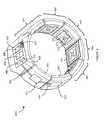
- FIG. 6is a perspective view of an exemplary wearable EMG device 600 that includes capacitive EMG sensors adapted to, in use, resistively couple to the user's skin in accordance with the present systems, articles, and methods.
- Exemplary wearable EMG device 600may, for example, form part of a human-electronics interface.
- Exemplary wearable EMG device 600is an armband designed to be worn on the forearm of a user, though a person of skill in the art will appreciate that the teachings described herein may readily be applied in wearable EMG devices designed to be worn elsewhere on the body of the user, including without limitation: on the upper arm, wrist, hand, finger, leg, foot, torso, or neck of the user.
- Device 600includes a set of eight pod structures 601 , 602 , 603 , 604 , 605 , 606 , 607 , and 608 that form physically coupled links of the wearable EMG device 600 .
- Each pod structure in the set of eight pod structures 601 , 602 , 603 , 604 , 605 , 606 , 607 , and 608is positioned adjacent and in between two other pod structures in the set of eight pod structures such that the set of pod structures forms a perimeter of an annular or closed loop configuration.
- pod structure 601is positioned adjacent and in between pod structures 602 and 608 at least approximately on a perimeter of the annular or closed loop configuration of pod structures
- pod structure 602is positioned adjacent and in between pod structures 601 and 603 at least approximately on the perimeter of the annular or closed loop configuration
- pod structure 603is positioned adjacent and in between pod structures 602 and 604 at least approximately on the perimeter of the annular or closed loop configuration
- Each of pod structures 601 , 602 , 603 , 604 , 605 , 606 , 607 , and 608is physically coupled to the two adjacent pod structures by at least one adaptive coupler (not visible in FIG. 6 ).
- pod structure 601is physically coupled to pod structure 608 by an adaptive coupler and to pod structure 602 by an adaptive coupler.
- adaptive coupleris used throughout this specification and the appended claims to denote a system, article or device that provides flexible, adjustable, modifiable, extendable, extensible, or otherwise “adaptive” physical coupling.
- Adaptive couplingis physical coupling between two objects that permits limited motion of the two objects relative to one another.
- An example of an adaptive coupleris an elastic material such as an elastic band.
- each of pod structures 601 , 602 , 603 , 604 , 605 , 606 , 607 , and 608 in the set of eight pod structuresmay be adaptively physically coupled to the two adjacent pod structures by at least one elastic band.
- the set of eight pod structuresmay be physically bound in the annular or closed loop configuration by a single elastic band that couples over or through all pod structures or by multiple separate elastic bands that couple between adjacent pairs of pod structures or between groups of adjacent pairs of pod structures.
- Device 600is depicted in FIG. 6 with the at least one adaptive coupler completely retracted and contained within the eight pod structures 601 , 602 , 603 , 604 , 605 , 606 , 607 , and 608 (and therefore the at least one adaptive coupler is not visible in FIG. 6 ).
- pod structureis used to refer to an individual link, segment, pod, section, structure, component, etc. of a wearable EMG device.
- an “individual link, segment, pod, section, structure, component, etc.”i.e., a “pod structure”
- pod structures 601 and 602 of device 600can each be moved or displaced relative to one another within the constraints imposed by the adaptive coupler providing adaptive physical coupling therebetween.
- each of pod structures 601 , 602 , 603 , 604 , 605 , 606 , 607 , and 608may correspond to a respective housing (e.g., housing 490 of sensor 400 ) of a respective capacitive EMG sensor adapted to, in use, resistively couple to the user's skin in accordance with the present systems, articles, and methods.
- Device 600includes eight pod structures 601 , 602 , 603 , 604 , 605 , 606 , 607 , and 608 that form physically coupled links thereof.
- Wearable EMG devices employing pod structurese.g., device 600
- Device 600is used herein as exemplary wearable EMG device designs, while the present systems, articles, and methods may be applied to wearable EMG devices that do not employ pod structures (or that employ any number of pod structures).
- descriptions relating to pod structurese.g., functions and/or components of pod structures
- each of pod structures 601 , 602 , 603 , 604 , 605 , 606 , 607 , and 608comprises a respective housing, with each housing being akin to a respective one of housing 490 from sensor 400 .
- Each housingmay comprise substantially rigid material that encloses a respective inner volume. Details of the components contained within the housings (i.e., within the inner volumes of the housings) of pod structures 601 , 602 , 603 , 604 , 605 , 606 , 607 , and 608 are not necessarily visible in FIG. 6 (e.g., the housings may be formed of material that is optically opaque).
- any or all of pod structures 601 , 602 , 603 , 604 , 605 , 606 , 607 , and/or 608may include circuitry (i.e., electrical and/or electronic circuitry).
- circuitryi.e., electrical and/or electronic circuitry
- a first pod structure 601is shown containing circuitry 611 (i.e., circuitry 611 is contained in the inner volume of the housing of pod structure 601 ), a second pod structure 602 is shown containing circuitry 612 , and a third pod structure 608 is shown containing circuitry 618 .
- the circuitry in any or all pod structuresmay be communicatively coupled to the circuitry in at least one other pod structure by at least one communicative pathway (e.g., by at least one electrically conductive pathway and/or by at least one optical pathway).
- FIG. 6shows a first set of communicative pathways 621 providing communicative coupling between circuitry 618 of pod structure 608 and circuitry 611 of pod structure 601 , and a second set of communicative pathways 622 providing communicative coupling between circuitry 611 of pod structure 601 and circuitry 612 of pod structure 602 .
- communicativeas in “communicative pathway,” “communicative coupling,” and in variants such as “communicatively coupled,” is generally used to refer to any engineered arrangement for transferring and/or exchanging information.
- exemplary communicative pathwaysinclude, but are not limited to, electrically conductive pathways (e.g., electrically conductive wires, electrically conductive traces), magnetic pathways (e.g., magnetic media), and/or optical pathways (e.g., optical fiber), and exemplary communicative couplings include, but are not limited to, electrical couplings, magnetic couplings, and/or optical couplings.
- Each capacitive EMG sensor 610is responsive to muscle activity of the user, meaning that each capacitive EMG sensor 610 included in device 600 to detect muscle activity of a user and to provide electrical signals in response to the detected muscle activity.
- each of pod structures 601 , 602 , 603 , 604 , 605 , 606 , and 607may be referred to as a respective “sensor pod.”
- the term “sensor pod”is used to denote an individual pod structure that includes at least one sensor responsive to (i.e., to detect and provide at least one signal in response to) muscle activity of a user.
- Pod structure 608 of device 600includes a processor 630 that processes the signals provided by the capacitive EMG sensors 610 of sensor pods 601 , 602 , 603 , 604 , 605 , 606 , and 607 in response to detected muscle activity.
- Pod structure 608may therefore be referred to as a “processor pod.”
- processor podis used to denote an individual pod structure that includes at least one processor to process signals.
- the processormay be any type of processor, including but not limited to: a digital microprocessor or microcontroller, an application-specific integrated circuit (ASIC), a field-programmable gate array (FPGA), a digital signal processor (DSP), a graphics processing unit (GPU), a programmable gate array (PGA), a programmable logic unit (PLU), or the like, that analyzes or otherwise processes the signals to determine at least one output, action, or function based on the signals.
- ASICapplication-specific integrated circuit
- FPGAfield-programmable gate array
- DSPdigital signal processor
- GPUgraphics processing unit
- PGAprogrammable gate array
- PLUprogrammable logic unit
- implementations that employ a digital processormay advantageously include a non-transitory processor-readable storage medium or memory communicatively coupled thereto and storing data and/or processor-executable instructions that control the operations thereof, whereas implementations that employ an ASIC, FPGA, or analog processor may or may optionally not include a non-transitory processor-readable storage medium, or may include on-board registers or other non-transitory storage structures.
- processor podincludes a capacitive EMG sensor 610 (not visible in FIG.
- processor pod 608could be referred to as a sensor pod.
- processor pod 608is the only pod structure that includes a processor 630 , thus processor pod 608 is the only pod structure in exemplary device 600 that can be referred to as a processor pod.
- the processor 630 in processor pod 608also processes the EMG signals provided by the capacitive EMG sensor 610 of processor pod 608 .
- multiple pod structuresmay include processors, and thus multiple pod structures may serve as processor pods.
- some pod structuresmay not include sensors, and/or some sensors and/or processors may be laid out in other configurations that do not involve pod structures.
- processor 630includes and/or is communicatively coupled to a non-transitory processor-readable storage medium or memory 640 .
- Memory 640may store processor-executable gesture identification instructions that, when executed by processor 630 , cause processor 630 to process the EMG signals from capacitive EMG sensors 610 and identify a gesture to which the EMG signals correspond.
- wearable EMG device 600includes at least one communication terminal.
- the term “communication terminal”is generally used to refer to any physical structure that provides a telecommunications link through which a data signal may enter and/or leave a device.
- a communication terminalrepresents the end (or “terminus”) of communicative signal transfer within a device and the beginning of communicative signal transfer to/from an external device (or external devices).
- device 600includes a first communication terminal 651 and a second communication terminal 652 .
- First communication terminal 651includes a wireless transmitter (i.e., a wireless communication terminal) and second communication terminal 652 includes a tethered connector port 652 .
- Wireless transmitter 651may include, for example, a Bluetooth® transmitter (or similar) and connector port 652 may include a Universal Serial Bus port, a mini-Universal Serial Bus port, a micro-Universal Serial Bus port, a SMA port, a THUNDERBOLT® port, or the like.
- device 600may also include at least one inertial sensor 660 (e.g., an inertial measurement unit, or “IMU,” that includes at least one accelerometer and/or at least one gyroscope) responsive to (i.e., to detect, sense, or measure and provide at least one signal in response to detecting, sensing, or measuring) motion effected by a user.
- IMUinertial measurement unit
- Signals provided by inertial sensor 660may be combined or otherwise processed in conjunction with signals provided by capacitive EMG sensors 610 .
- each of pod structures 601 , 602 , 603 , 604 , 605 , 606 , 607 , and 608may include circuitry (i.e., electrical and/or electronic circuitry).
- FIG. 6depicts circuitry 611 inside the inner volume of sensor pod 601 , circuitry 612 inside the inner volume of sensor pod 602 , and circuitry 618 inside the inner volume of processor pod 618 .
- the circuitry in any or all of pod structures 601 , 602 , 603 , 604 , 605 , 606 , 607 , and 608may include one or more discrete component capacitor(s), resistor(s), and/or amplifier(s) in the configuration(s) previously described for sensors 200 , 300 , and/or 400 .
- Device 600may also include at least one battery (not shown in FIG. 6 ) to provide a portable power source for device 600 .
- Each of the electrodes 671 , 672 , and 673 of each EMG sensor 610may be carried by a respective substrate, and the respective circuitry (e.g., 611 , 612 , and 618 ) of each pod structure 601 , 602 , 603 , 604 , 605 , 606 , 607 , and 608 may be carried by the same substrate and include the communicative pathway, amplifier, capacitor, and resistor elements previously described for sensors 200 , 300 , and 400 .
- each respective EMG sensor 610 of each pod structure 601 , 602 , 603 , 604 , 605 , 606 , 607 , and 608may include a respective substrate, with the first and second sensor electrodes 671 , 672 and the ground electrode 673 of each pod structure 601 , 602 , 603 , 604 , 605 , 606 , 607 , and 608 carried by a first surface of the substrate and circuitry 611 , 612 , 618 carried by a second surface of the substrate, the second surface being opposite the first surface across a thickness of the substrate.
- the circuitryrespectively includes at least an amplifier (e.g., 250 , 350 , 450 ), a first electrically conductive pathway (e.g., 211 a, 311 a, 411 a ) that communicatively couples the first sensor electrode 671 and the amplifier, a first capacitor (e.g., 221 a, 321 a, 421 a ) electrically coupled in series between the first sensor electrode 671 and the amplifier in the first electrically conductive pathway, and a first resistor (e.g., 231 a, 331 a, 431 a ) electrically coupled in series between the first sensor electrode and the amplifier in the first electrically conductive pathway.
- an amplifiere.g., 250 , 350 , 450
- a first electrically conductive pathwaye.g., 211 a, 311 a, 411 a
- a first capacitore.g., 221 a, 321 a, 421 a
- a first resistore
- the capacitive EMG sensors 610 of wearable EMG device 600are differential sensors that each implement two respective sensor electrodes 671 , 672 and a respective ground electrode 673 , though the teachings herein may similarly be applied to wearable EMG devices that employ single-ended capacitive EMG sensors that each implement a respective single sensor electrode and/or capacitive EMG sensors that share a common ground electrode.
- Device 600employs a set of communicative pathways (e.g., 621 and 622 ) to route the signals that are output by sensor pods 601 , 602 , 603 , 604 , 605 , 606 , and 607 to processor pod 608 .
- communicative pathwayse.g., 621 and 622
- Each respective pod structure 601 , 602 , 603 , 604 , 605 , 606 , 607 , and 608 in device 600is communicatively coupled to, over ,or through at least one of the two other pod structures between which the respective pod structure is positioned by at least one respective communicative pathway from the set of communicative pathways.
- Each communicative pathway(e.g., 621 and 622 ) may be realized in any communicative form, including but not limited to: electrically conductive wires or cables, ribbon cables, fiber-optic cables, optical/photonic waveguides, electrically conductive traces carried by a rigid printed circuit board, electrically conductive traces carried by a flexible printed circuit board, and/or electrically conductive traces carried by a stretchable printed circuit board.
- Device 600 from FIG. 6represents an example of a wearable EMG device that incorporates the teachings of the present systems, articles, and methods, though the teachings of the present systems, articles, and methods may be applicable to any wearable EMG device that includes at least one EMG sensor.
- infinitive verb formsare often used. Examples include, without limitation: “to detect,” “to provide,” “to transmit,” “to communicate,” “to process,” “to route,” and the like. Unless the specific context requires otherwise, such infinitive verb forms are used in an open, inclusive sense, that is as “to, at least, detect,” to, at least, provide,” “to, at least, transmit,” and so on.
- a “non-transitory processor-readable medium”can be any element that can store the program associated with logic and/or information for use by or in connection with the instruction execution system, apparatus, and/or device.
- the processor-readable mediumcan be, for example, but is not limited to, an electronic, magnetic, optical, electromagnetic, infrared, or semiconductor system, apparatus or device, provided that it is tangible and/or non-transitory.
- processor-readable mediumMore specific examples (a non-exhaustive list) of the processor-readable medium would include the following: a portable computer diskette (magnetic, compact flash card, secure digital, or the like), a random access memory (RAM), a read-only memory (ROM), an erasable programmable read-only memory (EPROM, EEPROM, or Flash memory), a portable compact disc read-only memory (CDROM), digital tape, and other non-transitory media.
- portable computer diskettemagnetic, compact flash card, secure digital, or the like
- RAMrandom access memory
- ROMread-only memory
- EPROMerasable programmable read-only memory
- Flash memoryerasable programmable read-only memory
- CDROMcompact disc read-only memory
- digital tapedigital tape
Landscapes
- Engineering & Computer Science (AREA)
- Life Sciences & Earth Sciences (AREA)
- Health & Medical Sciences (AREA)
- Microelectronics & Electronic Packaging (AREA)
- Heart & Thoracic Surgery (AREA)
- Surgery (AREA)
- Pathology (AREA)
- Biomedical Technology (AREA)
- Physics & Mathematics (AREA)
- Medical Informatics (AREA)
- Molecular Biology (AREA)
- Biophysics (AREA)
- Animal Behavior & Ethology (AREA)
- General Health & Medical Sciences (AREA)
- Public Health (AREA)
- Veterinary Medicine (AREA)
- Measurement And Recording Of Electrical Phenomena And Electrical Characteristics Of The Living Body (AREA)
- Manufacturing & Machinery (AREA)
Abstract
Description
Claims (5)
Priority Applications (8)
| Application Number | Priority Date | Filing Date | Title |
|---|---|---|---|
| US15/799,628US10251577B2 (en) | 2013-11-27 | 2017-10-31 | Systems, articles, and methods for electromyography sensors |
| US16/292,609US10898101B2 (en) | 2013-11-27 | 2019-03-05 | Systems, articles, and methods for electromyography sensors |
| US17/141,646US11666264B1 (en) | 2013-11-27 | 2021-01-05 | Systems, articles, and methods for electromyography sensors |
| US17/899,580US20230073303A1 (en) | 2013-08-16 | 2022-08-30 | Wearable devices for sensing neuromuscular signals using a small number of sensor pairs, and methods of manufacturing the wearable devices |
| US17/979,735US11921471B2 (en) | 2013-08-16 | 2022-11-02 | Systems, articles, and methods for wearable devices having secondary power sources in links of a band for providing secondary power in addition to a primary power source |
| US18/887,033US20250013206A1 (en) | 2013-08-16 | 2024-09-16 | Wearable devices and associated band structures for sensing neuromuscular signals using sensor pairs with a communicative pathway to a processor |
| US18/908,662US20250028286A1 (en) | 2013-08-16 | 2024-10-07 | Wearable devices and associated band structures for sensing neuromuscular signals and identifying hand gestures and methods of use thereof |
| US19/211,105US20250278062A1 (en) | 2013-08-16 | 2025-05-16 | Wearable devices and associated band structures for sensing neuromuscular signals and identifying hand gestures and methods of use thereof |
Applications Claiming Priority (3)
| Application Number | Priority Date | Filing Date | Title |
|---|---|---|---|
| US201361909786P | 2013-11-27 | 2013-11-27 | |
| US14/553,657US10188309B2 (en) | 2013-11-27 | 2014-11-25 | Systems, articles, and methods for electromyography sensors |
| US15/799,628US10251577B2 (en) | 2013-11-27 | 2017-10-31 | Systems, articles, and methods for electromyography sensors |
Related Parent Applications (1)
| Application Number | Title | Priority Date | Filing Date |
|---|---|---|---|
| US14/553,657DivisionUS10188309B2 (en) | 2013-08-16 | 2014-11-25 | Systems, articles, and methods for electromyography sensors |
Related Child Applications (1)
| Application Number | Title | Priority Date | Filing Date |
|---|---|---|---|
| US16/292,609ContinuationUS10898101B2 (en) | 2013-08-16 | 2019-03-05 | Systems, articles, and methods for electromyography sensors |
Publications (2)
| Publication Number | Publication Date |
|---|---|
| US20180064363A1 US20180064363A1 (en) | 2018-03-08 |
| US10251577B2true US10251577B2 (en) | 2019-04-09 |
Family
ID=53183205
Family Applications (5)
| Application Number | Title | Priority Date | Filing Date |
|---|---|---|---|
| US14/553,657Active2037-04-11US10188309B2 (en) | 2013-08-16 | 2014-11-25 | Systems, articles, and methods for electromyography sensors |
| US15/799,628ActiveUS10251577B2 (en) | 2013-08-16 | 2017-10-31 | Systems, articles, and methods for electromyography sensors |
| US16/057,573ActiveUS10362958B2 (en) | 2013-11-27 | 2018-08-07 | Systems, articles, and methods for electromyography sensors |
| US16/292,609Active2034-12-15US10898101B2 (en) | 2013-08-16 | 2019-03-05 | Systems, articles, and methods for electromyography sensors |
| US17/141,646Active2035-05-28US11666264B1 (en) | 2013-08-16 | 2021-01-05 | Systems, articles, and methods for electromyography sensors |
Family Applications Before (1)
| Application Number | Title | Priority Date | Filing Date |
|---|---|---|---|
| US14/553,657Active2037-04-11US10188309B2 (en) | 2013-08-16 | 2014-11-25 | Systems, articles, and methods for electromyography sensors |
Family Applications After (3)
| Application Number | Title | Priority Date | Filing Date |
|---|---|---|---|
| US16/057,573ActiveUS10362958B2 (en) | 2013-11-27 | 2018-08-07 | Systems, articles, and methods for electromyography sensors |
| US16/292,609Active2034-12-15US10898101B2 (en) | 2013-08-16 | 2019-03-05 | Systems, articles, and methods for electromyography sensors |
| US17/141,646Active2035-05-28US11666264B1 (en) | 2013-08-16 | 2021-01-05 | Systems, articles, and methods for electromyography sensors |
Country Status (2)
| Country | Link |
|---|---|
| US (5) | US10188309B2 (en) |
| WO (1) | WO2015081113A1 (en) |
Cited By (34)
| Publication number | Priority date | Publication date | Assignee | Title |
|---|---|---|---|---|
| US10592001B2 (en) | 2018-05-08 | 2020-03-17 | Facebook Technologies, Llc | Systems and methods for improved speech recognition using neuromuscular information |
| US10656711B2 (en) | 2016-07-25 | 2020-05-19 | Facebook Technologies, Llc | Methods and apparatus for inferring user intent based on neuromuscular signals |
| US10684692B2 (en) | 2014-06-19 | 2020-06-16 | Facebook Technologies, Llc | Systems, devices, and methods for gesture identification |
| US10687759B2 (en) | 2018-05-29 | 2020-06-23 | Facebook Technologies, Llc | Shielding techniques for noise reduction in surface electromyography signal measurement and related systems and methods |
| US10772519B2 (en) | 2018-05-25 | 2020-09-15 | Facebook Technologies, Llc | Methods and apparatus for providing sub-muscular control |
| US10817795B2 (en) | 2018-01-25 | 2020-10-27 | Facebook Technologies, Llc | Handstate reconstruction based on multiple inputs |
| US10842407B2 (en) | 2018-08-31 | 2020-11-24 | Facebook Technologies, Llc | Camera-guided interpretation of neuromuscular signals |
| US10898101B2 (en) | 2013-11-27 | 2021-01-26 | Facebook Technologies, Llc | Systems, articles, and methods for electromyography sensors |
| US10905383B2 (en) | 2019-02-28 | 2021-02-02 | Facebook Technologies, Llc | Methods and apparatus for unsupervised one-shot machine learning for classification of human gestures and estimation of applied forces |
| US10921764B2 (en) | 2018-09-26 | 2021-02-16 | Facebook Technologies, Llc | Neuromuscular control of physical objects in an environment |
| US10937414B2 (en) | 2018-05-08 | 2021-03-02 | Facebook Technologies, Llc | Systems and methods for text input using neuromuscular information |
| US10970936B2 (en) | 2018-10-05 | 2021-04-06 | Facebook Technologies, Llc | Use of neuromuscular signals to provide enhanced interactions with physical objects in an augmented reality environment |
| US10970374B2 (en) | 2018-06-14 | 2021-04-06 | Facebook Technologies, Llc | User identification and authentication with neuromuscular signatures |
| US10990174B2 (en) | 2016-07-25 | 2021-04-27 | Facebook Technologies, Llc | Methods and apparatus for predicting musculo-skeletal position information using wearable autonomous sensors |
| US11000211B2 (en) | 2016-07-25 | 2021-05-11 | Facebook Technologies, Llc | Adaptive system for deriving control signals from measurements of neuromuscular activity |
| US11045137B2 (en) | 2018-07-19 | 2021-06-29 | Facebook Technologies, Llc | Methods and apparatus for improved signal robustness for a wearable neuromuscular recording device |
| US11069148B2 (en) | 2018-01-25 | 2021-07-20 | Facebook Technologies, Llc | Visualization of reconstructed handstate information |
| US11079846B2 (en) | 2013-11-12 | 2021-08-03 | Facebook Technologies, Llc | Systems, articles, and methods for capacitive electromyography sensors |
| US11179066B2 (en) | 2018-08-13 | 2021-11-23 | Facebook Technologies, Llc | Real-time spike detection and identification |
| US11216069B2 (en) | 2018-05-08 | 2022-01-04 | Facebook Technologies, Llc | Systems and methods for improved speech recognition using neuromuscular information |
| US11331045B1 (en) | 2018-01-25 | 2022-05-17 | Facebook Technologies, Llc | Systems and methods for mitigating neuromuscular signal artifacts |
| US11337652B2 (en) | 2016-07-25 | 2022-05-24 | Facebook Technologies, Llc | System and method for measuring the movements of articulated rigid bodies |
| US11481031B1 (en) | 2019-04-30 | 2022-10-25 | Meta Platforms Technologies, Llc | Devices, systems, and methods for controlling computing devices via neuromuscular signals of users |
| US11481030B2 (en) | 2019-03-29 | 2022-10-25 | Meta Platforms Technologies, Llc | Methods and apparatus for gesture detection and classification |
| US11493993B2 (en) | 2019-09-04 | 2022-11-08 | Meta Platforms Technologies, Llc | Systems, methods, and interfaces for performing inputs based on neuromuscular control |
| US11567573B2 (en) | 2018-09-20 | 2023-01-31 | Meta Platforms Technologies, Llc | Neuromuscular text entry, writing and drawing in augmented reality systems |
| US11635736B2 (en) | 2017-10-19 | 2023-04-25 | Meta Platforms Technologies, Llc | Systems and methods for identifying biological structures associated with neuromuscular source signals |
| US11644799B2 (en) | 2013-10-04 | 2023-05-09 | Meta Platforms Technologies, Llc | Systems, articles and methods for wearable electronic devices employing contact sensors |
| US11797087B2 (en) | 2018-11-27 | 2023-10-24 | Meta Platforms Technologies, Llc | Methods and apparatus for autocalibration of a wearable electrode sensor system |
| US11868531B1 (en) | 2021-04-08 | 2024-01-09 | Meta Platforms Technologies, Llc | Wearable device providing for thumb-to-finger-based input gestures detected based on neuromuscular signals, and systems and methods of use thereof |
| US11907423B2 (en) | 2019-11-25 | 2024-02-20 | Meta Platforms Technologies, Llc | Systems and methods for contextualized interactions with an environment |
| US11921471B2 (en) | 2013-08-16 | 2024-03-05 | Meta Platforms Technologies, Llc | Systems, articles, and methods for wearable devices having secondary power sources in links of a band for providing secondary power in addition to a primary power source |
| US11961494B1 (en) | 2019-03-29 | 2024-04-16 | Meta Platforms Technologies, Llc | Electromagnetic interference reduction in extended reality environments |
| US12089953B1 (en) | 2019-12-04 | 2024-09-17 | Meta Platforms Technologies, Llc | Systems and methods for utilizing intrinsic current noise to measure interface impedances |
Families Citing this family (45)
| Publication number | Priority date | Publication date | Assignee | Title |
|---|---|---|---|---|
| US10921886B2 (en) | 2012-06-14 | 2021-02-16 | Medibotics Llc | Circumferential array of electromyographic (EMG) sensors |
| US20140198034A1 (en) | 2013-01-14 | 2014-07-17 | Thalmic Labs Inc. | Muscle interface device and method for interacting with content displayed on wearable head mounted displays |
| WO2014186370A1 (en) | 2013-05-13 | 2014-11-20 | Thalmic Labs Inc. | Systems, articles and methods for wearable electronic devices that accommodate different user forms |
| US11426123B2 (en) | 2013-08-16 | 2022-08-30 | Meta Platforms Technologies, Llc | Systems, articles and methods for signal routing in wearable electronic devices that detect muscle activity of a user using a set of discrete and separately enclosed pod structures |
| US9788789B2 (en) | 2013-08-30 | 2017-10-17 | Thalmic Labs Inc. | Systems, articles, and methods for stretchable printed circuit boards |
| US11071498B2 (en) | 2013-09-17 | 2021-07-27 | Medibotics Llc | Smart clothing with inertial, strain, and electromyographic sensors for human motion capture |
| US11892286B2 (en) | 2013-09-17 | 2024-02-06 | Medibotics Llc | Motion recognition clothing [TM] with an electroconductive mesh |
| US11304628B2 (en) | 2013-09-17 | 2022-04-19 | Medibotics Llc | Smart clothing with dual inertial sensors and dual stretch sensors for human motion capture |
| JP2017509386A (en) | 2014-02-14 | 2017-04-06 | サルミック ラブス インコーポレイテッド | System, product and method for elastic electrical cable and wearable electronic device using the same |
| US10199008B2 (en) | 2014-03-27 | 2019-02-05 | North Inc. | Systems, devices, and methods for wearable electronic devices as state machines |
| US9807221B2 (en) | 2014-11-28 | 2017-10-31 | Thalmic Labs Inc. | Systems, devices, and methods effected in response to establishing and/or terminating a physical communications link |
| US10078435B2 (en) | 2015-04-24 | 2018-09-18 | Thalmic Labs Inc. | Systems, methods, and computer program products for interacting with electronically displayed presentation materials |
| CN105012057B (en)* | 2015-07-30 | 2017-04-26 | 沈阳工业大学 | Intelligent artificial limb based on double-arm electromyogram and attitude information acquisition and motion classifying method |
| JP6506653B2 (en)* | 2015-07-30 | 2019-04-24 | 日本メクトロン株式会社 | Stretchable wiring board |
| US10449672B2 (en)* | 2016-03-14 | 2019-10-22 | California Institute Of Technology | Wearable electromyography sensor array using conductive cloth electrodes for human-robot interactions |
| JP6405334B2 (en) | 2016-04-18 | 2018-10-17 | 日本メクトロン株式会社 | Stretchable wiring board and method for manufacturing stretchable wiring board |
| CN109475737B (en)* | 2016-07-13 | 2022-09-16 | 特拉维夫大学拉莫特有限公司 | Novel biological signal acquisition method and algorithm for wearable device |
| KR101823496B1 (en)* | 2016-08-22 | 2018-01-31 | 조선대학교산학협력단 | Wearable device for measuring edema index and method of measuring edema index using thereof |
| US10902743B2 (en) | 2017-04-14 | 2021-01-26 | Arizona Board Of Regents On Behalf Of Arizona State University | Gesture recognition and communication |
| TWI634527B (en)* | 2017-05-23 | 2018-09-01 | 財團法人工業技術研究院 | Sensing system |
| WO2018218037A1 (en)* | 2017-05-26 | 2018-11-29 | Analog Devices, Inc. | Biopotential measurement system and apparatus |
| US20190150777A1 (en)* | 2017-11-17 | 2019-05-23 | Ctrl-Labs Corporation | Dual-supply analog circuitry for sensing surface emg signals |
| US10504286B2 (en) | 2018-01-25 | 2019-12-10 | Ctrl-Labs Corporation | Techniques for anonymizing neuromuscular signal data |
| EP3742961A4 (en) | 2018-01-25 | 2021-03-31 | Facebook Technologies, Inc. | CALIBRATION TECHNIQUES FOR HAND REPRESENTATION MODELING USING NEUROMUSCULAR SIGNALS |
| EP3743901A4 (en) | 2018-01-25 | 2021-03-31 | Facebook Technologies, Inc. | REAL-TIME PROCESSING OF HAND REPRESENTATION MODEL ESTIMATES |
| WO2019147958A1 (en) | 2018-01-25 | 2019-08-01 | Ctrl-Labs Corporation | User-controlled tuning of handstate representation model parameters |
| US11844602B2 (en) | 2018-03-05 | 2023-12-19 | The Medical Research Infrastructure And Health Services Fund Of The Tel Aviv Medical Center | Impedance-enriched electrophysiological measurements |
| KR102089139B1 (en)* | 2018-03-15 | 2020-03-13 | 김영진 | Capacitive type user intension sensing apparatus |
| CA3094526A1 (en) | 2018-03-23 | 2019-09-26 | The Alfred E. Mann Foundation For Scientific Research | Skin patches for sensing or affecting a body parameter |
| CN108563333B (en)* | 2018-04-12 | 2022-02-01 | 京东方科技集团股份有限公司 | Wearable device and control method thereof |
| TWI689859B (en) | 2019-03-19 | 2020-04-01 | 國立臺灣科技大學 | System for recognizing user gestures according to mechanomyogram detected from user's wrist and method thereof |
| WO2021015454A1 (en) | 2019-07-19 | 2021-01-28 | Samsung Electronics Co., Ltd. | Electronic device extending sensing area |
| US11803246B2 (en)* | 2019-08-22 | 2023-10-31 | University Of Maryland, College Park | Systems and methods for recognizing gesture |
| US11974857B2 (en) | 2019-10-08 | 2024-05-07 | Unlimited Tomorrow, Inc. | Biometric sensor array |
| JP7328869B2 (en)* | 2019-10-31 | 2023-08-17 | 日本光電工業株式会社 | Muscle relaxation monitoring device and calibration processing method |
| USD948057S1 (en)* | 2019-12-20 | 2022-04-05 | Neosensory, Inc. | Haptic wristband |
| WO2021130683A1 (en) | 2019-12-23 | 2021-07-01 | Alimetry Limited | Electrode patch and connection system |
| WO2022026177A1 (en)* | 2020-07-30 | 2022-02-03 | Battelle Memorial Institute | Stretchable fabric sleeve for functional electrical stimulation and/or electromyography |
| WO2023105538A1 (en)* | 2021-12-08 | 2023-06-15 | Life And Limb Pvt Ltd | Electromyography sensor |
| US20230309829A1 (en)* | 2022-02-25 | 2023-10-05 | Meta Platforms Technologies, Llc | Smart Electrode Structures Made of a Conductive Deformable Material and Methods of Manufacturing the Smart Electrode Structures to Have Signal-Processing Components Embedded in the Conductive Deformable Material |
| US20230270363A1 (en)* | 2022-02-25 | 2023-08-31 | Meta Platforms Technologies, Llc | Smart Electrodes for Sensing Signals and Processing Signals Using Internally-Housed Signal-Processing Components at Wearable Devices and Wearable Devices Incorporating the Smart Electrodes |
| WO2023164211A1 (en)* | 2022-02-25 | 2023-08-31 | Meta Platforms Technologies, Llc | Smart electrodes for sensing signals and processing signals using internally-housed signal-processing components at wearable devices and wearable devices incorporating the smart electrodes |
| TWI823574B (en)* | 2022-09-16 | 2023-11-21 | 國立臺北科技大學 | Embedded smart module |
| US12411549B2 (en)* | 2022-11-02 | 2025-09-09 | Meta Platforms Technologies, Llc | Wearable band structure having a band portion including embedded structural members with signal-processing components and another band portion not including any electrical components, and systems, devices, and methods of manufacturing thereof |
| WO2025084008A1 (en)* | 2023-10-19 | 2025-04-24 | ソニーグループ株式会社 | Biological signal detection device and biological signal detection system |
Citations (245)
| Publication number | Priority date | Publication date | Assignee | Title |
|---|---|---|---|---|
| US1411995A (en) | 1919-06-20 | 1922-04-04 | Raymond W Dull | Link belt |
| US3620208A (en) | 1969-11-03 | 1971-11-16 | Atomic Energy Commission | Ekg amplifying electrode pickup |
| US3880146A (en) | 1973-06-04 | 1975-04-29 | Donald B Everett | Noise compensation techniques for bioelectric potential sensing |
| US4602639A (en) | 1982-07-01 | 1986-07-29 | Mardice Holding S.A.R.L. | Method and apparatus for contactless measurement of charge concentrations and potential differences in biological organisms |
| US4705408A (en) | 1986-04-01 | 1987-11-10 | Altop S.A. | Watch mounted on a clip |
| EP0301790A2 (en) | 1987-07-24 | 1989-02-01 | BioControl Systems, Inc. | Biopotential digital controller for music and video applications |
| US4817064A (en) | 1985-02-05 | 1989-03-28 | Milles Victor A | Structure for fabricating jewelry parts or wrist watches |
| US5003978A (en) | 1985-08-21 | 1991-04-02 | Technology 21, Inc. | Non-polarizable dry biomedical electrode |
| USD322227S (en) | 1989-03-23 | 1991-12-10 | North American Watch Company | Watch |
| US5081852A (en) | 1991-02-14 | 1992-01-21 | Cox Michael F | Display bracelet |
| US5251189A (en) | 1992-10-16 | 1993-10-05 | Timex Corporation | Wristwatch radiotelephone |
| USD348660S (en) | 1993-04-29 | 1994-07-12 | Micro-Integration Corp. | Hand-held computer input device |
| US5445869A (en) | 1993-01-21 | 1995-08-29 | Matsushita Electric Industrial Co., Ltd. | Composite flexible substrate |
| DE4412278A1 (en) | 1994-04-09 | 1995-10-12 | Bosch Gmbh Robert | Circuit board with both rigid and flexible regions |
| US5482051A (en) | 1994-03-10 | 1996-01-09 | The University Of Akron | Electromyographic virtual reality system |
| US5605059A (en) | 1995-03-09 | 1997-02-25 | Woodward; Robin | Sleeved bangle bracelet |
| US5683404A (en) | 1996-06-05 | 1997-11-04 | Metagen, Llc | Clamp and method for its use |
| US6032530A (en) | 1994-04-29 | 2000-03-07 | Advantedge Systems Inc. | Biofeedback system for sensing body motion and flexure |
| US6184847B1 (en) | 1998-09-22 | 2001-02-06 | Vega Vista, Inc. | Intuitive control of portable data displays |
| US6238338B1 (en) | 1999-07-19 | 2001-05-29 | Altec, Inc. | Biosignal monitoring system and method |
| US6244873B1 (en) | 1998-10-16 | 2001-06-12 | At&T Corp. | Wireless myoelectric control apparatus and methods |
| US20020032386A1 (en) | 2000-04-17 | 2002-03-14 | Sackner Marvin A. | Systems and methods for ambulatory monitoring of physiological signs |
| US6377277B1 (en) | 1995-08-10 | 2002-04-23 | Sega Enterprises, Ltd. | Virtual image generation apparatus and method |
| US20020077534A1 (en) | 2000-12-18 | 2002-06-20 | Human Bionics Llc | Method and system for initiating activity based on sensed electrophysiological data |
| USD459352S1 (en) | 2001-08-10 | 2002-06-25 | Michael C. Giovanniello | Wireless mouse wristband |
| US6487906B1 (en) | 2000-09-18 | 2002-12-03 | Advantedge Systems Inc | Flexible film sensor system for monitoring body motion |
| US6510333B1 (en) | 2000-05-16 | 2003-01-21 | Mark J. Licata | Sensor for biopotential measurements |
| US20030036691A1 (en) | 2000-08-10 | 2003-02-20 | Stanaland Thomas G. | Capacitively coupled electrode system with variable capacitance for sensing potentials at the surface of tissue |
| US6527711B1 (en) | 1999-10-18 | 2003-03-04 | Bodymedia, Inc. | Wearable human physiological data sensors and reporting system therefor |
| US20030051505A1 (en) | 2001-09-14 | 2003-03-20 | Robertson Catrina M. | Selectively self-adjustable jewelry item and method of making same |
| US20030144586A1 (en) | 2002-01-31 | 2003-07-31 | Keisuke Tsubata | Biological information sensing device |
| US6619836B1 (en) | 1999-11-11 | 2003-09-16 | The Swatch Group Management Services Ag | Electronic wristwatch including a printed circuit incorporated in a flexible wristband |
| US6720984B1 (en) | 2000-06-13 | 2004-04-13 | The United States Of America As Represented By The Administrator Of The National Aeronautics And Space Administration | Characterization of bioelectric potentials |
| US20040073104A1 (en) | 2001-02-23 | 2004-04-15 | Riccardo Brun Del Re | Enhanced pickup-electrode |
| US6743982B2 (en) | 2000-11-29 | 2004-06-01 | Xerox Corporation | Stretchable interconnects using stress gradient films |
| US20040194500A1 (en) | 2003-04-03 | 2004-10-07 | Broadway Entertainment, Inc. | Article of jewelry |
| US6807438B1 (en) | 1999-08-26 | 2004-10-19 | Riccardo Brun Del Re | Electric field sensor |
| US20040210165A1 (en) | 2001-10-26 | 2004-10-21 | George Marmaropoulos | Selectively applied wearable medical sensors |
| US20050012715A1 (en) | 2003-06-12 | 2005-01-20 | Peter Charles Shann Hubird Ford | Method, system, and software for interactive communication and analysis |
| USD502662S1 (en) | 2004-02-23 | 2005-03-08 | Broadway Entertainment, Inc. | Bracelet |
| US6865409B2 (en) | 2001-11-07 | 2005-03-08 | Kinesense, Inc. | Surface electromyographic electrode assembly |
| USD502661S1 (en) | 2004-02-23 | 2005-03-08 | Broadway Entertainment, Inc. | Bracelet |
| US20050070227A1 (en) | 2003-09-30 | 2005-03-31 | Chih-Hsiang Shen | Detecting and actuating method of bluetooth devices and a control system thereof |
| USD503646S1 (en) | 2004-02-23 | 2005-04-05 | Broadway Entertainment, Inc. | Bracelet |
| US6880364B1 (en) | 1998-04-23 | 2005-04-19 | Michael F. Vidolin | Friendship band with exchangeable closed loop members |
| US20050119701A1 (en) | 2002-03-29 | 2005-06-02 | Koninklijka Philips Electronics N.V. | Wearable monitoring system and method of manufacturing of a wearable monitoring system |
| US6927343B2 (en) | 2002-01-09 | 2005-08-09 | Fujitsu Limited | Contactor for testing miniaturized devices and components |
| US20050177038A1 (en) | 2002-03-26 | 2005-08-11 | Hans Kolpin | Skin impedance matched biopotential electrode |
| US6965842B2 (en) | 2001-06-01 | 2005-11-15 | Sony Corporation | User input apparatus |
| US6972734B1 (en) | 1999-06-11 | 2005-12-06 | Canon Kabushiki Kaisha | Mixed reality apparatus and mixed reality presentation method |
| US6984208B2 (en) | 2002-08-01 | 2006-01-10 | The Hong Kong Polytechnic University | Method and apparatus for sensing body gesture, posture and movement |
| US20060037359A1 (en) | 2004-08-17 | 2006-02-23 | Carissa Stinespring | Adjustable fashion mechanism |
| US20060061544A1 (en) | 2004-09-20 | 2006-03-23 | Samsung Electronics Co., Ltd. | Apparatus and method for inputting keys using biological signals in head mounted display information terminal |
| US7022919B2 (en) | 2003-06-30 | 2006-04-04 | Intel Corporation | Printed circuit board trace routing method |
| US7028507B2 (en) | 2003-04-03 | 2006-04-18 | Broadway Entertainment, Inc. | Article of jewelry |
| US7086218B1 (en) | 2005-08-18 | 2006-08-08 | M & J - R & R Grosbard, Inc. | Linked ring structures |
| USD535401S1 (en) | 2005-06-21 | 2007-01-16 | Biocare Systems, Inc. | Heat and light therapy device |
| US7173437B2 (en) | 2004-06-10 | 2007-02-06 | Quantum Applied Science And Research, Inc. | Garment incorporating embedded physiological sensors |
| US7209114B2 (en) | 2000-02-28 | 2007-04-24 | Radley-Smith Philip J | Bracelet with information display and imputting capability |
| USD543212S1 (en) | 2006-01-04 | 2007-05-22 | Sony Computer Entertainment Inc. | Object for interfacing with a computer program |
| US20070132785A1 (en) | 2005-03-29 | 2007-06-14 | Ebersole John F Jr | Platform for immersive gaming |
| US7265298B2 (en) | 2003-05-30 | 2007-09-04 | The Regents Of The University Of California | Serpentine and corduroy circuits to enhance the stretchability of a stretchable electronic device |
| US7271774B2 (en) | 2005-10-21 | 2007-09-18 | Suunto Oy | Electronic wearable device |
| US7333090B2 (en) | 2002-10-07 | 2008-02-19 | Sony France S.A. | Method and apparatus for analysing gestures produced in free space, e.g. for commanding apparatus by gesture recognition |
| US20080136775A1 (en) | 2006-12-08 | 2008-06-12 | Conant Carson V | Virtual input device for computing |
| US20090007597A1 (en) | 2007-07-02 | 2009-01-08 | Hanevold Gail F | Body attached band with removal visual image pockets |
| US20090031757A1 (en) | 2007-08-01 | 2009-02-05 | Funki Llc | Modular toy bracelet |
| US20090040016A1 (en) | 2007-08-10 | 2009-02-12 | Sony Corporation | Remote controller, remote control system, and remote control method |
| US7491892B2 (en) | 2003-03-28 | 2009-02-17 | Princeton University | Stretchable and elastic interconnects |
| US20090051544A1 (en) | 2007-08-20 | 2009-02-26 | Ali Niknejad | Wearable User Interface Device, System, and Method of Use |
| JP2009050679A (en) | 2007-07-31 | 2009-03-12 | Equos Research Co Ltd | ECG sensor |
| US7517725B2 (en) | 2005-11-28 | 2009-04-14 | Xci, Inc. | System and method for separating and packaging integrated circuits |
| US20090102580A1 (en) | 2007-10-22 | 2009-04-23 | Uchaykin Sergey V | Systems, methods, and apparatus for electrical filters and input/output systems |
| US20090109241A1 (en) | 2007-10-26 | 2009-04-30 | Canon Kabushiki Kaisha | Image display system, image display apparatus, and control method thereof |
| US20090147004A1 (en) | 2007-12-06 | 2009-06-11 | Barco Nv | Method And System For Combining Images Generated By Separate Sources |
| US7558622B2 (en) | 2006-05-24 | 2009-07-07 | Bao Tran | Mesh network stroke monitoring appliance |
| US20090179824A1 (en) | 2008-01-10 | 2009-07-16 | Canon Kabushiki Kaisha | Image processing method, image processing apparatus, and system |
| US20090189867A1 (en) | 2008-01-30 | 2009-07-30 | Apple, Inc. | Auto Scanning for Multiple Frequency Stimulation Multi-Touch Sensor Panels |
| US7596393B2 (en) | 2004-12-06 | 2009-09-29 | Electronics And Telecommunications Research Institute | Wearable mobile phone using EMG and controlling method thereof |
| US20090251407A1 (en) | 2008-04-03 | 2009-10-08 | Microsoft Corporation | Device interaction with combination of rings |
| US20090258669A1 (en) | 2008-04-15 | 2009-10-15 | Hong Nie | Impulse ultra-wideband radio communication system |
| US7618260B2 (en) | 2004-02-27 | 2009-11-17 | Daniel Simon R | Wearable modular interface strap |
| US7636549B2 (en) | 2006-04-21 | 2009-12-22 | Abbott Medical Optics Inc. | Automated bonding for wireless devices |
| US20090318785A1 (en) | 2008-06-23 | 2009-12-24 | Akihiro Ishikawa | Real - time simultaneous measurement system, real - time simultaneous measurement apparatus, real-time simultaneous measurement method, and storage medium in which program is stored |
| US7640007B2 (en) | 1999-02-12 | 2009-12-29 | Fisher-Rosemount Systems, Inc. | Wireless handheld communicator in a process control environment |
| US7660126B2 (en) | 2004-04-21 | 2010-02-09 | Samsung Electronics Co., Ltd. | Flexible printed circuit board |
| US20100041974A1 (en) | 2003-08-22 | 2010-02-18 | Joseph Ting | Physiological monitoring garment |
| US7809435B1 (en) | 2006-01-11 | 2010-10-05 | Iq Biolabs, Inc. | Adjustable wireless electromyography sensor and system |
| US20100280628A1 (en) | 2003-08-21 | 2010-11-04 | University Of Tsukuba | Wearable action-assist device, and method and program for controlling wearable action-assist device |
| US20100293115A1 (en) | 2006-08-21 | 2010-11-18 | Kaveh Seyed Momen | Method, system and apparatus for real-time classification of muscle signals from self -selected intentional movements |
| US7844310B2 (en) | 2006-07-20 | 2010-11-30 | L3 Communications Corporation | Wearable communication device with contoured back |
| US20100317958A1 (en) | 2007-05-24 | 2010-12-16 | James Beck | Integrated wireless patch for physiological monitoring |
| US7870211B2 (en) | 2008-12-23 | 2011-01-11 | At&T Mobility Ii Llc | Conversation message routing supporting dynamic class transitions |
| US20110018754A1 (en) | 2008-03-28 | 2011-01-27 | Akira Tojima | Remote operation apparatus, operation target apparatus, method for controlling remote operation apparatus, method for controlling operation target apparatus, and remote operation system |
| US20110072510A1 (en) | 2009-09-23 | 2011-03-24 | At&T Intellectual Property I.L.P. | Apparatus, methods, and computer program products for entering secure passwords |
| US7925100B2 (en) | 2007-07-31 | 2011-04-12 | Microsoft Corporation | Tiled packaging of vector image data |
| US7948763B2 (en) | 2003-08-21 | 2011-05-24 | Chimei Innolux Corporation | Module with flexible printed circuit |
| US20110134026A1 (en) | 2009-12-04 | 2011-06-09 | Lg Electronics Inc. | Image display apparatus and method for operating the same |
| WO2011070554A2 (en) | 2009-12-13 | 2011-06-16 | Ringbow Ltd. | Finger-worn input devices and methods of use |
| US20110166434A1 (en) | 2008-07-07 | 2011-07-07 | Gaetano Gargiulo | System for sensing electrophysiological signals |
| US20110172503A1 (en) | 2007-07-16 | 2011-07-14 | Sunrise Medical Hhg, Inc. | Physiological Data Collection System |
| US20110181527A1 (en) | 2010-01-26 | 2011-07-28 | Jay Christopher Capela | Device, Method, and Graphical User Interface for Resizing Objects |
| USD643428S1 (en) | 2010-07-07 | 2011-08-16 | Iota, Inc. | Wearable mobile accessory |
| US20110213278A1 (en) | 2010-02-26 | 2011-09-01 | Apdm, Inc. | Movement monitoring system and apparatus for objective assessment of movement disorders |
| US20110224564A1 (en) | 2010-03-10 | 2011-09-15 | Sotera Wireless, Inc. | Body-worn vital sign monitor |
| USD646192S1 (en) | 2011-03-11 | 2011-10-04 | Jamie Renae Woode | Bracelet |
| US8054061B2 (en) | 2006-07-18 | 2011-11-08 | University Of Sussex | Electric potential sensor |
| CN102246125A (en) | 2008-10-15 | 2011-11-16 | 因文森斯公司 | Mobile devices with motion gesture recognition |
| US20120029322A1 (en) | 2009-04-02 | 2012-02-02 | Koninklijke Philips Electronics N.V. | Processing a bio-physiological signal |
| USD654622S1 (en) | 2011-09-15 | 2012-02-21 | Shih-Ling Hsu | Hair band |
| US20120053439A1 (en) | 2010-08-27 | 2012-03-01 | Antti Kustaa Antipas Ylostalo | Sensor for measuring biosignals |
| US20120051005A1 (en) | 2009-01-30 | 2012-03-01 | Universiteit Gent | Stretchable electronic device |
| US20120101357A1 (en) | 2009-05-15 | 2012-04-26 | Nox Medical | Systems and methods using flexible capacitve electrodes for measuring biosignals |
| US8170656B2 (en) | 2008-06-26 | 2012-05-01 | Microsoft Corporation | Wearable electromyography-based controllers for human-computer interface |
| US8179604B1 (en) | 2011-07-13 | 2012-05-15 | Google Inc. | Wearable marker for passive interaction |
| US8188937B1 (en) | 1999-09-06 | 2012-05-29 | Shimadzu Corporation | Body mounting type display system |
| USD661613S1 (en) | 2009-02-19 | 2012-06-12 | 1922 Manifatture Preziose Torino SpA | Jewelry |
| US8203502B1 (en) | 2011-05-25 | 2012-06-19 | Google Inc. | Wearable heads-up display with integrated finger-tracking input sensor |
| US20120157789A1 (en) | 2010-12-16 | 2012-06-21 | Nokia Corporation | Method, apparatus and computer program |
| US8207473B2 (en) | 2008-06-24 | 2012-06-26 | Imec | Method for manufacturing a stretchable electronic device |
| US20120165695A1 (en) | 2009-06-26 | 2012-06-28 | Widex A/S | Eeg monitoring apparatus and method for presenting messages therein |
| US8212859B2 (en) | 2006-10-13 | 2012-07-03 | Apple Inc. | Peripheral treatment for head-mounted displays |
| US20120182309A1 (en) | 2011-01-14 | 2012-07-19 | Research In Motion Limited | Device and method of conveying emotion in a messaging application |
| US20120188158A1 (en) | 2008-06-26 | 2012-07-26 | Microsoft Corporation | Wearable electromyography-based human-computer interface |
| US20120203076A1 (en) | 2011-02-08 | 2012-08-09 | Jean Pierre Fatta | Portable Physiological Data Monitoring Device |
| US20120209134A1 (en) | 2009-07-15 | 2012-08-16 | University Of Tsukuba | Classification estimating system and classification estimating program |
| KR20120094870A (en) | 2011-02-17 | 2012-08-27 | 주식회사 라이프사이언스테크놀로지 | System for measure of electromyogram by suit type electromyogram sensors and analisys method of rehabilitation using thereof |
| KR20120097997A (en) | 2011-02-28 | 2012-09-05 | (주)락싸 | Electric contactless electric potential sensor circuit |
| US20120226130A1 (en) | 2008-10-07 | 2012-09-06 | Mc10, Inc. | Systems, methods, and devices having stretchable integrated circuitry for sensing and delivering therapy |
| US20120265090A1 (en) | 2011-04-13 | 2012-10-18 | Fink Rainer J | System and method of acquiring uterine emg signals and wirelessly transmitting the same |
| US20120293548A1 (en) | 2011-05-20 | 2012-11-22 | Microsoft Corporation | Event augmentation with real-time information |
| US20120302858A1 (en) | 2010-02-01 | 2012-11-29 | Widex A/S | Portable eeg monitor system with wireless communication |
| US20120323521A1 (en) | 2009-09-29 | 2012-12-20 | Commissariat A L'energie Atomique Et Aux Energies Al Ternatives | System and method for recognizing gestures |
| US20130005303A1 (en) | 2011-06-29 | 2013-01-03 | Song Seungkyu | Terminal and control method thereof |
| US8355671B2 (en) | 2008-01-04 | 2013-01-15 | Kopin Corporation | Method and apparatus for transporting video signal over Bluetooth wireless interface |
| US20130020948A1 (en) | 2010-03-22 | 2013-01-24 | Ecosunny Co., Ltd. | Ambient lighting control method and ambient lighting control system |
| US20130027341A1 (en) | 2010-04-16 | 2013-01-31 | Mastandrea Nicholas J | Wearable motion sensing computing interface |
| US8389862B2 (en) | 2008-10-07 | 2013-03-05 | Mc10, Inc. | Extremely stretchable electronics |
| US20130080794A1 (en) | 2011-09-24 | 2013-03-28 | Jawbone Industrial Co., Ltd. | Wireless controller with universal serial bus and system having the same |
| US8421634B2 (en) | 2009-12-04 | 2013-04-16 | Microsoft Corporation | Sensing mechanical energy to appropriate the body for data input |
| US8427977B2 (en) | 2009-06-23 | 2013-04-23 | CSC Holdings, LLC | Wireless network polling and data warehousing |
| USD682727S1 (en) | 2012-03-27 | 2013-05-21 | Bulgari S.P.A. | Bracelet |
| US8447704B2 (en) | 2008-06-26 | 2013-05-21 | Microsoft Corporation | Recognizing gestures from forearm EMG signals |
| US20130127708A1 (en) | 2010-05-28 | 2013-05-23 | The Regents Of The University Of California | Cell-phone based wireless and mobile brain-machine interface |
| US8467270B2 (en) | 2011-10-26 | 2013-06-18 | Google Inc. | Smart-watch with user interface features |
| US8469741B2 (en) | 2008-05-01 | 2013-06-25 | 3M Innovative Properties Company | Stretchable conductive connector |
| US20130165813A1 (en) | 2011-12-23 | 2013-06-27 | Industrial Technology Research Institute | Sensor for acquiring muscle parameters |
| US20130191741A1 (en) | 2012-01-24 | 2013-07-25 | Motorola Mobility, Inc. | Methods and Apparatus for Providing Feedback from an Electronic Device |
| US20130198694A1 (en) | 2011-06-10 | 2013-08-01 | Aliphcom | Determinative processes for wearable devices |
| USD689862S1 (en) | 2012-08-15 | 2013-09-17 | Kye Systems Corp. | Ring mouse |
| US20130265437A1 (en) | 2012-04-09 | 2013-10-10 | Sony Mobile Communications Ab | Content transfer via skin input |
| US20130265229A1 (en) | 2012-04-09 | 2013-10-10 | Qualcomm Incorporated | Control of remote device based on gestures |
| US20130271292A1 (en) | 2011-10-09 | 2013-10-17 | James Andrew McDermott | Driver Alert and Monitoring System |
| US20130317648A1 (en) | 2012-05-25 | 2013-11-28 | California Institute Of Technology | Biosleeve human-machine interface |
| US20130312256A1 (en) | 2011-06-09 | 2013-11-28 | Multi-Fineline Electronix, Inc. | Stretchable circuit assemblies |
| USD695454S1 (en) | 2012-10-24 | 2013-12-10 | Patricia Lynn Moore | Hair holding device |
| US20130332196A1 (en) | 2012-06-07 | 2013-12-12 | The Government Of The United States As Represented By The Secretary Of The Army | Diabetes Monitoring Using Smart Device |
| US8620361B2 (en) | 2009-12-08 | 2013-12-31 | At&T Mobility Ii Llc | Intelligent routing of SMS and MMS messages to short codes |
| US8624124B2 (en) | 2010-05-07 | 2014-01-07 | Samsung Electronics Co., Ltd | Multilayer stretchable cable |
| US20140020945A1 (en) | 2012-07-23 | 2014-01-23 | Zhuhai Advanced Chip Carriers & Electronic Substrate Solutions Technologies Co., Ltd. | Multilayer Electronic Support Structure with Integral Constructional Elements |
| US20140028546A1 (en) | 2012-07-27 | 2014-01-30 | Lg Electronics Inc. | Terminal and control method thereof |
| US20140028539A1 (en) | 2012-07-29 | 2014-01-30 | Adam E. Newham | Anatomical gestures detection system using radio signals |
| US20140045547A1 (en) | 2012-08-10 | 2014-02-13 | Silverplus, Inc. | Wearable Communication Device and User Interface |
| US20140049417A1 (en) | 2012-08-20 | 2014-02-20 | Playtabase, LLC | Wireless motion activated command transfer device, system, and method |
| US20140094675A1 (en) | 2012-09-29 | 2014-04-03 | Aliphcom | Arrayed electrodes in a wearable device for determining physiological characteristics |
| US8702629B2 (en) | 2005-03-17 | 2014-04-22 | Great Lakes Neuro Technologies Inc. | Movement disorder recovery system and method for continuous monitoring |
| US8704882B2 (en) | 2011-11-18 | 2014-04-22 | L-3 Communications Corporation | Simulated head mounted display system and method |
| US20140121471A1 (en) | 2012-10-26 | 2014-05-01 | Nike, Inc. | Athletic Performance Monitoring System Utilizing Heart Rate Information |
| US20140122958A1 (en) | 2008-12-07 | 2014-05-01 | Apdm, Inc | Wireless Synchronized Apparatus and System |
| US20140194062A1 (en) | 2013-01-04 | 2014-07-10 | Nokia Corporation | Method, apparatus, and computer program product for wireless short-range communication |
| US8777668B2 (en) | 2010-04-22 | 2014-07-15 | Yazaki Corporation | Wiring member |
| US20140198035A1 (en) | 2013-01-14 | 2014-07-17 | Thalmic Labs Inc. | Wearable muscle interface systems, devices and methods that interact with content displayed on an electronic display |
| US20140236031A1 (en) | 2013-02-20 | 2014-08-21 | Perminova Inc. | Necklace-shaped physiological monitor |
| US20140240103A1 (en) | 2013-02-22 | 2014-08-28 | Thalmic Labs Inc. | Methods and devices for combining muscle activity sensor signals and inertial sensor signals for gesture-based control |
| US20140249397A1 (en) | 2013-03-01 | 2014-09-04 | Thalmic Labs Inc. | Differential non-contact biopotential sensor |
| US20140257141A1 (en) | 2013-03-05 | 2014-09-11 | Great Lakes Neurotechnologies Inc. | Movement disorder monitoring and symptom quantification system and method |
| US20140285326A1 (en) | 2013-03-15 | 2014-09-25 | Aliphcom | Combination speaker and light source responsive to state(s) of an organism based on sensor data |
| US20140299362A1 (en) | 2013-04-04 | 2014-10-09 | Electronics And Telecommunications Research Institute | Stretchable electric device and manufacturing method thereof |
| USD716457S1 (en) | 2012-05-23 | 2014-10-28 | Neurometrix, Inc. | Transcutaneous electrical nerve stimulation device |
| US8879276B2 (en) | 2011-06-15 | 2014-11-04 | Power Gold LLC | Flexible circuit assembly and method thereof |
| US8883287B2 (en) | 2009-06-29 | 2014-11-11 | Infinite Corridor Technology, Llc | Structured material substrates for flexible, stretchable electronics |
| US20140334083A1 (en) | 2013-05-13 | 2014-11-13 | Thalmic Labs Inc. | Systems, articles and methods for wearable electronic devices that accommodate different user forms |
| US20140334653A1 (en) | 2013-03-14 | 2014-11-13 | Aliphcom | Combination speaker and light source responsive to state(s) of an organism based on sensor data |
| US20140337861A1 (en) | 2013-05-10 | 2014-11-13 | Samsung Electronics Co., Ltd. | Method of using use log of portable terminal and apparatus using the same |
| USD717685S1 (en) | 2014-05-15 | 2014-11-18 | Thalmic Labs Inc. | Expandable armband |
| US20140340857A1 (en) | 2013-05-14 | 2014-11-20 | Mc10, Inc. | Conformal electronics including nested serpentine interconnects |
| US8895865B2 (en) | 2012-09-07 | 2014-11-25 | Conor P. Lenahan | Conductive connections allowing XYZ translation |
| US20140349257A1 (en) | 2013-05-23 | 2014-11-27 | Robert A. Connor | Smart Watch and Food Utensil for Monitoring Food Consumption |
| US20140354529A1 (en) | 2013-05-28 | 2014-12-04 | The Boeing Company | Tracking a user to support tasks performed on complex-system components |
| US20140354528A1 (en) | 2013-05-28 | 2014-12-04 | The Boeing Company | Ubiquitous natural user system |
| US20140364703A1 (en) | 2013-06-10 | 2014-12-11 | Korea Institute Of Science And Technology | Wearable electromyogram sensor system |
| US8912094B2 (en) | 2012-11-12 | 2014-12-16 | Electronics And Telecommunications Research Institute | Method for manufacturing stretchable thin film transistor |
| US20140375465A1 (en) | 2013-06-21 | 2014-12-25 | Mc10, Inc. | Band with conformable electronics |
| US8922481B1 (en) | 2012-03-16 | 2014-12-30 | Google Inc. | Content annotation |
| US20150011857A1 (en) | 2012-02-23 | 2015-01-08 | Bio-Signal Group Corp. | Shielded multi-channel eeg headset systems and methods |
| US8954135B2 (en) | 2012-06-22 | 2015-02-10 | Fitbit, Inc. | Portable biometric monitoring devices and methods of operating same |
| US20150051470A1 (en) | 2013-08-16 | 2015-02-19 | Thalmic Labs Inc. | Systems, articles and methods for signal routing in wearable electronic devices |
| US20150057770A1 (en) | 2013-08-23 | 2015-02-26 | Thaimic Labs Inc. | Systems, articles, and methods for human-electronics interfaces |
| US8970571B1 (en) | 2012-03-13 | 2015-03-03 | Google Inc. | Apparatus and method for display lighting adjustment |
| US8971023B2 (en) | 2012-03-21 | 2015-03-03 | Google Inc. | Wearable computing device frame |
| US20150106052A1 (en) | 2013-10-14 | 2015-04-16 | Nike, Inc. | Calculating Pace and Energy Expenditure from Athletic Movement Attributes |
| US20150124566A1 (en) | 2013-10-04 | 2015-05-07 | Thalmic Labs Inc. | Systems, articles and methods for wearable electronic devices employing contact sensors |
| US20150141784A1 (en) | 2013-11-12 | 2015-05-21 | Thalmic Labs Inc. | Systems, articles, and methods for capacitive electromyography sensors |
| US20150160621A1 (en) | 2013-12-10 | 2015-06-11 | Esat Yilmaz | Smart Watch with Adaptive Touch Screen |
| US20150182130A1 (en) | 2013-12-31 | 2015-07-02 | Aliphcom | True resting heart rate |
| US20150182163A1 (en) | 2013-12-31 | 2015-07-02 | Aliphcom | Wearable device to detect inflamation |
| US20150185838A1 (en) | 2013-12-27 | 2015-07-02 | Jose R. Camacho-Perez | Wrist based wearable virtual keyboard |
| US9086687B2 (en) | 2013-05-07 | 2015-07-21 | Lg Electronics Inc. | Smart watch and method for controlling the same |
| USD736664S1 (en) | 2014-03-18 | 2015-08-18 | Google Technology Holdings LLC | Wrist band for an electronic device |
| US20150237716A1 (en) | 2014-02-20 | 2015-08-20 | Advanced Flexible Circuits Co., Ltd. | Flexible circuit board with tear protection structure |
| US20150261306A1 (en) | 2014-03-17 | 2015-09-17 | Thalmic Labs Inc. | Systems, devices, and methods for selecting between multiple wireless connections |
| US9146730B2 (en) | 2013-03-15 | 2015-09-29 | Netgear, Inc. | System and method for remotely updating cable modem software |
| US20150277575A1 (en) | 2014-03-27 | 2015-10-01 | Thalmic Labs Inc. | Systems, devices, and methods for wearable electronic devices such as state machines |
| US20150296553A1 (en) | 2014-04-11 | 2015-10-15 | Thalmic Labs Inc. | Systems, devices, and methods that establish proximity-based wireless connections |
| USD741855S1 (en) | 2013-05-16 | 2015-10-27 | Samsung Electronics Co., Ltd. | Smart watch |
| USD742874S1 (en) | 2014-04-08 | 2015-11-10 | Wistron Corporation | Wearable electronic device |
| US20150325202A1 (en) | 2014-05-07 | 2015-11-12 | Thalmic Labs Inc. | Systems, devices, and methods for wearable computers with heads-up displays |
| USD743963S1 (en) | 2014-12-22 | 2015-11-24 | Osterhout Group, Inc. | Air mouse |
| US9211417B2 (en) | 2012-09-10 | 2015-12-15 | Great Lakes Neurotechnologies Inc | Movement disorder therapy system, devices and methods, and intelligent methods of tuning |
| US20150370333A1 (en) | 2014-06-19 | 2015-12-24 | Thalmic Labs Inc. | Systems, devices, and methods for gesture identification |
| USD747714S1 (en) | 2014-03-07 | 2016-01-19 | Sony Mobile Communications Ab | Watch shaped communications equipment |
| US20160020500A1 (en) | 2014-06-16 | 2016-01-21 | Nippon Mektron, Ltd. | Flexible printed circuit board and manufacturing method of flexible printed circuit board |
| USD750623S1 (en) | 2013-05-16 | 2016-03-01 | Samsung Electronics Co., Ltd. | Smart watch |
| USD751065S1 (en) | 2013-12-28 | 2016-03-08 | Intel Corporation | Wearable computing device |
| USD756359S1 (en) | 2014-05-15 | 2016-05-17 | Thalmic Labs Inc. | Expandable armband device |
| US20160150636A1 (en) | 2013-09-06 | 2016-05-26 | Murata Manufacturing Co., Ltd. | Multilayer substrate |
| US9367139B2 (en) | 2013-12-12 | 2016-06-14 | Thalmic Labs Inc. | Systems, articles, and methods for gesture identification in wearable electromyography devices |
| US9372535B2 (en) | 2013-09-06 | 2016-06-21 | Thalmic Labs Inc. | Systems, articles, and methods for electromyography-based human-electronics interfaces |
| US9389694B2 (en) | 2013-10-22 | 2016-07-12 | Thalmic Labs Inc. | Systems, articles, and methods for gesture identification in wearable electromyography devices |
| US20160202081A1 (en) | 2013-09-04 | 2016-07-14 | Essilor International (Compagnie Genrale d'Optique | Navigation method based on a see-through head-mounted device |
| US20160199699A1 (en) | 2008-07-29 | 2016-07-14 | James Brent Klassen | Balance training system |
| US9393418B2 (en) | 2011-06-03 | 2016-07-19 | Great Lakes Neuro Technologies Inc. | Movement disorder therapy system, devices and methods of tuning |
| US9408316B2 (en) | 2013-07-22 | 2016-08-02 | Thalmic Labs Inc. | Systems, articles and methods for strain mitigation in wearable electronic devices |
| US9418927B2 (en) | 2009-01-30 | 2016-08-16 | Imec | Stretchable electronic device |
| US9439566B2 (en) | 2008-12-15 | 2016-09-13 | Proteus Digital Health, Inc. | Re-wearable wireless device |
| US20160274758A1 (en) | 2015-03-20 | 2016-09-22 | Thalmic Labs Inc. | Systems, devices, and methods for mitigating false positives in human-electronics interfaces |
| US9472956B2 (en) | 2014-05-12 | 2016-10-18 | Commscope Technologies Llc | Remote radio heads having wireless jumper connections and related equipment, systems and methods |
| US20160309249A1 (en) | 2015-04-16 | 2016-10-20 | Hong Fu Jin Precision Industry (Wuhan) Co., Ltd. | Wearable electronic device |
| US9477313B2 (en) | 2012-11-20 | 2016-10-25 | Samsung Electronics Co., Ltd. | User gesture input to wearable electronic device involving outward-facing sensor of device |
| US20160313899A1 (en) | 2015-04-24 | 2016-10-27 | Thalmic Labs Inc. | Systems, methods, and computer program products for interacting with electronically displayed presentation materials |
| US9483123B2 (en) | 2013-09-23 | 2016-11-01 | Thalmic Labs Inc. | Systems, articles, and methods for gesture identification in wearable electromyography devices |
| US9529434B2 (en) | 2013-06-17 | 2016-12-27 | Samsung Electronics Co., Ltd. | Presentation device and method for operating the device |
| US9600030B2 (en) | 2014-02-14 | 2017-03-21 | Thalmic Labs Inc. | Systems, articles, and methods for elastic electrical cables and wearable electronic devices employing same |
| US9788789B2 (en) | 2013-08-30 | 2017-10-17 | Thalmic Labs Inc. | Systems, articles, and methods for stretchable printed circuit boards |
| US9807221B2 (en) | 2014-11-28 | 2017-10-31 | Thalmic Labs Inc. | Systems, devices, and methods effected in response to establishing and/or terminating a physical communications link |
Family Cites Families (515)
| Publication number | Priority date | Publication date | Assignee | Title |
|---|---|---|---|---|
| US3408133A (en) | 1964-01-23 | 1968-10-29 | Electro Optical Systems Inc | Kerr-cell camera shutter |
| US3580243A (en) | 1968-10-21 | 1971-05-25 | Marquette Electronics Inc | Means and method for subtracting dc noise from electrocardiographic signals |
| US3735425A (en) | 1971-02-10 | 1973-05-29 | Us Of America The Secretary Of | Myoelectrically controlled prothesis |
| US3712716A (en) | 1971-04-09 | 1973-01-23 | Stanford Research Inst | Eye tracker |
| US4055168A (en) | 1976-09-21 | 1977-10-25 | The Rockefeller University | Posture training device |
| JPS61198892A (en) | 1985-02-27 | 1986-09-03 | Nec Corp | Display device |
| IL78244A0 (en) | 1986-03-24 | 1986-07-31 | Zvi Kamil | Instrumentation amplifier arrangement |
| ATE86459T1 (en) | 1987-08-26 | 1993-03-15 | Hage Sami G El | DEVICE FOR DETERMINING THE CORNEAL CONTOUR OF A HUMAN EYE. |
| US5231674A (en) | 1989-06-09 | 1993-07-27 | Lc Technologies, Inc. | Eye tracking method and apparatus |
| US5103323A (en) | 1990-04-18 | 1992-04-07 | Holographic Optics, Inc. | Multi-layer holographic notch filter |
| US5625577A (en) | 1990-12-25 | 1997-04-29 | Shukyohojin, Kongo Zen Sohonzan Shorinji | Computer-implemented motion analysis method using dynamics |
| JP3103427B2 (en) | 1992-04-01 | 2000-10-30 | ダイヤメディカルシステム株式会社 | Bioelectricity detector |
| AU670311B2 (en) | 1992-07-06 | 1996-07-11 | Immersion Corporation | Determination of kinematically constrained multi-articulated structures |
| JP3151766B2 (en) | 1992-07-31 | 2001-04-03 | キヤノン株式会社 | Image display device |
| US6008781A (en) | 1992-10-22 | 1999-12-28 | Board Of Regents Of The University Of Washington | Virtual retinal display |
| US5596339A (en) | 1992-10-22 | 1997-01-21 | University Of Washington | Virtual retinal display with fiber optic point source |
| US5467104A (en) | 1992-10-22 | 1995-11-14 | Board Of Regents Of The University Of Washington | Virtual retinal display |
| JPH07248873A (en) | 1994-03-08 | 1995-09-26 | Sharp Corp | Control device using myoelectric signals |
| WO1995027341A1 (en) | 1994-04-04 | 1995-10-12 | Motorola Inc. | Shielded circuit assembly and method for forming same |
| US5462065A (en) | 1994-08-17 | 1995-10-31 | Cusimano; Maryrose | Integrated movement analyziing system |
| US6066794A (en) | 1997-01-21 | 2000-05-23 | Longo; Nicholas C. | Gesture synthesizer for electronic sound device |
| US5742421A (en) | 1996-03-01 | 1998-04-21 | Reflection Technology, Inc. | Split lens video display system |
| USD391597S (en) | 1996-05-17 | 1998-03-03 | Killer Loop S.P.A. | Sunglasses |
| CN1168057C (en) | 1996-08-14 | 2004-09-22 | 挪拉赫梅特·挪利斯拉莫维奇·拉都包夫 | Method for tracking and displaying the position and orientation of a user in space, method for presenting a virtual environment to a user and system for implementing these methods |
| US6009210A (en) | 1997-03-05 | 1999-12-28 | Digital Equipment Corporation | Hands-free interface to a virtual reality environment using head tracking |
| KR100227179B1 (en) | 1997-04-11 | 1999-10-15 | 박호군 | The manufacture apparatus for reflection type holographic optic element of high quality |
| US6027216A (en) | 1997-10-21 | 2000-02-22 | The Johns University School Of Medicine | Eye fixation monitor and tracker |
| AU5900299A (en) | 1998-08-24 | 2000-03-14 | Emory University | Method and apparatus for predicting the onset of seizures based on features derived from signals indicative of brain activity |
| US6745062B1 (en) | 1998-10-05 | 2004-06-01 | Advanced Imaging Systems, Inc. | Emg electrode apparatus and positioning system |
| US6774885B1 (en) | 1999-01-20 | 2004-08-10 | Motek B.V. | System for dynamic registration, evaluation, and correction of functional human behavior |
| US6411843B1 (en) | 1999-05-28 | 2002-06-25 | Respironics, Inc. | Method and apparatus for producing a model EMG signal from a measured EMG signal |
| CA2276962A1 (en) | 1999-07-07 | 2001-01-07 | Universite De Montreal | Electromyogram signal analysis method and system for use with electrode array |
| US6924476B2 (en) | 2002-11-25 | 2005-08-02 | Microvision, Inc. | Resonant beam scanner with raster pinch compensation |
| US6771294B1 (en) | 1999-12-29 | 2004-08-03 | Petri Pulli | User interface |
| WO2001059491A1 (en) | 2000-02-10 | 2001-08-16 | Digilens, Inc. | Switchable hologram and method of producing the same |
| US6330064B1 (en) | 2000-03-13 | 2001-12-11 | Satcon Technology Corporation | Doubly-differential interferometer and method for evanescent wave surface detection |
| US6683600B1 (en) | 2000-04-19 | 2004-01-27 | Microsoft Corporation | Adaptive input pen mode selection |
| US6813085B2 (en) | 2000-06-26 | 2004-11-02 | Angus Duncan Richards | Virtual reality display device |
| US7148879B2 (en) | 2000-07-06 | 2006-12-12 | At&T Corp. | Bioacoustic control system, method and apparatus |
| WO2002009037A2 (en) | 2000-07-24 | 2002-01-31 | Reflex Systems Inc. | Modeling human beings by symbol manipulation |
| AU2002230578A1 (en) | 2000-10-30 | 2002-05-15 | Naval Postgraduate School | Method and apparatus for motion tracking of an articulated rigid body |
| US20020120916A1 (en) | 2001-01-16 | 2002-08-29 | Snider Albert Monroe | Head-up display system utilizing fluorescent material |
| US6772074B2 (en) | 2001-02-27 | 2004-08-03 | Sikorsky Aircraft Corporation | Adaptation performance improvements for active control of sound or vibration |
| JP2002287869A (en) | 2001-03-26 | 2002-10-04 | System Lsi Kk | Discrimination system for myogenic potential signal, and input device using myogenic potential signal |
| WO2003063684A2 (en) | 2002-01-25 | 2003-08-07 | Intellipatch, Inc. | Evaluation of a patient and prediction of chronic symptoms |
| JP2003255993A (en) | 2002-03-04 | 2003-09-10 | Ntt Docomo Inc | Speech recognition system, speech recognition method, speech recognition program, speech synthesis system, speech synthesis method, speech synthesis program |
| US7092785B2 (en) | 2002-03-12 | 2006-08-15 | Gunilla Alsio | Data input device |
| US7036077B2 (en) | 2002-03-22 | 2006-04-25 | Xerox Corporation | Method for gestural interpretation in a system for selecting and arranging visible material in document images |
| US6942621B2 (en) | 2002-07-11 | 2005-09-13 | Ge Medical Systems Information Technologies, Inc. | Method and apparatus for detecting weak physiological signals |
| US7409242B2 (en) | 2002-09-11 | 2008-08-05 | National Institute Of Information And Communications Technology | Active muscle display device |
| KR100506084B1 (en) | 2002-10-24 | 2005-08-05 | 삼성전자주식회사 | Apparatus and method for searching acupuncture point |
| SE524003C2 (en) | 2002-11-21 | 2004-06-15 | Tobii Technology Ab | Procedure and facility for detecting and following an eye and its angle of view |
| CA2415173A1 (en) | 2002-12-09 | 2004-06-09 | Thomas Hemmerling | Neuromuscular monitoring using phonomyography |
| WO2005006956A2 (en) | 2003-07-09 | 2005-01-27 | Medical Technologies Unlimited, Inc. | Comprehensive neuromuscular profiler |
| EP1670547B1 (en) | 2003-08-18 | 2008-11-12 | Cardiac Pacemakers, Inc. | Patient monitoring system |
| CN1838933B (en) | 2003-08-21 | 2010-12-08 | 国立大学法人筑波大学 | Wearable motion assistance device, method for controlling wearable motion assistance device, and control program |
| US7565295B1 (en) | 2003-08-28 | 2009-07-21 | The George Washington University | Method and apparatus for translating hand gestures |
| US7574253B2 (en) | 2003-09-26 | 2009-08-11 | Northwestern University | Signal processing using non-linear regression with a sinusoidal model |
| GB2407378B (en) | 2003-10-24 | 2006-09-06 | Lein Applied Diagnostics Ltd | Ocular property measuring apparatus and method therefor |
| US7961909B2 (en) | 2006-03-08 | 2011-06-14 | Electronic Scripting Products, Inc. | Computer interface employing a manipulated object with absolute pose detection component and a display |
| US7418170B2 (en) | 2004-03-29 | 2008-08-26 | Sony Corporation | Optical device and virtual image display device |
| US20060018833A1 (en) | 2004-04-07 | 2006-01-26 | Randall Murphy | Method and system for screening compounds for muscular and/or neurological activity in animals |
| JP4379214B2 (en) | 2004-06-10 | 2009-12-09 | 日本電気株式会社 | Mobile terminal device |
| JP4590640B2 (en) | 2004-06-16 | 2010-12-01 | 国立大学法人 東京大学 | Method and apparatus for acquiring muscle strength based on musculoskeletal model |
| US20090207464A1 (en) | 2004-11-24 | 2009-08-20 | John David Wiltshire | Holograms and Hologram Fabrication Methods and Apparatus |
| US7254516B2 (en) | 2004-12-17 | 2007-08-07 | Nike, Inc. | Multi-sensor monitoring of athletic performance |
| US7066593B1 (en) | 2004-12-22 | 2006-06-27 | High Rainbow Ent. Co., Ltd. | Eyeglasses frame assembly |
| US7901368B2 (en) | 2005-01-06 | 2011-03-08 | Braingate Co., Llc | Neurally controlled patient ambulation system |
| US20070016265A1 (en) | 2005-02-09 | 2007-01-18 | Alfred E. Mann Institute For Biomedical Engineering At The University Of S. California | Method and system for training adaptive control of limb movement |
| CA2537569C (en) | 2005-02-24 | 2014-04-29 | National Research Council Of Canada | Microblinds and a method of fabrication thereof |
| US7773111B2 (en) | 2005-03-16 | 2010-08-10 | Lc Technologies, Inc. | System and method for perceived image processing in a gaze tracking system |
| US7351975B2 (en) | 2005-03-29 | 2008-04-01 | Duke University | Sensor system for identifying and tracking movements of multiple sources |
| US7428516B2 (en) | 2005-06-23 | 2008-09-23 | Microsoft Corporation | Handwriting recognition using neural networks |
| US8190249B1 (en) | 2005-08-01 | 2012-05-29 | Infinite Biomedical Technologies, Llc | Multi-parametric quantitative analysis of bioelectrical signals |
| US7725147B2 (en) | 2005-09-29 | 2010-05-25 | Nellcor Puritan Bennett Llc | System and method for removing artifacts from waveforms |
| US7733224B2 (en) | 2006-06-30 | 2010-06-08 | Bao Tran | Mesh network personal emergency response appliance |
| US8280503B2 (en) | 2008-10-27 | 2012-10-02 | Michael Linderman | EMG measured during controlled hand movement for biometric analysis, medical diagnosis and related analysis |
| US7365647B2 (en) | 2005-12-23 | 2008-04-29 | Avinoam Nativ | Kinesthetic training system with composite feedback |
| JP4826459B2 (en) | 2006-01-12 | 2011-11-30 | 株式会社豊田中央研究所 | Musculoskeletal model creation method, human stress / strain estimation method, program, and recording medium |
| US8762733B2 (en) | 2006-01-30 | 2014-06-24 | Adidas Ag | System and method for identity confirmation using physiologic biometrics to determine a physiologic fingerprint |
| US7580742B2 (en) | 2006-02-07 | 2009-08-25 | Microsoft Corporation | Using electroencephalograph signals for task classification and activity recognition |
| US7827000B2 (en) | 2006-03-03 | 2010-11-02 | Garmin Switzerland Gmbh | Method and apparatus for estimating a motion parameter |
| CN101415567B (en) | 2006-04-04 | 2011-06-15 | 皇家飞利浦电子股份有限公司 | Writing implement and writing method, as well as computer device |
| US8311623B2 (en) | 2006-04-15 | 2012-11-13 | The Board Of Trustees Of The Leland Stanford Junior University | Systems and methods for estimating surface electromyography |
| EP2010053A4 (en) | 2006-04-21 | 2010-05-12 | Quantum Applied Science And Re | System for measuring electric signals |
| US8120828B2 (en) | 2006-05-12 | 2012-02-21 | Seereal Technologies S.A. | Reflective optical system, tracking system and holographic projection system and method |
| WO2007137047A2 (en) | 2006-05-16 | 2007-11-29 | Greer Douglas S | Modeling the neocortex |
| US7539533B2 (en) | 2006-05-16 | 2009-05-26 | Bao Tran | Mesh network monitoring appliance |
| US7661068B2 (en) | 2006-06-12 | 2010-02-09 | Microsoft Corporation | Extended eraser functions |
| US9405372B2 (en) | 2006-07-14 | 2016-08-02 | Ailive, Inc. | Self-contained inertial navigation system for interactive control using movable controllers |
| US7848797B2 (en) | 2006-08-17 | 2010-12-07 | Neurometrix, Inc. | Motor unit number estimation (MUNE) for the assessment of neuromuscular function |
| JP4267648B2 (en) | 2006-08-25 | 2009-05-27 | 株式会社東芝 | Interface device and method thereof |
| US7885732B2 (en) | 2006-10-25 | 2011-02-08 | The Boeing Company | Systems and methods for haptics-enabled teleoperation of vehicles and other devices |
| US8082149B2 (en) | 2006-10-26 | 2011-12-20 | Biosensic, Llc | Methods and apparatuses for myoelectric-based speech processing |
| GB0622325D0 (en) | 2006-11-09 | 2006-12-20 | Optos Plc | Improvements in or relating to retinal scanning |
| KR100793079B1 (en) | 2006-12-08 | 2008-01-10 | 한국전자통신연구원 | Wrist wearable user command input device and method |
| US9311528B2 (en) | 2007-01-03 | 2016-04-12 | Apple Inc. | Gesture learning |
| JP4934813B2 (en) | 2007-02-06 | 2012-05-23 | 国立大学法人広島大学 | INPUT INFORMATION PROCESSING DEVICE, INPUT INFORMATION PROCESSING METHOD, INPUT INFORMATION PROCESSING PROGRAM, AND COMPUTER-READABLE RECORDING MEDIUM CONTAINING THE SAME |
| US20080221487A1 (en) | 2007-03-07 | 2008-09-11 | Motek Bv | Method for real time interactive visualization of muscle forces and joint torques in the human body |
| EP1970005B1 (en) | 2007-03-15 | 2012-10-03 | Xsens Holding B.V. | A system and a method for motion tracking using a calibration unit |
| CN101662984B (en) | 2007-04-24 | 2013-10-30 | 皇家飞利浦电子股份有限公司 | Sensor arrangement and method for monitoring physiological parameters |
| DK2144560T3 (en) | 2007-04-30 | 2017-01-16 | Ictalcare As | Apparatus and method for monitoring muscle activity |
| FR2916069B1 (en) | 2007-05-11 | 2009-07-31 | Commissariat Energie Atomique | PROCESSING METHOD FOR MOTION CAPTURE OF ARTICULATED STRUCTURE |
| US8504146B2 (en) | 2007-06-29 | 2013-08-06 | The Regents Of The University Of California | Multi-channel myoelectrical control using single muscle |
| DE102007044554B3 (en) | 2007-07-18 | 2009-07-16 | Siemens Ag | Sensor band with optical sensor fiber, sensor with this sensor band and method for calibrating an optical sensor fiber |
| US8726194B2 (en) | 2007-07-27 | 2014-05-13 | Qualcomm Incorporated | Item selection using enhanced control |
| EP2191458A4 (en) | 2007-08-19 | 2012-02-15 | Ringbow Ltd | Finger-worn devices and related methods of use |
| WO2009042579A1 (en) | 2007-09-24 | 2009-04-02 | Gesturetek, Inc. | Enhanced interface for voice and video communications |
| US20090082692A1 (en) | 2007-09-25 | 2009-03-26 | Hale Kelly S | System And Method For The Real-Time Evaluation Of Time-Locked Physiological Measures |
| US7714757B2 (en) | 2007-09-26 | 2010-05-11 | Medtronic, Inc. | Chopper-stabilized analog-to-digital converter |
| US7970176B2 (en) | 2007-10-02 | 2011-06-28 | Omek Interactive, Inc. | Method and system for gesture classification |
| US8343079B2 (en) | 2007-10-18 | 2013-01-01 | Innovative Surgical Solutions, Llc | Neural monitoring sensor |
| FI20075798A0 (en) | 2007-11-12 | 2007-11-12 | Polar Electro Oy | The electrode structure |
| GB0800144D0 (en) | 2008-01-04 | 2008-02-13 | Fitzpatrick Adam P | Electrocardiographic device and method |
| US8456425B2 (en) | 2008-01-30 | 2013-06-04 | International Business Machines Corporation | Self-adapting keypad |
| US8344998B2 (en) | 2008-02-01 | 2013-01-01 | Wimm Labs, Inc. | Gesture-based power management of a wearable portable electronic device with display |
| US9597015B2 (en) | 2008-02-12 | 2017-03-21 | Portland State University | Joint angle tracking with inertial sensors |
| US20100149073A1 (en) | 2008-11-02 | 2010-06-17 | David Chaum | Near to Eye Display System and Appliance |
| US20100030532A1 (en) | 2008-06-12 | 2010-02-04 | Jasbir Arora | System and methods for digital human model prediction and simulation |
| EP2138886A3 (en) | 2008-06-25 | 2011-10-05 | Samsung Electronics Co., Ltd. | Compact virtual display |
| US7850306B2 (en) | 2008-08-28 | 2010-12-14 | Nokia Corporation | Visual cognition aware display and visual data transmission architecture |
| JP4780186B2 (en) | 2008-12-09 | 2011-09-28 | ソニー株式会社 | Hologram recording film, method for producing the same, and image display device |
| US8444564B2 (en) | 2009-02-02 | 2013-05-21 | Jointvue, Llc | Noninvasive diagnostic system |
| GB0902468D0 (en) | 2009-02-16 | 2009-04-01 | Light Blue Optics Ltd | Optical systems |
| US20100228487A1 (en) | 2009-03-05 | 2010-09-09 | Searete Llc, A Limited Liability Corporation Of The State Of Delaware | Postural information system and method |
| US20100249635A1 (en) | 2009-03-26 | 2010-09-30 | Cordial Medical Europe B.V. | Hearing screening system for a subject or a patient, and a method for hearing screening |
| EP2427109A4 (en) | 2009-05-07 | 2015-01-07 | Massachusetts Eye & Ear Infirm | Signal processing in physiological noise |
| US8376968B2 (en) | 2009-05-15 | 2013-02-19 | The Hong Kong Polytechnic University | Method and system for quantifying an intention of movement of a user |
| US8856691B2 (en) | 2009-05-29 | 2014-10-07 | Microsoft Corporation | Gesture tool |
| US20100315266A1 (en) | 2009-06-15 | 2010-12-16 | Microsoft Corporation | Predictive interfaces with usability constraints |
| US9024865B2 (en) | 2009-07-23 | 2015-05-05 | Qualcomm Incorporated | Method and apparatus for controlling mobile and consumer electronic devices |
| WO2011012988A1 (en) | 2009-07-30 | 2011-02-03 | University Of Cape Town | Non-invasive deep muscle electromyography |
| JP2011033857A (en) | 2009-08-03 | 2011-02-17 | Seiko Epson Corp | Projector and method of controlling the same |
| WO2011018655A2 (en) | 2009-08-13 | 2011-02-17 | Bae Systems Plc | Head up display system |
| JP4988016B2 (en) | 2009-08-27 | 2012-08-01 | 韓國電子通信研究院 | Finger motion detection apparatus and method |
| US8718980B2 (en) | 2009-09-11 | 2014-05-06 | Qualcomm Incorporated | Method and apparatus for artifacts mitigation with multiple wireless sensors |
| US20110077484A1 (en) | 2009-09-30 | 2011-03-31 | Nellcor Puritan Bennett Ireland | Systems And Methods For Identifying Non-Corrupted Signal Segments For Use In Determining Physiological Parameters |
| US9779267B2 (en) | 2009-10-07 | 2017-10-03 | F-Secure Oyj | Computer security method and apparatus |
| KR101234111B1 (en) | 2009-10-13 | 2013-02-19 | 한국전자통신연구원 | Apparatus for contact-free input interfacing and contact-free input interfacing method using the same |
| TWI496558B (en) | 2009-10-20 | 2015-08-21 | Tatung Co | System and method for measuring electrocardiogram and respiratory signal using two-pole electrode patch |
| US9615767B2 (en) | 2009-10-26 | 2017-04-11 | Impedimed Limited | Fluid level indicator determination |
| US20110119216A1 (en) | 2009-11-16 | 2011-05-19 | Microsoft Corporation | Natural input trainer for gestural instruction |
| USD671590S1 (en) | 2010-09-10 | 2012-11-27 | X6D Limited | 3D glasses |
| USD692941S1 (en) | 2009-11-16 | 2013-11-05 | X6D Limited | 3D glasses |
| USD669522S1 (en) | 2010-08-27 | 2012-10-23 | X6D Limited | 3D glasses |
| USD634771S1 (en) | 2009-11-19 | 2011-03-22 | Silhouette International Schmied Ag | Eyeglasses, sunglasses, goggles, or like eyewear |
| US20110270135A1 (en) | 2009-11-30 | 2011-11-03 | Christopher John Dooley | Augmented reality for testing and training of human performance |
| EP2512331A4 (en) | 2009-12-16 | 2015-01-14 | Ictalcare As | A system for the prediction of epileptic seizures |
| US20110151974A1 (en) | 2009-12-18 | 2011-06-23 | Microsoft Corporation | Gesture style recognition and reward |
| US9307326B2 (en) | 2009-12-22 | 2016-04-05 | Mh Acoustics Llc | Surface-mounted microphone arrays on flexible printed circuit boards |
| US8631355B2 (en) | 2010-01-08 | 2014-01-14 | Microsoft Corporation | Assigning gesture dictionaries |
| US9268404B2 (en) | 2010-01-08 | 2016-02-23 | Microsoft Technology Licensing, Llc | Application gesture interpretation |
| JP5471490B2 (en) | 2010-01-20 | 2014-04-16 | オムロンヘルスケア株式会社 | Body motion detection device |
| US8947455B2 (en) | 2010-02-22 | 2015-02-03 | Nike, Inc. | Augmented reality design system |
| EP2541763B1 (en) | 2010-02-25 | 2018-12-05 | Sharp Kabushiki Kaisha | Bias circuit, lna, lnb, receiver for communication, transmitter for communication, and sensor system |
| WO2011106797A1 (en) | 2010-02-28 | 2011-09-01 | Osterhout Group, Inc. | Projection triggering through an external marker in an augmented reality eyepiece |
| US20120249797A1 (en) | 2010-02-28 | 2012-10-04 | Osterhout Group, Inc. | Head-worn adaptive display |
| WO2011113478A1 (en) | 2010-03-16 | 2011-09-22 | Carlo Trugenberger | Authentication system, method for authenticating an object, apparatus for producing an identication device, method for producing an identification device |
| US9341659B2 (en) | 2010-04-08 | 2016-05-17 | Disney Enterprises, Inc. | User interactive living organisms |
| US20110248914A1 (en) | 2010-04-11 | 2011-10-13 | Sherr Alan B | System and Method for Virtual Touch Typing |
| US8384683B2 (en) | 2010-04-23 | 2013-02-26 | Tong Luo | Method for user input from the back panel of a handheld computerized device |
| US8351651B2 (en) | 2010-04-26 | 2013-01-08 | Microsoft Corporation | Hand-location post-process refinement in a tracking system |
| USD628616S1 (en) | 2010-05-14 | 2010-12-07 | Hi-Shock Digital Electronics Technologies Co., Ltd. | 3D glasses |
| USD633939S1 (en) | 2010-05-17 | 2011-03-08 | Ronald Puentes | Glasses |
| US8588884B2 (en) | 2010-05-28 | 2013-11-19 | Emkinetics, Inc. | Microneedle electrode |
| US20110313762A1 (en) | 2010-06-20 | 2011-12-22 | International Business Machines Corporation | Speech output with confidence indication |
| US8634119B2 (en) | 2010-07-09 | 2014-01-21 | Tipd, Llc | System for holography |
| US8754862B2 (en) | 2010-07-11 | 2014-06-17 | Lester F. Ludwig | Sequential classification recognition of gesture primitives and window-based parameter smoothing for high dimensional touchpad (HDTP) user interfaces |
| FR2962821B1 (en) | 2010-07-13 | 2013-02-22 | Commissariat Energie Atomique | METHOD AND SYSTEM FOR CLASSIFYING NEURAL SIGNALS, AND METHOD FOR SELECTING ELECTRODES FOR DIRECT NEURONAL CONTROL. |
| TWD140566S1 (en) | 2010-07-16 | 2011-05-11 | 羅一國際股份有限公司; | glasses |
| EP2600813B1 (en) | 2010-08-02 | 2021-01-20 | The Johns Hopkins University | Surgical system using cooperativ manual/robot-control and audio feedback |
| EP2604180A4 (en) | 2010-08-09 | 2017-07-05 | National University Corporation Shizuoka University | Gaze point detection method and gaze point detection device |
| US20120066163A1 (en) | 2010-09-13 | 2012-03-15 | Nottingham Trent University | Time to event data analysis method and system |
| US8914075B2 (en) | 2010-09-17 | 2014-12-16 | Blackberry Limited | Electronic device including actuator and method of controlling same for providing tactile output |
| US9131888B2 (en) | 2010-09-21 | 2015-09-15 | Alexander B. Grey | Metrics and algorithms for interpretation of muscular use |
| US10216893B2 (en) | 2010-09-30 | 2019-02-26 | Fitbit, Inc. | Multimode sensor devices |
| AU336341S (en) | 2010-11-02 | 2011-05-03 | Sharp Kk | 3D glasses |
| US20120117514A1 (en) | 2010-11-04 | 2012-05-10 | Microsoft Corporation | Three-Dimensional User Interaction |
| WO2012062681A1 (en) | 2010-11-08 | 2012-05-18 | Seereal Technologies S.A. | Display device, in particular a head-mounted display, based on temporal and spatial multiplexing of hologram tiles |
| US20130123656A1 (en) | 2010-11-15 | 2013-05-16 | Sandy L. Heck | Control System and Apparatus Utilizing Signals Originating in the Periauricular Neuromuscular System |
| TWI487505B (en) | 2010-12-17 | 2015-06-11 | Ind Tech Res Inst | Mechanomyographic signal input device, human-machine operating system and identification method thereof |
| USD649177S1 (en) | 2011-01-10 | 2011-11-22 | Samsung Electronics Co., Inc. | Glasses for watching 3D image |
| USD667482S1 (en) | 2011-02-17 | 2012-09-18 | Dolby Laboratories Licensing Corporation | 3D eyeglasses |
| US8666212B1 (en) | 2011-04-28 | 2014-03-04 | Google Inc. | Head mounted display using a fused fiber bundle |
| US8760499B2 (en) | 2011-04-29 | 2014-06-24 | Austin Russell | Three-dimensional imager and projection device |
| US8831794B2 (en) | 2011-05-04 | 2014-09-09 | Qualcomm Incorporated | Gesture recognition via an ad-hoc proximity sensor mesh for remotely controlling objects |
| WO2012155157A1 (en) | 2011-05-06 | 2012-11-15 | Azoteq (Pty) Ltd | Multiple media capacitive sensor |
| CN103764021B (en) | 2011-05-20 | 2015-11-25 | 南洋理工大学 | A kind ofly to repair for collaborative neuro-physiological and/or system, instrument, the apparatus and method of functional promotion |
| US9921641B1 (en) | 2011-06-10 | 2018-03-20 | Amazon Technologies, Inc. | User/object interactions in an augmented reality environment |
| US9251588B2 (en) | 2011-06-20 | 2016-02-02 | Nokia Technologies Oy | Methods, apparatuses and computer program products for performing accurate pose estimation of objects |
| US8817379B2 (en) | 2011-07-12 | 2014-08-26 | Google Inc. | Whole image scanning mirror display system |
| US9128521B2 (en) | 2011-07-13 | 2015-09-08 | Lumo Bodytech, Inc. | System and method of biomechanical posture detection and feedback including sensor normalization |
| US8471967B2 (en) | 2011-07-15 | 2013-06-25 | Google Inc. | Eyepiece for near-to-eye display with multi-reflectors |
| US8832233B1 (en) | 2011-07-20 | 2014-09-09 | Google Inc. | Experience sharing for conveying communication status |
| US9123155B2 (en) | 2011-08-09 | 2015-09-01 | Covidien Lp | Apparatus and method for using augmented reality vision system in surgical procedures |
| EP2995986B1 (en) | 2011-08-24 | 2017-04-12 | Rockwell Collins, Inc. | Data display |
| WO2013029196A1 (en) | 2011-08-26 | 2013-03-07 | 国立云林科技大学 | Feedback-control wearable upper-limb electrical stimulation device |
| US20140202643A1 (en) | 2011-08-31 | 2014-07-24 | Koninklijke Philips N.V. | Light control panel |
| WO2013036925A2 (en) | 2011-09-08 | 2013-03-14 | President And Fellows Of Harvard College | Isolated orthosis for thumb actuation |
| KR20140069124A (en) | 2011-09-19 | 2014-06-09 | 아이사이트 모빌 테크놀로지 엘티디 | Touch free interface for augmented reality systems |
| US20130077820A1 (en) | 2011-09-26 | 2013-03-28 | Microsoft Corporation | Machine learning gesture detection |
| FR2981561B1 (en) | 2011-10-21 | 2015-03-20 | Commissariat Energie Atomique | METHOD FOR DETECTING MOTION SENSOR ACTIVITY, CORRESPONDING DEVICE AND COMPUTER PROGRAM |
| US8934160B2 (en) | 2011-10-25 | 2015-01-13 | National Central University | Optical head-mounted display with mechanical one-dimensional scanner |
| US20130106686A1 (en) | 2011-10-31 | 2013-05-02 | Broadcom Corporation | Gesture processing framework |
| ITTO20111024A1 (en) | 2011-11-08 | 2013-05-09 | Bitron Spa | MEASUREMENT DEVICE FOR HIGH-RESOLUTION ELECTROMYOGRAPHIC SIGNALS AND HIGH NUMBER OF CHANNELS. |
| WO2013071285A1 (en) | 2011-11-11 | 2013-05-16 | Rutgers, The State University Of New Jersey | Methods for the diagnosis and treatment of neurological disorders |
| JP5906692B2 (en) | 2011-11-29 | 2016-04-20 | セイコーエプソン株式会社 | Display device |
| WO2013079782A1 (en) | 2011-11-30 | 2013-06-06 | Nokia Corporation | An audio driver user interface |
| US9152376B2 (en) | 2011-12-01 | 2015-10-06 | At&T Intellectual Property I, L.P. | System and method for continuous multimodal speech and gesture interaction |
| US10430066B2 (en) | 2011-12-06 | 2019-10-01 | Nri R&D Patent Licensing, Llc | Gesteme (gesture primitive) recognition for advanced touch user interfaces |
| USD682343S1 (en) | 2011-12-23 | 2013-05-14 | Michael Waters | Lighted glasses |
| EP2613223A1 (en) | 2012-01-09 | 2013-07-10 | Softkinetic Software | System and method for enhanced gesture-based interaction |
| JP5464219B2 (en) | 2012-02-03 | 2014-04-09 | 株式会社デンソー | Head-up display device for vehicle |
| US9329384B2 (en) | 2012-03-15 | 2016-05-03 | Panasonic Intellectual Property Management Co., Ltd. | Optical reflecting element and actuator |
| ITMI20120494A1 (en) | 2012-03-27 | 2013-09-28 | B10Nix S R L | APPARATUS AND METHOD FOR THE ACQUISITION AND ANALYSIS OF A MUSCULAR ACTIVITY |
| JP2013206273A (en) | 2012-03-29 | 2013-10-07 | Sony Corp | Information processing apparatus, information processing method, and information processing system |
| US10448161B2 (en) | 2012-04-02 | 2019-10-15 | Qualcomm Incorporated | Systems, methods, apparatus, and computer-readable media for gestural manipulation of a sound field |
| US10130298B2 (en) | 2012-04-03 | 2018-11-20 | Carnegie Mellon University | Musculoskeletal activity recognition system and method |
| US9221177B2 (en) | 2012-04-18 | 2015-12-29 | Massachusetts Institute Of Technology | Neuromuscular model-based sensing and control paradigm for a robotic leg |
| KR20130121303A (en) | 2012-04-27 | 2013-11-06 | 한국전자통신연구원 | System and method for gaze tracking at a distance |
| US20130285916A1 (en) | 2012-04-30 | 2013-10-31 | Research In Motion Limited | Touchscreen keyboard providing word predictions at locations in association with candidate letters |
| US20130297460A1 (en) | 2012-05-01 | 2013-11-07 | Zambala Lllp | System and method for facilitating transactions of a physical product or real life service via an augmented reality environment |
| WO2013166299A1 (en) | 2012-05-03 | 2013-11-07 | University Of Pittsburgh - Of The Commonwealth System Of Higher Education | Intelligent algorithms for tracking three-dimensional skeletal movement from radiographic image sequences |
| US9867548B2 (en) | 2012-05-25 | 2018-01-16 | Emotiv, Inc. | System and method for providing and aggregating biosignals and action data |
| US10921886B2 (en) | 2012-06-14 | 2021-02-16 | Medibotics Llc | Circumferential array of electromyographic (EMG) sensors |
| US20150366504A1 (en) | 2014-06-20 | 2015-12-24 | Medibotics Llc | Electromyographic Clothing |
| US9582072B2 (en) | 2013-09-17 | 2017-02-28 | Medibotics Llc | Motion recognition clothing [TM] with flexible electromagnetic, light, or sonic energy pathways |
| US9814426B2 (en) | 2012-06-14 | 2017-11-14 | Medibotics Llc | Mobile wearable electromagnetic brain activity monitor |
| US9891718B2 (en) | 2015-04-22 | 2018-02-13 | Medibotics Llc | Devices for measuring finger motion and recognizing hand gestures |
| US9398229B2 (en) | 2012-06-18 | 2016-07-19 | Microsoft Technology Licensing, Llc | Selective illumination of a region within a field of view |
| US8484022B1 (en) | 2012-07-27 | 2013-07-09 | Google Inc. | Adaptive auto-encoders |
| US20150182165A1 (en) | 2012-08-03 | 2015-07-02 | Neurotopia, Inc. | Neurophysiological training headset |
| EP2893388B1 (en) | 2012-09-03 | 2016-08-03 | SensoMotoric Instruments Gesellschaft für innovative Sensorik mbH | Head mounted system and method to compute and render a stream of digital images using a head mounted system |
| USD687087S1 (en) | 2012-09-14 | 2013-07-30 | Michele Iurilli | Eyeglasses |
| US10606353B2 (en) | 2012-09-14 | 2020-03-31 | Interaxon Inc. | Systems and methods for collecting, analyzing, and sharing bio-signal and non-bio-signal data |
| US20170277282A1 (en) | 2012-09-14 | 2017-09-28 | Widevantage Inc. | Input device for transmitting user input |
| USD710928S1 (en) | 2012-09-25 | 2014-08-12 | Google Inc. | Wearable display device |
| US10824310B2 (en) | 2012-12-20 | 2020-11-03 | Sri International | Augmented reality virtual personal assistant for external representation |
| US10234941B2 (en) | 2012-10-04 | 2019-03-19 | Microsoft Technology Licensing, Llc | Wearable sensor for tracking articulated body-parts |
| US10413251B2 (en) | 2012-10-07 | 2019-09-17 | Rhythm Diagnostic Systems, Inc. | Wearable cardiac monitor |
| WO2014107213A2 (en) | 2012-10-16 | 2014-07-10 | The Florida International University Board Of Trustees | Neural interface activity simulator |
| GB2507963A (en) | 2012-11-14 | 2014-05-21 | Renergy Sarl | Controlling a Graphical User Interface |
| US10185416B2 (en) | 2012-11-20 | 2019-01-22 | Samsung Electronics Co., Ltd. | User gesture input to wearable electronic device involving movement of device |
| US9182826B2 (en) | 2012-11-21 | 2015-11-10 | Intel Corporation | Gesture-augmented speech recognition |
| US8743052B1 (en) | 2012-11-24 | 2014-06-03 | Eric Jeffrey Keller | Computing interface system |
| US9892655B2 (en) | 2012-11-28 | 2018-02-13 | Judy Sibille SNOW | Method to provide feedback to a physical therapy patient or athlete |
| US9351653B1 (en) | 2012-11-29 | 2016-05-31 | Intan Technologies, LLC | Multi-channel reconfigurable systems and methods for sensing biopotential signals |
| USD724647S1 (en) | 2012-11-29 | 2015-03-17 | Sbg Revo Holdings, Llc | Eyeglass and eyeglass components |
| US9092121B2 (en) | 2012-11-30 | 2015-07-28 | International Business Machines Corporation | Copy and paste experience |
| US10009644B2 (en) | 2012-12-04 | 2018-06-26 | Interaxon Inc | System and method for enhancing content using brain-state data |
| USD685019S1 (en) | 2012-12-11 | 2013-06-25 | Weihua Li | Sunglasses camera |
| US20140196131A1 (en) | 2013-01-07 | 2014-07-10 | Salutron, Inc. | User authentication based on a wrist vein pattern |
| US9092664B2 (en) | 2013-01-14 | 2015-07-28 | Qualcomm Incorporated | Use of EMG for subtle gesture recognition on surfaces |
| US9459697B2 (en) | 2013-01-15 | 2016-10-04 | Leap Motion, Inc. | Dynamic, free-space user interactions for machine control |
| US10610737B1 (en) | 2013-01-22 | 2020-04-07 | Bruce Scott Crawford | System and method for using video-synchronized electromyography to improve neuromuscular performance of a target muscle |
| WO2014115095A2 (en) | 2013-01-28 | 2014-07-31 | Ecole Polytechnique Federale De Lausanne (Epfl) | Transflective holographic film for head worn display |
| US9223139B2 (en) | 2013-02-15 | 2015-12-29 | Google Inc. | Cascading optics in optical combiners of head mounted displays |
| US20140245200A1 (en) | 2013-02-25 | 2014-08-28 | Leap Motion, Inc. | Display control with gesture-selectable control paradigms |
| US9436287B2 (en) | 2013-03-15 | 2016-09-06 | Qualcomm Incorporated | Systems and methods for switching processing modes using gestures |
| US9392129B2 (en) | 2013-03-15 | 2016-07-12 | John Castle Simmons | Light management for image and data control |
| US9766709B2 (en) | 2013-03-15 | 2017-09-19 | Leap Motion, Inc. | Dynamic user interactions for display control |
| US9495389B2 (en) | 2013-03-15 | 2016-11-15 | Qualcomm Incorporated | Client-server based dynamic search |
| US20140277622A1 (en) | 2013-03-15 | 2014-09-18 | First Principles, Inc. | System and method for bio-signal control of an electronic device |
| US9361411B2 (en) | 2013-03-15 | 2016-06-07 | Honeywell International, Inc. | System and method for selecting a respirator |
| WO2014155288A2 (en) | 2013-03-25 | 2014-10-02 | Ecole Polytechnique Federale De Lausanne (Epfl) | Method and apparatus for head worn display with multiple exit pupils |
| IN2013MU01148A (en) | 2013-03-26 | 2015-04-24 | Tata Consultancy Services Ltd | |
| US10620709B2 (en) | 2013-04-05 | 2020-04-14 | Ultrahaptics IP Two Limited | Customized gesture interpretation |
| USD701555S1 (en) | 2013-04-29 | 2014-03-25 | Cross Optical Group, Inc. | Eyeglasses |
| US9717440B2 (en) | 2013-05-03 | 2017-08-01 | The Florida International University Board Of Trustees | Systems and methods for decoding intended motor commands from recorded neural signals for the control of external devices or to interact in virtual environments |
| USD695333S1 (en) | 2013-05-13 | 2013-12-10 | Dolby Laboratories Licensing Corporation | Large format 3D eyeglasses |
| US10314506B2 (en) | 2013-05-15 | 2019-06-11 | Polar Electro Oy | Heart activity sensor structure |
| US10620775B2 (en) | 2013-05-17 | 2020-04-14 | Ultrahaptics IP Two Limited | Dynamic interactive objects |
| US9645652B2 (en) | 2013-05-28 | 2017-05-09 | The Boeing Company | Ubiquitous natural user system for human-machine interaction |
| US9218574B2 (en) | 2013-05-29 | 2015-12-22 | Purepredictive, Inc. | User interface for machine learning |
| CN108670195B (en) | 2013-05-31 | 2022-05-10 | 哈佛大学校长及研究员协会 | Soft Robotic Armor for Assisting Human Movement |
| EP3003149A4 (en) | 2013-06-03 | 2017-06-14 | Kacyvenski, Isaiah | Motion sensor and analysis |
| KR101933921B1 (en) | 2013-06-03 | 2018-12-31 | 삼성전자주식회사 | Method and apparatus for estimating pose |
| WO2015047462A2 (en) | 2013-06-03 | 2015-04-02 | The Regents Of The University Of California | Artifact removal techniques with signal reconstruction |
| US9383819B2 (en) | 2013-06-03 | 2016-07-05 | Daqri, Llc | Manipulation of virtual object in augmented reality via intent |
| US11083402B2 (en) | 2013-06-04 | 2021-08-10 | Medtronic, Inc. | Patient state determination based on one or more spectral characteristics of a bioelectrical brain signal |
| SG11201509901VA (en) | 2013-06-06 | 2016-01-28 | Tricord Holdings L L C | Modular physiologic monitoring systems, kits, and methods |
| WO2014204330A1 (en) | 2013-06-17 | 2014-12-24 | 3Divi Company | Methods and systems for determining 6dof location and orientation of head-mounted display and associated user movements |
| KR102170321B1 (en) | 2013-06-17 | 2020-10-26 | 삼성전자주식회사 | System, method and device to recognize motion using gripped object |
| USD704248S1 (en) | 2013-06-17 | 2014-05-06 | Liberty Sport Inc | Sunglasses |
| US10884493B2 (en) | 2013-06-20 | 2021-01-05 | Uday Parshionikar | Gesture based user interfaces, apparatuses and systems using eye tracking, head tracking, hand tracking, facial expressions and other user actions |
| US20140376773A1 (en) | 2013-06-21 | 2014-12-25 | Leap Motion, Inc. | Tunable operational parameters in motion-capture and touchless interface operation |
| US10402517B2 (en) | 2013-06-26 | 2019-09-03 | Dassault Systémes Simulia Corp. | Musculo-skeletal modeling using finite element analysis, process integration, and design optimization |
| US9146618B2 (en) | 2013-06-28 | 2015-09-29 | Google Inc. | Unlocking a head mounted device |
| US10228242B2 (en) | 2013-07-12 | 2019-03-12 | Magic Leap, Inc. | Method and system for determining user input based on gesture |
| US20150029092A1 (en) | 2013-07-23 | 2015-01-29 | Leap Motion, Inc. | Systems and methods of interpreting complex gestures |
| US20150036221A1 (en) | 2013-08-04 | 2015-02-05 | Robert S. Stephenson | Wide-field head-up display (HUD) eyeglasses |
| USD738373S1 (en) | 2013-08-09 | 2015-09-08 | Kopin Corporation | Eyewear viewing device |
| US10188309B2 (en) | 2013-11-27 | 2019-01-29 | North Inc. | Systems, articles, and methods for electromyography sensors |
| CN105578954B (en) | 2013-09-25 | 2019-03-29 | 迈恩德玛泽控股股份有限公司 | Physiological parameter measurement and feedback system |
| US10048761B2 (en) | 2013-09-30 | 2018-08-14 | Qualcomm Incorporated | Classification of gesture detection systems through use of known and yet to be worn sensors |
| US10405786B2 (en) | 2013-10-09 | 2019-09-10 | Nedim T. SAHIN | Systems, environment and methods for evaluation and management of autism spectrum disorder using a wearable data collection device |
| CN103777752A (en) | 2013-11-02 | 2014-05-07 | 上海威璞电子科技有限公司 | Gesture recognition device based on arm muscle current detection and motion sensor |
| GB2519987B (en) | 2013-11-04 | 2021-03-03 | Imperial College Innovations Ltd | Biomechanical activity monitoring |
| US9594433B2 (en) | 2013-11-05 | 2017-03-14 | At&T Intellectual Property I, L.P. | Gesture-based controls via bone conduction |
| EP3068349A4 (en) | 2013-11-13 | 2017-12-13 | Hrl Laboratories, Llc | System for controlling brain machine interfaces and neural prosthetic systems |
| US10676083B1 (en) | 2013-11-13 | 2020-06-09 | Hrl Laboratories, Llc | System and method for prediction of occupant motor response in accidents |
| US9349280B2 (en) | 2013-11-18 | 2016-05-24 | At&T Intellectual Property I, L.P. | Disrupting bone conduction signals |
| IL313875A (en) | 2013-11-27 | 2024-08-01 | Magic Leap Inc | Virtual and augmented reality systems and methods |
| US20150157944A1 (en) | 2013-12-06 | 2015-06-11 | Glenn I. Gottlieb | Software Application for Generating a Virtual Simulation for a Sport-Related Activity |
| US9971412B2 (en) | 2013-12-20 | 2018-05-15 | Lenovo (Singapore) Pte. Ltd. | Enabling device features according to gesture input |
| EP3082591B1 (en) | 2013-12-20 | 2023-08-23 | Integrum AB | System and method for neuromuscular rehabilitation comprising predicting aggregated motions |
| US9640181B2 (en) | 2013-12-27 | 2017-05-02 | Kopin Corporation | Text editing with gesture control and natural speech |
| KR20150077684A (en) | 2013-12-30 | 2015-07-08 | 삼성전자주식회사 | Function Operating Method based on Biological Signals and Electronic Device supporting the same |
| US9524580B2 (en) | 2014-01-06 | 2016-12-20 | Oculus Vr, Llc | Calibration of virtual reality systems |
| US9659403B1 (en) | 2014-01-06 | 2017-05-23 | Leap Motion, Inc. | Initializing orientation in space for predictive information for free space gesture control and communication |
| US9613262B2 (en) | 2014-01-15 | 2017-04-04 | Leap Motion, Inc. | Object detection and tracking for providing a virtual device experience |
| US20150205134A1 (en) | 2014-01-17 | 2015-07-23 | Thalmic Labs Inc. | Systems, articles, and methods for wearable heads-up displays |
| WO2015123775A1 (en) | 2014-02-18 | 2015-08-27 | Sulon Technologies Inc. | Systems and methods for incorporating a real image stream in a virtual image stream |
| US20150242120A1 (en) | 2014-02-21 | 2015-08-27 | Digimarc Corporation | Data input peripherals and methods |
| US20150242009A1 (en) | 2014-02-26 | 2015-08-27 | Qeexo, Co. | Using Capacitive Images for Touch Type Classification |
| JP2017508229A (en) | 2014-02-28 | 2017-03-23 | グプタ ヴィカスGUPTA, Vikas | Wrist-mounted camera system operated by gestures |
| US10613642B2 (en) | 2014-03-12 | 2020-04-07 | Microsoft Technology Licensing, Llc | Gesture parameter tuning |
| US9649558B2 (en) | 2014-03-14 | 2017-05-16 | Sony Interactive Entertainment Inc. | Gaming device with rotatably placed cameras |
| US10520378B1 (en) | 2014-03-20 | 2019-12-31 | Invent.Ly, Llc | Wearable user input device and sensors system to detect injury |
| US10327670B2 (en) | 2014-03-26 | 2019-06-25 | GestureLogic Inc. | Systems, methods and devices for exercise and activity metric computation |
| US10409382B2 (en) | 2014-04-03 | 2019-09-10 | Honda Motor Co., Ltd. | Smart tutorial for gesture control system |
| GB201406167D0 (en) | 2014-04-04 | 2014-05-21 | Acticheck Ltd | Wearable apparatus and network for communication therewith |
| US9149938B1 (en) | 2014-04-11 | 2015-10-06 | Harris Corporation | Robotic exoskeleton with adaptive viscous user coupling |
| US9858391B2 (en) | 2014-04-17 | 2018-01-02 | The Boeing Company | Method and system for tuning a musculoskeletal model |
| US9402582B1 (en) | 2014-04-21 | 2016-08-02 | Verily Life Sciences Llc | Smart surgical glove |
| US10845982B2 (en) | 2014-04-28 | 2020-11-24 | Facebook, Inc. | Providing intelligent transcriptions of sound messages in a messaging application |
| US20150310766A1 (en) | 2014-04-28 | 2015-10-29 | Saleh A. Alshehri | Portable Multilingual Braille Reader With Words Translator Device And Method |
| US20170080346A1 (en) | 2014-05-01 | 2017-03-23 | Mohamad Abbas | Methods and systems relating to personalized evolving avatars |
| US20150323998A1 (en) | 2014-05-06 | 2015-11-12 | Qualcomm Incorporated | Enhanced user interface for a wearable electronic device |
| US9785247B1 (en) | 2014-05-14 | 2017-10-10 | Leap Motion, Inc. | Systems and methods of tracking moving hands and recognizing gestural interactions |
| KR101666399B1 (en) | 2014-05-15 | 2016-10-14 | 한국과학기술연구원 | Human joint kinematics information extraction method from multi-channel surface electromyogram signals, recording medium and device for performing the method |
| US9741169B1 (en) | 2014-05-20 | 2017-08-22 | Leap Motion, Inc. | Wearable augmented reality devices with object detection and tracking |
| US10782657B2 (en) | 2014-05-27 | 2020-09-22 | Ultrahaptics IP Two Limited | Systems and methods of gestural interaction in a pervasive computing environment |
| CN105320248B (en) | 2014-06-03 | 2018-12-07 | 深圳Tcl新技术有限公司 | Aerial gesture input method and device |
| US9977505B2 (en) | 2014-06-06 | 2018-05-22 | International Business Machines Corporation | Controlling inadvertent inputs to a mobile device |
| US9329694B2 (en) | 2014-06-06 | 2016-05-03 | Google Technology Holdings LLC | Preemptive machine learning-based gesture recognition |
| CN106937531B (en) | 2014-06-14 | 2020-11-06 | 奇跃公司 | Method and system for generating virtual and augmented reality |
| WO2015199747A1 (en) | 2014-06-23 | 2015-12-30 | Thalmic Labs Inc. | Systems, articles, and methods for wearable human-electronics interface devices |
| US10216274B2 (en) | 2014-06-23 | 2019-02-26 | North Inc. | Systems, articles, and methods for wearable human-electronics interface devices |
| US9766449B2 (en) | 2014-06-25 | 2017-09-19 | Thalmic Labs Inc. | Systems, devices, and methods for wearable heads-up displays |
| US20150379770A1 (en) | 2014-06-27 | 2015-12-31 | David C. Haley, JR. | Digital action in response to object interaction |
| US9552069B2 (en) | 2014-07-11 | 2017-01-24 | Microsoft Technology Licensing, Llc | 3D gesture recognition |
| US9967445B2 (en) | 2014-07-23 | 2018-05-08 | Orcam Technologies Ltd. | Wearable apparatus securable to clothing |
| US9734704B2 (en) | 2014-08-12 | 2017-08-15 | Dominick S. LEE | Wireless gauntlet for electronic control |
| US20160050037A1 (en) | 2014-08-12 | 2016-02-18 | Valcom, Inc. | Emergency alert notification device, system, and method |
| USD723093S1 (en) | 2014-08-13 | 2015-02-24 | Weihua Li | High definition glasses camera |
| USD747759S1 (en) | 2014-08-13 | 2016-01-19 | Alpha Primitus, Inc. | Clip-on lens carrier for smart eyewear |
| US20160071319A1 (en) | 2014-09-09 | 2016-03-10 | Schneider Electric It Corporation | Method to use augumented reality to function as hmi display |
| WO2016041088A1 (en) | 2014-09-19 | 2016-03-24 | Sulon Technologies Inc. | System and method for tracking wearable peripherals in augmented reality and virtual reality applications |
| US9864461B2 (en) | 2014-09-26 | 2018-01-09 | Sensel, Inc. | Systems and methods for manipulating a virtual environment |
| US9811555B2 (en) | 2014-09-27 | 2017-11-07 | Intel Corporation | Recognition of free-form gestures from orientation tracking of a handheld or wearable device |
| US10783900B2 (en) | 2014-10-03 | 2020-09-22 | Google Llc | Convolutional, long short-term memory, fully connected deep neural networks |
| CN105573536B (en) | 2014-10-16 | 2018-09-07 | 华为技术有限公司 | Processing method, the device and system of touch-control interaction |
| CN107003723A (en) | 2014-10-21 | 2017-08-01 | 罗伯特·博世有限公司 | For the response selection in conversational system and the method and system of the automation of composition |
| JP6415592B2 (en) | 2014-11-12 | 2018-10-31 | 京セラ株式会社 | Wearable device |
| KR20160071732A (en) | 2014-12-12 | 2016-06-22 | 삼성전자주식회사 | Method and apparatus for processing voice input |
| JP2018506773A (en) | 2014-12-16 | 2018-03-08 | ソマティクス, インコーポレイテッド | Method and system for monitoring and influencing gesture-based behavior |
| USD758476S1 (en) | 2014-12-31 | 2016-06-07 | Alpha Primitus, Inc. | Clip-on lens carrier for smart eyewear |
| US9720515B2 (en) | 2015-01-02 | 2017-08-01 | Wearable Devices Ltd. | Method and apparatus for a gesture controlled interface for wearable devices |
| US9612661B2 (en) | 2015-01-02 | 2017-04-04 | Wearable Devices Ltd. | Closed loop feedback interface for wearable devices |
| US10362944B2 (en) | 2015-01-19 | 2019-07-30 | Samsung Electronics Company, Ltd. | Optical detection and analysis of internal body tissues |
| US9852546B2 (en) | 2015-01-28 | 2017-12-26 | CCP hf. | Method and system for receiving gesture input via virtual control objects |
| US9696795B2 (en) | 2015-02-13 | 2017-07-04 | Leap Motion, Inc. | Systems and methods of creating a realistic grab experience in virtual reality/augmented reality environments |
| USD771735S1 (en) | 2015-02-17 | 2016-11-15 | Electronics And Telecommunications Research Institute | Spectacle frame for measuring bio-signal |
| US9989764B2 (en) | 2015-02-17 | 2018-06-05 | Thalmic Labs Inc. | Systems, devices, and methods for eyebox expansion in wearable heads-up displays |
| WO2016132371A1 (en) | 2015-02-22 | 2016-08-25 | Technion Research & Development Foundation Limited | Gesture recognition using multi-sensory data |
| WO2016138178A1 (en) | 2015-02-25 | 2016-09-01 | Brian Mullins | Visual gestures for a head mounted device |
| EP3064130A1 (en) | 2015-03-02 | 2016-09-07 | MindMaze SA | Brain activity measurement and feedback system |
| US10599216B2 (en) | 2015-03-02 | 2020-03-24 | Tap Systems Inc. | Arbitrary surface and finger position keyboard |
| US10124210B2 (en) | 2015-03-13 | 2018-11-13 | KO Luxembourg SARL | Systems and methods for qualitative assessment of sports performance |
| USD766895S1 (en) | 2015-03-13 | 2016-09-20 | Samsung Electronics Co., Ltd. | Display device |
| USD768627S1 (en) | 2015-03-16 | 2016-10-11 | Samsung Electronics Co., Ltd. | Display device |
| GB201504362D0 (en) | 2015-03-16 | 2015-04-29 | Elliptic Laboratories As | Touchless user interfaces for electronic devices |
| US20160274365A1 (en) | 2015-03-17 | 2016-09-22 | Thalmic Labs Inc. | Systems, devices, and methods for wearable heads-up displays with heterogeneous display quality |
| US20160282947A1 (en) | 2015-03-26 | 2016-09-29 | Lenovo (Singapore) Pte. Ltd. | Controlling a wearable device using gestures |
| KR101927323B1 (en) | 2015-04-03 | 2018-12-10 | 엘지전자 주식회사 | Mobile terminal and method for controlling the same |
| US10432842B2 (en) | 2015-04-06 | 2019-10-01 | The Texas A&M University System | Fusion of inertial and depth sensors for movement measurements and recognition |
| US20170095178A1 (en) | 2015-04-09 | 2017-04-06 | Marco Schoen | EMG Home Trainer |
| USD760313S1 (en) | 2015-04-10 | 2016-06-28 | Alpha Primitus, Inc. | Full immersive shield for smart glasses |
| US20180107275A1 (en) | 2015-04-13 | 2018-04-19 | Empire Technology Development Llc | Detecting facial expressions |
| CN108883335A (en) | 2015-04-14 | 2018-11-23 | 约翰·詹姆斯·丹尼尔斯 | Wearable electronic multisensory interfaces for man-machine or man-man |
| KR102063895B1 (en) | 2015-04-20 | 2020-01-08 | 삼성전자주식회사 | Master device, slave device and control method thereof |
| US9804733B2 (en) | 2015-04-21 | 2017-10-31 | Dell Products L.P. | Dynamic cursor focus in a multi-display information handling system environment |
| US9972133B2 (en) | 2015-04-24 | 2018-05-15 | Jpw Industries Inc. | Wearable display for use with tool |
| US10175492B2 (en) | 2015-04-24 | 2019-01-08 | Eon Reality, Inc. | Systems and methods for transition between augmented reality and virtual reality |
| GB2537899B (en) | 2015-04-30 | 2018-02-21 | Hy5Pro As | Control of digits for artificial hand |
| US10133075B2 (en) | 2015-05-04 | 2018-11-20 | Thalmic Labs Inc. | Systems, devices, and methods for angle- and wavelength-multiplexed holographic optical elements |
| US9654477B1 (en) | 2015-05-05 | 2017-05-16 | Wells Fargo Bank, N. A. | Adaptive authentication |
| US9740310B2 (en) | 2015-05-22 | 2017-08-22 | Adobe Systems Incorporated | Intuitive control of pressure-sensitive stroke attributes |
| US9898864B2 (en) | 2015-05-28 | 2018-02-20 | Microsoft Technology Licensing, Llc | Shared tactile interaction and user safety in shared space multi-person immersive virtual reality |
| US10078219B2 (en) | 2015-05-28 | 2018-09-18 | Thalmic Labs Inc. | Wearable heads-up display with integrated eye tracker and different optical power holograms |
| EP3302691B1 (en) | 2015-06-02 | 2019-07-24 | Battelle Memorial Institute | Non-invasive motor impairment rehabilitation system |
| EP4134125B1 (en) | 2015-06-02 | 2024-11-27 | Battelle Memorial Institute | Neural sleeve for neuromuscular stimulation, sensing and recording |
| ES2940824T3 (en) | 2015-06-02 | 2023-05-11 | Battelle Memorial Institute | Systems for the formation of neural bridges of the central nervous system |
| US10813559B2 (en) | 2015-06-14 | 2020-10-27 | Facense Ltd. | Detecting respiratory tract infection based on changes in coughing sounds |
| US11589814B2 (en) | 2015-06-26 | 2023-02-28 | Carnegie Mellon University | System for wearable, low-cost electrical impedance tomography for non-invasive gesture recognition |
| US9240069B1 (en) | 2015-06-30 | 2016-01-19 | Ariadne's Thread (Usa), Inc. | Low-latency virtual reality display system |
| WO2017007518A1 (en) | 2015-07-07 | 2017-01-12 | Obma Padraic R | Noninvasive medical monitoring device, system and method |
| KR101626748B1 (en) | 2015-08-03 | 2016-06-14 | 숭실대학교산학협력단 | Apparatus for measuring movement pattern using brainwave and electromyogram and Method thereof |
| US10854104B2 (en) | 2015-08-28 | 2020-12-01 | Icuemotion Llc | System for movement skill analysis and skill augmentation and cueing |
| US10387034B2 (en) | 2015-09-03 | 2019-08-20 | Microsoft Technology Licensing, Llc | Modifying captured stroke information into an actionable form |
| CA2996721A1 (en) | 2015-09-04 | 2017-03-09 | Thalmic Labs Inc. | Systems, articles, and methods for integrating holographic optical elements with eyeglass lenses |
| US10348355B2 (en) | 2015-09-16 | 2019-07-09 | Intel Corporation | Techniques for gesture recognition using photoplethysmographic (PPMG) sensor and low-power wearable gesture recognition device using the same |
| US9824287B2 (en) | 2015-09-29 | 2017-11-21 | Huami Inc. | Method, apparatus and system for biometric identification |
| US10459537B2 (en) | 2015-09-30 | 2019-10-29 | Stmicroelectronics, Inc. | Encapsulated pressure sensor |
| US11026628B1 (en) | 2015-09-30 | 2021-06-08 | Apple Inc. | Systems and methods of spatial filtering for measuring electrical signals |
| US20170097753A1 (en) | 2015-10-01 | 2017-04-06 | Thalmic Labs Inc. | Systems, devices, and methods for interacting with content displayed on head-mounted displays |
| USD780829S1 (en) | 2015-10-02 | 2017-03-07 | Swatch Ltd | Sunglasses |
| WO2017062544A1 (en) | 2015-10-06 | 2017-04-13 | University Of Pittsburgh-Of The Commonwealth System Of Higher Education | Method, device and system for sensing neuromuscular, physiological, biomechanical, and musculoskeletal activity |
| US9904051B2 (en) | 2015-10-23 | 2018-02-27 | Thalmic Labs Inc. | Systems, devices, and methods for laser eye tracking |
| US9881273B2 (en) | 2015-10-28 | 2018-01-30 | Disney Interprises, Inc. | Automatic object detection and state estimation via electronic emissions sensing |
| US11106273B2 (en) | 2015-10-30 | 2021-08-31 | Ostendo Technologies, Inc. | System and methods for on-body gestural interfaces and projection displays |
| US10595941B2 (en) | 2015-10-30 | 2020-03-24 | Orthosensor Inc. | Spine measurement system and method therefor |
| US10552752B2 (en) | 2015-11-02 | 2020-02-04 | Microsoft Technology Licensing, Llc | Predictive controller for applications |
| GB201520367D0 (en) | 2015-11-19 | 2016-01-06 | Bespoke Vr Ltd | Editing interactive motion capture data for creating the interaction characteristics of non player characters |
| KR102570068B1 (en) | 2015-11-20 | 2023-08-23 | 삼성전자주식회사 | Gesture recognition method, gesture recognition apparatus, wearable device |
| KR101739656B1 (en) | 2015-11-23 | 2017-05-24 | 이경호 | Handy-type Breast Cancer Diagnosis Device |
| US20170153701A1 (en) | 2015-12-01 | 2017-06-01 | Thalmic Labs Inc. | Systems, devices, and methods for wearable heads-up displays as wireless controllers |
| US10776712B2 (en) | 2015-12-02 | 2020-09-15 | Preferred Networks, Inc. | Generative machine learning systems for drug design |
| CN105511615B (en) | 2015-12-04 | 2019-03-05 | 深圳大学 | Wearable text input system and method based on EMG |
| WO2017106692A1 (en) | 2015-12-17 | 2017-06-22 | Thalmic Labs Inc. | Systems, devices, and methods for curved holographic optical elements |
| US20170188980A1 (en) | 2016-01-06 | 2017-07-06 | Empire Technology Development Llc | Wearable sensor based body modeling |
| WO2017120669A1 (en) | 2016-01-12 | 2017-07-20 | Bigmotion Technologies Inc. | Systems and methods for human body motion capture |
| US10303246B2 (en) | 2016-01-20 | 2019-05-28 | North Inc. | Systems, devices, and methods for proximity-based eye tracking |
| US10973422B2 (en) | 2016-01-22 | 2021-04-13 | Fitbit, Inc. | Photoplethysmography-based pulse wave analysis using a wearable device |
| US10151926B2 (en) | 2016-01-29 | 2018-12-11 | North Inc. | Systems, devices, and methods for preventing eyebox degradation in a wearable heads-up display |
| KR102619981B1 (en) | 2016-02-02 | 2024-01-02 | 삼성전자주식회사 | Gesture classification apparatus and method using electromyogram signals |
| WO2017143303A1 (en) | 2016-02-17 | 2017-08-24 | Meta Company | Apparatuses, methods and systems for sharing virtual elements |
| US20170259167A1 (en) | 2016-03-14 | 2017-09-14 | Nathan Sterling Cook | Brainwave virtual reality apparatus and method |
| KR102158743B1 (en) | 2016-03-15 | 2020-09-22 | 한국전자통신연구원 | Data augmentation method for spontaneous speech recognition |
| US9864434B2 (en) | 2016-03-30 | 2018-01-09 | Huami Inc. | Gesture control of interactive events using multiple wearable devices |
| US10338686B2 (en) | 2016-03-31 | 2019-07-02 | Disney Enterprises, Inc. | Control system using aesthetically guided gesture recognition |
| WO2017173386A1 (en) | 2016-03-31 | 2017-10-05 | Sensel Inc. | Human-computer interface system |
| US10503253B2 (en) | 2016-03-31 | 2019-12-10 | Intel Corporation | Sensor signal processing to determine finger and/or hand position |
| CN109313383A (en) | 2016-04-13 | 2019-02-05 | 赛尔米克实验室公司 | For focusing the system, apparatus and method of laser projecting apparatus |
| US10852835B2 (en) | 2016-04-15 | 2020-12-01 | Board Of Regents, The University Of Texas System | Systems, apparatuses and methods for controlling prosthetic devices by gestures and other modalities |
| US10320071B2 (en) | 2016-04-19 | 2019-06-11 | Skyworks Solutions, Inc. | Methods for selectively shielding radio frequency modules |
| US10046229B2 (en) | 2016-05-02 | 2018-08-14 | Bao Tran | Smart device |
| US9864431B2 (en) | 2016-05-11 | 2018-01-09 | Microsoft Technology Licensing, Llc | Changing an application state using neurological data |
| US10203751B2 (en) | 2016-05-11 | 2019-02-12 | Microsoft Technology Licensing, Llc | Continuous motion controls operable using neurological data |
| US10555865B2 (en) | 2016-05-25 | 2020-02-11 | Carnegie Mellon University | Torque control methods for an exoskeleton device |
| US10426371B2 (en) | 2016-06-07 | 2019-10-01 | Smk Corporation | Muscle condition measurement sheet |
| KR101790147B1 (en) | 2016-06-22 | 2017-10-25 | 재단법인 실감교류인체감응솔루션연구단 | Virtual object control system and method |
| WO2018002722A1 (en) | 2016-07-01 | 2018-01-04 | L.I.F.E. Corporation S.A. | Biometric identification by garments having a plurality of sensors |
| US10943398B2 (en) | 2016-07-15 | 2021-03-09 | Samsung Electronics Co., Ltd. | Augmented reality device and operation thereof |
| US10516938B2 (en) | 2016-07-16 | 2019-12-24 | Ron Zass | System and method for assessing speaker spatial orientation |
| KR102655669B1 (en) | 2016-07-20 | 2024-04-05 | 삼성전자주식회사 | Apparatus and method for extracting bio-signal feature, apparatus for detecting bio-information |
| CN108369643B (en) | 2016-07-20 | 2022-05-13 | 杭州凌感科技有限公司 | Method and system for 3D hand skeleton tracking |
| EP3487402B1 (en) | 2016-07-25 | 2021-05-05 | Facebook Technologies, LLC | Methods and apparatus for inferring user intent based on neuromuscular signals |
| WO2018022657A1 (en) | 2016-07-25 | 2018-02-01 | Ctrl-Labs Corporation | System and method for measuring the movements of articulated rigid bodies |
| US10687759B2 (en) | 2018-05-29 | 2020-06-23 | Facebook Technologies, Llc | Shielding techniques for noise reduction in surface electromyography signal measurement and related systems and methods |
| US11216069B2 (en) | 2018-05-08 | 2022-01-04 | Facebook Technologies, Llc | Systems and methods for improved speech recognition using neuromuscular information |
| US20190223748A1 (en) | 2018-01-25 | 2019-07-25 | Ctrl-Labs Corporation | Methods and apparatus for mitigating neuromuscular signal artifacts |
| US10990174B2 (en) | 2016-07-25 | 2021-04-27 | Facebook Technologies, Llc | Methods and apparatus for predicting musculo-skeletal position information using wearable autonomous sensors |
| CN110312471B (en) | 2016-07-25 | 2022-04-29 | 脸谱科技有限责任公司 | Adaptive system for deriving control signals from neuromuscular activity measurements |
| US20180088675A1 (en) | 2016-09-29 | 2018-03-29 | Brian K. Vogel | Coordinate system for gesture control |
| US10765363B2 (en) | 2016-09-30 | 2020-09-08 | Cognionics, Inc. | Headgear for dry electroencephalogram sensors |
| US20180095542A1 (en) | 2016-09-30 | 2018-04-05 | Sony Interactive Entertainment Inc. | Object Holder for Virtual Reality Interaction |
| US10300372B2 (en) | 2016-09-30 | 2019-05-28 | Disney Enterprises, Inc. | Virtual blaster |
| US10162422B2 (en) | 2016-10-10 | 2018-12-25 | Deere & Company | Control of machines through detection of gestures by optical and muscle sensors |
| US20180133551A1 (en) | 2016-11-16 | 2018-05-17 | Lumo BodyTech, Inc | System and method for personalized exercise training and coaching |
| US11229787B2 (en) | 2016-11-25 | 2022-01-25 | Kinaptic, LLC | Haptic human machine interface and wearable electronics methods and apparatus |
| EP3548994B1 (en) | 2016-12-02 | 2021-08-11 | Pison Technology, Inc. | Detecting and using body tissue electrical signals |
| US10646139B2 (en) | 2016-12-05 | 2020-05-12 | Intel Corporation | Body movement tracking |
| US10736564B2 (en) | 2016-12-16 | 2020-08-11 | Elwha Llc | System and method for enhancing learning of a motor task |
| US20190025919A1 (en) | 2017-01-19 | 2019-01-24 | Mindmaze Holding Sa | System, method and apparatus for detecting facial expression in an augmented reality system |
| US10488510B2 (en) | 2017-02-02 | 2019-11-26 | Leah La Salla | Predictive probable cause system and unmanned vehicles using the same |
| GB2561537B (en) | 2017-02-27 | 2022-10-12 | Emteq Ltd | Optical expression detection |
| US20180247443A1 (en) | 2017-02-28 | 2018-08-30 | International Business Machines Corporation | Emotional analysis and depiction in virtual reality |
| WO2018191755A1 (en) | 2017-04-14 | 2018-10-18 | REHABILITATION INSTITUTE OF CHICAGO d/b/a Shirley Ryan AbilityLab | Prosthetic virtual reality training interface and related methods |
| US10874309B2 (en) | 2017-05-01 | 2020-12-29 | Samsung Electronics Company, Ltd. | Determining emotions using camera-based sensing |
| GB201709227D0 (en) | 2017-06-09 | 2017-07-26 | Microsoft Technology Licensing Llc | A wearable device |
| US11259746B2 (en) | 2017-07-10 | 2022-03-01 | General Electric Company | Method and system for neuromuscular transmission measurement |
| US20190027141A1 (en) | 2017-07-21 | 2019-01-24 | Pearson Education, Inc. | Systems and methods for virtual reality-based interaction evaluation |
| US10481699B2 (en) | 2017-07-27 | 2019-11-19 | Facebook Technologies, Llc | Armband for tracking hand motion using electrical impedance measurement |
| WO2019024051A1 (en) | 2017-08-03 | 2019-02-07 | Intel Corporation | Haptic gloves for virtual reality systems and methods of controlling the same |
| US11561806B2 (en) | 2017-08-04 | 2023-01-24 | Hannes Bendfeldt | Adaptive interface for screen-based interactions |
| KR102408359B1 (en) | 2017-08-23 | 2022-06-14 | 삼성전자주식회사 | Electronic device and method for controlling using the electronic device |
| RU2678494C1 (en) | 2017-08-24 | 2019-01-29 | Самсунг Электроникс Ко., Лтд. | Device and method for biometric user identification with rf (radio frequency) radar |
| US11762474B2 (en) | 2017-09-06 | 2023-09-19 | Georgia Tech Research Corporation | Systems, methods and devices for gesture recognition |
| WO2019050651A1 (en) | 2017-09-08 | 2019-03-14 | Intel Corporation | Low noise front-end for a heart rate monitor using photo-plethysmography |
| US20190076716A1 (en) | 2017-09-12 | 2019-03-14 | Intel Corporation | Activity training system |
| WO2019079757A1 (en) | 2017-10-19 | 2019-04-25 | Ctrl-Labs Corporation | Systems and methods for identifying biological structures associated with neuromuscular source signals |
| US10606620B2 (en) | 2017-11-16 | 2020-03-31 | International Business Machines Corporation | Notification interaction in a touchscreen user interface |
| US20190150777A1 (en) | 2017-11-17 | 2019-05-23 | Ctrl-Labs Corporation | Dual-supply analog circuitry for sensing surface emg signals |
| WO2019123463A1 (en) | 2017-12-20 | 2019-06-27 | The Elegant Monkeys Ltd. | Method and system of modelling a mental/ emotional state of a user |
| US10169678B1 (en) | 2017-12-21 | 2019-01-01 | Luminar Technologies, Inc. | Object identification and labeling tool for training autonomous vehicle controllers |
| US10671164B2 (en) | 2017-12-27 | 2020-06-02 | X Development Llc | Interface for electroencephalogram for computer control |
| US20190192024A1 (en) | 2017-12-27 | 2019-06-27 | X Development Llc | Electroencephalogram system with reconfigurable network of redundant electrodes |
| US10827942B2 (en) | 2018-01-03 | 2020-11-10 | Intel Corporation | Detecting fatigue based on electroencephalogram (EEG) data |
| EP3743901A4 (en) | 2018-01-25 | 2021-03-31 | Facebook Technologies, Inc. | REAL-TIME PROCESSING OF HAND REPRESENTATION MODEL ESTIMATES |
| WO2019147956A1 (en) | 2018-01-25 | 2019-08-01 | Ctrl-Labs Corporation | Visualization of reconstructed handstate information |
| US10504286B2 (en) | 2018-01-25 | 2019-12-10 | Ctrl-Labs Corporation | Techniques for anonymizing neuromuscular signal data |
| WO2019147928A1 (en) | 2018-01-25 | 2019-08-01 | Ctrl-Labs Corporation | Handstate reconstruction based on multiple inputs |
| WO2019147958A1 (en) | 2018-01-25 | 2019-08-01 | Ctrl-Labs Corporation | User-controlled tuning of handstate representation model parameters |
| US11567573B2 (en) | 2018-09-20 | 2023-01-31 | Meta Platforms Technologies, Llc | Neuromuscular text entry, writing and drawing in augmented reality systems |
| US11150730B1 (en) | 2019-04-30 | 2021-10-19 | Facebook Technologies, Llc | Devices, systems, and methods for controlling computing devices via neuromuscular signals of users |
| EP3742961A4 (en) | 2018-01-25 | 2021-03-31 | Facebook Technologies, Inc. | CALIBRATION TECHNIQUES FOR HAND REPRESENTATION MODELING USING NEUROMUSCULAR SIGNALS |
| US10937414B2 (en) | 2018-05-08 | 2021-03-02 | Facebook Technologies, Llc | Systems and methods for text input using neuromuscular information |
| US20190247650A1 (en) | 2018-02-14 | 2019-08-15 | Bao Tran | Systems and methods for augmenting human muscle controls |
| US11145096B2 (en) | 2018-03-07 | 2021-10-12 | Samsung Electronics Co., Ltd. | System and method for augmented reality interaction |
| US10901508B2 (en) | 2018-03-20 | 2021-01-26 | X Development Llc | Fused electroencephalogram and machine learning for precognitive brain-computer interface for computer control |
| US20190324549A1 (en) | 2018-04-20 | 2019-10-24 | Immersion Corporation | Systems, devices, and methods for providing immersive reality interface modes |
| WO2019217419A2 (en) | 2018-05-08 | 2019-11-14 | Ctrl-Labs Corporation | Systems and methods for improved speech recognition using neuromuscular information |
| US10592001B2 (en) | 2018-05-08 | 2020-03-17 | Facebook Technologies, Llc | Systems and methods for improved speech recognition using neuromuscular information |
| JP7341166B2 (en) | 2018-05-22 | 2023-09-08 | マジック リープ, インコーポレイテッド | Transmode input fusion for wearable systems |
| CN112469469B (en) | 2018-05-25 | 2024-11-12 | 元平台技术有限公司 | Method and apparatus for providing submuscular control |
| US11099647B2 (en) | 2018-08-05 | 2021-08-24 | Pison Technology, Inc. | User interface control of responsive devices |
| WO2020047429A1 (en) | 2018-08-31 | 2020-03-05 | Ctrl-Labs Corporation | Camera-guided interpretation of neuromuscular signals |
| CN112739254A (en) | 2018-09-20 | 2021-04-30 | 脸谱科技有限责任公司 | Neuromuscular control of augmented reality systems |
| US10921764B2 (en) | 2018-09-26 | 2021-02-16 | Facebook Technologies, Llc | Neuromuscular control of physical objects in an environment |
| WO2020072915A1 (en) | 2018-10-05 | 2020-04-09 | Ctrl-Labs Corporation | Use of neuromuscular signals to provide enhanced interactions with physical objects in an augmented reality environment |
| US10905383B2 (en) | 2019-02-28 | 2021-02-02 | Facebook Technologies, Llc | Methods and apparatus for unsupervised one-shot machine learning for classification of human gestures and estimation of applied forces |
| TWI689859B (en) | 2019-03-19 | 2020-04-01 | 國立臺灣科技大學 | System for recognizing user gestures according to mechanomyogram detected from user's wrist and method thereof |
| KR102278069B1 (en) | 2019-10-22 | 2021-07-14 | 조선대학교산학협력단 | EMG-based user authentication device and authentication method |
- 2014
- 2014-11-25USUS14/553,657patent/US10188309B2/enactiveActive
- 2014-11-25WOPCT/US2014/067443patent/WO2015081113A1/enactiveApplication Filing
- 2017
- 2017-10-31USUS15/799,628patent/US10251577B2/enactiveActive
- 2018
- 2018-08-07USUS16/057,573patent/US10362958B2/enactiveActive
- 2019
- 2019-03-05USUS16/292,609patent/US10898101B2/enactiveActive
- 2021
- 2021-01-05USUS17/141,646patent/US11666264B1/enactiveActive
Patent Citations (258)
| Publication number | Priority date | Publication date | Assignee | Title |
|---|---|---|---|---|
| US1411995A (en) | 1919-06-20 | 1922-04-04 | Raymond W Dull | Link belt |
| US3620208A (en) | 1969-11-03 | 1971-11-16 | Atomic Energy Commission | Ekg amplifying electrode pickup |
| US3880146A (en) | 1973-06-04 | 1975-04-29 | Donald B Everett | Noise compensation techniques for bioelectric potential sensing |
| US4602639A (en) | 1982-07-01 | 1986-07-29 | Mardice Holding S.A.R.L. | Method and apparatus for contactless measurement of charge concentrations and potential differences in biological organisms |
| US4817064A (en) | 1985-02-05 | 1989-03-28 | Milles Victor A | Structure for fabricating jewelry parts or wrist watches |
| US5003978A (en) | 1985-08-21 | 1991-04-02 | Technology 21, Inc. | Non-polarizable dry biomedical electrode |
| US4705408A (en) | 1986-04-01 | 1987-11-10 | Altop S.A. | Watch mounted on a clip |
| EP0301790A2 (en) | 1987-07-24 | 1989-02-01 | BioControl Systems, Inc. | Biopotential digital controller for music and video applications |
| USD322227S (en) | 1989-03-23 | 1991-12-10 | North American Watch Company | Watch |
| US5081852A (en) | 1991-02-14 | 1992-01-21 | Cox Michael F | Display bracelet |
| US5251189A (en) | 1992-10-16 | 1993-10-05 | Timex Corporation | Wristwatch radiotelephone |
| US5445869A (en) | 1993-01-21 | 1995-08-29 | Matsushita Electric Industrial Co., Ltd. | Composite flexible substrate |
| USD348660S (en) | 1993-04-29 | 1994-07-12 | Micro-Integration Corp. | Hand-held computer input device |
| US5482051A (en) | 1994-03-10 | 1996-01-09 | The University Of Akron | Electromyographic virtual reality system |
| DE4412278A1 (en) | 1994-04-09 | 1995-10-12 | Bosch Gmbh Robert | Circuit board with both rigid and flexible regions |
| US6032530A (en) | 1994-04-29 | 2000-03-07 | Advantedge Systems Inc. | Biofeedback system for sensing body motion and flexure |
| US5605059A (en) | 1995-03-09 | 1997-02-25 | Woodward; Robin | Sleeved bangle bracelet |
| US6377277B1 (en) | 1995-08-10 | 2002-04-23 | Sega Enterprises, Ltd. | Virtual image generation apparatus and method |
| US5683404A (en) | 1996-06-05 | 1997-11-04 | Metagen, Llc | Clamp and method for its use |
| US6880364B1 (en) | 1998-04-23 | 2005-04-19 | Michael F. Vidolin | Friendship band with exchangeable closed loop members |
| US6184847B1 (en) | 1998-09-22 | 2001-02-06 | Vega Vista, Inc. | Intuitive control of portable data displays |
| US6244873B1 (en) | 1998-10-16 | 2001-06-12 | At&T Corp. | Wireless myoelectric control apparatus and methods |
| US7640007B2 (en) | 1999-02-12 | 2009-12-29 | Fisher-Rosemount Systems, Inc. | Wireless handheld communicator in a process control environment |
| US6972734B1 (en) | 1999-06-11 | 2005-12-06 | Canon Kabushiki Kaisha | Mixed reality apparatus and mixed reality presentation method |
| US6238338B1 (en) | 1999-07-19 | 2001-05-29 | Altec, Inc. | Biosignal monitoring system and method |
| US6807438B1 (en) | 1999-08-26 | 2004-10-19 | Riccardo Brun Del Re | Electric field sensor |
| US8188937B1 (en) | 1999-09-06 | 2012-05-29 | Shimadzu Corporation | Body mounting type display system |
| US6527711B1 (en) | 1999-10-18 | 2003-03-04 | Bodymedia, Inc. | Wearable human physiological data sensors and reporting system therefor |
| US6619836B1 (en) | 1999-11-11 | 2003-09-16 | The Swatch Group Management Services Ag | Electronic wristwatch including a printed circuit incorporated in a flexible wristband |
| US7209114B2 (en) | 2000-02-28 | 2007-04-24 | Radley-Smith Philip J | Bracelet with information display and imputting capability |
| US7450107B2 (en) | 2000-02-28 | 2008-11-11 | Radley-Smith Philip J | Bracelet with information display and inputting capability |
| US20020032386A1 (en) | 2000-04-17 | 2002-03-14 | Sackner Marvin A. | Systems and methods for ambulatory monitoring of physiological signs |
| US6510333B1 (en) | 2000-05-16 | 2003-01-21 | Mark J. Licata | Sensor for biopotential measurements |
| US6720984B1 (en) | 2000-06-13 | 2004-04-13 | The United States Of America As Represented By The Administrator Of The National Aeronautics And Space Administration | Characterization of bioelectric potentials |
| US20030036691A1 (en) | 2000-08-10 | 2003-02-20 | Stanaland Thomas G. | Capacitively coupled electrode system with variable capacitance for sensing potentials at the surface of tissue |
| US6487906B1 (en) | 2000-09-18 | 2002-12-03 | Advantedge Systems Inc | Flexible film sensor system for monitoring body motion |
| US6743982B2 (en) | 2000-11-29 | 2004-06-01 | Xerox Corporation | Stretchable interconnects using stress gradient films |
| US20020077534A1 (en) | 2000-12-18 | 2002-06-20 | Human Bionics Llc | Method and system for initiating activity based on sensed electrophysiological data |
| US20040073104A1 (en) | 2001-02-23 | 2004-04-15 | Riccardo Brun Del Re | Enhanced pickup-electrode |
| US6965842B2 (en) | 2001-06-01 | 2005-11-15 | Sony Corporation | User input apparatus |
| USD459352S1 (en) | 2001-08-10 | 2002-06-25 | Michael C. Giovanniello | Wireless mouse wristband |
| US20030051505A1 (en) | 2001-09-14 | 2003-03-20 | Robertson Catrina M. | Selectively self-adjustable jewelry item and method of making same |
| US20040210165A1 (en) | 2001-10-26 | 2004-10-21 | George Marmaropoulos | Selectively applied wearable medical sensors |
| US6865409B2 (en) | 2001-11-07 | 2005-03-08 | Kinesense, Inc. | Surface electromyographic electrode assembly |
| US6927343B2 (en) | 2002-01-09 | 2005-08-09 | Fujitsu Limited | Contactor for testing miniaturized devices and components |
| US20030144586A1 (en) | 2002-01-31 | 2003-07-31 | Keisuke Tsubata | Biological information sensing device |
| US20050177038A1 (en) | 2002-03-26 | 2005-08-11 | Hans Kolpin | Skin impedance matched biopotential electrode |
| US20050119701A1 (en) | 2002-03-29 | 2005-06-02 | Koninklijka Philips Electronics N.V. | Wearable monitoring system and method of manufacturing of a wearable monitoring system |
| US6984208B2 (en) | 2002-08-01 | 2006-01-10 | The Hong Kong Polytechnic University | Method and apparatus for sensing body gesture, posture and movement |
| US7333090B2 (en) | 2002-10-07 | 2008-02-19 | Sony France S.A. | Method and apparatus for analysing gestures produced in free space, e.g. for commanding apparatus by gesture recognition |
| US7491892B2 (en) | 2003-03-28 | 2009-02-17 | Princeton University | Stretchable and elastic interconnects |
| US7028507B2 (en) | 2003-04-03 | 2006-04-18 | Broadway Entertainment, Inc. | Article of jewelry |
| US20040194500A1 (en) | 2003-04-03 | 2004-10-07 | Broadway Entertainment, Inc. | Article of jewelry |
| US7265298B2 (en) | 2003-05-30 | 2007-09-04 | The Regents Of The University Of California | Serpentine and corduroy circuits to enhance the stretchability of a stretchable electronic device |
| US20050012715A1 (en) | 2003-06-12 | 2005-01-20 | Peter Charles Shann Hubird Ford | Method, system, and software for interactive communication and analysis |
| US7022919B2 (en) | 2003-06-30 | 2006-04-04 | Intel Corporation | Printed circuit board trace routing method |
| US7948763B2 (en) | 2003-08-21 | 2011-05-24 | Chimei Innolux Corporation | Module with flexible printed circuit |
| US20100280628A1 (en) | 2003-08-21 | 2010-11-04 | University Of Tsukuba | Wearable action-assist device, and method and program for controlling wearable action-assist device |
| US20100041974A1 (en) | 2003-08-22 | 2010-02-18 | Joseph Ting | Physiological monitoring garment |
| US20050070227A1 (en) | 2003-09-30 | 2005-03-31 | Chih-Hsiang Shen | Detecting and actuating method of bluetooth devices and a control system thereof |
| USD502661S1 (en) | 2004-02-23 | 2005-03-08 | Broadway Entertainment, Inc. | Bracelet |
| USD502662S1 (en) | 2004-02-23 | 2005-03-08 | Broadway Entertainment, Inc. | Bracelet |
| USD503646S1 (en) | 2004-02-23 | 2005-04-05 | Broadway Entertainment, Inc. | Bracelet |
| US7618260B2 (en) | 2004-02-27 | 2009-11-17 | Daniel Simon R | Wearable modular interface strap |
| US7660126B2 (en) | 2004-04-21 | 2010-02-09 | Samsung Electronics Co., Ltd. | Flexible printed circuit board |
| US7173437B2 (en) | 2004-06-10 | 2007-02-06 | Quantum Applied Science And Research, Inc. | Garment incorporating embedded physiological sensors |
| US20060037359A1 (en) | 2004-08-17 | 2006-02-23 | Carissa Stinespring | Adjustable fashion mechanism |
| US20060061544A1 (en) | 2004-09-20 | 2006-03-23 | Samsung Electronics Co., Ltd. | Apparatus and method for inputting keys using biological signals in head mounted display information terminal |
| US7596393B2 (en) | 2004-12-06 | 2009-09-29 | Electronics And Telecommunications Research Institute | Wearable mobile phone using EMG and controlling method thereof |
| US8702629B2 (en) | 2005-03-17 | 2014-04-22 | Great Lakes Neuro Technologies Inc. | Movement disorder recovery system and method for continuous monitoring |
| US20070132785A1 (en) | 2005-03-29 | 2007-06-14 | Ebersole John F Jr | Platform for immersive gaming |
| USD535401S1 (en) | 2005-06-21 | 2007-01-16 | Biocare Systems, Inc. | Heat and light therapy device |
| US7086218B1 (en) | 2005-08-18 | 2006-08-08 | M & J - R & R Grosbard, Inc. | Linked ring structures |
| US7271774B2 (en) | 2005-10-21 | 2007-09-18 | Suunto Oy | Electronic wearable device |
| US7517725B2 (en) | 2005-11-28 | 2009-04-14 | Xci, Inc. | System and method for separating and packaging integrated circuits |
| USD543212S1 (en) | 2006-01-04 | 2007-05-22 | Sony Computer Entertainment Inc. | Object for interfacing with a computer program |
| US7809435B1 (en) | 2006-01-11 | 2010-10-05 | Iq Biolabs, Inc. | Adjustable wireless electromyography sensor and system |
| US7636549B2 (en) | 2006-04-21 | 2009-12-22 | Abbott Medical Optics Inc. | Automated bonding for wireless devices |
| US7558622B2 (en) | 2006-05-24 | 2009-07-07 | Bao Tran | Mesh network stroke monitoring appliance |
| US8054061B2 (en) | 2006-07-18 | 2011-11-08 | University Of Sussex | Electric potential sensor |
| US7844310B2 (en) | 2006-07-20 | 2010-11-30 | L3 Communications Corporation | Wearable communication device with contoured back |
| US20100293115A1 (en) | 2006-08-21 | 2010-11-18 | Kaveh Seyed Momen | Method, system and apparatus for real-time classification of muscle signals from self -selected intentional movements |
| US8212859B2 (en) | 2006-10-13 | 2012-07-03 | Apple Inc. | Peripheral treatment for head-mounted displays |
| US20080136775A1 (en) | 2006-12-08 | 2008-06-12 | Conant Carson V | Virtual input device for computing |
| US20100317958A1 (en) | 2007-05-24 | 2010-12-16 | James Beck | Integrated wireless patch for physiological monitoring |
| US20090007597A1 (en) | 2007-07-02 | 2009-01-08 | Hanevold Gail F | Body attached band with removal visual image pockets |
| US20110172503A1 (en) | 2007-07-16 | 2011-07-14 | Sunrise Medical Hhg, Inc. | Physiological Data Collection System |
| JP2009050679A (en) | 2007-07-31 | 2009-03-12 | Equos Research Co Ltd | ECG sensor |
| US7925100B2 (en) | 2007-07-31 | 2011-04-12 | Microsoft Corporation | Tiled packaging of vector image data |
| US20090031757A1 (en) | 2007-08-01 | 2009-02-05 | Funki Llc | Modular toy bracelet |
| US20090040016A1 (en) | 2007-08-10 | 2009-02-12 | Sony Corporation | Remote controller, remote control system, and remote control method |
| US20090051544A1 (en) | 2007-08-20 | 2009-02-26 | Ali Niknejad | Wearable User Interface Device, System, and Method of Use |
| US20090102580A1 (en) | 2007-10-22 | 2009-04-23 | Uchaykin Sergey V | Systems, methods, and apparatus for electrical filters and input/output systems |
| US20090109241A1 (en) | 2007-10-26 | 2009-04-30 | Canon Kabushiki Kaisha | Image display system, image display apparatus, and control method thereof |
| US20090147004A1 (en) | 2007-12-06 | 2009-06-11 | Barco Nv | Method And System For Combining Images Generated By Separate Sources |
| US8355671B2 (en) | 2008-01-04 | 2013-01-15 | Kopin Corporation | Method and apparatus for transporting video signal over Bluetooth wireless interface |
| US20090179824A1 (en) | 2008-01-10 | 2009-07-16 | Canon Kabushiki Kaisha | Image processing method, image processing apparatus, and system |
| US20090189867A1 (en) | 2008-01-30 | 2009-07-30 | Apple, Inc. | Auto Scanning for Multiple Frequency Stimulation Multi-Touch Sensor Panels |
| US20110018754A1 (en) | 2008-03-28 | 2011-01-27 | Akira Tojima | Remote operation apparatus, operation target apparatus, method for controlling remote operation apparatus, method for controlling operation target apparatus, and remote operation system |
| US20090251407A1 (en) | 2008-04-03 | 2009-10-08 | Microsoft Corporation | Device interaction with combination of rings |
| US20090258669A1 (en) | 2008-04-15 | 2009-10-15 | Hong Nie | Impulse ultra-wideband radio communication system |
| US8469741B2 (en) | 2008-05-01 | 2013-06-25 | 3M Innovative Properties Company | Stretchable conductive connector |
| US20090318785A1 (en) | 2008-06-23 | 2009-12-24 | Akihiro Ishikawa | Real - time simultaneous measurement system, real - time simultaneous measurement apparatus, real-time simultaneous measurement method, and storage medium in which program is stored |
| US8207473B2 (en) | 2008-06-24 | 2012-06-26 | Imec | Method for manufacturing a stretchable electronic device |
| US8447704B2 (en) | 2008-06-26 | 2013-05-21 | Microsoft Corporation | Recognizing gestures from forearm EMG signals |
| US20120188158A1 (en) | 2008-06-26 | 2012-07-26 | Microsoft Corporation | Wearable electromyography-based human-computer interface |
| US8170656B2 (en) | 2008-06-26 | 2012-05-01 | Microsoft Corporation | Wearable electromyography-based controllers for human-computer interface |
| US20110166434A1 (en) | 2008-07-07 | 2011-07-07 | Gaetano Gargiulo | System for sensing electrophysiological signals |
| US20160199699A1 (en) | 2008-07-29 | 2016-07-14 | James Brent Klassen | Balance training system |
| US20120226130A1 (en) | 2008-10-07 | 2012-09-06 | Mc10, Inc. | Systems, methods, and devices having stretchable integrated circuitry for sensing and delivering therapy |
| US8389862B2 (en) | 2008-10-07 | 2013-03-05 | Mc10, Inc. | Extremely stretchable electronics |
| CN102246125A (en) | 2008-10-15 | 2011-11-16 | 因文森斯公司 | Mobile devices with motion gesture recognition |
| US20140122958A1 (en) | 2008-12-07 | 2014-05-01 | Apdm, Inc | Wireless Synchronized Apparatus and System |
| US9439566B2 (en) | 2008-12-15 | 2016-09-13 | Proteus Digital Health, Inc. | Re-wearable wireless device |
| US7870211B2 (en) | 2008-12-23 | 2011-01-11 | At&T Mobility Ii Llc | Conversation message routing supporting dynamic class transitions |
| US9418927B2 (en) | 2009-01-30 | 2016-08-16 | Imec | Stretchable electronic device |
| US20120051005A1 (en) | 2009-01-30 | 2012-03-01 | Universiteit Gent | Stretchable electronic device |
| USD661613S1 (en) | 2009-02-19 | 2012-06-12 | 1922 Manifatture Preziose Torino SpA | Jewelry |
| US20120029322A1 (en) | 2009-04-02 | 2012-02-02 | Koninklijke Philips Electronics N.V. | Processing a bio-physiological signal |
| US20120101357A1 (en) | 2009-05-15 | 2012-04-26 | Nox Medical | Systems and methods using flexible capacitve electrodes for measuring biosignals |
| US8427977B2 (en) | 2009-06-23 | 2013-04-23 | CSC Holdings, LLC | Wireless network polling and data warehousing |
| US20120165695A1 (en) | 2009-06-26 | 2012-06-28 | Widex A/S | Eeg monitoring apparatus and method for presenting messages therein |
| US8883287B2 (en) | 2009-06-29 | 2014-11-11 | Infinite Corridor Technology, Llc | Structured material substrates for flexible, stretchable electronics |
| US20120209134A1 (en) | 2009-07-15 | 2012-08-16 | University Of Tsukuba | Classification estimating system and classification estimating program |
| US20110072510A1 (en) | 2009-09-23 | 2011-03-24 | At&T Intellectual Property I.L.P. | Apparatus, methods, and computer program products for entering secure passwords |
| US20120323521A1 (en) | 2009-09-29 | 2012-12-20 | Commissariat A L'energie Atomique Et Aux Energies Al Ternatives | System and method for recognizing gestures |
| US20110134026A1 (en) | 2009-12-04 | 2011-06-09 | Lg Electronics Inc. | Image display apparatus and method for operating the same |
| US8421634B2 (en) | 2009-12-04 | 2013-04-16 | Microsoft Corporation | Sensing mechanical energy to appropriate the body for data input |
| US8620361B2 (en) | 2009-12-08 | 2013-12-31 | At&T Mobility Ii Llc | Intelligent routing of SMS and MMS messages to short codes |
| WO2011070554A2 (en) | 2009-12-13 | 2011-06-16 | Ringbow Ltd. | Finger-worn input devices and methods of use |
| US20110181527A1 (en) | 2010-01-26 | 2011-07-28 | Jay Christopher Capela | Device, Method, and Graphical User Interface for Resizing Objects |
| US20120302858A1 (en) | 2010-02-01 | 2012-11-29 | Widex A/S | Portable eeg monitor system with wireless communication |
| US20110213278A1 (en) | 2010-02-26 | 2011-09-01 | Apdm, Inc. | Movement monitoring system and apparatus for objective assessment of movement disorders |
| US20110224564A1 (en) | 2010-03-10 | 2011-09-15 | Sotera Wireless, Inc. | Body-worn vital sign monitor |
| US20110224556A1 (en) | 2010-03-10 | 2011-09-15 | Sotera Wireless, Inc. | Body-worn vital sign monitor |
| US8591411B2 (en) | 2010-03-10 | 2013-11-26 | Sotera Wireless, Inc. | Body-worn vital sign monitor |
| US20130020948A1 (en) | 2010-03-22 | 2013-01-24 | Ecosunny Co., Ltd. | Ambient lighting control method and ambient lighting control system |
| US20130027341A1 (en) | 2010-04-16 | 2013-01-31 | Mastandrea Nicholas J | Wearable motion sensing computing interface |
| US8777668B2 (en) | 2010-04-22 | 2014-07-15 | Yazaki Corporation | Wiring member |
| US8624124B2 (en) | 2010-05-07 | 2014-01-07 | Samsung Electronics Co., Ltd | Multilayer stretchable cable |
| US20130127708A1 (en) | 2010-05-28 | 2013-05-23 | The Regents Of The University Of California | Cell-phone based wireless and mobile brain-machine interface |
| USD643428S1 (en) | 2010-07-07 | 2011-08-16 | Iota, Inc. | Wearable mobile accessory |
| US20120053439A1 (en) | 2010-08-27 | 2012-03-01 | Antti Kustaa Antipas Ylostalo | Sensor for measuring biosignals |
| US20120157789A1 (en) | 2010-12-16 | 2012-06-21 | Nokia Corporation | Method, apparatus and computer program |
| US20120182309A1 (en) | 2011-01-14 | 2012-07-19 | Research In Motion Limited | Device and method of conveying emotion in a messaging application |
| US20120203076A1 (en) | 2011-02-08 | 2012-08-09 | Jean Pierre Fatta | Portable Physiological Data Monitoring Device |
| KR20120094870A (en) | 2011-02-17 | 2012-08-27 | 주식회사 라이프사이언스테크놀로지 | System for measure of electromyogram by suit type electromyogram sensors and analisys method of rehabilitation using thereof |
| KR20120097997A (en) | 2011-02-28 | 2012-09-05 | (주)락싸 | Electric contactless electric potential sensor circuit |
| USD646192S1 (en) | 2011-03-11 | 2011-10-04 | Jamie Renae Woode | Bracelet |
| US20120265090A1 (en) | 2011-04-13 | 2012-10-18 | Fink Rainer J | System and method of acquiring uterine emg signals and wirelessly transmitting the same |
| US20120293548A1 (en) | 2011-05-20 | 2012-11-22 | Microsoft Corporation | Event augmentation with real-time information |
| US8203502B1 (en) | 2011-05-25 | 2012-06-19 | Google Inc. | Wearable heads-up display with integrated finger-tracking input sensor |
| US9393418B2 (en) | 2011-06-03 | 2016-07-19 | Great Lakes Neuro Technologies Inc. | Movement disorder therapy system, devices and methods of tuning |
| US20130312256A1 (en) | 2011-06-09 | 2013-11-28 | Multi-Fineline Electronix, Inc. | Stretchable circuit assemblies |
| US9018532B2 (en) | 2011-06-09 | 2015-04-28 | Multi-Fineline Electronix, Inc. | Stretchable circuit assemblies |
| US20130198694A1 (en) | 2011-06-10 | 2013-08-01 | Aliphcom | Determinative processes for wearable devices |
| US8879276B2 (en) | 2011-06-15 | 2014-11-04 | Power Gold LLC | Flexible circuit assembly and method thereof |
| US20130005303A1 (en) | 2011-06-29 | 2013-01-03 | Song Seungkyu | Terminal and control method thereof |
| US8179604B1 (en) | 2011-07-13 | 2012-05-15 | Google Inc. | Wearable marker for passive interaction |
| USD654622S1 (en) | 2011-09-15 | 2012-02-21 | Shih-Ling Hsu | Hair band |
| US20130080794A1 (en) | 2011-09-24 | 2013-03-28 | Jawbone Industrial Co., Ltd. | Wireless controller with universal serial bus and system having the same |
| US20130271292A1 (en) | 2011-10-09 | 2013-10-17 | James Andrew McDermott | Driver Alert and Monitoring System |
| US8467270B2 (en) | 2011-10-26 | 2013-06-18 | Google Inc. | Smart-watch with user interface features |
| US8704882B2 (en) | 2011-11-18 | 2014-04-22 | L-3 Communications Corporation | Simulated head mounted display system and method |
| US20130165813A1 (en) | 2011-12-23 | 2013-06-27 | Industrial Technology Research Institute | Sensor for acquiring muscle parameters |
| US20130191741A1 (en) | 2012-01-24 | 2013-07-25 | Motorola Mobility, Inc. | Methods and Apparatus for Providing Feedback from an Electronic Device |
| US20150011857A1 (en) | 2012-02-23 | 2015-01-08 | Bio-Signal Group Corp. | Shielded multi-channel eeg headset systems and methods |
| US8970571B1 (en) | 2012-03-13 | 2015-03-03 | Google Inc. | Apparatus and method for display lighting adjustment |
| US8922481B1 (en) | 2012-03-16 | 2014-12-30 | Google Inc. | Content annotation |
| US8971023B2 (en) | 2012-03-21 | 2015-03-03 | Google Inc. | Wearable computing device frame |
| USD682727S1 (en) | 2012-03-27 | 2013-05-21 | Bulgari S.P.A. | Bracelet |
| US20130265229A1 (en) | 2012-04-09 | 2013-10-10 | Qualcomm Incorporated | Control of remote device based on gestures |
| US20130265437A1 (en) | 2012-04-09 | 2013-10-10 | Sony Mobile Communications Ab | Content transfer via skin input |
| USD716457S1 (en) | 2012-05-23 | 2014-10-28 | Neurometrix, Inc. | Transcutaneous electrical nerve stimulation device |
| US20130317648A1 (en) | 2012-05-25 | 2013-11-28 | California Institute Of Technology | Biosleeve human-machine interface |
| US20130332196A1 (en) | 2012-06-07 | 2013-12-12 | The Government Of The United States As Represented By The Secretary Of The Army | Diabetes Monitoring Using Smart Device |
| US8954135B2 (en) | 2012-06-22 | 2015-02-10 | Fitbit, Inc. | Portable biometric monitoring devices and methods of operating same |
| US20140020945A1 (en) | 2012-07-23 | 2014-01-23 | Zhuhai Advanced Chip Carriers & Electronic Substrate Solutions Technologies Co., Ltd. | Multilayer Electronic Support Structure with Integral Constructional Elements |
| US20140028546A1 (en) | 2012-07-27 | 2014-01-30 | Lg Electronics Inc. | Terminal and control method thereof |
| US20140028539A1 (en) | 2012-07-29 | 2014-01-30 | Adam E. Newham | Anatomical gestures detection system using radio signals |
| US20140045547A1 (en) | 2012-08-10 | 2014-02-13 | Silverplus, Inc. | Wearable Communication Device and User Interface |
| USD689862S1 (en) | 2012-08-15 | 2013-09-17 | Kye Systems Corp. | Ring mouse |
| US20140049417A1 (en) | 2012-08-20 | 2014-02-20 | Playtabase, LLC | Wireless motion activated command transfer device, system, and method |
| US8895865B2 (en) | 2012-09-07 | 2014-11-25 | Conor P. Lenahan | Conductive connections allowing XYZ translation |
| US9211417B2 (en) | 2012-09-10 | 2015-12-15 | Great Lakes Neurotechnologies Inc | Movement disorder therapy system, devices and methods, and intelligent methods of tuning |
| US20150216475A1 (en) | 2012-09-29 | 2015-08-06 | Aliphcom | Determining physiological state(s) of an organism based on data sensed with sensors in motion |
| US20150230756A1 (en) | 2012-09-29 | 2015-08-20 | Aliphcom | Determining physiological characteristics from sensor signals including motion artifacts |
| US20140094675A1 (en) | 2012-09-29 | 2014-04-03 | Aliphcom | Arrayed electrodes in a wearable device for determining physiological characteristics |
| US20150057506A1 (en) | 2012-09-29 | 2015-02-26 | Aliphcom | Arrayed electrodes in a wearable device for determining physiological characteristics |
| USD695454S1 (en) | 2012-10-24 | 2013-12-10 | Patricia Lynn Moore | Hair holding device |
| US20140121471A1 (en) | 2012-10-26 | 2014-05-01 | Nike, Inc. | Athletic Performance Monitoring System Utilizing Heart Rate Information |
| US8912094B2 (en) | 2012-11-12 | 2014-12-16 | Electronics And Telecommunications Research Institute | Method for manufacturing stretchable thin film transistor |
| US9477313B2 (en) | 2012-11-20 | 2016-10-25 | Samsung Electronics Co., Ltd. | User gesture input to wearable electronic device involving outward-facing sensor of device |
| US20140194062A1 (en) | 2013-01-04 | 2014-07-10 | Nokia Corporation | Method, apparatus, and computer program product for wireless short-range communication |
| US20140198034A1 (en) | 2013-01-14 | 2014-07-17 | Thalmic Labs Inc. | Muscle interface device and method for interacting with content displayed on wearable head mounted displays |
| US20140198035A1 (en) | 2013-01-14 | 2014-07-17 | Thalmic Labs Inc. | Wearable muscle interface systems, devices and methods that interact with content displayed on an electronic display |
| US20140236031A1 (en) | 2013-02-20 | 2014-08-21 | Perminova Inc. | Necklace-shaped physiological monitor |
| US20140240103A1 (en) | 2013-02-22 | 2014-08-28 | Thalmic Labs Inc. | Methods and devices for combining muscle activity sensor signals and inertial sensor signals for gesture-based control |
| US9299248B2 (en) | 2013-02-22 | 2016-03-29 | Thalmic Labs Inc. | Method and apparatus for analyzing capacitive EMG and IMU sensor signals for gesture control |
| US20140249397A1 (en) | 2013-03-01 | 2014-09-04 | Thalmic Labs Inc. | Differential non-contact biopotential sensor |
| US20140257141A1 (en) | 2013-03-05 | 2014-09-11 | Great Lakes Neurotechnologies Inc. | Movement disorder monitoring and symptom quantification system and method |
| US20150186609A1 (en) | 2013-03-14 | 2015-07-02 | Aliphcom | Data capable strapband for sleep monitoring, coaching, and avoidance |
| US20150182164A1 (en) | 2013-03-14 | 2015-07-02 | Aliphcom | Wearable ring for sleep monitoring |
| US20140334653A1 (en) | 2013-03-14 | 2014-11-13 | Aliphcom | Combination speaker and light source responsive to state(s) of an organism based on sensor data |
| US9146730B2 (en) | 2013-03-15 | 2015-09-29 | Netgear, Inc. | System and method for remotely updating cable modem software |
| US20140285326A1 (en) | 2013-03-15 | 2014-09-25 | Aliphcom | Combination speaker and light source responsive to state(s) of an organism based on sensor data |
| US20140299362A1 (en) | 2013-04-04 | 2014-10-09 | Electronics And Telecommunications Research Institute | Stretchable electric device and manufacturing method thereof |
| US9086687B2 (en) | 2013-05-07 | 2015-07-21 | Lg Electronics Inc. | Smart watch and method for controlling the same |
| US20140337861A1 (en) | 2013-05-10 | 2014-11-13 | Samsung Electronics Co., Ltd. | Method of using use log of portable terminal and apparatus using the same |
| US20140334083A1 (en) | 2013-05-13 | 2014-11-13 | Thalmic Labs Inc. | Systems, articles and methods for wearable electronic devices that accommodate different user forms |
| US20140340857A1 (en) | 2013-05-14 | 2014-11-20 | Mc10, Inc. | Conformal electronics including nested serpentine interconnects |
| USD750623S1 (en) | 2013-05-16 | 2016-03-01 | Samsung Electronics Co., Ltd. | Smart watch |
| USD741855S1 (en) | 2013-05-16 | 2015-10-27 | Samsung Electronics Co., Ltd. | Smart watch |
| US20140349257A1 (en) | 2013-05-23 | 2014-11-27 | Robert A. Connor | Smart Watch and Food Utensil for Monitoring Food Consumption |
| US20140354528A1 (en) | 2013-05-28 | 2014-12-04 | The Boeing Company | Ubiquitous natural user system |
| US20140354529A1 (en) | 2013-05-28 | 2014-12-04 | The Boeing Company | Tracking a user to support tasks performed on complex-system components |
| US20140364703A1 (en) | 2013-06-10 | 2014-12-11 | Korea Institute Of Science And Technology | Wearable electromyogram sensor system |
| US9529434B2 (en) | 2013-06-17 | 2016-12-27 | Samsung Electronics Co., Ltd. | Presentation device and method for operating the device |
| US20140375465A1 (en) | 2013-06-21 | 2014-12-25 | Mc10, Inc. | Band with conformable electronics |
| US9408316B2 (en) | 2013-07-22 | 2016-08-02 | Thalmic Labs Inc. | Systems, articles and methods for strain mitigation in wearable electronic devices |
| US20150051470A1 (en) | 2013-08-16 | 2015-02-19 | Thalmic Labs Inc. | Systems, articles and methods for signal routing in wearable electronic devices |
| US20150057770A1 (en) | 2013-08-23 | 2015-02-26 | Thaimic Labs Inc. | Systems, articles, and methods for human-electronics interfaces |
| US9788789B2 (en) | 2013-08-30 | 2017-10-17 | Thalmic Labs Inc. | Systems, articles, and methods for stretchable printed circuit boards |
| US20160202081A1 (en) | 2013-09-04 | 2016-07-14 | Essilor International (Compagnie Genrale d'Optique | Navigation method based on a see-through head-mounted device |
| US20160150636A1 (en) | 2013-09-06 | 2016-05-26 | Murata Manufacturing Co., Ltd. | Multilayer substrate |
| US9372535B2 (en) | 2013-09-06 | 2016-06-21 | Thalmic Labs Inc. | Systems, articles, and methods for electromyography-based human-electronics interfaces |
| US9483123B2 (en) | 2013-09-23 | 2016-11-01 | Thalmic Labs Inc. | Systems, articles, and methods for gesture identification in wearable electromyography devices |
| US20150124566A1 (en) | 2013-10-04 | 2015-05-07 | Thalmic Labs Inc. | Systems, articles and methods for wearable electronic devices employing contact sensors |
| US20150106052A1 (en) | 2013-10-14 | 2015-04-16 | Nike, Inc. | Calculating Pace and Energy Expenditure from Athletic Movement Attributes |
| US9389694B2 (en) | 2013-10-22 | 2016-07-12 | Thalmic Labs Inc. | Systems, articles, and methods for gesture identification in wearable electromyography devices |
| US20150141784A1 (en) | 2013-11-12 | 2015-05-21 | Thalmic Labs Inc. | Systems, articles, and methods for capacitive electromyography sensors |
| US20150160621A1 (en) | 2013-12-10 | 2015-06-11 | Esat Yilmaz | Smart Watch with Adaptive Touch Screen |
| US9367139B2 (en) | 2013-12-12 | 2016-06-14 | Thalmic Labs Inc. | Systems, articles, and methods for gesture identification in wearable electromyography devices |
| US20150185838A1 (en) | 2013-12-27 | 2015-07-02 | Jose R. Camacho-Perez | Wrist based wearable virtual keyboard |
| USD751065S1 (en) | 2013-12-28 | 2016-03-08 | Intel Corporation | Wearable computing device |
| US20150182113A1 (en) | 2013-12-31 | 2015-07-02 | Aliphcom | Real-time fatigue, personal effectiveness, injury risk device(s) |
| US20150182163A1 (en) | 2013-12-31 | 2015-07-02 | Aliphcom | Wearable device to detect inflamation |
| US20150182130A1 (en) | 2013-12-31 | 2015-07-02 | Aliphcom | True resting heart rate |
| US9600030B2 (en) | 2014-02-14 | 2017-03-21 | Thalmic Labs Inc. | Systems, articles, and methods for elastic electrical cables and wearable electronic devices employing same |
| US20150237716A1 (en) | 2014-02-20 | 2015-08-20 | Advanced Flexible Circuits Co., Ltd. | Flexible circuit board with tear protection structure |
| USD747714S1 (en) | 2014-03-07 | 2016-01-19 | Sony Mobile Communications Ab | Watch shaped communications equipment |
| US20150261306A1 (en) | 2014-03-17 | 2015-09-17 | Thalmic Labs Inc. | Systems, devices, and methods for selecting between multiple wireless connections |
| USD736664S1 (en) | 2014-03-18 | 2015-08-18 | Google Technology Holdings LLC | Wrist band for an electronic device |
| US20150277575A1 (en) | 2014-03-27 | 2015-10-01 | Thalmic Labs Inc. | Systems, devices, and methods for wearable electronic devices such as state machines |
| USD742874S1 (en) | 2014-04-08 | 2015-11-10 | Wistron Corporation | Wearable electronic device |
| US20150296553A1 (en) | 2014-04-11 | 2015-10-15 | Thalmic Labs Inc. | Systems, devices, and methods that establish proximity-based wireless connections |
| US20150325202A1 (en) | 2014-05-07 | 2015-11-12 | Thalmic Labs Inc. | Systems, devices, and methods for wearable computers with heads-up displays |
| US9472956B2 (en) | 2014-05-12 | 2016-10-18 | Commscope Technologies Llc | Remote radio heads having wireless jumper connections and related equipment, systems and methods |
| USD742272S1 (en) | 2014-05-15 | 2015-11-03 | Thalmic Labs Inc. | Portion of an expandable armband |
| USD717685S1 (en) | 2014-05-15 | 2014-11-18 | Thalmic Labs Inc. | Expandable armband |
| USD756359S1 (en) | 2014-05-15 | 2016-05-17 | Thalmic Labs Inc. | Expandable armband device |
| US20160020500A1 (en) | 2014-06-16 | 2016-01-21 | Nippon Mektron, Ltd. | Flexible printed circuit board and manufacturing method of flexible printed circuit board |
| US20150370333A1 (en) | 2014-06-19 | 2015-12-24 | Thalmic Labs Inc. | Systems, devices, and methods for gesture identification |
| US9807221B2 (en) | 2014-11-28 | 2017-10-31 | Thalmic Labs Inc. | Systems, devices, and methods effected in response to establishing and/or terminating a physical communications link |
| USD743963S1 (en) | 2014-12-22 | 2015-11-24 | Osterhout Group, Inc. | Air mouse |
| US20160274758A1 (en) | 2015-03-20 | 2016-09-22 | Thalmic Labs Inc. | Systems, devices, and methods for mitigating false positives in human-electronics interfaces |
| US20160309249A1 (en) | 2015-04-16 | 2016-10-20 | Hong Fu Jin Precision Industry (Wuhan) Co., Ltd. | Wearable electronic device |
| US20160313899A1 (en) | 2015-04-24 | 2016-10-27 | Thalmic Labs Inc. | Systems, methods, and computer program products for interacting with electronically displayed presentation materials |
Non-Patent Citations (24)
| Title |
|---|
| Brownlee, "Finite State Machines (FSM): Finite state machines as a control technique in Artificial Intelligence (AI)," Jun. 2002, 12 pages. |
| Communication pursuant to Rule 164(1) EPC, dated Sep. 30, 2016, for corresponding EP Application No. 14753949.8, 7 pages. |
| Costanza et al., "EMG as a Subtle Input Interface for Mobile Computing," Mobile HCI 2004, LNCS 3160, edited by S. Brewster and M. Dunlop, Springer-Verlag Berlin Heidelberg, pp. 426-430, 2004. |
| Costanza et al., "Toward Subtle Intimate Interfaces for Mobile Devices Using an EMG Controller," CHI 2005, Proceedings of the SIGCHI Conference on Human Factors in Computing Systems, pp. 481-489, 2005. |
| Ghasemzadeh et al., "A Body Sensor Network With Electromyogram and Inertial Sensors: Multimodal Interpretation of Muscular Activities," IEEE Transactions on Information Technology in Biomedicine, vol. 14, No. 2, pp. 198-206, Mar. 2010. |
| Gourmelon et al., "Contactless sensors for Surface Electromyography," Proceedings of the 28th IEEE EMBS Annual International Conference, New York City, NY, Aug. 30-Sep. 3, 2006, pp. 2514-2517. |
| International Search Report and Written Opinion, dated Aug. 21, 2014, for International Application No. PCT/US2014/037863, 12 pages. |
| International Search Report and Written Opinion, dated Feb. 27, 2015, for International Application No. PCT/US2014/067443, 13 pages. |
| International Search Report and Written Opinion, dated May 16, 2014, for International Application No. PCT/US2014/017799, 11 pages. |
| International Search Report and Written Opinion, dated May 27, 2015, for International Application No. PCT/US2015/015675, 9 pages. |
| International Search Report and Written Opinion, dated Nov. 21, 2014, for International Application No. PCT/US2014/052143, 11 pages. |
| Janssen, "Radio Frequency (RF)" 2013, retrieved from https://web.archive.org/web/20130726153946/https://www.techopedia.com/definition/5083/radio-frequency-rf, retrieved on Jul. 12, 2017, 2 pages. |
| Merriam-Webster, "Radio Frequencies" retrieved from https://www.merriam-webster.com/table/collegiate/radiofre.htm, retrieved on Jul. 12, 2017, 2 pages. |
| Morris et al., "Emerging Input Technologies for Always-Available Mobile Interaction," Foundations and Trends in Human-Computer Interaction 4(4):245-316, 2011. (74 total pages). |
| Naik et al., "Real-Time Hand Gesture Identification for Human Computer Interaction Based on ICA of Surface Electromyogram," IADIS International Conference Interfaces and Human Computer Interaction 2007, 8 pages. |
| Picard et al., "Affective Wearables," Proceedings of the IEEE 1st International Symposium on Wearable Computers, ISWC, Cambridge, MA, USA, Oct. 13-14, 1997, pp. 90-97. |
| Rekimoto, "GestureWrist and GesturePad: Unobtrusive Wearable Interaction Devices," ISWC '01 Proceedings of the 5th IEEE International Symposium on Wearable Computers, 2001, 7 pages. |
| Saponas et al., "Making Muscle-Computer Interfaces More Practical," CHI 2010, Atlanta, Georgia, USA, Apr. 10-15, 2010, 4 pages. |
| Sato et al., "Touché: Enhancing Touch Interaction on Humans, Screens, Liquids, and Everyday Objects," CHI' 12, May 5-10, 2012, Austin, Texas. |
| Ueno et al., "A Capacitive Sensor System for Measuring Laplacian Electromyogram through Cloth: A Pilot Study," Proceedings of the 29th Annual International Conference of the IEEE EMBS, Cité Internationale, Lyon, France, Aug. 23-26, 2007, pp. 5731-5734. |
| Ueno et al., "Feasibility of Capacitive Sensing of Surface Electromyographic Potential through Cloth," Sensors and Materials 24(6):335-346, 2012. |
| Xiong et al., "A Novel HCI based on EMG and IMU," Proceedings of the 2011 IEEE International Conference on Robotics and Biomimetics, Phuket, Thailand, Dec. 7-11, 2011, 5 pages. |
| Xu et al., "Hand Gesture Recognition and Virtual Game Control Based on 3D Accelerometer and EMG Sensors," Proceedings of the 14th international conference on Intelligent user interfaces, Sanibel Island, Florida, Feb. 8-11, 2009, pp. 401-406. |
| Zhang et al., "A Framework for Hand Gesture Recognition Based on Accelerometer and EMG Sensors," IEEE Transactions on Systems, Man, and Cybernetics—Part A: Systems and Humans, vol. 41, No. 6, pp. 1064-1076, Nov. 2011. |
Cited By (39)
| Publication number | Priority date | Publication date | Assignee | Title |
|---|---|---|---|---|
| US11921471B2 (en) | 2013-08-16 | 2024-03-05 | Meta Platforms Technologies, Llc | Systems, articles, and methods for wearable devices having secondary power sources in links of a band for providing secondary power in addition to a primary power source |
| US11644799B2 (en) | 2013-10-04 | 2023-05-09 | Meta Platforms Technologies, Llc | Systems, articles and methods for wearable electronic devices employing contact sensors |
| US11079846B2 (en) | 2013-11-12 | 2021-08-03 | Facebook Technologies, Llc | Systems, articles, and methods for capacitive electromyography sensors |
| US10898101B2 (en) | 2013-11-27 | 2021-01-26 | Facebook Technologies, Llc | Systems, articles, and methods for electromyography sensors |
| US11666264B1 (en) | 2013-11-27 | 2023-06-06 | Meta Platforms Technologies, Llc | Systems, articles, and methods for electromyography sensors |
| US10684692B2 (en) | 2014-06-19 | 2020-06-16 | Facebook Technologies, Llc | Systems, devices, and methods for gesture identification |
| US10656711B2 (en) | 2016-07-25 | 2020-05-19 | Facebook Technologies, Llc | Methods and apparatus for inferring user intent based on neuromuscular signals |
| US11000211B2 (en) | 2016-07-25 | 2021-05-11 | Facebook Technologies, Llc | Adaptive system for deriving control signals from measurements of neuromuscular activity |
| US10990174B2 (en) | 2016-07-25 | 2021-04-27 | Facebook Technologies, Llc | Methods and apparatus for predicting musculo-skeletal position information using wearable autonomous sensors |
| US11337652B2 (en) | 2016-07-25 | 2022-05-24 | Facebook Technologies, Llc | System and method for measuring the movements of articulated rigid bodies |
| US11635736B2 (en) | 2017-10-19 | 2023-04-25 | Meta Platforms Technologies, Llc | Systems and methods for identifying biological structures associated with neuromuscular source signals |
| US11331045B1 (en) | 2018-01-25 | 2022-05-17 | Facebook Technologies, Llc | Systems and methods for mitigating neuromuscular signal artifacts |
| US10817795B2 (en) | 2018-01-25 | 2020-10-27 | Facebook Technologies, Llc | Handstate reconstruction based on multiple inputs |
| US11069148B2 (en) | 2018-01-25 | 2021-07-20 | Facebook Technologies, Llc | Visualization of reconstructed handstate information |
| US10937414B2 (en) | 2018-05-08 | 2021-03-02 | Facebook Technologies, Llc | Systems and methods for text input using neuromuscular information |
| US10592001B2 (en) | 2018-05-08 | 2020-03-17 | Facebook Technologies, Llc | Systems and methods for improved speech recognition using neuromuscular information |
| US11036302B1 (en) | 2018-05-08 | 2021-06-15 | Facebook Technologies, Llc | Wearable devices and methods for improved speech recognition |
| US11216069B2 (en) | 2018-05-08 | 2022-01-04 | Facebook Technologies, Llc | Systems and methods for improved speech recognition using neuromuscular information |
| US10772519B2 (en) | 2018-05-25 | 2020-09-15 | Facebook Technologies, Llc | Methods and apparatus for providing sub-muscular control |
| US11129569B1 (en) | 2018-05-29 | 2021-09-28 | Facebook Technologies, Llc | Shielding techniques for noise reduction in surface electromyography signal measurement and related systems and methods |
| US10687759B2 (en) | 2018-05-29 | 2020-06-23 | Facebook Technologies, Llc | Shielding techniques for noise reduction in surface electromyography signal measurement and related systems and methods |
| US10970374B2 (en) | 2018-06-14 | 2021-04-06 | Facebook Technologies, Llc | User identification and authentication with neuromuscular signatures |
| US11045137B2 (en) | 2018-07-19 | 2021-06-29 | Facebook Technologies, Llc | Methods and apparatus for improved signal robustness for a wearable neuromuscular recording device |
| US11179066B2 (en) | 2018-08-13 | 2021-11-23 | Facebook Technologies, Llc | Real-time spike detection and identification |
| US10905350B2 (en) | 2018-08-31 | 2021-02-02 | Facebook Technologies, Llc | Camera-guided interpretation of neuromuscular signals |
| US10842407B2 (en) | 2018-08-31 | 2020-11-24 | Facebook Technologies, Llc | Camera-guided interpretation of neuromuscular signals |
| US11567573B2 (en) | 2018-09-20 | 2023-01-31 | Meta Platforms Technologies, Llc | Neuromuscular text entry, writing and drawing in augmented reality systems |
| US10921764B2 (en) | 2018-09-26 | 2021-02-16 | Facebook Technologies, Llc | Neuromuscular control of physical objects in an environment |
| US10970936B2 (en) | 2018-10-05 | 2021-04-06 | Facebook Technologies, Llc | Use of neuromuscular signals to provide enhanced interactions with physical objects in an augmented reality environment |
| US11797087B2 (en) | 2018-11-27 | 2023-10-24 | Meta Platforms Technologies, Llc | Methods and apparatus for autocalibration of a wearable electrode sensor system |
| US11941176B1 (en) | 2018-11-27 | 2024-03-26 | Meta Platforms Technologies, Llc | Methods and apparatus for autocalibration of a wearable electrode sensor system |
| US10905383B2 (en) | 2019-02-28 | 2021-02-02 | Facebook Technologies, Llc | Methods and apparatus for unsupervised one-shot machine learning for classification of human gestures and estimation of applied forces |
| US11481030B2 (en) | 2019-03-29 | 2022-10-25 | Meta Platforms Technologies, Llc | Methods and apparatus for gesture detection and classification |
| US11961494B1 (en) | 2019-03-29 | 2024-04-16 | Meta Platforms Technologies, Llc | Electromagnetic interference reduction in extended reality environments |
| US11481031B1 (en) | 2019-04-30 | 2022-10-25 | Meta Platforms Technologies, Llc | Devices, systems, and methods for controlling computing devices via neuromuscular signals of users |
| US11493993B2 (en) | 2019-09-04 | 2022-11-08 | Meta Platforms Technologies, Llc | Systems, methods, and interfaces for performing inputs based on neuromuscular control |
| US11907423B2 (en) | 2019-11-25 | 2024-02-20 | Meta Platforms Technologies, Llc | Systems and methods for contextualized interactions with an environment |
| US12089953B1 (en) | 2019-12-04 | 2024-09-17 | Meta Platforms Technologies, Llc | Systems and methods for utilizing intrinsic current noise to measure interface impedances |
| US11868531B1 (en) | 2021-04-08 | 2024-01-09 | Meta Platforms Technologies, Llc | Wearable device providing for thumb-to-finger-based input gestures detected based on neuromuscular signals, and systems and methods of use thereof |
Also Published As
| Publication number | Publication date |
|---|---|
| US20150148641A1 (en) | 2015-05-28 |
| US20180064363A1 (en) | 2018-03-08 |
| WO2015081113A1 (en) | 2015-06-04 |
| US10188309B2 (en) | 2019-01-29 |
| US20180344195A1 (en) | 2018-12-06 |
| US10362958B2 (en) | 2019-07-30 |
| US20190192037A1 (en) | 2019-06-27 |
| US10898101B2 (en) | 2021-01-26 |
| US11666264B1 (en) | 2023-06-06 |
Similar Documents
| Publication | Publication Date | Title |
|---|---|---|
| US11666264B1 (en) | Systems, articles, and methods for electromyography sensors | |
| US10310601B2 (en) | Systems, articles, and methods for capacitive electromyography sensors | |
| US11921471B2 (en) | Systems, articles, and methods for wearable devices having secondary power sources in links of a band for providing secondary power in addition to a primary power source | |
| US10152082B2 (en) | Systems, articles and methods for wearable electronic devices that accommodate different user forms | |
| US9372535B2 (en) | Systems, articles, and methods for electromyography-based human-electronics interfaces | |
| US11426123B2 (en) | Systems, articles and methods for signal routing in wearable electronic devices that detect muscle activity of a user using a set of discrete and separately enclosed pod structures | |
| US20180150033A1 (en) | Systems, articles and methods for wearable electronic devices employing contact sensors | |
| US10199008B2 (en) | Systems, devices, and methods for wearable electronic devices as state machines | |
| US20230073303A1 (en) | Wearable devices for sensing neuromuscular signals using a small number of sensor pairs, and methods of manufacturing the wearable devices | |
| US10528135B2 (en) | Wearable muscle interface systems, devices and methods that interact with content displayed on an electronic display | |
| US10492726B2 (en) | Wearing dependent operation of wearable device | |
| US20150261306A1 (en) | Systems, devices, and methods for selecting between multiple wireless connections | |
| CN114173660B (en) | Electronic device with electrodes for measuring biological signals | |
| US20230270363A1 (en) | Smart Electrodes for Sensing Signals and Processing Signals Using Internally-Housed Signal-Processing Components at Wearable Devices and Wearable Devices Incorporating the Smart Electrodes | |
| EP4155877A1 (en) | Electrodes for gesture recognition | |
| US20230309829A1 (en) | Smart Electrode Structures Made of a Conductive Deformable Material and Methods of Manufacturing the Smart Electrode Structures to Have Signal-Processing Components Embedded in the Conductive Deformable Material | |
| KR20220133010A (en) | Wearable device for measuring biometric signals | |
| KR20200139135A (en) | Information processing system, information processing device, and information processing method | |
| CN118714974A (en) | Smart electrodes for sensing and processing signals using a signal processing component housed inside a wearable device, and wearable devices containing these smart electrodes |
Legal Events
| Date | Code | Title | Description |
|---|---|---|---|
| FEPP | Fee payment procedure | Free format text:ENTITY STATUS SET TO UNDISCOUNTED (ORIGINAL EVENT CODE: BIG.); ENTITY STATUS OF PATENT OWNER: LARGE ENTITY Free format text:ENTITY STATUS SET TO UNDISCOUNTED (ORIGINAL EVENT CODE: BIG.); ENTITY STATUS OF PATENT OWNER: SMALL ENTITY | |
| FEPP | Fee payment procedure | Free format text:ENTITY STATUS SET TO SMALL (ORIGINAL EVENT CODE: SMAL); ENTITY STATUS OF PATENT OWNER: LARGE ENTITY Free format text:ENTITY STATUS SET TO SMALL (ORIGINAL EVENT CODE: SMAL); ENTITY STATUS OF PATENT OWNER: SMALL ENTITY | |
| AS | Assignment | Owner name:NORTH INC., CANADA Free format text:CHANGE OF NAME;ASSIGNOR:THALMIC LABS INC.;REEL/FRAME:048460/0131 Effective date:20180830 Owner name:THALMIC LABS INC., CANADA Free format text:ASSIGNMENT OF ASSIGNORS INTEREST;ASSIGNORS:MORUN, CEZAR;LAKE, STEPHEN;SIGNING DATES FROM 20140714 TO 20141120;REEL/FRAME:049983/0611 | |
| STCF | Information on status: patent grant | Free format text:PATENTED CASE | |
| AS | Assignment | Owner name:THALMIC LABS INC., CANADA Free format text:ASSIGNMENT OF ASSIGNORS INTEREST;ASSIGNORS:MORUN, CEZAR;LAKE, STEPHEN;SIGNING DATES FROM 20140714 TO 20141120;REEL/FRAME:049311/0055 | |
| AS | Assignment | Owner name:CTRL-LABS CORPORATION, NEW YORK Free format text:ASSIGNMENT OF ASSIGNORS INTEREST;ASSIGNOR:NORTH INC.;REEL/FRAME:049368/0634 Effective date:20190502 | |
| AS | Assignment | Owner name:FACEBOOK TECHNOLOGIES, INC., CALIFORNIA Free format text:ASSIGNMENT OF ASSIGNORS INTEREST;ASSIGNOR:CTRL-LABS CORPORATION;REEL/FRAME:051649/0001 Effective date:20200116 | |
| AS | Assignment | Owner name:FACEBOOK TECHNOLOGIES, LLC, CALIFORNIA Free format text:CORRECTIVE ASSIGNMENT TO CORRECT THE RECEIVING PARTY DATA PREVIOUSLY RECORDED AT REEL: 051649 FRAME: 0001. ASSIGNOR(S) HEREBY CONFIRMS THE ASSIGNMENT;ASSIGNOR:CTRL-LABS CORPORATION;REEL/FRAME:051867/0136 Effective date:20200116 | |
| FEPP | Fee payment procedure | Free format text:ENTITY STATUS SET TO UNDISCOUNTED (ORIGINAL EVENT CODE: BIG.); ENTITY STATUS OF PATENT OWNER: LARGE ENTITY | |
| AS | Assignment | Owner name:META PLATFORMS TECHNOLOGIES, LLC, CALIFORNIA Free format text:CHANGE OF NAME;ASSIGNOR:FACEBOOK TECHNOLOGIES, LLC;REEL/FRAME:060199/0876 Effective date:20220318 | |
| MAFP | Maintenance fee payment | Free format text:PAYMENT OF MAINTENANCE FEE, 4TH YEAR, LARGE ENTITY (ORIGINAL EVENT CODE: M1551); ENTITY STATUS OF PATENT OWNER: LARGE ENTITY Year of fee payment:4 |