US10251532B2 - Method and system for using a variable direction of view endoscope with a robotic endoscope holder - Google Patents
Method and system for using a variable direction of view endoscope with a robotic endoscope holderDownload PDFInfo
- Publication number
- US10251532B2 US10251532B2US11/083,277US8327705AUS10251532B2US 10251532 B2US10251532 B2US 10251532B2US 8327705 AUS8327705 AUS 8327705AUS 10251532 B2US10251532 B2US 10251532B2
- Authority
- US
- United States
- Prior art keywords
- endoscope
- view
- moving
- longitudinal axis
- view vector
- Prior art date
- Legal status (The legal status is an assumption and is not a legal conclusion. Google has not performed a legal analysis and makes no representation as to the accuracy of the status listed.)
- Active, expires
Links
- 238000000034methodMethods0.000titleclaimsabstractdescription22
- 239000012636effectorSubstances0.000claimsdescription13
- 238000001356surgical procedureMethods0.000claimsdescription2
- 230000008901benefitEffects0.000description6
- 238000007689inspectionMethods0.000description2
- 238000013507mappingMethods0.000description2
- 230000007246mechanismEffects0.000description2
- 210000000056organAnatomy0.000description2
- 230000009466transformationEffects0.000description2
- 206010028980NeoplasmDiseases0.000description1
- 230000006978adaptationEffects0.000description1
- 230000008878couplingEffects0.000description1
- 238000010168coupling processMethods0.000description1
- 238000005859coupling reactionMethods0.000description1
- 238000010586diagramMethods0.000description1
- 238000001839endoscopyMethods0.000description1
- 238000003384imaging methodMethods0.000description1
- 230000003902lesionEffects0.000description1
- 238000012978minimally invasive surgical procedureMethods0.000description1
- 238000012986modificationMethods0.000description1
- 230000004048modificationEffects0.000description1
- 230000003287optical effectEffects0.000description1
- 238000012634optical imagingMethods0.000description1
- 238000002578otoscopyMethods0.000description1
- 230000002980postoperative effectEffects0.000description1
- 238000002604ultrasonographyMethods0.000description1
Images


Classifications
- A—HUMAN NECESSITIES
- A61—MEDICAL OR VETERINARY SCIENCE; HYGIENE
- A61B—DIAGNOSIS; SURGERY; IDENTIFICATION
- A61B1/00—Instruments for performing medical examinations of the interior of cavities or tubes of the body by visual or photographical inspection, e.g. endoscopes; Illuminating arrangements therefor
- A61B1/00147—Holding or positioning arrangements
- A61B1/00149—Holding or positioning arrangements using articulated arms
- A—HUMAN NECESSITIES
- A61—MEDICAL OR VETERINARY SCIENCE; HYGIENE
- A61B—DIAGNOSIS; SURGERY; IDENTIFICATION
- A61B1/00—Instruments for performing medical examinations of the interior of cavities or tubes of the body by visual or photographical inspection, e.g. endoscopes; Illuminating arrangements therefor
- A61B1/313—Instruments for performing medical examinations of the interior of cavities or tubes of the body by visual or photographical inspection, e.g. endoscopes; Illuminating arrangements therefor for introducing through surgical openings, e.g. laparoscopes
- A—HUMAN NECESSITIES
- A61—MEDICAL OR VETERINARY SCIENCE; HYGIENE
- A61B—DIAGNOSIS; SURGERY; IDENTIFICATION
- A61B90/00—Instruments, implements or accessories specially adapted for surgery or diagnosis and not covered by any of the groups A61B1/00 - A61B50/00, e.g. for luxation treatment or for protecting wound edges
- A61B90/50—Supports for surgical instruments, e.g. articulated arms
- A—HUMAN NECESSITIES
- A61—MEDICAL OR VETERINARY SCIENCE; HYGIENE
- A61B—DIAGNOSIS; SURGERY; IDENTIFICATION
- A61B34/00—Computer-aided surgery; Manipulators or robots specially adapted for use in surgery
- A61B34/30—Surgical robots
- A—HUMAN NECESSITIES
- A61—MEDICAL OR VETERINARY SCIENCE; HYGIENE
- A61B—DIAGNOSIS; SURGERY; IDENTIFICATION
- A61B90/00—Instruments, implements or accessories specially adapted for surgery or diagnosis and not covered by any of the groups A61B1/00 - A61B50/00, e.g. for luxation treatment or for protecting wound edges
- A61B90/36—Image-producing devices or illumination devices not otherwise provided for
- A61B90/361—Image-producing devices, e.g. surgical cameras
Definitions
- the present inventionrelates to electromechanical positioning of variable direction of view endoscopes.
- a heretofore unanticipated combination of a computer-controlled endoscope positioning system and a computer-controlled variable direction of view endoscopeaffords new and powerful navigation capabilities.
- coupling the 7DOF robotic endoscope holder disclosed in U.S. Pat. No. 5,524,180 to Wang with the 3DOF computer-controlled endoscope of U.S. Pat. No. 6,663,559 to Hale et al.yields a new 7DOF system with significant dexterity and wide ranging navigation capabilities.
- the primary object of the present inventionis to provide a system which merges/combines the advantages of robotic endoscope holders with the advantages of a variable direction of view endoscope and provides additional advantages. Still further objects and advantages will become apparent from the ensuing description and drawings.
- a variable direction of view endoscopeis coupled to robotic endoscope holder.
- the inventioncomprises a method for allowing a user to remotely control a movement of a variable direction of view endoscope having a longitudinal axis, a tip, and a view vector movable relative to the longitudinal axis, the method comprising the steps: a) establishing an original position of the tip of the endoscope; b) inputting a command provided by a user to move the endoscope in a desired direction relative to an object displayed on a display device; c) computing an incremental movement of the endoscope based on the command provided by the user and on the original position of the endoscope; d) moving the endoscope in the desired direction so that the tip of the endoscope always moves in a direction commanded by the user; e) inputting a command provided by the user to move the view vector relative to the longitudinal axis in a desired direction relative to an object displayed on the display device; and f) moving the view vector relative to the longitudinal axis so that the view vector moves in a direction commanded by the user.
- the step of inputting a commandcomprises a save command. In certain cases, the step of inputting a command comprises a return command.
- the inventioncomprises a system that allows a user to remotely control a movement of a variable direction of view endoscope and its view vector, wherein the view vector is movable relative to the longitudinal axis of the endoscope, and wherein the endoscope has a tip and is coupled to a display device that displays an object, comprising: a) movement means for moving the endoscope, the movement means having an original position; b) input means for inputting a command provided by the user to move the endoscope in a desired direction relative to the object displayed by the display device; and c) control means for receiving the command to move the endoscope in the desired direction, computing an incremental movement of the movement means based on the command and the original position of the movement means so that the surgical instrument tip moves in the desired direction, and providing output signals to the movement means to move the movement means the incremental movement so that the surgical instrument tip always moves in the desired direction commanded by the user; d) input means for inputting a command provided by the user to move the view vector in a desired direction
- the inventioncomprises a system for allowing a surgeon to control a variable direction of view endoscope with a longitudinal axis and a view vector which is movable relative to the longitudinal axis, and wherein the endoscope is inserted through an incision of a patient with the incision defining a pivot point
- the systemcomprising: a) an articulate arm having an end effector for holding the endoscope, and an actuator for moving the end effector, the articulate arm further having a passive joint located between the end effector and the actuator, the articulate arm for pivoting the endoscope about the pivot point; b) a input device for receiving input commands from the surgeon; and c) a controller for receiving the input commands, for computing movements of the articulate arm and the view vector based on the input commands, and for providing output commands to actuate the active joint and for moving the endoscope about the pivot point and for moving the view vector relative to the endoscope longitudinal axis.
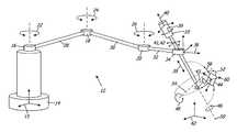
- FIG. 1shows variable direction of view endoscopes coupled to a robotic endoscope holder according to the preferred embodiment of the present invention.
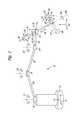
- FIG. 2illustrates the concept of scanning the lateral surface of an organ according to the preferred embodiment of the present invention.
- FIG. 3shows the principle of visually locking on an object while changing the position of the endoscope to accommodate surgical tools or obtain stereoscopic data.
- FIG. 1is a diagram of a basic variable direction of view endoscope 10 held by a robotic arm 12 with a base 14 and a base frame 15 .
- the robotic arm 12has three actuated revolute joints 16 , 18 , 20 with rotational degrees of freedom 22 , 24 , 26 .
- the joints 16 , 18 , 20are connected by links 28 , 30 .
- a third link 32extends from the joint 20 to an end-effector 34 which has a prismatic joint (not explicitly shown) and an associated tool frame 36 .
- the dynamic spatial relationship between the tool frame 36 and the base frame 15is determined by the geometry of the joints 16 , 18 , 20 and links 28 , 30 , 32 and is in robotics called the forward kinematic transformation (or conversely the inverse kinematic transformation).
- the end-effector 34passively holds the scope 10 and senses the dynamic attitude of an endoscope frame 40 fixed to the endoscope 10 .
- a mapping between the endoscope frame 40 and the tool frame 36is given in U.S. Pat. Nos. 5,515,478 and 5,524,180 to Wang et al.
- the endoscope 10itself has a view vector 43 and an associated view field 44 with at least two degrees of freedom 46 , 48 .
- the 1 st degree of freedom 46permits rotation of the view vector 43 about the endoscope longitudinal axis 50 , which allows the view vector 43 to scan in a latitudinal direction 52 .
- This degree of freedom 46is a duplicate of the rotational degree of freedom 39 ; only one of these is necessary for the full-fledged operation of the present invention.
- the 2 nd degree of freedom 48permits rotation of the view vector 43 about an axis 54 perpendicular to the longitudinal axis 50 , which allows the view vector 43 to scan in a longitudinal direction 56 .
- a 3 rd degree of freedom 58may also be available because it is usually possible to adjust the rotational orientation of the endoscopic image.
- a view frame 60is associated with the view field 44 .
- the mapping between the view frame 60 and the endoscope frame 40is described in U.S. Pat. No. 6,663,559 to Hale et al. who also describe the use of an environment frame or an arbitrary user-defined frame 62 dictating the motion of the view vector 43 .
- An overall kinematic relationship between the view frame 60 (or the arbitrary frame 62 ) and the base frame 15can thus be calculated, providing the operator with 10 (one redundant) overall degrees of freedom for controlling the position, direction, and orientation of the endoscopic view point.
- This integrated systemis thus a physical version of a virtual endoscopy method allowing the user to fly through an endoscopic space.
- FIG. 2illustrates the concept of moving the tip of the endoscope 10 through a trajectory 64 associated with inspecting the far side of an organ 66 .
- the view vector 43scans the surface as the endoscope 10 moves through the endoscopic space.
- Certain previous configurations 68 , 70 of the integrated arm-endoscope systemare shown.
- the endoscopic entry point 72 into the patientacts as a fulcrum which applies lateral forces as the robotic arm 12 is actuated. Because the endoscope 10 is passively supported by the end-effector 34 , these lateral forces cause the endoscope 10 to tilt without the risk of injuring the patient.
- the robotic arm 12 shown in this casehas universal joints rather than revolute, yielding two additional degrees of freedom 74 , 76 for each joint for a system total of 16. Depending on the application any type of joint or link can be used.
- FIG. 3shows how the system of the present invention can be used to keep the view vector 43 trained on a target 74 while the system configuration changes. This technique is useful because it can provide topographic information which is difficult to obtain with a single 2D endoscopic view. Further, being able to view the same object from many different angles makes it possible to obtain stereoscopic still images of the object and perform general 3D endoscopic photography.
- the present inventionprovides an integrated system for robotically controlling a variable direction of view endoscope, merging the advantages of electromechanical endoscope positioning and variable direction of view endoscopy and affording new capabilities such as 3D endoscopic photography.
Landscapes
- Health & Medical Sciences (AREA)
- Life Sciences & Earth Sciences (AREA)
- Surgery (AREA)
- General Health & Medical Sciences (AREA)
- Public Health (AREA)
- Veterinary Medicine (AREA)
- Pathology (AREA)
- Nuclear Medicine, Radiotherapy & Molecular Imaging (AREA)
- Animal Behavior & Ethology (AREA)
- Engineering & Computer Science (AREA)
- Biomedical Technology (AREA)
- Heart & Thoracic Surgery (AREA)
- Medical Informatics (AREA)
- Molecular Biology (AREA)
- Biophysics (AREA)
- Physics & Mathematics (AREA)
- Radiology & Medical Imaging (AREA)
- Optics & Photonics (AREA)
- Oral & Maxillofacial Surgery (AREA)
- Endoscopes (AREA)
- Manipulator (AREA)
Abstract
Description
Claims (12)
Priority Applications (1)
| Application Number | Priority Date | Filing Date | Title |
|---|---|---|---|
| US11/083,277US10251532B2 (en) | 2004-03-20 | 2005-03-17 | Method and system for using a variable direction of view endoscope with a robotic endoscope holder |
Applications Claiming Priority (2)
| Application Number | Priority Date | Filing Date | Title |
|---|---|---|---|
| US55497304P | 2004-03-20 | 2004-03-20 | |
| US11/083,277US10251532B2 (en) | 2004-03-20 | 2005-03-17 | Method and system for using a variable direction of view endoscope with a robotic endoscope holder |
Publications (2)
| Publication Number | Publication Date |
|---|---|
| US20050256371A1 US20050256371A1 (en) | 2005-11-17 |
| US10251532B2true US10251532B2 (en) | 2019-04-09 |
Family
ID=35310304
Family Applications (1)
| Application Number | Title | Priority Date | Filing Date |
|---|---|---|---|
| US11/083,277Active2034-11-30US10251532B2 (en) | 2004-03-20 | 2005-03-17 | Method and system for using a variable direction of view endoscope with a robotic endoscope holder |
Country Status (1)
| Country | Link |
|---|---|
| US (1) | US10251532B2 (en) |
Cited By (1)
| Publication number | Priority date | Publication date | Assignee | Title |
|---|---|---|---|---|
| US11992283B2 (en)* | 2017-03-07 | 2024-05-28 | Intuitive Surgical Operations, Inc. | Systems and methods for controlling tool with articulatable distal portion |
Families Citing this family (20)
| Publication number | Priority date | Publication date | Assignee | Title |
|---|---|---|---|---|
| US8004229B2 (en)* | 2005-05-19 | 2011-08-23 | Intuitive Surgical Operations, Inc. | Software center and highly configurable robotic systems for surgery and other uses |
| JP2004298458A (en)* | 2003-03-31 | 2004-10-28 | Olympus Corp | Stereoscopic observation system |
| JP2006288751A (en)* | 2005-04-11 | 2006-10-26 | Olympus Corp | Electric bending endoscopy instrument |
| KR101477133B1 (en)* | 2006-06-13 | 2014-12-29 | 인튜어티브 서지컬 인코포레이티드 | Minimally invasive surgical system |
| ES2298051B2 (en)* | 2006-07-28 | 2009-03-16 | Universidad De Malaga | ROBOTIC SYSTEM OF MINIMALLY INVASIVE SURGERY ASSISTANCE ABLE TO POSITION A SURGICAL INSTRUMENT IN RESPONSE TO THE ORDER OF A SURGEON WITHOUT FIXING THE OPERATING TABLE OR PRIOR CALIBRATION OF THE INSERT POINT. |
| DE102007006891A1 (en)* | 2007-02-13 | 2008-08-14 | University Of Dundee | Holding device for medical purposes |
| DE102007006892A1 (en)* | 2007-02-13 | 2008-08-14 | University Of Dundee | Holding device for medical purposes, has joint with two joint parts, which has meshed bosh element in warp connection with one another and mutual bosh elements are aligned perpendicular to support arm |
| JP4891823B2 (en)* | 2007-03-29 | 2012-03-07 | オリンパスメディカルシステムズ株式会社 | Endoscope device |
| US8982203B2 (en) | 2007-06-06 | 2015-03-17 | Karl Storz Gmbh & Co. Kg | Video system for viewing an object on a body |
| US20090182196A1 (en)* | 2007-10-30 | 2009-07-16 | The Cleveland Clinic Foundation | Method and apparatus for manually guiding an endoscope |
| US20120041263A1 (en)* | 2009-04-23 | 2012-02-16 | M.S.T. Medical Surgery Technologies Ltd. | Two-part endoscope surgical device |
| US8870759B2 (en)* | 2009-12-04 | 2014-10-28 | Covidien Lp | Suspension system for minimally invasive surgery |
| US8747309B2 (en) | 2010-11-09 | 2014-06-10 | Covidien Lp | Suspension system for minimally invasive surgery |
| US10143357B2 (en) | 2010-08-10 | 2018-12-04 | Ronald Yamada | Endoscope gripping device |
| AU2011302155B2 (en)* | 2010-09-14 | 2015-07-02 | The Johns Hopkins University | Robotic system to augment endoscopes |
| EP2624779B1 (en) | 2010-10-08 | 2018-05-30 | Koninklijke Philips N.V. | Endoscopy-guided deployment of vessel punch |
| US20130250081A1 (en)* | 2012-03-21 | 2013-09-26 | Covidien Lp | System and method for determining camera angles by using virtual planes derived from actual images |
| GB2588829B (en) | 2019-11-11 | 2023-11-29 | Cmr Surgical Ltd | Method of controlling a surgical robot |
| CN112155505A (en)* | 2020-08-31 | 2021-01-01 | 连云港市第一人民医院 | Peritoneoscope for gastrointestinal surgery |
| CN115363782A (en)* | 2022-08-17 | 2022-11-22 | 重庆诚联医疗器械有限公司 | Mechanical arm for operation |
Citations (12)
| Publication number | Priority date | Publication date | Assignee | Title |
|---|---|---|---|---|
| US3994557A (en)* | 1974-02-20 | 1976-11-30 | The Secretary Of State For Social Services In Her Brittanic Majesty's Government Of The United Kingdom Of Great Britain And Northern Ireland | Optical systems |
| US4517963A (en)* | 1983-01-04 | 1985-05-21 | Harold Unger | Image-erecting barrel rotator for articulated optical arm |
| US5351676A (en)* | 1991-08-05 | 1994-10-04 | Putman John M | Endoscope stabilizer |
| US5432543A (en)* | 1992-03-05 | 1995-07-11 | Olympus Optical Co., Ltd. | Endoscopic image processing device for estimating three-dimensional shape of object based on detection of same point on a plurality of different images |
| US5524180A (en)* | 1992-08-10 | 1996-06-04 | Computer Motion, Inc. | Automated endoscope system for optimal positioning |
| US6024695A (en)* | 1991-06-13 | 2000-02-15 | International Business Machines Corporation | System and method for augmentation of surgery |
| US6120433A (en)* | 1994-09-01 | 2000-09-19 | Olympus Optical Co., Ltd. | Surgical manipulator system |
| US6191809B1 (en)* | 1998-01-15 | 2001-02-20 | Vista Medical Technologies, Inc. | Method and apparatus for aligning stereo images |
| US6314211B1 (en)* | 1997-12-30 | 2001-11-06 | Samsung Electronics Co., Ltd. | Apparatus and method for converting two-dimensional image sequence into three-dimensional image using conversion of motion disparity into horizontal disparity and post-processing method during generation of three-dimensional image |
| US6668185B2 (en)* | 2000-10-31 | 2003-12-23 | Fuji Photo Film Co., Ltd. | Endoscope apparatus for setting a scanning area |
| US6695774B2 (en)* | 2001-01-19 | 2004-02-24 | Endactive, Inc. | Apparatus and method for controlling endoscopic instruments |
| US20040138524A1 (en)* | 2003-01-07 | 2004-07-15 | Olympus Corporation | Medical instrument holding apparatus |
- 2005
- 2005-03-17USUS11/083,277patent/US10251532B2/enactiveActive
Patent Citations (12)
| Publication number | Priority date | Publication date | Assignee | Title |
|---|---|---|---|---|
| US3994557A (en)* | 1974-02-20 | 1976-11-30 | The Secretary Of State For Social Services In Her Brittanic Majesty's Government Of The United Kingdom Of Great Britain And Northern Ireland | Optical systems |
| US4517963A (en)* | 1983-01-04 | 1985-05-21 | Harold Unger | Image-erecting barrel rotator for articulated optical arm |
| US6024695A (en)* | 1991-06-13 | 2000-02-15 | International Business Machines Corporation | System and method for augmentation of surgery |
| US5351676A (en)* | 1991-08-05 | 1994-10-04 | Putman John M | Endoscope stabilizer |
| US5432543A (en)* | 1992-03-05 | 1995-07-11 | Olympus Optical Co., Ltd. | Endoscopic image processing device for estimating three-dimensional shape of object based on detection of same point on a plurality of different images |
| US5524180A (en)* | 1992-08-10 | 1996-06-04 | Computer Motion, Inc. | Automated endoscope system for optimal positioning |
| US6120433A (en)* | 1994-09-01 | 2000-09-19 | Olympus Optical Co., Ltd. | Surgical manipulator system |
| US6314211B1 (en)* | 1997-12-30 | 2001-11-06 | Samsung Electronics Co., Ltd. | Apparatus and method for converting two-dimensional image sequence into three-dimensional image using conversion of motion disparity into horizontal disparity and post-processing method during generation of three-dimensional image |
| US6191809B1 (en)* | 1998-01-15 | 2001-02-20 | Vista Medical Technologies, Inc. | Method and apparatus for aligning stereo images |
| US6668185B2 (en)* | 2000-10-31 | 2003-12-23 | Fuji Photo Film Co., Ltd. | Endoscope apparatus for setting a scanning area |
| US6695774B2 (en)* | 2001-01-19 | 2004-02-24 | Endactive, Inc. | Apparatus and method for controlling endoscopic instruments |
| US20040138524A1 (en)* | 2003-01-07 | 2004-07-15 | Olympus Corporation | Medical instrument holding apparatus |
Cited By (1)
| Publication number | Priority date | Publication date | Assignee | Title |
|---|---|---|---|---|
| US11992283B2 (en)* | 2017-03-07 | 2024-05-28 | Intuitive Surgical Operations, Inc. | Systems and methods for controlling tool with articulatable distal portion |
Also Published As
| Publication number | Publication date |
|---|---|
| US20050256371A1 (en) | 2005-11-17 |
Similar Documents
| Publication | Publication Date | Title |
|---|---|---|
| US10251532B2 (en) | Method and system for using a variable direction of view endoscope with a robotic endoscope holder | |
| JP7729839B2 (en) | Systems and methods for in vivo reversal of the orientation and field of view of selected components of a miniaturized surgical robotic unit - Patents.com | |
| US11969889B2 (en) | Lever actuated gimbal plate | |
| US12082780B2 (en) | Method for positioning an endoscope with flexible shaft | |
| KR101651627B1 (en) | Coupler to transfer controller motion from a robotic manipulator to an attached instrument | |
| Dwyer et al. | A continuum robot and control interface for surgical assist in fetoscopic interventions | |
| KR101602241B1 (en) | 5 robotic arm with five-bar spherical linkage | |
| CN105992568B (en) | Robotic control of surgical instrument visibility | |
| CN110225720B (en) | Operation support device, recording medium, and operation support system | |
| US11096552B2 (en) | Method and apparatus for controlling manipulator | |
| KR20140110685A (en) | Method for controlling of single port surgical robot | |
| JP2002000550A (en) | Body cavity observation device | |
| US20190069955A1 (en) | Control unit, system and method for controlling hybrid robot having rigid proximal portion and flexible distal portion | |
| JP2008245838A (en) | Robotics arm system mounted on an endoscopic device | |
| Ma et al. | Design, teleoperation control and experimental validation of a dexterous robotic flexible endoscope for laparoscopic surgery | |
| EP4483831A1 (en) | Robotic assembly for a surgical system | |
| Ryu et al. | An active endoscope with small sweep volume that preserves image orientation for arthroscopic surgery | |
| Ryu et al. | Active Endoscope Preserving Image Orientation for Endonasal Skull Base Surgery | |
| CN119700315A (en) | Control method of master control arm, program product, electronic device and storage medium |
Legal Events
| Date | Code | Title | Description |
|---|---|---|---|
| AS | Assignment | Owner name:KARL STORZ DEVELOPMENT CORPORATION, CALIFORNIA Free format text:ASSIGNMENT OF ASSIGNORS INTEREST;ASSIGNOR:ENDACTIVE, INC;REEL/FRAME:016446/0734 Effective date:20050701 | |
| AS | Assignment | Owner name:KARL STORZ DEVELOPMENT CORP., CALIFORNIA Free format text:CORRECTIVE ASSIGNMENT TO CORRECT THE ASSIGNEE NAME PREVIOUSLY RECORDED ON REEL 016446 FRAME 0734. ASSIGNOR(S) HEREBY CONFIRMS THE ASSIGNMENT OF ASSIGNOR'S INTEREST;ASSIGNOR:ENDACTIVE, INC;REEL/FRAME:016522/0966 Effective date:20050701 Owner name:KARL STORZ DEVELOPMENT CORP., CALIFORNIA Free format text:CORRECTIVE ASSIGNMENT TO CORRECT THE ASSIGNEE NAME PREVIOUSLY RECORDED ON REEL 016446 FRAME 0734;ASSIGNOR:ENDACTIVE, INC;REEL/FRAME:016522/0966 Effective date:20050701 | |
| AS | Assignment | Owner name:ENDACTIVE, INC., CALIFORNIA Free format text:ASSIGNMENT OF ASSIGNORS INTEREST;ASSIGNORS:HALE, ERIC L.;HOEG, HANS DAVID;SCHARA, NATHAN JON;REEL/FRAME:018505/0657 Effective date:20061023 | |
| AS | Assignment | Owner name:KARL STORZ IMAGING, INC., CALIFORNIA Free format text:NUNC PRO TUNC ASSIGNMENT;ASSIGNOR:KARL STORZ DEVELOPMENT CORP.;REEL/FRAME:025114/0991 Effective date:20101004 | |
| FEPP | Fee payment procedure | Free format text:ENTITY STATUS SET TO UNDISCOUNTED (ORIGINAL EVENT CODE: BIG.); ENTITY STATUS OF PATENT OWNER: LARGE ENTITY | |
| STCF | Information on status: patent grant | Free format text:PATENTED CASE | |
| MAFP | Maintenance fee payment | Free format text:PAYMENT OF MAINTENANCE FEE, 4TH YEAR, LARGE ENTITY (ORIGINAL EVENT CODE: M1551); ENTITY STATUS OF PATENT OWNER: LARGE ENTITY Year of fee payment:4 |