US10245479B2 - Multi-material golf club head - Google Patents
Multi-material golf club headDownload PDFInfo
- Publication number
- US10245479B2 US10245479B2US15/375,877US201615375877AUS10245479B2US 10245479 B2US10245479 B2US 10245479B2US 201615375877 AUS201615375877 AUS 201615375877AUS 10245479 B2US10245479 B2US 10245479B2
- Authority
- US
- United States
- Prior art keywords
- golf club
- club head
- critical
- cover layer
- less
- Prior art date
- Legal status (The legal status is an assumption and is not a legal conclusion. Google has not performed a legal analysis and makes no representation as to the accuracy of the status listed.)
- Active
Links
- 239000000463materialSubstances0.000titleclaimsabstractdescription38
- 239000003562lightweight materialSubstances0.000abstractdescription10
- 239000010936titaniumSubstances0.000description12
- 229910052719titaniumInorganic materials0.000description12
- RTAQQCXQSZGOHL-UHFFFAOYSA-NTitaniumChemical compound[Ti]RTAQQCXQSZGOHL-UHFFFAOYSA-N0.000description11
- 239000002131composite materialSubstances0.000description9
- 238000010586diagramMethods0.000description9
- 238000000034methodMethods0.000description7
- 230000015556catabolic processEffects0.000description3
- 238000006731degradation reactionMethods0.000description3
- 238000013461designMethods0.000description3
- 230000003292diminished effectEffects0.000description3
- 230000005484gravityEffects0.000description3
- 239000007769metal materialSubstances0.000description3
- 238000004321preservationMethods0.000description3
- 238000003466weldingMethods0.000description3
- 238000005516engineering processMethods0.000description2
- 239000000835fiberSubstances0.000description2
- 238000005259measurementMethods0.000description2
- 229910052751metalInorganic materials0.000description2
- 239000002184metalSubstances0.000description2
- 230000010355oscillationEffects0.000description2
- 239000000126substanceSubstances0.000description2
- OKTJSMMVPCPJKN-UHFFFAOYSA-NCarbonChemical compound[C]OKTJSMMVPCPJKN-UHFFFAOYSA-N0.000description1
- 229920000049Carbon (fiber)Polymers0.000description1
- 239000004593EpoxySubstances0.000description1
- FYYHWMGAXLPEAU-UHFFFAOYSA-NMagnesiumChemical compound[Mg]FYYHWMGAXLPEAU-UHFFFAOYSA-N0.000description1
- 239000000853adhesiveSubstances0.000description1
- 230000001070adhesive effectEffects0.000description1
- 229910052782aluminiumInorganic materials0.000description1
- XAGFODPZIPBFFR-UHFFFAOYSA-NaluminiumChemical compound[Al]XAGFODPZIPBFFR-UHFFFAOYSA-N0.000description1
- 239000004917carbon fiberSubstances0.000description1
- 238000003486chemical etchingMethods0.000description1
- 238000013016dampingMethods0.000description1
- 230000003247decreasing effectEffects0.000description1
- 230000001419dependent effectEffects0.000description1
- 229910002804graphiteInorganic materials0.000description1
- 239000010439graphiteSubstances0.000description1
- 229910052749magnesiumInorganic materials0.000description1
- 239000011777magnesiumSubstances0.000description1
- VNWKTOKETHGBQD-UHFFFAOYSA-NmethaneChemical compoundCVNWKTOKETHGBQD-UHFFFAOYSA-N0.000description1
- 238000012986modificationMethods0.000description1
- 230000004048modificationEffects0.000description1
- 238000012360testing methodMethods0.000description1
- 150000003608titaniumChemical class0.000description1
Images


Classifications
- A—HUMAN NECESSITIES
- A63—SPORTS; GAMES; AMUSEMENTS
- A63B—APPARATUS FOR PHYSICAL TRAINING, GYMNASTICS, SWIMMING, CLIMBING, OR FENCING; BALL GAMES; TRAINING EQUIPMENT
- A63B53/00—Golf clubs
- A63B53/04—Heads
- A63B53/0466—Heads wood-type
- A—HUMAN NECESSITIES
- A63—SPORTS; GAMES; AMUSEMENTS
- A63B—APPARATUS FOR PHYSICAL TRAINING, GYMNASTICS, SWIMMING, CLIMBING, OR FENCING; BALL GAMES; TRAINING EQUIPMENT
- A63B53/00—Golf clubs
- A63B53/04—Heads
- A63B53/0408—Heads characterised by specific dimensions, e.g. thickness
- A—HUMAN NECESSITIES
- A63—SPORTS; GAMES; AMUSEMENTS
- A63B—APPARATUS FOR PHYSICAL TRAINING, GYMNASTICS, SWIMMING, CLIMBING, OR FENCING; BALL GAMES; TRAINING EQUIPMENT
- A63B53/00—Golf clubs
- A63B53/04—Heads
- A63B53/0433—Heads with special sole configurations
- A—HUMAN NECESSITIES
- A63—SPORTS; GAMES; AMUSEMENTS
- A63B—APPARATUS FOR PHYSICAL TRAINING, GYMNASTICS, SWIMMING, CLIMBING, OR FENCING; BALL GAMES; TRAINING EQUIPMENT
- A63B53/00—Golf clubs
- A63B53/04—Heads
- A63B53/0437—Heads with special crown configurations
- A—HUMAN NECESSITIES
- A63—SPORTS; GAMES; AMUSEMENTS
- A63B—APPARATUS FOR PHYSICAL TRAINING, GYMNASTICS, SWIMMING, CLIMBING, OR FENCING; BALL GAMES; TRAINING EQUIPMENT
- A63B60/00—Details or accessories of golf clubs, bats, rackets or the like
- A63B60/002—Resonance frequency related characteristics
- A—HUMAN NECESSITIES
- A63—SPORTS; GAMES; AMUSEMENTS
- A63B—APPARATUS FOR PHYSICAL TRAINING, GYMNASTICS, SWIMMING, CLIMBING, OR FENCING; BALL GAMES; TRAINING EQUIPMENT
- A63B60/00—Details or accessories of golf clubs, bats, rackets or the like
- A63B60/50—Details or accessories of golf clubs, bats, rackets or the like with through-holes
- A—HUMAN NECESSITIES
- A63—SPORTS; GAMES; AMUSEMENTS
- A63B—APPARATUS FOR PHYSICAL TRAINING, GYMNASTICS, SWIMMING, CLIMBING, OR FENCING; BALL GAMES; TRAINING EQUIPMENT
- A63B60/00—Details or accessories of golf clubs, bats, rackets or the like
- A63B60/52—Details or accessories of golf clubs, bats, rackets or the like with slits
- A63B2053/0408—
- A63B2053/0433—
- A63B2053/0437—
- A63B2060/002—
- A—HUMAN NECESSITIES
- A63—SPORTS; GAMES; AMUSEMENTS
- A63B—APPARATUS FOR PHYSICAL TRAINING, GYMNASTICS, SWIMMING, CLIMBING, OR FENCING; BALL GAMES; TRAINING EQUIPMENT
- A63B2209/00—Characteristics of used materials
- A—HUMAN NECESSITIES
- A63—SPORTS; GAMES; AMUSEMENTS
- A63B—APPARATUS FOR PHYSICAL TRAINING, GYMNASTICS, SWIMMING, CLIMBING, OR FENCING; BALL GAMES; TRAINING EQUIPMENT
- A63B2209/00—Characteristics of used materials
- A63B2209/02—Characteristics of used materials with reinforcing fibres, e.g. carbon, polyamide fibres
Definitions
- the present inventionrelates generally to an improved golf club head wherein a portion of the golf club head is made out of a multi-layered lightweight material. Using this lightweight material at different portions of the golf club head allows more discretionary mass to be created, which can be used to further improve the performance of the golf club by manipulating the center of gravity and moment of inertia of the golf club head.
- U.S. Pat. No. 6,860,824 to Evansillustrates another example of golf club designers attempt in creating more discretionary mass.
- a golf club headhas a body portion that is preferably composed of a lightweight non-metallic material to help reduce mass from the body portion of the golf club head.
- U.S. Pat. No. 5,624,331 to Lo et al.illustrates another example of increasing discretionary mass by creating a composite-metal wood-style golf club head having a metal casing with at least two opening in the crown in which composite covers are disposed.
- U.S. Pat. No. 7,361,100 to Morales et al.illustrates a modern day example of utilizing modern day materials to increase the discretionary mass within a golf club. More specifically, U.S. Pat. No. 7,361,100 discloses a golf club head that is formed with a crown having an aperture with an arcuate rear edge and a forward edge that is substantially parallel to the striking face, wherein the opening formed in the aperture by the ribs are filled with an organic-composite material such as carbon fiber epoxy.
- One aspect of the present inventionis a golf club head comprising of a striking face portion located at a frontal portion of said golf club head and a body portion attached to an aft portion of said striking face portion further comprising a crown portion and a sole portion.
- the golf club headhas at least one of the crown portion and the sole portion further comprising of a base layer and a lightweight cover layer, wherein the base layer further comprises a plurality of cutouts and the lightweight cover layer has an Internal Exposure Percentage of between about 15% to about 60%.
- a golf club headcomprising of a striking face portion located at a frontal portion of said golf club head and a body portion attached to an aft portion of said striking face portion further comprising a crown portion and a sole portion.
- the golf club headhas at least one of the crown portion and the sole portion further comprising of a base layer and a lightweight cover layer, wherein the base layer further comprises a plurality of cutouts and the lightweight cover layer has an Internal Exposure Percentage of between about 15% to about 60%, and the base layer has a maximum thickness of less than about 0.50 mm and the lightweight cover layer has a maximum thickness of less than about 0.30 mm.
- a golf club headwherein the golf club head produces a sound that has a Critical Time T critical of greater than about 0.01 seconds and less than about 0.02 seconds; the Critical Time T critical is defined as the amount of time it take the sound to oscillate from a peak amplitude A peak to a point of 10% of the peak amplitude A peak .
- the lightweight cover layerhas an Internal Exposure Percentage of 0%.
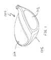
- FIG. 1 of the accompanying drawingsshows a perspective view of a golf club head in accordance with a preferred exemplary embodiment of the present invention
- FIG. 2 of the accompanying drawingsshows an exploded perspective view of a golf club head in accordance with the embodiment of the present invention shown in FIG. 1 ;
- FIG. 3 of the accompanying drawingsshows a cross-sectional view of the golf club head shown in FIG. 1 , taken down the middle of the golf club head in a forward and aft orientation;
- FIG. 4 of the accompanying drawingsshows an enlarged cross-sectional view of a portion of a golf club head identified by circular region A shown in FIG. 3 ;
- FIG. 5 of the accompanying drawingsshows a perspective view of a golf club head in accordance with an alternative embodiment of the present invention
- FIG. 6 of the accompanying drawingsshows an exploded perspective view of a golf club head in accordance with the alternative embodiment of the present invention shown in FIG. 5 ;
- FIG. 7 of the accompanying drawingsshows a perspective view of a golf club head in accordance with a further alternative embodiment of the present invention.
- FIG. 8 of the accompanying drawingsshows an exploded perspective view of a golf club head in accordance with the further alternative embodiment of the present invention shown in FIG. 7 ;
- FIG. 9 of the accompanying drawingsshows a perspective view of a golf club head in accordance with an even further alternative embodiment of the present invention.
- FIG. 10 of the accompanying drawingsshows a perspective view of a golf club head in accordance with another further alternative embodiment of the present invention.
- FIG. 11 of the accompanying drawingsshows a time sequence diagram representing the amplitude of the sound of a golf club head in accordance with an embodiment of the present invention
- FIG. 12 a of the accompanying drawingsshows a time sequence diagram representing the amplitude of the sound of an exemplary prior art golf club head
- FIG. 12 b of the accompanying drawingsshows a time sequence diagram representing the amplitude of sound of an another prior art golf club head
- FIG. 13 of the accompanying drawingsshows an exploded perspective view of a golf club head in accordance with an alternative embodiment of the present invention.
- FIG. 14 of the accompanying drawingsshows an exploded perspective view of a golf club head in accordance with an even further alternative embodiment of the present invention.
- FIG. 1shows a perspective view of a golf club head 100 in accordance with an exemplary embodiment of the present invention.
- Golf club head 100 shown in FIG. 1may generally have a striking face 102 attached to a frontal portion of the golf club head 100 and a body portion attached to an aft portion of the striking face 102 .
- the body portionmay generally be further comprised of a crown portion 104 near a top of the golf club head 100 and a sole portion 106 located near a bottom of the golf club head 100 .
- the crown portion 104 of the golf club head 100 in accordance with the exemplary embodiment of the present inventionmay be further comprised out of multiple layers that have different materials.
- the golf club head 100 in accordance with an exemplary embodiment of the present inventionmay have a multi-material crown.
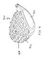
- FIG. 2shows an exploded perspective view of a golf club head 200 illustrating that the multi-material crown portion 204 may be further comprised out of a base layer 210 and a lightweight cover layer 212 .
- the base layer 210may generally be comprised out of a titanium type material with a density of between 4.0 g/cm 3 and about 4.7 g/cm 3 , more preferably between about 4.1 g/cm 3 and about 4.6 g/cm 3 , and most preferably about 4.4 g/cm 3 .
- This titanium base layer 210not only serves to help provide structural rigidity to the crown portion 204 of the golf club head 200 , but can also help contribute to the generation of discretionary mass by incorporating a plurality of cutouts 208 across the entire area.
- the plurality of cutouts 208 shown in this exemplary embodiment of the present inventionmay generally be oval or circular shaped in order to provide the most mass savings all while preserving the structural integrity of the base layer 210 .
- the oval or circular shaped cutouts 208are preferred, many other types of cutout 208 geometry can be used to remove material from the base layer 210 without departing from the scope and content of the present invention.
- the present inventionmay utilize a combination of different technologies.
- the present inventionattempts to recapture some of the lost structural rigidity by utilizing a higher strength titanium material for the base layer 210 .
- a higher strength titanium materialfor the base layer 210 .
- numerous other high strength materialsuch as SP 700 Titanium, KS 120 Titanium, KS 100 Titanium, Titanium 8-1-1—may all be used without departing from the scope and content of the present invention so long as it provides an elevated strength performance.
- the present inventionalso utilizes a lightweight cover layer 212 .
- the lightweight cover layer 212 shown in FIG. 2may generally be a lightweight material with a density that is lower than the density of the base layer 210 , sole 206 , and the striking face 202 .
- the layer of lightweight material 210may be constructed using an aluminum material with a density of about 2.7 g/cm 3 , a magnesium material with a density of about 1.738 g/cm 3 , a composite type material with a density of about 1.50 g/cm 3 , or any other material having a lower density than the density of the first material all without departing from the present invention.
- the material used to create lightweight cover layer 212may generally be a composite material having a very low fiber areal mass. More information regarding composite materials with a low fiber areal mass in a golf club head may be found in U.S.
- the combination of the base layer 210 and the lightweight cover layer 212allows the golf club head 200 to achieve the maximum amount of discretionary mass all while preserving the structural rigidity in the crown 204 portion to be able to endure the high impact stressed between a golf club 200 and a golf ball.
- the amount of discretionary mass saved from the crown 204 portioncan then easily be applied to more strategic locations within a golf club head 200 .
- discretionary massmay be concentrated towards the rear sole portion of the golf club head 200 , however the mass member 220 could be located at alternative locations within the golf club head 200 without departing from the scope and content of the present invention.
- the amount of additional mass located in the mass membermay generally be greater than about 5 grams, more preferably greater than about 7 grams, and most preferably greater than about 9 grains without departing from the scope and content of the present invention.
- FIG. 3 of the accompanying drawingis provided illustrating a cross-sectional view of a golf club head 300 .
- This cross-sectional areais taken along the center of the golf club head in a forward aft orientation, passing through the center of the striking face.
- the golf club head 300still has a striking face 302 , a crown portion 304 , and a sole portion 306 .
- the crown portion 304as previously illustrated in the exploded view shown in FIG. 2 , may be further comprised out of a base layer 310 and a lightweight cover layer 312 .
- the thickness of the crown portion 304is extremely small, allowing the golf club head 300 to achieve the discretionary mass that is desired. Given how thin the entire thickness of the crown portion 304 is, it can be easily deduced that the lightweight cover 312 could be even thinner.
- FIG. 4is provided, which focuses on an enlarged cross-sectional view of circular region A shown in FIG. 3 .
- FIG. 4 of the accompanying drawingsshows an enlarged cross-sectional view of a portion of a crown 304 of a golf club head 300 as illustrated by circular region. A shown in FIG. 3 .
- the base layer 410 shown in FIG. 4may generally be attached to the frontal crown portion of the golf club head via a welding process, near welding joint 416 . Since the base layer 410 and the frontal portion of the crown are both made out of a titanium type material, they may generally be welded together without any issues. Right behind the welding joint 416 , it can be seen that the base layer 410 may have a step 418 to allow the lightweight cover layer 412 to be placed above the base layer 410 .
- the lightweight cover layer 412may be attached to the base layer 410 by using an adhesive type material.
- the lightweight cover layer 412can be directly molded over the base layer 410 without departing from the scope and content of the present invention.
- the base layer 410may generally have a thickness d 1 that is less than about 0.50 mm, more preferably less than about 0.40 mm, and most preferably less than about 0.35 mm, all without departing from the scope and content of the present invention.
- the lightweight cover layer 412 shown in this current exemplary embodiment of the present inventionmay generally have a thickness d 2 that is less than about 0.30 mm, more preferably less than about 0.25 mm, and most preferably less than about 0.20 mm.
- the crux of the current inventionis based on the ability to achieve the mass savings without sacrificing the all-important sound and feel of the golf club head.
- the material used for the lightweight cover layerby the nature of having a lower density, can help reduce the mass of the golf club when it is used compared to standard titanium type material.
- the present inventionrecognizes that when lightweight material is used to replace traditional titanium materials, the sound and feel of the golf club head suffers. This degradation in the sound and feel of the golf club when lightweight material is used occurs because the acoustic vibration that occurs during impact with a golf ball will differ depending on the material.
- the present inventionnot only recognizes the potential for degradation of sound, but also addresses this issue by finding the proper balance between the amount of mass saving achieved together with the preservation of the sound and feel of the golf club head.
- the present inventionhas found that by focusing on the amount of the lightweight cover layer 412 being exposed internally through the cutouts 408 of the base layer 410 will help preserve the acoustic signature and feel of the golf club head all while obtaining the discretionary mass desired.
- This amount of exposed lightweight cover layer 412 through the cutouts 408is generally expressed as a percentage of the total internal surface area of the lightweight cover layer 412 , and is extremely critical to the proper functionality of the present invention.
- the present inventiononly between about 15% to about 60% of the internal surface area of the lightweight cover layer 412 is exposed internally through the cutouts 408 , more preferably between about 20% to about 50%, and most preferably between about 25% to about 45%.
- the range of internal surface area exposedis critical to the proper functionality of the present invention because if too much of the lightweight cover layer 412 is exposed internally through the cutouts 408 , the acoustic sound and feel of the golf club suffers. Alternatively, if too little of the internal surface area of the lightweight cover layer 412 is exposed through the cutouts 408 , then the mass savings does not become significant enough to achieve any mass savings.
- the Internal Exposure Percentage of a lightweight cover layer 412 for a golf club head in accordance with the present inventionis most preferably between about 15% to about 60%, more preferably between about 20% to about 50%, and most preferably between about 25% to about 45%.
- FIG. 5 of the accompanying drawingsshows a perspective view of a golf club head 500 in accordance with an alternative embodiment of the present invention.
- the base layer 510may not be limited to the crown portion 504 of the golf club head 500 , but could be applied towards the sole portion 506 of the golf club head 500 without departing from the scope and content of the present invention.
- FIG. 6providing an exploded view is also provided.
- FIG. 6 of the accompanying drawingsshows an exploded perspective views of a golf club head 600 in accordance with the alternative embodiment of the present invention shown in FIG. 5 .
- the sole 606 portion of the golf club head 600may also contain a base layer 610 in addition its utilization in the crown 604 portion.
- FIG. 6also illustrates the shape and dimension of the lightweight cover layer 612 , which was previously removed from FIG. 5 to illustrate the cutouts 508 .
- the cover layer 612does not need to be substantially planar as shown originally in FIG. 2 , but rather could take on the external shape of a golf club head like a skin without departing from the scope and content of the present invention.
- the base layer 610covers more of the golf club head, the percentage of internally exposed lightweight cover layer 612 is maintained to preserve the perfect balance between mass savings and preservation of sound and feel.
- FIG. 7 of the accompanying drawingsshows another perspective view of a golf club head 700 in accordance with a further alternative embodiment of the present invention.
- the base layer 710may be used at the toe and heel portion of the body of the golf club head 700 allowing the central portion of the golf club head 700 to create a bridge member 730 without departing from the scope and content of the present invention.
- the bridge member 730may generally help create more structural rigidity within the golf club head 700 , allowing the base layer 710 to be even thinner in some instances.
- FIG. 8 of the accompanying drawingsshows an exploded perspective view of the golf club head 800 shown in FIG. 7 .
- This exploded perspective viewnot only allows the lightweight cover layer 812 to be shown more clearly, but also illustrates the mass member 820 located at the rear portion of the golf club head 800 . It can be seen in this exploded perspective view that the mass member 820 is located along the bridge member 830 to allow the mass member 820 to be secured to the golf club head 800 without any need for additional features.
- the golf club headwill have the same percentage of internally exposed lightweight cover layer 812 through the cutouts 808 as previously discussed in order to preserve the perfect balance between mass savings and the preservation of sound and feel.
- FIG. 9 of the accompanying drawingsshows a perspective view of a golf club head 900 in accordance with a further alternative embodiment of the present invention.
- the golf club head 900could incorporate the plurality of cutouts 908 through the entire body portion to create the base layer 910 .
- This golf club head 900may generally be covered with a lightweight cover layer as previously discussed in prior embodiments, but the cover layer is not shown in FIG. 9 to allow more clarity of the internal structure.
- FIG. 10 of the accompanying drawingsshows a perspective view of a golf club head 1000 in accordance with a further alternative embodiment of the present invention.
- FIG. 10shows a slightly different internal structure wherein the base layer 1010 may be created using cutouts 1008 that is not circular in shape.
- the cutouts 1008may take on any shape that is circular, oval, rectangular, or any other shape all without departing from the scope and content of the present invention so long as it has an internal exposure percentage in accordance with the discussion above.
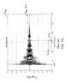
- FIG. 11 of the accompanying drawingsshows a time sequence diagram of the amplitude of the sound produced by the current inventive golf club head in accordance with an embodiment the present invention.
- the sound of the golf club head in accordance with the current inventive golf club headis one of the key factors in determining the performance of the golf club head.
- the time sequence diagramis created by gathering the audio profile using an audio recorder such as the TASCAM® DH-P2 Portable High Definition Stereo Audio recorder in conjunction with an A-weighting microphone. The recording is recorded at a distance of 39 inches away from the impact location, which is used because it closely simulates the distance a golfer's ear would be placed if he or she were hitting the golf club himself or herself.
- the time of the soundis shown in increments of 0.01 seconds; while on the other hand, on the y-axis shows the amplitude of the sound is shown in millivolts.
- the sound recordingbegins at location 1134 right before impact with a golf ball and goes into a sinusoidal wave that reaches the peak amplitude A max at a time point 1130 . Once the sound reaches the peak amplitude A max at time point 1130 , the amplitude begins to resonate and begins decreasing until it dissipates completely.
- the point where the amplitude drops to beneath 10% of the peak amplitude A maxis of particular interest, as it defines a time point 1132 where the sound amplitude becomes borderline negligible to the naked ear. Due to the inherent oscillating tendencies of sound shown here in FIG. 11 , the determination of when the sound oscillation actually reaches down to 10% of the peak amplitude A max can be difficult to discern visually. Hence, in order to help ease the determination, and in order to help pinpoint the oscillation variance inherent in these sound diagrams, the time where the amplitude is determined using a running average of the 5 most recent data points.
- the peak amplitude A maxis generally about 0.45 millivolts, occurring at a time point 1130 of about 0.008 seconds; while the diminished 10% peak amplitude A max occurs at a time point 1132 of about 0.026 seconds.
- the time that occurs between these the time points 1130 and 1132are critical to recognize because they help define a Critical Time T critical .
- Critical Time T criticalprovides a way to quantify the quality and desirability of the sound of the golf club head as it impacts a golf ball. In the present embodiment of the present invention, the Critical Time T critical may be about 0.019 seconds.
- a golf club head in accordance with the present inventionmay generally have a Critical Time T critical of greater than about 0.01 seconds and less than about 0.02 second, more preferably greater than about 0.015 seconds and less than about 0.02 seconds, and most preferably greater than about 0.0175 and less than about 0.02 seconds without departing from the scope and content of the present invention.
- the time it takes for the sound amplitude to go from the peak amplitude A peak to an amplitude that is 10% of peak amplitude A peakis defined as the Critical Time T critical , and is generally greater than about 0.01 seconds and less than about 0.02, more preferably greater than about 0.015 seconds and less than about 0.02 seconds, and most preferably greater than about 0.0175 seconds and less than about 0.02.
- FIG. 12 a of the accompanying drawingsprovide an illustration of a time sequence diagram of a prior art golf club head that incorporates a composite crown technology that fails to recognize the importance of the sound component of a golf club head.
- peak amplitude A peaksignificantly lower than the current inventive golf club head by being close to about 0.25 millivolts, it loses amplitude really quickly yielding a Critical Time T critical of less than about 0.01.
- the peak amplitude A peakoccurs at a time of about 0.008 second, while the diminished 10% of peak amplitude A peak occurs at a time of about 0.015 second, yielding a Critical Time T critical of about 0.007 seconds.
- This prior art time sequence shown in FIG. 12 agenerally yields an undesirable sound, which the present invention avoids by adjusting the thickness ranges of the different materials and their respective layers.
- FIG. 12 b of the accompanying drawingsprovides an illustration of a time sequence diagram of a prior art golf club head that also produces an undesirable sound, but in a completely different way than the prior art golf club head shown in FIG. 12 a .
- This golf club headwhose sound diagram is shown in FIG. 12 b produces a sound that is too loud, and does not contain sufficient amount of damping.
- FIG. 12 bnot only is the peak amplitude A peak so high, it is off the charts by being higher than about 0.5 millivolts, it loses amplitude really slowly yielding a Critical Time T critical of greater than about 0.02.
- the peak amplitude A peakoccurs at a time of about 0.007 second, while the diminished 10% of peak amplitude A peak occurs at a time of about 0.033 second, yielding a Critical Time T critical of about 0.026 seconds.
- This prior art time sequence shown in FIG. 12 balso yields an undesirable sound, which the present invention avoids by adjusting the thickness ranges of the different materials and their respective layers.
- FIG. 13 of the accompanying drawingsshows an exploded view of a golf club head 1300 in accordance with an alternative embodiment of the present invention. Similar to the earlier discussion showing an exploded view of a golf club head 200 shown in FIG. 2 , the current exploded view allows the relationship between the components of the golf club head 1300 to be shown more clearly. Right off the bat, it can be seen that golf club head 1300 is very similar to golf club head 200 , but differ from one another in that the golf club head 1300 does not contain any cutouts that exist in golf club head 200 . In addition to the base layer 1310 not having any cutouts, FIG. 13 also shows the lightweight cover layer 1312 , the striking face 1302 , as well as a weight member 1320 .
- the base layer 1310 in this embodiment of the present inventionmay generally be a standard sheet of metallic material.
- the lightweight cover layer 1312has an Internal Exposure Percentage of 0%.
- FIG. 14 of the accompanying drawingshows a further alternative embodiment of the present invention, wherein the base layer 1410 may be cast into the chassis of the golf club head 1400 without departing from the scope and content of the present invention.
- This embodimentmay be preferred in situations where it is desirable to cast the entirety of the chassis of the golf club head 1400 .
- a chemical etch processmay be used to reduce the thickness of the base layer 1410 without departing from the scope and content of the present invention.
- the chemical etching processmay be used on an internal surface of the base layer; however, in alternative embodiments of the present invention, the chemical etch process can be done on an exterior surface, or even use alternative techniques without departing from the scope and content of the present invention.
Landscapes
- Health & Medical Sciences (AREA)
- General Health & Medical Sciences (AREA)
- Physical Education & Sports Medicine (AREA)
- Life Sciences & Earth Sciences (AREA)
- Engineering & Computer Science (AREA)
- Wood Science & Technology (AREA)
- Golf Clubs (AREA)
Abstract
Description
As described above, the Internal Exposure Percentage of a
Claims (19)
Priority Applications (1)
| Application Number | Priority Date | Filing Date | Title |
|---|---|---|---|
| US15/375,877US10245479B2 (en) | 2015-11-18 | 2016-12-12 | Multi-material golf club head |
Applications Claiming Priority (2)
| Application Number | Priority Date | Filing Date | Title |
|---|---|---|---|
| US14/945,243US10065084B2 (en) | 2015-11-18 | 2015-11-18 | Multi-material golf club head |
| US15/375,877US10245479B2 (en) | 2015-11-18 | 2016-12-12 | Multi-material golf club head |
Related Parent Applications (1)
| Application Number | Title | Priority Date | Filing Date |
|---|---|---|---|
| US14/945,243Continuation-In-PartUS10065084B2 (en) | 2015-11-18 | 2015-11-18 | Multi-material golf club head |
Publications (2)
| Publication Number | Publication Date |
|---|---|
| US20170136318A1 US20170136318A1 (en) | 2017-05-18 |
| US10245479B2true US10245479B2 (en) | 2019-04-02 |
Family
ID=58690332
Family Applications (1)
| Application Number | Title | Priority Date | Filing Date |
|---|---|---|---|
| US15/375,877ActiveUS10245479B2 (en) | 2015-11-18 | 2016-12-12 | Multi-material golf club head |
Country Status (1)
| Country | Link |
|---|---|
| US (1) | US10245479B2 (en) |
Cited By (9)
| Publication number | Priority date | Publication date | Assignee | Title |
|---|---|---|---|---|
| US10653927B2 (en)* | 2018-07-23 | 2020-05-19 | Acushnet Company | Multi-material golf club head |
| US11007409B2 (en)* | 2015-11-18 | 2021-05-18 | Acushnet Company | Multi-material golf club head |
| US11219805B2 (en) | 2018-07-23 | 2022-01-11 | Acushnet Company | Multi-material golf club head |
| US11517799B2 (en) | 2017-12-08 | 2022-12-06 | Karsten Manufacturing Corporation | Multi-component golf club head |
| US11612793B2 (en)* | 2011-01-04 | 2023-03-28 | Karsten Manufacturing Corporation | Golf club heads with apertures and filler materials |
| US20230105620A1 (en)* | 2021-09-28 | 2023-04-06 | Topgolf Callaway Brands Corp. | Golf Club Head With Sole Compliance Zone |
| US11679313B2 (en) | 2021-09-24 | 2023-06-20 | Acushnet Company | Golf club head |
| US11684832B2 (en)* | 2011-01-04 | 2023-06-27 | Karsten Manufacturing Corporation | Golf club heads with apertures and methods to manufacture golf club heads |
| US11839802B2 (en) | 2017-12-08 | 2023-12-12 | Karsten Manufacturing Corporation | Multi-component golf club head |
Families Citing this family (1)
| Publication number | Priority date | Publication date | Assignee | Title |
|---|---|---|---|---|
| US11766592B2 (en)* | 2020-10-27 | 2023-09-26 | Acushnet Company | Multi-material golf club head |
Citations (94)
| Publication number | Priority date | Publication date | Assignee | Title |
|---|---|---|---|---|
| US4076254A (en) | 1976-04-07 | 1978-02-28 | Nygren Gordon W | Golf club with low density and high inertia head |
| US4139196A (en) | 1977-01-21 | 1979-02-13 | The Pinseeker Corporation | Distance golf clubs |
| US4229550A (en) | 1978-12-11 | 1980-10-21 | Trw Inc. | Flexibilized vinyl polybutadiene maleimide resins |
| US4448941A (en) | 1981-12-07 | 1984-05-15 | Ford Motor Company | Resin binder for fiber composite materials |
| US4681322A (en) | 1985-09-18 | 1987-07-21 | Straza George T | Golf club head |
| US5058895A (en) | 1989-01-25 | 1991-10-22 | Igarashi Lawrence Y | Golf club with improved moment of inertia |
| US5132178A (en) | 1987-05-08 | 1992-07-21 | Corning Incorporated | Ceramic matrix composites exhibiting high interlaminar shear strength |
| US5163682A (en) | 1990-10-16 | 1992-11-17 | Callaway Golf Company | Metal wood golf club with variable faceplate thickness |
| JPH057261A (en) | 1991-06-27 | 1993-01-14 | Nec Corp | Call tariff proportional distribution system |
| US5238529A (en) | 1992-04-20 | 1993-08-24 | Texas Instruments Incorporated | Anisotropic metal oxide etch |
| US5295689A (en) | 1993-01-11 | 1994-03-22 | S2 Golf Inc. | Golf club head |
| US5310185A (en) | 1992-02-27 | 1994-05-10 | Taylor Made Golf Company | Golf club head and processes for its manufacture |
| US5346216A (en) | 1992-02-27 | 1994-09-13 | Daiwa Golf Co., Ltd. | Golf club head |
| US5358249A (en) | 1993-07-06 | 1994-10-25 | Wilson Sporting Goods Co. | Golf club with plurality of inserts |
| US5362055A (en) | 1992-03-12 | 1994-11-08 | Progear, Inc. | Hollow having plate welded in crown and striking face insert metal wood |
| US5380010A (en) | 1993-10-28 | 1995-01-10 | Frank D. Werner | Golf club head construction |
| US5403007A (en) | 1992-07-28 | 1995-04-04 | Chen; Archer C. C. | Golf club head of compound material |
| US5405136A (en) | 1993-09-20 | 1995-04-11 | Wilson Sporting Goods Co. | Golf club with face insert of variable hardness |
| US5425538A (en) | 1991-07-11 | 1995-06-20 | Taylor Made Golf Company, Inc. | Golf club head having a fiber-based composite impact wall |
| US5499814A (en) | 1994-09-08 | 1996-03-19 | Lu; Clive S. | Hollow club head with deflecting insert face plate |
| US5524331A (en) | 1994-08-23 | 1996-06-11 | Odyssey Sports, Inc. | Method for manufacturing golf club head with integral inserts |
| US5547427A (en) | 1992-04-01 | 1996-08-20 | Taylor Made Golf Company, Inc. | Golf club head having a hollow plastic body and a metallic sealing element |
| US5570886A (en) | 1992-04-01 | 1996-11-05 | Taylor Made Golf Company, Inc. | Golf club head having an inner subassembly and an outer casing and method of manufacture |
| US5624331A (en) | 1995-10-30 | 1997-04-29 | Pro-Kennex, Inc. | Composite-metal golf club head |
| US5720673A (en) | 1989-06-12 | 1998-02-24 | Pacific Golf Holdings | Structure and process for affixing a golf club head insert to a golf club head body |
| US5743813A (en) | 1997-02-19 | 1998-04-28 | Chien Ting Precision Casting Co., Ltd. | Golf club head |
| US5839975A (en) | 1997-01-22 | 1998-11-24 | Black Rock Golf Corporation | Arch reinforced golf club head |
| US5967903A (en) | 1997-10-20 | 1999-10-19 | Harrison Sports, Inc. | Golf club head with sandwich structure and method of making the same |
| US5997415A (en) | 1997-02-11 | 1999-12-07 | Zevo Golf Co., Inc. | Golf club head |
| US6152833A (en) | 1998-06-15 | 2000-11-28 | Frank D. Werner | Large face golf club construction |
| US6440008B2 (en) | 1997-10-23 | 2002-08-27 | Callaway Golf Company | Composite golf club head |
| US6533681B2 (en) | 2000-05-12 | 2003-03-18 | Akihisa Inoue | Golf club head |
| US6558271B1 (en) | 2000-01-18 | 2003-05-06 | Taylor Made Golf Company, Inc. | Golf club head skeletal support structure |
| US6605007B1 (en) | 2000-04-18 | 2003-08-12 | Acushnet Company | Golf club head with a high coefficient of restitution |
| JP2003250938A (en) | 2001-12-28 | 2003-09-09 | Yokohama Rubber Co Ltd:The | Hollow golf club head |
| US6617013B2 (en) | 2001-05-10 | 2003-09-09 | Siemens Westinghouse Power Corporation | Ceramic matrix composite having improved interlaminar strength |
| US6623543B1 (en) | 1996-02-21 | 2003-09-23 | Mykrolis Corporation | Method for forming titanium anisotropic metal particles |
| JP2004159794A (en) | 2002-11-11 | 2004-06-10 | Kasco Corp | Wood type golf club head |
| JP2004208728A (en) | 2002-12-26 | 2004-07-29 | Daiwa Seiko Inc | Golf club head |
| US20040192468A1 (en) | 2002-12-02 | 2004-09-30 | Kenji Onoda | Composite metal wood |
| US6837094B2 (en) | 2003-02-21 | 2005-01-04 | Matthew M. Pringle | Portable apparatus for measuring the flexibility of a golf club head |
| US6860824B2 (en) | 2002-07-12 | 2005-03-01 | Callaway Golf Company | Golf club head with metal striking plate insert |
| JP2005058461A (en) | 2003-08-12 | 2005-03-10 | Endo Mfg Co Ltd | Golf club and its manufacturing method |
| US20050096154A1 (en) | 2003-11-04 | 2005-05-05 | Yun-Fang Chen | Golf club head and composite plate therefor |
| US20050143189A1 (en) | 2003-12-29 | 2005-06-30 | Lydia Lai | Golf club head |
| US6945876B2 (en) | 2001-12-28 | 2005-09-20 | The Yokohama Rubber Co., Ltd. | Hollow golf club head |
| JP2005323686A (en) | 2004-05-12 | 2005-11-24 | Sri Sports Ltd | Golf club head |
| JP2005329154A (en) | 2004-05-21 | 2005-12-02 | Sri Sports Ltd | Golf club head |
| JP2005348895A (en) | 2004-06-09 | 2005-12-22 | Endo Mfg Co Ltd | Golf club |
| JP2006020860A (en) | 2004-07-08 | 2006-01-26 | Fu Sheng Industrial Co Ltd | Assembly structure of golf club head |
| US7037214B2 (en) | 2001-12-28 | 2006-05-02 | The Yokohama Rubber Co., Ltd. | Hollow golf club head |
| US7056229B2 (en) | 2004-03-04 | 2006-06-06 | Chen Archer C C | Wood golf club head |
| US7074136B2 (en) | 2003-03-27 | 2006-07-11 | Mizuno Corporation | Golf club head and golf club |
| US7108614B2 (en)* | 2004-07-20 | 2006-09-19 | Fu Sheng Industrial Co., Ltd. | Golf club head with improved striking effect |
| US7140974B2 (en) | 2004-04-22 | 2006-11-28 | Taylor Made Golf Co., Inc. | Golf club head |
| US7267620B2 (en) | 2003-05-21 | 2007-09-11 | Taylor Made Golf Company, Inc. | Golf club head |
| US7281994B2 (en)* | 2002-12-11 | 2007-10-16 | Taylor Made Golf Company, Inc. | Golf club head |
| US7281991B2 (en) | 2003-06-25 | 2007-10-16 | Acushnet Company | Hollow golf club with composite core |
| US7331877B2 (en) | 2003-03-07 | 2008-02-19 | Sri Sports Limited | Golf club head |
| US7361100B1 (en) | 2006-12-20 | 2008-04-22 | Karsten Manufacturing Corporation | Metal composite golf club head |
| JP2008148762A (en) | 2006-12-14 | 2008-07-03 | Sri Sports Ltd | Golf club head |
| US7422528B2 (en) | 2004-10-07 | 2008-09-09 | Callaway Golf Company | Golf club head with variable face thickness |
| US7448964B2 (en) | 2005-09-20 | 2008-11-11 | Karsten Manufacturing Corporation | Golf club head having a crown with thin regions |
| GB2450764A (en) | 2007-07-03 | 2009-01-07 | Karsten Mfg Corp | Golf club heads with a plurality of stress zones |
| US7510486B2 (en) | 2004-09-30 | 2009-03-31 | Origin, Inc. | Elastic golf club head |
| US20090088272A1 (en) | 2005-01-03 | 2009-04-02 | Callaway Golf Company | Golf club head |
| US20090092831A1 (en) | 2006-04-28 | 2009-04-09 | Toho Tenax Europe Gmbh | Carbon Fiber |
| US7632193B2 (en) | 2005-08-10 | 2009-12-15 | Thielen Feinmechanik Gmbh & Co. Fertigungs Kg | Golf club |
| US7632195B2 (en) | 2005-08-15 | 2009-12-15 | Acushnet Company | Golf club head with low density crown |
| US7867612B2 (en) | 2002-04-03 | 2011-01-11 | Toho Tenax Europe Gmbh | Composite material, method for the production and use thereof |
| US7931546B2 (en) | 2006-10-25 | 2011-04-26 | Acushnet Company | Metal wood club with improved moment of inertia |
| US7993216B2 (en)* | 2008-11-17 | 2011-08-09 | Nike, Inc. | Golf club head or other ball striking device having multi-piece construction |
| US8172697B2 (en) | 2009-08-17 | 2012-05-08 | Callaway Golf Company | Selectively lightened wood-type golf club head |
| US20120142451A1 (en) | 2002-12-11 | 2012-06-07 | Taylor Made Golf Company, Inc. | Golf club head having a composite crown |
| US8221261B2 (en) | 2010-07-08 | 2012-07-17 | Acushnet Company | Golf club head having a multi-material face |
| US8247062B2 (en) | 2009-05-12 | 2012-08-21 | Siemens Energy, Inc. | Methodology and tooling arrangements for increasing interlaminar shear strength in a ceramic matrix composite structure |
| US8293356B2 (en) | 2009-05-12 | 2012-10-23 | Siemens Energy, Inc. | Subsurface inclusions of objects for increasing interlaminar shear strength of a ceramic matrix composite structure |
| US8419569B2 (en) | 2006-10-25 | 2013-04-16 | Acushnet Company | Metal wood club with improved moment of inertia |
| US20130137531A1 (en)* | 2011-11-30 | 2013-05-30 | Charles E. Golden | Composite golf club head with improved sound |
| US8475292B2 (en) | 2010-05-05 | 2013-07-02 | Nike, Inc. | Wood-type golf clubs with tubing and weights |
| US8517859B2 (en) | 2010-07-08 | 2013-08-27 | Acushnet Company | Golf club head having a multi-material face |
| US8540590B2 (en) | 2010-06-14 | 2013-09-24 | K.K. Endo Seisakusho | Hollow golf club head |
| US20130252757A1 (en) | 2010-07-08 | 2013-09-26 | Acushnet Company | Golf club having multi-material face |
| JP2014501167A (en) | 2011-01-04 | 2014-01-20 | カーステン マニュファクチュアリング コーポレーション | Golf club head having holes and method for manufacturing golf club head |
| US20140106897A1 (en) | 2010-07-08 | 2014-04-17 | Acushnet Company | Golf club head having a multi-material face |
| US8790196B2 (en) | 2011-01-04 | 2014-07-29 | Karsten Manufacturing Corporation | Golf club heads with apertures and methods to manufacture golf club heads |
| US8814723B2 (en) | 2007-04-05 | 2014-08-26 | Nike, Inc. | Rotational molded golf club heads |
| US8876629B2 (en) | 2010-07-08 | 2014-11-04 | Acushnet Company | Golf club head having a multi-material face |
| US20150108681A1 (en) | 2010-07-08 | 2015-04-23 | Acushnet Company | Golf club head having multi-material face and method of manufacture |
| US9079089B2 (en) | 2008-01-22 | 2015-07-14 | Altimate Medical, Inc. | Seat |
| US9079078B2 (en) | 2011-12-29 | 2015-07-14 | Taylor Made Golf Company, Inc. | Golf club head |
| US9101811B1 (en) | 2012-06-08 | 2015-08-11 | Callaway Golf Company | CG height adjustability by conformal weighting |
| US20150290503A1 (en) | 2014-04-11 | 2015-10-15 | Chi-Hung Su | Top crown of a golf club head |
| US20150298196A1 (en) | 2014-04-17 | 2015-10-22 | Chi-Hung Su | Manufacturing method of a top crown of a golf club head |
- 2016
- 2016-12-12USUS15/375,877patent/US10245479B2/enactiveActive
Patent Citations (109)
| Publication number | Priority date | Publication date | Assignee | Title |
|---|---|---|---|---|
| US4076254A (en) | 1976-04-07 | 1978-02-28 | Nygren Gordon W | Golf club with low density and high inertia head |
| US4139196A (en) | 1977-01-21 | 1979-02-13 | The Pinseeker Corporation | Distance golf clubs |
| US4229550A (en) | 1978-12-11 | 1980-10-21 | Trw Inc. | Flexibilized vinyl polybutadiene maleimide resins |
| US4448941A (en) | 1981-12-07 | 1984-05-15 | Ford Motor Company | Resin binder for fiber composite materials |
| US4681322A (en) | 1985-09-18 | 1987-07-21 | Straza George T | Golf club head |
| US5132178A (en) | 1987-05-08 | 1992-07-21 | Corning Incorporated | Ceramic matrix composites exhibiting high interlaminar shear strength |
| US5058895A (en) | 1989-01-25 | 1991-10-22 | Igarashi Lawrence Y | Golf club with improved moment of inertia |
| US5720673A (en) | 1989-06-12 | 1998-02-24 | Pacific Golf Holdings | Structure and process for affixing a golf club head insert to a golf club head body |
| US5163682A (en) | 1990-10-16 | 1992-11-17 | Callaway Golf Company | Metal wood golf club with variable faceplate thickness |
| JPH057261A (en) | 1991-06-27 | 1993-01-14 | Nec Corp | Call tariff proportional distribution system |
| US5425538A (en) | 1991-07-11 | 1995-06-20 | Taylor Made Golf Company, Inc. | Golf club head having a fiber-based composite impact wall |
| US5310185A (en) | 1992-02-27 | 1994-05-10 | Taylor Made Golf Company | Golf club head and processes for its manufacture |
| US5346216A (en) | 1992-02-27 | 1994-09-13 | Daiwa Golf Co., Ltd. | Golf club head |
| US5362055A (en) | 1992-03-12 | 1994-11-08 | Progear, Inc. | Hollow having plate welded in crown and striking face insert metal wood |
| US5570886A (en) | 1992-04-01 | 1996-11-05 | Taylor Made Golf Company, Inc. | Golf club head having an inner subassembly and an outer casing and method of manufacture |
| US5547427A (en) | 1992-04-01 | 1996-08-20 | Taylor Made Golf Company, Inc. | Golf club head having a hollow plastic body and a metallic sealing element |
| US5238529A (en) | 1992-04-20 | 1993-08-24 | Texas Instruments Incorporated | Anisotropic metal oxide etch |
| US5403007A (en) | 1992-07-28 | 1995-04-04 | Chen; Archer C. C. | Golf club head of compound material |
| US5295689A (en) | 1993-01-11 | 1994-03-22 | S2 Golf Inc. | Golf club head |
| US5358249A (en) | 1993-07-06 | 1994-10-25 | Wilson Sporting Goods Co. | Golf club with plurality of inserts |
| US5405136A (en) | 1993-09-20 | 1995-04-11 | Wilson Sporting Goods Co. | Golf club with face insert of variable hardness |
| US5380010A (en) | 1993-10-28 | 1995-01-10 | Frank D. Werner | Golf club head construction |
| US5524331A (en) | 1994-08-23 | 1996-06-11 | Odyssey Sports, Inc. | Method for manufacturing golf club head with integral inserts |
| US5499814A (en) | 1994-09-08 | 1996-03-19 | Lu; Clive S. | Hollow club head with deflecting insert face plate |
| US5624331A (en) | 1995-10-30 | 1997-04-29 | Pro-Kennex, Inc. | Composite-metal golf club head |
| US6623543B1 (en) | 1996-02-21 | 2003-09-23 | Mykrolis Corporation | Method for forming titanium anisotropic metal particles |
| US5839975A (en) | 1997-01-22 | 1998-11-24 | Black Rock Golf Corporation | Arch reinforced golf club head |
| US5997415A (en) | 1997-02-11 | 1999-12-07 | Zevo Golf Co., Inc. | Golf club head |
| US5743813A (en) | 1997-02-19 | 1998-04-28 | Chien Ting Precision Casting Co., Ltd. | Golf club head |
| US5967903A (en) | 1997-10-20 | 1999-10-19 | Harrison Sports, Inc. | Golf club head with sandwich structure and method of making the same |
| US6440008B2 (en) | 1997-10-23 | 2002-08-27 | Callaway Golf Company | Composite golf club head |
| US6152833A (en) | 1998-06-15 | 2000-11-28 | Frank D. Werner | Large face golf club construction |
| US6558271B1 (en) | 2000-01-18 | 2003-05-06 | Taylor Made Golf Company, Inc. | Golf club head skeletal support structure |
| US6605007B1 (en) | 2000-04-18 | 2003-08-12 | Acushnet Company | Golf club head with a high coefficient of restitution |
| US6533681B2 (en) | 2000-05-12 | 2003-03-18 | Akihisa Inoue | Golf club head |
| US6617013B2 (en) | 2001-05-10 | 2003-09-09 | Siemens Westinghouse Power Corporation | Ceramic matrix composite having improved interlaminar strength |
| JP2003250938A (en) | 2001-12-28 | 2003-09-09 | Yokohama Rubber Co Ltd:The | Hollow golf club head |
| US7037214B2 (en) | 2001-12-28 | 2006-05-02 | The Yokohama Rubber Co., Ltd. | Hollow golf club head |
| US6945876B2 (en) | 2001-12-28 | 2005-09-20 | The Yokohama Rubber Co., Ltd. | Hollow golf club head |
| US7867612B2 (en) | 2002-04-03 | 2011-01-11 | Toho Tenax Europe Gmbh | Composite material, method for the production and use thereof |
| US6860824B2 (en) | 2002-07-12 | 2005-03-01 | Callaway Golf Company | Golf club head with metal striking plate insert |
| JP2004159794A (en) | 2002-11-11 | 2004-06-10 | Kasco Corp | Wood type golf club head |
| US20040192468A1 (en) | 2002-12-02 | 2004-09-30 | Kenji Onoda | Composite metal wood |
| US7281994B2 (en)* | 2002-12-11 | 2007-10-16 | Taylor Made Golf Company, Inc. | Golf club head |
| US20120142451A1 (en) | 2002-12-11 | 2012-06-07 | Taylor Made Golf Company, Inc. | Golf club head having a composite crown |
| JP2004208728A (en) | 2002-12-26 | 2004-07-29 | Daiwa Seiko Inc | Golf club head |
| US6837094B2 (en) | 2003-02-21 | 2005-01-04 | Matthew M. Pringle | Portable apparatus for measuring the flexibility of a golf club head |
| US7331877B2 (en) | 2003-03-07 | 2008-02-19 | Sri Sports Limited | Golf club head |
| US7074136B2 (en) | 2003-03-27 | 2006-07-11 | Mizuno Corporation | Golf club head and golf club |
| US7628712B2 (en) | 2003-05-21 | 2009-12-08 | Taylor Made Golf Company, Inc. | Golf club head having a composite face insert |
| US7267620B2 (en) | 2003-05-21 | 2007-09-11 | Taylor Made Golf Company, Inc. | Golf club head |
| US7281991B2 (en) | 2003-06-25 | 2007-10-16 | Acushnet Company | Hollow golf club with composite core |
| JP2005058461A (en) | 2003-08-12 | 2005-03-10 | Endo Mfg Co Ltd | Golf club and its manufacturing method |
| US7258624B2 (en) | 2003-08-12 | 2007-08-21 | K.K. Endo Seisakusho | Golf club and method for manufacturing the same |
| US20050096154A1 (en) | 2003-11-04 | 2005-05-05 | Yun-Fang Chen | Golf club head and composite plate therefor |
| US20050143189A1 (en) | 2003-12-29 | 2005-06-30 | Lydia Lai | Golf club head |
| US7056229B2 (en) | 2004-03-04 | 2006-06-06 | Chen Archer C C | Wood golf club head |
| US7140974B2 (en) | 2004-04-22 | 2006-11-28 | Taylor Made Golf Co., Inc. | Golf club head |
| JP2005323686A (en) | 2004-05-12 | 2005-11-24 | Sri Sports Ltd | Golf club head |
| US7510485B2 (en) | 2004-05-21 | 2009-03-31 | Sri Sports Limited | Golf club head |
| JP2005329154A (en) | 2004-05-21 | 2005-12-02 | Sri Sports Ltd | Golf club head |
| US7347796B2 (en) | 2004-06-09 | 2008-03-25 | K.K. Endo Seisakusho | Golf club |
| JP2005348895A (en) | 2004-06-09 | 2005-12-22 | Endo Mfg Co Ltd | Golf club |
| JP2006020860A (en) | 2004-07-08 | 2006-01-26 | Fu Sheng Industrial Co Ltd | Assembly structure of golf club head |
| US7108614B2 (en)* | 2004-07-20 | 2006-09-19 | Fu Sheng Industrial Co., Ltd. | Golf club head with improved striking effect |
| US7510486B2 (en) | 2004-09-30 | 2009-03-31 | Origin, Inc. | Elastic golf club head |
| US7422528B2 (en) | 2004-10-07 | 2008-09-09 | Callaway Golf Company | Golf club head with variable face thickness |
| US20090088272A1 (en) | 2005-01-03 | 2009-04-02 | Callaway Golf Company | Golf club head |
| US7632193B2 (en) | 2005-08-10 | 2009-12-15 | Thielen Feinmechanik Gmbh & Co. Fertigungs Kg | Golf club |
| US8597139B2 (en) | 2005-08-15 | 2013-12-03 | Acushnet Company | Golf club head with low density crown |
| US7861395B2 (en) | 2005-08-15 | 2011-01-04 | Acushnet Company | Method of forming golf club head with low density crown |
| US7632195B2 (en) | 2005-08-15 | 2009-12-15 | Acushnet Company | Golf club head with low density crown |
| US7448964B2 (en) | 2005-09-20 | 2008-11-11 | Karsten Manufacturing Corporation | Golf club head having a crown with thin regions |
| US20090092831A1 (en) | 2006-04-28 | 2009-04-09 | Toho Tenax Europe Gmbh | Carbon Fiber |
| US7798203B2 (en) | 2006-09-06 | 2010-09-21 | Karsten Manufacturing Corporation | Golf club head having a crown with thin regions |
| US8715109B2 (en) | 2006-09-18 | 2014-05-06 | Acushnet Company | Metal wood club with improved moment of inertia |
| US7931546B2 (en) | 2006-10-25 | 2011-04-26 | Acushnet Company | Metal wood club with improved moment of inertia |
| US8419569B2 (en) | 2006-10-25 | 2013-04-16 | Acushnet Company | Metal wood club with improved moment of inertia |
| JP2008148762A (en) | 2006-12-14 | 2008-07-03 | Sri Sports Ltd | Golf club head |
| US7686708B2 (en) | 2006-12-20 | 2010-03-30 | Karsten Manufacturing Corporation | Metal-composite golf club head |
| US7361100B1 (en) | 2006-12-20 | 2008-04-22 | Karsten Manufacturing Corporation | Metal composite golf club head |
| US9079368B2 (en) | 2007-04-05 | 2015-07-14 | Nike, Inc. | Rotational molded golf club heads |
| US8814723B2 (en) | 2007-04-05 | 2014-08-26 | Nike, Inc. | Rotational molded golf club heads |
| GB2450764A (en) | 2007-07-03 | 2009-01-07 | Karsten Mfg Corp | Golf club heads with a plurality of stress zones |
| JP2009011839A (en) | 2007-07-03 | 2009-01-22 | Karsten Manufacturing Corp | Golf club heads with plurality of stress zones and methods to manufacture golf club heads |
| US9079089B2 (en) | 2008-01-22 | 2015-07-14 | Altimate Medical, Inc. | Seat |
| US7993216B2 (en)* | 2008-11-17 | 2011-08-09 | Nike, Inc. | Golf club head or other ball striking device having multi-piece construction |
| US8247062B2 (en) | 2009-05-12 | 2012-08-21 | Siemens Energy, Inc. | Methodology and tooling arrangements for increasing interlaminar shear strength in a ceramic matrix composite structure |
| US8293356B2 (en) | 2009-05-12 | 2012-10-23 | Siemens Energy, Inc. | Subsurface inclusions of objects for increasing interlaminar shear strength of a ceramic matrix composite structure |
| US8172697B2 (en) | 2009-08-17 | 2012-05-08 | Callaway Golf Company | Selectively lightened wood-type golf club head |
| US8475292B2 (en) | 2010-05-05 | 2013-07-02 | Nike, Inc. | Wood-type golf clubs with tubing and weights |
| US8540590B2 (en) | 2010-06-14 | 2013-09-24 | K.K. Endo Seisakusho | Hollow golf club head |
| US20140106897A1 (en) | 2010-07-08 | 2014-04-17 | Acushnet Company | Golf club head having a multi-material face |
| US8496542B2 (en) | 2010-07-08 | 2013-07-30 | Acushnet Company | Golf club head having a multi-material face |
| US8876629B2 (en) | 2010-07-08 | 2014-11-04 | Acushnet Company | Golf club head having a multi-material face |
| US20130252757A1 (en) | 2010-07-08 | 2013-09-26 | Acushnet Company | Golf club having multi-material face |
| US8758161B2 (en) | 2010-07-08 | 2014-06-24 | Acushnet Company | Golf club head having a multi-material face |
| US8221261B2 (en) | 2010-07-08 | 2012-07-17 | Acushnet Company | Golf club head having a multi-material face |
| US20150108681A1 (en) | 2010-07-08 | 2015-04-23 | Acushnet Company | Golf club head having multi-material face and method of manufacture |
| US8517859B2 (en) | 2010-07-08 | 2013-08-27 | Acushnet Company | Golf club head having a multi-material face |
| US8864602B2 (en) | 2010-07-08 | 2014-10-21 | Acushnet Company | Golf club head having a multi-material face |
| JP2014501167A (en) | 2011-01-04 | 2014-01-20 | カーステン マニュファクチュアリング コーポレーション | Golf club head having holes and method for manufacturing golf club head |
| US8790196B2 (en) | 2011-01-04 | 2014-07-29 | Karsten Manufacturing Corporation | Golf club heads with apertures and methods to manufacture golf club heads |
| US8777778B2 (en)* | 2011-01-04 | 2014-07-15 | Karsten Manufacturing Corporation | Golf club heads with apertures and methods to manufacture golf club heads |
| US20130137531A1 (en)* | 2011-11-30 | 2013-05-30 | Charles E. Golden | Composite golf club head with improved sound |
| US9079078B2 (en) | 2011-12-29 | 2015-07-14 | Taylor Made Golf Company, Inc. | Golf club head |
| US9101811B1 (en) | 2012-06-08 | 2015-08-11 | Callaway Golf Company | CG height adjustability by conformal weighting |
| US20150290503A1 (en) | 2014-04-11 | 2015-10-15 | Chi-Hung Su | Top crown of a golf club head |
| US20150298196A1 (en) | 2014-04-17 | 2015-10-22 | Chi-Hung Su | Manufacturing method of a top crown of a golf club head |
Non-Patent Citations (2)
| Title |
|---|
| Machine Translation of JPH05-7261. |
| The Royal and Ancient Golf Club of St. Andrews and USGA, Technical Description of the Pendulum Test revised version, Nov. 2003. |
Cited By (16)
| Publication number | Priority date | Publication date | Assignee | Title |
|---|---|---|---|---|
| US11612793B2 (en)* | 2011-01-04 | 2023-03-28 | Karsten Manufacturing Corporation | Golf club heads with apertures and filler materials |
| US11684832B2 (en)* | 2011-01-04 | 2023-06-27 | Karsten Manufacturing Corporation | Golf club heads with apertures and methods to manufacture golf club heads |
| US11813505B2 (en) | 2015-11-18 | 2023-11-14 | Acushnet Company | Multi-material golf club head |
| US11007409B2 (en)* | 2015-11-18 | 2021-05-18 | Acushnet Company | Multi-material golf club head |
| US11517799B2 (en) | 2017-12-08 | 2022-12-06 | Karsten Manufacturing Corporation | Multi-component golf club head |
| US11839802B2 (en) | 2017-12-08 | 2023-12-12 | Karsten Manufacturing Corporation | Multi-component golf club head |
| US10653927B2 (en)* | 2018-07-23 | 2020-05-19 | Acushnet Company | Multi-material golf club head |
| US11219805B2 (en) | 2018-07-23 | 2022-01-11 | Acushnet Company | Multi-material golf club head |
| US10940371B2 (en) | 2018-07-23 | 2021-03-09 | Acushnet Company | Multi-material golf club head |
| US11986709B2 (en) | 2018-07-23 | 2024-05-21 | Acushnet Company | Multi-material golf club head |
| US12102889B2 (en) | 2018-07-23 | 2024-10-01 | Acushnet Company | Multi-material golf club head |
| US11679313B2 (en) | 2021-09-24 | 2023-06-20 | Acushnet Company | Golf club head |
| US20230105620A1 (en)* | 2021-09-28 | 2023-04-06 | Topgolf Callaway Brands Corp. | Golf Club Head With Sole Compliance Zone |
| US11813504B2 (en)* | 2021-09-28 | 2023-11-14 | Topgolf Callaway Brands Corp. | Golf club head with sole compliance zone |
| US20240075352A1 (en)* | 2021-09-28 | 2024-03-07 | Topgolf Callaway Brands Corp. | Golf Club Head With Sole Compliance Zone |
| US12343600B2 (en)* | 2021-09-28 | 2025-07-01 | Topgolf Callaway Brands Corp. | Golf club head with sole compliance zone |
Also Published As
| Publication number | Publication date |
|---|---|
| US20170136318A1 (en) | 2017-05-18 |
Similar Documents
| Publication | Publication Date | Title |
|---|---|---|
| US10245479B2 (en) | Multi-material golf club head | |
| US10065084B2 (en) | Multi-material golf club head | |
| US8202174B2 (en) | Golf club | |
| US10232230B2 (en) | Multi-material golf club head | |
| US11813505B2 (en) | Multi-material golf club head | |
| US10343037B2 (en) | Golf club having striking face with supporting wall | |
| US7309296B2 (en) | Golf club head with pixellated substrate | |
| US10940371B2 (en) | Multi-material golf club head | |
| US6932719B2 (en) | Golf club head and golf club | |
| US8480514B2 (en) | Golf club having an improved face insert | |
| US10569143B2 (en) | Multi-material golf club head | |
| US20150094164A1 (en) | Golf club head with stiffening member | |
| US10343030B2 (en) | Multi-material golf club head | |
| JPH08164229A (en) | Golf club head | |
| US10350464B2 (en) | Multi-material golf club head | |
| US20210016137A1 (en) | Golf club head having multi-layered striking face | |
| US10086239B2 (en) | Multi-material golf club head | |
| JP2002102396A (en) | Golf club head | |
| JP4044382B2 (en) | Golf club head | |
| JP2000325506A (en) | Head for golf club |
Legal Events
| Date | Code | Title | Description |
|---|---|---|---|
| AS | Assignment | Owner name:ACUSHNET COMPANY, MASSACHUSETTS Free format text:ASSIGNMENT OF ASSIGNORS INTEREST;ASSIGNORS:MURPHY, STEPHEN S.;GOLDEN, CHARLES E.;MYRHUM, MARK C.;AND OTHERS;SIGNING DATES FROM 20161205 TO 20161207;REEL/FRAME:040714/0355 | |
| AS | Assignment | Owner name:ACUSHNET COMPANY, MASSACHUSETTS Free format text:ASSIGNMENT OF ASSIGNORS INTEREST;ASSIGNORS:MURPHY, STEPHEN S.;GOLDEN, CHARLES E.;MYRHUM, MARK C.;AND OTHERS;SIGNING DATES FROM 20170530 TO 20170918;REEL/FRAME:043712/0393 | |
| STCF | Information on status: patent grant | Free format text:PATENTED CASE | |
| AS | Assignment | Owner name:WELLS FARGO BANK, N.A., AS ADMINISTRATIVE AGENT, CALIFORNIA Free format text:SECURITY INTEREST;ASSIGNOR:ACUSHNET COMPANY;REEL/FRAME:051618/0777 Effective date:20200114 | |
| AS | Assignment | Owner name:JPMORGAN CHASE BANK, N.A., AS SUCCESSOR ADMINISTRATIVE AGENT, ILLINOIS Free format text:ASSIGNMENT OF SECURITY INTEREST IN PATENTS (ASSIGNS 051618-0777);ASSIGNOR:WELLS FARGO BANK, NATIONAL ASSOCIATION, AS RESIGNING ADMINISTRATIVE AGENT;REEL/FRAME:061069/0731 Effective date:20220802 Owner name:JPMORGAN CHASE BANK, N.A., AS ADMINISTRATIVE AGENT, ILLINOIS Free format text:SECURITY INTEREST;ASSIGNOR:ACUSHNET COMPANY;REEL/FRAME:061099/0236 Effective date:20220802 | |
| MAFP | Maintenance fee payment | Free format text:PAYMENT OF MAINTENANCE FEE, 4TH YEAR, LARGE ENTITY (ORIGINAL EVENT CODE: M1551); ENTITY STATUS OF PATENT OWNER: LARGE ENTITY Year of fee payment:4 |