US10245143B2 - Techniques for percutaneous mitral valve replacement and sealing - Google Patents
Techniques for percutaneous mitral valve replacement and sealingDownload PDFInfo
- Publication number
- US10245143B2 US10245143B2US15/213,791US201615213791AUS10245143B2US 10245143 B2US10245143 B2US 10245143B2US 201615213791 AUS201615213791 AUS 201615213791AUS 10245143 B2US10245143 B2US 10245143B2
- Authority
- US
- United States
- Prior art keywords
- prosthetic valve
- support
- valve
- applications
- native
- Prior art date
- Legal status (The legal status is an assumption and is not a legal conclusion. Google has not performed a legal analysis and makes no representation as to the accuracy of the status listed.)
- Active
Links
Images


Classifications
- A—HUMAN NECESSITIES
- A61—MEDICAL OR VETERINARY SCIENCE; HYGIENE
- A61F—FILTERS IMPLANTABLE INTO BLOOD VESSELS; PROSTHESES; DEVICES PROVIDING PATENCY TO, OR PREVENTING COLLAPSING OF, TUBULAR STRUCTURES OF THE BODY, e.g. STENTS; ORTHOPAEDIC, NURSING OR CONTRACEPTIVE DEVICES; FOMENTATION; TREATMENT OR PROTECTION OF EYES OR EARS; BANDAGES, DRESSINGS OR ABSORBENT PADS; FIRST-AID KITS
- A61F2/00—Filters implantable into blood vessels; Prostheses, i.e. artificial substitutes or replacements for parts of the body; Appliances for connecting them with the body; Devices providing patency to, or preventing collapsing of, tubular structures of the body, e.g. stents
- A61F2/02—Prostheses implantable into the body
- A61F2/24—Heart valves ; Vascular valves, e.g. venous valves; Heart implants, e.g. passive devices for improving the function of the native valve or the heart muscle; Transmyocardial revascularisation [TMR] devices; Valves implantable in the body
- A61F2/2412—Heart valves ; Vascular valves, e.g. venous valves; Heart implants, e.g. passive devices for improving the function of the native valve or the heart muscle; Transmyocardial revascularisation [TMR] devices; Valves implantable in the body with soft flexible valve members, e.g. tissue valves shaped like natural valves
- A61F2/2418—Scaffolds therefor, e.g. support stents
- A—HUMAN NECESSITIES
- A61—MEDICAL OR VETERINARY SCIENCE; HYGIENE
- A61F—FILTERS IMPLANTABLE INTO BLOOD VESSELS; PROSTHESES; DEVICES PROVIDING PATENCY TO, OR PREVENTING COLLAPSING OF, TUBULAR STRUCTURES OF THE BODY, e.g. STENTS; ORTHOPAEDIC, NURSING OR CONTRACEPTIVE DEVICES; FOMENTATION; TREATMENT OR PROTECTION OF EYES OR EARS; BANDAGES, DRESSINGS OR ABSORBENT PADS; FIRST-AID KITS
- A61F2/00—Filters implantable into blood vessels; Prostheses, i.e. artificial substitutes or replacements for parts of the body; Appliances for connecting them with the body; Devices providing patency to, or preventing collapsing of, tubular structures of the body, e.g. stents
- A61F2/02—Prostheses implantable into the body
- A61F2/24—Heart valves ; Vascular valves, e.g. venous valves; Heart implants, e.g. passive devices for improving the function of the native valve or the heart muscle; Transmyocardial revascularisation [TMR] devices; Valves implantable in the body
- A61F2/2409—Support rings therefor, e.g. for connecting valves to tissue
- A—HUMAN NECESSITIES
- A61—MEDICAL OR VETERINARY SCIENCE; HYGIENE
- A61F—FILTERS IMPLANTABLE INTO BLOOD VESSELS; PROSTHESES; DEVICES PROVIDING PATENCY TO, OR PREVENTING COLLAPSING OF, TUBULAR STRUCTURES OF THE BODY, e.g. STENTS; ORTHOPAEDIC, NURSING OR CONTRACEPTIVE DEVICES; FOMENTATION; TREATMENT OR PROTECTION OF EYES OR EARS; BANDAGES, DRESSINGS OR ABSORBENT PADS; FIRST-AID KITS
- A61F2/00—Filters implantable into blood vessels; Prostheses, i.e. artificial substitutes or replacements for parts of the body; Appliances for connecting them with the body; Devices providing patency to, or preventing collapsing of, tubular structures of the body, e.g. stents
- A61F2/02—Prostheses implantable into the body
- A61F2/24—Heart valves ; Vascular valves, e.g. venous valves; Heart implants, e.g. passive devices for improving the function of the native valve or the heart muscle; Transmyocardial revascularisation [TMR] devices; Valves implantable in the body
- A61F2/2427—Devices for manipulating or deploying heart valves during implantation
- A61F2/2436—Deployment by retracting a sheath
- A—HUMAN NECESSITIES
- A61—MEDICAL OR VETERINARY SCIENCE; HYGIENE
- A61F—FILTERS IMPLANTABLE INTO BLOOD VESSELS; PROSTHESES; DEVICES PROVIDING PATENCY TO, OR PREVENTING COLLAPSING OF, TUBULAR STRUCTURES OF THE BODY, e.g. STENTS; ORTHOPAEDIC, NURSING OR CONTRACEPTIVE DEVICES; FOMENTATION; TREATMENT OR PROTECTION OF EYES OR EARS; BANDAGES, DRESSINGS OR ABSORBENT PADS; FIRST-AID KITS
- A61F2/00—Filters implantable into blood vessels; Prostheses, i.e. artificial substitutes or replacements for parts of the body; Appliances for connecting them with the body; Devices providing patency to, or preventing collapsing of, tubular structures of the body, e.g. stents
- A61F2/02—Prostheses implantable into the body
- A61F2/24—Heart valves ; Vascular valves, e.g. venous valves; Heart implants, e.g. passive devices for improving the function of the native valve or the heart muscle; Transmyocardial revascularisation [TMR] devices; Valves implantable in the body
- A61F2/2427—Devices for manipulating or deploying heart valves during implantation
- A61F2/2439—Expansion controlled by filaments
- A—HUMAN NECESSITIES
- A61—MEDICAL OR VETERINARY SCIENCE; HYGIENE
- A61F—FILTERS IMPLANTABLE INTO BLOOD VESSELS; PROSTHESES; DEVICES PROVIDING PATENCY TO, OR PREVENTING COLLAPSING OF, TUBULAR STRUCTURES OF THE BODY, e.g. STENTS; ORTHOPAEDIC, NURSING OR CONTRACEPTIVE DEVICES; FOMENTATION; TREATMENT OR PROTECTION OF EYES OR EARS; BANDAGES, DRESSINGS OR ABSORBENT PADS; FIRST-AID KITS
- A61F2/00—Filters implantable into blood vessels; Prostheses, i.e. artificial substitutes or replacements for parts of the body; Appliances for connecting them with the body; Devices providing patency to, or preventing collapsing of, tubular structures of the body, e.g. stents
- A61F2/02—Prostheses implantable into the body
- A61F2/24—Heart valves ; Vascular valves, e.g. venous valves; Heart implants, e.g. passive devices for improving the function of the native valve or the heart muscle; Transmyocardial revascularisation [TMR] devices; Valves implantable in the body
- A61F2/2427—Devices for manipulating or deploying heart valves during implantation
- A61F2/243—Deployment by mechanical expansion
- A61F2/2433—Deployment by mechanical expansion using balloon catheter
- A—HUMAN NECESSITIES
- A61—MEDICAL OR VETERINARY SCIENCE; HYGIENE
- A61F—FILTERS IMPLANTABLE INTO BLOOD VESSELS; PROSTHESES; DEVICES PROVIDING PATENCY TO, OR PREVENTING COLLAPSING OF, TUBULAR STRUCTURES OF THE BODY, e.g. STENTS; ORTHOPAEDIC, NURSING OR CONTRACEPTIVE DEVICES; FOMENTATION; TREATMENT OR PROTECTION OF EYES OR EARS; BANDAGES, DRESSINGS OR ABSORBENT PADS; FIRST-AID KITS
- A61F2/00—Filters implantable into blood vessels; Prostheses, i.e. artificial substitutes or replacements for parts of the body; Appliances for connecting them with the body; Devices providing patency to, or preventing collapsing of, tubular structures of the body, e.g. stents
- A61F2/02—Prostheses implantable into the body
- A61F2/24—Heart valves ; Vascular valves, e.g. venous valves; Heart implants, e.g. passive devices for improving the function of the native valve or the heart muscle; Transmyocardial revascularisation [TMR] devices; Valves implantable in the body
- A61F2/2442—Annuloplasty rings or inserts for correcting the valve shape; Implants for improving the function of a native heart valve
- A—HUMAN NECESSITIES
- A61—MEDICAL OR VETERINARY SCIENCE; HYGIENE
- A61F—FILTERS IMPLANTABLE INTO BLOOD VESSELS; PROSTHESES; DEVICES PROVIDING PATENCY TO, OR PREVENTING COLLAPSING OF, TUBULAR STRUCTURES OF THE BODY, e.g. STENTS; ORTHOPAEDIC, NURSING OR CONTRACEPTIVE DEVICES; FOMENTATION; TREATMENT OR PROTECTION OF EYES OR EARS; BANDAGES, DRESSINGS OR ABSORBENT PADS; FIRST-AID KITS
- A61F2/00—Filters implantable into blood vessels; Prostheses, i.e. artificial substitutes or replacements for parts of the body; Appliances for connecting them with the body; Devices providing patency to, or preventing collapsing of, tubular structures of the body, e.g. stents
- A61F2/82—Devices providing patency to, or preventing collapsing of, tubular structures of the body, e.g. stents
- A61F2/848—Devices providing patency to, or preventing collapsing of, tubular structures of the body, e.g. stents having means for fixation to the vessel wall, e.g. barbs
- A—HUMAN NECESSITIES
- A61—MEDICAL OR VETERINARY SCIENCE; HYGIENE
- A61F—FILTERS IMPLANTABLE INTO BLOOD VESSELS; PROSTHESES; DEVICES PROVIDING PATENCY TO, OR PREVENTING COLLAPSING OF, TUBULAR STRUCTURES OF THE BODY, e.g. STENTS; ORTHOPAEDIC, NURSING OR CONTRACEPTIVE DEVICES; FOMENTATION; TREATMENT OR PROTECTION OF EYES OR EARS; BANDAGES, DRESSINGS OR ABSORBENT PADS; FIRST-AID KITS
- A61F2220/00—Fixations or connections for prostheses classified in groups A61F2/00 - A61F2/26 or A61F2/82 or A61F9/00 or A61F11/00 or subgroups thereof
- A61F2220/0008—Fixation appliances for connecting prostheses to the body
- A61F2220/0016—Fixation appliances for connecting prostheses to the body with sharp anchoring protrusions, e.g. barbs, pins, spikes
- A—HUMAN NECESSITIES
- A61—MEDICAL OR VETERINARY SCIENCE; HYGIENE
- A61F—FILTERS IMPLANTABLE INTO BLOOD VESSELS; PROSTHESES; DEVICES PROVIDING PATENCY TO, OR PREVENTING COLLAPSING OF, TUBULAR STRUCTURES OF THE BODY, e.g. STENTS; ORTHOPAEDIC, NURSING OR CONTRACEPTIVE DEVICES; FOMENTATION; TREATMENT OR PROTECTION OF EYES OR EARS; BANDAGES, DRESSINGS OR ABSORBENT PADS; FIRST-AID KITS
- A61F2220/00—Fixations or connections for prostheses classified in groups A61F2/00 - A61F2/26 or A61F2/82 or A61F9/00 or A61F11/00 or subgroups thereof
- A61F2220/0025—Connections or couplings between prosthetic parts, e.g. between modular parts; Connecting elements
- A61F2220/0091—Connections or couplings between prosthetic parts, e.g. between modular parts; Connecting elements connected by a hinged linkage mechanism, e.g. of the single-bar or multi-bar linkage type
- A—HUMAN NECESSITIES
- A61—MEDICAL OR VETERINARY SCIENCE; HYGIENE
- A61F—FILTERS IMPLANTABLE INTO BLOOD VESSELS; PROSTHESES; DEVICES PROVIDING PATENCY TO, OR PREVENTING COLLAPSING OF, TUBULAR STRUCTURES OF THE BODY, e.g. STENTS; ORTHOPAEDIC, NURSING OR CONTRACEPTIVE DEVICES; FOMENTATION; TREATMENT OR PROTECTION OF EYES OR EARS; BANDAGES, DRESSINGS OR ABSORBENT PADS; FIRST-AID KITS
- A61F2230/00—Geometry of prostheses classified in groups A61F2/00 - A61F2/26 or A61F2/82 or A61F9/00 or A61F11/00 or subgroups thereof
- A61F2230/0002—Two-dimensional shapes, e.g. cross-sections
- A61F2230/0004—Rounded shapes, e.g. with rounded corners
- A61F2230/0013—Horseshoe-shaped, e.g. crescent-shaped, C-shaped, U-shaped
- A—HUMAN NECESSITIES
- A61—MEDICAL OR VETERINARY SCIENCE; HYGIENE
- A61F—FILTERS IMPLANTABLE INTO BLOOD VESSELS; PROSTHESES; DEVICES PROVIDING PATENCY TO, OR PREVENTING COLLAPSING OF, TUBULAR STRUCTURES OF THE BODY, e.g. STENTS; ORTHOPAEDIC, NURSING OR CONTRACEPTIVE DEVICES; FOMENTATION; TREATMENT OR PROTECTION OF EYES OR EARS; BANDAGES, DRESSINGS OR ABSORBENT PADS; FIRST-AID KITS
- A61F2230/00—Geometry of prostheses classified in groups A61F2/00 - A61F2/26 or A61F2/82 or A61F9/00 or A61F11/00 or subgroups thereof
- A61F2230/0002—Two-dimensional shapes, e.g. cross-sections
- A61F2230/0028—Shapes in the form of latin or greek characters
- A61F2230/005—Rosette-shaped, e.g. star-shaped
- A—HUMAN NECESSITIES
- A61—MEDICAL OR VETERINARY SCIENCE; HYGIENE
- A61F—FILTERS IMPLANTABLE INTO BLOOD VESSELS; PROSTHESES; DEVICES PROVIDING PATENCY TO, OR PREVENTING COLLAPSING OF, TUBULAR STRUCTURES OF THE BODY, e.g. STENTS; ORTHOPAEDIC, NURSING OR CONTRACEPTIVE DEVICES; FOMENTATION; TREATMENT OR PROTECTION OF EYES OR EARS; BANDAGES, DRESSINGS OR ABSORBENT PADS; FIRST-AID KITS
- A61F2230/00—Geometry of prostheses classified in groups A61F2/00 - A61F2/26 or A61F2/82 or A61F9/00 or A61F11/00 or subgroups thereof
- A61F2230/0002—Two-dimensional shapes, e.g. cross-sections
- A61F2230/0028—Shapes in the form of latin or greek characters
- A61F2230/0054—V-shaped
- A—HUMAN NECESSITIES
- A61—MEDICAL OR VETERINARY SCIENCE; HYGIENE
- A61F—FILTERS IMPLANTABLE INTO BLOOD VESSELS; PROSTHESES; DEVICES PROVIDING PATENCY TO, OR PREVENTING COLLAPSING OF, TUBULAR STRUCTURES OF THE BODY, e.g. STENTS; ORTHOPAEDIC, NURSING OR CONTRACEPTIVE DEVICES; FOMENTATION; TREATMENT OR PROTECTION OF EYES OR EARS; BANDAGES, DRESSINGS OR ABSORBENT PADS; FIRST-AID KITS
- A61F2230/00—Geometry of prostheses classified in groups A61F2/00 - A61F2/26 or A61F2/82 or A61F9/00 or A61F11/00 or subgroups thereof
- A61F2230/0063—Three-dimensional shapes
- A61F2230/0073—Quadric-shaped
- A61F2230/0078—Quadric-shaped hyperboloidal
- A—HUMAN NECESSITIES
- A61—MEDICAL OR VETERINARY SCIENCE; HYGIENE
- A61F—FILTERS IMPLANTABLE INTO BLOOD VESSELS; PROSTHESES; DEVICES PROVIDING PATENCY TO, OR PREVENTING COLLAPSING OF, TUBULAR STRUCTURES OF THE BODY, e.g. STENTS; ORTHOPAEDIC, NURSING OR CONTRACEPTIVE DEVICES; FOMENTATION; TREATMENT OR PROTECTION OF EYES OR EARS; BANDAGES, DRESSINGS OR ABSORBENT PADS; FIRST-AID KITS
- A61F2250/00—Special features of prostheses classified in groups A61F2/00 - A61F2/26 or A61F2/82 or A61F9/00 or A61F11/00 or subgroups thereof
- A61F2250/0014—Special features of prostheses classified in groups A61F2/00 - A61F2/26 or A61F2/82 or A61F9/00 or A61F11/00 or subgroups thereof having different values of a given property or geometrical feature, e.g. mechanical property or material property, at different locations within the same prosthesis
- A61F2250/0015—Special features of prostheses classified in groups A61F2/00 - A61F2/26 or A61F2/82 or A61F9/00 or A61F11/00 or subgroups thereof having different values of a given property or geometrical feature, e.g. mechanical property or material property, at different locations within the same prosthesis differing in density or specific weight
- A—HUMAN NECESSITIES
- A61—MEDICAL OR VETERINARY SCIENCE; HYGIENE
- A61F—FILTERS IMPLANTABLE INTO BLOOD VESSELS; PROSTHESES; DEVICES PROVIDING PATENCY TO, OR PREVENTING COLLAPSING OF, TUBULAR STRUCTURES OF THE BODY, e.g. STENTS; ORTHOPAEDIC, NURSING OR CONTRACEPTIVE DEVICES; FOMENTATION; TREATMENT OR PROTECTION OF EYES OR EARS; BANDAGES, DRESSINGS OR ABSORBENT PADS; FIRST-AID KITS
- A61F2250/00—Special features of prostheses classified in groups A61F2/00 - A61F2/26 or A61F2/82 or A61F9/00 or A61F11/00 or subgroups thereof
- A61F2250/0058—Additional features; Implant or prostheses properties not otherwise provided for
- A61F2250/006—Additional features; Implant or prostheses properties not otherwise provided for modular
- A—HUMAN NECESSITIES
- A61—MEDICAL OR VETERINARY SCIENCE; HYGIENE
- A61F—FILTERS IMPLANTABLE INTO BLOOD VESSELS; PROSTHESES; DEVICES PROVIDING PATENCY TO, OR PREVENTING COLLAPSING OF, TUBULAR STRUCTURES OF THE BODY, e.g. STENTS; ORTHOPAEDIC, NURSING OR CONTRACEPTIVE DEVICES; FOMENTATION; TREATMENT OR PROTECTION OF EYES OR EARS; BANDAGES, DRESSINGS OR ABSORBENT PADS; FIRST-AID KITS
- A61F2250/00—Special features of prostheses classified in groups A61F2/00 - A61F2/26 or A61F2/82 or A61F9/00 or A61F11/00 or subgroups thereof
- A61F2250/0058—Additional features; Implant or prostheses properties not otherwise provided for
- A61F2250/0069—Sealing means
- A—HUMAN NECESSITIES
- A61—MEDICAL OR VETERINARY SCIENCE; HYGIENE
- A61F—FILTERS IMPLANTABLE INTO BLOOD VESSELS; PROSTHESES; DEVICES PROVIDING PATENCY TO, OR PREVENTING COLLAPSING OF, TUBULAR STRUCTURES OF THE BODY, e.g. STENTS; ORTHOPAEDIC, NURSING OR CONTRACEPTIVE DEVICES; FOMENTATION; TREATMENT OR PROTECTION OF EYES OR EARS; BANDAGES, DRESSINGS OR ABSORBENT PADS; FIRST-AID KITS
- A61F2250/00—Special features of prostheses classified in groups A61F2/00 - A61F2/26 or A61F2/82 or A61F9/00 or A61F11/00 or subgroups thereof
- A61F2250/0058—Additional features; Implant or prostheses properties not otherwise provided for
- A61F2250/0071—Additional features; Implant or prostheses properties not otherwise provided for breakable or frangible
Definitions
- Some applications of the present inventionrelate in general to valve replacement. More specifically, some applications of the present invention relate to prosthetic valves for replacement of a cardiac valve.
- Ischemic heart diseasecauses regurgitation of a heart valve by the combination of ischemic dysfunction of the papillary muscles, and the dilatation of the ventricle that is present in ischemic heart disease, with the subsequent displacement of the papillary muscles and the dilatation of the valve annulus.
- Dilation of the annulus of the valveprevents the valve leaflets from fully coapting when the valve is closed. Regurgitation of blood from the ventricle into the atrium results in increased total stroke volume and decreased cardiac output, and ultimate weakening of the ventricle secondary to a volume overload and a pressure overload of the atrium.
- a prosthetic valve supportfor facilitating transluminal implantation of a prosthetic valve at a native valve (e.g., a native heart valve) of a subject.
- the prosthetic valve supportis configured to be placed at the native valve, such as by placing an upstream support portion (e.g., an annular portion) of the prosthetic valve support against an upstream surface of the native valve (e.g., against a native valve annulus).
- the prosthetic valveis subsequently implanted at the native valve by coupling the prosthetic valve to the prosthetic valve support, such as by expanding the prosthetic valve in an opening defined by the prosthetic valve support.
- the prosthetic valve supportis couplable to the native valve, independently of the prosthetic valve.
- the implantation of the prosthetic valve at the native valvereplaces native check valve functionality of the native valve with substitute check valve functionality of the prosthetic valve.
- the prosthetic valve support and/or the prosthetic valvecomprise tissue-engaging elements (e.g., support-anchoring elements, and valve-anchoring elements, respectively), such as anchors or clips.
- the prosthetic valveis expanded within one or more openings defined by the prosthetic valve support, and coupling of the prosthetic valve to the prosthetic valve support is facilitated by radially-expansive force applied by the prosthetic valve against the prosthetic valve support.
- additional coupling techniquessuch as support-engaging elements, coupling leads, ratchet mechanisms, protrusions, and/or pockets are used.
- the prosthetic valve supportis configured to receive, at different periods, more than one prosthetic valve.
- a first prosthetic valvemay be removed from the prosthetic valve support, and replaced with a second prosthetic valve.
- the first prosthetic valvemay be left in place when the second prosthetic valve is implanted.
- the prosthetic valve supportmay define more than one lumen, each lumen configured to receive a respective prosthetic valve.
- the prosthetic valve supportmay define a lumen that is configured (e.g., shaped) to receive a first valve at a first period, and a second valve at a second period.
- the prosthetic valve supportcomprises support-anchoring elements that are flexibly-coupled to the upstream support portion.
- the support-anchoring elementsare configured to anchor the prosthetic valve support to the native valve, while allowing the leaflets of the native valve to continue to function, at least in part.
- the prosthetic valve supportcomprises support-anchoring elements whose length is variable (e.g., adjustable).
- a cross-sectional area of the opening defined by the prosthetic valve supportis adjustable.
- delivery apparatus for implantation of a medical devicee.g., a prosthetic valve and/or a prosthetic valve support
- the delivery apparatus and/or the medical devicebeing configured to allow retrievability of the medical device during one or more stages of delivery and/or deployment of the medical device.
- apparatus for use with a first prosthetic valve and a second prosthetic valve at a native heart valve of a subjectincluding:
- a prosthetic valve supportshaped to define at least one lumen, and configured:
- the prosthetic valve supportis configured to facilitate the implantation of the first prosthetic valve by being configured to receive the first prosthetic valve in the at least one lumen.
- the prosthetic valve supportincludes a seal, which:
- prosthetic valve supportis configured:
- the at least one lumenis shaped to define at least a first lumen and a second lumen, and the seal covers the second lumen.
- first region and the second regionare defined by the same lumen.
- the apparatusincludes a covering that covers the prosthetic valve support, and the seal is defined by a portion of the covering.
- the prosthetic valve supportis configured to receive the first prosthetic valve in the lumen, and is configured to facilitate the implantation of the second prosthetic valve by being configured to receive the second prosthetic valve in the same lumen.
- the apparatusfurther includes the first and second prosthetic valves, the first prosthetic valve defines a lumen therethrough, and the second prosthetic valve is configured to be implanted in the lumen of the first prosthetic valve.
- the second prosthetic valvedefines a lumen therethrough
- the lumen of the first prosthetic valvehas a first diameter
- the prosthetic valve supportis configured such that, after the second period, the lumen of the second prosthetic valve has a diameter that is at least as great as the first diameter.
- the prosthetic valve supportis configured such that, after the second period, the lumen of the second prosthetic valve has a diameter that is greater than the first diameter.
- the prosthetic valve supportincludes a weak zone that circumscribes and defines the lumen, and is configured to facilitate enlarging of the lumen.
- the prosthetic valve supportis configured to facilitate enlarging of the lumen by being configured to be deformed by a radially-expansive force applied from within the lumen.
- the prosthetic valve supportincludes a cylindrical element:
- the cylindrical elementis configured to receive the first prosthetic valve at a first longitudinal portion of the lumen, and to receive the second prosthetic valve at a second longitudinal portion of the lumen.
- apparatus for use with a prosthetic heart valve for implantation at a native heart valve of a subjectincluding:
- control filamentsone or more control filaments, slidable through the conduit, and reversibly couplable to the prosthetic valve
- the apparatusbeing configured such that sliding the control filaments in a first direction through the conduit facilitates expansion of the prosthetic valve, and sliding the control filaments in a second direction through the conduit facilitates compression of the prosthetic valve.
- the apparatusis configured such that sliding the control filaments in the first direction through the conduit facilitates radial expansion of the prosthetic valve away from the core.
- the prosthetic valvehas an expanded configuration and a compressed configuration
- the apparatusfurther includes one or more guide elements, radially extendable from the core, and configured to guide expansion of the prosthetic valve away from the core.
- the guide elementsare configured to automatically radially retract when the control filaments are decoupled from the prosthetic valve.
- apparatus for use at a native heart valve of a subjectincluding:
- a prosthetic valve supportconfigured to be transluminally delivered to the native valve of the subject, and to facilitate implantation of the prosthetic valve
- the coupling leadextends between a proximal portion of the prosthetic valve, and the prosthetic valve support.
- the prosthetic valve supportincludes one or more support-anchoring elements, configured to couple the prosthetic valve support to the native valve, and the coupling lead extends between the prosthetic valve and the support-anchoring elements.
- apparatus for use with a native heart valve of a subjectincluding:
- apparatus for use with a prosthetic valve for implantation at a native valve of a subjectthe native valve (1) defining an orifice, (2) including at least one native leaflet, having a native beating, and (3) having a native blood flow regulation functionality, the apparatus including:
- a prosthetic valve supportincluding:
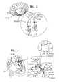
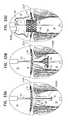
- FIGS. 1A-Hare schematic illustrations of sequential steps in the implantation of an implant comprising a prosthetic valve and a prosthetic valve support, in accordance with some applications of the present invention
- FIG. 2is a schematic illustration of a prosthetic valve support, comprising adjustable prosthetic valve support, in accordance with some applications of the invention
- FIG. 3is a schematic illustration of a prosthetic valve support, comprising an adjustable prosthetic valve support, in accordance with some applications of the invention
- FIG. 4is a schematic illustration of a prosthetic valve support, comprising an adjustable prosthetic valve support, in accordance with some applications of the invention
- FIG. 5is a schematic illustration of a prosthetic valve support, comprising a graduated prosthetic valve support, in accordance with some applications of the invention
- FIG. 6is a schematic illustration of a prosthetic valve support, comprising a flexibly-anchored prosthetic valve support, in accordance with some applications of the invention.
- FIG. 7is a schematic illustration of a prosthetic valve support, comprising a flexibly-anchored prosthetic valve support, in accordance with some applications of the invention.
- FIGS. 8A-Bare schematic illustrations of a prosthetic valve support, and a prosthetic valve, the prosthetic valve comprising an integrally-anchoring prosthetic valve, in accordance with some applications of the invention
- FIGS. 9A-Eare schematic illustrations of delivery apparatus, used to deploy a medical device, in accordance with some applications of the invention.
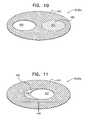
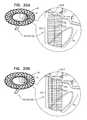
- FIG. 10is a schematic illustration of a prosthetic valve support, comprising a multi-lumen prosthetic valve support, in accordance with some applications of the invention.
- FIG. 11is a schematic illustration of a prosthetic valve, comprising an extended-lumen prosthetic valve support, in accordance with some applications of the invention.
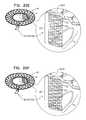
- FIGS. 12A-Bare schematic illustrations of a prosthetic valve support, comprising an adjustable-lumen prosthetic valve support, in accordance with some applications of the invention.
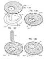
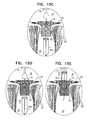
- FIGS. 13A-Dare schematic illustrations of a prosthetic valve support, comprising an asymmetric prosthetic valve support, in accordance with an application of the invention.
- FIG. 14is a schematic illustration of a prosthetic valve support, in accordance with some applications of the invention.
- FIGS. 15A-Eare schematic illustrations of the implantation of a prosthetic valve support and a prosthetic valve, in accordance with some applications of the invention.
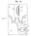
- FIG. 16is a schematic illustration of a prosthetic valve support being deployed in a native heart valve, in accordance with some applications of the invention.
- FIGS. 17A-Dare schematic illustrations of prosthetic valve supports, comprising tissue-engaging elements, which comprise support-anchoring elements, comprising length-adjustable holding elements, in accordance with some applications of the invention.
- FIGS. 18A-Bare schematic illustrations of prosthetic valve supports, comprising tissue-engaging elements, which comprise support-anchoring elements, comprising length-adjustable holding elements, in accordance with some applications of the invention.
- FIG. 19is a schematic illustration of a prosthetic valve support, comprising tissue-engaging elements, which comprise support-anchoring elements, comprising length-adjustable holding elements, in accordance with some applications of the invention.
- FIGS. 20A-Fare schematic illustrations of prosthetic valve supports, comprising tissue-engaging elements, which comp support-anchoring elements, comprising flexible support-anchoring elements, in accordance with some applications of the invention.
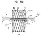
- FIGS. 21A-Care schematic illustrations of a prosthetic valve support, comprising an inflatable support-engaging element, in accordance with some applications of the invention.
- FIGS. 22A-Care schematic illustrations of sequential steps in the implantation of an implant, comprising a prosthetic valve and a prosthetic valve support, coupled via coupling leads;
- FIGS. 23A-Bare schematic illustrations of a prosthetic valve support, shaped to define at least one pocket, and the coupling thereto of a prosthetic valve, in accordance with some applications of the invention
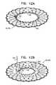
- FIG. 24is a schematic illustration of a prosthetic valve support, shaped to define at least one pocket, and the coupling thereto of a prosthetic valve, in accordance with some applications of the invention.
- FIGS. 25A-Eare schematic illustrations of a retrieval device, and sequential steps in the use thereof, in accordance with some applications of the invention.
- FIGS. 26A-Care schematic illustrations of a prosthetic valve support comprising a braided structure, and the deployment thereof, in accordance with some applications of the invention.
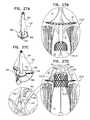
- FIGS. 27A-Dare schematic illustrations of delivery apparatus, in accordance with some applications of the invention.
- FIGS. 28A-Dare schematic illustrations of the deployment of a prosthetic valve in the lumen of another prosthetic valve, in accordance with some applications of the invention.
- FIGS. 30A-Bare schematic illustrations of the deployment of a second prosthetic valve in the lumen of a prosthetic valve support, in which a first prosthetic valve is already disposed, in accordance with some applications of the invention
- FIGS. 31A-Care schematic illustrations of a flexible delivery tube, configured to facilitate removal thereof from a subject, in accordance with some applications of the invention.
- FIGS. 32A-Care schematic illustrations of a compressible delivery tube, configured to facilitate removal thereof from a subject, in accordance with some applications of the invention.
- FIGS. 33A-Care schematic illustrations of a dismantling delivery tube, configured to facilitate removal thereof from a subject, in accordance with some applications of the invention.
- FIG. 34is an schematic illustration of a prosthetic valve, comprising a leaflet-engaging element, in accordance with some applications of the invention.
- FIGS. 35A-Care schematic illustrations of a prosthetic valve support comprising temporary valve components, and sequential steps in the coupling of a prosthetic valve to the support, in accordance with some applications of the invention
- FIGS. 36A-Dare schematic illustrations of a prosthetic valve support, comprising support-anchoring elements and stabilizing legs, in accordance with some applications of the invention.
- FIGS. 37A-Hare schematic illustrations of a prosthetic valve support, comprising support-anchoring elements and stabilizing legs, and sequential steps in the implantation thereof, in accordance with some applications of the invention.
- FIGS. 38A-Hare schematic illustrations of a prosthetic valve support, comprising support-anchoring elements and stabilizing legs, and sequential steps in the implantation thereof, in accordance with some applications of the invention.
- FIGS. 39A-Dare schematic illustrations of a medical device, comprising one or more coupling tabs, in accordance with some applications of the invention.
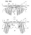
- FIGS. 40A-Care schematic illustrations of a prosthetic valve, comprising tissue-engaging elements, in accordance with some applications of the invention.
- FIGS. 41A-Bare schematic illustrations of a prosthetic valve, and a prosthetic valve support, comprising support-anchoring elements that are couplable to the prosthetic valve, in accordance with some applications of the invention
- FIGS. 42A-Bare schematic illustrations of a prosthetic valve, and a prosthetic valve support, comprising support-anchoring elements that are couplable to the prosthetic valve, in accordance with some applications of the invention
- FIGS. 43A-Care schematic illustrations of a prosthetic valve, and a prosthetic valve support, comprising support-anchoring elements that are couplable to the prosthetic valve, in accordance with some applications of the invention
- FIGS. 44A-Bare schematic illustrations of a prosthetic valve support, comprising support-anchoring elements, and a prosthetic valve, comprising valve-anchoring elements that are couplable to the tissue-engaging elements of the prosthetic valve support, in accordance with some applications of the invention;
- FIGS. 45A-Care schematic illustrations of a lock for facilitating delivery of a medical device, in accordance with some applications of the invention.
- FIGS. 46A-Bare schematic illustrations of a prosthetic valve support, comprising one or more support-anchoring elements, coupled to a stabilizing strip, in accordance with some applications of the invention.
- FIGS. 47A-Care schematic illustrations of sequential steps in the implantation of an implant, comprising a prosthetic valve and a prosthetic valve support, in accordance with some applications of the invention.
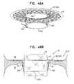
- FIGS. 48A-Care schematic illustrations of sequential steps in the implantation of an implant, comprising a prosthetic valve and a prosthetic valve support, in accordance with some applications of the invention.
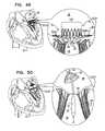
- FIG. 49is a schematic illustration of the prosthetic valve support, in accordance with some applications of the invention.
- FIG. 50is a schematic illustration of a step in the implantation of the implant, in accordance with some applications of the invention.
- FIGS. 51A-Bare schematic illustrations of the prosthetic valve support, in accordance with some applications of the invention.
- FIG. 52is a schematic illustration of the prosthetic valve, in accordance with some applications of the invention.
- FIGS. 53A-Care schematic illustrations of the prosthetic valve, comprising tissue-engaging elements, in accordance with some applications of the invention.
- FIGS. 54A-Dare schematic illustrations of the prosthetic valve, comprising tissue-engaging elements, in accordance with some applications of the invention.
- FIGS. 55A-Eare schematic illustrations of the prosthetic valve, comprising tissue-engaging elements, in accordance with some applications of the invention.
- FIGS. 56A-Dare schematic illustrations of the prosthetic valve, comprising tissue-engaging elements, in accordance with some applications of the invention.
- FIGS. 57A-Dare schematic illustrations of the prosthetic valve, comprising tissue-engaging elements, in accordance with some applications of the invention.
- FIGS. 58A-Dare schematic illustrations of the prosthetic valve support, comprising tissue-engaging elements, in accordance with some applications of the invention.
- FIGS. 59A-Bare schematic illustrations of the prosthetic valve support, comprising tissue-engaging elements, in accordance with some applications of the invention.
- FIGS. 60A-Bare schematic illustrations of the prosthetic valve support, comprising tissue-engaging elements, in accordance with some applications of the invention.
- FIGS. 61A-Care schematic illustrations of the prosthetic valve support, comprising tissue-engaging elements, in accordance with some applications of the invention.
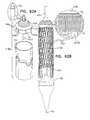
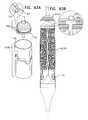
- FIGS. 62A-Dare schematic illustrations of a delivery device for the delivery and deployment of an expandable medical device, in accordance with some applications of the invention.
- FIGS. 63A-Bare schematic illustrations of the delivery device for the delivery and deployment of an expandable medical device, in accordance with some applications of the invention.
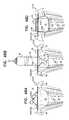
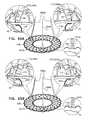
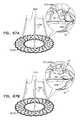
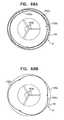
- FIGS. 64A-C , 65 A-B, 66 A-B, and 67 A-Bare schematic illustrations of a locking mechanism for delivery of an expandable medical device, in accordance with some applications of the invention.
- FIGS. 68A-B and 69 A-Eare schematic illustrations of a retrievable prosthetic valve support, and sequential steps in the retrieval of the retrievable prosthetic valve support, in accordance with some applications of the invention.
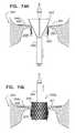
- FIG. 70A-Care schematic illustrations of the prosthetic valve, comprising tissue engaging elements, in accordance with some applications of the invention.
- FIG. 71is a schematic illustration of an implant comprising a prosthetic valve and a prosthetic valve support, in accordance with some applications of the present invention.
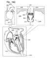
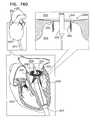
- FIGS. 72A-Dare schematic illustrations of an implant, comprising a prosthetic valve support and a prosthetic valve, in accordance with some applications of the invention.
- FIG. 73is a schematic illustration of a prosthetic valve support, for use with a prosthetic valve, in accordance with some applications of the invention.
- FIGS. 74A-Lare schematic illustrations of steps in the implantation of an implant, comprising a prosthetic valve and a prosthetic valve support, in a native valve of a subject, in accordance with some applications of the invention
- FIGS. 75A-Dare schematic illustrations of an implant, comprising a prosthetic valve support and a prosthetic valve, and steps in the implantation thereof, in accordance with some applications of the invention.
- FIGS. 76A-Fare schematic illustrations of steps in the implantation of an implant, comprising a prosthetic valve and a prosthetic valve support, in a native valve of a subject, in accordance with some applications of the invention
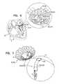
- FIG. 77is a schematic illustration of an implant, implanted at the mitral valve of a subject, in accordance with some applications of the invention.
- FIG. 78is a schematic illustration of an implant, implanted at the tricuspid valve of a subject, in accordance with some applications of the invention.
- FIG. 79is a schematic illustration of an implant, implanted at the pulmonary valve of a subject, in accordance with some applications of the invention.
- FIG. 80is a schematic illustration of an implant, implanted at the aortic valve of a subject, in accordance with some applications of the invention.
- FIGS. 1A-Hare schematic illustrations of sequential steps in the implantation in a native heart valve 23 of the heart 22 of a subject 20 of an implant 30 , comprising (1) a first prosthetic valve component, i.e., prosthetic valve support 40 , and (2) a second prosthetic valve component, i.e., a prosthetic valve 42 , in accordance with some applications of the present invention.
- native valve 23includes a native mitral valve 24 by way of illustration and not limitation; the scope of the present invention includes implanting implant 30 in other valves of the heart (e.g., the tricuspid valve, the pulmonary valve, or the aortic valve).
- FIG. 1A-Hare schematic illustrations of sequential steps in the implantation in a native heart valve 23 of the heart 22 of a subject 20 of an implant 30 , comprising (1) a first prosthetic valve component, i.e., prosthetic valve support 40 , and (2) a second prosthetic valve component, i.e., a prosthetic valve 42 , in accordance
- FIGS. 1B-Gillustrate the implantation procedure.
- native mitral valve 24includes native leaflets 82 , which are supported by native chordae tendineae 80 .
- FIG. 1Bshows prosthetic valve support 40 being deployed in a left atrium 26 .
- support 40Prior to deployment, support 40 is percutaneously (e.g., transcatheterally) advanced into left atrium 26 , typically via overtube 44 .
- the advancement of overtube 44 toward heart valve 23is preceded by advancement of a guidewire 45 through vasculature of the subject.
- guidewire 45is used to guide overtube 44 through the vasculature.
- support 40is moved distally (e.g., by a pushing coupling element, not shown for clarity of illustration and described hereinbelow), such that support 40 emerges from the distal end of overtube 44 .
- Support 40is typically expandable, and typically comprises a wire frame which comprises a shape-memory material such as, but not limited to, nickel titanium (nitinol).
- support 40comprises nickel cobalt, stainless steel and/or titanium. As support 40 gradually emerges from overtube 44 , it gradually expands to assume an expanded configuration.
- FIG. 1Cshows support 40 reversibly coupled to one or more holding members 46 , which exert a distal pushing force that causes support 40 to emerge from within overtube 44 .
- support 40expands to assume the expanded configuration, as shown.
- support 40is annular and is shaped so as to define a lumen therethrough.
- prosthetic valve support 40is shaped to define an outer edge 69 and an inner edge 68 (see FIG. 1H ).
- Outer edge 69typically defines the diameter of the annular prosthetic valve support
- inner edge 68typically defines the diameter of the lumen in which prosthetic valve 42 is typically disposed.
- holding members 46continue to push support 40 distally (i.e., in the direction as indicated by the arrows) until support 40 is positioned against an annulus of native heart valve 23 .
- Support 40is held against the annulus of native valve 23 (e.g., by holding members 46 ) such that the lumen of support 40 aligns with the lumen of the native valve, and such that atrium 26 and ventricle 28 remain in fluid communication.
- prosthetic valve 42is percutaneously (e.g., transcatheterally) advanced and delivered toward the native valve, typically along guidewire 45 , as shown in FIG. 1D .
- Prosthetic valve 42is typically expandable, and typically comprises a wire frame which comprises a shape-memory material such as, but not limited to, nickel titanium (nitinol).
- prosthetic valve 42comprises nickel cobalt, stainless steel and/or titanium.
- Delivery tube 60is slidably advanceable within tube 44 .
- Prosthetic valve 42is typically delivered through the native valve and into ventricle 28 , as shown in FIG. 1D .
- prosthetic valve 42is delivered to the native valve while support 40 is held against the annulus of native valve 23 by holding members 46 .
- FIG. 1Eshows prosthetic valve 42 being partially deployed from within delivery tube 60 .
- Prosthetic valve 42comprises a primary structural element 130 , which is typically cylindrical, prismatic, or any other suitable shape, and is shaped so to define a lumen.
- Prosthetic valve componentse.g., leaflets; not shown for clarity of illustration
- tissue-engaging elements 62are disposed at a distal portion of the primary structural element 130 of prosthetic valve 42 .
- tissue-engaging elements 62comprise valve-anchoring elements 64 .
- primary structural element 130 of prosthetic valve 42is generally cylindrical (e.g., shaped so as to define a right circular cylinder), and anchoring elements 64 protrude radially from a surface of the cylinder. It is to be noted that although prosthetic valve 42 is shown comprising tissue-engaging elements 62 , the scope of the present application includes prosthetic valves with no tissue-engaging elements 62 .
- FIG. 1Fshows prosthetic valve 42 being moved proximally, such that at least part of primary structural element 130 is disposed in the respective lumens of native valve 23 and prosthetic valve support 40 , and such that valve-anchoring elements 64 contact the ventricular side of the native valve.
- Such contacting of elements 64 with the ventricular side of the native valverestricts further undesired atrial (i.e., proximal) movement of the prosthetic valve.
- the contact between valve-anchoring elements 64 and the ventricular side of the native valveoccurs by valve-anchoring elements 64 protruding between chordae tendineae 80 and capturing leaflets 82 of the native valve.
- leaflets 82Responsively to the capturing by valve-anchoring elements 64 , leaflets 82 are typically pushed proximally and/or outward by the prosthetic valve. In some applications of the invention, leaflets 82 are held against the outer surface of primary structural element 130 by valve-anchoring elements 64 , so as to reduce blood flow between native leaflets 82 and prosthetic valve 42 . In an alternative application of the invention, rather than being partially deployed in the ventricle and subsequently moved proximally (as described with reference to FIGS. 1E-F ), prosthetic valve 42 is deployed directly in the lumen of the native valve.
- prosthetic valve 42is then fully exposed from within delivery tube 60 (by pushing valve 42 relative to delivery tube 60 or by retracting delivery tube 60 with respect to valve 42 ) and is allowed to expand further.
- FIG. 1Gshows prosthetic valve 42 in a deployed and expanded configuration after being fully exposed from within delivery tube 60 .
- the expansion of prosthetic valve 42exerts a radial force against support 40 , thereby facilitating coupling of prosthetic valve 42 to support 40 .
- Implant 30comprising prosthetic valve 42 and support 40 , is secured in place by sandwiching the native valve by the components of implant 30 .
- implant 30is inhibited from ventricular (i.e., distal) movement by support 40 and the radial force of prosthetic valve 42 exerted on support 40
- implant 30is inhibited from atrial (i.e., proximal) movement by valve-anchoring elements 64 .
- support 40prevents valve 42 from expanding to assume a fully-expanded configuration (i.e., a configuration to which valve 42 would otherwise expand without being impeded by support 40 or tissue).
- the radial force exerted by support 40 on valve 42facilitates coupling and sealing between support 40 and valve 42 (for example, by increasing friction between support 40 and valve 42 ), and facilitates implantation of implant 30 at native valve 23 .
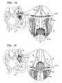
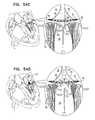
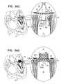
- FIG. 1Hshows implant 30 following implantation in the mitral valve of the subject.
- This figureis a transverse atrial cross-section, showing prosthetic valve support 40 in contact with the atrial side of the native valve.
- Prosthetic valve 42is expanded, and is disposed in, and coupled to, prosthetic valve support 40 .
- Tissue-engaging elements 62comprising valve-anchoring elements 64 , are disposed on the ventricular side of the native valve (as described hereinabove with reference to FIGS. 1F-G ), and are therefore illustrated in phantom.
- Valve-anchoring elements 64are typically arranged in two clusters, each cluster being disposed on opposite sides of prosthetic valve 42 .
- prosthetic valve 42when deployed as shown, prosthetic valve 42 is configured to be aligned with the native valve such that valve-anchoring elements 64 protrude toward, and engage leaflets 82 of the native valve.
- valve-anchoring elements 64protrude toward, and engage, commissures 84 of the native valve.
- a single valve-anchoring element 64is disposed on each side of the prosthetic valve. It is to be noted that the scope of the present application includes any other suitable arrangement of valve-anchoring elements 64 with respect to valve 64 .
- valve-anchoring elements 64capture leaflets 82 of the native valve, holding them clear of the flow of blood through the prosthetic valve and the left ventricular outflow tract (LVOT).
- LVOTleft ventricular outflow tract
- prosthetic valve 42typically comprises valve components (e.g., prosthetic valve leaflets, not shown in FIG. 1H ), that are disposed in the lumen of prosthetic valve 42 , coupled to structural element 130 , and configured to regulate blood flow through prosthetic valve 42 .
- valve componentse.g., prosthetic valve leaflets, not shown in FIG. 1H
- valve-anchoring elements 64function so as to (1) prevent proximal migration of prosthetic valve 42 into the subject's atrium, while (2) creating a seal between the native valve 23 and prosthetic valve 42 by generally clamping native leaflets 82 between valve-anchoring elements 64 and primary structural element 130 , valve support 40 , and/or native valve annulus.
- valve-anchoring elements 64may have the aforementioned functionalities by having lengths of less than 5 mm, and/or by having a total width of each cluster of valve-anchoring elements (corresponding to respective leaflets of the native valve) being less than 5 mm.
- the valvemay include a single valve-anchoring element 64 corresponding to each leaflet of the native valve, the width of each of the single valve-anchoring elements being less than 1 mm.
- the valvemay be stopped from proximally migrating into the atrium by the valve-coupling elements preventing the distal end of the valve from migrating further proximally than edges of native leaflets of the valve.
- the valve-anchoring elementsmay allow movement of the native leaflets with respect to the prosthetic valve by not generally squeezing the native leaflets between the valve-coupling elements and primary structural element 130 of the prosthetic valve.
- prosthetic valve support 40comprises support-anchoring elements (such as clips), and is directly coupled to the native valve.
- valve-anchoring elementsare used; rather, implant 30 is coupled to the native valve via prosthetic valve support 40 (e.g., as described hereinbelow, such as with reference to FIGS. 37A-H and 38 A-H).
- prosthetic valve support 40e.g., as described hereinbelow, such as with reference to FIGS. 37A-H and 38 A-H.
- both valve-anchoring elements and support-anchoring elementsare used.
- by allowing movement of the native leaflets with respect to the prosthetic valvesealing of the native leaflets against the outer surface of the primary structural element of the prosthetic valve is facilitated, in accordance with the techniques described herein.
- prosthetic valve 42is initially delivered to ventricle 28 . Subsequently, prosthetic valve support 40 is deployed within atrium 26 . In these applications of the invention, following deployment and positioning of prosthetic valve support 40 against the annulus of native valve 23 , prosthetic valve 42 is moved atrially (i.e., proximally) into the respective lumens of the native valve and prosthetic valve support 40 , and is deployed, as described hereinabove.
- valve-anchoring elements 64anchor prosthetic valve 42 to the native valve in a manner that restricts both proximal and distal movement of the prosthetic valve.
- deployment of prosthetic valve 42may occur in the reverse orientation, such that, following positioning in the native valve of prosthetic valve 42 compressed in delivery tube 60 , the delivery tube is moved distally (i.e., ventricularly) as prosthetic valve 42 is deployed from the delivery tube. Delivery tube 60 is then removed from the subject via the lumen of the deployed prosthetic valve. It is hypothesized that this approach facilitates maneuvering of implant components and delivery apparatus, both for delivery of implant 30 and for withdrawal of delivery apparatus.
- this approachis hypothesized to require less space on the proximal side of the native valve (e.g., in the atrium), compared to techniques whereby the prosthetic valve is deployed from the proximal side of the native valve.
- An example of this approachis described with reference to FIGS. 15A-E .
- surfaces of one or more components of implant 30are covered at least in part with a covering (not shown).
- surfaces of prosthetic valve support 40 and prosthetic valve 42may be covered so as to direct substantially all blood flowing through the valve, to flow through the lumen of prosthetic valve 42 .
- the surface of prosthetic valve support 40 (or another component) that is placed in contact with the native valveis covered; the covering is configured to facilitate coupling of support 40 to the native valve, by enhancing fibrosis at the interface between the prosthetic valve support and the native valve.
- the coveringmay comprise polyethylene terephthalate (e.g., polyester), polytetrafluoroethylene (e.g., Teflon, ePTFE), or pericardial tissue.
- a thickness of the coveringis less than 0.2 mm, e.g., less than 0.1 mm, or less than 0.05 mm.
- one or more dimensions of native valve 23is measured (e.g., by using imaging techniques) prior to deployment of valve 42 .
- a suitably-sized prosthetic valveis chosen to be placed in the annulus, in a manner in which a cross-sectional area of the prosthetic valve in its deployed state is less than 90% (e.g., less than 80%, or less than 60%) of the area defined by the annulus.
- the cross-sectional area of the prosthetic valve in its deployed statehas a longest length of less than 25 mm, e.g., less than 20 mm, and/or more than 15 mm, e.g., 15-25 mm.
- placing a prosthetic valve inside the native valve, with the dimensions of the native valve annulus and the prosthetic valve as describedfacilitates sealing of the prosthetic valve with respect to the native valve, by the native valve leaflets closing around the outer surface of the prosthetic valve.
- prosthetic valve 42is implanted directly within native valve 23 (i.e., without support 40 ).
- prosthetic valve support 40that is shaped to define a lumen, is placed against the annulus of native valve 23 (e.g., as described with reference to FIGS. 1A-H ).
- the lumen of support 40has a cross-sectional area that is less than 90% (e.g., less than 80%, or less than 60%) of an area defined by native valve 23 (e.g., area A 1 , FIG. 71 ).
- prosthetic valve 42is typically coupled to prosthetic valve support 40 and, thereby, to native valve 23 , at least in part by expansion of the prosthetic valve such that primary structural element 130 exerts a radial force against inner edge 68 of prosthetic valve support 40 .
- the cross-sectional area defined by the primary structural element 130 of the prosthetic valve, upon expansion of the prosthetic valve,is limited by the cross-sectional area of the lumen of the prosthetic valve support 40 to less than 90% (e.g., less than 80%, or less than 60%) of the area defined by the annulus of the native valve.
- placing a prosthetic valve support 40 at the native valve, as describedfacilitates sealing of the prosthetic valve with respect to the native valve, by the native valve leaflets closing around the outer surface of the prosthetic valve.
- placing a prosthetic valve inside the native valve with the dimensions of the native valve annulus, the prosthetic valve 42 , and/or valve support 40 as described in the above paragraphsfacilitates sealing of the prosthetic valve with respect to the native valve.
- the sealingis facilitated by the native leaflets being pushed against, and closing against, the outer surface of the frame of the valve during systole, in a similar manner to the manner in which native valve leaflets coapt during systole, in a healthy mitral valve.
- the proportion of the native leaflets that is pushed against the outer surface of the valve during systoleis increased, thereby enhancing the sealing of the native leaflets with respect to the frame of the prosthetic valve.
- the native valve leafletsare pushed apart at the commissures, thereby causing retrograde leakage of blood through the commissures.
- prosthetic valve 42 , and/or valve support 40are chosen such that the cross-sectional area of the prosthetic valve (when expanded inside the valve support) is less than 90% (e.g., less than 80%, or less than 60%) of the area defined by the annulus of native vale 23 .
- the valve supportfacilitates additional sealing of the prosthetic valve with respect to the native valve, by the native valve leaflets closing around the outer surface of the prosthetic valve, while not causing retrograde leakage of blood through the commissures.
- a materialis placed on the outer surface of the prosthetic valve in order to provide a sealing interface between the prosthetic valve and the native valve.
- a smooth material that prevents tissue growthe.g., polytetrafluoroethylene (PTFE), and/or pericardium
- PTFEpolytetrafluoroethylene
- a material that facilitates tissue growthsuch as polyethylene terephthalate; PET may be placed on the outer surface of the prosthetic valve, in order to (a) act as a sealing interface between the native valve and the prosthetic valve, and (b) facilitate tissue growth around the prosthetic valve to facilitate anchoring and/or sealing of the prosthetic valve.
- PETpolyethylene terephthalate
- one or more dimensions of native valve 23are measured (e.g., by using imaging techniques) prior to deployment of prosthetic valve 42 and/or prosthetic valve support 40 .
- a suitably-sized and/or suitably-configured prosthetic valve and/or prosthetic valve supportis selected for implantation.
- a prosthetic valve or prosthetic valve supportcomprising tissue-engaging elements 62 with appropriate configurations and/or dimensions may be selected.
- FIG. 2is a schematic illustration of prosthetic valve support 40 , comprising adjustable prosthetic valve support 40 e , which comprises tissue-engaging elements 62 , comprising support-anchoring elements 66 e , in accordance with some applications of the invention.
- Each support anchoring element 66 ecomprises, or is coupled to, a holding wire 522 , which is slidably coupled to an upstream support portion 41 (e.g., an annular portion) of support 40 e .
- upstream support portion 41e.g., an annular portion
- support 40 eis anchored to native valve 23 via support-anchoring elements 66 e .
- elements 66 emay engage commissures 84 or leaflets 82 of the native valve, as described hereinabove.
- the distance between upstream support portion 41 of support 40 e and a coupling portion 70 of anchoring element 66 eis adjustable by adjusting the length of the portion of holding wire 522 that couples the upstream support portion to the coupling portion.
- holding wire 522is disposed in a connector 540 , which further couples coupling portion 70 to upstream support portion 41 .
- Holding wire 522may be slidable through connector 540 .
- connector 540is more rigid than holding wire 522 .
- FIG. 3is a schematic illustration of prosthetic valve support 40 , comprising adjustable prosthetic valve support 40 f , which comprises tissue-engaging elements 62 , comprising support-anchoring elements 66 f , in accordance with some applications of the invention.
- Each support anchoring element 66 fcomprises, or is coupled to, a holding wire 522 f , which is slidably coupled to upstream support portion 41 of support 40 f .
- support 40 fis anchored to native valve 23 via support-anchoring elements 66 f .
- elements 66 fmay engage commissures 84 or leaflets 82 of the native valve, as described herein.
- the distance between upstream support portion 41 of support 40 f and a coupling portion of anchoring element 66 fis adjustable by adjusting the length of holding wire 522 f .
- holding wire 522 fis slidably coupled to upstream support portion 41 of support 40 f via a ratchet 526 , wherein holding wire 522 f is slidable through a ratchet housing 524 , and comprises a plurality of teeth 523 which allow the holding wire to slide through the ratchet housing in one direction, and restrict such sliding in another direction.
- Such adjustment of holding wire 522 fmay be performed while support 40 f is partially deployed, or after the support has been fully deployed.
- FIG. 3shows ratchet housing 524 being slidable over holding wire 522 f , such that the ratchet housing is movable with respect to upstream support portion 41 of support 40 f .
- a controller tube 528is typically used to slide (e.g., push) ratchet housing 524 over holding wire 522 f , so as to adjust the distance between upstream support portion 41 of support 40 f and the coupling portion.
- ratchet housing 524is substantially stationary with respect to upstream support portion 41 (e.g., ratchet housing 524 is attached to and/or embedded in portion 41 ), and holding wire 522 is slid (e.g., pulled) through housing 524 , so as to adjust the distance between upstream support portion 41 of support 40 f and coupling portion 70 .
- holding wire 522e.g., wire 522 f
- a connector 540e.g., connector 540 f
- Holding wire 522 fmay be slidable through connector 540 f .
- Connector 540 fis typically more rigid that holding wire 522 f.
- prosthetic valve support 40 fit is hypothesized that adjusting the position of coupling portion 70 of support-anchoring elements 66 f , with respect to upstream support portion 41 of prosthetic valve support 40 f , allows prosthetic valve support 40 f to be adapted to the anatomy of the subject during and/or subsequent to the implantation procedure.
- FIG. 4is a schematic illustration of prosthetic valve support 40 , comprising adjustable prosthetic valve support 40 g , which comprises tissue-engaging elements 62 , comprising support-anchoring elements 66 g , in accordance with some applications of the invention.
- Each support anchoring element 66 gcomprises, or is coupled to, a holding wire 522 , which is slidably coupled to upstream support portion 41 of support 40 g .
- support 40 gis anchored to native valve 23 via support-anchoring elements 66 g .
- elements 66 gmay engage commissures 84 or leaflets 82 of the native valve, as described herein.
- the distance between upstream support portion 41 of support 40 g and a coupling portion 70 (not shown) of anchoring element 66 gis adjustable by adjusting the length of holding wire 522 g .
- Holding wire 522 gis coupled to a spool 460 , such that operation (e.g., turning) of spool 460 withdraws and/or ejects portions of the holding wire, thereby adjusting the length of holding wire 522 g that couples the upstream support portion to the coupling portion, thereby adjusting the distance between upstream support portion 41 and coupling portion 70 .
- Such adjustment of holding wire 522 gmay be performed while support 40 g is partially deployed, or after the support has been fully deployed.
- holding wire 522e.g., wire 522 g
- a connector 540e.g., connector 540
- Holding wire 522 gmay be slidable through connector 540 g .
- connector 540 gis more rigid that holding wire 522 g.
- prosthetic valve support 40 git is hypothesized that adjusting the position of coupling portion 70 of support-anchoring elements 66 g , with respect to upstream support portion 41 of prosthetic valve support 40 g , allows prosthetic valve support 40 g to be adapted to the anatomy of the subject during and/or subsequent to the implantation procedure.
- FIG. 5is a schematic illustration of prosthetic valve support 40 , comprising graduated prosthetic valve support 40 h , which comprises tissue-engaging elements 62 , comprising support-anchoring elements 66 h , in accordance with some applications of the invention.
- Each support-anchoring element 66 his coupled to upstream support portion 41 of support 40 h via a graduated connector 542 .
- Graduated connector 542comprises a plurality of coupling points 543 , to which coupling portion 70 of element 66 h is couplable.
- the distance between upstream support portion 41 of support 40 h and coupling portion 70is adjustable, by selecting the coupling point 543 to which each coupling portion 70 is coupled.
- prosthetic valve support 40 hit is hypothesized that adjusting the position of coupling portion 70 of support-anchoring elements 66 h , with respect to upstream support portion 41 of prosthetic valve support 40 h , allows prosthetic valve support 40 h to be adapted to the anatomy of the subject during and/or subsequent to the implantation procedure.
- FIG. 6is a schematic illustration of prosthetic valve support 40 , comprising flexibly-anchored prosthetic valve support 40 i , which comprises tissue-engaging elements 62 , comprising support-anchoring elements 66 i , in accordance with some applications of the invention.
- Each support-anchoring element 66 iis coupled to upstream support portion 41 of support 40 i via a connector 540 , such as flexible connector 544 .
- Flexible connector 544typically comprises a flexible material which typically, but not necessarily, comprises polyethylene terephthalate (e.g., polyester), polytetrafluoroethylene (e.g., Teflon, ePTFE), silicone (e.g., silicone rubber), and/or or pericardial tissue.
- Flexible connector 544facilitates movement of coupling portion 70 of elements 66 i to move with respect to upstream support portion 41 of support 40 i . It is hypothesized that this flexibility allows elements 66 i to anchor prosthetic valve support 40 i to the native valve (e.g., by coupling to leaflets 82 ), whilst allowing leaflets 82 to continue to function, at least in part.
- FIG. 7is a schematic illustration of prosthetic valve support 40 , comprising flexibly-anchored prosthetic valve support 40 j , which comprises tissue-engaging elements 62 , comprising support-anchoring elements 66 j , in accordance with some applications of the invention.
- Coupling portion 70 of each element 66 jis coupled to upstream support portion 41 of support 40 j via at least one connector ring 548 .
- Connector ring 548typically facilitates movement of coupling portion 70 with respect to upstream support portion 41 .
- Each support-anchoring element 66 jtypically comprises a connector 540 , such as flexible connector 546 .
- Flexible connector 546typically comprises a flexible material which typically, but not necessarily, comprises polyethylene terephthalate (e.g., polyester), polytetrafluoroethylene (e.g., Teflon, ePTFE), silicone (e.g., silicone rubber), and/or or pericardial tissue. Flexible connector 546 typically further facilitates coupling portion 70 to move with respect to upstream support portion 41 of support 40 j . It is hypothesized that this flexibility allows elements 66 j to anchor prosthetic valve support 40 j to the native valve (e.g., by coupling to leaflets 82 ), whilst allowing leaflets 82 to continue to function, at least in part.
- polyethylene terephthalatee.g., polyester
- polytetrafluoroethylenee.g., Teflon, ePTFE
- siliconee.g., silicone rubber
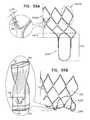
- FIGS. 8A-Bare schematic illustrations of prosthetic valve support 40 , and prosthetic valve 42 , the prosthetic valve comprising an integrally-anchoring prosthetic valve 42 a , which comprises support-engaging elements 422 comprising a plurality of integral support-engaging elements 424 , in accordance with some applications of the invention.
- support-engaging elements 422comprise other valve-anchoring elements described herein, such as valve-anchoring elements 64 .
- Prosthetic valve 42 acomprises a lattice structure, comprising a plurality of struts which typically collectively define a tessellation of shapes and voids. In some regions of the prosthetic valve, there is a separation between adjacent shapes. This separation allows a portion of the shape to move or be moved out of the plane of the lattice, thereby protruding from primary structural element 130 of prosthetic valve 42 a when the prosthetic valve is expanded. The protruding portion of the shapes thereby form integral support-engaging elements 424 , which are typically configured to anchor prosthetic valve 42 a to the distal side of prosthetic valve support 40 .
- FIG. 8Bshows implant 30 , comprising prosthetic valve 42 a and prosthetic valve support 40 , implanted in native valve 23 .
- FIG. 8Bshows implant 30 , comprising prosthetic valve support 40 and prosthetic valve 42 a , implanted in native valve 23 , comprising mitral valve 24 .
- Prosthetic valve support 40typically comprises a plurality of tissue-engaging elements 62 , comprising support-anchoring elements 66 , which engage leaflets 82 and/or chordae tendineae 80 , and/or commissures 84 , thereby anchoring support 40 to the native valve.
- Prosthetic valve 42 ais compressible (e.g., crimpable) and expandable, and typically comprises a shape-memory material, as described hereinabove with reference to prosthetic valve 42 .
- Prosthetic valve 42 ais configured (e.g., shape-set) such that support-engaging elements 422 , comprising integral support-engaging elements 424 , are biased to protrude from the surface of primary structural element 130 .
- primary structural element 130 of prosthetic valve 42 ais generally cylindrical, and integral support-engaging elements 424 protrude radially from the surface of the cylinder.
- integral support-engaging elements 424are formed from the regular repeating structure of the lattice that forms prosthetic valve 42 a , support-engaging elements 424 fit back into the plane of structural element 130 when valve 42 a is crimped into delivery tube 60 , prior to and even during implantation. Integral support-engaging elements 424 , thereby typically do not increase the length nor the transverse cross-sectional longest dimension of the crimped configuration of prosthetic valve 42 , as compared to those of any other prosthetic valves that do not comprise support-engaging elements 422 , or that comprise elements 422 at a proximal end thereof.
- FIG. 8Bshows prosthetic valve 42 a in a fully-deployed state, such that integral support-engaging elements 424 have emerged from delivery tube 60 , and have assumed an unconstrained, expanded, resting configuration in which the integral support-engaging elements 424 protrude radially from the surface of primary structural element 130 of the prosthetic valve.
- FIG. 8Bshows prosthetic valve 42 a in a fully-deployed state, such that integral support-engaging elements 424 have emerged from delivery tube 60 , and have assumed an unconstrained, expanded, resting configuration in which the integral support-engaging elements 424 protrude radially from the surface of primary structural element 130 of the prosthetic valve.
- integral support-engaging elements 424typically protrude up to and including 110 degrees (e.g., between 10 and 60 degrees, such as between 15 and 30 degrees) from the surface of primary structural element 130 , in a resting state of support-engaging elements 424 . That is, in the protruded state, the proximal portions of support-engaging elements 424 are distanced further from structural element 130 than the distal portions of support-engaging elements 424 which function as the pivot joints 74 between support-engaging elements 424 and structural element 130 , as shown in FIG. 8A .
- the radially-protruding proximal portions thereoftypically define a cross-sectional area, the longest dimension of which is typically longer than a transverse cross-sectional longest dimension of the lumen defined by prosthetic valve support 40 . That is, in the expanded state, support-engaging elements 424 increase a longest transverse cross-sectional length of prosthetic valve 42 a , such that the longest transverse cross-sectional length is longer than a longest transverse cross-sectional length of the lumen defined by prosthetic valve support 40 .
- the radially-protruding support-engaging elements 424restrict proximal movement of prosthetic valve 42 a with respect to prosthetic valve support 40 , thereby anchoring prosthetic valve 42 a to the distal side of prosthetic valve support 40 , and to native valve 23 .
- FIGS. 9A-Eare schematic illustrations of delivery apparatus 438 , used to deploy a medical device 150 , in accordance with some applications of the invention.
- Delivery apparatus 438comprises a delivery tube 154 and a pushing member 140 .
- Pushing member 140comprises a support 142 and one or more coupling tabs 146 , extending from the support.
- support 142comprises a core 144
- coupling tabs 146extend radially from the core.
- support 142is shaped to define a plate 148 at the proximal end of support 142 .
- the dimensions and relative positions of support 142 , tabs 146 , and plate 148may be adjusted for the specific medical device 150 to be deployed using delivery apparatus 438 .
- Support 142is shaped to define a plurality of conduits 492 (e.g., holes).
- Delivery apparatus 438further comprises one or more control filaments, such as retrieval wires 490 , slidably disposed in conduits 492 .
- conduits 492provide communication between a proximal side of support 142 and a circumference of the support, such that a proximal end of each retrieval wire 490 is disposed at a site proximal to delivery tube 154 , and a distal end of each wire is reversibly coupled to medical device 150 , retrieval wires 490 extending through conduits 492 .
- retrieval wires 490are coupled to medical device 150 by being looped around parts of the medical device (e.g., looped around a strut of the lattice structure, as shown in FIG. 9D ), and are uncouplable from the medical device by being unlooped.
- retrieval wires 490are coupled to medical device 150 via a lock, such as a lock comprising a plug disposed in a tubular member (e.g., as described with reference to FIGS. 45A-C and/or 64 A-C, mutatis mutandis).
- medical device 150comprises prosthetic valve 42 .
- FIG. 9Bshows prosthetic valve 42 in a compressed (i.e., crimped) configuration for delivery and deployment using delivery apparatus 438 .
- Prosthetic valve 42typically has a lattice structure that defines a plurality of shapes, and respective voids 126 ( FIG. 9C ), and has shape memory (described in more detail hereinbelow, such as with reference to FIGS. 53A-C and 62 A-D, mutatis mutandis).
- Prosthetic valve 42is shown in a compressed (e.g., crimped) configuration, and as shown in the enlarged image, a proximal portion of valve 42 is disposed around (e.g., against) core 144 of pushing member 140 such that each of coupling tabs 146 is disposed within a respective void 126 defined by the lattice structure of the prosthetic valve.
- Prosthetic valve 42 and pushing member 140are disposed within the lumen of delivery tube 154 .
- Delivery tube 154restricts expansion of prosthetic valve 42 , thereby holding the proximal portion of prosthetic valve 42 around core 144 of pushing member 140 , in the configuration described herein.
- Coupling tabs 146restrict movement of prosthetic valve 42 with respect to pushing member 140 .
- Delivery tube 154therefore facilitates coupling of prosthetic valve 42 to pushing member 140 via coupling tabs 146 .
- the platetypically further facilitates this coupling by restricting proximal movement of prosthetic valve 42 with respect to the pushing member (i.e., by functioning as a cap).
- prosthetic valve 42is configured to be fixedly coupled to pushing member 140 .
- a control tube 152is typically coupled at a distal end thereof to pushing member 140 (e.g., control tube 152 is coupled to support 142 ).
- Control tube 152is shaped so as to define a lumen through which a guidewire tube 153 passes, and control tube 152 is slidable with respect to and along guidewire tube 153 .
- Guidewire tube 153houses guidewire 45 described hereinabove.
- Control tube 152is slidably disposed within a lumen of an overtube 155 .
- FIG. 9Cshows prosthetic valve 42 partially deployed from delivery tube 154 .
- Pushing member 140and, thereby, prosthetic valve 42 , are moved distally through delivery tube 154 .
- Pushing member 140is pushed distally by pushing control tube 152 along guidewire tube 153 such that pushing member 140 pushes prosthetic valve 42 .
- pushing member 140pushes valve 42 distally, distal portions of the prosthetic valve expand toward the expanded configuration as they become exposed from delivery tube 154 , while the proximal end of valve 42 remains coupled to pushing member 140 via tabs 146 .
- FIG. 9Dshows prosthetic valve 42 having been fully deployed from within delivery tube 154 .
- Pushing member 140 and prosthetic valve 42are moved further distally through delivery tube 154 by control tube 152 .
- expansion of the proximal portion of prosthetic valve 42uncouples the prosthetic valve from coupling tabs 146 by expanding voids 126 away from tabs 146 , thereby releasing the prosthetic valve from pushing member 140 .
- retrieval wires 490are generally loose, such that expansion of prosthetic valve 42 pulls the wires through conduits 492 , and radially outward from core 144 .
- retrieval wires 490are under tension, and are released gradually, so as to control expansion of prosthetic valve 42 . That is, for some applications, the expansion of prosthetic valve 42 is restricted (e.g., controlled) by the distal advancement of retrieval wires 490 .
- medical device 150e.g., prosthetic valve 42
- pushing member 140i.e., while the proximal portion of medical device 150 is crimped within delivery tube 154
- the deployed, expanded portions of medical device 150i.e., the portions of medical device 150 that are exposed from delivery tube 154
- prosthetic valve 42may be drawn back against support 142 (e.g., radially inward) by proximally pulling retrieval wires 490 . Subsequently, prosthetic valve 42 may be drawn back, along with pushing member 140 , into delivery tube 154 . That is, for some applications, prosthetic valve 42 is recompressible (i.e., the expansion of prosthetic valve 42 is at least in part reversible) by proximal retraction of retrieval wires 490 .
- FIG. 9Eshows retrieval wires 490 having been pulled proximally (e.g., by a user), such that wires 490 pull at least part of prosthetic valve 42 into a compressed configuration around and against support 142 .
- Prosthetic valve 42is thereby recoupled to pushing member 140 .
- Pushing member 140 and prosthetic valve 42are moved proximally and drawn into delivery tube 154 .
- Prosthetic valve 42may subsequently redeployed, or removed from the subject along with delivery tube 154 .
- retrieval wires 490are slidable through conduits 492 of core 144 , and reversibly couplable to prosthetic valve 42
- delivery apparatus 438is configured to control and/or facilitate (a) expansion of prosthetic valve 42 , by the retrieval wires being advanced distally through the conduits, and (b) recompression of prosthetic valve 42 , by the retrieval wires being retracted proximally through the conduits.
- delivery tube 154 of FIGS. 9A-Eis similar to, and/or may comprise, delivery tube 60 of FIGS. 1D-F .
- FIG. 10is a schematic illustration of prosthetic valve support 40 , comprising multi-lumen prosthetic valve support 40 a , in accordance with some applications of the invention.
- prosthetic valve support 40is generally annular and shaped to define a lumen, in which prosthetic valve 42 is deployed and expanded.
- prosthetic valve support 40comprising multi-lumen prosthetic valve support 40 a
- Prosthetic valve support 40 ais typically couplable to the native valve using techniques described herein for coupling other prosthetic valve supports to the native valve.
- prosthetic valve support 40 amay comprise tissue-engaging elements (e.g., support-anchoring elements).
- other prosthetic valve supports described hereinmay comprise prosthetic valve support 40 a.
- Prosthetic valve support 40 ais typically covered with a covering 440 , such as a fabric.
- Covering 440may comprise polyethylene terephthalate (e.g., polyester), polytetrafluoroethylene (e.g., Teflon, ePTFE), or pericardial tissue.
- a thickness of covering 440is less than 0.2 mm, e.g., less than 0.1 mm, or less than 0.05 mm.
- covering 440typically covers support 40 a such that only a first lumen 444 is open and configured to receive a prosthetic valve, and the second lumen 446 is closed. That is, the wire frame of support 40 a defines two or more lumens but the covering defines only one lumen, thereby covering 440 functions as a seal 442 .
- covering 440is not disposed over second lumen 446 ; rather a different element functions as seal 442 .
- a weaker and/or softer materiale.g., pericardial tissue
- a removable plugmay be coupled to prosthetic valve support 40 a , and disposed over second lumen 446 to function as seal 442 .
- Implant 30comprising prosthetic valve 42 and prosthetic valve support 40 a , is implanted in native valve 23 (e.g., as described with reference to FIGS. 1A-H , mutatis mutandis), whereby prosthetic valve prosthetic valve 42 is deployed in first lumen 444 of the support.
- a second prosthetic valvemay be introduced by deploying the second prosthetic valve in second lumen 446 . That is, at a first period, prosthetic valve support 40 a facilitates implantation of a first prosthetic valve at the native valve, and at a second period, the prosthetic valve support facilitates implantation of a second prosthetic valve at the native valve.
- seal 442is opened, and thereby configured to receive a prosthetic valve (e.g., by being broken, cut and/or torn) by the introduction of the second prosthetic valve.
- seal 442is opened with a cutting tool (not shown) prior to deployment of the second prosthetic valve.
- seal 442is uncoupled from support 40 a , prior to deployment of the second prosthetic valve.
- the first prosthetic valvei.e., prosthetic valve 42
- the first prosthetic valveis disabled (e.g., sealed).
- an expandable plugmay be expanded in the lumen of the first prosthetic valve.
- Prosthetic cardiac valvestypically require replacement after several years (e.g., after 2-20 years, such as after 5-10 years).
- the condition of the subjectmay change and/or components of the prosthetic valve (e.g., prosthetic valve leaflets) may suffer fatigue.
- multi-lumen prosthetic valve support 40 aallows a second prosthetic valve to be implanted in the native valve, the second prosthetic valve being supported by the originally-implanted prosthetic valve support 40 a .
- the first prosthetic valvemay be sealed, for example, if the original prosthetic valve allows, or is predicted to allow, retrograde leakage. Implantation of a second prosthetic valve is hypothesized to increase the lifespan of implant 30 .
- FIG. 11is a schematic illustration of prosthetic valve 40 , comprising extended-lumen prosthetic valve support 40 e , in accordance with some applications of the invention.
- prosthetic valve support 40is generally annular and shaped to define a lumen, in which prosthetic valve 42 is deployed and expanded.
- Extended-lumen prosthetic valve support 40 eis shaped to define a lumen 448 , which has an extended dimension. That is, the wire frame of support 40 e typically defines lumen 448 , which has (1) a primary region 447 , and (2) a secondary region 449 that is generally not filled by expansion of prosthetic valve 42 in the lumen.
- lumen 448has a first length that is longer than, and generally orthogonal to, a second length, and has one or more concave portions.
- lumen 448may be generally shaped to define an oval or ellipse with one or more concave portions generally midway along the first length (e.g., a Cassini oval or a hippopede).
- Prosthetic valve support 40 eis typically couplable to the native valve using techniques described herein for coupling other prosthetic valve supports to the native valve.
- prosthetic valve support 40 emay comprise tissue-engaging elements (e.g., support-anchoring elements).
- other prosthetic valve supports described hereinmay comprise prosthetic valve support 40 e.
- Prosthetic valve support 40 eis typically covered with a covering 440 , such as a fabric.
- Covering 440may comprise polyethylene terephthalate (e.g., polyester), polytetrafluoroethylene (e.g., Teflon, ePTFE), or pericardial tissue.
- a thickness of covering 440is less than 0.2 mm, e.g., less than 0.1 mm, or less than 0.05 mm.
- covering 440typically covers support 40 e such that secondary region 449 is closed. That is, the wire frame of support 40 e defines a generally elongated lumen 448 , whilst covering 440 defines a generally round primary region 447 . In this manner, covering 440 functions as a seal 442 over secondary region 449 .
- covering 440is not disposed over secondary region 449 ; rather a different element functions as seal 442 .
- a weaker and/or softer materiale.g., pericardial tissue
- a removable plugmay be coupled to prosthetic valve support 40 e , and disposed over secondary region 449 , so as to function as seal 442 .
- Implant 30comprising prosthetic valve 42 and prosthetic valve support 40 e , is implanted in native valve 23 (e.g., as described with reference to FIGS. 1A-H ), whereby prosthetic valve 42 is deployed in primary region 447 of the support.
- a second prosthetic valvemay be introduced by deploying the second prosthetic valve in secondary region 449 . That is, at a first period, prosthetic valve support 40 e facilitates implantation of a first prosthetic valve at the native valve, and at a second period, the prosthetic valve support facilitates implantation of a second prosthetic valve at the native valve.
- seal 442is opened (e.g., broken, cut and/or torn) by the introduction of the second prosthetic valve. In other applications, seal 442 is opened with a cutting tool (not shown) prior to deployment of the second prosthetic valve. In some applications of the invention, seal 442 is uncoupled from support 40 e , prior to deployment of the second prosthetic valve.
- expansion of the second prosthetic valve during deploymentdeforms the first prosthetic valve (i.e., a radially-expansive force of the second prosthetic valve is stronger than that of the first prosthetic valve).
- the first valvemay assume a lune shape or a generally semicircular shape.
- the second prosthetic valveis shaped to fit into secondary region 449 without deforming the first prosthetic valve.
- Prosthetic cardiac valvestypically require replacement after several years (e.g., after 2-20 years, such as after 5-10 years).
- the condition of the subjectmay change and/or components of the prosthetic valve (e.g., prosthetic valve leaflets) may suffer fatigue.
- extended-lumen prosthetic valve support 40allows a second prosthetic valve to be implanted in the native valve, the second prosthetic valve being supported by the originally-implanted prosthetic valve support 40 .
- the first prosthetic valvemay be sealed, as described hereinabove, for example, if the original prosthetic valve allows, or is predicted to allow, retrograde leakage. Implantation of a second prosthetic valve is hypothesized to increase the lifespan of implant 30 .
- FIGS. 12A-Bare schematic illustrations of prosthetic valve support 40 , comprising adjustable-lumen prosthetic valve support 40 b , in accordance with some applications of the invention.
- expansion of prosthetic valve 42is restricted by the lumen of prosthetic valve support 40 .
- the optimum lumen sizemay depend on the individual subject and/or condition being treated. Adjusting the size of the lumen of prosthetic valve 42 is hypothesized to alter the flow of blood through the prosthetic valve, and the sealing of leaflets 82 of the native valve against the outer surface of the prosthetic valve.
- FIGS. 12A-Bshow adjustable-lumen prosthetic valve support 40 b , which comprises a spool 461 and a tightening wire 462 .
- Tightening wire 462typically forms a loop around a central portion of support 40 b (e.g., threadedly coupled around an inner edge 68 ), and is coupled to spool 461 such that the tightening wire can be tightened (i.e., shortened) via spool 461 .
- FIG. 12Ashows support 40 b with a larger lumen (i.e., when tightening wire 462 is relatively loose) and FIG. 12B shows support 40 b with a smaller lumen, following tightening of tightening wire 462 with a tightening tool 464 .
- prosthetic valve support 40 b and prosthetic valve 42are implanted as described herein (e.g., with reference to FIGS. 1A-H ), and tightening wire 462 is subsequently tightened.
- the annulus of the native valveis measured, and tightening wire 462 is responsively adjusted, prior to implantation.
- a support 40 b of appropriate sizeis selected from a range.
- FIGS. 13A-Dare schematic illustrations of prosthetic valve support 40 , comprising asymmetric prosthetic valve support 40 c , in accordance with an application of the invention.
- support 40is generally annular, and shaped to define a lumen.
- FIG. 13Ashows that the lumen defined by support 40 c (i.e., oblique lumen 480 ) is typically not central with respect to the support. That is, support 40 c is typically rotationally asymmetric.
- Support 40 ctypically defines a total cross-sectional area of between 16 cm ⁇ 2 and 38 cm ⁇ 2 (e.g., between 22 cm ⁇ 2 and 28 cm ⁇ 2).
- the cross-sectional area of lumen 480is less than 70% (e.g., less than 60%, or less than 40%) of the cross-sectional area of area of support 40 c .
- the cross-sectional area of lumen 480has a longest length of less than 25 mm, e.g., less than 20 mm, and/or more than 15 mm, e.g., 15-25 mm.
- surfaces of prosthetic valve support 40are covered with a covering so as to direct substantially all blood to flow through the lumen of prosthetic valve 42 .
- Asymmetric prosthetic valve support 40 cis typically not covered, i.e., the lattice structure of which the support is comprised, is exposed.
- FIG. 13Bshows prosthetic valve support 40 c having been deployed to the annulus of native valve 23 , as described herein (e.g., with reference to FIGS. 1A-H ).
- prosthetic valve supporttypically comprises a plurality of tissue-engaging elements (e.g., support-anchoring elements), such as those described herein (not shown in FIGS. 13A-D ).
- Support-anchoring elements 66are typically configured and oriented to engage commissures 84 of the native valve, so as to anchor support 40 to the native valve whilst allowing leaflets 82 to continue to function.
- Prosthetic valve support 40 cis typically deployed to native valve 23 such that lumen 480 is positioned over (i.e., proximal to) a place of coaptation of the two leaflets 82 of the native valve. Subsequently, prosthetic valve 42 is deployed in lumen 480 (as described hereinabove; e.g., with reference to FIGS. 1A-H ), such that, in the expanded state, prosthetic valve 42 is disposed between leaflets 82 .
- FIG. 13Cshows implant 30 , comprising prosthetic valve support 40 c and prosthetic valve 42 , implanted in native valve 23 , in accordance with an application of the invention.
- prosthetic valve 42does not comprise valve-anchoring elements 64 .
- prosthetic valve 42is typically anchored to native valve 23 by being coupled to support 40 c , which is, itself, anchored to the native valve, as described hereinabove.
- Prosthetic valve 42is positioned between leaflets 82 of the native valve, due to the oblique position of lumen 480 of support 40 c .
- leaflets 82are generally free to move with respect to the prosthetic valve, and move proximally and distally with the beating of the heart, coapting and sealing around prosthetic valve 42 .
- This movement of leaflets 82is facilitated by support 40 c being uncovered and fluid communication being maintained between atrium 26 and ventricle 28 through the lattice structure of support 40 c .
- native valve 23comprises mitral valve 24
- leaflets 82open, and left atrial blood moves into the left ventricle, both through and around prosthetic valve 42 (i.e., through the lumen of prosthetic valve 42 and through the exposed lattice structure of support 40 c ).
- leaflets 82close, i.e., coapt together, and seal around prosthetic valve 42 , restricting retrograde movement of blood.
- FIG. 14is a schematic illustration of prosthetic valve support 40 , comprising prosthetic valve support 40 d , which comprises tissue-engaging elements 62 , comprising a plurality of support-anchoring elements 66 a , in accordance with some applications of the invention.
- support 40 dcomprises two elements 66 a , typically coupled to inner edge 68 , and positioned generally opposite each other.
- Elements 66 atypically comprise two or more (e.g., three) coupling portions 70 , which extend radially from a structural component 71 .
- FIG. 14shows elements 66 a comprising three coupling portions 70 , arranged in a T-shape.
- Support 40 dis typically deployed in the native valve such that elements 66 a are oriented toward commissures 84 of the native valve, and engage both the commissures and the closest regions of leaflets 82 . It is hypothesized that this structure and positioning of elements 66 a anchor support 40 d to the native valve, whilst allowing leaflets 82 to move, thereby allowing native valve 23 to continue to function, at least partly, until prosthetic valve 42 is deployed.
- FIGS. 15A-Eare schematic illustrations of the implantation of prosthetic valve support 40 and prosthetic valve 42 , in accordance with some applications of the invention.
- Prosthetic valve 42is compressible (e.g., crimpable) and expandable, and typically comprises a shape-memory material, as described hereinabove.
- FIG. 15Ashows prosthetic valve support 40 having been deployed to the annulus of native valve 23 , and prosthetic valve 42 having been delivered, in the crimped configuration thereof, within delivery tube 60 a , to the native valve.
- Prosthetic valve 42 and delivery tube 60 aare disposed in the lumen of native valve 23 .
- Leaflets 82 of the native valvetypically coapt and seal around delivery tube 60 a .
- the proximal end of delivery tube 60 ais shown open.
- FIG. 15Bshows delivery tube 60 a being moved distally while prosthetic valve 42 remains relatively stationary, thereby exposing the prosthetic valve from the delivery tube.
- portions of prosthetic valve 42are exposed, they expand from the crimped configuration to an expanded configuration.
- expansion of the proximal portion of prosthetic valve 42facilitates coupling of the prosthetic valve to prosthetic valve support 40 .
- prosthetic valve 42is shaped to define a widened proximal end, which facilitates coupling of prosthetic valve 42 to prosthetic valve support 40 . It is to be noted that the scope of the present application includes other configurations of prosthetic valve 42 , such as those included herein.
- FIG. 15Cshows delivery tube 60 a having been removed entirely from prosthetic valve 42 , and prosthetic valve 42 having expanded to its expanded configuration, the expansion facilitating coupling of the prosthetic valve to support 40 and, thereby, native valve 23 .
- Delivery tube 60 ais shown in left ventricle 28 of the heart.
- FIGS. 15D and 15Eshow delivery tube 60 a being withdrawn proximally, through the lumen of prosthetic valve 42 .
- Delivery tube 60 ais subsequently removed from the subject.
- delivery tube 60 ais withdrawn between leaflets of prosthetic valve 42 (not shown), which are typically disposed in the lumen of the prosthetic valve.
- delivery tube 60 ais withdrawn into overtube 44 prior to removal from the subject. It is to be noted that the scope of the present application includes deployment of the prosthetic valve from the distal (i.e., ventricular) side of native valve 23 , and the withdrawal of the delivery tube via the lumen of the prosthetic valve.
- this approachfacilitates maneuvering of implant components and delivery apparatus, both for delivery of implant 30 and for withdrawal of delivery apparatus.
- this approachis hypothesized to require less space on the proximal side of the native valve (e.g., in atrium 26 ), compared to techniques whereby the prosthetic valve is deployed from the proximal side of the native valve.
- FIG. 16is a schematic illustration of prosthetic valve support 40 being deployed in native valve 23 , comprising mitral valve 24 , in accordance with some applications of the invention.
- Support 40is typically delivered to the native valve in a compressed (e.g., crimped) configuration, within overtube 44 .
- a compressed configurationsupport 40 typically assumes a tubular shape, having a proximal end and a distal end.
- the distal endis defined by inner edge 68 (described hereinabove), and tissue-engaging elements 62 , comprising support-anchoring elements 66 , extend distally from the distal end.
- support 40To deploy support 40 , the support is moved (e.g., pushed) through overtube 44 , such that support-anchoring elements 66 emerge from the overtube. Support-anchoring elements 66 engage native valve 23 , typically by grasping leaflets 82 , commissures 84 , and/or chordae 80 of the native valve. Subsequently, the remaining portions of support 40 (e.g., upstream support portion 41 ) are moved out of overtube 44 , and support 40 expands to assume its expanded, generally annular, shape. Prosthetic valve support 40 is thereby anchored to the native valve, typically with upstream support portion 41 held against the annulus of the native valve, by support-anchoring elements 66 (e.g., as described hereinabove).
- support-anchoring elements 66e.g., as described hereinabove.
- support-anchoring elements 66are configured and/or arranged so as to anchor prosthetic valve support 40 to the native valve (e.g., by engaging leaflets 82 , and/or commissures 84 , and/or chordae tendineae 80 ), whilst allowing leaflets 82 to continue to function, at least in part.
- support 40is retrievable before it is fully deployed, by withdrawing the support proximally, back into overtube 44 .
- support 40is retrievable after it has been fully deployed.
- support 40may be drawn back around and against a pushing member of delivery apparatus, recompressing support 40 for withdrawal into a delivery tube, in a similar way to the technique described with reference to FIGS. 9A-E , mutatis mutandis.
- Prosthetic valve support 40may subsequently be removed from the subject, and/or repositioned, and/or redeployed.
- FIGS. 17A-Dare schematic illustrations of support 40 , comprising tissue-engaging elements 62 , which comprise support-anchoring elements 66 , comprising length-adjustable holding elements 600 , in accordance with some applications of the invention.
- Native heart valvesvary naturally in various dimensions, such as, but not limited to, the length, width and/or thickness of leaflets 82 , the distance between commissures 84 , and/or the distance between fibrous trigones. In this context, in the specification and in the claims, these varying parameters are referred to as “dimensions.”
- Length-adjustable holding elements 600are configured such that the distance between coupling portion 70 and upstream support portion 41 of prosthetic valve support 40 is adjustable.
- This adjustabilitytypically facilitates placement (i.e., implantation) of the prosthetic valve support at native valves of different dimensions, such that (1) upstream support portion 41 is placeable against the proximal (i.e., atrial) side of the prosthetic valve, and (2) coupling portion 70 is placeable on the distal (i.e., ventricular) side of the native valve (e.g., to engage the native leaflets and/or commissures, as described hereinabove).
- coupling portions 70engage (e.g., are coupled to) leaflets 82 and/or commissures 84 of native valve 23 while prosthetic valve support 40 is still in a partially-deployed configuration (e.g., as described with reference to FIGS. 1B and 16 ).
- support 40is first expanded, upstream support portion 41 is then placed against the annulus of the native valve, and coupling portions 70 subsequently engage (e.g., are coupled to) the leaflets and/or commissures.
- holding elements 600are typically biased to assume a contracted configuration, and are typically expanded (e.g., stretched) so as to couple portions 70 to the native valve.
- This biasthereby provides a pulling force, which is hypothesized to facilitate coupling of prosthetic valve support 40 to native valve 23 by sandwiching the native valve between upstream support portion 41 and coupling portion 70 , in some applications of the invention.
- support-anchoring elements 66may be performed prior to the implantation procedure, e.g., following imaging-based sizing of one or more dimensions of native valve 23 (e.g., of leaflets 82 , and/or of the annulus of the native valve), and/or during the implantation procedure (e.g., when the prosthetic valve support is at the site of implantation).
- FIG. 17Ashows prosthetic valve support 40 , comprising prosthetic valve support 40 n , which comprises support-anchoring elements 66 , comprising support-anchoring elements 66 n .
- Each support-anchoring element 66 ncomprises a coupling portion 70 , coupled to upstream support portion 41 of support 40 n via a length-adjustable holding element 600 , comprising a stretchable holding element 600 n .
- Stretchable holding element 600 ncomprises a tension spring, typically comprising a coil spring.
- Stretchable holding element 600 nfacilitates adjusting the distance between coupling portion 70 and upstream support portion 41 such that, for native valves of different dimensions, (1) upstream support portion 41 is placeable against the proximal (i.e., atrial) side of the prosthetic valve, and (2) coupling portion 70 is placeable on the distal (i.e., ventricular) side of the native valve (e.g., to engage the native leaflets and/or commissures, as described hereinabove).
- FIG. 17Bshows prosthetic valve support 40 , comprising prosthetic valve support 40 p , which comprises support-anchoring elements 66 , comprising support-anchoring elements 66 p .
- Each support-anchoring element 66 pcomprises a coupling portion 70 , coupled to upstream support portion 41 of support 40 p via length-adjustable holding element 600 , comprising a stretchable holding element 600 p .
- Stretchable holding element 600 pcomprises a tension spring, typically comprising a zigzag-shaped piece of material, such as a shape-memory material, e.g., nitinol.
- Stretchable holding element 600 pfacilitates adjusting the distance between coupling portion 70 and upstream support portion 41 such that, for native valves of different dimensions, (1) upstream support portion 41 is placeable against the proximal (i.e., atrial) side of the prosthetic valve, and (2) coupling portion 70 is placeable on the distal (i.e., ventricular) side of the native valve (e.g., to engage the native leaflets and/or commissures, as described hereinabove).
- FIG. 17Cshows prosthetic valve support 40 , comprising prosthetic valve support 40 q , which comprises support-anchoring elements 66 , comprising support-anchoring elements 66 q .
- Each support-anchoring element 66 qcomprises a coupling portion 70 , coupled to upstream support portion 41 of support 40 q via length-adjustable holding element 600 , comprising a stretchable holding element 600 q .
- Stretchable holding element 600 qcomprises a tension spring, typically comprising an elastic tube 602 , such as a tube of elastic silicone.
- Stretchable holding element 600 qfacilitates adjusting the distance between coupling portion 70 and upstream support portion 41 such that, for native valves of different dimensions, (1) upstream support portion 41 is placeable against the proximal (i.e., atrial) side of the prosthetic valve, and (2) coupling portion 70 is placeable on the distal (i.e., ventricular) side of the native valve (e.g., to engage the native leaflets and/or commissures, as described hereinabove).
- stretchable holding element 600 qfurther comprises a limiting wire 604 , typically coupled to upstream support portion 41 and coupling portion 70 .
- Limiting wire 604is generally non-elastic, and is configured to limit the expansion (i.e., stretching) of holding element 600 q .
- limiting wiremay be configured to prevent overstretching of holding element 600 q , e.g., to prevent failure of the holding element.
- limiting wire 604is longer than the length of elastic tube 602 in the relaxed (i.e., contracted) configuration thereof, and is shorter than the length of elastic tube 602 in a maximally-expanded (i.e., maximally-stretched) configuration thereof.
- limiting wire 604In the relaxed (i.e., contracted) configuration of elastic tube 602 , limiting wire 604 is typically loose (e.g., generally bent, crumpled, flexed). When elastic tube 602 is expanded (i.e., stretched), limiting wire 604 typically becomes taut (e.g., generally straight), thereby limiting the expansion of elastic tube 602 to generally the length of limiting wire 604 .
- limiting wire 604in combination with other length-adjustable holding elements including, but not limited to, stretchable holding element 600 n , described with reference to FIG. 17A .
- FIG. 17Dshows prosthetic valve support 40 , comprising prosthetic valve support 40 u , which comprises support-anchoring elements 66 , comprising support-anchoring elements 66 u .
- Each support-anchoring element 66 ucomprises a coupling portion 70 , coupled to upstream support portion 41 of support 40 u via a length-adjustable holding element 600 , comprising a stretchable holding element 600 u .
- Stretchable holding element 600 ufacilitates adjusting the distance between coupling portion 70 and upstream support portion 41 such that, for native valves of different dimensions, (1) upstream support portion 41 is placeable against the proximal (i.e., atrial) side of the prosthetic valve, and (2) coupling portion 70 is placeable on the distal (i.e., ventricular) side of the native valve (e.g., to engage the native leaflets and/or commissures, as described hereinabove).
- Stretchable holding element 600 ucomprises a tension spring, typically comprising a coil spring 610 .
- coil spring 610is generally similar to the coil spring of stretchable holding element 600 n , as described hereinabove.
- Stretchable holding element 600 ufurther comprises, or is coupled to, a restrictor 612 .
- Restrictor 612typically holds spring 610 in an expanded (i.e., stretched) configuration.
- restrictor 612is decouplable from spring 610 .
- restrictor 612may be mechanically removed by the user.
- restrictor 612may comprise a material that disintegrates in the body (e.g., a material that is at least in part soluble and/or biodegradable and/or bioresorbable).
- restrictor 612typically disintegrates over a predictable period of time e.g., between 15 minutes and 1 week, such as between 30 minutes and 3 days, for example, between 1 h and 1 day.
- restrictor 612is configured to decouple from (i.e., release) spring 610 gradually, e.g., in stages.
- restrictor 612is coupled to spring 610 and/or another part of prosthetic valve support 40 u , such that, following the release of spring 610 , the restrictor is retained so as not to enter the vasculature of the subject.
- spring 610When spring 610 is released from restrictor 612 , the spring relaxes (i.e., contracts), and provides a pulling force that sandwiches the native valve between support 40 u and coupling elements 70 , e.g., as described hereinabove, mutatis mutandis.
- FIGS. 18A-Bare schematic illustrations of prosthetic valve support 40 , which comprises support-anchoring elements 66 , comprising length-adjustable holding elements 600 , in accordance with some applications of the invention.
- FIG. 18Ashows prosthetic valve support 40 , comprising prosthetic valve support 40 r , which comprises support-anchoring elements 66 , comprising support-anchoring elements 66 r .
- Each support-anchoring element 66 rcomprises a coupling portion 70 , coupled to upstream support portion 41 of support 40 r via length-adjustable holding element 600 , comprising a telescopic holding element 600 r .
- Telescopic holding element 600 rcomprises a plurality of portions, typically cylinders, which are slidable over and/or through each other.
- FIG. 18Ashows telescopic holding element 600 r comprising two externally-threaded cylinders connected by an internally-threaded cylinder, and configured such that rotation of the internally-threaded cylinder with respect to the externally-threaded cylinders adjusts the distance between the externally-threaded cylinders. Thereby, rotation of the internally-threaded cylinder adjusts the distance between coupling portion 70 and upstream support portion 41 . Adjustment of this distance may be performed prior to implantation of prosthetic valve support 40 r , and/or during the implantation procedure (e.g., after deployment of support 40 r ).
- FIGS. 17A-D , and 18 A-Bcomprise support-anchoring elements 66 that comprise length-adjustable holding elements 600 , such as stretchable holding elements 600 n , 600 p , and 600 q .
- these holding elementsare typically laterally flexible. This flexibility is hypothesized to be advantageous in some applications of the invention.
- leaflets 82 of the native valvemay continue to function, at least in part, after support-anchoring elements 66 are coupled to the leaflets.
- the adjustable holding elements 600 described with reference to FIGS. 18A-Bi.e., elements 600 r and 600 t
- FIG. 18Bshows prosthetic valve support 40 , comprising prosthetic valve support 40 t , which comprises support-anchoring elements 66 , comprising support-anchoring elements 66 t , in accordance with some applications of the invention.
- Each support-anchoring element 66 tcomprises a coupling portion 70 , coupled to upstream support portion 41 of support 40 t via length-adjustable holding element 600 , comprising a telescopic holding element 600 t .
- Telescopic holding element 600 rcomprises a plurality of portions, typically cylinders, which are slidable over and/or through each other.
- FIG. 18Bshows telescopic holding element 600 t comprising two overlapping cylinders.
- Sliding of the cylinders over each otheradjusts the distance between coupling portion 70 and upstream support portion 41 . Adjustment of this distance may be performed prior to implantation of prosthetic valve support 40 t , and/or during the implantation procedure (e.g., after deployment of support 40 t ).
- telescopic holding element 600 tfurther comprises another element (not shown), which controls and/or adjusts the sliding of the cylinders described hereinabove.
- element 600 tmay comprise a tension spring, such as those described with reference to FIGS. 17A-D , typically disposed inside the lumen defined by the overlapping cylinders. The combination of the tension spring with the overlapping cylinders combines the stretchability described with reference to FIGS. 17A-D , with the rigidity described with reference to FIGS. 18A-B .
- FIG. 19is a schematic illustration of prosthetic valve support 40 , comprising prosthetic valve support 40 v , which comprises support-anchoring elements 66 , comprising support-anchoring elements 66 v , in accordance with some applications of the invention.
- Each support-anchoring element 66 vcomprises a coupling portion 70 , coupled to upstream support portion 41 of support 40 v via length-adjustable holding element 600 , comprising length-adjustable holding element 600 v .
- Element 600 vcomprises a strap 630 and a strap adjuster 632 (e.g., a buckle, a ladder lock, a tri-glide).
- Strap 630 and adjuster 632are configured and arranged such that the distance between coupling portion 70 and upstream support portion 41 is adjustable by sliding adjuster 632 along strap 630 , and/or by sliding at least part of strap 630 through adjuster 632 . That is, strap 630 and strap adjuster 632 are generally similar to the strap and adjustor of a bag, such as a backpack. Adjustment of element 600 v may be performed prior to implantation of prosthetic valve support 40 v , and/or during the implantation procedure (e.g., after deployment of support 40 v ).
- Non-limiting examples of materials which strap 630 and/or strap adjuster 632 may compriseinclude polyester, PTFE (e.g., ePTFE), nylon, cotton, nitinol, stainless steel, nickel cobalt, and cobalt chrome.
- FIGS. 20A-Fare schematic illustrations of prosthetic valve support 40 , comprising support-anchoring elements 66 , comprising flexible support-anchoring elements 720 , in accordance with some applications of the invention.
- Elements 720comprise a coupling portion 70 and a connector 540 , which comprises (1) a flexible material 722 , such as a fabric (e.g., covering 440 ), pericardial tissue, and/or a polymer, and (2) one or more stiffening filaments 724 .
- Filaments 724typically comprise a material that is stiffer and/or more resilient than flexible material 722 .
- filaments 724may comprise a metallic or plastic wire.
- Filaments 724are coupled to material 722 , such as by weaving and/or by gluing.
- the absolute and relative quantities and configurations of material 722 and filaments 724may be generated and/or selected so as to provide a desired stiffness of an element 720 .
- an element 720 that comprises more and/or more densely-woven filaments 724may be selected for applications that require a stiffer element 720 .
- an element 720 that comprises fewer and/or less densely-woven filaments 724may be selected for applications that require a more flexible element 720 .
- FIGS. 20A-Fshow elements 720 comprising flexible support-anchoring elements 720 a - f , comprising various relative quantities of material 722 and filaments 724 , in accordance with respective applications of the invention.
- These figuresare not intended to limit the scope of the invention but, rather, to illustrate the variability of the invention as a whole, and of elements 720 in particular.
- a kitcontaining a plurality of prosthetic valve supports 40 , each prosthetic valve support comprising a flexible support-anchoring element 720 having a different configuration of material 722 and filaments 724 , and thereby a different flexibility (e.g., elements 720 a - 720 f ).
- a usertypically selects a support 40 that comprises a support-anchoring element 720 of a desired configuration for a particular application.
- a kitcontaining (1) at least one prosthetic valve support 40 (i.e., upstream support portion 41 ), and (2) a plurality of flexible support-anchoring elements 720 , each element 720 having a different configuration of material 722 and filaments 724 , and thereby a different flexibility.
- a usertypically (1) selects a support-anchoring element 720 of a desired configuration for a particular application, and (2) couples the selected element 720 to the upstream support portion 41 .
- a kitcontaining (1) at least one prosthetic valve support 40 (i.e., upstream support portion 41 ), (2) at least one coupling portion 70 , and (3) a plurality of connectors 540 , each connector 540 having a different configuration of material 722 and filaments 724 , and thereby a different flexibility.
- a usertypically (1) selects a connector 540 of a desired configuration for a particular application, and (2) couples the selected connector 540 to the coupling portion 70 , and to the upstream support portion 41 .
- FIGS. 21A-Care schematic illustrations of prosthetic valve 42 , comprising prosthetic valve 42 j , in accordance with some applications of the invention.
- Prosthetic valve 42 jcomprises at least one support-engaging element 422 , comprising inflatable support-engaging element 426 , disposed on the outer surface of primary structural element 130 of prosthetic valve 42 j .
- FIGS. 21A-Bshow prosthetic valve 42 j comprising one annular inflatable support-engaging element 426 , disposed circumferentially around primary structural element 130 .
- prosthetic valve support 40comprises one or more support-anchoring elements (not shown; e.g., support-anchoring elements 66 , as described herein) which anchor the prosthetic valve support to native valve 23 .
- FIG. 21Ashows prosthetic valve 42 j and prosthetic valve support 40 .
- prosthetic valve 42 jis passed through the lumen of the prosthetic valve support as described hereinabove (e.g., with reference to FIGS. 1A-H ).
- prosthetic valve 42 jis typically less than fully expanded (e.g., prosthetic valve 42 j is partially expanded) when it is passed through the lumen of the prosthetic valve.
- FIG. 21Ashows prosthetic valve 42 j in a partially-expanded configuration.
- FIG. 21Bshows prosthetic valve 42 j having been expanded in the lumen of prosthetic valve support 40 , such that inflatable support-engaging element 426 is disposed distal (e.g., ventricularly) to prosthetic valve support 40 .
- Element 426is inflated (e.g., with saline) and thereby expands, thereby increasing a longest transverse cross-sectional length of prosthetic valve 42 j , such that the transverse cross-sectional length is longer than a longest transverse cross-sectional length of the lumen defined by prosthetic valve support 40 .
- inflatable support-engaging element 426restricts proximal movement of prosthetic valve 42 j with respect to prosthetic valve support 40 , thereby anchoring prosthetic valve 42 j to the distal side of prosthetic valve support 40 , and to native valve 23 .
- Inflatable support-engaging element 426is typically coupled to prosthetic valve 42 such that the prosthetic valve is compressible (i.e., crimpable) for delivery, as described hereinabove.
- inflatable support-engaging element 426is coupled to the prosthetic valve using sutures.
- suturesare arranged in a single circumferential suture line, so as to facilitate deformation (e.g., flattening) of element 426 during crimping of the prosthetic valve for delivery.
- element 426is coupled to the prosthetic valve using an adhesive.
- FIG. 21Cshows implant 30 , comprising prosthetic valve support 40 and prosthetic valve 42 j , implanted at native valve 23 , comprising mitral valve 24 .
- Support 40is deployed against the proximal (i.e., atrial) surface of the annulus of the native valve, and is typically coupled to the valve via support-anchoring elements 66 (not shown).
- Prosthetic valve 42 jis deployed in the lumen of support 40 such that, when inflated, element 426 restricts proximal movement of the prosthetic valve with respect to support 40 . This restriction, combined with the coupling of support 40 to the native valve, couples implant 30 to the native valve.
- prosthetic valve 42 jis deployed in the lumen of support 40 , such that element 426 is disposed on the proximal side of support 40 . It is hypothesized that, when in this position and inflated, element 426 restricts distal movement of the prosthetic valve with respect to the support.
- prosthetic valve 42 jis deployed in the lumen of support 40 , such that element 426 is planar with upstream support portion 41 of the support, and such that at least part of element 426 is disposed proximal to portion 41 , and at least part of element 426 is disposed distal to portion 41 . It is hypothesized that, when in this position and inflated, element 426 : (1) applies a radially-expansive force on support 40 (i.e., supplements radially-expansive forces applied by prosthetic valve 42 on support 40 ), and (2) restricts proximal and distal movement of the prosthetic valve with respect to the support.
- FIGS. 22A-Care schematic illustrations of the implantation of implant 30 , comprising prosthetic valve support 40 and prosthetic valve 42 , coupled by one or more (e.g., 2 or more, such as 4) coupling leads 840 (e.g., coupling wires), in accordance with some applications of the invention.
- coupling leads 840are coupled to prosthetic valve support 40 and prosthetic valve 42 .
- coupling leads 840are slidably coupled to support 40 and/or prosthetic valve 42 .
- prosthetic valve 42may be disposed proximally to support 40 , and coupled to support 40 by being slidably coupled to coupling leads 840 .
- FIG. 22Ashows prosthetic valve support 40 , having been coupled to native valve 23 , comprising mitral valve 24 .
- support 40may be coupled to the native valve using techniques described herein (e.g., via support-anchoring elements 66 ).
- Support 40is coupled to coupling leads 840 , which extend from support 40 to at least prosthetic valve 42 , which remains disposed within overtube 44 .
- FIG. 22Bshows prosthetic valve 42 having been deployed in the lumen of support 40 , and in the lumen of native valve 23 , as described herein, mutatis mutandis.
- Coupling leads 840extend from support 40 , through a proximal portion (e.g., an upstream portion and/or proximal portion 110 ) of prosthetic valve 42 , and into overtube 44 .
- coupling lead 840comprises a plurality of teeth 846 , typically disposed at a distal end of the coupling lead.
- a controller tube 844is typically used to slide (e.g., push) ratchet housing 842 over coupling lead 840 , and over teeth 846 , such that the proximal portion of prosthetic valve 42 is pushed against support 40 .
- Teeth 846allow ratchet housing 842 to slide over coupling lead 840 in one direction, and inhibit (e.g., restrict) such sliding in another (e.g., the opposite) direction.
- Pushing prosthetic valve 42 against support 40 using controller tube 844 and ratchet housing 842thereby facilitates coupling of prosthetic valve 42 to support 40 .
- sliding of ratchet housing 842 over coupling lead 840facilitates coupling of the prosthetic valve to the prosthetic valve support.
- FIG. 22CFollowing the coupling of prosthetic valve 42 to prosthetic valve support 40 , and thereby the implantation of implant 30 in native valve 23 , coupling leads are typically cut at a point proximal to ratchet housing 842 , and overtube 44 is withdrawn from the subject.
- FIGS. 23A-24are schematic illustrations of prosthetic valve support 40 , comprising prosthetic valve support 40 w , which is shaped to define at least one pocket 640 , in accordance with some applications of the invention.
- Prosthetic valve support 40i.e., support 40 w
- Prosthetic valve support 40typically comprises a wire frame, such as an expandable wire frame.
- the wire frame of support 40 wis shaped to define pocket 640 .
- the wire frame of prosthetic valve support 40i.e., support 40 w
- the coveringmay form at least one wall of pocket 640 .
- FIG. 23Ashows an application of support 40 w , comprising upstream support portion 41 that comprises a wire frame 642 , generally covered with a covering 644 .
- pocket 640is generally annular, and circumscribes the lumen defined by support 40 w (i.e., the lumen defined by upstream support portion 41 of support 40 w ). That is, the lumen defined by support 40 w can be considered to be defined by two holes: (1) a proximal (i.e., upper) hole defined by a proximal (i.e., upper) wall of pocket 640 , and (2) a distal (i.e., lower) hole defined by a distal (i.e., lower) wall of pocket 640 .
- a longest dimension of the distal holeis generally equal to the longest dimension of the proximal hole.
- the two holesare generally not equally dimensioned.
- one of the holes that defines the lumen of support 40 wmay have a smaller longest dimension than the other hole.
- FIG. 23Bshows prosthetic valve 42 comprising support-engaging elements 422 (e.g., prosthetic valve 42 a comprising integral support-engaging elements 424 , as described with reference to FIG. 8A ), coupled to prosthetic valve support 40 w .
- Elements 422typically define a cross-sectional area, the longest dimension of which is typically longer than a transverse cross-sectional longest dimension of the lumen defined by prosthetic valve support 40 w (i.e., of the upper and/or lower holes described with reference to FIG. 23A ).
- elements 422are placed within pocket 640 .
- the radially-protruding support-engaging elements 422restrict axial (i.e., proximal and distal) movement of prosthetic valve 42 with respect to support 40 w , thereby anchoring prosthetic valve 42 to support 40 w , and to native valve 23 .
- prosthetic valveis provisionally expanded (1) sufficiently such that elements 422 protrude into pocket 420 and prevent axial movement of prosthetic valve 42 , but (2) insufficiently for radially-expansive forces to fixedly couple the prosthetic valve to prosthetic valve support 40 w .
- a usermay rotate the prosthetic valve to a desired orientation, before finally allowing the prosthetic valve to expand and become coupled to support 40 w.
- FIG. 24shows prosthetic valve 42 , configured to comprise an expanded proximal portion 110 of primary structural element 130 .
- Proximal portion 110defines a cross-sectional area with a longest length that is longer than a transverse cross-sectional longest dimension of the lumen defined by prosthetic valve support 40 w (i.e., of the upper and/or lower holes described with reference to FIG. 23A ).
- portion 110is placed within pocket 640 .
- portion 110restricts axial (i.e., proximal and distal) movement of prosthetic valve 42 with respect to support 40 w , thereby anchoring prosthetic valve 42 to support 40 w , and to native valve 23 .
- FIGS. 25A-Eare schematic illustrations of sequential steps in the use of a retrieval device 800 , in accordance with some applications of the invention.
- Retrieval device 800comprises a plurality of struts 804 , and typically comprises a shaft 802 , with which struts 804 are axially aligned, and around which the struts are circumferentially disposed.
- a coupling element 805such as a hook 806 , is coupled to a middle portion of each strut.
- FIGS. 25A-BAt some time subsequent to implantation of a prosthetic valve (i.e., prosthetic valve 42 ), it may be necessary and/or desirable to retrieve the prosthetic valve (i.e., to remove the prosthetic valve from the subject).
- retrieval device 800is delivered to the site of the prosthetic valve (i.e., to the native valve) in and/or using an overtube 808 .
- Retrieval device 800is advanced toward prosthetic valve 42 , and into the lumen defined by the prosthetic valve.
- FIG. 25Cshows middle portions of struts 804 being extended radially outward from shaft 802 .
- one or more middle portions of struts 804are extended radially outward by reducing the distance between the proximal end and the distal end of each strut.
- struts 804may be bent and/or folded.
- retrieval devicefurther comprises a cuff 810 , coupled to the proximal ends of struts 804 , and slidably coupled to shaft 802 . Movement of cuff 810 distally, reduces the distance between the proximal and distal ends of struts 804 , thereby extending the middle portions of struts 808 radially outward.
- FIG. 25Dshows two, respectively orthogonal, cross-sectional views of retrieval apparatus 800 in the lumen of prosthetic valve 42 .
- the middle portions of struts 804have been extended radially outward, and typically make contact with prosthetic valve 42 .
- Prosthetic valve 42is typically covered with a covering, which facilitates the desired flow of blood through the prosthetic valve.
- the coveringmay comprise polyethylene terephthalate (e.g., polyester), polytetrafluoroethylene (e.g., Teflon, ePTFE), pericardial tissue, or any other suitable material.
- Hooks 806protrude through wire frame 812 of prosthetic valve 42 , and typically do not extend through covering 814 .
- coupling element 805is coupled to (e.g., hooks 806 are hooked around) wire frame 812 of prosthetic valve 42 .
- hooks 806are arranged to point in the same direction as each other (e.g., such that all hooks point clockwise, or all hooks point anticlockwise).
- retrieval apparatus 800is rotated, such that hooks 806 hook around wire frame 812 , between the wire frame and covering 814 .
- FIG. 25EFollowing coupling of coupling elements 805 (i.e., hooks 806 ) to wire frame 812 of prosthetic valve 42 , the middle portions of struts 804 are retracted radially inward, i.e., toward shaft 802 . For example, the distance between proximal and distal ends of struts 804 is increased, e.g., by sliding cuff 810 proximally. Because struts 804 are coupled to the wire frame, prosthetic valve 42 is drawn radially inward. That is, prosthetic valve 42 is compressed (i.e., re-crimped). Retrieval apparatus 800 and prosthetic valve 42 are drawn into overtube 808 , and subsequently removed from the subject.
- coupling elements 805i.e., hooks 806
- FIGS. 25A-Eillustrate each strut 804 having two outwardly-extendable middle portions, in order to couple to, and compress prosthetic valve 42 at/from two sites (i.e., a proximal site and a distal site). It is hypothesized that the use of apparatus 800 comprising struts 804 with different numbers and/or configurations of outwardly-extendable middle portions, allows the compression and/or retrieval of prosthetic valve of different dimensions and/or configurations.
- a hem 820is disposed within, and slidable through overtube 808 .
- Hem 820is advanced out of the overtube during or after the advancement of retrieval apparatus, and expands, such that a distal portion of the hem defines a lumen that has a longer transverse cross-sectional area than that of overtube 808 (e.g., as shown in FIGS. 25B-C ).
- retrieval apparatus 800 and prosthetic valve 42are drawn into overtube 808 , at least proximal portions of the retrieval apparatus and prosthetic valve are first drawn into hem 820 .
- Hem 820facilitates the drawing in of the retrieval apparatus and prosthetic valve, by widening the effective open end of the overtube, and/or by reducing resistance between the prosthetic valve 42 and overtube 808 .
- hem 820is described herein with respect to the use of retrieval apparatus 800 , it is to be noted that the scope of the present invention includes the use of hem 820 in combination with any retrieval apparatus.
- FIGS. 26A-Care schematic illustrations of prosthetic valve support 40 , comprising a braided prosthetic valve support 860 , in accordance with some applications of the invention.
- support 40is typically expandable, and typically comprises a shape-memory material.
- Support 860typically further comprises a braided structure, comprising a plurality of intertwining strands 862 . At least some regions of strands 862 are slidable past (e.g., over, under) each other.
- strands 862comprise a shape-memory material such as, but not limited to, nitinol.
- support 40In an expanded state (i.e., uncompressed), support 40 is annular, and is shaped to define a lumen therethrough.
- support 860is typically advanced through the vasculature of the subject in a compressed configuration, e.g., within an overtube 44 .
- FIG. 26Ashows support 860 being deployed from overtube 44 at native valve 23 (i.e., proximal to the native valve). Typically, support 860 is deployed proximal to the native valve.
- FIG. 26Bshows sequential illustrations of the expansion of support 860 as it is deployed from overtube 44 .
- Support 860is typically coupled to a restricting element, such as drawstring 864 , in a manner that at least partly restricts expansion of the support.
- FIG. 26Bshows drawstring 864 threaded through a plurality of rings 866 , disposed at the proximal end of support 860 , whereby both ends of drawstring 864 are disposed proximal to the open distal end of overtube 44 (e.g., within overtube 44 , and/or outside the body of the subject).
- Drawstring 864thereby forms a closed loop that is coupled to rings 866 and, thereby, to support 860 .
- drawstring 864typically restricts expansion of support 860 .
- at least one end of drawstring 864is moved distally (i.e., the drawstring is at least partially loosened), such that support 860 moves toward its uncompressed, expanded shape.
- one end of drawstring 864is released, typically in combination with drawing (i.e., retracting) the other end of drawstring 864 proximally, thereby releasing support 860 from the drawstring.
- FIG. 26Cshows prosthetic valve support 860 in its fully-expanded configuration, against the proximal (i.e., atrial) side of the annulus of native valve 23 .
- One end of drawstring 864has been released, and the drawstring is shown being retracted proximally.
- support 860may be retrieved by moving drawstring 864 proximally (i.e., pulling the drawstring). Pulling the drawstring (1) tightens the loop formed by the drawstring, thereby bringing rings 866 closer to each other, and compressing the proximal portion of support 860 , and (2) draws support 860 into overtube 44 .
- drawstring 864proximally (i.e., pulling the drawstring).
- Pulling the drawstring(1) tightens the loop formed by the drawstring, thereby bringing rings 866 closer to each other, and compressing the proximal portion of support 860 , and (2) draws support 860 into overtube 44 .
- FIGS. 27A-Dare schematic illustrations of delivery apparatus 880 , and the use thereof, in accordance with some applications of the invention.
- FIGS. 27A-Dshow apparatus 880 being used to deliver and deploy a medical device 150 , comprising prosthetic valve 42 , to native valve 23 .
- Apparatus 880comprises a plurality of control filaments 882 , disposed and slidable within respective guide elements, such as rail-pairs 884 (e.g., between individual rails thereof).
- Rail-pairs 884are typically extendable.
- rail-pairs 884may comprise sections that are slidable over and/or through each other, such that the rail-pairs are telescopically extendable.
- Apparatus 880typically comprises a core 886 , from which rail-pairs 884 typically protrude radially, such that extension of rail-pairs 884 comprises outwardly-radial extension of the rail-pairs from core 886 .
- Apparatus 880has a contracted configuration and an extended configuration, is typically reversibly movable between these two configurations, and is further typically movable into continuous configurations between the contracted and extended configurations.
- FIG. 27Ashows apparatus 880 in the contracted configuration.
- rail-pairs 884are typically telescopically retracted, such that apparatus 880 is disposable in delivery tube 60 . That is, in the contracted configuration, a longest length of a transverse cross-section of apparatus 880 is smaller than a longest length of a transverse cross-section of delivery tube 60 .
- FIG. 27Bshows medical device 150 , comprising prosthetic valve 42 , being deployed from delivery tube 60 , at native valve 23 , using apparatus 880 .
- Apparatus 880is coupled to a portion (e.g., a proximal portion) of prosthetic valve 42 , and is disposed within delivery tube 60 .
- Apparatus 880is thereby not visible in FIG. 27B .
- a distal portion of prosthetic valve 42has been exposed from delivery tube 60 , and has begun to expand toward its expanded configuration.
- prosthetic valve 42is moved with respect to delivery tube 60 (e.g., is pushed out of the delivery tube) by core 886 , which thereby acts as a pushing member.
- prosthetic valve 42typically comprises a shape-memory material, and expands toward its expanded configuration as it is exposed from delivery tube 60 .
- apparatus 880typically controls this expansion.
- Control filaments 882are typically coupled (e.g., slidably coupled) to prosthetic valve 42 , e.g., via respective coupling pins 888 , which are couplable to prosthetic valve 42 , and slidably couplable to control filaments 882 .
- Release wires 892facilitate the coupling of control filaments 882 to prosthetic valve 42 , e.g., by facilitating the coupling of coupling pins 888 to prosthetic valve 42 .
- Control filaments 882are distally advanceable, and proximally retractable, through a control tube 890 , e.g., using a control unit external to the subject.
- Control filaments 882are slidably couplable to core 886 and/or control tube 890 , such as being slidable through respective conduits (e.g., holes) in the core or the control tube.
- the expansion of apparatus 880 , and thereby that of prosthetic valve 42is restricted and/or facilitated (e.g., controlled) by the distal advancement and/or proximal retraction of control filaments 882 .
- control filaments 882form respective loops.
- the size of the loopsis increased when the control filaments are distally advanced, and reduced when the control filaments are proximally retracted.
- control filaments 882restrict expansion of prosthetic valve 42 .
- FIG. 27Cshows apparatus 880 in its expanded configuration.
- FIG. 27Dshows apparatus 880 in its expanded configuration, coupled to prosthetic valve 42 , during the deployment of the prosthetic valve.
- Rail-pairs 884protrude radially from core 886 , and control filaments 882 remain coupled to the prosthetic valve, facilitated by release wires 892 , as described hereinabove.
- Rail-pairs 884typically facilitate (e.g., guide) the expansion of prosthetic valve 42 .
- prosthetic valve 42When prosthetic valve 42 is successfully positioned (i.e., when a user determines that the prosthetic valve is in the desired position), prosthetic valve 42 is released from control filaments 882 , e.g., by pulling release wires 892 proximally. Release of prosthetic valve 42 allows (1) the prosthetic valve to expand further (e.g., until it couples to, and is restricted by, support 40 ), and/or (2) control filaments 882 to be retracted, and rail-pairs 884 to be telescopically retracted, such that apparatus 880 is retractable into delivery tube 60 .
- rail-pairs 884are biased toward moving into the contracted configuration thereof, are pulled radially outward by the expansion of prosthetic valve 42 , and automatically return to the contracted configuration upon release of the prosthetic valve.
- the rail-pairsmay provide a contractive force
- the prosthetic valvemay provide an expansive force that is sufficient to overcome the contractive force, and thereby to pull the rail-pairs radially outward.
- the contractive forceautomatically returns the rail-pairs to the contracted configuration thereof.
- rail-pairs 884may be actively controllable (e.g., extracorporeally) by a user.
- proximal portions of control filaments 882are coupled to each other (e.g., fixedly coupled to each other, such as adhered and/or welded to each other), such that the plurality of control filaments are synchronously distally advanceable, and synchronously proximally retractable, e.g., via a control rod and/or control unit.
- proximal portions of release wires 892are coupled to each other (e.g., fixedly coupled to each other, such as adhered and/or welded to each other), such that the plurality of release wires are pullable synchronously, e.g., via a control rod and/or control unit, thereby facilitating synchronous release of control filaments 882 .
- prosthetic valve 42may be re-compressed (e.g., for repositioning and/or retrieval into delivery tube 60 ) by proximally retracting control filaments 880 .
- a usercan determine if and/or when to release prosthetic valve 42 , throughout the deployment procedure. That is, prosthetic valve 42 is recompressible (i.e., the expansion of prosthetic valve 42 is at least in part reversible) by proximal retraction of control filaments 882 .
- control filaments 882are slidable through conduits of core 886 , and reversibly couplable to prosthetic valve 42
- delivery apparatus 880is configured to control and/or facilitate (a) expansion of prosthetic valve 42 , by the control filaments being advanced distally through the conduits, and (b) recompression of prosthetic valve 42 , by the control filaments being retracted proximally through the conduits.
- FIGS. 28A-30Bare schematic illustrations of techniques for replacement of a prosthetic valve, in accordance with some applications of the invention.
- replacementwith respect to a prosthetic valve includes both (a) placement at a valve site of a new prosthetic valve while removing or disabling a prosthetic valve that was already at the valve site, as well as (b) placement of a new prosthetic valve at the valve site without removing or disabling a prosthetic valve that was already at the site.
- Prosthetic cardiac valvestypically require replacement after a duration (e.g., after between 1 month and 10 years, such as after between 1 and 5 years).
- a duratione.g., after between 1 month and 10 years, such as after between 1 and 5 years.
- components of the prosthetic valvee.g., prosthetic valve leaflets, sutures, frame
- tissue growthmay block blood flow or otherwise interfere with prosthetic valve function.
- prosthetic valve supports described with reference to FIGS. 28A-30Bare typically couplable to the native valve using techniques described herein for coupling other prosthetic valve supports to the native valve.
- the prosthetic valve supports described with reference to FIGS. 28A-30Bmay comprise tissue-engaging elements (e.g., support-anchoring elements), such as those described herein.
- other prosthetic valve supports described hereinmay comprise the upstream support portions and/or the cylindrical elements of the prosthetic valve supports described with reference to FIGS. 28A-30B .
- FIGS. 28A-Dshow implant 30 , comprising prosthetic valve 42 coupled to prosthetic valve support 40 , such as described hereinabove with reference to the implantation of implant 30 (e.g., with reference to FIGS. 1A-H ).
- FIG. 28Ashows a side view and FIG. 28B shows a top view.
- a second prosthetic valve 42 ′is delivered to the lumen of the first prosthetic valve, and deployed therein.
- delivery and deployment of prosthetic valve 42 ′is performed using similar techniques to those used to deploy prosthetic valve 42 .
- FIGS. 28C-Dshow second prosthetic valve 42 ′ in an expanded configuration within the lumen of prosthetic valve 42 .
- FIG. 28Cshows a side view
- FIG. 28Dshows a top view.
- Both prosthetic valve 42 and prosthetic valve 42 ′comprise valve components, typically valve leaflets 660 , disposed in the lumen of the prosthetic valve. As it expands, prosthetic valve 42 ′ typically pushes aside leaflets 660 of prosthetic valve 42 . Prosthetic valve 42 ′ exerts radially-expansive forces against the inner surface of prosthetic valve 42 , thereby coupling prosthetic valve 42 ′ to prosthetic valve 42 .
- leaflets 660are sandwiched between prosthetic valve 42 and prosthetic valve 42 ′ (i.e., between the primary structural elements 130 of the prosthetic valves). In some applications, leaflets 660 facilitate sealing between the two prosthetic valves. Following the deployment of prosthetic valve 42 ′, leaflets 660 ′ of prosthetic valve 42 ′ begin to function, thereby replacing the function of leaflets 660 .
- diameter d 2 of deployed prosthetic valve 42 ′is smaller than diameter d 1 of deployed prosthetic valve 42 .
- the difference in diameteris caused at least in part by prosthetic valve 42 restricting the expansion of prosthetic valve 42 ′.
- FIGS. 29A-Fshow implant 30 , comprising prosthetic valve 42 coupled to prosthetic valve support 40 , comprising prosthetic valve support 40 x .
- FIG. 29Ashows a side view
- FIG. 29Bshows a top view.
- prosthetic valve support 40is generally annular, and typically comprises a wire frame and/or a shape-memory material.
- the wire frame of prosthetic valve support 40i.e., wire frame 672 of support 40 x
- covering 440such as a fabric, e.g., as described herein.
- Support 40 xtypically comprises a weak zone 670 that circumscribes the lumen defined by the support (i.e., the lumen defined by upstream support portion 41 of support 40 x ).
- wire frame 672does not extend into weak zone 670 ; rather the weak zone only comprises covering 440 .
- a stretchable and/or breakable reinforcing-wire 674is disposed at or near inner edge 68 of upstream support portion 41 of support 40 x .
- wire frame 672has a different structure in weak zone 670 than in other regions of upstream support portion 41 of support 40 x .
- wire frame 672may comprise fewer struts in weak zone 670 .
- FIG. 29Cshows an expanding device, such as a balloon 678 , having been delivered to the lumen of prosthetic valve 42 , and being used to expand (e.g., to enlarge) the lumen of the prosthetic valve and the lumen of prosthetic valve support 40 x .
- FIG. 29Dshows a transverse cross-sectional view of support 40 x and prosthetic valve 42 , following the expansion of the lumen of the prosthetic valve with balloon 678 .
- balloon 678is delivered to the prosthetic valve and inflated (e.g., using saline), such that it applies a radially-expansive force, from within the lumen of prosthetic valve 42 , to the prosthetic valve and support 40 x .
- the radially-expansive force applied by the balloonis greater than the radially-expansive force applied by prosthetic valve 42 on support 40 (i.e., support 40 x ), that typically couples prosthetic valve 42 to support 40 .
- balloon 678is shaped to define a lumen, so that blood can continue to flow while the balloon is expanded.
- balloon 678comprises a temporary prosthetic valve (i.e., one or more temporary prosthetic valve leaflets), disposed in the lumen of the balloon, and configured to further facilitate continued blood flow while the balloon is expanded.
- the radially-expansive force applied by balloon 678increases the lumen of prosthetic valve 42 , typically by increasing the lumen of support 40 x by deforming (e.g., crushing) weak zone 670 .
- a material which weak zone 670 comprisesmay be compressed, broken, bent, stretched and/or torn (e.g., reinforcing wire 674 may be broken and/or covering 440 may be stretched and/or torn).
- Balloon 678is subsequently removed from the subject.
- leaflets 660continue to function at least in part until second prosthetic valve 42 ′ is deployed.
- leaflets 660are disposed in a portion of prosthetic valve 42 that is distal (i.e., ventricular) to the portion of prosthetic valve 42 that is coupled to prosthetic valve support 40 x .
- balloon 678is typically disposable in a proximal portion of valve 42 , and thereby may be used to increase the lumen of prosthetic valve 42 , without damaging (e.g., crushing) leaflets 660 .
- FIGS. 29E-Fshow second prosthetic valve 42 ′ in an expanded configuration within the lumen of prosthetic valve 42 .
- FIG. 29Eshows a side view
- FIG. 29Fshows a top view.
- Prosthetic valve 42 ′exerts radially-expansive forces against the inner surface of prosthetic valve 42 , thereby coupling prosthetic valve 42 ′ to prosthetic valve 42 .
- a diameter d 3 of the lumen defined by prosthetic valve 42 ′may not be smaller than the diameter d 1 of the lumen originally defined by prosthetic valve 42 (i.e., d 3 may be at least as great as d 1 ).
- diameter d 3may be equal to, or larger than, diameter d 1 .
- prosthetic valve 42 ′comprises a second prosthetic valve 42 . That is, a second (i.e., new) prosthetic valve 42 is used to replace a first prosthetic valve 42 .
- prosthetic valve 42 ′may be different to prosthetic valve 42 .
- prosthetic valve 42 ′may comprise a sealing element, such as a circumferential seal (e.g., a soft material and/or a balloon), that facilitates sealing and/or coupling between prosthetic valve 42 ′ and prosthetic valve 42 .
- prosthetic valve 42 ′comprises protruding barbs, which facilitate coupling between the two prosthetic valves.
- a distal portion of prosthetic valve 42 ′defines a cross-sectional area with a longest length that is longer than a transverse cross-sectional longest dimension of the lumen defined by prosthetic valve 42 (i.e., defined by primary structural element 130 of prosthetic valve 42 ).
- the distal portionis placed distal to the open distal end of prosthetic valve 42 (i.e., in the ventricle).
- the distal portionrestricts proximal movement of prosthetic valve 42 ′ with respect to prosthetic valve 42 , thereby anchoring prosthetic valve 42 ′ to prosthetic valve 42 , and to native valve 23 .
- FIGS. 30A-Bare schematic illustrations of implant 30 , comprising prosthetic valve 42 and prosthetic valve support 40 y , being restored by the addition of a second prosthetic valve 42 ′, in accordance with some applications of the invention.
- Prosthetic valve support 40 ycomprises upstream support portion 41 coupled to a cylindrical element 690 that is typically configured to extend distally through native valve 23 .
- cylindrical element 690may be configured to extend away from the native valve.
- Prosthetic valve support 40 yis typically couplable to the native valve using techniques described herein for coupling other prosthetic valve supports to the native valve.
- prosthetic valve support 40 ymay comprise tissue-engaging elements (e.g., support-anchoring elements).
- Cylindrical element 690is typically configured to (1) facilitate coupling of prosthetic valve support 40 y to the native valve, and/or sealing therebetween, (2) to facilitate coupling of prosthetic valves to prosthetic valve support 40 y , and/or sealing therebetween, and/or (3) to push aside native leaflets 82 of native valve 23 .
- FIG. 30Ashows prosthetic valve 42 having been deployed in the lumen of prosthetic valve support 40 y .
- prosthetic valve 42is deployed in a distal (i.e., more ventricular and/or downstream) portion of the lumen.
- FIG. 30Bshows prosthetic valve 42 ′ having been deployed in the lumen of prosthetic valve support 40 y .
- prosthetic valve 42 ′is delivered to, and deployed in, another portion of prosthetic valve support 40 y .
- prosthetic valve 42 ′is deployed in a portion of the lumen that is proximal to (e.g., upstream of) prosthetic valve 42 .
- prosthetic valve support 40 yis configured to receive, at a first period, a first prosthetic valve at a first longitudinal portion of the lumen of cylindrical element 690 , and to receive, at a second period, a second prosthetic valve at a second longitudinal portion of the lumen.
- prosthetic valve 42continues to function at least in part, and at least temporarily. That is, prosthetic valve 42 and prosthetic valve 42 ′ operate generally simultaneously.
- prosthetic valve 42is disabled in conjunction with deployment of prosthetic valve 42 ′.
- leaflets 660 of prosthetic valve 42may be disabled, removed and/or restrained, by using a separate device (not shown) and/or by using a part (e.g., an extending element; not shown) of prosthetic valve 42 ′.
- the primary structural element 130 of prosthetic valve 42 ′is longer than the primary structural element of prosthetic valve 42 , and the leaflets of prosthetic valve 42 ′ are disposed in a proximal portion of the primary structural element thereof.
- a distal portion of the primary structural element of prosthetic valve 42 ′is deployed in the lumen of prosthetic valve 42 , such that the leaflets of prosthetic valve 42 are crushed upon expansion of prosthetic valve 42 ′.
- FIGS. 31A-33Care schematic illustrations of delivery tube 60 , in accordance with some applications of the invention.
- Deployment of a medical device 150such as prosthetic valve 42 , as described with reference to FIGS. 1A-H , typically comprises proximal movement of delivery tube 60 relative to prosthetic valve 42 , as described hereinabove.
- the length of the delivery tube-plus-prosthetic valvemay be double or more than that of the delivery tube or prosthetic valve alone. For some applications, this extra length can hinder the movement of, and removal of, the delivery tube from the body.
- a delivery tube that takes up less room during and/or following deployment of prosthetic valve 42would thereby be advantageous.
- FIGS. 31A-Cshow delivery tube 60 , comprising a flexible delivery tube 60 b being used to deliver prosthetic valve 42 , in accordance with some applications of the invention.
- Delivery tube 60 bcomprises a flexible material, such as a fabric or polymer.
- FIG. 31Ashows prosthetic valve 42 in a compressed (i.e., crimped) configuration within delivery tube 60 b .
- Prosthetic valve 42exerts an expansive force on tube 60 b
- tube 60 bprovides a reciprocal compressive force on prosthetic valve 42 .
- Delivery tube 60 bis typically not rigid; rather prosthetic valve 42 provides (i.e., dictates) the shape to which the delivery tube conforms. That is, prosthetic valve 42 functions as a scaffold on which delivery tube 60 b is disposed.
- FIG. 31Bshows prosthetic valve 42 partially deployed from delivery tube 60 b .
- prosthetic valve 42may be pushed distally out of the delivery tube using a pushing member (e.g., pushing member 140 ).
- FIG. 31Cshows prosthetic valve 42 fully deployed from delivery tube 60 b .
- Prosthetic valve 42has expanded toward its expanded configuration. The reciprocal expansive and compressive forces are thereby no longer exerted, and delivery tube 60 b no longer conforms to a rigid shape. That is, delivery tube 60 b becomes flaccid, facilitating its removal from the subject.
- delivery tube 60 bmay be moved around corners and/or into an overtube such as a catheter.
- FIGS. 32A-Cshow delivery tube 60 , comprising a compressible delivery tube 60 c being used to deliver prosthetic valve 42 , in accordance with some applications of the invention.
- Delivery tube 60 ccomprises a flexible material, such as a fabric or polymer, and one or more pulling wires 740 .
- Delivery tube 60 ctypically further comprises an aperture ring 742 .
- FIG. 32Ashows prosthetic valve 42 in a compressed (i.e., crimped) configuration within delivery tube 60 c .
- Prosthetic valve 42exerts an expansive force on tube 60 c
- tube 60 cprovides a reciprocal compressive force on prosthetic valve 42 .
- Delivery tube 60 cis typically not rigid; rather prosthetic valve 42 provides (i.e., dictates) the shape to which the delivery tube conforms. That is, prosthetic valve 42 functions as a scaffold on which delivery tube 60 c is disposed.
- Pulling wires 740extend from a proximal site (e.g., outside the subject) and are coupled to a distal portion of delivery tube 60 c (e.g., to aperture ring 742 ).
- FIG. 32Bshows prosthetic valve 42 partially deployed from delivery tube 60 c .
- delivery tube 60 cand thereby prosthetic valve 42
- pulling wires 740are pulled, drawing the distal portion of the delivery tube (e.g., aperture ring 742 ) proximally.
- Delivery tube 60 cis thereby compressed (i.e., shortened) and a distal portion of prosthetic valve 42 is exposed, and typically expands at least in part responsively.
- a proximal end of delivery tube 60 cmay be generally closed, such that compressing (i.e., shortening) of the delivery tube, exposes the distal portion of prosthetic valve 42 from the distal end of the delivery tube.
- compressingi.e., shortening
- prosthetic valve 42fully deployed from delivery tube 60 c .
- Prosthetic valve 42has expanded toward its expanded configuration.
- Delivery tube 60 cis generally compressed such that it has a length of less than 50% (e.g., less than 30%, such as less than 10%) of its length when containing prosthetic valve 42 , thereby facilitating its removal from the subject.
- delivery tube 60 cmay be moved around corners and/or into an overtube such as a catheter.
- FIGS. 33A-Cshow delivery tube 60 , comprising a dismantling delivery tube 60 d being used to deliver prosthetic valve 42 , in accordance with some applications of the invention.
- Delivery tube 60 dcomprises a flexible material, such as a fabric or polymer, and a pullstring 750 .
- FIG. 33Ashows prosthetic valve 42 in a compressed (i.e., crimped) configuration within delivery tube 60 d .
- Prosthetic valve 42exerts an expansive force on tube 60 d
- tube 60 dprovides a reciprocal compressive force on prosthetic valve 42 .
- Delivery tube 60 dis typically not rigid; rather prosthetic valve 42 provides (i.e., dictates) the shape to which the delivery tube conforms.
- prosthetic valve 42functions as a scaffold on which delivery tube 60 d is disposed.
- Pullstring 750is coupled to the flexible material of delivery tube 60 d , typically along the length of the delivery tube.
- delivery tube 60 dcomprises a sheet of the flexible material, held in a generally cylindrical shape by pullstring 750 .
- pullstring 750may weave between two parts of the flexible material, stitching them together.
- pullstring 750may be coupled to the two parts of the flexible material via a weakened (e.g., perforated) join.
- FIG. 33Bshows prosthetic valve 42 partially deployed from delivery tube 60 d .
- pullstring 750is pulled, decoupling the two parts of the flexible material, and thereby opening delivery tube 60 d .
- regions of prosthetic valve 42expand as regions of delivery tube 60 d are opened.
- FIG. 33Cshows prosthetic valve 42 fully deployed from delivery tube 60 d .
- Prosthetic valve 42has expanded toward its expanded configuration.
- Pullstring 750has been pulled sufficiently, such that the flexible material of delivery tube 60 d becomes a generally open sheet. That is, delivery tube 60 d typically loses its cylindrical shape and becomes flaccid, thereby facilitating its removal from the subject.
- delivery tube 60 dmay be moved around corners and/or into an overtube such as a catheter.
- FIG. 34is a schematic illustration of prosthetic valve 42 , comprising a tissue-engaging element 62 , comprising a leaflet-engaging element 760 , coupled to a distal portion of primary structural element 130 of the prosthetic valve, in accordance with some applications of the invention.
- leaflet-engaging 760is similar in structure to a valve-anchoring element 64 , such as a loop-shaped valve-anchoring element 200 .
- Element 760is positioned and configured so as to engage a single leaflet, typically the anterior leaflet, of native valve 23 .
- the engagement of the leafletis hypothesized to reduce undesired interference with blood flow. Specifically, holding the anterior leaflet clear of the LVOT is hypothesized to reduce interference with blood flowing from the left ventricle into the aorta.
- element 760is described with reference to FIG. 34 as being coupled to the primary structural element of prosthetic valve 42 , it is to be noted that the scope of the present invention includes an element 760 being additionally or alternatively coupled to prosthetic valve support 40 .
- FIGS. 35A-Care schematic illustrations of sequential steps in the implantation of prosthetic valve 42 , and prosthetic valve support 40 , comprising prosthetic valve support 40 z , in accordance with some applications of the invention.
- support 40comprises an upstream support portion 41 which is shaped to define a lumen.
- prosthetic valve 42is deployed in this lumen.
- support 40is coupled to native valve 23 prior to delivery and/or deployment of prosthetic valve 42 .
- support 40may comprise tissue-engaging elements 62 , comprising support-anchoring elements 66 (not shown in FIGS. 35A-C ).
- support 40 and/or the coupling thereof to native valve 23interferes with the functioning of leaflets 82 of the native valve.
- support 40is coupled to the native valve via support-anchoring elements 66 engaging (i.e., coupling to) leaflets 82 , thereby disrupting native valve function.
- elements 66move leaflets 82 , so as to sandwich the leaflets against prosthetic valve 42 .
- Prosthetic valve support 40 zcomprises one or more temporary valve components, such as temporary leaflets 700 , and advantageously provides temporary valve functionality during this period.
- FIG. 35Ashows prosthetic valve support 40 z , which comprises one or more temporary valve components, such as temporary leaflets 700 , typically disposed in the lumen defined by support 40 z .
- Leaflets 700provide temporary valve functionality to support 40 z , thereby facilitating pumping of blood by the heart in the absence of native valve function.
- Temporary leaflets 700may comprise a biological material, such as pericardial tissue, and/or a synthetic material, such as silicone, polyethylene terephthalate (e.g., polyester), and/or polytetrafluoroethylene (e.g., Teflon).
- Temporary leafletsare typically coupled to upstream support portion 41 using sutures.
- prosthetic valve 40 zis illustrated in FIGS. 35A-C as not comprising tissue-engaging elements such as support-anchoring elements 66
- prosthetic valve 40 ztypically does comprise support-anchoring elements 66 , such as those described elsewhere herein.
- FIG. 35Bshows prosthetic valve 42 being deployed in the lumen of support 40 z .
- prosthetic valve 42is deployed as described with reference to FIGS. 1A-H , mutatis mutandis.
- prosthetic valve 42is deployed as described with reference to FIGS. 15A-L , mutatis mutandis. As it expands, prosthetic valve 42 typically pushes aside temporary leaflets 700 .
- FIG. 35Cshows prosthetic valve 42 having been fully deployed (i.e., expanded) in the lumen of support 40 z .
- leaflets 700are sandwiched between prosthetic valve 42 and support 40 z .
- leaflets 700facilitate sealing between prosthetic valve 42 and support 40 z .
- the techniques described with reference to FIGS. 35A-Cprovide ongoing valve functionality throughout the implantation of a prosthetic valve.
- FIGS. 36A-Dare schematic illustrations of prosthetic valve support 40 , comprising a prosthetic valve support 1040 , in accordance with some applications of the invention.
- prosthetic valve support 1040is analogous to other prosthetic valve supports described herein.
- prosthetic valve support 1040comprises prosthetic valve support 40 .
- Support 1040comprises upstream support portion 41 , which is shaped to define a lumen.
- Support 1040comprises one or more support-anchoring elements 900 and one or more stabilizing legs 910 .
- support 1040comprises two support-anchoring elements 900 and two stabilizing legs 910 .
- support-anchoring elements 900 and stabilizing legs 910are coupled to inner edge 68 of upstream support portion 41 .
- support-anchoring elements 900are embodiments of support-anchoring elements 66 , which are embodiments of tissue-engaging elements 62 , as described hereinabove.
- stabilizing legs 910are embodiments of support-anchoring elements and/or of tissue-engaging elements 62 , as described hereinabove.
- FIG. 36Ashows a lower side view of support 1040 .
- support-anchoring elements 900comprise clips and/or clip functionality. Elements 900 are illustrated in FIG. 36A as generic clips, and may comprise any of the clips described herein, and/or any other clips that are couplable to the leaflets of the native valve (e.g., support-anchoring elements 900 a and 900 b and the clip functionalities thereof, described hereinbelow with reference to FIGS. 37A-H , and 38 A-H).
- support-anchoring element 900comprises two clip elements, (1) coupled at a coupling point, and (2) between which, during implantation, leaflets 82 of the native valve are typically clamped. Clamping of a leaflet between the two clip elements couples element 900 to the leaflet.
- one clip elementis substantially immobile, and the other clip element is (1) biased to assume a first configuration, and (2) movable between the first configuration and another configuration.
- each support-anchoring element 900Typically, the clip elements are disposed at a distal portion of each support-anchoring element 900 , and a proximal portion (e.g., a proximal end) of each element 900 is coupled to upstream support portion 41 .
- support-anchoring elements 900have a length (i.e., a distance from (1) the point of coupling of the element 900 to upstream support portion 41 , to (2) a distal end of the element 900 ) of between 3 and 20 mm, (e.g., between 5 and 12 mm).
- the proximal portionhas a length (i.e., a distance between (1) the point of coupling of element 900 to upstream support portion 41 , and (2) a clip element) of between 2 and 10 mm, (e.g., between 2 and 8 mm).
- Support 1040typically comprises two support-anchoring elements 900 and two stabilizing legs 910 .
- elements 900 and legs 910are disposed at inner edge 68 in an alternating manner, i.e., such that each leg 910 is between two elements 900 , and each element 900 is between two legs 910 .
- stabilizing leg 910is longer than support-anchoring element 900 . That is, a distance between (1) a coupling point 911 of upstream support portion 41 and a stabilizing leg 910 and (2) a distal end of the stabilizing leg, is typically greater than a distance between (1) a coupling point of upstream support portion 41 and an element 900 and (2) a distal end of the element 900 .
- stabilizing leg 910has a length of between 5 mm and 30 mm (e.g., between 5 mm and 20 mm), and a width of between 0.4 mm and 5.0 mm.
- each stabilizing leg 910comprises a proximal portion 912 and a distal portion 914 , whereby the proximal portion is coupled at coupling point 913 between the stabilizing leg and the distal portion.
- stabilizing leg 910comprises a bend, such that an axis defined by distal portion 914 is divergent to an axis defined by the proximal portion.
- proximal portion 912has a length of between 5 mm and 20 mm.
- stabilizing legs 910have a stabilizing configuration, in which they stabilize prosthetic valve support 1040 at the native valve.
- the proximal portion 912 of each leg 910is disposed on a plane between (1) a plane that is orthogonal to a plane defined by upstream support portion 41 , and (2) a position in which the leg touches a part of upstream support portion 41 that is peripheral to inner edge 68 . That is, in the stabilizing configuration, proximal portion 912 typically forms an acute angle with a portion of upstream support portion 41 .
- Stabilizing legs 910are hypothesized to increase the stability of prosthetic valve support 1040 at the native valve.
- legs 910are hypothesized to at least partly inhibit (1) lateral rotation (i.e., rotation around an atrial-ventricular axis) of the prosthetic valve support, and/or (2) movement of the parts of upstream support portion 41 that are disposed against the proximal (e.g., atrial) side of the native valve, from moving away from, or through, the native valve.
- legs 910are further hypothesized to reduce rolling movement (e.g., movement around a lateral axis, e.g., an axis between two elements 900 , such as an axis that is generally orthogonal to an axis between the stabilizing legs) of the prosthetic valve and/or implant 30 , including inversion (e.g., ‘flipping’) of the implant.
- rolling movemente.g., movement around a lateral axis, e.g., an axis between two elements 900 , such as an axis that is generally orthogonal to an axis between the stabilizing legs
- inversione.g., ‘flipping’
- legs 910 and/or elements 900are rotatable around coupling point 911 .
- legs 910 and/or elements 900may be coupled to upstream support portion 41 via a hinge point (e.g., a hinge element), which may comprise a flexible material and/or moving components.
- a hinge pointe.g., a hinge element
- legs 910 and/or elements 900rotate freely around coupling point 911 as far as their shape and juxtaposition allows.
- the stabilizing legshave (1) a floating configuration, in which the stabilizing legs rotate freely, and (2) a stabilizing configuration, in which the stabilizing legs assume the pre-selected configuration, and are movable from the floating configuration to the pre-selected configuration.
- stabilizing legsassume the floating configuration when support 1040 is implanted, and are moved to the stabilizing configuration when the prosthetic valve is deployed in the lumen of the support.
- FIG. 36Bshows a top (i.e., atrial side) view of implant 30 , comprising support 1040 and prosthetic valve 42 , following implantation in native valve 23 , comprising mitral valve 24 , in accordance with some applications of the invention.
- Zones (scallops) P 1 , P 2 and P 3 of posterior leaflet 82 p , and zones A 1 and A 3 of anterior leaflet 82 aare labeled.
- elements 900 and legs 910are disposed at inner edge 68 in an alternating manner.
- support-anchoring elements 900are coupled to leaflets 82 , i.e., one element 900 is coupled to anterior leaflet 82 a , and one element 900 is coupled to posterior leaflet 82 p .
- stabilizing legs 910are oriented toward zones (scallops) P 1 and P 3 of the posterior leaflet. This configuration and orientation of elements 900 and legs 910 with respect to each other, and with respect to the native valve, is hypothesized to facilitate the stable placement and coupling (i.e., implantation) of prosthetic valve support 1040 at/to the native valve, and thereby is hypothesized to facilitate the stable implantation of implant 30 at the native valve.
- support-anchoring elements 900are coupled to leaflets 82 , i.e., one element 900 is coupled to anterior leaflet 82 a , and one element 900 is coupled to posterior leaflet 82 p .
- Elements 900 and legs 910are typically arranged such that (1) the two elements 900 are disposed opposite each other, and (2) each leg 910 is disposed between 30 degrees and 120 degrees (e.g., between 60 degrees and 120 degrees) from the element 900 that is coupled to the posterior leaflet.
- Stabilizing legs 910are thereby typically oriented toward parts of posterior leaflet 82 p .
- This configuration and orientation of elements 900 and legs 910 with respect to each other, and with respect to the native valve,is hypothesized to facilitate the stable placement and coupling (i.e., implantation) of prosthetic valve support 1040 at/to the native valve, and thereby is hypothesized to facilitate the stable implantation of implant 30 at the native valve.
- Support-anchoring element 900 afurther comprises, or is coupled to, an actuator, typically comprising a pull-wire 924 , which facilitates movement of plate 922 between the closed and open configurations.
- Pull-wire 924is typically coupled to plate 922 , and controlled from outside the subject.
- pull-wire 924may be coupled to plate 922 , and extend to a control unit outside the body of the subject, for use by a physician.
- pull-wire 924is coupled to the portion of plate 922 that is furthest from the coupling point, such that movement of the pull-wire proximally (e.g., by pulling) moves plate 922 toward the open configuration.
- FIG. 37Cshows prosthetic valve support 1040 a being delivered to native valve 23 , comprising mitral valve 24 .
- Support 1040 ais shown in a partially deployed configuration, whereby upstream support portion 41 is compressed within an overtube 1044 , and support-anchoring elements 900 a and stabilizing legs 910 are exposed from the distal end of the overtube.
- Support-anchoring elements 900 aare shown in the closed configuration thereof.
- at least part of support 1040 ais coupled to (e.g., disposed around) a scaffold, such as a core 926 .
- core 926is configured to facilitate the opening of elements 900 a (i.e., movement of elements 900 a and/or plate 922 to the open configuration), and/or to facilitate the enveloping of leaflets 82 of the native valve by elements 900 a .
- core 926may support elements 900 a at an angle that facilitates the movement of plate 922 by pull-wire 924 .
- FIG. 37Dshows native valve 23 in an open configuration thereof, whereby leaflets 82 generally extend into ventricle 28 .
- elements 900 aare configured to allow leaflets 82 to continue to function, at least in part.
- FIG. 37Fillustrates a snapshot of the position of leaflets 82 during diastole.
- elements 900 aare configured to be biased to assume a pre-selected position with respect to upstream support portion 41 .
- FIG. 37Fillustrates leaflets 82 being held in the open configuration thereof, by elements 900 a that are configured to be biased to assume the position shown.
- elements 900 b and legs 910are disposed at inner edge 68 such that (1) the two elements 900 b are disposed opposite each other, (2) the two legs 910 are disposed opposite each other, and (3) each leg 910 is generally midway between the two elements 900 b.
- FIG. 38Ashows detailed illustrations of support-anchoring element 900 b in the open and closed configurations, and further shows an exploded view of the components of element 900 b .
- plate 942comprises more than one element, including a spring element 942 a , and a face element 942 b .
- Spring element 942 atypically comprises a strip of shape-memory material (e.g., nitinol, stainless steel, nickel cobalt, cobalt chrome, and/or titanium), that is configured such that plate 942 is biased to assume the open configuration.
- shape-memory materiale.g., nitinol, stainless steel, nickel cobalt, cobalt chrome, and/or titanium
- Support-anchoring element 900 bfurther comprises an actuator, typically comprising a restraint, such as cuff 944 , which facilitates movement of plate 922 between the closed and open configurations.
- Cuff 944is typically coupled to plate 940 and/or plate 942 , and controlled from outside the subject (e.g., controlled from outside the body of the subject by a physician, such as via a control unit).
- cuff 944is coupled to plate 940 via a spring 950 , and is slidable over (e.g., onto and off of) at least a portion of plate 942 .
- FIG. 38Bshows a top side view of prosthetic valve support 1040 b .
- Support-coupling elements 900 bare shown in their open configuration.
- FIG. 38Dshows support 1040 b in a partially-deployed configuration within native valve 23 .
- Annular portion 41 of support 1040 bis in a compressed configuration thereof, and is partially disposed within overtube 1044 .
- Support-anchoring elements 900 b and stabilizing legs 910are exposed from the distal end of the overtube (i.e., have been deployed from the overtube).
- Arrowsindicate the movement of cuff 944 , caused by distal movement (e.g., pushing) of control rod 952 .
- Support-anchoring elements 900 bare shown having been moved to the open configuration thereof, by the movement of cuff 944 .
- each leaflet 82is shown within the ‘clip’ of a respective element 900 b (i.e., enveloped by and/or disposed between plate 940 and plate 942 of a respective element 900 b ).
- the entry of leaflets 82 between the platesis facilitated by the movement of the leaflets caused by the beating of heart 22 .
- the entry of leaflets 82 between the platesis facilitated by movement of support 1040 b , and/or iterative opening and closing of elements 900 b.
- FIG. 38Eshows support-anchoring elements 900 b having moved to the closed configuration thereof, following the release of cuff 944 (e.g., caused by the release of control rod 952 ). Arrows indicate the movement of cuff 944 following the release thereof.
- the part of each leaflet 82 that was previously enveloped by (i.e., disposed between) plate 940 and plate 942is thereby clamped between the two plates. That is, elements 900 b are coupled to leaflets 82 of the native valve.
- prosthetic valve support 1040 be.g., upstream support portion 41 .
- FIG. 38Fshows prosthetic valve support 1040 b in a fully-deployed configuration thereof.
- overtube 1044is retracted proximally, and/or support 1040 b is moved distally, such that the support emerges from the overtube, and expands to its expanded configuration.
- the expansion of support 1040 bautomatically decouples the support from the scaffold (e.g., core 946 ), which is subsequently removed from the subject.
- Annular portion 41 of support 1040 bis shown disposed against the proximal side (e.g., the atrial surface) of the native valve, as described hereinabove with respect to upstream support portion 41 of other prosthetic valve supports.
- FIG. 38Dshows native valve 23 in an open configuration thereof, whereby leaflets 82 generally extend into ventricle 28 .
- elements 900 bare configured to allow leaflets 82 to continue to function, at least in part.
- FIG. 38Fillustrates a snapshot of the position of leaflets 82 during diastole.
- elements 900 bare configured to be biased to assume a pre-selected position with respect to upstream support portion 41 .
- FIG. 38Fillustrates leaflets 82 being held in the open configuration thereof, by elements 900 b that are configured to be biased to assume the position shown.
- control rod 952is moved distally using a pusher, disposed within delivery apparatus (e.g., overtube 1044 ), and typically not fixedly coupled to the control rod.
- delivery apparatuse.g., overtube 1044
- the pusherremains within the delivery apparatus, and is removed with the delivery apparatus, following full deployment of prosthetic valve support 1040 b .
- FIG. 38Fthus shows a proximal end 953 of each control rod 952 , previously disposed within overtube 1044 , now exposed and not in contact with the pusher, following removal of the overtube.
- FIG. 38Gshows prosthetic valve 42 , having been deployed (e.g., delivered and expanded) in the lumen of prosthetic valve support 1040 b , and coupled thereto, as described herein (e.g., with reference to other prosthetic valve supports).
- FIG. 38His a top (e.g., atrial) view of prosthetic valve 42 , having been deployed (e.g., delivered and expanded) in the lumen of prosthetic valve support 1040 b , and coupled thereto, as described herein (e.g., with reference to other prosthetic valve supports).
- Support-anchoring elements 900 bare coupled to leaflets 82 , i.e., one element 900 b is coupled to anterior leaflet 82 a , and one element 900 b is coupled to posterior leaflet 82 p .
- Elements 900 b and legs 910are typically arranged such that (1) the two elements 900 b are disposed opposite each other, and (2) each leg 910 is disposed between 60 degrees and 120 degrees from the element 900 b that is coupled to the posterior leaflet.
- support-anchoring elements 900e.g., elements 900 a and 900 b
- stabilizing legs 910are configured to be movable independently from each other, and to be at least in part flexible and/or movable with respect to annular element 41 . That is, elements 900 and legs 910 are typically positionable according to the individual anatomy of the subject in which the implant is implanted. For some applications of the invention, this is conferred at least in part by the connection between (1) the element 900 and/or leg 910 , and (2) upstream support portion 41 . For some applications of the invention, this is conferred at least in part by the composition of the element 900 and/or leg 910 itself.
- FIGS. 2-7 and 17A-20Fmay be used in combination with those described with reference to FIGS. 36A-37H (e.g., in combination with support-anchoring elements 900 , 900 a , and/or 900 b , and stabilizing legs 910 ).
- prosthetic valve support 1040e.g., support 1040 a , and/or support 1040 b
- the usere.g., physician
- a forcee.g., pushing, pulling, twisting
- support-anchoring elements 900are operable (i.e., openable, and/or closable) repeatedly. Should coupling of elements 900 to leaflets 82 be determined to be suboptimal, elements 900 may be opened (e.g., decoupled from the leaflets) and reclosed (e.g., re-coupled to the leaflets), until optimal coupling has been achieved.
- a prosthetic valve supportcomprises two support-anchoring elements 900 a and/or support-anchoring elements 900 b , and does not comprise stabilizing legs 910 .
- a prosthetic valve supportcomprises greater or fewer than two such support-anchoring elements.
- the structure and/or function of element 900 a and/or 900may be incorporated in a valve-anchoring element (e.g., valve-anchoring element 64 ). That is, for some applications of the invention, a prosthetic valve comprises at least one valve-anchoring element, which is described as a support-anchoring element with reference to one or more of FIGS. 36A-38H , mutatis mutandis.
- FIG. 39A-Bshow coupling tabs 1100 comprising T-shaped coupling tabs 1100 a
- FIG. 39C-Dshow coupling tabs 1100 comprising box-shaped coupling tabs 1100 b .
- Tabs 1100 a and 1100 bare configured, respectively, to be reversibly couplable to delivery apparatus of a respective, complimentary configuration.
- prosthetic valve 42has (1) a compressed configuration, in which it is typically delivered, within a delivery tube (e.g., tube 60 ), to the implantation site (e.g., native valve 23 ), and (2) an expanded configuration, toward which the prosthetic valve moves during deployment.
- Coupling tabs 1100are configured such that (1) in the compressed configuration of the prosthetic valve, the tabs assume a restrained configuration ( FIGS. 39A and 39C ), and (2) in the expanded configuration of the prosthetic valve, the tabs assume an unconstrained configuration, e.g., a pre-selected configuration ( FIGS. 39B and 39D ).
- coupling tabs 1100extend collinearly from an end of prosthetic valve 42 .
- coupling tabs 1100extend proximally from the proximal end of the prosthetic valve.
- at least part of each coupling tab 1100protrudes radially from primary structural element 130 of the prosthetic valve.
- coupling tabs 1100in the unconstrained configuration, extend radially outward from primary structural element 130 of the prosthetic valve.
- the arrowsindicate the direction of the movement of coupling tabs 1100 from the constrained to the unconstrained configuration. This movement is typically between 5 degrees and 180 degrees (e.g., between 80 degrees and 180 degrees). For some applications, this movement is greater than 180 degrees, whereby coupling tabs 1100 protrude into voids defined by prosthetic valve 42 .
- coupling tabs 1100comprise a shape-memory material (e.g., nitinol, stainless steel, nickel cobalt, cobalt chrome, and/or titanium), and the unconstrained configuration is pre-selected by shape-setting the material.
- shape-memory materiale.g., nitinol, stainless steel, nickel cobalt, cobalt chrome, and/or titanium
- coupling tabs 1100further facilitate coupling of the prosthetic valve to the prosthetic valve support (e.g., prosthetic valve support 40 ).
- the size of the lumen of support 40typically determines the size to which prosthetic valve 42 expands, when implanted in this lumen.
- the primary structural element of prosthetic valve 42typically has a longest transverse cross-sectional length that generally corresponds to a longest transverse cross-sectional length of the lumen of support 40 .
- a transverse cross section of prosthetic valve 42 at the position of radially-protruding coupling tabs 1100typically has a longest length that is greater than the longest transverse cross-sectional length of the lumen of support 40 . That is, in the region of coupling tabs 1100 , prosthetic valve 42 is typically wider than in other (e.g., more distal) regions of the prosthetic valve. This extra width provides axial resistance against undesired distal (e.g., ventricular) movement of prosthetic valve 42 with respect to support 40 , in addition to the resistance typically provided by radially expansive forces of prosthetic valve against the support.
- coupling tabs 1100increase the rigidity of prosthetic valve 42 (e.g., the rigidity of primary structural element 130 of the prosthetic valve).
- coupling tabs 1100inhibit deformation of element 130 .
- FIGS. 40A-Care schematic illustrations of prosthetic valve 42 , comprising prosthetic valve 2000 , which comprises one or more tissue-engaging elements 2002 .
- elements 2002are embodiments of tissue-engaging elements 62 .
- elements 2002are embodiments of valve-anchoring elements 64 .
- Tissue-engaging elements 2002protrude laterally from primary structural element 130 of prosthetic valve 2000 .
- Tissue-engaging elements 2002are configured to couple to leaflets 82 of the native valve, subsequent to the deployment (e.g., implantation) of prosthetic valve 2000 .
- elements 2002are configured to couple to the leaflets by piercing the leaflets, at least in part.
- prosthetic valve 2000comprises two elements 2002 , that are disposed at sites on the circumference of primary structural element 130 that are generally opposite each other.
- prosthetic valve 2000comprises more than two (e.g., four or more, such as six or more) elements 2002 , that are disposed circumferentially around primary structural element 130 .
- tissue-engaging elements 2002protrude generally orthogonally to the outer surface of primary structural element 130 (i.e., generally straight outward laterally from element 130 ).
- elements 2002protrude at an acute angle from the outer surface of primary structural element 130 .
- elements 2002may protrude proximally, such that a portion (e.g., a tip) of elements 2002 that is further from a point of coupling between the element 2002 and primary structural element 130 , is closer to the proximal end of element 130 than is a portion of elements 2002 that is closer to that point of coupling.
- FIG. 40Ashows prosthetic valve 2010 , comprising a plurality of tissue-engaging elements 2012 .
- Prosthetic valve 2010is an embodiment of prosthetic valve 2000
- elements 2012are embodiments of tissue-engaging elements 2002 .
- Elements 2012are typically configured to protrude at an acute angle from the outer surface of primary structural element 130 of prosthetic valve 2010 .
- Tip 2014is the portion of element 2012 that is furthest from a point of coupling between the element 2012 and element 130 .
- tip 2014is sharp (e.g., pointed) so as to facilitate piercing of the native leaflets.
- FIG. 40Bshows prosthetic valve 2020 , comprising a plurality of tissue-engaging elements 2022 .
- Prosthetic valve 2020is an embodiment of prosthetic valve 2000
- elements 2022are embodiments of tissue-engaging elements 2002 .
- prosthetic valve 2020 and elements 2022are analogous to, and/or comprise, prosthetic valve 2010 and elements 2012 , respectively.
- Elements 2022are typically configured to protrude at an acute angle from the outer surface of primary structural element 130 of prosthetic valve 2020 .
- elements 2022are formed from a lattice structure that the prosthetic valve comprises. For example, a separation in the structure may allow a portion of the structure to be moved out of the plane of the structure, thereby protruding from element 130 .
- Element 2022thereby comprises the protruding portion of the structure.
- Tip 2024is the portion of element 2022 that is furthest from a point of coupling between the element 2022 and element 130 .
- tip 2024is sharp (e.g., pointed) so as to facilitate piercing of the native leaflets.
- FIG. 40Cshows implant 30 , comprising prosthetic valve support 2030 and prosthetic valve 2000 , following implantation thereof in native valve 23 .
- Prosthetic valve support 2030typically comprises support-anchoring elements 2032 .
- prosthetic valve support 2030 and/or support-anchoring elements 2032are analogous, respectively, to other prosthetic valve supports and support-anchoring elements described herein.
- prosthetic valve support 2030comprises prosthetic valve support 40 .
- leaflets 82 of the native valvetypically continue to function, at least in part.
- support-anchoring elements 2032may be configured to rotate around a coupling point with upstream support portion 41 of the prosthetic valve, so as to allow the leaflets to continue to function, at least in part (e.g., as described herein for several support-anchoring elements).
- tissue-engaging elements 2002couple to (e.g., by piercing) the leaflets.
- tissue-engaging elements 2032are configured to move leaflets 82 against prosthetic valve 2000 , and thereby onto tissue-engaging elements 2002 .
- elements 2032may be configured to move toward each other, such that following implantation of prosthetic valve support 2030 and coupling of elements 2032 to leaflets 82 , when prosthetic valve 2000 is deployed in the lumen of support 2030 , elements 2032 push leaflets 82 against the prosthetic valve.
- FIG. 40Cshows, by way of illustration and not limitation, prosthetic valve 2000 being used in combination with a prosthetic valve support that comprises support-anchoring elements. It is to be noted that, for some applications, prosthetic valve 2000 is used in combination with other prosthetic valve supports that comprise support-anchoring elements, and/or with prosthetic valve supports that do not comprise support-anchoring elements.
- FIGS. 41A-B , 42 A-B, 43 A-C, and 44 A-Bare schematic illustrations of prosthetic valves and prosthetic valve supports, comprising a coupling functionality for coupling support-anchoring elements of the prosthetic valve support to the prosthetic valve.
- FIGS. 41A-Bare schematic illustrations of prosthetic valve support 40 , comprising a prosthetic valve support 1122 , which comprises one or more support-anchoring elements 1124 , in accordance with some applications of the invention.
- FIG. 41Ashows support 1122
- FIG. 41Bshows, implanted in a native valve 23
- an implant 30which comprises support 1122 and prosthetic valve 42 , comprising a prosthetic valve 1120 .
- support-anchoring elements 1124comprise (1) other support-anchoring elements described herein (e.g., support-anchoring elements 66 ), and/or (tissue-engaging elements 62 ).
- Support-anchoring elements 1124comprise one or more barbs 1126 , which comprise the coupling functionality for coupling the support-anchoring elements of the prosthetic valve support to the prosthetic valve.
- each barb 1126protrudes from another part of element 1124 at between 10 degrees and 80 degrees (e.g., between 15 degrees and 60 degrees).
- a tip of each barbis thereby disposed more distally (e.g., ventricularly) than a base of that barb.
- each barb 1136has a length of between 0.5 and 5 mm.
- Prosthetic valve support 1122is typically delivered to, and deployed at, native valve 23 , as described herein for other prosthetic valve supports.
- Support-anchoring elements 1124are typically coupled to leaflets 82 of the native valve, as described herein for other support-anchoring elements.
- prosthetic valve 1120is deployed in the lumen of the prosthetic valve support, as described herein for other prosthetic valves.
- barbs 1126engage and couple to the prosthetic valve, typically by protruding into voids defined by the prosthetic valve.
- elements 1124are configured to assume a pre-selected configuration, such as that shown in FIG.
- elements 1124are configured to allow leaflets 82 to continue to function, at least in part.
- movement of leaflets 82 and elements 1124is hypothesized to facilitate engagement of the prosthetic valve by barbs 1126 .
- barbs 1126are configured to protrude into the voids defined by prosthetic valve 1120 , but to not protrude further into the prosthetic valve, e.g., into the lumen defined by the prosthetic valve.
- prosthetic valve 1120comprises a wire frame, and a covering 1128 , which covers at least part of the inner surface of the prosthetic valve (i.e., the walls of the lumen), so as to facilitate blood flow through the prosthetic valve.
- barbs 1126are dimensioned so as to protrude into the voids defined by the prosthetic valve, but to not protrude into and/or through covering 1128 . That is, prosthetic valve 1120 and prosthetic valve support 1122 are configured so as to be couplable to each other using barbs 1126 , without the barbs contacting (and possibly damaging) covering 1128 .
- the prosthetic valveis coupled to prosthetic valve support only by (1) a radially-expansive force exerted by the prosthetic valve on the prosthetic valve support, and (2) barbs 1126 protruding into the voids defined by the prosthetic valve.
- the prosthetic valvee.g., prosthetic valve 1120
- the prosthetic valveis typically couplable to the prosthetic valve support at a plurality of relative positions. That is, the prosthetic valve is typically implantable in the native valve at a plurality of depths i.e., a physician may decide on the depth at which the prosthetic valve is implanted in the native valve.
- FIGS. 42A-Bare schematic illustrations of prosthetic valve support 40 , comprising a prosthetic valve support 1132 , which comprises one or more support-anchoring elements 1134 , in accordance with some applications of the invention.
- FIG. 42Ashows support 1132
- FIG. 42Bshows, implanted in a native valve 23 , an implant 30 , which comprises support 1132 and prosthetic valve 42 , comprising a prosthetic valve 1130 .
- support-anchoring elements 1134comprise (1) other support-anchoring elements described herein (e.g., support-anchoring elements 66 ), and/or (2) tissue-engaging elements 62 .
- Support-anchoring elements 1134comprise one or more barbs 1136 , which comprise the coupling functionality for coupling the support-anchoring elements of the prosthetic valve support to the prosthetic valve.
- each barb 1136protrudes from another part of element 1134 at between 10 degrees and 80 degrees (e.g., between 15 degrees and 60 degrees).
- a tip of each barbis thereby disposed more distally (e.g., ventricularly) than a base of that barb.
- each barb 1136has a length of between 0.5 and 5 mm.
- each support-anchoring element 1134 of prosthetic valve support 1132typically comprises no more than 4 barbs 1136 (e.g., 2 barbs 1136 ).
- Prosthetic valve 1130comprises a wire frame, and a covering 1138 , which covers at least part of the inner surface of the prosthetic valve (i.e., the walls of the lumen), so as to facilitate blood flow through the prosthetic valve.
- the inner surface of a portion (e.g., a distal portion 1139 ) of prosthetic valve 1130is not covered with covering 1138 .
- barbs 1136are positioned and/or configured to engage and couple distal portion 1139 . That is, prosthetic valve 1130 and prosthetic valve support 1132 are configured so as to be couplable to each other using barbs 1136 , without the barbs contacting (and possibly damaging) covering 1138 .
- FIGS. 43A-Care schematic illustrations of a prosthetic valve support 1142 , comprising one or more support-anchoring elements 1144 , which are couplable to a prosthetic valve 1140 , in accordance with some applications of the invention.
- prosthetic valve support 1142comprises, and/or is analogous to, another prosthetic valve support described herein (e.g., prosthetic valve support 40 ).
- prosthetic valve 1140comprises, and/or is analogous to, another prosthetic valve described herein (e.g., prosthetic valve 42 ).
- Prosthetic valve support 1142comprises one or more support-anchoring elements 1144 , which, for some applications of the invention, comprise, and/or are analogous to, (1) other support-anchoring elements described herein (e.g., support-anchoring elements 66 ), and/or (2) tissue-engaging elements 62 .
- Support-anchoring elements 1144comprise a coupling lead 1146 (e.g., a coupling wire) and a stopper 1147 , which is slidably coupled to the coupling lead.
- Coupling lead 114 and stopper 1147comprise the coupling functionality for coupling the support-anchoring elements of the prosthetic valve support to the prosthetic valve.
- coupling lead 1146One end (e.g., a distal end) of coupling lead 1146 is typically coupled to element 1144 , and portion (e.g., a proximal portion) of the coupling lead is slidably coupled to prosthetic valve 1140 .
- prosthetic valve 1140is shaped to define an eyelet (not shown), through which coupling lead is slidable.
- FIG. 43Ashows prosthetic valve support 1142 having been deployed (e.g., implanted) in native valve 23 , and prosthetic valve 1140 in a compressed configuration within delivery tube 60 , prior to deployment.
- a coupling lead 1146is coupled to each support-anchoring element 1144 , and extends proximally, through prosthetic valve 1140 .
- FIG. 43Bshows prosthetic valve 1140 following deployment thereof in the lumen defined by prosthetic valve support 1142 .
- Prosthetic valve 1140has been slid over coupling leads 1146 . That is, the length of each coupling lead that is disposed between an element 1144 and a closest portion of the prosthetic valve, has been shortened.
- Each stopper 1147has been slid distally over coupling lead 1146 (e.g., using a pusher; not shown), thereby sandwiching a portion of the prosthetic valve between each stopper and a respective element 1144 .
- coupling lead 1146 and stopper 1147are configured to inhibit movement of the stopper in the opposite direction.
- stopper 1147may comprise a ratchet housing (e.g., may contain a ratchet mechanism), and coupling lead 1146 may comprise ratchet teeth. Thereby, sliding of stopper 1147 over coupling lead 1146 facilitates coupling of the prosthetic valve to the prosthetic valve support.
- coupling leads 1146facilitate rotational orientation of prosthetic valve 1140 with respect to support 1142 during deployment of the prosthetic valve in the lumen of the support.
- coupling leads 1146may act as guidewires, along which the prosthetic valve is slid during deployment thereof.
- prosthetic valve 1140is coupled to prosthetic valve support 1142 using coupling leads 1146 and stoppers 1147 (i.e., stoppers 1147 are slid distally, sandwiching the portions of the prosthetic valve between the stoppers and elements 1144 ) before the prosthetic valve is fully deployed.
- this couplingmay be performed when the prosthetic valve is semi-deployed from delivery tube 60 , i.e., when a proximal portion of the prosthetic valve is still compressed within the delivery tube.
- Coupling of prosthetic valve 1140 to elements 1144 with coupling lead 1146is hypothesized to inhibit lateral rotation (e.g., rotation around an atrial-ventricular axis), and/or axial movement, of the prosthetic valve, with respect to the support.
- FIG. 43Cshows a distal portion of coupling lead 1146 having been decoupled from a proximal portion of the coupling lead.
- coupling lead 1146is cut.
- the proximal portion of the coupling leadcomprises a loop, which is (1) coupled to the distal portion of the coupling lead by being looped around an element of the distal portion of the coupling lead, and (2) decoupled from the distal portion of the coupling lead by being unlooped from the distal portion of the coupling lead.
- the proximal portion of the coupling leadis (1) coupled to the distal portion of the guidewire using a lock described herein (e.g., with reference to FIGS. 45A-C and/or 64 A-C, mutatis mutandis), and (2) decoupled from the distal portion of the coupling lead by moving the lock to the open configuration.
- a lock described hereine.g., with reference to FIGS. 45A-C and/or 64 A-C, mutatis mutandis
- FIGS. 44A-Bare schematic illustrations of (1) a prosthetic valve support 1162 , comprising one or more support-anchoring elements 1164 , and (2) a prosthetic valve 1160 , comprising one or more valve-anchoring elements 1146 , which are couplable to prosthetic valve support 1162 , in accordance with some applications of the invention.
- valve-anchoring elements 1146are couplable to the prosthetic valve support by being couplable to support-anchoring elements 1164 .
- prosthetic valve support 1142comprises, and/or is analogous to, another prosthetic valve support described herein (e.g., prosthetic valve support 40 ).
- prosthetic valve 1160comprises, and/or is analogous to, another prosthetic valve described herein (e.g., prosthetic valve 42 ).
- support-anchoring elements 1164comprise, and/or are analogous to, (1) other support-anchoring elements described herein (e.g., support-anchoring elements 66 ), and/or (2) tissue-engaging elements 62 .
- valve-anchoring elements 1146comprise, and/or are analogous to, other valve-anchoring elements described herein (e.g., valve-anchoring elements 64 ).
- valve-anchoring elements 1146comprise, and/or are analogous to, support-engaging elements, such as support-engaging elements 422 .
- FIG. 44Ashows prosthetic valve support 1162 having been deployed (e.g., implanted) in native valve 23 , and at least part of prosthetic valve 1160 in a compressed configuration within delivery tube 60 , prior to deployment.
- Valve-anchoring elements 1166are typically coupled to a distal portion (e.g., a distal end) of the primary structural element of prosthetic valve 1160 , and, in the compressed configuration of the prosthetic valve, elements 1166 extending distally from the prosthetic valve. Elements 1166 are shown emerging from delivery tube 60 .
- valve-anchoring elements 1166are formed from the regular repeating structure of the lattice that forms the prosthetic valve, e.g., as described with reference to support-engaging elements 424 ( FIGS. 8A-B ), mutatis mutandis.
- FIG. 44Bshows prosthetic valve 1160 following deployment thereof in the lumen defined by prosthetic valve support 1162 .
- Valve-anchoring elements 1166are deployed on the distal (e.g., ventricular) side of the native valve, and are coupled to support-anchoring elements 1164 .
- support-anchoring elements 1164are configured to facilitate coupling (1) of elements 1164 to the native valve (e.g., to leaflets 82 ), and (2) of valve-anchoring elements 1166 to support-anchoring elements 1164 .
- Valve-anchoring elements 1166thereby restrict proximal movement of prosthetic valve 1160 , i.e., elements 1166 couple the prosthetic valve to support 1162 , and to the native valve.
- FIGS. 45A-Care schematic illustrations of a lock 1170 for facilitating delivery of a medical device, in accordance with some applications of the invention.
- Lock 1170comprises a tubular member 1172 and a plug 1174 .
- Plug 1174is dimensioned such that it is disposable in, and slidable through (e.g., into and out of) the lumen of tubular member 1172 .
- Plug 1174comprises a restricting portion 1190 and a second portion 1192 .
- Lock 1170has a locking configuration, in which (1) at least part of restricting portion 1190 is disposed inside the lumen of tubular member 1172 , and (2) a coupling lead 1180 (e.g., a coupling wire) that is coupled to the lock, is generally not decouplable from the lock.
- a coupling lead 1180e.g., a coupling wire
- Lock 1170further has an open configuration, in which (1) at least restricting portion 1190 is disposed outside the lumen of tubular member 1172 , and (2) coupling lead 1180 is decouplable from the lock.
- plug 1174e.g., restricting portion 1190
- plug 1174is dimensioned so as to fit tightly in the lumen of tubular member 1172 , in a manner in which an outer surface of plug 1174 (e.g., an outer surface of portion 1190 ) is disposed very close to an inner surface of tubular member 1172 , i.e., such that little space exists between the at least part of the plug and the tubular member.
- a surface of second portion 1192is disposed further from the inner surface of tubular member 1172 , than is the surface of the at least part of portion 1190 .
- second portion 1192is shaped to define at least part of a trough, and the surface of the second portion that is disposed further from the inner surface of the tubular member, comprises a surface of the trough.
- FIG. 45Ashows coupling lead 1180 comprising a loop, and coupled to lock 1170 by at least part of the loop being disposed against second portion 1192 when the lock is in the locking configuration.
- Restricting portion 1190inhibits axial movement of the coupling lead
- tubular member 1172inhibits lateral movement of the coupling lead (e.g., the inner surface of tubular member holds the coupling lead against second portion 1192 ).
- Tubular member 172thereby facilitates coupling of coupling lead 1180 to plug 1174 , and thereby to lock 1170 .
- coupling lead 1180is typically coupled to a medical device 150 and facilitates (1) coupling of medical device 150 to delivery apparatus during delivery of the medical device and (2) decoupling of medical device 150 from the delivery apparatus following implantation of device 150 .
- Plug 1174is slid distally through tubular member 1172 , such that lock 1170 is in an open configuration.
- plug 1174is moved using control wire 1175 .
- restricting portion 1190and typically at least part of second portion 1192 , are exposed from the tubular member (i.e., are outside the lumen of the tubular member).
- Coupling lead 1180is shown in FIG.
- FIG. 45Cshows lock 1170 in the open configuration, and coupling lead 1180 decoupled from the lock.
- coupling lead 1180In the open configuration of the lock, coupling lead 1180 is allowed to move away from plug 1174 (e.g., tubular member 1172 does not restrict lateral movement of the coupling lead away from second portion 1192 ). That is, in the open configuration of the lock, coupling lead 1180 is decouplable from the lock.
- coupling lead 1180is moved away from plug 1174 by moving the former with respect to the latter (e.g., by applying a moving force to coupling lead 1180 and/or to plug 1174 ).
- coupling lead 1180is configured such that it automatically moves out of the trough upon being exposed from the tubular member (i.e., when lock 1170 moves to the open configuration).
- the coupling leadmay comprise a shape-memory material such as nitinol, stainless steel, nickel cobalt, cobalt chrome, and/or titanium.
- portions 1190 and 1192are shaped to facilitate the decoupling of coupling lead 1180 from the lock. For example, a boundary between portions 1190 and 1192 may be sloped.
- FIGS. 46A-Bare schematic illustrations of prosthetic valve support 40 , comprising prosthetic valve support 1060 , which comprises one or more support-anchoring elements, such as support-anchoring elements 900 , coupled to a stabilizing element 1062 (e.g., a stabilizing strip or a stabilizing element), in accordance with some applications of the invention.
- FIG. 46Ashows a lower side view of support 1060 .
- the support-anchoring elementsare typically coupled to inner edge 68 , which defines the lumen of upstream support portion 41 . That is, a first portion (e.g., a proximal end) of each support-anchoring element is typically coupled to inner edge 68 .
- each support-anchoring elementis typically coupled to stabilizing element 1062 .
- stabilizing element 1062comprises an annular band.
- a distal portion of each support-anchoring elementsis coupled to the stabilizing element.
- Stabilizing element 1062defines an opening (e.g., an aperture), and is typically inelastic and at least partly flexible.
- Non-limiting examples of materials that stabilizing element 1062 may compriseinclude polyester, PTFE (e.g., ePTFE), nylon, cotton, nitinol, stainless steel, nickel cobalt, cobalt chrome, titanium, tantalum and palladium.
- the flexibility of element 1062typically facilitates the compressibility of the prosthetic valve support (e.g., for transvascular delivery).
- the support-anchoring elementsare configured to rotate freely around the point at which they couple to upstream support portion 41 , e.g., so as to allow leaflets of the native valve to continue to function (i.e., to move), at least in part.
- the flexibility of stabilizing element 1062typically allows (i.e., does not generally inhibit) this movement of the support-anchoring elements and the leaflets.
- Stabilizing element 1062is hypothesized to increase the stability of prosthetic valve support 1060 at the native valve.
- stabilizing element 1062is hypothesized to at least partly inhibit lateral rotation (e.g., rotation around an atrial-ventricular axis, e.g., ‘yaw’) of the support and/or support-anchoring elements.
- stabilizing element 1062is further hypothesized to reduce rolling movement (e.g., movement around a lateral axis, e.g., an axis between two elements 900 , e.g., ‘pitch’ and ‘roll’) of the prosthetic valve and/or implant 30 , including inversion (e.g., ‘flipping’) of the implant.
- rolling movemente.g., movement around a lateral axis, e.g., an axis between two elements 900 , e.g., ‘pitch’ and ‘roll’
- inversione.g., ‘flipping’
- stabilizing element 1062is further hypothesized to stabilize elements 900 during deployment of the elements, e.g., by facilitating coupling thereof to delivery apparatus.
- FIG. 46Bshows implant 30 , comprising prosthetic valve support 1060 and prosthetic valve 42 , following implantation in native valve 23 .
- the prosthetic valve support and the prosthetic valveare typically implanted as described hereinabove, mutatis mutandis.
- Prosthetic valve 42is deployed (e.g., delivered and expanded) in the lumen of support 1060 , and in the opening defined by stabilizing element 1062 . That is, when prosthetic valve 42 is deployed at the native valve, it is expanded such that (1) a proximal portion of the prosthetic valve couples to inner edge 68 of support 1060 , and (2) a distal portion of the prosthetic valve is disposed within the opening of the stabilizing element.
- the distal portion of the prosthetic valvemakes contact with the stabilizing element.
- stabilizing element 1062is configured (e.g., dimensioned) such that, when the prosthetic valve is expanded within the opening of the stabilizing element, the stabilizing element limits the expansion of the distal portion of primary structural element 130 of the prosthetic valve. That is, for some applications, the cross-sectional area defined by the primary structural element 130 of the prosthetic valve, upon expansion of the prosthetic valve, is determined by the cross-sectional area of the opening of the stabilizing element.
- the cross-sectional area of the opening of the stabilizing elementis substantially equal to the cross-sectional area of the lumen defined by upstream support portion 41 , thereby the expansion of both the distal and proximal portions of the primary structural element are limited to the same diameter, thereby facilitating the primary structural element to assume a cylindrical shape.
- a radially-expansive forceis thereby applied by prosthetic valve 42 to stabilizing element 1062 .
- the radially-expansive forcetypically couples the prosthetic valve to the stabilizing element. That is, for some applications, prosthetic valve 42 is couplable to the stabilizing element.
- the prosthetic valveis coupled to the stabilizing element by alternative or additional means.
- the stabilizing elementmay comprise barbs and/or hooks, which facilitate coupling to the prosthetic valve.
- At least part (e.g., an inner surface) of stabilizing element 1062comprises a friction coating, that is configured to increase friction, and thereby coupling, between the stabilizing element and the prosthetic valve.
- At least part of stabilizing element 1062is shaped to define ridges, which are configured (e.g., dimensioned) to protrude between struts of the lattice structure of the prosthetic valve (i.e., into voids defined by the lattice structure).
- the protruding partsfacilitate coupling of the stabilizing element to the prosthetic valve, e.g., by inhibiting axial movement of the prosthetic valve through the opening defined by the stabilizing element.
- a soft (e.g., crushable) materialis disposed on the inner surface of stabilizing element 1062 (e.g., the stabilizing element comprises the soft material).
- the struts of the lattice structure of the prosthetic valvecompress (e.g., crush) the parts of the soft material against which the struts apply the force
- the parts of the soft material that are disposed between the strutsi.e., that are disposed at voids defined by the lattice structure
- the protruding parts of the soft materialfacilitate coupling of the stabilizing element to the prosthetic valve, e.g., by inhibiting axial movement of the prosthetic valve through the opening defined by the band, such as by increasing friction.
- prosthetic valve 42(e.g., the primary structural element of prosthetic valve 42 ) is shaped to define a circumferential groove that is configured (e.g., dimensioned) to receive stabilizing element 1062 . That is, for some applications of the invention, stabilizing element 1062 is configured (e.g., dimensioned) to be placeable in a circumferential groove defined by prosthetic valve 42 .
- stabilizing element 1062is disposed in the groove, thereby further facilitating coupling of the stabilizing element to the prosthetic valve, e.g., by inhibiting axial movement of the prosthetic valve through the opening defined by the stabilizing element.
- stabilizing element 1062is described with reference to FIGS. 46A-B as being coupled to support-anchoring elements 900 , the scope of the present invention includes stabilizing elements coupled to other support-anchoring elements described herein, such as support-anchoring elements 66 .
- FIGS. 47A-Care schematic illustrations of sequential steps in the implantation of implant 30 , comprising prosthetic valve 42 and prosthetic valve support 1040 , which comprises prosthetic valve support 1080 , in accordance with some applications of the invention.
- Prosthetic valve support 1080comprises two stabilizing legs 910 , which comprise stabilizing legs 910 a .
- Support 1080 and/or legs 910 aare configured such that, during deployment of support 1080 (e.g., from an overtube), legs 910 a automatically move toward a pre-defined stabilizing configuration thereof.
- legs 910 amay comprise a shape-memory material that is biased (e.g., shape-set) to move the legs toward the stabilizing configuration thereof.
- FIG. 47Ashows support 1080 during deployment thereof. Annular portion 41 is disposed against the proximal (e.g., atrial) side of native valve 23 , and stabilizing legs 910 a are moving toward the stabilizing configuration thereof. That is, FIG. 47A is a ‘snapshot’ of support 1080 immediately following the release thereof from a delivery tube.
- proximale.g., atrial
- FIG. 47Bshows support 1080 following deployment thereof at native valve 23 .
- Stabilizing legs 910 ahave moved into the stabilizing configuration thereof.
- proximal portion 912 of each legis disposed on a plane between (1) a plane 999 that is orthogonal to a plane defined by upstream support portion 41 , and (2) a position in which the leg touches a part of upstream support portion 41 that is peripheral to inner edge 68 .
- FIG. 47Cshows prosthetic valve 42 following deployment thereof in the lumen of support 1080 .
- the primary structural element of prosthetic valve 42defines plane 999 , that is orthogonal to the plane defined by upstream support portion 41 . That is, in the stabilizing configuration thereof, stabilizing legs 910 a are typically disposed on a plane between (1) a plane defined by the primary structural element of prosthetic valve 42 , and (2) a plane defined by upstream support portion 41 .
- FIGS. 48A-Care schematic illustrations of sequential steps in the implantation of implant 30 , comprising prosthetic valve 42 and prosthetic valve support 1040 , which comprises prosthetic valve support 1090 , in accordance with some applications of the invention.
- Prosthetic valve support 1090comprises two stabilizing legs 910 , which comprise stabilizing legs 910 b.
- FIG. 48Ashows prosthetic valve support 1090 in an at-rest configuration thereof, subsequent to deployment of the support at prosthetic valve 23 .
- Support 1090 and/or legs 910 bare configured such that, subsequent to deployment of support 1090 (e.g., from an overtube), legs 910 b are disposed proximal to upstream support portion 41 (e.g., atrially).
- legs 910 bmay comprise a shape-memory material that is biased (e.g., shape-set) to move the legs toward the at-rest configuration.
- FIG. 48Bshows prosthetic valve 42 , in a compressed configuration thereof, disposed within a delivery tube 60 , being delivered to native valve 23 .
- Prosthetic valve 42is moved distally into the lumen defined by upstream support portion 41 .
- Stabilizing legs 910 bmove (e.g., rotate) through the lumen, responsively to the movement of the prosthetic valve. For example, distal movement of the prosthetic valve may directly push the stabilizing legs through the lumen.
- prosthetic valve 42 and/or stabilizing legs 910 bmay comprise engaging elements (e.g., barbs and/or levers) which facilitate the movement of the stabilizing legs in response to the movement of the prosthetic valve.
- FIG. 48Cshows prosthetic valve 42 following deployment thereof in the lumen of support 1090 .
- Stabilizing legs 910 bhave moved into the stabilizing configuration thereof.
- the primary structural element of prosthetic valve 42defines plane 999 , that is orthogonal to the plane defined by upstream support portion 41 . That is, in the stabilizing configuration thereof, stabilizing legs 910 b are typically disposed on a plane between (1) a plane defined by the primary structural element of prosthetic valve 42 , and (2) a plane defined by upstream support portion 41 .
- FIG. 49is a schematic illustration of prosthetic valve support 40 , embodied as a prosthetic valve support 4040 a , in accordance with some applications of the invention.
- Prosthetic valve support 4040 acomprises a cylindrical element 90 that is configured to extend distally through native valve 23 .
- Cylindrical element 90is typically configured to (1) facilitate coupling of prosthetic valve support 4040 a to the native valve, and/or sealing therebetween, (2) to facilitate coupling of prosthetic valve support 4040 a to prosthetic valve 42 (or any other prosthetic valve described herein), and/or sealing therebetween, and/or (3) to push aside native leaflets 82 of native valve 23 .
- prosthetic valve support 40i.e., prosthetic valve support 4040 a
- support 40 and prosthetic valve 42may be implanted in a manner as described hereinabove with reference to FIGS. 1A-H .
- FIG. 50is a schematic illustration of an alternative technique for the implantation of implant 30 , in accordance with some applications of the invention.
- FIG. 50shows a technique in which prosthetic valve 42 (shown crimped within delivery tube 60 ) is advanced within ventricle 28 prior to and/or in conjunction with the deployment of support 40 .
- prosthetic valve 42is moved atrially (i.e., proximally) into the respective lumens of the native valve and prosthetic valve support 40 , and is deployed, as described hereinabove with reference to FIGS. 1G-H .
- implants 30 described hereinmay be implanted using the method described hereinabove with reference to FIGS. 1A-H , or using the method described hereinabove with reference to FIG. 50 .
- FIGS. 51A-Bare schematic illustrations of prosthetic valve support 40 , comprising respective prosthetic valve supports 4040 b and 4040 c which each comprise one or more wings 100 , in accordance with respective applications of the invention.
- Prosthetic valve support 40is generally annular and is shaped to define a lumen. Wings 100 are configured and positioned with respect to prosthetic valve supports 4040 b and 4040 c so as to provide one or more of the following advantages: (1) Increasing the stability of the support on the atrial surface of the native valve annulus during the implantation procedure and/or post-implantation. (2) Distributing forces more evenly across the annulus of the native valve. (3) Restricting movement of native valve leaflets. (4) Preventing tilting of support 40 and subsequent interference with the LVOT.
- Wings 100typically increase a ratio of surface area of the support to annular tissue. Wings 100 typically protrude between 5 mm and 40 mm (e.g., between 10 mm and 30 mm) from outer edge 69 of the support.
- Prosthetic valve support 4040 bcomprises two wings, as shown in FIG. 51A , typically positioned spaced apart from each other by 80-150 degrees, as shown.
- Prosthetic valve support 4040 ccomprises three wings, as shown in FIG. 51B , typically positioned spaced apart from each other by 80-150 degrees (e.g., by 120 degrees, as shown). Other quantities and configurations of wings 100 may be used in order to optimize the positioning and/or stability of prosthetic valve support 40 .
- prosthetic valve support 40(e.g., prosthetic valve supports 4040 a , 4040 b , 4040 c ) comprises barbs 102 , which protrude into the lumen defined by support 40 .
- barbs 102protrude into and engage prosthetic valve 42 .
- Barbs 102thereby facilitate coupling between support 40 and prosthetic valve 42 in addition to the radial forces between support 40 and prosthetic valve 42 .
- some or all of barbs 102may be curved, as shown in the enlarged images of FIGS. 51A-B .
- the curved barbscurve away from the transverse plane of prosthetic valve support 40 , such that, when implanted, barbs 102 point proximally (i.e., into atrium 26 ).
- the applications of the invention described with reference to FIGS. 51A-Bmay be used in combination with other applications of the invention described herein (i.e., applications described herein in which prosthetic valve support 40 is used).
- FIG. 52is a schematic illustration of prosthetic valve 42 which comprises a variable-dimensioned valve 4042 a , in accordance with some applications of the present invention.
- expansion of prosthetic valve 42 in the lumen of prosthetic valve support 40creates radial force between prosthetic valve support 40 and prosthetic valve 42 , which facilitates coupling of prosthetic valve 42 to prosthetic valve support 40 .
- portion 110expands more than at least the portion of prosthetic valve 4042 a that is disposed within the lumen of support 40 .
- portion 110expands more than at least the distal end of valve 4042 a (e.g., the portion of valve 42 designated for positioning within ventricle 28 ).
- proximal portion 110may be trumpet-shaped.
- proximal portion 110may be frustoconical, or may be any other configuration that has a dimension larger than the lumen defined by prosthetic valve support 40 .
- the extra expansion of proximal portion 110 described hereinaboveprovides axial resistance against undesired distal (i.e., ventricular) movement of prosthetic valve 4042 a with respect to support 40 , in addition to the resistance provided by the radially expansive forces between prosthetic valve 42 (i.e., prosthetic valve 4042 a ) and prosthetic valve support 40 , as described hereinabove.
- proximal portion 110is further hypothesized to facilitate release of proximal portion 110 from delivery apparatus (e. g., from a pushing member, from coupling tabs 4146 , and/or from troughs 222 , described hereinbelow with reference to FIGS. 62A-D and 63 A-B) thereby facilitating deployment of prosthetic valve 4042 a .
- delivery apparatuse. g., from a pushing member, from coupling tabs 4146 , and/or from troughs 222 , described hereinbelow with reference to FIGS. 62A-D and 63 A-B
- shape of prosthetic valve 4042 ais hypothesized to facilitate its alignment with respect to prosthetic valve support 40 and/or native valve 23 (e.g., to be at least in part self-righting, at least during deployment).
- prosthetic valve 4042 ais illustrated by a solid surface for clarity of illustration. It is to be noted that, typically, prosthetic valve 42 comprises a lattice structure as described hereinabove.
- the application of the present invention described with reference to FIG. 52may be used in combination with applications of the present invention described herein (i.e., applications for which prosthetic valve 42 is used).
- FIGS. 53A-Care schematic illustrations of prosthetic valve 42 comprising an integrally-anchoring prosthetic valve 42 b , which comprises valve-anchoring elements 64 comprising a plurality of integral anchors 300 , in accordance with some applications of the present invention.
- FIG. 53Ais a schematic illustration of prosthetic valve 42 b , in planar/flattened view in which prosthetic valve 42 b is cut longitudinally and flattened, for clarity of illustration. It is to be noted, however, that the configuration shown in FIG. 53B defines the configuration of valve 42 b in an assembled, crimped state.
- Prosthetic valve 42 bcomprises a lattice structure, comprising a plurality of struts which typically collectively define a tessellation of shapes 128 , e.g., generally-quadrilateral shapes, as shown.
- shapes 128e.g., generally-quadrilateral shapes
- the shapes 128 that form the lattice structureinclude crude diamonds 120 or crude kite-shapes (i.e., deltoids) 122 , or a combination thereof. It is to be noted that the scope of the present invention includes prosthetic valves having a tessellation of one or a combination of other shapes.
- the lattice structure of prosthetic valve 42 bfurther defines a plurality of voids 126 .
- Shapes 128are typically arranged in columns 118 , each shape connected to the next in each column.
- there is a separation 124 between a distal shape and an adjacent shapee.g., between the final shape in a column and a respective penultimate shape in the column that is longitudinally proximal to the distal quadrilateral. This separation 124 allows a portion of the shape to move or be moved out of the plane of the lattice, thereby protruding from primary structural element 130 of prosthetic valve 42 b when the distal portion of prosthetic valve 42 b is expanded.
- prosthetic valve 42 bhas a functional length (i.e., a length selected so as to facilitate prosthetic valve function), and integral anchors 300 typically do not increase the length of prosthetic valve 42 b to be greater than the functional length.
- FIGS. 53B-Care schematic illustrations of sequential steps of prosthetic valve 42 b being implanted.
- Prosthetic valve 42 bis compressible (e.g., crimpable) and expandable, and typically comprises a shape-memory material (e.g., nitinol).
- Prosthetic valve 42 bis configured (e.g., shape-set) such that valve-anchoring elements 64 , embodied as integral anchors 300 , are biased to protrude from the surface of primary structural element 130 .
- primary structural element 130 of prosthetic valve 42 bis generally cylindrical, and integral anchors 300 protrude radially from the surface of the cylinder.
- integral anchors 300are formed from the regular repeating structure of the lattice that forms prosthetic valve 42 b , anchors 300 fit back into the plane of structural element 130 when valve 42 b is crimped into delivery tube 60 , prior to and even during implantation. Integral anchors 300 , thereby typically do not increase the length nor the transverse cross-sectional longest dimension of the crimped configuration of prosthetic valve 42 , as compared to those of any other prosthetic valves that do not comprise valve-anchoring elements 64 or that comprise elements 64 at a distal end thereof.
- FIG. 53Bshows prosthetic valve 42 b in a partially-deployed state, such that integral anchors 300 have emerged from delivery tube 60 , and have assumed an unconstrained, expanded, resting configuration in which the integral anchors 300 protrude from the surface of primary structural element 130 of the prosthetic valve.
- integral anchors 300typically protrude up to and including 110 degrees (e.g., between 45 and 90, such as between 45 and 60 degrees) from the surface of primary structural element 130 , in a resting state of anchors 300 .
- the proximal portions of anchors 300are distanced further from structural element than the distal portions of anchors 300 which function as the pivot joints 4074 between anchors 300 and structural element 130 , as shown in the enlarged image of FIG. 53B .
- this partial deployment of prosthetic valve 42is performed on the distal side of native heart valve 23 (e.g., the ventricular side of mitral valve 24 ).
- prosthetic valve 42 bis pulled proximally (i.e., toward atrium 26 ), along with delivery tube 60 .
- This proximal movementcauses integral anchors 300 to abut against and capture leaflets 82 of the native valve in order to anchor prosthetic valve 42 b to the ventricular side of the native valve.
- integral anchors 300capture leaflets 82 of the native valve by sandwiching leaflets 82 against primary structural element 130 of prosthetic valve 42 b and/or against the wall of ventricle 28 .
- integral anchors 300protrude between chordae tendineae 80 of the native valve.
- the anchoring of the prosthetic valve and/or the capturing of leaflets of the native valveare performed while prosthetic valve 42 b is partially deployed from delivery tube 60 , as shown in FIG. 53C .
- Prosthetic valve 42 bis then fully deployed by moving delivery tube 60 proximally with respect to valve 42 b , thereby sliding the delivery tube off of the prosthetic valve and allowing the prosthetic valve to expand.
- Such expanding of prosthetic valve 42 bfacilitates coupling of the prosthetic valve to support 40 , as described with reference to FIG. 1G .
- FIGS. 54A-Dare schematic illustrations of prosthetic valve 42 comprising an integrally-anchoring prosthetic valve 42 c , which comprises valve-anchoring elements 64 comprising a plurality of integral anchors 310 , in accordance with some applications of the present invention.
- Integral anchors 310are similar in form and function to integral anchors 300 , and are typically formed by separations 124 in the lattice structure of structural element 130 , as described with reference to FIGS. 53A-C . Integral anchors 310 are configured (e.g., shape-set) so as protrude from primary structural element 130 of prosthetic valve 42 c , typically at a more acute angle than integral anchors 300 of FIGS. 53A-C protrude from prosthetic valve 42 b .
- integral anchors 310may have an unconstrained, expanded, resting configuration in an expanded state of at least the distal portion of prosthetic valve 42 c , in which anchors 310 protrude up to and including 110 degrees (e.g., up to an including 60 degrees, or between 5 and 80 degrees, or between 5 and 40 degrees) from the surface of primary structural element 130 in a resting state of anchors 310 .
- Integral anchors 310can be deformed by a deforming force (e.g., by pushing tube 60 distally against pivot joints 4074 between anchors 310 and structural element 130 , as described hereinbelow) into a further-expanded configuration, in which anchors 310 protrude at a greater angle from the surface of primary structural element 130 than the angle of the resting configuration of anchors 310 ; thus, integral anchors 310 may be considered more open in this configuration than they are in their resting configuration.
- integral anchors 310typically are made to protrude up to and including 160 degrees (e.g., between 30 and 110 degrees, such as between 60 and 110 degrees) from the surface of structural element 130 of prosthetic valve 42 c .
- anchors 310have a shape memory of assuming the resting state in the absence of force applied thereto, integral anchors 310 return toward the resting state upon removal of the deforming force (e.g., once tube 60 is not pushed distally against pivot joints 4074 ).
- prosthetic valve 42is deployed by distal movement out of delivery tube 60 .
- FIG. 54Ashows prosthetic valve 42 c in a partially-deployed state, such that integral anchors 310 have emerged from delivery tube 60 , and have assumed the unconstrained, expanded resting configuration described hereinabove.
- this partial deployment of prosthetic valve 42is performed on the distal side of native heart valve 23 (e.g., the ventricular side of mitral valve 24 ).
- prosthetic valve 42 cis moved proximally with respect to delivery tube 60 (e.g., prosthetic valve 42 c is moved proximally while delivery tube 60 remains stationary, or prosthetic valve 42 c remains stationary while delivery tube 60 is moved distally, or prosthetic valve 42 c is moved proximally while delivery tube 60 is moved distally).
- the distal end of delivery tube 60is thereby pushed between primary structural element 130 and integral anchors 310 , and provides the deforming force that pushes the integral anchors toward their further-expanded open configuration, described hereinabove.
- Delivery tube 60 and prosthetic valve 42 care pulled proximally (i.e., toward atrium 26 ). This proximal movement causes the open integral anchors 310 to engage leaflets 82 of the native valve, as described hereinabove.
- Delivery tube 60is moved proximally with respect to prosthetic valve 42 c (e.g., by withdrawing delivery tube 60 proximally), thereby removing the deforming force on anchors 310 .
- this removal of the deforming forcereleases integral anchors 310 , which are thereby allowed to return toward their resting state, to (1) clamp the chordae tendineae 80 and/or leaflets 82 of native valve 23 against primary structural element 130 of prosthetic valve 42 c , and (2) anchor the prosthetic valve to the ventricular side of the native valve.
- prosthetic valve 42is then fully deployed from delivery tube 60 (e.g., by retracting tube 60 with respect to valve 42 ), thereby allowing radial expansion of the prosthetic valve to couple prosthetic valve 42 to prosthetic valve support 40 , as described hereinabove.
- prosthetic valve 42i.e., prosthetic valves 42 b and/or 42 c
- prosthetic valve support 40 and prosthetic valve 42may be implanted in a manner as described hereinabove with reference to FIGS. 1A-H .
- the scope of the present inventionincludes implantation of implant 30 in a manner whereby prosthetic valve 42 is delivered to native valve 23 and/or at least partially deployed, prior to the deployment of support 40 (e.g., as described hereinabove with reference to FIG. 50 ).
- FIGS. 55A-Eare schematic illustrations of prosthetic valve 42 comprising a twisted-anchor-based prosthetic valve 42 d , which comprises valve-anchoring elements 64 comprising twisted anchors 320 , in accordance with some application of the invention.
- FIGS. 55A-Bshow valve-anchoring elements 64 , comprising twisted anchors 320 , in their constrained and unconstrained configurations, respectively.
- Prosthetic valve 42 dtypically comprises a shape-memory material (e.g., nitinol), shaped to define a lattice structure.
- the lattice structurecomprises a plurality of struts which typically collectively define a tessellation of shapes 128 (e.g., crude diamonds 120 ).
- Prosthetic valve 42 dcomprises one or more twisted anchors 320 , disposed at the distal end of prosthetic valve 42 d.
- valve-anchoring elements 64typically have a constrained configuration for delivery, and an unconstrained configuration whereby they protrude radially from primary structural element 130 of prosthetic valve 42 .
- elements 64are typically but not necessarily disposed distal to the generally-cylindrical structure of valve 42 at an angle that is between 165 and 180 degrees with respect to the generally-cylindrical structure.
- a distal portion of prosthetic valve 42 dis typically torsionally bent to define twisted anchors 320 .
- a distal portion of prosthetic valve 42 dis typically bent to define twisted anchors 320 .
- the material comprising the lattice structure of prosthetic valve 42has a depth 242 and each strut of the lattice structure has a width 244 (shown in FIG. 55B ).
- depth 242is greater than width 244 .
- Depth 242is typically between 0.15 mm and 1.1 mm (e.g., between 0.3 mm and 0.6 mm) and width 244 is typically between 0.05 mm and 0.9 mm, (e.g., between 0.1 mm and 0.4 mm).
- the bendingcomprises twisting in the vicinity of a bending region 240 , such that a bend axis 246 (shown in FIG.
- a bend radius 248lies on a plane that is substantially parallel to the relatively smaller width 244 , thereby allowing a smaller thickness of material to be bent, compared to if bend radius 248 were parallel with the relatively greater depth 242 .
- twisted anchors 320can (1) be disposed distal to (e.g., planar with) primary structural element 130 of prosthetic valve 42 d when the twisted anchors are in their constrained configuration (i.e., when compressed in delivery tube 60 for delivery) as shown in FIG. 55A , and (2) pivot greater than 90 degrees (e.g., greater than 110 degrees, greater than 120 degrees, or greater than 150 degrees), to protrude radially from primary structural element 130 when in their unconstrained configuration (i.e., following deployment of at least the distal portion of prosthetic valve 42 d ).
- constrained configurationi.e., when compressed in delivery tube 60 for delivery
- pivot greater than 90 degreese.g., greater than 110 degrees, greater than 120 degrees, or greater than 150 degrees
- valve 42 dis crimped within delivery tube 60 such that anchors 320 assume a constrained and compressed state within tube 60 .
- FIGS. 55C-Eare schematic illustrations of sequential steps in the deployment and retrieval of prosthetic valve 42 d that comprises twisted anchors 320 .
- FIG. 55Cshows delivery tube 60 being moved proximally with respect to prosthetic valve 42 d (e.g., prosthetic valve 42 d is moved distally while delivery tube 60 remains stationary, or prosthetic valve 42 d remains stationary while delivery tube 60 is moved proximally, or prosthetic valve 42 d is moved distally while delivery tube 60 is moved proximally).
- Twisted anchors 320(disposed at a distal portion of valve 42 ), emerge first from within tube 60 and begin to move from their constrained and compressed configuration toward their unconstrained and expanded configuration once exposed from within tube 60 .
- Delivery tube 60is moved further proximally, such that prosthetic valve 42 d is partially deployed toward its expanded configuration. Because delivery tube 60 clears anchors 320 , twisted anchors 320 typically assume their resting unconstrained configuration. The physician may proceed to couple prosthetic valve 42 d to the native valve and/or to prosthetic valve support 40 , as described with reference to FIGS. 1F-G .
- Valve-anchoring elements 64comprising twisted anchors 320 , facilitate retrieval of prosthetic valve 42 d into delivery tube 60 .
- delivery tube 60may be moved distally with respect to prosthetic valve 42 d (e.g., prosthetic valve 42 d is moved proximally while delivery tube 60 remains stationary, prosthetic valve 42 d remains stationary while delivery tube 60 is moved distally, or prosthetic valve 42 d is moved proximally while delivery tube 60 is moved distally), thereby recompressing prosthetic valve 42 d into the delivery tube.
- Twisted anchors 320are pushed distally by delivery tube 60 , such that they may also by straightened, as shown, and subsequently enter the delivery tube.
- Prosthetic valve 42 dmay then be repositioned and redeployed, or may be removed from the subject.
- twisted anchors 320comprise more than one bending region 240 .
- the material comprising prosthetic valve 42 dis bent and twisted in each respective bending region, as described with reference to FIGS. 55A-B .
- one bending regionmay be longitudinally proximal (i.e., coaxial) with respect to another bending region.
- Twisted anchors 320 that comprise more than one bending regionare hypothesized to have enhanced pivoting ability compared to valve-anchoring elements that comprise one bending region. That is, twisted anchors 320 having more than one bending region enable anchors 320 to move more than 90 degrees, e.g., more than 160 degrees, with respect to a surface of structural element 130 .
- twisted anchors 320may pivot such that they clamp leaflets 82 of the native valve against primary structural element 130 of prosthetic valve 42 , thereby anchoring the prosthetic valve to the native valve.
- FIGS. 56A-Dare schematic illustrations of prosthetic valve 42 comprising a clip-on prosthetic valve 42 e , which comprises valve-anchoring elements 64 that comprise loop-shaped valve-anchoring elements 200 arranged in pairs 132 to form clips 65 a , in accordance with some applications of the invention.
- prosthetic valve 42is compressible (e.g., crimpable) and expandable, and typically comprises a shape-memory material (e.g., nitinol).
- prosthetic valve 42 ecomprises loop-shaped valve-anchoring elements 200 , arranged in pairs 132 .
- a first loop-shaped valve-anchoring element 200 a in each pairis smaller than a second loop-shaped element valve-anchoring 200 b , such that first loop-shaped element 200 a is disposable within and/or passable through a space defined by the larger loop shape of second loop-shaped valve-anchoring element 200 b .
- the scope of the present inventionincludes other configurations and arrangements of elements 200 .
- first loop-shaped valve-anchoring element 200 abeing larger than second loop-shaped element valve-anchoring 200 b , such that second loop-shaped element 200 b is disposable within and/or passable through a space defined by the larger loop shape of first loop-shaped valve-anchoring element 200 a.
- valve-anchoring elements 64have a constrained and compressed configuration for delivery of prosthetic valve 42 e (as shown in FIG. 56A ), and an unconstrained, expanded configuration when prosthetic valve 42 e is deployed (as shown in FIG. 56B ).
- Loop-shaped valve-anchoring elements 200are shown in FIG. 56A in their constrained configuration in which second loop-shaped valve-anchoring element 200 b of each pair 132 is typically disposed distal to primary structural element 130 , and first loop-shaped valve-anchoring element 200 a of each pair 132 is typically disposed against the surface of primary structural element 130 . That is, in their constrained configuration, loop-shaped valve-anchoring elements 200 are typically longitudinally aligned.
- FIG. 56Bshows loop-shaped valve-anchoring elements 200 in their unconstrained, expanded configuration. Movement from the constrained configuration to the unconstrained configuration of elements 200 typically comprises (1) pivoting proximally of second valve-anchoring element 200 b of each pair 132 , and (2) pivoting distally of first valve-anchoring element 200 a of each pair 132 . In some applications of the invention, in the unconstrained configuration, the planes defined by the two valve-anchoring elements 200 of each pair 132 are generally aligned (e.g., within 20 degrees of each other).
- a rounded end of second valve-anchoring element 200 b of each pair 132is disposed more proximally than a rounded end of first valve-anchoring element 200 a .
- movement of valve-anchoring elements 200 from the constrained configuration to the unconstrained configurationcomprises movement of the rounded ends of the second valve-anchoring elements 200 b of each pair 132 proximally past the respective rounded ends of the first valve anchoring elements 200 a of each pair 132 .
- valve-anchoring elements 200In either application, movement of valve-anchoring elements 200 from the constrained configuration to the unconstrained configuration allows elements 200 a and 200 b to capture material (e.g., leaflets 82 of the native valve) between them, i.e., in a manner in which elements 200 a and 200 b function together as a clip 65 a.
- materiale.g., leaflets 82 of the native valve
- FIGS. 56C-Dshow sequential steps in the implantation of prosthetic valve 42 e .
- FIG. 56Cshows prosthetic valve 42 e disposed in a crimped configuration in delivery tube 60 .
- Delivery tube 60is moved proximally with respect to prosthetic valve 42 e , such that only loop-shaped valve-anchoring elements 200 b (i.e., the first-deployed anchoring elements) of each pair 132 are released and move toward their unconstrained configuration, typically by pivoting in a proximal direction and in a direction toward the ventricular surface of respective leaflets 82 .
- loop-shaped valve-anchoring elements 200 bi.e., the first-deployed anchoring elements
- elements 200 aare positioned within tube 60 in a manner in which during their expansion from within tube 60 , elements 200 a move toward respective atrial surfaces of leaflets 82 .
- valve 42 eis pulled proximally (e.g., by pulling proximally on both valve 42 e and tube 60 ) in order to adjust the positioning of valve 42 e with respect to leaflets 82 and so as to ensure that, once deployed from within tube 60 , elements 200 a will press against respective atrial surfaces of leaflets 82 .
- FIG. 56Dshows delivery tube 60 having been removed (i.e., by being retracted) from the body of the subject.
- loop-shaped valve-anchoring elements 200 ai.e., the second-deployed anchoring elements
- elements 200 amove toward their unconstrained configuration, typically by pivoting in a distal direction and in a direction toward the atrial surfaces of respective leaflets 82 .
- Leaflets 82 of the native valveare thereby clamped between the two loop-shaped valve-anchoring elements 200 a and 200 b of each pair 132 , thereby anchoring prosthetic valve 42 e to native valve 23 .
- pairs 132 of loop-shaped valve-anchoring elements 200function as clips 65 a.
- FIGS. 57A-Dare schematic illustrations of prosthetic valve 42 comprising a clip-on prosthetic valve 42 f , which comprises valve-anchoring elements 64 that comprise clips 65 b , in accordance with some applications of the invention.
- FIG. 57Ashows clips 65 b being typically coupled to the distal end of primary structural element 130 of prosthetic valve 42 f .
- clips 65 bare flexibly coupled to prosthetic valve 42 f , i.e., valve-coupling elements 64 are configured such that clips 65 b are able to move with respect to prosthetic valve 42 f .
- clips 65 bare clipped to leaflets 82 and/or chordae 80 of the native valve, thereby anchoring the prosthetic valve to the native valve.
- FIG. 57Ashows two valve-anchoring elements 64 comprising respective clips 65 b , disposed on opposite sides of the distal end of prosthetic valve 42 f .
- the scope of the present inventionincludes prosthetic valves 42 f having any suitable quantity and arrangement of clips 65 b , depending on the technique used and the individual anatomy of the subject.
- valve 42 fis crimped within delivery tube 60 .
- FIG. 57Bshows prosthetic valve 42 f being partially deployed from delivery tube 60 , such that clips 65 b are disposed outside of the delivery tube.
- Clips 65 bare coupled to leaflets 82 of the native valve, holding the leaflets and drawing them close to the primary structural element 130 of prosthetic valve 42 f .
- clips 65 bhave a tendency to close, and are held open during delivery of valve 42 f by a force applied to clips 65 b (e.g., by a pull wire).
- clips 65 bclose around respective leaflets 82 .
- the opening and closing of clips 65 bare remotely controlled by the operating physician.
- clips 65 bmay be opened and closed repeatedly until a firm grasping of leaflets 82 is achieved.
- Clips 65 bare typically configured such that they do not cause substantial damage to leaflets 82 .
- FIG. 57Cis a top-view schematic illustration of prosthetic valve 42 f in the partially-deployed state, as described hereinabove with reference to FIG. 57B . While prosthetic valve 42 f is in a compressed configuration within delivery tube 60 , it has a cross-sectional diameter smaller than that of the lumen defined by prosthetic valve support 40 . Typically, clips 65 b couple parts of leaflets 82 (e.g., central parts, or part of leaflets 82 adjacent one another) to prosthetic valve 42 f , the remaining portions of leaflets 82 remain relatively free.
- parts of leaflets 82e.g., central parts, or part of leaflets 82 adjacent one another
- This arrangementtypically results in a double-orifice configuration of native valve 23 , whereby native valve 23 (comprising a pair of leaflets 82 ) can be considered to be divided into two orifices 86 , on opposite sides of prosthetic valve 42 f , each orifice 86 being surrounded by respective pairs of remaining portions of leaflets 82 . It is hypothesized that, in this arrangement, the native valve can continue to function until prosthetic valve 42 f is fully deployed. It is further hypothesized that this double-orifice state provides even greater advantage in applications of the invention where the prosthetic valve is delivered before prosthetic valve support 40 (such as the application of the invention described with reference to FIG. 50 ).
- the interval between delivery and full deployment of the prosthetic valveis typically longer than in applications where prosthetic valve support 40 is delivered and deployed before delivery of the prosthetic valve.
- the double orifice created by the prosthetic valvefacilitates blood flow from the atrium to the ventricle during the implantation procedure.
- FIG. 57Dis a side-view schematic illustration of prosthetic valve 42 f , fully deployed in the annulus of the native valve.
- Valve-anchoring elements 64comprising clips 65 b , couple leaflets 82 of the native valve to the primary structural element 130 of prosthetic valve 42 , thereby anchoring the prosthetic valve to the native valve.
- valve-anchoring elements 64comprise clips 65 or clip functionality, such as integral anchors 310 , described with reference to FIGS. 54A-D , and/or twisted anchors 320 , described with reference to FIGS. 55A-E , and/or pairs 132 loop-shaped valve-anchoring elements 200 , described with reference to FIGS. 56A-D .
- FIGS. 52, 53A -C, 54 A-C, 55 A-E, 56 A-D, and 57 A-Dimplanting the respective prosthetic valves 42 disclosed herein at native valve 23 prior to implanting support 40 .
- anchoring elements 64enable prosthetic valves 42 described herein to remain coupled to native valve 23 until support 40 is positioned at the annulus of native valve 23 .
- leaflets 82are brought closer together, temporarily in a manner which forms a double orifice in native valve 23 for blood to pass from the atrium to the ventricle during the implantation procedure (as described hereinabove with reference to FIG. 57C ).
- support 40is then positioned around the proximal portion of prosthetic valve 42 in order to facilitate coupling of support 40 to valve 42 and provide the radial force against valve 42 in order to maintain implanting of prosthetic valve 42 at native valve 23 , as described hereinabove.
- support 40is positioned around the proximal portion of prosthetic valve 42 when the proximal portion of prosthetic valve 42 is crimped and compressed within tube 60 (for ease of positioning support 40 around the proximal portion of valve 42 ).
- FIGS. 58A-61Care schematic illustrations of prosthetic valve support 40 , embodied as anchoring prosthetic valve supports 4040 d , 4040 e , and 4040 f , comprising tissue-engaging elements 62 , in accordance with respective applications of the invention.
- tissue-engaging elements 62comprise support-anchoring elements 66 , which anchor prosthetic valve support 40 to native valve 23 .
- prosthetic valve support 40is typically used in combination with prosthetic valve 42 .
- the anchoring of prosthetic valve support 40 to the native valveprovides one or more of the following advantages: (1) The delivery apparatus used to deploy the prosthetic valve support (e.g., holding members 46 , described with reference to FIGS.
- 1C-Fmay be removed following implantation of support 40 and prior to delivering and/or deploying prosthetic valve 42 , thereby providing more space in atrium 26 for the delivery and/or deployment of the prosthetic valve;
- Implant 30comprising prosthetic valve 42 and prosthetic valve support 40 , is anchored more securely to the native valve; and
- Support-anchoring elements 66contribute toward the capture of leaflets 82 of the native valve.
- prosthetic valve 42does not comprise valve-anchoring elements 64 .
- leaflets 82 of the native valveare allowed to function, at least in part, following implantation of the prosthetic valve.
- FIGS. 58A-Dare schematic illustrations of prosthetic valve support 40 comprising anchoring prosthetic valve support 4040 d , which comprises support-anchoring elements 66 comprising fixed anchors 330 , in accordance with some applications of the invention.
- FIG. 58Ashows prosthetic valve support 4040 d in its expanded configuration, as described hereinabove with reference to support 40 in FIG. 1B .
- prosthetic valve support 4040 dis annular and is shaped to define an outer edge 69 and an inner edge 68 .
- Outer edge 69typically defines the diameter of the annular prosthetic valve support
- inner edge 68typically defines the diameter of the lumen in which prosthetic valve 42 is typically disposed, as described hereinabove.
- Support-anchoring elements 66comprising fixed anchors 330 , are typically coupled to inner edge 68 .
- fixed anchors 330comprise coupling-portion 70 configured to engage tissue of the native valve.
- Coupling-portion 70is illustrated as an extension of fixed anchors 330 such that fixed anchors 330 assume a generally L-shape.
- coupling-portion 70may be disposed differently (e.g., at an angle other than the angle as shown), or may comprise clips 65 a or 65 b , or another means for engaging native valve 23 .
- fixed anchors 330do not comprise a coupling-portion.
- FIG. 58Bshows prosthetic valve support 4040 d , partially deployed proximal to native valve 23 (i.e., in atrium 26 ), as described hereinabove (e.g., with reference to FIG. 1B ).
- Fixed anchors 330extend distally from the semi-deployed prosthetic valve support, and are moved distally, between the leaflets of the native valve.
- Fixed anchors 330move apart as prosthetic valve support 4040 d expands to its fully-deployed, expanded configuration at native valve 23 . That is, as inner edge 68 expands to assume its expanded state, the lumen of support 4040 d expands thereby moving apart anchors 330 .
- Fixed anchors 330engage leaflets 82 of the native valve, thereby anchoring prosthetic valve support 4040 d to the native valve.
- fixed anchors 330are configured such that native leaflets 82 continue to function, at least in part when support 4040 d is implanted. For example, in some applications, the dimensions and relative positions of fixed anchors 330 do not substantially restrict the movement of leaflets 82 .
- each of the fixed anchors 330 elementsmay be less than 1 mm.
- the forces exerted on leaflets 82 by the flow of bloodare hypothesized to overcome at least some of the force applied to leaflets 82 by the rigidity of fixed anchors 330 , i.e., in order to cause fixed anchors 330 to flex as leaflets 82 move.
- FIG. 58Dis a schematic illustration of a transverse atrial cross-section of the fully-deployed prosthetic valve support described with reference to FIG. 58C .
- Fixed anchors 330engage leaflets 82 of the native valve, thereby anchoring prosthetic valve support 4040 d to the native valve.
- Coupling-portions 70are disposed on the distal (i.e., ventricular) side of the native valve, and are therefore illustrated in phantom.
- FIGS. 59A-Bare schematic illustrations of anchoring prosthetic valve support 4040 d comprising support-anchoring elements 66 comprising fixed anchors 330 , in accordance with some applications of the invention.
- Anchoring prosthetic valve support 4040 dis anchored to native valve 23 in a different orientation to that described with reference to FIGS. 58A-D .
- FIG. 59Ashows prosthetic valve support 40 fully deployed and anchored to native valve 23 .
- Fixed anchors 330extend toward, and engage, commissures 84 of the native valve, thereby anchoring prosthetic valve support 4040 d to the native valve.
- FIG. 59Bis a schematic illustration of a transverse atrial cross-section of the fully-deployed prosthetic valve support 4040 d described with reference to FIG. 59A .
- Fixed anchors 330engage commissures 84 of the native valve, holding the leaflets apart at commissures 84 and anchoring prosthetic valve support 4040 d to the native valve.
- Coupling-portions 70are disposed on the distal (i.e., ventricular) side of the native valve, and are therefore illustrated in phantom. It is hypothesized that the orientation of prosthetic valve support 4040 d and positioning of fixed anchors 330 , described with reference to FIGS.
- FIGS. 60A-B and 61 A-Care schematic illustrations of prosthetic valve support 40 comprising prosthetic valve support 4040 e and 4040 f , respectively, in accordance with some applications of the invention.
- Support-anchoring elements 66 in such applicationscomprise hinged anchors 340 that are typically coupled to inner edge 68 of support 40 .
- hinged anchors 340comprise a coupling-portion 70 , configured to engage tissue of the native valve.
- Coupling-portion 70is illustrated as an extension of hinged anchors 340 , thereby forming the hinged anchors into generally L-shapes.
- coupling-portion 70may be disposed differently (e.g., at an angle different to that as shown in FIGS. 60A-B and 61 A-C), or may comprise clips 65 a or 65 b , or another means for engaging native valve 23 .
- hinged anchors 340do not comprise a coupling-portion.
- Hinged anchors 340are typically coupled to prosthetic valve support 40 via a hinge point 72 .
- Hinge point 72may comprise a flexible material and/or moving components.
- hinged anchors 340rotate freely around hinge point 72 as far as their shape and juxtaposition allows.
- hinged anchors 340are biased to reside in a particular configuration.
- hinged anchors 340 and/or hinge point 72 and/or prosthetic valve support 40may comprise a shape-memory material (e.g., nitinol) or a spring mechanism, configured to push hinged anchors 340 radially outward.
- hinge points 72 for coupling support-anchoring elements 66 to prosthetic valve support 40is hypothesized to provide one or more of the following advantages: (1) Improving compressibility of prosthetic valve support 40 , for transcatheter delivery. (2) Improving movement of native leaflets 82 following deployment of prosthetic valve support 40 to the native valve. (3) Increasing adjustability of the dimensions and configuration of support-anchoring elements 66 .
- FIGS. 60A-Bare schematic illustrations of prosthetic valve support 40 comprising hinged prosthetic valve support 4040 e , comprising hinged anchors 340 , in accordance with some applications of the invention.
- FIG. 60Ashows prosthetic valve support 4040 e in a fully-expanded configuration.
- Prosthetic valve 4040 eis configured such that hinged anchors 340 are biased to extend radially outward.
- FIG. 60Bshows prosthetic valve support 4040 e fully deployed at native valve 23 .
- support-anchoring elements 66may be positioned to engage commissures 84 ( FIGS. 59A-B ) and/or leaflets 82 of the native valve ( FIGS. 58C-D ).
- prosthetic valve support 4040 e and hinged anchors 340are configured such that the hinged anchors extend radially to engage the commissures 84 of the native valve.
- hinged anchors 340are freely rotatable, and are coupled to leaflets 82 such that support 40 is anchored to the native valve whilst allowing leaflets 82 to move.
- FIGS. 61A-Care schematic illustrations of prosthetic valve support 40 comprising free-hinged prosthetic valve support 40 f , comprising hinged anchors 340 comprising clamping-hinged-anchors 350 , in accordance with some applications of the invention.
- FIG. 61Ashows prosthetic valve support 4040 f , comprising hinged anchors 350 , in a fully-expanded configuration and a resting state thereof.
- Clamping-hinged-anchors 350are coupled to prosthetic valve support 4040 f via hinge point 72 and are typically free to pivot around the hinge point as far as their shape and juxtaposition allows.
- Coupling-portion 70is shown in an unconstrained clamped configuration, in which it is typically configured to extend from structural component 71 of clamping-hinged-anchor 350 , at an acute angle (e.g., less than 80 degrees, less than 45 degrees, or less than 20 degrees).
- coupling-portion 70may be configured to extend at less than 1 degree, i.e., to touch the structural component 71 of clamping-hinged-anchor 350 .
- Clamping-hinged-anchors 350typically comprise a shape-memory material (e.g., nitinol), such that they are compressible into a compressed (e.g., crimped) configuration for delivery, and are deformable and expandable at the site of implantation.
- FIG. 61Bshows clamping-hinged anchors 350 of prosthetic valve support 4040 f , in a compressed configuration, e.g., for delivery toward the native valve within overtube 44 (e.g., as described hereinabove with reference to support 40 in FIG. 1B ). It is to be noted that overtube 44 is not shown for clarity of illustration. Clamping-hinged-anchors 350 are disposed distally to other parts of prosthetic valve support 4040 f . Prior to delivery, coupling-portions 70 are typically in an unclamped configuration, in which they extend further distally from prosthetic valve support 4040 f and from structural component 71 of clamping-hinged-anchor 350 .
- clamping-hinged-anchors 350are extended from within tube 44 (coupling-portion 70 first followed by structural component 71 ) and between leaflets 82 of native valve 23 . As clamping-hinged-anchors 350 are fully exposed from within overtube 44 , they move toward their clamped configuration, and are allowed to assume their resting state (as shown in FIG. 61A ) in which coupling-portion 70 moves toward structural component 71 in order to clamp a portion of leaflet 82 therebetween and to thereby anchor prosthetic valve support 4040 f to the native valve.
- FIG. 61Cshows prosthetic valve support 4040 f fully deployed at native valve 23 .
- Coupling-portions 70clamp leaflets 82 against respective structural components 71 of clamping-hinged-anchors 350 , as described hereinabove.
- clamping-hinged-anchors 350function as clips 65 c .
- clamping-hinged-anchors 350are typically able to rotate freely about hinge point 72 as far as their shape and juxtaposition allows.
- Leaflets 82are thereby able to move proximally and distally (i.e., atrially and ventricularly), as illustrated by the upper and lower panels of FIG. 61C .
- Clamping-hinged-anchors 350thereby allow native valve 23 to continue to function until prosthetic valve 42 is deployed, as described hereinabove.
- prosthetic valve support 4040 fis configured such that clamping hinged anchors 350 are biased to extend radially inward (i.e., toward each other). This configuration is illustrated by the upper panel of FIG. 61C .
- leaflets 82 of the native valveare held together, forming a double-orifice configuration, as described herein (e.g., with reference to FIG. 57C ). Clamping hinged anchors 350 thereby allow native valve 23 to continue to function, at least in part, until prosthetic valve 42 is deployed.
- supports 40 described hereincomprise two support-anchoring elements 66 by way of illustration and not limitation. That is, the scope of the present invention includes the supports 40 comprising any suitable number and configuration of anchoring elements 66 .
- valve support 40may comprise four support-anchoring elements 66 configured such that a pair of elements 66 are anchored to commissures 84 and a pair of elements 66 are anchored to leaflets 82 of the native valve.
- tissue-engaging elements 62described herein are interchangeable as valve-anchoring elements 64 , and/or as support-anchoring elements 66 .
- pairs 132 of loop-shaped anchoring elements 200described with reference to FIGS. 56A-D as valve-anchoring elements 64
- clamping-hinged-anchors- 350for example, described with reference to FIGS. 61A-C as support-anchoring elements 66 , may be employed to couple prosthetic valve 42 to the native valve (i.e., and function as valve-anchoring elements 64 ).
- FIGS. 62A-Dare schematic illustrations of delivery apparatus 4138 a , used to deploy a medical device 150 , in accordance with some applications of the invention.
- delivery apparatus 4138 acomprises a delivery tube 154 and a pushing member 140 a .
- Pushing member 140 acomprises a support 4142 a and one or more coupling tabs 4146 , extending from the support.
- support 4142 acomprises a core 144
- coupling tabs 4146extend radially from the core.
- support 4142 ais shaped to define a plate 4148 at the proximal end of support 4142 a . The dimensions and relative positions of support 4142 a , tabs 4146 , and plate 4148 may be adjusted for the specific medical device 150 to be deployed using delivery apparatus 4138 a.
- medical device 150comprises prosthetic valve 42 (e.g., any one of prosthetic valves 42 described herein).
- FIG. 62Bshows prosthetic valve 42 in a compressed (i.e., crimped) configuration for delivery and deployment using delivery apparatus 4138 a .
- prosthetic valve 42typically has a lattice structure that defines a plurality of shapes, and voids 4126 , and has elastic memory.
- Prosthetic valve 42is shown in a compressed (e.g., crimped) configuration, and as shown in the enlarged image, a proximal portion of valve 42 is disposed around core 144 of pushing member 140 a such that each of coupling tabs 4146 is disposed within a respective void 4126 defined by the lattice structure of the prosthetic valve.
- Prosthetic valve 42 and pushing member 140 aare disposed within the lumen of delivery tube 154 .
- Delivery tube 154restricts expansion of prosthetic valve 42 , thereby holding the proximal portion of prosthetic valve 42 around core 144 of pushing member 140 a , in the configuration described herein.
- Coupling tabs 4146restrict movement of prosthetic valve 42 with respect to pushing member 140 a .
- Delivery tube 154therefore facilitates coupling of prosthetic valve 42 to pushing member 140 a via coupling tabs 4146 .
- the platetypically further facilitates this coupling by restricting proximal movement of prosthetic valve 42 with respect to the pushing member (e.g., by functioning as a cap).
- FIG. 62Cshows prosthetic valve 42 partially deployed from delivery tube 154 .
- Pushing member 140 aand, thereby, prosthetic valve 42 , are moved distally through delivery tube 154 .
- a control tube 4152is coupled at a distal end thereof to pushing member 140 a (e.g., control tube 4152 is coupled to support 4142 a ).
- Control tube 4152is shaped so as to define a lumen through which a guidewire tube 4153 passes, and control tube 4152 is slidable with respect to and along guidewire tube 4153 .
- Guidewire tube 4153houses guidewire 45 described hereinabove.
- Control tube 4152is slidably disposed within a lumen of an overtube 4155 .
- Pushing member 140 ais pushed distally by pushing control tube 4152 along guidewire tube 4153 such that pushing member 140 a pushes prosthetic valve 42 .
- pushing member 140 apushes valve 42 distally, distal portions of the prosthetic valve expand toward the expanded configuration as they become exposed from delivery tube 154 , while the proximal end of valve 42 remains coupled to pushing member 140 a via tabs 4146 .
- FIG. 62Dshows prosthetic valve 42 having been fully deployed from within delivery tube 154 .
- Pushing member 140 a and prosthetic valve 42are moved further distally through delivery tube 154 by control tube 4152 .
- expansion of the proximal portion of prosthetic valve 42uncouples the prosthetic valve from coupling tabs 4146 by expanding voids 4126 away from tabs 4146 , thereby releasing the prosthetic valve from pushing member 140 a.
- medical device 150e.g., prosthetic valve 42
- pushing member 140 ai.e., while the proximal portion of medical device 150 is crimped within delivery tube 154
- the remaining portions of medical device 150may be drawn back into delivery tube 154 (e.g., for repositioning or withdrawal of the medical device).
- FIGS. 54A-D and 62 A-DIt is to be noted that for some applications, withdrawing of a portion of prosthetic valve 42 within delivery tube 42 facilitates deforming of integral anchors 310 toward their constrained, further-expanded open configuration. This occurs when a distal end of tube 154 pushes against pivot joint 4074 between anchor 310 and structural element 130 as the portion of prosthetic valve 42 is withdrawn.
- voids 4126are defined by the lattice structure of medical device 150 (i.e., prosthetic valve 42 ). In other applications of the invention, voids in medical device 150 may be defined by other structural features of the medical device and not necessarily by a lattice structure.
- coupling tabs 4146couple medical device 150 to pushing element 140 a at a proximal portion of the medical device, thereby retaining coupling of the medical device to pushing member 140 a until the medical device is fully deployed from delivery tube 154 . It is to be noted that the scope of the present invention includes tabs which alternatively or additionally couple medical device 150 to pushing element 140 a at portions of the medical device other than the proximal portion thereof.
- pushing member 140 acomprising coupling tabs 4146 that are disposable in voids 4126 defined by an expandable medical device 150 , (1) reduces the overall length of the apparatus (i.e., the combined lengths of medical device 150 and delivery device 154 ) being advanced into the subject, and/or (2) reduces the requirement for additional components of medical device 150 which function as coupling structures of medical device 150 . That is, medical device 150 has an integral coupling system by which voids 4126 are coupled to tabs 4146 .
- the applications of the invention described with reference to FIGS. 62A-Dmay be used in combination with applications of the invention described hereinabove, as well as for the delivery of other expandable medical devices.
- delivery tube 154 of FIGS. 9A-E and 62 A-Dmay be similar to, may act as, and/or may comprise, overtube 44 and/or delivery tube 60 of FIGS. 1A-H .
- FIGS. 63A-Bare schematic illustrations of delivery apparatus 4138 b , used to deploy an expandable medical device 150 , in accordance with some applications of the invention.
- Delivery apparatus 4138 bcomprises delivery tube 154 and a pushing member 140 b , which comprises a support 4142 b .
- pushing member 140 bis shaped to define a plurality of troughs 222 .
- troughs 222run along the surface of pushing member 140 b , from one end of the pushing member (e.g., a distal end) to a point along the length of the pushing member.
- troughs 222are shaped so as to define a respective widened part 224 (e.g., at a proximal end of the trough) or is configured to open into a larger widened part 224 (as shown).
- widened part 224comprises a single circumferential groove surrounding the circumference of pushing member 140 b , into which all troughs 222 open.
- each trough 222may be shaped so as to define a respective widened part.
- Medical device 150embodied in this application of the invention as expandable prosthetic valve 42 , comprises a plurality of coupling tabs 220 .
- Coupling tabs 220are configured to be disposable in respective troughs 222 of pushing member 140 b , such that troughs 222 restrict distal movement of medical device 150 .
- coupling tabs 220are T-shaped, so as to be disposable in respective troughs 222 and in the circumferential groove that forms widened part 224 .
- the disposition of coupling tabs 220 in troughs 222couples prosthetic valve 42 to pushing member 140 b .
- Coupling tabs 220 , troughs 222 , and widened part 224may assume any shape that allows such coupling.
- prosthetic valve 42Prior to delivery, prosthetic valve 42 is compressed (e.g., crimped) such that all coupling tabs 200 are disposed in respective troughs 222 .
- Prosthetic valve 42 and pushing member 140 bare disposed within the lumen of delivery tube 154 .
- Delivery tube 154restricts expansion of prosthetic valve 42 , thereby holding coupling tabs 220 in troughs 222 , in the configuration described herein.
- Coupling tabs 220restrict movement of prosthetic valve 42 with respect to pushing member 140 b . Delivery tube 154 therefore facilitates coupling of prosthetic valve 42 to pushing member 140 b via coupling tabs 220 .
- prosthetic valve 42(or another medical device 150 ) is advanced to the site of implantation, where pushing member 140 b pushes prosthetic valve 42 out of delivery tube 154 .
- pushing member 140 bpushes prosthetic valve 42 out of delivery tube 154 .
- expansion of prosthetic valve 42releases coupling tabs 220 from troughs 222 , thereby releasing prosthetic valve 42 from the pushing member.
- FIGS. 64A-Care schematic illustrations of a lock 170 for facilitating delivery of a medical device, in accordance with some applications of the invention.
- Lock 170comprises a tubular member 4172 and a plug 174 .
- Plug 174is dimensioned such that it is disposable in, and slidable through the lumen of tubular member 4172 .
- plug 174is dimensioned so as to fit tightly in the lumen of tubular member 4172 in a manner in which an outer surface of plug 174 is disposed very close to an inner surface to tubular member 4172 , i.e., such that little space exists between the plug and the tubular member.
- Plug 174is shaped to define a trough 176 .
- Trough 176typically runs along the surface of the plug from one end of the plug to a point along the length of the plug.
- trough 176is shaped so as to define a widened part 178 .
- a coupling lead 4180(e.g., a coupling wire) is disposable in trough 176 , and is reversibly couplable thereto (and thereby to lock 170 ), as described hereinbelow. As is described hereinbelow, coupling lead 4180 is coupled to a medical device 150 and facilitates (1) coupling of medical device 150 to a delivery mechanism during delivery of the medical device and (2) decoupling of medical device 150 from the delivery mechanism following implantation of device 150 .
- a region at an end of coupling lead 4180is shaped to define a stopper 182 , which is thicker than other regions of the coupling lead, and is configured to be disposable in widened part 178 of trough 176 , typically when tubular member 4172 surrounds plug 174 .
- stopper 182may comprise a distinct component that is coupled to coupling lead 4180 .
- Trough 176 , coupling lead 4180 , widened part 178 , and stopper 182are dimensioned such that when the coupling lead and the stopper are disposed in trough 176 , plug 174 remains disposable in, and slidable through, tubular member 4172 .
- 64Ashows trough 176 disposed within the lumen of tubular member 4172 such that lock 170 assumes a locking configuration.
- coupling lead 4180is held in the trough by the inner surface of the tubular member.
- Tubular member 4172therefore facilitates coupling of coupling lead 4180 to plug 174 .
- Plug 174is slid distally through tubular member 4172 , such that lock 170 is in an open configuration. Typically, plug 174 is moved using control wire 175 . In this open configuration, trough 176 and stopper 182 are exposed from the tubular member (i.e., are outside the tubular member). Coupling lead 4180 and stopper 182 are shown in FIG. 64B as being disposed within trough 176 , by way of illustration and not limitation, as a temporary configuration prior to disengaging wire 4180 and stopper 182 from trough 176 (disengaging of wire 4180 and stopper 182 are described hereinbelow).
- coupling lead 4180(and stopper 182 ) are allowed to leave trough 176 .
- coupling lead 4180is released from trough 176 by moving the former with respect to the latter (e.g., by applying a moving force to either coupling lead 4180 , directly or indirectly, or by applying a moving force to plug 174 away from wire 4180 ).
- at least a portion of coupling lead 4180is configured such that it automatically moves out of the trough upon being exposed from the tubular member (e.g., the coupling lead comprises a shape-memory material such as nitinol).
- trough 176 and widened part 178are shaped to facilitate release of coupling lead 4180 from trough 176 .
- a distal edge of widened part 178may be sloped such that distal movement of coupling lead 4180 facilitates the release.
- FIGS. 65A-Bare schematic illustrations of sequential steps in lock 170 being used to facilitate the delivery of a medical device 150 , the medical device embodied by prosthetic valve support 40 , in accordance with some applications of the invention.
- FIG. 65Ashows a coupling lead 4180 (e.g., a coupling wire) extending from a holding member 4046 (e.g., a holding member 4046 a ) to another holding member 4046 (e.g., a holding member 4046 b ).
- holding members 4046comprise holding members 46 , described hereinabove with reference to FIGS. 1C-F .
- Coupling lead 4180is coupled to medical device 150 .
- coupling lead 4180may loop around a part of medical device 150 .
- coupling lead 4180may weave through at least a portion of medical device 150 , as shown in FIG. 65A .
- At least one holding member 4046(e.g., holding member 4046 a ) comprises lock 170 at a distal end of holding member 4046 .
- Holding member 4046is shaped to define a lumen and defines tubular member 4172 of lock 170 .
- Holding member 4046 ais reversibly coupled to a first portion of coupling lead 4180 (e.g., an end portion of wire 4180 , as shown) via lock 170 .
- wire 4180are threaded through support 40 , as shown, and extend through a lumen, of holding member 4046 b , as shown.
- a second portion of coupling lead 4180is coupled to a portion of holding member 4046 b.
- two holding members 4046 aare coupled to coupling lead 4180 via respective locks 170
- one holding member 4046 bis coupled to coupling lead 4180 without a lock 170
- a first holding member 4046 aholds a first end of wire 4180
- a second holding member 4046 aholds a second end of wire 4180
- Portions of wire 4180 extending from the first and second ends thereofare threaded through respective portions of support 40 and extend through a lumen of holding member 4046 b , as shown.
- each holding member 4046 ais coupled to respective first ends of respective first and second coupling leads 4180 .
- Respective portions of the first and second coupling leads 4180 extending from the respective first ends thereofare threaded through respective portions of support 40 , and extend through a lumen of holding member 4046 b .
- respective second portions of the first and second coupling leads 4180are coupled to a portion of holding member 4046 b.
- FIG. 65BAt the site of implantation, lock 170 is moved into its open configuration, thereby releasing coupling lead 4180 from holding member 4046 a . Coupling lead 4180 is then decoupled (e.g., unthreaded or unlooped) from medical device 150 (e.g., by pulling on a portion of coupling lead 4180 ). In some applications of the invention, holding member 4046 b is slidably coupled to coupling lead 4180 , and the decoupling of coupling lead 4180 from medical device 150 is performed by withdrawing coupling lead 4180 proximally, through holding member 4046 b .
- lock 170is moved into its open configuration, thereby releasing coupling lead 4180 from holding member 4046 a .
- Coupling lead 4180is then decoupled (e.g., unthreaded or unlooped) from medical device 150 (e.g., by pulling on a portion of coupling lead 4180 ).
- holding member 4046 bis slidably
- holding member 4046 bis substantially attached to coupling lead 4180 , and the decoupling of coupling lead 4180 from medical device 150 is performed by withdrawing holding members 4046 proximally following the decoupling of holding members 4042 a from coupling lead 4180 .
- Medical device 150is typically left at the site of implantation following the decoupling.
- FIGS. 66A-Bare schematic illustrations of sequential steps in lock 170 facilitating the delivery of a medical device 150 , the medical device embodied by prosthetic valve support 40 , in accordance with some applications of the invention.
- FIG. 66Aboth ends of each coupling lead 4180 are coupled to one respective holding member 4046 .
- Each one of holding members 4046comprises a respective lock 170 .
- a respective coupling lead 4180is coupled to each holding member 4046 .
- one end of coupling lead 4180(i.e., the end of wire 4180 comprising stopper 182 ) is reversibly coupled to the holding member via lock 170 , as described hereinabove with reference to FIG. 65A .
- the other end of the coupling leadis coupled to the holding member in a substantially fixed manner (e.g., attached to the holding member, or attached to a second part of lock, such as a second part of plug 174 ).
- each coupling lead 4180forms a loop around a part of medical device 150 (as shown in the enlarged image of FIG. 66A ), thereby coupling each coupling lead 4180 , and thereby coupling each holding member 4046 , to medical device 150 .
- each lock 170is moved into its open configuration (described hereinabove), thereby releasing one end of each coupling lead 4180 (i.e., the end of wire 4180 comprising stopper 182 ), and thereby opening the loop formed by coupling lead 4180 .
- Each coupling lead 4180is withdrawn proximally (i.e., by pulling proximally on each holding member 4046 , as shown), thereby uncoupling (e.g., unthreading or unlooping) coupling lead 4180 from medical device 150 .
- the other end of coupling lead 4180is attached to a portion of holding member 4046 .
- withdrawal of coupling lead 4180typically comprises withdrawing holding member 4046 proximally.
- the other end of coupling lead 4180is attached to a portion (e.g., an outer surface of) of plug 174 .
- withdrawal of coupling lead 4180may comprise withdrawing the plug into tubular member 4172 (i.e., holding member 4046 ).
- medical device 150is typically left at the site of implantation.
- FIGS. 67A-Bare schematic illustrations of sequential steps in lock 170 facilitating the delivery of a medical device 150 , the medical device embodied by prosthetic valve support 40 , in accordance with some applications of the invention.
- FIG. 67AOne end of coupling lead 4180 (i.e., the end of wire 4180 comprising stopper 182 ) is reversibly coupled to holding member 4046 via lock 170 , as described hereinabove with reference to FIG. 65A .
- the other end of the coupling leadis coupled to medical device 150 in a substantially fixed manner.
- coupling lead 4180is short in comparison to the coupling lead described with reference to FIGS. 65A-B and 66 A-B.
- FIG. 67BAt the site of implantation, lock 170 is moved into its open configuration, releasing one end of coupling lead 4180 (i.e., the end of wire 4180 comprising stopper 182 ). Holding members 4046 are withdrawn proximally, releasing coupling lead 4180 and medical device 150 from holding members 4046 . Following the decoupling of holding members 4046 from device 150 , medical device 150 is typically left at the site of implantation. In this application of the invention, coupling leads 4180 typically remain coupled to medical device 150 .
- the applications of the invention described with reference to FIGS. 64A-C , 65 A-B, 66 A-B, and 67 A-Bmay be used in combination with each other, and/or in combination with applications of the invention described herein, including those comprising delivery and/or deployment of prosthetic valve 42 , prosthetic valve support 40 , and/or medical device 150 . These applications of the invention may also be used to deliver and/or deploy medical devices not described herein.
- FIGS. 68A-B and 69 A-Eare schematic illustrations of prosthetic valve support 40 comprising a retrievability functionality, in accordance with some applications of the invention.
- FIGS. 68A-Bshow prosthetic valve support 40 is coupled to one or more holding members 4046 via one or more coupling retrieving wires 4180 , in accordance with respective applications of the invention.
- prosthetic valve support 40is coupled to 2 or more (e.g., 3) holding members 4046 via 2 or more (e.g., 3) coupling leads 4180 .
- the ends of each coupling lead 4180are disposed within holding members 4046 , or more proximally (e.g., outside a body of the subject).
- each coupling leadis disposed through respective portions of prosthetic valve support 40 (e.g., threaded through support 40 ), thereby coupling the prosthetic valve support to holding members 4046 . Since (1) the respective ends of coupling leads 4180 are coupled to or extend beyond a proximal end of holding members 4046 , and (2) respective middle portions of wires 4180 are threaded through respective portions of support 40 , each coupling lead forms a loop. Typically, this middle portion of each coupling lead is disposed through a peripheral region (e.g., close to an outer edge 69 ) of the prosthetic valve support.
- FIGS. 68A-Bshow two configurations of coupling leads 4180 , coupling holding members 4046 to prosthetic valve support 40 , in accordance with respective applications of the invention.
- three coupling leads 4180e.g., coupling wires
- Prosthetic valve support 40is typically deployed in the atrium 26 of the subject, e.g., as described with reference to FIGS. 1B-D .
- FIG. 68Ashows the middle portions of wires 4180 a - c forming respective pulling loops (e.g., closed loops) around and threaded through support 40 . That is, a respective pulling force is applied annularly to the entire support 40 by each one of wires 4180 a - c.
- respective pulling loopse.g., closed loops
- FIG. 68Bshows the middle portions of wires 4180 a - c threaded through portions of support 40 in a manner in which the respective middle portions of wires 4180 a - c collectively form a pulling loop. That is, a respective pulling force is applied to respective portions of support 40 (i.e., to respective thirds of support 40 ) corresponding to the portions of support 40 through which the respective middle portions of wires 4180 a - c are threaded.
- FIGS. 69A-Eare schematic illustrations of sequential steps in the retrieval of prosthetic valve support 40 described hereinabove with reference to FIGS. 68A-B , in accordance with some applications of the invention.
- the deployed prosthetic valve supportmay be retrieved into overtube 44 .
- FIG. 69Ashows prosthetic valve support 40 in a fully deployed configuration, still coupled to holding members 4046 via coupling leads 4180 .
- prosthetic valve support 40is typically flat, but may have a different shape (e.g., a saddle shape).
- FIG. 69BA user moves coupling leads 4180 proximally with respect to holding members 4046 and prosthetic valve support 40 (e.g., the user pulls coupling leads 4180 through holding members 4046 ). Due to the configuration of coupling leads 4180 (as described with reference to FIGS. 68A-B ) the portion of each coupling lead that passes through the prosthetic valve support becomes shortened, thereby reducing a perimeter of the peripheral region (e.g. of outer edge 69 ) of prosthetic valve support 40 , through which coupling leads 4180 are disposed.
- FIG. 69Cshows the perimeter of outer edge 69 of prosthetic valve support 40 having been reduced further, thereby deforming prosthetic valve support toward a cylindrical shape, with outer edge 69 defining a proximal end of the further-reduced support 40 .
- FIG. 69Dshows the diameter of outer edge 69 having been reduced, such that the proximal end comprising outer edge 69 of prosthetic valve support 40 is slidable and disposable in overtube 44 . As the user pulls coupling leads 4180 , he/she pushes overtube 44 distally over successive portions of support 40 .
- FIG. 69Cshows the perimeter of outer edge 69 of prosthetic valve support 40 having been reduced further, thereby deforming prosthetic valve support toward a cylindrical shape, with outer edge 69 defining a proximal end of the further-reduced support 40 .
- FIG. 69Dshows the diameter of outer edge 69 having been reduced, such that the proximal end comprising outer edge 69 of prosthetic valve support 40 is
- 69Eshows holding members 4046 and prosthetic valve support 40 being moved proximally with respect to overtube 44 (e.g., the prosthetic valve support is moved proximally and/or the overtube is moved distally).
- overtube 44slides over prosthetic valve support 40 , it compresses more distal portions of the prosthetic valve support, until the prosthetic valve support has been entirely retrieved into overtube 44 .
- Prosthetic valve support 40may be redeployed or may be removed from the subject. Retrieval and/or deployment may be halted and/or reversed at any stage in the process described with reference to FIGS. 69A-E .
- FIGS. 68A-B and 69 A-Emay be used in combination with each other, and/or in combination with applications of the invention described herein, including those which include prosthetic valve support 40 .
- FIGS. 70A-Care schematic illustrations of prosthetic valve 42 , comprising tissue-engagement elements 62 , in accordance with some applications of the invention.
- tissue-engagement elements 62comprise valve-anchoring elements 64 , disposed at the distal end of prosthetic valve 42 .
- Each valve-anchoring element 64may comprise a loop-shaped valve-anchoring element 200 or a stick-shaped valve-anchoring element 202 .
- Loop-shaped valve-anchoring elements 200have a larger surface area with which to grasp leaflets 82 , and are hypothesized to be facilitate more atraumatic advancement with respect to tissue than are stick-shaped valve-anchoring elements 202 .
- Stick-shaped valve-anchoring elements 202are hypothesized to more easily, be insertable between chordae tendineae 80 (e.g., comb between chordae tendineae), than are loop-shaped valve-anchoring elements 200 .
- Prosthetic valve 42may be coupled to one or more valve-anchoring elements 64 , comprising loop-shaped valve-anchoring elements 200 , stick-shaped valve-anchoring elements 202 , or a combination thereof, in order to facilitate deployment of prosthetic valve 42 and coupling of the prosthetic valve to native heart valve 23 .
- stick-shaped valve-anchoring elements 202may be used in areas of heart valve 23 in which chordae tendineae 80 are disposed more densely, whereas loop-shaped valve-anchoring elements 200 may be used to capture relatively exposed regions of leaflets 82 .
- Loop-shaped valve-anchoring elements 200 and stick-shaped valve-anchoring elements 202are illustrated here as fixed anchors.
- elements 200 and 202may be alternatively or additionally used as hinged anchors (e.g., hinged anchors 340 ) and/or clamping hinged anchors (e.g., clamping hinged anchors 350 ), as described hereinabove.
- hinged anchorse.g., hinged anchors 340
- clamping hinged anchorse.g., clamping hinged anchors 350
- FIG. 71is a schematic illustration of prosthetic valve 42 , for placing inside native heart valve 23 of the patient, in accordance with some applications of the present invention.
- native valve 23includes mitral valve 24 .
- the primary structural element 130 of the prosthetic valvehas a diameter d, and a corresponding cross-sectional area.
- the annulus of the native valvewhich is typically saddle-shaped, defines an area A 1 , as shown.
- area A 1is measured, e.g., using a measuring ring prior to deployment of valve 42 .
- a suitably-sized prosthetic valveis chosen to be placed in the annulus, in a manner in which the cross-sectional area of the prosthetic valve in its deployed state is less than 90% (e.g., less than 80%, or less than 60%) of area A 1 .
- diameter d of the prosthetic valveis less than 25 mm, e.g., less than 20 mm, and/or more than 15 mm, e.g., 15-25 mm.
- placing a prosthetic valve inside the native valve, with the dimensions of the native valve annulus and the prosthetic valve as described,facilitates sealing of the prosthetic valve with respect to the native valve, by the native valve leaflets closing around the outer surface of the prosthetic valve.
- prosthetic valve 42is implanted directly within native valve 23 (i.e., without support 40 ).
- a prosthetic valve support 40that is shaped to define a lumen, is placed against the annulus of native valve 23 (e.g., as described with reference to FIGS. 1A-H ).
- the lumen of support 40has a cross-sectional area A 2 that is less than 90% (e.g., less than 80%, or less than 60%) of area A 1 of native valve 23 .
- prosthetic valve 42is typically coupled to prosthetic valve support 40 and, thereby, to native valve 23 , at least in part by expansion of the prosthetic valve such that primary structural element 130 exerts a radial force against inner edge 68 of prosthetic valve support 40 .
- the cross-sectional area defined by the primary structural element 130 of the prosthetic valve, upon expansion of the prosthetic valve,is limited by the cross-sectional area A 2 of the lumen of the prosthetic valve support 40 to less than 90% (e.g., less than 80%, or less than 60%) of area A 1 of native valve 23 .
- placing a prosthetic valve support 40 at the native valve, as describedfacilitates sealing of the prosthetic valve with respect to the native valve, by the native valve leaflets closing around the outer surface of the prosthetic valve.
- placing a prosthetic valve inside the native valve with the dimensions of the native valve annulus, the prosthetic valve 42 , and/or valve support 40 as described in the above paragraphsfacilitates sealing of the prosthetic valve with respect to the native valve.
- the sealingis facilitated by the native leaflets being pushed against, and closing against, the outer surface of the frame of the valve during systole, in a similar manner to the manner in which native valve leaflets coapt during systole, in a healthy mitral valve.
- the proportion of the native leaflets that is pushed against the outer surface of the valve during systoleis increased, thereby enhancing the sealing of the native leaflets with respect to the frame of the prosthetic valve.
- the native valve leafletsare pushed apart at the commissures, thereby causing retrograde leakage of blood through the commissures.
- prosthetic valve 42 , and/or valve support 40are chosen such that the cross-sectional area of the prosthetic valve (when expanded inside the valve support) is less than 90% (e.g., less than 80%, or less than 60%) of area A 1 of native vale 23 .
- the valve supportfacilitates additional sealing of the prosthetic valve with respect to the native valve, by the native valve leaflets closing around the outer surface of the prosthetic valve, while not causing retrograde leakage of blood through the commissures.
- a materialis placed on the outer surface of the prosthetic valve in order to provide a sealing interface between the prosthetic valve and the native valve.
- a smooth material that prevents tissue growthe.g., polytetrafluoroethylene (PTFE), and/or pericardium
- PTFEpolytetrafluoroethylene
- a material that facilitates tissue growthsuch as polyethylene terephthalate; PET may be placed on the outer surface of the prosthetic valve, in order to (a) act as a sealing interface between the native valve and the prosthetic valve, and (b) facilitate tissue growth around the prosthetic valve to facilitate anchoring and/or sealing of the prosthetic valve.
- PETpolyethylene terephthalate
- FIGS. 72A-Dare schematic illustrations of an implant 2030 , comprising a prosthetic valve support 2040 , and a prosthetic valve 2042 , in accordance with some applications of the invention.
- Implant 2030is configured to be implanted at a native heart valve of a subject, such as the mitral valve 2024 of the subject.
- FIG. 72Ashows support 2040 and prosthetic valve 2042 of implant 2030 in respective fully uncompressed configurations thereof.
- Support 2040comprises an upstream support portion 2041 , which is shaped to define an opening 2045 , and configured to be placed against an upstream side of the native valve of the subject (e.g., against an atrial side of the mitral valve of the subject, such as against the annulus of the mitral valve of the subject).
- upstream support portion 2041is configured to be placed against the upstream side of the native valve such that the entire of opening 2045 is disposed above (i.e., upstream and within a periphery defined by) the orifice of the native valve.
- upstream support portion 2041is configured and/or selected such that opening 2045 has a greatest diameter that is less than 90% (e.g., less than 80%, e.g., as less than 60%, such as less than 50%) of a greatest diameter of the orifice of the native valve.
- upstream support portion 2041is generally annular (e.g., portion 2041 and opening 2045 are generally elliptical, circular, and/or oval).
- upstream support portion 2041typically has an outer perimeter 2069 of length between 125 and 190 mm (e.g., between 140 and 170 mm, such as between 140 and 150 mm), and an inner perimeter 2068 (that defines opening 2045 ) of length between 62 and 105 mm (e.g., between 65 and 80 mm, such as between 75 and 80 mm).
- the upstream support portionin the fully uncompressed configuration thereof, typically has an outer diameter d 10 (e.g., a greatest outer diameter) of between 40 and 80 mm (e.g., between 40 and 70 mm, such as between 40 and 60 mm), and an inner diameter d 11 (e.g., a greatest inner diameter) of between 20 and 35 mm (e.g., between 23 and 32 mm, such as between 25 and 30 mm). That is, opening 2045 typically has a diameter of between 20 and 35 mm (e.g., between 23 and 32 mm, such as between 25 and 30 mm).
- outer perimeter 2069has a length that is at least 10% (e.g., at least 50%, such as at least 80%) greater than inner perimeter 2068 .
- upstream support portion 2041is typically (but not necessarily) generally flat (e.g., laminar, and/or planar). For some applications, in the fully uncompressed configuration, portion 2041 assumes a frustoconical shape, typically arranged from the generally flat composition of the portion. Portion 2041 has a thickness of less than 5 mm, such as less than 2 mm. Opening 2045 has a depth (e.g., a height) d 12 from an upstream side 2047 of the upstream support portion to a downstream side 2049 of the upstream support portion. Depth d 12 of opening 2045 is less than 5 mm, such as less than 2 mm.
- inner diameter d 11is more than 4 times (e.g., more than 6 times, such as more than 10 times) greater than depth d 12 . That is, opening 2045 is more than 4 times (e.g., more than 6 times, such as more than 10 times) wider than it is deep.
- upstream support portion 2041has a total height of less than 10 mm (e.g., less than 5 mm, such as less than 2 mm).
- inner perimeter 2068comprises, or is defined by, a free inner edge of upstream support portion 2041 . That is, opening 2045 resembles a hole cut out of a lamina (e.g., out of a disc).
- inner perimeter 2068comprises, or is defined by, a curved and/or folded inner edge of upstream support portion 2041 . If the inner perimeter of upstream support portion 2041 comprises, or is defined by, a curved or folded edge, then a radius of curvature of the curved or folded edge is typically less than 2.5 mm, such as less than 1 mm. That is, the curve or fold of the edge is generally sharp, such that when viewed from within opening 2045 , the curved or folded edge looks generally like a free edge.
- upstream support portion 2041is generally described herein in terms of symmetrical geometric shapes (e.g., ellipse and frustum), but that the upstream support portion may assume a symmetrical or an unsymmetrical shape.
- Prosthetic valve 2042comprises a generally tubular (e.g., cylindrical) primary structural element 2130 , shaped to define a lumen 2043 therethrough, and at least one check valve element (not shown), configured to regulate blood flow through the prosthetic valve.
- the check valve elementcomprises one or more prosthetic valve leaflets, disposed in lumen 2043 , and coupled (e.g., sutured) to the primary structural element.
- the check valve elementcomprises a ball, disc, or other check valve component.
- prosthetic valve 2042comprises a commercially-available stent-based prosthetic valve.
- Prosthetic valve 2042is configured to be placeable in opening 2045 of support 2040 , and couplable to the support by being expandable within this opening, e.g., as described in more detail hereinbelow.
- support 2040comprises tissue-engaging elements (e.g., support-anchoring elements), such as those described herein (not shown in FIGS. 72A-D ), and is couplable to the native valve, such that coupling of prosthetic valve 2042 to the support, couples the prosthetic valve to the native valve.
- prosthetic valve 2042comprises tissue-engaging elements (e.g., valve-anchoring elements), such as those described herein (not shown in FIGS. 72A-D ), and is alternatively or additionally directly couplable to the native valve.
- prosthetic valve 2042In the fully uncompressed configuration thereof, prosthetic valve 2042 typically has a perimeter 2051 of length between 62 and 110 mm (e.g., between 70 and 90 mm, such as between 80 and 90 mm), and a height d 14 , (i.e., a length from an upstream end to a downstream end) of between 15 and 40 mm (e.g., between 20 and 35 mm, such as between 25 and 25 mm).
- structural element 2130is cylindrical
- prosthetic valve 2042in the fully uncompressed configuration thereof, typically has a diameter d 13 of between 20 and 35 mm (e.g., between 25 and 35 mm, such as between 25 and 30 mm).
- support 2040 and prosthetic valve 2042are configured and/or selected (e.g., paired), such that perimeter 2051 is slightly (e.g., between 1 and 15 mm, such as between 1 and 7 mm) greater than perimeter 2068 , and/or that diameter d 13 is slightly (e.g., between 1 and 5 mm, such as between 1 and 3 mm) greater than diameter d 11 .
- height d 14 of prosthetic valve 2042is typically at least 1.5 times greater (e.g., at least 3 times greater, such as at least 5 times greater) than the total height of upstream support portion 2041 .
- support 2040comprises a lattice structure which defines a plurality of struts 2120 , typically in a repeating arrangement, and a plurality of voids between the struts.
- upstream support portion 2041comprises the lattice structure of support 2040 .
- prosthetic valve 2042comprises a lattice structure which defines a plurality of struts 2124 , and a plurality of voids between the struts.
- Support 2040 and prosthetic valve 2042typically have shape-memory (e.g., resilient, pseudoelastic and/or superelastic) properties.
- struts 2120 and/or struts 2124comprise a shape-memory (e.g., resilient, pseudoelastic and/or superelastic) material, such that support 2040 and/or prosthetic valve 2042 are compressible when a compressive force is applied (e.g., prior to implantation), and re-expandable when the compressive force is removed (e.g., during implantation), as described hereinbelow.
- shape-memorye.g., resilient, pseudoelastic and/or superelastic
- Non-limiting examples of materials that the support (e.g., struts 2120 ) and/or prosthetic valve (e.g., struts 2124 ) may compriseinclude nickel-titanium (Nitinol), stainless steel, nickel cobalt, cobalt chrome, titanium, tantalum, and palladium.
- support 2040 and/or prosthetic valve 2042are at least in part covered with a covering 2440 (for clarity, covering 2440 is only shown on support 2040 ).
- a covering 2440may comprise include polyethylene terephthalate (e.g., polyester), polytetrafluoroethylene (e.g., Teflon, ePTFE), and pericardial tissue.
- covering 2440comprises a fabric.
- a thickness of the coveringis less than 0.5 mm, such as less than 0.2 mm, e.g., less than 0.1 mm, or less than 0.05 mm.
- struts 2120are shown in phantom, as they are covered by covering 2440 .
- covering 2440is configured to facilitate blood flow through the prosthetic valve, e.g., to channel blood through lumen 2043 defined by prosthetic valve 2042 , and/or to prevent leakage (1) between the prosthetic valve and support 2040 , and/or (2) between implant 2030 and the native valve.
- the coveringis configured to mask sharp and/or hard surfaces (e.g., metal surfaces, such as surfaces of struts 2120 and/or 2124 ), and thereby to protect native tissues from being damaged by such surfaces.
- the coveringis configured to facilitate (e.g., to enhance) coupling between support 2040 and prosthetic valve 2042 (e.g., as described hereinbelow), such as by increasing friction.
- the coveringis configured to facilitate (e.g., to encourage) growth of tissue (e.g., fibrosis) over one or more components of implant 2030 .
- FIG. 72Bshows support 2040 and prosthetic valve 2042 of implant 2030 in respective compressed configurations thereof, typically for delivery to the native valve.
- support 2040 and prosthetic valve 2042are delivered percutaneously (e.g., transcatheterally).
- the support and the valve componentare delivered to the native valve transluminally (e.g., transfemorally).
- support 2040 and prosthetic valve 2042are delivered to the native valve transatrially.
- support 2040 and prosthetic valve 2042are delivered to the native valve transapically.
- upstream support portion 2041is typically generally cylindrical, and is typically delivered to a site that is upstream of the native valve of the subject (e.g., the left atrium, upstream of the mitral valve of the subject), such that a downstream (e.g., distal) end 2053 of the support has a perimeter 2068 b , which is a compressed inner perimeter 2068 , and an upstream end 2055 of the support comprises perimeter 2069 b , which is a compressed outer perimeter 2069 .
- upstream support portion 2041typically has (e.g., perimeters 2068 b and 2069 b have) a perimeter of length between 9 and 30 mm (e.g., between 15 and 25 mm, such as between 18 and 22 mm), and a height d 15 of between 11 and 30 mm (e.g., between 15 and 30 mm, such as between 15 and 25 mm).
- portion 2041typically has a diameter of between 3 and 9 mm (e.g., between 5 and 8 mm, such as between 6 and 7 mm).
- prosthetic valve 2042is typically generally cylindrical. Compression of the prosthetic valve typically comprises inwardly-radial compression, such that the component is narrower and taller in the compressed configuration than in the fully uncompressed configuration thereof.
- prosthetic valve 2042typically has a perimeter 2051 b (a compressed perimeter 2051 ) of between 9 and 30 mm (e.g., between 10 and 20 mm, such as between 15 and 20 mm), and a height d 16 of between 16 and 41 mm (e.g., between 20 and 35 mm, such as between 20 and 30 mm).
- prosthetic valve 2042in the compressed configuration thereof, is cylindrical, prosthetic valve 2042 typically has a diameter of between 2 and 9 mm (e.g., between 3 and 8 mm, such as between 3 and 6 mm).
- Support 2040 and prosthetic valve 2042typically have shape-memory properties, and are compressed (e.g., crimped) into their respective compressed configurations prior to (e.g., immediately prior to) the implantation procedure.
- the support and prosthetic valveare retained (e.g., ‘constrained’) in this configuration by a constraining member, such as an overtube, a delivery tube, and/or other delivery apparatus.
- Support 2040 and prosthetic valve 2042are typically subsequently expanded (e.g., ‘deployed’) close to the site of implantation by releasing the constraining (e.g., compressive) force (e.g., by removing the constraining member).
- the compressed configurations of prosthetic valve support 2040e.g., of upstream support portion 2041
- prosthetic valve 2042described with reference to FIG. 72B
- the fully uncompressed configurations, described with reference to FIG. 72Aare unconstrained uncompressed configurations.
- FIG. 72Cshows an end-view of implant 2030 , with prosthetic valve 2042 coupled to prosthetic valve support 2040 by being disposed and expanded within opening 2045 (not shown in FIG. 72C ) defined by portion 2041 .
- FIG. 72Cshows downstream side 2049 of support 2040 , therefore struts 2120 are shown in solid form.
- prosthetic valve 2042is delivered to opening 2045 in a constrained compressed configuration thereof (e.g., as described with reference to FIG. 72B ), and expanded (e.g., released) in the opening, such that prosthetic valve 2042 applies a radially-expansive force against inner perimeter 2068 of portion 2041 .
- this radially-expansive forcefacilitates coupling of prosthetic valve 2042 to portion 2041 .
- prosthetic valve 2042 and support 2040are typically configured and/or selected (e.g., paired) such that perimeter 2051 of prosthetic valve 2042 , in the fully uncompressed configuration thereof, is slightly greater than inner perimeter 2068 of portion 2041 .
- portion 2041e.g., inner perimeter 2068
- a perimeter 2051 c of prosthetic valve 2042is typically smaller than perimeter 2051 of the prosthetic valve in the fully uncompressed configuration thereof.
- upstream support portion 2041is configured to be placed against an upstream side of the native valve.
- radial expansion of prosthetic valve 2042 against inner perimeter 2068 of upstream support portion 2041thereby typically does not cause the prosthetic valve support to apply a radially-expansive force to the native valve.
- the prosthetic valveis couplable to the upstream support portion at a continuum of positions along the axial length of the prosthetic valve. That is, a physician can couple the prosthetic valve to the support at a continuum of depths within the support.
- the prosthetic valvemay be coupled to the upstream support portion at a continuum of positions along the length of the prosthetic valve.
- the lattice structures of prosthetic valve 2042 and portion 2041typically define a repeating arrangement of struts, e.g., a repeating arrangement of shapes.
- prosthetic valve 2042 and portion 2041comprise the same number of arrangement repeats.
- this matching number of repeatsfacilitates coupling of prosthetic valve 2042 and portion 2041 .
- a number of inwardly-protruding ridges 2057 of portion 2041protrude (e.g., interpose) within an equal number of corresponding circumferential voids defined by the lattice structure of prosthetic valve 2042 .
- These ridgesfacilitate coupling of support 2040 and prosthetic valve 2042 , e.g., by inhibiting axial movement of the prosthetic valve through opening 2045 of upstream support portion 2041 .
- the arrangement of repeating circumferential voids defined by the lattice structure of the prosthetic valveis repeated axially, thereby defining a prismatic (e.g., cylindrical) shape of the prosthetic valve.
- the prosthetic valveis thereby couplable to the upstream support portion at a plurality of positions along the axial length of the prosthetic valve. That is, a physician can couple the prosthetic valve is couplable to the upstream support portion at a plurality of depths within the support.
- the prosthetic valveis typically couplable to the upstream support portion at four positions along the axial length of the prosthetic valve.
- prosthetic valve 2042 and support 2040are applicable to (e.g., the applications described above are combinable with) other embodiments of prosthetic valves and prosthetic valve supports described herein.
- FIG. 72Dshows an end view of an implant 2030 a , comprising prosthetic valve 2042 coupled to a prosthetic valve support 2040 a .
- prosthetic valve support 2040 acomprises, and/or is analogous to, another prosthetic valve support (e.g., prosthetic valve support 2040 ) described herein
- implant 2030 acomprises, and/or is analogous to, other implants (e.g., implant 2030 ) described herein.
- Prosthetic valve 2040 acomprises an upstream support portion 2041 a .
- upstream support portion 2041 acomprises, and/or is analogous to, other upstream support portions described herein.
- Upstream support portion 2041 acomprises a plurality of inwardly-protruding barbs 2102 , protruding from inner perimeter 2068 into opening 2045 , such that, when prosthetic valve 2042 is expanded within opening 2045 , barbs 2102 protrude (e.g., interpose) into voids defined by the lattice structure of prosthetic valve 2042 .
- the protrusion of barbs 2102further facilitates coupling of prosthetic valve support 2040 a and prosthetic valve 2042 .
- barbs 2102are disposed on (e.g., protrude from) ridges 2057 .
- barbs 2102are disposed between ridges 2057 (e.g., protrude from sites between ridges 2057 ).
- FIG. 73is a schematic illustration of a prosthetic valve support 2040 b , in accordance with some applications of the invention.
- prosthetic valve support 2040 bcomprises, and/or is analogous to, other prosthetic valve supports described herein.
- prosthetic valve support 2040 bcomprises prosthetic valve support 2040 , described hereinabove.
- Support 2040 bcomprises upstream support portion 2041 , coupled to one or more clips 2900 , configured to be couplable to one or more native leaflets 2082 of the native valve.
- clips 2900comprise tissue-engaging elements and/or support-anchoring elements (e.g., as described hereinabove).
- prosthetic valve support 2040 balternatively or additionally comprises other tissue-engaging elements.
- support 2040 bcomprises two clips 2900 , coupled to portion 2041 at or near inner perimeter 2068 .
- clips 2900are disposed opposite each other.
- clips 2900are articulatably coupled to portion 2041 . That is, typically, clips 2900 can move, at least in part, with respect to portion 2041 .
- each clip 2900is coupled to portion 2041 via a connector 2540 , which facilitates this movement.
- connector 2540comprises a flexible material, such as a fabric and/or polymer.
- connector 2540comprises one or more hinge points, to facilitate the movement of the clips.
- Each clip 2900typically comprises two or more clip elements, such as a clip arm 2920 and a clip arm 2922 , movable with respect to each other.
- the clip armsare articulatably-coupled at an articulation point 2921 , and are movable with respect to each other by the relative angular disposition of the clip arms being controllable.
- clip 2900is configured to be biased (e.g., pre-set, such as shape-set) to be in a closed configuration, such that arms 2920 and 2922 are relatively disposed at a generally small angle (e.g., less than 45 degrees, such as less than 20 degrees, such as less than 5 degrees) to each other.
- each clip 2900is configured to be couplable to a native leaflet 2082 of the native valve by enveloping the native leaflet when the clip is in the open configuration thereof, and clipping the leaflet between the clip arms when the clip subsequently moves toward the closed configuration thereof.
- arm 2920is substantially immobile, and arm 2922 is (1) biased to assume a first configuration, and (2) movable between the first configuration and another configuration.
- the first configuration of arm 2922is a closed configuration.
- the other configuration of arm 2922is an open configuration, whereby a portion of arm 2922 that is furthest from articulation point 2921 is disposed (1) further from arm 2920 than is the same portion in the first, closed configuration, and (2) further from arm 2920 than a portion of arm 2922 that is closest to the articulation point. That is, an angular disposition of arm 2922 to arm 2920 is greater when arm 2922 is in the open configuration thereof, than when arm 2922 is in the closed configuration thereof.
- FIG. 73shows detailed illustrations of clip 900 in the open and closed configurations, and further shows an exploded view of the components of clip 2900 .
- Clip 2900further comprises a clip-controller interface, typically comprising a pull-wire 2924 , which facilitates movement of arm 2922 between the closed and open configurations, i.e., relative angular movement of arms 2920 and 2922 .
- Pull-wire 2924is typically coupled to plate 2922 , and controlled from outside the body of the subject.
- pull-wire 2924may be coupled to arm 2922 , and extend to a clip controller (e.g., clip controller 2930 , described with reference to FIGS. 74A-L ) disposed within delivery apparatus, and ultimately controlled by a physician.
- a clip controllere.g., clip controller 2930 , described with reference to FIGS. 74A-L
- pull-wire 2924is coupled to arm 2922 such that (1) placing the pull-wire under tension (e.g., by pulling) moves arm 2922 toward the open configuration, and (2) releasing the tension, at least in part, allows the arm to return toward the closed configuration.
- both clips 2900are controlled simultaneously by a user (e.g., clips 2900 are configured to operate simultaneously).
- each clip 2900is controllable independently.
- clip 2900further comprises one or more grips, such as teeth 2928 , which facilitate the clamping of leaflets 2082 when clip 2900 is closed.
- clips 2900may alternatively or additionally be directly coupled to the prosthetic valve, and configured to couple the prosthetic valve directly to the native valve.
- FIGS. 74A-Lare schematic illustrations of steps in the implantation of implant 2030 b , comprising prosthetic valve 2042 and prosthetic valve support 2040 b , in a native heart valve, such as mitral valve 2024 of a subject, in accordance with some applications of the invention.
- Plug 2174is dimensioned such that it is disposable in, and slidable through (e.g., within, into, and out of) the lumen of tubular member 2172 .
- Plug 2174comprises a restricting portion 2190 and a second portion 2192 .
- plug 2174e.g., restricting portion 2190
- plug 2174is dimensioned so as to fit tightly in the lumen of tubular member 2172 , in a manner in which an outer surface of plug 2174 (e.g., an outer surface of portion 2190 ) is disposed very close to an inner surface of tubular member 2172 , i.e., such that little space exists between the at least part of the plug and the tubular member.
- the widest space between portion 2190 and member 2172may be smaller than a thickness of pull-wire 2924 .
- a surface of second portion 2192is disposed further from the inner surface of tubular member 2172 , than is the surface of the at least part of portion 2190 .
- Controller 2930has at least one locking configuration, in which (1) at least part of restricting portion 2190 is disposed inside the lumen of tubular member 2172 , and (2) pull-wire 2924 , when coupled to the controller, is generally not decouplable from the controller.
- the first and second controller configurations, described hereinaboveare locking configurations.
- Controller 2930further has at least one open configuration, in which (1) at least restricting portion 2190 is disposed outside the lumen of tubular member 2172 , and (2) pull-wire 2924 is decouplable from the controller.
- the third controller configuration, described hereinaboveis an open configuration.
- FIG. 74Ashows support 2040 b having been delivered, using support-delivery apparatus 2960 , to left atrium 2026 of the heart of a subject (i.e., to a site upstream of native mitral valve 2024 of the subject).
- Support 2040 bis typically delivered transcatheterally (e.g., transvascularly, such as transfemorally), while in a compressed configuration thereof (e.g., as described with reference to FIG. 72B for support 2040 ).
- support 2040 bis delivered within an overtube 2044 , which provides a constraining (e.g., compressive) force, to constrain the support in the compressed configuration thereof.
- a constraininge.g., compressive
- upstream support portion 2041 of support 2040 bis coupled to a scaffold, such as a core 2946 , and constrained in the compressed configuration by being disposed within an overtube 2044 of the delivery apparatus.
- clips 2900are typically disposed downstream (e.g., distal) to the cylinder of upstream support portion 2041 , and coupled to core 2946 .
- FIG. 74Bshows support 2040 b and core 2946 having been moved closer to the native valve, and clips 2900 enveloping leaflets 2082 of the native valve.
- Adjuster 2934 of control handle 2932is in a second position (B) thereof (typically more proximal than the first position), and controller 2930 is in the second configuration thereof. Movement of controller 2930 into the second configuration thereof (i.e., moving plug 2174 proximally) places pull-wire 2924 under tension (i.e., pulls the pull-wire), thereby pulling clip arm 2922 , and opening clip 2900 .
- the position of prosthetic valve support 2040 bis adjusted, so as to envelope native leaflets 2082 between the clip arms of clips 2900 .
- clips 2900further comprise a securing element (not shown), configured to secure the clips in the closed configuration, following coupling of the clips to the native leaflets.
- the securing elementis configured to secure the clips in one or a pre-defined selection of closed configurations (e.g., in a partially-closed configuration).
- control handle 2932comprises a safety device, such as a safety lock 2936 , configured to prevent inadvertent movement of adjuster 2394 into position (C), and thereby inadvertent release of clips 2900 .
- a safety lock 2936configured to prevent inadvertent movement of adjuster 2394 into position (C), and thereby inadvertent release of clips 2900 .
- safety lockis disabled (e.g., removed) prior to releasing clips 2900 .
- Non-limiting examples of materials that pull-wire 2924may comprise include nickel-titanium (Nitinol), stainless steel, nickel cobalt, cobalt chrome, titanium, tantalum, palladium, polyester, PTFE, nylon, and cotton.
- pull-wire 2924is biodegradable (e.g., bioabsorbent).
- upstream support portion 2041 of prosthetic valve support 2040 bis deployed (e.g., released from overtube 2044 ).
- overtube 2044is withdrawn proximally, exposing successively more proximal (e.g., upstream) parts of portion 2041 .
- portion 2041typically comprises a shape-memory material, and is compressed prior to implantation. Portion 2041 thereby automatically expands upon removal of the constraining (e.g., compressive) force, i.e., when overtube 2044 is withdrawn.
- overtube 2044Immediately prior to the release of prosthetic valve support 2040 b from the overtube, the total length of overtube 2044 and support 2040 b may be double or more than that of the overtube or support alone. For some applications, this extra length can hinder the movement and/or removal of the overtube from the body of the subject.
- overtube 2044comprises a flexible and/or soft material, such as a fabric or polymer, thereby becoming flexible as support 2040 b is removed from within the overtube. It is hypothesized that this composition/configuration of overtube 2044 facilitates deployment of support 2040 b , and removal of the overtube from the body of the subject.
- FIGS. 74G-Hshow support 2040 b in the implanted configuration thereof.
- Upstream support portion 2041is described hereinabove (e.g., with reference to FIG. 72A ) as being generally flat when in its fully uncompressed configuration.
- portion 2041is typically at least partly resilient.
- portion 2041typically comprises a shape-memory material.
- Implanting support 2040 bas described with reference to FIGS. 74A-F , disposes portion 2041 against the upstream side of the native valve (e.g., the upstream side of the native valve annulus).
- Upstream support portion 2041 and clips 2900are typically configured such that, when support 2040 b is implanted at the native valve, upstream support portion inhibits downstream (e.g., ventricular) movement of support 2040 b , and clips 2900 inhibit upstream (e.g., atrial) movement of the support.
- clips 2900are configured to couple the prosthetic valve support to the native valve such that upstream support portion 2041 is in contact with the upstream side of the native valve (e.g., with the upstream side of the native annulus).
- clips 2900are the only component of prosthetic valve support 2040 b that inhibits upstream movement of prosthetic valve support.
- upstream support portion 2041 in the implanted configuration thereofare typically similar to those of the same portion in the fully uncompressed configuration thereof, with any difference between the configurations typically due to the portion being implanted.
- upstream support portion 2041is generally flat in the fully uncompressed (e.g., unconstrained uncompressed) configuration thereof, when support 2040 b is implanted at the native valve, clips 2900 apply a downstream force to inner perimeter 2068 of upstream support portion 2041 , thereby inducing portion 2041 to assume a frustoconical shape in the implanted configuration thereof.
- upstream support portion 2041is generally described herein in terms of symmetrical geometric shapes (e.g., ellipse and frustum), when conforming to native tissue, the upstream support portion may assume a symmetrical or an unsymmetrical shape.
- no part of upstream support portion 2041is disposed downstream of native leaflets 2082 (e.g., no part of portion 2041 is disposed in ventricle 2028 ).
- no part of support 2040 b that circumscribes a spaceis disposed downstream of the native leaflets.
- no part of support 2040 b that circumscribes a spaceis disposed downstream of the native annulus.
- a heighti.e., a length along an upstream-to-downstream axis ax 1 from a most upstream end to a most downstream end
- upstream support portion 2041is typically less than 20 mm (e.g., less than 10 mm, such as less than 5 mm).
- no part of the support that circumscribes a spacehas a height of more than 20 mm.
- no part of the support that circumscribes a spacehas a height of more than 10 mm.
- no part of the support that circumscribes a spacehas a height of more than 5 mm.
- prosthetic valve 2042As regions of prosthetic valve 2042 are successively exposed as they exit delivery tube 2060 , they expand (e.g., radially). When delivery tube 2060 is withdrawn in the downstream direction, the upstream end of the prosthetic valve is exposed, and expands, thereby coupling the prosthetic valve to the upstream support portion of prosthetic valve support 2040 b , as shown in FIG. 74K (in which prosthetic valve 2042 is represented by a trapezoid/frustum). As described hereinabove (e.g., with reference to FIG. 72C ), for some applications, the prosthetic valve is couplable to the upstream support portion at a plurality of positions along the axial length of the prosthetic valve.
- a physiciancan typically implant (e.g., couple to support 2040 b ) the prosthetic valve at a plurality of depths with respect to upstream support portion 2041 and/or the native valve.
- the physiciancan implant the prosthetic valve prosthetic valve is implantable at a continuum of depths with respect to upstream support portion 2041 and/or the native valve.
- delivery tube 2060is removed from the body of the subject.
- the delivery tubeis withdrawn in the downstream direction (e.g., ventricularly), it is removed from the body via the lumen of the prosthetic valve, as shown in FIG. 74L .
- prosthetic valve support 2040 bit is thereby hypothesized that, following implantation of prosthetic valve support 2040 b , the heart of the subject is able to continue pumping blood sufficiently to support the subject for longer than a minute, e.g., longer than 2 minutes, e.g., longer than 5 minutes, such as longer than an hour. It is thereby hypothesized that a period of generally normal physiological activity of the subject of up to a minute, e.g., up to 2 minutes, e.g., up to 5 minutes, such as up to an hour, between implantation of support 2040 b and implantation of prosthetic valve 2042 (e.g., as described with reference to FIGS. 74I-L and/or 76 D-E), is supported by prosthetic valve support 2040 b .
- a period of generally normal physiological activity of the subjectof up to a minute, e.g., up to 2 minutes, e.g., up to 5 minutes, such as up to an hour, between implantation of support 20
- clips 2900 , clip-controller interface (e.g., pull-wire 2924 ), clip controller 2930 ), and/or the support-delivery apparatus (e.g., support-delivery apparatus 2930 )are typically configured such that the clips are controllable independently of the deployment (e.g., expansion) of the prosthetic valve support (e.g., the withdrawal of overtube 2044 from upstream support portion 2041 ). That is, clips 2900 are typically configured to be controllable independently of a state of deployment of the prosthetic valve support (e.g., prosthetic valve support 2040 b .
- a physicianmay independently control (1) the coupling (e.g., ‘clipping’) of clips 2900 to the leaflets of the native valve, and (2) the deployment of the prosthetic valve support (e.g., expansion of the upstream support portion).
- FIGS. 75A-Eare schematic illustrations of implant 2030 c , comprising prosthetic valve 2042 and prosthetic valve support 2040 c , and the implantation thereof, in accordance with some applications of the invention.
- prosthetic valve support 2040 ccomprises, and/or is analogous to, other prosthetic valve supports (e.g., prosthetic valve support 2040 ), and implant 2030 c comprises, and/or is analogous to, other implants (e.g., implant 2030 ) described herein.
- Support 2040 ccomprises upstream support portion 2041 , coupled to one or more clips 2900 , described hereinabove (e.g., with reference to FIGS.
- stabilizing element 3062is coupled to a downstream (e.g., distal) portion of clips 2900 , and forms a ring shape downstream (e.g., distal) to upstream support portion 2041 .
- Stabilizing element 3062defines an opening 3064 (e.g., an aperture), and is typically inelastic and at least partly flexible.
- Non-limiting examples of materials that element 3062 may compriseinclude polyester, PTFE (e.g., ePTFE), nylon, cotton, nitinol, stainless steel, nickel cobalt, cobalt chrome, titanium, tantalum and palladium.
- the flexibility of element 3062typically facilitates the compressibility of the prosthetic valve support (e.g., for delivery) and/or movement (e.g., articulation) of clips 2900 with respect to upstream support portion 2041 .
- FIGS. 75B-Cshow prosthetic valve support 2040 c , following implantation thereof at mitral valve 2024 .
- the upstream support portionis disposed upstream of the native valve.
- Stabilizing elementis disposed downstream of the native valve (i.e., in ventricle 2028 ).
- Prosthetic valve support 2040 cis typically implanted as described elsewhere herein for other prosthetic valve supports, mutatis mutandis.
- stabilizing element 3062is typically at least partly flexible, such that clips 2900 are movable with respect to upstream support portion 2041 .
- element 3062is sufficiently flexible to allow native leaflets 2082 to continue to function, at least in part.
- FIG. 75Bshows support 2040 c implanted at mitral valve 2024 , with native leaflets 2082 open (e.g., during ventricular diastole).
- FIG. 75Cshows support 2040 c implanted at mitral valve 2024 , with native leaflets 2082 closed (e.g., during ventricular systole).
- stabilizing element 3062deforms toward a generally lemniscate (e.g., ‘figure-8’ or ‘butterfly’) configuration (e.g., as shown in FIG. 75C ).
- a similar generally lemniscate configurationis formed by element 3062 when prosthetic valve support 2040 c is coupled to delivery apparatus, during delivery to the native valve (e.g., as described for support 2040 b with reference to FIGS. 74A-B ).
- stabilizing element 3062protrudes from the compressed prosthetic valve support, and facilitates positioning and/or orientation of the support.
- the ‘limbs’ of the lemniscateare typically oriented at right angles to clips 2900 , and protrude from the compressed support. When the clips are in close proximity to the native leaflets, the ‘limbs’ are typically downstream of the leaflets, and interact (e.g., touch) chordae tendineae of the native valve.
- a userBy orienting the prosthetic valve support such that the ‘limbs’ have the least interaction with chordae tendineae (typically when the ‘limbs are oriented toward commissures of the native valve), a user automatically orients clips 2900 toward leaflets 2082 of the native valve.
- prosthetic valve support 2040 cat a native valve does not eliminate the native blood flow regulation functionality of the native valve. It is thereby hypothesized that, following implantation of prosthetic valve support 2040 c , the heart of the subject is able to continue pumping blood sufficiently well to support the physiological systems of the subject for longer than a minute, e.g., longer than 2 minutes, e.g., longer than 5 minutes, such as longer than an hour.
- no part of stabilizing element 3062is disposed upstream of native leaflets 2082 (e.g., no part of element 3062 is disposed in atrium 2026 ).
- no part of support 2040 c that circumscribes a spacee.g., portion 2041 , which circumscribes opening 2045 and/or element 3062 , which circumscribes opening 3064 ) traverses (e.g., fully traverses) the native annulus.
- a heighti.e., a length along an upstream-to-downstream axis ax 2 from a most upstream part to a most downstream part
- stabilizing element 3062is typically less than 20 mm (e.g., less than 10 mm, such as less than 5 mm).
- stabilizing element 3062typically has a thickness of less than 20 mm (e.g., less than 10 mm, e.g., less than 5 mm, such as less than 1 mm).
- no part of the support that circumscribes a spacehas a height of more than 20 mm.
- prosthetic valve support 2040 cwhen prosthetic valve support 2040 c is implanted at the native valve, no part of the support that circumscribes a space has a height of more than 10 mm. For some applications, when prosthetic valve support 2040 c is implanted at the native valve, no part of the support that circumscribes a space has a height of more than 5 mm.
- FIG. 75Dshows implant 2030 , comprising prosthetic valve support 2040 c and prosthetic valve 2042 , following implantation at mitral valve 2024 .
- the prosthetic valveis typically implanted as described elsewhere herein (e.g., with reference to FIGS. 74I-L ), mutatis mutandis.
- Prosthetic valve 2042is deployed (e.g., delivered and expanded) in opening 2045 , defined by upstream support portion 2041 , and in opening 3064 , defined by stabilizing element 3062 .
- the expansion of both the downstream and upstream portions of the prosthetic valveare restricted to substantially the same transverse cross-sectional dimensions, thereby facilitating the primary structural element of the prosthetic valve to assume a generally prismatic (e.g., generally cylindrical) shape.
- At least part (e.g., an inner surface) of stabilizing element 3062comprises a friction coating that is configured to increase friction and, thereby, coupling between the stabilizing element and the prosthetic valve.
- a soft (e.g., crushable) materialis disposed on the inner surface of stabilizing element 3062 (e.g., the stabilizing element comprises the soft material).
- the struts of the lattice structure of the prosthetic valvecompress (e.g., crush) the parts of the soft material against which the struts apply the force
- the parts of the soft material that are disposed between the strutsi.e., that are disposed at voids defined by the lattice structure
- the protruding parts of the soft materialfacilitate coupling of the stabilizing element to the prosthetic valve, e.g., by inhibiting axial movement of the prosthetic valve through opening 3064 , such as by increasing friction.
- prosthetic valve 2042(e.g., the primary structural element of prosthetic valve 2042 ) is shaped to define a circumferential groove that is configured (e.g., dimensioned) to receive stabilizing element 3062 . That is, for some applications of the invention, stabilizing element 3062 is configured (e.g., dimensioned) to be placeable in a circumferential groove defined by prosthetic valve 2042 .
- prosthetic valve 2042When prosthetic valve 2042 is deployed, and expands within opening 3064 , element 3062 is disposed in the groove, thereby further facilitating coupling of the stabilizing element to the prosthetic valve, e.g., by inhibiting axial movement of the prosthetic valve through the opening 3064 .
- FIG. 76Ashows support 2040 h being delivered, using support-delivery apparatus 2970 , via the apex of the heart, to left ventricle 2028 of the subject.
- portion 2041is disposed, in the compressed configuration thereof, within an overtube 2972 of the delivery apparatus.
- portion 2041is disposed within a delivery tube 2976 , which itself is disposed within the overtube.
- FIG. 76Bshows clips 2900 in the open configuration thereof, and coupled to a scaffold, such as core 2974 .
- Clips 2900are typically operated and coupled to native leaflets 2082 as described hereinabove, mutatis mutandis.
- Upstream support portion 2041is advanced, in the compressed configuration thereof, such that upstream end 2055 is upstream of downstream end 2053 .
- Upstream end 2055 of portion 2041is advanced between native leaflets 2082 .
- coupling clips 2900 to leaflets 2082automatically advances at least part of portion 2041 (e.g., upstream end 2055 ) between the native leaflets.
- FIG. 76Cshows clips 2900 in the closed configuration thereof, coupled to native leaflets 2900 .
- FIG. 76Eshows prosthetic valve 2042 being coupled to support 2040 h (i.e., implanted).
- Prosthetic valve 2042is delivered transapically, to ventricle 2028 of the subject.
- prosthetic valve 2042is disposed, in a compressed configuration thereof, within a delivery tube 2986 of the delivery apparatus.
- the delivery tube containing the prosthetic valveis disposed in opening 2045 of upstream support portion 2041 .
- the delivery tubeis subsequently withdrawn proximally (e.g., ventricularly) from prosthetic valve 2042 , such that the upstream end of the prosthetic valve is exposed.
- prosthetic valve 2042As successively more proximal (e.g., downstream) parts of prosthetic valve 2042 are exposed as they exit delivery tube 2986 , they expand (e.g., radially). When prosthetic valve 2042 is sufficiently exposed from the delivery tube, the prosthetic valve engages inner perimeter 2068 of upstream support portion 2041 of support 2040 h , and couples the prosthetic valve thereto, as described hereinabove, mutatis mutandis.
- prosthetic valve 2042Once prosthetic valve 2042 is completely exposed (e.g., deployed), the prosthetic valve thereby assumes its implanted configuration, as described hereinabove.
- Support-delivery apparatus 2980(including delivery tube 2986 ) is subsequently withdrawn from the body of the subject.
- FIGS. 77-80are schematic illustrations of implants, each comprising a prosthetic valve support and a prosthetic valve, implanted at native valves of a heart 2020 of a subject, in accordance with some applications of the invention.
- FIGS. 77-80are not intended to limit the scope of the invention, but to indicate some placements of the implants with respect to the anatomy of the heart and/or native valve, and to illustrate commonalities between such placements.
- Other prosthetic valves and prosthetic valve supports described hereinmay be implanted at the native valves, as described with reference to FIGS. 77-80 , mutatis mutandis.
- FIG. 77shows implant 2030 d , comprising a prosthetic valve support 2040 d and a prosthetic valve 2042 d , implanted at mitral valve 2024 of heart 2020 of a subject, in accordance with some applications of the invention.
- prosthetic valve support 2040 dcomprises, and/or is analogous to, other prosthetic valve supports described herein
- implant 2030 dcomprises, and/or is analogous to, other implants described herein.
- Implant 2030 de.g., support 2040 d and prosthetic valve 2042 d
- Implant 2030 dis typically implanted at mitral valve 2024 as described elsewhere herein (e.g., with reference to FIGS. 74A-L and/or 76 A-E).
- An upstream support portion 2041 d of support 2040 dis disposed against the upstream (i.e., atrial) side of mitral valve 2024 , and is coupled to the native valve, e.g., using clips or another support-anchoring element.
- Prosthetic valve 2042 dis disposed and expanded in the opening defined by portion 2041 d , thereby traversing the annulus of the native valve.
- FIG. 78shows implant 2030 e , comprising a prosthetic valve support 2040 e and a prosthetic valve 2042 e , implanted at tricuspid valve 2010 of heart 2020 of a subject, in accordance with some applications of the invention.
- prosthetic valve support 2040 ecomprise, and/or is analogous to, other prosthetic valve supports described herein
- implant 2030 ecomprises, and/or is analogous to, other implants described herein.
- Implant 2030 ee.g., support 2040 e and prosthetic valve 2042 e
- FIG. 78shows implant 2030 e , comprising a prosthetic valve support 2040 e and a prosthetic valve 2042 e , implanted at tricuspid valve 2010 of heart 2020 of a subject, in accordance with some applications of the invention.
- prosthetic valve support 2040 ecomprise, and/or is analogous to, other prosthetic valve
- an upstream support portion 2041 e of support 2040 etypically defines a concavity 2121 , configured to be oriented toward the atrioventricular (AV) node, so as to reduce a likelihood of support 2040 e interfering with electrical activity of the heart.
- Upstream support portion 2041 e of support 2040 eis disposed against the upstream (i.e., atrial) side of tricuspid valve 2010 , and is coupled to the native valve, e.g., using clips or another support-anchoring element.
- Prosthetic valve 2042 eis disposed and expanded in the opening defined by portion 2041 e , thereby traversing the annulus of the native valve.
- FIG. 79shows implant 2030 f , comprising a prosthetic valve support 2040 f and a prosthetic valve 2042 f , implanted at pulmonary valve 2012 of heart 2020 of a subject, in accordance with some applications of the invention.
- prosthetic valve support 2040 fcomprises, and/or is analogous to, other prosthetic valve supports described herein
- implant 2030 fcomprises, and/or is analogous to, other implants described herein.
- Implant 2030 fe.g., support 2040 f and prosthetic valve 2042 f
- FIG. 79shows implant 2030 f , comprising a prosthetic valve support 2040 f and a prosthetic valve 2042 f , implanted at pulmonary valve 2012 of heart 2020 of a subject, in accordance with some applications of the invention.
- prosthetic valve support 2040 fcomprises, and/or is analogous to, other prosthetic valve supports described herein
- an outer perimeter of upstream support portion 2041 f of support 2040 fmay be dimensioned to be small enough to fit within the downstream portion of right ventricle 2013 , but large enough to inhibit movement of implant 2030 f downstream through the pulmonary valve.
- Upstream support portion 2041 f of support 2040 fis disposed against the upstream (i.e., ventricular) side of pulmonary valve 2012 , and is coupled to the native valve, e.g., using clips or another support-anchoring element.
- Prosthetic valve 2042 fis disposed and expanded in the opening defined by portion 2041 f , thereby traversing the annulus of the native valve.
- FIG. 80shows implant 2030 g , comprising a prosthetic valve support 2040 g and a prosthetic valve 2042 g , implanted at aortic valve 2014 of heart 2020 of a subject, in accordance with some applications of the invention.
- prosthetic valve support 2040 gcomprises, and/or is analogous to, other prosthetic valve supports described herein
- implant 2030 gcomprises, and/or is analogous to, other implants described herein.
- Implant 2030 ge.g., support 2040 g and prosthetic valve 2042 g
- FIG. 80shows implant 2030 g , comprising a prosthetic valve support 2040 g and a prosthetic valve 2042 g , implanted at aortic valve 2014 of heart 2020 of a subject, in accordance with some applications of the invention.
- prosthetic valve support 2040 gcomprises, and/or is analogous to, other prosthetic valve supports described
- an outer perimeter of upstream support portion 2041 g of support 2040 gmay be dimensioned to be sufficiently large to inhibit movement of implant 2030 g downstream through the aortic valve, and/or prosthetic valve 2042 g , and prosthetic valve 2042 g may be dimensioned to reduce a likelihood of interference with (e.g., reduction of) blood flow into the coronary arteries of the subject.
- Upstream support portion 2041 g of support 2040 gis disposed against the upstream (i.e., ventricular) side of aortic valve 2014 , and is coupled to the native valve, e.g., using clips or another support-anchoring element.
- Prosthetic valve 2042 gis disposed and expanded in the opening defined by portion 2041 g , thereby traversing the annulus of the native valve.
- FIGS. 77-80Reference is again made to FIGS. 77-80 . It is thereby to be noted that although some apparatus and methods are described herein to facilitate replacement of a native mitral valve of the subject, apparatus (and subcomponents thereof) and methods described herein may also be used to replace a native cardiac valve other than the native mitral valve, such as the tricuspid valve, the aortic valve, and the pulmonary valve.
- the upstream support portions and stabilizing elements described hereinabovedefine respective openings (e.g., apertures). These openings are thereby spaces that the upstream support portions and stabilizing elements circumscribe.
- no part of the prosthetic valve support that circumscribes a spacetraverses the native leaflets and/or annulus.
- the upstream support portions described hereinabovee.g., upstream support portions 41 and 2041
- the prosthetic valve supportcomprises a stabilizing element (e.g., stabilizing element 1062 or 3062 )
- the stabilizing elementis typically disposed only downstream to the native leaflets and/or annulus. It is hypothesized that this advantageously facilitates continued function of the native leaflets following implantation of the prosthetic valve support, and prior to the implantation of a prosthetic valve, as described hereinabove.
- the perimeter (e.g., the circumference) of the spaces defined by the upstream support portions and stabilizing elements described hereinaboveis greater than 60 mm.
- the upstream support portions and stabilizing elementshave respective heights of less than 10 mm.
- no part of the prosthetic valve support that circumscribes a space that has a perimeter that is greater than 60 mmhas a height (e.g., a depth) that is greater than 10 mm.
- prosthetic valve supportsthat do not comprise a cylindrical element (e.g., cylindrical element 90 or 690 ), do not comprise a part that (1) circumscribes a space that has a perimeter that is greater than 60 mm, and (2) has a height (e.g., a depth) that is greater than 10 mm.
- a cylindrical elemente.g., cylindrical element 90 or 690
- a heighte.g., a depth
- FIGS. 1A-80Reference is again made to FIGS. 1A-80 . It is to be noted that the apparatus and techniques described hereinabove are not limited to the combinations described hereinabove. For example:
- any of the prosthetic valves described hereinabovemay be used in combination with any of the prosthetic valve supports (including features and/or components thereof) described hereinabove (e.g., any of the prosthetic valve supports described hereinabove may be used to facilitate implantation of any of the prosthetic valves described hereinabove), mutatis mutandis;
- any of the prosthetic valve supports described hereinabovemay comprise any of the upstream support portions, tissue-engaging elements (e.g., support-anchoring elements and/or clips), connectors (e.g., flexible and/or length-adjustable connectors), holding wires and/or stabilizing elements described hereinabove, mutatis mutandis;
- tissue-engaging elementse.g., support-anchoring elements and/or clips
- connectorse.g., flexible and/or length-adjustable connectors
- holding wires and/or stabilizing elements described hereinabovemutatis mutandis
- any of the prosthetic valves or prosthetic valve supports described hereinabovemay comprise any of the coupling functionalities (e.g., barbs, coupling leads and/or support-engaging elements) described hereinabove, for coupling a prosthetic valve support (e.g., support-anchoring elements thereof) to a prosthetic valve, mutatis mutandis;
- a prosthetic valve supporte.g., support-anchoring elements thereof
- tissue-engaging elementse.g., support-anchoring elements
- tissue-engaging elementsthat are described hereinabove for coupling a prosthetic valve support to the native valve
- tissue-engaging elementsmay be alternatively or additionally used to couple a prosthetic valve to the native valve (the tissue-engaging element thereby acting as a valve-anchoring element), mutatis mutandis.
- tissue-engaging elementse.g., valve-anchoring elements
- tissue-engaging elementsthat are described hereinabove for coupling a prosthetic valve to the native valve
- tissue-engaging elementmay be alternatively or additionally used to couple a prosthetic valve support to the native valve (the tissue-engaging element thereby acting as a support-anchoring element), mutatis mutandis;
- any of the delivery apparatus described hereinabovemay be used to facilitate delivery of any of the implants (e.g., any of the prosthetic valves and/or prosthetic valve supports) described hereinabove, mutatis mutandis; and
- any of the techniques and apparatus described hereinabovee.g., those described with reference to FIGS. 9A-F , 25 A-E, 27 A-D, and 68 A- 69 E
- a prosthetic valve or prosthetic valve supportmay be used in combination with (e.g., may be used to retrieve) any of the prosthetic valves and/or prosthetic valve supports described hereinabove, mutatis mutandis.
- tissue-engaging elements 62movement of tissue-engaging elements 62 from their constrained configuration to their unconstrained configuration during deployment, comprises movement of over 180 degrees.
- tissue-engaging elementscomprising valve-anchoring elements
- apparatussuch as the prosthetic valves and/or prosthetic valve supports described hereinabove (e.g., the primary structural elements, upstream support portions, and tissue-engaging elements thereof), are covered at least in part with a covering.
- the coveringmay comprise polyethylene terephthalate (e.g., polyester), polytetrafluoroethylene (e.g., Teflon, ePTFE), a fabric, and/or or pericardial tissue.
- a thickness of the coveringis less than 0.2 mm, e.g., less than 0.1 mm, or less than 0.05 mm.
- the coveringmay be selected according to requirements.
- a surface of the apparatus that is placed in contact with the native valveis covered; the covering being configured to facilitate coupling of the prosthetic valve support to the native valve, by enhancing tissue growth at the interface between the prosthetic valve support and the native valve.
- the coveringmay be configured to inhibit tissue growth thereon.
- a surface of the apparatusis covered with the covering so as to inhibit (e.g., prevent) leakage of blood between the prosthetic valve and the native valve, and/or between the prosthetic valve and the prosthetic valve support.
- the prosthetic valve support(e.g., the upstream support portion thereof) is not covered with the covering, and is configured to allow flow of blood therethrough.
- the prosthetic valve supportmay be configured to allow flow of blood through the interface between the valve support and the prosthetic valve, in order to accommodate antegrade flow of blood between the subject's atrium and the subject's ventricle that is greater than can be accommodated by blood flowing through the prosthetic valve alone.
- the prosthetic valve supportis not covered with the covering and is configured to support prosthetic valve, such that the leaflets of the native valve (1) move in response to the beating of the heart, (2) coapt with each other and/or with the primary structural element of the prosthetic valve, and (3) inhibit (e.g., prevent) retrograde flow of blood through the prosthetic valve support.
- FIGS. 1A-80Reference is yet again made to FIGS. 1A-80 .
- apparatus and methodsare described herein to replace a native heart valve (e.g., a native mitral valve) of the subject
- apparatus (and subcomponents thereof) and methods described hereinmay also be used at any other site in the body of the subject.
- delivery apparatus and/or locks described hereinmay be used to facilitate implantation and/or adjustment of any suitable implant at a given implantation site of a body of the subject, e.g., the stomach.
- medical device 150comprises an implant that comprises a prosthetic valve support and a prosthetic valve.
- medical device 150comprises a prosthetic valve support.
- medical device 150comprises a prosthetic valve.
- tissue-engaging elementsthat are described herein as adjustable (e.g., length-adjustable), may be adjusted prior to implantation, during the implantation procedure, or following implantation.
Landscapes
- Health & Medical Sciences (AREA)
- Cardiology (AREA)
- Engineering & Computer Science (AREA)
- Biomedical Technology (AREA)
- Heart & Thoracic Surgery (AREA)
- Transplantation (AREA)
- Oral & Maxillofacial Surgery (AREA)
- Vascular Medicine (AREA)
- Life Sciences & Earth Sciences (AREA)
- Animal Behavior & Ethology (AREA)
- General Health & Medical Sciences (AREA)
- Public Health (AREA)
- Veterinary Medicine (AREA)
- Prostheses (AREA)
- Mechanical Engineering (AREA)
Abstract
Description
- U.S. 61/515,372 to Gross, filed Aug. 5, 2011;
- U.S. 61/525,281 to Gross, filed Aug. 19, 2011;
- U.S. 61/537,276 to Gross, filed Sep. 21, 2011;
- U.S. 61/555,160 to Gross, filed Nov. 3, 2011;
- U.S. 61/588,892 to Gross, filed Jan. 20, 2012; and
- U.S. Ser. No. 13/412,814 to Gross et al., filed Mar. 6, 2012 (now U.S. Pat. No. 8,852,272), all of which are incorporated herein by reference; and
- to be implanted at the native valve,
- to facilitate, at a first period, implantation at the native valve of the first prosthetic valve, and
- to facilitate, at a second period, implantation at the native valve of the second prosthetic valve without removal of the first valve.
- to be disposed within the delivery tube,
- to be fixedly coupled, within the delivery tube, to the prosthetic valve in the compressed configuration thereof,
- when fixedly coupled to the prosthetic valve, to facilitate movement of the prosthetic valve with respect to the delivery tube, and
- to be decouplable from the prosthetic valve.
- an upstream support portion, configured to be placed against an upstream side of the native valve, to have an inner perimeter that defines an opening that is configured to receive the prosthetic valve, and
- at least one clip, configured to be coupled to a native leaflet of the native valve, the clip including a plurality of clip arms, at least one clip arm coupled to a clip-controller interface; and
- a clip controller, couplable to the clip-controller interface, and configured to control a relative angular disposition between the clip arms.
- an upstream support portion, configured to be placed against an upstream side of the native valve, to have an inner perimeter that defines an opening that is configured to receive the prosthetic valve, and
Claims (19)
Priority Applications (8)
| Application Number | Priority Date | Filing Date | Title |
|---|---|---|---|
| US15/213,791US10245143B2 (en) | 2011-08-05 | 2016-07-19 | Techniques for percutaneous mitral valve replacement and sealing |
| US16/045,059US10376361B2 (en) | 2011-08-05 | 2018-07-25 | Techniques for percutaneous mitral valve replacement and sealing |
| US16/460,313US10695173B2 (en) | 2011-08-05 | 2019-07-02 | Techniques for percutaneous mitral valve replacement and sealing |
| US16/881,350US11690712B2 (en) | 2011-08-05 | 2020-05-22 | Clip-secured implant for heart valve |
| US17/366,711US11344410B2 (en) | 2011-08-05 | 2021-07-02 | Implant for heart valve |
| US17/394,807US11369469B2 (en) | 2011-08-05 | 2021-08-05 | Method for use at a heart valve |
| US17/473,472US11517429B2 (en) | 2011-08-05 | 2021-09-13 | Apparatus for use at a heart valve |
| US18/197,337US12396848B2 (en) | 2011-08-05 | 2023-05-15 | Method for use at a heart valve |
Applications Claiming Priority (9)
| Application Number | Priority Date | Filing Date | Title |
|---|---|---|---|
| US201161515372P | 2011-08-05 | 2011-08-05 | |
| US201161525281P | 2011-08-19 | 2011-08-19 | |
| US201161537276P | 2011-09-21 | 2011-09-21 | |
| US201161555160P | 2011-11-03 | 2011-11-03 | |
| US201261588892P | 2012-01-20 | 2012-01-20 | |
| US13/412,814US8852272B2 (en) | 2011-08-05 | 2012-03-06 | Techniques for percutaneous mitral valve replacement and sealing |
| PCT/IL2012/000292WO2013021374A2 (en) | 2011-08-05 | 2012-08-05 | Techniques for percutaneous mitral valve replacement and sealing |
| US14/237,264US20140324164A1 (en) | 2011-08-05 | 2012-08-05 | Techniques for percutaneous mitral valve replacement and sealing |
| US15/213,791US10245143B2 (en) | 2011-08-05 | 2016-07-19 | Techniques for percutaneous mitral valve replacement and sealing |
Related Parent Applications (2)
| Application Number | Title | Priority Date | Filing Date |
|---|---|---|---|
| PCT/IL2012/000292ContinuationWO2013021374A2 (en) | 2011-08-05 | 2012-08-05 | Techniques for percutaneous mitral valve replacement and sealing |
| US14/237,264ContinuationUS20140324164A1 (en) | 2011-08-05 | 2012-08-05 | Techniques for percutaneous mitral valve replacement and sealing |
Related Child Applications (1)
| Application Number | Title | Priority Date | Filing Date |
|---|---|---|---|
| US16/045,059ContinuationUS10376361B2 (en) | 2011-08-05 | 2018-07-25 | Techniques for percutaneous mitral valve replacement and sealing |
Publications (2)
| Publication Number | Publication Date |
|---|---|
| US20160324633A1 US20160324633A1 (en) | 2016-11-10 |
| US10245143B2true US10245143B2 (en) | 2019-04-02 |
Family
ID=51789869
Family Applications (2)
| Application Number | Title | Priority Date | Filing Date |
|---|---|---|---|
| US14/237,264AbandonedUS20140324164A1 (en) | 2011-08-05 | 2012-08-05 | Techniques for percutaneous mitral valve replacement and sealing |
| US15/213,791ActiveUS10245143B2 (en) | 2011-08-05 | 2016-07-19 | Techniques for percutaneous mitral valve replacement and sealing |
Family Applications Before (1)
| Application Number | Title | Priority Date | Filing Date |
|---|---|---|---|
| US14/237,264AbandonedUS20140324164A1 (en) | 2011-08-05 | 2012-08-05 | Techniques for percutaneous mitral valve replacement and sealing |
Country Status (1)
| Country | Link |
|---|---|
| US (2) | US20140324164A1 (en) |
Cited By (30)
| Publication number | Priority date | Publication date | Assignee | Title |
|---|---|---|---|---|
| US20180296336A1 (en)* | 2014-06-06 | 2018-10-18 | Edwards Lifesciences Corporation | Prosthetic valve for replacing a mitral valve |
| US20190321172A1 (en)* | 2011-08-05 | 2019-10-24 | Cardiovalve Ltd. | Techniques for percutaneous mitral valve replacement and sealing |
| US20200046496A1 (en)* | 2014-07-30 | 2020-02-13 | Cardiovalve Ltd. | Anchoring of a prosthetic valve |
| US10575948B2 (en) | 2017-08-03 | 2020-03-03 | Cardiovalve Ltd. | Prosthetic heart valve |
| US10610359B2 (en) | 2009-12-08 | 2020-04-07 | Cardiovalve Ltd. | Folding ring prosthetic heart valve |
| US10631982B2 (en) | 2013-01-24 | 2020-04-28 | Cardiovale Ltd. | Prosthetic valve and upstream support therefor |
| US10667908B2 (en) | 2015-02-05 | 2020-06-02 | Cardiovalve Ltd. | Prosthetic valve with S-shaped tissue anchors |
| US10702385B2 (en) | 2011-08-05 | 2020-07-07 | Cardiovalve Ltd. | Implant for heart valve |
| US10758344B2 (en) | 2015-02-05 | 2020-09-01 | Cardiovalve Ltd. | Prosthetic valve with angularly offset frames |
| US10779946B2 (en) | 2018-09-17 | 2020-09-22 | Cardiovalve Ltd. | Leaflet-testing apparatus |
| US10799345B2 (en) | 2017-09-19 | 2020-10-13 | Cardiovalve Ltd. | Prosthetic valve with protective fabric covering around tissue anchor bases |
| US10856975B2 (en) | 2016-08-10 | 2020-12-08 | Cardiovalve Ltd. | Prosthetic valve with concentric frames |
| US20210000593A1 (en)* | 2018-02-15 | 2021-01-07 | Tricares SAS | Stent and replacement heart valve prosthesis with improved fixation features |
| US10888421B2 (en) | 2017-09-19 | 2021-01-12 | Cardiovalve Ltd. | Prosthetic heart valve with pouch |
| US10925595B2 (en) | 2010-07-21 | 2021-02-23 | Cardiovalve Ltd. | Valve prosthesis configured for deployment in annular spacer |
| US10952850B2 (en) | 2016-08-01 | 2021-03-23 | Cardiovalve Ltd. | Minimally-invasive delivery systems |
| US11065122B2 (en) | 2017-10-19 | 2021-07-20 | Cardiovalve Ltd. | Techniques for use with prosthetic valve leaflets |
| US11109964B2 (en) | 2010-03-10 | 2021-09-07 | Cardiovalve Ltd. | Axially-shortening prosthetic valve |
| US20210322159A1 (en)* | 2012-03-22 | 2021-10-21 | Boston Scientific Limited | Relating to transcatheter stent-valves |
| US11246704B2 (en) | 2017-08-03 | 2022-02-15 | Cardiovalve Ltd. | Prosthetic heart valve |
| US11291545B2 (en) | 2011-08-05 | 2022-04-05 | Cardiovalve Ltd. | Implant for heart valve |
| US11298117B2 (en) | 2016-02-16 | 2022-04-12 | Cardiovalve Ltd. | Techniques for providing a replacement valve and transseptal communication |
| US11382746B2 (en) | 2017-12-13 | 2022-07-12 | Cardiovalve Ltd. | Prosthetic valve and delivery tool therefor |
| US11633277B2 (en) | 2018-01-10 | 2023-04-25 | Cardiovalve Ltd. | Temperature-control during crimping of an implant |
| US11653910B2 (en) | 2010-07-21 | 2023-05-23 | Cardiovalve Ltd. | Helical anchor implantation |
| US11666444B2 (en) | 2017-08-03 | 2023-06-06 | The Regents Of The University Of California | Atrial cage for placement, securing and anchoring of atrioventricular valves |
| US11793633B2 (en) | 2017-08-03 | 2023-10-24 | Cardiovalve Ltd. | Prosthetic heart valve |
| US12029646B2 (en) | 2017-08-03 | 2024-07-09 | Cardiovalve Ltd. | Prosthetic heart valve |
| US12127757B2 (en) | 2019-02-11 | 2024-10-29 | Cardiovalve Ltd. | Device for conditioning ex vivo pericardial tissue |
| US12357459B2 (en) | 2020-12-03 | 2025-07-15 | Cardiovalve Ltd. | Transluminal delivery system |
Families Citing this family (318)
| Publication number | Priority date | Publication date | Assignee | Title |
|---|---|---|---|---|
| US8608797B2 (en) | 2005-03-17 | 2013-12-17 | Valtech Cardio Ltd. | Mitral valve treatment techniques |
| CA2881760C (en) | 2005-11-10 | 2017-06-13 | Arshad Quadri | Balloon-expandable, self-expanding, vascular prosthesis connecting stent |
| US9883943B2 (en) | 2006-12-05 | 2018-02-06 | Valtech Cardio, Ltd. | Implantation of repair devices in the heart |
| DE102007043830A1 (en) | 2007-09-13 | 2009-04-02 | Lozonschi, Lucian, Madison | Heart valve stent |
| EP3443938B1 (en) | 2007-09-26 | 2024-01-24 | St. Jude Medical, LLC | Collapsible prosthetic heart valves |
| US9532868B2 (en) | 2007-09-28 | 2017-01-03 | St. Jude Medical, Inc. | Collapsible-expandable prosthetic heart valves with structures for clamping native tissue |
| US20090276040A1 (en) | 2008-05-01 | 2009-11-05 | Edwards Lifesciences Corporation | Device and method for replacing mitral valve |
| EP2296744B1 (en) | 2008-06-16 | 2019-07-31 | Valtech Cardio, Ltd. | Annuloplasty devices |
| EP2815724B2 (en) | 2008-07-15 | 2024-03-13 | St. Jude Medical, Inc. | Collapsible and re-expandable prosthetic heart valve cuff designs and complementary technological applications |
| US8652202B2 (en) | 2008-08-22 | 2014-02-18 | Edwards Lifesciences Corporation | Prosthetic heart valve and delivery apparatus |
| CN102292053A (en) | 2008-09-29 | 2011-12-21 | 卡迪尔克阀门技术公司 | Heart valve |
| US8715342B2 (en) | 2009-05-07 | 2014-05-06 | Valtech Cardio, Ltd. | Annuloplasty ring with intra-ring anchoring |
| US8911494B2 (en) | 2009-05-04 | 2014-12-16 | Valtech Cardio, Ltd. | Deployment techniques for annuloplasty ring |
| US10517719B2 (en) | 2008-12-22 | 2019-12-31 | Valtech Cardio, Ltd. | Implantation of repair devices in the heart |
| US8353956B2 (en) | 2009-02-17 | 2013-01-15 | Valtech Cardio, Ltd. | Actively-engageable movement-restriction mechanism for use with an annuloplasty structure |
| AU2010218384B2 (en) | 2009-02-27 | 2014-11-20 | St. Jude Medical, Inc. | Stent features for collapsible prosthetic heart valves |
| CA2961053C (en) | 2009-04-15 | 2019-04-30 | Edwards Lifesciences Cardiaq Llc | Vascular implant and delivery system |
| NZ596179A (en) | 2009-04-29 | 2014-05-30 | Cleveland Clinic Foundation | Apparatus and method for replacing a diseased cardiac valve |
| US9968452B2 (en) | 2009-05-04 | 2018-05-15 | Valtech Cardio, Ltd. | Annuloplasty ring delivery cathethers |
| US8652203B2 (en) | 2010-09-23 | 2014-02-18 | Cardiaq Valve Technologies, Inc. | Replacement heart valves, delivery devices and methods |
| US9730790B2 (en) | 2009-09-29 | 2017-08-15 | Edwards Lifesciences Cardiaq Llc | Replacement valve and method |
| US9180007B2 (en) | 2009-10-29 | 2015-11-10 | Valtech Cardio, Ltd. | Apparatus and method for guide-wire based advancement of an adjustable implant |
| US10098737B2 (en) | 2009-10-29 | 2018-10-16 | Valtech Cardio, Ltd. | Tissue anchor for annuloplasty device |
| US8734467B2 (en) | 2009-12-02 | 2014-05-27 | Valtech Cardio, Ltd. | Delivery tool for implantation of spool assembly coupled to a helical anchor |
| US8449599B2 (en) | 2009-12-04 | 2013-05-28 | Edwards Lifesciences Corporation | Prosthetic valve for replacing mitral valve |
| EP3300695B1 (en) | 2009-12-08 | 2023-05-24 | Avalon Medical Ltd. | Device and system for transcatheter mitral valve replacement |
| US9307980B2 (en) | 2010-01-22 | 2016-04-12 | 4Tech Inc. | Tricuspid valve repair using tension |
| US8475525B2 (en) | 2010-01-22 | 2013-07-02 | 4Tech Inc. | Tricuspid valve repair using tension |
| US10058323B2 (en) | 2010-01-22 | 2018-08-28 | 4 Tech Inc. | Tricuspid valve repair using tension |
| US8579964B2 (en) | 2010-05-05 | 2013-11-12 | Neovasc Inc. | Transcatheter mitral valve prosthesis |
| WO2011163275A2 (en) | 2010-06-21 | 2011-12-29 | Cardiaq Valve Technologies, Inc. | Replacement heart valve |
| US9579193B2 (en)* | 2010-09-23 | 2017-02-28 | Transmural Systems Llc | Methods and systems for delivering prostheses using rail techniques |
| US9005279B2 (en)* | 2010-11-12 | 2015-04-14 | Shlomo Gabbay | Beating heart buttress and implantation method to prevent prolapse of a heart valve |
| CA2822381C (en) | 2010-12-23 | 2019-04-02 | Foundry Newco Xii, Inc. | System for mitral valve repair and replacement |
| EP2688516B1 (en) | 2011-03-21 | 2022-08-17 | Cephea Valve Technologies, Inc. | Disk-based valve apparatus |
| US9308087B2 (en) | 2011-04-28 | 2016-04-12 | Neovasc Tiara Inc. | Sequentially deployed transcatheter mitral valve prosthesis |
| US9554897B2 (en) | 2011-04-28 | 2017-01-31 | Neovasc Tiara Inc. | Methods and apparatus for engaging a valve prosthesis with tissue |
| JP5872692B2 (en) | 2011-06-21 | 2016-03-01 | トゥエルヴ, インコーポレイテッド | Artificial therapy device |
| EP3345573B1 (en) | 2011-06-23 | 2020-01-29 | Valtech Cardio, Ltd. | Closure element for use with annuloplasty structure |
| US20140324164A1 (en) | 2011-08-05 | 2014-10-30 | Mitraltech Ltd. | Techniques for percutaneous mitral valve replacement and sealing |
| EP4289398A3 (en) | 2011-08-11 | 2024-03-13 | Tendyne Holdings, Inc. | Improvements for prosthetic valves and related inventions |
| US9549817B2 (en)* | 2011-09-22 | 2017-01-24 | Transmural Systems Llc | Devices, systems and methods for repairing lumenal systems |
| JP6133309B2 (en) | 2011-10-19 | 2017-05-24 | トゥエルヴ, インコーポレイテッド | Prosthetic heart valve device |
| US9039757B2 (en) | 2011-10-19 | 2015-05-26 | Twelve, Inc. | Prosthetic heart valve devices, prosthetic mitral valves and associated systems and methods |
| US9655722B2 (en) | 2011-10-19 | 2017-05-23 | Twelve, Inc. | Prosthetic heart valve devices, prosthetic mitral valves and associated systems and methods |
| EA201400478A1 (en) | 2011-10-19 | 2014-10-30 | Твелв, Инк. | DEVICES, SYSTEMS AND METHODS OF PROTESIZING THE HEART VALVE |
| US11202704B2 (en) | 2011-10-19 | 2021-12-21 | Twelve, Inc. | Prosthetic heart valve devices, prosthetic mitral valves and associated systems and methods |
| US9763780B2 (en) | 2011-10-19 | 2017-09-19 | Twelve, Inc. | Devices, systems and methods for heart valve replacement |
| US8858623B2 (en) | 2011-11-04 | 2014-10-14 | Valtech Cardio, Ltd. | Implant having multiple rotational assemblies |
| EP3656434B1 (en) | 2011-11-08 | 2021-10-20 | Valtech Cardio, Ltd. | Controlled steering functionality for implant-delivery tool |
| US9827092B2 (en) | 2011-12-16 | 2017-11-28 | Tendyne Holdings, Inc. | Tethers for prosthetic mitral valve |
| US9579198B2 (en) | 2012-03-01 | 2017-02-28 | Twelve, Inc. | Hydraulic delivery systems for prosthetic heart valve devices and associated methods |
| US9427315B2 (en) | 2012-04-19 | 2016-08-30 | Caisson Interventional, LLC | Valve replacement systems and methods |
| US9011515B2 (en) | 2012-04-19 | 2015-04-21 | Caisson Interventional, LLC | Heart valve assembly systems and methods |
| US9345573B2 (en) | 2012-05-30 | 2016-05-24 | Neovasc Tiara Inc. | Methods and apparatus for loading a prosthesis onto a delivery system |
| US8961594B2 (en) | 2012-05-31 | 2015-02-24 | 4Tech Inc. | Heart valve repair system |
| US9283072B2 (en)* | 2012-07-25 | 2016-03-15 | W. L. Gore & Associates, Inc. | Everting transcatheter valve and methods |
| US10376360B2 (en) | 2012-07-27 | 2019-08-13 | W. L. Gore & Associates, Inc. | Multi-frame prosthetic valve apparatus and methods |
| WO2014022124A1 (en)* | 2012-07-28 | 2014-02-06 | Tendyne Holdings, Inc. | Improved multi-component designs for heart valve retrieval device, sealing structures and stent assembly |
| WO2014021905A1 (en) | 2012-07-30 | 2014-02-06 | Tendyne Holdings, Inc. | Improved delivery systems and methods for transcatheter prosthetic valves |
| US12053378B2 (en) | 2012-11-07 | 2024-08-06 | Transmural Systems Llc | Devices, systems and methods for repairing lumenal systems |
| US8628571B1 (en) | 2012-11-13 | 2014-01-14 | Mitraltech Ltd. | Percutaneously-deliverable mechanical valve |
| WO2014087402A1 (en) | 2012-12-06 | 2014-06-12 | Valtech Cardio, Ltd. | Techniques for guide-wire based advancement of a tool |
| US9968443B2 (en) | 2012-12-19 | 2018-05-15 | W. L. Gore & Associates, Inc. | Vertical coaptation zone in a planar portion of prosthetic heart valve leaflet |
| US9101469B2 (en) | 2012-12-19 | 2015-08-11 | W. L. Gore & Associates, Inc. | Prosthetic heart valve with leaflet shelving |
| US9144492B2 (en) | 2012-12-19 | 2015-09-29 | W. L. Gore & Associates, Inc. | Truncated leaflet for prosthetic heart valves, preformed valve |
| US10321986B2 (en) | 2012-12-19 | 2019-06-18 | W. L. Gore & Associates, Inc. | Multi-frame prosthetic heart valve |
| US10039638B2 (en) | 2012-12-19 | 2018-08-07 | W. L. Gore & Associates, Inc. | Geometric prosthetic heart valves |
| US10966820B2 (en) | 2012-12-19 | 2021-04-06 | W. L. Gore & Associates, Inc. | Geometric control of bending character in prosthetic heart valve leaflets |
| US9737398B2 (en) | 2012-12-19 | 2017-08-22 | W. L. Gore & Associates, Inc. | Prosthetic valves, frames and leaflets and methods thereof |
| CN105007832B (en) | 2013-01-09 | 2018-01-23 | 4科技有限公司 | Organize ancora equipment |
| US9675451B2 (en)* | 2013-02-01 | 2017-06-13 | Medtronic CV Luxembourg S.a.r.l. | Anti-paravalvular leakage component for a transcatheter valve prosthesis |
| US9439763B2 (en) | 2013-02-04 | 2016-09-13 | Edwards Lifesciences Corporation | Prosthetic valve for replacing mitral valve |
| US10583002B2 (en) | 2013-03-11 | 2020-03-10 | Neovasc Tiara Inc. | Prosthetic valve with anti-pivoting mechanism |
| EP2967849B1 (en) | 2013-03-12 | 2025-08-13 | St. Jude Medical, Cardiology Division, Inc. | Self-actuating sealing portions for paravalvular leak protection |
| US10271949B2 (en) | 2013-03-12 | 2019-04-30 | St. Jude Medical, Cardiology Division, Inc. | Paravalvular leak occlusion device for self-expanding heart valves |
| US9339274B2 (en) | 2013-03-12 | 2016-05-17 | St. Jude Medical, Cardiology Division, Inc. | Paravalvular leak occlusion device for self-expanding heart valves |
| US9398951B2 (en) | 2013-03-12 | 2016-07-26 | St. Jude Medical, Cardiology Division, Inc. | Self-actuating sealing portions for paravalvular leak protection |
| US9907681B2 (en) | 2013-03-14 | 2018-03-06 | 4Tech Inc. | Stent with tether interface |
| US9326856B2 (en) | 2013-03-14 | 2016-05-03 | St. Jude Medical, Cardiology Division, Inc. | Cuff configurations for prosthetic heart valve |
| US20140277427A1 (en) | 2013-03-14 | 2014-09-18 | Cardiaq Valve Technologies, Inc. | Prosthesis for atraumatically grasping intralumenal tissue and methods of delivery |
| US10449333B2 (en) | 2013-03-14 | 2019-10-22 | Valtech Cardio, Ltd. | Guidewire feeder |
| US9730791B2 (en) | 2013-03-14 | 2017-08-15 | Edwards Lifesciences Cardiaq Llc | Prosthesis for atraumatically grasping intralumenal tissue and methods of delivery |
| US9681951B2 (en) | 2013-03-14 | 2017-06-20 | Edwards Lifesciences Cardiaq Llc | Prosthesis with outer skirt and anchors |
| US11224510B2 (en) | 2013-04-02 | 2022-01-18 | Tendyne Holdings, Inc. | Prosthetic heart valve and systems and methods for delivering the same |
| US9486306B2 (en) | 2013-04-02 | 2016-11-08 | Tendyne Holdings, Inc. | Inflatable annular sealing device for prosthetic mitral valve |
| US10463489B2 (en) | 2013-04-02 | 2019-11-05 | Tendyne Holdings, Inc. | Prosthetic heart valve and systems and methods for delivering the same |
| US10478293B2 (en) | 2013-04-04 | 2019-11-19 | Tendyne Holdings, Inc. | Retrieval and repositioning system for prosthetic heart valve |
| US9572665B2 (en) | 2013-04-04 | 2017-02-21 | Neovasc Tiara Inc. | Methods and apparatus for delivering a prosthetic valve to a beating heart |
| AU2014268631B2 (en) | 2013-05-20 | 2019-08-01 | Twelve, Inc. | Implantable heart valve devices, mitral valve repair devices and associated systems and methods |
| US9610159B2 (en) | 2013-05-30 | 2017-04-04 | Tendyne Holdings, Inc. | Structural members for prosthetic mitral valves |
| WO2014204807A1 (en) | 2013-06-19 | 2014-12-24 | Aga Medical Corporation | Collapsible valve having paravalvular leak protection |
| CN105658178B (en) | 2013-06-25 | 2018-05-08 | 坦迪尼控股股份有限公司 | Thrombus management and structural compliance features for prosthetic heart valves |
| US8870948B1 (en) | 2013-07-17 | 2014-10-28 | Cephea Valve Technologies, Inc. | System and method for cardiac valve repair and replacement |
| AU2014296087B2 (en) | 2013-08-01 | 2019-08-01 | Tendyne Holdings, Inc. | Epicardial anchor devices and methods |
| US10117742B2 (en) | 2013-09-12 | 2018-11-06 | St. Jude Medical, Cardiology Division, Inc. | Stent designs for prosthetic heart valves |
| WO2015058039A1 (en) | 2013-10-17 | 2015-04-23 | Robert Vidlund | Apparatus and methods for alignment and deployment of intracardiac devices |
| US9050188B2 (en) | 2013-10-23 | 2015-06-09 | Caisson Interventional, LLC | Methods and systems for heart valve therapy |
| WO2015059699A2 (en) | 2013-10-23 | 2015-04-30 | Valtech Cardio, Ltd. | Anchor magazine |
| US10646333B2 (en)* | 2013-10-24 | 2020-05-12 | Medtronic, Inc. | Two-piece valve prosthesis with anchor stent and valve component |
| EP3062744B1 (en) | 2013-10-28 | 2020-01-22 | Tendyne Holdings, Inc. | Prosthetic heart valve and systems for delivering the same |
| US9526611B2 (en) | 2013-10-29 | 2016-12-27 | Tendyne Holdings, Inc. | Apparatus and methods for delivery of transcatheter prosthetic valves |
| US10022114B2 (en) | 2013-10-30 | 2018-07-17 | 4Tech Inc. | Percutaneous tether locking |
| US10052095B2 (en) | 2013-10-30 | 2018-08-21 | 4Tech Inc. | Multiple anchoring-point tension system |
| WO2015063580A2 (en) | 2013-10-30 | 2015-05-07 | 4Tech Inc. | Multiple anchoring-point tension system |
| EP2870946B1 (en) | 2013-11-06 | 2018-10-31 | St. Jude Medical, Cardiology Division, Inc. | Paravalvular leak sealing mechanism |
| US9913715B2 (en) | 2013-11-06 | 2018-03-13 | St. Jude Medical, Cardiology Division, Inc. | Paravalvular leak sealing mechanism |
| EP4176844B1 (en) | 2013-11-06 | 2025-08-20 | St. Jude Medical, Cardiology Division, Inc. | Reduced profile prosthetic heart valve |
| WO2015077274A1 (en) | 2013-11-19 | 2015-05-28 | St. Jude Medical, Cardiology Division, Inc. | Sealing structures for paravalvular leak protection |
| US9622863B2 (en) | 2013-11-22 | 2017-04-18 | Edwards Lifesciences Corporation | Aortic insufficiency repair device and method |
| JP2016538076A (en)* | 2013-11-28 | 2016-12-08 | ムバルブ・テクノロジーズ・リミテッド | Intracardiac device comprising a stabilizing element with improved fatigue resistance |
| US9610162B2 (en) | 2013-12-26 | 2017-04-04 | Valtech Cardio, Ltd. | Implantation of flexible implant |
| US20150209141A1 (en) | 2014-01-24 | 2015-07-30 | St. Jude Medical, Cardiology Division, Inc. | Stationary intra-annular halo designs for paravalvular leak (pvl) reduction-passive channel filling cuff designs |
| US9820852B2 (en) | 2014-01-24 | 2017-11-21 | St. Jude Medical, Cardiology Division, Inc. | Stationary intra-annular halo designs for paravalvular leak (PVL) reduction—active channel filling cuff designs |
| WO2015120122A2 (en) | 2014-02-05 | 2015-08-13 | Robert Vidlund | Apparatus and methods for transfemoral delivery of prosthetic mitral valve |
| US9986993B2 (en) | 2014-02-11 | 2018-06-05 | Tendyne Holdings, Inc. | Adjustable tether and epicardial pad system for prosthetic heart valve |
| WO2015126712A1 (en) | 2014-02-18 | 2015-08-27 | St. Jude Medical, Cardiology Division, Inc. | Bowed runners for paravalvular leak protection |
| EP3107497B1 (en) | 2014-02-21 | 2020-07-22 | Edwards Lifesciences CardiAQ LLC | Delivery device for controlled deployment of a replacement valve |
| US10064719B2 (en)* | 2014-03-11 | 2018-09-04 | Highlife Sas | Transcatheter valve prosthesis |
| USD755384S1 (en) | 2014-03-05 | 2016-05-03 | Edwards Lifesciences Cardiaq Llc | Stent |
| JP6865037B2 (en) | 2014-03-10 | 2021-04-28 | テンダイン ホールディングス,インコーポレイテッド | Devices and methods for positioning the artificial mitral valve and monitoring the tether load of the artificial mitral valve |
| US9572666B2 (en) | 2014-03-17 | 2017-02-21 | Evalve, Inc. | Mitral valve fixation device removal devices and methods |
| EP3122289A1 (en) | 2014-03-26 | 2017-02-01 | St. Jude Medical, Cardiology Division, Inc. | Transcatheter mitral valve stent frames |
| WO2015152980A1 (en) | 2014-03-31 | 2015-10-08 | St. Jude Medical, Cardiology Division, Inc. | Paravalvular sealing via extended cuff mechanisms |
| EP3142604B1 (en) | 2014-05-16 | 2024-01-10 | St. Jude Medical, Cardiology Division, Inc. | Transcatheter valve with paravalvular leak sealing ring |
| US9757230B2 (en) | 2014-05-16 | 2017-09-12 | St. Jude Medical, Cardiology Division, Inc. | Stent assembly for use in prosthetic heart valves |
| ES2795358T3 (en) | 2014-05-16 | 2020-11-23 | St Jude Medical Cardiology Div Inc | Subannular sealing for paravalvular leak protection |
| EP4470506A3 (en) | 2014-05-19 | 2025-01-08 | Edwards Lifesciences CardiAQ LLC | Replacement mitral valve with annular flap |
| US9974647B2 (en) | 2014-06-12 | 2018-05-22 | Caisson Interventional, LLC | Two stage anchor and mitral valve assembly |
| WO2015193728A2 (en) | 2014-06-19 | 2015-12-23 | 4Tech Inc. | Cardiac tissue cinching |
| BR112017003339A2 (en) | 2014-08-18 | 2017-11-28 | Gore & Ass | integral seamed structure for protective valves |
| US9827094B2 (en) | 2014-09-15 | 2017-11-28 | W. L. Gore & Associates, Inc. | Prosthetic heart valve with retention elements |
| KR20170066470A (en) | 2014-09-28 | 2017-06-14 | 카디오키네틱스 인크. | Apparatuses for treating cardiac dysfunction |
| US9750607B2 (en) | 2014-10-23 | 2017-09-05 | Caisson Interventional, LLC | Systems and methods for heart valve therapy |
| US9750605B2 (en) | 2014-10-23 | 2017-09-05 | Caisson Interventional, LLC | Systems and methods for heart valve therapy |
| US10531951B2 (en) | 2014-11-26 | 2020-01-14 | Edwards Lifesciences Corporation | Transcatheter prosthetic heart valve and delivery system |
| US9907547B2 (en) | 2014-12-02 | 2018-03-06 | 4Tech Inc. | Off-center tissue anchors |
| WO2016090308A1 (en) | 2014-12-04 | 2016-06-09 | Edwards Lifesciences Corporation | Percutaneous clip for repairing a heart valve |
| WO2016093877A1 (en) | 2014-12-09 | 2016-06-16 | Cephea Valve Technologies, Inc. | Replacement cardiac valves and methods of use and manufacture |
| AU2016205371B2 (en) | 2015-01-07 | 2019-10-10 | Tendyne Holdings, Inc. | Prosthetic mitral valves and apparatus and methods for delivery of same |
| AU2016215197B2 (en) | 2015-02-05 | 2020-01-02 | Tendyne Holdings Inc. | Expandable epicardial pads and devices and methods for their delivery |
| WO2016153918A1 (en) | 2015-03-20 | 2016-09-29 | Cardiokinetix, Inc. | Systems and methods for delivering an implantable device |
| US9962260B2 (en) | 2015-03-24 | 2018-05-08 | St. Jude Medical, Cardiology Division, Inc. | Prosthetic mitral valve |
| CA2983002C (en) | 2015-04-16 | 2023-07-04 | Tendyne Holdings, Inc. | Apparatus and methods for delivery, repositioning, and retrieval of transcatheter prosthetic valves |
| US10441416B2 (en) | 2015-04-21 | 2019-10-15 | Edwards Lifesciences Corporation | Percutaneous mitral valve replacement device |
| US10376363B2 (en) | 2015-04-30 | 2019-08-13 | Edwards Lifesciences Cardiaq Llc | Replacement mitral valve, delivery system for replacement mitral valve and methods of use |
| EP3294219B1 (en) | 2015-05-14 | 2020-05-13 | Edwards Lifesciences Corporation | Heart valve sealing devices and delivery devices therefor |
| WO2018136959A1 (en) | 2017-01-23 | 2018-07-26 | Cephea Valve Technologies, Inc. | Replacement mitral valves |
| AU2016262564B2 (en) | 2015-05-14 | 2020-11-05 | Cephea Valve Technologies, Inc. | Replacement mitral valves |
| EP3294220B1 (en) | 2015-05-14 | 2023-12-06 | Cephea Valve Technologies, Inc. | Cardiac valve delivery devices and systems |
| EP3302364B2 (en)* | 2015-06-04 | 2023-05-10 | Epygon | Atrio-ventricular valve stent with native leaflet grasping and holding mechanism |
| EP3100701A1 (en)* | 2015-06-04 | 2016-12-07 | Epygon Sasu | Mitral valve stent with anterior native leaflet grasping and holding mechanism |
| EP3307207A1 (en) | 2015-06-12 | 2018-04-18 | St. Jude Medical, Cardiology Division, Inc. | Heart valve repair and replacement |
| US10376673B2 (en) | 2015-06-19 | 2019-08-13 | Evalve, Inc. | Catheter guiding system and methods |
| CA2990872C (en) | 2015-06-22 | 2022-03-22 | Edwards Lifescience Cardiaq Llc | Actively controllable heart valve implant and methods of controlling same |
| US10092400B2 (en) | 2015-06-23 | 2018-10-09 | Edwards Lifesciences Cardiaq Llc | Systems and methods for anchoring and sealing a prosthetic heart valve |
| US10238490B2 (en) | 2015-08-21 | 2019-03-26 | Twelve, Inc. | Implant heart valve devices, mitral valve repair devices and associated systems and methods |
| US10575951B2 (en) | 2015-08-26 | 2020-03-03 | Edwards Lifesciences Cardiaq Llc | Delivery device and methods of use for transapical delivery of replacement mitral valve |
| US10117744B2 (en) | 2015-08-26 | 2018-11-06 | Edwards Lifesciences Cardiaq Llc | Replacement heart valves and methods of delivery |
| US10034747B2 (en) | 2015-08-27 | 2018-07-31 | Medtronic Vascular, Inc. | Prosthetic valve system having a docking component and a prosthetic valve component |
| US10350066B2 (en) | 2015-08-28 | 2019-07-16 | Edwards Lifesciences Cardiaq Llc | Steerable delivery system for replacement mitral valve and methods of use |
| US10327894B2 (en) | 2015-09-18 | 2019-06-25 | Tendyne Holdings, Inc. | Methods for delivery of prosthetic mitral valves |
| US10456243B2 (en) | 2015-10-09 | 2019-10-29 | Medtronic Vascular, Inc. | Heart valves prostheses and methods for percutaneous heart valve replacement |
| CN109091272B (en)* | 2015-11-06 | 2021-10-22 | 麦克尔有限公司 | mitral valve prosthesis |
| AU2016362474B2 (en) | 2015-12-03 | 2021-04-22 | Tendyne Holdings, Inc. | Frame features for prosthetic mitral valves |
| WO2017117109A1 (en) | 2015-12-28 | 2017-07-06 | Tendyne Holdings, Inc. | Atrial pocket closures for prosthetic heart valves |
| WO2017117388A1 (en) | 2015-12-30 | 2017-07-06 | Caisson Interventional, LLC | Systems and methods for heart valve therapy |
| US10321992B2 (en) | 2016-02-01 | 2019-06-18 | Medtronic, Inc. | Heart valve prostheses having multiple support arms and methods for percutaneous heart valve replacement |
| US11219746B2 (en) | 2016-03-21 | 2022-01-11 | Edwards Lifesciences Corporation | Multi-direction steerable handles for steering catheters |
| US10835714B2 (en) | 2016-03-21 | 2020-11-17 | Edwards Lifesciences Corporation | Multi-direction steerable handles for steering catheters |
| US10799675B2 (en) | 2016-03-21 | 2020-10-13 | Edwards Lifesciences Corporation | Cam controlled multi-direction steerable handles |
| EP3225218A1 (en)* | 2016-03-30 | 2017-10-04 | Biotronik AG | Catheter device with an implant capsule attached to the external shaft by means of tabs |
| USD815744S1 (en) | 2016-04-28 | 2018-04-17 | Edwards Lifesciences Cardiaq Llc | Valve frame for a delivery system |
| WO2017189276A1 (en) | 2016-04-29 | 2017-11-02 | Medtronic Vascular Inc. | Prosthetic heart valve devices with tethered anchors and associated systems and methods |
| US10470877B2 (en) | 2016-05-03 | 2019-11-12 | Tendyne Holdings, Inc. | Apparatus and methods for anterior valve leaflet management |
| US10357363B2 (en)* | 2016-06-09 | 2019-07-23 | Medtronic Vascular, Inc. | Transcatheter valve delivery system with crimped prosthetic heart valve |
| US11039921B2 (en) | 2016-06-13 | 2021-06-22 | Tendyne Holdings, Inc. | Sequential delivery of two-part prosthetic mitral valve |
| WO2017218877A1 (en) | 2016-06-17 | 2017-12-21 | Cephea Valve Technologies, Inc. | Cardiac valve delivery devices and systems |
| US10588745B2 (en) | 2016-06-20 | 2020-03-17 | Medtronic Vascular, Inc. | Modular valve prosthesis, delivery system, and method of delivering and deploying a modular valve prosthesis |
| JP6968113B2 (en) | 2016-06-30 | 2021-11-17 | テンダイン ホールディングス,インコーポレイテッド | Transapical delivery device for artificial heart valves |
| US10736632B2 (en) | 2016-07-06 | 2020-08-11 | Evalve, Inc. | Methods and devices for valve clip excision |
| US10973638B2 (en) | 2016-07-07 | 2021-04-13 | Edwards Lifesciences Corporation | Device and method for treating vascular insufficiency |
| WO2018013515A1 (en) | 2016-07-12 | 2018-01-18 | Tendyne Holdings, Inc. | Apparatus and methods for trans-septal retrieval of prosthetic heart valves |
| US10350062B2 (en) | 2016-07-21 | 2019-07-16 | Edwards Lifesciences Corporation | Replacement heart valve prosthesis |
| US10974027B2 (en) | 2016-07-29 | 2021-04-13 | Cephea Valve Technologies, Inc. | Combination steerable catheter and systems |
| US10661052B2 (en) | 2016-07-29 | 2020-05-26 | Cephea Valve Technologies, Inc. | Intravascular device delivery sheath |
| US10639151B2 (en) | 2016-07-29 | 2020-05-05 | Cephea Valve Technologies, Inc. | Threaded coil |
| US10646689B2 (en) | 2016-07-29 | 2020-05-12 | Cephea Valve Technologies, Inc. | Mechanical interlock for catheters |
| US11324495B2 (en) | 2016-07-29 | 2022-05-10 | Cephea Valve Technologies, Inc. | Systems and methods for delivering an intravascular device to the mitral annulus |
| USD800908S1 (en) | 2016-08-10 | 2017-10-24 | Mitraltech Ltd. | Prosthetic valve element |
| US10646340B2 (en) | 2016-08-19 | 2020-05-12 | Edwards Lifesciences Corporation | Steerable delivery system for replacement mitral valve |
| WO2018039631A1 (en) | 2016-08-26 | 2018-03-01 | Edwards Lifesciences Corporation | Multi-portion replacement heat valve prosthesis |
| US10548722B2 (en) | 2016-08-26 | 2020-02-04 | St. Jude Medical, Cardiology Division, Inc. | Prosthetic heart valve with paravalvular leak mitigation features |
| US10933216B2 (en) | 2016-08-29 | 2021-03-02 | Cephea Valve Technologies, Inc. | Multilumen catheter |
| US11109967B2 (en) | 2016-08-29 | 2021-09-07 | Cephea Valve Technologies, Inc. | Systems and methods for loading and deploying an intravascular device |
| US11045315B2 (en) | 2016-08-29 | 2021-06-29 | Cephea Valve Technologies, Inc. | Methods of steering and delivery of intravascular devices |
| US10456249B2 (en) | 2016-09-15 | 2019-10-29 | St. Jude Medical, Cardiology Division, Inc. | Prosthetic heart valve with paravalvular leak mitigation features |
| US10874512B2 (en) | 2016-10-05 | 2020-12-29 | Cephea Valve Technologies, Inc. | System and methods for delivering and deploying an artificial heart valve within the mitral annulus |
| US11071564B2 (en) | 2016-10-05 | 2021-07-27 | Evalve, Inc. | Cardiac valve cutting device |
| EP3531977B1 (en) | 2016-10-28 | 2024-06-26 | St. Jude Medical, Cardiology Division, Inc. | Prosthetic mitral valve |
| US10758348B2 (en) | 2016-11-02 | 2020-09-01 | Edwards Lifesciences Corporation | Supra and sub-annular mitral valve delivery system |
| US10653862B2 (en) | 2016-11-07 | 2020-05-19 | Edwards Lifesciences Corporation | Apparatus for the introduction and manipulation of multiple telescoping catheters |
| US10363138B2 (en) | 2016-11-09 | 2019-07-30 | Evalve, Inc. | Devices for adjusting the curvature of cardiac valve structures |
| US10398553B2 (en) | 2016-11-11 | 2019-09-03 | Evalve, Inc. | Opposing disk device for grasping cardiac valve tissue |
| US10631981B2 (en)* | 2016-11-15 | 2020-04-28 | Cephea Valve Technologies, Inc. | Delivery catheter distal cap |
| US10905554B2 (en) | 2017-01-05 | 2021-02-02 | Edwards Lifesciences Corporation | Heart valve coaptation device |
| AU2018203053B2 (en) | 2017-01-23 | 2020-03-05 | Cephea Valve Technologies, Inc. | Replacement mitral valves |
| JP6718189B2 (en) | 2017-02-08 | 2020-07-08 | 4テック インコーポレイテッド | Tensioning after implantation in heart implantation |
| US10441266B2 (en) | 2017-03-01 | 2019-10-15 | 4Tech Inc. | Post-implantation tension adjustment in cardiac implants |
| US11160653B2 (en) | 2017-03-27 | 2021-11-02 | Truleaf Medicai Ltd. | Docking elements |
| EP4613214A2 (en) | 2017-04-18 | 2025-09-10 | Edwards Lifesciences Corporation | Heart valve sealing devices and delivery devices therefor |
| US10433961B2 (en) | 2017-04-18 | 2019-10-08 | Twelve, Inc. | Delivery systems with tethers for prosthetic heart valve devices and associated methods |
| US10702378B2 (en) | 2017-04-18 | 2020-07-07 | Twelve, Inc. | Prosthetic heart valve device and associated systems and methods |
| US10575950B2 (en) | 2017-04-18 | 2020-03-03 | Twelve, Inc. | Hydraulic systems for delivering prosthetic heart valve devices and associated methods |
| US11224511B2 (en)* | 2017-04-18 | 2022-01-18 | Edwards Lifesciences Corporation | Heart valve sealing devices and delivery devices therefor |
| US10799312B2 (en) | 2017-04-28 | 2020-10-13 | Edwards Lifesciences Corporation | Medical device stabilizing apparatus and method of use |
| US10959846B2 (en) | 2017-05-10 | 2021-03-30 | Edwards Lifesciences Corporation | Mitral valve spacer device |
| US10792151B2 (en) | 2017-05-11 | 2020-10-06 | Twelve, Inc. | Delivery systems for delivering prosthetic heart valve devices and associated methods |
| USD889653S1 (en) | 2017-05-15 | 2020-07-07 | St. Jude Medical, Cardiology Division, Inc. | Stent having tapered struts |
| USD875250S1 (en) | 2017-05-15 | 2020-02-11 | St. Jude Medical, Cardiology Division, Inc. | Stent having tapered aortic struts |
| USD875935S1 (en) | 2017-05-15 | 2020-02-18 | St. Jude Medical, Cardiology Division, Inc. | Stent having tapered struts |
| US10646338B2 (en) | 2017-06-02 | 2020-05-12 | Twelve, Inc. | Delivery systems with telescoping capsules for deploying prosthetic heart valve devices and associated methods |
| US10709591B2 (en) | 2017-06-06 | 2020-07-14 | Twelve, Inc. | Crimping device and method for loading stents and prosthetic heart valves |
| JP7068349B2 (en) | 2017-06-20 | 2022-05-16 | ボストン サイエンティフィック サイムド,インコーポレイテッド | Systems and methods for creating permanent drainage fistulas |
| US10729541B2 (en) | 2017-07-06 | 2020-08-04 | Twelve, Inc. | Prosthetic heart valve devices and associated systems and methods |
| US10786352B2 (en) | 2017-07-06 | 2020-09-29 | Twelve, Inc. | Prosthetic heart valve devices and associated systems and methods |
| EP4112009A1 (en) | 2017-07-06 | 2023-01-04 | Edwards Lifesciences Corporation | Steerable rail delivery system |
| CN111050702B (en) | 2017-07-13 | 2022-07-05 | 坦迪尼控股股份有限公司 | Prosthetic heart valve and devices and methods for delivering the prosthetic heart valve |
| EP3431040A1 (en)* | 2017-07-20 | 2019-01-23 | The Provost, Fellows, Foundation Scholars, and The Other Members of Board, of The College of The Holy and Undivided Trinity of Queen Elizabeth | A stented valve |
| US10537426B2 (en) | 2017-08-03 | 2020-01-21 | Cardiovalve Ltd. | Prosthetic heart valve |
| AU2018323900A1 (en) | 2017-08-28 | 2020-02-27 | Tendyne Holdings, Inc. | Prosthetic heart valves with tether coupling features |
| US11173032B2 (en)* | 2017-08-28 | 2021-11-16 | Edwards Lifesciences Corporation | Transcatheter device for treating mitral regurgitation |
| US11051940B2 (en) | 2017-09-07 | 2021-07-06 | Edwards Lifesciences Corporation | Prosthetic spacer device for heart valve |
| US11065117B2 (en) | 2017-09-08 | 2021-07-20 | Edwards Lifesciences Corporation | Axisymmetric adjustable device for treating mitral regurgitation |
| WO2019055577A1 (en) | 2017-09-12 | 2019-03-21 | W. L. Gore & Associates, Inc. | Leaflet frame attachment for prosthetic valves |
| US11040174B2 (en) | 2017-09-19 | 2021-06-22 | Edwards Lifesciences Corporation | Multi-direction steerable handles for steering catheters |
| CN111132636B (en) | 2017-09-27 | 2022-04-08 | W.L.戈尔及同仁股份有限公司 | Prosthetic valve with expandable frame and related systems and methods |
| CN111163728B (en) | 2017-09-27 | 2022-04-29 | W.L.戈尔及同仁股份有限公司 | Prosthetic valve with mechanically coupled leaflets |
| US11090153B2 (en) | 2017-10-13 | 2021-08-17 | W. L. Gore & Associates, Inc. | Telescoping prosthetic valve and delivery system |
| US11382751B2 (en) | 2017-10-24 | 2022-07-12 | St. Jude Medical, Cardiology Division, Inc. | Self-expandable filler for mitigating paravalvular leak |
| JP7072062B2 (en) | 2017-10-31 | 2022-05-19 | ダブリュ.エル.ゴア アンド アソシエイツ,インコーポレイティド | Transcatheter placement system and related methods |
| EP3703618A1 (en) | 2017-10-31 | 2020-09-09 | W. L. Gore & Associates, Inc. | Prosthetic heart valve |
| US11154397B2 (en) | 2017-10-31 | 2021-10-26 | W. L. Gore & Associates, Inc. | Jacket for surgical heart valve |
| CN111295158A (en) | 2017-10-31 | 2020-06-16 | W.L.戈尔及同仁股份有限公司 | Medical valve and valve leaflet for promoting tissue ingrowth |
| US10076415B1 (en) | 2018-01-09 | 2018-09-18 | Edwards Lifesciences Corporation | Native valve repair devices and procedures |
| US10111751B1 (en) | 2018-01-09 | 2018-10-30 | Edwards Lifesciences Corporation | Native valve repair devices and procedures |
| US10123873B1 (en) | 2018-01-09 | 2018-11-13 | Edwards Lifesciences Corporation | Native valve repair devices and procedures |
| US10973639B2 (en) | 2018-01-09 | 2021-04-13 | Edwards Lifesciences Corporation | Native valve repair devices and procedures |
| US10238493B1 (en) | 2018-01-09 | 2019-03-26 | Edwards Lifesciences Corporation | Native valve repair devices and procedures |
| US10136993B1 (en) | 2018-01-09 | 2018-11-27 | Edwards Lifesciences Corporation | Native valve repair devices and procedures |
| US10159570B1 (en) | 2018-01-09 | 2018-12-25 | Edwards Lifesciences Corporation | Native valve repair devices and procedures |
| US10245144B1 (en) | 2018-01-09 | 2019-04-02 | Edwards Lifesciences Corporation | Native valve repair devices and procedures |
| US10231837B1 (en) | 2018-01-09 | 2019-03-19 | Edwards Lifesciences Corporation | Native valve repair devices and procedures |
| US10105222B1 (en) | 2018-01-09 | 2018-10-23 | Edwards Lifesciences Corporation | Native valve repair devices and procedures |
| FI3964175T3 (en) | 2018-01-09 | 2024-12-03 | Edwards Lifesciences Corp | Native valve repair devices |
| CN117481869A (en) | 2018-01-25 | 2024-02-02 | 爱德华兹生命科学公司 | Delivery system for assisting in recapture and repositioning of replacement valves after deployment |
| US10898326B2 (en) | 2018-02-20 | 2021-01-26 | St. Jude Medical, Cardiology Division, Inc. | Crimping heart valve with nitinol braid |
| US11051934B2 (en) | 2018-02-28 | 2021-07-06 | Edwards Lifesciences Corporation | Prosthetic mitral valve with improved anchors and seal |
| US11813413B2 (en) | 2018-03-27 | 2023-11-14 | St. Jude Medical, Cardiology Division, Inc. | Radiopaque outer cuff for transcatheter valve |
| WO2019195860A2 (en) | 2018-04-04 | 2019-10-10 | Vdyne, Llc | Devices and methods for anchoring transcatheter heart valve |
| US11389297B2 (en) | 2018-04-12 | 2022-07-19 | Edwards Lifesciences Corporation | Mitral valve spacer device |
| US11207181B2 (en) | 2018-04-18 | 2021-12-28 | Edwards Lifesciences Corporation | Heart valve sealing devices and delivery devices therefor |
| EP3784174B8 (en)* | 2018-04-24 | 2024-12-11 | Caisson Interventional, LLC | Systems for heart valve therapy |
| JP2022502095A (en)* | 2018-08-07 | 2022-01-11 | 4テック インコーポレイテッド | Post-embedding tension in cardiac implants |
| US12161551B2 (en)* | 2018-08-30 | 2024-12-10 | Edwards Lifesciences Corporation | Systems and methods for sizing and implanting prosthetic heart valves |
| US11278437B2 (en) | 2018-12-08 | 2022-03-22 | Vdyne, Inc. | Compression capable annular frames for side delivery of transcatheter heart valve replacement |
| WO2020060828A1 (en) | 2018-09-20 | 2020-03-26 | St. Jude Medical, Cardiology Division, Inc. | Attachment of leaflets to prosthetic heart valve |
| US10321995B1 (en) | 2018-09-20 | 2019-06-18 | Vdyne, Llc | Orthogonally delivered transcatheter heart valve replacement |
| US11344413B2 (en) | 2018-09-20 | 2022-05-31 | Vdyne, Inc. | Transcatheter deliverable prosthetic heart valves and methods of delivery |
| US12310850B2 (en) | 2018-09-20 | 2025-05-27 | Vdyne, Inc. | Transcatheter deliverable prosthetic heart valves and methods of delivery |
| US12186187B2 (en) | 2018-09-20 | 2025-01-07 | Vdyne, Inc. | Transcatheter deliverable prosthetic heart valves and methods of delivery |
| EP3628274B1 (en) | 2018-09-25 | 2022-03-09 | TruLeaf Medical Ltd. | Mitral annulus repair device |
| US10945844B2 (en) | 2018-10-10 | 2021-03-16 | Edwards Lifesciences Corporation | Heart valve sealing devices and delivery devices therefor |
| US11364117B2 (en) | 2018-10-15 | 2022-06-21 | St. Jude Medical, Cardiology Division, Inc. | Braid connections for prosthetic heart valves |
| US12102531B2 (en) | 2018-10-22 | 2024-10-01 | Evalve, Inc. | Tissue cutting systems, devices and methods |
| USD926322S1 (en) | 2018-11-07 | 2021-07-27 | W. L. Gore & Associates, Inc. | Heart valve cover |
| US11724068B2 (en) | 2018-11-16 | 2023-08-15 | Cephea Valve Technologies, Inc. | Intravascular delivery system |
| CN113226223A (en) | 2018-11-20 | 2021-08-06 | 爱德华兹生命科学公司 | Deployment tools and methods for delivering devices to native heart valves |
| CA3118988A1 (en) | 2018-11-21 | 2020-05-28 | Edwards Lifesciences Corporation | Heart valve sealing devices, delivery devices therefor, and retrieval devices |
| CR20210312A (en) | 2018-11-29 | 2021-09-14 | Edwards Lifesciences Corp | Catheterization method and apparatus |
| US11471277B2 (en) | 2018-12-10 | 2022-10-18 | St. Jude Medical, Cardiology Division, Inc. | Prosthetic tricuspid valve replacement design |
| US11253359B2 (en) | 2018-12-20 | 2022-02-22 | Vdyne, Inc. | Proximal tab for side-delivered transcatheter heart valves and methods of delivery |
| EP3902503B1 (en) | 2018-12-26 | 2025-01-29 | St. Jude Medical, Cardiology Division, Inc. | Elevated outer cuff for reducing paravalvular leakage and increasing stent fatigue life |
| WO2020146842A1 (en) | 2019-01-10 | 2020-07-16 | Vdyne, Llc | Anchor hook for side-delivery transcatheter heart valve prosthesis |
| US11273032B2 (en) | 2019-01-26 | 2022-03-15 | Vdyne, Inc. | Collapsible inner flow control component for side-deliverable transcatheter heart valve prosthesis |
| ES2969252T3 (en) | 2019-02-14 | 2024-05-17 | Edwards Lifesciences Corp | Heart valve sealing devices and delivery devices therefor |
| US11497601B2 (en) | 2019-03-01 | 2022-11-15 | W. L. Gore & Associates, Inc. | Telescoping prosthetic valve with retention element |
| WO2020181154A2 (en) | 2019-03-05 | 2020-09-10 | Vdyne, Inc. | Tricuspid regurgitation control devices for orthogonal transcatheter heart valve prosthesis |
| US11173027B2 (en) | 2019-03-14 | 2021-11-16 | Vdyne, Inc. | Side-deliverable transcatheter prosthetic valves and methods for delivering and anchoring the same |
| ES2982566T3 (en) | 2019-04-23 | 2024-10-16 | Edwards Lifesciences Corp | Motorized implant delivery system |
| CA3138875A1 (en) | 2019-05-04 | 2020-11-12 | Vdyne, Inc. | Cinch device and method for deployment of a side-delivered prosthetic heart valve in a native annulus |
| EP4480458A3 (en) | 2019-08-20 | 2025-04-09 | Vdyne, Inc. | Delivery devices for side-deliverable transcatheter prosthetic valves |
| CN120531525A (en) | 2019-08-26 | 2025-08-26 | 维迪内股份有限公司 | Laterally deliverable transcatheter prosthetic valve and method for its delivery and anchoring |
| US11583397B2 (en) | 2019-09-24 | 2023-02-21 | Medtronic, Inc. | Prosthesis with anti-paravalvular leakage component including a one-way valve |
| EP3831343B1 (en) | 2019-12-05 | 2024-01-31 | Tendyne Holdings, Inc. | Braided anchor for mitral valve |
| US11648114B2 (en) | 2019-12-20 | 2023-05-16 | Tendyne Holdings, Inc. | Distally loaded sheath and loading funnel |
| US11234813B2 (en) | 2020-01-17 | 2022-02-01 | Vdyne, Inc. | Ventricular stability elements for side-deliverable prosthetic heart valves and methods of delivery |
| CA3170042A1 (en) | 2020-02-04 | 2021-08-12 | Cardiovalve Ltd. | Support-guided steering |
| US11951002B2 (en) | 2020-03-30 | 2024-04-09 | Tendyne Holdings, Inc. | Apparatus and methods for valve and tether fixation |
| US20240415643A1 (en)* | 2020-04-24 | 2024-12-19 | ReValve Solutions Inc. | Devices, systems, and methods for a valve replacement |
| US12171486B2 (en) | 2020-05-06 | 2024-12-24 | Evalve, Inc. | Devices and methods for clip separation |
| US12171485B2 (en) | 2020-05-06 | 2024-12-24 | Evalve, Inc. | Systems and methods for leaflet cutting using a hook catheter |
| US12178444B2 (en) | 2020-05-06 | 2024-12-31 | Evalve, Inc. | Clip removal systems and methods |
| US12414811B2 (en) | 2020-05-06 | 2025-09-16 | Evalve, Inc. | Devices and methods for leaflet cutting |
| US12048448B2 (en) | 2020-05-06 | 2024-07-30 | Evalve, Inc. | Leaflet grasping and cutting device |
| US11707355B2 (en) | 2020-05-28 | 2023-07-25 | Medtronic, Inc. | Modular heart valve prosthesis |
| US11938022B2 (en) | 2020-06-26 | 2024-03-26 | Highlife Sas | Transcatheter valve prosthesis and method for implanting the same |
| EP4199860A1 (en) | 2020-08-19 | 2023-06-28 | Tendyne Holdings, Inc. | Fully-transseptal apical pad with pulley for tensioning |
| JP2023543757A (en)* | 2020-09-23 | 2023-10-18 | リバルブ ソリューションズ インコーポレイテッド | Devices, systems, and methods for implantable heart valve adapters |
| EP4247297A1 (en) | 2020-12-18 | 2023-09-27 | Edwards Lifesciences Corporation | Storage jar assembly for aprosthetic heart valve |
| US12336904B2 (en)* | 2021-02-19 | 2025-06-24 | Johnson Consulting Llc | Anchoring frame device for an artificial valve and related systems and method |
| EP4122425A1 (en) | 2021-07-23 | 2023-01-25 | The Provost, Fellows, Foundation Scholars, and the other members of Board, of the College of the Holy & Undiv. Trinity of Queen Elizabeth near Dublin | A fixation device for implantation |
| JP2024541394A (en)* | 2021-11-17 | 2024-11-08 | 北京佰仁医療科技股▲ふん▼有限公司 | Transcatheter bicuspid valve system with separate and precise anchoring |
| US11510777B1 (en) | 2022-02-10 | 2022-11-29 | Laplace Interventional Inc. | Prosthetic heart valves |
| DE112022006758T5 (en)* | 2022-03-01 | 2025-01-09 | St. Jude Medical, Cardiology Division, Inc. | Two-stage tricuspid valve implant |
| EP4374826A1 (en) | 2022-11-23 | 2024-05-29 | The Provost, Fellows, Foundation Scholars, and The Other Members of Board, of The College of The Holy and Undivided Trinity of Queen Elizabeth | A fixation device for implantation |
| USD1071198S1 (en) | 2023-06-28 | 2025-04-15 | Edwards Lifesciences Corporation | Cradle |
| US12376963B1 (en) | 2025-02-11 | 2025-08-05 | Laplace Interventional Inc. | Prosthetic heart valves |
Citations (564)
| Publication number | Priority date | Publication date | Assignee | Title |
|---|---|---|---|---|
| US3048138A (en) | 1959-09-08 | 1962-08-07 | Ryan Stanley | Anchor line holders |
| US4261342A (en) | 1978-10-26 | 1981-04-14 | Iker Aranguren Duo | Process for installing mitral valves in their anatomical space by attaching cords to an artificial stent |
| US4423525A (en) | 1981-07-14 | 1984-01-03 | Sorin Biomedica S.P.A. | Heart valve prosthesis |
| US4853986A (en) | 1986-01-02 | 1989-08-08 | The Awareness Marketing Corporation | Water level control |
| US4892541A (en) | 1982-11-29 | 1990-01-09 | Tascon Medical Technology Corporation | Heart valve prosthesis |
| US5108420A (en) | 1991-02-01 | 1992-04-28 | Temple University | Aperture occlusion device |
| US5314473A (en)* | 1989-07-20 | 1994-05-24 | Godin Norman J | Prosthesis for preventing gastric reflux into the esophagus |
| US5405378A (en) | 1992-05-20 | 1995-04-11 | Strecker; Ernst P. | Device with a prosthesis implantable in the body of a patient |
| US5443500A (en) | 1989-01-26 | 1995-08-22 | Advanced Cardiovascular Systems, Inc. | Intravascular stent |
| US5607470A (en) | 1995-05-01 | 1997-03-04 | Milo; Simcha | Suture rings for prosthetic heart valves |
| US5607444A (en) | 1993-12-02 | 1997-03-04 | Advanced Cardiovascular Systems, Inc. | Ostial stent for bifurcations |
| US5647857A (en) | 1995-03-16 | 1997-07-15 | Endotex Interventional Systems, Inc. | Protective intraluminal sheath |
| US5765682A (en) | 1994-10-13 | 1998-06-16 | Menlo Care, Inc. | Restrictive package for expandable or shape memory medical devices and method of preventing premature change of same |
| US5873906A (en) | 1994-09-08 | 1999-02-23 | Gore Enterprise Holdings, Inc. | Procedures for introducing stents and stent-grafts |
| WO1999030647A1 (en) | 1997-12-17 | 1999-06-24 | Myocor, Inc. | Valve to myocardium tension members device and method |
| US5954766A (en)* | 1997-09-16 | 1999-09-21 | Zadno-Azizi; Gholam-Reza | Body fluid flow control device |
| US5980565A (en) | 1997-10-20 | 1999-11-09 | Iowa-India Investments Company Limited | Sandwich stent |
| US6019787A (en) | 1992-03-12 | 2000-02-01 | Laboratoire Perouse Implant | Fitting tool for use of an expansible endoprosthesis for a human or animal tubular organ |
| US6042607A (en) | 1996-02-23 | 2000-03-28 | Cardiovascular Technologies Llc | Means and method of replacing a heart valve in a minimally invasive manner |
| US6074417A (en) | 1992-11-16 | 2000-06-13 | St. Jude Medical, Inc. | Total mitral heterologous bioprosthesis to be used in mitral or tricuspid heart replacement |
| WO2000047139A1 (en) | 1999-02-10 | 2000-08-17 | Heartport, Inc. | Methods and devices for implanting cardiac valves |
| US6113612A (en) | 1998-11-06 | 2000-09-05 | St. Jude Medical Cardiovascular Group, Inc. | Medical anastomosis apparatus |
| US6120534A (en) | 1997-10-29 | 2000-09-19 | Ruiz; Carlos E. | Endoluminal prosthesis having adjustable constriction |
| US6152937A (en) | 1998-11-06 | 2000-11-28 | St. Jude Medical Cardiovascular Group, Inc. | Medical graft connector and methods of making and installing same |
| US6165210A (en) | 1994-04-01 | 2000-12-26 | Gore Enterprise Holdings, Inc. | Self-expandable helical intravascular stent and stent-graft |
| US6187020B1 (en) | 1998-04-17 | 2001-02-13 | Laboratoire Perouse Implant | Connecting device for anastomosis, device for fitting fasteners and implant including them |
| US6193745B1 (en) | 1995-10-03 | 2001-02-27 | Medtronic, Inc. | Modular intraluminal prosteheses construction and methods |
| US6264700B1 (en)* | 1998-08-27 | 2001-07-24 | Endonetics, Inc. | Prosthetic gastroesophageal valve |
| WO2001062189A1 (en) | 2000-02-28 | 2001-08-30 | Fraunhofer-Gesellschaft zur Förderung der angewandten Forschung e.V. | Device for fastening and anchoring cardiac valve prostheses |
| US6287339B1 (en) | 1999-05-27 | 2001-09-11 | Sulzer Carbomedics Inc. | Sutureless heart valve prosthesis |
| US20010021872A1 (en) | 1999-12-31 | 2001-09-13 | Bailey Steven R. | Endoluminal cardiac and venous valve prostheses and methods of manufacture and delivery thereof |
| WO2001087190A2 (en) | 2000-05-17 | 2001-11-22 | St. Jude Medical, Inc. | Two piece bioprosthetic heart valve |
| US20010056295A1 (en) | 2000-06-22 | 2001-12-27 | Solem Jan O. | Delivery system |
| US6334873B1 (en) | 1998-09-28 | 2002-01-01 | Autogenics | Heart valve having tissue retention with anchors and an outer sheath |
| US6350278B1 (en) | 1994-06-08 | 2002-02-26 | Medtronic Ave, Inc. | Apparatus and methods for placement and repositioning of intraluminal prostheses |
| US6352561B1 (en) | 1996-12-23 | 2002-03-05 | W. L. Gore & Associates | Implant deployment apparatus |
| US20020032481A1 (en) | 2000-09-12 | 2002-03-14 | Shlomo Gabbay | Heart valve prosthesis and sutureless implantation of a heart valve prosthesis |
| US6391036B1 (en) | 1998-01-30 | 2002-05-21 | St. Jude Medical Atg Inc. | Medical graft connector or plug structures, and methods of making and installing same |
| US6402780B2 (en) | 1996-02-23 | 2002-06-11 | Cardiovascular Technologies, L.L.C. | Means and method of replacing a heart valve in a minimally invasive manner |
| US6409755B1 (en) | 1997-05-29 | 2002-06-25 | Scimed Life Systems, Inc. | Balloon expandable stent with a self-expanding portion |
| US6419696B1 (en) | 2000-07-06 | 2002-07-16 | Paul A. Spence | Annuloplasty devices and related heart valve repair methods |
| US20020099436A1 (en) | 1996-12-23 | 2002-07-25 | Troy Thornton | Kink-resistant bifurcated prosthesis |
| US6428550B1 (en) | 1999-05-18 | 2002-08-06 | Cardica, Inc. | Sutureless closure and deployment system for connecting blood vessels |
| US6440164B1 (en) | 1999-10-21 | 2002-08-27 | Scimed Life Systems, Inc. | Implantable prosthetic valve |
| US6454799B1 (en) | 2000-04-06 | 2002-09-24 | Edwards Lifesciences Corporation | Minimally-invasive heart valves and methods of use |
| US20020177894A1 (en)* | 2001-04-16 | 2002-11-28 | Acosta George M. | Implantable venous valve |
| EP1264582A2 (en) | 2001-06-05 | 2002-12-11 | M.I. Tech Co., Ltd. | Medical stent |
| US20030009236A1 (en)* | 1999-12-13 | 2003-01-09 | Norman Godin | Prosthesis for controlling the direction of flow in a duct of a living organism |
| US6511491B2 (en) | 1999-03-09 | 2003-01-28 | St. Jude Medical Atg, Inc. | Medical grafting methods and apparatus |
| US20030036791A1 (en) | 2001-08-03 | 2003-02-20 | Bonhoeffer Philipp | Implant implantation unit and procedure for implanting the unit |
| US6530952B2 (en) | 1997-12-29 | 2003-03-11 | The Cleveland Clinic Foundation | Bioprosthetic cardiovascular valve system |
| US20030060875A1 (en)* | 2000-01-17 | 2003-03-27 | Wittens Cornelis Hendrikus Anna | Implant valve for implantation in a blood vessel |
| US6540782B1 (en) | 2000-02-02 | 2003-04-01 | Robert V. Snyders | Artificial heart valve |
| US20030069635A1 (en)* | 2001-05-29 | 2003-04-10 | Cartledge Richard G. | Prosthetic heart valve |
| WO2003028558A2 (en) | 2001-10-01 | 2003-04-10 | Ample Medical Corporation | Methods and devices for heart valve treatments |
| US20030074052A1 (en) | 1997-01-24 | 2003-04-17 | Jomed Gmbh | Bistable spring construction for a stent and other medical apparatus |
| US20030083742A1 (en) | 2000-02-02 | 2003-05-01 | Paul A. Spence | Heart valve repair apparatus and methods |
| US6558396B1 (en) | 1999-05-06 | 2003-05-06 | Kanji Inoue | Apparatus for folding instrument and use of the same apparatus |
| US6558418B2 (en) | 1999-01-26 | 2003-05-06 | Edwards Lifesciences Corporation | Flexible heart valve |
| US6569196B1 (en) | 1997-12-29 | 2003-05-27 | The Cleveland Clinic Foundation | System for minimally invasive insertion of a bioprosthetic heart valve |
| US20030105519A1 (en) | 1997-09-04 | 2003-06-05 | Roland Fasol | Artificial chordae replacement |
| US6602263B1 (en) | 1999-11-30 | 2003-08-05 | St. Jude Medical Atg, Inc. | Medical grafting methods and apparatus |
| US20030158578A1 (en) | 2002-02-21 | 2003-08-21 | Integrated Vascular Systems, Inc. | Sheath apparatus and methods for delivering a closure device |
| US6616875B2 (en) | 1999-09-16 | 2003-09-09 | Ness Capacitor Co., Ltd. | Manufacturing method for a metal oxide electrode for supercapacitor |
| US6652556B1 (en) | 1999-10-27 | 2003-11-25 | Atritech, Inc. | Filter apparatus for ostium of left atrial appendage |
| US20040010272A1 (en) | 2001-08-21 | 2004-01-15 | Emmanuel Manetakis | Reduced diameter clip applying arrangement |
| US6682558B2 (en) | 2001-05-10 | 2004-01-27 | 3F Therapeutics, Inc. | Delivery system for a stentless valve bioprosthesis |
| US20040039414A1 (en) | 2000-12-07 | 2004-02-26 | Integrated Vascular Systems, Inc. | Methods for manufacturing a clip and clip |
| US6699256B1 (en) | 1999-06-04 | 2004-03-02 | St. Jude Medical Atg, Inc. | Medical grafting apparatus and methods |
| US6716244B2 (en) | 2000-12-20 | 2004-04-06 | Carbomedics, Inc. | Sewing cuff assembly for heart valves |
| US6719781B1 (en) | 1996-06-14 | 2004-04-13 | Aptus Medical Inc. | Catheter apparatus having an improved shape-memory alloy cuff and inflatable on-demand balloon for creating a bypass graft in-vivo |
| US6730118B2 (en) | 2001-10-11 | 2004-05-04 | Percutaneous Valve Technologies, Inc. | Implantable prosthetic valve |
| US6733525B2 (en) | 2001-03-23 | 2004-05-11 | Edwards Lifesciences Corporation | Rolled minimally-invasive heart valves and methods of use |
| US20040093060A1 (en) | 1999-11-17 | 2004-05-13 | Jacques Seguin | Prosthetic valve for transluminal delivery |
| US20040122514A1 (en) | 2002-12-20 | 2004-06-24 | Fogarty Thomas J. | Biologically implantable prosthesis and methods of using the same |
| US20040122503A1 (en) | 2002-12-20 | 2004-06-24 | Campbell Carey V. | Implantable medical device assembly |
| US20040133267A1 (en)* | 2001-03-23 | 2004-07-08 | Lane Rodney James | External venous valve stents for the correction of incompetent venous valves |
| US20040143315A1 (en) | 2003-01-17 | 2004-07-22 | Bruun Steven R. | Deployment system for an endoluminal device |
| US20040176839A1 (en) | 2000-06-01 | 2004-09-09 | Huynh Van Le | Low-profile heart valve sewing ring and method of use |
| US20040186566A1 (en) | 2003-03-18 | 2004-09-23 | Hindrichs Paul J. | Body tissue remodeling methods and apparatus |
| US20040210304A1 (en) | 1999-11-17 | 2004-10-21 | Corevalve, S.A. | Prosthetic valve for transluminal delivery |
| US20040220593A1 (en) | 2003-05-01 | 2004-11-04 | Secant Medical, Llc | Restraining clip for mitral valve repair |
| US20040225354A1 (en) | 2003-04-30 | 2004-11-11 | Medtronic Vascular, Inc. | Percutaneously delivered temporary valve Assembly |
| US6821297B2 (en) | 2000-02-02 | 2004-11-23 | Robert V. Snyders | Artificial heart valve, implantation instrument and method therefor |
| US20040249433A1 (en) | 2001-09-28 | 2004-12-09 | Lutz Freitag | Instrument for implanting vascular prostheses |
| US6830585B1 (en) | 2003-01-14 | 2004-12-14 | 3F Therapeutics, Inc. | Percutaneously deliverable heart valve and methods of implantation |
| US6830638B2 (en) | 2002-05-24 | 2004-12-14 | Advanced Cardiovascular Systems, Inc. | Medical devices configured from deep drawn nickel-titanium alloys and nickel-titanium clad alloys and method of making the same |
| US20040260389A1 (en) | 2003-04-24 | 2004-12-23 | Cook Incorporated | Artificial valve prosthesis with improved flow dynamics |
| US20040260394A1 (en) | 2003-06-20 | 2004-12-23 | Medtronic Vascular, Inc. | Cardiac valve annulus compressor system |
| US20050004668A1 (en) | 2003-07-02 | 2005-01-06 | Flexcor, Inc. | Annuloplasty rings and methods for repairing cardiac valves |
| US20050021056A1 (en) | 1999-04-09 | 2005-01-27 | Evalve, Inc. | Leaflet structuring |
| US20050038494A1 (en) | 2003-08-15 | 2005-02-17 | Scimed Life Systems, Inc. | Clutch driven stent delivery system |
| US20050055086A1 (en) | 1999-01-26 | 2005-03-10 | Robert Stobie | Heart valve sizers dimensioned larger than corresponding heart valves |
| US20050075731A1 (en) | 2003-10-06 | 2005-04-07 | Jason Artof | Minimally invasive valve replacement system |
| US20050080430A1 (en) | 2003-08-19 | 2005-04-14 | Nmt Medical, Inc. | Expandable sheath tubing |
| US20050137688A1 (en) | 2003-12-23 | 2005-06-23 | Sadra Medical, A Delaware Corporation | Repositionable heart valve and method |
| US20050137690A1 (en)* | 2003-12-23 | 2005-06-23 | Sadra Medical | Low profile heart valve and delivery system |
| US20050137689A1 (en) | 2003-12-23 | 2005-06-23 | Sadra Medical, A Delware Corporation | Retrievable heart valve anchor and method |
| US20050137695A1 (en) | 2003-12-23 | 2005-06-23 | Sadra Medical | Replacement valve and anchor |
| US20050137697A1 (en) | 2003-12-23 | 2005-06-23 | Amr Salahieh | Leaflet engagement elements and methods for use thereof |
| US20050137686A1 (en) | 2003-12-23 | 2005-06-23 | Sadra Medical, A Delaware Corporation | Externally expandable heart valve anchor and method |
| US20050143809A1 (en) | 2003-12-23 | 2005-06-30 | Sadra Medical A Delaware Corporation | Methods and apparatus for endovascularly replacing a heart valve |
| US20050154443A1 (en) | 2004-01-09 | 2005-07-14 | Rubicon Medical, Inc. | Stent delivery device |
| US20050182486A1 (en) | 2004-02-13 | 2005-08-18 | Shlomo Gabbay | Support apparatus and heart valve prosthesis for sutureless implantation |
| US20050197695A1 (en) | 2004-03-03 | 2005-09-08 | Sorin Biomedica Cardio S.R.L. | Minimally-invasive cardiac-valve prosthesis |
| US20050203549A1 (en) | 2004-03-09 | 2005-09-15 | Fidel Realyvasquez | Methods and apparatus for off pump aortic valve replacement with a valve prosthesis |
| US20050216079A1 (en) | 2000-09-20 | 2005-09-29 | Ample Medical, Inc. | Heart valve annulus device and method of using same |
| US20050234508A1 (en) | 2002-06-04 | 2005-10-20 | Christy Cummins | Blood vessel closure clip and delivery device |
| US20050240200A1 (en) | 2004-04-23 | 2005-10-27 | Bjarne Bergheim | Method and system for cardiac valve delivery |
| US6960217B2 (en) | 2001-11-28 | 2005-11-01 | Aptus Endosystems, Inc. | Endovascular aneurysm repair system |
| US20050251251A1 (en) | 1996-12-31 | 2005-11-10 | Alain Cribier | Valve prosthesis for implantation in body channels |
| US20050267573A9 (en) | 2000-09-20 | 2005-12-01 | Ample Medical, Inc. | Devices, systems, and methods for supplementing, repairing, or replacing a native heart valve leaflet |
| US6974476B2 (en) | 2003-05-05 | 2005-12-13 | Rex Medical, L.P. | Percutaneous aortic valve |
| US20060004439A1 (en) | 2004-06-30 | 2006-01-05 | Benjamin Spenser | Device and method for assisting in the implantation of a prosthetic valve |
| US20060015171A1 (en) | 2004-07-16 | 2006-01-19 | Armstrong Joseph R | Deployment system for intraluminal devices |
| US20060020333A1 (en) | 2004-05-05 | 2006-01-26 | Lashinski Randall T | Method of in situ formation of translumenally deployable heart valve support |
| US20060041189A1 (en)* | 2004-08-17 | 2006-02-23 | Vancaillie Thierry G | Grummet |
| US20060047297A1 (en) | 2004-08-27 | 2006-03-02 | Case Brian C | Placement of multiple intraluminal medical devices within a body vessel |
| US20060089627A1 (en) | 2004-10-26 | 2006-04-27 | Polymorfix, Inc. | Medical device delivery catheter |
| US7041132B2 (en) | 2002-08-16 | 2006-05-09 | 3F Therapeutics, Inc, | Percutaneously delivered heart valve and delivery means thereof |
| US20060111773A1 (en)* | 2004-11-19 | 2006-05-25 | Biomedical Research Associates, Inc. | Prosthetic venous valves |
| WO2006054930A1 (en) | 2004-11-19 | 2006-05-26 | Medtentia Ab | Annuloplasty instrument |
| WO2006070372A2 (en) | 2004-12-30 | 2006-07-06 | Ventor Technologies, Ltd. | Fluid flow prosthetic device |
| US20060178700A1 (en) | 2004-12-15 | 2006-08-10 | Martin Quinn | Medical device suitable for use in treatment of a valve |
| US20060178740A1 (en) | 2005-02-10 | 2006-08-10 | Sorin Biomedica Cardio S.R.L. | Cardiac-valve prosthesis |
| US20060190036A1 (en) | 2003-07-30 | 2006-08-24 | Eberhard-Karls-Universitaet Teubingen | Sealing plug for an opening in a wall of a vessel or hollow organ |
| US20060190038A1 (en) | 2000-12-07 | 2006-08-24 | Carley Michael T | Closure device and methods for making and using them |
| WO2006089236A1 (en) | 2005-02-18 | 2006-08-24 | The Cleveland Clinic Foundation | Apparatus and methods for replacing a cardiac valve |
| US20060195184A1 (en) | 2005-02-28 | 2006-08-31 | Ernest Lane | Conformable prosthesis for implanting two-piece heart valves and methods for using them |
| US7101395B2 (en) | 2002-06-12 | 2006-09-05 | Mitral Interventions, Inc. | Method and apparatus for tissue connection |
| US20060201519A1 (en) | 2005-02-08 | 2006-09-14 | Andrew Frazier | System for adjustable tissue anchors |
| US20060212111A1 (en) | 2004-10-29 | 2006-09-21 | Case Brian C | Vascular valves having implanted and target configurations and methods of preparing the same |
| US20060241748A1 (en) | 2005-03-25 | 2006-10-26 | Lee Leonard Y | Methods and apparatus for controlling the internal circumference of an anatomic orifice or lumen |
| US20060241656A1 (en) | 2002-06-13 | 2006-10-26 | Starksen Niel F | Delivery devices and methods for heart valve repair |
| US20060247680A1 (en) | 2004-04-08 | 2006-11-02 | Aga Medical Corporation | Flanged occlusion devices and methods |
| US20060253191A1 (en) | 2003-12-23 | 2006-11-09 | Amr Salahieh | Methods and apparatus for endovascular heart valve replacement comprising tissue grasping elements |
| US20060259136A1 (en) | 2005-05-13 | 2006-11-16 | Corevalve Sa | Heart valve prosthesis and methods of manufacture and use |
| US20060259137A1 (en) | 2003-10-06 | 2006-11-16 | Jason Artof | Minimally invasive valve replacement system |
| US7137184B2 (en) | 2002-09-20 | 2006-11-21 | Edwards Lifesciences Corporation | Continuous heart valve support frame and method of manufacture |
| US20060271171A1 (en) | 2005-04-01 | 2006-11-30 | Mcquinn Tim C | Artificial heart valve |
| US20060271166A1 (en) | 2005-05-27 | 2006-11-30 | Heart Leaflet Technologies, Inc. | Stentless support structure |
| US20060287719A1 (en) | 2005-05-24 | 2006-12-21 | Rowe Stanton J | Rapid deployment prosthetic heart valve |
| US20070016288A1 (en) | 2005-07-13 | 2007-01-18 | Gurskis Donnell W | Two-piece percutaneous prosthetic heart valves and methods for making and using them |
| US20070027528A1 (en)* | 2005-07-29 | 2007-02-01 | Cook Incorporated | Elliptical implantable device |
| US20070027549A1 (en)* | 2003-09-02 | 2007-02-01 | Norman Godin | Gastrointestinal anti-reflux prosthesis apparatus and method |
| US7172625B2 (en) | 2002-07-16 | 2007-02-06 | Medtronic, Inc. | Suturing rings for implantable heart valve prostheses |
| US20070038295A1 (en) | 2005-08-12 | 2007-02-15 | Cook Incorporated | Artificial valve prosthesis having a ring frame |
| US20070043435A1 (en) | 1999-11-17 | 2007-02-22 | Jacques Seguin | Non-cylindrical prosthetic valve system for transluminal delivery |
| US20070055340A1 (en) | 2005-09-02 | 2007-03-08 | Medtronic Vascular, Inc., A Delaware Corporation | Stent delivery system with multiple evenly spaced pullwires |
| US20070112422A1 (en) | 2005-11-16 | 2007-05-17 | Mark Dehdashtian | Transapical heart valve delivery system and method |
| US20070118151A1 (en) | 2005-11-21 | 2007-05-24 | The Brigham And Women's Hospital, Inc. | Percutaneous cardiac valve repair with adjustable artificial chordae |
| US7226477B2 (en) | 2002-11-15 | 2007-06-05 | Advanced Cardiovascular Systems, Inc. | Apparatuses and methods for heart valve repair |
| US20070162111A1 (en) | 2005-07-06 | 2007-07-12 | The Cleveland Clinic Foundation | Apparatus and method for replacing a cardiac valve |
| US20070162103A1 (en) | 2001-02-05 | 2007-07-12 | Cook Incorporated | Implantable device with remodelable material and covering material |
| US20070162107A1 (en) | 2003-12-23 | 2007-07-12 | Sadra Medical, Inc. | Methods and apparatus for endovascularly replacing a patient's heart valve |
| US20070173932A1 (en) | 2002-09-23 | 2007-07-26 | 3F Therapeutics, Inc. | Prosthetic mitral valve |
| US20070198077A1 (en) | 2006-01-20 | 2007-08-23 | Cully Edward H | Device for rapid repair of body conduits |
| US20070198097A1 (en) | 2003-12-23 | 2007-08-23 | Laboratoires Perouse | Kit For Implanting In A Duct |
| US20070213813A1 (en) | 2005-12-22 | 2007-09-13 | Symetis Sa | Stent-valves for valve replacement and associated methods and systems for surgery |
| US20070225760A1 (en) | 2006-03-24 | 2007-09-27 | Occlutech Gmbh | Occlusion Device and Method for its Manufacture |
| US20070225759A1 (en) | 2006-03-22 | 2007-09-27 | Daniel Thommen | Method for delivering a medical device to the heart of a patient |
| US20070233237A1 (en) | 2006-04-04 | 2007-10-04 | Medtronic Vascular | Valved Conduit Designed for Subsequent Catheter Delivered Valve Therapy |
| US20070233186A1 (en) | 2006-04-03 | 2007-10-04 | Jian Meng | Occlusion device with edge profile that reduces tissue damage |
| US20070239272A1 (en) | 2003-05-20 | 2007-10-11 | Navia Jose L | Apparatus and methods for repair of a cardiac valve |
| US7288111B1 (en) | 2002-03-26 | 2007-10-30 | Thoratec Corporation | Flexible stent and method of making the same |
| US20070255400A1 (en) | 2003-10-23 | 2007-11-01 | Parravicini Roberto E | Prosthetic Valve Apparatus, In Particular for Cardiac Applications |
| US20080004697A1 (en) | 2006-06-28 | 2008-01-03 | Samuel Victor Lichtenstein | Method for anchoring a mitral valve |
| US20080004683A1 (en) | 2006-06-28 | 2008-01-03 | Eric John Wengreen | Lead system having a non-stationary to stationary electrical interconnect and method therefor |
| US7316716B2 (en)* | 2002-05-09 | 2008-01-08 | Gastrix Medical, Llc | Gastric bypass prosthesis |
| WO2008013915A2 (en) | 2006-07-28 | 2008-01-31 | Arshad Quadri | Percutaneous valve prosthesis and system and method for implanting same |
| US7329279B2 (en) | 2003-12-23 | 2008-02-12 | Sadra Medical, Inc. | Methods and apparatus for endovascularly replacing a patient's heart valve |
| US7335213B1 (en) | 2002-11-15 | 2008-02-26 | Abbott Cardiovascular Systems Inc. | Apparatus and methods for heart valve repair |
| US20080051703A1 (en) | 1999-04-09 | 2008-02-28 | Evalve, Inc. | Multi-catheter steerable guiding system and methods of use |
| WO2008029296A2 (en) | 2006-02-16 | 2008-03-13 | Endocor Pte Ltd. | Minimally invasive heart valve replacement |
| US20080071366A1 (en) | 2006-09-19 | 2008-03-20 | Yosi Tuval | Axial-force fixation member for valve |
| US20080077235A1 (en) | 2006-08-11 | 2008-03-27 | Kirson E D | Annuloplasty with enhanced anchoring to the annulus based on tissue healing |
| US7351256B2 (en) | 2002-05-10 | 2008-04-01 | Cordis Corporation | Frame based unidirectional flow prosthetic implant |
| US20080082083A1 (en) | 2006-09-28 | 2008-04-03 | Forde Sean T | Perforated expandable implant recovery sheath |
| US20080082166A1 (en) | 2006-09-28 | 2008-04-03 | Mikolaj Styrc | Implant which is intended to be placed in a blood vessel |
| US20080086204A1 (en) | 2006-10-06 | 2008-04-10 | Rankin J Scott | Intra-annular mounting frame for aortic valve repair |
| US20080086164A1 (en) | 2006-10-04 | 2008-04-10 | Rowe Stanton J | Method and apparatus for reshaping a ventricle |
| US20080091261A1 (en)* | 2006-10-13 | 2008-04-17 | Creighton University | Implantable valve prosthesis |
| US20080097595A1 (en) | 2006-08-22 | 2008-04-24 | Shlomo Gabbay | Intraventricular cardiac prosthesis |
| US7374573B2 (en) | 2004-05-03 | 2008-05-20 | Shlomo Gabbay | System and method for improving ventricular function |
| US7377938B2 (en) | 2001-07-19 | 2008-05-27 | The Cleveland Clinic Foundation | Prosthetic cardiac value and method for making same |
| WO2008070797A2 (en) | 2006-12-06 | 2008-06-12 | Medtronic Corevalve, Inc. | System and method for transapical delivery of an annulus anchored self-expanding valve |
| US20080140003A1 (en) | 2006-12-06 | 2008-06-12 | Advanced Cardiovascular Systems, Inc. | Balloon catheter having a regrooming sheath and method for collapsing an expanded medical device |
| US20080161910A1 (en) | 2004-09-07 | 2008-07-03 | Revuelta Jose M | Replacement prosthetic heart valve, system and method of implant |
| US20080167705A1 (en) | 2007-01-10 | 2008-07-10 | Cook Incorporated | Short wire stent delivery system with splittable outer sheath |
| US20080168929A1 (en) | 2007-01-16 | 2008-07-17 | Barbarian Industries, L.L.C. | Trailer hitch and detachable winch mounting assembly |
| US7404824B1 (en) | 2002-11-15 | 2008-07-29 | Advanced Cardiovascular Systems, Inc. | Valve aptation assist device |
| US20080195200A1 (en) | 2002-01-09 | 2008-08-14 | Myocor, Inc. | Devices and methods for heart valve treatment |
| US20080208332A1 (en) | 2007-02-23 | 2008-08-28 | Endovalve, Inc. | Valve Prosthesis Systems and Methods |
| WO2008103722A2 (en) | 2007-02-23 | 2008-08-28 | Endovalve, Inc. | Mitral valve system |
| US7422603B2 (en) | 2001-12-27 | 2008-09-09 | Arbor Surgical Technologies, Inc. | Bioprosthetic heart valve |
| US7429269B2 (en) | 2003-07-08 | 2008-09-30 | Ventor Technologies Ltd. | Aortic prosthetic devices |
| US20080243245A1 (en) | 2004-03-11 | 2008-10-02 | Percutaneous Cardiovascular Solutions Pty Limited | Percutaneous Heart Valve Prosthesis |
| US20080255580A1 (en) | 2007-03-31 | 2008-10-16 | Hoffman Grant T | Medical device delivery system with sheath separation |
| US20080262609A1 (en) | 2006-12-05 | 2008-10-23 | Valtech Cardio, Ltd. | Segmented ring placement |
| US20080269879A1 (en)* | 2005-07-27 | 2008-10-30 | Rahul Dilip Sathe | Implantable Prosthetic Vascular Valve |
| US20080281411A1 (en) | 2004-03-26 | 2008-11-13 | Eric Berreklouw | Assembly Comprising A Ring For Attachment In A Passage Surrounded By Body Tissue As Well As An Applicator For Fitting The Ring In The Passage |
| US7455688B2 (en) | 2004-11-12 | 2008-11-25 | Con Interventional Systems, Inc. | Ostial stent |
| US7455677B2 (en) | 2002-01-22 | 2008-11-25 | Cardica, Inc. | Anastomosis device having a deployable section |
| US20080294234A1 (en) | 2007-05-11 | 2008-11-27 | William A. Cook Australia Pty. Ltd. | Stent grafts for the thoracic aorta |
| US7462162B2 (en) | 2001-09-04 | 2008-12-09 | Broncus Technologies, Inc. | Antiproliferative devices for maintaining patency of surgically created channels in a body organ |
| US7481838B2 (en) | 1999-01-26 | 2009-01-27 | Edwards Lifesciences Corporation | Flexible heart valve and associated connecting band |
| US20090054969A1 (en) | 2003-12-23 | 2009-02-26 | Amr Salahieh | Repositionable Heart Valve and Method |
| WO2009033469A1 (en) | 2007-09-13 | 2009-03-19 | Georg Lutter | Heart valve stent |
| US20090088836A1 (en) | 2007-08-23 | 2009-04-02 | Direct Flow Medical, Inc. | Translumenally implantable heart valve with formed in place support |
| US7513909B2 (en) | 2005-04-08 | 2009-04-07 | Arbor Surgical Technologies, Inc. | Two-piece prosthetic valves with snap-in connection and methods for use |
| US20090099650A1 (en) | 2001-11-28 | 2009-04-16 | Lee Bolduc | Devices, systems, and methods for endovascular staple and/or prosthesis delivery and implantation |
| US7524331B2 (en) | 2006-04-06 | 2009-04-28 | Medtronic Vascular, Inc. | Catheter delivered valve having a barrier to provide an enhanced seal |
| US20090112159A1 (en) | 2007-10-31 | 2009-04-30 | David Slattery | Delivery System With Profiled Sheath Having Balloon-Oriented Position |
| WO2009053497A1 (en) | 2007-10-25 | 2009-04-30 | Symetis Sa | Stents, valved-stents and methods and systems for delivery thereof |
| US7527646B2 (en) | 2000-09-20 | 2009-05-05 | Ample Medical, Inc. | Devices, systems, and methods for retaining a native heart valve leaflet |
| US20090171363A1 (en) | 2007-12-28 | 2009-07-02 | Universite De Franche-Comte | Automated insertion device for heart valve prosthesis |
| US7556646B2 (en) | 2001-09-13 | 2009-07-07 | Edwards Lifesciences Corporation | Methods and apparatuses for deploying minimally-invasive heart valves |
| WO2009091509A1 (en) | 2008-01-16 | 2009-07-23 | St. Jude Medical, Inc. | Delivery and retrieval systems for collapsible/expandable prosthetic heart valves |
| US20090210052A1 (en) | 2006-06-20 | 2009-08-20 | Forster David C | Prosthetic heart valves, support structures and systems and methods for implanting same |
| US7582111B2 (en) | 2005-08-22 | 2009-09-01 | Incept, Llc | Steep-taper flared stents and apparatus and methods for delivering them |
| US20090222081A1 (en) | 2008-01-24 | 2009-09-03 | Coherex Medical, Inc. | Methods and apparatus for reducing valve prolapse |
| US20090240320A1 (en) | 2008-03-18 | 2009-09-24 | Yosi Tuval | Valve suturing and implantation procedures |
| US20090241656A1 (en) | 2002-11-06 | 2009-10-01 | Nxp B.V. | Method of adhesion measurement at the interface between layers |
| US7597711B2 (en) | 2004-01-26 | 2009-10-06 | Arbor Surgical Technologies, Inc. | Heart valve assembly with slidable coupling connections |
| US20090264994A1 (en) | 1999-06-25 | 2009-10-22 | Hansen Medical, Inc. | Apparatus and methods for treating tissue |
| US7611534B2 (en) | 2005-08-25 | 2009-11-03 | The Cleveland Clinic Foundation | Percutaneous atrioventricular valve and method of use |
| US20090276040A1 (en)* | 2008-05-01 | 2009-11-05 | Edwards Lifesciences Corporation | Device and method for replacing mitral valve |
| US20090287304A1 (en) | 2008-05-13 | 2009-11-19 | Kardium Inc. | Medical Device for Constricting Tissue or a Bodily Orifice, for example a mitral valve |
| US7621948B2 (en) | 2003-07-21 | 2009-11-24 | The Trustees Of The University Of Pennsylvania | Percutaneous heart valve |
| US20090299449A1 (en) | 2005-05-19 | 2009-12-03 | Mikolaj Witold Styrc | Kit for inserting a cavity-treatment element and method for preparing an associated treatment element |
| US7632302B2 (en) | 2005-11-14 | 2009-12-15 | Ev3 Inc. | Stent and stent delivery system for ostial locations in a conduit |
| US20090319037A1 (en) | 2008-06-20 | 2009-12-24 | Edwards Lifesciences Corporation | Retaining mechanisms for prosthetic valves |
| US7648528B2 (en) | 2004-09-07 | 2010-01-19 | Laboratoires Perouse | valve prosthesis |
| WO2010006627A1 (en) | 2008-07-17 | 2010-01-21 | Nvt Ag | Cardiac valve prosthesis system |
| US20100023117A1 (en) | 2005-12-15 | 2010-01-28 | Georgia Tech Research Corporation | Papillary muscle position control devices, systems, & methods |
| US20100036479A1 (en) | 2008-04-23 | 2010-02-11 | Medtronic, Inc. | Stented Heart Valve Devices |
| US20100049313A1 (en) | 2008-08-22 | 2010-02-25 | Edwards Lifesciences Corporation | Prosthetic heart valve and delivery apparatus |
| US20100076548A1 (en) | 2008-09-19 | 2010-03-25 | Edwards Lifesciences Corporation | Prosthetic Heart Valve Configured to Receive a Percutaneous Prosthetic Heart Valve Implantation |
| US20100114299A1 (en) | 2000-03-27 | 2010-05-06 | Neovasc Medical Ltd. | Flow reducing implant |
| US7717952B2 (en) | 2003-04-24 | 2010-05-18 | Cook Incorporated | Artificial prostheses with preferred geometries |
| US7731741B2 (en) | 2005-09-08 | 2010-06-08 | Boston Scientific Scimed, Inc. | Inflatable bifurcation stent |
| US20100161042A1 (en) | 2008-12-22 | 2010-06-24 | Valtech Cardio,Ltd. | Implantation of repair chords in the heart |
| US20100160958A1 (en) | 2008-12-22 | 2010-06-24 | Abbott Laboratories | Closure Device |
| US20100161036A1 (en) | 2008-12-19 | 2010-06-24 | Edwards Lifesciences Corporation | Quick-connect prosthetic heart valve and methods |
| WO2010073246A2 (en) | 2008-12-22 | 2010-07-01 | Valtech Cardio, Ltd. | Adjustable annuloplasty devices and adjustment mechanisms therefor |
| US7748389B2 (en) | 2003-12-23 | 2010-07-06 | Sadra Medical, Inc. | Leaflet engagement elements and methods for use thereof |
| US20100174363A1 (en) | 2009-01-07 | 2010-07-08 | Endovalve, Inc. | One Piece Prosthetic Valve Support Structure and Related Assemblies |
| US7753922B2 (en) | 2003-09-04 | 2010-07-13 | Guided Delivery Systems, Inc. | Devices and methods for cardiac annulus stabilization and treatment |
| US20100179649A1 (en) | 2009-01-12 | 2010-07-15 | Valve Medical Ltd. | Method and apparatus for fine adjustment of a percutaneous valve structure |
| US20100179648A1 (en) | 2009-01-12 | 2010-07-15 | Valve Medical Ltd. | System and method for placing a percutaneous valve device |
| WO2010081033A1 (en) | 2009-01-08 | 2010-07-15 | Coherex Medical, Inc. | Medical device for modification of left atrial appendage and related systems and methods |
| US20100179643A1 (en) | 2000-03-27 | 2010-07-15 | Neovasc Medical Ltd. | Device and method for treating ischemic heart disease |
| US7758632B2 (en) | 2002-05-10 | 2010-07-20 | Cordis Corporation | Frame based unidirectional flow prosthetic implant |
| US7758595B2 (en) | 1999-10-21 | 2010-07-20 | Edwards Lifesciences Corporation | Minimally invasive mitral valve repair method and apparatus |
| US7758640B2 (en) | 2004-12-16 | 2010-07-20 | Valvexchange Inc. | Cardiovascular valve assembly |
| US7771469B2 (en) | 2000-09-07 | 2010-08-10 | Medtronic, Inc. | Method for implantation of fixation band and prosthetic heart valve to tissue |
| US7771467B2 (en) | 2006-11-03 | 2010-08-10 | The Cleveland Clinic Foundation | Apparatus for repairing the function of a native aortic valve |
| US7780726B2 (en) | 2001-07-04 | 2010-08-24 | Medtronic, Inc. | Assembly for placing a prosthetic valve in a duct in the body |
| US20100217382A1 (en) | 2009-02-25 | 2010-08-26 | Edwards Lifesciences | Mitral valve replacement with atrial anchoring |
| US20100222810A1 (en) | 2002-01-18 | 2010-09-02 | Debeer Nicholas | Methods and devices for delivering injections |
| US20100234940A1 (en) | 2009-03-12 | 2010-09-16 | Medtronic Vascular , Inc. | Prosthetic Valve Delivery System |
| US20100249908A1 (en) | 2009-03-31 | 2010-09-30 | Edwards Lifesciences Corporation | Prosthetic heart valve system with positioning markers |
| US20100249917A1 (en) | 2009-03-30 | 2010-09-30 | Ji Zhang | Methods for Delivery of a Sutureless Pulmonary or Mitral Valve |
| US7811316B2 (en) | 2006-05-25 | 2010-10-12 | Deep Vein Medical, Inc. | Device for regulating blood flow |
| US20100262232A1 (en) | 2009-04-10 | 2010-10-14 | Lon Southerland Annest | Implantable scaffolding containing an orifice for use with a prosthetic or bio-prosthetic valve |
| US7824442B2 (en) | 2003-12-23 | 2010-11-02 | Sadra Medical, Inc. | Methods and apparatus for endovascularly replacing a heart valve |
| US20100280606A1 (en) | 2009-03-17 | 2010-11-04 | Biomedxl | Heart valve prosthesis with collapsible valve and method of delivery thereof |
| US7837645B2 (en)* | 2002-08-26 | 2010-11-23 | The Trustees Of Columbia University In The City Of New York | Endoscopic gastric bypass |
| US7842081B2 (en) | 2005-11-14 | 2010-11-30 | Boston Scientific Scimed, Inc. | Stent with spiral side-branch |
| US7850725B2 (en) | 1996-11-04 | 2010-12-14 | Boston Scientific Scimed, Inc. | Extendible stent apparatus |
| US20100324595A1 (en) | 2006-08-09 | 2010-12-23 | Coherex Medical, Inc. | Devices for reducing the size of an internal tissue opening |
| US7871436B2 (en) | 2007-02-16 | 2011-01-18 | Medtronic, Inc. | Replacement prosthetic heart valves and methods of implantation |
| US7871432B2 (en) | 2006-08-02 | 2011-01-18 | Medtronic, Inc. | Heart valve holder for use in valve implantation procedures |
| US20110015729A1 (en) | 2009-07-14 | 2011-01-20 | Edwards Lifesciences Corporation | Transapical delivery system for heart valves |
| US20110015731A1 (en) | 2004-01-23 | 2011-01-20 | Edwards Lifesciences Corporation | Anatomically Approximate Prosthetic Mitral Valve |
| US20110022165A1 (en) | 2009-07-23 | 2011-01-27 | Edwards Lifesciences Corporation | Introducer for prosthetic heart valve |
| US7896915B2 (en) | 2007-04-13 | 2011-03-01 | Jenavalve Technology, Inc. | Medical device for treating a heart valve insufficiency |
| US20110054598A1 (en) | 2005-07-13 | 2011-03-03 | Edwards Lifesciences Corporation | Contoured Sewing Ring for a Prosthetic Mitral Heart Valve |
| US20110054466A1 (en) | 2009-08-27 | 2011-03-03 | Medtronic, Inc. | Paravalvular Leak Closure Devices and Methods |
| US20110054596A1 (en) | 2005-06-13 | 2011-03-03 | Edwards Lifesciences Corporation | Method of Delivering a Prosthetic Heart Valve |
| US20110071626A1 (en) | 2008-05-12 | 2011-03-24 | Wright John T M | Device and Method for the Surgical Treatment of Ischemic Mitral Regurgitation |
| US7914544B2 (en) | 2000-10-10 | 2011-03-29 | Medtronic, Inc. | Minimally invasive valve repair procedure and apparatus |
| US20110077730A1 (en) | 2009-09-30 | 2011-03-31 | Fenster Michael S | Bifurcated balloon stent |
| US20110082538A1 (en) | 2009-10-01 | 2011-04-07 | Jonathan Dahlgren | Medical device, kit and method for constricting tissue or a bodily orifice, for example, a mitral valve |
| US20110093063A1 (en) | 2002-03-26 | 2011-04-21 | Edwards Lifesciences Corporation | Sequential Heart Valve Leaflet Repair Device |
| US20110098525A1 (en) | 2009-10-26 | 2011-04-28 | Kermode James R | Ventricular volume reduction |
| US20110106247A1 (en) | 2009-10-29 | 2011-05-05 | Valtech Cardio, Ltd. | Tissue anchor for annuloplasty device |
| US20110112625A1 (en) | 2000-03-27 | 2011-05-12 | Neovasc Medical Ltd. | Varying diameter vascular implant and balloon |
| US7942927B2 (en) | 2004-03-15 | 2011-05-17 | Baker Medical Research Institute | Treating valve failure |
| US20110118830A1 (en) | 2000-06-30 | 2011-05-19 | Medtronic Inc. Minneapolis MN | System For Replacing Native Valve Function Of A Diseased Aortic Valve |
| US7955384B2 (en) | 2003-11-12 | 2011-06-07 | Medtronic Vascular, Inc. | Coronary sinus approach for repair of mitral valve regurgitation |
| US7955375B2 (en) | 2004-02-20 | 2011-06-07 | Cook Medical Technologies Llc | Prosthetic valve with spacing member |
| US7955377B2 (en) | 2008-01-22 | 2011-06-07 | Cook Medical Technologies Llc | Valve frame |
| US20110137397A1 (en)* | 2009-12-04 | 2011-06-09 | Edwards Lifesciences Corporation | Prosthetic valve for replacing mitral valve |
| US20110137410A1 (en) | 2009-12-08 | 2011-06-09 | Hacohen Gil | Foldable hinged prosthetic heart valve |
| US20110137326A1 (en) | 2002-09-03 | 2011-06-09 | Edwards Lifesciences Corporation | Single Catheter Mitral Valve Repair Device and Method for Use |
| US7967833B2 (en) | 1992-12-03 | 2011-06-28 | Edwards Lifesciences Llc | Devices and methods for intracardiac procedures |
| US7967857B2 (en) | 2006-01-27 | 2011-06-28 | Medtronic, Inc. | Gasket with spring collar for prosthetic heart valves and methods for making and using them |
| US20110166636A1 (en) | 2007-02-27 | 2011-07-07 | Edwards Lifesciences Corporation | Method and Apparatus for Replacing a Prosthetic Valve |
| US20110172784A1 (en) | 2010-01-12 | 2011-07-14 | Valve Medical Ltd. | Self-assembling modular percutaneous valve and methods of folding, assembly and delivery |
| US7981151B2 (en) | 2007-10-15 | 2011-07-19 | Edwards Lifesciences Corporation | Transcatheter heart valve with micro-anchors |
| US20110178597A9 (en) | 2006-02-18 | 2011-07-21 | The Cleveland Clinic Foundation | Apparatus and method for replacing a diseased cardiac valve |
| US20110184510A1 (en) | 2010-01-22 | 2011-07-28 | 4Tech, Sarl | Tricuspid valve repair using tension |
| US20110190879A1 (en) | 2010-02-03 | 2011-08-04 | Edwards Lifesciences Corporation | Devices and Methods for Treating a Heart |
| US20110202076A1 (en) | 2003-06-27 | 2011-08-18 | Zuli Holdings, Ltd. | Amorphous metal alloy medical devices |
| US20110208298A1 (en) | 2010-02-24 | 2011-08-25 | Medtronic Ventor Technologies Ltd | Mitral Prosthesis and Methods for Implantation |
| US20110208283A1 (en) | 2010-02-24 | 2011-08-25 | Rust Matthew J | Transcatheter valve structure and methods for valve delivery |
| US20110208293A1 (en) | 2010-02-23 | 2011-08-25 | Medtronic, Inc. | Catheter-Based Heart Valve Therapy System with Sizing Balloon |
| WO2011106137A1 (en) | 2010-02-24 | 2011-09-01 | Medtronic Inc. | Mitral prosthesis |
| US20110218620A1 (en) | 2010-03-05 | 2011-09-08 | Edwards Lifesciences Corporation | Retaining Mechanisms for Prosthetic Valves |
| US20110218619A1 (en) | 2010-03-05 | 2011-09-08 | Edwards Lifesciences Corporation | Low-profile heart valve and delivery system |
| US8016877B2 (en) | 1999-11-17 | 2011-09-13 | Medtronic Corevalve Llc | Prosthetic valve for transluminal delivery |
| US20110224785A1 (en)* | 2010-03-10 | 2011-09-15 | Hacohen Gil | Prosthetic mitral valve with tissue anchors |
| US8021421B2 (en) | 2003-08-22 | 2011-09-20 | Medtronic, Inc. | Prosthesis heart valve fixturing device |
| US8029564B2 (en) | 2002-01-02 | 2011-10-04 | Medtronic, Inc. | Prosthetic heart valve system |
| US8029518B2 (en) | 1999-04-09 | 2011-10-04 | Evalve, Inc. | Methods and devices for capturing and fixing leaflets in valve repair |
| US8029557B2 (en)* | 2008-06-20 | 2011-10-04 | Vysera Biomedical Limited | Esophageal valve |
| US20110245911A1 (en) | 2010-04-01 | 2011-10-06 | Medtronic, Inc. | Transcatheter Valve with Torsion Spring Fixation and Related Systems and Methods |
| US20110245917A1 (en) | 2010-03-30 | 2011-10-06 | Medtronic, Inc. | Transcatheter Prosthetic Heart Valve Delivery System With Recapturing Feature and Method |
| US20110251679A1 (en) | 2010-04-08 | 2011-10-13 | Medtronic, Inc. | Transcatheter Prosthetic Heart Valve Delivery System and Method With Stretchable Stability Tube |
| US20110251676A1 (en) | 2010-04-12 | 2011-10-13 | Medtronic Vascular, Inc. | Sheath for Controlled Delivery of a Heart Valve Prosthesis |
| US20110251675A1 (en) | 2010-04-09 | 2011-10-13 | Medtronic, Inc. | Transcatheter Prosthetic Heart Valve Delivery Device With Partial Deployment and Release Features and Methods |
| US20110251678A1 (en) | 2007-02-05 | 2011-10-13 | Boston Scientific Scimed, Inc. | Percutaneous Valve, System, and Method |
| US20110251680A1 (en) | 2010-04-09 | 2011-10-13 | Medtronic, Inc. | Transcatheter Heart Valve Delivery System With Reduced Area Moment of Inertia |
| US20110251682A1 (en) | 2010-04-12 | 2011-10-13 | Medtronic, Inc. | Transcatheter Prosthetic Heart Valve Delivery System With Funnel Recapturing Feature and Method |
| US20110251683A1 (en) | 2010-04-13 | 2011-10-13 | Medtronic, Inc. | Transcatheter Prosthetic Heart Valve Delivery Device with Stability Tube and Method |
| US8038720B2 (en)* | 2005-10-18 | 2011-10-18 | Wallace Jeffrey M | Methods and devices for intragastrointestinal prostheses |
| US20110257721A1 (en) | 2010-04-15 | 2011-10-20 | Medtronic, Inc. | Prosthetic Heart Valves and Delivery Methods |
| US8043360B2 (en) | 2006-11-07 | 2011-10-25 | Dc Devices, Inc. | Devices, systems and methods to treat heart failure |
| US20110264206A1 (en) | 2010-04-21 | 2011-10-27 | Medtronic, Inc. | Prosthetic Valve with Sealing Members and Methods of Use Thereof |
| US20110264196A1 (en) | 2010-04-23 | 2011-10-27 | Medtronic, Inc. | Stents for Prosthetic Heart Valves |
| US20110264198A1 (en) | 2010-04-21 | 2011-10-27 | Medtronic, Inc. | Transcatheter Prosthetic Heart Valve Delivery System and Method with Controlled Expansion of Prosthetic Heart Valve |
| US20110264200A1 (en) | 2010-04-21 | 2011-10-27 | Medtronic, Inc. | Prosthetic Heart Valve Delivery System with Spacing |
| US20110264201A1 (en) | 2010-04-26 | 2011-10-27 | Medtronic, Inc. | Transcatheter Prosthetic Heart Valve Post-Dilatation Remodeling Devices and Methods |
| US20110264191A1 (en) | 2010-04-23 | 2011-10-27 | Medtronic, Inc. | Delivery Systems and Methods of Implantation for Prosthetic Heart Valves |
| US20110264202A1 (en) | 2010-04-27 | 2011-10-27 | Medtronic Vascular, Inc. | Transcatheter Prosthetic Heart Valve Delivery Device with Biased Release Features |
| US20110264203A1 (en) | 2010-04-27 | 2011-10-27 | Medtronic Vascular, Inc. | Transcatheter Prosthetic Heart Valve Delivery Device With Passive Trigger Release |
| US20110264199A1 (en) | 2010-04-21 | 2011-10-27 | Medtronic, Inc. | Transcatheter Prosthetic Heart Valve Delivery System with Flush Report |
| US20110264208A1 (en) | 2010-04-27 | 2011-10-27 | Medtronic, Inc. | Prosthetic Heart Valve Devices and Methods of Valve Repair |
| US8048140B2 (en) | 2004-03-31 | 2011-11-01 | Cook Medical Technologies Llc | Fenestrated intraluminal stent system |
| US20110270276A1 (en) | 2010-04-30 | 2011-11-03 | Medtronic, Inc. | Methods and Devices for Cardiac Valve Repair or Replacement |
| US8052741B2 (en) | 2009-03-23 | 2011-11-08 | Medtronic Vascular, Inc. | Branch vessel prosthesis with a roll-up sealing assembly |
| WO2011137531A1 (en) | 2010-05-05 | 2011-11-10 | Neovasc Inc. | Transcatheter mitral valve prosthesis |
| US20110271967A1 (en) | 1998-07-29 | 2011-11-10 | Edwards Lifesciences Corporation | Transventricular implant tools and devices |
| US8057532B2 (en) | 2007-11-28 | 2011-11-15 | Cook Medical Technologies Llc | Implantable frame and valve design |
| US20110282440A1 (en) | 2010-05-12 | 2011-11-17 | Edwards Lifesciences Corporation | Low Gradient Prosthetic Heart Valve |
| WO2011143263A2 (en) | 2010-05-10 | 2011-11-17 | Heart Leaflet Technologies, Inc. | Stentless support structure |
| US20110282438A1 (en) | 2006-03-10 | 2011-11-17 | Medtronic, Inc. | Valve Introducers And Methods For Making And Using Them |
| US8062355B2 (en) | 2005-11-04 | 2011-11-22 | Jenavalve Technology, Inc. | Self-expandable medical instrument for treating defects in a patient's heart |
| US8062359B2 (en) | 2005-04-06 | 2011-11-22 | Edwards Lifesciences Corporation | Highly flexible heart valve connecting band |
| US20110295363A1 (en) | 2010-05-25 | 2011-12-01 | Girard Michael J | Prosthetic Heart Valve And Transcatheter Delivered Endoprosthesis Comprising A Prosthetic Heart Valve And A Stent |
| US8070708B2 (en) | 2004-02-03 | 2011-12-06 | V-Wave Limited | Device and method for controlling in-vivo pressure |
| US8070800B2 (en) | 2006-05-05 | 2011-12-06 | Children's Medical Center Corporation | Transcatheter heart valve prostheses |
| US20110301701A1 (en) | 2008-12-04 | 2011-12-08 | Georgia Tech Research Corporation | Method and apparatus for minimally invasive heart valve procedures |
| US20110301702A1 (en) | 2010-06-02 | 2011-12-08 | Medtronic, Inc. | Transcatheter Delivery System and Method with Controlled Expansion and Contraction of Prosthetic Heart Valve |
| US8075611B2 (en) | 2009-06-02 | 2011-12-13 | Medtronic, Inc. | Stented prosthetic heart valves |
| WO2011154942A2 (en) | 2010-06-07 | 2011-12-15 | Valtech Cardio, Ltd. | Apparatus and method for guide-wire based advancement of a rotation assembly |
| US8080054B2 (en) | 2003-10-02 | 2011-12-20 | Edwards Lifesciences Corporation | Implantable prosthetic valve with non-laminar flow |
| US20110313515A1 (en) | 2010-06-21 | 2011-12-22 | Arshad Quadri | Replacement heart valve |
| US8083793B2 (en) | 2005-02-28 | 2011-12-27 | Medtronic, Inc. | Two piece heart valves including multiple lobe valves and methods for implanting them |
| US20110319991A1 (en) | 2008-06-06 | 2011-12-29 | Edwards Lifesciences Corporation | Low Profile Transcatheter Heart Valve |
| US8092521B2 (en) | 2005-10-28 | 2012-01-10 | Jenavalve Technology, Inc. | Device for the implantation and fixation of prosthetic valves |
| US8092520B2 (en) | 2005-11-10 | 2012-01-10 | CardiAQ Technologies, Inc. | Vascular prosthesis connecting stent |
| US20120010694A1 (en) | 2009-02-11 | 2012-01-12 | Tendyne Medical, Inc. | Catheter |
| WO2012011108A2 (en) | 2010-07-21 | 2012-01-26 | Mitraltech Ltd. | Techniques for percutaneous mitral valve replacement and sealing |
| US20120022633A1 (en) | 2010-07-23 | 2012-01-26 | Christopher Olson | Retaining mechanisms for prosthetic valves |
| US20120022637A1 (en) | 2003-11-19 | 2012-01-26 | Neovasc Medical Ltd. | Vascular implant |
| US20120022639A1 (en) | 2010-07-21 | 2012-01-26 | Hacohen Gil | Guide wires with commissural anchors to advance a prosthetic valve |
| US20120041547A1 (en) | 2010-02-17 | 2012-02-16 | Medtronic Vascular, Inc. | Heart Valve Delivery Catheter With Safety Button |
| WO2012024428A2 (en) | 2010-08-17 | 2012-02-23 | Palmaz Scientific, Inc. | Transluminal cardiac ball valve and method for deployment for deployment thereof |
| US20120046738A1 (en) | 2010-08-23 | 2012-02-23 | Edwards Lifesciences Corporation | Color-Coded Prosthetic Valve System and Methods for Using the Same |
| US20120053682A1 (en) | 2010-09-01 | 2012-03-01 | Medtronic Vascular Galway Limited | Prosthetic Valve Support Structure |
| US20120053676A1 (en)* | 2009-05-07 | 2012-03-01 | Ku David N | Implantable Prosthetic Vascular Valves |
| US8133270B2 (en) | 2007-01-08 | 2012-03-13 | California Institute Of Technology | In-situ formation of a valve |
| US8136218B2 (en) | 2008-04-29 | 2012-03-20 | Medtronic, Inc. | Prosthetic heart valve, prosthetic heart valve assembly and method for making same |
| US8137398B2 (en) | 2008-10-13 | 2012-03-20 | Medtronic Ventor Technologies Ltd | Prosthetic valve having tapered tip when compressed for delivery |
| WO2012036740A2 (en) | 2010-09-17 | 2012-03-22 | St. Jude Medical, Cardiology Division, Inc. | Retainers for transcatheter heart valve delivery systems |
| US8142497B2 (en) | 2006-10-02 | 2012-03-27 | Edwards Lifesciences Corporation | Sutureless heart valve attachment |
| US8142496B2 (en) | 1999-05-25 | 2012-03-27 | Daidalos Solutions B.V. | Fixing device, in particular for fixing to vascular wall tissue |
| US8142492B2 (en) | 2006-06-21 | 2012-03-27 | Aortx, Inc. | Prosthetic valve implantation systems |
| US20120078353A1 (en) | 2010-09-23 | 2012-03-29 | Cardiaq Valve Technologies, Inc. | Replacement heart valves, delivery devices and methods |
| US20120078357A1 (en) | 2010-09-27 | 2012-03-29 | Edwards Lifesciences Corporation | Prosthetic Heart Valve Frame With Flexible Commissures |
| US8147504B2 (en) | 2007-05-05 | 2012-04-03 | Medtronic, Inc. | Apparatus and methods for delivering fasteners during valve replacement |
| US20120083879A1 (en) | 2006-03-28 | 2012-04-05 | Medtronic, Inc. | Prosthetic Cardiac Valve from Pericardium Material and Methods of Making Same |
| US20120083832A1 (en) | 2009-06-03 | 2012-04-05 | Symetis Sa | Closure device and methods and systems for using same |
| US20120089223A1 (en) | 2010-10-05 | 2012-04-12 | Edwards Lifesciences Corporation | Bar-less commissure attachment for prosthetic valve |
| US8157852B2 (en) | 2008-01-24 | 2012-04-17 | Medtronic, Inc. | Delivery systems and methods of implantation for prosthetic heart valves |
| US8163008B2 (en) | 2002-08-28 | 2012-04-24 | Heart Leaflet Technologies, Inc. | Leaflet valve |
| US20120101572A1 (en) | 2010-10-21 | 2012-04-26 | Medtronic, Inc. | Mitral Bioprosthesis with Low Ventricular Profile |
| US20120101571A1 (en)* | 2008-11-21 | 2012-04-26 | Percutaneous Cardiovascular Solutions Pty Limited | Heart valve prosthesis and method |
| US8167932B2 (en) | 2005-10-18 | 2012-05-01 | Edwards Lifesciences Corporation | Heart valve delivery system with valve catheter |
| US8167894B2 (en) | 2006-08-09 | 2012-05-01 | Coherex Medical, Inc. | Methods, systems and devices for reducing the size of an internal tissue opening |
| US8172898B2 (en) | 2001-12-05 | 2012-05-08 | Cardiac Dimensions, Inc. | Device and method for modifying the shape of a body organ |
| US8177836B2 (en) | 2008-03-10 | 2012-05-15 | Medtronic, Inc. | Apparatus and methods for minimally invasive valve repair |
| US20120123511A1 (en) | 2010-11-17 | 2012-05-17 | Cook Critical Care Incorporated | Prosthesis deployment system for vascular repair |
| US20120130473A1 (en) | 2010-11-11 | 2012-05-24 | Norris Patrick M | Deployment of endoluminal devices |
| US20120130474A1 (en) | 2010-11-11 | 2012-05-24 | Buckley Kyle R | Deployment sleeve shortening mechanism |
| US20120130475A1 (en) | 2010-11-16 | 2012-05-24 | Shaw Edward E | Sleeves for expandable medical devices |
| US20120136434A1 (en) | 2010-11-30 | 2012-05-31 | Edwards Lifesciences Corporation | Ergonomic mitral heart valve holders |
| US20120150218A1 (en) | 2007-09-13 | 2012-06-14 | Robert Tyler Sandgren | Medical device for occluding a heart defect and a method of manufacturing the same |
| US20120165915A1 (en) | 2010-12-22 | 2012-06-28 | Cook Incorporated (d/b/a Cook Critical Care Incorporated) | Emergency vascular repair prosthesis deployment system |
| US8211169B2 (en) | 2005-05-27 | 2012-07-03 | Medtronic, Inc. | Gasket with collar for prosthetic heart valves and methods for using them |
| US20120179244A1 (en) | 2009-12-08 | 2012-07-12 | Avalon Medical, Ltd. | Device and System for Transcatheter Mitral Valve Replacement |
| US20120197292A1 (en) | 2005-09-01 | 2012-08-02 | Cordis Corporation | Patent foramen ovale closure method |
| US8236045B2 (en) | 2006-12-22 | 2012-08-07 | Edwards Lifesciences Corporation | Implantable prosthetic valve assembly and method of making the same |
| US8267988B2 (en) | 2007-04-24 | 2012-09-18 | W. L. Gore & Associates, Inc. | Side branched endoluminal prostheses and methods of delivery thereof |
| WO2012127309A1 (en) | 2011-03-21 | 2012-09-27 | Ontorfano Matteo | Disk-based valve apparatus and method for the treatment of valve dysfunction |
| US8277501B2 (en) | 2007-12-21 | 2012-10-02 | Boston Scientific Scimed, Inc. | Bi-stable bifurcated stent petal geometry |
| US8287591B2 (en) | 2008-09-19 | 2012-10-16 | Edwards Lifesciences Corporation | Transformable annuloplasty ring configured to receive a percutaneous prosthetic heart valve implantation |
| US8298280B2 (en) | 2003-08-21 | 2012-10-30 | Boston Scientific Scimed, Inc. | Stent with protruding branch portion for bifurcated vessels |
| US20120296360A1 (en) | 2010-11-16 | 2012-11-22 | Norris Patrick M | Apposition fiber for use in endoluminal deployment of expandable devices in tortuous anatomies |
| US8317855B2 (en) | 2005-05-26 | 2012-11-27 | Boston Scientific Scimed, Inc. | Crimpable and expandable side branch cell |
| US20120310328A1 (en) | 2011-05-31 | 2012-12-06 | Edwards Lifesciences Corporation | System and method for treating valve insufficiency or vessel dilatation |
| US8328868B2 (en) | 2004-11-05 | 2012-12-11 | Sadra Medical, Inc. | Medical devices and delivery systems for delivering medical devices |
| US8337541B2 (en) | 2008-10-01 | 2012-12-25 | Cardiaq Valve Technologies, Inc. | Delivery system for vascular implant |
| WO2012177942A2 (en) | 2011-06-21 | 2012-12-27 | Hanson Gifford, Iii | Prosthetic heart valve devices and associated systems and methods |
| US20120330408A1 (en) | 2011-02-02 | 2012-12-27 | St. Jude Medical, Inc. | System for loading a collapsible heart valve |
| US8343174B2 (en) | 1999-04-09 | 2013-01-01 | Evalve, Inc. | Locking mechanisms for fixation devices and methods of engaging tissue |
| US20130006347A1 (en) | 2011-06-30 | 2013-01-03 | Cook Medical Technologies Llc | Stent Delivery System |
| US20130018458A1 (en) | 2011-07-15 | 2013-01-17 | Edwards Lifesciences Corporation | Perivalvular sealing for transcatheter heart valve |
| US20130018450A1 (en) | 2011-07-13 | 2013-01-17 | Hunt James B | Prosthesis delivery system with retention sleeve |
| US20130035759A1 (en) | 2011-08-05 | 2013-02-07 | Yossi Gross | Techniques for percutaneous mitral valve replacement and sealing |
| US8372140B2 (en) | 2009-01-07 | 2013-02-12 | Cook Medical Technologies Llc | Implantable valve prosthesis with independent frame elements |
| US20130041451A1 (en) | 2011-08-09 | 2013-02-14 | Cook Medical Technologies Llc | Prosthesis deployment system for open surgical repair |
| WO2013021374A2 (en) | 2011-08-05 | 2013-02-14 | Mitraltech Ltd. | Techniques for percutaneous mitral valve replacement and sealing |
| WO2013021384A1 (en) | 2011-08-11 | 2013-02-14 | Yeda Research And Development Co. Ltd | Compositions and methods for modulating apoptosis |
| WO2013021375A2 (en) | 2011-08-05 | 2013-02-14 | Mitraltech Ltd. | Percutaneous mitral valve replacement and sealing |
| US20130046373A1 (en) | 2010-06-24 | 2013-02-21 | Syntheon Cardiology, Llc | Actively Controllable Stent, Stent Graft, Heart Valve and Method of Controlling Same |
| US8403983B2 (en) | 2008-09-29 | 2013-03-26 | Cardiaq Valve Technologies, Inc. | Heart valve |
| US8403981B2 (en) | 2006-02-27 | 2013-03-26 | CardiacMC, Inc. | Methods and devices for delivery of prosthetic heart valves and other prosthetics |
| US8408214B2 (en) | 2010-07-08 | 2013-04-02 | Benjamin Spenser | Method for implanting prosthetic valve |
| US8414644B2 (en) | 2009-04-15 | 2013-04-09 | Cardiaq Valve Technologies, Inc. | Vascular implant and delivery system |
| US8425593B2 (en) | 2007-09-26 | 2013-04-23 | St. Jude Medical, Inc. | Collapsible prosthetic heart valves |
| WO2013059747A1 (en) | 2011-10-19 | 2013-04-25 | Foundry Newco Xii, Inc. | Prosthetic heart valve devices, prosthetic mitral valves and associated systems and methods |
| US8430934B2 (en) | 2002-03-01 | 2013-04-30 | Regents Of The University Of Minnesota | Vascular occlusion device |
| US20130116780A1 (en) | 2011-11-04 | 2013-05-09 | Valtech Cardio, Ltd. | Implant having multiple rotational assemblies |
| US20130123900A1 (en) | 2011-11-16 | 2013-05-16 | W. L. Gore & Associates, Inc. | Implant assembly with tactile indicator |
| US20130123896A1 (en) | 2011-11-14 | 2013-05-16 | W. L. Gore & Associates, Inc. | External steerable fiber for use in endoluminal deployment of expandable devices |
| US8449625B2 (en) | 2009-10-27 | 2013-05-28 | Edwards Lifesciences Corporation | Methods of measuring heart valve annuluses for valve replacement |
| US8454686B2 (en) | 2007-09-28 | 2013-06-04 | St. Jude Medical, Inc. | Two-stage collapsible/expandable prosthetic heart valves and anchoring systems |
| WO2013078497A1 (en) | 2011-12-01 | 2013-06-06 | Milijasevic, Zoran | Endoluminal prosthesis |
| US8460365B2 (en) | 2005-09-21 | 2013-06-11 | Boston Scientific Scimed, Inc. | Venous valve, system, and method with sinus pocket |
| US20130150945A1 (en) | 2011-12-08 | 2013-06-13 | W. L. Gore & Associates, Inc. | Systems and methods for delivery of a medical device |
| US20130150956A1 (en) | 2011-12-09 | 2013-06-13 | Ziv Yohanan | Prosthetic heart valve having improved commissure supports |
| US20130158647A1 (en) | 2011-06-14 | 2013-06-20 | Patrick M. Norris | Apposition fiber for use in endoluminal deployment of expandable implants |
| US20130166022A1 (en) | 2011-12-21 | 2013-06-27 | Edwards Lifesciences Corporation | Anchoring device and method for replacing or repairing a heart valve |
| US20130166017A1 (en) | 2007-07-31 | 2013-06-27 | Syntheon Cardiology, Llc | Actively Controllable Stent, Stent Graft, Heart Valve and Method of Controlling Same |
| US8474460B2 (en)* | 2000-03-04 | 2013-07-02 | Pulmonx Corporation | Implanted bronchial isolation devices and methods |
| US20130172978A1 (en) | 2011-12-16 | 2013-07-04 | Tendyne Holdings Inc. | Tethers for Prosthetic Mitral Valve |
| US20130211501A1 (en) | 2012-02-14 | 2013-08-15 | W. L. Gore & Associates, Inc. | Endoprosthesis having aligned legs for ease of cannulation |
| WO2013128436A1 (en) | 2012-02-28 | 2013-09-06 | Mvalve Technologies Ltd. | Single-ring cardiac valve support |
| US20130245742A1 (en) | 2012-03-13 | 2013-09-19 | W. L. Gore & Associates, Inc. | External steerable fiber for use in endoluminal deployment of expandable devices |
| US8545544B2 (en) | 2008-04-03 | 2013-10-01 | Gardia Medical Ltd. | Delivery catheter with constraining sheath and methods of deploying medical devices into a body lumen |
| US20130261737A1 (en) | 2012-03-28 | 2013-10-03 | Medtronic Vascular Galway Limited | Dual Valve Prosthesis for Transcatheter Valve Implantation |
| US8551161B2 (en) | 2006-04-25 | 2013-10-08 | Medtronic Vascular, Inc. | Cardiac valve annulus restraining device |
| US8562672B2 (en) | 2004-11-19 | 2013-10-22 | Medtronic, Inc. | Apparatus for treatment of cardiac valves and method of its manufacture |
| US20130289711A1 (en)* | 2012-04-27 | 2013-10-31 | Cook Medical Technologies Llc | Anti-Aspiration Valve |
| US20130297013A1 (en) | 2012-05-04 | 2013-11-07 | St. Jude Medical, Cardiology Division, Inc. | Hypotube shaft with articulation mechanism |
| US20130304200A1 (en) | 2011-10-19 | 2013-11-14 | Foundry Newco Xii, Inc. | Prosthetic heart valve devices, prosthetic mitral valves and associated systems and methods |
| US20130304197A1 (en) | 2012-02-28 | 2013-11-14 | Mvalve Technologies Ltd. | Cardiac valve modification device |
| US8591460B2 (en) | 2008-06-13 | 2013-11-26 | Cardiosolutions, Inc. | Steerable catheter and dilator and system and method for implanting a heart implant |
| US20130331929A1 (en) | 2011-09-09 | 2013-12-12 | Endoluminal Sciences Pty Ltd. | Means for Controlled Sealing of Endovascular Devices |
| US20140005778A1 (en) | 2010-09-01 | 2014-01-02 | Mvalve Technologies Ltd. | Cardiac valve support structure |
| US8628571B1 (en) | 2012-11-13 | 2014-01-14 | Mitraltech Ltd. | Percutaneously-deliverable mechanical valve |
| US20140018911A1 (en) | 2012-07-12 | 2014-01-16 | Boston Scientific Scimed, Inc. | Low Profile Heart Valve Delivery System and Method |
| US20140031928A1 (en) | 2011-01-25 | 2014-01-30 | National University Of Ireland, Galway | Implant Device |
| WO2014022124A1 (en) | 2012-07-28 | 2014-02-06 | Tendyne Holdings, Inc. | Improved multi-component designs for heart valve retrieval device, sealing structures and stent assembly |
| US20140052237A1 (en) | 2011-04-28 | 2014-02-20 | Neovasc, Inc. | Methods and apparatus for engaging a valve prosthesis with tissue |
| US8657872B2 (en) | 2010-07-19 | 2014-02-25 | Jacques Seguin | Cardiac valve repair system and methods of use |
| US8663322B2 (en) | 2006-11-13 | 2014-03-04 | Medtentia International Ltd. Oy | Device and method for improving function of heart valve |
| US20140067054A1 (en) | 2012-09-06 | 2014-03-06 | Edwards Lifesciences Corporation | Heart Valve Sealing Devices |
| US8679174B2 (en) | 2005-01-20 | 2014-03-25 | JenaValve Technology, GmbH | Catheter for the transvascular implantation of prosthetic heart valves |
| US8696742B2 (en) | 2009-06-26 | 2014-04-15 | Edwards Lifesciences Corporation | Unitary quick-connect prosthetic heart valve deployment methods |
| US20140106951A1 (en) | 2012-10-15 | 2014-04-17 | W. L. Gore & Associates, Inc. | Methods and systems for securing a sleeve for endoluminal devices |
| US20140120287A1 (en) | 2012-10-30 | 2014-05-01 | W. L. Gore & Associates, Inc. | Sleeve for medical device assembly |
| US20140121763A1 (en) | 2012-10-31 | 2014-05-01 | Medtronic Vascular Galway Limited | Prosthetic Mitral Valve and Delivery Method |
| US20140135895A1 (en) | 2012-11-12 | 2014-05-15 | W. L. Gore & Associates, Inc. | Sleeves for expandable medical devices and methods of making the same |
| US20140135894A1 (en) | 2012-11-12 | 2014-05-15 | W. L. Gore & Associates, Inc. | Friction fiber sleeve retraction system |
| US20140142681A1 (en) | 2012-08-10 | 2014-05-22 | W. L. Gore & Associates, Inc. | Systems and methods of deployment of endoluminal devices |
| US20140148891A1 (en) | 2011-07-12 | 2014-05-29 | Rush University Medical Center | Vessel bifurcation stent deployment system with zippered catheters |
| US20140163690A1 (en) | 2008-07-21 | 2014-06-12 | Jenesis Surgical, Llc | Repositionable endoluminal support structure and its applications |
| US20140172069A1 (en) | 2012-12-19 | 2014-06-19 | Cook Medical Technologies Llc | Repositionable diameter constraints |
| US20140188210A1 (en) | 2011-11-14 | 2014-07-03 | W. L. Gore & Associates, Inc. | External steerable fiber for use in endoluminal deployment of expandable devices |
| US20140188221A1 (en) | 2012-12-31 | 2014-07-03 | Edwards Lifesciences Corporation | Surgical heart valves adapted for post-implant expansion |
| US20140194983A1 (en) | 2013-01-08 | 2014-07-10 | Medtronic, Inc. | Valve Prosthesis and Method for Delivery |
| US8784481B2 (en) | 2007-09-28 | 2014-07-22 | St. Jude Medical, Inc. | Collapsible/expandable prosthetic heart valves with native calcified leaflet retention features |
| US20140207231A1 (en) | 2013-01-24 | 2014-07-24 | Mitraltech Ltd. | Anchoring of prosthetic valve supports |
| US20140214159A1 (en) | 2011-08-11 | 2014-07-31 | Tendyne Holdings, Inc. | Prosthetic valves and related inventions |
| US8795355B2 (en) | 2007-06-26 | 2014-08-05 | St. Jude Medical, Inc. | Apparatus and method for implanting collapsible/expandable prosthetic heart valves |
| US20140222136A1 (en)* | 2013-02-04 | 2014-08-07 | Edwards Lifesciences Corporation | Prosthetic valve for replacing mitral valve |
| US8801776B2 (en) | 2008-02-25 | 2014-08-12 | Medtronic Vascular, Inc. | Infundibular reducer devices |
| US8808366B2 (en) | 2009-02-27 | 2014-08-19 | St. Jude Medical, Inc. | Stent features for collapsible prosthetic heart valves |
| US20140249622A1 (en) | 2011-11-17 | 2014-09-04 | Laboratoires Invalv | Implant Intended for Positioning in a Blood Flow Passage and Associated Treatment Device |
| US20140257461A1 (en)* | 2013-03-05 | 2014-09-11 | Merit Medical Systems, Inc. | Reinforced valve |
| US20140257467A1 (en) | 2013-03-11 | 2014-09-11 | Neovasc Tiara Inc. | Prosthetic valve with anti-pivoting mechanism |
| US20140277418A1 (en) | 2013-03-15 | 2014-09-18 | Medtronic Ventor Technologies Ltd. | Stented Prosthetic Heart Valve and Methods for Making |
| US20140277427A1 (en) | 2013-03-14 | 2014-09-18 | Cardiaq Valve Technologies, Inc. | Prosthesis for atraumatically grasping intralumenal tissue and methods of delivery |
| US20140277358A1 (en) | 2013-03-13 | 2014-09-18 | DePuy Synthes Products, LLC | Striped stent introducer |
| WO2014145338A1 (en) | 2013-03-15 | 2014-09-18 | Navigate Cardiac Structures, Inc. | Catheter-guided replacement valves apparatus and methods |
| US20140277409A1 (en) | 2011-09-12 | 2014-09-18 | Highlife Sas | Transcatheter valve prosthesis |
| US20140277422A1 (en) | 2013-03-14 | 2014-09-18 | Cardiaq Valve Technologies, Inc. | Prosthesis with outer skirt |
| US8840664B2 (en) | 2011-06-15 | 2014-09-23 | Edwards Lifesciences Corporation | Heart valve prosthesis anchoring device and methods |
| US8845722B2 (en) | 2009-08-03 | 2014-09-30 | Shlomo Gabbay | Heart valve prosthesis and method of implantation thereof |
| US20140296969A1 (en) | 2013-04-02 | 2014-10-02 | Tendyne Holdlings, Inc. | Anterior Leaflet Clip Device for Prosthetic Mitral Valve |
| US20140296962A1 (en) | 2011-10-21 | 2014-10-02 | Syntheon Cardiology, Llc | Actively Controllable Stent, Stent Graft, Heart Valve and Method of Controlling Same |
| WO2014164364A1 (en) | 2013-03-13 | 2014-10-09 | Aortic Innovations, Llc | Dual frame stent and valve devices and implantation |
| US8870948B1 (en) | 2013-07-17 | 2014-10-28 | Cephea Valve Technologies, Inc. | System and method for cardiac valve repair and replacement |
| US20140324164A1 (en) | 2011-08-05 | 2014-10-30 | Mitraltech Ltd. | Techniques for percutaneous mitral valve replacement and sealing |
| US8876800B2 (en)* | 2009-12-18 | 2014-11-04 | Vysera Biomedical Limited | Urological device |
| US20140343670A1 (en) | 2013-05-20 | 2014-11-20 | Edwards Lifesciences Corporation | Prosthetic heart valve delivery apparatus |
| US8900294B2 (en) | 2002-01-04 | 2014-12-02 | Colibri Heart Valve Llc | Method of controlled release of a percutaneous replacement heart valve |
| US8900295B2 (en) | 2011-09-26 | 2014-12-02 | Edwards Lifesciences Corporation | Prosthetic valve with ventricular tethers |
| US20140358224A1 (en) | 2013-05-30 | 2014-12-04 | Tendyne Holdlings, Inc. | Six cell inner stent device for prosthetic mitral valves |
| US8906083B2 (en)* | 2000-01-31 | 2014-12-09 | Cook Biotech Incorporated | Stent valves and uses of same |
| US20140379074A1 (en) | 2012-01-31 | 2014-12-25 | Mitral Valve Technologies Sa | Mitral valve docking devices, systems and methods |
| US20140379076A1 (en) | 2013-06-25 | 2014-12-25 | Tendyne Holdings, Inc. | Halo Wire Fluid Seal Device for Prosthetic Mitral Valves |
| US20140379065A1 (en) | 2013-06-21 | 2014-12-25 | Abbott Cardiovascular Systems Inc. | Removable sheath assembly for a polymer scaffold |
| US8932343B2 (en) | 2011-02-01 | 2015-01-13 | St. Jude Medical, Cardiology Division, Inc. | Blunt ended stent for prosthetic heart valve |
| US20150045881A1 (en) | 2012-01-13 | 2015-02-12 | Assistance Publique - Hopitaux De Paris | Anchoring device for a prosthetic heart valve |
| US8992599B2 (en) | 2010-03-26 | 2015-03-31 | Thubrikar Aortic Valve, Inc. | Valve component, frame component and prosthetic valve device including the same for implantation in a body lumen |
| US20150094802A1 (en) | 2012-02-28 | 2015-04-02 | Mvalve Technologies Ltd. | Single-ring cardiac valve support |
| US9005273B2 (en) | 2003-12-23 | 2015-04-14 | Sadra Medical, Inc. | Assessing the location and performance of replacement heart valves |
| US9011527B2 (en) | 2010-09-20 | 2015-04-21 | St. Jude Medical, Cardiology Division, Inc. | Valve leaflet attachment in collapsible prosthetic valves |
| US20150119970A1 (en)* | 2011-09-09 | 2015-04-30 | Shinkan Kogyo K.K. | Valved stent, base material for forming valved stent, and method for producing valved stent |
| US20150127097A1 (en) | 2012-06-01 | 2015-05-07 | Universität Duisburg-Essen | Implantable device for improving or rectifying a heart valve insufficiency |
| US9050188B2 (en) | 2013-10-23 | 2015-06-09 | Caisson Interventional, LLC | Methods and systems for heart valve therapy |
| US20150173897A1 (en) | 2012-05-20 | 2015-06-25 | Tel Hashomer Medical Research Infrastructure And Services Ltd. | Prosthetic mitral valve |
| US20150216661A1 (en) | 2010-07-21 | 2015-08-06 | Mitraltech Ltd. | Techniques for percutaneous mitral valve replacement and sealing |
| US9125738B2 (en) | 2011-01-11 | 2015-09-08 | Hans Reiner Figulla | Prosthetic valve for replacing an atrioventricular heart valve |
| US20150272730A1 (en) | 2014-02-11 | 2015-10-01 | Gilberto Melnick | Modular transcatheter heart valve and implantation method |
| US9155619B2 (en) | 2011-02-25 | 2015-10-13 | Edwards Lifesciences Corporation | Prosthetic heart valve delivery apparatus |
| US20150320556A1 (en) | 2014-05-12 | 2015-11-12 | Edwards Lifesciences Corporation | Prosthetic heart valve |
| WO2015173794A1 (en) | 2014-05-16 | 2015-11-19 | Benichou, Netanel | Replacement heart valve |
| US20150328000A1 (en) | 2014-05-19 | 2015-11-19 | Cardiaq Valve Technologies, Inc. | Replacement mitral valve with annular flap |
| US20150359629A1 (en) | 2014-06-12 | 2015-12-17 | Caisson Interventional, LLC | Two stage anchor and mitral valve assembly |
| US9220594B2 (en) | 2008-07-15 | 2015-12-29 | St. Jude Medical, Inc. | Collapsible and re-expandable prosthetic heart valve cuff designs and complementary technological applications |
| US9226820B2 (en) | 2008-07-15 | 2016-01-05 | St. Jude Medical, Inc. | Axially anchoring collapsible and re-expandable prosthetic heart valves for various disease states |
| US9226839B1 (en) | 2013-03-14 | 2016-01-05 | W. L. Gore & Associates, Inc. | Torque sleeve |
| US9232995B2 (en) | 2013-01-08 | 2016-01-12 | Medtronic, Inc. | Valve prosthesis and method for delivery |
| US9241791B2 (en) | 2012-06-29 | 2016-01-26 | St. Jude Medical, Cardiology Division, Inc. | Valve assembly for crimp profile |
| US9289291B2 (en) | 2009-11-05 | 2016-03-22 | The Trustees Of The University Of Pennsylvania | Valve prosthesis |
| US9301836B2 (en) | 2010-09-01 | 2016-04-05 | Mvalve Technologies Ltd. | Cardiac valve support structure |
| US20160095700A1 (en) | 2013-04-19 | 2016-04-07 | Laboratoires Invalv | Implant, intended to be placed in a blood circulation passage, comprising a system for separating the proximal arms |
| US20160106539A1 (en) | 2013-05-29 | 2016-04-21 | Mvalve Technologies Ltd. | Cardiac valve support device fitted with valve leaflets |
| US20160113766A1 (en) | 2014-10-23 | 2016-04-28 | Caisson Interventional, LLC | Systems and methods for heart valve therapy |
| US20160113768A1 (en) | 2014-10-23 | 2016-04-28 | Caisson Interventional, LLC | Systems and methods for heart valve therapy |
| US9326852B2 (en) | 2010-07-08 | 2016-05-03 | Benjamin Spenser | Method for implanting prosthetic valve |
| USD755384S1 (en) | 2014-03-05 | 2016-05-03 | Edwards Lifesciences Cardiaq Llc | Stent |
| US9345573B2 (en) | 2012-05-30 | 2016-05-24 | Neovasc Tiara Inc. | Methods and apparatus for loading a prosthesis onto a delivery system |
| WO2016093877A1 (en) | 2014-12-09 | 2016-06-16 | Cephea Valve Technologies, Inc. | Replacement cardiac valves and methods of use and manufacture |
| US20160220367A1 (en) | 2015-02-04 | 2016-08-04 | Medtronic Vascular, Inc. | Balloon valvuloplasty delivery system |
| US9421098B2 (en) | 2010-12-23 | 2016-08-23 | Twelve, Inc. | System for mitral valve repair and replacement |
| US9427316B2 (en) | 2012-04-19 | 2016-08-30 | Caisson Interventional, LLC | Valve replacement systems and methods |
| US20160270911A1 (en) | 2015-03-19 | 2016-09-22 | Caisson Interventional Llc | Systems and Methods for Heart Valve Therapy |
| US20160310268A1 (en) | 2015-04-21 | 2016-10-27 | Edwards Lifesciences Corporation | Percutaneous mitral valve replacement device |
| US20160317301A1 (en) | 2015-04-30 | 2016-11-03 | Edwards Lifesciences Cardiaq Llc | Replacement mitral valve, delivery system for replacement mitral valve and methods of use |
| US20160367368A1 (en) | 2014-03-10 | 2016-12-22 | Tendyne Holdings, Inc. | Devices and methods for positioning and monitoring tether load for prosthetic mitral valve |
| US20160367360A1 (en) | 2015-06-22 | 2016-12-22 | Edwards Lifesciences Cardiaq, Llc | Actively Controllable Heart Valve Implant and Method of Controlling Same |
| US9532870B2 (en) | 2014-06-06 | 2017-01-03 | Edwards Lifesciences Corporation | Prosthetic valve for replacing a mitral valve |
| US9566152B2 (en) | 2012-04-19 | 2017-02-14 | Caisson Interventional, LLC | Heart valve assembly and methods |
| US20170042678A1 (en) | 2015-08-14 | 2017-02-16 | Caisson Interventional Llc | Systems and methods for heart valve therapy |
| US20170196688A1 (en)* | 2013-05-30 | 2017-07-13 | Tendyne Holdings, Inc. | Structural members for prosthetic mitral valves |
| US20170196692A1 (en)* | 2015-10-13 | 2017-07-13 | Venarum Medical, Llc | Implantable valve and method |
| US20170216026A1 (en)* | 2016-02-01 | 2017-08-03 | Medtronic Vascular, Inc. | Heart valve prostheses having multiple support arms and methods for percutaneous heart valve replacement |
Family Cites Families (1)
| Publication number | Priority date | Publication date | Assignee | Title |
|---|---|---|---|---|
| US6533806B1 (en)* | 1999-10-01 | 2003-03-18 | Scimed Life Systems, Inc. | Balloon yielded delivery system and endovascular graft design for easy deployment |
- 2012
- 2012-08-05USUS14/237,264patent/US20140324164A1/ennot_activeAbandoned
- 2016
- 2016-07-19USUS15/213,791patent/US10245143B2/enactiveActive
Patent Citations (791)
| Publication number | Priority date | Publication date | Assignee | Title |
|---|---|---|---|---|
| US3048138A (en) | 1959-09-08 | 1962-08-07 | Ryan Stanley | Anchor line holders |
| US4261342A (en) | 1978-10-26 | 1981-04-14 | Iker Aranguren Duo | Process for installing mitral valves in their anatomical space by attaching cords to an artificial stent |
| US4423525A (en) | 1981-07-14 | 1984-01-03 | Sorin Biomedica S.P.A. | Heart valve prosthesis |
| US4892541A (en) | 1982-11-29 | 1990-01-09 | Tascon Medical Technology Corporation | Heart valve prosthesis |
| US4853986A (en) | 1986-01-02 | 1989-08-08 | The Awareness Marketing Corporation | Water level control |
| US5443500A (en) | 1989-01-26 | 1995-08-22 | Advanced Cardiovascular Systems, Inc. | Intravascular stent |
| US5314473A (en)* | 1989-07-20 | 1994-05-24 | Godin Norman J | Prosthesis for preventing gastric reflux into the esophagus |
| US5108420A (en) | 1991-02-01 | 1992-04-28 | Temple University | Aperture occlusion device |
| US6019787A (en) | 1992-03-12 | 2000-02-01 | Laboratoire Perouse Implant | Fitting tool for use of an expansible endoprosthesis for a human or animal tubular organ |
| US5405378A (en) | 1992-05-20 | 1995-04-11 | Strecker; Ernst P. | Device with a prosthesis implantable in the body of a patient |
| US6074417A (en) | 1992-11-16 | 2000-06-13 | St. Jude Medical, Inc. | Total mitral heterologous bioprosthesis to be used in mitral or tricuspid heart replacement |
| US7967833B2 (en) | 1992-12-03 | 2011-06-28 | Edwards Lifesciences Llc | Devices and methods for intracardiac procedures |
| US5607444A (en) | 1993-12-02 | 1997-03-04 | Advanced Cardiovascular Systems, Inc. | Ostial stent for bifurcations |
| US5868777A (en) | 1993-12-02 | 1999-02-09 | Advanced Cardiovascular Systems, Inc. | Method for repairing a bifurcated vessel |
| US6165210A (en) | 1994-04-01 | 2000-12-26 | Gore Enterprise Holdings, Inc. | Self-expandable helical intravascular stent and stent-graft |
| US6350278B1 (en) | 1994-06-08 | 2002-02-26 | Medtronic Ave, Inc. | Apparatus and methods for placement and repositioning of intraluminal prostheses |
| US5873906A (en) | 1994-09-08 | 1999-02-23 | Gore Enterprise Holdings, Inc. | Procedures for introducing stents and stent-grafts |
| US5765682A (en) | 1994-10-13 | 1998-06-16 | Menlo Care, Inc. | Restrictive package for expandable or shape memory medical devices and method of preventing premature change of same |
| US5647857A (en) | 1995-03-16 | 1997-07-15 | Endotex Interventional Systems, Inc. | Protective intraluminal sheath |
| US5607470A (en) | 1995-05-01 | 1997-03-04 | Milo; Simcha | Suture rings for prosthetic heart valves |
| US6193745B1 (en) | 1995-10-03 | 2001-02-27 | Medtronic, Inc. | Modular intraluminal prosteheses construction and methods |
| US6402780B2 (en) | 1996-02-23 | 2002-06-11 | Cardiovascular Technologies, L.L.C. | Means and method of replacing a heart valve in a minimally invasive manner |
| US6042607A (en) | 1996-02-23 | 2000-03-28 | Cardiovascular Technologies Llc | Means and method of replacing a heart valve in a minimally invasive manner |
| US6719781B1 (en) | 1996-06-14 | 2004-04-13 | Aptus Medical Inc. | Catheter apparatus having an improved shape-memory alloy cuff and inflatable on-demand balloon for creating a bypass graft in-vivo |
| US7850725B2 (en) | 1996-11-04 | 2010-12-14 | Boston Scientific Scimed, Inc. | Extendible stent apparatus |
| US6352561B1 (en) | 1996-12-23 | 2002-03-05 | W. L. Gore & Associates | Implant deployment apparatus |
| US6551350B1 (en) | 1996-12-23 | 2003-04-22 | Gore Enterprise Holdings, Inc. | Kink resistant bifurcated prosthesis |
| US20020099436A1 (en) | 1996-12-23 | 2002-07-25 | Troy Thornton | Kink-resistant bifurcated prosthesis |
| US7682380B2 (en) | 1996-12-23 | 2010-03-23 | Gore Enterprise Holdings, Inc. | Kink-resistant bifurcated prosthesis |
| US20050251251A1 (en) | 1996-12-31 | 2005-11-10 | Alain Cribier | Valve prosthesis for implantation in body channels |
| US20120083839A1 (en) | 1996-12-31 | 2012-04-05 | Edwards Lifesciences Pvt, Inc. | Method of Manufacturing a Prosthetic Valve |
| US8057540B2 (en) | 1996-12-31 | 2011-11-15 | Edwards Lifesciences Pvt, Inc. | Method of treating aortic stenosis using an implantable prosthetic valve |
| US20110040375A1 (en) | 1996-12-31 | 2011-02-17 | Edwards Lifesciences Pvt, Inc. | Implantable prosthetic valve for treating aortic stenosis |
| US20110087322A1 (en) | 1996-12-31 | 2011-04-14 | Edwards Lifesciences Pvt, Inc. | Method of Treating Aortic Stenosis Using an Implantable Prosthetic Valve |
| US7585321B2 (en) | 1996-12-31 | 2009-09-08 | Edwards Lifesciences Pvt, Inc. | Methods of implanting a prosthetic heart valve within a native heart valve |
| US8002825B2 (en) | 1996-12-31 | 2011-08-23 | Edwards Lifesciences Pvt, Inc. | Implantable prosthetic valve for treating aortic stenosis |
| US20030074052A1 (en) | 1997-01-24 | 2003-04-17 | Jomed Gmbh | Bistable spring construction for a stent and other medical apparatus |
| US6409755B1 (en) | 1997-05-29 | 2002-06-25 | Scimed Life Systems, Inc. | Balloon expandable stent with a self-expanding portion |
| US20030105519A1 (en) | 1997-09-04 | 2003-06-05 | Roland Fasol | Artificial chordae replacement |
| US5954766A (en)* | 1997-09-16 | 1999-09-21 | Zadno-Azizi; Gholam-Reza | Body fluid flow control device |
| US5980565A (en) | 1997-10-20 | 1999-11-09 | Iowa-India Investments Company Limited | Sandwich stent |
| US6120534A (en) | 1997-10-29 | 2000-09-19 | Ruiz; Carlos E. | Endoluminal prosthesis having adjustable constriction |
| US6332893B1 (en) | 1997-12-17 | 2001-12-25 | Myocor, Inc. | Valve to myocardium tension members device and method |
| WO1999030647A1 (en) | 1997-12-17 | 1999-06-24 | Myocor, Inc. | Valve to myocardium tension members device and method |
| US6569196B1 (en) | 1997-12-29 | 2003-05-27 | The Cleveland Clinic Foundation | System for minimally invasive insertion of a bioprosthetic heart valve |
| US20060135964A1 (en) | 1997-12-29 | 2006-06-22 | The Cleveland Clinic Foundation | Bioprosthetic cardiovascular valve system |
| US6530952B2 (en) | 1997-12-29 | 2003-03-11 | The Cleveland Clinic Foundation | Bioprosthetic cardiovascular valve system |
| US7011681B2 (en) | 1997-12-29 | 2006-03-14 | The Cleveland Clinic Foundation | Bioprosthetic cardiovascular valve system |
| US7776083B2 (en) | 1997-12-29 | 2010-08-17 | The Cleveland Clinic Foundation | Bioprosthetic cardiovascular valve system |
| US6391036B1 (en) | 1998-01-30 | 2002-05-21 | St. Jude Medical Atg Inc. | Medical graft connector or plug structures, and methods of making and installing same |
| US6187020B1 (en) | 1998-04-17 | 2001-02-13 | Laboratoire Perouse Implant | Connecting device for anastomosis, device for fitting fasteners and implant including them |
| US20110271967A1 (en) | 1998-07-29 | 2011-11-10 | Edwards Lifesciences Corporation | Transventricular implant tools and devices |
| US6264700B1 (en)* | 1998-08-27 | 2001-07-24 | Endonetics, Inc. | Prosthetic gastroesophageal valve |
| US6334873B1 (en) | 1998-09-28 | 2002-01-01 | Autogenics | Heart valve having tissue retention with anchors and an outer sheath |
| US6113612A (en) | 1998-11-06 | 2000-09-05 | St. Jude Medical Cardiovascular Group, Inc. | Medical anastomosis apparatus |
| US6152937A (en) | 1998-11-06 | 2000-11-28 | St. Jude Medical Cardiovascular Group, Inc. | Medical graft connector and methods of making and installing same |
| US7993393B2 (en) | 1999-01-26 | 2011-08-09 | Edwards Lifesciences Corporation | Flexible heart valve and associated connecting band |
| US20050055086A1 (en) | 1999-01-26 | 2005-03-10 | Robert Stobie | Heart valve sizers dimensioned larger than corresponding heart valves |
| US6558418B2 (en) | 1999-01-26 | 2003-05-06 | Edwards Lifesciences Corporation | Flexible heart valve |
| US20110257736A1 (en) | 1999-01-26 | 2011-10-20 | Edwards Lifesciences Corporation | Flexible Heart Valve and Holder Therefor |
| US7481838B2 (en) | 1999-01-26 | 2009-01-27 | Edwards Lifesciences Corporation | Flexible heart valve and associated connecting band |
| US20020151970A1 (en) | 1999-02-10 | 2002-10-17 | Garrison Michi E. | Methods and devices for implanting cardiac valves |
| WO2000047139A1 (en) | 1999-02-10 | 2000-08-17 | Heartport, Inc. | Methods and devices for implanting cardiac valves |
| US6511491B2 (en) | 1999-03-09 | 2003-01-28 | St. Jude Medical Atg, Inc. | Medical grafting methods and apparatus |
| US8343174B2 (en) | 1999-04-09 | 2013-01-01 | Evalve, Inc. | Locking mechanisms for fixation devices and methods of engaging tissue |
| US8029518B2 (en) | 1999-04-09 | 2011-10-04 | Evalve, Inc. | Methods and devices for capturing and fixing leaflets in valve repair |
| US20080051703A1 (en) | 1999-04-09 | 2008-02-28 | Evalve, Inc. | Multi-catheter steerable guiding system and methods of use |
| US8057493B2 (en) | 1999-04-09 | 2011-11-15 | Evalve, Inc. | Fixation devices, systems and methods for engaging tissue |
| US20080167714A1 (en) | 1999-04-09 | 2008-07-10 | Evalve, Inc. | Methods and apparatus for cardiac valve repair |
| US20050021056A1 (en) | 1999-04-09 | 2005-01-27 | Evalve, Inc. | Leaflet structuring |
| US6558396B1 (en) | 1999-05-06 | 2003-05-06 | Kanji Inoue | Apparatus for folding instrument and use of the same apparatus |
| US20040210244A1 (en) | 1999-05-18 | 2004-10-21 | Cardica, Inc. | Sutureless closure and deployment system for connecting blood vessels |
| US6428550B1 (en) | 1999-05-18 | 2002-08-06 | Cardica, Inc. | Sutureless closure and deployment system for connecting blood vessels |
| US8142496B2 (en) | 1999-05-25 | 2012-03-27 | Daidalos Solutions B.V. | Fixing device, in particular for fixing to vascular wall tissue |
| US6287339B1 (en) | 1999-05-27 | 2001-09-11 | Sulzer Carbomedics Inc. | Sutureless heart valve prosthesis |
| US6699256B1 (en) | 1999-06-04 | 2004-03-02 | St. Jude Medical Atg, Inc. | Medical grafting apparatus and methods |
| US20090264994A1 (en) | 1999-06-25 | 2009-10-22 | Hansen Medical, Inc. | Apparatus and methods for treating tissue |
| US6616875B2 (en) | 1999-09-16 | 2003-09-09 | Ness Capacitor Co., Ltd. | Manufacturing method for a metal oxide electrode for supercapacitor |
| US6440164B1 (en) | 1999-10-21 | 2002-08-27 | Scimed Life Systems, Inc. | Implantable prosthetic valve |
| US7758595B2 (en) | 1999-10-21 | 2010-07-20 | Edwards Lifesciences Corporation | Minimally invasive mitral valve repair method and apparatus |
| US6652556B1 (en) | 1999-10-27 | 2003-11-25 | Atritech, Inc. | Filter apparatus for ostium of left atrial appendage |
| US20040210304A1 (en) | 1999-11-17 | 2004-10-21 | Corevalve, S.A. | Prosthetic valve for transluminal delivery |
| US8016877B2 (en) | 1999-11-17 | 2011-09-13 | Medtronic Corevalve Llc | Prosthetic valve for transluminal delivery |
| US20110125257A1 (en) | 1999-11-17 | 2011-05-26 | Medtronic Corevalve Llc | Prosthetic Valve For Transluminal Delivery |
| US7892281B2 (en) | 1999-11-17 | 2011-02-22 | Medtronic Corevalve Llc | Prosthetic valve for transluminal delivery |
| US20070043435A1 (en) | 1999-11-17 | 2007-02-22 | Jacques Seguin | Non-cylindrical prosthetic valve system for transluminal delivery |
| US20110213461A1 (en) | 1999-11-17 | 2011-09-01 | Medtronic Corevalve Llc | Prosthetic Valve for Transluminal Delivery |
| US7018406B2 (en) | 1999-11-17 | 2006-03-28 | Corevalve Sa | Prosthetic valve for transluminal delivery |
| US20040093060A1 (en) | 1999-11-17 | 2004-05-13 | Jacques Seguin | Prosthetic valve for transluminal delivery |
| US6602263B1 (en) | 1999-11-30 | 2003-08-05 | St. Jude Medical Atg, Inc. | Medical grafting methods and apparatus |
| US6764518B2 (en)* | 1999-12-13 | 2004-07-20 | Biomedix S.A. | Prosthesis for controlling the direction of flow in a duct of a living organism |
| US20030009236A1 (en)* | 1999-12-13 | 2003-01-09 | Norman Godin | Prosthesis for controlling the direction of flow in a duct of a living organism |
| US8221493B2 (en) | 1999-12-31 | 2012-07-17 | Abps Venture One, Ltd. | Endoluminal cardiac and venous valve prostheses and methods of manufacture and delivery thereof |
| US7799069B2 (en) | 1999-12-31 | 2010-09-21 | Abps Venture One, Ltd. | Endoluminal cardiac and venous valve prostheses and methods of manufacture and delivery thereof |
| US20010021872A1 (en) | 1999-12-31 | 2001-09-13 | Bailey Steven R. | Endoluminal cardiac and venous valve prostheses and methods of manufacture and delivery thereof |
| US6458153B1 (en) | 1999-12-31 | 2002-10-01 | Abps Venture One, Ltd. | Endoluminal cardiac and venous valve prostheses and methods of manufacture and delivery thereof |
| US20030060875A1 (en)* | 2000-01-17 | 2003-03-27 | Wittens Cornelis Hendrikus Anna | Implant valve for implantation in a blood vessel |
| US8906083B2 (en)* | 2000-01-31 | 2014-12-09 | Cook Biotech Incorporated | Stent valves and uses of same |
| US6821297B2 (en) | 2000-02-02 | 2004-11-23 | Robert V. Snyders | Artificial heart valve, implantation instrument and method therefor |
| US20090177278A1 (en) | 2000-02-02 | 2009-07-09 | Spence Paul A | Heart valve repair apparatus and methods |
| US6797002B2 (en) | 2000-02-02 | 2004-09-28 | Paul A. Spence | Heart valve repair apparatus and methods |
| US20030083742A1 (en) | 2000-02-02 | 2003-05-01 | Paul A. Spence | Heart valve repair apparatus and methods |
| US6540782B1 (en) | 2000-02-02 | 2003-04-01 | Robert V. Snyders | Artificial heart valve |
| US7198646B2 (en) | 2000-02-28 | 2007-04-03 | Fraunhofer-Gesellschaft Zur Forderung Der Angewandten Forschung E.V. | Device for fastening and anchoring cardiac valve prostheses |
| WO2001062189A1 (en) | 2000-02-28 | 2001-08-30 | Fraunhofer-Gesellschaft zur Förderung der angewandten Forschung e.V. | Device for fastening and anchoring cardiac valve prostheses |
| US8474460B2 (en)* | 2000-03-04 | 2013-07-02 | Pulmonx Corporation | Implanted bronchial isolation devices and methods |
| US20110112625A1 (en) | 2000-03-27 | 2011-05-12 | Neovasc Medical Ltd. | Varying diameter vascular implant and balloon |
| US20100114299A1 (en) | 2000-03-27 | 2010-05-06 | Neovasc Medical Ltd. | Flow reducing implant |
| US20100179643A1 (en) | 2000-03-27 | 2010-07-15 | Neovasc Medical Ltd. | Device and method for treating ischemic heart disease |
| US7381218B2 (en) | 2000-04-06 | 2008-06-03 | Edwards Lifesciences Corporation | System and method for implanting a two-part prosthetic heart valve |
| US6767362B2 (en) | 2000-04-06 | 2004-07-27 | Edwards Lifesciences Corporation | Minimally-invasive heart valves and methods of use |
| US8092518B2 (en) | 2000-04-06 | 2012-01-10 | Edwards Lifesciences Corporation | Methods of implanting two-part heart valves |
| US6454799B1 (en) | 2000-04-06 | 2002-09-24 | Edwards Lifesciences Corporation | Minimally-invasive heart valves and methods of use |
| US20040186565A1 (en) | 2000-04-06 | 2004-09-23 | Stefan Schreck | Minimally-invasive heart valves with wireforms |
| WO2001087190A2 (en) | 2000-05-17 | 2001-11-22 | St. Jude Medical, Inc. | Two piece bioprosthetic heart valve |
| US20040176839A1 (en) | 2000-06-01 | 2004-09-09 | Huynh Van Le | Low-profile heart valve sewing ring and method of use |
| US20010056295A1 (en) | 2000-06-22 | 2001-12-27 | Solem Jan O. | Delivery system |
| US20110118830A1 (en) | 2000-06-30 | 2011-05-19 | Medtronic Inc. Minneapolis MN | System For Replacing Native Valve Function Of A Diseased Aortic Valve |
| US6419696B1 (en) | 2000-07-06 | 2002-07-16 | Paul A. Spence | Annuloplasty devices and related heart valve repair methods |
| US7077861B2 (en) | 2000-07-06 | 2006-07-18 | Medtentia Ab | Annuloplasty instrument |
| US6964684B2 (en) | 2000-07-06 | 2005-11-15 | Medtentia | Annuloplasty devices and related heart valve repair methods |
| US7771469B2 (en) | 2000-09-07 | 2010-08-10 | Medtronic, Inc. | Method for implantation of fixation band and prosthetic heart valve to tissue |
| US8105377B2 (en) | 2000-09-07 | 2012-01-31 | Medtronic, Inc. | Fixation band for affixing a prosthetic heart valve to tissue |
| US20020032481A1 (en) | 2000-09-12 | 2002-03-14 | Shlomo Gabbay | Heart valve prosthesis and sutureless implantation of a heart valve prosthesis |
| US7527646B2 (en) | 2000-09-20 | 2009-05-05 | Ample Medical, Inc. | Devices, systems, and methods for retaining a native heart valve leaflet |
| US7887583B2 (en) | 2000-09-20 | 2011-02-15 | Mvrx, Inc. | Heart valve annulus device and method of using same |
| US8142494B2 (en) | 2000-09-20 | 2012-03-27 | Mvrx, Inc. | Devices, systems, and methods for retaining a native heart valve leaflet |
| US20050267573A9 (en) | 2000-09-20 | 2005-12-01 | Ample Medical, Inc. | Devices, systems, and methods for supplementing, repairing, or replacing a native heart valve leaflet |
| US20050216079A1 (en) | 2000-09-20 | 2005-09-29 | Ample Medical, Inc. | Heart valve annulus device and method of using same |
| US8016882B2 (en) | 2000-09-20 | 2011-09-13 | Mvrx, Inc. | Devices, systems, and methods for supplementing, repairing, or replacing a native heart valve leaflet |
| US7914544B2 (en) | 2000-10-10 | 2011-03-29 | Medtronic, Inc. | Minimally invasive valve repair procedure and apparatus |
| US8167935B2 (en) | 2000-11-21 | 2012-05-01 | Rex Medical, L.P. | Percutaneous aortic valve |
| US20060190038A1 (en) | 2000-12-07 | 2006-08-24 | Carley Michael T | Closure device and methods for making and using them |
| US20110313452A1 (en) | 2000-12-07 | 2011-12-22 | Integrated Vascular Systems, Inc. | Closure device and methods for making and using them |
| US8257390B2 (en) | 2000-12-07 | 2012-09-04 | Integrated Vascular Systems, Inc. | Closure device and methods for making and using them |
| US20040039414A1 (en) | 2000-12-07 | 2004-02-26 | Integrated Vascular Systems, Inc. | Methods for manufacturing a clip and clip |
| US6716244B2 (en) | 2000-12-20 | 2004-04-06 | Carbomedics, Inc. | Sewing cuff assembly for heart valves |
| US20070162103A1 (en) | 2001-02-05 | 2007-07-12 | Cook Incorporated | Implantable device with remodelable material and covering material |
| US20040133267A1 (en)* | 2001-03-23 | 2004-07-08 | Lane Rodney James | External venous valve stents for the correction of incompetent venous valves |
| US6733525B2 (en) | 2001-03-23 | 2004-05-11 | Edwards Lifesciences Corporation | Rolled minimally-invasive heart valves and methods of use |
| US20110137409A1 (en) | 2001-03-23 | 2011-06-09 | Edwards Lifesciences Corporation | Prosthetic heart valve having flared outflow section |
| US7947072B2 (en) | 2001-03-23 | 2011-05-24 | Edwards Lifesciences Corporation | Two-part expandable heart valve |
| US20020177894A1 (en)* | 2001-04-16 | 2002-11-28 | Acosta George M. | Implantable venous valve |
| US6682558B2 (en) | 2001-05-10 | 2004-01-27 | 3F Therapeutics, Inc. | Delivery system for a stentless valve bioprosthesis |
| US20030069635A1 (en)* | 2001-05-29 | 2003-04-10 | Cartledge Richard G. | Prosthetic heart valve |
| EP1264582A2 (en) | 2001-06-05 | 2002-12-11 | M.I. Tech Co., Ltd. | Medical stent |
| US6669724B2 (en) | 2001-06-05 | 2003-12-30 | M.I. Tech Co. Ltd. | Medical stent |
| US7780726B2 (en) | 2001-07-04 | 2010-08-24 | Medtronic, Inc. | Assembly for placing a prosthetic valve in a duct in the body |
| US8628570B2 (en) | 2001-07-04 | 2014-01-14 | Medtronic Corevalve Llc | Assembly for placing a prosthetic valve in a duct in the body |
| US8002826B2 (en) | 2001-07-04 | 2011-08-23 | Medtronic Corevalve Llc | Assembly for placing a prosthetic valve in a duct in the body |
| US7377938B2 (en) | 2001-07-19 | 2008-05-27 | The Cleveland Clinic Foundation | Prosthetic cardiac value and method for making same |
| US20030036791A1 (en) | 2001-08-03 | 2003-02-20 | Bonhoeffer Philipp | Implant implantation unit and procedure for implanting the unit |
| US8579965B2 (en) | 2001-08-03 | 2013-11-12 | Jenavalve Technology, Inc. | Methods of implanting an implantation device |
| US8303653B2 (en) | 2001-08-03 | 2012-11-06 | Philipp Bonhoeffer | Implant implantation unit and procedure for implanting the unit |
| US8216301B2 (en) | 2001-08-03 | 2012-07-10 | Philipp Bonhoeffer | Implant implantation unit |
| US8585756B2 (en) | 2001-08-03 | 2013-11-19 | Jenavalve Technology, Inc. | Methods of treating valves |
| US20040010272A1 (en) | 2001-08-21 | 2004-01-15 | Emmanuel Manetakis | Reduced diameter clip applying arrangement |
| US7462162B2 (en) | 2001-09-04 | 2008-12-09 | Broncus Technologies, Inc. | Antiproliferative devices for maintaining patency of surgically created channels in a body organ |
| US7556646B2 (en) | 2001-09-13 | 2009-07-07 | Edwards Lifesciences Corporation | Methods and apparatuses for deploying minimally-invasive heart valves |
| US20040249433A1 (en) | 2001-09-28 | 2004-12-09 | Lutz Freitag | Instrument for implanting vascular prostheses |
| WO2003028558A2 (en) | 2001-10-01 | 2003-04-10 | Ample Medical Corporation | Methods and devices for heart valve treatments |
| US20110257729A1 (en) | 2001-10-11 | 2011-10-20 | Edwards Lifesciences Pvt, Inc. | Implantable Prosthetic Valve |
| US7510575B2 (en) | 2001-10-11 | 2009-03-31 | Edwards Lifesciences Corporation | Implantable prosthetic valve |
| US9132006B2 (en) | 2001-10-11 | 2015-09-15 | Edwards Lifesciences Pvt, Inc. | Prosthetic heart valve and method |
| US6893460B2 (en) | 2001-10-11 | 2005-05-17 | Percutaneous Valve Technologies Inc. | Implantable prosthetic valve |
| US20120041551A1 (en) | 2001-10-11 | 2012-02-16 | Edwards Lifesciences Pvt, Inc. | Prosthetic valve for catheter delivery |
| US6730118B2 (en) | 2001-10-11 | 2004-05-04 | Percutaneous Valve Technologies, Inc. | Implantable prosthetic valve |
| US20090099650A1 (en) | 2001-11-28 | 2009-04-16 | Lee Bolduc | Devices, systems, and methods for endovascular staple and/or prosthesis delivery and implantation |
| US6960217B2 (en) | 2001-11-28 | 2005-11-01 | Aptus Endosystems, Inc. | Endovascular aneurysm repair system |
| US8172898B2 (en) | 2001-12-05 | 2012-05-08 | Cardiac Dimensions, Inc. | Device and method for modifying the shape of a body organ |
| US7422603B2 (en) | 2001-12-27 | 2008-09-09 | Arbor Surgical Technologies, Inc. | Bioprosthetic heart valve |
| US8029564B2 (en) | 2002-01-02 | 2011-10-04 | Medtronic, Inc. | Prosthetic heart valve system |
| US8900294B2 (en) | 2002-01-04 | 2014-12-02 | Colibri Heart Valve Llc | Method of controlled release of a percutaneous replacement heart valve |
| US20080195200A1 (en) | 2002-01-09 | 2008-08-14 | Myocor, Inc. | Devices and methods for heart valve treatment |
| US20100222810A1 (en) | 2002-01-18 | 2010-09-02 | Debeer Nicholas | Methods and devices for delivering injections |
| US7455677B2 (en) | 2002-01-22 | 2008-11-25 | Cardica, Inc. | Anastomosis device having a deployable section |
| US20030158578A1 (en) | 2002-02-21 | 2003-08-21 | Integrated Vascular Systems, Inc. | Sheath apparatus and methods for delivering a closure device |
| US8430934B2 (en) | 2002-03-01 | 2013-04-30 | Regents Of The University Of Minnesota | Vascular occlusion device |
| US7288111B1 (en) | 2002-03-26 | 2007-10-30 | Thoratec Corporation | Flexible stent and method of making the same |
| US20110093063A1 (en) | 2002-03-26 | 2011-04-21 | Edwards Lifesciences Corporation | Sequential Heart Valve Leaflet Repair Device |
| US7316716B2 (en)* | 2002-05-09 | 2008-01-08 | Gastrix Medical, Llc | Gastric bypass prosthesis |
| US7758632B2 (en) | 2002-05-10 | 2010-07-20 | Cordis Corporation | Frame based unidirectional flow prosthetic implant |
| US7351256B2 (en) | 2002-05-10 | 2008-04-01 | Cordis Corporation | Frame based unidirectional flow prosthetic implant |
| US6830638B2 (en) | 2002-05-24 | 2004-12-14 | Advanced Cardiovascular Systems, Inc. | Medical devices configured from deep drawn nickel-titanium alloys and nickel-titanium clad alloys and method of making the same |
| US20050234508A1 (en) | 2002-06-04 | 2005-10-20 | Christy Cummins | Blood vessel closure clip and delivery device |
| US7101395B2 (en) | 2002-06-12 | 2006-09-05 | Mitral Interventions, Inc. | Method and apparatus for tissue connection |
| US20060241656A1 (en) | 2002-06-13 | 2006-10-26 | Starksen Niel F | Delivery devices and methods for heart valve repair |
| US7172625B2 (en) | 2002-07-16 | 2007-02-06 | Medtronic, Inc. | Suturing rings for implantable heart valve prostheses |
| US7041132B2 (en) | 2002-08-16 | 2006-05-09 | 3F Therapeutics, Inc, | Percutaneously delivered heart valve and delivery means thereof |
| US7837645B2 (en)* | 2002-08-26 | 2010-11-23 | The Trustees Of Columbia University In The City Of New York | Endoscopic gastric bypass |
| US8163008B2 (en) | 2002-08-28 | 2012-04-24 | Heart Leaflet Technologies, Inc. | Leaflet valve |
| US20110137326A1 (en) | 2002-09-03 | 2011-06-09 | Edwards Lifesciences Corporation | Single Catheter Mitral Valve Repair Device and Method for Use |
| US7137184B2 (en) | 2002-09-20 | 2006-11-21 | Edwards Lifesciences Corporation | Continuous heart valve support frame and method of manufacture |
| US20070173932A1 (en) | 2002-09-23 | 2007-07-26 | 3F Therapeutics, Inc. | Prosthetic mitral valve |
| US20090241656A1 (en) | 2002-11-06 | 2009-10-01 | Nxp B.V. | Method of adhesion measurement at the interface between layers |
| US7226477B2 (en) | 2002-11-15 | 2007-06-05 | Advanced Cardiovascular Systems, Inc. | Apparatuses and methods for heart valve repair |
| US8070804B2 (en) | 2002-11-15 | 2011-12-06 | Abbott Cardiovascular Systems Inc. | Apparatus and methods for heart valve repair |
| US7335213B1 (en) | 2002-11-15 | 2008-02-26 | Abbott Cardiovascular Systems Inc. | Apparatus and methods for heart valve repair |
| US7404824B1 (en) | 2002-11-15 | 2008-07-29 | Advanced Cardiovascular Systems, Inc. | Valve aptation assist device |
| US7927370B2 (en) | 2002-11-15 | 2011-04-19 | Advanced Cardiovascular Systems, Inc. | Valve aptation assist device |
| US20040122503A1 (en) | 2002-12-20 | 2004-06-24 | Campbell Carey V. | Implantable medical device assembly |
| US20120053688A1 (en) | 2002-12-20 | 2012-03-01 | Medtronic, Inc. | Biologically Implantable Prosthesis and Methods of Using the Same |
| US20110257737A1 (en) | 2002-12-20 | 2011-10-20 | Medtronic, Inc. | Biologically implantable prosthesis and methods of using the same |
| US20040122514A1 (en) | 2002-12-20 | 2004-06-24 | Fogarty Thomas J. | Biologically implantable prosthesis and methods of using the same |
| US8623080B2 (en) | 2002-12-20 | 2014-01-07 | Medtronic, Inc. | Biologically implantable prosthesis and methods of using the same |
| US8025695B2 (en) | 2002-12-20 | 2011-09-27 | Medtronic, Inc. | Biologically implantable heart valve system |
| US7981153B2 (en) | 2002-12-20 | 2011-07-19 | Medtronic, Inc. | Biologically implantable prosthesis methods of using |
| US6830585B1 (en) | 2003-01-14 | 2004-12-14 | 3F Therapeutics, Inc. | Percutaneously deliverable heart valve and methods of implantation |
| US20040143315A1 (en) | 2003-01-17 | 2004-07-22 | Bruun Steven R. | Deployment system for an endoluminal device |
| US20040186566A1 (en) | 2003-03-18 | 2004-09-23 | Hindrichs Paul J. | Body tissue remodeling methods and apparatus |
| US20040260389A1 (en) | 2003-04-24 | 2004-12-23 | Cook Incorporated | Artificial valve prosthesis with improved flow dynamics |
| US7717952B2 (en) | 2003-04-24 | 2010-05-18 | Cook Incorporated | Artificial prostheses with preferred geometries |
| US8221492B2 (en) | 2003-04-24 | 2012-07-17 | Cook Medical Technologies | Artificial valve prosthesis with improved flow dynamics |
| US20040225354A1 (en) | 2003-04-30 | 2004-11-11 | Medtronic Vascular, Inc. | Percutaneously delivered temporary valve Assembly |
| US20040220593A1 (en) | 2003-05-01 | 2004-11-04 | Secant Medical, Llc | Restraining clip for mitral valve repair |
| US6974476B2 (en) | 2003-05-05 | 2005-12-13 | Rex Medical, L.P. | Percutaneous aortic valve |
| US20070239272A1 (en) | 2003-05-20 | 2007-10-11 | Navia Jose L | Apparatus and methods for repair of a cardiac valve |
| US20040260394A1 (en) | 2003-06-20 | 2004-12-23 | Medtronic Vascular, Inc. | Cardiac valve annulus compressor system |
| US20110202076A1 (en) | 2003-06-27 | 2011-08-18 | Zuli Holdings, Ltd. | Amorphous metal alloy medical devices |
| US20050004668A1 (en) | 2003-07-02 | 2005-01-06 | Flexcor, Inc. | Annuloplasty rings and methods for repairing cardiac valves |
| US7429269B2 (en) | 2003-07-08 | 2008-09-30 | Ventor Technologies Ltd. | Aortic prosthetic devices |
| US7442204B2 (en) | 2003-07-08 | 2008-10-28 | Ventor Technologies, Ltd. | Fluid flow prosthetic device |
| US7201772B2 (en) | 2003-07-08 | 2007-04-10 | Ventor Technologies, Ltd. | Fluid flow prosthetic device |
| US8118866B2 (en) | 2003-07-21 | 2012-02-21 | The Trustees Of The University Of Pennsylvania | Method for heart valve implantation |
| US7621948B2 (en) | 2003-07-21 | 2009-11-24 | The Trustees Of The University Of Pennsylvania | Percutaneous heart valve |
| US20060190036A1 (en) | 2003-07-30 | 2006-08-24 | Eberhard-Karls-Universitaet Teubingen | Sealing plug for an opening in a wall of a vessel or hollow organ |
| US20050038494A1 (en) | 2003-08-15 | 2005-02-17 | Scimed Life Systems, Inc. | Clutch driven stent delivery system |
| US8784472B2 (en) | 2003-08-15 | 2014-07-22 | Boston Scientific Scimed, Inc. | Clutch driven stent delivery system |
| US20050080430A1 (en) | 2003-08-19 | 2005-04-14 | Nmt Medical, Inc. | Expandable sheath tubing |
| US8298280B2 (en) | 2003-08-21 | 2012-10-30 | Boston Scientific Scimed, Inc. | Stent with protruding branch portion for bifurcated vessels |
| US8021421B2 (en) | 2003-08-22 | 2011-09-20 | Medtronic, Inc. | Prosthesis heart valve fixturing device |
| US20110283514A1 (en) | 2003-08-22 | 2011-11-24 | Medtronic, Inc. | Prosthesis fixturing device and methods of using the same |
| US20070027549A1 (en)* | 2003-09-02 | 2007-02-01 | Norman Godin | Gastrointestinal anti-reflux prosthesis apparatus and method |
| US7753922B2 (en) | 2003-09-04 | 2010-07-13 | Guided Delivery Systems, Inc. | Devices and methods for cardiac annulus stabilization and treatment |
| US8080054B2 (en) | 2003-10-02 | 2011-12-20 | Edwards Lifesciences Corporation | Implantable prosthetic valve with non-laminar flow |
| US20050075731A1 (en) | 2003-10-06 | 2005-04-07 | Jason Artof | Minimally invasive valve replacement system |
| US7101396B2 (en) | 2003-10-06 | 2006-09-05 | 3F Therapeutics, Inc. | Minimally invasive valve replacement system |
| US20060259137A1 (en) | 2003-10-06 | 2006-11-16 | Jason Artof | Minimally invasive valve replacement system |
| US20070255400A1 (en) | 2003-10-23 | 2007-11-01 | Parravicini Roberto E | Prosthetic Valve Apparatus, In Particular for Cardiac Applications |
| US7955384B2 (en) | 2003-11-12 | 2011-06-07 | Medtronic Vascular, Inc. | Coronary sinus approach for repair of mitral valve regurgitation |
| US8911489B2 (en) | 2003-11-19 | 2014-12-16 | Neovasc Medical Ltd | Vascular implant |
| US20120022637A1 (en) | 2003-11-19 | 2012-01-26 | Neovasc Medical Ltd. | Vascular implant |
| US7748389B2 (en) | 2003-12-23 | 2010-07-06 | Sadra Medical, Inc. | Leaflet engagement elements and methods for use thereof |
| US7959666B2 (en) | 2003-12-23 | 2011-06-14 | Sadra Medical, Inc. | Methods and apparatus for endovascularly replacing a heart valve |
| US20070198097A1 (en) | 2003-12-23 | 2007-08-23 | Laboratoires Perouse | Kit For Implanting In A Duct |
| US8048153B2 (en) | 2003-12-23 | 2011-11-01 | Sadra Medical, Inc. | Low profile heart valve and delivery system |
| US20050143809A1 (en) | 2003-12-23 | 2005-06-30 | Sadra Medical A Delaware Corporation | Methods and apparatus for endovascularly replacing a heart valve |
| US8052749B2 (en) | 2003-12-23 | 2011-11-08 | Sadra Medical, Inc. | Methods and apparatus for endovascular heart valve replacement comprising tissue grasping elements |
| US7329279B2 (en) | 2003-12-23 | 2008-02-12 | Sadra Medical, Inc. | Methods and apparatus for endovascularly replacing a patient's heart valve |
| US8231670B2 (en) | 2003-12-23 | 2012-07-31 | Sadra Medical, Inc. | Repositionable heart valve and method |
| US20070162107A1 (en) | 2003-12-23 | 2007-07-12 | Sadra Medical, Inc. | Methods and apparatus for endovascularly replacing a patient's heart valve |
| US9005273B2 (en) | 2003-12-23 | 2015-04-14 | Sadra Medical, Inc. | Assessing the location and performance of replacement heart valves |
| US8182528B2 (en) | 2003-12-23 | 2012-05-22 | Sadra Medical, Inc. | Locking heart valve anchor |
| US20060253191A1 (en) | 2003-12-23 | 2006-11-09 | Amr Salahieh | Methods and apparatus for endovascular heart valve replacement comprising tissue grasping elements |
| US20050137686A1 (en) | 2003-12-23 | 2005-06-23 | Sadra Medical, A Delaware Corporation | Externally expandable heart valve anchor and method |
| US8252052B2 (en) | 2003-12-23 | 2012-08-28 | Sadra Medical, Inc. | Methods and apparatus for endovascularly replacing a patient's heart valve |
| US7959672B2 (en) | 2003-12-23 | 2011-06-14 | Sadra Medical | Replacement valve and anchor |
| US7824442B2 (en) | 2003-12-23 | 2010-11-02 | Sadra Medical, Inc. | Methods and apparatus for endovascularly replacing a heart valve |
| US20090054969A1 (en) | 2003-12-23 | 2009-02-26 | Amr Salahieh | Repositionable Heart Valve and Method |
| US8343213B2 (en) | 2003-12-23 | 2013-01-01 | Sadra Medical, Inc. | Leaflet engagement elements and methods for use thereof |
| US20050137697A1 (en) | 2003-12-23 | 2005-06-23 | Amr Salahieh | Leaflet engagement elements and methods for use thereof |
| US20050137688A1 (en) | 2003-12-23 | 2005-06-23 | Sadra Medical, A Delaware Corporation | Repositionable heart valve and method |
| US7381219B2 (en) | 2003-12-23 | 2008-06-03 | Sadra Medical, Inc. | Low profile heart valve and delivery system |
| US20050137690A1 (en)* | 2003-12-23 | 2005-06-23 | Sadra Medical | Low profile heart valve and delivery system |
| US20050137695A1 (en) | 2003-12-23 | 2005-06-23 | Sadra Medical | Replacement valve and anchor |
| US20080234814A1 (en) | 2003-12-23 | 2008-09-25 | Sadra Medical, Inc. | Low Profile Heart Valve and Delivery System |
| US8840663B2 (en) | 2003-12-23 | 2014-09-23 | Sadra Medical, Inc. | Repositionable heart valve method |
| US20050137689A1 (en) | 2003-12-23 | 2005-06-23 | Sadra Medical, A Delware Corporation | Retrievable heart valve anchor and method |
| US20050154443A1 (en) | 2004-01-09 | 2005-07-14 | Rubicon Medical, Inc. | Stent delivery device |
| US20110015731A1 (en) | 2004-01-23 | 2011-01-20 | Edwards Lifesciences Corporation | Anatomically Approximate Prosthetic Mitral Valve |
| US20120123530A1 (en) | 2004-01-23 | 2012-05-17 | Edwards Lifesciences Corporation | Prosthetic heart valve with dissimilar leaflets |
| US8034104B2 (en) | 2004-01-23 | 2011-10-11 | Edwards Lifesciences Corporation | Anatomically approximate prosthetic mitral valve |
| US8377119B2 (en) | 2004-01-26 | 2013-02-19 | Medtronic, Inc. | Heart valve assemblies |
| US7597711B2 (en) | 2004-01-26 | 2009-10-06 | Arbor Surgical Technologies, Inc. | Heart valve assembly with slidable coupling connections |
| US8070708B2 (en) | 2004-02-03 | 2011-12-06 | V-Wave Limited | Device and method for controlling in-vivo pressure |
| US20050182486A1 (en) | 2004-02-13 | 2005-08-18 | Shlomo Gabbay | Support apparatus and heart valve prosthesis for sutureless implantation |
| US7955375B2 (en) | 2004-02-20 | 2011-06-07 | Cook Medical Technologies Llc | Prosthetic valve with spacing member |
| US8317853B2 (en) | 2004-02-20 | 2012-11-27 | Cook Medical Technologies Llc | Prosthetic valve with external support frame |
| US20050197695A1 (en) | 2004-03-03 | 2005-09-08 | Sorin Biomedica Cardio S.R.L. | Minimally-invasive cardiac-valve prosthesis |
| US8109996B2 (en) | 2004-03-03 | 2012-02-07 | Sorin Biomedica Cardio, S.R.L. | Minimally-invasive cardiac-valve prosthesis |
| US20050203549A1 (en) | 2004-03-09 | 2005-09-15 | Fidel Realyvasquez | Methods and apparatus for off pump aortic valve replacement with a valve prosthesis |
| US8979922B2 (en) | 2004-03-11 | 2015-03-17 | Percutaneous Cardiovascular Solutions Pty Limited | Percutaneous heart valve prosthesis |
| US20080243245A1 (en) | 2004-03-11 | 2008-10-02 | Percutaneous Cardiovascular Solutions Pty Limited | Percutaneous Heart Valve Prosthesis |
| US7942927B2 (en) | 2004-03-15 | 2011-05-17 | Baker Medical Research Institute | Treating valve failure |
| US20080281411A1 (en) | 2004-03-26 | 2008-11-13 | Eric Berreklouw | Assembly Comprising A Ring For Attachment In A Passage Surrounded By Body Tissue As Well As An Applicator For Fitting The Ring In The Passage |
| US8048140B2 (en) | 2004-03-31 | 2011-11-01 | Cook Medical Technologies Llc | Fenestrated intraluminal stent system |
| US20060247680A1 (en) | 2004-04-08 | 2006-11-02 | Aga Medical Corporation | Flanged occlusion devices and methods |
| US9743932B2 (en)* | 2004-04-08 | 2017-08-29 | St. Jude Medical, Cardiology Division, Inc. | Flanged occlusion devices and methods |
| US20050240200A1 (en) | 2004-04-23 | 2005-10-27 | Bjarne Bergheim | Method and system for cardiac valve delivery |
| US7374573B2 (en) | 2004-05-03 | 2008-05-20 | Shlomo Gabbay | System and method for improving ventricular function |
| US7445630B2 (en) | 2004-05-05 | 2008-11-04 | Direct Flow Medical, Inc. | Method of in situ formation of translumenally deployable heart valve support |
| US20060020333A1 (en) | 2004-05-05 | 2006-01-26 | Lashinski Randall T | Method of in situ formation of translumenally deployable heart valve support |
| US20060020327A1 (en) | 2004-05-05 | 2006-01-26 | Lashinski Randall T | Nonstented heart valves with formed in situ support |
| US20060004439A1 (en) | 2004-06-30 | 2006-01-05 | Benjamin Spenser | Device and method for assisting in the implantation of a prosthetic valve |
| US20060015171A1 (en) | 2004-07-16 | 2006-01-19 | Armstrong Joseph R | Deployment system for intraluminal devices |
| US20060041189A1 (en)* | 2004-08-17 | 2006-02-23 | Vancaillie Thierry G | Grummet |
| US20060047297A1 (en) | 2004-08-27 | 2006-03-02 | Case Brian C | Placement of multiple intraluminal medical devices within a body vessel |
| US8591570B2 (en) | 2004-09-07 | 2013-11-26 | Medtronic, Inc. | Prosthetic heart valve for replacing previously implanted heart valve |
| US20080161910A1 (en) | 2004-09-07 | 2008-07-03 | Revuelta Jose M | Replacement prosthetic heart valve, system and method of implant |
| US7648528B2 (en) | 2004-09-07 | 2010-01-19 | Laboratoires Perouse | valve prosthesis |
| US20060089627A1 (en) | 2004-10-26 | 2006-04-27 | Polymorfix, Inc. | Medical device delivery catheter |
| US20060212111A1 (en) | 2004-10-29 | 2006-09-21 | Case Brian C | Vascular valves having implanted and target configurations and methods of preparing the same |
| US8328868B2 (en) | 2004-11-05 | 2012-12-11 | Sadra Medical, Inc. | Medical devices and delivery systems for delivering medical devices |
| US7455688B2 (en) | 2004-11-12 | 2008-11-25 | Con Interventional Systems, Inc. | Ostial stent |
| US7803181B2 (en) | 2004-11-12 | 2010-09-28 | Icon Interventional Systems, Inc. | Ostial stent |
| US8562672B2 (en) | 2004-11-19 | 2013-10-22 | Medtronic, Inc. | Apparatus for treatment of cardiac valves and method of its manufacture |
| WO2006054930A1 (en) | 2004-11-19 | 2006-05-26 | Medtentia Ab | Annuloplasty instrument |
| US20060111773A1 (en)* | 2004-11-19 | 2006-05-25 | Biomedical Research Associates, Inc. | Prosthetic venous valves |
| US8784479B2 (en) | 2004-11-19 | 2014-07-22 | Medtentia International Ltd. Oy | Method of replacing native heart valve tissue |
| US20060178700A1 (en) | 2004-12-15 | 2006-08-10 | Martin Quinn | Medical device suitable for use in treatment of a valve |
| US7758640B2 (en) | 2004-12-16 | 2010-07-20 | Valvexchange Inc. | Cardiovascular valve assembly |
| WO2006070372A2 (en) | 2004-12-30 | 2006-07-06 | Ventor Technologies, Ltd. | Fluid flow prosthetic device |
| US8679174B2 (en) | 2005-01-20 | 2014-03-25 | JenaValve Technology, GmbH | Catheter for the transvascular implantation of prosthetic heart valves |
| US7992567B2 (en) | 2005-02-08 | 2011-08-09 | Koninklijke Philips Electronics N.V. | System and method for percutaneous glossoplasty |
| US20060201519A1 (en) | 2005-02-08 | 2006-09-14 | Andrew Frazier | System for adjustable tissue anchors |
| US20060178740A1 (en) | 2005-02-10 | 2006-08-10 | Sorin Biomedica Cardio S.R.L. | Cardiac-valve prosthesis |
| US8539662B2 (en) | 2005-02-10 | 2013-09-24 | Sorin Group Italia S.R.L. | Cardiac-valve prosthesis |
| WO2006089236A1 (en) | 2005-02-18 | 2006-08-24 | The Cleveland Clinic Foundation | Apparatus and methods for replacing a cardiac valve |
| US20060195183A1 (en) | 2005-02-18 | 2006-08-31 | The Cleveland Clinic Foundation | Apparatus and methods for replacing a cardiac valve |
| US8163014B2 (en) | 2005-02-28 | 2012-04-24 | Medtronic, Inc. | Conformable prostheses for implanting two-piece heart valves and methods for using them |
| US8083793B2 (en) | 2005-02-28 | 2011-12-27 | Medtronic, Inc. | Two piece heart valves including multiple lobe valves and methods for implanting them |
| US20060195184A1 (en) | 2005-02-28 | 2006-08-31 | Ernest Lane | Conformable prosthesis for implanting two-piece heart valves and methods for using them |
| US7717955B2 (en) | 2005-02-28 | 2010-05-18 | Medtronic, Inc. | Conformable prosthesis for implanting two-piece heart valves and methods for using them |
| US20060241748A1 (en) | 2005-03-25 | 2006-10-26 | Lee Leonard Y | Methods and apparatus for controlling the internal circumference of an anatomic orifice or lumen |
| US20060271171A1 (en) | 2005-04-01 | 2006-11-30 | Mcquinn Tim C | Artificial heart valve |
| US8062359B2 (en) | 2005-04-06 | 2011-11-22 | Edwards Lifesciences Corporation | Highly flexible heart valve connecting band |
| US20110190877A1 (en) | 2005-04-08 | 2011-08-04 | Medtronic, Inc. | Two-Piece Prosthetic Valves with Snap-In Connection and Methods for Use |
| US7513909B2 (en) | 2005-04-08 | 2009-04-07 | Arbor Surgical Technologies, Inc. | Two-piece prosthetic valves with snap-in connection and methods for use |
| US8226710B2 (en) | 2005-05-13 | 2012-07-24 | Medtronic Corevalve, Inc. | Heart valve prosthesis and methods of manufacture and use |
| US20060259136A1 (en) | 2005-05-13 | 2006-11-16 | Corevalve Sa | Heart valve prosthesis and methods of manufacture and use |
| US7914569B2 (en) | 2005-05-13 | 2011-03-29 | Medtronics Corevalve Llc | Heart valve prosthesis and methods of manufacture and use |
| US20090299449A1 (en) | 2005-05-19 | 2009-12-03 | Mikolaj Witold Styrc | Kit for inserting a cavity-treatment element and method for preparing an associated treatment element |
| US8911493B2 (en) | 2005-05-24 | 2014-12-16 | Edwards Lifesciences Corporation | Rapid deployment prosthetic heart valves |
| US7708775B2 (en) | 2005-05-24 | 2010-05-04 | Edwards Lifesciences Corporation | Methods for rapid deployment of prosthetic heart valves |
| US20060287719A1 (en) | 2005-05-24 | 2006-12-21 | Rowe Stanton J | Rapid deployment prosthetic heart valve |
| US8317855B2 (en) | 2005-05-26 | 2012-11-27 | Boston Scientific Scimed, Inc. | Crimpable and expandable side branch cell |
| US20110282439A1 (en) | 2005-05-27 | 2011-11-17 | Thill Gary A | Stentless Support Structure |
| US8211169B2 (en) | 2005-05-27 | 2012-07-03 | Medtronic, Inc. | Gasket with collar for prosthetic heart valves and methods for using them |
| US20060271166A1 (en) | 2005-05-27 | 2006-11-30 | Heart Leaflet Technologies, Inc. | Stentless support structure |
| US20110054596A1 (en) | 2005-06-13 | 2011-03-03 | Edwards Lifesciences Corporation | Method of Delivering a Prosthetic Heart Valve |
| US20070162111A1 (en) | 2005-07-06 | 2007-07-12 | The Cleveland Clinic Foundation | Apparatus and method for replacing a cardiac valve |
| US20110054598A1 (en) | 2005-07-13 | 2011-03-03 | Edwards Lifesciences Corporation | Contoured Sewing Ring for a Prosthetic Mitral Heart Valve |
| US20070016288A1 (en) | 2005-07-13 | 2007-01-18 | Gurskis Donnell W | Two-piece percutaneous prosthetic heart valves and methods for making and using them |
| US20080269879A1 (en)* | 2005-07-27 | 2008-10-30 | Rahul Dilip Sathe | Implantable Prosthetic Vascular Valve |
| US20070027528A1 (en)* | 2005-07-29 | 2007-02-01 | Cook Incorporated | Elliptical implantable device |
| US20070038295A1 (en) | 2005-08-12 | 2007-02-15 | Cook Incorporated | Artificial valve prosthesis having a ring frame |
| US7582111B2 (en) | 2005-08-22 | 2009-09-01 | Incept, Llc | Steep-taper flared stents and apparatus and methods for delivering them |
| US7611534B2 (en) | 2005-08-25 | 2009-11-03 | The Cleveland Clinic Foundation | Percutaneous atrioventricular valve and method of use |
| US20120197292A1 (en) | 2005-09-01 | 2012-08-02 | Cordis Corporation | Patent foramen ovale closure method |
| US20070055340A1 (en) | 2005-09-02 | 2007-03-08 | Medtronic Vascular, Inc., A Delaware Corporation | Stent delivery system with multiple evenly spaced pullwires |
| US7731741B2 (en) | 2005-09-08 | 2010-06-08 | Boston Scientific Scimed, Inc. | Inflatable bifurcation stent |
| US8460365B2 (en) | 2005-09-21 | 2013-06-11 | Boston Scientific Scimed, Inc. | Venous valve, system, and method with sinus pocket |
| US8038720B2 (en)* | 2005-10-18 | 2011-10-18 | Wallace Jeffrey M | Methods and devices for intragastrointestinal prostheses |
| US8167932B2 (en) | 2005-10-18 | 2012-05-01 | Edwards Lifesciences Corporation | Heart valve delivery system with valve catheter |
| US8092521B2 (en) | 2005-10-28 | 2012-01-10 | Jenavalve Technology, Inc. | Device for the implantation and fixation of prosthetic valves |
| US8551160B2 (en) | 2005-10-28 | 2013-10-08 | Jenavalve Technology, Inc. | Device for the implantation and fixation of prosthetic valves |
| US8062355B2 (en) | 2005-11-04 | 2011-11-22 | Jenavalve Technology, Inc. | Self-expandable medical instrument for treating defects in a patient's heart |
| US8092520B2 (en) | 2005-11-10 | 2012-01-10 | CardiAQ Technologies, Inc. | Vascular prosthesis connecting stent |
| US7632302B2 (en) | 2005-11-14 | 2009-12-15 | Ev3 Inc. | Stent and stent delivery system for ostial locations in a conduit |
| US7842081B2 (en) | 2005-11-14 | 2010-11-30 | Boston Scientific Scimed, Inc. | Stent with spiral side-branch |
| WO2007059252A1 (en) | 2005-11-16 | 2007-05-24 | Edwards Lifesciences Corporation | Transapical heart valve delivery system and method |
| US20070112422A1 (en) | 2005-11-16 | 2007-05-17 | Mark Dehdashtian | Transapical heart valve delivery system and method |
| US20070118151A1 (en) | 2005-11-21 | 2007-05-24 | The Brigham And Women's Hospital, Inc. | Percutaneous cardiac valve repair with adjustable artificial chordae |
| US20100023117A1 (en) | 2005-12-15 | 2010-01-28 | Georgia Tech Research Corporation | Papillary muscle position control devices, systems, & methods |
| US20070213813A1 (en) | 2005-12-22 | 2007-09-13 | Symetis Sa | Stent-valves for valve replacement and associated methods and systems for surgery |
| US20070198077A1 (en) | 2006-01-20 | 2007-08-23 | Cully Edward H | Device for rapid repair of body conduits |
| US7967857B2 (en) | 2006-01-27 | 2011-06-28 | Medtronic, Inc. | Gasket with spring collar for prosthetic heart valves and methods for making and using them |
| US20090005863A1 (en) | 2006-02-16 | 2009-01-01 | Goetz Wolfgang | Minimally invasive heart valve replacement |
| US20110040374A1 (en) | 2006-02-16 | 2011-02-17 | Transcatheter Technologies Gmbh | Minimally invasive heart valve replacement |
| US7947075B2 (en) | 2006-02-16 | 2011-05-24 | Transcatheter Technologies Gmbh | Minimally invasive heart valve replacement |
| US7837727B2 (en) | 2006-02-16 | 2010-11-23 | Transcatheter Technologies Gmbh | Minimally invasive heart valve replacement |
| WO2008029296A2 (en) | 2006-02-16 | 2008-03-13 | Endocor Pte Ltd. | Minimally invasive heart valve replacement |
| US20110178597A9 (en) | 2006-02-18 | 2011-07-21 | The Cleveland Clinic Foundation | Apparatus and method for replacing a diseased cardiac valve |
| US8685086B2 (en) | 2006-02-18 | 2014-04-01 | The Cleveland Clinic Foundation | Apparatus and method for replacing a diseased cardiac valve |
| US8403981B2 (en) | 2006-02-27 | 2013-03-26 | CardiacMC, Inc. | Methods and devices for delivery of prosthetic heart valves and other prosthetics |
| US20110282438A1 (en) | 2006-03-10 | 2011-11-17 | Medtronic, Inc. | Valve Introducers And Methods For Making And Using Them |
| US20070225759A1 (en) | 2006-03-22 | 2007-09-27 | Daniel Thommen | Method for delivering a medical device to the heart of a patient |
| US20070225760A1 (en) | 2006-03-24 | 2007-09-27 | Occlutech Gmbh | Occlusion Device and Method for its Manufacture |
| US20110046662A1 (en) | 2006-03-24 | 2011-02-24 | Robert Moszner | Occlusion Device And Method For Its Manufacture |
| US20120083879A1 (en) | 2006-03-28 | 2012-04-05 | Medtronic, Inc. | Prosthetic Cardiac Valve from Pericardium Material and Methods of Making Same |
| US20070233186A1 (en) | 2006-04-03 | 2007-10-04 | Jian Meng | Occlusion device with edge profile that reduces tissue damage |
| US7625403B2 (en) | 2006-04-04 | 2009-12-01 | Medtronic Vascular, Inc. | Valved conduit designed for subsequent catheter delivered valve therapy |
| US20070233237A1 (en) | 2006-04-04 | 2007-10-04 | Medtronic Vascular | Valved Conduit Designed for Subsequent Catheter Delivered Valve Therapy |
| US7524331B2 (en) | 2006-04-06 | 2009-04-28 | Medtronic Vascular, Inc. | Catheter delivered valve having a barrier to provide an enhanced seal |
| US8551161B2 (en) | 2006-04-25 | 2013-10-08 | Medtronic Vascular, Inc. | Cardiac valve annulus restraining device |
| US8070800B2 (en) | 2006-05-05 | 2011-12-06 | Children's Medical Center Corporation | Transcatheter heart valve prostheses |
| US7811316B2 (en) | 2006-05-25 | 2010-10-12 | Deep Vein Medical, Inc. | Device for regulating blood flow |
| US20090210052A1 (en) | 2006-06-20 | 2009-08-20 | Forster David C | Prosthetic heart valves, support structures and systems and methods for implanting same |
| US8142492B2 (en) | 2006-06-21 | 2012-03-27 | Aortx, Inc. | Prosthetic valve implantation systems |
| US20080004683A1 (en) | 2006-06-28 | 2008-01-03 | Eric John Wengreen | Lead system having a non-stationary to stationary electrical interconnect and method therefor |
| US20080004697A1 (en) | 2006-06-28 | 2008-01-03 | Samuel Victor Lichtenstein | Method for anchoring a mitral valve |
| WO2008013915A2 (en) | 2006-07-28 | 2008-01-31 | Arshad Quadri | Percutaneous valve prosthesis and system and method for implanting same |
| US20090306768A1 (en) | 2006-07-28 | 2009-12-10 | Cardiaq Valve Technologies, Inc. | Percutaneous valve prosthesis and system and method for implanting same |
| WO2008013915A3 (en) | 2006-07-28 | 2008-07-03 | Arshad Quadri | Percutaneous valve prosthesis and system and method for implanting same |
| US7871432B2 (en) | 2006-08-02 | 2011-01-18 | Medtronic, Inc. | Heart valve holder for use in valve implantation procedures |
| US8167894B2 (en) | 2006-08-09 | 2012-05-01 | Coherex Medical, Inc. | Methods, systems and devices for reducing the size of an internal tissue opening |
| US20100324595A1 (en) | 2006-08-09 | 2010-12-23 | Coherex Medical, Inc. | Devices for reducing the size of an internal tissue opening |
| US20080077235A1 (en) | 2006-08-11 | 2008-03-27 | Kirson E D | Annuloplasty with enhanced anchoring to the annulus based on tissue healing |
| US20080097595A1 (en) | 2006-08-22 | 2008-04-24 | Shlomo Gabbay | Intraventricular cardiac prosthesis |
| US20080071366A1 (en) | 2006-09-19 | 2008-03-20 | Yosi Tuval | Axial-force fixation member for valve |
| US8747460B2 (en) | 2006-09-19 | 2014-06-10 | Medtronic Ventor Technologies Ltd. | Methods for implanting a valve prothesis |
| US20100131054A1 (en) | 2006-09-19 | 2010-05-27 | Yosi Tuval | Sinus-engaging Valve Fixation Member |
| US20110288634A1 (en) | 2006-09-19 | 2011-11-24 | Medtronic Vascular, Inc. | Valve Prosthetic Fixation Techniques Using Sandwiching |
| US9138312B2 (en) | 2006-09-19 | 2015-09-22 | Medtronic Ventor Technologies Ltd. | Valve prostheses |
| US20080071369A1 (en) | 2006-09-19 | 2008-03-20 | Yosi Tuval | Valve fixation member having engagement arms |
| US20100137979A1 (en) | 2006-09-19 | 2010-06-03 | Yosi Tuval | Sinus-engaging Valve Fixation Member |
| US20080071363A1 (en) | 2006-09-19 | 2008-03-20 | Yosi Tuval | Valve prosthesis fixation techniques using sandwiching |
| US8771345B2 (en) | 2006-09-19 | 2014-07-08 | Medtronic Ventor Technologies Ltd. | Valve prosthesis fixation techniques using sandwiching |
| US20120046742A1 (en) | 2006-09-19 | 2012-02-23 | Medtronic Ventor Technologies Ltd. | Valve Prosthesis Fixation Techniques Using Sandwiching |
| US20120101570A1 (en) | 2006-09-19 | 2012-04-26 | Medtronic Ventor Technologies Ltd. | Methods for Implanting a Valve Prothesis |
| US20080082166A1 (en) | 2006-09-28 | 2008-04-03 | Mikolaj Styrc | Implant which is intended to be placed in a blood vessel |
| US20080082083A1 (en) | 2006-09-28 | 2008-04-03 | Forde Sean T | Perforated expandable implant recovery sheath |
| US8142497B2 (en) | 2006-10-02 | 2012-03-27 | Edwards Lifesciences Corporation | Sutureless heart valve attachment |
| US20080086164A1 (en) | 2006-10-04 | 2008-04-10 | Rowe Stanton J | Method and apparatus for reshaping a ventricle |
| US20080086204A1 (en) | 2006-10-06 | 2008-04-10 | Rankin J Scott | Intra-annular mounting frame for aortic valve repair |
| US20080091261A1 (en)* | 2006-10-13 | 2008-04-17 | Creighton University | Implantable valve prosthesis |
| US7771467B2 (en) | 2006-11-03 | 2010-08-10 | The Cleveland Clinic Foundation | Apparatus for repairing the function of a native aortic valve |
| US8157860B2 (en) | 2006-11-07 | 2012-04-17 | Dc Devices, Inc. | Devices, systems and methods to treat heart failure |
| US8252042B2 (en) | 2006-11-07 | 2012-08-28 | Dc Devices, Inc. | Devices, systems and methods to treat heart failure |
| US8172896B2 (en) | 2006-11-07 | 2012-05-08 | Dc Devices, Inc. | Devices, systems and methods to treat heart failure |
| US8043360B2 (en) | 2006-11-07 | 2011-10-25 | Dc Devices, Inc. | Devices, systems and methods to treat heart failure |
| US20120290062A1 (en) | 2006-11-07 | 2012-11-15 | Mcnamara Edward | Intra-atrial implants made of non-braided material |
| US8734507B2 (en) | 2006-11-13 | 2014-05-27 | Medtentia International Ltd. Oy | Device and method for improving function of heart valve |
| US8663322B2 (en) | 2006-11-13 | 2014-03-04 | Medtentia International Ltd. Oy | Device and method for improving function of heart valve |
| US20080262609A1 (en) | 2006-12-05 | 2008-10-23 | Valtech Cardio, Ltd. | Segmented ring placement |
| US20080140003A1 (en) | 2006-12-06 | 2008-06-12 | Advanced Cardiovascular Systems, Inc. | Balloon catheter having a regrooming sheath and method for collapsing an expanded medical device |
| WO2008070797A2 (en) | 2006-12-06 | 2008-06-12 | Medtronic Corevalve, Inc. | System and method for transapical delivery of an annulus anchored self-expanding valve |
| US9295550B2 (en) | 2006-12-06 | 2016-03-29 | Medtronic CV Luxembourg S.a.r.l. | Methods for delivering a self-expanding valve |
| US8628569B2 (en) | 2006-12-22 | 2014-01-14 | Edwards Lifesciences Corporation | Implantable prosthetic valve assembly and method for making the same |
| US8236045B2 (en) | 2006-12-22 | 2012-08-07 | Edwards Lifesciences Corporation | Implantable prosthetic valve assembly and method of making the same |
| US8133270B2 (en) | 2007-01-08 | 2012-03-13 | California Institute Of Technology | In-situ formation of a valve |
| US8348999B2 (en) | 2007-01-08 | 2013-01-08 | California Institute Of Technology | In-situ formation of a valve |
| US20080167705A1 (en) | 2007-01-10 | 2008-07-10 | Cook Incorporated | Short wire stent delivery system with splittable outer sheath |
| US20080168929A1 (en) | 2007-01-16 | 2008-07-17 | Barbarian Industries, L.L.C. | Trailer hitch and detachable winch mounting assembly |
| US20110251678A1 (en) | 2007-02-05 | 2011-10-13 | Boston Scientific Scimed, Inc. | Percutaneous Valve, System, and Method |
| US7871436B2 (en) | 2007-02-16 | 2011-01-18 | Medtronic, Inc. | Replacement prosthetic heart valves and methods of implantation |
| US20080221672A1 (en) | 2007-02-23 | 2008-09-11 | Endovalve, Inc. | Mitral Valve System |
| WO2008103722A2 (en) | 2007-02-23 | 2008-08-28 | Endovalve, Inc. | Mitral valve system |
| US20080208332A1 (en) | 2007-02-23 | 2008-08-28 | Endovalve, Inc. | Valve Prosthesis Systems and Methods |
| US8070802B2 (en) | 2007-02-23 | 2011-12-06 | The Trustees Of The University Of Pennsylvania | Mitral valve system |
| US20110166636A1 (en) | 2007-02-27 | 2011-07-07 | Edwards Lifesciences Corporation | Method and Apparatus for Replacing a Prosthetic Valve |
| US20080255580A1 (en) | 2007-03-31 | 2008-10-16 | Hoffman Grant T | Medical device delivery system with sheath separation |
| US20110238159A1 (en) | 2007-04-13 | 2011-09-29 | Volker Guyenot | Medical device for treating a heart valve insufficiency |
| US7896915B2 (en) | 2007-04-13 | 2011-03-01 | Jenavalve Technology, Inc. | Medical device for treating a heart valve insufficiency |
| US8267988B2 (en) | 2007-04-24 | 2012-09-18 | W. L. Gore & Associates, Inc. | Side branched endoluminal prostheses and methods of delivery thereof |
| US8147504B2 (en) | 2007-05-05 | 2012-04-03 | Medtronic, Inc. | Apparatus and methods for delivering fasteners during valve replacement |
| US20080294234A1 (en) | 2007-05-11 | 2008-11-27 | William A. Cook Australia Pty. Ltd. | Stent grafts for the thoracic aorta |
| US8795355B2 (en) | 2007-06-26 | 2014-08-05 | St. Jude Medical, Inc. | Apparatus and method for implanting collapsible/expandable prosthetic heart valves |
| US20130166017A1 (en) | 2007-07-31 | 2013-06-27 | Syntheon Cardiology, Llc | Actively Controllable Stent, Stent Graft, Heart Valve and Method of Controlling Same |
| US20090088836A1 (en) | 2007-08-23 | 2009-04-02 | Direct Flow Medical, Inc. | Translumenally implantable heart valve with formed in place support |
| US20120035703A1 (en) | 2007-09-13 | 2012-02-09 | Tendyne Medical, Inc. | Truncated Conical Heart Valve Stent with Anchoring Threads and Methods of Use |
| US20120150218A1 (en) | 2007-09-13 | 2012-06-14 | Robert Tyler Sandgren | Medical device for occluding a heart defect and a method of manufacturing the same |
| WO2009033469A1 (en) | 2007-09-13 | 2009-03-19 | Georg Lutter | Heart valve stent |
| US20110004296A1 (en) | 2007-09-13 | 2011-01-06 | Georg Lutter | Heart Valve Stent |
| US20120035713A1 (en) | 2007-09-13 | 2012-02-09 | Tendyne Medical, Inc. | Truncated Cone Heart Valve Stent |
| US20120283824A1 (en) | 2007-09-13 | 2012-11-08 | Georg Lutter | Heart Valve Stent |
| US8425593B2 (en) | 2007-09-26 | 2013-04-23 | St. Jude Medical, Inc. | Collapsible prosthetic heart valves |
| US9241794B2 (en) | 2007-09-26 | 2016-01-26 | St. Jude Medical, Inc. | Collapsible prosthetic heart valves |
| US8784481B2 (en) | 2007-09-28 | 2014-07-22 | St. Jude Medical, Inc. | Collapsible/expandable prosthetic heart valves with native calcified leaflet retention features |
| US9289290B2 (en) | 2007-09-28 | 2016-03-22 | St. Jude Medical, Inc. | Collapsible/expandable prosthetic heart valves with native calcified leaflet retention features |
| US8961595B2 (en) | 2007-09-28 | 2015-02-24 | St. Jude Medical, Inc. | Two-stage collapsible/expandable prosthetic heart valves and anchoring systems |
| US8454686B2 (en) | 2007-09-28 | 2013-06-04 | St. Jude Medical, Inc. | Two-stage collapsible/expandable prosthetic heart valves and anchoring systems |
| US7981151B2 (en) | 2007-10-15 | 2011-07-19 | Edwards Lifesciences Corporation | Transcatheter heart valve with micro-anchors |
| US8870949B2 (en) | 2007-10-15 | 2014-10-28 | Edwards Lifesciences Corporation | Transcatheter heart valve with micro-anchors |
| WO2009053497A1 (en) | 2007-10-25 | 2009-04-30 | Symetis Sa | Stents, valved-stents and methods and systems for delivery thereof |
| US20090112159A1 (en) | 2007-10-31 | 2009-04-30 | David Slattery | Delivery System With Profiled Sheath Having Balloon-Oriented Position |
| US8057532B2 (en) | 2007-11-28 | 2011-11-15 | Cook Medical Technologies Llc | Implantable frame and valve design |
| US8277501B2 (en) | 2007-12-21 | 2012-10-02 | Boston Scientific Scimed, Inc. | Bi-stable bifurcated stent petal geometry |
| US20090171363A1 (en) | 2007-12-28 | 2009-07-02 | Universite De Franche-Comte | Automated insertion device for heart valve prosthesis |
| WO2009091509A1 (en) | 2008-01-16 | 2009-07-23 | St. Jude Medical, Inc. | Delivery and retrieval systems for collapsible/expandable prosthetic heart valves |
| US7955377B2 (en) | 2008-01-22 | 2011-06-07 | Cook Medical Technologies Llc | Valve frame |
| US8157852B2 (en) | 2008-01-24 | 2012-04-17 | Medtronic, Inc. | Delivery systems and methods of implantation for prosthetic heart valves |
| US8157853B2 (en) | 2008-01-24 | 2012-04-17 | Medtronic, Inc. | Delivery systems and methods of implantation for prosthetic heart valves |
| US20090222081A1 (en) | 2008-01-24 | 2009-09-03 | Coherex Medical, Inc. | Methods and apparatus for reducing valve prolapse |
| US8801776B2 (en) | 2008-02-25 | 2014-08-12 | Medtronic Vascular, Inc. | Infundibular reducer devices |
| US8177836B2 (en) | 2008-03-10 | 2012-05-15 | Medtronic, Inc. | Apparatus and methods for minimally invasive valve repair |
| US20090240320A1 (en) | 2008-03-18 | 2009-09-24 | Yosi Tuval | Valve suturing and implantation procedures |
| US8545544B2 (en) | 2008-04-03 | 2013-10-01 | Gardia Medical Ltd. | Delivery catheter with constraining sheath and methods of deploying medical devices into a body lumen |
| US20100036479A1 (en) | 2008-04-23 | 2010-02-11 | Medtronic, Inc. | Stented Heart Valve Devices |
| US8136218B2 (en) | 2008-04-29 | 2012-03-20 | Medtronic, Inc. | Prosthetic heart valve, prosthetic heart valve assembly and method for making same |
| US20090276040A1 (en)* | 2008-05-01 | 2009-11-05 | Edwards Lifesciences Corporation | Device and method for replacing mitral valve |
| US20110071626A1 (en) | 2008-05-12 | 2011-03-24 | Wright John T M | Device and Method for the Surgical Treatment of Ischemic Mitral Regurgitation |
| US20090287304A1 (en) | 2008-05-13 | 2009-11-19 | Kardium Inc. | Medical Device for Constricting Tissue or a Bodily Orifice, for example a mitral valve |
| US20110319991A1 (en) | 2008-06-06 | 2011-12-29 | Edwards Lifesciences Corporation | Low Profile Transcatheter Heart Valve |
| US8591460B2 (en) | 2008-06-13 | 2013-11-26 | Cardiosolutions, Inc. | Steerable catheter and dilator and system and method for implanting a heart implant |
| US8029557B2 (en)* | 2008-06-20 | 2011-10-04 | Vysera Biomedical Limited | Esophageal valve |
| US8323335B2 (en) | 2008-06-20 | 2012-12-04 | Edwards Lifesciences Corporation | Retaining mechanisms for prosthetic valves and methods for using |
| US8500821B2 (en)* | 2008-06-20 | 2013-08-06 | Vysera Biomedical Limited | Esophageal valve device for placing in the cardia |
| US8236049B2 (en) | 2008-06-20 | 2012-08-07 | Edwards Lifesciences Corporation | Multipiece prosthetic mitral valve and method |
| US20090319037A1 (en) | 2008-06-20 | 2009-12-24 | Edwards Lifesciences Corporation | Retaining mechanisms for prosthetic valves |
| US8673020B2 (en)* | 2008-06-20 | 2014-03-18 | Vysera Biomedical Limited | Esophageal valve device for placing in the cardia |
| US9226820B2 (en) | 2008-07-15 | 2016-01-05 | St. Jude Medical, Inc. | Axially anchoring collapsible and re-expandable prosthetic heart valves for various disease states |
| US9220594B2 (en) | 2008-07-15 | 2015-12-29 | St. Jude Medical, Inc. | Collapsible and re-expandable prosthetic heart valve cuff designs and complementary technological applications |
| WO2010006627A1 (en) | 2008-07-17 | 2010-01-21 | Nvt Ag | Cardiac valve prosthesis system |
| US20110125258A1 (en) | 2008-07-17 | 2011-05-26 | Nvt Ag | Cardiac valve prosthesis system |
| US20140163690A1 (en) | 2008-07-21 | 2014-06-12 | Jenesis Surgical, Llc | Repositionable endoluminal support structure and its applications |
| US8852261B2 (en) | 2008-07-21 | 2014-10-07 | Jenesis Surgical, Llc | Repositionable endoluminal support structure and its applications |
| US20100049313A1 (en) | 2008-08-22 | 2010-02-25 | Edwards Lifesciences Corporation | Prosthetic heart valve and delivery apparatus |
| US8287591B2 (en) | 2008-09-19 | 2012-10-16 | Edwards Lifesciences Corporation | Transformable annuloplasty ring configured to receive a percutaneous prosthetic heart valve implantation |
| US20100076548A1 (en) | 2008-09-19 | 2010-03-25 | Edwards Lifesciences Corporation | Prosthetic Heart Valve Configured to Receive a Percutaneous Prosthetic Heart Valve Implantation |
| US8403983B2 (en) | 2008-09-29 | 2013-03-26 | Cardiaq Valve Technologies, Inc. | Heart valve |
| US8894702B2 (en) | 2008-09-29 | 2014-11-25 | Cardiaq Valve Technologies, Inc. | Replacement heart valve and method |
| US8337541B2 (en) | 2008-10-01 | 2012-12-25 | Cardiaq Valve Technologies, Inc. | Delivery system for vascular implant |
| US8911455B2 (en) | 2008-10-01 | 2014-12-16 | Cardiaq Valve Technologies, Inc. | Delivery system for vascular implant |
| US8137398B2 (en) | 2008-10-13 | 2012-03-20 | Medtronic Ventor Technologies Ltd | Prosthetic valve having tapered tip when compressed for delivery |
| US20120101571A1 (en)* | 2008-11-21 | 2012-04-26 | Percutaneous Cardiovascular Solutions Pty Limited | Heart valve prosthesis and method |
| US20110301701A1 (en) | 2008-12-04 | 2011-12-08 | Georgia Tech Research Corporation | Method and apparatus for minimally invasive heart valve procedures |
| US20100161036A1 (en) | 2008-12-19 | 2010-06-24 | Edwards Lifesciences Corporation | Quick-connect prosthetic heart valve and methods |
| US8308798B2 (en) | 2008-12-19 | 2012-11-13 | Edwards Lifesciences Corporation | Quick-connect prosthetic heart valve and methods |
| WO2010073246A2 (en) | 2008-12-22 | 2010-07-01 | Valtech Cardio, Ltd. | Adjustable annuloplasty devices and adjustment mechanisms therefor |
| US20100160958A1 (en) | 2008-12-22 | 2010-06-24 | Abbott Laboratories | Closure Device |
| US20100161042A1 (en) | 2008-12-22 | 2010-06-24 | Valtech Cardio,Ltd. | Implantation of repair chords in the heart |
| US8372140B2 (en) | 2009-01-07 | 2013-02-12 | Cook Medical Technologies Llc | Implantable valve prosthesis with independent frame elements |
| US20100174363A1 (en) | 2009-01-07 | 2010-07-08 | Endovalve, Inc. | One Piece Prosthetic Valve Support Structure and Related Assemblies |
| US20100228285A1 (en) | 2009-01-08 | 2010-09-09 | Coherex Medical, Inc. | Medical device for modification of left atrial appendage and related systems and methods |
| WO2010081033A1 (en) | 2009-01-08 | 2010-07-15 | Coherex Medical, Inc. | Medical device for modification of left atrial appendage and related systems and methods |
| US8998982B2 (en) | 2009-01-12 | 2015-04-07 | Valve Medical Ltd. | Method and apparatus for fine adjustment of a percutaneous valve structure |
| US20150173896A1 (en) | 2009-01-12 | 2015-06-25 | Valve Medical Ltd. | Method and apparatus for fine adjustment of a percutaneous valve structure |
| US20100179648A1 (en) | 2009-01-12 | 2010-07-15 | Valve Medical Ltd. | System and method for placing a percutaneous valve device |
| US20100179649A1 (en) | 2009-01-12 | 2010-07-15 | Valve Medical Ltd. | Method and apparatus for fine adjustment of a percutaneous valve structure |
| US20120010694A1 (en) | 2009-02-11 | 2012-01-12 | Tendyne Medical, Inc. | Catheter |
| US20100217382A1 (en) | 2009-02-25 | 2010-08-26 | Edwards Lifesciences | Mitral valve replacement with atrial anchoring |
| US20110112632A1 (en) | 2009-02-25 | 2011-05-12 | Edwards Lifesciences Corporation | Method of implanting a prosthetic valve in a mitral valve with pulmonary vein anchoring |
| US8252051B2 (en) | 2009-02-25 | 2012-08-28 | Edwards Lifesciences Corporation | Method of implanting a prosthetic valve in a mitral valve with pulmonary vein anchoring |
| US8808366B2 (en) | 2009-02-27 | 2014-08-19 | St. Jude Medical, Inc. | Stent features for collapsible prosthetic heart valves |
| US20100234940A1 (en) | 2009-03-12 | 2010-09-16 | Medtronic Vascular , Inc. | Prosthetic Valve Delivery System |
| US8021420B2 (en) | 2009-03-12 | 2011-09-20 | Medtronic Vascular, Inc. | Prosthetic valve delivery system |
| US20110301688A1 (en) | 2009-03-12 | 2011-12-08 | Medtronic Vascular, Inc. | Prosthetic Valve Delivery System |
| US20100280606A1 (en) | 2009-03-17 | 2010-11-04 | Biomedxl | Heart valve prosthesis with collapsible valve and method of delivery thereof |
| US8052741B2 (en) | 2009-03-23 | 2011-11-08 | Medtronic Vascular, Inc. | Branch vessel prosthesis with a roll-up sealing assembly |
| US8366767B2 (en) | 2009-03-30 | 2013-02-05 | Causper Medical Inc. | Methods and devices for transapical delivery of a sutureless valve prosthesis |
| US20100249917A1 (en) | 2009-03-30 | 2010-09-30 | Ji Zhang | Methods for Delivery of a Sutureless Pulmonary or Mitral Valve |
| US8444689B2 (en) | 2009-03-30 | 2013-05-21 | Causper Medical Inc. | Valve prosthesis with movably attached claspers with apex |
| US20100249908A1 (en) | 2009-03-31 | 2010-09-30 | Edwards Lifesciences Corporation | Prosthetic heart valve system with positioning markers |
| US8986370B2 (en) | 2009-04-10 | 2015-03-24 | Lon Sutherland ANNEST | Implantable scaffolding containing an orifice for use with a prosthetic or bio-prosthetic valve |
| US20100262232A1 (en) | 2009-04-10 | 2010-10-14 | Lon Southerland Annest | Implantable scaffolding containing an orifice for use with a prosthetic or bio-prosthetic valve |
| US8414644B2 (en) | 2009-04-15 | 2013-04-09 | Cardiaq Valve Technologies, Inc. | Vascular implant and delivery system |
| US8795356B2 (en) | 2009-04-15 | 2014-08-05 | Cardiaq Valve Technologies, Inc. | Vascular implant |
| US20100280603A1 (en) | 2009-05-04 | 2010-11-04 | Valtech Cardio, Ltd. | Implantation of repair chords in the heart |
| US20120053676A1 (en)* | 2009-05-07 | 2012-03-01 | Ku David N | Implantable Prosthetic Vascular Valves |
| US8075611B2 (en) | 2009-06-02 | 2011-12-13 | Medtronic, Inc. | Stented prosthetic heart valves |
| US20120059454A1 (en) | 2009-06-02 | 2012-03-08 | Medtronic, Inc. | Stented Prosthetic Heart Valves |
| US20120083832A1 (en) | 2009-06-03 | 2012-04-05 | Symetis Sa | Closure device and methods and systems for using same |
| US8696742B2 (en) | 2009-06-26 | 2014-04-15 | Edwards Lifesciences Corporation | Unitary quick-connect prosthetic heart valve deployment methods |
| US20110015729A1 (en) | 2009-07-14 | 2011-01-20 | Edwards Lifesciences Corporation | Transapical delivery system for heart valves |
| US20110022165A1 (en) | 2009-07-23 | 2011-01-27 | Edwards Lifesciences Corporation | Introducer for prosthetic heart valve |
| US8845722B2 (en) | 2009-08-03 | 2014-09-30 | Shlomo Gabbay | Heart valve prosthesis and method of implantation thereof |
| US20110054466A1 (en) | 2009-08-27 | 2011-03-03 | Medtronic, Inc. | Paravalvular Leak Closure Devices and Methods |
| US9023100B2 (en) | 2009-09-29 | 2015-05-05 | Cardiaq Valve Technologies, Inc. | Replacement heart valves, delivery devices and methods |
| US20110077730A1 (en) | 2009-09-30 | 2011-03-31 | Fenster Michael S | Bifurcated balloon stent |
| US20110082538A1 (en) | 2009-10-01 | 2011-04-07 | Jonathan Dahlgren | Medical device, kit and method for constricting tissue or a bodily orifice, for example, a mitral valve |
| US20110098525A1 (en) | 2009-10-26 | 2011-04-28 | Kermode James R | Ventricular volume reduction |
| US8449625B2 (en) | 2009-10-27 | 2013-05-28 | Edwards Lifesciences Corporation | Methods of measuring heart valve annuluses for valve replacement |
| US20110106247A1 (en) | 2009-10-29 | 2011-05-05 | Valtech Cardio, Ltd. | Tissue anchor for annuloplasty device |
| US9289291B2 (en) | 2009-11-05 | 2016-03-22 | The Trustees Of The University Of Pennsylvania | Valve prosthesis |
| US20110137397A1 (en)* | 2009-12-04 | 2011-06-09 | Edwards Lifesciences Corporation | Prosthetic valve for replacing mitral valve |
| US9717591B2 (en)* | 2009-12-04 | 2017-08-01 | Edwards Lifesciences Corporation | Prosthetic valve for replacing mitral valve |
| US8986373B2 (en) | 2009-12-04 | 2015-03-24 | Edwards Lifesciences Corporation | Method for implanting a prosthetic mitral valve |
| WO2011069048A2 (en) | 2009-12-04 | 2011-06-09 | Edward Lifesciences Corporation | Prosthetic valve for replacing mitral valve |
| US8585755B2 (en) | 2009-12-04 | 2013-11-19 | Edwards Lifesciences Corporation | Prosthetic apparatus for implantation at mitral valve |
| US20120323316A1 (en) | 2009-12-04 | 2012-12-20 | Edwards Lifesciences Corporation | Prosthetic apparatus for implantation at mitral valve |
| US8449599B2 (en) | 2009-12-04 | 2013-05-28 | Edwards Lifesciences Corporation | Prosthetic valve for replacing mitral valve |
| US9084676B2 (en) | 2009-12-04 | 2015-07-21 | Edwards Lifesciences Corporation | Apparatus for treating a mitral valve |
| US8870950B2 (en) | 2009-12-08 | 2014-10-28 | Mitral Tech Ltd. | Rotation-based anchoring of an implant |
| US20120179244A1 (en) | 2009-12-08 | 2012-07-12 | Avalon Medical, Ltd. | Device and System for Transcatheter Mitral Valve Replacement |
| US20110137410A1 (en) | 2009-12-08 | 2011-06-09 | Hacohen Gil | Foldable hinged prosthetic heart valve |
| US9498314B2 (en)* | 2009-12-18 | 2016-11-22 | Coloplast A/S | Urological device |
| US8876800B2 (en)* | 2009-12-18 | 2014-11-04 | Vysera Biomedical Limited | Urological device |
| US20110172784A1 (en) | 2010-01-12 | 2011-07-14 | Valve Medical Ltd. | Self-assembling modular percutaneous valve and methods of folding, assembly and delivery |
| US20110184510A1 (en) | 2010-01-22 | 2011-07-28 | 4Tech, Sarl | Tricuspid valve repair using tension |
| US20110190879A1 (en) | 2010-02-03 | 2011-08-04 | Edwards Lifesciences Corporation | Devices and Methods for Treating a Heart |
| US20120041547A1 (en) | 2010-02-17 | 2012-02-16 | Medtronic Vascular, Inc. | Heart Valve Delivery Catheter With Safety Button |
| US20110208293A1 (en) | 2010-02-23 | 2011-08-25 | Medtronic, Inc. | Catheter-Based Heart Valve Therapy System with Sizing Balloon |
| US20120035722A1 (en) | 2010-02-24 | 2012-02-09 | Medtronic Ventor Technologies, Ltd | Mitral Prosthesis and Methods for Implantation |
| US20110208298A1 (en) | 2010-02-24 | 2011-08-25 | Medtronic Ventor Technologies Ltd | Mitral Prosthesis and Methods for Implantation |
| US9072603B2 (en) | 2010-02-24 | 2015-07-07 | Medtronic Ventor Technologies, Ltd. | Mitral prosthesis and methods for implantation |
| WO2011106137A1 (en) | 2010-02-24 | 2011-09-01 | Medtronic Inc. | Mitral prosthesis |
| US20110208283A1 (en) | 2010-02-24 | 2011-08-25 | Rust Matthew J | Transcatheter valve structure and methods for valve delivery |
| US8398708B2 (en) | 2010-03-05 | 2013-03-19 | Edwards Lifesciences Corporation | Retaining mechanisms for prosthetic valves |
| US20110218620A1 (en) | 2010-03-05 | 2011-09-08 | Edwards Lifesciences Corporation | Retaining Mechanisms for Prosthetic Valves |
| US20110218619A1 (en) | 2010-03-05 | 2011-09-08 | Edwards Lifesciences Corporation | Low-profile heart valve and delivery system |
| US20110224785A1 (en)* | 2010-03-10 | 2011-09-15 | Hacohen Gil | Prosthetic mitral valve with tissue anchors |
| WO2011111047A2 (en) | 2010-03-10 | 2011-09-15 | Mitraltech Ltd. | Prosthetic mitral valve with tissue anchors |
| US8992599B2 (en) | 2010-03-26 | 2015-03-31 | Thubrikar Aortic Valve, Inc. | Valve component, frame component and prosthetic valve device including the same for implantation in a body lumen |
| US20110245917A1 (en) | 2010-03-30 | 2011-10-06 | Medtronic, Inc. | Transcatheter Prosthetic Heart Valve Delivery System With Recapturing Feature and Method |
| US20110245911A1 (en) | 2010-04-01 | 2011-10-06 | Medtronic, Inc. | Transcatheter Valve with Torsion Spring Fixation and Related Systems and Methods |
| US8652204B2 (en) | 2010-04-01 | 2014-02-18 | Medtronic, Inc. | Transcatheter valve with torsion spring fixation and related systems and methods |
| US20110251679A1 (en) | 2010-04-08 | 2011-10-13 | Medtronic, Inc. | Transcatheter Prosthetic Heart Valve Delivery System and Method With Stretchable Stability Tube |
| US20110251675A1 (en) | 2010-04-09 | 2011-10-13 | Medtronic, Inc. | Transcatheter Prosthetic Heart Valve Delivery Device With Partial Deployment and Release Features and Methods |
| US20110251680A1 (en) | 2010-04-09 | 2011-10-13 | Medtronic, Inc. | Transcatheter Heart Valve Delivery System With Reduced Area Moment of Inertia |
| US8512400B2 (en) | 2010-04-09 | 2013-08-20 | Medtronic, Inc. | Transcatheter heart valve delivery system with reduced area moment of inertia |
| US20110251682A1 (en) | 2010-04-12 | 2011-10-13 | Medtronic, Inc. | Transcatheter Prosthetic Heart Valve Delivery System With Funnel Recapturing Feature and Method |
| US20110251676A1 (en) | 2010-04-12 | 2011-10-13 | Medtronic Vascular, Inc. | Sheath for Controlled Delivery of a Heart Valve Prosthesis |
| US20110251683A1 (en) | 2010-04-13 | 2011-10-13 | Medtronic, Inc. | Transcatheter Prosthetic Heart Valve Delivery Device with Stability Tube and Method |
| US20110257721A1 (en) | 2010-04-15 | 2011-10-20 | Medtronic, Inc. | Prosthetic Heart Valves and Delivery Methods |
| US20110264198A1 (en) | 2010-04-21 | 2011-10-27 | Medtronic, Inc. | Transcatheter Prosthetic Heart Valve Delivery System and Method with Controlled Expansion of Prosthetic Heart Valve |
| US20110264199A1 (en) | 2010-04-21 | 2011-10-27 | Medtronic, Inc. | Transcatheter Prosthetic Heart Valve Delivery System with Flush Report |
| US20110264200A1 (en) | 2010-04-21 | 2011-10-27 | Medtronic, Inc. | Prosthetic Heart Valve Delivery System with Spacing |
| US8623075B2 (en) | 2010-04-21 | 2014-01-07 | Medtronic, Inc. | Transcatheter prosthetic heart valve delivery system and method with controlled expansion of prosthetic heart valve |
| US20110264206A1 (en) | 2010-04-21 | 2011-10-27 | Medtronic, Inc. | Prosthetic Valve with Sealing Members and Methods of Use Thereof |
| US9173738B2 (en) | 2010-04-21 | 2015-11-03 | Medtronic, Inc. | Transcatheter prosthetic heart valve delivery system and method with controlled expansion of prosthetic heart valve |
| US20110264191A1 (en) | 2010-04-23 | 2011-10-27 | Medtronic, Inc. | Delivery Systems and Methods of Implantation for Prosthetic Heart Valves |
| US20110264196A1 (en) | 2010-04-23 | 2011-10-27 | Medtronic, Inc. | Stents for Prosthetic Heart Valves |
| US20110264201A1 (en) | 2010-04-26 | 2011-10-27 | Medtronic, Inc. | Transcatheter Prosthetic Heart Valve Post-Dilatation Remodeling Devices and Methods |
| US20110264203A1 (en) | 2010-04-27 | 2011-10-27 | Medtronic Vascular, Inc. | Transcatheter Prosthetic Heart Valve Delivery Device With Passive Trigger Release |
| US20110264208A1 (en) | 2010-04-27 | 2011-10-27 | Medtronic, Inc. | Prosthetic Heart Valve Devices and Methods of Valve Repair |
| US20110264202A1 (en) | 2010-04-27 | 2011-10-27 | Medtronic Vascular, Inc. | Transcatheter Prosthetic Heart Valve Delivery Device with Biased Release Features |
| US20110270276A1 (en) | 2010-04-30 | 2011-11-03 | Medtronic, Inc. | Methods and Devices for Cardiac Valve Repair or Replacement |
| US9248014B2 (en)* | 2010-05-05 | 2016-02-02 | Neovasc Tiara Inc. | Transcatheter mitral valve prosthesis |
| US8579964B2 (en)* | 2010-05-05 | 2013-11-12 | Neovasc Inc. | Transcatheter mitral valve prosthesis |
| US20110319989A1 (en) | 2010-05-05 | 2011-12-29 | Neovasc, Inc. | Transcatheter mitral valve prosthesis |
| US9241790B2 (en) | 2010-05-05 | 2016-01-26 | Neovasc Tiara Inc. | Transcatheter mitral valve prosthesis |
| WO2011137531A1 (en) | 2010-05-05 | 2011-11-10 | Neovasc Inc. | Transcatheter mitral valve prosthesis |
| WO2011143263A2 (en) | 2010-05-10 | 2011-11-17 | Heart Leaflet Technologies, Inc. | Stentless support structure |
| US20110282440A1 (en) | 2010-05-12 | 2011-11-17 | Edwards Lifesciences Corporation | Low Gradient Prosthetic Heart Valve |
| US20110295363A1 (en) | 2010-05-25 | 2011-12-01 | Girard Michael J | Prosthetic Heart Valve And Transcatheter Delivered Endoprosthesis Comprising A Prosthetic Heart Valve And A Stent |
| US20110301702A1 (en) | 2010-06-02 | 2011-12-08 | Medtronic, Inc. | Transcatheter Delivery System and Method with Controlled Expansion and Contraction of Prosthetic Heart Valve |
| WO2011154942A2 (en) | 2010-06-07 | 2011-12-15 | Valtech Cardio, Ltd. | Apparatus and method for guide-wire based advancement of a rotation assembly |
| US20110313515A1 (en) | 2010-06-21 | 2011-12-22 | Arshad Quadri | Replacement heart valve |
| US20130046373A1 (en) | 2010-06-24 | 2013-02-21 | Syntheon Cardiology, Llc | Actively Controllable Stent, Stent Graft, Heart Valve and Method of Controlling Same |
| US8408214B2 (en) | 2010-07-08 | 2013-04-02 | Benjamin Spenser | Method for implanting prosthetic valve |
| US9326852B2 (en) | 2010-07-08 | 2016-05-03 | Benjamin Spenser | Method for implanting prosthetic valve |
| US9629716B2 (en) | 2010-07-19 | 2017-04-25 | Bmeye B.V. | Cardiac valve repair system and methods of use |
| US8657872B2 (en) | 2010-07-19 | 2014-02-25 | Jacques Seguin | Cardiac valve repair system and methods of use |
| US8992604B2 (en) | 2010-07-21 | 2015-03-31 | Mitraltech Ltd. | Techniques for percutaneous mitral valve replacement and sealing |
| US20120022639A1 (en) | 2010-07-21 | 2012-01-26 | Hacohen Gil | Guide wires with commissural anchors to advance a prosthetic valve |
| US9017399B2 (en) | 2010-07-21 | 2015-04-28 | Mitraltech Ltd. | Techniques for percutaneous mitral valve replacement and sealing |
| WO2012011108A2 (en) | 2010-07-21 | 2012-01-26 | Mitraltech Ltd. | Techniques for percutaneous mitral valve replacement and sealing |
| US20120022640A1 (en) | 2010-07-21 | 2012-01-26 | Yossi Gross | Techniques for percutaneous mitral valve replacement and sealing |
| US20150216661A1 (en) | 2010-07-21 | 2015-08-06 | Mitraltech Ltd. | Techniques for percutaneous mitral valve replacement and sealing |
| US9132009B2 (en) | 2010-07-21 | 2015-09-15 | Mitraltech Ltd. | Guide wires with commissural anchors to advance a prosthetic valve |
| US20130172992A1 (en) | 2010-07-21 | 2013-07-04 | Mitraltech Ltd. | Techniques for percutaneous mitral valve replacement and sealing |
| US20120022633A1 (en) | 2010-07-23 | 2012-01-26 | Christopher Olson | Retaining mechanisms for prosthetic valves |
| WO2012024428A2 (en) | 2010-08-17 | 2012-02-23 | Palmaz Scientific, Inc. | Transluminal cardiac ball valve and method for deployment for deployment thereof |
| US20120046738A1 (en) | 2010-08-23 | 2012-02-23 | Edwards Lifesciences Corporation | Color-Coded Prosthetic Valve System and Methods for Using the Same |
| US20120053682A1 (en) | 2010-09-01 | 2012-03-01 | Medtronic Vascular Galway Limited | Prosthetic Valve Support Structure |
| US20140005778A1 (en) | 2010-09-01 | 2014-01-02 | Mvalve Technologies Ltd. | Cardiac valve support structure |
| US9301836B2 (en) | 2010-09-01 | 2016-04-05 | Mvalve Technologies Ltd. | Cardiac valve support structure |
| WO2012036740A2 (en) | 2010-09-17 | 2012-03-22 | St. Jude Medical, Cardiology Division, Inc. | Retainers for transcatheter heart valve delivery systems |
| US9011527B2 (en) | 2010-09-20 | 2015-04-21 | St. Jude Medical, Cardiology Division, Inc. | Valve leaflet attachment in collapsible prosthetic valves |
| US20120078353A1 (en) | 2010-09-23 | 2012-03-29 | Cardiaq Valve Technologies, Inc. | Replacement heart valves, delivery devices and methods |
| US8652203B2 (en) | 2010-09-23 | 2014-02-18 | Cardiaq Valve Technologies, Inc. | Replacement heart valves, delivery devices and methods |
| US20120078357A1 (en) | 2010-09-27 | 2012-03-29 | Edwards Lifesciences Corporation | Prosthetic Heart Valve Frame With Flexible Commissures |
| US20120089223A1 (en) | 2010-10-05 | 2012-04-12 | Edwards Lifesciences Corporation | Bar-less commissure attachment for prosthetic valve |
| US20120101572A1 (en) | 2010-10-21 | 2012-04-26 | Medtronic, Inc. | Mitral Bioprosthesis with Low Ventricular Profile |
| US20120130474A1 (en) | 2010-11-11 | 2012-05-24 | Buckley Kyle R | Deployment sleeve shortening mechanism |
| US20120130473A1 (en) | 2010-11-11 | 2012-05-24 | Norris Patrick M | Deployment of endoluminal devices |
| US20140046430A1 (en) | 2010-11-16 | 2014-02-13 | W. L. Gore & Associates, Inc. | Sleeves for expandable medical devices |
| US20120130475A1 (en) | 2010-11-16 | 2012-05-24 | Shaw Edward E | Sleeves for expandable medical devices |
| US20120296360A1 (en) | 2010-11-16 | 2012-11-22 | Norris Patrick M | Apposition fiber for use in endoluminal deployment of expandable devices in tortuous anatomies |
| US20120123511A1 (en) | 2010-11-17 | 2012-05-17 | Cook Critical Care Incorporated | Prosthesis deployment system for vascular repair |
| US20120136434A1 (en) | 2010-11-30 | 2012-05-31 | Edwards Lifesciences Corporation | Ergonomic mitral heart valve holders |
| US20120165915A1 (en) | 2010-12-22 | 2012-06-28 | Cook Incorporated (d/b/a Cook Critical Care Incorporated) | Emergency vascular repair prosthesis deployment system |
| US9421098B2 (en) | 2010-12-23 | 2016-08-23 | Twelve, Inc. | System for mitral valve repair and replacement |
| US20160324640A1 (en) | 2010-12-23 | 2016-11-10 | Twelve, Inc. | System for mitral valve repair and replacement |
| US9125738B2 (en) | 2011-01-11 | 2015-09-08 | Hans Reiner Figulla | Prosthetic valve for replacing an atrioventricular heart valve |
| US20140031928A1 (en) | 2011-01-25 | 2014-01-30 | National University Of Ireland, Galway | Implant Device |
| US8932343B2 (en) | 2011-02-01 | 2015-01-13 | St. Jude Medical, Cardiology Division, Inc. | Blunt ended stent for prosthetic heart valve |
| US20120330408A1 (en) | 2011-02-02 | 2012-12-27 | St. Jude Medical, Inc. | System for loading a collapsible heart valve |
| US9155619B2 (en) | 2011-02-25 | 2015-10-13 | Edwards Lifesciences Corporation | Prosthetic heart valve delivery apparatus |
| US8728155B2 (en) | 2011-03-21 | 2014-05-20 | Cephea Valve Technologies, Inc. | Disk-based valve apparatus and method for the treatment of valve dysfunction |
| US20140257476A1 (en) | 2011-03-21 | 2014-09-11 | Matteo Montorfano | Disk-Based Valve Apparatus and Method for the Treatment of Valve Dysfunction |
| WO2012127309A1 (en) | 2011-03-21 | 2012-09-27 | Ontorfano Matteo | Disk-based valve apparatus and method for the treatment of valve dysfunction |
| US20140052237A1 (en) | 2011-04-28 | 2014-02-20 | Neovasc, Inc. | Methods and apparatus for engaging a valve prosthesis with tissue |
| US9554897B2 (en) | 2011-04-28 | 2017-01-31 | Neovasc Tiara Inc. | Methods and apparatus for engaging a valve prosthesis with tissue |
| US20120310328A1 (en) | 2011-05-31 | 2012-12-06 | Edwards Lifesciences Corporation | System and method for treating valve insufficiency or vessel dilatation |
| US20130158647A1 (en) | 2011-06-14 | 2013-06-20 | Patrick M. Norris | Apposition fiber for use in endoluminal deployment of expandable implants |
| US8840664B2 (en) | 2011-06-15 | 2014-09-23 | Edwards Lifesciences Corporation | Heart valve prosthesis anchoring device and methods |
| US20150327994A1 (en) | 2011-06-21 | 2015-11-19 | Twelve, Inc. | Prosthetic heart valve devices and associated systems and methods |
| US9125740B2 (en) | 2011-06-21 | 2015-09-08 | Twelve, Inc. | Prosthetic heart valve devices and associated systems and methods |
| US20130310928A1 (en) | 2011-06-21 | 2013-11-21 | Foundry Newco Xii, Inc. | Prosthetic heart valve devices and associated systems and methods |
| WO2012177942A2 (en) | 2011-06-21 | 2012-12-27 | Hanson Gifford, Iii | Prosthetic heart valve devices and associated systems and methods |
| US20160242902A1 (en) | 2011-06-21 | 2016-08-25 | Twelve, Inc. | Prosthetic heart valve devices and associated systems and methods |
| US20130006347A1 (en) | 2011-06-30 | 2013-01-03 | Cook Medical Technologies Llc | Stent Delivery System |
| US20140148891A1 (en) | 2011-07-12 | 2014-05-29 | Rush University Medical Center | Vessel bifurcation stent deployment system with zippered catheters |
| US20130018450A1 (en) | 2011-07-13 | 2013-01-17 | Hunt James B | Prosthesis delivery system with retention sleeve |
| US20130018458A1 (en) | 2011-07-15 | 2013-01-17 | Edwards Lifesciences Corporation | Perivalvular sealing for transcatheter heart valve |
| US8795357B2 (en) | 2011-07-15 | 2014-08-05 | Edwards Lifesciences Corporation | Perivalvular sealing for transcatheter heart valve |
| US20130035759A1 (en) | 2011-08-05 | 2013-02-07 | Yossi Gross | Techniques for percutaneous mitral valve replacement and sealing |
| WO2013021375A2 (en) | 2011-08-05 | 2013-02-14 | Mitraltech Ltd. | Percutaneous mitral valve replacement and sealing |
| WO2013021374A2 (en) | 2011-08-05 | 2013-02-14 | Mitraltech Ltd. | Techniques for percutaneous mitral valve replacement and sealing |
| US8852272B2 (en) | 2011-08-05 | 2014-10-07 | Mitraltech Ltd. | Techniques for percutaneous mitral valve replacement and sealing |
| US9387078B2 (en) | 2011-08-05 | 2016-07-12 | Mitraltech Ltd. | Percutaneous mitral valve replacement and sealing |
| US20140257475A1 (en) | 2011-08-05 | 2014-09-11 | Mitraltech Ltd. | Percutaneous mitral valve replacement and sealing |
| US20160310274A1 (en) | 2011-08-05 | 2016-10-27 | Mitraltech Ltd. | Percutaneous mitral valve replacement and sealing |
| US20140324164A1 (en) | 2011-08-05 | 2014-10-30 | Mitraltech Ltd. | Techniques for percutaneous mitral valve replacement and sealing |
| US20130041451A1 (en) | 2011-08-09 | 2013-02-14 | Cook Medical Technologies Llc | Prosthesis deployment system for open surgical repair |
| WO2013021384A1 (en) | 2011-08-11 | 2013-02-14 | Yeda Research And Development Co. Ltd | Compositions and methods for modulating apoptosis |
| US9480559B2 (en) | 2011-08-11 | 2016-11-01 | Tendyne Holdings, Inc. | Prosthetic valves and related inventions |
| US20140214159A1 (en) | 2011-08-11 | 2014-07-31 | Tendyne Holdings, Inc. | Prosthetic valves and related inventions |
| US20150119970A1 (en)* | 2011-09-09 | 2015-04-30 | Shinkan Kogyo K.K. | Valved stent, base material for forming valved stent, and method for producing valved stent |
| US20130331929A1 (en) | 2011-09-09 | 2013-12-12 | Endoluminal Sciences Pty Ltd. | Means for Controlled Sealing of Endovascular Devices |
| US20140277409A1 (en) | 2011-09-12 | 2014-09-18 | Highlife Sas | Transcatheter valve prosthesis |
| US8900295B2 (en) | 2011-09-26 | 2014-12-02 | Edwards Lifesciences Corporation | Prosthetic valve with ventricular tethers |
| US9039757B2 (en) | 2011-10-19 | 2015-05-26 | Twelve, Inc. | Prosthetic heart valve devices, prosthetic mitral valves and associated systems and methods |
| WO2013059747A1 (en) | 2011-10-19 | 2013-04-25 | Foundry Newco Xii, Inc. | Prosthetic heart valve devices, prosthetic mitral valves and associated systems and methods |
| US20150164640A1 (en) | 2011-10-19 | 2015-06-18 | Twelve, Inc. | Prosthetic heart valve devices, prosthetic mitral valves and associated systems and methods |
| US20130325114A1 (en) | 2011-10-19 | 2013-12-05 | Foundry Newco Xii, Inc. | Prosthetic heart valve devices, prosthetic mitral valves and associated systems and methods |
| US9295552B2 (en) | 2011-10-19 | 2016-03-29 | Twelve, Inc. | Prosthetic heart valve devices, prosthetic mitral valves and associated systems and methods |
| US20130304200A1 (en) | 2011-10-19 | 2013-11-14 | Foundry Newco Xii, Inc. | Prosthetic heart valve devices, prosthetic mitral valves and associated systems and methods |
| US9034032B2 (en) | 2011-10-19 | 2015-05-19 | Twelve, Inc. | Prosthetic heart valve devices, prosthetic mitral valves and associated systems and methods |
| US9034033B2 (en) | 2011-10-19 | 2015-05-19 | Twelve, Inc. | Prosthetic heart valve devices, prosthetic mitral valves and associated systems and methods |
| US20140296962A1 (en) | 2011-10-21 | 2014-10-02 | Syntheon Cardiology, Llc | Actively Controllable Stent, Stent Graft, Heart Valve and Method of Controlling Same |
| US20130116780A1 (en) | 2011-11-04 | 2013-05-09 | Valtech Cardio, Ltd. | Implant having multiple rotational assemblies |
| US20140188210A1 (en) | 2011-11-14 | 2014-07-03 | W. L. Gore & Associates, Inc. | External steerable fiber for use in endoluminal deployment of expandable devices |
| US20130123896A1 (en) | 2011-11-14 | 2013-05-16 | W. L. Gore & Associates, Inc. | External steerable fiber for use in endoluminal deployment of expandable devices |
| US20130123900A1 (en) | 2011-11-16 | 2013-05-16 | W. L. Gore & Associates, Inc. | Implant assembly with tactile indicator |
| US20140249622A1 (en) | 2011-11-17 | 2014-09-04 | Laboratoires Invalv | Implant Intended for Positioning in a Blood Flow Passage and Associated Treatment Device |
| WO2013078497A1 (en) | 2011-12-01 | 2013-06-06 | Milijasevic, Zoran | Endoluminal prosthesis |
| US20130150945A1 (en) | 2011-12-08 | 2013-06-13 | W. L. Gore & Associates, Inc. | Systems and methods for delivery of a medical device |
| US20130150956A1 (en) | 2011-12-09 | 2013-06-13 | Ziv Yohanan | Prosthetic heart valve having improved commissure supports |
| US20130172978A1 (en) | 2011-12-16 | 2013-07-04 | Tendyne Holdings Inc. | Tethers for Prosthetic Mitral Valve |
| US20130166022A1 (en) | 2011-12-21 | 2013-06-27 | Edwards Lifesciences Corporation | Anchoring device and method for replacing or repairing a heart valve |
| US20150045881A1 (en) | 2012-01-13 | 2015-02-12 | Assistance Publique - Hopitaux De Paris | Anchoring device for a prosthetic heart valve |
| US20140379074A1 (en) | 2012-01-31 | 2014-12-25 | Mitral Valve Technologies Sa | Mitral valve docking devices, systems and methods |
| US20130211501A1 (en) | 2012-02-14 | 2013-08-15 | W. L. Gore & Associates, Inc. | Endoprosthesis having aligned legs for ease of cannulation |
| US20170231760A1 (en)* | 2012-02-14 | 2017-08-17 | Neovasc Tiara Inc. | Methods and apparatus for engaging a valve prosthesis with tissue |
| WO2013128436A1 (en) | 2012-02-28 | 2013-09-06 | Mvalve Technologies Ltd. | Single-ring cardiac valve support |
| US20130304197A1 (en) | 2012-02-28 | 2013-11-14 | Mvalve Technologies Ltd. | Cardiac valve modification device |
| US20150094802A1 (en) | 2012-02-28 | 2015-04-02 | Mvalve Technologies Ltd. | Single-ring cardiac valve support |
| US20130245742A1 (en) | 2012-03-13 | 2013-09-19 | W. L. Gore & Associates, Inc. | External steerable fiber for use in endoluminal deployment of expandable devices |
| US20140081376A1 (en) | 2012-03-13 | 2014-03-20 | W. L. Gore & Associates, Inc. | External steerable fiber for use in endoluminal deployment of expandable devices |
| US20130261737A1 (en) | 2012-03-28 | 2013-10-03 | Medtronic Vascular Galway Limited | Dual Valve Prosthesis for Transcatheter Valve Implantation |
| US9427316B2 (en) | 2012-04-19 | 2016-08-30 | Caisson Interventional, LLC | Valve replacement systems and methods |
| US9566152B2 (en) | 2012-04-19 | 2017-02-14 | Caisson Interventional, LLC | Heart valve assembly and methods |
| US20160331526A1 (en) | 2012-04-19 | 2016-11-17 | Caisson Interventional, LLC | Valve replacement systems and methods |
| US20130289711A1 (en)* | 2012-04-27 | 2013-10-31 | Cook Medical Technologies Llc | Anti-Aspiration Valve |
| US9427303B2 (en)* | 2012-04-27 | 2016-08-30 | Cook Medical Technologies Llc | Anti-aspiration valve |
| US20130297013A1 (en) | 2012-05-04 | 2013-11-07 | St. Jude Medical, Cardiology Division, Inc. | Hypotube shaft with articulation mechanism |
| US20150173897A1 (en) | 2012-05-20 | 2015-06-25 | Tel Hashomer Medical Research Infrastructure And Services Ltd. | Prosthetic mitral valve |
| US9345573B2 (en) | 2012-05-30 | 2016-05-24 | Neovasc Tiara Inc. | Methods and apparatus for loading a prosthesis onto a delivery system |
| US20150127097A1 (en) | 2012-06-01 | 2015-05-07 | Universität Duisburg-Essen | Implantable device for improving or rectifying a heart valve insufficiency |
| US9241791B2 (en) | 2012-06-29 | 2016-01-26 | St. Jude Medical, Cardiology Division, Inc. | Valve assembly for crimp profile |
| US20140018911A1 (en) | 2012-07-12 | 2014-01-16 | Boston Scientific Scimed, Inc. | Low Profile Heart Valve Delivery System and Method |
| US20150142103A1 (en) | 2012-07-28 | 2015-05-21 | Tendyne Holdings, Inc. | Multi-component designs for heart valve retrieval device, sealing structures and stent assembly |
| WO2014022124A1 (en) | 2012-07-28 | 2014-02-06 | Tendyne Holdings, Inc. | Improved multi-component designs for heart valve retrieval device, sealing structures and stent assembly |
| US20140142681A1 (en) | 2012-08-10 | 2014-05-22 | W. L. Gore & Associates, Inc. | Systems and methods of deployment of endoluminal devices |
| US20140067054A1 (en) | 2012-09-06 | 2014-03-06 | Edwards Lifesciences Corporation | Heart Valve Sealing Devices |
| US20140106951A1 (en) | 2012-10-15 | 2014-04-17 | W. L. Gore & Associates, Inc. | Methods and systems for securing a sleeve for endoluminal devices |
| US20140120287A1 (en) | 2012-10-30 | 2014-05-01 | W. L. Gore & Associates, Inc. | Sleeve for medical device assembly |
| US20140121763A1 (en) | 2012-10-31 | 2014-05-01 | Medtronic Vascular Galway Limited | Prosthetic Mitral Valve and Delivery Method |
| US20140135894A1 (en) | 2012-11-12 | 2014-05-15 | W. L. Gore & Associates, Inc. | Friction fiber sleeve retraction system |
| US20140135895A1 (en) | 2012-11-12 | 2014-05-15 | W. L. Gore & Associates, Inc. | Sleeves for expandable medical devices and methods of making the same |
| US8628571B1 (en) | 2012-11-13 | 2014-01-14 | Mitraltech Ltd. | Percutaneously-deliverable mechanical valve |
| US20140172069A1 (en) | 2012-12-19 | 2014-06-19 | Cook Medical Technologies Llc | Repositionable diameter constraints |
| US20140188221A1 (en) | 2012-12-31 | 2014-07-03 | Edwards Lifesciences Corporation | Surgical heart valves adapted for post-implant expansion |
| US20140194983A1 (en) | 2013-01-08 | 2014-07-10 | Medtronic, Inc. | Valve Prosthesis and Method for Delivery |
| US9232995B2 (en) | 2013-01-08 | 2016-01-12 | Medtronic, Inc. | Valve prosthesis and method for delivery |
| US9681952B2 (en)* | 2013-01-24 | 2017-06-20 | Mitraltech Ltd. | Anchoring of prosthetic valve supports |
| US20140207231A1 (en) | 2013-01-24 | 2014-07-24 | Mitraltech Ltd. | Anchoring of prosthetic valve supports |
| US20140222136A1 (en)* | 2013-02-04 | 2014-08-07 | Edwards Lifesciences Corporation | Prosthetic valve for replacing mitral valve |
| US9474638B2 (en)* | 2013-03-05 | 2016-10-25 | Merit Medical Systems, Inc. | Reinforced valve |
| US20140257461A1 (en)* | 2013-03-05 | 2014-09-11 | Merit Medical Systems, Inc. | Reinforced valve |
| US20140257467A1 (en) | 2013-03-11 | 2014-09-11 | Neovasc Tiara Inc. | Prosthetic valve with anti-pivoting mechanism |
| US20140277358A1 (en) | 2013-03-13 | 2014-09-18 | DePuy Synthes Products, LLC | Striped stent introducer |
| WO2014164364A1 (en) | 2013-03-13 | 2014-10-09 | Aortic Innovations, Llc | Dual frame stent and valve devices and implantation |
| US9226839B1 (en) | 2013-03-14 | 2016-01-05 | W. L. Gore & Associates, Inc. | Torque sleeve |
| US20140277422A1 (en) | 2013-03-14 | 2014-09-18 | Cardiaq Valve Technologies, Inc. | Prosthesis with outer skirt |
| US20140277427A1 (en) | 2013-03-14 | 2014-09-18 | Cardiaq Valve Technologies, Inc. | Prosthesis for atraumatically grasping intralumenal tissue and methods of delivery |
| WO2014145338A1 (en) | 2013-03-15 | 2014-09-18 | Navigate Cardiac Structures, Inc. | Catheter-guided replacement valves apparatus and methods |
| US20160030171A1 (en) | 2013-03-15 | 2016-02-04 | Navigate Caediac Structures, Inc. | Catheter-guided replacement valves apparatus and methods |
| US20140277418A1 (en) | 2013-03-15 | 2014-09-18 | Medtronic Ventor Technologies Ltd. | Stented Prosthetic Heart Valve and Methods for Making |
| US20140296969A1 (en) | 2013-04-02 | 2014-10-02 | Tendyne Holdlings, Inc. | Anterior Leaflet Clip Device for Prosthetic Mitral Valve |
| US20160095700A1 (en) | 2013-04-19 | 2016-04-07 | Laboratoires Invalv | Implant, intended to be placed in a blood circulation passage, comprising a system for separating the proximal arms |
| US20140343670A1 (en) | 2013-05-20 | 2014-11-20 | Edwards Lifesciences Corporation | Prosthetic heart valve delivery apparatus |
| US20160106539A1 (en) | 2013-05-29 | 2016-04-21 | Mvalve Technologies Ltd. | Cardiac valve support device fitted with valve leaflets |
| US20170196688A1 (en)* | 2013-05-30 | 2017-07-13 | Tendyne Holdings, Inc. | Structural members for prosthetic mitral valves |
| US20140358224A1 (en) | 2013-05-30 | 2014-12-04 | Tendyne Holdlings, Inc. | Six cell inner stent device for prosthetic mitral valves |
| US20140379065A1 (en) | 2013-06-21 | 2014-12-25 | Abbott Cardiovascular Systems Inc. | Removable sheath assembly for a polymer scaffold |
| US20140379076A1 (en) | 2013-06-25 | 2014-12-25 | Tendyne Holdings, Inc. | Halo Wire Fluid Seal Device for Prosthetic Mitral Valves |
| US8870948B1 (en) | 2013-07-17 | 2014-10-28 | Cephea Valve Technologies, Inc. | System and method for cardiac valve repair and replacement |
| US9050188B2 (en) | 2013-10-23 | 2015-06-09 | Caisson Interventional, LLC | Methods and systems for heart valve therapy |
| US20150272730A1 (en) | 2014-02-11 | 2015-10-01 | Gilberto Melnick | Modular transcatheter heart valve and implantation method |
| USD755384S1 (en) | 2014-03-05 | 2016-05-03 | Edwards Lifesciences Cardiaq Llc | Stent |
| US20160367368A1 (en) | 2014-03-10 | 2016-12-22 | Tendyne Holdings, Inc. | Devices and methods for positioning and monitoring tether load for prosthetic mitral valve |
| US20150320556A1 (en) | 2014-05-12 | 2015-11-12 | Edwards Lifesciences Corporation | Prosthetic heart valve |
| WO2015173794A1 (en) | 2014-05-16 | 2015-11-19 | Benichou, Netanel | Replacement heart valve |
| US20150328000A1 (en) | 2014-05-19 | 2015-11-19 | Cardiaq Valve Technologies, Inc. | Replacement mitral valve with annular flap |
| US9532870B2 (en) | 2014-06-06 | 2017-01-03 | Edwards Lifesciences Corporation | Prosthetic valve for replacing a mitral valve |
| US20150359629A1 (en) | 2014-06-12 | 2015-12-17 | Caisson Interventional, LLC | Two stage anchor and mitral valve assembly |
| US20160113766A1 (en) | 2014-10-23 | 2016-04-28 | Caisson Interventional, LLC | Systems and methods for heart valve therapy |
| US20160113768A1 (en) | 2014-10-23 | 2016-04-28 | Caisson Interventional, LLC | Systems and methods for heart valve therapy |
| WO2016093877A1 (en) | 2014-12-09 | 2016-06-16 | Cephea Valve Technologies, Inc. | Replacement cardiac valves and methods of use and manufacture |
| US20160220367A1 (en) | 2015-02-04 | 2016-08-04 | Medtronic Vascular, Inc. | Balloon valvuloplasty delivery system |
| US20160270911A1 (en) | 2015-03-19 | 2016-09-22 | Caisson Interventional Llc | Systems and Methods for Heart Valve Therapy |
| US20160310268A1 (en) | 2015-04-21 | 2016-10-27 | Edwards Lifesciences Corporation | Percutaneous mitral valve replacement device |
| US20160317301A1 (en) | 2015-04-30 | 2016-11-03 | Edwards Lifesciences Cardiaq Llc | Replacement mitral valve, delivery system for replacement mitral valve and methods of use |
| US20160367360A1 (en) | 2015-06-22 | 2016-12-22 | Edwards Lifesciences Cardiaq, Llc | Actively Controllable Heart Valve Implant and Method of Controlling Same |
| US20170042678A1 (en) | 2015-08-14 | 2017-02-16 | Caisson Interventional Llc | Systems and methods for heart valve therapy |
| US20170196692A1 (en)* | 2015-10-13 | 2017-07-13 | Venarum Medical, Llc | Implantable valve and method |
| US20170216026A1 (en)* | 2016-02-01 | 2017-08-03 | Medtronic Vascular, Inc. | Heart valve prostheses having multiple support arms and methods for percutaneous heart valve replacement |
Non-Patent Citations (81)
| Title |
|---|
| Alexander S. Geha, et al; "Replacement of Degenerated Mitral and Aortic Bioprostheses Without Explantation", Ann Thorac Surg; Jun. 2001; 72:1509-1514. |
| Dominique Himbert; "Mitral Regurgitation and Stensos from Bioprosthesis and Annuloplasty Failure: Transcatheter approaches and outcomes", 24 pages, Oct. 28, 2013. |
| EPO Office Action dated Feb. 10, 2017; Appln. 12 821 522.5-1651. |
| Extended European Search Report dated Feb. 18, 2015; Appln. 12821522.5-1651/2739214 PCT/IL2012000293. |
| Francesco Maisano; "Valtech Cardiovalve: Novel Design Feature and Clinical Update", TCR 2015 presentation re Cardiovalve. |
| Frank Langer, et al; "Ring+String Successful Repair Technique for Ischemic Mitral Regurgitation With Severe Leaflet Tethering", Circulation 120[suppl 1]: S85-S91, Sep. 2009. |
| Frank Langer; "Ring plus String: Papillary muscle repositioning as an adjunctive repair technique for ischemic mitral regurgitation", J. Thorac Cardiovasc Surg; 133:247-9, Jan. 2007. |
| Internationai Search Report and Written Opinion dated Feb. 6, 2013; PCT/IL12/00292. |
| International Preliminary Report on Patentability dated Dec. 2, 2013; PCT/IL2011/000582. |
| International Preliminary Report on Patentability dated Feb. 11, 2014; PCT/IL2012/000292. |
| International Preliminary Report on Patentability dated Feb. 11, 2014; PCT/IL2012/000293. |
| International Preliminary Report on Patentability dated Sep. 11, 2012; PCT/IL2011/000231. |
| International Search Report and Written Opinion dated Dec. 5, 2011; PCT/IL11/00582. |
| International Search Report and Written Opinion dated Feb. 6, 2013; PCT/IL2012/000293. |
| International Search Report and Written Opinion dated Mar. 17, 2014; PCT/IL13/50937. |
| International Search Report and Written Opinion dated May 30, 2016; PCT/IL2016/050125. |
| International Search Report and Written Opinion dated Oct. 13, 2011; PCT/IL11/00231. |
| International Search Report and Written Opinion dated Sep. 4, 2014; PCT/IL2014/050067. |
| International Search Report Report and Written Opinion dated Oct. 27, 2015; PCT/IL2015/050792. |
| Invitation to pay additional fees dated Jan. 2, 2018; PCT/IL2017/050849. |
| Invitation to pay additional fees dated Sep. 29, 2017; PCT/IL2017/050873. |
| Invitation to Pay Additional Fees; dated Jun. 12, 2014; PCT/IL2014/050087. |
| J. Jansen, et al; "Detachable shape-memory sewing ring for heart valves", Artificial Organs, 16:294-297, 1992 (abstract only). |
| John G. Webb, et al; "Transcatheter Valve-in-Valve Implantation for Failed Bioprosthetic Heart Valves", Circulation, Apr. 2010; 121: 1848-1857. |
| Righini presentation EuroPCR May 2015 (Saturn)—(downloaded from; https://www.pcronline.com/Cases-resourcesimages/Resources/Course-videos-slides/2015/Cardiovascularinnovation-pipeline-Mitral-and-triscupid-valve-interventions.). |
| Saturn Project—a novel solution for transcatheter heart valve replacement specifically designed to address clinical therapeutic needs on mitral valve; Dec. 2016. |
| The Extended European Search Report dated Jun. 29, 2017; Appln. No. 11809374.9. |
| U.S. Appl. No. 61/283,819, filed Dec. 8, 2009. |
| U.S. Appl. No. 61/492,449, filed Jun. 2, 2011. |
| U.S. Appl. No. 61/515,372, filed Aug. 5, 2011. |
| U.S. Appl. No. 61/525,281, filed Aug. 19, 2011. |
| U.S. Appl. No. 61/537,276, filed Sep. 21, 2011. |
| U.S. Appl. No. 61/555,160, filed Nov. 3, 2011. |
| U.S. Appl. No. 61/588,892, filed Jan. 20, 2012. |
| UK Office Action dated Feb. 8, 2017; UK Appln. 1613219.3. |
| UPTO FOA dated Jul. 18, 2013 in connection with U.S. Appl. No. 13/044,694. |
| USPTO FOA dated Apr. 13, 2016 in connection with U.S. Appl. No. 14/626,267. |
| USPTO FOA dated Feb. 10, 2014 in connection with U.S. Appl. No. 13/033,852. |
| USPTO FOA dated Feb. 15, 2013 in connection with U.S. Appl. No. 12/840,463. |
| USPTO FOA dated Feb. 25, 2016 in connection with U.S. Appl. No. 14/522,987. |
| USPTO FOA dated Jan. 17, 2018 in connection with U.S. Appl. No. 14/763,004. |
| USPTO FOA dated Jul. 23, 2013 in connection with U.S. Appl. No. 12/961,721. |
| USPTO FOA dated Mar. 25, 2015 in connection with U.S. Appl. No. 12/840,463. |
| USPTO FOA dated May 23, 2014 in connection with U.S. Appl. No. 13/412,814. |
| USPTO NFOA dated Aug. 2, 2013 in connection with U.S. Appl. No. 13/033,852. |
| USPTO NFOA dated Dec. 10, 2015 in connection with U.S. Appl. No. 14/237,258. |
| USPTO NFOA dated Dec. 31, 2012 in connection with U.S. Appl. No. 13/044,694. |
| USPTO NFOA dated Feb. 2, 2018 in connection with U.S. Appl. No. 15/329,920. |
| USPTO NFOA dated Feb. 6, 2013 in connection with U.S. Appl. No. 13/412,814. |
| USPTO NFOA dated Feb. 7, 2017 in connection with U.S. Appl. No. 14/689,608. |
| USPTO NFOA dated Feb. 7, 2018 in connection with U.S. Appl. No. 15/197,069. |
| USPTO NFOA dated Jan. 18, 2017 in connection with U.S. Appl. No. 14/626,267. |
| USPTO NFOA dated Jan. 21, 2016 in connection with U.S. Appl. No. 14/237,264. |
| USPTO NFOA dated Jan. 5, 2018 in connection with U.S. Appl. No. 15/541,783. |
| USPTO NFOA dated Jul. 2, 2014 in connection with U.S. Appl. No. 13/811,308. |
| USPTO NFOA dated Jul. 3, 2014 in connection with U.S. Appl. No. 13/033,852. |
| USPTO NFOA dated Jun. 17, 2014 in connection with U.S. Appl. No. 12/961,721. |
| USPTO NFOA dated Jun. 30, 2015 in connection with U.S. Appl. No. 14/522,987. |
| USPTO NFOA dated Jun. 4, 2014 in connection with U.S. Appl. No. 12/840,463. |
| USPTO NFOA dated May 29, 2012 in connection with U.S. Appl. No. 12/840,463. |
| USPTO NFOA dated Nov. 23, 2012 in connection with U.S. Appl. No. 13/033,852. |
| USPTO NFOA dated Nov. 27, 2015 in connection with U.S. Appl. No. 14/626,267. |
| USPTO NFOA dated Nov. 28, 2012 in connection with U.S. Appl. No. 12/961,721. |
| USPTO NFOA dated Nov. 8, 2013 in connection with U.S. Appl. No. 12/840,463. |
| USPTO NFOA dated Oct. 23, 2017 in connection with U.S. Appl. No. 14/763,004. |
| USPTO NFOA dated Sep. 12, 2013 in connection with U.S. Appl. No. 13/412,814. |
| USPTO NFOA dated Sep. 19, 2014 in connection with U.S. Appl. No. 13/044,694. |
| USPTO NOA dated Apr. 8, 2016 in connection with U.S. Appl. No. 14/237,258. |
| USPTO NOA dated Aug. 15, 2014 in connection with U.S. Appl. No. 13/412,814. |
| USPTO NOA dated Feb. 11, 2015 in connection with U.S. Appl. No. 13/033,852. |
| USPTO NOA dated Mar. 10, 2015 in connection with U.S. Appl. No. 13/811,308. |
| USPTO NOA dated May 5, 2015 in connection with U.S. Appl. No. 12/840,463. |
| USPTO RR dated Aug. 13, 2012 in connection with U.S. Appl. No. 13/044,694. |
| USPTO RR dated Aug. 14, 2012 in connection with U.S. Appl. No. 12/961,721. |
| USPTO RR dated Aug. 28, 2015 in connection with U.S. Appl. No. 14/237,264. |
| USPTO RR dated Feb. 3, 2014 in connection with U.S. Appl. No. 13/811,308. |
| USPTO RR dated Jan. 20, 2016 in connection with U.S. Appl. No. 14/161,921. |
| USPTO RR dated Jul. 2, 2012 in connection with U.S. Appl. No. 13/033,852. |
| USPTO RR dated Sep. 26, 2016 in connection with U.S. Appl. No. 14/763,004. |
| USPTO Supplemental NOA dated May 10, 2016 in connection with U.S. Appl. No. 14/237,258. |
| USPTO Supplemental NOA dated May 20, 2016 in connection with U.S. Appl. No. 14/237,258. |
Cited By (101)
| Publication number | Priority date | Publication date | Assignee | Title |
|---|---|---|---|---|
| US10610359B2 (en) | 2009-12-08 | 2020-04-07 | Cardiovalve Ltd. | Folding ring prosthetic heart valve |
| US11839541B2 (en) | 2009-12-08 | 2023-12-12 | Cardiovalve Ltd. | Prosthetic heart valve with upper skirt |
| US10660751B2 (en) | 2009-12-08 | 2020-05-26 | Cardiovalve Ltd. | Prosthetic heart valve with upper skirt |
| US11351026B2 (en) | 2009-12-08 | 2022-06-07 | Cardiovalve Ltd. | Rotation-based anchoring of an implant |
| US11141268B2 (en) | 2009-12-08 | 2021-10-12 | Cardiovalve Ltd. | Prosthetic heart valve with upper and lower skirts |
| US12167963B2 (en) | 2010-03-10 | 2024-12-17 | Cardiovalve Ltd. | Method for use at a heart valve |
| US11109964B2 (en) | 2010-03-10 | 2021-09-07 | Cardiovalve Ltd. | Axially-shortening prosthetic valve |
| US10925595B2 (en) | 2010-07-21 | 2021-02-23 | Cardiovalve Ltd. | Valve prosthesis configured for deployment in annular spacer |
| US12310575B2 (en) | 2010-07-21 | 2025-05-27 | Cardiovalve Ltd. | Helical anchor implantation |
| US11969163B2 (en) | 2010-07-21 | 2024-04-30 | Cardiovalve Ltd. | Valve prosthesis configured for deployment in annular spacer |
| US11653910B2 (en) | 2010-07-21 | 2023-05-23 | Cardiovalve Ltd. | Helical anchor implantation |
| US11426155B2 (en) | 2010-07-21 | 2022-08-30 | Cardiovalve Ltd. | Helical anchor implantation |
| US11864995B2 (en) | 2011-08-05 | 2024-01-09 | Cardiovalve Ltd. | Implant for heart valve |
| US10702385B2 (en) | 2011-08-05 | 2020-07-07 | Cardiovalve Ltd. | Implant for heart valve |
| US12396848B2 (en) | 2011-08-05 | 2025-08-26 | Cardiovalve Ltd. | Method for use at a heart valve |
| US20190321172A1 (en)* | 2011-08-05 | 2019-10-24 | Cardiovalve Ltd. | Techniques for percutaneous mitral valve replacement and sealing |
| US11951005B2 (en) | 2011-08-05 | 2024-04-09 | Cardiovalve Ltd. | Implant for heart valve |
| US11690712B2 (en) | 2011-08-05 | 2023-07-04 | Cardiovalve Ltd. | Clip-secured implant for heart valve |
| US11517429B2 (en) | 2011-08-05 | 2022-12-06 | Cardiovalve Ltd. | Apparatus for use at a heart valve |
| US11517436B2 (en) | 2011-08-05 | 2022-12-06 | Cardiovalve Ltd. | Implant for heart valve |
| US11369469B2 (en) | 2011-08-05 | 2022-06-28 | Cardiovalve Ltd. | Method for use at a heart valve |
| US11344410B2 (en)* | 2011-08-05 | 2022-05-31 | Cardiovalve Ltd. | Implant for heart valve |
| US11291547B2 (en)* | 2011-08-05 | 2022-04-05 | Cardiovalve Ltd. | Leaflet clip with collars |
| US11291546B2 (en)* | 2011-08-05 | 2022-04-05 | Cardiovalve Ltd. | Leaflet clip with collars |
| US11291545B2 (en) | 2011-08-05 | 2022-04-05 | Cardiovalve Ltd. | Implant for heart valve |
| US10695173B2 (en)* | 2011-08-05 | 2020-06-30 | Cardiovalve Ltd. | Techniques for percutaneous mitral valve replacement and sealing |
| US20210322159A1 (en)* | 2012-03-22 | 2021-10-21 | Boston Scientific Limited | Relating to transcatheter stent-valves |
| US11957573B2 (en)* | 2012-03-22 | 2024-04-16 | Boston Scientific Medical Device Limited | Relating to transcatheter stent-valves |
| US10835377B2 (en) | 2013-01-24 | 2020-11-17 | Cardiovalve Ltd. | Rolled prosthetic valve support |
| US10631982B2 (en) | 2013-01-24 | 2020-04-28 | Cardiovale Ltd. | Prosthetic valve and upstream support therefor |
| US11844691B2 (en) | 2013-01-24 | 2023-12-19 | Cardiovalve Ltd. | Partially-covered prosthetic valves |
| US20180296336A1 (en)* | 2014-06-06 | 2018-10-18 | Edwards Lifesciences Corporation | Prosthetic valve for replacing a mitral valve |
| US10687939B2 (en)* | 2014-06-06 | 2020-06-23 | Edwards Lifesciences Corporation | Prosthetic valve for replacing a mitral valve |
| US11684471B2 (en) | 2014-06-06 | 2023-06-27 | Edwards Lifesciences Corporation | Prosthetic valve for replacing a native mitral or tricuspid valve |
| US20200046496A1 (en)* | 2014-07-30 | 2020-02-13 | Cardiovalve Ltd. | Anchoring of a prosthetic valve |
| US11872130B2 (en)* | 2014-07-30 | 2024-01-16 | Cardiovalve Ltd. | Prosthetic heart valve implant |
| US12053380B2 (en) | 2014-07-30 | 2024-08-06 | Cardiovalve Ltd. | Anchoring of a prosthetic valve |
| US11701225B2 (en) | 2014-07-30 | 2023-07-18 | Cardiovalve Ltd. | Delivery of a prosthetic valve |
| US10722360B2 (en) | 2015-02-05 | 2020-07-28 | Cardiovalve Ltd. | Prosthetic valve with radially-deflectable tissue anchors |
| US10682227B2 (en) | 2015-02-05 | 2020-06-16 | Cardiovalve Ltd. | Prosthetic valve with pivoting tissue anchor portions |
| US10864078B2 (en) | 2015-02-05 | 2020-12-15 | Cardiovalve Ltd. | Prosthetic valve with separably-deployable valve body and tissue anchors |
| US11793635B2 (en) | 2015-02-05 | 2023-10-24 | Cardiovalve Ltd. | Prosthetic valve with angularly offset frames |
| US11793638B2 (en) | 2015-02-05 | 2023-10-24 | Cardiovalve Ltd. | Prosthetic valve with pivoting tissue anchor portions |
| US11801135B2 (en) | 2015-02-05 | 2023-10-31 | Cardiovalve Ltd. | Techniques for deployment of a prosthetic valve |
| US11534298B2 (en) | 2015-02-05 | 2022-12-27 | Cardiovalve Ltd. | Prosthetic valve with s-shaped tissue anchors |
| US10667908B2 (en) | 2015-02-05 | 2020-06-02 | Cardiovalve Ltd. | Prosthetic valve with S-shaped tissue anchors |
| US11672658B2 (en) | 2015-02-05 | 2023-06-13 | Cardiovalve Ltd. | Prosthetic valve with aligned inner and outer frames |
| US10736742B2 (en) | 2015-02-05 | 2020-08-11 | Cardiovalve Ltd. | Prosthetic valve with atrial arms |
| US10888422B2 (en) | 2015-02-05 | 2021-01-12 | Cardiovalve Ltd. | Prosthetic valve with flexible tissue anchor portions |
| US10695177B2 (en) | 2015-02-05 | 2020-06-30 | Cardiovalve Ltd. | Prosthetic valve with aligned inner and outer frames |
| US10849748B2 (en) | 2015-02-05 | 2020-12-01 | Cardiovalve Ltd. | Prosthetic valve delivery system with independently-movable capsule portions |
| US10758344B2 (en) | 2015-02-05 | 2020-09-01 | Cardiovalve Ltd. | Prosthetic valve with angularly offset frames |
| US12396851B2 (en) | 2015-02-05 | 2025-08-26 | Cardiovalve Ltd. | Prosthetic valve with arms and flanges |
| US10973636B2 (en) | 2015-02-05 | 2021-04-13 | Cardiovalve Ltd. | Prosthetic valve with tissue anchors free from lateral interconnections |
| US11937795B2 (en) | 2016-02-16 | 2024-03-26 | Cardiovalve Ltd. | Techniques for providing a replacement valve and transseptal communication |
| US11298117B2 (en) | 2016-02-16 | 2022-04-12 | Cardiovalve Ltd. | Techniques for providing a replacement valve and transseptal communication |
| US10952850B2 (en) | 2016-08-01 | 2021-03-23 | Cardiovalve Ltd. | Minimally-invasive delivery systems |
| US12053379B2 (en) | 2016-08-01 | 2024-08-06 | Cardiovalve Ltd. | Minimally-invasive delivery systems |
| US10856975B2 (en) | 2016-08-10 | 2020-12-08 | Cardiovalve Ltd. | Prosthetic valve with concentric frames |
| US11779458B2 (en) | 2016-08-10 | 2023-10-10 | Cardiovalve Ltd. | Prosthetic valve with leaflet connectors |
| US12090048B2 (en) | 2017-08-03 | 2024-09-17 | Cardiovalve Ltd. | Prosthetic heart valve |
| US11571298B2 (en) | 2017-08-03 | 2023-02-07 | Cardiovalve Ltd. | Prosthetic valve with appendages |
| US11793633B2 (en) | 2017-08-03 | 2023-10-24 | Cardiovalve Ltd. | Prosthetic heart valve |
| US11666444B2 (en) | 2017-08-03 | 2023-06-06 | The Regents Of The University Of California | Atrial cage for placement, securing and anchoring of atrioventricular valves |
| US10575948B2 (en) | 2017-08-03 | 2020-03-03 | Cardiovalve Ltd. | Prosthetic heart valve |
| US12029646B2 (en) | 2017-08-03 | 2024-07-09 | Cardiovalve Ltd. | Prosthetic heart valve |
| US12064347B2 (en) | 2017-08-03 | 2024-08-20 | Cardiovalve Ltd. | Prosthetic heart valve |
| US11246704B2 (en) | 2017-08-03 | 2022-02-15 | Cardiovalve Ltd. | Prosthetic heart valve |
| US12232958B2 (en) | 2017-08-03 | 2025-02-25 | Cardiovalve Ltd. | Prosthetic heart valve |
| US11318015B2 (en) | 2017-09-19 | 2022-05-03 | Cardiovalve Ltd. | Prosthetic valve configured to fill a volume between tissue anchors with native valve tissue |
| US11337802B2 (en) | 2017-09-19 | 2022-05-24 | Cardiovalve Ltd. | Heart valve delivery systems and methods |
| US10905549B2 (en) | 2017-09-19 | 2021-02-02 | Cardiovalve Ltd. | Prosthetic valve with overlapping atrial tissue anchors and ventricular tissue anchors |
| US10888421B2 (en) | 2017-09-19 | 2021-01-12 | Cardiovalve Ltd. | Prosthetic heart valve with pouch |
| US11819405B2 (en) | 2017-09-19 | 2023-11-21 | Cardiovalve Ltd. | Prosthetic valve with inflatable cuff configured for radial extension |
| US10881511B2 (en) | 2017-09-19 | 2021-01-05 | Cardiovalve Ltd. | Prosthetic valve with tissue anchors configured to exert opposing clamping forces on native valve tissue |
| US11304806B2 (en) | 2017-09-19 | 2022-04-19 | Cardiovalve Ltd. | Prosthetic valve with atrial tissue anchors having variable flexibility and ventricular tissue anchors having constant flexibility |
| US10856972B2 (en) | 2017-09-19 | 2020-12-08 | Cardiovalve Ltd. | Prosthetic valve with angularly offset atrial anchoring arms and ventricular anchoring legs |
| US11864996B2 (en) | 2017-09-19 | 2024-01-09 | Cardiovalve Ltd. | Prosthetic valve with protective sleeve around an outlet rim |
| US11337804B2 (en) | 2017-09-19 | 2022-05-24 | Cardiovalve Ltd. | Prosthetic valve with radially-deformable tissue anchors configured to restrict axial valve migration |
| US11304805B2 (en) | 2017-09-19 | 2022-04-19 | Cardiovalve Ltd. | Prosthetic valve with inflatable cuff configured to fill a volume between atrial and ventricular tissue anchors |
| US11304804B2 (en) | 2017-09-19 | 2022-04-19 | Cardiovalve, Ltd. | Prosthetic valve with connecting struts of variable size and tissue anchoring legs of variable size that extend from junctions |
| US10905548B2 (en) | 2017-09-19 | 2021-02-02 | Cardio Valve Ltd. | Prosthetic valve with protective sleeve around an outlet rim |
| US11337803B2 (en) | 2017-09-19 | 2022-05-24 | Cardiovalve Ltd. | Prosthetic valve with inner and outer frames connected at a location of tissue anchor portion |
| US12023243B2 (en) | 2017-09-19 | 2024-07-02 | Cardiovalve Ltd. | Prosthetic valve with protective fabric covering around tissue anchor bases |
| US10799345B2 (en) | 2017-09-19 | 2020-10-13 | Cardiovalve Ltd. | Prosthetic valve with protective fabric covering around tissue anchor bases |
| US11318014B2 (en) | 2017-09-19 | 2022-05-03 | Cardiovalve Ltd. | Prosthetic valve delivery system with multi-planar steering |
| US11648122B2 (en) | 2017-10-19 | 2023-05-16 | Cardiovalve Ltd. | Techniques for use with prosthetic valve leaflets |
| US11065122B2 (en) | 2017-10-19 | 2021-07-20 | Cardiovalve Ltd. | Techniques for use with prosthetic valve leaflets |
| US11980547B2 (en) | 2017-10-19 | 2024-05-14 | Cardiovalve Ltd. | Techniques for use with prosthetic valve leaflets |
| US11382746B2 (en) | 2017-12-13 | 2022-07-12 | Cardiovalve Ltd. | Prosthetic valve and delivery tool therefor |
| US11872131B2 (en) | 2017-12-13 | 2024-01-16 | Cardiovalve Ltd. | Prosthetic valve and delivery tool therefor |
| US11633277B2 (en) | 2018-01-10 | 2023-04-25 | Cardiovalve Ltd. | Temperature-control during crimping of an implant |
| US11872124B2 (en) | 2018-01-10 | 2024-01-16 | Cardiovalve Ltd. | Temperature-control during crimping of an implant |
| US20210000593A1 (en)* | 2018-02-15 | 2021-01-07 | Tricares SAS | Stent and replacement heart valve prosthesis with improved fixation features |
| US12336905B2 (en)* | 2018-02-15 | 2025-06-24 | Tricares SAS | Stent and replacement heart valve prosthesis with improved fixation features |
| US11491011B2 (en) | 2018-09-17 | 2022-11-08 | Cardiovalve Ltd. | Leaflet-grouping system |
| US11883293B2 (en) | 2018-09-17 | 2024-01-30 | Cardiovalve Ltd. | Leaflet-grouping system |
| US11026792B2 (en) | 2018-09-17 | 2021-06-08 | Cardiovalve Ltd. | Leaflet-grouping system |
| US10779946B2 (en) | 2018-09-17 | 2020-09-22 | Cardiovalve Ltd. | Leaflet-testing apparatus |
| US12127757B2 (en) | 2019-02-11 | 2024-10-29 | Cardiovalve Ltd. | Device for conditioning ex vivo pericardial tissue |
| US12357459B2 (en) | 2020-12-03 | 2025-07-15 | Cardiovalve Ltd. | Transluminal delivery system |
Also Published As
| Publication number | Publication date |
|---|---|
| US20140324164A1 (en) | 2014-10-30 |
| US20160324633A1 (en) | 2016-11-10 |
Similar Documents
| Publication | Publication Date | Title |
|---|---|---|
| US11369469B2 (en) | Method for use at a heart valve | |
| US10245143B2 (en) | Techniques for percutaneous mitral valve replacement and sealing | |
| US11291546B2 (en) | Leaflet clip with collars | |
| US12303385B2 (en) | Method of implanting a spacer body in a mitral valve | |
| US10702385B2 (en) | Implant for heart valve | |
| CN114903657B (en) | Artificial heart valve device, artificial mitral valve, and related systems and methods | |
| CA3141656A1 (en) | Systems and methods for heart valve leaflet repair | |
| EP2654624B1 (en) | System for mitral valve repair and replacement | |
| CN104768500B (en) | Cardiac valves sealing device | |
| WO2022063434A2 (en) | Method and apparatus for treating cardiovascular valve dysfunction |
Legal Events
| Date | Code | Title | Description |
|---|---|---|---|
| AS | Assignment | Owner name:CARDIOVALVE LTD., ISRAEL Free format text:CHANGE OF NAME;ASSIGNOR:MITRALTECH LTD.;REEL/FRAME:047209/0237 Effective date:20180802 | |
| STCF | Information on status: patent grant | Free format text:PATENTED CASE | |
| AS | Assignment | Owner name:BEST, LAWRENCE C., MASSACHUSETTS Free format text:SECURITY INTEREST;ASSIGNOR:CARDIOVALVE LTD.;REEL/FRAME:056539/0833 Effective date:20210515 Owner name:OXO CAPITAL VALVE VENTURES LLC, MASSACHUSETTS Free format text:SECURITY INTEREST;ASSIGNOR:CARDIOVALVE LTD.;REEL/FRAME:056539/0833 Effective date:20210515 Owner name:PEREGRINE VC INVESTMENTS IV (IL) L.P., ISRAEL Free format text:SECURITY INTEREST;ASSIGNOR:CARDIOVALVE LTD.;REEL/FRAME:056539/0833 Effective date:20210515 Owner name:PEREGRINE VC INVESTMENTS IV (US INVESTORS) L.P, ISRAEL Free format text:SECURITY INTEREST;ASSIGNOR:CARDIOVALVE LTD.;REEL/FRAME:056539/0833 Effective date:20210515 Owner name:PEREGRINE VC INVESTMENTS IV (OTHER INVESTORS) L.P., ISRAEL Free format text:SECURITY INTEREST;ASSIGNOR:CARDIOVALVE LTD.;REEL/FRAME:056539/0833 Effective date:20210515 Owner name:NGN BIOMED OPPORTUNITY II, L.P., CONNECTICUT Free format text:SECURITY INTEREST;ASSIGNOR:CARDIOVALVE LTD.;REEL/FRAME:056539/0833 Effective date:20210515 Owner name:IF A PE FUND II, LP, NEW YORK Free format text:SECURITY INTEREST;ASSIGNOR:CARDIOVALVE LTD.;REEL/FRAME:056539/0833 Effective date:20210515 Owner name:IF A PE FUND II US, LP, NEW YORK Free format text:SECURITY INTEREST;ASSIGNOR:CARDIOVALVE LTD.;REEL/FRAME:056539/0833 Effective date:20210515 | |
| MAFP | Maintenance fee payment | Free format text:PAYMENT OF MAINTENANCE FEE, 4TH YEAR, LARGE ENTITY (ORIGINAL EVENT CODE: M1551); ENTITY STATUS OF PATENT OWNER: LARGE ENTITY Year of fee payment:4 |