US10238834B2 - Catheter - Google Patents
CatheterDownload PDFInfo
- Publication number
- US10238834B2 US10238834B2US15/686,962US201715686962AUS10238834B2US 10238834 B2US10238834 B2US 10238834B2US 201715686962 AUS201715686962 AUS 201715686962AUS 10238834 B2US10238834 B2US 10238834B2
- Authority
- US
- United States
- Prior art keywords
- catheter
- polymer
- shaft body
- distal
- tip
- Prior art date
- Legal status (The legal status is an assumption and is not a legal conclusion. Google has not performed a legal analysis and makes no representation as to the accuracy of the status listed.)
- Active, expires
Links
Images


Classifications
- A—HUMAN NECESSITIES
- A61—MEDICAL OR VETERINARY SCIENCE; HYGIENE
- A61M—DEVICES FOR INTRODUCING MEDIA INTO, OR ONTO, THE BODY; DEVICES FOR TRANSDUCING BODY MEDIA OR FOR TAKING MEDIA FROM THE BODY; DEVICES FOR PRODUCING OR ENDING SLEEP OR STUPOR
- A61M25/00—Catheters; Hollow probes
- A61M25/0043—Catheters; Hollow probes characterised by structural features
- A61M25/005—Catheters; Hollow probes characterised by structural features with embedded materials for reinforcement, e.g. wires, coils, braids
- A—HUMAN NECESSITIES
- A61—MEDICAL OR VETERINARY SCIENCE; HYGIENE
- A61L—METHODS OR APPARATUS FOR STERILISING MATERIALS OR OBJECTS IN GENERAL; DISINFECTION, STERILISATION OR DEODORISATION OF AIR; CHEMICAL ASPECTS OF BANDAGES, DRESSINGS, ABSORBENT PADS OR SURGICAL ARTICLES; MATERIALS FOR BANDAGES, DRESSINGS, ABSORBENT PADS OR SURGICAL ARTICLES
- A61L29/00—Materials for catheters, medical tubing, cannulae, or endoscopes or for coating catheters
- A61L29/04—Macromolecular materials
- A61L29/06—Macromolecular materials obtained otherwise than by reactions only involving carbon-to-carbon unsaturated bonds
- A—HUMAN NECESSITIES
- A61—MEDICAL OR VETERINARY SCIENCE; HYGIENE
- A61L—METHODS OR APPARATUS FOR STERILISING MATERIALS OR OBJECTS IN GENERAL; DISINFECTION, STERILISATION OR DEODORISATION OF AIR; CHEMICAL ASPECTS OF BANDAGES, DRESSINGS, ABSORBENT PADS OR SURGICAL ARTICLES; MATERIALS FOR BANDAGES, DRESSINGS, ABSORBENT PADS OR SURGICAL ARTICLES
- A61L29/00—Materials for catheters, medical tubing, cannulae, or endoscopes or for coating catheters
- A61L29/08—Materials for coatings
- A61L29/085—Macromolecular materials
- A—HUMAN NECESSITIES
- A61—MEDICAL OR VETERINARY SCIENCE; HYGIENE
- A61L—METHODS OR APPARATUS FOR STERILISING MATERIALS OR OBJECTS IN GENERAL; DISINFECTION, STERILISATION OR DEODORISATION OF AIR; CHEMICAL ASPECTS OF BANDAGES, DRESSINGS, ABSORBENT PADS OR SURGICAL ARTICLES; MATERIALS FOR BANDAGES, DRESSINGS, ABSORBENT PADS OR SURGICAL ARTICLES
- A61L29/00—Materials for catheters, medical tubing, cannulae, or endoscopes or for coating catheters
- A61L29/14—Materials characterised by their function or physical properties, e.g. lubricating compositions
- A61L29/18—Materials at least partially X-ray or laser opaque
- A—HUMAN NECESSITIES
- A61—MEDICAL OR VETERINARY SCIENCE; HYGIENE
- A61M—DEVICES FOR INTRODUCING MEDIA INTO, OR ONTO, THE BODY; DEVICES FOR TRANSDUCING BODY MEDIA OR FOR TAKING MEDIA FROM THE BODY; DEVICES FOR PRODUCING OR ENDING SLEEP OR STUPOR
- A61M25/00—Catheters; Hollow probes
- A61M25/0067—Catheters; Hollow probes characterised by the distal end, e.g. tips
- A61M25/008—Strength or flexibility characteristics of the catheter tip
- A—HUMAN NECESSITIES
- A61—MEDICAL OR VETERINARY SCIENCE; HYGIENE
- A61M—DEVICES FOR INTRODUCING MEDIA INTO, OR ONTO, THE BODY; DEVICES FOR TRANSDUCING BODY MEDIA OR FOR TAKING MEDIA FROM THE BODY; DEVICES FOR PRODUCING OR ENDING SLEEP OR STUPOR
- A61M25/00—Catheters; Hollow probes
- A61M25/01—Introducing, guiding, advancing, emplacing or holding catheters
- A61M25/0105—Steering means as part of the catheter or advancing means; Markers for positioning
- A61M25/0108—Steering means as part of the catheter or advancing means; Markers for positioning using radio-opaque or ultrasound markers
- A—HUMAN NECESSITIES
- A61—MEDICAL OR VETERINARY SCIENCE; HYGIENE
- A61M—DEVICES FOR INTRODUCING MEDIA INTO, OR ONTO, THE BODY; DEVICES FOR TRANSDUCING BODY MEDIA OR FOR TAKING MEDIA FROM THE BODY; DEVICES FOR PRODUCING OR ENDING SLEEP OR STUPOR
- A61M25/00—Catheters; Hollow probes
- A61M25/01—Introducing, guiding, advancing, emplacing or holding catheters
- A61M25/0105—Steering means as part of the catheter or advancing means; Markers for positioning
- A61M25/0113—Mechanical advancing means, e.g. catheter dispensers
- A—HUMAN NECESSITIES
- A61—MEDICAL OR VETERINARY SCIENCE; HYGIENE
- A61B—DIAGNOSIS; SURGERY; IDENTIFICATION
- A61B17/00—Surgical instruments, devices or methods
- A61B17/32—Surgical cutting instruments
- A61B17/3205—Excision instruments
- A61B17/3207—Atherectomy devices working by cutting or abrading; Similar devices specially adapted for non-vascular obstructions
- A—HUMAN NECESSITIES
- A61—MEDICAL OR VETERINARY SCIENCE; HYGIENE
- A61M—DEVICES FOR INTRODUCING MEDIA INTO, OR ONTO, THE BODY; DEVICES FOR TRANSDUCING BODY MEDIA OR FOR TAKING MEDIA FROM THE BODY; DEVICES FOR PRODUCING OR ENDING SLEEP OR STUPOR
- A61M25/00—Catheters; Hollow probes
- A61M25/0043—Catheters; Hollow probes characterised by structural features
- A61M2025/006—Catheters; Hollow probes characterised by structural features having a special surface topography or special surface properties, e.g. roughened or knurled surface
- A—HUMAN NECESSITIES
- A61—MEDICAL OR VETERINARY SCIENCE; HYGIENE
- A61M—DEVICES FOR INTRODUCING MEDIA INTO, OR ONTO, THE BODY; DEVICES FOR TRANSDUCING BODY MEDIA OR FOR TAKING MEDIA FROM THE BODY; DEVICES FOR PRODUCING OR ENDING SLEEP OR STUPOR
- A61M25/00—Catheters; Hollow probes
- A61M25/0067—Catheters; Hollow probes characterised by the distal end, e.g. tips
- A61M25/008—Strength or flexibility characteristics of the catheter tip
- A61M2025/0081—Soft tip
- A—HUMAN NECESSITIES
- A61—MEDICAL OR VETERINARY SCIENCE; HYGIENE
- A61M—DEVICES FOR INTRODUCING MEDIA INTO, OR ONTO, THE BODY; DEVICES FOR TRANSDUCING BODY MEDIA OR FOR TAKING MEDIA FROM THE BODY; DEVICES FOR PRODUCING OR ENDING SLEEP OR STUPOR
- A61M2205/00—General characteristics of the apparatus
- A61M2205/02—General characteristics of the apparatus characterised by a particular materials
- A61M2205/0216—Materials providing elastic properties, e.g. for facilitating deformation and avoid breaking
- A—HUMAN NECESSITIES
- A61—MEDICAL OR VETERINARY SCIENCE; HYGIENE
- A61M—DEVICES FOR INTRODUCING MEDIA INTO, OR ONTO, THE BODY; DEVICES FOR TRANSDUCING BODY MEDIA OR FOR TAKING MEDIA FROM THE BODY; DEVICES FOR PRODUCING OR ENDING SLEEP OR STUPOR
- A61M25/00—Catheters; Hollow probes
- A61M25/01—Introducing, guiding, advancing, emplacing or holding catheters
Definitions
- the subject matter of this patent documentrelates to the field of medical devices. More particularly, but not by way of limitation, the subject matter relates to catheters and methods for supporting a guidewire or delivering a radiopaque, diagnostic or therapeutic agent.
- a guidewirecan be inserted through the lumen of a hollow needle and made to enter the vascular system.
- a cathetercan fit over and slide along the guidewire as it passes through vasculature.
- the guidewire alone or with the help of the cathetercan be incrementally maneuvered through the vasculature to a target (diseased) site.
- Cathetersare typically introduced through a large artery, such as those found in the groin, neck or forearm, and then passed through ever-narrower regions of the vascular system until reaching the target site. Often, such pathways will wind back upon themselves in a multi-looped path.
- the quest to provide treatment options for narrowing and winding vessels and other lumenshas given rise to the need to reduce catheter diametrical size, yet retain a catheter's favorable structural properties.
- catheterscan be used to describe a catheter's axial strength to facilitate movement of its distal end through vascular passages or other body lumens by applying an axial pushing force near its proximal end.
- a related characteristic, “torqueability,”can be used to describe the ability to rotate the catheter's distal end by rotating its proximal end.
- “Flexibility,” particularly along a distal portion of the catheter,becomes increasingly important as the catheter enters winding or tortuous passages. Other characteristics that become more important with increased curvature of vascular passages include the ability to resist kinking, tip damage (e.g., fraying or separating) and guidewire locking. Guidewire locking can occur when the tip member of a catheter deforms during rotation and locks onto an outer surface of a guidewire.
- the present inventorsrecognize a difficulty in placing existing “push-to-advance” catheter designs, which include a relatively stiff, thick wall to navigate a vascular passage.
- the present inventorsfurther recognize that as higher demands for length have been placed on catheters, a competing difficulty of smaller catheter distal end portions has developed.
- catheter threads configured to engage intraluminal lesions or vessel wallsmay detach from the catheter body during operation, thereby leaving voids or pits where the threads were previously attached.
- a cathetercan comprise an elongate shaft body and a tip member disposed at a distal end of the shaft body.
- the shaft bodycan extend from a proximal end to the distal end and can define an inner lumen.
- the shaft bodycan include a liner, a braid member surrounding the liner, a multi-layer coil surrounding the braid member, and a polymer cover surrounding the multi-layer coil.
- An outer surface portion of the polymer covercan include one or more helical threads.
- the one or more helical threadsis positioned around a distal end portion of the shaft body and has a radial height sufficient to provide a longitudinal pull on a vessel wall or a stenosis when rotated.
- the tip membercan be made from a metal or a polymer and can also include one or more helical threads around its outer surface.
- Polymer tip memberscan include a distal tip comprised of a polymer having a durometer that is higher than the rest of the tip member and/or lack a radiopaque filler material.
- An outer wrappercan cover the polymer cover and the helical threads.
- the present methodscan include advancing a distal end of a guidewire to a location proximate a stenosis or other narrowing in a blood vessel; guiding a catheter over the guidewire; using the guidewire as a rail, advancing a distal end of the catheter to the location proximate the stenosis or narrowing; rotating the catheter in a first direction and advancing it into the stenosis or narrowing; and advancing the guidewire through the stenosis or narrowing with the support of the catheter.
- the guidewirecan be inserted into an inner lumen of the catheter, where the inner lumen is defined, in part, by a liner, a braid member surrounding the liner, a multi-layer coil surrounding the braid member, and a polymer cover surrounding the multi-layer coil.
- Rotation of the catheter in the first directioncan engage one or more helical threads on an outer surface of the polymer cover with the stenosis or wall of the blood vessel, which can help advance the catheter into and eventually through the stenosis or narrowing.
- FIG. 1illustrates a schematic view of a present catheter, as constructed in accordance with at least one embodiment, located in coronary vasculature.
- FIG. 2illustrates a distal end portion of a present catheter, as constructed in accordance with at least one embodiment, with one or more helical threads located on both an outer surface of a shaft body and a tip member being engaged with a vessel wall.
- FIG. 3illustrates partial, staggered cutaways of a present catheter, as constructed in accordance with at least one embodiment.
- FIG. 4illustrates an enlarged side view of a distal end portion of a present catheter's shaft body, as constructed in accordance with at least one embodiment.
- FIG. 5illustrates a metallic tip member including one or more helical threads coupled with a distal end of a present catheter's shaft body, as constructed in accordance with at least one embodiment.
- FIG. 6illustrates a metallic tip member including a smooth outer surface coupled with a distal end of a present catheter's shaft body, as constructed in accordance with at least one embodiment.
- FIG. 7illustrates a polymer tip member including a non-tapered proximal portion, a tapered distal portion and a distal tip coupled with a distal end of a present catheter's shaft body, as constructed in accordance with at least one embodiment.
- FIG. 8illustrates partial, staggered cutaways of portions of a present catheter's shaft body, as constructed in accordance with at least one embodiment.
- FIG. 9illustrates a cross-section of a proximal end portion of a present catheter's shaft body, such as a cross-section along line 9 - 9 of FIG. 3 .
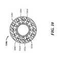
- FIG. 10illustrates a cross-section of a distal end portion of a present catheter's shaft body, such as a cross-section along line 10 - 10 of FIG. 3 .
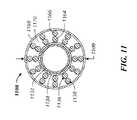
- FIG. 11illustrates a cross-section of a present catheter's polymer tip member, such as a cross-section along line 11 - 11 of FIG. 3 .
- FIG. 12illustrates a method of using a present catheter to navigate through vasculature, as constructed in accordance with at least one embodiment.
- FIG. 13illustrates the stepwise addition of an outer wrapper to a shaft body of a present catheter, as constructed in accordance with at least one embodiment.
- FIG. 1illustrates a present catheter 100 for supporting a guidewire 102 or delivering a radiopaque, diagnostic or therapeutic agent through a vessel stenosis or other tortuous anatomy of coronary vasculature 104 , as constructed in accordance with at least one embodiment.
- the present catheter 100can be used in peripheral and coronary applications.
- the catheter 100can include a shaft body 106 and a tip member 108 and can be delivered through a surgically created opening in a femoral or radial artery, for example.
- the shaft body 106can extend from a proximal end 110 to a distal end 112 and can define an inner lumen.
- the tip member 108can be connected to the distal end 112 of the shaft body 106 and can include a lumen coaxial with the shaft body's inner lumen to facilitate receipt or delivery of the guidewire or agent.
- a luer hub 114can be connected to the proximal end 110 of the shaft body 106 to facilitate connection to other medical devices, such as valves, syringes or adaptors, and to provide access to the shaft body's inner lumen.
- a proximal portion 116 of the shaft body 106can be designed to be less flexible than its distal portion 118 .
- the less flexible proximal portion 116can provide enhanced axial and circumferential strength to the catheter 100 for greater pushability and torqueability.
- the distal portion 118can provide the catheter 100 with enhanced flexibility for negotiating winding or tortuous vascular passages.
- An outer surface portion of the shaft body 106such as the distal end portion 118 , can include one or more helical threads 120 to enhance catheter delivery or withdrawal through rotation.
- FIG. 2illustrates engagement between a vessel wall 226 and one or more helical threads 220 , 224 projecting from outer surfaces of a catheter's shaft body 206 and tip member 208 , respectively.
- a treating cliniciancan gently push the “rotate-to-advance” catheter 200 through vasculature far enough to engage the helical threads 220 , 224 with the vessel wall 226 .
- the cliniciancan then rotate a proximal end of the catheter 200 in the direction 228 of the helical threads, such as in a clockwise direction, to advance the catheter through small and tortuous vessels to a target site.
- the helical threads 220 , 224can have a sufficient radial height, relative to an outer surface of the shaft body 206 or tip member 208 , to provide a longitudinal pull on the vessel wall 226 or a stenosis, if present, when rotated.
- the catheter 200can be removed by rotating the proximal end of the catheter in a direction 230 opposite the direction of delivery, such as in a counterclockwise direction.
- the catheter 200may include helical threads 220 only on the shaft body 206 .
- the helical threads 220can extend along an outer surface portion of the tip member 208 .
- FIG. 3A side view of a catheter 300 , including a shaft body 306 and a tip member 308 , is illustrated in FIG. 3 .
- the shaft body 306can include multiple components, including an inner liner 332 , a reinforcing braid member 334 , two coil layers 336 , 338 wound in opposing directions, and an outer polymer cover 340 .
- the braid member 334can be composed of multiple elongate strands having a rectangular transverse profile and arranged with its thickness directed radially.
- Each coil layer 336 , 338can be composed of multiple elongate stands having a fully-round transverse profile.
- the catheter 300can optionally include a polymer tip member 308 composed of a non-tapered proximal portion and a tapered distal portion.
- the proximal portion of the tip member 308can receive distal ends of the braid member 334 and coil layers 336 , 338 .
- the sandwiching of the braid member 334 and coil layers 336 , 338 between the inner liner 332 and the outer polymer cover 340 , and the polymer tip member's 308 receipt of distal ends of the braid member 334 and the coil layers 336 , 338permits the catheter 300 to be formed at a reduced thickness while maintaining favorable structural characteristics including pushability, torqueability, flexibility and resistance to kinking.
- FIG. 4illustrates, in enlarged view, one or more helical threads 420 on an outer surface portion of a polymer cover 440 , which can help propel a catheter through a blood vessel when rotated.
- a thin, outer wrapper 441can surround both the helical threads 420 and the polymer cover 440 along a portion of the length of the shaft body 406 .
- the outer wrapper 441can protect the threads 420 and prevent them from detaching during rotation and intraluminal advancement of the catheter.
- the helical threads 420can be positioned around a distal end portion 418 of a shaft body 406 and project radially outward.
- Ends 442 , 444 of the helical threads 420can be tapered from zero to full height in one-half turn of the helix, for example, to facilitate gentle, gradual displacement of a vessel wall or stenosis by the threads when the catheter is rotated for advancement and retraction.
- Thread width 446 and thread pitch 448can be designed so that the vessel wall or stenosis does not bridge between adjacent turns of the threads 420 but rather is only displaced in a manner closely conforming to the threads 420 , thereby providing the necessary longitudinal grip on the vessel wall or stenosis for advancing and retracting the catheter.
- the outer wrapper 441can provide a smooth protective layer between the threads 420 and a lesion or vessel wall. As a result, the outer wrapper 441 can improve the performance of the catheter, especially when passing through dense, e.g., calcified, lesions by preventing the detachment of the threads during rotation therethrough.
- the protection provided by the outer wrapper 441can allow increased distal extension of the helical threads 420 during construction of the catheter, which also increases the likelihood of the threads engaging a lesion.
- the outer wrapper 441can be any suitable material.
- the outer wrapper 441can be a thin-wailed, heat-shrink tubing.
- the outer wrapper 441can comprised of any suitable material, including various polymers, such as thermoplastic elastomers.
- the outer wrapper 441includes polyether block amide (commonly referred to as “PEBAX,” a registered trademark of Arkema France Corporation). As shown in FIG. 4 , the outer wrapper 441 can be conformed precisely to the shape of the polymer cover 440 and helical threads 420 such that the wrapper appears as an external coating on the catheter body 406 .
- the thin-walled, heat-shrink tubingcan be cross-linked such that it shrinks, but does not melt, around the threads 420 when heated. Such cross-linking can increase the strength and/or melting temperature of the outer wrapper 441 .
- the hardness of the outer wrapper 441can vary, and can include any desired hardness or range or ranges of hardness, including but not limited to ranging in durometer from about 45D to about 70D, about 50D to about 65D, about 55D to about 63D, about 54D to about 56D, or about 62D to about 64D in various embodiments.
- the one or more helical threads 420includes a polymer member wound around the polymer cover 440 .
- the polymer membercan be a strip of a synthetic fiber, such as nylon or polyester, having a fully-round cross-sectional shape of about 0.05 mm-0.2 mm in diameter prior to being bonded to the polymer cover 440 .
- the polymer membercan have a melting temperature higher than a melting temperature of the polymer cover 440 so that the helical threads 420 can be thermally bonded to, and inlaid in, the polymer cover 440 .
- the helical threads 420can be attached to the polymer cover 440 by sonic or adhesive bonding.
- the polymer membercan, for example, extend 20-50 turns around the outer surface of the polymer cover 440 at a uniform pitch of 1.0 mm-2.0 mm, resulting in a threaded section 2-8 cm in length.
- the polymer membercan be reinforced with wire or fibers.
- Hard, metallic tip members or softer, polymer tip memberscan be utilized by the present catheters and coupled to a distal end 112 , 212 , 312 , 512 , 612 , 712 of a shaft body 106 , 206 , 306 , 506 , 606 , 706 .
- FIGS. 1, 2, 5 and 6illustrate optional metallic tip members 108 , 208 , 508 , 608
- FIGS. 3 and 7illustrate an optional polymer tip member 308 , 708 .
- Metallic tip members 108 , 208 , 508 , 608can facilitate crossing of a difficult stenosis or other narrowing and allow for imaging on a screen as a catheter advances through vasculature.
- the metallic tip member 108 , 208 , 508 , 608includes a gold-plated, stainless steel member available with ( FIGS. 1, 2 and 5 ) or without ( FIG. 6 ) one or more helical threads 224 , 524 .
- the gold-platingallows for imaging on the screen.
- the helical threads 224 , 524can provide rotational advancement (in additional to the helical threads of the shaft body) through a vessel stenosis or other tortuous anatomy when the catheter is rotated.
- the one or more helical threads 224 , 524extends radially outward from an outer surface of the tip member 208 , 508 ; in other examples, the one or more helical threads extends radially inward from the outer surface and form a helical depression.
- Metallic tip members 608 including a smooth outer surfacecan be used in treatment cases benefiting from minimized friction during catheter advancement.
- a proximal diameter of the metallic tip memberscan be in a range of 0.8 mm to 1.10 mm and a distal diameter 509 , 609 can be in a range of 0.50 mm to 0.80 mm, such as about 0.70 mm.
- Polymer tip members 308 , 708can facilitate tracking through tortuous vasculature using their inherent flexibility and low profile, including a distal diameter 709 in a range of 0.3 mm to 0.6 mm.
- the polymer tip member 708includes a non-tapered proximal portion 750 and a tapered distal portion 752 that culminates in a distal tip 754 .
- the proximal portion 750 and the distal portion 752can have a similar length, or the proximal portion 750 can be longer than the distal portion 752 .
- the polymer tip member 708has a length of 11 mm, including a 6-mm proximal portion 750 and a 5-mm distal portion 752 .
- One or more portions of the polymer tip member 708can be impregnated with a radiopaque filler material, such as barium sulfate, bismuth trioxide, bismuth carbonate, powdered tungsten, powdered tantalum or like, so that its location within a subject's body can be radiographically visualized.
- a radiopaque filler materialsuch as barium sulfate, bismuth trioxide, bismuth carbonate, powdered tungsten, powdered tantalum or like, so that its location within a subject's body can be radiographically visualized.
- the helical threads 520 , 620 , 720 of the shaft body 506 , 606 , 706can be covered by an outer wrapper 541 , 641 , 741 .
- the helical threads 720can extend distally onto the non-tapered proximal portion 750 of the tip member 708 .
- the threads 720can extend distally on the tip member 708 to about the point where the tapered distal portion 752 begins.
- the distal tip 754can be made of a different material than the remainder of the proximal portion 750 and/or the tapered distal portion 752 . In some embodiments, the distal tip 754 can have a greater durometer relative to the remainder of the tip member 708 .
- the distal tip 754can be made of a thermoplastic elastomer, e.g., PEBAX, with a suitable hardness. The hardness can be as desired, and can, for example, range from about 35D to about 70D, about 35D to about 40D, about 40D to about 45D, about 45D to about 55D, about 54D to about 56D, or about 55D to about 65D.
- the present inventorsrecognize that, with the use of a stronger durometer polymer than the polymer forming the proximal and intermediate portions of the tip member 708 , deformation, separation or damage of the tip member 708 can be reduced during operation, which also can reduce or eliminate locking of the distal tip 754 onto the outer surface of a guidewire.
- the distal tip 754can also or alternatively lack a radiopaque filler material, which, the present inventors have recognized, can reduce structural integrity of the tip making it more susceptible to falling apart or separating when deformed.
- the length of the distal tip 754may be of any desired or suitable range, including ranging from about 0.5 mm to about 3.0 mm, about 1.0 mm to about 2.0 mm, about 1.4 mm to about 1.6 mm, or about 2.0 mm to about 3.0 mm.
- the polymer tip members 308 , 708can be formed by a die tipping process.
- Die tippingmay require less manufacturing time and generate less waste than other methods, e.g., laser tipping. Die tipping may also enhance manufacturing consistency, thereby generating tip members of consistent flexibility and taper profiles, for example.
- FIG. 8further illustrates the multiple components of a present catheter's shaft body 806 , including a liner 832 , a braid member 834 , multiple coil layers 836 , 838 and a polymer cover 840 .
- the shaft body 806can define an inner lumen 860 and have an inner surface 854 , an outer surface 856 , a wall thickness 858 in a radial direction, and a length 859 of 60 cm-200 cm, for example.
- the liner 832can extend the length of the shaft body 806 and, optionally, into and through the catheter's tip member.
- the liner 832can be formed of a material providing high lubricity, such as polytetrafluoroethylene (PTFE) or polyethylene, to reduce the forces required to advance a guidewire or other member through an associated catheter.
- PTFEpolytetrafluoroethylene
- a braid member 834formed of multiple elongate strands 862 wound helically in opposite directions and interbraided with one another to form multiple crossings.
- the braid member 834can extend the length of the shaft body 806 and into the catheter's tip member.
- the strands 862can be formed of stainless steel or another high tensile strength material and can be axially spaced apart to define multiple pies. The axial length of the pies, as determined by the strand spacing, can be selected to influence one or more of the catheter's pushability, torqueability, flexibility and kink resistance properties.
- the transverse profiles of the strands 862can also be selected to influence these characteristics. For example, structural strength can be increased by increasing the strand width while maintaining the same thickness. Flexibility can be increased by increasing the pie axial length. Another factor influencing the desired characteristics is the braid angle of the filament strand windings, i.e., the angle of each helical strand 862 with respect to a longitudinal central axis. Increasing the braid angle tends to increase the torqueability while reducing the pushability. In short, strands 862 and arrangements of the strands 862 can be selected to customize the present catheter's properties.
- the braid member 834includes 16 stainless steel strands 862 having a braid angle of 45 degrees along the axis of the catheter. Other braid angle ranges from 20 degrees to 60 degrees, for example, are also suitable.
- the braid member 834can be stretched axially as it is placed upon the liner 832 during manufacture. When the coil layers 836 , 838 and the polymer cover 840 are placed over the braid member 834 , the braid member 834 can assume an unbiased configuration.
- strands 862 of the braid member 834can have a thickness ranging from 0.010 mm to 0.015 mm, but both larger and smaller strand thicknesses can also be used. Widths of the strands 862 can also vary. Some embodiments use strand widths in the range of about 0.057 mm to 0.070 mm.
- the multiple coil layerswhich surround the braid member 834 , can include a first coil layer 836 composed of one or more wires 864 wound in a first direction and a second coil layer 838 composed of one or more wires 866 wound in a second direction, opposing the first direction.
- the second coil layer 838can be positioned around and in contact with the first coil layer 836 .
- the wires 864 , 866 of the first and second coil layers 836 , 838can interlock and provide the present catheter with bi-directional torqueability and pushability capabilities.
- one wire 864 , 866 in a coil layerhas a tendency to kink or bend in use, particularly under influence of a load
- the other wires 864 , 866 in the same layer or the adjacent layercan support it and inhibit kinking.
- the wires 864 , 866can include a fully-rounded cross-section and can vary in size, number and pitch between the first coil layer 836 and the second coil layer 838 to alter structural properties of the catheter. Wire properties can be selected to balance structural properties, such as pushability, torqueability and flexibility.
- each coil layerincludes 12 wires having a diameter of about 0.050 mm.
- Each of the 12 wirescan have a uniform pitch that is equal to or greater than about 0.623 mm.
- Adjacent wires of the 12-wire groupingcan be view as having a pitch that is equal to or greater than about 0.072 mm, with a small gap distributed throughout each 12-wire grouping.
- the size of the pitchcan depend on the diameter of the wires, the diameter of the inner lumen 860 and the number of wires in the layer.
- the polymer cover 840can surround the coil layers 836 , 838 and, in light of the liner 832 , can form the second of two polymer layers included in the shaft body 806 .
- the polymer cover 840can include a low-friction polymer, to reduce the forces required to advance the catheter through vasculature, or a polymer with low viscosity at melting temperatures, to allow flow through and around the coil layers 836 , 838 and the braid member 834 , the latter of which is shown in FIG. 9 .
- the polymer cover 840is composed of polyether block amide (PEBAX).
- the polymer cover 840can be applied to the coil layers 836 , 838 after they are wound into a tubular shape via an extrusion, molding or shrink tubing process, and can be applied thicker along a proximal portion of the shaft body 806 than along a distal portion of the shaft body to enhance distal flexibility and provide a smaller leading size.
- the proximal portionincludes an outer diameter 909 (see FIG. 9 ) between 0.9 mm-1.1 mm and the distal portion includes an outer diameter 1009 (see FIG. 10 ) between 0.8-1.0 mm.
- a hydrophilic coatingcan be provided on the outer surface 856 of the shaft body 806 for lubricious delivery and to aid in steerability.
- the hydrophilic coatingcan be thin and constitute only a minor part of the wall thickness of the shaft body 806 .
- FIGS. 9 and 10respectively illustrate cross-sections of a proximal portion and a distal portion of a shaft body 906 , 1006 , such as along lines 9 - 9 and 10 - 10 of FIG. 3 .
- a polymer cover 940 , 1040can extend inward and seal around first and second coil layers 936 , 938 , 1036 , 1038 and a braid member 934 , 1034 .
- Inherent elasticity of the polymer cover 940 , 1040can allow wires 964 , 966 , 1064 , 1066 of the coil layers 936 , 938 , 1036 , 1038 to make small movements so that the flexibility of the coil layers is maintained; the elasticity also allows the shaft body wall to stay leak-proof when the wires move.
- the polymer cover 940 , 1040can terminate at the distal end of the shaft body 906 , 1006 , proximal to a tip member.
- an outer wrapper 1041can fully envelop the polymer cover 1040 . Where helical threads are present, the outer wrapper 1041 can envelop both the helical threads and the polymer cover 1040 . In some examples, the outer wrapper 1041 can terminate at the distal end of the shaft body 1006 , proximal to the end of the shaft body 1006 , or on the tip member.
- the cross-sectional thickness of the outer wrapper 1041can vary and can be of any desired dimensions, including ranging from about 0.01 mm to about 0.5 mm, about 0.05 mm to about 0.3 mm, or about 0.1 mm to about 0.2 mm.
- FIG. 11illustrates a cross-section of a proximal portion of a tip member 1108 , and specifically a polymer tip member, which is coupled with a distal end of a shaft body.
- Distal ends of first and second coil layers 1136 , 1138 , a braid member 1134 and a liner 1132can extend into the tip member 1108 and can be surrounded by a polymer impregnated with a radiopaque material.
- the polymer 1168 of the tip member 1108can have a higher viscosity at melting temperatures such that little to no flow through or around the coil layers 1136 , 1138 or the braid member 1134 occurs.
- the polymer of the tip memberis pellethane and the void space 1170 existing within the polymer 1168 can provide the catheter's distal end portion with increased flexibility relative to the shaft body.
- FIG. 12illustrates a method 1272 of using a present catheter to navigate through vasculature, as constructed in accordance with at least one embodiment.
- the methodcan include advancing a distal end of a guidewire through vasculature to a location proximate a stenosis or other narrowing in a blood vessel.
- a cathetercan be guided over the guidewire by inserting its proximal end into an inner lumen of the catheter from the catheter's distal end.
- the inner lumencan be defined, in part, by a liner, a braid member surrounding the liner, a multi-layer coil surrounding the braid member, and a polymer cover surrounding the multi-layer coil.
- a distal end of the cathetercan be advanced to the location proximate the stenosis or narrowing at step 1278 .
- the cathetercan be rotated in a first direction at step 1280 , thereby engaging one or more helical threads on an outer surface of the polymer cover with the stenosis or wall of the blood vessel.
- An outer wrapper surrounding the helical threads and outer surface of the polymer covercan protect the helical threads from detachment or loosening during engagement with the stenosis or blood vessel wall.
- the guidewirecan be advanced distally with the support of the catheter.
- the methodcan be configured such that the distal end of the guidewire is at all times distal to the distal end of the catheter.
- the catheter's tip membermay include a hard or semi-hard distal tip, which can prevent its deformation, separation or other damage during rotation through the blood vessel, and further prevent the tip member from locking with an outer surface of the guidewire.
- the cathetercan be withdrawn from the blood vessel at step 1284 by rotating its proximal end in a second direction, opposite the first direction. Rotation of the catheter, whether in the first direction or the second direction, can cause wires of the first and second coil layers to engage.
- the methodcan optionally include viewing a tip member using an imaging means.
- the methodcan optionally include delivering a radiopaque, diagnostic or therapeutic agent through the inner lumen of the catheter.
- the methodcan optionally include exchanging the guidewire advanced to the location proximate the stenosis or narrowing with a second guidewire.
- FIG. 13illustrates the stepwise addition of an outer wrapper 1341 to the shaft body 1306 of a present catheter.
- the outer wrapper 1341may be slid over the shaft body 1306 in the direction of the arrow until the wrapper circumferentially surrounds the helical threads 1320 .
- the outer wrapper 1341Prior to heating, the outer wrapper 1341 may be in the form of a rigid or semi-rigid tube having a diameter slightly greater than the thread-wrapped portion of the catheter. The length of the outer wrapper 1341 can approximately match the length of the shaft body 1306 that is wrapped in helical threads 1320 .
- the length of the outer wrapper 1341can be greater than the threaded portion of the shaft body, such that the outer wrapper extends proximally and/or distally from the helical threads 1320 , and in some cases, onto the tip member 1308 .
- the outer wrapper 1341may be heated, thereby causing the wrapper to shrink until it conforms tightly to the exterior of the threaded portion of the shaft body 1306 .
- the temperature necessary to shrink the outer wrapper 1341 around the shaft body 1306can range, including from about 260° F. to about 360° F., about 280° F. to about 355° F., about 300° F. to about 350° F., about 320° F. to about 340° F., or about 330° F. to about 340° F., for example, depending on the particular material used.
- the outer wrappercan be allowed to cool and harden around the shaft body 1306 .
- the outer wrapper 1341can be thin and transparent, such that after heating, the portion of the shaft body 1306 covered by the outer wrapper remains visible.
- the outer wrapper 1341can have a smooth and glossy finish to facilitate sliding and rotating through a vessel lumen.
- the present catheters and methodsinclude or use a multi-component shaft body, which can include one or more helical threads projecting from its outer surface.
- the multi-component shaft bodycan provide catheters with favorable structural characteristics including pushability, torqueability, flexibility and resistance to kinking, guidewire locking and thread detachment.
- First and second helically-wound coil layers of the shaft bodycan provide torqueability and pushability to the catheter.
- a braid membercan enable a small shaft body diameter for extending through a tortuous path and reaching small vessels and can further provide kink resistance.
- the one or more helical threadscan provide the catheter with a rotationally-activated propulsion means.
- An outer wrappercan protect the helical threads from damage or dislodgment during propulsion.
- a hard or semi-hard distal tipcan be resistant to deformation during lesion engagement. Accordingly, the present catheters and methods can overcome difficulties associated with placing existing “push-to-advance” catheter designs and can possess a small cross-section to navigate tortuous anatomy.
- a cathetercan comprise an elongate shaft body and a tip member disposed at a distal end of the shaft body.
- the shaft bodycan extend from a proximal end to the distal end and can define an inner lumen.
- the shaft bodycan include a liner, a braid or coil surrounding the liner, and a polymer cover surrounding the braid or coil.
- An outer surface portion of the polymer covercan include one or more helical threads.
- An outer wrappercan cover the distal outer surface portion of the polymer cover and the one or more helical threads.
- a tip membercan be disposed at the distal end of the shaft body.
- Example 2the catheter of Example 1 can optionally be configured such that the tip member includes a polymer tip member having a distal tip.
- Example 3the catheter of Example 2 can optionally be configured such that proximal and intermediate portions of the tip member are loaded with a radiopaque filler material, and the distal tip lacks the radiopaque filler material.
- Example 4the catheter of any one of Examples 2-3 can optionally be configured such that the tip member includes a distal tip comprised of a polymer having a durometer of about 50D to about 60D.
- Example 5the catheter of Example 4 can optionally be configured such that the polymer of the distal tip is a thermoplastic elastomer.
- Example 6the catheter of any one of Examples 4-5 can optionally be configured such that the distal tip has a length of about 1 mm to about 2 mm.
- Example 7the catheter of any one or any combination of Examples 2-6 can optionally be configured such that the distal tip has a length of about 1 mm to about 2 mm.
- Example 8the catheter of any one or any combination of Examples 2-7 can optionally be configured such that the polymer tip member includes a non-tapered proximal portion and a tapered distal portion.
- Example 9the catheter of Example 8 can optionally be configured such that the one or more helical threads extends onto the non-tapered proximal portion of the polymer tip member.
- Example 10the catheter of Example 9 can optionally be configured such that the one or more helical threads extends to a junction between the non-tapered proximal portion and the tapered distal portion.
- Example 11the catheter of any one or any combination of Examples 8-10 can optionally be configured such that the outer wrapper extends to the junction between the non-tapered proximal portion and the tapered distal portion.
- Example 12the catheter of any one or any combination of Examples 1-11 can optionally be configured such that the outer wrapper comprises a thermoplastic elastomer configured to shrink upon heating.
- Example 13the catheter of Example 12 can optionally be configured such that the thermoplastic elastomer has a durometer of about 50D to about 60D.
- Example 14the catheter of any one of Examples 12-13 can optionally be configured such that a melting temperature of the thermoplastic elastomer is about 260° F. to about 360° F.
- Example 15the catheter of any one or any combination of Examples 1-14 can optionally be configured such that the one or more helical threads includes a polymer member wound around the polymer cover.
- a cathetercan comprise an elongate shaft body extending from a proximal end to a distal end and defining an inner lumen.
- the shaft bodycan include a liner, a multi-layer coil surrounding the liner, and a polymer cover surrounding the multi-layer coil.
- the cathetercan include a distal outer surface portion of the polymer cover of the shaft body including one or more helical threads.
- the cathetercan include a tip member disposed at the distal end of the shaft body.
- the tip membercan include a distal tip comprised of a polymer having a hardness greater than that of a remainder of the tip member.
- Example 17the catheter of Example 16 can optionally be configured such that the distal tip has a durometer of about 50D to about 60D and a length of about 1 mm to about 2 mm.
- Example 18the catheter of Example 17 can optionally be configured such that the distal tip is comprised of PEBAX.
- Example 19the catheter of any one or any combination of Examples 16-18 can optionally be configured to include an outer wrapper covering the distal outer surface portion of the polymer cover and the one or more helical threads.
- Example 20the catheter of Example 19 can optionally be configured such that the outer wrapper is comprised of PEBAX and has a durometer of about 50D to about 60D.
- Example 21the catheter of any one or any combination of Examples 1-20 can optionally be configured such that all components or options recited are available to use or select from.
- the term “about”can include numbers that are rounded to the nearest significant figure.
- the recitation of numerical ranges by endpointsincludes all numbers and sub-ranges within and bounding that range (e.g., 1 to 4 includes 1, 1.5, 1.75, 2, 2.3, 2.6, 2.9, etc. and 1 to 1.5, 1 to 2, 1 to 3, 2 to 3.5, 2 to 4, 3 to 4, etc.).
- patientand “subject” are intended to include mammals, such as for human or veterinary applications.
- the terms “distal” and “proximal”are used to refer to a position or direction relative to the treating clinician. “Distal” and “distally” refer to a position that is distant from, or in a direction away from, the treating clinician. “Proximal” and “proximally” refer to a position that is near, or in a direction toward, the treating clinician.
Landscapes
- Health & Medical Sciences (AREA)
- Life Sciences & Earth Sciences (AREA)
- Veterinary Medicine (AREA)
- General Health & Medical Sciences (AREA)
- Public Health (AREA)
- Animal Behavior & Ethology (AREA)
- Engineering & Computer Science (AREA)
- Biophysics (AREA)
- Pulmonology (AREA)
- Anesthesiology (AREA)
- Biomedical Technology (AREA)
- Heart & Thoracic Surgery (AREA)
- Hematology (AREA)
- Epidemiology (AREA)
- Optics & Photonics (AREA)
- Physics & Mathematics (AREA)
- Chemical & Material Sciences (AREA)
- Chemical Kinetics & Catalysis (AREA)
- Media Introduction/Drainage Providing Device (AREA)
Abstract
Description
Claims (18)
Priority Applications (12)
| Application Number | Priority Date | Filing Date | Title |
|---|---|---|---|
| US15/686,962US10238834B2 (en) | 2017-08-25 | 2017-08-25 | Catheter |
| CN201880003146.8ACN109715244A (en) | 2017-08-25 | 2018-06-06 | catheter |
| CN201910214671.0ACN109876274A (en) | 2017-08-25 | 2018-06-06 | Conduit |
| CA3050931ACA3050931C (en) | 2017-08-25 | 2018-06-06 | Catheter for coronary and peripheral interventions |
| JP2019508840AJP6643522B2 (en) | 2017-08-25 | 2018-06-06 | catheter |
| EP18737025.9AEP3468652B1 (en) | 2017-08-25 | 2018-06-06 | Catheter |
| PCT/IB2018/054054WO2019038603A1 (en) | 2017-08-25 | 2018-06-06 | Catheter |
| CA3029522ACA3029522C (en) | 2017-08-25 | 2018-06-06 | Catheter |
| EP19163614.1AEP3520851A1 (en) | 2017-08-25 | 2018-06-06 | Catheter |
| ES18737025TES2862382T3 (en) | 2017-08-25 | 2018-06-06 | Catheter |
| US16/266,785US11160952B2 (en) | 2017-08-25 | 2019-02-04 | Catheter |
| JP2019042568AJP7003077B2 (en) | 2017-08-25 | 2019-03-08 | catheter |
Applications Claiming Priority (1)
| Application Number | Priority Date | Filing Date | Title |
|---|---|---|---|
| US15/686,962US10238834B2 (en) | 2017-08-25 | 2017-08-25 | Catheter |
Related Child Applications (1)
| Application Number | Title | Priority Date | Filing Date |
|---|---|---|---|
| US16/266,785DivisionUS11160952B2 (en) | 2017-08-25 | 2019-02-04 | Catheter |
Publications (2)
| Publication Number | Publication Date |
|---|---|
| US20190060608A1 US20190060608A1 (en) | 2019-02-28 |
| US10238834B2true US10238834B2 (en) | 2019-03-26 |
Family
ID=62815091
Family Applications (2)
| Application Number | Title | Priority Date | Filing Date |
|---|---|---|---|
| US15/686,962Active2037-11-30US10238834B2 (en) | 2017-08-25 | 2017-08-25 | Catheter |
| US16/266,785Active2038-04-07US11160952B2 (en) | 2017-08-25 | 2019-02-04 | Catheter |
Family Applications After (1)
| Application Number | Title | Priority Date | Filing Date |
|---|---|---|---|
| US16/266,785Active2038-04-07US11160952B2 (en) | 2017-08-25 | 2019-02-04 | Catheter |
Country Status (7)
| Country | Link |
|---|---|
| US (2) | US10238834B2 (en) |
| EP (2) | EP3468652B1 (en) |
| JP (2) | JP6643522B2 (en) |
| CN (2) | CN109876274A (en) |
| CA (2) | CA3050931C (en) |
| ES (1) | ES2862382T3 (en) |
| WO (1) | WO2019038603A1 (en) |
Cited By (4)
| Publication number | Priority date | Publication date | Assignee | Title |
|---|---|---|---|---|
| US10835283B2 (en) | 2014-10-09 | 2020-11-17 | Teleflex Life Sciences Limited | Catheter |
| US11813418B2 (en) | 2019-08-22 | 2023-11-14 | Becton, Dickinson And Company | Echogenic balloon dilation catheter and balloon thereof |
| US12109382B2 (en) | 2019-08-23 | 2024-10-08 | Becton, Dickinson And Company | Device set designed for PCNL surgery |
| US12178660B2 (en) | 2019-08-22 | 2024-12-31 | Becton, Dickinson And Company | Echogenicity quantitative test system for an echogenic medical device |
Families Citing this family (9)
| Publication number | Priority date | Publication date | Assignee | Title |
|---|---|---|---|---|
| KR102286267B1 (en)* | 2017-09-18 | 2021-08-06 | 주식회사 백양 이엔지 | Rock collecting apparatus |
| KR101844210B1 (en) | 2018-02-06 | 2018-05-14 | 윤길수 | A tilting device for excavator bucket |
| CN109833556A (en)* | 2019-03-13 | 2019-06-04 | 业聚医疗器械(深圳)有限公司 | A kind of tip for foley's tube |
| EP4013480B1 (en)* | 2019-08-13 | 2025-09-24 | Reflow Medical, Inc. | Support catheter |
| CN115297922A (en)* | 2020-03-30 | 2022-11-04 | 美敦力公司 | 3D printed splines on medical devices and methods of making the same |
| CN111905236A (en)* | 2020-09-03 | 2020-11-10 | 青岛博泰医疗器械有限责任公司 | Drug balloon catheter system |
| EP4281159A1 (en) | 2021-01-20 | 2023-11-29 | Medtronic, Inc. | Lead construction including alignable marker elements |
| WO2022201246A1 (en)* | 2021-03-22 | 2022-09-29 | テルモ株式会社 | Medical device |
| EP4547305A1 (en) | 2022-07-01 | 2025-05-07 | ETH Zurich | Magnetically steerable device for use inside of a mammalian body |
Citations (156)
| Publication number | Priority date | Publication date | Assignee | Title |
|---|---|---|---|---|
| US3815608A (en) | 1972-03-10 | 1974-06-11 | East West Med Prod | Retaining catheter |
| US4898212A (en) | 1984-10-01 | 1990-02-06 | Eaton Corporation | Fatigue resistant hose |
| US4947864A (en) | 1989-03-13 | 1990-08-14 | Schneider (U.S.A.), Inc. A Pfizer Company | Guidewire exchange catheter |
| US5037404A (en) | 1988-11-14 | 1991-08-06 | Cordis Corporation | Catheter having sections of variable torsion characteristics |
| US5057092A (en) | 1990-04-04 | 1991-10-15 | Webster Wilton W Jr | Braided catheter with low modulus warp |
| US5129910A (en) | 1991-07-26 | 1992-07-14 | The Regents Of The University Of California | Stone expulsion stent |
| US5183079A (en) | 1989-07-05 | 1993-02-02 | Hutchinson S.A. | Heat and fire resistant protective covering for hoses, cables and the like |
| US5263959A (en) | 1991-10-21 | 1993-11-23 | Cathco, Inc. | Dottering auger catheter system and method |
| US5423846A (en) | 1991-10-21 | 1995-06-13 | Cathco, Inc. | Dottering auger catheter system |
| EP0661072A1 (en) | 1993-12-24 | 1995-07-05 | Terumo Kabushiki Kaisha | Catheter |
| US5454795A (en) | 1994-06-27 | 1995-10-03 | Target Therapeutics, Inc. | Kink-free spiral-wound catheter |
| JPH07323090A (en) | 1994-05-31 | 1995-12-12 | Terumo Corp | Medical tube |
| US5569218A (en) | 1994-02-14 | 1996-10-29 | Scimed Life Systems, Inc. | Elastic guide catheter transition element |
| US5569220A (en) | 1991-01-24 | 1996-10-29 | Cordis Webster, Inc. | Cardiovascular catheter having high torsional stiffness |
| US5601537A (en) | 1995-06-05 | 1997-02-11 | Frassica; James J. | Catheter system |
| US5658264A (en) | 1994-11-10 | 1997-08-19 | Target Therapeutics, Inc. | High performance spiral-wound catheter |
| US5662622A (en) | 1995-04-04 | 1997-09-02 | Cordis Corporation | Intravascular catheter |
| US5681296A (en) | 1994-07-11 | 1997-10-28 | Terumo Kabushiki Kaisha | Catheter tube and a method of processing the inner surface of a tube |
| US5702373A (en) | 1995-08-31 | 1997-12-30 | Target Therapeutics, Inc. | Composite super-elastic alloy braid reinforced catheter |
| US5769830A (en) | 1991-06-28 | 1998-06-23 | Cook Incorporated | Soft tip guiding catheter |
| US5792124A (en) | 1995-01-04 | 1998-08-11 | Medtronic, Inc. | Reinforced catheter which gets softer towards the distal tip |
| US5871537A (en) | 1996-02-13 | 1999-02-16 | Scimed Life Systems, Inc. | Endovascular apparatus |
| US5871475A (en) | 1995-06-05 | 1999-02-16 | Frassica; James J. | Catheter system |
| US5876385A (en) | 1996-09-13 | 1999-03-02 | Terumo Kabushiki Kaisha | Catheter |
| US5891114A (en) | 1997-09-30 | 1999-04-06 | Target Therapeutics, Inc. | Soft-tip high performance braided catheter |
| US5911715A (en) | 1994-02-14 | 1999-06-15 | Scimed Life Systems, Inc. | Guide catheter having selected flexural modulus segments |
| US5927345A (en) | 1996-04-30 | 1999-07-27 | Target Therapeutics, Inc. | Super-elastic alloy braid structure |
| US5951539A (en) | 1997-06-10 | 1999-09-14 | Target Therpeutics, Inc. | Optimized high performance multiple coil spiral-wound vascular catheter |
| US5968064A (en) | 1997-02-28 | 1999-10-19 | Lumend, Inc. | Catheter system for treating a vascular occlusion |
| US6003561A (en) | 1998-04-16 | 1999-12-21 | Southeastern Universities Research Assn., Inc. | Flexible cryogenic conduit |
| US6143013A (en) | 1995-04-28 | 2000-11-07 | Target Therapeutics, Inc. | High performance braided catheter |
| US6171297B1 (en)* | 1998-06-30 | 2001-01-09 | Schneider (Usa) Inc | Radiopaque catheter tip |
| US6217565B1 (en) | 1998-07-16 | 2001-04-17 | Mark Cohen | Reinforced variable stiffness tubing |
| US6231546B1 (en) | 1998-01-13 | 2001-05-15 | Lumend, Inc. | Methods and apparatus for crossing total occlusions in blood vessels |
| US6245098B1 (en) | 1997-05-23 | 2001-06-12 | C. R. Bard, Inc. | Catheter system with high kink resistance |
| US20020032408A1 (en) | 2000-07-14 | 2002-03-14 | Cook Incorporated | Medical device including tube having a braid and an expanded coil |
| US6368316B1 (en) | 1998-06-11 | 2002-04-09 | Target Therapeutics, Inc. | Catheter with composite stiffener |
| US6485457B1 (en) | 1999-09-28 | 2002-11-26 | Terumo Kabushiki Kaisha | Catheter |
| US6508825B1 (en) | 1997-02-28 | 2003-01-21 | Lumend, Inc. | Apparatus for treating vascular occlusions |
| US6508806B1 (en) | 2000-12-13 | 2003-01-21 | Advanced Cardiovascular Systems, Inc. | Catheter with multi-layer wire reinforced wall construction |
| US6508804B2 (en) | 1999-07-28 | 2003-01-21 | Scimed Life Systems, Inc. | Catheter having continuous lattice and coil reinforcement |
| US6511462B1 (en) | 1999-07-16 | 2003-01-28 | Terumo Kabushiki Kaisha | Catheter and method of manufacturing the same |
| US6533754B1 (en) | 1999-11-26 | 2003-03-18 | Terumo Kabushiki Kaisha | Catheter |
| US20030097138A1 (en) | 1997-12-12 | 2003-05-22 | Boris Reydel | Body canal intrusion instrumentation having bi-directional coefficient of surface friction with body tissue |
| US6589227B2 (en) | 2000-01-28 | 2003-07-08 | William Cook Europe Aps | Endovascular medical device with plurality of wires |
| US20030191451A1 (en) | 2002-04-05 | 2003-10-09 | Kevin Gilmartin | Reinforced catheter system |
| US20040002677A1 (en) | 2001-12-11 | 2004-01-01 | Gentsler Curtis C. | Alternate site gene therapy |
| US6689120B1 (en) | 1999-08-06 | 2004-02-10 | Boston Scientific Scimed, Inc. | Reduced profile delivery system |
| US6726712B1 (en) | 1999-05-14 | 2004-04-27 | Boston Scientific Scimed | Prosthesis deployment device with translucent distal end |
| US20040087885A1 (en) | 2000-03-11 | 2004-05-06 | Takumi Kawano | Medical tube and production method and production device therefor and medical appliance |
| US20040102719A1 (en) | 2002-11-22 | 2004-05-27 | Velocimed, L.L.C. | Guide wire control catheters for crossing occlusions and related methods of use |
| US6824553B1 (en) | 1995-04-28 | 2004-11-30 | Target Therapeutics, Inc. | High performance braided catheter |
| US20050021002A1 (en) | 2003-06-10 | 2005-01-27 | Deckman Robert K. | Catheter systems and methods for crossing vascular occlusions |
| US6858024B1 (en) | 1994-02-14 | 2005-02-22 | Scimed Life Systems, Inc. | Guide catheter having selected flexural modulus segments |
| US20050171478A1 (en) | 1998-01-13 | 2005-08-04 | Selmon Matthew R. | Catheter system for crossing total occlusions in vasculature |
| US6926721B2 (en) | 1996-03-06 | 2005-08-09 | Medical Components, Inc. | Catheter extracting device |
| US20050222585A1 (en) | 2004-04-06 | 2005-10-06 | Asahi Intecc Co., Ltd. | Medical equipment |
| WO2005105192A1 (en) | 2004-05-05 | 2005-11-10 | Invatec S.R.L. | A catheter and the method for making it |
| US6966891B2 (en) | 2002-08-27 | 2005-11-22 | Terumo Kabushiki Kaisha | Catheter |
| US7037288B2 (en) | 2002-01-14 | 2006-05-02 | Codman & Shurtleff, Inc. | Anti-block catheter |
| US20060100602A1 (en) | 2001-01-26 | 2006-05-11 | William Cook Europe Aps | Endovascular medical device with plurality of wires |
| US20060151043A1 (en) | 2005-01-07 | 2006-07-13 | Shadrach Nanney | Fire resistant hose construction |
| US7104966B2 (en) | 2003-07-16 | 2006-09-12 | Samuel Shiber | Guidewire system with exposed midsection |
| US7117703B2 (en) | 2002-12-11 | 2006-10-10 | Asahi Intecc Co., Ltd. | Wire-stranded hollow coil body, a medical equipment made therefrom and a method of making the same |
| US20060258987A1 (en) | 2005-05-10 | 2006-11-16 | Cook Incorporated | Catheter stiffening member |
| US20060264904A1 (en) | 2005-05-09 | 2006-11-23 | Kerby Walter L | Medical device |
| US7155272B2 (en) | 2002-09-05 | 2006-12-26 | Terumo Kabushiki Kaisha | Catheter |
| US20070010863A1 (en) | 2005-06-24 | 2007-01-11 | Stenzel Eric B | Rapid exchange pre-dilator |
| US7166100B2 (en) | 2004-06-29 | 2007-01-23 | Cordis Neurovascular, Inc. | Balloon catheter shaft design |
| JP2007029120A (en) | 2005-07-22 | 2007-02-08 | Kaneka Corp | Medical catheter tube and its manufacturing method |
| US20070060996A1 (en) | 2005-09-09 | 2007-03-15 | Richard Goodin | Coil shaft |
| JP2007061311A (en) | 2005-08-30 | 2007-03-15 | Piolax Medical Device:Kk | Catheter |
| US20070208221A1 (en) | 2006-03-03 | 2007-09-06 | Wilson-Cook Medical Inc. | Endoscopic apparatus having an improved catheter |
| US7291127B2 (en) | 2003-07-28 | 2007-11-06 | Boston Scientific Scimed, Inc. | Variable manipulative strength catheter |
| US7297302B2 (en) | 1993-08-18 | 2007-11-20 | Boston Scientific Scimed, Inc. | Catheter having a high tensile strength braid wire constraint and method of manufacture |
| US7300534B2 (en) | 2002-01-15 | 2007-11-27 | Boston Scientific Scimed, Inc. | Bonds between metals and polymers for medical devices |
| US7322988B2 (en) | 2003-01-17 | 2008-01-29 | Boston Scientific Scimed, Inc. | Methods of forming catheters with soft distal tips |
| US20080039823A1 (en) | 2006-02-14 | 2008-02-14 | Asahi Intecc Co. Ltd. | Medical Equipment, Tubular Insertion Device and Tubular Insertion Device Having the Same Medical Equipment |
| US7354430B2 (en) | 2001-12-27 | 2008-04-08 | Boston Scientific Scimed, Inc. | Catheter incorporating a curable polymer layer to control flexibility |
| US20080108974A1 (en) | 2006-10-20 | 2008-05-08 | Vital Signs, Inc. | Reinforced catheter with radiopaque distal tip and process of manufacture |
| US20080185063A1 (en) | 2007-02-01 | 2008-08-07 | Eaton Corporation | Braided hose and method of making same |
| US7434437B2 (en) | 2003-06-26 | 2008-10-14 | Asahi Intec Co., Ltd. | Method of making a metallic thin wire for a medical tool |
| US7488338B2 (en) | 2001-12-27 | 2009-02-10 | Boston Scientific Scimed, Inc. | Catheter having an improved torque transmitting shaft |
| US20090048657A1 (en) | 2007-08-15 | 2009-02-19 | Boston Scientific Scimed, Inc. | Preferentially varying-density ePTFE structure |
| US7494478B2 (en) | 2003-06-02 | 2009-02-24 | Terumo Kabushiki Kaisha | Catheter assembly |
| US20090112063A1 (en) | 2007-10-31 | 2009-04-30 | Bakos Gregory J | Endoscopic overtubes |
| US20090124899A1 (en) | 2007-10-22 | 2009-05-14 | Peter Alan Jacobs | Methods and devices for crossing chronic total occlusions |
| US7579550B2 (en) | 2006-03-31 | 2009-08-25 | Boston Scientific Scimed, Inc. | Flexible device shaft with angled spiral wrap |
| US7597830B2 (en) | 2003-07-09 | 2009-10-06 | Boston Scientific Scimed, Inc. | Method of forming catheter distal tip |
| US7615043B2 (en) | 2003-08-20 | 2009-11-10 | Boston Scientific Scimed, Inc. | Medical device incorporating a polymer blend |
| US7621904B2 (en) | 2004-10-21 | 2009-11-24 | Boston Scientific Scimed, Inc. | Catheter with a pre-shaped distal tip |
| US20090312831A1 (en) | 2008-06-11 | 2009-12-17 | C. R. Bard, Inc. | Catheter delivery device |
| US20100069718A1 (en) | 2005-05-04 | 2010-03-18 | Frassica James J | Rotate-to-advance catheterization system |
| US20100094258A1 (en) | 2008-10-11 | 2010-04-15 | Asahi Intecc Co., Ltd. | Catheter |
| US7699790B2 (en) | 2000-12-20 | 2010-04-20 | Ev3, Inc. | Debulking catheters and methods |
| US7704245B2 (en) | 2003-04-14 | 2010-04-27 | Cook Incorporated | Large diameter delivery catheter/sheath |
| US7740652B2 (en) | 2005-03-30 | 2010-06-22 | Boston Scientific Scimed, Inc. | Catheter |
| US7758624B2 (en) | 2000-11-13 | 2010-07-20 | C. R. Bard, Inc. | Implant delivery device |
| US7763012B2 (en) | 2003-09-02 | 2010-07-27 | St. Jude Medical, Cardiology Division, Inc. | Devices and methods for crossing a chronic total occlusion |
| US7766896B2 (en) | 2006-04-25 | 2010-08-03 | Boston Scientific Scimed, Inc. | Variable stiffness catheter assembly |
| US7771444B2 (en) | 2000-12-20 | 2010-08-10 | Fox Hollow Technologies, Inc. | Methods and devices for removing material from a body lumen |
| US7803169B2 (en) | 2004-06-09 | 2010-09-28 | Ovalum Ltd. | Blood vessel occlusion auger |
| US7815599B2 (en) | 2004-12-10 | 2010-10-19 | Boston Scientific Scimed, Inc. | Catheter having an ultra soft tip and methods for making the same |
| US7824392B2 (en) | 2003-08-20 | 2010-11-02 | Boston Scientific Scimed, Inc. | Catheter with thin-walled braid |
| US7828790B2 (en) | 2004-12-03 | 2010-11-09 | Boston Scientific Scimed, Inc. | Selectively flexible catheter and method of use |
| US7841994B2 (en) | 2007-11-02 | 2010-11-30 | Boston Scientific Scimed, Inc. | Medical device for crossing an occlusion in a vessel |
| US7854755B2 (en) | 2005-02-01 | 2010-12-21 | Boston Scientific Scimed, Inc. | Vascular catheter, system, and method |
| US7871430B2 (en) | 2001-11-29 | 2011-01-18 | Cook Incorporated | Medical device delivery system |
| US7887529B2 (en) | 2004-04-19 | 2011-02-15 | Boston Scientific Scimed, Inc. | Hybrid micro guide catheter |
| US7909779B2 (en) | 2004-12-21 | 2011-03-22 | Asahi Intecc Co., Ltd. | Catheter and method of producing the same |
| US7914520B2 (en) | 2005-12-19 | 2011-03-29 | Cook Medical Technologies Llc | Medical catheters of modular construction |
| US7914515B2 (en) | 2007-07-18 | 2011-03-29 | St. Jude Medical, Atrial Fibrillation Division, Inc. | Catheter and introducer catheter having torque transfer layer and method of manufacture |
| US7927784B2 (en) | 2000-12-20 | 2011-04-19 | Ev3 | Vascular lumen debulking catheters and methods |
| US7955313B2 (en) | 2003-12-17 | 2011-06-07 | Boston Scientific Scimed, Inc. | Composite catheter braid |
| US7981091B2 (en) | 2006-10-24 | 2011-07-19 | Vascular Solutions, Inc. | Small diameter intravascular catheter with screw tip and limited torsional displacement |
| US7985214B2 (en) | 1999-01-20 | 2011-07-26 | Boston Scientific Scimed, Inc. | Intravascular catheter with composite reinforcement |
| US7985213B2 (en) | 2003-04-25 | 2011-07-26 | Cook Medical Technologies Llc | Delivery catheter and method of manufacture |
| US7998132B2 (en) | 2005-09-02 | 2011-08-16 | Boston Scientific Scimed, Inc. | Adjustable stiffness catheter |
| US8021352B2 (en) | 2006-08-23 | 2011-09-20 | Codman & Shurtleff, Inc. | Unfused catheter body feature and methods of manufacture |
| US20120016344A1 (en) | 2010-07-16 | 2012-01-19 | Terumo Clinical Supply Co., Ltd. | Aspiration catheter |
| US8109985B2 (en) | 2008-07-23 | 2012-02-07 | Boston Scientific Scimed, Inc. | Occlusion crossing device and method |
| US8118804B2 (en) | 2008-07-30 | 2012-02-21 | Terumo Kabushiki Kaisha | Catheter assembly |
| US8172863B2 (en) | 2008-04-28 | 2012-05-08 | Bridgepoint Medical, Inc. | Methods and apparatus for crossing occlusions in blood vessels |
| US20120136340A1 (en) | 2009-09-15 | 2012-05-31 | Terumo Kabushiki Kaisha | Catheter |
| US20120149985A1 (en) | 2007-05-18 | 2012-06-14 | Frassica James J | Rotate-to-advance catheterization system |
| US8202246B2 (en) | 2008-02-05 | 2012-06-19 | Bridgepoint Medical, Inc. | Crossing occlusions in blood vessels |
| US8206373B2 (en) | 2008-07-01 | 2012-06-26 | Boston Scientific Scimed, Inc. | Medical device including braid with coated portion |
| US8221387B2 (en) | 2004-02-24 | 2012-07-17 | Boston Scientific Scimed, Inc. | Catheter having an improved distal tip |
| US20120209302A1 (en) | 2008-11-26 | 2012-08-16 | Revascular Therapeutics, Inc. | Delivery and exchange catheter for storing guidewire |
| US8257314B2 (en) | 2005-11-16 | 2012-09-04 | Cook Medical Technologies Llc | Spiral shaft catheter |
| US20120271174A1 (en) | 2011-04-19 | 2012-10-25 | Terumo Kabushiki Kaisha | Catheter |
| US8337425B2 (en) | 2008-02-05 | 2012-12-25 | Bridgepoint Medical, Inc. | Endovascular device with a tissue piercing distal probe and associated methods |
| US8366674B2 (en) | 2005-05-04 | 2013-02-05 | Olympus Endo Technology America Inc. | Rotate-to-advance catheterization system |
| US8377035B2 (en) | 2003-01-17 | 2013-02-19 | Boston Scientific Scimed, Inc. | Unbalanced reinforcement members for medical device |
| US8382739B2 (en) | 2003-12-02 | 2013-02-26 | Boston Scientific Scimed, Inc. | Composite medical device and method of forming |
| US20130053766A1 (en) | 2011-08-22 | 2013-02-28 | Boston Scientific Scimed, Inc. | Rotatable Tip for Endoscopic Medical Devices |
| US8387347B2 (en) | 2005-01-21 | 2013-03-05 | Terumo Kabushiki Kaisha | Process for producing and sterilizing a catheter |
| US8414477B2 (en) | 2005-05-04 | 2013-04-09 | Olympus Endo Technology America Inc. | Rotate-to-advance catheterization system |
| US8419658B2 (en) | 2006-09-06 | 2013-04-16 | Boston Scientific Scimed, Inc. | Medical device including structure for crossing an occlusion in a vessel |
| US20130116721A1 (en) | 2010-06-30 | 2013-05-09 | Terumo Kabushiki Kaisha | Medical Device |
| US8454578B2 (en) | 2009-02-18 | 2013-06-04 | AUST Development, LLC | Apparatus and methods for making coated liners and tubular devices including such liners |
| US20130150808A1 (en)* | 2010-08-13 | 2013-06-13 | Cathrx Ltd | Catheter sheath and a method of manufacturing |
| US8486010B2 (en) | 2010-09-23 | 2013-07-16 | Olympus Medical Systems Corp. | Bendable catheter |
| US8500785B2 (en) | 2004-07-13 | 2013-08-06 | Boston Scientific Scimed, Inc. | Catheter |
| US8523841B2 (en) | 2010-03-12 | 2013-09-03 | Terumo Kabushiki Kaisha | Catheter with spiral slit terminating in slit termination portion oriented to suppress crack occurrence |
| USD690806S1 (en) | 2010-10-26 | 2013-10-01 | Asahi Intecc Co., Ltd. | Coil |
| KR101314714B1 (en) | 2005-07-28 | 2013-10-08 | 가부시키가이샤 가네카 | Medical catheter tube and process for producing the same |
| US8551073B2 (en) | 2003-02-17 | 2013-10-08 | Osamu Katoh | Catheter device |
| US8556914B2 (en) | 2006-12-15 | 2013-10-15 | Boston Scientific Scimed, Inc. | Medical device including structure for crossing an occlusion in a vessel |
| US8574219B2 (en) | 2006-09-18 | 2013-11-05 | Boston Scientific Scimed, Inc. | Catheter shaft including a metallic tapered region |
| JP2014097090A (en) | 2012-11-13 | 2014-05-29 | Terumo Corp | Catheter |
| US8764631B2 (en) | 1997-02-10 | 2014-07-01 | Olympus Endo Technology America Inc. | Rotate to advance catheterization system |
| US8870755B2 (en) | 2007-05-18 | 2014-10-28 | Olympus Endo Technology America Inc. | Rotate-to-advance catheterization system |
| US8955552B2 (en) | 2009-07-24 | 2015-02-17 | Parker-Hannifin Corporation | Fire resistant hose assembly |
| US20160101261A1 (en) | 2014-10-09 | 2016-04-14 | Vascular Solutions, Inc. | Catheter tip |
| US20160101262A1 (en) | 2014-10-09 | 2016-04-14 | Vascular Solutions, Inc. | Catheter |
Family Cites Families (22)
| Publication number | Priority date | Publication date | Assignee | Title |
|---|---|---|---|---|
| US5234416A (en)* | 1991-06-06 | 1993-08-10 | Advanced Cardiovascular Systems, Inc. | Intravascular catheter with a nontraumatic distal tip |
| NL9300670A (en) | 1993-04-20 | 1994-11-16 | Cordis Europ | Catheter with electrically conductive wire reinforcement. |
| US5462523A (en) | 1993-05-18 | 1995-10-31 | Target Therapeutics, Inc. | Drug delivery system |
| US5971975A (en) | 1996-10-09 | 1999-10-26 | Target Therapeutics, Inc. | Guide catheter with enhanced guidewire tracking |
| JP4339940B2 (en) | 1998-07-03 | 2009-10-07 | 清仁 石田 | Catheter and manufacturing method thereof |
| US6858019B2 (en)* | 2001-01-09 | 2005-02-22 | Rex Medical, L.P. | Dialysis catheter and methods of insertion |
| US20020156460A1 (en) | 2001-04-20 | 2002-10-24 | Scimed Life Systems, Inc | Microcatheter with improved distal tip and transitions |
| US20030114831A1 (en) | 2001-12-14 | 2003-06-19 | Scimed Life Systems, Inc. | Catheter having improved curve retention and method of manufacture |
| US7641647B2 (en) | 2003-12-29 | 2010-01-05 | Boston Scientific Scimed, Inc. | Medical device with modified marker band |
| US20070260224A1 (en)* | 2006-03-09 | 2007-11-08 | Abbott Laboratories | Flexible catheter tip having a shaped head |
| JP2007296030A (en) | 2006-04-28 | 2007-11-15 | Kaneka Corp | Medical catheter tube and its manufacturing method |
| JP5805529B2 (en)* | 2008-05-17 | 2015-11-04 | オリンパス エンド テクノロジー アメリカ インコーポレイテッドOlympus Endo Technology America Inc. | Rotary advance catheterization system |
| US8821510B2 (en) | 2009-04-15 | 2014-09-02 | Cook Medical Technologies Llc | Flexible sheath with polymer coil |
| CA2813067C (en) | 2010-10-04 | 2017-01-24 | Lynn Miyeko Shimada | Distal access aspiration guide catheter |
| US9486605B2 (en) | 2011-07-15 | 2016-11-08 | Cook Medical Technologies Llc | Introducer sheath with braided filament securement mechanism |
| JP2013198633A (en) | 2012-03-26 | 2013-10-03 | Sumitomo Bakelite Co Ltd | Medical instrument, and method for manufacturing medical instrument |
| JP5502249B1 (en)* | 2012-06-13 | 2014-05-28 | オリンパスメディカルシステムズ株式会社 | Rotating unit and insertion device |
| JP6076855B2 (en) | 2013-08-09 | 2017-02-08 | 川澄化学工業株式会社 | Microcatheter and catheter apparatus |
| JP6568056B2 (en)* | 2013-10-14 | 2019-08-28 | ボルケーノ コーポレイション | Intravascular device, system, and method |
| CN104707235A (en)* | 2013-12-17 | 2015-06-17 | 常州乐奥医疗科技有限公司 | Novel micro-catheter |
| EP3072549A1 (en)* | 2015-03-23 | 2016-09-28 | Asahi Intecc Co., Ltd. | Catheter |
| US10398874B2 (en)* | 2015-05-29 | 2019-09-03 | Covidien Lp | Catheter distal tip configuration |
- 2017
- 2017-08-25USUS15/686,962patent/US10238834B2/enactiveActive
- 2018
- 2018-06-06JPJP2019508840Apatent/JP6643522B2/enactiveActive
- 2018-06-06CACA3050931Apatent/CA3050931C/enactiveActive
- 2018-06-06EPEP18737025.9Apatent/EP3468652B1/enactiveActive
- 2018-06-06EPEP19163614.1Apatent/EP3520851A1/enactivePending
- 2018-06-06CNCN201910214671.0Apatent/CN109876274A/enactivePending
- 2018-06-06ESES18737025Tpatent/ES2862382T3/enactiveActive
- 2018-06-06WOPCT/IB2018/054054patent/WO2019038603A1/ennot_activeCeased
- 2018-06-06CACA3029522Apatent/CA3029522C/enactiveActive
- 2018-06-06CNCN201880003146.8Apatent/CN109715244A/enactivePending
- 2019
- 2019-02-04USUS16/266,785patent/US11160952B2/enactiveActive
- 2019-03-08JPJP2019042568Apatent/JP7003077B2/enactiveActive
Patent Citations (218)
| Publication number | Priority date | Publication date | Assignee | Title |
|---|---|---|---|---|
| US3815608A (en) | 1972-03-10 | 1974-06-11 | East West Med Prod | Retaining catheter |
| US4898212A (en) | 1984-10-01 | 1990-02-06 | Eaton Corporation | Fatigue resistant hose |
| US5037404A (en) | 1988-11-14 | 1991-08-06 | Cordis Corporation | Catheter having sections of variable torsion characteristics |
| US4947864A (en) | 1989-03-13 | 1990-08-14 | Schneider (U.S.A.), Inc. A Pfizer Company | Guidewire exchange catheter |
| US5183079A (en) | 1989-07-05 | 1993-02-02 | Hutchinson S.A. | Heat and fire resistant protective covering for hoses, cables and the like |
| US5057092A (en) | 1990-04-04 | 1991-10-15 | Webster Wilton W Jr | Braided catheter with low modulus warp |
| US5569220A (en) | 1991-01-24 | 1996-10-29 | Cordis Webster, Inc. | Cardiovascular catheter having high torsional stiffness |
| US5769830A (en) | 1991-06-28 | 1998-06-23 | Cook Incorporated | Soft tip guiding catheter |
| US5129910A (en) | 1991-07-26 | 1992-07-14 | The Regents Of The University Of California | Stone expulsion stent |
| US5263959A (en) | 1991-10-21 | 1993-11-23 | Cathco, Inc. | Dottering auger catheter system and method |
| US5423846A (en) | 1991-10-21 | 1995-06-13 | Cathco, Inc. | Dottering auger catheter system |
| US7297302B2 (en) | 1993-08-18 | 2007-11-20 | Boston Scientific Scimed, Inc. | Catheter having a high tensile strength braid wire constraint and method of manufacture |
| US5554139A (en) | 1993-12-24 | 1996-09-10 | Terumo Kabushiki Kaisha | Catheter |
| EP0661072A1 (en) | 1993-12-24 | 1995-07-05 | Terumo Kabushiki Kaisha | Catheter |
| DE69424027T2 (en) | 1993-12-24 | 2000-09-14 | Terumo K.K., Tokio/Tokyo | catheter |
| US5569218A (en) | 1994-02-14 | 1996-10-29 | Scimed Life Systems, Inc. | Elastic guide catheter transition element |
| US5897537A (en) | 1994-02-14 | 1999-04-27 | Scimed Life Systems, Inc. | Guide catheter having a plurality of filled distal grooves |
| US5911715A (en) | 1994-02-14 | 1999-06-15 | Scimed Life Systems, Inc. | Guide catheter having selected flexural modulus segments |
| US7674411B2 (en) | 1994-02-14 | 2010-03-09 | Boston Scientific Scimed, Inc. | Guide catheter having selected flexural modulus segments |
| US6858024B1 (en) | 1994-02-14 | 2005-02-22 | Scimed Life Systems, Inc. | Guide catheter having selected flexural modulus segments |
| JPH07323090A (en) | 1994-05-31 | 1995-12-12 | Terumo Corp | Medical tube |
| JP3659664B2 (en) | 1994-05-31 | 2005-06-15 | テルモ株式会社 | Medical tube |
| US5454795A (en) | 1994-06-27 | 1995-10-03 | Target Therapeutics, Inc. | Kink-free spiral-wound catheter |
| US5876386A (en) | 1994-06-27 | 1999-03-02 | Target Therapeutics, Inc. | Kink-free spiral-wound catheter |
| US5695483A (en) | 1994-06-27 | 1997-12-09 | Target Therapeutics Inc. | Kink-free spiral-wound catheter |
| US5885508A (en) | 1994-07-11 | 1999-03-23 | Terumo Kabushiki Kaisha | Catheter tube and a method of processing the inner surface of a tube |
| US5681296A (en) | 1994-07-11 | 1997-10-28 | Terumo Kabushiki Kaisha | Catheter tube and a method of processing the inner surface of a tube |
| US5658264A (en) | 1994-11-10 | 1997-08-19 | Target Therapeutics, Inc. | High performance spiral-wound catheter |
| US6053903A (en) | 1994-11-10 | 2000-04-25 | Target Therapeutics, Inc. | High performance spiral-wound catheter |
| US5853400A (en) | 1994-11-10 | 1998-12-29 | Target Therapeutics, Inc. | High performance spiral-wound catheter |
| US5792124A (en) | 1995-01-04 | 1998-08-11 | Medtronic, Inc. | Reinforced catheter which gets softer towards the distal tip |
| US5662622A (en) | 1995-04-04 | 1997-09-02 | Cordis Corporation | Intravascular catheter |
| US6143013A (en) | 1995-04-28 | 2000-11-07 | Target Therapeutics, Inc. | High performance braided catheter |
| US6824553B1 (en) | 1995-04-28 | 2004-11-30 | Target Therapeutics, Inc. | High performance braided catheter |
| US5601537A (en) | 1995-06-05 | 1997-02-11 | Frassica; James J. | Catheter system |
| US5871475A (en) | 1995-06-05 | 1999-02-16 | Frassica; James J. | Catheter system |
| US5702373A (en) | 1995-08-31 | 1997-12-30 | Target Therapeutics, Inc. | Composite super-elastic alloy braid reinforced catheter |
| US6319276B1 (en) | 1996-02-13 | 2001-11-20 | Scimed Life Systems, Inc. | Endovascular apparatus |
| US6059823A (en) | 1996-02-13 | 2000-05-09 | Scimed Life Systems, Inc. | Endovascular apparatus |
| US7785365B2 (en) | 1996-02-13 | 2010-08-31 | Boston Scientific Scimed, Inc. | Endovascular apparatus |
| US7491230B2 (en) | 1996-02-13 | 2009-02-17 | Boston Scientific Scimed, Inc. | Endovascular apparatus |
| US6692523B2 (en) | 1996-02-13 | 2004-02-17 | Scimed Life Systems, Inc. | Endovascular apparatus |
| US5871537A (en) | 1996-02-13 | 1999-02-16 | Scimed Life Systems, Inc. | Endovascular apparatus |
| US7799068B2 (en) | 1996-02-13 | 2010-09-21 | Boston Scientific Scimed, Inc. | Endovascular apparatus |
| US6926721B2 (en) | 1996-03-06 | 2005-08-09 | Medical Components, Inc. | Catheter extracting device |
| US5927345A (en) | 1996-04-30 | 1999-07-27 | Target Therapeutics, Inc. | Super-elastic alloy braid structure |
| US5876385A (en) | 1996-09-13 | 1999-03-02 | Terumo Kabushiki Kaisha | Catheter |
| US8764631B2 (en) | 1997-02-10 | 2014-07-01 | Olympus Endo Technology America Inc. | Rotate to advance catheterization system |
| US6638247B1 (en) | 1997-02-28 | 2003-10-28 | Lumend, Inc. | Method and apparatus for treating vascular occlusions |
| US6508825B1 (en) | 1997-02-28 | 2003-01-21 | Lumend, Inc. | Apparatus for treating vascular occlusions |
| US5968064A (en) | 1997-02-28 | 1999-10-19 | Lumend, Inc. | Catheter system for treating a vascular occlusion |
| US6245098B1 (en) | 1997-05-23 | 2001-06-12 | C. R. Bard, Inc. | Catheter system with high kink resistance |
| US5951539A (en) | 1997-06-10 | 1999-09-14 | Target Therpeutics, Inc. | Optimized high performance multiple coil spiral-wound vascular catheter |
| US6165163A (en) | 1997-09-30 | 2000-12-26 | Target Therapeutics, Inc. | Soft-tip performance braided catheter |
| US5891114A (en) | 1997-09-30 | 1999-04-06 | Target Therapeutics, Inc. | Soft-tip high performance braided catheter |
| US20030097138A1 (en) | 1997-12-12 | 2003-05-22 | Boris Reydel | Body canal intrusion instrumentation having bi-directional coefficient of surface friction with body tissue |
| US6511458B2 (en) | 1998-01-13 | 2003-01-28 | Lumend, Inc. | Vascular re-entry catheter |
| US6235000B1 (en) | 1998-01-13 | 2001-05-22 | Lumend, Inc. | Apparatus for crossing total occlusion in blood vessels |
| US6231546B1 (en) | 1998-01-13 | 2001-05-15 | Lumend, Inc. | Methods and apparatus for crossing total occlusions in blood vessels |
| US20050171478A1 (en) | 1998-01-13 | 2005-08-04 | Selmon Matthew R. | Catheter system for crossing total occlusions in vasculature |
| US6719725B2 (en) | 1998-01-13 | 2004-04-13 | Lumend, Inc. | Re-entry catheter |
| US6003561A (en) | 1998-04-16 | 1999-12-21 | Southeastern Universities Research Assn., Inc. | Flexible cryogenic conduit |
| US7909812B2 (en) | 1998-06-11 | 2011-03-22 | Target Therapeutics, Inc. | Catheter with composite stiffener |
| US6368316B1 (en) | 1998-06-11 | 2002-04-09 | Target Therapeutics, Inc. | Catheter with composite stiffener |
| US7104979B2 (en) | 1998-06-11 | 2006-09-12 | Target Therapeutics, Inc. | Catheter with composite stiffener |
| US8317772B2 (en) | 1998-06-11 | 2012-11-27 | Target Therapeutics, Inc. | Catheter with composite stiffener |
| US20130072905A1 (en) | 1998-06-11 | 2013-03-21 | Boston Scientific Scimed, Inc. | Catheter with composite stiffener |
| US6652692B2 (en) | 1998-06-30 | 2003-11-25 | Boston Scientific Scimed, Inc. | Method of making radiopaque catheter tip |
| US6171297B1 (en)* | 1998-06-30 | 2001-01-09 | Schneider (Usa) Inc | Radiopaque catheter tip |
| EP1096965B1 (en) | 1998-07-16 | 2007-12-05 | Mark Cohen | Reinforced variable stiffness tubing |
| US6217565B1 (en) | 1998-07-16 | 2001-04-17 | Mark Cohen | Reinforced variable stiffness tubing |
| US7985214B2 (en) | 1999-01-20 | 2011-07-26 | Boston Scientific Scimed, Inc. | Intravascular catheter with composite reinforcement |
| US8535369B2 (en) | 1999-05-14 | 2013-09-17 | Boston Scientific Scimed, Inc. | Prosthesis deployment device with translucent distal end |
| US8226702B2 (en) | 1999-05-14 | 2012-07-24 | Boston Scientific Scimed, Inc. | Prosthesis deployment device with translucent distal end |
| US6726712B1 (en) | 1999-05-14 | 2004-04-27 | Boston Scientific Scimed | Prosthesis deployment device with translucent distal end |
| US6511462B1 (en) | 1999-07-16 | 2003-01-28 | Terumo Kabushiki Kaisha | Catheter and method of manufacturing the same |
| US6508804B2 (en) | 1999-07-28 | 2003-01-21 | Scimed Life Systems, Inc. | Catheter having continuous lattice and coil reinforcement |
| US6689120B1 (en) | 1999-08-06 | 2004-02-10 | Boston Scientific Scimed, Inc. | Reduced profile delivery system |
| US6485457B1 (en) | 1999-09-28 | 2002-11-26 | Terumo Kabushiki Kaisha | Catheter |
| US8092509B2 (en) | 1999-11-11 | 2012-01-10 | Angiomed Gmbh & Co. Medizintechnik Kg | Implant delivery device |
| US6533754B1 (en) | 1999-11-26 | 2003-03-18 | Terumo Kabushiki Kaisha | Catheter |
| US6589227B2 (en) | 2000-01-28 | 2003-07-08 | William Cook Europe Aps | Endovascular medical device with plurality of wires |
| US7025758B2 (en) | 2000-01-28 | 2006-04-11 | William Cook Europe Aps | Endovascular medical device with plurality of wires |
| US20040087885A1 (en) | 2000-03-11 | 2004-05-06 | Takumi Kawano | Medical tube and production method and production device therefor and medical appliance |
| US20020032408A1 (en) | 2000-07-14 | 2002-03-14 | Cook Incorporated | Medical device including tube having a braid and an expanded coil |
| US7758624B2 (en) | 2000-11-13 | 2010-07-20 | C. R. Bard, Inc. | Implant delivery device |
| US6508806B1 (en) | 2000-12-13 | 2003-01-21 | Advanced Cardiovascular Systems, Inc. | Catheter with multi-layer wire reinforced wall construction |
| US7699790B2 (en) | 2000-12-20 | 2010-04-20 | Ev3, Inc. | Debulking catheters and methods |
| US7771444B2 (en) | 2000-12-20 | 2010-08-10 | Fox Hollow Technologies, Inc. | Methods and devices for removing material from a body lumen |
| US7927784B2 (en) | 2000-12-20 | 2011-04-19 | Ev3 | Vascular lumen debulking catheters and methods |
| US20110257042A1 (en) | 2000-12-20 | 2011-10-20 | Simpson John B | Debulking Catheters And Methods |
| US20060100602A1 (en) | 2001-01-26 | 2006-05-11 | William Cook Europe Aps | Endovascular medical device with plurality of wires |
| US7871430B2 (en) | 2001-11-29 | 2011-01-18 | Cook Incorporated | Medical device delivery system |
| US20040002677A1 (en) | 2001-12-11 | 2004-01-01 | Gentsler Curtis C. | Alternate site gene therapy |
| US8231647B2 (en) | 2001-12-27 | 2012-07-31 | Boston Scientific Scimed, Inc. | Catheter having an improved torque transmitting shaft |
| US7488338B2 (en) | 2001-12-27 | 2009-02-10 | Boston Scientific Scimed, Inc. | Catheter having an improved torque transmitting shaft |
| US7354430B2 (en) | 2001-12-27 | 2008-04-08 | Boston Scientific Scimed, Inc. | Catheter incorporating a curable polymer layer to control flexibility |
| US7037288B2 (en) | 2002-01-14 | 2006-05-02 | Codman & Shurtleff, Inc. | Anti-block catheter |
| US7300534B2 (en) | 2002-01-15 | 2007-11-27 | Boston Scientific Scimed, Inc. | Bonds between metals and polymers for medical devices |
| US20030191451A1 (en) | 2002-04-05 | 2003-10-09 | Kevin Gilmartin | Reinforced catheter system |
| US6966891B2 (en) | 2002-08-27 | 2005-11-22 | Terumo Kabushiki Kaisha | Catheter |
| US7155272B2 (en) | 2002-09-05 | 2006-12-26 | Terumo Kabushiki Kaisha | Catheter |
| US20040102719A1 (en) | 2002-11-22 | 2004-05-27 | Velocimed, L.L.C. | Guide wire control catheters for crossing occlusions and related methods of use |
| US7117703B2 (en) | 2002-12-11 | 2006-10-10 | Asahi Intecc Co., Ltd. | Wire-stranded hollow coil body, a medical equipment made therefrom and a method of making the same |
| US7322988B2 (en) | 2003-01-17 | 2008-01-29 | Boston Scientific Scimed, Inc. | Methods of forming catheters with soft distal tips |
| US8377035B2 (en) | 2003-01-17 | 2013-02-19 | Boston Scientific Scimed, Inc. | Unbalanced reinforcement members for medical device |
| US8551073B2 (en) | 2003-02-17 | 2013-10-08 | Osamu Katoh | Catheter device |
| US7968038B2 (en) | 2003-04-14 | 2011-06-28 | Cook Medical Technologies Llc | Large diameter delivery catheter/sheath |
| US7704245B2 (en) | 2003-04-14 | 2010-04-27 | Cook Incorporated | Large diameter delivery catheter/sheath |
| US7985213B2 (en) | 2003-04-25 | 2011-07-26 | Cook Medical Technologies Llc | Delivery catheter and method of manufacture |
| US7494478B2 (en) | 2003-06-02 | 2009-02-24 | Terumo Kabushiki Kaisha | Catheter assembly |
| US20050021002A1 (en) | 2003-06-10 | 2005-01-27 | Deckman Robert K. | Catheter systems and methods for crossing vascular occlusions |
| US7434437B2 (en) | 2003-06-26 | 2008-10-14 | Asahi Intec Co., Ltd. | Method of making a metallic thin wire for a medical tool |
| US7597830B2 (en) | 2003-07-09 | 2009-10-06 | Boston Scientific Scimed, Inc. | Method of forming catheter distal tip |
| US7104966B2 (en) | 2003-07-16 | 2006-09-12 | Samuel Shiber | Guidewire system with exposed midsection |
| US7291127B2 (en) | 2003-07-28 | 2007-11-06 | Boston Scientific Scimed, Inc. | Variable manipulative strength catheter |
| US7615043B2 (en) | 2003-08-20 | 2009-11-10 | Boston Scientific Scimed, Inc. | Medical device incorporating a polymer blend |
| US7824392B2 (en) | 2003-08-20 | 2010-11-02 | Boston Scientific Scimed, Inc. | Catheter with thin-walled braid |
| US8251976B2 (en) | 2003-08-20 | 2012-08-28 | Boston Scientific Scimed, Inc. | Medical device incorporating a polymer blend |
| US7763012B2 (en) | 2003-09-02 | 2010-07-27 | St. Jude Medical, Cardiology Division, Inc. | Devices and methods for crossing a chronic total occlusion |
| US8382739B2 (en) | 2003-12-02 | 2013-02-26 | Boston Scientific Scimed, Inc. | Composite medical device and method of forming |
| US7955313B2 (en) | 2003-12-17 | 2011-06-07 | Boston Scientific Scimed, Inc. | Composite catheter braid |
| US8221387B2 (en) | 2004-02-24 | 2012-07-17 | Boston Scientific Scimed, Inc. | Catheter having an improved distal tip |
| US20050222585A1 (en) | 2004-04-06 | 2005-10-06 | Asahi Intecc Co., Ltd. | Medical equipment |
| US7887529B2 (en) | 2004-04-19 | 2011-02-15 | Boston Scientific Scimed, Inc. | Hybrid micro guide catheter |
| US20130137977A1 (en) | 2004-04-19 | 2013-05-30 | Boston Scientific Scimed, Inc. | Hybrid micro guide catheter |
| US8372056B2 (en) | 2004-04-19 | 2013-02-12 | Boston Scientific Scimed, Inc. | Hybrid micro guide catheter |
| WO2005105192A1 (en) | 2004-05-05 | 2005-11-10 | Invatec S.R.L. | A catheter and the method for making it |
| US7803169B2 (en) | 2004-06-09 | 2010-09-28 | Ovalum Ltd. | Blood vessel occlusion auger |
| US20110009889A1 (en) | 2004-06-09 | 2011-01-13 | Ovalum Ltd. | Blood vessel occlusion auger |
| US7166100B2 (en) | 2004-06-29 | 2007-01-23 | Cordis Neurovascular, Inc. | Balloon catheter shaft design |
| US8500785B2 (en) | 2004-07-13 | 2013-08-06 | Boston Scientific Scimed, Inc. | Catheter |
| US7896861B2 (en) | 2004-10-21 | 2011-03-01 | Boston Scientific Scimed, Inc. | Catheter with a pre-shaped distal tip |
| US8403912B2 (en) | 2004-10-21 | 2013-03-26 | Boston Scientific Scimed, Inc. | Catheter with a pre-shaped distal tip |
| US7621904B2 (en) | 2004-10-21 | 2009-11-24 | Boston Scientific Scimed, Inc. | Catheter with a pre-shaped distal tip |
| US7828790B2 (en) | 2004-12-03 | 2010-11-09 | Boston Scientific Scimed, Inc. | Selectively flexible catheter and method of use |
| US8328791B2 (en) | 2004-12-03 | 2012-12-11 | Stryker Corporation | Selectively flexible catheter and method of use |
| US20110035927A1 (en) | 2004-12-10 | 2011-02-17 | Boston Scientific Scimed, Inc. | Catheter Having an Ultra Soft Tip and Methods for Making the Same |
| US7815599B2 (en) | 2004-12-10 | 2010-10-19 | Boston Scientific Scimed, Inc. | Catheter having an ultra soft tip and methods for making the same |
| US7909779B2 (en) | 2004-12-21 | 2011-03-22 | Asahi Intecc Co., Ltd. | Catheter and method of producing the same |
| US20060151043A1 (en) | 2005-01-07 | 2006-07-13 | Shadrach Nanney | Fire resistant hose construction |
| US8387347B2 (en) | 2005-01-21 | 2013-03-05 | Terumo Kabushiki Kaisha | Process for producing and sterilizing a catheter |
| US7854755B2 (en) | 2005-02-01 | 2010-12-21 | Boston Scientific Scimed, Inc. | Vascular catheter, system, and method |
| US7740652B2 (en) | 2005-03-30 | 2010-06-22 | Boston Scientific Scimed, Inc. | Catheter |
| US20100256727A1 (en) | 2005-03-30 | 2010-10-07 | Boston Scientific Scimed, Inc. | Catheter |
| US8235942B2 (en) | 2005-05-04 | 2012-08-07 | Olympus Endo Technology America Inc. | Rotate-to-advance catheterization system |
| US8366674B2 (en) | 2005-05-04 | 2013-02-05 | Olympus Endo Technology America Inc. | Rotate-to-advance catheterization system |
| US20100069718A1 (en) | 2005-05-04 | 2010-03-18 | Frassica James J | Rotate-to-advance catheterization system |
| US8414477B2 (en) | 2005-05-04 | 2013-04-09 | Olympus Endo Technology America Inc. | Rotate-to-advance catheterization system |
| US20060264904A1 (en) | 2005-05-09 | 2006-11-23 | Kerby Walter L | Medical device |
| US20060258987A1 (en) | 2005-05-10 | 2006-11-16 | Cook Incorporated | Catheter stiffening member |
| US20070010863A1 (en) | 2005-06-24 | 2007-01-11 | Stenzel Eric B | Rapid exchange pre-dilator |
| JP2007029120A (en) | 2005-07-22 | 2007-02-08 | Kaneka Corp | Medical catheter tube and its manufacturing method |
| KR101314714B1 (en) | 2005-07-28 | 2013-10-08 | 가부시키가이샤 가네카 | Medical catheter tube and process for producing the same |
| JP2007061311A (en) | 2005-08-30 | 2007-03-15 | Piolax Medical Device:Kk | Catheter |
| US8303570B2 (en) | 2005-09-02 | 2012-11-06 | Boston Scientific Scimed, Inc. | Adjustable stiffness catheter |
| US20130096535A1 (en) | 2005-09-02 | 2013-04-18 | Boston Scientific Scimed, Inc. | Adjustable stiffness catheter |
| US7998132B2 (en) | 2005-09-02 | 2011-08-16 | Boston Scientific Scimed, Inc. | Adjustable stiffness catheter |
| US20070060996A1 (en) | 2005-09-09 | 2007-03-15 | Richard Goodin | Coil shaft |
| US8257314B2 (en) | 2005-11-16 | 2012-09-04 | Cook Medical Technologies Llc | Spiral shaft catheter |
| US7914520B2 (en) | 2005-12-19 | 2011-03-29 | Cook Medical Technologies Llc | Medical catheters of modular construction |
| US20080039823A1 (en) | 2006-02-14 | 2008-02-14 | Asahi Intecc Co. Ltd. | Medical Equipment, Tubular Insertion Device and Tubular Insertion Device Having the Same Medical Equipment |
| US8109872B2 (en) | 2006-03-03 | 2012-02-07 | Cook Medical Technologies Llc | Endoscopic apparatus having an improved catheter |
| US20070208221A1 (en) | 2006-03-03 | 2007-09-06 | Wilson-Cook Medical Inc. | Endoscopic apparatus having an improved catheter |
| US7579550B2 (en) | 2006-03-31 | 2009-08-25 | Boston Scientific Scimed, Inc. | Flexible device shaft with angled spiral wrap |
| US8124876B2 (en) | 2006-03-31 | 2012-02-28 | Boston Scientific Scimed, Inc. | Flexible device shaft with angled spiral wrap |
| US20130023858A1 (en) | 2006-03-31 | 2013-01-24 | Boston Scientific Scimed | Flexible device shaft with angled spiral wrap |
| US20100297334A1 (en) | 2006-04-25 | 2010-11-25 | Boston Scientific Scimed, Inc. | Variable Stiffness Catheter Assembly |
| US7766896B2 (en) | 2006-04-25 | 2010-08-03 | Boston Scientific Scimed, Inc. | Variable stiffness catheter assembly |
| US8021352B2 (en) | 2006-08-23 | 2011-09-20 | Codman & Shurtleff, Inc. | Unfused catheter body feature and methods of manufacture |
| US20110297307A1 (en) | 2006-08-23 | 2011-12-08 | Codman & Shurtleff, Inc. | Unfused catheter body feature methods of manufacture |
| US8419658B2 (en) | 2006-09-06 | 2013-04-16 | Boston Scientific Scimed, Inc. | Medical device including structure for crossing an occlusion in a vessel |
| US8574219B2 (en) | 2006-09-18 | 2013-11-05 | Boston Scientific Scimed, Inc. | Catheter shaft including a metallic tapered region |
| US20080108974A1 (en) | 2006-10-20 | 2008-05-08 | Vital Signs, Inc. | Reinforced catheter with radiopaque distal tip and process of manufacture |
| US7981091B2 (en) | 2006-10-24 | 2011-07-19 | Vascular Solutions, Inc. | Small diameter intravascular catheter with screw tip and limited torsional displacement |
| US8556914B2 (en) | 2006-12-15 | 2013-10-15 | Boston Scientific Scimed, Inc. | Medical device including structure for crossing an occlusion in a vessel |
| US20080185063A1 (en) | 2007-02-01 | 2008-08-07 | Eaton Corporation | Braided hose and method of making same |
| US20120149985A1 (en) | 2007-05-18 | 2012-06-14 | Frassica James J | Rotate-to-advance catheterization system |
| US8870755B2 (en) | 2007-05-18 | 2014-10-28 | Olympus Endo Technology America Inc. | Rotate-to-advance catheterization system |
| US7914515B2 (en) | 2007-07-18 | 2011-03-29 | St. Jude Medical, Atrial Fibrillation Division, Inc. | Catheter and introducer catheter having torque transfer layer and method of manufacture |
| US8603066B2 (en) | 2007-07-18 | 2013-12-10 | St. Jude Medical, Atrial Fibrillation Division, Inc. | Catheter and introducer catheter having torque transfer layer and method of manufacture |
| US20090048657A1 (en) | 2007-08-15 | 2009-02-19 | Boston Scientific Scimed, Inc. | Preferentially varying-density ePTFE structure |
| US20090124899A1 (en) | 2007-10-22 | 2009-05-14 | Peter Alan Jacobs | Methods and devices for crossing chronic total occlusions |
| US20090112063A1 (en) | 2007-10-31 | 2009-04-30 | Bakos Gregory J | Endoscopic overtubes |
| US7841994B2 (en) | 2007-11-02 | 2010-11-30 | Boston Scientific Scimed, Inc. | Medical device for crossing an occlusion in a vessel |
| US20120323251A1 (en) | 2008-02-05 | 2012-12-20 | Bridgepoint Medical, Inc. | Crossing occlusions in blood vessels |
| US8337425B2 (en) | 2008-02-05 | 2012-12-25 | Bridgepoint Medical, Inc. | Endovascular device with a tissue piercing distal probe and associated methods |
| US8202246B2 (en) | 2008-02-05 | 2012-06-19 | Bridgepoint Medical, Inc. | Crossing occlusions in blood vessels |
| US20130110144A1 (en) | 2008-02-05 | 2013-05-02 | Bridgepoint Medical, Inc. | Endovascular device with a tissue piercing distal probe and associated methods |
| US20130296907A1 (en) | 2008-04-28 | 2013-11-07 | Bridgepoint Medical, Inc. | Methods and appartus for crossing occlusions in blood vessels |
| US8172863B2 (en) | 2008-04-28 | 2012-05-08 | Bridgepoint Medical, Inc. | Methods and apparatus for crossing occlusions in blood vessels |
| US8496679B2 (en) | 2008-04-28 | 2013-07-30 | Bridgepoint Medical, Inc. | Methods and apparatus for crossing occlusions in blood vessels |
| US20090312831A1 (en) | 2008-06-11 | 2009-12-17 | C. R. Bard, Inc. | Catheter delivery device |
| US8206373B2 (en) | 2008-07-01 | 2012-06-26 | Boston Scientific Scimed, Inc. | Medical device including braid with coated portion |
| US20120116491A1 (en) | 2008-07-23 | 2012-05-10 | Boston Scientific Scimed, Inc. | Occlusion crossing device and method |
| US8109985B2 (en) | 2008-07-23 | 2012-02-07 | Boston Scientific Scimed, Inc. | Occlusion crossing device and method |
| US8118804B2 (en) | 2008-07-30 | 2012-02-21 | Terumo Kabushiki Kaisha | Catheter assembly |
| US20100094258A1 (en) | 2008-10-11 | 2010-04-15 | Asahi Intecc Co., Ltd. | Catheter |
| US8540695B2 (en) | 2008-10-11 | 2013-09-24 | Asahi Intecc Co., Ltd. | Catheter |
| US20120209302A1 (en) | 2008-11-26 | 2012-08-16 | Revascular Therapeutics, Inc. | Delivery and exchange catheter for storing guidewire |
| US8454578B2 (en) | 2009-02-18 | 2013-06-04 | AUST Development, LLC | Apparatus and methods for making coated liners and tubular devices including such liners |
| US8955552B2 (en) | 2009-07-24 | 2015-02-17 | Parker-Hannifin Corporation | Fire resistant hose assembly |
| US20120136340A1 (en) | 2009-09-15 | 2012-05-31 | Terumo Kabushiki Kaisha | Catheter |
| US20130331820A1 (en) | 2010-03-12 | 2013-12-12 | Terumo Kabushiki Kaisha | Catheter with spiral slit terminating in slit termination portion oriented to suppress crack occurrence |
| US8523841B2 (en) | 2010-03-12 | 2013-09-03 | Terumo Kabushiki Kaisha | Catheter with spiral slit terminating in slit termination portion oriented to suppress crack occurrence |
| US20130116721A1 (en) | 2010-06-30 | 2013-05-09 | Terumo Kabushiki Kaisha | Medical Device |
| US20120016344A1 (en) | 2010-07-16 | 2012-01-19 | Terumo Clinical Supply Co., Ltd. | Aspiration catheter |
| US20130150808A1 (en)* | 2010-08-13 | 2013-06-13 | Cathrx Ltd | Catheter sheath and a method of manufacturing |
| US8486010B2 (en) | 2010-09-23 | 2013-07-16 | Olympus Medical Systems Corp. | Bendable catheter |
| USD690806S1 (en) | 2010-10-26 | 2013-10-01 | Asahi Intecc Co., Ltd. | Coil |
| US20120271174A1 (en) | 2011-04-19 | 2012-10-25 | Terumo Kabushiki Kaisha | Catheter |
| US20130053766A1 (en) | 2011-08-22 | 2013-02-28 | Boston Scientific Scimed, Inc. | Rotatable Tip for Endoscopic Medical Devices |
| JP2014097090A (en) | 2012-11-13 | 2014-05-29 | Terumo Corp | Catheter |
| US20160101261A1 (en) | 2014-10-09 | 2016-04-14 | Vascular Solutions, Inc. | Catheter tip |
| US20160101262A1 (en) | 2014-10-09 | 2016-04-14 | Vascular Solutions, Inc. | Catheter |
| US9636477B2 (en) | 2014-10-09 | 2017-05-02 | Vascular Solutions, Inc. | Catheter |
| US20170156750A1 (en) | 2014-10-09 | 2017-06-08 | Vascular Solutions, Inc. | Catheter |
| US9782561B2 (en) | 2014-10-09 | 2017-10-10 | Vacular Solutions, Inc. | Catheter tip |
Non-Patent Citations (3)
| Title |
|---|
| PCT Application No. PCT/IB2018/054054 International Search Report dated Nov. 30, 2018. |
| PCT Application No. PCT/IB2018/054054 partial search report dated Sep. 28, 2018. |
| PCT Application No. PCT/IB2018/054054 Written Opinion dated Nov. 30, 2018. |
Cited By (4)
| Publication number | Priority date | Publication date | Assignee | Title |
|---|---|---|---|---|
| US10835283B2 (en) | 2014-10-09 | 2020-11-17 | Teleflex Life Sciences Limited | Catheter |
| US11813418B2 (en) | 2019-08-22 | 2023-11-14 | Becton, Dickinson And Company | Echogenic balloon dilation catheter and balloon thereof |
| US12178660B2 (en) | 2019-08-22 | 2024-12-31 | Becton, Dickinson And Company | Echogenicity quantitative test system for an echogenic medical device |
| US12109382B2 (en) | 2019-08-23 | 2024-10-08 | Becton, Dickinson And Company | Device set designed for PCNL surgery |
Also Published As
| Publication number | Publication date |
|---|---|
| EP3468652A1 (en) | 2019-04-17 |
| EP3520851A1 (en) | 2019-08-07 |
| JP6643522B2 (en) | 2020-02-12 |
| CA3029522A1 (en) | 2019-02-25 |
| EP3468652B1 (en) | 2021-01-13 |
| JP2019146968A (en) | 2019-09-05 |
| CN109876274A (en) | 2019-06-14 |
| CA3050931C (en) | 2023-04-25 |
| CA3029522C (en) | 2020-01-07 |
| JP7003077B2 (en) | 2022-01-20 |
| JP2019528112A (en) | 2019-10-10 |
| ES2862382T3 (en) | 2021-10-07 |
| WO2019038603A1 (en) | 2019-02-28 |
| CA3050931A1 (en) | 2019-02-25 |
| CN109715244A (en) | 2019-05-03 |
| US20190060608A1 (en) | 2019-02-28 |
| US11160952B2 (en) | 2021-11-02 |
| US20190167943A1 (en) | 2019-06-06 |
Similar Documents
| Publication | Publication Date | Title |
|---|---|---|
| US11160952B2 (en) | Catheter | |
| US10835283B2 (en) | Catheter | |
| US9782561B2 (en) | Catheter tip | |
| CN110430913B (en) | flexible tip catheter | |
| EP2450077B1 (en) | Micro catheter | |
| US20240261542A1 (en) | Catheter Structure with Improved Support and Related Systems, Methods, and Devices | |
| EP3355980B1 (en) | Catheter structure with improved support | |
| US5599326A (en) | Catheter with multi-layer section | |
| US20110245775A1 (en) | Tapered sheath | |
| EP3347078B1 (en) | Polymeric catheter shaft with reinforcement | |
| HK40028288A (en) | Catheter | |
| HK40003727B (en) | Catheter | |
| HK40003727A (en) | Catheter | |
| WO2010023108A1 (en) | Multifunction catheter | |
| EP4291275A1 (en) | Catheter and manufacturing method therefor |
Legal Events
| Date | Code | Title | Description |
|---|---|---|---|
| AS | Assignment | Owner name:VASCULAR SOLUTIONS, INC., MINNESOTA Free format text:ASSIGNMENT OF ASSIGNORS INTEREST;ASSIGNORS:BRIDGEMAN, JOHN;JINDRA, DANIEL;BO, PETER;SIGNING DATES FROM 20170822 TO 20170825;REEL/FRAME:043406/0062 | |
| AS | Assignment | Owner name:VASCULAR SOLUTIONS LLC, MINNESOTA Free format text:CHANGE OF NAME;ASSIGNOR:VASCULAR SOLUTIONS, INC.;REEL/FRAME:044767/0246 Effective date:20170808 | |
| AS | Assignment | Owner name:TELEFLEX INNOVATIONS S.A.R.L., LUXEMBOURG Free format text:ASSIGNMENT OF ASSIGNORS INTEREST;ASSIGNOR:VASCULAR SOLUTIONS LLC;REEL/FRAME:044822/0837 Effective date:20171122 | |
| STCF | Information on status: patent grant | Free format text:PATENTED CASE | |
| AS | Assignment | Owner name:TELEFLEX MEDICAL DEVICES S.A.R.L., LUXEMBOURG Free format text:ASSIGNMENT OF ASSIGNORS INTEREST;ASSIGNOR:TELEFLEX INNOVATIONS S.A.R.L.;REEL/FRAME:051519/0816 Effective date:20190930 Owner name:TELEFLEX LIFE SCIENCES LIMITED, MALTA Free format text:ASSIGNMENT OF ASSIGNORS INTEREST;ASSIGNOR:TELEFLEX MEDICAL DEVICES S.A.R.L.;REEL/FRAME:051519/0873 Effective date:20191230 | |
| MAFP | Maintenance fee payment | Free format text:PAYMENT OF MAINTENANCE FEE, 4TH YEAR, LARGE ENTITY (ORIGINAL EVENT CODE: M1551); ENTITY STATUS OF PATENT OWNER: LARGE ENTITY Year of fee payment:4 | |
| AS | Assignment | Owner name:TELEFLEX LIFE SCIENCES LLC, DELAWARE Free format text:MERGER;ASSIGNOR:TELEFLEX LIFE SCIENCES III LLC;REEL/FRAME:066305/0817 Effective date:20231212 Owner name:TELEFLEX LIFE SCIENCES III LLC, DELAWARE Free format text:ASSIGNMENT OF ASSIGNORS INTEREST;ASSIGNOR:TELEFLEX LIFE SCIENCES LIMITED;REEL/FRAME:066305/0565 Effective date:20231211 |