US10238507B2 - Bone graft delivery system and method for using same - Google Patents
Bone graft delivery system and method for using sameDownload PDFInfo
- Publication number
- US10238507B2 US10238507B2US14/992,954US201614992954AUS10238507B2US 10238507 B2US10238507 B2US 10238507B2US 201614992954 AUS201614992954 AUS 201614992954AUS 10238507 B2US10238507 B2US 10238507B2
- Authority
- US
- United States
- Prior art keywords
- tube
- bone graft
- handle
- elongate
- kit
- Prior art date
- Legal status (The legal status is an assumption and is not a legal conclusion. Google has not performed a legal analysis and makes no representation as to the accuracy of the status listed.)
- Active, expires
Links
- GDOPTJXRTPNYNR-UHFFFAOYSA-NCC1CCCC1Chemical compoundCC1CCCC1GDOPTJXRTPNYNR-UHFFFAOYSA-N0.000description1
Images


Classifications
- A—HUMAN NECESSITIES
- A61—MEDICAL OR VETERINARY SCIENCE; HYGIENE
- A61F—FILTERS IMPLANTABLE INTO BLOOD VESSELS; PROSTHESES; DEVICES PROVIDING PATENCY TO, OR PREVENTING COLLAPSING OF, TUBULAR STRUCTURES OF THE BODY, e.g. STENTS; ORTHOPAEDIC, NURSING OR CONTRACEPTIVE DEVICES; FOMENTATION; TREATMENT OR PROTECTION OF EYES OR EARS; BANDAGES, DRESSINGS OR ABSORBENT PADS; FIRST-AID KITS
- A61F2/00—Filters implantable into blood vessels; Prostheses, i.e. artificial substitutes or replacements for parts of the body; Appliances for connecting them with the body; Devices providing patency to, or preventing collapsing of, tubular structures of the body, e.g. stents
- A61F2/02—Prostheses implantable into the body
- A61F2/30—Joints
- A61F2/46—Special tools for implanting artificial joints
- A61F2/4601—Special tools for implanting artificial joints for introducing bone substitute, for implanting bone graft implants or for compacting them in the bone cavity
- A—HUMAN NECESSITIES
- A61—MEDICAL OR VETERINARY SCIENCE; HYGIENE
- A61B—DIAGNOSIS; SURGERY; IDENTIFICATION
- A61B17/00—Surgical instruments, devices or methods
- A61B17/16—Instruments for performing osteoclasis; Drills or chisels for bones; Trepans
- A61B17/1659—Surgical rasps, files, planes, or scrapers
- A—HUMAN NECESSITIES
- A61—MEDICAL OR VETERINARY SCIENCE; HYGIENE
- A61B—DIAGNOSIS; SURGERY; IDENTIFICATION
- A61B17/00—Surgical instruments, devices or methods
- A61B17/16—Instruments for performing osteoclasis; Drills or chisels for bones; Trepans
- A61B17/1662—Instruments for performing osteoclasis; Drills or chisels for bones; Trepans for particular parts of the body
- A61B17/1671—Instruments for performing osteoclasis; Drills or chisels for bones; Trepans for particular parts of the body for the spine
- A—HUMAN NECESSITIES
- A61—MEDICAL OR VETERINARY SCIENCE; HYGIENE
- A61F—FILTERS IMPLANTABLE INTO BLOOD VESSELS; PROSTHESES; DEVICES PROVIDING PATENCY TO, OR PREVENTING COLLAPSING OF, TUBULAR STRUCTURES OF THE BODY, e.g. STENTS; ORTHOPAEDIC, NURSING OR CONTRACEPTIVE DEVICES; FOMENTATION; TREATMENT OR PROTECTION OF EYES OR EARS; BANDAGES, DRESSINGS OR ABSORBENT PADS; FIRST-AID KITS
- A61F2/00—Filters implantable into blood vessels; Prostheses, i.e. artificial substitutes or replacements for parts of the body; Appliances for connecting them with the body; Devices providing patency to, or preventing collapsing of, tubular structures of the body, e.g. stents
- A61F2/02—Prostheses implantable into the body
- A61F2/30—Joints
- A61F2/44—Joints for the spine, e.g. vertebrae, spinal discs
- A61F2/4455—Joints for the spine, e.g. vertebrae, spinal discs for the fusion of spinal bodies, e.g. intervertebral fusion of adjacent spinal bodies, e.g. fusion cages
- A61F2/447—Joints for the spine, e.g. vertebrae, spinal discs for the fusion of spinal bodies, e.g. intervertebral fusion of adjacent spinal bodies, e.g. fusion cages substantially parallelepipedal, e.g. having a rectangular or trapezoidal cross-section
- A—HUMAN NECESSITIES
- A61—MEDICAL OR VETERINARY SCIENCE; HYGIENE
- A61F—FILTERS IMPLANTABLE INTO BLOOD VESSELS; PROSTHESES; DEVICES PROVIDING PATENCY TO, OR PREVENTING COLLAPSING OF, TUBULAR STRUCTURES OF THE BODY, e.g. STENTS; ORTHOPAEDIC, NURSING OR CONTRACEPTIVE DEVICES; FOMENTATION; TREATMENT OR PROTECTION OF EYES OR EARS; BANDAGES, DRESSINGS OR ABSORBENT PADS; FIRST-AID KITS
- A61F2/00—Filters implantable into blood vessels; Prostheses, i.e. artificial substitutes or replacements for parts of the body; Appliances for connecting them with the body; Devices providing patency to, or preventing collapsing of, tubular structures of the body, e.g. stents
- A61F2/02—Prostheses implantable into the body
- A61F2/30—Joints
- A61F2/46—Special tools for implanting artificial joints
- A61F2/4603—Special tools for implanting artificial joints for insertion or extraction of endoprosthetic joints or of accessories thereof
- A61F2/4611—Special tools for implanting artificial joints for insertion or extraction of endoprosthetic joints or of accessories thereof of spinal prostheses
- A—HUMAN NECESSITIES
- A61—MEDICAL OR VETERINARY SCIENCE; HYGIENE
- A61B—DIAGNOSIS; SURGERY; IDENTIFICATION
- A61B17/00—Surgical instruments, devices or methods
- A61B17/56—Surgical instruments or methods for treatment of bones or joints; Devices specially adapted therefor
- A61B17/58—Surgical instruments or methods for treatment of bones or joints; Devices specially adapted therefor for osteosynthesis, e.g. bone plates, screws or setting implements
- A61B17/88—Osteosynthesis instruments; Methods or means for implanting or extracting internal or external fixation devices
- A61B17/8802—Equipment for handling bone cement or other fluid fillers
- A61B17/8805—Equipment for handling bone cement or other fluid fillers for introducing fluid filler into bone or extracting it
- A61B17/8825—Equipment for handling bone cement or other fluid fillers for introducing fluid filler into bone or extracting it characterised by syringe details
- A—HUMAN NECESSITIES
- A61—MEDICAL OR VETERINARY SCIENCE; HYGIENE
- A61B—DIAGNOSIS; SURGERY; IDENTIFICATION
- A61B17/00—Surgical instruments, devices or methods
- A61B2017/00367—Details of actuation of instruments, e.g. relations between pushing buttons, or the like, and activation of the tool, working tip, or the like
- A61B2017/00407—Ratchet means
- A—HUMAN NECESSITIES
- A61—MEDICAL OR VETERINARY SCIENCE; HYGIENE
- A61B—DIAGNOSIS; SURGERY; IDENTIFICATION
- A61B17/00—Surgical instruments, devices or methods
- A61B2017/00535—Surgical instruments, devices or methods pneumatically or hydraulically operated
- A61B2017/00544—Surgical instruments, devices or methods pneumatically or hydraulically operated pneumatically
- A—HUMAN NECESSITIES
- A61—MEDICAL OR VETERINARY SCIENCE; HYGIENE
- A61B—DIAGNOSIS; SURGERY; IDENTIFICATION
- A61B17/00—Surgical instruments, devices or methods
- A61B2017/00681—Aspects not otherwise provided for
- A61B2017/00734—Aspects not otherwise provided for battery operated
- A—HUMAN NECESSITIES
- A61—MEDICAL OR VETERINARY SCIENCE; HYGIENE
- A61B—DIAGNOSIS; SURGERY; IDENTIFICATION
- A61B90/00—Instruments, implements or accessories specially adapted for surgery or diagnosis and not covered by any of the groups A61B1/00 - A61B50/00, e.g. for luxation treatment or for protecting wound edges
- A61B90/39—Markers, e.g. radio-opaque or breast lesions markers
- A61B2090/3966—Radiopaque markers visible in an X-ray image
- A—HUMAN NECESSITIES
- A61—MEDICAL OR VETERINARY SCIENCE; HYGIENE
- A61B—DIAGNOSIS; SURGERY; IDENTIFICATION
- A61B90/00—Instruments, implements or accessories specially adapted for surgery or diagnosis and not covered by any of the groups A61B1/00 - A61B50/00, e.g. for luxation treatment or for protecting wound edges
- A61B90/36—Image-producing devices or illumination devices not otherwise provided for
- A61B90/361—Image-producing devices, e.g. surgical cameras
- A—HUMAN NECESSITIES
- A61—MEDICAL OR VETERINARY SCIENCE; HYGIENE
- A61F—FILTERS IMPLANTABLE INTO BLOOD VESSELS; PROSTHESES; DEVICES PROVIDING PATENCY TO, OR PREVENTING COLLAPSING OF, TUBULAR STRUCTURES OF THE BODY, e.g. STENTS; ORTHOPAEDIC, NURSING OR CONTRACEPTIVE DEVICES; FOMENTATION; TREATMENT OR PROTECTION OF EYES OR EARS; BANDAGES, DRESSINGS OR ABSORBENT PADS; FIRST-AID KITS
- A61F2/00—Filters implantable into blood vessels; Prostheses, i.e. artificial substitutes or replacements for parts of the body; Appliances for connecting them with the body; Devices providing patency to, or preventing collapsing of, tubular structures of the body, e.g. stents
- A61F2/02—Prostheses implantable into the body
- A61F2/28—Bones
- A61F2002/2835—Bone graft implants for filling a bony defect or an endoprosthesis cavity, e.g. by synthetic material or biological material
- A—HUMAN NECESSITIES
- A61—MEDICAL OR VETERINARY SCIENCE; HYGIENE
- A61F—FILTERS IMPLANTABLE INTO BLOOD VESSELS; PROSTHESES; DEVICES PROVIDING PATENCY TO, OR PREVENTING COLLAPSING OF, TUBULAR STRUCTURES OF THE BODY, e.g. STENTS; ORTHOPAEDIC, NURSING OR CONTRACEPTIVE DEVICES; FOMENTATION; TREATMENT OR PROTECTION OF EYES OR EARS; BANDAGES, DRESSINGS OR ABSORBENT PADS; FIRST-AID KITS
- A61F2/00—Filters implantable into blood vessels; Prostheses, i.e. artificial substitutes or replacements for parts of the body; Appliances for connecting them with the body; Devices providing patency to, or preventing collapsing of, tubular structures of the body, e.g. stents
- A61F2/02—Prostheses implantable into the body
- A61F2/30—Joints
- A61F2002/30001—Additional features of subject-matter classified in A61F2/28, A61F2/30 and subgroups thereof
- A61F2002/30316—The prosthesis having different structural features at different locations within the same prosthesis; Connections between prosthetic parts; Special structural features of bone or joint prostheses not otherwise provided for
- A61F2002/30535—Special structural features of bone or joint prostheses not otherwise provided for
- A61F2002/30537—Special structural features of bone or joint prostheses not otherwise provided for adjustable
- A61F2002/30538—Special structural features of bone or joint prostheses not otherwise provided for adjustable for adjusting angular orientation
- A—HUMAN NECESSITIES
- A61—MEDICAL OR VETERINARY SCIENCE; HYGIENE
- A61F—FILTERS IMPLANTABLE INTO BLOOD VESSELS; PROSTHESES; DEVICES PROVIDING PATENCY TO, OR PREVENTING COLLAPSING OF, TUBULAR STRUCTURES OF THE BODY, e.g. STENTS; ORTHOPAEDIC, NURSING OR CONTRACEPTIVE DEVICES; FOMENTATION; TREATMENT OR PROTECTION OF EYES OR EARS; BANDAGES, DRESSINGS OR ABSORBENT PADS; FIRST-AID KITS
- A61F2/00—Filters implantable into blood vessels; Prostheses, i.e. artificial substitutes or replacements for parts of the body; Appliances for connecting them with the body; Devices providing patency to, or preventing collapsing of, tubular structures of the body, e.g. stents
- A61F2/02—Prostheses implantable into the body
- A61F2/30—Joints
- A61F2002/30001—Additional features of subject-matter classified in A61F2/28, A61F2/30 and subgroups thereof
- A61F2002/30316—The prosthesis having different structural features at different locations within the same prosthesis; Connections between prosthetic parts; Special structural features of bone or joint prostheses not otherwise provided for
- A61F2002/30535—Special structural features of bone or joint prostheses not otherwise provided for
- A61F2002/30537—Special structural features of bone or joint prostheses not otherwise provided for adjustable
- A61F2002/30556—Special structural features of bone or joint prostheses not otherwise provided for adjustable for adjusting thickness
- A—HUMAN NECESSITIES
- A61—MEDICAL OR VETERINARY SCIENCE; HYGIENE
- A61F—FILTERS IMPLANTABLE INTO BLOOD VESSELS; PROSTHESES; DEVICES PROVIDING PATENCY TO, OR PREVENTING COLLAPSING OF, TUBULAR STRUCTURES OF THE BODY, e.g. STENTS; ORTHOPAEDIC, NURSING OR CONTRACEPTIVE DEVICES; FOMENTATION; TREATMENT OR PROTECTION OF EYES OR EARS; BANDAGES, DRESSINGS OR ABSORBENT PADS; FIRST-AID KITS
- A61F2/00—Filters implantable into blood vessels; Prostheses, i.e. artificial substitutes or replacements for parts of the body; Appliances for connecting them with the body; Devices providing patency to, or preventing collapsing of, tubular structures of the body, e.g. stents
- A61F2/02—Prostheses implantable into the body
- A61F2/30—Joints
- A61F2002/30001—Additional features of subject-matter classified in A61F2/28, A61F2/30 and subgroups thereof
- A61F2002/30316—The prosthesis having different structural features at different locations within the same prosthesis; Connections between prosthetic parts; Special structural features of bone or joint prostheses not otherwise provided for
- A61F2002/30535—Special structural features of bone or joint prostheses not otherwise provided for
- A61F2002/30593—Special structural features of bone or joint prostheses not otherwise provided for hollow
- A—HUMAN NECESSITIES
- A61—MEDICAL OR VETERINARY SCIENCE; HYGIENE
- A61F—FILTERS IMPLANTABLE INTO BLOOD VESSELS; PROSTHESES; DEVICES PROVIDING PATENCY TO, OR PREVENTING COLLAPSING OF, TUBULAR STRUCTURES OF THE BODY, e.g. STENTS; ORTHOPAEDIC, NURSING OR CONTRACEPTIVE DEVICES; FOMENTATION; TREATMENT OR PROTECTION OF EYES OR EARS; BANDAGES, DRESSINGS OR ABSORBENT PADS; FIRST-AID KITS
- A61F2/00—Filters implantable into blood vessels; Prostheses, i.e. artificial substitutes or replacements for parts of the body; Appliances for connecting them with the body; Devices providing patency to, or preventing collapsing of, tubular structures of the body, e.g. stents
- A61F2/02—Prostheses implantable into the body
- A61F2/30—Joints
- A61F2/30767—Special external or bone-contacting surface, e.g. coating for improving bone ingrowth
- A61F2/30771—Special external or bone-contacting surface, e.g. coating for improving bone ingrowth applied in original prostheses, e.g. holes or grooves
- A61F2002/30772—Apertures or holes, e.g. of circular cross section
- A61F2002/30784—Plurality of holes
- A—HUMAN NECESSITIES
- A61—MEDICAL OR VETERINARY SCIENCE; HYGIENE
- A61F—FILTERS IMPLANTABLE INTO BLOOD VESSELS; PROSTHESES; DEVICES PROVIDING PATENCY TO, OR PREVENTING COLLAPSING OF, TUBULAR STRUCTURES OF THE BODY, e.g. STENTS; ORTHOPAEDIC, NURSING OR CONTRACEPTIVE DEVICES; FOMENTATION; TREATMENT OR PROTECTION OF EYES OR EARS; BANDAGES, DRESSINGS OR ABSORBENT PADS; FIRST-AID KITS
- A61F2/00—Filters implantable into blood vessels; Prostheses, i.e. artificial substitutes or replacements for parts of the body; Appliances for connecting them with the body; Devices providing patency to, or preventing collapsing of, tubular structures of the body, e.g. stents
- A61F2/02—Prostheses implantable into the body
- A61F2/30—Joints
- A61F2/30767—Special external or bone-contacting surface, e.g. coating for improving bone ingrowth
- A61F2/30771—Special external or bone-contacting surface, e.g. coating for improving bone ingrowth applied in original prostheses, e.g. holes or grooves
- A61F2002/30904—Special external or bone-contacting surface, e.g. coating for improving bone ingrowth applied in original prostheses, e.g. holes or grooves serrated profile, i.e. saw-toothed
- A61F2002/4475—
- A—HUMAN NECESSITIES
- A61—MEDICAL OR VETERINARY SCIENCE; HYGIENE
- A61F—FILTERS IMPLANTABLE INTO BLOOD VESSELS; PROSTHESES; DEVICES PROVIDING PATENCY TO, OR PREVENTING COLLAPSING OF, TUBULAR STRUCTURES OF THE BODY, e.g. STENTS; ORTHOPAEDIC, NURSING OR CONTRACEPTIVE DEVICES; FOMENTATION; TREATMENT OR PROTECTION OF EYES OR EARS; BANDAGES, DRESSINGS OR ABSORBENT PADS; FIRST-AID KITS
- A61F2/00—Filters implantable into blood vessels; Prostheses, i.e. artificial substitutes or replacements for parts of the body; Appliances for connecting them with the body; Devices providing patency to, or preventing collapsing of, tubular structures of the body, e.g. stents
- A61F2/02—Prostheses implantable into the body
- A61F2/30—Joints
- A61F2/46—Special tools for implanting artificial joints
- A61F2/4603—Special tools for implanting artificial joints for insertion or extraction of endoprosthetic joints or of accessories thereof
- A61F2002/4629—Special tools for implanting artificial joints for insertion or extraction of endoprosthetic joints or of accessories thereof connected to the endoprosthesis or implant via a threaded connection
Definitions
- the present applicationrelates to orthopedic surgery in general, and more particularly, to bone graft delivery systems and methods.
- Bone graftscan be used to help treat various orthopedic problems, for example, to fuse a joint or repair a fracture.
- Bone graft materialcan be, for example, autogenous (harvested from the patient's own body), allogeneic (harvested from another person, usually a cadaver), or synthetic.
- Many bone grafting proceduresare performed via open surgery implantation. However, these procedures can also be performed minimally invasively, for example, by using a needle to inject the bone graft material into the target location without requiring a surgical incision.
- decortication of the bony area receiving the graftis performed prior to delivery of the bone graft material. Decortication removes superficial cortical bone and exposes the underlying cancellous bone, which can help accelerate the integration of the bone graft with the native bone.
- the devices, systems, and methods described hereinallow for minimally invasive delivery of bone graft material to a desired location in a patient's body. In some embodiments, the devices, systems, and methods described herein allow for delivery of bone graft material to a desired location in an open or mini-open procedure. In some embodiments, the devices, systems, and methods described herein also provide for bone decortication.
- a bone graft delivery systemincludes an elongated tube, a handle at a proximal end of the tube, and a tip at a distal end of the tube.
- the handleis configured to be actuated to deliver bone graft material through the tube.
- the tipincludes one or more openings configured to deliver the bone graft material to a desired location and a surface suitable to serve as a rasp for scraping bone.
- the rasping surface of the tipincludes jagged edges.
- the tipcan be made of a metal, a radiopaque material, a durable medical plastic, a composite material, or another material or combination of materials.
- the tipincludes one or more radiopaque markers.
- the tipcan have a sharp or blunt end.
- the tipcan be removably attachable to the distal end of the tube.
- the tipcan be integrally formed or permanently coupled to the distal end of the tube.
- the tubeis rigid.
- the tubeis at least somewhat bendable.
- the tubeis straight, while in other embodiments the tube includes a permanent bend.
- the handlecan include a trigger configured to be actuated to deliver the bone graft material through the tube.
- the bone graft delivery systemincludes an endoscopic camera positioned adjacent the tip.
- a method for delivering bone graft material to a surgical locationincludes providing a bone graft delivery device and positioning the device adjacent the surgical location.
- the bone graft delivery devicecomprises an elongate tube and a distal tip.
- the distal tipincludes at least one opening for delivering the bone graft material to the surgical location.
- the methodfurther includes decorticating bone with the distal tip and delivering bone graft material through the tube and out the at least one opening of the tip.
- the bone graft materialcan be one or more autogenous, allogenic, cadaveric, and/or synthetic materials.
- the bone graft delivery deviceis positioned at the surgical location through a minimally invasive opening in a patient's skin.
- the surgical locationis a portion of the patient's spine, so the bone graft delivery device is positioned adjacent to the spine and the distal tip decorticates a portion of the spine.
- decorticating bone with the distal tipis accomplished by rasping bone with jagged edges of the distal tip.
- boneis decorticated with the distal tip by actuating the distal tip with mechanical, battery powered, electric, pneumatic, or other means of force.
- a bone graft delivery systemincludes an elongate tube and a handle at a proximal end of the tube configured to be actuated to deliver bone graft material through the tube.
- the tubecan be removably coupled to the handle.
- a distal end of the tubecan be configured to couple to an interbody device disposed within a disc space to deliver bone graft within the interbody device.
- the handleincludes a trigger configured to be actuated to deliver bone graft material through the tube.
- the handleincludes a funnel configured to receive bone graft material, a channel in fluid communication with the funnel and the proximal end of the tube, and a ratcheting mechanism configured to advance bone graft material distally through the tube.
- the bone graft delivery systemcan further include a plunger configured to be removably received in the channel and tube.
- the channelcan include a window along at least one side of the channel, and the handle can further include a sheath movably disposed within the channel and configured to selectively cover the window of the channel.
- the ratcheting mechanismcan include a pawl operatively coupled to the trigger, the plunger can include a series of notches, and the pawl can be configured to engage the notches of the plunger through the window of the channel when the plunger is inserted into the channel and the window is at least partially uncovered.
- a bone graft delivery system kitincludes a handle, one or more elongate tubes configured to be coupled to the handle, and one or more plungers configured to be removably received in the handle and tube.
- the kitcan further include one or more tips configured to be coupled to a distal end of the tube and having one or more openings configured to deliver bone graft material to a desired location and a surface configured to decorticate bone.
- a method for delivering bone graft material to a surgical locationincludes providing a bone graft delivery device.
- the bone graft delivery devicecan include an elongate tube and a handle at a proximal end of the tube that includes a ratcheting mechanism, a trigger operatively coupled to the ratcheting mechanism, a proximal opening, and a lumen extending between and in fluid communication with the proximal opening and proximal end of the tube.
- the methodfurther includes loading bone graft material into the bone graft delivery device, for example into the proximal opening, inserting a plunger into the lumen and tube, and manipulating the trigger so that the ratcheting mechanism engages the plunger.
- the methodfurther includes coupling a distal end of the elongate tube to an interbody implant positioned within a disc space and delivering bone graft material within the interbody implant.
- an interbody implantincludes a leading end, a trailing end, first and second sidewalls extending between the leading end and the trailing end, and a central opening bounded by the leading end, trailing end, and first and second sidewalls.
- the trailing endincludes a hole in fluid communication with the central opening, and a perimeter of the hole includes engagement features configured to mate with corresponding engagement features on a distal end of a tube of a bone graft delivery device.
- At least one of the first and second sidewallscan include at least one hold in fluid communication with the central opening.
- a perimeter of the at least one holecan be tapered outwardly from an inner surface to an outer surface of the at least one of the first and second sidewalls.
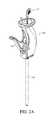
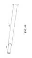
- FIG. 1Aillustrates a side view of an example embodiment of a bone graft delivery device
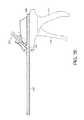
- FIG. 1Billustrates a perspective view of the bone graft delivery device of FIG. 1A ;
- FIGS. 2A and 2Billustrate perspective views of another example embodiment of a bone graft delivery device
- FIG. 2Cillustrates a side view of another example embodiment of a bone graft delivery device
- FIG. 2Dillustrates a section view of the bone graft delivery device of FIG. 2C ;
- FIG. 2Eillustrates a section view of the bone graft delivery device of FIGS. 2C and 2D including a pusher rod;
- FIG. 2Fillustrates a side view of another example embodiment of a bone graft delivery device
- FIG. 2Gillustrates a section view of the bone graft delivery device of FIG. 2F ;
- FIG. 2Hillustrates a section view of the bone graft delivery device of FIGS. 2F and 2G including a pusher rod;
- FIG. 2Iillustrates a bottom view of another example embodiment of a bone graft delivery device
- FIG. 2Jillustrates a section view of the bone graft delivery device of FIG. 2I ;
- FIG. 2Killustrates a section view of the bone graft delivery device of FIGS. 2I and 2J including a pusher rod;
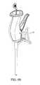
- FIG. 3illustrates a perspective view of a handle of a bone graft delivery device including a funnel for introduction of bone graft;
- FIGS. 4A-4Eare section views illustrating operation of an example embodiment of a ratcheting mechanism in a handle of a bone graft delivery device
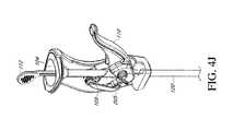
- FIGS. 4F and 4Gillustrate exploded views of an example embodiment of a bone graft delivery device including a ratcheting mechanism
- FIGS. 4H-4Millustrate operation of the ratcheting mechanism of the device of FIGS. 4F and 4G ;
- FIG. 4Nillustrates a perspective view of an example embodiment of a bone graft delivery device including a ratcheting mechanism
- FIG. 4Oillustrates an exploded view of the bone graft delivery device of FIG. 4N ;
- FIGS. 4P-4Tare section views illustrating operation of the ratcheting mechanism of the device of FIGS. 4N and 4O ;
- FIGS. 4U and 4Villustrate section views of an example embodiment of a handle of a bone graft delivery device including a ratcheting mechanism
- FIG. 4Willustrates a radiopaque ring configured to be placed on a distal end of a tube of a bone graft delivery device
- FIG. 4Xillustrates a section view of a distal end of a plunger of a bone graft delivery device
- FIGS. 5A and 5Billustrate an example embodiment of a bone graft delivery device having a modular handle and tube construction
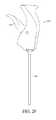
- FIGS. 6A-6Cillustrate various views of a distal tip of the bone graft delivery device of FIGS. 1A and 1B ;
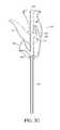
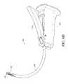
- FIG. 6Dillustrates a perspective view of an example embodiment of a bone graft delivery device having a curved tube
- FIG. 6Eillustrates a perspective view of an example embodiment of a bone graft delivery device having a straight tube
- FIG. 6Fillustrates an enlarged view of a rasping distal tip of the bone graft delivery device of FIG. 6E ;
- FIG. 6Gillustrates the distal tip of FIG. 6F extruding bone graft material
- FIG. 6Hillustrates an example embodiment of a rasping distal tip coupled to a tube of a bone graft delivery device
- FIG. 6Iillustrates the distal tip of FIG. 6H extruding bone graft material
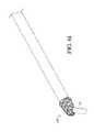
- FIG. 7Aillustrates a perspective view of an example embodiment of a bone graft delivery device
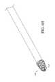
- FIG. 7Billustrates a perspective view of an example embodiment of a bone graft delivery device including a shaft having a distal burr disposed therethrough;
- FIG. 7Cillustrates an enlarged view of the distal end of the bone graft delivery device of FIG. 7B ;
- FIG. 8Aillustrates a distal section of an example embodiment of a bone graft delivery device including an endoscope
- FIG. 8Billustrates a distal section of another example embodiment of a bone graft delivery device including an endoscope
- FIGS. 9A and 9Billustrate the bone graft delivery device of FIGS. 2A and 2B with a guide bracket for a surgical navigation system
- FIGS. 10A-10Eillustrate a bone graft delivery device configured to deliver bone graft to an interbody device
- FIG. 11Aillustrates a perspective view of an example embodiment of an interbody device configured to be coupled to a bone graft delivery device
- FIG. 11Billustrates a side view of the interbody device of FIG. 11A ;
- FIG. 11Cillustrates a section view of the interbody device of FIGS. 11A-11B taken along line 11 C- 11 C in FIG. 11B ;
- FIG. 11Dillustrates a top view of the interbody device of FIGS. 11A-11C ;
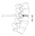
- FIG. 11Eillustrates a bone graft delivery device coupled to the interbody device of FIGS. 10A-10D disposed within a disc space and bone graft spreading to the surrounding disc space from inside the interbody device;
- FIG. 12illustrates an example embodiment of an expandable interbody device coupled to a bone graft delivery device
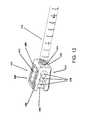
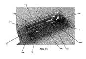
- FIG. 13illustrates an example embodiment of a bone graft delivery system kit
- FIG. 14illustrates an example embodiment of an attachment member coupling a tube of a bone graft delivery device to an interbody cage
- FIGS. 15A-15Billustrate example embodiments of applicators configured to be coupled to a tube of a bone graft delivery device to direct bone graft material in various directions;
- FIG. 16Aillustrates a side view of an example embodiment of a bone graft delivery device having a handle including a trigger and a ratcheting mechanism with the trigger in a first position;
- FIG. 16Billustrates a section view of the bone graft delivery device of FIG. 16A ;
- FIG. 16Cillustrates a side view of the bone graft delivery device of FIG. 16A with the trigger in a second position
- FIG. 16Dillustrates a section view of the bone graft delivery device of FIG. 16C ;
- FIG. 17Aillustrates a perspective view of an example embodiment of a bone graft loading device
- FIG. 17Billustrates a section view of the bone graft loading device of FIG. 17A ;
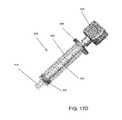
- FIG. 17Cillustrates an exploded view of the bone graft loading device of FIGS. 17A-17B ;
- FIG. 17Dillustrates a perspective view of another example embodiment of a bone graft loading device
- FIG. 17Eillustrates a side view of the bone graft loading device of FIG. 17D ;
- FIG. 17Fillustrates an exploded view of the bone graft loading device of FIGS. 17D-17E ;
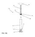
- FIG. 18Aillustrates an exploded view of another example embodiment of a bone graft loading device
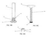
- FIG. 18Billustrates a tube body and base of the bone graft loading device of FIG. 18A ;
- FIG. 18Cillustrates a plunger of the bone graft loading device of FIG. 18A ;
- FIG. 18Dillustrates a cap or coupling of the bone graft loading device of FIG. 18A .
- an example embodiment of a bone graft delivery device 100generally includes a handle 102 having a trigger 110 or other actuation mechanism, a tube 120 having a lumen therethrough, and a distal tip 130 .
- the bone graft delivery device 100is similar to a caulking gun.
- the handle 102can house a supply of the desired bone graft material.
- the bone graft materialcan be pre-loaded in the handle 102 or tube 120 or can be supplied to the handle, for example, via a cartridge that can be removably coupled to the handle 102 .
- the device 100can further include a plunger 112 that is retracted proximally to allow the handle to receive a cartridge or pre-loaded volume of bone graft material.
- the bone graft delivery device 100does not include a distal tip 130 .
- the bone graft delivery devicedoes not include a rasping distal tip as described in greater detail herein.
- the trigger 110is actuated to deliver bone graft material through the tube 120 and distal tip 130 to a desired surgical location.
- the plunger 112is simultaneously pushed distally to help deliver bone graft material through the tube 120 .
- the trigger 110 or other actuation mechanismis configured to deliver a controlled release amount of bone graft material during actuation of the device, for example, 1 ⁇ 2 cc of bone graft material per complete squeeze of the trigger 110 .
- the trigger 110 or other actuation mechanismmay be operated manually or by mechanical, battery powered, electric, pneumatic, or any other means of force.
- a portion of the handle 102can include an opening configured to receive the bone graft material.
- a base of the handle 102can include a funnel 104 as shown in FIGS. 2A-2B and 3 .
- a side or another portion of the handle 102can include a funnel 104 or other opening configured to receive the bone graft material, for example as shown in FIGS. 2C-2K .
- the funnel 104can be designed to advantageously allow the user to use any bone graft material or combination of bone graft materials he or she wishes or deems appropriate.
- the usercan use synthetic, autologous, stem cell, DMB, cadaveric, and/or any other available bone graft material.
- the handle 102can further include a channel or funnel shaft 106 extending therethrough connecting and in fluid communication with the funnel 104 and tube 120 .
- the usercan mix the desired bone graft material in the funnel 104 , then use the plunger 112 or other means to advance the bone graft material through the channel 106 and into the tube 120 for delivery.
- the handle 102includes a ratcheting mechanism 108 configured to advance the plunger 112 and bone graft material from the funnel 104 and through the channel 106 and tube 120 for delivery, as shown in FIGS. 4A-4E .
- the ratcheting mechanism 108(or any of the ratcheting mechanisms described herein) and plunger 112 can advantageously create pressure on the bone graft material in the tube 120 to improve delivery to the target location.
- the plunger 112fully or substantially seals with the inner diameter of the tube 120 . This can create a vacuum within the tube 120 and/or can provide greater pressure on the bone graft material to force the bone graft material through the tube 120 and out of the distal end of the tube 120 or distal tip 130 .
- the plunger 112 or a portion of the plunger 112is made of, for example, rubber silicone, which can help improve the seal with the tube 120 and/or can help provide pressure on the bone graft material.
- the plunger 112can be made of a plastic or another material and can include an elastomeric rubber stopper 115 at the distal end, for example as shown in FIG. 4O .
- the stopper 115can be dual injection molded or co-molded with the plunger 112 so that the stopper 115 cannot normally be removed from the plunger 112 . As shown in FIG. 4X , the stopper 115 can be molded onto or over a barb-shaped distal end of the plunger 112 .
- the plunger 112 and ratcheting mechanism 108can therefore allow the bone graft delivery device to extrude even highly viscous and/or granular bone graft material.
- the ratcheting mechanism 108includes a cover 105 and a pawl 109 coupled to the trigger 110 via an arm 208 .
- the funnel shaft 106includes a window 107 in a portion of the shaft 106 facing the pawl 109 .
- the plunger 112can be made of a rigid or flexible material.
- the plunger 112can be plastic, carbon fiber, metal, or any other suitable material.
- the plunger 112includes a series of teeth 114 and notches 113 located between the teeth 114 and configured to receive the pawl 109 .
- the notches 113can be generally triangular.
- distal edges of the teeth 114slope proximally toward the outer edge of the plunger 112 to allow the pawl 109 to slide along the distal edges in use.
- extending the trigger 110 away from the handle 102for example to a position perpendicular to the handle 102 , causes the cover 105 to rest in and close the window 107 of the funnel shaft 106 , as illustrated in FIGS. 4A and 4B , to allow for loading of the bone graft material through the funnel 104 into the channel 106 . In this position, the pawl 109 rests proximal to the window 107 .
- the plunger 112can be inserted into the funnel 104 and channel 106 to advance some or all of the bone graft material past the window 107 .
- the trigger 110can be moved toward the handle 102 to an intermediate position, as shown in FIG. 4C . This moves the pawl 109 distally so that the pawl 109 engages one of the notches 113 on the plunger 112 through the window 107 .
- Movement of the trigger 110 to a final position closest the handle 102causes the pawl 109 to move distally within the window 107 (or away from the funnel 104 and toward the tube 120 ), thereby advancing the plunger 112 distally within the channel 106 to force the bone graft material distally within the channel 106 and/or tube 120 , as shown in FIGS. 4D and 4E .
- the trigger 110can be moved back to the intermediate position to cause the pawl 109 to slide proximally along the plunger 112 and over one of the teeth 114 to engage a more proximal notch 113 .
- the trigger 110can be moved between the intermediate position and final position multiple times until the pawl 109 has reached the proximal end of the plunger 112 .
- the usercan re-load the device 100 as needed during a procedure.
- the ratcheting mechanism 108 and trigger 110 in combinationcan advantageously provide a mechanical advantage and allow the user to apply a greater force in operating the bone graft delivery device 100 and/or delivering the bone graft material compared to, for example, a standard syringe used to deliver bone graft material.
- FIGS. 4F-4MAnother example embodiment of a handle 102 and ratcheting mechanism 108 is shown in FIGS. 4F-4M .
- the handle 102includes a two-part clamshell housing 102 a , 102 b that houses the funnel 104 , funnel shaft 106 , and ratcheting mechanism 108 assembly as shown in the exploded views of FIGS. 4F and 4G .
- the ratcheting mechanism 108includes the pawl 109 and a sheath 205 coupled to the trigger 110 via arm 208 .
- the plunger 112includes a series of sloped teeth 114 alternating with notches 113 that are configured to receive the pawl 109 .
- the sheath 205covers the pawl window 107 and the pawl 109 rests proximal to the window 107 .
- Movement of the trigger 110 to the intermediate positioncauses the sheath 205 and pawl 109 to move distally, exposing the window 107 and allowing the pawl 109 to engage the plunger 112 , as shown in FIGS. 4J and 4K .
- Movement of the trigger 110 to the final positioncauses the pawl 109 to move distally, advancing the plunger 112 distally, as shown in FIGS. 4L and 4M .
- FIGS. 4N-4TYet another example embodiment of a handle 102 and ratcheting mechanism 108 is shown in FIGS. 4N-4T .
- the funnel shaft 106includes an upper shaft portion 106 a and a lower shaft portion 106 b
- the lower shaft portion 106 bhas an outer diameter smaller than an outer diameter of the upper shaft portion 106 a .
- the outer diameter of the lower shaft portion 106 bcan be approximately the same as an inner diameter of the upper shaft portion 106 a
- the shaft 106can include a step 206 (shown in FIG. 4R ) at a transition point between the upper shaft portion 106 a and lower shaft portion 106 b .
- the upper 106 a and lower 106 b shaft portionsare integrally formed.
- the upper 106 a and lower 106 b shaft portionscan be separate pieces, and a proximal end of the lower shaft portion 106 b can be coupled to an inner perimeter of a distal end of the upper shaft portion 106 a .
- the upper shaft portion 106 aincludes a first window 107 a for the pawl 109 and a second window 107 b on an opposite side of the upper shaft portion 106 a from the first window 107 a .
- a sheath 305is disposed within or inside the upper shaft portion 106 a , and in the illustrated embodiment, a lever 308 extends from the trigger 110 and engages the sheath 305 through the second window 107 b , as shown in FIGS. 4P-4T .
- the lever 308is integrally formed with the sheath 305 .
- the lever 308can be coupled to the sheath 305 , for example, with a pin 313 .
- the lever 308includes a body 310 having a generally circular or ovular aperture 307 , and an arm 309 extending from one end of the body 310 .
- the aperture 307receives the funnel shaft 106 so that the body 310 surrounds the upper shaft portion 106 a .
- the sheath 305includes a protrusion 311 that can extend through or over the second window 107 b when the sheath 305 is disposed in the upper shaft portion 106 a .
- the protrusion 311is aligned with the lever body 310 with the protrusion 311 disposed in the aperture 307 .
- the pin 313extends through holes in the body 310 and protrusion 311 to couple the sheath 305 to the lever 308 .
- the pin 313is secured to the protrusion 311 and lever body 310 with a weld, glue, or other appropriate means.
- the free end of the arm 309 of the lever 308releasably engages the trigger 110 .
- the trigger 110can include a track 116 configured to releasably receive the arm 309 as shown in FIGS. 4P and 4Q , and the arm 309 can engage the track 116 via, for example, a snap fit.
- the trigger 110is biased or naturally rests at a distance from the handle body that holds the arm 309 in the track 116 .
- the trigger 110can be flexed or allowed to move slightly away from the handle body to release the arm 309 .
- the sheath 305has an outer diameter about the same and slightly less than the inner diameter of the upper shaft portion 106 a and a thickness about the same as a thickness of the lower shaft portion 106 b .
- the sheath 305can include an upper lip 306 , and a length of the sheath 305 can be selected such that in an initial loading position, shown in FIG. 4P , the lip 306 rests against an inner surface of the funnel 104 and a distal end of the sheath 305 rests against the step 206 . In the loading position, the sheath 305 covers the first window 107 a .
- the dimensions of the upper shaft portion 106 a , lower shaft portion 106 b , and sheath 305advantageously allow the sheath 305 to be substantially flush with an inner surface of the upper shaft portion 106 a and step 206 and provide a substantially smooth and constant-diameter inner passageway from the sheath 305 to the lower shaft portion 106 b .
- the bone graft delivery device of FIGS. 4N-4Talso includes a pusher rod 312 and a tube end cap 124 .
- the lever 308is coupled to the trigger 110 so that the sheath 305 sits in the initial loading position shown in FIG. 4P .
- Bone graft material 10is loaded into the funnel 104 , and the pusher rod 312 can be inserted into the funnel 104 to help urge the bone graft material 10 through the sheath 305 and lower shaft portion 106 b and into the tube 120 as shown in FIG. 4Q .
- the pusher rod 312is made of, for example, a glass filled or rigid polymer material.
- the tube end cap 124inhibits or prevents the bone graft material 10 from exiting the distal end of the tube 120 during the loading process and until the user wishes to deliver the bone graft material 10 .
- the tube end cap 124can be attached to the distal end of the tube 120 via a threaded coupling, friction fit, or other suitable means.
- the tube 120includes external threads 125 b at or near the distal end configured to mate with internal threads in the tube end cap 124 .
- the plunger 112can be inserted before or after releasing the lever 308 and extends through the sheath 305 , upper shaft portion 106 a , and lower shaft portion 106 b and into the tube 120 as shown in FIG. 4S .
- the lever 308can advantageously provide the user with a greater mechanical advantage and/or greater control in moving the sheath 305 proximally to expose the first window 107 a .
- the sheathincludes a protrusion 316 without a lever as shown in FIGS. 4U and 4V . The user can use the protrusion 316 to lift or lower the sheath 305 .
- the tube end cap 124is removed when the user wishes to deliver the bone graft material 10 through the tube 120 .
- Movement of the trigger 110 toward the handlecauses the pawl 109 to move distally, advancing the plunger 112 distally, as shown in FIG. 4T .
- the trigger 110is moved away from and toward the handle to advance the plunger 112 and bone graft material 10 through the tube 120 in discreet increments.
- Other ratcheting mechanisms and/or other mechanisms for advancing bone graft material through the handle 102 and/or tube 120are also possible.
- the funnel 104 or other opening for loading of bone graft materialcan be positioned in the handle 102 in locations other than a proximal end or base of the handle 102 .
- the handle 102is configured such that the trigger 110 and a grip 111 extend from a main body portion 103 of the handle 102 .
- the funnel 104is located on an opposite side of the body portion 103 from the grip 111 and trigger 110 .
- a main channel 406extends through the handle 102 from an opening in a proximal end of the body portion 103 to an opening in a distal end of the body portion 103 and is in fluid communication with the tube 120 .
- the funnel shaft 106extends from the funnel 104 to intersect the main channel 406 as shown in FIGS. 2D and 2E .
- the funnel 104 and funnel shaft 106are oriented at an angle 1 relative to the main channel 406 .
- the anglecan advantageously help direct bone graft material inserted into the funnel 104 and funnel shaft 106 distally toward the tube 120 .
- the bone graft delivery devicecan include a pusher rod 312 as shown in FIG. 2E to help urge bone graft material from the funnel 104 through the funnel shaft 106 and into the main channel 406 .
- the pusher rod 312can be configured such that when fully inserted into the funnel 104 and funnel shaft 106 , a distal end 314 of the pusher rod 312 rests at the intersection of the funnel shaft 106 with the main channel 406 to at least partially or substantially close the main channel 406 .
- the distal end 314 of the pusher rod 312can be formed at an angle with the angle corresponding to the angle of the funnel shaft 106 so that the distal end 314 is continuous with a wall of the main channel 406 when inserted into the funnel shaft 106 .
- the pusher rod 312can be configured to remain in place during delivery of bone graft material.
- the handle 102 of FIGS. 2C-2Ecan include any of the ratcheting mechanisms described herein or any other suitable ratcheting mechanism.
- the plunger 112is inserted from the proximal opening of the main channel 406 through the handle 102 and into the tube 120 .
- the main channel 406can include a window to allow the pawl to engage notches on the plunger.
- movement of the trigger 110 toward the grip 111can cause the pawl to advance the plunger and bone graft material distally in the tube 120 .
- the handle 102 of FIGS. 2C-2Edoes not include a ratcheting mechanism, and a plunger can be inserted into and advanced through the main channel 406 and tube 120 to advance and deliver the bone graft material.
- FIGS. 2F-2Hillustrate an alternative embodiment in which the funnel 104 is located on the same side or surface of the handle 102 as the trigger 110 .
- the funnel 104is advantageously located distal to the trigger 110 so that the pusher rod 312 , when inserted into the funnel 104 , does not interfere with operation of the trigger 110 .
- the embodiment of FIGS. 2F-2Hcan also include a main channel 406 , an angled funnel 104 , funnel shaft 106 , and distal end 314 of the pusher rod 312 , and any suitable ratcheting mechanism similar to the embodiment shown in FIGS. 2C-2E and discussed above.
- a plungeris inserted into the main channel 406 and tube 120 .
- the main channel 406includes a window 107 to allow the pawl 109 to engage notches on the plunger when the plunger is inserted. Movement of the trigger 110 towards the handle 102 causes the pawl 109 to move distally within the window 107 , thereby advancing the plunger and bone graft material. Movement of the trigger 110 away from the handle causes the pawl 109 to slide proximally along the plunger and engage a more proximal notch.
- the window 107 and ratcheting mechanismare located proximal to the intersection of the funnel shaft 106 with the main channel 406 , and the ratcheting mechanism does not include a cover or sheath.
- 2I-2Killustrate another alternative embodiment, similar to the embodiment of FIGS. 2F-2H , with the funnel 104 positioned on a side or surface of the handle 102 lateral or generally perpendicular to the trigger 110 .
- the funnel 104can be located on any side or surface of the handle 102 , for example, opposite the trigger 110 , to either side of the trigger, or any other position around the handle 102 .
- the funnel 104can also be located distal to, even with, or proximal to the trigger 110 .
- FIGS. 16A-16Dillustrate another alternative embodiment of a bone graft delivery device 100 having a handle 102 including a ratcheting mechanism 508 .
- the ratcheting mechanism 508is used to advance the plunger 112 and bone graft material through the tube 120 for delivery.
- the ratcheting mechanism 508includes a pawl 509 having one or more teeth 514 that are received in the notches 113 of the plunger 112 .
- the pawl 509includes four teeth 514 , although more or fewer teeth 514 are also possible.
- a pawl 509 having multiple teeth 514can engage multiple notches 113 of the plunger 112 simultaneously, which can advantageously provide a more secure engagement between the ratcheting mechanism 508 and the plunger 112 , allow the pawl 509 to apply a greater advancement force on the plunger 112 , and/or compensate for possible malfunctioning or manufacturing variances or defects to better ensure at least one tooth 514 engages the plunger 112 .
- the pawl 509can be coupled to the trigger 110 via a pivot point 515 and/or a spring 517 .
- the spring 517can advantageously provide resistance to movement of the trigger 110 relative to the body of the handle 102 .
- the spring 517can bias the trigger 110 away from the body of the handle 102 (toward the position shown in FIGS. 16A-16B ).
- the handle 102 and tube 120have a modular construction such that the tube 120 is removably coupleable to the handle 102 as described herein.
- the tube 120can be provided preloaded with bone graft or can be loaded with bone graft prior to being coupled to the handle 102 as described in greater detail herein.
- a handle 102for example, a handle 102 including any of the ratcheting mechanisms described herein or another suitable ratcheting or advancement mechanism, need not include a funnel and/or a channel or funnel shaft.
- a tube 120 loaded with bone graftis coupled to the handle 102 , the plunger 112 is inserted through the handle 102 into the tube 120 , and the ratcheting mechanism 508 is used to advance the plunger 112 and bone graft material through the tube 120 for delivery.
- movement of the trigger 110 from the position shown in FIGS. 16A-16B to the position closest to the handle 102 body shown in FIGS. 16C-16Dcauses the teeth 514 of the pawl 509 to move distally (toward the tube 120 ) within the handle 102 , thereby advancing the plunger 112 distally within the tube 120 to force the bone graft material distally within the tube 120 .
- Movement of the trigger 110 back to the position shown in FIGS. 16A-16Bcauses the teeth 514 of the pawl 509 to side proximally along the plunger 112 and over the teeth 114 to engage more proximal notches 113 .
- the plunger 112 teeth 114can be spaced relatively closer together (for example, as shown in FIGS. 16A-16B compared to FIG. 4I ). Such closer spacing can allow the ratcheting mechanism 108 , 508 to be more reliable such that in the event that the pawl 509 misses a notch 113 , the pawl 509 can engage the next notch 113 more quickly, easily, and/or with less backlash.
- the closer spacingcan also allow the user to squeeze the trigger 110 toward the handle 102 body to a lesser extent (for example, only halfway or to another intermediate point) to deliver a smaller amount of bone graft material at a particular time if desired.
- the pawl 109 , 509can engage a more proximal notch 113 as long as the trigger 110 is moved toward the handle 102 body enough that the plunger 112 is displaced by a distance greater than the distance between adjacent notches 113 .
- the tube 120 of any of the devices described hereincan include a permanent bend or curve that may be useful in positioning the device 100 at a desired location, for example, a space between two spinal discs, transverse process, facet joint, lamina, or other target area.
- the tube 120may be straight, for example, as shown in FIGS. 2A and 2B , to deliver bone graft material directly into a desired location such as a disc space, transverse process, facet joint, lamina, or other target area.
- the tube 120is somewhat flexible or repositionable and can be manipulated to bend or curve the tube 120 as needed to reach the desired location.
- the tube 120is made of a rigid material, for example, a plastic, composite, or metal.
- the tube 120can be at least partially transparent, which can allow the user to view, for example, the volume or position of the graft material within the tube 120 .
- the tube 120can also include volume markings to allow the user to monitor the amount of graft material delivered to the target site and remaining in the tube 120 , for example, as shown in FIGS. 4N-4O .
- the tube 120includes one or more radiopaque markers to allow for visualization on, for example, x-ray or fluoroscopy.
- the tube 120is generally hollow to allow for the passage of bone graft material through the lumen of the tube 120 .
- the tube 120 and lumencan have various diameters, for example, for different applications and/or target locations.
- the tube 120can be integrally formed with or permanently coupled to the handle 102 .
- the bone graft delivery device 100can have a modular construction so that various tubes 120 can be selected and coupled to the handle 102 .
- Such a modular constructioncan advantageously allow the user to interchange straight and curved handles and/or handles having various other features depending on the target location, particular patient, and/or other factors.
- the distal end of the handle 102 or any of the handles described hereincan include a recess 60 configured to receive a base 62 coupled to or integrally formed with the tube 120 .
- the base 62can be coupled to the tube 120 via a threaded coupling, press fit, or any other suitable means.
- the tube 120includes external threads 125 a at or near a proximal end of the tube configured to mate with internal threads in the base 62 .
- the base 62can include an aperture to allow fluid communication between the funnel shaft 106 in the handle 102 and the tube 120 .
- the tube 120can also be coupled to the handle 102 by any other appropriate means.
- a distal end of the tube 120(which may be any of the tubes described herein) can include a tip 130 .
- the tip 130can be integrally formed with or coupled, removably or permanently, to the tube 120 .
- the tube 120 and tip 130can be a modular system such that different tips can be selected and coupled to the tube 120 for different procedures and/or target locations.
- the tip 130can be made of a metallic, radiopaque material to facilitate visualization on, for example, fluoroscopy or x-ray.
- the tip 130may be made of another material, for example a durable medical plastic or a composite material, and may include markers to facilitate visualization.
- the tip 130is somewhat bullet-shaped with a generally triangular cross-section; however, other shapes and configurations are also possible.
- the tip 130can be generally flat as shown in the example embodiments of FIGS. 6D-6G .
- the tip 130is generally conical. This shape can be beneficial for delivering bone graft material to, for example, a facet joint.
- the tip 130is pointed and/or sharp to dissect or split muscle and tissue as it is advanced through the patient's skin and body to the surgical location.
- the tip 130can be blunt to allow for displacement of muscle without risk of cutting of nerves or other tissue.
- the tipmay have a single or multiple openings 132 in fluid communication with the tube 120 lumen and configured to deliver the bone graft material 10 from the tube 120 , as shown in FIG. 6G , to the desired location.
- At least one side or area of the tip 130includes a series of jagged edges or other suitable surface 134 configured to serve as a rasp for scraping bone.
- the edgesmay be triangular in shape, and as shown in in FIGS. 6D-6G , they may be flat. With respect to the embodiment shown in FIGS. 6D-6G , the jagged edges may form a plurality of flat surfaces parallel with each other all within the same plane.
- the rasping surface 134can include a roughened surface extending around an outer surface of the tip.
- the raspmay be operated manually or by mechanical, battery powered, electric, pneumatic, or any other means of force to allow for decortication of the area to receive the bone graft material.
- the opening(s) 132 for delivering bone graft materialis located on a side(s) or portion(s) of the tip 130 that does not include a rasping surface, for example as shown in FIGS. 1A-1B and 6A-6C .
- the opening(s) 132is located on a side(s) or portion(s) that does include a rasping surface, for example as shown in FIGS. 6D-6I and 8A .
- the delivery device 100includes a sleeve slidably or telescopingly disposed over the tip 130 .
- the sleevecan extend to a proximal end of the tube 120 adjacent the handle 102 so that a user can distally advance or proximally retract the sleeve by manipulating a proximal end of the sleeve.
- the sleeveextends over only a portion of the tube 120 or over only the tip 130 and the delivery device 100 includes an actuating mechanism that allows the sleeve to be advanced and retracted.
- the sleevecan be disposed over the tip 130 during insertion of the tip 130 to the target area to advantageously protect skin, tissue, and/or muscle along the insertion path from damage or injury from the rasping surface 134 and to allow the tip 130 to pass through the skin, tissue, and/or muscle more easily.
- the sleevecan be proximally retracted to expose the rasping surface 134 for decortication of the target area. After decortication and/or after delivery of the bone graft material, the sleeve can be distally advanced to cover the rasping surface 134 for withdrawal of the tip 130 from the body.
- the distal end of the tube 120does not include a rasping tip 130 , for example as shown in FIGS. 7A-7C .
- an elongate shaft 150 having a burr 152 at a distal endcan be inserted through the tube 120 as needed or desired to decorticate a target area, for example as shown in FIGS. 7B and 7C .
- the burr 152can have various shapes and configurations, for example, a generally spherical shape as shown in FIGS. 7B and 7C , a bullet shape similar to the distal tip 130 shown in FIGS. 6A-6C , a generally flat shape similar to the distal tip 130 shown in FIGS.
- FIGS. 6H-6Ia generally conical shape as shown in FIGS. 6H-6I , or any other suitable shape or configuration.
- the use of a separate instrument for decorticationcan advantageously allow the user to select different burrs, rasps, or the like for different patients, target areas, or situations.
- the elongate shaft 150 and burr 152can be operated manually.
- a proximal end of the shaft 150can be coupled to a drill 154 or another device to provide decortication by mechanical, battery powered, electric, pneumatic, or any other means of force.
- the distal end of the tube 120includes a radiopaque ring or other marker 122 as shown in FIG. 7C to allow for visualization on, for example, x-ray or fluoroscopy.
- the radiopaque ring 122can be used to assist the user in assessing depth during the procedure.
- the radiopaque ring 122can be press fit or snapped onto the distal end of the tube 120 during manufacturing and assembly.
- the radiopaque ring 122can be press fit or snapped into a groove 222 near a distal end of the tube 120 .
- the groove 222is distal to the threads 125 b configured to receive the tube end cap 124 and is therefore covered by the tube end cap 124 when the tube end cap 124 is coupled to the tube 120 .
- the radiopaque ring 122can be co-molded with the tube 120 during manufacturing.
- FIGS. 17A-18Dshow example embodiments of loading devices 600 for loading bone graft material into the tube 120 .
- Such loading devices 600can allow the user to load the tube 120 with any bone graft material or combination of bone graft materials he or she wishes or deems appropriate.
- the usercan use synthetic, autologous, stem cell, DMB, cadaveric, and/or any other available bone graft material.
- the loading devices 600include a hollow tube body 602 , a plunger shaft 604 , a plunger 605 , and a cap or coupling 608 .
- the tube body 602can hold a volume of about 20 cc, although other sizes and volume are also possible.
- the tube body 602can have a smooth or generally smooth inner wall.
- the tube body 602includes measurement markings to allow the user to determine the amount of bone graft material within the tube body 602 .
- the tube body 602includes a distal tip or end 610 . As shown, the distal tip 610 has a smaller diameter than the tube body 602 .
- the tube 120 of a bone graft delivery device 100such as those described herein is coupled to the distal tip 610 for loading.
- the distal tip 610is internally threaded to receive and engage external threads 125 a at or near the proximal end of the tube 120 (shown in FIG. 4O ).
- the plunger 605is made in part or entirely of rubber.
- the plunger 605is coupled, either removably or permanently, to a distal end of the plunger shaft 604 .
- the plunger shaft 604 and plunger 605are integrally molded or formed.
- the plunger 605has a greater diameter than the plunger shaft 604 and is sized and shaped to contact and seal against the inner wall of the tube body 102 .
- the loading device 600includes a handle 606 that allows the user to better grip the plunger shaft 604 .
- the handle 606is integrally molded or formed or coupled, either removably or permanently, to a proximal end of the plunger shaft 604 .
- the handle 606can have various shapes and configurations, for example as shown in the embodiments of FIGS. 17A-17C and 17D-17F .
- the plunger shaft 604is externally threaded.
- the cap or coupling 608couples to a proximal end of the tube body 602 , for example, via a threaded, snap-fit, or other suitable connection.
- the cap 608couples to the tube body 602 via a combined snap fit and rotational coupling mechanism whereby the cap 608 is attached to the tube body 602 by rotating the cap 608 (e.g., clockwise) until the cap 608 snaps into place; the cap 608 can be removed from the tube body 602 by rotating the opposite direction (e.g., counter clockwise) to disengage the snap fit and rotating until the cap 608 fully releases from the tube body 602 .
- the cap 608has a through-hole that is sized to receive the plunger shaft 604 therethrough and internally threaded to engage the external threads of the plunger shaft 604 .
- the cap 608can be predisposed on the plunger shaft 604 .
- the cap 608can be threaded along the plunger shaft 604 , but can be retained on the plunger shaft 604 , which has a larger diameter than the plunger shaft 604 and therefore a larger diameter than the through-hole in the cap 608 that is sized to engage the plunger shaft 604 .
- the tube body 602includes handles or wings 612 extending generally laterally outwardly from the tube body 602 .
- the wings 612can advantageously allow the user to grip the tube body 602 more easily and securely in use.
- the wings 612can have various shapes and configurations as shown.
- the usercan couple the tube 120 of the bone graft delivery device 100 to the distal tip 610 of the loading device 600 before or after loading the desired bone graft material into the tube body 602 .
- the userthreads the cap 608 to the distal end of the plunger shaft 604 proximate the plunger 605 .
- the userthen inserts the plunger 605 into the tube body 602 and couples the cap 608 to the proximal end of the tube body 602 .
- the userrotates the plunger shaft 604 (e.g., clockwise), for example, by rotating the handle 606 , into the cap 608 .
- the internally threaded cap 608converts the rotational motion of the externally threaded plunger shaft 604 relative to the cap 608 into translational motion of the plunger shaft 604 and plunger 605 distally within the tube body 602 . Distal motion of the plunger 605 forces the bone graft material through the distal tip 610 and into the tube 120 .
- the threaded coupling between the plunger 605 and the cap 608advantageously allows the user to apply greater torque compared to a syringe-type arrangement wherein the plunger is simply pushed distally within the tube body. This greater torque allows the bone graft material to be loaded into the tube 120 more easily.
- the usercan remove the tube 120 from the loading device 600 and couple the tube 120 to a handle 102 for use. If needed during the course of a procedure, the tube 120 can be decoupled from the handle 102 , reloaded with the loading device 600 , then decoupled from the loading device 600 and recoupled to the handle 102 to continue the procedure.
- FIGS. 18A-18Dillustrate an alternative embodiment of a loading device 700 .
- the loading device 700similarly includes a tube body 702 , an externally threaded plunger shaft 704 , a plunger 705 , and an internally threaded cap or coupling 708 that couples to a proximal end of the tube body 702 .
- the cap 608can include an internally threaded proximal ring 722 and two arms 724 extending distally from the proximal ring 722 on opposite sides of the proximal ring 722 . Distal ends of the arms 724 can include hooks to secure the cap 608 to the tube body 702 .
- Other shapes and configurations for the cap 708are also possible. As shown in FIG.
- a plunger stop 720can be disposed about the plunger shaft 704 proximate the distal end of the plunger shaft 704 and the plunger 705 .
- the proximal ring 722 of the cap 708is disposed about the plunger shaft 704 proximal to the plunger stop 720 .
- the plunger stop 720can help prevent or inhibit the cap 708 from falling off the plunger shaft 704 .
- the loading device 700also includes a handle 706 at the proximal end of the plunger shaft 704 .
- the handle 706can be integrally formed with the plunger shaft 704 as shown or can be coupled, removably or permanently, to the plunger shaft 704 .
- the tube body 702includes a side spout 714 extending laterally from a side of the tube body 702 and in fluid communication with the internal volume of the tube body 702 .
- the loading device 700includes a base 716 , which can advantageously allow the loading device 700 to stand on a table or other support surface before, during, or after use.
- the loading device 700includes a tube stop 718 that fills the internal volume of the tube body 702 between the distal end or bottom of the tube body 702 and the side spout 714 .
- the tube stop 718extends proximally within the tube body 702 to a point proximal to a distal side of the side spout 714 .
- the tube stop 718can be made of a material that adds some weight to the bottom of the tube body 702 to advantageously provide the tube body 702 with greater stability when placed on a table or other surface.
- the loading device 700operates similarly to the loading devices 600 described above. However, in this embodiment, the tube 120 of the bone graft delivery device 100 is coupled to the side spout 714 for loading, and advancement of the plunger shaft 704 and plunger 705 distally within the tube body 702 forces the bone graft material within the tube body 702 through the side spout 714 and into the tube 120 .
- the bone graft delivery device 100can be configured to deliver bone graft material inside an interbody cage or other interbody device that has been disposed within a disc space. If sufficient bone graft is not applied to a disc space during a fusion procedure, there is a decreased likelihood of fusion and an increased chance of revision surgery.
- Some interbody implants or cagesinclude an opening or window that can be filled with bone graft. However, this provides for limited surface area for the bone graft to contact the vertebral end plates. In some cases, surgeons use funnels or similar devices to fill the disc space prior to insertion of the implant. However, inserting an interbody cage after delivering bone graft material can disrupt the placement of the bone graft material.
- the bone graft delivery device 100allows for pressurized and controlled delivery of bone graft material into the cage to maximize filling of the cage with the bone graft material.
- an attachment membercan be provided to couple the distal end of the tube 120 of the bone graft delivery device 100 to the interbody cage. Bone graft material is delivered through the tube 120 and attachment member and into the interbody cage.
- FIG. 14illustrates an example embodiment of an attachment member 800 that can couple the distal end of the tube 120 to an interbody cage 401 .
- a proximal end of the attachment member 800is sized and configured to couple to the distal end of the tube 120
- the distal end of the attachment member 800is sized and configured to couple to the interbody cage 401 .
- the proximal end of the attachment member 800can be internally threaded to engage external threads 125 b at the distal end of the tube 120 .
- the attachment member 800can couple to the tube 120 via a snap fit or another suitable connection mechanism.
- Various attachment memberscan be manufactured and/or provided for use with various interbody cages or other interbody devices.
- the distal end of the tube 120itself includes features configured to engage corresponding features on an interbody device.
- FIGS. 10A-10Eillustrate an example embodiment of a tube 120 having a distal end 122 configured to engage an interbody cage 400 .
- the distal end 122 of the tube 120can be coupled to the cage 400 after the cage 400 has been placed in the disc space as shown in FIGS. 10A and 10B .
- the distal end 122 of the tube 120includes alternating ridges 121 and recesses 123 configured to mate with corresponding recesses 404 and ridges 402 on the cage 400 .
- various tubes 120 with different engagement featurescan be manufactured and/or provided for use with various interbody devices, and the user can select the appropriate tube 120 after selecting the interbody device to be used.
- the tubes 120 and/or attachment memberscan be configured to couple to various cages via threaded connections, snap fit connections, clip-on connections, wedge connections, and/or any other suitable connection mechanism.
- the tubes 120 and/or attachment memberscan be configured to abut one or more cages without such a connection mechanism.
- FIGS. 15A-15Billustrate example embodiments of applicators 850 a , 850 b that can be coupled to the distal end of the tube 120 to direct bone graft in various directions.
- the applicators 850 a , 850 ballow bone graft material to be directed around a cage disposed within the disc space.
- a proximal end of the applicator 850 a , 850 bcouples to the distal end of the tube 120 .
- the proximal end of the applicator 850 a , 850 bis internally threaded to engage external threads 125 b at the distal end of the tube 120 .
- the applicator 850 a , 850 bcan couple to the tube 120 via a snap fit or another suitable connection mechanism.
- the applicators 850 a , 850 bcan have various shapes.
- FIG. 15Aillustrates an applicator 850 a having an approximately 90° curve proximate the distal end such that bone graft material can be extruded in a direction approximately 90° from the distal end of the tube 120 .
- FIG. 15Billustrates an applicator 850 b having an S-shape or serpentine shape.
- the applicator 850 ballows the bone graft material to be extruded along a direction generally parallel but offset from the distal end of the tube 120 .
- Other shapes and configurationsfor example, various curved and/or angular shapes, are also possible.
- FIGS. 11A-12Example embodiments of cages that can be used with the bone graft delivery device 100 are illustrated in FIGS. 11A-12 .
- the cage 400has a leading end 410 , a trailing end 412 , and first and second sidewalls 414 , 416 extending between the leading end 410 and trailing end 412 .
- the leading end 410is tapered or generally wedge-shaped.
- the sidewalls 414 , 416have an upper bone contacting surface 418 configured to contact a superior vertebra and a lower bone contacting surface 420 configured to contact an inferior vertebra.
- the cage 400also has a central opening 422 bounded by the leading end 410 , trailing end 412 , and sidewalls 414 , 416 and an opening 424 in the trailing end that is in fluid communication with the central opening 422 .
- a perimeter of the opening 424 in the trailing endincludes the recesses 404 and ridges 402 configured to mate with the distal end 122 of the tube 120 or attachment member.
- the opening 424can include other engagement features configured to mate with corresponding engagement features on the distal end of the tube 120 or attachment member.
- the opening 424is sized to mate with or receive the tube 120 or attachment member and can be larger than openings included in various other cages to mate with insertion instruments.
- the sidewalls 414 , 416can include holes 426 that are in fluid communication with the central opening 422 .
- the holes 426allow bone graft material delivered into the central opening 422 from the tube 120 to spread to the surrounding disc space outside of the cage 400 , for example as shown in FIG. 11E .
- each of the sidewalls 414 , 416includes three holes 426 , although more or fewer holes are also possible.
- the holes 426have an at least partially conical shape. As shown, a portion of the holes 426 adjacent the central opening 422 and inner surfaces of the sidewalls 414 , 416 is generally circular.
- the perimeter of the holes 426then flares or tapers outwardly toward outer surfaces of the sidewalls 414 , 416 , as shown in FIG. 11C .
- the perimeter of the holes 426can be flared or tapered continuously from the inner surfaces of the sidewalls 414 , 416 to the outer surfaces of the sidewalls 414 , 416 .
- the holes 426allow bone graft material to spread from inside the central opening 422 to outside of the cage 400 in the surrounding disc space.
- the tapered shape of the holes 426allows or promotes dispersal of bone graft material outside of the cage 400 in multiple directions and over a greater area and can allow for a more uniform distribution of bone graft material around the cage 400 in the surrounding disc space to promote fusion.
- FIG. 12illustrates an example embodiment of an expandable cage 450 configured to be coupled to the tube 120 as shown.
- the surgeonmay fill or pack the cage with bone graft before inserting the cage in the patient, then expand the cage within the disc space. However, this then results in excess space within the cage not filled with bone graft material. Coupling the bone graft delivery device 100 to the cage 450 or another expandable cage with the cage in the disc space allows the cage to be filled as it is expanded within the disc space or after it has been expanded to maximize filling of the cage with the bone graft material.
- the cage 450has a proximal wall 462 , a distal wall 460 , and first and second sidewalls 464 , 466 .
- the sidewalls 464 , 466have an upper bone contacting surface 468 configured to contact a superior vertebra and a lower bone contacting surface 470 configured to contact an inferior vertebra.
- the cage 450also has a central opening 472 and a hole 474 in the proximal wall 462 in fluid communication with the central opening 472 and configured to receive the distal end of the tube 120 .
- the distal end of the tube 120can be coupled to the proximal wall 462 via a threaded connection as soon or any other suitable mechanism. Similar to the embodiment of FIGS.
- one or both of the first and second sidewalls 464 , 466can include one or more holes 476 in fluid communication with the central opening 472 .
- the holes 476are connected to one another.
- a distance between the upper bone contacting surface 468 and the lower bone contacting surface 470is greater adjacent the distal wall 460 than the proximal wall 462 , and a height of the cage 450 increases from the proximal wall 462 to the distal wall 460 .
- the distal wall 460includes a mechanism that expands the distal end of the cage 450 relative to the proximal end.
- the distal end of the tube 120can be coupled to the cage 450 before or after the cage 450 is expanded to allow the cage 450 to be filled with bone graft material as it is being expanded or after it has been expanded.
- the bone graft delivery device 100can include an endoscope or endoscopic camera to allow for visualization during insertion of the tip 130 to the target area, decortication, and/or delivery of the graft material. This can advantageously allow the physician to visualize muscles, nerves, and other tissue and structures under the skin to help avoid and inhibit damage to sensitive structures.
- an endoscope 140can extend along the tube 120 and can be removably or permanently coupled to the tube 120 .
- the endoscope 140 or cameracan extend through the lumen of the tube 120 , for example as shown in FIG. 8B .
- the bone graft delivery device 100can also or alternatively be used in conjunction with various image-guided surgery systems and devices, such as, for example, StealthStation® Navigation Systems available from Medtronic or other navigation systems.
- the bone graft delivery deviceincludes a guide 170 having markers 172 configured to be visualized with, for example, fluoroscopy or x-ray.
- the guide 170can include a sheath 174 configured to receive the tube 120 to couple the guide 170 to the bone graft delivery device.
- a surgical navigation systemcan include an imaging modality, such as an X-ray or CT scanner or fluoroscope, and a camera.
- a reference framewhich can include radiopaque markers, is attached to a pin positioned in a reference location in the patient's spine or other target area. Images are taken, and the image data is transferred to the navigation system for processing and registration. During the procedure, the camera can track the position of the markers 172 on the guide 170 relative to the markers on the reference frame.
- the navigation systemcan process images obtained by the camera and/or an imaging modality to display the position of the bone graft delivery device on the pre-operative images. In some embodiments, the navigation system can process images obtained by an endoscopic camera extending alongside or through the tube 120 as described herein.
- one or more handles 102 of a bone graft delivery devicecan be provided in a system or kit with one or more tips 130 , tubes 120 , and/or other instruments.
- the kitcan allow a surgeon or other medical personnel to select an appropriate tube 120 and/or tip 130 for the particular patient, procedure, and/or treatment location. As described above, certain tip 130 configurations can be suited for certain target locations. For some procedures, the surgeon may select a curved or straight tube 120 to help improve access to the particular target location and/or may select from two or more tubes 120 having different lengths.
- the kitcan include an endoscopic camera.
- the kitcan include one or more separate rasping instruments. The kit can include various other instruments that might be used during an orthopedic procedure.
- FIG. 13illustrates an example embodiment of a kit that can be provided to a surgeon in a tray.
- the kitincludes a handle 102 , a relatively shorter tube 120 a and corresponding relatively shorter plunger 112 a , a relatively longer tube 120 b and corresponding relatively longer plunger 112 b , and a pusher rod 312 .
- the kitcan include more or fewer tubes 120 and/or plungers 112 .
- each tube 120 a , 120 bincludes a tube end cap 124 on its distal end.
- Each tubealso includes a proximal end cap 124 b on its proximal end for shipping and storage.
- the surgeon or other medical professionalselects the desired tube 120 a , 120 b , removes the proximal end cap 124 b , and couples the proximal end of the selected tube 120 a , 120 b to the base 62 of the handle 102 .
- the surgeon or other medical professionalcan then proceed to load bone graft into the handle 102 , use the pusher rod 312 to urge the bone graft material into the tube 120 a , 120 b , then remove the pusher rod 312 and select the appropriate plunger 112 a , 112 b for use in delivering the bone graft material using the bone graft delivery device 100 .
- one or more of the tubes 120 a , 120 b and/or handle 102can be provided pre-loaded with bone graft material.
- a kitincludes a handle 102 , one or more prefilled tubes 120 , and one or more plungers 112 .
- the kitcan include one or more tubes 120 prefilled with a synthetic bone graft material.
- the synthetic bone graft material prefilled in the tube(s) 120has a composition of about 40-95% calcium phosphate and about 5-60% collagen.
- the kitcan include one or more tubes 120 prefilled with a demineralized bone matrix material. Any prefilled tubes can be sealed in the kit or other package for shipment and storage to preserve the integrity of the bone graft material.
- a kitcan be provided including a handle 102 , one or more tubes 120 , one or more plungers 112 , and a bone graft loading device 600 , 700 .
- the loading device 600 , 700can be used to load the tube(s) 120 with any appropriate bone graft material the surgeon desires or requires.
- the kitcan further include one or more types of bone graft material.
- the device 100 described hereinmay be used in minimally invasive spinal surgery.
- screws and or fusion cagesmay be delivered to adjacent vertebrae using small incisions made in a patient's back. It may additionally be desirable to deliver bone graft material to the surgical location, e.g., to the transverse processes, disc spaces, lamina, or facet joints, through one of these small incisions.
- the device described hereinis sized to be delivered through a minimally invasive opening made in the patient's skin (e.g., through a skin incision of 4 cm or less), and configured so that the tip can be positioned adjacent a pedicle screw or other desired location.
- the optional curvature of the tube 120can facilitate positioning of the tip 130 at desired spinal locations and allows, for example, insertion of the device 100 through an incision over one vertebra, and positioning of the tip 130 at an adjacent vertebra.
- the devicecan be delivered through any desired opening made in the patient's skin (e.g., minimally invasive, mini-open, or open).
- the optional jagged edges or other surface 134 on the devicecan be used to decorticate desired bone locations, causing bleeding of the bone and creating a surface that promotes bone fusion.
- the trigger 110 or other actuation mechanismcan then be actuated to deliver bone graft material through the tube 120 lumen and optional openings 132 in the tip 130 to promote fusion of the bone.
- an endoscope or cameracan be inserted through the tube 120 and used to help guide the physician or other medical professional to the target location and/or to allow the physician to evaluate the area. If the physician wants to decorticate the bone, the physician can remove the endoscope or camera, insert the shaft 150 having the burr 152 or another suitable rasping instrument, and decorticate the target area.
- the tube 120can be inserted into the patient with the shaft 150 or other rasping instrument already inserted or with a rasping tip 130 attached and the physician can use an endoscope, camera, navigation system, or the like placed alongside, adjacent, or proximal the tube 120 to navigate to and/or evaluate the target area. Once the target location is ready, the physician can remove the shaft 150 or other rasping instrument if present and deliver the bone graft material, for example, using the trigger 110 .
- the device 100can also be used in other spinal procedures and other orthopedic applications to deliver bone graft material to other locations in the body (for example, the femur or tibia).
- a bone graft delivery devicecan include a handle and tube and may or may not include a distal rasping tip.
- the tubecan be integrally formed with the handle and/or a distal rasping tip and/or any or all of the components can have a modular configuration such that various tubes and/or distal tips can be selected and exchanged as desired by the surgeon or other user.
- a bone graft delivery devicecan have a curved or straight tube.
- a distal tipcan have any suitable configuration, including bullet-shaped, flat, conical, or any other configuration.
- a bone graft delivery devicecan be configured to received and/or supplied with various endoscopes, other cameras or imaging equipment, and/or guide brackets for imaging equipment.
- a bone graft delivery devicecan include any suitable ratcheting mechanism to advance bone graft material through the device for delivery and may include a plunger and/or pusher rod. Certain embodiments of the invention are encompassed in the claim set listed below.
Landscapes
- Health & Medical Sciences (AREA)
- Biomedical Technology (AREA)
- Engineering & Computer Science (AREA)
- Orthopedic Medicine & Surgery (AREA)
- Life Sciences & Earth Sciences (AREA)
- Transplantation (AREA)
- Veterinary Medicine (AREA)
- Oral & Maxillofacial Surgery (AREA)
- Heart & Thoracic Surgery (AREA)
- Animal Behavior & Ethology (AREA)
- General Health & Medical Sciences (AREA)
- Public Health (AREA)
- Neurology (AREA)
- Vascular Medicine (AREA)
- Cardiology (AREA)
- Surgery (AREA)
- Physical Education & Sports Medicine (AREA)
- Molecular Biology (AREA)
- Medical Informatics (AREA)
- Nuclear Medicine, Radiotherapy & Molecular Imaging (AREA)
- Dentistry (AREA)
- Prostheses (AREA)
- Surgical Instruments (AREA)
Abstract
Description
Claims (25)
Priority Applications (4)
| Application Number | Priority Date | Filing Date | Title |
|---|---|---|---|
| US14/992,954US10238507B2 (en) | 2015-01-12 | 2016-01-11 | Bone graft delivery system and method for using same |
| US16/256,923US11116646B2 (en) | 2015-01-12 | 2019-01-24 | Bone graft delivery system and method for using same |
| US17/473,948US20220241091A1 (en) | 2015-01-12 | 2021-09-13 | Bone graft delivery system and method for using same |
| US18/670,614US20250127629A1 (en) | 2015-01-12 | 2024-05-21 | Bone graft delivery system and method for using same |
Applications Claiming Priority (2)
| Application Number | Priority Date | Filing Date | Title |
|---|---|---|---|
| US201562102471P | 2015-01-12 | 2015-01-12 | |
| US14/992,954US10238507B2 (en) | 2015-01-12 | 2016-01-11 | Bone graft delivery system and method for using same |
Related Child Applications (1)
| Application Number | Title | Priority Date | Filing Date |
|---|---|---|---|
| US16/256,923ContinuationUS11116646B2 (en) | 2015-01-12 | 2019-01-24 | Bone graft delivery system and method for using same |
Publications (2)
| Publication Number | Publication Date |
|---|---|
| US20160296344A1 US20160296344A1 (en) | 2016-10-13 |
| US10238507B2true US10238507B2 (en) | 2019-03-26 |
Family
ID=57111473
Family Applications (4)
| Application Number | Title | Priority Date | Filing Date |
|---|---|---|---|
| US14/992,954Active2036-08-28US10238507B2 (en) | 2015-01-12 | 2016-01-11 | Bone graft delivery system and method for using same |
| US16/256,923Active2036-04-22US11116646B2 (en) | 2015-01-12 | 2019-01-24 | Bone graft delivery system and method for using same |
| US17/473,948AbandonedUS20220241091A1 (en) | 2015-01-12 | 2021-09-13 | Bone graft delivery system and method for using same |
| US18/670,614PendingUS20250127629A1 (en) | 2015-01-12 | 2024-05-21 | Bone graft delivery system and method for using same |
Family Applications After (3)
| Application Number | Title | Priority Date | Filing Date |
|---|---|---|---|
| US16/256,923Active2036-04-22US11116646B2 (en) | 2015-01-12 | 2019-01-24 | Bone graft delivery system and method for using same |
| US17/473,948AbandonedUS20220241091A1 (en) | 2015-01-12 | 2021-09-13 | Bone graft delivery system and method for using same |
| US18/670,614PendingUS20250127629A1 (en) | 2015-01-12 | 2024-05-21 | Bone graft delivery system and method for using same |
Country Status (1)
| Country | Link |
|---|---|
| US (4) | US10238507B2 (en) |
Cited By (6)
| Publication number | Priority date | Publication date | Assignee | Title |
|---|---|---|---|---|
| US20190314040A1 (en)* | 2018-04-13 | 2019-10-17 | Surgentec, Llc | Bone graft delivery system and method for using same |
| US10543105B2 (en) | 2013-03-15 | 2020-01-28 | Surgentec, Llc | Bone graft delivery system and method for using same |
| US11116646B2 (en) | 2015-01-12 | 2021-09-14 | Surgentec, Llc | Bone graft delivery system and method for using same |
| US11116647B2 (en) | 2018-04-13 | 2021-09-14 | Surgentec, Llc | Bone graft delivery system and method for using same |
| US12171669B2 (en) | 2020-10-09 | 2024-12-24 | Spinal Elements, Inc. | Systems and methods for filling material |
| US12433762B2 (en) | 2022-12-01 | 2025-10-07 | Percheron Spine, Llc | Spinal implant and delivery system |
Families Citing this family (34)
| Publication number | Priority date | Publication date | Assignee | Title |
|---|---|---|---|---|
| US8088163B1 (en) | 2008-02-06 | 2012-01-03 | Kleiner Jeffrey B | Tools and methods for spinal fusion |
| US9247943B1 (en) | 2009-02-06 | 2016-02-02 | Kleiner Intellectual Property, Llc | Devices and methods for preparing an intervertebral workspace |
| US10973656B2 (en) | 2009-09-18 | 2021-04-13 | Spinal Surgical Strategies, Inc. | Bone graft delivery system and method for using same |
| US10245159B1 (en) | 2009-09-18 | 2019-04-02 | Spinal Surgical Strategies, Llc | Bone graft delivery system and method for using same |
| US20170238984A1 (en) | 2009-09-18 | 2017-08-24 | Spinal Surgical Strategies, Llc | Bone graft delivery device with positioning handle |
| US8906028B2 (en) | 2009-09-18 | 2014-12-09 | Spinal Surgical Strategies, Llc | Bone graft delivery device and method of using the same |
| US9839529B2 (en)* | 2015-05-18 | 2017-12-12 | Zavation Medical Products, Llc | Method and system of installing a spinal fusion cage |
| WO2016204711A1 (en)* | 2015-06-16 | 2016-12-22 | Spine Wave, Inc. | Instrument and system for placing graft, implant and graft material for minimally invasive posterolateral fusion |
| KR101723574B1 (en)* | 2015-06-29 | 2017-04-06 | 송광용 | Anterior Bone Bridging (ABB) Cage |
| US9987144B2 (en) | 2015-07-17 | 2018-06-05 | Globus Medical, Inc. | Intervertebral spacer and plate |
| US11045326B2 (en) | 2015-07-17 | 2021-06-29 | Global Medical Inc | Intervertebral spacer and plate |
| US9956087B2 (en) | 2015-07-17 | 2018-05-01 | Globus Medical, Inc | Intervertebral spacer and plate |
| US10016282B2 (en) | 2015-07-17 | 2018-07-10 | Globus Medical, Inc. | Intervertebral spacer and plate |
| US10285825B2 (en)* | 2016-04-07 | 2019-05-14 | Howmedica Osteonics Corp. | Surgical insertion instruments |
| US10420591B2 (en)* | 2016-04-14 | 2019-09-24 | Spinal Simplicity, Llc | Interspinous implant insertion instrument with staggered path implant deployment mechanism |
| EP4368128A3 (en) | 2016-09-07 | 2024-07-17 | Vertos Medical, Inc. | Percutaneous lateral recess resection methods and instruments |
| GB2565598A (en)* | 2017-08-18 | 2019-02-20 | Hoogland Spine Products Gmbh | Surgical reamer for removing bone |
| EP3456297B1 (en) | 2017-09-15 | 2023-10-04 | Howmedica Osteonics Corp. | Instruments for expandable interbody implants |
| EP3470022B1 (en)* | 2017-10-11 | 2023-12-06 | Globus Medical, Inc. | Intervertebral spacer and inserter |
| CN107744401B (en)* | 2017-11-14 | 2024-05-07 | 北京水木天蓬医疗技术有限公司 | Ultrasonic bone knife head |
| US10758373B2 (en) | 2018-01-10 | 2020-09-01 | Warsaw Orthopedic, Inc. | Bone material delivery system |
| US11311314B2 (en) | 2018-07-31 | 2022-04-26 | GetSet Surgical SA | Spinal surgery systems and methods |
| US20200129188A1 (en)* | 2018-10-25 | 2020-04-30 | Warsaw Orthopedic, Inc. | Devices and methods for the decortication of bone |
| JP7259035B2 (en)* | 2018-12-13 | 2023-04-17 | シー.アール.バードゥ,インク. | Ureteroscope device, system and method |
| WO2020181211A1 (en)* | 2019-03-07 | 2020-09-10 | Spinal Surgical Strategies, Llc | Bone graft delivery system and method for using same |
| USD926978S1 (en) | 2019-06-07 | 2021-08-03 | GetSet Surgical SA | Surgical instrument handle |
| USD926312S1 (en) | 2019-06-07 | 2021-07-27 | GetSet Surgical SA | Surgical instrument handle |
| USD896384S1 (en) | 2019-06-07 | 2020-09-15 | GetSet Surgical SA | Spinal fusion cage |
| USD927687S1 (en) | 2019-06-07 | 2021-08-10 | GetSet Surgical SA | Surgical instrument handle |
| US20250213373A1 (en)* | 2021-10-25 | 2025-07-03 | Spinal Surgical Strategies, Inc., A Nevada Corporation D/B/A Kleiner Device Labs | Spinal implant system, implant inserter assembly, implantation methods and kit |
| US20230404561A1 (en) | 2022-06-16 | 2023-12-21 | Vertos Medical, Inc. | Integrated instrument assembly |
| US11523834B1 (en) | 2022-06-20 | 2022-12-13 | University Of Utah Research Foundation | Cartilage and bone harvest and delivery system and methods |
| US11660194B1 (en) | 2022-06-20 | 2023-05-30 | University Of Utah Research Foundation | Cartilage and bone harvest and delivery system and methods |
| AU2024225774A1 (en)* | 2023-02-24 | 2025-10-02 | Arthrex, Inc. | Bone graft delivery system, components and method of use of same |
Citations (228)
| Publication number | Priority date | Publication date | Assignee | Title |
|---|---|---|---|---|
| US2316095A (en) | 1941-07-15 | 1943-04-06 | Jr John H Mead | Vaccinating syringe |
| US4277184A (en) | 1979-08-14 | 1981-07-07 | Alan Solomon | Disposable orthopedic implement and method |
| US4338925A (en) | 1979-12-20 | 1982-07-13 | Jo Miller | Pressure injection of bone cement apparatus and method |
| EP0287584B1 (en) | 1986-09-05 | 1992-03-11 | Biocon Oy | Bone graft implant |
| US5531749A (en) | 1993-06-10 | 1996-07-02 | Gary K. Michelson | Spinal bone waxer |
| US5733288A (en) | 1995-07-18 | 1998-03-31 | Cohort Medical Products Group, Inc. | Bone brush |
| WO1998016267A1 (en) | 1996-10-15 | 1998-04-23 | University College Dublin | Bone replacement materials with interconnecting pore system |
| US5861176A (en) | 1994-07-27 | 1999-01-19 | The Trustees Of The University Of Pennsylvania | Incorporation of biological molecules into bioactive glasses |
| EP0891421A1 (en) | 1996-03-18 | 1999-01-20 | The Trustees Of The University Of Pennsylvania | Bioactive material substrate for enhanced cellular attachment and function |
| EP0741785B1 (en) | 1994-02-18 | 1999-11-03 | The Regents of The University of Michigan | Methods and compositions for stimulating bone cells |
| WO2000027316A1 (en) | 1998-11-06 | 2000-05-18 | John Ricci | Implantation of surgical implants with calcium sulfate |
| EP1018978A1 (en) | 1997-04-11 | 2000-07-19 | Usbiomaterials Corporation | Biodegradable implant material comprising bioactive ceramic |
| EP1051205A2 (en) | 1998-01-28 | 2000-11-15 | Regeneration Technologies | Bone paste subjected to irradiative and thermal treatment |
| US6187047B1 (en) | 1995-10-16 | 2001-02-13 | Orquest, Inc. | Bone grafting matrix |
| EP1121072A1 (en) | 1998-10-12 | 2001-08-08 | Therics, Inc. | Composites for tissue regeneration and methods of manufacture thereof |
| US6331312B1 (en) | 1995-05-19 | 2001-12-18 | Etex Corporation | Bioresorbable ceramic composites |
| US6439439B1 (en) | 2001-01-12 | 2002-08-27 | Telios Orthopedic Systems, Inc. | Bone cement delivery apparatus and hand-held fluent material dispensing apparatus |
| US20020155167A1 (en) | 1995-05-19 | 2002-10-24 | Etex Corporation | Self-setting calcium phosphate pastes and related products |
| EP1263353A2 (en) | 2000-03-10 | 2002-12-11 | SDGI Holdings, Inc. | Synthetic reinforced interbody fusion implants |
| US20030049328A1 (en) | 2001-03-02 | 2003-03-13 | Dalal Paresh S. | Porous beta-tricalcium phosphate granules and methods for producing same |
| US20030049329A1 (en) | 1996-10-10 | 2003-03-13 | Lee Dosuk D. | Method of preparing a poorly crystalline calcium phosphate and methods of its use |
| US20030055512A1 (en) | 2001-05-21 | 2003-03-20 | Genin Francois Y. | Calcium based neutral and bioresorbable bone graft |
| EP1311656A1 (en) | 2000-07-11 | 2003-05-21 | Imperial College Innovations Limited | Use of bioactive glass compositions to stimulate osteoblast production |
| US20030129748A1 (en) | 2001-10-26 | 2003-07-10 | Children's Hospital Of Philadelphia | Enginerred bone marrow |
| US20030158602A1 (en) | 1999-10-05 | 2003-08-21 | Kang Ting | Nell-1 enhanced bone mineralization |
| EP1233794B1 (en) | 1999-11-30 | 2003-09-03 | BCI Bioabsorbable Concepts Ltd. | A bioabsorbable drug delivery system |
| EP1344538A1 (en) | 2002-03-14 | 2003-09-17 | Degradable Solutions AG | Porous biodegradable implant material and method for its fabrication |
| EP1348453A1 (en) | 2002-03-29 | 2003-10-01 | DePuy AcroMed, Inc. | Autologous bone graft material |
| EP1359951A2 (en) | 2001-01-25 | 2003-11-12 | Regeneration Technologies, Inc. | Injectable porous bone graft materials |
| US20030216777A1 (en) | 2002-05-16 | 2003-11-20 | Yin-Chun Tien | Method of enhancing healing of interfacial gap between bone and tendon or ligament |
| EP1363551A1 (en) | 2000-09-14 | 2003-11-26 | Etex Corporation | Implant with access channels |
| EP1365792A2 (en) | 2000-12-22 | 2003-12-03 | Centerpulse Biologics Inc. | Composition and process for bone growth and repair |
| EP1377236A1 (en) | 2001-02-23 | 2004-01-07 | Smith & Nephew, Inc. | Manufacture of bone graft substitutes |
| EP1383509A1 (en) | 2001-04-03 | 2004-01-28 | The Royal Alexandra Hospital for Children | A drug for use in bone grafting |
| US20040024409A1 (en) | 1997-08-13 | 2004-02-05 | Kyphon Inc. | Systems and methods for injecting flowable materials into bones |
| US6696073B2 (en) | 1999-02-23 | 2004-02-24 | Osteotech, Inc. | Shaped load-bearing osteoimplant and methods of making same |
| US20040071668A1 (en) | 2002-10-10 | 2004-04-15 | Bays F. Barry | Bone marrow infusion chamber and method |
| EP1410810A1 (en) | 2002-10-18 | 2004-04-21 | Ethicon, Inc. | Biocompatible scaffold for ligament or tendon repair |
| US20040133211A1 (en) | 2002-10-03 | 2004-07-08 | Raskin Keith B. | Radially ported needle for delivering bone graft material and method of use |
| EP1140239B1 (en) | 1998-12-14 | 2004-07-14 | Osteotech, Inc., | Bone graft made of bone particles |
| US6767550B1 (en) | 2000-06-30 | 2004-07-27 | Berkeley Advanced Biomaterials, Inc. | Hydroxyapatite based drug delivery implant for cancer treatment |
| EP0883410B1 (en) | 1996-02-29 | 2004-08-18 | Bioactive Bone Substitute OY, AB | An osteogenic device and a method for preparing the device |
| US6793660B2 (en)* | 2001-08-20 | 2004-09-21 | Synthes (U.S.A.) | Threaded syringe for delivery of a bone substitute material |
| EP1194518B1 (en) | 1999-07-09 | 2004-09-22 | Schott Glas | Non-toxic, microbicidal detergent |
| EP1464345A2 (en) | 2003-04-03 | 2004-10-06 | Dennis W. Szymaitis | Bone growth and adjacent tissue regeneration composition |
| US20040215201A1 (en) | 2003-04-23 | 2004-10-28 | The Cleveland Clinic Foundation | Apparatus for depositing bone grafting material |
| US6814736B2 (en) | 1997-08-13 | 2004-11-09 | Kyphon Inc. | Methods for injecting flowable materials into bones |
| EP1250163B1 (en) | 2000-01-28 | 2004-12-15 | DOT GmbH | Inorganic resorbable bone substitute material and production method |
| DE10338634A1 (en) | 2003-08-22 | 2005-03-17 | Artoss Gmbh | Hydroxyapatite granulate for production of e.g. bone substitutes and bone- growth materials comprises calcium phosphate crystallites embedded in a silicon dioxide xerogel matrix |
| US20050098915A1 (en) | 2003-11-07 | 2005-05-12 | Smith & Nephew Inc. | Manufacture of bone graft substitutes |
| US20050107800A1 (en) | 2003-11-19 | 2005-05-19 | Frankel Bruce M. | Fenestrated bone tap and method |
| US20050137604A1 (en) | 2003-10-23 | 2005-06-23 | Assell Robert L. | Method and apparatus for introducing material along an access path to a treatment site |
| US20050171549A1 (en) | 2003-12-18 | 2005-08-04 | Boehm Frank H.Jr. | Apparatus and method for treating the spine |
| CN1654543A (en) | 2005-01-27 | 2005-08-17 | 浙江大学 | Biodegradable medical calcium phosphate/collagen composite material and preparation method thereof |
| US20050203523A1 (en) | 2004-03-05 | 2005-09-15 | Wenstrom Richard F.Jr. | Tunnel notcher and guidewire delivery device |
| WO2005102281A2 (en) | 2004-04-16 | 2005-11-03 | University Of Massachusetts | Porous calcium phosphate networks for synthetic bone material |
| EP1137448B1 (en) | 1998-12-11 | 2006-01-25 | Vivoxid Oy | Porous textile product made from bioactive glass fibers and its use |
| EP1085842B1 (en) | 1996-07-03 | 2006-03-08 | The Cleveland Clinic Foundation | Apparatus and methods for preparing an implantable graft |
| EP1152777B1 (en) | 1999-02-23 | 2006-05-03 | Osteotech, Inc. | Load-bearing osteoimplant and method for its manufacture |
| US7141054B2 (en) | 2003-02-03 | 2006-11-28 | Biomet, Inc. | Method and apparatus for intramedullary delivery of a material |
| US7150879B1 (en) | 1995-05-19 | 2006-12-19 | Etex Corporation | Neutral self-setting calcium phosphate paste |
| US20060293687A1 (en) | 2005-06-07 | 2006-12-28 | Bogert Roy B | Syringe plunger seal |
| EP1624904B1 (en) | 2003-05-22 | 2007-01-03 | Artoss GmbH | Inorganic resorbable bone substitute material |
| US20070005072A1 (en) | 2005-06-18 | 2007-01-04 | Ortho Impact Inc. | Pedicle punch |
| US20070016163A1 (en) | 2005-06-28 | 2007-01-18 | Microchips, Inc. | Medical and dental implant devices for controlled drug delivery |
| WO2007011172A1 (en) | 2005-07-20 | 2007-01-25 | Oscotec Inc. | Preparation method of porous beta tricalcium phosphate granules |
| US20070026069A1 (en) | 2003-03-28 | 2007-02-01 | Shastri Venkatram P | Biommetic hierarchies using functionalized nanoparticles as building blocks |
| US20070026030A1 (en) | 2005-07-27 | 2007-02-01 | Berkeley Advanced Biomaterials, Inc. | Method of preparing rheological materials for bone and cartilage repair |
| EP1094851B1 (en) | 1998-07-13 | 2007-02-14 | Nobel Biocare AB (publ) | Material for bone reconstruction |
| EP1753396A2 (en) | 2004-06-09 | 2007-02-21 | Scil Technology GmbH | Composite material for use as protein carrier |
| US20070043376A1 (en) | 2003-02-21 | 2007-02-22 | Osteobiologics, Inc. | Bone and cartilage implant delivery device |
| US20070040478A1 (en) | 2005-07-19 | 2007-02-22 | Tofail Syed A | Implants |
| EP0874601B1 (en) | 1995-12-07 | 2007-03-21 | Vita Special Purpose Corporation | Bioactive load bearing bone bonding compositions |
| EP1778760A1 (en) | 2004-07-30 | 2007-05-02 | University of Nebraska | Bioresorbable composites and method of formation thereof |
| US7214635B2 (en) | 2003-10-14 | 2007-05-08 | Pentax Corporation | CaO-MgO-SiO2-based bioactive glass and sintered calcium phosphate glass using same |
| EP1781319A2 (en) | 2004-07-30 | 2007-05-09 | The Trustees Of Columbia University In The City Of New York | Method for enhancing bone formation |
| EP1804814A2 (en) | 2004-09-21 | 2007-07-11 | Thomas Joseph Lally | Multi-purpose bio-material composition |
| CN101007183A (en) | 2006-12-01 | 2007-08-01 | 华南理工大学 | Preparation method of an in situ pore-forming self-setting calcium phosphate composite tissue engineering scaffold |
| US20070190102A1 (en) | 2000-06-30 | 2007-08-16 | Ping Luo | Method of preparing hydroxyapatite based drug delivery implant for infection and cancer treatment |
| EP1824530A2 (en) | 2004-11-24 | 2007-08-29 | Biocomposites Limited | Bioabsorbable composite fibres |
| US20070224245A1 (en) | 2006-02-08 | 2007-09-27 | Northwestern University | Poly (diol co-citrate) hydroxyapatite composite for tissue engineering and orthopaedic fixation devices |
| US20070276397A1 (en) | 2004-02-20 | 2007-11-29 | Pacheco Hector O | Method for improving pedicles screw placement in spinal surgery |
| US7306603B2 (en) | 2002-08-21 | 2007-12-11 | Innovative Spinal Technologies | Device and method for percutaneous placement of lumbar pedicle screws and connecting rods |
| US20070289998A1 (en) | 2004-08-04 | 2007-12-20 | Mixpac Systems Ag | Dispensing Device Comprising a Dispensing Appliance and a Multicomponent Syringe |
| US20080033572A1 (en) | 2006-08-03 | 2008-02-07 | Ebi L.P. | Bone graft composites and methods of treating bone defects |
| US20080065082A1 (en) | 2006-09-08 | 2008-03-13 | Narissa Chang | Steerable rasp/trial inserter |
| US20080071284A1 (en) | 2004-04-26 | 2008-03-20 | Beat Lechmann | Device for Manipulating and Supplying Hollow or Intervertebral or Disk Prosthesis With Flowable Osteocementum |
| EP1909860A2 (en) | 2005-06-22 | 2008-04-16 | Warsaw Orthopedic, Inc. | Osteograft treatment to promote osteoinduction and osteograft incorporation |
| WO2008049242A1 (en) | 2006-10-23 | 2008-05-02 | Eth Zurich | Implant material |
| US20080125856A1 (en) | 2006-11-29 | 2008-05-29 | Mi4Spine, Llc | Bone Graft Delivery System for a Vertebral Interbody Device |
| WO2008102985A1 (en) | 2007-02-23 | 2008-08-28 | Seoul National University Industry Foundation | Bioactive apatite having dual structure and method for preparing the same |
| EP1976459A2 (en) | 2006-01-19 | 2008-10-08 | Osteotech, Inc., | Porous osteoimplant |
| EP1981440A2 (en) | 2006-01-19 | 2008-10-22 | Osteotech, Inc., | Polyurethanes for osteoimplants |
| EP1988940A1 (en) | 2006-02-01 | 2008-11-12 | Warsaw Orthopedic, Inc. | Cohesive osteogenic putty and materials therefor |
| EP1996114A2 (en) | 2006-03-06 | 2008-12-03 | Nano Orthopedics, Llc | Plga/hydroxyapatite composite biomaterial and method of making the same |
| US20080300684A1 (en) | 2007-05-31 | 2008-12-04 | Shelokov Alexis P | System and method for controlled delivery of bone morphogenic protein and other bone graft substitutes for bone formation, repair and healing |
| EP2007317A2 (en) | 2006-04-05 | 2008-12-31 | University Of Nebraska | Bioresorbable polymer reconstituted bone and methods of formation thereof |
| EP2010104A2 (en) | 2006-04-25 | 2009-01-07 | Teleflex Medical Incorporated | Calcium phosphate polymer composite and method |
| EP2037973A1 (en) | 2006-06-16 | 2009-03-25 | Imperial Innovations Limited | Bioactive glass |
| US7513901B2 (en) | 2005-05-19 | 2009-04-07 | Warsaw Orthopedic, Inc. | Graft syringe assembly |
| EP1210092B1 (en) | 1999-07-08 | 2009-04-08 | CAP Biotechnology, Inc. | Calcium-containing structures and methods of making and using the same |
| CN101401966A (en) | 2008-11-17 | 2009-04-08 | 昆明理工大学 | Process for producing composite bone restoration bioactive material |
| US7517539B1 (en) | 1996-10-16 | 2009-04-14 | Etex Corporation | Method of preparing a poorly crystalline calcium phosphate and methods of its use |
| US20090155332A1 (en) | 2005-02-25 | 2009-06-18 | Eugene Sherry | Replacement bone tissue |
| CN101461963A (en) | 2009-01-07 | 2009-06-24 | 华南理工大学 | Multiplex composite bone tissue engineering bracket material capable of degrading gradiently and preparation method thereof |
| WO2009101228A1 (en) | 2008-02-14 | 2009-08-20 | Universidad Politécnica De Valencia | Co-continuous hybrid structure for the regeneration of bone defects |
| US20090216238A1 (en) | 2008-02-27 | 2009-08-27 | Stark John G | Tools for performing less invasive orthopedic joint procedures |
| US20090276056A1 (en) | 2006-04-25 | 2009-11-05 | Washington State University | Resorbable ceramics with controlled strength loss rates |
| EP2127689A1 (en) | 2008-05-27 | 2009-12-02 | RevisiOs B.V. i.o. | Novel homogenous osteoinductive nanocomposites |
| EP2131851A1 (en) | 2007-03-01 | 2009-12-16 | The Regents of the University of California | Nell-1 enhanced bone mineralization |
| US20090317447A1 (en) | 2008-06-24 | 2009-12-24 | Sunmax Biotechnology Co., Ltd. | Biodegradable bone graft for orthopedic use |
| US20090318925A1 (en) | 2008-06-23 | 2009-12-24 | Apatech Limited | Dispensing Instrument |
| US20090325775A1 (en) | 2008-06-26 | 2009-12-31 | Nan-Hui Yeh | Method for manufacturing a bioactive glass ceramic material |
| US20090324683A1 (en) | 2008-03-25 | 2009-12-31 | Evans Bruce G | Controlled release tissue graft combination biomaterials |
| CN101618230A (en) | 2008-07-01 | 2010-01-06 | 叶南辉 | Method for manufacturing biomedical glass ceramic material |
| US20100021518A1 (en) | 2008-07-23 | 2010-01-28 | Warsaw Orthopedic, Inc. | Foam carrier for bone grafting |
| US20100036381A1 (en) | 2008-08-07 | 2010-02-11 | Ryan Vanleeuwen | Cavity creator with integral cement delivery lumen |
| EP1399199B1 (en) | 2001-02-28 | 2010-02-24 | The Cleveland Clinic Foundation | Composite bone marrow graft material with method and kit |
| US20100057087A1 (en) | 2004-12-20 | 2010-03-04 | Spinascope, Inc. | Surgical instrument for orthopedic surgery |
| US20100114317A1 (en) | 2007-09-07 | 2010-05-06 | Intrinsic Therapeutics, Inc. | Impaction grafting for vertebral fusion |
| EP2182886A1 (en) | 2007-07-12 | 2010-05-12 | The University of North Carolina At Chapel Hill | Formable bioceramics |
| US20100121459A1 (en) | 2008-11-12 | 2010-05-13 | Garigapati Venkat R | Tetra Calcium Phosphate Based Organophosphorus Compositions and Methods |
| US7718616B2 (en) | 2006-12-21 | 2010-05-18 | Zimmer Orthobiologics, Inc. | Bone growth particles and osteoinductive composition thereof |
| US20100174286A1 (en) | 2004-11-10 | 2010-07-08 | Dfine, Inc. | Bone treatment systems and methods for introducing an abrading structure to abrade bone |
| US20100179556A1 (en) | 1998-08-14 | 2010-07-15 | Kyphon Sarl | Methods for placing materials into bone |
| US20100204702A1 (en) | 2003-04-28 | 2010-08-12 | Greatbatch Medical S.A | Precision assembleable surgical tool handle |
| US20100222750A1 (en) | 2009-02-27 | 2010-09-02 | Vanderbilt University | Replenishable drug delivery implant for bone and cartilage |
| US20100226959A1 (en) | 2009-03-04 | 2010-09-09 | Warsaw Orthopedic, Inc. | Matrix that prolongs growth factor release |
| WO2010115138A2 (en) | 2009-04-03 | 2010-10-07 | Light Cure, Llc | Devices and injectable or implantable compositions for intervertebral fusion |
| US7811291B2 (en) | 2007-11-16 | 2010-10-12 | Osseon Therapeutics, Inc. | Closed vertebroplasty bone cement injection system |
| US20100262146A1 (en) | 2009-04-09 | 2010-10-14 | Howmedica Osteonics Corp. | Disposable bone cutting instrument |
| US20100297082A1 (en) | 2009-05-19 | 2010-11-25 | Osteotech, Inc. | Weight-bearing polyurethane composites and methods thereof |
| EP2272470A2 (en) | 2005-04-29 | 2011-01-12 | Warsaw Orthopedic, Inc. | Synthetic loadbearing collagen-mineral composites for spinal implants |
| EP2271378A2 (en) | 2008-03-27 | 2011-01-12 | Warsaw Orthopedic, Inc. | Malleable multi-component implants and materials therefor |
| US7909833B2 (en)* | 2003-09-29 | 2011-03-22 | Depuy Acromed, Inc. | Vertebroplasty device having a flexible plunger |
| US20110071527A1 (en) | 2009-09-24 | 2011-03-24 | Medicinelodge, Inc. Dba Imds Co-Innovation | Surgical rasping systems and mehtods |
| US20110071536A1 (en) | 2009-09-18 | 2011-03-24 | Kleiner Jeffrey | Bone graft delivery device and method of using the same |
| US20110117165A1 (en) | 2009-11-18 | 2011-05-19 | Affinergy, Inc. | Implantable bone graft materials |
| WO2011058443A1 (en) | 2009-11-13 | 2011-05-19 | Barralet Jake E | Method and device to induce collagen biomineralisation |
| US7964206B2 (en) | 2003-08-20 | 2011-06-21 | Bioretec Oy | Porous medical device and method for its manufacture |
| EP1778306B1 (en) | 2004-07-27 | 2011-06-29 | Institut National Des Sciences Appliquees | Porous bioglass and preparation method thereof |
| WO2011084731A1 (en) | 2009-12-21 | 2011-07-14 | Orthovita, Inc. | Strontium-doped calcium phosphate bone graft materials |
| US20110196492A1 (en) | 2007-09-07 | 2011-08-11 | Intrinsic Therapeutics, Inc. | Bone anchoring systems |
| EP2358408A2 (en) | 2008-10-30 | 2011-08-24 | Osteotech, Inc., | Bone/polyurethane composites and methods thereof |
| US20110237704A1 (en) | 2010-01-12 | 2011-09-29 | Guelcher Scott A | Particle/Polyurethane Composites and Methods thereof |
| US20110243913A1 (en) | 2010-04-06 | 2011-10-06 | Orthovita, Inc. | Biomaterial Compositions and Methods of Use |
| US20110276147A1 (en) | 2006-07-20 | 2011-11-10 | Nuvasive, Inc. | Bone Graft Substitutes and Methods Thereof |
| US20110280924A1 (en) | 2010-05-12 | 2011-11-17 | Sunmax Biotechnology Co., Ltd. | Biodegradable filler for restoration of alveolar bones |
| US20120100225A1 (en) | 2010-10-25 | 2012-04-26 | Warsaw Orthopedic, Inc. | Osteoinductive bone graft injectable cement |
| US20120107383A1 (en) | 2010-10-27 | 2012-05-03 | Warsaw Orthopedic, Inc. | Osteoconductive matrices comprising calcium phosphate particles and statins and methods of using the same |
| EP2448607A1 (en) | 2009-06-29 | 2012-05-09 | BonAlive Biomaterials Oy | A bioactive glass for use in conditions relating to bone infections |
| EP2456389A2 (en) | 2009-07-24 | 2012-05-30 | Warsaw Orthopedic, Inc. | Implantable screw and system for socket preservation |
| WO2012134540A2 (en) | 2010-10-22 | 2012-10-04 | Vanderbilt University | Injectable synthetic pur composite |
| US20120253316A1 (en) | 2011-03-28 | 2012-10-04 | Oktavec Ray G | Percutaneous biologic delivery system |
| US8287915B2 (en) | 2004-02-03 | 2012-10-16 | Orthovita, Inc. | Bone restorative carrier mediums |
| US8303967B2 (en) | 2006-06-29 | 2012-11-06 | Orthovita, Inc. | Bioactive bone graft substitute |
| US8308805B2 (en) | 2010-03-16 | 2012-11-13 | Pinnacle Spine Group, Llc | Methods of delivering an implant to an intervertebral space |
| EP2542187A1 (en) | 2010-03-03 | 2013-01-09 | Novabone Products, LLC | Devices and methods for the regeneration of bony defects |
| EP2344081B1 (en) | 2008-08-26 | 2013-01-16 | Boiangiu, Andy | A dental bone implant |
| US20130090662A1 (en) | 2011-10-11 | 2013-04-11 | Knee Creations, Llc | Methods and instruments for subchondral treatment of osteoarthritis in a small joint |
| EP2588154A1 (en) | 2010-07-02 | 2013-05-08 | Agnovos Healthcare, LLC | Composition comprising calcium phosphate and sulfate powders and tri - calcium phosphate particles used in the treatment of degenerative bone conditions |
| US20130122057A1 (en) | 2011-11-10 | 2013-05-16 | Venkat R. Garigapati | Organophosphorous, Multivalent Metal Compounds, and Bioactive Glass Material Macromolecular Network Compositions and Methods |
| EP2600912A2 (en) | 2010-08-05 | 2013-06-12 | Collagen Matrix, Inc. | Self-expandable biopolymer-mineral composite |
| US8551525B2 (en) | 2010-12-23 | 2013-10-08 | Biostructures, Llc | Bone graft materials and methods |
| US20130282128A1 (en) | 2012-04-24 | 2013-10-24 | Warsaw Orthopedic, Inc. | Facet joint implant device |
| US8613938B2 (en) | 2010-11-15 | 2013-12-24 | Zimmer Orthobiologics, Inc. | Bone void fillers |
| EP2678052A2 (en) | 2011-02-24 | 2014-01-01 | Emory University | Jab1 blocking compositions for ossification and methods related thereto |
| EP2678050A2 (en) | 2011-02-24 | 2014-01-01 | Emory University | Noggin blocking compositions for ossification and methods related thereto |
| US8623089B2 (en) | 2011-08-07 | 2014-01-07 | Zimmer Knee Creations, Inc. | Subchondral treatment of joint pain of the spine |
| US8628536B2 (en) | 2010-03-05 | 2014-01-14 | Imds Corporation | Biologics delivery system |
| US20140039454A1 (en) | 2012-08-03 | 2014-02-06 | Zimmer Gmbh, Inc. | Methods of treating subchondral bone to prevent the progression of osteoarthritis in joints |
| WO2014032099A1 (en) | 2012-08-28 | 2014-03-06 | The Sydney Children's Hospitals Network (Randwick And Westmead) (Incorporating The Royal Alexandra Hospital For Children) | Composition and method for bone growth |
| US20140079753A1 (en) | 2011-05-18 | 2014-03-20 | Affinergy, Llc | Bmp binding peptides |
| US20140121781A1 (en) | 2002-12-12 | 2014-05-01 | Warsaw Orthopedic, Inc. | Injectable and moldable bone substitute materials |
| WO2014099967A1 (en) | 2012-12-18 | 2014-06-26 | Novabone Products, Llc | Bioactive glass with ethylene oxide propylene oxide block copolymers |
| US8778378B2 (en) | 2009-12-21 | 2014-07-15 | Orthovita, Inc. | Bioactive antibacterial bone graft materials |
| US20140200676A1 (en) | 2013-01-14 | 2014-07-17 | Warsaw Orthopedic, Inc. | Delivery systems containing bioactive materials |
| WO2014110284A1 (en) | 2013-01-09 | 2014-07-17 | Bacterin International, Inc. | Bone graft substitute containing a temporary contrast agent and a method of generating such and a method of use thereof |
| KR101427305B1 (en) | 2013-03-26 | 2014-08-06 | 조선대학교산학협력단 | Bone grafting material and method thereof |
| EP1677846B1 (en) | 2003-10-22 | 2014-08-20 | Encelle, Inc. | Bioactive hydrogel compositions for regenerating connective tissue |
| WO2014124496A1 (en) | 2013-02-14 | 2014-08-21 | The University Of Sydney | Biocompatible material and uses thereof |
| EP2771041A1 (en) | 2011-10-24 | 2014-09-03 | Synergy Biomedical LLC | Compositions and their use in bone healing |
| US20140248372A1 (en) | 2011-09-19 | 2014-09-04 | Emory University | Bone morphogenetic protein pathway activation, compositions for ossification, and methods related thereto |
| US20140255334A1 (en) | 2013-03-07 | 2014-09-11 | Orthovita, Inc. | Bone graft materials containing calcium phosphate and povidone-iodine |
| US20140251438A1 (en) | 2013-03-06 | 2014-09-11 | Orthovita, Inc. | Mixing system and valve assembly |
| US20140252044A1 (en) | 2011-11-01 | 2014-09-11 | Medmix Systems Ag | Discharge device for semi-solid materials |
| US20140277569A1 (en) | 2013-03-13 | 2014-09-18 | Warsaw Orthopedic, Inc. | Hybrid osteoinductive bone graft |
| US20140271779A1 (en) | 2013-03-14 | 2014-09-18 | Prosidyan, Inc. | Bone graft implants containing allograft |
| US20140271786A1 (en) | 2013-03-14 | 2014-09-18 | Prosidyan, Inc. | Bioactive porous bone graft compositions in synthetic containment |
| US20140271785A1 (en) | 2013-03-14 | 2014-09-18 | Prosidyan, Inc. | Bioactive porous bone graft implants |
| US20140271914A1 (en) | 2013-03-13 | 2014-09-18 | Orthovita, Inc. | Bone graft materials containing calcium phosphate and chitosan |
| WO2014147622A1 (en) | 2013-03-21 | 2014-09-25 | Collplant Ltd. | Compositions comprising collagen and prp for tissue regeneration |
| WO2014152113A2 (en) | 2013-03-14 | 2014-09-25 | Prosidyan, Inc. | Bioactive porous composite bone graft implants |
| EP2793915A2 (en) | 2011-12-23 | 2014-10-29 | Cerapedics, Inc. | Implantable materials for bone repair |
| GB2513599A (en) | 2013-04-30 | 2014-11-05 | King S College London | Bone Growth Scaffold |
| EP2585124B1 (en) | 2010-06-25 | 2014-11-19 | The University Court of The University of Aberdeen | Bone graft system |
| EP1945132B1 (en) | 2005-10-21 | 2014-12-03 | Wake Forest University Health Sciences | Keratin bioceramic compositions |
| US20140358188A1 (en) | 2013-05-28 | 2014-12-04 | Mind Rocket, Inc. | Orthopedic tamp and bone stabilization material delivery device |
| US8932295B1 (en) | 2011-06-01 | 2015-01-13 | Surgical Device Exchange, LLC | Bone graft delivery system and method for using same |
| EP2823829A1 (en) | 2007-04-23 | 2015-01-14 | Baxter International Inc. | Fibrin compositions containing strontium compounds for use in bone growth |
| EP2826495A1 (en) | 2013-07-19 | 2015-01-21 | Geistlich Pharma AG | Biomimetic collagen-hydroxyapatite composite material |
| US8945137B1 (en) | 2013-03-15 | 2015-02-03 | Surgical Device Exchange, LLC | Bone graft delivery system and method for using same |
| US20150054195A1 (en) | 2013-08-20 | 2015-02-26 | Arthur Greyf | Method for 3-D Printing a Custom Bone Graft |
| US20150079146A1 (en) | 2012-04-12 | 2015-03-19 | Novabone Products, Llc. | Bioactive glass fiber mesh for repair of hard tissues |
| US9005286B2 (en) | 2012-02-21 | 2015-04-14 | Thierry Giorno | PLGA/HA hydroxyapatite composite bone grafts and method of making |
| US20150105748A1 (en) | 2010-03-03 | 2015-04-16 | Novabone Products, Llc | System and kit for delivering collagen bioglass composite bone grafting materials for regenerating hard tissues |
| US20150148292A1 (en) | 2012-07-09 | 2015-05-28 | Emory University | Bone morphogenetic protein pathway activation, compositions for ossification, and methods related thereto |
| EP1528894B1 (en) | 2002-04-29 | 2015-06-03 | Gel-Del Technologies, Inc. | Biomatrix structural containment and fixation systems |
| US20150165092A1 (en) | 2012-04-06 | 2015-06-18 | Trustess Of Tufts College | Methods of producing and using silk microfibers |
| EP2897560A1 (en) | 2012-09-18 | 2015-07-29 | Novabone Products, LLC | Bioglass with glycosaminoglycans |
| EP2903657A2 (en) | 2012-10-05 | 2015-08-12 | Novabone Products, LLC | Production of novel ionically crosslinked materials |
| EP2904094A2 (en) | 2012-10-08 | 2015-08-12 | MIMEDX Group Inc. | Micronized compositions composed of bone grafts and methods of making and using the same |
| EP2512537B1 (en) | 2009-12-18 | 2015-08-26 | Howmedica Osteonics Corp. | Dual paste direct injectable bone cement precursor systems and methods of making same |
| WO2015123733A1 (en) | 2014-02-21 | 2015-08-27 | The Sydney Children's Hopsitals Network (Randwick And Westmead) | An implantable device |
| WO2015123734A1 (en) | 2014-02-21 | 2015-08-27 | The University Of Sydney | Liquid carrier materials |
| US9119646B2 (en) | 2011-08-07 | 2015-09-01 | Zimmer Knee Creations, Inc. | Subchondral treatment to prevent the progression of osteoarthritis of the joint |
| US9138187B2 (en) | 2011-08-07 | 2015-09-22 | Zimmer Knee Creations, Inc. | Treatment of subchondral bone by biochemical diagnosis to prevent the progression of osteoarthritis of the joint |
| WO2015147834A1 (en) | 2014-03-27 | 2015-10-01 | Novapone Products, Llc | Bioactive glass and collagen combination products and kits |
| US20150283300A1 (en) | 2014-04-03 | 2015-10-08 | Gregory J. Pomrink | Bioactive glasses with surface immobilized peptides and uses thereof |
| US20150283298A1 (en) | 2012-10-26 | 2015-10-08 | Tufts University | Silk-based fabrication techniques to prepare high strength calcium phosphate ceramic scaffolds |
| US9173694B2 (en) | 2009-09-18 | 2015-11-03 | Spinal Surgical Strategies, Llc | Fusion cage with combined biological delivery system |
| EP1986712B1 (en) | 2006-02-23 | 2015-12-23 | Université René Descartes Paris 5 | Use of fucans for the purposes of bone grafting, engineering and regeneration |
| EP1404346B1 (en) | 2001-06-08 | 2016-03-23 | Wyeth LLC | Calcium phosphate delivery vehicles for osteoinductive proteins |
| EP1638621B1 (en) | 2003-06-20 | 2016-03-30 | Kensey Nash BVF Technology, LLC | High density fibrous polymers suitable for implant |
| EP1148847B1 (en) | 1999-01-05 | 2016-07-13 | Lifenet | Composite bone graft, method of making and using same |
| EP2605804B1 (en) | 2010-08-18 | 2017-03-15 | Emory University | Compounds and compositions for ossification and methods related thereto |
| EP2381970B1 (en) | 2009-01-08 | 2017-04-12 | Sirakoss Limited | Silicate- substituted hydroxyapatite |
| US9668881B1 (en) | 2013-03-15 | 2017-06-06 | Surgentec, Llc | Bone graft delivery system and method for using same |
Family Cites Families (8)
| Publication number | Priority date | Publication date | Assignee | Title |
|---|---|---|---|---|
| US4801263A (en)* | 1986-05-27 | 1989-01-31 | Clark William C | Osseous implant syringe |
| ATE464847T1 (en) | 1999-01-25 | 2010-05-15 | Warsaw Orthopedic Inc | INSTRUMENT FOR CREATION OF AN INTERVERBEL SPACE FOR ACCOMMODATION OF AN IMPLANT |
| ES2164548B1 (en)* | 1999-08-05 | 2003-03-01 | Probitas Pharma Sa | DEVICE FOR DOSAGE OF FRAGUABLE MASS FOR VERTEBROPLASTIA AND OTHER SIMILAR OSEOS TREATMENTS. |
| US8696679B2 (en)* | 2006-12-08 | 2014-04-15 | Dfine, Inc. | Bone treatment systems and methods |
| US7824427B2 (en)* | 2007-01-16 | 2010-11-02 | Perez-Cruet Miquelangelo J | Minimally invasive interbody device |
| WO2012151253A1 (en) | 2011-05-02 | 2012-11-08 | Insight Surgical Instruments Llc | Minimally invasive surgical applicator |
| US10238507B2 (en) | 2015-01-12 | 2019-03-26 | Surgentec, Llc | Bone graft delivery system and method for using same |
| US10117752B2 (en) | 2015-02-26 | 2018-11-06 | Uncinate Joint, Llc | Uncinate joint stabilizers and associated systems and methods |
- 2016
- 2016-01-11USUS14/992,954patent/US10238507B2/enactiveActive
- 2019
- 2019-01-24USUS16/256,923patent/US11116646B2/enactiveActive
- 2021
- 2021-09-13USUS17/473,948patent/US20220241091A1/ennot_activeAbandoned
- 2024
- 2024-05-21USUS18/670,614patent/US20250127629A1/enactivePending
Patent Citations (243)
| Publication number | Priority date | Publication date | Assignee | Title |
|---|---|---|---|---|
| US2316095A (en) | 1941-07-15 | 1943-04-06 | Jr John H Mead | Vaccinating syringe |
| US4277184A (en) | 1979-08-14 | 1981-07-07 | Alan Solomon | Disposable orthopedic implement and method |
| US4338925A (en) | 1979-12-20 | 1982-07-13 | Jo Miller | Pressure injection of bone cement apparatus and method |
| EP0287584B1 (en) | 1986-09-05 | 1992-03-11 | Biocon Oy | Bone graft implant |
| US5531749A (en) | 1993-06-10 | 1996-07-02 | Gary K. Michelson | Spinal bone waxer |
| EP0741785B1 (en) | 1994-02-18 | 1999-11-03 | The Regents of The University of Michigan | Methods and compositions for stimulating bone cells |
| US5861176A (en) | 1994-07-27 | 1999-01-19 | The Trustees Of The University Of Pennsylvania | Incorporation of biological molecules into bioactive glasses |
| US6331312B1 (en) | 1995-05-19 | 2001-12-18 | Etex Corporation | Bioresorbable ceramic composites |
| US7150879B1 (en) | 1995-05-19 | 2006-12-19 | Etex Corporation | Neutral self-setting calcium phosphate paste |
| US20020155167A1 (en) | 1995-05-19 | 2002-10-24 | Etex Corporation | Self-setting calcium phosphate pastes and related products |
| US5733288A (en) | 1995-07-18 | 1998-03-31 | Cohort Medical Products Group, Inc. | Bone brush |
| US6187047B1 (en) | 1995-10-16 | 2001-02-13 | Orquest, Inc. | Bone grafting matrix |
| EP0874601B1 (en) | 1995-12-07 | 2007-03-21 | Vita Special Purpose Corporation | Bioactive load bearing bone bonding compositions |
| US20050142164A1 (en) | 1996-02-29 | 2005-06-30 | Bioactive Bone Substitutes Oy, Ab | Osteogenic device and a method for preparing the device |
| EP0883410B1 (en) | 1996-02-29 | 2004-08-18 | Bioactive Bone Substitute OY, AB | An osteogenic device and a method for preparing the device |
| EP0891421A1 (en) | 1996-03-18 | 1999-01-20 | The Trustees Of The University Of Pennsylvania | Bioactive material substrate for enhanced cellular attachment and function |
| EP1085842B1 (en) | 1996-07-03 | 2006-03-08 | The Cleveland Clinic Foundation | Apparatus and methods for preparing an implantable graft |
| US20030049329A1 (en) | 1996-10-10 | 2003-03-13 | Lee Dosuk D. | Method of preparing a poorly crystalline calcium phosphate and methods of its use |
| WO1998016267A1 (en) | 1996-10-15 | 1998-04-23 | University College Dublin | Bone replacement materials with interconnecting pore system |
| US7517539B1 (en) | 1996-10-16 | 2009-04-14 | Etex Corporation | Method of preparing a poorly crystalline calcium phosphate and methods of its use |
| EP1018978A1 (en) | 1997-04-11 | 2000-07-19 | Usbiomaterials Corporation | Biodegradable implant material comprising bioactive ceramic |
| US20040024409A1 (en) | 1997-08-13 | 2004-02-05 | Kyphon Inc. | Systems and methods for injecting flowable materials into bones |
| US7887543B2 (en) | 1997-08-13 | 2011-02-15 | Kyphon Sarl | Systems and methods for injecting flowable materials into bones |
| US6814736B2 (en) | 1997-08-13 | 2004-11-09 | Kyphon Inc. | Methods for injecting flowable materials into bones |
| EP1051205A2 (en) | 1998-01-28 | 2000-11-15 | Regeneration Technologies | Bone paste subjected to irradiative and thermal treatment |
| EP1094851B1 (en) | 1998-07-13 | 2007-02-14 | Nobel Biocare AB (publ) | Material for bone reconstruction |
| US20100179556A1 (en) | 1998-08-14 | 2010-07-15 | Kyphon Sarl | Methods for placing materials into bone |
| EP1121072A1 (en) | 1998-10-12 | 2001-08-08 | Therics, Inc. | Composites for tissue regeneration and methods of manufacture thereof |
| WO2000027316A1 (en) | 1998-11-06 | 2000-05-18 | John Ricci | Implantation of surgical implants with calcium sulfate |
| EP1137448B1 (en) | 1998-12-11 | 2006-01-25 | Vivoxid Oy | Porous textile product made from bioactive glass fibers and its use |
| EP1140239B1 (en) | 1998-12-14 | 2004-07-14 | Osteotech, Inc., | Bone graft made of bone particles |
| EP1148847B1 (en) | 1999-01-05 | 2016-07-13 | Lifenet | Composite bone graft, method of making and using same |
| EP1152777B1 (en) | 1999-02-23 | 2006-05-03 | Osteotech, Inc. | Load-bearing osteoimplant and method for its manufacture |
| US6696073B2 (en) | 1999-02-23 | 2004-02-24 | Osteotech, Inc. | Shaped load-bearing osteoimplant and methods of making same |
| EP1210092B1 (en) | 1999-07-08 | 2009-04-08 | CAP Biotechnology, Inc. | Calcium-containing structures and methods of making and using the same |
| EP1194518B1 (en) | 1999-07-09 | 2004-09-22 | Schott Glas | Non-toxic, microbicidal detergent |
| US20030158602A1 (en) | 1999-10-05 | 2003-08-21 | Kang Ting | Nell-1 enhanced bone mineralization |
| EP1233794B1 (en) | 1999-11-30 | 2003-09-03 | BCI Bioabsorbable Concepts Ltd. | A bioabsorbable drug delivery system |
| EP1250163B1 (en) | 2000-01-28 | 2004-12-15 | DOT GmbH | Inorganic resorbable bone substitute material and production method |
| US20060025861A1 (en) | 2000-03-10 | 2006-02-02 | Sdgi Holdings, Inc. | Synthetic reinforced interbody fusion implants |
| EP1263353A2 (en) | 2000-03-10 | 2002-12-11 | SDGI Holdings, Inc. | Synthetic reinforced interbody fusion implants |
| US20070190102A1 (en) | 2000-06-30 | 2007-08-16 | Ping Luo | Method of preparing hydroxyapatite based drug delivery implant for infection and cancer treatment |
| US6767550B1 (en) | 2000-06-30 | 2004-07-27 | Berkeley Advanced Biomaterials, Inc. | Hydroxyapatite based drug delivery implant for cancer treatment |
| EP1311656A1 (en) | 2000-07-11 | 2003-05-21 | Imperial College Innovations Limited | Use of bioactive glass compositions to stimulate osteoblast production |
| EP1363551A1 (en) | 2000-09-14 | 2003-11-26 | Etex Corporation | Implant with access channels |
| US20110165199A1 (en) | 2000-12-22 | 2011-07-07 | Thorne Kevin J | Composition and Process for Bone Growth and Repair |
| EP1365792A2 (en) | 2000-12-22 | 2003-12-03 | Centerpulse Biologics Inc. | Composition and process for bone growth and repair |
| US6439439B1 (en) | 2001-01-12 | 2002-08-27 | Telios Orthopedic Systems, Inc. | Bone cement delivery apparatus and hand-held fluent material dispensing apparatus |
| EP1359951A2 (en) | 2001-01-25 | 2003-11-12 | Regeneration Technologies, Inc. | Injectable porous bone graft materials |
| EP1377236A1 (en) | 2001-02-23 | 2004-01-07 | Smith & Nephew, Inc. | Manufacture of bone graft substitutes |
| EP1399199B1 (en) | 2001-02-28 | 2010-02-24 | The Cleveland Clinic Foundation | Composite bone marrow graft material with method and kit |
| US20030049328A1 (en) | 2001-03-02 | 2003-03-13 | Dalal Paresh S. | Porous beta-tricalcium phosphate granules and methods for producing same |
| EP1383509A1 (en) | 2001-04-03 | 2004-01-28 | The Royal Alexandra Hospital for Children | A drug for use in bone grafting |
| US20090318982A1 (en) | 2001-05-21 | 2009-12-24 | Berkeley Advanced Biomaterials, Inc. | Methods of injecting calcium based neutral and bioresorbable bone grafts |
| US20030055512A1 (en) | 2001-05-21 | 2003-03-20 | Genin Francois Y. | Calcium based neutral and bioresorbable bone graft |
| EP1404346B1 (en) | 2001-06-08 | 2016-03-23 | Wyeth LLC | Calcium phosphate delivery vehicles for osteoinductive proteins |
| US6793660B2 (en)* | 2001-08-20 | 2004-09-21 | Synthes (U.S.A.) | Threaded syringe for delivery of a bone substitute material |
| US20030129748A1 (en) | 2001-10-26 | 2003-07-10 | Children's Hospital Of Philadelphia | Enginerred bone marrow |
| EP1344538A1 (en) | 2002-03-14 | 2003-09-17 | Degradable Solutions AG | Porous biodegradable implant material and method for its fabrication |
| EP1348453A1 (en) | 2002-03-29 | 2003-10-01 | DePuy AcroMed, Inc. | Autologous bone graft material |
| EP1528894B1 (en) | 2002-04-29 | 2015-06-03 | Gel-Del Technologies, Inc. | Biomatrix structural containment and fixation systems |
| US20030216777A1 (en) | 2002-05-16 | 2003-11-20 | Yin-Chun Tien | Method of enhancing healing of interfacial gap between bone and tendon or ligament |
| US7306603B2 (en) | 2002-08-21 | 2007-12-11 | Innovative Spinal Technologies | Device and method for percutaneous placement of lumbar pedicle screws and connecting rods |
| US20040133211A1 (en) | 2002-10-03 | 2004-07-08 | Raskin Keith B. | Radially ported needle for delivering bone graft material and method of use |
| US20040071668A1 (en) | 2002-10-10 | 2004-04-15 | Bays F. Barry | Bone marrow infusion chamber and method |
| EP1410810A1 (en) | 2002-10-18 | 2004-04-21 | Ethicon, Inc. | Biocompatible scaffold for ligament or tendon repair |
| US20140121781A1 (en) | 2002-12-12 | 2014-05-01 | Warsaw Orthopedic, Inc. | Injectable and moldable bone substitute materials |
| US7141054B2 (en) | 2003-02-03 | 2006-11-28 | Biomet, Inc. | Method and apparatus for intramedullary delivery of a material |
| US20070043376A1 (en) | 2003-02-21 | 2007-02-22 | Osteobiologics, Inc. | Bone and cartilage implant delivery device |
| US20070026069A1 (en) | 2003-03-28 | 2007-02-01 | Shastri Venkatram P | Biommetic hierarchies using functionalized nanoparticles as building blocks |
| EP1464345A2 (en) | 2003-04-03 | 2004-10-06 | Dennis W. Szymaitis | Bone growth and adjacent tissue regeneration composition |
| US20040215201A1 (en) | 2003-04-23 | 2004-10-28 | The Cleveland Clinic Foundation | Apparatus for depositing bone grafting material |
| US20100204702A1 (en) | 2003-04-28 | 2010-08-12 | Greatbatch Medical S.A | Precision assembleable surgical tool handle |
| EP1624904B1 (en) | 2003-05-22 | 2007-01-03 | Artoss GmbH | Inorganic resorbable bone substitute material |
| EP1638621B1 (en) | 2003-06-20 | 2016-03-30 | Kensey Nash BVF Technology, LLC | High density fibrous polymers suitable for implant |
| US7964206B2 (en) | 2003-08-20 | 2011-06-21 | Bioretec Oy | Porous medical device and method for its manufacture |
| DE10338634A1 (en) | 2003-08-22 | 2005-03-17 | Artoss Gmbh | Hydroxyapatite granulate for production of e.g. bone substitutes and bone- growth materials comprises calcium phosphate crystallites embedded in a silicon dioxide xerogel matrix |
| US7909833B2 (en)* | 2003-09-29 | 2011-03-22 | Depuy Acromed, Inc. | Vertebroplasty device having a flexible plunger |
| US7214635B2 (en) | 2003-10-14 | 2007-05-08 | Pentax Corporation | CaO-MgO-SiO2-based bioactive glass and sintered calcium phosphate glass using same |
| EP1677846B1 (en) | 2003-10-22 | 2014-08-20 | Encelle, Inc. | Bioactive hydrogel compositions for regenerating connective tissue |
| US20050137604A1 (en) | 2003-10-23 | 2005-06-23 | Assell Robert L. | Method and apparatus for introducing material along an access path to a treatment site |
| US7799033B2 (en) | 2003-10-23 | 2010-09-21 | Trans1 Inc. | Access kits for enabling axial access and procedures in the spine |
| US20050098915A1 (en) | 2003-11-07 | 2005-05-12 | Smith & Nephew Inc. | Manufacture of bone graft substitutes |
| US20050107800A1 (en) | 2003-11-19 | 2005-05-19 | Frankel Bruce M. | Fenestrated bone tap and method |
| US20050171549A1 (en) | 2003-12-18 | 2005-08-04 | Boehm Frank H.Jr. | Apparatus and method for treating the spine |
| US8287915B2 (en) | 2004-02-03 | 2012-10-16 | Orthovita, Inc. | Bone restorative carrier mediums |
| US20070276397A1 (en) | 2004-02-20 | 2007-11-29 | Pacheco Hector O | Method for improving pedicles screw placement in spinal surgery |
| US20050203523A1 (en) | 2004-03-05 | 2005-09-15 | Wenstrom Richard F.Jr. | Tunnel notcher and guidewire delivery device |
| WO2005102281A2 (en) | 2004-04-16 | 2005-11-03 | University Of Massachusetts | Porous calcium phosphate networks for synthetic bone material |
| US20080071284A1 (en) | 2004-04-26 | 2008-03-20 | Beat Lechmann | Device for Manipulating and Supplying Hollow or Intervertebral or Disk Prosthesis With Flowable Osteocementum |
| EP1753396A2 (en) | 2004-06-09 | 2007-02-21 | Scil Technology GmbH | Composite material for use as protein carrier |
| EP1778306B1 (en) | 2004-07-27 | 2011-06-29 | Institut National Des Sciences Appliquees | Porous bioglass and preparation method thereof |
| EP1781319A2 (en) | 2004-07-30 | 2007-05-09 | The Trustees Of Columbia University In The City Of New York | Method for enhancing bone formation |
| EP1778760A1 (en) | 2004-07-30 | 2007-05-02 | University of Nebraska | Bioresorbable composites and method of formation thereof |
| US20070289998A1 (en) | 2004-08-04 | 2007-12-20 | Mixpac Systems Ag | Dispensing Device Comprising a Dispensing Appliance and a Multicomponent Syringe |
| EP1804814A2 (en) | 2004-09-21 | 2007-07-11 | Thomas Joseph Lally | Multi-purpose bio-material composition |
| US20100174286A1 (en) | 2004-11-10 | 2010-07-08 | Dfine, Inc. | Bone treatment systems and methods for introducing an abrading structure to abrade bone |
| EP1824530A2 (en) | 2004-11-24 | 2007-08-29 | Biocomposites Limited | Bioabsorbable composite fibres |
| US20100057087A1 (en) | 2004-12-20 | 2010-03-04 | Spinascope, Inc. | Surgical instrument for orthopedic surgery |
| CN1654543A (en) | 2005-01-27 | 2005-08-17 | 浙江大学 | Biodegradable medical calcium phosphate/collagen composite material and preparation method thereof |
| US20090155332A1 (en) | 2005-02-25 | 2009-06-18 | Eugene Sherry | Replacement bone tissue |
| EP2272470A2 (en) | 2005-04-29 | 2011-01-12 | Warsaw Orthopedic, Inc. | Synthetic loadbearing collagen-mineral composites for spinal implants |
| US7513901B2 (en) | 2005-05-19 | 2009-04-07 | Warsaw Orthopedic, Inc. | Graft syringe assembly |
| US20060293687A1 (en) | 2005-06-07 | 2006-12-28 | Bogert Roy B | Syringe plunger seal |
| US20070005072A1 (en) | 2005-06-18 | 2007-01-04 | Ortho Impact Inc. | Pedicle punch |
| EP1909860A2 (en) | 2005-06-22 | 2008-04-16 | Warsaw Orthopedic, Inc. | Osteograft treatment to promote osteoinduction and osteograft incorporation |
| US20070016163A1 (en) | 2005-06-28 | 2007-01-18 | Microchips, Inc. | Medical and dental implant devices for controlled drug delivery |
| US20070040478A1 (en) | 2005-07-19 | 2007-02-22 | Tofail Syed A | Implants |
| WO2007011172A1 (en) | 2005-07-20 | 2007-01-25 | Oscotec Inc. | Preparation method of porous beta tricalcium phosphate granules |
| US20070026030A1 (en) | 2005-07-27 | 2007-02-01 | Berkeley Advanced Biomaterials, Inc. | Method of preparing rheological materials for bone and cartilage repair |
| EP1945132B1 (en) | 2005-10-21 | 2014-12-03 | Wake Forest University Health Sciences | Keratin bioceramic compositions |
| EP1981440A2 (en) | 2006-01-19 | 2008-10-22 | Osteotech, Inc., | Polyurethanes for osteoimplants |
| EP1976459A2 (en) | 2006-01-19 | 2008-10-08 | Osteotech, Inc., | Porous osteoimplant |
| EP1988940A1 (en) | 2006-02-01 | 2008-11-12 | Warsaw Orthopedic, Inc. | Cohesive osteogenic putty and materials therefor |
| US20070224245A1 (en) | 2006-02-08 | 2007-09-27 | Northwestern University | Poly (diol co-citrate) hydroxyapatite composite for tissue engineering and orthopaedic fixation devices |
| EP1986712B1 (en) | 2006-02-23 | 2015-12-23 | Université René Descartes Paris 5 | Use of fucans for the purposes of bone grafting, engineering and regeneration |
| EP1996114A2 (en) | 2006-03-06 | 2008-12-03 | Nano Orthopedics, Llc | Plga/hydroxyapatite composite biomaterial and method of making the same |
| EP2007317A2 (en) | 2006-04-05 | 2008-12-31 | University Of Nebraska | Bioresorbable polymer reconstituted bone and methods of formation thereof |
| US20090276056A1 (en) | 2006-04-25 | 2009-11-05 | Washington State University | Resorbable ceramics with controlled strength loss rates |
| EP2010104A2 (en) | 2006-04-25 | 2009-01-07 | Teleflex Medical Incorporated | Calcium phosphate polymer composite and method |
| CN104876439A (en) | 2006-06-16 | 2015-09-02 | 帝国创新有限公司 | Bioactive glass |
| EP2037973A1 (en) | 2006-06-16 | 2009-03-25 | Imperial Innovations Limited | Bioactive glass |
| US8303967B2 (en) | 2006-06-29 | 2012-11-06 | Orthovita, Inc. | Bioactive bone graft substitute |
| US8460686B2 (en) | 2006-06-29 | 2013-06-11 | Orthovita, Inc. | Bioactive bone graft substitute |
| CA2656050C (en) | 2006-06-29 | 2015-02-03 | Orthovita, Inc. | Kit for bone graft comprising collagen,calcium phosphate,and bioactive glass |
| US20110276147A1 (en) | 2006-07-20 | 2011-11-10 | Nuvasive, Inc. | Bone Graft Substitutes and Methods Thereof |
| US20080033572A1 (en) | 2006-08-03 | 2008-02-07 | Ebi L.P. | Bone graft composites and methods of treating bone defects |
| US20080065082A1 (en) | 2006-09-08 | 2008-03-13 | Narissa Chang | Steerable rasp/trial inserter |
| WO2008049242A1 (en) | 2006-10-23 | 2008-05-02 | Eth Zurich | Implant material |
| US20080125856A1 (en) | 2006-11-29 | 2008-05-29 | Mi4Spine, Llc | Bone Graft Delivery System for a Vertebral Interbody Device |
| CN101007183A (en) | 2006-12-01 | 2007-08-01 | 华南理工大学 | Preparation method of an in situ pore-forming self-setting calcium phosphate composite tissue engineering scaffold |
| US7718616B2 (en) | 2006-12-21 | 2010-05-18 | Zimmer Orthobiologics, Inc. | Bone growth particles and osteoinductive composition thereof |
| WO2008102985A1 (en) | 2007-02-23 | 2008-08-28 | Seoul National University Industry Foundation | Bioactive apatite having dual structure and method for preparing the same |
| EP2131851A1 (en) | 2007-03-01 | 2009-12-16 | The Regents of the University of California | Nell-1 enhanced bone mineralization |
| EP2823829A1 (en) | 2007-04-23 | 2015-01-14 | Baxter International Inc. | Fibrin compositions containing strontium compounds for use in bone growth |
| US20080300684A1 (en) | 2007-05-31 | 2008-12-04 | Shelokov Alexis P | System and method for controlled delivery of bone morphogenic protein and other bone graft substitutes for bone formation, repair and healing |
| EP2182886A1 (en) | 2007-07-12 | 2010-05-12 | The University of North Carolina At Chapel Hill | Formable bioceramics |
| US20100178278A1 (en) | 2007-07-12 | 2010-07-15 | The University Of North Carolina At Chapel Hill | Formable bioceramics |
| US20110196492A1 (en) | 2007-09-07 | 2011-08-11 | Intrinsic Therapeutics, Inc. | Bone anchoring systems |
| US20100114317A1 (en) | 2007-09-07 | 2010-05-06 | Intrinsic Therapeutics, Inc. | Impaction grafting for vertebral fusion |
| US7811291B2 (en) | 2007-11-16 | 2010-10-12 | Osseon Therapeutics, Inc. | Closed vertebroplasty bone cement injection system |
| WO2009101228A1 (en) | 2008-02-14 | 2009-08-20 | Universidad Politécnica De Valencia | Co-continuous hybrid structure for the regeneration of bone defects |
| US20090216238A1 (en) | 2008-02-27 | 2009-08-27 | Stark John G | Tools for performing less invasive orthopedic joint procedures |
| US20090324683A1 (en) | 2008-03-25 | 2009-12-31 | Evans Bruce G | Controlled release tissue graft combination biomaterials |
| EP2271378A2 (en) | 2008-03-27 | 2011-01-12 | Warsaw Orthopedic, Inc. | Malleable multi-component implants and materials therefor |
| EP2127689A1 (en) | 2008-05-27 | 2009-12-02 | RevisiOs B.V. i.o. | Novel homogenous osteoinductive nanocomposites |
| US20090318925A1 (en) | 2008-06-23 | 2009-12-24 | Apatech Limited | Dispensing Instrument |
| US20090317447A1 (en) | 2008-06-24 | 2009-12-24 | Sunmax Biotechnology Co., Ltd. | Biodegradable bone graft for orthopedic use |
| US20090325775A1 (en) | 2008-06-26 | 2009-12-31 | Nan-Hui Yeh | Method for manufacturing a bioactive glass ceramic material |
| CN101618230A (en) | 2008-07-01 | 2010-01-06 | 叶南辉 | Method for manufacturing biomedical glass ceramic material |
| US20100021518A1 (en) | 2008-07-23 | 2010-01-28 | Warsaw Orthopedic, Inc. | Foam carrier for bone grafting |
| US20100036381A1 (en) | 2008-08-07 | 2010-02-11 | Ryan Vanleeuwen | Cavity creator with integral cement delivery lumen |
| EP2344081B1 (en) | 2008-08-26 | 2013-01-16 | Boiangiu, Andy | A dental bone implant |
| EP2358408A2 (en) | 2008-10-30 | 2011-08-24 | Osteotech, Inc., | Bone/polyurethane composites and methods thereof |
| US20130236513A1 (en) | 2008-10-30 | 2013-09-12 | Vanderbilt University | Synthetic Polyurethane Composite |
| US20100121459A1 (en) | 2008-11-12 | 2010-05-13 | Garigapati Venkat R | Tetra Calcium Phosphate Based Organophosphorus Compositions and Methods |
| CN101401966A (en) | 2008-11-17 | 2009-04-08 | 昆明理工大学 | Process for producing composite bone restoration bioactive material |
| CN101461963A (en) | 2009-01-07 | 2009-06-24 | 华南理工大学 | Multiplex composite bone tissue engineering bracket material capable of degrading gradiently and preparation method thereof |
| EP2381970B1 (en) | 2009-01-08 | 2017-04-12 | Sirakoss Limited | Silicate- substituted hydroxyapatite |
| US20100222750A1 (en) | 2009-02-27 | 2010-09-02 | Vanderbilt University | Replenishable drug delivery implant for bone and cartilage |
| US20100226959A1 (en) | 2009-03-04 | 2010-09-09 | Warsaw Orthopedic, Inc. | Matrix that prolongs growth factor release |
| WO2010115138A2 (en) | 2009-04-03 | 2010-10-07 | Light Cure, Llc | Devices and injectable or implantable compositions for intervertebral fusion |
| US20100262146A1 (en) | 2009-04-09 | 2010-10-14 | Howmedica Osteonics Corp. | Disposable bone cutting instrument |
| US20100297082A1 (en) | 2009-05-19 | 2010-11-25 | Osteotech, Inc. | Weight-bearing polyurethane composites and methods thereof |
| EP2448607A1 (en) | 2009-06-29 | 2012-05-09 | BonAlive Biomaterials Oy | A bioactive glass for use in conditions relating to bone infections |
| EP2456389A2 (en) | 2009-07-24 | 2012-05-30 | Warsaw Orthopedic, Inc. | Implantable screw and system for socket preservation |
| US9173694B2 (en) | 2009-09-18 | 2015-11-03 | Spinal Surgical Strategies, Llc | Fusion cage with combined biological delivery system |
| US20110071536A1 (en) | 2009-09-18 | 2011-03-24 | Kleiner Jeffrey | Bone graft delivery device and method of using the same |
| US20110071527A1 (en) | 2009-09-24 | 2011-03-24 | Medicinelodge, Inc. Dba Imds Co-Innovation | Surgical rasping systems and mehtods |
| WO2011058443A1 (en) | 2009-11-13 | 2011-05-19 | Barralet Jake E | Method and device to induce collagen biomineralisation |
| US20110117165A1 (en) | 2009-11-18 | 2011-05-19 | Affinergy, Inc. | Implantable bone graft materials |
| EP2512537B1 (en) | 2009-12-18 | 2015-08-26 | Howmedica Osteonics Corp. | Dual paste direct injectable bone cement precursor systems and methods of making same |
| WO2011084731A1 (en) | 2009-12-21 | 2011-07-14 | Orthovita, Inc. | Strontium-doped calcium phosphate bone graft materials |
| US8778378B2 (en) | 2009-12-21 | 2014-07-15 | Orthovita, Inc. | Bioactive antibacterial bone graft materials |
| US20110237704A1 (en) | 2010-01-12 | 2011-09-29 | Guelcher Scott A | Particle/Polyurethane Composites and Methods thereof |
| US20150105748A1 (en) | 2010-03-03 | 2015-04-16 | Novabone Products, Llc | System and kit for delivering collagen bioglass composite bone grafting materials for regenerating hard tissues |
| EP2542187A1 (en) | 2010-03-03 | 2013-01-09 | Novabone Products, LLC | Devices and methods for the regeneration of bony defects |
| US8628536B2 (en) | 2010-03-05 | 2014-01-14 | Imds Corporation | Biologics delivery system |
| US8308805B2 (en) | 2010-03-16 | 2012-11-13 | Pinnacle Spine Group, Llc | Methods of delivering an implant to an intervertebral space |
| US20110243913A1 (en) | 2010-04-06 | 2011-10-06 | Orthovita, Inc. | Biomaterial Compositions and Methods of Use |
| US20110280924A1 (en) | 2010-05-12 | 2011-11-17 | Sunmax Biotechnology Co., Ltd. | Biodegradable filler for restoration of alveolar bones |
| EP2585124B1 (en) | 2010-06-25 | 2014-11-19 | The University Court of The University of Aberdeen | Bone graft system |
| EP2588154A1 (en) | 2010-07-02 | 2013-05-08 | Agnovos Healthcare, LLC | Composition comprising calcium phosphate and sulfate powders and tri - calcium phosphate particles used in the treatment of degenerative bone conditions |
| EP2600912A2 (en) | 2010-08-05 | 2013-06-12 | Collagen Matrix, Inc. | Self-expandable biopolymer-mineral composite |
| EP2605804B1 (en) | 2010-08-18 | 2017-03-15 | Emory University | Compounds and compositions for ossification and methods related thereto |
| WO2012134540A2 (en) | 2010-10-22 | 2012-10-04 | Vanderbilt University | Injectable synthetic pur composite |
| US20120100225A1 (en) | 2010-10-25 | 2012-04-26 | Warsaw Orthopedic, Inc. | Osteoinductive bone graft injectable cement |
| US20120107383A1 (en) | 2010-10-27 | 2012-05-03 | Warsaw Orthopedic, Inc. | Osteoconductive matrices comprising calcium phosphate particles and statins and methods of using the same |
| US8613938B2 (en) | 2010-11-15 | 2013-12-24 | Zimmer Orthobiologics, Inc. | Bone void fillers |
| US8551525B2 (en) | 2010-12-23 | 2013-10-08 | Biostructures, Llc | Bone graft materials and methods |
| EP2678052A2 (en) | 2011-02-24 | 2014-01-01 | Emory University | Jab1 blocking compositions for ossification and methods related thereto |
| EP2678050A2 (en) | 2011-02-24 | 2014-01-01 | Emory University | Noggin blocking compositions for ossification and methods related thereto |
| US20120253316A1 (en) | 2011-03-28 | 2012-10-04 | Oktavec Ray G | Percutaneous biologic delivery system |
| US20140079753A1 (en) | 2011-05-18 | 2014-03-20 | Affinergy, Llc | Bmp binding peptides |
| US20150190148A1 (en) | 2011-06-01 | 2015-07-09 | Surgical Device Exchange, Llc Doing Business Under The Fictitious Name Of Sierra Surgical | Bone graft delivery system and method for using same |
| US8932295B1 (en) | 2011-06-01 | 2015-01-13 | Surgical Device Exchange, LLC | Bone graft delivery system and method for using same |
| US9138187B2 (en) | 2011-08-07 | 2015-09-22 | Zimmer Knee Creations, Inc. | Treatment of subchondral bone by biochemical diagnosis to prevent the progression of osteoarthritis of the joint |
| US8623089B2 (en) | 2011-08-07 | 2014-01-07 | Zimmer Knee Creations, Inc. | Subchondral treatment of joint pain of the spine |
| US9119646B2 (en) | 2011-08-07 | 2015-09-01 | Zimmer Knee Creations, Inc. | Subchondral treatment to prevent the progression of osteoarthritis of the joint |
| US20140248372A1 (en) | 2011-09-19 | 2014-09-04 | Emory University | Bone morphogenetic protein pathway activation, compositions for ossification, and methods related thereto |
| US20130090662A1 (en) | 2011-10-11 | 2013-04-11 | Knee Creations, Llc | Methods and instruments for subchondral treatment of osteoarthritis in a small joint |
| EP2771041A1 (en) | 2011-10-24 | 2014-09-03 | Synergy Biomedical LLC | Compositions and their use in bone healing |
| US20140252044A1 (en) | 2011-11-01 | 2014-09-11 | Medmix Systems Ag | Discharge device for semi-solid materials |
| US20130122057A1 (en) | 2011-11-10 | 2013-05-16 | Venkat R. Garigapati | Organophosphorous, Multivalent Metal Compounds, and Bioactive Glass Material Macromolecular Network Compositions and Methods |
| EP2793915A2 (en) | 2011-12-23 | 2014-10-29 | Cerapedics, Inc. | Implantable materials for bone repair |
| US9005286B2 (en) | 2012-02-21 | 2015-04-14 | Thierry Giorno | PLGA/HA hydroxyapatite composite bone grafts and method of making |
| US20150165092A1 (en) | 2012-04-06 | 2015-06-18 | Trustess Of Tufts College | Methods of producing and using silk microfibers |
| US20150079146A1 (en) | 2012-04-12 | 2015-03-19 | Novabone Products, Llc. | Bioactive glass fiber mesh for repair of hard tissues |
| US20130282128A1 (en) | 2012-04-24 | 2013-10-24 | Warsaw Orthopedic, Inc. | Facet joint implant device |
| US20150148292A1 (en) | 2012-07-09 | 2015-05-28 | Emory University | Bone morphogenetic protein pathway activation, compositions for ossification, and methods related thereto |
| US20140039454A1 (en) | 2012-08-03 | 2014-02-06 | Zimmer Gmbh, Inc. | Methods of treating subchondral bone to prevent the progression of osteoarthritis in joints |
| WO2014032099A1 (en) | 2012-08-28 | 2014-03-06 | The Sydney Children's Hospitals Network (Randwick And Westmead) (Incorporating The Royal Alexandra Hospital For Children) | Composition and method for bone growth |
| EP2897560A1 (en) | 2012-09-18 | 2015-07-29 | Novabone Products, LLC | Bioglass with glycosaminoglycans |
| EP2903657A2 (en) | 2012-10-05 | 2015-08-12 | Novabone Products, LLC | Production of novel ionically crosslinked materials |
| EP2904094A2 (en) | 2012-10-08 | 2015-08-12 | MIMEDX Group Inc. | Micronized compositions composed of bone grafts and methods of making and using the same |
| US20150283298A1 (en) | 2012-10-26 | 2015-10-08 | Tufts University | Silk-based fabrication techniques to prepare high strength calcium phosphate ceramic scaffolds |
| WO2014099967A1 (en) | 2012-12-18 | 2014-06-26 | Novabone Products, Llc | Bioactive glass with ethylene oxide propylene oxide block copolymers |
| EP2934394A1 (en) | 2012-12-18 | 2015-10-28 | Novabone Products, LLC | Bioactive glass with ethylene oxide propylene oxide block copolymers |
| WO2014110284A1 (en) | 2013-01-09 | 2014-07-17 | Bacterin International, Inc. | Bone graft substitute containing a temporary contrast agent and a method of generating such and a method of use thereof |
| US20140200676A1 (en) | 2013-01-14 | 2014-07-17 | Warsaw Orthopedic, Inc. | Delivery systems containing bioactive materials |
| WO2014124496A1 (en) | 2013-02-14 | 2014-08-21 | The University Of Sydney | Biocompatible material and uses thereof |
| US20140251438A1 (en) | 2013-03-06 | 2014-09-11 | Orthovita, Inc. | Mixing system and valve assembly |
| US20140255334A1 (en) | 2013-03-07 | 2014-09-11 | Orthovita, Inc. | Bone graft materials containing calcium phosphate and povidone-iodine |
| US20140277569A1 (en) | 2013-03-13 | 2014-09-18 | Warsaw Orthopedic, Inc. | Hybrid osteoinductive bone graft |
| US20140271914A1 (en) | 2013-03-13 | 2014-09-18 | Orthovita, Inc. | Bone graft materials containing calcium phosphate and chitosan |
| US20140271779A1 (en) | 2013-03-14 | 2014-09-18 | Prosidyan, Inc. | Bone graft implants containing allograft |
| US20140271786A1 (en) | 2013-03-14 | 2014-09-18 | Prosidyan, Inc. | Bioactive porous bone graft compositions in synthetic containment |
| US20140271785A1 (en) | 2013-03-14 | 2014-09-18 | Prosidyan, Inc. | Bioactive porous bone graft implants |
| WO2014152113A2 (en) | 2013-03-14 | 2014-09-25 | Prosidyan, Inc. | Bioactive porous composite bone graft implants |
| US20150071983A1 (en) | 2013-03-14 | 2015-03-12 | Prosidyan, Inc. | Bioactive porous bone graft compositions with collagen |
| US8945137B1 (en) | 2013-03-15 | 2015-02-03 | Surgical Device Exchange, LLC | Bone graft delivery system and method for using same |
| US20150209156A1 (en) | 2013-03-15 | 2015-07-30 | Surgical Device Exchange, LLC, doing business under the flctitious name of Sierra Surgical | Bone graft delivery system and method for using same |
| US9668881B1 (en) | 2013-03-15 | 2017-06-06 | Surgentec, Llc | Bone graft delivery system and method for using same |
| WO2014147622A1 (en) | 2013-03-21 | 2014-09-25 | Collplant Ltd. | Compositions comprising collagen and prp for tissue regeneration |
| KR101427305B1 (en) | 2013-03-26 | 2014-08-06 | 조선대학교산학협력단 | Bone grafting material and method thereof |
| GB2513599A (en) | 2013-04-30 | 2014-11-05 | King S College London | Bone Growth Scaffold |
| US20140358188A1 (en) | 2013-05-28 | 2014-12-04 | Mind Rocket, Inc. | Orthopedic tamp and bone stabilization material delivery device |
| EP2826495A1 (en) | 2013-07-19 | 2015-01-21 | Geistlich Pharma AG | Biomimetic collagen-hydroxyapatite composite material |
| US20150054195A1 (en) | 2013-08-20 | 2015-02-26 | Arthur Greyf | Method for 3-D Printing a Custom Bone Graft |
| WO2015123734A1 (en) | 2014-02-21 | 2015-08-27 | The University Of Sydney | Liquid carrier materials |
| WO2015123733A1 (en) | 2014-02-21 | 2015-08-27 | The Sydney Children's Hopsitals Network (Randwick And Westmead) | An implantable device |
| WO2015147834A1 (en) | 2014-03-27 | 2015-10-01 | Novapone Products, Llc | Bioactive glass and collagen combination products and kits |
| US20150283300A1 (en) | 2014-04-03 | 2015-10-08 | Gregory J. Pomrink | Bioactive glasses with surface immobilized peptides and uses thereof |
Non-Patent Citations (12)
| Title |
|---|
| Berkeley Advanced Biomaterials, Inc., 2014, Cem-Ostetic®, catalog, 3 pp. |
| Bioventus Surgical, 2017, OsteoPlus, product brochure, 4 pp. |
| Globus Medical Allocate product, http://www.globusmedical.com/portfolio/allocate/, 2014, 2 pp. |
| IFGL Bio Ceramics Ltd, Nov. 20, 2008, Bone regenerative solutions for advanced dental surgeries, 3 pp. |
| Kumar et al., Jun. 2013, Bone grafts in dentistry, J. Pharm Bioallied Sci, 5(Suppl1):S125-S127. |
| Maxigen Biotech Inc., 2010, Formagraft® Bone Graft Substitute, product brochure, 1 p. |
| Medtronic, 2005, Mastergraft®, product brochure, 12 pp. |
| RTI Surgical, Inc., 2017 NanOss® Loaded Advanced Bone Graft Substitute, product brochure, 3 pp. |
| Straumann AG, Maxresorb® inject, product brochure, 2 pp. |
| Stryker Corporation 1998, Vitoss Bone Graft Substitute, product brochure, 2 pp. |
| Third Party Submission Under 37 CFR 1.290 dated Apr. 4, 2017 in U.S. Appl. No. 14/992,954. |
| Zimmer Biomet, 2017, CopiOs® Bone Void Filler, product brochure, 2 pp. |
Cited By (10)
| Publication number | Priority date | Publication date | Assignee | Title |
|---|---|---|---|---|
| US10543105B2 (en) | 2013-03-15 | 2020-01-28 | Surgentec, Llc | Bone graft delivery system and method for using same |
| US11583416B2 (en) | 2013-03-15 | 2023-02-21 | Surgentec, Llc | Bone graft delivery system and method for using same |
| US12144745B2 (en) | 2013-03-15 | 2024-11-19 | Surgentec, Llc | Bone graft delivery system and method for using same |
| US11116646B2 (en) | 2015-01-12 | 2021-09-14 | Surgentec, Llc | Bone graft delivery system and method for using same |
| US20190314040A1 (en)* | 2018-04-13 | 2019-10-17 | Surgentec, Llc | Bone graft delivery system and method for using same |
| US10687828B2 (en)* | 2018-04-13 | 2020-06-23 | Surgentec, Llc | Bone graft delivery system and method for using same |
| US11116647B2 (en) | 2018-04-13 | 2021-09-14 | Surgentec, Llc | Bone graft delivery system and method for using same |
| US12245953B2 (en) | 2018-04-13 | 2025-03-11 | Surgentec, Llc | Bone graft delivery system and method for using same |
| US12171669B2 (en) | 2020-10-09 | 2024-12-24 | Spinal Elements, Inc. | Systems and methods for filling material |
| US12433762B2 (en) | 2022-12-01 | 2025-10-07 | Percheron Spine, Llc | Spinal implant and delivery system |
Also Published As
| Publication number | Publication date |
|---|---|
| US11116646B2 (en) | 2021-09-14 |
| US20250127629A1 (en) | 2025-04-24 |
| US20190247201A1 (en) | 2019-08-15 |
| US20160296344A1 (en) | 2016-10-13 |
| US20220241091A1 (en) | 2022-08-04 |
Similar Documents
| Publication | Publication Date | Title |
|---|---|---|
| US20220241091A1 (en) | Bone graft delivery system and method for using same | |
| US12144745B2 (en) | Bone graft delivery system and method for using same | |
| US10687828B2 (en) | Bone graft delivery system and method for using same | |
| US20230255672A1 (en) | Bone graft delivery system and method for using same | |
| US11116647B2 (en) | Bone graft delivery system and method for using same | |
| US8932295B1 (en) | Bone graft delivery system and method for using same | |
| AU759710B2 (en) | Systems and methods for placing materials into bone | |
| US20080086142A1 (en) | Products and Methods for Delivery of Material to Bone and Other Internal Body Parts | |
| US20240173146A1 (en) | Methods, systems, and apparatuses for spinal fusion |
Legal Events
| Date | Code | Title | Description |
|---|---|---|---|
| AS | Assignment | Owner name:SURGICAL DEVICE EXCHANGE, LLC DOING BUSINESS UNDER Free format text:ASSIGNMENT OF ASSIGNORS INTEREST;ASSIGNOR:SHOUP, ANDREW;REEL/FRAME:041466/0460 Effective date:20170227 Owner name:SURGICAL DEVICE EXCHANGE, LLC DOING BUSINESS UNDER Free format text:ASSIGNMENT OF ASSIGNORS INTEREST;ASSIGNORS:LEWIS, RYAN;KAPSTONE MEDICAL, LLC;SIGNING DATES FROM 20150717 TO 20150722;REEL/FRAME:041466/0433 Owner name:SURGICAL DEVICE EXCHANGE, LLC DOING BUSINESS UNDER Free format text:ASSIGNMENT OF ASSIGNORS INTEREST;ASSIGNOR:CALDEIRA, BRAD;REEL/FRAME:041466/0449 Effective date:20170228 Owner name:SURGICAL DEVICE EXCHANGE, LLC DOING BUSINESS UNDER Free format text:ASSIGNMENT OF ASSIGNORS INTEREST;ASSIGNOR:GREENHALGH, TRAVIS;REEL/FRAME:041466/0310 Effective date:20150602 Owner name:SURGICAL DEVICE EXCHANGE, LLC DOING BUSINESS UNDER Free format text:ASSIGNMENT OF ASSIGNORS INTEREST;ASSIGNORS:KOOIMAN, KRAIG;NEXGEN PRODUCT DESIGN & DEVELOPMENT;REEL/FRAME:041466/0401 Effective date:20151121 | |
| AS | Assignment | Owner name:SURGENTEC, LLC, FLORIDA Free format text:ASSIGNMENT OF ASSIGNORS INTEREST;ASSIGNOR:SURGICAL DEVICE EXCHANGE, LLC;REEL/FRAME:041478/0985 Effective date:20170306 | |
| STCF | Information on status: patent grant | Free format text:PATENTED CASE | |
| MAFP | Maintenance fee payment | Free format text:PAYMENT OF MAINTENANCE FEE, 4TH YR, SMALL ENTITY (ORIGINAL EVENT CODE: M2551); ENTITY STATUS OF PATENT OWNER: SMALL ENTITY Year of fee payment:4 |