US10235585B2 - Methods and apparatus to determine the dimensions of a region of interest of a target object from an image using target object landmarks - Google Patents
Methods and apparatus to determine the dimensions of a region of interest of a target object from an image using target object landmarksDownload PDFInfo
- Publication number
- US10235585B2 US10235585B2US15/258,325US201615258325AUS10235585B2US 10235585 B2US10235585 B2US 10235585B2US 201615258325 AUS201615258325 AUS 201615258325AUS 10235585 B2US10235585 B2US 10235585B2
- Authority
- US
- United States
- Prior art keywords
- landmark
- edge
- target object
- region
- image
- Prior art date
- Legal status (The legal status is an assumption and is not a legal conclusion. Google has not performed a legal analysis and makes no representation as to the accuracy of the status listed.)
- Active, expires
Links
Images


Classifications
- G—PHYSICS
- G06—COMPUTING OR CALCULATING; COUNTING
- G06V—IMAGE OR VIDEO RECOGNITION OR UNDERSTANDING
- G06V30/00—Character recognition; Recognising digital ink; Document-oriented image-based pattern recognition
- G06V30/10—Character recognition
- G06V30/14—Image acquisition
- G06V30/146—Aligning or centring of the image pick-up or image-field
- G06V30/147—Determination of region of interest
- G06K9/2063—
- G—PHYSICS
- G06—COMPUTING OR CALCULATING; COUNTING
- G06F—ELECTRIC DIGITAL DATA PROCESSING
- G06F18/00—Pattern recognition
- G06F18/20—Analysing
- G06F18/22—Matching criteria, e.g. proximity measures
- G—PHYSICS
- G06—COMPUTING OR CALCULATING; COUNTING
- G06F—ELECTRIC DIGITAL DATA PROCESSING
- G06F18/00—Pattern recognition
- G06F18/20—Analysing
- G06F18/24—Classification techniques
- G06K9/00456—
- G06K9/00463—
- G06K9/00483—
- G06K9/6211—
- G—PHYSICS
- G06—COMPUTING OR CALCULATING; COUNTING
- G06T—IMAGE DATA PROCESSING OR GENERATION, IN GENERAL
- G06T3/00—Geometric image transformations in the plane of the image
- G06T3/40—Scaling of whole images or parts thereof, e.g. expanding or contracting
- G—PHYSICS
- G06—COMPUTING OR CALCULATING; COUNTING
- G06T—IMAGE DATA PROCESSING OR GENERATION, IN GENERAL
- G06T3/00—Geometric image transformations in the plane of the image
- G06T3/60—Rotation of whole images or parts thereof
- G06T7/0085—
- G—PHYSICS
- G06—COMPUTING OR CALCULATING; COUNTING
- G06V—IMAGE OR VIDEO RECOGNITION OR UNDERSTANDING
- G06V20/00—Scenes; Scene-specific elements
- G06V20/60—Type of objects
- G06V20/62—Text, e.g. of license plates, overlay texts or captions on TV images
- G—PHYSICS
- G06—COMPUTING OR CALCULATING; COUNTING
- G06V—IMAGE OR VIDEO RECOGNITION OR UNDERSTANDING
- G06V30/00—Character recognition; Recognising digital ink; Document-oriented image-based pattern recognition
- G06V30/10—Character recognition
- G06V30/19—Recognition using electronic means
- G06V30/19007—Matching; Proximity measures
- G06V30/19013—Comparing pixel values or logical combinations thereof, or feature values having positional relevance, e.g. template matching
- G06V30/1902—Shifting or otherwise transforming the patterns to accommodate for positional errors
- G06V30/19067—Matching configurations of points or features, e.g. constellation matching
- G—PHYSICS
- G06—COMPUTING OR CALCULATING; COUNTING
- G06V—IMAGE OR VIDEO RECOGNITION OR UNDERSTANDING
- G06V30/00—Character recognition; Recognising digital ink; Document-oriented image-based pattern recognition
- G06V30/10—Character recognition
- G06V30/19—Recognition using electronic means
- G06V30/191—Design or setup of recognition systems or techniques; Extraction of features in feature space; Clustering techniques; Blind source separation
- G06V30/19173—Classification techniques
- G—PHYSICS
- G06—COMPUTING OR CALCULATING; COUNTING
- G06V—IMAGE OR VIDEO RECOGNITION OR UNDERSTANDING
- G06V30/00—Character recognition; Recognising digital ink; Document-oriented image-based pattern recognition
- G06V30/40—Document-oriented image-based pattern recognition
- G06V30/41—Analysis of document content
- G06V30/413—Classification of content, e.g. text, photographs or tables
- G—PHYSICS
- G06—COMPUTING OR CALCULATING; COUNTING
- G06V—IMAGE OR VIDEO RECOGNITION OR UNDERSTANDING
- G06V30/00—Character recognition; Recognising digital ink; Document-oriented image-based pattern recognition
- G06V30/40—Document-oriented image-based pattern recognition
- G06V30/41—Analysis of document content
- G06V30/414—Extracting the geometrical structure, e.g. layout tree; Block segmentation, e.g. bounding boxes for graphics or text
- G—PHYSICS
- G06—COMPUTING OR CALCULATING; COUNTING
- G06V—IMAGE OR VIDEO RECOGNITION OR UNDERSTANDING
- G06V30/00—Character recognition; Recognising digital ink; Document-oriented image-based pattern recognition
- G06V30/40—Document-oriented image-based pattern recognition
- G06V30/41—Analysis of document content
- G06V30/418—Document matching, e.g. of document images
- G06K2009/6213—
- G06K2209/01—
- G—PHYSICS
- G06—COMPUTING OR CALCULATING; COUNTING
- G06T—IMAGE DATA PROCESSING OR GENERATION, IN GENERAL
- G06T2207/00—Indexing scheme for image analysis or image enhancement
- G06T2207/30—Subject of image; Context of image processing
- G06T2207/30176—Document
- G—PHYSICS
- G06—COMPUTING OR CALCULATING; COUNTING
- G06V—IMAGE OR VIDEO RECOGNITION OR UNDERSTANDING
- G06V30/00—Character recognition; Recognising digital ink; Document-oriented image-based pattern recognition
- G06V30/10—Character recognition
Definitions
- This disclosurerelates generally to image processing, more particularly, to methods and apparatus to determine the dimensions of a region of interest of a target object from an image using target object landmarks.
- FIG. 1illustrates example dimension determiner to determine dimensions of a region of interest of an example target object.
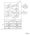
- FIG. 2is a block diagram of the example dimension determiner of FIG. 1 .
- FIGS. 3-7are flowcharts representative of example machine readable instructions that may be executed to implement the example dimension determiner of FIGS. 1 and/or 2 to determine the dimensions of the region of interest and/or categories of the example target object of FIG. 1 .
- FIGS. 8A-8Fillustrate an example image associated with an example process used by the example dimension determiner of FIGS. 1 and/or 2 to determine the dimensions of the region of interest of the example target object of FIG. 1 .
- FIG. 9is a block diagram of an example processor platform that may be utilized to execute the example instructions of FIGS. 3-7 to implement the example dimension determiner of FIG. 1 and/or FIG. 2 .
- Manual text extractioninvolves a human reviewing an image of a document (or a paper copy of the document) and manually typing the text associated with that document.
- Manual extractionhas a high level of accuracy, but can be cost prohibitive and time consuming.
- Optical character recognition (OCR)is a technique to automatically detect, identify, and encode image-based text documents using a computer. While using OCR to extract text is typically faster and cheaper than manual extraction, OCR is less accurate and more prone to error. Furthermore, the accuracy of OCR techniques diminishes when the original image including text to be extracted is of poor quality.
- an OCR enginemay be able to recognize the clearly printed text of a magazine article imaged using a flatbed scanner with a relatively high level of accuracy
- the same OCR enginemay be much less accurate in recognizing the text on a receipt imaged using a camera in connection with, for example, different (e.g., poor) lighting conditions, crumpledness and/or optical distortions of the receipt, the receipt does not lay flat, and/or the captured image cuts off the corners of the receipt.
- Accurately determining the dimensions of text of a target object in an imageincreases the accuracy of OCR techniques, thereby reducing the cost associated with manual review to correct for errors. Examples disclosed herein provide an improved accuracy determination of the dimensions of a region of interest of target object (e.g., corresponding to region of text in the target object) than conventional techniques.
- examples disclosed hereinmay determine the categories of a target object.
- categoriesare defined as the sources of the receipts represented by their headers, footers or bar codes.
- the header and/or footerare usually presented as graphic design that is beyond any OCR capability. Without loss of generality, the header and/or footer presented as some text can also be treated as a graphic design. Examples disclosed herein also provide a determination of their categories.
- Conventional techniques to determine text of a target object from an imageinclude transforming sub-regions of an image onto a rectified target object by identifying the corners of the target object directly or indirectly through comparing the target object to the background of the image.
- Such conventional techniquesexhibit difficulty and/or are not able to identify corners.
- the cornersare often confused with many corner-like elements naturally presented in the image.
- detecting cornersmay be difficult or impossible when (a) the background of the captured image includes boundary-like elements, confusing with the true boundaries, (b) the background is substantially similar to the target object, making the true boundary less visible or invisible (e.g., the background has text/font similar to that of the target object, the background has an intensity similar to that of the paper of a target), (c) the target object is crumpled or misshaped, making the boundary curved instead of straight (d) shadows are present in the captured image, generating false boundaries and/or (e) the boundary(s) of the target object are not within the image.
- Examples disclosed hereindetermine a region of interest of a target object and a class of the target object (e.g., a company corresponding to the target object) based on identifying and locating a landmark in the target object.
- the identification of the landmarkdetermines the class of the landmark while the location of the landmark provides a reference for determination of boundaries of the landmark, and eventually the corners of the landmark.
- Identifying the region of interest based on the landmark of the target objectis an indirect technique. It alleviates the problems that arise by conventional indirect techniques of identifying the boundaries of the target object based on a comparison of the target object to the background because the boundaries are determined with referenced transition points instead of all transition points when they are available, and are implied when the transition points are not available or not formed in a straight line.
- Examples disclosed hereinidentify the dimensions of a region of interest of a target object using landmarks (e.g., headers, footers, barcodes, advertisements, etc.).
- Landmarksare independent of the background and resilient to noise (e.g., due to printing quality, camera quality, and/or imaging conditions), thereby increasing the accuracy and/or efficiency of text extraction from captured images.
- the identified landmarkis also used to determine its class based on a class corresponding to a matched template landmark.
- conventional techniquesperform an OCR process to determine if a target object is one of interest. For example, such conventional techniques may perform OCR to identify an address and/or phone number of a company of interest. If identified addresses and/or phone numbers do not correspond to a company of interest, the image is discarded, wasting memory and processing resources associated with the OCR process. Examples disclosed herein identify a landmark object before the memory and/or processor intensive OCR process occurs. Examples disclosed herein identify a class associated with the target object based on a template landmark that matches the identified landmark. In this manner, example disclosed herein can discard images that do not correspond to a company of interest based on the class prior to the OCR process, thereby saving processor and/or memory resources. Additionally, examples disclosed herein removes the need for a map between a store(s) and addresses and/or phone numbers corresponding to the store(s), thereby reducing cost and memory resources associated with additional storage structures.
- Examples disclosed hereinreceive an image and determine if a target object within the image includes a landmark.
- the landmarkis a graphic design that is printed on the target object.
- a landmarkmay be a header corresponding to a company's name and/or logo, a footer corresponding to a company's name and/or logo, or on-object landmark corresponding to an on-receipt promotion, a bar code, a Quick Response (QR) code, a watermark, etc.
- Examples disclosed hereincompare the received and/or otherwise captured image to template landmarks stored in one or more storage device(s) and/or database(s) to determine if the received image includes a landmark (e.g., an imaged landmark).
- a template landmarkis a previously stored landmark.
- the template landmarkis also marked based on its purpose, such as header, footer, bar-code, or promotion.
- the template landmarkcorresponds to a class (e.g., if the example landmark is a logo, the class is the company associated with the logo).
- the class of the imaged landmarkis identified.
- the template landmarkis used as truth data and an imaged landmark is a landmark presented in a received image.
- examples disclosed hereinlocate the imaged landmark, determine its class, and determine whether the landmark is a header, footer, or on-object landmark based on the template landmark's mark.
- the type of landmarkdetermines how examples disclosed herein proceed in determining the dimensions of the target object. More specifically, the template landmark predicates where the true transition point may be, excludes some of the false transition points when a boundary is imaged, and provides a default boundary when the boundary is not imaged or is invisible. The predication makes it possible to determine the region of interest independent of the scale and the orientation.
- examples disclosed hereinproject the template landmark onto the imaged landmark of the image using an image overlaying process to generate a left side search area (LSSA) and a right side search area (RSSA) based on the location of the template landmark.
- LSSAleft side search area
- RSSAright side search area
- the example LSSA and RSSAcorresponds to a restricted search range in direction and area.
- Examples disclosed hereinprocess the LSSA and the RSSA to identify a left side edge of the imaged landmark and a right side edge of the imaged landmark using detected transition points and a Hough Transform.
- a first corner of the region of interestis determined based on an intersection between the left side imaged landmark edge and a bottom or top edge of the imaged template landmark and a second corner of the region of interest is determined based on an intersection between the right side imaged landmark edge and the bottom or top edge of the imaged template landmark.
- Examples disclosed hereindetermine a left side edge of the target object by generating multiple candidate edge lines within a left side search area using Hough line detection method, as even a curved line can be approximated with straight line within a small section such as within the left side search area.
- the left side edge of the target objectcorresponds to the line among the multiple candidate edge lines that has the highest normalized transition point count.
- Examples disclosed hereindetermine a right side edge of the target object by generating multiple candidate edge lines within a right side search area using Hough line detection method, as even a curved line can be approximated with straight line within a small section such as within the right side search area.
- the right side edge of the target objectcorresponds to the line among the multiple candidate edge lines that has the highest normalized transition point count.
- examples disclosed hereindetermine a third corner and a fourth corner of the region of interest. Examples disclosed herein approximate the left side edge with a straight line by selecting a line among all lines starting at the first detected corner and ending at an image boundary with an angle between the imaged landmark left side greater than—SA and less than SA, where SA is a predetermined constant. Examples disclosed herein select the line corresponding to the largest number of the transition points per unit length. The right side edge is determined similarly, except that the starting point is the second detected corner. Additionally, examples disclosed herein compute all dark-to-bright transition points in an area defined by a line N pixels away from the bottom of the detected landmark, the detected left side, the detected right side, and the boundary of the image.
- examples disclosed hereinuse a Hough transform to find a line furthest from the bottom of the imaged landmark, with an orientation O e , such that
- Examples disclosed hereindetermine the third corner of the region of interest based on an intersection between the right edge and the lowest text line. Additionally, examples disclosed herein determine the fourth corner of the region of interest based on an intersection between the left edge and the lowest text line.
- the examplesmay be altered to incorporate different geometric constraints to determine corners of a target object.
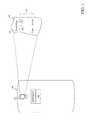
- FIG. 1illustrates an example imaging device 100 capturing an image of an example target object 102 .
- the example imaging device 100includes an example camera 104 and an example dimension determiner 106 .
- the example target object 102includes an example landmark 108 and example text 110 .
- the example imaging device 100 of FIG. 1is a device capable of capturing an image.
- the imaging device 100is a mobile device (e.g., a cell phone, a tablet, a 2in1, etc.).
- the imaging device 100may be a scanner, a web cam, a computer, a laptop, a digital camera, a three-dimensional sensor, and/or any device that includes a camera or sensor.
- the example imaging device 100includes the example camera 104 .
- the example camera 104captures an image of all or part of the example target object 102 .
- the example target object 102 of FIG. 1is an object that includes text (e.g., the example text 110 ) that may be recognized by text recognition software (e.g., OCR).
- the target object 102is a receipt.
- the target object 102may be any object that includes text.
- the example target object 102includes the landmark 108 and the text 110 .
- the example landmark 108is a header, the example landmark 108 may be a footer, an on-target image landmark (e.g., barcode, advertisement, etc.), and/or any other type of landmark. Examples disclosed herein process an image of the example target object 102 and use the example landmark 108 to increase the accuracy and of text recognition of the example text 110 . In some examples, the image may be processed in a backend office.
- the example camera 104 and/or another devicemay filter and/or pre-process the received image. Additionally, the camera 104 and/or other device transmits the image to the example dimension determiner 106 .
- the dimension determiner 106retrieves and/or otherwise receives the captured image and processes the captured image to identify the example landmark 108 by comparing the landmark 108 to one or more stored template landmarks.
- the dimension determiner 106determines a region of interest of the target object 102 by identifying corners (e.g., four corners) corresponding to the example text 110 based on the example landmark 108 , as further described in conjunction with FIG. 2 .
- the example landmark 108is processed to indicate the class of the target object.
- the class of the target objectmay be a store name.
- the dimension determiner 106determines the corners of region of interest the target object 102 (e.g., corresponding to the example text 110 )
- the dimension determiner 106transmits the dimension data and/or any other extracted data to another process for text recognition.
- the example dimension determiner 106is included in the illustrated imaging device 100 of FIG. 1 , the example dimension determiner 106 may be located at a remote location. If the dimension determiner 106 is located a remote location, the example imaging device 100 may provide captured images to the dimension determiner 106 via a wired or wireless connection (e.g., via a network connection).
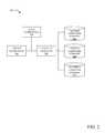
- FIG. 2is a block diagram of the example dimension determiner 106 of FIG. 1 disclosed herein, to determine the corners (e.g., four corners) of a region of interest of the target object 102 of FIG. 1 . While the example dimension determiner 106 is described in conjunction with the example imaging device 100 and the example target object 102 ( FIG. 1 ), the example dimension determiner 106 may be utilized to determine corners of any target object captured by any imaging device.
- the example dimension determiner 106includes an example data interface(s) 200 , an example landmark detector 202 , an example header landmark storage 204 a , and an example footer landmark storage 204 b , an example on-object landmark storage 204 c , and an example corner determiner 206 .
- the example data interface(s) 200 of FIG. 2receives and/or otherwise retrieves captured images from the example camera 104 ( FIG. 1 ).
- the example data interface(s) 200interfaces with another device (e.g., a user interface) to communicate with a user when a landmark has not been found in the image, a manual intervention is needed, and/or any other error occurred.
- the example data interface(s) 200may serve as a control center to manage the whole system.
- the example landmark detector 202 of FIG. 2identifies and locates landmarks in the captured image of the example target object 102 .
- the landmark detector 202uses planar object detection to compare parts of the captured image to template landmarks stored in the landmark storage (e.g., the example header landmark storage 204 a , the example footer landmark storage 204 b , and/or the example on-object landmark storage 204 c ).
- any type of image processingmay be used to determine a match between a captured (e.g., imaged) landmark and a template (e.g., truth) landmark.
- the identified landmarkis used to indicate the target's class (e.g., based on the class of the matched template landmark) and the location of the landmark is used to determine a left side search area, a right side search area of the template landmark, the top of the landmark, and the bottom of the landmark.
- the example corner determiner 206uses the LSSA and the RSSA to determine a first and second corner of the target object 102 .
- the example landmark detector 202may determine that the imaged landmark is partially cut-off (e.g., the image does not include a portion of the landmark). In some examples, in response to determining that the landmark is cut-off, or no landmark is identified, the landmark detector 202 prompts data interface 200 for manual interventions.
- Such manual interventionsinclude discarding the image, confirming a weak detection or classification, defining a boundary manually, and/or harvesting a new landmark template.
- the landmark detector 202determines a class of an imaged landmark based on the class associated with a matched template landmark. In such examples, when the landmark detector 202 determines that the class of the imaged landmark is not of interest, the example landmark detector 202 may prevent further processing of the received image, thereby conserving processor and/or memory resources associated with processing the image and/or OCRing the image. In this manner, examples disclosed herein do not need to generate and/or store mappings between a company and addresses and/or phone numbers associated with the company.
- the example storage devices 204 a - c of FIG. 2store template landmarks corresponding to previously scanned or captured landmarks of target objects of interest.
- the example storage devices 204 a - cmay be updated to include additional collected landmarks from target objects at any time.
- the stored landmarksmay include additional data corresponding to the target object 102 .
- the additional datamay include data corresponding to class (e.g., the entity that generated the target object) of the target object 102 , a format (e.g., layout) of the target object 102 , a type of landmark (e.g., header, footer, on-object, etc.), etc.
- the example landmark detector 202can determine a class of an imaged landmark based on the class corresponding to the template landmark.
- the example header landmark storage 204 astores template header landmarks
- the example footer landmark storage 204 bstores template footer landmarks
- the example on-object landmark storage 204 cstores on-object landmarks (e.g., barcodes, advertisements, watermarks etc.)
- the header landmark storage 204 a , the footer landmark storage 204 b , and/or the on-object landmark storage 204 cmay be combined into one storage device (e.g., a single database).
- the storage devices 204 a - cmay be located in a remote location.
- the landmark detector 202may communicate with the storage devices 204 a - c via a wired or wireless connection.
- the landmark detector 202may instruct the data interface(s) 200 to send an error message to a user identifying the problem (e.g., via a user interface).
- the example corner determiner 206 of FIG. 2determines corners (e.g., four corners) for a region of interest of the example target object 102 based on the imaged landmark detected by the example landmark detector 202 . In some examples, such as when the landmark is an on-object landmark, the example corner determiner 206 may determine eight corners of a region of interest.
- the corner determiner 206may (A) determine the first four corners of the a first region of interest for text above the on-object landmark (e.g., in a manner substantially similar to determining four corners of a footer landmark) and (B) determine an additional four corners of a second region of interest for text below the on-object landmark (e.g., in a manner sustainably similar to determining four corners of a header landmark), or (C) determine the top two corners above the on-object landmark and the bottom two corners below the on-object landmark to construct the desired four corners.
- the example corner determiner 206 of FIG. 2generates an LSSA and an RSSA to identify a first (e.g., left side) and second (e.g., right side) edge of the imaged landmark based on vertical transition points.
- a vertical transition pointis a point whose intensity is substantially different (e.g., based on one or more threshold(s)) from a neighboring point (e.g., Abs(C(x,y) ⁇ C(x+n, y))>T1 and Abs(C(x+n,y) ⁇ C(x+n+m,y)) ⁇ T2 for some point (x,y) where C(x,y) is the intensity (C) at location (x,y), n and m are integers corresponding to neighboring points, and T1 and T2 are threshold values).
- the corner determiner 206may instruct the data interface(s) 200 to send an error message to a user identifying the problem (e.g., via a user interface). Because the LSSA and the RSSA are relatively small regions (e.g., restricted range in direction and area) compared to the total captured image, the accuracy of identifying the edge as a line increases, regardless of whether the edges of the target object 102 are not substantially straight.
- the example corner determiner 206determines the first and second corner based on an intersection of a bottom or top edge of the located (e.g., matched) template landmark and the left side and the right side detected in LSSA, and RSSA, respectively, as the top and bottom edge detection is much more reliable than that of the left and the right. For example, if the imaged landmark is a header, the example corner determiner 206 may determine a first corner based on the bottom edge of the located template landmark and the computed left side within LSSA. If the imaged landmark is a footer, the example corner determiner 206 may determine a first corner based on the top edge of the template landmark and computed left side within RSSA
- the example corner determiner 206 of FIG. 2determines the landmark sides and the first and second corners of the target object 102 .
- the example corner determiner 206projects (e.g., extends) the landmark sides toward the top of the image (e.g., for a footer/on-object landmark) and/or the bottom of the image (e.g., for a header/on-object landmark) to determine the third and fourth corners of the target object 102 .
- the target object 102may not be straight, the projected landmark edge may not be the best representation of the edge of the target object 102 .
- the example corner determiner 206generates one or more alternate target object edge lines within a threshold range of the projected landmark edge to identify the best representation of the edge of the target object 102 .
- the example corner determiner 206determines the optimal edge (e.g., best estimation of the actual target object edge) for the left and right side of the target object 102 based on the generated target object edge line with the highest normalized transition point count.
- the example corner determiner 206calculates a number of horizontal dark-to-bright transition points (HTP) within a neighborhood of the candidate line.
- An HTPindicates where a printed character ends.
- the example corner determiner 206make a point (x,y) as an HTP point if C(x,y+n) ⁇ C(x, y)>T3 and C(x,y+n) ⁇ C(x,y+n+m)) ⁇ T4 where C(x,y) is the intensity (C) at location (x,y), n and m are integers corresponding to neighboring points, and T2 and T3 are threshold values.
- a candidate sideis a line starting at detected corners extending until the image boundary with an orientation deviating from the corresponding side line no more than a predetermined constant S A .
- a line associated with the largest number of HTS per unitis selected as a side line best approximating the true boundary of the target object 102 .
- the extension of the detected sides of the located landmarkmay be used to approximate the boundary.
- the example corner determiner 206determines the third and fourth corners of the target object 102 based on an intersection between the object edges and the lowest text line (e.g., for a header) or the highest text line (e.g., for a footer), as further described in conjunction with FIG. 7 . In some examples (e.g., when such sides cannot be determined satisfactorily), the corner determiner 206 instructs the data interface(s) 200 to interface with a user for manual confirmation or intervention.
- example manners of implementing the example dimension determiner 106 of FIG. 1are illustrated in conjunction with FIG. 2 , elements, processes and/or devices illustrated in conjunction with FIG. 2 may be combined, divided, re-arranged, omitted, eliminated and/or implemented in any other way.
- the example data interface(s) 200 , the example landmark detector 202 , the example header landmark storage 204 a , the example footer landmark storage 204 b , the example on-object landmark storage 204 c , the example corner determiner 206 , and/or, more generally, the example dimension determiner 106 of FIG. 2may be implemented by hardware, machine readable instructions, software, firmware and/or any combination of hardware, machine readable instructions, software and/or firmware.
- any of the example data interface(s) 200 , the example landmark detector 202 , the example header landmark storage 204 a , the example footer landmark storage 204 b , the example on-object landmark storage 204 c , the example corner determiner 206 , and/or, more generally, the example dimension determiner 106 of FIG. 2could be implemented by analog and/or digital circuit(s), logic circuit(s), programmable processor(s), application specific integrated circuit(s) (ASIC(s)), programmable logic device(s) (PLD(s)) and/or field programmable logic device(s) (FPLD(s)).
- ASICapplication specific integrated circuit
- PLDprogrammable logic device
- FPLDfield programmable logic device
- the example dimension determiner 106 of FIG. 2is/are hereby expressly defined to include a tangible computer readable storage device or storage disk such as a memory, a digital versatile disk (DVD), a compact disk (CD), a Blu-ray disk, etc. storing the software and/or firmware.
- the example dimension determiner 106 of FIG. 2include elements, processes and/or devices in addition to, or instead of, those illustrated in conjunction with FIGS. 3-7 , and/or may include more than one of any or all of the illustrated elements, processes and devices.
- the machine readable instructionscomprise a program for execution by a processor such as the processor 912 shown in the example processor platform 900 discussed below in connection with FIG. 9 .
- the programmay be embodied in machine readable instructions stored on a tangible computer readable storage medium such as a CD-ROM, a floppy disk, a hard drive, a digital versatile disk (DVD), a Blu-ray disk, or a memory associated with the processor 912 , but the entire program and/or parts thereof could alternatively be executed by a device other than the processor 912 and/or embodied in firmware or dedicated hardware.
- example programis described with reference to the flowcharts illustrated in conjunction with FIGS. 3-7 , many other methods of implementing the example dimension determiner 106 of FIG. 2 may alternatively be used.
- order of execution of the blocksmay be changed, and/or some of the blocks described may be changed, eliminated, or combined.
- FIGS. 3-7depict example operations in an illustrated order, these operations are not exhaustive and are not limited to the illustrated order.
- blocks illustrated in the flowchart(s)may be performed in an alternative order or may be performed in parallel.
- FIGS. 3-7may be implemented using coded instructions (e.g., computer and/or machine readable instructions) stored on a tangible computer readable storage medium such as a hard disk drive, a flash memory, a read-only memory (ROM), a compact disk (CD), a digital versatile disk (DVD), a cache, a random-access memory (RAM) and/or any other storage device or storage disk in which information is stored for any duration (e.g., for extended time periods, permanently, for brief instances, for temporarily buffering, and/or for caching of the information).
- a tangible computer readable storage mediumsuch as a hard disk drive, a flash memory, a read-only memory (ROM), a compact disk (CD), a digital versatile disk (DVD), a cache, a random-access memory (RAM) and/or any other storage device or storage disk in which information is stored for any duration (e.g., for extended time periods, permanently, for brief instances, for temporarily buffering, and/or for caching of the information).
- tangible computer readable storage mediumand “tangible machine readable storage medium” are used interchangeably. Additionally or alternatively, the example processes of FIGS. 3-7 may be implemented using coded instructions (e.g., computer and/or machine readable instructions) stored on a non-transitory computer and/or machine readable medium such as a hard disk drive, a flash memory, a read-only memory, a compact disk, a digital versatile disk, a cache, a random-access memory and/or any other storage device or storage disk in which information is stored for any duration (e.g., for extended time periods, permanently, for brief instances, for temporarily buffering, and/or for caching of the information).
- coded instructionse.g., computer and/or machine readable instructions
- a non-transitory computer and/or machine readable mediumsuch as a hard disk drive, a flash memory, a read-only memory, a compact disk, a digital versatile disk, a cache, a random-access memory and/or any other storage device or storage disk in which
- non-transitory computer readable mediumis expressly defined to include any type of computer readable storage device and/or storage disk and to exclude propagating signals and to exclude transmission media.
- phrase “at least”is used as the transition term in a preamble of a claim, it is open-ended in the same manner as the term “comprising” is open ended.
- the term “including”is open-ended in the same manner as the term “comprising” is open-ended.
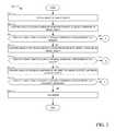
- FIG. 3is an example flowchart 300 representative of example machine readable instructions that may be executed to implement the example dimension determiner 106 of FIGS. 1 and 2 to determine corners (e.g., four corners) of interest corresponding to the corners of the target object 102 of FIG. 1 .
- the example flowchart 300is described in conjunction with an example image 800 as a shown in FIG. 8A .
- the example captured image of FIG. 8Aincludes an example target object 802 .
- the example target object 802may correspond to the example target object 102 and/or any target object.
- FIG. 8Aincludes the example image 800 , the example target object 802 , and an example imaged landmark 804 .
- FIG. 8Aillustrates techniques for determine corners (e.g., four corners) of a region of interest for the target object 802 based on the example landmark 804 being a header, similar techniques may be utilized to determine four corner (e.g., or two sets of four corners) based on the example landmark 804 being a footer and/or an on-object landmark.
- the example interface(s) 200receives and/or otherwise retrieves the example image 800 of the example target object 802 .
- the target object 802includes one corner that is outside of (e.g., cut-off from) the image 800 .
- the example target object 802 of FIG. 8Aincludes the example imaged landmark 804 , which is a header landmark.
- the example landmark detector 202compares the image 800 (e.g., a part of the example image 800 ) to one or more stored template landmarks in the example header landmark storage 204 a ( FIG. 2 ) to detect the example imaged landmark 804 in the example target object 802 .
- the example landmark detector 202determines if the target object 802 includes a landmark corresponding to a template header landmark based on the comparison.
- the processcontinues to process ‘A,’ which is further described in conjunction with FIG. 4 . If the example landmark detector 202 determines that the target object 802 does not include a landmark corresponding to a template header landmark (block 306 ), the example landmark detector 202 compares the image 800 to the stored landmarks in the example footer landmark storage 204 b ( FIG. 2 ) to detect the example imaged landmark 804 in the example target object 802 (block 308 ). Alternatively, the example landmark detector 202 may determine that the target object 802 includes a header landmark that is cut-off. In such examples, the landmark detector 202 may continue to search for an additional landmark (e.g., a footer landmark or an on-object landmark) that is not cut-off the example image 800 .
- an additional landmarke.g., a footer landmark or an on-object landmark
- the example landmark detector 202determines if the target object 802 includes a landmark corresponding to a template footer landmark based on the comparison. If the example landmark detector 202 determines that the target object 802 includes a footer landmark (block 310 ), the example process continues to process ‘B.’
- Process ‘B’is a similar process to process ‘A,’ but in a different direction. For example, process ‘A’ identifies the first two corners (e.g., upper corners) based on the template header and determines the last two corners (e.g., lower corners) accordingly.
- Process ‘B’identifies the first two corners (e.g., lower corners) based on the template footer and determines the last two corners (e.g., upper corners) accordingly, using a substantially similar process as Process ‘A.’ If the example landmark detector 202 determines that the target object 802 does not includes a footer landmark (block 310 ), the example landmark detector 202 compares the image 800 to the stored landmarks in the example on-object landmark storage 204 c ( FIG. 2 ) to detect the example imaged landmark 804 in the example target object 802 (block 312 ).
- the example landmark detector 202determines if the target object 802 includes a landmark corresponding to an on-object template landmark based on the comparison. If the example landmark detector 202 determines that the target object 802 includes an on-object landmark, the example process continues to process ‘C.’
- Process ‘C’is a similar process to process ‘A’ and ‘B’, operating in both directions (e.g., up and down from the landmark). For example, process ‘C’ may identify two sets of four corners, the first set in a process similar to process ‘A’ and the second set in the process similar to process ‘B.’ In this manner, the target object 802 is processed both above and below the on-object landmark. Alternatively, process ‘C’ may use process ‘A’ to obtain the lower corners of the example target object 802 and may use process ‘B’ to obtain the upper corners of the target object 802 .
- the example landmark detector 202determines that the target object 802 does not include an on-object landmark, the example landmark detector 202 flags the example image 800 (block 316 ).
- the flagmay include transmitting instructions to the example data interface(s) 200 to send an error message to a user of the imaging device 100 ( FIG. 1 ).
- the landmark detector 202may identify an error in the image (e.g., a message identifying that one or more portions of the object is missing) and request the user to capture an additional image (e.g., a request to capture an image with an alternate orientation) of the target object 802 .
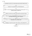
- FIG. 4is an example flowchart 400 representative of example machine readable instructions that may be executed to implement the example dimension determiner 106 of FIGS. 1 and 2 to determine the corners (e.g., four corners) corresponding to a region of interest of the example target object 802 .
- the example flowchart 400is described in conjunction with the example image 800 as a shown in FIGS. 8B-8F .
- FIG. 8Bincludes the example image 800 , the example target object 802 , and the example landmark 804 of FIG. 8A and example matched template landmark corners 806 a - d .
- FIG. 8Cincludes the example image 800 , the example target object 802 , the example landmark 804 , and example matched template landmark corners 806 a - d of FIG.
- FIG. 8Bis an example LSSA 808 and an example RSSA 810 .
- FIG. 8Dis an example of the LSSA 808 of FIG. 8C .
- the example LSSA 808includes the example matched template landmark corners 806 a , 806 d of FIG. 8C , example vertical transition points 811 , and an example imaged landmark edge 812 .
- FIG. 8Eincludes the example the example image 800 , the example target object 802 , the example landmark 804 , and example matched template landmark corners 806 a - d of FIG. 8B , the example imaged landmark edge 812 of FIG.
- FIG. 8Fincludes the example image 800 , the example target object 802 , the example landmark 804 , the example matched template landmark bottom edge 814 , the example first corner 816 , the example bottom image line 118 , the example left side edge 822 , the example second corner 824 , the example right side edge 826 of FIG.
- FIGS. 8B-Fillustrate techniques for determine corners of the target object 802 based on the example landmark 804 being a header, similar techniques may be utilized to determine four corner (e.g., or two sets of four corners) based on the example landmark 804 being a footer and/or an on-object landmark.
- the example landmark detector 202determines if the imaged landmark 804 corresponds to a class of interest. As described above, the example landmark detector 202 may identify a class of the imaged landmark 804 based on a class corresponding to the matched template landmark. If the class is not a class of interest, then the example landmark detector 202 determines that there is no need to perform any further identification because the information within the image 800 is not of interest. If the class of the imaged landmark does not correspond to a class of interest (block 402 ), the example landmark detector 202 prevents utilization of resources (e.g., processor resources and/or memory resources associated with identifying the corners and/or OCRing the image 800 ) by discarding the image 800 and ending the processes (block 404 ).
- resourcese.g., processor resources and/or memory resources associated with identifying the corners and/or OCRing the image 800
- the example corner determiner 206projects (e.g., overlays) the example matched template landmark corners 806 a - d onto the example image 800 based on the identified imaged landmark 804 of FIG. 8B .
- the corner determiner 206transforms (e.g., matches) a corresponding template landmark and matches the transformed template landmark onto the imaged landmark 804 to project the example matched template landmark corners 806 a - d when the imaged landmark is matched to a landmark template.
- the landmark cornerscorrespond to the dimensions of the corresponding matched template landmark transformed to the dimensions of the imaged landmark 804 .
- the example corner determiner 206determines the example LSSA 808 and the example RSSA 810 of FIG. 8C based on the matched template landmark.
- the LSSA 808is centered around the left edge of the matched template landmark and the RSSA 810 is centered around the right edge of the matched template landmark.
- the height and the width of the LSSA 808 and/or RSSA 810correspond to the length and width of the matched template landmark (e.g., represented by the matched template landmark corners 806 a - d ).
- the height of the LSSA 808may be substantially similar to the height of the matched template landmark and the width of the LSSA 808 may be a fraction (e.g., a quarter) of the width of the matched template landmark.
- any scalarmay be used to generate the dimensions of the LSSA 808 and/or RSSA 810 .
- the example corner determiner 206determines if the LSSA 808 overlaps (e.g., at least partially overlaps) the example image 800 . If the example LSSA 808 overlaps the example image 800 (e.g., is at least partially included in the example image 800 ) (block 410 ), the example corner determiner 206 analyzes the example LSSA 808 to determine a first corner (e.g., the example first corner 816 of FIG. 8E ) of the region of interest and the left example imaged landmark edge 812 ( FIGS. 8D and 8E ) of the imaged landmark 804 (block 412 ), as further described in conjunction with FIG. 5 .
- a first cornere.g., the example first corner 816 of FIG. 8E
- the left example imaged landmark edge 812FIGS. 8D and 8E
- the example corner determiner 206determines the first corner of the target object 802 and a first (e.g., left) imaged landmark edge of the example imaged landmark 804 based on the matched template landmark (block 414 ).
- the example corner determiner 206may determine the first corner and the first imaged landmark edge of the target object 802 based on the example first matched template landmark corner 806 a ( FIG. 8C ), example fourth matched template landmark corner 806 d ( FIG. 8C ), and/or any other point within the example LSSA 808 .
- the example corner determiner 206determines if the RSSA 810 overlaps (e.g., at least partially overlaps) the example image 800 . If the example RSSA 810 overlaps the example image 800 (block 416 ), the example corner determiner 206 analyzes the example RSSA 810 to determine a second corner (e.g., the example second corner 824 of FIG. 8E ) and the example right side edge 826 of the imaged landmark 804 (block 418 ).
- a second cornere.g., the example second corner 824 of FIG. 8E
- the example right side edge 826 of the imaged landmark 804block 418 .
- the example corner determiner 206determines the second corner of the target object 802 and a second (e.g., right) imaged landmark edge of the example imaged landmark 804 based on the matched template landmark (block 420 ).
- the example corner determiner 206may determine the second corner and the second (e.g., right) landmark edge of the target object 802 based on the example second matched template landmark corner 806 b ( FIG. 8C ), based on the example third matched template landmark corner 806 c ( FIG. 8C ), and/or based on any other point within the example RSSA 810 .
- the example corner determiner 206determines the example left side edge 822 of the example target object 802 ( FIG. 8E ) based on the first (e.g., left) imaged landmark edge, as further described in conjunction with FIG. 6 and described in further detail below.
- the example corner determiner 206determines the example right side edge 826 of the example target object 802 ( FIG. 8E ) based on the second (e.g., right) imaged landmark edge.
- the example corner determiner 206determines the example third corner 832 and the example fourth corner 834 of the region of interest of the target object 802 based on the example left side edge 822 and the example right side edge 826 , as further described in conjunction with FIG.
- the example interface(s) 200transmits the image, the region of interest data (e.g., including the example corners 816 , 824 , 832 , 834 of FIG. 8F ), and additional data (e.g., data related to the landmark) to a device for further processing, including but not limited to OCR.
- the region of interest datae.g., including the example corners 816 , 824 , 832 , 834 of FIG. 8F
- additional datae.g., data related to the landmark
- FIG. 5is an example flowchart 412 representative of example machine readable instructions that may be executed to implement the example dimension determiner 106 of FIGS. 1 and 2 to analyze the example LSSA 808 to determine the example left side edge 822 and the first example corner 816 of the region of interest of the example target object 802 .
- the example flowchart 412 of FIG. 5is described in conjunction with FIGS. 8D and 8E .
- the example corner determiner 206locates all of the example vertical transition points 811 of FIG. 8F in the example LSSA 808 .
- the example vertical transition points 811are points having an intensity that varies more than a threshold amount from a neighboring point (e.g., Abs(C(x,y) ⁇ C(x+n, y))>T1 and Abs(C(x+n,y) ⁇ C(x+n+m,y)) ⁇ T2 for some point (x,y) where C(x,y) is the intensity (C) at location (x,y), n and m are integers corresponding to neighboring points, and T1 and T2 are threshold values).
- the example corner determiner 206generates lines of best fit for all lines with a threshold number of vertical transition points. For example, if the threshold is five points, then the example corner determiner 206 generates all lines include more than five substantially linear vertical transition points. In some examples, the example corner determiner 206 determines the lines using a Hough transform. In some examples, the example corner determiner 206 removes any lines that are not within a threshold angle range corresponding to an angle of the matched template landmark. For example, if the orientation of a line is more than a threshold angle (e.g., 30 degrees) different from the orientation of the matched template landmark, the line is discarded.
- a threshold anglee.g. 30 degrees
- the example corner determiner 206determines if there is a line in the example LSSA 808 that satisfies a threshold number of vertical transition points. If there is not a line that satisfies the threshold number of vertical transition points, the example corner determiner 206 determines an imaged landmark edge based on the example matched template landmark corners 806 a , 806 d (block 506 ). In the illustrated example of FIG. 8D , the line defined with 806 a and 806 d is denoted as the reference line. If there is a line that satisfies the threshold number of vertical transition points, the example corner determiner 206 determines a strongest line of orientation as the imaged landmark edge.
- the strongest line of orientationis the line that fits with the most vertical transition points (block 508 ) and whose orientation does not deviate from that of the reference line more than some predefined threshold value.
- the strongest line of orientationis the example imaged landmark edge line 812 .
- the example corner determiner 206determines the example first corner 816 ( FIG. 8E ) based on an intersection between the imaged landmark edge line 812 and the example matched template landmark bottom edge 814 .
- FIG. 6is an example flowchart 422 representative of example machine readable instructions that may be executed to implement the example dimension determiner 106 of FIGS. 1 and 2 to determine the example left side edge 822 of the example target object 802 based on the example imaged landmark edge 812 .
- the example flowchart 422 of FIG. 6is described in conjunction with FIG. 8E .
- the example corner determiner 206extends the example imaged landmark edge 812 to the example bottom image line 818 .
- the example corner determiner 206searches lines between the example first corner 816 and points between example edge limit lines 820 a , 820 b on the example bottom image line 818 .
- the first example edge limit line 820 ais the intersection point between the bottom image line 818 and the line starting at the example first corner 816 with an orientation S a degrees clockwise away from the of the reference line.
- the second example edge limit line 820 bis the intersection point between the example bottom image line 818 and the line starting at the example first corner 816 with an orientation S a degrees counter-clockwise away from that of the reference line.
- the threshold rangeis represented by the example edge limit lines 820 a , 820 b.
- the example corner determiner 206computes a normalized transition point count for each of the multiple lines (e.g., represented by the open circles of FIG. 8E ). When a transition point lies in the neighborhood of one of the multiple lines, the count associated with the line is increased by one. The total of such points is divided by the length of the line to obtain the normalized transition point count. The line with the highest normalized transition point count corresponds to the best estimation of the left side edge 822 .
- the example corner determiner 206determines if the line with the maximum normalized transition point count satisfies a normalized transition point count threshold.
- the example corner determiner 206determines the example left side edge 822 of the example target object 802 based on the line with the maximum normalized transition point count (e.g., the example left side edge 822 ) (block 608 ). If the example corner determiner 206 determines that there are not any lines that satisfy the normalized transition point count threshold, the example corner determiner 206 determines a left imaged edge of the example target 802 to correspond to the imaged landmark edge 812 (block 610 ).
- FIG. 7is an example flowchart 426 representative of example machine readable instructions that may be executed to implement the example dimension determiner 106 of FIGS. 1 and 2 to determine the example third corner 832 and the example fourth corner 834 of the region of interest of the example target object 802 based on the example left side edge 822 and the example right side edge 826 .
- the example flowchart 426 of FIG. 7is described in conjunction with FIG. 8F .
- the example corner determiner 206computes all the example vertical dark-to-bright transition points (e.g., represented by the dots in FIG. 8F ) within a region defined by the example matched template landmark bottom edge 814 , the example right side edge 826 , the example left side edge 822 , and the example bottom image line 818 . As described above in conjunction with FIG. 8F , the example corner determiner 206 computes all the example vertical dark-to-bright transition points (e.g., represented by the dots in FIG. 8F ) within a region defined by the example matched template landmark bottom edge 814 , the example right side edge 826 , the example left side edge 822 , and the example bottom image line 818 . As described above in conjunction with FIG.
- the example corner determiner 206computes the vertical dark-to-bright transition points to determine where text ends vertically (e.g., C(x,y+n) ⁇ C(x, y)>T3 and C(x,y+n) ⁇ C(x,y+n+m)) ⁇ T4 for some point (x,y) where C(x,y) is the intensity (C) at (x,y), n and m are integers corresponding to neighboring points, and T2 and T3 are threshold values).
- the example corner determiner 206identifies all the example text lines 828 , 829 in the region based on the vertical dark-to-bright transition points. In some examples, the example corner determiner 206 uses a Hough transform to identify the example text lines 828 , 829 .
- the example corner determiner 206eliminates all the example error text lines 829 outside a threshold orientation of the example target object 802 . As described above, the orientation of the target object 802 is determined based on the location of the matched landmark. For example, the orientation may be based on the bottom edge of the matched landmark, the top edge of the matched landmark, or an average of the top and bottom edges.
- the example error text lines 829are lines that do not fall within the threshold orientation of the example target object 802 (e.g., within a threshold angle of the angle of the matched template landmark).
- the example corner determiner 206identifies the example bottom text line 830 based on the text line (e.g., of the example text lines 828 ) closest to the bottom of the image 800 .
- the example corner determiner 206determines the example third corner 832 based on an intersection between the example left side edge 822 and the example bottom text line 830 .
- the example corner determiner 206determines the example fourth corner 834 based on an intersection between the example right side edge 826 and the example bottom text line 830 .
- the example corners 816 , 824 , 832 , 834represent the region of interest of the example target object 802 .
- the region of interestcorresponds to the corners of the example target object 802 . In some examples, the region of interest corresponds to a subset of the example target object 802 .
- the example target object 802can be separated from the background and be rectified onto an image as if the image were scanned instead of being imaged by a camera, thereby leading to more accurate OCR extraction.
- FIG. 9is a block diagram of an example processor platform 900 capable of executing the instructions of FIGS. 4A, 4B, and 5 to implement the example dimension determiner 106 of FIG. 2 .
- the processor platform 900can be, for example, a server, a personal computer, a mobile device (e.g., a cell phone, a smart phone, a tablet such as an iPadTM), a personal digital assistant (PDA), an Internet appliance, or any other type of computing device.
- the processor platform 900 of the illustrated exampleincludes a processor 912 .
- the processor 912 of the illustrated exampleis hardware.
- the processor 912can be implemented by integrated circuits, logic circuits, microprocessors or controllers from any desired family or manufacturer.
- the processor 912 of the illustrated exampleincludes the example memory 212 (e.g., a cache).
- the example processor 912 of FIG. 9executes the instructions of FIGS. 4A, 4B, and 5 to implement the example data interface(s) 200 , the example landmark detector 202 , the example header landmark storage 204 a , the example footer landmark storage 204 b , the example on-object landmark storage 204 c , and/or the example corner determiner 206 of FIG. 2 to implement the example dimension determiner 106 ( FIGS. 1 and 2 ).
- the processor 912 of the illustrated exampleis in communication with a main memory including a volatile memory 914 and a non-volatile memory 916 via a bus 918 .
- the volatile memory 914may be implemented by Synchronous Dynamic Random Access Memory (SDRAM), Dynamic Random Access Memory (DRAM), RAMBUS Dynamic Random Access Memory (RDRAM) and/or any other type of random access memory device.
- the non-volatile memory 916may be implemented by flash memory and/or any other desired type of memory device. Access to the main memory 914 , 916 is controlled by a memory controller.
- the processor platform 900 of the illustrated examplealso includes an interface circuit 920 .
- the interface circuit 920may be implemented by any type of interface standard, such as an Ethernet interface, a universal serial bus (USB), and/or a PCI express interface.
- one or more input devices 922are connected to the interface circuit 920 .
- the input device(s) 922permit(s) a user to enter data and commands into the processor 912 .
- the input device(s)can be implemented by, for example, a sensor, a microphone, a camera (still or video), a keyboard, a button, a mouse, a touchscreen, a track-pad, a trackball, isopoint and/or a voice recognition system.
- One or more output devices 924are also connected to the interface circuit 920 of the illustrated example.
- the output devices 924can be implemented, for example, by display devices (e.g., a light emitting diode (LED), an organic light emitting diode (OLED), a liquid crystal display, a cathode ray tube display (CRT), a touchscreen, a tactile output device, and/or speakers).
- the interface circuit 920 of the illustrated examplethus, typically includes a graphics driver card, a graphics driver chip or a graphics driver processor.
- the interface circuit 920 of the illustrated examplealso includes a communication device such as a transmitter, a receiver, a transceiver, a modem and/or network interface card to facilitate exchange of data with external machines (e.g., computing devices of any kind) via a network 926 (e.g., an Ethernet connection, a digital subscriber line (DSL), a telephone line, coaxial cable, a cellular telephone system, etc.).
- a network 926e.g., an Ethernet connection, a digital subscriber line (DSL), a telephone line, coaxial cable, a cellular telephone system, etc.
- the processor platform 900 of the illustrated examplealso includes one or more mass storage devices 928 for storing software and/or data.
- mass storage devices 928include floppy disk drives, hard drive disks, compact disk drives, Blu-ray disk drives, RAID systems, and digital versatile disk (DVD) drives.
- the coded instructions 932 of FIGS. 4A, 4B, and 5may be stored in the mass storage device 928 , in the volatile memory 914 , in the non-volatile memory 916 , and/or on a removable tangible computer readable storage medium such as a CD or DVD.
- Prior techniques of processing images for text recognition techniquesinclude determining the corners of the target object.
- Prior methodshave difficulty and/or are not able to identify corners when (a) the background of the image includes boundary-like elements, (b) the background is substantially similar to the target object, (c) the target object is crumpled or misshaped, (d) shadows are present in the image, (e) prospective distortion is present, and/or (f) the corner(s) of the target object are not within the image.
- Examples disclosed hereindetermine a region of interest of a target object and the class of the target object based on identifying and locating a landmark in the target object and text in the target object. Identifying and locating the region of interest based on the landmark/text of the target object alleviates the problems that arise by conventional techniques of directly locating the corners of the target object because the corners might not be imaged, well formed, or distinguishable from the background. Examples disclosed herein alleviate such problems that arise by conventional techniques of indirectly locating corners because the landmark provides a reference framework that significantly eliminates the fast edges that often appear in the background. Furthermore, the landmark may indicate a class of the target object regardless of if the landmark is text or graphical while OCR techniques cannot determine the class of the target object when the landmark is graphic. The alleviations and the class determination make the disclosed method a much more robust way to construct a rectified image and to determine the class of the target object, thereby proving a more robust way to extract textual information from the image of the target object.
Landscapes
- Engineering & Computer Science (AREA)
- Theoretical Computer Science (AREA)
- Physics & Mathematics (AREA)
- General Physics & Mathematics (AREA)
- Computer Vision & Pattern Recognition (AREA)
- Multimedia (AREA)
- Artificial Intelligence (AREA)
- Data Mining & Analysis (AREA)
- Evolutionary Computation (AREA)
- Bioinformatics & Cheminformatics (AREA)
- Bioinformatics & Computational Biology (AREA)
- Evolutionary Biology (AREA)
- Life Sciences & Earth Sciences (AREA)
- General Engineering & Computer Science (AREA)
- Geometry (AREA)
- Computer Graphics (AREA)
- Character Input (AREA)
- Health & Medical Sciences (AREA)
- Computing Systems (AREA)
- Databases & Information Systems (AREA)
- General Health & Medical Sciences (AREA)
- Medical Informatics (AREA)
- Software Systems (AREA)
- Image Analysis (AREA)
Abstract
Description
Claims (22)
Priority Applications (3)
| Application Number | Priority Date | Filing Date | Title |
|---|---|---|---|
| US15/258,325US10235585B2 (en) | 2016-04-11 | 2016-09-07 | Methods and apparatus to determine the dimensions of a region of interest of a target object from an image using target object landmarks |
| US16/282,060US10860884B2 (en) | 2016-04-11 | 2019-02-21 | Methods and apparatus to determine the dimensions of a region of interest of a target object from an image using target object landmarks |
| US17/113,963US11538235B2 (en) | 2016-04-11 | 2020-12-07 | Methods and apparatus to determine the dimensions of a region of interest of a target object from an image using target object landmarks |
Applications Claiming Priority (2)
| Application Number | Priority Date | Filing Date | Title |
|---|---|---|---|
| US201662320881P | 2016-04-11 | 2016-04-11 | |
| US15/258,325US10235585B2 (en) | 2016-04-11 | 2016-09-07 | Methods and apparatus to determine the dimensions of a region of interest of a target object from an image using target object landmarks |
Related Child Applications (1)
| Application Number | Title | Priority Date | Filing Date |
|---|---|---|---|
| US16/282,060ContinuationUS10860884B2 (en) | 2016-04-11 | 2019-02-21 | Methods and apparatus to determine the dimensions of a region of interest of a target object from an image using target object landmarks |
Publications (2)
| Publication Number | Publication Date |
|---|---|
| US20170293819A1 US20170293819A1 (en) | 2017-10-12 |
| US10235585B2true US10235585B2 (en) | 2019-03-19 |
Family
ID=59998734
Family Applications (3)
| Application Number | Title | Priority Date | Filing Date |
|---|---|---|---|
| US15/258,325Active2036-12-07US10235585B2 (en) | 2016-04-11 | 2016-09-07 | Methods and apparatus to determine the dimensions of a region of interest of a target object from an image using target object landmarks |
| US16/282,060Active2036-09-12US10860884B2 (en) | 2016-04-11 | 2019-02-21 | Methods and apparatus to determine the dimensions of a region of interest of a target object from an image using target object landmarks |
| US17/113,963Active2037-03-15US11538235B2 (en) | 2016-04-11 | 2020-12-07 | Methods and apparatus to determine the dimensions of a region of interest of a target object from an image using target object landmarks |
Family Applications After (2)
| Application Number | Title | Priority Date | Filing Date |
|---|---|---|---|
| US16/282,060Active2036-09-12US10860884B2 (en) | 2016-04-11 | 2019-02-21 | Methods and apparatus to determine the dimensions of a region of interest of a target object from an image using target object landmarks |
| US17/113,963Active2037-03-15US11538235B2 (en) | 2016-04-11 | 2020-12-07 | Methods and apparatus to determine the dimensions of a region of interest of a target object from an image using target object landmarks |
Country Status (1)
| Country | Link |
|---|---|
| US (3) | US10235585B2 (en) |
Cited By (14)
| Publication number | Priority date | Publication date | Assignee | Title |
|---|---|---|---|---|
| US20190188527A1 (en)* | 2016-04-11 | 2019-06-20 | The Nielsen Company (Us), Llc | Methods and apparatus to determine the dimensions of a region of interest of a target object from an image using target object landmarks |
| US11410446B2 (en) | 2019-11-22 | 2022-08-09 | Nielsen Consumer Llc | Methods, systems, apparatus and articles of manufacture for receipt decoding |
| US11625930B2 (en) | 2021-06-30 | 2023-04-11 | Nielsen Consumer Llc | Methods, systems, articles of manufacture and apparatus to decode receipts based on neural graph architecture |
| US11810380B2 (en) | 2020-06-30 | 2023-11-07 | Nielsen Consumer Llc | Methods and apparatus to decode documents based on images using artificial intelligence |
| US11822216B2 (en) | 2021-06-11 | 2023-11-21 | Nielsen Consumer Llc | Methods, systems, apparatus, and articles of manufacture for document scanning |
| US12175782B2 (en) | 2021-07-12 | 2024-12-24 | Nielsen Consumer Llc | Methods, systems, articles of manufacture and apparatus to label text on images |
| US12182703B2 (en) | 2019-03-28 | 2024-12-31 | Nielsen Consumer Llc | Methods and apparatus to detect a text region of interest in a digital image using machine-based analysis |
| US12229741B2 (en) | 2021-06-24 | 2025-02-18 | Nielsen Consumer Llc | Methods, systems, articles of manufacture, and apparatus for decoding purchase data using an image |
| US12229805B2 (en) | 2021-12-30 | 2025-02-18 | Nielsen Consumer Llc | Methods, systems, articles of manufacture, and apparatus for processing an image using visual and textual information |
| US12277786B2 (en) | 2020-07-17 | 2025-04-15 | Nielsen Consumer Llc | Methods, systems, articles of manufacture and apparatus to categorize image text |
| US12288405B2 (en) | 2021-12-22 | 2025-04-29 | Nielsen Consumer Llc | Methods, systems, articles of manufacture and apparatus to extract region of interest text from receipts |
| US12315283B2 (en) | 2022-01-14 | 2025-05-27 | Nielsen Consumer Llc | Methods, systems, articles of manufacture, and apparatus for decoding images |
| US12322195B2 (en) | 2022-07-06 | 2025-06-03 | Nielsen Consumer Llc | Methods, systems, articles of manufacture, and apparatus to determine related content in a document |
| US12327425B2 (en) | 2021-06-24 | 2025-06-10 | Nielsen Consumer Llc | Methods, systems, articles of manufacture, and apparatus for decoding purchase data using an image |
Families Citing this family (15)
| Publication number | Priority date | Publication date | Assignee | Title |
|---|---|---|---|---|
| WO2018009567A1 (en) | 2016-07-05 | 2018-01-11 | Nauto Global Limited | System and method for automatic driver identification |
| WO2018009552A1 (en) | 2016-07-05 | 2018-01-11 | Nauto Global Limited | System and method for image analysis |
| WO2018031678A1 (en) | 2016-08-09 | 2018-02-15 | Nauto Global Limited | System and method for precision localization and mapping |
| EP3513265B1 (en) | 2016-09-14 | 2024-09-18 | Nauto, Inc. | Method for near-collision determination |
| US10733460B2 (en) | 2016-09-14 | 2020-08-04 | Nauto, Inc. | Systems and methods for safe route determination |
| CN110178104A (en) | 2016-11-07 | 2019-08-27 | 新自动公司 | System and method for determining driver distraction |
| US10453150B2 (en) | 2017-06-16 | 2019-10-22 | Nauto, Inc. | System and method for adverse vehicle event determination |
| US11113557B2 (en)* | 2018-02-06 | 2021-09-07 | Vatbox, Ltd. | System and method for generating an electronic template corresponding to an image of an evidence |
| KR102667740B1 (en)* | 2018-02-12 | 2024-05-22 | 삼성전자주식회사 | Device and method for matching image |
| US11392131B2 (en) | 2018-02-27 | 2022-07-19 | Nauto, Inc. | Method for determining driving policy |
| CN109255300B (en)* | 2018-08-14 | 2023-12-01 | 中国平安财产保险股份有限公司 | Bill information extraction method, bill information extraction device, computer equipment and storage medium |
| JP6683280B1 (en) | 2018-10-19 | 2020-04-15 | ソニー株式会社 | Sensor device and signal processing method |
| JP7694095B2 (en)* | 2021-03-26 | 2025-06-18 | 京セラドキュメントソリューションズ株式会社 | Information processing system and information processing method |
| CN113936153B (en)* | 2021-09-26 | 2025-07-18 | 国网北京市电力公司 | Charging pile information processing method and device, storage medium and processor |
| CN113989314A (en)* | 2021-10-26 | 2022-01-28 | 深圳前海环融联易信息科技服务有限公司 | Method for removing header and footer based on Hough transform linear detection |
Citations (32)
| Publication number | Priority date | Publication date | Assignee | Title |
|---|---|---|---|---|
| US5528290A (en)* | 1994-09-09 | 1996-06-18 | Xerox Corporation | Device for transcribing images on a board using a camera based board scanner |
| US5581629A (en)* | 1995-01-30 | 1996-12-03 | David Sarnoff Research Center, Inc | Method for estimating the location of an image target region from tracked multiple image landmark regions |
| US5742263A (en)* | 1995-12-18 | 1998-04-21 | Telxon Corporation | Head tracking system for a head mounted display system |
| US5832100A (en)* | 1991-08-30 | 1998-11-03 | Trw Inc. | Method and apparatus for converting documents between paper medium and electronic media using a user profile |
| US6009212A (en)* | 1996-07-10 | 1999-12-28 | Washington University | Method and apparatus for image registration |
| US6565003B1 (en)* | 1998-12-16 | 2003-05-20 | Matsushita Electric Industrial Co., Ltd. | Method for locating and reading a two-dimensional barcode |
| US6688525B1 (en)* | 1999-09-22 | 2004-02-10 | Eastman Kodak Company | Apparatus and method for reading a coded pattern |
| US20060232619A1 (en)* | 2005-04-15 | 2006-10-19 | Seiko Epson Corporation | Printer system, printer, and image registration method |
| US20060251339A1 (en)* | 2005-05-09 | 2006-11-09 | Gokturk Salih B | System and method for enabling the use of captured images through recognition |
| US20110052075A1 (en) | 2009-08-31 | 2011-03-03 | Ofer Comay | Remote receipt analysis |
| US20110091092A1 (en)* | 2008-01-18 | 2011-04-21 | Mitek Systems | Systems for mobile image capture and remittance processing |
| US20110182508A1 (en)* | 2010-01-27 | 2011-07-28 | Ives Paul M | Segregation of handwritten information from typographic information on a document |
| US20120109689A1 (en)* | 2010-10-28 | 2012-05-03 | Jason Lee | Support System for Improved Quality Healthcare |
| US20120183211A1 (en)* | 2010-01-27 | 2012-07-19 | Chin Hsu | Extraction of data using landmarks |
| US20120274953A1 (en)* | 2011-04-28 | 2012-11-01 | Seiko Epson Corporation | Recording device, recording device control method, and storage medium storing a program |
| US20130094695A1 (en)* | 2011-10-13 | 2013-04-18 | Symbol Technologies, Inc. | Method and apparatus for auto-detecting orientation of free-form document using barcode |
| US20130148862A1 (en)* | 2008-01-18 | 2013-06-13 | Mitek Systems | Systems and methods for obtaining financial offers using mobile image capture |
| US20130223721A1 (en)* | 2008-01-18 | 2013-08-29 | Mitek Systems | Systems and methods for developing and verifying image processing standards for moble deposit |
| US20130287265A1 (en)* | 2008-01-18 | 2013-10-31 | Mitek Systems | Systems and methods for mobile image capture and content processing of driver's licenses |
| US20130294652A1 (en)* | 2012-05-04 | 2013-11-07 | Xerox Corporation | License plate character segmentation using likelihood maximization |
| US8590794B2 (en)* | 2012-03-27 | 2013-11-26 | Visionatics Inc. | Barcode recognion method and computer product thereof |
| US20140195891A1 (en)* | 2013-01-04 | 2014-07-10 | Cognizant Technology Solutions India Pvt. Ltd. | System and method for automatically extracting multi-format data from documents and converting into xml |
| US20140301645A1 (en)* | 2013-04-03 | 2014-10-09 | Nokia Corporation | Method and apparatus for mapping a point of interest based on user-captured images |
| US20150076229A1 (en)* | 2013-09-18 | 2015-03-19 | Kabushiki Kaisha Toshiba | Information recognition processing device and diagnosis method |
| US20150169951A1 (en)* | 2013-12-18 | 2015-06-18 | Abbyy Development Llc | Comparing documents using a trusted source |
| US9298964B2 (en)* | 2010-03-31 | 2016-03-29 | Hand Held Products, Inc. | Imaging terminal, imaging sensor to determine document orientation based on bar code orientation and methods for operating the same |
| US20160133002A1 (en)* | 2014-11-07 | 2016-05-12 | Samsung Electronics Co., Ltd. | Method and device to determine landmark from region of interest of image |
| US9384389B1 (en)* | 2012-09-12 | 2016-07-05 | Amazon Technologies, Inc. | Detecting errors in recognized text |
| US20160246302A1 (en)* | 2014-09-03 | 2016-08-25 | Sharp Laboratories Of America, Inc. | Methods and systems for mobile-agent navigation |
| US9747504B2 (en)* | 2013-11-15 | 2017-08-29 | Kofax, Inc. | Systems and methods for generating composite images of long documents using mobile video data |
| US20170270508A1 (en)* | 2008-01-18 | 2017-09-21 | Mitek Systems, Inc. | Systems and methods for automatic image capture on a mobile device |
| US9824270B1 (en)* | 2015-01-30 | 2017-11-21 | Intuit Inc. | Self-learning receipt optical character recognition engine |
Family Cites Families (13)
| Publication number | Priority date | Publication date | Assignee | Title |
|---|---|---|---|---|
| CA2077970C (en)* | 1991-11-19 | 1999-02-23 | Daniel P. Huttenlocher | Optical word recognition by examination of word shape |
| JP3042945B2 (en)* | 1993-07-07 | 2000-05-22 | 富士通株式会社 | Image extraction device |
| US6738518B1 (en)* | 2000-05-12 | 2004-05-18 | Xerox Corporation | Document image decoding using text line column-based heuristic scoring |
| US7031553B2 (en)* | 2000-09-22 | 2006-04-18 | Sri International | Method and apparatus for recognizing text in an image sequence of scene imagery |
| US8839121B2 (en)* | 2009-05-06 | 2014-09-16 | Joseph Bertolami | Systems and methods for unifying coordinate systems in augmented reality applications |
| TWI369637B (en)* | 2010-06-17 | 2012-08-01 | Mstar Semiconductor Inc | Barcode image recognition system and associated method for hand-held device |
| US9286501B2 (en)* | 2012-10-23 | 2016-03-15 | Sicpa Holding Sa | Method and device for identifying a two-dimensional barcode |
| US8787695B2 (en)* | 2012-11-20 | 2014-07-22 | Eastman Kodak Company | Image rectification using text line tracks |
| US9311531B2 (en)* | 2013-03-13 | 2016-04-12 | Kofax, Inc. | Systems and methods for classifying objects in digital images captured using mobile devices |
| US9927337B2 (en)* | 2014-07-01 | 2018-03-27 | The United States Of America As Represented By The Government Publishing Office | Systems and methods for determining adhesive strength |
| US9721185B2 (en)* | 2015-01-13 | 2017-08-01 | Arris Enterprises Llc | Automatic detection of logos in video sequences |
| US9684842B2 (en) | 2015-10-29 | 2017-06-20 | The Nielsen Company (Us), Llc | Methods and apparatus to extract text from imaged documents |
| US10235585B2 (en) | 2016-04-11 | 2019-03-19 | The Nielsen Company (US) | Methods and apparatus to determine the dimensions of a region of interest of a target object from an image using target object landmarks |
- 2016
- 2016-09-07USUS15/258,325patent/US10235585B2/enactiveActive
- 2019
- 2019-02-21USUS16/282,060patent/US10860884B2/enactiveActive
- 2020
- 2020-12-07USUS17/113,963patent/US11538235B2/enactiveActive
Patent Citations (55)
| Publication number | Priority date | Publication date | Assignee | Title |
|---|---|---|---|---|
| US5832100A (en)* | 1991-08-30 | 1998-11-03 | Trw Inc. | Method and apparatus for converting documents between paper medium and electronic media using a user profile |
| US5528290A (en)* | 1994-09-09 | 1996-06-18 | Xerox Corporation | Device for transcribing images on a board using a camera based board scanner |
| US5581629A (en)* | 1995-01-30 | 1996-12-03 | David Sarnoff Research Center, Inc | Method for estimating the location of an image target region from tracked multiple image landmark regions |
| US5742263A (en)* | 1995-12-18 | 1998-04-21 | Telxon Corporation | Head tracking system for a head mounted display system |
| US6009212A (en)* | 1996-07-10 | 1999-12-28 | Washington University | Method and apparatus for image registration |
| US6553152B1 (en)* | 1996-07-10 | 2003-04-22 | Surgical Navigation Technologies, Inc. | Method and apparatus for image registration |
| US6565003B1 (en)* | 1998-12-16 | 2003-05-20 | Matsushita Electric Industrial Co., Ltd. | Method for locating and reading a two-dimensional barcode |
| US6688525B1 (en)* | 1999-09-22 | 2004-02-10 | Eastman Kodak Company | Apparatus and method for reading a coded pattern |
| US20060232619A1 (en)* | 2005-04-15 | 2006-10-19 | Seiko Epson Corporation | Printer system, printer, and image registration method |
| US7884958B2 (en)* | 2005-04-15 | 2011-02-08 | Seiko Epson Corporation | Printer system, printer, and image registration method |
| US20110122443A1 (en)* | 2005-04-15 | 2011-05-26 | Seiko Epson Corporation | Printer System, Printer, and Image Registration Method |
| US8237971B2 (en)* | 2005-04-15 | 2012-08-07 | Seiko Epson Corporation | Printer system, printer, and image registration method |
| US20060251339A1 (en)* | 2005-05-09 | 2006-11-09 | Gokturk Salih B | System and method for enabling the use of captured images through recognition |
| US7519200B2 (en)* | 2005-05-09 | 2009-04-14 | Like.Com | System and method for enabling the use of captured images through recognition |
| US20090196510A1 (en)* | 2005-05-09 | 2009-08-06 | Salih Burak Gokturk | System and method for enabling the use of captured images through recognition |
| US8897505B2 (en)* | 2005-05-09 | 2014-11-25 | Google Inc. | System and method for enabling the use of captured images through recognition |
| US8649572B2 (en)* | 2005-05-09 | 2014-02-11 | Google Inc. | System and method for enabling the use of captured images through recognition |
| US20130121589A1 (en)* | 2005-05-09 | 2013-05-16 | Salih Burak Gokturk | System and method for enabling the use of captured images through recognition |
| US20130287265A1 (en)* | 2008-01-18 | 2013-10-31 | Mitek Systems | Systems and methods for mobile image capture and content processing of driver's licenses |
| US20140099001A1 (en)* | 2008-01-18 | 2014-04-10 | Mitek Systems, Inc. | Systems for mobile image capture and remittance processing |
| US20150317528A1 (en)* | 2008-01-18 | 2015-11-05 | Mitek Systems, Inc. | Systems and methods for developing and verifying image processing standards for mobile deposit |
| US9298979B2 (en)* | 2008-01-18 | 2016-03-29 | Mitek Systems, Inc. | Systems and methods for mobile image capture and content processing of driver's licenses |
| US9324073B2 (en)* | 2008-01-18 | 2016-04-26 | Mitek Systems, Inc. | Systems for mobile image capture and remittance processing |
| US20130148862A1 (en)* | 2008-01-18 | 2013-06-13 | Mitek Systems | Systems and methods for obtaining financial offers using mobile image capture |
| US20160283787A1 (en)* | 2008-01-18 | 2016-09-29 | Mitek Systems, Inc. | Systems and methods for mobile image capture and content processing of driver's licenses |
| US20130223721A1 (en)* | 2008-01-18 | 2013-08-29 | Mitek Systems | Systems and methods for developing and verifying image processing standards for moble deposit |
| US8983170B2 (en)* | 2008-01-18 | 2015-03-17 | Mitek Systems, Inc. | Systems and methods for developing and verifying image processing standards for mobile deposit |
| US8577118B2 (en)* | 2008-01-18 | 2013-11-05 | Mitek Systems | Systems for mobile image capture and remittance processing |
| US9710702B2 (en)* | 2008-01-18 | 2017-07-18 | Mitek Systems, Inc. | Systems and methods for mobile image capture and content processing of driver's licenses |
| US20170270508A1 (en)* | 2008-01-18 | 2017-09-21 | Mitek Systems, Inc. | Systems and methods for automatic image capture on a mobile device |
| US20110091092A1 (en)* | 2008-01-18 | 2011-04-21 | Mitek Systems | Systems for mobile image capture and remittance processing |
| US20110052075A1 (en) | 2009-08-31 | 2011-03-03 | Ofer Comay | Remote receipt analysis |
| US20120183211A1 (en)* | 2010-01-27 | 2012-07-19 | Chin Hsu | Extraction of data using landmarks |
| US20110182508A1 (en)* | 2010-01-27 | 2011-07-28 | Ives Paul M | Segregation of handwritten information from typographic information on a document |
| US20130170741A9 (en)* | 2010-01-27 | 2013-07-04 | Chin Hsu | Methods and systems fro extraction of data from electronic images of documents |
| US9239952B2 (en)* | 2010-01-27 | 2016-01-19 | Dst Technologies, Inc. | Methods and systems for extraction of data from electronic images of documents |
| US9298964B2 (en)* | 2010-03-31 | 2016-03-29 | Hand Held Products, Inc. | Imaging terminal, imaging sensor to determine document orientation based on bar code orientation and methods for operating the same |
| US20120109689A1 (en)* | 2010-10-28 | 2012-05-03 | Jason Lee | Support System for Improved Quality Healthcare |
| US20160012195A1 (en)* | 2010-10-28 | 2016-01-14 | Jason Lee | Clinical descision support (cds) system and method for real time interfacing with medical information management systems of medical service providers |
| US9290022B2 (en)* | 2011-04-28 | 2016-03-22 | Seiko Epson Corporation | Receipt printing device having improved recording and cutting operation |
| US20120274953A1 (en)* | 2011-04-28 | 2012-11-01 | Seiko Epson Corporation | Recording device, recording device control method, and storage medium storing a program |
| US20130094695A1 (en)* | 2011-10-13 | 2013-04-18 | Symbol Technologies, Inc. | Method and apparatus for auto-detecting orientation of free-form document using barcode |
| US8590794B2 (en)* | 2012-03-27 | 2013-11-26 | Visionatics Inc. | Barcode recognion method and computer product thereof |
| US20130294652A1 (en)* | 2012-05-04 | 2013-11-07 | Xerox Corporation | License plate character segmentation using likelihood maximization |
| US9014432B2 (en)* | 2012-05-04 | 2015-04-21 | Xerox Corporation | License plate character segmentation using likelihood maximization |
| US9384389B1 (en)* | 2012-09-12 | 2016-07-05 | Amazon Technologies, Inc. | Detecting errors in recognized text |
| US9158744B2 (en)* | 2013-01-04 | 2015-10-13 | Cognizant Technology Solutions India Pvt. Ltd. | System and method for automatically extracting multi-format data from documents and converting into XML |
| US20140195891A1 (en)* | 2013-01-04 | 2014-07-10 | Cognizant Technology Solutions India Pvt. Ltd. | System and method for automatically extracting multi-format data from documents and converting into xml |
| US20140301645A1 (en)* | 2013-04-03 | 2014-10-09 | Nokia Corporation | Method and apparatus for mapping a point of interest based on user-captured images |
| US20150076229A1 (en)* | 2013-09-18 | 2015-03-19 | Kabushiki Kaisha Toshiba | Information recognition processing device and diagnosis method |
| US9747504B2 (en)* | 2013-11-15 | 2017-08-29 | Kofax, Inc. | Systems and methods for generating composite images of long documents using mobile video data |
| US20150169951A1 (en)* | 2013-12-18 | 2015-06-18 | Abbyy Development Llc | Comparing documents using a trusted source |
| US20160246302A1 (en)* | 2014-09-03 | 2016-08-25 | Sharp Laboratories Of America, Inc. | Methods and systems for mobile-agent navigation |
| US20160133002A1 (en)* | 2014-11-07 | 2016-05-12 | Samsung Electronics Co., Ltd. | Method and device to determine landmark from region of interest of image |
| US9824270B1 (en)* | 2015-01-30 | 2017-11-21 | Intuit Inc. | Self-learning receipt optical character recognition engine |
Non-Patent Citations (12)
| Title |
|---|
| ABBYY, "ABBYY FineReader Engine 11," © 2013, ABBYY Production LLC., 4 pages. |
| Fisher et al., "Hough Transform," http://homepages.inf.ed.ac.uk/rbf/HIPR2/hough.htm, 2003, 12 pages. |
| Kavalerov, "Using Pattern Recognition to Automatically Crop Framed Art," Sep. 24, 2014, http://artsy.github.io/blog/2014/09/24/using-pattern-recognition-to-automatically-crop-framed-art/, 5 pages. |
| Lazebnik,"Fitting: The Hough transform," lecture, http://www.cs.unc.edu/˜lazebnik/spring09/lec09_hough.pdf, Spring 2009, 52 pages. |
| Nshuti, "Mobile Scanner and OCR (A first step towards receipt to spreadsheet)," Jun. 6, 2015, https://web.stanford.edu/class/ee368/Project_Spring_1415/Reports/Nshuti.pdf, 5 pages. |
| O'Gorman et al., "Document Image Analysis," IEEE Computer Society Executive Briefings, ISBN 0-8186-7802-X, Library of Congress No. 97-17283, 1997, 125 pages. |
| Papusha et al., "Hough Transform for Directional Orientation," Stanford Department of Electrical Engineering, Spring 2010, 5 pages. |
| Solberg, "INF 4300-Hough transform," Oct. 21, 2009, 20 pages. |
| Solberg, "INF 4300—Hough transform," Oct. 21, 2009, 20 pages. |
| Stack Overflow, "Algorithm to detect corners of paper sheet in photo," http://stackoverflow.com/questions/6555629/algorithm-to-detect-corners-of-paper-sheet-in-photo, 2011, 12 pages. |
| U.S. Appl. No. 14/927,014, filed Oct. 29, 2015, 73 pages. |
| Wikipedia, "Hough Transform," https://en.wikipedia.org/w/index.php?title=Hough_transform&oldid=713919571, Apr. 6, 2016, 9 pages. |
Cited By (18)
| Publication number | Priority date | Publication date | Assignee | Title |
|---|---|---|---|---|
| US11538235B2 (en) | 2016-04-11 | 2022-12-27 | The Nielsen Company (Us), Llc | Methods and apparatus to determine the dimensions of a region of interest of a target object from an image using target object landmarks |
| US10860884B2 (en)* | 2016-04-11 | 2020-12-08 | The Nielsen Company (Us), Llc | Methods and apparatus to determine the dimensions of a region of interest of a target object from an image using target object landmarks |
| US20190188527A1 (en)* | 2016-04-11 | 2019-06-20 | The Nielsen Company (Us), Llc | Methods and apparatus to determine the dimensions of a region of interest of a target object from an image using target object landmarks |
| US12182703B2 (en) | 2019-03-28 | 2024-12-31 | Nielsen Consumer Llc | Methods and apparatus to detect a text region of interest in a digital image using machine-based analysis |
| US11768993B2 (en) | 2019-11-22 | 2023-09-26 | Nielsen Consumer Llc | Methods, systems, apparatus and articles of manufacture for receipt decoding |
| US11410446B2 (en) | 2019-11-22 | 2022-08-09 | Nielsen Consumer Llc | Methods, systems, apparatus and articles of manufacture for receipt decoding |
| US11810380B2 (en) | 2020-06-30 | 2023-11-07 | Nielsen Consumer Llc | Methods and apparatus to decode documents based on images using artificial intelligence |
| US12277786B2 (en) | 2020-07-17 | 2025-04-15 | Nielsen Consumer Llc | Methods, systems, articles of manufacture and apparatus to categorize image text |
| US11822216B2 (en) | 2021-06-11 | 2023-11-21 | Nielsen Consumer Llc | Methods, systems, apparatus, and articles of manufacture for document scanning |
| US12229741B2 (en) | 2021-06-24 | 2025-02-18 | Nielsen Consumer Llc | Methods, systems, articles of manufacture, and apparatus for decoding purchase data using an image |
| US12327425B2 (en) | 2021-06-24 | 2025-06-10 | Nielsen Consumer Llc | Methods, systems, articles of manufacture, and apparatus for decoding purchase data using an image |
| US11625930B2 (en) | 2021-06-30 | 2023-04-11 | Nielsen Consumer Llc | Methods, systems, articles of manufacture and apparatus to decode receipts based on neural graph architecture |
| US12190618B2 (en) | 2021-06-30 | 2025-01-07 | Nielsen Consumer Llc | Methods, systems, articles of manufacture and apparatus to decode receipts based on neural graph architecture |
| US12175782B2 (en) | 2021-07-12 | 2024-12-24 | Nielsen Consumer Llc | Methods, systems, articles of manufacture and apparatus to label text on images |
| US12288405B2 (en) | 2021-12-22 | 2025-04-29 | Nielsen Consumer Llc | Methods, systems, articles of manufacture and apparatus to extract region of interest text from receipts |
| US12229805B2 (en) | 2021-12-30 | 2025-02-18 | Nielsen Consumer Llc | Methods, systems, articles of manufacture, and apparatus for processing an image using visual and textual information |
| US12315283B2 (en) | 2022-01-14 | 2025-05-27 | Nielsen Consumer Llc | Methods, systems, articles of manufacture, and apparatus for decoding images |
| US12322195B2 (en) | 2022-07-06 | 2025-06-03 | Nielsen Consumer Llc | Methods, systems, articles of manufacture, and apparatus to determine related content in a document |
Also Published As
| Publication number | Publication date |
|---|---|
| US20170293819A1 (en) | 2017-10-12 |
| US20210232844A1 (en) | 2021-07-29 |
| US20190188527A1 (en) | 2019-06-20 |
| US10860884B2 (en) | 2020-12-08 |
| US11538235B2 (en) | 2022-12-27 |
Similar Documents
| Publication | Publication Date | Title |
|---|---|---|
| US11538235B2 (en) | Methods and apparatus to determine the dimensions of a region of interest of a target object from an image using target object landmarks | |
| CN110046529B (en) | Two-dimensional code identification method, device and equipment | |
| CN109543501B (en) | Image processing apparatus, image processing method, and storage medium | |
| US9754164B2 (en) | Systems and methods for classifying objects in digital images captured using mobile devices | |
| US8611662B2 (en) | Text detection using multi-layer connected components with histograms | |
| EP2650821B1 (en) | Text image trimming method | |
| US8218890B2 (en) | Method and apparatus for cropping images | |
| US9111183B2 (en) | Performing a comparison between two images which are scaled to a common resolution | |
| TW201437925A (en) | Object identification device, method, and storage medium | |
| US9251430B2 (en) | Apparatus, method, and program for character recognition using minimum intensity curve of image data | |
| JP2014225932A (en) | Method of detecting document alteration by comparing characters using shape features of characters | |
| WO2019200802A1 (en) | Contract image recognition method, electronic device and readable storage medium | |
| JP2007272348A (en) | Character string recognition method and character string recognition device | |
| CN103489254B (en) | Lottery recognition method and lottery recognition system | |
| CN113557520A (en) | Character processing and character recognition method, storage medium and terminal device | |
| US20130050765A1 (en) | Method and apparatus for document authentication using image comparison on a block-by-block basis | |
| US10643097B2 (en) | Image processing apparatuses and non-transitory computer readable medium | |
| CN116311292A (en) | Document image information extraction method, device, computer equipment and storage medium | |
| US10360471B2 (en) | Image retrieving device, image retrieving method, and recording medium | |
| US10706337B2 (en) | Character recognition device, character recognition method, and recording medium | |
| US20130156288A1 (en) | Systems And Methods For Locating Characters On A Document | |
| JP2004096435A (en) | Image analyzing device, image analysis method, and image analysis program | |
| JP2017142690A (en) | Information processing apparatus and control method thereof | |
| CN117475453B (en) | Document detection method and device based on OCR and electronic equipment | |
| CN119904884A (en) | A method and system for classifying accounting documents based on image recognition |
Legal Events
| Date | Code | Title | Description |
|---|---|---|---|
| AS | Assignment | Owner name:THE NIELSEN COMPANY (US), LLC., NEW YORK Free format text:ASSIGNMENT OF ASSIGNORS INTEREST;ASSIGNOR:DENG, KEVIN;REEL/FRAME:039859/0200 Effective date:20160413 | |
| STCF | Information on status: patent grant | Free format text:PATENTED CASE | |
| CC | Certificate of correction | ||
| AS | Assignment | Owner name:CITIBANK, N.A., NEW YORK Free format text:SUPPLEMENTAL SECURITY AGREEMENT;ASSIGNORS:A. C. NIELSEN COMPANY, LLC;ACN HOLDINGS INC.;ACNIELSEN CORPORATION;AND OTHERS;REEL/FRAME:053473/0001 Effective date:20200604 | |
| AS | Assignment | Owner name:CITIBANK, N.A, NEW YORK Free format text:CORRECTIVE ASSIGNMENT TO CORRECT THE PATENTS LISTED ON SCHEDULE 1 RECORDED ON 6-9-2020 PREVIOUSLY RECORDED ON REEL 053473 FRAME 0001. ASSIGNOR(S) HEREBY CONFIRMS THE SUPPLEMENTAL IP SECURITY AGREEMENT;ASSIGNORS:A.C. NIELSEN (ARGENTINA) S.A.;A.C. NIELSEN COMPANY, LLC;ACN HOLDINGS INC.;AND OTHERS;REEL/FRAME:054066/0064 Effective date:20200604 | |
| MAFP | Maintenance fee payment | Free format text:PAYMENT OF MAINTENANCE FEE, 4TH YEAR, LARGE ENTITY (ORIGINAL EVENT CODE: M1551); ENTITY STATUS OF PATENT OWNER: LARGE ENTITY Year of fee payment:4 | |
| AS | Assignment | Owner name:BANK OF AMERICA, N.A., NEW YORK Free format text:SECURITY AGREEMENT;ASSIGNORS:GRACENOTE DIGITAL VENTURES, LLC;GRACENOTE MEDIA SERVICES, LLC;GRACENOTE, INC.;AND OTHERS;REEL/FRAME:063560/0547 Effective date:20230123 | |
| AS | Assignment | Owner name:CITIBANK, N.A., NEW YORK Free format text:SECURITY INTEREST;ASSIGNORS:GRACENOTE DIGITAL VENTURES, LLC;GRACENOTE MEDIA SERVICES, LLC;GRACENOTE, INC.;AND OTHERS;REEL/FRAME:063561/0381 Effective date:20230427 | |
| AS | Assignment | Owner name:ARES CAPITAL CORPORATION, NEW YORK Free format text:SECURITY INTEREST;ASSIGNORS:GRACENOTE DIGITAL VENTURES, LLC;GRACENOTE MEDIA SERVICES, LLC;GRACENOTE, INC.;AND OTHERS;REEL/FRAME:063574/0632 Effective date:20230508 | |
| AS | Assignment | Owner name:NETRATINGS, LLC, NEW YORK Free format text:RELEASE (REEL 053473 / FRAME 0001);ASSIGNOR:CITIBANK, N.A.;REEL/FRAME:063603/0001 Effective date:20221011 Owner name:THE NIELSEN COMPANY (US), LLC, NEW YORK Free format text:RELEASE (REEL 053473 / FRAME 0001);ASSIGNOR:CITIBANK, N.A.;REEL/FRAME:063603/0001 Effective date:20221011 Owner name:GRACENOTE MEDIA SERVICES, LLC, NEW YORK Free format text:RELEASE (REEL 053473 / FRAME 0001);ASSIGNOR:CITIBANK, N.A.;REEL/FRAME:063603/0001 Effective date:20221011 Owner name:GRACENOTE, INC., NEW YORK Free format text:RELEASE (REEL 053473 / FRAME 0001);ASSIGNOR:CITIBANK, N.A.;REEL/FRAME:063603/0001 Effective date:20221011 Owner name:EXELATE, INC., NEW YORK Free format text:RELEASE (REEL 053473 / FRAME 0001);ASSIGNOR:CITIBANK, N.A.;REEL/FRAME:063603/0001 Effective date:20221011 Owner name:A. C. NIELSEN COMPANY, LLC, NEW YORK Free format text:RELEASE (REEL 053473 / FRAME 0001);ASSIGNOR:CITIBANK, N.A.;REEL/FRAME:063603/0001 Effective date:20221011 Owner name:NETRATINGS, LLC, NEW YORK Free format text:RELEASE (REEL 054066 / FRAME 0064);ASSIGNOR:CITIBANK, N.A.;REEL/FRAME:063605/0001 Effective date:20221011 Owner name:THE NIELSEN COMPANY (US), LLC, NEW YORK Free format text:RELEASE (REEL 054066 / FRAME 0064);ASSIGNOR:CITIBANK, N.A.;REEL/FRAME:063605/0001 Effective date:20221011 Owner name:GRACENOTE MEDIA SERVICES, LLC, NEW YORK Free format text:RELEASE (REEL 054066 / FRAME 0064);ASSIGNOR:CITIBANK, N.A.;REEL/FRAME:063605/0001 Effective date:20221011 Owner name:GRACENOTE, INC., NEW YORK Free format text:RELEASE (REEL 054066 / FRAME 0064);ASSIGNOR:CITIBANK, N.A.;REEL/FRAME:063605/0001 Effective date:20221011 Owner name:EXELATE, INC., NEW YORK Free format text:RELEASE (REEL 054066 / FRAME 0064);ASSIGNOR:CITIBANK, N.A.;REEL/FRAME:063605/0001 Effective date:20221011 Owner name:A. C. NIELSEN COMPANY, LLC, NEW YORK Free format text:RELEASE (REEL 054066 / FRAME 0064);ASSIGNOR:CITIBANK, N.A.;REEL/FRAME:063605/0001 Effective date:20221011 |