US10233700B2 - Downhole drilling motor with an adjustment assembly - Google Patents
Downhole drilling motor with an adjustment assemblyDownload PDFInfo
- Publication number
- US10233700B2 US10233700B2US14/675,378US201514675378AUS10233700B2US 10233700 B2US10233700 B2US 10233700B2US 201514675378 AUS201514675378 AUS 201514675378AUS 10233700 B2US10233700 B2US 10233700B2
- Authority
- US
- United States
- Prior art keywords
- downhole
- downhole motor
- motor
- component
- adjustment assembly
- Prior art date
- Legal status (The legal status is an assumption and is not a legal conclusion. Google has not performed a legal analysis and makes no representation as to the accuracy of the status listed.)
- Active, expires
Links
Images


Classifications
- E—FIXED CONSTRUCTIONS
- E21—EARTH OR ROCK DRILLING; MINING
- E21B—EARTH OR ROCK DRILLING; OBTAINING OIL, GAS, WATER, SOLUBLE OR MELTABLE MATERIALS OR A SLURRY OF MINERALS FROM WELLS
- E21B17/00—Drilling rods or pipes; Flexible drill strings; Kellies; Drill collars; Sucker rods; Cables; Casings; Tubings
- E21B17/10—Wear protectors; Centralising devices, e.g. stabilisers
- E21B17/1057—Centralising devices with rollers or with a relatively rotating sleeve
- E21B17/1064—Pipes or rods with a relatively rotating sleeve
- E—FIXED CONSTRUCTIONS
- E21—EARTH OR ROCK DRILLING; MINING
- E21B—EARTH OR ROCK DRILLING; OBTAINING OIL, GAS, WATER, SOLUBLE OR MELTABLE MATERIALS OR A SLURRY OF MINERALS FROM WELLS
- E21B7/00—Special methods or apparatus for drilling
- E21B7/04—Directional drilling
- E21B7/06—Deflecting the direction of boreholes
- E21B7/067—Deflecting the direction of boreholes with means for locking sections of a pipe or of a guide for a shaft in angular relation, e.g. adjustable bent sub
Definitions
- the present disclosurerelates to a downhole motor configured to operate a drill bit to drill a well in an earthen formation, and in particular, to a downhole motor including one or more bends and an adjustment assembly that can facilitate directional control of the drill bit during drilling, as well related methods and drilling systems for drilling a well with such a downhole motor, and method of assembling such downhole motors.
- Drilling systemsare designed to drill into the earth to target hydrocarbon sources as efficiently as possible. Because of the significant financial investment required to reach and then extract hydrocarbons from the earth, drilling operators are under pressure to drill and reach the target as quickly as possible without compromising the safety of personal operating the drilling system.
- Typical drilling systemsinclude a rig or derrick, a drill string supported by the rig, and a drill bit coupled to a downhole end of the drill string that is used to drill ther well into the earthen formation.
- Surface motorscan apply torque to the drill string via a Kelly or top-drive thereby rotating the drill string and drill bit. Rotation of the drill string causes the drill bit to rotate thereby causing the drill bit to cut into the formation.
- Downhole or “mud motors” mounted in the drill stringare used to rotate the drill bit independent from rotation of the drill string.
- Drilling fluid or “drilling mud”is pumped downhole through an internal passage of the drill string, through the downhole motor, out of the drill bit and is returned back to the surface through an annular passage defined between the drill string and well wall. Circulation of the drilling fluid removes cuttings from the well, cools the drill bit, and powers the downhole motors. Either or both the surface and the downhole motors can be used during drilling depending on the well plan.
- one measure of drilling efficiencyis rate of penetration (ROP) (feet/hour) of the drill bit through the formation. The higher the ROP the less time is required to reach the target source. Because costs associated with drilling the well are pure expense to the drilling operator any decrease in the time needed to reach the target hydrocarbon source can potentially increase the return on investment required to extract hydrocarbons from that target source.
- ROPrate of penetration
- Directional drillingis a technique used to reach target hydrocarbons that are not vertically below the rig location.
- the wellbegins vertically then deviates off of the vertical path at a kickoff point to turn toward the hydrocarbon source.
- Conventional techniques for causing slight deviations in the wellinclude drill bit jetting and use of whipstocks.
- More prevalent directional drilling techniquesinclude steerable motors and rotary steerable systems.
- Steerable motors and rotary steerable systemsare fundamentally different systems.
- Steerable motorsuse bent downhole motors to steer the rotating drill bit while the drill string slides, i.e. when the drill string does not rotate. As the drill bit rotates, the bent housing guides the drill bit in the direction of the bend.
- Using a steerable motor with a large bend during a rotary drilling modecan lead to failure of the downhole motor, the drill bit and other downhole tools. More severe bends increase the risk of failure. Lower bend angles decrease component failure risk but also decrease the build-up rate and can therefore decrease ROP.
- An embodiment of the present disclosureis a downhole motor configured to operate a drill bit to drill a well into an earthen formation.
- the downhole motorincludes a motor housing having an uphole portion, one more bends, and a downhole portion that extends relative to bend away from the uphole portion in a downhole direction.
- the motor housingis configured to orient the drill bit in a direction that is offset with respect to the uphole portion of the motor housing when the downhole motor is coupled to the drill bit.
- the downhole motorincludes a motor assembly including a stator supported by an inner surface of the motor housing and a rotor operably coupled to the stator.
- the rotoris configured to be operably coupled to the drill bit so as to cause rotation of the drill bit as a fluid passes through the motor housing.
- the downhole motoralso includes an adjustment assembly supported by the motor housing and further including a contact surface.
- the adjustment assemblyis configured to transition between a retracted configuration where the contact surface of the adjustment assembly is aligned a portion of the motor housing, and an extended configuration where the contact surface of the adjustment assembly extends outwardly away from the motor housing.
- Another embodiment of the present disclosureis a method for controlling a drilling direction during a drilling operation that drills a well into an earthen formation.
- the methodincludes the step of rotating a drill string so as to drill the well into the earthen formation, the drill string including a downhole motor and a drill bit, the downhole motor includes one or more bends that offsets the drill bit respect to the drill string uphole relative to the one or more bends bend.
- the methodincludes causing rotation of the drill string in the well to stop.
- the methodincludes rotating the drill bit via the downhole motor disposed along the drill string while rotation of drill string in the well has stopped.
- the methodincludes actuating an adjustment assembly carried by the downhole motor such that a contact surface extends toward a wall of the well in a first direction so as to guide the drill bit along a second direction that is opposite to the first direction.
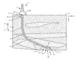
- FIG. 1is a schematic side view of a drilling system according to an embodiment of the present disclosure
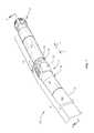
- FIG. 2is a perspective view of a downhole motor with an adjustment assembly in the drilling system shown in FIG. 1 ;
- FIG. 3is a cross-sectional view of the downhole motor taken along lines 3 - 3 in FIG. 2 ;
- FIG. 4is a cross-sectional view of the downhole motor taken along lines 4 - 4 in FIG. 2 ;
- FIG. 5Ais a detailed cross-sectional view of a portion of the downhole motor illustrated in FIG. 4 ;
- FIG. 5Bis a plan view of a portion of downhole motor illustrated in FIG. 2 ; with a moveable member removed for clarity;
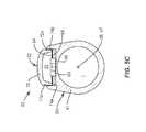
- FIG. 5Cis a cross-sectional view the downhole motor taken along lines 5 C- 5 C in FIG. 2 ;
- FIGS. 6A and 6Billustrate the downhole motor in shown FIG. 2 with an adjustment assembly in a retracted configuration and an extended configuration, respectively;
- FIG. 7is a perspective view of a downhole motor with an adjustment assembly in the drilling system shown in FIG. 1 , in accordance with another embodiment of the present disclosure
- FIG. 8is a cross-sectional view of the downhole motor taken along lines 8 - 8 in FIG. 2 ;
- FIGS. 9 and 10are a perspective end views of a portion of the downhole motor in shown in FIG. 7 , illustrating transition of the adjustment assembly;
- FIGS. 11A and 11Billustrate the downhole motor in shown in FIG. 7 , with the adjustment assembly in a retracted configuration and an extended configuration, respectively;
- FIG. 12is a schematic of a control system used to actuate the adjustment assembly of the downhole motor between the retracted and extended configuration
- FIG. 13is a chart illustrates with exemplary data indicating the relationship between the extension characteristics of an adjustment assembly and the build-up rate of the drilling system illustrated in FIG. 1 .
- embodiments of the present disclosureis a downhole motor 30 that includes one or more bends 36 and an adjustment assembly 36 that can selectively contact a wall of the well during drilling to help facilitate directional control of the drill bit, for instance to help achieve the desired build-up rate (BUR) during drilling.
- the downhole motorsare used herein may be referred to as steerable downhole motors, bent motors, or even steerable bent motors.
- the downhole motor 30comprises part of a drilling system 1 .
- the drilling system 1includes a rig or derrick 5 that supports a drill string 6 .
- the drill string 6includes a bottomhole (BHA) assembly 12 coupled to a drill bit 14 .
- the drill bit 14is configured to drill a borehole or well 2 into the earthen formation 3 along a vertical direction V and an offset direction O that is offset from or deviated from the vertical direction V.
- the drilling system 1can include a surface motor 20 located at the surface 4 that applies torque to the drill string 6 via a rotary table or top drive (not shown), and the downhole motor 30 disposed along the drill string 6 and is operably coupled to the drill bit 14 .
- the drilling system 1is configured to operate the in a rotary steering mode where the drill string 6 and the drill bit 14 rotate, and (preferably) a sliding mode where the drill string 6 does not rotate but the drill bit does.
- Operation of the downhole motor 30causes the drill bit 14 to rotate along with or without rotation of the drill string 6 .
- both the surface motor 20 and the downhole motor 30can operate during the drilling operation to define the well 2 .
- a pump 17pumps drilling fluid 9 (shown in FIG. 3 ) downhole through an internal passage 7 of the drill string 6 out of the drill bit 14 and is returned back to the surface 4 through an annular passage 13 defined between the drill string 6 and well wall 11 . Operation of the downhole motor 30 will be described below.
- the downhole motor 30is provided with one or more bends or bend 36 and an adjustment assembly 50 (see also reference 150 in FIG. 7 ).
- the adjustment assembly 50is configured to selectively apply a force against the well wall 11 in a direction that is opposite the direction of the bend 36 .
- the resultlikely is a side force applied to the drill bit 14 that causes the drill bit 14 to drill in the direction of the bend 36 orients the drill bit.
- Application of the force against the well wall 11 in the manner further detailed belowcan result in a desirable (usually higher) BUR even when the bend 36 defines relatively low bend angle.
- the resultis an optimized BUR without the associated risks of utilizing a bend with larger bend angles during the rotary drilling mode (when the drill string rotates).
- the drill string 6is elongate along a longitudinal central axis 26 that is aligned with a well axis E and further includes an uphole end 8 and a downhole end 10 spaced from the uphole end 8 along the longitudinal central axis 26 .
- a downhole direction Drefers to a direction from the surface 4 toward the downhole end 10 of the drill string 6 .
- Uphole direction Uis opposite to the downhole direction D.
- downholerefers to a location that is closer to the drill string downhole end 10 than the surface 4 , relative to a point of reference.
- Upholerefers to a location that is closer to the surface 4 than the drill sting downhole end 10 , relative to a point of reference.
- the drilling system 1can include a control system 100 , a telemetry system 250 ( FIG. 12 ), and a measurement-while-drilling (MWD) tool 22 disposed downhole for obtaining drilling data, such as inclination and azimuth.
- the control system 100can include a surface control system in the form of one or more computing devices 200 and a downhole control system 210 ( FIG. 12 ). Details concerning the control system 100 will be described below.
- the drilling system 1includes a casing 18 that extends from the surface 4 and into the well 2 . The one or more such casings 18 can be used stabilize the formation near the surface.
- One or more blowout preventerscan be disposed at the surface 4 at or near the casing 18 .
- the telemetry system 250facilitates communication among the surface control system components 200 and downhole control system 210 for instance components of the MWD tool 22 and downhole motor 30 as further described below.
- the telemetry system 250can be a mud-pulse telemetry system, an electromagnetic (EM) telemetry system, an acoustic telemetry system, a wired-pipe telemetry system, or any other communication system suitable for transmitting information between the surface and downhole locations.
- Exemplary telemetry systemscan include a transmitters, receivers, and/or transceivers, along with encoders, decoders, and controllers.
- the MWD tool 22can be attached to or suspended within the drill string 6 at a location up-hole relative to the downhole motor 30 .
- the MWD tool 22can include a power source, transmitter (or transceiver) for communication with the telemetry system, a short-hop transceiver in communication with other electronic components of the bottom hole assembly 12 , such as the downhole motor 30 , and a controller including a processor and memory.
- the MWD tool 22is configured to obtain drilling information indicative of the drilling direction of the drill bit 14 (or other components of the bottom hole assembly 12 ) and includes a plurality of sensors for this purpose. In accordance with one embodiment, the sensors obtain direct measurements of the azimuth and inclination of the drill bit 14 .
- the MWD toolmay include three magnetometers for measuring azimuth about three orthogonal axes, and three accelerometers for measuring inclination about the three orthogonal axes.
- the plurality of sensorsobtains information that can be used to determine azimuth, inclination and tool face angle of a drill bit 14 .
- the MWD processoris configured to, in response to receiving measurements obtained from the magnetometers and the accelerometers, determine the tool face angle—the angular orientation of a fixed reference point on the circumference of the drill string 6 in relation to a reference point on the bore 2 .
- MWD processorcan be configured to determine tool face angle of the drill bit 14
- processors housed elsewherecan be configured to determine drilling direction information based on inputs from the MWD sensors.
- Drilling direction information as used in this disclosurecan include one or any combination of azimuth, inclination, and tool face angle. Drilling direction information obtained during a drilling operation can be used to control operation of the adjustment assembly 50 in order to guide the drill bit 14 in accordance with the well plan.
- MWD tool 22is illustrated, a logging-while-drilling (LWD) tool may be used in combination with or in lieu of the MWD tool 22 .
- LWDlogging-while-drilling
- the downhole motor 30can include a motor housing 38 , a motor assembly 40 contained in and supported by the motor housing 38 , and the adjustment assembly 50 .
- the drill bit 14can be operably coupled to the motor assembly 40 and driven by operation of drilling fluid through the motor housing 38 as further detailed below.
- the downhole motor 30(or downhole motor 130 shown in FIG. 7 ) can include one or more optional stabilizers that help position the motor 30 toward the center of the well 2 . The stabilizers are not shown in the figures.
- the downhole motor 30can include an uphole stabilizer disposed uphole relative to the bent housing component 39 b .
- the downhole motor 30can include a near-bit stabilizer located just uphole from the drill bit 14 .
- the motor housing 38includes a bend 36 that is selected to orient the drill bit 14 in an offset direction.
- the motor housing 38can be referred to as a bent motor housing 38 .
- the motor housing 38includes an uphole portion 32 and a downhole portion 34 disposed relative the uphole portion 32 along the downhole direction D.
- the uphole and downhole portions 32 and 34meet at the bend 36 .
- the motor housing 38includes an uphole or first housing component 39 a , an intermediate or second housing component 39 b , and a downhole or third housing component 39 c .
- the uphole or first housing component 39 acan have a first or uphole end 41 u and a second or downhole end 41 d spaced from the uphole end 41 u along the downhole direction D.
- the uphole end 41 u of the housing component 39 ais threadably connected to a housing component such as a drill pipe or a drill collar.
- the intermediate or second housing component 39 bsometimes referred to as a bent housing component, defines the bend 36 .
- the second housing component 39 bcan carry or support the adjustment assembly 50 .
- the intermediate housing component 39 bcan define a housing body 37 a with a rib 37 b .
- the housing body 37 adefines a cavity 51 ( FIG.
- the downhole or third housing component 39 cincludes opposed uphole and downhole ends 43 u and 43 d spaced apart along the downhole direction D.
- Each housing component 39 a , 39 b and 39 cdefine respective inner surfaces 42 a , 42 b , and 42 c ( 42 a and 42 b shown in FIG. 4 ), and opposing respective outer surfaces (not numbered) that face the well wall 11 .
- the inner surface 42 a , 42 b , and 42 cdefine a portion of the internal passage 7 that extends through the entirety of the drill sting 6 . While three housing components are shown, more or few housing components can be used to define the drilling motor housing 38 .
- the housing 38can define a particular bend angle in order to attain a desired build up rate (BUR).
- the housing uphole portion 32can extend along an uphole or first axis 27 a and the downhole portion 34 can extend from the bend 36 along a downhole or second axis 27 b .
- the first and second axes 27 a and 27 bcan intersect at a point I that is disposed along the longitudinal central axis 47 of the downhole motor 30 .
- the first and second axes 27 a and 27 bcan be considered components of the longitudinal central axis 47 and are coincident with the longitudinal central axis 26 .
- the bend 36includes an angle ⁇ defined by the uphole axis 27 a and the downhole axis 27 b .
- the bend angle ⁇can vary based on the particular use and need of the well.
- the bend angle ⁇can be between some value greater than 0 degrees and up to about 5 degrees.
- the bend anglecan be between about 0.10 degrees to about 5.0 degrees.
- the bend anglecan be between about 0.10 degrees to about 5.0 degrees.
- the bend anglecan be between about 0.10 degrees to about 4.5 degrees.
- the bend anglecan be between about 0.10 degrees to about 4.0 degrees.
- the bend anglecan be between about 0.10 degrees to about 3.5 degrees.
- the bend anglecan be between about 0.10 degrees to about 3.0 degrees.
- the bend anglecan be between about 0.10 degrees to about 2.5 degrees.
- the bend anglecan be between about 0.10 degrees to about 2.0 degrees. In one embodiment, the bend angle can be between about 0.10 degrees to about 1.5 degrees. In one embodiment, the bend angle can be between about 0.10 degrees to about 1.0 degrees. In one embodiment, the bend angle can be between about 0.10 degrees and 0.75 degrees. In another embodiment, the bend angle can be between about 0.10 degrees and 0.50 degrees. In another embodiment, the bend angle can be between up to about 0.10 degrees. The other embodiments, the bend angle can be about 0.10 degrees, about 0.2 degrees, about 0.50 degrees, about 0.75, about 1.0 degrees, about 1.5 degrees, about 2.0 degrees, about 2.50 degrees, about 3.0 degrees, about 3.5 degrees, about 4.0 degrees, about 4.50 degrees, or about 5.0 degrees. The bend angle is not limited to the aforementioned values and ranges.
- the downhole motor 30may not include a bend 36 located or defined by the intermediate housing component 39 b as illustrated in FIGS. 2 and 4 . Rather, the bend 36 could be defined at any portion of the housing 38 .
- the bend 36can be defined by a sub connected between the drill bit 14 and the housing 38 .
- the bend 36can be connected uphole to the motor housing 38 .
- a bent subcan be used to couple the drill bit 14 to the housing 38 in order to orient the drill bit 14 at an angle relative to at least an uphole portion of the downhole motor 30 .
- the motor housingcan include more than one specifically defined bend. For instance, a housing can include several bends that collective orient the drill bit 14 in a direction that is offset with respect to an uphole portion the downhole motor 30 .
- the motor assembly 40is disposed inside the internal passage 7 of the housing component 39 a .
- the motor assembly 40includes a stator 45 mounted to the inner surface 42 a , a rotor 44 rotatably disposed within an internal cavity of the stator 45 , and a shaft assembly 49 coupled to the rotor 44 by a flexible coupling 48 .
- the stator 45typically includes a cavity with a number of channels, e.g. 4 channels arranged in a helical pattern (channels not shown).
- the stator 45defines an inner cross-sectional shape.
- the rotor 44includes multiple lobes, but generally a fewer of number lobes, e.g.
- the different number in lobes in rotor compared to the number of channels in the statorcause the rotor 44 to rotate eccentrically in the stator cavity.
- the difference between the inner cross-section of rotor 44 and outer cross-sectional shape of the stator 45define internal passages in motor assembly 40 that vary with rotation position of the stator 45 relative to the rotor 44 and allow the drilling fluid to pass through the motor assembly 40 .
- the rotor 44is supported uphole indirectly by the housing component 39 a with a support 46 .
- the support 46is configured to hold the rotor 44 and also permit drilling fluid 9 to pass therethrough into the spaces defined between the stator 45 and rotor 44 .
- the shaft assembly 49is operably connected to the drill bit 14 at the bit box (not numbered) such that drill bit 14 rotates along with rotation of the shaft assembly 49 .
- the pump 17 at the surface 4pumps the drilling fluid 9 downward through the internal passage 7 in the drill string 6 into the motor assembly 40 .
- the drilling fluid 9passes into the spaces defined between the rotor 44 and stator 45 and impinges the rotor 44 and driving eccentric rotation of the rotor 44 relative to the stator 45 .
- Rotation of the rotor 44rotates the shaft assembly 49 which rotates the drill bit 14 .
- the flexible coupling 48transmits the eccentric rotation of the rotor 44 to the shaft assembly 49 .
- the flexible coupling 48is a universal joint and bearing assembly which allows the shaft assembly 49 to rotate despite the eccentric rotation of the rotor 44 and the angular offset created by the bent housing component 39 b.
- the adjustment assembly 50 and bend 36 in the motor 30can help the drilling operator obtain and maintain a desirable BUR during drilling.
- the resultant theoretical BURcan be increased. See for example FIG. 13 and the discussion regarding FIG. 13 found below.
- the adjustment assembly 50is located proximate the bend 36 .
- the adjustment assembly 50can be aligned with the bend 36 along a direction transverse to the axis longitudinal central axis 47 , or spaced slightly uphole or downhole relative the bend 36 .
- the adjustment assembly 50can be spaced downhole relative to the bend 36 or spaced uphole relative the bend.
- the bend 36can defined by one housing component and the adjustment assembly 50 can be carried by a different housing component.
- the intermediate housing 39 bmay not have a bend but would include an adjustment assembly 50 (or 150 shown in FIG. 7 ).
- the adjustment assembly 50includes a moveable member 52 that is used to guide direction the drill bit 14 while drilling a turn in the well.
- the moveable member 52can be configured as an arm or pad.
- the moveable memberis an engagement pad disposed on a rotatable shaft.
- the adjustment assembly 50is configured to transition the moveable member 52 between an extended configuration 50 e as shown in FIG. 6B and the retracted configuration 50 r as shown in FIGS. 2 and 6A .
- the adjustment assembly 50 in the extended configuration 50 ea portion of the moveable member 52 projects outwardly away from the central axis 26 along a radial direction R that is perpendicular to the central axes 26 and 47 .
- a free end 71 bFIG.
- the moveable member 52extends an extension distance E 1 from an outer surface (not shown) of the downhole motor 30 to apply a force F to wall 11 in a first direction 15 a , which results in a side force applied to the drill bit 14 along a second direction 15 b that is aligned with the direction of the bend 36 .
- the adjustment assembly 50is in the retracted configuration 50 r
- the moveable member 52is disposed more toward the central axis 26 as shown in FIG. 6A and is generally aligned with the outer surface (not numbered) of the downhole motor 30 .
- the free end 71 bFIG.
- the moveable member 52is aligned with the outer surface of the downhole motor 30 .
- the bend 36apply forces to the well wall 11 and to cause a directional change in the drill bit 14 .
- the BURcan increase compared to when the adjustment assembly 50 is in the retracted configuration 50 r so that the moveable member 52 is not extended toward the well wall 11 . The result is possible higher BUR with lower than expected bend angles in the downhole motor 30 .
- the adjustment assembly 50is includes on or more actuators 54 that control movement or activation of the moveable member 52 .
- the actuator 54can be operably connected with a controller 220 ( FIG. 12 ).
- the controller 220is configured operate the actuator 54 so as to selectively cause the moveable member 52 to transition between the retracted configuration and the extended configuration.
- the controller 220forms part of the downhole control system 210 as will be further described below.
- the actuator 54is disposed in the housing cavity 51 .
- the controller 220can be contained on a board 69 with other circuitry.
- the board 69is shown contained in the cavity 51 , but the board 69 can be isolated from the cavity 51 and the actuator 54 .
- the moveable member 52is an arm or pad configured to pivot relative to the housing 38 about a pivot location 64 .
- the moveable member 52 or armdefines a body 70 having a first end or base end 71 a and a second or free end 71 b opposed to the base end 71 a .
- the body 70has an outer surface 73 that faces the wall of the well.
- the outer surface 73can be referred to as contact surface that can engage the wall 11 the well when the moveable member 52 is extended.
- the base end 71 ais coupled to the housing 38 by a pin 64 which also defines the pivot location.
- the arm 52includes a first portion 76 a aligned with the free end 71 b and a second portion 76 b disposed toward the base end 71 a .
- the first and second portions 76 a and 76 bare configured to engage a portion of portion of the actuator 54 to cause the moveable member 52 to pivot about the pivot location 64 in response to the pressure of the drilling fluid.
- the body 70defines opposed sidewalls 72 a and 72 b spaced apart to define an internal space sized to receive an abutment 62 (see dotted lines portion in FIG. 5B ) and a portion of the actuator 54 .
- Each side walldefines arcuate edges 74 a and 74 b that extend along the sidewalls 72 a and 72 b from the free end 71 b toward base end 71 a .
- the first portion 76 a of the moveable member 52can define a first dimension (not shown) that extends from the edges 74 a and 74 b to the housing body 37 a at a location aligned with the free end 71 b of the body 70 .
- the second portion 76 bdefines a second dimension (not shown) extends from the edges 74 a and 74 b to the housing body 37 a at a location disposed toward the base end 71 a and aligned with the abutment 62 of the housing body 37 a .
- the second dimensionis less than the first dimension such that the first portion 76 a is elevated above the housing body 37 a .
- the side walls 72 a and 72 bhave a smaller wall height along the first portion 76 a compared to the height of the walls 72 a and 72 b along the second portion 76 b .
- the moveable member 52can define an engagement surface (not numbered) disposed on the edges 74 a and 74 b that extends along the first and second portions 76 a and 76 b .
- the engagement surfacecan abut a portion of the actuator 54 as further detailed below.
- the actuator 54can be a fluid operated system that causes the moveable member 52 to pivot about the pivot connection 64 as needed to direct a force against the well wall 11 .
- the actuator 54includes a valve 56 , an engagement member 58 configured to move relative to valve 56 , a biasing member 60 disposed between the engagement member 58 and the abutment 62 .
- the valve 56is electronically connected to the controller 220 .
- the valve 56includes at least one chamber (not numbered) that is in flow communication with the internal passage 7 such that drilling fluid can be directed into the chamber.
- the valve 56is configured to, in response to inputs from the controller 220 , selectively direct drilling fluid from the chamber toward the engagement member 58 or out of the release port 68 .
- the engagement member 58includes a rod 57 a operably and moveably coupled to the valve 56 and an engagement head 57 b attached to the rod 57 a .
- the biasing member 60which can be a compression spring, applies a force against the engagement head 57 b urging the engagement head 57 b in a first direction 61 a toward the valve 56 when the adjustment assembly 50 is in the retracted configuration. With engagement head 57 b biased in a retracted position toward the valve 56 , the moveable member 52 rests at least partially within the cavity 51 .
- the opposed side walls 72 a and 72 b disposed adjacent the abutment 62 and the free end 71 b of the moveable member 52is generally aligned with the outer surface of the downhole motor 30 (see FIG. 5A ).
- Another biasing member(not shown) disposed in housing body 37 a and extends to the moveable member 52 over the pin 64 biases the moveable member 52 into the retracted position.
- a leaf springcan be coupled to housing body 37 a and the moveable member 52 to bias the moveable member 52 into the retracted position.
- drilling fluid 9enters the chamber in the valve 56 .
- the controller 220causes the valve 56 to direct drilling fluid from the chamber to impinge a distal end of the engagement member 58 .
- the drilling fluid 9can impinge a distal end of the rod 57 a .
- Pressure of the drilling fluid directed against the rod 57 acauses the engagement head 57 b move in the second or actuation direction 61 b toward the abutment 62 , thereby compressing the biasing member 60 against the abutment 62 .
- the engagement head 57 bmoves from a region in the cavity 51 aligned with the first portion 76 a of the moveable member 52 toward the second portion 76 b of the moveable member 52 . More specifically, the engagement head 57 b rides along the arcuate edges 74 a and 74 of the moveable member 52 toward the pivot location 64 . Further movement of engagement head 57 b along the edges 74 a , 74 b toward the abutment 62 cause the moveable member 52 to pivot outwardly into the extended configuration as shown in FIG. 6B .
- the actuatorcan be hydraulic pump configured to actuate the moveable member 52 .
- the actuatorcan include the valve 56 operably connected to pump (not shown). The pump can supply a fluid to the valve 56 under pressure. The valve 56 can selectively permit the pressurized fluid to impinge the engagement member 58 to cause the engagement member 58 to move relative to the moveable member 52 as described above.
- the moveable member or arm 52 as shown in FIGS. 5A-5C and described aboveincludes sidewalls 72 a and 72 b and arcuate edges 74 a and 74 b .
- the moveable member 52can be a flat rod, a plate, cylinder, or tube is coupled to the housing body 37 a .
- the movement member 52may define any type of engagement surface configured to engage the actuator 54 .
- the moveable member 52can be configured as an arm or piston that translates along the radial direction R that is perpendicular to the central axis 26 in lieu of arm that that pivots in order to move from the retracted configuration into the extended configuration.
- a downhole motor 130 in accordance with another embodiment of the present disclosureincludes one or more bends 36 and an adjustment assembly 150 .
- the downhole motor 140is constructed in some respects similar to the downhole motor 30 illustrated in FIGS. 2 through 6B and discussed above. Accordingly, similar reference numbers will be used to refer to components that are common between the downhole motor 30 describe above and shown in FIGS. 2-6B and the downhole motor 130 described below and shown in FIGS. 7-11B .
- the downhole motor 130has an uphole portion 32 , a downhole portion 34 , and or more bends or bend 36 that can define a bend angle ⁇ .
- the downhole motor 150can also include multiple housing components, such as a first or uphole housing component 39 a , an intermediate or bent housing component 139 , and a second or downhole housing component 39 c .
- the adjustment assembly 150is fixed to the intermediate or bent housing component 139 and also fixed to the downhole component 39 b so that the adjustment assembly 150 is positioned proximate yet downhole from the bend 36 .
- the adjustment assembly 150can be positioned uphole relative to the bend 36 as well.
- the adjustment assembly 150can be fixed to the intermediate or bent housing component 139 and fixed to the uphole component 39 a so that the adjustment assembly 150 is positioned proximate yet uphole from the bend 36 .
- the adjustment assembly 150is carried by or supported by the motor housing.
- the downhole motor 150includes an adjustment assembly 150 configured to selective engage the well wall 11 during drilling.
- the adjustment assembly 150includes a first component or inner component 152 , a second or outer component disposed around and moveable relative to the inner component 152 , and a moveable member 164 carried by the outer component 162 .
- the outer component 162carries the moveable member 164 and can rotate around the inner eccentric component 152 in a rotational direction A in order to selectively apply the force the well wall 11 .
- the moveable member 164includes an outer or contact surface 165 that can engage the well wall 11 based on the rotational position of the outer component 162 relative to the inner component 152 , as will be further described below.
- the outer and inner components 162 and 152can include eccentric portions.
- the first component 152can be referred to as the first or inner eccentric component 152 and the second component 162 can be referred to the second or outer eccentric component 162 .
- the outer eccentric component 162is sometimes referred to as a moveable component while the inner eccentric component is sometimes referred to as a fixed component.
- the inner eccentric component 152is threadably coupled to the bent housing 139 and the uphole housing 39 c .
- the inner eccentric componentmay be referred to as a housing component.
- the adjustment assembly 150can also include one or more attachment members 170 and 172 that rotatably couple the outer component 162 to the inner component 152 ( FIG. 8 ). In FIG. 7 , the attachment members 170 and 172 are removed to better illustrate the outer and inner components 162 and 152 .
- the adjustment assembly 150also includes an actuator (not shown) and a controller 220 in communication with the actuator.
- the controller 220is configured operate the actuator so as to selectively cause the outer eccentric component 162 to rotate about the inner eccentric component 162 .
- moveable member 164iterates between a retracted configuration, whereby the moveable member 164 or contact surface 165 is disposed toward the central axis 26 along the radial direction R as shown FIG. 11A , and an extended configuration whereby the moveable member 164 or contact surface 165 is at least partly projecting outward away from the central axis 26 along the radial direction R as shown in FIG. 11B .
- the contact surface 165is further away from the central axis 26 when the adjustment assembly 150 is in the extended configuration compared to when the adjustment assembly 150 is in the retracted configuration.
- the controller 220can be part of the downhole control system 210 as shown in FIG. 12 and further described below.
- the inner eccentric component 152includes a body or wall 153 that defines an outer surface 155 , and an inner surface 157 opposed to the outer surface 155 along the radial direction R.
- the wall 153also defines a first end 158 a , a second end 158 b spaced from the first end 158 a along the central axis 26 .
- the inner surface 157can define the internal passage 7 within which a portion of the motor assembly 40 is disposed and through which drilling fluid flows toward the drill bit 14 .
- the inner surface 157also defines an inner cross-sectional shape that is perpendicular to the central axis 26 and is centered about a first center C 1 that lies on the central axis 26 .
- the outer surface 155defines an outer cross-sectional shape that is perpendicular to the central axis 26 and is centered about a second center C 2 that is offset from the first center C 1 .
- the inner eccentric component 152or wall 153 , includes a thickness defined from the outer surface 155 to the inner surface 157 that can vary circumferentially about the central axis 26 .
- the wall 153can include a first or enlarged or thick wall segment 154 and second or thin wall segment 156 that is opposite from the thick wall segment 154 .
- the thick wall segment 154defines a first thickness T 1 that extends from the inner surface 157 to the outer surface 155 .
- the thin wall segmentdefines a second thickness T 2 that extends from the inner surface 157 to the outer surface 155 and is less than the first thickness.
- the thick wall segment 154can be oriented in any particular direction as desired. In the illustrated embodiment, the wall segment 154 is disposed such that its maximum thickness is oriented along a first radial axis 126 that intersects the central axis 26 and extends outwardly away from the center C 1 in the radial direction.
- the inner component wall or body 153extends the first end 158 a to the second end 158 b along the axis 26 to define component length.
- the thin wall segment 156extends along a portion of the length and around a portion of the circumference so as define a recessed portion (not numbered).
- the wall 153has a relatively consistent wall thickness in regions adjacent the first and second ends 158 a and 158 b .
- the inner eccentric component 152can be coupled to standard sized housing components, such as the bent housing 139 , the uphole housing component 39 c , or other sections of standard sized drill pipe.
- the recessed portionis sized and configured carry a portion of the outer eccentric component 162 . And depending on what portion of the outer eccentric component 162 is aligned with recess portion define whether the adjustment assembly in the retracted configuration or the extended configuration.
- the outer eccentric component 162includes a body 163 that includes a wall 166 and an enlarged segment 164 , referred to as the moveable member 164 , that extends outwardly away from the wall 166 .
- the moveable member 164can be disposed along a second radial axis 128 that intersects the central axis 26 and extends outwardly along the radial direction R.
- the body 163defines a first end 168 a , a second end 168 b spaced from the first end 168 a along the central axis 26 , an outer surface 165 , and an inner surface 167 opposed to the outer surface 165 along a radial direction R that is perpendicular to the central axis 26 .
- the inner surface 167defines an inner cross-sectional shape that is perpendicular to the central axis 26 and is centered about the second center C 2 that is offset from the central axis 26 .
- the inner cross-sectional shape of the outer eccentric component 162conforms to the outer cross-sectional shape of the inner eccentric component 152 so that the outer component 162 is rotatable about the inner component 152 .
- the outer surface 165 of the outer eccentric component 162defines an outer cross-sectional shape that is perpendicular to the central axis 26 and includes the shape of the moveable member 164 .
- the moveable member 164can be monolithic with the wall 166 .
- the moveable member 164can be secured to the wall 166 with a connector.
- a kitcan be provide that includes multiple moveable members 164 with different thicknesses that can attached to wall 166 to adjust the extent that the moveable member 164 can extend outwardly from the wall 166 .
- the moveable member 164can be multiple pieces such that it could be assembled on the wall 166 .
- the outer eccentric component 162 or wall 166can have a thickness that varies circumferentially about the central axis 26 and along a length aligned with the central axis 26 .
- the enlarged segment 164defines an enlarged or third thickness T 3 that extends from the inner surface 167 to the outer surface 165 .
- the portion of the wall 166 disposed opposite the enlarged segment 164defines a wall or fourth thickness T 4 that extends from the inner surface 157 to the outer surface 155 and is less than the third thickness T 3 .
- Wall thicknesses T 4 discussed hereincan vary between about 0.125 inches about to about 2.0, 3.0, or 4.0 inches, depending on the size of the downhole motor 130 .
- the enlarged wall segment 164is disposed such that its maximum thickness is oriented along the second radial axis 128 that intersects the central axis 26 and extends outwardly away from the center C 1 in the radial direction R.
- the adjustment assembly 150includes the attachment members 170 and 172 as discussed above.
- the attachment members 170 and 172couple the outer eccentric component 162 to the inner eccentric component 152 such that the outer eccentric component 162 is moveable relative to the inner eccentric component 162 and the attachment members 170 and 172 .
- Connectors 171 and 173such as fasteners, bolts or welds, couple the attachment members 170 and 172 to the inner eccentric component 162 .
- the attachment members 170 and 172can be threadably connected to the inner eccentric component 152 .
- Each attachment member 170 and 172defines gap (not numbered) defined with respect to the outer surface 155 of the inner eccentric component 152 .
- Each attachment member gapreceives the respective ends 168 a and 168 b of the outer eccentric component 162 so that the ends 168 a and 168 b are rotationally moveable within the gaps.
- Either the housing 139 or the attachment member 170 and 172can include the actuator (not shown).
- the outer eccentric component 162can be attached to the inner eccentric component 152 with snap fittings, retaining rings, threads, welding, or the fastening means.
- the attachment memberscan be integral with the housing 152 .
- the motorcould include one attachment member on either end of moveable member.
- the outer centric component 162is configured to change its rotational position relative to the inner eccentric component 152 in order to position the moveable member 164 in either the extended configuration 150 e as shown in FIGS. 9 and 11B or the retracted configuration as shown in FIGS. 10 and 11A .
- the outer eccentric component 162is in a first rotational position relative to the inner eccentric component 152 such that the moveable member 164 projects outwardly away from the central axis 26 .
- the outer eccentric component 162is in a second rotational position relative to the inner eccentric component 152 that is different from the first rotational position and the moveable member 164 is disposed inwardly toward the central axis 26 .
- the adjustment assembly 150is in the extended configuration 150 e .
- the first radial axis 126 of the inner eccentric component 152is aligned with the second radial axis 128 of the outer eccentric component 162 such that the first and second radial axes define an angle ⁇ 1 equal to about 0 (zero) degrees.
- Angle ⁇ 1can vary by several degrees, such as plus or minus 5 to 10 degrees off of 0 (zero) degrees and still cause the moveable member 164 to project outwardly to contact the well wall 11 .
- both the movement member 164 and enlarged segment 154are oriented at a 0 degree position when in the extended configuration.
- the adjustment assembly 150is in the retracted configuration 150 r when the moveable member 164 is rotationally offset with respect to the enlarged wall segment 154 of the inner component 152 .
- the first radial axis 126 of the inner eccentric component 152is offset from the second radial axis 128 of the outer eccentric component 162 when the first and second radial axes define an angle ⁇ 2 that is greater than 0 (zero) degrees, preferably greater than about 20 degrees.
- the inner eccentric component 152is fixed and its enlarged segment 154 is oriented at the 0 degree position.
- the moveable member 164When the adjustment assembly 150 is in the retracted configuration 150 r , the moveable member 164 is orientated at about the 180 degree position and the angle ⁇ 2 is also about 180 degrees. In the illustrated configuration, the moveable member 164 is circumferentially opposite to the enlarged wall segment 154 of the inner eccentric component 152 .
- an actuatorcan cause movement of the outer component 162 relative to the inner eccentric component 152 .
- the actuatorcan be a valve and a conduit that is in flow communication with the internal passage 7 of the housing 138 .
- the conduitcan extend from the internal passage 7 to an area near one of gaps of the attachment members 170 or 172 .
- the valvecan selectively open or close off the conduit in response to inputs from the controller 220 .
- drilling fluidcan enter the conduit and apply pressure to a vane disposed along one the ends 168 a and 168 b of the outer eccentric component 162 .
- pressure of the drilling fluidcauses the outer eccentric component 162 to rotate relative to the inner eccentric component 152 .
- the actuatorcan be any type of actuator that can be use used selectively change the rotational position of the outer eccentric component 162 relative to the inner eccentric component 152 .
- the actuatorcan be operated by electric motors or hydraulic motors. Motors could be geared to the outer component to affect rotation.
- the control system 100can be used operate and control a drilling system that includes the downhole motor 30 and adjustment assembly 50 described above and shown in FIGS. 2-6B as well as a drilling system that includes the downhole motor 130 and the adjustment assembly 150 shown in FIGS. 7-11B .
- the control system 100includes a surface control system in the form of one or more computing devices 200 and a downhole control system 210 .
- Inputs from the surface control systemcan be transmitted to the downhole control system 210 via the telemetry system 250 .
- inputs for operating the downhole motor 30 , 130can be downlinked from the surface control system to the downhole motor control system 210 via the telemetry system 250 .
- drilling informationcan be transmitted from the downhole control system 210 to the surface control system.
- Any suitable computing device 200may be configured to host a software application configured to process drilling data encoded in the signals and further monitor and analyze drilling operations, or control the downhole motor 30 , 130 .
- the computing device 200can include any appropriate device, examples of which include a desktop computing device, a server computing device, or a portable computing device, such as a laptop, tablet or smart phone.
- the computing device 200includes a processing portion 202 , a memory portion 204 , an input/output portion 206 , and a user interface (UI) portion 208 .
- UIuser interface
- the block diagram depiction of the computing device 200is exemplary and not intended to imply a specific implementation and/or configuration.
- the processing portion 202 , memory portion 204 , input/output portion 206 and user interface portion 208can be coupled together to allow communications therebetween. As should be appreciated, any of the above components may be distributed across one or more separate devices and/or locations.
- the input/output portion 206includes a receiver of the computing device 200 , a transmitter (not to be confused with components of the telemetry tool 22 described above) of the computing device 200 , or an electronic connector for wired connection, or a combination thereof.
- the input/output portion 206is capable of receiving and/or providing information pertaining to communication with a network such as, for example, the Internet.
- transmit and receive functionalitymay also be provided by one or more devices external to the computing device 200 .
- the input/output portion 206can be in electronic communication with the receiver.
- the memory portion 204can be volatile (such as some types of RAM), non-volatile (such as ROM, flash memory, etc.), or a combination thereof.
- the computing device 200can include additional storage (e.g., removable storage and/or non-removable storage) including, but not limited to, tape, flash memory, smart cards, CD-ROM, digital versatile disks (DVD) or other optical storage, magnetic cassettes, magnetic tape, magnetic disk storage or other magnetic storage devices, universal serial bus (USB) compatible memory, or any other medium which can be used to store information and which can be accessed by the computing device 200 .
- the computing device 200can contain the user interface portion 208 , which can include an input device and/or display (input device and display not shown), that allows a user to communicate with the computing device 200 .
- the user interface 208can include inputs that provide the ability to control the computing device 200 , via, for example, buttons, soft keys, a mouse, voice actuated controls, a touch screen, movement of the computing device 200 , visual cues (e.g., moving a hand in front of a camera on the computing device 200 ), or the like.
- the user interface 208can provide outputs, including visual information. Other outputs can include audio information (e.g., via speaker), mechanically (e.g., via a vibrating mechanism), or a combination thereof.
- the user interface 208can include a display, a touch screen, a keyboard, a mouse, an accelerometer, a motion detector, a speaker, a microphone, a camera, or any combination thereof.
- the user interface 208can further include any suitable device for inputting biometric information, such as, for example, fingerprint information, retinal information, voice information, and/or facial characteristic information, for instance, so as to require specific biometric information for access to the computing device 200 .
- the downhole control system 210can include the downhole motor controller 220 .
- the controller 220contains a processor 230 in electronic communication with an actuator 54 (or actuator used with adjustment assembly 150 ).
- the controller 220can include volatile or non-volatile memory and an input/output portion in the form receiver, transmitter, and/or transceiver.
- the input/output portionis configured to receive information or signals from the surface control system or MWD tool 22 .
- the signalscan be include inputs, such as instructions to cause the actuator to iterate the adjustment assembly 50 , 150 between retracted configuration and the extended configuration as described above.
- the controller 220can, in response to inputs from surface control system or based on a predefined drilling plan stored in the memory portion of the controller 220 , cause the valve to direct drilling fluid to the engagement member 58 , thereby cause the moveable member 52 to move into the extended configuration. Further inputs can direct the controller 220 to close of flow communication between the drilling fluid and the engagement member 58 so the moveable member 52 is moved into the retracted configuration. Furthermore, the controller is configured to cause movement of the moveable member in response to predetermined fluctuations in drilling parameters, such as the flow rate, drilling fluid pressure, WOB, and rotational speed of the drill bit and/or drill string.
- predetermined fluctuations in drilling parameterssuch as the flow rate, drilling fluid pressure, WOB, and rotational speed of the drill bit and/or drill string.
- Another embodiment of the present disclosureincludes a method for guiding a drilling direction of a drill bit 14 during a drilling operation.
- the bottom hole assembly 12is assembled such the drill bit 14 is coupled the downhole motor 30 .
- the drill bit 14 and downhole motor 30can be lowered into the casing at the initial stages of well formation.
- the MWD and LWD toolsare added and the bottom hole assembly 12 and drill bit 14 are advanced further into the formation.
- AdditionAL tools or sections of drill pipeare added to the drill 6 .
- the surface control systemcause the surface motors rotate the drill string 6 to drill the well 2 into the earthen formation 3 until the planned turn. At initial stages or leading up the turn stage both drill string 6 and the drill bit 14 are rotating with via operation of the surface and downhole motors.
- the drill bitis coupled to the downhole motor 30 , 130 such that the drill bit 14 is oriented along a first direction that is angularly offset relative to at least a portion of the drill string 6 and or downhole motor 30 .
- inputs into the surface control systemcauses rotation of the drill string in the well to stop.
- the drilling system 1transitions from the rotary drilling mode into a sliding mode whereby only the drill bit 14 rotates and the drill string 6 slides along the well 2 .
- the bitmay continue rotation when the drill string 6 stops rotating or the both the drill string 6 and drill bit 14 may stop rotating.
- an MWD surveycan be conducted or some other maintenance event can occur.
- the methodincludes the step of rotating the drill bit via the downhole motor 30 , 130 while rotation of drill string 6 in the well 2 has stopped.
- the methodcan include actuating an adjustment assembly 50 , 150 carried by the downhole motor 30 , 130 toward a wall 11 of the well in a second direction that is opposite to the first direction, thereby causing a reactive force to guide the drill bit along the first direction.
- the step of actuating the adjustment assembly 50 , 150includes causing a moveable member 52 , 164 to move between the extended configuration where the moveable member 52 , 164 projects outward from the downhole motor 30 , 130 to contact the wall 11 of the well, and the retracted configuration where the moveable member 52 , 164 is disposed at least partially in the downhole motor 30 , 130 .
- the step of actuating an adjustment assembly 50includes causing the moveable member 52 to pivot or alternatively translate into the extended configuration.
- the step of actuating an adjustment assembly 50 , 150includes causing, via the controller 220 , the actuator to transition the adjustment assembly 50 , 150 from the retracted configuration into the extended configuration.
- actuating the adjustment assembly 150 into the extended configurationincludes rotating at least one of the first and second components 152 and 162 relative to the other of the first and second components 152 and 162 such that the enlarged segment 154 and the enlarged segment 164 (sometimes referred to as the moveable member 164 ) are at least partially aligned with each other. Further actuating the adjustment assembly 150 from the extended configuration into the retracted configuration causes that the enlarged segments 154 and 164 to move out of alignment with each other. Thereafter, the rotary drilling can resume when the desired direction is attained.
- FIG. 13illustrates an exemplary data set utilizing one the downhole motors 30 , 130 as described above to steer the drill bit 14 .
- the Y-axisis the BUR and the X-axis is the moveable member extension (E 1 , E 2 ) in inches. Extension is distance from the outer surface of the housing 38 , 138 to an outermost point of the moveable member 52 , 164 ( FIGS. 6B, 11B ).
- the downhole motor 30slides like a conventional motor to build the turn and rotate again like a conventional motor to drill straight.
- the advantageis that downhole motor 30 , 130 has a small bend which does not create excessive stress in the tools when rotated as opposed to conventional motors which are often rotated with 2 degree plus bends.
- drillerswant the high build potential of a “large” bends, i.e. when a is between about 1.75 degrees to 3 degrees or higher, to quickly affect directional corrections.
- drillerswant to maximize the amount of time during the drilling operation that the drill string 6 rotates so as to optimize ROP.
- the adjustment assembly 50 , 150 of the present disclosurecan utilize relative to small bend angles to prevent excessive stress on the tools while rotating and yet deploy or extend the moveable member 52 , 164 during sliding modes to rapidly affect directional changes in the drill bit 14 and realize a higher BUR.
- the BUR ratewas calculated using the 3-point curvature BUR well known to those of skill in the art. As can be seen in the graph of FIG.
Landscapes
- Engineering & Computer Science (AREA)
- Life Sciences & Earth Sciences (AREA)
- Geology (AREA)
- Mining & Mineral Resources (AREA)
- Physics & Mathematics (AREA)
- Environmental & Geological Engineering (AREA)
- Fluid Mechanics (AREA)
- General Life Sciences & Earth Sciences (AREA)
- Geochemistry & Mineralogy (AREA)
- Mechanical Engineering (AREA)
- Earth Drilling (AREA)
Abstract
Description
Claims (36)
Priority Applications (4)
| Application Number | Priority Date | Filing Date | Title |
|---|---|---|---|
| US14/675,378US10233700B2 (en) | 2015-03-31 | 2015-03-31 | Downhole drilling motor with an adjustment assembly |
| CA2925615ACA2925615A1 (en) | 2015-03-31 | 2016-03-30 | Downhole drilling motor with an adjustment assembly |
| RU2016111941ARU2016111941A (en) | 2015-03-31 | 2016-03-30 | BOTTOM DRILLING MOTOR WITH MOUNTING UNIT |
| CN201610200700.4ACN106014257A (en) | 2015-03-31 | 2016-03-31 | Downhole drilling motor with adjustment assembly |
Applications Claiming Priority (1)
| Application Number | Priority Date | Filing Date | Title |
|---|---|---|---|
| US14/675,378US10233700B2 (en) | 2015-03-31 | 2015-03-31 | Downhole drilling motor with an adjustment assembly |
Publications (2)
| Publication Number | Publication Date |
|---|---|
| US20160290050A1 US20160290050A1 (en) | 2016-10-06 |
| US10233700B2true US10233700B2 (en) | 2019-03-19 |
Family
ID=56998736
Family Applications (1)
| Application Number | Title | Priority Date | Filing Date |
|---|---|---|---|
| US14/675,378Active2037-02-19US10233700B2 (en) | 2015-03-31 | 2015-03-31 | Downhole drilling motor with an adjustment assembly |
Country Status (4)
| Country | Link |
|---|---|
| US (1) | US10233700B2 (en) |
| CN (1) | CN106014257A (en) |
| CA (1) | CA2925615A1 (en) |
| RU (1) | RU2016111941A (en) |
Families Citing this family (8)
| Publication number | Priority date | Publication date | Assignee | Title |
|---|---|---|---|---|
| US20170342773A1 (en)* | 2016-05-27 | 2017-11-30 | Scientific Drilling International, Inc. | Motor Power Section with Integrated Sensors |
| US10731416B2 (en)* | 2017-12-21 | 2020-08-04 | Halliburton Energy Services, Inc. | System and method to control adjustable pads for use in downhole directional drilling assemblies |
| US11008809B2 (en)* | 2019-01-29 | 2021-05-18 | Rival Downhole Tools, Lc | Bent housing drilling motor with counter-rotating lower end |
| CN113944428A (en)* | 2020-07-15 | 2022-01-18 | 中国石油化工股份有限公司 | Quality-improving and speed-increasing drilling tool for oil and gas well |
| CN112211557B (en)* | 2020-10-20 | 2023-04-25 | 长江大学 | Push-type rotary guiding tool driven by double eccentric rings |
| CN113073938B (en)* | 2021-03-19 | 2022-01-11 | 四川宏华石油设备有限公司 | Rotary guide tool |
| EP4407141A1 (en)* | 2023-01-25 | 2024-07-31 | TRACTO-TECHNIK GmbH & Co. KG | Drillstring system |
| CN116950567B (en)* | 2023-09-20 | 2023-12-29 | 黑龙江豪利斯能源发展集团股份有限公司 | Tool for orientation of ultra-short radius sidetracking and use method thereof |
Citations (111)
| Publication number | Priority date | Publication date | Assignee | Title |
|---|---|---|---|---|
| US2345766A (en)* | 1940-12-02 | 1944-04-04 | Eastman Oil Well Survey Co | Deflecting tool |
| US2906143A (en) | 1955-03-21 | 1959-09-29 | United Shoe Machinery Corp | Strain wave gearing |
| US3062303A (en)* | 1960-03-21 | 1962-11-06 | Shell Oil Co | Method and apparatus for controlling hole direction and inclination |
| US3092188A (en) | 1961-07-31 | 1963-06-04 | Whipstock Inc | Directional drilling tool |
| US3255627A (en) | 1963-04-16 | 1966-06-14 | Shell Oil Co | Drill pipe stress indicator |
| US3466597A (en) | 1967-10-10 | 1969-09-09 | Texaco Inc | Logging while drilling system |
| US3650338A (en) | 1970-05-25 | 1972-03-21 | Branch M Mcneely Jr | Rotary bit guide |
| US3825081A (en) | 1973-03-08 | 1974-07-23 | H Mcmahon | Apparatus for slant hole directional drilling |
| US3903974A (en) | 1974-03-12 | 1975-09-09 | Roy H Cullen | Drilling assembly, deviation sub therewith, and method of using same |
| US3968473A (en) | 1974-03-04 | 1976-07-06 | Mobil Oil Corporation | Weight-on-drill-bit and torque-measuring apparatus |
| US4220213A (en) | 1978-12-07 | 1980-09-02 | Hamilton Jack E | Method and apparatus for self orienting a drill string while drilling a well bore |
| US4303994A (en) | 1979-04-12 | 1981-12-01 | Schlumberger Technology Corporation | System and method for monitoring drill string characteristics during drilling |
| US4305474A (en)* | 1980-02-04 | 1981-12-15 | Conoco Inc. | Thrust actuated drill guidance device |
| US4319649A (en) | 1973-06-18 | 1982-03-16 | Jeter John D | Stabilizer |
| US4324297A (en) | 1980-07-03 | 1982-04-13 | Shell Oil Company | Steering drill string |
| US4343369A (en) | 1980-09-19 | 1982-08-10 | Drilling Development, Inc. | Apparatus for drilling straight portion of a deviated hole |
| US4359898A (en) | 1980-12-09 | 1982-11-23 | Schlumberger Technology Corporation | Weight-on-bit and torque measuring apparatus |
| US4445578A (en) | 1979-02-28 | 1984-05-01 | Standard Oil Company (Indiana) | System for measuring downhole drilling forces |
| US4479564A (en) | 1979-04-12 | 1984-10-30 | Schlumberger Technology Corporation | System and method for monitoring drill string characteristics during drilling |
| US4507735A (en) | 1982-06-21 | 1985-03-26 | Trans-Texas Energy, Inc. | Method and apparatus for monitoring and controlling well drilling parameters |
| US4608861A (en) | 1984-11-07 | 1986-09-02 | Macleod Laboratories, Inc. | MWD tool for measuring weight and torque on bit |
| US4638873A (en) | 1984-05-23 | 1987-01-27 | Welborn Austin E | Direction and angle maintenance tool and method for adjusting and maintaining the angle of deviation of a directionally drilled borehole |
| US4662458A (en) | 1985-10-23 | 1987-05-05 | Nl Industries, Inc. | Method and apparatus for bottom hole measurement |
| US4709726A (en) | 1987-02-17 | 1987-12-01 | Ferranti Subsea Systems, Inc. | Hydraulic coupler with floating metal seal |
| US4715451A (en) | 1986-09-17 | 1987-12-29 | Atlantic Richfield Company | Measuring drillstem loading and behavior |
| US4732223A (en) | 1984-06-12 | 1988-03-22 | Universal Downhole Controls, Ltd. | Controllable downhole directional drilling tool |
| US4739843A (en) | 1986-05-12 | 1988-04-26 | Sidewinder Tool Joint Venture | Apparatus for lateral drilling in oil and gas wells |
| US4760735A (en) | 1986-10-07 | 1988-08-02 | Anadrill, Inc. | Method and apparatus for investigating drag and torque loss in the drilling process |
| US4802143A (en) | 1986-04-16 | 1989-01-31 | Smith Robert D | Alarm system for measurement while drilling oil wells |
| US4821563A (en) | 1988-01-15 | 1989-04-18 | Teleco Oilfield Services Inc. | Apparatus for measuring weight, torque and side force on a drill bit |
| US4884643A (en)* | 1989-01-17 | 1989-12-05 | 392534 Alberta Ltd. | Downhole adjustable bent sub |
| US4958125A (en) | 1988-12-03 | 1990-09-18 | Anadrill, Inc. | Method and apparatus for determining characteristics of the movement of a rotating drill string including rotation speed and lateral shocks |
| US4958517A (en) | 1989-08-07 | 1990-09-25 | Teleco Oilfield Services Inc. | Apparatus for measuring weight, torque and side force on a drill bit |
| US5048621A (en)* | 1990-08-10 | 1991-09-17 | Masx Energy Services Group, Inc. | Adjustable bent housing for controlled directional drilling |
| US5052501A (en)* | 1990-08-01 | 1991-10-01 | Douglas Wenzel | Adjustable bent housing |
| US5117927A (en)* | 1991-02-01 | 1992-06-02 | Anadrill | Downhole adjustable bent assemblies |
| US5125463A (en)* | 1990-11-16 | 1992-06-30 | Livingstone Raymond S S | Adjustable bent sub |
| US5131479A (en) | 1990-03-07 | 1992-07-21 | Institut Francais Du Petrole | Rotary drilling device comprising means for adjusting the azimuth angle of the path of the drilling tool and corresponding drilling process |
| US5168943A (en)* | 1991-06-24 | 1992-12-08 | Falgout Sr Thomas E | Adjustable bent sub |
| EP0530045A1 (en) | 1991-08-30 | 1993-03-03 | Camco Drilling Group Limited | Modulated bias units for steerable rotary drilling systems |
| US5193628A (en) | 1991-06-03 | 1993-03-16 | Utd Incorporated | Method and apparatus for determining path orientation of a passageway |
| EP0540045A1 (en) | 1991-10-31 | 1993-05-05 | Bridgestone Corporation | Road vehicle tire curing device |
| US5251708A (en) | 1990-04-17 | 1993-10-12 | Baker Hughes Incorporated | Modular connector for measurement-while-drilling tool |
| US5311953A (en)* | 1992-08-07 | 1994-05-17 | Baroid Technology, Inc. | Drill bit steering |
| US5363095A (en) | 1993-06-18 | 1994-11-08 | Sandai Corporation | Downhole telemetry system |
| US5386724A (en) | 1993-08-31 | 1995-02-07 | Schlumberger Technology Corporation | Load cells for sensing weight and torque on a drill bit while drilling a well bore |
| US5419405A (en) | 1989-12-22 | 1995-05-30 | Patton Consulting | System for controlled drilling of boreholes along planned profile |
| EP0770760A1 (en) | 1995-10-26 | 1997-05-02 | Camco Drilling Group Limited | A drilling assembly for drilling holes in subsurface formations |
| WO1997047848A1 (en) | 1996-06-14 | 1997-12-18 | Andergauge Limited | Drilling apparatus |
| US5813480A (en) | 1995-02-16 | 1998-09-29 | Baker Hughes Incorporated | Method and apparatus for monitoring and recording of operating conditions of a downhole drill bit during drilling operations |
| EP0874128A2 (en) | 1997-04-26 | 1998-10-28 | Camco International (UK) Limited | Rotary drill bit having movable formation-engaging members |
| US5857531A (en)* | 1997-04-10 | 1999-01-12 | Halliburton Energy Services, Inc. | Bottom hole assembly for directional drilling |
| US6050346A (en) | 1998-02-12 | 2000-04-18 | Baker Hughes Incorporated | High torque, low speed mud motor for use in drilling oil and gas wells |
| US6057784A (en) | 1997-09-02 | 2000-05-02 | Schlumberger Technology Corporatioin | Apparatus and system for making at-bit measurements while drilling |
| GB2343470A (en) | 1998-11-07 | 2000-05-10 | Andergauge Ltd | Eccentrically weighted drilling apparatus for deviated boreholes |
| US6068394A (en) | 1995-10-12 | 2000-05-30 | Industrial Sensors & Instrument | Method and apparatus for providing dynamic data during drilling |
| US6089332A (en) | 1995-02-25 | 2000-07-18 | Camco International (Uk) Limited | Steerable rotary drilling systems |
| US6102681A (en) | 1997-10-15 | 2000-08-15 | Aps Technology | Stator especially adapted for use in a helicoidal pump/motor |
| US6105690A (en) | 1998-05-29 | 2000-08-22 | Aps Technology, Inc. | Method and apparatus for communicating with devices downhole in a well especially adapted for use as a bottom hole mud flow sensor |
| US6213205B1 (en)* | 1999-02-25 | 2001-04-10 | Halliburton Energy Services, Inc. | Pressure activated bendable tool |
| WO2001025586A1 (en) | 1999-10-06 | 2001-04-12 | Aps Technology, Inc. | Steerable drill string |
| US6216802B1 (en) | 1999-10-18 | 2001-04-17 | Donald M. Sawyer | Gravity oriented directional drilling apparatus and method |
| US6230823B1 (en) | 1998-11-03 | 2001-05-15 | Dariusz Sieniawski | Downhole motor |
| US6244361B1 (en) | 1999-07-12 | 2001-06-12 | Halliburton Energy Services, Inc. | Steerable rotary drilling device and directional drilling method |
| WO2001046549A1 (en) | 1999-12-20 | 2001-06-28 | Halliburton Energy Services, Inc. | Three dimensional steerable system |
| US6328119B1 (en) | 1998-04-09 | 2001-12-11 | Halliburton Energy Services, Inc. | Adjustable gauge downhole drilling assembly |
| US20010052428A1 (en)* | 2000-06-15 | 2001-12-20 | Larronde Michael L. | Steerable drilling tool |
| US6392561B1 (en) | 1998-12-18 | 2002-05-21 | Dresser Industries, Inc. | Short hop telemetry system and method |
| US20020070050A1 (en) | 2000-12-12 | 2002-06-13 | Wassell Mark Ellsworth | Apparatus for measuring weight and torque on drill bit operating in a well |
| WO2002059447A1 (en) | 2001-01-23 | 2002-08-01 | Andergauge Limited | Directional drilling apparatus |
| US6427783B2 (en) | 2000-01-12 | 2002-08-06 | Baker Hughes Incorporated | Steerable modular drilling assembly |
| US6554083B1 (en)* | 2001-12-05 | 2003-04-29 | Scott Kerstetter | Adjustable bent housing sub for a mud motor |
| US6595303B2 (en) | 2000-11-03 | 2003-07-22 | Canadian Downhole Drill Systems | Rotary steerable drilling tool |
| WO2003076760A2 (en) | 2002-03-08 | 2003-09-18 | Shell Internationale Research Maatschappij B.V. | Steerable soil penetration system |
| US6626254B1 (en) | 1997-01-30 | 2003-09-30 | Baker Hughes Incorporated | Drilling assembly with a steering device for coiled-tubing operations |
| US6659200B1 (en) | 1999-12-20 | 2003-12-09 | Halliburton Energy Services, Inc. | Actuator assembly and method for actuating downhole assembly |
| US20040016571A1 (en) | 2002-05-15 | 2004-01-29 | Baker Hughes Incorporated | Closed loop drilling assembly with electronics outside a non-rotating sleeve |
| US6714138B1 (en) | 2000-09-29 | 2004-03-30 | Aps Technology, Inc. | Method and apparatus for transmitting information to the surface from a drill string down hole in a well |
| US6799646B1 (en)* | 2002-09-03 | 2004-10-05 | Tomahawk Downhole, Llc | Adjustable deflecting sub |
| US6802215B1 (en) | 2003-10-15 | 2004-10-12 | Reedhyealog L.P. | Apparatus for weight on bit measurements, and methods of using same |
| US6808027B2 (en) | 2001-06-11 | 2004-10-26 | Rst (Bvi), Inc. | Wellbore directional steering tool |
| US20040262043A1 (en) | 2003-04-25 | 2004-12-30 | Stuart Schuaf | Systems and methods for the drilling and completion of boreholes using a continuously variable transmission to control one or more system components |
| WO2005028805A1 (en) | 2003-09-15 | 2005-03-31 | Baker Hughes Incorporated | Steerable bit assembly and methods |
| US20050109097A1 (en) | 2003-11-20 | 2005-05-26 | Schlumberger Technology Corporation | Downhole tool sensor system and method |
| GB2408526A (en) | 2003-11-26 | 2005-06-01 | Schlumberger Holdings | Steerable drilling system for deflecting the direction of boreholes |
| US20050150689A1 (en) | 2003-12-19 | 2005-07-14 | Baker Hughes Incorporated | Method and apparatus for enhancing directional accuracy and control using bottomhole assembly bending measurements |
| GB2410042A (en) | 2004-01-15 | 2005-07-20 | Schlumberger Holdings | A shielded hydraulic actuator for a drilling tool |
| US20060215491A1 (en) | 2005-03-21 | 2006-09-28 | Hall Brent S | System and method for transmitting information through a fluid medium |
| US20060260843A1 (en) | 2005-04-29 | 2006-11-23 | Cobern Martin E | Methods and systems for determining angular orientation of a drill string |
| GB2427222A (en) | 2005-06-17 | 2006-12-20 | Pathfinder Energy Services Inc | Downhole steering tool having a bendable section |
| US20070095575A1 (en)* | 2004-06-07 | 2007-05-03 | Johnson Orren S | Adjustable bent housing |
| US7327634B2 (en) | 2004-07-09 | 2008-02-05 | Aps Technology, Inc. | Rotary pulser for transmitting information to the surface from a drill string down hole in a well |
| US20080099247A1 (en)* | 2003-08-18 | 2008-05-01 | Obschestvo S Ogranichennoi Otvetstvennostyu "Firma Radius-Servis" Ul. Geroev Khasana, D.50 | Regulator Of Angle And Reactive Moment Of A Gerotor Type Motor Having A Spindle And Drilling Bit In A Bent Drilling String |
| US7389830B2 (en) | 2005-04-29 | 2008-06-24 | Aps Technology, Inc. | Rotary steerable motor system for underground drilling |
| US20080197732A1 (en)* | 2007-02-16 | 2008-08-21 | Nicu Cioceanu | Adjustable bent housing with single offset |
| US7503408B2 (en) | 2006-01-27 | 2009-03-17 | Smart Stabilizer Systems Limited | Steering assembly and steering component |
| US7556105B2 (en) | 2002-05-15 | 2009-07-07 | Baker Hughes Incorporated | Closed loop drilling assembly with electronics outside a non-rotating sleeve |
| WO2009129386A2 (en) | 2008-04-16 | 2009-10-22 | Baker Hughes Incorporated | Steering device for downhole tools |
| US20100006341A1 (en) | 2008-07-11 | 2010-01-14 | Schlumberger Technology Corporation | Steerable piloted drill bit, drill system, and method of drilling curved boreholes |
| US20100032212A1 (en) | 2008-08-06 | 2010-02-11 | Applied Technologies Associates, Inc. | Downhole adjustable bent-angle mechanism for use with a motor for directional drilling |
| US7942214B2 (en) | 2006-11-16 | 2011-05-17 | Schlumberger Technology Corporation | Steerable drilling system |
| US7999695B2 (en) | 2004-03-03 | 2011-08-16 | Halliburton Energy Services, Inc. | Surface real-time processing of downhole data |
| US8087477B2 (en) | 2009-05-05 | 2012-01-03 | Baker Hughes Incorporated | Methods and apparatuses for measuring drill bit conditions |
| US8087479B2 (en) | 2009-08-04 | 2012-01-03 | Baker Hughes Incorporated | Drill bit with an adjustable steering device |
| US8157025B2 (en)* | 2008-05-26 | 2012-04-17 | Johnson Orren S | Adjustable angle drive connection for a downhole drilling motor |
| US8205686B2 (en) | 2008-09-25 | 2012-06-26 | Baker Hughes Incorporated | Drill bit with adjustable axial pad for controlling torsional fluctuations |
| US8397562B2 (en) | 2009-07-30 | 2013-03-19 | Aps Technology, Inc. | Apparatus for measuring bending on a drill bit operating in a well |
| US8534385B2 (en) | 2009-04-30 | 2013-09-17 | Mclaughlin Group, Inc. | Steering head |
| US8590636B2 (en) | 2006-04-28 | 2013-11-26 | Schlumberger Technology Corporation | Rotary steerable drilling system |
| US20140131106A1 (en) | 2012-11-12 | 2014-05-15 | David A. Coull | Rotary steerable drilling apparatus |
| US20150218934A1 (en) | 2014-02-03 | 2015-08-06 | Aps Technology, Inc. | System, apparatus and method for guiding a drill bit based on forces applied to a drill bit, and drilling methods related to same |
Family Cites Families (1)
| Publication number | Priority date | Publication date | Assignee | Title |
|---|---|---|---|---|
| EP1892228B1 (en)* | 2006-07-24 | 2009-01-21 | Akzo Nobel N.V. | Use of polymer powder in jointing materials for paving stones |
- 2015
- 2015-03-31USUS14/675,378patent/US10233700B2/enactiveActive
- 2016
- 2016-03-30RURU2016111941Apatent/RU2016111941A/ennot_activeApplication Discontinuation
- 2016-03-30CACA2925615Apatent/CA2925615A1/ennot_activeAbandoned
- 2016-03-31CNCN201610200700.4Apatent/CN106014257A/enactivePending
Patent Citations (120)
| Publication number | Priority date | Publication date | Assignee | Title |
|---|---|---|---|---|
| US2345766A (en)* | 1940-12-02 | 1944-04-04 | Eastman Oil Well Survey Co | Deflecting tool |
| US2906143A (en) | 1955-03-21 | 1959-09-29 | United Shoe Machinery Corp | Strain wave gearing |
| US3062303A (en)* | 1960-03-21 | 1962-11-06 | Shell Oil Co | Method and apparatus for controlling hole direction and inclination |
| US3092188A (en) | 1961-07-31 | 1963-06-04 | Whipstock Inc | Directional drilling tool |
| US3255627A (en) | 1963-04-16 | 1966-06-14 | Shell Oil Co | Drill pipe stress indicator |
| US3466597A (en) | 1967-10-10 | 1969-09-09 | Texaco Inc | Logging while drilling system |
| US3650338A (en) | 1970-05-25 | 1972-03-21 | Branch M Mcneely Jr | Rotary bit guide |
| US3825081A (en) | 1973-03-08 | 1974-07-23 | H Mcmahon | Apparatus for slant hole directional drilling |
| US4319649A (en) | 1973-06-18 | 1982-03-16 | Jeter John D | Stabilizer |
| US3968473A (en) | 1974-03-04 | 1976-07-06 | Mobil Oil Corporation | Weight-on-drill-bit and torque-measuring apparatus |
| US3903974A (en) | 1974-03-12 | 1975-09-09 | Roy H Cullen | Drilling assembly, deviation sub therewith, and method of using same |
| US4220213A (en) | 1978-12-07 | 1980-09-02 | Hamilton Jack E | Method and apparatus for self orienting a drill string while drilling a well bore |
| US4445578A (en) | 1979-02-28 | 1984-05-01 | Standard Oil Company (Indiana) | System for measuring downhole drilling forces |
| US4303994A (en) | 1979-04-12 | 1981-12-01 | Schlumberger Technology Corporation | System and method for monitoring drill string characteristics during drilling |
| US4479564A (en) | 1979-04-12 | 1984-10-30 | Schlumberger Technology Corporation | System and method for monitoring drill string characteristics during drilling |
| US4305474A (en)* | 1980-02-04 | 1981-12-15 | Conoco Inc. | Thrust actuated drill guidance device |
| US4324297A (en) | 1980-07-03 | 1982-04-13 | Shell Oil Company | Steering drill string |
| US4343369A (en) | 1980-09-19 | 1982-08-10 | Drilling Development, Inc. | Apparatus for drilling straight portion of a deviated hole |
| US4359898A (en) | 1980-12-09 | 1982-11-23 | Schlumberger Technology Corporation | Weight-on-bit and torque measuring apparatus |
| US4507735A (en) | 1982-06-21 | 1985-03-26 | Trans-Texas Energy, Inc. | Method and apparatus for monitoring and controlling well drilling parameters |
| US4638873A (en) | 1984-05-23 | 1987-01-27 | Welborn Austin E | Direction and angle maintenance tool and method for adjusting and maintaining the angle of deviation of a directionally drilled borehole |
| US4732223A (en) | 1984-06-12 | 1988-03-22 | Universal Downhole Controls, Ltd. | Controllable downhole directional drilling tool |
| US4608861A (en) | 1984-11-07 | 1986-09-02 | Macleod Laboratories, Inc. | MWD tool for measuring weight and torque on bit |
| US4662458A (en) | 1985-10-23 | 1987-05-05 | Nl Industries, Inc. | Method and apparatus for bottom hole measurement |
| US4802143A (en) | 1986-04-16 | 1989-01-31 | Smith Robert D | Alarm system for measurement while drilling oil wells |
| US4739843A (en) | 1986-05-12 | 1988-04-26 | Sidewinder Tool Joint Venture | Apparatus for lateral drilling in oil and gas wells |
| US4715451A (en) | 1986-09-17 | 1987-12-29 | Atlantic Richfield Company | Measuring drillstem loading and behavior |
| US4760735A (en) | 1986-10-07 | 1988-08-02 | Anadrill, Inc. | Method and apparatus for investigating drag and torque loss in the drilling process |
| US4709726A (en) | 1987-02-17 | 1987-12-01 | Ferranti Subsea Systems, Inc. | Hydraulic coupler with floating metal seal |
| US4821563A (en) | 1988-01-15 | 1989-04-18 | Teleco Oilfield Services Inc. | Apparatus for measuring weight, torque and side force on a drill bit |
| US4958125A (en) | 1988-12-03 | 1990-09-18 | Anadrill, Inc. | Method and apparatus for determining characteristics of the movement of a rotating drill string including rotation speed and lateral shocks |
| US4884643A (en)* | 1989-01-17 | 1989-12-05 | 392534 Alberta Ltd. | Downhole adjustable bent sub |
| US4958517A (en) | 1989-08-07 | 1990-09-25 | Teleco Oilfield Services Inc. | Apparatus for measuring weight, torque and side force on a drill bit |
| US5419405A (en) | 1989-12-22 | 1995-05-30 | Patton Consulting | System for controlled drilling of boreholes along planned profile |
| US5131479A (en) | 1990-03-07 | 1992-07-21 | Institut Francais Du Petrole | Rotary drilling device comprising means for adjusting the azimuth angle of the path of the drilling tool and corresponding drilling process |
| US5251708A (en) | 1990-04-17 | 1993-10-12 | Baker Hughes Incorporated | Modular connector for measurement-while-drilling tool |
| US5052501A (en)* | 1990-08-01 | 1991-10-01 | Douglas Wenzel | Adjustable bent housing |
| US5048621A (en)* | 1990-08-10 | 1991-09-17 | Masx Energy Services Group, Inc. | Adjustable bent housing for controlled directional drilling |
| US5125463A (en)* | 1990-11-16 | 1992-06-30 | Livingstone Raymond S S | Adjustable bent sub |
| US5117927A (en)* | 1991-02-01 | 1992-06-02 | Anadrill | Downhole adjustable bent assemblies |
| US5193628A (en) | 1991-06-03 | 1993-03-16 | Utd Incorporated | Method and apparatus for determining path orientation of a passageway |
| US5168943A (en)* | 1991-06-24 | 1992-12-08 | Falgout Sr Thomas E | Adjustable bent sub |
| EP0530045A1 (en) | 1991-08-30 | 1993-03-03 | Camco Drilling Group Limited | Modulated bias units for steerable rotary drilling systems |
| GB2259316A (en) | 1991-08-30 | 1993-03-10 | Camco Drilling Group Ltd | Modulated bias units for steerable rotary drilling systems |
| EP0540045A1 (en) | 1991-10-31 | 1993-05-05 | Bridgestone Corporation | Road vehicle tire curing device |
| US5311953A (en)* | 1992-08-07 | 1994-05-17 | Baroid Technology, Inc. | Drill bit steering |
| US5363095A (en) | 1993-06-18 | 1994-11-08 | Sandai Corporation | Downhole telemetry system |
| US5386724A (en) | 1993-08-31 | 1995-02-07 | Schlumberger Technology Corporation | Load cells for sensing weight and torque on a drill bit while drilling a well bore |
| US5813480A (en) | 1995-02-16 | 1998-09-29 | Baker Hughes Incorporated | Method and apparatus for monitoring and recording of operating conditions of a downhole drill bit during drilling operations |
| US6089332A (en) | 1995-02-25 | 2000-07-18 | Camco International (Uk) Limited | Steerable rotary drilling systems |
| US6068394A (en) | 1995-10-12 | 2000-05-30 | Industrial Sensors & Instrument | Method and apparatus for providing dynamic data during drilling |
| EP0770760A1 (en) | 1995-10-26 | 1997-05-02 | Camco Drilling Group Limited | A drilling assembly for drilling holes in subsurface formations |
| WO1997047848A1 (en) | 1996-06-14 | 1997-12-18 | Andergauge Limited | Drilling apparatus |
| US6321857B1 (en) | 1996-06-14 | 2001-11-27 | Andergauge Limited | Directional drilling apparatus and method utilizing eccentric stabilizer |
| EP0904478B1 (en) | 1996-06-14 | 2000-08-23 | Andergauge Limited | Drilling apparatus |
| US6626254B1 (en) | 1997-01-30 | 2003-09-30 | Baker Hughes Incorporated | Drilling assembly with a steering device for coiled-tubing operations |
| US5857531A (en)* | 1997-04-10 | 1999-01-12 | Halliburton Energy Services, Inc. | Bottom hole assembly for directional drilling |
| EP0874128A2 (en) | 1997-04-26 | 1998-10-28 | Camco International (UK) Limited | Rotary drill bit having movable formation-engaging members |
| US6057784A (en) | 1997-09-02 | 2000-05-02 | Schlumberger Technology Corporatioin | Apparatus and system for making at-bit measurements while drilling |
| US6102681A (en) | 1997-10-15 | 2000-08-15 | Aps Technology | Stator especially adapted for use in a helicoidal pump/motor |
| US6050346A (en) | 1998-02-12 | 2000-04-18 | Baker Hughes Incorporated | High torque, low speed mud motor for use in drilling oil and gas wells |
| US6328119B1 (en) | 1998-04-09 | 2001-12-11 | Halliburton Energy Services, Inc. | Adjustable gauge downhole drilling assembly |
| US6105690A (en) | 1998-05-29 | 2000-08-22 | Aps Technology, Inc. | Method and apparatus for communicating with devices downhole in a well especially adapted for use as a bottom hole mud flow sensor |
| US6230823B1 (en) | 1998-11-03 | 2001-05-15 | Dariusz Sieniawski | Downhole motor |
| GB2343470A (en) | 1998-11-07 | 2000-05-10 | Andergauge Ltd | Eccentrically weighted drilling apparatus for deviated boreholes |
| US6392561B1 (en) | 1998-12-18 | 2002-05-21 | Dresser Industries, Inc. | Short hop telemetry system and method |
| US6213205B1 (en)* | 1999-02-25 | 2001-04-10 | Halliburton Energy Services, Inc. | Pressure activated bendable tool |
| US6244361B1 (en) | 1999-07-12 | 2001-06-12 | Halliburton Energy Services, Inc. | Steerable rotary drilling device and directional drilling method |
| US6257356B1 (en) | 1999-10-06 | 2001-07-10 | Aps Technology, Inc. | Magnetorheological fluid apparatus, especially adapted for use in a steerable drill string, and a method of using same |
| WO2001025586A1 (en) | 1999-10-06 | 2001-04-12 | Aps Technology, Inc. | Steerable drill string |
| US6216802B1 (en) | 1999-10-18 | 2001-04-17 | Donald M. Sawyer | Gravity oriented directional drilling apparatus and method |
| WO2001046549A1 (en) | 1999-12-20 | 2001-06-28 | Halliburton Energy Services, Inc. | Three dimensional steerable system |
| US6659200B1 (en) | 1999-12-20 | 2003-12-09 | Halliburton Energy Services, Inc. | Actuator assembly and method for actuating downhole assembly |
| US6427783B2 (en) | 2000-01-12 | 2002-08-06 | Baker Hughes Incorporated | Steerable modular drilling assembly |
| US20010052428A1 (en)* | 2000-06-15 | 2001-12-20 | Larronde Michael L. | Steerable drilling tool |
| US6714138B1 (en) | 2000-09-29 | 2004-03-30 | Aps Technology, Inc. | Method and apparatus for transmitting information to the surface from a drill string down hole in a well |
| US6595303B2 (en) | 2000-11-03 | 2003-07-22 | Canadian Downhole Drill Systems | Rotary steerable drilling tool |
| US20020070050A1 (en) | 2000-12-12 | 2002-06-13 | Wassell Mark Ellsworth | Apparatus for measuring weight and torque on drill bit operating in a well |
| WO2002059447A1 (en) | 2001-01-23 | 2002-08-01 | Andergauge Limited | Directional drilling apparatus |
| US7013994B2 (en) | 2001-01-23 | 2006-03-21 | Andergauge Limited | Directional drilling apparatus |
| US6808027B2 (en) | 2001-06-11 | 2004-10-26 | Rst (Bvi), Inc. | Wellbore directional steering tool |
| US6554083B1 (en)* | 2001-12-05 | 2003-04-29 | Scott Kerstetter | Adjustable bent housing sub for a mud motor |
| WO2003076760A2 (en) | 2002-03-08 | 2003-09-18 | Shell Internationale Research Maatschappij B.V. | Steerable soil penetration system |
| US6913095B2 (en) | 2002-05-15 | 2005-07-05 | Baker Hughes Incorporated | Closed loop drilling assembly with electronics outside a non-rotating sleeve |
| US7556105B2 (en) | 2002-05-15 | 2009-07-07 | Baker Hughes Incorporated | Closed loop drilling assembly with electronics outside a non-rotating sleeve |
| US20040016571A1 (en) | 2002-05-15 | 2004-01-29 | Baker Hughes Incorporated | Closed loop drilling assembly with electronics outside a non-rotating sleeve |
| US6799646B1 (en)* | 2002-09-03 | 2004-10-05 | Tomahawk Downhole, Llc | Adjustable deflecting sub |
| US20040262043A1 (en) | 2003-04-25 | 2004-12-30 | Stuart Schuaf | Systems and methods for the drilling and completion of boreholes using a continuously variable transmission to control one or more system components |
| US20080099247A1 (en)* | 2003-08-18 | 2008-05-01 | Obschestvo S Ogranichennoi Otvetstvennostyu "Firma Radius-Servis" Ul. Geroev Khasana, D.50 | Regulator Of Angle And Reactive Moment Of A Gerotor Type Motor Having A Spindle And Drilling Bit In A Bent Drilling String |
| WO2005028805A1 (en) | 2003-09-15 | 2005-03-31 | Baker Hughes Incorporated | Steerable bit assembly and methods |
| US6802215B1 (en) | 2003-10-15 | 2004-10-12 | Reedhyealog L.P. | Apparatus for weight on bit measurements, and methods of using same |
| US20050109097A1 (en) | 2003-11-20 | 2005-05-26 | Schlumberger Technology Corporation | Downhole tool sensor system and method |
| GB2408526A (en) | 2003-11-26 | 2005-06-01 | Schlumberger Holdings | Steerable drilling system for deflecting the direction of boreholes |
| US8011452B2 (en) | 2003-11-26 | 2011-09-06 | Schlumberger Technology Corporation | Steerable drilling system |
| US20050150689A1 (en) | 2003-12-19 | 2005-07-14 | Baker Hughes Incorporated | Method and apparatus for enhancing directional accuracy and control using bottomhole assembly bending measurements |
| GB2410042A (en) | 2004-01-15 | 2005-07-20 | Schlumberger Holdings | A shielded hydraulic actuator for a drilling tool |
| US7999695B2 (en) | 2004-03-03 | 2011-08-16 | Halliburton Energy Services, Inc. | Surface real-time processing of downhole data |
| US20070095575A1 (en)* | 2004-06-07 | 2007-05-03 | Johnson Orren S | Adjustable bent housing |
| US7327634B2 (en) | 2004-07-09 | 2008-02-05 | Aps Technology, Inc. | Rotary pulser for transmitting information to the surface from a drill string down hole in a well |
| US20060215491A1 (en) | 2005-03-21 | 2006-09-28 | Hall Brent S | System and method for transmitting information through a fluid medium |
| US7681663B2 (en) | 2005-04-29 | 2010-03-23 | Aps Technology, Inc. | Methods and systems for determining angular orientation of a drill string |
| US20060260843A1 (en) | 2005-04-29 | 2006-11-23 | Cobern Martin E | Methods and systems for determining angular orientation of a drill string |
| US7389830B2 (en) | 2005-04-29 | 2008-06-24 | Aps Technology, Inc. | Rotary steerable motor system for underground drilling |
| US7762356B2 (en) | 2005-04-29 | 2010-07-27 | Aps Technology, Inc. | Rotary steerable motor system for underground drilling |
| GB2427222A (en) | 2005-06-17 | 2006-12-20 | Pathfinder Energy Services Inc | Downhole steering tool having a bendable section |
| US7503408B2 (en) | 2006-01-27 | 2009-03-17 | Smart Stabilizer Systems Limited | Steering assembly and steering component |
| US8590636B2 (en) | 2006-04-28 | 2013-11-26 | Schlumberger Technology Corporation | Rotary steerable drilling system |
| US7942214B2 (en) | 2006-11-16 | 2011-05-17 | Schlumberger Technology Corporation | Steerable drilling system |
| US20080197732A1 (en)* | 2007-02-16 | 2008-08-21 | Nicu Cioceanu | Adjustable bent housing with single offset |
| WO2009129386A2 (en) | 2008-04-16 | 2009-10-22 | Baker Hughes Incorporated | Steering device for downhole tools |
| US8157025B2 (en)* | 2008-05-26 | 2012-04-17 | Johnson Orren S | Adjustable angle drive connection for a downhole drilling motor |
| US20100006341A1 (en) | 2008-07-11 | 2010-01-14 | Schlumberger Technology Corporation | Steerable piloted drill bit, drill system, and method of drilling curved boreholes |
| US20100032212A1 (en) | 2008-08-06 | 2010-02-11 | Applied Technologies Associates, Inc. | Downhole adjustable bent-angle mechanism for use with a motor for directional drilling |
| US8205686B2 (en) | 2008-09-25 | 2012-06-26 | Baker Hughes Incorporated | Drill bit with adjustable axial pad for controlling torsional fluctuations |
| US8534385B2 (en) | 2009-04-30 | 2013-09-17 | Mclaughlin Group, Inc. | Steering head |
| US8087477B2 (en) | 2009-05-05 | 2012-01-03 | Baker Hughes Incorporated | Methods and apparatuses for measuring drill bit conditions |
| US8397562B2 (en) | 2009-07-30 | 2013-03-19 | Aps Technology, Inc. | Apparatus for measuring bending on a drill bit operating in a well |
| US8087479B2 (en) | 2009-08-04 | 2012-01-03 | Baker Hughes Incorporated | Drill bit with an adjustable steering device |
| US20140131106A1 (en) | 2012-11-12 | 2014-05-15 | David A. Coull | Rotary steerable drilling apparatus |
| US20150218934A1 (en) | 2014-02-03 | 2015-08-06 | Aps Technology, Inc. | System, apparatus and method for guiding a drill bit based on forces applied to a drill bit, and drilling methods related to same |
Non-Patent Citations (12)
| Title |
|---|
| Catalog. Schlumberger, Power Drive Vortex, Rotary Steerable System for Supercharged Drilling, Mar. 2005, 5 pgs. |
| Catalog. Schlumberger, Power Drive Xtra Series, Complete Series of Rotary Steerable Systems for Reduced Well Construction Cost, Oct. 2002, 7 pages. |
| Durant, Slimhole Rotary Steerable System Now a Reality, Drilling Contractor, Jul.-Aug. 2002_pp. 24-25. |
| In the United States Patent and Trademark Office, In Re: U.S. Appl. No. 09/734,983, Non-final Office Action dated Apr. 9, 2002. |
| In the United States Patent and Trademark Office, In Re: U.S. Appl. No. 11/117,802 Non-Final Office Action dated May 15, 2007. |
| International Application No. PCT/US2010/043985: International Search Report and Written Opinion dated Sep. 22, 2010. |
| International Application No. PCT/US2013/069054; International Search Report dated Apr. 23, 2014, 15 pages. |
| International Application No. PCT/US2015/014312: International Search Report and Written Opinion dated Sep. 17, 2015, 18 pages. |
| Response to Written Opinion under Article 34 submitted May 27, 2011 in PCT/US2010/043985. |
| Schlumberger, PowerDrive Xtra 475 Rotary Steerable System, SMP.5897.1_connect.slb.com, Dec. 2002, 2 pages. |
| Schlumberger, Statoil Saves Big with New Rotary Steerable System, Drilling Contractor, Mar.-Apr. 2004, p. 44. |
| U.S. Appl. No. 60/676,072, filed Apr. 29, 2005, Martin E. Cobern. |
Also Published As
| Publication number | Publication date |
|---|---|
| RU2016111941A (en) | 2017-10-04 |
| US20160290050A1 (en) | 2016-10-06 |
| CN106014257A (en) | 2016-10-12 |
| CA2925615A1 (en) | 2016-09-30 |
Similar Documents
| Publication | Publication Date | Title |
|---|---|---|
| US10233700B2 (en) | Downhole drilling motor with an adjustment assembly | |
| US9371696B2 (en) | Apparatus and method for drilling deviated wellbores that utilizes an internally tilted drive shaft in a drilling assembly | |
| EP2475835B1 (en) | Valves, bottom hole assemblies, and methods of selectively actuating a motor | |
| US8720604B2 (en) | Method and system for steering a directional drilling system | |
| EP3485130B1 (en) | Drilling assembly utilizing tilted disintegrating device for drilling deviated wellbores | |
| US10526847B2 (en) | Downhole adjustable drilling inclination tool | |
| US20050150692A1 (en) | Directional cased hole side track method applying rotary closed loop system and casing mill | |
| US8307914B2 (en) | Drill bits and methods of drilling curved boreholes | |
| US8567528B2 (en) | Apparatus and method for directional drilling | |
| EP2176494A1 (en) | Method and system for steering a directional drilling system | |
| CN102282333A (en) | Valve Controlled Bottomhole Motor | |
| NO20190242A1 (en) | Downhole mud motor with adjustable bend angle | |
| CA3011718C (en) | A method and application for directional drilling with an asymmetric deflecting bend | |
| US20160258219A1 (en) | Deviated drilling system utilizing steerable bias unit | |
| US11047207B2 (en) | Controlling the sensitivity of a valve by adjusting a gap |
Legal Events
| Date | Code | Title | Description |
|---|---|---|---|
| AS | Assignment | Owner name:APS TECHNOLOGY, INC., CONNECTICUT Free format text:ASSIGNMENT OF ASSIGNORS INTEREST;ASSIGNORS:MURRAY, BILL;WASSELL, MARK ELLSWORTH;SIGNING DATES FROM 20160328 TO 20160329;REEL/FRAME:038127/0187 | |
| AS | Assignment | Owner name:APS TECHNOLOGY, INC., CONNECTICUT Free format text:ASSIGNMENT OF ASSIGNORS INTEREST;ASSIGNOR:HOLDMAN, DAVID;REEL/FRAME:042487/0050 Effective date:20170522 | |
| AS | Assignment | Owner name:BALANCE POINT CAPITAL PARTNERS III, LP, CONNECTICUT Free format text:SECURITY INTEREST;ASSIGNORS:APS TECHNOLOGY, INC.;APS INDUSTRIES, INC.;APST INTERNATIONAL, INC.;REEL/FRAME:044169/0053 Effective date:20171002 Owner name:BALANCE POINT CAPITAL PARTNERS III, LP, CONNECTICU Free format text:SECURITY INTEREST;ASSIGNORS:APS TECHNOLOGY, INC.;APS INDUSTRIES, INC.;APST INTERNATIONAL, INC.;REEL/FRAME:044169/0053 Effective date:20171002 | |
| AS | Assignment | Owner name:KEYBANK NATIONAL ASSOCIATION, CONNECTICUT Free format text:SECURITY INTEREST;ASSIGNORS:APS TECHNOLOGY, INC.;APS INDUSTRIES, INC.;APST INTERNATIONAL, INC.;REEL/FRAME:048375/0848 Effective date:20190206 Owner name:BALANCE POINT CAPITAL PARTNERS III, LP, CONNECTICU Free format text:AMENDED AND RESTATED INTELLECTUAL PROPERTY SECURITY AGREEMENT;ASSIGNORS:APS TECHNOLOGY, INC.;APS INDUSTRIES, INC.;APST INTERNATIONAL, INC.;REEL/FRAME:049856/0434 Effective date:20190206 Owner name:BALANCE POINT CAPITAL PARTNERS III, LP, CONNECTICUT Free format text:AMENDED AND RESTATED INTELLECTUAL PROPERTY SECURITY AGREEMENT;ASSIGNORS:APS TECHNOLOGY, INC.;APS INDUSTRIES, INC.;APST INTERNATIONAL, INC.;REEL/FRAME:049856/0434 Effective date:20190206 | |
| STCF | Information on status: patent grant | Free format text:PATENTED CASE | |
| MAFP | Maintenance fee payment | Free format text:PAYMENT OF MAINTENANCE FEE, 4TH YR, SMALL ENTITY (ORIGINAL EVENT CODE: M2551); ENTITY STATUS OF PATENT OWNER: SMALL ENTITY Year of fee payment:4 | |
| AS | Assignment | Owner name:BALANCE POINT CAPITAL PARTNERS III, LP, AS AGENT, CONNECTICUT Free format text:SECURITY INTEREST;ASSIGNOR:APS TECHNOLOGY LLC;REEL/FRAME:066341/0846 Effective date:20231231 | |
| AS | Assignment | Owner name:APST INTERNATIONAL INC, CONNECTICUT Free format text:RELEASE BY SECURED PARTY;ASSIGNOR:KEYBANK NATIONAL ASSOCIATION;REEL/FRAME:066405/0762 Effective date:20240201 Owner name:APS INDUSTRIES INC, TEXAS Free format text:RELEASE BY SECURED PARTY;ASSIGNOR:KEYBANK NATIONAL ASSOCIATION;REEL/FRAME:066405/0762 Effective date:20240201 Owner name:APS TECHNOLOGY INC, CONNECTICUT Free format text:RELEASE BY SECURED PARTY;ASSIGNOR:KEYBANK NATIONAL ASSOCIATION;REEL/FRAME:066405/0762 Effective date:20240201 |