US10232155B2 - Combined solution pump and storage system for use with a reduced-pressure treatment system - Google Patents
Combined solution pump and storage system for use with a reduced-pressure treatment systemDownload PDFInfo
- Publication number
- US10232155B2 US10232155B2US14/087,418US201314087418AUS10232155B2US 10232155 B2US10232155 B2US 10232155B2US 201314087418 AUS201314087418 AUS 201314087418AUS 10232155 B2US10232155 B2US 10232155B2
- Authority
- US
- United States
- Prior art keywords
- therapy device
- tube
- cartridge
- fluid
- therapy
- Prior art date
- Legal status (The legal status is an assumption and is not a legal conclusion. Google has not performed a legal analysis and makes no representation as to the accuracy of the status listed.)
- Active, expires
Links
Images


Classifications
- A—HUMAN NECESSITIES
- A61—MEDICAL OR VETERINARY SCIENCE; HYGIENE
- A61M—DEVICES FOR INTRODUCING MEDIA INTO, OR ONTO, THE BODY; DEVICES FOR TRANSDUCING BODY MEDIA OR FOR TAKING MEDIA FROM THE BODY; DEVICES FOR PRODUCING OR ENDING SLEEP OR STUPOR
- A61M1/00—Suction or pumping devices for medical purposes; Devices for carrying-off, for treatment of, or for carrying-over, body-liquids; Drainage systems
- A61M1/90—Negative pressure wound therapy devices, i.e. devices for applying suction to a wound to promote healing, e.g. including a vacuum dressing
- A61M1/92—Negative pressure wound therapy devices, i.e. devices for applying suction to a wound to promote healing, e.g. including a vacuum dressing with liquid supply means
- A—HUMAN NECESSITIES
- A61—MEDICAL OR VETERINARY SCIENCE; HYGIENE
- A61M—DEVICES FOR INTRODUCING MEDIA INTO, OR ONTO, THE BODY; DEVICES FOR TRANSDUCING BODY MEDIA OR FOR TAKING MEDIA FROM THE BODY; DEVICES FOR PRODUCING OR ENDING SLEEP OR STUPOR
- A61M35/00—Devices for applying media, e.g. remedies, on the human body
- A61M1/0023—
- A—HUMAN NECESSITIES
- A61—MEDICAL OR VETERINARY SCIENCE; HYGIENE
- A61M—DEVICES FOR INTRODUCING MEDIA INTO, OR ONTO, THE BODY; DEVICES FOR TRANSDUCING BODY MEDIA OR FOR TAKING MEDIA FROM THE BODY; DEVICES FOR PRODUCING OR ENDING SLEEP OR STUPOR
- A61M1/00—Suction or pumping devices for medical purposes; Devices for carrying-off, for treatment of, or for carrying-over, body-liquids; Drainage systems
- A61M1/71—Suction drainage systems
- A61M1/72—Cassettes forming partially or totally the fluid circuit
- A—HUMAN NECESSITIES
- A61—MEDICAL OR VETERINARY SCIENCE; HYGIENE
- A61M—DEVICES FOR INTRODUCING MEDIA INTO, OR ONTO, THE BODY; DEVICES FOR TRANSDUCING BODY MEDIA OR FOR TAKING MEDIA FROM THE BODY; DEVICES FOR PRODUCING OR ENDING SLEEP OR STUPOR
- A61M3/00—Medical syringes, e.g. enemata; Irrigators
- A61M3/02—Enemata; Irrigators
- A61M3/0201—Cassettes therefor
- A—HUMAN NECESSITIES
- A61—MEDICAL OR VETERINARY SCIENCE; HYGIENE
- A61M—DEVICES FOR INTRODUCING MEDIA INTO, OR ONTO, THE BODY; DEVICES FOR TRANSDUCING BODY MEDIA OR FOR TAKING MEDIA FROM THE BODY; DEVICES FOR PRODUCING OR ENDING SLEEP OR STUPOR
- A61M3/00—Medical syringes, e.g. enemata; Irrigators
- A61M3/02—Enemata; Irrigators
- A61M3/0202—Enemata; Irrigators with electronic control means or interfaces
- A—HUMAN NECESSITIES
- A61—MEDICAL OR VETERINARY SCIENCE; HYGIENE
- A61M—DEVICES FOR INTRODUCING MEDIA INTO, OR ONTO, THE BODY; DEVICES FOR TRANSDUCING BODY MEDIA OR FOR TAKING MEDIA FROM THE BODY; DEVICES FOR PRODUCING OR ENDING SLEEP OR STUPOR
- A61M3/00—Medical syringes, e.g. enemata; Irrigators
- A61M3/02—Enemata; Irrigators
- A61M3/0204—Physical characteristics of the irrigation fluid, e.g. conductivity or turbidity
- A61M3/022—Volume; Flow rate
- A—HUMAN NECESSITIES
- A61—MEDICAL OR VETERINARY SCIENCE; HYGIENE
- A61M—DEVICES FOR INTRODUCING MEDIA INTO, OR ONTO, THE BODY; DEVICES FOR TRANSDUCING BODY MEDIA OR FOR TAKING MEDIA FROM THE BODY; DEVICES FOR PRODUCING OR ENDING SLEEP OR STUPOR
- A61M3/00—Medical syringes, e.g. enemata; Irrigators
- A61M3/02—Enemata; Irrigators
- A61M3/0233—Enemata; Irrigators characterised by liquid supply means, e.g. from pressurised reservoirs
- A61M3/0254—Enemata; Irrigators characterised by liquid supply means, e.g. from pressurised reservoirs the liquid being pumped
- A61M3/0258—Enemata; Irrigators characterised by liquid supply means, e.g. from pressurised reservoirs the liquid being pumped by means of electric pumps
- A61M1/0084—
- A61M1/0088—
- A—HUMAN NECESSITIES
- A61—MEDICAL OR VETERINARY SCIENCE; HYGIENE
- A61M—DEVICES FOR INTRODUCING MEDIA INTO, OR ONTO, THE BODY; DEVICES FOR TRANSDUCING BODY MEDIA OR FOR TAKING MEDIA FROM THE BODY; DEVICES FOR PRODUCING OR ENDING SLEEP OR STUPOR
- A61M1/00—Suction or pumping devices for medical purposes; Devices for carrying-off, for treatment of, or for carrying-over, body-liquids; Drainage systems
- A61M1/84—Drainage tubes; Aspiration tips
- A61M1/85—Drainage tubes; Aspiration tips with gas or fluid supply means, e.g. for supplying rinsing fluids or anticoagulants
- A—HUMAN NECESSITIES
- A61—MEDICAL OR VETERINARY SCIENCE; HYGIENE
- A61M—DEVICES FOR INTRODUCING MEDIA INTO, OR ONTO, THE BODY; DEVICES FOR TRANSDUCING BODY MEDIA OR FOR TAKING MEDIA FROM THE BODY; DEVICES FOR PRODUCING OR ENDING SLEEP OR STUPOR
- A61M1/00—Suction or pumping devices for medical purposes; Devices for carrying-off, for treatment of, or for carrying-over, body-liquids; Drainage systems
- A61M1/90—Negative pressure wound therapy devices, i.e. devices for applying suction to a wound to promote healing, e.g. including a vacuum dressing
- A61M1/91—Suction aspects of the dressing
- A61M1/916—Suction aspects of the dressing specially adapted for deep wounds
- A—HUMAN NECESSITIES
- A61—MEDICAL OR VETERINARY SCIENCE; HYGIENE
- A61M—DEVICES FOR INTRODUCING MEDIA INTO, OR ONTO, THE BODY; DEVICES FOR TRANSDUCING BODY MEDIA OR FOR TAKING MEDIA FROM THE BODY; DEVICES FOR PRODUCING OR ENDING SLEEP OR STUPOR
- A61M1/00—Suction or pumping devices for medical purposes; Devices for carrying-off, for treatment of, or for carrying-over, body-liquids; Drainage systems
- A61M1/90—Negative pressure wound therapy devices, i.e. devices for applying suction to a wound to promote healing, e.g. including a vacuum dressing
- A61M1/96—Suction control thereof
- A—HUMAN NECESSITIES
- A61—MEDICAL OR VETERINARY SCIENCE; HYGIENE
- A61M—DEVICES FOR INTRODUCING MEDIA INTO, OR ONTO, THE BODY; DEVICES FOR TRANSDUCING BODY MEDIA OR FOR TAKING MEDIA FROM THE BODY; DEVICES FOR PRODUCING OR ENDING SLEEP OR STUPOR
- A61M2205/00—General characteristics of the apparatus
- A61M2205/12—General characteristics of the apparatus with interchangeable cassettes forming partially or totally the fluid circuit
- A—HUMAN NECESSITIES
- A61—MEDICAL OR VETERINARY SCIENCE; HYGIENE
- A61M—DEVICES FOR INTRODUCING MEDIA INTO, OR ONTO, THE BODY; DEVICES FOR TRANSDUCING BODY MEDIA OR FOR TAKING MEDIA FROM THE BODY; DEVICES FOR PRODUCING OR ENDING SLEEP OR STUPOR
- A61M2205/00—General characteristics of the apparatus
- A61M2205/14—Detection of the presence or absence of a tube, a connector or a container in an apparatus
- A—HUMAN NECESSITIES
- A61—MEDICAL OR VETERINARY SCIENCE; HYGIENE
- A61M—DEVICES FOR INTRODUCING MEDIA INTO, OR ONTO, THE BODY; DEVICES FOR TRANSDUCING BODY MEDIA OR FOR TAKING MEDIA FROM THE BODY; DEVICES FOR PRODUCING OR ENDING SLEEP OR STUPOR
- A61M2205/00—General characteristics of the apparatus
- A61M2205/33—Controlling, regulating or measuring
- A61M2205/332—Force measuring means
- A—HUMAN NECESSITIES
- A61—MEDICAL OR VETERINARY SCIENCE; HYGIENE
- A61M—DEVICES FOR INTRODUCING MEDIA INTO, OR ONTO, THE BODY; DEVICES FOR TRANSDUCING BODY MEDIA OR FOR TAKING MEDIA FROM THE BODY; DEVICES FOR PRODUCING OR ENDING SLEEP OR STUPOR
- A61M2205/00—General characteristics of the apparatus
- A61M2205/33—Controlling, regulating or measuring
- A61M2205/3375—Acoustical, e.g. ultrasonic, measuring means
- A—HUMAN NECESSITIES
- A61—MEDICAL OR VETERINARY SCIENCE; HYGIENE
- A61M—DEVICES FOR INTRODUCING MEDIA INTO, OR ONTO, THE BODY; DEVICES FOR TRANSDUCING BODY MEDIA OR FOR TAKING MEDIA FROM THE BODY; DEVICES FOR PRODUCING OR ENDING SLEEP OR STUPOR
- A61M2205/00—General characteristics of the apparatus
- A61M2205/50—General characteristics of the apparatus with microprocessors or computers
- A61M2205/502—User interfaces, e.g. screens or keyboards
- A—HUMAN NECESSITIES
- A61—MEDICAL OR VETERINARY SCIENCE; HYGIENE
- A61M—DEVICES FOR INTRODUCING MEDIA INTO, OR ONTO, THE BODY; DEVICES FOR TRANSDUCING BODY MEDIA OR FOR TAKING MEDIA FROM THE BODY; DEVICES FOR PRODUCING OR ENDING SLEEP OR STUPOR
- A61M2205/00—General characteristics of the apparatus
- A61M2205/60—General characteristics of the apparatus with identification means
- A61M2205/6045—General characteristics of the apparatus with identification means having complementary physical shapes for indexing or registration purposes
- A—HUMAN NECESSITIES
- A61—MEDICAL OR VETERINARY SCIENCE; HYGIENE
- A61M—DEVICES FOR INTRODUCING MEDIA INTO, OR ONTO, THE BODY; DEVICES FOR TRANSDUCING BODY MEDIA OR FOR TAKING MEDIA FROM THE BODY; DEVICES FOR PRODUCING OR ENDING SLEEP OR STUPOR
- A61M3/00—Medical syringes, e.g. enemata; Irrigators
- A61M3/02—Enemata; Irrigators
- A61M3/0266—Stands, holders or storage means for irrigation devices
Definitions
- the present disclosurerelates generally to medical treatment systems for treating tissue sites that produce liquids, such as exudate, and for processing body fluids. More particularly, but not by way of limitation, the present disclosure relates to a system for volumetric delivery of solution with a therapy device.
- Reduced-pressure therapymay provide a number of benefits, including migration of epithelial and subcutaneous tissues, improved blood flow, and micro-deformation of tissue at a wound site. Together, these benefits can increase development of granulation tissue and reduce healing times.
- the delivery of therapeutic fluidscan also provide healing benefits to the tissue site.
- Treatment of tissue sites with the delivery of therapeutic fluidsmay be referred to as “instillation therapy.” Instillation therapy may assist in cleaning the tissue site by aiding in the removal of infectious agents or necrotic tissue.
- the therapeutic fluids used in instillation therapymay also include medicinal fluids, such as antibiotics, anti-fungals, antiseptics, analgesics, or other similar substances, to aid in the treatment of a tissue site.
- a therapy devicefor instillation of fluid to a tissue site.
- the therapy devicemay include a base having a cartridge receptacle and a support coupled to the base to secure the base to a pole.
- the therapy devicemay also include a cartridge configured to engage the base when positioned in the cartridge receptacle.
- the therapy devicemay further include a pump head disposed within the cartridge receptacle and configured to engage the cartridge for movement of fluid.
- a solution cartridge for an instillation therapy devicemay include a body forming at least a portion of a fluid reservoir.
- a fill portfluidly may be coupled to the fluid reservoir and configured to receive fluid.
- a heat sealmay be coupled to the fill port.
- the solution cartridgemay include a tube segment coupled to the body and in fluid communication with the fluid reservoir. The tube segment may be configured to engage a pump head of a therapy device for movement of fluid from the fluid reservoir.
- a solution cartridge for an instillation therapy devicemay include a body forming at least a portion of a fluid reservoir.
- the bodymay have an ovoid-shape with a rounded end and a flattened end opposite the rounded end.
- the bodymay include a fill port fluidly coupled to the fluid reservoir and configured to receive fluid and a cap coupled to the fill port.
- the solution cartridgemay also include a tube segment coupled to the body and in fluid communication with the fluid reservoir. The tube segment may be configured to engage a pump head of a therapy device for movement of fluid from the fluid reservoir.
- a solution cartridge for an instillation therapy deviceincludes a carrier having a base housing and a tube housing.
- the solution cartridgealso includes a fluid container having a port configured to engage the base housing.
- the solution cartridgemay further include a tube segment disposed in the tube housing and coupled to the carrier. The tube segment may be configured to be in fluid communication with the fluid container and to engage a pump head of a therapy device for movement of fluid from the fluid container.
- a therapy devicefor treating a tissue site.
- the therapy devicemay include a solution cartridge having a fluid reservoir, a raceway, and a tube suspended across the raceway.
- the therapy devicemay also include a cartridge receptacle adapted to receive the solution cartridge.
- the therapy devicemay further include a rotary-delivery pump head disposed within the cartridge receptacle.
- the rotary-delivery pump headmay have a circumferential edge and lobes coupled to the circumferential edge. The circumferential edge may be adapted to press the tube into the raceway and the lobes are adapted to cyclically engage the tube in the raceway.
- FIG. 1is a functional block diagram of an example embodiment of a therapy system that can regulate therapeutic pressure and/or supply instillation solution in accordance with this specification;
- FIG. 2is a perspective view of a therapy device with a solution cartridge installed in accordance with an illustrative embodiment
- FIG. 3is a side elevation of the therapy device of FIG. 2 with the solution cartridge installed;
- FIG. 4is a perspective view of a portion of the therapy device of FIG. 2 having the solution cartridge removed;
- FIG. 5is a perspective view of the solution cartridge of FIG. 2 ;
- FIG. 6is a side elevation of the solution cartridge of FIG. 5 ;
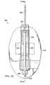
- FIG. 7is a side elevation of another solution cartridge installed in a therapy device
- FIG. 8is perspective view of the solution cartridge of FIG. 7 ;
- FIG. 9Ais a sectional view of the solution cartridge of FIG. 8 taken along line 9 A- 9 A of FIG. 8 ;
- FIG. 9Bis a sectional view of the solution cartridge of FIG. 8 taken along line 9 B- 9 B of FIG. 8 ;
- FIG. 9Cis a sectional view of another example embodiment of the solution cartridge of FIG. 8 taken along line 9 B- 9 B of FIG. 8 ;
- FIG. 9Dis a plan view of a port of the solution cartridge of FIG. 8 ;
- FIG. 10is a side elevation of the therapy device of FIG. 7 having the solution cartridge removed;
- FIG. 11is an exploded view of another example embodiment of a solution cartridge
- FIG. 12 and FIG. 13are sectional views of a portion of a port of the solution cartridge of FIG. 11 having a venting spike disposed therein;
- FIG. 14is a plan view of a cap of the port of FIG. 12 and FIG. 13 ;
- FIG. 15is a side elevation of an example embodiment of a therapy device that may be used with the solution cartridge of FIG. 11 ;
- FIG. 16is an exploded view of another example embodiment of a lid of the solution cartridge of FIG. 11 ;
- FIG. 17is a side elevation of another embodiment of a solution cartridge
- FIG. 18is a rear elevation of the solution cartridge of FIG. 17 ;
- FIG. 19is a sectional view of the solution cartridge of FIG. 18 taken along line 19 - 19 ;
- FIG. 20is a side elevation of a therapy device that may be used with the fluid container of FIG. 17 ;
- FIG. 21is a partial front elevation of the therapy device of FIG. 20 .
- FIG. 1is a simplified functional block diagram illustrating details that may be associated with some embodiments of a therapy system 100 .
- the therapy system 100can provide therapeutic pressure and/or instillation in accordance with this specification.
- the therapy system 100may include a dressing 102 fluidly coupled to a therapy device 104 .
- the dressing 102may include a drape, such as a drape 108 , and a tissue interface, such as a manifold 110 .
- the therapy system 100may also include a fluid container, such as a container 112 , and/or a solution cartridge, such as a cartridge 114 .
- the container 112may be fluidly coupled between the dressing 102 and the therapy device 104 .
- the cartridge 114may be fluidly coupled to the dressing 102 and operationally coupled the therapy device 104 .
- components of the therapy system 100may be coupled directly or indirectly to each other.
- the therapy device 104may be directly coupled to the container 112 and indirectly coupled to the dressing 102 through the container 112 .
- Componentsmay be fluidly coupled to each other to provide a path for transferring fluids (i.e., liquid and/or gas) between the components.
- componentsmay be fluidly coupled with a tube, for example.
- a tubeis an elongated, cylindrical structure with some flexibility, but the geometry and rigidity may vary.
- componentsmay additionally or alternatively be coupled by virtue of physical proximity, being integral to a single structure, or being formed from the same piece of material. Coupling may also include mechanical, thermal, electrical, or chemical union (such as a chemical bond) in some contexts.
- a tissue interfacesuch as the manifold 110
- the manifold 110may be placed against a tissue site
- the drape 108may be placed over the manifold 110 and sealed to tissue proximate to the tissue site. Tissue proximate to a tissue site is often undamaged epidermis peripheral to the tissue site.
- the dressing 102can provide a sealed therapeutic environment proximate to a tissue site, substantially isolated from the external environment, and the therapy device 104 can reduce the pressure in the sealed therapeutic environment. Reduced pressure can be distributed through the tissue interface across the tissue site in the sealed therapeutic environment to induce macrostrain and microstrain, as well as to remove exudates and other fluids from a tissue site, which can be collected in the container 112 and disposed of properly.
- Exudatesmay refer to fluid that filters from the circulatory system into lesions or areas of inflammation.
- Exudatesmay include water and dissolved solutes. Dissolved solutes may include blood, plasma proteins, white blood cells, platelets, and red blood cells.
- exudatesmay include serum, fibrin, and white blood cells.
- exudatesmay include pus having a thin protein-rich fluid and dead leukocytes.
- the fluid mechanics of using a reduced-pressure source to reduce pressure in another component or location, such as within a sealed therapeutic environment,can be mathematically complex.
- the basic principles of fluid mechanics applicable to reduced-pressure therapyare generally well-known to those skilled in the art, and the process of reducing pressure may be described illustratively herein as “delivering,” “distributing,” or “generating” reduced pressure, for example.
- tissue sitein this context broadly refers to a wound or defect located on or within tissue, including but not limited to, bone tissue, adipose tissue, muscle tissue, neural tissue, dermal tissue, vascular tissue, connective tissue, cartilage, tendons, or ligaments.
- a woundmay include chronic, acute, traumatic, subacute, and dehisced wounds, partial-thickness burns, ulcers (such as diabetic, pressure, or venous insufficiency ulcers), flaps, and grafts, for example.
- tissue sitemay also refer to areas of any tissue that are not necessarily wounded or defective, but are instead areas in which it may be desirable to add or promote the growth of additional tissue. For example, reduced pressure may be used in certain tissue areas to grow additional tissue that may be harvested and transplanted to another tissue location.
- Reduced pressuregenerally refers to a pressure less than a local ambient pressure, such as the ambient pressure in a local environment external to a sealed therapeutic environment provided by the dressing 102 .
- the local ambient pressuremay also be the atmospheric pressure at which a patient is located.
- the pressuremay be less than a hydrostatic pressure associated with tissue at the tissue site. Unless otherwise indicated, values of pressure stated herein are gauge pressures.
- references to increases in reduced pressuretypically refer to a decrease in absolute pressure, while decreases in reduced pressure typically refer to an increase in absolute pressure.
- the therapy device 104may include a reduced-pressure source.
- a reduced-pressure sourcemay be a reservoir of air at a reduced pressure, or may be a manual or electrically-powered device that can reduce the pressure in a sealed volume, such as a vacuum pump, a suction pump, a wall suction port available at many healthcare facilities, or a micro-pump, for example.
- a reduced-pressure sourcemay be housed within or used in conjunction with other components, such as sensors, processing units, alarm indicators, memory, databases, software, display devices, or user interfaces that further facilitate reduced-pressure therapy.
- the pressuretypically ranges between ⁇ 5 mm Hg ( ⁇ 667 Pa) and ⁇ 500 mm Hg ( ⁇ 66.7 kPa). Common therapeutic ranges are between ⁇ 75 mm Hg ( ⁇ 9.9 kPa) and ⁇ 300 mm Hg ( ⁇ 39.9 kPa).
- the therapy device 104may also include a fluid source.
- a fluid sourcemay be a reservoir of fluid at an atmospheric or greater pressure, or may be a manual or electrically-powered device, such as a pump, that can convey fluid to a sealed volume, such as a sealed therapeutic environment, for example.
- a fluid sourcemay be a peristaltic pump.
- a peristaltic pumpmay include a circular pump casing having a rotor with one or more rollers.
- a rotormay also be referred to as a pump head, and rollers may also be referred to as shoes, wipers, or lobes, for example.
- the rollersmay be attached around a circumference of the rotor and positioned proximate to a section of tube.
- a peristaltic pumpmay further include a motor coupled to the rotor and configured to rotate the rotor so that the rollers engage the section of tube. As each roller engages the tube it may compress a portion of the tube, occluding the compressed portion of the tube. Rotation of the rotor may move the compressed location of the tube, pushing fluid through the tube ahead of the roller. In addition, as the tube opens after a roller passes, fluid may be drawn into the tube behind the roller. In this manner, fluid may be drawn into and moved through the tube.
- tubes engaged by a roller of a peristaltic pumpmay be formed of silicone.
- a fluid sourcemay be housed within or used in conjunction with other components, such as sensors, processing units, alarm indicators, memory, databases, software, display devices, or user interfaces that further facilitate instillation therapy.
- the amount and nature of the fluid applied to a tissue sitemay vary according to therapeutic requirements, which may include the size of the sealed therapeutic environment, the type of fluid, and any additives to the fluid.
- the fluidmay include: hypochlorite based solutions, such as hypochlorous acid and sodium hypochlorite; silver nitrate; sulfur based solutions, such as sulfonamides; biguanides, such as polyhexanide; cationic solutions, such as octenidine and benzalkonium chloride; and isotonic solutions.
- the therapy device 104may also include a user interface.
- a user interfacemay be a device configured to allow communication between a controller and an environment external to the therapy device 104 .
- an external environmentmay include an operator or a computer system configured to interface with the therapy device 104 , for example.
- a user interfacemay receive a signal from a controller and present the signal in a manner that may be understood by an external environment.
- a user interfacemay receive signals from an external environment and, in response, send signals to a controller.
- a user interfacemay be a graphical user interface, a touchscreen, or one or more motion tracking devices.
- a user interfacemay also include one or more display screens, such as a liquid crystal display (“LCD”), lighting devices, such as light emitting diodes (“LED”) of various colors, and audible indicators, such as a whistle, configured to emit a sound that may be heard by an operator.
- LCDliquid crystal display
- LEDlight emitting diodes
- a user interfacemay further include one or more devices, such as knobs, buttons, keyboards, remotes, touchscreens, ports that may be configured to receive a discrete or continuous signal from another device, or other similar devices; these devices may be configured to permit the external environment to interact with the user interface.
- a user interfacemay permit an external environment to select a therapy to be performed with the therapy device 104 .
- a user interfacemay display information for an external environment such as a duration of the therapy, a type of therapy, an amount of reduced pressure being supplied, an amount of instillation solution being provided, a fluid level of a container, or a fluid level of a cartridge, for example.
- the therapy device 104may also include one or more pressure sensors.
- a pressure sensormay be a piezoresistive strain gauge, a capacitive sensor, an electromagnetic sensor, a piezoelectric sensor, an optical sensor, or a potentiometric sensor, for example.
- a pressure sensorcan measure a strain caused by an applied pressure.
- a pressure sensormay be calibrated by relating a known amount of strain to a known pressure applied. The known relationship may be used to determine an unknown applied pressure based on a measured amount of strain.
- a pressure sensormay include a receptacle configured to receive an applied pressure.
- the therapy device 104may also include one or more valves.
- a valvemay be fluidly coupled between a fluid reservoir and the dressing 102 .
- a valvemay be a device configured to selectively permit fluid flow through the valve.
- a valvemay be a ball valve, a gate valve, a butterfly valve, or other valve type that may be operated to prevent or permit fluid flow through the valve.
- a valvemay include a valve body having a flow passage, a valve member disposed in the flow passage and operable to selectively block the flow passage, and an actuator configured to operate the valve member.
- An actuatormay be configured to position the valve member in a closed position, preventing fluid flow through the flow passage of the valve; an open position, permitting fluid flow through the fluid passage of the valve; or a metering position, permitting fluid flow through the flow passage of the valve at a selected flow rate.
- the actuatormay be a mechanical actuator configured to be operated by an operator.
- the actuatormay be an electromechanical actuator configured to be operated in response to the receipt of a signal input.
- the actuatormay include an electrical motor configured to receive a signal from a controller. In response to the signal, the electrical motor of the actuator may move the valve member of the valve.
- a valvemay be configured to selectively permit fluid communication between the therapy device 104 and the dressing 102 .
- the therapy device 104may also include one or more flow meters.
- a flow metermay be a device configured to measure a fluid flow rate.
- a flow metermay include a mechanical flow meter, a pressure based flow meter, an optical flow meter, an open channel flow meter, a thermal mass flow meter, a vortex flow meter, electromagnetic, ultrasonic and coriolis flow meters, and laser doppler flow meters.
- the flow metermay determine a rate of fluid flow through the valve and transmit a signal to a controller corresponding to the determined flow rate.
- the therapy device 104may also include one or more controllers communicatively coupled to components of the therapy device 104 , such as a valve, a flow meter, a sensor, a user interface, or a pump, for example, to control operation of the same.
- communicative couplingmay refer to a coupling between components that permits the transmission of signals between the components.
- the signalsmay be discrete or continuous signals.
- a discrete signalmay be a signal representing a value at a particular instance in a time period.
- a plurality of discrete signalsmay be used to represent a changing value over a time period.
- a continuous signalmay be a signal that provides a value for each instance in a time period.
- the signalsmay also be analog signals or digital signals.
- An analog signalmay be a continuous signal that includes a time varying feature that represents another time varying quantity.
- a digital signalmay be a signal composed of a sequence of discrete values.
- the communicative coupling between a controller and other devicesmay be one-way communication. In one-way communication, signals may only be sent in one direction. For example, a sensor may generate a signal that may be communicated to a controller, but the controller may not be capable of sending a signal to the sensor.
- the communicative coupling between a controller and another devicemay be two-way communication. In two-way communication, signals may be sent in both directions.
- a controller and a user interfacemay be communicatively coupled so that the controller may send and receive signals from the user interface.
- a user interfacemay send and receive signals from a controller.
- signal transmission between a controller and another devicemay be referred to as the controller operating the device.
- interaction between a controller and a valvemay be referred to as the controller: operating the valve; placing the valve in an open position, a closed position, or a metering position; or opening the valve, closing the valve, or metering the valve.
- a controllermay be a computing device or system, such as a programmable logic controller, or a data processing system, for example.
- a controllermay be configured to receive input from one or more devices, such as a user interface, a sensor, or a flow meter, for example.
- a controllermay receive input, such as an electrical signal, from an alternative source, such as through an electrical port, for example.
- a controllermay be a data processing system.
- a data processing system suitable for storing and/or executing program codemay include at least one processor coupled directly or indirectly to memory elements through a system bus.
- the memory elementscan include local memory employed during actual execution of the program code, bulk storage, and cache memories which provide temporary storage of at least some program code in order to reduce the number of times code is retrieved from bulk storage during execution.
- a controllermay be a programmable logic controller (PLC).
- PLCmay be a digital computer configured to receive one or more inputs and send one or more outputs in response to the one or more inputs.
- a PLCmay include a non-volatile memory configured to store programs or operational instructions.
- the non-volatile memorymay be operationally coupled to a battery-back up so that the non-volatile memory retains the programs or operational instructions if the PLC otherwise loses power.
- a PLCmay be configured to receive discrete signals and continuous signals and produce discrete and continuous signals in response.
- the therapy device 104may also include a power source.
- a power sourcemay be a device that supplies electric power to an electric load.
- a power sourcemay include a battery, a direct current (DC) power supply, an alternating current (AC) power supply, a linear regulated power supply, or a switched-mode power supply, for example.
- a power supplymay supply electric power to a controller, a sensor, a flow meter, a valve, a user interface, or a pump, for example.
- a tissue interfacesuch as the manifold 110
- a tissue interfacemay be partially or fully in contact with a tissue site. If a tissue site is a wound, for example, a tissue interface may partially or completely fill the wound, or may be placed over the wound.
- a tissue interfacemay take many forms, and may have many sizes, shapes, or thicknesses depending on a variety of factors, such as the type of treatment being implemented or the nature and size of a tissue site. For example, the size and shape of a tissue interface may be adapted to the contours of deep and irregular shaped tissue sites.
- a manifoldsuch as the manifold 110
- a manifoldmay include flow channels or pathways providing multiple openings that distribute fluids provided to and removed from a tissue site around the manifold.
- the flow channels or pathwaysmay be interconnected to improve uniformity of distribution of fluids provided to or removed from a tissue site.
- open-cell foam, porous tissue collections, and other porous materialsuch as gauze or felted mat generally include structural elements arranged to form flow channels.
- Liquids, gels, and other foamsmay also include or be cured to include flow channels.
- the manifold 110may be a porous foam pad having interconnected cells adapted to distribute reduced pressure across a tissue site.
- the foammay be either hydrophobic or hydrophilic.
- the manifold 110can be an open-cell, reticulated polyurethane foam, such as GranuFoam® dressing available from Kinetic Concepts, Inc. of San Antonio, Tex.
- the manifold 110may also wick fluid away from a tissue site, while continuing to distribute reduced pressure across the tissue site.
- the wicking properties of the manifold 110may draw fluid away from a tissue site by capillary flow or other wicking mechanisms.
- An example of a hydrophilic foamis a polyvinyl alcohol, open-cell foam such as V.A.C. WhiteFoam® dressing available from Kinetic Concepts, Inc. of San Antonio, Tex.
- Other hydrophilic foamsmay include those made from polyether.
- Other foams that may exhibit hydrophilic characteristicsinclude hydrophobic foams that have been treated or coated to provide hydrophilicity.
- a tissue interfacemay further promote granulation at a tissue site when pressure within the sealed therapeutic environment is reduced.
- any or all of the surfaces of the manifold 110may have an uneven, coarse, or jagged profile that can induce microstrains and stresses at a tissue site if reduced pressure is applied through the manifold 110 .
- a tissue interfacemay be constructed from bioresorbable materials.
- Suitable bioresorbable materialsmay include, without limitation, a polymeric blend of polylactic acid (PLA) and polyglycolic acid (PGA).
- the polymeric blendmay also include, without limitation, polycarbonates, polyfumarates, and capralactones.
- the tissue interfacemay further serve as a scaffold for new cell-growth, or a scaffold material may be used in conjunction with a tissue interface to promote cell-growth.
- a scaffoldis generally a biodegradable or biocompatible substance or structure used to enhance or promote the growth of cells or formation of tissue, such as a three-dimensional porous structure that provides a template for cell growth.
- Illustrative examples of scaffold materialsinclude calcium phosphate, collagen, PLA/PGA, coral hydroxy apatites, carbonates, or processed allograft materials.
- the drape 108is an example of a sealing member.
- a sealing membermay be constructed from a material that can provide a fluid seal between two components or two environments, such as between a therapeutic environment and a local external environment.
- a sealing membermay be, for example, an impermeable or semi-permeable, elastomeric film that can provide a seal adequate to maintain a reduced pressure at a tissue site for a given reduced-pressure source.
- the permeability of gasgenerally should be low enough that a desired reduced pressure may be maintained.
- An attachment devicemay be used to attach a sealing member to an attachment surface, such as undamaged epidermis, a gasket, or another sealing member.
- An attachment devicemay take many forms.
- an attachment devicemay be a medically-acceptable, pressure-sensitive adhesive that extends about a periphery, a portion, or an entire sealing member.
- Other example embodiments of an attachment devicemay include a double-sided tape, paste, hydrocolloid, hydrogel, silicone gel, organogel, or an acrylic adhesive.
- a “container,” such as the container 112broadly includes a canister, pouch, bottle, vial, or other fluid collection apparatus.
- the container 112for example, can be used to manage exudates and other fluids withdrawn from a tissue site.
- the container 112may include substances to manage fluid in the container 112 , such as isolyzers or absorbents, for example.
- a rigid containermay be preferred or required for collecting, storing, and disposing of fluids.
- fluidsmay be properly disposed of without rigid container storage, and a re-usable container could reduce waste and costs associated with reduced-pressure therapy.
- a “cartridge,” such as the cartridge 114is representative of another container, canister, pouch, or other storage component, which can be used to manage fluids, such as instillation solution, that can be supplied to the tissue site.
- a rigid containermay be preferred or required for delivering, storing, and supplying of the instillation solution.
- instillation solutionmay be provided in a non-rigid container.
- a re-usable containercould reduce waste and costs associated with instillation.
- reduced-pressure therapycan be beneficial for wounds of all severity, but the cost and complexity of reduced-pressure therapy systems often limit the application of reduced-pressure therapy to large, highly-exudating wounds present on patients undergoing acute or chronic care, as well as other severe wounds that are not readily susceptible to healing without application of reduced pressure.
- Instillation of a fluid to a woundmay further aid in healing of a wound. Instillation may include the slow introduction of a solution to the wound, for example. The solution may be used to provide moisture to the wound, to provide warmth or cold to the wound, to provide a drug to the wound, or to provide another substance to the wound.
- each type of instillation therapymay require a different type of instillation fluid to achieve a desired effect.
- a first type of fluidmay provide moisture to the wound.
- a different type of fluidmay supply a drug to the wound.
- the need for different fluid types to treat the woundmay make instillation therapy time consuming to administer.
- Some patientsmay experience improved outcomes with a combined treatment that includes using both reduced-pressure therapy and instillation therapy.
- Existing therapy systems that provide instillation or irrigation of a tissue site as well as reduced-pressure therapycan be complicated to use and setup. Multiple tubes, clamps, and interfaces may often be needed to properly apply both reduced pressure and fluid to the tissue site.
- components for both systemsmay be placed proximate to a patient.
- the reduced-pressure therapy portionmay need at least one tube set extending from the tissue site to the therapy system.
- floor space near the patientmay be taken up by a separate collection container that may also require a separate tube set extending between the tissue site and/or the therapy device.
- the instillation therapy systemmay need at least one intravenous pole to be placed near the patient. Another intravenous pole may be needed to support additional therapy devices. At least one, and often multiple, intravenous bags may be hung from the intravenous pole. Each bag hung from the intravenous pole may contain a different type of instillation fluid to apply a particular type of instillation fluid to the tissue site to achieve a desired effect. Each bag may need a separate tube set leading from the bag to the therapy device and from the therapy device to the tissue site. Each bag may also need clamps and valves for each tube set. As multiple bags, tube sets, clamps, and valves are added to the therapy system, the complexity increases. The increased complexity increases set up time for a caregiver and increases the likelihood that the caregiver administering therapy may incorrectly administer therapy.
- the therapy system 100can overcome these shortcomings and others by providing a combined solution pump and solution storage system.
- the therapy device 104may place all components pertinent to the volumetric delivery of fluid into a single disposable assembly.
- the disposable assemblymay interface with the therapy device 104 automatically if the disposable assembly engages the therapy device 104 .
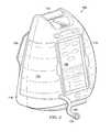
- FIG. 2is a perspective view of the therapy device 104 illustrating details that may be associated with some embodiments.
- the therapy device 104may have a base member, such as a body 116 , a user interface panel, such as a panel 118 , and a pole support, such as a support 120 .
- the body 116may be a housing, container, or other member configured to enclose components of the therapy device 104 .
- the body 116may have an interior space into which pumps, tube, valves, electronics, controllers, regulators, metering devices, or sensors, for example, may be contained.
- the devicesmay be similar to and operate as described above to provide reduced-pressure therapy and/or instillation therapy.
- the body 116may also include a handle 115 .
- the handle 115may be a portion of the body 116 configured to permit a caregiver to grip and carry the therapy device 104 .
- the therapy device 104may include the cartridge 114 and the container 112 . Both the container 112 and the cartridge 114 may insert into the therapy device 104 . In some embodiments, the container 112 and the cartridge 114 may placed into a front portion of the therapy device 104 . As shown in FIG. 2 , the therapy device 104 may include a tube 107 and a coupling 123 . The tube 107 may protrude from a front of the therapy device 104 proximate to the cartridge 114 . The coupling 123 may be fluidly coupled to the tube 107 .
- FIG. 3is a side view of the therapy device 104 illustrating additional details that may be associated with some embodiments.
- the support 120may be a device configured for mounting of the therapy device 104 to a support, intravenous pole, or other device. In some embodiments, the support 120 may be configured to mount to an intravenous pole, such as a pole 119 , for example.
- the support 120may include a clamping device 121 .
- the clamping device 121may be a threaded bolt having a handle. The bolt may be screwed into the support 120 so that an end of the threaded bolt of the clamping device 121 may be pressed against the pole 119 .
- the clamping device 121may compress the pole 119 against the support 120 , preventing the support 120 , and the therapy device 104 , from moving relative to the pole 119 .
- the support 120may include other devices to secure the therapy device 104 to the pole 119 , such as latching mechanisms, tying mechanisms, or fusing mechanisms, for example.
- FIG. 4is a perspective view of the therapy device 104 illustrating additional details that may be associated with some embodiments.
- the therapy device 104may include a cartridge receptacle 122 .
- the cartridge receptacle 122may be a cavity or other recessed portion of the therapy device 104 .
- the cartridge receptacle 122may be extend into the body 116 from a front of the body 116 .
- the cartridge receptacle 122may have at least a bottom surface 127 , a rear surface 131 , and a side surface 133 .
- the bottom surface 127 , the rear surface 131 , and the side surface 133are perpendicular to each other.
- the cartridge receptacle 122may be configured to receive the cartridge 114 .
- the cartridge receptacle 122may have a size and shape so that the cartridge 114 may at least partially fit within the cartridge receptacle 122 .
- the cartridge 114 and the cartridge receptacle 122may be sized so that if the cartridge 114 is inserted into the cartridge receptacle 122 , an exterior surface of the cartridge 114 may be flush with an exterior of the therapy device 104 as shown in FIG. 2 and FIG. 3 .
- a key 124may be positioned within the cartridge receptacle 122 on the side surface 133 .
- the key 124may be disposed near a center of a height of the side surface 133 .
- the key 124may have a length equal to the length of the side surface 133 so that the key 124 extends from the front of the therapy device 104 to the rear surface 131 .
- the key 124may protrude from the side surface 133 of the cartridge receptacle 122 .
- the key 124may also include an opening 126 .
- the opening 126may be configured to receive a mating component of the cartridge 114 , such as a latch, for example.
- the mating componentmay be a tube component, a venting component, a sensing component, or a pump component, for example.
- a pump head 128may be positioned within the cartridge receptacle 122 .
- the pump head 128may be positioned on the side surface 133 between the bottom surface 127 and the key 124 .
- the pump head 128may be rotary-delivery pump head having a rotor with one or more rollers 129 .
- the rollers 129may be configured to engage a tube segment to move fluid through the tube segment using peristalsis.
- the pump head 128may be coupled to operating components disposed within the body 116 of the therapy device 104 .
- the operating componentsmay include motors, linking devices, or power sources, for example.
- the pump head 128 and the associated operating componentsmay be disposed within the body 116 of the therapy device 104 and may be operatively or communicatively coupled to the panel 118 .
- the panel 118may be manipulated by a caregiver to activate the pump head 128 , causing the pump head 128 to rotate in a plane parallel to the side surface 133 . As described above, rotation of the pump head 128 may move instillation solution from the cartridge 114 to the tissue site.
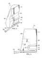
- FIG. 5is a perspective view of the cartridge 114 illustrating additional details that may be associated with some embodiments.
- FIG. 6is a side elevation of the cartridge 114 in FIG. 5 .
- the cartridge 114may include a keyway 113 .
- the keyway 113may be a recessed portion of the cartridge 114 .
- the keyway 113may be a slot or channel having a shape configured to receive the key 124 of the cartridge receptacle 122 .
- the keyway 113may have a pentagonal shape to match the key 124 .
- the keyway 113may extend from a front 109 of the cartridge 114 to a back 111 of the cartridge 114 .
- the cartridge 114may also include a tube housing 117 .
- the tube housing 117may be a recessed portion of the cartridge 114 extending from the back 111 of the cartridge 114 toward the front 109 of the cartridge 111 .
- the tube housing 117may be a generally rectangularly-shaped recess having a rounded end proximate to the front 109 of the cartridge 114 .
- the rounded end of the tube housing 117may be shaped to accommodate the tube 107 .
- the tube 107may have an end 105 fluidly coupled to an interior of the cartridge 114 .
- the tube 107may also have an elbow 103 .
- the elbow 103may be a U-shaped elbow.
- the tube housing 117may be sized to receive the pump head 128 . If the cartridge 114 is inserted into the cartridge receptacle 122 , the pump head 128 may engage the tube 107 and be operable to compress the tube 107 against the tube housing 117 for peristaltic movement of fluid through the tube 107 .
- the cartridge 114may also include a tube channel 134 .
- the tube channel 134may be another recessed portion of the cartridge 114 that may be positioned between the tube housing 117 and a bottom of the cartridge 114 .
- the tube channel 134may extend from the front 109 of the cartridge 114 to the back 111 of the cartridge 114 .
- the tube channel 134may be configured to accommodate at least a portion of a tube, such as the tube 107 .
- the elbow 103may turn the tube 107 so that the tube 107 can be routed from the tube housing 117 to the tube channel 134 and protrude from the front 109 of the cartridge 114 .
- the tube 107may be fluidly coupled to a union, such as the coupling 123 , for example.
- the coupling 123may be a device configured to fluidly couple the tube 107 to the tissue site.
- the coupling 123may be configured to be fluidly coupled to a tube that is fluidly coupled to the tissue site.
- the cartridge 114may be inserted into the therapy device 104 . If the cartridge 114 is inserted into the cartridge receptacle 122 , the key 124 and the keyway 113 may be aligned so that the key 124 may insert into the keyway 113 . Alignment of the key 124 and the keyway 113 may align the tube housing 117 and the pump head 128 . The pump head 128 may engage the tube 107 if the cartridge 114 is fully seated in the cartridge receptacle 122 of the therapy device 104 . Operation of the pump head 128 may move fluid through the tube 107 from an interior of the cartridge 114 through the coupling 123 .
- FIG. 7is an elevation view of a cartridge 214 illustrating details that may be associated with some embodiments.
- the cartridge 214may be configured to engage a therapy device, for example a therapy device 204 .
- the therapy device 204may be similar to and include the components of the therapy device 104 .
- the therapy, device 204may be configured to receive the cartridge 214 .
- the therapy device 204may include a ledge 232 configured to support the cartridge 214 and one or more retainers 234 configured to limit lateral motion of the cartridge 214 .
- the cartridge 214may include a fluid container 215 and a carrier 216 . Generally, the fluid container 215 may interface with the carrier 216 .
- the carrier 216may interface with the therapy device 204 to secure the fluid container 215 to the therapy device 204 to provide instillation therapy.
- the carrier 216may be an integral component of the therapy device 204 . In other embodiments, the carrier 216 may be an independent component of the therapy device 204 .
- FIG. 8is a perspective view of the cartridge 214 illustrating additional details that may be associated with some embodiments.
- the fluid container 215may be a container configured to receive and store a fluid, such as an instillation fluid.
- the fluid container 215may be a refillable bottle or other device.
- the fluid container 215may be a pre-manufactured fluid container configured to engage the carrier 216 .
- the fluid container 215may have an open end and a closed end (not shown) opposite the open end.
- the open end of the fluid container 215may be configured to receive a cap, coupling, or other similar device.
- the fluid container 215may have a port 218 coupled to the open end of the fluid container 215 .
- the port 218may be a device coupled to the open end of the fluid container 215 and configured to be selectively opened.
- the port 218may include a seal, such as a seal 217 .
- the seal 217may be a device configured to seal the fluid container 215 to another device or component.
- the seal 217may be formed of a material, such as a rubber or other material configured to prevent fluid flow across the seal 217 .
- the seal 217may be an O-ring.
- the seal 217may be separated from an end of the port 218 . In other embodiments, the seal 217 may be proximate to an end of the port 218 .
- the carrier 216may include a base housing 220 and a tube housing 226 .
- the base housing 220may be a rectangular body having a receptacle 222 and a venting spike 224 disposed in the receptacle 222 .
- the receptacle 222may be a recess disposed in a center of the base housing 220 that extends from a top of the base housing 220 toward a bottom of the base housing 220 .
- the receptacle 222is cylindrical. In other embodiments, the receptacle 222 may have other sizes and shapes.
- the receptacle 222may have a size, shape, and depth configured to mate with the port 218 so that the port 218 fits within the receptacle 222 .
- the seal 217may be configured to seal to the receptacle 222 if the port 218 is disposed in the receptacle 222 .
- the receptacle 222may have a size, shape, and depth such that non-specific ports of other fluid containers may be inserted into the receptacle 222 to engage with the base housing 220 of the carrier 216 .
- the tube housing 226may couple to the base housing 220 .
- the tube housing 226may be a C-channel shaped piece coupled to a side of the base housing 220 .
- the tube housing 226may form a wall perpendicular to the base housing 220 that extends upward beyond the surface of the base housing 220 in which the receptacle 222 is formed.
- An inner portion of the tube housing 226may face away from the base housing 220 .
- An upper end of the tube housing 226may form an archway 211 between two sidewalls 213 of the channel-shaped piece. The inner portion may be disposed between the archway 211 and the two sidewalls 213 of the channel-shaped piece.
- the tube housing 226may have an open end opposite the archway 211 .
- the inner portion of the tube housing 226may be configured to receive a tube 228 .
- the tube 228may have a first end and a second end opposite the first end. The ends of the tube 228 may be proximate to the open end of the tube housing 226 .
- the tube 228may conform to the archway 211 of the tube housing 226 .
- the tube 228may be in contact with the two sidewalls 213 and the archway 211 of the tube housing 226 along a length of the tube 228 .
- the tube 228may be coupled to the base housing 220 via elbow couplings 230 .
- the elbow couplings 230may be in fluid communication with the receptacle 222 or venting spike 224 and the tissue site.
- FIG. 9Ais a sectional view of the carrier 216 illustrating additional details that may be associated with some embodiments.
- an elbow 227may be fluidly coupled to the elbow coupling 230 and the tube 228 .
- the elbow 227may provide a fluid coupling for another tube (not shown) that may be fluidly coupled to the tissue site. Fluid flowing from the fluid container 215 into the tube 228 in response to operation of the therapy device 204 may flow through the elbow coupling 230 , the elbow 227 , and to the tissue site.
- FIG. 9Bis another sectional view of the carrier 216 illustrating additional details that may be associated with some embodiments.
- FIG. 9Bmay be a reverse sectional view of the carrier 216 of FIG. 9A .
- the base housing 220may include a coupling cavity 229 extending into the base housing 220 from a surface opposite the receptacle 222 .
- the coupling cavity 229may have a major dimension, such as a diameter, that is greater than a major dimension of the receptacle 222 .
- the receptacle 222 and the coupling cavity 229may be coaxial.
- the venting spike 224may be disposed within the receptacle 222 .
- the venting spike 224may extend outwardly from an inner surface of the receptacle 222 .
- the venting spike 224may have a wider portion where the venting spike 224 joins a surface of the receptacle 222 and tapers to a narrower portion at a distal end of the venting spike 224 .
- the venting spike 224may be configured to penetrate the port 218 if the port 218 of the fluid container 215 is inserted into the receptacle 222 .
- the venting spike 224may breach the port 218 .
- the venting spike 224may have a conduit 223 .
- the conduit 223may be in fluid communication with the coupling cavity 229 .
- the receptacle 222may have a fluid passage 231 in fluid communication with an elbow 233 .
- the elbow 233may be fluidly coupled to the coupling 230 so that the elbow 233 is in fluid communication with the tube 228 .
- the port 218may be fitted into the receptacle 222 so that the venting spike 224 breaches into the port 218 , and the conduit 223 may permit the flow of ambient air pressure into the fluid container 215 .
- the venting spike 224may form fluid paths in the port 218 adjacent to the venting spike 224 .
- Fluidmay flow from the fluid container 215 through the port 218 into the receptacle 222 around the venting spike 224 .
- the fluidmay flow through the fluid passage 231 into the elbow 233 and the tube 228 in response to operation of the therapy device 204 .
- Ambient air pressuremay flow through the conduit 223 into the fluid container 215 to prevent formation of a vacuum in the fluid container 215 during operation of the therapy device 204 .
- FIG. 9Cis a sectional view of the carrier 216 illustrating additional details that may be associated with other embodiments.
- the conduit 223 of the venting spike 224may be fluidly coupled to an elbow 225 .
- the elbow 225may be fluidly coupled to the elbow coupling 230 so that the elbow 225 may be in fluid communication with the tube 228 .
- Operation of the therapy device 204may move fluid from the fluid container 215 through the conduit 223 of the venting spike 224 , through the elbow 225 and the elbow coupling 230 and into the tube 228 .
- the venting spike 224may include multiple lumens to allow for both venting of the fluid container 215 and flow of the solution in the fluid container 215 into the therapy device 204 .
- FIG. 9Dis a plan view of the port 218 illustrating additional details that may be associated with some embodiments.
- the port 218may include a channel 219 .
- the channel 219may be an area of the port 218 configured to be breached by the venting spike 224 .
- the channel 219may include tear lines 221 .
- the tear lines 221may be portions of the port 218 configured to open for flow of fluid if the venting spike 224 punctures the channel 219 .
- the tear lines 221may be perforations in the port 218 .
- FIG. 10is a side elevation view of the therapy device 204 illustrating additional details that may be associated with some embodiments.
- the cartridge 214has been removed from the therapy device 204 .
- the therapy device 204may include a cartridge receptacle and a pump head.
- the cartridge receptaclemay be formed by a ledge 232 and retainers 234 .
- the ledge 232may be a portion of the therapy device 204 extending away from the therapy device 204 .
- the ledge 232may provide a location onto which at least a portion of the cartridge 214 may be rested while the cartridge 214 is engaged with the therapy device 204 .
- the retainers 234may be elongated portions of the therapy device 204 that protrude from opposite sides of the therapy device 204 .
- the retainers 234may limit lateral motion of the cartridge 214 if the cartridge 214 is engaged with the therapy device 204 .
- the pump head 236may be a rotary-delivery pump head similar to the pump head 128 described above.
- the pump head 236may include rollers or lobes 238 that may be configured to engage the tube 228 if the cartridge 214 is engaged with the therapy device 204 .
- the pump head 236may be positioned relative to the ledge 232 so that if the cartridge 214 is engaged with the therapy device 204 , the pump head 236 and the lobes 238 engage the tube 228 . In operation, the pump head 236 may be rotated, causing fluid to flow from the venting spike 224 or the receptacle 222 through the tube 228 and to the tissue site.
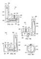
- FIG. 11is an exploded view of a cartridge 314 illustrating details that may be associated with some embodiments.
- the cartridge 314may include a body 316 and a lid 318 .
- the body 316may be a rigid member having a rectangular shape as shown. In other embodiments, the body 316 may not be rigid and may have other shapes, such as triangular, circular, or amorphous shapes.
- the body 316may have a back 317 and walls 319 .
- the body 316may have a fluid reservoir 320 formed by the back 317 and the walls 319 .
- the lid 318may enclose the fluid reservoir 320 .
- the fluid reservoir 320may be configured to receive and store instillation solution or other fluid for use with a therapy device, such as the therapy device 104 or the therapy device 204 .
- the body 316may include a port 322 in one of the walls 319 of the body 316 .
- the port 322may be a tubular body that mounts to one of the walls 319 .
- the port 322may have a central channel 323 that extends through the wall 319 so that the channel 323 is in fluid communication with the fluid reservoir 320 .
- a cap mount 324may be coupled to the port 322 .
- the cap mount 324may be a rim coupled to the port 322 to provide a mounting surface for a cap 326 .
- the cap 326may be coupled to the cap mount 324 to prevent fluid communication through the port 322 .
- the cap 326may be coupled to the cap mount 324 following the filling of the fluid reservoir 320 .
- the cap 326may be threaded, secured with adhesive, or otherwise latched to the cap mount 324 .
- the cap 326may be a heat seal.
- a heat sealmay be a cap welded to the cap mount 324 following filling of the fluid reservoir 320 .
- the port 322 , the cap mount 324 , and the cap 326may allow a manufacturer or pharmacist to fill the fluid reservoir 320 and then seal the fluid reservoir 320 for transport.
- the lid 318may be configured to mount and seal to the body 316 to form the fluid reservoir 320 .
- the lid 318may include a port 328 .
- the port 328may be a tubular body extending into the fluid reservoir 320 if the lid 318 is mounted to the body 316 .
- the port 328may include a channel 329 in fluid communication with the fluid reservoir 320 .
- a vent cap 330may be coupled to the port 328 .
- a therapy devicesuch as the therapy device 104 or the therapy device 204 , may include a venting spike 332 .
- the vent cap 330may block fluid flow through the port 328 until the cartridge 314 is engaged with a therapy device.
- the lid 318may also include a latch 336 .
- the latch 336may be disposed on the lid 318 so that the latch 336 is on an opposite side of the lid 318 from the fluid reservoir 320 .
- the latch 336may be configured to mate with a corresponding component on a therapy device, such as the key 124 of the therapy device 104 , for example. If the latch 336 mates with the corresponding component of a therapy device, the latch 336 secures the cartridge 314 to the therapy device. In this manner, the cartridge 314 may be securely positioned on a therapy device while the therapy device instills an instillation solution or fluid from the fluid reservoir 320 to a tissue site.
- a tube assembly 338may be coupled to the lid 318 .
- the tube assembly 338may include a first mount 340 , a second mount 342 , and a tube 344 .
- the first mount 340may be coupled to the lid 318 and include one or more channels providing a fluid path through the lid 318 . If the lid 318 is mounted to the body 316 , the channels may be in fluid communication with the fluid reservoir 320 .
- a first barb 348may be coupled to the first mount 340 .
- the first barb 348may be a tubular body having a channel in fluid communication with the channels of the first mount 340 .
- the tube 344may be a flexible tube having at least one lumen.
- the first barb 348may be configured to be inserted into a first end of the tube 344 so that the tube 344 may be fluidly coupled to the first mount 340 .
- a retaining collar 346may be mounted on the tube 344 .
- the retaining collar 346may be placed over the portion of the tube 344 into which the first barb 348 was inserted. If the first barb 348 is inserted into the first end of the tube 344 , the first end of the tube 344 may be expanded to accommodate the first barb 348 .
- the retaining collar 346may exert a frictional force on the tube 344 clamping the tube 344 to the first barb 348 .
- the second mount 342may be coupled to the lid 318 and include one or more channels providing a fluid path through the lid 318 . If the lid 318 is mounted to the body 316 , the channels may be in fluid communication with the fluid reservoir 320 .
- a second barb 350may be coupled to the second mount 342 .
- the second barb 350may be a tubular body having a channel in fluid communication with the channels of the second mount 342 .
- the second barb 350may be configured to be inserted into a second end of the tube 344 so that the tube 344 may be fluidly coupled to the second mount 342 .
- a retaining collar 347may be mounted on the tube 344 . The retaining collar 347 may be placed over the portion of the tube 344 into which the second barb 350 was inserted.
- the second end of the tube 344may be expanded to accommodate the second barb 350 .
- the retaining collar 347may exert a frictional force on the tube 344 clamping the tube 344 to the second barb 350 .
- the tube 344may arc between the first mount 340 and the second mount 342 so that a pump head, such as the pump head 128 of the therapy device 104 , may be disposed under the tube 344 to engage the tube 344 . If actuated by a therapy device, the pump head 128 may engage in peristalsis as described above to move fluid from the fluid reservoir 320 through the first mount 340 , the tube 344 , and the second mount 342 for fluid communication with a tissue site.
- a pump headsuch as the pump head 128 of the therapy device 104
- the second mount 342may also include a valve connector 352 .
- the valve connector 352may be in fluid communication with the second mount 342 and the tube 344 through the second barb 350 .
- the valve connector 352may be configured to receive a tube that is in fluid communication with the tissue site.
- the valve connector 352may include a valve member that is positionable to selectively block fluid flow through the valve connector 352 .
- the valve connector 352may be a check valve configured to permit fluid flow out of the second mount 342 and block fluid flow through the valve connector 352 into the second mount 342 .
- the second mount 342may also include a pressure diaphragm 354 coupled to an outward facing portion of the second mount 342 .
- the pressure diaphragm 354may be a device configured to engage a corresponding sensor on a therapy device.
- the pressure diaphragm 354may communicate a pressure in the second mount 342 to a therapy device.
- a therapy devicemay receive a pressure signal from the pressure diaphragm 354 and, in response, adjust therapy.
- FIG. 12is a sectional view of the venting spike 332 and the port 328 illustrating additional details that may be associated with some embodiments.
- the venting spike 332may have a conical portion 333 and a base portion 335 .
- the conical portion 333may have a central channel 337 extending through the conical portion 333 .
- the conical portion 333may be coupled to the base portion 335 .
- the conical portion 333may have a wider portion adjacent to the base portion 335 .
- the conical portion 333may taper from the base portion 335 to a distal end.
- the conical portion 333may be configured to penetrate the vent cap 330 if the vent cap 330 of the lid 318 is placed proximate to the venting spike 332 , for example, if the cartridge 314 is engaged with a therapy device.
- the base portion 335may be a generally tubular body having a central channel having a filter 334 disposed within the channel.
- the filter 334 and the central channel 337may be in fluid communication so that fluid may flow through the venting spike 332 .
- the base portion 335may include a first flange 339 and a second flange 341 .
- the first flange 339may be conical and extend away from the venting spike 332 .
- the first flange 339may be coupled to the venting spike 332 adjacent to a base of the conical portion 333 .
- the second flange 341may be coupled to a center of the base portion 335 .
- the second flange 341may have a conical surface proximate to the first flange 339 and a planar surface opposite the first flange 339 .
- the port 328may include one or more detents.
- the port 328may include a first detent 343 , and a second detent 345 .
- the first detent 343may be an annular member disposed on an interior surface of the port 328 proximate to the vent cap 330 .
- the second detent 345may also be an annular member disposed on the interior surface of the port 328 between the first detent 343 and an end of the port 328 opposite the vent cap 330 .
- FIG. 13is a sectional view of the port 328 and the venting spike 332 illustrating additional details that may be associated with some embodiments.
- the first flange 339 and the second flange 341may be configured to engage with the first detent 343 and the second detent 345 if the venting spike 332 is inserted into the port 328 .
- the conical portion 333may pierce the vent cap 330 , allowing fluid communication across the vent cap 330 through the venting spike 332 .
- the venting spike 332may serve as a pathway for flow of ambient air pressure into the fluid reservoir 320 to prevent formation of a vacuum in the fluid reservoir 320 during operation of the therapy device.
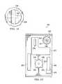
- FIG. 14is a plan view of the vent cap 330 illustrating additional details that may be associated with some embodiments.
- the vent cap 330may include a channel 331 .
- the channel 331may form a cross extending parallel to respective diameters of the vent cap 330 .
- the channel 331may be aligned with the venting spike 332 if the venting spike 332 is disposed within the port 328 .
- the channel 331may be a portion of the vent cap 330 that is more susceptible to penetration than remaining portions of the vent cap 330 .
- the channel 331may be a portion of the vent cap 330 having a thickness that is less than a thickness of the remainder of the vent cap 330 .
- the channel 331may be a portion of the vent cap 330 that has been treated to make the channel 331 more susceptible to penetration compared to the remaining portions of the vent cap 330 .
- FIG. 15is a side elevation view of a therapy device 304 illustrating additional details that may be associated with some embodiments.
- the venting spike 332may be coupled to the therapy device 304 .
- the venting spike 332may be positioned on the therapy device 304 so that if the cartridge 314 is engaged with the therapy device 304 , the venting spike 332 may engage the port 328 .
- the therapy device 304may also include a striker 370 .
- the therapy device 304may also include a recessed portion 372 surrounding the striker 370 .
- the recessed portion 372may be configured to receive at least a portion of the latch 336 , so that the latch 336 and the striker 370 may engage one another if the cartridge 314 is engaged with the therapy device 304 .
- the therapy device 304may also include a pump head 374 having one or more lobes 376 .
- the pump head 374may be similar to and operate as described above with respect to the pump head 128 , and the pump head 236 .
- the lobes 376may be similar to and operate as described above with respect to the rollers 129 and the lobes 238 .
- the pump head 374may be positioned on the therapy device 304 so that the pump head 374 may engage the tube 344 if the cartridge 314 is engaged to the therapy device 304 .
- the therapy device 304may also include a pressure sensor 378 .
- the pressure sensor 378may be a sensor configured to engage the pressure diaphragm 354 to determine a pressure in the second mount 342 .
- the therapy device 304may include a sensor 380 and a sensor 382 .
- the sensor 380 and the sensor 382may be positioned on the therapy device 304 to communicate with optional sensors that may be included on the cartridge 314 .
- FIG. 16is an exploded view of a lid 418 illustrating details that may be associated with some embodiments of the cartridge 314 of FIG. 11 .
- the lid 418is similar to the lid 318 and may include the components thereof, modified as described below.
- the lid 418may include a port 428 similar to the port 328 .
- the port 428may operate in a manner similar to the port 328 .
- the port 428may be configured to receive the venting spike 332 as described above.
- the lid 418may also have a tube assembly 438 .
- the tube assembly 438may include a tube 450 and a plurality of couplings 440 .
- the tube 450may have a first end configured to pass through an aperture 452 formed in the lid 418 .
- the aperture 452may be positioned on an end of the lid 418 proximate to the port 428 .
- the aperture 452may be disposed in a recessed portion of the end of the lid 418 .
- the aperture 452may be sized to accommodate the tube 450 while providing a seal to the tube 450 .
- the tube 450may be in fluid communication with the fluid reservoir 320 through the aperture 452 in the lid 418 .
- the tube 450may include a segment (not shown) that extends from the aperture 452 to an end of the lid 418 that is opposite the aperture 452 so that an end of the tube 450 may be located proximate to a bottom of the fluid reservoir 320 .
- the tube 450may be have a lining of polyethylene. Lining the tube 450 with polyethylene may reduce reactions with fluid stored in the fluid reservoir 320 . In some embodiments, additional tubes may be lined with polyethylene.
- the tube assembly 438may also include a tube 444 , an ultra-sonic inspection segment 446 , a load cell segment 448 , and a tube 454 .
- the tube 450is fluidly coupled to the load cell segment 448 with a coupling 440 so that fluid in the tube 450 may flow into the load cell segment 448 .
- a load cellsuch as the load cell segment 448 , may be a transducer that converts a force into an electrical signal.
- a force applied through a load cellmay deform a strain gauge, changing the electrical resistance of the strain gauge which may be interpreted by a controller or other device as an amount of force applied.
- the load cell segment 448may be configured to communicate with a corresponding sensor on a therapy device.
- the load cell segment 448may communicate with the sensor 380 or the sensor 382 of the therapy device 304 .
- the load cell segment 448may be configured to communicate with the sensor 380 if the cartridge 314 , having the lid 418 , is engaged with the therapy device 304 . If fluid flows through the load cell segment 448 , the fluid may exert a force on the load cell segment 448 that may generate a corresponding signal in the sensor 380 . In this manner, the therapy device 304 may determine if there is fluid in the fluid reservoir 320 .
- the load cell segment 448may also detect occlusion situations (blockages).
- the load cell segment 448may be fluidly coupled to the tube 444 through another coupling 440 .
- the coupling 440may be an elbow coupling, such as the coupling 440 between the load cell segment 448 and the tube 444 .
- the tube 444may be fluidly coupled to the ultra-sonic inspection segment 446 with yet another coupling 440 .
- the tube 444may be positioned to form an arc so that the tube 444 may receive a pump head, such as the pump head 374 of the therapy device 304 . If actuated by a therapy device 304 , the pump head 374 may engage in peristalsis to move fluid from the fluid reservoir 320 through the tube 444 for fluid communication with a tissue site as described above.
- the ultra-sonic inspection segment 446may be a device configured to use ultrasound to monitor the fluid reservoir 320 .
- the ultra-sonic inspection segment 446may be configured to communicate with a therapy device, such as the therapy device 304 .
- a therapy devicesuch as the therapy device 304 .
- the ultra-sonic inspection segment 446may be in communication with the sensor 382 .
- the ultra-sonic inspection segment 446may also detect occlusion situations (blockages).
- the ultra-sonic inspection segment 446may be fluidly coupled to another tube 454 with another coupling 440 .
- the tube 454may have a coupling on an end of the tube 454 opposite the ultra-sonic inspection segment 446 . In this manner, the tube 454 may be used to fluidly couple the cartridge 314 having the lid 418 to a dressing and a tissue site.
- the lid 418includes a recess 456 molded into the lid 418 .
- the recess 456may be shaped to accommodate the connection of the tube assembly 438 so that the tube assembly 438 is flush with, or at least partially recessed from an exterior surface of the lid 418 .
- a portion of recess 456may be sized to receive a pump head, such as the pump head 374 of the therapy device 304 so that the exterior surface of the lid 418 is flush with the therapy device if the cartridge 314 is engaged with the therapy device 304 .
- FIG. 17is an elevation of another example embodiment of a cartridge 514 that may be used with a therapy device, such as the therapy device 104 , the therapy device 204 , or the therapy device 304 , modified as described below.
- the cartridge 514may be similar in many respects to the cartridge 114 , the cartridge 214 , and the cartridge 314 .
- the cartridge 514may include a shell 516 .
- the shell 516is at least partially ovoid-shaped having a rounded end and a flattened end opposite the rounded end.
- the rounded endis a lower end configured to engage a portion of a therapy device to at least partially secure the cartridge 514 to the therapy device.
- the shell 516also may include notches 521 .
- the notches 521may be molded recesses formed in a portion of the shell 516 proximate to the flattened end.
- the notches 521may provide a handle portion configured to allow a person to grip the cartridge 514 for engagement and disengagement with a therapy device.
- the shell 516may include an aperture 517 through the flattened end of the shell 516 .
- the aperture 517can provide fluid communication between an exterior of the cartridge 514 and an interior of the cartridge 514 .
- the cartridge 514may also include a port 522 .
- a filtermay be disposed in the port 522 to prevent bacteria, viruses, and other undesirable materials from entering the cartridge 514 .
- the cartridge 514also has a tube assembly 538 , which may be similar to the tube assembly 338 or the tube assembly 438 .
- the tube assembly 538may include suitable connectors, such as an elbow 540 , and a tube 544 .
- the tube assembly 538may be fluidly coupled to a conduit 508 , which may be adapted for coupling to a dressing.
- the tube 544may extend across a raceway 546 .
- the tube assembly 538is configured to engage a pump head of a therapy device, so that the pump head may cause instillation solution disposed within the cartridge 514 to flow through the tube assembly 538 and the conduit 508 to a tissue site as described above.
- FIG. 18is an elevation of a second side of the cartridge 514 illustrating additional details that may be associated with some embodiments.
- the raceway 546may be a cavity in the shell 516 adapted to receive a circumferential edge of a rotary-delivery pump head (not shown). In some embodiments, the raceway 546 may be a portion of amount 545 .
- the mount 545may be a device coupled to the shell 516 and configured to position the tube assembly 538 to receive a pump head.
- the mount 545may also include a latch 506 .
- the latch 506may be positioned adjacent to the flattened end of the shell 516 .
- the latch 506may be configured to engage a portion of a therapy device to secure the cartridge 514 to the therapy device.
- FIG. 19is a cross-sectional view of the cartridge 514 illustrating additional details that may be associated with some embodiments.
- the shell 516may form a fluid reservoir 520 , similar to the fluid reservoir of the cartridge 114 , the fluid container 215 , and the fluid reservoir 320 .
- the shell 516may include mounting locations 523 configured to receive fasteners 527 to secure the shell 516 to the mount 545 .
- the fasteners 527may seal to the shell 516 to prevent leakage of fluid through the mounting locations 523 .
- the cartridge 514may be positioned to engage with and interact with a pump head.
- the raceway 546may be a semicircular cavity, and tube 544 may be suspended across the cavity.
- the raceway 546may be a cavity with an arc of about 180 degrees.
- the tube 544 and the raceway 546may be aligned with and disposed on a circumferential edge of a rotary-delivery pump head.
- the tube 544is disposed between raceway 546 and the edge of a pump head.
- the tube 544may be stretched and pressed into and against raceway 546 by a pump head.
- the latch 506may be a spring loaded mechanism configured to engage a mating component of a therapy device.
- the latch 506may include buttoning mechanisms, threaded mechanisms, clip mechanisms, or friction engagement mechanisms, for example.
- the latch 506may be disposed on the cartridge 514 and engage a mating element, such as a notch, clip, or threaded coupler, for example, on a therapy device.
- FIG. 20is a side elevation of a therapy device 504 illustrating details that may be associated with some embodiments.
- FIG. 21is a partial front elevation of the therapy device 504 illustrating additional details that may be associated with some embodiments.
- the therapy device 504may be similar to the therapy device 104 , the therapy device 204 , and the therapy device 304 , modified as described herein.
- the therapy device 504may have outer dimensions similar to the outer dimensions of the cartridge 514 proximate to the mount 545 . In some embodiments, if the cartridge 514 is engaged with the therapy device 504 , the edges of the therapy device 504 may be flush with the edges of the cartridge 514 .
- the therapy device 504may include a recess 505 .
- the recess 505may have a shape configured to receive the mount 545 .
- the recess 505may include a counterpart to the latch 506 proximate to a flattened end of the therapy device 504 that is configured to engage the latch 506 .
- the therapy device 504may also include a pump head 507 having one or more lobes 509 .
- the pump head 507may be similar to the pump head 128 , the pump head 236 , and the pump head 374 .
- the pump head 507may be oriented perpendicular to a plane containing a side surface of the therapy device 504 . In this manner, the pump head 507 may protrude from the recess 505 of the therapy device 504 .
- the therapy device 504may rotate the pump head 507 , and the lobes 509 attached to the external circumference of the pump head 507 may cyclically engage and compress the tube 544 .
- the pump head 507turns, the part of the tube 544 under compression is occluded, which can force fluid through the tube 544 .
- fluidmay be drawn into the tube 544 from the fluid reservoir 520 through the port 522 and elbow 540 .
- fluidmay be cyclically drawn in from a bottom portion of the fluid reservoir 520 and pumped upwards through tube assembly 538 to conduit 508 .
- the therapy system 100minimizes usability problems in clinical care settings by replacing hanging irrigation bags and bottles on intravenous poles.
- the systemprovides the instillation solution via a solution cartridge that minimizes intravenous bags and the confusion associated with the device placement and setup of the same. Still further the system can decrease the amount of time required to setup and change canisters.
- the systemcan also provide volumetric delivery of instillation solution (via a solution cartridge) with a negative wound pressure therapy device. Specifically, the system allows for a rotary-delivery pump (located on the device) to engage a disposable cartridge that contains an instillation solution.
Landscapes
- Health & Medical Sciences (AREA)
- Heart & Thoracic Surgery (AREA)
- Animal Behavior & Ethology (AREA)
- General Health & Medical Sciences (AREA)
- Anesthesiology (AREA)
- Biomedical Technology (AREA)
- Hematology (AREA)
- Life Sciences & Earth Sciences (AREA)
- Veterinary Medicine (AREA)
- Engineering & Computer Science (AREA)
- Public Health (AREA)
- Vascular Medicine (AREA)
- Physics & Mathematics (AREA)
- Fluid Mechanics (AREA)
- Infusion, Injection, And Reservoir Apparatuses (AREA)
- Media Introduction/Drainage Providing Device (AREA)
- Medical Preparation Storing Or Oral Administration Devices (AREA)
- External Artificial Organs (AREA)
Abstract
Description
Claims (17)
Priority Applications (2)
| Application Number | Priority Date | Filing Date | Title |
|---|---|---|---|
| US14/087,418US10232155B2 (en) | 2012-11-26 | 2013-11-22 | Combined solution pump and storage system for use with a reduced-pressure treatment system |
| US16/262,594US20190160271A1 (en) | 2012-11-26 | 2019-01-30 | Combined Solution Pump And Storage System For Use With A Reduced-Pressure Treatment System |
Applications Claiming Priority (2)
| Application Number | Priority Date | Filing Date | Title |
|---|---|---|---|
| US201261729926P | 2012-11-26 | 2012-11-26 | |
| US14/087,418US10232155B2 (en) | 2012-11-26 | 2013-11-22 | Combined solution pump and storage system for use with a reduced-pressure treatment system |
Related Child Applications (1)
| Application Number | Title | Priority Date | Filing Date |
|---|---|---|---|
| US16/262,594DivisionUS20190160271A1 (en) | 2012-11-26 | 2019-01-30 | Combined Solution Pump And Storage System For Use With A Reduced-Pressure Treatment System |
Publications (2)
| Publication Number | Publication Date |
|---|---|
| US20140163487A1 US20140163487A1 (en) | 2014-06-12 |
| US10232155B2true US10232155B2 (en) | 2019-03-19 |
Family
ID=49780338
Family Applications (2)
| Application Number | Title | Priority Date | Filing Date |
|---|---|---|---|
| US14/087,418Active2036-11-03US10232155B2 (en) | 2012-11-26 | 2013-11-22 | Combined solution pump and storage system for use with a reduced-pressure treatment system |
| US16/262,594AbandonedUS20190160271A1 (en) | 2012-11-26 | 2019-01-30 | Combined Solution Pump And Storage System For Use With A Reduced-Pressure Treatment System |
Family Applications After (1)
| Application Number | Title | Priority Date | Filing Date |
|---|---|---|---|
| US16/262,594AbandonedUS20190160271A1 (en) | 2012-11-26 | 2019-01-30 | Combined Solution Pump And Storage System For Use With A Reduced-Pressure Treatment System |
Country Status (10)
| Country | Link |
|---|---|
| US (2) | US10232155B2 (en) |
| EP (2) | EP2922587B1 (en) |
| JP (3) | JP6424312B2 (en) |
| KR (1) | KR102226847B1 (en) |
| CN (2) | CN104822401B (en) |
| AU (3) | AU2013347852B2 (en) |
| BR (1) | BR112015011666B1 (en) |
| CA (1) | CA2891227C (en) |
| HK (1) | HK1211882A1 (en) |
| WO (1) | WO2014082003A1 (en) |
Cited By (5)
| Publication number | Priority date | Publication date | Assignee | Title |
|---|---|---|---|---|
| USD881202S1 (en)* | 2017-05-08 | 2020-04-14 | Kci Licensing, Inc. | Display screen with graphical user interface for negative pressure unit |
| WO2022263938A1 (en) | 2021-06-15 | 2022-12-22 | Kci Manufacturing Unlimited Company | Fistula ring |
| WO2023062465A1 (en) | 2021-10-13 | 2023-04-20 | Kci Manufacturing Unlimited Company | Systems and methods for detecting negative pressure wound therapy dressing leakage using stethoscope |
| WO2023067416A1 (en) | 2021-10-22 | 2023-04-27 | Kci Manufacturing Unlimited Company | Negative pressure wound therapy and phototherapy |
| WO2023079378A1 (en) | 2021-11-03 | 2023-05-11 | Kci Manufacturing Unlimited Company | Systems and methods for negative pressure wound therapy system with noise cancelling |
Families Citing this family (22)
| Publication number | Priority date | Publication date | Assignee | Title |
|---|---|---|---|---|
| DE102013226713A1 (en) | 2013-12-19 | 2015-06-25 | Paul Hartmann Ag | System for combined vacuum and instillation treatment of wounds |
| WO2015134749A2 (en)* | 2014-03-06 | 2015-09-11 | Stryker Corporation | Medical/surgical waste collection unit with a light assembly separate from the primary display, the light assembly presenting informatin about the operation of the system by selectively outputting light |
| US9928591B2 (en) | 2014-06-13 | 2018-03-27 | The Procter & Gamble Company | Apparatus and methods for modifying keratinous surfaces |
| EP3154392B1 (en) | 2014-06-13 | 2020-03-18 | The Procter and Gamble Company | Cartridges for the deposition of treatment compositions on keratinous surfaces |
| CN111280770A (en) | 2014-06-13 | 2020-06-16 | 宝洁公司 | Apparatus and method for modifying keratinous surfaces |
| WO2015191823A2 (en) | 2014-06-13 | 2015-12-17 | The Procter & Gamble Company | Apparatus and methods for modifying keratinous surfaces |
| US10314378B2 (en) | 2014-07-25 | 2019-06-11 | The Procter & Gamble Company | Cartridge assembly for a dispensing device |
| US11083880B2 (en)* | 2014-07-25 | 2021-08-10 | The Procter & Gamble Company | Angled cartridge assembly for a dispensing device |
| US10188193B2 (en) | 2014-07-25 | 2019-01-29 | The Procter & Gamble Company | Applicator heads for handheld treatment apparatus for modifying keratinous surfaces |
| US9955769B2 (en) | 2014-07-25 | 2018-05-01 | The Procter & Gamble Company | Applicator heads for handheld treatment apparatus for modifying keratinous surfaces |
| US9949552B2 (en) | 2014-07-25 | 2018-04-24 | The Procter & Gamble Company | Handheld treatment apparatus for modifying keratinous surfaces |
| WO2016040520A1 (en)* | 2014-09-10 | 2016-03-17 | Kci Licensing, Inc. | Therapy apparatus with integrated fluid conductors and noise attenuation |
| US11116302B2 (en) | 2015-06-11 | 2021-09-14 | The Procter & Gamble Company | Apparatus and methods for modifying keratinous surfaces |
| US11644026B2 (en) | 2016-09-20 | 2023-05-09 | Medela Holding Ag | Device for suctioning bodily fluids and for supplying a substance |
| WO2018054833A2 (en) | 2016-09-20 | 2018-03-29 | Medela Holding Ag | Suctioning and supply device with drive unit and connecting part |
| WO2018172217A1 (en) | 2017-03-23 | 2018-09-27 | Medela Holding Ag | Device with a peristaltic pump unit which can be coupled |
| AU2018320883B2 (en)* | 2017-08-24 | 2023-11-16 | Hollister Incorporated | Hollow organ irrigation systems |
| US11318244B2 (en) | 2017-10-26 | 2022-05-03 | Kci Licensing, Inc. | Negative pressure wound therapy device with automated filter purging |
| WO2019125898A1 (en)* | 2017-12-20 | 2019-06-27 | Kci Licensing, Inc. | Combination hanger arm extension and pump cover for a wound therapy device |
| USD886648S1 (en) | 2018-04-12 | 2020-06-09 | Kci Licensing, Inc. | Cutting template |
| USD867907S1 (en) | 2018-04-12 | 2019-11-26 | Kci Licensing, Inc. | Cutting template |
| EP3773384B1 (en) | 2018-04-12 | 2024-07-17 | Solventum Intellectual Properties Company | Cutting template for a negative pressure wound therapy drape |
Citations (144)
| Publication number | Priority date | Publication date | Assignee | Title |
|---|---|---|---|---|
| US1355846A (en) | 1920-02-06 | 1920-10-19 | David A Rannells | Medical appliance |
| US2547758A (en) | 1949-01-05 | 1951-04-03 | Wilmer B Keeling | Instrument for treating the male urethra |
| US2632443A (en) | 1949-04-18 | 1953-03-24 | Eleanor P Lesher | Surgical dressing |
| GB692578A (en) | 1949-09-13 | 1953-06-10 | Minnesota Mining & Mfg | Improvements in or relating to drape sheets for surgical use |
| US2682873A (en) | 1952-07-30 | 1954-07-06 | Johnson & Johnson | General purpose protective dressing |
| US2910763A (en) | 1955-08-17 | 1959-11-03 | Du Pont | Felt-like products |
| US2969057A (en) | 1957-11-04 | 1961-01-24 | Brady Co W H | Nematodic swab |
| US3066672A (en) | 1960-09-27 | 1962-12-04 | Jr William H Crosby | Method and apparatus for serial sampling of intestinal juice |
| US3367332A (en) | 1965-08-27 | 1968-02-06 | Gen Electric | Product and process for establishing a sterile area of skin |
| US3520300A (en) | 1967-03-15 | 1970-07-14 | Amp Inc | Surgical sponge and suction device |
| US3568675A (en) | 1968-08-30 | 1971-03-09 | Clyde B Harvey | Fistula and penetrating wound dressing |
| US3648692A (en) | 1970-12-07 | 1972-03-14 | Parke Davis & Co | Medical-surgical dressing for burns and the like |
| US3682180A (en) | 1970-06-08 | 1972-08-08 | Coilform Co Inc | Drain clip for surgical drain |
| US3826254A (en) | 1973-02-26 | 1974-07-30 | Verco Ind | Needle or catheter retaining appliance |
| DE2640413A1 (en) | 1976-09-08 | 1978-03-09 | Wolf Gmbh Richard | CATHETER MONITORING DEVICE |
| US4080970A (en) | 1976-11-17 | 1978-03-28 | Miller Thomas J | Post-operative combination dressing and internal drain tube with external shield and tube connector |
| US4096853A (en) | 1975-06-21 | 1978-06-27 | Hoechst Aktiengesellschaft | Device for the introduction of contrast medium into an anus praeter |
| US4139004A (en) | 1977-02-17 | 1979-02-13 | Gonzalez Jr Harry | Bandage apparatus for treating burns |
| US4165748A (en) | 1977-11-07 | 1979-08-28 | Johnson Melissa C | Catheter tube holder |
| US4184510A (en) | 1977-03-15 | 1980-01-22 | Fibra-Sonics, Inc. | Valued device for controlling vacuum in surgery |
| WO1980002182A1 (en) | 1979-04-06 | 1980-10-16 | J Moss | Portable suction device for collecting fluids from a closed wound |
| US4233969A (en) | 1976-11-11 | 1980-11-18 | Lock Peter M | Wound dressing materials |
| US4245630A (en) | 1976-10-08 | 1981-01-20 | T. J. Smith & Nephew, Ltd. | Tearable composite strip of materials |
| US4256109A (en) | 1978-07-10 | 1981-03-17 | Nichols Robert L | Shut off valve for medical suction apparatus |
| US4261363A (en) | 1979-11-09 | 1981-04-14 | C. R. Bard, Inc. | Retention clips for body fluid drains |
| US4275721A (en) | 1978-11-28 | 1981-06-30 | Landstingens Inkopscentral Lic, Ekonomisk Forening | Vein catheter bandage |
| US4284079A (en) | 1979-06-28 | 1981-08-18 | Adair Edwin Lloyd | Method for applying a male incontinence device |
| US4297995A (en) | 1980-06-03 | 1981-11-03 | Key Pharmaceuticals, Inc. | Bandage containing attachment post |
| US4333468A (en) | 1980-08-18 | 1982-06-08 | Geist Robert W | Mesentery tube holder apparatus |
| US4373519A (en) | 1981-06-26 | 1983-02-15 | Minnesota Mining And Manufacturing Company | Composite wound dressing |
| US4382441A (en) | 1978-12-06 | 1983-05-10 | Svedman Paul | Device for treating tissues, for example skin |
| GB2110564A (en) | 1981-10-06 | 1983-06-22 | Elmar Medical Systems Ltd | Blood treatment system |
| US4392853A (en) | 1981-03-16 | 1983-07-12 | Rudolph Muto | Sterile assembly for protecting and fastening an indwelling device |
| US4392858A (en) | 1981-07-16 | 1983-07-12 | Sherwood Medical Company | Wound drainage device |
| US4419097A (en) | 1981-07-31 | 1983-12-06 | Rexar Industries, Inc. | Attachment for catheter tube |
| EP0100148A1 (en) | 1982-07-06 | 1984-02-08 | Dow Corning Limited | Medical-surgical dressing and a process for the production thereof |
| US4465485A (en) | 1981-03-06 | 1984-08-14 | Becton, Dickinson And Company | Suction canister with unitary shut-off valve and filter features |
| EP0117632A2 (en) | 1983-01-27 | 1984-09-05 | Johnson & Johnson Products Inc. | Adhesive film dressing |
| US4475909A (en) | 1982-05-06 | 1984-10-09 | Eisenberg Melvin I | Male urinary device and method for applying the device |
| US4480638A (en) | 1980-03-11 | 1984-11-06 | Eduard Schmid | Cushion for holding an element of grafted skin |
| US4525374A (en) | 1984-02-27 | 1985-06-25 | Manresa, Inc. | Treating hydrophobic filters to render them hydrophilic |
| US4525166A (en) | 1981-11-21 | 1985-06-25 | Intermedicat Gmbh | Rolled flexible medical suction drainage device |
| US4540412A (en) | 1983-07-14 | 1985-09-10 | The Kendall Company | Device for moist heat therapy |
| US4543100A (en) | 1983-11-01 | 1985-09-24 | Brodsky Stuart A | Catheter and drain tube retainer |
| US4548202A (en) | 1983-06-20 | 1985-10-22 | Ethicon, Inc. | Mesh tissue fasteners |
| US4551139A (en) | 1982-02-08 | 1985-11-05 | Marion Laboratories, Inc. | Method and apparatus for burn wound treatment |
| EP0161865A2 (en) | 1984-05-03 | 1985-11-21 | Smith and Nephew Associated Companies p.l.c. | Adhesive wound dressing |
| US4569348A (en) | 1980-02-22 | 1986-02-11 | Velcro Usa Inc. | Catheter tube holder strap |
| AU550575B2 (en) | 1981-08-07 | 1986-03-27 | Richard Christian Wright | Wound drainage device |
| US4604089A (en) | 1983-08-15 | 1986-08-05 | Codman & Shurtleff, Inc. | Pressure regulated irrigation system for arthroscopy |
| US4605399A (en) | 1984-12-04 | 1986-08-12 | Complex, Inc. | Transdermal infusion device |
| US4608041A (en) | 1981-10-14 | 1986-08-26 | Frese Nielsen | Device for treatment of wounds in body tissue of patients by exposure to jets of gas |
| US4640688A (en) | 1985-08-23 | 1987-02-03 | Mentor Corporation | Urine collection catheter |
| US4655754A (en) | 1984-11-09 | 1987-04-07 | Stryker Corporation | Vacuum wound drainage system and lipids baffle therefor |
| US4664662A (en) | 1984-08-02 | 1987-05-12 | Smith And Nephew Associated Companies Plc | Wound dressing |
| WO1987004626A1 (en) | 1986-01-31 | 1987-08-13 | Osmond, Roger, L., W. | Suction system for wound and gastro-intestinal drainage |
| US4710165A (en) | 1985-09-16 | 1987-12-01 | Mcneil Charles B | Wearable, variable rate suction/collection device |
| US4733659A (en) | 1986-01-17 | 1988-03-29 | Seton Company | Foam bandage |
| GB2195255A (en) | 1986-09-30 | 1988-04-07 | Vacutec Uk Limited | Method and apparatus for vacuum treatment of an epidermal surface |
| US4743232A (en) | 1986-10-06 | 1988-05-10 | The Clinipad Corporation | Package assembly for plastic film bandage |
| GB2197789A (en) | 1986-11-28 | 1988-06-02 | Smiths Industries Plc | Anti-foaming disinfectants used in surgical suction apparatus |
| US4758220A (en) | 1985-09-26 | 1988-07-19 | Alcon Laboratories, Inc. | Surgical cassette proximity sensing and latching apparatus |
| US4787888A (en) | 1987-06-01 | 1988-11-29 | University Of Connecticut | Disposable piezoelectric polymer bandage for percutaneous delivery of drugs and method for such percutaneous delivery (a) |
| US4826494A (en) | 1984-11-09 | 1989-05-02 | Stryker Corporation | Vacuum wound drainage system |
| US4838883A (en) | 1986-03-07 | 1989-06-13 | Nissho Corporation | Urine-collecting device |
| US4840187A (en) | 1986-09-11 | 1989-06-20 | Bard Limited | Sheath applicator |
| US4863449A (en) | 1987-07-06 | 1989-09-05 | Hollister Incorporated | Adhesive-lined elastic condom cathether |
| US4872450A (en) | 1984-08-17 | 1989-10-10 | Austad Eric D | Wound dressing and method of forming same |
| US4878901A (en) | 1986-10-10 | 1989-11-07 | Sachse Hans Ernst | Condom catheter, a urethral catheter for the prevention of ascending infections |
| GB2220357A (en) | 1988-05-28 | 1990-01-10 | Smiths Industries Plc | Medico-surgical containers |
| US4897081A (en) | 1984-05-25 | 1990-01-30 | Thermedics Inc. | Percutaneous access device |
| US4906233A (en) | 1986-05-29 | 1990-03-06 | Terumo Kabushiki Kaisha | Method of securing a catheter body to a human skin surface |
| US4906240A (en) | 1988-02-01 | 1990-03-06 | Matrix Medica, Inc. | Adhesive-faced porous absorbent sheet and method of making same |
| US4919654A (en) | 1988-08-03 | 1990-04-24 | Kalt Medical Corporation | IV clamp with membrane |
| CA2005436A1 (en) | 1988-12-13 | 1990-06-13 | Glenda G. Kalt | Transparent tracheostomy tube dressing |
| US4941882A (en) | 1987-03-14 | 1990-07-17 | Smith And Nephew Associated Companies, P.L.C. | Adhesive dressing for retaining a cannula on the skin |
| US4953565A (en) | 1986-11-26 | 1990-09-04 | Shunro Tachibana | Endermic application kits for external medicines |
| WO1990010424A1 (en) | 1989-03-16 | 1990-09-20 | Smith & Nephew Plc | Absorbent devices and precursors therefor |
| US4969880A (en) | 1989-04-03 | 1990-11-13 | Zamierowski David S | Wound dressing and treatment method |
| US4985019A (en) | 1988-03-11 | 1991-01-15 | Michelson Gary K | X-ray marker |
| GB2235877A (en) | 1989-09-18 | 1991-03-20 | Antonio Talluri | Closed wound suction apparatus |
| US5037397A (en) | 1985-05-03 | 1991-08-06 | Medical Distributors, Inc. | Universal clamp |
| US5086170A (en) | 1989-01-16 | 1992-02-04 | Roussel Uclaf | Process for the preparation of azabicyclo compounds |
| US5092858A (en) | 1990-03-20 | 1992-03-03 | Becton, Dickinson And Company | Liquid gelling agent distributor device |
| US5100396A (en) | 1989-04-03 | 1992-03-31 | Zamierowski David S | Fluidic connection system and method |
| JPH04129536A (en) | 1990-09-19 | 1992-04-30 | Terumo Corp | Balance device |
| US5134994A (en) | 1990-02-12 | 1992-08-04 | Say Sam L | Field aspirator in a soft pack with externally mounted container |
| US5149331A (en) | 1991-05-03 | 1992-09-22 | Ariel Ferdman | Method and device for wound closure |
| US5167613A (en) | 1992-03-23 | 1992-12-01 | The Kendall Company | Composite vented wound dressing |
| US5176663A (en) | 1987-12-02 | 1993-01-05 | Pal Svedman | Dressing having pad with compressibility limiting elements |
| WO1993009727A1 (en) | 1991-11-14 | 1993-05-27 | Wake Forest University | Method and apparatus for treating tissue damage |
| US5215522A (en) | 1984-07-23 | 1993-06-01 | Ballard Medical Products | Single use medical aspirating device and method |
| US5232453A (en) | 1989-07-14 | 1993-08-03 | E. R. Squibb & Sons, Inc. | Catheter holder |
| US5261893A (en) | 1989-04-03 | 1993-11-16 | Zamierowski David S | Fastening system and method |
| US5278100A (en) | 1991-11-08 | 1994-01-11 | Micron Technology, Inc. | Chemical vapor deposition technique for depositing titanium silicide on semiconductor wafers |
| US5279550A (en) | 1991-12-19 | 1994-01-18 | Gish Biomedical, Inc. | Orthopedic autotransfusion system |
| US5298015A (en) | 1989-07-11 | 1994-03-29 | Nippon Zeon Co., Ltd. | Wound dressing having a porous structure |
| US5342376A (en) | 1993-05-03 | 1994-08-30 | Dermagraphics, Inc. | Inserting device for a barbed tissue connector |
| US5344415A (en) | 1993-06-15 | 1994-09-06 | Deroyal Industries, Inc. | Sterile system for dressing vascular access site |
| DE4306478A1 (en) | 1993-03-02 | 1994-09-08 | Wolfgang Dr Wagner | Drainage device, in particular pleural drainage device, and drainage method |
| WO1994020041A1 (en) | 1993-03-09 | 1994-09-15 | Wake Forest University | Wound treatment employing reduced pressure |
| US5358494A (en) | 1989-07-11 | 1994-10-25 | Svedman Paul | Irrigation dressing |
| US5437651A (en) | 1993-09-01 | 1995-08-01 | Research Medical, Inc. | Medical suction apparatus |
| US5437622A (en) | 1992-04-29 | 1995-08-01 | Laboratoire Hydrex (Sa) | Transparent adhesive dressing with reinforced starter cuts |
| DE29504378U1 (en) | 1995-03-15 | 1995-09-14 | MTG Medizinisch, technische Gerätebau GmbH, 66299 Friedrichsthal | Electronically controlled low-vacuum pump for chest and wound drainage |
| WO1996005873A1 (en) | 1994-08-22 | 1996-02-29 | Kinetic Concepts Inc. | Wound drainage equipment |
| US5527293A (en) | 1989-04-03 | 1996-06-18 | Kinetic Concepts, Inc. | Fastening system and method |
| US5549584A (en) | 1994-02-14 | 1996-08-27 | The Kendall Company | Apparatus for removing fluid from a wound |
| US5556375A (en) | 1994-06-16 | 1996-09-17 | Hercules Incorporated | Wound dressing having a fenestrated base layer |
| US5607388A (en) | 1994-06-16 | 1997-03-04 | Hercules Incorporated | Multi-purpose wound dressing |
| WO1997018007A1 (en) | 1995-11-14 | 1997-05-22 | Kci Medical Limited | Portable wound treatment apparatus |
| WO1999013793A1 (en) | 1997-09-12 | 1999-03-25 | Kci Medical Limited | Surgical drape and suction head for wound treatment |
| US6024720A (en)* | 1995-07-18 | 2000-02-15 | Aquarius Medical Corporation | Fluid management system for arthroscopic surgery |
| US6071267A (en) | 1998-02-06 | 2000-06-06 | Kinetic Concepts, Inc. | Medical patient fluid management interface system and method |
| US6135116A (en) | 1997-07-28 | 2000-10-24 | Kci Licensing, Inc. | Therapeutic method for treating ulcers |
| US6241747B1 (en) | 1993-05-03 | 2001-06-05 | Quill Medical, Inc. | Barbed Bodily tissue connector |
| US6287316B1 (en) | 1999-03-26 | 2001-09-11 | Ethicon, Inc. | Knitted surgical mesh |
| US20020032403A1 (en)* | 1995-11-01 | 2002-03-14 | Savagle Geroge M. | System for fluid retention management |
| WO2002024253A2 (en) | 2000-09-22 | 2002-03-28 | C.R. Bard, Inc. | Electrically powered surgical irrigator |
| US20020077661A1 (en) | 2000-12-20 | 2002-06-20 | Vahid Saadat | Multi-barbed device for retaining tissue in apposition and methods of use |
| US20020115951A1 (en) | 2001-02-22 | 2002-08-22 | Core Products International, Inc. | Ankle brace providing upper and lower ankle adjustment |
| US20020120185A1 (en) | 2000-05-26 | 2002-08-29 | Kci Licensing, Inc. | System for combined transcutaneous blood gas monitoring and vacuum assisted wound closure |
| US20020143286A1 (en) | 2001-03-05 | 2002-10-03 | Kci Licensing, Inc. | Vacuum assisted wound treatment apparatus and infection identification system and method |
| US6488643B1 (en) | 1998-10-08 | 2002-12-03 | Kci Licensing, Inc. | Wound healing foot wrap |
| US6493568B1 (en) | 1994-07-19 | 2002-12-10 | Kci Licensing, Inc. | Patient interface system |
| AU755496B2 (en) | 1997-09-12 | 2002-12-12 | Kci Licensing, Inc. | Surgical drape and suction head for wound treatment |
| US20030040700A1 (en) | 2001-07-31 | 2003-02-27 | Scott Laboratories, Inc. | Apparatuses and methods for providing IV infusion administration |
| US20040202561A1 (en)* | 2003-04-14 | 2004-10-14 | Stryker Instruments | Surgical irrigation pump and tool system |
| US20060079852A1 (en) | 2002-12-31 | 2006-04-13 | Bubb Stephen K | Externally-applied patient interface system and method |
| US20070078377A1 (en)* | 2002-08-12 | 2007-04-05 | Mason Jeffrey T | Medication infusion and aspiration system and method |
| JP4129536B2 (en) | 2000-02-24 | 2008-08-06 | ヴェネテック インターナショナル,インコーポレイテッド | Highly compatible catheter anchoring system |
| US7846141B2 (en) | 2002-09-03 | 2010-12-07 | Bluesky Medical Group Incorporated | Reduced pressure treatment system |
| US20110004143A1 (en) | 2009-07-01 | 2011-01-06 | Michael James Beiriger | Drug Delivery Devices And Related Systems And Methods |
| US20110190735A1 (en)* | 2010-01-29 | 2011-08-04 | Kci Licensing, Inc. | Wound Treatment Apparatuses and Methods for Controlled Delivery of Fluids to a Wound |
| US8216198B2 (en) | 2009-01-09 | 2012-07-10 | Tyco Healthcare Group Lp | Canister for receiving wound exudate in a negative pressure therapy system |
| US8251979B2 (en) | 2009-05-11 | 2012-08-28 | Tyco Healthcare Group Lp | Orientation independent canister for a negative pressure wound therapy device |
| US8257327B2 (en) | 2003-10-28 | 2012-09-04 | Smith & Nephew Plc | Wound cleansing apparatus with actives |
| US20120289928A1 (en)* | 2011-05-12 | 2012-11-15 | Fresenius Medical Care Holdings, Inc. | Medical Tubing Installation Detection |
| US8398614B2 (en) | 2002-10-28 | 2013-03-19 | Smith & Nephew Plc | Apparatus for aspirating, irrigating and cleansing wounds |
| US8449509B2 (en) | 2004-04-05 | 2013-05-28 | Bluesky Medical Group Incorporated | Flexible reduced pressure treatment appliance |
| US8529548B2 (en) | 2004-04-27 | 2013-09-10 | Smith & Nephew Plc | Wound treatment apparatus and method |
| US8551060B2 (en) | 2008-07-17 | 2013-10-08 | Smith & Nephew, Inc. | Subatmospheric pressure mechanism for wound therapy system and related methods therefor |
| US8926592B2 (en) | 2003-10-28 | 2015-01-06 | Smith & Nephew Plc | Wound cleansing apparatus with heat |
| US9017302B2 (en) | 2008-07-21 | 2015-04-28 | Smith & Nephew, Inc. | Thin film wound dressing |
Family Cites Families (16)
| Publication number | Priority date | Publication date | Assignee | Title |
|---|---|---|---|---|
| US5267956A (en)* | 1992-02-05 | 1993-12-07 | Alcon Surgical, Inc. | Surgical cassette |
| CH689443A5 (en)* | 1992-09-16 | 1999-04-30 | Debiotech Sa | Portable pump assembly for parenteral administration of medicaments |
| US5857843A (en)* | 1995-10-20 | 1999-01-12 | Harvest Technologies Llc | Peristaltic pump with removable rotor |
| US6070761A (en)* | 1997-08-22 | 2000-06-06 | Deka Products Limited Partnership | Vial loading method and apparatus for intelligent admixture and delivery of intravenous drugs |
| EP1087807B1 (en)* | 1998-06-18 | 2003-04-02 | Medical Research Group, Inc. | Medical infusion device with a source of controlled compliance |
| US6962488B2 (en)* | 1999-11-10 | 2005-11-08 | Alcon, Inc. | Surgical cassette having an aspiration pressure sensor |
| JP4681185B2 (en)* | 1999-11-29 | 2011-05-11 | ケーシーアイ メディカル リソーシーズ | Trauma treatment device |
| US7699833B2 (en)* | 2005-05-06 | 2010-04-20 | Moberg Sheldon B | Pump assembly and method for infusion device |
| US8137314B2 (en)* | 2006-08-23 | 2012-03-20 | Medtronic Minimed, Inc. | Infusion medium delivery device and method with compressible or curved reservoir or conduit |
| CN101478957A (en)* | 2006-05-31 | 2009-07-08 | 凯利宝医疗公司 | Disposable infusion device with linear peristaltic pump |
| JP2009544398A (en)* | 2006-07-24 | 2009-12-17 | メディンゴ・リミテッド | Systems, devices and methods for fluid / drug delivery |
| KR20090117721A (en)* | 2007-02-09 | 2009-11-12 | 케이씨아이 라이센싱 인코포레이티드 | Systems and Methods for Applying Reduced Pressure to Tissue Sites |
| KR101509827B1 (en)* | 2007-03-19 | 2015-04-06 | 인슐린 메디컬 엘티디 | Method and device for drug delivery |
| US9138534B2 (en)* | 2007-05-11 | 2015-09-22 | Roche Diabetes Care, Inc. | Positive displacement pump |
| US20120130341A1 (en)* | 2010-11-19 | 2012-05-24 | Carefusion 303, Inc. | Combined iv bag and pump system and method |
| JP2012187365A (en)* | 2011-03-11 | 2012-10-04 | Aquatech:Kk | Tube pump for liquid medicine infusion |
- 2013
- 2013-11-22AUAU2013347852Apatent/AU2013347852B2/enactiveActive
- 2013-11-22CNCN201380062758.1Apatent/CN104822401B/enactiveActive
- 2013-11-22JPJP2015544151Apatent/JP6424312B2/enactiveActive
- 2013-11-22KRKR1020157016893Apatent/KR102226847B1/enactiveActive
- 2013-11-22WOPCT/US2013/071455patent/WO2014082003A1/enactiveApplication Filing
- 2013-11-22HKHK15112767.9Apatent/HK1211882A1/enunknown
- 2013-11-22EPEP13808319.1Apatent/EP2922587B1/enactiveActive
- 2013-11-22EPEP19182827.6Apatent/EP3566730B1/enactiveActive
- 2013-11-22USUS14/087,418patent/US10232155B2/enactiveActive
- 2013-11-22CACA2891227Apatent/CA2891227C/enactiveActive
- 2013-11-22CNCN201910124369.6Apatent/CN109701095B/enactiveActive
- 2013-11-22BRBR112015011666-3Apatent/BR112015011666B1/enactiveIP Right Grant
- 2018
- 2018-03-13AUAU2018201782Apatent/AU2018201782B2/enactiveActive
- 2018-06-20JPJP2018117179Apatent/JP6612394B2/enactiveActive
- 2019
- 2019-01-30USUS16/262,594patent/US20190160271A1/ennot_activeAbandoned
- 2019-06-27AUAU2019204533Apatent/AU2019204533B2/enactiveActive
- 2019-09-18JPJP2019168916Apatent/JP6970865B2/enactiveActive
Patent Citations (164)
| Publication number | Priority date | Publication date | Assignee | Title |
|---|---|---|---|---|
| US1355846A (en) | 1920-02-06 | 1920-10-19 | David A Rannells | Medical appliance |
| US2547758A (en) | 1949-01-05 | 1951-04-03 | Wilmer B Keeling | Instrument for treating the male urethra |
| US2632443A (en) | 1949-04-18 | 1953-03-24 | Eleanor P Lesher | Surgical dressing |
| GB692578A (en) | 1949-09-13 | 1953-06-10 | Minnesota Mining & Mfg | Improvements in or relating to drape sheets for surgical use |
| US2682873A (en) | 1952-07-30 | 1954-07-06 | Johnson & Johnson | General purpose protective dressing |
| US2910763A (en) | 1955-08-17 | 1959-11-03 | Du Pont | Felt-like products |
| US2969057A (en) | 1957-11-04 | 1961-01-24 | Brady Co W H | Nematodic swab |
| US3066672A (en) | 1960-09-27 | 1962-12-04 | Jr William H Crosby | Method and apparatus for serial sampling of intestinal juice |
| US3367332A (en) | 1965-08-27 | 1968-02-06 | Gen Electric | Product and process for establishing a sterile area of skin |
| US3520300A (en) | 1967-03-15 | 1970-07-14 | Amp Inc | Surgical sponge and suction device |
| US3568675A (en) | 1968-08-30 | 1971-03-09 | Clyde B Harvey | Fistula and penetrating wound dressing |
| US3682180A (en) | 1970-06-08 | 1972-08-08 | Coilform Co Inc | Drain clip for surgical drain |
| US3648692A (en) | 1970-12-07 | 1972-03-14 | Parke Davis & Co | Medical-surgical dressing for burns and the like |
| US3826254A (en) | 1973-02-26 | 1974-07-30 | Verco Ind | Needle or catheter retaining appliance |
| US4096853A (en) | 1975-06-21 | 1978-06-27 | Hoechst Aktiengesellschaft | Device for the introduction of contrast medium into an anus praeter |
| DE2640413A1 (en) | 1976-09-08 | 1978-03-09 | Wolf Gmbh Richard | CATHETER MONITORING DEVICE |
| US4245630A (en) | 1976-10-08 | 1981-01-20 | T. J. Smith & Nephew, Ltd. | Tearable composite strip of materials |
| US4233969A (en) | 1976-11-11 | 1980-11-18 | Lock Peter M | Wound dressing materials |
| US4080970A (en) | 1976-11-17 | 1978-03-28 | Miller Thomas J | Post-operative combination dressing and internal drain tube with external shield and tube connector |
| US4139004A (en) | 1977-02-17 | 1979-02-13 | Gonzalez Jr Harry | Bandage apparatus for treating burns |
| US4184510A (en) | 1977-03-15 | 1980-01-22 | Fibra-Sonics, Inc. | Valued device for controlling vacuum in surgery |
| US4165748A (en) | 1977-11-07 | 1979-08-28 | Johnson Melissa C | Catheter tube holder |
| US4256109A (en) | 1978-07-10 | 1981-03-17 | Nichols Robert L | Shut off valve for medical suction apparatus |
| US4275721A (en) | 1978-11-28 | 1981-06-30 | Landstingens Inkopscentral Lic, Ekonomisk Forening | Vein catheter bandage |
| US4382441A (en) | 1978-12-06 | 1983-05-10 | Svedman Paul | Device for treating tissues, for example skin |
| WO1980002182A1 (en) | 1979-04-06 | 1980-10-16 | J Moss | Portable suction device for collecting fluids from a closed wound |
| US4284079A (en) | 1979-06-28 | 1981-08-18 | Adair Edwin Lloyd | Method for applying a male incontinence device |
| US4261363A (en) | 1979-11-09 | 1981-04-14 | C. R. Bard, Inc. | Retention clips for body fluid drains |
| US4569348A (en) | 1980-02-22 | 1986-02-11 | Velcro Usa Inc. | Catheter tube holder strap |
| US4480638A (en) | 1980-03-11 | 1984-11-06 | Eduard Schmid | Cushion for holding an element of grafted skin |
| US4297995A (en) | 1980-06-03 | 1981-11-03 | Key Pharmaceuticals, Inc. | Bandage containing attachment post |
| US4333468A (en) | 1980-08-18 | 1982-06-08 | Geist Robert W | Mesentery tube holder apparatus |
| US4465485A (en) | 1981-03-06 | 1984-08-14 | Becton, Dickinson And Company | Suction canister with unitary shut-off valve and filter features |
| US4392853A (en) | 1981-03-16 | 1983-07-12 | Rudolph Muto | Sterile assembly for protecting and fastening an indwelling device |
| US4373519A (en) | 1981-06-26 | 1983-02-15 | Minnesota Mining And Manufacturing Company | Composite wound dressing |
| US4392858A (en) | 1981-07-16 | 1983-07-12 | Sherwood Medical Company | Wound drainage device |
| US4419097A (en) | 1981-07-31 | 1983-12-06 | Rexar Industries, Inc. | Attachment for catheter tube |
| AU550575B2 (en) | 1981-08-07 | 1986-03-27 | Richard Christian Wright | Wound drainage device |
| GB2110564A (en) | 1981-10-06 | 1983-06-22 | Elmar Medical Systems Ltd | Blood treatment system |
| US4608041A (en) | 1981-10-14 | 1986-08-26 | Frese Nielsen | Device for treatment of wounds in body tissue of patients by exposure to jets of gas |
| US4525166A (en) | 1981-11-21 | 1985-06-25 | Intermedicat Gmbh | Rolled flexible medical suction drainage device |
| US4551139A (en) | 1982-02-08 | 1985-11-05 | Marion Laboratories, Inc. | Method and apparatus for burn wound treatment |
| US4475909A (en) | 1982-05-06 | 1984-10-09 | Eisenberg Melvin I | Male urinary device and method for applying the device |
| EP0100148A1 (en) | 1982-07-06 | 1984-02-08 | Dow Corning Limited | Medical-surgical dressing and a process for the production thereof |
| EP0117632A2 (en) | 1983-01-27 | 1984-09-05 | Johnson & Johnson Products Inc. | Adhesive film dressing |
| US4548202A (en) | 1983-06-20 | 1985-10-22 | Ethicon, Inc. | Mesh tissue fasteners |
| US4540412A (en) | 1983-07-14 | 1985-09-10 | The Kendall Company | Device for moist heat therapy |
| US4604089A (en) | 1983-08-15 | 1986-08-05 | Codman & Shurtleff, Inc. | Pressure regulated irrigation system for arthroscopy |
| US4543100A (en) | 1983-11-01 | 1985-09-24 | Brodsky Stuart A | Catheter and drain tube retainer |
| US4525374A (en) | 1984-02-27 | 1985-06-25 | Manresa, Inc. | Treating hydrophobic filters to render them hydrophilic |
| EP0161865A2 (en) | 1984-05-03 | 1985-11-21 | Smith and Nephew Associated Companies p.l.c. | Adhesive wound dressing |
| US4897081A (en) | 1984-05-25 | 1990-01-30 | Thermedics Inc. | Percutaneous access device |
| US5215522A (en) | 1984-07-23 | 1993-06-01 | Ballard Medical Products | Single use medical aspirating device and method |
| US4664662A (en) | 1984-08-02 | 1987-05-12 | Smith And Nephew Associated Companies Plc | Wound dressing |
| US4872450A (en) | 1984-08-17 | 1989-10-10 | Austad Eric D | Wound dressing and method of forming same |
| US4655754A (en) | 1984-11-09 | 1987-04-07 | Stryker Corporation | Vacuum wound drainage system and lipids baffle therefor |
| US4826494A (en) | 1984-11-09 | 1989-05-02 | Stryker Corporation | Vacuum wound drainage system |
| US4605399A (en) | 1984-12-04 | 1986-08-12 | Complex, Inc. | Transdermal infusion device |
| US5037397A (en) | 1985-05-03 | 1991-08-06 | Medical Distributors, Inc. | Universal clamp |
| US4640688A (en) | 1985-08-23 | 1987-02-03 | Mentor Corporation | Urine collection catheter |
| US4710165A (en) | 1985-09-16 | 1987-12-01 | Mcneil Charles B | Wearable, variable rate suction/collection device |
| US4758220A (en) | 1985-09-26 | 1988-07-19 | Alcon Laboratories, Inc. | Surgical cassette proximity sensing and latching apparatus |
| US4733659A (en) | 1986-01-17 | 1988-03-29 | Seton Company | Foam bandage |
| WO1987004626A1 (en) | 1986-01-31 | 1987-08-13 | Osmond, Roger, L., W. | Suction system for wound and gastro-intestinal drainage |
| US4838883A (en) | 1986-03-07 | 1989-06-13 | Nissho Corporation | Urine-collecting device |
| US4906233A (en) | 1986-05-29 | 1990-03-06 | Terumo Kabushiki Kaisha | Method of securing a catheter body to a human skin surface |
| US4840187A (en) | 1986-09-11 | 1989-06-20 | Bard Limited | Sheath applicator |
| GB2195255A (en) | 1986-09-30 | 1988-04-07 | Vacutec Uk Limited | Method and apparatus for vacuum treatment of an epidermal surface |
| US4743232A (en) | 1986-10-06 | 1988-05-10 | The Clinipad Corporation | Package assembly for plastic film bandage |
| US4878901A (en) | 1986-10-10 | 1989-11-07 | Sachse Hans Ernst | Condom catheter, a urethral catheter for the prevention of ascending infections |
| US4953565A (en) | 1986-11-26 | 1990-09-04 | Shunro Tachibana | Endermic application kits for external medicines |
| GB2197789A (en) | 1986-11-28 | 1988-06-02 | Smiths Industries Plc | Anti-foaming disinfectants used in surgical suction apparatus |
| US4941882A (en) | 1987-03-14 | 1990-07-17 | Smith And Nephew Associated Companies, P.L.C. | Adhesive dressing for retaining a cannula on the skin |
| US4787888A (en) | 1987-06-01 | 1988-11-29 | University Of Connecticut | Disposable piezoelectric polymer bandage for percutaneous delivery of drugs and method for such percutaneous delivery (a) |
| US4863449A (en) | 1987-07-06 | 1989-09-05 | Hollister Incorporated | Adhesive-lined elastic condom cathether |
| US5176663A (en) | 1987-12-02 | 1993-01-05 | Pal Svedman | Dressing having pad with compressibility limiting elements |
| US4906240A (en) | 1988-02-01 | 1990-03-06 | Matrix Medica, Inc. | Adhesive-faced porous absorbent sheet and method of making same |
| US4985019A (en) | 1988-03-11 | 1991-01-15 | Michelson Gary K | X-ray marker |
| GB2220357A (en) | 1988-05-28 | 1990-01-10 | Smiths Industries Plc | Medico-surgical containers |
| EP0358302A2 (en) | 1988-05-28 | 1990-03-14 | Smiths Industries Public Limited Company | Medico-surgical suction container |
| US4919654A (en) | 1988-08-03 | 1990-04-24 | Kalt Medical Corporation | IV clamp with membrane |
| CA2005436A1 (en) | 1988-12-13 | 1990-06-13 | Glenda G. Kalt | Transparent tracheostomy tube dressing |
| US5086170A (en) | 1989-01-16 | 1992-02-04 | Roussel Uclaf | Process for the preparation of azabicyclo compounds |
| WO1990010424A1 (en) | 1989-03-16 | 1990-09-20 | Smith & Nephew Plc | Absorbent devices and precursors therefor |
| US5527293A (en) | 1989-04-03 | 1996-06-18 | Kinetic Concepts, Inc. | Fastening system and method |
| US5100396A (en) | 1989-04-03 | 1992-03-31 | Zamierowski David S | Fluidic connection system and method |
| US5261893A (en) | 1989-04-03 | 1993-11-16 | Zamierowski David S | Fastening system and method |
| US4969880A (en) | 1989-04-03 | 1990-11-13 | Zamierowski David S | Wound dressing and treatment method |
| US5358494A (en) | 1989-07-11 | 1994-10-25 | Svedman Paul | Irrigation dressing |
| US5298015A (en) | 1989-07-11 | 1994-03-29 | Nippon Zeon Co., Ltd. | Wound dressing having a porous structure |
| US5232453A (en) | 1989-07-14 | 1993-08-03 | E. R. Squibb & Sons, Inc. | Catheter holder |
| GB2235877A (en) | 1989-09-18 | 1991-03-20 | Antonio Talluri | Closed wound suction apparatus |
| US5134994A (en) | 1990-02-12 | 1992-08-04 | Say Sam L | Field aspirator in a soft pack with externally mounted container |
| US5092858A (en) | 1990-03-20 | 1992-03-03 | Becton, Dickinson And Company | Liquid gelling agent distributor device |
| JPH04129536A (en) | 1990-09-19 | 1992-04-30 | Terumo Corp | Balance device |
| US5149331A (en) | 1991-05-03 | 1992-09-22 | Ariel Ferdman | Method and device for wound closure |
| US5278100A (en) | 1991-11-08 | 1994-01-11 | Micron Technology, Inc. | Chemical vapor deposition technique for depositing titanium silicide on semiconductor wafers |
| WO1993009727A1 (en) | 1991-11-14 | 1993-05-27 | Wake Forest University | Method and apparatus for treating tissue damage |
| US5645081A (en) | 1991-11-14 | 1997-07-08 | Wake Forest University | Method of treating tissue damage and apparatus for same |
| US5636643A (en) | 1991-11-14 | 1997-06-10 | Wake Forest University | Wound treatment employing reduced pressure |
| US5279550A (en) | 1991-12-19 | 1994-01-18 | Gish Biomedical, Inc. | Orthopedic autotransfusion system |
| US5167613A (en) | 1992-03-23 | 1992-12-01 | The Kendall Company | Composite vented wound dressing |
| US5437622A (en) | 1992-04-29 | 1995-08-01 | Laboratoire Hydrex (Sa) | Transparent adhesive dressing with reinforced starter cuts |
| DE4306478A1 (en) | 1993-03-02 | 1994-09-08 | Wolfgang Dr Wagner | Drainage device, in particular pleural drainage device, and drainage method |
| WO1994020041A1 (en) | 1993-03-09 | 1994-09-15 | Wake Forest University | Wound treatment employing reduced pressure |
| US6241747B1 (en) | 1993-05-03 | 2001-06-05 | Quill Medical, Inc. | Barbed Bodily tissue connector |
| US5342376A (en) | 1993-05-03 | 1994-08-30 | Dermagraphics, Inc. | Inserting device for a barbed tissue connector |
| US5344415A (en) | 1993-06-15 | 1994-09-06 | Deroyal Industries, Inc. | Sterile system for dressing vascular access site |
| US5437651A (en) | 1993-09-01 | 1995-08-01 | Research Medical, Inc. | Medical suction apparatus |
| US5549584A (en) | 1994-02-14 | 1996-08-27 | The Kendall Company | Apparatus for removing fluid from a wound |
| US5556375A (en) | 1994-06-16 | 1996-09-17 | Hercules Incorporated | Wound dressing having a fenestrated base layer |
| US5607388A (en) | 1994-06-16 | 1997-03-04 | Hercules Incorporated | Multi-purpose wound dressing |
| US6493568B1 (en) | 1994-07-19 | 2002-12-10 | Kci Licensing, Inc. | Patient interface system |
| WO1996005873A1 (en) | 1994-08-22 | 1996-02-29 | Kinetic Concepts Inc. | Wound drainage equipment |
| DE29504378U1 (en) | 1995-03-15 | 1995-09-14 | MTG Medizinisch, technische Gerätebau GmbH, 66299 Friedrichsthal | Electronically controlled low-vacuum pump for chest and wound drainage |
| US6024720A (en)* | 1995-07-18 | 2000-02-15 | Aquarius Medical Corporation | Fluid management system for arthroscopic surgery |
| US20020032403A1 (en)* | 1995-11-01 | 2002-03-14 | Savagle Geroge M. | System for fluid retention management |
| WO1997018007A1 (en) | 1995-11-14 | 1997-05-22 | Kci Medical Limited | Portable wound treatment apparatus |
| US6135116A (en) | 1997-07-28 | 2000-10-24 | Kci Licensing, Inc. | Therapeutic method for treating ulcers |
| US6345623B1 (en) | 1997-09-12 | 2002-02-12 | Keith Patrick Heaton | Surgical drape and suction head for wound treatment |
| AU755496B2 (en) | 1997-09-12 | 2002-12-12 | Kci Licensing, Inc. | Surgical drape and suction head for wound treatment |
| US6814079B2 (en) | 1997-09-12 | 2004-11-09 | Kci Licensing, Inc. | Surgical drape and suction head for wound treatment |
| GB2329127B (en) | 1997-09-12 | 2000-08-16 | Kci Medical Ltd | Surgical drape and suction head for wound treatment |
| AU745271B2 (en) | 1997-09-12 | 2002-03-14 | Kci Licensing, Inc. | Surgical drape and suction head for wound treatment |
| GB2333965A (en) | 1997-09-12 | 1999-08-11 | Kci Medical Ltd | Surgical drape |
| EP1018967B1 (en) | 1997-09-12 | 2004-08-18 | KCI Licensing, Inc. | Suction head for wound treatment and combination with a surgical drape |
| US6553998B2 (en) | 1997-09-12 | 2003-04-29 | Kci Licensing, Inc. | Surgical drape and suction head for wound treatment |
| WO1999013793A1 (en) | 1997-09-12 | 1999-03-25 | Kci Medical Limited | Surgical drape and suction head for wound treatment |
| US6071267A (en) | 1998-02-06 | 2000-06-06 | Kinetic Concepts, Inc. | Medical patient fluid management interface system and method |
| US6488643B1 (en) | 1998-10-08 | 2002-12-03 | Kci Licensing, Inc. | Wound healing foot wrap |
| US6287316B1 (en) | 1999-03-26 | 2001-09-11 | Ethicon, Inc. | Knitted surgical mesh |
| JP4129536B2 (en) | 2000-02-24 | 2008-08-06 | ヴェネテック インターナショナル,インコーポレイテッド | Highly compatible catheter anchoring system |
| US20020120185A1 (en) | 2000-05-26 | 2002-08-29 | Kci Licensing, Inc. | System for combined transcutaneous blood gas monitoring and vacuum assisted wound closure |
| WO2002024253A2 (en) | 2000-09-22 | 2002-03-28 | C.R. Bard, Inc. | Electrically powered surgical irrigator |
| US20020077661A1 (en) | 2000-12-20 | 2002-06-20 | Vahid Saadat | Multi-barbed device for retaining tissue in apposition and methods of use |
| US20020115951A1 (en) | 2001-02-22 | 2002-08-22 | Core Products International, Inc. | Ankle brace providing upper and lower ankle adjustment |
| US20020143286A1 (en) | 2001-03-05 | 2002-10-03 | Kci Licensing, Inc. | Vacuum assisted wound treatment apparatus and infection identification system and method |
| US20030040700A1 (en) | 2001-07-31 | 2003-02-27 | Scott Laboratories, Inc. | Apparatuses and methods for providing IV infusion administration |
| US20070078377A1 (en)* | 2002-08-12 | 2007-04-05 | Mason Jeffrey T | Medication infusion and aspiration system and method |
| US8062273B2 (en) | 2002-09-03 | 2011-11-22 | Bluesky Medical Group Incorporated | Reduced pressure treatment system |
| US9211365B2 (en) | 2002-09-03 | 2015-12-15 | Bluesky Medical Group, Inc. | Reduced pressure treatment system |
| US7846141B2 (en) | 2002-09-03 | 2010-12-07 | Bluesky Medical Group Incorporated | Reduced pressure treatment system |
| US8398614B2 (en) | 2002-10-28 | 2013-03-19 | Smith & Nephew Plc | Apparatus for aspirating, irrigating and cleansing wounds |
| US8834451B2 (en) | 2002-10-28 | 2014-09-16 | Smith & Nephew Plc | In-situ wound cleansing apparatus |
| US8535296B2 (en) | 2002-10-28 | 2013-09-17 | Smith & Nephew Plc | Apparatus for aspirating, irrigating and cleansing wounds |
| US20060079852A1 (en) | 2002-12-31 | 2006-04-13 | Bubb Stephen K | Externally-applied patient interface system and method |
| US20040202561A1 (en)* | 2003-04-14 | 2004-10-14 | Stryker Instruments | Surgical irrigation pump and tool system |
| US9289542B2 (en) | 2003-10-28 | 2016-03-22 | Smith & Nephew Plc | Wound cleansing apparatus |
| US8257327B2 (en) | 2003-10-28 | 2012-09-04 | Smith & Nephew Plc | Wound cleansing apparatus with actives |
| US8926592B2 (en) | 2003-10-28 | 2015-01-06 | Smith & Nephew Plc | Wound cleansing apparatus with heat |
| US9198801B2 (en) | 2004-04-05 | 2015-12-01 | Bluesky Medical Group, Inc. | Flexible reduced pressure treatment appliance |
| US8449509B2 (en) | 2004-04-05 | 2013-05-28 | Bluesky Medical Group Incorporated | Flexible reduced pressure treatment appliance |
| US20150080788A1 (en) | 2004-04-27 | 2015-03-19 | Smith & Nephew Plc | Wound treatment apparatus and method |
| US8529548B2 (en) | 2004-04-27 | 2013-09-10 | Smith & Nephew Plc | Wound treatment apparatus and method |
| US8551060B2 (en) | 2008-07-17 | 2013-10-08 | Smith & Nephew, Inc. | Subatmospheric pressure mechanism for wound therapy system and related methods therefor |
| US20140163491A1 (en) | 2008-07-17 | 2014-06-12 | Smith & Nephew, Inc. | Subatmospheric pressure mechanism for wound therapy system and related methods therefor |
| US9017302B2 (en) | 2008-07-21 | 2015-04-28 | Smith & Nephew, Inc. | Thin film wound dressing |
| US8679081B2 (en) | 2009-01-09 | 2014-03-25 | Smith & Nephew, Inc. | Canister for receiving wound exudate in a negative pressure therapy system |
| US8216198B2 (en) | 2009-01-09 | 2012-07-10 | Tyco Healthcare Group Lp | Canister for receiving wound exudate in a negative pressure therapy system |
| US8568386B2 (en) | 2009-05-11 | 2013-10-29 | Smith & Nephew, Inc. | Orientation independent canister for a negative pressure wound therapy device |
| US8251979B2 (en) | 2009-05-11 | 2012-08-28 | Tyco Healthcare Group Lp | Orientation independent canister for a negative pressure wound therapy device |
| US20110004143A1 (en) | 2009-07-01 | 2011-01-06 | Michael James Beiriger | Drug Delivery Devices And Related Systems And Methods |
| US20110190735A1 (en)* | 2010-01-29 | 2011-08-04 | Kci Licensing, Inc. | Wound Treatment Apparatuses and Methods for Controlled Delivery of Fluids to a Wound |
| US20120289928A1 (en)* | 2011-05-12 | 2012-11-15 | Fresenius Medical Care Holdings, Inc. | Medical Tubing Installation Detection |
Non-Patent Citations (43)
| Title |
|---|
| A.A. Safronov, Dissertation Abstract, Vacuum Therapy of Trophic Ulcers of the Lower Leg with Simultaneous Autoplasty of the Skin (Central Scientific Research Institute of Traumatology and Orthopedics, Moscow, U.S.S.R. 1967) (copy and certified translation). |
| Arnljots, Björn et al.: "Irrigation Treatment in Split-Thickness Skin Grafting of Intractable Leg Ulcers", Scand J. Plast Reconstr. Surg., vol. 19, 1985, pp. 211-213. |
| C.E. Tennant, "The Use of Hypermia in the Postoperative Treatment of Lesions of the Extremities and Thorax," Journal of the American Medical Association 64 (1915), pp. 1548-1549. |
| Chariker, Mark E., M.D., et al; "Effective Management of incisional and cutaneous fistulae with closed suction wound drainage"; Contemporary Surgery, vol. 34, Jun. 1989, pp. 59-63. |
| Chinn, Steven D. et al.: "Closed Wound Suction Drainage", The Journal of Foot Surgery, vol. 24, No. 1, 1985, pp. 76-81. |
| D.E. Tribble, "An Improved Sump Drain-Irrigation Device of Simple Construction," Archives of Surgery 105 (1972) pp. 511-513. |
| Dattilo, Philip P., Jr., et al; "Medical Textiles: Application of an Absorbable Barbed Bi-directional Surgical Suture"; Journal of Textile and Apparel, Technology and Management, vol. 2, Issue 2, Spring 2002, pp. 1-5. |
| Davydov, Yu. A., et al; "Bacteriological and Cytological Assessment of Vacuum Therapy for Purulent Wounds"; Vestnik Khirurgi, Oct. 1988, pp. 48-52, and 8 page English translation thereof. |
| Davydov, Yu. A., et al; "Concepts for the Clinical-Biological Management of the Wound Process in the Treatment of Purulent Wounds by Means of Vacuum Therapy"; Vestnik Khirurgi, Jul. 7, 1980, pp. 132-136, and 8 page English translation thereof. |
| Davydov, Yu. A., et al; "Vacuum Therapy in the Treatment of Purulent Lactation Mastitis"; Vestnik Khirurgi, May 14, 1986, pp. 66-70, and 9 page English translation thereof. |
| Egnell Minor, Instruction Book, First Edition, 300 7502, Feb. 1975, pp. 24. |
| Egnell Minor: Addition to the Users Manual Concerning Overflow Protection—Concerns all Egnell Pumps, Feb. 3, 1983, p. 1. |
| English Summary of Notice of Rejection for corresponding Japanese Application No. 2015-544151 dated Aug. 1, 2017. |
| European Examination Report for corresponding Application 138083191, filed Apr. 4, 2018. |
| F.E. Johnson, "An Improved Technique for Skin Graft Placement Using a Suction Drain," Surgery, Gynecology, and Obstetrics 159 (1984), pp. 584-585. |
| First Office Action for corresponding Chinese Application No. 201380062758.1, dated Feb. 28, 2017. |
| G. {hacek over (Z)}ivadinovic, V. Ðukić, {hacek over (Z)}. Maksimović, Ð. Radak, and P. Pe{hacek over (s)}ka, "Vacuum Therapy in the Treatment of Peripheral Blood Vessels," Timok Medical Journal 11 (1986), pp. 161-164 (copy and certified translation). |
| George V. Letsou, MD., et al; "Stimulation of Adenylate Cyclase Activity in Cultured Endothelial Cells Subjected to Cyclic Stretch"; Journal of Cardiovascular Surgery, vol. 31, 1990, pp. 634-639. |
| International Search Report and Written Opinion for corresponding PCT/US2013/071455 dated Feb. 28, 2014. |
| International Search Report for PCT International Application PCT/GB95/01983; dated Nov. 23, 1995. |
| James H. Blackburn, II, MD, et al; "Negative-Pressure Dressings as a Bolster for Skin Grafts"; Annals of Plastic Surgery, vol. 40, No. 5, May 1998, pp. 453-457. |
| John Masters; "Reliable, Inexpensive and Simple Suction Dressings"; Letters to the Editor, British Journal of Plastic Surgery, 1998, vol. 51 (3), p. 267; Elsevier Science/The British Association of Plastic Surgeons, UK. |
| K.F. Jeter, T.E. Tintle, and M. Chariker, "Managing Draining Wounds and Fistulae: New and Established Methods," Chronic Wound Care, edited by D. Krasner (Health Management Publications, Inc., King of Prussia, PA 1990), pp. 240-246. |
| Kostyuchenok, B.M., et al; "Vacuum Treatment in the Surgical Management of Purulent Wounds"; Vestnik Khirurgi, Sep. 1986, pp. 18-21 and 6 page English translation thereof. |
| Louis C. Argenta, MD and Michael J. Morykwas, PhD; "Vacuum-Assisted Closure: A New Method for Wound Control and Treatment: Animal Studies & Basic Foundation"; Annals of Plastic Surgery, vol. 38, No. 6, Jun. 1997; pp. 553-562. |
| M. Schein, R. Saadia, J.R. Jamieson, and G.A.G. Decker, "The ‘Sandwich Technique’ in the Management of the Open Abdomen," British Journal of Surgery 73 (1986), pp. 369-370. |
| N.A. Bagautdinov, "Variant of External Vacuum Aspiration in the Treatment of Purulent Diseases of the Soft Tissues," Current Problems in Modern Clinical Surgery: Interdepartmental Collection, edited by V. Ye Volkov et al. (Chuvashia State University, Cheboksary, U.S.S.R. 1986);pp. 94-96 (copy and certified translation). |
| Orringer, Jay, et al; "Management of Wounds in Patients with Complex Enterocutaneous Fistulas"; Surgery, Gynecology & Obstetrics, Jul. 1987, vol. 165, pp. 79-80. |
| PCT International Examination and Search Report, PCT International Application PCT/GB96/02802; dated Jan. 15, 1998 & Apr. 29, 1997. |
| PCT International Search Report for PCT International Application PCT/GB98/02713; dated Jan. 8, 1999. |
| PCT Written Opinion, PCT International Application PCT/GB96/02802; dated Sep. 3, 1997. |
| PCT Written Opinion; PCT International Application PCT/GB98/02713; dated Jun. 8, 1999. |
| S.E. Greer, et al "The Use of Subatmospheric Pressure Dressing Therapy to Close Lymphocutaneous Fistulas of the Groin" British Journal of Plastic Surgery (2000), vol. 53, pp. 484-487. |
| Selections from W. Meyer and V. Schmieden, Bier's Hyperemic Treatment in Surgery, Medicine, and the Specialties: A Manual of Its Practical Application, (W.B. Saunders Co., Philadelphia, PA 1909), pp. 17-25, 44-64, 90-96, 167-170, and 210-211. |
| Susan Mendez-Eastmen, RN; "When Wounds Won't Heal" RN Jan. 1998, vol. 61 (1); Medical Economics Company, Inc., Montvale, NJ, USA; pp. 20-24. |
| Svedman, P. et al.: "A Dressing System Providing Fluid Supply and Suction Drainage Used for Continuous or Intermittent Irrigation", Annals of Plastic Surgery, vol. 17, No. 2, Aug. 1986, pp. 125-133. |
| Svedman, P.: "A Dressing Allowing Continuous Treatment of a Biosurface", IRCS Medical Science: Biomedical Technology, Clinical Medicine, Surgery and Transplantation, vol. 7, 1979, p. 221. |
| Svedman, P.: "Irrigation Treatment of Leg Ulcers", The Lancet, Sep. 3, 1983, pp. 532-534. |
| V.A. Kuznetsov & N.A. Bagautdinov, "Vacuum and Vacuum-Sorption Treatment of Open Septic Wounds," in II All-Union Conference on Wounds and Wound Infections: Presentation Abstracts, edited by B.M. Kostyuchenok et al. (Moscow, U.S.S.R. Oct. 28-29, 1986) pp. 91-92 ("Bagautdinov II"). |
| V.A. Solovev et al., Guidelines, The Method of Treatment of Immature External Fistulas in the Upper Gastrointestinal Tract, editor-in-chief Prov. V.I. Parahonyak (S.M. Kirov Gorky State Medical Institute, Gorky, U.S.S.R. 1987) ("Solovev Guidelines"). |
| V.A. Solovev, Dissertation Abstract, Treatment and Prevention of Suture Failures after Gastric Resection (S.M. Kirov Gorky State Medical Institute, Gorky, U.S.S.R. 1988) ("Solovev Abstract"). |
| V.A.C. ® Therapy Clinical Guidelines: A Reference Source for Clinicians (Jul. 2007). |
| Yusupov. Yu. N., et al; "Active Wound Drainage", Vestnik Khirurgi, vol. 138, Issue 4, 1987, and 7 page English translation thereof. |
Cited By (6)
| Publication number | Priority date | Publication date | Assignee | Title |
|---|---|---|---|---|
| USD881202S1 (en)* | 2017-05-08 | 2020-04-14 | Kci Licensing, Inc. | Display screen with graphical user interface for negative pressure unit |
| WO2022263938A1 (en) | 2021-06-15 | 2022-12-22 | Kci Manufacturing Unlimited Company | Fistula ring |
| WO2023062465A1 (en) | 2021-10-13 | 2023-04-20 | Kci Manufacturing Unlimited Company | Systems and methods for detecting negative pressure wound therapy dressing leakage using stethoscope |
| WO2023067416A1 (en) | 2021-10-22 | 2023-04-27 | Kci Manufacturing Unlimited Company | Negative pressure wound therapy and phototherapy |
| EP4403148A1 (en) | 2021-10-22 | 2024-07-24 | KCI Manufacturing Unlimited Company | Negative pressure wound therapy and phototherapy |
| WO2023079378A1 (en) | 2021-11-03 | 2023-05-11 | Kci Manufacturing Unlimited Company | Systems and methods for negative pressure wound therapy system with noise cancelling |
Also Published As
| Publication number | Publication date |
|---|---|
| AU2019204533A1 (en) | 2019-07-18 |
| KR102226847B1 (en) | 2021-03-15 |
| EP2922587A1 (en) | 2015-09-30 |
| JP2020062385A (en) | 2020-04-23 |
| KR20150090171A (en) | 2015-08-05 |
| AU2013347852B2 (en) | 2017-12-14 |
| CN104822401A (en) | 2015-08-05 |
| AU2013347852A1 (en) | 2015-05-28 |
| HK1211882A1 (en) | 2016-06-03 |
| BR112015011666B1 (en) | 2022-01-25 |
| US20190160271A1 (en) | 2019-05-30 |
| AU2018201782A1 (en) | 2018-04-05 |
| CA2891227C (en) | 2021-01-19 |
| CN109701095B (en) | 2022-10-28 |
| JP2018167053A (en) | 2018-11-01 |
| CN104822401B (en) | 2019-03-08 |
| WO2014082003A1 (en) | 2014-05-30 |
| US20140163487A1 (en) | 2014-06-12 |
| CA2891227A1 (en) | 2014-05-30 |
| EP2922587B1 (en) | 2019-09-04 |
| EP3566730A1 (en) | 2019-11-13 |
| BR112015011666A2 (en) | 2019-12-03 |
| JP6612394B2 (en) | 2019-11-27 |
| AU2019204533B2 (en) | 2020-12-03 |
| CN109701095A (en) | 2019-05-03 |
| JP6424312B2 (en) | 2018-11-21 |
| JP6970865B2 (en) | 2021-11-24 |
| JP2016501587A (en) | 2016-01-21 |
| EP3566730B1 (en) | 2022-01-19 |
| AU2018201782B2 (en) | 2019-04-04 |
Similar Documents
| Publication | Publication Date | Title |
|---|---|---|
| AU2019204533B2 (en) | Combined solution pump and storage system for use with a reduced-pressure treatment system | |
| US12403239B2 (en) | Disposable cartridge for vacuum actuated fluid delivery | |
| US20230398281A1 (en) | Instillation cartridge for vacuum actuated fluid delivery | |
| US20190328941A1 (en) | Instillation cartridge and therapy system for negative-pressure therapy and instillation therapy |
Legal Events
| Date | Code | Title | Description |
|---|---|---|---|
| AS | Assignment | Owner name:KCI LICENSING, INC., TEXAS Free format text:ASSIGNMENT OF ASSIGNORS INTEREST;ASSIGNORS:TOUT, AIDAN MARCUS;SMITH, KENNETH R.;SIGNING DATES FROM 20140210 TO 20140218;REEL/FRAME:032720/0413 | |
| AS | Assignment | Owner name:KCI LICENSING, INC., TEXAS Free format text:ASSIGNMENT OF ASSIGNORS INTEREST;ASSIGNOR:LAWHORN, THOMAS;REEL/FRAME:033993/0163 Effective date:20140822 | |
| AS | Assignment | Owner name:WILMINGTON TRUST, NATIONAL ASSOCIATION, AS COLLATERAL AGENT, MINNESOTA Free format text:SECOND LIEN SECURITY AGREEMENT;ASSIGNORS:KCI USA, INC.;LIFECELL CORPORATION;KCI LICENSING, INC.;REEL/FRAME:040098/0268 Effective date:20160920 Owner name:WILMINGTON TRUST, NATIONAL ASSOCIATION, AS COLLATE Free format text:SECOND LIEN SECURITY AGREEMENT;ASSIGNORS:KCI USA, INC.;LIFECELL CORPORATION;KCI LICENSING, INC.;REEL/FRAME:040098/0268 Effective date:20160920 | |
| AS | Assignment | Owner name:WILMINGTON TRUST, NATIONAL ASSOCIATION, AS COLLATERAL AGENT, MINNESOTA Free format text:LIMITED THIRD LIEN INTELLECTUAL PROPERTY SECURITY AGREEMENT;ASSIGNORS:KCI USA, INC.;LIFECELL CORPORATION;KCI LICENSING, INC.;REEL/FRAME:040291/0237 Effective date:20161006 Owner name:WILMINGTON TRUST, NATIONAL ASSOCIATION, AS COLLATE Free format text:LIMITED THIRD LIEN INTELLECTUAL PROPERTY SECURITY AGREEMENT;ASSIGNORS:KCI USA, INC.;LIFECELL CORPORATION;KCI LICENSING, INC.;REEL/FRAME:040291/0237 Effective date:20161006 | |
| AS | Assignment | Owner name:KCI USA, INC., TEXAS Free format text:RELEASE OF SECURITY INTEREST REEL/FRAME 040098/0268;ASSIGNOR:WILMINGTON TRUST;REEL/FRAME:041666/0320 Effective date:20170203 | |
| STCF | Information on status: patent grant | Free format text:PATENTED CASE | |
| AS | Assignment | Owner name:KCI USA, INC., TEXAS Free format text:RELEASE OF SECURITY INTEREST IN PATENTS;ASSIGNOR:WILMINGTON TRUST, NATIONAL ASSOCIATION;REEL/FRAME:050966/0547 Effective date:20191011 Owner name:KCI LICENSING, INC., TEXAS Free format text:RELEASE OF SECURITY INTEREST IN PATENTS;ASSIGNOR:WILMINGTON TRUST, NATIONAL ASSOCIATION;REEL/FRAME:050966/0547 Effective date:20191011 | |
| MAFP | Maintenance fee payment | Free format text:PAYMENT OF MAINTENANCE FEE, 4TH YEAR, LARGE ENTITY (ORIGINAL EVENT CODE: M1551); ENTITY STATUS OF PATENT OWNER: LARGE ENTITY Year of fee payment:4 | |
| AS | Assignment | Owner name:3M INNOVATIVE PROPERTIES COMPANY, MINNESOTA Free format text:ASSIGNMENT OF ASSIGNORS INTEREST;ASSIGNOR:KCI LICENSING, INC.;REEL/FRAME:064718/0544 Effective date:20230824 | |
| AS | Assignment | Owner name:SOLVENTUM INTELLECTUAL PROPERTIES COMPANY, MINNESOTA Free format text:ASSIGNMENT OF ASSIGNORS INTEREST;ASSIGNOR:3M INNOVATIVE PROPERTIES COMPANY;REEL/FRAME:066445/0336 Effective date:20240201 |