US10232150B2 - Body cavity drainage devices and related methods - Google Patents
Body cavity drainage devices and related methodsDownload PDFInfo
- Publication number
- US10232150B2 US10232150B2US13/840,986US201313840986AUS10232150B2US 10232150 B2US10232150 B2US 10232150B2US 201313840986 AUS201313840986 AUS 201313840986AUS 10232150 B2US10232150 B2US 10232150B2
- Authority
- US
- United States
- Prior art keywords
- drainage tube
- body cavity
- distal end
- drainage
- flexible members
- Prior art date
- Legal status (The legal status is an assumption and is not a legal conclusion. Google has not performed a legal analysis and makes no representation as to the accuracy of the status listed.)
- Active, expires
Links
Images


Classifications
- A—HUMAN NECESSITIES
- A61—MEDICAL OR VETERINARY SCIENCE; HYGIENE
- A61M—DEVICES FOR INTRODUCING MEDIA INTO, OR ONTO, THE BODY; DEVICES FOR TRANSDUCING BODY MEDIA OR FOR TAKING MEDIA FROM THE BODY; DEVICES FOR PRODUCING OR ENDING SLEEP OR STUPOR
- A61M27/00—Drainage appliance for wounds or the like, i.e. wound drains, implanted drains
- A61M1/008—
- A—HUMAN NECESSITIES
- A61—MEDICAL OR VETERINARY SCIENCE; HYGIENE
- A61M—DEVICES FOR INTRODUCING MEDIA INTO, OR ONTO, THE BODY; DEVICES FOR TRANSDUCING BODY MEDIA OR FOR TAKING MEDIA FROM THE BODY; DEVICES FOR PRODUCING OR ENDING SLEEP OR STUPOR
- A61M1/00—Suction or pumping devices for medical purposes; Devices for carrying-off, for treatment of, or for carrying-over, body-liquids; Drainage systems
- A61M1/84—Drainage tubes; Aspiration tips
- A61M1/87—Details of the aspiration tip, not otherwise provided for
- A—HUMAN NECESSITIES
- A61—MEDICAL OR VETERINARY SCIENCE; HYGIENE
- A61M—DEVICES FOR INTRODUCING MEDIA INTO, OR ONTO, THE BODY; DEVICES FOR TRANSDUCING BODY MEDIA OR FOR TAKING MEDIA FROM THE BODY; DEVICES FOR PRODUCING OR ENDING SLEEP OR STUPOR
- A61M25/00—Catheters; Hollow probes
- A61M25/0021—Catheters; Hollow probes characterised by the form of the tubing
- A61M25/0023—Catheters; Hollow probes characterised by the form of the tubing by the form of the lumen, e.g. cross-section, variable diameter
- A61M25/0026—Multi-lumen catheters with stationary elements
- A61M25/003—Multi-lumen catheters with stationary elements characterized by features relating to least one lumen located at the distal part of the catheter, e.g. filters, plugs or valves
- A—HUMAN NECESSITIES
- A61—MEDICAL OR VETERINARY SCIENCE; HYGIENE
- A61M—DEVICES FOR INTRODUCING MEDIA INTO, OR ONTO, THE BODY; DEVICES FOR TRANSDUCING BODY MEDIA OR FOR TAKING MEDIA FROM THE BODY; DEVICES FOR PRODUCING OR ENDING SLEEP OR STUPOR
- A61M25/00—Catheters; Hollow probes
- A61M25/0043—Catheters; Hollow probes characterised by structural features
- A61M25/0054—Catheters; Hollow probes characterised by structural features with regions for increasing flexibility
- A—HUMAN NECESSITIES
- A61—MEDICAL OR VETERINARY SCIENCE; HYGIENE
- A61M—DEVICES FOR INTRODUCING MEDIA INTO, OR ONTO, THE BODY; DEVICES FOR TRANSDUCING BODY MEDIA OR FOR TAKING MEDIA FROM THE BODY; DEVICES FOR PRODUCING OR ENDING SLEEP OR STUPOR
- A61M25/00—Catheters; Hollow probes
- A61M25/01—Introducing, guiding, advancing, emplacing or holding catheters
- A61M25/0105—Steering means as part of the catheter or advancing means; Markers for positioning
- A61M25/0127—Magnetic means; Magnetic markers
- A—HUMAN NECESSITIES
- A61—MEDICAL OR VETERINARY SCIENCE; HYGIENE
- A61M—DEVICES FOR INTRODUCING MEDIA INTO, OR ONTO, THE BODY; DEVICES FOR TRANSDUCING BODY MEDIA OR FOR TAKING MEDIA FROM THE BODY; DEVICES FOR PRODUCING OR ENDING SLEEP OR STUPOR
- A61M25/00—Catheters; Hollow probes
- A61M25/01—Introducing, guiding, advancing, emplacing or holding catheters
- A61M25/0105—Steering means as part of the catheter or advancing means; Markers for positioning
- A61M25/0133—Tip steering devices
- A61M25/0136—Handles therefor
- A—HUMAN NECESSITIES
- A61—MEDICAL OR VETERINARY SCIENCE; HYGIENE
- A61M—DEVICES FOR INTRODUCING MEDIA INTO, OR ONTO, THE BODY; DEVICES FOR TRANSDUCING BODY MEDIA OR FOR TAKING MEDIA FROM THE BODY; DEVICES FOR PRODUCING OR ENDING SLEEP OR STUPOR
- A61M25/00—Catheters; Hollow probes
- A61M25/0021—Catheters; Hollow probes characterised by the form of the tubing
- A61M25/0023—Catheters; Hollow probes characterised by the form of the tubing by the form of the lumen, e.g. cross-section, variable diameter
- A61M25/0026—Multi-lumen catheters with stationary elements
- A61M2025/0037—Multi-lumen catheters with stationary elements characterized by lumina being arranged side-by-side
- A—HUMAN NECESSITIES
- A61—MEDICAL OR VETERINARY SCIENCE; HYGIENE
- A61M—DEVICES FOR INTRODUCING MEDIA INTO, OR ONTO, THE BODY; DEVICES FOR TRANSDUCING BODY MEDIA OR FOR TAKING MEDIA FROM THE BODY; DEVICES FOR PRODUCING OR ENDING SLEEP OR STUPOR
- A61M25/00—Catheters; Hollow probes
- A61M25/0021—Catheters; Hollow probes characterised by the form of the tubing
- A61M25/0023—Catheters; Hollow probes characterised by the form of the tubing by the form of the lumen, e.g. cross-section, variable diameter
- A61M25/0026—Multi-lumen catheters with stationary elements
- A61M2025/004—Multi-lumen catheters with stationary elements characterized by lumina being arranged circumferentially
- A—HUMAN NECESSITIES
- A61—MEDICAL OR VETERINARY SCIENCE; HYGIENE
- A61M—DEVICES FOR INTRODUCING MEDIA INTO, OR ONTO, THE BODY; DEVICES FOR TRANSDUCING BODY MEDIA OR FOR TAKING MEDIA FROM THE BODY; DEVICES FOR PRODUCING OR ENDING SLEEP OR STUPOR
- A61M25/00—Catheters; Hollow probes
- A61M25/0043—Catheters; Hollow probes characterised by structural features
- A61M2025/0063—Catheters; Hollow probes characterised by structural features having means, e.g. stylets, mandrils, rods or wires to reinforce or adjust temporarily the stiffness, column strength or pushability of catheters which are already inserted into the human body
- A—HUMAN NECESSITIES
- A61—MEDICAL OR VETERINARY SCIENCE; HYGIENE
- A61M—DEVICES FOR INTRODUCING MEDIA INTO, OR ONTO, THE BODY; DEVICES FOR TRANSDUCING BODY MEDIA OR FOR TAKING MEDIA FROM THE BODY; DEVICES FOR PRODUCING OR ENDING SLEEP OR STUPOR
- A61M25/00—Catheters; Hollow probes
- A61M25/01—Introducing, guiding, advancing, emplacing or holding catheters
- A61M25/0105—Steering means as part of the catheter or advancing means; Markers for positioning
- A61M25/0133—Tip steering devices
- A61M25/0147—Tip steering devices with movable mechanical means, e.g. pull wires
- A61M2025/015—Details of the distal fixation of the movable mechanical means
- A—HUMAN NECESSITIES
- A61—MEDICAL OR VETERINARY SCIENCE; HYGIENE
- A61M—DEVICES FOR INTRODUCING MEDIA INTO, OR ONTO, THE BODY; DEVICES FOR TRANSDUCING BODY MEDIA OR FOR TAKING MEDIA FROM THE BODY; DEVICES FOR PRODUCING OR ENDING SLEEP OR STUPOR
- A61M2210/00—Anatomical parts of the body
- A61M2210/10—Trunk
- A61M2210/101—Pleural cavity
- A—HUMAN NECESSITIES
- A61—MEDICAL OR VETERINARY SCIENCE; HYGIENE
- A61M—DEVICES FOR INTRODUCING MEDIA INTO, OR ONTO, THE BODY; DEVICES FOR TRANSDUCING BODY MEDIA OR FOR TAKING MEDIA FROM THE BODY; DEVICES FOR PRODUCING OR ENDING SLEEP OR STUPOR
- A61M25/00—Catheters; Hollow probes
- A61M25/0021—Catheters; Hollow probes characterised by the form of the tubing
- A61M25/0041—Catheters; Hollow probes characterised by the form of the tubing pre-formed, e.g. specially adapted to fit with the anatomy of body channels
- A—HUMAN NECESSITIES
- A61—MEDICAL OR VETERINARY SCIENCE; HYGIENE
- A61M—DEVICES FOR INTRODUCING MEDIA INTO, OR ONTO, THE BODY; DEVICES FOR TRANSDUCING BODY MEDIA OR FOR TAKING MEDIA FROM THE BODY; DEVICES FOR PRODUCING OR ENDING SLEEP OR STUPOR
- A61M25/00—Catheters; Hollow probes
- A61M25/0067—Catheters; Hollow probes characterised by the distal end, e.g. tips
- A61M25/0068—Static characteristics of the catheter tip, e.g. shape, atraumatic tip, curved tip or tip structure
- A61M25/007—Side holes, e.g. their profiles or arrangements; Provisions to keep side holes unblocked
- A—HUMAN NECESSITIES
- A61—MEDICAL OR VETERINARY SCIENCE; HYGIENE
- A61M—DEVICES FOR INTRODUCING MEDIA INTO, OR ONTO, THE BODY; DEVICES FOR TRANSDUCING BODY MEDIA OR FOR TAKING MEDIA FROM THE BODY; DEVICES FOR PRODUCING OR ENDING SLEEP OR STUPOR
- A61M25/00—Catheters; Hollow probes
- A61M25/01—Introducing, guiding, advancing, emplacing or holding catheters
- A61M25/0105—Steering means as part of the catheter or advancing means; Markers for positioning
- A61M25/0133—Tip steering devices
- A61M25/0147—Tip steering devices with movable mechanical means, e.g. pull wires
- A—HUMAN NECESSITIES
- A61—MEDICAL OR VETERINARY SCIENCE; HYGIENE
- A61M—DEVICES FOR INTRODUCING MEDIA INTO, OR ONTO, THE BODY; DEVICES FOR TRANSDUCING BODY MEDIA OR FOR TAKING MEDIA FROM THE BODY; DEVICES FOR PRODUCING OR ENDING SLEEP OR STUPOR
- A61M25/00—Catheters; Hollow probes
- A61M25/01—Introducing, guiding, advancing, emplacing or holding catheters
- A61M25/0105—Steering means as part of the catheter or advancing means; Markers for positioning
- A61M25/0133—Tip steering devices
- A61M25/0155—Tip steering devices with hydraulic or pneumatic means, e.g. balloons or inflatable compartments
Definitions
- Embodiments of the inventionrelate to body cavity drainage devices and related methods.
- Drainage devicesespecially for the evacuation of a pleural cavity, may consist of a hollow flexible tube inserted through an incision into the pleural cavity.
- the shape and configuration of the pleural cavityoften necessitates multiple incisions to be made to permit the drainage tube to reach various locations in the pleural cavity.
- the need for multiple incisionsmay generally result in an extended hospital stay from a patient suffering from a severe case of pleurisy.
- a body cavity drainage device for a patientmay comprise a drainage tube and an activation device.
- the drainage tubemay have a proximal end and a distal end and a length sufficient to extend the distal end into the body cavity with the proximal end external to the patient.
- the activation devicemay be at least partially external to the patient for attachment to the proximal end of the drainage tube and adapted and structured to move the distal end of the drainage tube within a body cavity.
- a body cavity drainage devicemay comprise a drainage tube having a proximal end and a distal end, and an automated means to move the distal end of the device about a body cavity of a patient.
- a body cavity drainage devicemay comprise a drainage tube that includes at least one open lumen having at least one opening at a proximal end and at least one opening at a distal end, and at least one closed lumen having at least one opening at a proximal end and a closed distal end.
- a body cavity drainage devicemay comprise a drainage tube having a distal end sized and configured for insertion into a body cavity, a sleeve sized and configured to couple to a body cavity wall sealingly coupled with the drainage tube and slidable relative thereto, the distal end of the drainage tube positioned at a first side of the sleeve.
- the body cavity drainage devicemay further include a motion generator positioned on a second side of the sleeve and coupled to the drainage tube to effectuate movement of the distal end of the drain tube.
- a body cavity drainage devicemay comprise a drainage tube having a proximal end and a distal end, a first lumen and a second lumen.
- the first lumenmay have at least one opening at the distal end and may be coupled to a suction source at the proximal end.
- the second lumenmay have at least one opening at the distal end and may be coupled to a pressurized fluid source.
- methods of providing a treatment within a body cavitymay comprise positioning a distal end of a drainage tube within the body cavity, and automatically moving the distal end of the drainage tube within the body cavity.
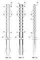
- FIG. 1shows a detail view of a distal end portion of a drainage tube in a relaxed state, according to an embodiment of the present disclosure.
- FIG. 2shows a detail view of the distal end portion of the drainage tube shown in FIG. 1 , wherein a closed lumen is filled with a pressurized fluid.
- FIG. 3shows a detail view of the distal end portion of the drainage tube shown in FIG. 1 , wherein the fluid within the closed lumen is at an intermediate pressure.
- FIG. 4shows a cross-sectional view of a drainage tube including a plurality of closed lumens, according to an additional embodiment of the present disclosure.
- FIG. 5shows a detail view of a distal end portion of the drainage tube of FIG. 4 , wherein a closed lumen is filled with a pressurized fluid.
- FIG. 6shows a detail view of a distal end portion of the drainage tube of FIG. 4 , wherein a different closed lumen is filled with a pressurized fluid.
- FIG. 7shows front view of a drainage tube including wires attached to the distal end of the drainage tube, according to an embodiment of the present disclosure.
- FIG. 8shows a cross-sectional view of the drainage tube of FIG. 7 .
- FIG. 9shows a side view of the drainage tube of FIG. 7 .
- FIG. 10shows front view of a drainage tube including wires attached to the distal end of the drainage tube and routed through lumens, according to an embodiment of the present disclosure.
- FIG. 11shows a cross-sectional view of the drainage tube of FIG. 10 .
- FIG. 12shows a side view of the drainage tube of FIG. 10 .
- FIG. 13shows a cross-sectional detail view of a distal end of a drainage tube including wires surrounding a portion of the distal end.
- FIG. 14shows a cross-sectional detail view of a distal end of a drainage tube including wires with stops thereon.
- FIG. 15shows a cross-sectional detail view of a distal end of a drainage tube including a single wire with a stop thereon.
- FIG. 16shows a schematic view of a drainage tube with wires, such as shown in FIGS. 7 and 10 , in operation.
- FIG. 17shows a schematic view of the drainage tube of FIG. 16 moved to a second position.
- FIG. 18shows a schematic view of a device for operating the wires of a drainage tube with wires, such as shown in FIGS. 7 and 10 , including a yoke.
- FIG. 19shows a schematic view of a device for operating the wires of a drainage tube with wires, such as shown in FIGS. 7 and 10 , including separate reels.
- FIG. 20shows a schematic view of a device for operating the wires of a drainage tube with wires, such as shown in FIGS. 7 and 10 , including linear actuators.
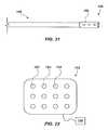
- FIG. 21shows a detail view of a distal end portion of a drainage tube including a magnetic end portion, according to an embodiment of the present invention.
- FIG. 22shows a schematic view of a magnetic field generator, according to an embodiment of the present invention.
- FIG. 23shows a schematic view of a linear motion generator in a fully extended state coupled to a drainage tube inserted into a body cavity, according to an embodiment of the present invention.
- FIG. 24shows a schematic view of the linear motion generator, drainage tube and body cavity of FIG. 23 , wherein the linear motion generator is in a partially extended state.
- FIG. 25shows a schematic view of the linear motion generator, drainage tube and body cavity of FIG. 23 , wherein the linear motion generator is in a retracted state.
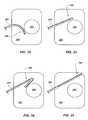
- FIG. 26shows a schematic view of a circular motion generator in a first position coupled to a drainage tube inserted into a body cavity, according to an embodiment of the present invention.
- FIG. 27shows a schematic view of the circular motion generator, drainage tube and body cavity of FIG. 26 , wherein the circular motion generator has been rotated one-quarter revolution.
- FIG. 28shows a schematic view of the circular motion generator, drainage tube and body cavity of FIG. 26 , wherein the circular motion generator has been rotated one-half revolution.
- FIG. 29shows a schematic view of the circular motion generator, drainage tube and body cavity of FIG. 26 , wherein the circular motion generator has been rotated three-quarters revolution.
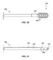
- FIG. 30shows a detail view of a distal end portion of a drainage tube including a rotatable end portion, according to an embodiment of the present disclosure.
- FIG. 31shows a detail view of a distal end portion of a drainage tube including a separate open lumen, according to an embodiment of the present disclosure.
- FIG. 32shows a schematic detail view of a drainage tube having a distal end in a first position within a pleural cavity.
- FIG. 33shows a schematic detail view of the drainage tube of FIG. 32 , wherein the distal end has been moved to a second position within the pleural cavity.
- FIG. 34shows a schematic detail view of a drainage tube having a distal end in a first position within a pleural cavity.
- FIG. 35shows a schematic detail view of the drainage tube of FIG. 34 , wherein the distal end has been moved to a second position within the pleural cavity.
- FIGS. 36 through 41show schematic detail views of a drainage tube according to an embodiment of the present invention having a distal end positioned at different locations within a pleural cavity as a result of a movement of the distal end within the pleural cavity.
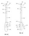
- FIG. 42shows a top view of a drainage device according to an embodiment of the present disclosure.
- FIG. 43shows a side view of the drainage device of FIG. 42 .
- FIGS. 44 and 45show cross-sectional views of the drainage device of FIG. 42 .
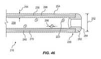
- FIG. 46shows a cross-sectional detail view of a drainage tube according to an embodiment of the present invention.
- a drainage devicemay include a drainage tube configured to change shape in response to fluid pressure to facilitate the movement of a distal end thereof.
- a drainage tube 10may be generally configured as a catheter and may include a plurality of lumens.
- the drainage tube 10may include an open lumen 12 and a closed lumen 14 .
- the drainage tubemay further include a biasing structure 16 , such as an elastic material region (e.g., flexible material region).
- the open lumen 12may include at least one opening 18 proximate to a first distal end 20 thereof and, in some embodiments, may include a plurality of openings 18 proximate to the first distal end 20 .
- the one or more openings 18may be defined by a one or more of apertures, porous regions, and other fluid permeable structures.
- the open lumen 12may additionally include an opening at an opposing, second distal end that may be selectively coupled to a suction source, such as a vacuum (not shown).
- the biasing structure 16may be defined by an elastically deformable wall of the drainage tube 10 .
- the biasing structure 16may bias the drainage tube 10 to extend along a generally arcuate path, such as shown in FIG. 1 .
- a biasing structure 16may bias a drainage tube 10 to extend along a spiral path (not shown).
- a biasing structure 16may bias a drainage tube 10 to extend along another path, such as a path having a generally linear shape.
- the closed lumen 14may extend longitudinally along at least a portion of the open lumen 12 .
- the closed lumen 14may extend along the open lumen 12 and a closed, distal end of the closed lumen 14 may be at least proximate to the distal end of the open lumen 12 .
- the closed lumen 14may additionally include an opening at an opposing, proximal end that may be selectively coupled to a fluid pressure source, such as a piston pump (e.g., a syringe) (not shown).
- the drainage tube 10When fluid within the interior of the closed lumen 14 is at a pressure at or near ambient pressure, the drainage tube 10 may be biased into a first path, such as a non-linear path (e.g., a generally arcuate path). However, as the fluid pressure within the closed lumen 14 is increased above the ambient pressure, such as by inflation with a gas (i.e., air) or insertion of a liquid (i.e., water), the closed lumen 14 may change in shape and cause the drainage tube 10 to extend along a different second path, such as a substantially linear path as shown in FIG. 2 . In view of this, the shape of the drainage tube 10 , and thus the position of the distal end 20 thereof, may be affected by varying the fluid pressure within the closed lumen 14 .
- a gasi.e., air
- a liquidi.e., water
- the drainage tube 10when fluid within the interior of the closed lumen 14 is at a pressure at or near ambient pressure, the drainage tube 10 may be biased into a first path, such as a linear path. However, as the fluid pressure within the closed lumen 14 is increased above the ambient pressure, such as by inflation with a gas (i.e., air) or insertion of a liquid (i.e., water), the closed lumen 14 may change in shape and cause the drainage tube 10 to extend along a different second path, such as a substantially non-linear path (e.g., a generally arcuate path) as shown in FIG. 1 . Additionally, by applying an intermediate fluid pressure within the closed lumen 14 , the drainage tube 10 may assume an intermediate shape, such as shown in FIG. 3 .
- a gasi.e., air
- a liquidi.e., water
- the closed lumen 14may change in shape and cause the drainage tube 10 to extend along a different second path, such as a substantially non-linear path (e.g.,
- a drainage tube 22may include an open lumen 24 for drainage and a plurality of closed lumens 26 , 28 , 30 , 32 configured to facilitate the selective movement of a distal end in a number of directions in response to fluid pressure, as shown in cross-section in FIG. 4 .
- the drainage tube 22may be biased along a generally linear path when the fluid within each closed lumen 26 , 28 , 30 , 32 is at or near ambient pressure.
- the first closed lumen 26may change shape, such as a shape extending along a generally arcuate path, and facilitate the movement of the distal end 34 of the drainage tube 22 , having openings 36 therein, in a first direction 38 , as indicated in FIG.
- the second closed lumen 28may change shape, such as a shape extending along another generally arcuate path, and facilitate the movement of the distal end 34 of the drainage tube 22 in a second direction 40 , generally opposite the first direction 38 , as indicated in FIG. 4 and as shown in FIG. 6 .
- the third closed lumen 30may change shape, such as a shape extending along yet another generally arcuate path, and facilitate the movement of the distal end of the drainage tube in a third direction 42 , generally perpendicular to the first direction 38 and second direction 40 , as indicated in FIG. 4 .
- the fourth closed lumen 32may change shape and facilitate the movement of the distal end 34 of the drainage tube 22 in a fourth direction 44 , generally opposite to the third direction 42 , as indicated in FIG. 4 .
- an elongated structuremay be utilized, rather than fluid pressure, to effectuate movement of a distal end of a drainage tube.
- a wire or rodmay be inserted into a closed lumen to change the shape thereof and facilitate movement of the distal end of the drainage tube.
- At least one wiremay be attached at or near a distal end of a drainage tube to effectuate the movement thereof, such as shown in FIGS. 7-15 .
- a drainage tubemay not utilize fluid pressure; such embodiments may not include any closed lumens.
- the term “wire”is a broad term that encompasses any type of flexible elongated material capable of providing a pulling force and encompasses, by way of example and not limitation, metal wire, coated wire, polymer wire, woven or braided wire, string, yarn, line, cable, filament, lace, and cord.
- a drainage tube 46may be comprised of a single open lumen forming a central passage 48 ( FIG. 8 ) through the drainage tube 46 .
- the drainage tube 46may be formed of a flexible material, such as a flexible polymer material, and may include a plurality of openings 50 , 52 , 54 , 56 , 58 , 60 near a distal end 62 .
- the drainage tube 46may include a first plurality of openings 50 , 52 , 54 to the central passage 48 along a first side 64 of the drainage tube 46 near the distal end 62 .
- the drainage tube 46may also include a second plurality of openings 56 , 58 , 60 to the central passage 48 along an opposing, second side 66 of the drainage tube 46 near the distal end 62 .
- a proximal end 68 of the drainage tube 46may include an opening 70 configured for attachment to a vacuum source.
- a first wire 72such as a nickel titanium wire (e.g., a nitinol wire) having a polytetrafluoroethylene (e.g., TEFLON®) coating, may be attached to the drainage tube 46 at or near the distal end 62 of the drainage tube 46 and may be woven through the first plurality of openings 50 , 52 , 54 .
- the first wire 72may extend from an outside surface of the drainage tube 46 and into the central passage 48 of the drainage tube 46 through a first opening 50 of the first plurality of openings 50 , 52 , 54 .
- the first wire 72may then extend along the central passage 48 for a distance and then extend to the outside of the drainage tube 46 through a second opening 52 of the first plurality of openings 50 , 52 , 54 .
- the first wire 72may then extend along the outside of the drainage tube 46 for another distance and extend back into the central passage 48 of the drainage tube 46 through a third opening 54 of the first plurality of openings 50 , 52 , 54 .
- the first wire 72may be woven in a similar manner through any number of additional openings formed along a first side 64 of the drainage tube 46 .
- the first wire 72may then extend through the central passage 48 of the drainage tube 46 toward the proximal end 68 of the drainage tube 46 and may extend out of the drainage tube 46 at or near the proximal end 68 of the drainage tube 46 .
- an opposing, second wire 74such as a nickel titanium wire (e.g., a nitinol wire) having a polytetrafluoroethylene (e.g., TEFLON®) coating, may be attached to the drainage tube 46 at or near the distal end 62 of the drainage tube 46 and may be woven through the second plurality of openings 56 , 58 , 60 .
- the second wire 74may extend from an outside surface of the drainage tube 46 and into the central passage 48 of the drainage tube 46 through a first opening 56 of the second plurality of openings 56 , 58 , 60 .
- the second wire 74may then extend along the central passage 48 for a distance and then extend to the outside of the drainage tube 46 through a second opening 58 of the second plurality of openings 56 , 58 , 60 .
- the second wire 74may then extend along the outside of the drainage tube 46 for another distance and extend back into the central passage 48 of the drainage tube 46 through a third opening 60 of the second plurality of openings 56 , 58 , 60 .
- the second wire 74may be woven in a similar manner through any number of additional openings formed along a second side 66 of the drainage tube 46 .
- the second wire 74may then extend through the central passage 48 of the drainage tube 46 toward the proximal end 68 of the drainage tube 46 and may extend out of the drainage tube 46 at or near the proximal end 68 of the drainage tube 46 .
- the first and second wires 72 , 74may extend out of the drainage tube 46 through relatively small openings 76 near the distal end 68 of the drainage tube 46 .
- the first and second wires 72 , 74may extend out of the drainage tube 46 through openings 76 that provide a fluid seal around the first and second wires 72 , 74 . In view of this, there may be little or no leakage of ambient air into the drainage tube 46 through such openings 76 during operation thereof.
- a first wire 78 and a second wire 80may be inserted into relatively small lumens 82 , 84 that are separate from a primary open lumen of a drainage tube 86 and the first and second wires 78 , 80 may be attached to a distal end 88 of the drainage tube 86 .
- openings 90 into a central passage 92 of the drainage tube 86may extend through the lumens 82 , 84 , creating a plurality of lumen 82 , 84 segments.
- the first and second wires 78 , 80may be exposed at the openings 90 into the central passage 92 of the drainage tube 86 .
- the lumens 82 , 84 and wires 78 , 80may be positioned on opposing sides of the drainage tube 86 .
- each wire 72 , 74 , 78 , 80may be accomplished by one of any number of attachment configurations.
- each wire 72 , 74may wrap around a portion of the distal end 62 of the drainage tube 46 , as shown in FIG. 13 .
- Each wire 72 , 74may then be attached to itself at a joint 94 , such as by a weld joint, a swaged or crimped joint, a knot, or another joint.
- a first wire 96 and a second wire 98may extend through an opening 100 sized similar to a diameter of each respective wire 96 , 98 and a stop 102 , such as a weld bead or a swaged member, may be attached to a free end of each wire 96 , 98 to prevent the free end of each wire 96 , 98 from passing through the openings 100 , respectively, such as shown in FIG. 14 .
- a single cable 104may be utilized as a first cable and a second cable, such as shown in FIG. 15 .
- the cable 104may extend through first opening 106 and second opening 108 sized similar to a diameter of the wire 104 and a stop 110 , such as a weld bead or a swaged member, may be attached to the cable 104 at a location between the first opening 106 and the second opening 108 .
- a stop 110such as a weld bead or a swaged member
- the distal ends 62 , 88 of drainage tubes 46 , 86 including wires 72 , 74 , 78 , 80may be moved by the manipulation of the wires 72 , 74 , 78 , 80 at the proximal end 68 of the drainage tube 46 , 86 .
- the first side 64 of the drainage tube 46may be put into compression.
- the drainage tube 46When the first side 64 of the drainage tube 46 is put into compression, the drainage tube 46 may flex at locations where the first plurality of openings 50 , 52 , 54 is located and the drainage tube 46 may bend in a first direction, as shown in FIGS. 16 and 17 .
- a tensile forceis applied to the second wire 74 (e.g., when a pulling force is applied to the second wire 74 from the proximal end 68 ) the second side 66 of the drainage tube 46 may be put into compression.
- the opposing, second side 66 of the drainage tube 46When the opposing, second side 66 of the drainage tube 46 is put into compression the drainage tube may flex at locations where the second plurality of openings 56 , 58 , 60 is located and the drainage tube 46 may bend in an opposing, second direction (not shown).
- the number of openings 50 , 52 , 54 , 56 , 58 , 60 and the position of the openings 50 , 52 , 54 , 56 , 58 , 60 in the drainage tube 46may be chosen to cause the drainage tube 46 to exhibit a desired change in shape upon manipulation of the wires 72 , 74 from the proximal end 68 .
- the distal end 62 of the drainage tube 46may remain in contact with the edge of the obstruction 112 as the drainage tube 46 continues to flex, as shown in FIGS. 16 and 17 . This may allow the edges of a body cavity, or the edges of an object within the body cavity, to be efficiently cleared of fluids and improve the drainage of the body cavity.
- any number of mechanismsmay be attached to the proximal ends of the wires to selectively apply tensile force to the wires.
- the proximal ends of the wiresmay be manipulated directly by a physician.
- the wiresmay be manipulated automatically by a programmed device.
- a motor(not shown) may be attached to a yoke 114 at a central location 116 thereof, such as shown in FIG. 18 .
- a first wire 118When the motor is turned in a first direction, a first wire 118 may be pulled by the yoke 114 and a tensile force may be applied to the first wire 118 , which may be attached at a first end 120 of the yoke 114 .
- a second wire 122may be pulled by the yoke 114 and a tensile force may be applied to the second wire 122 , which may be attached to a second end 124 of the yoke 114 .
- a first reel 126may be attached to a first wire 128 and a second reel 130 may be attached to a second wire 132 , and motors (not shown) attached to each reel 126 , 130 and may selectively apply a tensile force to each wire 128 , 132 , respectively, such as shown in FIG. 19 .
- a linear actuator 134such as a pneumatic, hydraulic, or electric linear actuator, may be attached to each wire 136 and may selectively apply a tensile force to each wire 136 , respectively, such as shown in FIG. 20 .
- a drainage tubemay include only a first wire and not include a second wire.
- a drainage tubemay include a first wire, a second wire, and any number of additional wires.
- the more wires that are includedthe greater the range of motion that may be achieved with a distal end of a drainage tube.
- two opposing wiresmay provide sufficient range of motion for many therapeutic uses, such as for draining fluid from a body cavity, such as a pleural cavity.
- the drainage tube 148may include a magnetic material portion (i.e., a material that may experience a force in response to an applied magnetic field), such as a ferromagnetic material portion (e.g., iron, nickel, cobalt, gadolinium, neodymium, samarium and alloys thereof).
- a magnetic material portioni.e., a material that may experience a force in response to an applied magnetic field
- a ferromagnetic material portione.g., iron, nickel, cobalt, gadolinium, neodymium, samarium and alloys thereof.
- the drainage tube 148may include a magnetic structure 150 formed of a magnetic material positioned near the distal end 146 thereof, such as shown in FIG. 16 .
- the magnetic structure 150may be formed of a material that is different than a majority of the drainage tube 148 , or may be defined by a region doped with a magnetic material. In view of this, a magnetic force may be applied to the distal end 146 of the drainage tube 148 by the application of a magnetic field generating device 152 , such as shown in FIG. 22 , which may cause the distal end 146 of the drainage tube 148 to move in response thereto.
- the magnetic field generating device 152may be configured as an external covering that may be worn by a patient (e.g., as a vest) or may be draped over the patient.
- the magnetic field generating device 152may deliver a reconfigurable magnetic field that may cause the distal end 146 of a drainage tube 148 positioned within a body cavity, such as a pleural cavity of a patient, to move about the body cavity.
- the magnetic field generating device 152may include a plurality of temporary magnets 154 (e.g., electromagnets), distributed thereabout that may be selectively activated to generate a number of magnetic field configurations to affect the movement of the distal end 146 of the drainage tube 148 to a number of positions within the body cavity.
- a magnetic field generating devicemay include permanent magnets that may be utilized to generate a number of magnetic field configurations. For example, a permanent magnet may be moved about or the orientation of a plurality of permanent magnets relative to one another may be manipulated to generate different magnetic field configurations. Additionally, the magnetic field generation may be automatically activated and manipulated, such as by a programmed control module 156 .
- motion generators positioned external to a patientmay facilitate movement of a distal end of a drain tube positioned within a body cavity of the patient.
- a linear motion generatorsuch as a piston 158
- a linear motion generatormay be attached to a drainage tube 160 , such as shown in FIGS. 23 through 25 .
- the drainage tube 160may be positioned within a sleeve 162 that may be positioned within a cavity wall, such as a chest wall, of a patient.
- a distal end 164 of the drainage tube 160may be positioned within a body cavity 166 at a first side of the sleeve 162 and the piston 158 may be coupled to the drainage tube 160 at an opposing, second side of the sleeve 162 .
- the sleeve 162may be configured to allow the movement of the drainage tube 160 relative to the sleeve 162 , and thus relative to the patient's cavity wall as the sleeve 162 may be configured to contact and be coupled to the patient's cavity wall, while maintaining a seal between the sleeve 162 and the drainage tube 160 .
- the distal end 164 of the drainage tube 160may be inserted into a body cavity of a patient, such as a pleural cavity, and an outer wall of the sleeve 162 may be coupled to the chest wall of the patient.
- the piston 158may be extended and/or retracted to facilitate movement of the distal end 164 of the drainage tube 160 within the patient's body cavity 166 , as shown in FIGS. 23 through 25 .
- a circular motion generatorsuch as a wheel 168 attached to a motor, may be attached to a drainage tube 170 , such as shown in FIGS. 26 through 29 .
- the drainage tube 170may be positioned within a sleeve 172 that may be positioned within a cavity wall, such as a chest wall, of a patient.
- a distal end 174 of the drainage tube 170may be positioned at a first side of the sleeve 172 and the wheel 168 may be coupled to the drainage tube 170 at an opposing, second side of the sleeve 172 .
- the sleeve 172may be configured to allow the movement of the drainage tube 170 relative to the sleeve 172 , and thus relative to the patient's cavity wall as the sleeve 172 may be configured to contact and be coupled to the patient's cavity wall, while maintaining a seal between the sleeve 172 and the drainage tube 170 .
- the distal end 174 of the drainage tube 170may be inserted into a body cavity of a patient, such as a pleural cavity, and an outer wall of the sleeve 172 may be coupled to the chest wall of the patient.
- the wheel 168may be selectively rotated, such as in a direction indicated by the arrow 176 , to facilitate movement of the distal end 174 of the drainage tube 170 within a patient's body cavity 178 , as shown in FIGS. 26 through 29 .
- a portion of a drainage tubemay be inserted and/or retracted from the patient outside of a sterile environment, at least a portion of the drainage tube may be covered by a flexible covering that may be attached to the sleeve, such as a flexible plastic film (not shown).
- linear and circular motion generatorshave been shown and described in particular embodiments herein, other motion generators, as will be recognized by a person of ordinary skill in the art, may also be utilized to generate other simple motions or compound motions.
- a drainage tube 180may include a locomotion device positioned at least proximate to a distal end 182 thereof.
- the drainage tubemay include a distal end portion 184 that is rotatable, as shown in FIG. 30 .
- the rotatable distal end portion 184may further include protrusions 186 laterally extending from a surface thereof, such as similar to relatively soft bristles of a brush.
- the distal end 182 of the drainage tube 180may move about a body cavity, such as a pleural cavity.
- the protrusions 186may be utilized to massage internal body tissue, such as lung tissue.
- the locomotion devicemay be powered by electric power, hydraulic power, or another power source.
- powermay be provided by directing electricity through a wire positioned within the drainage tube 180 or by directing fluid through lumens of the drainage tube 180 , such as by fluid injection or by fluid suction.
- a rotatable end portion 184is shown and described with reference to FIG. 30
- other locomotion devicesmay be positioned at least proximate to a distal end 182 of the drainage tube 180 to provide locomotion of the distal end 182 of the drainage tube 180 relative to a patient's body cavity.
- any number of mechanical device configurationse.g., a microelecromechanical system (MEMS)
- MEMSmicroelecromechanical system
- a drainage tube 188may include a plurality of open lumens 190 , 192 , such as shown in FIG. 31 .
- each open lumen 190 ; 192may extend along a length of the drainage tube 188 and have at least one opening 194 , 196 at a distal end thereof.
- a first open lumen 190may have another opening at an opposing, proximal end that may be coupled to a suction source (not shown).
- a second lumen 192may also have an opening at an opposing, proximal end (not shown). However, the opening at the proximal end of the second lumen 192 may be coupled to a fluid source, rather than a suction source.
- a fluidmay be injected into a body cavity from the fluid source through the opening 194 of the second open lumen 192 while fluid is removed from the body cavity through the openings 196 of the first open lumen 190 .
- fluidssuch as one or more of antibiotics, saline water, enzymes, and other fluids may be injected through the opening 194 of the second open lumen 192 into a body cavity such as for one or more of irrigation, blood thinning, medication delivery, tissue stimulation, and other treatments.
- fluidmay be removed from the body cavity through the openings 196 of the first open lumen 190 .
- methods of utilizing a drainage tube having a moveable distal endmay include determining a size and shape of a body cavity, preselecting a range of movement for a drainage tube, inserting the drainage tube into the body cavity and moving the distal end of the drainage tube within the body cavity according to the preselected range of movement.
- body imaging technologysuch as X-ray imaging, ultrasound imaging, magnetic resonance imaging (MRI), and computed tomography (CT) scanning may be utilized to determine the size and shape of a body cavity.
- a size and shape of a body cavitymay be estimated by external measurements of a patient without utilizing body imaging technology.
- a range of movementmay be selected by utilizing the estimated size and shape of the body cavity and specific treatment objectives.
- a range of movement about a curved surfacesuch as a shape of a surface of a pleural cavity defined by a chest wall, may be selected for the cleaning and drainage of the pleural cavity.
- a drainage tubemay be configured to achieve the selected range of movement and may be inserted into the body cavity. After insertion into the body cavity, the distal end of the drainage tube may be moved within the body cavity according to the preselected range of movement to facilitate a specific treatment.
- embodimentsmay be utilized to treat and drain body cavities of patients.
- embodimentsmay be utilized to move a distal end 198 of a drainage tube 200 within a pleural cavity 202 , providing drainage about a lung 204 , as shown in FIGS. 32 and 33 and FIGS. 34 and 35 , to treat and drain an empyema or other flowable liquid, gaseous or semisolid matter from the pleural cavity 202 or from another body cavity.
- Embodiments that include a drainage tube having a distal end that may be moveable after insertion into a body cavitymay be utilized to remove substantially all of a flowable material from a body cavity.
- the moveable distal endmay provide other beneficial treatments, such as the massaging of tissue, such as lung tissue.
- embodimentsmay provide the infusion of medication, the introduction of irrigation fluids, enzymes or other treatments into specific regions of a body cavity or may distribute such treatments over substantially all of a body cavity.
- a distal end 206 of a drainage tube 208may move about a body cavity in a snake-like motion, as shown in FIGS. 36 through 41 .
- the drainage tube 208may be inserted at a generally central region of a pleural cavity 210 and the distal end 206 of the drainage tube 208 may move about an upper portion of the pleural cavity 210 from an insertion point 212 , such as in a snake-like motion.
- the drainage tube 208may move about the lower portion of the pleural cavity 210 from the insertion point 212 .
- a drainage tubemay have a significantly smaller diameter than conventional drainage tubes, yet have superior efficacy.
- a relatively small diameter drainage tubemay facilitate insertion, reduce pain and discomfort experienced by a patient, reduce bleeding, and decrease recurrent pneumothorax on withdrawal of the drainage tube.
- the devicemay be especially effective in draining or evacuating fluid from the complex configuration of a pleural cavity.
- FIG. 42shows a drainage device 214 according to another embodiment of the present disclosure.
- the drainage device 214may include a drainage tube 216 configured to provide drainage to a body cavity defined by or surrounded by soft tissue.
- the drainage device 214may be used to withdraw infection exudates from a pleural cavity by applying suction to the drainage tube 216 .
- positive pressuremay be applied to the drainage tube 216 , such as to introduce a fluid into the drainage tube 216 and/or body cavity, such as to dissolve material to be removed or to dislodge flow restrictions within the drainage tube 216 .
- the drainage device 214may be configured to inhibit damage to the soft tissue surrounding the cavity while a portion of the drainage device 214 is inserted into the cavity or moved about within the cavity.
- the drainage tube 216may include a proximal end 218 and a distal end 220 .
- the drainage tube 216may include at least one of an axial opening 222 in the distal end 220 and one or more lateral openings 223 proximate the distal end 220 into an open lumen (shown in FIG. 46 ).
- the distal end 220 of the drainage device 214may include a substantially blunted geometry to prevent damage to the body cavity, as will be explained in more detail below with reference to FIG. 46 .
- the distal end 220may not have any sharp, pointed, or abrupt edges that, if present, could puncture or otherwise damage soft tissue of a body cavity.
- the proximal end 218 of the drainage tube 216may be connected to an activation device 224 that may include a control device 226 .
- the control device 226may include, for example, a lever 228 configured to be manually manipulated by a physician or other care provider.
- the control device 226may be an automated actuation device that includes, for example, an electronic stepper motor, a linear actuator, a pneumatic motor or actuator, or another type of automated control system.
- FIG. 43shows a side view of the drainage device 214 of FIG. 42 .
- the drainage device 214may include an outlet port 230 in fluid communication with the drainage tube 216 and configured for connection to a vacuum source for removal of material from a body cavity or to a source of one or more treatments to be introduced into the body cavity.
- the outlet port 230may be an integral extension of the drainage tube 216 .
- FIG. 44shows a cross-sectional view of the drainage device 214 of the embodiment of FIG. 42 .
- An activation device 224may be attached to the proximal end 218 of the drainage tube 216 .
- the activation device 224may include a pinion gear 232 , a first rack 234 , and a second rack 236 .
- the first and second racks 234 , 236may be complementary to and meshed with the pinion gear 232 .
- First and second flexible members 238 , 240may be attached to the first and second racks 234 , 236 , respectively.
- the first and second flexible members 238 , 240may include, for example, metallic wires made from steel, titanium, nitinol, or other metals or alloys, synthetic fibers such as nylon, polyester, or other polymers, or naturally occurring fibers such as cotton, silk, or sinew. Such wires or fibers may include a single strand or multiple strands of one or more materials bundled or woven together.
- the first and second flexible members 238 , 240may be constructed as described above in connection with FIGS. 7-15 .
- the first and second flexible members 238 , 240may be disposed within closed lumens within a wall (described in more detail below in connection with FIG. 46 ) of the drainage tube 216 .
- the lumens through which the first and second flexible members 238 , 240 extendmay not be in fluid communication with the open lumen defined by the drainage tube 216 or with an exterior of the drainage tube 216 .
- the flexible members 238 , 240may be completely laterally enclosed within the walls of the drainage tube 216 .
- the lumensmay be positioned within the wall of the drainage tube 216 such that each of the flexible members 238 , 240 is substantially directly opposite the other across a diameter of the drainage tube 216 .
- FIG. 45shows another cross-sectional view of the drainage device 214 of the embodiment of FIG. 42 .
- the pinion gear 232may rotate in response to an applied torque 242 .
- the torque 242may be applied by the lever 228 ( FIG. 42 ), which may be connected to the pinion gear 232 , or by an automated system as described above.
- Rotation of the pinion gear 232may cause generally linear movement of the first rack 234 in a first direction 244 and a corresponding movement of the second rack 236 in a second, opposite direction 246 . Movement of the first rack 234 may create tension in the first flexible member 238 , which imparts a compressive force to a first side 248 of the drainage tube 216 .
- Movement of the second rack 236may allow slack in the second flexible member 240 .
- Such a compressive forcemay cause the drainage tube 216 to contract along the first side 248 in which the first flexible member 238 is disposed and lengthen along a second side 250 in which the second flexible member 240 is disposed, causing the drainage tube 216 to assume an arcuate shape, such as the shape shown in FIG. 45 .
- the magnitude of the applied torque 242may determine the amount of rotation of the pinion gear 232 and the corresponding amount of curvature imparted to the drainage tube 216 .
- Torquemay be applied in a direction opposite the direction indicated in FIG. 45 , resulting in curvature of the drainage tube 216 in an opposite direction to the curvature shown.
- the drainage device 214may be configured such that the distal end 220 may rotate at least about 360° from a first fully curved position (e.g., pointing down and to the left in the perspective shown in FIG. 45 ) to a second, opposite fully curved position (e.g., pointing down and to the right from the same perspective).
- a first fully curved positione.g., pointing down and to the left in the perspective shown in FIG. 45
- a second, opposite fully curved positione.g., pointing down and to the right from the same perspective
- FIG. 46shows a cross-sectional view of a portion of the drainage tube 216 proximate the distal end 220 .
- the drainage tube 216may include an outside diameter 252 between approximately 0.125 (1 ⁇ 8) inches (3.2 mm) and approximately 0.75 (3 ⁇ 4) inches (19 mm).
- the drainage tube 216may include a wall 254 with a wall thickness 256 of between approximately 0.03125 ( 1/32) inches (0.8 mm) and approximately 0.125 (1 ⁇ 8) inches (3.2 mm).
- the drainage tube 216may be made from a polymer material, such as polyvinyl chloride (PVC), polyurethane, or silicone, for example.
- PVCpolyvinyl chloride
- a material of the drainage tube 216may be selected to exhibit a hardness that enables the desired bending of the drainage tube 216 , as described above, and to facilitate the insertion of the drainage tube 216 into a body cavity without buckling.
- the hardness of the drainage tube 216may be selected to inhibit collapsing of the drainage tube 216 when the drainage tube is inserted into a body cavity, particularly when suction is applied to remove material from the body cavity through the drainage tube 216 .
- the drainage tube 216may be configured to bend while inhibiting collapse, as explained, at a temperature of the body cavity.
- a temperature of the body cavitymay be between about 96° F. (35.6° C.) and about 105° F.
- the material of the drainage tube 216may exhibit a Shore A durometer measurement between approximately 75 A and approximately 95 A, such as between approximately 80 A and approximately 90 A.
- the drainage tube 216may define an open lumen. 258 extending centrally through the drainage tube 216 . Lateral openings 223 into the open lumen 258 may extend through the wall 254 of the drainage tube 216 .
- the size and spacing of the lateral openings 223may be selected to inhibit collapsing of the drainage tube 216 when the wires 238 and 240 are used to bend the drainage tube 216 and/or when a vacuum is applied to the drainage tube 216 .
- the lateral openings 223may be spaced approximately 0.25 (1 ⁇ 4) inch (6.4 mm) to approximately 1 inch apart and may have a diameter 266 of between approximately 0.0625 ( 1/16) inches (1.6 mm) and approximately 0.5 (1 ⁇ 2) inches (12.7 mm).
- no two openingsmay be less than about 0.25 (1 ⁇ 4) inches (6.4 mm) apart along an outer surface of the drainage tube.
- the openingsmay be arranged along a path defined by one or more substantially helical lines along an outer surface of the drainage tube 216 .
- Such spacingmay help to maintain the structural integrity and rigidity of the drainage tube and enable the drainage tube to be inserted into and used within a patient's body cavity. Furthermore, such spacing may prevent the drainage tube from collapsing under applied vacuum or under the compressive forces applied by the activation device ( FIG. 45 ).
- the drainage tube 216may include an annular open end cap 262 with a rounded distal surface 264 .
- At least a radially outer portion of the end cap 262 at the distal surface 264may be curved when viewed in cross section, as shown in FIG. 46 .
- First and second flexible members 238 , 240may be coupled to the end cap 262 , such that the end cap 262 provides an anchor for the flexible members 238 , 240 to enable tension to be applied to the flexible members 238 , 240 , as explained above.
- the first and second flexible members 238 , 240may be disposed within closed lumens 268 and 270 extending longitudinally through the wall 254 , such that no part of the flexible members 238 , 240 are exposed to the body cavity or to the open lumen 258 .
- the drainage tube 216may be configured to provide both a desired range of motion through bending thereof and to resist collapsing during use within a body cavity. The range of motion and the resistance to collapse may be accomplished by balancing the outside diameter 252 , the wall thickness 256 , the durometer, size of the lateral openings 223 , and the spacing of the lateral openings 223 . As noted above, the drainage tube 216 may be configured to remove infection exudates or other materials from a body cavity, such as a pleural cavity, that is defined by relatively soft tissue. Infection exudates or other materials to be removed from a body cavity by the drainage tube 216 may be relatively viscous, such as more viscous than water or blood.
- a relatively high suction levelmay be applied to the drainage tube 216 , and the drainage tube 216 may have an inner diameter sufficiently large to enable and facilitate flow of the viscous material therethrough.
- the relatively high suction level and the size of the inner diametermay tend to facilitate collapse of the drainage tube 216 and resist bending and movement of the drainage tube 216 using the mechanism described above. Accordingly, the durometer of the material of the drainage tube 216 , the wall thickness 256 , and the size and spacing of the lateral openings 223 may be selected to inhibit such collapse while enabling the desired movement and bending.
- selecting the parameters of the outside diameter 252 , the wall thickness 256 , the durometer, the size of the lateral openings 223 , and the spacing of the lateral openings 223 to fall within the ranges listed abovemay enable the drainage tube 216 to be moved (e.g., bent) a desired distance within the body cavity, while enabling a sufficient suction to be applied for removing material from a body cavity, as desired, without collapsing.
- the drainage devicemay be configured to be inserted into a body cavity of a patient and remain inside the cavity for extended periods of time such as hours, days, weeks, or even months.
- a physician or other care providermay operate the manual or automatic activation device to cause the distal end of the drainage device to move within the body cavity, such as to reach fluid or other material that is to be removed from the body cavity. Such movement may be continuous or periodic.
- an automatic activation devicesuch as described in connection with FIG. 42 may be connected to a timer that initiates periodic movement while the drainage device is in the body cavity, such as at a predetermined number of minutes, hours, or days.
- embodiments of drainage devices the present disclosuremay be suitable for removing material from body cavities that are defined by soft tissues and for being moved within such body cavities without repositioning a base or proximal end thereof.
- other prior known tubular devices for insertion into bodiesmay not be suitable for removing material from soft body cavities while being capable of bending and movement within the body cavities with a range of movement comparable to the drainage tube of the present disclosure.
- tubular devices for sampling bone marrowmay be formed of a material having a sufficiently high durometer and/or wall thickness to avoid collapse under suction, but such devices may not exhibit the same range of movement when bent or moved.
- tubular devices with cameras thereon for exploring body cavitiesmay be sufficiently soft to inhibit damaging soft tissues and to move or bend within the body cavities, but collapse of such tubular devices is generally not an issue since suction is not applied thereto and material is not removed by such devices.
- prior known tubular devices that are used to remove material from soft body cavities by suctionare not configured to move or bend in the manner described in the present disclosure, and are often required to be repositioned by forming multiple incisions. Accordingly, the drainage devices of the present disclosure may exhibit advantages over prior known tubular devices for at least certain applications.
Landscapes
- Health & Medical Sciences (AREA)
- Life Sciences & Earth Sciences (AREA)
- Heart & Thoracic Surgery (AREA)
- Engineering & Computer Science (AREA)
- General Health & Medical Sciences (AREA)
- Anesthesiology (AREA)
- Biomedical Technology (AREA)
- Hematology (AREA)
- Veterinary Medicine (AREA)
- Animal Behavior & Ethology (AREA)
- Public Health (AREA)
- Biophysics (AREA)
- Pulmonology (AREA)
- Vascular Medicine (AREA)
- Surgery (AREA)
- Otolaryngology (AREA)
- External Artificial Organs (AREA)
Abstract
Description
Claims (20)
Priority Applications (1)
| Application Number | Priority Date | Filing Date | Title |
|---|---|---|---|
| US13/840,986US10232150B2 (en) | 2010-03-11 | 2013-03-15 | Body cavity drainage devices and related methods |
Applications Claiming Priority (3)
| Application Number | Priority Date | Filing Date | Title |
|---|---|---|---|
| US31287810P | 2010-03-11 | 2010-03-11 | |
| US13/045,274US20110224647A1 (en) | 2010-03-11 | 2011-03-10 | Body cavity drainage devices and related methods |
| US13/840,986US10232150B2 (en) | 2010-03-11 | 2013-03-15 | Body cavity drainage devices and related methods |
Related Parent Applications (1)
| Application Number | Title | Priority Date | Filing Date |
|---|---|---|---|
| US13/045,274Continuation-In-PartUS20110224647A1 (en) | 2010-03-11 | 2011-03-10 | Body cavity drainage devices and related methods |
Publications (2)
| Publication Number | Publication Date |
|---|---|
| US20130211385A1 US20130211385A1 (en) | 2013-08-15 |
| US10232150B2true US10232150B2 (en) | 2019-03-19 |
Family
ID=48946221
Family Applications (1)
| Application Number | Title | Priority Date | Filing Date |
|---|---|---|---|
| US13/840,986Active2032-02-25US10232150B2 (en) | 2010-03-11 | 2013-03-15 | Body cavity drainage devices and related methods |
Country Status (1)
| Country | Link |
|---|---|
| US (1) | US10232150B2 (en) |
Cited By (1)
| Publication number | Priority date | Publication date | Assignee | Title |
|---|---|---|---|---|
| US11559662B2 (en)* | 2018-04-13 | 2023-01-24 | Merit Medical Systems, Inc. | Steerable drainage devices |
Families Citing this family (23)
| Publication number | Priority date | Publication date | Assignee | Title |
|---|---|---|---|---|
| US10232150B2 (en) | 2010-03-11 | 2019-03-19 | Merit Medical Systems, Inc. | Body cavity drainage devices and related methods |
| WO2015095475A1 (en)* | 2013-12-19 | 2015-06-25 | Bendit Technologies Ltd. | Steering tool |
| US10029036B2 (en) | 2014-06-27 | 2018-07-24 | Merit Medical Systems, Inc. | Placement tools for body cavity drainage devices and related methods |
| US9604033B2 (en) | 2014-06-27 | 2017-03-28 | Harrison M. Lazarus | Body cavity drainage devices with locking devices and related methods |
| US9821097B2 (en) | 2014-06-27 | 2017-11-21 | Merit Medical Systems, Inc. | Body cavity drainage devices including drainage tubes having inline portions and related methods |
| US9649415B2 (en) | 2014-06-27 | 2017-05-16 | Harrison M. Lazarus | Surgical kits for body cavity drainage and related methods |
| WO2015200854A1 (en)* | 2014-06-27 | 2015-12-30 | Lazarus Harrison M | Body cavity drainage devices including drainage tubes having inline portions and related methods |
| JP6235428B2 (en) | 2014-07-29 | 2017-11-22 | 朝日インテック株式会社 | catheter |
| JP7074666B2 (en) | 2015-11-25 | 2022-05-24 | メリット・メディカル・システムズ・インコーポレイテッド | Maneuverable sheath catheter and how to use |
| US20170197018A1 (en)* | 2016-01-07 | 2017-07-13 | Covidien Lp | Motorized chest drainage system |
| WO2017176765A1 (en)* | 2016-04-04 | 2017-10-12 | Dearmond Daniel | Sensor, system, and method for monitoring lung integrity |
| EP3375477A1 (en)* | 2017-03-16 | 2018-09-19 | Basecamp Vascular | Flexible elongated structure having a steerable end |
| CN109893686B (en)* | 2017-12-11 | 2023-11-24 | 上海中医药大学附属龙华医院 | Drainage device |
| CN108498143A (en)* | 2018-04-23 | 2018-09-07 | 费延庆 | A kind of comprehensive solution system of Puncture of lumbar cistern drainage |
| US12097325B2 (en)* | 2018-11-15 | 2024-09-24 | NevAp, Inc. | Systems and devices for preventing occlusion of a suction line resident in a medical device |
| CA3152630A1 (en)* | 2019-08-27 | 2021-03-04 | Hollister Incorporated | Sleeved hydrophilic medical products |
| CN111467587A (en)* | 2020-04-17 | 2020-07-31 | 贵州省人民医院 | Pericardium mediastinum drainage device capable of continuously generating negative pressure |
| CN114377224B (en)* | 2022-01-21 | 2023-12-05 | 安徽平天湖投资控股集团有限公司 | Drainage device for oncology |
| US20230364384A1 (en)* | 2022-05-11 | 2023-11-16 | Bard Access Systems, Inc. | Systems, Medical Devices, and Methods for Controlling Stiffness of the Medical Devices |
| US20230364386A1 (en)* | 2022-05-11 | 2023-11-16 | Bard Access Systems, Inc. | Systems, Medical Devices, and Methods for Steering the Medical Devices |
| DE102022118531B4 (en)* | 2022-07-25 | 2024-06-20 | Atmos Medizintechnik Gmbh & Co. Kg | Probe system for endoluminal negative pressure therapy |
| US20240108855A1 (en)* | 2022-10-03 | 2024-04-04 | German Antonio ROSERO | Devices, systems, and methods for percutaneous- mediated fluid removal |
| WO2024148323A2 (en)* | 2023-01-06 | 2024-07-11 | Raydiant Oximetry, Inc. | Surgical drains and systems and methods for using same |
Citations (171)
| Publication number | Priority date | Publication date | Assignee | Title |
|---|---|---|---|---|
| US2393002A (en) | 1944-05-03 | 1946-01-15 | Smith Minton Larkin | Kidney catheter |
| US2898917A (en) | 1958-04-07 | 1959-08-11 | American Cystoscope Makers Inc | Surgical retaining device |
| US3225762A (en) | 1963-10-25 | 1965-12-28 | Yolan R Guttman | Intravenous stylet catheter |
| US3416532A (en) | 1964-07-24 | 1968-12-17 | Grossman Alan Richard | Drainage tube with means for scraping away debris therewithin |
| US3610231A (en) | 1967-07-21 | 1971-10-05 | Olympus Optical Co | Endoscope |
| US3683929A (en) | 1970-12-28 | 1972-08-15 | Extracorporeal Med Spec | Device for draining cerebrospinal fluid in cases of hydrocephalus |
| US3830238A (en) | 1972-11-07 | 1974-08-20 | Deknatel Inc | Surgical drainage system with pressure measuring device |
| US3863641A (en) | 1972-09-29 | 1975-02-04 | Inst Pentru Creatie Stintific | Thoracic drainage catheter |
| US3867945A (en) | 1973-05-14 | 1975-02-25 | Wendell M Long | Catheter stylets |
| US3937418A (en) | 1975-01-13 | 1976-02-10 | Lawrence Peska Associates, Inc. | Retractable dog leash |
| US3943929A (en) | 1974-11-15 | 1976-03-16 | The Kendall Company | Multi-chamber container and method |
| US4068383A (en) | 1975-10-09 | 1978-01-17 | Hoechstmass Balzer Gmbh & Co. | Tape measure reel |
| US4105031A (en) | 1975-10-10 | 1978-08-08 | Deknatel, Inc. | Attachable expansion chamber for pleural drainage device |
| US4202510A (en) | 1978-12-04 | 1980-05-13 | Stanish Walter F | Retractable pet leash |
| US4203430A (en) | 1976-12-16 | 1980-05-20 | Nagashige Takahashi | Device for controlling curvature of an end section in an endoscope |
| US4228802A (en) | 1977-06-15 | 1980-10-21 | Medical Products Institute Incorporated | Self-inflating and self-cleaning catheter assembly |
| US4439189A (en) | 1981-06-18 | 1984-03-27 | Bentley Laboratories, Inc. | Pleural drainage system |
| US4571239A (en) | 1982-03-01 | 1986-02-18 | Heyman Arnold M | Catheter-stylet assembly for slipover urethral instruments |
| US4580551A (en) | 1984-11-02 | 1986-04-08 | Warner-Lambert Technologies, Inc. | Flexible plastic tube for endoscopes and the like |
| US4608982A (en) | 1984-03-07 | 1986-09-02 | Pollard Clifford W | Forceps |
| US4692154A (en) | 1986-06-02 | 1987-09-08 | Illinois Tool Works Inc. | Catheter guide |
| US4769019A (en) | 1987-02-13 | 1988-09-06 | Sherwood Medical Company | Drainage apparatus |
| US4862891A (en) | 1988-03-14 | 1989-09-05 | Canyon Medical Products | Device for sequential percutaneous dilation |
| US4883474A (en) | 1986-07-30 | 1989-11-28 | David S. Sheridan | Thoracic catheter |
| US4920980A (en) | 1987-09-14 | 1990-05-01 | Cordis Corporation | Catheter with controllable tip |
| US5026358A (en) | 1986-10-07 | 1991-06-25 | Pfizer Products Hospital Group Inc. | Drainage device |
| US5040543A (en) | 1990-07-25 | 1991-08-20 | C. R. Bard, Inc. | Movable core guidewire |
| US5047018A (en) | 1989-08-14 | 1991-09-10 | Minnesota Mining And Manufacturing Company | Catheter and stylet assembly having dual position stylet |
| US5108368A (en) | 1990-01-04 | 1992-04-28 | Pilot Cardiovascular System, Inc. | Steerable medical device |
| US5141503A (en) | 1991-01-29 | 1992-08-25 | Sewell Jr Frank K | Wound suction drainage system |
| US5157813A (en) | 1991-10-31 | 1992-10-27 | William Carroll | Shoelace tensioning device |
| US5205830A (en) | 1991-11-12 | 1993-04-27 | Arrow International Investment Corporation | Catheter assembly |
| US5207661A (en) | 1991-06-07 | 1993-05-04 | Smiths Industries Public Limited Company | Body fluid drainage assembly |
| US5211644A (en) | 1991-09-20 | 1993-05-18 | Pmt Corporation | Process and apparatus for a dermal graft |
| WO1993025264A1 (en) | 1992-06-18 | 1993-12-23 | Nikomed Aps | A device for fixating a drainage tube, and a drainage tube assembly |
| US5297310A (en) | 1993-01-21 | 1994-03-29 | Dennis Cox | Cleaning brush for endoscopes |
| US5300050A (en) | 1986-10-07 | 1994-04-05 | Deknatel Technology Corporation | Drainage device |
| RU2012371C1 (en) | 1992-03-10 | 1994-05-15 | Анатолий Иванович Борисов | Catheter |
| US5312357A (en) | 1991-11-04 | 1994-05-17 | Drager Medical Electonic B.V. | Catheter |
| US5364351A (en) | 1992-11-13 | 1994-11-15 | Ep Technologies, Inc. | Catheter steering mechanism |
| US5370610A (en) | 1993-02-09 | 1994-12-06 | Reynolds; James R. | Surgical drainage tube system |
| US5397321A (en) | 1993-07-30 | 1995-03-14 | Ep Technologies, Inc. | Variable curve electrophysiology catheter |
| US5409468A (en) | 1991-09-13 | 1995-04-25 | Sachse; Hans | Arrangement comprising a ureter tube, an auxiliary tube as well as a mandrin |
| US5409462A (en) | 1993-12-30 | 1995-04-25 | Cordis Corporation | Cyst puncture catheter assembly |
| US5540648A (en) | 1992-08-17 | 1996-07-30 | Yoon; Inbae | Medical instrument stabilizer with anchoring system and methods |
| US5601087A (en) | 1992-11-18 | 1997-02-11 | Spectrascience, Inc. | System for diagnosing tissue with guidewire |
| US5616131A (en) | 1992-09-23 | 1997-04-01 | Lasersurge, Inc. | Apparatus and method for anchoring surgical instrumentation |
| US5630795A (en)* | 1991-08-02 | 1997-05-20 | Olympus Optical Co., Ltd. | Cleaning tube apparatus for endoscope |
| US5653696A (en) | 1984-05-14 | 1997-08-05 | Surgical Systems & Instruments, Inc. | Stent unclogging method |
| US5772670A (en) | 1995-10-18 | 1998-06-30 | Brosa; Ramon Bofill | Forceps for the surgical introduction of catheters and the like |
| US5807341A (en) | 1996-12-11 | 1998-09-15 | Team Medical Llc | Medical catheter dressing device |
| US5895400A (en)* | 1997-06-27 | 1999-04-20 | Abela; George S. | Catheter with bristles |
| US5897534A (en) | 1996-08-29 | 1999-04-27 | Team Medical, Llc | Body fluids and solids drainage system |
| WO1999052481A1 (en) | 1998-04-16 | 1999-10-21 | Beth Israel Deaconess Medical Center | Catheter apparatus having an improved shape-memory alloy cuff and inflatable on-demand balloon for creating a bypass graft in vivo |
| US5987344A (en) | 1996-08-08 | 1999-11-16 | Medtronic, Inc. | Handle for catheter assembly with multifunction wire |
| US6045623A (en) | 1997-04-24 | 2000-04-04 | Cannon; Bradley Jay | Method and apparatus for cleaning catheter lumens |
| US6146355A (en) | 1996-12-30 | 2000-11-14 | Myelotec, Inc. | Steerable catheter |
| US6171277B1 (en) | 1997-12-01 | 2001-01-09 | Cordis Webster, Inc. | Bi-directional control handle for steerable catheter |
| US6183450B1 (en) | 1999-06-04 | 2001-02-06 | William A Lois | Catheter de-clogging device |
| US6193691B1 (en) | 1999-03-30 | 2001-02-27 | Depuy Orthopaedics, Inc. | Catheter system |
| US20010005785A1 (en) | 1999-12-22 | 2001-06-28 | Hans Sachse | Probe for the small intestines |
| US6254581B1 (en) | 1998-09-18 | 2001-07-03 | Creighton University | Pleural cavity drainage device |
| US20010007922A1 (en) | 1995-06-28 | 2001-07-12 | Schneider (Europe) Gmbh | Vascular pressure measuring device |
| US6468260B1 (en) | 1999-05-07 | 2002-10-22 | Biosense Webster, Inc. | Single gear drive bidirectional control handle for steerable catheter |
| US6500167B1 (en) | 1997-09-05 | 2002-12-31 | Biosense Webster, Inc. | Omni-directional steerable catheter |
| US6514273B1 (en) | 2000-03-22 | 2003-02-04 | Endovascular Technologies, Inc. | Device for removal of thrombus through physiological adhesion |
| US6530935B2 (en) | 1996-02-02 | 2003-03-11 | Regents Of The University Of California, The | Clot capture coil and method of using the same |
| US6530913B1 (en) | 1997-04-04 | 2003-03-11 | Jeffrey Giba | Steerable catheter |
| US6638253B2 (en) | 2001-07-17 | 2003-10-28 | Eugene Michael Breznock | Method and apparatus for chest drainage |
| US20030208252A1 (en)* | 2001-05-14 | 2003-11-06 | O' Boyle Gary S. | Mri ablation catheter |
| US20030225364A1 (en)* | 2002-06-04 | 2003-12-04 | Stanford, Office Of Technology Licensing | Device and method for rapid aspiration and collection of body tissue from within an enclosed body space |
| US20030236493A1 (en) | 2002-06-25 | 2003-12-25 | Medamicus, Inc. | Articulating handle for a deflectable catheter and method therefor |
| US20040035017A1 (en) | 2002-08-20 | 2004-02-26 | Ching-Chun Yang | Second brake of measuring tape |
| US20040059293A1 (en)* | 2002-05-01 | 2004-03-25 | Chu Michael S.H. | Medical catheter assembly and method of using the same |
| US20040116852A1 (en) | 2002-12-17 | 2004-06-17 | Scopton Paul M. | Rapid exchange dilation catheter for non-vascular applications |
| US20040143197A1 (en) | 2001-08-21 | 2004-07-22 | Synovis Interventional Solutions | Steerable stylet |
| US20050131393A1 (en) | 2001-03-09 | 2005-06-16 | Scimed Life Systems, Inc. | Systems, methods and devices relating to delivery of medical implants |
| US6907992B2 (en) | 2002-02-28 | 2005-06-21 | Kimberly-Clark Worldwide, Inc. | Surgical kit for “push” type percutaneous endoscopic gastrostomy procedures |
| US20050184186A1 (en) | 2004-02-20 | 2005-08-25 | Chung Haap Tsoi | Retractable cable winder |
| US20050277875A1 (en) | 2004-06-15 | 2005-12-15 | Selkee Thomas V | Steering mechanism for bi-directional catheter |
| US20060069311A1 (en) | 2004-09-30 | 2006-03-30 | Roy Sullivan | Manually controlled endoscope |
| US7037290B2 (en) | 2002-12-16 | 2006-05-02 | Medtronic, Inc. | Multi-lumen steerable catheter |
| US20060142695A1 (en)* | 2004-12-28 | 2006-06-29 | Knudson John C | Long travel steerable catheter actuator |
| US20060173449A1 (en) | 2004-11-15 | 2006-08-03 | Shiva Sharareh | Catheter with microfabricated temperature sensing |
| US20060217667A1 (en) | 2005-03-11 | 2006-09-28 | Accisano Nicholas G Iii | Drainage catheter hub with locking cam |
| US20060264925A1 (en) | 2004-11-15 | 2006-11-23 | Shiva Sharareh | Catheter with multiple microfabricated temperature sensors |
| US20060264988A1 (en) | 2003-05-02 | 2006-11-23 | Metolius Biomedical, Llc | Body-space drainage-tube debris removal |
| US20060280773A1 (en) | 1999-08-05 | 2006-12-14 | Broncus Technologies, Inc. | Methods and devices for maintaining patency of surgically created channels in a body organ |
| US20070016133A1 (en) | 2005-07-05 | 2007-01-18 | Futurematrix Interventional, Inc. | Rapid exchange balloon dilation catheter having reinforced multi-lumen distal portion |
| US20070060997A1 (en) | 2005-09-15 | 2007-03-15 | Jan De Boer | Multi-lumen steerable catheter |
| US20070078455A1 (en)* | 1997-06-20 | 2007-04-05 | Rassoll Rashidi | Electrophysiology/ablation catheter and remote actuator therefor |
| US20070156116A1 (en) | 2005-12-30 | 2007-07-05 | Gonzalez Pablo A | Dual-lever bi-directional handle |
| US20070167923A1 (en) | 2005-11-30 | 2007-07-19 | Wilson-Cook Medical Inc. D/B/A/ Cook Endoscopy | Short wire PEG and PEG-J tube |
| US20070287993A1 (en) | 2006-06-13 | 2007-12-13 | Hinman Cameron D | Tool with rotation lock |
| US20080021415A1 (en) | 2006-04-07 | 2008-01-24 | Anthony Durkin | Device suitable for connection to a substantially tubular element |
| US20080045921A1 (en) | 2003-11-25 | 2008-02-21 | Anderson Neil L | Modular Catheter |
| US20080097293A1 (en) | 2006-09-11 | 2008-04-24 | Boston Scientific Scimed, Inc. | Steerable catheter with rapid exchange lumen |
| US20080125848A1 (en) | 2006-06-30 | 2008-05-29 | Kusleika Richard S | Medical devices with amorphous metals, and methods therefor |
| US7407128B1 (en) | 2007-08-16 | 2008-08-05 | Hsi-Fan Chang | Cord reel box |
| US20080214948A1 (en) | 2007-02-02 | 2008-09-04 | Helge Myklebust | Method and apparatus for monitoring respiration |
| US20080236209A1 (en) | 2007-03-28 | 2008-10-02 | Checkpoint Systems, Inc. | Cable wrap security device |
| US20080249483A1 (en)* | 2007-01-09 | 2008-10-09 | Slenker Dale E | Surgical instrument, system, and method for biofilm removal |
| US20080300462A1 (en)* | 2007-05-31 | 2008-12-04 | Boston Scientific Scimed, Inc. | Active controlled bending in medical devices |
| US20090005771A1 (en) | 2007-06-28 | 2009-01-01 | Chad Allen Lieber | Optical Pyrometric Catheter for Tissue Temperature Monitoring During Cardiac Ablation |
| US20090012365A1 (en) | 2005-07-22 | 2009-01-08 | Olympus Medical Systems Corp. | Endoscope |
| US7497854B2 (en)* | 2004-05-07 | 2009-03-03 | Ethicon Endo-Surgery, Inc. | Method and instrument for effecting anastomosis of respective tissues defining two body lumens |
| US20090062769A1 (en) | 2007-04-13 | 2009-03-05 | Boston Scientific Scimed, Inc. | Rapid exchange catheter converter |
| US7578814B2 (en)* | 2005-08-05 | 2009-08-25 | Merit Medical Systems, Inc. | Drainage catheter with lockable hub |
| US20090227900A1 (en) | 2008-03-10 | 2009-09-10 | Isaac Kim | Corewire design and construction for medical devices |
| US20090270800A1 (en) | 2008-04-24 | 2009-10-29 | Medtronic Vascular, Inc. | Aspiration Catheter Having Selectively Deformable Tip |
| US20090270838A1 (en) | 2008-04-24 | 2009-10-29 | Medtronic Vascular, Inc. | Catheter Flushing Mandrel |
| US20090299327A1 (en) | 2008-06-02 | 2009-12-03 | Lorna Vista Medical, Inc. | Inflatable medical devices |
| US20100070024A1 (en) | 2007-03-23 | 2010-03-18 | Invatec Technology Center Gmbh | Endoluminal Prosthesis |
| US20100101061A1 (en) | 2005-06-27 | 2010-04-29 | Shin Kyung Inc. | Shoelace tightening device |
| US20100137775A1 (en) | 2008-11-25 | 2010-06-03 | Spiracur Inc. | Device for delivery of reduced pressure to body surfaces |
| US20100145368A1 (en) | 2008-12-05 | 2010-06-10 | Chu Michael S H | Insertion Device and Method for Delivery of a Mesh Carrier |
| US7740623B2 (en) | 2001-01-13 | 2010-06-22 | Medtronic, Inc. | Devices and methods for interstitial injection of biologic agents into tissue |
| US20100168731A1 (en) | 2008-12-31 | 2010-07-01 | Ardian, Inc. | Apparatus, systems, and methods for achieving intravascular, thermally-induced renal neuromodulation |
| US7758586B2 (en) | 2003-05-02 | 2010-07-20 | Atrium Medical Corporation | Method and apparatus for introducing catheters |
| US20100191057A1 (en) | 2008-07-28 | 2010-07-29 | Jansen Lex P | Penetrating member with direct visualization |
| US20100222664A1 (en) | 2008-08-22 | 2010-09-02 | C. R. Bard. Inc. | Catheter assembly including ecg sensor and magnetic assemblies |
| US20100234799A1 (en) | 2006-05-22 | 2010-09-16 | Orthovita, Inc | Delivery of multicomponent compositions |
| US20100249490A1 (en) | 2009-03-27 | 2010-09-30 | Circulite, Inc. | Transseptal cannula device, coaxial balloon delivery device, and methods of using the same |
| US20100249520A1 (en) | 2009-03-31 | 2010-09-30 | Shelton Iv Frederick E | Method Of Surgical Access |
| US20100264244A1 (en) | 2009-04-16 | 2010-10-21 | Cameron Nicholas Spencer | Flexible conduit storage device |
| US20110062268A1 (en) | 2009-09-17 | 2011-03-17 | Chi-Wen Cheng | Retractable cable device having protecting function |
| US20110077498A1 (en) | 2009-09-29 | 2011-03-31 | Mcdaniel Benjamin D | Catheter with biased planar deflection |
| RU2415682C1 (en) | 2009-12-22 | 2011-04-10 | Государственное образовательное учреждение высшего профессионального образования "БАШКИРСКИЙ ГОСУДАРСТВЕННЫЙ МЕДИЦИНСКИЙ УНИВЕРСИТЕТ ФЕДЕРАЛЬНОГО АГЕНТСТВА ПО ЗДРАВООХРАНЕНИЮ И СОЦИАЛЬНОМУ РАЗВИТИЮ" | Draining device for pleural cavity |
| US20110197888A1 (en) | 2008-10-24 | 2011-08-18 | Hospitech Respiration Ltd. Matalon Center Building Wing-A 3rd floor | Method and system for ventilation |
| US20110213300A1 (en) | 2004-03-23 | 2011-09-01 | Boston Scientific Scimed, Inc. | In-vivo visualization system |
| US20110224647A1 (en) | 2010-03-11 | 2011-09-15 | Lazarus Harrison M | Body cavity drainage devices and related methods |
| US20110264089A1 (en) | 2010-04-26 | 2011-10-27 | Michael Olen Zirkle | Irrigated catheter with internal position sensor |
| US20110282153A1 (en) | 2010-01-29 | 2011-11-17 | Olympus Medical Systems Corp. | Insertion instrument endoscope |
| US20120116161A1 (en) | 2009-04-09 | 2012-05-10 | Nieman Timothy R | Optically guided medical tube and control unit assembly and methods of use |
| US20120157921A1 (en) | 2007-09-28 | 2012-06-21 | Codman & Shurtleff, Inc. | Catheter For Reduced Reflux in Targeted Tissue Delivery of a Therapeutic Agent |
| US20120172703A1 (en) | 2010-12-30 | 2012-07-05 | Maribeth Esguerra | Catheter with single axial sensors |
| US8220460B2 (en) | 2004-11-19 | 2012-07-17 | Portaero, Inc. | Evacuation device and method for creating a localized pleurodesis |
| US8246752B2 (en) | 2008-01-25 | 2012-08-21 | Clear Catheter Systems, Inc. | Methods and devices to clear obstructions from medical tubes |
| USD669168S1 (en) | 2005-11-18 | 2012-10-16 | Carefusion 2200, Inc. | Vertebral augmentation needle |
| USD669577S1 (en) | 2003-11-05 | 2012-10-23 | Kimberly-Clark Worldwide, Inc. | Cannula with band markings |
| US20130023840A1 (en) | 2009-09-30 | 2013-01-24 | Gunnar Loske | Vacuum Sponge Drainage |
| US20130046250A1 (en) | 2009-12-02 | 2013-02-21 | Sanofi-Aventis Deutschland Gmbh | Drive Mechanism for Drug Delivery Devices |
| US8388759B2 (en) | 2008-01-25 | 2013-03-05 | Clear Catheter Systems, Inc. | Methods and devices to clear obstructions from medical tubes |
| US8409070B2 (en) | 2007-10-26 | 2013-04-02 | Xoft, Inc. | Brachytherapy apparatus and method for use with minimally invasive surgeries of the lung |
| US20130158379A1 (en) | 2011-12-15 | 2013-06-20 | Thomas V. Selkee | Self-holding medical device control handle with cam actuated clutch mechanism |
| US20130184642A1 (en) | 2011-12-22 | 2013-07-18 | Joseph A. O'Donnell | Steerable sheath handle pulley mechanism |
| US20130204087A1 (en) | 2012-02-06 | 2013-08-08 | Cook Medical Technologies Llc | Body cavity access tube assembly and method of use |
| US20130211385A1 (en) | 2010-03-11 | 2013-08-15 | Harrison M. Lazarus | Body cavity drainage devices and related methods |
| US20130253505A1 (en) | 2012-03-26 | 2013-09-26 | Jeffrey W. Schultz | Catheter with composite construction |
| US20130276718A1 (en) | 2012-04-19 | 2013-10-24 | Rollo Pet Company, Llc | Apparatus for retraction and extension of a leash or other flexible material |
| US20130310767A1 (en) | 2010-11-16 | 2013-11-21 | C2C Developement, LLC | Seal tip catheter devices or methods |
| USD700322S1 (en) | 2008-02-06 | 2014-02-25 | Jeffrey B. Kleiner | Intervertebral surgical tool |
| US20140150782A1 (en) | 2012-12-04 | 2014-06-05 | Endoclear Llc | Closed suction cleaning devices, systems and methods |
| USD708741S1 (en) | 2012-11-08 | 2014-07-08 | Anchor Orthopedics Xt Inc | Handle for a medical device |
| US20140193138A1 (en) | 2013-01-10 | 2014-07-10 | Ilan Koren | System and a method for constructing and for exchanging multimedia content |
| USD710495S1 (en) | 2013-03-18 | 2014-08-05 | Mao-Tsun Wu | Peripherally inserted central catheter |
| US20140290014A1 (en) | 2013-03-27 | 2014-10-02 | Danny Lee Myrick | Device for securely tying shoelaces and method of use |
| US8870892B2 (en) | 2009-12-31 | 2014-10-28 | Qingliang Feng | Device for puncturing body and introducing catheter |
| USD718440S1 (en) | 2012-11-07 | 2014-11-25 | Karl Storz Gmbh & Co. Kg | Angled medical screwdriver |
| US8979744B2 (en) | 2008-09-08 | 2015-03-17 | Covidien Lp | Tunneling system |
| USD724725S1 (en) | 2012-12-24 | 2015-03-17 | Hui-Yu Chang | Video stylet |
| USD726304S1 (en) | 2012-03-22 | 2015-04-07 | Terumo Kabushiki Kaisha | Medicament sprayer |
| USD728781S1 (en) | 2013-10-01 | 2015-05-05 | Dentsply International Inc. | Dental material dispenser tip |
| US20150148595A1 (en) | 2013-11-25 | 2015-05-28 | Avent, Inc. | Method of Placing a Drainage Catheter System |
| US20150157399A1 (en) | 2010-04-09 | 2015-06-11 | St. Jude Medical Gva Sàrl | Control handle for a contact force ablation catheter |
| USD732160S1 (en) | 2012-08-30 | 2015-06-16 | Terumo Kabushiki Kaisha | Intravenous catheter |
| US20150374959A1 (en) | 2014-06-27 | 2015-12-31 | Harrison M. Lazarus | Body cavity drainage devices with locking devices and related methods |
| US20150374889A1 (en) | 2014-06-27 | 2015-12-31 | Harrison M. Lazarus | Surgical kits for body cavity drainage and related methods |
| US20170050041A1 (en) | 2013-02-25 | 2017-02-23 | Cosman Medical, Inc. | Catheter system cannula |
| US20170143940A1 (en) | 2015-11-25 | 2017-05-25 | Merit Medical Systems, Inc. | Steerable sheath catheter and methods of use |
| US9821097B2 (en) | 2014-06-27 | 2017-11-21 | Merit Medical Systems, Inc. | Body cavity drainage devices including drainage tubes having inline portions and related methods |
- 2013
- 2013-03-15USUS13/840,986patent/US10232150B2/enactiveActive
Patent Citations (175)
| Publication number | Priority date | Publication date | Assignee | Title |
|---|---|---|---|---|
| US2393002A (en) | 1944-05-03 | 1946-01-15 | Smith Minton Larkin | Kidney catheter |
| US2898917A (en) | 1958-04-07 | 1959-08-11 | American Cystoscope Makers Inc | Surgical retaining device |
| US3225762A (en) | 1963-10-25 | 1965-12-28 | Yolan R Guttman | Intravenous stylet catheter |
| US3416532A (en) | 1964-07-24 | 1968-12-17 | Grossman Alan Richard | Drainage tube with means for scraping away debris therewithin |
| US3610231A (en) | 1967-07-21 | 1971-10-05 | Olympus Optical Co | Endoscope |
| US3683929A (en) | 1970-12-28 | 1972-08-15 | Extracorporeal Med Spec | Device for draining cerebrospinal fluid in cases of hydrocephalus |
| US3863641A (en) | 1972-09-29 | 1975-02-04 | Inst Pentru Creatie Stintific | Thoracic drainage catheter |
| US3830238A (en) | 1972-11-07 | 1974-08-20 | Deknatel Inc | Surgical drainage system with pressure measuring device |
| US3867945A (en) | 1973-05-14 | 1975-02-25 | Wendell M Long | Catheter stylets |
| US3943929A (en) | 1974-11-15 | 1976-03-16 | The Kendall Company | Multi-chamber container and method |
| US3937418A (en) | 1975-01-13 | 1976-02-10 | Lawrence Peska Associates, Inc. | Retractable dog leash |
| US4068383A (en) | 1975-10-09 | 1978-01-17 | Hoechstmass Balzer Gmbh & Co. | Tape measure reel |
| US4105031A (en) | 1975-10-10 | 1978-08-08 | Deknatel, Inc. | Attachable expansion chamber for pleural drainage device |
| US4203430A (en) | 1976-12-16 | 1980-05-20 | Nagashige Takahashi | Device for controlling curvature of an end section in an endoscope |
| US4228802A (en) | 1977-06-15 | 1980-10-21 | Medical Products Institute Incorporated | Self-inflating and self-cleaning catheter assembly |
| US4202510A (en) | 1978-12-04 | 1980-05-13 | Stanish Walter F | Retractable pet leash |
| US4439189A (en) | 1981-06-18 | 1984-03-27 | Bentley Laboratories, Inc. | Pleural drainage system |
| US4571239A (en) | 1982-03-01 | 1986-02-18 | Heyman Arnold M | Catheter-stylet assembly for slipover urethral instruments |
| US4608982A (en) | 1984-03-07 | 1986-09-02 | Pollard Clifford W | Forceps |
| US5653696A (en) | 1984-05-14 | 1997-08-05 | Surgical Systems & Instruments, Inc. | Stent unclogging method |
| US4580551A (en) | 1984-11-02 | 1986-04-08 | Warner-Lambert Technologies, Inc. | Flexible plastic tube for endoscopes and the like |
| US4692154A (en) | 1986-06-02 | 1987-09-08 | Illinois Tool Works Inc. | Catheter guide |
| US4883474A (en) | 1986-07-30 | 1989-11-28 | David S. Sheridan | Thoracic catheter |
| US5026358A (en) | 1986-10-07 | 1991-06-25 | Pfizer Products Hospital Group Inc. | Drainage device |
| US5300050A (en) | 1986-10-07 | 1994-04-05 | Deknatel Technology Corporation | Drainage device |
| US4769019A (en) | 1987-02-13 | 1988-09-06 | Sherwood Medical Company | Drainage apparatus |
| US4920980A (en) | 1987-09-14 | 1990-05-01 | Cordis Corporation | Catheter with controllable tip |
| US4862891A (en) | 1988-03-14 | 1989-09-05 | Canyon Medical Products | Device for sequential percutaneous dilation |
| US5047018A (en) | 1989-08-14 | 1991-09-10 | Minnesota Mining And Manufacturing Company | Catheter and stylet assembly having dual position stylet |
| US5108368A (en) | 1990-01-04 | 1992-04-28 | Pilot Cardiovascular System, Inc. | Steerable medical device |
| US5040543A (en) | 1990-07-25 | 1991-08-20 | C. R. Bard, Inc. | Movable core guidewire |
| US5141503A (en) | 1991-01-29 | 1992-08-25 | Sewell Jr Frank K | Wound suction drainage system |
| US5207661A (en) | 1991-06-07 | 1993-05-04 | Smiths Industries Public Limited Company | Body fluid drainage assembly |
| US5630795A (en)* | 1991-08-02 | 1997-05-20 | Olympus Optical Co., Ltd. | Cleaning tube apparatus for endoscope |
| US5409468A (en) | 1991-09-13 | 1995-04-25 | Sachse; Hans | Arrangement comprising a ureter tube, an auxiliary tube as well as a mandrin |
| US5211644A (en) | 1991-09-20 | 1993-05-18 | Pmt Corporation | Process and apparatus for a dermal graft |
| US5157813A (en) | 1991-10-31 | 1992-10-27 | William Carroll | Shoelace tensioning device |
| US5312357A (en) | 1991-11-04 | 1994-05-17 | Drager Medical Electonic B.V. | Catheter |
| US5205830A (en) | 1991-11-12 | 1993-04-27 | Arrow International Investment Corporation | Catheter assembly |
| RU2012371C1 (en) | 1992-03-10 | 1994-05-15 | Анатолий Иванович Борисов | Catheter |
| WO1993025264A1 (en) | 1992-06-18 | 1993-12-23 | Nikomed Aps | A device for fixating a drainage tube, and a drainage tube assembly |
| US5540648A (en) | 1992-08-17 | 1996-07-30 | Yoon; Inbae | Medical instrument stabilizer with anchoring system and methods |
| US5616131A (en) | 1992-09-23 | 1997-04-01 | Lasersurge, Inc. | Apparatus and method for anchoring surgical instrumentation |
| US5364351A (en) | 1992-11-13 | 1994-11-15 | Ep Technologies, Inc. | Catheter steering mechanism |
| US5456664A (en) | 1992-11-13 | 1995-10-10 | Ep Technologies, Inc. | Catheter steering mechanism |
| US5601087A (en) | 1992-11-18 | 1997-02-11 | Spectrascience, Inc. | System for diagnosing tissue with guidewire |
| US5297310A (en) | 1993-01-21 | 1994-03-29 | Dennis Cox | Cleaning brush for endoscopes |
| US5370610A (en) | 1993-02-09 | 1994-12-06 | Reynolds; James R. | Surgical drainage tube system |
| US5397321A (en) | 1993-07-30 | 1995-03-14 | Ep Technologies, Inc. | Variable curve electrophysiology catheter |
| US5409462A (en) | 1993-12-30 | 1995-04-25 | Cordis Corporation | Cyst puncture catheter assembly |
| US20010007922A1 (en) | 1995-06-28 | 2001-07-12 | Schneider (Europe) Gmbh | Vascular pressure measuring device |
| US5772670A (en) | 1995-10-18 | 1998-06-30 | Brosa; Ramon Bofill | Forceps for the surgical introduction of catheters and the like |
| US6530935B2 (en) | 1996-02-02 | 2003-03-11 | Regents Of The University Of California, The | Clot capture coil and method of using the same |
| US5987344A (en) | 1996-08-08 | 1999-11-16 | Medtronic, Inc. | Handle for catheter assembly with multifunction wire |
| US5897534A (en) | 1996-08-29 | 1999-04-27 | Team Medical, Llc | Body fluids and solids drainage system |
| US5807341A (en) | 1996-12-11 | 1998-09-15 | Team Medical Llc | Medical catheter dressing device |
| US6146355A (en) | 1996-12-30 | 2000-11-14 | Myelotec, Inc. | Steerable catheter |
| US6530913B1 (en) | 1997-04-04 | 2003-03-11 | Jeffrey Giba | Steerable catheter |
| US6045623A (en) | 1997-04-24 | 2000-04-04 | Cannon; Bradley Jay | Method and apparatus for cleaning catheter lumens |
| US20070078455A1 (en)* | 1997-06-20 | 2007-04-05 | Rassoll Rashidi | Electrophysiology/ablation catheter and remote actuator therefor |
| US5895400A (en)* | 1997-06-27 | 1999-04-20 | Abela; George S. | Catheter with bristles |
| US6500167B1 (en) | 1997-09-05 | 2002-12-31 | Biosense Webster, Inc. | Omni-directional steerable catheter |
| US6171277B1 (en) | 1997-12-01 | 2001-01-09 | Cordis Webster, Inc. | Bi-directional control handle for steerable catheter |
| WO1999052481A1 (en) | 1998-04-16 | 1999-10-21 | Beth Israel Deaconess Medical Center | Catheter apparatus having an improved shape-memory alloy cuff and inflatable on-demand balloon for creating a bypass graft in vivo |
| US6254581B1 (en) | 1998-09-18 | 2001-07-03 | Creighton University | Pleural cavity drainage device |
| US6193691B1 (en) | 1999-03-30 | 2001-02-27 | Depuy Orthopaedics, Inc. | Catheter system |
| US6468260B1 (en) | 1999-05-07 | 2002-10-22 | Biosense Webster, Inc. | Single gear drive bidirectional control handle for steerable catheter |
| US6183450B1 (en) | 1999-06-04 | 2001-02-06 | William A Lois | Catheter de-clogging device |
| US20060280773A1 (en) | 1999-08-05 | 2006-12-14 | Broncus Technologies, Inc. | Methods and devices for maintaining patency of surgically created channels in a body organ |
| US20010005785A1 (en) | 1999-12-22 | 2001-06-28 | Hans Sachse | Probe for the small intestines |
| US6514273B1 (en) | 2000-03-22 | 2003-02-04 | Endovascular Technologies, Inc. | Device for removal of thrombus through physiological adhesion |
| US7740623B2 (en) | 2001-01-13 | 2010-06-22 | Medtronic, Inc. | Devices and methods for interstitial injection of biologic agents into tissue |
| US20050131393A1 (en) | 2001-03-09 | 2005-06-16 | Scimed Life Systems, Inc. | Systems, methods and devices relating to delivery of medical implants |
| US20030208252A1 (en)* | 2001-05-14 | 2003-11-06 | O' Boyle Gary S. | Mri ablation catheter |
| US6638253B2 (en) | 2001-07-17 | 2003-10-28 | Eugene Michael Breznock | Method and apparatus for chest drainage |
| US20040143197A1 (en) | 2001-08-21 | 2004-07-22 | Synovis Interventional Solutions | Steerable stylet |
| US6907992B2 (en) | 2002-02-28 | 2005-06-21 | Kimberly-Clark Worldwide, Inc. | Surgical kit for “push” type percutaneous endoscopic gastrostomy procedures |
| US20040059293A1 (en)* | 2002-05-01 | 2004-03-25 | Chu Michael S.H. | Medical catheter assembly and method of using the same |
| US20030225364A1 (en)* | 2002-06-04 | 2003-12-04 | Stanford, Office Of Technology Licensing | Device and method for rapid aspiration and collection of body tissue from within an enclosed body space |
| US20030236493A1 (en) | 2002-06-25 | 2003-12-25 | Medamicus, Inc. | Articulating handle for a deflectable catheter and method therefor |
| US20040035017A1 (en) | 2002-08-20 | 2004-02-26 | Ching-Chun Yang | Second brake of measuring tape |
| US7037290B2 (en) | 2002-12-16 | 2006-05-02 | Medtronic, Inc. | Multi-lumen steerable catheter |
| US20040116852A1 (en) | 2002-12-17 | 2004-06-17 | Scopton Paul M. | Rapid exchange dilation catheter for non-vascular applications |
| US20110040285A1 (en) | 2003-05-02 | 2011-02-17 | Medical Device Innovations, LLC | Body-space drainage-tube debris removal |
| US20060264988A1 (en) | 2003-05-02 | 2006-11-23 | Metolius Biomedical, Llc | Body-space drainage-tube debris removal |
| US7758586B2 (en) | 2003-05-02 | 2010-07-20 | Atrium Medical Corporation | Method and apparatus for introducing catheters |
| USD669577S1 (en) | 2003-11-05 | 2012-10-23 | Kimberly-Clark Worldwide, Inc. | Cannula with band markings |
| US20080045921A1 (en) | 2003-11-25 | 2008-02-21 | Anderson Neil L | Modular Catheter |
| US20050184186A1 (en) | 2004-02-20 | 2005-08-25 | Chung Haap Tsoi | Retractable cable winder |
| US20110213300A1 (en) | 2004-03-23 | 2011-09-01 | Boston Scientific Scimed, Inc. | In-vivo visualization system |
| US7497854B2 (en)* | 2004-05-07 | 2009-03-03 | Ethicon Endo-Surgery, Inc. | Method and instrument for effecting anastomosis of respective tissues defining two body lumens |
| US20050277875A1 (en) | 2004-06-15 | 2005-12-15 | Selkee Thomas V | Steering mechanism for bi-directional catheter |
| US20060069311A1 (en) | 2004-09-30 | 2006-03-30 | Roy Sullivan | Manually controlled endoscope |
| US20060264925A1 (en) | 2004-11-15 | 2006-11-23 | Shiva Sharareh | Catheter with multiple microfabricated temperature sensors |
| US20060173449A1 (en) | 2004-11-15 | 2006-08-03 | Shiva Sharareh | Catheter with microfabricated temperature sensing |
| US8220460B2 (en) | 2004-11-19 | 2012-07-17 | Portaero, Inc. | Evacuation device and method for creating a localized pleurodesis |
| US20060142695A1 (en)* | 2004-12-28 | 2006-06-29 | Knudson John C | Long travel steerable catheter actuator |
| US20060217667A1 (en) | 2005-03-11 | 2006-09-28 | Accisano Nicholas G Iii | Drainage catheter hub with locking cam |
| US20100101061A1 (en) | 2005-06-27 | 2010-04-29 | Shin Kyung Inc. | Shoelace tightening device |
| US20070016133A1 (en) | 2005-07-05 | 2007-01-18 | Futurematrix Interventional, Inc. | Rapid exchange balloon dilation catheter having reinforced multi-lumen distal portion |
| US20090012365A1 (en) | 2005-07-22 | 2009-01-08 | Olympus Medical Systems Corp. | Endoscope |
| US7578814B2 (en)* | 2005-08-05 | 2009-08-25 | Merit Medical Systems, Inc. | Drainage catheter with lockable hub |
| US20070060997A1 (en) | 2005-09-15 | 2007-03-15 | Jan De Boer | Multi-lumen steerable catheter |
| USD669168S1 (en) | 2005-11-18 | 2012-10-16 | Carefusion 2200, Inc. | Vertebral augmentation needle |
| US20070167923A1 (en) | 2005-11-30 | 2007-07-19 | Wilson-Cook Medical Inc. D/B/A/ Cook Endoscopy | Short wire PEG and PEG-J tube |
| US20070156116A1 (en) | 2005-12-30 | 2007-07-05 | Gonzalez Pablo A | Dual-lever bi-directional handle |
| US20080021415A1 (en) | 2006-04-07 | 2008-01-24 | Anthony Durkin | Device suitable for connection to a substantially tubular element |
| US20100234799A1 (en) | 2006-05-22 | 2010-09-16 | Orthovita, Inc | Delivery of multicomponent compositions |
| US20070287993A1 (en) | 2006-06-13 | 2007-12-13 | Hinman Cameron D | Tool with rotation lock |
| US20080125848A1 (en) | 2006-06-30 | 2008-05-29 | Kusleika Richard S | Medical devices with amorphous metals, and methods therefor |
| US20080097293A1 (en) | 2006-09-11 | 2008-04-24 | Boston Scientific Scimed, Inc. | Steerable catheter with rapid exchange lumen |
| US20080249483A1 (en)* | 2007-01-09 | 2008-10-09 | Slenker Dale E | Surgical instrument, system, and method for biofilm removal |
| US20080214948A1 (en) | 2007-02-02 | 2008-09-04 | Helge Myklebust | Method and apparatus for monitoring respiration |
| US20100070024A1 (en) | 2007-03-23 | 2010-03-18 | Invatec Technology Center Gmbh | Endoluminal Prosthesis |
| US20080236209A1 (en) | 2007-03-28 | 2008-10-02 | Checkpoint Systems, Inc. | Cable wrap security device |
| US20090062769A1 (en) | 2007-04-13 | 2009-03-05 | Boston Scientific Scimed, Inc. | Rapid exchange catheter converter |
| US20080300462A1 (en)* | 2007-05-31 | 2008-12-04 | Boston Scientific Scimed, Inc. | Active controlled bending in medical devices |
| US20090005771A1 (en) | 2007-06-28 | 2009-01-01 | Chad Allen Lieber | Optical Pyrometric Catheter for Tissue Temperature Monitoring During Cardiac Ablation |
| US7407128B1 (en) | 2007-08-16 | 2008-08-05 | Hsi-Fan Chang | Cord reel box |
| US20120157921A1 (en) | 2007-09-28 | 2012-06-21 | Codman & Shurtleff, Inc. | Catheter For Reduced Reflux in Targeted Tissue Delivery of a Therapeutic Agent |
| US8409070B2 (en) | 2007-10-26 | 2013-04-02 | Xoft, Inc. | Brachytherapy apparatus and method for use with minimally invasive surgeries of the lung |
| US8246752B2 (en) | 2008-01-25 | 2012-08-21 | Clear Catheter Systems, Inc. | Methods and devices to clear obstructions from medical tubes |
| US8388759B2 (en) | 2008-01-25 | 2013-03-05 | Clear Catheter Systems, Inc. | Methods and devices to clear obstructions from medical tubes |
| USD700322S1 (en) | 2008-02-06 | 2014-02-25 | Jeffrey B. Kleiner | Intervertebral surgical tool |
| US20090227900A1 (en) | 2008-03-10 | 2009-09-10 | Isaac Kim | Corewire design and construction for medical devices |
| US20090270838A1 (en) | 2008-04-24 | 2009-10-29 | Medtronic Vascular, Inc. | Catheter Flushing Mandrel |
| US20090270800A1 (en) | 2008-04-24 | 2009-10-29 | Medtronic Vascular, Inc. | Aspiration Catheter Having Selectively Deformable Tip |
| US20090299327A1 (en) | 2008-06-02 | 2009-12-03 | Lorna Vista Medical, Inc. | Inflatable medical devices |
| US20100191057A1 (en) | 2008-07-28 | 2010-07-29 | Jansen Lex P | Penetrating member with direct visualization |
| US20100222664A1 (en) | 2008-08-22 | 2010-09-02 | C. R. Bard. Inc. | Catheter assembly including ecg sensor and magnetic assemblies |
| US8979744B2 (en) | 2008-09-08 | 2015-03-17 | Covidien Lp | Tunneling system |
| US20110197888A1 (en) | 2008-10-24 | 2011-08-18 | Hospitech Respiration Ltd. Matalon Center Building Wing-A 3rd floor | Method and system for ventilation |
| US20100137775A1 (en) | 2008-11-25 | 2010-06-03 | Spiracur Inc. | Device for delivery of reduced pressure to body surfaces |
| US20100145368A1 (en) | 2008-12-05 | 2010-06-10 | Chu Michael S H | Insertion Device and Method for Delivery of a Mesh Carrier |
| US20100168731A1 (en) | 2008-12-31 | 2010-07-01 | Ardian, Inc. | Apparatus, systems, and methods for achieving intravascular, thermally-induced renal neuromodulation |
| US20100249490A1 (en) | 2009-03-27 | 2010-09-30 | Circulite, Inc. | Transseptal cannula device, coaxial balloon delivery device, and methods of using the same |
| US20100249520A1 (en) | 2009-03-31 | 2010-09-30 | Shelton Iv Frederick E | Method Of Surgical Access |
| US20120116161A1 (en) | 2009-04-09 | 2012-05-10 | Nieman Timothy R | Optically guided medical tube and control unit assembly and methods of use |
| US20100264244A1 (en) | 2009-04-16 | 2010-10-21 | Cameron Nicholas Spencer | Flexible conduit storage device |
| US20110062268A1 (en) | 2009-09-17 | 2011-03-17 | Chi-Wen Cheng | Retractable cable device having protecting function |
| US20110077498A1 (en) | 2009-09-29 | 2011-03-31 | Mcdaniel Benjamin D | Catheter with biased planar deflection |
| US20130023840A1 (en) | 2009-09-30 | 2013-01-24 | Gunnar Loske | Vacuum Sponge Drainage |
| US20130046250A1 (en) | 2009-12-02 | 2013-02-21 | Sanofi-Aventis Deutschland Gmbh | Drive Mechanism for Drug Delivery Devices |
| RU2415682C1 (en) | 2009-12-22 | 2011-04-10 | Государственное образовательное учреждение высшего профессионального образования "БАШКИРСКИЙ ГОСУДАРСТВЕННЫЙ МЕДИЦИНСКИЙ УНИВЕРСИТЕТ ФЕДЕРАЛЬНОГО АГЕНТСТВА ПО ЗДРАВООХРАНЕНИЮ И СОЦИАЛЬНОМУ РАЗВИТИЮ" | Draining device for pleural cavity |
| US8870892B2 (en) | 2009-12-31 | 2014-10-28 | Qingliang Feng | Device for puncturing body and introducing catheter |
| US20110282153A1 (en) | 2010-01-29 | 2011-11-17 | Olympus Medical Systems Corp. | Insertion instrument endoscope |
| US20130211385A1 (en) | 2010-03-11 | 2013-08-15 | Harrison M. Lazarus | Body cavity drainage devices and related methods |
| US20110224647A1 (en) | 2010-03-11 | 2011-09-15 | Lazarus Harrison M | Body cavity drainage devices and related methods |
| US20150157399A1 (en) | 2010-04-09 | 2015-06-11 | St. Jude Medical Gva Sàrl | Control handle for a contact force ablation catheter |
| US20110264089A1 (en) | 2010-04-26 | 2011-10-27 | Michael Olen Zirkle | Irrigated catheter with internal position sensor |
| US20130310767A1 (en) | 2010-11-16 | 2013-11-21 | C2C Developement, LLC | Seal tip catheter devices or methods |
| US20120172703A1 (en) | 2010-12-30 | 2012-07-05 | Maribeth Esguerra | Catheter with single axial sensors |
| US20130158379A1 (en) | 2011-12-15 | 2013-06-20 | Thomas V. Selkee | Self-holding medical device control handle with cam actuated clutch mechanism |
| US20130184642A1 (en) | 2011-12-22 | 2013-07-18 | Joseph A. O'Donnell | Steerable sheath handle pulley mechanism |
| US20130204087A1 (en) | 2012-02-06 | 2013-08-08 | Cook Medical Technologies Llc | Body cavity access tube assembly and method of use |
| USD726304S1 (en) | 2012-03-22 | 2015-04-07 | Terumo Kabushiki Kaisha | Medicament sprayer |
| US20130253505A1 (en) | 2012-03-26 | 2013-09-26 | Jeffrey W. Schultz | Catheter with composite construction |
| US20130276718A1 (en) | 2012-04-19 | 2013-10-24 | Rollo Pet Company, Llc | Apparatus for retraction and extension of a leash or other flexible material |
| USD732160S1 (en) | 2012-08-30 | 2015-06-16 | Terumo Kabushiki Kaisha | Intravenous catheter |
| USD718440S1 (en) | 2012-11-07 | 2014-11-25 | Karl Storz Gmbh & Co. Kg | Angled medical screwdriver |
| USD708741S1 (en) | 2012-11-08 | 2014-07-08 | Anchor Orthopedics Xt Inc | Handle for a medical device |
| US20140150782A1 (en) | 2012-12-04 | 2014-06-05 | Endoclear Llc | Closed suction cleaning devices, systems and methods |
| USD724725S1 (en) | 2012-12-24 | 2015-03-17 | Hui-Yu Chang | Video stylet |
| US20140193138A1 (en) | 2013-01-10 | 2014-07-10 | Ilan Koren | System and a method for constructing and for exchanging multimedia content |
| US20170050041A1 (en) | 2013-02-25 | 2017-02-23 | Cosman Medical, Inc. | Catheter system cannula |
| USD710495S1 (en) | 2013-03-18 | 2014-08-05 | Mao-Tsun Wu | Peripherally inserted central catheter |
| US20140290014A1 (en) | 2013-03-27 | 2014-10-02 | Danny Lee Myrick | Device for securely tying shoelaces and method of use |
| USD728781S1 (en) | 2013-10-01 | 2015-05-05 | Dentsply International Inc. | Dental material dispenser tip |
| US20150148595A1 (en) | 2013-11-25 | 2015-05-28 | Avent, Inc. | Method of Placing a Drainage Catheter System |
| US20150374959A1 (en) | 2014-06-27 | 2015-12-31 | Harrison M. Lazarus | Body cavity drainage devices with locking devices and related methods |
| US20150374889A1 (en) | 2014-06-27 | 2015-12-31 | Harrison M. Lazarus | Surgical kits for body cavity drainage and related methods |
| US9604033B2 (en) | 2014-06-27 | 2017-03-28 | Harrison M. Lazarus | Body cavity drainage devices with locking devices and related methods |
| US9649415B2 (en) | 2014-06-27 | 2017-05-16 | Harrison M. Lazarus | Surgical kits for body cavity drainage and related methods |
| US9821097B2 (en) | 2014-06-27 | 2017-11-21 | Merit Medical Systems, Inc. | Body cavity drainage devices including drainage tubes having inline portions and related methods |
| US20170143940A1 (en) | 2015-11-25 | 2017-05-25 | Merit Medical Systems, Inc. | Steerable sheath catheter and methods of use |
Non-Patent Citations (13)
| Title |
|---|
| "Catheter prevents clogging," Research & Development, <<http://www.rdmag.com/printpdf/award-winners/2011/08/catheter-prevents-clogging>>, Aug. 14, 2011, 3 pages. |
| "Express Dry Seal Chest Drain, Instructions for Use," Atrium, www.atriummed.com (2003) 2 pages. |
| "Medical pleuroscopy", <http://www.cancercenter.com/treatments/medical-pleuroscopy/>, Cancer Treatment Centers of America, retrieved Aug. 19, 2013, 2 Pages. |
| "Rocket® Cardiothoracic Range," Rocketmedical, Issue 1, R89947, Jan. 2011, 23 pages. |
| Ben-Isaac et al., "Flexible Fiberoptic Pleuroscopy: Pleural and Lung Biopsy*," Experimental Approaches, Chest Journal No. 67, <http://journal.publications.chestnet.org/data/Journals/CHEST/20966/573.pdf>, May 5, 1975, pp. 573-576. |
| International Preliminary Report and Written Opinion dated Dec. 27, 2016 for PCT/US2015/038112. |
| International Search Report and Written Opinion dated Aug. 27, 2015 for PCT/US2015/038086. |
| International Search Report and Written Opinion dated Mar. 8, 2017 for PCT/US2016/063251. |
| International Search Report and Written Opinion dated Oct. 1, 2015 for PCT/US2015/038112. |
| International Search Report dated Sep. 3, 2015 for PCT/US2015/038102. |
| 'Occlutech Steerable Guiding Sheath, 2015. |
| Office Action dated May 11, 2017 for U.S. Appl. No. 14/318,571. |
| Office Action dated Sep. 12, 2017 for U.S. Appl. No. 14/318,571. |
Cited By (1)
| Publication number | Priority date | Publication date | Assignee | Title |
|---|---|---|---|---|
| US11559662B2 (en)* | 2018-04-13 | 2023-01-24 | Merit Medical Systems, Inc. | Steerable drainage devices |
Also Published As
| Publication number | Publication date |
|---|---|
| US20130211385A1 (en) | 2013-08-15 |
Similar Documents
| Publication | Publication Date | Title |
|---|---|---|
| US10232150B2 (en) | Body cavity drainage devices and related methods | |
| US20110224647A1 (en) | Body cavity drainage devices and related methods | |
| JP7428417B2 (en) | Devices and methods related to medical tubing | |
| US7815566B2 (en) | Methods for stabilizing and positioning an endoscope and surgical procedures | |
| US20070260225A1 (en) | Steerable sheath actuator | |
| JP2022529936A (en) | Dynamic curing composite structure for medical use | |
| JP2019205939A (en) | Medical tube clearance | |
| US20050256452A1 (en) | Steerable vascular sheath | |
| CN104095665B (en) | Membrane type ureteral calculus stops taking-up device | |
| AU2005254572A1 (en) | Steerable vascular sheath | |
| US8622957B2 (en) | Adjustable variable stiffness transluminal device | |
| AU2004233987A1 (en) | Steerable kink-resistant sheath | |
| KR20100080537A (en) | Dilating trocar cannula | |
| JP2009050695A (en) | Surgical method and device with movement assistance | |
| US20140276590A1 (en) | Delivery devices and related methods of use | |
| EP4046578A1 (en) | Plugging device | |
| CN105251094A (en) | Bendable sheathing canal | |
| CN111772556A (en) | Endoscope and insertion tube thereof | |
| CN114466672A (en) | Catheter tubing for steerable catheters and methods for implanting implantable medical devices through steerable catheters | |
| WO2007124340A2 (en) | Improvements in central venous catheters and related equipment | |
| CN101259300B (en) | Catheter for main vessel interventional operation | |
| TWI770054B (en) | Catheter for denervation and denervation apparatus including the same | |
| CN212465939U (en) | Endoscope and insertion tube thereof | |
| CN205181963U (en) | Adjustable bent sheath | |
| CN203988234U (en) | Membrane type ureter stone taking device |
Legal Events
| Date | Code | Title | Description |
|---|---|---|---|
| AS | Assignment | Owner name:LAZARUS MEDICAL TECHNOLOGIES, LLC, UTAH Free format text:ASSIGNMENT OF ASSIGNORS INTEREST;ASSIGNOR:LAZARUS, HARRISON, M.D.;REEL/FRAME:042460/0368 Effective date:20170522 | |
| AS | Assignment | Owner name:MERIT MEDICAL SYSTEMS, INC., UTAH Free format text:ASSIGNMENT OF ASSIGNORS INTEREST;ASSIGNOR:LAZARUS MEDICAL TECHNOLOGIES, LLC;REEL/FRAME:042812/0572 Effective date:20170616 | |
| AS | Assignment | Owner name:WELLS FARGO BANK, NATIONAL ASSOCIATION, AS ADMINISTRATIVE AGENT, NORTH CAROLINA Free format text:SECURITY INTEREST;ASSIGNOR:MERIT MEDICAL SYSTEMS, INC.;REEL/FRAME:043706/0746 Effective date:20170915 Owner name:WELLS FARGO BANK, NATIONAL ASSOCIATION, AS ADMINIS Free format text:SECURITY INTEREST;ASSIGNOR:MERIT MEDICAL SYSTEMS, INC.;REEL/FRAME:043706/0746 Effective date:20170915 | |
| STCF | Information on status: patent grant | Free format text:PATENTED CASE | |
| AS | Assignment | Owner name:LAZARUS MEDICAL TECHNOLOGIES, LLC, UTAH Free format text:ASSIGNMENT OF ASSIGNORS INTEREST;ASSIGNOR:MERIT MEDICAL SYSTEMS, INC.;REEL/FRAME:051237/0092 Effective date:20190524 | |
| AS | Assignment | Owner name:THE SEABERG COMPANY, INC., DBA SAM MEDICAL, OREGON Free format text:LICENSE;ASSIGNOR:LAZARUS MEDICAL TECHNOLOGIES, LLC;REEL/FRAME:052434/0956 Effective date:20200118 | |
| AS | Assignment | Owner name:THE SEABERG COMPANY, INC., DBA SAM MEDICAL, OREGON Free format text:LICENSE;ASSIGNOR:LAZARUS MEDICAL TECHNOLOGIES, LLC;REEL/FRAME:054101/0905 Effective date:20201012 | |
| MAFP | Maintenance fee payment | Free format text:PAYMENT OF MAINTENANCE FEE, 4TH YEAR, LARGE ENTITY (ORIGINAL EVENT CODE: M1551); ENTITY STATUS OF PATENT OWNER: LARGE ENTITY Year of fee payment:4 | |
| FEPP | Fee payment procedure | Free format text:ENTITY STATUS SET TO SMALL (ORIGINAL EVENT CODE: SMAL); ENTITY STATUS OF PATENT OWNER: SMALL ENTITY |