US10231609B2 - Systems and methods for optimizing and maintaining visualization of a surgical field during the use of surgical scopes - Google Patents
Systems and methods for optimizing and maintaining visualization of a surgical field during the use of surgical scopesDownload PDFInfo
- Publication number
- US10231609B2 US10231609B2US14/490,501US201414490501AUS10231609B2US 10231609 B2US10231609 B2US 10231609B2US 201414490501 AUS201414490501 AUS 201414490501AUS 10231609 B2US10231609 B2US 10231609B2
- Authority
- US
- United States
- Prior art keywords
- laparoscope
- sheath
- lens
- fluid
- gas
- Prior art date
- Legal status (The legal status is an assumption and is not a legal conclusion. Google has not performed a legal analysis and makes no representation as to the accuracy of the status listed.)
- Active
Links
Images


Classifications
- A—HUMAN NECESSITIES
- A61—MEDICAL OR VETERINARY SCIENCE; HYGIENE
- A61B—DIAGNOSIS; SURGERY; IDENTIFICATION
- A61B1/00—Instruments for performing medical examinations of the interior of cavities or tubes of the body by visual or photographical inspection, e.g. endoscopes; Illuminating arrangements therefor
- A61B1/12—Instruments for performing medical examinations of the interior of cavities or tubes of the body by visual or photographical inspection, e.g. endoscopes; Illuminating arrangements therefor with cooling or rinsing arrangements
- A61B1/127—Instruments for performing medical examinations of the interior of cavities or tubes of the body by visual or photographical inspection, e.g. endoscopes; Illuminating arrangements therefor with cooling or rinsing arrangements with means for preventing fogging
- A—HUMAN NECESSITIES
- A61—MEDICAL OR VETERINARY SCIENCE; HYGIENE
- A61B—DIAGNOSIS; SURGERY; IDENTIFICATION
- A61B1/00—Instruments for performing medical examinations of the interior of cavities or tubes of the body by visual or photographical inspection, e.g. endoscopes; Illuminating arrangements therefor
- A61B1/00064—Constructional details of the endoscope body
- A61B1/00071—Insertion part of the endoscope body
- A61B1/0008—Insertion part of the endoscope body characterised by distal tip features
- A61B1/00091—Nozzles
- A—HUMAN NECESSITIES
- A61—MEDICAL OR VETERINARY SCIENCE; HYGIENE
- A61B—DIAGNOSIS; SURGERY; IDENTIFICATION
- A61B1/00—Instruments for performing medical examinations of the interior of cavities or tubes of the body by visual or photographical inspection, e.g. endoscopes; Illuminating arrangements therefor
- A61B1/00131—Accessories for endoscopes
- A61B1/00135—Oversleeves mounted on the endoscope prior to insertion
- A—HUMAN NECESSITIES
- A61—MEDICAL OR VETERINARY SCIENCE; HYGIENE
- A61B—DIAGNOSIS; SURGERY; IDENTIFICATION
- A61B1/00—Instruments for performing medical examinations of the interior of cavities or tubes of the body by visual or photographical inspection, e.g. endoscopes; Illuminating arrangements therefor
- A61B1/00142—Instruments for performing medical examinations of the interior of cavities or tubes of the body by visual or photographical inspection, e.g. endoscopes; Illuminating arrangements therefor with means for preventing contamination, e.g. by using a sanitary sheath
- A—HUMAN NECESSITIES
- A61—MEDICAL OR VETERINARY SCIENCE; HYGIENE
- A61B—DIAGNOSIS; SURGERY; IDENTIFICATION
- A61B1/00—Instruments for performing medical examinations of the interior of cavities or tubes of the body by visual or photographical inspection, e.g. endoscopes; Illuminating arrangements therefor
- A61B1/012—Instruments for performing medical examinations of the interior of cavities or tubes of the body by visual or photographical inspection, e.g. endoscopes; Illuminating arrangements therefor characterised by internal passages or accessories therefor
- A61B1/015—Control of fluid supply or evacuation
- A—HUMAN NECESSITIES
- A61—MEDICAL OR VETERINARY SCIENCE; HYGIENE
- A61B—DIAGNOSIS; SURGERY; IDENTIFICATION
- A61B1/00—Instruments for performing medical examinations of the interior of cavities or tubes of the body by visual or photographical inspection, e.g. endoscopes; Illuminating arrangements therefor
- A61B1/12—Instruments for performing medical examinations of the interior of cavities or tubes of the body by visual or photographical inspection, e.g. endoscopes; Illuminating arrangements therefor with cooling or rinsing arrangements
- A61B1/126—Instruments for performing medical examinations of the interior of cavities or tubes of the body by visual or photographical inspection, e.g. endoscopes; Illuminating arrangements therefor with cooling or rinsing arrangements provided with means for cleaning in-use
- A—HUMAN NECESSITIES
- A61—MEDICAL OR VETERINARY SCIENCE; HYGIENE
- A61B—DIAGNOSIS; SURGERY; IDENTIFICATION
- A61B1/00—Instruments for performing medical examinations of the interior of cavities or tubes of the body by visual or photographical inspection, e.g. endoscopes; Illuminating arrangements therefor
- A61B1/313—Instruments for performing medical examinations of the interior of cavities or tubes of the body by visual or photographical inspection, e.g. endoscopes; Illuminating arrangements therefor for introducing through surgical openings, e.g. laparoscopes
- A61B1/3132—Instruments for performing medical examinations of the interior of cavities or tubes of the body by visual or photographical inspection, e.g. endoscopes; Illuminating arrangements therefor for introducing through surgical openings, e.g. laparoscopes for laparoscopy
- A—HUMAN NECESSITIES
- A61—MEDICAL OR VETERINARY SCIENCE; HYGIENE
- A61B—DIAGNOSIS; SURGERY; IDENTIFICATION
- A61B17/00—Surgical instruments, devices or methods
- A61B17/34—Trocars; Puncturing needles
- A61B17/3474—Insufflating needles, e.g. Veress needles
- A—HUMAN NECESSITIES
- A61—MEDICAL OR VETERINARY SCIENCE; HYGIENE
- A61M—DEVICES FOR INTRODUCING MEDIA INTO, OR ONTO, THE BODY; DEVICES FOR TRANSDUCING BODY MEDIA OR FOR TAKING MEDIA FROM THE BODY; DEVICES FOR PRODUCING OR ENDING SLEEP OR STUPOR
- A61M13/00—Insufflators for therapeutic or disinfectant purposes, i.e. devices for blowing a gas, powder or vapour into the body
- A61M13/003—Blowing gases other than for carrying powders, e.g. for inflating, dilating or rinsing
- A—HUMAN NECESSITIES
- A61—MEDICAL OR VETERINARY SCIENCE; HYGIENE
- A61B—DIAGNOSIS; SURGERY; IDENTIFICATION
- A61B17/00—Surgical instruments, devices or methods
- A61B17/34—Trocars; Puncturing needles
- A61B2017/347—Locking means, e.g. for locking instrument in cannula
- A—HUMAN NECESSITIES
- A61—MEDICAL OR VETERINARY SCIENCE; HYGIENE
- A61M—DEVICES FOR INTRODUCING MEDIA INTO, OR ONTO, THE BODY; DEVICES FOR TRANSDUCING BODY MEDIA OR FOR TAKING MEDIA FROM THE BODY; DEVICES FOR PRODUCING OR ENDING SLEEP OR STUPOR
- A61M2202/00—Special media to be introduced, removed or treated
- A61M2202/02—Gases
- A61M2202/0225—Carbon oxides, e.g. Carbon dioxide
- A—HUMAN NECESSITIES
- A61—MEDICAL OR VETERINARY SCIENCE; HYGIENE
- A61M—DEVICES FOR INTRODUCING MEDIA INTO, OR ONTO, THE BODY; DEVICES FOR TRANSDUCING BODY MEDIA OR FOR TAKING MEDIA FROM THE BODY; DEVICES FOR PRODUCING OR ENDING SLEEP OR STUPOR
- A61M2205/00—General characteristics of the apparatus
- A61M2205/33—Controlling, regulating or measuring
- A61M2205/3331—Pressure; Flow
- A61M2205/3344—Measuring or controlling pressure at the body treatment site
Definitions
- U.S. patent application Ser. No. 12/653,148is also a continuation-in-part of U.S. patent application Ser. No. 11/765,340, filed on Jun. 19, 2007, titled “DEVICE FOR MAINTAINING VISUALIZATION WITH SURGICAL SCOPES,” now U.S. Patent Application Publication No. 2008-0319266-A1, which corresponds to International Application No. PCT/US2008/067426, filed Jun. 19, 2008, and titled “DEVICE FOR MAINTAINING VISUALIZATION WITH SURGICAL SCOPES,” each of which is incorporated herein by reference.
- the inventiongenerally relates to surgical scopes, and, more particularly, for optimizing and maintaining visualization of a surgical field when using a surgical scope, such as, e.g., a laparoscope.
- Minimally invasive surgical procedures utilizing surgical scopesare desirable because they often provide one or more of the following advantages: reduced blood loss; reduced post-operative patient discomfort; shortened recovery and hospitalization time; smaller incisions; and reduced exposure of internal organs to possible contaminants.
- Surgical scopessuch as laparoscopes, that permit remote visualization of a surgical site within a patient's body while the surgical procedure is being performed.
- the patient's abdominal or pelvic cavityis accessed through two or more relatively small incisions rather than through a single large incision that is typical in a conventional surgery.
- Surgical scopesusually consist in part of a rigid or relatively rigid rod or shaft having an objective lens at one end and an eyepiece and/or integrated visual display at the other.
- the scopemay also be connected to a remote visual display device or a video camera to record surgical procedures.
- the abdomenis typically inflated with a gas through the use of an insufflator, to distend the abdominal space by elevating the abdominal wall above the internal organs and thereby create a sufficient working and viewing space for the surgeon.
- a gasusually used for insufflation, though other suitable gases may also be used.
- Conventional insufflatorsare adapted to cycle on and off to maintain a preset and suitable pressure within the patient's body cavity.
- the local environment within a patient's abdominal spaceis generally rather warm and humid, and the use of devices such as harmonic scalpels and other cutting and coagulating devices generate mist, smoke, and other debris that is released into the surgical field and often becomes suspended throughout the expanded abdominal space. Additionally, blood, bodily fluids, pieces of tissue, fat or other bodily material may come in contact with or even attach to the lens. As a result of these conditions, visualization through the scope can be significantly diminished.
- the only solution to fogging and debris collection on the lensis removal of the scope from the body cavity and defogging or cleaning the lens by wiping it with a cloth, warming the scope tip, or utilizing another defogging method.
- the need to remove the scope to defog and remove debris from the lensis inconvenient for the scope operator and the surgeon and can interrupt and undesirably prolong surgical procedures.
- One aspect of the inventionprovides a view optimizing assembly having a deflector assembly with critical physical, pneumatic, and optical characteristics that make possible intra-operative defogging, surgical debris deflection, and cleaning of a laparoscope lens during minimally invasive surgery, while also maintaining visualization of the surgical site.
- the view optimizing assemblymakes possible the practice of a surgical method for maintaining clear visualization of the surgical site without removing the laparoscope 12 from the abdominal cavity for the purpose of cleaning or de-fogging its lens.
- the quick exchange featuremakes possible a surgical method for maintaining clear visualization that includes the ability to make a quick exchange of laparoscopes having different operating characteristics (e.g., laparoscopes with different tip angles, lengths, or diameters) entirely on the sterile operating field and without interference with the preexisting surgical set-up on the sterile operating field.
- the view optimizing assemblyintegrates with the existing suite of minimally invasive instrumentation. It does not interfere with the surgical set-up, and it requires minimal change in the process or practice of a surgical operating room (OR) team.
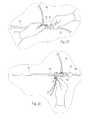
- FIG. 1Ais a somewhat schematic views of a view optimizing assembly for use with a laparoscope having a 0° shaft tip.
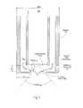
- FIG. 1Bis a section view of the sheath, showing internal fluid flow lumens, taken generally along line 1 B- 1 B in FIG. 1A .
- FIG. 2Ais a somewhat schematic of a view optimizing assembly for use with a laparoscope having an angled shaft tip.
- FIG. 2Bis a section view of the sheath, showing internal fluid flow lumens, taken generally along line 2 B- 2 B in FIG. 2A .
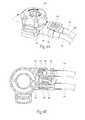
- FIG. 3Ais an enlarged perspective view of a manifold that the view optimizing assembly shown in FIG. 1A or FIG. 2A incorporates, including a quick exchange coupling, and a quick exchange coupler that the tubing set shown in FIG. 1A or FIG. 2A incorporates, the coupling and the coupler being disconnected.
- FIG. 3Bis a sectional view taken generally along line 3 B- 3 B in FIG. 3A , showing a one way check valve that is normally closed.
- FIG. 4Ais an enlarged perspective view of the manifold including a quick exchange coupling and the quick exchange coupler of the tubing set, as shown in FIG. 3A , but now connected.
- FIG. 4Bis a sectional view taken generally along line 4 B- 4 B in FIG. 4A , showing the one way check valve that is opened by the connection of the quick exchange coupling and connectors.
- FIGS. 5A ( 1 ) and 5 A( 2 )are enlarged, exploded views of the deflector assembly for use with a laparoscope having a 0° shaft tip.
- FIGS. 5B ( 1 ) and 5 B( 2 )are enlarged, exploded views of the deflector assembly for use with a laparoscope having an angled shaft tip.
- FIG. 6is a schematic view of the critical physical, pneumatic, and optical characteristics of the deflector assembly shown in FIGS. 5A and 5B .
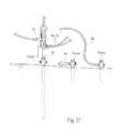
- FIGS. 7 to 34illustrate a representative method including the set up and use of the view optimizing assembly using sterile technique by technicians/operating room personnel.
- FIGS. 1A / 1 B and FIG. 2A / 2 Bshow a view optimizing assembly 10 for use in association with a state of the art laparoscope 12 .
- the laparoscope 12possesses a 0° (blunt) shaft tip.
- the laparoscopepossess an angled shaft tip (e.g., a 30° shaft tip or 45° shaft tip).
- the components of the view optimizing assembly 10may be made from plastic materials (extruded and/or molded), but other suitable materials, such as metal or a composite material, or combinations thereof could be used.
- the view optimizing assembly 10facilitates intra-operative defogging, surgical debris deflection, and cleaning of a laparoscope lens during minimally invasive surgery, while also maintaining visualization of the surgical site.
- the view optimizing assembly 10is intended to be a single-use, disposable laparoscopic accessory.
- the view optimizing assembly 10is desirably a sterile accessory for immediate set up and use on a sterile operating field.
- the view optimizing assembly 10comprises a multi-lumen sheath assembly 14 , which mounts over the shaft of the laparoscope 12 .
- the end of the shaftis sized and configured to match the size and configuration of the corresponding laparoscope 12 , having a blunt tip in FIG. 1A and angled tip in FIG. 2A .
- the assembly 10includes a tubing set 16 to connect the sheath 14 to an existing anhydrous carbon dioxide (CO 2 ) insufflation circuit.
- CO 2anhydrous carbon dioxide
- the view optimizing assembly 10makes possible the practice of a surgical method for maintaining clear visualization of the surgical site without removing the laparoscope 12 from the abdominal cavity for the purpose of cleaning or de-fogging its lens. Furthermore, the view optimizing assembly 10 also makes possible a surgical method for maintaining clear visualization that includes the ability to make a quick exchange of laparoscopes having different operating characteristics (e.g., laparoscopes with different tip angles, lengths, or diameters) entirely on the sterile operating field and without interference with the preexisting surgical set-up on the sterile operating field.
- the view optimizing assembly 10integrates with the existing suite of minimally invasive instrumentation. It does not interfere with the surgical set-up, and it requires minimal change in the process or practice of a surgical operating room (OR) team.
- the view optimization assembly 10desirably comes packaged for use in sterile peel away pouches (see FIG. 7 ).
- the pouchescontain the components of the view optimization assembly 10 , including the sheath 14 and a manifold 18 that is assembled to the sheath 14 and that includes a quick exchange coupling 20 ; the tubing set 16 which includes a quick exchange coupler 22 that mates with the quick exchange coupling 20 on the manifold 18 ; and (optionally) a vent device 24 .
- the sheath 14 /manifold 18 assemblyincludes a sheath 14 that is sized and configured to receive a laparoscope 12 having a prescribed tip angle, length, and diameter.
- the sheath 14includes a stop 26 (see FIGS. 5A ( 2 ) and 5 B( 2 )) formed adjacent the distal end of the sheath 14 .
- the stop 26prevents advancement of the laparoscope 12 beyond the distal end of the sheath 14 , so that lens at the distal end of the laparoscope 12 rests in a desired, generally coterminous alignment with the distal end of the sheath 14 .
- the sheath 14also includes a locking collar 28 at its proximal end to frictionally engage the laparoscope 12 and resist axial withdrawal of the laparoscope 12 from the sheath 14 .
- the laparoscope 12In use, it is expected that the laparoscope 12 will be inserted into the sheath 14 by a scrub nurse during set-up for the operation (see FIGS. 8 to 11 ). The assembled laparoscopic and sheath 14 will then be handed as a unit to personnel at the operating room (OR) table at the desired time). The laparoscope 12 is then connected by personnel at the OR table in conventional fashion to a light cable 30 (which directs light to illuminate the operative field) and the camera cable 32 (which takes the image from the scope and displays it on monitors in the OR) (see FIG. 14 ). The sheath 14 is sized and configured not to interfere with this normal set-up of the laparoscope 12 .
- the assembled laparoscopic and sheath 14are placed as a unit through a trocar into the body cavity (e.g., the abdominal cavity), for viewing the surgical procedure as it is performed (see FIG. 16 ).
- a trocarinto the body cavity (e.g., the abdominal cavity), for viewing the surgical procedure as it is performed (see FIG. 16 ).
- the sheath 14 /manifold 18 assemblyalso includes the manifold 18 at the proximal end of the sheath 14 .
- the manifold 18communicates with multiple lumens (five, 34 to 42 , are shown in the illustrated embodiment) formed within the wall of the sheath 14 (see FIGS. 1B and 2B ).
- the lumens 34 to 42convey anhydrous CO 2 to the distal end of the sheath 14 ; vent or exhaust air from the distal end of the sheath 14 through the manifold 18 ; and, if desired, convey sterile fluid and bursts of air to the distal end of the sheath 14 .
- two lumens 34 and 36are dedicated to the transport of CO 2 ; two lumens 40 and 42 are dedicated to venting; and one lumen 38 is dedicated to the transports of sterile fluid or air.
- the tubing set 16includes a quick exchange coupler 22 that mates with the quick exchange coupling 20 on the manifold 18 (see FIGS. 3A / 3 B and 4 A/ 4 B).
- the tubing set 16includes lengths of flexible medical grade tubing with individual end couplers (best shown in FIGS. 1A and 2A ) that connect to an existing CO 2 insufflation circuit and, if desired, a source of sterile fluid (saline or sterile water, preferably with a “surface active agent”) on the sterile operating field (e.g., a bag or a syringe).
- a source of sterile fluidsaline or sterile water, preferably with a “surface active agent”
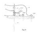
- the tubing set 16includes a Y-connector 44 that divides the anhydrous CO 2 output of the insufflation circuit in a first branch 46 for coupling to an insufflation trocar inserted in the body cavity (as will be described later), and a second branch 48 coupled to the quick exchange coupler 22 .
- the second branch 48diverts a small portion of the CO 2 output (e.g., 20% or less) to the quick exchange coupler 22 .
- the quick exchange coupler 22includes a one way check valve 50 that communicates with the second branch 48 of the tubing set 16 .
- the check valve 50comprises a ball valve. Insufflation pressure normally presses the ball valve 50 against a ball valve seat 52 (as shown in FIG. 3B ). A projection 54 in the manifold 18 displaces the ball valve 50 from the valve seat 52 when the quick exchange coupler 22 mates with the quick exchange coupling 20 on the manifold 18 (as shown in FIG. 4B ). Unseating the ball valve 50 opens flow communication through the check valve 50 . In the absence of coupling the quick exchange coupler 22 on the tubing set 16 to the quick exchange coupling 20 on the manifold 18 , the check valve 50 remains closed, normally blocking flow of CO 2 through the second branch 48 .
- the tubing set 16accommodates the set-up of the supply of the entire CO 2 output to a insufflation trocar through the tubing set 16 , separate and independent of the connection of the tubing set 16 to the manifold 18 of the sheath 14 .
- FIGS. 3A and 4Afurther show, a latch 56 carried on a spring-biased button 58 on the quick exchange coupler 22 “clicks” into a detent 60 on the quick exchange coupling 20 on the manifold 18 to reliably lock the coupler 22 and coupling 20 together for use, opening the check valve to flow CO 2 through the second branch 48 (shown in FIGS. 4A / 4 B). Depressing the button 58 allows the quick exchange coupler 22 and coupling 20 to be separated, and the check valve 50 will close in response to insufflation pressure in the second branch 48 (as shown in FIGS. 3A / 3 B).
- connection of the quick exchange coupling 20 on the manifold 18 to the quick exchange coupler 22 on the tubing set 16is intended to occur at the OR table in the normal course, after the laparoscope 12 is connected to the light cable 30 and the camera cable 32 (see FIG. 15 ).
- the one way check valve 50is opened, and the manifold 18 directs the small portion of CO 2 from the CO 2 insufflation circuit.
- Disconnection of the of the quick exchange coupling 20 on the manifold 18 to the quick exchange coupler 22 on the tubing set 16is also intended to occur at the OR table in the normal course, after a removal and/or exchange of a laparoscope 12 (see FIG. 22 ).
- the vent device 24(see FIGS. 1A and 2A ) comprises a tube with an inline membrane 62 that restricts air flow through the tube. A proximal end of the tube is sized and configured to couple to a stopcock valve of a conventional trocar, as will be described later. In use, the vent device 24 provides a controlled leak of CO 2 from the operating cavity, as will also be described in greater detail later.
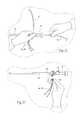
- the sheath 14includes at its distal end a deflector assembly 64 (see FIGS. 5A ( 1 ) and 5 A( 2 ) for a blunt shaft tip and FIGS. 5B ( 1 ) and 5 B( 2 ) for an angled shaft tip).
- the deflector assembly 64projects a predetermined distance beyond the distal end of the sheath 14 , and thus also a predetermined distance beyond the lens at the distal end of the laparoscope 12 .
- the deflector assembly 64communicates with the lumens in the sheath 14 .
- the deflector assembly 64is sized and configured to direct the small portion of the CO 2 from the insufflation circuit in a prescribed flow path and flow velocity continuously across the laparoscopic lens.
- the desired flow path and flow velocity of CO 2 established by the deflector assembly 64 continuously across the laparoscopic lenscreates a “wind shear.”
- the wind shear path of anhydrous CO 2prevents fogging.
- the desired flow path and flow velocity of CO 2 established by the deflector assembly 64 continuously across the laparoscopic lensalso desirably serves to deflect smoke and surgical debris away from the laparoscopic lens during surgery.
- the size and configuration of the deflector assemblyare defined and constrained by several, sometime overlapping considerations including (i) prescribed physical characteristics, which are imposed due to the need to access the operating environment in as minimally invasive manner as possible and to be compatible with state of the art laparoscopes and other laparoscopic surgical instruments and techniques; (ii) prescribed pneumatic characteristics, which are imposed due to the need to create a particular “wind shear” effect in terms of the flow path and flow velocity of CO 2 across the laparoscopic lens; and (iii) prescribed optical characteristics, which are imposed due to the need to prevent interference with the field of view and the visualization of the operating field by the laparoscope 12 .
- the size and configuration requirements for minimally invasive access compatible with state of the art laparoscopic instrumentation and techniquesare paramount. These requirements impose constrains upon the minimum inside diameter of the sheath 14 as well as the maximum outside diameter of the sheath 14 . Because state of the art laparoscopes are provided with different shaft diameters, lengths, and lens configurations, the sheath dimensions and configuration change for compatibility with them.
- the view optimizing assembly 10actually includes a family of sheath 14 /manifold 18 assemblies differently sized and configured to accommodate different classes of laparoscopes, to make possible compatibility with the families of state of the art laparoscopes that are in use.
- state of the art laparoscopesinclude 10 mm laparoscopes, 5 mm laparoscopes, and, within these sizes, 0° shaft tips, 30° shaft tips, and 45° shaft tips.
- manufacturing tolerancestypically vary from scope to scope, as well as from manufacturer to manufacturer.
- a given sheath 14 /manifold 18 assembly for a given laparoscope class(e.g., 10 mm or 5 mm) desirably takes these typical manufacturing and manufacturer variances into account, and is desirably sized and configured to fit the largest scope variance encountered within a given laparoscope class.
- the minimum inside diameter of a given sheath 14must closely conform to the maximum outside diameter of the shaft of the particular state of the class of laparoscope 12 selected for use, which the sheath 14 must accommodate in a smooth, sliding fit. Further, a gap between the outside diameter of the laparoscope shaft and the inside diameter of the sheath 14 must be minimized to avoid the transport and leakage of blood and fluids from the operating field. Still further, minimizing the gap also assures that the laparoscope 12 self-centers in the sheath 14 , thereby assuring faithful and accurate visualization through the laparoscope lens.
- the inside diameter of the sheath 14is manufactured to 0.405 inch, providing a gap thickness of 0.0064 inch.
- the inside diameter of the sheath 14is manufactured to 0.218 inch, providing gap thickness of 0.011 inch.
- the maximum outside diameter of the sheath 14 for minimally invasive accessmust take into account the minimum inside diameter of the trocar, which the maximum outside diameter cannot exceed.
- the outside diameter of the sheath 14is manufactured to 0.486 inch, providing a gap thickness of 0.0115 inch.
- the outside diameter of the sheath 14is manufactured to 0.300 inch, providing a gap thickness of 0.012 inch.
- the inside and outside diameters of the sheath 14define the wall thickness for the sheath S w
- the wall thickness S wtogether with the length of the sheath 14 , in turn, define the maximum area available for the transport of the CO 2 and fluids by the sheath 14 .
- the area of the fluid flow lumen or lumens dedicated to the supply of CO 2defines the maximum flow rate of the CO 2 directed by the deflector assembly 64 .
- the flow rateshould be sufficient at a minimum, given the output of the insufflator selected for use, to supply anhydrous CO 2 across the lens of the laparoscope 12 sufficient to prevent fogging. Also affecting the effectiveness of the CO 2 to defog the lens, is the water content of the anhydrous CO 2 . Given the same flow rate, the less water that is present in the anhydrous CO 2 , the greater is the defogging capacity of the assembly. Further, the flow rate desirable should also be sufficient to deflect smoke and surgical debris away from the viewing field of the laparoscopic lens during surgery, so that the anhydrous CO 2 directed by the deflector assembly 64 both defogs and deflects debris.
- Medical grade CO 2 for use with conventional insufflatorsis typically 99% pure, that is, no more than 1% of the gas is other than CO 2 , and such medical grade anhydrous CO 2 generally has a maximum moisture content of 25 parts per million by volume.
- a state of the art insufflator circuitdelivers anhydrous CO 2 at a max flow rate of about 20 liters per hour.
- the insufflator circuitwill sense pressure in the circuit and cycle off when the sensed pressure is at or above 15 mmHg and cycle on when the sensed pressure is below 15 mmHg.
- a flow rate of at least about 1.0 liters per minuteis critical to achieving this objective.
- a flow rate less than 0.8 liters per minuteis not sufficient to prevent significant accumulation of moisture on the laparoscope lens.
- the total area available in the sheath wallis 0.056 square inches. Based upon required structural support within the wall (inside, outside, and radial) the total available area for lumens to transport fluids is 0.027 square inch.
- the total lumen areais occupied by five lumens 34 to 42 , two for transporting CO 2 ( 34 and 36 ), one for sterile fluid ( 38 ), and two for passive exhaust air venting ( 40 and 42 ).
- each lumencan be maximized by selection of lumen geometry.
- lumen geometryis generally triangular or pie shaped with rounded corners.
- the radial walls that separate the lumens within the sheath 14are sized to minimize the spacing between the lumens.
- CO 2 transportis accomplished by two lumens 34 and 36 that extend about 175 degrees about the outer circumference of the sheath 14 and comprising a flow area of 0.013 square inches.
- Sterile fluid transportis accomplished by one lumen 38 comprising a flow area of 0.003 square inches.
- Exhaust air ventingis accomplished by two lumens 40 and 42 comprising a flow area of 0.011 square inches.
- the distal openings of the exhaust lumens 40 and 42desirably are spaced from the distal end of the sheath, to prevent uptake of blood and fluids.
- the deflector assembly 64must overhang the laparoscopic lens by a prescribed transverse distance, defining a deflection width X, sufficient to change the direction of CO 2 flowing axially through lumens of the sheath 14 (i.e., along the axis of the laparoscope shaft) into a non-axially, transverse path across the laparoscopic lens (i.e., at an angle relative to the axis of the laparoscope shaft). Still, the distance of the deflection width X should not extend to the point that is obstructs the field of the view of the laparoscopic lens. This is an example where a pneumatic characteristic of the deflector assembly 64 overlaps with an optical characteristic. Further optical characteristics will be described in greater detail below.
- the deflector assembly 64must also project axially beyond the distal terminus of the sheath 14 by a prescribed axial distance, defining an air channel distance Y, sufficient to maintain the CO 2 flowing along the path bounded by the deflection width X at a distance sufficiently close (proximal) to the laparoscopic lens to achieve the desired shear flow effect, but without forming an abrupt flow bend that can lead to a reduction in the desired CO 2 flow velocity.
- the deflection width X and the channel distance Ydefine the pneumatic characteristics of the deflection assembly.
- the pneumatic characteristicscreate a flow path that conveys CO 2 continuously across the laparoscopic lens at the desired flow velocity, in shorthand called the “wind shear.”
- the pneumatic characteristics of the CO 2 “wind shear” across the laparoscopic lensprevent fogging, as well as desirably deflect smoke and surgical debris away from the viewing field of the laparoscopic lens during surgery.
- the pneumatic characteristics defined by the deflection width X and the channel distance Ycreate an exit angle A EXIT , measured between the plane of the laparoscopic lens and the terminal edge of the deflector assembly 64 .
- the exit angle A EXITmust be less than a maximum angle of 45 degrees, else the flow path of the CO 2 will not pass sufficiently both across and proximal to the laparoscopic lens.
- the channel distance Yshould be at least equal to the wall thickness of the sheath S w and should not exceed 1.5 times the wall thickness of the sheath S w .
- the deflection width Xshould be at least equally to two times the channel distance Y, but not extend into the field of view of the laparoscopic lens.
- the optical characteristics of the deflector assembly 64are selected (i) to not block or reduce the illuminated image of the operating field provided by the laparoscope 12 ; (ii) not decrease the intensity of the illumination provided by the laparoscope 12 on the operating field; and (iii) prevent reflection of illumination light at the lens of the laparoscope 12 .
- the maximum deflection width Xtakes into account one of the desirable optical characteristics; namely, the deflection width X should not obstruct the field of the view of the laparoscopic lens.
- the deflector assembly 64is desirably made from a material having high light transmission properties (i.e., transparency), to not interfere with the passage of light through the light cable 30 onto the operating field as well as the passage of the reflected image conveyed to the camera cable 32 of the laparoscope 12 .
- the material and surface finish of the deflector assembly 64must pose minimal reflectively to light.
- the deflector assembly 64is made from Bayer Makrolen Rx1805 with a surface finish defined as SPI/SPE A-3.
- CO 2 transportis accomplished by two lumens 34 and 36 that extend about 175 degrees about the outer circumference of the sheath 14 .
- the orientation of the deflector assembly 64 relative to the laparoscopic lensis not critical.
- the orientation of the deflector assembly 64 relative to the laparoscopic lensis critical.
- the angled tip of a typical laparoscope 12has a high end 66 and a low end 68 .
- the lensslopes at the prescribed angle between the high end 66 and the low end 68 .
- the illumination cable 30transmitting light onto the operating field
- the camera cable 32transmitting reflected light back to the camera
- the deflector assembly 64be oriented relative to the sloped laparoscopic lens such that the flow CO 2 is directed across the sloped plane of the lens from the low end 68 of the tip toward the high end 66 of the tip.
- the defogging and debris deflection flow pathoriginates proximal to the camera cable 32 , which effectively comprises the eyes of the OR team.
- the desired exit angle A EXITdirects the flow path of the CO 2 both sufficiently across and proximal to the sloped plane of the laparoscopic lens to achieve optimal defogging and debris deflection.
- the tubing set 16can also include, connected to the quick exchange coupler 22 , a length of tubing 70 sized and configured for connection to a source 72 of sterile fluid, such as saline or sterile water (as shown in FIGS. 1A and 2A ).
- a source 72 of sterile fluidsuch as saline or sterile water (as shown in FIGS. 1A and 2A ).
- the sterile fluidincludes in solution a “surface-active agent” that stabilizes mixtures of oil and water (e.g., fat) by reducing the surface tension at the interface between the oil and water molecules.
- the quick exchange coupling 20 on the manifold 18can also include a port to integrally connect the sterile fluid tubing 70 to direct the sterile fluid through the separate lumen 38 in the sheath 14 to the distal end of the sheath 14 .
- the deflector assembly 64directs the sterile fluid across the laparoscopic lens.
- the sterile fluid tubing 70desirably includes an in-line pumping device 72 .
- the in-line pumping device 72is sized and configured to be operated on demand by a person at the OR table to convey bursts of sterile fluid through the manifold 18 through the lumen to the distal end of the sheath 14 .
- the in-line pumping device 72 and sourcecan be integrated and comprise, e.g., a 20 cc syringe filled with sterile fluid and connected by a tubing luer-lock on the saline tubing.
- the in-line pumping device 72 and sourcecan be separate and comprise, e.g., a bag of sterile fluid, a spike connection on the saline tubing of the tubing set 16 to open communication with the bag in conventional fashion, and an inline squeeze bulb or the like to pump burst of sterile fluid from the bag to the quick exchange coupler 22 .
- the deflector assembly 64is also sized and configured to direct the burst of sterile fluid in a desired path across the laparoscopic lens.
- the bursts of sterile fluidserve to flush debris off the end of the lens that may eventually accumulate, thereby cleaning the lens.
- bursts of air supplied through the deflector assembly 64 by a squeeze pump 74 in the tubing set 16serve to clear residual fluid droplets off the lens and away from the deflector assembly 64 to maintain the desired flow path and flow velocity of CO 2 established by the deflector assembly 64 continuously across the laparoscopic lens, to maintain an acceptable view.
- the deflector assembly 64directs the bursts of sterile fluid or air along a plurality of individual diverging channels 76 (three are shown).
- the diverging channels 76distribute the bursts of sterile fluid or air in a fanning pattern across the lens of the laparoscope 12 .
- the diverging channels 76discharge the bursts of sterile fluid or air in a path that is generally ninety-degrees to the path of CO 2 . This orientation of the sterile fluid path relative to the CO 2 path across the lens, optimal for effective lens cleaning, applies to both 0° shaft tips and angled tips (e.g., 30° shaft tips and 45° shaft tips).
- the view optimizing assemblyis well suited for use as a single-use disposable laparoscopic accessory device to facilitate intra-operative defogging and debris deflection (due to the flow of anhydrous CO 2 ) and cleaning of the lens of a laparoscope 12 (due to burst of sterile fluid, preferably including a “surface-active agent”) during minimally invasive surgery, while also maintaining visualization of the surgical site.
- FIGS. 7 to 34illustrate a representative method including the set up and use of the view optimizing assembly using sterile technique by qualified technicians/operating room personnel.
- the procedurecan be incorporated into written instructions for use that accompany the packaging.
- the instructionscan also be supplied separately, e.g., embodied in separate instruction manuals, or in video or audio tapes, CD's, and DVD's.
- the instructions for usecan also be available through an internet web page.
- the instructionscan direct the OR set-up to peel open the outer pouches in which the components of the view optimizing assembly (shown in FIG. 7 ), and remove the sterile contents on the sterile field.
- the sheath 14 /manifold 18 assemblyis removed, taking care to prevent damage to the walls of the sheath 14 or to its distal end, and also keeping the tubing set 16 and vent device 24 on the sterile field prior to making necessary connections.
- the sheath 14(with the manifold 18 , which is integrally connected to the sheath 14 during manufacture, called a sheath assembly) can be assembled to the corresponding laparoscope 12 .
- the laparoscope 12can be inserted down into the sheath 14 .
- the sheath 14is sized and configured so that the laparoscope 12 will slide smoothly through the sheath 14 . Insertion continues until the lens and distal rim of the laparoscope 12 seat against the stop at the distal end of the sheath 14 .
- the laparoscope 12will “bottom out” inside the sheath 14 against the stop 26 , assuring correct axial alignment of the lens with the deflector assembly 64 .
- the corresponding sheath assemblywill also include an alignment fork guide 78 .
- the light post of the scopeseats within the alignment fork guide 78 , therefore assuring correct rotational alignment between the angled lens and the deflector assembly 64 .
- the laparoscope 12(now fully inserted into the sheath 14 ) the manifold 18 are supported by hand, a member of the OR set-up team rotates the locking collar 28 on the sheath assembly in the desired direction, e.g., clockwise (see FIGS. 9 and 11 ), indicated by an arrow on the locking collar 28 , until a firm stop is felt tactilely (e.g., after approximately one-third (1 ⁇ 3) of a turn). Registration of an alignment mark on the locking collar 28 and an alignment mark on the manifold 18 serves to visually confirm that the laparoscope 12 is secured against axial movement relative to the sheath 14 .
- the insufflatoris set up off the sterile field. Once the patient is draped on the sterile field, and it is expected that the end of the output tubing from the insufflator (originating from the insufflator off the sterile field) will brought onto the sterile field. It is also expected that the light cable 30 and the camera cable 32 for the laparoscope 12 will be brought onto the sterile field.
- the OR teammakes an incision to gain access to the laparoscopic operating site within the body, e.g., into the abdominal cavity through the abdominal wall.
- a first trocar with a stopcock valve(which may take the form of an optical trocar) is inserted through the incision.
- the first trocarcan be pushed through abdominal wall with only a skin incision.
- the obturator(the sharp inner insert of the trocar) is removed from the first trocar once it is in position.
- the insufflator line of the tubing set 16 on the sterile fieldis connected to the output tubing of the insufflator circuit on the sterile field.
- the first branch 46 of the tubing set 16 on the sterile field, originating at the Y-connector 44 ,is coupled to the stopcock valve of the first trocar (see FIG. 13 ).
- the stopcock valveis opened, and the insufflator is turned on. CO 2 output of the insufflation circuit inflates the abdomen through the first trocar.
- the second branch 48 of the tubing set 16 on the sterile fieldalso originating at the Y-connector 44 , and the quick exchange coupler 22 integrally attached to it can remain on the sterile field in a free, unconnected condition as the insufflator supplies CO 2 through the first branch 46 .
- the one-way check valve in the quick exchange coupler 22serves to block flow of CO 2 through the second branch 48 , even as the insufflator supplies CO 2 through the first branch 46 .
- the entire CO 2 pressure of the insufflator circuitis, at the present, delivered to the first trocar through the first branch 46 .
- the first laparoscope 12 selected for usewhich has been pre-inserted into the sheath 14 by the OR set-up team as just described, is handed to personnel at the OR table at the appropriate time.
- personnel at the OR tableconnect the light cable 30 and the camera cable 32 to the laparoscope 12 (see FIG. 14 ).
- personnel at the OR tablenow connect the quick exchange coupler 22 of the tubing set 16 to the quick exchange coupling 20 of the manifold 18 (see FIG. 15 ).
- the one way valveopens, and a small portion of the output of the insufflator circuit is routed by the second branch 48 through the manifold 18 into to the sheath 14 .
- the laparoscope/sheath assemblyis then placed as an integrated unit through the first trocar to get an initial view of the abdominal cavity (see FIG. 16 ). Due to the technical features of the deflector assembly 64 , CO 2 flows over the lens, eliminating fogging and also deflecting away debris.
- the pumpe.g., the 20 cc syringe
- sterile fluidpreferably with a “surface-active agent”
- the deflector assembly 64directs the fluid bursts across the lens in a path generally 90-degrees offset from the CO 2 path. Once this is done, the bulb on the tubing set 16 can be pumped several times introduce bursts of air to clear droplets off the lens and away from the tip deflector, to maintain to the continuous directed flow of CO 2 across the laparoscopic lens.
- additional ancillary trocars with stopcock valvese.g. three to four, or more, are also placed through incisions to provide access for other instruments (see FIG. 17 ).
- the trocar vent device 24 provided with the view optimizing assemblyis desirably placed in the stopcock of one of the ancillary trocars, and the stopcock valve is opened (see FIG. 18 ).
- a member of the OR teampreferable decouples the main insufflation line (the first branch 46 tubing of the Y-connector 44 of the tubing set 16 ) from the first trocar to the stopcock valve of another available trocar on the sterile field (except the trocar to which the vent device 24 is coupled).
- This other trocarthen serves as the main insufflation trocar, separate from the first trocar, which now serves as the main visualization trocar.
- the main CO 2 insufflation provided for the duration of the surgeryis provided by an insufflation trocar that is also not the visualization trocar.
- the controlled leak of insufflation pressure that the vent device 24 providescreates a pressure gradient within the pneumo-peritoneum that helps maintain a generally continuous flow of CO 2 from the deflector assembly 64 across the lens, despite periodic cycling of the insufflator.
- Lumens 40 and 42 in the sheath 14can also serve as additional passive vents, to leak insufflation pressure out through the manifold 18 .
- the deflector assembly 64provides intra-operative defogging and cleaning of the laparoscope lens during the minimally invasive surgery, while maintaining visualization of the surgical site.
- the sterile fluid flush mechanismcan be used, as desired, if required to augment visualization by flushing the lens. If this is done, the bulb on the tubing set 16 should be pumped several times to clear droplets off the lens and away from the deflector assembly 64 to maintain the CO 2 curtain across the lens.
- the OR teamcan decide, e.g., that one portion of the procedure is better visualized with a different angle scope.
- the quick exchange features of the coupler of the tubing set 16 and the coupling of the manifold 18greatly facilitate the exchange of one laparoscope 12 for another with minimal interruption of the surgical procedure and without compromising the sterile field.
- a member of the OR teamwithdraws the laparoscope/sheath assembly an integrated unit from the visualization trocar (see FIG. 20 ).
- a member of the OR teamdisconnects the laparoscope 12 from the light cable 30 and camera cable 32 (see FIG. 21 ).
- a member of the OR teamuncouples the quick exchange coupler 22 from the quick exchange coupling 20 , freeing the laparoscope/sheath assembly from the tubing set 16 (see FIG. 22 ).
- the disconnected laparoscope/sheath assemblyis handed as an integrated unit to a member of the OR team, e.g., a scrub nurse (see FIG. 23 ). There is no reason to remove the sheath 14 from the matching laparoscope 12 at this time. This can be accomplished later, after the surgery is all done.
- the laparoscope/sheath assemblythat includes the second laparoscope 12 that is to be used, has already been assembled into an integrated unit, as previously described. This pre-assembled unit is handed to a member of the OR team (see FIG. 24 ). A member of the OR team connects the second laparoscope 12 to the light cable 30 and camera cable 32 (see FIG. 25 ). A member of the OR team couples the quick exchange coupler 22 of the tubing set 16 to the quick exchange coupling 20 , connecting the second laparoscope/sheath assembly in flow communication with the tubing set 16 (see FIG. 26 ), completing the quick exchange. The second laparoscope/sheath assembly is inserted into the visualization trocar (see FIG. 27 ).
- the quick connect featurefunctions with a manifold 18 associated with every sheath 14 .
- the tubing set 16 on the sterile fieldcan be rapidly disconnected, but need not, and desirably is not, exchanged with another tubing set 16 .
- the same tubing set 16serves every laparoscope/sheath assembly used (unneeded tubing sets 16 that came with the additional sheaths can be simply discarded).
- the surgeryproceeds using the second laparoscope/sheath assembly.
- a member of the OR teamdisconnects the laparoscope 12 from the light cable 30 and camera cable 32 (see FIG. 29 ).
- a member of the OR teamuncouples the quick exchange coupler 22 from the quick exchange coupling 20 , freeing the laparoscope/sheath assembly from the tubing set 16 .
- the laparoscope/sheath assemblyis handed to a member of the OR team (see FIG. 31 ), and placed alongside previously used laparoscope/sheath assemblies (see FIG. 32 ).
- Access sitesare closed.
- the insufflatoris shut off.
- the tubing set 16is disconnected from the insufflator circuit.
- the lock collars on the manifolds 18are loosened, and laparoscopes are withdrawn from the sheaths for reuse ( FIG. 33 ).
- the sheaths and tubing set 16are disposed of ( FIG. 34 ).
- Some trocarsare called “optical trocars” that have a lumen within the obturator, that is within the trocar. If the lens of a laparoscope 12 is first placed into the center of an optical trocar to guide the first trocar insertion, then the sheath 14 cannot be present on the laparoscope 12 , as the combination cannot fit through the lumen of the obturator. In this situation, the laparoscope 12 is used without a sheath 14 is used to place the first trocar. The laparoscope 12 is then inserted through the sheath 14 , and connection of the tubing set 16 occurs in the manner just described. With the obturator removed from the trocar, the laparoscope/sheath assembly is placed through the first trocar in the manner described.
Landscapes
- Health & Medical Sciences (AREA)
- Life Sciences & Earth Sciences (AREA)
- Surgery (AREA)
- General Health & Medical Sciences (AREA)
- Biomedical Technology (AREA)
- Veterinary Medicine (AREA)
- Public Health (AREA)
- Animal Behavior & Ethology (AREA)
- Heart & Thoracic Surgery (AREA)
- Engineering & Computer Science (AREA)
- Medical Informatics (AREA)
- Nuclear Medicine, Radiotherapy & Molecular Imaging (AREA)
- Molecular Biology (AREA)
- Pathology (AREA)
- Biophysics (AREA)
- Radiology & Medical Imaging (AREA)
- Physics & Mathematics (AREA)
- Optics & Photonics (AREA)
- Anesthesiology (AREA)
- Hematology (AREA)
- Endoscopes (AREA)
Abstract
Description
Claims (11)
Priority Applications (1)
| Application Number | Priority Date | Filing Date | Title |
|---|---|---|---|
| US14/490,501US10231609B2 (en) | 2007-06-19 | 2014-09-18 | Systems and methods for optimizing and maintaining visualization of a surgical field during the use of surgical scopes |
Applications Claiming Priority (5)
| Application Number | Priority Date | Filing Date | Title |
|---|---|---|---|
| US11/765,340US9050036B2 (en) | 2007-06-19 | 2007-06-19 | Device for maintaining visualization with surgical scopes |
| US12151408P | 2008-12-10 | 2008-12-10 | |
| US17086409P | 2009-04-20 | 2009-04-20 | |
| US12/653,148US8888689B2 (en) | 2007-06-19 | 2009-12-09 | Systems and methods for optimizing and maintaining visualization of a surgical field during the use of surgical scopes |
| US14/490,501US10231609B2 (en) | 2007-06-19 | 2014-09-18 | Systems and methods for optimizing and maintaining visualization of a surgical field during the use of surgical scopes |
Related Parent Applications (1)
| Application Number | Title | Priority Date | Filing Date |
|---|---|---|---|
| US12/653,148ContinuationUS8888689B2 (en) | 2007-06-19 | 2009-12-09 | Systems and methods for optimizing and maintaining visualization of a surgical field during the use of surgical scopes |
Publications (2)
| Publication Number | Publication Date |
|---|---|
| US20150005582A1 US20150005582A1 (en) | 2015-01-01 |
| US10231609B2true US10231609B2 (en) | 2019-03-19 |
Family
ID=42242996
Family Applications (4)
| Application Number | Title | Priority Date | Filing Date |
|---|---|---|---|
| US12/653,148Expired - Fee RelatedUS8888689B2 (en) | 2007-06-19 | 2009-12-09 | Systems and methods for optimizing and maintaining visualization of a surgical field during the use of surgical scopes |
| US12/635,632Active2032-01-26US9050037B2 (en) | 2007-06-19 | 2009-12-10 | View optimizer and stabilizer for use with surgical scopes |
| US14/490,501ActiveUS10231609B2 (en) | 2007-06-19 | 2014-09-18 | Systems and methods for optimizing and maintaining visualization of a surgical field during the use of surgical scopes |
| US14/733,752AbandonedUS20150342449A1 (en) | 2007-06-19 | 2015-06-08 | View optimizer and stabilizer for use with surgical scopes |
Family Applications Before (2)
| Application Number | Title | Priority Date | Filing Date |
|---|---|---|---|
| US12/653,148Expired - Fee RelatedUS8888689B2 (en) | 2007-06-19 | 2009-12-09 | Systems and methods for optimizing and maintaining visualization of a surgical field during the use of surgical scopes |
| US12/635,632Active2032-01-26US9050037B2 (en) | 2007-06-19 | 2009-12-10 | View optimizer and stabilizer for use with surgical scopes |
Family Applications After (1)
| Application Number | Title | Priority Date | Filing Date |
|---|---|---|---|
| US14/733,752AbandonedUS20150342449A1 (en) | 2007-06-19 | 2015-06-08 | View optimizer and stabilizer for use with surgical scopes |
Country Status (7)
| Country | Link |
|---|---|
| US (4) | US8888689B2 (en) |
| EP (1) | EP2361034B1 (en) |
| JP (1) | JP5537563B2 (en) |
| CN (1) | CN102307511B (en) |
| AU (1) | AU2009325140A1 (en) |
| CA (1) | CA2746371C (en) |
| WO (2) | WO2010068265A1 (en) |
Cited By (1)
| Publication number | Priority date | Publication date | Assignee | Title |
|---|---|---|---|---|
| US20190290114A1 (en)* | 2010-08-04 | 2019-09-26 | Floshield, Inc. | Systems and methods for optimizing and maintaining visualization of a surgical field during the use of surgical scopes |
Families Citing this family (101)
| Publication number | Priority date | Publication date | Assignee | Title |
|---|---|---|---|---|
| DE102006057809A1 (en)* | 2006-12-06 | 2008-06-12 | Ruprecht-Karls-Universität Heidelberg | intubation tube |
| US9050036B2 (en) | 2007-06-19 | 2015-06-09 | Minimally Invasive Devices, Inc. | Device for maintaining visualization with surgical scopes |
| WO2010068265A1 (en) | 2008-12-10 | 2010-06-17 | Minimally Invasive Devices, Llc | Systems and methods for optimizing and maintaining visualization of a surgical field during the use of surgical scopes |
| US9078562B2 (en) | 2010-01-11 | 2015-07-14 | Minimally Invasive Devices, Inc. | Systems and methods for optimizing and maintaining visualization of a surgical field during the use of surgical scopes |
| US20110201888A1 (en)* | 2010-02-18 | 2011-08-18 | Verner Sarah N | Medical Devices and Methods |
| US9610412B2 (en)* | 2010-03-02 | 2017-04-04 | Covidien Lp | Internally pressurized medical devices |
| US20110313255A1 (en)* | 2010-06-18 | 2011-12-22 | Eric Stanley | Veress needle with removable optical inserts |
| US20120184897A1 (en)* | 2010-07-19 | 2012-07-19 | Minimally Invasive Devices, Llc | Integrated systems and methods for maintenance and management of an intra-abdominal gas environment during laparoscopic surgery |
| ES2725204T3 (en)* | 2010-10-14 | 2019-09-20 | Medivators Inc | Universal cover |
| US9522017B2 (en) | 2010-12-03 | 2016-12-20 | Minimally Invasive Devices, Inc. | Devices, systems, and methods for performing endoscopic surgical procedures |
| US9023064B2 (en) | 2011-11-16 | 2015-05-05 | Inx Medical, Llc | Ligator and method of operating and manufacturing same |
| US10912699B2 (en) | 2012-01-10 | 2021-02-09 | Alessio Pigazzi | Method of securing a patient onto an operating table when the patient is in a position such as the trendelenburg position and apparatus therefor including a kit |
| US8920456B2 (en)* | 2012-04-18 | 2014-12-30 | Terumo Cardiovascular Systems Corp. | Insufflation damper for endoscopic vessel dissector/harvester |
| US9615728B2 (en) | 2012-06-27 | 2017-04-11 | Camplex, Inc. | Surgical visualization system with camera tracking |
| US9642606B2 (en) | 2012-06-27 | 2017-05-09 | Camplex, Inc. | Surgical visualization system |
| US20140005640A1 (en) | 2012-06-28 | 2014-01-02 | Ethicon Endo-Surgery, Inc. | Surgical end effector jaw and electrode configurations |
| US10595719B2 (en) | 2012-08-01 | 2020-03-24 | Ronald Hurst | System and method for cleaning a cannula during a surgical procedure using a hinged tip |
| US9839349B2 (en)* | 2012-10-05 | 2017-12-12 | Fujifilm Corporation | Method of placing medical insertion instruments in body cavity |
| CN105103192B (en) | 2013-01-10 | 2018-09-25 | 汤姆逊许可公司 | Method and apparatus for vertex error correction |
| US9782159B2 (en) | 2013-03-13 | 2017-10-10 | Camplex, Inc. | Surgical visualization systems |
| WO2014151824A1 (en)* | 2013-03-14 | 2014-09-25 | Minimally Invasive Devices, Inc. | Fluid dispensing control systems and methods |
| US10028651B2 (en) | 2013-09-20 | 2018-07-24 | Camplex, Inc. | Surgical visualization systems and displays |
| EP3046458B1 (en) | 2013-09-20 | 2020-10-21 | Camplex, Inc. | Surgical visualization systems |
| US20150087911A1 (en) | 2013-09-26 | 2015-03-26 | Gyrus Acmi, Inc. D.B.A Olympus Surgical Technologies America | Endoscope sheath deflection devices |
| US10264957B2 (en) | 2013-09-30 | 2019-04-23 | Nagase Medicals Co., Ltd. | Endoscope lens cleaner |
| US20150297311A1 (en)* | 2013-12-23 | 2015-10-22 | Camplex, Inc. | Surgical visualization systems |
| US20160331220A1 (en)* | 2014-01-13 | 2016-11-17 | Covidien Lp | Medical device cleaning system |
| CN104887311A (en)* | 2014-03-04 | 2015-09-09 | 镇江市新天医疗器械有限公司 | Surface demister of optical lens of oral dental surgical microscope |
| US10314513B2 (en) | 2014-10-10 | 2019-06-11 | Intuitive Surgical Operations, Inc. | Systems and methods for reducing measurement error using optical fiber shape sensors |
| CN104306063A (en)* | 2014-11-10 | 2015-01-28 | 纪勇 | Video endoscopic surgical tool |
| US9345386B1 (en)* | 2014-11-24 | 2016-05-24 | Gyrus Acmi, Inc. | Adjustable endoscope sheath |
| EP3226799A4 (en) | 2014-12-05 | 2018-07-25 | Camplex, Inc. | Surgical visualization systems and displays |
| US10080488B2 (en) | 2014-12-12 | 2018-09-25 | Medix3d LLC | Cleaning device for cleaning a scope, laparoscope or microscope used in surgery or other medical procedures and a method of using the device during surgical or other medical procedures |
| WO2016154589A1 (en) | 2015-03-25 | 2016-09-29 | Camplex, Inc. | Surgical visualization systems and displays |
| CN107072742B (en)* | 2015-04-22 | 2020-01-07 | 奥林巴斯株式会社 | medical device |
| WO2016194648A1 (en)* | 2015-06-03 | 2016-12-08 | オリンパス株式会社 | Endoscopic device and endoscopic system |
| CN106308726A (en)* | 2015-06-30 | 2017-01-11 | 袁媛 | Uterus detector |
| CN113143355A (en) | 2015-09-04 | 2021-07-23 | 美多斯国际有限公司 | Multi-shield spinal access system |
| US12150636B2 (en) | 2015-09-04 | 2024-11-26 | Medos International Sárl | Surgical instrument connectors and related methods |
| US11744447B2 (en) | 2015-09-04 | 2023-09-05 | Medos International | Surgical visualization systems and related methods |
| US11439380B2 (en) | 2015-09-04 | 2022-09-13 | Medos International Sarl | Surgical instrument connectors and related methods |
| US10987129B2 (en) | 2015-09-04 | 2021-04-27 | Medos International Sarl | Multi-shield spinal access system |
| US11672562B2 (en) | 2015-09-04 | 2023-06-13 | Medos International Sarl | Multi-shield spinal access system |
| US10413168B2 (en) | 2015-09-07 | 2019-09-17 | Plasmatica Ltd. | Preventing fog on a medical device viewport |
| US11896203B2 (en) | 2015-09-07 | 2024-02-13 | Plasmatica Ltd. | Methods and systems for providing plasma treatments to optical surfaces |
| US11896204B2 (en) | 2015-09-07 | 2024-02-13 | Plasmatica Ltd. | Methods and systems for providing plasma treatments to optical surfaces |
| US11246480B2 (en) | 2015-09-07 | 2022-02-15 | Plasmatica Ltd. | Preventing fog on a medical device viewport |
| WO2017091704A1 (en) | 2015-11-25 | 2017-06-01 | Camplex, Inc. | Surgical visualization systems and displays |
| WO2017177309A1 (en)* | 2016-04-15 | 2017-10-19 | Titan Medical Inc. | Apparatus for cleaning an imaging system used during a medical procedure |
| ITUA20163961A1 (en)* | 2016-05-31 | 2017-12-01 | Medacta Int Sa | arthroscope |
| US10709321B2 (en) | 2016-07-13 | 2020-07-14 | Washington University | Self-cleaning endoscope |
| WO2018039239A1 (en)* | 2016-08-22 | 2018-03-01 | Poll Wayne L | Continuous gas supply insufflator having exhaust line peritoneal pressure control methods |
| US11686995B2 (en) | 2016-10-14 | 2023-06-27 | Intuitive Surgical Operations, Inc. | Image capture device with reduced fogging |
| CN108175365A (en)* | 2016-12-08 | 2018-06-19 | 上海执中医疗技术有限公司 | A kind of sheath and hysteroscope equipment and surgery systems for hysteroscope |
| ES2881465T3 (en)* | 2017-01-25 | 2021-11-29 | Koenig Silke | Applicator for introducing a substance into a body cavity |
| CN107007361A (en)* | 2017-04-13 | 2017-08-04 | 金梦 | Laparoscope cleans fume extractor |
| CN107088542A (en)* | 2017-04-13 | 2017-08-25 | 金梦 | Multi-cavity sleeve pipe laparoscope cleans fume extractor |
| WO2018208691A1 (en) | 2017-05-08 | 2018-11-15 | Camplex, Inc. | Variable light source |
| EP4491133A3 (en) | 2017-07-25 | 2025-03-12 | Stryker European Operations Holdings LLC | Irrigation sleeves for use with surgical systems |
| WO2019028458A1 (en) | 2017-08-04 | 2019-02-07 | Brigham And Women's Hospital, Inc. | Veress-type needles with illuminated guidance and safety features |
| US11382662B2 (en) | 2017-08-04 | 2022-07-12 | The Brigham And Women's Hospital, Inc. | Trocars and veress-type needles with illuminated guidance and safety features |
| WO2019155661A1 (en) | 2018-02-06 | 2019-08-15 | オリンパス株式会社 | Connector for pneumoperitoneum apparatus and pneumoperitoneum device |
| US11167096B2 (en)* | 2018-06-25 | 2021-11-09 | Conmed Corporation | Filter cartridge assemblies for managing fluid and humidity in endoscopic surgery |
| FR3083697B1 (en)* | 2018-07-12 | 2022-10-14 | Dtamedical | APPARATUS AND METHOD FOR TREATMENT WITH A GAS MEDIUM FLOW CONTROL SYSTEM |
| WO2020040649A1 (en)* | 2018-08-21 | 2020-02-27 | Fisher & Paykel Healthcare Limited | Surgical smoke and gases venting cannula attachment |
| US20200100811A1 (en) | 2018-10-02 | 2020-04-02 | Covidien Lp | Multi lumen access device |
| GB2577912A (en)* | 2018-10-10 | 2020-04-15 | Surgease Innovations Ltd | Digital endoscope |
| GB201816769D0 (en)* | 2018-10-15 | 2018-11-28 | Meditech Endoscopy Ltd | Connector |
| WO2020176717A1 (en) | 2019-02-28 | 2020-09-03 | Medix3d LLC | Scope cleaning device configured to be removably connected to a surgical tool |
| GB2583532B (en)* | 2019-05-03 | 2023-04-05 | Spectrum Medical Ltd | Control system |
| US11937783B2 (en) | 2019-05-29 | 2024-03-26 | Stryker Corporation | Systems and methods for intraoperative surgical scope cleaning |
| US11612445B2 (en) | 2019-06-27 | 2023-03-28 | Cilag Gmbh International | Cooperative operation of robotic arms |
| US11547468B2 (en) | 2019-06-27 | 2023-01-10 | Cilag Gmbh International | Robotic surgical system with safety and cooperative sensing control |
| US11607278B2 (en) | 2019-06-27 | 2023-03-21 | Cilag Gmbh International | Cooperative robotic surgical systems |
| US11376082B2 (en) | 2019-06-27 | 2022-07-05 | Cilag Gmbh International | Robotic surgical system with local sensing of functional parameters based on measurements of multiple physical inputs |
| US11723729B2 (en) | 2019-06-27 | 2023-08-15 | Cilag Gmbh International | Robotic surgical assembly coupling safety mechanisms |
| WO2021086960A1 (en)* | 2019-10-28 | 2021-05-06 | Stryker Corporation | Systems and methods for peristaltic endoscope cleaning |
| CN112869833A (en)* | 2019-11-29 | 2021-06-01 | 深圳市擎源医疗器械有限公司 | Visual puncture outfit |
| CN111000523A (en)* | 2019-12-27 | 2020-04-14 | 北京瑞沃医疗器械有限公司 | Laparoscopic lens anti-fog device and endoscope |
| BR212022007502U2 (en)* | 2020-01-30 | 2022-08-23 | Renato De Abreu Igor | CONSTRUCTION PROVISION APPLIED IN RIGID ENDOSCOPE FOR CLEANING THE OBJECTIVE LENS DURING THE VIDEO-SURGICAL PROCEDURE |
| CN111329433A (en)* | 2020-03-06 | 2020-06-26 | 首都医科大学附属北京天坛医院 | A neuroendoscope with self-cleaning function |
| US11033179B1 (en)* | 2020-06-12 | 2021-06-15 | ClearCam Inc. | Method for placement of an imaging element cleaning apparatus and obturator for enabling same |
| CN111643773B (en)* | 2020-06-15 | 2022-02-11 | 苏州科技城医院 | Pulse head for punching pipe and its using method |
| CN111658150B (en)* | 2020-06-24 | 2025-04-22 | 哈尔滨思哲睿智能医疗设备股份有限公司 | Laparoscopic bacteria-isolating locking interface and laparoscopic surgical robot |
| CN112120764B (en)* | 2020-09-23 | 2022-02-01 | 安徽医科大学第一附属医院 | Multifunctional laparoscopic surgery trocar |
| CN115461001A (en) | 2021-01-27 | 2022-12-09 | M·索列夫 | Surgical port |
| CN112998826B (en)* | 2021-04-13 | 2023-04-07 | 上海特普优医疗科技有限公司 | Puncture outfit for laparoscopic surgery |
| WO2022224040A2 (en) | 2021-04-22 | 2022-10-27 | Plasmatica Ltd. | Methods and systems for providing plasma treatments to optical surfaces |
| US12042133B2 (en) | 2021-05-07 | 2024-07-23 | Arthrex, Inc. | System providing improved visibility for minimally invasive surgery systems |
| US11931026B2 (en) | 2021-06-30 | 2024-03-19 | Cilag Gmbh International | Staple cartridge replacement |
| US11974829B2 (en) | 2021-06-30 | 2024-05-07 | Cilag Gmbh International | Link-driven articulation device for a surgical device |
| US12358136B2 (en) | 2021-06-30 | 2025-07-15 | Cilag Gmbh International | Grasping work determination and indications thereof |
| USD1002844S1 (en)* | 2021-07-01 | 2023-10-24 | Karl Storz Se & Co. Kg | Mini IBS optic |
| CN113499024B (en)* | 2021-09-09 | 2022-01-21 | 上海执中医疗技术有限公司 | Deflector, deflection system and lens holding system |
| CN113598693A (en)* | 2021-09-15 | 2021-11-05 | 中国科学院长春光学精密机械与物理研究所 | Endoscope flushing pressurizing device and method thereof |
| EP4558031A2 (en)* | 2022-07-20 | 2025-05-28 | Mark Dassel | Rotational assistance device for surgical instruments |
| US11931011B1 (en) | 2022-09-25 | 2024-03-19 | Robert Michael Evans | Telescope maintenance devices and assemblies |
| CN115530731B (en)* | 2022-12-01 | 2024-01-05 | 苏州汇禾医疗科技有限公司 | Cardiovascular visual endoscope and endoscope system |
| US12201274B1 (en) | 2023-07-09 | 2025-01-21 | Scopix Ltd. | Surgical port add-on and adaptor for a surgical port |
| CN118680497A (en)* | 2024-07-09 | 2024-09-24 | 中国人民解放军总医院第一医学中心 | An oil-proof sheath for laparoscope |
| US12364573B1 (en) | 2024-10-14 | 2025-07-22 | Scopix Ltd. | Surgical port with integrated cleaning means |
Citations (266)
| Publication number | Priority date | Publication date | Assignee | Title |
|---|---|---|---|---|
| US3373736A (en) | 1965-03-22 | 1968-03-19 | Smith Kline French Lab | Sigmoidoscope and illuminating means therefor |
| US4207874A (en) | 1978-03-27 | 1980-06-17 | Choy Daniel S J | Laser tunnelling device |
| US4279246A (en) | 1978-06-19 | 1981-07-21 | Machida Endoscope Co., Ltd. | Device for preventing clouding of an observing window |
| US4281646A (en) | 1978-06-30 | 1981-08-04 | Olympus Optical Co., Ltd. | Cleaning device for an observation window of an endoscope |
| US4436087A (en) | 1977-12-11 | 1984-03-13 | Kabushiki Kaisha Medos Kenkyusho | Bioptic instrument |
| JPS59203534A (en) | 1983-04-30 | 1984-11-17 | オリンパス光学工業株式会社 | Connector apparatus for cleaning pipeline of endoscope |
| USD277408S (en) | 1982-03-18 | 1985-01-29 | Olympus Optical Company, Ltd. | Light guide for endoscope |
| USD277505S (en) | 1982-03-19 | 1985-02-05 | Olympus Optical Co., Ltd. | Endoscope |
| US4497550A (en) | 1979-04-23 | 1985-02-05 | Kabushiki Kaisha Medos Kenkyusho | Device for preventing the observing objective lens window of an endoscope from collecting moisture |
| US4537209A (en) | 1982-10-15 | 1985-08-27 | Olympus Optical Co., Ltd. | Device for cleaning endoscopes |
| USD280929S (en) | 1981-10-29 | 1985-10-08 | 3M A/S | Light unit for curing dental restorative materials |
| US4548197A (en) | 1983-03-22 | 1985-10-22 | Olympus Optical Co., Ltd. | Air and liquid supplying device for endoscope |
| US4552130A (en) | 1983-03-01 | 1985-11-12 | Olympus Optical Co., Ltd. | Air and liquid supplying device for endoscopes |
| USD284028S (en) | 1983-01-10 | 1986-05-27 | Warner-Lambert Company | Sigmoidoscope |
| US4598698A (en) | 1983-01-20 | 1986-07-08 | Warner-Lambert Technologies, Inc. | Diagnostic device |
| JPS61168328A (en) | 1985-01-21 | 1986-07-30 | オリンパス光学工業株式会社 | Endoscope apparatus |
| US4616169A (en) | 1985-04-08 | 1986-10-07 | Scovill Inc. | Battery-powered appliance |
| US4617013A (en) | 1983-03-14 | 1986-10-14 | Timron Instruments, Incorporated | Method and apparatus for surgical irrigation, aspiration and illumination |
| US4633855A (en) | 1980-09-02 | 1987-01-06 | Olympus Optical Co., Ltd. | Endoscope apparatus |
| US4637814A (en) | 1985-04-05 | 1987-01-20 | Arnold Leiboff | Method and apparatus for intestinal irrigation |
| US4646722A (en) | 1984-12-10 | 1987-03-03 | Opielab, Inc. | Protective endoscope sheath and method of installing same |
| US4735603A (en) | 1986-09-10 | 1988-04-05 | James H. Goodson | Laser smoke evacuation system and method |
| US4741326A (en) | 1986-10-01 | 1988-05-03 | Fujinon, Inc. | Endoscope disposable sheath |
| US4748970A (en)* | 1986-05-30 | 1988-06-07 | Olympus Optical Co., Ltd. | Endoscope systems |
| US4760838A (en) | 1986-06-12 | 1988-08-02 | Olympus Optical Co., Ltd. | Endoscope apparatus and air-/liquid-supply device therefor |
| US4773413A (en) | 1983-06-13 | 1988-09-27 | Trimedyne Laser Systems, Inc. | Localized heat applying medical device |
| US4794911A (en) | 1986-09-20 | 1989-01-03 | Olympus Optical Company Ltd. | Means to facilitate detachably mounting cap to distal end of endoscope |
| US4800869A (en) | 1987-02-13 | 1989-01-31 | Olympus Optical Co. Ltd. | Endoscope |
| US4877016A (en) | 1988-07-29 | 1989-10-31 | Kantor Edward A | Video endoscopic microscope |
| US4941872A (en) | 1985-01-22 | 1990-07-17 | C. R. Bard, Inc. | Control handle for surgical irrigation and suction device |
| US4973321A (en) | 1989-03-17 | 1990-11-27 | Michelson Gary K | Cannula for an arthroscope |
| US4991565A (en) | 1989-06-26 | 1991-02-12 | Asahi Kogaku Kogyo Kabushiki Kaisha | Sheath device for endoscope and fluid conduit connecting structure therefor |
| US4998527A (en) | 1989-07-27 | 1991-03-12 | Percutaneous Technologies Inc. | Endoscopic abdominal, urological, and gynecological tissue removing device |
| US5009655A (en) | 1989-05-24 | 1991-04-23 | C. R. Bard, Inc. | Hot tip device with optical diagnostic capability |
| US5019054A (en) | 1989-11-06 | 1991-05-28 | Mectra Labs, Inc. | Medical device valving mechanism |
| US5027791A (en) | 1988-12-22 | 1991-07-02 | Asahi Kogaku Kogyo Kabushiki Kaisha | Air and water supply apparatus for endoscope |
| US5050585A (en) | 1988-03-28 | 1991-09-24 | Asahi Kogaku Kogyo Kabushiki Kaisha | Sheathed endoscope |
| WO1992010969A1 (en) | 1990-12-18 | 1992-07-09 | The University Of Sheffield | Surgical device |
| US5133336A (en) | 1990-10-22 | 1992-07-28 | Endoscopy Support Services, Inc. | Disposable liquid supply system for use in an endoscope |
| US5144942A (en) | 1991-03-21 | 1992-09-08 | United States Surgical Corporation | Endoscopic instrumentation kit and package therefor |
| US5147292A (en) | 1991-02-05 | 1992-09-15 | C. R. Bard, Inc. | Control handle with locking means for surgical irrigation |
| US5163927A (en) | 1991-10-17 | 1992-11-17 | Imagyn Medical, Inc. | Linear eversion catheter system with position indicating indicia |
| US5167220A (en) | 1990-08-09 | 1992-12-01 | Brown Cathy K | Systems and methods for maintaining a clear visual field during endoscopic procedures |
| WO1992022238A1 (en) | 1991-06-10 | 1992-12-23 | Jones Jeffrey S | Sheath for protecting endoscope from contamination |
| JPH05103756A (en) | 1991-10-16 | 1993-04-27 | Olympus Optical Co Ltd | Endoscope |
| US5207213A (en) | 1991-02-01 | 1993-05-04 | Circon Corporation | Laparoscope having means for removing image impeding material from a distal lens |
| US5225001A (en) | 1990-09-19 | 1993-07-06 | Healthtek | Single channel scope cleaning method and apparatus |
| JPH05199979A (en) | 1992-01-27 | 1993-08-10 | Olympus Optical Co Ltd | Hard endoscopic device |
| US5279549A (en) | 1991-01-04 | 1994-01-18 | Sherwood Medical Company | Closed ventilation and suction catheter system |
| USD346023S (en) | 1992-05-28 | 1994-04-12 | Stewart Sr Edward T | Manually actuated vacuum pump for male sexual disfunction |
| US5306272A (en) | 1992-11-02 | 1994-04-26 | Neuro Navigational Corporation | Advancer for surgical instrument |
| US5312400A (en) | 1992-10-09 | 1994-05-17 | Symbiosis Corporation | Cautery probes for endoscopic electrosurgical suction-irrigation instrument |
| US5313934A (en) | 1992-09-10 | 1994-05-24 | Deumed Group Inc. | Lens cleaning means for invasive viewing medical instruments |
| US5320091A (en) | 1992-04-27 | 1994-06-14 | Circon Corporation | Continuous flow hysteroscope |
| US5322070A (en) | 1992-08-21 | 1994-06-21 | E-Z-Em, Inc. | Barium enema insufflation system |
| US5328458A (en) | 1991-12-03 | 1994-07-12 | Olympus Optical Co., Ltd. | Insufflation apparatus |
| US5336170A (en) | 1992-07-29 | 1994-08-09 | Research Medical, Inc. | Surgical site visualization wand |
| US5339800A (en) | 1992-09-10 | 1994-08-23 | Devmed Group Inc. | Lens cleaning means for invasive viewing medical instruments with anti-contamination means |
| US5359991A (en) | 1991-04-24 | 1994-11-01 | Asahi Kogaku Kogyo Kabushiki Kaisha | Cover device for endoscope |
| US5364407A (en) | 1994-03-21 | 1994-11-15 | Poll Wayne L | Laparoscopic suturing system |
| US5386817A (en) | 1991-06-10 | 1995-02-07 | Endomedical Technologies, Inc. | Endoscope sheath and valve system |
| US5392766A (en) | 1993-10-06 | 1995-02-28 | Innerdyne Medical, Inc. | System and method for cleaning viewing scope lenses |
| US5400767A (en) | 1991-05-14 | 1995-03-28 | Murdoch; Mervyn J. | Laparoscopic telescope lens cleaner and protector |
| EP0664101A1 (en) | 1994-01-21 | 1995-07-26 | Devmed Group Inc. | Lens cleaning apparatus |
| US5448990A (en) | 1994-02-15 | 1995-09-12 | Very Inventive Physicians, Inc. | Endoscope viewing cannula and surgical techniques |
| US5448891A (en) | 1993-03-10 | 1995-09-12 | Matsushita Electric Industrial Co., Ltd. | Dehumidifier |
| JPH07275185A (en) | 1994-04-05 | 1995-10-24 | Olympus Optical Co Ltd | Sheath device for endoscope |
| US5464008A (en) | 1994-04-14 | 1995-11-07 | Kim; John H. | Laparoscope defogging |
| US5468240A (en) | 1992-12-03 | 1995-11-21 | Conmed Corporation | Manual control device for laparoscopic instrument |
| US5514074A (en) | 1993-02-12 | 1996-05-07 | Olympus Optical Co., Ltd. | Endoscope apparatus of an endoscope cover system for preventing buckling of an endoscope cover |
| US5514084A (en) | 1994-07-26 | 1996-05-07 | Fisher; Yale | Retractable wipe for cleaning endoscopic surgical devices |
| USD369862S (en) | 1995-03-13 | 1996-05-14 | Pos-T-Vac, Inc. | Compact manual vacuum pump |
| US5518502A (en)* | 1994-06-08 | 1996-05-21 | The United States Surgical Corporation | Compositions, methods and apparatus for inhibiting fogging of endoscope lenses |
| US5563737A (en) | 1991-09-18 | 1996-10-08 | Janesko Oy | Arrangement for cleaning an optical window in a process |
| US5562600A (en) | 1994-06-13 | 1996-10-08 | Asahi Kogaku Kogyo Kabushiki Kaisha | Endoscope |
| US5569157A (en) | 1993-05-07 | 1996-10-29 | Olympus Optical Co., Ltd. | Endoscope |
| US5575756A (en) | 1993-08-16 | 1996-11-19 | Olympus Optical Co., Ltd. | Endoscope apparatus |
| US5575753A (en) | 1993-03-05 | 1996-11-19 | Olympus Optical Co., Ltd. | Endoscopic apparatus using a covered type endoscope fitted in an endoscope cover |
| US5605532A (en) | 1995-10-20 | 1997-02-25 | Vista Medical Technologies, Inc. | Fog-free endoscope |
| US5630795A (en) | 1991-08-02 | 1997-05-20 | Olympus Optical Co., Ltd. | Cleaning tube apparatus for endoscope |
| JPH09135804A (en) | 1995-11-17 | 1997-05-27 | Olympus Optical Co Ltd | Endoscope |
| US5637075A (en) | 1994-04-25 | 1997-06-10 | Hamamatsu Ent Surgicenter | Apparatus for observing inside of body cavity |
| US5647840A (en) | 1994-09-14 | 1997-07-15 | Circon Corporation | Endoscope having a distally heated distal lens |
| EP0790652A1 (en) | 1995-08-02 | 1997-08-20 | Matsushita Electronics Corporation | Solid-state image pickup device and its manufacture |
| US5697888A (en)* | 1994-04-21 | 1997-12-16 | Olympus Optical Co., Ltd. | Endoscope apparatus having valve device for supplying water and gas |
| US5722933A (en) | 1993-01-27 | 1998-03-03 | Olympus Optical Co., Ltd. | Channeled endoscope cover fitted type endoscope |
| US5746695A (en) | 1993-11-18 | 1998-05-05 | Asahi Kogaku Kogyo Kabushiki Kaisha | Front end structure of endoscope |
| US5788628A (en) | 1994-05-26 | 1998-08-04 | Asahi Kogaku Kogyo Kabushiki Kaisha | Endoscope |
| US5857961A (en) | 1995-06-07 | 1999-01-12 | Clarus Medical Systems, Inc. | Surgical instrument for use with a viewing system |
| US5863286A (en) | 1993-01-27 | 1999-01-26 | Olympus Optical Company, Ltd. | Endoscope system including endoscope and disposable protection cover |
| US5865730A (en) | 1997-10-07 | 1999-02-02 | Ethicon Endo-Surgery, Inc. | Tissue stabilization device for use during surgery having remotely actuated feet |
| US5869107A (en) | 1995-10-02 | 1999-02-09 | Tanaka Kikinzoku Kogyo K.K. | Fabrication machine of optical fiber |
| US5868663A (en) | 1996-03-26 | 1999-02-09 | Asahi Kogaku Kogyo Kabushiki Kaisha | Front end structure of side-view type endoscope |
| US5894369A (en) | 1996-11-15 | 1999-04-13 | Fuji Photo Optical Co., Ltd. | Lens device with anti-fogging |
| US5922105A (en) | 1992-12-02 | 1999-07-13 | Ebara Research Co., Ltd. | Method and apparatus for the preparation of clean gases |
| US5954637A (en) | 1995-10-20 | 1999-09-21 | United States Surgical Corporation | Laparoscope |
| US5957888A (en) | 1995-10-10 | 1999-09-28 | United States Surgical Corporation | Surgical cannula having a variable length |
| US5989183A (en) | 1993-07-22 | 1999-11-23 | Xomed Surgical Products, Inc. | Disposable endoscope sheath |
| US6017333A (en) | 1995-04-13 | 2000-01-25 | Bailey; Robert W. | Irrigating laparoscopic cannula |
| US6040053A (en) | 1996-07-19 | 2000-03-21 | Minnesota Mining And Manufacturing Company | Coating composition having anti-reflective and anti-fogging properties |
| US6071606A (en) | 1996-08-26 | 2000-06-06 | Nissan Motor Co., Ltd | Hydrophilic film and method for forming same on substrate |
| USD428487S (en) | 1997-05-27 | 2000-07-18 | Karl Storz Gmbh & Co. Kg | Endoscope |
| US6096026A (en) | 1997-09-22 | 2000-08-01 | Jlj Medical Devices, International, Llc | Surgical instruments for minimally invasive surgical procedures |
| JP2000225093A (en) | 1999-02-08 | 2000-08-15 | Fuji Photo Optical Co Ltd | Endoscope device having pipeline |
| US6110259A (en) | 1997-11-21 | 2000-08-29 | Jlj International, Inc. | Smoke evacuation system |
| US6110103A (en) | 1993-06-03 | 2000-08-29 | Xomed Surgical Products, Inc. | Disposable endoscope sheath |
| US6113586A (en) | 1998-01-16 | 2000-09-05 | Asahi Kogaku Kabushiki Kaisha | Joint mechanism for endoscopic treatment instrument, and endoscopic treatment system using that mechanism |
| US6117070A (en) | 1996-11-28 | 2000-09-12 | Fuji Photo Optical Co., Ltd. | Plug device for endoscopic instrument channel |
| US6126592A (en) | 1998-09-12 | 2000-10-03 | Smith & Nephew, Inc. | Endoscope cleaning and irrigation sheath |
| US6149659A (en) | 1993-02-23 | 2000-11-21 | Dabegran Technologies, Inc. | Endoscopic ligating apparatus |
| US6156409A (en) | 1996-12-09 | 2000-12-05 | Nippon Sheet Glass Co., Ltd. | Non-fogging article and process for the production thereof |
| US6176825B1 (en) | 1998-06-22 | 2001-01-23 | Origin Medsystems, Inc. | Cannula-based irrigation system and method |
| US6206825B1 (en) | 1995-06-29 | 2001-03-27 | Olympus Optical Co., Ltd. | Illumination system for endoscopes and an endoscope having the illumination system |
| US6234635B1 (en) | 1998-07-30 | 2001-05-22 | Michael R. Seitzinger | Method for preventing laparoscope fogging |
| US20010011162A1 (en) | 1997-04-14 | 2001-08-02 | Epstein Gordon Howard | Multipurpose fluid applicator and method, with surgical uses |
| US6282442B1 (en) | 1998-09-11 | 2001-08-28 | Surgical Laser Technologies, Inc. | Multi-fit suction irrigation hand piece |
| US6293909B1 (en) | 1998-08-07 | 2001-09-25 | Scimed Life Systems, Inc. | Device and method of using a surgical assembly with mesh sheath |
| US6299592B1 (en) | 1998-03-31 | 2001-10-09 | Northgate Technologies Inc. | Laparoscopic insufflator |
| US6306932B1 (en) | 1997-08-27 | 2001-10-23 | Canon Kabushiki Kaisha | Anti-fogging coating material, anti-fogging coating film and anti-fogging article |
| US20020022762A1 (en) | 2000-02-18 | 2002-02-21 | Richard Beane | Devices and methods for warming and cleaning lenses of optical surgical instruments |
| US6354992B1 (en) | 1999-11-08 | 2002-03-12 | Daniel T. Kato | Automated laparoscopic lens cleaner |
| EP1188415A2 (en) | 2000-09-08 | 2002-03-20 | Pall Corporation | Cannula assembly |
| US6361492B1 (en) | 1997-03-28 | 2002-03-26 | Kapp Surgical Instrument, Inc. | Surgical stabilizer |
| US6383134B1 (en) | 1997-03-28 | 2002-05-07 | Albert N. Santilli | Surgical stabilizer having suction capability |
| US20020058858A1 (en) | 2000-10-02 | 2002-05-16 | Olympus Optical Co., Ltd., | Endoscope |
| US20020072652A1 (en) | 1999-02-12 | 2002-06-13 | George Berci | Apparatus for introducing an intubation tube into the trachea |
| US6409657B1 (en) | 1999-03-31 | 2002-06-25 | Fuji Photo Optical. Co., Ltd. | Cleaning device for cleaning view window of endoscope |
| US20020091304A1 (en) | 2000-10-02 | 2002-07-11 | Takeshi Ogura | Endoscope |
| US6425535B1 (en) | 1999-08-02 | 2002-07-30 | Fuji Photo Optical Co., Ltd. | Fluid supplying apparatus for endoscope |
| US6447446B1 (en) | 1999-11-02 | 2002-09-10 | Medtronic Xomed, Inc. | Method and apparatus for cleaning an endoscope lens |
| US20020193806A1 (en) | 1996-02-29 | 2002-12-19 | Stephen P. Moenning | Apparatus and procedure for protecting a port site opening in the wall of a body cavity and reducing electrosurgical injuries |
| US6582357B2 (en) | 2000-05-24 | 2003-06-24 | Pentax Corporation | Treating instrument erecting device for use in endoscope |
| USD481126S1 (en) | 2002-02-27 | 2003-10-21 | Pentax Corporation | Remote control switch for endoscope |
| US20030200738A1 (en) | 1998-11-30 | 2003-10-30 | Pall Corporation | Filter for use in medical procedures |
| US6645197B2 (en) | 1995-06-07 | 2003-11-11 | Heartport, Inc. | Method and apparatus for minimizing the risk of air embolism when performing a procedure in a patient's thoracic cavity |
| USD484594S1 (en) | 2002-02-27 | 2003-12-30 | Pentax Corporation | Operating knob for endoscope |
| USD486910S1 (en) | 2002-02-27 | 2004-02-17 | Pentax Corporation | Endoscope |
| US20040034339A1 (en) | 2002-08-16 | 2004-02-19 | The Regents Of The University Of California | Device for improved visualization of operative sites during surgery |
| US6695772B1 (en) | 2001-11-26 | 2004-02-24 | Visionary Biomedical, Inc. | Small diameter cannula devices, systems and methods |
| US6699185B2 (en) | 1999-03-09 | 2004-03-02 | Karl Storz Gmbh & Co. Kg | Medical endoscopic instrument |
| US20040059363A1 (en) | 2002-07-13 | 2004-03-25 | Alvarez Edgardo L. | System and method for performing irrigated nose and throat surgery |
| US6712479B1 (en) | 1998-07-30 | 2004-03-30 | Innovative Surgical Technology, Inc. | Method for preventing laparoscope fogging |
| US6712757B2 (en) | 2001-05-16 | 2004-03-30 | Stephen Becker | Endoscope sleeve and irrigation device |
| US6712759B2 (en) | 2002-01-07 | 2004-03-30 | Acmi Corporation | Outflow system for an endoscope |
| US20040082915A1 (en) | 2000-02-01 | 2004-04-29 | Kadan Jeffrey S. | Diagnostic needle arthroscopy and lavage system |
| US6752755B2 (en) | 2000-08-07 | 2004-06-22 | Fuji Photo Optical Co., Ltd. | Endoscope and endoscope cap with recessed focal point |
| US6755782B2 (en) | 2000-11-29 | 2004-06-29 | Olympus Corporation | Endoscope dirt remover |
| US6764445B2 (en) | 1998-11-20 | 2004-07-20 | Intuitive Surgical, Inc. | Stabilizer for robotic beating-heart surgery |
| USD493529S1 (en) | 2002-02-27 | 2004-07-27 | Pentax Corporation | Endoscope |
| US6780516B2 (en) | 2002-01-31 | 2004-08-24 | General Electric Company | Anti-fog coating composition, process, and article |
| US6783845B2 (en) | 2002-02-12 | 2004-08-31 | Canon Kabushiki Kaisha | Anti-fogging coating material, anti-fogging coating, and anti-fogging optical member |
| JP2004267583A (en) | 2003-03-11 | 2004-09-30 | Takeshi Ohira | Laparoscope defogging device, member for defogging laparoscope, optical transmission member for defogging laparoscope and defogging method for laparoscope |
| US20040204671A1 (en) | 2003-04-08 | 2004-10-14 | Stubbs Jack B. | Continuous gas flow trocar assembly |
| US20040216468A1 (en) | 2003-04-30 | 2004-11-04 | Siemens Westinghouse Power Corporation | High-temperature inspection device and cooling apparatus therefor |
| US6814697B2 (en) | 2002-05-16 | 2004-11-09 | Pentax Corporation | Endoscope having protective cover for flexible inserting tube |
| WO2005002210A1 (en) | 2003-06-30 | 2005-01-06 | Medigus Ltd. | Autoclavable imager assembly |
| WO2005009227A1 (en) | 2003-07-29 | 2005-02-03 | Pentax Corporation | Internal treatment apparatus for a patient and an internal treatment system for a patient |
| US6858005B2 (en) | 2000-04-03 | 2005-02-22 | Neo Guide Systems, Inc. | Tendon-driven endoscope and methods of insertion |
| US6857436B2 (en) | 1997-06-23 | 2005-02-22 | Princeton Trade & Technology, Inc. | Method of cleaning passageways using a mixed phase flow of a gas and a liquid |
| US20050043683A1 (en) | 2003-08-20 | 2005-02-24 | Biagio Ravo | Trocar with integral irrigation and suction tube |
| US20050059981A1 (en) | 2003-09-16 | 2005-03-17 | Poll Wayne L. | Fragmentation and extraction basket |
| US20050065405A1 (en) | 2000-02-17 | 2005-03-24 | Olympus Corporation | Device for and method of cleaning and disinfecting endoscope |
| US20050080342A1 (en) | 2001-01-11 | 2005-04-14 | Gilreath Mark G. | Device and system for in-vivo procedures |
| US6882236B2 (en) | 2002-11-05 | 2005-04-19 | Magneto-Inductive Systems Limited | Dynamically tuned amplifier for frequency shift keyed signals |
| JP2005110978A (en) | 2003-10-08 | 2005-04-28 | Olympus Corp | Gas feeding device |
| US6889400B2 (en) | 2002-03-28 | 2005-05-10 | One Step Co., Ltd. | Cleaning member for medical tubes, porous member for cleaning treatment appliance insertion lumen of endoscope, and cleaning apparatus for cleaning treatment appliance insertion lumen of endoscope |
| US20050113797A1 (en) | 1998-05-19 | 2005-05-26 | Ott Douglas E. | Method and apparatus for delivering an agent to the abdomen |
| US20050119528A1 (en) | 2002-11-18 | 2005-06-02 | Weinberg Andrew M. | Colonoscope apparatus and method |
| US20050137529A1 (en) | 2003-10-07 | 2005-06-23 | Mantell Robert R. | System and method for delivering a substance to a body cavity |
| US20050154355A1 (en) | 2004-01-09 | 2005-07-14 | G.I. View Ltd. | Pressure-propelled system for body lumen |
| US20050159765A1 (en) | 1999-05-18 | 2005-07-21 | Hydrocision, Inc. | Fluid jet surgical instruments |
| US6921362B2 (en) | 2002-10-10 | 2005-07-26 | Pentax Corporation | Outer sheathed endoscope |
| US6921380B1 (en) | 1998-10-01 | 2005-07-26 | Baxter International Inc. | Component mixing catheter |
| US20050171528A1 (en) | 2004-02-03 | 2005-08-04 | Sartor Joe D. | Self contained, gas-enhanced surgical instrument |
| US20050171467A1 (en) | 2004-01-30 | 2005-08-04 | Jaime Landman | Multiple function surgical device |
| US20050203342A1 (en) | 2004-01-29 | 2005-09-15 | Cannuflow Incorporated | Atraumatic arthroscopic instrument sheath |
| US20050234301A1 (en) | 2004-04-16 | 2005-10-20 | Gomez Ricardo A | Method and apparatus for heating and applying warm antifog solution to endoscopes as well as a distal lens protector |
| US20050261553A1 (en) | 2004-04-28 | 2005-11-24 | Swain Christopher P | Endoscope, for example a colonoscope, and a cleaning method for use therewith |
| WO2005115221A1 (en) | 2004-05-31 | 2005-12-08 | Medigus Ltd. | A reusable miniature camera head |
| US6977053B2 (en) | 2001-09-27 | 2005-12-20 | Fujinon Corporation | Manufacturing method of front-end component of endoscope |
| US6984204B2 (en) | 2002-10-23 | 2006-01-10 | Fujinon Corporation | Liquid feed device for use on endoscopes |
| US6989183B2 (en) | 1999-10-13 | 2006-01-24 | Malessa Partners, L.L.C. | Integrated forms and method of making such forms |
| US20060020165A1 (en) | 2004-07-26 | 2006-01-26 | Medtronic Xomed, Inc. | Disposable endoscope sheath having adjustable length |
| WO2006014814A1 (en) | 2004-07-26 | 2006-02-09 | Medtronic Xomed, Inc. | Disposable endoscope sheath having adjustable length |
| US20060041186A1 (en) | 2004-08-17 | 2006-02-23 | Vancaillie Thierry G | Continuous flow single sheath for endoscope |
| US20060047184A1 (en) | 2004-08-26 | 2006-03-02 | Scimed Life Systems, Inc. | Endoscope having auto-insufflation and exsufflation |
| US20060052661A1 (en) | 2003-01-23 | 2006-03-09 | Ramot At Tel Aviv University Ltd. | Minimally invasive control surgical system with feedback |
| US20060069306A1 (en) | 2004-09-30 | 2006-03-30 | Banik Michael S | Automated control of irrigation and aspiration in a single-use endoscope |
| US7074180B2 (en) | 1996-04-10 | 2006-07-11 | Endoscopic Technologies, Inc. | Visualization during closed-chest surgery |
| US7080641B2 (en) | 2004-04-16 | 2006-07-25 | Ricardo Alexander Gomez | Method and apparatus for heating sterile solutions during medical procedures |
| US7087013B2 (en) | 2000-04-03 | 2006-08-08 | Neoguide Systems, Inc. | Steerable segmented endoscope and method of insertion |
| US20060252993A1 (en) | 2005-03-23 | 2006-11-09 | Freed David I | Medical devices and systems |
| US20060270910A1 (en) | 2005-05-25 | 2006-11-30 | Cardiothoracic System, Inc. | Surgical stabilizers and methods for use in reduced-access surgical sites |
| US7150713B2 (en) | 2003-10-16 | 2006-12-19 | Smith & Nephew, Inc. | Endoscopic device |
| USD534655S1 (en) | 2005-01-14 | 2007-01-02 | Karl Storz Gmbh & Co. Kg | Light source for medical purposes |
| USD535743S1 (en) | 2005-08-15 | 2007-01-23 | Arthur Myles Williams | Vein stabilizer device |
| US7169167B2 (en) | 2001-12-04 | 2007-01-30 | Scimed Life Systems, Inc. | Endoscopic apparatus and method |
| US7198599B2 (en) | 2002-05-29 | 2007-04-03 | Olympus Corporation | Endoscope apparatus |
| US20070088275A1 (en) | 2003-04-08 | 2007-04-19 | Ralph Stearns | Trocar assembly with pneumatic sealing |
| US7223231B2 (en) | 2003-03-26 | 2007-05-29 | Fujinon Corporation | Anti-twist casing for endoscopic manipulating head assembly |
| US7250028B2 (en) | 1999-11-09 | 2007-07-31 | Intuitive Surgical Inc | Endoscopic beating-heart stabilizer and vessel occlusion fastener |
| US20070179432A1 (en) | 2005-12-27 | 2007-08-02 | Stryker Gi Ltd. | Endoscopic Apparatus Provided With Pressure Relief Arrangement |
| US20070203474A1 (en) | 2006-01-09 | 2007-08-30 | Vance Products Incorporated | Deflectable tip access sheath |
| US7270670B1 (en) | 2003-04-21 | 2007-09-18 | Cardica, Inc. | Minimally-invasive surgical system utilizing a stabilizer |
| US20070282253A1 (en) | 2006-06-06 | 2007-12-06 | Sasaki Larry S | Laparoscopic lens cleaner |
| US20070289449A1 (en) | 2006-06-14 | 2007-12-20 | Hemostasis, Llc | Operating room filter systems |
| US20070299310A1 (en) | 2006-06-21 | 2007-12-27 | Phillips Edward H | Device for shielding the lens of a flexible or rigid surgical endoscope |
| US20080021277A1 (en) | 2006-07-20 | 2008-01-24 | David Stefanchik | Methods for stabilizing and positioning an endoscope and surgical procedures |
| US20080051631A1 (en) | 2006-01-13 | 2008-02-28 | Olympus Medical Systems Corp. | Medical treatment endoscope |
| US20080058591A1 (en) | 2005-10-25 | 2008-03-06 | Voyage Medical, Inc. | Tissue visualization device and method variations |
| US7341556B2 (en) | 2001-06-11 | 2008-03-11 | M.S. Vision Ltd. | Endoscope with cleaning optics |
| WO2008030256A1 (en) | 2006-09-08 | 2008-03-13 | Surgiquest, Incorporated | Trocar assembly with pneumatic sealing |
| US20080081948A1 (en) | 2006-10-03 | 2008-04-03 | Ethicon Endo-Surgery, Inc. | Apparatus for cleaning a distal scope end of a medical viewing scope |
| US20080082084A1 (en) | 2006-09-29 | 2008-04-03 | Hemostasis, Llc | System and Method to Vent Gas From a Body Cavity |
| US20080086704A1 (en) | 2006-10-06 | 2008-04-10 | Veveo, Inc. | Methods and systems for a Linear Character Selection Display Interface for Ambiguous Text Input |
| US20080108871A1 (en) | 2006-11-06 | 2008-05-08 | Mohr Catherine J | Vacuum stabilized overtube for endoscopic surgery |
| WO2008077080A2 (en) | 2006-12-18 | 2008-06-26 | Surgiquest, Incorporated | System for surgical insufflation and gas recirculation |
| US20080161646A1 (en) | 2006-01-30 | 2008-07-03 | New Wave Surgical Corp. | Device For White Balancing And Appying An Anti-Fog Agent To Medical Videoscopes Prior To Medical Procedures |
| USD573711S1 (en) | 2007-03-01 | 2008-07-22 | Ethicon Endo-Surgery, Inc. | Iris valve ring |
| US20080188715A1 (en) | 2006-10-11 | 2008-08-07 | Olympus Medical Systems Corp. | Endoscope cleaning sheath, and endoscope apparatus and endoscope comprising the cleaning sheath |
| US7413543B2 (en) | 2003-04-01 | 2008-08-19 | Scimed Life Systems, Inc. | Endoscope with actively cooled illumination sources |
| US20080200765A1 (en) | 2007-02-16 | 2008-08-21 | Mondschein Robert | Laparoscope cleaning system |
| US20080208128A1 (en) | 2005-04-28 | 2008-08-28 | Xiaoping Guo | Peelable Atraumatic Tip and Body For a Catheter or Sheath |
| US20080249362A1 (en) | 2004-12-14 | 2008-10-09 | Kerang Jiang | Endoscope System with a Disposal Sheath |
| US7435218B2 (en) | 2001-04-27 | 2008-10-14 | Storz Endoskop Gmbh | Optical instrument, in particular an endoscope, having an interchangeable head |
| US20080255424A1 (en) | 2007-04-10 | 2008-10-16 | Boston Scientific Scimed, Inc. | Endoscopes including distal chamber and related methods of use |
| US20080255419A1 (en) | 2007-03-22 | 2008-10-16 | Amar Kendale | Methods and devices for reducing reflection-illuminated artifacts |
| WO2008128142A2 (en) | 2007-04-13 | 2008-10-23 | Surgiquest, Inc. | Elastically deformable surgical access device having telescoping guide tube |
| WO2008130582A2 (en) | 2007-04-17 | 2008-10-30 | Surgiquest, Incorporated | Endoluminal and transluminal surgical methods and devices |
| US20080319266A1 (en) | 2007-06-19 | 2008-12-25 | Minimally Invasive Devices, Llc | Device for maintaining visualization with surgical scopes |
| US20090018602A1 (en) | 2007-07-11 | 2009-01-15 | Vladimir Mitelberg | Methods And Systems For Performing Submucosal Medical Procedures |
| US20090113644A1 (en) | 2007-11-05 | 2009-05-07 | New Wave Surgical | Method and apparatus for cleaning the interior cannula of laparoscopic and endoscopic access devices |
| WO2009073577A2 (en) | 2007-11-29 | 2009-06-11 | Surgiquest, Inc. | Surgical instruments with improved dexterity for use in minimally invasive surgical procedures |
| US20090215018A1 (en) | 2008-02-26 | 2009-08-27 | Therenow, Inc. | Remote Observation System and Method of Use |
| US20090234193A1 (en) | 2008-03-13 | 2009-09-17 | Ethicon Endo-Surgery, Inc. | Apparatus for keeping clean a distal scope end of a medical viewing scope |
| USD600807S1 (en) | 2008-06-04 | 2009-09-22 | Karl Storz Gmbh & Co. Kg | Aiming device |
| US20090253965A1 (en)* | 2008-04-04 | 2009-10-08 | Shinichi Miyamoto | Endoscope, distal end cap-equipped endoscope and endoscope cleaning sheath |
| US20090253964A1 (en) | 2008-04-04 | 2009-10-08 | Shinichi Miyamoto | Endoscope, distal end cap-equipped endoscope and endoscope cleaning sheath |
| US20090253962A1 (en) | 2006-04-03 | 2009-10-08 | V.I.M.S. Video | Protection for endoscope, and corresponding endoscope |
| JP2009240596A (en) | 2008-03-31 | 2009-10-22 | Olympus Medical Systems Corp | Endoscope, endoscope with distal end cap and endoscope washing sheath |
| US20100010310A1 (en) | 2008-07-14 | 2010-01-14 | Ethicon Endo-Surgery, Inc. | Methods and devices for maintaining visibility and providing irrigation and/or suction during surgical procedures |
| USD613403S1 (en) | 2008-12-10 | 2010-04-06 | Minimally Invasive Devices, Llc | Sheath tip for maintaining surgical scope visualization |
| WO2010042915A2 (en) | 2008-10-10 | 2010-04-15 | Surgiquest, Inc. | Low-profile surgical access devices with anchoring |
| WO2010042913A2 (en) | 2006-10-06 | 2010-04-15 | Surgiquest, Incorporated | Devices for and methods of performing minimally-invasive surgical procedures through a single incision |
| US20100168520A1 (en) | 2007-06-19 | 2010-07-01 | Minimally Invasive Devices, Llc | View optimizer and stabilizer for use with surgical scopes |
| US7803144B1 (en) | 2009-06-08 | 2010-09-28 | Victor J. Vollrath | Device for supporting an ex-dwelling catheter |
| US7803109B2 (en) | 2004-04-16 | 2010-09-28 | Ricardo Alexander Gomez | Method and apparatus for protecting the distal lens of endoscopes |
| US20100331856A1 (en) | 2008-12-12 | 2010-12-30 | Hansen Medical Inc. | Multiple flexible and steerable elongate instruments for minimally invasive operations |
| WO2011041387A1 (en) | 2009-09-29 | 2011-04-07 | Surgiquest, Incorporated | Multimodal surgical gas delivery system for laparoscopic surgical procedures |
| WO2011044448A2 (en) | 2009-10-10 | 2011-04-14 | Surgiquest, Incorporated | Low-profile surgical access devices with anchoring |
| US7927271B2 (en) | 2006-05-17 | 2011-04-19 | C.R. Bard, Inc. | Endoscope tool coupling |
| US8047215B1 (en) | 2006-06-06 | 2011-11-01 | Larry Sasaki | Laparoscopic lens cleaner |
| US8062214B2 (en) | 2004-08-27 | 2011-11-22 | Smith & Nephew, Inc. | Tissue resecting system |
| US8075481B2 (en) | 2006-10-10 | 2011-12-13 | Surgiquest, Inc. | Internal retraction systems and devices |
| US8096944B2 (en) | 2007-10-26 | 2012-01-17 | Harrel Stephen K | Air shield for videoscope imagers |
| US20120022331A1 (en) | 2010-01-11 | 2012-01-26 | Minimally Invasive Devices, Llc | Systems and Methods for Optimizing and Maintaining Visualization of a Surgical Field During the Use of Surgical Scopes |
| US20120165610A1 (en) | 2010-01-11 | 2012-06-28 | Minimally Invasive Devices, Llc | Systems and methods for optimizing and maintaining visualization of a surgical field during the use of surgical scopes |
| US20120184897A1 (en) | 2010-07-19 | 2012-07-19 | Minimally Invasive Devices, Llc | Integrated systems and methods for maintenance and management of an intra-abdominal gas environment during laparoscopic surgery |
| US8226549B2 (en) | 2006-10-11 | 2012-07-24 | Alka Kumar | Efficient continuous flow irrigation system |
| US20120197084A1 (en) | 2007-06-19 | 2012-08-02 | Minimally Invasive Devices, Llc | Systems and methods for optimizing and maintaining visualization of a surgical field during the use of surgical scopes |
| US20120310147A1 (en) | 2010-12-03 | 2012-12-06 | Minimally Invasive Devices, Llc | Devices, systems, and methods for performing endoscopic surgical procedures |
| US8419624B2 (en) | 2009-10-12 | 2013-04-16 | Endoguard Limited | Flow guide |
| US8517921B2 (en) | 2004-04-16 | 2013-08-27 | Gyrus Acmi, Inc. | Endoscopic instrument having reduced diameter flexible shaft |
| US20130231606A1 (en) | 2010-09-20 | 2013-09-05 | Surgiquest, Inc. | Filter interface for multimodal surgical gas delivery system |
| US8545395B2 (en) | 2008-07-22 | 2013-10-01 | Fujifilm Corporation | Endoscopically inserting surgical tool |
| US20130317295A1 (en) | 2006-12-29 | 2013-11-28 | GE Inspection Technologies | Light assembly for remote visual inspection apparatus |
Family Cites Families (5)
| Publication number | Priority date | Publication date | Assignee | Title |
|---|---|---|---|---|
| US511942A (en)* | 1894-01-02 | Insole | ||
| JPS61168328U (en) | 1985-04-09 | 1986-10-18 | ||
| CA2110097C (en)* | 1992-11-30 | 2002-07-09 | Soichiro Kawakami | Secondary battery |
| US7692893B2 (en)* | 2004-06-30 | 2010-04-06 | Hitachi Global Storage Technologies Netherlands, B.V. | Side-by-side magnetic head configuration with flared pole tip layer and read sensor sharing same plane |
| US9345386B1 (en)* | 2014-11-24 | 2016-05-24 | Gyrus Acmi, Inc. | Adjustable endoscope sheath |
- 2009
- 2009-12-09WOPCT/US2009/006467patent/WO2010068265A1/enactiveApplication Filing
- 2009-12-09USUS12/653,148patent/US8888689B2/ennot_activeExpired - Fee Related
- 2009-12-09EPEP09832235.7Apatent/EP2361034B1/enactiveActive
- 2009-12-09CNCN200980156794.8Apatent/CN102307511B/enactiveActive
- 2009-12-09AUAU2009325140Apatent/AU2009325140A1/ennot_activeAbandoned
- 2009-12-09CACA2746371Apatent/CA2746371C/ennot_activeExpired - Fee Related
- 2009-12-09JPJP2011540694Apatent/JP5537563B2/ennot_activeExpired - Fee Related
- 2009-12-10USUS12/635,632patent/US9050037B2/enactiveActive
- 2009-12-10WOPCT/US2009/067590patent/WO2010068822A2/enactiveApplication Filing
- 2014
- 2014-09-18USUS14/490,501patent/US10231609B2/enactiveActive
- 2015
- 2015-06-08USUS14/733,752patent/US20150342449A1/ennot_activeAbandoned
Patent Citations (273)
| Publication number | Priority date | Publication date | Assignee | Title |
|---|---|---|---|---|
| US3373736A (en) | 1965-03-22 | 1968-03-19 | Smith Kline French Lab | Sigmoidoscope and illuminating means therefor |
| US4436087A (en) | 1977-12-11 | 1984-03-13 | Kabushiki Kaisha Medos Kenkyusho | Bioptic instrument |
| US4207874A (en) | 1978-03-27 | 1980-06-17 | Choy Daniel S J | Laser tunnelling device |
| US4279246A (en) | 1978-06-19 | 1981-07-21 | Machida Endoscope Co., Ltd. | Device for preventing clouding of an observing window |
| US4281646A (en) | 1978-06-30 | 1981-08-04 | Olympus Optical Co., Ltd. | Cleaning device for an observation window of an endoscope |
| US4497550A (en) | 1979-04-23 | 1985-02-05 | Kabushiki Kaisha Medos Kenkyusho | Device for preventing the observing objective lens window of an endoscope from collecting moisture |
| US4633855A (en) | 1980-09-02 | 1987-01-06 | Olympus Optical Co., Ltd. | Endoscope apparatus |
| USD280929S (en) | 1981-10-29 | 1985-10-08 | 3M A/S | Light unit for curing dental restorative materials |
| USD277408S (en) | 1982-03-18 | 1985-01-29 | Olympus Optical Company, Ltd. | Light guide for endoscope |
| USD277505S (en) | 1982-03-19 | 1985-02-05 | Olympus Optical Co., Ltd. | Endoscope |
| US4537209A (en) | 1982-10-15 | 1985-08-27 | Olympus Optical Co., Ltd. | Device for cleaning endoscopes |
| USD284028S (en) | 1983-01-10 | 1986-05-27 | Warner-Lambert Company | Sigmoidoscope |
| US4598698A (en) | 1983-01-20 | 1986-07-08 | Warner-Lambert Technologies, Inc. | Diagnostic device |
| US4552130A (en) | 1983-03-01 | 1985-11-12 | Olympus Optical Co., Ltd. | Air and liquid supplying device for endoscopes |
| US4617013A (en) | 1983-03-14 | 1986-10-14 | Timron Instruments, Incorporated | Method and apparatus for surgical irrigation, aspiration and illumination |
| US4548197A (en) | 1983-03-22 | 1985-10-22 | Olympus Optical Co., Ltd. | Air and liquid supplying device for endoscope |
| JPS59203534A (en) | 1983-04-30 | 1984-11-17 | オリンパス光学工業株式会社 | Connector apparatus for cleaning pipeline of endoscope |
| US4773413A (en) | 1983-06-13 | 1988-09-27 | Trimedyne Laser Systems, Inc. | Localized heat applying medical device |
| US4646722A (en) | 1984-12-10 | 1987-03-03 | Opielab, Inc. | Protective endoscope sheath and method of installing same |
| JPS61168328A (en) | 1985-01-21 | 1986-07-30 | オリンパス光学工業株式会社 | Endoscope apparatus |
| US4941872A (en) | 1985-01-22 | 1990-07-17 | C. R. Bard, Inc. | Control handle for surgical irrigation and suction device |
| US4637814A (en) | 1985-04-05 | 1987-01-20 | Arnold Leiboff | Method and apparatus for intestinal irrigation |
| US4616169A (en) | 1985-04-08 | 1986-10-07 | Scovill Inc. | Battery-powered appliance |
| US4748970A (en)* | 1986-05-30 | 1988-06-07 | Olympus Optical Co., Ltd. | Endoscope systems |
| US4760838A (en) | 1986-06-12 | 1988-08-02 | Olympus Optical Co., Ltd. | Endoscope apparatus and air-/liquid-supply device therefor |
| US4735603A (en) | 1986-09-10 | 1988-04-05 | James H. Goodson | Laser smoke evacuation system and method |
| US4794911A (en) | 1986-09-20 | 1989-01-03 | Olympus Optical Company Ltd. | Means to facilitate detachably mounting cap to distal end of endoscope |
| US4741326A (en) | 1986-10-01 | 1988-05-03 | Fujinon, Inc. | Endoscope disposable sheath |
| US4800869A (en) | 1987-02-13 | 1989-01-31 | Olympus Optical Co. Ltd. | Endoscope |
| US5050585A (en) | 1988-03-28 | 1991-09-24 | Asahi Kogaku Kogyo Kabushiki Kaisha | Sheathed endoscope |
| US4877016A (en) | 1988-07-29 | 1989-10-31 | Kantor Edward A | Video endoscopic microscope |
| US5027791A (en) | 1988-12-22 | 1991-07-02 | Asahi Kogaku Kogyo Kabushiki Kaisha | Air and water supply apparatus for endoscope |
| US4973321A (en) | 1989-03-17 | 1990-11-27 | Michelson Gary K | Cannula for an arthroscope |
| US5009655A (en) | 1989-05-24 | 1991-04-23 | C. R. Bard, Inc. | Hot tip device with optical diagnostic capability |
| US4991565A (en) | 1989-06-26 | 1991-02-12 | Asahi Kogaku Kogyo Kabushiki Kaisha | Sheath device for endoscope and fluid conduit connecting structure therefor |
| US4998527A (en) | 1989-07-27 | 1991-03-12 | Percutaneous Technologies Inc. | Endoscopic abdominal, urological, and gynecological tissue removing device |
| US5019054A (en) | 1989-11-06 | 1991-05-28 | Mectra Labs, Inc. | Medical device valving mechanism |
| US5167220A (en) | 1990-08-09 | 1992-12-01 | Brown Cathy K | Systems and methods for maintaining a clear visual field during endoscopic procedures |
| US5225001A (en) | 1990-09-19 | 1993-07-06 | Healthtek | Single channel scope cleaning method and apparatus |
| US5133336A (en) | 1990-10-22 | 1992-07-28 | Endoscopy Support Services, Inc. | Disposable liquid supply system for use in an endoscope |
| WO1992010969A1 (en) | 1990-12-18 | 1992-07-09 | The University Of Sheffield | Surgical device |
| US5279549A (en) | 1991-01-04 | 1994-01-18 | Sherwood Medical Company | Closed ventilation and suction catheter system |
| US5207213A (en) | 1991-02-01 | 1993-05-04 | Circon Corporation | Laparoscope having means for removing image impeding material from a distal lens |
| US5147292A (en) | 1991-02-05 | 1992-09-15 | C. R. Bard, Inc. | Control handle with locking means for surgical irrigation |
| US5144942A (en) | 1991-03-21 | 1992-09-08 | United States Surgical Corporation | Endoscopic instrumentation kit and package therefor |
| US5359991A (en) | 1991-04-24 | 1994-11-01 | Asahi Kogaku Kogyo Kabushiki Kaisha | Cover device for endoscope |
| US5400767A (en) | 1991-05-14 | 1995-03-28 | Murdoch; Mervyn J. | Laparoscopic telescope lens cleaner and protector |
| US5201908A (en) | 1991-06-10 | 1993-04-13 | Endomedical Technologies, Inc. | Sheath for protecting endoscope from contamination |
| WO1992022238A1 (en) | 1991-06-10 | 1992-12-23 | Jones Jeffrey S | Sheath for protecting endoscope from contamination |
| US5386817A (en) | 1991-06-10 | 1995-02-07 | Endomedical Technologies, Inc. | Endoscope sheath and valve system |
| US5630795A (en) | 1991-08-02 | 1997-05-20 | Olympus Optical Co., Ltd. | Cleaning tube apparatus for endoscope |
| US5563737A (en) | 1991-09-18 | 1996-10-08 | Janesko Oy | Arrangement for cleaning an optical window in a process |
| JPH05103756A (en) | 1991-10-16 | 1993-04-27 | Olympus Optical Co Ltd | Endoscope |
| US5163927A (en) | 1991-10-17 | 1992-11-17 | Imagyn Medical, Inc. | Linear eversion catheter system with position indicating indicia |
| US5328458A (en) | 1991-12-03 | 1994-07-12 | Olympus Optical Co., Ltd. | Insufflation apparatus |
| JPH05199979A (en) | 1992-01-27 | 1993-08-10 | Olympus Optical Co Ltd | Hard endoscopic device |
| US5320091A (en) | 1992-04-27 | 1994-06-14 | Circon Corporation | Continuous flow hysteroscope |
| USD346023S (en) | 1992-05-28 | 1994-04-12 | Stewart Sr Edward T | Manually actuated vacuum pump for male sexual disfunction |
| US5336170A (en) | 1992-07-29 | 1994-08-09 | Research Medical, Inc. | Surgical site visualization wand |
| US5322070A (en) | 1992-08-21 | 1994-06-21 | E-Z-Em, Inc. | Barium enema insufflation system |
| US5339800A (en) | 1992-09-10 | 1994-08-23 | Devmed Group Inc. | Lens cleaning means for invasive viewing medical instruments with anti-contamination means |
| US5313934A (en) | 1992-09-10 | 1994-05-24 | Deumed Group Inc. | Lens cleaning means for invasive viewing medical instruments |
| US5312400A (en) | 1992-10-09 | 1994-05-17 | Symbiosis Corporation | Cautery probes for endoscopic electrosurgical suction-irrigation instrument |
| US5306272A (en) | 1992-11-02 | 1994-04-26 | Neuro Navigational Corporation | Advancer for surgical instrument |
| US5922105A (en) | 1992-12-02 | 1999-07-13 | Ebara Research Co., Ltd. | Method and apparatus for the preparation of clean gases |
| US5468240A (en) | 1992-12-03 | 1995-11-21 | Conmed Corporation | Manual control device for laparoscopic instrument |
| US5722933A (en) | 1993-01-27 | 1998-03-03 | Olympus Optical Co., Ltd. | Channeled endoscope cover fitted type endoscope |
| US5863286A (en) | 1993-01-27 | 1999-01-26 | Olympus Optical Company, Ltd. | Endoscope system including endoscope and disposable protection cover |
| US5514074A (en) | 1993-02-12 | 1996-05-07 | Olympus Optical Co., Ltd. | Endoscope apparatus of an endoscope cover system for preventing buckling of an endoscope cover |
| US6149659A (en) | 1993-02-23 | 2000-11-21 | Dabegran Technologies, Inc. | Endoscopic ligating apparatus |
| US5575753A (en) | 1993-03-05 | 1996-11-19 | Olympus Optical Co., Ltd. | Endoscopic apparatus using a covered type endoscope fitted in an endoscope cover |
| US5448891A (en) | 1993-03-10 | 1995-09-12 | Matsushita Electric Industrial Co., Ltd. | Dehumidifier |
| US5569157A (en) | 1993-05-07 | 1996-10-29 | Olympus Optical Co., Ltd. | Endoscope |
| US6110103A (en) | 1993-06-03 | 2000-08-29 | Xomed Surgical Products, Inc. | Disposable endoscope sheath |
| US5989183A (en) | 1993-07-22 | 1999-11-23 | Xomed Surgical Products, Inc. | Disposable endoscope sheath |
| US5575756A (en) | 1993-08-16 | 1996-11-19 | Olympus Optical Co., Ltd. | Endoscope apparatus |
| US5392766A (en) | 1993-10-06 | 1995-02-28 | Innerdyne Medical, Inc. | System and method for cleaning viewing scope lenses |
| US5746695A (en) | 1993-11-18 | 1998-05-05 | Asahi Kogaku Kogyo Kabushiki Kaisha | Front end structure of endoscope |
| EP0664101A1 (en) | 1994-01-21 | 1995-07-26 | Devmed Group Inc. | Lens cleaning apparatus |
| US5448990A (en) | 1994-02-15 | 1995-09-12 | Very Inventive Physicians, Inc. | Endoscope viewing cannula and surgical techniques |
| US5364407A (en) | 1994-03-21 | 1994-11-15 | Poll Wayne L | Laparoscopic suturing system |
| JPH07275185A (en) | 1994-04-05 | 1995-10-24 | Olympus Optical Co Ltd | Sheath device for endoscope |
| US5464008A (en) | 1994-04-14 | 1995-11-07 | Kim; John H. | Laparoscope defogging |
| US5697888A (en)* | 1994-04-21 | 1997-12-16 | Olympus Optical Co., Ltd. | Endoscope apparatus having valve device for supplying water and gas |
| US5637075A (en) | 1994-04-25 | 1997-06-10 | Hamamatsu Ent Surgicenter | Apparatus for observing inside of body cavity |
| US5788628A (en) | 1994-05-26 | 1998-08-04 | Asahi Kogaku Kogyo Kabushiki Kaisha | Endoscope |
| US5518502A (en)* | 1994-06-08 | 1996-05-21 | The United States Surgical Corporation | Compositions, methods and apparatus for inhibiting fogging of endoscope lenses |
| US5562600A (en) | 1994-06-13 | 1996-10-08 | Asahi Kogaku Kogyo Kabushiki Kaisha | Endoscope |
| US5514084A (en) | 1994-07-26 | 1996-05-07 | Fisher; Yale | Retractable wipe for cleaning endoscopic surgical devices |
| US5647840A (en) | 1994-09-14 | 1997-07-15 | Circon Corporation | Endoscope having a distally heated distal lens |
| USD369862S (en) | 1995-03-13 | 1996-05-14 | Pos-T-Vac, Inc. | Compact manual vacuum pump |
| US6017333A (en) | 1995-04-13 | 2000-01-25 | Bailey; Robert W. | Irrigating laparoscopic cannula |
| US5857961A (en) | 1995-06-07 | 1999-01-12 | Clarus Medical Systems, Inc. | Surgical instrument for use with a viewing system |
| US6645197B2 (en) | 1995-06-07 | 2003-11-11 | Heartport, Inc. | Method and apparatus for minimizing the risk of air embolism when performing a procedure in a patient's thoracic cavity |
| US6206825B1 (en) | 1995-06-29 | 2001-03-27 | Olympus Optical Co., Ltd. | Illumination system for endoscopes and an endoscope having the illumination system |
| EP0790652A1 (en) | 1995-08-02 | 1997-08-20 | Matsushita Electronics Corporation | Solid-state image pickup device and its manufacture |
| US5869107A (en) | 1995-10-02 | 1999-02-09 | Tanaka Kikinzoku Kogyo K.K. | Fabrication machine of optical fiber |
| US5957888A (en) | 1995-10-10 | 1999-09-28 | United States Surgical Corporation | Surgical cannula having a variable length |
| US5605532A (en) | 1995-10-20 | 1997-02-25 | Vista Medical Technologies, Inc. | Fog-free endoscope |
| US5954637A (en) | 1995-10-20 | 1999-09-21 | United States Surgical Corporation | Laparoscope |
| JPH09135804A (en) | 1995-11-17 | 1997-05-27 | Olympus Optical Co Ltd | Endoscope |
| US20020193806A1 (en) | 1996-02-29 | 2002-12-19 | Stephen P. Moenning | Apparatus and procedure for protecting a port site opening in the wall of a body cavity and reducing electrosurgical injuries |
| US5868663A (en) | 1996-03-26 | 1999-02-09 | Asahi Kogaku Kogyo Kabushiki Kaisha | Front end structure of side-view type endoscope |
| US7074180B2 (en) | 1996-04-10 | 2006-07-11 | Endoscopic Technologies, Inc. | Visualization during closed-chest surgery |
| US6040053A (en) | 1996-07-19 | 2000-03-21 | Minnesota Mining And Manufacturing Company | Coating composition having anti-reflective and anti-fogging properties |
| US6071606A (en) | 1996-08-26 | 2000-06-06 | Nissan Motor Co., Ltd | Hydrophilic film and method for forming same on substrate |
| US5894369A (en) | 1996-11-15 | 1999-04-13 | Fuji Photo Optical Co., Ltd. | Lens device with anti-fogging |
| US6117070A (en) | 1996-11-28 | 2000-09-12 | Fuji Photo Optical Co., Ltd. | Plug device for endoscopic instrument channel |
| US6156409A (en) | 1996-12-09 | 2000-12-05 | Nippon Sheet Glass Co., Ltd. | Non-fogging article and process for the production thereof |
| US6383134B1 (en) | 1997-03-28 | 2002-05-07 | Albert N. Santilli | Surgical stabilizer having suction capability |
| US6361492B1 (en) | 1997-03-28 | 2002-03-26 | Kapp Surgical Instrument, Inc. | Surgical stabilizer |
| US20010011162A1 (en) | 1997-04-14 | 2001-08-02 | Epstein Gordon Howard | Multipurpose fluid applicator and method, with surgical uses |
| USD428487S (en) | 1997-05-27 | 2000-07-18 | Karl Storz Gmbh & Co. Kg | Endoscope |
| US6857436B2 (en) | 1997-06-23 | 2005-02-22 | Princeton Trade & Technology, Inc. | Method of cleaning passageways using a mixed phase flow of a gas and a liquid |
| US6306932B1 (en) | 1997-08-27 | 2001-10-23 | Canon Kabushiki Kaisha | Anti-fogging coating material, anti-fogging coating film and anti-fogging article |
| US6096026A (en) | 1997-09-22 | 2000-08-01 | Jlj Medical Devices, International, Llc | Surgical instruments for minimally invasive surgical procedures |
| US5865730A (en) | 1997-10-07 | 1999-02-02 | Ethicon Endo-Surgery, Inc. | Tissue stabilization device for use during surgery having remotely actuated feet |
| US6589316B1 (en) | 1997-11-21 | 2003-07-08 | Leonard S. Schultz | Smoke evacuation system |
| US6110259A (en) | 1997-11-21 | 2000-08-29 | Jlj International, Inc. | Smoke evacuation system |
| US6113586A (en) | 1998-01-16 | 2000-09-05 | Asahi Kogaku Kabushiki Kaisha | Joint mechanism for endoscopic treatment instrument, and endoscopic treatment system using that mechanism |
| US6299592B1 (en) | 1998-03-31 | 2001-10-09 | Northgate Technologies Inc. | Laparoscopic insufflator |
| US20050113797A1 (en) | 1998-05-19 | 2005-05-26 | Ott Douglas E. | Method and apparatus for delivering an agent to the abdomen |
| US6176825B1 (en) | 1998-06-22 | 2001-01-23 | Origin Medsystems, Inc. | Cannula-based irrigation system and method |
| US6712479B1 (en) | 1998-07-30 | 2004-03-30 | Innovative Surgical Technology, Inc. | Method for preventing laparoscope fogging |
| US6234635B1 (en) | 1998-07-30 | 2001-05-22 | Michael R. Seitzinger | Method for preventing laparoscope fogging |
| US6293909B1 (en) | 1998-08-07 | 2001-09-25 | Scimed Life Systems, Inc. | Device and method of using a surgical assembly with mesh sheath |
| US6282442B1 (en) | 1998-09-11 | 2001-08-28 | Surgical Laser Technologies, Inc. | Multi-fit suction irrigation hand piece |
| US6126592A (en) | 1998-09-12 | 2000-10-03 | Smith & Nephew, Inc. | Endoscope cleaning and irrigation sheath |
| US6921380B1 (en) | 1998-10-01 | 2005-07-26 | Baxter International Inc. | Component mixing catheter |
| US6764445B2 (en) | 1998-11-20 | 2004-07-20 | Intuitive Surgical, Inc. | Stabilizer for robotic beating-heart surgery |
| US20030200738A1 (en) | 1998-11-30 | 2003-10-30 | Pall Corporation | Filter for use in medical procedures |
| JP2000225093A (en) | 1999-02-08 | 2000-08-15 | Fuji Photo Optical Co Ltd | Endoscope device having pipeline |
| US20020072652A1 (en) | 1999-02-12 | 2002-06-13 | George Berci | Apparatus for introducing an intubation tube into the trachea |
| US6699185B2 (en) | 1999-03-09 | 2004-03-02 | Karl Storz Gmbh & Co. Kg | Medical endoscopic instrument |
| US6409657B1 (en) | 1999-03-31 | 2002-06-25 | Fuji Photo Optical. Co., Ltd. | Cleaning device for cleaning view window of endoscope |
| US20050159765A1 (en) | 1999-05-18 | 2005-07-21 | Hydrocision, Inc. | Fluid jet surgical instruments |
| US6425535B1 (en) | 1999-08-02 | 2002-07-30 | Fuji Photo Optical Co., Ltd. | Fluid supplying apparatus for endoscope |
| US6989183B2 (en) | 1999-10-13 | 2006-01-24 | Malessa Partners, L.L.C. | Integrated forms and method of making such forms |
| US6447446B1 (en) | 1999-11-02 | 2002-09-10 | Medtronic Xomed, Inc. | Method and apparatus for cleaning an endoscope lens |
| US6354992B1 (en) | 1999-11-08 | 2002-03-12 | Daniel T. Kato | Automated laparoscopic lens cleaner |
| US7250028B2 (en) | 1999-11-09 | 2007-07-31 | Intuitive Surgical Inc | Endoscopic beating-heart stabilizer and vessel occlusion fastener |
| US20040082915A1 (en) | 2000-02-01 | 2004-04-29 | Kadan Jeffrey S. | Diagnostic needle arthroscopy and lavage system |
| US20050065405A1 (en) | 2000-02-17 | 2005-03-24 | Olympus Corporation | Device for and method of cleaning and disinfecting endoscope |
| US20020022762A1 (en) | 2000-02-18 | 2002-02-21 | Richard Beane | Devices and methods for warming and cleaning lenses of optical surgical instruments |
| US7087013B2 (en) | 2000-04-03 | 2006-08-08 | Neoguide Systems, Inc. | Steerable segmented endoscope and method of insertion |
| US6858005B2 (en) | 2000-04-03 | 2005-02-22 | Neo Guide Systems, Inc. | Tendon-driven endoscope and methods of insertion |
| US6582357B2 (en) | 2000-05-24 | 2003-06-24 | Pentax Corporation | Treating instrument erecting device for use in endoscope |
| US6752755B2 (en) | 2000-08-07 | 2004-06-22 | Fuji Photo Optical Co., Ltd. | Endoscope and endoscope cap with recessed focal point |
| EP1188415A2 (en) | 2000-09-08 | 2002-03-20 | Pall Corporation | Cannula assembly |
| US20020058858A1 (en) | 2000-10-02 | 2002-05-16 | Olympus Optical Co., Ltd., | Endoscope |
| US20020091304A1 (en) | 2000-10-02 | 2002-07-11 | Takeshi Ogura | Endoscope |
| US6755782B2 (en) | 2000-11-29 | 2004-06-29 | Olympus Corporation | Endoscope dirt remover |
| US20050080342A1 (en) | 2001-01-11 | 2005-04-14 | Gilreath Mark G. | Device and system for in-vivo procedures |
| US7435218B2 (en) | 2001-04-27 | 2008-10-14 | Storz Endoskop Gmbh | Optical instrument, in particular an endoscope, having an interchangeable head |
| US6712757B2 (en) | 2001-05-16 | 2004-03-30 | Stephen Becker | Endoscope sleeve and irrigation device |
| US7341556B2 (en) | 2001-06-11 | 2008-03-11 | M.S. Vision Ltd. | Endoscope with cleaning optics |
| US6977053B2 (en) | 2001-09-27 | 2005-12-20 | Fujinon Corporation | Manufacturing method of front-end component of endoscope |
| US6695772B1 (en) | 2001-11-26 | 2004-02-24 | Visionary Biomedical, Inc. | Small diameter cannula devices, systems and methods |
| US7169167B2 (en) | 2001-12-04 | 2007-01-30 | Scimed Life Systems, Inc. | Endoscopic apparatus and method |
| US6712759B2 (en) | 2002-01-07 | 2004-03-30 | Acmi Corporation | Outflow system for an endoscope |
| US6780516B2 (en) | 2002-01-31 | 2004-08-24 | General Electric Company | Anti-fog coating composition, process, and article |
| US6783845B2 (en) | 2002-02-12 | 2004-08-31 | Canon Kabushiki Kaisha | Anti-fogging coating material, anti-fogging coating, and anti-fogging optical member |
| USD493529S1 (en) | 2002-02-27 | 2004-07-27 | Pentax Corporation | Endoscope |
| USD486910S1 (en) | 2002-02-27 | 2004-02-17 | Pentax Corporation | Endoscope |
| USD484594S1 (en) | 2002-02-27 | 2003-12-30 | Pentax Corporation | Operating knob for endoscope |
| USD498846S1 (en) | 2002-02-27 | 2004-11-23 | Pentax Corporation | Endoscope |
| USD481126S1 (en) | 2002-02-27 | 2003-10-21 | Pentax Corporation | Remote control switch for endoscope |
| US6889400B2 (en) | 2002-03-28 | 2005-05-10 | One Step Co., Ltd. | Cleaning member for medical tubes, porous member for cleaning treatment appliance insertion lumen of endoscope, and cleaning apparatus for cleaning treatment appliance insertion lumen of endoscope |
| US6814697B2 (en) | 2002-05-16 | 2004-11-09 | Pentax Corporation | Endoscope having protective cover for flexible inserting tube |
| US7198599B2 (en) | 2002-05-29 | 2007-04-03 | Olympus Corporation | Endoscope apparatus |
| US20040059363A1 (en) | 2002-07-13 | 2004-03-25 | Alvarez Edgardo L. | System and method for performing irrigated nose and throat surgery |
| US20040034339A1 (en) | 2002-08-16 | 2004-02-19 | The Regents Of The University Of California | Device for improved visualization of operative sites during surgery |
| US6921362B2 (en) | 2002-10-10 | 2005-07-26 | Pentax Corporation | Outer sheathed endoscope |
| US6984204B2 (en) | 2002-10-23 | 2006-01-10 | Fujinon Corporation | Liquid feed device for use on endoscopes |
| US6882236B2 (en) | 2002-11-05 | 2005-04-19 | Magneto-Inductive Systems Limited | Dynamically tuned amplifier for frequency shift keyed signals |
| US20050119528A1 (en) | 2002-11-18 | 2005-06-02 | Weinberg Andrew M. | Colonoscope apparatus and method |
| US20060052661A1 (en) | 2003-01-23 | 2006-03-09 | Ramot At Tel Aviv University Ltd. | Minimally invasive control surgical system with feedback |
| JP2004267583A (en) | 2003-03-11 | 2004-09-30 | Takeshi Ohira | Laparoscope defogging device, member for defogging laparoscope, optical transmission member for defogging laparoscope and defogging method for laparoscope |
| US7223231B2 (en) | 2003-03-26 | 2007-05-29 | Fujinon Corporation | Anti-twist casing for endoscopic manipulating head assembly |
| US7413543B2 (en) | 2003-04-01 | 2008-08-19 | Scimed Life Systems, Inc. | Endoscope with actively cooled illumination sources |
| US20070088275A1 (en) | 2003-04-08 | 2007-04-19 | Ralph Stearns | Trocar assembly with pneumatic sealing |
| US20040204671A1 (en) | 2003-04-08 | 2004-10-14 | Stubbs Jack B. | Continuous gas flow trocar assembly |
| US7270670B1 (en) | 2003-04-21 | 2007-09-18 | Cardica, Inc. | Minimally-invasive surgical system utilizing a stabilizer |
| US20040216468A1 (en) | 2003-04-30 | 2004-11-04 | Siemens Westinghouse Power Corporation | High-temperature inspection device and cooling apparatus therefor |
| WO2005002210A1 (en) | 2003-06-30 | 2005-01-06 | Medigus Ltd. | Autoclavable imager assembly |
| WO2005009227A1 (en) | 2003-07-29 | 2005-02-03 | Pentax Corporation | Internal treatment apparatus for a patient and an internal treatment system for a patient |
| US20050043683A1 (en) | 2003-08-20 | 2005-02-24 | Biagio Ravo | Trocar with integral irrigation and suction tube |
| US20050059981A1 (en) | 2003-09-16 | 2005-03-17 | Poll Wayne L. | Fragmentation and extraction basket |
| US20050137529A1 (en) | 2003-10-07 | 2005-06-23 | Mantell Robert R. | System and method for delivering a substance to a body cavity |
| JP2005110978A (en) | 2003-10-08 | 2005-04-28 | Olympus Corp | Gas feeding device |
| US7150713B2 (en) | 2003-10-16 | 2006-12-19 | Smith & Nephew, Inc. | Endoscopic device |
| US20050154355A1 (en) | 2004-01-09 | 2005-07-14 | G.I. View Ltd. | Pressure-propelled system for body lumen |
| US20050203342A1 (en) | 2004-01-29 | 2005-09-15 | Cannuflow Incorporated | Atraumatic arthroscopic instrument sheath |
| US20050171467A1 (en) | 2004-01-30 | 2005-08-04 | Jaime Landman | Multiple function surgical device |
| US20050171528A1 (en) | 2004-02-03 | 2005-08-04 | Sartor Joe D. | Self contained, gas-enhanced surgical instrument |
| US8517921B2 (en) | 2004-04-16 | 2013-08-27 | Gyrus Acmi, Inc. | Endoscopic instrument having reduced diameter flexible shaft |
| US7803109B2 (en) | 2004-04-16 | 2010-09-28 | Ricardo Alexander Gomez | Method and apparatus for protecting the distal lens of endoscopes |
| US20050234301A1 (en) | 2004-04-16 | 2005-10-20 | Gomez Ricardo A | Method and apparatus for heating and applying warm antifog solution to endoscopes as well as a distal lens protector |
| US7080641B2 (en) | 2004-04-16 | 2006-07-25 | Ricardo Alexander Gomez | Method and apparatus for heating sterile solutions during medical procedures |
| US20050261553A1 (en) | 2004-04-28 | 2005-11-24 | Swain Christopher P | Endoscope, for example a colonoscope, and a cleaning method for use therewith |
| US20070182842A1 (en) | 2004-05-31 | 2007-08-09 | Medigus Ltd. | Reusable miniature camera head |
| WO2005115221A1 (en) | 2004-05-31 | 2005-12-08 | Medigus Ltd. | A reusable miniature camera head |
| WO2006014814A1 (en) | 2004-07-26 | 2006-02-09 | Medtronic Xomed, Inc. | Disposable endoscope sheath having adjustable length |
| US20060020165A1 (en) | 2004-07-26 | 2006-01-26 | Medtronic Xomed, Inc. | Disposable endoscope sheath having adjustable length |
| US20060041186A1 (en) | 2004-08-17 | 2006-02-23 | Vancaillie Thierry G | Continuous flow single sheath for endoscope |
| US20060047184A1 (en) | 2004-08-26 | 2006-03-02 | Scimed Life Systems, Inc. | Endoscope having auto-insufflation and exsufflation |
| US8062214B2 (en) | 2004-08-27 | 2011-11-22 | Smith & Nephew, Inc. | Tissue resecting system |
| US20060069306A1 (en) | 2004-09-30 | 2006-03-30 | Banik Michael S | Automated control of irrigation and aspiration in a single-use endoscope |
| US20080249362A1 (en) | 2004-12-14 | 2008-10-09 | Kerang Jiang | Endoscope System with a Disposal Sheath |
| USD534655S1 (en) | 2005-01-14 | 2007-01-02 | Karl Storz Gmbh & Co. Kg | Light source for medical purposes |
| US20060252993A1 (en) | 2005-03-23 | 2006-11-09 | Freed David I | Medical devices and systems |
| US20080208128A1 (en) | 2005-04-28 | 2008-08-28 | Xiaoping Guo | Peelable Atraumatic Tip and Body For a Catheter or Sheath |
| US20060270910A1 (en) | 2005-05-25 | 2006-11-30 | Cardiothoracic System, Inc. | Surgical stabilizers and methods for use in reduced-access surgical sites |
| USD535743S1 (en) | 2005-08-15 | 2007-01-23 | Arthur Myles Williams | Vein stabilizer device |
| US20080058591A1 (en) | 2005-10-25 | 2008-03-06 | Voyage Medical, Inc. | Tissue visualization device and method variations |
| US20070179432A1 (en) | 2005-12-27 | 2007-08-02 | Stryker Gi Ltd. | Endoscopic Apparatus Provided With Pressure Relief Arrangement |
| US20070203474A1 (en) | 2006-01-09 | 2007-08-30 | Vance Products Incorporated | Deflectable tip access sheath |
| US20080051631A1 (en) | 2006-01-13 | 2008-02-28 | Olympus Medical Systems Corp. | Medical treatment endoscope |
| US20080161646A1 (en) | 2006-01-30 | 2008-07-03 | New Wave Surgical Corp. | Device For White Balancing And Appying An Anti-Fog Agent To Medical Videoscopes Prior To Medical Procedures |
| US20090253962A1 (en) | 2006-04-03 | 2009-10-08 | V.I.M.S. Video | Protection for endoscope, and corresponding endoscope |
| US7927271B2 (en) | 2006-05-17 | 2011-04-19 | C.R. Bard, Inc. | Endoscope tool coupling |
| US20070282253A1 (en) | 2006-06-06 | 2007-12-06 | Sasaki Larry S | Laparoscopic lens cleaner |
| US8047215B1 (en) | 2006-06-06 | 2011-11-01 | Larry Sasaki | Laparoscopic lens cleaner |
| US20070289449A1 (en) | 2006-06-14 | 2007-12-20 | Hemostasis, Llc | Operating room filter systems |
| US20070299310A1 (en) | 2006-06-21 | 2007-12-27 | Phillips Edward H | Device for shielding the lens of a flexible or rigid surgical endoscope |
| US20080021277A1 (en) | 2006-07-20 | 2008-01-24 | David Stefanchik | Methods for stabilizing and positioning an endoscope and surgical procedures |
| WO2008030256A1 (en) | 2006-09-08 | 2008-03-13 | Surgiquest, Incorporated | Trocar assembly with pneumatic sealing |
| US20080082084A1 (en) | 2006-09-29 | 2008-04-03 | Hemostasis, Llc | System and Method to Vent Gas From a Body Cavity |
| US20080081948A1 (en) | 2006-10-03 | 2008-04-03 | Ethicon Endo-Surgery, Inc. | Apparatus for cleaning a distal scope end of a medical viewing scope |
| US20080086704A1 (en) | 2006-10-06 | 2008-04-10 | Veveo, Inc. | Methods and systems for a Linear Character Selection Display Interface for Ambiguous Text Input |
| WO2010042913A2 (en) | 2006-10-06 | 2010-04-15 | Surgiquest, Incorporated | Devices for and methods of performing minimally-invasive surgical procedures through a single incision |
| US8075481B2 (en) | 2006-10-10 | 2011-12-13 | Surgiquest, Inc. | Internal retraction systems and devices |
| US8226549B2 (en) | 2006-10-11 | 2012-07-24 | Alka Kumar | Efficient continuous flow irrigation system |
| US20080188715A1 (en) | 2006-10-11 | 2008-08-07 | Olympus Medical Systems Corp. | Endoscope cleaning sheath, and endoscope apparatus and endoscope comprising the cleaning sheath |
| US20080108871A1 (en) | 2006-11-06 | 2008-05-08 | Mohr Catherine J | Vacuum stabilized overtube for endoscopic surgery |
| WO2008077080A2 (en) | 2006-12-18 | 2008-06-26 | Surgiquest, Incorporated | System for surgical insufflation and gas recirculation |
| US20130317295A1 (en) | 2006-12-29 | 2013-11-28 | GE Inspection Technologies | Light assembly for remote visual inspection apparatus |
| US20080200765A1 (en) | 2007-02-16 | 2008-08-21 | Mondschein Robert | Laparoscope cleaning system |
| USD573711S1 (en) | 2007-03-01 | 2008-07-22 | Ethicon Endo-Surgery, Inc. | Iris valve ring |
| US20080255419A1 (en) | 2007-03-22 | 2008-10-16 | Amar Kendale | Methods and devices for reducing reflection-illuminated artifacts |
| US20080255424A1 (en) | 2007-04-10 | 2008-10-16 | Boston Scientific Scimed, Inc. | Endoscopes including distal chamber and related methods of use |
| WO2008128142A2 (en) | 2007-04-13 | 2008-10-23 | Surgiquest, Inc. | Elastically deformable surgical access device having telescoping guide tube |
| WO2008130582A2 (en) | 2007-04-17 | 2008-10-30 | Surgiquest, Incorporated | Endoluminal and transluminal surgical methods and devices |
| US8888689B2 (en) | 2007-06-19 | 2014-11-18 | Minimally Invasive Devices, Inc. | Systems and methods for optimizing and maintaining visualization of a surgical field during the use of surgical scopes |
| US20080319266A1 (en) | 2007-06-19 | 2008-12-25 | Minimally Invasive Devices, Llc | Device for maintaining visualization with surgical scopes |
| US20120197084A1 (en) | 2007-06-19 | 2012-08-02 | Minimally Invasive Devices, Llc | Systems and methods for optimizing and maintaining visualization of a surgical field during the use of surgical scopes |
| US20100168520A1 (en) | 2007-06-19 | 2010-07-01 | Minimally Invasive Devices, Llc | View optimizer and stabilizer for use with surgical scopes |
| US20090018602A1 (en) | 2007-07-11 | 2009-01-15 | Vladimir Mitelberg | Methods And Systems For Performing Submucosal Medical Procedures |
| US8096944B2 (en) | 2007-10-26 | 2012-01-17 | Harrel Stephen K | Air shield for videoscope imagers |
| US20090113644A1 (en) | 2007-11-05 | 2009-05-07 | New Wave Surgical | Method and apparatus for cleaning the interior cannula of laparoscopic and endoscopic access devices |
| WO2009073577A2 (en) | 2007-11-29 | 2009-06-11 | Surgiquest, Inc. | Surgical instruments with improved dexterity for use in minimally invasive surgical procedures |
| US20090215018A1 (en) | 2008-02-26 | 2009-08-27 | Therenow, Inc. | Remote Observation System and Method of Use |
| US20090234193A1 (en) | 2008-03-13 | 2009-09-17 | Ethicon Endo-Surgery, Inc. | Apparatus for keeping clean a distal scope end of a medical viewing scope |
| JP2009240596A (en) | 2008-03-31 | 2009-10-22 | Olympus Medical Systems Corp | Endoscope, endoscope with distal end cap and endoscope washing sheath |
| US20090253964A1 (en) | 2008-04-04 | 2009-10-08 | Shinichi Miyamoto | Endoscope, distal end cap-equipped endoscope and endoscope cleaning sheath |
| US20090253965A1 (en)* | 2008-04-04 | 2009-10-08 | Shinichi Miyamoto | Endoscope, distal end cap-equipped endoscope and endoscope cleaning sheath |
| USD600807S1 (en) | 2008-06-04 | 2009-09-22 | Karl Storz Gmbh & Co. Kg | Aiming device |
| US20100010310A1 (en) | 2008-07-14 | 2010-01-14 | Ethicon Endo-Surgery, Inc. | Methods and devices for maintaining visibility and providing irrigation and/or suction during surgical procedures |
| US8545395B2 (en) | 2008-07-22 | 2013-10-01 | Fujifilm Corporation | Endoscopically inserting surgical tool |
| WO2010042915A2 (en) | 2008-10-10 | 2010-04-15 | Surgiquest, Inc. | Low-profile surgical access devices with anchoring |
| USD613403S1 (en) | 2008-12-10 | 2010-04-06 | Minimally Invasive Devices, Llc | Sheath tip for maintaining surgical scope visualization |
| US20100331856A1 (en) | 2008-12-12 | 2010-12-30 | Hansen Medical Inc. | Multiple flexible and steerable elongate instruments for minimally invasive operations |
| US7803144B1 (en) | 2009-06-08 | 2010-09-28 | Victor J. Vollrath | Device for supporting an ex-dwelling catheter |
| WO2011041387A1 (en) | 2009-09-29 | 2011-04-07 | Surgiquest, Incorporated | Multimodal surgical gas delivery system for laparoscopic surgical procedures |
| WO2011044448A2 (en) | 2009-10-10 | 2011-04-14 | Surgiquest, Incorporated | Low-profile surgical access devices with anchoring |
| US8419624B2 (en) | 2009-10-12 | 2013-04-16 | Endoguard Limited | Flow guide |
| US20120022331A1 (en) | 2010-01-11 | 2012-01-26 | Minimally Invasive Devices, Llc | Systems and Methods for Optimizing and Maintaining Visualization of a Surgical Field During the Use of Surgical Scopes |
| US20120165610A1 (en) | 2010-01-11 | 2012-06-28 | Minimally Invasive Devices, Llc | Systems and methods for optimizing and maintaining visualization of a surgical field during the use of surgical scopes |
| US20160089006A1 (en) | 2010-01-11 | 2016-03-31 | Wayne L. Poll | Systems and methods for optimizing and maintaining visualization of a surgical field during the use of surgical scopes |
| US20120184897A1 (en) | 2010-07-19 | 2012-07-19 | Minimally Invasive Devices, Llc | Integrated systems and methods for maintenance and management of an intra-abdominal gas environment during laparoscopic surgery |
| US20160174828A1 (en) | 2010-08-04 | 2016-06-23 | Gregory P. Drach | Systems and methods for optimizing and maintaining visualization of a surgical field during the use of surgical scopes |
| US20130231606A1 (en) | 2010-09-20 | 2013-09-05 | Surgiquest, Inc. | Filter interface for multimodal surgical gas delivery system |
| US20120310147A1 (en) | 2010-12-03 | 2012-12-06 | Minimally Invasive Devices, Llc | Devices, systems, and methods for performing endoscopic surgical procedures |
Non-Patent Citations (15)
| Title |
|---|
| Drach et al.; U.S. Appl. No. 14/767,862 entitled "Fluid dispensing control systems and methods," filed Aug. 13, 2015. |
| Farley et al.; Double-blind, prospective, randomized study of warmed, humidified carbon dioxide insufflation vs standard carbon dioxide for patients undergoing lararoscopic cholecystectomy; Arch Surg; 139; pp. 739-744; Jul. 2004. |
| Hashimoto et al.; Development of a fogless scope and its analysis using infrared radiation pyrometer; Surg Endosc; 11(8); pp. 805-808; Aug. 1997. |
| Ohdaira et al.; Antifogging effects of a socket-type device with the superhydrophilic, titanium dioxide coated glass for laparoscope; Surg endosc; 21(2); pp. 333-338; Dec. 2007. |
| Ott, Douglas E.; Chapter 1. Pneumoperitoneum: Production, management, effects and consequences; in Prevention & Management of Laparoendoscopic Surgical Complications, 1st Ed.; 6 pgs.; Jan. 1999 (retrieved from: http://laparoscopy.blogs.com/prevention_management/2006/02/chapter_1_pneum.html on Oct. 7, 2013). |
| Poll et al.; Design U.S. Appl. No. 29/329,221 entitled "Handle for Maintaining Surgical Scope Visualization," filed Dec. 10, 2008 (now abandoned). |
| Poll et al.; Design U.S. Appl. No. 29/329,224 entitled "Manifold Coupling," filed Dec. 10, 2008 (now abandoned). |
| Poll et al.; Design U.S. Appl. No. 29/329,225 entitled "Sheath Manifold for Maintaining Surgical Scope Visualization," filed Dec. 10, 2008 (now abandoned). |
| Poll et al.; Design U.S. Appl. No. 29/335,699 entitled "Surgical Scope Stabilizer," filed Apr. 20, 2009 (now abandoned). |
| Poll et al.; U.S. Appl. No. 14/308,644 entitled "Sheath for hand-held and robotic laparoscopes," filed Jun. 18, 2014. |
| Poll et al.; U.S. Appl. No. 14/733,672 entitled "Device for maintaining visualization with surgical scopes," filed Jun. 8, 2015. |
| Poll et al.; U.S. Appl. No. 14/733,752 entitled "View optimizer and stabilizer for use with surgical scopes," filed Jun. 8, 2015. |
| Poll et al.; U.S. Appl. No. 15/385,693 entitled "Devices, systems, and methods for performing endoscopic surgical procedures," filed Dec. 20, 2016. |
| Poll et al.; U.S. Appl. No. 15/566,503 entitled "Endoscope having integrated visual field enhancement system," filed Oct. 13, 2017. |
| Poll et al.; U.S. Appl. No. 15/703,402 entitled "Sheath for hand-held and robotic laparoscopes," filed Sep. 13, 2017. |
Cited By (2)
| Publication number | Priority date | Publication date | Assignee | Title |
|---|---|---|---|---|
| US20190290114A1 (en)* | 2010-08-04 | 2019-09-26 | Floshield, Inc. | Systems and methods for optimizing and maintaining visualization of a surgical field during the use of surgical scopes |
| US11696679B2 (en)* | 2010-08-04 | 2023-07-11 | Floshield, Inc. | Systems and methods for optimizing and maintaining visualization of a surgical field during the use of surgical scopes |
Also Published As
| Publication number | Publication date |
|---|---|
| CN102307511B (en) | 2015-06-03 |
| EP2361034A4 (en) | 2013-03-13 |
| WO2010068265A1 (en) | 2010-06-17 |
| CN102307511A (en) | 2012-01-04 |
| JP5537563B2 (en) | 2014-07-02 |
| CA2746371C (en) | 2015-08-04 |
| WO2010068822A2 (en) | 2010-06-17 |
| JP2012511394A (en) | 2012-05-24 |
| CA2746371A1 (en) | 2010-06-17 |
| US20150342449A1 (en) | 2015-12-03 |
| US20100198014A1 (en) | 2010-08-05 |
| US20100168520A1 (en) | 2010-07-01 |
| EP2361034B1 (en) | 2014-07-30 |
| WO2010068822A3 (en) | 2010-09-10 |
| US9050037B2 (en) | 2015-06-09 |
| AU2009325140A1 (en) | 2011-06-30 |
| EP2361034A1 (en) | 2011-08-31 |
| US20150005582A1 (en) | 2015-01-01 |
| US8888689B2 (en) | 2014-11-18 |
Similar Documents
| Publication | Publication Date | Title |
|---|---|---|
| US10231609B2 (en) | Systems and methods for optimizing and maintaining visualization of a surgical field during the use of surgical scopes | |
| US11696679B2 (en) | Systems and methods for optimizing and maintaining visualization of a surgical field during the use of surgical scopes | |
| US12369789B2 (en) | Imaging sensor providing improved visualization for surgical scopes | |
| US9078562B2 (en) | Systems and methods for optimizing and maintaining visualization of a surgical field during the use of surgical scopes | |
| US20160089006A1 (en) | Systems and methods for optimizing and maintaining visualization of a surgical field during the use of surgical scopes | |
| US9827009B2 (en) | Atraumatic arthroscopic instrument sheath | |
| US8915842B2 (en) | Methods and devices for maintaining visibility and providing irrigation and/or suction during surgical procedures | |
| EP3632293A2 (en) | Multi lumen access device | |
| CN223158354U (en) | Articulated sleeve assembly | |
| WO2023026118A1 (en) | In-situ scope cleaner |
Legal Events
| Date | Code | Title | Description |
|---|---|---|---|
| AS | Assignment | Owner name:MINIMALLY INVASIVE DEVICES, INC., OHIO Free format text:ASSIGNMENT OF ASSIGNORS INTEREST;ASSIGNORS:POLL, WAYNE L.;CRISAFULLI, CAROLINE M.;DRACH, GREGORY P.;REEL/FRAME:034760/0400 Effective date:20140513 Owner name:WARD ENGINEERING, INC., OHIO Free format text:ASSIGNMENT OF ASSIGNORS INTEREST;ASSIGNORS:HUDDLESTON, MATTHEW J.;LANDIS, ADAM;SIGNING DATES FROM 20140513 TO 20140521;REEL/FRAME:034759/0884 Owner name:MINIMALLY INVASIVE DEVICES, INC., OHIO Free format text:ASSIGNMENT OF ASSIGNORS INTEREST;ASSIGNOR:WARD ENGINEERING, INC.;REEL/FRAME:034760/0695 Effective date:20090925 | |
| AS | Assignment | Owner name:PACIFIC WESTERN BANK, NORTH CAROLINA Free format text:SECURITY INTEREST;ASSIGNOR:MINIMALLY INVASIVE DEVICES, INC.;REEL/FRAME:040709/0284 Effective date:20161206 | |
| AS | Assignment | Owner name:FLOSHIELD, INC., CALIFORNIA Free format text:ASSIGNMENT OF ASSIGNORS INTEREST;ASSIGNOR:MINIMALLY INVASIVE DEVICES, INC.;REEL/FRAME:043864/0814 Effective date:20170917 | |
| STCF | Information on status: patent grant | Free format text:PATENTED CASE | |
| FEPP | Fee payment procedure | Free format text:MAINTENANCE FEE REMINDER MAILED (ORIGINAL EVENT CODE: REM.); ENTITY STATUS OF PATENT OWNER: SMALL ENTITY | |
| FEPP | Fee payment procedure | Free format text:SURCHARGE FOR LATE PAYMENT, SMALL ENTITY (ORIGINAL EVENT CODE: M2554); ENTITY STATUS OF PATENT OWNER: SMALL ENTITY | |
| MAFP | Maintenance fee payment | Free format text:PAYMENT OF MAINTENANCE FEE, 4TH YR, SMALL ENTITY (ORIGINAL EVENT CODE: M2551); ENTITY STATUS OF PATENT OWNER: SMALL ENTITY Year of fee payment:4 |