US10231151B2 - Optimized train solution - Google Patents
Optimized train solutionDownload PDFInfo
- Publication number
- US10231151B2 US10231151B2US15/686,152US201715686152AUS10231151B2US 10231151 B2US10231151 B2US 10231151B2US 201715686152 AUS201715686152 AUS 201715686152AUS 10231151 B2US10231151 B2US 10231151B2
- Authority
- US
- United States
- Prior art keywords
- base station
- wireless backhaul
- backhaul connection
- vehicle base
- backhaul
- Prior art date
- Legal status (The legal status is an assumption and is not a legal conclusion. Google has not performed a legal analysis and makes no representation as to the accuracy of the status listed.)
- Active
Links
- 239000000835fiberSubstances0.000claimsdescription3
- 238000005538encapsulationMethods0.000claimsdescription2
- 238000010586diagramMethods0.000description27
- 238000000034methodMethods0.000description26
- 230000011664signalingEffects0.000description21
- 230000001413cellular effectEffects0.000description15
- 238000004891communicationMethods0.000description12
- 230000006870functionEffects0.000description11
- 230000005641tunnelingEffects0.000description10
- 238000012545processingMethods0.000description9
- 238000013519translationMethods0.000description8
- 230000005540biological transmissionEffects0.000description5
- 238000005516engineering processMethods0.000description5
- 230000008569processEffects0.000description5
- 238000012544monitoring processMethods0.000description4
- 230000008901benefitEffects0.000description3
- 230000007774longtermEffects0.000description3
- 238000007726management methodMethods0.000description3
- 238000012913prioritisationMethods0.000description3
- 238000013475authorizationMethods0.000description2
- 230000008859changeEffects0.000description2
- 230000001419dependent effectEffects0.000description2
- 239000000446fuelSubstances0.000description2
- 230000000116mitigating effectEffects0.000description2
- 238000001228spectrumMethods0.000description2
- 238000012360testing methodMethods0.000description2
- 230000033228biological regulationEffects0.000description1
- 230000006835compressionEffects0.000description1
- 238000007906compressionMethods0.000description1
- 238000013461designMethods0.000description1
- 230000000694effectsEffects0.000description1
- 238000009432framingMethods0.000description1
- 238000012423maintenanceMethods0.000description1
- 230000007246mechanismEffects0.000description1
- 238000012986modificationMethods0.000description1
- 230000004048modificationEffects0.000description1
- 230000006855networkingEffects0.000description1
- 230000002093peripheral effectEffects0.000description1
- 230000009467reductionEffects0.000description1
- 230000008054signal transmissionEffects0.000description1
- 238000000060site-specific infrared dichroism spectroscopyMethods0.000description1
- 230000001629suppressionEffects0.000description1
- 230000001360synchronised effectEffects0.000description1
- 238000012546transferMethods0.000description1
- 238000011144upstream manufacturingMethods0.000description1
- XLYOFNOQVPJJNP-UHFFFAOYSA-NwaterSubstancesOXLYOFNOQVPJJNP-UHFFFAOYSA-N0.000description1
Images


Classifications
- H—ELECTRICITY
- H04—ELECTRIC COMMUNICATION TECHNIQUE
- H04W—WIRELESS COMMUNICATION NETWORKS
- H04W36/00—Hand-off or reselection arrangements
- H04W36/0005—Control or signalling for completing the hand-off
- H04W36/0011—Control or signalling for completing the hand-off for data sessions of end-to-end connection
- H04W36/0016—Hand-off preparation specially adapted for end-to-end data sessions
- H—ELECTRICITY
- H04—ELECTRIC COMMUNICATION TECHNIQUE
- H04W—WIRELESS COMMUNICATION NETWORKS
- H04W36/00—Hand-off or reselection arrangements
- H04W36/0005—Control or signalling for completing the hand-off
- H04W36/0011—Control or signalling for completing the hand-off for data sessions of end-to-end connection
- H04W36/0022—Control or signalling for completing the hand-off for data sessions of end-to-end connection for transferring data sessions between adjacent core network technologies
- H—ELECTRICITY
- H04—ELECTRIC COMMUNICATION TECHNIQUE
- H04W—WIRELESS COMMUNICATION NETWORKS
- H04W76/00—Connection management
- H04W76/10—Connection setup
- H04W76/12—Setup of transport tunnels
- H—ELECTRICITY
- H04—ELECTRIC COMMUNICATION TECHNIQUE
- H04W—WIRELESS COMMUNICATION NETWORKS
- H04W36/00—Hand-off or reselection arrangements
- H04W36/0005—Control or signalling for completing the hand-off
- H04W36/0011—Control or signalling for completing the hand-off for data sessions of end-to-end connection
- H04W36/0033—Control or signalling for completing the hand-off for data sessions of end-to-end connection with transfer of context information
- H04W36/0038—Control or signalling for completing the hand-off for data sessions of end-to-end connection with transfer of context information of security context information
- H—ELECTRICITY
- H04—ELECTRIC COMMUNICATION TECHNIQUE
- H04W—WIRELESS COMMUNICATION NETWORKS
- H04W36/00—Hand-off or reselection arrangements
- H04W36/0005—Control or signalling for completing the hand-off
- H04W36/0011—Control or signalling for completing the hand-off for data sessions of end-to-end connection
- H04W36/0033—Control or signalling for completing the hand-off for data sessions of end-to-end connection with transfer of context information
- H04W36/0044—Control or signalling for completing the hand-off for data sessions of end-to-end connection with transfer of context information of quality context information
- H—ELECTRICITY
- H04—ELECTRIC COMMUNICATION TECHNIQUE
- H04W—WIRELESS COMMUNICATION NETWORKS
- H04W36/00—Hand-off or reselection arrangements
- H04W36/14—Reselecting a network or an air interface
- H—ELECTRICITY
- H04—ELECTRIC COMMUNICATION TECHNIQUE
- H04W—WIRELESS COMMUNICATION NETWORKS
- H04W84/00—Network topologies
- H04W84/005—Moving wireless networks
Definitions
- Wireless accessis provided to user equipments (UEs) or other mobile devices by cellular base stations.
- UEsuser equipments
- Each cellular base stationalso needs backhaul, with sufficient capacity to meet the needs of every connected user simultaneously.
- backhaulis typically provided using a wired connection to the Internet or to a private operator network, in some cases backhaul is provided using a wireless connection.
- Wireless backhaulcan be provided over a Wi-Fi connection, thus avoiding interference with the bands used for cellular access.
- Wireless accessis also provided to users within subways and trains, as well as other vehicles.
- providing access with the quality that users have come to expectrequires expensive buildout of coverage within subterranean tunnels, and improving coverage only at train stations does not solve this problem.
- a system for providing wireless access within a vehiclecomprising: an in-vehicle base station for providing access to mobile devices, the in-vehicle base station connected to an operator core network via a first and a second wireless backhaul connection,
- the first wireless backhaul connectionmay be a lower-bandwidth mobile wireless backhaul connection and the second wireless backhaul connection may be a higher-bandwidth wireless backhaul connection; and a coordinating node coupled to the in-vehicle base station via the first and the second wireless backhaul connection; wherein mobile device data packets may be double encapsulated into a first data tunnel and a second data tunnel to be sent over the first wireless backhaul connection, and wherein a source network address of the first data tunnel may be translated at the in-vehicle base station to an address assigned to the in-vehicle base station by a first mobility anchor node in a core network of the first wireless backhaul connection, thereby enabling mobile device handover between the first wireless backhaul connection and the second
- the methodmay further comprise an ePDG located at the coordinating node, a Wi-Fi UE, and an additional IPsec tunnel between the Wi-Fi UE and the ePDG.
- the endpoints of the first data tunnelmay be the in-vehicle base station and the first mobility anchor node
- the endpoints of the second data tunnelmay be the in-vehicle base station and the coordinating node.
- Mobile device data packetsmay be encapsulated into a third data tunnel to be sent over the second wireless backhaul connection, and where the endpoints of the third data tunnel may be the in-vehicle base station and the coordinating node.
- the source network address of the first data tunnelmay be translated to a network address of the in-vehicle base station assigned by the first mobility anchor node of the in-vehicle base station for the lower-bandwidth mobile wireless backhaul connection.
- At least one mobile device of the mobile devicesmay be a UE, and The UE may be anchored to a second mobility anchor node, the second mobility anchor node being a packet data network gateway (PGW), the second mobility anchor node being accessed via the coordinating node as a gateway.
- PGWpacket data network gateway
- the second mobility anchor nodemay be the first mobility anchor node.
- the in-vehicle base stationmay be configured to permit handover of the first wireless backhaul connection from a first eNB to a second eNB.
- the in-vehicle base stationmay be configured to permit handover from the first wireless backhaul connection to the second wireless backhaul connection.
- the lower-bandwidth wireless backhaul connectionmay be an LTE UE connection via an LTE macro eNodeB to an LTE core network, and
- the in-vehicle base stationmay be assigned an IP address via a packet data network gateway (PGW) acting as a mobility anchor node in the LTE core network.
- PGWpacket data network gateway
- the source network address of the first data tunnelmay be translated to the PGW-assigned in-vehicle base station IP address.
- the first and the second data tunnelsmay be an ESP-UDP IPsec tunnel and a GTP-U tunnel.
- the second wireless backhaul connectionmay be via a base station with Ethernet or fiber wired backhaul.
- the methodmay further comprise a plurality of in-vehicle base stations configured to provide Wi-Fi access inside the vehicle on a plurality of channels.
- the vehiclemay be a train, a subway, a plane, a boat, a ship, a bus, or a drone.
- the coordinating nodemay be configured to check an international mobile subscriber identity (IMSI) of a mobile device to determine whether an IP address should be preserved, and configuring the in-vehicle base station for encapsulation.
- the methodmay further comprise a train.
- the in-vehicle base stationmay be configured to use the second wireless backhaul connection when within range, the second wireless backhaul connection providing access from a location in a train station.
- Multiple Wi-Fi access pointsmay be mounted within a plurality of train cars.
- the multiple Wi-Fi access pointsmay be configured to form a single mesh network, and
- the multiple Wi-Fi access pointsmay be configured to share access to the second wireless backhaul connection when one or more of the Wi-Fi access points may be within range of the second wireless backhaul connection.
- the in-vehicle base stationmay be configured to permit handin and handout of Wi-Fi devices to and from other Wi-Fi networks via an evolved packet data gateway (ePDG) functionality at the coordinating node.
- ePDGevolved packet data gateway
- the in-vehicle base stationmay be configured to permit handin and handout of LTE UE devices to and from other cells.
- FIG. 1is a schematic diagram of a wireless network architecture, in accordance with some embodiments.
- FIG. 2is a schematic diagram of a wireless network showing antennas and signal coverage within a train, in accordance with some embodiments.
- FIG. 3Ais a further schematic diagram of a wireless network showing antennas and signal coverage within a train, in accordance with some embodiments.
- FIG. 3Bis a further schematic diagram of a wireless network showing antennas and signal coverage within a train, in accordance with some embodiments.
- FIG. 4is a schematic diagram of a wireless network architecture for trains and train stations, in accordance with some embodiments.
- FIG. 5is a schematic diagram of a wireless network showing wireless coverage of a train with relation to train stations, in accordance with some embodiments.
- FIG. 6is a schematic diagram of a wireless network showing tunneling and network address translation for a mobile device, in accordance with some embodiments.
- FIG. 7is a schematic diagram of a wireless network showing tunneling and network address translation for a further mobile device, in accordance with some embodiments.
- FIG. 8is a schematic diagram of a wireless network showing antennas and signal coverage in a maritime environment, in accordance with some embodiments.
- FIG. 9is a further schematic diagram of a wireless network showing antennas and signal coverage in a maritime environment, in accordance with some embodiments.
- FIG. 10is a schematic diagram of an enhanced base station, in accordance with some embodiments.
- FIG. 11is a schematic diagram of a signaling coordinator server, in accordance with some embodiments.
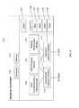
- FIG. 12is a system architecture diagram of an exemplary network configuration, in accordance with some embodiments.
- wireless backhaulposes special challenges for in-vehicle base stations. Users that are connected to an in-vehicle base station expect continuous service, even as the in-vehicle base station passes in and out of different wireless backhaul coverage zones, such as when a train passes from a train station with good coverage to a tunnel with poor coverage. The base station thus needs seamless backhaul handover. This is similar to the need for seamless handover for mobile devices. A system that enables an in-vehicle base station to receive continuous service across different backhaul coverage zones is needed.
- the systeminvolves double-tunneling mobile device data packets in an ESP-UDP IPsec tunnel encapsulated in a GTP-U tunnel. Traffic is transmitted from a mobile device to a specially configured base station.
- the specially configured base stationencapsulates mobile device data packets and sends them to the network via wireless backhaul using an LTE UE modem connection.
- IP connectionDisruption of an IP connection occurs when an endpoint has an IP address change.
- a combination of network address translation, multihoming, and tunnelingmay be used to insulate UEs and reduce any negative impact of a backhaul change.
- accessmay be provided using Wi-Fi.
- accessmay be provided using one or more wireless access media, including 2G, 3G, 4G, 5G, or other wireless media.
- the access provided to UEsis dependent only on the access technology supported by the in-vehicle base station, not the backhaul solution supported thereby.
- a trainmay be provided with a plurality of base stations. Two base stations may be mounted in each car. The base stations may provide access using Wi-Fi. The Wi-Fi channels used by the base stations may be non-contiguous, such that each base station transmits with a minimum of interference within its designated range. Each base station may provide power output appropriate to provide access coverage to half of the vehicle car.
- the base stationsmay each be connected to its own antenna mounted on the exterior of the vehicle.
- the externally-mounted antennasmay provide global positioning service (GPS) capability.
- GPSglobal positioning service
- the externally-mounted antennasmay provide LTE capability, such that they connect to LTE macro base stations located outside.
- the base stations mounted in the vehiclemay be connected using a mesh network, either via a wired or wireless mesh network. If the network is a wireless mesh network, such as a Wi-Fi network, a different frequency may be selected for mesh networking than the wireless access provided to UEs.
- a wireless mesh networksuch as a Wi-Fi network
- switchable backhaulmay be provided.
- the mesh network within the vehiclemay determine that one backhaul network is preferred over another backhaul network.
- Backhaulmay be handed over from one backhaul to the other backhaul without disruption of service using the method described within.
- the IPsec tunnelcontinues to provide signal continuity while the outermost tunnel (GTP-U or another tunnel) is changed, UEs do not experience a disruption of service.
- a handovermay result in a significant increase in backhaul bandwidth, leading to a step function difference in bandwidth when a Parallel Wireless CWS base station makes contact with the station, e.g., 50 Mbps to 200 Mbps, in a short period of time.
- This increasemay be the result of a single CWS obtaining additional bandwidth, even for a mesh network consisting of several CWSes.
- each train CWSmay speak to its own station CWS, increasing bandwidth many times over.
- these changes to the meshmay resolve quickly, with single-digit millisecond routing settling with mesh.
- the double tunneling method described hereinis fully transparent to UE because of the use of network address translation (NAT) at CWS, and the use of double tunneling (IPsec encapsulated in GTP tunnel).
- NATnetwork address translation
- IPsecIPsec encapsulated in GTP tunnel
- Sessionsmay be anchored at HNG (with their IP addresses maintained at the HNG and mobility tracked by the HNG). Note that there are two PGWs, because UE is anchored at PGW on other side of HNG and CWS-UE is anchored at PGW on this side of HNG.
- multihomingmay be used at the CWS, for switchable backhaul. Both backhaul connections anchored at same PGW. Either method can be used with any access at UE.
- the CWSmay act as a Hotspot 2.0 client or ePDG client on behalf of multiple UE's.
- multiple CWSesare handed over by a single CWS performing a handover. The handover is transparent to all UEs.
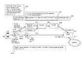
- FIG. 1is a schematic diagram of a wireless network architecture, in accordance with some embodiments.
- a conventional mobile networkis shown, including Long Term Evolution (LTE) macro eNodeBs 101 and 103 , LTE UE 102 , evolved packet core (EPC) 100 , and Internet 107 .
- EPC 100includes a policy, charging and rules function (PCRF), an authorization, authentication and accounting (AAA) node, a home subscriber server (HSS), a packet data network gateway node (PGW), a serving data network gateway node (SGW), and a mobility management entity (MME).
- PCRFpolicy, charging and rules function
- AAAauthorization, authentication and accounting
- HSShome subscriber server
- PGWpacket data network gateway node
- SGWserving data network gateway node
- MMEmobility management entity
- Wi-Fi UE 104which connects to Wi-Fi access point 105 for Wi-Fi access, and which connects via an S14 interface to an ePDG 106 .
- Wi-Fi AP 105is labeled “CWS” and can be an enhanced eNodeB/Wi-Fi multi-RAT node, in some embodiments, such as the Parallel Wireless Converged Wireless System (CWS)TM.
- ePDG 106includes additional elements, such as a trusted wireless access gateway (TWAG), ANDSF, HS Gateway, etc. and is labeled “HNG”; this node can be a Parallel Wireless HetNet GatewayTM, in some embodiments.
- the HNGsits between a wireless radio access network (RAN) and its core network.
- RANwireless radio access network
- the Wi-Fi UE 104is attached to the CWS 105 , which is coupled through LTE backhaul to core network 103 , 100 , and via core network 100 and Internet 107 to HNG 106 .
- HNG 106provides coordination of CWS 105 via a point-to-point connection; specifically, an IPsec tunnel is formed between 105 and 106 to permit transfer of signaling and data. This tunnel prevents EPC 100 from being able to read or alter the data, even as the data moves through the core network.
- LTE backhaul connectionthe reader is referred to U.S. patent application Ser. No. 15/202,496, issued as U.S. Pat. No. 9,386,480, hereby incorporated by reference in its entirety.
- CWS 105includes a physical UE card coupled electrically to the CWS as a module, with its own subscriber identity module (SIM) card, used to connect to macro base station 103 .
- SIMsubscriber identity module
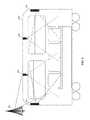
- FIG. 2is a schematic diagram of a wireless network showing antennas and signal coverage within a train, in accordance with some embodiments.
- Train car 200is shown having antennas 201 , 202 , 203 , 204 for providing access to devices on the train.
- the access networkscan be Wi-Fi networks or LTE networks or another type of network. In some embodiments, a subset of these antennas may be present, or additional antennas.
- antennas 201 and 204are patch directional antennas, installed on either end of the coach to cover passengers in the coach. Antennas 201 and 204 are configured to not interfere with each other, with different transmitting channels and with coverage limited to the footprint of each particular AP.
- omnidirectional antennas 202 and 203can be mounted on the roof of the train car to provide access to devices on the train, with different transmitting signals and with different transmit power.
- the antennasmay be connected to a CWS or multi-RAT base station/access point (not shown)
- Macro base station 205may provide LTE backhaul to the train car.
- LTEis well-designed to support high-speed mobility and is well-suited for backhaul in this case.
- Multiple train carsmay be equipped with their own base stations, access points, and antennas to provide service in all cars.
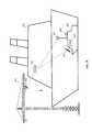
- FIG. 3Ais a further schematic diagram of a wireless network showing antennas and signal coverage within a train, from a top-down view of the train, in accordance with some embodiments.
- Wi-Fi access networks 301 a and 302 aare shown in the first train car on Wi-Fi channels 1 and 2 , respectively.
- Wi-Fi access networks 303 a and 304 aare shown in the second train car on Wi-Fi channels 3 and 1 , respectively, such that no channel is reused in two adjacent access networks and no AP in proximity transmits on the same channel. 5 GHz or 2.4 GHz or another Wi-Fi band could be used. SG and SGx coverage could be provided.
- FIG. 3Bis a further schematic diagram of a wireless network showing antennas and signal coverage within a train, in accordance with some embodiments, from a side view of the train.
- Wi-Fi access networks 301 b and 302 bare shown in the first train car.
- Wi-Fi access networks 303 b and 304 bare shown in the second train car.
- the access networksare the same networks shown in the top-down view in FIG. 3A .
- the antennasare shown mounted on the roof of the train cars using omnidirectional antennas.
- FIG. 4is a schematic diagram of a wireless network architecture for trains and train stations, in accordance with some embodiments.
- a wireless network architectureincludes Internet 401 , EPC 403 , HNG 402 , and macro base station 404 .
- UE 405is attached to macro base station 404 .
- Moving train 406 , train station 407 , and train at station 407 dare also shown.
- Moving train 406includes Wi-Fi UE 406 a attached to in-vehicle access point/multi-RAT base station 406 b .
- Train station 407includes a train at the station 407 d , as well as an access point/base station 407 c .
- a Wi-Fi UE 407 a and an in-vehicle access point/multi-RAT base station 407 bare also provided.
- Gateway 402is acting as an ePDG/TWAG, ANDSF, and a hotspot gateway.
- the access point/base station described herein and referred to as a CWSmay be a multi-RAT base station with Wi-Fi and LTE access capability; integrated flexible backhaul including line of sight (LOS) and non-line of sight, fiber, Ethernet, and LTE backhaul; multi-radio multipoint-to-multipoint wireless mesh capability; control, security and traffic prioritization capability; self-organizing network (SON)-based interference mitigation for superior subscriber experience and dynamic RF power adjustments, as described in U.S. Pat. No.
- LOSline of sight
- non-line of sightfiber, Ethernet, and LTE backhaul
- multi-radio multipoint-to-multipoint wireless mesh capabilitycontrol, security and traffic prioritization capability
- SONself-organizing network
- a higher quality of service channel indicatorcould be configured for the LTE backhaul, for voice traffic over the LTE backhaul, and/or other QCI/QoS parameters.
- LTE backhaul handoverscan be coordinated between macro base stations to ensure coverage of the train, in some embodiments, in situations where the train handover patterns are well known, for example, if a train has a known route.
- FIG. 5is a schematic diagram of a wireless network showing wireless coverage of a train with relation to train stations, in accordance with some embodiments.
- Train 510is moving from train station A 501 to train station B 507 along a track.
- the area 506 between train stationshas poor coverage.
- Train station A 501has a ceiling-mounted multi-RAT base station 502 , providing access network coverage to users within the train station, and a directional antenna and base station 503 , providing coverage into a small fraction of area 506 .
- Train station A 501also has mesh base station 505 , providing coverage within the train station area.
- Train station B 507has a similar set of base stations, including ceiling-mounted multi-RAT base station 508 , providing access network coverage to users within the train station, and a directional antenna and base station 509 , and mesh base station 512 . It is known in the prior art to, for example, have Wi-Fi access points throughout a train station, but the prior art implementation is improved upon in the present disclosure at least as follows.
- Train 510includes a mesh network. As train 510 moves between train stations, each train car moves out of coverage for certain access networks and into coverage for other access networks.
- the first train caris able to make a connection with antennas 508 , 509 and mesh network 512 when it pulls into train station B.
- the other train carsare able to immediately utilize the coverage available at train station B throughout the train, enabling a relatively short period of limited connectivity while train cars transit through area 506 .
- the bandwidth available through the train station networkis also higher bandwidth, enabling more and better connectivity within the train once the train mesh network joins the train station network.
- the train stationmay have multiple base stations, each with wired backhaul.
- Each train-mounted base stationmay connect to its own wired backhaul equipped base station to create a mesh backhaul network with many wired egress nodes, to immediately make a large amount of bandwidth available for use by the train.
- the mesh nodes in the trainmay connect to the mesh nodes in the station one by one, dynamically increasing the available egress bandwidth.
- the present disclosureis intended to provide similar support for other moving vehicles, drones, planes, buses, aboveground light rail, etc.
- the present disclosureprovides support for non-vehicle uses, for example, providing flexible backhaul capabilities in a rural area using a mesh backhaul network with multiple nodes, or flexible backhaul capabilities in a semi-isolated access network with limited backhaul, or any use of this network address translation (NAT) plus tunneling architecture with ePDG, or TWAG, or satellite backhaul, or space-based or other network systems with limited or high-latency backhaul.
- NATnetwork address translation
- LTE resources for backhaulwould be freed up by leveraging Wi-Fi access at the station.
- Underground stationsmay not be able to provide LTE backhaul, but may be able to provide wired or Wi-Fi backhaul.
- Using some conservative assumptions, such as 12 base stations on a train, each carrying 60 Mbps of traffic, and 4 minutes of mesh backhaul per stop (2 minutes while train is stopped at station, along with 1 minute before stopping and 1 minute after leaving), a savings of 720 Mbps times 240 seconds, or 168 gigabits per train stop, of LTE backhaul bandwidthcould be obtained.
- FIG. 6is a schematic diagram of a wireless network showing tunneling and network address translation for a mobile device, in accordance with some embodiments.
- UE 604with IP address 10.1.1.1 assigned by its PGW in the operator network (not shown), is attached to base station 605 .
- Base station 605is a multi-RAT base station/CWS as described herein, with two backhaul connections.
- a first backhaul connectionis via an LTE UE to LTE eNodeB/macro 607 .
- this LTE backhaul connectioncan be via eNodeB 612 .
- eNodeBs 607 and 612are shown connecting to SGW 608 and 609 , which are core network nodes for the macro base station.
- PGW 609provides a gateway to another network where an HNG 610 resides, with an IP 172.168.2.4 at the relevant network interface.
- a second backhaul connectionis via a Wi-Fi mesh connection to multi-RAT node 606 , which is on a wired backhaul connection and has a separate connection to HNG 610 , with an IP 172.168.2.3 at the relevant network interface.
- An Internet 611is connected on the other side of the HNG 610 .
- the HNG 610is also known as a coordinating gateway throughout this disclosure.
- 603is an explanatory note, stating that ESP-UDP IPsec Tunnel, Src IP natted to 192.168.1.1, so that P-GW does not drop the packet (carrying internal traffic from 10.1.1.1).
- a standard GTP-U tunnel 601exists between macro eNB 607 and PGW 609 , carrying payload data over this tunnel.
- This payload dataincludes data received over the LTE backhaul link from base station 605 .
- an IPsec tunnel 602between base station 605 , with source IP 172.168.2.2, and HNG 610 , with target address 172.168.2.4, is shown. The data for this tunnel is carried as a payload over tunnel 601 , enabling secure communications between base station 605 and HNG 610 over the operator core network of eNB 607 .
- an IPsec tunnel 613is shown between base station 605 and HNG 610 over wired backhaul and mesh base station 606 , carrying data from BS 605 to HNG 610 over another secure tunnel for the second backhaul connection.
- the second tunnelhas its source IP natted to 192.168.1.1, here shown as the address assigned to base station 605 by PGW 609 . All payload traffic from UE is thus indicated to core network nodes 608 , 609 as coming from an IP address assigned by PGW 609 .
- NATnetwork address translation
- LTE backhaul 605is able to be handed over from macro base station 607 to base station 612 , for example, without dropping data during the handover.
- mobility for connected user devicesis enabled as follows.
- an in-vehicle access networkis connected via at least two wireless backhaul connections, one being a low-bandwidth wireless backhaul connection and the other being a high-bandwidth, high-quality wireless backhaul connection.
- the high-bandwidth wireless backhaulis connected to a fixed backhaul connection.
- the in-vehicle access networkestablishes a connection to the mobility anchor for the UE or mobile device, such as a PGW in an LTE network.
- This connectioncan be transparently multi-homed using the tunneling architecture described herein, such that the PGW is enabled to connect via the high-bandwidth backhaul when available, and via the low-bandwidth backhaul otherwise.
- handover within the in-vehicle access networkis transparently handled by the in-vehicle access network or the coordinating node without generating messaging to the mobility anchor; this enables users to move around within, e.g., the train even in areas of poor backhaul connectivity.
- handovers between the in-vehicle access network and an access network with fixed backhaul, e.g., an access network in a train stationare also transparently handled without generating messaging to the mobility anchor.
- Transparent handling of mobilityis enabled by performing handover message proxying and suppression at the coordinating node toward both the radio access network and the mobility anchor, as described in U.S. Pat. No. 9,491,801, hereby incorporated by reference in its entirety for all purposes; for purposes of the mobility anchor, the UE or other mobile device is located at a virtualized base station as represented by the coordinating node toward the mobility anchor.
- Advantages of this handover architectureinclude the following. Users are enabled to move around within, e.g., the train even in areas of poor backhaul connectivity. When a train stops at a station and many users exit a train, the UEs need not generate a handover request toward the mobility anchor in the core network, as the UEs are transparently handed over to the train station access network, and subsequent handovers from the train station access network are more likely to succeed given the high-capacity fixed backhaul at the train station.
- backhaul startupbackhaul handin; backhaul handout; backhaul handover to mesh; UE handin; and UE handout, in accordance with some embodiments.
- Base station 605which can be located on the train in some embodiments, contains a UE module.
- Base station 605activates the UE module to connect to an existing macro base station, here shown as eNB 607 .
- eNB 607may be part of any wireless operator network.
- BS 605may search for or identify particular wireless operator networks based on prioritization or configuration.
- BS 605connects to eNB 607
- BS 605 's UE moduleobtains an IP address, here shown as 192.168.1.1, from PGW 609 .
- BS 605then initiates a connection to HNG 610 via the operator network.
- Backhaul handinis effected as follows.
- base station 605has existing backhaul.
- BS 605 's UE modulehands over to another eNB, shown as 612
- backhaul handoutis effected as follows.
- base station 605 's UE moduleidentifies eNB 612 as having superior signal characteristics, and hands over to eNB 612
- BS 605has the same IP address from PGW 609 , all existing connections and tunnels do not need to be modified.
- the Wi-Fi mesh network toward base station 606is independent of the LTE UE module.
- BS 606 's connectionmay be established via Wi-Fi when the connection is available, and the mesh connection may be marked as available at BS 605 .
- BS 605may immediately switch from sending payload data over tunnel 602 to sending payload data over tunnel 613 .
- mesh node 606is representative of access to any mesh network with any number of mesh egress nodes.
- Handin of UE 604involves attaching to BS 605 .
- the UEattempts to connect to its own core network, as configured by its IMSI. However, the UE must traverse one of the backhaul connections to do so.
- the backhaul connectionis selected by base station 605 .
- UE 604sends its data as payload data over either tunnel 602 or tunnel 613 .
- UE 604 's attach requestpasses through a tunnel to HNG 610 , then to Internet 611 , then to a PGW (either PGW 609 or another PGW, not shown).
- PGWeither PGW 609 or another PGW, not shown
- the handoveris then completed via the PGW.
- UE handoutoccurs by the UE handing over to another base station, such as eNB 607 directly, in which case it will use PGW 609 as its new PGW.
- FIG. 7is a schematic diagram of a wireless network showing tunneling and network address translation for a further mobile device, in accordance with some embodiments.
- a Wi-Fi UE 704 , multi-RAT base station 705 , wired backhaul mesh node 706 , HNG/ePDG 710 , P-GW 712 , and Internet 711are shown.
- Tunnelsinclude GTP-U tunnel 701 , IPsec tunnel 702 , IPsec tunnel 715 , IPsec tunnel 713 , and GTP-U tunnel 714 .
- 703is an explanatory note, stating that ESP-UDP IPsec Tunnel, Src IP natted to 192.168.1.1, so that P-GW does not drop the packet (carrying internal traffic from 10.1.1.1).
- the UE 704is a Wi-Fi UE, and connects via an ePDG.
- the ePDGis colocated at the HNG 710 .
- a Wi-Fi UEis authenticated by an ePDG prior to accessing a core network (here, PGW 712 ).
- Data transmitted by Wi-FI UE 704is first sent over a fourth tunnel, an IPsec tunnel between the Wi-Fi UE directly and the ePDG.
- the fourth tunneltravels as payload data over either the second tunnel (which is nested within the first tunnel) or the third tunnel.
- another GTP-U tunnel, unsecured, 714is used to forward the data to PGW 712 and from there to the Internet.
- an IP addressis assigned to the mobile station from the PGW.
- the PGWreceives the Create Session Request from the ePDG, given that the request contains UE's IMSI info, the PGW will check whether IP address has already been assigned to this UE or not (in case this UE was served by the LTE before handing-in to the WIFI coverage). If there was no IP address assigned, PGW assigns one new IP address. If IP address has been assigned, the same IP address will be assigned by the PGW to this UE. In this way, the UE can preserve the same IP address in between the LTE and Wi-Fi HO process, hence achieving the seamless experience.
- Wi-Fi handin and handoutare performed as follows.
- a Wi-Fi UEsuch as UE 704
- an existing ePDG tunnel 715 between UE 704 and ePDG 710is presumed to exist. Because connectivity is available via either tunnel 702 or tunnel 713 to deliver the tunnel payload, no break in the tunnel occurs and handin occurs without disruption.
- IMSIcould be provided on authorization of the UE at the ePDG.
- the PGW or ePDGcan determine whether it should preserve the IP address currently assigned to the Wi-Fi UE 704 .
- NAT traversalcould be used according to the IPsec specification.
- the PGW located on the other side of the HNGcould be the same PGW shown as 709 .
- FIG. 8is a schematic diagram of a wireless network showing antennas and signal coverage in a maritime environment, in accordance with some embodiments.
- Large oceangoing vessel 802is shown, along with crane 801 and small oceangoing vessel 803 .
- Vessel 802may be a cruise ship, a tanker ship, a container ship, or another such vessel.
- Vessel 803may be a tugboat, motorboat, yacht, or other such vessel.
- Crane 801is intended to represent any and all land-based maritime vessel maintenance facilities.
- Crane 801includes a wireless network access antenna 809 , connected to a base station (not shown) and to a wired backhaul link.
- Vessel 802may have a multi-radio access technology (multi-RAT), flexible backhaul base station, shown as CWS 808 , coupled to radio access network antennas (not shown) and/or satellite backhaul antennas (not shown).
- Vessel 803may have one or more radio access network antennas, including directional patch antenna 806 , omnidirectional antenna 805 , and sectorized cellular antennas 804 , and at least one access point/base station 807 , for providing access to users on board vessel 803 .
- Vessel 803may also be configured to provide relay access to vessel 802 , as a relay node or by creating a mesh network with vessel 802 .
- Sectorized antennas 804may be provided to increase coverage to users on board vessel 803 , such as, for example, passengers on a cruise ship attaching to LTE networks via sectorized antennas 804 .
- the network aboard vessel 802may be treated analogous to the train network described previously.
- vessel 802When vessel 802 enters into proximity of vessel 803 it may be able to connect to a network generated by vessel 803 .
- the network of vessel 803may provide access to the network of harbor facility 801 . Alternately, when vessel 802 enters into a harbor area, it may connect to the network of harbor facility 801 .
- Base stations at vessel 803 and facility 801may be used to provide LTE backhaul or mesh backhaul to vessel 802 .
- Vessel 802may treat its low-bandwidth satellite backhaul as a first backhaul connection, and the LTE backhaul/mesh backhaul provided via facility 801 or vessel 803 as a second backhaul connection with greater bandwidth. Further embodiments are as described herein.
- in-ship cellular accesscan be turned on to capture roaming revenue.
- the choice of cellular access scheme(3G or 4G, spectrum range) will be dynamically determined to minimize the interference from the surrounding environment.
- the choice of cellular for backhaulwill be different from that used for the access either technology wise (3G vs. 4G) or spectrum-band wise.
- geofencingneeds to be applied, i.e., certain cellular access can be turned on only matching certain permitted geographic coordinates.
- a high gain antenna towards CWScan be mounted on a ship.
- CWSwill be installed on the refueling boat.
- Cellular base station's RF coveragewill act as Backhaul for the CWS installed on the re-fueling boat. Additional coverage tests needs to be conducted as RF signal propagation/reflection is different in water than usual land case. If the coverage towards sea is not available PW CWS with boosters can be installed on the sea shores.
- Backhaul Antennawill be installed such that it does not face shadowing and always be connected to cellular backhaul.
- Access antennacan be directional or Omni directional and can be installed according to the requirements. With multiple directional antennas more coverage and area/ships can be covered. The access antennas installed on CWS will direct Wi-Fi/Cellular signal towards Big ship while refueling. Directional antennas can be used for the signal transmission.
- CWScan also be mounted on the cranes and antennas can be directed towards ships in dockyard. Live monitoring and surveillance can be conducted by using cameras. CWS can also be installed or additional directional antennas can be installed in dockyard area to provide access coverage.
- FIG. 9is a further schematic diagram of a wireless network showing antennas and signal coverage in a maritime environment, in accordance with some embodiments.
- base station 902providing access to mobile device 901 , which may be an LTE UE or a Wi-Fi mobile device; coordinating node 902 ; and local content caching server 903 .
- mobile device 901may be an LTE UE or a Wi-Fi mobile device
- coordinating node 902coordinating node 902
- local content caching server 903may enable mobile device 901 to have access to a subset of services and content when no or limited connectivity is available, while when base station 902 enters into range of a reliable or high-bandwidth backhaul connection, it may provide high network throughput to mobile device 901 .
- FIG. 10is a schematic diagram of an enhanced base station, in accordance with some embodiments.
- Enhanced base station 1000described herein as a multi-RAT node or a CWS, may be an eNodeB for use with LTE, and may include processor 1002 , processor memory 1004 in communication with the processor, baseband processor 1006 , and baseband processor memory 1008 in communication with the baseband processor.
- Enhanced eNodeB 1000may also include first radio transceiver 1014 , which is a Wi-Fi transceiver, and second radio transceiver 1012 , which is an LTE transceiver; enhanced eNodeB 1000 is thus a multi-radio access technology (multi-RAT) node.
- multi-RATmulti-radio access technology
- Enhanced eNodeB 1000may also include internal universal serial bus (USB) port 1016 , and subscriber information module card (SIM card) 1018 coupled to USB port 1016 .
- the second radio transceiver 1012itself may be coupled to USB port 1016 , and communications from the baseband processor may be passed through USB port 1016 .
- Transceiver 1014is connected to Antenna 1 , which provides Wi-Fi antenna functionality, and transceiver 1012 is connected to Antenna 2 , which provides LTE transmit and receive antenna functionality.
- Wi-Fi radio transceiver 1014may provide, e.g., IEEE 802.11a/b/g/n/ac functionality or other Wi-Fi functionality.
- Wi-Fi transceiver and Antenna 1may provide multiple-in, multiple-out (MIMO) functionality.
- LTE transceiver 1012may be a user equipment (UE) modem.
- UE modemmay be connected via a USB bus.
- Processor 1002 and baseband processor 1006are in communication with one another.
- Processor 1002may perform routing functions, and may determine if/when a switch in network configuration is needed.
- Baseband processor 1006may generate and receive radio signals for both radio transceivers 1012 and 1014 , based on instructions from processor 1002 .
- processors 1002 and 1006may be on the same physical logic board. In other embodiments, they may be on separate logic boards.
- Either transceivermay be coupled to processor 1002 via a Peripheral Component Interconnect-Express (PCI-E) bus, and/or via a daughtercard.
- PCI-EPeripheral Component Interconnect-Express
- transceiver 1012is for providing LTE UE functionality, in effect emulating a user equipment, it may be connected via the same or different PCI-E bus, or by a USB bus, and may also be coupled to SIM card 1018 .
- SIM card 1018may provide information required for authenticating the simulated UE to the evolved packet core (EPC). When no access to an operator EPC is available, local EPC 1020 may be used, or another local EPC on the network may be used. This information may be stored within the SIM card, and may include one or more of an international mobile equipment identity (IMEI), international mobile subscriber identity (IMSI), or other parameter needed to identify a UE. Special parameters may also be stored in the SIM card or provided by the processor during processing to identify to a target eNodeB that device 1000 is not an ordinary UE but instead is a special UE for providing backhaul to device 1000 .
- IMEIinternational mobile equipment identity
- IMSIinternational mobile subscriber identity
- Special parametersmay also be stored in the SIM card or provided by the processor during processing to identify to a target eNodeB that device 1000 is not an ordinary UE but instead is a special UE for providing backhaul to device 1000 .
- wireless radio coveragei.e., access
- Wi-Fi radio transceiver 1014wireless radio coverage (i.e., access) to user devices may be provided via Wi-Fi radio transceiver 1014 .
- an additional radio transceiver capable of providing LTE eNodeB functionality(not shown) may be provided, and may be capable of higher power and multi-channel OFDMA for providing access.
- Processor 1002may be configured to provide eNodeB, nodeB, BTS, base station, access point, and/or other functionality.
- Wireless backhaul or wired backhaulmay be used.
- Wired backhaulmay be an Ethernet-based backhaul (including Gigabit Ethernet), or a fiber-optic backhaul connection, or a cable-based backhaul connection, in some embodiments.
- Wireless backhaulmay be provided using an LTE connection, using LTE UE modem 1012 .
- wireless backhaulmay be provided in addition to wireless transceivers 1010 and 1012 , which may be Wi-Fi 802.11a/b/g/n/ac/ad/ah, Bluetooth, ZigBee, microwave (including line-of-sight microwave), or another wireless backhaul connection. Any of the wired and wireless connections may be used for either access or backhaul, according to identified network conditions and needs, and may be under the control of processor 1002 for reconfiguration.
- a home eNodeBa local gateway (LGW), a self-organizing network (SON) module, or another module. Additional radio amplifiers, radio transceivers and/or wired network connections may also be included.
- the SON modulemay be configured to provide transmit power increase/decrease functionality, radio band switching functionality, or communications with another remote SON module providing, for example, these types of functionality, in some embodiments.
- the SON modulemay execute on the general purpose processor 1002 .
- Processor 1002may identify the appropriate network configuration, and may perform routing of packets from one network interface to another accordingly.
- Processor 1002may use memory 1004 , in particular to store a routing table to be used for routing packets.
- Baseband processor 1006may perform operations to generate the radio frequency signals for transmission or retransmission by both transceivers 1010 and 1012 .
- Baseband processor 1006may also perform operations to decode signals received by transceivers 1010 and 1012 .
- Baseband processor 1006may use memory 1008 to perform these tasks.
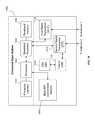
- FIG. 11is a schematic diagram of a signaling coordinator server, in accordance with some embodiments.
- Signaling coordinator 1100referred to herein as an HNG, includes processor 1102 and memory 1104 , which are configured to provide the functions described herein. Also present are radio access network coordination/signaling (RAN Coordination and signaling) module 1106 , RAN proxying module 1108 , and routing virtualization module 1110 .
- RAN Coordination and signalingradio access network coordination/signaling
- coordinator server 1100may coordinate multiple RANs using coordination module 1106 .
- coordination servermay also provide proxying, routing virtualization and RAN virtualization, via modules 1110 and 1108 .
- a downstream network interface 1112is provided for interfacing with the RANs, which may be a radio interface (e.g., LTE), and an upstream network interface 1114 is provided for interfacing with the core network, which may be either a radio interface (e.g., LTE) or a wired interface (e.g., Ethernet).
- RANswhich may be a radio interface (e.g., LTE)
- upstream network interface 1114is provided for interfacing with the core network, which may be either a radio interface (e.g., LTE) or a wired interface (e.g., Ethernet).
- Signaling storm reduction functionsmay be performed in module 1106 .
- Signaling coordinator 1100includes local evolved packet core (EPC) module 1120 , for authenticating users, storing and caching priority profile information, and performing other EPC-dependent functions when no backhaul link is available.
- EPC 1120may include local HSS 1122 , local MME 1124 , local SGW 1126 , and local PGW 1128 , as well as other modules.
- Local EPC 1120may incorporate these modules as software modules, processes, or containers. Local EPC 1120 may alternatively incorporate these modules as a small number of monolithic software processes.
- Modules 1106 , 1108 , 1110 and local EPC 1120may each run on processor 1102 or on another processor, or may be located within another device.
- An ePDG 1130is also present.
- Signaling coordinator 1100may be a pass-through gateway for data tunnels, forwarding data through to a core network. Signaling coordinator 1100 may also provide encryption functions, e.g., using IPsec for encrypting or decrypting data for forwarding over one or more bearers to the core network. In the case that Wi-Fi is used at one or more base stations to provide access to user devices, the signaling coordinator may be a trusted wireless access gateway (TWAG) or evolved packet data gateway (ePDG), providing the ability for the Wi-Fi user devices to participate in and join the operator network. In some cases, signaling coordinator 1100 may be a home eNodeB gateway (HENBGW). Because the built-in QCI and TOS mechanisms used by the methods described herein are passed through by IPsec, GTP-U, and other tunneling protocols, these quality of service (QOS) parameters are preserved by the signaling coordinator 1100 .
- TWAGtrusted wireless access gateway
- ePDGevolved packet data gateway
- HENBGWhome eNodeB gateway
- FIG. 12is a system architecture diagram of an exemplary network configuration, in accordance with some embodiments, showing the signaling coordinator or HNG in its relationship as a gateway between the radio access network and the core network.
- Base stations 1201 and 1202are connected via an S1-AP and an X2 interface to signaling coordinator 1203 .
- Base stations 1201 and 1202are eNodeBs, in some embodiments.
- Base station 1201is a mobile base station located on a bus, and is connected via wireless LTE backhaul.
- Base station 1202is a fixed base station connected via wired backhaul.
- Signaling coordinator 1203which may be the same as described earlier in FIG.
- EPCevolved packet core
- Core 11is connected to the evolved packet core (EPC)/Core Network 1208 via an S1 protocol connection and an S1-MME protocol connection.
- Coordination of base stations 1202 and 1204may be performed at the coordination server.
- the coordination servermay be located within the EPC/Core Network 1208 .
- EPC/Core Network 1208provides various LTE core network functions, such as authentication, data routing, charging, and other functions, and includes mobility management entity (MME) 1204 a , serving gateway (SGW) 1204 b , and packet data network gateway (PGW) 1204 c .
- MMEmobility management entity
- SGWserving gateway
- PGWpacket data network gateway
- mobility managementis performed both by coordination server 1206 and within the EPC/Core Network 1208 .
- EPC/Core Network 1208provides, typically through PGW 1204 c , a connection to the public Internet 1210 .
- datais received at, e.g., a Wi-Fi access point that is part of base station 1201 , which is a multi-RAT base station.
- the datais assigned a TOS and an LTE bearer, and the data is sent via signaling coordinator 1203 to core network 1204 .
- the datais encapsulated in a bearer at base station 1201 and un-encapsulated from the bearer at the core network 1204 , and experiences quality of service prioritization within the network. If the data is forwarded on from the core network to the Internet 1205 , TOS is preserved.
- the described methodmay be used without a signaling coordinator, e.g., in a standard LTE core network where eNodeBs are connected directly to an operator core network.
- the functions and steps described hereinmay be split among the eNodeB/multi-RAT node 1201 and signaling coordinator 1203 , so that the Wi-Fi SSID may be assigned to a TOS at base station 1201 or at a Wi-Fi femto cell, but not used for QoS until reaching a coordinating node 1203 .
- the radio transceivers described hereinmay be base stations compatible with a Long Term Evolution (LTE) radio transmission protocol or air interface.
- LTE-compatible base stationsmay be eNodeBs.
- the base stationsmay also support other air interfaces, such as UMTS/HSPA, CDMA/CDMA2000, GSM/EDGE, GPRS, EVDO, other 10G/2G, legacy TDD, or other air interfaces used for mobile telephony.
- the base stations described hereinmay support Wi-Fi air interfaces, which may include one or more of IEEE 802.11a/b/g/n/ac/af/p/h.
- the base stations described hereinmay support IEEE 802.16 (WiMAX), to LTE transmissions in unlicensed frequency bands (e.g., LTE-U, Licensed Access or LA-LTE), to LTE transmissions using dynamic spectrum access (DSA), to radio transceivers for ZigBee, Bluetooth, or other radio frequency protocols, or other air interfaces.
- WiMAXIEEE 802.16
- LTE-ULong Term Evolution-U
- LA-LTELTE transmissions in unlicensed frequency bands
- DSAdynamic spectrum access
- the base stations described hereinmay use programmable frequency filters.
- the Wi-Fi frequency bands described hereinmay be channels determined by the respective IEEE 802.11 protocols, which are incorporated herein to the maximum extent permitted by law.
- the base stations described hereinmay provide access to land mobile radio (LMR)-associated radio frequency bands.
- LMRland mobile radio
- the base stations described hereinmay also support more than one of the above radio frequency protocols, and may also support transmit power adjustments for some or all of the radio frequency protocols supported.
- the embodiments disclosed hereincan be used with a variety of protocols so long as there are contiguous frequency bands/channels.
- SISOsingle-in, single-output
- MIMOmultiple-in, multiple-out
- the multi-RAT nodes of the present inventionmay be designed to contain as many radio cards as desired given the radio parameters of heterogeneous mesh networks within which the multi-RAT node is likely to operate.
- a radio card capable of performing, e.g., in white space frequencieswould not be difficult to design.
- processingmay also be performed in coordination with a cloud coordination server.
- the eNodeBmay be in communication with the cloud coordination server via an X2 protocol connection, or another connection.
- the eNodeBmay perform inter-cell coordination via the cloud communication server, when other cells are in communication with the cloud coordination server.
- the eNodeBmay communicate with the cloud coordination server to determine whether the UE has the ability to support a handover to Wi-Fi, e.g., in a heterogeneous network.
- LTELong Term Evolution
- the software needed for implementing the methods and procedures described hereinmay be implemented in a high level procedural or an object-oriented language such as C, C++, C#, Python, Java, or Perl.
- the softwaremay also be implemented in assembly language if desired.
- Packet processing implemented in a network devicecan include any processing determined by the context. For example, packet processing may involve high-level data link control (HDLC) framing, header compression, and/or encryption.
- HDLChigh-level data link control
- software that, when executed, causes a device to perform the methods described hereinmay be stored on a computer-readable medium such as read-only memory (ROM), programmable-read-only memory (PROM), electrically erasable programmable-read-only memory (EEPROM), flash memory, or a magnetic disk that is readable by a general or special purpose-processing unit to perform the processes described in this document.
- the processorscan include any microprocessor (single or multiple core), system on chip (SoC), microcontroller, digital signal processor (DSP), graphics processing unit (GPU), or any other integrated circuit capable of processing instructions such as an x86 microprocessor.
Landscapes
- Engineering & Computer Science (AREA)
- Computer Networks & Wireless Communication (AREA)
- Signal Processing (AREA)
- Mobile Radio Communication Systems (AREA)
- Computer Security & Cryptography (AREA)
Abstract
Description
Claims (19)
Priority Applications (3)
| Application Number | Priority Date | Filing Date | Title |
|---|---|---|---|
| US15/686,152US10231151B2 (en) | 2016-08-24 | 2017-08-24 | Optimized train solution |
| US16/298,562US10863391B2 (en) | 2016-08-24 | 2019-03-11 | Optimized train solution |
| US17/115,030US11671878B2 (en) | 2016-08-24 | 2020-12-08 | Optimized train solution |
Applications Claiming Priority (2)
| Application Number | Priority Date | Filing Date | Title |
|---|---|---|---|
| US201662379058P | 2016-08-24 | 2016-08-24 | |
| US15/686,152US10231151B2 (en) | 2016-08-24 | 2017-08-24 | Optimized train solution |
Related Child Applications (1)
| Application Number | Title | Priority Date | Filing Date |
|---|---|---|---|
| US16/298,562ContinuationUS10863391B2 (en) | 2016-08-24 | 2019-03-11 | Optimized train solution |
Publications (2)
| Publication Number | Publication Date |
|---|---|
| US20180063753A1 US20180063753A1 (en) | 2018-03-01 |
| US10231151B2true US10231151B2 (en) | 2019-03-12 |
Family
ID=61240915
Family Applications (3)
| Application Number | Title | Priority Date | Filing Date |
|---|---|---|---|
| US15/686,152ActiveUS10231151B2 (en) | 2016-08-24 | 2017-08-24 | Optimized train solution |
| US16/298,562ActiveUS10863391B2 (en) | 2016-08-24 | 2019-03-11 | Optimized train solution |
| US17/115,030Active2037-12-18US11671878B2 (en) | 2016-08-24 | 2020-12-08 | Optimized train solution |
Family Applications After (2)
| Application Number | Title | Priority Date | Filing Date |
|---|---|---|---|
| US16/298,562ActiveUS10863391B2 (en) | 2016-08-24 | 2019-03-11 | Optimized train solution |
| US17/115,030Active2037-12-18US11671878B2 (en) | 2016-08-24 | 2020-12-08 | Optimized train solution |
Country Status (1)
| Country | Link |
|---|---|
| US (3) | US10231151B2 (en) |
Cited By (1)
| Publication number | Priority date | Publication date | Assignee | Title |
|---|---|---|---|---|
| US12219350B2 (en) | 2022-03-03 | 2025-02-04 | T-Mobile Usa, Inc. | Enabling peer-to-peer authentication between at least two mobile devices associated with one or more wireless telecommunication networks |
Families Citing this family (16)
| Publication number | Priority date | Publication date | Assignee | Title |
|---|---|---|---|---|
| US10517021B2 (en) | 2016-06-30 | 2019-12-24 | Evolve Cellular Inc. | Long term evolution-primary WiFi (LTE-PW) |
| WO2018208275A1 (en)* | 2017-05-09 | 2018-11-15 | Nokia Solutions And Networks Oy | Communicating over a local area network connection between a radio access node and a user equipment relay |
| EP3804406A4 (en)* | 2018-05-25 | 2022-03-09 | Parallel Wireless, Inc. | 5g interoperability architecture |
| CN109152096B (en)* | 2018-09-27 | 2020-09-25 | 安科讯(福建)科技有限公司 | Message transmission method of EPS (evolved packet System) architecture and computer-readable storage medium |
| CN109286435B (en)* | 2018-11-01 | 2021-11-23 | 上海歌尔泰克机器人有限公司 | Data transmission method, device and system |
| MX2021005347A (en)* | 2018-11-07 | 2021-06-30 | Commscope Technologies Llc | Wireless local area network with reliable backhaul between access points. |
| US20200177221A1 (en)* | 2018-12-04 | 2020-06-04 | The United States Of America As Represented By Secretary Of The Navy | Submerged Maritime Tag Track and Locate Device and System |
| US11930484B2 (en) | 2019-03-26 | 2024-03-12 | Charter Communications Operating, Llc | Methods and apparatus for system information management in a wireless system |
| CN209402739U (en)* | 2019-06-13 | 2019-09-17 | 广州新世纪通信科技有限公司 | A kind of network communicating system applied to mobile context |
| US12267890B2 (en)* | 2019-08-02 | 2025-04-01 | Telefonaktiebolaget Lm Ericsson (Publ) | Multi-operator maritime mesh network |
| EP3809606A1 (en)* | 2019-10-15 | 2021-04-21 | Mitsubishi Electric R & D Centre Europe B.V. | Method for performing transmission between a base station and a terminal via a multi-hop network |
| US11564155B2 (en)* | 2020-04-07 | 2023-01-24 | Charter Communications Operating, Llc | Apparatus and methods for interworking in wireless networks |
| US11672031B2 (en)* | 2020-06-03 | 2023-06-06 | Qualcomm Incorporated | Managing a backhaul configuration in a wireless multi-hop network |
| CN115175203B (en)* | 2022-06-28 | 2023-06-02 | 南京邮电大学 | An intelligent trajectory planning method for on-demand coverage of vehicle-mounted base stations in hotspot areas |
| CN116017359B (en)* | 2022-12-30 | 2025-08-12 | 中国铁道科学研究院集团有限公司 | Urban rail transit hot standby encryption wireless transmission equipment based on public network |
| CN119521319A (en)* | 2023-08-23 | 2025-02-25 | 联发科技(新加坡)私人有限公司 | Cell switching method and user equipment |
Citations (51)
| Publication number | Priority date | Publication date | Assignee | Title |
|---|---|---|---|---|
| US20050026622A1 (en) | 2003-06-24 | 2005-02-03 | Nortel Networks Limited | Method of controlling access to resources of a radiocommunication network and base station for implementing the method |
| US20050135243A1 (en) | 2003-12-18 | 2005-06-23 | Lee Wang B. | System and method for guaranteeing quality of service in IP networks |
| US20060083186A1 (en) | 2004-10-18 | 2006-04-20 | Nortel Networks Limited | Method and apparatus for improving quality of service over meshed bachaul facilities in a wireless network |
| US20070030809A1 (en) | 2005-08-08 | 2007-02-08 | Dayama Ashish K | System and method for multiple access and backhaul of a base station |
| US20080232304A1 (en) | 2007-03-22 | 2008-09-25 | Mooney Christopher F | Method of determining characteristics of access classes in wireless communication systems |
| US20090156213A1 (en) | 2007-10-25 | 2009-06-18 | Spinelli Vincent | Interworking gateway for mobile nodes |
| US7562213B1 (en) | 2003-09-16 | 2009-07-14 | Cisco Technology, Inc. | Approaches for applying service policies to encrypted packets |
| US20100020774A1 (en)* | 2008-07-23 | 2010-01-28 | Microsoft Corporation | INTERACTIVE WiFi CONNECTIVITY FOR MOVING VEHICLES |
| US20100150120A1 (en) | 2008-09-04 | 2010-06-17 | Ludger Schlicht | Mobile applications for a mobile, broadband, routable internet |
| US20100234071A1 (en) | 2009-03-12 | 2010-09-16 | Comsys Communication & Signal Processing Ltd. | Vehicle integrated communications system |
| US20110194483A1 (en) | 2009-08-12 | 2011-08-11 | Qualcomm Incorporated | Method and apparatus for relay backhaul design in a wireless communication system |
| US20120039175A1 (en) | 2010-08-11 | 2012-02-16 | Alcatel-Lucent Usa Inc. | Enabling a distributed policy architecture with extended son (extended self organizing networks) |
| WO2012044148A1 (en) | 2010-09-27 | 2012-04-05 | Mimos Berhad | A network architecture for intelligent cloud base station |
| US20120120831A1 (en) | 2009-06-05 | 2012-05-17 | Panasonic Corporation | Qos multiplexing via base station-relay node interface |
| US20120155298A1 (en) | 2010-12-20 | 2012-06-21 | Chen-Yui Yang | Method and apparatus for providing mapping management |
| WO2012120519A1 (en) | 2011-03-10 | 2012-09-13 | Elta Systems Ltd | Moving cellular communication system operative in an emergency mode |
| US20130077482A1 (en) | 2011-09-20 | 2013-03-28 | Accelera Mobile Broadband, Inc. | Seamless handoff, offload, and load balancing in integrated wi-fi/small cell systems |
| US20130163508A1 (en) | 2010-09-03 | 2013-06-27 | Nokia Siemens Networks Oy | Relay Nodes in Multi-Operator Scenario |
| WO2013145592A1 (en) | 2012-03-30 | 2013-10-03 | Nec Corporation | Communications device, base station, communications node, communications system and method thereof |
| US20130336199A1 (en) | 2010-11-24 | 2013-12-19 | Elta Systems Ltd. | Various traffic management methods for dynamic multi-hop backhauling cellular network and systems useful in conjunction therewith |
| US20140044018A1 (en) | 2012-08-07 | 2014-02-13 | International Business Machines Corporation | Charging and policy for services at the edge of a mobile data network |
| US20140050208A1 (en) | 2012-08-14 | 2014-02-20 | Stoke, Inc. | Apn ip management |
| US20140080492A1 (en) | 2010-11-24 | 2014-03-20 | Elta Systems Ltd. | Various routing architectures for dynamic multi-hop backhauling cellular network and various methods useful in conjunction therewith |
| US20140086120A1 (en) | 2012-09-25 | 2014-03-27 | Parallel Wireless, Inc. | Heterogeneous Mesh Network and a Multi-RAT Node Used Therein |
| US20140092765A1 (en) | 2012-09-25 | 2014-04-03 | Parallel Wireless Inc. | Heterogeneous Self-Organizing Network for Access and Backhaul |
| US20140133456A1 (en) | 2012-09-25 | 2014-05-15 | Parallel Wireless, Inc. | Dynamic Multi-Access Wireless Network Virtualization |
| US20140192643A1 (en) | 2013-01-08 | 2014-07-10 | Broadcom Corporation | Systems and methods for network discovery and selection using contextual information |
| US20140206368A1 (en) | 2013-01-24 | 2014-07-24 | Alexander Maltsev | Apparatus, system and method of wireless backhaul communication between wireless communication nodes |
| US20140233386A1 (en) | 2013-02-18 | 2014-08-21 | Samsung Electronics Co., Ltd. | Method and system for offloading handover of wireless connections from a lte network to a wi-fi network |
| US20140233412A1 (en) | 2013-02-17 | 2014-08-21 | Parallel Wireless Inc. | Methods of Incorporating an Ad Hoc Cellular Network Into a Fixed Cellular Network |
| US20140285146A1 (en)* | 2013-03-15 | 2014-09-25 | Kenguru, Inc. | Vehicle communications, power management, and seating systems |
| US20150009822A1 (en) | 2013-07-02 | 2015-01-08 | Fujitsu Limited | Control device, control method, and communication system |
| US20150045063A1 (en) | 2013-08-07 | 2015-02-12 | Parallel Wireless, Inc. | Multi-RAT Node Used for Search and Rescue |
| US20150063101A1 (en) | 2013-08-29 | 2015-03-05 | Telefonaktiebolaget L M Ericsson (Publ) | 3gpp bearer-based qos model support on wifi |
| US20150063218A1 (en) | 2013-09-04 | 2015-03-05 | Cellco Partnership D/B/A Verizon Wireless | Quality of service access device |
| US20150063295A1 (en) | 2013-08-30 | 2015-03-05 | Nageen Himayat | User equipment reallocation between nodes |
| US20150078167A1 (en) | 2013-08-06 | 2015-03-19 | Parallel Wireless, Inc. | Systems and Methods for Providing LTE-Based Backhaul |
| US20150092688A1 (en) | 2012-03-19 | 2015-04-02 | Samsung Electronics Co., Ltd. | Communication method and apparatus using wireless lan access point |
| US20150173111A1 (en)* | 2013-12-13 | 2015-06-18 | Parallel Wireless, Inc. | Virtualization of the Evolved Packet Core to Create a Local EPC |
| US9078286B1 (en) | 2006-02-22 | 2015-07-07 | Apple Inc. | Mesh base transceiver station network optimized for backhaul access |
| US20150229970A1 (en) | 2011-08-18 | 2015-08-13 | Vid Scale, Inc. | Methods and systems for packet differentiation |
| US20150257051A1 (en) | 2014-03-07 | 2015-09-10 | Parallel Wireless, Inc. | Federated X2 Gateway |
| US20150257024A1 (en) | 2012-09-17 | 2015-09-10 | Interdigital Patent Holdings, Inc. | Self-optimization of backhaul radio resources and small cell backhaul delay estimation |
| US20150312843A1 (en) | 2012-08-31 | 2015-10-29 | Qualcomm Incorporated | Providing group call priority access in lte and priority access for user equipments with dual access classes |
| US20150365954A1 (en) | 2014-06-16 | 2015-12-17 | United States Cellular Corporation | System and Method for Managing Frequency Layer Priority Assignments Within Mobile Wireless Network Radio Interfaces |
| US20160088585A1 (en)* | 2014-09-24 | 2016-03-24 | Parallel Wireless, Inc. | Radio Operation Switch Based on GPS Mobility Data |
| WO2016083524A1 (en) | 2014-11-28 | 2016-06-02 | Vodafone Ip Licensing Limited | Self-organizing network engine for mobility load balancing between wi-fi and cellular networks |
| US20160227551A1 (en)* | 2015-02-02 | 2016-08-04 | Accelerated Media Technologies, Inc. | Systems and methods for electronic news gathering |
| US20160242226A1 (en) | 2013-10-23 | 2016-08-18 | Kddi Corporation | Base station device and control method |
| US20160242080A1 (en) | 2015-02-13 | 2016-08-18 | Telefonaktiebolaget L M Ericsson (Publ) | Establishment of Dual Connectivity |
| US20170208508A1 (en)* | 2014-07-11 | 2017-07-20 | Telefonaktiebolaget Lm Ericsson (Publ) | A node and method for secure connected vehicle small cells |
Family Cites Families (27)
| Publication number | Priority date | Publication date | Assignee | Title |
|---|---|---|---|---|
| US7111163B1 (en)* | 2000-07-10 | 2006-09-19 | Alterwan, Inc. | Wide area network using internet with quality of service |
| ATE287169T1 (en) | 2001-09-12 | 2005-01-15 | Cit Alcatel | METHOD AND DEVICE FOR SERVICE DIFFERENTIATION IN A DATA NETWORK |
| CA2534448C (en) | 2003-08-14 | 2009-10-27 | Telcordia Technologies, Inc. | Auto-ip traffic optimization in mobile telecommunications systems |
| US7305706B2 (en) | 2004-01-15 | 2007-12-04 | Cisco Technology, Inc. | Establishing a virtual private network for a road warrior |
| US20080075003A1 (en) | 2006-09-21 | 2008-03-27 | Futurewei Technologies, Inc. | Method and system for admission and congestion control of network communication traffic |
| US20100005178A1 (en) | 2006-10-24 | 2010-01-07 | Catalin Sindelaru | Method and system for firewall friendly real-time communication |
| US7969953B1 (en) | 2007-01-22 | 2011-06-28 | Sprint Communications Company L.P. | Mobile device handoff while maintaining connectivity with multiple access points |
| US8275349B2 (en) | 2007-11-29 | 2012-09-25 | Rivada Networks, Llc | Method and system for providing tiered priority access to communication network resources |
| US8825040B2 (en) | 2008-07-17 | 2014-09-02 | Nokia Siemens Networks Oy | Selection of connection type in cellular system |
| WO2011146662A2 (en)* | 2010-05-18 | 2011-11-24 | Novatel Wireless, Inc. | Systems and methods for an intelligent mobile media server |
| WO2012110771A2 (en)* | 2011-02-19 | 2012-08-23 | Nomad Spectrum Limited | Mobile data communication |
| GB2495145A (en) | 2011-09-30 | 2013-04-03 | Nec Corp | Relay services used in LTE advanced systems |
| US20130205412A1 (en)* | 2011-11-16 | 2013-08-08 | Flextronics Ap, Llc | On board vehicle media controller |
| US9088572B2 (en)* | 2011-11-16 | 2015-07-21 | Flextronics Ap, Llc | On board vehicle media controller |
| GB2503719A (en) | 2012-07-05 | 2014-01-08 | Nec Corp | Providing information relating to a location of a user device in a cell configured as a mobile cell |
| GB2508354B (en)* | 2012-11-28 | 2018-09-05 | Nomad Spectrum Ltd | Communication method |
| US20140153789A1 (en)* | 2012-11-30 | 2014-06-05 | Qualcomm Incorporated | Building boundary detection for indoor maps |
| US9585038B2 (en) | 2013-03-13 | 2017-02-28 | Futurewei Technologies, Inc. | Forward traffic announcements for enhanced resource reservation in high speed mobile relays |
| US9648560B2 (en) | 2013-10-16 | 2017-05-09 | At&T Intellectual Property I, L.P. | Utilizing explicit congestion notification for network selection |
| US9531565B2 (en)* | 2013-12-20 | 2016-12-27 | Pismo Labs Technology Limited | Methods and systems for transmitting and receiving packets |
| WO2015103338A1 (en)* | 2013-12-31 | 2015-07-09 | Lookout, Inc. | Cloud-based network security |
| US10630505B2 (en)* | 2015-01-28 | 2020-04-21 | Umbra Technologies Ltd. | System and method for a global virtual network |
| US10597056B2 (en)* | 2015-02-12 | 2020-03-24 | Mitsubishi Electric Corporation | Train control system, base-station control device, ground wireless base station, and on-vehicle wireless station |
| EP3352486B1 (en)* | 2015-09-18 | 2021-12-08 | Nec Corporation | Rsu device, base station device, control node and method therefor |
| US9918345B2 (en)* | 2016-01-20 | 2018-03-13 | Time Warner Cable Enterprises Llc | Apparatus and method for wireless network services in moving vehicles |
| WO2017166260A1 (en)* | 2016-04-01 | 2017-10-05 | Panasonic Intellectual Property Corporation Of America | Improved semi-persistent resource allocation for v2v traffic |
| US20210368392A1 (en) | 2016-12-09 | 2021-11-25 | Nokia Technologies Oy | Method and apparatus for load balancing ip address selection in a network environment |
- 2017
- 2017-08-24USUS15/686,152patent/US10231151B2/enactiveActive
- 2019
- 2019-03-11USUS16/298,562patent/US10863391B2/enactiveActive
- 2020
- 2020-12-08USUS17/115,030patent/US11671878B2/enactiveActive
Patent Citations (56)
| Publication number | Priority date | Publication date | Assignee | Title |
|---|---|---|---|---|
| US20050026622A1 (en) | 2003-06-24 | 2005-02-03 | Nortel Networks Limited | Method of controlling access to resources of a radiocommunication network and base station for implementing the method |
| US7562213B1 (en) | 2003-09-16 | 2009-07-14 | Cisco Technology, Inc. | Approaches for applying service policies to encrypted packets |
| US20050135243A1 (en) | 2003-12-18 | 2005-06-23 | Lee Wang B. | System and method for guaranteeing quality of service in IP networks |
| US20060083186A1 (en) | 2004-10-18 | 2006-04-20 | Nortel Networks Limited | Method and apparatus for improving quality of service over meshed bachaul facilities in a wireless network |
| US20070030809A1 (en) | 2005-08-08 | 2007-02-08 | Dayama Ashish K | System and method for multiple access and backhaul of a base station |
| US9078286B1 (en) | 2006-02-22 | 2015-07-07 | Apple Inc. | Mesh base transceiver station network optimized for backhaul access |
| US20080232304A1 (en) | 2007-03-22 | 2008-09-25 | Mooney Christopher F | Method of determining characteristics of access classes in wireless communication systems |
| US20090156213A1 (en) | 2007-10-25 | 2009-06-18 | Spinelli Vincent | Interworking gateway for mobile nodes |
| US20100020774A1 (en)* | 2008-07-23 | 2010-01-28 | Microsoft Corporation | INTERACTIVE WiFi CONNECTIVITY FOR MOVING VEHICLES |
| US20100150120A1 (en) | 2008-09-04 | 2010-06-17 | Ludger Schlicht | Mobile applications for a mobile, broadband, routable internet |
| US20100234071A1 (en) | 2009-03-12 | 2010-09-16 | Comsys Communication & Signal Processing Ltd. | Vehicle integrated communications system |
| US20120120831A1 (en) | 2009-06-05 | 2012-05-17 | Panasonic Corporation | Qos multiplexing via base station-relay node interface |
| US20110194483A1 (en) | 2009-08-12 | 2011-08-11 | Qualcomm Incorporated | Method and apparatus for relay backhaul design in a wireless communication system |
| US20120039175A1 (en) | 2010-08-11 | 2012-02-16 | Alcatel-Lucent Usa Inc. | Enabling a distributed policy architecture with extended son (extended self organizing networks) |
| US20130163508A1 (en) | 2010-09-03 | 2013-06-27 | Nokia Siemens Networks Oy | Relay Nodes in Multi-Operator Scenario |
| WO2012044148A1 (en) | 2010-09-27 | 2012-04-05 | Mimos Berhad | A network architecture for intelligent cloud base station |
| US20130336199A1 (en) | 2010-11-24 | 2013-12-19 | Elta Systems Ltd. | Various traffic management methods for dynamic multi-hop backhauling cellular network and systems useful in conjunction therewith |
| US20140080492A1 (en) | 2010-11-24 | 2014-03-20 | Elta Systems Ltd. | Various routing architectures for dynamic multi-hop backhauling cellular network and various methods useful in conjunction therewith |
| US20120155298A1 (en) | 2010-12-20 | 2012-06-21 | Chen-Yui Yang | Method and apparatus for providing mapping management |
| WO2012120519A1 (en) | 2011-03-10 | 2012-09-13 | Elta Systems Ltd | Moving cellular communication system operative in an emergency mode |
| US20150229970A1 (en) | 2011-08-18 | 2015-08-13 | Vid Scale, Inc. | Methods and systems for packet differentiation |
| US20130077482A1 (en) | 2011-09-20 | 2013-03-28 | Accelera Mobile Broadband, Inc. | Seamless handoff, offload, and load balancing in integrated wi-fi/small cell systems |
| US20150092688A1 (en) | 2012-03-19 | 2015-04-02 | Samsung Electronics Co., Ltd. | Communication method and apparatus using wireless lan access point |
| WO2013145592A1 (en) | 2012-03-30 | 2013-10-03 | Nec Corporation | Communications device, base station, communications node, communications system and method thereof |
| US20150078280A1 (en) | 2012-03-30 | 2015-03-19 | Nec Corporation | Communications Device, Base Station, Communications Node, Communications System and Method Thereof |
| US20140044018A1 (en) | 2012-08-07 | 2014-02-13 | International Business Machines Corporation | Charging and policy for services at the edge of a mobile data network |
| US20140050208A1 (en) | 2012-08-14 | 2014-02-20 | Stoke, Inc. | Apn ip management |
| US20150312843A1 (en) | 2012-08-31 | 2015-10-29 | Qualcomm Incorporated | Providing group call priority access in lte and priority access for user equipments with dual access classes |
| US20150257024A1 (en) | 2012-09-17 | 2015-09-10 | Interdigital Patent Holdings, Inc. | Self-optimization of backhaul radio resources and small cell backhaul delay estimation |
| US9113352B2 (en) | 2012-09-25 | 2015-08-18 | Parallel Wireless, Inc. | Heterogeneous self-organizing network for access and backhaul |
| US9491801B2 (en) | 2012-09-25 | 2016-11-08 | Parallel Wireless, Inc. | Dynamic multi-access wireless network virtualization |
| US20140086120A1 (en) | 2012-09-25 | 2014-03-27 | Parallel Wireless, Inc. | Heterogeneous Mesh Network and a Multi-RAT Node Used Therein |
| US20140092765A1 (en) | 2012-09-25 | 2014-04-03 | Parallel Wireless Inc. | Heterogeneous Self-Organizing Network for Access and Backhaul |
| US20140133456A1 (en) | 2012-09-25 | 2014-05-15 | Parallel Wireless, Inc. | Dynamic Multi-Access Wireless Network Virtualization |
| US20140192643A1 (en) | 2013-01-08 | 2014-07-10 | Broadcom Corporation | Systems and methods for network discovery and selection using contextual information |
| US20140206368A1 (en) | 2013-01-24 | 2014-07-24 | Alexander Maltsev | Apparatus, system and method of wireless backhaul communication between wireless communication nodes |
| US20160135204A1 (en)* | 2013-02-17 | 2016-05-12 | Parallel Wireless, Inc. | Methods of Incorporating an Ad Hoc Cellular Network into a Fixed Cellular Network |
| US20140233412A1 (en) | 2013-02-17 | 2014-08-21 | Parallel Wireless Inc. | Methods of Incorporating an Ad Hoc Cellular Network Into a Fixed Cellular Network |
| US20140233386A1 (en) | 2013-02-18 | 2014-08-21 | Samsung Electronics Co., Ltd. | Method and system for offloading handover of wireless connections from a lte network to a wi-fi network |
| US20140285146A1 (en)* | 2013-03-15 | 2014-09-25 | Kenguru, Inc. | Vehicle communications, power management, and seating systems |
| US20150009822A1 (en) | 2013-07-02 | 2015-01-08 | Fujitsu Limited | Control device, control method, and communication system |
| US20150078167A1 (en) | 2013-08-06 | 2015-03-19 | Parallel Wireless, Inc. | Systems and Methods for Providing LTE-Based Backhaul |
| US9386480B2 (en) | 2013-08-06 | 2016-07-05 | Parallel Wireless, Inc. | Systems and methods for providing LTE-based backhaul |
| US20150045063A1 (en) | 2013-08-07 | 2015-02-12 | Parallel Wireless, Inc. | Multi-RAT Node Used for Search and Rescue |
| US20150063101A1 (en) | 2013-08-29 | 2015-03-05 | Telefonaktiebolaget L M Ericsson (Publ) | 3gpp bearer-based qos model support on wifi |
| US20150063295A1 (en) | 2013-08-30 | 2015-03-05 | Nageen Himayat | User equipment reallocation between nodes |
| US20150063218A1 (en) | 2013-09-04 | 2015-03-05 | Cellco Partnership D/B/A Verizon Wireless | Quality of service access device |
| US20160242226A1 (en) | 2013-10-23 | 2016-08-18 | Kddi Corporation | Base station device and control method |
| US20150173111A1 (en)* | 2013-12-13 | 2015-06-18 | Parallel Wireless, Inc. | Virtualization of the Evolved Packet Core to Create a Local EPC |
| US20150257051A1 (en) | 2014-03-07 | 2015-09-10 | Parallel Wireless, Inc. | Federated X2 Gateway |
| US20150365954A1 (en) | 2014-06-16 | 2015-12-17 | United States Cellular Corporation | System and Method for Managing Frequency Layer Priority Assignments Within Mobile Wireless Network Radio Interfaces |
| US20170208508A1 (en)* | 2014-07-11 | 2017-07-20 | Telefonaktiebolaget Lm Ericsson (Publ) | A node and method for secure connected vehicle small cells |
| US20160088585A1 (en)* | 2014-09-24 | 2016-03-24 | Parallel Wireless, Inc. | Radio Operation Switch Based on GPS Mobility Data |
| WO2016083524A1 (en) | 2014-11-28 | 2016-06-02 | Vodafone Ip Licensing Limited | Self-organizing network engine for mobility load balancing between wi-fi and cellular networks |
| US20160227551A1 (en)* | 2015-02-02 | 2016-08-04 | Accelerated Media Technologies, Inc. | Systems and methods for electronic news gathering |
| US20160242080A1 (en) | 2015-02-13 | 2016-08-18 | Telefonaktiebolaget L M Ericsson (Publ) | Establishment of Dual Connectivity |
Non-Patent Citations (27)
| Title |
|---|
| "Evolved Packet Data Gateway Overview," ePDG Administration Guide, StarOS Release 20, pp. 1-90, retrieved from https://www.cisco.com/c/en/us/td/docs/wireless/asr_5000/20/ePDG/b_20-ePDG-Admin/b_20-ePDG-Admin_chapter_01.pdf. |
| "GTP-based S2b Interface Support on the P-GW and SAEGW," SAE-GW Administration Guide, Star OS Release 20, pp. 1-50, retrieved from https://www.cisco.com/c/en/us/td/docs/wireless/asr_5000/20/SAEGW/b_20_SAEGW_Admin/b_19_SAEGW_Admin_chapter_01000.pdf. |
| "HeNB (LTE Femto) Network Architecture," The Femto Forum, May 2011, retrieved from http://www.3g4g.co.uk/SmallCells/Femtocells_WP_Architecture_1105_FemtoForum_pdf. |
| "IPSec Basics," pp. 1-9, retrieved on Sep. 1, 2017, retrieved from http://www.amaranten.com/support/user%20guide/VPN/IPSec_Basics/Overview.htm#ESP__Encapsulating_Security_Payload_. |
| "UE Relay for Public Safety," HTC, 3rd Generation Partnership Project, SA WG2 Meeting S2 #98, Jul. 9, 2013, retrieved from http://www.3gpp.org/ftp/tsg_sa/WG2_Arch/TSGS2_98_Valencia/Docs/ (Not Believed to Be Prior Art). |
| "UE Relay for Public Safety," HTC, 3rd Generation Partnership Project, SA WG2 Meeting S2 #98, Jul. 9, 2013, retrieved from http://www.3gpp.org/ftp/tsg_sa/WG2_Arch/TSGS2_98_Valencia/Docs/. |
| 3rd Generation Partnership Project, 3GPP TR 23.830 v9.0.0 (Sep. 2009), "3rd Generation Partnership Project; Technical Specification Group Services and System Aspects; Architecture Aspects of Home NodeB and Home eNodeB (Release 9)," 3rd Generation Partnership Project, Sep. 2009, V9.0.0. |
| 3rd Generation Partnership Project, 3GPP TR 23.830 V9.0.0 (Sep. 2009), "3rd Generation Partnership Project; Technical Specification Group Services and System Aspects; Architecture Aspects of Home NodeB and Home eNodeB (Release 9)," Sep. 2009, V9.0.0. |
| 3rd Generation Partnership Project, 3GPP TR 36.806 v9.0.0 (Mar. 2010), "3rd Generation Partnership Project; Technical Specification Group Radio Access Network; Evolved Universal Terrestrial Radio Access (E-UTRA); Relay Architectures for E-UTRA (LTE-Advanced) (Release 9)," 3rd Generation Partnership Project, Mar. 2010, V9.0.0. |
| 3rd Generation Partnership Project, 3GPP TR 36.826 v0.13.0 (Feb. 2012), "3rd Generation Partnership Project; Technical Specification Group TSG RAN; Evolved Universal Terrestrial Radio Access (E-UTRA); Relay Radio Transmission and Reception (Release 10)," 3rd Generation Partnership Project, Feb. 2012, V0.13.0. |
| 3rd Generation Partnership Project, 3GPP TS 23.401 V13.7.0 (Jun. 2016), "3rd Generation Partnership Project; Technical Specification Group Services and System Aspects; General Packet Radio Service (GPRS) Enhancements for Evolved Universal Terrestrial Radio Access Network (E-UTRAN) Access (Release 13)," Jun. 2016, V13.7.0. |
| 3rd Generation Partnership Project, 3GPP TS 23.401 V14.0.0 (Jun. 2016), "3rd Generation Partnership Jroject; Technical Specification Group Services and System Aspects; General Packet Radio Service (GPRS) Enhancements for Evolved Universal Terrestrial Radio Access Network (E-UTRAN) Access (Release 14)," Jun. 2016, V14.0.0. |
| 3rd Generation Partnership Project, 3GPP TS 24.301 V8.1.0 (Mar. 2009), "3rd Generation Partnership Project; Technical Specification Group Core Network and Terminals; Non-Access-Stratum (NAS) protocol for Evolved Jacket System (EPS) Stage 3 (Release 8)," Mar. 2009, V8.1.0. |
| 3rd Generation Partnership Project, 3GPP TS 32.240 V8.6.0 (Jun. 2010), "3rd Generation Partnership Project; Technical Specification Group Services and System Aspects; Telecommunication Management; Charging Management; Charging Architecture and Principles (Release 8)," Jun. 2010, V8.6.0. |
| 3rd Generation Partnership Project, 3GPP TS 32.453 v11.0.0 (Sep. 2011), "3rd Generation Partnership Project; Technical Specification Group Services and System Aspects; Telecommunication Management; Performance Management (PM); Performance Measurements Home Enhanced Node B (HeNB) Subsystem (HeNS) (Release 11)," 3rd Generation Partnership Project, Sep. 2011, V11.0.0. |
| 3rd Generation Partnership Project, 3GPP TS 32.593 v11.0.0 (Sep. 2011), "3rd Generation Partnership Project; Technical Specification Group Services and System Aspects; Telecommunication Management; Home Enhanced Node B (HeNB) Operations, Administration, Maintenance and Provisioning (OAM&P); Procedure Flows for Type 1 Interface HeNB to HeNB Management Systems (HeMS) (Release 11)," 3rd Generation Partnership Project, Sep. 2011, V11.0.0. |
| Erik Dahlman et al., "Chapter 16-Relaying," 4G LTE/LTE-Advanced for Mobile Broadband-Kindle Edition, Mar. 21, 2011, pp. 331-345, paragraph 16.2. |
| Erik Dahlman et al., "Chapter 16—Relaying," 4G LTE/LTE-Advanced for Mobile Broadband—Kindle Edition, Mar. 21, 2011, pp. 331-345, paragraph 16.2. |
| European Telecommunication Standards Institute, ETSI TS 123 203 v12.6.0 (Sep. 2014), "Digital cellular telecommunications system (Phase 2+); Universal Mobile Telecommunications System (UMTS); LTE; Policy and charging control architecture (3GPP TS 23.203 version 12.6.0 Release 12)," V12.6.0 Sep. 2014. |
| European Telecommunication Standards Institute, ETSI TS 123 401 v12.8.0 (Apr. 2015), "LTE; General Packet Radio Service (GPRS) enhancements for Evolved Universal Terrestrial Radio Access Network (E-UTRAN) access (3GPP TS 23.401 version 12.8.0 Release 12)," V12.8.0, Apr. 2015. |
| Fenner, B., "Experimental Values in IPv4, IPv6, ICMPv4, ICMPv6, UDP, and TCP Headers," Network Working Group, RFC 4727, Nov. 2006, retrieved from https://tools.ietf.org/pdf/rfc4727.pdf. |
| Information Sciences Institute, University of Southern California, Internet Protocol Darpa Internet Program Protocol Specification, Sep. 1981, pp. 1-45, retrieved from https://tools.ietf.org/html/rfc791. |
| Institute of Electrical and Electronics Engineers, "IEEE Standard for Information technology-Telecommunications and information exchange between systems-Local and metropolitan area networks-Specific Requirements, Part 11: Wireless LAN Medium Access Control (MAC) and Physical Layer (PHY) Specifications," IEEE Computer Society, Revision of IEEE Std 802.11, Jun. 12, 2007. |
| Institute of Electrical and Electronics Engineers, "IEEE Standard for Information technology—Telecommunications and information exchange between systems—Local and metropolitan area networks—Specific Requirements, Part 11: Wireless LAN Medium Access Control (MAC) and Physical Layer (PHY) Specifications," IEEE Computer Society, Revision of IEEE Std 802.11, Jun. 12, 2007. |
| Mikio Iwamura, Hideaki Takahashi, and Satoshi Nagata, "Relay Technology in LTE-Advanced," NTT Docomo Technical Journal, vol. 12, No. 2, pp. 29-36. |
| Nichols, K, Blake, S., Baker, F., Black, D., "Definition of the Differentiated Services Field (DS Field) in the IPv4 and IPv6 Headers," Network Working Group, RFC 2474, Dec. 1998, retrieved from https://tools.ietf.org/pdf/rfc2474.pdf. |
| Sandvine Intelligent Broadband Networks, "Quality of Service in LTE," Sandvine Incorporated ULC., Sep. 21, 2014. |
Cited By (1)
| Publication number | Priority date | Publication date | Assignee | Title |
|---|---|---|---|---|
| US12219350B2 (en) | 2022-03-03 | 2025-02-04 | T-Mobile Usa, Inc. | Enabling peer-to-peer authentication between at least two mobile devices associated with one or more wireless telecommunication networks |
Also Published As
| Publication number | Publication date |
|---|---|
| US20180063753A1 (en) | 2018-03-01 |
| US10863391B2 (en) | 2020-12-08 |
| US20190268809A1 (en) | 2019-08-29 |
| US11671878B2 (en) | 2023-06-06 |
| US20210092649A1 (en) | 2021-03-25 |
Similar Documents
| Publication | Publication Date | Title |
|---|---|---|
| US11671878B2 (en) | Optimized train solution | |
| US11115953B2 (en) | Radio operation switch based on GPS mobility data | |
| US10506475B2 (en) | Seamless mobile handover | |
| US10362521B2 (en) | Method of multi-radio interworking in heterogeneous wireless communication networks | |
| US11166212B2 (en) | Elevation based mode switch for 5G based aerial UE | |
| US11129240B2 (en) | 5G interoperability architecture | |
| US11924899B2 (en) | Multipath TCP with mesh access | |
| US20200396785A1 (en) | Multi-RAT Dual Connectvity | |
| US11632812B2 (en) | Inter-PGW handover architecture | |
| EP4568350A1 (en) | Multi-path management method | |
| KR20240099072A (en) | Method and apparatus for performing group handover in wireless communication system | |
| WO2023070511A1 (en) | Enhancement on integrated access and backhaul network | |
| WO2024119510A1 (en) | Devices and methods for communication | |
| WO2025210176A2 (en) | Managing connectivity of a wireless access and backhaul node | |
| WO2023080823A1 (en) | Methods, radio network node, and user equipment or integrated access and backhaul node for handling communication | |
| KR20180093166A (en) | Wireless backhaul device |
Legal Events
| Date | Code | Title | Description |
|---|---|---|---|
| FEPP | Fee payment procedure | Free format text:ENTITY STATUS SET TO SMALL (ORIGINAL EVENT CODE: SMAL); ENTITY STATUS OF PATENT OWNER: SMALL ENTITY | |
| AS | Assignment | Owner name:PARALLEL WIRELESS, INC., NEW HAMPSHIRE Free format text:ASSIGNMENT OF ASSIGNORS INTEREST;ASSIGNORS:CAO, YANG;LUBENSKI, ZEEV;ARORA, JITENDER;SIGNING DATES FROM 20151229 TO 20180131;REEL/FRAME:044795/0202 | |
| STCF | Information on status: patent grant | Free format text:PATENTED CASE | |
| AS | Assignment | Owner name:VENTURE LENDING & LEASING IX, INC., CALIFORNIA Free format text:SECURITY INTEREST;ASSIGNOR:PARALLEL WIRELESS, INC.;REEL/FRAME:051459/0959 Effective date:20191220 Owner name:VENTURE LENDING & LEASING VIII, INC., CALIFORNIA Free format text:SECURITY INTEREST;ASSIGNOR:PARALLEL WIRELESS, INC.;REEL/FRAME:051459/0959 Effective date:20191220 | |
| AS | Assignment | Owner name:WTI FUND X, INC., CALIFORNIA Free format text:SECURITY INTEREST;ASSIGNOR:PARALLEL WIRELESS, INC.;REEL/FRAME:059279/0851 Effective date:20220225 Owner name:VENTURE LENDING & LEASING IX, INC., CALIFORNIA Free format text:SECURITY INTEREST;ASSIGNOR:PARALLEL WIRELESS, INC.;REEL/FRAME:059279/0851 Effective date:20220225 | |
| MAFP | Maintenance fee payment | Free format text:PAYMENT OF MAINTENANCE FEE, 4TH YR, SMALL ENTITY (ORIGINAL EVENT CODE: M2551); ENTITY STATUS OF PATENT OWNER: SMALL ENTITY Year of fee payment:4 | |
| AS | Assignment | Owner name:PARALLEL WIRELESS, INC., NEW HAMPSHIRE Free format text:RELEASE BY SECURED PARTY;ASSIGNORS:VENTURE LENDING & LEASING IX, INC.;VENTURE LENDING & LEASING VIII, INC.;REEL/FRAME:060828/0394 Effective date:20220629 | |
| AS | Assignment | Owner name:PARALLEL WIRELESS, INC., NEW HAMPSHIRE Free format text:RELEASE BY SECURED PARTY;ASSIGNORS:VENTURE LENDING & LEASING IX, INC.;WTI FUND X, INC.;REEL/FRAME:060900/0022 Effective date:20220629 |