US10228526B2 - Traceable cable with side-emitting optical fiber and method of forming the same - Google Patents
Traceable cable with side-emitting optical fiber and method of forming the sameDownload PDFInfo
- Publication number
- US10228526B2 US10228526B2US15/054,380US201615054380AUS10228526B2US 10228526 B2US10228526 B2US 10228526B2US 201615054380 AUS201615054380 AUS 201615054380AUS 10228526 B2US10228526 B2US 10228526B2
- Authority
- US
- United States
- Prior art keywords
- cladding
- optical fiber
- emitting optical
- ablated
- laser
- Prior art date
- Legal status (The legal status is an assumption and is not a legal conclusion. Google has not performed a legal analysis and makes no representation as to the accuracy of the status listed.)
- Active
Links
Images


Classifications
- G—PHYSICS
- G02—OPTICS
- G02B—OPTICAL ELEMENTS, SYSTEMS OR APPARATUS
- G02B6/00—Light guides; Structural details of arrangements comprising light guides and other optical elements, e.g. couplings
- G02B6/46—Processes or apparatus adapted for installing or repairing optical fibres or optical cables
- G02B6/56—Processes for repairing optical cables
- G02B6/562—Processes for repairing optical cables locatable, e.g. using magnetic means
- G02B6/447—
- G—PHYSICS
- G02—OPTICS
- G02B—OPTICAL ELEMENTS, SYSTEMS OR APPARATUS
- G02B6/00—Light guides; Structural details of arrangements comprising light guides and other optical elements, e.g. couplings
- G02B6/0001—Light guides; Structural details of arrangements comprising light guides and other optical elements, e.g. couplings specially adapted for lighting devices or systems
- G02B6/0005—Light guides; Structural details of arrangements comprising light guides and other optical elements, e.g. couplings specially adapted for lighting devices or systems the light guides being of the fibre type
- G02B6/0006—Coupling light into the fibre
- G—PHYSICS
- G02—OPTICS
- G02B—OPTICAL ELEMENTS, SYSTEMS OR APPARATUS
- G02B6/00—Light guides; Structural details of arrangements comprising light guides and other optical elements, e.g. couplings
- G02B6/0001—Light guides; Structural details of arrangements comprising light guides and other optical elements, e.g. couplings specially adapted for lighting devices or systems
- G02B6/0005—Light guides; Structural details of arrangements comprising light guides and other optical elements, e.g. couplings specially adapted for lighting devices or systems the light guides being of the fibre type
- G02B6/001—Light guides; Structural details of arrangements comprising light guides and other optical elements, e.g. couplings specially adapted for lighting devices or systems the light guides being of the fibre type the light being emitted along at least a portion of the lateral surface of the fibre
- G—PHYSICS
- G02—OPTICS
- G02B—OPTICAL ELEMENTS, SYSTEMS OR APPARATUS
- G02B6/00—Light guides; Structural details of arrangements comprising light guides and other optical elements, e.g. couplings
- G02B6/44—Mechanical structures for providing tensile strength and external protection for fibres, e.g. optical transmission cables
- G02B6/4401—Optical cables
- G02B6/4429—Means specially adapted for strengthening or protecting the cables
- G02B6/443—Protective covering
Definitions
- This disclosuregenerally relates to waveguides that scatter light from the side thereof. More particularly, this disclosure relates to cables and cable assemblies, such as patch cords, that are traceable due to the addition of a side-emitting optical fiber.
- a network's cablesoften called patch cords
- the cablesmay begin in one equipment rack, run through the floor or other conduit, and terminate at a component in a second equipment rack.
- the cableincludes at least one data transmission element, a jacket at least partially surrounding the at least one data transmission element, and a side-emitting optical fiber incorporated with and extending along at least a portion of the length of the cable.
- the side-emitting optical fiberhas a core and a cladding substantially surrounding the core to define an exterior surface.
- the claddinghas spaced apart scattering sites penetrating the exterior surface along the length of the optical fiber. The scattering sites scatter light so that the scattered light is emitted from the side-emitting optical fiber at discrete locations. When light is transmitted through the core, light scattered from the side-emitting optical fiber allows the cable to be traced along at least a portion of the length thereof.
- the present disclosurealso includes methods of forming traceable cables having at least one data transmission element and a jacket at least partially surrounding the at least one data transmission element.
- the methodmay comprise forming a side-emitting optical fiber by: adding a cladding around a glass core to create an exterior surface, the cladding having a lower index of refraction than the glass core, selectively ablating portions of the cladding to create scattering sites penetrating the exterior surface and configured to allow the side-emitting optical fiber to scatter light therefrom, and at least partially embedding the side-emitting optical fiber within the jacket so that the side-emitting optical fiber extends along at least a portion of a length of the cable.
- the present disclosurealso includes another method of forming a traceable cable that includes at least one data transmission element and a jacket at least partially surrounding the at least one data transmission element.
- the methodmay comprise forming an optical fiber by: passing a glass core through a first die block that applies a UV-curable cladding onto the glass core to form an optical fiber, wherein the cladding has a lower index of refraction than the glass core.
- the optical fiberis further formed by drawing the optical fiber past a laser, wherein the laser is pulsed as the optical fiber is drawn past the laser to selectively ablate portions of the cladding, the laser ablated portions defining scattering sites configured to allow the optical fiber to scatter light therefrom.
- Forming the optical fibermay further comprise passing the optical fiber through a second die block after selectively ablating portions of the cladding with the laser, wherein the second die block applies an acrylic coating over the cladding.
- the methodmay further include at least partially embedding the optical fiber within the jacket so that the optical fiber extends along at least a portion of a length of the cable.
- FIG. 1is a perspective view of an equipment rack supporting patch cords.
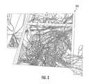
- FIG. 2is a perspective view of an under-floor cable tray supporting patch cords.
- FIG. 3is a side view, partially in cross-section, of a portion of a traceable cable assembly according to one embodiment.
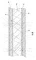
- FIG. 4is a cross-sectional view of the cable assembly of FIG. 3 along the plane IV-IV.
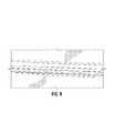
- FIG. 5is a lengthwise cross sectional view of a tracer element of the cable assembly according to embodiments of the present disclosure.
- FIG. 6is a schematic view of light propagating through and being scattered from the tracer element of FIG. 5 .
- FIG. 7shows a method of forming a side-emitting optical fiber as the tracer element of FIG. 5 .
- FIG. 8shows example scattering sites of the side-emitting optical fiber as viewed under a microscope.
- the descriptionrelates to side-emitting waveguides, cables, and cable assemblies using the waveguides to facilitate the traceability of the cable or cable assembly.
- This descriptionalso relates to methods of forming the side-emitting waveguides, cables and cable assemblies.
- FIG. 1shows an example of congestion in an equipment rack 110 .
- FIG. 2shows congestion in an under-floor cable tray 210 .
- Network operatorsfrequently desire to change connections to accommodate moves, adds, and changes in the network.
- congestionmakes it difficult to trace a particular cable from the source to the receiver, which may be required to perform the moves, adds, and changes in the network.
- An aspect of this disclosureis the provision of side-emitting waveguides, usable within traceable cables, which provide efficient light emission that may provide visibility of the waveguide in well-lit rooms over a significant distance, wherein the waveguides may be produced by an efficient manufacturing method.
- FIG. 3shows a cable assembly 1 with improved tracing capabilities according to embodiments of the present disclosure.
- the cable assembly 1includes a cable 3 , tracer locations 4 , and a connector 5 .
- a connector 5may be present on each opposite end of the cable 3 to allow the cable assembly 1 to act as a patch cord between components of a network.
- the connector 5may vary widely depending on the nature of the cable 3 and the components being connected.
- the specific connector 5 selectedshould match the port configuration of the network component and will vary based upon the quantity and type of signals being transmitted by the cable 3 .
- the distance between the connectors 5may define a length for the cable 3 .
- Cables 3 of the present disclosureare not specifically limited in their length, however, the cables 3 may have a length of at least about 1 meter and up to several tens of meters, such as one-hundred meters.
- FIG. 4shows a cross section of the cable 3 to represent one possible embodiment.
- the cable 3may include one or more data transmission elements 7 . Two such data transmission elements 7 are shown.
- the data transmission elements 7may be of the same type or different types as compared to one another.
- a data transmission element 7is a structure capable of carrying a data signal from one end of the cable 3 to the other.
- the data transmission element 7may be configured to transmit an electrical signal, for example, using a copper wire or other electrically conductive material.
- the data transmission element 7may be configured to transmit an optical signal by conducting electromagnetic waves such as ultraviolet, infrared, or visible light to carry data from one location to another.
- the cable 3may be more appropriately referred to as a conduit, without having any data transmission elements 7 .
- these cables 3may transmit fluids such as air or liquid.
- These cables 3may be appropriate for use in a medical setting such as IV lines or oxygen tubing.
- the cable 3includes a jacket 10 .
- the jacket 10may be a hollow tube forming a conduit that can substantially surround the data transmission elements 7 and that can define an outer surface of the cable 3 .
- the data transmission elements 7may be at least partially embedded within the jacket 10 .
- Cables 3 of the present disclosureinclude a tracer element 15 .
- the tracer element 15is provided to enable the cable 3 to be selectively identified at one or more areas along the cable 3 .
- the tracer element 15may be visually identified with or without special equipment, such as an IR camera.
- a tracer element 15is a side-emitting optical fiber 20 used to identify one or more portions of the cable 3 .
- the side-emitting optical fiber 20may be referred to interchangeably as a side-emitting optical waveguide herein. Therefore this disclosure does not intend to differentiate between the terms “optical fiber” and “optical waveguide” per se.
- the side-emitting optical fiber 20may conduct nonvisible light.
- the side-emitting optical fiber 20can also be used to conduct visible light, such as green light at approximately 532 nm. Red light, blue light, or a combination thereof could also be used to assist with tracing the cable 3 . Green light may be used due to the relative high degree of sensitivity of the human eye to green light.
- the side-emitting optical fiber 20is embedded within a portion of the jacket 10 .
- the side-emitting optical fiber 20could be adjacent to the data transmission elements 7 inside a cavity formed by the jacket 10 . If the side-emitting optical fiber 20 is within such a cavity, the jacket 10 may have at least some areas that are highly transparent. In yet other embodiments, the side-emitting optical fiber 20 could be provided on or mounted to the outside of the jacket 10 .
- the jacket 10may include a pigmented portion 22 and an un-pigmented portion 24 .
- the pigment used in the pigmented portion 22may be selected to identify the nature of the cable 3 to one of ordinary skill in the art, based on the number, type, and arrangement of data transmission elements 7 therein.
- the side-emitting optical fiber 20may be embedded within the un-pigmented portion 24 .
- the un-pigmented portion 24may include some pigment, but is typically more optically transparent than the pigmented portion 22 . Therefore by locating the side-emitting optical fiber 20 within the un-pigmented portion 24 , any light scattered from the side-emitting optical fiber 20 will be more visible.
- the side-emitting optical fiber 20includes at least a core 30 and a cladding 32 .
- the core 30may be made from glass, particularly silica-based glass, having a first index of refraction.
- the core 30may be formed from a polymer.
- the size of the core 30is not particularly limited, but in some embodiments diameters may be between and including about 100 microns and about 250 microns.
- the coremay be, for example, 125 microns. Cores that are significantly smaller may be subject to damage from handling, and cores that are significantly larger may be subject to damage when bending.
- the core 30may be a substantially solid core, generally free of voids or air pockets as found within the airline optical fiber type of diffusive optical fibers.
- a core 30 that is free from voidsmay facilitate splicing, polishing, or other processing operations, which may be needed in some embodiments to make ends of the side-emitting optical fiber 20 compatible with a device for launching light into the side-emitting optical fiber.
- the cladding 32can be a polymer, such as fluoro-acrylate.
- the material for the cladding 32is selected to have an index of refraction that differs from the index of refraction of the core 30 .
- the index of refraction of the cladding 32is lower than that of the core.
- the indices of refractionproduce a step-index optical fiber.
- the side-emitting optical fiber 20may be a trapezium or triangular index fiber.
- the cladding 32closely surrounds the core 30 to help maintain light within the side-emitting optical fiber 20 .
- the cladding 32may have a thickness between about 4% and about 40% of the diameter of the core.
- the cladding 32may be between about 5 and about 50 microns thick from the surface of the core 30 to an exterior surface 36 of the cladding 32 when the core 30 has a diameter of 125 microns.
- scattering sites 40are selectively provided at spaced apart locations on the cladding 32 along the length of the side-emitting optical fiber 20 .
- the scattering sites 40are configured to provide areas where light, which is otherwise traveling along the side-emitting optical fiber 20 , is scattered and therefore able to be emitted from the side of the side-emitting optical fiber 20 , as shown in stippled lines in FIG. 6 , to form the tracer locations 4 shown in FIG. 3 .
- the scattering sites 40are areas where the exterior surface 36 is modified, removed, deformed, or damaged to produce optical surfaces tending to scatter incoming light. Some or all of the scattering sites 40 may be annular or otherwise generally ring shaped, extending around the entire circumference of the side-emitting optical fiber 20 . In some embodiments, as understood from FIG. 6 , each scattering site 40 does not extend around the full circumference of the side-emitting optical fiber 20 . The scattering sites 40 may sweep an arc approximately 180 degrees, 90 degrees, or even less around the circumference.
- a complete ring shapemay provide the most uniformly scattered light, but a full ring is not believed necessary to have light scatter in all 360 degrees around a lengthwise axis of the side-emitting optical fiber 20 and/or light to be seen 360 degrees a lengthwise axis of the cable 3 .
- the scattering sites 40scatter light generally in all directions with varying intensity. Therefore, each scattering site 40 directs light immediately out of an adjacent portion of the exterior surface 36 , and also directs light back through the core 30 and out an opposite portion of the exterior surface 36 as schematically illustrated in FIG. 6 . Scattering light from the side-emitting optical fiber 20 about 360 degrees can be desired to avoid directionality in the side-emitting optical fiber 20 .
- Directionalitymay require more precise orientation of the side-emitting optical fiber 20 with the jacket 10 and cable 3 . If the side-emitting optical fiber 20 emitted light in to a particular direction, that emission direction may need to be oriented toward the exterior of the cable 3 to be visible. Again, by scattering light 360 degrees around the side-emitting optical fiber 20 , the side-emitting optical fiber allows the scattered light be to be seen from any viewpoint around the lengthwise axis of the cable 3 .
- the scattering sites 40may be produced by a variety of mechanical, optical, or chemical processes. In the embodiment of FIG. 7 , the scattering sites 40 are produced as the result of ablation caused by impact with high intensity light from a laser 76 . The ablation process removes some of the cladding 32 and leaves behind an optically rough surface portion.
- characteristics of the scattering sites 40may be refined to help ensure that the extraction of light from the core 30 and cladding 32 to provide tracer locations 4 along the cable 3 are each visible in a well-lit environment.
- the characteristicsmay also be refined based the practical manufacturability of the cable 3 and side-emitting optical fiber 20 .
- the separation P between the scattering sites 40may be selected to address the unique challenges associated with cable assemblies for data centers or similar network locations.
- the scattering sites 40should be at least about 1 cm apart and less than about 1 meter apart. Scattering sites 40 that are too close together approach a uniform emission along the length of the cable 3 , and may lose the efficient use of light provided by the discrete tracer locations 4 . Scattering sites 40 that are too far apart may lose the benefits of along-the-length tracer locations 4 and the ability to sufficiently trace the cable 3 in its environment with other cables. Additionally, scattering sites 40 that are too far apart may result in no scattering sites 40 sufficiently close to the terminal end of the cable 3 to provide a tracer location 4 within the appropriate equipment rack 110 .
- An approximate separation P of about 10 cmmay balance the light efficiency and traceability benefits, keeping in mind that several of the tracer locations 4 may be hidden behind other cables, effectively increasing the relative spacing between each tracer location 4 .
- the separation Pmay facilitate identifying the overall length of the cable 3 .
- the approximate separation Pmay be about 1 meter in some embodiments, thereby allowing a person to count the tracer locations 4 to approximate the total length of the cable 3 in meters.
- the approximate separation Pmay be about 1 foot, thereby allowing a person to count the tracer locations 4 to estimate the total length of the cable 3 in feet.
- the cable 3 and the side-emitting optical fiber 20may be described as each having respective launched ends and traced ends.
- the launched endscan be the known, accessible end of the cable 3 and end of the side-emitting optical fiber 20 where the network operator would provide (i.e. launch) tracer light to the side-emitting optical fiber 20 .
- the respective traced endsshould therefore be understood as the respective ends of the cable 3 and optical fiber 20 opposite the launched ends.
- the traced end, particularly of the cable 3is the end of the cable that needs to be identified by the tracing process. It should be understood that these ends are not fixed. For any given operation, either end of the cable 3 may constitute the launched end and the traced end.
- the size of each scattering site 40may also be based on the challenges associated with cable assemblies for data centers or similar network locations.
- the size of each scattering site 40may include the arc sweep around the side-emitting optical fiber 20 .
- the size of each scattering site 40may also include the magnitude M ( FIG. 3 ) along the length of the side-emitting optical fiber 20 (i.e., “magnitude M” refers to the length of each scattering site measured parallel to the lengthwise axis of the side-emitting optical fiber 20 ).
- the magnitude Mmay be between about 10 microns and about 50 mm, or even between about 0.5 mm and about 4 mm (such as about 2 mm for one specific example).
- the scattering sites 40may be characterized by their depth D ( FIG. 5 ) from the exterior surface 36 to a point closest to the core 30 .
- Ddepth
- the scattering sites 40may be characterized by their depth D ( FIG. 5 ) from the exterior surface 36 to a point closest to the core 30 .
- the edges of the distribution, the part traveling through the cladding 32may be referred to as the evanescent tail of the propagating light. It is this tail that is clipped by the scattering sites 40 and sent traveling in all directions. Therefore, the deeper each scattering site 40 penetrates into the cladding 32 , the greater portion of the light distribution that is available for scattering by the scattering site 40 .
- selecting the depth D of each scattering site 40balances the desire to scatter out a sufficient amount of light to be visible in a well-lit room with the desire to maintain enough light within the side-emitting optical fiber 20 to provide sufficient light to each of the scattering sites 40 downstream.
- the scattering sites 40may remove the cladding 32 completely down to the core 30 . In one example, the scattering sites 40 do not completely remove the cladding 32 at the given location.
- Depths Dmay include between about 1% to about 100% of the thickness of the cladding 32 .
- the depth D of each scattering site 40may be substantially consistent along the length of the cable 3 .
- the depth Dmay vary as a function of the distance from an end of the cable 3 or side-emitting optical fiber 20 . For example the depth D may increase with distance from the launched end.
- the depth Dis generally defined as a maximum distance toward the core 30 or a maximum percentage of cladding removal for any given scattering site 40 .
- each scattering site 40is likely to render a range of depths for any given scattering site 40 .
- the range of depthsmay be minimized and essentially random.
- the range of depthsmay be provided with a general profile, like the concave areas represented in FIGS. 5 and 6 .
- the side-emitting optical fiber 20may include at least one coating 50 applied to the exterior surface 36 and scattering sites 40 of the cladding 32 .
- the coating 50may be between about 10 and about 70 microns thick.
- the coating 50may be provided as a layer of protection for the core 30 and the cladding 32 .
- the coating 50should be at least translucent, if not fully transparent, in locations corresponding with the scattering sites 40 .
- the coating 50may have light transmission windows or have generally uniform light transmission characteristics.
- the coating 50may be made from acrylate.
- the refractive index of the coating 50may be 1.56 relative to the refractive index of the optical cladding 32 of 1.35.
- the side-emitting optical fiber 20may also include an ink layer 60 applied to the coating 50 .
- the ink layer 60may be selectively applied to locations corresponding with the scattering sites 40 .
- the ink layer 60may be uniformly applied to the coating 50 .
- the ink layer 60may have further scattering elements, such as titanium oxide spheres, configured to diffuse the light being emitted from the side-emitting optical fiber 20 .
- the ink layer 60is configured to provide each tracer location 4 with an approximate Lambertian distribution pattern.
- the side-emitting optical fiber 20 of the present disclosurehas been described for use in facilitating traceability of a cable 3 .
- the side-emitting optical fiber 20may have uses independent of the cable 3 .
- the side-emitting optical fiber 20may not be used for tracing at all, but may itself provide decorative or functional illumination or indication.
- a core 30such as a glass core may be fed, pulled, or drawn, or otherwise passed at typical telecom speeds through a first liquid die block 70 .
- a cladding 32is deposited or otherwise applied to the core 30 .
- process for adding the cladding 32may be a pultrusion process.
- the cladded core 33may pass through a curing station 73 where the cladding 32 is at least partially cured.
- the curing station 73may emit UV light from lamps or LEDs to rapidly, optically cure the cladding 32 .
- the scattering sites 40may be created by ablating the exterior surface 36 with at least one high intensity light source, such as a laser 76 as the cladded core 33 is drawn past. Two or more light sources positioned around the core 30 may be provided to achieve the desired arc sweep for each scattering site 40 .
- the high intensity lightimpacts the cladding 32 and forms the scattering sites 40 by vaporizing or burning off some of the cladding 32 while locally affecting other portions of the cladding 32 to produce the resulting locally roughened surface as shown in FIG. 8 .
- the roughened surfacemay be described as having a series of defects or voids. It should be recognized that the scattering sites 40 will be at least as large as the wavelength of the laser 76 .
- Using a less collimated beam emitted from slightly further from the cladded core 33can produce scattering sites 40 that are wider radially.
- the laser 76is also likely to cause a hot spot on the cladding 32 that spreads beyond the area directly in path with the light beam.
- each laser 76is a CO2 laser, running at a repetition rate of 0.25 Hz to 100000 Hz with pulse energies of approximately 10000 W/s to 20000 W/s and pulse duration of 0.1 ⁇ s to 10 seconds.
- pulse energiesapproximately 10000 W/s to 20000 W/s
- pulse duration0.1 ⁇ s to 10 seconds.
- the repetition rate, pulse energy, and pulse durationmay all be adjusted based on the draw rate of the cladded core 33 to achieve scattering sites 40 with the desired separation P, magnitude M, and depth D.
- the cladded core 33may pass through a second liquid die block 80 where a similar pultrusion process may add a coating 50 over the ablated cladding.
- the coating 50may be cured as it passing through a second curing station (not shown), or may be cured by other known means, such as temperature.
- a scattering ink layer 60may be applied onto the coating 50 at a third liquid die block 84 , or other processing unit, such as a spray applicator or printer.
- the side-emitting optical fiber 20is manufactured on a single draw.
- the side-emitting optical fiber 20can be produced in a continuous fashion on a single line, at a single location.
- the side-emitting optical fibers 20 of the present descriptioncould also be produced by discrete steps at separate locations.
- the core 30may be wound up, transported between locations or manufacturing stations, and then run through the first liquid die block 70 for cladding.
- the scattering sites 40may be created separate from the drawing of the cladded cores 33 .
- the side-emitting optical fibers 20may continue on the single line directly to the manufacture of the cable 3 .
- the side-emitting optical fiber 20may be separately combined with the data transmission elements 7 and the jacket 10 in a different location or distinct time.
- an extrusion or pultrusion processmay be used to at least partially embed the side-emitting optical fiber 20 with the jacket 10 as the jacket 10 is being formed around the data transmission element 7 .
- the side-emitting optical fiber 20may be combined with at least one data transmission element 7 and a jacket 10 by a variety of processes known in the art, depending upon the particular type of cable 3 that is being manufactured.
- Cable assemblies 1may be made by cutting the cable 3 to a desired length and attaching the desired connectors 5 to each end according to processes known in the art, and dependent upon the type of cable assembly 1 being produced.
- the connector 5may be SC, LC, ST, FC, or MPO type connectors.
- the side-emitting optical fibers 20 , cables 3 that incorporate the side-emitting optical fibers 20 , and cable assemblies 1 that incorporate the cables 3each have several advantages that will be apparent to one of ordinary skill in the art. Particularly, use of a side-emitting optical fiber 20 within the cable 3 provides an improved ability for a network operator to quickly and efficiently trace a particular cable assembly 1 so that a traced end can be identified from a predetermined launched end of the cable assembly 1 .
- the side-emitting optical fibers 20 of this disclosurecan be configured to facilitate the ability to trace along the full length of the cable 3 . This may be helpful to identify tangles or knots. This may also help when the particular equipment rack 110 , in which the traced end is connected, is unknown. For example, equipment racks 110 often have front doors that are kept closed. Tracing along the length of the cable 3 may help identify which rack to search. If a tracer location 4 were only on the traced end the cable 3 , it may be hidden behind the door.
- side-emitting optical fibers 20may provide tracer locations 4 along the length of a cable 3 , they are usually not intended to provide continuous illumination along the length. As a result, the side-emitting optical fibers 20 are able to make more efficient use of a tracer source light. This means that tracer locations 4 can be provided along cables 3 of significant length, for example 30 m or more, while the tracer locations 4 may remain sufficiently bright to be readily visible in a well-lit room using a tracer source light of reasonable intensity.
- a tracer light sourcemay be integrated into the cable 3 , or the connector 5 , to illuminate the side-emitting optical fiber 20 .
- a separate tracer light sourcemay be used to selectively emit light into the side-emitting optical fiber 20 .
- the cost of the cable 3may be reduced compared to systems integrating a light source or using active light sources along the length to form the individual tracer locations 4 .
- the side-emitting optical fiber 20can be made with a continuous manufacturing process where each step is performed on a single draw. Such a continuous process may provide a high rate of manufacture with minimum waste, transportation costs or labor costs.
- Use of laser ablation to form the scattering sites 40provides a processing step that can be readily controlled in terms of pulse rate, pulse energy, and duration to finely tune the separation, arc sweep, and magnitude of the scattering sites 40 to achieve the best combination of traceability, brightness, and manufacturing efficiency.
Landscapes
- Physics & Mathematics (AREA)
- General Physics & Mathematics (AREA)
- Optics & Photonics (AREA)
- Light Guides In General And Applications Therefor (AREA)
- Optical Couplings Of Light Guides (AREA)
Abstract
Description
This application is a continuation of U.S. application Ser. No. 14/690,752 filed on Apr. 20, 2015, which claims the benefit of priority to Provisional Application Ser. No. 62/140,620, filed on Mar. 31, 2015, both applications being relied upon and incorporated herein by reference their entireties.
This disclosure generally relates to waveguides that scatter light from the side thereof. More particularly, this disclosure relates to cables and cable assemblies, such as patch cords, that are traceable due to the addition of a side-emitting optical fiber.
Today's computer networks continue to increase in size and complexity. Businesses and individuals rely on these networks to store, transmit, and receive critical data at high speeds. Even with the expansion of wireless technology, wired connections remain critical to the operation of computer networks, including enterprise data centers. Portions of these wired computer networks are regularly subject to removal, replacement, upgrade or other moves and changes. To ensure the continued proper operation of each network, the maze of cables connecting the individual components must be precisely understood and properly connected between specific ports.
In many cases, a network's cables, often called patch cords, can be required to bridge several meters across a data center. The cables may begin in one equipment rack, run through the floor or other conduit, and terminate at a component in a second equipment rack.
As a result, there is a need for a traceable cable that provides a means for the network operator to quickly identify the path and approximate terminal end of a given cable that is being replaced, relocated, or tested.
The present disclosure includes traceable cables and side-emitting waveguides used in the same. In one embodiment of this disclosure, the cable includes at least one data transmission element, a jacket at least partially surrounding the at least one data transmission element, and a side-emitting optical fiber incorporated with and extending along at least a portion of the length of the cable. The side-emitting optical fiber has a core and a cladding substantially surrounding the core to define an exterior surface. The cladding has spaced apart scattering sites penetrating the exterior surface along the length of the optical fiber. The scattering sites scatter light so that the scattered light is emitted from the side-emitting optical fiber at discrete locations. When light is transmitted through the core, light scattered from the side-emitting optical fiber allows the cable to be traced along at least a portion of the length thereof.
The present disclosure also includes methods of forming traceable cables having at least one data transmission element and a jacket at least partially surrounding the at least one data transmission element. The method may comprise forming a side-emitting optical fiber by: adding a cladding around a glass core to create an exterior surface, the cladding having a lower index of refraction than the glass core, selectively ablating portions of the cladding to create scattering sites penetrating the exterior surface and configured to allow the side-emitting optical fiber to scatter light therefrom, and at least partially embedding the side-emitting optical fiber within the jacket so that the side-emitting optical fiber extends along at least a portion of a length of the cable.
The present disclosure also includes another method of forming a traceable cable that includes at least one data transmission element and a jacket at least partially surrounding the at least one data transmission element. The method may comprise forming an optical fiber by: passing a glass core through a first die block that applies a UV-curable cladding onto the glass core to form an optical fiber, wherein the cladding has a lower index of refraction than the glass core. The optical fiber is further formed by drawing the optical fiber past a laser, wherein the laser is pulsed as the optical fiber is drawn past the laser to selectively ablate portions of the cladding, the laser ablated portions defining scattering sites configured to allow the optical fiber to scatter light therefrom. Forming the optical fiber may further comprise passing the optical fiber through a second die block after selectively ablating portions of the cladding with the laser, wherein the second die block applies an acrylic coating over the cladding. The method may further include at least partially embedding the optical fiber within the jacket so that the optical fiber extends along at least a portion of a length of the cable.
Additional features and advantages will be set forth in the detailed description which follows, and in part will be readily apparent to those skilled in the art. It is to be understood that the foregoing general description, the following detailed description, and the accompanying drawings are merely exemplary and intended to provide an overview or framework to understand the nature and character of the claims.
The accompanying drawings are included to provide a further understanding, and are incorporated in and constitute a part of this specification. The drawings illustrate one or more embodiments, and together with the description serve to explain principles and operation of the various embodiments. Features and attributes associated with any of the embodiments shown or described may be applied to other embodiments shown, described, or appreciated based on this disclosure.
Various embodiments will be further clarified by examples in the description below. In general, the description relates to side-emitting waveguides, cables, and cable assemblies using the waveguides to facilitate the traceability of the cable or cable assembly. This description also relates to methods of forming the side-emitting waveguides, cables and cable assemblies.
A problem that occurs in data centers or similar network locations is congestion and clutter caused by large quantities of cables.FIG. 1 shows an example of congestion in an equipment rack110.FIG. 2 shows congestion in an under-floor cable tray 210. Network operators frequently desire to change connections to accommodate moves, adds, and changes in the network. However, such congestion makes it difficult to trace a particular cable from the source to the receiver, which may be required to perform the moves, adds, and changes in the network.
An aspect of this disclosure is the provision of side-emitting waveguides, usable within traceable cables, which provide efficient light emission that may provide visibility of the waveguide in well-lit rooms over a significant distance, wherein the waveguides may be produced by an efficient manufacturing method.
Turning back to the figures,FIG. 3 shows acable assembly 1 with improved tracing capabilities according to embodiments of the present disclosure. Thecable assembly 1 includes acable 3,tracer locations 4, and aconnector 5. Although not shown, it should be understood that aconnector 5 may be present on each opposite end of thecable 3 to allow thecable assembly 1 to act as a patch cord between components of a network. Theconnector 5 may vary widely depending on the nature of thecable 3 and the components being connected. Thespecific connector 5 selected should match the port configuration of the network component and will vary based upon the quantity and type of signals being transmitted by thecable 3. The distance between theconnectors 5 may define a length for thecable 3.Cables 3 of the present disclosure are not specifically limited in their length, however, thecables 3 may have a length of at least about 1 meter and up to several tens of meters, such as one-hundred meters.
In some embodiments, thecable 3 may be more appropriately referred to as a conduit, without having anydata transmission elements 7. Instead of transmitting a data signal, thesecables 3 may transmit fluids such as air or liquid. Thesecables 3 may be appropriate for use in a medical setting such as IV lines or oxygen tubing. Thecable 3 includes ajacket 10. Thejacket 10 may be a hollow tube forming a conduit that can substantially surround thedata transmission elements 7 and that can define an outer surface of thecable 3. Alternatively, thedata transmission elements 7 may be at least partially embedded within thejacket 10.
One example of atracer element 15 is a side-emittingoptical fiber 20 used to identify one or more portions of thecable 3. The side-emittingoptical fiber 20 may be referred to interchangeably as a side-emitting optical waveguide herein. Therefore this disclosure does not intend to differentiate between the terms “optical fiber” and “optical waveguide” per se. The side-emittingoptical fiber 20 may conduct nonvisible light. The side-emittingoptical fiber 20 can also be used to conduct visible light, such as green light at approximately 532 nm. Red light, blue light, or a combination thereof could also be used to assist with tracing thecable 3. Green light may be used due to the relative high degree of sensitivity of the human eye to green light.
As seen inFIG. 4 , the side-emittingoptical fiber 20 is embedded within a portion of thejacket 10. In alternative embodiments, the side-emittingoptical fiber 20 could be adjacent to thedata transmission elements 7 inside a cavity formed by thejacket 10. If the side-emittingoptical fiber 20 is within such a cavity, thejacket 10 may have at least some areas that are highly transparent. In yet other embodiments, the side-emittingoptical fiber 20 could be provided on or mounted to the outside of thejacket 10.
Still referring toFIG. 4 , thejacket 10 may include a pigmentedportion 22 and anun-pigmented portion 24. The pigment used in the pigmentedportion 22 may be selected to identify the nature of thecable 3 to one of ordinary skill in the art, based on the number, type, and arrangement ofdata transmission elements 7 therein. The side-emittingoptical fiber 20 may be embedded within theun-pigmented portion 24. Theun-pigmented portion 24 may include some pigment, but is typically more optically transparent than the pigmentedportion 22. Therefore by locating the side-emittingoptical fiber 20 within theun-pigmented portion 24, any light scattered from the side-emittingoptical fiber 20 will be more visible.
Turning toFIG. 5 , the side-emittingoptical fiber 20 includes at least a core30 and acladding 32. The core30 may be made from glass, particularly silica-based glass, having a first index of refraction. Alternatively, thecore 30 may be formed from a polymer. The size of thecore 30 is not particularly limited, but in some embodiments diameters may be between and including about 100 microns and about 250 microns. The core may be, for example, 125 microns. Cores that are significantly smaller may be subject to damage from handling, and cores that are significantly larger may be subject to damage when bending.
In some embodiments, thecore 30 may be a substantially solid core, generally free of voids or air pockets as found within the airline optical fiber type of diffusive optical fibers. A core30 that is free from voids may facilitate splicing, polishing, or other processing operations, which may be needed in some embodiments to make ends of the side-emittingoptical fiber 20 compatible with a device for launching light into the side-emitting optical fiber.
Thecladding 32 can be a polymer, such as fluoro-acrylate. In the embodiment illustrated in the drawings, the material for thecladding 32 is selected to have an index of refraction that differs from the index of refraction of thecore 30. In some embodiments the index of refraction of thecladding 32 is lower than that of the core. In some embodiments, the indices of refraction produce a step-index optical fiber. In other embodiments, the side-emittingoptical fiber 20 may be a trapezium or triangular index fiber. Thecladding 32 closely surrounds the core30 to help maintain light within the side-emittingoptical fiber 20. Thecladding 32 may have a thickness between about 4% and about 40% of the diameter of the core. For example, thecladding 32 may be between about 5 and about 50 microns thick from the surface of the core30 to anexterior surface 36 of thecladding 32 when thecore 30 has a diameter of 125 microns.
According to embodiments of the present description, scatteringsites 40 are selectively provided at spaced apart locations on thecladding 32 along the length of the side-emittingoptical fiber 20. Thescattering sites 40 are configured to provide areas where light, which is otherwise traveling along the side-emittingoptical fiber 20, is scattered and therefore able to be emitted from the side of the side-emittingoptical fiber 20, as shown in stippled lines inFIG. 6 , to form thetracer locations 4 shown inFIG. 3 .
Thescattering sites 40 are areas where theexterior surface 36 is modified, removed, deformed, or damaged to produce optical surfaces tending to scatter incoming light. Some or all of thescattering sites 40 may be annular or otherwise generally ring shaped, extending around the entire circumference of the side-emittingoptical fiber 20. In some embodiments, as understood fromFIG. 6 , each scatteringsite 40 does not extend around the full circumference of the side-emittingoptical fiber 20. Thescattering sites 40 may sweep an arc approximately 180 degrees, 90 degrees, or even less around the circumference.
A complete ring shape may provide the most uniformly scattered light, but a full ring is not believed necessary to have light scatter in all 360 degrees around a lengthwise axis of the side-emittingoptical fiber 20 and/or light to be seen 360 degrees a lengthwise axis of thecable 3. Thescattering sites 40 scatter light generally in all directions with varying intensity. Therefore, each scatteringsite 40 directs light immediately out of an adjacent portion of theexterior surface 36, and also directs light back through thecore 30 and out an opposite portion of theexterior surface 36 as schematically illustrated inFIG. 6 . Scattering light from the side-emittingoptical fiber 20 about 360 degrees can be desired to avoid directionality in the side-emittingoptical fiber 20. Directionality may require more precise orientation of the side-emittingoptical fiber 20 with thejacket 10 andcable 3. If the side-emittingoptical fiber 20 emitted light in to a particular direction, that emission direction may need to be oriented toward the exterior of thecable 3 to be visible. Again, by scattering light 360 degrees around the side-emittingoptical fiber 20, the side-emitting optical fiber allows the scattered light be to be seen from any viewpoint around the lengthwise axis of thecable 3.
Thescattering sites 40 may be produced by a variety of mechanical, optical, or chemical processes. In the embodiment ofFIG. 7 , thescattering sites 40 are produced as the result of ablation caused by impact with high intensity light from alaser 76. The ablation process removes some of thecladding 32 and leaves behind an optically rough surface portion.
Several characteristics of thescattering sites 40 may be refined to help ensure that the extraction of light from thecore 30 andcladding 32 to providetracer locations 4 along thecable 3 are each visible in a well-lit environment. The characteristics may also be refined based the practical manufacturability of thecable 3 and side-emittingoptical fiber 20.
First, the separation P between the scatteringsites 40 may be selected to address the unique challenges associated with cable assemblies for data centers or similar network locations. In one embodiment, thescattering sites 40 should be at least about 1 cm apart and less than about 1 meter apart.Scattering sites 40 that are too close together approach a uniform emission along the length of thecable 3, and may lose the efficient use of light provided by thediscrete tracer locations 4.Scattering sites 40 that are too far apart may lose the benefits of along-the-length tracer locations 4 and the ability to sufficiently trace thecable 3 in its environment with other cables. Additionally, scatteringsites 40 that are too far apart may result in noscattering sites 40 sufficiently close to the terminal end of thecable 3 to provide atracer location 4 within the appropriate equipment rack110. An approximate separation P of about 10 cm may balance the light efficiency and traceability benefits, keeping in mind that several of thetracer locations 4 may be hidden behind other cables, effectively increasing the relative spacing between eachtracer location 4. In some embodiments, the separation P may facilitate identifying the overall length of thecable 3. For example, the approximate separation P may be about 1 meter in some embodiments, thereby allowing a person to count thetracer locations 4 to approximate the total length of thecable 3 in meters. In other embodiments, the approximate separation P may be about 1 foot, thereby allowing a person to count thetracer locations 4 to estimate the total length of thecable 3 in feet.
As used herein, thecable 3 and the side-emittingoptical fiber 20 may be described as each having respective launched ends and traced ends. The launched ends can be the known, accessible end of thecable 3 and end of the side-emittingoptical fiber 20 where the network operator would provide (i.e. launch) tracer light to the side-emittingoptical fiber 20. The respective traced ends should therefore be understood as the respective ends of thecable 3 andoptical fiber 20 opposite the launched ends. The traced end, particularly of thecable 3, is the end of the cable that needs to be identified by the tracing process. It should be understood that these ends are not fixed. For any given operation, either end of thecable 3 may constitute the launched end and the traced end.
The size of eachscattering site 40 may also be based on the challenges associated with cable assemblies for data centers or similar network locations. The size of eachscattering site 40 may include the arc sweep around the side-emittingoptical fiber 20. The size of eachscattering site 40 may also include the magnitude M (FIG. 3 ) along the length of the side-emitting optical fiber20 (i.e., “magnitude M” refers to the length of each scattering site measured parallel to the lengthwise axis of the side-emitting optical fiber20). In some embodiments, the magnitude M may be between about 10 microns and about 50 mm, or even between about 0.5 mm and about 4 mm (such as about 2 mm for one specific example).
Further, thescattering sites 40 may be characterized by their depth D (FIG. 5 ) from theexterior surface 36 to a point closest to thecore 30. One skilled in the art will appreciate that light traveling through the side-emittingoptical fiber 20 may be described as forming a bell shaped distribution pattern relative to the central lengthwise axis of thecore 30. The edges of the distribution, the part traveling through thecladding 32, may be referred to as the evanescent tail of the propagating light. It is this tail that is clipped by thescattering sites 40 and sent traveling in all directions. Therefore, the deeper eachscattering site 40 penetrates into thecladding 32, the greater portion of the light distribution that is available for scattering by thescattering site 40. Therefore, selecting the depth D of eachscattering site 40 balances the desire to scatter out a sufficient amount of light to be visible in a well-lit room with the desire to maintain enough light within the side-emittingoptical fiber 20 to provide sufficient light to each of thescattering sites 40 downstream.
In an extreme example, thescattering sites 40 may remove thecladding 32 completely down to thecore 30. In one example, thescattering sites 40 do not completely remove thecladding 32 at the given location. Depths D may include between about 1% to about 100% of the thickness of thecladding 32. Yet again, the depth D of eachscattering site 40 may be substantially consistent along the length of thecable 3. Alternatively, the depth D may vary as a function of the distance from an end of thecable 3 or side-emittingoptical fiber 20. For example the depth D may increase with distance from the launched end. The depth D is generally defined as a maximum distance toward the core30 or a maximum percentage of cladding removal for any givenscattering site 40. The process used, and resulting surface profile of eachscattering site 40, is likely to render a range of depths for any givenscattering site 40. In some embodiments, the range of depths may be minimized and essentially random. In other embodiments, the range of depths may be provided with a general profile, like the concave areas represented inFIGS. 5 and 6 .
The side-emittingoptical fiber 20 may include at least onecoating 50 applied to theexterior surface 36 andscattering sites 40 of thecladding 32. Thecoating 50 may be between about 10 and about 70 microns thick. Thecoating 50 may be provided as a layer of protection for thecore 30 and thecladding 32. Thecoating 50 should be at least translucent, if not fully transparent, in locations corresponding with thescattering sites 40. Thecoating 50 may have light transmission windows or have generally uniform light transmission characteristics. Thecoating 50 may be made from acrylate. The refractive index of thecoating 50 may be 1.56 relative to the refractive index of theoptical cladding 32 of 1.35.
The side-emittingoptical fiber 20 may also include anink layer 60 applied to thecoating 50. Theink layer 60 may be selectively applied to locations corresponding with thescattering sites 40. Alternatively, theink layer 60 may be uniformly applied to thecoating 50. Theink layer 60 may have further scattering elements, such as titanium oxide spheres, configured to diffuse the light being emitted from the side-emittingoptical fiber 20. Theink layer 60 is configured to provide eachtracer location 4 with an approximate Lambertian distribution pattern.
The side-emittingoptical fiber 20 of the present disclosure has been described for use in facilitating traceability of acable 3. In some embodiments, the side-emittingoptical fiber 20 may have uses independent of thecable 3. For example, the side-emittingoptical fiber 20 may not be used for tracing at all, but may itself provide decorative or functional illumination or indication.
Side-emittingoptical fibers 20 according to this disclosure may be manufactured according to a process schematically illustrated inFIG. 7 . A core30, such as a glass core may be fed, pulled, or drawn, or otherwise passed at typical telecom speeds through a firstliquid die block 70. There, acladding 32 is deposited or otherwise applied to thecore 30. In one example, process for adding thecladding 32 may be a pultrusion process. The cladded core33 may pass through a curingstation 73 where thecladding 32 is at least partially cured. In one example, the curingstation 73 may emit UV light from lamps or LEDs to rapidly, optically cure thecladding 32.
After thecladding 32 is at least partially cured, thescattering sites 40 may be created by ablating theexterior surface 36 with at least one high intensity light source, such as alaser 76 as the cladded core33 is drawn past. Two or more light sources positioned around thecore 30 may be provided to achieve the desired arc sweep for eachscattering site 40. The high intensity light impacts thecladding 32 and forms thescattering sites 40 by vaporizing or burning off some of thecladding 32 while locally affecting other portions of thecladding 32 to produce the resulting locally roughened surface as shown inFIG. 8 . The roughened surface may be described as having a series of defects or voids. It should be recognized that thescattering sites 40 will be at least as large as the wavelength of thelaser 76. Using a less collimated beam emitted from slightly further from the cladded core33 can producescattering sites 40 that are wider radially. Thelaser 76 is also likely to cause a hot spot on thecladding 32 that spreads beyond the area directly in path with the light beam.
In one embodiment, eachlaser 76 is a CO2 laser, running at a repetition rate of 0.25 Hz to 100000 Hz with pulse energies of approximately 10000 W/s to 20000 W/s and pulse duration of 0.1 μs to 10 seconds. As will be appreciated by one of ordinary skill in the art, other types of lasers, emitting other wavelengths of light, may be used. The repetition rate, pulse energy, and pulse duration may all be adjusted based on the draw rate of the cladded core33 to achieve scatteringsites 40 with the desired separation P, magnitude M, and depth D.
After the formation of thescattering sites 40 penetrating theexterior surface 36 of thecladding 32, the cladded core33 may pass through a secondliquid die block 80 where a similar pultrusion process may add acoating 50 over the ablated cladding. Thecoating 50 may be cured as it passing through a second curing station (not shown), or may be cured by other known means, such as temperature.
To provide a smoother, more Lambertian, light distribution pattern from the side-emittingoptical fiber 20, ascattering ink layer 60 may be applied onto thecoating 50 at a thirdliquid die block 84, or other processing unit, such as a spray applicator or printer.
In one embodiment, the side-emittingoptical fiber 20 is manufactured on a single draw. As will be understood by those of skill in the art, the side-emittingoptical fiber 20 can be produced in a continuous fashion on a single line, at a single location. Alternatively, it is possible that the side-emittingoptical fibers 20 of the present description could also be produced by discrete steps at separate locations. For example, thecore 30 may be wound up, transported between locations or manufacturing stations, and then run through the firstliquid die block 70 for cladding. In another example, thescattering sites 40 may be created separate from the drawing of the cladded cores33.
The side-emittingoptical fibers 20 may continue on the single line directly to the manufacture of thecable 3. Alternatively, the side-emittingoptical fiber 20 may be separately combined with thedata transmission elements 7 and thejacket 10 in a different location or distinct time. In one embodiment, an extrusion or pultrusion process may be used to at least partially embed the side-emittingoptical fiber 20 with thejacket 10 as thejacket 10 is being formed around thedata transmission element 7. The side-emittingoptical fiber 20 may be combined with at least onedata transmission element 7 and ajacket 10 by a variety of processes known in the art, depending upon the particular type ofcable 3 that is being manufactured.
The side-emittingoptical fibers 20,cables 3 that incorporate the side-emittingoptical fibers 20, andcable assemblies 1 that incorporate thecables 3, each have several advantages that will be apparent to one of ordinary skill in the art. Particularly, use of a side-emittingoptical fiber 20 within thecable 3 provides an improved ability for a network operator to quickly and efficiently trace aparticular cable assembly 1 so that a traced end can be identified from a predetermined launched end of thecable assembly 1. The side-emittingoptical fibers 20 of this disclosure can be configured to facilitate the ability to trace along the full length of thecable 3. This may be helpful to identify tangles or knots. This may also help when the particular equipment rack110, in which the traced end is connected, is unknown. For example, equipment racks110 often have front doors that are kept closed. Tracing along the length of thecable 3 may help identify which rack to search. If atracer location 4 were only on the traced end thecable 3, it may be hidden behind the door.
While side-emittingoptical fibers 20 according to this disclosure may providetracer locations 4 along the length of acable 3, they are usually not intended to provide continuous illumination along the length. As a result, the side-emittingoptical fibers 20 are able to make more efficient use of a tracer source light. This means thattracer locations 4 can be provided alongcables 3 of significant length, for example 30 m or more, while thetracer locations 4 may remain sufficiently bright to be readily visible in a well-lit room using a tracer source light of reasonable intensity.
A tracer light source may be integrated into thecable 3, or theconnector 5, to illuminate the side-emittingoptical fiber 20. In some embodiments, however, a separate tracer light source may be used to selectively emit light into the side-emittingoptical fiber 20. By using a separate tracer light source, the cost of thecable 3 may be reduced compared to systems integrating a light source or using active light sources along the length to form theindividual tracer locations 4.
In advantageous embodiments, the side-emittingoptical fiber 20 can be made with a continuous manufacturing process where each step is performed on a single draw. Such a continuous process may provide a high rate of manufacture with minimum waste, transportation costs or labor costs. Use of laser ablation to form thescattering sites 40 provides a processing step that can be readily controlled in terms of pulse rate, pulse energy, and duration to finely tune the separation, arc sweep, and magnitude of thescattering sites 40 to achieve the best combination of traceability, brightness, and manufacturing efficiency.
Persons skilled in waveguide technology will appreciate additional variations and modifications of the devices and methods already described. Additionally, where a method claim below does not explicitly recite a step mentioned in the description above, it should not be assumed that the step is required by the claim. Furthermore, where a method claim below does not actually recite an order to be followed by its steps or an order is otherwise not required based on the claim language, it is not intended that any particular order be inferred.
The above examples are in no way intended to limit the scope of the present invention. It will be understood by those skilled in the art that while the present disclosure has been discussed above with reference to examples of embodiments, various additions, modifications and changes can be made thereto without departing from the spirit and scope of the invention as set forth in the claims.
Claims (26)
1. A traceable cable having a length, comprising:
at least one data transmission element;
a jacket at least partially surrounding the at least one data transmission element; and
a side-emitting optical fiber incorporated with and extending along at least a portion of the length of the traceable cable, wherein the side-emitting optical fiber is at least partially embedded in the jacket, the side-emitting optical fiber comprising:
a core having a first index of refraction;
a cladding having a second index of refraction less than the first index of refraction, the cladding substantially surrounding the core, the cladding having an exterior surface and spaced apart laser-ablated scattering sites penetrating the exterior surface along a length of the side-emitting optical fiber, wherein the laser-ablated scattering sites each comprise an optically rough surface portion of the cladding; and
an acrylic coating on the exterior surface of the cladding and on the optically rough surface portion of the cladding.
2. The traceable cable ofclaim 1 , wherein the core comprises glass or polymer having diameter between about 100 and about 250 microns, and further wherein the cladding comprises fluoro-acrylate.
3. The traceable cable ofclaim 1 , wherein the laser-ablated scattering sites extend completely through the cladding.
4. The traceable cable ofclaim 1 , wherein the laser-ablated scattering sites do not extend to the core.
5. The traceable cable ofclaim 1 , wherein the laser-ablated scattering sites are configured to scatter light in all directions around a lengthwise axis of the side-emitting optical fiber.
6. The traceable cable ofclaim 1 , wherein at least some of the laser-ablated scattering sites extend fully around a circumference of the cladding.
7. The traceable cable ofclaim 1 , wherein at least some of the laser-ablated scattering sites extend only partially around a circumference of the cladding.
8. The traceable cable ofclaim 1 , wherein the laser-ablated scattering sites are periodically spaced along the length of the side-emitting optical fiber between about 4 cm and about 1 m apart.
9. The traceable cable ofclaim 1 , wherein the side-emitting optical fiber is a step-index optical fiber.
10. The traceable cable ofclaim 1 , wherein a depth of the laser-ablated scattering sites varies as a function of the distance from an end of the side-emitting optical fiber.
11. The traceable cable ofclaim 1 , wherein each laser-ablated scattering site has a magnitude between about 0.1 mm and about 50 mm along the length of the side-emitting optical fiber.
12. The traceable cable ofclaim 11 , wherein the magnitude varies as a function of the distance from an end of the side-emitting optical fiber.
13. The traceable cable ofclaim 12 , further comprising an ink layer applied to the acrylic coating for further diffusion of scattered light.
14. The traceable cable ofclaim 1 , wherein the at least one data transmission element is an optical fiber.
15. The traceable cable ofclaim 1 , wherein the jacket comprises a pigmented portion and an un-pigmented portion, the side-emitting optical fiber being at least partially embedded in the un-pigmented portion.
16. A traceable cable having a length, comprising:
a first connector;
a second connector;
at least one data transmission element extending between the first connector and the second connector;
a jacket at least partially surrounding the at least one data transmission element; and
a side-emitting optical fiber extending along at least a portion of the length of the traceable cable, wherein the side-emitting optical fiber is at least partially embedded in the jacket, the side-emitting optical fiber comprising:
a core having a first index of refraction;
a cladding having a second index of refraction less than the first index of refraction, the cladding substantially surrounding the core, the cladding having an exterior surface and spaced apart laser-ablated scattering sites penetrating the exterior surface along a length of the side-emitting optical fiber, wherein the laser-ablated scattering sites each comprise an optically rough surface portion of the cladding; and
an acrylic coating over the exterior surface of the cladding and on the optically rough surface portion of the cladding.
17. A traceable cable having a length, comprising:
at least one data transmission element extending between a first connector and a second connector;
a jacket at least partially surrounding the at least one data transmission element, wherein the jacket comprises a first pigmented portion and a second pigmented portion, wherein the first pigmented portion comprises more pigment than the second pigmented portion; and
a side-emitting optical fiber extending along at least a portion of the length of the traceable cable, wherein the side-emitting optical fiber is at least partially embedded in the second pigmented portion of the jacket, the side-emitting optical fiber comprising:
a core having a first index of refraction;
a cladding having a second index of refraction less than the first index of refraction, the cladding substantially surrounding the core, the cladding having an exterior surface and spaced apart laser-ablated scattering sites penetrating the exterior surface along a length of the side-emitting optical fiber, wherein the laser-ablated scattering sites each comprise an optically rough surface portion of the cladding; and
an acrylic coating over the exterior surface of the cladding and on the optically rough surface portion of the cladding.
18. The traceable cable ofclaim 17 , wherein the second pigmented portion is at least partially transparent.
19. The traceable cable ofclaim 17 , wherein the first pigmented portion comprises a pigment selected to identify the traceable cable.
20. The traceable cable ofclaim 17 , wherein a depth of the laser-ablated scattering sites varies as a function of the distance from an end of the side-emitting optical fiber.
21. A traceable cable having a length, comprising:
at least one data transmission element;
a jacket at least partially surrounding the at least one data transmission element; and
a side-emitting optical fiber incorporated with and extending along at least a portion of the length of the traceable cable, wherein the side-emitting optical fiber is at least partially embedded in the jacket, the side-emitting optical fiber comprising:
a core having a first index of refraction;
a cladding having a second index of refraction less than the first index of refraction, the cladding substantially surrounding the core, the cladding having an exterior surface and spaced apart laser-ablated scattering sites penetrating the exterior surface along a length of the side-emitting optical fiber, wherein the laser-ablated scattering sites each comprise an optically rough surface portion of the cladding, wherein at least some of the laser-ablated scattering sites extend at least partially around a circumference of the side-emitting optical fiber; and
an acrylic coating on the exterior surface of the cladding and on the optically rough surface portion of the cladding.
22. The traceable cable ofclaim 21 , wherein at least some of the laser-ablated scattering sites extend fully around a circumference of the cladding.
23. The traceable cable ofclaim 21 , wherein at least some of the laser-ablated scattering sites extend only partially around a circumference of the cladding.
24. A traceable cable having a length, comprising:
at least one data transmission element;
a jacket at least partially surrounding the at least one data transmission element; and
a side-emitting optical fiber incorporated with and extending along at least a portion of the length of the traceable cable, wherein the side-emitting optical fiber is at least partially embedded in the jacket, the side-emitting optical fiber comprising:
a core having a first index of refraction;
a cladding having a second index of refraction less than the first index of refraction, the cladding substantially surrounding the core, the cladding having an exterior surface and spaced apart laser-ablated scattering sites penetrating the exterior surface along a length of the side-emitting optical fiber, wherein the laser-ablated scattering sites each comprise an optically rough surface portion of the cladding, wherein the laser-ablated scattering sites are periodically spaced along the length at least 1 cm apart; and
an acrylic coating on the exterior surface of the cladding and on the optically rough surface portion of the cladding.
25. A traceable cable having a length, comprising:
at least one data transmission element;
a jacket at least partially surrounding the at least one data transmission element; and
a side-emitting optical fiber incorporated with and extending along at least a portion of the length of the traceable cable, wherein the side-emitting optical fiber is at least partially embedded in the jacket, the side-emitting optical fiber comprising:
a core having a first index of refraction;
a cladding having a second index of refraction less than the first index of refraction, the cladding substantially surrounding the core and having a thickness between about 4% and about 40% of a diameter of the core, the cladding having an exterior surface and spaced apart laser-ablated scattering sites penetrating the exterior surface along a length of the side-emitting optical fiber, wherein the laser-ablated scattering sites each comprise an optically rough surface portion of the cladding; and
an acrylic coating on the exterior surface of the cladding and on the optically rough surface portion of the cladding.
26. A traceable cable having a length, comprising:
at least one data transmission element;
a jacket at least partially surrounding the at least one data transmission element; and
a side-emitting optical fiber incorporated with and extending along at least a portion of the length of the traceable cable, wherein the side-emitting optical fiber is at least partially embedded in the jacket, the side-emitting optical fiber comprising:
a core having a first index of refraction;
a cladding having a second index of refraction less than the first index of refraction, the cladding substantially surrounding the core, the cladding having an exterior surface and spaced apart laser-ablated scattering sites penetrating the exterior surface along a length of the side emitting optical fiber, wherein the laser-ablated scattering sites each comprise an optically rough surface portion of the cladding; and
an acrylic coating on the exterior surface of the cladding and on the optically rough surface portion of the cladding, the acrylic coating having a thickness between about 10 microns and about 70 microns.
Priority Applications (1)
| Application Number | Priority Date | Filing Date | Title |
|---|---|---|---|
| US15/054,380US10228526B2 (en) | 2015-03-31 | 2016-02-26 | Traceable cable with side-emitting optical fiber and method of forming the same |
Applications Claiming Priority (3)
| Application Number | Priority Date | Filing Date | Title |
|---|---|---|---|
| US201562140620P | 2015-03-31 | 2015-03-31 | |
| US14/690,752US9304278B1 (en) | 2015-03-31 | 2015-04-20 | Traceable cable with side-emitting optical fiber and method of forming the same |
| US15/054,380US10228526B2 (en) | 2015-03-31 | 2016-02-26 | Traceable cable with side-emitting optical fiber and method of forming the same |
Related Parent Applications (1)
| Application Number | Title | Priority Date | Filing Date |
|---|---|---|---|
| US14/690,752ContinuationUS9304278B1 (en) | 2015-03-31 | 2015-04-20 | Traceable cable with side-emitting optical fiber and method of forming the same |
Publications (2)
| Publication Number | Publication Date |
|---|---|
| US20160291277A1 US20160291277A1 (en) | 2016-10-06 |
| US10228526B2true US10228526B2 (en) | 2019-03-12 |
Family
ID=57005087
Family Applications (1)
| Application Number | Title | Priority Date | Filing Date |
|---|---|---|---|
| US15/054,380ActiveUS10228526B2 (en) | 2015-03-31 | 2016-02-26 | Traceable cable with side-emitting optical fiber and method of forming the same |
Country Status (4)
| Country | Link |
|---|---|
| US (1) | US10228526B2 (en) |
| EP (1) | EP3278156B1 (en) |
| CN (1) | CN107995954A (en) |
| WO (1) | WO2016160255A1 (en) |
Families Citing this family (7)
| Publication number | Priority date | Publication date | Assignee | Title |
|---|---|---|---|---|
| US10234614B2 (en) | 2017-01-20 | 2019-03-19 | Corning Research & Development Corporation | Light source assemblies and systems and methods with mode homogenization |
| US10539747B2 (en) | 2017-12-05 | 2020-01-21 | Corning Research & Development Corporation | Bend induced light scattering fiber and cable assemblies and method of making |
| US10539758B2 (en) | 2017-12-05 | 2020-01-21 | Corning Research & Development Corporation | Traceable fiber optic cable assembly with indication of polarity |
| CN109326371A (en)* | 2018-09-20 | 2019-02-12 | 国家电网有限公司 | A wire with light guiding function |
| FR3094977A1 (en)* | 2019-04-12 | 2020-10-16 | Folan | METHOD OF MANUFACTURING A SIGNAL TRANSPORT WIRE INCLUDING A TRACKING MEANS, AND SIGNAL TRANSPORT WIRE OBTAINED BY THIS PROCESS |
| FR3122001B1 (en) | 2021-04-19 | 2024-03-22 | Efi Lighting | Method for preparing optical fibers with lateral light emission and installation for its implementation |
| TWI781766B (en) | 2021-09-17 | 2022-10-21 | 立佳興業股份有限公司 | Port tracer |
Citations (232)
| Publication number | Priority date | Publication date | Assignee | Title |
|---|---|---|---|---|
| US3942859A (en) | 1974-11-11 | 1976-03-09 | Korodi Miklos B | Electrical conductor with light indicating means |
| JPS5711305A (en) | 1980-06-23 | 1982-01-21 | Fujikura Ltd | Optical fiber cable |
| US4412936A (en) | 1980-06-20 | 1983-11-01 | Khmelkov Stanislav F | Pigment for color-changing heat indicator |
| US4466697A (en) | 1981-11-12 | 1984-08-21 | Maurice Daniel | Light dispersive optical lightpipes and method of making the same |
| JPS59182404A (en) | 1983-04-01 | 1984-10-17 | Showa Electric Wire & Cable Co Ltd | Radiation resistant optical fiber cable |
| US4557552A (en) | 1981-11-19 | 1985-12-10 | Board Of Trustees Of The Leland Stanford Junior University | Microbend optical fiber tapped delay line |
| JPS61139221A (en) | 1984-12-07 | 1986-06-26 | 住友電気工業株式会社 | How to determine the accident section of power lines |
| JPS61161827U (en) | 1985-03-27 | 1986-10-07 | ||
| US4637686A (en) | 1983-04-08 | 1987-01-20 | Kokusai Denshin Denwa Co., Ltd. | Optical fiber with light reflecting particles dispersed through buffer layers to dissipate leaky cladding modes |
| US4712858A (en) | 1985-05-13 | 1987-12-15 | American Telephone And Telegraph Company, At&T Bell Labratories | Lightguide access port |
| US4755018A (en) | 1986-01-23 | 1988-07-05 | Cgee Alsthom | Connector for optical fibers |
| US4763984A (en) | 1987-01-02 | 1988-08-16 | Awai George K | Lighting apparatus and method |
| JPH0255506A (en) | 1988-08-20 | 1990-02-23 | Chubu Electric Power Co Inc | Overhead power line monitoring system |
| JPH02108007A (en) | 1988-10-17 | 1990-04-19 | Sumitomo Electric Ind Ltd | leaky fiber optic cable |
| JPH02108008A (en) | 1988-10-17 | 1990-04-19 | Sumitomo Electric Ind Ltd | leaky fiber optic cable |
| JPH02108808A (en) | 1988-10-19 | 1990-04-20 | Yamaha Motor Co Ltd | Heating device for gas bomb |
| US4923274A (en) | 1989-06-26 | 1990-05-08 | Siecor Corporation | Connector for optical fibers |
| US4995691A (en) | 1989-10-16 | 1991-02-26 | Ensign-Bickford Optics Company | Angled optical fiber input end face and method for delivering energy |
| US5006806A (en) | 1989-03-15 | 1991-04-09 | Schonstedt Instrument Company | Methods and apparatus employing permanent magnets for marking, locating, tracing and identifying hidden objects such as burried fiber optic cables |
| US5017873A (en) | 1989-03-15 | 1991-05-21 | Schonstedt Instrument Company | Methods and apparatus employing permanent magnets for marking, locating, tracing and identifying hidden objects such as buried fiber optic cables |
| US5040867A (en) | 1990-03-21 | 1991-08-20 | Siecor Corporation | Slide fit optical connector having end cap to prevent rotation |
| US5122750A (en) | 1989-03-15 | 1992-06-16 | Schonstedt Instrument Company | Methods employing permanent magnets for marking, locating, tracing and identifying hidden objects such as buried fiber optic cables |
| US5179611A (en) | 1990-07-17 | 1993-01-12 | Tokai Rubber Industries, Ltd. | Optical fiber cable having a water absorptive member |
| GB2260198A (en) | 1991-05-16 | 1993-04-07 | John Michael Harrington | Coaxial cable tracer |
| US5206065A (en) | 1989-03-15 | 1993-04-27 | Schonstedt Instrument Company | Methods, apparatus and devices relating to magnetic markers for elongated hidden objects |
| JPH0617157U (en) | 1992-07-31 | 1994-03-04 | 安藤電気株式会社 | Electrical equipment with outlet plug with operating indicator |
| US5305405A (en) | 1993-02-25 | 1994-04-19 | Adc Telecommunications, Inc. | Patch cord |
| JPH06130253A (en) | 1992-10-21 | 1994-05-13 | Fuji Electric Co Ltd | Fixing device for optical fiber connector |
| US5329348A (en) | 1991-10-04 | 1994-07-12 | The Furukawa Electric Co., Ltd. | Method of identifying a particular optical cable out of a number of similar optical cables |
| US5333228A (en) | 1993-05-21 | 1994-07-26 | Super Vision International Inc. | Lateral illumination fiber optic cable device and method of manufacture |
| US5377292A (en) | 1992-03-26 | 1994-12-27 | Kabel Rheydt A.G. | Optical fiber with additional color markings |
| US5394496A (en) | 1993-12-08 | 1995-02-28 | Northern Telecom Limited | Optical fiber mechanical splice |
| US5395362A (en) | 1992-01-14 | 1995-03-07 | Summit Technology | Methods and apparatus for distributing laser radiation |
| US5432876A (en)* | 1992-10-19 | 1995-07-11 | Minnesota Mining And Manufacturing Company | Illumination devices and optical fibres for use therein |
| DE4413597A1 (en) | 1994-04-20 | 1995-10-26 | Tkm Telekommunikation Und Elek | Electric power or signals transmission line with marker light-guide |
| US5463706A (en) | 1994-02-16 | 1995-10-31 | Thomas & Betts Corporation | Light traceable transmission conduit assembly |
| US5500913A (en)* | 1993-03-15 | 1996-03-19 | Administrators Of The Tulane Educational Fund | Apparatus and method of fabricating directional fiber optic taps, sensors and other devices with variable angle output |
| US5591160A (en) | 1993-09-24 | 1997-01-07 | Reynard; Michael | Fiber optic sleeve for surgical instruments |
| JPH09178956A (en) | 1996-10-24 | 1997-07-11 | Fujitsu Ltd | Connection cable detection method |
| JPH09237524A (en) | 1996-02-28 | 1997-09-09 | Kyowa Electron Instr Co Ltd | Lead cable with set position identification function |
| US5666453A (en) | 1994-07-15 | 1997-09-09 | Roy Witte | Fiber optic jumper cables and tracing method using same |
| US5741152A (en) | 1995-04-25 | 1998-04-21 | Amphenol Corporation | Electrical connector with indicator lights |
| US5764043A (en) | 1996-12-20 | 1998-06-09 | Siecor Corporation | Traceable patch cord and connector assembly and method for locating patch cord ends |
| WO1998034144A1 (en) | 1997-02-03 | 1998-08-06 | Integrated Optical Components Limited | Optical components |
| EP0874191A2 (en) | 1997-04-24 | 1998-10-28 | Bridgestone Corporation | Optical transmission tube, method for making it and linear illuminant system |
| US5835654A (en) | 1995-12-08 | 1998-11-10 | Lucent Technologies Inc. | Optical coupling |
| WO1999024856A1 (en) | 1997-11-07 | 1999-05-20 | Gore Enterprise Holdings, Inc. | Optical subassembly for transmitting an optical signal with a controlled divergence angle and output power |
| EP0952589A2 (en) | 1998-04-20 | 1999-10-27 | AT & T Laboratories - Cambridge Limited | Cables |
| US5979188A (en) | 1996-06-22 | 1999-11-09 | Northern Telecom Limited | Method of fabricating a planar waveguide structure |
| US5982967A (en) | 1997-12-12 | 1999-11-09 | Lucent Technologies Inc. | Color-coded optical fiber cable and a method for manufacturing the same |
| WO2000011484A1 (en) | 1998-08-01 | 2000-03-02 | Bae Systems Plc | Thermographic wiring inspection |
| US6126325A (en) | 1998-01-21 | 2000-10-03 | Fujitsu Limited | Receptacle module for optical telecommunication |
| US6137935A (en) | 1997-04-24 | 2000-10-24 | Alcatel | Method for fabricating an optical cable |
| US6137928A (en) | 1999-01-29 | 2000-10-24 | Albrecht; Richard E. | Optical fiber light distribution system and method of manufacture and illumination |
| US6173097B1 (en) | 1998-07-01 | 2001-01-09 | Siecor Operations, Llc | Field installable multifiber connector |
| US6257750B1 (en) | 1999-07-09 | 2001-07-10 | Richard T. Strasser | Illuminating fire hose |
| US6293081B1 (en) | 1997-06-12 | 2001-09-25 | Siecor Operations, Llc | Fiber optic cable marking process and a sensor device use therewith |
| US6301418B1 (en)* | 1997-10-24 | 2001-10-09 | 3M Innovative Properties Company | Optical waveguide with diffuse light extraction |
| US6311000B1 (en) | 1996-02-13 | 2001-10-30 | Siemens Aktiengesellschaft | Optical cable and an apparatus for manufacturing the optical cable |
| US6317553B1 (en) | 1999-05-07 | 2001-11-13 | Lucent Technologies Inc. | Coated fiber strands having one or more heterogeneous regions and methods of making the same |
| US6314713B1 (en) | 1999-03-18 | 2001-11-13 | Pirelli Cables & Systems, Llc | Method and system for identifying a feature on a longitudinally advancing member and marking the advancing member based on the identification |
| US20010048797A1 (en) | 2000-03-14 | 2001-12-06 | Van Dijk Saskia I. | Fully indentifiable optical fiber assemblies |
| EP1168025A2 (en) | 2000-06-28 | 2002-01-02 | Nexans | Cable having side-emitting fiber under transparent or translucent cable jacket |
| US6356690B1 (en) | 1999-10-20 | 2002-03-12 | Corning Cable Systems Llc | Self-supporting fiber optic cable |
| US20020037133A1 (en) | 2000-08-22 | 2002-03-28 | Unsworth John D. | Side firing optical fiber |
| US20020036775A1 (en) | 2000-08-08 | 2002-03-28 | Carl Zeiss Jena Gmbh | Method for increasing the spectral and spatial resolution of detectors |
| US6388194B1 (en) | 1994-09-27 | 2002-05-14 | Hazardguard, Inc. | Electrical cable having indicating malfunction means therein |
| US6403947B1 (en) | 1999-03-18 | 2002-06-11 | Cambridge Research & Instrumentation Inc. | High-efficiency multiple probe imaging system |
| US6425694B1 (en) | 2000-09-18 | 2002-07-30 | Molex Incorporated | Fiber optic receptacle with protective shutter |
| US6439780B1 (en) | 2000-08-31 | 2002-08-27 | Corning Cable Systems Llc | Field-installable fiber optic ribbon connector and installation tool |
| US6456768B1 (en) | 2000-10-18 | 2002-09-24 | Fitel Usa Corp. | Optical fiber cable tracing system |
| US6456785B1 (en) | 1999-06-01 | 2002-09-24 | Robert Evans | Resistance heating element |
| US20020136497A1 (en) | 1999-10-05 | 2002-09-26 | Mcgarry Steven P. | Adaptive optical waveguides |
| US6471412B1 (en) | 2000-02-04 | 2002-10-29 | Molex Incorporated | Fiber optic connector receptacle |
| US20020159735A1 (en) | 2001-02-07 | 2002-10-31 | Bent Edvold | Dispersion compensating fiber with reduced splice loss and methods for making same |
| GB2375898A (en) | 2001-05-24 | 2002-11-27 | Christopher Kelly | Cable tracer for patch cords |
| US20020185299A1 (en) | 1999-03-10 | 2002-12-12 | Wolfgang Giebel | Underwater cable |
| US20030002830A1 (en) | 2001-06-27 | 2003-01-02 | Michael Petryszak | Method of determining lay length of S-Z stranded buffer tubes in optical fiber cable during manufacturing |
| US20030016924A1 (en) | 2001-07-10 | 2003-01-23 | Alcatel | Visibly distinguishable colored optical fiber ribbons |
| US6519396B2 (en) | 2000-06-09 | 2003-02-11 | Ccs Technology, Inc. | Aerial cable containing optical transmission elements and process for the manufacture of an aerial cable |
| US6526200B1 (en) | 1998-09-24 | 2003-02-25 | Ferranti Photonics Limited | Optical cable based directional way finding apparatus and method |
| US6532328B1 (en) | 2000-10-31 | 2003-03-11 | International Business Machines Corporation | Network cable with optical identification element |
| US6554485B1 (en) | 2000-09-11 | 2003-04-29 | Corning Cable Systems Llc | Translucent dust cap and associated method for testing the continuity of an optical fiber jumper |
| US6577243B1 (en) | 1999-12-14 | 2003-06-10 | Alan J. Brown | Method and apparatus for tracing remote ends of networking cables |
| US20030108270A1 (en) | 2001-12-05 | 2003-06-12 | Brimacombe Robert K. | Visible light tracer for high power-carrying optical fibers |
| US20030206519A1 (en) | 2002-05-03 | 2003-11-06 | Michael Sanders | System and method for encoding and decoding messages |
| US20040022504A1 (en) | 2002-07-31 | 2004-02-05 | Hurley William C. | Transmit/receive optical cables |
| DE10239602B3 (en) | 2002-08-28 | 2004-02-19 | Krone Gmbh | Optical signal system, for a railway shunting yard, has a green-emitting laser coupled to an optic fiber along at least part of the length of connecting cable, giving externally visible illumination |
| US6695491B1 (en) | 1999-06-09 | 2004-02-24 | Tyco Electronics Raychem N.V. | Detent for optical fibres |
| US6704479B2 (en) | 2001-07-24 | 2004-03-09 | The United States Of America As Represented By The Secretary Of The Navy | Method for coupling light into cladding-pumped fiber sources using an embedded mirror |
| US20040052473A1 (en) | 2002-09-03 | 2004-03-18 | The Furukawa Electric Co., Ltd. | Optical fiber connector part |
| US6710254B2 (en) | 2002-08-05 | 2004-03-23 | Test Rite International Company, Ltd. | Cable having location-indicating function |
| US20040146254A1 (en) | 2002-07-16 | 2004-07-29 | Morrison John M. | Optical cable with indicator |
| US20040160774A1 (en) | 2003-02-13 | 2004-08-19 | Dell Products L.P. | Cable having an illuminating tracer element mounted thereon |
| US20040179777A1 (en) | 2003-03-10 | 2004-09-16 | Buelow Roger F. | Light pipe with side-light extraction |
| US20040196648A1 (en) | 2001-05-22 | 2004-10-07 | Franklin James Bruce | Side scattering polymer light guide and method of manufacture |
| US6816661B1 (en) | 2000-03-22 | 2004-11-09 | Corning Cable Systems Llc | Multifiber connector, installation tool and associated methods of validating optical fiber continuity |
| US20050052174A1 (en) | 2003-09-05 | 2005-03-10 | Angelo Deborah A. | Traceable patch cable and connector assembly and method for identifying patch cable ends |
| US20050089284A1 (en) | 2003-10-24 | 2005-04-28 | Ming-Chuan Ma | Light emitting cable wire |
| US6906505B2 (en) | 2000-03-06 | 2005-06-14 | Patrice Brunet | Device for visual identification of cables or conduits |
| US6933438B1 (en) | 2002-10-04 | 2005-08-23 | The Lamson & Sessions Co. | Duct with wire locator |
| US20050212503A1 (en) | 2004-03-26 | 2005-09-29 | Deibele Craig E | Fast faraday cup with high bandwidth |
| WO2005106899A1 (en) | 2004-04-29 | 2005-11-10 | University Of Technology, Sydney | An optically traceable transmission cable for transmitting data or electricity and a traceable conduit |
| US6969273B2 (en) | 2004-03-26 | 2005-11-29 | Wilson Chen | Transmission cable for computer |
| US6979223B2 (en) | 2004-03-26 | 2005-12-27 | Wilson Chen | Indicator circuit arrangement of a transmission cable for computer |
| US7020369B2 (en) | 2004-07-08 | 2006-03-28 | Berwick Offray Llc | Ribbon with fiber optics |
| WO2006044177A2 (en) | 2004-10-13 | 2006-04-27 | Nortel Networks Limited | Fiber tracer patch cord |
| US7038135B1 (en) | 2004-06-28 | 2006-05-02 | Avaya Technology Corp. | Embedded cable connection identification circuits |
| US20060104578A1 (en) | 2004-11-13 | 2006-05-18 | Alcoa Inc. | Fiber optic cable with miniature bend incorporated |
| US7049937B1 (en) | 2002-06-11 | 2006-05-23 | Nortel Networks Limited | Self-identifying cable for interconnecting electronic devices |
| US20060133750A1 (en) | 2004-12-20 | 2006-06-22 | Jean-Hway Lee | Light petal generation structure for optical fibers |
| US20060140562A1 (en) | 2002-09-06 | 2006-06-29 | Joseph Edmond K | Side-scattering light guides |
| US7090411B2 (en) | 2002-02-22 | 2006-08-15 | Brown Joe D | Apparatus and method for diffusing laser energy that fails to couple into small core fibers, and for reducing coupling to the cladding of the fiber |
| US20060193575A1 (en) | 2005-02-28 | 2006-08-31 | Greenwood Jody L | Loose tube fiber optic cables having at least one access location |
| US7121707B2 (en) | 2002-02-14 | 2006-10-17 | Plastic Inventions And Patents, Inc. | Illuminated electrical cords and outlets |
| US20060232385A1 (en) | 2005-04-13 | 2006-10-19 | Scherer Christopher B | Networking cable tracer system |
| US20060285350A1 (en) | 2005-06-17 | 2006-12-21 | Bwt Property, Inc. | A Lighting System for Navigational Aids |
| US7164819B2 (en) | 2003-03-10 | 2007-01-16 | Fiberstars, Inc. | Side-light extraction by light pipe-surface alteration and light-extraction devices extending radially beyond the outer cladding |
| WO2007053371A1 (en) | 2005-11-01 | 2007-05-10 | Corning Cable Systems Llc | Fiber optic cables suitable for automated preconnectorization |
| US7217152B1 (en) | 2005-12-19 | 2007-05-15 | Telect Inc. | Patch panel with tracer |
| US20070116402A1 (en) | 2005-06-30 | 2007-05-24 | Infoscitex Corporation | Humidity sensor and method for monitoring moisture in concrete |
| US20070153508A1 (en) | 2005-12-30 | 2007-07-05 | Jeffrey Nall | Lighting strips with improved manufacturability |
| US7242831B2 (en) | 2004-02-27 | 2007-07-10 | Verizon Business Global Llc | Low strain optical fiber cable |
| CN200941319Y (en) | 2006-08-28 | 2007-08-29 | 慧坦科技股份有限公司 | Wire able to change color when temp rising |
| US20070217749A1 (en) | 2006-03-14 | 2007-09-20 | Jong Michael D | Translucent dust cap for fiber optic adapter |
| US7313304B2 (en) | 2004-08-09 | 2007-12-25 | Sumitomo Electric Lightwave Corp. | Locatable dielectric optical fiber cable having easily removable locating element |
| US20080087082A1 (en) | 2004-08-06 | 2008-04-17 | Hankuk Sensys Co., Ltd. | Method and Device for Measuring Acceleration and/or Inclination by Using Thermal Convention of a Fluid |
| WO2008048955A2 (en) | 2006-10-16 | 2008-04-24 | Panduit Corp. | Patch cord with a light pipe |
| US20080121171A1 (en) | 2006-11-28 | 2008-05-29 | Hulsey James | Temperature sensitive color changing cable apparatus |
| JP2008153030A (en) | 2006-12-15 | 2008-07-03 | Toko Electrical Construction Co Ltd | Cable with identification function |
| US7401961B2 (en) | 2002-05-02 | 2008-07-22 | Fatzer Ag | Luminous wire rope |
| US7406231B1 (en) | 2005-06-21 | 2008-07-29 | Avaya Technology Corp. | Electroluminescent patch cable |
| US20080198618A1 (en) | 2007-02-16 | 2008-08-21 | Todd Michael North | Networking cable with lighting system for cable tracing |
| US20080204235A1 (en) | 2007-02-22 | 2008-08-28 | Superior Essex Communications Lp | Fiber optic cable with integral radio frequency identification system |
| US20080273844A1 (en) | 2007-05-04 | 2008-11-06 | Dr. Anthony Stephen Kewitsch | Electrically Traceable and Identifiable Fiber Optic Cables and Connectors |
| DE102007025494A1 (en) | 2007-06-01 | 2008-12-04 | Schilli, Bernd, Dipl.-Ing. (FH) | Powerful electric cable tracer for locating tracing cables and pipes, and depth measurements, has simple converter or transformer based on low voltage halogen illumination technique |
| KR100875507B1 (en) | 2008-06-24 | 2008-12-22 | 이병렬 | Temperature-sensitive discoloration numbering tube |
| US20090027873A1 (en) | 2007-07-06 | 2009-01-29 | Tarlton Peter B | Illumination source |
| US7544909B2 (en) | 2006-10-25 | 2009-06-09 | Dhir Alok K | Illuminated cable |
| US7596293B2 (en) | 2006-04-18 | 2009-09-29 | Corning Cable Systems Llc | Loopback device utilizing bend insensitive optical fiber |
| US7603020B1 (en) | 2008-05-27 | 2009-10-13 | Emerson Network Power, Energy Systems, North America, Inc. | Cable clamp with integrated trace and bond capability |
| JP2009244288A (en) | 2008-03-28 | 2009-10-22 | Toyokuni Electric Cable Co Ltd | Optical fiber cable with connector |
| EP2113969A1 (en) | 2008-04-30 | 2009-11-04 | Tyco Electronics Corporation | Connector assembly having a light pipe assembly |
| US7618175B1 (en) | 2005-07-08 | 2009-11-17 | Ilight Technologies, Inc. | LED lighting system with helical fiber filament |
| US7620279B2 (en) | 2004-12-17 | 2009-11-17 | Poly Optics Australia Pty. Ltd. | Polyurethane light guides |
| US20090299440A9 (en) | 2001-12-10 | 2009-12-03 | Michael Slatkine | Method and apparatus for improving safety during exposure to a monochromatic light source |
| US20090297104A1 (en) | 2008-05-28 | 2009-12-03 | Kachmar Wayne M | Fiber optic cable |
| US20100021114A1 (en) | 2008-07-24 | 2010-01-28 | Xin Chen | Double-Clad Optical Fibers And Devices With Double-Clad Optical Fibers |
| WO2010011299A2 (en) | 2008-07-25 | 2010-01-28 | Corning Incorporated | Nanostructured optical fiber illumination systems and methods for biological applications |
| WO2010021896A1 (en) | 2008-08-22 | 2010-02-25 | 3M Innovative Properties Company | Light guides including laser-processed light extractors and methods |
| US7671279B2 (en) | 2005-11-10 | 2010-03-02 | Yongjiang Yin | Current-seen cable |
| CN201419706Y (en) | 2009-05-18 | 2010-03-10 | 唐山轨道客车有限责任公司 | A high-speed EMU skirt plate locking structure |
| US20100066254A1 (en) | 2006-12-22 | 2010-03-18 | Hubert Ott | Light-Emitting Device |
| CN201429706Y (en) | 2009-03-09 | 2010-03-24 | 中国石化集团胜利石油管理局电力管理总公司 | Cable tracer |
| US20100148747A1 (en) | 2008-12-15 | 2010-06-17 | Rathbun Dale Ii | Traceable fiber optic jumpers |
| US20100166374A1 (en) | 2007-04-10 | 2010-07-01 | Lapp Engineering & Co. | Cable |
| US7748860B2 (en) | 2006-11-24 | 2010-07-06 | Patrice Brunet | Identification device for visually identifying cables or ducts over their entire length |
| DE102009015263A1 (en) | 2009-04-01 | 2010-10-14 | Areva Np Gmbh | electric wire |
| US7817884B2 (en) | 2007-10-30 | 2010-10-19 | Corning Incorporated | Strain-managed optical waveguide assemblies and methods of forming same |
| JP2010237233A (en) | 2009-03-30 | 2010-10-21 | Fujikura Ltd | Optical fiber with connector |
| US20100274235A1 (en) | 2007-12-06 | 2010-10-28 | Koninklijke Philips Electronics N.V. | Apparatus, method and computer program for applying energy to an object |
| US20110034068A1 (en) | 2009-08-05 | 2011-02-10 | Realm Communications Group, Inc. | Networking cable with tracer optical waveguide |
| US20110085776A1 (en) | 2008-09-02 | 2011-04-14 | Eric Biribuze | High-Density Patch-Panel Assemblies for Optical Fiber Telecommunications |
| US7932805B2 (en) | 2003-07-08 | 2011-04-26 | Cooper Technologies Company | Fuse with fuse state indicator |
| US20110103747A1 (en) | 2009-10-30 | 2011-05-05 | Hon Hai Precision Industry Co., Ltd. | Optical fiber connector configured with separated seat member and lens member |
| US20110103757A1 (en) | 2008-02-14 | 2011-05-05 | Jochen Alkemper | Side-emitting step index fiber |
| WO2011063214A1 (en) | 2009-11-20 | 2011-05-26 | Corning Incorporated | Illumination system with side - emitting optical photonic fibre and manufacturing method thereof |
| US8102169B2 (en) | 2008-07-25 | 2012-01-24 | International Business Machines Corporation | Cable tracing system and method for cable management |
| US20120019900A1 (en) | 2009-07-07 | 2012-01-26 | Stephen Kitson | Light diffusers and displays comprising same |
| US8152385B2 (en) | 2009-02-27 | 2012-04-10 | Corning Cable Systems Llc | Duplex fiber optic assemblies suitable for polarity reversal and methods therefor |
| US8167471B1 (en) | 2009-11-19 | 2012-05-01 | Daniel Moritz | Self-illuminating extension cord |
| CN202305952U (en) | 2011-11-08 | 2012-07-04 | 李即佳 | able with high sensitivity |
| CN102589728A (en) | 2012-03-07 | 2012-07-18 | 大同电线电缆科技(吴江)有限公司 | Temperature-sensing color-changing cable |
| US20120275180A1 (en) | 2011-04-29 | 2012-11-01 | Leslie James Button | Light Diffusing Fibers and Methods for Making the Same |
| US20120275178A1 (en) | 2011-04-26 | 2012-11-01 | Stephan Lvovich Logunov | Light-coupling optical systems and methods employing light-diffusing optical fibert |
| US20120275745A1 (en) | 2011-04-26 | 2012-11-01 | Stephan Lvovich Logunov | Systems and Methods for Coupling Light into a Transparent Sheet |
| US8322871B1 (en) | 2010-05-26 | 2012-12-04 | Telect, Inc. | Optical fiber tracing system |
| US20130021597A1 (en) | 2011-07-21 | 2013-01-24 | International Business Machines Corporation | Cable identification |
| US8408029B2 (en) | 2009-11-17 | 2013-04-02 | Corning Incorporated | Method for thermally conditioning molten glass |
| US8414319B2 (en) | 2008-11-12 | 2013-04-09 | Panduit Corp. | Patch cord with insertion detection and light illumination capabilities |
| US20130088888A1 (en) | 2011-10-07 | 2013-04-11 | Edward John Fewkes | Optical Fiber Illumination Systems and Methods |
| WO2013055842A1 (en) | 2011-10-11 | 2013-04-18 | Corning Incorporated | Multi-wavelength light source using light diffusing fibers |
| WO2013059811A1 (en) | 2011-10-21 | 2013-04-25 | Energy Focus, Inc. | Efficient side-light distribution system |
| US20130107565A1 (en) | 2011-10-31 | 2013-05-02 | Michael Lucien Genier | Light diffusing optical fiber with uv protection layer |
| US20130156392A1 (en)* | 2011-12-19 | 2013-06-20 | Stephan Lvovich Logunov | Uniform uv efficient light diffusing fiber |
| US8492448B2 (en) | 2011-10-07 | 2013-07-23 | Corning Incorporated | Systems and methods for performing photoreactions using light-diffusing optical fiber |
| US20130201001A1 (en) | 2012-02-07 | 2013-08-08 | Nitesh Ratnakar | End connection identification device and method |
| US8509579B2 (en) | 2009-03-16 | 2013-08-13 | Fernando Ramon Martin-Lopez | Solar energy collector |
| US20130209045A1 (en)* | 2012-02-13 | 2013-08-15 | David L. Dean, Jr. | Visual tracer system for fiber optic cable |
| JP2013196960A (en) | 2012-03-21 | 2013-09-30 | Nec Computertechno Ltd | Cable and cable discrimination method |
| CN203241575U (en) | 2013-05-09 | 2013-10-16 | 东莞市多亚电子有限公司 | A SFP fiber optic socket |
| US8582939B2 (en) | 2010-11-23 | 2013-11-12 | Corning Cable Systems Llc | Fiber optic cables with access features |
| US8582940B2 (en) | 2010-10-28 | 2013-11-12 | Corning Cable Systems Llc | Fiber optic cables with extruded access features and methods of making fiber optic cables |
| US20130341922A1 (en) | 2012-05-03 | 2013-12-26 | Gamesa Innovation & Technology, S.L. | Method and module for measuring the rate of change of frequency of waveforms related to converter units in wind turbine generators |
| WO2014026300A1 (en) | 2012-08-17 | 2014-02-20 | Lopez Domez Mariano | Energy extraction system for illuminating cables, among other uses, which comprises a power cable and an energy extraction device; method for manufacturing and repairing said system |
| US20140070639A1 (en) | 2012-09-07 | 2014-03-13 | Denso Corporation | Rotary electric machine |
| US8724842B2 (en) | 2012-03-21 | 2014-05-13 | Sound Sources Technology, Inc. | Universal angle loudspeaker bracket |
| US8770525B2 (en) | 2009-07-21 | 2014-07-08 | Afl Telecommunications Llc | High density cable management bracket |
| US8791829B2 (en) | 2005-03-07 | 2014-07-29 | The Interactive Institute Ii Ab | Visualisation arrangement |
| US8798419B2 (en) | 2010-08-23 | 2014-08-05 | Commscope, Inc. Of North Carolina | Conductive elements in cable jackets and separators |
| US20140221763A1 (en) | 2012-09-24 | 2014-08-07 | Invuity, Inc. | Methods and apparatus for controlling optical properties of light |
| US20140270639A1 (en) | 2013-03-12 | 2014-09-18 | Schott Corporation | Optical element for mie scattering light from an optical fiber |
| US8896287B2 (en) | 2011-11-30 | 2014-11-25 | International Business Machines Corporation | Cable identification using a unique signal carried on an external conductor |
| US8896286B2 (en) | 2011-11-30 | 2014-11-25 | International Business Machines Corporation | Cable identification using a unique signal carried on an unused conductor |
| US20140355295A1 (en) | 2013-05-31 | 2014-12-04 | Corning Incorporated | Uniform illumination light diffusing fiber device |
| US8909013B1 (en) | 2013-06-14 | 2014-12-09 | Amphenol Fiber Optic Technology (Shenzhen) | Traceable cable assembly |
| US20140363134A1 (en)* | 2013-06-10 | 2014-12-11 | Corning Optical Communications LLC | Optical fiber cable assembly comprising optical tracer fiber |
| WO2015000194A1 (en) | 2013-07-01 | 2015-01-08 | 深圳市特发信息光网科技股份有限公司 | Passive visible light patch cord tracers, light patch cord and method for tracking light patch cord |
| US20150043875A1 (en) | 2013-08-12 | 2015-02-12 | Corning Optical Communications LLC | Optical fiber cable assembly comprising optical tracer fiber |
| US20150049992A1 (en) | 2013-08-13 | 2015-02-19 | Corning Cable Systems Llc | Optical fiber cable with cable heating element |
| US9025923B2 (en) | 2011-12-19 | 2015-05-05 | Corning Incorporated | Uniform white color light diffusing fiber |
| US9073243B2 (en) | 2010-04-30 | 2015-07-07 | Corning Cable Systems Llc | Fiber optic cables with access features and methods of making fiber optic cables |
| DE202015007044U1 (en) | 2015-10-08 | 2015-11-12 | Rosenberger-Osi Gmbh & Co. Ohg | Patch cord and identification device with such a jumper cable |
| US9196975B2 (en) | 2010-04-29 | 2015-11-24 | Mertek Industries, Llc | Networking cable tracer system |
| US9271709B2 (en) | 2006-01-18 | 2016-03-01 | Invuity, Inc. | Retractor illumination system |
| US9304278B1 (en) | 2015-03-31 | 2016-04-05 | Corning Optical Communications LLC | Traceable cable with side-emitting optical fiber and method of forming the same |
| US20160139353A1 (en) | 2014-11-18 | 2016-05-19 | Corning Optical Communications LLC | Traceable optical fiber cable and filtered viewing device for enhanced traceability |
| US9388975B2 (en) | 2013-11-07 | 2016-07-12 | Swisscom Ag | Communication cables with illumination |
| US20160202418A1 (en) | 2013-06-14 | 2016-07-14 | Exfo Inc. | Optical fiber modal distribution conditioner |
| US20160231521A1 (en) | 2013-09-16 | 2016-08-11 | 3M Innovative Properties Company | Optical communication assemblies |
| US9435713B2 (en) | 2012-05-29 | 2016-09-06 | Afl Telecommunications Llc | System and method for identifying fiber sequence in a multi-fiber optical cable |
| US9448380B2 (en) | 2010-09-16 | 2016-09-20 | Gm Plast A/S | Optical fibre guiding |
| US20160313483A1 (en) | 2015-04-24 | 2016-10-27 | Bogdan Chomycz | Cable Identifier |
| US20160313513A1 (en) | 2013-12-09 | 2016-10-27 | Koninklijke Philips N.V. | Optical fiber connector validation |
| US9507096B2 (en) | 2012-07-26 | 2016-11-29 | Corning Optical Communications LLC | Fiber optic connectors employing moveable optical interfaces with fiber protection features and related components and methods |
| US9529167B2 (en) | 2014-05-30 | 2016-12-27 | Liseen Corporation | Optical cable module and method for manufacturing the same |
| US20160377818A1 (en) | 2014-01-14 | 2016-12-29 | Tyco Electronics (Shanghai) Co., Ltd. | Alignment system and method for calibrating position of optical fiber bore ferrule |
| US9541694B2 (en) | 2011-04-28 | 2017-01-10 | L.E.S.S. Ltd | Waveguide apparatus for illumination systems |
| US9709750B1 (en) | 2016-06-21 | 2017-07-18 | Alliance Fiber Optic Products Inc. | 2-dimensional fiber array structure |
| US20170207585A1 (en) | 2016-01-19 | 2017-07-20 | Corning Optical Communications LLC | Traceable cable system, traceable cable assembly and connector |
| US20170293102A1 (en) | 2016-04-08 | 2017-10-12 | Corning Optical Communications LLC | Traceable end point cable assembly |
| US20180128996A1 (en) | 2016-11-07 | 2018-05-10 | 3M Innovative Properties Company | Optical fiber connector with integrated installation tools |
Family Cites Families (2)
| Publication number | Priority date | Publication date | Assignee | Title |
|---|---|---|---|---|
| KR100207818B1 (en)* | 1995-11-27 | 1999-07-15 | 윤종용 | Structure and manufacturing method of optical fiber composite processing wire using loose tube |
| JP2000067662A (en)* | 1998-08-22 | 2000-03-03 | Masahiro Yokoyama | Electric wire |
- 2016
- 2016-02-26USUS15/054,380patent/US10228526B2/enactiveActive
- 2016-03-03WOPCT/US2016/020542patent/WO2016160255A1/ennot_activeCeased
- 2016-03-03EPEP16710576.6Apatent/EP3278156B1/enactiveActive
- 2016-03-03CNCN201680026045.3Apatent/CN107995954A/enactivePending
Patent Citations (286)
| Publication number | Priority date | Publication date | Assignee | Title |
|---|---|---|---|---|
| US3942859A (en) | 1974-11-11 | 1976-03-09 | Korodi Miklos B | Electrical conductor with light indicating means |
| US4412936A (en) | 1980-06-20 | 1983-11-01 | Khmelkov Stanislav F | Pigment for color-changing heat indicator |
| JPS5711305A (en) | 1980-06-23 | 1982-01-21 | Fujikura Ltd | Optical fiber cable |
| US4466697A (en) | 1981-11-12 | 1984-08-21 | Maurice Daniel | Light dispersive optical lightpipes and method of making the same |
| US4557552A (en) | 1981-11-19 | 1985-12-10 | Board Of Trustees Of The Leland Stanford Junior University | Microbend optical fiber tapped delay line |
| JPS59182404A (en) | 1983-04-01 | 1984-10-17 | Showa Electric Wire & Cable Co Ltd | Radiation resistant optical fiber cable |
| US4637686A (en) | 1983-04-08 | 1987-01-20 | Kokusai Denshin Denwa Co., Ltd. | Optical fiber with light reflecting particles dispersed through buffer layers to dissipate leaky cladding modes |
| JPS61139221A (en) | 1984-12-07 | 1986-06-26 | 住友電気工業株式会社 | How to determine the accident section of power lines |
| JPS61161827U (en) | 1985-03-27 | 1986-10-07 | ||
| US4712858A (en) | 1985-05-13 | 1987-12-15 | American Telephone And Telegraph Company, At&T Bell Labratories | Lightguide access port |
| US4755018A (en) | 1986-01-23 | 1988-07-05 | Cgee Alsthom | Connector for optical fibers |
| US4763984A (en) | 1987-01-02 | 1988-08-16 | Awai George K | Lighting apparatus and method |
| JPH0255506A (en) | 1988-08-20 | 1990-02-23 | Chubu Electric Power Co Inc | Overhead power line monitoring system |
| JPH02108007A (en) | 1988-10-17 | 1990-04-19 | Sumitomo Electric Ind Ltd | leaky fiber optic cable |
| JPH02108008A (en) | 1988-10-17 | 1990-04-19 | Sumitomo Electric Ind Ltd | leaky fiber optic cable |
| JPH02108808A (en) | 1988-10-19 | 1990-04-20 | Yamaha Motor Co Ltd | Heating device for gas bomb |
| US5006806A (en) | 1989-03-15 | 1991-04-09 | Schonstedt Instrument Company | Methods and apparatus employing permanent magnets for marking, locating, tracing and identifying hidden objects such as burried fiber optic cables |
| US5017873A (en) | 1989-03-15 | 1991-05-21 | Schonstedt Instrument Company | Methods and apparatus employing permanent magnets for marking, locating, tracing and identifying hidden objects such as buried fiber optic cables |
| US5206065A (en) | 1989-03-15 | 1993-04-27 | Schonstedt Instrument Company | Methods, apparatus and devices relating to magnetic markers for elongated hidden objects |
| US5122750A (en) | 1989-03-15 | 1992-06-16 | Schonstedt Instrument Company | Methods employing permanent magnets for marking, locating, tracing and identifying hidden objects such as buried fiber optic cables |
| US4923274A (en) | 1989-06-26 | 1990-05-08 | Siecor Corporation | Connector for optical fibers |
| US4995691A (en) | 1989-10-16 | 1991-02-26 | Ensign-Bickford Optics Company | Angled optical fiber input end face and method for delivering energy |
| US5040867A (en) | 1990-03-21 | 1991-08-20 | Siecor Corporation | Slide fit optical connector having end cap to prevent rotation |
| US5179611A (en) | 1990-07-17 | 1993-01-12 | Tokai Rubber Industries, Ltd. | Optical fiber cable having a water absorptive member |
| GB2260198A (en) | 1991-05-16 | 1993-04-07 | John Michael Harrington | Coaxial cable tracer |
| US5329348A (en) | 1991-10-04 | 1994-07-12 | The Furukawa Electric Co., Ltd. | Method of identifying a particular optical cable out of a number of similar optical cables |
| US5395362A (en) | 1992-01-14 | 1995-03-07 | Summit Technology | Methods and apparatus for distributing laser radiation |
| US5377292A (en) | 1992-03-26 | 1994-12-27 | Kabel Rheydt A.G. | Optical fiber with additional color markings |
| JPH0617157U (en) | 1992-07-31 | 1994-03-04 | 安藤電気株式会社 | Electrical equipment with outlet plug with operating indicator |
| US5432876C1 (en)* | 1992-10-19 | 2002-05-21 | Minnesota Mining & Mfg | Illumination devices and optical fibres for use therein |
| US5432876A (en)* | 1992-10-19 | 1995-07-11 | Minnesota Mining And Manufacturing Company | Illumination devices and optical fibres for use therein |
| JPH06130253A (en) | 1992-10-21 | 1994-05-13 | Fuji Electric Co Ltd | Fixing device for optical fiber connector |
| US5305405A (en) | 1993-02-25 | 1994-04-19 | Adc Telecommunications, Inc. | Patch cord |
| US5500913A (en)* | 1993-03-15 | 1996-03-19 | Administrators Of The Tulane Educational Fund | Apparatus and method of fabricating directional fiber optic taps, sensors and other devices with variable angle output |
| US5333228A (en) | 1993-05-21 | 1994-07-26 | Super Vision International Inc. | Lateral illumination fiber optic cable device and method of manufacture |
| US5591160A (en) | 1993-09-24 | 1997-01-07 | Reynard; Michael | Fiber optic sleeve for surgical instruments |
| US5394496A (en) | 1993-12-08 | 1995-02-28 | Northern Telecom Limited | Optical fiber mechanical splice |
| US5463706A (en) | 1994-02-16 | 1995-10-31 | Thomas & Betts Corporation | Light traceable transmission conduit assembly |
| DE4413597A1 (en) | 1994-04-20 | 1995-10-26 | Tkm Telekommunikation Und Elek | Electric power or signals transmission line with marker light-guide |
| US5666453A (en) | 1994-07-15 | 1997-09-09 | Roy Witte | Fiber optic jumper cables and tracing method using same |
| US6388194B1 (en) | 1994-09-27 | 2002-05-14 | Hazardguard, Inc. | Electrical cable having indicating malfunction means therein |
| US5741152A (en) | 1995-04-25 | 1998-04-21 | Amphenol Corporation | Electrical connector with indicator lights |
| US5835654A (en) | 1995-12-08 | 1998-11-10 | Lucent Technologies Inc. | Optical coupling |
| US6311000B1 (en) | 1996-02-13 | 2001-10-30 | Siemens Aktiengesellschaft | Optical cable and an apparatus for manufacturing the optical cable |
| JPH09237524A (en) | 1996-02-28 | 1997-09-09 | Kyowa Electron Instr Co Ltd | Lead cable with set position identification function |
| US5979188A (en) | 1996-06-22 | 1999-11-09 | Northern Telecom Limited | Method of fabricating a planar waveguide structure |
| JPH09178956A (en) | 1996-10-24 | 1997-07-11 | Fujitsu Ltd | Connection cable detection method |
| US5764043A (en) | 1996-12-20 | 1998-06-09 | Siecor Corporation | Traceable patch cord and connector assembly and method for locating patch cord ends |
| WO1998034144A1 (en) | 1997-02-03 | 1998-08-06 | Integrated Optical Components Limited | Optical components |
| US6137935A (en) | 1997-04-24 | 2000-10-24 | Alcatel | Method for fabricating an optical cable |
| EP0874191A2 (en) | 1997-04-24 | 1998-10-28 | Bridgestone Corporation | Optical transmission tube, method for making it and linear illuminant system |
| US20020009282A1 (en) | 1997-06-12 | 2002-01-24 | Grulick Matthew J. | Fiber optic cable marking process and a sensor device for use therewith |
| US6560390B2 (en) | 1997-06-12 | 2003-05-06 | Corning Cable Systems, Llc | Fiber optic cable marking process and a sensor device for use therewith |
| US6293081B1 (en) | 1997-06-12 | 2001-09-25 | Siecor Operations, Llc | Fiber optic cable marking process and a sensor device use therewith |
| US6301418B1 (en)* | 1997-10-24 | 2001-10-09 | 3M Innovative Properties Company | Optical waveguide with diffuse light extraction |
| WO1999024856A1 (en) | 1997-11-07 | 1999-05-20 | Gore Enterprise Holdings, Inc. | Optical subassembly for transmitting an optical signal with a controlled divergence angle and output power |
| US5982967A (en) | 1997-12-12 | 1999-11-09 | Lucent Technologies Inc. | Color-coded optical fiber cable and a method for manufacturing the same |
| US6126325A (en) | 1998-01-21 | 2000-10-03 | Fujitsu Limited | Receptacle module for optical telecommunication |
| EP0952589A2 (en) | 1998-04-20 | 1999-10-27 | AT & T Laboratories - Cambridge Limited | Cables |
| US6596943B1 (en) | 1998-04-20 | 2003-07-22 | At&T Laboratories-Cambridge Ltd. | Cables |
| US6173097B1 (en) | 1998-07-01 | 2001-01-09 | Siecor Operations, Llc | Field installable multifiber connector |
| US20010002220A1 (en) | 1998-07-01 | 2001-05-31 | Throckmorton Rodney A. | Field installable multifiber connector |
| US6379054B2 (en) | 1998-07-01 | 2002-04-30 | Corning Cable Systems Llc | Field installable multifiber connector |
| WO2000011484A1 (en) | 1998-08-01 | 2000-03-02 | Bae Systems Plc | Thermographic wiring inspection |
| US6526200B1 (en) | 1998-09-24 | 2003-02-25 | Ferranti Photonics Limited | Optical cable based directional way finding apparatus and method |
| US6137928A (en) | 1999-01-29 | 2000-10-24 | Albrecht; Richard E. | Optical fiber light distribution system and method of manufacture and illumination |
| US20020185299A1 (en) | 1999-03-10 | 2002-12-12 | Wolfgang Giebel | Underwater cable |
| US6403947B1 (en) | 1999-03-18 | 2002-06-11 | Cambridge Research & Instrumentation Inc. | High-efficiency multiple probe imaging system |
| US6314713B1 (en) | 1999-03-18 | 2001-11-13 | Pirelli Cables & Systems, Llc | Method and system for identifying a feature on a longitudinally advancing member and marking the advancing member based on the identification |
| US6317553B1 (en) | 1999-05-07 | 2001-11-13 | Lucent Technologies Inc. | Coated fiber strands having one or more heterogeneous regions and methods of making the same |
| US6456785B1 (en) | 1999-06-01 | 2002-09-24 | Robert Evans | Resistance heating element |
| US6695491B1 (en) | 1999-06-09 | 2004-02-24 | Tyco Electronics Raychem N.V. | Detent for optical fibres |
| US6257750B1 (en) | 1999-07-09 | 2001-07-10 | Richard T. Strasser | Illuminating fire hose |
| US20020136497A1 (en) | 1999-10-05 | 2002-09-26 | Mcgarry Steven P. | Adaptive optical waveguides |
| US6356690B1 (en) | 1999-10-20 | 2002-03-12 | Corning Cable Systems Llc | Self-supporting fiber optic cable |
| US20030222786A1 (en) | 1999-12-14 | 2003-12-04 | John Dannenmann | Method and apparatus for tracking remote ends of networking cables |
| US6577243B1 (en) | 1999-12-14 | 2003-06-10 | Alan J. Brown | Method and apparatus for tracing remote ends of networking cables |
| US6471412B1 (en) | 2000-02-04 | 2002-10-29 | Molex Incorporated | Fiber optic connector receptacle |
| US6906505B2 (en) | 2000-03-06 | 2005-06-14 | Patrice Brunet | Device for visual identification of cables or conduits |
| US20010048797A1 (en) | 2000-03-14 | 2001-12-06 | Van Dijk Saskia I. | Fully indentifiable optical fiber assemblies |
| US6816661B1 (en) | 2000-03-22 | 2004-11-09 | Corning Cable Systems Llc | Multifiber connector, installation tool and associated methods of validating optical fiber continuity |
| US6519396B2 (en) | 2000-06-09 | 2003-02-11 | Ccs Technology, Inc. | Aerial cable containing optical transmission elements and process for the manufacture of an aerial cable |
| US6347172B1 (en) | 2000-06-28 | 2002-02-12 | Alcatel | Cable having side-emitting fiber under transparent or translucent cable jacket |
| EP1168025A2 (en) | 2000-06-28 | 2002-01-02 | Nexans | Cable having side-emitting fiber under transparent or translucent cable jacket |
| US20020036775A1 (en) | 2000-08-08 | 2002-03-28 | Carl Zeiss Jena Gmbh | Method for increasing the spectral and spatial resolution of detectors |
| US6606431B2 (en) | 2000-08-22 | 2003-08-12 | John D. Unsworth | Method for creating side firing or leaky optical fibers |
| US20020037133A1 (en) | 2000-08-22 | 2002-03-28 | Unsworth John D. | Side firing optical fiber |
| US6439780B1 (en) | 2000-08-31 | 2002-08-27 | Corning Cable Systems Llc | Field-installable fiber optic ribbon connector and installation tool |
| US6712524B2 (en) | 2000-09-11 | 2004-03-30 | Corning Cable Systems Llc | Translucent dust cap and associated method for testing the continuity of an optical fiber jumper |
| US6554485B1 (en) | 2000-09-11 | 2003-04-29 | Corning Cable Systems Llc | Translucent dust cap and associated method for testing the continuity of an optical fiber jumper |
| US6425694B1 (en) | 2000-09-18 | 2002-07-30 | Molex Incorporated | Fiber optic receptacle with protective shutter |
| US6456768B1 (en) | 2000-10-18 | 2002-09-24 | Fitel Usa Corp. | Optical fiber cable tracing system |
| US6532328B1 (en) | 2000-10-31 | 2003-03-11 | International Business Machines Corporation | Network cable with optical identification element |
| US20020159735A1 (en) | 2001-02-07 | 2002-10-31 | Bent Edvold | Dispersion compensating fiber with reduced splice loss and methods for making same |
| US20040196648A1 (en) | 2001-05-22 | 2004-10-07 | Franklin James Bruce | Side scattering polymer light guide and method of manufacture |
| GB2375898A (en) | 2001-05-24 | 2002-11-27 | Christopher Kelly | Cable tracer for patch cords |
| US6728453B2 (en) | 2001-06-27 | 2004-04-27 | Pirelli Communications Cables And Systems Usa, Llc | Method of determining lay length of S-Z stranded buffer tubes in optical fiber cable during manufacturing |
| US20030002830A1 (en) | 2001-06-27 | 2003-01-02 | Michael Petryszak | Method of determining lay length of S-Z stranded buffer tubes in optical fiber cable during manufacturing |
| US6678449B2 (en) | 2001-07-10 | 2004-01-13 | Alcatel | Visibly distinguishable colored optical fiber ribbons |
| US20030016924A1 (en) | 2001-07-10 | 2003-01-23 | Alcatel | Visibly distinguishable colored optical fiber ribbons |
| US6704479B2 (en) | 2001-07-24 | 2004-03-09 | The United States Of America As Represented By The Secretary Of The Navy | Method for coupling light into cladding-pumped fiber sources using an embedded mirror |
| US20030108270A1 (en) | 2001-12-05 | 2003-06-12 | Brimacombe Robert K. | Visible light tracer for high power-carrying optical fibers |
| US20090299440A9 (en) | 2001-12-10 | 2009-12-03 | Michael Slatkine | Method and apparatus for improving safety during exposure to a monochromatic light source |
| US7121707B2 (en) | 2002-02-14 | 2006-10-17 | Plastic Inventions And Patents, Inc. | Illuminated electrical cords and outlets |
| US7090411B2 (en) | 2002-02-22 | 2006-08-15 | Brown Joe D | Apparatus and method for diffusing laser energy that fails to couple into small core fibers, and for reducing coupling to the cladding of the fiber |
| US7401961B2 (en) | 2002-05-02 | 2008-07-22 | Fatzer Ag | Luminous wire rope |
| US20030206519A1 (en) | 2002-05-03 | 2003-11-06 | Michael Sanders | System and method for encoding and decoding messages |
| US7049937B1 (en) | 2002-06-11 | 2006-05-23 | Nortel Networks Limited | Self-identifying cable for interconnecting electronic devices |
| US6798956B2 (en) | 2002-07-16 | 2004-09-28 | Sun Microsystems, Inc. | Optical cable with indicator |
| US20040146254A1 (en) | 2002-07-16 | 2004-07-29 | Morrison John M. | Optical cable with indicator |
| US6823120B2 (en) | 2002-07-31 | 2004-11-23 | Corning Cable Systems Llc | Transmit/receive optical cables |
| US20040022504A1 (en) | 2002-07-31 | 2004-02-05 | Hurley William C. | Transmit/receive optical cables |
| US6710254B2 (en) | 2002-08-05 | 2004-03-23 | Test Rite International Company, Ltd. | Cable having location-indicating function |
| DE10239602B3 (en) | 2002-08-28 | 2004-02-19 | Krone Gmbh | Optical signal system, for a railway shunting yard, has a green-emitting laser coupled to an optic fiber along at least part of the length of connecting cable, giving externally visible illumination |
| US20040052473A1 (en) | 2002-09-03 | 2004-03-18 | The Furukawa Electric Co., Ltd. | Optical fiber connector part |
| US20060140562A1 (en) | 2002-09-06 | 2006-06-29 | Joseph Edmond K | Side-scattering light guides |
| US7433565B2 (en) | 2002-09-06 | 2008-10-07 | Poly Optics Australia Pty | Side-scattering light guides |
| US6933438B1 (en) | 2002-10-04 | 2005-08-23 | The Lamson & Sessions Co. | Duct with wire locator |
| US20040160774A1 (en) | 2003-02-13 | 2004-08-19 | Dell Products L.P. | Cable having an illuminating tracer element mounted thereon |
| US7029137B2 (en) | 2003-02-13 | 2006-04-18 | Dell Products L.P. | Cable having an illuminating tracer element mounted thereon |
| US7164819B2 (en) | 2003-03-10 | 2007-01-16 | Fiberstars, Inc. | Side-light extraction by light pipe-surface alteration and light-extraction devices extending radially beyond the outer cladding |
| US20040179777A1 (en) | 2003-03-10 | 2004-09-16 | Buelow Roger F. | Light pipe with side-light extraction |
| US7932805B2 (en) | 2003-07-08 | 2011-04-26 | Cooper Technologies Company | Fuse with fuse state indicator |
| US20050052174A1 (en) | 2003-09-05 | 2005-03-10 | Angelo Deborah A. | Traceable patch cable and connector assembly and method for identifying patch cable ends |
| US20050089284A1 (en) | 2003-10-24 | 2005-04-28 | Ming-Chuan Ma | Light emitting cable wire |
| US7242831B2 (en) | 2004-02-27 | 2007-07-10 | Verizon Business Global Llc | Low strain optical fiber cable |
| US6979223B2 (en) | 2004-03-26 | 2005-12-27 | Wilson Chen | Indicator circuit arrangement of a transmission cable for computer |
| US6969273B2 (en) | 2004-03-26 | 2005-11-29 | Wilson Chen | Transmission cable for computer |
| US20050212503A1 (en) | 2004-03-26 | 2005-09-29 | Deibele Craig E | Fast faraday cup with high bandwidth |
| WO2005106899A1 (en) | 2004-04-29 | 2005-11-10 | University Of Technology, Sydney | An optically traceable transmission cable for transmitting data or electricity and a traceable conduit |
| US7038135B1 (en) | 2004-06-28 | 2006-05-02 | Avaya Technology Corp. | Embedded cable connection identification circuits |
| US7020369B2 (en) | 2004-07-08 | 2006-03-28 | Berwick Offray Llc | Ribbon with fiber optics |
| US20080087082A1 (en) | 2004-08-06 | 2008-04-17 | Hankuk Sensys Co., Ltd. | Method and Device for Measuring Acceleration and/or Inclination by Using Thermal Convention of a Fluid |
| US20080080820A1 (en) | 2004-08-09 | 2008-04-03 | Andrews Robert J | Locatable dielectric optical fiber cable having easily removable locating element |
| US7313304B2 (en) | 2004-08-09 | 2007-12-25 | Sumitomo Electric Lightwave Corp. | Locatable dielectric optical fiber cable having easily removable locating element |
| US7653277B2 (en) | 2004-08-09 | 2010-01-26 | Sumitomo Electric Lightwave Corp. | Locatable dielectric optical fiber cable having easily removable locating element |
| WO2006044177A2 (en) | 2004-10-13 | 2006-04-27 | Nortel Networks Limited | Fiber tracer patch cord |
| US20060104578A1 (en) | 2004-11-13 | 2006-05-18 | Alcoa Inc. | Fiber optic cable with miniature bend incorporated |
| US7620279B2 (en) | 2004-12-17 | 2009-11-17 | Poly Optics Australia Pty. Ltd. | Polyurethane light guides |
| US20060133750A1 (en) | 2004-12-20 | 2006-06-22 | Jean-Hway Lee | Light petal generation structure for optical fibers |
| US20060193575A1 (en) | 2005-02-28 | 2006-08-31 | Greenwood Jody L | Loose tube fiber optic cables having at least one access location |
| US8791829B2 (en) | 2005-03-07 | 2014-07-29 | The Interactive Institute Ii Ab | Visualisation arrangement |
| WO2006113114A2 (en) | 2005-04-13 | 2006-10-26 | Christopher Briand Scherer | Networking cable tracer system |
| US20060232385A1 (en) | 2005-04-13 | 2006-10-19 | Scherer Christopher B | Networking cable tracer system |
| US7221284B2 (en) | 2005-04-13 | 2007-05-22 | Mertek Industries, Llc | Networking cable tracer system |
| US20060285350A1 (en) | 2005-06-17 | 2006-12-21 | Bwt Property, Inc. | A Lighting System for Navigational Aids |
| US7406231B1 (en) | 2005-06-21 | 2008-07-29 | Avaya Technology Corp. | Electroluminescent patch cable |
| US20070116402A1 (en) | 2005-06-30 | 2007-05-24 | Infoscitex Corporation | Humidity sensor and method for monitoring moisture in concrete |
| US7618175B1 (en) | 2005-07-08 | 2009-11-17 | Ilight Technologies, Inc. | LED lighting system with helical fiber filament |
| WO2007053371A1 (en) | 2005-11-01 | 2007-05-10 | Corning Cable Systems Llc | Fiber optic cables suitable for automated preconnectorization |
| US7671279B2 (en) | 2005-11-10 | 2010-03-02 | Yongjiang Yin | Current-seen cable |
| US7217152B1 (en) | 2005-12-19 | 2007-05-15 | Telect Inc. | Patch panel with tracer |
| US20070153508A1 (en) | 2005-12-30 | 2007-07-05 | Jeffrey Nall | Lighting strips with improved manufacturability |
| US9271709B2 (en) | 2006-01-18 | 2016-03-01 | Invuity, Inc. | Retractor illumination system |
| US20070217749A1 (en) | 2006-03-14 | 2007-09-20 | Jong Michael D | Translucent dust cap for fiber optic adapter |
| US7572066B2 (en) | 2006-03-14 | 2009-08-11 | Corning Cable Systems Llc | Translucent dust cap for fiber optic adapter |
| US7596293B2 (en) | 2006-04-18 | 2009-09-29 | Corning Cable Systems Llc | Loopback device utilizing bend insensitive optical fiber |
| CN200941319Y (en) | 2006-08-28 | 2007-08-29 | 慧坦科技股份有限公司 | Wire able to change color when temp rising |
| WO2008048955A2 (en) | 2006-10-16 | 2008-04-24 | Panduit Corp. | Patch cord with a light pipe |
| US7544909B2 (en) | 2006-10-25 | 2009-06-09 | Dhir Alok K | Illuminated cable |
| US7748860B2 (en) | 2006-11-24 | 2010-07-06 | Patrice Brunet | Identification device for visually identifying cables or ducts over their entire length |
| US20080121171A1 (en) | 2006-11-28 | 2008-05-29 | Hulsey James | Temperature sensitive color changing cable apparatus |
| JP2008153030A (en) | 2006-12-15 | 2008-07-03 | Toko Electrical Construction Co Ltd | Cable with identification function |
| US20100066254A1 (en) | 2006-12-22 | 2010-03-18 | Hubert Ott | Light-Emitting Device |
| US20080198618A1 (en) | 2007-02-16 | 2008-08-21 | Todd Michael North | Networking cable with lighting system for cable tracing |
| US7524082B2 (en) | 2007-02-16 | 2009-04-28 | Todd Michael North | Networking cable with lighting system for cable tracing |
| US20080204235A1 (en) | 2007-02-22 | 2008-08-28 | Superior Essex Communications Lp | Fiber optic cable with integral radio frequency identification system |
| US20100166374A1 (en) | 2007-04-10 | 2010-07-01 | Lapp Engineering & Co. | Cable |
| US7920764B2 (en) | 2007-05-04 | 2011-04-05 | Anthony Stephen Kewitsch | Electrically traceable and identifiable fiber optic cables and connectors |
| US8150227B2 (en) | 2007-05-04 | 2012-04-03 | Telescent Inc. | Electrically traceable and identifiable fiber optic cables and connectors |
| US8428405B2 (en) | 2007-05-04 | 2013-04-23 | Telescent Inc. | Electrically traceable and identifiable fiber optic cables and connectors |
| US20080273844A1 (en) | 2007-05-04 | 2008-11-06 | Dr. Anthony Stephen Kewitsch | Electrically Traceable and Identifiable Fiber Optic Cables and Connectors |
| US20110150488A1 (en) | 2007-05-04 | 2011-06-23 | Telescent Inc. | Electrically Traceable and Identifiable Fiber Optic Cables and Connectors |
| US20120219259A1 (en) | 2007-05-04 | 2012-08-30 | Telescent Inc. | Electrically Traceable and Identifiable Fiber Optic Cables and Connectors |
| DE102007025494A1 (en) | 2007-06-01 | 2008-12-04 | Schilli, Bernd, Dipl.-Ing. (FH) | Powerful electric cable tracer for locating tracing cables and pipes, and depth measurements, has simple converter or transformer based on low voltage halogen illumination technique |
| US20090027873A1 (en) | 2007-07-06 | 2009-01-29 | Tarlton Peter B | Illumination source |
| US7817884B2 (en) | 2007-10-30 | 2010-10-19 | Corning Incorporated | Strain-managed optical waveguide assemblies and methods of forming same |
| US20100274235A1 (en) | 2007-12-06 | 2010-10-28 | Koninklijke Philips Electronics N.V. | Apparatus, method and computer program for applying energy to an object |
| US20110103757A1 (en) | 2008-02-14 | 2011-05-05 | Jochen Alkemper | Side-emitting step index fiber |
| JP2009244288A (en) | 2008-03-28 | 2009-10-22 | Toyokuni Electric Cable Co Ltd | Optical fiber cable with connector |
| EP2113969A1 (en) | 2008-04-30 | 2009-11-04 | Tyco Electronics Corporation | Connector assembly having a light pipe assembly |
| US7603020B1 (en) | 2008-05-27 | 2009-10-13 | Emerson Network Power, Energy Systems, North America, Inc. | Cable clamp with integrated trace and bond capability |
| US20140016904A1 (en) | 2008-05-28 | 2014-01-16 | Adc Telecommunications, Inc. | Fiber optic cable |
| US8548293B2 (en) | 2008-05-28 | 2013-10-01 | Adc Telecommunications, Inc. | Fiber optic cable |
| US20090297104A1 (en) | 2008-05-28 | 2009-12-03 | Kachmar Wayne M | Fiber optic cable |
| US8903212B2 (en) | 2008-05-28 | 2014-12-02 | Adc Telecommunications, Inc. | Fiber optic cable |
| KR100875507B1 (en) | 2008-06-24 | 2008-12-22 | 이병렬 | Temperature-sensitive discoloration numbering tube |
| US20100021114A1 (en) | 2008-07-24 | 2010-01-28 | Xin Chen | Double-Clad Optical Fibers And Devices With Double-Clad Optical Fibers |
| US8000576B2 (en) | 2008-07-24 | 2011-08-16 | Corning Incorporated | Double-clad optical fibers and devices with double-clad optical fibers |
| WO2010011299A2 (en) | 2008-07-25 | 2010-01-28 | Corning Incorporated | Nanostructured optical fiber illumination systems and methods for biological applications |
| US8102169B2 (en) | 2008-07-25 | 2012-01-24 | International Business Machines Corporation | Cable tracing system and method for cable management |
| WO2010021896A1 (en) | 2008-08-22 | 2010-02-25 | 3M Innovative Properties Company | Light guides including laser-processed light extractors and methods |
| US8331752B2 (en) | 2008-09-02 | 2012-12-11 | Corning Cable Systems Llc | High-density patch-panel assemblies for optical fiber telecommunications |
| US20110085776A1 (en) | 2008-09-02 | 2011-04-14 | Eric Biribuze | High-Density Patch-Panel Assemblies for Optical Fiber Telecommunications |
| US8708724B2 (en) | 2008-11-12 | 2014-04-29 | Panduit Corp. | Patch cord insertion detection and light illumination capabilities |
| US8414319B2 (en) | 2008-11-12 | 2013-04-09 | Panduit Corp. | Patch cord with insertion detection and light illumination capabilities |
| US7948226B2 (en) | 2008-12-15 | 2011-05-24 | At&T Intellectual Property I, L.P. | Traceable fiber optic jumpers |
| US20100148747A1 (en) | 2008-12-15 | 2010-06-17 | Rathbun Dale Ii | Traceable fiber optic jumpers |
| US8152385B2 (en) | 2009-02-27 | 2012-04-10 | Corning Cable Systems Llc | Duplex fiber optic assemblies suitable for polarity reversal and methods therefor |
| CN201429706Y (en) | 2009-03-09 | 2010-03-24 | 中国石化集团胜利石油管理局电力管理总公司 | Cable tracer |
| US8509579B2 (en) | 2009-03-16 | 2013-08-13 | Fernando Ramon Martin-Lopez | Solar energy collector |
| JP2010237233A (en) | 2009-03-30 | 2010-10-21 | Fujikura Ltd | Optical fiber with connector |
| DE102009015263A1 (en) | 2009-04-01 | 2010-10-14 | Areva Np Gmbh | electric wire |
| CN201419706Y (en) | 2009-05-18 | 2010-03-10 | 唐山轨道客车有限责任公司 | A high-speed EMU skirt plate locking structure |
| US20120019900A1 (en) | 2009-07-07 | 2012-01-26 | Stephen Kitson | Light diffusers and displays comprising same |
| US8770525B2 (en) | 2009-07-21 | 2014-07-08 | Afl Telecommunications Llc | High density cable management bracket |
| US8314603B2 (en) | 2009-08-05 | 2012-11-20 | Realm Communications Group, Inc. | Network cable with tracer optical waveguide |
| US20110034068A1 (en) | 2009-08-05 | 2011-02-10 | Realm Communications Group, Inc. | Networking cable with tracer optical waveguide |
| US20110103747A1 (en) | 2009-10-30 | 2011-05-05 | Hon Hai Precision Industry Co., Ltd. | Optical fiber connector configured with separated seat member and lens member |
| US8408029B2 (en) | 2009-11-17 | 2013-04-02 | Corning Incorporated | Method for thermally conditioning molten glass |
| US8683827B2 (en) | 2009-11-17 | 2014-04-01 | Corning Incorporated | Methods and apparatus for thermally conditioning molten glass |
| US8167471B1 (en) | 2009-11-19 | 2012-05-01 | Daniel Moritz | Self-illuminating extension cord |
| WO2011063214A1 (en) | 2009-11-20 | 2011-05-26 | Corning Incorporated | Illumination system with side - emitting optical photonic fibre and manufacturing method thereof |
| US8545076B2 (en) | 2009-11-20 | 2013-10-01 | Corning Incorporated | Optical fiber illumination systems and methods |
| US20110305035A1 (en) | 2009-11-20 | 2011-12-15 | Scott Robertson Bickham | Optical Fiber Illumination Systems and Methods |
| US20110122646A1 (en) | 2009-11-20 | 2011-05-26 | Scott Robertson Bickham | Optical Fiber Illumination Systems and Methods |
| US8591087B2 (en) | 2009-11-20 | 2013-11-26 | Corning Incorporated | Optical fiber illumination systems and methods |
| US9196975B2 (en) | 2010-04-29 | 2015-11-24 | Mertek Industries, Llc | Networking cable tracer system |
| US9073243B2 (en) | 2010-04-30 | 2015-07-07 | Corning Cable Systems Llc | Fiber optic cables with access features and methods of making fiber optic cables |
| US8322871B1 (en) | 2010-05-26 | 2012-12-04 | Telect, Inc. | Optical fiber tracing system |
| US8798419B2 (en) | 2010-08-23 | 2014-08-05 | Commscope, Inc. Of North Carolina | Conductive elements in cable jackets and separators |
| US9448380B2 (en) | 2010-09-16 | 2016-09-20 | Gm Plast A/S | Optical fibre guiding |
| US8582940B2 (en) | 2010-10-28 | 2013-11-12 | Corning Cable Systems Llc | Fiber optic cables with extruded access features and methods of making fiber optic cables |
| US8582939B2 (en) | 2010-11-23 | 2013-11-12 | Corning Cable Systems Llc | Fiber optic cables with access features |
| US8897612B2 (en) | 2011-04-26 | 2014-11-25 | Corning Incorporated | Light-coupling optical systems and methods employing light-diffusing optical fiber |
| US8787717B2 (en) | 2011-04-26 | 2014-07-22 | Corning Incorporated | Systems and methods for coupling light into a transparent sheet |
| US8724942B2 (en) | 2011-04-26 | 2014-05-13 | Corning Incorporated | Light-coupling optical systems and methods employing light-diffusing optical fiber |
| US20120275178A1 (en) | 2011-04-26 | 2012-11-01 | Stephan Lvovich Logunov | Light-coupling optical systems and methods employing light-diffusing optical fibert |
| US20120275745A1 (en) | 2011-04-26 | 2012-11-01 | Stephan Lvovich Logunov | Systems and Methods for Coupling Light into a Transparent Sheet |
| US9541694B2 (en) | 2011-04-28 | 2017-01-10 | L.E.S.S. Ltd | Waveguide apparatus for illumination systems |
| US8620125B2 (en) | 2011-04-29 | 2013-12-31 | Corning Incorporated | Light diffusing fibers and methods for making the same |
| US20120275180A1 (en) | 2011-04-29 | 2012-11-01 | Leslie James Button | Light Diffusing Fibers and Methods for Making the Same |
| US20130021597A1 (en) | 2011-07-21 | 2013-01-24 | International Business Machines Corporation | Cable identification |
| US8805141B2 (en) | 2011-10-07 | 2014-08-12 | Corning Incorporated | Optical fiber illumination systems and methods |
| US8492448B2 (en) | 2011-10-07 | 2013-07-23 | Corning Incorporated | Systems and methods for performing photoreactions using light-diffusing optical fiber |
| US20130088888A1 (en) | 2011-10-07 | 2013-04-11 | Edward John Fewkes | Optical Fiber Illumination Systems and Methods |
| US20130272014A1 (en) | 2011-10-11 | 2013-10-17 | Stephan Lvovich Logunov | Multi-wavelength light source using light diffusing fibers |
| WO2013055842A1 (en) | 2011-10-11 | 2013-04-18 | Corning Incorporated | Multi-wavelength light source using light diffusing fibers |
| WO2013059811A1 (en) | 2011-10-21 | 2013-04-25 | Energy Focus, Inc. | Efficient side-light distribution system |
| US20130107565A1 (en) | 2011-10-31 | 2013-05-02 | Michael Lucien Genier | Light diffusing optical fiber with uv protection layer |
| CN202305952U (en) | 2011-11-08 | 2012-07-04 | 李即佳 | able with high sensitivity |
| US8896286B2 (en) | 2011-11-30 | 2014-11-25 | International Business Machines Corporation | Cable identification using a unique signal carried on an unused conductor |
| US8896287B2 (en) | 2011-11-30 | 2014-11-25 | International Business Machines Corporation | Cable identification using a unique signal carried on an external conductor |
| US20150369986A1 (en) | 2011-12-19 | 2015-12-24 | Corning Incorporated | Uniform efficient light diffusing fiber |
| US9146347B2 (en) | 2011-12-19 | 2015-09-29 | Corning Incorporated | Uniform UV efficient light diffusing fiber |
| US9025923B2 (en) | 2011-12-19 | 2015-05-05 | Corning Incorporated | Uniform white color light diffusing fiber |
| US20130156392A1 (en)* | 2011-12-19 | 2013-06-20 | Stephan Lvovich Logunov | Uniform uv efficient light diffusing fiber |
| US8929703B2 (en) | 2011-12-19 | 2015-01-06 | Corning Incorporated | Uniform UV efficient light diffusing fiber |
| US20130201001A1 (en) | 2012-02-07 | 2013-08-08 | Nitesh Ratnakar | End connection identification device and method |
| WO2013122825A1 (en) | 2012-02-13 | 2013-08-22 | Corning Cable Systems Llc | Visual tracer system for fiber optic cable |
| US20130209045A1 (en)* | 2012-02-13 | 2013-08-15 | David L. Dean, Jr. | Visual tracer system for fiber optic cable |
| US20140227438A1 (en) | 2012-02-13 | 2014-08-14 | Corning Cable Systems Llc | Visual tracer system for fiber optic cable |
| US8620123B2 (en) | 2012-02-13 | 2013-12-31 | Corning Cable Systems Llc | Visual tracer system for fiber optic cable |
| CN102589728A (en) | 2012-03-07 | 2012-07-18 | 大同电线电缆科技(吴江)有限公司 | Temperature-sensing color-changing cable |
| US8724842B2 (en) | 2012-03-21 | 2014-05-13 | Sound Sources Technology, Inc. | Universal angle loudspeaker bracket |
| JP2013196960A (en) | 2012-03-21 | 2013-09-30 | Nec Computertechno Ltd | Cable and cable discrimination method |
| US20130341922A1 (en) | 2012-05-03 | 2013-12-26 | Gamesa Innovation & Technology, S.L. | Method and module for measuring the rate of change of frequency of waveforms related to converter units in wind turbine generators |
| US9435713B2 (en) | 2012-05-29 | 2016-09-06 | Afl Telecommunications Llc | System and method for identifying fiber sequence in a multi-fiber optical cable |
| US9507096B2 (en) | 2012-07-26 | 2016-11-29 | Corning Optical Communications LLC | Fiber optic connectors employing moveable optical interfaces with fiber protection features and related components and methods |
| WO2014026300A1 (en) | 2012-08-17 | 2014-02-20 | Lopez Domez Mariano | Energy extraction system for illuminating cables, among other uses, which comprises a power cable and an energy extraction device; method for manufacturing and repairing said system |
| US20140070639A1 (en) | 2012-09-07 | 2014-03-13 | Denso Corporation | Rotary electric machine |
| US20140221763A1 (en) | 2012-09-24 | 2014-08-07 | Invuity, Inc. | Methods and apparatus for controlling optical properties of light |
| US20140270639A1 (en) | 2013-03-12 | 2014-09-18 | Schott Corporation | Optical element for mie scattering light from an optical fiber |
| CN203241575U (en) | 2013-05-09 | 2013-10-16 | 东莞市多亚电子有限公司 | A SFP fiber optic socket |
| US20140355295A1 (en) | 2013-05-31 | 2014-12-04 | Corning Incorporated | Uniform illumination light diffusing fiber device |
| US20140363134A1 (en)* | 2013-06-10 | 2014-12-11 | Corning Optical Communications LLC | Optical fiber cable assembly comprising optical tracer fiber |
| US8909013B1 (en) | 2013-06-14 | 2014-12-09 | Amphenol Fiber Optic Technology (Shenzhen) | Traceable cable assembly |
| US20160202418A1 (en) | 2013-06-14 | 2016-07-14 | Exfo Inc. | Optical fiber modal distribution conditioner |
| WO2015000194A1 (en) | 2013-07-01 | 2015-01-08 | 深圳市特发信息光网科技股份有限公司 | Passive visible light patch cord tracers, light patch cord and method for tracking light patch cord |
| US20150043875A1 (en) | 2013-08-12 | 2015-02-12 | Corning Optical Communications LLC | Optical fiber cable assembly comprising optical tracer fiber |
| US9429731B2 (en) | 2013-08-12 | 2016-08-30 | Corning Optical Communications LLC | Optical fiber cable assembly comprising optical tracer fiber |
| US20150049992A1 (en) | 2013-08-13 | 2015-02-19 | Corning Cable Systems Llc | Optical fiber cable with cable heating element |
| US9182561B2 (en) | 2013-08-13 | 2015-11-10 | Corning Cable Systems Llc | Optical fiber cable with cable heating element |
| US20160231521A1 (en) | 2013-09-16 | 2016-08-11 | 3M Innovative Properties Company | Optical communication assemblies |
| US9388975B2 (en) | 2013-11-07 | 2016-07-12 | Swisscom Ag | Communication cables with illumination |
| US20160313513A1 (en) | 2013-12-09 | 2016-10-27 | Koninklijke Philips N.V. | Optical fiber connector validation |
| US20160377818A1 (en) | 2014-01-14 | 2016-12-29 | Tyco Electronics (Shanghai) Co., Ltd. | Alignment system and method for calibrating position of optical fiber bore ferrule |
| US9529167B2 (en) | 2014-05-30 | 2016-12-27 | Liseen Corporation | Optical cable module and method for manufacturing the same |
| US20160139353A1 (en) | 2014-11-18 | 2016-05-19 | Corning Optical Communications LLC | Traceable optical fiber cable and filtered viewing device for enhanced traceability |
| US9304278B1 (en) | 2015-03-31 | 2016-04-05 | Corning Optical Communications LLC | Traceable cable with side-emitting optical fiber and method of forming the same |
| US20160313483A1 (en) | 2015-04-24 | 2016-10-27 | Bogdan Chomycz | Cable Identifier |
| DE202015007044U1 (en) | 2015-10-08 | 2015-11-12 | Rosenberger-Osi Gmbh & Co. Ohg | Patch cord and identification device with such a jumper cable |
| US20170207585A1 (en) | 2016-01-19 | 2017-07-20 | Corning Optical Communications LLC | Traceable cable system, traceable cable assembly and connector |
| US20170293102A1 (en) | 2016-04-08 | 2017-10-12 | Corning Optical Communications LLC | Traceable end point cable assembly |
| US9709750B1 (en) | 2016-06-21 | 2017-07-18 | Alliance Fiber Optic Products Inc. | 2-dimensional fiber array structure |
| US20180128996A1 (en) | 2016-11-07 | 2018-05-10 | 3M Innovative Properties Company | Optical fiber connector with integrated installation tools |
Non-Patent Citations (46)
| Title |
|---|
| "Diode Lasers, Fiber Optics, IR, Red, Green, Blue Diode Lasers, Laser Diode, Fiber Illuminators, Fiber Optics, Coupler, Galvonarneters, Laser Show Acessories," Jan 1, 2013, httn://www.meshtel.com/, 1 oage. |
| "Super Vision Fiber Optics Side Glow Cables," TriN01ihLighting.com, Tri North Lighting, Inc., n.d., Web. Aug. 1, 2013. |
| Endruweit et al. "Spectroscopic experiments regarding the efficiency of side emission optical fibres in the UV-A and visible blue spectrum", Optics and Lasers in Engineering 46 (2008) pp. 97-105. |
| European Search Report, Application No. 15168466.9-1553, dated Dec. 17, 2015, 9 pages. |
| Fiber Optic Products, Inc., "Specifications of our Fiber and Cable," n.d. Retrieved on Aug. 9, 2013, 2 pages. |
| http://www.dexim.net/list.php?id=7, Dexim product reference, downloaded from the web Feb. 24, 2016. 2 pages. |
| International Preliminary Report on Patentability for PCT/US2016/020542, dated Oct. 12, 2017, 8 pages. |
| International Search Report and Written Opinion PCT/US2016/020542 dated Jun. 7, 2016. |
| International Search Report and Written Opinion PCT/US2016/031624 dated Aug. 31, 2016. |
| International Search Report and Written Opinion PCT/US2016/042414 dated Oct. 5, 2016. |
| International Searching Authority Invitation to Pay Additional Fees PCT/US2016/055497 dated Dec. 19, 2016. |
| International Searching Authority Invitation to Pay Additional Search Fees PCT/US2016/042416 dated Oct. 7, 2016. |
| Kremenakova, et al., "Characterizaion of Side EmmittingPolymeric Optical Fibres," Jounal of Fiber Bioengineering & Informatics 5:4 (2012) pp. 423-431, http://www.jfbi.org, Dec. 2012. |
| M. Rajesh, "Polymer Photonics: An Overview," Fabrication and Characterisation, 2011, 38 pages. |
| Non-Final Office Action for U.S. Appl. No. 14/690,752, dated Oct. 2, 2015, 12 pages. |
| Optical fiber with nanostructured cladding of TiO2 nanoparticles self-assembled onto a side polished fiber and its temperature sensing, Lu et al., Optics Express, vol. 22, No. 26, Dec. 29, 2014, 7 pages, downloaded from internet on Jan. 5, 2015. |
| Patent Cooperation Treaty International Search Report, Application No. PCT/US2013/025262, Jul. 16, 2013, 7 pages. |
| Patent Cooperation Treaty International Search Report, Application No. PCT/US2014/049524, dated Jan. 20, 2015, 5 pages. |
| Patent Cooperation Treaty International Search Report, Application No. PCT/US2014/049524, Jan. 20, 2015, 5 pages. |
| Patent Cooperation Treaty International Search Report, Application No. PCT/US2014/049525, Jan. 23, 2015, 18 pages. |
| Patent Cooperation Treaty, International Search Report and Written Opinion for International Application No. PCT/US2014/041510, dated Sep. 18, 2014, 10 pages. |
| Patent Cooperation Treaty, International Search Report for PCT/US2015/060558, dated Feb. 9, 2016, 5 pages. |
| Patent Cooperation Treaty, International Search Report, Application No. PCT/US2013/025262, dated Jul. 16, 2013, 7 pages. |
| Patent Cooperation Treaty, International Search Report, PCT/US2014/049525, dated Jan. 23, 2015, 18 pages. |
| Polymer Photonics: An Overview, M. Rajesh, 2011, 38 pages. |
| Schott SpectraStream Glass Harnesses, Rev. 11/06, 2 pages. |
| Schott, "SpectraStream Glass Harnesses," Rev. Nov. 2006, 2 pages. |
| Side Emitting Super Glowing Fiber, Diode Lasers, Meshtel Lasers Fiber Optics Communications, Jan. 1, 2013, 1 page. |
| Side Emitting Super Glowing Fiber, MeshTel—INTELITE, Inc., 1996-2015, downloaded from Web Jan. 5, 2016, 2 pages. |
| Side-Emitting Fibers Brighten Our World in New Ways, Janis Spigulis, Oct. 2005, 6 pages. |
| Specifications of our Fiber and Cable, N.p., n.d. Web, Aug. 9, 2013, 2 pages. |
| Spigulis, J., "Side-Emitting Fibers Brighten Our World in New Ways," Oct. 2005, Retrieved from www.osa-opn.org, 6 pages. |
| Super Vision Side Glow Cable, TriNorth Lighting, Inc., 2016, downloaded from Web Jan. 5, 2016, 2 pages. |
| U.S. Appl. No. 13/431,565, filed Mar. 27, 2012, David L. Dean, Jr., 32 pages. |
| U.S. Appl. No. 14/295,844, Bookbinder et al., filed Jun. 4, 2014, 25 pages. |
| U.S. Appl. No. 14/295,844, Bookbinder filed Jun. 4, 2014, 25 pages. |
| U.S. Appl. No. 14/791,924, filed May 20, 2015. |
| U.S. Appl. No. 15/000,128, filed Jan. 19, 2016. |
| U.S. Appl. No. 15/054,380, filed Mar. 31, 2015. |
| U.S. Appl. No. 15/142,853, filed Apr. 29, 2016. |
| U.S. Appl. No. 62/193,638, filed Jul. 17, 2015. |
| U.S. Appl. No. 62/193,638, U.S. Appl. No. 62/221,769—Listed in ID as 26113. |
| U.S. Appl. No. 62/193,643, filed Jul. 17, 2015. |
| U.S. Appl. No. 62/221,769, filed Sep. 22, 2015. |
| U.S. Appl. No. 62/221,774, filed Sep. 22, 2015. |
| U.S. Appl. No. 62/248,490, filed Oct. 30, 2015. |
Also Published As
| Publication number | Publication date |
|---|---|
| CN107995954A (en) | 2018-05-04 |
| US20160291277A1 (en) | 2016-10-06 |
| WO2016160255A1 (en) | 2016-10-06 |
| EP3278156A1 (en) | 2018-02-07 |
| EP3278156B1 (en) | 2023-10-04 |
Similar Documents
| Publication | Publication Date | Title |
|---|---|---|
| US9304278B1 (en) | Traceable cable with side-emitting optical fiber and method of forming the same | |
| US10228526B2 (en) | Traceable cable with side-emitting optical fiber and method of forming the same | |
| US10101553B2 (en) | Traceable cable with side-emitting optical fiber and method of forming the same | |
| US10107983B2 (en) | Preferential mode coupling for enhanced traceable patch cord performance | |
| US10185111B2 (en) | Traceable end point cable assembly | |
| US20180172925A1 (en) | Traceable end point cable assembly having a tracing waveguide | |
| US9671551B2 (en) | Visual tracer system for fiber optic cable | |
| US10534135B2 (en) | Systems and methods for tracing cables and cables for such systems and methods | |
| US10101545B2 (en) | Traceable cable assembly and connector | |
| US10338317B2 (en) | Systems and methods for traceable cables | |
| US20190170949A1 (en) | Bend induced light scattering fiber and cable assemblies and method of making | |
| WO2005106899A1 (en) | An optically traceable transmission cable for transmitting data or electricity and a traceable conduit | |
| US10234614B2 (en) | Light source assemblies and systems and methods with mode homogenization | |
| EP3096077A1 (en) | Traceable cable with side-emitting optical fiber and method of forming the same |
Legal Events
| Date | Code | Title | Description |
|---|---|---|---|
| STCF | Information on status: patent grant | Free format text:PATENTED CASE | |
| MAFP | Maintenance fee payment | Free format text:PAYMENT OF MAINTENANCE FEE, 4TH YEAR, LARGE ENTITY (ORIGINAL EVENT CODE: M1551); ENTITY STATUS OF PATENT OWNER: LARGE ENTITY Year of fee payment:4 |