US10226664B2 - Exercise machine with multiple exercising modes - Google Patents
Exercise machine with multiple exercising modesDownload PDFInfo
- Publication number
- US10226664B2 US10226664B2US15/163,996US201615163996AUS10226664B2US 10226664 B2US10226664 B2US 10226664B2US 201615163996 AUS201615163996 AUS 201615163996AUS 10226664 B2US10226664 B2US 10226664B2
- Authority
- US
- United States
- Prior art keywords
- console
- pedal
- seat
- rod
- configuration
- Prior art date
- Legal status (The legal status is an assumption and is not a legal conclusion. Google has not performed a legal analysis and makes no representation as to the accuracy of the status listed.)
- Active
Links
Images


Classifications
- A—HUMAN NECESSITIES
- A63—SPORTS; GAMES; AMUSEMENTS
- A63B—APPARATUS FOR PHYSICAL TRAINING, GYMNASTICS, SWIMMING, CLIMBING, OR FENCING; BALL GAMES; TRAINING EQUIPMENT
- A63B22/00—Exercising apparatus specially adapted for conditioning the cardio-vascular system, for training agility or co-ordination of movements
- A63B22/06—Exercising apparatus specially adapted for conditioning the cardio-vascular system, for training agility or co-ordination of movements with support elements performing a rotating cycling movement, i.e. a closed path movement
- A—HUMAN NECESSITIES
- A63—SPORTS; GAMES; AMUSEMENTS
- A63B—APPARATUS FOR PHYSICAL TRAINING, GYMNASTICS, SWIMMING, CLIMBING, OR FENCING; BALL GAMES; TRAINING EQUIPMENT
- A63B21/00—Exercising apparatus for developing or strengthening the muscles or joints of the body by working against a counterforce, with or without measuring devices
- A63B21/00192—Exercising apparatus for developing or strengthening the muscles or joints of the body by working against a counterforce, with or without measuring devices using resistance provided by magnetic means
- A—HUMAN NECESSITIES
- A63—SPORTS; GAMES; AMUSEMENTS
- A63B—APPARATUS FOR PHYSICAL TRAINING, GYMNASTICS, SWIMMING, CLIMBING, OR FENCING; BALL GAMES; TRAINING EQUIPMENT
- A63B21/00—Exercising apparatus for developing or strengthening the muscles or joints of the body by working against a counterforce, with or without measuring devices
- A63B21/22—Resisting devices with rotary bodies
- A—HUMAN NECESSITIES
- A63—SPORTS; GAMES; AMUSEMENTS
- A63B—APPARATUS FOR PHYSICAL TRAINING, GYMNASTICS, SWIMMING, CLIMBING, OR FENCING; BALL GAMES; TRAINING EQUIPMENT
- A63B21/00—Exercising apparatus for developing or strengthening the muscles or joints of the body by working against a counterforce, with or without measuring devices
- A63B21/40—Interfaces with the user related to strength training; Details thereof
- A63B21/4027—Specific exercise interfaces
- A63B21/4033—Handles, pedals, bars or platforms
- A63B21/4034—Handles, pedals, bars or platforms for operation by feet
- A—HUMAN NECESSITIES
- A63—SPORTS; GAMES; AMUSEMENTS
- A63B—APPARATUS FOR PHYSICAL TRAINING, GYMNASTICS, SWIMMING, CLIMBING, OR FENCING; BALL GAMES; TRAINING EQUIPMENT
- A63B21/00—Exercising apparatus for developing or strengthening the muscles or joints of the body by working against a counterforce, with or without measuring devices
- A63B21/40—Interfaces with the user related to strength training; Details thereof
- A63B21/4027—Specific exercise interfaces
- A63B21/4033—Handles, pedals, bars or platforms
- A63B21/4035—Handles, pedals, bars or platforms for operation by hand
- A—HUMAN NECESSITIES
- A63—SPORTS; GAMES; AMUSEMENTS
- A63B—APPARATUS FOR PHYSICAL TRAINING, GYMNASTICS, SWIMMING, CLIMBING, OR FENCING; BALL GAMES; TRAINING EQUIPMENT
- A63B22/00—Exercising apparatus specially adapted for conditioning the cardio-vascular system, for training agility or co-ordination of movements
- A63B22/0002—Exercising apparatus specially adapted for conditioning the cardio-vascular system, for training agility or co-ordination of movements involving an exercising of arms
- A63B22/001—Exercising apparatus specially adapted for conditioning the cardio-vascular system, for training agility or co-ordination of movements involving an exercising of arms by simultaneously exercising arms and legs, e.g. diagonally in anti-phase
- A—HUMAN NECESSITIES
- A63—SPORTS; GAMES; AMUSEMENTS
- A63B—APPARATUS FOR PHYSICAL TRAINING, GYMNASTICS, SWIMMING, CLIMBING, OR FENCING; BALL GAMES; TRAINING EQUIPMENT
- A63B22/00—Exercising apparatus specially adapted for conditioning the cardio-vascular system, for training agility or co-ordination of movements
- A63B22/0015—Exercising apparatus specially adapted for conditioning the cardio-vascular system, for training agility or co-ordination of movements with an adjustable movement path of the support elements
- A—HUMAN NECESSITIES
- A63—SPORTS; GAMES; AMUSEMENTS
- A63B—APPARATUS FOR PHYSICAL TRAINING, GYMNASTICS, SWIMMING, CLIMBING, OR FENCING; BALL GAMES; TRAINING EQUIPMENT
- A63B22/00—Exercising apparatus specially adapted for conditioning the cardio-vascular system, for training agility or co-ordination of movements
- A63B22/06—Exercising apparatus specially adapted for conditioning the cardio-vascular system, for training agility or co-ordination of movements with support elements performing a rotating cycling movement, i.e. a closed path movement
- A63B22/0605—Exercising apparatus specially adapted for conditioning the cardio-vascular system, for training agility or co-ordination of movements with support elements performing a rotating cycling movement, i.e. a closed path movement performing a circular movement, e.g. ergometers
- A—HUMAN NECESSITIES
- A63—SPORTS; GAMES; AMUSEMENTS
- A63B—APPARATUS FOR PHYSICAL TRAINING, GYMNASTICS, SWIMMING, CLIMBING, OR FENCING; BALL GAMES; TRAINING EQUIPMENT
- A63B22/00—Exercising apparatus specially adapted for conditioning the cardio-vascular system, for training agility or co-ordination of movements
- A63B22/06—Exercising apparatus specially adapted for conditioning the cardio-vascular system, for training agility or co-ordination of movements with support elements performing a rotating cycling movement, i.e. a closed path movement
- A63B22/0664—Exercising apparatus specially adapted for conditioning the cardio-vascular system, for training agility or co-ordination of movements with support elements performing a rotating cycling movement, i.e. a closed path movement performing an elliptic movement
- A—HUMAN NECESSITIES
- A63—SPORTS; GAMES; AMUSEMENTS
- A63B—APPARATUS FOR PHYSICAL TRAINING, GYMNASTICS, SWIMMING, CLIMBING, OR FENCING; BALL GAMES; TRAINING EQUIPMENT
- A63B24/00—Electric or electronic controls for exercising apparatus of preceding groups; Controlling or monitoring of exercises, sportive games, training or athletic performances
- A63B24/0087—Electric or electronic controls for exercising apparatus of groups A63B21/00 - A63B23/00, e.g. controlling load
- A—HUMAN NECESSITIES
- A61—MEDICAL OR VETERINARY SCIENCE; HYGIENE
- A61H—PHYSICAL THERAPY APPARATUS, e.g. DEVICES FOR LOCATING OR STIMULATING REFLEX POINTS IN THE BODY; ARTIFICIAL RESPIRATION; MASSAGE; BATHING DEVICES FOR SPECIAL THERAPEUTIC OR HYGIENIC PURPOSES OR SPECIFIC PARTS OF THE BODY
- A61H1/00—Apparatus for passive exercising; Vibrating apparatus; Chiropractic devices, e.g. body impacting devices, external devices for briefly extending or aligning unbroken bones
- A61H1/02—Stretching or bending or torsioning apparatus for exercising
- A61H1/0214—Stretching or bending or torsioning apparatus for exercising by rotating cycling movement
- A—HUMAN NECESSITIES
- A63—SPORTS; GAMES; AMUSEMENTS
- A63B—APPARATUS FOR PHYSICAL TRAINING, GYMNASTICS, SWIMMING, CLIMBING, OR FENCING; BALL GAMES; TRAINING EQUIPMENT
- A63B22/00—Exercising apparatus specially adapted for conditioning the cardio-vascular system, for training agility or co-ordination of movements
- A63B22/06—Exercising apparatus specially adapted for conditioning the cardio-vascular system, for training agility or co-ordination of movements with support elements performing a rotating cycling movement, i.e. a closed path movement
- A63B22/0664—Exercising apparatus specially adapted for conditioning the cardio-vascular system, for training agility or co-ordination of movements with support elements performing a rotating cycling movement, i.e. a closed path movement performing an elliptic movement
- A63B2022/067—Exercising apparatus specially adapted for conditioning the cardio-vascular system, for training agility or co-ordination of movements with support elements performing a rotating cycling movement, i.e. a closed path movement performing an elliptic movement with crank and handles being on opposite sides of the exercising apparatus with respect to the frontal body-plane of the user, e.g. the crank is behind and handles are in front of the user
- A—HUMAN NECESSITIES
- A63—SPORTS; GAMES; AMUSEMENTS
- A63B—APPARATUS FOR PHYSICAL TRAINING, GYMNASTICS, SWIMMING, CLIMBING, OR FENCING; BALL GAMES; TRAINING EQUIPMENT
- A63B22/00—Exercising apparatus specially adapted for conditioning the cardio-vascular system, for training agility or co-ordination of movements
- A63B22/06—Exercising apparatus specially adapted for conditioning the cardio-vascular system, for training agility or co-ordination of movements with support elements performing a rotating cycling movement, i.e. a closed path movement
- A63B22/0664—Exercising apparatus specially adapted for conditioning the cardio-vascular system, for training agility or co-ordination of movements with support elements performing a rotating cycling movement, i.e. a closed path movement performing an elliptic movement
- A63B2022/0676—Exercising apparatus specially adapted for conditioning the cardio-vascular system, for training agility or co-ordination of movements with support elements performing a rotating cycling movement, i.e. a closed path movement performing an elliptic movement with crank and handles being on the same side of the exercising apparatus with respect to the frontal body-plane of the user, e.g. crank and handles are in front of the user
- A—HUMAN NECESSITIES
- A63—SPORTS; GAMES; AMUSEMENTS
- A63B—APPARATUS FOR PHYSICAL TRAINING, GYMNASTICS, SWIMMING, CLIMBING, OR FENCING; BALL GAMES; TRAINING EQUIPMENT
- A63B21/00—Exercising apparatus for developing or strengthening the muscles or joints of the body by working against a counterforce, with or without measuring devices
- A63B21/012—Exercising apparatus for developing or strengthening the muscles or joints of the body by working against a counterforce, with or without measuring devices using frictional force-resisters
- A63B21/015—Exercising apparatus for developing or strengthening the muscles or joints of the body by working against a counterforce, with or without measuring devices using frictional force-resisters including rotating or oscillating elements rubbing against fixed elements
- A—HUMAN NECESSITIES
- A63—SPORTS; GAMES; AMUSEMENTS
- A63B—APPARATUS FOR PHYSICAL TRAINING, GYMNASTICS, SWIMMING, CLIMBING, OR FENCING; BALL GAMES; TRAINING EQUIPMENT
- A63B21/00—Exercising apparatus for developing or strengthening the muscles or joints of the body by working against a counterforce, with or without measuring devices
- A63B21/22—Resisting devices with rotary bodies
- A63B21/225—Resisting devices with rotary bodies with flywheels
- A—HUMAN NECESSITIES
- A63—SPORTS; GAMES; AMUSEMENTS
- A63B—APPARATUS FOR PHYSICAL TRAINING, GYMNASTICS, SWIMMING, CLIMBING, OR FENCING; BALL GAMES; TRAINING EQUIPMENT
- A63B2208/00—Characteristics or parameters related to the user or player
- A63B2208/02—Characteristics or parameters related to the user or player posture
- A63B2208/0204—Standing on the feet
- A—HUMAN NECESSITIES
- A63—SPORTS; GAMES; AMUSEMENTS
- A63B—APPARATUS FOR PHYSICAL TRAINING, GYMNASTICS, SWIMMING, CLIMBING, OR FENCING; BALL GAMES; TRAINING EQUIPMENT
- A63B2208/00—Characteristics or parameters related to the user or player
- A63B2208/02—Characteristics or parameters related to the user or player posture
- A63B2208/0228—Sitting on the buttocks
- A63B2208/0233—Sitting on the buttocks in 90/90 position, like on a chair
- A—HUMAN NECESSITIES
- A63—SPORTS; GAMES; AMUSEMENTS
- A63B—APPARATUS FOR PHYSICAL TRAINING, GYMNASTICS, SWIMMING, CLIMBING, OR FENCING; BALL GAMES; TRAINING EQUIPMENT
- A63B2208/00—Characteristics or parameters related to the user or player
- A63B2208/02—Characteristics or parameters related to the user or player posture
- A63B2208/0228—Sitting on the buttocks
- A63B2208/0238—Sitting on the buttocks with stretched legs, like on a bed
- A—HUMAN NECESSITIES
- A63—SPORTS; GAMES; AMUSEMENTS
- A63B—APPARATUS FOR PHYSICAL TRAINING, GYMNASTICS, SWIMMING, CLIMBING, OR FENCING; BALL GAMES; TRAINING EQUIPMENT
- A63B2225/00—Miscellaneous features of sport apparatus, devices or equipment
- A63B2225/09—Adjustable dimensions
Definitions
- Aerobic exerciseis a popular form of exercise that improves one's cardiovascular health by reducing blood pressure and providing other benefits to the human body. Aerobic exercise generally involves low intensity physical exertion over a long duration of time. Generally, the human body can adequately supply enough oxygen to meet the body's demands at the intensity levels involved with aerobic exercise. Popular forms of aerobic exercise include running, jogging, swimming, and cycling among others activities. In contrast, anaerobic exercise often involves high intensity exercises over a short duration of time. Popular forms of anaerobic exercise include strength training and short distance running.
- aerobic exercise machineMany choose to perform aerobic exercises indoors, such as in a gym or their home. Often, a user will use an aerobic exercise machine to have an aerobic workout indoors.
- One such type of aerobic exercise machineis an elliptical exercise machine, which often includes foot supports that move in fixed reciprocating directions when moved by the feet of a user. Often, the foot supports are mechanically linked to arm levers that can be held by the user during the workout. The arm levers and foot supports move together and collectively provide resistance against the user's motion during the user's workout.
- Other popular exercise machines that allow a user to perform aerobic exercises indoorsinclude treadmills, rowing machines, and stepper machines, to name a few.
- Cyclingis typically done on stationary bikes indoors or on moving bikes outside that travel off road or on streets.
- a traditional upright bicyclethe user rests his or her body weight entirely on a small portion of the bike's seat, handles, and pedals.
- an upright bikethe user typically leans forward as he or she pedals.
- Another form of cyclingis recumbent cycling.
- the recumbent bicyclethe user is often reclined in a seat with a back support which distributes the user's weight over a larger area, including the user's back.
- a bicycleprovides a frame having forward and rear frame portions that selectively attach and detach from each other in upright and recumbent positions.
- cranksare connected to a gear box that is adapted to drive a typical chain sprocket.
- the cranksare removed from the rear gear box and are attached to a forward gear box.
- a drive shaftis positioned between the gear boxes so that the bicycle rider may power the bicycle from the forward gear box.
- the bicyclemay also be configured to be used as a tandem with a second set of cranks attached to the rear gear box.
- Other types of cycling devicesare disclosed in U.S. Pat. No. 6,648,353 to Pedro Pablo Cabal and U.S. Patent Publication No. 2013/0260964 issued to Benjamin Chia.
- an exercise machinein the preferred embodiment of the present invention includes a frame, a seat selectively movable with respect to the frame, and a resistance mechanism connected to the frame.
- the seatis adjustably positioned between an upright position that orients a user in an upright orientation with respect to the pedal assembly when the exercise machine is in an upright exercise mode and a recumbent position that orients the user in a recumbent orientation with respect to the pedal assembly when the exercise machine is in a recumbent cycling exercise mode.
- the exercise machinecomprises a pedal assembly.
- the pedal assemblyfurther comprises a first beam and a first platform positioned in a mid-region of the first beam.
- the first beamis also in communication with the resistance mechanism.
- a first rodconnected to the first beam and selectively movable with respect to the first beam.
- a first pedalis connected to the rod.
- the pedal assemblyfurther comprises a second rod.
- a second platformis connected to the second beam.
- a second rodis connected to the second beam and selectively movable with respect to the second beam.
- a second pedalis connected to the rod.
- a first arm supportis movably coupled to the first beam.
- a second arm supportis moveably coupled to the second beam.
- the first arm support and the second arm supportmove in a reciprocating motion during the performance of the exercise.
- the frameis rotatably connected to a base structure.
- the first rodis selectively movable between multiple orientations with respect to the first beam where each of the selected multiple orientations is maintained during the performance of the exercise.
- an upright orientation of the multiple orientationsforms a forward angle between the first rod and first beam.
- a recumbent orientation of the multiple orientationsforms a rearward angle between the first rod and first beam.
- an elliptical orientation of the multiple orientationsforms an angle of 15.0 degrees or less between the first rod and first beam.
- a console memberis connected to the frame.
- the console memberis pivotally connected to the frame.
- a consoleis pivotally attached to a free end of the console member.
- the pedal assemblyfurther comprises a first crank arm connected to the rotary resistance mechanism and connected to at least the first beam.
- an exercise machinecomprises a frame.
- a seatis selectively movable with respect to the frame.
- a resistance mechanismis connected to the frame.
- a pedal assemblyis movably attached to the frame and movable in a performance of an exercise.
- the pedal assemblycomprises a first beam.
- a first platformis positioned in a mid-region of the first beam.
- the first beamis in communication with the resistance mechanism.
- a first rodis connected to the first beam and selectively movable with respect to the first beam.
- a first pedalis connected to the rod.
- a second beamis in communication with the resistance mechanism.
- a second platformis connected to the second beam.
- a second rodis connected to the second beam and selectively movable with respect to the second beam.
- a second pedalis connected to the rod.
- a first arm supportis movably coupled to the first beam.
- a second arm supportis moveably coupled to the second beam.
- the first arm support and the second arm supportmove in a reciprocating motion during the performance of the exercise.
- the seatis adjustably positioned between an upright position that orients a user in an upright orientation with respect to the pedal assembly when the exercise machine is in an upright exercise mode and a recumbent position that orients the user in a recumbent orientation with respect to the pedal assembly when the exercise machine is in a recumbent cycling exercise mode.
- the first rodis selectively movable between multiple orientations with respect to the first beam where each of the selected multiple orientations is maintained during the performance of the exercise.
- an upright orientation of the multiple orientationsforms a forward angle between the first rod and first beam.
- a recumbent orientation of the multiple orientationsforms a rearward angle between the first rod and first beam.
- an elliptical orientation of the multiple orientationsforms an angle of 15.0 degrees or less between the first rod and first beam.
- a console memberis pivotally connected to the frame.
- a consoleis pivotally attached to a free end of the console member.
- the pedal assemblyfurther comprises a first crank arm connected to the rotary resistance mechanism and connected to at least the first beam.
- an exercise machinein one aspect of the invention, which can be combined with any other aspect of the invention, includes a frame.
- a seatis selectively movable with respect to the frame.
- a resistance mechanismis connected to the frame.
- a pedal assemblyis movably attached to the frame and movable in a performance of an exercise.
- the pedal assemblycomprises a first beam.
- a first platformis positioned in a mid-region of the first beam.
- the first beamis in communication with the resistance mechanism.
- a first rodis connected to the first beam and selectively movable with respect to the first beam.
- a first pedalis connected to the rod.
- a second beamis in communication with the resistance mechanism.
- a second platformis connected to the second beam.
- a second rodis connected to the second beam and selectively movable with respect to the second beam.
- a second pedalis connected to the rod.
- a first arm supportis movably coupled to the first beam.
- a second arm supportis moveably coupled to the second beam.
- a console memberis pivotally connected to the frame.
- a consoleis pivotally attached to a free end of the console member.
- the first rodis selectively movable between an upright orientation that forms a forward angle between the first rod and first beam, a recumbent orientation that forms a rearward angle between the first rod and first beam, an elliptical orientation that forms an angle of 15.0 degrees or less between the first rod and first beam.
- the seatis adjustably positioned between an upright position that orients a user in an upright orientation with respect to the pedal assembly when the exercise machine is in an upright exercise mode and a recumbent position that orients the user in a recumbent orientation with respect to the pedal assembly when the exercise machine is in a recumbent cycling exercise mode.
- FIG. 1illustrates a side view of an example of an exercise machine in an upright cycling mode accordance with the present disclosure.
- FIG. 2illustrates a side view of an example of an exercise machine in a recumbent cycling mode accordance with the present disclosure.
- FIG. 3illustrates a side view of an example of an exercise machine in an elliptical mode accordance with the present disclosure.
- FIG. 4illustrates a side view of an example of an exercise machine in accordance with the present disclosure.
- FIG. 5illustrates a side view of an example of an exercise machine in accordance with the present disclosure.
- FIG. 6illustrates a side view of an example of an exercise machine in accordance with the present disclosure.
- alignedmeans parallel, substantially parallel, or forming an angle of less than 35.0 degrees.
- transversemeans perpendicular, substantially perpendicular, or forming an angle between 55.0 and 125.0 degrees.
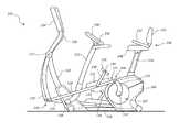
- FIG. 1depicts an example of an exercise machine 100 .
- the exercise machine 100includes a frame 102 attached to a base 104 . At least a portion of the frame 102 is covered by an outer covering 106 , which hides at least some of the internal components of the exercise machine 100 .
- a resistance mechanismis housed in the outer covering 106 and is attached to a crank assembly 108 .
- the crank assembly 108includes a crank axle 110 connected to a first crank arm 112 and a second crank arm (not shown).
- the first crank arm 112is attached to a first beam 114 on a first end 116 and to a first arm support 118 on a second end 120 .
- the first arm support 118is pivotally attached to the frame 102 at a pivot connection 122 .
- the first arm support 118also includes a handle 124 on a far end of the first arm support 118 .
- the second crank armis attached to a second beam 126 on a first end and to a second arm support 128 on a second end.
- the second arm support 128is pivotally attached to the frame 102 at the pivot connection 122 .
- the second arm support 128also includes a handle 130 on a far end of the second arm support 128 .
- a first platform 132is attached to the first beam 114 .
- the first platform 132is directly attached to a surface of the first beam 114 , and the first platform 132 is supported by the first beam 114 along the first platform's length.
- a second platform 134is attached to the second beam 126 .
- the second platform 134is directly attached to a surface of the second beam 126 , and the first platform 132 is likewise supported by the second beam 126 along the first platform's length.
- a first pedal 136is also attached to the first beam 114 .
- the first pedal 136is attached to the first beam 114 through a first rod 138 .
- the first rodis positioned in an upright orientation that forms a rearward angle between the first rod 138 and the first beam 114 . The rearward angle is maintained during the performance of an exercise.
- the first pedal 136is free to rotate about a pedal axle 140 .
- a second pedal 142is also attached to the second beam 126 .
- the second pedal 142is attached to the first beam 114 through a second rod 144 .
- the second rod 144is also positioned in an upright orientation that forms a rearward angle between the second rod 144 and the second beam 126 . This rearward angle is also maintained during the performance of an exercise.
- a seat 146is connected to the frame 102 .
- the seatcomprises a padded region 148 , a back support 150 , a handle 152 , and support rod 154 .
- a console member 156is attached to the frame 102 at a member pivot connection 158 .
- a console 160is attached to the console member 156 at a console pivot connection 162 .
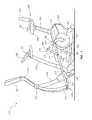
- FIG. 2depicts an example of an exercise machine 200 with a seat 202 at a lower elevation than the seat 146 depicted in FIG. 2 .
- the first rod 204 connected to the first beam 206 and the second rod 208 connected to the second beam 210are in a forward position such that the first and second rods 204 , 208 form forward angles with the first and second beams 206 , 210 , respectively.
- the console 212is tilted downward through the console pivot connection 214 .
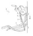
- FIG. 3depicts an example of an exercise machine 300 with the console member 302 moved forward about the console pivot member 304 .
- the exercise machine 300also includes a first beam 306 and a second beam 308 .
- a first pedal 310is attached to the first beam 306 through a first rod 312
- a second pedalis attached to the second beam 308 through a second rod.
- the first and second rodsare moved forward to where the first and second pedals are flush with the first and second beams 306 , 308 respectively.
- FIG. 4depicts an example of an exercise machine 400 .
- the exercise machine 400includes a frame 402 and a pedal assembly 404 movably attached to the frame 402 .
- the pedal assembly 404is movable in the performance of an exercise.
- the pedal assembly 404comprises a first beam 406 , a first platform 408 connected to the first beam 406 , a first rod 410 connected to the first beam 406 , and a first pedal 412 connected to the first rod 410 .
- FIG. 5depicts an example of an exercise machine 500 .
- the exercise machine 500includes a frame 502 and a pedal assembly movably attached to the frame 502 .
- the pedal assemblycomprises a beam 506 and a pedal 508 connected to the first beam 506 .
- the pedal 508is hingedly attached to the beam 506 on a side of the pedal 508 that is closest to a seat 510 of the exercise machine 500 .
- the position of the pedal 508is adjustable along an arc.
- the pedals 508may be angled to be relatively aligned with the beam 506 .
- the pedals 508may form a steeper angle with the beam 506 by being rotated upwards about the hinged connection.
- a locking mechanismmay ensure that the angle of the pedal 508 is maintained during the performance of the exercise based on the exercise machine's current exercise mode.
- a gas spring, a lever, or another type of mechanismmay be used to provide additional support to the pedal 508 when the pedal is rotated upwards.
- the angle of the pedals 508may be controlled by an actuator. In some of such examples, the user may be able to control the pedal angle from commands delivered through the console.
- FIG. 6depicts an example of an exercise machine 600 .
- the exercise machine 600includes a frame 602 and a flywheel 604 .
- the flywheel 604is located in a front of the exercise machine 600 .
- a pedal 606is movably attached to the flywheel 604 .
- the seat 608moves relative to the flywheel 604 when transitioning between the upright cycling mode and the recumbent cycling mode to give the user the appropriate orientation during the performance of the desired exercise.
- the seat 608is supported by a telescoping support member that is angled forward. As the telescoping frame member moves upwards, the seat 608 moves upwards and forward to position the seat 608 in an upright cycling mode orientation.
- the seat 608can be manually positioned by the user.
- the position of the seat 608is controlled by an actuator.
- the usermay input commands through the console to cause the seat 608 to move.
- the distance between the pedals 606 and the seat 608is the same regardless of where the seat 608 is positioned along the path defined by the telescoping support member. However, in other examples, the distance between the pedals 606 and the seat may be different depending on the exercise machine's current mode.
- the pedals 606are connected to the flywheel 604 on the same axle that connects the beam and the arm support to the flywheel 604 . However, in other examples, the pedals 606 may be connected to the flywheel 604 at a different location than where the beam and arm support are connected.
- the invention disclosed hereinmay provide the user with an exercise machine that has multiple exercise modes.
- a first exercise modemay be an upright cycling mode
- a second exercise modemay be a recumbent cycling mode
- a third exercise modemay be an elliptical trainer exercise mode.
- the exercise machinemay include additional exercise modes that are intended to cause the user to perform different types of workouts.
- the different exercise modesmay work out different types of muscles groups.
- the seatIn the upright cycling mode, the seat is positioned relative to the pedals such that the user is caused to sit upright during the performance of a cycling exercise.
- the relative position of the seat with the pedalsmay allow the user to lean forward in a comfortable convenient manner.
- the seatincludes a back rest
- the useris positioned such that the user's back does not likely rest on the back rest.
- the user's weightis supported by just the exercise machine on the padded region of the seat region, the pedals, and the handles.
- the userIn the upright orientation, the user may primarily assume a vertical orientation.
- the seatIn the recumbent cycling mode, the seat is positioned relative to the pedals such that the user is caused to have a reclined position during the performance of a cycling exercise.
- the usermay conveniently load a portion of his or her body weight against a back support of the exercise machine's seat while in the recumbent position.
- the userIn such examples, the user is positioned so that his or her weight is supported by the padded region of the seat region, the pedals, the handles, and the back rest of the seat.
- the recumbent orientationthe user may primarily assume a horizontal orientation.
- the pedals and consoleare positioned such that the user can stand on the beams without interference.
- the usercan stand on the pedals and conveniently reach the arm supports.
- the beamsmove in a reciprocating motion.
- the reciprocating motion of the beamscause the arm supports to likewise move in a reciprocating motion with the beams.
- the exercise machineincludes a resistance mechanism that is connected to a frame.
- the resistance mechanismmay include a flywheel that is proximate a magnetic unit which resists the movement of the flywheel.
- the amount of resistance applied to the flywheelmay be changed by moving the magnetic unit towards or away from the flywheel.
- the resistance applied to the flywheelmay be increased by moving the magnetic unit closer to the flywheel.
- the resistance applied to the flywheelmay be decreased by moving the magnetic unit closer to the flywheel.
- the magnetic unitmay emit a variable amount of magnetic resistance by applying a varying amount of electrical power to the magnetic unit.
- resistance mechanismthat includes a flywheel and a magnetic unit
- any appropriate type of resistance unitmay be used in accordance with the principles described herein.
- a non-exhaustive list of resistance mechanisms that may be usedinclude an air resistance mechanism, a fan, a hydraulic mechanism, a pneumatic mechanism, another type of resistance mechanism, or combinations thereof.
- a crank assemblymay be attached to the resistance mechanism.
- the crank assemblymay include a crank axle connected to a first crank arm and a second crank arm.
- the first crank armmay be attached to a first beam on a first end and to a first arm support on a second end.
- the first arm supportmay be pivotally attached to the frame at a pivot connection.
- the second crank armmay be attached to a second beam on a first end and to a second arm support on a second end.
- the second arm supportmay also be pivotally attached to the frame at the pivot connection.
- the arm supportmay move in a reciprocating motion with the beams.
- the beamsare mechanically separated from the arm supports. In such examples, the arm supports move independently of the beams.
- the reciprocating movement of the arm supportsis caused by the movement of the user's arms rather than the combined movement of the user's feet and arms.
- a platformmay be attached or formed on the beams.
- the platformmay an element or an assembly that provides a location for a user to place his or her foot and transfer power to the beam during the performance of an exercise.
- the platformsmay be located on the pedal beams in positions where the user can conveniently stand while performing an elliptical training exercise when the exercise machine is in the elliptical training exercise mode.
- a first platformis attached to the first beam. In this example, the first platform is directly attached to a surface of the first beam, and the first platform is supported by the first beam along the first platform's length.
- a second platformis attached to the second beam. In this example, the second platform is directly attached to a surface of the second beam, and the first platform is likewise supported by the second beam along the first platform's length.
- the first and second platformsmay be attached to the beams through any appropriate mechanism.
- the platformsmay be connected to the beams with fasteners, bolts, wires, adhesives, welding, soldering, other types of mechanisms, or combinations thereof.
- the platformsmay be integrally formed with the beams.
- the beamsmay comprise an increased width in the beam's region where the user is intended to place his or her feet during the elliptical trainer exercise mode.
- Such a platformmay include a gripping feature to provide additional friction to increase the user's stability during the performance of the elliptical training exercise.
- the userWhile in the elliptical exercise mode, the user may place his or her feet on the platforms and move his or her feet in a reciprocating motion. In response to such an action by the user, the beams may move.
- one end of the beamis attached to the crank arm of the resistance mechanism and the other end of the beam is attached to an arm support.
- the other end of the beamsmay be attached to the frame.
- the other end of the beamsare attached to linkages that movably connect the other ends of the beams to the frame.
- the pedalsmay be used in either the upright or recumbent cycling modes.
- pedalsIn the upright cycling mode, pedals are positioned more rearward.
- the seatmay be positioned at an elevated height.
- an imaginary line that travels the distance between the pedals and the seatmay comprise a primary vertical component.
- the seatIn the recumbent position, the seat may lowered and the pedals moved forward. In some examples when the seat is lowered and the pedals are brought forward, the distance between the pedals and the seat is approximately the same distance as when the exercise machine is in the upright position.
- the imaginary line that travels the distance between the seat and pedalscomprises a primary horizontal component.
- the userWith the relatively horizontal positional relationship between the seat and the pedals, the user is in a reclined positioned during the performance of the cycling exercise. While the examples above have been described with the distance between the seat and the pedals being approximately the same in both the upright cycling mode and the recumbent cycling mode, in alternative examples, the distance between the seat and pedals in the upright cycling mode and the recumbent cycling mode may be different.
- a first pedalis attached to the first beam with a first rod.
- the first rodmay be positioned in an upright orientation that forms a rearward angle between the first rod and the first beam. The rearward angle may be maintained during the performance of an exercise such that there is no relative movement between the rod and the beam during the cycling exercise.
- the pedalmay be free to rotate about a pedal axle that joins the pedal to the rod.
- a second pedalmay be attached to the second beam with a second rod.
- the pedalsare separated a distance away from the beams.
- the pedalstravel in a generally circular path.
- the rodsmay be positioned at an appropriate angle with respect to the user's seat and to the beams that the pedal travel along a circular path even though the beams themselves travel along a path that has a major axis and a minor axis.
- the circular path traveled by the pedalsis determined by the angle and length of the crank arm, the angle and length of the beam, and the angle and length of the rod.
- the rodhas a preset position when in the upright cycling mode so that the pedals can travel in the circular path during the performance of an upright cycling exercise.
- the rodhas a preset position when in the recumbent cycling mode so that the pedals can travel in the circular path during the performance of a recumbent cycling exercise.
- the pedals assembliesare arranged such that the pedals can travel in an elliptical path with a minor and major axis during the performance of an upright cycling exercise and/or a recumbent cycling exercise.
- the rodmay be selectively positioned to be in any of the exercise modes.
- the rodcan be selectively positioned manually.
- the rodmay be manually rotated about a pivot connection and locked in place.
- Any appropriate locking mechanismmay be used.
- the rodmay be spring loaded against the beam and caused be interlocked in place with a feature formed in the beam.
- the usermay pull the rod away from the beam with a force sufficient to overcome the spring force.
- the rodWith the rod pulled away from the beam, the rod unhooks from the interlocking feature of the beam and frees the rod to be rotated into the desired position.
- the rodWith the rod aligned with the desired position, the rod may be gradually released from the user allowing the rod to return to the beam and interlock with an interlocking feature of the beam in the desired position.
- the rodmay be fastened into place with a fastener.
- the rodmay pivot about a pivot axle.
- a hole in the rodmay be aligned with one of multiple holes in the beam, where at least some of the holes formed in the beam correspond with the positions for different exercise modes.
- a screw or another type of fastenermay be inserted into both holes to lock the rod to the beam.
- the rodmay be positioned with an actuator.
- the rodmay be positioned with a screw motor that moves the angle of the rod about the pivot axle as the screw motor rotates.
- actuatorsmay include hydraulic actuators, pneumatic actuators, motors, solenoids, smart materials, electric actuators, gas springs, pulleys, other types of actuators, or combinations thereof.
- the rodmay be moved in other appropriate ways.
- the rodsmay have a slidable connection with the beam.
- the rodmay be removably attached to the beam such that the user can detach the rod from the beam at a first position corresponding with a first exercise mode and reattach the rod at a second position corresponding with a second exercise mode.
- the rodmay be moved through a telescope mechanism.
- the rodmay have an articulated joint that joins a first part of the rod to a second part of the rod.
- the first part of the rodmay be connected to the beam, and the second part of the rod may be connected to the pedal.
- the second part of the rodmay move with respect to the first part of the rod.
- the first part of the rodmay remain stationary with respect to the beam while the second part of the rod moves to position the pedal.
- the pedalsmay be moved out of the way of the user when the exercise machine is in the elliptical trainer exercise mode.
- the usermay use the platforms of the beams to transfer foot power into the exercise machine instead of through the pedals as in the cycling exercise modes.
- the pedalsmay be lowered to an angle of 15.0 degrees or less with respect to the beam.
- the rodmay move sufficiently out of the way of the user's feet during the performance of an elliptical trainer exercise.
- the pedalmay be out of the user's way as the user mounts and/or dismounts the exercise machine. In some examples, the rod is moved to be flush with the beam.
- the rodmay form an angle of 10.0 degrees or less with the beam or an angle of 5.0 degrees or less with the beam when the exercise machine is in the elliptical exercise mode.
- the pedalsare rotated horizontally out of the way from interfering with the user's feet during the performance of an elliptical exercise.
- the pedalsare platform pedals that are connected directly to the pedal assembly's beam.
- the platform pedalsmay be hingedly attached to the beam on a side that is closest to the seat.
- the platform pedalsmay pivot along an arc segment to appropriately angle the platform pedals for the desired exercise.
- the platform pedalsmay be substantially aligned with the beam when the exercise machine is in the upright cycling mode and/or the elliptical mode.
- the platform pedalsmay be oriented more transversely when the user is in the exercise machine is in the recumbent orientation.
- the platform pedalsmay be oriented differently for each of the upright cycling and elliptical modes.
- the pedalsmay be form a steeper angle with the beam during the upright cycling mode than in the elliptical mode.
- the pedalsmay be attached directly to the flywheel or another rotary element of the resistance mechanism.
- the seatmay move laterally and/or vertically to appropriately position the seat for the appropriate exercise mode.
- the seatmay be positioned at a higher elevation in the upright mode and at a lower elevation in the recumbent mode.
- the seatmay be movable with respect to the exercise machine's frame.
- the seat's support rodmay telescope with respect to a portion of the frame.
- the support rodmay be slidably attached to a portion of the frame.
- the seatis brought to an upright position when the exercise machine is in the upright cycling mode, and the seat may be in a lower recumbent position when the exercise machine is in the recumbent position. In some cases, the seat may be in either the upright position or the recumbent position when the exercise machine is in the elliptical training exercise mode.
- the seat and pedalsmay be positioned anywhere along a continuum.
- the seatis positioned at a maximum height for the upright position, and the seat is positioned at a minimum elevation for a recumbent position.
- the seatmay be adjusted to accommodate the different heights of the users.
- the usermay desire to position the seat at a height that is between the maximum and minimum positions (i.e. half way between the maximum and minimum positions).
- the pedalsmay be moved to be half way between the upright pedal orientation and the recumbent orientation to place the pedals at an appropriate distance away from the seat.
- the maximum positionmay place the seat over 36 inches vertically from the base, and the minimum position places the seat less than 36 inches vertically from the base.
- the exercise machinemay include a console member that connects the console to the exercise machine's frame.
- the console memberis selectively adjustable between multiple positions corresponding to different exercise modes of the exercise machine.
- the console membermay be connected to a base portion of the frame and extend between 3.0 feet to 7.0 feet to a height that is convenient for the user to view while performing an exercise with the exercise machine.
- the console membermay be shorter and connected to a portion of the frame that is elevated higher than the base portion of the frame.
- the console membermay be pivotally attached to the frame.
- the console membermay be positioned in the same location for both the upright and recumbent cycling modes.
- Such a console member position for the upright and recumbent cycling positionsmay occupy a three dimensional space that would be occupied by the user while the user is elliptical exercise mode. In such a circumstance, the console member may be moved to a forward position when the exercise machine is in the elliptical trainer exercise mode. In some embodiments, the console member has a different location in the upright cycling mode and the recumbent cycling mode.
- the consolemay be moved manually in similar or different ways as described above with respect to the rods.
- the consolemay be pivotally connected to the frame.
- the console membermay be slidably attached to the frame.
- the console membermay telescopically move with respect to the frame.
- the console membermay be movable manually or with an actuator.
- the consolemay be movable with respect to the console member.
- the console membermay be tilted with respect to the console member.
- the tilt angle of the consolemay correspond to an exercise mode of the exercise machine.
- the consolemay be tilted upward when the exercise machine is in the upright cycling mode.
- the consolemay be tilted downward or straight forward in the recumbent exercise mode.
- the consoleIn the elliptical mode, the console may be tilted upward or downward such that the tilt angle in the elliptical trainer exercise mode corresponds to either the upright cycling mode's console angle or the recumbent cycling mode's console angle.
- the elliptical trainer exercise modecomprises a console tilt angle that is unique to the elliptical trainer exercise mode.
- the console assemblymay further include a pair of handles that the user may grip during the performance of an exercise.
- the usermay grip the handles attached to the console assembly when the user is in the upright position.
- a pair of handles incorporated into the seatmay be within a convenient arms reach for the user while performing an exercise in the recumbent exercise mode.
- the usermay grip the reciprocating arm supports.
- the handles/arm supportsthat the user can use during the performance of different exercises in the different exercise modes
- the usermay grip any of the handles/arm supports within a convenient reach of the user and/or desirable by the user.
- the consolemay include a display screen that indicates at least one operating parameter of the exercise machine or a physiological parameter of the user during the workout.
- the display screenmay depict the settings of the resistance mechanism, the speed at which the user is operating the exercise machine, the current exercise mode of the exercise machine, the estimated calories of the user's workout, the user's heart rate, the time of day, the time duration of the workout, other operating parameters, other physiological parameters of the user, or combinations thereof.
- the calories burned estimatemay be based on information gathered from the exercise machine's operating parameters.
- the information used to determine the calorie burnis based on a user profile that contains personal information about the user, such as height, weight, age, gender, health conditions, body composition, other types of personal information, or combinations thereof.
- the personal informationmay be inputted into the console of the exercise machine.
- the consolemay be in communication with a remote device that contains the user profile.
- the consolemay be in wireless communication with a personal computer, a mobile device, a datacenter, a website, a network device, another type of device, or combinations thereof that contain at least one item of personal information about the user.
- the consolemay be in communication with a remote device that operates a fitness tracking program.
- some of the personal informationmay be received from the fitness tracking program.
- the consolemay send information about the user's workout to the fitness tracking program.
- workout informationmay include the type and duration of the exercise, the resistance settings, the estimated number of calories burned, other types of information, or combinations thereof.
- the consolemay also include at least one input mechanism for inputting information into the console.
- the usermay control the operating parameters of the exercise machine with the console. In some cases, the user can control the resistance settings through the console. Also, the user may be able to raise and lower the seat through commands inputted into the console. Further, the user may be able to control the position of the pedals though the console. Additionally, in some examples, the user can control the position of the console member through the console and/or control the console tilt angle through the console.
- the input mechanism of the consolemay include a button, lever, dial, touch screen, key board, microphone, another type of input mechanism, camera, or combinations thereof.
- the usermay command the exercise machine to change from one exercise mode to another. In such an example, the exercise machine may change the seat position, the pedal position, the console tilt angle, the console member position, any other positions to put the exercise machine in the desired exercise mode without further input from the user.
Landscapes
- Health & Medical Sciences (AREA)
- General Health & Medical Sciences (AREA)
- Physical Education & Sports Medicine (AREA)
- Cardiology (AREA)
- Vascular Medicine (AREA)
- Life Sciences & Earth Sciences (AREA)
- Biophysics (AREA)
- Orthopedic Medicine & Surgery (AREA)
- Rehabilitation Tools (AREA)
Abstract
Description
Claims (20)
Priority Applications (1)
| Application Number | Priority Date | Filing Date | Title |
|---|---|---|---|
| US15/163,996US10226664B2 (en) | 2015-05-26 | 2016-05-25 | Exercise machine with multiple exercising modes |
Applications Claiming Priority (2)
| Application Number | Priority Date | Filing Date | Title |
|---|---|---|---|
| US201562166547P | 2015-05-26 | 2015-05-26 | |
| US15/163,996US10226664B2 (en) | 2015-05-26 | 2016-05-25 | Exercise machine with multiple exercising modes |
Publications (2)
| Publication Number | Publication Date |
|---|---|
| US20160346599A1 US20160346599A1 (en) | 2016-12-01 |
| US10226664B2true US10226664B2 (en) | 2019-03-12 |
Family
ID=55913547
Family Applications (1)
| Application Number | Title | Priority Date | Filing Date |
|---|---|---|---|
| US15/163,996ActiveUS10226664B2 (en) | 2015-05-26 | 2016-05-25 | Exercise machine with multiple exercising modes |
Country Status (4)
| Country | Link |
|---|---|
| US (1) | US10226664B2 (en) |
| EP (1) | EP3097957B1 (en) |
| CN (1) | CN106178409B (en) |
| TW (1) | TWI640340B (en) |
Cited By (36)
| Publication number | Priority date | Publication date | Assignee | Title |
|---|---|---|---|---|
| US10388183B2 (en) | 2015-02-27 | 2019-08-20 | Icon Health & Fitness, Inc. | Encouraging achievement of health goals |
| US10709925B2 (en) | 2013-03-14 | 2020-07-14 | Icon Health & Fitness, Inc. | Strength training apparatus |
| US10758767B2 (en) | 2013-12-26 | 2020-09-01 | Icon Health & Fitness, Inc. | Resistance mechanism in a cable exercise machine |
| US10786706B2 (en) | 2018-07-13 | 2020-09-29 | Icon Health & Fitness, Inc. | Cycling shoe power sensors |
| US10918905B2 (en) | 2016-10-12 | 2021-02-16 | Icon Health & Fitness, Inc. | Systems and methods for reducing runaway resistance on an exercise device |
| US10940360B2 (en) | 2015-08-26 | 2021-03-09 | Icon Health & Fitness, Inc. | Strength exercise mechanisms |
| US10994173B2 (en) | 2016-05-13 | 2021-05-04 | Icon Health & Fitness, Inc. | Weight platform treadmill |
| US11000730B2 (en) | 2018-03-16 | 2021-05-11 | Icon Health & Fitness, Inc. | Elliptical exercise machine |
| US11013960B2 (en) | 2016-03-18 | 2021-05-25 | Icon Health & Fitness, Inc. | Exercise system including a stationary bicycle and a free weight cradle |
| US11033777B1 (en) | 2019-02-12 | 2021-06-15 | Icon Health & Fitness, Inc. | Stationary exercise machine |
| US11058913B2 (en) | 2017-12-22 | 2021-07-13 | Icon Health & Fitness, Inc. | Inclinable exercise machine |
| US11058914B2 (en) | 2016-07-01 | 2021-07-13 | Icon Health & Fitness, Inc. | Cooling methods for exercise equipment |
| US11187285B2 (en) | 2017-12-09 | 2021-11-30 | Icon Health & Fitness, Inc. | Systems and methods for selectively rotationally fixing a pedaled drivetrain |
| US11298577B2 (en) | 2019-02-11 | 2022-04-12 | Ifit Inc. | Cable and power rack exercise machine |
| US11326673B2 (en) | 2018-06-11 | 2022-05-10 | Ifit Inc. | Increased durability linear actuator |
| US11451108B2 (en) | 2017-08-16 | 2022-09-20 | Ifit Inc. | Systems and methods for axial impact resistance in electric motors |
| US11534654B2 (en) | 2019-01-25 | 2022-12-27 | Ifit Inc. | Systems and methods for an interactive pedaled exercise device |
| US11534651B2 (en) | 2019-08-15 | 2022-12-27 | Ifit Inc. | Adjustable dumbbell system |
| US11565148B2 (en) | 2016-03-18 | 2023-01-31 | Ifit Inc. | Treadmill with a scale mechanism in a motor cover |
| US11673036B2 (en) | 2019-11-12 | 2023-06-13 | Ifit Inc. | Exercise storage system |
| US11700905B2 (en) | 2014-03-10 | 2023-07-18 | Ifit Inc. | Pressure sensor to quantify work |
| US11794070B2 (en) | 2019-05-23 | 2023-10-24 | Ifit Inc. | Systems and methods for cooling an exercise device |
| US11850497B2 (en) | 2019-10-11 | 2023-12-26 | Ifit Inc. | Modular exercise device |
| US11878199B2 (en) | 2021-02-16 | 2024-01-23 | Ifit Inc. | Safety mechanism for an adjustable dumbbell |
| US11931621B2 (en) | 2020-03-18 | 2024-03-19 | Ifit Inc. | Systems and methods for treadmill drift avoidance |
| US11951377B2 (en) | 2020-03-24 | 2024-04-09 | Ifit Inc. | Leaderboard with irregularity flags in an exercise machine system |
| US12029961B2 (en) | 2020-03-24 | 2024-07-09 | Ifit Inc. | Flagging irregularities in user performance in an exercise machine system |
| US12029935B2 (en) | 2021-08-19 | 2024-07-09 | Ifit Inc. | Adjustment mechanism for an adjustable kettlebell |
| US12176009B2 (en) | 2021-12-30 | 2024-12-24 | Ifit Inc. | Systems and methods for synchronizing workout equipment with video files |
| US12219201B2 (en) | 2021-08-05 | 2025-02-04 | Ifit Inc. | Synchronizing video workout programs across multiple devices |
| US12263371B2 (en) | 2021-04-27 | 2025-04-01 | Ifit Inc. | Devices, systems, and methods for rotating a tread belt in two directions |
| US12280294B2 (en) | 2021-10-15 | 2025-04-22 | Ifit Inc. | Magnetic clutch for a pedaled drivetrain |
| US12350573B2 (en) | 2021-04-27 | 2025-07-08 | Ifit Inc. | Systems and methods for cross-training on exercise devices |
| US12350547B2 (en) | 2022-02-28 | 2025-07-08 | Ifit Inc. | Devices, systems, and methods for moving a movable step through a transition zone |
| US12409375B2 (en) | 2022-03-18 | 2025-09-09 | Ifit Inc. | Systems and methods for haptic simulation in incline exercise devices |
| US12433815B2 (en) | 2020-10-02 | 2025-10-07 | Ifit Inc. | Massage roller with pressure sensors |
Families Citing this family (14)
| Publication number | Priority date | Publication date | Assignee | Title |
|---|---|---|---|---|
| US9345948B2 (en) | 2012-10-19 | 2016-05-24 | Todd Martin | System for providing a coach with live training data of an athlete as the athlete is training |
| US9962305B2 (en)* | 2015-01-09 | 2018-05-08 | Panasonic Corporation | Living support system and living support method |
| US10493349B2 (en) | 2016-03-18 | 2019-12-03 | Icon Health & Fitness, Inc. | Display on exercise device |
| US10625137B2 (en) | 2016-03-18 | 2020-04-21 | Icon Health & Fitness, Inc. | Coordinated displays in an exercise device |
| US10625114B2 (en) | 2016-11-01 | 2020-04-21 | Icon Health & Fitness, Inc. | Elliptical and stationary bicycle apparatus including row functionality |
| KR101952412B1 (en)* | 2016-12-05 | 2019-02-27 | 김은비 | Exercise method and device to preserve ankle and knee joint while exercising upper leg and hip |
| WO2018128891A1 (en)* | 2017-01-03 | 2018-07-12 | Engen Fitness, Inc. | Guided movement exercise machine |
| CA2956938C (en) | 2017-02-03 | 2018-04-24 | Ali Kiani | Exercise apparatus with oscillating tilt system |
| CA2963803C (en) | 2017-04-11 | 2018-05-15 | Ali Kiani | Exercise apparatus with divergent/convergent motion along the symmetric semi elliptical route |
| TWI636811B (en)* | 2017-07-26 | 2018-10-01 | 力伽實業股份有限公司 | Composite motion exercise machine |
| CN109200535B (en)* | 2018-10-10 | 2024-02-13 | 侯岩卫 | Spinning with elliptical machine function |
| US11291883B2 (en)* | 2019-12-26 | 2022-04-05 | Nautilus, Inc. | Tilt-enabled bike with tilt-disabling mechanism |
| TWI769934B (en)* | 2021-10-04 | 2022-07-01 | 健泰科技有限公司 | elliptical machine |
| US12186621B2 (en)* | 2021-11-02 | 2025-01-07 | Apex Ip Holdings, Llc | Gravity resistance trainer |
Citations (36)
| Publication number | Priority date | Publication date | Assignee | Title |
|---|---|---|---|---|
| US4828522A (en)* | 1988-06-20 | 1989-05-09 | Santos T R | Aquatic exerciser |
| US5354251A (en) | 1993-11-01 | 1994-10-11 | Sleamaker Robert H | Multifunction excercise machine with ergometric input-responsive resistance |
| US5445583A (en) | 1990-06-21 | 1995-08-29 | Pacific Fitness Corporation | Floating back pad leg exerciser |
| US5823915A (en) | 1997-10-06 | 1998-10-20 | Chen; Ping | Exercise bicycle |
| US5850460A (en) | 1994-09-01 | 1998-12-15 | Matsushita Electric Industrial Co., Ltd. | Bass speaker |
| US5916065A (en) | 1998-02-10 | 1999-06-29 | Stamina Products, Inc. | Multiple leg movement exercise apparatus |
| US5944638A (en)* | 1997-04-26 | 1999-08-31 | Maresh; Joseph D. | Exercise apparatus and methods involving a flywheel |
| US20020004439A1 (en)* | 2000-02-09 | 2002-01-10 | Galbraith Richard Scott | Multi-position exercise bicycle |
| US6497426B2 (en) | 2000-05-23 | 2002-12-24 | Vanpelt James L. | Convertible bicycle |
| US6648353B1 (en) | 2002-07-01 | 2003-11-18 | Pedro Pablo Cabal | Upright step-cycle with elliptical motion pedalling |
| US6682462B1 (en) | 2003-02-21 | 2004-01-27 | Sunny Lee | Dual-purpose exerciser operable in pedaling and rowing modes |
| US20050075222A1 (en) | 2003-07-22 | 2005-04-07 | Adley Robert J. | Aquatic exercise bicycle |
| US20050129258A1 (en) | 2001-02-09 | 2005-06-16 | Fincham Lawrence R. | Narrow profile speaker configurations and systems |
| US6926645B1 (en) | 2003-04-22 | 2005-08-09 | Kenneth W. Stearns | Multi-mode exercise cycling methods and apparatus |
| US20060226630A1 (en) | 2005-04-12 | 2006-10-12 | Tolhurst John I | Assembly for converting standard bicycle into a recumbent and a bicycle incorporating the assembly |
| CA2509122A1 (en) | 2005-06-03 | 2006-12-03 | Lung-Huei Lee | Foldable exerciser |
| JP2007134955A (en) | 2005-11-10 | 2007-05-31 | Yamaha Corp | Loudspeaker apparatus |
| US20070287597A1 (en) | 2006-05-31 | 2007-12-13 | Blaine Cameron | Comprehensive multi-purpose exercise equipment |
| US20090239714A1 (en)* | 2008-03-19 | 2009-09-24 | Ty Sellers | Exercise machine |
| TW200946173A (en) | 2008-03-05 | 2009-11-16 | Mad Dogg Athletics Inc | Programmable exercise bicycle |
| WO2009156996A1 (en) | 2008-06-25 | 2009-12-30 | Herzel Frenkel | A bicycle device having multiple position seats |
| US20100206652A1 (en) | 2006-09-26 | 2010-08-19 | Peter Kielland | Dual-posture electric assist bicycle |
| US20110028277A1 (en)* | 2007-09-13 | 2011-02-03 | Christopher Merli | Seated exercise apparatus |
| US8002671B1 (en)* | 2010-03-31 | 2011-08-23 | Larry Vigilia | Supine elevation cycle |
| US8062190B2 (en) | 2005-10-31 | 2011-11-22 | Johnson Health Tech Co., Ltd. | Stationary exercise bicycle |
| CN202261701U (en) | 2011-08-24 | 2012-05-30 | 无锡杰夫电声有限公司 | Multi-point excitation loudspeaker array |
| CN102753240A (en) | 2010-02-18 | 2012-10-24 | 朴勋根 | Exercise bike for simultaneous arm movement |
| US20130260964A1 (en) | 2012-04-02 | 2013-10-03 | Rexon Industrial Corp., Ltd. | Exercise apparatus |
| US20130260965A1 (en)* | 2012-04-02 | 2013-10-03 | Rexon Industrial Corp., Ltd. | Exercise apparatus |
| US20130260967A1 (en) | 2012-04-02 | 2013-10-03 | Rexon Industrial Corp., Ltd. | Support frame for exercise apparatus |
| US20130260966A1 (en) | 2012-04-02 | 2013-10-03 | Rexon Industrial Corp., Ltd | Support frame for exercise apparatus |
| US8764609B1 (en)* | 2012-05-20 | 2014-07-01 | Issam A. Elahmadie | Exercise enhancement machine |
| US20140274574A1 (en)* | 2013-03-14 | 2014-09-18 | Icon Health & Fitness, Inc. | Exercise apparatus comprising adjustable foot pads and related methods |
| TWM493398U (en) | 2013-04-22 | 2015-01-11 | Bob Hsiung | Three-in-one exercise bicycle combining an upright bicycle and elliptical trainer with a recumbent bicycle |
| CH708378A2 (en) | 2013-07-29 | 2015-01-30 | Peter A Müller | Folding ergometer in the form of a bicycle. |
| US9616281B2 (en)* | 2013-02-26 | 2017-04-11 | Hupa International Inc. | Crank for exercise equipment which helps prevent injuries on a rider's ankle during an unexpected drop in speed and assists in avoiding stress on the knees of a rider during exercising |
Family Cites Families (6)
| Publication number | Priority date | Publication date | Assignee | Title |
|---|---|---|---|---|
| US5836855A (en)* | 1997-02-18 | 1998-11-17 | Eschenbach; Paul William | Recumbent elliptical exercise machine |
| TW200709827A (en)* | 2005-09-02 | 2007-03-16 | Chia Ting Foundries Co Ltd | Elliptical fitness device |
| TWM320402U (en)* | 2006-11-22 | 2007-10-11 | Lian Hang Technology Co Ltd | Self-powered structure of body fitness apparatus |
| CN201175544Y (en)* | 2007-12-07 | 2009-01-07 | 乔山健康科技(上海)有限公司 | Elliptical exercise machine |
| TW201105383A (en)* | 2009-08-13 | 2011-02-16 | Johnson Health Tech Co Ltd | Foldable elliptical exercise machine |
| TW201318669A (en)* | 2011-11-01 | 2013-05-16 | Dyaco Int Inc | Riding type elliptical machine |
- 2016
- 2016-05-05EPEP16168504.5Apatent/EP3097957B1/enactiveActive
- 2016-05-18TWTW105115278Apatent/TWI640340B/enactive
- 2016-05-25USUS15/163,996patent/US10226664B2/enactiveActive
- 2016-05-26CNCN201610355606.6Apatent/CN106178409B/enactiveActive
Patent Citations (41)
| Publication number | Priority date | Publication date | Assignee | Title |
|---|---|---|---|---|
| US4828522A (en)* | 1988-06-20 | 1989-05-09 | Santos T R | Aquatic exerciser |
| US5445583A (en) | 1990-06-21 | 1995-08-29 | Pacific Fitness Corporation | Floating back pad leg exerciser |
| US5354251A (en) | 1993-11-01 | 1994-10-11 | Sleamaker Robert H | Multifunction excercise machine with ergometric input-responsive resistance |
| US5850460A (en) | 1994-09-01 | 1998-12-15 | Matsushita Electric Industrial Co., Ltd. | Bass speaker |
| US5944638A (en)* | 1997-04-26 | 1999-08-31 | Maresh; Joseph D. | Exercise apparatus and methods involving a flywheel |
| US5823915A (en) | 1997-10-06 | 1998-10-20 | Chen; Ping | Exercise bicycle |
| US5916065A (en) | 1998-02-10 | 1999-06-29 | Stamina Products, Inc. | Multiple leg movement exercise apparatus |
| US20020004439A1 (en)* | 2000-02-09 | 2002-01-10 | Galbraith Richard Scott | Multi-position exercise bicycle |
| US6497426B2 (en) | 2000-05-23 | 2002-12-24 | Vanpelt James L. | Convertible bicycle |
| US20050129258A1 (en) | 2001-02-09 | 2005-06-16 | Fincham Lawrence R. | Narrow profile speaker configurations and systems |
| US6648353B1 (en) | 2002-07-01 | 2003-11-18 | Pedro Pablo Cabal | Upright step-cycle with elliptical motion pedalling |
| US6682462B1 (en) | 2003-02-21 | 2004-01-27 | Sunny Lee | Dual-purpose exerciser operable in pedaling and rowing modes |
| US6926645B1 (en) | 2003-04-22 | 2005-08-09 | Kenneth W. Stearns | Multi-mode exercise cycling methods and apparatus |
| US20050075222A1 (en) | 2003-07-22 | 2005-04-07 | Adley Robert J. | Aquatic exercise bicycle |
| US20060226630A1 (en) | 2005-04-12 | 2006-10-12 | Tolhurst John I | Assembly for converting standard bicycle into a recumbent and a bicycle incorporating the assembly |
| CA2509122A1 (en) | 2005-06-03 | 2006-12-03 | Lung-Huei Lee | Foldable exerciser |
| US8062190B2 (en) | 2005-10-31 | 2011-11-22 | Johnson Health Tech Co., Ltd. | Stationary exercise bicycle |
| JP2007134955A (en) | 2005-11-10 | 2007-05-31 | Yamaha Corp | Loudspeaker apparatus |
| US20070287597A1 (en) | 2006-05-31 | 2007-12-13 | Blaine Cameron | Comprehensive multi-purpose exercise equipment |
| US20100206652A1 (en) | 2006-09-26 | 2010-08-19 | Peter Kielland | Dual-posture electric assist bicycle |
| US20110028277A1 (en)* | 2007-09-13 | 2011-02-03 | Christopher Merli | Seated exercise apparatus |
| TW200946173A (en) | 2008-03-05 | 2009-11-16 | Mad Dogg Athletics Inc | Programmable exercise bicycle |
| US8951168B2 (en) | 2008-03-05 | 2015-02-10 | Mad Dogg Athletics, Inc. | Programmable exercise bicycle |
| US20090239714A1 (en)* | 2008-03-19 | 2009-09-24 | Ty Sellers | Exercise machine |
| WO2009156996A1 (en) | 2008-06-25 | 2009-12-30 | Herzel Frenkel | A bicycle device having multiple position seats |
| US20110177919A1 (en)* | 2008-06-25 | 2011-07-21 | Tamari Ran | A bicycle device having multiple position seats |
| US8827872B2 (en) | 2008-06-25 | 2014-09-09 | Ran TAMARI | Bicycle device having multiple positions for connecting a seat |
| CN102753240A (en) | 2010-02-18 | 2012-10-24 | 朴勋根 | Exercise bike for simultaneous arm movement |
| US20120322625A1 (en) | 2010-02-18 | 2012-12-20 | Hun Geun Park | Health bicycle with arm exercise function |
| US8002671B1 (en)* | 2010-03-31 | 2011-08-23 | Larry Vigilia | Supine elevation cycle |
| CN202261701U (en) | 2011-08-24 | 2012-05-30 | 无锡杰夫电声有限公司 | Multi-point excitation loudspeaker array |
| US20130260964A1 (en) | 2012-04-02 | 2013-10-03 | Rexon Industrial Corp., Ltd. | Exercise apparatus |
| US20130260965A1 (en)* | 2012-04-02 | 2013-10-03 | Rexon Industrial Corp., Ltd. | Exercise apparatus |
| US20130260967A1 (en) | 2012-04-02 | 2013-10-03 | Rexon Industrial Corp., Ltd. | Support frame for exercise apparatus |
| US20130260966A1 (en) | 2012-04-02 | 2013-10-03 | Rexon Industrial Corp., Ltd | Support frame for exercise apparatus |
| US8764609B1 (en)* | 2012-05-20 | 2014-07-01 | Issam A. Elahmadie | Exercise enhancement machine |
| US9616281B2 (en)* | 2013-02-26 | 2017-04-11 | Hupa International Inc. | Crank for exercise equipment which helps prevent injuries on a rider's ankle during an unexpected drop in speed and assists in avoiding stress on the knees of a rider during exercising |
| US20140274574A1 (en)* | 2013-03-14 | 2014-09-18 | Icon Health & Fitness, Inc. | Exercise apparatus comprising adjustable foot pads and related methods |
| TWM493398U (en) | 2013-04-22 | 2015-01-11 | Bob Hsiung | Three-in-one exercise bicycle combining an upright bicycle and elliptical trainer with a recumbent bicycle |
| US9474925B1 (en)* | 2013-04-22 | 2016-10-25 | Hupa International Inc. | Three-in-one exercise bicycle combining an upright bicycle and elliptical trainer with a recumbent bicycle |
| CH708378A2 (en) | 2013-07-29 | 2015-01-30 | Peter A Müller | Folding ergometer in the form of a bicycle. |
Non-Patent Citations (4)
| Title |
|---|
| English Translation of Chinese Office Action and Search Report issued for 2014800275002 dated Jan. 31, 2018. |
| English Translation of Taiwan First Office Action and Search Report issued for 105115278 dated Mar. 21, 2017. |
| English Translation of the Abstract of CH708378. Jan. 30, 2015. |
| European Patent Application No. 16168504.5 office action dated Oct. 7, 2016 with search report. |
Cited By (57)
| Publication number | Priority date | Publication date | Assignee | Title |
|---|---|---|---|---|
| US11878206B2 (en) | 2013-03-14 | 2024-01-23 | Ifit Inc. | Strength training apparatus |
| US10709925B2 (en) | 2013-03-14 | 2020-07-14 | Icon Health & Fitness, Inc. | Strength training apparatus |
| US11338169B2 (en) | 2013-03-14 | 2022-05-24 | IFIT, Inc. | Strength training apparatus |
| US10953268B1 (en) | 2013-03-14 | 2021-03-23 | Icon Health & Fitness, Inc. | Strength training apparatus |
| US10758767B2 (en) | 2013-12-26 | 2020-09-01 | Icon Health & Fitness, Inc. | Resistance mechanism in a cable exercise machine |
| US10967214B1 (en) | 2013-12-26 | 2021-04-06 | Icon Health & Fitness, Inc. | Cable exercise machine |
| US11700905B2 (en) | 2014-03-10 | 2023-07-18 | Ifit Inc. | Pressure sensor to quantify work |
| US10388183B2 (en) | 2015-02-27 | 2019-08-20 | Icon Health & Fitness, Inc. | Encouraging achievement of health goals |
| US10940360B2 (en) | 2015-08-26 | 2021-03-09 | Icon Health & Fitness, Inc. | Strength exercise mechanisms |
| US12029943B2 (en) | 2016-03-18 | 2024-07-09 | Ifit Inc. | Stationary exercise machine configured to execute a programmed workout with aerobic portions and lifting portions |
| US11013960B2 (en) | 2016-03-18 | 2021-05-25 | Icon Health & Fitness, Inc. | Exercise system including a stationary bicycle and a free weight cradle |
| US12023549B2 (en) | 2016-03-18 | 2024-07-02 | Ifit Inc. | Stationary exercise machine configured to execute a programmed workout with aerobic portions and lifting portions |
| US11794075B2 (en) | 2016-03-18 | 2023-10-24 | Ifit Inc. | Stationary exercise machine configured to execute a programmed workout with aerobic portions and lifting portions |
| US12029944B2 (en) | 2016-03-18 | 2024-07-09 | Ifit Inc. | Stationary exercise machine configured to execute a programmed workout with aerobic portions and lifting portions |
| US11565148B2 (en) | 2016-03-18 | 2023-01-31 | Ifit Inc. | Treadmill with a scale mechanism in a motor cover |
| US10994173B2 (en) | 2016-05-13 | 2021-05-04 | Icon Health & Fitness, Inc. | Weight platform treadmill |
| US11779812B2 (en) | 2016-05-13 | 2023-10-10 | Ifit Inc. | Treadmill configured to automatically determine user exercise movement |
| US11058914B2 (en) | 2016-07-01 | 2021-07-13 | Icon Health & Fitness, Inc. | Cooling methods for exercise equipment |
| US10918905B2 (en) | 2016-10-12 | 2021-02-16 | Icon Health & Fitness, Inc. | Systems and methods for reducing runaway resistance on an exercise device |
| US11451108B2 (en) | 2017-08-16 | 2022-09-20 | Ifit Inc. | Systems and methods for axial impact resistance in electric motors |
| US11187285B2 (en) | 2017-12-09 | 2021-11-30 | Icon Health & Fitness, Inc. | Systems and methods for selectively rotationally fixing a pedaled drivetrain |
| US12270441B2 (en) | 2017-12-09 | 2025-04-08 | Ifit Inc. | Systems and methods for selectively rotationally fixing a pedaled drivetrain |
| US11680611B2 (en) | 2017-12-09 | 2023-06-20 | Ifit Inc. | Systems and methods for selectively rotationally fixing a pedaled drivetrain |
| US11708874B2 (en) | 2017-12-09 | 2023-07-25 | Ifit Inc. | Systems and methods for selectively rotationally fixing a pedaled drivetrain |
| US11058913B2 (en) | 2017-12-22 | 2021-07-13 | Icon Health & Fitness, Inc. | Inclinable exercise machine |
| US11000730B2 (en) | 2018-03-16 | 2021-05-11 | Icon Health & Fitness, Inc. | Elliptical exercise machine |
| US11596830B2 (en) | 2018-03-16 | 2023-03-07 | Ifit Inc. | Elliptical exercise machine |
| US11326673B2 (en) | 2018-06-11 | 2022-05-10 | Ifit Inc. | Increased durability linear actuator |
| US10786706B2 (en) | 2018-07-13 | 2020-09-29 | Icon Health & Fitness, Inc. | Cycling shoe power sensors |
| US12005315B2 (en) | 2018-07-13 | 2024-06-11 | Ifit Inc. | Cycling shoe power sensors |
| US11534654B2 (en) | 2019-01-25 | 2022-12-27 | Ifit Inc. | Systems and methods for an interactive pedaled exercise device |
| US11298577B2 (en) | 2019-02-11 | 2022-04-12 | Ifit Inc. | Cable and power rack exercise machine |
| US11452903B2 (en) | 2019-02-11 | 2022-09-27 | Ifit Inc. | Exercise machine |
| US11642564B2 (en) | 2019-02-11 | 2023-05-09 | Ifit Inc. | Exercise machine |
| US11058918B1 (en) | 2019-02-12 | 2021-07-13 | Icon Health & Fitness, Inc. | Producing a workout video to control a stationary exercise machine |
| US11951358B2 (en) | 2019-02-12 | 2024-04-09 | Ifit Inc. | Encoding exercise machine control commands in subtitle streams |
| US11033777B1 (en) | 2019-02-12 | 2021-06-15 | Icon Health & Fitness, Inc. | Stationary exercise machine |
| US11426633B2 (en) | 2019-02-12 | 2022-08-30 | Ifit Inc. | Controlling an exercise machine using a video workout program |
| US11794070B2 (en) | 2019-05-23 | 2023-10-24 | Ifit Inc. | Systems and methods for cooling an exercise device |
| US11534651B2 (en) | 2019-08-15 | 2022-12-27 | Ifit Inc. | Adjustable dumbbell system |
| US11850497B2 (en) | 2019-10-11 | 2023-12-26 | Ifit Inc. | Modular exercise device |
| US12296247B2 (en) | 2019-10-11 | 2025-05-13 | Ifit Inc. | Modular exercise device |
| US11673036B2 (en) | 2019-11-12 | 2023-06-13 | Ifit Inc. | Exercise storage system |
| US11931621B2 (en) | 2020-03-18 | 2024-03-19 | Ifit Inc. | Systems and methods for treadmill drift avoidance |
| US11951377B2 (en) | 2020-03-24 | 2024-04-09 | Ifit Inc. | Leaderboard with irregularity flags in an exercise machine system |
| US12029961B2 (en) | 2020-03-24 | 2024-07-09 | Ifit Inc. | Flagging irregularities in user performance in an exercise machine system |
| US12433815B2 (en) | 2020-10-02 | 2025-10-07 | Ifit Inc. | Massage roller with pressure sensors |
| US12239872B2 (en) | 2021-02-16 | 2025-03-04 | Ifit Inc. | Safety mechanism for an adjustable dumbbell |
| US11878199B2 (en) | 2021-02-16 | 2024-01-23 | Ifit Inc. | Safety mechanism for an adjustable dumbbell |
| US12263371B2 (en) | 2021-04-27 | 2025-04-01 | Ifit Inc. | Devices, systems, and methods for rotating a tread belt in two directions |
| US12350573B2 (en) | 2021-04-27 | 2025-07-08 | Ifit Inc. | Systems and methods for cross-training on exercise devices |
| US12219201B2 (en) | 2021-08-05 | 2025-02-04 | Ifit Inc. | Synchronizing video workout programs across multiple devices |
| US12029935B2 (en) | 2021-08-19 | 2024-07-09 | Ifit Inc. | Adjustment mechanism for an adjustable kettlebell |
| US12280294B2 (en) | 2021-10-15 | 2025-04-22 | Ifit Inc. | Magnetic clutch for a pedaled drivetrain |
| US12176009B2 (en) | 2021-12-30 | 2024-12-24 | Ifit Inc. | Systems and methods for synchronizing workout equipment with video files |
| US12350547B2 (en) | 2022-02-28 | 2025-07-08 | Ifit Inc. | Devices, systems, and methods for moving a movable step through a transition zone |
| US12409375B2 (en) | 2022-03-18 | 2025-09-09 | Ifit Inc. | Systems and methods for haptic simulation in incline exercise devices |
Also Published As
| Publication number | Publication date |
|---|---|
| TW201642930A (en) | 2016-12-16 |
| CN106178409A (en) | 2016-12-07 |
| US20160346599A1 (en) | 2016-12-01 |
| CN106178409B (en) | 2018-11-16 |
| TWI640340B (en) | 2018-11-11 |
| EP3097957A1 (en) | 2016-11-30 |
| EP3097957B1 (en) | 2019-04-17 |
Similar Documents
| Publication | Publication Date | Title |
|---|---|---|
| US10226664B2 (en) | Exercise machine with multiple exercising modes | |
| US20160346595A1 (en) | Exercise Machine with Upright and Recumbent Cycling Modes | |
| US10561877B2 (en) | Drop-in pivot configuration for stationary bike | |
| US10625114B2 (en) | Elliptical and stationary bicycle apparatus including row functionality | |
| US10207147B2 (en) | Pedal path of a stepping machine | |
| US10046196B2 (en) | Pedal path of a stepping machine | |
| US7507185B2 (en) | Recumbent elliptical exercise apparatus with adjustment | |
| US8808148B2 (en) | Elliptical exercise machine with declining adjustable ramp | |
| US20160158595A1 (en) | Adjustable Stride Length in an Exercise Machine | |
| CA2956938C (en) | Exercise apparatus with oscillating tilt system | |
| US20070179023A1 (en) | Cross training exercise device | |
| US20090111663A1 (en) | Elliptical exercise machine | |
| CN105848734A (en) | Selective angular positioning of the crank of elliptical | |
| CN106823272A (en) | A kind of elliptical machine | |
| CN206631080U (en) | A kind of elliptical machine | |
| EP2186549B1 (en) | Athletic apparatus with non-parallel linear sliding track | |
| JP3114683U (en) | Elliptical exercise machine with adjustable stride length | |
| US10926132B1 (en) | Linkage mechanism with handles linked to elliptical motion trajectory |
Legal Events
| Date | Code | Title | Description |
|---|---|---|---|
| AS | Assignment | Owner name:JPMORGAN CHASE BANK, N.A., AS ADMINISTRATIVE AGENT Free format text:PATENT SECURITY AGREEMENT;ASSIGNORS:ICON HEALTH FITNESS, INC.;HF HOLDINGS, INC.;UNIVERSAL TECHNICAL SERVICES;AND OTHERS;REEL/FRAME:039669/0311 Effective date:20160803 Owner name:JPMORGAN CHASE BANK, N.A., AS ADMINISTRATIVE AGENT Free format text:PATENT SECURITY AGREEMENT;ASSIGNORS:ICON HEALTH & FITNESS, INC.;HF HOLDINGS, INC.;UNIVERSAL TECHNICAL SERVICES;AND OTHERS;REEL/FRAME:039669/0311 Effective date:20160803 | |
| STPP | Information on status: patent application and granting procedure in general | Free format text:RESPONSE AFTER FINAL ACTION FORWARDED TO EXAMINER | |
| STCF | Information on status: patent grant | Free format text:PATENTED CASE | |
| AS | Assignment | Owner name:ICON HEALTH & FITNESS, INC., UTAH Free format text:TERMINATION AND RELEASE OF SECURITY INTEREST IN PATENT RIGHTS;ASSIGNOR:JPMORGAN CHASE BANK, N.A., AS ADMINISTRATIVE AGENT;REEL/FRAME:052671/0737 Effective date:20200427 Owner name:ICON IP, INC., UTAH Free format text:TERMINATION AND RELEASE OF SECURITY INTEREST IN PATENT RIGHTS;ASSIGNOR:JPMORGAN CHASE BANK, N.A., AS ADMINISTRATIVE AGENT;REEL/FRAME:052671/0737 Effective date:20200427 Owner name:JPMORGAN CHASE BANK, N.A., AS ADMINISTRATIVE AGENT, ILLINOIS Free format text:PATENT SECURITY AGREEMENT;ASSIGNOR:ICON HEALTH & FITNESS, INC.;REEL/FRAME:053548/0453 Effective date:20200427 | |
| AS | Assignment | Owner name:BANK OF AMERICA, N.A., AS ADMINISTRATIVE AGENT, CALIFORNIA Free format text:SECURITY INTEREST;ASSIGNOR:ICON HEALTH & FITNESS, INC.;REEL/FRAME:056238/0818 Effective date:20210512 | |
| AS | Assignment | Owner name:ICON HEALTH & FITNESS, INC., UTAH Free format text:TERMINATION AND RELEASE OF SECURITY INTEREST IN PATENTS;ASSIGNOR:JPMORGAN CHASE BANK, N.A., AS ADMINISTRATIVE AGENT;REEL/FRAME:056654/0951 Effective date:20210512 | |
| AS | Assignment | Owner name:IFIT INC, UTAH Free format text:CHANGE OF NAME;ASSIGNOR:ICON HEALTH & FITNESS, INC.;REEL/FRAME:058742/0476 Effective date:20210809 | |
| AS | Assignment | Owner name:IFIT INC., UTAH Free format text:TO CORRECT AN ERROR IN A COVER SHEET PREVIOUSLY RECORDED AT REEL/FRAME 058742/0476 - CORRECT ASSIGNEE NAME IFIT INC TO IFIT INC;ASSIGNOR:ICON HEALTH & FITNESS, INC.;REEL/FRAME:058957/0531 Effective date:20210809 | |
| AS | Assignment | Owner name:PLC AGENT LLC, MASSACHUSETTS Free format text:SECURITY INTEREST;ASSIGNOR:IFIT INC.;REEL/FRAME:059249/0466 Effective date:20220224 | |
| AS | Assignment | Owner name:ICON PREFERRED HOLDINGS, L.P., UTAH Free format text:INTELLECTUAL PROPERTY SECURITY AGREEMENT;ASSIGNOR:IFIT INC.;REEL/FRAME:059633/0313 Effective date:20220224 | |
| AS | Assignment | Owner name:ICON PREFERRED HOLDINGS, L.P., NEW YORK Free format text:CORRECTIVE ASSIGNMENT TO CORRECT THE THE ASSIGNEE'S ADDRESS PREVIOUSLY RECORDED AT REEL: 059633 FRAME: 0313. ASSIGNOR(S) HEREBY CONFIRMS THE ASSIGNMENT;ASSIGNOR:IFIT INC.;REEL/FRAME:060512/0315 Effective date:20220224 | |
| AS | Assignment | Owner name:LC9 CONNECTED HOLDINGS, LP, CONNECTICUT Free format text:SECURITY INTEREST;ASSIGNORS:IFIT INC.;ICON IP, INC.;REEL/FRAME:059857/0830 Effective date:20220224 | |
| MAFP | Maintenance fee payment | Free format text:PAYMENT OF MAINTENANCE FEE, 4TH YEAR, LARGE ENTITY (ORIGINAL EVENT CODE: M1551); ENTITY STATUS OF PATENT OWNER: LARGE ENTITY Year of fee payment:4 | |
| AS | Assignment | Owner name:LC9 CONNECTED HOLDINGS, LP, CONNECTICUT Free format text:SECURITY INTEREST;ASSIGNORS:IFIT INC.;ICON IP, INC.;REEL/FRAME:066094/0529 Effective date:20231214 | |
| AS | Assignment | Owner name:CERBERUS BUSINESS FINANCE AGENCY, LLC, NEW YORK Free format text:SECURITY INTEREST;ASSIGNOR:IFIT, INC.;REEL/FRAME:071278/0707 Effective date:20250512 | |
| AS | Assignment | Owner name:ICON IP INC., UTAH Free format text:RELEASE BY SECURED PARTY;ASSIGNOR:ICON PREFERRED HOLDINGS, L.P.;REEL/FRAME:071336/0725 Effective date:20250512 Owner name:IFIT INC., UTAH Free format text:RELEASE BY SECURED PARTY;ASSIGNOR:ICON PREFERRED HOLDINGS, L.P.;REEL/FRAME:071336/0725 Effective date:20250512 | |
| AS | Assignment | Owner name:ICON IP, INC., UTAH Free format text:RELEASE BY SECURED PARTY;ASSIGNOR:BANK OF AMERICA, N.A.;REEL/FRAME:071351/0624 Effective date:20250512 Owner name:IFIT, INC. (F/K/A ICON HEALTH & FITNESS, INC.), UTAH Free format text:RELEASE BY SECURED PARTY;ASSIGNOR:BANK OF AMERICA, N.A.;REEL/FRAME:071351/0624 Effective date:20250512 Owner name:ICON IP, INC., UTAH Free format text:RELEASE BY SECURED PARTY;ASSIGNOR:PLC AGENT LLC;REEL/FRAME:071358/0584 Effective date:20250512 Owner name:IFIT INC., UTAH Free format text:RELEASE BY SECURED PARTY;ASSIGNOR:PLC AGENT LLC;REEL/FRAME:071358/0584 Effective date:20250512 | |
| AS | Assignment | Owner name:ICON IP INC., UTAH Free format text:RELEASE BY SECURED PARTY;ASSIGNOR:LC9 CONNECTED HOLDINGS, LP;REEL/FRAME:071407/0001 Effective date:20250512 Owner name:IFIT INC., UTAH Free format text:RELEASE BY SECURED PARTY;ASSIGNOR:LC9 CONNECTED HOLDINGS, LP;REEL/FRAME:071407/0001 Effective date:20250512 | |
| AS | Assignment | Owner name:ICON IP INC., UTAH Free format text:RELEASE OF INTELLECTUAL PROPERTY SECURITY INTEREST (4TH LIEN);ASSIGNOR:LC9 CONNECTED HOLDINGS, LP;REEL/FRAME:071429/0479 Effective date:20250512 Owner name:IFIT INC., UTAH Free format text:RELEASE OF INTELLECTUAL PROPERTY SECURITY INTEREST (4TH LIEN);ASSIGNOR:LC9 CONNECTED HOLDINGS, LP;REEL/FRAME:071429/0479 Effective date:20250512 |