US10226291B2 - Bone plate system - Google Patents
Bone plate systemDownload PDFInfo
- Publication number
- US10226291B2 US10226291B2US15/165,778US201615165778AUS10226291B2US 10226291 B2US10226291 B2US 10226291B2US 201615165778 AUS201615165778 AUS 201615165778AUS 10226291 B2US10226291 B2US 10226291B2
- Authority
- US
- United States
- Prior art keywords
- bone
- pivot base
- pivot
- bone plate
- plate
- Prior art date
- Legal status (The legal status is an assumption and is not a legal conclusion. Google has not performed a legal analysis and makes no representation as to the accuracy of the status listed.)
- Active
Links
Images


Classifications
- A—HUMAN NECESSITIES
- A61—MEDICAL OR VETERINARY SCIENCE; HYGIENE
- A61B—DIAGNOSIS; SURGERY; IDENTIFICATION
- A61B17/00—Surgical instruments, devices or methods
- A61B17/56—Surgical instruments or methods for treatment of bones or joints; Devices specially adapted therefor
- A61B17/58—Surgical instruments or methods for treatment of bones or joints; Devices specially adapted therefor for osteosynthesis, e.g. bone plates, screws or setting implements
- A61B17/68—Internal fixation devices, including fasteners and spinal fixators, even if a part thereof projects from the skin
- A61B17/80—Cortical plates, i.e. bone plates; Instruments for holding or positioning cortical plates, or for compressing bones attached to cortical plates
- A61B17/808—Instruments for holding or positioning bone plates, or for adjusting screw-to-plate locking mechanisms
- A—HUMAN NECESSITIES
- A61—MEDICAL OR VETERINARY SCIENCE; HYGIENE
- A61B—DIAGNOSIS; SURGERY; IDENTIFICATION
- A61B17/00—Surgical instruments, devices or methods
- A61B17/16—Instruments for performing osteoclasis; Drills or chisels for bones; Trepans
- A61B17/1662—Instruments for performing osteoclasis; Drills or chisels for bones; Trepans for particular parts of the body
- A61B17/1671—Instruments for performing osteoclasis; Drills or chisels for bones; Trepans for particular parts of the body for the spine
- A—HUMAN NECESSITIES
- A61—MEDICAL OR VETERINARY SCIENCE; HYGIENE
- A61B—DIAGNOSIS; SURGERY; IDENTIFICATION
- A61B17/00—Surgical instruments, devices or methods
- A61B17/16—Instruments for performing osteoclasis; Drills or chisels for bones; Trepans
- A61B17/17—Guides or aligning means for drills, mills, pins or wires
- A61B17/1728—Guides or aligning means for drills, mills, pins or wires for holes for bone plates or plate screws
- A—HUMAN NECESSITIES
- A61—MEDICAL OR VETERINARY SCIENCE; HYGIENE
- A61B—DIAGNOSIS; SURGERY; IDENTIFICATION
- A61B17/00—Surgical instruments, devices or methods
- A61B17/16—Instruments for performing osteoclasis; Drills or chisels for bones; Trepans
- A61B17/17—Guides or aligning means for drills, mills, pins or wires
- A61B17/1739—Guides or aligning means for drills, mills, pins or wires specially adapted for particular parts of the body
- A61B17/1757—Guides or aligning means for drills, mills, pins or wires specially adapted for particular parts of the body for the spine
- A—HUMAN NECESSITIES
- A61—MEDICAL OR VETERINARY SCIENCE; HYGIENE
- A61B—DIAGNOSIS; SURGERY; IDENTIFICATION
- A61B17/00—Surgical instruments, devices or methods
- A61B17/56—Surgical instruments or methods for treatment of bones or joints; Devices specially adapted therefor
- A61B17/58—Surgical instruments or methods for treatment of bones or joints; Devices specially adapted therefor for osteosynthesis, e.g. bone plates, screws or setting implements
- A61B17/68—Internal fixation devices, including fasteners and spinal fixators, even if a part thereof projects from the skin
- A61B17/70—Spinal positioners or stabilisers, e.g. stabilisers comprising fluid filler in an implant
- A61B17/7059—Cortical plates
- A—HUMAN NECESSITIES
- A61—MEDICAL OR VETERINARY SCIENCE; HYGIENE
- A61B—DIAGNOSIS; SURGERY; IDENTIFICATION
- A61B17/00—Surgical instruments, devices or methods
- A61B17/56—Surgical instruments or methods for treatment of bones or joints; Devices specially adapted therefor
- A61B17/58—Surgical instruments or methods for treatment of bones or joints; Devices specially adapted therefor for osteosynthesis, e.g. bone plates, screws or setting implements
- A61B17/68—Internal fixation devices, including fasteners and spinal fixators, even if a part thereof projects from the skin
- A61B17/80—Cortical plates, i.e. bone plates; Instruments for holding or positioning cortical plates, or for compressing bones attached to cortical plates
- A61B17/8033—Cortical plates, i.e. bone plates; Instruments for holding or positioning cortical plates, or for compressing bones attached to cortical plates having indirect contact with screw heads, or having contact with screw heads maintained with the aid of additional components, e.g. nuts, wedges or head covers
- A61B17/8038—Cortical plates, i.e. bone plates; Instruments for holding or positioning cortical plates, or for compressing bones attached to cortical plates having indirect contact with screw heads, or having contact with screw heads maintained with the aid of additional components, e.g. nuts, wedges or head covers the additional component being inserted in the screw head
- A—HUMAN NECESSITIES
- A61—MEDICAL OR VETERINARY SCIENCE; HYGIENE
- A61B—DIAGNOSIS; SURGERY; IDENTIFICATION
- A61B17/00—Surgical instruments, devices or methods
- A61B17/56—Surgical instruments or methods for treatment of bones or joints; Devices specially adapted therefor
- A61B17/58—Surgical instruments or methods for treatment of bones or joints; Devices specially adapted therefor for osteosynthesis, e.g. bone plates, screws or setting implements
- A61B17/68—Internal fixation devices, including fasteners and spinal fixators, even if a part thereof projects from the skin
- A61B17/80—Cortical plates, i.e. bone plates; Instruments for holding or positioning cortical plates, or for compressing bones attached to cortical plates
- A61B17/8033—Cortical plates, i.e. bone plates; Instruments for holding or positioning cortical plates, or for compressing bones attached to cortical plates having indirect contact with screw heads, or having contact with screw heads maintained with the aid of additional components, e.g. nuts, wedges or head covers
- A61B17/8042—Cortical plates, i.e. bone plates; Instruments for holding or positioning cortical plates, or for compressing bones attached to cortical plates having indirect contact with screw heads, or having contact with screw heads maintained with the aid of additional components, e.g. nuts, wedges or head covers the additional component being a cover over the screw head
- A—HUMAN NECESSITIES
- A61—MEDICAL OR VETERINARY SCIENCE; HYGIENE
- A61B—DIAGNOSIS; SURGERY; IDENTIFICATION
- A61B17/00—Surgical instruments, devices or methods
- A61B17/56—Surgical instruments or methods for treatment of bones or joints; Devices specially adapted therefor
- A61B17/58—Surgical instruments or methods for treatment of bones or joints; Devices specially adapted therefor for osteosynthesis, e.g. bone plates, screws or setting implements
- A61B17/68—Internal fixation devices, including fasteners and spinal fixators, even if a part thereof projects from the skin
- A61B17/80—Cortical plates, i.e. bone plates; Instruments for holding or positioning cortical plates, or for compressing bones attached to cortical plates
- A61B17/8033—Cortical plates, i.e. bone plates; Instruments for holding or positioning cortical plates, or for compressing bones attached to cortical plates having indirect contact with screw heads, or having contact with screw heads maintained with the aid of additional components, e.g. nuts, wedges or head covers
- A61B17/8047—Cortical plates, i.e. bone plates; Instruments for holding or positioning cortical plates, or for compressing bones attached to cortical plates having indirect contact with screw heads, or having contact with screw heads maintained with the aid of additional components, e.g. nuts, wedges or head covers wherein the additional element surrounds the screw head in the plate hole
- A—HUMAN NECESSITIES
- A61—MEDICAL OR VETERINARY SCIENCE; HYGIENE
- A61B—DIAGNOSIS; SURGERY; IDENTIFICATION
- A61B17/00—Surgical instruments, devices or methods
- A61B17/56—Surgical instruments or methods for treatment of bones or joints; Devices specially adapted therefor
- A61B17/58—Surgical instruments or methods for treatment of bones or joints; Devices specially adapted therefor for osteosynthesis, e.g. bone plates, screws or setting implements
- A61B17/88—Osteosynthesis instruments; Methods or means for implanting or extracting internal or external fixation devices
- A61B17/8875—Screwdrivers, spanners or wrenches
- A61B17/8886—Screwdrivers, spanners or wrenches holding the screw head
- A61B17/8888—Screwdrivers, spanners or wrenches holding the screw head at its central region
- A—HUMAN NECESSITIES
- A61—MEDICAL OR VETERINARY SCIENCE; HYGIENE
- A61B—DIAGNOSIS; SURGERY; IDENTIFICATION
- A61B17/00—Surgical instruments, devices or methods
- A61B17/56—Surgical instruments or methods for treatment of bones or joints; Devices specially adapted therefor
- A61B17/58—Surgical instruments or methods for treatment of bones or joints; Devices specially adapted therefor for osteosynthesis, e.g. bone plates, screws or setting implements
- A61B17/88—Osteosynthesis instruments; Methods or means for implanting or extracting internal or external fixation devices
- A61B17/8875—Screwdrivers, spanners or wrenches
- A61B17/8894—Screwdrivers, spanners or wrenches holding the implant into or through which the screw is to be inserted
- A—HUMAN NECESSITIES
- A61—MEDICAL OR VETERINARY SCIENCE; HYGIENE
- A61B—DIAGNOSIS; SURGERY; IDENTIFICATION
- A61B90/00—Instruments, implements or accessories specially adapted for surgery or diagnosis and not covered by any of the groups A61B1/00 - A61B50/00, e.g. for luxation treatment or for protecting wound edges
- A61B90/06—Measuring instruments not otherwise provided for
- A61B2090/061—Measuring instruments not otherwise provided for for measuring dimensions, e.g. length
Definitions
- the inventionrelates to bone plate systems and, more particularly, to a bone plate system that allows for motion of the bone anchors relative to the bone plate member.
- bonemay refer to a bone, or a bone fragment or portion, and the term may refer to a portion of a bone that is covered with another material, such as the endplates covering the top and bottom surface of a vertebra.
- fusionrefers to the joining of materials, such as bone or graft material, and the fusion site is the entire region in which fusion may be desired.
- Bone plate systemsare typically used to assist or direct spinal fusion or vertebral healing procedures. These procedures promote earlier post-operative patient mobility and improve success in correcting spinal deformities while decreasing the need for post-operative collars and the incidence of graft dislodgement if a graft is used.
- bone plates with relatively wide profiles or a wide portion in addition to a narrow portionhave a tendency to encroach upon and/or irritate the esophagus and other soft tissues of the patient during the recovery period.
- plate members with relatively wide profilesmay require a larger incision and path of entry into the body than bone plate systems with smaller profiles, causing the patient extra pain and discomfort and a resulting in a longer recovery time.
- many of these systemsrequire two bone anchors to be inserted into a least one vertebra, requiring a larger amount of time for bone plate installation and increasing the risk of degrading the structural integrity of the vertebra.
- Some prior bone plate systemsseek to provide a compressive force while allowing the vertebrae to settle naturally under the force of gravity and the weight of the head by offering bone anchors such as screws or alternatively coupling members that couple the screw heads to the bone plates that can pivot with respect to the plate as the vertebrae shift, settle, and/or curvature of the spine is altered.
- Many previous bone plate systemsdo not even allow such motion, and many that do provide inadequate control over the manner in which the vertebrae settle under this compression.
- These designsdo not properly discipline the spine, allowing the screws to angle however the spine is inclined to shift, and thus these designs may be ineffective in keeping the spine from exhibiting curvature in the coronal plane as the vertebrae settle under the compressive loads. Additionally, if this shifting or settling of vertebrae is improperly or inadequately accounted for, additional stress may be added to the vertebrae and an undesirable load path through the spine may be created, hindering the recovery, grafting, and/or fusion process.
- Another manner for permitting compressive loads between joined bonesis to utilize a dynamic plate having at least one elongated screw aperture that allows settling of the vertebrae by gravity and the weight of the head by allowing at least one secured bone and its associated bone anchor to move relative to the plate.
- a dynamic platehaving at least one elongated screw aperture that allows settling of the vertebrae by gravity and the weight of the head by allowing at least one secured bone and its associated bone anchor to move relative to the plate.
- bone plate systemsAnother shortcoming of many bone plate systems is the backing out or loosening of the bone anchors, which are often bone screws. If the bone screws loosen, the bones are not properly secured and may be allowed to move relative to one another in an uncontrolled manner. This may compromise the ability to achieve optimal bone fusion and bone alignment, and it may lead to loss of graft material and damage or loss of bone. Furthermore, when the plate is a dynamic or dynamized plate, such that at least some screws may be permitted to move relative to the plate, these issues may be further compounded or exacerbated by a screw backing out. Additionally, in the case of anterior cervical plates, a bone anchor backing out could hinder swallowing and cause irritation or even a puncture wound to the esophagus, which may lead to infection or even death.
- the present bone plate systemsovercome shortcomings of prior bone plate systems and generally allow motion for the bone anchors such that they may move relative to the bone plates to accommodate shifting or settling of secured vertebrae while offering desirable levels of control and predictability of this motion.
- the present inventionfurther includes a new and novel approach to combining a narrow bone plate profile with enhanced torsional stability.
- a bone plate systemhaving an elongate plate member and a plurality of throughbores of the plate member.
- a pivot baseis received in one of the throughbores with the pivot base having an opening configured to seat the head end of a bone anchor that may be driven into spinal bone.
- the pivot base and plate memberhave at least one pivot member extending therebetween and the pivot base and bone anchor pivots relative to the plate member about a pivot axis defined by the pivot member. In this way, the pivot base can exhibit well controlled pivoting motion relative to the plate to allow the spine to settle to a desirable configuration and accommodate shifts in spinal curvature.
- a bone plate systemhaving an elongate plate member extending along an axis thereof and a plurality of throughbores of the plate member.
- the throughboresare configured to receive a base member which has a bone anchor member driven therethrough, the head end of the bone anchor member able to be seated within an opening in the base member.
- the base memberhas a substantially rigid body, and seating the head end of the bone anchor therein does not deform the body of the base member.
- the rigid base portion and the throughbore of the bone plate memberare configured to allow controlled motion of the base member and associated bone anchor member relative to the plate member even after the bone anchor member has been driven into bone and the head end of the bone anchor member has been seated within the opening of the base member.
- rigid base membersare provided that exhibit controlled motion relative to the plate to accommodate spinal shifting and/or changes in spinal curvature.
- a bone plate systemhaving an elongate plate member with a plurality of throughbores extending therethrough.
- Each throughboreis configured to receive a pivot base, each pivot base having an opening to receive a bone anchor member having a head end which is seated within the opening of the pivot base.
- Cooperating surfaces of the pivot base and the throughbore of the plate memberallow for both translation and pivoting of the pivot base and bone anchor member relative to the plate member even with the bone anchor member driven into bone and the head end of the bone anchor member seated in the opening of the pivot base.
- a bone plate systemhaving an elongate bone plate member extending along an axis thereof.
- the bone plate memberfeatures a plurality of throughbores each configured to receive a base member therein, and at least one throughbore has substantially straight surfaces that extend in a direction parallel to the axis along which plate member is elongated.
- the base memberhas an opening therethrough, the opening configured to receive a bone anchor member for being driven into bone, and the head end of the bone anchor member is configured to be seated within the opening of the base member.
- the base memberhas opposite, straight sides that are in confronting relation with the straight, axially extending surfaces of the throughbore to keep the base member and corresponding bone anchor member from turning in the throughbore due to torque applied to the base member via the seated head of the bone anchor member.
- the confronting straight surfaces of the plate member throughbore and straight sides of the base membermay enhance to the overall torsional stability of the bone plate system, allowing the plate member to have a narrow or monoplate configuration, for example, with desirable mechanical properties.
- Bone plate systems with more narrow profilestend to cause less irritation or harm to the surrounding soft tissues, and, in the case of anterior cervical plates for example, a narrow plate member profile may result in less encroachment and/or irritation to the esophagus.
- bone plate systemshaving a bone plate with at least one throughbore therein.
- the platefeatures one throughbore per level or tier, each throughbore being configured to receive a pivot base therein.
- the throughbores and pivot basesfeature opposite, straight sides and as a result the throughbores and pivot bases preferably have generally polygonal profiles, and, more preferably, the generally polygonal profiles are generally rectangular profiles, the opposite straight sides providing enhanced torsional stability to the bone plate systems.
- the throughbores in the bone platefeature side walls that run generally parallel to the longitudinal axis of the bone plate, the side walls having a cavity defined therein.
- the pivot baseshave an opening extending therethrough, the opening defining at least one side wall, the side wall having at least one aperture that extends through the side wall in a direction that is transverse and preferably orthogonal to the longitudinal axis of the bone plate.
- a pivot membersuch as a pin is inserted into the aperture of the pivot base, a portion of the pin projecting into the cavity in the bone plate.
- the pivot baseis free to pivot relative to the plate about a pivot axis defined by the pin and preferably within a predetermined range of motion. If the bone plate system is a dynamic bone plate system, at least one tier of the bone plate will feature a throughbore that is elongated along the longitudinal axis of the bone plate such that the pivot base is allowed to translate relative to the bone plate as well as pivot about the pivot axis defined by the pivot pin.
- the bone plateis an anterior cervical plate, and during installation of the bone plate system, the plate is placed over a plurality of cervical vertebrae with each tier and corresponding throughbore in the bone plate aligned to a corresponding individual vertebra, forming a single row of throughbores.
- One bone anchor per tieris driven into a corresponding vertebra, with the head end of each bone anchor being seated in the opening defined by each pivot base such that the bone anchor and pivot base pivot and, in the case of a dynamized throughbore, translate as one relative to the plate and the pivot base and bone anchor are fixed relative to one another.
- the rectangular profile of the pivot baseoffers the bone plate system enhanced torsional and rotational stability, meaning that the preferable generally rectangular profile of the pivot base may allow the pivot base to add to the overall torsional resistance of the bone plate system and aid in preventing a patient from rotating or twisting coupled vertebrae relative to one another in a manner that may hinder the recovery process by, for example, damaging a graft site or weakened vertebra.
- the small or narrow profile of the bone platemay cause less irritation to the esophagus and other soft tissues while allowing the bone plate system to be installed with a smaller incision than is necessary for bone plates with wider profiles.
- using only one bone anchor per tiermay allow a shortened installation time, a bone plate system that is easier and less costly to manufacture, and cause less degradation to the structural integrity of the vertebrae.
- the geometric configuration between the bone plate and the pivot basesprovides clearances that accommodate the pivoting motion of the pivot bases relative to the plate.
- this pivoting motionhas a predetermined defined range. Due to the clearances, the geometric configurations, and the generally rectangular profiles of the pivot bases and throughbores in the bone plate, the pivot bases are generally constrained to pivot about an axis defined by the pivot members that mount the pivot bases to the bone plate, preferably allowing the pivot bases to pivot fore and aft with respect to the longitudinal axis of the bone plate.
- the freedom to pivotallows the bone plate system to accommodate at least a portion of the settling of the coupled vertebrae during the recovery period, as well as adapt to changes in spinal curvature.
- the uppermost and lowermost bone screwswill be installed at diverging angles with respect to one another, and as the vertebrae settle, these angles tend to relax.
- the preferable generally rectangular profile of the pivot basesalso provides a degree of discipline to the coupled vertebrae, only allowing them to shift with respect to one another in the midsagittal plane but hindering shifts in the coronal plane.
- the geometric configuration between the bone plate and the pivot basesfeatures elongated or dynamized throughbores wherein the pivoting relationship is the same as described above, but the elongation of at least one throughbore provides the pivot base received therein with the ability to translate as well as pivot relative to the bone plate.
- at least one throughboreis a standard or non-dynamized throughbore, and the pivot bases disposed within dynamized or elongated throughbores are moved as far away from the standard throughbore as possible before the bone anchors are inserted.
- a dynamic bone platemay be used when a surgeon believes that the coupled vertebrae may experience more settling or shifting than pivoting alone could account for.
- the compressive forces and shifting of the vertebraecause the dynamized throughbores to allow the pivot bases disposed therein to demonstrate controlled translational motion toward the standard throughbore as well as a predetermined range of angular motion, both working to accommodate settling of the vertebrae and possible changes in curvature.
- This combinationmay allow the spine more freedom to settle to a more stable configuration, which may lead to a more desirable load path through the spine and better promote the recovery, grafting, and or/fusion process.
- the head end of the bone anchoris retained within the opening of the pivot base and is inhibited from backing out by a retaining member or clip.
- the pivot members that mount the pivot bases to the bone plate memberare at least partially hollow and a portion of a resilient retaining member is configured to be received within the hollow portion of the pivot member, which in a preferred form is a pin.
- the retaining memberkeeps the pins from being removed from the apertures in the pivot bases and maintain a portion the pins in the cavities in the longitudinal side walls of the throughbores of the bone plate member.
- the retaining membercovers at least a portion of the opening in the pivot base, and when a bone anchor is driven into corresponding vertebra, the resilient retaining member is deflected to allow the bone anchor to pass thereby.
- the head portion of the bone anchorwhen the head portion of the bone anchor is seated within the opening of the pivot base, the head portion acts as a secondary retainer to keep the pins within the apertures and a portion of the resilient retaining member within the pins.
- the retaining memberWith the bone anchor has fully passed by the resilient retaining member, the retaining member returns at least partially to its original position and cover a portion of the head end of the bone anchor, inhibiting back out of the bone anchor while the bone plate system is installed within the body.
- the head endpreferably features a hex-shaped aperture whereby a driver may engage the bone anchor.
- the pivot members or pins that connect the pivot bases to the bone plateneed not be hollow, and the pivot members feature an enlarged portion that creates a tight frictional or interference fit with the aperture defined in the side wall of the opening in the pivot base.
- the bone anchorfeatures a resilient head portion, and after the head end of the bone anchor is seated within the opening in the pivot base, a locking member is seated within the resilient head portion of the bone anchor, expanding the head portion to create a tight frictional engagement between the head portion of the bone anchor and the pivot base to lock the bone anchor to the pivot base, which inhibits back out of the bone anchor while the bone plate system is installed within the body.
- the head end of the bone anchorpreferably features cross-shaped or Phillips-style engagement slots, creating gaps that aid in configuring the head portion to behave in a resilient manner.
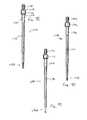
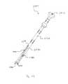
- calipersmay be provided for aiding a surgeon or clinician in selecting the proper size bone plate member. Measuring legs of the calipers enter the body, measure the distance between two points of interest on the surgical site, which may be, for example, desired insertion points for bone anchors.
- the calipersmay further feature an indicator sleeve that rotates relative to a housing such that a measurement of the distance between the ends of the legs of the calipers may be obtained from the indicator sleeve. This differs from prior calipers used for selecting a proper bone plate member size.
- Prior calipershave legs which are extended to place the ends of the legs at two points of interest on the surgical site, but these calipers need the legs to be removed from the body and then compared either directly to available bone plates or measured by a ruler or measuring stick to choose a proper bone plate member size.
- the present calipersallow a surgeon to choose a proper bone plate size directly from the measurement obtained from the indicator sleeve, which may further reduce operation time and reduce the possibility of choosing an improper plate size.
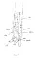
- the bone plate systemsmay utilize guides that aid in directing tools or instruments toward positions on the surgical site, such as, for example, bone anchor insertion points.
- the toolsmay be preparation tools used to prepare the bone anchor insertion sites, or the tools could be drivers used to drive the bone anchors into bone.
- the guidewill feature a tube portion and a base portion, the base portion operable to engage and pivot a pivot base to obtain the desired bone anchor trajectory.
- the guidescould be used to translate the pivot bases to be moved into alignment with the desired bone anchor insertion points, which are generally as far away from the standard or non-dynamized throughbores as possible with respect to the longitudinal axis of the bone plate.
- the guideis a fixed guide that may be used in conjunction with preparation tools or a driver.
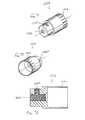
- the base portion of the fixed guideis configured to engage the pivot base that utilizes a resilient retaining member, and thus the base portion of the guide has at least one recessed portion to account for the configuration of the retaining member.
- the driver to be used in conjunction with the fixed guidemay be, in a preferred form, a generally hex-shaped driver.
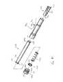
- the tip of the driverfeatures a retainer spring having a main body portion that abuts the end of the tip of the driver.
- the retainer springfurther defines a plurality of resilient legs that project in a direction parallel to the longitudinal axis of the driver and fit into a plurality of grooves in the tip of the driver with each leg fitting into a corresponding groove.
- the legsfeature a generally curved portion which extends above of the groove and project over the face of the hex portion of the driver, thus when the tip of the driver is inserted into a corresponding hex aperture of a bone anchor, the curvature of the curved portions of the retainer spring decreases and a load is applied to the hex aperture, aiding in retaining the bone anchor to the driver while the driver and screw are moved over the surgical site and down a throughbore of the fixed guide as the driver and bone anchor approach the bone anchor insertion site.
- the driver and retainer springare intended to be removed from the hex aperture of the bone anchor after the head end of the bone anchor is seated in the opening of the pivot base and the resilient retaining clip covers at least a portion of the head end of the bone anchor to prevent back out.
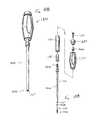
- a guided sleevemay be used with the present bone plate systems.
- the guided sleeveis configured to engage pivot bases that do not utilize a resilient retaining member to cover a portion of the seated head end of the bone anchor to inhibit back out, and the guided sleeve is configured to be used in conjunction with at least one preparation tool that may be used to prepare the desired bone anchor insertion site.
- the preparation toolswould preferably be available in the form of an awl, drill, and tap, and a surgeon may prefer to use all, none, or any combination of these tools to prepare the bone anchor insertion site.
- the guided sleeveis preferably biased to an extended position by an internally housed biasing or compression member, and this configuration may bias the tips of the preparation tools away from the bone when an affirmative load is not being applied to the tools by a surgeon or clinician.
- shafts of the preparation toolsare configured to be inserted only a predetermined distance into the guided sleeve, and an internal o-ring within the guided sleeve frictionally engages a portion of the shaft, acting to couple the preparation tool to the guided sleeve.
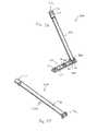
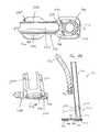
- a guide with an offset handleis also preferably used with bone plate system embodiments that do not utilize a retaining member that covers a portion of the seated head end of the bone anchor to inhibit back out.
- the guideis configured to be used with an awl, drill, tap, and/or driver, the driver for driving bone anchors into bone.
- the guidefeatures a coupling member which couples the offset handle to the guide tube or shaft, allowing a surgeon or clinician to actuate and position an engaged pivot base by actuating the offset handle.
- the coupling memberfurther comprises a window or aperture which offers the surgeon an at least partial view of the base portion and the pivot base. The view path allowed by the coupling member may be advantageous in aligning the guide to the pivot base while the pivot base is brought into engagement with the base portion of the guide.
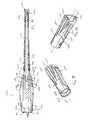
- a drivermay be used with the guide, and the driver preferably has a shaft with a tip portion featuring a plurality of protruding bone anchor head portion engagement members that generally form a cross-shape.
- the tip portionfurther defines a bore in substantial alignment with the central longitudinal axis of the driver, the bore configured to accept a portion of an insert.
- the inserthas a plurality of resilient teeth
- the bone anchor with a resilient head portionhas a locking member partially inserted therein. A surgeon or clinician would receive the bone anchor with the locking member in the proud position (i.e. engaged but not fully seated).
- the head portion engagement membersare configured to slide into slots that form the cross-shape in the resilient head portion and engage the bone anchor thereby.
- the resilient teeth of the insertengage an aperture in the locking member, holding the locking member to the driver as the bone anchor is moved over the surgical site and down a throughbore in the guide toward the desired bone anchor insertion site.
- the bone anchoris preferably driven into the bone and the head portion is seated within the opening of the pivot base while the locking member remains proud, and then the locking member itself is intended to be driven until fully seated.
- Seating the locking membercauses expansion of the resilient head portion of the bone anchor and creates a strong frictional engagement with the side walls of the opening in the pivot base, inhibiting bone anchor back out.
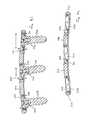
- FIG. 1is a plan view of a dynamized bone plate system including features in accordance with the present invention and securing vertebrae in a particular orientation;
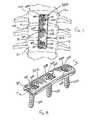
- FIG. 2is a perspective view of the dynamized bone plate system of FIG. 1 ;
- FIG. 3is a perspective view of the dynamized bone plate system of FIG. 2 without the bone anchors;
- FIG. 4is a top plan view of the dynamized bone plate system of FIG. 2 ;
- FIG. 5is a cross-sectional side view of the dynamized bone plate system of FIG. 2 taken along line 5 - 5 thereof;
- FIG. 6is a cross-sectional side view of the dynamized bone plate system of FIG. 3 taken along line 6 - 6 thereof;
- FIG. 7is a plan view of a standard bone plate system including features in accordance with the present invention and securing vertebrae in a particular orientation;
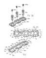
- FIG. 8is a perspective view of the standard bone plate system of FIG. 7 ;
- FIG. 9is a perspective view of the standard bone plate system of FIG. 8 without the bone anchors;
- FIG. 10is a top plan view of the standard bone plate system of FIG. 8 ;
- FIG. 11is a cross-sectional side view of the standard bone plate system of FIG. 8 taken along 11 - 11 thereof;
- FIG. 12is a cross-sectional end view of the dynamized or standard bone plate systems of FIG. 2 or 8 ;
- FIG. 13is a cross-sectional side view of the standard bone plate system of FIG. 9 taken along line 13 - 13 thereof;
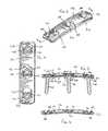
- FIG. 14is a perspective view of the bone plate of the dynamized bone plate system of FIG. 2 ;
- FIG. 15is a top plan view of the bone plate of FIG. 14 ;
- FIG. 16is a cross-sectional side view of the bone plate of FIG. 15 taken along line 16 - 16 thereof;
- FIG. 17is a perspective view of the bone plate of the standard bone plate system of FIG. 8 ;
- FIG. 18is a top plan view of the standard bone plate of FIG. 17 ;
- FIG. 19is a bottom plan view of the standard bone plate of FIG. 17 ;
- FIG. 20is a cross-sectional side view of the standard bone plate of FIG. 18 taken along line 20 - 20 thereof;
- FIG. 21is a cross-sectional end view of the dynamized or standard bone plates of the standard or dynamic bone plate systems of FIG. 2 or 8 ;
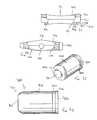
- FIG. 22is a perspective view of the bone screw of the dynamized or standard bone plate systems of FIG. 2 or 8 ;
- FIG. 23is a side view of the bone screw of FIG. 22 ;
- FIG. 24is a top plan view of the bone screw of FIG. 22 ;
- FIG. 25is a perspective view of the pivot member of the dynamized or standard bone plate systems of FIG. 2 or 8 ;
- FIG. 26is a cross-sectional side view of the pivot pin of FIG. 25 taken along line 26 - 26 thereof;
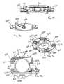
- FIG. 27is a perspective view of the pivot base assembly of the dynamized or standard bone plate systems of FIG. 2 or 8 ;
- FIG. 28is an exploded perspective view of the pivot base assembly of FIG. 27 ;
- FIG. 29is an end view of the pivot base assembly of FIG. 27 taken along line 29 - 29 thereof;
- FIG. 30is a cross-sectional side view of the pivot base assembly of FIG. 27 taken along line 30 - 30 thereof;
- FIG. 31is a perspective view of the pivot base of the pivot base assembly of the dynamized or standard bone plate systems of FIG. 2 or 8 ;
- FIG. 32is a top plan view of the pivot base of FIG. 31 ;
- FIG. 33is a bottom plan view of the pivot base of FIG. 31 ;
- FIG. 34is a cross-sectional side view of the pivot base of FIG. 32 taken along line 34 - 34 thereof;
- FIG. 35is a cross-sectional side view of the pivot base of FIG. 32 taken along line 35 - 35 thereof;
- FIG. 36is a plan view of a dynamized bone plate system including features in accordance with the present invention and securing vertebrae in a particular orientation;
- FIG. 37is a perspective view of the dynamized bone plate system of FIG. 36 ;
- FIG. 38is an exploded perspective view of the dynamized bone plate system of FIG. 37 ;
- FIG. 39is a top plan view of the dynamized bone plate system of FIG. 37 without the bone anchors;
- FIG. 40is a perspective view of the bone plate of the dynamized bone plate system of FIG. 37 ;
- FIG. 41is cross-sectional side view of the dynamized bone plate system of FIG. 37 taken along line 41 - 41 thereof;
- FIG. 42is a cross-sectional side view of the dynamized bone plate system of FIG. 39 taken along line 42 - 42 thereof;
- FIG. 43is a plan view of a standard bone plate system including features in accordance with the present invention and securing vertebrae in a particular orientation;
- FIG. 44is a perspective view of the dynamized bone plate system of FIG. 43 ;
- FIG. 45is perspective view of a dynamized bone plate system including features in accordance with the present invention without the bone anchors;
- FIG. 46is a top plan view of the bone plate system of FIG. 45 ;
- FIG. 47is an exploded perspective view of the pivot base and pivot members of the dynamized or standard bone plate systems of FIG. 37, 45 , or 44 ;
- FIG. 48is a perspective view of the pivot base of the dynamized or standard bone plate systems of FIG. 37, 45 , or 44 ;
- FIG. 49is a cross-sectional side view of the pivot base of FIG. 48 taken along line 49 - 49 thereof;
- FIG. 50is a cross-sectional side view of the pivot base of FIG. 48 taken along line 50 - 50 thereof;
- FIG. 51is a top plan view of the pivot base of FIG. 48 ;
- FIG. 52is a side view of the pivot base of FIG. 49 ;
- FIG. 53is a cross-sectional side view of the pivot base of FIG. 48 taken along line 50 - 50 thereof in the opposite direction of FIG. 50 ;
- FIG. 54is a cross-sectional side view of the pivot base of FIG. 48 taken along line 49 - 49 thereof in the opposite direction of FIG. 49 ;
- FIG. 55is a perspective view of the pivot member of the dynamized or standard bone plate systems of FIG. 37, 45 , or 44 ;
- FIG. 56is a side view of the pivot member of the dynamized or standard bone plate systems of FIG. 37, 45 , or 44
- FIG. 57is an exploded perspective view of the bone screw and corresponding locking member of the dynamized or standard bone plate systems of FIG. 37, 45 , or 44 ;
- FIG. 58is a cross-sectional side view of the bone screw and locking member of FIG. 57 with the locking member proud;
- FIG. 59is a cross-sectional side view of the bone screw and locking member of FIG. 57 with the locking member seated;
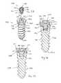
- FIG. 60is an exploded perspective view of the dynamized bone plate system of FIG. 36 with rescue screws and corresponding locking members in lieu of the bone screws and locking members of FIG. 57 ;
- FIG. 61is a perspective view of the rescue screw and corresponding locking member of FIG. 60 ;
- FIG. 62is a cross-sectional side view of the rescue screw and locking member of FIG. 61 with the locking member proud;
- FIG. 63is a cross-sectional side view of the rescue screw and locking member of FIG. 61 with the locking member seated;
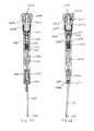
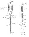
- FIG. 64is an exploded perspective view of measuring calipers including features in accordance with another aspect of the present invention.
- FIG. 65is a side view of the measuring calipers of FIG. 64 ;
- FIG. 66is a side view of the measuring calipers of FIG. 64 turned ninety degrees from the side view of FIG. 65 ;
- FIG. 67is a cross-sectional side view of the measuring calipers of FIG. 64 ;
- FIG. 68is a cross-sectional side view of the measuring calipers of FIG. 64 turned ninety degrees from the cross-sectional side view of FIG. 67 ;
- FIG. 69is a close-up cross-sectional side view of the measuring calipers of FIG. 67 ;
- FIG. 70is a close-up cross-sectional side view of the measuring calipers of FIG. 68 ;
- FIG. 71is a perspective view of the indicator sleeve of the measuring calipers of FIG. 64 ;
- FIG. 72is a perspective view of the indicator sleeve of the measuring calipers of FIG. 64 ;
- FIG. 73is a cross-sectional side view of the indicator sleeve of the measuring calipers of FIG. 64 ;
- FIG. 74is a perspective view of the measuring calipers of FIG. 64 ;
- FIG. 75is a close-up perspective view of a portion of a fixed guide including features in accordance with another aspect of the present invention.
- FIG. 76is a perspective view of the fixed guide of FIG. 75 engaged with a pivot base in the standard bone plate system of FIG. 3 ;
- FIG. 77is a perspective view of the fixed guide of FIG. 76 ;
- FIG. 78is a perspective view of a bone anchor driver including features in accordance with another aspect of the present invention and configured to drive the bone screw of FIG. 22 ;
- FIG. 79is a close-up perspective view of a portion of the driver of FIG. 78 ;
- FIG. 80is a close-up exploded perspective view of a portion of the driver of FIG. 78 ;
- FIG. 81is a close-up cross-sectional side view of a portion of the driver of FIG. 78 ;
- FIG. 82is a cross-sectional side view of the driver of FIG. 78 ;
- FIG. 83is a perspective view of a guided sleeve including features in accordance with another aspect of the present invention.
- FIG. 84is a side view of the guided sleeve of FIG. 83 ;
- FIG. 85is a cross-sectional side view of the guided sleeve of FIG. 83 ;
- FIG. 86is a cross-sectional side view of the guided sleeve of FIG. 83 with the bias member compressed;
- FIG. 87is an exploded perspective view of the guided sleeve of FIG. 83 ;
- FIG. 88is a perspective view of the base member of the guided sleeve of FIG. 83 ;
- FIG. 89is a perspective view of the base member of the guided sleeve of FIG. 83 ;
- FIG. 90is a cross-sectional side view of the guided sleeve of FIG. 83 engaged with a bone anchor insertion site preparation tool including features in accordance with another aspect of the present invention
- FIG. 91is a side view of the preparation tool of FIG. 90 ;
- FIG. 92is an exploded side view of the preparation tool of FIG. 91 ;
- FIG. 93is a shaft of the preparation tool of FIG. 91 wherein the tip portion is an awl;
- FIG. 94is a shaft of the preparation tool of FIG. 91 wherein the tip portion is a drill;
- FIG. 95is a shaft of the preparation tool of FIG. 91 wherein the tip portion is a tap;
- FIG. 96is a perspective view of a guide including features in accordance with another aspect of the present invention.
- FIG. 97is a partially exploded perspective view of a portion of the guide of FIG. 96 ;
- FIG. 98is an exploded side view of the guide of FIG. 96 ;
- FIG. 99is a close-up perspective view of a portion of the guide of FIG. 96 ;
- FIG. 100is a cross-sectional side view of a portion of the guide of FIG. 96 ;
- FIG. 101is perspective view of the coupling member of the guide of FIG. 96 ;
- FIG. 102is a top plan view of the coupling member of FIG. 101 ;
- FIG. 103is a top plan view of a portion of the guide of FIG. 96 engaged with the pivot base of the dynamized bone plate system of FIG. 45 ;
- FIG. 104is a close-up cross-sectional side view of a portion of the guide of FIG. 96 engaged with the pivot base of the dynamized bone plate system of FIG. 45 ;
- FIG. 105is a cross-sectional side view of a portion of the guide of FIG. 96 engaged with the pivot base of the bone plate of the dynamized bone plate system of FIG. 45 ;
- FIG. 106is a cross-sectional side view of the guide of FIG. 96 engaged with a bone anchor driver including features in accordance with another aspect of the present invention, the driver configured to drive the bone screws of FIGS. 58 and 61 ;
- FIG. 107is an exploded perspective view of the guide and driver of FIG. 106
- FIG. 108is a perspective view of the driver of FIG. 106 ;
- FIG. 109is an exploded perspective view of the driver and of FIG. 108 and the bone screw and locking member of FIG. 58 ;
- FIG. 110is a close-up perspective view of a portion of the driver of FIG. 108 ;
- FIG. 111is a close-up perspective view of the portion of FIG. 110 with the insert exploded;
- FIG. 112is the insert of FIG. 111 aligned with the bone screw and locking member of FIG. 58 .
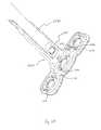
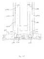
- FIG. 113is a side view of a plate holder including features in accordance with another aspect of the present invention.
- FIG. 114is a front view of the plate holder of FIG. 113 ;
- FIG. 115is a perspective view of the plate holder of FIG. 113 ;
- FIG. 116is a perspective view of the clamping mechanism of the plate holder of FIG. 113 ;
- FIG. 117is a perspective view of the plate holder of FIG. 113 engaged with the bone plate system of FIG. 39 ;
- FIG. 118is a close-up perspective view of the plate holder and bone plate system of FIG. 117 ;
- FIG. 119is a close-up perspective view of the plate holder and bone plate system of FIG. 117 ;
- FIG. 120is a perspective view of a locking guide in an unlocked configuration, including features in accordance with another aspect of the present invention.
- FIG. 121is a perspective view of the locking guide of FIG. 120 in a locked configuration
- FIG. 122is an exploded perspective view of the locking guide of FIG. 120 ;
- FIG. 123is a close-up perspective view of a portion of the locking guide of FIG. 120 ;
- FIG. 124is a cross-sectional side view of a portion of the locking guide of FIG. 120 ;
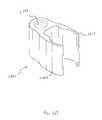
- FIG. 125is a perspective view of the coupling member of the locking guide of FIG. 120 ;
- FIG. 126is a top plan view of a portion of the locking guide of FIG. 120 engaged with the bone plate system of FIG. 39 ;
- FIG. 127is a close-up cross-sectional side view of a portion of the locking guide of FIG. 120 engaged with a pivot base of the bone plate system of FIG. 39 ;
- FIG. 128is a close-up perspective view of a portion of the locking guide of FIG. 120 engaged with a pivot base of the bone plate system of FIG. 39 ;
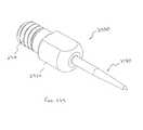
- FIG. 129is a perspective view of a bone pin configured to temporarily hold the bone plate system of FIG. 39 in a desired position, including features in accordance with another aspect of the present invention
- FIG. 130is a perspective view of the bone pin of FIG. 129 engaged with the bone plate system of FIG. 39 ;
- FIG. 131is a perspective view of a bone pin instrument, the bone pin of FIG. 129 , and the bone plate system of FIG. 39 .
- bone plate systemsare disclosed herein for securing a plurality of bones 12 in a desired orientation and arrangement.
- the bone plate systemutilizes a dynamized plate with dynamic bores so that bones may compress and shift toward each other, such as with dynamic or dynamized bone plate systems 100 , 1100 , 1700 shown in FIGS. 1, 36, and 45 , respectively.
- bone plate systemsutilize standard plate members with throughbores of the same size, such as standard bone plate systems 200 , 1200 shown in FIGS. 7, 43 .
- a dynamized bone plate system 100assists in the healing and repair of damaged, fractured, or broken bones.
- bones 12are adjacently located vertebrae of a spine, each spaced by a spinal disc 14 .
- the bone plate system 100may also be used to assist in the healing necessary after trauma has been experienced by the spinal disc 14 .
- the bone plate system 100may be utilized for stabilization and securement when adjacent vertebrae 12 are fused, with or without the assistance of a bone graft between the vertebrae 12 .
- the bone plate system 100may be used to correct and/or relieve symptoms of a variety of spinal disorders, which may include but are not limited to degenerative disorders, disorders induced by trauma, and pinched nerves.
- the bone plate system 100is used to secure the bones 12 (and any prosthetic or graft) in a desired spatial relationship.
- the desired spatial relationship between the bones 12is generally vertical, such as the vertebrae 12 would be in a normal, healthy spine when the person is standing.
- compression or loading of bonespromotes healing of the bones or bone fragments and improves the integrity of the fusion therebetween.
- the weight of the persondue to gravity, compresses those bones.
- the fusion of adjacent vertebraecan similarly benefit from using gravity to compress the adjacent vertebrae.
- the dynamized bone plate system 100preferably allows the bones 12 to shift relative to each other.
- the bone plate system 100is designed to allow the bones 12 to compress in a manner dictated by the bone plate system 100 .
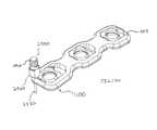
- the bone plate system 100generally includes a bone plate member 102 secured to the bones 12 with bone anchors that are, in a preferred form, bone screws 400 .
- the bone plate 102includes throughbores 106 , 108 , 110 formed in the plate 102 with a generally rectangular pivot base 300 secured within each throughbore 106 , 108 , 110 .
- the bone screws 400are secured in the generally rectangular pivot base 300 by retaining members 500 .
- the bone plate 102may be provided with curvature in the longitudinal direction that conforms the plate member 102 to the average natural curvature of the spine, as well as to reduce interference with surrounding tissues.
- the plate 102is preferably pre-bent to have a curvature in a longitudinal direction, more preferably with a radius of curvature of approximately 200 millimeters, and in a lateral direction, more preferably with a radius of curvature of approximately 20 millimeters. It is often desirable to alter the standard shape of the plate 102 to fit an individual patient's unique anatomy. This should be done in a manner so as not to scratch or mar the surfaces of the bone plate 102 , which otherwise may negatively affect the long-term fatigue performance of the bone plate 102 .
- a plate bending instrumentmay be used for altering the curvature of the plate 102 when necessary due to a unique anatomy. The plate bender is operated to either increase or decrease the radius of the lordotic curvature of the plate 102 .
- the plate 102is generally rectangular, although other configurations are possible.
- the bone plate 102may have indentations formed along the sides thereof between each throughbore.
- the bone plate 102may also have apertures therethrough in the areas between the bores to aid bone graft visualization.
- the bone plate 102includes a pair of generally parallel longitudinal side wall portions 150 and a pair of generally parallel end wall portions 152 and a top face 104 and a bottom face 114 .
- the bone plate 102preferably has a throughbore 106 , 108 , or 110 located at each level at which a bone 12 is to be secured thereto to thereby define tiers 20 , 22 24 of the bone plate 102 . As depicted in FIG.
- the plate 102has an uppermost tier 20 , an intermediary tier 22 , and a lowermost tier 24 , each respectively in general proximity to an uppermost vertebrae 12 a , an intermediary vertebrae 12 b , and a lowermost vertebrae 12 c , where the plate 102 is utilized for securing the three vertebrae 12 a , 12 b , 12 c in a spatial relationship.
- any number of tierscould be provided for securing a plurality of bones, bone segments, or implanted materials.
- a single throughbore 106 , 108 , 110is formed in the plate 102 at each tier 20 , 22 , 24 .
- the plate 102may have a minimized width profile, thereby reducing the encroachment and irritation to the esophagus and other soft tissues, the occurrence of esophageal dysphagia, as well as the required size of the access surgical opening required for insertion and mounting of the plate 102 .
- the narrow width of the plate 102further provides for improved visualization of the surrounding disc space.
- the single-bore configurationrequires half as many bone anchors, thereby reducing patient exposure, time required to complete the surgical procedure, and overall production costs.
- the preferred length of the plate 102is generally 12 to 40 millimeters.
- the plate 102is a dynamized or dynamic plate.
- the plate 102allows the bones 12 to compress towards each other by allowing the pivot base 300 and the bone screw 400 secured therein to shift relative to the plate 102 in a manner defined by the plate 102 .
- the throughbores 108 , 110are dynamized, meaning they are elongate with respect to the longitudinal direction of the plate 102 .
- the throughbores 108 , 110 of the intermediary tier 22 and lowermost tier 24are dynamized throughbores, while the throughbore 106 of the uppermost tier 20 is non-dynamized such that the non-dynamized throughbore 106 permits either no or minimal translation of the pivot base 300 and the bone screw 400 secured therein relative to the bone plate 102 .
- the intermediary vertebrae 12 b secured by the bone screw 400 through the dynamized throughbore 108 of the intermediary tier 22 and the lowermost vertebrae 12 c secured by the bone screw 400 through the dynamized throughbore 110 of the lowermost tier 24may translate toward the uppermost vertebrae 12 a secured by the non-dynamized throughbore 106 of the uppermost tier 20 as the vertebrae 12 compress.
- the length of the dynamized throughbores 108 , 110depends on the amount of translational desired subsidence at each tier. As shown, the throughbore 110 of the lowermost tier 24 is longer than the throughbore 108 of the intermediary tier 22 . As a result, the pivot base 300 secured in the throughbore 110 of the lowermost tier 24 may translate a greater distance than the pivot base 300 secured in the throughbore 108 of the intermediary tier 22 , with the throughbore 110 of the lowermost tier 24 allowing for approximately 2.50 millimeters of translation and the throughbore 108 of the intermediary tier 22 allowing for approximately 1.25 millimeters of translation. As shown in FIG.
- the pivot base 300 of the intermediary and lowermost tiers 22 , 24is preferably initially placed in the lower end 116 of the dynamized throughbores 108 , 110 at the furthest point away from the non-dynamized throughbore 106 .
- the placement of the pivot base 300 in the lower end 116 of the throughbores 108 , 110allows for maximum translation of the pivot base 300 and the bone screw 400 secured therein as the vertebrae 12 a , 12 b , 12 c compress.
- the throughbore 110 of the lowermost tier 24may translate to accommodate the translational movement of the pivot base 300 within the throughbore 108 of the intermediary tier 22 caused by compression between the uppermost vertebrae 12 and the intermediary vertebrae 12 b and then may also further translate to allow for further compression between the intermediary vertebrae 12 b and the lowermost vertebrae 12 c.
- the plate 102may be equipped with two or more tiers, with each tier having non-dynamized throughbores, or each tier having dynamized throughbores, or any combination thereof, as desired.
- the length and location of each dynamized throughboremay also be varied.
- the throughbore 108 of the intermediary tier 22may be non-dynamized, while the throughbores 106 , 110 of the uppermost tier 20 and lowermost tier 24 may be dynamized, with each dynamized throughbore having an equal length to allow for equal translation of the pivot base 300 within the throughbore toward the non-dynamized throughbore 108 .
- each throughbore 106 , 108 , 110has a generally rectangular profile comprised of a pair of longitudinal side wall portions 126 and a pair of end wall portions 128 .
- the pair of longitudinal side wall portions 126 of each throughbore 106 , 108 , 110in conjunction with slot portions 130 described below, vary in length depending on the amount of translational movement allowed for each throughbore 106 , 108 , 110 .
- the throughbore 110 associated with the lowermost tier 24has the longest longitudinal side wall portions 126 to allow for the approximately 2.50 millimeters of translational movement of the pivot base 300 .
- the throughbore 108 associated with the intermediary tier 22has slightly shorter longitudinal side wall portions 126 to allow for the approximately 1.25 millimeters of translational movement of the pivot base 300 .
- the throughbore 106 associated with the uppermost tier 20has longitudinal side wall portions 126 sized to accommodate the pivot base 300 while allowing for no or minimal translational movement.
- the pair of end wall portions 128are the same size for each throughbore 106 , 108 , 110 and are generally sized to accommodate the width of the pivot base 300 with little clearance.
- relief areas 118extend from the end wall portions 128 to allow for instrument clearance.
- the relief areas 118create space in which an instrument may be inserted to engage the plate 102 and/or pivot base 300 within each throughbore 106 , 108 , 110 .
- the relief areas 118are generally comprised of a pair of angled walls 120 extending to an end wall 122 , although other relief area geometry is contemplated to accommodate tools of different shapes or configurations.
- Each throughbore 106 , 108 , 110has a floor portion 124 extending along each longitudinal side wall portion 126 along the lower face 114 of the bone plate 102 .
- the floor portions 124extend into the throughbore 106 , 108 , 110 to narrow a portion of the throughbore 106 , 108 , 110 .
- the floor portions 124support bottom portions of the pivot base 300 , as described below.
- the floor portions 124support pivot members or pins 600 extending from the pivot base 300 , with the pivot members 600 sliding along the floor portions 124 to allow for the translational movement of the pivot base 300 .
- the floor portions 124 and the configuration of the pivot base 300also limit the pivotal movement of the pivot base 300 , as described below.
- Cavitieswhich, in a preferred form are slot portions or elongated grooves 130 are formed in the side wall portions 126 just above the intersection of the floor portion 124 and the longitudinal side wall portion 126 .
- the slot portions 130allow the pivot pins 600 extending from each side of the pivot base 300 to be received in the longitudinal side wall portions 126 of each throughbore 106 , 108 , 110 .
- the slot portions 130are sized in length to accommodate the desired translational movement of each pivot base 300 within the throughbores 106 , 108 , 110 .
- the throughbore 110 associated with the lowermost tier 24has the longest slot portions 130 to allow for the 2.50 millimeters of translational movement of the pivot base 300 .
- the throughbore 108 associated with the intermediary tier 22has slightly shorter slot portions 130 to allow for the 1.25 millimeters of translational movement of the pivot base 300 .
- the throughbore 106 associated with the uppermost tier 20has slot portions 130 sized to accommodate the pivot base 300 while allowing for no or minimal translational movement.
- the slot portions 130are generally sized in height and depth to accommodate the pivot pins 600 therein.
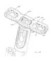
- the pivot base 300is generally rectangular, having longitudinal side wall portions 302 that generally align with the longitudinal side wall portions 126 of the throughbore 106 , 108 , 110 when the pivot base 300 is placed therein.
- the generally rectangular configuration of the pivot base 300resists torsion by increasing the torsional strength and stability of the pivot base 300 and the plate 102 .
- the pivot base 300further includes end wall portions 304 having a pair of forked projections 306 extending therefrom.
- the forked projections 306allow for instrument engagement and, in conjunction with the relief areas 118 of the plate 102 , facilitate engagement of the plate 102 and/or the pivot base 300 within each throughbore 106 , 108 , 110 .
- the instrumentmay grasp the pivot base 300 by inserting the instrument in a space 308 between the pair of forked projections 306 .
- the pivot base 300includes forked projections 306
- other end wall geometryis contemplated to accommodate instruments or tools of different shapes or configurations.
- the pivot base 300has a generally centrally located opening 310 extending therethrough to accommodate the bone screw 400 to be inserted therein.
- the opening 310is sized to accommodate the diameter of the bone screw 400 secured therein.
- the opening 310has tapered side walls 312 around the diameter thereof which mates with the tapered head portion 404 of the bone screw 400 , as described below.
- the mating tapers of the opening side walls 312 and the screw head portion 404assist in securing the bone screw 400 in place within the pivot base 300 and further limits the ability of the bone screw 400 to back out of the plate 102 .
- the side wall portions 302 and end wall portions 304define a top face 314 and a bottom face 316 of the pivot base 300 , with the top face 314 of the pivot base 300 generally aligned with the top face 104 of the bone plate 102 when the pivot base 300 is secured within the respective throughbore thereof.
- the upper face 314 and the bottom face 316 of the pivot base 300have a generally convex shape, as shown in FIG. 34 .
- the pivot base 300has a thicker center portion 318 and narrows toward the end wall portions 304 .
- Each longitudinal side wall portion 302 of the pivot base 300includes an aperture 320 therethrough to accommodate the pivot pins 600 , with the apertures 320 extending through from the longitudinal side wall portions 302 to the opening 310 .
- each longitudinal side wall portion 302are generally aligned with one another on either side of the pivot base 300 .
- the apertures 320are generally cylindrical and sized to receive the pivot pins 600 .
- the anchor pin apertures 320are positioned generally centrally along the longitudinal side wall portions 302 within the thicker center portion 318 of the side wall portion 302 . With respect to the center opening 310 , the aperture 320 is spaced equidistant from both end wall portions 304 and from the top 314 and bottom face 316 of the pivot base 300 .
- the top face 314 of the pivot base 300further includes a ramp portion 322 extending from one end wall portion 304 and down toward the anchor pin apertures 320 .
- the ramp portion 322includes a shallow initial ramp portion 324 adjacent the end wall 304 and then a deeper angled lower ramp portion 326 that extends from the initial ramp portion 324 and down to the apertures 320 .
- the ramp portion 322generally functions to accommodate the retaining member 500 , as will be discussed below.
- Upper edge portions 328 of the ramp portion 322are exposed by cutouts 330 in the top face 314 of the pivot base 300 , while lower edge portions 332 of the ramp portion 322 extend below the top face 314 of the pivot base 300 and are concealed by the top face 314 of the pivot base 300 , with the top face 314 of the pivot base 300 extending over the lower edge portions 332 of the ramp portions further securing the retaining member or clip 500 in place.
- the bottom face 316 of the pivot base 300has longitudinal recessed portions 334 adjacent the longitudinal side wall portions 302 of the pivot base 300 to create a two-tiered bottom face comprised of an upper level bottom face 336 adjacent the longitudinal side wall portions 302 and a lower level bottom face 338 on the remainder of the bottom face 316 .
- the recessed portions 334provide a notched profile 340 , as shown in FIG. 35 , adjacent the longitudinal side walls 302 .
- the notched profile 340 of the pivot base 300generally aligns with the notched profile 140 of the bone plate 102 , as shown in FIG.
- the pivot base 300sits into the throughbore 106 , 108 , 110 of the bone plate 102 , with the recessed portions 334 being generally aligned with and generally supported by the floor portions 124 of the throughbores 106 , 108 , 110 , and the lower level bottom face 338 seated into the narrowed hole portion of the throughbore 106 , 108 , 110 formed by the floor portions 124 .
- the pivot base 300is dropped into each throughbore 106 , 108 , 110 , with the longitudinal side walls 302 of the pivot base 300 generally aligned with and confronting the longitudinal side walls 126 of the throughbore 106 , 108 , 110 with a minimal amount of clearance between the side walls 302 , 126 to allow for relative translational movement of the pivot base 300 within the throughbore 106 , 108 , 110 .
- the generally rectangular profile of the pivot base 300mates with the equivalent generally rectangular profile of the throughbores 106 , 108 , 110 in the plate 102 .
- the mating profiles of the pivot base 300 and the throughbores 106 , 108 , 110limit the rotational translation between the pivot base 300 and the plate 102 , resulting in increased torsional plate strength.
- the pivot pin 600has a generally cylindrical profile with a through hole 602 formed therein.
- a slot 604is formed in the pin 600 and extends from a first end 606 thereof to approximately halfway down the length of the pin 600 to accommodate the retaining member 500 therein.
- a second end 608 of the pin 600may optionally be tapered or rounded to provide for better mating of the pin 600 in the slot 130 of the bone plate 102 .
- the pins 600are inserted into the apertures 320 in the pivot base 300 after the pivot base 300 has been deposited in the throughbores 106 , 108 , 110 of the bone plate 102 .
- the pins 600are oriented with the slot 604 generally facing the ramp portion 322 of the pivot base 300 so that the slot 604 may receive a portion of the retaining member 500 therein.
- the pins 600are inserted in the apertures 320 of the pivot base 300 such that a portion of the pin 600 extends beyond the longitudinal side wall portions 302 of the pivot base 300 and into the slot portion 130 of the throughbore 106 , 108 , 110 of the bone plate 102 .
- the pins 600can move along the length of the slot 130 to allow for the translational movement of the pivot base 300 within the dynamized throughbores 108 , 110 .
- the pivot pins 600limit any pivot action of the pivot base 300 relative to the plate 102 about the lateral axis of the plate 102 .
- the pivot pins 600allow the pivot base 300 to toggle or pivot relative to the plate 102 in the direction of the longitudinal axis of the plate 102 , with the pivot angle being generally defined by the geometry of the plate 102 and the pivot base 300 .
- the floor portions 124 of each throughbore 106 , 108 , 110 of the bone plate 102limit the pivot angle of the pivot base 300 because the upper level bottom face 336 of the pivot base 300 contacts the floor portions 124 as the pivot base 300 pivots to thereby limit the pivot angle.
- the predetermined range through which the pivot base 300 may togglemay be, for example, plus or minus ten degrees relative to the plate 102 .
- FIGS. 1-13show the pivot bases 300 oriented in one of two directions such that the retaining members 500 may project in a direction that is either generally up or generally down with respect to the longitudinal axis of the spine.
- the pivot bases 300may be installed in either direction with no degradation of performance, and it will be appreciated that other combinations of pivot base orientations other than those shown would, of course, be possible.
- the retaining member, shown in FIG. 28, 500has a generally U-shaped profile comprised of a generally straight center portion 502 and a pair of prongs 504 extending generally transversely to the center portion 502 .
- a leg portion 506extends generally transverse to each of the prongs 504 , with the leg portions 506 configured to be secured at least partially within the pivot pins 600 .
- the retaining member 500is preferably made of a resilient material to allow for flexing and bending of the retaining member 500 during the insertion, removal, and/or surgical operation.
- the retaining member 500is elastically resilient so that the distal ends may be compressed and return to their natural shape when released, and so that the retaining member 500 may expand and contract as the screw head 404 passes through and beyond the retaining member 500 , as described below.
- the retaining member 500generally functions to secure the pivot members 600 in place, thus mounting the pivot base 300 in place within a corresponding throughbore 106 , 108 , 110 of the plate 102 .
- the retaining member 500further functions to retain the bone screw 400 in place to limit the ability of the bone screw 400 to back out of the plate 102 .
- the retaining member 500is generally aligned with the ramp portion 322 of the pivot base 300 , with the prongs 504 and the leg portions 506 of the retaining member 500 extending toward the ramp portion 322 .
- the pair of prongs 504may be compressed toward each other to reduce the width of the distal end of the retaining member 500 to allow for the legs 506 to clear the longitudinal side wall portions 302 of the pivot base 300 and slide down the ramp portion 322 .
- the retaining member 500is released from the compressed position and allowed to expand at least partially such that the legs 506 extend into the center through holes 602 of the pivot members or pins 600 .
- the legs 506extend into the through holes 602 , while the prongs 504 seat flush against the ramp portion 322 , with the top face 314 of the pivot base 300 extending over a portion of the prongs 504 to maintain the retaining member 500 in place.
- the prongs 504also seat flush against the longitudinal side walls 302 of the pivot base 300 .
- each prong 504 and leg projection 506 extending therefromengages with an end 610 of the slot 604 in the pivot pin 600 to thereby secure the pin 600 in place.
- the retaining member 500thus holds the pins 600 in place, thereby mounting the pivot base 300 in the plate 102 prior to bone screw 400 insertion.
- the center portion 502 of the retaining member 500extends across a portion of the opening 310 of the pivot base 300 to interfere with the path of the screw head 404 to thereby secure a bone screw 400 in place, as will be described.
- the resilient retaining members 500may deform elastically while the bone screw 400 is being driven into place, returning at least partially to their original shapes to cover at least a portion of the screw head 404 and inhibit bone anchor back out.
- one of the leg projections 506 extending from one of the prongs 504may slide down the ramp portion 522 and be inserted into the through hole 602 of the pivot pin 600 .
- the other prong 504may be compressed inwardly to clear the longitudinal side wall 302 of the pivot base 300 and then be moved down the ramp portion 322 until the other leg projection 506 is generally aligned with the through hole 602 of the opposite pin 600 .
- the other prong 504may then be released from the compressed position and may expand such that the leg projection 506 is inserted into the through hole 602 of the pin 600 , thus bringing the retaining member 500 and the pivot members 600 to the installed and seated orientations described above with respect to the first installation method.
- the assembly of the bone plate 102 , pivot base 300 , pivot member 600 , and retaining member 500occurs pre-surgery, such that a surgeon receives the bone plate system 100 in this assembled configuration, with only the bone screws 400 to be inserted through the plate 102 and driven into the bone 12 and seated within the pivot bases 300 to secure the bone plate 102 in place. It will, of course, be appreciated that at least a portion of this assembly may be completed by the surgeon or clinician at the time of surgery.
- the bone plate 102including the pivot base 300 , pins 600 , and retaining member 500 secured therein, is generally aligned in position along the vertebrae or other bones 12 such that the bone screw 400 may then be inserted to secure the bone plate 102 to the bones 12 .
- the bone plate 102may optionally include pin through holes (not shown) for temporarily pinning the bone plate 102 in the desired position prior to driving the bone screw 400 .
- the pivot base 300is aligned within the dynamized throughbores 108 , 110 such that the pivot base 300 of each dynamized throughbore 108 , 110 is placed at the lower end 116 of the throughbore 108 , 110 , as discussed above.
- the plate 102is then ready to receive the bone screws 400 .
- the bone screw 400has a threaded shank 402 , a head portion 404 , and a neck 406 therebetween.
- the bone screw 400is aligned with the opening 310 of the pivot base 300 .
- the screw head 404preferably has a center hex aperture 408 that will engage with a driver 2200 to drive the bone screw 400 into the bone 12 , but it will, of course, be appreciated that engagement configurations other than a hex aperture and hex-tipped driver are possible.
- the driver instrument or tool 2200may engage the hex aperture 408 of the screw head 404 , with the driver 2200 driving the bone screw 400 into the bone 12 .
- the screw head 404contacts the center portion 502 of the retaining member 500 .
- the arcuate profile of the screw head 404cams against the straight center portion 502 of the retaining member 500 and forces, wedgelike, the center portion 502 to deflect outwardly—and preferably, elastically—to allow the screw head 404 to pass.
- the retaining member 500generally returns at least partially to its position prior to insertion of the bone screw 400 .
- the bone screw 400is seated in the bone 12 and plate 102 such that the screw head 404 is generally below or approximately coincident with the upper face 314 of the pivot base 300 so that the center portion 502 of the retaining member 500 held within the pivot base 300 is over the head portion 404 of the bone screw 400 to prevent bone anchor back out.
- the screw head 404is aligned with the pivot pins 600 such that the screw head 404 holds the pins 600 and retaining member legs 506 in place, thus aiding in retaining the retaining member 500 itself and reinforcing its own back out obstacle.
- a self-tapping screw 400 to be used in the bone plate system 100is shown in FIGS. 22-24 .
- the self-tapping screw 400is provided with a tip 410 that is rounded and substantially dull.
- the bone screw 400may be advanced into a pilot hole formed in the bone 12 , and the threaded shank 402 forms cooperating threads in the bone 12 as the bone screw 400 is forcibly driven into the bone 12 .
- the rounded tip 410 of the self-tapping screw 400is intended to limit tissue damage.
- the tip 410features a fluted portion 403 to remove bone chips as tapping occurs.
- the self-tapping screw 400is available in a variety of lengths.
- These lengthsmay be, for example, approximately 12, 14, or 16 millimeters, with the lengths representing the approximate amount of screw shank 402 that extends from the backside of the plate 102 after the head portion 404 bone screw 400 is fully seated in the opening 310 of the pivot base 300 .
- the screw head portion 404preferably has a taper of the side walls 412 thereof that mates with the tapered side wall 312 of the opening 310 of the pivot base 300 , as discussed above.
- the angle of the tapermay be, for example, approximately ten degrees.
- the mating tapered side walls 312 , 412further limit the ability of the bone screw 400 to back out of its secured position within the plate 102 and in the bone 12 .
- the taper lock conditionalso minimizes the rotational translation between the bone screw 400 and the pivot base 300 .
- the screw head portion 404may also be optionally colored to create visual contrast relative to the retaining member 500 , the pivot base 300 , and the plate 102 .
- the bone screw 400has a major diameter of approximately 4.5 millimeters and a minor diameter of approximately 3.0 millimeters.
- the bone screw 400further has a pitch and a half lead-in to increase the cross-sectional area for improved head strength.
- the screw head portion 404preferably has a top surface 414 that is generally flat.
- a convex shapemay promote or assist bone anchor back out as the convex head may force the retaining member 500 open.
- a concave shapemay be employed for the top surface 414 .
- the bone anchormay be a self-drilling screw (not shown).
- Self-drilling screwsgenerally feature tips that are pointed and at least one of a cutting flute formed in the threaded shank to aid in removing bone chips as they are cut.
- the cutting edges of the tipmay be approximately 90 degrees relative to one another and are generally relieved at a rate of approximately 0.010 per 100 degrees of rotation to aid in cutting.
- the self-drilling screwmay be placed against a bone 12 or in a pilot hole of a bone 12 and is advanced by forcibly driving the screw into the bone 12 .
- the cutting fluteforms a hole in the bone 12 as the screw is advanced, and the threads cut into the bone 12 to form cooperating threads in the bone 12 .
- the self-drilling screwsare provided in a length short enough to prevent accidental driving of these sharper screw tips into sensitive tissues, such as nerves or blood circulatory passages.
- the self-drilling screwis available in variety of lengths. These lengths may be, for example, approximately 12, 14, or 16 millimeters in length with the screw lengths being designated as defined above.
- rescue screwsmay be provided for the bone plate system 100 for securing in the bone.
- a rescue screwis a screw that has a larger thread diameter, or a larger central or minor diameter, or both. The rescue screw is able to gain purchase in the stripped hole, treating the stripped hole as if it were a pilot hole, by virtue of its larger size.
- the rescue screw used in this systemmay feature a major diameter of approximately 4.5 millimeters and a minor diameter of approximately 3.0 millimeters.
- the rescue screwis self-tapping and is available in a variety of lengths. These lengths may be, for example, approximately 12, 14, or 16 millimeters with the screw lengths being designated as defined above.
- the angle of bone anchor toggleis limited by the geometry of the throughbore 106 , 108 , 110 and the pivot base 300 mounted therein.
- the pivot base 300and thus the bone screw 400 with a head portion 404 seated therein, may be configured to pivot plus or minus approximately ten degrees relative to the plate 102 in the direction of the longitudinal axis of the plate 102 (cephal/caudel direction) and approximately 0 degrees relative to the plate 102 in the direction of the lateral axis of the plate 102 (medial/lateral direction).
- the standard bone plate 200generally includes a bone plate 202 secured to the bones 12 with bone screws 400 .
- the present bone plate 202includes through throughbores 206 , 208 , 210 formed in the plate 202 , with a generally rectangular pivot base 300 secured within each throughbore 206 , 208 , 210 .
- the bone screws 400are secured in the pivot base 300 by retaining members 500 .
- the same pivot base 300 , bone screw 400 , retaining member 500 , and pivot members 600 used in the dynamized bone plate system 100may be used in the standard bone plate system 200 .
- the main difference between the dynamized bone plate system 100 and the standard plate system 200is the availability of translational movement within the throughbores. While the dynamized plate 102 included dynamized throughbores 108 , 110 to allow for translational movement of the pivot base 300 relative to the plate 102 , the standard plate 202 includes non-dynamized or standard throughbores 206 , 208 , 210 of generally identical size that allow relatively little to no translational movement.
- the dynamized and non-dynamized throughboreshave generally similar construction, with the length of the longitudinal side wall portions 126 , 226 being the notable difference in allowing for or limiting the translational movement of the pivot base 300 within the plate 102 , 202 .
- the standard plate 202has generally the same construction and configuration as the dynamized plate 102 . It should be noted that similar elements of each plate 102 , 202 have been assigned similar reference numbers for consistency.
- the bone plate 202preferably has a throughbore 206 , 208 , 210 located at each level at which a bone 12 is to be secured thereto, with the throughbores 206 , 208 , 210 defining tiers 20 , 22 , 24 of the bone plate 202 , as depicted in FIG. 7 .
- a single throughbore 206 , 208 , 210is formed in the plate 202 at each tier 20 , 22 , 24 . Again, any number of tiers could be provided for securing a plurality of bones 12 .
- each throughbore 206 , 208 , 210has a generally rectangular profile comprised of a pair of longitudinal side wall portions 226 and a pair of end wall portions 228 .
- the pair of longitudinal side wall portions 226 of each throughbore 206 , 208 , 210are generally the same length and are generally sized to receive the pivot base 300 therein with little or no side-to-side translational movement allowed relative to the longitudinal axis of the plate 202 .
- the end wall portions 228are generally the same size for each throughbore 206 , 208 , 210 and are generally sized to accommodate the length of the pivot base 300 with little more clearance than what is needed to accommodate the pivoting motion of the pivot base 300 relative to the plate 202 .
- the longitudinal side wall portions 226 and the end wall portions 228are generally just minimally larger in terms of length and width with respect to the corresponding side wall portions 302 and end wall portions 304 of the pivot base 300 to restrict the translational movement of the pivot base 300 .
- relief areas 218extend from the end wall portions 228 to allow for instrument clearance and forked projections 306 .
- Each throughbore 206 , 208 , 210has a floor portion 224 extending along and generally perpendicular to each longitudinal side wall portion 226 along the bone plate 202 .
- the floor portions 224extend into the throughbore 206 , 208 , 210 to narrow the throughbore hole such that the floor portions 224 support bottom portions of the pivot base 300 .
- the floor portions 224support pivot members 600 extending from the pivot base 300 .
- the floor portions 224also serve to limit the pivotal movement of the pivot base 300 .
- Cavitiessuch as, in a preferred form, slot portions or elongated grooves 230 are formed in the side wall portions 226 just above the intersection of the floor portion 224 and the longitudinal side wall portion 226 .
- the slot portions 230allow the pivot members 600 extending from either side of the pivot base 300 to be received in the longitudinal side wall portions 226 of each throughbore 206 , 208 , 210 .
- the slot portions 230are sized in length to receive the pivot pins 600 .
- the slot portions 230may extend along the length of the side wall portions 226 , the pivot base 300 will experience little or no translation, as the length of the side walls portions 226 serves as the limiting factor in restricting the translational movement of the pivot base 300 within the throughbore 206 208 , 210 .
- the longitudinal side wall portions 226are generally minimally longer than the length of the longitudinal side wall portions 302 of the pivot base 300 to restrict the translational movement of the pivot base 300 .
- the slot portions 230are generally sized in height and depth to accommodate the pivot members 600 therein.
- the pivot members or pins 600 securing the pivot base 300 in the slots 230limit pivotal movement of the pivot base 300 in the direction of the lateral axis of the plate 202 within the throughbore 206 , 208 , 210 .
- the pivot base 300 in the standard plate 202is allowed to pivot in the direction of the longitudinal axis of the plate 202 , and the range of pivoting may be, for example, approximately plus or minus ten degrees, with the floor portions 224 and the configuration of the pivot base 300 limiting the amount of pivotal movement.
- FIGS. 36-42another embodiment according to the present invention is shown in the form of a dynamic or dynamized bone plate system 1100 .
- the bone plate system 1100is similar in many respects to the dynamized bone plate system 100 , with one of the important distinctions being that no resilient retaining member 500 is used.
- discussion of the present bone plate system 1100will primarily focus on aspects of the present embodiment that differ from the previously discussed dynamized bone plate system 100 .
- the bone plate system 1100comprises a bone plate 1102 featuring throughbores 1106 , 1108 , 1110 on each tier 20 , 22 , 24 , respectively.
- the present bone plate 1102may also feature indented regions 1160 , which offer enhanced visualization of the surgical site, graft region, and/or intervertebral disc space.
- the reduced cross-section in these regionsallows a surgeon or clinician to bend the plate 1102 with greater precision should the plate 1102 require bending to better contour the patient's natural spinal curvature.
- the reduced cross section in the regions of the plate 1102 between opposing indented regions 1160make the plate 1102 easier to bend in these regions, avoiding bending at the throughbores 1106 , 1108 , 1110 , which is preferable because if the plate 1102 is bent too close to or within the region of the throughbores 1106 , 1108 , 1110 , the structural integrity of the throughbores 1106 , 1108 , 1110 and the intended configurations between the throughbores 1106 , 1108 , 1110 and the corresponding pivot bases 1300 may be compromised.
- the plate 1102may feature at least one of an aperture 1103 for temporarily holding the bone plate 1102 in the location and orientation desired by the surgeon such that the plate 1102 is retained in the desired position before bone anchors such as bone screws 1400 are installed.
- bone pinsare inserted through the apertures 1103 , and the bone pins are intended to be temporary and are designed to cause minimal damage to the osseous tissue such that any region affected by the bone pins will heal quickly and the mechanical characteristics of the vertebrae 12 will see little or no appreciable degradation.
- Each bone pin 2900preferably has a threaded portion 2910 , an intermediate portion 2920 , and a tip 2930 , as shown in FIG. 129 .
- Tip 2930extends through the aperture 1103 when the bone pin 2900 is in position to hold the bone plate 1102 against a vertebra, as shown in FIG. 130 .
- the threaded portion 2910enables the bone pin 2900 to be releasably attached to a pin instrument 2950 , as shown in FIG. 131 .
- a surgeonmay insert a bone pin 2900 through a first aperture 1103 and into a vertebra, unscrew the pin instrument 2950 from the first bone pin 2900 , and repeat the procedure with a second bone pin 2900 and second aperture 1103 .
- bone pins 2900 in apertures 1103 on opposite corners of the bone plate 1102provides a secure, but temporary, method of retaining the plate 1102 in the desired position before anchors are installed. Though this feature is not shown on the plates 102 , 202 discussed above, it will be appreciated that this or a similar feature may be present on all embodiments shown for exemplary purposes herein. It will further be appreciated that this feature would be optional and the surgeon may choose not to use the apertures 1103 even if the apertures 1103 are present on the bone plate being installed.
- the plate 1102is, in many respects, quite similar to the previously described bone plate 102 .
- the bone plate 1102features a top face 1104 and a bottom face 1114 , as well as a pair of generally parallel longitudinal side wall portions 1150 and generally parallel end wall portions 1152 .
- the throughbores 1106 , 1108 , 1110 of the present plate 1102are very similar to the throughbores 106 , 108 , 110 of the previously discussed dynamized plate 102 such that the geometric relationships and the movements of pivot bases 1300 within the throughbores 1106 , 1108 , 1110 are largely the same.
- the throughbores 1106 , 1108 , 1110feature longitudinal sidewall portions 1126 , elongated grooves or slot portions 1130 , floor portions 1124 , end wall portions 1128 , angled walls 1120 which terminate in end walls 1122 and define relief areas 1118 , and a notched profile 1140 .
- the dynamized throughbores 1108 , 1110also feature lower ends 1116 whereby pivot bases 1300 disposed within the dynamized throughbores 1108 , 1110 may be positioned to allow maximum settling of the vertebrae 12 . It should be noted that many similar feature to previously described embodiments retain a similar denotation; for example, the lower ends 116 of the plate 102 and the lower ends 1116 of the plate 1102 .
- the throughbores 1106 , 1108 , 1110are designed to accommodate pivot bases 1300 , which are similar in many respects to the pivot bases 300 discussed above, but the pivot bases 1300 do not use the resilient retaining members 500 . Rather, the pivot bases 1300 are retained within the throughbores 1106 , 1108 , 1110 primarily by pivot members or pivot pins 1600 shown in FIGS. 55, 56 .
- the pivot pins 1600are similar in many respects to the previously discussed pivot members 600 , but the present pivot pins 1600 do not feature a center through hole or a slot which were used to engage the leg portions 506 of the retaining member 500 .
- the pivot pins 1600feature a front surface 1610 of a rounded or partially rounded tip 1620 , and a body portion 1630 , but the pivot pins 1600 also feature a tapered region 1640 which terminates in a slightly enlarged portion 1650 that aid in the assembly process.
- the pivot pin 1600also features an end surface 1660 and in a preferred form the pivot pin 1600 is solid, as it need not engage a retaining member 500 .
- the pivot base 1300is aligned in one of the throughbores 1106 , 1108 , 1110 .
- the pivot pins 1600are inserted into apertures 1320 in the pivot base 1300 and are forced further into the apertures 1320 until the enlarged portion 1650 comes into a tight frictional or interference engagement with the pivot base 1300 , a portion of the pivot pin 1600 projects into the slot portion 1130 of the plate 1102 , and the rear surface 1660 of the pivot member 1600 will not interfere with the insertion of the bone screws 1400 .
- the pivot bases 1300shown in FIGS. 48-54 , are similar in many respects to the pivot bases 300 described previously, but the pivot bases 1300 may be easier to manufacture as they do not require additional geometric considerations to accommodate the use of the retaining members or clips 500 .
- the present pivot base 1300features longitudinal side walls 1302 , end wall portions 1304 , forked projections 1306 which define a space 1308 therebetween, a center through opening 1310 , a top face 1314 , a bottom face 1316 , and because the top and bottom faces 1314 , 1316 are generally convex in shape, the pivot base 1300 has a thicker center portion 1318 .
- the pivot base 1300features apertures 1320 for receiving pivot members or pins 1600 .
- the opening 1310also features an enlarged upper portion 1312 and a lower portion 1313 to accommodate the head geometry of a bone anchor such as a bone screw 1400 .
- the present pivot base 1300features longitudinal recessed portions 1334 , an upper level bottom face 1336 , a lower level bottom face 1338 , and a notched profile 1340 which is contoured to the notched profile 1140 of the plate 1102 , all of which were described in detail with respect to the pivot base 300 .
- the pivot bases 1300are designed to pivot with respect to the plate 1102 , and this will be accomplished by clearances and geometric relationships that allow for this motion.
- the clearance between the longitudinal side wall 1302 and the longitudinal side wall portion 1126may be as much as 0.002 inches, and in the standard throughbores such as the standard throughbore 1106 of the present bone plate system 1100 , the clearance between the end wall portions 1304 of the pivot base 1300 and the end wall portions 1128 of the plate 1102 may be as much as 0.005 inches, which may allow a slight amount of translation relative to the plate 1102 in the standardized throughbore 1106 , but this amounts to very little translation relative to the dynamized throughbores 1108 , 1110 and may be necessary to allow for the pivoting motion of the pivot base 1300 .
- the pivot base 1300is configured to accommodate a bone anchor or fastener such as the bone screw 1400 shown in FIGS. 57-59 .
- the bone screw 1400is shown with a rounded or dull tip 1410 , which is customary for a self-tapping screw, but it will be appreciated that the screw 1400 could have a sharp tip and be a self-drilling screw or it could be any type of bone screw that features a screw head configured to be seated within the pivot base 1300 .
- the threaded shank 1402features a fluted portion 1403 to remove bone chips upon installation.
- the bone screw 1400would be available in different lengths.
- These lengthsmay be, for example, 12, 14, or 16 millimeters, with the screw length representing the approximate amount of screw shank 1402 that extends from the backside of the plate 1102 after the screw 1400 is fully seated in the opening 1310 of the pivot base 1300 .
- a head portion or head end 1404 of the bone anchor 1400is a resilient head portion.
- the screw head 1404features a plurality of upper ledge portions 1412 that define an upper surface 1414 and are configured to compliment the enlarged upper region 1312 of the through hole or opening 1310 of the pivot base 1300 .
- lower portions 1413complement the lower portion 1313 of the pivot base 1300
- the upper and lower portions 1412 and 1413are separated from one another by a plurality of driver engagement slots 1430 , as shown in FIG. 57 .
- a chamfer 1416begins at the bottom of the lower portion 1413 and angles inwardly, terminating at the top of the shank 1402 , thus serving as a transition between the screw head 1404 and the threaded region 1402 .
- the bone screw 1400is driven into the bone 12 with the shank 1402 passing through the through hole or opening 1310 of the base member 1300 .
- a locking membersuch as a locking screw or setscrew 1450 will be seated to expand the resilient screw head 1404 and/or cause hoop stress to be applied on the walls of the opening 1310 of the pivot base 1300 .
- the locking member or locking screw 1450is designed to be inserted into a cavity 1440 within the screw head portion 1404 and the locking screw 1450 is generally rigid in comparison to the generally resilient screw head portion 1404 .
- the surgeon or clinicianwould receive the bone screw 1400 and locking screw 1450 as one unit, with the locking screw 1450 in the proud position as shown for exemplary purposes in FIG. 58 .
- a driver 2600will first engage the screw 1400 and drive the screw 1400 into the bone 12 before the locking screw 1450 is engaged by a driver (not shown), preferably within a hex aperture 1458 , and is driven into a seated configuration thereby to impart hoop stress to the screw head 1404 as shown in FIG. 59 and thus aid in retaining or locking the screw head 1404 within the opening 1310 of the pivot base 1300 and inhibit back out by creating enhanced frictional engagement between the screw head 1404 and the pivot base 1300 .
- the screw head 1404has a chamfer 1425 that compliments an inwardly sloped surface 1465 of the locking member 1450 .
- An annular lip 1462creates an annular groove 1460 which, along with a ledge 1422 of the screw head 1404 , inhibits the locking member 1450 from being removed from the screw head portion 1404 .
- the locking member 1450further defines a threaded shank 1452 , which allows the locking screw 1450 to be driven further into the internal threaded region 1442 of the bone screw 1400 .
- the locking member 1450may be driven until fully seated when the a bottom surface 1464 of the annular lip 1462 of the locking member 1450 contacts a bottom surface 1444 of the cavity 1440 .
- An outer surface 1451 of the locking screw 1450is then in contact with the ledge 1422 , imposing hoop stress on the head portion 1404 of the bone screw 1400 and expanding the head portion 1404 to create enhanced engagement with the opening 1310 of a pivot base 1300 .
- another bone anchorsuch as a rescue screw 1400 ′, shown in FIGS. 60-63 , may be employed.
- the rescue screw 1400 ′differs from the rescue screws (not shown) described above with respect to the previously discussed bone plate system 100 because the rescue screws of the previous system 100 feature dimensions that, upon installation, interfere with the dimensions of the hole in the bone 12 .
- the present rescue screw 1400 ′is installed in the same manner as the bone screw 1400 and is then expanded to cause hoop stress and/or create interfering dimensions with the hole into which the rescue screw 1400 ′ is installed.
- the rescue screw 1400 ′is the same in many respects to the bone screw 1400 , but a cavity 1440 ′ terminates in a chamfer 1480 ′ which leads to a channel 1482 ′, as shown in FIGS. 62, 63 .
- the channel 1482 ′ends in curved portions 1484 ′ and the screw tip 1410 ′ is then split into a plurality of tip segments 1486 ′ by slots 1488 ′.
- both the screw head portion 1404 ′ and the screw tip 1410 ′ of the rescue screw 1400 ′are resilient.
- the rescue screw 1400 ′would be available in different lengths.
- These lengthsmay be, for example, 12, 14, or 16 millimeters, with the screw length representing the approximate amount of screw shank 1402 ′ that extends from the backside of the plate 1102 after the rescue screw 1400 ′ is seated in the opening 1310 of the pivot base 1300 .
- the rescue screw 1400 ′will also feature a locking member such as a locking screw 1450 ′ that is similar in many respects to the locking screw 1450 described above, but differs with respect to the fact that the locking screw 1450 ′ features a post 1490 ′ that extends generally parallel to the longitudinal axis of the screw 1400 ′.
- the post 1490 ′terminates in a rounded tip 1494 ′ which, in the proud configuration shown in FIG. 62 , is generally flush with the curved portion 1484 ′ of the rescue screw 1400 ′.
- the locking screw 1450 ′may be seated as described above with respect to the locking screw 1450 , but as the locking member 1450 ′ is seated, the post 1490 ′ will be advanced, pushing the rounded tip 1494 ′ past the curved portions 1484 ′ of the channel 1482 ′ and expanding the screw tip segments 1486 ′ so that the screw tip segments 1486 ′ will cause interference and/or enhanced frictional engagement with the hole formed in the bone 12 . In this way, seating the locking member 1450 ′ of the rescue screw 1400 ′ will expand both the screw head 1404 ′ and the screw tip 1410 ′ as shown in FIG. 63 , avoiding the need to drill a second hole in the vertebrae 12 .
- FIGS. 43, 44another embodiment of the present invention is shown in the form of a standard or non-dynamized bone plate system 1200 .
- the bone plate system 1200is similar in many respects to the dynamic bone plate system 1100 described above, the primary difference being that the present bone plate system 1200 is of the standard or non-dynamized variety.
- the present bone plate system 1200differs from the dynamized bone plate system 1100 in primarily the same way the previously discussed non-dynamized bone plate system 200 differs from the dynamized bone plate system 100 .
- the bone plate system 1200features a plate member 1202 with a top face 1204 , a bottom face 1214 , as well as a pair of generally parallel longitudinal side wall portions 1250 and generally parallel end wall portions 1252 , and throughbores 1206 , 1208 , 1210 , all of which are non-dynamized throughbores.
- the present plate 1202features indented regions 1260 , floor portions (not shown, but similar to floor portions 1124 ), end wall portions 1228 , and longitudinal sidewall portions 1226 having cavities such as elongated grooves or slot portions (not shown, but similar to slot portions 1130 ) defined therein, and notched portions (not shown, but similar to notched portions 1140 ) that are configured to confront the notched portions 1340 of the pivot base 1300 .
- the throughbores 1206 , 1208 , 1210further comprise angled walls 1220 which define relief areas 1218 , these areas configured to compliment forked projections 1306 and indentation 1308 of the pivot bases 1300 .
- the present bone plate system 1200employs pivot bases 1300 that do not use retaining members 500 , but rather are primarily retained within the throughbores 1206 , 1208 , 1210 by anchor or pivot pins 1600 that project into the slot portions (not shown) in the plate 1202 and form a tight fit with the apertures 1320 of the pivot bases 1300 , allowing the pivot bases 1300 to pivot fore and aft with respect to the longitudinal axis of the plate member 1202 .
- the pivot bases 1300 in the plate 1202are generally allowed little or no translation by virtue of the end walls 1228 and relief areas 1218 , which allow enough clearance to accommodate the pivotal motion of the pivot base 1300 but little space for translation relative to the plate member 1202 .
- the present bone plate system 1700may be referred to as a single-level or two-tiered bone plate system because a plate member 1702 features only one throughbore 1708 in addition to a standard throughbore 1706 that is generally placed over the bone 12 that the surgeon desires to keep stationary.
- the dynamized or elongated throughbore 1708would feature the same general dimensions as the dynamized throughbores 108 , 1108 of the previously discussed dynamized bone plate systems 100 , 1100 , which may allow, for example, approximately 1.25 millimeters of translation in addition to a predetermined range of pivoting.
- the bone plate 1702also features indented regions 1760 similar to the indented regions 1160 , 1260 of the previously discussed bone plates 1102 , 1202 .
- the bone plate system 1700is generally the same as the previously discussed bone plate system 1100 .
- the bone plate system 1700is shown as a dynamized system, it will be appreciated that the throughbore 1708 may be a standard, non-dynamized throughbore similar to the standard throughbores 1106 , 1206 , 1208 , 1210 , 1706 discussed previously.
- the materials to be used for the bone plate systems 100 , 200 , 1100 , 1200 , 1700 described abovemust be sufficiently strong and demonstrate desirable mechanical characteristics while also fulfilling other requirements such as biocompatibility and galvanic corrosion considerations.
- the bone plate members 102 , 202 , 1102 , 1202 , 1702may be composed at least partially of titanium, a titanium alloy, or carbon-fiber polyetheretherketone (PEEK).
- the pivot bases 300 , 1300 and pivot pins 600 , 1600may be composed at least partially of titanium, a titanium alloy, or a cobalt-chrome alloy.
- the bone anchor members or bone screws 400 , 1400 ; rescue screw 1400 ′; and locking members or locking screws 1450 , 1450 ′may be composed at least partially of titanium or a titanium alloy.
- the retaining member or clip 500may be composed at least partially of either Nitinol (Nickel Titanium Navel Ordnance Laboratory) or Elgiloy, but the retaining member 500 could be composed of any biocompatible material demonstrating a degree of resilience that is suitable for use in the described manner by virtue of the considerations described above. It will, of course, be appreciated that the materials listed herein are listed for exemplary purposes only, and the components described above could be composed of any materials that satisfy the mechanical, chemical, galvanic, and biocompatibility considerations necessary for the present invention.
- a plate sizersuch as a sizing caliper or calipers 2000 , shown in FIGS. 64-74 , may be utilized.
- the sizing calipers 2000include a pair of legs 2004 adjustably positioned to align with points of interest on the surgical site, such as bone anchor insertion points on one or more vertebrae 12 to determine the proper distance between the bone anchor insertion points and/or the proper length of the plate member required for the patient's anatomy.
- the measuring legs 2004have ball-shaped tips 2008 for being placed on first and second desired location points on vertebrae 12 , which may be the locations where bone anchors are to be inserted, other points used in judging proper plate sizes, or other reference points according to the preferences of the surgeon.
- a pilot holemay be made in a vertebra 12 denoting the desired point of insertion for a bone anchor, and a portion of a ball-shaped end 2008 may be set in place over pilot hole so that the position of one of the measuring legs 2008 is more easily retained in place on the vertebra 12 while using the calipers 2000 to obtain the desired measurement.
- the caliper 2000is shown with two ball-shaped tips 2008 , it will be appreciated that one or both tips could be pointed or sharp reference tips that create a small indentation on the bone 12 as are known in the art.
- the sizing caliper 2000may be adjusted by rotating a knob 2010 . This rotation causes one of the measuring legs 2004 to move towards or away from the other measuring leg 2004 positioned at the first desired location point.
- the ball-shaped tip 2008is shaped as such so that it may move across the surface of the vertebra 12 or other tissue, for instance, with minimal catching on the surface of the vertebra 12 or other, possibly soft, tissue attached thereto.
- the position of the free measuring leg 2004is adjusted until the ball tip 2008 is located at the second desired location point.
- the measurement taken by the legs 2004may be obtained by way of an indicator sleeve 2020 having a plurality of markings such as notches or etchings 2026 , shown in FIGS. 71-73 .
- a measurement of the distance between the ends 2008may be obtained by holding the ends up to a scale, or a plate size may be chosen by comparing the caliper legs 2004 directly to at least one of a bone plate available for use at the time of surgery.
- the sizing caliper 2000includes a housing sleeve 2030 with the knob 2010 and indicator sleeve 2020 located at a proximal end 2032 and the legs 2004 generally secured at a distal end 2034 .
- the legs 2004are secured together at a pivot point 2040 through which a pin 2042 is inserted to retain the legs 2004 on the body or housing 2030 .
- the knob 2010is rotated, the legs 2004 are actuated and the ends 2008 move either farther apart or closer together depending on the direction of knob rotation by pivoting about the pivot point 2040 .
- Both legs 2004include a pivot arm 2056 that is outwardly angled in the proximal direction from the rest of the leg 2004 such that force on a terminal end of the pivot arm 2056 causes the legs 2004 to rotate around the pivot point 2040 .
- the respective pivot arms 2056 of the legs 2004are angled away from each other and, when force is applied to both pivot arms 2056 , the legs 2004 pivot in opposite directions. The legs 2004 thus operate in a scissors-like fashion.
- the pivot arms 2056are pivotally connected to a central reciprocating member 2060 .
- the knob 2010is in threaded engagement to a first threaded region 2075 of an advancing shaft 2074 , and a shaft-engaging threaded throughbore 2022 of the indicator sleeve 2020 is in threaded engagement with a second threaded region 2076 of the shaft 2074 .
- the position indicator sleeve 2020is engaged with the threaded region 2076 and further retained in position by a setscrew 2025 that is inserted into a threaded setscrew throughbore 2024 on the indicator sleeve 2020 .
- a third, larger threaded region 2077is engaged with the housing sleeve 2030 .
- the advancing shaft 2074has an extended portion 2097 extending therefrom.
- the extended portion 2097defines a plurality of resilient teeth 2098 featuring hook portions 2099 .
- the extended portion 2097extends at least partially into a pinned shaft 2083 that defines a bore 2085 featuring an inner annular groove 2086 .
- the resilient teeth 2098are compressed as the extended portion 2097 of the advancing shaft 2074 is inserted into the bore 2085 , the teeth 2098 able to expand when the hook portions 2099 enter the annular groove 2086 of the pinned shaft 2083 . This configuration locks the advancing shaft 2074 to the pinned shaft 2083 while allowing rotational motion therebetween with respect to one another.
- a resilient member 2092 and a bearing member 2093are disposed between a lower surface 2096 on the advancing shaft 2074 and an upper surface 2084 on the pinned shaft 2083 , the bearing member 2093 having an upper surface 2094 and a lower surface 2095 .
- the resilient member 2092may compensate for possible gaps due to tolerance stack-ups between various components of the measuring calipers 2000 , and the bearing member 2093 is intended to enable the advancing shaft 2074 and the pinned shaft 2083 to rotate relative to one another.
- the resilient member 2092is disposed between the lower surface 2096 of the advancing shaft 2074 and the upper surface 2094 of the bearing member 2093 while the bearing member 2093 is disposed between the resilient member 2092 and the upper surface 2084 of the pinned shaft 2083 , though it will, of course, be appreciated that other configurations are possible.
- the knob 2010As the knob 2010 is rotated, the advancing shaft 2074 and indicator sleeve 2020 rotate therewith, rotating relative to the housing 2030 and causing the advancement shaft 2074 and pinned shaft 2083 to translate relative to the housing 2030 and compress the bias member 2082 .
- rotation of the knob 2010causes translation of the reciprocating member 2060 .
- Movement of the reciprocating member 2060 in one directioncauses the legs 2004 to move towards each other, while movement in the other direction causes the legs 2004 to move apart.
- the path of the reciprocating member 2060is defined by the path of motion for the pin 2090 that joins a slot or guide rail 2073 to an aperture 2081 in the drive end 2089 of the pinned shaft 2083 so that the path is generally linear.
- the measuring legs 2004are spread such that the ball-shaped tips 2008 are a predetermined distance apart from one another. This distance may be, for example, 10 millimeters.
- the setscrew 2025is inserted into the threaded setscrew orifice 2024 of the position indicator sleeve 2020 and driven into firm contact with an unthreaded portion of the advancing shaft 2074 defined between the first and second threaded portions 2075 , 2076 , thereby acting as a calibration device to properly align the correct relative angular positions of the indicator sleeve 2020 and the advancing shaft 2074 so that the indicator sleeve 2020 will retract to the proper neutral position when the legs 2004 are at their minimally spread position, and furthermore so that the legs 2004 are calibrated to indicate the correct distance between the ball-shaped ends 2008 when the caliper 2000 is used in practice.
- the reciprocating member 2060has a connection end 2061 pivotally attached to proximal ends 2062 a of links 2062 , which are then pivotally attached at distal ends 2062 b to the outwardly angled pivot arms 2056 . Being attached to the connection end 2061 and to the outwardly angled pivot arms 2056 , the links 2062 are inwardly angled in the proximal direction. As the connection end 2061 moves towards the pivot point 2040 common to both legs 2004 and the distance therebetween is decreased, the links 2062 attached to the connection end 2061 are further spread outward relative to each other. Conversely, when the connection end 2061 is retracted along with the reciprocating member 2060 , the links 2062 are drawn together to draw the legs 2004 together.
- the reciprocating member 2060includes a proximal, drive end 2070 having a recess or cavity 2072 for receiving therein a drive end 2089 of the pinned shaft 2083 .
- the cavity 2072includes a distal wall 2078 generally facing an end surface 2080 of the drive end 2089 .
- a bias or compression member 2082is located within the cavity 2072 in between the distal wall 2078 and the end surface 2080 .
- the reciprocating member cavity 2072is provided with the transversely oriented slot or guide rail 2073 for guiding the motion of the drive member 2074 and pinned shaft member 2083 .
- the drive end 2089 of the pinned shaft 2083is secured within the cavity 2072 by inserting the pin 2090 through the opening 2073 and through the aperture 2081 of the pinned shaft member 2083 .
- the pin 2090interferes with a rear wall 2071 in the opening 2073 so that the reciprocating member 2060 is also retracted.
- the minimally invasive sizing caliper 2000may be utilized over a span of vertebrae 12 for which the surrounding tissue is not completely removed or resected.
- the minimally invasive sizing caliper 2000preferably may access the implant site without requiring an opening in the patient as large as the implant site.
- the sizing caliper 2000may be directed into the patient opening, and the legs 2004 may then be opened.
- the caliper 2000may be configured to be used in conjunction with a retractor or other instrument to further ensure that the caliper 2000 is minimally invasive.
- the legs 2004When the legs 2004 are opened, they are often spread over a distance larger than the patient opening. So that the sizing caliper 2000 may be removed prior to comparing the calipers 2000 to, for instance, the desired distance between throughbores on a plate, the legs 2004 may pivot to be separated by a smaller distance as the caliper 2000 is being withdrawn. Once the legs 2004 are clear of the patient opening, the legs 2004 may return to the position they were in prior to removal and positioned at measuring points. This is achieved by use of the compression member 2082 . After the instrument 2000 is removed from the patient, it may be compared directly to the plates of different sizes or may be compared to a scale to determine the required plate size. This is, of course, an optional step as the surgeon could obtain a measurement from the marked or notched indicator sleeve 2020 and choose a plate size accordingly based on the measurement obtained therefrom.
- the calipers 2000offer other advantageous features.
- the patient's fleshmay force the legs 2004 together, or a surgeon may alternatively force them closed to ease removal of the caliper 2000 .
- the reciprocating member 2060must retract towards the proximal end of the caliper 2000 .
- the compression member 2082permits such retraction.
- the reciprocating member 2060compresses the bias or compression member 2082 against the pinned shaft 2083 .
- the drive member 2074 and pinned shaft 2083remain stationary so that, once the caliper 2000 is removed and the force applied to the legs 2004 is relieved, the legs 2004 return to the position in which they were when measuring the implant site. An accurate measurement may then be taken from the legs 2004 .
- the enlarged threaded region 2077 of the advancing shaft 2074would, of course, be configured such that under normal conditions of use, the shaft 2074 , knob 2010 , and indicator sleeve 2020 are only rotated by the surgeon or clinician and not by the force of the compression member 2082 . In this manner, the knob 2010 may be used to alter the compressive force of the compression member 2082 but the alternative arrangement would not hold true.
- the knob 2010is rotated in one direction or the other, as previously noted.
- the knob 2010does not change position relative to the housing sleeve 2030 , other than by rotating.
- the drive member 2074rotates and advances the pinned shaft 2083 with the pin 2090 being received by the slot or guide rail 2073 of the reciprocating member 2060 , which guides the reciprocating member 2060 along the general longitudinal axis of the calipers 2000 .
- the reciprocating member 2060is advanced or retracted, and the legs 2004 are opened or closed.
- a fixed guide 2100shown in FIGS. 75-77 , is configured for use with the bone plate systems 100 , 200 that use the pivot bases 300 employing retaining members 500 .
- the fixed guide 2100comprises a shaft or tube portion 2110 and a base or tip 2120 .
- the tube portion 2110is generally a hollow cylinder intended to aid a surgeon by guiding at least one of a plurality of tools and instruments during preparation of the surgical site or installation of the bone plate systems 100 , 200 that employ retaining members 500 .
- the tube 2110has an upper portion 2111 which may feature predetermined dimensions to prevent a tool from translating further than a predetermined distance in the direction of the longitudinal axis of the fixed guide 2100 .
- the tube 2110has a first end 2114 , and the tube 2110 further defines a throughbore 2112 which continues along the longitudinal axis of the tube 2110 to a second end 2116 .
- the base 2120is configured to have a through hole 2122 which defines an inner surface 2128 that forms a tight fit with an outer surface 2118 of the tube 2110 .
- the tip 2120further defines at least one of a support leg 2124 and a support shelf 2126 , both of which may be angled or curved to complement the convex shape of the top face 314 of the pivot base 300 .
- the tip 2120features a support shelf 2126 one side and support legs 2124 on the other so that at least one of a slot or gap 2125 may accommodate the retaining member 500 that is secured in place by the bone plate 102 , 202 , pivot base 300 , and pivot members 600 .
- the base 2120further defines a plurality of teeth 2138 configured to engage the pivot base 300 within the gap 308 between forked projections 306 , and a curved portion 2139 to aid the surgeon while aligning the fixed guide 2100 and pivot base 300 for the teeth 2138 to be brought into engagement.
- the fixed guide 2100is not only configured to guide instruments or tools toward the desired position on the surgical site, but the surgeon may also engage a pivot base 300 to either slide the pivot base 300 to the desired location (e.g.
- a dynamized throughbore 108 , 110hold the pivot base 300 at a desired angle during the installation of a bone screw 400 to achieve the desired screw trajectory (e.g. in any standard throughbore 106 , 206 , 208 , 210 or dynamized throughbore 108 , 110 ), or both (e.g. in a dynamized throughbore 108 , 110 ).
- the uppermost bone screw 400which is installed within the uppermost throughbore 106 , 206 and the lowermost bone screw 400 , which is installed within the lowermost throughbore 110 , 210 are installed at diverging angles with respect to one another with the center bone screw 400 , which is installed within the center throughbore 108 , 208 being installed generally perpendicular to the longitudinal axes of the bone plate 102 , 202 and the spine.
- the diverging angle of the uppermost and lowermost bone screws 400becomes less pronounced and the pivot bases 300 facilitate the settling of the spine through pivoting or, in the case of dynamized throughbores 108 , 110 pivoting and translating.
- the driver 2200features a shaft 2210 with a transition region 2212 that transitions to a tip or end portion 2220 which, in a preferred form, comprises a hex portion 2222 , but it will be appreciated that many bone anchor engagement configurations are possible.
- the hex portion 2222has an end surface 2224 and a plurality of grooves 2225 , each groove 2225 defining groove walls 2226 , a curved leading edge 2227 , a generally flat portion 2228 , and a curved end 2229 .
- the hex portion 2222 and groove 2225are configured to accommodate a bone screw retaining spring 2230 .
- the bone screw retaining spring 2230comprises a main body 2232 which, when seated, is held generally flush to the end surface 2224 of the shaft tip 2220 . With the retaining spring 2230 seated, the body 2232 is permanently joined to the end surface 2224 of the shaft tip portion 2220 , such as, for example, by laser welding.
- the spring 2230also features a plurality of resilient arms 2234 extending therefrom and configured to be seated within the grooves 2225 , the curved leading edge 2227 aiding in seating the arms 2234 within the grooves 2225 , and the arms 2234 defining a raised portion 2236 that rises above the profile of the groove walls 2226 , as shown in FIG. 81 .
- the shape of the driver tip 2220is configured to be inserted within the center hex aperture 408 of the bone screw 400 .
- the curvature of the curves 2236is reduced, the ends 2235 of the spring arms 2234 slide further into the grooves 2225 as the curved portions 2236 are depressed, and the retaining spring 2230 aids in creating a tight fit between the driver 2200 and the bone screw 400 .
- the bone screw 400is biased to remain attached the driver 2200 prior to installation until the threaded shank 402 is held securely such that the load required to pull the driver tip 2220 out of the aperture 408 is less than the load required to remove the bone screw 400 from the bone 12 or other tissue.
- the surgeonmay move the driver 2200 and bone screw 400 together over the surgical site and down the fixed guide 2100 or other guide tube with little risk of the bone screw 400 falling off of the driver 2200 .
- the retaining spring 2230is configured such that an advantageous retainment load is applied to the screw head 404 , but the load required to remove the shaft tip 2220 and spring 2230 from the aperture 408 is less than the load required to remove the retaining spring 2230 from the shaft tip 2220 so that the spring 2230 will not become loose or pull out of its seated position during surgery.
- the bone screw 400is held in engagement by the spring 2230 until the bone screw 400 has been driven past the retaining member 500 and the resilient member 500 has returned at least partially to its original shape and covers at least a portion of the top surface 414 of the bone screw 400 .
- the driver tip 2220 and spring 2230are together removed from the screw aperture 408 and the driver 2200 is cleared of the surgical site.
- the driver 2200also comprises a threaded insert 2240 , a handle insert 2250 , a thrust bearing 2260 , a jeweler's knob 2270 , a shoulder screw 2280 , and a handle cover 2290 , forming a handle 2295 assembly for the surgeon to manipulate while driving the bone screw 400 .
- the shaft 2210defines an upper threaded region 2214 which is threaded into the threaded insert 2240 until an annular wall 2216 of the shaft 2210 abuts to a front surface 2246 of the threaded insert 2240 .
- the threaded insert 2240forms a fixed connection with the handle insert 2250 , and the handle insert 2250 contacts a thrust bearing 2260 that is in fixed connection with a jeweler's knob 2270 by a shoulder screw 2280 .
- the handle insert 2250 and threaded insert 2240are also in connection with a handle cover 2290 , which in a preferred form is ergonomically configured to be controlled by a surgeon's hand.
- the handle 2290 and shaft 2210rotate commonly with one another, but the jeweler's knob 2270 may be held stationary relative to the rotation of the handle 2290 by virtue of the thrust bearing 2260 . In this way, the surgeon may hold the knob 2270 in the palm of his hand and rotate the handle 2290 with his fingers.
- a guided sleeve 2300shown in FIGS. 83-90 , may be employed to aid the surgeon or clinician in preparing the surgical site prior to installing bone screws 1400 .
- the guided sleeve 2300has an end cap 2310 which is threaded to a housing member 2320 .
- the housing member 2320is generally concentric with and surrounds a portion of a shaft or tube portion 2330 , and a base 2340 is interconnected with the lower portion of the guide tube portion 2330 .
- An annular groove 2318 of the cap 2310houses an o-ring 2350 , the housing 2320 is configured to have a bias or compression member 2360 disposed therein within a cavity 2323 , and a pin 2370 is connected with and aids in aligning the housing member 2320 and the guide tube 2330 .
- the cap 2310defines a throughbore 2312 and a threaded region 2314 which terminates in an end surface 2315 .
- the cap 2310is threaded into an internal threaded region 2324 of the housing 2320 an annular lip 2316 of the cap contacts a top face 2321 of the housing 2320 .
- the compression member 2360is seated at a top end 2331 of the tube 2330 and remains in compression between the tube 2330 and the end surface 2315 of the cap 2310 , the compression member 2360 being disposed within the cavity 2323 defined by the housing member 2320 .
- the tube 2330is held in relationship with the housing member 2320 and is prevented from translating further than a predetermined distance by an annular ledge 2332 on the tube 2330 that contacts an annular lip 2322 of the housing 2320 .
- the ledge 2332is biased towards the lip by the bias or compression member 2360 that is held in compression within the cavity 2323 between end face 2315 of the cap 2310 and the top face 2331 of the tube 2330 .
- the tube 2330extends down the longitudinal axis of the guided sleeve 2300 and further defines an insertion portion 2336 at the end that is not generally disposed with within the housing 2320 , as shown in FIG. 85 .
- the insertion portion 2336is configured to form a tight fit with a reception portion 2346 of the base 2340 .
- the base 2340defines a top face 2348 that abuts to the lip 2338 of the shaft or tube portion 2330 , the top face 2348 terminating in a chamfer 2347 that aids in inserting the insertion portion 2336 of the tube member 2330 into the reception portion 2346 of the base 2340 .
- the base portion 2340also features pivot base engagement teeth 2342 , shown in FIGS. 88, 89 , which are configured to engage the pivot base 1300 in the indentation 1308 defined by the forked projections 1306 .
- the base 2340further defines gaps 2343 to aid as at least a portion of the base 2340 member expands elastically as the teeth 2342 are brought into engagement with the pivot base 1300 , the at least a portion of the base 2340 retracting at least partially when fully engaged therewith to form a resilient engagement configuration therebetween.
- the gaps 2343terminate in stress mitigation apertures 2344 so that the expansion of the gaps 2343 during engagement will be prevented from creating a stress concentration that is large enough to permanently deform and/or cause failure of at least a portion of the base 2340 as the teeth 2342 are brought into engagement the pivot base 1300 .
- the base 2340may be contoured or sloped between opposing pairs of teeth 2342 , as shown in FIG. 86 , to complement the convex curvature of the top face 1314 of the pivot base 1300 .
- the guided sleeve 2300may be employed to pivot and/or, in the case of dynamized throughbores 1108 , 1110 , 1708 , translate the pivot base 1300 to the desired angle of trajectory and/or longitudinal location wherein the surgeon wishes to insert a bone anchor such as a bone screw 1400 into a bone 12 .
- the base portion 2340may also feature at least one of an aperture 2341 to aid in visualizing the bone anchor insertion site on the bone 12 .
- the apertures 2341may allow the surgeon or clinician to monitor the preparation of the bone anchor insertion site and work with more confidence as the guided sleeve 2300 will not force the surgeon or clinician to prepare the bone anchor insertion site solely by feel. In this way, the preparation tools are advantageously guided, but at least a portion of the bone screw insertion site may be viewed by the surgeon during preparation.
- the housing 2320defines a pin aperture 2324 which features an enlarged upper portion 2326 and a more narrow lower portion 2328
- the tube 2330defines a slot or guide rail 2334 that is designed to be held in substantial alignment with the pin aperture 2324 .
- a pin 2370which comprises an enlarged upper segment 2376 and a narrowed lower segment 2378 complements the configuration of the pin aperture 2325 and extends into the slot 2334 , as shown in FIGS. 85, 86 .
- the guided sleeve 2300is designed to be used with a preparation tool 2400 which comprises a shaft 2410 , and the shaft 2410 may end in various tips such as an awl 2430 , drill 2440 , or tap 2450 , as shown in FIGS. 90-95 , but it will be appreciated that various other tip configurations are possible.
- the various possible tips 2430 , 2440 , 2450would be available for the surgeon to use, but based on the preference of the surgeon, it is possible that all, none, or any combination of the preparation tips 2430 , 2440 , 2450 would be employed to prepare the bone anchor insertion site.
- the awl 2430may be employed to create a small indentation to aid in forming a later hole, the drill 2440 may be used to form an unthreaded pilot hole, and the tap 2450 may be used to create a threaded hole to aid in the installation of a bone anchor 1400 .
- the tips 2430 , 2440 , and 2450may be portions of three separate instruments 2400 .
- the tips 2430 , 2440 , 2450could be used with one instrument 2400 in which different shafts 2410 , each featuring one variety of tip as shown in FIGS. 93-95 , may be disconnected and used with a common handle assembly 2495 , or the tips 2430 , 2440 , 2450 could themselves be interchangeable by being connected to the shaft 2410 in a manner other than being formed as a portion thereof.
- the shaft 2410further comprises an elongate portion 2412 , which terminates at an enlarged o-ring engagement portion 2414 , the o-ring engagement portion 2414 terminating at a first annular lip 2415 that forms a transition between the o-ring engagement portion 2414 and an enlarged portion 2416 . As seen in FIG. 92 , the enlarged portion 2416 continues until a second annular lip 2417 . Finally, the shaft 2410 features a threaded region 2418 , which may be engaged with an internal threaded region 2468 of a bore 2462 in a threaded insert 2460 . The shaft 2410 may be threaded into the bore 2462 until an end surface 2467 of the threaded insert 2460 abuts the second annular lip 2417 of the shaft 2410 , as shown in FIG. 90 .
- the threaded insert 2460is disposed within a first bore 2472 of a handle insert 2470 such that an end surface 2465 of the threaded insert 2460 abuts to an end surface 2475 of the handle insert 2470 .
- the handle insert 2470is inserted into cavity 2482 in a handle cover 2480 until the end surface 2475 of the handle insert 2470 abuts an inner annular surface 2485 of the handle 2480 .
- the insert 2470is held securely therein, with an outer surface 2474 being generally concentric to an inner surface 2484 , and the assembly is capped by a cap 2490 .
- the cap 2490features an insertion portion 2492 which is disposed within a second bore 2476 of the handle insert 2470 , the insertion portion defining an outer surface 2493 that is generally concentric to and in tight frictional engagement with an inner surface 2478 .
- the cap 2490is inserted therein until an annular lip 2491 of the cap 2490 abuts an end surface 2481 of the handle cover 2480 .
- the preparation tool 2400 and guided sleeve 2300are configured so that the two may be used in conjunction with one another.
- the preparation tool 2400will described largely in terms of use in conjunction with the guided sleeve 2300 , it will, or course, be appreciated that at the discretion of the surgeon, the bone anchor insertion site preparation tool 2400 may be used with or without the guided sleeve 2300 , and may not be used at all according to the preferences of the surgeon or clinician.
- the shaft 2410 of the preparation tool 2400is inserted through the throughbore 2312 of the end cap 2310 of the guided sleeve 2300 so that the o-ring engagement portion 2414 of the shaft 2410 is brought into contact with an inner diameter surface 2354 of the o-ring 2350 and may continue to be inserted until the contact surface 2415 abuts a top surface 2311 of the cap 2310 , as indicated in FIG. 90 .
- further downward translation of the tool 2400will push the cap 2310 and housing 2320 down along with the instrument 2400 , all translating relative to the tube 2330 and base 2340 with alignment being retained by the pin 2370 that is generally in alignment with and guided by the slot 2334 .
- the configuration described aboveallows the instrument 2400 to be brought into engagement with the guided sleeve 2300 whether the guided sleeve 2300 is free of the pivot base 1300 or fully engaged therewith. If the tool 2400 is inserted into the guided sleeve 2300 when the base 2340 portion is free of the pivot base 1300 , the surfaces 2415 , 2311 may be abutted and the instrument 2400 will be biased away from the bone surface while the base 2340 engages the pivot base 1300 .
- the o-ring 2350 and the o-ring engagement portion 2414 of the shaft 2410may be configured to form a tight fit such that the guided sleeve 2300 will not easily be jostled and/or slide off of the tool 2400 when the guided sleeve 2300 and tool 2400 engaged therewith are moved over the surgical site to be brought into engagement with the pivot base 1300 .
- the tip 2430 , 2440 , 2450will contact the bone 12 and the shaft or tube portion 2330 of the guided sleeve 2300 will begin to translate such that a progressively greater portion of the tube 2330 retracts into the housing 2320 , causing the o-ring engagement portion 2414 to slide further through the o-ring 2350 and further compressing the bias member 2360 in kind.
- the loadmay be removed and the tool 2400 and guided sleeve 2300 will revert to their neutral, upwardly biased positions as shown in FIGS. 85, 90 . In this manner, the tool 2400 is biased away from the bone anchor insertion site when the surgeon is not applying an affirmative load toward the bone 12 .
- a guide 2500may also be available for use with the bone plate systems 1100 , 1200 , 1700 that do not employ a retaining member 500 .
- the guide 2500may be used with the preparation tool 2400 , but differs from the guided sleeve 2300 because the guide 2500 may also be used to guide a bone anchor such as a bone screw 1400 attached to the driver 2600 toward a bone anchor insertion site.
- the guide 2500features a guide tube 2520 with an upper shaft or tube portion 2530 and a lower pivot base engaging or base portion 2540 .
- the base portion 2540is similar in many respects to the base 2340 of the guided sleeve 2300 , but, in a preferred form, the tube portion 2530 and base portion 2540 are formed as one unit, not two adjoining units as depicted in a preferred form of the tube portion 2330 and base portions 2340 of the guided sleeve 2300 shown in FIG. 85 .
- the base portion 2540features apertures 2541 , pivot base engagement teeth 2542 with gaps 2543 and stress mitigation apertures 2544 .
- the guide 2500may also feature a coupling member 2550 , a connection portion or arm 2560 , a threaded insert 2570 , a handle 2580 , and a cap 2590 , all seen in FIG. 98 .
- This arrangementallows the surgeon or clinician to engage and actuate the pivot base 1300 while causing only limited obstruction of the view of the surgical site.
- the surgeonmay grip the offset handle 2580 and move the guide 2500 therewith.
- the handle 2580features a first end 2588 which is abutted to an end surface 2598 of the cap 2590 .
- the handle 2580also features a second end 2584 that defines a bore 2582 into which a threaded insert 2570 is inserted, abutting an annular surface 2574 of the threaded insert 2570 and the second end surface 2584 of the handle 2580 , and the bore 2582 engaged with an outer surface 2572 of the insert 2570 .
- the insert 2570further defines an internally threaded bore 2578 which is in threaded engagement with a threaded portion 2568 of the connection arm 2560 .
- the arm 2560further features an elongate portion 2566 which extends between the handle 2580 and the guide tube 2520 .
- the connection arm 2560terminates in an insertion portion 2562 , which features an outer surface 2563 , the insertion portion 2562 configured to connect the elongate member 2560 to the coupling member 2550 .
- the coupling member 2550couples the guide tube 2520 to the elongate member 2560 , thereby allowing the surgeon to use the handle 2580 to actuate the guide tube 2520 and therefore control the pivot base 1300 while the base portion 2540 is in engagement therewith.
- the coupling member 2550features a chamfer 2551 at the upper portion of a throughbore 2552 , which defines an inner surface 2553 .
- the chamfer 2551aids when inserting the insertion portion 2562 of the elongate member 2560 .
- the insertion portion 2562slides into the throughbore 2552 , creating a connection between the inner surface 2553 of the throughbore 2552 and the outer surface 2563 of the insertion portion 2562 .
- the insertion portion 2562 of the elongate member 2560is permanently bonded to the coupling member, such as, for example, by laser welding.
- the coupling member 2550defines chamfers 2554 on curved arm portions 2555 , the curved arm portions 2555 defining a tube retainment cavity 2556 and retainment surfaces 2557 .
- a generally U-shaped window portion or aperture 2558is defined next to the cavity 2556 .
- the shaft or tube portion 2530 of the guide tube 2520is brought into substantial alignment with the cavity 2556 with the chamfers 2554 aiding in guiding the tube 2520 into position.
- the tube portion 2530is then permanently bonded to the coupling member 2550 , such as, for example, by a laser welding bonding the retainment surfaces 2557 of the arm portions 2555 to an outer surface 2557 of the tube portion 2530 .
- the configuration described above, depicted in FIG. 103offers a guide apparatus with the novel feature that the aperture 2558 offers a partial view of the pivot base 1300 and engagement teeth 2542 , which may be very helpful when aligning the engagement teeth 2542 to the impression 1308 defined by the forked projections 1306 of the pivot base 1300 . If the aperture 2558 were not present during engagement of the pivot base 1300 , the guide 2500 would be more difficult to align properly and any difficulty in this regard may prolong the time it takes to complete the surgical operation wherein the bone plate 1100 , 1200 , 1700 is installed.
- the guide 2500may be used to pivot and, in the case of dynamized throughbores 1108 , 1110 , 1708 , translate the pivot bases 1300 . It will, of course, be appreciated that an apparatus employing many of the features of the guide 2500 could be used with the previously discussed bone plate systems 100 , 200 if configured to accommodate the retaining member 500 in a manner similar to the slots 2125 on the base 2120 of the fixed guide 2100 .
- the guide 2500is also configured to be used in conjunction with the driver 2600 seen in FIGS. 106-111 .
- the driver 2600has a handle assembly portion 2695 with a shoulder screw 2690 , a jeweler's knob 2685 , a thrust bearing 2680 , a handle cover portion 2675 , a handle insert 2670 , and a threaded insert 2665 .
- the present driver 2600employs much the same general handle configuration as the previously described driver 2200 that is intended to be used with the bone plate systems 100 , 200 employing retaining members 500 , in which the jeweler's knob 2685 is held in the palm of the surgeon's hand and is linked to the remainder of the handle assembly 2695 by a thrust bearing 2680 , which allows the surgeon to drive the bone screw 1400 by rotating the handle cover 2675 with his fingertips and therefore rotating a handle insert 2670 , threaded insert 2665 , and shaft 2610 all in kind with a threaded portion 2618 of the shaft 2610 connecting the shaft 2610 to the handle assembly 2695 .
- the present driver 2600retains the bone anchor 1400 to the driver 2600 in a different, however still resilient manner and accounts for the locking member 1450 of the back out prevention method of the bone screw 1400 .
- the shaft 2610 of the driver 2600features an outer surface 2612 and an end portion or tip 2620 .
- the shaft 2610 of the driver 2600 and a bone screw 1400may be directed down a throughbore 2522 of the guide 2500 and thereby be directed to the correct configuration in terms of location and angle of trajectory with respect to the pivot base 1300 and the desired bone anchor insertion site on the vertebra 12 .
- the tip portion 2620 of the driver 2600features a plurality of bone anchor engagement projections 2624 that are configured to fit within the driver engagement slots 1430 in the screw head 1404 .
- the driver 2600further comprises a chamfer 2621 which leads into a bore 2622 , as seen in FIG. 111 .
- the bore 2622is designed to house an insert 2650 , the insert 2650 also defining a chamfer 2651 in addition to an enlarged portion 2652 .
- the insert 2650further features an elongate portion 2656 , a second enlarged portion 2657 which terminates in a lower surface 2654 , and, in a preferred form, the insert 2650 features a plurality of resilient teeth 2658 each having a sloped or curved portion 2659 .
- the insert 2650may be inserted into the bore 2622 of the tip portion 2620 , as shown in FIG. 110 , with the enlarged portion 2652 of the insert 2650 creating a tight frictional or, alternatively, threaded engagement with the bore 26
- the engagement projections 2624slide into the engagement slots 1430 , and the resilient teeth 2658 of the insert 2650 slide into the hex aperture 1458 of the locking screw 1450 and are compressed, creating an outward hoop stress and thereby retaining the locking screw 1450 to the driver 2600 .
- the curved portions 2659 of the resilient teeth 2658aid in aligning the insert 2650 to the hex aperture 1458 , as indicated in FIG. 112 .
- the driver 2600is brought into full engagement with the bone anchor 1400 either when a bottom surface 2614 of the shaft 2610 contacts the top surface 1414 of the screw head 1404 , or alternatively when end surfaces 2625 of the engagement projections 2624 contact bottom surfaces 1431 of the engagement slots 1430 .
- This configurationallows the surgeon to move the screw 1400 and driver 2600 over the surgical site and down the guide tube 2520 with the screw 1400 being unlikely to loosen and become free of the driver 2600 .
- This engagement configurationalso allows the driver 2600 to drive the bone screw 1400 while keeping the locking screw 1450 proud. After the bone screw 1400 is driven to the desired depth, the driver 2600 is pulled out of engagement with the screw 1400 , removing the engagement projections 2624 from the engagement slots 1430 and the resilient teeth 2658 from the hex aperture 1458 of the locking member 1450 .
- the insert 2650is configured such that the load required to remove the resilient teeth 2658 from the hex aperture 1458 is less than the load required to remove the insert 2650 from the bore 2622 , and thus the insert 2650 will not become loose or remain in engagement with the locking screw 1450 as the driver 2600 is pulled away from the bone screw 1400 after the bone anchor 1400 has been driven into bone 12 and the head portion 1404 has been seated within the opening 1310 of a pivot base 1300 .
- the locking screw 1450may be seated by a hex driver (not shown), which may be similar in form to the hex driver 2200 but configured and sized to engage the hex aperture 1458 of the locking screw 1450 .
- a hex driver(not shown), which may be similar in form to the hex driver 2200 but configured and sized to engage the hex aperture 1458 of the locking screw 1450 .
- the resilient screw head 1404will be expanded and a hoop stress will be applied to the annular walls of the opening 1310 in the pivot base 1300 , serving to retain the screw head 1404 therein and inhibit bone anchor back out.
- the rescue screw 1400 ′configured for use with the bone plate systems 1100 , 1200 , 1700 that do not employ retaining members 500 may be configured to be driven by the present driver 2600 , as well.
- a surgeonmay use a plate holder 2700 to position bone plate systems 100 , 200 that use pivot bases 300 , as well as bone plate systems 1100 , 1200 , 1700 that use pivot bases 1300 .
- the plate holder 2700engages a bone plate and allows the surgeon to maneuver the bone plate into the desired position along the vertebrae before the bone plate is secured thereto.
- FIGS. 117-119show plate holder 2700 engaging bone plate system 1100 , but this configuration is provided as merely an example and should not be considered limited to this bone plate system.
- the plate holder 2700comprises a handle 2710 , an expansion sleeve 2720 , and a clamping mechanism 2750 .
- the handle 2710is secured to the clamping mechanism 2750 by a cap screw 2712 .
- the clamping mechanism 2750is received within the elongated expansion sleeve 2720 and may translate longitudinally therein. In operation, the surgeon inserts legs 2776 of the unexpanded plate holder 2700 into openings 2792 on both sides of the pivot base 1300 , as shown in FIG. 119 .
- the surgeongrasps the handle 2710 in the palm of his hand and uses his fingers to push an enlarged grip 2726 of the expansion sleeve 2720 away from the handle 2710 , which creates a spacing 2740 between the expansion sleeve 2720 and the handle 2710 , as shown in FIG. 117 .
- the translation of the expansion sleeve 2720 along the clamping mechanism 2750shifts the plate holder 2700 between the unexpanded and expanded configuration by ramping an expansion pin 2742 against inclined regions 2766 of clamping arms 2764 , which forces the arms apart.
- clamping arms 2764causes the outer face 2758 of each leg 2776 to contact a relief area 1118 of the bone plate 1102 , as shown in FIG. 118 .
- the expansion force of the outer faces 2758 against the relief areas 1118enables the plate holder 2700 to rigidly grasp the bone plate system 1100 .
- the surgeonmust continue to apply a force to the expansion sleeve 2720 to overcome the resilient nature of the clamping arms 2764 and maintain the legs 2776 in their expanded state.
- the surgeonmay use bone pins 2900 described above to temporarily fasten the bone plate system 1100 to the vertebrae.
- the surgeonwould then remove the plate holder 2700 by shifting the expansion sleeve 2720 toward the handle 2710 and withdrawing the plate holder 2700 from the surgical area.
- a surgeonmay decide not to use bone pins 2900 and would fasten the bone plate system 1100 to the vertebrae through openings 1310 in the pivot bases 1300 that are not obstructed by the plate holder 2700 .
- the expansion sleeve 2720comprises a proximal end 2722 , an enlarged grip 2726 , and a distal end 2728 , as shown in FIGS. 113 and 114 .
- the distal end 2728includes fork members 2730 which define a gap 2738 and are joined by an arcuate cut-out 2736 .
- the fork members 2730each have a tapered portion 2732 adjacent the expansion pin 2742 .
- the clamping mechanism 2750comprises a proximal end 2756 and a distal end 2768 , as shown in FIG. 116 .
- the distal end 2768includes an upper tapered portion 2786 , an intermediate flat portion 2752 , a lower tapered portion 2754 and clamping arms 2764 .
- the intermediate flat portion 2752has a cavity 2788 and a spacing 2794 that define resilient arms 2790 .
- the spacing 2794extends from the cavity 2788 to a void 2762 which is defined between clamping arms 2764 .
- the spacing 2794 and cavity 2788are designed to allow the clamping arms 2764 to resiliently expand apart during operation of the plate holder 2700 .
- the cavity 2788 , spacing 2794 , and void 2762are cut into the clamping mechanism 2750 during manufacturing by a wire electrical discharge machining process (EDM).
- EDMwire electrical discharge machining process
- each leg 2776includes a projection 2772 that holds the bone plate between the projection 2772 and a bottom surface 2770 of the respective clamping arm 2764 when the plate holder 2700 engages the bone plate system 1100 .
- the projection 2772has both a taper 2760 and a projection curvature 2778 that improve the ease with which the surgeon may insert the legs 2776 into the opening 2792 .
- a surgeonmay alternatively use a locking guide 2800 , shown in FIGS. 120-128 , to position bone plate systems 1100 , 1200 , 1700 that use pivot bases 1300 .
- the locking guide 2800may also be used with bone plate systems 100 , 200 that use pivot bases 300 , if the locking guide 2800 is configured to accommodate the upper surfaces of the pivot base 300 and the retaining member 500 .
- the locking guidehas an open configuration for positioning onto a bone plate system, as shown in FIGS. 120 and 124 , and a locked position that engages a bone plate system, as shown in FIGS. 121, 127, and 128 .
- the locking guide 2800is similar in many respects to the guide 2500 shown in FIGS. 96-107 . Specifically, the locking guide 2800 allows the surgeon to maneuver a bone plate 1100 by engaging the pivot base 1300 . Once the bone plate is in the desired position along the vertebra, the surgeon may insert a tool, such as the driver 2600 , through a bore 2884 formed in the guide tube 2820 while the locking guide 2800 is still attached to the pivot base 1300 .
- a toolsuch as the driver 2600
- the locking guide 2800features a handle 2890 , a connection arm 2860 , a compression lever 2802 , a guide tube 2820 , and a compression sleeve 2870 , as shown in FIG. 120 .
- the surgeonoperates the locking guide 2800 by grasping the handle 2890 and positioning the guide tube 2820 over the pivot base 1300 while the locking guide is in its unlocked configuration.
- the surgeonshifts the locking guide into a locked position about the pivot base by using his fingers to pull the finger grip portion 2806 of the compression lever 2802 toward the handle 2890 , as shown in FIG. 121 .
- the compression lever 2802pivots about a pin 2888 located in pivot portion 2808 , which rotates rounded ends 2810 downward.
- the rounded endsapply a force against a lower aperture surface 2876 formed in the compression sleeve 2870 , which shifts the compression sleeve downward along the guide tube 2820 .
- the guide tube 2820has pivot base engagement arms 2846 with an outer taper 2882 , so that translation of the compression sleeve 2870 downward along the pivot base engagement arms 2846 creates an inwardly directed force which collapses the pivot base engagement arms 2846 toward one another and engages the pivot base 1300 .
- the surgeondisengages the locking guide 2800 from the pivot base 1300 by pushing the finger grip portion 2806 away from the handle 2890 , which rotates rounded ends 2810 upward.
- the rounded endsapply a force against an upper aperture surface 2874 formed in compression sleeve 2870 , which shifts the compression sleeve 2870 upward and allows the pivot base engagement arms 2846 to return to their undeflected state.
- a handle extension base 2850connects the guide tube 2820 and the connection arm 2860 in a manner similar to the coupling member 2550 shown in FIGS. 101 and 102 .
- the handle extension base 2850has a bore 2852 that receives a first end 2862 of the connection arm 2860 , and curved arm portions 2855 that partially surround the guide tube 2820 , as shown in FIGS. 122 and 125 .
- the compression sleeve 2870is first placed over the guide tube 2820 before the guide tube 2820 is seated in the curved arm portions 2855 .
- the handle extension base 2850is then permanently bonded to the guide tube 2820 using, for example, laser welding.
- the handle extension base 2850is also permanently bonded to a first end 2862 of the connection arm 2860 after the first end 2862 has been placed within the bore 2852 .
- a pin 2886connects the second end 2864 of the connection arm 2860 to the handle 2890 .
- the pivot base engagement arms 2846when the locking guide 2800 is in the unlocked configuration, the pivot base engagement arms 2846 have opposing pivot base engagement teeth 2842 that are separated by a spacing 2824 that is wider than the distance between impressions 1308 in the pivot base 1300 . This allows the engagement teeth 2842 to be inserted between the forked projections 1306 in the unlocked configuration, and to grasp the pivot base 1300 when the locking guide 2800 is shifted to the locked position.
- Each pivot base engagement tooth 2842has, two contoured portions 2838 that are separated by a gap 2843 , as shown in FIG. 123 .
- the pivot base engagement arms 2846are made from a resilient material that permits the contoured portions 2838 to move relative to one another.
- Each contoured portion 2838has a radius profile 2848 that contacts a forked projection 1306 in the pivot base 1300 when the surgeon engages the locking guide 2800 onto the pivot base 1300 .
- each pivot base engagement tooth 2842In an undeflected position, each pivot base engagement tooth 2842 has a width 2836 that is wider than the distance between forked projections 1306 of the pivot base 1300 .
- the resilient nature of each pivot base engagement arm 2846causes the contoured portions 2838 to exert a force against the respective forked projection 1306 to create an interference fit between the contoured portions 2838 and the pivot base 1300 .
- the surgeoncontinues to insert the engagement teeth 2842 into the pivot base impression 1308 until a portion of the bottom surfaces 2834 of the pivot base engagement arms 2846 contacts a top face 1314 of the pivot base 1300 , as shown in FIG. 127 .
- the surgeonthen pulls the finger grip portion 2806 toward the handle 2890 to shift the locking guide 2800 into the locked configuration which releasably engages the pivot base, as described above.
Landscapes
- Health & Medical Sciences (AREA)
- Orthopedic Medicine & Surgery (AREA)
- Surgery (AREA)
- Life Sciences & Earth Sciences (AREA)
- Biomedical Technology (AREA)
- Public Health (AREA)
- Veterinary Medicine (AREA)
- Engineering & Computer Science (AREA)
- Nuclear Medicine, Radiotherapy & Molecular Imaging (AREA)
- Heart & Thoracic Surgery (AREA)
- Medical Informatics (AREA)
- Molecular Biology (AREA)
- Animal Behavior & Ethology (AREA)
- General Health & Medical Sciences (AREA)
- Neurology (AREA)
- Dentistry (AREA)
- Oral & Maxillofacial Surgery (AREA)
- Surgical Instruments (AREA)
- Prostheses (AREA)
Abstract
Description
Claims (11)
Priority Applications (2)
| Application Number | Priority Date | Filing Date | Title |
|---|---|---|---|
| US15/165,778US10226291B2 (en) | 2007-07-03 | 2016-05-26 | Bone plate system |
| US16/216,105US10898247B2 (en) | 2007-07-03 | 2018-12-11 | Bone plate system |
Applications Claiming Priority (5)
| Application Number | Priority Date | Filing Date | Title |
|---|---|---|---|
| US94787307P | 2007-07-03 | 2007-07-03 | |
| US2428708P | 2008-01-29 | 2008-01-29 | |
| US12/167,666US8623019B2 (en) | 2007-07-03 | 2008-07-03 | Bone plate system |
| US14/137,132US9381046B2 (en) | 2007-07-03 | 2013-12-20 | Bone plate system |
| US15/165,778US10226291B2 (en) | 2007-07-03 | 2016-05-26 | Bone plate system |
Related Parent Applications (1)
| Application Number | Title | Priority Date | Filing Date |
|---|---|---|---|
| US14/137,132ContinuationUS9381046B2 (en) | 2007-07-03 | 2013-12-20 | Bone plate system |
Related Child Applications (1)
| Application Number | Title | Priority Date | Filing Date |
|---|---|---|---|
| US16/216,105ContinuationUS10898247B2 (en) | 2007-07-03 | 2018-12-11 | Bone plate system |
Publications (2)
| Publication Number | Publication Date |
|---|---|
| US20160270831A1 US20160270831A1 (en) | 2016-09-22 |
| US10226291B2true US10226291B2 (en) | 2019-03-12 |
Family
ID=40222071
Family Applications (4)
| Application Number | Title | Priority Date | Filing Date |
|---|---|---|---|
| US12/167,666Active2030-05-18US8623019B2 (en) | 2007-07-03 | 2008-07-03 | Bone plate system |
| US14/137,132Active2029-01-27US9381046B2 (en) | 2007-07-03 | 2013-12-20 | Bone plate system |
| US15/165,778ActiveUS10226291B2 (en) | 2007-07-03 | 2016-05-26 | Bone plate system |
| US16/216,105Active2028-08-12US10898247B2 (en) | 2007-07-03 | 2018-12-11 | Bone plate system |
Family Applications Before (2)
| Application Number | Title | Priority Date | Filing Date |
|---|---|---|---|
| US12/167,666Active2030-05-18US8623019B2 (en) | 2007-07-03 | 2008-07-03 | Bone plate system |
| US14/137,132Active2029-01-27US9381046B2 (en) | 2007-07-03 | 2013-12-20 | Bone plate system |
Family Applications After (1)
| Application Number | Title | Priority Date | Filing Date |
|---|---|---|---|
| US16/216,105Active2028-08-12US10898247B2 (en) | 2007-07-03 | 2018-12-11 | Bone plate system |
Country Status (2)
| Country | Link |
|---|---|
| US (4) | US8623019B2 (en) |
| WO (1) | WO2009006604A1 (en) |
Cited By (5)
| Publication number | Priority date | Publication date | Assignee | Title |
|---|---|---|---|---|
| US10898247B2 (en) | 2007-07-03 | 2021-01-26 | Pioneer Surgical Technology, Inc. | Bone plate system |
| US10932833B2 (en) | 2015-03-03 | 2021-03-02 | Pioneer Surgical Technology, Inc. | Bone compression device and method |
| US11344346B2 (en) | 2018-06-29 | 2022-05-31 | Pioneer Surgical Technology, Inc. | Bone plate system |
| US11877779B2 (en) | 2020-03-26 | 2024-01-23 | Xtant Medical Holdings, Inc. | Bone plate system |
| US12426929B2 (en) | 2019-08-06 | 2025-09-30 | Paragon 28, Inc. | Dynamic bone plate and method of use |
Families Citing this family (88)
| Publication number | Priority date | Publication date | Assignee | Title |
|---|---|---|---|---|
| US9615866B1 (en) | 2004-10-18 | 2017-04-11 | Nuvasive, Inc. | Surgical fixation system and related methods |
| EP1987792B1 (en)* | 2007-05-03 | 2011-06-22 | Medartis AG | Fixing device, combination of a fixing device with a long element, assembly with such a combination and osteosynthesis set |
| US8361126B2 (en)* | 2007-07-03 | 2013-01-29 | Pioneer Surgical Technology, Inc. | Bone plate system |
| US8496693B2 (en)* | 2007-10-16 | 2013-07-30 | Amendia Inc. | Bone screw retaining and removal system |
| US20090228010A1 (en) | 2008-03-10 | 2009-09-10 | Eduardo Gonzalez-Hernandez | Bone fixation system |
| AU2008354730A1 (en) | 2008-04-17 | 2009-10-22 | Toby Orthopaedics, Inc. | Soft tissue attachment system and clip |
| US9358050B2 (en) | 2011-10-14 | 2016-06-07 | Globus Medical, Inc. | Orthopedic anchor assembly |
| US9987057B2 (en) | 2009-02-13 | 2018-06-05 | Globus Medical, Inc. | Orthopedic anchor assembly |
| US8574270B2 (en) | 2009-03-13 | 2013-11-05 | Spinal Simplicity Llc | Bone plate assembly with bone screw retention features |
| JP5548710B2 (en) | 2009-03-13 | 2014-07-16 | スパイナル シンプリシティ エルエルシー | Dynamic spine plate system |
| US8728133B2 (en) | 2009-06-30 | 2014-05-20 | The Penn State Research Foundation | Bone repair system and method |
| US8652183B1 (en)* | 2009-07-07 | 2014-02-18 | Mari S Truman | Multi-angle orthopedic expansion head fastener |
| USD734853S1 (en) | 2009-10-14 | 2015-07-21 | Nuvasive, Inc. | Bone plate |
| CN102740786A (en)* | 2009-12-22 | 2012-10-17 | 托比骨科有限公司 | Bone plate and tool assembly and method for use thereof |
| US8419745B2 (en) | 2010-04-23 | 2013-04-16 | Biomet C.V. | Bone plate bender system |
| US8870932B2 (en) | 2010-06-02 | 2014-10-28 | James C. Robinson | Bone screw retaining system with pinned retainer |
| US8790379B2 (en) | 2010-06-23 | 2014-07-29 | Zimmer, Inc. | Flexible plate fixation of bone fractures |
| EP3639775B1 (en) | 2010-06-23 | 2024-07-17 | Zimmer, Inc. | Flexible plate fixation of bone fractures |
| US8894694B2 (en)* | 2010-08-26 | 2014-11-25 | Mark Leonard Brandon | Locking plates having guided locking screws and methods therefor |
| US8961573B2 (en) | 2010-10-05 | 2015-02-24 | Toby Orthopaedics, Inc. | System and method for facilitating repair and reattachment of comminuted bone portions |
| US8562656B2 (en)* | 2010-10-15 | 2013-10-22 | Warsaw Orrthopedic, Inc. | Retaining mechanism |
| WO2012058448A2 (en) | 2010-10-27 | 2012-05-03 | Toby Orthopaedics, Llc | System and method for fracture replacement of comminuted bone fractures or portions thereof adjacent bone joints |
| CN101999927B (en)* | 2010-11-28 | 2012-07-25 | 孙德修 | Universal locking pressure device for bone fracture plate |
| US9084636B2 (en)* | 2011-01-10 | 2015-07-21 | Spine Craft, LLC | Surgical plate system and method |
| US8940030B1 (en) | 2011-01-28 | 2015-01-27 | Nuvasive, Inc. | Spinal fixation system and related methods |
| CA2826941C (en) | 2011-02-14 | 2019-09-10 | Glenn R. Buttermann | Orthopaedic device |
| WO2012119146A2 (en) | 2011-03-03 | 2012-09-07 | Toby Orthopaedics, Llc | Anterior lesser tuberosity fixed angle fixation device and method of use associated therewith |
| US9480510B2 (en)* | 2011-03-23 | 2016-11-01 | Spinecraft, LLC | Devices, systems and methods of attaching same to the spine |
| US8771324B2 (en) | 2011-05-27 | 2014-07-08 | Globus Medical, Inc. | Securing fasteners |
| US9351768B2 (en)* | 2011-08-26 | 2016-05-31 | Life Spine, Inc. | Bone screw retention in a spinal implant |
| US9730797B2 (en) | 2011-10-27 | 2017-08-15 | Toby Orthopaedics, Inc. | Bone joint replacement and repair assembly and method of repairing and replacing a bone joint |
| US9271772B2 (en) | 2011-10-27 | 2016-03-01 | Toby Orthopaedics, Inc. | System and method for fracture replacement of comminuted bone fractures or portions thereof adjacent bone joints |
| US11123117B1 (en) | 2011-11-01 | 2021-09-21 | Nuvasive, Inc. | Surgical fixation system and related methods |
| WO2013067454A1 (en)* | 2011-11-02 | 2013-05-10 | Robinson James C | Bone screw retaining system with pinned retainer |
| US9402667B2 (en) | 2011-11-09 | 2016-08-02 | Eduardo Gonzalez-Hernandez | Apparatus and method for use of the apparatus for fracture fixation of the distal humerus |
| US9198769B2 (en) | 2011-12-23 | 2015-12-01 | Pioneer Surgical Technology, Inc. | Bone anchor assembly, bone plate system, and method |
| US8784459B2 (en) | 2012-01-17 | 2014-07-22 | Genesys Spine | Spinal plate and locking screw devices, methods, and systems |
| US8887975B1 (en) | 2012-02-01 | 2014-11-18 | Vincent M. Basile | Rail mounting apparatus |
| US9295508B2 (en) | 2012-02-03 | 2016-03-29 | Zimmer, Inc. | Bone plate for elastic osteosynthesis |
| US8974504B2 (en) | 2012-05-10 | 2015-03-10 | Spinal Simplicity Llc | Dynamic bone fracture plates |
| US9265531B2 (en) | 2012-06-05 | 2016-02-23 | Blackstone Medical, Inc. | Orthopedic devices with a locking mechanism |
| US10076364B2 (en) | 2012-06-29 | 2018-09-18 | K2M, Inc. | Minimal-profile anterior cervical plate and cage apparatus and method of using same |
| EP2719348A1 (en)* | 2012-10-10 | 2014-04-16 | FACET-LINK Inc. | Bone screw fixation assembly protected against excess tightening |
| CA2927433C (en)* | 2012-10-15 | 2020-03-10 | Dynamic Spine, Llc | Orthopaedic device with orthopaedic plate and rotatable tissue protector |
| US9283008B2 (en) | 2012-12-17 | 2016-03-15 | Toby Orthopaedics, Inc. | Bone plate for plate osteosynthesis and method for use thereof |
| US9642652B2 (en)* | 2013-02-13 | 2017-05-09 | Choice Spine, Lp | Variable angle bone plate with semi-constrained articulating screw |
| SG11201507297QA (en)* | 2013-03-12 | 2015-10-29 | Ziptek Llc | Apparatus and method for securing tissue |
| US9333014B2 (en) | 2013-03-15 | 2016-05-10 | Eduardo Gonzalez-Hernandez | Bone fixation and reduction apparatus and method for fixation and reduction of a distal bone fracture and malunion |
| US9173687B2 (en)* | 2013-03-15 | 2015-11-03 | DePuy Synthes Products, Inc. | Fulcrum cap for spinal constructs |
| US10231767B2 (en)* | 2013-03-15 | 2019-03-19 | The Penn State Research Foundation | Bone repair system, kit and method |
| WO2014169189A1 (en)* | 2013-04-12 | 2014-10-16 | Alphatec Spine, Inc. | Uniplanar screw assembly and methods of use |
| WO2014176416A1 (en) | 2013-04-24 | 2014-10-30 | Skeletal Dynamics, Llc | Bone plate with transversal slots for receiving a fastener |
| US9943341B2 (en) | 2013-07-16 | 2018-04-17 | K2M, Llc | Retention plate member for a spinal plate system |
| US9468479B2 (en) | 2013-09-06 | 2016-10-18 | Cardinal Health 247, Inc. | Bone plate |
| DE102013110796A1 (en)* | 2013-09-30 | 2015-04-02 | Z-Medical Gmbh & Co. Kg | Surgical instrument |
| US9999454B2 (en) | 2013-12-05 | 2018-06-19 | A&E Advanced Closure Systems, Llc | Bone plate system and method |
| US9675384B2 (en)* | 2014-01-23 | 2017-06-13 | K2M, Inc. | Spinal stabilization system |
| US9044843B1 (en) | 2014-05-07 | 2015-06-02 | David Mokhtee | Strip resistant screw and rescue driver |
| US9913672B2 (en) | 2014-05-28 | 2018-03-13 | Genesys Spine | Resiliant spinal plate system |
| EP3203920A4 (en)* | 2014-10-06 | 2018-07-04 | Implantable Design LLC | Distraction plate system |
| AU2016200195B2 (en) | 2015-01-14 | 2020-07-02 | Vb Spine Us Opco Llc | Spinal implant with fluid delivery capabilities |
| AU2016200179B2 (en) | 2015-01-14 | 2020-09-17 | Stryker European Operations Holdings Llc | Spinal implant with porous and solid surfaces |
| US10363145B2 (en)* | 2015-02-23 | 2019-07-30 | Amendia, Inc. | Lateral plate and spinal implant system and method |
| CA2930123A1 (en) | 2015-05-18 | 2016-11-18 | Stryker European Holdings I, Llc | Partially resorbable implants and methods |
| FR3040285B1 (en)* | 2015-08-31 | 2017-09-15 | Bpath | VERTEBRAL IMPLANT, METHOD FOR SETTING SUCH IMPLANT AND TOOL FOR IMPLANT PLACEMENT |
| ITUB20155222A1 (en) | 2015-10-16 | 2017-04-16 | Medical Microinstruments S R L | Method of manufacturing a joint device and manufacturing equipment |
| JP2018534104A (en)* | 2015-10-22 | 2018-11-22 | エスイーエム・ソルジオニ・イノヴァティブ・メディカリ・エスアーゲーエル | Osteosynthesis plate and osteosynthesis kit comprising said plate |
| US10064741B2 (en) | 2015-12-28 | 2018-09-04 | Titan Spine, Inc. | Clamping device for affixing a stop plate to an interbody implant |
| US11331128B2 (en) | 2016-08-17 | 2022-05-17 | Globus Medical Inc. | Distal radius stabilization system |
| US11141204B2 (en) | 2016-08-17 | 2021-10-12 | Globus Medical Inc. | Wrist stabilization systems |
| US10420596B2 (en) | 2016-08-17 | 2019-09-24 | Globus Medical, Inc. | Volar distal radius stabilization system |
| EP3459502B1 (en) | 2017-09-20 | 2024-05-22 | Stryker European Operations Holdings LLC | Spinal implants |
| WO2019120528A1 (en)* | 2017-12-20 | 2019-06-27 | Swemac Innovation Ab | A targeting device for fixation of bone fragments at a bone fracture |
| EP4108194A1 (en) | 2018-03-02 | 2022-12-28 | Stryker European Holdings I, LLC | Bone plates and associated screws |
| US11744619B2 (en) | 2018-04-06 | 2023-09-05 | K2M, Inc. | Faceted bone plate |
| WO2020181211A1 (en)* | 2019-03-07 | 2020-09-10 | Spinal Surgical Strategies, Llc | Bone graft delivery system and method for using same |
| US11793558B2 (en) | 2019-08-30 | 2023-10-24 | K2M, Inc. | All in one plate holder and spring loaded awl |
| US11324538B2 (en) | 2019-12-04 | 2022-05-10 | Biomet Manufacturing, Llc | Active bone plate |
| CN110801273B (en)* | 2019-12-05 | 2024-08-20 | 成都美益达医疗科技有限公司 | Bone repair fixing assembly capable of pre-tightening and stopping |
| EP3868313B1 (en)* | 2020-02-20 | 2023-11-01 | Globus Medical, Inc. | Distal radius stabilization system |
| CN111281522B (en)* | 2020-03-13 | 2024-01-02 | 山东大学齐鲁医院(青岛) | Distal plug assembly for fixing bone cement type femoral stem |
| WO2021202123A1 (en)* | 2020-03-30 | 2021-10-07 | Responsive Arthroscopy, LLC | Suture based clamping device |
| US12290296B2 (en)* | 2020-07-02 | 2025-05-06 | Xieping DONG | Bone fixation system capable of gradually changing from rigid fixation to axial non-rigid fixation |
| US20230263560A1 (en)* | 2020-07-20 | 2023-08-24 | Texas Scottish Rite Hospital For Children | Flexible Intramedullary Device Tether |
| TWI773142B (en)* | 2021-02-19 | 2022-08-01 | 健寶生技股份有限公司 | Bone locking system and method |
| US12127773B2 (en)* | 2022-06-15 | 2024-10-29 | DePuy Synthes Products, Inc. | Orthopedic fixation system and methods of use thereof |
| US11883080B1 (en)* | 2022-07-13 | 2024-01-30 | Globus Medical, Inc | Reverse dynamization implants |
| US20240268840A1 (en)* | 2023-02-09 | 2024-08-15 | DePuy Synthes Products, Inc. | Guide for joint fusion compression using plates |
Citations (465)
| Publication number | Priority date | Publication date | Assignee | Title |
|---|---|---|---|---|
| US434503A (en) | 1890-08-19 | William corry | ||
| US556642A (en) | 1896-03-17 | Nut-lock | ||
| US872897A (en) | 1907-08-31 | 1907-12-03 | John W Chapman | Nut-lock. |
| US951800A (en) | 1909-11-01 | 1910-03-15 | Henry C Lacey | Nut-lock. |
| DE251246C (en) | 1911-12-21 | 1912-09-28 | Lucien Luttrell Miner | Connecting and reinforcing splint for broken bones |
| US1084680A (en) | 1913-03-05 | 1914-01-20 | Arnold Heinrich Wegener | Nut-lock. |
| US1087797A (en) | 1913-01-08 | 1914-02-17 | Claude C Lowe | Checker-board. |
| US1385780A (en) | 1919-09-10 | 1921-07-26 | Flannery Bolt Co | Staybolt structure |
| US1409157A (en) | 1920-01-20 | 1922-03-14 | Flannery Bolt Co | Stay-bolt structure |
| US1756239A (en) | 1929-02-12 | 1930-04-29 | Paul B Chojnacki | Trailer |
| US1907506A (en) | 1931-06-20 | 1933-05-09 | Delco Remy Corp | Retainer clip |
| US1980336A (en) | 1933-05-17 | 1934-11-13 | Pratt & Whitney Co | Chuck retaining means |
| US2248054A (en) | 1939-06-07 | 1941-07-08 | Becker Joseph | Screw driver |
| US2376768A (en) | 1943-11-19 | 1945-05-22 | Tuerca Victorla | Nonloosening safety nut |
| US2401856A (en) | 1943-05-06 | 1946-06-11 | Automotive Prod Co Ltd | Retaining washer and the like |
| US2580821A (en) | 1950-10-21 | 1952-01-01 | Nicola Toufick | Spring impactor bone plate |
| US2628838A (en) | 1947-01-29 | 1953-02-17 | Daniel F Smalley | Rotary block game apparatus |
| US2780223A (en) | 1955-05-17 | 1957-02-05 | Paul B Haggland | Fracture plate |
| US2877792A (en) | 1956-10-12 | 1959-03-17 | Frank W Tybus | Surge or back flow valve |
| US3100516A (en) | 1959-02-06 | 1963-08-13 | Ingersoll Rand Co | Threaded members locked by expanded tubular locking pin |
| US3244170A (en) | 1962-11-23 | 1966-04-05 | Robert T Mcelvenny | Compression type bone splint |
| US3426364A (en) | 1966-08-25 | 1969-02-11 | Colorado State Univ Research F | Prosthetic appliance for replacing one or more natural vertebrae |
| US3534731A (en) | 1967-08-18 | 1970-10-20 | Jean Nicolas Muller | Means for joining parts of fractured bones |
| DE1949923A1 (en) | 1969-10-03 | 1971-04-22 | Artur Fischer | Splint for surgical purposes for connecting broken bone parts |
| US3596656A (en) | 1969-01-21 | 1971-08-03 | Bernd B Kaute | Fracture fixation device |
| US3599977A (en) | 1969-03-17 | 1971-08-17 | Marvin Glass & Associates | Rotary block tic-tac-toe board and projectiles |
| US3604487A (en) | 1969-03-10 | 1971-09-14 | Richard S Gilbert | Orthopedic screw driving means |
| US3659595A (en) | 1969-10-22 | 1972-05-02 | Edward J Haboush | Compensating plates for bone fractures |
| US3695259A (en) | 1970-11-10 | 1972-10-03 | Clyde E Yost | Bone plate |
| US3741205A (en) | 1971-06-14 | 1973-06-26 | K Markolf | Bone fixation plate |
| US3842825A (en) | 1973-11-12 | 1974-10-22 | R Wagner | Hip fixation device |
| US3844291A (en) | 1973-04-26 | 1974-10-29 | G Moen | Grip device |
| USRE28841E (en) | 1966-06-22 | 1976-06-08 | Synthes A.G. | Osteosynthetic pressure plate construction |
| US4003376A (en) | 1975-08-25 | 1977-01-18 | Bio-Dynamics, Inc. | Apparatus for straightening the spinal column |
| US4029091A (en) | 1974-08-12 | 1977-06-14 | Von Bezold Gotz Dietrich | Osteosynthesis |
| FR2435243A1 (en) | 1978-09-07 | 1980-04-04 | Tornier Sa | Bone fracture fixing plate - has series of arcuate teeth on surface to grip bone and holes seating bone screws |
| DE2933141A1 (en) | 1978-10-06 | 1980-04-10 | Sulzer Ag | ANCHORING PIN FOR BONE IMPLANTS |
| US4334599A (en) | 1980-08-18 | 1982-06-15 | The Bendix Corporation | Disc brake and mounting pin assembly therefor |
| USRE31040E (en) | 1975-04-24 | 1982-09-28 | St. Jude Medical, Inc. | Heart valve prosthesis |
| US4361141A (en) | 1979-07-27 | 1982-11-30 | Zimmer Usa, Inc. | Scoliosis transverse traction assembly |
| US4388921A (en) | 1980-05-28 | 1983-06-21 | Institut Straumann Ag | Device comprising a plate and screws for fastening a plate to a bone |
| FR2519857A1 (en) | 1982-01-19 | 1983-07-22 | Butel Jean | DEVICE FOR OSTEOSYNTHESIS OF THE FRACTURES OF THE END OF THE FEMUR |
| USRE31628E (en) | 1966-06-22 | 1984-07-10 | Synthes Ag | Osteosynthetic pressure plate construction |
| US4473068A (en) | 1982-01-18 | 1984-09-25 | Indong Oh | Trochanteric basket |
| US4484570A (en) | 1980-05-28 | 1984-11-27 | Synthes Ltd. | Device comprising an implant and screws for fastening said implant to a bone, and a device for connecting two separated pieces of bone |
| US4493317A (en) | 1980-11-20 | 1985-01-15 | Synthes Ltd. (U.S.A.) | Surgical compression plate and drill guide |
| US4503848A (en) | 1981-04-08 | 1985-03-12 | Aesculap-Werke Aktiengesellschaft | Osteosynthesis plate |
| FR2556583A1 (en) | 1983-12-19 | 1985-06-21 | Inst Nat Sante Rech Med | Osteosynthesis plates for bone derotation, in particular for femoral derotation |
| EP0179695A1 (en) | 1984-09-26 | 1986-04-30 | Pierre Kehr | Vertebral prosthesis, in particular for cervical vertebrae |
| US4599086A (en) | 1985-06-07 | 1986-07-08 | Doty James R | Spine stabilization device and method |
| EP0201024A1 (en) | 1985-05-06 | 1986-11-12 | Dietmar Prof. Dr. Wolter | Bone plate arrangement |
| EP0242842A2 (en) | 1986-04-21 | 1987-10-28 | Dietmar Prof. Dr. Wolter | Bone plate arrangement |
| EP0251583A2 (en) | 1986-06-23 | 1988-01-07 | Howmedica Inc. | Modular femoral fixation system |
| WO1988003781A1 (en) | 1986-11-25 | 1988-06-02 | Synthes Ag | Osteosynthetic device |
| US4762122A (en) | 1987-02-06 | 1988-08-09 | Barclay Slocum | Device and method for pelvic osteotomy fixation |
| US4771767A (en) | 1986-02-03 | 1988-09-20 | Acromed Corporation | Apparatus and method for maintaining vertebrae in a desired relationship |
| SU1424824A1 (en) | 1987-03-30 | 1988-09-23 | Устиновский Государственный Медицинский Институт | Arrangement for osteosynthesis |
| US4890845A (en) | 1988-12-15 | 1990-01-02 | Sidney Gatewood | Game apparatus with rotating elements |
| US4892545A (en) | 1988-07-14 | 1990-01-09 | Ohio Medical Instrument Company, Inc. | Vertebral lock |
| US4904261A (en) | 1987-08-06 | 1990-02-27 | A. W. Showell (Surgicraft) Limited | Spinal implants |
| US4905679A (en) | 1988-02-22 | 1990-03-06 | M P Operation, Inc. | Bone fracture reduction device and method of internal fixation of bone fractures |
| US4943292A (en) | 1989-11-08 | 1990-07-24 | National Research Council Of Canada | Plate for broken bone fixation |
| US4955908A (en) | 1987-07-09 | 1990-09-11 | Sulzer Brothers Limited | Metallic intervertebral prosthesis |
| US4957497A (en) | 1984-10-27 | 1990-09-18 | Thomas Hoogland | Device for osteosynthesis |
| US4964403A (en) | 1986-12-19 | 1990-10-23 | Huta Baildon Przedsiebiorstwo Panstwowe Katowice | Stabilizer for the treatment of the fracture of the neck and upper metaphysis of the femur |
| EP0410309A1 (en) | 1989-07-20 | 1991-01-30 | Lutz Biedermann | Stabilising element for bones |
| US5002544A (en) | 1987-12-02 | 1991-03-26 | Synthes (U.S.A.) | Osteosynthetic pressure plate osteosynthetic compression plate |
| WO1991003994A1 (en) | 1989-09-21 | 1991-04-04 | Krasnodarsky Kraevoi Sovet Vsesojuznogo Obschestva Izobretatelei I Ratsionalizatorov | Device for fitting a prosthesis for an extremity |
| US5020519A (en) | 1990-12-07 | 1991-06-04 | Zimmer, Inc. | Sagittal approximator |
| US5053036A (en) | 1987-11-03 | 1991-10-01 | Synthes (U.S.A.) | Point contact bone compression plate |
| US5057111A (en) | 1987-11-04 | 1991-10-15 | Park Joon B | Non-stress-shielding bone fracture healing device |
| EP0455255A1 (en) | 1990-05-04 | 1991-11-06 | Witold Ramotowski | A plate-type bone stabilizer |
| US5085660A (en) | 1990-11-19 | 1992-02-04 | Lin Kwan C | Innovative locking plate system |
| US5092866A (en) | 1989-02-03 | 1992-03-03 | Breard Francis H | Flexible inter-vertebral stabilizer as well as process and apparatus for determining or verifying its tension before installation on the spinal column |
| US5092320A (en) | 1991-03-19 | 1992-03-03 | Empi, Inc. | Knee brace with magnetic securing means |
| US5108395A (en) | 1989-09-18 | 1992-04-28 | Societe De Fabrication De Materiel Orthopedique - Sofamor | Implant for anterior dorsolumbar spinal osteosynthesis, intended for the correction of kyphoses |
| US5113685A (en) | 1991-01-28 | 1992-05-19 | Acromed Corporation | Apparatus for contouring spine plates and/or rods |
| US5127914A (en) | 1989-02-10 | 1992-07-07 | Calderale Pasquale M | Osteosynthesis means for the connection of bone fracture segments |
| US5127912A (en) | 1990-10-05 | 1992-07-07 | R. Charles Ray | Sacral implant system |
| US5129899A (en) | 1991-03-27 | 1992-07-14 | Smith & Nephew Richards Inc. | Bone fixation apparatus |
| US5129903A (en) | 1988-06-18 | 1992-07-14 | Luhr Hans Georg | Bone plate |
| US5139498A (en) | 1988-10-18 | 1992-08-18 | Astudillo Ley Freddy R | Device for closing sternum in heart surgery |
| US5139499A (en) | 1989-02-06 | 1992-08-18 | American Cyanamid Company | Screw and driver |
| EP0502815A1 (en) | 1991-03-07 | 1992-09-09 | SULZER Medizinaltechnik AG | Nut for threaded connection in an implant |
| US5147360A (en) | 1990-02-19 | 1992-09-15 | Societe De Fabrication De Materiel Orthopedique | Osteosynthesis device for the correction of spinal curvatures |
| US5147361A (en) | 1989-11-29 | 1992-09-15 | Asahi Kogaku Kogyo Kabushiki Kaisha | Vertebral connecting plate |
| US5151103A (en) | 1987-11-03 | 1992-09-29 | Synthes (U.S.A.) | Point contact bone compression plate |
| US5171279A (en) | 1992-03-17 | 1992-12-15 | Danek Medical | Method for subcutaneous suprafascial pedicular internal fixation |
| US5180381A (en) | 1991-09-24 | 1993-01-19 | Aust Gilbert M | Anterior lumbar/cervical bicortical compression plate |
| US5190544A (en) | 1986-06-23 | 1993-03-02 | Pfizer Hospital Products Group, Inc. | Modular femoral fixation system |
| US5234431A (en) | 1991-04-03 | 1993-08-10 | Waldemar Link Gmbh & Co. | Bone plate arrangement |
| US5242443A (en) | 1991-08-15 | 1993-09-07 | Smith & Nephew Dyonics, Inc. | Percutaneous fixation of vertebrae |
| US5258005A (en) | 1991-12-13 | 1993-11-02 | Unisurge, Inc. | Atraumatic grasping device for laparoscopic surgery |
| US5261910A (en) | 1992-02-19 | 1993-11-16 | Acromed Corporation | Apparatus for maintaining spinal elements in a desired spatial relationship |
| US5269784A (en) | 1991-12-10 | 1993-12-14 | Synthes (U.S.A.) | Screw nut for plate osteosynthesis |
| US5275601A (en) | 1991-09-03 | 1994-01-04 | Synthes (U.S.A) | Self-locking resorbable screws and plates for internal fixation of bone fractures and tendon-to-bone attachment |
| US5304179A (en) | 1993-06-17 | 1994-04-19 | Amei Technologies Inc. | System and method for installing a spinal fixation system at variable angles |
| EP0599640A1 (en) | 1992-11-25 | 1994-06-01 | CODMAN & SHURTLEFF INC. | Osteosynthesis plate system |
| US5324290A (en) | 1992-09-24 | 1994-06-28 | Danek Medical, Inc. | Anterior thoracolumbar plate |
| US5326206A (en) | 1993-04-19 | 1994-07-05 | Northrop Corporation | Method for compensating for bolt hole misalignment and bolt assemblies therefor |
| WO1994017744A1 (en) | 1993-02-05 | 1994-08-18 | Danek Medical, Inc. | Anterior cervical plating system |
| US5344421A (en) | 1993-07-16 | 1994-09-06 | Amei Technologies Inc. | Apparatus and method for adjusting a bone plate |
| US5346492A (en) | 1992-03-30 | 1994-09-13 | Timesh, Inc. | Perforated metallic panels and strips for internal fixation of bone fractures and for reconstructive surgery |
| US5380323A (en) | 1993-06-16 | 1995-01-10 | Advanced Spine Fixation Systems, Inc. | Clamps for spinal fixation systems |
| US5380327A (en) | 1992-12-04 | 1995-01-10 | Waldemar Link Gmbh & Co. | Device for connecting bone fragments by means of a bone plate |
| US5382248A (en) | 1992-09-10 | 1995-01-17 | H. D. Medical, Inc. | System and method for stabilizing bone segments |
| US5397363A (en) | 1992-08-11 | 1995-03-14 | Gelbard; Steven D. | Spinal stabilization implant system |
| US5397364A (en) | 1993-10-12 | 1995-03-14 | Danek Medical, Inc. | Anterior interbody fusion device |
| US5415661A (en) | 1993-03-24 | 1995-05-16 | University Of Miami | Implantable spinal assist device |
| US5423826A (en) | 1993-02-05 | 1995-06-13 | Danek Medical, Inc. | Anterior cervical plate holder/drill guide and method of use |
| WO1995025474A1 (en) | 1994-03-22 | 1995-09-28 | Biedermann Motech Gmbh | Stabilising arrangement, in particular for stabilising the spinal column |
| US5454769A (en) | 1995-03-09 | 1995-10-03 | Chen; Ping | Wrist and forearm exercise apparatus with improved resistance adjustment device |
| US5458641A (en) | 1993-09-08 | 1995-10-17 | Ramirez Jimenez; Juan J. | Vertebral body prosthesis |
| US5468242A (en) | 1993-11-19 | 1995-11-21 | Leibinger Gmbh | Form-fitting mesh implant |
| WO1995031941A1 (en) | 1994-05-25 | 1995-11-30 | American Cyanamid Company | Vertebral fusion system with expandable anchor |
| US5478342A (en) | 1994-06-30 | 1995-12-26 | Spinetech, Inc. | Reversible bone screw lock |
| US5480440A (en) | 1991-08-15 | 1996-01-02 | Smith & Nephew Richards, Inc. | Open surgical technique for vertebral fixation with subcutaneous fixators positioned between the skin and the lumbar fascia of a patient |
| US5486176A (en) | 1991-03-27 | 1996-01-23 | Smith & Nephew Richards, Inc. | Angled bone fixation apparatus |
| WO1996005778A1 (en) | 1994-08-23 | 1996-02-29 | Spinetech, Inc. | Cervical spine stabilization system |
| WO1996008206A1 (en) | 1994-09-15 | 1996-03-21 | Smith & Nephew Richards Inc. | Osteosynthesis apparatus |
| US5501684A (en) | 1992-06-25 | 1996-03-26 | Synthes (U.S.A.) | Osteosynthetic fixation device |
| US5507772A (en) | 1993-05-25 | 1996-04-16 | Depuy Inc. | Cleanable, inspectable, and replaceable surgical instrument |
| FR2726461A1 (en) | 1994-11-07 | 1996-05-10 | Hardy Jean Marie | Compressive osteosynthesis plate for long bones |
| US5520696A (en) | 1994-09-27 | 1996-05-28 | Mitek Surgical Products, Inc. | Bone anchor installation tool |
| US5520690A (en) | 1995-04-13 | 1996-05-28 | Errico; Joseph P. | Anterior spinal polyaxial locking screw plate assembly |
| US5522899A (en) | 1988-06-28 | 1996-06-04 | Sofamor Danek Properties, Inc. | Artificial spinal fusion implants |
| US5527311A (en) | 1991-11-13 | 1996-06-18 | Howmedica Gmbh | Support for the human spine |
| US5534032A (en) | 1993-06-21 | 1996-07-09 | Zimmer, Inc. | Orthopaedic implant assembly |
| WO1996029948A1 (en) | 1995-03-27 | 1996-10-03 | Synthes Ag, Chur | Bone plate |
| US5569247A (en) | 1995-03-27 | 1996-10-29 | Smith & Nephew Richards, Inc. | Enhanced variable angle bone bolt |
| US5571109A (en) | 1993-08-26 | 1996-11-05 | Man Ceramics Gmbh | System for the immobilization of vertebrae |
| US5578034A (en) | 1995-06-07 | 1996-11-26 | Danek Medical, Inc. | Apparatus for preventing screw backout in a bone plate fixation system |
| US5584887A (en) | 1991-08-15 | 1996-12-17 | Smith & Nephew Richards, Inc. | Percutaneous screw adapter |
| US5601553A (en) | 1994-10-03 | 1997-02-11 | Synthes (U.S.A.) | Locking plate and bone screw |
| US5603713A (en) | 1991-09-24 | 1997-02-18 | Aust; Gilbert M. | Anterior lumbar/cervical bicortical compression plate |
| US5607428A (en) | 1995-05-01 | 1997-03-04 | Lin; Kwan C. | Orthopedic fixation device having a double-threaded screw |
| US5620443A (en) | 1995-01-25 | 1997-04-15 | Danek Medical, Inc. | Anterior screw-rod connector |
| FR2740321A1 (en) | 1995-10-27 | 1997-04-30 | Fuentes Jean Marc | Osteosynthesis insert for cervical vertebrae |
| US5626449A (en) | 1995-09-15 | 1997-05-06 | Hong Kong Disc Lock Company Limited | Wedge-locking fastener assembly with a cammed flange |
| WO1997022306A1 (en) | 1995-12-20 | 1997-06-26 | Smith & Nephew Inc. | Osteosynthesis apparatus |
| US5647872A (en) | 1991-01-14 | 1997-07-15 | Donald Chow | Spinal support plates |
| US5651651A (en) | 1996-08-16 | 1997-07-29 | Spencer; Paul E. | Tamper resistant fastening assembly and method of use |
| US5653708A (en) | 1992-12-28 | 1997-08-05 | Advanced Spine Fixation Systems, Inc. | Cervical spine rod fixation system |
| US5667513A (en) | 1995-06-07 | 1997-09-16 | Smith & Nephew Dyonics Inc. | Soft tissue anchor delivery apparatus |
| DE19548395A1 (en) | 1995-12-22 | 1997-09-18 | Leibinger Gmbh | Osteosynthesis device |
| US5676703A (en) | 1994-05-11 | 1997-10-14 | Gelbard; Steven D. | Spinal stabilization implant system |
| US5681312A (en) | 1996-05-31 | 1997-10-28 | Acromed Corporation | Spine construct with band clamp |
| US5683465A (en) | 1996-03-18 | 1997-11-04 | Shinn; Gary Lee | Artificial intervertebral disk prosthesis |
| US5683392A (en) | 1995-10-17 | 1997-11-04 | Wright Medical Technology, Inc. | Multi-planar locking mechanism for bone fixation |
| US5690631A (en) | 1996-09-11 | 1997-11-25 | Walter Lorenz Surgical, Inc. | Multi-configurable plating system |
| EP0809971A2 (en) | 1996-05-31 | 1997-12-03 | Acromed Corporation | Spinal column retaining system |
| US5704936A (en) | 1992-04-10 | 1998-01-06 | Eurosurgical | Spinal osteosynthesis device |
| US5707372A (en) | 1996-07-11 | 1998-01-13 | Third Millennium Engineering, Llc. | Multiple node variable length cross-link device |
| US5713900A (en) | 1996-05-31 | 1998-02-03 | Acromed Corporation | Apparatus for retaining bone portions in a desired spatial relationship |
| US5720751A (en) | 1996-11-27 | 1998-02-24 | Jackson; Roger P. | Tools for use in seating spinal rods in open ended implants |
| US5731275A (en) | 1994-04-05 | 1998-03-24 | Universite De Montreal | Synergistic detergent and disinfectant combinations for decontaminating biofilm-coated surfaces |
| US5735853A (en) | 1994-06-17 | 1998-04-07 | Olerud; Sven | Bone screw for osteosynthesis |
| US5735899A (en) | 1994-12-08 | 1998-04-07 | Vanderbilt University | Low profile intraosseous anterior spinal fusion system and method |
| US5735850A (en) | 1995-02-17 | 1998-04-07 | Sulzer Medizinaltechnik Ag | Fastening system for pedicel screws |
| US5741258A (en) | 1993-01-25 | 1998-04-21 | Synthes (U.S.A.) | Lock washer for bone plate osteosynthesis |
| US5766176A (en) | 1996-09-11 | 1998-06-16 | Walter Lorenz Surgical, Inc. | Formable mesh |
| US5782833A (en) | 1996-12-20 | 1998-07-21 | Haider; Thomas T. | Pedicle screw system for osteosynthesis |
| WO1998034556A1 (en) | 1997-02-11 | 1998-08-13 | Michelson Gary K | Skeletal plating system |
| WO1998034553A1 (en) | 1997-02-11 | 1998-08-13 | Michelson Gary K | Anterior cervical plating system, instrumentation, and method of installation |
| US5797912A (en) | 1995-09-22 | 1998-08-25 | Terray Corporation | Washer for use with a bone screw |
| US5810823A (en) | 1994-09-12 | 1998-09-22 | Synthes (U.S.A.) | Osteosynthetic bone plate and lock washer |
| US5814048A (en) | 1996-05-03 | 1998-09-29 | Sofamor Danek Properties, Inc. | Cranioplasty plates and method of installation |
| US5827285A (en) | 1996-12-12 | 1998-10-27 | Bramlet; Dale G. | Multipiece interfragmentary fixation assembly |
| WO1998051226A2 (en) | 1997-05-15 | 1998-11-19 | Sdgi Holdings, Inc. | Anterior cervical plating system |
| US5840078A (en) | 1995-03-01 | 1998-11-24 | Yerys; Paul | Method and apparatus for mechanical attachment of soft tissue to bone tissue |
| US5843082A (en) | 1996-05-31 | 1998-12-01 | Acromed Corporation | Cervical spine stabilization method and system |
| US5863293A (en) | 1996-10-18 | 1999-01-26 | Spinal Innovations | Spinal implant fixation assembly |
| WO1999004718A1 (en) | 1997-07-28 | 1999-02-04 | Dimso (Distribution Medicale Du Sud-Ouest) | Implant, in particular front cervical plate |
| EP0897697A1 (en) | 1997-05-09 | 1999-02-24 | Spinal Innovations | Spinal fixation plate |
| US5879389A (en) | 1995-04-07 | 1999-03-09 | Koshino; Tomihisa | Medical substituting element for hard tissues and artificial joint |
| EP0903113A2 (en) | 1997-09-09 | 1999-03-24 | Fuchs, Werner | Fixed-angle screw connection for bone plates |
| US5888221A (en) | 1992-08-11 | 1999-03-30 | Gelbard; Steven D. | Spinal stabilization implant system |
| WO1999021502A1 (en) | 1997-10-24 | 1999-05-06 | Bray Robert S Jr | Bone plate and bone screw guide mechanism |
| US5904683A (en) | 1998-07-10 | 1999-05-18 | Sulzer Spine-Tech Inc. | Anterior cervical vertebral stabilizing device |
| US5916200A (en) | 1997-10-01 | 1999-06-29 | Walter Lorenz Surgical, Inc. | Apparatus and method for stabilization of a cranial shunt |
| US5941885A (en) | 1996-10-08 | 1999-08-24 | Jackson; Roger P. | Tools for use in installing osteosynthesis apparatus utilizing set screw with break-off head |
| US5951557A (en) | 1997-12-30 | 1999-09-14 | Luter; Dennis W. | Bone plate |
| US5951558A (en) | 1998-04-22 | 1999-09-14 | Fiz; Daniel | Bone fixation device |
| US5954635A (en) | 1996-03-22 | 1999-09-21 | Sdgi Holdings Inc. | Devices and methods for percutaneous surgery |
| US5954722A (en) | 1997-07-29 | 1999-09-21 | Depuy Acromed, Inc. | Polyaxial locking plate |
| US5964762A (en) | 1996-09-17 | 1999-10-12 | Biedermann; Lutz | Bone plate |
| US5964760A (en) | 1996-10-18 | 1999-10-12 | Spinal Innovations | Spinal implant fixation assembly |
| US5964761A (en) | 1997-07-15 | 1999-10-12 | Kambin; Parviz | Method and instruments for percutaneous arthroscopic disc removal, bone biopsy and fixation of vertebrae |
| US5976141A (en) | 1995-02-23 | 1999-11-02 | Synthes (U.S.A.) | Threaded insert for bone plate screw hole |
| US5980540A (en) | 1997-04-11 | 1999-11-09 | Kinamed, Inc. | Perforated cover for covering spaces in the cranium and conforming to the shape of the cranium |
| WO1999056653A1 (en) | 1998-04-30 | 1999-11-11 | Societe De Fabrication De Materiel Orthopedique (Sofamor) | Bone plate with bone screw securing means |
| US5984924A (en) | 1998-10-07 | 1999-11-16 | Isola Implants, Inc. | Bone alignment system having variable orientation bone anchors |
| WO1999059492A1 (en) | 1998-05-19 | 1999-11-25 | Synthes Ag Chur | Osteosynthetic implant with an embedded hinge joint |
| US6010503A (en) | 1998-04-03 | 2000-01-04 | Spinal Innovations, Llc | Locking mechanism |
| WO2000003653A2 (en) | 1998-07-14 | 2000-01-27 | Theken Surgical, Llc | Bone fixation system |
| US6022350A (en) | 1996-05-13 | 2000-02-08 | Stryker France S.A. | Bone fixing device, in particular for fixing to the sacrum during osteosynthesis of the backbone |
| US6030389A (en) | 1997-08-04 | 2000-02-29 | Spinal Concepts, Inc. | System and method for stabilizing the human spine with a bone plate |
| US6039740A (en) | 1995-02-07 | 2000-03-21 | Olerud; Sven | Method and a device for implant locking |
| EP0988833A2 (en) | 1998-09-24 | 2000-03-29 | Sulzer Orthopedics Ltd. | Osteosynthesis plate with multiple bone screws |
| EP0995404A1 (en) | 1998-10-20 | 2000-04-26 | Industrias Quirurgicas De Levante | Cervical plate |
| WO2000025689A1 (en) | 1998-10-29 | 2000-05-11 | Alphatec Manufacturing, Inc. | Fastening system with deformable set screw |
| US6090111A (en) | 1998-06-17 | 2000-07-18 | Surgical Dynamics, Inc. | Device for securing spinal rods |
| US6096044A (en) | 1995-04-24 | 2000-08-01 | Sdgi Holdings, Inc. | Template assembly for facilitating the placement of interbody fusion devices |
| US6106557A (en) | 1998-07-23 | 2000-08-22 | Howmedica Gmbh | Reconstruction system for vertebra |
| US6117173A (en) | 1995-12-07 | 2000-09-12 | Aesculap Ag & Co., Kg | Orthopaedic fixing system |
| US6129730A (en) | 1999-02-10 | 2000-10-10 | Depuy Acromed, Inc. | Bi-fed offset pitch bone screw |
| US6132434A (en) | 1996-11-07 | 2000-10-17 | Sdgi Holdings, Inc. | Multi-angle bone screw assembly using shape-memory technology |
| WO2000066011A1 (en) | 1999-05-05 | 2000-11-09 | Michelson Gary K | Screws of cortical bone and method of manufacture thereof |
| US6159213A (en) | 1998-10-02 | 2000-12-12 | Rogozinski; Chaim | Cervical plate |
| FR2794963A1 (en) | 1999-06-17 | 2000-12-22 | Eurosurgical | Anti-slip system for securing screw in orthopedic implant comprises housing including hole and deflection zone, and retaining rod, located inside housing |
| WO2001001874A1 (en) | 1999-07-01 | 2001-01-11 | Spinevision S.A. | Vertebral osteosynthesis plate and osteosynthesis system |
| US6174311B1 (en) | 1998-10-28 | 2001-01-16 | Sdgi Holdings, Inc. | Interbody fusion grafts and instrumentation |
| US6183476B1 (en) | 1998-06-26 | 2001-02-06 | Orto Maquet Gmbh & Co. Kg | Plate arrangement for osteosynthesis |
| US6189422B1 (en) | 1998-07-17 | 2001-02-20 | Karl Storz Gmbh & Co. Kg | Screwdriver |
| US6193720B1 (en) | 1998-11-30 | 2001-02-27 | Depuy Orthopaedics, Inc. | Cervical spine stabilization method and system |
| US6206882B1 (en) | 1999-03-30 | 2001-03-27 | Surgical Dynamics Inc. | Plating system for the spine |
| US6206881B1 (en) | 1995-09-06 | 2001-03-27 | Synthes (Usa) | Bone plate |
| WO2001026566A1 (en) | 1999-10-13 | 2001-04-19 | Sdgi Holdings, Inc. | Anterior cervical plating system and method |
| WO2001026567A1 (en) | 1999-10-11 | 2001-04-19 | Interpore Cross International | Bone stabilization plate with a secured-locking mechanism for cervical fixation |
| US6224602B1 (en) | 1999-10-11 | 2001-05-01 | Interpore Cross International | Bone stabilization plate with a secured-locking mechanism for cervical fixation |
| US6226548B1 (en) | 1997-09-24 | 2001-05-01 | Surgical Navigation Technologies, Inc. | Percutaneous registration apparatus and method for use in computer-assisted surgical navigation |
| US6235032B1 (en) | 1996-08-22 | 2001-05-22 | Waldemar Link (Gmbh & Co) | Calcaneal bone plate |
| US6235033B1 (en) | 2000-04-19 | 2001-05-22 | Synthes (Usa) | Bone fixation assembly |
| US6241731B1 (en) | 1998-08-11 | 2001-06-05 | Daniel Fiz | Plate and screw assembly for fixing bones |
| EP1106114A1 (en) | 1999-12-09 | 2001-06-13 | The Procter & Gamble Company | Disposable, moisture vapour permeable, liquid impermeable mattress cover having an improved structure for increased stability |
| US6258089B1 (en) | 1998-05-19 | 2001-07-10 | Alphatec Manufacturing, Inc. | Anterior cervical plate and fixation system |
| US6257593B1 (en) | 1999-05-14 | 2001-07-10 | Patrick Michel White | Stress induced interposed connector |
| WO2001049191A1 (en) | 2000-01-06 | 2001-07-12 | Spinal Concepts, Inc. | System and method for stabilizing the human spine with a bone plate |
| US6261042B1 (en) | 1998-11-03 | 2001-07-17 | Textron Inc. | Quick-release fastener system |
| US6261291B1 (en) | 1999-07-08 | 2001-07-17 | David J. Talaber | Orthopedic implant assembly |
| US20010014807A1 (en) | 1997-08-04 | 2001-08-16 | Erik J. Wagner | System and method for stabilizing the human spine with a bone plate |
| US6280445B1 (en) | 1999-04-16 | 2001-08-28 | Sdgi Holdings, Inc. | Multi-axial bone anchor system |
| WO2001064144A2 (en) | 2000-03-01 | 2001-09-07 | Sdgi Holdings, Inc. | Superelastic spinal stabilization system and method |
| US6287313B1 (en) | 1999-11-23 | 2001-09-11 | Sdgi Holdings, Inc. | Screw delivery system and method |
| US6287309B1 (en) | 1997-09-23 | 2001-09-11 | Dimso (Distribution Medicale Du Sudouest) | Screw and plate system for backbone osteosynthesis |
| US20010021851A1 (en) | 1998-07-20 | 2001-09-13 | Roland Eberlein | Fastening assembly |
| US6306139B1 (en) | 1998-10-19 | 2001-10-23 | Scint'x | Intervertebral connection device with an anti-extraction device to prevent extraction of anchoring screws |
| USD449692S1 (en) | 1998-02-11 | 2001-10-23 | Gary K. Michelson | Anterior cervical plate |
| WO2001082805A1 (en) | 2000-04-28 | 2001-11-08 | Synthes Ag Chur | Remotely aligned surgical drill guide |
| WO2001082804A1 (en) | 2000-04-28 | 2001-11-08 | Synthes Ag Chur | Dual drill guide for a locking bone plate |
| US6315779B1 (en) | 1999-04-16 | 2001-11-13 | Sdgi Holdings, Inc. | Multi-axial bone anchor system |
| US6322562B1 (en) | 1998-12-19 | 2001-11-27 | Dietmar Wolter | Fixation system for bones |
| US20010047174A1 (en) | 2000-05-12 | 2001-11-29 | Cosimo Donno | Connection of a bone screw to a bone plate |
| US20010047172A1 (en) | 1999-10-13 | 2001-11-29 | Foley Kevin T. | System and method for securing a plate to the spinal column |
| WO2001089400A2 (en) | 2000-05-25 | 2001-11-29 | Sofia, Michel | Anchoring system for fixing objects to bones |
| WO2001089428A2 (en) | 2000-05-25 | 2001-11-29 | Neurortho Implants Design, Llc | Inter-vertebral disc prosthesis for rachis for an anterior surgery thereof |
| US6328738B1 (en) | 1999-11-24 | 2001-12-11 | Loubert Suddaby | Anterior cervical fusion compression plate and screw guide |
| US6332887B1 (en) | 1999-04-06 | 2001-12-25 | Benjamin D. Knox | Spinal fusion instrumentation system |
| FR2810532A1 (en) | 2000-06-26 | 2001-12-28 | Stryker Spine Sa | Ostheosynthesis implant, for spinal column, has plate with blind holes having recess housing circlip which, when in resting position, protrudes into openings and secures bone screws |
| EP1169971A2 (en) | 2000-06-26 | 2002-01-09 | Stryker Spine SA | Bone screw retaining system |
| US6342055B1 (en) | 1999-04-29 | 2002-01-29 | Theken Surgical Llc | Bone fixation system |
| US20020016595A1 (en) | 1999-05-05 | 2002-02-07 | Gary K. Michelson | Screws of cortical bone and method of manufacture thereof |
| US6361537B1 (en) | 2001-05-18 | 2002-03-26 | Cinci M. Anderson | Surgical plate with pawl and process for repair of a broken bone |
| US6364880B1 (en) | 1994-03-28 | 2002-04-02 | Gary Karlin Michelson | Spinal implant with bone screws |
| US20020045899A1 (en) | 1995-04-13 | 2002-04-18 | Errico Joseph P. | Anterior cervical plate having polyaxial locking screws and sliding coupling elements |
| US6381806B1 (en) | 2001-01-12 | 2002-05-07 | Nifty Products, Inc. | Retainer assembly for positive retention of floor mat |
| US20020065517A1 (en) | 2000-11-28 | 2002-05-30 | Paul Kamaljit S. | Bone support assembly |
| US20020068938A1 (en) | 2000-12-05 | 2002-06-06 | Jackson Roger P. | Removable gripping set screw |
| US6402756B1 (en) | 2001-02-15 | 2002-06-11 | Third Millennium Engineering, Llc | Longitudinal plate assembly having an adjustable length |
| US6402206B1 (en) | 2000-05-10 | 2002-06-11 | John M. Simmons | Fitting for plastic tubing |
| US6402755B1 (en) | 2000-12-21 | 2002-06-11 | Perumala Corporation | Plate system for bridging and stabilizing spaced apart bone segments |
| US6402759B1 (en) | 1998-12-11 | 2002-06-11 | Biohorizons Implant Systems, Inc. | Surgical fastener driver |
| US6406478B1 (en) | 2001-05-24 | 2002-06-18 | Robert W. H. Kuo | Bone reinforcement plate for use on the spine |
| US20020077630A1 (en) | 2000-12-19 | 2002-06-20 | Chih-I Lin | Spinal fixation and retrieval device |
| US6413259B1 (en) | 2000-12-14 | 2002-07-02 | Blackstone Medical, Inc | Bone plate assembly including a screw retaining member |
| US6423068B1 (en) | 2000-10-18 | 2002-07-23 | Erhard Reisberg | Method and apparatus for mandibular osteosynthesis |
| US20020111630A1 (en) | 2001-02-15 | 2002-08-15 | Ralph James D. | Longitudinal plate assembly having an adjustable length |
| US6440133B1 (en) | 2001-07-03 | 2002-08-27 | Sdgi Holdings, Inc. | Rod reducer instruments and methods |
| US20020120272A1 (en) | 1998-06-17 | 2002-08-29 | Hansen Yuan | Device for securing spinal rods |
| US20020120268A1 (en) | 2001-02-21 | 2002-08-29 | Roger Berger | Occipital plate and system for spinal stabilization |
| US20020120271A1 (en) | 2001-02-27 | 2002-08-29 | Dixon Robert A. | Method and device for using extended interference fit screw shanks for spinal stabilization |
| US20020128654A1 (en) | 1998-02-18 | 2002-09-12 | Steger Shon D. | Method and apparatus for bone fracture fixation |
| US6454711B1 (en) | 1999-04-23 | 2002-09-24 | The Regents Of The University Of California | Microwave hemorrhagic stroke detector |
| WO2002076317A1 (en) | 2001-03-27 | 2002-10-03 | Ferree Bret A | Hinged anterior thoracic/lumbar plate |
| US20020151893A1 (en) | 2001-02-23 | 2002-10-17 | Santilli Albert N. | Cage plate for spinal fusion and method of operation |
| WO2002080789A1 (en) | 2001-04-05 | 2002-10-17 | Osteotech, Inc. | Bone fixation system and method |
| US20020151900A1 (en) | 2001-01-12 | 2002-10-17 | Craig Glascott | Polyaxial screw with improved locking |
| US20020151899A1 (en) | 2001-04-17 | 2002-10-17 | Bailey Kirk J. | Anterior cervical plating system |
| US20020156474A1 (en) | 2001-04-20 | 2002-10-24 | Michael Wack | Polyaxial locking plate |
| US20020161370A1 (en) | 1999-07-07 | 2002-10-31 | Robert Frigg | Bone screw with two-part screw head |
| US20020161368A1 (en) | 1999-10-20 | 2002-10-31 | Foley Kevin T. | Instruments and methods for stabilization of bony structures |
| US6478797B1 (en) | 2001-05-16 | 2002-11-12 | Kamaljit S. Paul | Spinal fixation device |
| US20020173790A1 (en) | 2000-09-22 | 2002-11-21 | Han Chang | Device of an anterior cervical plate with a peg and screw |
| US6485491B1 (en) | 2000-09-15 | 2002-11-26 | Sdgi Holdings, Inc. | Posterior fixation system |
| US6485591B1 (en) | 1988-03-07 | 2002-11-26 | Matsushita Electric Industrial Co., Ltd. | Method for manufacturing laminated-ceramic electronic components |
| US20020183756A1 (en) | 2001-06-04 | 2002-12-05 | Michelson Gary K. | Dynamic, modular, single-lock anterior cervical plate system, having assembleable and moveable segments, instrumentation, and method for installation thereof |
| US20020183757A1 (en) | 2001-06-04 | 2002-12-05 | Michelson Gary K. | Dynamic single-lock anterior cervical plate system having non-detachably fastened and moveable segments, instrumentation, and method for installation thereof |
| US20020183747A1 (en) | 2001-05-30 | 2002-12-05 | Merries International Inc. | Spinal fixation apparatus |
| US20020183755A1 (en) | 2001-06-04 | 2002-12-05 | Michelson Gary K. | Dynamic anterior cervical plate system having moveable segments, instrumentation, and method for installation thereof |
| US20020183754A1 (en) | 2001-06-04 | 2002-12-05 | Michelson Gary K. | Anterior cervical plate system having vertebral body engaging anchors, connecting plate, and method for installation thereof |
| US20020188296A1 (en) | 2001-06-06 | 2002-12-12 | Michelson Gary K. | Dynamic, modular, multilock anterior cervical plate system having detachably fastened assembleable and moveable segments, instrumentation, and method for installation thereof |
| US20030004519A1 (en) | 2001-06-29 | 2003-01-02 | Ian Torode | Tool and system for aligning and applying fastener to implanted anchor |
| US20030023242A1 (en) | 1999-04-28 | 2003-01-30 | Harrington James Frederick | Modular anterior cervical plate |
| EP1285632A1 (en) | 2001-08-09 | 2003-02-26 | Lafitt, S.A. | Anterior cervical plate and fixation system |
| US20030040749A1 (en) | 2001-08-24 | 2003-02-27 | Grabowski John J. | Bone fixation device |
| US20030060828A1 (en) | 2001-06-06 | 2003-03-27 | Michelson Gary K. | Dynamic multilock anterior cervical plate system having non-detachably fastened and moveable segments, instrumentation, and method for installation thereof |
| US20030073998A1 (en) | 2000-08-01 | 2003-04-17 | Endius Incorporated | Method of securing vertebrae |
| US20030078583A1 (en) | 2001-10-23 | 2003-04-24 | Biedermann Motech Gmbh | Bone fixing device |
| EP1306058A2 (en) | 2001-10-25 | 2003-05-02 | Corin Limited | A surgical plate implant |
| US20030105462A1 (en) | 2001-11-30 | 2003-06-05 | Haider Thomas T. | Poly axial cervical plate system |
| US6579290B1 (en) | 1997-11-29 | 2003-06-17 | Surgicraft Limited | Surgical implant and surgical fixing screw |
| US6585769B1 (en) | 1999-04-05 | 2003-07-01 | Howmedica Osteonics Corp. | Artificial spinal ligament |
| US20030130661A1 (en) | 2002-01-08 | 2003-07-10 | Osman Said G. | Uni-directional dynamic spinal fixation device |
| US6602257B1 (en) | 2002-06-24 | 2003-08-05 | Jeffrey J. Thramann | Cervical plate |
| WO2003063714A2 (en) | 2002-02-01 | 2003-08-07 | Spinal Concepts, Inc. | Spinal plate system for stabilizing a portion of a spine |
| US6605090B1 (en) | 2000-10-25 | 2003-08-12 | Sdgi Holdings, Inc. | Non-metallic implant devices and intra-operative methods for assembly and fixation |
| US6613728B1 (en) | 1998-06-26 | 2003-09-02 | The Procter & Gamble Company | Use of an anti-microbial compound for disinfection |
| US20030167058A1 (en) | 2002-03-01 | 2003-09-04 | Endius Incorporated | Apparatus for connecting a longitudinal member to a bone portion |
| WO2003071966A1 (en) | 2002-02-25 | 2003-09-04 | Dinh Dzung H | Methods and apparatuses for promoting fusion of vertebrae |
| US6623486B1 (en) | 1999-09-13 | 2003-09-23 | Synthes (U.S.A.) | bone plating system |
| EP1346697A2 (en) | 2002-03-12 | 2003-09-24 | Spinal Innovations, Inc. | Bone plate and screw retaining mechanism |
| US6627590B1 (en) | 1998-05-22 | 2003-09-30 | The Procter & Gamble Company | Acidic cleaning compositions with C10 alkyl sulfate detergent surfactant |
| US20030187509A1 (en) | 2002-04-01 | 2003-10-02 | Lemole G. Michael | Modulus plating system and method |
| US20030208203A1 (en) | 2002-05-06 | 2003-11-06 | Roy Lim | Minimally invasive instruments and methods for inserting implants |
| US6648888B1 (en) | 2002-09-06 | 2003-11-18 | Endius Incorporated | Surgical instrument for moving a vertebra |
| US20030225409A1 (en) | 2002-02-01 | 2003-12-04 | Freid James M. | Spinal plate extender system and method |
| US20030225408A1 (en) | 2002-06-04 | 2003-12-04 | Howmedica Osteonics Corp. | Apparatus for securing a spinal rod system |
| US6660006B2 (en) | 2002-04-17 | 2003-12-09 | Stryker Spine | Rod persuader |
| US6666866B2 (en) | 2000-11-07 | 2003-12-23 | Osteotech, Inc. | Spinal intervertebral implant insertion tool |
| US20030236447A1 (en) | 2001-01-29 | 2003-12-25 | Stephen Ritland | Retractor and method for spinal pedicle screw placement |
| US20040030338A1 (en) | 2001-12-14 | 2004-02-12 | Paul Kamaljit S. | Spinal plate assembly |
| US20040039384A1 (en) | 2002-08-21 | 2004-02-26 | Boehm Frank H. | Device and method for pertcutaneous placement of lumbar pedicle screws and connecting rods |
| US20040059333A1 (en) | 1999-05-10 | 2004-03-25 | Allen Carl | Systems, methods, devices and device kits for fixation of bones and spinal vertebrae |
| US20040068319A1 (en) | 2002-10-04 | 2004-04-08 | Cordaro Nicholas M. | Cervical plate/screw system for immobilizing vertebral bodies |
| US20040087951A1 (en) | 2002-11-04 | 2004-05-06 | Khalili Farid Bruce | Fastener retention system |
| US20040092952A1 (en) | 2002-08-02 | 2004-05-13 | Peter Newton | Screw placement guide |
| US20040092938A1 (en) | 2002-11-08 | 2004-05-13 | Scient ' X | Clamping nut for an osteosynthesis device |
| WO2004047650A2 (en) | 2002-11-23 | 2004-06-10 | Sdgi Holdings, Inc. | Istraction and retraction system for spinal surgery |
| US6749614B2 (en) | 2000-06-23 | 2004-06-15 | Vertelink Corporation | Formable orthopedic fixation system with cross linking |
| US6755829B1 (en) | 2000-09-22 | 2004-06-29 | Depuy Acromed, Inc. | Lock cap anchor assembly for orthopaedic fixation |
| US20040127896A1 (en) | 2002-10-28 | 2004-07-01 | Alan Lombardo | Bone plate assembly provided with screw locking mechanisms |
| US20040127900A1 (en) | 2002-12-31 | 2004-07-01 | Konieczynski David D. | Resilient bone plate and screw system allowing bi-directional assembly |
| US20040127899A1 (en) | 2002-12-31 | 2004-07-01 | Konieczynski David D. | Bone plate and screw system allowing bi-directional attachment |
| US20040133201A1 (en) | 2000-08-01 | 2004-07-08 | Alan Shluzas | Methods and apparatuses for treating the spine through an access device |
| US20040138662A1 (en) | 2002-10-30 | 2004-07-15 | Landry Michael E. | Spinal stabilization systems and methods |
| US20040147937A1 (en) | 2003-01-24 | 2004-07-29 | Depuy Spine, Inc. | Spinal rod approximators |
| WO2004071339A2 (en) | 2003-02-05 | 2004-08-26 | Pioneer Laboratories, Inc. | Low profile spinal fixation system |
| US20040186482A1 (en) | 2003-03-21 | 2004-09-23 | Kolb Eric D. | Modular drill guide |
| US20040204710A1 (en) | 2003-04-09 | 2004-10-14 | Tushar Patel | Drill guide and plate inserter |
| US20040204717A1 (en) | 2003-04-09 | 2004-10-14 | Jonathan Fanger | Guide for spinal tools, implants, and devices |
| US20040204716A1 (en) | 2003-04-09 | 2004-10-14 | Jonathan Fanger | Drill guide with alignment feature |
| US20040215190A1 (en) | 2003-04-25 | 2004-10-28 | Nguyen Thanh V. | System and method for minimally invasive posterior fixation |
| US20040220571A1 (en) | 1998-04-30 | 2004-11-04 | Richard Assaker | Bone plate assembly |
| US20040230100A1 (en) | 2003-05-16 | 2004-11-18 | Shluzas Alan E. | Access device for minimally invasive surgery |
| US20050004519A1 (en) | 2003-07-03 | 2005-01-06 | Werner Desmond Van Jaarsveldt | Ear syringe tip |
| US20050004593A1 (en) | 2001-10-30 | 2005-01-06 | Depuy Spine, Inc. | Non cannulated dilators |
| USD501231S1 (en) | 2004-04-30 | 2005-01-25 | Prosoft Software, Inc. | Puzzle |
| US20050033298A1 (en) | 2001-10-31 | 2005-02-10 | Ortho Development Corporation | Cervical plate for stabilizing the human spine |
| US6860883B2 (en) | 2002-02-11 | 2005-03-01 | Pioneer Laboratories, Inc. | External fixation apparatus and method |
| US20050049593A1 (en) | 2003-09-03 | 2005-03-03 | Duong Lan Anh Nguyen | Bone plate with captive clips |
| US20050065516A1 (en) | 2003-09-24 | 2005-03-24 | Tae-Ahn Jahng | Method and apparatus for flexible fixation of a spine |
| US20050065517A1 (en) | 2003-09-24 | 2005-03-24 | Chin Kingsley Richard | Methods and devices for improving percutaneous access in minimally invasive surgeries |
| US6875212B2 (en) | 2000-06-23 | 2005-04-05 | Vertelink Corporation | Curable media for implantable medical device |
| US20050075540A1 (en) | 2003-08-26 | 2005-04-07 | Shluzas Alan E. | Minimally invasive access device and method |
| US20050075644A1 (en) | 2003-10-02 | 2005-04-07 | Dipoto Gene | Methods and apparatuses for minimally invasive replacement of intervertebral discs |
| US20050080418A1 (en) | 2001-10-30 | 2005-04-14 | Simonson Robert E. | Instruments and methods for minimally invasive spine surgery |
| US20050085813A1 (en) | 2003-10-21 | 2005-04-21 | Innovative Spinal Technologies | System and method for stabilizing of internal structures |
| US20050090822A1 (en) | 2003-10-24 | 2005-04-28 | Dipoto Gene | Methods and apparatus for stabilizing the spine through an access device |
| US20050090899A1 (en) | 2003-10-24 | 2005-04-28 | Dipoto Gene | Methods and apparatuses for treating the spine through an access device |
| US20050090824A1 (en) | 2003-10-22 | 2005-04-28 | Endius Incorporated | Method and surgical tool for inserting a longitudinal member |
| US20050090833A1 (en) | 2003-10-24 | 2005-04-28 | Dipoto Gene | Methods and apparatuses for fixation of the spine through an access device |
| US20050107789A1 (en) | 2003-10-21 | 2005-05-19 | Endius Incorporated | Method for interconnecting longitudinal members extending along a spinal column |
| US20050131421A1 (en) | 2003-12-16 | 2005-06-16 | Anderson David G. | Methods and devices for minimally invasive spinal fixation element placement |
| US20050131422A1 (en) | 2003-12-16 | 2005-06-16 | Anderson David G. | Methods and devices for spinal fixation element placement |
| US20050131420A1 (en) | 2003-12-16 | 2005-06-16 | Techiera Richard C. | Pivoting implant holder |
| US20050131408A1 (en) | 2003-12-16 | 2005-06-16 | Sicvol Christopher W. | Percutaneous access devices and bone anchor assemblies |
| US20050131419A1 (en) | 2003-12-16 | 2005-06-16 | Mccord David | Pivoting implant holder |
| US20050137593A1 (en) | 2000-10-02 | 2005-06-23 | Sulzer Spine-Tech Inc. | Temporary spinal fixation apparatuses and methods |
| US20050149053A1 (en) | 2003-12-17 | 2005-07-07 | Varieur Michael S. | Instruments and methods for bone anchor engagement and spinal rod reduction |
| US20050154392A1 (en) | 2004-01-08 | 2005-07-14 | Medoff Robert J. | Fracture fixation system |
| US20050159651A1 (en) | 2003-12-18 | 2005-07-21 | Depuy Spine, Inc. | Surgical retractor systems and illuminated cannulae |
| US20050171540A1 (en) | 2004-01-30 | 2005-08-04 | Roy Lim | Instruments and methods for minimally invasive spinal stabilization |
| US20050171551A1 (en) | 2003-10-21 | 2005-08-04 | William Sukovich | Instrument and method for preparing a bone to receive an implant |
| US20050192577A1 (en) | 2004-02-26 | 2005-09-01 | Pioneer Laboratories, Inc. | Bone plate system and methods |
| US20050192579A1 (en) | 2004-02-27 | 2005-09-01 | Jackson Roger P. | Orthopedic implant rod reduction tool set and method |
| US20050192589A1 (en) | 2004-02-06 | 2005-09-01 | Douglas Raymond | Devices and methods for inserting a spinal fixation element |
| US20050192570A1 (en) | 2004-02-27 | 2005-09-01 | Jackson Roger P. | Orthopedic implant rod reduction tool set and method |
| US20050216002A1 (en) | 2001-10-30 | 2005-09-29 | Depuy Spine, Inc. | Configured and sized cannula |
| US20050215999A1 (en) | 2004-03-19 | 2005-09-29 | Depuy Spine, Inc. | Spinal fixation element and methods |
| US6951538B2 (en) | 2001-01-29 | 2005-10-04 | Depuy Spine, Inc. | Retractor and method for spinal pedicle screw placement |
| US20050228400A1 (en) | 2004-03-31 | 2005-10-13 | Chao Nam T | Instrument for inserting, adjusting and removing pedicle screws and other orthopedic implants |
| US20050228380A1 (en) | 2004-04-09 | 2005-10-13 | Depuy Spine Inc. | Instruments and methods for minimally invasive spine surgery |
| US20050234456A1 (en) | 2004-04-16 | 2005-10-20 | Malandain Hugues F | Plate system for minimally invasive support of the spine |
| US20050245942A1 (en) | 2003-08-26 | 2005-11-03 | Dipoto Gene P | Adjustable height access device for treating the spine of a patient |
| US20050251192A1 (en) | 2004-03-31 | 2005-11-10 | Shluzas Alan E | Access device having discrete visualization locations |
| US6964667B2 (en) | 2000-06-23 | 2005-11-15 | Sdgi Holdings, Inc. | Formed in place fixation system with thermal acceleration |
| US6966735B1 (en) | 1999-06-14 | 2005-11-22 | Masaki Yamazaki | Screw mechanism |
| US6997086B1 (en) | 2005-09-02 | 2006-02-14 | Neil John Graham | Locking screwdriver |
| US20060036244A1 (en) | 2003-10-21 | 2006-02-16 | Innovative Spinal Technologies | Implant assembly and method for use in an internal structure stabilization system |
| US20060074445A1 (en) | 2004-09-29 | 2006-04-06 | David Gerber | Less invasive surgical system and methods |
| US20060079900A1 (en) | 2002-12-02 | 2006-04-13 | Mathys Medizinaltechnik Ag | Implant for fixing bones |
| US20060089651A1 (en) | 2004-10-26 | 2006-04-27 | Trudeau Jeffrey L | Apparatus and method for anchoring a surgical rod |
| US20060106387A1 (en) | 2004-11-16 | 2006-05-18 | Depuy Spine, Inc. | Spinal plate system and method of use |
| US7048739B2 (en) | 2002-12-31 | 2006-05-23 | Depuy Spine, Inc. | Bone plate and resilient screw system allowing bi-directional assembly |
| US20060122602A1 (en) | 2004-12-08 | 2006-06-08 | Depuy Spine, Inc. | Hybrid spinal plates |
| US20060122604A1 (en) | 2004-12-08 | 2006-06-08 | Depuy Spine, Inc. | Locking bone screw and spinal plate system |
| US20060155278A1 (en) | 2004-10-25 | 2006-07-13 | Alphaspine, Inc. | Pedicle screw systems and methods of assembling/installing the same |
| US20060167547A1 (en) | 2005-01-21 | 2006-07-27 | Loubert Suddaby | Expandable intervertebral fusion implants having hinged sidewalls |
| US20060167457A1 (en) | 2005-01-21 | 2006-07-27 | Loubert Suddaby | Orthopedic fusion plate having both active and passive subsidence controlling features |
| US20060173456A1 (en) | 2005-01-31 | 2006-08-03 | Hawkes David T | Polyaxial pedicle screw assembly |
| US7090674B2 (en) | 2003-11-03 | 2006-08-15 | Spinal, Llc | Bone fixation system with low profile fastener |
| WO2006091863A2 (en) | 2005-02-23 | 2006-08-31 | Pioneer Laboratories, Inc. | Minimally invasive surgical system |
| US20060200147A1 (en) | 2005-02-18 | 2006-09-07 | Ensign Michael D | Orthopedic plate system and method for using the same |
| US20060200132A1 (en)* | 2005-03-04 | 2006-09-07 | Chao Nam T | Instruments and methods for manipulating a vertebra |
| US20060217725A1 (en) | 2005-03-11 | 2006-09-28 | Suh Sean S | Translational plate with spring beam retainer |
| US20060235399A1 (en) | 2005-04-14 | 2006-10-19 | Sdgi Holdings, Inc. | Anti-backout mechanism for an implant fastener |
| US20060241600A1 (en) | 2005-03-23 | 2006-10-26 | Ensign Michael D | Percutaneous pedicle screw assembly |
| US20060247630A1 (en) | 2005-04-27 | 2006-11-02 | Andrew Iott | Percutaneous vertebral stabilization system |
| US20060264962A1 (en) | 2003-09-24 | 2006-11-23 | Chin Kingsley R | System and method for spinal implant placement |
| US20060276791A1 (en) | 2002-02-13 | 2006-12-07 | Shluzas Alan E | Methods for connecting a longitudinal member to a bone portion |
| US20060276792A1 (en) | 2005-05-25 | 2006-12-07 | Ensign Michael D | Low profile pedicle screw and rod assembly |
| US20070010817A1 (en) | 2005-07-06 | 2007-01-11 | Stryker Spine S.A. | Multi-axial bone plate system |
| US20070055251A1 (en) | 2005-07-13 | 2007-03-08 | Huebner Randall J | Bone plates with movable locking elements |
| US20070078460A1 (en) | 2005-08-25 | 2007-04-05 | Robert Frigg | Methods of spinal fixation and instrumentation |
| US20070093826A1 (en) | 2005-10-04 | 2007-04-26 | Hawkes David T | Modular pedicle screw systems and methods of intra-operatively assembling the same |
| US20070093817A1 (en) | 2005-09-29 | 2007-04-26 | Michael Barrus | Spinal fixation system having locking and unlocking devices for use with a multi-planar, taper lock screw |
| US20070093827A1 (en) | 2005-10-04 | 2007-04-26 | Warnick David R | Pedicle screw system with provisional locking aspects |
| US20070123879A1 (en) | 2003-02-05 | 2007-05-31 | Pioneer Laboratories, Inc. | Bone plate system |
| US20070162016A1 (en) | 2005-10-25 | 2007-07-12 | Matityahu Amir M | Bone fastening assembly and bushing and screw for use therewith |
| US20070213714A1 (en) | 2006-02-07 | 2007-09-13 | Sdgi Holdings, Inc. | Surgical instruments and techniques for percutaneous placement of spinal stabilization elements |
| US20070225711A1 (en) | 2006-03-22 | 2007-09-27 | Ensign Michael D | Low top bone fixation system and method for using the same |
| US20070288004A1 (en) | 2006-06-05 | 2007-12-13 | Luis Marquez Alvarez | Vertebral fixation device and tool for assembling the device |
| EP1561429B1 (en) | 2004-02-04 | 2008-01-09 | Bone and Joint Research S.A. | Fastener having a deformable head |
| US20080015591A1 (en)* | 2006-07-13 | 2008-01-17 | Castaneda Javier E | Threaded Guide for an Orthopedic Fixation Plate |
| US20080027439A1 (en) | 2006-07-31 | 2008-01-31 | Sasing Jude L | Cervical plate system having an insertable rotating element |
| WO2008024937A2 (en) | 2006-08-23 | 2008-02-28 | Pioneer Surgical Technology, Inc. | Minimally invasive surgical system |
| US20080140129A1 (en) | 2003-07-07 | 2008-06-12 | Aesculap Implant Systems, Inc. | Spinal stabilization implant and method of application |
| US20080154277A1 (en) | 2004-10-26 | 2008-06-26 | Scott Machalk | Tool apparatus for locking a spinal rod in an anchoring device therefor |
| US20080172094A1 (en) | 2001-12-24 | 2008-07-17 | Synthes (U.S.A) | Device for osteosynthesis |
| US20080177330A1 (en) | 2006-10-24 | 2008-07-24 | Ralph James D | Self-locking screws for medical implants |
| US7410496B2 (en) | 2001-11-22 | 2008-08-12 | Dlp | Orthopedic implant consisting of a support structure provided with at least an orifice for passing through a fixing screw associated with a nut |
| US20080195155A1 (en) | 2007-02-12 | 2008-08-14 | Jeffrey Hoffman | Locking instrument for implantable fixation device |
| US20080228233A1 (en) | 2007-02-12 | 2008-09-18 | Jeffrey Hoffman | Instrument for manipulating spinal implant system |
| US20080243133A1 (en) | 2007-02-27 | 2008-10-02 | Warsaw Orthopedic, Inc. | Surgical Driver |
| US7452370B2 (en) | 2005-04-29 | 2008-11-18 | Warsaw Orthopedic, Inc | Apparatus for retaining a bone anchor in a bone plate and method for use thereof |
| US20080306550A1 (en)* | 2007-06-07 | 2008-12-11 | Matityahu Amir M | Spine repair assembly |
| US20090012571A1 (en) | 2007-07-03 | 2009-01-08 | Pioneer Surgical Technology, Inc. | Bone Plate System |
| US7476239B2 (en) | 2005-05-10 | 2009-01-13 | Jackson Roger P | Polyaxial bone screw with compound articulation |
| US20090024170A1 (en) | 2007-07-16 | 2009-01-22 | X-Spine Systems, Inc. | Implant plate screw locking system and screw having a locking member |
| US20090038446A1 (en) | 2007-08-07 | 2009-02-12 | Ensign Michael D | Locking Screw Driver Handle |
| US20090062862A1 (en) | 2007-07-03 | 2009-03-05 | Pioneer Surgical Technology, Inc. | Bone Plate System |
| US20090228054A1 (en) | 2008-01-29 | 2009-09-10 | Jeffrey Hoffman | Rod Locking Instrument |
| US7618443B2 (en) | 2004-06-14 | 2009-11-17 | Abdou M Samy | Occipito fixation system and method of use |
| US7635366B2 (en) | 2003-12-29 | 2009-12-22 | Abdou M Samy | Plating system for bone fixation and method of implantation |
| US7662175B2 (en) | 2003-06-18 | 2010-02-16 | Jackson Roger P | Upload shank swivel head bone screw spinal implant |
| US7666185B2 (en) | 2003-09-03 | 2010-02-23 | Synthes Usa, Llc | Translatable carriage fixation system |
| US20100160977A1 (en) | 2008-10-14 | 2010-06-24 | Gephart Matthew P | Low Profile Dual Locking Fixation System and Offset Anchor Member |
| US7766915B2 (en) | 2004-02-27 | 2010-08-03 | Jackson Roger P | Dynamic fixation assemblies with inner core and outer coil-like member |
| US7780706B2 (en) | 2005-04-27 | 2010-08-24 | Trinity Orthopedics, Llc | Mono-planar pedicle screw method, system and kit |
| US7854752B2 (en) | 2004-08-09 | 2010-12-21 | Theken Spine, Llc | System and method for dynamic skeletal stabilization |
| US7862591B2 (en) | 2005-11-10 | 2011-01-04 | Warsaw Orthopedic, Inc. | Intervertebral prosthetic device for spinal stabilization and method of implanting same |
| US7875065B2 (en) | 2004-11-23 | 2011-01-25 | Jackson Roger P | Polyaxial bone screw with multi-part shank retainer and pressure insert |
| US7901437B2 (en) | 2007-01-26 | 2011-03-08 | Jackson Roger P | Dynamic stabilization member with molded connection |
| US7909852B2 (en) | 2004-03-31 | 2011-03-22 | Depuy Spine Sarl | Adjustable-angle spinal fixation element |
| US7927359B2 (en) | 2005-10-06 | 2011-04-19 | Paradigm Spine, Llc | Polyaxial screw |
| US7935126B2 (en) | 2006-03-20 | 2011-05-03 | Depuy Products, Inc. | Bone plate shaping system |
| US7942910B2 (en) | 2007-05-16 | 2011-05-17 | Ortho Innovations, Llc | Polyaxial bone screw |
| US7942911B2 (en) | 2007-05-16 | 2011-05-17 | Ortho Innovations, Llc | Polyaxial bone screw |
| US7942909B2 (en) | 2009-08-13 | 2011-05-17 | Ortho Innovations, Llc | Thread-thru polyaxial pedicle screw system |
| US7947065B2 (en) | 2008-11-14 | 2011-05-24 | Ortho Innovations, Llc | Locking polyaxial ball and socket fastener |
| US7951170B2 (en) | 2007-05-31 | 2011-05-31 | Jackson Roger P | Dynamic stabilization connecting member with pre-tensioned solid core |
| US7951173B2 (en) | 2007-05-16 | 2011-05-31 | Ortho Innovations, Llc | Pedicle screw implant system |
| US7967850B2 (en) | 2003-06-18 | 2011-06-28 | Jackson Roger P | Polyaxial bone anchor with helical capture connection, insert and dual locking assembly |
| US8012177B2 (en) | 2007-02-12 | 2011-09-06 | Jackson Roger P | Dynamic stabilization assembly with frusto-conical connection |
| US8025681B2 (en) | 2006-03-29 | 2011-09-27 | Theken Spine, Llc | Dynamic motion spinal stabilization system |
Family Cites Families (5)
| Publication number | Priority date | Publication date | Assignee | Title |
|---|---|---|---|---|
| US448570A (en)* | 1891-03-17 | Island | ||
| DE1949923U (en) | 1966-09-29 | 1966-11-17 | Stahl Schanz Frankfurt Am Main | DOOR FRAME. |
| EP0025583B1 (en) | 1979-09-14 | 1982-11-24 | Mitsubishi Materials Corporation | Electroconductive powder and process for production thereof |
| CA2449690C (en)* | 2001-06-07 | 2008-03-25 | Mental Images, Gmbh | Rendering images using a strictly-deterministic methodology for generating a coarse sequence of sample points |
| US7618422B2 (en)* | 2005-11-07 | 2009-11-17 | Howmedica Osteonics Corp. | Tibial augmentation guide |
- 2008
- 2008-07-03USUS12/167,666patent/US8623019B2/enactiveActive
- 2008-07-03WOPCT/US2008/069221patent/WO2009006604A1/enactiveApplication Filing
- 2013
- 2013-12-20USUS14/137,132patent/US9381046B2/enactiveActive
- 2016
- 2016-05-26USUS15/165,778patent/US10226291B2/enactiveActive
- 2018
- 2018-12-11USUS16/216,105patent/US10898247B2/enactiveActive
Patent Citations (651)
| Publication number | Priority date | Publication date | Assignee | Title |
|---|---|---|---|---|
| US434503A (en) | 1890-08-19 | William corry | ||
| US556642A (en) | 1896-03-17 | Nut-lock | ||
| US872897A (en) | 1907-08-31 | 1907-12-03 | John W Chapman | Nut-lock. |
| US951800A (en) | 1909-11-01 | 1910-03-15 | Henry C Lacey | Nut-lock. |
| DE251246C (en) | 1911-12-21 | 1912-09-28 | Lucien Luttrell Miner | Connecting and reinforcing splint for broken bones |
| US1087797A (en) | 1913-01-08 | 1914-02-17 | Claude C Lowe | Checker-board. |
| US1084680A (en) | 1913-03-05 | 1914-01-20 | Arnold Heinrich Wegener | Nut-lock. |
| US1385780A (en) | 1919-09-10 | 1921-07-26 | Flannery Bolt Co | Staybolt structure |
| US1409157A (en) | 1920-01-20 | 1922-03-14 | Flannery Bolt Co | Stay-bolt structure |
| US1756239A (en) | 1929-02-12 | 1930-04-29 | Paul B Chojnacki | Trailer |
| US1907506A (en) | 1931-06-20 | 1933-05-09 | Delco Remy Corp | Retainer clip |
| US1980336A (en) | 1933-05-17 | 1934-11-13 | Pratt & Whitney Co | Chuck retaining means |
| US2248054A (en) | 1939-06-07 | 1941-07-08 | Becker Joseph | Screw driver |
| US2401856A (en) | 1943-05-06 | 1946-06-11 | Automotive Prod Co Ltd | Retaining washer and the like |
| US2376768A (en) | 1943-11-19 | 1945-05-22 | Tuerca Victorla | Nonloosening safety nut |
| US2628838A (en) | 1947-01-29 | 1953-02-17 | Daniel F Smalley | Rotary block game apparatus |
| US2580821A (en) | 1950-10-21 | 1952-01-01 | Nicola Toufick | Spring impactor bone plate |
| US2780223A (en) | 1955-05-17 | 1957-02-05 | Paul B Haggland | Fracture plate |
| US2877792A (en) | 1956-10-12 | 1959-03-17 | Frank W Tybus | Surge or back flow valve |
| US3100516A (en) | 1959-02-06 | 1963-08-13 | Ingersoll Rand Co | Threaded members locked by expanded tubular locking pin |
| US3244170A (en) | 1962-11-23 | 1966-04-05 | Robert T Mcelvenny | Compression type bone splint |
| USRE31628E (en) | 1966-06-22 | 1984-07-10 | Synthes Ag | Osteosynthetic pressure plate construction |
| USRE28841E (en) | 1966-06-22 | 1976-06-08 | Synthes A.G. | Osteosynthetic pressure plate construction |
| US3426364A (en) | 1966-08-25 | 1969-02-11 | Colorado State Univ Research F | Prosthetic appliance for replacing one or more natural vertebrae |
| US3534731A (en) | 1967-08-18 | 1970-10-20 | Jean Nicolas Muller | Means for joining parts of fractured bones |
| US3596656A (en) | 1969-01-21 | 1971-08-03 | Bernd B Kaute | Fracture fixation device |
| US3604487A (en) | 1969-03-10 | 1971-09-14 | Richard S Gilbert | Orthopedic screw driving means |
| US3599977A (en) | 1969-03-17 | 1971-08-17 | Marvin Glass & Associates | Rotary block tic-tac-toe board and projectiles |
| DE1949923A1 (en) | 1969-10-03 | 1971-04-22 | Artur Fischer | Splint for surgical purposes for connecting broken bone parts |
| US3659595A (en) | 1969-10-22 | 1972-05-02 | Edward J Haboush | Compensating plates for bone fractures |
| US3695259A (en) | 1970-11-10 | 1972-10-03 | Clyde E Yost | Bone plate |
| US3741205A (en) | 1971-06-14 | 1973-06-26 | K Markolf | Bone fixation plate |
| US3844291A (en) | 1973-04-26 | 1974-10-29 | G Moen | Grip device |
| US3842825A (en) | 1973-11-12 | 1974-10-22 | R Wagner | Hip fixation device |
| US4029091A (en) | 1974-08-12 | 1977-06-14 | Von Bezold Gotz Dietrich | Osteosynthesis |
| USRE31040E (en) | 1975-04-24 | 1982-09-28 | St. Jude Medical, Inc. | Heart valve prosthesis |
| US4003376A (en) | 1975-08-25 | 1977-01-18 | Bio-Dynamics, Inc. | Apparatus for straightening the spinal column |
| FR2435243A1 (en) | 1978-09-07 | 1980-04-04 | Tornier Sa | Bone fracture fixing plate - has series of arcuate teeth on surface to grip bone and holes seating bone screws |
| DE2933141A1 (en) | 1978-10-06 | 1980-04-10 | Sulzer Ag | ANCHORING PIN FOR BONE IMPLANTS |
| US4361141A (en) | 1979-07-27 | 1982-11-30 | Zimmer Usa, Inc. | Scoliosis transverse traction assembly |
| US4484570A (en) | 1980-05-28 | 1984-11-27 | Synthes Ltd. | Device comprising an implant and screws for fastening said implant to a bone, and a device for connecting two separated pieces of bone |
| US4388921A (en) | 1980-05-28 | 1983-06-21 | Institut Straumann Ag | Device comprising a plate and screws for fastening a plate to a bone |
| US4334599A (en) | 1980-08-18 | 1982-06-15 | The Bendix Corporation | Disc brake and mounting pin assembly therefor |
| US4493317A (en) | 1980-11-20 | 1985-01-15 | Synthes Ltd. (U.S.A.) | Surgical compression plate and drill guide |
| US4503848A (en) | 1981-04-08 | 1985-03-12 | Aesculap-Werke Aktiengesellschaft | Osteosynthesis plate |
| US4473068A (en) | 1982-01-18 | 1984-09-25 | Indong Oh | Trochanteric basket |
| US4488543A (en) | 1982-01-19 | 1984-12-18 | Tornier S.A. France | Device for osteosynthesis of fractures of the extremities of the femur |
| FR2519857A1 (en) | 1982-01-19 | 1983-07-22 | Butel Jean | DEVICE FOR OSTEOSYNTHESIS OF THE FRACTURES OF THE END OF THE FEMUR |
| FR2556583A1 (en) | 1983-12-19 | 1985-06-21 | Inst Nat Sante Rech Med | Osteosynthesis plates for bone derotation, in particular for femoral derotation |
| EP0179695A1 (en) | 1984-09-26 | 1986-04-30 | Pierre Kehr | Vertebral prosthesis, in particular for cervical vertebrae |
| US4957497A (en) | 1984-10-27 | 1990-09-18 | Thomas Hoogland | Device for osteosynthesis |
| EP0201024A1 (en) | 1985-05-06 | 1986-11-12 | Dietmar Prof. Dr. Wolter | Bone plate arrangement |
| US4794918A (en) | 1985-05-06 | 1989-01-03 | Dietmar Wolter | Bone plate arrangement |
| US4599086A (en) | 1985-06-07 | 1986-07-08 | Doty James R | Spine stabilization device and method |
| US4771767A (en) | 1986-02-03 | 1988-09-20 | Acromed Corporation | Apparatus and method for maintaining vertebrae in a desired relationship |
| EP0242842A2 (en) | 1986-04-21 | 1987-10-28 | Dietmar Prof. Dr. Wolter | Bone plate arrangement |
| EP0251583A2 (en) | 1986-06-23 | 1988-01-07 | Howmedica Inc. | Modular femoral fixation system |
| US5190544A (en) | 1986-06-23 | 1993-03-02 | Pfizer Hospital Products Group, Inc. | Modular femoral fixation system |
| US4776330A (en) | 1986-06-23 | 1988-10-11 | Pfizer Hospital Products Group, Inc. | Modular femoral fixation system |
| EP0471418A1 (en) | 1986-06-23 | 1992-02-19 | Howmedica Inc. | Components of a modular femoral fixation system |
| US5041114A (en) | 1986-06-23 | 1991-08-20 | Pfizer Hospital Products Group, Inc. | Modular femoral fixation system |
| WO1988003781A1 (en) | 1986-11-25 | 1988-06-02 | Synthes Ag | Osteosynthetic device |
| US4964403A (en) | 1986-12-19 | 1990-10-23 | Huta Baildon Przedsiebiorstwo Panstwowe Katowice | Stabilizer for the treatment of the fracture of the neck and upper metaphysis of the femur |
| US4762122A (en) | 1987-02-06 | 1988-08-09 | Barclay Slocum | Device and method for pelvic osteotomy fixation |
| SU1424824A1 (en) | 1987-03-30 | 1988-09-23 | Устиновский Государственный Медицинский Институт | Arrangement for osteosynthesis |
| US4955908A (en) | 1987-07-09 | 1990-09-11 | Sulzer Brothers Limited | Metallic intervertebral prosthesis |
| US4904261A (en) | 1987-08-06 | 1990-02-27 | A. W. Showell (Surgicraft) Limited | Spinal implants |
| US5053036A (en) | 1987-11-03 | 1991-10-01 | Synthes (U.S.A.) | Point contact bone compression plate |
| US5151103A (en) | 1987-11-03 | 1992-09-29 | Synthes (U.S.A.) | Point contact bone compression plate |
| US5057111A (en) | 1987-11-04 | 1991-10-15 | Park Joon B | Non-stress-shielding bone fracture healing device |
| US5002544A (en) | 1987-12-02 | 1991-03-26 | Synthes (U.S.A.) | Osteosynthetic pressure plate osteosynthetic compression plate |
| US4905679A (en) | 1988-02-22 | 1990-03-06 | M P Operation, Inc. | Bone fracture reduction device and method of internal fixation of bone fractures |
| US6485591B1 (en) | 1988-03-07 | 2002-11-26 | Matsushita Electric Industrial Co., Ltd. | Method for manufacturing laminated-ceramic electronic components |
| US5129903A (en) | 1988-06-18 | 1992-07-14 | Luhr Hans Georg | Bone plate |
| US5522899A (en) | 1988-06-28 | 1996-06-04 | Sofamor Danek Properties, Inc. | Artificial spinal fusion implants |
| US4892545A (en) | 1988-07-14 | 1990-01-09 | Ohio Medical Instrument Company, Inc. | Vertebral lock |
| US5139498A (en) | 1988-10-18 | 1992-08-18 | Astudillo Ley Freddy R | Device for closing sternum in heart surgery |
| US4890845A (en) | 1988-12-15 | 1990-01-02 | Sidney Gatewood | Game apparatus with rotating elements |
| US5092866A (en) | 1989-02-03 | 1992-03-03 | Breard Francis H | Flexible inter-vertebral stabilizer as well as process and apparatus for determining or verifying its tension before installation on the spinal column |
| US5139499A (en) | 1989-02-06 | 1992-08-18 | American Cyanamid Company | Screw and driver |
| US5127914A (en) | 1989-02-10 | 1992-07-07 | Calderale Pasquale M | Osteosynthesis means for the connection of bone fracture segments |
| US5041113A (en) | 1989-07-20 | 1991-08-20 | Lutz Biedermann | Stabilization member for stabilizing bones |
| EP0410309A1 (en) | 1989-07-20 | 1991-01-30 | Lutz Biedermann | Stabilising element for bones |
| US5108395A (en) | 1989-09-18 | 1992-04-28 | Societe De Fabrication De Materiel Orthopedique - Sofamor | Implant for anterior dorsolumbar spinal osteosynthesis, intended for the correction of kyphoses |
| WO1991003994A1 (en) | 1989-09-21 | 1991-04-04 | Krasnodarsky Kraevoi Sovet Vsesojuznogo Obschestva Izobretatelei I Ratsionalizatorov | Device for fitting a prosthesis for an extremity |
| US4943292A (en) | 1989-11-08 | 1990-07-24 | National Research Council Of Canada | Plate for broken bone fixation |
| US5147361A (en) | 1989-11-29 | 1992-09-15 | Asahi Kogaku Kogyo Kabushiki Kaisha | Vertebral connecting plate |
| US5147360A (en) | 1990-02-19 | 1992-09-15 | Societe De Fabrication De Materiel Orthopedique | Osteosynthesis device for the correction of spinal curvatures |
| EP0455255A1 (en) | 1990-05-04 | 1991-11-06 | Witold Ramotowski | A plate-type bone stabilizer |
| US5127912A (en) | 1990-10-05 | 1992-07-07 | R. Charles Ray | Sacral implant system |
| US5085660A (en) | 1990-11-19 | 1992-02-04 | Lin Kwan C | Innovative locking plate system |
| US5020519A (en) | 1990-12-07 | 1991-06-04 | Zimmer, Inc. | Sagittal approximator |
| US5647872A (en) | 1991-01-14 | 1997-07-15 | Donald Chow | Spinal support plates |
| US5113685A (en) | 1991-01-28 | 1992-05-19 | Acromed Corporation | Apparatus for contouring spine plates and/or rods |
| EP0502815A1 (en) | 1991-03-07 | 1992-09-09 | SULZER Medizinaltechnik AG | Nut for threaded connection in an implant |
| US5330535A (en) | 1991-03-07 | 1994-07-19 | Sulzer Brothers Limited | Screw-nut for screwing implants together |
| US5092320A (en) | 1991-03-19 | 1992-03-03 | Empi, Inc. | Knee brace with magnetic securing means |
| US5486176A (en) | 1991-03-27 | 1996-01-23 | Smith & Nephew Richards, Inc. | Angled bone fixation apparatus |
| US5129899A (en) | 1991-03-27 | 1992-07-14 | Smith & Nephew Richards Inc. | Bone fixation apparatus |
| US5234431A (en) | 1991-04-03 | 1993-08-10 | Waldemar Link Gmbh & Co. | Bone plate arrangement |
| US5242443A (en) | 1991-08-15 | 1993-09-07 | Smith & Nephew Dyonics, Inc. | Percutaneous fixation of vertebrae |
| US5584887A (en) | 1991-08-15 | 1996-12-17 | Smith & Nephew Richards, Inc. | Percutaneous screw adapter |
| US5480440A (en) | 1991-08-15 | 1996-01-02 | Smith & Nephew Richards, Inc. | Open surgical technique for vertebral fixation with subcutaneous fixators positioned between the skin and the lumbar fascia of a patient |
| US5275601A (en) | 1991-09-03 | 1994-01-04 | Synthes (U.S.A) | Self-locking resorbable screws and plates for internal fixation of bone fractures and tendon-to-bone attachment |
| US5603713A (en) | 1991-09-24 | 1997-02-18 | Aust; Gilbert M. | Anterior lumbar/cervical bicortical compression plate |
| US5180381A (en) | 1991-09-24 | 1993-01-19 | Aust Gilbert M | Anterior lumbar/cervical bicortical compression plate |
| US5527311A (en) | 1991-11-13 | 1996-06-18 | Howmedica Gmbh | Support for the human spine |
| US5269784A (en) | 1991-12-10 | 1993-12-14 | Synthes (U.S.A.) | Screw nut for plate osteosynthesis |
| US5258005A (en) | 1991-12-13 | 1993-11-02 | Unisurge, Inc. | Atraumatic grasping device for laparoscopic surgery |
| US5261910A (en) | 1992-02-19 | 1993-11-16 | Acromed Corporation | Apparatus for maintaining spinal elements in a desired spatial relationship |
| US6793656B1 (en) | 1992-03-17 | 2004-09-21 | Sdgi Holdings, Inc. | Systems and methods for fixation of adjacent vertebrae |
| US5171279A (en) | 1992-03-17 | 1992-12-15 | Danek Medical | Method for subcutaneous suprafascial pedicular internal fixation |
| US5346492A (en) | 1992-03-30 | 1994-09-13 | Timesh, Inc. | Perforated metallic panels and strips for internal fixation of bone fractures and for reconstructive surgery |
| US5704936A (en) | 1992-04-10 | 1998-01-06 | Eurosurgical | Spinal osteosynthesis device |
| US5501684A (en) | 1992-06-25 | 1996-03-26 | Synthes (U.S.A.) | Osteosynthetic fixation device |
| US5397363A (en) | 1992-08-11 | 1995-03-14 | Gelbard; Steven D. | Spinal stabilization implant system |
| US5766254A (en) | 1992-08-11 | 1998-06-16 | Gelbard; Steven D. | Spinal stabilization implant system |
| US5888221A (en) | 1992-08-11 | 1999-03-30 | Gelbard; Steven D. | Spinal stabilization implant system |
| US5382248A (en) | 1992-09-10 | 1995-01-17 | H. D. Medical, Inc. | System and method for stabilizing bone segments |
| US5324290A (en) | 1992-09-24 | 1994-06-28 | Danek Medical, Inc. | Anterior thoracolumbar plate |
| EP0599640A1 (en) | 1992-11-25 | 1994-06-01 | CODMAN & SHURTLEFF INC. | Osteosynthesis plate system |
| US5616144A (en) | 1992-11-25 | 1997-04-01 | Codman & Shurtleff, Inc. | Osteosynthesis plate system |
| US5549612A (en) | 1992-11-25 | 1996-08-27 | Codman & Shurtleff, Inc. | Osteosynthesis plate system |
| US5380327A (en) | 1992-12-04 | 1995-01-10 | Waldemar Link Gmbh & Co. | Device for connecting bone fragments by means of a bone plate |
| US5653708A (en) | 1992-12-28 | 1997-08-05 | Advanced Spine Fixation Systems, Inc. | Cervical spine rod fixation system |
| US5741258A (en) | 1993-01-25 | 1998-04-21 | Synthes (U.S.A.) | Lock washer for bone plate osteosynthesis |
| WO1994017744A1 (en) | 1993-02-05 | 1994-08-18 | Danek Medical, Inc. | Anterior cervical plating system |
| US5423826A (en) | 1993-02-05 | 1995-06-13 | Danek Medical, Inc. | Anterior cervical plate holder/drill guide and method of use |
| EP1106144A1 (en) | 1993-02-05 | 2001-06-13 | Danek Medical, Inc. | Anterior cervical plating system |
| US5364399A (en) | 1993-02-05 | 1994-11-15 | Danek Medical, Inc. | Anterior cervical plating system |
| US5415661A (en) | 1993-03-24 | 1995-05-16 | University Of Miami | Implantable spinal assist device |
| US5326206A (en) | 1993-04-19 | 1994-07-05 | Northrop Corporation | Method for compensating for bolt hole misalignment and bolt assemblies therefor |
| US5507772A (en) | 1993-05-25 | 1996-04-16 | Depuy Inc. | Cleanable, inspectable, and replaceable surgical instrument |
| US5380323A (en) | 1993-06-16 | 1995-01-10 | Advanced Spine Fixation Systems, Inc. | Clamps for spinal fixation systems |
| US5304179A (en) | 1993-06-17 | 1994-04-19 | Amei Technologies Inc. | System and method for installing a spinal fixation system at variable angles |
| US5534032A (en) | 1993-06-21 | 1996-07-09 | Zimmer, Inc. | Orthopaedic implant assembly |
| US5534027A (en) | 1993-06-21 | 1996-07-09 | Zimmer, Inc. | Method for providing a barrier to the advancement of wear debris in an orthopaedic implant assembly |
| US5344421A (en) | 1993-07-16 | 1994-09-06 | Amei Technologies Inc. | Apparatus and method for adjusting a bone plate |
| US5571109A (en) | 1993-08-26 | 1996-11-05 | Man Ceramics Gmbh | System for the immobilization of vertebrae |
| US5458641A (en) | 1993-09-08 | 1995-10-17 | Ramirez Jimenez; Juan J. | Vertebral body prosthesis |
| US5397364A (en) | 1993-10-12 | 1995-03-14 | Danek Medical, Inc. | Anterior interbody fusion device |
| US5468242A (en) | 1993-11-19 | 1995-11-21 | Leibinger Gmbh | Form-fitting mesh implant |
| EP0699057A1 (en) | 1994-03-22 | 1996-03-06 | BIEDERMANN MOTECH GmbH | Stabilising arrangement, in particular for stabilising the spinal column |
| WO1995025474A1 (en) | 1994-03-22 | 1995-09-28 | Biedermann Motech Gmbh | Stabilising arrangement, in particular for stabilising the spinal column |
| DE4409833A1 (en) | 1994-03-22 | 1995-10-05 | Biedermann Motech Gmbh | Stabilizing device, in particular for stabilizing the spine |
| US6364880B1 (en) | 1994-03-28 | 2002-04-02 | Gary Karlin Michelson | Spinal implant with bone screws |
| US5731275A (en) | 1994-04-05 | 1998-03-24 | Universite De Montreal | Synergistic detergent and disinfectant combinations for decontaminating biofilm-coated surfaces |
| US5676703A (en) | 1994-05-11 | 1997-10-14 | Gelbard; Steven D. | Spinal stabilization implant system |
| WO1995031941A1 (en) | 1994-05-25 | 1995-11-30 | American Cyanamid Company | Vertebral fusion system with expandable anchor |
| US5735853A (en) | 1994-06-17 | 1998-04-07 | Olerud; Sven | Bone screw for osteosynthesis |
| WO1996000530A1 (en) | 1994-06-30 | 1996-01-11 | Spinetech, Inc. | Reversible bone screw lock |
| US5478342A (en) | 1994-06-30 | 1995-12-26 | Spinetech, Inc. | Reversible bone screw lock |
| EP0767631A1 (en) | 1994-06-30 | 1997-04-16 | Spinetech, Inc. | Reversible bone screw lock |
| US5676666A (en) | 1994-08-23 | 1997-10-14 | Spinetech, Inc. | Cervical spine stabilization system |
| WO1996005778A1 (en) | 1994-08-23 | 1996-02-29 | Spinetech, Inc. | Cervical spine stabilization system |
| US5810823A (en) | 1994-09-12 | 1998-09-22 | Synthes (U.S.A.) | Osteosynthetic bone plate and lock washer |
| US5681311A (en) | 1994-09-15 | 1997-10-28 | Smith & Nephew, Inc. | Osteosynthesis apparatus |
| WO1996008206A1 (en) | 1994-09-15 | 1996-03-21 | Smith & Nephew Richards Inc. | Osteosynthesis apparatus |
| US5520696A (en) | 1994-09-27 | 1996-05-28 | Mitek Surgical Products, Inc. | Bone anchor installation tool |
| US5601553A (en) | 1994-10-03 | 1997-02-11 | Synthes (U.S.A.) | Locking plate and bone screw |
| FR2726461A1 (en) | 1994-11-07 | 1996-05-10 | Hardy Jean Marie | Compressive osteosynthesis plate for long bones |
| US5735899A (en) | 1994-12-08 | 1998-04-07 | Vanderbilt University | Low profile intraosseous anterior spinal fusion system and method |
| US5620443A (en) | 1995-01-25 | 1997-04-15 | Danek Medical, Inc. | Anterior screw-rod connector |
| US6471704B2 (en) | 1995-01-25 | 2002-10-29 | Sdgi Holdings, Inc. | Spinal rod transverse connectors |
| US6254603B1 (en) | 1995-01-25 | 2001-07-03 | Sdgi Holdings, Inc. | Spinal rod transverse connectors |
| US6039740A (en) | 1995-02-07 | 2000-03-21 | Olerud; Sven | Method and a device for implant locking |
| US5735850A (en) | 1995-02-17 | 1998-04-07 | Sulzer Medizinaltechnik Ag | Fastening system for pedicel screws |
| US5976141A (en) | 1995-02-23 | 1999-11-02 | Synthes (U.S.A.) | Threaded insert for bone plate screw hole |
| US5840078A (en) | 1995-03-01 | 1998-11-24 | Yerys; Paul | Method and apparatus for mechanical attachment of soft tissue to bone tissue |
| US5454769A (en) | 1995-03-09 | 1995-10-03 | Chen; Ping | Wrist and forearm exercise apparatus with improved resistance adjustment device |
| US5709686A (en) | 1995-03-27 | 1998-01-20 | Synthes (U.S.A.) | Bone plate |
| US5569247A (en) | 1995-03-27 | 1996-10-29 | Smith & Nephew Richards, Inc. | Enhanced variable angle bone bolt |
| WO1996029948A1 (en) | 1995-03-27 | 1996-10-03 | Synthes Ag, Chur | Bone plate |
| US5879389A (en) | 1995-04-07 | 1999-03-09 | Koshino; Tomihisa | Medical substituting element for hard tissues and artificial joint |
| WO1996032071A1 (en) | 1995-04-13 | 1996-10-17 | Fastenetix, L.L.C. | A polyaxial locking screw collar and plate assembly |
| US5531746A (en) | 1995-04-13 | 1996-07-02 | Fastenetix, L.L.C. | Posterior spinal polyaxial locking lateral mass screw plate assembly |
| US20020045899A1 (en) | 1995-04-13 | 2002-04-18 | Errico Joseph P. | Anterior cervical plate having polyaxial locking screws and sliding coupling elements |
| US5876402A (en) | 1995-04-13 | 1999-03-02 | Errico; Joseph P. | Anterior spinal polyaxial locking screw plate assembly having recessed retaining rings |
| US5520690A (en) | 1995-04-13 | 1996-05-28 | Errico; Joseph P. | Anterior spinal polyaxial locking screw plate assembly |
| US5725588A (en) | 1995-04-13 | 1998-03-10 | Fastenetix, Llc | Acetabular cup having polyaxial locking screws |
| EP0828459A1 (en) | 1995-04-13 | 1998-03-18 | Fastenetix, L.L.C. | A polyaxial locking screw collar and plate assembly |
| US5643265A (en) | 1995-04-13 | 1997-07-01 | Fastenetix, L.L.C. | Dynamic compression polyaxial locking screw plate assembly |
| EP1364623A1 (en) | 1995-04-13 | 2003-11-26 | Fastenetix, L.L.C. | A polyaxial locking screw collar and plate assembly |
| US5607426A (en) | 1995-04-13 | 1997-03-04 | Fastenletix, L.L.C. | Threaded polyaxial locking screw plate assembly |
| US6096044A (en) | 1995-04-24 | 2000-08-01 | Sdgi Holdings, Inc. | Template assembly for facilitating the placement of interbody fusion devices |
| US5607428A (en) | 1995-05-01 | 1997-03-04 | Lin; Kwan C. | Orthopedic fixation device having a double-threaded screw |
| US5667513A (en) | 1995-06-07 | 1997-09-16 | Smith & Nephew Dyonics Inc. | Soft tissue anchor delivery apparatus |
| US5578034A (en) | 1995-06-07 | 1996-11-26 | Danek Medical, Inc. | Apparatus for preventing screw backout in a bone plate fixation system |
| WO1996039975A1 (en) | 1995-06-07 | 1996-12-19 | Sdgi Holdings, Inc. | Apparatus for preventing screw backout in a bone plate fixation system |
| EP1336383A1 (en) | 1995-06-07 | 2003-08-20 | SDGI Holdings, Inc. | Apparatus for preventing screw backout in a bone plate fixation system |
| EP0876128A1 (en) | 1995-06-07 | 1998-11-11 | SDGI Holdings, Inc. | Apparatus for preventing screw backout in a bone plate fixation system |
| US6206881B1 (en) | 1995-09-06 | 2001-03-27 | Synthes (Usa) | Bone plate |
| US5626449A (en) | 1995-09-15 | 1997-05-06 | Hong Kong Disc Lock Company Limited | Wedge-locking fastener assembly with a cammed flange |
| US5797912A (en) | 1995-09-22 | 1998-08-25 | Terray Corporation | Washer for use with a bone screw |
| US5683392A (en) | 1995-10-17 | 1997-11-04 | Wright Medical Technology, Inc. | Multi-planar locking mechanism for bone fixation |
| FR2740321A1 (en) | 1995-10-27 | 1997-04-30 | Fuentes Jean Marc | Osteosynthesis insert for cervical vertebrae |
| US6117173A (en) | 1995-12-07 | 2000-09-12 | Aesculap Ag & Co., Kg | Orthopaedic fixing system |
| EP0874595A1 (en) | 1995-12-20 | 1998-11-04 | Surgical Dynamics, Inc. | Osteosynthesis apparatus |
| WO1997022306A1 (en) | 1995-12-20 | 1997-06-26 | Smith & Nephew Inc. | Osteosynthesis apparatus |
| US5807396A (en) | 1995-12-22 | 1998-09-15 | Howmedica Leibinger Gmbh | Bone plate with conical holes |
| DE19548395A1 (en) | 1995-12-22 | 1997-09-18 | Leibinger Gmbh | Osteosynthesis device |
| US5683465A (en) | 1996-03-18 | 1997-11-04 | Shinn; Gary Lee | Artificial intervertebral disk prosthesis |
| US5954635A (en) | 1996-03-22 | 1999-09-21 | Sdgi Holdings Inc. | Devices and methods for percutaneous surgery |
| US5814048A (en) | 1996-05-03 | 1998-09-29 | Sofamor Danek Properties, Inc. | Cranioplasty plates and method of installation |
| US6022350A (en) | 1996-05-13 | 2000-02-08 | Stryker France S.A. | Bone fixing device, in particular for fixing to the sacrum during osteosynthesis of the backbone |
| US6290703B1 (en) | 1996-05-13 | 2001-09-18 | Stryker France S.A. | Device for fixing the sacral bone to adjacent vertebrae during osteosynthesis of the backbone |
| US5681312A (en) | 1996-05-31 | 1997-10-28 | Acromed Corporation | Spine construct with band clamp |
| EP0809972A2 (en) | 1996-05-31 | 1997-12-03 | Acromed Corporation | Connecting element for a stabilizing system for a human spine |
| EP0809971A2 (en) | 1996-05-31 | 1997-12-03 | Acromed Corporation | Spinal column retaining system |
| US5800433A (en) | 1996-05-31 | 1998-09-01 | Acromed Corporation | Spinal column retaining apparatus |
| US5713900A (en) | 1996-05-31 | 1998-02-03 | Acromed Corporation | Apparatus for retaining bone portions in a desired spatial relationship |
| US6036693A (en) | 1996-05-31 | 2000-03-14 | Depuy Orthopaedics, Inc. | Cervical spine stabilization method and system |
| US5843082A (en) | 1996-05-31 | 1998-12-01 | Acromed Corporation | Cervical spine stabilization method and system |
| US6214005B1 (en) | 1996-05-31 | 2001-04-10 | Depuy Acromed, Inc. | Spinal column retaining apparatus |
| US5707372A (en) | 1996-07-11 | 1998-01-13 | Third Millennium Engineering, Llc. | Multiple node variable length cross-link device |
| US5651651A (en) | 1996-08-16 | 1997-07-29 | Spencer; Paul E. | Tamper resistant fastening assembly and method of use |
| US6235032B1 (en) | 1996-08-22 | 2001-05-22 | Waldemar Link (Gmbh & Co) | Calcaneal bone plate |
| US5766176A (en) | 1996-09-11 | 1998-06-16 | Walter Lorenz Surgical, Inc. | Formable mesh |
| US5690631A (en) | 1996-09-11 | 1997-11-25 | Walter Lorenz Surgical, Inc. | Multi-configurable plating system |
| US5964762A (en) | 1996-09-17 | 1999-10-12 | Biedermann; Lutz | Bone plate |
| US5941885A (en) | 1996-10-08 | 1999-08-24 | Jackson; Roger P. | Tools for use in installing osteosynthesis apparatus utilizing set screw with break-off head |
| US5964760A (en) | 1996-10-18 | 1999-10-12 | Spinal Innovations | Spinal implant fixation assembly |
| US5863293A (en) | 1996-10-18 | 1999-01-26 | Spinal Innovations | Spinal implant fixation assembly |
| US6132432A (en) | 1996-10-18 | 2000-10-17 | Spinal Innovations Llc | Spinal implant fixation assembly |
| US6132434A (en) | 1996-11-07 | 2000-10-17 | Sdgi Holdings, Inc. | Multi-angle bone screw assembly using shape-memory technology |
| US5720751A (en) | 1996-11-27 | 1998-02-24 | Jackson; Roger P. | Tools for use in seating spinal rods in open ended implants |
| US5827285A (en) | 1996-12-12 | 1998-10-27 | Bramlet; Dale G. | Multipiece interfragmentary fixation assembly |
| US5782833A (en) | 1996-12-20 | 1998-07-21 | Haider; Thomas T. | Pedicle screw system for osteosynthesis |
| US20030181912A1 (en) | 1997-02-11 | 2003-09-25 | Michelson Gary K. | Anterior cervical plating system and bone screw |
| US20040122426A1 (en) | 1997-02-11 | 2004-06-24 | Michelson Gary K. | Bone plate having a portion adapted to overlie a fastener |
| US6620163B1 (en) | 1997-02-11 | 2003-09-16 | Gary K. Michelson | Anterior cervical plating system and bone screw |
| US6193721B1 (en) | 1997-02-11 | 2001-02-27 | Gary K. Michelson | Multi-lock anterior cervical plating system |
| US6616666B1 (en) | 1997-02-11 | 2003-09-09 | Gary K. Michelson | Apparatus for compressing a spinal disc space disposed between two adjacent vertebral bodies of a cervical spine |
| US20030045880A1 (en) | 1997-02-11 | 2003-03-06 | Michelson Gary K. | Anterior cervical plate system |
| US20040236334A1 (en) | 1997-02-11 | 2004-11-25 | Michelson Gary K. | Plating apparatus and system having a retaining element |
| WO1998034556A1 (en) | 1997-02-11 | 1998-08-13 | Michelson Gary K | Skeletal plating system |
| US6527776B1 (en) | 1997-02-11 | 2003-03-04 | Gary K. Michelson | Locking element for locking at least two bone screws to an orthopedic device |
| WO1998034553A1 (en) | 1997-02-11 | 1998-08-13 | Michelson Gary K | Anterior cervical plating system, instrumentation, and method of installation |
| US20030018335A1 (en) | 1997-02-11 | 2003-01-23 | Michelson Gary K. | Anterior cervical plate system |
| US20030191471A1 (en) | 1997-02-11 | 2003-10-09 | Michelson Gary K. | Multilock anterior cervical plating system |
| US20050038436A1 (en) | 1997-02-11 | 2005-02-17 | Michelson Gary K. | System and method for stabilizing a portion of the spine |
| US6398783B1 (en) | 1997-02-11 | 2002-06-04 | Sulzer Spine-Tech Inc. | Multi-lock anterior cervical plate |
| US20020045896A1 (en) | 1997-02-11 | 2002-04-18 | Michelson Gary K. | Anterior cervical plating system, instrumentation, and method of installation |
| US6139550A (en) | 1997-02-11 | 2000-10-31 | Michelson; Gary K. | Skeletal plating system |
| US6916320B2 (en) | 1997-02-11 | 2005-07-12 | Gary K. Michelson | Anterior cervical plate system |
| US6383186B1 (en) | 1997-02-11 | 2002-05-07 | Gary K. Michelson | Single-lock skeletal plating system |
| US20030191472A1 (en) | 1997-02-11 | 2003-10-09 | Michelson Gary K. | Multilock anterior cervical plating system |
| US6592586B1 (en) | 1997-02-11 | 2003-07-15 | Gary K. Michelson | Single-lock anterior cervical plating system |
| US7074221B2 (en) | 1997-02-11 | 2006-07-11 | Sdgi Holdings, Inc. | Anterior cervical plate system |
| US6454771B1 (en) | 1997-02-11 | 2002-09-24 | Gary K. Michelson | Anterior cervical plating system |
| US20020128655A1 (en) | 1997-02-11 | 2002-09-12 | Michelson Gary K. | Segmentable skeletal plating system |
| US6428542B1 (en) | 1997-02-11 | 2002-08-06 | Gary K. Michelson | Single-lock anterior cervical plate |
| US6416528B1 (en) | 1997-02-11 | 2002-07-09 | Gary K. Michelson | Anterior cervical plating system, instrumentation, and method of installation |
| US5980540A (en) | 1997-04-11 | 1999-11-09 | Kinamed, Inc. | Perforated cover for covering spaces in the cranium and conforming to the shape of the cranium |
| EP0897697A1 (en) | 1997-05-09 | 1999-02-24 | Spinal Innovations | Spinal fixation plate |
| US6017345A (en) | 1997-05-09 | 2000-01-25 | Spinal Innovations, L.L.C. | Spinal fixation plate |
| US6273889B1 (en) | 1997-05-09 | 2001-08-14 | Spinal Innovations, Llc | Method of fixing a spine with a fixation plate |
| US20040097934A1 (en) | 1997-05-15 | 2004-05-20 | Farris Robert A. | Anterior cervical plating system |
| WO1998051226A2 (en) | 1997-05-15 | 1998-11-19 | Sdgi Holdings, Inc. | Anterior cervical plating system |
| US6152927A (en) | 1997-05-15 | 2000-11-28 | Sdgi Holdings, Inc. | Anterior cervical plating system |
| EP1340468A2 (en) | 1997-05-15 | 2003-09-03 | SDGI Holdings, Inc. | Anterior cervical plating system |
| US6669700B1 (en) | 1997-05-15 | 2003-12-30 | Sdgi Holdings, Inc. | Anterior cervical plating system |
| US5964761A (en) | 1997-07-15 | 1999-10-12 | Kambin; Parviz | Method and instruments for percutaneous arthroscopic disc removal, bone biopsy and fixation of vertebrae |
| WO1999004718A1 (en) | 1997-07-28 | 1999-02-04 | Dimso (Distribution Medicale Du Sud-Ouest) | Implant, in particular front cervical plate |
| US6306136B1 (en) | 1997-07-28 | 2001-10-23 | Dimso (Distribution Medicales Du Sud-Ouest) | Implant, in particular front cervical plate |
| EP0999796A1 (en) | 1997-07-28 | 2000-05-17 | Dimso (Distribution Medicale du Sud-Ouest) | Implant, in particular front cervical plate |
| US5954722A (en) | 1997-07-29 | 1999-09-21 | Depuy Acromed, Inc. | Polyaxial locking plate |
| US20020058939A1 (en) | 1997-08-04 | 2002-05-16 | Spinal Concepts, Inc. | System and method for stabilizing the human spine with a bone plate |
| US20010014807A1 (en) | 1997-08-04 | 2001-08-16 | Erik J. Wagner | System and method for stabilizing the human spine with a bone plate |
| US6454769B2 (en) | 1997-08-04 | 2002-09-24 | Spinal Concepts, Inc. | System and method for stabilizing the human spine with a bone plate |
| US6030389A (en) | 1997-08-04 | 2000-02-29 | Spinal Concepts, Inc. | System and method for stabilizing the human spine with a bone plate |
| US20060149256A1 (en) | 1997-08-04 | 2006-07-06 | Wagner Erik J | System and method for stabilizing the human spine with a bone plate |
| EP0903113A2 (en) | 1997-09-09 | 1999-03-24 | Fuchs, Werner | Fixed-angle screw connection for bone plates |
| US6287309B1 (en) | 1997-09-23 | 2001-09-11 | Dimso (Distribution Medicale Du Sudouest) | Screw and plate system for backbone osteosynthesis |
| US6226548B1 (en) | 1997-09-24 | 2001-05-01 | Surgical Navigation Technologies, Inc. | Percutaneous registration apparatus and method for use in computer-assisted surgical navigation |
| US5916200A (en) | 1997-10-01 | 1999-06-29 | Walter Lorenz Surgical, Inc. | Apparatus and method for stabilization of a cranial shunt |
| WO1999021502A1 (en) | 1997-10-24 | 1999-05-06 | Bray Robert S Jr | Bone plate and bone screw guide mechanism |
| US6235034B1 (en) | 1997-10-24 | 2001-05-22 | Robert S. Bray | Bone plate and bone screw guide mechanism |
| US6579290B1 (en) | 1997-11-29 | 2003-06-17 | Surgicraft Limited | Surgical implant and surgical fixing screw |
| US5951557A (en) | 1997-12-30 | 1999-09-14 | Luter; Dennis W. | Bone plate |
| USD449692S1 (en) | 1998-02-11 | 2001-10-23 | Gary K. Michelson | Anterior cervical plate |
| US20020128654A1 (en) | 1998-02-18 | 2002-09-12 | Steger Shon D. | Method and apparatus for bone fracture fixation |
| US6355040B1 (en) | 1998-04-03 | 2002-03-12 | Spinal Innovations, L.L.C. | Locking mechanism |
| US6010503A (en) | 1998-04-03 | 2000-01-04 | Spinal Innovations, Llc | Locking mechanism |
| US5951558A (en) | 1998-04-22 | 1999-09-14 | Fiz; Daniel | Bone fixation device |
| US20040158246A1 (en) | 1998-04-30 | 2004-08-12 | Sofamor S.N.C. | Anterior implant for the spine |
| US20040220571A1 (en) | 1998-04-30 | 2004-11-04 | Richard Assaker | Bone plate assembly |
| WO1999056653A1 (en) | 1998-04-30 | 1999-11-11 | Societe De Fabrication De Materiel Orthopedique (Sofamor) | Bone plate with bone screw securing means |
| US6652525B1 (en) | 1998-04-30 | 2003-11-25 | Sofamor S.N.C. | Anterior implant for the spine |
| US20040220570A1 (en) | 1998-05-19 | 2004-11-04 | Synthes (Usa) | Osteosynthetic implant with an embedded hinge joint |
| US7887569B2 (en) | 1998-05-19 | 2011-02-15 | Synthes Usa, Llc | Osteosynthetic implant with an embedded hinge joint |
| US6626907B2 (en) | 1998-05-19 | 2003-09-30 | Alphatec Manufacturing, Inc. | Anterior cervical plate and fixation system |
| US20010041894A1 (en) | 1998-05-19 | 2001-11-15 | Campbell Christopher M. | Anterior cervical plate and fixation system |
| US6663632B1 (en) | 1998-05-19 | 2003-12-16 | Synthes (U.S.A.) | Osteosynthetic implant with an embedded hinge joint |
| WO1999059492A1 (en) | 1998-05-19 | 1999-11-25 | Synthes Ag Chur | Osteosynthetic implant with an embedded hinge joint |
| US20110112584A1 (en) | 1998-05-19 | 2011-05-12 | Robert Frigg | Osteosynthetic Implant With An Embedded Hinge Joint |
| US6258089B1 (en) | 1998-05-19 | 2001-07-10 | Alphatec Manufacturing, Inc. | Anterior cervical plate and fixation system |
| US6627590B1 (en) | 1998-05-22 | 2003-09-30 | The Procter & Gamble Company | Acidic cleaning compositions with C10 alkyl sulfate detergent surfactant |
| US20060247636A1 (en) | 1998-06-17 | 2006-11-02 | Hansen Yuan | Methods for securing spinal rods |
| US20050288671A1 (en) | 1998-06-17 | 2005-12-29 | Hansen Yuan | Methods for securing spinal rods |
| US20030125742A1 (en) | 1998-06-17 | 2003-07-03 | Howmedica Osteonics Corp. | Device for securing spinal rods |
| US20020120272A1 (en) | 1998-06-17 | 2002-08-29 | Hansen Yuan | Device for securing spinal rods |
| US6565565B1 (en) | 1998-06-17 | 2003-05-20 | Howmedica Osteonics Corp. | Device for securing spinal rods |
| US6090111A (en) | 1998-06-17 | 2000-07-18 | Surgical Dynamics, Inc. | Device for securing spinal rods |
| US6183476B1 (en) | 1998-06-26 | 2001-02-06 | Orto Maquet Gmbh & Co. Kg | Plate arrangement for osteosynthesis |
| US6613728B1 (en) | 1998-06-26 | 2003-09-02 | The Procter & Gamble Company | Use of an anti-microbial compound for disinfection |
| US5904683A (en) | 1998-07-10 | 1999-05-18 | Sulzer Spine-Tech Inc. | Anterior cervical vertebral stabilizing device |
| US6228085B1 (en) | 1998-07-14 | 2001-05-08 | Theken Surgical Llc | Bone fixation system |
| WO2000003653A2 (en) | 1998-07-14 | 2000-01-27 | Theken Surgical, Llc | Bone fixation system |
| US6189422B1 (en) | 1998-07-17 | 2001-02-20 | Karl Storz Gmbh & Co. Kg | Screwdriver |
| US20010021851A1 (en) | 1998-07-20 | 2001-09-13 | Roland Eberlein | Fastening assembly |
| US6106557A (en) | 1998-07-23 | 2000-08-22 | Howmedica Gmbh | Reconstruction system for vertebra |
| US6241731B1 (en) | 1998-08-11 | 2001-06-05 | Daniel Fiz | Plate and screw assembly for fixing bones |
| EP0988833A2 (en) | 1998-09-24 | 2000-03-29 | Sulzer Orthopedics Ltd. | Osteosynthesis plate with multiple bone screws |
| US6159213A (en) | 1998-10-02 | 2000-12-12 | Rogozinski; Chaim | Cervical plate |
| US5984924A (en) | 1998-10-07 | 1999-11-16 | Isola Implants, Inc. | Bone alignment system having variable orientation bone anchors |
| US6306139B1 (en) | 1998-10-19 | 2001-10-23 | Scint'x | Intervertebral connection device with an anti-extraction device to prevent extraction of anchoring screws |
| EP0995404A1 (en) | 1998-10-20 | 2000-04-26 | Industrias Quirurgicas De Levante | Cervical plate |
| US6174311B1 (en) | 1998-10-28 | 2001-01-16 | Sdgi Holdings, Inc. | Interbody fusion grafts and instrumentation |
| WO2000025689A1 (en) | 1998-10-29 | 2000-05-11 | Alphatec Manufacturing, Inc. | Fastening system with deformable set screw |
| US6261042B1 (en) | 1998-11-03 | 2001-07-17 | Textron Inc. | Quick-release fastener system |
| US6193720B1 (en) | 1998-11-30 | 2001-02-27 | Depuy Orthopaedics, Inc. | Cervical spine stabilization method and system |
| US6402759B1 (en) | 1998-12-11 | 2002-06-11 | Biohorizons Implant Systems, Inc. | Surgical fastener driver |
| US6322562B1 (en) | 1998-12-19 | 2001-11-27 | Dietmar Wolter | Fixation system for bones |
| US6129730A (en) | 1999-02-10 | 2000-10-10 | Depuy Acromed, Inc. | Bi-fed offset pitch bone screw |
| US6206882B1 (en) | 1999-03-30 | 2001-03-27 | Surgical Dynamics Inc. | Plating system for the spine |
| US6585769B1 (en) | 1999-04-05 | 2003-07-01 | Howmedica Osteonics Corp. | Artificial spinal ligament |
| US20020049444A1 (en) | 1999-04-06 | 2002-04-25 | Knox Benjamin D. | Spinal fusion instrumentation system |
| US6332887B1 (en) | 1999-04-06 | 2001-12-25 | Benjamin D. Knox | Spinal fusion instrumentation system |
| US20020029040A1 (en) | 1999-04-16 | 2002-03-07 | Morrison Matthew M. | Multi-axial bone anchor system |
| US6315779B1 (en) | 1999-04-16 | 2001-11-13 | Sdgi Holdings, Inc. | Multi-axial bone anchor system |
| US6280445B1 (en) | 1999-04-16 | 2001-08-28 | Sdgi Holdings, Inc. | Multi-axial bone anchor system |
| US6454711B1 (en) | 1999-04-23 | 2002-09-24 | The Regents Of The University Of California | Microwave hemorrhagic stroke detector |
| US20030023242A1 (en) | 1999-04-28 | 2003-01-30 | Harrington James Frederick | Modular anterior cervical plate |
| US6342055B1 (en) | 1999-04-29 | 2002-01-29 | Theken Surgical Llc | Bone fixation system |
| US20020022843A1 (en) | 1999-05-05 | 2002-02-21 | Michelson Gary K. | Screws of cortical bone and method of manufacture thereof |
| WO2000066011A1 (en) | 1999-05-05 | 2000-11-09 | Michelson Gary K | Screws of cortical bone and method of manufacture thereof |
| US20020016595A1 (en) | 1999-05-05 | 2002-02-07 | Gary K. Michelson | Screws of cortical bone and method of manufacture thereof |
| US20040059333A1 (en) | 1999-05-10 | 2004-03-25 | Allen Carl | Systems, methods, devices and device kits for fixation of bones and spinal vertebrae |
| US6257593B1 (en) | 1999-05-14 | 2001-07-10 | Patrick Michel White | Stress induced interposed connector |
| US6966735B1 (en) | 1999-06-14 | 2005-11-22 | Masaki Yamazaki | Screw mechanism |
| FR2794963A1 (en) | 1999-06-17 | 2000-12-22 | Eurosurgical | Anti-slip system for securing screw in orthopedic implant comprises housing including hole and deflection zone, and retaining rod, located inside housing |
| EP1185210A1 (en) | 1999-06-17 | 2002-03-13 | Eurosurgical | Anti-slip device for an orthopedic implant |
| WO2000078238A1 (en) | 1999-06-17 | 2000-12-28 | Eurosurgical | Anti-slip device for an orthopedic implant |
| WO2001001874A1 (en) | 1999-07-01 | 2001-01-11 | Spinevision S.A. | Vertebral osteosynthesis plate and osteosynthesis system |
| US20030187441A1 (en) | 1999-07-01 | 2003-10-02 | Ciaran Bolger | Vertebral osteosynthesis plate, osteosynthesis system and method to implant such a plate |
| US20020161370A1 (en) | 1999-07-07 | 2002-10-31 | Robert Frigg | Bone screw with two-part screw head |
| US6261291B1 (en) | 1999-07-08 | 2001-07-17 | David J. Talaber | Orthopedic implant assembly |
| US6623486B1 (en) | 1999-09-13 | 2003-09-23 | Synthes (U.S.A.) | bone plating system |
| US6602256B1 (en) | 1999-10-11 | 2003-08-05 | Cross Medical Products, Inc. | Bone stabilization plate with a secured-locking mechanism for cervical fixation |
| US6224602B1 (en) | 1999-10-11 | 2001-05-01 | Interpore Cross International | Bone stabilization plate with a secured-locking mechanism for cervical fixation |
| WO2001026567A1 (en) | 1999-10-11 | 2001-04-19 | Interpore Cross International | Bone stabilization plate with a secured-locking mechanism for cervical fixation |
| US6533786B1 (en) | 1999-10-13 | 2003-03-18 | Sdgi Holdings, Inc. | Anterior cervical plating system |
| US6692503B2 (en) | 1999-10-13 | 2004-02-17 | Sdgi Holdings, Inc | System and method for securing a plate to the spinal column |
| WO2001026566A1 (en) | 1999-10-13 | 2001-04-19 | Sdgi Holdings, Inc. | Anterior cervical plating system and method |
| US20020120273A1 (en) | 1999-10-13 | 2002-08-29 | Needham Dusty Anna | Anterior cervical plating system and method |
| US20040097950A1 (en) | 1999-10-13 | 2004-05-20 | Foley Kevin T. | System and method for securing a plate to a spinal column |
| EP1220645A1 (en) | 1999-10-13 | 2002-07-10 | SDGI Holdings, Inc. | Anterior cervical plating system and method |
| US20010047172A1 (en) | 1999-10-13 | 2001-11-29 | Foley Kevin T. | System and method for securing a plate to the spinal column |
| US6530929B1 (en) | 1999-10-20 | 2003-03-11 | Sdgi Holdings, Inc. | Instruments for stabilization of bony structures |
| US7011660B2 (en) | 1999-10-20 | 2006-03-14 | Sdgi Holdings, Inc. | Instruments and methods for stabilization of bony structures |
| US20030229347A1 (en) | 1999-10-20 | 2003-12-11 | Sherman Michael C. | Instruments and methods for stabilization of bony structures |
| US20070185491A1 (en) | 1999-10-20 | 2007-08-09 | Foley Kevin T | Instruments and methods for stabilization of bony structures |
| US20020161368A1 (en) | 1999-10-20 | 2002-10-31 | Foley Kevin T. | Instruments and methods for stabilization of bony structures |
| US20060229614A1 (en) | 1999-10-20 | 2006-10-12 | Foley Kevin T | Instruments and methods for stabilization of bony structures |
| US20070198015A1 (en) | 1999-10-20 | 2007-08-23 | Foley Kevin T | Instruments and methods for stabilization of bony structures |
| US20050021031A1 (en) | 1999-10-20 | 2005-01-27 | Foley Kevin T. | Instruments and methods for stabilization of bony structures |
| US20060200135A1 (en) | 1999-10-20 | 2006-09-07 | Sherman Michael C | Instruments and methods for stabilization of bony structures |
| US20030060826A1 (en) | 1999-10-20 | 2003-03-27 | Foley Kevin T. | Instruments and methods for stabilization of bony structures |
| US20060111714A1 (en) | 1999-10-20 | 2006-05-25 | Foley Kevin T | Instruments and methods for stabilization of bony structures |
| US6287313B1 (en) | 1999-11-23 | 2001-09-11 | Sdgi Holdings, Inc. | Screw delivery system and method |
| US6328738B1 (en) | 1999-11-24 | 2001-12-11 | Loubert Suddaby | Anterior cervical fusion compression plate and screw guide |
| EP1106114A1 (en) | 1999-12-09 | 2001-06-13 | The Procter & Gamble Company | Disposable, moisture vapour permeable, liquid impermeable mattress cover having an improved structure for increased stability |
| US20040127897A1 (en) | 2000-01-06 | 2004-07-01 | Jim Freid | System and method for stabilizing the human spine with a bone plate |
| US6964664B2 (en) | 2000-01-06 | 2005-11-15 | Spinal Concepts Inc. | System and method for stabilizing the human spine with a bone plate |
| US6331179B1 (en) | 2000-01-06 | 2001-12-18 | Spinal Concepts, Inc. | System and method for stabilizing the human spine with a bone plate |
| WO2001049191A1 (en) | 2000-01-06 | 2001-07-12 | Spinal Concepts, Inc. | System and method for stabilizing the human spine with a bone plate |
| US20020045898A1 (en) | 2000-01-06 | 2002-04-18 | Spinal Concepts, Inc. | System and method for stabilizing the human spine with a bone plate |
| US20020013586A1 (en) | 2000-03-01 | 2002-01-31 | Justis Jeff R. | Superelastic spinal stabilization system and method |
| US6293949B1 (en) | 2000-03-01 | 2001-09-25 | Sdgi Holdings, Inc. | Superelastic spinal stabilization system and method |
| WO2001064144A2 (en) | 2000-03-01 | 2001-09-07 | Sdgi Holdings, Inc. | Superelastic spinal stabilization system and method |
| US20010037112A1 (en) | 2000-04-19 | 2001-11-01 | Synthes (U.S.A.) | Bone fixation assembly |
| US6890334B2 (en) | 2000-04-19 | 2005-05-10 | Synthes (U.S.A.) | Bone fixation assembly |
| US6235033B1 (en) | 2000-04-19 | 2001-05-22 | Synthes (Usa) | Bone fixation assembly |
| US6575975B2 (en) | 2000-04-19 | 2003-06-10 | Synthes (U.S.A.) | Bone fixation method |
| US6342057B1 (en) | 2000-04-28 | 2002-01-29 | Synthes (Usa) | Remotely aligned surgical drill guide |
| WO2001082805A1 (en) | 2000-04-28 | 2001-11-08 | Synthes Ag Chur | Remotely aligned surgical drill guide |
| WO2001082804A1 (en) | 2000-04-28 | 2001-11-08 | Synthes Ag Chur | Dual drill guide for a locking bone plate |
| US6379364B1 (en) | 2000-04-28 | 2002-04-30 | Synthes (Usa) | Dual drill guide for a locking bone plate |
| US6402206B1 (en) | 2000-05-10 | 2002-06-11 | John M. Simmons | Fitting for plastic tubing |
| US20010047174A1 (en) | 2000-05-12 | 2001-11-29 | Cosimo Donno | Connection of a bone screw to a bone plate |
| US6595993B2 (en) | 2000-05-12 | 2003-07-22 | Suler Orthopedics Ltd. | Connection of a bone screw to a bone plate |
| WO2001089400A2 (en) | 2000-05-25 | 2001-11-29 | Sofia, Michel | Anchoring system for fixing objects to bones |
| WO2001089428A2 (en) | 2000-05-25 | 2001-11-29 | Neurortho Implants Design, Llc | Inter-vertebral disc prosthesis for rachis for an anterior surgery thereof |
| US6964667B2 (en) | 2000-06-23 | 2005-11-15 | Sdgi Holdings, Inc. | Formed in place fixation system with thermal acceleration |
| US6875212B2 (en) | 2000-06-23 | 2005-04-05 | Vertelink Corporation | Curable media for implantable medical device |
| US20050149022A1 (en) | 2000-06-23 | 2005-07-07 | Shaolian Samuel M. | Curable media for implantable medical device |
| US6749614B2 (en) | 2000-06-23 | 2004-06-15 | Vertelink Corporation | Formable orthopedic fixation system with cross linking |
| US6602255B1 (en) | 2000-06-26 | 2003-08-05 | Stryker Spine | Bone screw retaining system |
| US20030093082A1 (en) | 2000-06-26 | 2003-05-15 | Stryker Spine | Bone screw retaining system |
| EP1169971A2 (en) | 2000-06-26 | 2002-01-09 | Stryker Spine SA | Bone screw retaining system |
| FR2810532A1 (en) | 2000-06-26 | 2001-12-28 | Stryker Spine Sa | Ostheosynthesis implant, for spinal column, has plate with blind holes having recess housing circlip which, when in resting position, protrudes into openings and secures bone screws |
| US20040082960A1 (en) | 2000-08-01 | 2004-04-29 | Davison Thomas W. | Method of securing vertebrae |
| US20050021030A1 (en) | 2000-08-01 | 2005-01-27 | Endius Incorporated | Method of securing vertebrae |
| US20050033297A1 (en) | 2000-08-01 | 2005-02-10 | Davison Thomas W. | Method of securing vertebrae |
| US20030073998A1 (en) | 2000-08-01 | 2003-04-17 | Endius Incorporated | Method of securing vertebrae |
| US20040133201A1 (en) | 2000-08-01 | 2004-07-08 | Alan Shluzas | Methods and apparatuses for treating the spine through an access device |
| US6485491B1 (en) | 2000-09-15 | 2002-11-26 | Sdgi Holdings, Inc. | Posterior fixation system |
| US7125426B2 (en) | 2000-09-22 | 2006-10-24 | Depuy Spine Sarl | Locking cap assembly for spinal fixation instrumentation |
| US7081117B2 (en) | 2000-09-22 | 2006-07-25 | Depuy Acromed, Inc. | Locking cap assembly for spinal fixation instrumentation |
| US20020173790A1 (en) | 2000-09-22 | 2002-11-21 | Han Chang | Device of an anterior cervical plate with a peg and screw |
| US6755829B1 (en) | 2000-09-22 | 2004-06-29 | Depuy Acromed, Inc. | Lock cap anchor assembly for orthopaedic fixation |
| US20060235393A1 (en) | 2000-09-22 | 2006-10-19 | Depuy Spine, Inc. | Locking cap assembly for spinal fixation instrumentation |
| US20050137593A1 (en) | 2000-10-02 | 2005-06-23 | Sulzer Spine-Tech Inc. | Temporary spinal fixation apparatuses and methods |
| US6423068B1 (en) | 2000-10-18 | 2002-07-23 | Erhard Reisberg | Method and apparatus for mandibular osteosynthesis |
| US6605090B1 (en) | 2000-10-25 | 2003-08-12 | Sdgi Holdings, Inc. | Non-metallic implant devices and intra-operative methods for assembly and fixation |
| US6666866B2 (en) | 2000-11-07 | 2003-12-23 | Osteotech, Inc. | Spinal intervertebral implant insertion tool |
| US20020065517A1 (en) | 2000-11-28 | 2002-05-30 | Paul Kamaljit S. | Bone support assembly |
| US6503250B2 (en) | 2000-11-28 | 2003-01-07 | Kamaljit S. Paul | Bone support assembly |
| US20030149434A1 (en) | 2000-11-28 | 2003-08-07 | Paul Kamaljit S. | Bone support assembly |
| US20020068938A1 (en) | 2000-12-05 | 2002-06-06 | Jackson Roger P. | Removable gripping set screw |
| WO2003053262A1 (en) | 2000-12-14 | 2003-07-03 | Blackstone Medical, Inc. | A bone plate assembly |
| US6413259B1 (en) | 2000-12-14 | 2002-07-02 | Blackstone Medical, Inc | Bone plate assembly including a screw retaining member |
| US6458133B1 (en) | 2000-12-19 | 2002-10-01 | Chih-I Lin | Spinal fixation and retrieval device |
| US20020077630A1 (en) | 2000-12-19 | 2002-06-20 | Chih-I Lin | Spinal fixation and retrieval device |
| US6402755B1 (en) | 2000-12-21 | 2002-06-11 | Perumala Corporation | Plate system for bridging and stabilizing spaced apart bone segments |
| US20020151900A1 (en) | 2001-01-12 | 2002-10-17 | Craig Glascott | Polyaxial screw with improved locking |
| US6381806B1 (en) | 2001-01-12 | 2002-05-07 | Nifty Products, Inc. | Retainer assembly for positive retention of floor mat |
| US20030236447A1 (en) | 2001-01-29 | 2003-12-25 | Stephen Ritland | Retractor and method for spinal pedicle screw placement |
| US6951538B2 (en) | 2001-01-29 | 2005-10-04 | Depuy Spine, Inc. | Retractor and method for spinal pedicle screw placement |
| US20020111630A1 (en) | 2001-02-15 | 2002-08-15 | Ralph James D. | Longitudinal plate assembly having an adjustable length |
| US6402756B1 (en) | 2001-02-15 | 2002-06-11 | Third Millennium Engineering, Llc | Longitudinal plate assembly having an adjustable length |
| US20020120268A1 (en) | 2001-02-21 | 2002-08-29 | Roger Berger | Occipital plate and system for spinal stabilization |
| US20020151893A1 (en) | 2001-02-23 | 2002-10-17 | Santilli Albert N. | Cage plate for spinal fusion and method of operation |
| US6572619B2 (en) | 2001-02-23 | 2003-06-03 | Albert N. Santilli | Cage plate for spinal fusion and method of operation |
| US20020120271A1 (en) | 2001-02-27 | 2002-08-29 | Dixon Robert A. | Method and device for using extended interference fit screw shanks for spinal stabilization |
| WO2002076317A1 (en) | 2001-03-27 | 2002-10-03 | Ferree Bret A | Hinged anterior thoracic/lumbar plate |
| WO2002080789A1 (en) | 2001-04-05 | 2002-10-17 | Osteotech, Inc. | Bone fixation system and method |
| US20020151899A1 (en) | 2001-04-17 | 2002-10-17 | Bailey Kirk J. | Anterior cervical plating system |
| US6599290B2 (en) | 2001-04-17 | 2003-07-29 | Ebi, L.P. | Anterior cervical plating system and associated method |
| US20030208204A1 (en) | 2001-04-17 | 2003-11-06 | Bailey Kirk J. | Anterior cervical plating system |
| US20020156474A1 (en) | 2001-04-20 | 2002-10-24 | Michael Wack | Polyaxial locking plate |
| US6478797B1 (en) | 2001-05-16 | 2002-11-12 | Kamaljit S. Paul | Spinal fixation device |
| US6361537B1 (en) | 2001-05-18 | 2002-03-26 | Cinci M. Anderson | Surgical plate with pawl and process for repair of a broken bone |
| US6406478B1 (en) | 2001-05-24 | 2002-06-18 | Robert W. H. Kuo | Bone reinforcement plate for use on the spine |
| US20020183747A1 (en) | 2001-05-30 | 2002-12-05 | Merries International Inc. | Spinal fixation apparatus |
| US20020183756A1 (en) | 2001-06-04 | 2002-12-05 | Michelson Gary K. | Dynamic, modular, single-lock anterior cervical plate system, having assembleable and moveable segments, instrumentation, and method for installation thereof |
| WO2002098277A2 (en) | 2001-06-04 | 2002-12-12 | Michelson Gary K | Anterior cervical plate system having vertebral body engaging anchors, connecting plate, and method for installation thereof |
| US20020183755A1 (en) | 2001-06-04 | 2002-12-05 | Michelson Gary K. | Dynamic anterior cervical plate system having moveable segments, instrumentation, and method for installation thereof |
| US20020183754A1 (en) | 2001-06-04 | 2002-12-05 | Michelson Gary K. | Anterior cervical plate system having vertebral body engaging anchors, connecting plate, and method for installation thereof |
| WO2002098276A2 (en) | 2001-06-04 | 2002-12-12 | Michelson Gary K | Dynamic anterior cervical plate system having moveable segments, instrumentation, and method for installation thereof |
| US20020183757A1 (en) | 2001-06-04 | 2002-12-05 | Michelson Gary K. | Dynamic single-lock anterior cervical plate system having non-detachably fastened and moveable segments, instrumentation, and method for installation thereof |
| US20020188296A1 (en) | 2001-06-06 | 2002-12-12 | Michelson Gary K. | Dynamic, modular, multilock anterior cervical plate system having detachably fastened assembleable and moveable segments, instrumentation, and method for installation thereof |
| US20030060828A1 (en) | 2001-06-06 | 2003-03-27 | Michelson Gary K. | Dynamic multilock anterior cervical plate system having non-detachably fastened and moveable segments, instrumentation, and method for installation thereof |
| US20030004519A1 (en) | 2001-06-29 | 2003-01-02 | Ian Torode | Tool and system for aligning and applying fastener to implanted anchor |
| US6440133B1 (en) | 2001-07-03 | 2002-08-27 | Sdgi Holdings, Inc. | Rod reducer instruments and methods |
| WO2003007826A1 (en) | 2001-07-17 | 2003-01-30 | Sdgi Holdings, Inc, | System and method for securing a plate to the spinal column |
| EP1285632A1 (en) | 2001-08-09 | 2003-02-26 | Lafitt, S.A. | Anterior cervical plate and fixation system |
| US20030040749A1 (en) | 2001-08-24 | 2003-02-27 | Grabowski John J. | Bone fixation device |
| US6890335B2 (en) | 2001-08-24 | 2005-05-10 | Zimmer Spine, Inc. | Bone fixation device |
| WO2003017856A1 (en) | 2001-08-24 | 2003-03-06 | Sulzer Spine-Tech Inc. | Bone fixation device |
| US20030078583A1 (en) | 2001-10-23 | 2003-04-24 | Biedermann Motech Gmbh | Bone fixing device |
| EP1306058A2 (en) | 2001-10-25 | 2003-05-02 | Corin Limited | A surgical plate implant |
| US6613053B1 (en) | 2001-10-25 | 2003-09-02 | Corin Limited | Surgical implant |
| US20050080418A1 (en) | 2001-10-30 | 2005-04-14 | Simonson Robert E. | Instruments and methods for minimally invasive spine surgery |
| US20050004593A1 (en) | 2001-10-30 | 2005-01-06 | Depuy Spine, Inc. | Non cannulated dilators |
| US20050216002A1 (en) | 2001-10-30 | 2005-09-29 | Depuy Spine, Inc. | Configured and sized cannula |
| US20050033298A1 (en) | 2001-10-31 | 2005-02-10 | Ortho Development Corporation | Cervical plate for stabilizing the human spine |
| US7410496B2 (en) | 2001-11-22 | 2008-08-12 | Dlp | Orthopedic implant consisting of a support structure provided with at least an orifice for passing through a fixing screw associated with a nut |
| US20030105462A1 (en) | 2001-11-30 | 2003-06-05 | Haider Thomas T. | Poly axial cervical plate system |
| US6755833B1 (en) | 2001-12-14 | 2004-06-29 | Kamaljit S. Paul | Bone support assembly |
| US20040030338A1 (en) | 2001-12-14 | 2004-02-12 | Paul Kamaljit S. | Spinal plate assembly |
| US20080172094A1 (en) | 2001-12-24 | 2008-07-17 | Synthes (U.S.A) | Device for osteosynthesis |
| US7682379B2 (en) | 2001-12-24 | 2010-03-23 | Synthes Usa, Llc | Device for osteosynthesis |
| US7794482B2 (en) | 2001-12-24 | 2010-09-14 | Synthes Usa, Llc | Device for osteosynthesis |
| US20030130661A1 (en) | 2002-01-08 | 2003-07-10 | Osman Said G. | Uni-directional dynamic spinal fixation device |
| US20030225409A1 (en) | 2002-02-01 | 2003-12-04 | Freid James M. | Spinal plate extender system and method |
| WO2003063714A2 (en) | 2002-02-01 | 2003-08-07 | Spinal Concepts, Inc. | Spinal plate system for stabilizing a portion of a spine |
| US20040019353A1 (en) | 2002-02-01 | 2004-01-29 | Freid James M. | Spinal plate system for stabilizing a portion of a spine |
| US6860883B2 (en) | 2002-02-11 | 2005-03-01 | Pioneer Laboratories, Inc. | External fixation apparatus and method |
| US20030153920A1 (en) | 2002-02-13 | 2003-08-14 | Ralph James D. | Longitudinal plate assembly having an adjustable length |
| US20060276791A1 (en) | 2002-02-13 | 2006-12-07 | Shluzas Alan E | Methods for connecting a longitudinal member to a bone portion |
| WO2003071966A1 (en) | 2002-02-25 | 2003-09-04 | Dinh Dzung H | Methods and apparatuses for promoting fusion of vertebrae |
| US20030167058A1 (en) | 2002-03-01 | 2003-09-04 | Endius Incorporated | Apparatus for connecting a longitudinal member to a bone portion |
| US6695846B2 (en) | 2002-03-12 | 2004-02-24 | Spinal Innovations, Llc | Bone plate and screw retaining mechanism |
| EP1346697A2 (en) | 2002-03-12 | 2003-09-24 | Spinal Innovations, Inc. | Bone plate and screw retaining mechanism |
| US20040097935A1 (en) | 2002-03-12 | 2004-05-20 | Marc Richelsoph | Bone plate and screw retaining mechanism |
| US20030187440A1 (en) | 2002-03-12 | 2003-10-02 | Marc Richelsoph | Bone plate and screw retaining mechanism |
| US20030187442A1 (en) | 2002-03-12 | 2003-10-02 | Marc Richelsoph | Bone plate and screw retaining mechanism |
| US20030187509A1 (en) | 2002-04-01 | 2003-10-02 | Lemole G. Michael | Modulus plating system and method |
| US6660006B2 (en) | 2002-04-17 | 2003-12-09 | Stryker Spine | Rod persuader |
| US20030208203A1 (en) | 2002-05-06 | 2003-11-06 | Roy Lim | Minimally invasive instruments and methods for inserting implants |
| US20030225408A1 (en) | 2002-06-04 | 2003-12-04 | Howmedica Osteonics Corp. | Apparatus for securing a spinal rod system |
| US6602257B1 (en) | 2002-06-24 | 2003-08-05 | Jeffrey J. Thramann | Cervical plate |
| US20040092952A1 (en) | 2002-08-02 | 2004-05-13 | Peter Newton | Screw placement guide |
| WO2004017847A2 (en) | 2002-08-21 | 2004-03-04 | Boehm Frank H Jr | Device and method for percutaneous placement of lumbar pedicle screws and connecting rods |
| US20040039384A1 (en) | 2002-08-21 | 2004-02-26 | Boehm Frank H. | Device and method for pertcutaneous placement of lumbar pedicle screws and connecting rods |
| US20050033299A1 (en) | 2002-09-06 | 2005-02-10 | Shluzas Alan E. | Surgical instrument for moving a vertebra |
| US6648888B1 (en) | 2002-09-06 | 2003-11-18 | Endius Incorporated | Surgical instrument for moving a vertebra |
| US20040068319A1 (en) | 2002-10-04 | 2004-04-08 | Cordaro Nicholas M. | Cervical plate/screw system for immobilizing vertebral bodies |
| US20040127896A1 (en) | 2002-10-28 | 2004-07-01 | Alan Lombardo | Bone plate assembly provided with screw locking mechanisms |
| US7273481B2 (en) | 2002-10-28 | 2007-09-25 | Blackstone Medical, Inc. | Bone plate assembly provided with screw locking mechanisms |
| US20040143265A1 (en) | 2002-10-30 | 2004-07-22 | Landry Michael E. | Spinal stabilization systems and methods using minimally invasive surgical procedures |
| US20040172022A1 (en) | 2002-10-30 | 2004-09-02 | Landry Michael E. | Bone fastener assembly for a spinal stabilization system |
| US20040138662A1 (en) | 2002-10-30 | 2004-07-15 | Landry Michael E. | Spinal stabilization systems and methods |
| US20040087951A1 (en) | 2002-11-04 | 2004-05-06 | Khalili Farid Bruce | Fastener retention system |
| US20040092938A1 (en) | 2002-11-08 | 2004-05-13 | Scient ' X | Clamping nut for an osteosynthesis device |
| WO2004047650A2 (en) | 2002-11-23 | 2004-06-10 | Sdgi Holdings, Inc. | Istraction and retraction system for spinal surgery |
| US20040230191A1 (en) | 2002-11-23 | 2004-11-18 | George Frey | Distraction and retraction system for spinal surgery |
| US20060079900A1 (en) | 2002-12-02 | 2006-04-13 | Mathys Medizinaltechnik Ag | Implant for fixing bones |
| US20060241616A1 (en) | 2002-12-31 | 2006-10-26 | Depuy Spine, Inc. | Bone Plate and Resilient Screw System Allowing Bi-Directional Assembly |
| US7048739B2 (en) | 2002-12-31 | 2006-05-23 | Depuy Spine, Inc. | Bone plate and resilient screw system allowing bi-directional assembly |
| US20040127899A1 (en) | 2002-12-31 | 2004-07-01 | Konieczynski David D. | Bone plate and screw system allowing bi-directional attachment |
| US20040127900A1 (en) | 2002-12-31 | 2004-07-01 | Konieczynski David D. | Resilient bone plate and screw system allowing bi-directional assembly |
| US20040147937A1 (en) | 2003-01-24 | 2004-07-29 | Depuy Spine, Inc. | Spinal rod approximators |
| US20070055235A1 (en) | 2003-02-05 | 2007-03-08 | Pioneer Laboratories, Inc. | Low profile spinal fixation system |
| US7141051B2 (en) | 2003-02-05 | 2006-11-28 | Pioneer Laboratories, Inc. | Low profile spinal fixation system |
| WO2004071339A2 (en) | 2003-02-05 | 2004-08-26 | Pioneer Laboratories, Inc. | Low profile spinal fixation system |
| US20070123879A1 (en) | 2003-02-05 | 2007-05-31 | Pioneer Laboratories, Inc. | Bone plate system |
| US20040186482A1 (en) | 2003-03-21 | 2004-09-23 | Kolb Eric D. | Modular drill guide |
| US20040204716A1 (en) | 2003-04-09 | 2004-10-14 | Jonathan Fanger | Drill guide with alignment feature |
| US20040204710A1 (en) | 2003-04-09 | 2004-10-14 | Tushar Patel | Drill guide and plate inserter |
| US20040204717A1 (en) | 2003-04-09 | 2004-10-14 | Jonathan Fanger | Guide for spinal tools, implants, and devices |
| US7083621B2 (en) | 2003-04-25 | 2006-08-01 | Sdgi Holdings, Inc. | Articulating spinal fixation rod and system |
| US20040215190A1 (en) | 2003-04-25 | 2004-10-28 | Nguyen Thanh V. | System and method for minimally invasive posterior fixation |
| US20040230100A1 (en) | 2003-05-16 | 2004-11-18 | Shluzas Alan E. | Access device for minimally invasive surgery |
| US7967850B2 (en) | 2003-06-18 | 2011-06-28 | Jackson Roger P | Polyaxial bone anchor with helical capture connection, insert and dual locking assembly |
| US7662175B2 (en) | 2003-06-18 | 2010-02-16 | Jackson Roger P | Upload shank swivel head bone screw spinal implant |
| US20050004519A1 (en) | 2003-07-03 | 2005-01-06 | Werner Desmond Van Jaarsveldt | Ear syringe tip |
| US20080140129A1 (en) | 2003-07-07 | 2008-06-12 | Aesculap Implant Systems, Inc. | Spinal stabilization implant and method of application |
| US20050245942A1 (en) | 2003-08-26 | 2005-11-03 | Dipoto Gene P | Adjustable height access device for treating the spine of a patient |
| US20050273131A1 (en) | 2003-08-26 | 2005-12-08 | Shluzas Alan E | Access systems and methods for minimally invasive surgery |
| US20050273133A1 (en) | 2003-08-26 | 2005-12-08 | Shluzas Alan E | Access systems and methods for minimally invasive surgery |
| US20050273132A1 (en) | 2003-08-26 | 2005-12-08 | Shluzas Alan E | Access systems and methods for minimally invasive surgery |
| US20050075540A1 (en) | 2003-08-26 | 2005-04-07 | Shluzas Alan E. | Minimally invasive access device and method |
| US20050049593A1 (en) | 2003-09-03 | 2005-03-03 | Duong Lan Anh Nguyen | Bone plate with captive clips |
| US7666185B2 (en) | 2003-09-03 | 2010-02-23 | Synthes Usa, Llc | Translatable carriage fixation system |
| US20050065517A1 (en) | 2003-09-24 | 2005-03-24 | Chin Kingsley Richard | Methods and devices for improving percutaneous access in minimally invasive surgeries |
| US20060264962A1 (en) | 2003-09-24 | 2006-11-23 | Chin Kingsley R | System and method for spinal implant placement |
| US20050065516A1 (en) | 2003-09-24 | 2005-03-24 | Tae-Ahn Jahng | Method and apparatus for flexible fixation of a spine |
| US20050075644A1 (en) | 2003-10-02 | 2005-04-07 | Dipoto Gene | Methods and apparatuses for minimally invasive replacement of intervertebral discs |
| US20060036244A1 (en) | 2003-10-21 | 2006-02-16 | Innovative Spinal Technologies | Implant assembly and method for use in an internal structure stabilization system |
| US20050171551A1 (en) | 2003-10-21 | 2005-08-04 | William Sukovich | Instrument and method for preparing a bone to receive an implant |
| US20050085813A1 (en) | 2003-10-21 | 2005-04-21 | Innovative Spinal Technologies | System and method for stabilizing of internal structures |
| US20050107789A1 (en) | 2003-10-21 | 2005-05-19 | Endius Incorporated | Method for interconnecting longitudinal members extending along a spinal column |
| US20050090824A1 (en) | 2003-10-22 | 2005-04-28 | Endius Incorporated | Method and surgical tool for inserting a longitudinal member |
| US20050090822A1 (en) | 2003-10-24 | 2005-04-28 | Dipoto Gene | Methods and apparatus for stabilizing the spine through an access device |
| US20050090899A1 (en) | 2003-10-24 | 2005-04-28 | Dipoto Gene | Methods and apparatuses for treating the spine through an access device |
| US20050090833A1 (en) | 2003-10-24 | 2005-04-28 | Dipoto Gene | Methods and apparatuses for fixation of the spine through an access device |
| US7090674B2 (en) | 2003-11-03 | 2006-08-15 | Spinal, Llc | Bone fixation system with low profile fastener |
| US20050131419A1 (en) | 2003-12-16 | 2005-06-16 | Mccord David | Pivoting implant holder |
| US20050131422A1 (en) | 2003-12-16 | 2005-06-16 | Anderson David G. | Methods and devices for spinal fixation element placement |
| US20050131420A1 (en) | 2003-12-16 | 2005-06-16 | Techiera Richard C. | Pivoting implant holder |
| US20050131408A1 (en) | 2003-12-16 | 2005-06-16 | Sicvol Christopher W. | Percutaneous access devices and bone anchor assemblies |
| US20050131421A1 (en) | 2003-12-16 | 2005-06-16 | Anderson David G. | Methods and devices for minimally invasive spinal fixation element placement |
| US20050154389A1 (en) | 2003-12-16 | 2005-07-14 | Depuy Spine, Inc. | Methods and devices for minimally invasive spinal fixation element placement |
| US20050149053A1 (en) | 2003-12-17 | 2005-07-07 | Varieur Michael S. | Instruments and methods for bone anchor engagement and spinal rod reduction |
| US20050149036A1 (en) | 2003-12-17 | 2005-07-07 | Varieur Michael S. | Instruments and methods for bone anchor engagement and spinal rod reduction |
| US20050159651A1 (en) | 2003-12-18 | 2005-07-21 | Depuy Spine, Inc. | Surgical retractor systems and illuminated cannulae |
| US7635366B2 (en) | 2003-12-29 | 2009-12-22 | Abdou M Samy | Plating system for bone fixation and method of implantation |
| US20050154392A1 (en) | 2004-01-08 | 2005-07-14 | Medoff Robert J. | Fracture fixation system |
| US20050171540A1 (en) | 2004-01-30 | 2005-08-04 | Roy Lim | Instruments and methods for minimally invasive spinal stabilization |
| EP1561429B1 (en) | 2004-02-04 | 2008-01-09 | Bone and Joint Research S.A. | Fastener having a deformable head |
| US20050192589A1 (en) | 2004-02-06 | 2005-09-01 | Douglas Raymond | Devices and methods for inserting a spinal fixation element |
| US7476240B2 (en) | 2004-02-06 | 2009-01-13 | Depuy Spine, Inc. | Devices and methods for inserting a spinal fixation element |
| US20050192577A1 (en) | 2004-02-26 | 2005-09-01 | Pioneer Laboratories, Inc. | Bone plate system and methods |
| US20060161157A1 (en) | 2004-02-26 | 2006-07-20 | Lawrence Mosca | Bone plate system and methods |
| US7766915B2 (en) | 2004-02-27 | 2010-08-03 | Jackson Roger P | Dynamic fixation assemblies with inner core and outer coil-like member |
| US20050192579A1 (en) | 2004-02-27 | 2005-09-01 | Jackson Roger P. | Orthopedic implant rod reduction tool set and method |
| US20050192570A1 (en) | 2004-02-27 | 2005-09-01 | Jackson Roger P. | Orthopedic implant rod reduction tool set and method |
| US20050215999A1 (en) | 2004-03-19 | 2005-09-29 | Depuy Spine, Inc. | Spinal fixation element and methods |
| US20050228400A1 (en) | 2004-03-31 | 2005-10-13 | Chao Nam T | Instrument for inserting, adjusting and removing pedicle screws and other orthopedic implants |
| US20050251192A1 (en) | 2004-03-31 | 2005-11-10 | Shluzas Alan E | Access device having discrete visualization locations |
| US7909852B2 (en) | 2004-03-31 | 2011-03-22 | Depuy Spine Sarl | Adjustable-angle spinal fixation element |
| US20050228380A1 (en) | 2004-04-09 | 2005-10-13 | Depuy Spine Inc. | Instruments and methods for minimally invasive spine surgery |
| US20050234456A1 (en) | 2004-04-16 | 2005-10-20 | Malandain Hugues F | Plate system for minimally invasive support of the spine |
| USD501231S1 (en) | 2004-04-30 | 2005-01-25 | Prosoft Software, Inc. | Puzzle |
| US7618443B2 (en) | 2004-06-14 | 2009-11-17 | Abdou M Samy | Occipito fixation system and method of use |
| US7854752B2 (en) | 2004-08-09 | 2010-12-21 | Theken Spine, Llc | System and method for dynamic skeletal stabilization |
| US20060074445A1 (en) | 2004-09-29 | 2006-04-06 | David Gerber | Less invasive surgical system and methods |
| US20060155278A1 (en) | 2004-10-25 | 2006-07-13 | Alphaspine, Inc. | Pedicle screw systems and methods of assembling/installing the same |
| US20060089651A1 (en) | 2004-10-26 | 2006-04-27 | Trudeau Jeffrey L | Apparatus and method for anchoring a surgical rod |
| US20080154277A1 (en) | 2004-10-26 | 2008-06-26 | Scott Machalk | Tool apparatus for locking a spinal rod in an anchoring device therefor |
| US20060106387A1 (en) | 2004-11-16 | 2006-05-18 | Depuy Spine, Inc. | Spinal plate system and method of use |
| US7875065B2 (en) | 2004-11-23 | 2011-01-25 | Jackson Roger P | Polyaxial bone screw with multi-part shank retainer and pressure insert |
| US20060122604A1 (en) | 2004-12-08 | 2006-06-08 | Depuy Spine, Inc. | Locking bone screw and spinal plate system |
| US20060122602A1 (en) | 2004-12-08 | 2006-06-08 | Depuy Spine, Inc. | Hybrid spinal plates |
| US20060167547A1 (en) | 2005-01-21 | 2006-07-27 | Loubert Suddaby | Expandable intervertebral fusion implants having hinged sidewalls |
| US20060167457A1 (en) | 2005-01-21 | 2006-07-27 | Loubert Suddaby | Orthopedic fusion plate having both active and passive subsidence controlling features |
| US20060173456A1 (en) | 2005-01-31 | 2006-08-03 | Hawkes David T | Polyaxial pedicle screw assembly |
| US20060200147A1 (en) | 2005-02-18 | 2006-09-07 | Ensign Michael D | Orthopedic plate system and method for using the same |
| US8192439B2 (en) | 2005-02-23 | 2012-06-05 | Pioneer Surgical Technology, Inc. | Minimally invasive surgical system |
| US7918878B2 (en) | 2005-02-23 | 2011-04-05 | Pioneer Surgical Technology, Inc. | Minimally invasive surgical system |
| US20080039840A1 (en) | 2005-02-23 | 2008-02-14 | Pioneer Laboratories, Inc. | Minimally invasive surgical system |
| US7922727B2 (en) | 2005-02-23 | 2011-04-12 | Pioneer Surgical Technology, Inc. | Minimally invasive surgical system |
| US8641719B2 (en) | 2005-02-23 | 2014-02-04 | Pioneer Surgical Technology, Inc. | Minimally invasive surgical system |
| US9033988B2 (en) | 2005-02-23 | 2015-05-19 | Pioneer Surgical Technology, Inc. | Minimally invasive surgical system |
| WO2006091863A2 (en) | 2005-02-23 | 2006-08-31 | Pioneer Laboratories, Inc. | Minimally invasive surgical system |
| US20060200132A1 (en)* | 2005-03-04 | 2006-09-07 | Chao Nam T | Instruments and methods for manipulating a vertebra |
| US20060217725A1 (en) | 2005-03-11 | 2006-09-28 | Suh Sean S | Translational plate with spring beam retainer |
| US20060241600A1 (en) | 2005-03-23 | 2006-10-26 | Ensign Michael D | Percutaneous pedicle screw assembly |
| US20060235399A1 (en) | 2005-04-14 | 2006-10-19 | Sdgi Holdings, Inc. | Anti-backout mechanism for an implant fastener |
| US7780706B2 (en) | 2005-04-27 | 2010-08-24 | Trinity Orthopedics, Llc | Mono-planar pedicle screw method, system and kit |
| US20060247630A1 (en) | 2005-04-27 | 2006-11-02 | Andrew Iott | Percutaneous vertebral stabilization system |
| US7452370B2 (en) | 2005-04-29 | 2008-11-18 | Warsaw Orthopedic, Inc | Apparatus for retaining a bone anchor in a bone plate and method for use thereof |
| US7476239B2 (en) | 2005-05-10 | 2009-01-13 | Jackson Roger P | Polyaxial bone screw with compound articulation |
| US20060276792A1 (en) | 2005-05-25 | 2006-12-07 | Ensign Michael D | Low profile pedicle screw and rod assembly |
| US20070010817A1 (en) | 2005-07-06 | 2007-01-11 | Stryker Spine S.A. | Multi-axial bone plate system |
| US20070055251A1 (en) | 2005-07-13 | 2007-03-08 | Huebner Randall J | Bone plates with movable locking elements |
| US7857836B2 (en) | 2005-07-13 | 2010-12-28 | Acumed Llc | Bone plates with movable locking elements |
| US20070078460A1 (en) | 2005-08-25 | 2007-04-05 | Robert Frigg | Methods of spinal fixation and instrumentation |
| US6997086B1 (en) | 2005-09-02 | 2006-02-14 | Neil John Graham | Locking screwdriver |
| US20070093817A1 (en) | 2005-09-29 | 2007-04-26 | Michael Barrus | Spinal fixation system having locking and unlocking devices for use with a multi-planar, taper lock screw |
| US20070093826A1 (en) | 2005-10-04 | 2007-04-26 | Hawkes David T | Modular pedicle screw systems and methods of intra-operatively assembling the same |
| US20070093827A1 (en) | 2005-10-04 | 2007-04-26 | Warnick David R | Pedicle screw system with provisional locking aspects |
| US7927359B2 (en) | 2005-10-06 | 2011-04-19 | Paradigm Spine, Llc | Polyaxial screw |
| US20070162016A1 (en) | 2005-10-25 | 2007-07-12 | Matityahu Amir M | Bone fastening assembly and bushing and screw for use therewith |
| US7951179B2 (en) | 2005-10-25 | 2011-05-31 | Anthem Orthopaedics Llc | Bone attachment screw |
| US7862591B2 (en) | 2005-11-10 | 2011-01-04 | Warsaw Orthopedic, Inc. | Intervertebral prosthetic device for spinal stabilization and method of implanting same |
| US20070213714A1 (en) | 2006-02-07 | 2007-09-13 | Sdgi Holdings, Inc. | Surgical instruments and techniques for percutaneous placement of spinal stabilization elements |
| US7935126B2 (en) | 2006-03-20 | 2011-05-03 | Depuy Products, Inc. | Bone plate shaping system |
| US20070225711A1 (en) | 2006-03-22 | 2007-09-27 | Ensign Michael D | Low top bone fixation system and method for using the same |
| US8025681B2 (en) | 2006-03-29 | 2011-09-27 | Theken Spine, Llc | Dynamic motion spinal stabilization system |
| US20070288004A1 (en) | 2006-06-05 | 2007-12-13 | Luis Marquez Alvarez | Vertebral fixation device and tool for assembling the device |
| US20080015591A1 (en)* | 2006-07-13 | 2008-01-17 | Castaneda Javier E | Threaded Guide for an Orthopedic Fixation Plate |
| US20080027439A1 (en) | 2006-07-31 | 2008-01-31 | Sasing Jude L | Cervical plate system having an insertable rotating element |
| US8551141B2 (en) | 2006-08-23 | 2013-10-08 | Pioneer Surgical Technology, Inc. | Minimally invasive surgical system |
| WO2008024937A2 (en) | 2006-08-23 | 2008-02-28 | Pioneer Surgical Technology, Inc. | Minimally invasive surgical system |
| US20080177330A1 (en) | 2006-10-24 | 2008-07-24 | Ralph James D | Self-locking screws for medical implants |
| US7901437B2 (en) | 2007-01-26 | 2011-03-08 | Jackson Roger P | Dynamic stabilization member with molded connection |
| US20080195155A1 (en) | 2007-02-12 | 2008-08-14 | Jeffrey Hoffman | Locking instrument for implantable fixation device |
| US20080228233A1 (en) | 2007-02-12 | 2008-09-18 | Jeffrey Hoffman | Instrument for manipulating spinal implant system |
| US8012177B2 (en) | 2007-02-12 | 2011-09-06 | Jackson Roger P | Dynamic stabilization assembly with frusto-conical connection |
| US20080243133A1 (en) | 2007-02-27 | 2008-10-02 | Warsaw Orthopedic, Inc. | Surgical Driver |
| US7942911B2 (en) | 2007-05-16 | 2011-05-17 | Ortho Innovations, Llc | Polyaxial bone screw |
| US7951173B2 (en) | 2007-05-16 | 2011-05-31 | Ortho Innovations, Llc | Pedicle screw implant system |
| US7942910B2 (en) | 2007-05-16 | 2011-05-17 | Ortho Innovations, Llc | Polyaxial bone screw |
| US7951170B2 (en) | 2007-05-31 | 2011-05-31 | Jackson Roger P | Dynamic stabilization connecting member with pre-tensioned solid core |
| US20080306550A1 (en)* | 2007-06-07 | 2008-12-11 | Matityahu Amir M | Spine repair assembly |
| US8623019B2 (en) | 2007-07-03 | 2014-01-07 | Pioneer Surgical Technology, Inc. | Bone plate system |
| US20090012571A1 (en) | 2007-07-03 | 2009-01-08 | Pioneer Surgical Technology, Inc. | Bone Plate System |
| US8361126B2 (en) | 2007-07-03 | 2013-01-29 | Pioneer Surgical Technology, Inc. | Bone plate system |
| US20130131685A1 (en) | 2007-07-03 | 2013-05-23 | Pioneer Surgical Technology, Inc. | Bone Plate Systems |
| US20090062862A1 (en) | 2007-07-03 | 2009-03-05 | Pioneer Surgical Technology, Inc. | Bone Plate System |
| US9381046B2 (en) | 2007-07-03 | 2016-07-05 | Pioneer Surgical Technology, Inc. | Bone plate system |
| US20090024170A1 (en) | 2007-07-16 | 2009-01-22 | X-Spine Systems, Inc. | Implant plate screw locking system and screw having a locking member |
| US20090038446A1 (en) | 2007-08-07 | 2009-02-12 | Ensign Michael D | Locking Screw Driver Handle |
| US20090228054A1 (en) | 2008-01-29 | 2009-09-10 | Jeffrey Hoffman | Rod Locking Instrument |
| US20100160977A1 (en) | 2008-10-14 | 2010-06-24 | Gephart Matthew P | Low Profile Dual Locking Fixation System and Offset Anchor Member |
| US7947065B2 (en) | 2008-11-14 | 2011-05-24 | Ortho Innovations, Llc | Locking polyaxial ball and socket fastener |
| US7942909B2 (en) | 2009-08-13 | 2011-05-17 | Ortho Innovations, Llc | Thread-thru polyaxial pedicle screw system |
Non-Patent Citations (15)
| Title |
|---|
| Armstrong, Gordon; Chow, Donald. The Contoured Anterior Spinal Plate. Spinal Instrumentation. 1992. Williams & Wilkins; Baltimore, MD, USA. |
| Benzel, Edward, MD; Leon, Steven, MD. Enhancing Cervical Spine Fusion, www.medscape.com. Mar. 2001. 31 pages. |
| Bose, Bikash, MD. Anterior Cervical Fusion Using Caspar Plating: Analysis of Results and Review of the Literature. Surgical Neurology, vol. 29, No. 1. Jan. 1998. 8 pages. Elsevier Biomedical; New York, NY, USA. |
| Caspar, W, Barbier, DD, Klara, PM. Anterior Cervical Fusion and Caspar Plate Stabilization for Cervical Trauma. Neurosurgery, vol. 25, No. 4. Oct. 1989. Lippincott Williams & Wilkins, Hagerstown, MD, USA. 1 page. |
| Chang, J.H.; Chang, G.L.; Hsu, A.T. Kinematic Study of Cervical Vertebrae Adjacent to Fixation Procedures. 1999 Bioengineering Conference, Big Sky, Montana, USA. Jun. 1999. 2 pages. |
| Chen, Ing-Ho, Yang, Rong-Sen, Chen, Po-Quang. Plate Fixation for Anterior Cervical Interbody Fusion. Journal of the Formosan Medical Association, vol. 90, No. 2. Feb. 1991. Scientific Communications International, Hong Kong, China. 4 pages. |
| Clausen, John; Tyken, Timothy, MD; Traynelis, Vincent, MD; Sawin, Paul, MD; Dexter, Franklin, MD; Goel, Vijay. Biomechanical Evaluation of Caspar and Cervical Spine Locking Plate Systems in a Cadaveric Model. Journal of Neurosurgery, vol. 84, No. 6. Jun. 1996. 9 pages. American Association of Neurological Surgeons; Rolling Meadows, IL, USA. |
| Foley, M.D., Kevin T., Schwender, MD., James D., and Rouben, MD., David P., PyrametriX.RTM. Advance: Instrument Set Technique, surgical brochure provided by manufacturer Medtronic Sofamor Danek, Inc., 2005, (25 pages). |
| Moftakhar, Roham, MD; Trost, Gregory, MD. Anterior Cervical Plates: A Historical Perspective. Neurosurgical Focus, vol. 16, No. 1. Jan. 2004. American Association of Neurological Surgeons; Charlottesville, VA, USA. 5 pages. |
| Omeis et al., "History of Instrumentation for Stabilization of the Subaxial Cervical Spine," Neurosurg Focus 16 (1): Article 10, 2004. |
| Paramore, Christopher, MD; Dickman, Curtis, MD; Sonntag, Volker, MD. Radiographic and Clinical Follow-Up Review of Caspar Plates in 49 Patents. Journal of Neurosurgery, vol. 84, No. 6. Jun. 1996. 5 pages. American Association of Neurological Surgeons; Rolling Meadows, IL, USA. |
| Pitzen, T.; Steudel, W.; Oxland, T. The Effect of Posterior Element Injury on Cervical Spine Flexibility While Using Anterior Plates With and Without Posterior Fixation. An In Vitro Trauma Model. 52nd Annual Meeting of the German Society of Neurosurgery, Bielefeld, Germany. May 2001. 1 page. |
| Takahashi, Toshiyuki; Tominaga, Teiji; Yoshimoto, Takashi; Koshu, Keiji; Tokobori, A. Toshimitsu; Aizawa, Yoichi. Biomechanical Evaluation of Hydroxyapatite Intervertebral Graft and Anterior Cervical Plating in a Porcine Cadaveric Model. Bio-medical Materials and Engineering, vol. 7, No. 2. 1997. IOS Press; Amsterdam, Netherlands. 7 pages. |
| Tippets, Richard H., MD; Apfelbaum, Ronald I., MD. Anterior Cervical Fusion with the Caspar Instrumentation System. Neurosurgery, vol. 22, No. 6, Part 1. Jun. 1998. 6 pages. Lippincott Williams & Wilkins; Hagerstown, MD, USA. |
| Zdeblick, Thomas, MD; Ghanayem, Alexander, MD; Rapoff, Andrew, MS; Swain, Carol, MS; Bassett, Tim, MD; Cooke, Mary, MS; Markel, Mark, DVM. Cervical Interbody Fusion Cages: An Animal Model With and Without Bone Morphogenetic Protein. Spine, vol. 23, No. 7. Apr. 1998. Lippincott Williams & Wilkins; Hagerstown, MD, USA. 8 pages. |
Cited By (6)
| Publication number | Priority date | Publication date | Assignee | Title |
|---|---|---|---|---|
| US10898247B2 (en) | 2007-07-03 | 2021-01-26 | Pioneer Surgical Technology, Inc. | Bone plate system |
| US10932833B2 (en) | 2015-03-03 | 2021-03-02 | Pioneer Surgical Technology, Inc. | Bone compression device and method |
| US11857231B2 (en) | 2015-03-03 | 2024-01-02 | Pioneer Surgical Technology, Inc. | Bone compression device and method |
| US11344346B2 (en) | 2018-06-29 | 2022-05-31 | Pioneer Surgical Technology, Inc. | Bone plate system |
| US12426929B2 (en) | 2019-08-06 | 2025-09-30 | Paragon 28, Inc. | Dynamic bone plate and method of use |
| US11877779B2 (en) | 2020-03-26 | 2024-01-23 | Xtant Medical Holdings, Inc. | Bone plate system |
Also Published As
| Publication number | Publication date |
|---|---|
| US20160270831A1 (en) | 2016-09-22 |
| US20140128924A1 (en) | 2014-05-08 |
| US20090012571A1 (en) | 2009-01-08 |
| US10898247B2 (en) | 2021-01-26 |
| WO2009006604A1 (en) | 2009-01-08 |
| US8623019B2 (en) | 2014-01-07 |
| US20190175234A1 (en) | 2019-06-13 |
| US9381046B2 (en) | 2016-07-05 |
Similar Documents
| Publication | Publication Date | Title |
|---|---|---|
| US10898247B2 (en) | Bone plate system | |
| US10080670B2 (en) | Apparatus and method for stabilizing adjacent bone portions | |
| US10278743B2 (en) | Facet joint replacement instruments and methods | |
| JP4584876B2 (en) | Fixing assembly | |
| US7740649B2 (en) | Bone plate system and methods | |
| US7476240B2 (en) | Devices and methods for inserting a spinal fixation element | |
| US9655665B2 (en) | Bone plate systems | |
| US9486324B2 (en) | Apparatus and method for stabilizing adjacent bone portions | |
| US7468069B2 (en) | Static anterior cervical plate | |
| EP3081179B1 (en) | Lamina implants for spinal decompression | |
| US10159517B2 (en) | Bone plate with attachable wedge | |
| US12186195B2 (en) | Sacroiliac joint stabilization system | |
| US9579128B2 (en) | Translational plate and compressor instrument | |
| US20250025310A1 (en) | Joint stabilization system | |
| WO2008100239A2 (en) | Improved static anterior cervical plate |
Legal Events
| Date | Code | Title | Description |
|---|---|---|---|
| AS | Assignment | Owner name:PIONEER SURGICAL TECHNOLOGY, INC., MICHIGAN Free format text:ASSIGNMENT OF ASSIGNORS INTEREST;ASSIGNORS:PERROW, SCOTT J.;FREDIN, BRAD;FILIZETTI, CRAIG;SIGNING DATES FROM 20080701 TO 20080707;REEL/FRAME:038730/0950 | |
| AS | Assignment | Owner name:JPMORGAN CHASE BANK, N.A., AS THE ADMINISTRATIVE AGENT, ILLINOIS Free format text:SECURITY INTEREST;ASSIGNORS:RTI SURGICAL, INC.;PIONEER SURGICAL TECHNOLOGY, INC.;TUTOGEN MEDICAL, INC.;REEL/FRAME:046303/0926 Effective date:20180605 Owner name:JPMORGAN CHASE BANK, N.A., AS THE ADMINISTRATIVE A Free format text:SECURITY INTEREST;ASSIGNORS:RTI SURGICAL, INC.;PIONEER SURGICAL TECHNOLOGY, INC.;TUTOGEN MEDICAL, INC.;REEL/FRAME:046303/0926 Effective date:20180605 | |
| STCF | Information on status: patent grant | Free format text:PATENTED CASE | |
| AS | Assignment | Owner name:ARES CAPITAL CORPORATION, AS ADMINISTRATIVE AGENT, Free format text:SECURITY INTEREST;ASSIGNORS:RTI SURGICAL, INC.;PIONEER SURGICAL TECHNOLOGY, INC.;TUTOGEN MEDICAL, INC.;AND OTHERS;REEL/FRAME:048543/0505 Effective date:20190308 Owner name:ARES CAPITAL CORPORATION, AS ADMINISTRATIVE AGENT, NEW YORK Free format text:SECURITY INTEREST;ASSIGNORS:RTI SURGICAL, INC.;PIONEER SURGICAL TECHNOLOGY, INC.;TUTOGEN MEDICAL, INC.;AND OTHERS;REEL/FRAME:048543/0505 Effective date:20190308 | |
| AS | Assignment | Owner name:FOURTH DIMENSION SPINE, LLC, NEW YORK Free format text:RELEASE BY SECURED PARTY;ASSIGNOR:ARES CAPITAL CORPORATION, AS AGENT;REEL/FRAME:053257/0652 Effective date:20200720 Owner name:PARADIGM SPINE, LLC, NEW YORK Free format text:RELEASE BY SECURED PARTY;ASSIGNOR:ARES CAPITAL CORPORATION, AS AGENT;REEL/FRAME:053257/0652 Effective date:20200720 Owner name:TUTOGEN MEDICAL, INC., FLORIDA Free format text:RELEASE BY SECURED PARTY;ASSIGNOR:ARES CAPITAL CORPORATION, AS AGENT;REEL/FRAME:053257/0652 Effective date:20200720 Owner name:PIONEER SURGICAL TECHNOLOGY, INC., FLORIDA Free format text:RELEASE BY SECURED PARTY;ASSIGNOR:ARES CAPITAL CORPORATION, AS AGENT;REEL/FRAME:053257/0652 Effective date:20200720 Owner name:RTI SURGICAL, INC., FLORIDA Free format text:RELEASE BY SECURED PARTY;ASSIGNOR:ARES CAPITAL CORPORATION, AS AGENT;REEL/FRAME:053257/0652 Effective date:20200720 | |
| AS | Assignment | Owner name:PIONEER SURGICAL TECHNOLOGY, INC., FLORIDA Free format text:RELEASE BY SECURED PARTY;ASSIGNOR:JPMORGAN CHASE BANK, N.A., AS ADMINISTRATIVE AGENT;REEL/FRAME:053260/0398 Effective date:20200720 Owner name:TUTOGEN MEDICAL, INC., FLORIDA Free format text:RELEASE BY SECURED PARTY;ASSIGNOR:JPMORGAN CHASE BANK, N.A., AS ADMINISTRATIVE AGENT;REEL/FRAME:053260/0398 Effective date:20200720 Owner name:RTI SURGICAL, INC., FLORIDA Free format text:RELEASE BY SECURED PARTY;ASSIGNOR:JPMORGAN CHASE BANK, N.A., AS ADMINISTRATIVE AGENT;REEL/FRAME:053260/0398 Effective date:20200720 | |
| MAFP | Maintenance fee payment | Free format text:PAYMENT OF MAINTENANCE FEE, 4TH YEAR, LARGE ENTITY (ORIGINAL EVENT CODE: M1551); ENTITY STATUS OF PATENT OWNER: LARGE ENTITY Year of fee payment:4 | |
| AS | Assignment | Owner name:XTANT MEDICAL HOLDINGS, INC., MONTANA Free format text:ASSIGNMENT OF ASSIGNORS INTEREST;ASSIGNOR:PIONEER SURGICAL TECHNOLOGY NEWCO, INC.;REEL/FRAME:065218/0590 Effective date:20230810 | |
| AS | Assignment | Owner name:PIONEER SURGICAL TECHNOLOGY NEWCO, INC., TEXAS Free format text:MERGER;ASSIGNOR:PIONEER SURGICAL TECHNOLOGY, INC.;REEL/FRAME:065287/0641 Effective date:20230614 | |
| AS | Assignment | Owner name:MIDCAP FUNDING IV TRUST, MARYLAND Free format text:SECURITY AGREEMENT SUPPLEMENT (REVOLVING);ASSIGNORS:XTANT MEDICAL HOLDINGS, INC.;XTANT MEDICAL, INC.;BACTERIN INTERNATIONAL, INC.;AND OTHERS;REEL/FRAME:066095/0652 Effective date:20231218 Owner name:MIDCAP FINANCIAL TRUST, MARYLAND Free format text:SECURITY AGREEMENT SUPPLEMENT (TERM);ASSIGNORS:XTANT MEDICAL HOLDINGS, INC.;XTANT MEDICAL, INC.;BACTERIN INTERNATIONAL, INC.;AND OTHERS;REEL/FRAME:066095/0635 Effective date:20231218 | |
| AS | Assignment | Owner name:MIDCAP FINANCIAL TRUST, MARYLAND Free format text:SECURITY INTEREST;ASSIGNORS:XTANT MEDICAL, INC.;BACTERIN INTERNATIONAL, INC.;X-SPINE SYSTEMS, INC.;AND OTHERS;REEL/FRAME:068539/0665 Effective date:20240307 Owner name:MIDCAP FUNDING IV TRUST, MARYLAND Free format text:SECURITY INTEREST;ASSIGNORS:XTANT MEDICAL, INC.;BACTERIN INTERNATIONAL, INC.;X-SPINE SYSTEMS, INC.;AND OTHERS;REEL/FRAME:068539/0492 Effective date:20240307 |