US10226246B2 - Tissue stapler anvil feature to prevent premature jaw opening - Google Patents
Tissue stapler anvil feature to prevent premature jaw openingDownload PDFInfo
- Publication number
- US10226246B2 US10226246B2US14/881,533US201514881533AUS10226246B2US 10226246 B2US10226246 B2US 10226246B2US 201514881533 AUS201514881533 AUS 201514881533AUS 10226246 B2US10226246 B2US 10226246B2
- Authority
- US
- United States
- Prior art keywords
- anvil
- rod
- trocar
- detection feature
- trigger
- Prior art date
- Legal status (The legal status is an assumption and is not a legal conclusion. Google has not performed a legal analysis and makes no representation as to the accuracy of the status listed.)
- Active, expires
Links
- 230000002028prematureEffects0.000titledescription2
- 238000001514detection methodMethods0.000claimsabstractdescription63
- 230000004044responseEffects0.000claimsdescription13
- 238000010304firingMethods0.000description28
- 230000036961partial effectEffects0.000description21
- 239000000463materialSubstances0.000description17
- 230000000712assemblyEffects0.000description14
- 238000000429assemblyMethods0.000description14
- 230000008878couplingEffects0.000description11
- 238000010168coupling processMethods0.000description11
- 238000005859coupling reactionMethods0.000description11
- 238000005516engineering processMethods0.000description11
- 238000000034methodMethods0.000description9
- 230000013011matingEffects0.000description8
- 230000003874surgical anastomosisEffects0.000description8
- 230000000007visual effectEffects0.000description8
- 230000007246mechanismEffects0.000description7
- 230000033001locomotionEffects0.000description6
- 230000005855radiationEffects0.000description4
- 238000001356surgical procedureMethods0.000description4
- CWYNVVGOOAEACU-UHFFFAOYSA-NFe2+Chemical compound[Fe+2]CWYNVVGOOAEACU-UHFFFAOYSA-N0.000description3
- 239000000853adhesiveSubstances0.000description3
- 230000001070adhesive effectEffects0.000description3
- 238000004140cleaningMethods0.000description3
- 230000000994depressogenic effectEffects0.000description3
- 230000014509gene expressionEffects0.000description3
- 238000007373indentationMethods0.000description3
- 238000012986modificationMethods0.000description3
- 230000004048modificationEffects0.000description3
- 239000003086colorantSubstances0.000description2
- 230000000295complement effectEffects0.000description2
- 229910001172neodymium magnetInorganic materials0.000description2
- 230000002829reductive effectEffects0.000description2
- 229910000938samarium–cobalt magnetInorganic materials0.000description2
- 241000894006BacteriaSpecies0.000description1
- IAYPIBMASNFSPL-UHFFFAOYSA-NEthylene oxideChemical compoundC1CO1IAYPIBMASNFSPL-UHFFFAOYSA-N0.000description1
- 239000004775TyvekSubstances0.000description1
- 229920000690TyvekPolymers0.000description1
- 230000009471actionEffects0.000description1
- 230000006978adaptationEffects0.000description1
- 238000005452bendingMethods0.000description1
- 230000005540biological transmissionEffects0.000description1
- 230000006835compressionEffects0.000description1
- 238000007906compressionMethods0.000description1
- 210000001035gastrointestinal tractAnatomy0.000description1
- 238000003780insertionMethods0.000description1
- 230000037431insertionEffects0.000description1
- 230000002452interceptive effectEffects0.000description1
- 238000002955isolationMethods0.000description1
- 230000000670limiting effectEffects0.000description1
- 230000014759maintenance of locationEffects0.000description1
- HLXZNVUGXRDIFK-UHFFFAOYSA-Nnickel titaniumChemical compound[Ti].[Ti].[Ti].[Ti].[Ti].[Ti].[Ti].[Ti].[Ti].[Ti].[Ti].[Ni].[Ni].[Ni].[Ni].[Ni].[Ni].[Ni].[Ni].[Ni].[Ni].[Ni].[Ni].[Ni].[Ni]HLXZNVUGXRDIFK-UHFFFAOYSA-N0.000description1
- 229910001000nickel titaniumInorganic materials0.000description1
- 230000002265preventionEffects0.000description1
- 230000000452restraining effectEffects0.000description1
- 230000001953sensory effectEffects0.000description1
- 238000010008shearingMethods0.000description1
- 230000001954sterilising effectEffects0.000description1
- 238000004659sterilization and disinfectionMethods0.000description1
- 238000002604ultrasonographyMethods0.000description1
- 210000001835visceraAnatomy0.000description1
Images


Classifications
- A—HUMAN NECESSITIES
- A61—MEDICAL OR VETERINARY SCIENCE; HYGIENE
- A61B—DIAGNOSIS; SURGERY; IDENTIFICATION
- A61B17/00—Surgical instruments, devices or methods
- A61B17/064—Surgical staples, i.e. penetrating the tissue
- A—HUMAN NECESSITIES
- A61—MEDICAL OR VETERINARY SCIENCE; HYGIENE
- A61B—DIAGNOSIS; SURGERY; IDENTIFICATION
- A61B17/00—Surgical instruments, devices or methods
- A61B17/068—Surgical staplers, e.g. containing multiple staples or clamps
- A61B17/0682—Surgical staplers, e.g. containing multiple staples or clamps for applying U-shaped staples or clamps, e.g. without a forming anvil
- A61B17/0686—Surgical staplers, e.g. containing multiple staples or clamps for applying U-shaped staples or clamps, e.g. without a forming anvil having a forming anvil staying below the tissue during stapling
- A—HUMAN NECESSITIES
- A61—MEDICAL OR VETERINARY SCIENCE; HYGIENE
- A61B—DIAGNOSIS; SURGERY; IDENTIFICATION
- A61B17/00—Surgical instruments, devices or methods
- A61B17/068—Surgical staplers, e.g. containing multiple staples or clamps
- A61B17/072—Surgical staplers, e.g. containing multiple staples or clamps for applying a row of staples in a single action, e.g. the staples being applied simultaneously
- A61B17/07207—Surgical staplers, e.g. containing multiple staples or clamps for applying a row of staples in a single action, e.g. the staples being applied simultaneously the staples being applied sequentially
- A—HUMAN NECESSITIES
- A61—MEDICAL OR VETERINARY SCIENCE; HYGIENE
- A61B—DIAGNOSIS; SURGERY; IDENTIFICATION
- A61B17/00—Surgical instruments, devices or methods
- A61B17/11—Surgical instruments, devices or methods for performing anastomosis; Buttons for anastomosis
- A61B17/115—Staplers for performing anastomosis, e.g. in a single operation
- A61B17/1155—Circular staplers comprising a plurality of staples
- A—HUMAN NECESSITIES
- A61—MEDICAL OR VETERINARY SCIENCE; HYGIENE
- A61B—DIAGNOSIS; SURGERY; IDENTIFICATION
- A61B17/00—Surgical instruments, devices or methods
- A61B2017/00831—Material properties
- A61B2017/00876—Material properties magnetic
- A—HUMAN NECESSITIES
- A61—MEDICAL OR VETERINARY SCIENCE; HYGIENE
- A61B—DIAGNOSIS; SURGERY; IDENTIFICATION
- A61B17/00—Surgical instruments, devices or methods
- A61B17/068—Surgical staplers, e.g. containing multiple staples or clamps
- A61B17/072—Surgical staplers, e.g. containing multiple staples or clamps for applying a row of staples in a single action, e.g. the staples being applied simultaneously
- A61B2017/07214—Stapler heads
- A61B2017/0725—Stapler heads with settable gap between anvil and cartridge, e.g. for different staple heights at different shots
- A—HUMAN NECESSITIES
- A61—MEDICAL OR VETERINARY SCIENCE; HYGIENE
- A61B—DIAGNOSIS; SURGERY; IDENTIFICATION
- A61B17/00—Surgical instruments, devices or methods
- A61B17/28—Surgical forceps
- A61B17/29—Forceps for use in minimally invasive surgery
- A61B2017/2946—Locking means
- A—HUMAN NECESSITIES
- A61—MEDICAL OR VETERINARY SCIENCE; HYGIENE
- A61B—DIAGNOSIS; SURGERY; IDENTIFICATION
- A61B90/00—Instruments, implements or accessories specially adapted for surgery or diagnosis and not covered by any of the groups A61B1/00 - A61B50/00, e.g. for luxation treatment or for protecting wound edges
- A61B90/08—Accessories or related features not otherwise provided for
- A61B2090/0807—Indication means
- A61B2090/0811—Indication means for the position of a particular part of an instrument with respect to the rest of the instrument, e.g. position of the anvil of a stapling instrument
Definitions
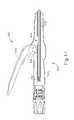
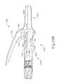
- FIG. 1depicts a side elevation view of an exemplary circular stapling surgical instrument
- FIG. 2Adepicts an enlarged longitudinal cross-section view of an exemplary stapling head assembly of the instrument of FIG. 1 showing an exemplary anvil in an open position;
- FIG. 2Bdepicts an enlarged longitudinal cross-sectional view of the stapling head assembly of FIG. 2A showing the anvil in a closed position;
- FIG. 4Bdepicts an enlarged side elevation view of the actuator handle assembly of FIG. 4A , showing the trigger in a fired position and the lockout feature in an unlocked position;
- FIG. 5depicts an enlarged partial perspective view of an exemplary indicator assembly of the surgical instrument of FIG. 1 showing an indicator window and indicator lever;
- FIG. 6depicts an diagrammatic view of the indicator window of FIG. 5 showing an exemplary indicator bar and exemplary corresponding staple representations;
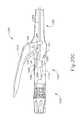
- FIG. 7depicts a partial side cross-sectional view of a surgical instrument having an exemplary trocar with an anvil presence rod
- FIG. 8depicts an enlarged partial cross-sectional view of an exemplary anvil detection assembly having a resiliently biased tab, an exemplary staple driver, a trocar, and an anvil;
- FIG. 9Adepicts a partial cross-sectional view on an alternative anvil detection assembly having a pair of spring clips, shown in an extended position
- FIG. 9Bdepicts a partial cross-sectional view on the anvil detection assembly of FIG. 9A showing the trocar and spring clips in the retracted position without an anvil attached;
- FIG. 9Cdepicts a partial cross-sectional view on the anvil detection assembly shown in the retracted position with the anvil attached;
- FIG. 10Adepicts an enlarged partial longitudinal cross-sectional view of an anvil detection assembly having a pair of resiliently biased locking features with magnetic portions;
- FIG. 10Bdepicts an enlarged partial longitudinal cross-sectional view of the anvil detection assembly of FIG. 10A showing a complementary anvil coupled to the trocar and aligned with the magnetic portions;
- FIG. 11depicts a side cross-sectional view of an exemplary surgical instrument having an exemplary anvil detection assembly with an anvil sensing tube;
- FIG. 12depicts an enlarged partial perspective view of the distal end of the anvil detection assembly of FIG. 11 ;
- FIG. 13depicts an enlarged partial perspective view of another exemplary anvil detection assembly having an exemplary alternative anvil presence tube with a cup;
- FIG. 14depicts an enlarged partial cross-sectional view of yet another exemplary anvil detection assembly showing an exemplary alternative anvil with a split collet shaft and a pair of tabs;
- FIG. 15depicts an enlarged partial cross-sectional view of a further exemplary anvil detection assembly showing a trocar with spring-loaded pins;
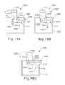
- FIG. 16Adepicts a rear cross-sectional view of an exemplary surgical instrument showing an exemplary lockout button assembly with a button shown in a first position;
- FIG. 16Bdepicts a rear cross-sectional view of the surgical instrument of FIG. 16A showing the button cammed to a second position;
- FIG. 16Cdepicts a rear cross-sectional view of the surgical instrument of FIG. 16A showing the button actuated to a third position;
- FIG. 17depicts a side elevation view of the surgical instrument of FIG. 16A with a portion of the body removed;
- FIG. 18Adepicts a rear cross-sectional view of an exemplary surgical instrument with an alternative exemplary lockout button assembly, with a button shown in a first position;
- FIG. 18Bdepicts a rear cross-sectional view of the surgical instrument of FIG. 18A showing the button cammed to a second position;
- FIG. 18Cdepicts a rear cross-sectional view of the surgical instrument of FIG. 18A showing the button rotated to a third position;
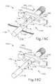
- FIG. 19Adepicts a partial perspective view of yet another exemplary lockout button assembly with a button shown in a first position and an anvil pin inserted therethrough;
- FIG. 19Bdepicts a partial perspective view of the lockout button assembly of FIG. 19A showing the anvil pin removed;
- FIG. 19Cdepicts a partial perspective view of the lockout button assembly of FIG. 19A showing button actuated to a second position;
- FIG. 19Ddepicts a partial perspective view of the lockout button assembly of FIG. 19A showing the button rotated to a third position;
- FIG. 19Edepicts a partial perspective view of the lockout button assembly of FIG. 19A showing the button actuated to a fourth position;
- FIG. 19Fdepicts a partial perspective view of the lockout button assembly of FIG. 19A showing firing bar actuated relative to the button in the fourth position;
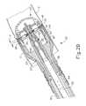
- FIG. 20Adepicts a side cross-sectional view of an exemplary surgical instrument having an alternative lockout button assembly shown in a first position
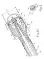
- FIG. 20Bdepicts the alternative lockout button assembly of FIG. 20A shown in a second position
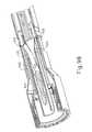
- FIG. 20Cdepicts the alternative lockout button assembly of FIG. 20A showing a proximal end feature pivoting a pivot member
- FIG. 21Adepicts a schematic view of an exemplary interlock safety assembly shown in a locked position
- FIG. 21Bdepicts a schematic view of the interlock safety assembly of FIG. 21A shown in an unlocked position
- FIG. 22depicts an enlarged partial perspective view of the interlock safety assembly of FIG. 21A showing an exemplary anvil rod in the locked position
- FIG. 23depicts an enlarged partial perspective view of the interlock safety assembly of FIG. 21A showing an exemplary safety lever in the locked position.
- FIGS. 1-6depict an exemplary circular surgical stapling instrument ( 10 ) having a stapling head assembly ( 20 ), a shaft assembly ( 60 ), and an actuator handle assembly ( 70 ), each of which will be described in more detail below.
- Shaft assembly ( 60 )extends distally from actuator handle assembly ( 70 ) and stapling head assembly ( 20 ) is coupled to a distal end of shaft assembly ( 60 ).
- actuator handle assembly ( 70 )is operable to actuate a staple driver ( 24 ) of stapling head assembly ( 20 ) to drive a plurality of staples ( 66 ) out of stapling head assembly ( 20 ).
- instrument ( 10 )comprises a closure system and a firing system.
- the closure systemcomprises a trocar ( 38 ), a trocar actuator ( 39 ), and a rotating knob ( 98 ).
- An anvil ( 40 )may be coupled to a distal end of trocar ( 38 ).
- Rotating knob ( 98 )is operable to longitudinally translate trocar ( 38 ) relative to stapling head assembly ( 20 ), thereby translating anvil ( 40 ) when anvil ( 40 ) is coupled to trocar ( 38 ), to clamp tissue between anvil ( 40 ) and stapling head assembly ( 20 ).
- the firing systemcomprises a trigger ( 74 ), a trigger actuation assembly ( 84 ), a driver actuator ( 64 ), and a staple driver ( 24 ).
- Staple driver ( 24 )includes a knife ( 36 ) configured to sever tissue when staple driver ( 24 ) is actuated longitudinally.
- staples ( 66 )are positioned distal to a plurality of staple driving members ( 30 ) of staple driver ( 24 ) such that staple driver ( 24 ) also drives staples ( 66 ) distally when staple driver ( 24 ) is actuated longitudinally.
- anvil ( 40 )is selectively coupleable to instrument ( 10 ) to provide a surface against which staples ( 66 ) may be bent to staple material contained between stapling head assembly ( 20 ) and anvil ( 40 ).
- Anvil ( 40 ) of the present exampleis selectively coupleable to a trocar or pointed rod ( 38 ) that extends distally relative to stapling head assembly ( 20 ).
- anvil ( 40 )is selectively coupleable via the coupling of a proximal shaft ( 42 ) of anvil ( 40 ) to a distal tip of trocar ( 38 ).
- Anvil ( 40 )comprises a generally circular anvil head ( 48 ) and a proximal shaft ( 42 ) extending proximally from anvil head ( 48 ).
- proximal shaft ( 42 )comprises a tubular member ( 44 ) having resiliently biased retaining clips ( 46 ) to selectively couple anvil ( 40 ) to trocar ( 38 ), though this is merely optional, and it should be understood that other retention features for coupling anvil ( 40 ) to trocar ( 38 ) may be used as well.
- C-clips, clamps, threading, pins, adhesives, etc.may be employed to couple anvil ( 40 ) to trocar ( 38 ).
- anvil ( 40 )may be inserted and secured to a portion of tissue ( 2 ) prior to being coupled to stapling head assembly ( 20 ).
- anvil ( 40 )may be inserted into and secured to a first tubular portion of tissue ( 2 ) while instrument ( 10 ) is inserted into and secured to a second tubular portion of tissue ( 2 ).
- the first tubular portion of tissue ( 2 )may be sutured to or about a portion of anvil ( 40 ), and the second tubular portion of tissue ( 2 ) may be sutured to or about trocar ( 38 ).
- Trocar ( 38 ) of the present exampleis shown in a distal most actuated position. Such an extended position for trocar ( 38 ) may provide a larger area to which tissue ( 2 ) may be coupled prior to attachment of anvil ( 40 ). In addition, the extended position of trocar ( 38 ) may also provide for easier attachment of anvil ( 40 ) to trocar ( 38 ).
- Trocar ( 38 )further includes a tapered distal tip. Such a tip may be capable of piercing through tissue and/or aiding the insertion of anvil ( 40 ) on to trocar ( 38 ), though the tapered distal tip is merely optional.
- Trocar ( 38 ) of the present exampleis translatable longitudinally relative to stapling head assembly ( 20 ) via an adjusting knob ( 98 ) located at a proximal end of actuator handle assembly ( 70 ), as will be described in greater detail below. Accordingly, when anvil ( 40 ) is coupled to trocar ( 38 ), rotation of adjusting knob ( 98 ) enlarges or reduces gap distance d by actuating anvil ( 40 ) relative to stapling head assembly ( 20 ).
- anvil ( 40 )is shown actuating proximally relative to actuator handle assembly ( 70 ) from an initial, open position to a closed position, thereby reducing the gap distance d and the distance between the two portions of tissue ( 2 ) to be joined.
- stapling head assembly ( 20 )may be fired, as shown in FIG. 2C , to staple and sever tissue ( 2 ) between anvil ( 40 ) and stapling head assembly ( 20 ).
- Stapling head assembly ( 20 )is operable to staple and sever tissue ( 2 ) by a user pivoting a trigger ( 74 ) of actuator handle assembly ( 70 ), as will be described in greater detail below.
- gap distance dcorresponds to the distance between anvil ( 40 ) and stapling head assembly ( 20 ).
- this gap distance dmay not be easily viewable.
- a moveable indicator bar ( 110 )shown in FIGS. 5-6 , is provided to be visible through an indicator window ( 120 ) positioned opposite to trigger ( 74 ).
- Indicator bar ( 110 )is operable to move in response to rotation of adjusting knob ( 98 ) such that the position of indicator bar ( 110 ) is representative of the gap distance d. As shown in FIG.
- Anvil ( 40 )may be further constructed in accordance with at least some of the teachings of U.S. Pat. No. 5,205,459; U.S. Pat. No. 5,271,544; U.S. Pat. No. 5,275,322; U.S. Pat. No. 5,285,945; U.S. Pat. No. 5,292,053; U.S. Pat. No. 5,333,773; U.S. Pat. No. 5,350,104; U.S. Pat. No. 5,533,661, the disclosures of which are incorporated by reference herein; and/or in accordance with other configurations as will be apparent to one of ordinary skill in the art in view of the teachings herein.
- Stapling head assembly ( 20 ) of the present exampleis coupled to a distal end of shaft assembly ( 60 ) and comprises a tubular casing ( 22 ) housing a slidable staple driver ( 24 ) and a plurality of staples ( 66 ) contained within staple pockets ( 32 ). Staples ( 66 ) and staple pockets ( 32 ) are disposed in a circular array about tubular casing ( 22 ). In the present example, staples ( 66 ) and staple pockets ( 32 ) are disposed in a pair of concentric annular rows of staples ( 66 ) and staple pockets ( 32 ).
- Staple driver ( 24 )is operable to actuate longitudinally within tubular casing ( 22 ) in response to rotation of trigger ( 74 ) of actuator handle assembly ( 70 ).
- staple driver ( 24 )comprises a flared cylindrical member having a trocar opening ( 26 ), a central recess ( 28 ), and a plurality of members ( 30 ) disposed circumferentially about central recess ( 28 ) and extending distally relative to shaft assembly ( 60 ).
- Each member ( 30 )is configured to contact and engage a corresponding staple ( 66 ) of the plurality of staples ( 66 ) within staple pockets ( 32 ).
- each member ( 30 )drives a corresponding staple ( 66 ) out of its staple pocket ( 32 ) through a staple aperture ( 34 ) formed in a distal end of tubular casing ( 22 ). Because each member ( 30 ) extends from staple driver ( 24 ), the plurality of staples ( 66 ) are driven out of stapling head assembly ( 20 ) at substantially the same time.
- FIG. 3depicts one merely exemplary staple ( 66 ) driven by a member ( 30 ) into a staple forming pocket ( 32 ) of anvil ( 40 ) to bend legs ( 68 ).
- Staple driver ( 24 )further includes a cylindrical knife ( 36 ) that is coaxial to trocar opening ( 26 ) and inset from staple pockets ( 32 ).
- cylindrical knife ( 36 )is disposed within central recess ( 28 ) to translate distally with staple driver ( 24 ).
- anvil head ( 48 )provides a surface against which cylindrical knife ( 36 ) cuts the material contained between anvil ( 40 ) and stapling head assembly ( 20 ).
- anvil head ( 48 )may include a recess (not shown) for cylindrical knife ( 36 ) to aid in cutting the material (e.g., by providing a cooperative shearing edge).
- anvil head ( 48 )may include one or more opposing cylindrical knives (not shown) offset from cylindrical knife ( 36 ) such that a scissor-type cutting action may be provided. Still other configurations will be apparent to one of ordinary skill in the art in view of the teachings herein. Stapling head assembly ( 20 ) is thus operable to both staple and cut tissue ( 2 ) substantially simultaneously in response to actuation by actuator handle assembly ( 70 ).
- stapling head assembly ( 20 )may be further constructed in accordance with at least some of the teachings of U.S. Pat. No. 5,205,459; U.S. Pat. No. 5,271,544; U.S. Pat. No. 5,275,322; U.S. Pat. No. 5,285,945; U.S. Pat. No. 5,292,053; U.S. Pat. No. 5,333,773; U.S. Pat. No. 5,350,104; U.S. Pat. No. 5,533,661, the disclosures of which are incorporated by reference herein; and/or in accordance with other configurations as will be apparent to one of ordinary skill in the art in view of the teachings herein.
- staple driver ( 24 )includes a trocar opening ( 26 ).
- Trocar opening ( 26 )is configured to permit trocar ( 38 ) to longitudinally slide relative to stapling head assembly ( 20 ) and/or shaft assembly ( 60 ).
- trocar ( 38 )is coupled to a trocar actuator ( 39 ) such that trocar ( 38 ) can be actuated longitudinally via rotation of rotating knob ( 98 ), as will be described in greater detail below in reference to actuator handle assembly ( 70 ).
- trocar actuator ( 39 )comprises an elongated, relatively stiff shaft coupled to trocar ( 38 ), though this is merely optional.
- actuator ( 39 )may comprise a longitudinally stiff material while permitting lateral bending such that portions of instrument ( 10 ) may be selectively bent or curved during use; or instrument ( 10 ) may include a preset bent shaft assembly ( 60 ).
- One merely exemplary materialis nitinol.
- Stapling head assembly ( 20 ) and trocar ( 38 )are positioned at a distal end of shaft assembly ( 60 ), as shown in FIGS. 2A-2C .
- Shaft assembly ( 60 ) of the present examplecomprises an outer tubular member ( 62 ) and a driver actuator ( 64 ).
- Outer tubular member ( 62 )is coupled to tubular casing ( 22 ) of stapling head assembly ( 20 ) and to a body ( 72 ) of actuator handle assembly ( 70 ), thereby providing a mechanical ground for the actuating components therein.
- the proximal end of driver actuator ( 64 )is coupled to a trigger actuation assembly ( 84 ) of actuator handle assembly ( 70 ), described below.
- driver actuator ( 64 )is coupled to staple driver ( 24 ) such that the rotation of trigger ( 74 ) longitudinally actuates staple driver ( 24 ).
- driver actuator ( 64 )comprises a tubular member having an open longitudinal axis such that actuator ( 39 ) coupled to trocar ( 38 ) may actuate longitudinally within and relative to driver actuator ( 64 ).
- driver actuator ( 64 )may be disposed within driver actuator ( 64 ) as will be apparent to one of ordinary skill in the art in view of the teachings herein.
- Shaft assembly ( 60 )may be further constructed in accordance with at least some of the teachings of U.S. Pat. No. 5,205,459; U.S. Pat. No. 5,271,544; U.S. Pat. No. 5,275,322; U.S. Pat. No. 5,285,945; U.S. Pat. No. 5,292,053; U.S. Pat. No. 5,333,773; U.S. Pat. No. 5,350,104; U.S. Pat. No. 5,533,661, the disclosures of which are incorporated by reference herein; and/or in accordance with other configurations as will be apparent to one of ordinary skill in the art in view of the teachings herein.
- actuator handle assembly ( 70 )comprises a body ( 72 ), a trigger ( 74 ), a lockout feature ( 82 ), a trigger actuation assembly ( 84 ), and a trocar actuation assembly ( 90 ).
- Trigger ( 74 ) of the present exampleis pivotably mounted to body ( 72 ) and is coupled to trigger actuation assembly ( 84 ) such that rotation of trigger ( 74 ) from an unfired position (shown in FIG. 4A ) to a fired position (shown in FIG. 4B ) actuates driver actuator ( 64 ) described above.
- a spring ( 78 )is coupled to body ( 72 ) and trigger ( 74 ) to bias trigger ( 74 ) towards the unfired position.
- Lockout feature ( 82 )is a pivotable member that is coupled to body ( 72 ). In a first, locked position, lockout feature ( 82 ) is pivoted upwards and away from body ( 72 ) such that lockout feature ( 82 ) engages trigger ( 74 ) and mechanically resists actuation of trigger ( 74 ) by a user. In a second, unlocked position, such as that shown in FIGS. 1 and 4B , lockout feature ( 82 ) is pivoted downward such that trigger ( 74 ) may be actuated by the user. Accordingly, with lockout feature ( 82 ) in the second position, trigger ( 74 ) can engage a trigger actuation assembly ( 84 ) to fire instrument ( 10 ).
- trigger actuation assembly ( 84 ) of the present examplecomprises a slidable trigger carriage ( 86 ) engaged with a proximal end of driver actuator ( 64 ).
- Carriage ( 86 )includes a set of tabs ( 88 ) on a proximal end of carriage ( 86 ) to retain and engage a pair of trigger arms ( 76 ) extending from trigger ( 74 ). Accordingly, when trigger ( 74 ) is pivoted, carriage ( 86 ) is actuated longitudinally and transfers the longitudinal motion to driver actuator ( 64 ).
- carriage ( 86 )is fixedly coupled to the proximal end of driver actuator ( 64 ), though this is merely optional. Indeed, in one merely exemplary alternative, carriage ( 86 ) may simply abut driver actuator ( 64 ) while a distal spring (not shown) biases driver actuator ( 64 ) proximally relative to actuator handle assembly ( 70 ).
- Trigger actuation assembly( 84 ) may be further constructed in accordance with at least some of the teachings of U.S. Pat. No. 5,205,459; U.S. Pat. No. 5,271,544; U.S. Pat. No. 5,275,322; U.S. Pat. No. 5,285,945; U.S. Pat. No. 5,292,053; U.S. Pat. No. 5,333,773; U.S. Pat. No. 5,350,104; U.S. Pat. No. 5,533,661, the disclosures of which are incorporated by reference herein; and/or in accordance with other configurations as will be apparent to one of ordinary skill in the art in view of the teachings herein.
- Body ( 72 )also houses a trocar actuation assembly ( 90 ) configured to actuate trocar ( 38 ) longitudinally in response to rotation of adjusting knob ( 98 ).
- trocar actuation assembly ( 90 ) of the present examplecomprises adjusting knob ( 98 ), a grooved shank ( 94 ), and a sleeve ( 92 ).
- Grooved shank ( 94 ) of the present exampleis located at a distal end of trocar actuator ( 39 ), though it should be understood that grooved shank ( 94 ) and trocar actuator ( 39 ) may alternatively be separate components that engage to transmit longitudinal movement.
- Adjusting knob ( 98 )is rotatably supported by the proximal end of body ( 72 ) and is operable to rotate sleeve ( 92 ) that is engaged with grooved shank ( 94 ) via an internal tab (not shown).
- Grooved shank ( 94 ) of the present examplecomprises a continuous groove ( 96 ) formed in the outer surface of grooved shank ( 94 ). Accordingly, when adjusting knob ( 98 ) is rotated, the internal tab rides within groove ( 96 ) and grooved shank ( 94 ) is longitudinally actuated relative to sleeve ( 92 ).
- trocar actuator ( 39 )Since grooved shank ( 94 ) is located at the distal end of trocar actuator ( 39 ), rotating adjusting knob ( 98 ) in a first direction advances trocar actuator ( 39 ) distally relative to actuator handle assembly ( 70 ). Accordingly, the gap distance d between anvil ( 40 ) and stapling head assembly ( 20 ) is increased.
- trocar actuator ( 39 )By rotating adjusting knob ( 98 ) in the opposite direction, trocar actuator ( 39 ) is actuated proximally relative to actuator handle assembly ( 70 ) to reduce the gap distance d between anvil ( 40 ) and stapling head assembly ( 20 ).
- trocar actuation assembly ( 90 )is operable to actuate trocar ( 38 ) in response to rotating adjustment knob ( 98 ).
- other configurations for trocar actuation assembly ( 90 )will be apparent to one of ordinary skill in the art in view of the teachings herein.
- Groove ( 96 ) of the present examplecomprises a plurality of different portions ( 96 A, 96 B, 96 C) that have a varying pitch or number of grooves per axial distance.
- the present groove ( 96 )is divided into a distal portion ( 96 A), a middle portion ( 96 B) and a proximal portion ( 96 C).
- distal portion ( 96 A)comprises a fine pitch or a high number of grooves over a short axial distance of grooved shank ( 94 ) such that a large number of rotations of adjusting knob ( 98 ) are required to traverse the short axial distance.
- Middle portion ( 96 B)comprises a section with comparably coarser pitch or fewer grooves per axial distance such that relatively few rotations are required to traverse a long axial distance. Accordingly, the gap distance d may be quickly reduced through relatively few rotations of adjusting knob ( 98 ).
- Proximal portion ( 96 C) of the present exampleis substantially similar to distal portion ( 96 A) and comprises a fine pitch or a high number of grooves over a short axial distance of grooved shank ( 94 ) such that a large number of rotations are required to traverse the short axial distance.
- Proximal portion ( 96 C) of the present exampleis positioned within sleeve ( 92 ) when anvil ( 40 ) is substantially near to stapling head assembly ( 20 ) such that indicator bar ( 110 ) moves within indicator window ( 120 ) along scale ( 130 ) to indicate that the anvil gap is within a desired operating range, as will be described in more detail below. Accordingly, when the tab is within proximal portion ( 96 C) of groove ( 96 ), each rotation of adjusting knob ( 98 ) may reduce the gap distance d by a small amount to provide for fine tuning.
- Trocar actuation assembly ( 90 )may be further constructed in accordance with at least some of the teachings of U.S. Pat. No. 5,205,459; U.S. Pat. No. 5,271,544; U.S. Pat. No. 5,275,322; U.S. Pat. No. 5,285,945; U.S. Pat. No. 5,292,053; U.S. Pat. No. 5,333,773; U.S. Pat. No. 5,350,104; U.S. Pat. No. 5,533,661, the disclosures of which are incorporated by reference herein; and/or in accordance with other configurations as will be apparent to one of ordinary skill in the art in view of the teachings herein.
- a U-shaped clip ( 100 )is attached to an intermediate portion of trocar actuator ( 39 ) located distally of grooved shank ( 94 ).
- U-shaped clip ( 100 )engages with a portion of body ( 72 ) to substantially prevent trocar actuator ( 39 ) from rotating about its axis when adjusting knob ( 98 ) is rotated.
- U-shaped clip ( 100 )further includes an elongated slot ( 102 ) on each of its opposite sides for receiving an attachment member, such as a screw, bolt, pin, clip, etc., to selectively adjust the longitudinal position of elongated slot ( 102 ) of U-shaped clip ( 100 ) relative to trocar actuator ( 39 ) for purposes of calibrating indicator bar ( 110 ) relative to scale ( 130 ).
- an attachment membersuch as a screw, bolt, pin, clip, etc.
- actuator handle assembly ( 70 )further includes an indicator bracket ( 140 ) configured to engage and pivot an indicator ( 104 ).
- Indicator bracket ( 140 ) of the present exampleis slidable relative to body ( 72 ) along a pair of slots formed on body ( 72 ).
- Indicator bracket ( 140 )comprises a rectangular plate ( 144 ), an indicator arm ( 146 ), and an angled flange ( 142 ).
- Angled flange ( 142 )is formed at the proximal end of rectangular plate ( 144 ) and includes an aperture (not shown) to slidable mount onto trocar actuator ( 39 ) and/or grooved shank ( 94 ).
- a coil spring ( 150 )is interposed between flange ( 142 ) and a boss ( 152 ) to bias flange ( 142 ) against U-shaped clip ( 100 ). Accordingly, when U-shaped clip ( 100 ) actuates distally with trocar actuator ( 39 ) and/or grooved shank ( 94 ), coil spring ( 150 ) urges indicator bracket ( 140 ) to travel distally with U-shaped clip ( 100 ). In addition, U-shaped clip ( 100 ) urges indicator bracket ( 140 ) proximally relative to boss ( 152 ) when trocar actuator ( 39 ) and/or grooved shank ( 94 ) translate proximally, thereby compressing coil spring ( 150 ). Of course, it should be understood that in some versions indicator bracket ( 140 ) may be fixedly attached to trocar actuator ( 39 ) and/or grooved shank ( 94 ).
- a portion of lockout feature ( 82 )abuts a surface ( 141 ) of indicator bracket ( 140 ) when indicator bracket ( 140 ) is in a longitudinal position that does not correspond to when the anvil gap is within a desired operating range (e.g., a green colored region or “green zone”).
- a desired operating rangee.g., a green colored region or “green zone”.
- indicator bracket ( 140 )narrows to provide a pair of gaps ( 145 ) on either side of an indicator arm ( 146 ) that permits lockout feature ( 82 ) to pivot, thereby releasing trigger ( 74 ).
- lockout feature ( 82 ) and indicator bracket ( 140 )can substantially prevent a user from releasing and operating trigger ( 74 ) until anvil ( 40 ) is in a predetermined operating range.
- lockout feature ( 82 )may be omitted entirely in some versions.
- This operating rangemay be visually communicated to the user via an indicator bar ( 110 ) of an indicator ( 104 ) shown against a scale ( 130 ), described briefly above.
- indicator bracket ( 140 )At the distal end of indicator bracket ( 140 ) is a distally projecting indicator arm ( 146 ) which terminates at a laterally projecting finger ( 148 ) for controlling the movement of indicator ( 104 ).
- Indicator arm ( 146 ) and finger ( 148 ), best shown in FIG. 5are configured to engage a tab ( 106 ) of indicator ( 104 ) such that indicator ( 104 ) is pivoted when indicator bracket ( 140 ) is actuated longitudinally.
- indicator ( 104 )is pivotably coupled to body ( 72 ) at a first end of indicator ( 104 ), though this is merely optional and other pivot points for indicator ( 104 ) will be apparent to one of ordinary skill in the art in view of the teachings herein.
- An indicator bar ( 110 )is positioned on the second end of indicator ( 104 ) such that indicator bar ( 110 ) moves in response to the actuation of indicator bracket ( 140 ). Accordingly, as discussed above, indicator bar ( 110 ) is displayed through an indicator window ( 120 ) against a scale ( 130 ) (shown in FIG. 6 ) to show the relative gap distance d between anvil ( 40 ) and stapling head assembly ( 20 ).
- indicator bracket ( 140 ), indicator ( 104 ), and/or actuator handle assembly ( 70 )may be further constructed in accordance with at least some of the teachings of U.S. Pat. No. 5,205,459; U.S. Pat. No. 5,271,544; U.S. Pat. No. 5,275,322; U.S. Pat. No. 5,285,945; U.S. Pat. No. 5,292,053; U.S. Pat. No. 5,333,773; U.S. Pat. No. 5,350,104; U.S. Pat. No. 5,533,661, the disclosures of which are incorporated by reference herein; and/or in accordance with other configurations as will be apparent to one of ordinary skill in the art in view of the teachings herein.
- anvil ( 40 )it may be desirable for a user to detect when anvil ( 40 ) is sufficiently coupled to trocar ( 38 ). Such detection can confirm that anvil ( 40 ) is properly coupled to trocar ( 38 ) such that anvil ( 40 ) does not move distally relative to staple driver ( 24 ) when instrument ( 10 ) is fired.
- the indicator for such detectionmay be provided through a sensory indicator assembly (e.g., visual, auditory, tactile, etc.) and/or through a trigger lock-out assembly to prevent trigger ( 74 ) from being actuatable by the user.
- a usermay be able to determine whether anvil ( 40 ) is properly attached, or fully seated on trocar ( 38 ), prior to firing instrument ( 10 ) or, in some instances, instrument ( 10 ) will prevent the user from firing until anvil ( 40 ) is properly attached. Accordingly, various anvil detection assemblies, indicator assemblies, and trigger lockout assemblies will now be described below.
- FIG. 7depicts a surgical instrument ( 200 ) that includes an exemplary anvil presence rod ( 230 ) incorporated into an exemplary trocar ( 220 ).
- surgical instrument ( 200 )comprises a body ( 202 ), a trigger ( 204 ), a lockout feature ( 210 ), an adjusting knob ( 216 ), a trocar ( 220 ), and an anvil presence rod ( 230 ).
- Body ( 202 ), trigger ( 204 ), lockout feature ( 210 ), adjusting knob ( 216 ), and trocar ( 220 )may be constructed in substantial accordance with body ( 72 ), trigger ( 74 ), lockout feature ( 82 ), adjusting knob ( 98 ) and trocar ( 38 ) described above.
- Surgical instrument ( 200 )may be further constructed substantially in accordance with surgical instrument ( 10 ) described above, or in accordance with at least some of the teachings of U.S. Pat. No. 5,205,459; U.S. Pat. No. 5,271,544; U.S. Pat. No. 5,275,322; U.S. Pat. No. 5,285,945; U.S. Pat. No. 5,292,053; U.S. Pat. No. 5,333,773; U.S. Pat. No. 5,350,104; and/or U.S. Pat. No. 5,533,661, the disclosures of which are incorporated by reference herein.
- trocar ( 220 )includes a central rod tube ( 222 ) configured to slidably receive anvil presence rod ( 230 ) therein.
- Anvil presence rod ( 230 )comprises a longitudinally stiff rod member that is slidable within rod tube ( 222 ) of trocar ( 220 ) and extends into an aperture ( 218 ) formed through adjusting knob ( 216 ). As shown in FIG. 7 , anvil presence rod ( 230 ) is positioned in an unactuated position. Anvil presence rod ( 230 ) is slid proximally relative to trocar ( 220 ) when an anvil, such as anvil ( 40 ) shown in FIGS.
- anvil presence rod ( 230 )is inserted onto trocar ( 220 ), thereby moving anvil presence rod ( 230 ) proximally to an actuated position.
- This proximal movement of anvil presence rod ( 230 )can be used to mechanically interact or release components of instrument ( 200 ) to indicate when the anvil is properly seated on trocar ( 220 ).
- anvil presence rod ( 230 )includes a proximal end ( 232 ) that extends out through an aperture ( 218 ) formed in adjusting knob ( 216 ) when anvil presence rod ( 230 ) is slid proximally relative to trocar ( 220 ).
- This proximal end ( 232 )may include one or more regions and/or markings ( 234 ) to visually indicate the position of anvil presence rod ( 230 ).
- markings ( 234 )may include a plurality of colors (e.g., red, yellow, green) and/or symbols (e.g., numbers, letters, etc.) to indicate the longitudinal position of anvil presence rod ( 230 ).
- markings ( 234 )comprise three regions ( 234 A, 234 B, 234 C) corresponding to the colors red ( 234 A), yellow ( 234 B), and green ( 234 C).
- the usermay use markings ( 234 ) to detect whether anvil presence rod ( 230 ) has been sufficiently actuated to indicate that the anvil is properly seated on trocar ( 220 ).
- the green marking portion ( 234 C)may correspond to when the anvil has sufficiently coupled to trocar ( 220 ) such that the anvil will not detach when firing instrument ( 200 ).
- the yellow marking portion ( 234 B) of the present examplemay be provided to indicate to the user that anvil presence rod ( 230 ) has been actuated proximally relative to trocar ( 220 ), but the anvil has not fully seated on trocar ( 220 ).
- only a single marking, such as green portion ( 234 C)may be provided to indicate the position corresponding to when the anvil has sufficiently coupled to trocar ( 220 ).
- markings ( 234 ) and/or the extension of proximal end ( 232 ) out of aperture ( 218 ) of adjusting knob ( 216 )are merely optional.
- anvil presence rod ( 230 ) of the present exampleis biased distally by a coil spring ( 240 ) that is disposed within a portion of trocar ( 220 ). Accordingly, when no object is actuating anvil presence rod ( 230 ) proximally relative to trocar ( 220 ), coil spring ( 240 ) urges the distal end of anvil presence rod ( 230 ) out of the distal end of rod tube ( 222 ). If a user attempts to couple the anvil to trocar ( 220 ) and the anvil is not properly seated on trocar ( 220 ), the distal bias provided by coil spring ( 240 ) ejects the anvil away from trocar ( 220 ).
- anvil presence rod ( 230 )may physically and visually provide an indication to the user that the anvil is not properly seated on trocar ( 220 ).
- coil spring ( 240 )is coupled to a portion of anvil presence rod ( 230 ) such as by abutting a tab, being fixedly coupled at one end, and/or otherwise.
- proximal end ( 232 ) of anvil presence rod ( 230 )may not extend through aperture ( 218 ) of adjusting knob ( 216 ), but instead abuts coil spring ( 240 ) to provide the distal bias.
- a distal tab or flared portion ( 236 ), shown in FIG. 7prevents anvil presence rod ( 230 ) from ejecting distally out of trocar ( 220 ) from the distal bias provided by coil spring ( 240 ), though this is also merely optional.
- lockout feature ( 210 )comprises a pivotable member having a leg ( 212 ) that abuts a protrusion ( 238 ) of anvil presence rod ( 230 ) when anvil presence rod ( 230 ) is in the unactuated position shown in FIG. 7 .
- Protrusion ( 238 )extends outwardly through a slot ( 224 ) formed in trocar ( 220 ) such that protrusion ( 238 ) is longitudinally slidable along slot ( 224 ) when anvil presence rod ( 230 ) is actuated proximally relative to trocar ( 220 ).
- the longitudinal length of protrusion ( 238 ) of the present examplecorresponds to the longitudinal distance traveled by anvil presence rod ( 230 ) to indicate that the anvil is properly coupled to trocar ( 220 ). Accordingly, when the anvil is properly coupled, protrusion ( 238 ) no longer abuts leg ( 212 ) of lockout feature ( 210 ).
- lockout feature ( 210 )The user then pivots lockout feature ( 210 ) to unlock and permit operation of trigger ( 204 ) to fire instrument ( 200 ).
- the combination of protrusion ( 238 ) and lockout feature ( 210 )may substantially prevent the user from firing instrument ( 10 ) when the anvil is not properly coupled to trocar ( 220 ).
- leg ( 212 )may be integrally formed with or otherwise linked to trigger ( 204 ).
- lockout feature ( 210 )may be omitted.
- other assemblies to prevent lockout feature ( 210 ) from pivoting prior to actuation of anvil presence rod ( 230 ) to the actuated positionwill be apparent to one of ordinary skill in the art in view of the teachings herein.
- FIG. 8depicts an alternative anvil detection assembly ( 300 ) that may be incorporated into a surgical instrument, such as surgical instruments ( 10 , 200 ) described above.
- anvil detection assembly ( 300 )comprises a hinged tab ( 310 ) extending outwardly from a trocar ( 302 ).
- Trocar ( 302 )may be constructed in accordance with at least some of the teachings of trocars ( 38 , 220 ) described above.
- a spring ( 312 )biases tab ( 310 ) outwardly from trocar ( 302 ), though this is merely optional.
- spring ( 312 )may be omitted and tab ( 310 ) may be integrally formed with trocar ( 302 ) such that tab ( 310 ) is a resiliently biased tab.
- tab ( 310 )is illustrated, it should be understood that a plurality of tabs ( 310 ) may be positioned about trocar ( 302 ).
- tab ( 310 )When tab ( 310 ) is extended away from trocar ( 302 ), tab ( 310 ) of the present example mechanically interferes with a staple driver ( 308 ) to substantially prevent staple driver ( 308 ) from actuating distally relative to trocar ( 302 ). Accordingly, a user may be prevented from firing staple driver ( 308 ) via operation of a trigger, such as trigger ( 74 ) described above, until tab ( 310 ) is depressed against or into trocar ( 302 ).
- a triggersuch as trigger ( 74 ) described above
- an anvil ( 340 )comprises an anvil head ( 342 ) and a hollow shaft ( 344 ).
- Anvil ( 340 )may be further constructed in accordance with at least some of the teachings of anvil ( 40 ) described above.
- Hollow shaft ( 344 )comprises a cylindrical tube configured to slide over trocar ( 302 ) and selectively couple anvil ( 340 ) to trocar ( 302 ).
- hollow shaft ( 344 )includes detents ( 346 ) that engage indentations ( 304 ) of trocar ( 302 ) to selectively secure anvil ( 340 ) to trocar ( 302 ).
- hollow shaft ( 344 )When hollow shaft ( 344 ) is slid over trocar ( 302 ), hollow shaft ( 344 ) compresses tab ( 310 ) against trocar ( 302 ), thereby permitting staple driver ( 308 ) to actuate distally relative to trocar ( 302 ) and/or anvil ( 340 ) when the user operates the instrument.
- the length of hollow shaft ( 344 )is such that hollow shaft ( 344 ) only engages tab ( 310 ) when anvil ( 340 ) is fully seated on trocar ( 302 ).
- the present assemblymay thus prevent a user from firing the device unless anvil ( 340 ) is properly coupled to trocar ( 302 ).
- anvil ( 340 )is properly coupled to trocar ( 302 ).
- tab ( 310 )may be mechanically associated with a lockout feature in the actuator handle assembly.
- tab ( 310 )may comprise a camming surface that is operable to actuate a rod, such as anvil presence rod ( 230 ) described above, when tab ( 310 ) is compressed against trocar ( 302 ).
- the rod of this examplemay include a protrusion, such as protrusion ( 238 ), that selectively interferes with the release of a lockout feature depending upon the longitudinal position of the rod.
- the rodmay include a proximal end, such as proximal end ( 232 ), that protrudes out of the proximal end of the surgical instrument to provide visual feedback to the user.
- proximal endsuch as proximal end ( 232 )
- tab ( 310 )may be mechanically associated with other lockout features and/or visual indicators as will be apparent to one of ordinary skill in the art in view of the teachings herein.
- tab ( 310 )may be positioned such that trocar ( 302 ) cannot be actuated proximally relative to staple driver ( 308 ) from an extended position via the adjusting knob. For instance, tab ( 310 ) may be positioned to abut staple driver ( 308 ) while trocar ( 302 ) is in the extended position.
- tab ( 310 )resists the proximal actuation and provides tactile feedback that tab ( 310 ) has not been depressed by attachment of shaft ( 344 ) of anvil ( 340 ). If trocar ( 302 ) is not actuatable proximally due to the interference of tab ( 310 ), then, in an instrument such as instrument ( 10 ), a user may not pivot lockout feature ( 82 ) to release trigger ( 74 ) due to the position of indicator bracket ( 140 ), as discussed above. Thus, when tab ( 310 ) is extended, a user may be substantially prevented from firing the instrument.
- tab ( 310 )is extended, a user may be substantially prevented from firing the instrument.
- FIGS. 9A-9Cdepict an alternative anvil detection assembly ( 400 ) comprising a trocar ( 410 ) having a pair of spring clips ( 420 ).
- spring clips ( 420 )are contained within a slot ( 412 ) formed in trocar ( 410 ).
- spring clips ( 420 )are biased outwardly from trocar ( 410 ) such that proximal ends ( 422 ) extend laterally from trocar ( 410 ).
- spring clips ( 420 )are coupled to trocar ( 410 ) at a pivot point ( 424 ) and a spring (not shown) is interposed between spring clips ( 420 ) to bias each away from the other.
- spring clips ( 420 )may comprise resiliently biased members that are biased away from pivot point ( 424 ).
- trocar ( 410 )when spring clips ( 420 ) are extended laterally, trocar ( 410 ) is prevent from actuating proximally due to proximal ends ( 422 ) engaging a trocar opening ( 416 ).
- an anvil ( 440 )shown in FIG. 9C ) is not coupled to trocar ( 410 )
- trocar ( 410 )is prevented from actuating proximally relative to a staple driver ( 430 ).
- the usermust squeeze spring clips ( 420 ) together to permit retraction.
- anvil ( 440 )is not coupled to trocar ( 410 ), then spring clips ( 420 ) provide a lockout mechanism to prevent the instrument from firing.
- an anvil shaft ( 442 )cams spring clips ( 420 ) inwardly such that proximal ends ( 422 ) do not engage notches ( 432 ). Accordingly, staple driver ( 430 ) can be actuated distally relative to trocar ( 410 ) to fire the instrument. Still further configurations for anvil detection assembly ( 400 ) and/or spring clips ( 420 ) will be apparent to one of ordinary skill in the art in view of the teachings herein.
- FIGS. 10A-10Bdepict an alternative anvil detection assembly ( 500 ) that may be incorporated into a surgical instrument, such as surgical instrument ( 10 ) described above.
- a trocar ( 510 ) and a staple driver ( 520 )extend distally from an actuator handle assembly (not shown).
- Trocar ( 510 ) and staple driver ( 520 )may be constructed in accordance with at least some of the teachings of trocar ( 38 ) and staple driver ( 24 ) described herein.
- a pair of resilient members ( 530 )also extend distally from the actuator handle assembly and are biased outwardly away from trocar ( 510 ).
- resilient members ( 530 )are coupled to a portion of the actuator handle assembly to mechanically ground resilient members ( 530 ).
- resilient members ( 530 )may be integrally formed with the body of actuator handle assembly or mechanically coupled via an attachment member, such as a screw, bolt, adhesive, etc.
- the proximal ends of resilient members ( 530 )may be coupled to trocar ( 510 ).
- the proximal ends of resilient members ( 530 )may be coupled to staple driver ( 520 ).
- Still further configurations to couple resilient members ( 530 ) at their proximal endswill be apparent to one of ordinary skill in the art in view of the teachings herein.
- Resilient members ( 530 )each comprise an elongated member having a lockout arm ( 532 ) and a magnet ( 534 ).
- Magnet ( 534 )may be a ferrous magnet, a neodymium magnet, a samarium-cobalt magnet, or any other suitable magnet ( 534 ) as will be apparent to one of ordinary skill in the art in view of the teachings herein.
- Each lockout arm ( 532 )extends outward from the longitudinal axis of a corresponding resilient member ( 530 ).
- each lockout arm ( 532 )is perpendicular to the longitudinal axis of the corresponding resilient member ( 530 ) such that each lockout arm ( 532 ) is configured to mechanically interfere with the distal actuation of staple driver ( 520 ) relative to resilient member ( 530 ) and/or trocar ( 510 ). Accordingly, when resilient arms ( 530 ) are in a locked position, such as that shown in FIG. 10A , staple driver ( 520 ) is substantially prevented from actuating distally by lockout arms ( 532 ). While only a pair of resilient members ( 530 ) are shown, it should be understood that any number of resilient members ( 530 ) may be used to restrict distal actuation of staple driver ( 520 ). For example, 1, 2, 3, 4, 5, or 6 resilient members ( 530 ) may be disposed about trocar ( 510 ) and configured to interfere with the distal actuation of staple driver ( 520 ).
- FIG. 10Bdepicts a complementary anvil ( 540 ) for anvil detection assembly ( 500 ).
- Anvil ( 540 )comprises an anvil head ( 542 ) and a shaft ( 544 ).
- Anvil ( 540 )may be further constructed in accordance with at least some of the teachings of anvil ( 40 ) described herein.
- Shaft ( 544 ) of the present exampleis configured to selectively couple anvil ( 540 ) to trocar ( 510 ).
- shaft ( 544 )may comprise detents ( 546 ) configured to engage with indentations ( 512 ) (shown in FIG. 10A ) of trocar ( 510 ) to selectively couple anvil ( 540 ) to trocar ( 510 ).
- Shaft ( 544 )further comprises a magnetic portion ( 548 ) positioned along the longitudinal length of shaft ( 544 ).
- Magnetic portion ( 548 )may comprise a single annular magnet embedded in shaft ( 544 ) or a plurality of magnets disposed within shaft ( 544 ).
- magnetic portion ( 548 )may not be embedded within shaft ( 544 ) but may be coupled to the exterior or interior surface of shaft ( 544 ).
- magnetic portion ( 548 )may comprise one or more ferrous magnets, neodymium magnets, samarium-cobalt magnets, and/or any other suitable magnet as will be apparent to one of ordinary skill in the art in view of the teachings herein.
- magnetic portion ( 548 )is longitudinally positioned to align with magnets ( 534 ) of resilient arms ( 530 ) only when anvil ( 540 ) is fully seated on trocar ( 510 ).
- resilient arms ( 530 )may omit magnets ( 534 ) and may instead be constructed of a ferrous material such that magnetic portion ( 548 ) attracts resilient arms ( 530 ) inwardly.
- the spring constant for resilient arms ( 530 )may be set such that lockout arms ( 532 ) no longer impede distal movement of staple driver ( 520 ) only when anvil ( 540 ) is fully seated on trocar ( 510 ).
- lockout arms ( 532 )no longer impede distal movement of staple driver ( 520 ) only when anvil ( 540 ) is fully seated on trocar ( 510 ).
- resilient arms ( 530 )begin to bend inwardly due to magnetic portion ( 548 ) magnetically attracting the material.
- resilient arms ( 530 )may comprise magnets ( 534 ) while magnetic portion ( 548 ) of shaft ( 544 ) is omitted.
- a pair of arms ( 616 )may be provided, such as trigger arms ( 76 ) described above.
- arm ( 616 )may be a separate feature that distinct from trigger arms ( 76 ).
- Instrument ( 600 ), trocar ( 602 ), and/or actuator handle assembly ( 610 )may be further constructed in accordance with at least some of the teachings for instrument ( 10 ), trocar ( 38 ), and/or actuator handle assembly ( 70 ) described above.
- Anvil sensing tube ( 622 ) of the present examplecomprises a tubular member coaxially disposed about trocar ( 602 ), though it should be understood that this is merely optional.
- anvil sensing tube ( 622 )may comprise a longitudinal bar extending along a side of trocar ( 602 ) or anvil sensing tube ( 622 ) may include a U-shaped member partially encircling a portion of trocar ( 602 ). Still further configurations for anvil sensing tube ( 622 ) will be apparent to one of ordinary skill in the art in view of the teachings herein.
- FIG. 11includes a notch ( 624 ) formed in a proximal portion of anvil sensing tube ( 622 ). Accordingly, when anvil sensing tube ( 622 ) is in an unactuated position, such as that shown in FIG. 11 , notch ( 624 ) is not aligned with arm ( 616 ). Instead, arm ( 616 ) abuts a portion of anvil sensing tube ( 622 ) such that trigger ( 614 ) cannot be pivoted relative to body ( 612 ).
- notch ( 624 )is aligned with arm ( 616 ) such that trigger ( 614 ) is pivotable relative to body ( 612 ).
- a spring ( 627 )is coupled to a proximal end of anvil sensing tube ( 622 ) to bias anvil sensing tube ( 622 ) distally relative to actuator handle assembly ( 610 ).
- the longitudinal position of notch ( 624 )is located such that arm ( 616 ) aligns with notch ( 624 ) only when an anvil ( 630 ) is fully seated on trocar ( 602 ) and trocar ( 602 ) is actuated proximally into the “green zone” described above.
- the “green zone”indicates that the anvil gap, or the distance between the anvil head (not shown) and staple driver ( 604 ), is within a desired operating range. If anvil ( 630 ) is not fully seated on trocar ( 602 ), then spring ( 627 ) ejects anvil ( 630 ) off of trocar ( 602 ), as will be discussed in more detail below.
- annular shelf ( 640 )engages mating surface ( 628 ) when trocar ( 602 ) is actuated proximally via the rotating knob.
- annular shelf ( 640 )engages mating surface ( 628 ) when trocar ( 602 ) is actuated proximally via the rotating knob.
- notch ( 624 )does not align with arm ( 616 ) until trocar ( 602 ) and anvil ( 630 ) are actuated proximally into the “green zone” described above.
- trigger ( 614 )is “locked” until anvil ( 630 ) is both fully seated and positioned in the “green zone.”
- notch ( 624 )may align with arm ( 616 ) of trigger ( 614 ) when anvil ( 630 ) is initially fully seated on trocar ( 602 ).
- the usermay partially pivot trigger ( 614 ) to determine that anvil ( 630 ) is fully seated on trocar ( 602 ) prior to actuating trocar ( 602 ) and anvil ( 630 ) proximally via the rotating knob. Accordingly, the user may be provided with a form of tactile feedback indicating anvil ( 630 ) is fully seated on trocar ( 602 ).
- anvil sensing tube ( 622 ) and/or annular shelf ( 640 )will be apparent to one of ordinary skill in the art in view of the teachings herein.
- FIG. 14depicts an alternative anvil ( 800 ) that may be used to engage anvil sensing tubes ( 622 , 722 ).
- Anvil ( 800 )comprises an anvil head (not shown), a shaft ( 802 ), and a pair of pegs ( 810 ) extending outwardly from shaft ( 802 ).
- Shaft ( 802 ) of the present examplecomprises a split collet configured to fit over and selectively couple to a flared portion ( 822 ) of a trocar ( 820 ).
- shaft ( 802 )may comprise a magnetic member ( 804 ) to be magnetically guided towards trocar ( 820 ).
- trocar ( 820 ) and/or flared portion ( 822 )may comprise a magnetic member ( 824 ) to guide shaft ( 802 ) onto trocar ( 820 ).
- Pegs ( 810 )are configured to engage mating surfaces ( 628 , 728 ) in a substantially similar manner to annular shelf ( 640 ).
- anvil ( 800 ) and trocar ( 820 )can be actuated proximally via an adjusting knob such that anvil sensing tube ( 622 , 722 ) engages and/or disengages a locking feature, such as arm ( 616 ) and notch ( 624 ) described above.
- mating surfaces ( 628 , 728 )may include a recessed portion (not shown) such that pegs ( 810 ) snap into the recessed portion to selectively secure anvil ( 800 ) to anvil sensing tubes ( 622 , 722 ).
- FIG. 15depicts an alternative trocar ( 850 ) having spring-loaded pins ( 852 ) biased outwardly against an anvil sensing tube ( 860 ).
- Anvil sensing tube ( 860 ) of the present examplemay be constructed in accordance with at least some of the teachings for anvil sensing tubes ( 622 , 722 ) described above.
- Anvil ( 870 ) of the present exampleincludes a shaft ( 872 ) that has a pair of openings ( 874 ) into which pins ( 852 ) spring into when shaft ( 872 ) is pushed onto trocar ( 850 ).
- the foregoing assembliesmay be preferable for the foregoing assemblies to engage one or more lockout features to release trigger ( 74 ) to fire instrument ( 10 ).
- the anvil detection featuresmay pop out a lockout button that must be depressed or operated by the user to release trigger ( 74 ), thereby preventing instrument ( 10 ) from being fired until anvil ( 40 ) is properly coupled to trocar ( 38 ) and the lockout button is operated by the user.
- FIGS. 16A-17depict an exemplary surgical instrument ( 900 ) having an exemplary lockout button assembly ( 950 ).
- lockout button assembly ( 950 )comprises an anvil sensing shaft ( 960 ) extending longitudinally into actuator handle assembly ( 930 ) to engage a button ( 970 ).
- Anvil sensing shaft ( 960 )includes a proximal end ( 962 ) having an obliquely angled camming surface ( 964 ) configured to engage button ( 970 ).
- Anvil sensing shaft ( 960 )may be further constructed in accordance with the teachings for anvil sensing tube ( 622 ) described herein, though it should be understood that any of the foregoing anvil detecting assemblies may be used in addition or in the alternative to anvil sensing shaft ( 960 ).
- Actuator handle assembly ( 930 ) of the present exampleincludes a body ( 938 ) having a first lateral hole ( 940 ) (shown in phantom in FIG. 17 ), a second lateral hole ( 942 ), a first channel ( 944 ) (shown in phantom in FIG. 17 ), a second channel ( 946 ), and a vertical slot ( 948 ).
- Button ( 970 )comprises an inner member ( 972 ), an intermediate member ( 974 ), an intermediate axle ( 976 ), and an outer member ( 978 ).
- first lateral hole ( 940 )is sized to permit intermediate member ( 974 ) of button ( 970 ) to pass therethrough.
- Second lateral hole ( 942 )is sized to permit outer member ( 978 ) to pass therethrough, but is sized to not permit intermediate member ( 974 ) therethrough.
- First channel ( 944 )is configured to permit inner member ( 972 ) to actuate vertically along first channel ( 944 ).
- Second channel ( 946 )is configured to permit intermediate axle ( 976 ) to actuate vertically along second channel ( 946 ).
- vertical slot ( 948 )is configured to permit intermediate member ( 974 ) to actuate vertically therein.
- button ( 970 ) and/or body ( 938 )will be apparent to one of ordinary skill in the art in view of the teachings herein.
- button ( 970 )is initially positioned such that inner member ( 972 ) mechanically interferes with the actuation of trigger ( 932 ).
- button ( 970 )is positioned such that a protrusion ( 934 ) extending from trigger ( 932 ) abuts inner member ( 972 ) to prevent a user from pivoting trigger ( 932 ).
- intermediate member ( 974 )is within first lateral hole ( 940 ) and outer member ( 978 ) is within second lateral hole ( 942 ), thereby forming a substantially flush outer surface of body ( 938 ).
- anvil sensing shaft ( 960 )When anvil sensing shaft ( 960 ) is actuated proximally via attachment of an anvil, such as anvil ( 40 ), camming surface ( 964 ) engages inner member ( 972 ) to cam button ( 970 ) outwardly, as shown in FIG. 16B .
- button ( 970 )When button ( 970 ) is cammed outwardly, outer member ( 978 ) extends outward from second lateral hole ( 942 ), intermediate axle ( 976 ) substantially aligns with second channel ( 946 ), intermediate member ( 974 ) enters into vertical slot ( 948 ), and inner member ( 972 ) substantially aligns with first channel ( 944 ). As shown in FIG.
- outer member ( 978 )provides visual indication (via protruding out of body ( 938 )) that anvil sensing shaft ( 960 ) has been actuated proximally relative to actuator handle assembly ( 930 ) and that the anvil is fully seated on the trocar. In this position, inner member ( 972 ) still mechanically interferes with the actuation of trigger ( 932 ).
- button ( 970 )is actuated outwardly to the position shown in FIG. 16B by anvil sensing shaft ( 960 ) when the anvil is initially coupled to the trocar. Once the anvil is coupled, the user can reduce the anvil gap via an adjusting knob, such as adjusting knob ( 98 ) described above.
- buttons ( 970 )can actuate button ( 970 ) downwardly via sliding outer member ( 978 ) along the outer surface of body ( 938 ).
- intermediate axle ( 976 )slides within second channel ( 946 )
- intermediate member ( 974 )slides within vertical slot ( 948 )
- inner member ( 972 )slides along first channel ( 944 ).
- inner member ( 972 )is actuated to a position such that protrusion ( 934 ) of trigger ( 932 ) is no longer impeded by inner member ( 972 ).
- the usermay then fire instrument ( 900 ).
- button ( 970 )is cammed via anvil sensing shaft ( 960 ) when the anvil and trocar are actuated proximally via the adjusting knob.
- a lockout featuresuch as lockout feature ( 82 ) described above, may be provided to lockout trigger ( 932 ) unless the anvil and trocar are within the “green zone,” thereby providing a secondary lockout assembly.
- inner member ( 972 )may be configured such that when button ( 970 ) is cammed outwardly via anvil sensing shaft ( 960 ), inner member ( 972 ) no longer interferes with protrusion ( 934 ) of trigger ( 932 ).
- channels ( 944 , 946 ), vertical slot ( 948 ), intermediate member ( 974 ) and/or intermediate axle ( 976 )may be omitted.
- a spring(not shown) may be interposed between intermediate member ( 974 ) and/or inner member ( 972 ) and a portion of body ( 938 ) to bias button ( 970 ) inwardly such that button ( 970 ) is not actuated outwardly unless anvil sensing shaft ( 960 ) cams button ( 970 ) against the spring bias.
- the usermay then fire instrument ( 900 ).
- instrument ( 900 ) and/or lockout button assembly ( 950 )will be apparent to one of ordinary skill in the art in view of the teachings herein.
- FIGS. 18A-18Cdepict an exemplary surgical instrument ( 1000 ) having an exemplary lockout button assembly ( 1050 ).
- lockout button assembly ( 1050 )comprises an anvil sensing shaft ( 1060 ) extending longitudinally into actuator handle assembly ( 1030 ) to engage a button ( 1070 ).
- Anvil sensing shaft ( 1060 )includes a proximal end ( 1062 ) having an obliquely angled camming surface ( 1064 ) configured to engage button ( 1070 ).
- Anvil sensing shaft ( 1060 )may be further constructed in accordance with the teachings for anvil sensing tube ( 622 ) described herein, though it should be understood that any of the foregoing anvil detecting assemblies may be used in addition or in the alternative to anvil sensing shaft ( 1060 ).
- Actuator handle assembly ( 1030 ) of the present exampleincludes a body ( 1038 ) having a hole ( 1040 ).
- Button ( 1070 )comprises an inner member ( 1072 ), a paddle feature ( 1074 ) on inner member ( 1072 ), and an outer member ( 1076 ).
- hole ( 1040 )is sized to permit outer member ( 1076 ) of button ( 1070 ) to pass therethrough.
- button ( 1070 ) and/or body ( 1038 )will be apparent to one of ordinary skill in the art in view of the teachings herein.
- button ( 1070 )is initially positioned such that paddle feature ( 1074 ) mechanically interferes with the actuation of a trigger ( 1032 ).
- a protrusion ( 1034 ) extending from trigger ( 1032 )abuts paddle feature ( 1074 ) to prevent a user from pivoting trigger ( 1032 ), though other features may be provided to prevent the user from pivoting trigger ( 1032 ).
- outer member ( 1076 )is within hole ( 1040 ) of body ( 1038 ), such that outer member ( 1076 ) is substantially flush with the outer surface of body ( 1038 ).
- anvil sensing shaft ( 1060 )When anvil sensing shaft ( 1060 ) is actuated proximally via attachment of an anvil, such as anvil ( 40 ), camming surface ( 1064 ) engages inner member ( 1072 ) to cam button ( 1070 ) outwardly to a second position, as shown in FIG. 18B .
- button ( 1070 )When button ( 1070 ) is cammed outwardly, outer member ( 1076 ) extends outward from hole ( 1040 ).
- Outer member ( 1076 )thus provides a visual indication (by protruding out of body ( 1038 )) that anvil sensing shaft ( 1060 ) has been actuated proximally relative to actuator handle assembly ( 1030 ) and that the anvil is fully seated on the trocar.
- FIGS. 19A-19Fdepict yet another exemplary surgical instrument ( 1100 ) having an exemplary lockout button assembly ( 1150 ).
- lockout button assembly ( 1150 )comprises an anvil sensing pin ( 1160 ) coupled to an anvil sensing rod (not shown) that extends longitudinally into an actuator handle assembly to engage a button ( 1170 ).
- button ( 1170 )comprises an inner portion ( 1172 ), an intermediate portion ( 1176 ) and an outer portion ( 1178 ).
- a spring ( 1180 )is associated with inner portion ( 1172 ) and biases button ( 1170 ) laterally relative to a body ( 1138 ) (a cut away portion of which is shown in FIGS.
- outer portion ( 1178 ) of button ( 1170 )is initially positioned within an opening ( 1139 ) in body ( 1138 ) and is substantially flush with the exterior of body ( 1138 ) in the first position.
- Inner portion ( 1172 ) of button ( 1170 )includes a hole ( 1174 ) that is configured to receive anvil sensing pin ( 1160 ).
- hole ( 1174 )may be formed in intermediate portion ( 1176 ) and/or outer portion ( 1178 ) or, in some versions, omitted entirely.
- Intermediate portion ( 1176 ) of the present examplecomprises a rectangular member defined by a first dimension d 1 and a second dimension d 2 such that d 2 is less than d 1 .
- Intermediate portion ( 1176 )will be described in more detail below.
- Inner portion ( 1172 ) and outer portion ( 1178 )are depicted as cylindrical members having diameters that are substantially equal to first dimension d 1 , though this is merely optional and inner portion ( 1172 ) and/or outer portion ( 1178 ) may have other shapes and/or configurations as will be apparent to one of ordinary skill in the art in view of the teachings herein.
- Surgical instrument ( 1100 )also includes a firing rod ( 1140 ) having a stepped aperture ( 1142 ) formed therethrough and configured to receive button ( 1170 ).
- Firing rod ( 1140 )is coupled to a trigger (not shown) and is operable to actuate a staple driver (not shown) of instrument ( 1100 ).
- stepped aperture ( 1142 )comprises a first portion ( 1144 ) and a second portion ( 1146 ) with a step ( 1148 ).
- First portion ( 1144 )is sized to be substantially equal to first dimension d 1 such that intermediate portion ( 1176 ) of button ( 1170 ) can actuate laterally through first portion ( 1144 ).
- Second portion ( 1146 )is located proximally of first portion ( 1144 ) and is reduced in size by step ( 1148 ). Second portion ( 1146 ) is sized to be substantially equal to second dimension d 2 of intermediate portion ( 1176 ) such that firing rod ( 1140 ) can actuate longitudinally relative to intermediate portion ( 1176 ) when button ( 1170 ) is rotated to a third position, shown in FIGS. 19D-19F and described in greater detail below.
- anvil sensing pin ( 1160 )is retracted distally relative to button ( 1170 ) to disengage from hole ( 1174 ), as shown in FIG. 19B .
- Spring ( 1180 )urges button ( 1170 ) laterally relative to body ( 1138 ) (shown in FIG. 19A ), such that outer portion ( 1178 ) protrudes through opening ( 1139 ) to a second position shown in FIG. 19C .
- inner portion ( 1172 )is positioned within first portion ( 1144 ) of stepped aperture ( 1142 ) such that firing rod ( 1140 ) cannot be actuated longitudinally relative to button ( 1170 ).
- spring ( 1180 )may be omitted and button ( 1170 ) may be manually actuated to the second position.
- button ( 1170 )into body ( 1138 ) such that intermediate portion ( 1176 ) is aligned within stepped aperture ( 1142 ), as shown in FIG. 19E .
- firing rod ( 1140 )may then be actuated longitudinally relative to button ( 1170 ) since step ( 1148 ) and intermediate portion ( 1176 ) no longer abut and engage each other. Accordingly, the user may then fire instrument ( 1100 ).
- other configurations and or assemblieswill be apparent to one of ordinary skill in the art in view of the teachings herein.
- FIG. 20A-20Cdepicts an exemplary alternative surgical instrument ( 1200 ) having exemplary lockout button assembly ( 1250 ).
- surgical instrument ( 1200 ) of the present examplecomprises a stapling head assembly (not shown), a shaft assembly ( 1220 ), and an actuator handle assembly ( 1230 ).
- Shaft assembly ( 1220 )extends distally from actuator handle assembly ( 1230 ) and the stapling head assembly is coupled to a distal end of shaft assembly ( 1220 ).
- actuator handle assembly ( 1230 )includes a trigger ( 1232 ) that is operable to actuate a staple driver (not shown) of the stapling head assembly to drive a plurality of staples (not shown) out of the stapling head assembly.
- the staplesare bent to form completed staples by an anvil (not shown), such as anvil ( 40 ), that is attached to a trocar that extends out from the distal end of instrument ( 1200 ). Accordingly, tissue may be stapled utilizing instrument ( 1200 ).
- the stapling head assembly, shaft assembly ( 1220 ), and actuator handle assembly ( 1230 )may be further constructed in accordance with stapling head assembly ( 20 ), shaft assembly ( 60 ), and actuator handle assembly ( 70 ) described above.
- lockout button assembly ( 1250 ) of the present examplecomprises an anvil sensing shaft ( 1260 ), a palm button ( 1270 ), and a pivot member ( 1280 ).
- FIG. 20Adepicts anvil sensing shaft ( 1260 ), palm button ( 1270 ), and pivot member ( 1280 ) in an initial, locked position. In this position, pivot member ( 1280 ) is configured to mechanically interfere with pivoting of a lockout feature ( 1234 ) such that trigger ( 1232 ) cannot be actuated.
- pivot member ( 1280 )mechanically interferes with lockout feature ( 1234 ) via an arm ( 1286 ) that extends outwardly from a distal end ( 1284 ) of pivot member ( 1280 ).
- proximal end feature ( 1262 )may be located distally of both palm button ( 1270 ) and pivot member ( 1280 ) such that a space is formed between palm button ( 1270 ) and pivot member ( 1280 ). Accordingly, even if a user attempts to actuate of palm button ( 1280 ) inwardly toward pivot member ( 1280 ) in this initial, locked position, palm button ( 1270 ) does not engage pivot member ( 1280 ). Thus, pivot member ( 1280 ) and arm ( 1286 ) remain in a position to mechanically interfere with lockout feature ( 1234 ).
- pivot member ( 1280 )may include a spring (not shown) to bias arm ( 1282 ) towards interfering with lockout feature ( 1234 ).
- proximal end feature ( 1262 )includes a camming surface ( 1264 ), a button surface ( 1266 ), and a lever arm ( 1268 ).
- camming surface ( 1264 )is operable to engage and cam palm button ( 1270 ) outwardly when anvil sensing shaft ( 1260 ) is actuated proximally relative to actuator handle assembly ( 1230 ), such as by attachment of an anvil and adjustment of the anvil and trocar into the “green zone.” Palm button ( 1270 ) may thus provide a visual indicator that the anvil is properly attached and the device is within the operating range.
- palm button ( 1270 )is cammed outwardly, at least part of palm button ( 1270 ) is adjacent to button surface ( 1266 ) such that palm button ( 1270 ) may engage button surface ( 1266 ) when palm button ( 1270 ) is pushed inwardly.
- lever arm ( 1268 ) of proximal end feature ( 1262 )is aligned with a proximal end ( 1282 ) of pivot member ( 1280 ).
- Anvil sensing shaft ( 1260 )may be further constructed in accordance with the teachings for anvil sensing tube ( 622 ) described herein, though it should be understood that any of the foregoing anvil detecting assemblies may be used in addition or in the alternative to anvil sensing shaft ( 1260 ).
- proximal end feature ( 1262 )omits camming surface ( 1264 ) and palm button ( 1270 ) does not cam outwardly relative to the exterior of instrument ( 1200 ).
- FIGS. 21A-23depict yet another exemplary lockout button assembly ( 1300 ) comprising a spring-loaded push rod ( 1310 ), a spring-loaded pin ( 1320 ), and a pivotable lockout feature ( 1340 ).
- FIG. 21Adepicts spring-loaded push rod ( 1310 ), spring-loaded pin ( 1320 ), and pivotable lockout feature ( 1340 ) shown in an initial or locked position and contained within a body ( 1350 ) of an exemplary surgical instrument, such as instrument ( 10 ) described above.
- body ( 1350 )includes a pin hole ( 1352 ) sized to permit an outer portion ( 1338 ) of pin ( 1320 ) to extend therethrough.
- pin hole ( 1352 )may be sized to permit outer portion ( 1338 ) to extend therethrough, but comprises a smaller diameter than an intermediate portion ( 1332 ), thereby only permitting outer portion ( 1338 ) to protrude through.
- pin hole ( 1352 )is merely optional and may be omitted in some versions.
- Body ( 1350 )may be further constructed in accordance with at least some of the teachings for body ( 72 ) described above.
- push rod ( 1310 )comprises an elongated rod extending longitudinally within a surgical instrument.
- a spring ( 1312 )engages a proximal end of push rod ( 1310 ) to provide a distal bias.
- push rod ( 1310 )may be configured to be actuated proximally when an anvil, such as anvil ( 40 ) is coupled to a trocar, such as trocar ( 38 ), and both the anvil and trocar are actuated into the operating range or “green zone” described above.
- push rod ( 1310 )includes a lateral hole ( 1314 ) and a longitudinal slot ( 1316 ) formed through push rod ( 1310 ).
- lateral hole ( 1314 )is sized to permit an intermediate portion ( 1332 ) of pin ( 1320 ) to pass through lateral hole ( 1314 ).
- Longitudinal slot ( 1316 )is sized to permit an intermediate axle ( 1334 ) of pin ( 1320 ) to slide along longitudinal slot ( 1316 ). As shown in FIG.
- pin ( 1320 ) and push rod ( 1310 )are shown in the initial or locked position with push rod ( 1310 ) actuated distally via spring ( 1312 ), thereby laterally restraining pin ( 1320 ) with axle ( 1334 ) within slot ( 1316 ).
- push rod ( 1310 )may be constructed in accordance with the teachings for anvil sensing tube ( 622 ) described herein, though it should be understood that any of the foregoing anvil detecting assemblies may be incorporated into the present lockout button assembly ( 1300 ). Still other configurations for push rod ( 1310 ) will be apparent to one of ordinary skill in the art in view of the teachings herein.
- inner portion ( 1324 ), intermediate portion ( 1332 ), and outer portion ( 1338 )all comprise different sizes and/or shapes. Accordingly, the lateral actuation of pin ( 1320 ) may be controlled by having varying sizes and/or shapes for inner portion ( 1324 ), intermediate portion ( 1332 ), and outer portion ( 1338 ).
- Inner axle ( 1328 )couples inner portion ( 1324 ) to intermediate portion ( 1332 ) and is substantially smaller than either inner portion ( 1324 ) and/or intermediate portion ( 1332 ).
- axle ( 1328 )is configured to permit lockout feature ( 1340 ) to be pivoted while axle ( 1328 ) rides within an arcuate slot ( 1349 ), described in greater detail below.
- axle ( 1334 )couples intermediate portion ( 1332 ) to outer portion ( 1338 ) and is substantially smaller than either intermediate portion ( 1332 ) and/or outer portion ( 1338 ).
- axle ( 1334 )is configured to permit push rod ( 1310 ) to be actuated proximally relative to axle ( 1334 ) while axle ( 1334 ) rides within longitudinal slot ( 1316 ), described above.
- Lockout feature ( 1340 ) of the present examplecomprises an arm ( 1342 ), a pivot member ( 1344 ), and a main body ( 1346 ).
- Arm ( 1342 )is configured to abut a trigger (not shown) in a substantially similar manner to lockout feature ( 82 ) described above.
- Pivot member ( 1344 )is configured to couple to a portion of body ( 1350 ), such as a recess, to permit lockout feature ( 1340 ) to be pivoted relative to body ( 1350 ).
- Main body ( 1346 )comprises a sector, or pie-shaped, component having a hole ( 1348 ) and an arcuate slot ( 1349 ).
- Hole ( 1348 )is sized to permit passage of intermediate portion ( 1332 ) of pin ( 1320 ) through hole ( 1348 ), but does not permit enlarged portion ( 1326 ) of inner portion ( 1324 ) to pass through.
- Arcuate slot ( 1349 )is configured to permit inner axle ( 1328 ) to be slidably received within arcuate slot ( 1349 ). Accordingly, when inner axle ( 1328 ) is within hole ( 1348 ), such as that shown in FIG. 21B , lockout feature ( 1340 ) may be pivoted such that arcuate slot ( 1349 ) slides about inner axle ( 1328 ).
- lockout feature ( 1340 )when lockout feature ( 1340 ) is pivoted, arm ( 1342 ) no longer impedes actuation of the trigger, thereby allowing the user to fire the instrument.
- lockout feature ( 1340 )When lockout feature ( 1340 ) is in the first or locked position shown in FIGS. 21A and 23 , lockout feature ( 1340 ) prevents the trigger from actuating and lockout feature ( 1340 ) is prevented from pivoting via the interference provided by the presence of intermediate portion ( 1332 ) of pin ( 1320 ) within hole ( 1348 ).
- lockout feature ( 1340 )will be apparent to one of ordinary skill in the art in view of the teachings herein.
- outer portion ( 1338 )is within pin hole ( 1352 ) and is flush with the exterior of body ( 1350 ).
- anvilsuch as anvil ( 40
- a trocarsuch as trocar ( 38 )
- anvilmay engage a distal end of push rod ( 1310 ) and begin to actuate push rod ( 1310 ) proximally against the bias provided by spring ( 1312 ).
- spring ( 1312 )may provide a sufficient distal force such that the anvil is ejected off of the trocar if the anvil is not fully seated.
- longitudinal slot ( 1316 )begins to slide proximally relative to intermediate axle ( 1334 ) to move lateral hole ( 1314 ) into closer alignment with intermediate portion ( 1332 ).
- Spring ( 1322 )urges pin laterally, thereby pushing intermediate portion ( 1332 ) into lateral hole ( 1314 ) and aligns inner axle ( 1328 ) with arcuate slot ( 1349 ) of lockout feature ( 1340 ), as shown in FIG. 21B .
- Enlarged portion ( 1326 )abuts lockout feature ( 1340 ) to prevent spring ( 1322 ) from ejecting pin ( 1320 ) too far or out of the device.
- the usermay pivot lockout feature ( 1340 ) about pivot member ( 1344 ), thereby releasing the trigger and permitting the user to fire the instrument.
- a rotational spring(not shown) may be coupled to lockout feature ( 1340 ) to automatically pivot lockout feature ( 1340 ), though this is merely optional.
- spring ( 1322 )also extends outer portion ( 1338 ) of pin ( 1320 ) out of pin hole ( 1352 ).
- outer portion ( 1338 ) through pin hole ( 1352 )can be used as a visual indicator by the user that the instrument is within the operating range such that lockout feature ( 1340 ) may be pivoted to release the trigger.
- outer portion ( 1338 ) and/or pin hole ( 1352 )may be omitted. Still further configurations for lockout button assembly ( 1300 ) will be apparent to one of ordinary skill in the art in view of the teachings herein.
- Embodiments of the present inventionhave application in conventional endoscopic and open surgical instrumentation as well as application in robotic-assisted surgery.
- those of ordinary skill in the artwill recognize that various teaching herein may be readily combined with various teachings of U.S. Pat. No. 6,783,524, entitled “Robotic Surgical Tool with Ultrasound Cauterizing and Cutting Instrument,” published Aug. 31, 2004, the disclosure of which is incorporated by reference herein.
- a new or used instrumentmay be obtained and if necessary cleaned.
- the instrumentmay then be sterilized.
- the instrumentis placed in a closed and sealed container, such as a plastic or TYVEK bag.
- the container and instrumentmay then be placed in a field of radiation that can penetrate the container, such as gamma radiation, x-rays, or high-energy electrons.
- the radiationmay kill bacteria on the instrument and in the container.
- the sterilized instrumentmay then be stored in the sterile container.
- the sealed containermay keep the instrument sterile until it is opened in a medical facility.
- a devicemay also be sterilized using any other technique known in the art, including but not limited to beta or gamma radiation, ethylene oxide, or steam.
- Embodiments of the devices disclosed hereincan be reconditioned for reuse after at least one use.
- Reconditioningmay include any combination of the steps of disassembly of the device, followed by cleaning or replacement of particular pieces, and subsequent reassembly.
- embodiments of the devices disclosed hereinmay be disassembled, and any number of the particular pieces or parts of the devices may be selectively replaced or removed in any combination.
- embodiments of the devicesmay be reassembled for subsequent use either at a reconditioning facility, or by a surgical team immediately prior to a surgical procedure.
- reconditioning of a devicemay utilize a variety of techniques for disassembly, cleaning/replacement, and reassembly. Use of such techniques, and the resulting reconditioned device, are all within the scope of the present application.
Landscapes
- Health & Medical Sciences (AREA)
- Life Sciences & Earth Sciences (AREA)
- Surgery (AREA)
- Heart & Thoracic Surgery (AREA)
- Engineering & Computer Science (AREA)
- Biomedical Technology (AREA)
- Nuclear Medicine, Radiotherapy & Molecular Imaging (AREA)
- Medical Informatics (AREA)
- Molecular Biology (AREA)
- Animal Behavior & Ethology (AREA)
- General Health & Medical Sciences (AREA)
- Public Health (AREA)
- Veterinary Medicine (AREA)
- Surgical Instruments (AREA)
Abstract
Description
Claims (20)
Priority Applications (1)
| Application Number | Priority Date | Filing Date | Title |
|---|---|---|---|
| US14/881,533US10226246B2 (en) | 2012-01-05 | 2015-10-13 | Tissue stapler anvil feature to prevent premature jaw opening |
Applications Claiming Priority (2)
| Application Number | Priority Date | Filing Date | Title |
|---|---|---|---|
| US13/344,061US9186148B2 (en) | 2012-01-05 | 2012-01-05 | Tissue stapler anvil feature to prevent premature jaw opening |
| US14/881,533US10226246B2 (en) | 2012-01-05 | 2015-10-13 | Tissue stapler anvil feature to prevent premature jaw opening |
Related Parent Applications (1)
| Application Number | Title | Priority Date | Filing Date |
|---|---|---|---|
| US13/344,061ContinuationUS9186148B2 (en) | 2012-01-05 | 2012-01-05 | Tissue stapler anvil feature to prevent premature jaw opening |
Publications (2)
| Publication Number | Publication Date |
|---|---|
| US20160030038A1 US20160030038A1 (en) | 2016-02-04 |
| US10226246B2true US10226246B2 (en) | 2019-03-12 |
Family
ID=47557496
Family Applications (2)
| Application Number | Title | Priority Date | Filing Date |
|---|---|---|---|
| US13/344,061Active2034-07-06US9186148B2 (en) | 2012-01-05 | 2012-01-05 | Tissue stapler anvil feature to prevent premature jaw opening |
| US14/881,533Active2033-03-19US10226246B2 (en) | 2012-01-05 | 2015-10-13 | Tissue stapler anvil feature to prevent premature jaw opening |
Family Applications Before (1)
| Application Number | Title | Priority Date | Filing Date |
|---|---|---|---|
| US13/344,061Active2034-07-06US9186148B2 (en) | 2012-01-05 | 2012-01-05 | Tissue stapler anvil feature to prevent premature jaw opening |
Country Status (8)
| Country | Link |
|---|---|
| US (2) | US9186148B2 (en) |
| EP (3) | EP2800526B1 (en) |
| JP (1) | JP6224002B2 (en) |
| CN (1) | CN104039244B (en) |
| BR (1) | BR112014016658B1 (en) |
| MX (1) | MX345532B (en) |
| RU (1) | RU2619382C2 (en) |
| WO (1) | WO2013103505A2 (en) |
Families Citing this family (599)
| Publication number | Priority date | Publication date | Assignee | Title |
|---|---|---|---|---|
| US9060770B2 (en) | 2003-05-20 | 2015-06-23 | Ethicon Endo-Surgery, Inc. | Robotically-driven surgical instrument with E-beam driver |
| US20070084897A1 (en) | 2003-05-20 | 2007-04-19 | Shelton Frederick E Iv | Articulating surgical stapling instrument incorporating a two-piece e-beam firing mechanism |
| US8215531B2 (en) | 2004-07-28 | 2012-07-10 | Ethicon Endo-Surgery, Inc. | Surgical stapling instrument having a medical substance dispenser |
| US11890012B2 (en) | 2004-07-28 | 2024-02-06 | Cilag Gmbh International | Staple cartridge comprising cartridge body and attached support |
| US9072535B2 (en) | 2011-05-27 | 2015-07-07 | Ethicon Endo-Surgery, Inc. | Surgical stapling instruments with rotatable staple deployment arrangements |
| US11998198B2 (en) | 2004-07-28 | 2024-06-04 | Cilag Gmbh International | Surgical stapling instrument incorporating a two-piece E-beam firing mechanism |
| US10159482B2 (en) | 2005-08-31 | 2018-12-25 | Ethicon Llc | Fastener cartridge assembly comprising a fixed anvil and different staple heights |
| US9237891B2 (en) | 2005-08-31 | 2016-01-19 | Ethicon Endo-Surgery, Inc. | Robotically-controlled surgical stapling devices that produce formed staples having different lengths |
| US11246590B2 (en) | 2005-08-31 | 2022-02-15 | Cilag Gmbh International | Staple cartridge including staple drivers having different unfired heights |
| US11484312B2 (en) | 2005-08-31 | 2022-11-01 | Cilag Gmbh International | Staple cartridge comprising a staple driver arrangement |
| US7934630B2 (en) | 2005-08-31 | 2011-05-03 | Ethicon Endo-Surgery, Inc. | Staple cartridges for forming staples having differing formed staple heights |
| US7669746B2 (en) | 2005-08-31 | 2010-03-02 | Ethicon Endo-Surgery, Inc. | Staple cartridges for forming staples having differing formed staple heights |
| US20070106317A1 (en) | 2005-11-09 | 2007-05-10 | Shelton Frederick E Iv | Hydraulically and electrically actuated articulation joints for surgical instruments |
| US7845537B2 (en) | 2006-01-31 | 2010-12-07 | Ethicon Endo-Surgery, Inc. | Surgical instrument having recording capabilities |
| US8708213B2 (en) | 2006-01-31 | 2014-04-29 | Ethicon Endo-Surgery, Inc. | Surgical instrument having a feedback system |
| US11224427B2 (en) | 2006-01-31 | 2022-01-18 | Cilag Gmbh International | Surgical stapling system including a console and retraction assembly |
| US20110024477A1 (en) | 2009-02-06 | 2011-02-03 | Hall Steven G | Driven Surgical Stapler Improvements |
| US7753904B2 (en) | 2006-01-31 | 2010-07-13 | Ethicon Endo-Surgery, Inc. | Endoscopic surgical instrument with a handle that can articulate with respect to the shaft |
| US8186555B2 (en) | 2006-01-31 | 2012-05-29 | Ethicon Endo-Surgery, Inc. | Motor-driven surgical cutting and fastening instrument with mechanical closure system |
| US20110295295A1 (en) | 2006-01-31 | 2011-12-01 | Ethicon Endo-Surgery, Inc. | Robotically-controlled surgical instrument having recording capabilities |
| US11793518B2 (en) | 2006-01-31 | 2023-10-24 | Cilag Gmbh International | Powered surgical instruments with firing system lockout arrangements |
| US20120292367A1 (en) | 2006-01-31 | 2012-11-22 | Ethicon Endo-Surgery, Inc. | Robotically-controlled end effector |
| US8820603B2 (en) | 2006-01-31 | 2014-09-02 | Ethicon Endo-Surgery, Inc. | Accessing data stored in a memory of a surgical instrument |
| US11278279B2 (en) | 2006-01-31 | 2022-03-22 | Cilag Gmbh International | Surgical instrument assembly |
| US8236010B2 (en) | 2006-03-23 | 2012-08-07 | Ethicon Endo-Surgery, Inc. | Surgical fastener and cutter with mimicking end effector |
| US8992422B2 (en) | 2006-03-23 | 2015-03-31 | Ethicon Endo-Surgery, Inc. | Robotically-controlled endoscopic accessory channel |
| US8322455B2 (en) | 2006-06-27 | 2012-12-04 | Ethicon Endo-Surgery, Inc. | Manually driven surgical cutting and fastening instrument |
| US7506791B2 (en) | 2006-09-29 | 2009-03-24 | Ethicon Endo-Surgery, Inc. | Surgical stapling instrument with mechanical mechanism for limiting maximum tissue compression |
| US10568652B2 (en) | 2006-09-29 | 2020-02-25 | Ethicon Llc | Surgical staples having attached drivers of different heights and stapling instruments for deploying the same |
| US11980366B2 (en) | 2006-10-03 | 2024-05-14 | Cilag Gmbh International | Surgical instrument |
| US8632535B2 (en) | 2007-01-10 | 2014-01-21 | Ethicon Endo-Surgery, Inc. | Interlock and surgical instrument including same |
| US8684253B2 (en) | 2007-01-10 | 2014-04-01 | Ethicon Endo-Surgery, Inc. | Surgical instrument with wireless communication between a control unit of a robotic system and remote sensor |
| US8652120B2 (en) | 2007-01-10 | 2014-02-18 | Ethicon Endo-Surgery, Inc. | Surgical instrument with wireless communication between control unit and sensor transponders |
| US11291441B2 (en) | 2007-01-10 | 2022-04-05 | Cilag Gmbh International | Surgical instrument with wireless communication between control unit and remote sensor |
| US11039836B2 (en) | 2007-01-11 | 2021-06-22 | Cilag Gmbh International | Staple cartridge for use with a surgical stapling instrument |
| US20080169333A1 (en) | 2007-01-11 | 2008-07-17 | Shelton Frederick E | Surgical stapler end effector with tapered distal end |
| US7673782B2 (en) | 2007-03-15 | 2010-03-09 | Ethicon Endo-Surgery, Inc. | Surgical stapling instrument having a releasable buttress material |
| US8893946B2 (en) | 2007-03-28 | 2014-11-25 | Ethicon Endo-Surgery, Inc. | Laparoscopic tissue thickness and clamp load measuring devices |
| US11564682B2 (en) | 2007-06-04 | 2023-01-31 | Cilag Gmbh International | Surgical stapler device |
| US8931682B2 (en) | 2007-06-04 | 2015-01-13 | Ethicon Endo-Surgery, Inc. | Robotically-controlled shaft based rotary drive systems for surgical instruments |
| US7753245B2 (en) | 2007-06-22 | 2010-07-13 | Ethicon Endo-Surgery, Inc. | Surgical stapling instruments |
| US11849941B2 (en) | 2007-06-29 | 2023-12-26 | Cilag Gmbh International | Staple cartridge having staple cavities extending at a transverse angle relative to a longitudinal cartridge axis |
| US8573465B2 (en) | 2008-02-14 | 2013-11-05 | Ethicon Endo-Surgery, Inc. | Robotically-controlled surgical end effector system with rotary actuated closure systems |
| JP5410110B2 (en) | 2008-02-14 | 2014-02-05 | エシコン・エンド−サージェリィ・インコーポレイテッド | Surgical cutting / fixing instrument with RF electrode |
| US11986183B2 (en) | 2008-02-14 | 2024-05-21 | Cilag Gmbh International | Surgical cutting and fastening instrument comprising a plurality of sensors to measure an electrical parameter |
| US8758391B2 (en) | 2008-02-14 | 2014-06-24 | Ethicon Endo-Surgery, Inc. | Interchangeable tools for surgical instruments |
| US9179912B2 (en) | 2008-02-14 | 2015-11-10 | Ethicon Endo-Surgery, Inc. | Robotically-controlled motorized surgical cutting and fastening instrument |
| US8636736B2 (en) | 2008-02-14 | 2014-01-28 | Ethicon Endo-Surgery, Inc. | Motorized surgical cutting and fastening instrument |
| US7866527B2 (en) | 2008-02-14 | 2011-01-11 | Ethicon Endo-Surgery, Inc. | Surgical stapling apparatus with interlockable firing system |
| US7819298B2 (en) | 2008-02-14 | 2010-10-26 | Ethicon Endo-Surgery, Inc. | Surgical stapling apparatus with control features operable with one hand |
| US9585657B2 (en) | 2008-02-15 | 2017-03-07 | Ethicon Endo-Surgery, Llc | Actuator for releasing a layer of material from a surgical end effector |
| US11272927B2 (en) | 2008-02-15 | 2022-03-15 | Cilag Gmbh International | Layer arrangements for surgical staple cartridges |
| US11648005B2 (en) | 2008-09-23 | 2023-05-16 | Cilag Gmbh International | Robotically-controlled motorized surgical instrument with an end effector |
| US9005230B2 (en) | 2008-09-23 | 2015-04-14 | Ethicon Endo-Surgery, Inc. | Motorized surgical instrument |
| US9386983B2 (en) | 2008-09-23 | 2016-07-12 | Ethicon Endo-Surgery, Llc | Robotically-controlled motorized surgical instrument |
| US8210411B2 (en) | 2008-09-23 | 2012-07-03 | Ethicon Endo-Surgery, Inc. | Motor-driven surgical cutting instrument |
| US8608045B2 (en) | 2008-10-10 | 2013-12-17 | Ethicon Endo-Sugery, Inc. | Powered surgical cutting and stapling apparatus with manually retractable firing system |
| US8408441B2 (en)* | 2009-01-06 | 2013-04-02 | Covidien Lp | Surgical stapler |
| US8517239B2 (en) | 2009-02-05 | 2013-08-27 | Ethicon Endo-Surgery, Inc. | Surgical stapling instrument comprising a magnetic element driver |
| US8444036B2 (en) | 2009-02-06 | 2013-05-21 | Ethicon Endo-Surgery, Inc. | Motor driven surgical fastener device with mechanisms for adjusting a tissue gap within the end effector |
| RU2525225C2 (en) | 2009-02-06 | 2014-08-10 | Этикон Эндо-Серджери, Инк. | Improvement of drive surgical suturing instrument |
| US8851354B2 (en) | 2009-12-24 | 2014-10-07 | Ethicon Endo-Surgery, Inc. | Surgical cutting instrument that analyzes tissue thickness |
| US8220688B2 (en) | 2009-12-24 | 2012-07-17 | Ethicon Endo-Surgery, Inc. | Motor-driven surgical cutting instrument with electric actuator directional control assembly |
| US8783543B2 (en) | 2010-07-30 | 2014-07-22 | Ethicon Endo-Surgery, Inc. | Tissue acquisition arrangements and methods for surgical stapling devices |
| US8360296B2 (en) | 2010-09-09 | 2013-01-29 | Ethicon Endo-Surgery, Inc. | Surgical stapling head assembly with firing lockout for a surgical stapler |
| US11925354B2 (en) | 2010-09-30 | 2024-03-12 | Cilag Gmbh International | Staple cartridge comprising staples positioned within a compressible portion thereof |
| RU2013119928A (en) | 2010-09-30 | 2014-11-10 | Этикон Эндо-Серджери, Инк. | A STAPLING SYSTEM CONTAINING A RETAINING MATRIX AND A LEVELING MATRIX |
| US10945731B2 (en) | 2010-09-30 | 2021-03-16 | Ethicon Llc | Tissue thickness compensator comprising controlled release and expansion |
| US11812965B2 (en) | 2010-09-30 | 2023-11-14 | Cilag Gmbh International | Layer of material for a surgical end effector |
| US9386988B2 (en) | 2010-09-30 | 2016-07-12 | Ethicon End-Surgery, LLC | Retainer assembly including a tissue thickness compensator |
| US9232941B2 (en) | 2010-09-30 | 2016-01-12 | Ethicon Endo-Surgery, Inc. | Tissue thickness compensator comprising a reservoir |
| US9277919B2 (en) | 2010-09-30 | 2016-03-08 | Ethicon Endo-Surgery, Llc | Tissue thickness compensator comprising fibers to produce a resilient load |
| US9788834B2 (en) | 2010-09-30 | 2017-10-17 | Ethicon Llc | Layer comprising deployable attachment members |
| US9220501B2 (en) | 2010-09-30 | 2015-12-29 | Ethicon Endo-Surgery, Inc. | Tissue thickness compensators |
| US12213666B2 (en) | 2010-09-30 | 2025-02-04 | Cilag Gmbh International | Tissue thickness compensator comprising layers |
| US9629814B2 (en) | 2010-09-30 | 2017-04-25 | Ethicon Endo-Surgery, Llc | Tissue thickness compensator configured to redistribute compressive forces |
| US9016542B2 (en) | 2010-09-30 | 2015-04-28 | Ethicon Endo-Surgery, Inc. | Staple cartridge comprising compressible distortion resistant components |
| US9301753B2 (en) | 2010-09-30 | 2016-04-05 | Ethicon Endo-Surgery, Llc | Expandable tissue thickness compensator |
| US9364233B2 (en) | 2010-09-30 | 2016-06-14 | Ethicon Endo-Surgery, Llc | Tissue thickness compensators for circular surgical staplers |
| US9351730B2 (en) | 2011-04-29 | 2016-05-31 | Ethicon Endo-Surgery, Llc | Tissue thickness compensator comprising channels |
| US11298125B2 (en) | 2010-09-30 | 2022-04-12 | Cilag Gmbh International | Tissue stapler having a thickness compensator |
| US8695866B2 (en) | 2010-10-01 | 2014-04-15 | Ethicon Endo-Surgery, Inc. | Surgical instrument having a power control circuit |
| US9211122B2 (en) | 2011-03-14 | 2015-12-15 | Ethicon Endo-Surgery, Inc. | Surgical access devices with anvil introduction and specimen retrieval structures |
| AU2012250197B2 (en) | 2011-04-29 | 2017-08-10 | Ethicon Endo-Surgery, Inc. | Staple cartridge comprising staples positioned within a compressible portion thereof |
| US11207064B2 (en) | 2011-05-27 | 2021-12-28 | Cilag Gmbh International | Automated end effector component reloading system for use with a robotic system |
| US9186148B2 (en) | 2012-01-05 | 2015-11-17 | Ethicon Endo-Surgery, Inc. | Tissue stapler anvil feature to prevent premature jaw opening |
| US9044230B2 (en) | 2012-02-13 | 2015-06-02 | Ethicon Endo-Surgery, Inc. | Surgical cutting and fastening instrument with apparatus for determining cartridge and firing motion status |
| JP6224070B2 (en) | 2012-03-28 | 2017-11-01 | エシコン・エンド−サージェリィ・インコーポレイテッドEthicon Endo−Surgery,Inc. | Retainer assembly including tissue thickness compensator |
| BR112014024098B1 (en) | 2012-03-28 | 2021-05-25 | Ethicon Endo-Surgery, Inc. | staple cartridge |
| MX358135B (en) | 2012-03-28 | 2018-08-06 | Ethicon Endo Surgery Inc | Tissue thickness compensator comprising a plurality of layers. |
| US10080563B2 (en)* | 2012-06-01 | 2018-09-25 | Covidien Lp | Loading unit detection assembly and surgical device for use therewith |
| US9101358B2 (en) | 2012-06-15 | 2015-08-11 | Ethicon Endo-Surgery, Inc. | Articulatable surgical instrument comprising a firing drive |
| US9282974B2 (en) | 2012-06-28 | 2016-03-15 | Ethicon Endo-Surgery, Llc | Empty clip cartridge lockout |
| US9289256B2 (en) | 2012-06-28 | 2016-03-22 | Ethicon Endo-Surgery, Llc | Surgical end effectors having angled tissue-contacting surfaces |
| JP6290201B2 (en) | 2012-06-28 | 2018-03-07 | エシコン・エンド−サージェリィ・インコーポレイテッドEthicon Endo−Surgery,Inc. | Lockout for empty clip cartridge |
| US20140005718A1 (en) | 2012-06-28 | 2014-01-02 | Ethicon Endo-Surgery, Inc. | Multi-functional powered surgical device with external dissection features |
| US9408606B2 (en) | 2012-06-28 | 2016-08-09 | Ethicon Endo-Surgery, Llc | Robotically powered surgical device with manually-actuatable reversing system |
| BR112014032776B1 (en) | 2012-06-28 | 2021-09-08 | Ethicon Endo-Surgery, Inc | SURGICAL INSTRUMENT SYSTEM AND SURGICAL KIT FOR USE WITH A SURGICAL INSTRUMENT SYSTEM |
| US11278284B2 (en) | 2012-06-28 | 2022-03-22 | Cilag Gmbh International | Rotary drive arrangements for surgical instruments |
| US20140001231A1 (en) | 2012-06-28 | 2014-01-02 | Ethicon Endo-Surgery, Inc. | Firing system lockout arrangements for surgical instruments |
| US12383267B2 (en) | 2012-06-28 | 2025-08-12 | Cilag Gmbh International | Robotically powered surgical device with manually-actuatable reversing system |
| US9724100B2 (en)* | 2012-12-04 | 2017-08-08 | Ethicon Llc | Circular anvil introduction system with alignment feature |
| BR112015021082B1 (en) | 2013-03-01 | 2022-05-10 | Ethicon Endo-Surgery, Inc | surgical instrument |
| RU2672520C2 (en) | 2013-03-01 | 2018-11-15 | Этикон Эндо-Серджери, Инк. | Hingedly turnable surgical instruments with conducting ways for signal transfer |
| US9808244B2 (en) | 2013-03-14 | 2017-11-07 | Ethicon Llc | Sensor arrangements for absolute positioning system for surgical instruments |
| US9629629B2 (en) | 2013-03-14 | 2017-04-25 | Ethicon Endo-Surgey, LLC | Control systems for surgical instruments |
| CN104042292A (en) | 2013-03-15 | 2014-09-17 | 柯惠Lp公司 | Surgical anastomosis device comprising assemblies capable of being repeatedly utilized |
| BR112015026109B1 (en) | 2013-04-16 | 2022-02-22 | Ethicon Endo-Surgery, Inc | surgical instrument |
| US9826976B2 (en) | 2013-04-16 | 2017-11-28 | Ethicon Llc | Motor driven surgical instruments with lockable dual drive shafts |
| US10271843B2 (en) | 2013-06-17 | 2019-04-30 | Covidien Lp | Surgical instrument with lockout mechanism |
| MX369362B (en) | 2013-08-23 | 2019-11-06 | Ethicon Endo Surgery Llc | Firing member retraction devices for powered surgical instruments. |
| US9775609B2 (en) | 2013-08-23 | 2017-10-03 | Ethicon Llc | Tamper proof circuit for surgical instrument battery pack |
| US10478189B2 (en)* | 2015-06-26 | 2019-11-19 | Ethicon Llc | Method of applying an annular array of staples to tissue |
| CN103462663A (en)* | 2013-09-29 | 2013-12-25 | 无锡市神康医疗器械设备有限公司 | Indication device for disposable guide type anorectal hemorrhoid anastomat |
| US9517070B2 (en) | 2013-11-13 | 2016-12-13 | Covidien Lp | Anvil assembly and delivery system |
| US9554802B2 (en) | 2013-11-13 | 2017-01-31 | Covidien Lp | Anvil assembly with frangible retaining member |
| US9962161B2 (en) | 2014-02-12 | 2018-05-08 | Ethicon Llc | Deliverable surgical instrument |
| US9707005B2 (en) | 2014-02-14 | 2017-07-18 | Ethicon Llc | Lockout mechanisms for surgical devices |
| JP6462004B2 (en) | 2014-02-24 | 2019-01-30 | エシコン エルエルシー | Fastening system with launcher lockout |
| US20140166724A1 (en) | 2014-02-24 | 2014-06-19 | Ethicon Endo-Surgery, Inc. | Staple cartridge including a barbed staple |
| US10013049B2 (en) | 2014-03-26 | 2018-07-03 | Ethicon Llc | Power management through sleep options of segmented circuit and wake up control |
| BR112016021943B1 (en) | 2014-03-26 | 2022-06-14 | Ethicon Endo-Surgery, Llc | SURGICAL INSTRUMENT FOR USE BY AN OPERATOR IN A SURGICAL PROCEDURE |
| US10004497B2 (en) | 2014-03-26 | 2018-06-26 | Ethicon Llc | Interface systems for use with surgical instruments |
| US20150272580A1 (en) | 2014-03-26 | 2015-10-01 | Ethicon Endo-Surgery, Inc. | Verification of number of battery exchanges/procedure count |
| US12232723B2 (en) | 2014-03-26 | 2025-02-25 | Cilag Gmbh International | Systems and methods for controlling a segmented circuit |
| US10470768B2 (en) | 2014-04-16 | 2019-11-12 | Ethicon Llc | Fastener cartridge including a layer attached thereto |
| BR112016023825B1 (en) | 2014-04-16 | 2022-08-02 | Ethicon Endo-Surgery, Llc | STAPLE CARTRIDGE FOR USE WITH A SURGICAL STAPLER AND STAPLE CARTRIDGE FOR USE WITH A SURGICAL INSTRUMENT |
| CN106456159B (en) | 2014-04-16 | 2019-03-08 | 伊西康内外科有限责任公司 | Fastener Cartridge Assembly and Nail Retainer Cover Arrangement |
| CN106456176B (en) | 2014-04-16 | 2019-06-28 | 伊西康内外科有限责任公司 | Fastener Cartridge Including Extensions With Different Configurations |
| US10327764B2 (en) | 2014-09-26 | 2019-06-25 | Ethicon Llc | Method for creating a flexible staple line |
| US20150297225A1 (en) | 2014-04-16 | 2015-10-22 | Ethicon Endo-Surgery, Inc. | Fastener cartridges including extensions having different configurations |
| US9913643B2 (en) | 2014-05-09 | 2018-03-13 | Covidien Lp | Interlock assemblies for replaceable loading unit |
| CA2949253A1 (en) | 2014-06-12 | 2015-12-17 | Covidien Lp | Surgical stapling apparatus |
| US10045781B2 (en) | 2014-06-13 | 2018-08-14 | Ethicon Llc | Closure lockout systems for surgical instruments |
| US9861367B2 (en) | 2014-06-24 | 2018-01-09 | Covidien Lp | Anvil assembly delivery systems |
| US9867619B2 (en) | 2014-06-24 | 2018-01-16 | Covidien Lp | System for delivering an anvil assembly to a surgical site |
| WO2016000247A1 (en) | 2014-07-04 | 2016-01-07 | Covidien Lp | Loading unit with shipping member for surgical stapling device |
| US9757133B2 (en) | 2014-07-09 | 2017-09-12 | Covidien Lp | Methods and devices for performing a surgical anastomosis |
| BR112017004361B1 (en) | 2014-09-05 | 2023-04-11 | Ethicon Llc | ELECTRONIC SYSTEM FOR A SURGICAL INSTRUMENT |
| US11311294B2 (en) | 2014-09-05 | 2022-04-26 | Cilag Gmbh International | Powered medical device including measurement of closure state of jaws |
| US10135242B2 (en) | 2014-09-05 | 2018-11-20 | Ethicon Llc | Smart cartridge wake up operation and data retention |
| US10105142B2 (en) | 2014-09-18 | 2018-10-23 | Ethicon Llc | Surgical stapler with plurality of cutting elements |
| US11523821B2 (en) | 2014-09-26 | 2022-12-13 | Cilag Gmbh International | Method for creating a flexible staple line |
| CN107427300B (en) | 2014-09-26 | 2020-12-04 | 伊西康有限责任公司 | Surgical suture buttresses and auxiliary materials |
| US10076325B2 (en) | 2014-10-13 | 2018-09-18 | Ethicon Llc | Surgical stapling apparatus comprising a tissue stop |
| US9924944B2 (en) | 2014-10-16 | 2018-03-27 | Ethicon Llc | Staple cartridge comprising an adjunct material |
| US11141153B2 (en) | 2014-10-29 | 2021-10-12 | Cilag Gmbh International | Staple cartridges comprising driver arrangements |
| US10517594B2 (en) | 2014-10-29 | 2019-12-31 | Ethicon Llc | Cartridge assemblies for surgical staplers |
| US9844376B2 (en) | 2014-11-06 | 2017-12-19 | Ethicon Llc | Staple cartridge comprising a releasable adjunct material |
| US10085744B2 (en) | 2014-12-08 | 2018-10-02 | Covidien Lp | Loading unit attachment band for surgical stapling instrument |
| US9855045B2 (en) | 2014-12-09 | 2018-01-02 | Covidien Lp | Anvil assembly delivery system |
| US10736636B2 (en) | 2014-12-10 | 2020-08-11 | Ethicon Llc | Articulatable surgical instrument system |
| WO2016090594A1 (en) | 2014-12-11 | 2016-06-16 | Covidien Lp | Surgical stapling loading unit |
| EP3229708B1 (en) | 2014-12-11 | 2019-08-28 | Covidien LP | Stapler with automatic lockout mechanism |
| JP6518766B2 (en) | 2014-12-17 | 2019-05-22 | コヴィディエン リミテッド パートナーシップ | Surgical stapling device with firing indicator |
| US9844374B2 (en) | 2014-12-18 | 2017-12-19 | Ethicon Llc | Surgical instrument systems comprising an articulatable end effector and means for adjusting the firing stroke of a firing member |
| US9943309B2 (en) | 2014-12-18 | 2018-04-17 | Ethicon Llc | Surgical instruments with articulatable end effectors and movable firing beam support arrangements |
| US9987000B2 (en) | 2014-12-18 | 2018-06-05 | Ethicon Llc | Surgical instrument assembly comprising a flexible articulation system |
| US10085748B2 (en) | 2014-12-18 | 2018-10-02 | Ethicon Llc | Locking arrangements for detachable shaft assemblies with articulatable surgical end effectors |
| US9844375B2 (en) | 2014-12-18 | 2017-12-19 | Ethicon Llc | Drive arrangements for articulatable surgical instruments |
| US10188385B2 (en) | 2014-12-18 | 2019-01-29 | Ethicon Llc | Surgical instrument system comprising lockable systems |
| MX389118B (en) | 2014-12-18 | 2025-03-20 | Ethicon Llc | SURGICAL INSTRUMENT WITH AN ANVIL THAT CAN BE SELECTIVELY MOVED ON A DISCRETE, NON-MOBILE AXIS RELATIVE TO A STAPLE CARTRIDGE. |
| US10039549B2 (en) | 2015-01-07 | 2018-08-07 | Covidien Lp | Loading unit retention clip for surgical stapling instrument |
| US10022126B2 (en) | 2015-01-07 | 2018-07-17 | Covidien Lp | Loading unit locking collar |
| US10117656B2 (en) | 2015-01-07 | 2018-11-06 | Covidien Lp | Loading unit locking collar |
| WO2016127433A1 (en) | 2015-02-15 | 2016-08-18 | Covidien Lp | Surgical stapling device with firing indicator of unitary construction |
| US10159483B2 (en) | 2015-02-27 | 2018-12-25 | Ethicon Llc | Surgical apparatus configured to track an end-of-life parameter |
| US9993258B2 (en) | 2015-02-27 | 2018-06-12 | Ethicon Llc | Adaptable surgical instrument handle |
| US10180463B2 (en) | 2015-02-27 | 2019-01-15 | Ethicon Llc | Surgical apparatus configured to assess whether a performance parameter of the surgical apparatus is within an acceptable performance band |
| US11154301B2 (en) | 2015-02-27 | 2021-10-26 | Cilag Gmbh International | Modular stapling assembly |
| US9993248B2 (en) | 2015-03-06 | 2018-06-12 | Ethicon Endo-Surgery, Llc | Smart sensors with local signal processing |
| US10441279B2 (en) | 2015-03-06 | 2019-10-15 | Ethicon Llc | Multiple level thresholds to modify operation of powered surgical instruments |
| US9901342B2 (en) | 2015-03-06 | 2018-02-27 | Ethicon Endo-Surgery, Llc | Signal and power communication system positioned on a rotatable shaft |
| US10617412B2 (en) | 2015-03-06 | 2020-04-14 | Ethicon Llc | System for detecting the mis-insertion of a staple cartridge into a surgical stapler |
| US9895148B2 (en) | 2015-03-06 | 2018-02-20 | Ethicon Endo-Surgery, Llc | Monitoring speed control and precision incrementing of motor for powered surgical instruments |
| US9924961B2 (en) | 2015-03-06 | 2018-03-27 | Ethicon Endo-Surgery, Llc | Interactive feedback system for powered surgical instruments |
| US9808246B2 (en) | 2015-03-06 | 2017-11-07 | Ethicon Endo-Surgery, Llc | Method of operating a powered surgical instrument |
| US10548504B2 (en) | 2015-03-06 | 2020-02-04 | Ethicon Llc | Overlaid multi sensor radio frequency (RF) electrode system to measure tissue compression |
| US10245033B2 (en) | 2015-03-06 | 2019-04-02 | Ethicon Llc | Surgical instrument comprising a lockable battery housing |
| US10687806B2 (en) | 2015-03-06 | 2020-06-23 | Ethicon Llc | Adaptive tissue compression techniques to adjust closure rates for multiple tissue types |
| JP2020121162A (en) | 2015-03-06 | 2020-08-13 | エシコン エルエルシーEthicon LLC | Time dependent evaluation of sensor data to determine stability element, creep element and viscoelastic element of measurement |
| US10045776B2 (en) | 2015-03-06 | 2018-08-14 | Ethicon Llc | Control techniques and sub-processor contained within modular shaft with select control processing from handle |
| US10433844B2 (en) | 2015-03-31 | 2019-10-08 | Ethicon Llc | Surgical instrument with selectively disengageable threaded drive systems |
| US10881408B2 (en) | 2015-04-22 | 2021-01-05 | Covidien Lp | Interlock assembly for replaceable loading units |
| US10426480B2 (en) | 2015-04-29 | 2019-10-01 | Covidien Lp | Cutting ring assembly with rigid cutting member |
| WO2016192037A1 (en)* | 2015-06-02 | 2016-12-08 | Covidien Lp | Surgical stapling instrument with self-locking screw |
| US9987001B2 (en) | 2015-06-12 | 2018-06-05 | Covidien Lp | Surgical anastomosis apparatus |
| US10154841B2 (en) | 2015-06-18 | 2018-12-18 | Ethicon Llc | Surgical stapling instruments with lockout arrangements for preventing firing system actuation when a cartridge is spent or missing |
| US10307157B2 (en)* | 2015-06-26 | 2019-06-04 | Ethicon Llc | Surgical stapler with anvil seating detection |
| US10405855B2 (en)* | 2015-06-26 | 2019-09-10 | Ethicon Llc | Firing circuit for surgical stapler |
| US10188386B2 (en)* | 2015-06-26 | 2019-01-29 | Ethicon Llc | Surgical stapler with anvil state indicator |
| DE102015110415A1 (en)* | 2015-06-29 | 2016-12-29 | Aesculap Ag | Surgery handle with internal and spring-biased anti-rotation unit |
| US10111668B2 (en) | 2015-07-02 | 2018-10-30 | Covidien Lp | Anvil assembly with snap backup ring |
| US9974536B2 (en) | 2015-07-02 | 2018-05-22 | Covidien Lp | Anvil assemblies and delivery systems |
| US10117655B2 (en) | 2015-07-22 | 2018-11-06 | Covidien Lp | Loading unit locking band for surgical stapling instrument |
| US10085756B2 (en) | 2015-07-24 | 2018-10-02 | Covidien Lp | Anvil assembly and anvil assembly delivery system |
| US10117675B2 (en) | 2015-07-28 | 2018-11-06 | Covidien Lp | Trocar tip protector |
| US10835249B2 (en) | 2015-08-17 | 2020-11-17 | Ethicon Llc | Implantable layers for a surgical instrument |
| US10980538B2 (en) | 2015-08-26 | 2021-04-20 | Ethicon Llc | Surgical stapling configurations for curved and circular stapling instruments |
| US9980730B2 (en) | 2015-09-21 | 2018-05-29 | Covidien Lp | Loading unit locking collar with rotational actuated release |
| US10076326B2 (en) | 2015-09-23 | 2018-09-18 | Ethicon Llc | Surgical stapler having current mirror-based motor control |
| US10238386B2 (en) | 2015-09-23 | 2019-03-26 | Ethicon Llc | Surgical stapler having motor control based on an electrical parameter related to a motor current |
| US10105139B2 (en) | 2015-09-23 | 2018-10-23 | Ethicon Llc | Surgical stapler having downstream current-based motor control |
| US10327769B2 (en) | 2015-09-23 | 2019-06-25 | Ethicon Llc | Surgical stapler having motor control based on a drive system component |
| US10363036B2 (en) | 2015-09-23 | 2019-07-30 | Ethicon Llc | Surgical stapler having force-based motor control |
| US10085751B2 (en) | 2015-09-23 | 2018-10-02 | Ethicon Llc | Surgical stapler having temperature-based motor control |
| US10299878B2 (en) | 2015-09-25 | 2019-05-28 | Ethicon Llc | Implantable adjunct systems for determining adjunct skew |
| US10111684B2 (en) | 2015-09-25 | 2018-10-30 | Covidien Lp | Adapter assembly including a removable trocar assembly |
| US11890015B2 (en) | 2015-09-30 | 2024-02-06 | Cilag Gmbh International | Compressible adjunct with crossing spacer fibers |
| US10433846B2 (en) | 2015-09-30 | 2019-10-08 | Ethicon Llc | Compressible adjunct with crossing spacer fibers |
| US10980539B2 (en) | 2015-09-30 | 2021-04-20 | Ethicon Llc | Implantable adjunct comprising bonded layers |
| US10478188B2 (en) | 2015-09-30 | 2019-11-19 | Ethicon Llc | Implantable layer comprising a constricted configuration |
| US10542992B2 (en) | 2015-10-19 | 2020-01-28 | Covidien Lp | Loading unit with stretchable bushing |
| CN111803163B (en) | 2015-10-20 | 2024-04-26 | 柯惠有限合伙公司 | Circular stapler with tissue gap indicator assembly |
| US10842495B2 (en) | 2015-10-21 | 2020-11-24 | Covidien Lp | Annular knife for a surgical stapler |
| US10512466B2 (en) | 2015-11-05 | 2019-12-24 | Covidien Lp | Adapter assembly for surgical device |
| WO2017079970A1 (en) | 2015-11-13 | 2017-05-18 | Covidien Lp | Circular stapler with audible indicator mechanism |
| WO2017096502A1 (en) | 2015-12-07 | 2017-06-15 | Covidien Lp | Anvil assembly and delivery system |
| US10390835B2 (en) | 2015-12-10 | 2019-08-27 | Covidien Lp | Surgical fastener apparatus with linear position sensor |
| US10292704B2 (en) | 2015-12-30 | 2019-05-21 | Ethicon Llc | Mechanisms for compensating for battery pack failure in powered surgical instruments |
| US10265068B2 (en) | 2015-12-30 | 2019-04-23 | Ethicon Llc | Surgical instruments with separable motors and motor control circuits |
| US10368865B2 (en) | 2015-12-30 | 2019-08-06 | Ethicon Llc | Mechanisms for compensating for drivetrain failure in powered surgical instruments |
| US10524797B2 (en) | 2016-01-13 | 2020-01-07 | Covidien Lp | Adapter assembly including a removable trocar assembly |
| EP3410957B1 (en)* | 2016-02-04 | 2020-06-03 | Covidien LP | Circular stapler with visual indicator mechanism |
| US10413291B2 (en) | 2016-02-09 | 2019-09-17 | Ethicon Llc | Surgical instrument articulation mechanism with slotted secondary constraint |
| US11213293B2 (en) | 2016-02-09 | 2022-01-04 | Cilag Gmbh International | Articulatable surgical instruments with single articulation link arrangements |
| BR112018016098B1 (en) | 2016-02-09 | 2023-02-23 | Ethicon Llc | SURGICAL INSTRUMENT |
| US10603042B2 (en) | 2016-02-10 | 2020-03-31 | Covidien Lp | Flexible circular stapler |
| US10398439B2 (en) | 2016-02-10 | 2019-09-03 | Covidien Lp | Adapter, extension, and connector assemblies for surgical devices |
| US11224426B2 (en) | 2016-02-12 | 2022-01-18 | Cilag Gmbh International | Mechanisms for compensating for drivetrain failure in powered surgical instruments |
| US10448948B2 (en) | 2016-02-12 | 2019-10-22 | Ethicon Llc | Mechanisms for compensating for drivetrain failure in powered surgical instruments |
| US10258331B2 (en) | 2016-02-12 | 2019-04-16 | Ethicon Llc | Mechanisms for compensating for drivetrain failure in powered surgical instruments |
| US10420552B2 (en)* | 2016-04-01 | 2019-09-24 | Ethicon Llc | Surgical stapling system configured to provide selective cutting of tissue |
| CN109310432B (en)* | 2016-04-01 | 2021-08-24 | 伊西康有限责任公司 | Surgical stapling system including jaw attachment lockout |
| JP7010838B2 (en) | 2016-04-01 | 2022-01-26 | エシコン エルエルシー | Surgical staple fasteners |
| US10617413B2 (en) | 2016-04-01 | 2020-04-14 | Ethicon Llc | Closure system arrangements for surgical cutting and stapling devices with separate and distinct firing shafts |
| US10531874B2 (en) | 2016-04-01 | 2020-01-14 | Ethicon Llc | Surgical cutting and stapling end effector with anvil concentric drive member |
| US10413297B2 (en) | 2016-04-01 | 2019-09-17 | Ethicon Llc | Surgical stapling system configured to apply annular rows of staples having different heights |
| US11284890B2 (en) | 2016-04-01 | 2022-03-29 | Cilag Gmbh International | Circular stapling system comprising an incisable tissue support |
| US10456137B2 (en) | 2016-04-15 | 2019-10-29 | Ethicon Llc | Staple formation detection mechanisms |
| US10426467B2 (en) | 2016-04-15 | 2019-10-01 | Ethicon Llc | Surgical instrument with detection sensors |
| US10335145B2 (en) | 2016-04-15 | 2019-07-02 | Ethicon Llc | Modular surgical instrument with configurable operating mode |
| US10492783B2 (en) | 2016-04-15 | 2019-12-03 | Ethicon, Llc | Surgical instrument with improved stop/start control during a firing motion |
| US10405859B2 (en) | 2016-04-15 | 2019-09-10 | Ethicon Llc | Surgical instrument with adjustable stop/start control during a firing motion |
| US11607239B2 (en) | 2016-04-15 | 2023-03-21 | Cilag Gmbh International | Systems and methods for controlling a surgical stapling and cutting instrument |
| US11179150B2 (en) | 2016-04-15 | 2021-11-23 | Cilag Gmbh International | Systems and methods for controlling a surgical stapling and cutting instrument |
| US10828028B2 (en) | 2016-04-15 | 2020-11-10 | Ethicon Llc | Surgical instrument with multiple program responses during a firing motion |
| US10357247B2 (en) | 2016-04-15 | 2019-07-23 | Ethicon Llc | Surgical instrument with multiple program responses during a firing motion |
| US10363037B2 (en) | 2016-04-18 | 2019-07-30 | Ethicon Llc | Surgical instrument system comprising a magnetic lockout |
| US11317917B2 (en) | 2016-04-18 | 2022-05-03 | Cilag Gmbh International | Surgical stapling system comprising a lockable firing assembly |
| US20170296173A1 (en) | 2016-04-18 | 2017-10-19 | Ethicon Endo-Surgery, Llc | Method for operating a surgical instrument |
| US10595871B2 (en)* | 2016-05-10 | 2020-03-24 | Covidien Lp | Insertion instrument, adapter assemblies and protector assemblies for a flexible circular stapler |
| US10722800B2 (en)* | 2016-05-16 | 2020-07-28 | Google Llc | Co-presence handling in virtual reality |
| US11141162B2 (en) | 2016-07-08 | 2021-10-12 | Covidien Lp | Loading unit locking collar with linearly actuated release |
| US11452522B2 (en) | 2016-08-15 | 2022-09-27 | Covidien Lp | Circular stapling device with articulating anvil retainer assembly |
| US10500000B2 (en) | 2016-08-16 | 2019-12-10 | Ethicon Llc | Surgical tool with manual control of end effector jaws |
| US10426470B2 (en) | 2016-11-04 | 2019-10-01 | Covidien Lp | Stapling device with releasable knife carrier |
| US10499922B2 (en) | 2016-11-04 | 2019-12-10 | Covidien Lp | Stapling device with self-releasing knife carrier pusher |
| JP7010957B2 (en) | 2016-12-21 | 2022-01-26 | エシコン エルエルシー | Shaft assembly with lockout |
| US10898186B2 (en) | 2016-12-21 | 2021-01-26 | Ethicon Llc | Staple forming pocket arrangements comprising primary sidewalls and pocket sidewalls |
| US10542982B2 (en) | 2016-12-21 | 2020-01-28 | Ethicon Llc | Shaft assembly comprising first and second articulation lockouts |
| US10758229B2 (en) | 2016-12-21 | 2020-09-01 | Ethicon Llc | Surgical instrument comprising improved jaw control |
| US10973516B2 (en) | 2016-12-21 | 2021-04-13 | Ethicon Llc | Surgical end effectors and adaptable firing members therefor |
| US10980536B2 (en) | 2016-12-21 | 2021-04-20 | Ethicon Llc | No-cartridge and spent cartridge lockout arrangements for surgical staplers |
| US10695055B2 (en) | 2016-12-21 | 2020-06-30 | Ethicon Llc | Firing assembly comprising a lockout |
| US11134942B2 (en) | 2016-12-21 | 2021-10-05 | Cilag Gmbh International | Surgical stapling instruments and staple-forming anvils |
| JP2020501815A (en) | 2016-12-21 | 2020-01-23 | エシコン エルエルシーEthicon LLC | Surgical stapling system |
| US10426471B2 (en) | 2016-12-21 | 2019-10-01 | Ethicon Llc | Surgical instrument with multiple failure response modes |
| US11419606B2 (en) | 2016-12-21 | 2022-08-23 | Cilag Gmbh International | Shaft assembly comprising a clutch configured to adapt the output of a rotary firing member to two different systems |
| MX2019007295A (en) | 2016-12-21 | 2019-10-15 | Ethicon Llc | Surgical instrument system comprising an end effector lockout and a firing assembly lockout. |
| JP7010956B2 (en) | 2016-12-21 | 2022-01-26 | エシコン エルエルシー | How to staple tissue |
| JP6983893B2 (en) | 2016-12-21 | 2021-12-17 | エシコン エルエルシーEthicon LLC | Lockout configuration for surgical end effectors and replaceable tool assemblies |
| US10582928B2 (en) | 2016-12-21 | 2020-03-10 | Ethicon Llc | Articulation lock arrangements for locking an end effector in an articulated position in response to actuation of a jaw closure system |
| US10568625B2 (en) | 2016-12-21 | 2020-02-25 | Ethicon Llc | Staple cartridges and arrangements of staples and staple cavities therein |
| US11090048B2 (en) | 2016-12-21 | 2021-08-17 | Cilag Gmbh International | Method for resetting a fuse of a surgical instrument shaft |
| US20180168625A1 (en) | 2016-12-21 | 2018-06-21 | Ethicon Endo-Surgery, Llc | Surgical stapling instruments with smart staple cartridges |
| CN110087565A (en) | 2016-12-21 | 2019-08-02 | 爱惜康有限责任公司 | Surgical stapling system |
| US20180168615A1 (en) | 2016-12-21 | 2018-06-21 | Ethicon Endo-Surgery, Llc | Method of deforming staples from two different types of staple cartridges with the same surgical stapling instrument |
| US10813638B2 (en) | 2016-12-21 | 2020-10-27 | Ethicon Llc | Surgical end effectors with expandable tissue stop arrangements |
| US10485543B2 (en) | 2016-12-21 | 2019-11-26 | Ethicon Llc | Anvil having a knife slot width |
| US11241232B2 (en) | 2017-01-24 | 2022-02-08 | Covidien Lp | Surgical stapling device with resettable anvil assembly |
| EP3573543A4 (en) | 2017-01-25 | 2021-03-03 | Covidien LP | Circular stapling device and method of use |
| US10542993B2 (en) | 2017-02-24 | 2020-01-28 | Covidien Lp | Anvil assembly of circular stapling device including alignment splines |
| WO2018161301A1 (en) | 2017-03-09 | 2018-09-13 | Covidien Lp | End effector assembly for circular stapler apparatus |
| WO2018161314A1 (en) | 2017-03-09 | 2018-09-13 | Covidien Lp | Surgical stapling device with audible indicator mechanism |
| CN110402111A (en)* | 2017-03-17 | 2019-11-01 | 柯惠有限合伙公司 | Cutting boards for surgical stapling instruments |
| US10342534B2 (en) | 2017-03-23 | 2019-07-09 | Covidien Lp | Surgical stapling device with releasable knife carrier |
| US11071549B2 (en) | 2017-03-23 | 2021-07-27 | Covidien Lp | Circular stapling device with alignment splines |
| US10881409B2 (en) | 2017-05-02 | 2021-01-05 | Covidien Lp | Rotation assembly for a surgical device |
| US11045199B2 (en) | 2017-06-09 | 2021-06-29 | Covidien Lp | Handheld electromechanical surgical system |
| US11596400B2 (en) | 2017-06-09 | 2023-03-07 | Covidien Lp | Handheld electromechanical surgical system |
| US10932784B2 (en) | 2017-06-09 | 2021-03-02 | Covidien Lp | Handheld electromechanical surgical system |
| USD890784S1 (en) | 2017-06-20 | 2020-07-21 | Ethicon Llc | Display panel with changeable graphical user interface |
| US10813639B2 (en) | 2017-06-20 | 2020-10-27 | Ethicon Llc | Closed loop feedback control of motor velocity of a surgical stapling and cutting instrument based on system conditions |
| US10327767B2 (en) | 2017-06-20 | 2019-06-25 | Ethicon Llc | Control of motor velocity of a surgical stapling and cutting instrument based on angle of articulation |
| US10368864B2 (en) | 2017-06-20 | 2019-08-06 | Ethicon Llc | Systems and methods for controlling displaying motor velocity for a surgical instrument |
| US10307170B2 (en) | 2017-06-20 | 2019-06-04 | Ethicon Llc | Method for closed loop control of motor velocity of a surgical stapling and cutting instrument |
| US10888321B2 (en) | 2017-06-20 | 2021-01-12 | Ethicon Llc | Systems and methods for controlling velocity of a displacement member of a surgical stapling and cutting instrument |
| US10624633B2 (en) | 2017-06-20 | 2020-04-21 | Ethicon Llc | Systems and methods for controlling motor velocity of a surgical stapling and cutting instrument |
| US10779820B2 (en) | 2017-06-20 | 2020-09-22 | Ethicon Llc | Systems and methods for controlling motor speed according to user input for a surgical instrument |
| US11517325B2 (en) | 2017-06-20 | 2022-12-06 | Cilag Gmbh International | Closed loop feedback control of motor velocity of a surgical stapling and cutting instrument based on measured displacement distance traveled over a specified time interval |
| US10646220B2 (en) | 2017-06-20 | 2020-05-12 | Ethicon Llc | Systems and methods for controlling displacement member velocity for a surgical instrument |
| US10390841B2 (en) | 2017-06-20 | 2019-08-27 | Ethicon Llc | Control of motor velocity of a surgical stapling and cutting instrument based on angle of articulation |
| US10980537B2 (en) | 2017-06-20 | 2021-04-20 | Ethicon Llc | Closed loop feedback control of motor velocity of a surgical stapling and cutting instrument based on measured time over a specified number of shaft rotations |
| US11071554B2 (en) | 2017-06-20 | 2021-07-27 | Cilag Gmbh International | Closed loop feedback control of motor velocity of a surgical stapling and cutting instrument based on magnitude of velocity error measurements |
| USD879808S1 (en) | 2017-06-20 | 2020-03-31 | Ethicon Llc | Display panel with graphical user interface |
| US10881396B2 (en) | 2017-06-20 | 2021-01-05 | Ethicon Llc | Surgical instrument with variable duration trigger arrangement |
| US11382638B2 (en) | 2017-06-20 | 2022-07-12 | Cilag Gmbh International | Closed loop feedback control of motor velocity of a surgical stapling and cutting instrument based on measured time over a specified displacement distance |
| USD879809S1 (en) | 2017-06-20 | 2020-03-31 | Ethicon Llc | Display panel with changeable graphical user interface |
| US11090046B2 (en) | 2017-06-20 | 2021-08-17 | Cilag Gmbh International | Systems and methods for controlling displacement member motion of a surgical stapling and cutting instrument |
| US11653914B2 (en) | 2017-06-20 | 2023-05-23 | Cilag Gmbh International | Systems and methods for controlling motor velocity of a surgical stapling and cutting instrument according to articulation angle of end effector |
| US10881399B2 (en) | 2017-06-20 | 2021-01-05 | Ethicon Llc | Techniques for adaptive control of motor velocity of a surgical stapling and cutting instrument |
| US11266405B2 (en) | 2017-06-27 | 2022-03-08 | Cilag Gmbh International | Surgical anvil manufacturing methods |
| US10856869B2 (en) | 2017-06-27 | 2020-12-08 | Ethicon Llc | Surgical anvil arrangements |
| US10993716B2 (en) | 2017-06-27 | 2021-05-04 | Ethicon Llc | Surgical anvil arrangements |
| US11324503B2 (en) | 2017-06-27 | 2022-05-10 | Cilag Gmbh International | Surgical firing member arrangements |
| US11090049B2 (en) | 2017-06-27 | 2021-08-17 | Cilag Gmbh International | Staple forming pocket arrangements |
| US10772629B2 (en) | 2017-06-27 | 2020-09-15 | Ethicon Llc | Surgical anvil arrangements |
| US10716614B2 (en) | 2017-06-28 | 2020-07-21 | Ethicon Llc | Surgical shaft assemblies with slip ring assemblies with increased contact pressure |
| US11564686B2 (en) | 2017-06-28 | 2023-01-31 | Cilag Gmbh International | Surgical shaft assemblies with flexible interfaces |
| USD906355S1 (en) | 2017-06-28 | 2020-12-29 | Ethicon Llc | Display screen or portion thereof with a graphical user interface for a surgical instrument |
| US11259805B2 (en) | 2017-06-28 | 2022-03-01 | Cilag Gmbh International | Surgical instrument comprising firing member supports |
| US11484310B2 (en) | 2017-06-28 | 2022-11-01 | Cilag Gmbh International | Surgical instrument comprising a shaft including a closure tube profile |
| US11246592B2 (en) | 2017-06-28 | 2022-02-15 | Cilag Gmbh International | Surgical instrument comprising an articulation system lockable to a frame |
| US10903685B2 (en) | 2017-06-28 | 2021-01-26 | Ethicon Llc | Surgical shaft assemblies with slip ring assemblies forming capacitive channels |
| US10211586B2 (en) | 2017-06-28 | 2019-02-19 | Ethicon Llc | Surgical shaft assemblies with watertight housings |
| US10758232B2 (en) | 2017-06-28 | 2020-09-01 | Ethicon Llc | Surgical instrument with positive jaw opening features |
| USD851762S1 (en) | 2017-06-28 | 2019-06-18 | Ethicon Llc | Anvil |
| USD869655S1 (en) | 2017-06-28 | 2019-12-10 | Ethicon Llc | Surgical fastener cartridge |
| EP3420947B1 (en) | 2017-06-28 | 2022-05-25 | Cilag GmbH International | Surgical instrument comprising selectively actuatable rotatable couplers |
| USD854151S1 (en) | 2017-06-28 | 2019-07-16 | Ethicon Llc | Surgical instrument shaft |
| US10765427B2 (en) | 2017-06-28 | 2020-09-08 | Ethicon Llc | Method for articulating a surgical instrument |
| US10258418B2 (en) | 2017-06-29 | 2019-04-16 | Ethicon Llc | System for controlling articulation forces |
| US10398434B2 (en) | 2017-06-29 | 2019-09-03 | Ethicon Llc | Closed loop velocity control of closure member for robotic surgical instrument |
| US10898183B2 (en) | 2017-06-29 | 2021-01-26 | Ethicon Llc | Robotic surgical instrument with closed loop feedback techniques for advancement of closure member during firing |
| US11007022B2 (en) | 2017-06-29 | 2021-05-18 | Ethicon Llc | Closed loop velocity control techniques based on sensed tissue parameters for robotic surgical instrument |
| US10932772B2 (en) | 2017-06-29 | 2021-03-02 | Ethicon Llc | Methods for closed loop velocity control for robotic surgical instrument |
| US10987107B2 (en) | 2017-07-05 | 2021-04-27 | Covidien Lp | Surgical stapling device |
| US11304695B2 (en) | 2017-08-03 | 2022-04-19 | Cilag Gmbh International | Surgical system shaft interconnection |
| US11974742B2 (en) | 2017-08-03 | 2024-05-07 | Cilag Gmbh International | Surgical system comprising an articulation bailout |
| US11944300B2 (en) | 2017-08-03 | 2024-04-02 | Cilag Gmbh International | Method for operating a surgical system bailout |
| US11471155B2 (en) | 2017-08-03 | 2022-10-18 | Cilag Gmbh International | Surgical system bailout |
| US11090054B2 (en) | 2017-08-07 | 2021-08-17 | Covidien Lp | Stapling device with resettable tilt anvil assembly |
| US10828026B2 (en) | 2017-08-08 | 2020-11-10 | Covidien Lp | Tiltable anvil assembly |
| US10695069B2 (en) | 2017-08-23 | 2020-06-30 | Covidien Lp | Circular stapling device with offset spline tip |
| EP3675748B1 (en) | 2017-09-01 | 2024-06-12 | Covidien LP | Circular stapling device with position ribs |
| USD851249S1 (en)* | 2017-09-27 | 2019-06-11 | Ethicon Llc | Surgical stapler |
| US10729501B2 (en) | 2017-09-29 | 2020-08-04 | Ethicon Llc | Systems and methods for language selection of a surgical instrument |
| US10765429B2 (en) | 2017-09-29 | 2020-09-08 | Ethicon Llc | Systems and methods for providing alerts according to the operational state of a surgical instrument |
| USD917500S1 (en) | 2017-09-29 | 2021-04-27 | Ethicon Llc | Display screen or portion thereof with graphical user interface |
| USD907648S1 (en) | 2017-09-29 | 2021-01-12 | Ethicon Llc | Display screen or portion thereof with animated graphical user interface |
| US10796471B2 (en) | 2017-09-29 | 2020-10-06 | Ethicon Llc | Systems and methods of displaying a knife position for a surgical instrument |
| US11399829B2 (en) | 2017-09-29 | 2022-08-02 | Cilag Gmbh International | Systems and methods of initiating a power shutdown mode for a surgical instrument |
| US10743872B2 (en) | 2017-09-29 | 2020-08-18 | Ethicon Llc | System and methods for controlling a display of a surgical instrument |
| USD907647S1 (en) | 2017-09-29 | 2021-01-12 | Ethicon Llc | Display screen or portion thereof with animated graphical user interface |
| US11090075B2 (en) | 2017-10-30 | 2021-08-17 | Cilag Gmbh International | Articulation features for surgical end effector |
| US11134944B2 (en) | 2017-10-30 | 2021-10-05 | Cilag Gmbh International | Surgical stapler knife motion controls |
| US10842490B2 (en) | 2017-10-31 | 2020-11-24 | Ethicon Llc | Cartridge body design with force reduction based on firing completion |
| US10779903B2 (en) | 2017-10-31 | 2020-09-22 | Ethicon Llc | Positive shaft rotation lock activated by jaw closure |
| US11324507B2 (en) | 2017-11-03 | 2022-05-10 | Covidien Lp | Device and method for attachment of a stomal sleeve |
| US10779825B2 (en) | 2017-12-15 | 2020-09-22 | Ethicon Llc | Adapters with end effector position sensing and control arrangements for use in connection with electromechanical surgical instruments |
| US10966718B2 (en) | 2017-12-15 | 2021-04-06 | Ethicon Llc | Dynamic clamping assemblies with improved wear characteristics for use in connection with electromechanical surgical instruments |
| US10779826B2 (en) | 2017-12-15 | 2020-09-22 | Ethicon Llc | Methods of operating surgical end effectors |
| US10743874B2 (en) | 2017-12-15 | 2020-08-18 | Ethicon Llc | Sealed adapters for use with electromechanical surgical instruments |
| US10687813B2 (en) | 2017-12-15 | 2020-06-23 | Ethicon Llc | Adapters with firing stroke sensing arrangements for use in connection with electromechanical surgical instruments |
| US11071543B2 (en) | 2017-12-15 | 2021-07-27 | Cilag Gmbh International | Surgical end effectors with clamping assemblies configured to increase jaw aperture ranges |
| US10869666B2 (en) | 2017-12-15 | 2020-12-22 | Ethicon Llc | Adapters with control systems for controlling multiple motors of an electromechanical surgical instrument |
| US10828033B2 (en) | 2017-12-15 | 2020-11-10 | Ethicon Llc | Handheld electromechanical surgical instruments with improved motor control arrangements for positioning components of an adapter coupled thereto |
| US10743875B2 (en) | 2017-12-15 | 2020-08-18 | Ethicon Llc | Surgical end effectors with jaw stiffener arrangements configured to permit monitoring of firing member |
| US11006955B2 (en) | 2017-12-15 | 2021-05-18 | Ethicon Llc | End effectors with positive jaw opening features for use with adapters for electromechanical surgical instruments |
| US11033267B2 (en) | 2017-12-15 | 2021-06-15 | Ethicon Llc | Systems and methods of controlling a clamping member firing rate of a surgical instrument |
| US11197670B2 (en) | 2017-12-15 | 2021-12-14 | Cilag Gmbh International | Surgical end effectors with pivotal jaws configured to touch at their respective distal ends when fully closed |
| USD910847S1 (en) | 2017-12-19 | 2021-02-16 | Ethicon Llc | Surgical instrument assembly |
| US10716565B2 (en) | 2017-12-19 | 2020-07-21 | Ethicon Llc | Surgical instruments with dual articulation drivers |
| US10835330B2 (en) | 2017-12-19 | 2020-11-17 | Ethicon Llc | Method for determining the position of a rotatable jaw of a surgical instrument attachment assembly |
| US10729509B2 (en) | 2017-12-19 | 2020-08-04 | Ethicon Llc | Surgical instrument comprising closure and firing locking mechanism |
| US11045270B2 (en) | 2017-12-19 | 2021-06-29 | Cilag Gmbh International | Robotic attachment comprising exterior drive actuator |
| US11020112B2 (en) | 2017-12-19 | 2021-06-01 | Ethicon Llc | Surgical tools configured for interchangeable use with different controller interfaces |
| US11129680B2 (en) | 2017-12-21 | 2021-09-28 | Cilag Gmbh International | Surgical instrument comprising a projector |
| US11311290B2 (en) | 2017-12-21 | 2022-04-26 | Cilag Gmbh International | Surgical instrument comprising an end effector dampener |
| US12336705B2 (en) | 2017-12-21 | 2025-06-24 | Cilag Gmbh International | Continuous use self-propelled stapling instrument |
| US11076853B2 (en) | 2017-12-21 | 2021-08-03 | Cilag Gmbh International | Systems and methods of displaying a knife position during transection for a surgical instrument |
| US11179151B2 (en) | 2017-12-21 | 2021-11-23 | Cilag Gmbh International | Surgical instrument comprising a display |
| US20190201034A1 (en)* | 2017-12-28 | 2019-07-04 | Ethicon Llc | Powered stapling device configured to adjust force, advancement speed, and overall stroke of cutting member based on sensed parameter of firing or clamping |
| US11497501B2 (en) | 2018-03-26 | 2022-11-15 | Covidien Lp | Circular stapling device with A-frame splines |
| US11006959B2 (en)* | 2018-03-28 | 2021-05-18 | Covidien Lp | Surgical anvil assemblies for surgical stapling instruments |
| US10952734B2 (en) | 2018-04-23 | 2021-03-23 | Covidien Lp | Stapling device with cut ring biasing member |
| US11197676B2 (en) | 2018-06-28 | 2021-12-14 | Covidien Lp | Tie-down method for anvil assembly delivery system |
| US11241234B2 (en) | 2018-08-14 | 2022-02-08 | Covidien Lp | Anvil assembly with self-retaining backup member |
| US11045192B2 (en) | 2018-08-20 | 2021-06-29 | Cilag Gmbh International | Fabricating techniques for surgical stapler anvils |
| US10856870B2 (en) | 2018-08-20 | 2020-12-08 | Ethicon Llc | Switching arrangements for motor powered articulatable surgical instruments |
| US11291440B2 (en) | 2018-08-20 | 2022-04-05 | Cilag Gmbh International | Method for operating a powered articulatable surgical instrument |
| US11207065B2 (en) | 2018-08-20 | 2021-12-28 | Cilag Gmbh International | Method for fabricating surgical stapler anvils |
| US10842492B2 (en) | 2018-08-20 | 2020-11-24 | Ethicon Llc | Powered articulatable surgical instruments with clutching and locking arrangements for linking an articulation drive system to a firing drive system |
| US11083458B2 (en) | 2018-08-20 | 2021-08-10 | Cilag Gmbh International | Powered surgical instruments with clutching arrangements to convert linear drive motions to rotary drive motions |
| US20200054321A1 (en) | 2018-08-20 | 2020-02-20 | Ethicon Llc | Surgical instruments with progressive jaw closure arrangements |
| US11324501B2 (en) | 2018-08-20 | 2022-05-10 | Cilag Gmbh International | Surgical stapling devices with improved closure members |
| US11253256B2 (en) | 2018-08-20 | 2022-02-22 | Cilag Gmbh International | Articulatable motor powered surgical instruments with dedicated articulation motor arrangements |
| USD914878S1 (en) | 2018-08-20 | 2021-03-30 | Ethicon Llc | Surgical instrument anvil |
| US10779821B2 (en) | 2018-08-20 | 2020-09-22 | Ethicon Llc | Surgical stapler anvils with tissue stop features configured to avoid tissue pinch |
| US11039834B2 (en) | 2018-08-20 | 2021-06-22 | Cilag Gmbh International | Surgical stapler anvils with staple directing protrusions and tissue stability features |
| US10912559B2 (en) | 2018-08-20 | 2021-02-09 | Ethicon Llc | Reinforced deformable anvil tip for surgical stapler anvil |
| US11564691B2 (en) | 2018-08-24 | 2023-01-31 | Covidien Lp | Powered circular stapling device |
| US10973544B2 (en) | 2018-10-02 | 2021-04-13 | Covidien Lp | Retaining mechanism for trocar assembly |
| US11141163B2 (en) | 2018-10-04 | 2021-10-12 | Covidien Lp | Circular stapling device with anvil rotation locking structure |
| US11065005B2 (en) | 2018-11-07 | 2021-07-20 | Covidien Lp | Reload assembly for a circular stapling device |
| RU188787U1 (en)* | 2018-11-13 | 2019-04-23 | Сергей Александрович Акинин | SHOCK-POINT MARKER |
| US11147561B2 (en) | 2018-11-28 | 2021-10-19 | Covidien Lp | Reload assembly for a circular stapling device |
| US11389263B2 (en) | 2018-12-13 | 2022-07-19 | Covidien Lp | Lockout mechanisms for surgical instruments |
| US11166728B2 (en) | 2019-02-08 | 2021-11-09 | Covidien Lp | Reload assembly for a circular stapling device |
| US11547411B2 (en) | 2019-02-22 | 2023-01-10 | Covidien Lp | Anastomosis wound protector |
| US11529144B2 (en) | 2019-02-22 | 2022-12-20 | Covidien Lp | Encapsulated plug assembly for electromechanical surgical devices |
| US11331782B2 (en) | 2019-03-01 | 2022-05-17 | Covidien Lp | Reload assembly for a circular stapling device |
| US11337701B2 (en) | 2019-03-01 | 2022-05-24 | Covidien Lp | Devices and methods for assembling adapter assemblies |
| US11172929B2 (en) | 2019-03-25 | 2021-11-16 | Cilag Gmbh International | Articulation drive arrangements for surgical systems |
| US11147551B2 (en) | 2019-03-25 | 2021-10-19 | Cilag Gmbh International | Firing drive arrangements for surgical systems |
| US11147553B2 (en) | 2019-03-25 | 2021-10-19 | Cilag Gmbh International | Firing drive arrangements for surgical systems |
| US11696761B2 (en) | 2019-03-25 | 2023-07-11 | Cilag Gmbh International | Firing drive arrangements for surgical systems |
| US11457921B2 (en) | 2019-03-26 | 2022-10-04 | Covidien Lp | Anvil assembly for surgical stapling instrument |
| US11596410B2 (en) | 2019-04-05 | 2023-03-07 | Covidien Lp | Surgical stapling device |
| US11534164B2 (en) | 2019-04-05 | 2022-12-27 | Covidien Lp | Strain gauge stabilization in a surgical device |
| US11660116B2 (en) | 2019-04-16 | 2023-05-30 | Covidien Lp | Trocar assemblies for adapter assemblies for surgical stapling instruments |
| US11317945B2 (en) | 2019-04-16 | 2022-05-03 | Covidien Lp | Trocar assemblies for adapter assemblies for surgical stapling instruments |
| US11419631B2 (en) | 2019-04-16 | 2022-08-23 | Covidien Lp | Trocar assemblies for adapter assemblies for surgical stapling instruments |
| US11344330B2 (en) | 2019-04-16 | 2022-05-31 | Covidien Lp | Trocar assemblies for adapter assemblies for surgical stapling instruments |
| US11839378B2 (en) | 2019-04-19 | 2023-12-12 | Covidien Lp | Circular stapling instruments |
| US11399838B2 (en) | 2019-04-22 | 2022-08-02 | Covidien Lp | Reload assembly for circular stapling devices |
| US11246599B2 (en) | 2019-04-25 | 2022-02-15 | Covidien Lp | End effector for circular stapling instrument |
| US11903581B2 (en) | 2019-04-30 | 2024-02-20 | Cilag Gmbh International | Methods for stapling tissue using a surgical instrument |
| US11426251B2 (en) | 2019-04-30 | 2022-08-30 | Cilag Gmbh International | Articulation directional lights on a surgical instrument |
| US11253254B2 (en) | 2019-04-30 | 2022-02-22 | Cilag Gmbh International | Shaft rotation actuator on a surgical instrument |
| US11452528B2 (en) | 2019-04-30 | 2022-09-27 | Cilag Gmbh International | Articulation actuators for a surgical instrument |
| US11648009B2 (en) | 2019-04-30 | 2023-05-16 | Cilag Gmbh International | Rotatable jaw tip for a surgical instrument |
| US11432816B2 (en) | 2019-04-30 | 2022-09-06 | Cilag Gmbh International | Articulation pin for a surgical instrument |
| US11471157B2 (en) | 2019-04-30 | 2022-10-18 | Cilag Gmbh International | Articulation control mapping for a surgical instrument |
| CA3139541A1 (en) | 2019-05-31 | 2020-12-03 | Covidien Lp | Circular stapling device |
| US11690624B2 (en) | 2019-06-21 | 2023-07-04 | Covidien Lp | Reload assembly injection molded strain gauge |
| US11123101B2 (en) | 2019-07-05 | 2021-09-21 | Covidien Lp | Retaining mechanisms for trocar assemblies |
| US11446035B2 (en) | 2019-06-24 | 2022-09-20 | Covidien Lp | Retaining mechanisms for trocar assemblies |
| US11399837B2 (en) | 2019-06-28 | 2022-08-02 | Cilag Gmbh International | Mechanisms for motor control adjustments of a motorized surgical instrument |
| US11298132B2 (en) | 2019-06-28 | 2022-04-12 | Cilag GmbH Inlernational | Staple cartridge including a honeycomb extension |
| US11376098B2 (en) | 2019-06-28 | 2022-07-05 | Cilag Gmbh International | Surgical instrument system comprising an RFID system |
| US11259803B2 (en) | 2019-06-28 | 2022-03-01 | Cilag Gmbh International | Surgical stapling system having an information encryption protocol |
| US11478241B2 (en) | 2019-06-28 | 2022-10-25 | Cilag Gmbh International | Staple cartridge including projections |
| US11627959B2 (en) | 2019-06-28 | 2023-04-18 | Cilag Gmbh International | Surgical instruments including manual and powered system lockouts |
| US11246678B2 (en) | 2019-06-28 | 2022-02-15 | Cilag Gmbh International | Surgical stapling system having a frangible RFID tag |
| US11684434B2 (en) | 2019-06-28 | 2023-06-27 | Cilag Gmbh International | Surgical RFID assemblies for instrument operational setting control |
| US11497492B2 (en) | 2019-06-28 | 2022-11-15 | Cilag Gmbh International | Surgical instrument including an articulation lock |
| US11638587B2 (en) | 2019-06-28 | 2023-05-02 | Cilag Gmbh International | RFID identification systems for surgical instruments |
| US11660163B2 (en) | 2019-06-28 | 2023-05-30 | Cilag Gmbh International | Surgical system with RFID tags for updating motor assembly parameters |
| US11051807B2 (en) | 2019-06-28 | 2021-07-06 | Cilag Gmbh International | Packaging assembly including a particulate trap |
| US11464601B2 (en) | 2019-06-28 | 2022-10-11 | Cilag Gmbh International | Surgical instrument comprising an RFID system for tracking a movable component |
| US11219455B2 (en) | 2019-06-28 | 2022-01-11 | Cilag Gmbh International | Surgical instrument including a lockout key |
| US11291451B2 (en) | 2019-06-28 | 2022-04-05 | Cilag Gmbh International | Surgical instrument with battery compatibility verification functionality |
| US11523822B2 (en) | 2019-06-28 | 2022-12-13 | Cilag Gmbh International | Battery pack including a circuit interrupter |
| US11241235B2 (en) | 2019-06-28 | 2022-02-08 | Cilag Gmbh International | Method of using multiple RFID chips with a surgical assembly |
| US11426167B2 (en) | 2019-06-28 | 2022-08-30 | Cilag Gmbh International | Mechanisms for proper anvil attachment surgical stapling head assembly |
| US12004740B2 (en) | 2019-06-28 | 2024-06-11 | Cilag Gmbh International | Surgical stapling system having an information decryption protocol |
| US11553971B2 (en) | 2019-06-28 | 2023-01-17 | Cilag Gmbh International | Surgical RFID assemblies for display and communication |
| US11298127B2 (en) | 2019-06-28 | 2022-04-12 | Cilag GmbH Interational | Surgical stapling system having a lockout mechanism for an incompatible cartridge |
| US11224497B2 (en) | 2019-06-28 | 2022-01-18 | Cilag Gmbh International | Surgical systems with multiple RFID tags |
| US11771419B2 (en) | 2019-06-28 | 2023-10-03 | Cilag Gmbh International | Packaging for a replaceable component of a surgical stapling system |
| US11357509B2 (en) | 2019-07-11 | 2022-06-14 | Covidien Lp | Reload assembly for a circular stapling device |
| US11192227B2 (en) | 2019-07-16 | 2021-12-07 | Covidien Lp | Reload assembly for circular stapling devices |
| US11464510B2 (en) | 2019-07-26 | 2022-10-11 | Covidien Lp | Reload assembly with knife carrier lockout |
| US11253255B2 (en) | 2019-07-26 | 2022-02-22 | Covidien Lp | Knife lockout wedge |
| US11185324B2 (en)* | 2019-09-18 | 2021-11-30 | Cilag Gmbh International | Anvil retention and release features for powered circular surgical stapler |
| US11399825B2 (en) | 2019-10-28 | 2022-08-02 | Covidien Lp | Reload assembly with knife carrier lockout |
| US11553918B2 (en) | 2019-12-16 | 2023-01-17 | Covidien Lp | Reload assembly with knife carrier lockout |
| US11529139B2 (en) | 2019-12-19 | 2022-12-20 | Cilag Gmbh International | Motor driven surgical instrument |
| US11446029B2 (en) | 2019-12-19 | 2022-09-20 | Cilag Gmbh International | Staple cartridge comprising projections extending from a curved deck surface |
| US11529137B2 (en) | 2019-12-19 | 2022-12-20 | Cilag Gmbh International | Staple cartridge comprising driver retention members |
| US11576672B2 (en) | 2019-12-19 | 2023-02-14 | Cilag Gmbh International | Surgical instrument comprising a closure system including a closure member and an opening member driven by a drive screw |
| US11464512B2 (en) | 2019-12-19 | 2022-10-11 | Cilag Gmbh International | Staple cartridge comprising a curved deck surface |
| US11234698B2 (en) | 2019-12-19 | 2022-02-01 | Cilag Gmbh International | Stapling system comprising a clamp lockout and a firing lockout |
| US11304696B2 (en) | 2019-12-19 | 2022-04-19 | Cilag Gmbh International | Surgical instrument comprising a powered articulation system |
| US11607219B2 (en) | 2019-12-19 | 2023-03-21 | Cilag Gmbh International | Staple cartridge comprising a detachable tissue cutting knife |
| US11559304B2 (en) | 2019-12-19 | 2023-01-24 | Cilag Gmbh International | Surgical instrument comprising a rapid closure mechanism |
| US11291447B2 (en) | 2019-12-19 | 2022-04-05 | Cilag Gmbh International | Stapling instrument comprising independent jaw closing and staple firing systems |
| US11504122B2 (en) | 2019-12-19 | 2022-11-22 | Cilag Gmbh International | Surgical instrument comprising a nested firing member |
| US11931033B2 (en) | 2019-12-19 | 2024-03-19 | Cilag Gmbh International | Staple cartridge comprising a latch lockout |
| US11844520B2 (en) | 2019-12-19 | 2023-12-19 | Cilag Gmbh International | Staple cartridge comprising driver retention members |
| US12035913B2 (en) | 2019-12-19 | 2024-07-16 | Cilag Gmbh International | Staple cartridge comprising a deployable knife |
| US11911032B2 (en) | 2019-12-19 | 2024-02-27 | Cilag Gmbh International | Staple cartridge comprising a seating cam |
| US11701111B2 (en) | 2019-12-19 | 2023-07-18 | Cilag Gmbh International | Method for operating a surgical stapling instrument |
| US11730481B2 (en) | 2020-01-06 | 2023-08-22 | Covidien Lp | Assemblies for retaining a trocar assembly |
| US11517317B2 (en) | 2020-01-06 | 2022-12-06 | Covidien Lp | Trocar release assemblies for a surgical stapler |
| US11911038B2 (en) | 2020-01-13 | 2024-02-27 | Covidien Lp | Cut optimization for excessive tissue conditions |
| US11523828B2 (en) | 2020-01-28 | 2022-12-13 | Covidien Lp | Sealed reload assembly for stapling device |
| US11622767B2 (en) | 2020-02-19 | 2023-04-11 | Covidien Lp | Sealed trocar assembly for stapling device |
| US11547438B2 (en) | 2020-02-24 | 2023-01-10 | Covidien Lp | Tip protector for ensuring trocar insertion |
| US11382630B2 (en) | 2020-02-25 | 2022-07-12 | Covidien Lp | Surgical stapling device with two part knife assembly |
| US11779343B2 (en) | 2020-02-26 | 2023-10-10 | Covidien Lp | Staple reload assembly with releasable knife |
| US11298152B2 (en) | 2020-02-28 | 2022-04-12 | Covidien Lp | Trocar retaining mechanism including band support |
| US11272998B2 (en) | 2020-03-04 | 2022-03-15 | Covidien Lp | Strain gage fixation in tension |
| US11350939B2 (en) | 2020-03-24 | 2022-06-07 | Covidien Lp | Retaining mechanisms for trocar assemblies |
| US11426169B2 (en) | 2020-03-24 | 2022-08-30 | Covidien Lp | Retaining mechanisms for trocar assemblies |
| US11426170B2 (en) | 2020-03-24 | 2022-08-30 | Covidien Lp | Retaining mechanisms for trocar assemblies |
| US12121237B2 (en)* | 2020-04-28 | 2024-10-22 | Covidien Lp | Surgical stapling apparatus with tissue gap lock |
| US11653925B2 (en) | 2020-05-21 | 2023-05-23 | Covidien Lp | Tissue relaxation monitoring for optimized tissue stapling |
| US11547405B2 (en) | 2020-05-22 | 2023-01-10 | Covidien Lp | Surgical stapling device |
| USD974560S1 (en) | 2020-06-02 | 2023-01-03 | Cilag Gmbh International | Staple cartridge |
| USD975851S1 (en) | 2020-06-02 | 2023-01-17 | Cilag Gmbh International | Staple cartridge |
| USD967421S1 (en) | 2020-06-02 | 2022-10-18 | Cilag Gmbh International | Staple cartridge |
| USD976401S1 (en) | 2020-06-02 | 2023-01-24 | Cilag Gmbh International | Staple cartridge |
| USD975850S1 (en) | 2020-06-02 | 2023-01-17 | Cilag Gmbh International | Staple cartridge |
| USD975278S1 (en) | 2020-06-02 | 2023-01-10 | Cilag Gmbh International | Staple cartridge |
| USD966512S1 (en) | 2020-06-02 | 2022-10-11 | Cilag Gmbh International | Staple cartridge |
| US11553921B2 (en) | 2020-07-15 | 2023-01-17 | Covidien Lp | Surgical stapling device with flexible shaft |
| US11547412B2 (en) | 2020-07-22 | 2023-01-10 | Covidien Lp | Surgical instruments and methods of assembly |
| US11871925B2 (en) | 2020-07-28 | 2024-01-16 | Cilag Gmbh International | Surgical instruments with dual spherical articulation joint arrangements |
| US11877744B2 (en) | 2020-08-14 | 2024-01-23 | Covidien Lp | Low-cost powered stapler with end stop selection |
| US11627966B2 (en) | 2020-08-26 | 2023-04-18 | Covidien Lp | Surgical stapling device |
| US11801054B2 (en) | 2020-09-22 | 2023-10-31 | Covidien Lp | Surgical stapler with oval tool assembly |
| US11712509B2 (en) | 2020-10-02 | 2023-08-01 | Covidien Lp | Seal assembly for circular stapling instrument |
| US20220125541A1 (en)* | 2020-10-26 | 2022-04-28 | Covidien Lp | Alignment mechanism for circular stapling instruments |
| US11931025B2 (en) | 2020-10-29 | 2024-03-19 | Cilag Gmbh International | Surgical instrument comprising a releasable closure drive lock |
| USD1013170S1 (en) | 2020-10-29 | 2024-01-30 | Cilag Gmbh International | Surgical instrument assembly |
| US11617577B2 (en) | 2020-10-29 | 2023-04-04 | Cilag Gmbh International | Surgical instrument comprising a sensor configured to sense whether an articulation drive of the surgical instrument is actuatable |
| US11717289B2 (en) | 2020-10-29 | 2023-08-08 | Cilag Gmbh International | Surgical instrument comprising an indicator which indicates that an articulation drive is actuatable |
| US11534259B2 (en) | 2020-10-29 | 2022-12-27 | Cilag Gmbh International | Surgical instrument comprising an articulation indicator |
| US11896217B2 (en) | 2020-10-29 | 2024-02-13 | Cilag Gmbh International | Surgical instrument comprising an articulation lock |
| US11844518B2 (en) | 2020-10-29 | 2023-12-19 | Cilag Gmbh International | Method for operating a surgical instrument |
| US11779330B2 (en) | 2020-10-29 | 2023-10-10 | Cilag Gmbh International | Surgical instrument comprising a jaw alignment system |
| US11517390B2 (en) | 2020-10-29 | 2022-12-06 | Cilag Gmbh International | Surgical instrument comprising a limited travel switch |
| US12053175B2 (en) | 2020-10-29 | 2024-08-06 | Cilag Gmbh International | Surgical instrument comprising a stowed closure actuator stop |
| USD980425S1 (en) | 2020-10-29 | 2023-03-07 | Cilag Gmbh International | Surgical instrument assembly |
| US11452526B2 (en) | 2020-10-29 | 2022-09-27 | Cilag Gmbh International | Surgical instrument comprising a staged voltage regulation start-up system |
| CN112353445B (en)* | 2020-11-03 | 2022-02-22 | 宝玛医疗科技(无锡)有限公司 | Anastomat with protective structure |
| US11627967B2 (en) | 2020-11-23 | 2023-04-18 | Covidien Lp | Trans-anastomotic insertion device |
| US11890010B2 (en) | 2020-12-02 | 2024-02-06 | Cllag GmbH International | Dual-sided reinforced reload for surgical instruments |
| US11653920B2 (en) | 2020-12-02 | 2023-05-23 | Cilag Gmbh International | Powered surgical instruments with communication interfaces through sterile barrier |
| US11678882B2 (en) | 2020-12-02 | 2023-06-20 | Cilag Gmbh International | Surgical instruments with interactive features to remedy incidental sled movements |
| US11627960B2 (en) | 2020-12-02 | 2023-04-18 | Cilag Gmbh International | Powered surgical instruments with smart reload with separately attachable exteriorly mounted wiring connections |
| US11944296B2 (en) | 2020-12-02 | 2024-04-02 | Cilag Gmbh International | Powered surgical instruments with external connectors |
| US11653915B2 (en) | 2020-12-02 | 2023-05-23 | Cilag Gmbh International | Surgical instruments with sled location detection and adjustment features |
| US11744581B2 (en) | 2020-12-02 | 2023-09-05 | Cilag Gmbh International | Powered surgical instruments with multi-phase tissue treatment |
| US11737751B2 (en) | 2020-12-02 | 2023-08-29 | Cilag Gmbh International | Devices and methods of managing energy dissipated within sterile barriers of surgical instrument housings |
| US11849943B2 (en) | 2020-12-02 | 2023-12-26 | Cilag Gmbh International | Surgical instrument with cartridge release mechanisms |
| EP4262580B1 (en) | 2020-12-15 | 2025-10-08 | Covidien LP | Surgical stapling device rotatable camming element |
| US11877750B2 (en) | 2021-01-21 | 2024-01-23 | Covidien Lp | Surgical stapler with powered and manual functions |
| US11986187B2 (en) | 2021-01-29 | 2024-05-21 | Covidien Lp | Circular stapling device with integrated visualization device |
| US11786241B2 (en) | 2021-02-16 | 2023-10-17 | Covidien Lp | Surgical stapling device including a hydraulic staple formation mechanism |
| US11696757B2 (en) | 2021-02-26 | 2023-07-11 | Cilag Gmbh International | Monitoring of internal systems to detect and track cartridge motion status |
| US11793514B2 (en) | 2021-02-26 | 2023-10-24 | Cilag Gmbh International | Staple cartridge comprising sensor array which may be embedded in cartridge body |
| US12324580B2 (en) | 2021-02-26 | 2025-06-10 | Cilag Gmbh International | Method of powering and communicating with a staple cartridge |
| US11723657B2 (en) | 2021-02-26 | 2023-08-15 | Cilag Gmbh International | Adjustable communication based on available bandwidth and power capacity |
| US11701113B2 (en) | 2021-02-26 | 2023-07-18 | Cilag Gmbh International | Stapling instrument comprising a separate power antenna and a data transfer antenna |
| US11980362B2 (en) | 2021-02-26 | 2024-05-14 | Cilag Gmbh International | Surgical instrument system comprising a power transfer coil |
| US11925349B2 (en) | 2021-02-26 | 2024-03-12 | Cilag Gmbh International | Adjustment to transfer parameters to improve available power |
| US11950779B2 (en) | 2021-02-26 | 2024-04-09 | Cilag Gmbh International | Method of powering and communicating with a staple cartridge |
| US11751869B2 (en) | 2021-02-26 | 2023-09-12 | Cilag Gmbh International | Monitoring of multiple sensors over time to detect moving characteristics of tissue |
| US11730473B2 (en) | 2021-02-26 | 2023-08-22 | Cilag Gmbh International | Monitoring of manufacturing life-cycle |
| US12108951B2 (en) | 2021-02-26 | 2024-10-08 | Cilag Gmbh International | Staple cartridge comprising a sensing array and a temperature control system |
| US11744583B2 (en) | 2021-02-26 | 2023-09-05 | Cilag Gmbh International | Distal communication array to tune frequency of RF systems |
| US11812964B2 (en) | 2021-02-26 | 2023-11-14 | Cilag Gmbh International | Staple cartridge comprising a power management circuit |
| US11950777B2 (en) | 2021-02-26 | 2024-04-09 | Cilag Gmbh International | Staple cartridge comprising an information access control system |
| US11749877B2 (en) | 2021-02-26 | 2023-09-05 | Cilag Gmbh International | Stapling instrument comprising a signal antenna |
| US11806011B2 (en) | 2021-03-22 | 2023-11-07 | Cilag Gmbh International | Stapling instrument comprising tissue compression systems |
| US11717291B2 (en) | 2021-03-22 | 2023-08-08 | Cilag Gmbh International | Staple cartridge comprising staples configured to apply different tissue compression |
| US11826042B2 (en) | 2021-03-22 | 2023-11-28 | Cilag Gmbh International | Surgical instrument comprising a firing drive including a selectable leverage mechanism |
| US11723658B2 (en) | 2021-03-22 | 2023-08-15 | Cilag Gmbh International | Staple cartridge comprising a firing lockout |
| US11737749B2 (en) | 2021-03-22 | 2023-08-29 | Cilag Gmbh International | Surgical stapling instrument comprising a retraction system |
| US11826012B2 (en) | 2021-03-22 | 2023-11-28 | Cilag Gmbh International | Stapling instrument comprising a pulsed motor-driven firing rack |
| US11759202B2 (en) | 2021-03-22 | 2023-09-19 | Cilag Gmbh International | Staple cartridge comprising an implantable layer |
| US11896218B2 (en) | 2021-03-24 | 2024-02-13 | Cilag Gmbh International | Method of using a powered stapling device |
| US11793516B2 (en) | 2021-03-24 | 2023-10-24 | Cilag Gmbh International | Surgical staple cartridge comprising longitudinal support beam |
| US11944336B2 (en) | 2021-03-24 | 2024-04-02 | Cilag Gmbh International | Joint arrangements for multi-planar alignment and support of operational drive shafts in articulatable surgical instruments |
| US11903582B2 (en) | 2021-03-24 | 2024-02-20 | Cilag Gmbh International | Leveraging surfaces for cartridge installation |
| US11896219B2 (en) | 2021-03-24 | 2024-02-13 | Cilag Gmbh International | Mating features between drivers and underside of a cartridge deck |
| US11744603B2 (en) | 2021-03-24 | 2023-09-05 | Cilag Gmbh International | Multi-axis pivot joints for surgical instruments and methods for manufacturing same |
| US11849944B2 (en) | 2021-03-24 | 2023-12-26 | Cilag Gmbh International | Drivers for fastener cartridge assemblies having rotary drive screws |
| US11857183B2 (en) | 2021-03-24 | 2024-01-02 | Cilag Gmbh International | Stapling assembly components having metal substrates and plastic bodies |
| US12102323B2 (en) | 2021-03-24 | 2024-10-01 | Cilag Gmbh International | Rotary-driven surgical stapling assembly comprising a floatable component |
| US11849945B2 (en) | 2021-03-24 | 2023-12-26 | Cilag Gmbh International | Rotary-driven surgical stapling assembly comprising eccentrically driven firing member |
| US11786243B2 (en) | 2021-03-24 | 2023-10-17 | Cilag Gmbh International | Firing members having flexible portions for adapting to a load during a surgical firing stroke |
| US11786239B2 (en) | 2021-03-24 | 2023-10-17 | Cilag Gmbh International | Surgical instrument articulation joint arrangements comprising multiple moving linkage features |
| US11832816B2 (en) | 2021-03-24 | 2023-12-05 | Cilag Gmbh International | Surgical stapling assembly comprising nonplanar staples and planar staples |
| US11553920B2 (en) | 2021-05-03 | 2023-01-17 | Covidien Lp | Trocar retainer assembly for surgical stapler |
| US11490894B1 (en) | 2021-05-12 | 2022-11-08 | Covidien Lp | Surgical device with grease filter |
| US11642131B2 (en) | 2021-05-17 | 2023-05-09 | Covidien Lp | Devices and methods for shortening a rectal stump during a lower anterior resection procedure |
| US11612400B2 (en) | 2021-05-24 | 2023-03-28 | Covidien Lp | Trocar assembly with bearing assembly for load sharing |
| CN117715596A (en) | 2021-05-24 | 2024-03-15 | 柯惠有限合伙公司 | Anvil and delivery system components with automatic holding suture release |
| US11826047B2 (en) | 2021-05-28 | 2023-11-28 | Cilag Gmbh International | Stapling instrument comprising jaw mounts |
| US11819208B2 (en) | 2021-08-05 | 2023-11-21 | Covidien Lp | Handheld electromechanical surgical device with strain gauge drift detection |
| US11737759B2 (en) | 2021-08-05 | 2023-08-29 | Covidien Lp | Surgical stapling device accommodating prolapsed tissue |
| US11744592B2 (en) | 2021-08-05 | 2023-09-05 | Covidien Lp | Handheld electromechanical stapler with tissue thickness detection |
| US11883028B2 (en) | 2021-09-08 | 2024-01-30 | Covidien Lp | Systems and methods for post-operative anastomotic leak detection |
| US11717299B2 (en) | 2021-10-12 | 2023-08-08 | Covidien Lp | Surgical stapling device with probiotics |
| US11980363B2 (en) | 2021-10-18 | 2024-05-14 | Cilag Gmbh International | Row-to-row staple array variations |
| US12239317B2 (en) | 2021-10-18 | 2025-03-04 | Cilag Gmbh International | Anvil comprising an arrangement of forming pockets proximal to tissue stop |
| US11877745B2 (en) | 2021-10-18 | 2024-01-23 | Cilag Gmbh International | Surgical stapling assembly having longitudinally-repeating staple leg clusters |
| US11957337B2 (en) | 2021-10-18 | 2024-04-16 | Cilag Gmbh International | Surgical stapling assembly with offset ramped drive surfaces |
| US12432790B2 (en) | 2021-10-28 | 2025-09-30 | Cilag Gmbh International | Method and device for transmitting UART communications over a security short range wireless communication |
| US11937816B2 (en) | 2021-10-28 | 2024-03-26 | Cilag Gmbh International | Electrical lead arrangements for surgical instruments |
| US12089841B2 (en) | 2021-10-28 | 2024-09-17 | Cilag CmbH International | Staple cartridge identification systems |
| US12213674B2 (en) | 2021-12-08 | 2025-02-04 | Covidien Lp | Determination of premature staple ejection |
| US20230404572A1 (en)* | 2022-06-17 | 2023-12-21 | Cilag Gmbh International | Smart circular staplers |
| WO2024245136A1 (en)* | 2023-05-31 | 2024-12-05 | 天臣国际医疗科技股份有限公司 | Surgical instrument |
Citations (56)
| Publication number | Priority date | Publication date | Assignee | Title |
|---|---|---|---|---|
| US4319576A (en) | 1980-02-26 | 1982-03-16 | Senco Products, Inc. | Intralumenal anastomosis surgical stapling instrument |
| US4805823A (en) | 1988-03-18 | 1989-02-21 | Ethicon, Inc. | Pocket configuration for internal organ staplers |
| US5205459A (en) | 1991-08-23 | 1993-04-27 | Ethicon, Inc. | Surgical anastomosis stapling instrument |
| US5333773A (en) | 1991-08-23 | 1994-08-02 | Ethicon, Inc. | Sealing means for endoscopic surgical anastomosis stapling instrument |
| US5350104A (en) | 1991-08-23 | 1994-09-27 | Ethicon, Inc. | Sealing means for endoscopic surgical anastomosis stapling instrument |
| US5415334A (en) | 1993-05-05 | 1995-05-16 | Ethicon Endo-Surgery | Surgical stapler and staple cartridge |
| US5465895A (en) | 1994-02-03 | 1995-11-14 | Ethicon Endo-Surgery, Inc. | Surgical stapler instrument |
| US5597107A (en) | 1994-02-03 | 1997-01-28 | Ethicon Endo-Surgery, Inc. | Surgical stapler instrument |
| US5632432A (en) | 1994-12-19 | 1997-05-27 | Ethicon Endo-Surgery, Inc. | Surgical instrument |
| WO1997034533A1 (en) | 1996-03-21 | 1997-09-25 | S.A. Development Of Advanced Medical Products Ltd. | Surgical stapler and method of surgical fastening |
| US5685474A (en) | 1994-10-04 | 1997-11-11 | United States Surgical Corporation | Tactile indicator for surgical instrument |
| US5704534A (en) | 1994-12-19 | 1998-01-06 | Ethicon Endo-Surgery, Inc. | Articulation assembly for surgical instruments |
| US5799857A (en) | 1993-10-07 | 1998-09-01 | United States Surgical Corporation | Circular anastomosis device |
| US5814055A (en) | 1995-09-19 | 1998-09-29 | Ethicon Endo-Surgery, Inc. | Surgical clamping mechanism |
| US5839639A (en) | 1995-08-17 | 1998-11-24 | Lasersurge, Inc. | Collapsible anvil assembly and applicator instrument |
| WO2001062164A2 (en) | 2000-02-22 | 2001-08-30 | Power Medical Interventions, Inc. | An electromechanical driver and remote surgical instrument attachment having computer assisted control capabilities |
| WO2003034926A1 (en) | 2001-10-22 | 2003-05-01 | Interventional Therapies, L.L.C. | Crimping and cutting device |
| US6783524B2 (en) | 2001-04-19 | 2004-08-31 | Intuitive Surgical, Inc. | Robotic surgical tool with ultrasound cauterizing and cutting instrument |
| US6945444B2 (en) | 2001-04-03 | 2005-09-20 | Tyco Healthcare Group, Lp | Surgical stapling device for performing circular anastomoses |
| US6978921B2 (en) | 2003-05-20 | 2005-12-27 | Ethicon Endo-Surgery, Inc. | Surgical stapling instrument incorporating an E-beam firing mechanism |
| EP1616526A1 (en) | 2004-07-14 | 2006-01-18 | Olympus Corporation | Tissue stapling method and tissue stapler |
| US7143923B2 (en) | 2003-05-20 | 2006-12-05 | Ethicon Endo-Surgery, Inc. | Surgical stapling instrument having a firing lockout for an unclosed anvil |
| US7303106B2 (en) | 2002-10-04 | 2007-12-04 | Tyco Healthcare Group Lp | Surgical stapling device with visual indicator |
| US7303108B2 (en) | 2003-09-29 | 2007-12-04 | Ethicon Endo-Surgery, Inc. | Surgical stapling instrument incorporating a multi-stroke firing mechanism with a flexible rack |
| US7367485B2 (en) | 2004-06-30 | 2008-05-06 | Ethicon Endo-Surgery, Inc. | Surgical stapling instrument incorporating a multistroke firing mechanism having a rotary transmission |
| US7380695B2 (en) | 2003-05-20 | 2008-06-03 | Ethicon Endo-Surgery, Inc. | Surgical stapling instrument having a single lockout mechanism for prevention of firing |
| US7380696B2 (en) | 2003-05-20 | 2008-06-03 | Ethicon Endo-Surgery, Inc. | Articulating surgical stapling instrument incorporating a two-piece E-beam firing mechanism |
| US7404508B2 (en) | 2005-07-26 | 2008-07-29 | Ethicon Endo-Surgery, Inc. | Surgical stapling and cutting device |
| US7434715B2 (en) | 2003-09-29 | 2008-10-14 | Ethicon Endo-Surgery, Inc. | Surgical stapling instrument having multistroke firing with opening lockout |
| US7721930B2 (en) | 2006-11-10 | 2010-05-25 | Thicon Endo-Surgery, Inc. | Disposable cartridge with adhesive for use with a stapling device |
| US7802712B2 (en) | 2003-06-20 | 2010-09-28 | Tyco Healthcare Group, Lp | Surgical stapling device |
| JP2010214127A (en) | 2003-07-16 | 2010-09-30 | Tyco Healthcare Group Lp | Surgical stapling device with tissue tensioner |
| US7810692B2 (en) | 2008-02-14 | 2010-10-12 | Ethicon Endo-Surgery, Inc. | Disposable loading unit with firing indicator |
| US7837080B2 (en)* | 2008-09-18 | 2010-11-23 | Ethicon Endo-Surgery, Inc. | Surgical stapling instrument with device for indicating when the instrument has cut through tissue |
| EP2283784A1 (en) | 2008-04-30 | 2011-02-16 | Educational Foundation Jichi Medical University | Surgical system and surgical method for natural orifice transluminal endoscopic surgery (notes) |
| US7918377B2 (en)* | 2008-10-16 | 2011-04-05 | Ethicon Endo-Surgery, Inc. | Surgical stapling instrument with apparatus for providing anvil position feedback |
| US7975895B2 (en) | 2004-03-19 | 2011-07-12 | Tyco Healthcare Group L.P. | Tissue tensioner assembly and approximation mechanism for surgical stapling device |
| US7980443B2 (en) | 2008-02-15 | 2011-07-19 | Ethicon Endo-Surgery, Inc. | End effectors for a surgical cutting and stapling instrument |
| US8011554B2 (en)* | 2008-01-09 | 2011-09-06 | Tyco Healthcare Group, Lp | Raised boss for staple guide |
| US8109426B2 (en)* | 2008-08-12 | 2012-02-07 | Tyco Healthcare Group Lp | Surgical tilt anvil assembly |
| US8113405B2 (en) | 2008-09-03 | 2012-02-14 | Tyco Healthcare Group, Lp | Surgical instrument with indicator |
| US8136712B2 (en) | 2009-12-10 | 2012-03-20 | Ethicon Endo-Surgery, Inc. | Surgical stapler with discrete staple height adjustment and tactile feedback |
| US8146790B2 (en)* | 2009-07-11 | 2012-04-03 | Tyco Healthcare Group Lp | Surgical instrument with safety mechanism |
| US8181838B2 (en) | 2008-09-10 | 2012-05-22 | Tyco Healthcare Group Lp | Surgical stapling device |
| US8231042B2 (en)* | 2008-11-06 | 2012-07-31 | Tyco Healthcare Group Lp | Surgical stapler |
| US8281974B2 (en) | 2009-01-14 | 2012-10-09 | Tyco Healthcare, Group LP | Surgical stapler with suture locator |
| US8322590B2 (en)* | 2009-10-28 | 2012-12-04 | Covidien Lp | Surgical stapling instrument |
| US8353438B2 (en)* | 2009-11-19 | 2013-01-15 | Ethicon Endo-Surgery, Inc. | Circular stapler introducer with rigid cap assembly configured for easy removal |
| US8393514B2 (en) | 2010-09-30 | 2013-03-12 | Ethicon Endo-Surgery, Inc. | Selectively orientable implantable fastener cartridge |
| US8496157B2 (en)* | 2011-02-18 | 2013-07-30 | Covidien Lp | Tilting anvil for annular surgical stapler |
| US8636766B2 (en)* | 1997-09-23 | 2014-01-28 | Covidien Lp | Surgical stapling apparatus including sensing mechanism |
| US8708212B2 (en)* | 2011-10-18 | 2014-04-29 | Covidien Lp | Tilt top anvil with torsion spring |
| US8794497B2 (en)* | 2010-09-09 | 2014-08-05 | Ethicon Endo-Surgery, Inc. | Surgical stapling head assembly with firing lockout for a surgical stapler |
| US8800841B2 (en)* | 2011-03-15 | 2014-08-12 | Ethicon Endo-Surgery, Inc. | Surgical staple cartridges |
| US9010605B2 (en)* | 2012-01-12 | 2015-04-21 | Covidien Lp | Sliding sleeve for circular stapling instrument reloads |
| US9186148B2 (en) | 2012-01-05 | 2015-11-17 | Ethicon Endo-Surgery, Inc. | Tissue stapler anvil feature to prevent premature jaw opening |
Family Cites Families (8)
| Publication number | Priority date | Publication date | Assignee | Title |
|---|---|---|---|---|
| US697892A (en) | 1902-01-31 | 1902-04-15 | William Sellers | Trolley-wheel. |
| SU659146A1 (en)* | 1974-02-12 | 1979-04-30 | Организация П/Я М-5237 | Surgical instrument for placing anastomoses between hollow organs |
| US5358184A (en) | 1993-03-16 | 1994-10-25 | Elite Ink & Coatings, Ltd. | Method for separating multi-ply packaging material for recycling |
| DE19509115C2 (en)* | 1995-03-16 | 1997-11-27 | Deutsche Forsch Luft Raumfahrt | Surgical device for preparing an anastomosis using minimally invasive surgical techniques |
| WO2004090490A1 (en) | 2003-04-11 | 2004-10-21 | Carl Zeiss Smt Ag | Diffuser, wavefront source, wavefront sensor and projection lighting facility |
| BRPI0410416A (en)* | 2003-08-20 | 2006-05-30 | Samsonite Corp | safety feature backpack |
| CN101248377B (en) | 2005-03-16 | 2012-04-25 | 通用电气公司 | Data storage devices and methods |
| JP4861656B2 (en) | 2005-08-12 | 2012-01-25 | 昭和電工株式会社 | Friction stir welding method and hollow body manufacturing method |
- 2012
- 2012-01-05USUS13/344,061patent/US9186148B2/enactiveActive
- 2012-12-17BRBR112014016658-7Apatent/BR112014016658B1/enactiveIP Right Grant
- 2012-12-17EPEP12814065.4Apatent/EP2800526B1/enactiveActive
- 2012-12-17EPEP21157373.8Apatent/EP3895630A1/enactivePending
- 2012-12-17RURU2014132163Apatent/RU2619382C2/ennot_activeIP Right Cessation
- 2012-12-17EPEP22188301.0Apatent/EP4101396A1/enactivePending
- 2012-12-17CNCN201280066141.2Apatent/CN104039244B/enactiveActive
- 2012-12-17MXMX2014008262Apatent/MX345532B/enactiveIP Right Grant
- 2012-12-17JPJP2014551259Apatent/JP6224002B2/enactiveActive
- 2012-12-17WOPCT/US2012/069990patent/WO2013103505A2/enactiveApplication Filing
- 2015
- 2015-10-13USUS14/881,533patent/US10226246B2/enactiveActive
Patent Citations (67)
| Publication number | Priority date | Publication date | Assignee | Title |
|---|---|---|---|---|
| US4319576A (en) | 1980-02-26 | 1982-03-16 | Senco Products, Inc. | Intralumenal anastomosis surgical stapling instrument |
| US4319576B1 (en) | 1980-02-26 | 1986-02-25 | ||
| US4805823A (en) | 1988-03-18 | 1989-02-21 | Ethicon, Inc. | Pocket configuration for internal organ staplers |
| US5333773A (en) | 1991-08-23 | 1994-08-02 | Ethicon, Inc. | Sealing means for endoscopic surgical anastomosis stapling instrument |
| US5271544A (en) | 1991-08-23 | 1993-12-21 | Ethicon, Inc. | Surgical anastomosis stapling instrument |
| US5275322A (en) | 1991-08-23 | 1994-01-04 | Ethicon, Inc. | Surgical anastomosis stapling instrument |
| US5285945A (en) | 1991-08-23 | 1994-02-15 | Ethicon, Inc. | Surgical anastomosis stapling instrument |
| US5292053A (en) | 1991-08-23 | 1994-03-08 | Ethicon, Inc. | Surgical anastomosis stapling instrument |
| US5350104A (en) | 1991-08-23 | 1994-09-27 | Ethicon, Inc. | Sealing means for endoscopic surgical anastomosis stapling instrument |
| US5533661A (en) | 1991-08-23 | 1996-07-09 | Ethicon, Inc. | Sealing means for endoscopic surgical anastomosis stapling instrument |
| US5205459A (en) | 1991-08-23 | 1993-04-27 | Ethicon, Inc. | Surgical anastomosis stapling instrument |
| US5415334A (en) | 1993-05-05 | 1995-05-16 | Ethicon Endo-Surgery | Surgical stapler and staple cartridge |
| US5799857A (en) | 1993-10-07 | 1998-09-01 | United States Surgical Corporation | Circular anastomosis device |
| US5465895A (en) | 1994-02-03 | 1995-11-14 | Ethicon Endo-Surgery, Inc. | Surgical stapler instrument |
| US5597107A (en) | 1994-02-03 | 1997-01-28 | Ethicon Endo-Surgery, Inc. | Surgical stapler instrument |
| US5685474A (en) | 1994-10-04 | 1997-11-11 | United States Surgical Corporation | Tactile indicator for surgical instrument |
| US5704534A (en) | 1994-12-19 | 1998-01-06 | Ethicon Endo-Surgery, Inc. | Articulation assembly for surgical instruments |
| US5632432A (en) | 1994-12-19 | 1997-05-27 | Ethicon Endo-Surgery, Inc. | Surgical instrument |
| US5673840A (en) | 1994-12-19 | 1997-10-07 | Ethicon Endo-Surgery, Inc. | Surgical instrument |
| US5839639A (en) | 1995-08-17 | 1998-11-24 | Lasersurge, Inc. | Collapsible anvil assembly and applicator instrument |
| US5814055A (en) | 1995-09-19 | 1998-09-29 | Ethicon Endo-Surgery, Inc. | Surgical clamping mechanism |
| WO1997034533A1 (en) | 1996-03-21 | 1997-09-25 | S.A. Development Of Advanced Medical Products Ltd. | Surgical stapler and method of surgical fastening |
| US8636766B2 (en)* | 1997-09-23 | 2014-01-28 | Covidien Lp | Surgical stapling apparatus including sensing mechanism |
| WO2001062164A2 (en) | 2000-02-22 | 2001-08-30 | Power Medical Interventions, Inc. | An electromechanical driver and remote surgical instrument attachment having computer assisted control capabilities |
| JP2003523255A (en) | 2000-02-22 | 2003-08-05 | パワー メディカル インターベンションズ,インコーポレイテッド | Telesurgical instrument attachment with electromechanical driver and computer control capabilities |
| US6945444B2 (en) | 2001-04-03 | 2005-09-20 | Tyco Healthcare Group, Lp | Surgical stapling device for performing circular anastomoses |
| JP4388745B2 (en) | 2001-04-03 | 2009-12-24 | タイコ ヘルスケア グループ リミテッド パートナーシップ | Surgical stapling device for performing annular anastomosis |
| US6783524B2 (en) | 2001-04-19 | 2004-08-31 | Intuitive Surgical, Inc. | Robotic surgical tool with ultrasound cauterizing and cutting instrument |
| WO2003034926A1 (en) | 2001-10-22 | 2003-05-01 | Interventional Therapies, L.L.C. | Crimping and cutting device |
| US7303106B2 (en) | 2002-10-04 | 2007-12-04 | Tyco Healthcare Group Lp | Surgical stapling device with visual indicator |
| US7143923B2 (en) | 2003-05-20 | 2006-12-05 | Ethicon Endo-Surgery, Inc. | Surgical stapling instrument having a firing lockout for an unclosed anvil |
| US7000818B2 (en) | 2003-05-20 | 2006-02-21 | Ethicon, Endo-Surger, Inc. | Surgical stapling instrument having separate distinct closing and firing systems |
| US6978921B2 (en) | 2003-05-20 | 2005-12-27 | Ethicon Endo-Surgery, Inc. | Surgical stapling instrument incorporating an E-beam firing mechanism |
| US7380695B2 (en) | 2003-05-20 | 2008-06-03 | Ethicon Endo-Surgery, Inc. | Surgical stapling instrument having a single lockout mechanism for prevention of firing |
| US7380696B2 (en) | 2003-05-20 | 2008-06-03 | Ethicon Endo-Surgery, Inc. | Articulating surgical stapling instrument incorporating a two-piece E-beam firing mechanism |
| US7802712B2 (en) | 2003-06-20 | 2010-09-28 | Tyco Healthcare Group, Lp | Surgical stapling device |
| JP2010214127A (en) | 2003-07-16 | 2010-09-30 | Tyco Healthcare Group Lp | Surgical stapling device with tissue tensioner |
| US7303108B2 (en) | 2003-09-29 | 2007-12-04 | Ethicon Endo-Surgery, Inc. | Surgical stapling instrument incorporating a multi-stroke firing mechanism with a flexible rack |
| US7434715B2 (en) | 2003-09-29 | 2008-10-14 | Ethicon Endo-Surgery, Inc. | Surgical stapling instrument having multistroke firing with opening lockout |
| US7975895B2 (en) | 2004-03-19 | 2011-07-12 | Tyco Healthcare Group L.P. | Tissue tensioner assembly and approximation mechanism for surgical stapling device |
| US7367485B2 (en) | 2004-06-30 | 2008-05-06 | Ethicon Endo-Surgery, Inc. | Surgical stapling instrument incorporating a multistroke firing mechanism having a rotary transmission |
| EP1616526A1 (en) | 2004-07-14 | 2006-01-18 | Olympus Corporation | Tissue stapling method and tissue stapler |
| US7404508B2 (en) | 2005-07-26 | 2008-07-29 | Ethicon Endo-Surgery, Inc. | Surgical stapling and cutting device |
| US7721930B2 (en) | 2006-11-10 | 2010-05-25 | Thicon Endo-Surgery, Inc. | Disposable cartridge with adhesive for use with a stapling device |
| US8011554B2 (en)* | 2008-01-09 | 2011-09-06 | Tyco Healthcare Group, Lp | Raised boss for staple guide |
| US7810692B2 (en) | 2008-02-14 | 2010-10-12 | Ethicon Endo-Surgery, Inc. | Disposable loading unit with firing indicator |
| US7980443B2 (en) | 2008-02-15 | 2011-07-19 | Ethicon Endo-Surgery, Inc. | End effectors for a surgical cutting and stapling instrument |
| EP2283784A1 (en) | 2008-04-30 | 2011-02-16 | Educational Foundation Jichi Medical University | Surgical system and surgical method for natural orifice transluminal endoscopic surgery (notes) |
| US8109426B2 (en)* | 2008-08-12 | 2012-02-07 | Tyco Healthcare Group Lp | Surgical tilt anvil assembly |
| US8113405B2 (en) | 2008-09-03 | 2012-02-14 | Tyco Healthcare Group, Lp | Surgical instrument with indicator |
| US8181838B2 (en) | 2008-09-10 | 2012-05-22 | Tyco Healthcare Group Lp | Surgical stapling device |
| US7837080B2 (en)* | 2008-09-18 | 2010-11-23 | Ethicon Endo-Surgery, Inc. | Surgical stapling instrument with device for indicating when the instrument has cut through tissue |
| US7918377B2 (en)* | 2008-10-16 | 2011-04-05 | Ethicon Endo-Surgery, Inc. | Surgical stapling instrument with apparatus for providing anvil position feedback |
| US8231042B2 (en)* | 2008-11-06 | 2012-07-31 | Tyco Healthcare Group Lp | Surgical stapler |
| US8281974B2 (en) | 2009-01-14 | 2012-10-09 | Tyco Healthcare, Group LP | Surgical stapler with suture locator |
| US8146790B2 (en)* | 2009-07-11 | 2012-04-03 | Tyco Healthcare Group Lp | Surgical instrument with safety mechanism |
| US8322590B2 (en)* | 2009-10-28 | 2012-12-04 | Covidien Lp | Surgical stapling instrument |
| US8353438B2 (en)* | 2009-11-19 | 2013-01-15 | Ethicon Endo-Surgery, Inc. | Circular stapler introducer with rigid cap assembly configured for easy removal |
| US8899466B2 (en)* | 2009-11-19 | 2014-12-02 | Ethicon Endo-Surgery, Inc. | Devices and methods for introducing a surgical circular stapling instrument into a patient |
| US8136712B2 (en) | 2009-12-10 | 2012-03-20 | Ethicon Endo-Surgery, Inc. | Surgical stapler with discrete staple height adjustment and tactile feedback |
| US8794497B2 (en)* | 2010-09-09 | 2014-08-05 | Ethicon Endo-Surgery, Inc. | Surgical stapling head assembly with firing lockout for a surgical stapler |
| US8393514B2 (en) | 2010-09-30 | 2013-03-12 | Ethicon Endo-Surgery, Inc. | Selectively orientable implantable fastener cartridge |
| US8496157B2 (en)* | 2011-02-18 | 2013-07-30 | Covidien Lp | Tilting anvil for annular surgical stapler |
| US8800841B2 (en)* | 2011-03-15 | 2014-08-12 | Ethicon Endo-Surgery, Inc. | Surgical staple cartridges |
| US8708212B2 (en)* | 2011-10-18 | 2014-04-29 | Covidien Lp | Tilt top anvil with torsion spring |
| US9186148B2 (en) | 2012-01-05 | 2015-11-17 | Ethicon Endo-Surgery, Inc. | Tissue stapler anvil feature to prevent premature jaw opening |
| US9010605B2 (en)* | 2012-01-12 | 2015-04-21 | Covidien Lp | Sliding sleeve for circular stapling instrument reloads |
Non-Patent Citations (12)
| Title |
|---|
| Chinese Office Action, Notification to Grant Patent Rights for Invention, dated Aug. 9, 2016 for Application No. CN 201280066141.2, 3 pgs. |
| Chinese Office Action, The First Office Action, dated Feb. 4, 2016 for Application No. CN 201280066141.2, 20 pgs. |
| Chinese Search Report dated Jan. 26, 2016 for Application No. CN 201280066141.2, 2 pgs. |
| Chinese Search Report, Supplemental, dated Jul. 10, 2016 for Application No. CN 201280066141.2, 1 pg. |
| European Examination Report dated Apr. 11, 2017 for Application No. EP 12814065.4, 6 pgs. |
| International Preliminary Report on Patentability and Written Opinion dated Jul. 8, 2014 for Application No. PCT/US2012/069990. |
| International Search Report dated Sep. 27, 2013 for Application No. PCT/US2012/069990. |
| Japanese Office Action dated Dec. 6, 2016 for Application No. JP 2014-551259, 4 pgs. |
| Japanese Office Action, Decision of Refusal, dated May 9, 2017 for Application No. JP 2014-551259, 7 pgs. |
| Japanese Office Action, Decision to Grant a Patent, dated Sep. 5, 2017 for Application No. JP 2014-551259, 6 pgs. |
| Japanese Search Report dated Nov. 29, 2016 for Application No. JP 2014-551259, 34 pgs. |
| Russian Office Action dated Sep. 27, 2016 for Application No. RU 2014132163/14, 3 pgs. |
Also Published As
| Publication number | Publication date |
|---|---|
| US9186148B2 (en) | 2015-11-17 |
| EP2800526B1 (en) | 2021-02-17 |
| WO2013103505A3 (en) | 2013-11-28 |
| RU2619382C2 (en) | 2017-05-15 |
| EP4101396A1 (en) | 2022-12-14 |
| RU2014132163A (en) | 2016-02-27 |
| US20130175318A1 (en) | 2013-07-11 |
| EP3895630A1 (en) | 2021-10-20 |
| BR112014016658A2 (en) | 2017-06-13 |
| EP2800526A2 (en) | 2014-11-12 |
| BR112014016658B1 (en) | 2021-06-29 |
| MX345532B (en) | 2017-02-03 |
| JP2015506223A (en) | 2015-03-02 |
| CN104039244B (en) | 2016-11-16 |
| MX2014008262A (en) | 2014-09-22 |
| BR112014016658A8 (en) | 2017-07-04 |
| WO2013103505A2 (en) | 2013-07-11 |
| US20160030038A1 (en) | 2016-02-04 |
| CN104039244A (en) | 2014-09-10 |
| JP6224002B2 (en) | 2017-11-01 |
Similar Documents
| Publication | Publication Date | Title |
|---|---|---|
| US10226246B2 (en) | Tissue stapler anvil feature to prevent premature jaw opening | |
| US11690625B2 (en) | Pivoting anvil for surgical circular stapler | |
| US10631867B2 (en) | Feature to reengage safety switch of tissue stapler | |
| US11020120B2 (en) | Motor driven rotary input circular stapler with modular end effector | |
| EP2800525B1 (en) | Ratcheting feature on tissue staple trigger to prevent premature jaw opening | |
| US20140158747A1 (en) | Surgical stapler with varying staple widths along different circumferences | |
| US11051819B2 (en) | Latch to prevent back-driving of circular surgical stapler | |
| US10758236B2 (en) | Circular stapling instrument with torque limiting feature | |
| EP3461433B1 (en) | Circular stapling instrument with asymmetric molded shroud components | |
| EP3461432B1 (en) | Circular stapling instrument with firing trigger having integral resilient features |
Legal Events
| Date | Code | Title | Description |
|---|---|---|---|
| AS | Assignment | Owner name:ETHICON ENDO-SURGERY, INC., OHIO Free format text:ASSIGNMENT OF ASSIGNORS INTEREST;ASSIGNORS:FELDER, KEVIN D.;CUMMINGS, JOHN F.;SCHOWALTER, JOSEPH P.;AND OTHERS;SIGNING DATES FROM 20151112 TO 20160219;REEL/FRAME:037857/0918 | |
| AS | Assignment | Owner name:ETHICON ENDO-SURGERY, LLC, PUERTO RICO Free format text:ASSIGNMENT OF ASSIGNORS INTEREST;ASSIGNOR:ETHICON ENDO-SURGERY, INC.;REEL/FRAME:038569/0273 Effective date:20151209 | |
| AS | Assignment | Owner name:ETHICON ENDO-SURGERY, LLC, PUERTO RICO Free format text:CORRECTIVE ASSIGNMENT TO CORRECT THE APPLICATION NUMBER 14/932497 PREVIOUSLY RECORDED ON REEL 038569 FRAME 0273. ASSIGNOR(S) HEREBY CONFIRMS THE ASSIGNMENT;ASSIGNOR:ETHICON ENDO-SURGERY, INC.;REEL/FRAME:044250/0200 Effective date:20151209 | |
| AS | Assignment | Owner name:ETHICON LLC, PUERTO RICO Free format text:CHANGE OF NAME;ASSIGNOR:ETHICON ENDO-SURGERY, LLC;REEL/FRAME:045644/0357 Effective date:20161230 | |
| STCF | Information on status: patent grant | Free format text:PATENTED CASE | |
| AS | Assignment | Owner name:CILAG GMBH INTERNATIONAL, SWITZERLAND Free format text:ASSIGNMENT OF ASSIGNORS INTEREST;ASSIGNOR:ETHICON LLC;REEL/FRAME:056601/0339 Effective date:20210405 | |
| MAFP | Maintenance fee payment | Free format text:PAYMENT OF MAINTENANCE FEE, 4TH YEAR, LARGE ENTITY (ORIGINAL EVENT CODE: M1551); ENTITY STATUS OF PATENT OWNER: LARGE ENTITY Year of fee payment:4 |