US10226242B2 - Noninvasively adjustable suture anchors - Google Patents
Noninvasively adjustable suture anchorsDownload PDFInfo
- Publication number
- US10226242B2 US10226242B2US14/447,391US201414447391AUS10226242B2US 10226242 B2US10226242 B2US 10226242B2US 201414447391 AUS201414447391 AUS 201414447391AUS 10226242 B2US10226242 B2US 10226242B2
- Authority
- US
- United States
- Prior art keywords
- adjustable implant
- implant system
- adjustable
- housing
- driving element
- Prior art date
- Legal status (The legal status is an assumption and is not a legal conclusion. Google has not performed a legal analysis and makes no representation as to the accuracy of the status listed.)
- Active, expires
Links
- 210000000988bone and boneAnatomy0.000claimsabstractdescription49
- 239000007943implantSubstances0.000claimsabstractdescription25
- 210000004872soft tissueAnatomy0.000claimsabstractdescription17
- 230000001054cortical effectEffects0.000claimsdescription8
- 238000007920subcutaneous administrationMethods0.000claimsdescription3
- QJVKUMXDEUEQLH-UHFFFAOYSA-N[B].[Fe].[Nd]Chemical compound[B].[Fe].[Nd]QJVKUMXDEUEQLH-UHFFFAOYSA-N0.000claimsdescription2
- 239000000853adhesiveSubstances0.000claimsdescription2
- 230000001070adhesive effectEffects0.000claimsdescription2
- 229910001172neodymium magnetInorganic materials0.000claimsdescription2
- 229910052761rare earth metalInorganic materials0.000claimsdescription2
- 150000002910rare earth metalsChemical class0.000claimsdescription2
- 238000004804windingMethods0.000claims1
- 210000000513rotator cuffAnatomy0.000abstractdescription17
- 230000008859changeEffects0.000abstractdescription2
- 210000002435tendonAnatomy0.000description23
- 238000001356surgical procedureMethods0.000description21
- 210000002758humerusAnatomy0.000description20
- 210000001264anterior cruciate ligamentAnatomy0.000description11
- 210000001519tissueAnatomy0.000description9
- 238000000034methodMethods0.000description8
- 210000003205muscleAnatomy0.000description8
- 210000003041ligamentAnatomy0.000description6
- 239000000463materialSubstances0.000description5
- 210000001991scapulaAnatomy0.000description5
- 210000000323shoulder jointAnatomy0.000description5
- 210000002303tibiaAnatomy0.000description5
- 210000000689upper legAnatomy0.000description5
- 208000027418Wounds and injuryDiseases0.000description4
- 230000006378damageEffects0.000description4
- 239000012530fluidSubstances0.000description4
- 208000014674injuryDiseases0.000description4
- 238000003780insertionMethods0.000description4
- 230000037431insertionEffects0.000description4
- 210000001124body fluidAnatomy0.000description3
- 239000010839body fluidSubstances0.000description3
- 230000008878couplingEffects0.000description3
- 238000010168coupling processMethods0.000description3
- 238000005859coupling reactionMethods0.000description3
- 230000035876healingEffects0.000description3
- 210000000426patellar ligamentAnatomy0.000description3
- 238000011084recoveryMethods0.000description3
- 206010052904Musculoskeletal stiffnessDiseases0.000description2
- 239000004696Poly ether ether ketoneSubstances0.000description2
- 208000024288Rotator Cuff injuryDiseases0.000description2
- 208000000491TendinopathyDiseases0.000description2
- 206010043255TendonitisDiseases0.000description2
- RTAQQCXQSZGOHL-UHFFFAOYSA-NTitaniumChemical compound[Ti]RTAQQCXQSZGOHL-UHFFFAOYSA-N0.000description2
- 210000001361achilles tendonAnatomy0.000description2
- 238000004873anchoringMethods0.000description2
- 230000008901benefitEffects0.000description2
- 239000000560biocompatible materialSubstances0.000description2
- 210000003109clavicleAnatomy0.000description2
- 210000004439collateral ligamentAnatomy0.000description2
- 230000006735deficitEffects0.000description2
- 229920002530polyetherether ketonePolymers0.000description2
- 230000002980postoperative effectEffects0.000description2
- 201000004415tendinitisDiseases0.000description2
- 229910052719titaniumInorganic materials0.000description2
- 239000010936titaniumSubstances0.000description2
- 241001260012BursaSpecies0.000description1
- 206010034464PeriarthritisDiseases0.000description1
- 206010039227Rotator cuff syndromeDiseases0.000description1
- 206010066218Stress Urinary IncontinenceDiseases0.000description1
- 210000000142acromioclavicular jointAnatomy0.000description1
- 210000002659acromionAnatomy0.000description1
- 239000000654additiveSubstances0.000description1
- 230000000996additive effectEffects0.000description1
- 238000013459approachMethods0.000description1
- 230000015556catabolic processEffects0.000description1
- 230000000295complement effectEffects0.000description1
- 238000006731degradation reactionMethods0.000description1
- 210000000852deltoid muscleAnatomy0.000description1
- 229910003460diamondInorganic materials0.000description1
- 239000010432diamondSubstances0.000description1
- 230000000694effectsEffects0.000description1
- 210000002082fibulaAnatomy0.000description1
- 210000004095humeral headAnatomy0.000description1
- 238000003384imaging methodMethods0.000description1
- 238000002513implantationMethods0.000description1
- 238000010348incorporationMethods0.000description1
- 230000001939inductive effectEffects0.000description1
- 230000002401inhibitory effectEffects0.000description1
- 210000003127kneeAnatomy0.000description1
- 230000007774longtermEffects0.000description1
- 238000002595magnetic resonance imagingMethods0.000description1
- 230000002085persistent effectEffects0.000description1
- 230000008569processEffects0.000description1
- 210000003689pubic boneAnatomy0.000description1
- 230000005855radiationEffects0.000description1
- 230000009467reductionEffects0.000description1
- 230000004044responseEffects0.000description1
- 231100000241scarToxicity0.000description1
- 125000006850spacer groupChemical group0.000description1
- 238000011477surgical interventionMethods0.000description1
- 238000012546transferMethods0.000description1
- 230000008736traumatic injuryEffects0.000description1
Images


Classifications
- A—HUMAN NECESSITIES
- A61—MEDICAL OR VETERINARY SCIENCE; HYGIENE
- A61B—DIAGNOSIS; SURGERY; IDENTIFICATION
- A61B17/00—Surgical instruments, devices or methods
- A61B17/04—Surgical instruments, devices or methods for suturing wounds; Holders or packages for needles or suture materials
- A61B17/0401—Suture anchors, buttons or pledgets, i.e. means for attaching sutures to bone, cartilage or soft tissue; Instruments for applying or removing suture anchors
- A—HUMAN NECESSITIES
- A61—MEDICAL OR VETERINARY SCIENCE; HYGIENE
- A61B—DIAGNOSIS; SURGERY; IDENTIFICATION
- A61B17/00—Surgical instruments, devices or methods
- A61B2017/00831—Material properties
- A61B2017/00876—Material properties magnetic
- A—HUMAN NECESSITIES
- A61—MEDICAL OR VETERINARY SCIENCE; HYGIENE
- A61B—DIAGNOSIS; SURGERY; IDENTIFICATION
- A61B17/00—Surgical instruments, devices or methods
- A61B17/04—Surgical instruments, devices or methods for suturing wounds; Holders or packages for needles or suture materials
- A61B17/0401—Suture anchors, buttons or pledgets, i.e. means for attaching sutures to bone, cartilage or soft tissue; Instruments for applying or removing suture anchors
- A61B2017/0409—Instruments for applying suture anchors
- A—HUMAN NECESSITIES
- A61—MEDICAL OR VETERINARY SCIENCE; HYGIENE
- A61B—DIAGNOSIS; SURGERY; IDENTIFICATION
- A61B17/00—Surgical instruments, devices or methods
- A61B17/04—Surgical instruments, devices or methods for suturing wounds; Holders or packages for needles or suture materials
- A61B17/0401—Suture anchors, buttons or pledgets, i.e. means for attaching sutures to bone, cartilage or soft tissue; Instruments for applying or removing suture anchors
- A61B2017/0414—Suture anchors, buttons or pledgets, i.e. means for attaching sutures to bone, cartilage or soft tissue; Instruments for applying or removing suture anchors having a suture-receiving opening, e.g. lateral opening
- A—HUMAN NECESSITIES
- A61—MEDICAL OR VETERINARY SCIENCE; HYGIENE
- A61B—DIAGNOSIS; SURGERY; IDENTIFICATION
- A61B17/00—Surgical instruments, devices or methods
- A61B17/04—Surgical instruments, devices or methods for suturing wounds; Holders or packages for needles or suture materials
- A61B17/0401—Suture anchors, buttons or pledgets, i.e. means for attaching sutures to bone, cartilage or soft tissue; Instruments for applying or removing suture anchors
- A61B2017/044—Suture anchors, buttons or pledgets, i.e. means for attaching sutures to bone, cartilage or soft tissue; Instruments for applying or removing suture anchors with a threaded shaft, e.g. screws
- A—HUMAN NECESSITIES
- A61—MEDICAL OR VETERINARY SCIENCE; HYGIENE
- A61B—DIAGNOSIS; SURGERY; IDENTIFICATION
- A61B17/00—Surgical instruments, devices or methods
- A61B17/04—Surgical instruments, devices or methods for suturing wounds; Holders or packages for needles or suture materials
- A61B17/0401—Suture anchors, buttons or pledgets, i.e. means for attaching sutures to bone, cartilage or soft tissue; Instruments for applying or removing suture anchors
- A61B2017/0446—Means for attaching and blocking the suture in the suture anchor
- A61B2017/0448—Additional elements on or within the anchor
- A61B2017/0453—Additional elements on or within the anchor threaded elements, e.g. set screws
- A—HUMAN NECESSITIES
- A61—MEDICAL OR VETERINARY SCIENCE; HYGIENE
- A61B—DIAGNOSIS; SURGERY; IDENTIFICATION
- A61B17/00—Surgical instruments, devices or methods
- A61B17/04—Surgical instruments, devices or methods for suturing wounds; Holders or packages for needles or suture materials
- A61B17/0401—Suture anchors, buttons or pledgets, i.e. means for attaching sutures to bone, cartilage or soft tissue; Instruments for applying or removing suture anchors
- A61B2017/0446—Means for attaching and blocking the suture in the suture anchor
- A61B2017/0458—Longitudinal through hole, e.g. suture blocked by a distal suture knot
Definitions
- the field of the inventiongenerally relates to medical devices for attaching soft tissue to bone.
- soft tissuemuscle, tendon, ligament
- tissue anchorsIn many common surgical techniques, soft tissue (muscle, tendon, ligament) is secured to the bone using a variety of types of tissue anchors. In most of these surgeries, it is important that that the connection between the soft tissue and the bone remain consistent, without significant degradation after surgery and recovery, both short term and long term.
- One common method of securing soft tissue to boneis with a suture anchor, which is sutured or otherwise attached to the particular portion of soft tissue and then anchored to the bone.
- the anchoring to the bonemay be achieved by a threaded screw, or several other types of securement.
- connection between the soft tissue and the bonemay degrade.
- the healing of the tissuemay cause the tensile force at which the soft tissue is secured to the bone to increase or decrease.
- the length of the connectionmay increase or decrease, creating such effects as too much joint motion, too little joint motion, hyperextension, and of course fatigue and pain.
- Laxity of a sutureis a common occurrence, and can increase the variance in the final tension in the connection of the soft tissue to the bone.
- Rotator cuff injuryis one of the most common ailments of the shoulder.
- the rotator cuffis a group of muscles and tendons that stabilize the shoulder joint. Many of the injuries to the rotator cuff are able to be treated without surgery, for example, certain cases of tendonitis and other traumatic injuries. Often, the injury to the rotator cuff involves the tearing of the tendons that attach one or more of the rotator cuff muscles to the humerus (upper arm) bone. Active patients who have substantial or complete tears of one of more portions of the rotator cuff are often treated by rotator cuff surgery.
- Rotator cuff tearsare sometimes classified as small ( ⁇ 1 cm), medium (1 cm to 3 cm), large (3 cm to 5 cm), and massive (>5 cm). They are also characterized by shape, such as transverse, L-shaped, linear, crescent, and triangular.
- Rotator cuff surgerymay be performed as an open surgery, a mini-open surgery (wherein the deltoid muscle need not be detached during surgery), or an arthroscopic surgery.
- Many different suture techniquesare used, each attempting to improve upon strength, stability, safety and procedural speed and invasiveness.
- postoperative stiffnessdevelops. This may happen in more than 8% of patient under the age of 50, and in more than 15% of patients who also have either calcific tendonitis or adhesive capsulitis.
- Many patients with postoperative stiffnesschoose to undergo subsequent arthrosopic procedures to remove or remodel scar tissue. Re-tears are also somewhat common after the recovery following the initial rotator cuff surgery, with reported rates between 4% to 26%.
- Anterior cruciate ligament (ACL) injuryis common in athletes in a variety of sports, especially in contact sports, with the ACL.
- ACL reconstruction surgeryis often performed after tear or rupture of the ACL, and usually includes the removal of the damaged ligament and replacement with a graft.
- the graftmay be an autograft (a portion of the patient's own patellar tendon or hamstring) or an allograft (cadaveric patellar tendon, anterior tibialis tendon, or Achilles tendon). This surgery is commonly performed arthroscopically, with the graft inserted into tunnels created in the tibia and femur, and then secured to these bones with tissue anchors.
- a classification systemhas been proposed that includes four different grades: Type 1: less than a 10° loss of extension with normal flexion, Type 2: more than a 10° loss of extension with normal flexion, Type 3: more than a 10° loss of extension with a flexion deficit of greater than 25°, and Type 4: more than a 20° loss of extension with a flexion deficit greater than 30°.
- an adjustable implant systemin a first embodiment, includes a bone anchor having a first end and a second end, and including a bone engagement surface adjacent the first end, the bone anchor further comprising a housing extending between the first end and the second end.
- the adjustable implant systemfurther includes a driving element carried within the housing and configured for non-invasive actuation, wherein the driving element is coupled to an adjustment component, the adjustment component configured for coupling to a flexible elongate tension member capable of engaging soft tissue of a patient, wherein non-invasive actuation of the driving element causes the adjustment component to change the amount of tension on the flexible elongate tension member.
- the adjustable implant systemfurther includes an external adjustment device comprising at least one energy transferring component and configured to be placed on or adjacent the skin of the patient, and wherein the at least one energy transferring component of the external adjustment device is configured to energize the driving element inside the housing of the adjustable implant.
- a method of treating a patientincludes the steps of providing a tensioning device having a connector for connection to soft tissue, and a drive for drawing the connector in the direction of the tensioning device, inserting the tensioning device into a bone, and connecting the connector to soft tissue, wherein the tensioning device is configured to draw the connector in the direction of the tensioning device in response to a wireless signal.
- FIG. 1illustrates the human shoulder.
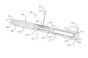
- FIG. 2illustrates a cross-section of an embodiment of an adjustable suture anchor secured in the humerus of a rotator cuff surgery patient.
- FIG. 3illustrates a detailed cross-sectional view of the adjustable suture anchor of FIG. 2 .
- FIG. 4illustrates a first end of the adjustable suture anchor supplied with a threading tool.
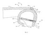
- FIG. 5illustrates a cross-section of an embodiment of an adjustable suture anchor secured in the humerus of a rotator cuff surgery patient.
- FIG. 6illustrates a detailed cross-section view of the adjustable suture anchor of FIG. 5 .
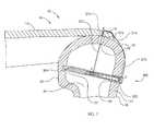
- FIG. 7illustrates a cross-section of an embodiment of an adjustable anchor secured in the humerus of a rotator cuff surgery patient.
- FIG. 8illustrates a detailed cross-section view of the adjustable suture anchor of FIG. 7 .
- FIG. 9illustrates internal components of an external adjustment device for non-invasively adjusting an adjustable suture anchor according to one embodiment.
- FIG. 10illustrates an external adjustment device in a configuration for adjusting an adjustable suture anchor implanted within the humerus.
- FIG. 11illustrates a humerus with a hole drilled for placement of an adjustable suture anchor in a rotator cuff patient.
- FIG. 12illustrates a tibia with a hole drilled for placement of an adjustable suture anchor in an anterior cruciate ligament patient.
- FIG. 1illustrates an anatomical view of a human shoulder 10 , which includes the following bones: scapula 28 , clavicle 26 and humerus 18
- the glenohumeral joint 42(or shoulder joint) is an articulation between the scapula 28 and the head 20 of the humerus 18 , the head 20 visible in a cross-sectional view in FIG. 2 .
- the acromion 32is a bony process on the scapula 28 which articulates with the clavicle 26 at the acromioclavicular joint 30 .
- the rotator cuff 46is a group of muscles and their respective tendons which serve to stabilize the shoulder 10 , including the supraspinatus 36 , infraspinatus (not visible in FIG. 1 ), subscapularis 38 , and teres minor 40 . All four of these muscles arise from different portions of the scapula 28 and attach via their respective tendons to either the greater tubercle 12 of the humerus 18 , which is lateral to the humeral head 20 or the lesser tubercle (not shown). Also shown in FIG. 1 is the bursa 34 , a fluid-filled sac which cushions the bones, muscles and tendons of the glenohumeral joint 42 . Additionally, the biceps muscle 44 is show for perspective purposes.
- FIG. 2A simplified cross-sectional view of the shoulder 10 is shown in FIG. 2 , with an embodiment of an adjustable suture anchor 100 implanted within the shoulder 10 .
- the adjustable suture anchor 100has a first end 102 and a second end 104 , the second end 104 configured for insertion through cancellous bone 24 and the first end 102 configured for securing in the cortical bone 22 of the humerus 18 .
- FIG. 3detail of the second end 104 shows a tapered thread 106 and a tapered tip 108 , which can aid in driving the adjustable suture anchor 100 through the humerus 18 .
- an initial holemay be reamed in the cortical bone 22 and cancellous bone 24 to aid in the insertion of the adjustable suture anchor 100 .
- a housing 110extends between the first end 102 and second end 104 of the adjustable suture anchor 100 .
- a threaded portion 112is provided which allows a secure interface with the cortical bone 22 .
- the threaded portion 112may be of a single major diameter (for example with a minor diameter that increases towards the first end), or the major diameter may vary from smaller to larger as it approaches the first end 102 .
- the threaded portion 112may be provided with cutting threads, in order to better create the interface with the cortical bone 22 .
- a keyed cavity 114is provided in the first end 102 for interfacing with a driving tool.
- the shapes of both the driving tool and the keyed cavity 114may be hexagonal, cross-shaped, star-shaped or a number of other keyed shapes that allow a maximal torque in securing the adjustable suture anchor 100 into the humerus 18 .
- a simplified rotator cuff 46is represented in FIG. 2 by a muscle 14 and its tendon 16 , in cross-section.
- a suture 116is secured to the tendon 16 through at least one puncture 118 .
- the suture 116is held in place with one or more knots 120 , which may comprise a number of different knot types. Any of the possible suturing techniques are envisioned, including: single-row technique, double-row techniques, diamond, mattress double anchor, or modified mattress double anchor.
- the adjustable suture anchor 100contains within its housing 110 an adjustable component 122 having an eyelet 124 .
- the eyelet 124is configured for securing an end of the suture 116 .
- the adjustable suture anchor 100is supplied with a threading tool 126 , which can be used to aid the placement of the suture 116 through the eyelet 124 of the adjustable component 122 .
- the suture 116is looped through or tied to a hook 128 in the threading tool 126 , and then the threading tool 126 is pulled from gripping structure 130 at the opposite end of the threading tool 126 from the hook 128 .
- the suture 116is pulled through the eyelet 124 of the adjustable component 122 and tied or otherwise secured in place.
- the suture 116is tied with the desired amount of tension.
- the adjustable component 122 of the adjustable suture anchor 100further includes a shaft 132 and a base 134 at the opposite end of the shaft 132 from the eyelet 124 .
- the adjustable component 122is configured to be axially movable within a longitudinal cavity 136 of the housing 110 . Fins 138 are slidable within longitudinal grooves 140 in the longitudinal cavity 136 of the housing 110 , thus inhibiting the rotation of the adjustable component 122 in relation to the housing 110 .
- the hollow magnet 142is radially poled, and is bonded within a threaded magnet housing 144 .
- the threaded magnet housing 144threadingly engages an internal thread 146 of the housing 110 .
- a thrust bearing 148is disposed between the base 134 of the adjustable component 122 and a first end 150 of the threaded magnet housing 144 . If it is desired during or particularly after surgery to tighten the tension on the suture 116 , a moving magnetic field is applied externally to the patient in a first rotational direction A, causing the hollow magnet 142 and threaded magnet housing 144 to spin in a second rotational direction B. Because it is secured to the hollow magnet 142 , the threaded magnet housing 144 therefore turns within the internal thread 146 of the housing 110 , actuating it in a first axial direction C.
- the adjustable component 122is moved in the first axial direction C. This shortens the effective length of the suture 116 , and thus increases its tensile force, which is the force it applies to the tendon 16 . This ability to adjust the tension on the suture 16 non-invasively on an awake, mobile patient, make it possible to assure the ideal state of the shoulder 10 during the healing process.
- a seal 152is carried near the first end 102 of the adjustable suture anchor 100 .
- the suture 116is able to move within this seal 152 (o-ring or slit diaphragm) without causing any significant material to enter the longitudinal cavity 136 . If the tension on the suture 116 is higher than desired, a moving magnetic field is applied externally to the patient in a rotational direction D (opposite A), causing the hollow magnet 142 and threaded magnet housing 144 to spin in a rotational direction E (opposite B). This moves the adjustable component in an axial direction F (opposite C). The tension on the suture 116 is thus lowered.
- FIG. 5a different embodiment of an adjustable suture anchor 200 is depicted in its implanted configuration within the humerus 18 .
- the adjustable suture anchor 200has a first end 202 and a second end 204 .
- the second end 204includes a tapered tip 208 , to aid in insertion through the cancellous bone 24 .
- a pilot holemay be drilled through the cortical bone 24 and the cancellous bone 24 , and an additional pocket 23 may be drilled, into which the tapered tip 208 may reside, for increased stability.
- a threaded portion 212is provided adjacent the first end 202 of the adjustable suture anchor 200 for engaging with the cortical bone 24 .
- a keyed outer surface 215having for example a hexagonal shape, is provided for tightening the adjustable suture anchor into humerus 18 .
- suture 216extends from a longitudinal cavity 236 within a housing 210 of the adjustable suture anchor.
- the suture 216is partially wound on a spool 222 , which is rotatable within the longitudinal cavity 236 .
- the suture 216can slide through a seal 252 , which protects the longitudinal cavity 236 from body fluids.
- the first end 202 of the adjustable suture anchor 200includes a radiused surface 213 , which allows the suture 216 to be slid over it without fraying.
- the magnet housing 243is constrained axially within the longitudinal cavity 236 .
- the pin 245turns within a radial bearing 247 .
- the magnet housing 243connects to a first planetary gear stage 249 , which connects to a second planetary gear stage 251 .
- the second planetary gear stage 251is coupled to the spool 222 by a pin 253 .
- a moving magnetic fieldis applied externally to the patient in a first rotational direction, causing the magnet 241 to be turned, and thus the first and second planetary gear stages 249 , 251 and spool 222 . Because of the gear reduction from the first and second planetary gear stages 249 , 251 , the spool 222 is turned at a slower rotational speed than the magnet 241 , allowing precision adjustment of the tension in the suture 216 .
- the gearingalso allows the desired tension to be achievable without an undesirably large applied moving magnetic field, for example a field that is above International Commission on Non-Ionizing Radiation Protection (ICNIRP) guidelines for current density in body tissues and fluids, for example 0.04 Amperes/m 2 or less.
- ICNIRPInternational Commission on Non-Ionizing Radiation Protection
- a stepped post 255is secured to the first end 202 of the adjustable suture anchor 200 .
- a thrust bearing 248 and the spool 222are both carried on a small diameter portion 257 of the stepped post 255 .
- a pulleymay be carried by the first end 102 , 202 to serve the function of the radiused surface 213 , both in keeping the suture 116 , 216 from fraying, and in changing the direction of the of the suture 116 , 216 which is in tension.
- FIGS. 7 and 8A different embodiment of an adjustable suture anchor 300 is depicted in FIGS. 7 and 8 .
- a loop of suture 316extends from the tendon 16 in an external portion 370 and an internal portion 372 .
- a tunnel 374 through which the suture 316 can slideis made in the tendon 16 , so that the length of the loop of suture 316 which extends from point A to point B to point C, can be adjusted, thus adjusting the tension with which the suture 316 holds the tendon 16 .
- a pad 376 of biocompatible materialis placed underneath the suture 316 to minimize damage to the tendon as the suture 316 slides over it.
- a first end 302 of the adjustable suture anchor 300includes a threaded portion 312 and an external circumferential groove 378 , around which external portion 370 of suture 316 can be wrapped and/or tied.
- a second end 304 of the adjustable suture anchor 300has a tapered tip 308 , which may be used as described in the prior embodiments.
- a cylindrical, radially poled magnet 341is bonded within a magnet housing 343 , which is secured to a rotating shaft 380 .
- the magnet housing 343 and shaft 380are rotatably held between a radial bearing 347 and a thrust bearing 348 .
- a spool 322is secured to the shaft 380 so that rotation of magnet 341 causes rotation of the shaft.
- a spacer 384is disposed between the spool 322 and the magnet 341 and secured to the housing 310 .
- a seal or diaphragm 352is carried within an aperture 382 in the lateral wall of the housing 310 , allowing the internal portion 372 of the loop of suture 316 to move in and out of the housing 310 of the adjustable suture anchor 300 , with the contents of the longitudinal cavity 336 remaining protected from body fluids.
- two pilot holesare drilled through which through the cortical bone 22 and cancellous bone 24 , a first hole 50 extending from point C towards point A. The first hole may even be extended to create an additional pocket 23 .
- a second hole 48extends from point B towards (and just past) point A.
- a grasper toolis placed through hole 48 , and a suture insertion tool inserts the end of the external portion 370 of the suture 316 through hole 50 .
- the grasper toolgrasps the suture 316 and pulls it out through hole 48 .
- the adjustable suture anchoris then inserted and secured inside hole 50 , tightening it with a driving tool inserted into a keyed cavity 314 .
- the housingmay be oriented so that the aperture 382 extends in a direction towards hole 48 .
- the external portion 370 of the suture 316is now placed through the tunnel 374 in the tendon 16 , and then wrapped and/or tied around the external circumferential groove 378 , thus closing the loop in the suture 316 .
- a moving magnetic fieldis applied externally to the patient in a first rotational direction, causing the magnet 341 to turn and the spool 322 to tighten the tension in the suture 316 .
- the moving magnetic fieldmay be applied in an opposite rotational direction in order to loosen the tension in the suture 316 .
- FIGS. 9 and 10illustrate an external adjustment device 478 configured for applying a moving magnetic field to allow for non-invasive adjustment of the adjustable suture anchor 100 , 200 , 300 by turning the magnet 142 , 241 , 341 within the adjustable suture anchor 100 , 200 , 300 .
- FIG. 9illustrates the internal components of the external adjustment device 478 , and for clear reference, shows a simplified version 338 of the magnet 142 , 241 , 341 of the adjustable suture anchor 100 , 200 , 300 , without the rest of the assembly.
- the internal working components of the external adjustment device 478may, in certain embodiments, be similar to that described in U.S. Patent Application Publication No. 2012/0004494.
- a motor 480 with a gear box 482outputs to a motor gear 484 .
- the motor gear 484engages and turns a central (idler) gear 486 , which has the appropriate number of teeth to turn first and second magnet gears 488 , 490 at identical rotational speeds.
- First and second magnets 492 , 494turn in unison with the first and second magnet gears 488 , 490 , respectively.
- Each magnet 492 , 494is held within a respective magnet cup 496 (shown partially).
- An exemplary rotational speedis 60 RPM or less. This speed range may be desired in order to limit the amount of current density induced in the body tissue and fluids, to meet international guidelines or standards. As seen in FIG.
- the south pole 498 of the first magnet 492is oriented the same as the north pole 404 of the second magnet 494 , and likewise, the first magnet 492 has its north pole 400 oriented the same as the south pole 402 of the second magnet 494 .
- these two magnets 492 , 494turn synchronously together, they apply a complementary and additive moving magnetic field to the radially-poled, magnet 338 , having a north pole 406 and a south pole 408 .
- Magnets having multiple north poles (for example, two) and multiple south poles (for example, two)are also contemplated in each of the devices.
- the magnetic couplingcauses the magnet 338 to turn in a second, opposite rotational direction 412 (e.g., clockwise).
- the rotational direction of the motor 480is controlled by buttons 414 , 416 .
- One or more circuit boards 418contain control circuitry for both sensing rotation of the magnets 492 , 494 and controlling the rotation of the magnets 492 , 494 .
- FIG. 10shows the external adjustment device 478 for use with an adjustable suture anchor 100 , 200 , 300 placed in the humerus.
- the external adjustment device 478has a first handle 424 attached to a housing 444 for carrying or for steadying the external adjustment device 478 , for example, steadying it against a shoulder 10 , as in FIG. 10 , or against a knee, in the case of an adjustable anchor for anterior cruciate ligament attachment.
- the external adjustment device 478includes a control panel including a display (not shown). Control circuitry contained on circuit boards 418 may be used by the surgeon to store important information related to the specific aspects of each particular patient.
- the external adjustment device 478may be able to receive and transfer information via an SD card or USB device, or by wireless input.
- An additional featureis a camera at the portion of the external adjustment device 478 that is placed over the skin.
- the cameramay be located between the first magnet 492 and the second magnet 494 .
- the skin directly over the implanted magnet 338may be marked with indelible ink.
- a live image from the camerais then displayed on the display 448 of the control panel 446 , allowing the user to place the first and second magnets 492 , 494 directly over the area marked on the skin.
- Crosshairscan be overlayed on the display over the live image, allowing the user to align the mark on the skin between the crosshairs, and thus optimally place the external adjustment device 478 .
- FIG. 11illustrates an alternative geometry for creating a hole 62 at the greater tubercule 12 of the humerus 18 .
- An adjustable suture anchor 500 having an adjustable component 522is implanted in the hole 62 and is capable of adjusting the tension in a suture 516 , which is attached to a tendon 16 of a rotator cuff 46 .
- the hole 62is parallel the axis of the humerus 18 , and thus allows for a longer length adjustable suture anchor 500 . This makes possible an adjustable suture anchor 500 with more planetary gear sets and allow allows for a greater range of adjustability (length, tension).
- FIG. 12shows a configuration for an adjustable suture anchor 600 for adjusting the tension in a graft 690 for replacing the ACL (for example a portion of the patellar tendon).
- the graft 690is secured in a femoral tunnel 686 in a femur 678 with a traditional tissue anchor 684 .
- the tissue anchor 684may be metallic, or may be of a resorbable material.
- the adjustable suture anchor 600is anchored to bone inside a tibial tunnel 688 created in a tibia 680 .
- An adjustable component 682 within the adjustable suture anchor 600adjusts the tension in a suture 616 which is attached to the graft 690 .
- the diameter of the tissue anchor 684may be less than about 14 mm, or preferably less than about 12 mm.
- the length of the femoral tunnel 686may be on the order of about 25 mm to about 35 mm.
- An alternative ligament for which the adjustable suture anchors 100 , 200 , 300 , 500 , 600 may be usedis the medial collateral ligament (MCL) whose attachment points are the femur 678 and tibia 680 .
- the lateral collateral ligament (LCL)whose attachment points are the femur 678 and fibula 676 , may also be adjustably attached by a modified embodiment of the adjustable suture anchor 100 , 200 , 300 , 500 , 600 .
- Other tendons and ligaments which may benefit from the adjustability of the adjustable suture anchors 100 , 200 , 300 , 500 , 600include the talo-fibular ligament, the tibial tendon, and the Achilles tendon. Typical ranges of the length of adjustment for the tendon and ligament applications discussed may be typically on the order of less than about 2 cm, or in some embodiments less than about 1 cm.
- adjustable suture anchors 100 , 200 , 300 , 500 , 600include adjustable slings attached to the pubic bone, for urinary stress incontinence.
- Magnet materialsmay include rare earth magnets, including Neodymium-Iron-Boron.
- Rigid components of the adjustable suture anchormay be made from titanium, titanium allows, or other biocompatible materials.
- PEEKpolyether ether ketone
- at least some componentsmay comprise bioabsorbable materials.
- a unidirectional versionmay be constructed.
- a ratcheting wheelthat allows stepped increases in in the rotational direction which increases the tension on the suture, but does not allow the opposite rotational direction to occur.
- any of the embodimentsmay or may not use gearing, for example to increase the deliverable for or increase the precision.
- the bone anchormay comprise an interference fit, for example a tack, a bone adhesive interface, or a staple. Additionally pronged, flanged, snagging, barbed, spiked, tabbed or curved anchors may be secured to the bone. Often, multiple anchors are attached in the same patient.
- the adjustable componentmay be driven by any of a variety of alternative drives such as an implanted motor which may be powered via inductive coupling, internal battery, or hard wired connection via leads that extend percutaneously but may be detached from the implant and removed following a post-surgical adjustment.
- the adjustable componentmay instead be driven by an ultrasonically actuated motor, such as a piezoelectric motor manufactured by Actuated Medical of Bellefonte, Pa.
- the adjustable componentmay also be driven by a subcutaneous hydraulic or pneumatic pump which pressurizes fluid through a valve when pressure is placed on the skin of the patient, over the pump interface.
- the adjustable componentmay also be driven by an implantable shape-memory driven actuator.
- the adjustable suture anchors 100 , 200 , 300 , 500 , 600may be configured so that the magnets and magnet housings may be removed from the adjustable suture anchor assembly, using a small minimally invasive incision, leaving the remained of the adjustable suture anchor 100 , 200 , 300 , 500 , 600 in place.
- the magnetmay be temporarily or permanently removed, to allow imaging of the implant area.
Landscapes
- Health & Medical Sciences (AREA)
- Surgery (AREA)
- Life Sciences & Earth Sciences (AREA)
- Medical Informatics (AREA)
- Nuclear Medicine, Radiotherapy & Molecular Imaging (AREA)
- Engineering & Computer Science (AREA)
- Biomedical Technology (AREA)
- Heart & Thoracic Surgery (AREA)
- Molecular Biology (AREA)
- Animal Behavior & Ethology (AREA)
- General Health & Medical Sciences (AREA)
- Public Health (AREA)
- Veterinary Medicine (AREA)
- Rheumatology (AREA)
- Prostheses (AREA)
- Surgical Instruments (AREA)
Abstract
Description
Claims (12)
Priority Applications (4)
| Application Number | Priority Date | Filing Date | Title |
|---|---|---|---|
| US14/447,391US10226242B2 (en) | 2013-07-31 | 2014-07-30 | Noninvasively adjustable suture anchors |
| US16/257,526US11090039B2 (en) | 2013-07-31 | 2019-01-25 | Noninvasively adjustable suture anchors |
| US17/374,350US11766252B2 (en) | 2013-07-31 | 2021-07-13 | Noninvasively adjustable suture anchors |
| US18/233,472US12329374B2 (en) | 2013-07-31 | 2023-08-14 | Noninvasively adjustable suture anchors |
Applications Claiming Priority (2)
| Application Number | Priority Date | Filing Date | Title |
|---|---|---|---|
| US201361860668P | 2013-07-31 | 2013-07-31 | |
| US14/447,391US10226242B2 (en) | 2013-07-31 | 2014-07-30 | Noninvasively adjustable suture anchors |
Related Child Applications (1)
| Application Number | Title | Priority Date | Filing Date |
|---|---|---|---|
| US16/257,526ContinuationUS11090039B2 (en) | 2013-07-31 | 2019-01-25 | Noninvasively adjustable suture anchors |
Publications (2)
| Publication Number | Publication Date |
|---|---|
| US20150038976A1 US20150038976A1 (en) | 2015-02-05 |
| US10226242B2true US10226242B2 (en) | 2019-03-12 |
Family
ID=52428329
Family Applications (4)
| Application Number | Title | Priority Date | Filing Date |
|---|---|---|---|
| US14/447,391Active2037-04-26US10226242B2 (en) | 2013-07-31 | 2014-07-30 | Noninvasively adjustable suture anchors |
| US16/257,526Active2034-10-15US11090039B2 (en) | 2013-07-31 | 2019-01-25 | Noninvasively adjustable suture anchors |
| US17/374,350Active2034-12-12US11766252B2 (en) | 2013-07-31 | 2021-07-13 | Noninvasively adjustable suture anchors |
| US18/233,472ActiveUS12329374B2 (en) | 2013-07-31 | 2023-08-14 | Noninvasively adjustable suture anchors |
Family Applications After (3)
| Application Number | Title | Priority Date | Filing Date |
|---|---|---|---|
| US16/257,526Active2034-10-15US11090039B2 (en) | 2013-07-31 | 2019-01-25 | Noninvasively adjustable suture anchors |
| US17/374,350Active2034-12-12US11766252B2 (en) | 2013-07-31 | 2021-07-13 | Noninvasively adjustable suture anchors |
| US18/233,472ActiveUS12329374B2 (en) | 2013-07-31 | 2023-08-14 | Noninvasively adjustable suture anchors |
Country Status (1)
| Country | Link |
|---|---|
| US (4) | US10226242B2 (en) |
Cited By (4)
| Publication number | Priority date | Publication date | Assignee | Title |
|---|---|---|---|---|
| US11065037B2 (en) | 2016-05-19 | 2021-07-20 | Auctus Surgical, Inc. | Spinal curvature modulation systems and methods |
| US11766252B2 (en) | 2013-07-31 | 2023-09-26 | Nuvasive Specialized Orthopedics, Inc. | Noninvasively adjustable suture anchors |
| US12262917B2 (en) | 2016-05-19 | 2025-04-01 | Auctus Surgical, Inc. | Spinal curvature modulation systems and methods |
| US12433649B2 (en) | 2019-02-13 | 2025-10-07 | The Trustees Of The University Of Pennsylvania | Systems and methods for a smart, implantable cranio-maxillo-facial distractor |
Families Citing this family (9)
| Publication number | Priority date | Publication date | Assignee | Title |
|---|---|---|---|---|
| US10548712B2 (en) | 2016-02-29 | 2020-02-04 | Biosense Webster (Israel) Ltd. | Pressure changer for a breast implant |
| WO2019043519A1 (en)* | 2017-09-01 | 2019-03-07 | Ethicon, Inc. | Adjustable implant |
| US10751163B2 (en) | 2017-09-01 | 2020-08-25 | Mentor Worldwide Llc | Adjustable implant |
| US10751165B2 (en) | 2017-12-12 | 2020-08-25 | Mentor Worldwide Llc | Adjustable implant |
| US10653517B2 (en) | 2017-11-08 | 2020-05-19 | Mentor Worldwide Llc | Adjustable implant |
| CN110403677B (en)* | 2019-07-22 | 2020-06-19 | 杭州科锐特医疗设备有限公司 | Power system for paranasal sinus endoscope operation |
| JP2022546586A (en)* | 2019-09-04 | 2022-11-04 | アプライド・メディカル・テクノロジー・インコーポレーテッド | magnetic suture |
| WO2022245822A1 (en) | 2021-05-17 | 2022-11-24 | Applied Medical Technology, Inc. | Magnet-assisted suture graspers |
| CN119366983B (en)* | 2024-12-31 | 2025-03-18 | 华融科创生物科技(天津)有限公司 | Multifunctional fixing device capable of being used for tendon suture and fracture fixation simultaneously |
Citations (100)
| Publication number | Priority date | Publication date | Assignee | Title |
|---|---|---|---|---|
| US5429638A (en) | 1993-02-12 | 1995-07-04 | The Cleveland Clinic Foundation | Bone transport and lengthening system |
| US5626579A (en) | 1993-02-12 | 1997-05-06 | The Cleveland Clinic Foundation | Bone transport and lengthening system |
| US5704938A (en)* | 1996-03-27 | 1998-01-06 | Volunteers For Medical Engineering | Implantable bone lengthening apparatus using a drive gear mechanism |
| US6375682B1 (en) | 2001-08-06 | 2002-04-23 | Lewis W. Fleischmann | Collapsible, rotatable and expandable spinal hydraulic prosthetic device |
| US6416516B1 (en) | 1999-02-16 | 2002-07-09 | Wittenstein Gmbh & Co. Kg | Active intramedullary nail for the distraction of bone parts |
| US20040023623A1 (en) | 2000-11-09 | 2004-02-05 | Roman Stauch | Device for controlling, regulating and/or putting an active implant into operation |
| US6706042B2 (en) | 2001-03-16 | 2004-03-16 | Finsbury (Development) Limited | Tissue distractor |
| HU223454B1 (en) | 2000-07-21 | 2004-07-28 | László Bodó | Strain-setting device for tendonrekonstruction or replacement and introductionspipe for implant a tension-adjusting device |
| US20050090823A1 (en) | 2003-10-28 | 2005-04-28 | Bartimus Christopher S. | Posterior fixation system |
| US20050159754A1 (en) | 2004-01-21 | 2005-07-21 | Odrich Ronald B. | Periosteal distraction bone growth |
| US20050267485A1 (en) | 2004-02-06 | 2005-12-01 | Synvasive Technology, Inc. | Dynamic knee balancer with opposing adjustment mechanism |
| US20060036246A1 (en) | 2004-08-03 | 2006-02-16 | Carl Allen L | Device and method for correcting a spinal deformity |
| US20060047282A1 (en)* | 2004-08-30 | 2006-03-02 | Vermillion Technologies, Llc | Implant for correction of spinal deformity |
| US20060058792A1 (en) | 2004-09-16 | 2006-03-16 | Hynes Richard A | Intervertebral support device with bias adjustment and related methods |
| US7063706B2 (en) | 2001-11-19 | 2006-06-20 | Wittenstein Ag | Distraction device |
| US20060235424A1 (en) | 2005-04-01 | 2006-10-19 | Foster-Miller, Inc. | Implantable bone distraction device and method |
| US20060293683A1 (en) | 2003-04-16 | 2006-12-28 | Roman Stauch | Device for lengthening bones or bone parts |
| US20070010814A1 (en) | 2003-08-28 | 2007-01-11 | Roman Stauch | Device for extending bones |
| US20070264605A1 (en) | 2005-05-19 | 2007-11-15 | Theodore Belfor | System and method to bioengineer facial form in adults |
| US20080033436A1 (en) | 2004-08-30 | 2008-02-07 | Vermillion Technologies, Llc | Device and method for treatment of spinal deformity |
| US20080051788A1 (en) | 2006-08-21 | 2008-02-28 | Schwab Frank J | System And Method For Correcting Spinal Deformity |
| US7357635B2 (en) | 2004-05-19 | 2008-04-15 | Orthovisage Inc. | System and method to bioengineer facial form in adults |
| US20080097487A1 (en) | 2006-10-20 | 2008-04-24 | Scott Pool | Method and apparatus for adjusting a gastrointestinal restriction device |
| US20080161933A1 (en) | 2005-09-26 | 2008-07-03 | Innvotec Surgical, Inc. | Selectively expanding spine cage, hydraulically controllable in three dimensions for vertebral body replacement |
| US20080167685A1 (en) | 2007-01-05 | 2008-07-10 | Warsaw Orthopedic, Inc. | System and Method For Percutanously Curing An Implantable Device |
| US20080228186A1 (en) | 2005-04-01 | 2008-09-18 | The Regents Of The University Of Colorado | Graft Fixation Device |
| US20080255615A1 (en) | 2007-03-27 | 2008-10-16 | Warsaw Orthopedic, Inc. | Treatments for Correcting Spinal Deformities |
| US7458981B2 (en) | 2004-03-09 | 2008-12-02 | The Board Of Trustees Of The Leland Stanford Junior University | Spinal implant and method for restricting spinal flexion |
| US20090012565A1 (en) | 2007-06-06 | 2009-01-08 | Vertech, Inc. | Medical device and method to correct deformity |
| US20090076597A1 (en) | 2007-09-19 | 2009-03-19 | Jonathan Micheal Dahlgren | System for mechanical adjustment of medical implants |
| US20090093890A1 (en) | 2007-10-04 | 2009-04-09 | Daniel Gelbart | Precise control of orthopedic actuators |
| US20090112207A1 (en)* | 2007-10-30 | 2009-04-30 | Blair Walker | Skeletal manipulation method |
| US7531002B2 (en) | 2004-04-16 | 2009-05-12 | Depuy Spine, Inc. | Intervertebral disc with monitoring and adjusting capabilities |
| US20090171356A1 (en) | 2008-01-02 | 2009-07-02 | International Business Machines Corporation | Bone Repositioning Apparatus and System |
| US20090192514A1 (en) | 2007-10-09 | 2009-07-30 | Feinberg Stephen E | Implantable distraction osteogenesis device and methods of using same |
| US7601156B2 (en) | 2001-12-05 | 2009-10-13 | Randolph C. Robinson | Limb lengthener |
| US7611526B2 (en) | 2004-08-03 | 2009-11-03 | K Spine, Inc. | Spinous process reinforcement device and method |
| US7666184B2 (en) | 2003-08-28 | 2010-02-23 | Wittenstein Ag | Planetary roll system, in particular for a device for extending bones |
| US20100094302A1 (en) | 2008-10-13 | 2010-04-15 | Scott Pool | Spinal distraction system |
| US20100100185A1 (en) | 2008-10-22 | 2010-04-22 | Warsaw Orthopedic, Inc. | Intervertebral Disc Prosthesis Having Viscoelastic Properties |
| US20100121323A1 (en) | 2008-11-10 | 2010-05-13 | Ellipse Technologies, Inc. | External adjustment device for distraction device |
| US20100191248A1 (en) | 2009-01-27 | 2010-07-29 | Vishal Mahul Mehta | Arthroscopic tunnel guide for rotator cuff repair |
| US7776091B2 (en) | 2004-06-30 | 2010-08-17 | Depuy Spine, Inc. | Adjustable posterior spinal column positioner |
| US7794476B2 (en) | 2003-08-08 | 2010-09-14 | Warsaw Orthopedic, Inc. | Implants formed of shape memory polymeric material for spinal fixation |
| US20100249837A1 (en)* | 2009-03-26 | 2010-09-30 | Kspine, Inc. | Semi-constrained anchoring system |
| US20100249847A1 (en) | 2006-06-29 | 2010-09-30 | Searete Llc, A Limited Liability Corporation Of The State Of Delaware | Position augmenting mechanism |
| US7811328B2 (en) | 2005-04-29 | 2010-10-12 | Warsaw Orthopedic, Inc. | System, device and methods for replacing the intervertebral disc with a magnetic or electromagnetic prosthesis |
| US20100280551A1 (en) | 2009-04-29 | 2010-11-04 | Ellipse Technologies, Inc. | Interspinous process device and method |
| US20100318129A1 (en) | 2009-06-16 | 2010-12-16 | Kspine, Inc. | Deformity alignment system with reactive force balancing |
| US20100324600A1 (en) | 2009-06-18 | 2010-12-23 | Ashok Biyani | Unidirectional rotatory pedicle screw and spinal deformity correction device for correction of spinal deformity in growing children |
| HU3895U (en) | 2010-07-27 | 2011-02-28 | Tensofix Fejlesztoe Es Szolgaltato Beteti Tarsasag | Tension-adjusting fixing element |
| US20110054536A1 (en) | 2008-11-11 | 2011-03-03 | Kspine, Inc. | Growth directed vertebral fixation system with distractible connector(s) and apical control |
| US20110066188A1 (en) | 2009-09-15 | 2011-03-17 | Kspine, Inc. | Growth modulation system |
| US20110106165A1 (en) | 2009-10-30 | 2011-05-05 | Warsaw Orthopedic, Inc. | Devices and methods for dynamic spinal stabilization and correction of spinal deformities |
| US20110230883A1 (en)* | 2010-03-19 | 2011-09-22 | Smith & Nephew, Inc. | Telescoping im nail and actuating mechanism |
| US20110238126A1 (en) | 2010-03-23 | 2011-09-29 | Arnaud Soubeiran | Device for the displacement of tissues, especially bone tissues |
| US20110257655A1 (en) | 2008-10-02 | 2011-10-20 | Copf Jr Franz | Instrument for measuring the distraction pressure between vertebral bodies |
| US8043299B2 (en) | 2006-11-06 | 2011-10-25 | Janet Conway | Internal bone transport |
| US20120053633A1 (en) | 2010-08-26 | 2012-03-01 | Wittenstein Ag | Actuator for correcting scoliosis |
| US8147517B2 (en) | 2006-05-23 | 2012-04-03 | Warsaw Orthopedic, Inc. | Systems and methods for adjusting properties of a spinal implant |
| US8147549B2 (en) | 2008-11-24 | 2012-04-03 | Warsaw Orthopedic, Inc. | Orthopedic implant with sensor communications antenna and associated diagnostics measuring, monitoring, and response system |
| US20120088953A1 (en) | 2010-10-08 | 2012-04-12 | Jerry King | Fractured Bone Treatment Methods And Fractured Bone Treatment Assemblies |
| US20120109207A1 (en) | 2010-10-29 | 2012-05-03 | Warsaw Orthopedic, Inc. | Enhanced Interfacial Conformance for a Composite Rod for Spinal Implant Systems with Higher Modulus Core and Lower Modulus Polymeric Sleeve |
| US8177789B2 (en) | 2007-10-01 | 2012-05-15 | The General Hospital Corporation | Distraction osteogenesis methods and devices |
| US8221420B2 (en) | 2009-02-16 | 2012-07-17 | Aoi Medical, Inc. | Trauma nail accumulator |
| US8241331B2 (en) | 2007-11-08 | 2012-08-14 | Spine21 Ltd. | Spinal implant having a post-operative adjustable dimension |
| US8252063B2 (en) | 2009-03-04 | 2012-08-28 | Wittenstein Ag | Growing prosthesis |
| US8282671B2 (en) | 2010-10-25 | 2012-10-09 | Orthonex | Smart device for non-invasive skeletal adjustment |
| US8298240B2 (en) | 2006-04-06 | 2012-10-30 | Synthes (Usa) | Remotely adjustable tissue displacement device |
| US20120283781A1 (en) | 2009-11-25 | 2012-11-08 | Uri Arnin | Spinal rod having a post-operative adjustable dimension |
| US8419801B2 (en) | 2004-09-30 | 2013-04-16 | DePuy Synthes Products, LLC | Adjustable, remote-controllable orthopaedic prosthesis and associated method |
| US20130096677A1 (en) | 2011-10-18 | 2013-04-18 | Dr. Thomas H. Myers | Acl implants, instruments, and methods |
| WO2013066946A1 (en) | 2011-11-01 | 2013-05-10 | Ellipse Technologies, Inc. | Adjustable magnetic devices and methods of using same |
| US8439915B2 (en) | 2004-09-29 | 2013-05-14 | The Regents Of The University Of California | Apparatus and methods for magnetic alteration of anatomical features |
| US8469908B2 (en) | 2007-04-06 | 2013-06-25 | Wilson T. Asfora | Analgesic implant device and system |
| US20130172940A1 (en) | 2012-01-04 | 2013-07-04 | Warsaw Orthopedic, Inc | System and method for correction of a spinal disorder |
| US8529606B2 (en) | 2009-03-10 | 2013-09-10 | Simpirica Spine, Inc. | Surgical tether apparatus and methods of use |
| US20130253344A1 (en) | 2012-03-26 | 2013-09-26 | Medtronic, Inc. | Intravascular implantable medical device introduction |
| US8562653B2 (en) | 2009-03-10 | 2013-10-22 | Simpirica Spine, Inc. | Surgical tether apparatus and methods of use |
| US8568457B2 (en) | 2009-12-01 | 2013-10-29 | DePuy Synthes Products, LLC | Non-fusion scoliosis expandable spinal rod |
| US20130296940A1 (en) | 2012-04-17 | 2013-11-07 | Aurora Spine, Llc | Dynamic and non-dynamic interspinous fusion implant and bone growth stimulation system |
| US20140005788A1 (en) | 2010-05-24 | 2014-01-02 | Aalto University Foundation | Implantable treatment device fixed or interlinked to bone |
| US8632544B2 (en) | 2008-03-19 | 2014-01-21 | Synoste Oy | Internal osteodistraction device |
| US20140025172A1 (en) | 2012-07-17 | 2014-01-23 | Kim John Chillag | Lockable implants and related methods |
| US8641723B2 (en) | 2010-06-03 | 2014-02-04 | Orthonex LLC | Skeletal adjustment device |
| US8663285B2 (en) | 2009-09-03 | 2014-03-04 | Dalmatic Lystrup A/S | Expansion devices |
| US20140114311A1 (en) | 2012-10-18 | 2014-04-24 | Ellipse Technologies, Inc. | Intramedullary implants for replacing lost bone |
| US20140128920A1 (en) | 2012-11-05 | 2014-05-08 | Sven Kantelhardt | Dynamic Stabilizing Device for Bones |
| US8790409B2 (en) | 2012-12-07 | 2014-07-29 | Cochlear Limited | Securable implantable component |
| US20140214034A1 (en)* | 2013-01-25 | 2014-07-31 | Fady Rayes | Cannulated telescopic femoral neck screw device and related fixation method |
| US20140236234A1 (en)* | 2011-06-03 | 2014-08-21 | Kspine, Inc. | Spinal correction system actuators |
| US20140296918A1 (en) | 2011-12-12 | 2014-10-02 | Stephen D. Fening | Noninvasive device for adjusting fastener |
| US20140303538A1 (en) | 2013-04-08 | 2014-10-09 | Elwha Llc | Apparatus, System, and Method for Controlling Movement of an Orthopedic Joint Prosthesis in a Mammalian Subject |
| US20140303539A1 (en) | 2013-04-08 | 2014-10-09 | Elwha Llc | Apparatus, System, and Method for Controlling Movement of an Orthopedic Joint Prosthesis in a Mammalian Subject |
| US8870959B2 (en) | 2009-11-24 | 2014-10-28 | Spine21 Ltd. | Spinal fusion cage having post-operative adjustable dimensions |
| US20140358150A1 (en) | 2013-05-29 | 2014-12-04 | Children's National Medical Center | Surgical distraction device with external activation |
| US8961567B2 (en) | 2010-11-22 | 2015-02-24 | DePuy Synthes Products, LLC | Non-fusion scoliosis expandable spinal rod |
| US8992527B2 (en) | 2009-06-24 | 2015-03-31 | Jean-Marc Guichet | Elongation nail for long bone or similar |
| US20150105824A1 (en) | 2005-04-12 | 2015-04-16 | Nathan C. Moskowitz | Bi-directional fixating transvertebral body screws, zero-profile horizontal intervertebral miniplates, total intervertebral body fusion devices, and posterior motion-calibrating interarticulating joint stapling device for spinal fusion |
| US9022917B2 (en) | 2012-07-16 | 2015-05-05 | Sophono, Inc. | Magnetic spacer systems, devices, components and methods for bone conduction hearing aids |
Family Cites Families (470)
| Publication number | Priority date | Publication date | Assignee | Title |
|---|---|---|---|---|
| US2702031A (en) | 1953-09-25 | 1955-02-15 | Wenger Herman Leslie | Method and apparatus for treatment of scoliosis |
| US3111945A (en) | 1961-01-05 | 1963-11-26 | Solbrig Charles R Von | Bone band and process of applying the same |
| US3377576A (en) | 1965-05-03 | 1968-04-09 | Metcom Inc | Gallium-wetted movable electrode switch |
| US3372476A (en) | 1967-04-05 | 1968-03-12 | Amp Inc | Method of making permanent connections between interfitting parts |
| FR1556730A (en) | 1967-06-05 | 1969-02-07 | ||
| USRE28907E (en) | 1967-06-05 | 1976-07-20 | Self-tapping threaded bushings | |
| US3512901A (en) | 1967-07-28 | 1970-05-19 | Carrier Corp | Magnetically coupled pump with slip detection means |
| DE2314573C2 (en) | 1973-03-23 | 1986-12-18 | Werner Dipl.-Ing. 8000 München Kraus | Device for promoting healing processes |
| GB1467248A (en) | 1973-07-30 | 1977-03-16 | Horstmann Magnetics Ltd | Electric motors |
| CH581988A5 (en) | 1974-04-09 | 1976-11-30 | Messerschmitt Boelkow Blohm | |
| US3900025A (en) | 1974-04-24 | 1975-08-19 | Jr Walter P Barnes | Apparatus for distracting or compressing longitudinal bone segments |
| FI53062C (en) | 1975-05-30 | 1978-02-10 | Erkki Einari Nissinen | |
| US4010758A (en) | 1975-09-03 | 1977-03-08 | Medtronic, Inc. | Bipolar body tissue electrode |
| US4068821A (en) | 1976-09-13 | 1978-01-17 | Acf Industries, Incorporated | Valve seat ring having a corner groove to receive an elastic seal ring |
| SU715082A1 (en) | 1977-01-24 | 1980-02-15 | Всесоюзный научно-исследовательский и испытательный институт медицинской техники | Surgical suturing apparatus |
| US4357946A (en) | 1980-03-24 | 1982-11-09 | Medtronic, Inc. | Epicardial pacing lead with stylet controlled helical fixation screw |
| US4386603A (en) | 1981-03-23 | 1983-06-07 | Mayfield Jack K | Distraction device for spinal distraction systems |
| US4448191A (en) | 1981-07-07 | 1984-05-15 | Rodnyansky Lazar I | Implantable correctant of a spinal curvature and a method for treatment of a spinal curvature |
| FR2514250A1 (en) | 1981-10-08 | 1983-04-15 | Artus | HANDPIECE WITH INTEGRATED MOTOR |
| FR2523232B1 (en) | 1982-03-09 | 1985-09-20 | Thomson Csf | TELESCOPIC COLUMN WITH CYLINDRICAL TUBES |
| CH648723GA3 (en) | 1982-09-10 | 1985-04-15 | ||
| DE3340596A1 (en) | 1982-11-16 | 1984-05-24 | Tokyo Electric Co., Ltd., Tokyo | MATRIX PRINTER |
| IL67773A (en) | 1983-01-28 | 1985-02-28 | Antebi E | Tie for tying live tissue and an instrument for performing said tying operation |
| DE3306657C2 (en) | 1983-02-25 | 1986-12-11 | Fa. Heinrich C. Ulrich, 7900 Ulm | Spine correction implant with a distraction rod |
| US4501266A (en) | 1983-03-04 | 1985-02-26 | Biomet, Inc. | Knee distraction device |
| US4595007A (en) | 1983-03-14 | 1986-06-17 | Ethicon, Inc. | Split ring type tissue fastener |
| FR2551350B1 (en) | 1983-09-02 | 1985-10-25 | Buffet Jacques | FLUID INJECTION DEVICE, SUITABLE FOR IMPLANTATION |
| US4522501A (en) | 1984-04-06 | 1985-06-11 | Northern Telecom Limited | Monitoring magnetically permeable particles in admixture with a fluid carrier |
| US4573454A (en) | 1984-05-17 | 1986-03-04 | Hoffman Gregory A | Spinal fixation apparatus |
| DE8515687U1 (en) | 1985-05-29 | 1985-10-24 | Aesculap-Werke Ag Vormals Jetter & Scheerer, 7200 Tuttlingen | Distraction device for extension osteotomy |
| US4642257A (en) | 1985-06-13 | 1987-02-10 | Michael Chase | Magnetic occluding device |
| US4931055A (en) | 1986-05-30 | 1990-06-05 | John Bumpus | Distraction rods |
| US4700091A (en) | 1986-08-22 | 1987-10-13 | Timex Corporation | Bipolar stepping motor rotor with drive pinion and method of manufacture |
| SE460301B (en) | 1986-10-15 | 1989-09-25 | Sandvik Ab | CUTTING ROD FOR STOCKING DRILLING MACHINE |
| DE8704134U1 (en) | 1987-03-19 | 1987-07-16 | Zielke, Klaus, Dr.med., 3590 Bad Wildungen | Implant designed as a distraction and compression rod |
| DE3711091A1 (en) | 1987-04-02 | 1988-10-13 | Kluger Patrick | DEVICE FOR SETTING UP A SPINE WITH A DAMAGED SPINE |
| DE3728686A1 (en) | 1987-08-27 | 1989-03-09 | Draenert Klaus | PREDICTABLE SURGICAL NETWORK |
| US4940467A (en) | 1988-02-03 | 1990-07-10 | Tronzo Raymond G | Variable length fixation device |
| FR2632514B1 (en) | 1988-06-09 | 1990-10-12 | Medinov Sarl | PROGRESSIVE CENTRO-MEDULAR NAIL |
| US4904861A (en) | 1988-12-27 | 1990-02-27 | Hewlett-Packard Company | Optical encoder using sufficient inactive photodetectors to make leakage current equal throughout |
| US4973331A (en) | 1989-03-08 | 1990-11-27 | Autogenesis Corporation | Automatic compression-distraction-torsion method and apparatus |
| JPH0620466B2 (en) | 1989-03-31 | 1994-03-23 | 有限会社田中医科器械製作所 | Spinal column correction device |
| US5092889A (en) | 1989-04-14 | 1992-03-03 | Campbell Robert M Jr | Expandable vertical prosthetic rib |
| US5053047A (en) | 1989-05-16 | 1991-10-01 | Inbae Yoon | Suture devices particularly useful in endoscopic surgery and methods of suturing |
| DE3921972C2 (en) | 1989-07-04 | 1994-06-09 | Rainer Dr Med Baumgart | Intramedullary nail |
| IT1236172B (en) | 1989-11-30 | 1993-01-11 | Franco Mingozzi | EXTERNAL FIXER FOR THE TREATMENT OF LONG BONE FRACTURES OF THE LIMBS. |
| US5142407A (en) | 1989-12-22 | 1992-08-25 | Donnelly Corporation | Method of reducing leakage current in electrochemichromic solutions and solutions based thereon |
| US5030235A (en) | 1990-04-20 | 1991-07-09 | Campbell Robert M Jr | Prosthetic first rib |
| US5290289A (en) | 1990-05-22 | 1994-03-01 | Sanders Albert E | Nitinol spinal instrumentation and method for surgically treating scoliosis |
| US5156605A (en) | 1990-07-06 | 1992-10-20 | Autogenesis Corporation | Automatic internal compression-distraction-method and apparatus |
| US5133716A (en) | 1990-11-07 | 1992-07-28 | Codespi Corporation | Device for correction of spinal deformities |
| AU4630393A (en) | 1992-06-08 | 1994-01-04 | Robert M. Campbell Jr. | Segmental rib carriage instrumentation and associated methods |
| US5437266A (en) | 1992-07-02 | 1995-08-01 | Mcpherson; William | Coil screw surgical retractor |
| US5676651A (en) | 1992-08-06 | 1997-10-14 | Electric Boat Corporation | Surgically implantable pump arrangement and method for pumping body fluids |
| US5466261A (en) | 1992-11-19 | 1995-11-14 | Wright Medical Technology, Inc. | Non-invasive expandable prosthesis for growing children |
| US5306275A (en) | 1992-12-31 | 1994-04-26 | Bryan Donald W | Lumbar spine fixation apparatus and method |
| US5336223A (en) | 1993-02-04 | 1994-08-09 | Rogers Charles L | Telescoping spinal fixator |
| US5356424A (en) | 1993-02-05 | 1994-10-18 | American Cyanamid Co. | Laparoscopic suturing device |
| US5536269A (en) | 1993-02-18 | 1996-07-16 | Genesis Orthopedics | Bone and tissue lengthening device |
| US5356411A (en) | 1993-02-18 | 1994-10-18 | Spievack Alan R | Bone transporter |
| US5516335A (en) | 1993-03-24 | 1996-05-14 | Hospital For Joint Diseases Orthopaedic Institute | Intramedullary nail for femoral lengthening |
| US5364396A (en) | 1993-03-29 | 1994-11-15 | Robinson Randolph C | Distraction method and apparatus |
| US5334202A (en) | 1993-04-06 | 1994-08-02 | Carter Michael A | Portable bone distraction apparatus |
| US5527309A (en) | 1993-04-21 | 1996-06-18 | The Trustees Of Columbia University In The City Of New York | Pelvo-femoral fixator |
| US5403322A (en) | 1993-07-08 | 1995-04-04 | Smith & Nephew Richards Inc. | Drill guide and method for avoiding intramedullary nails in the placement of bone pins |
| FR2709246B1 (en) | 1993-08-27 | 1995-09-29 | Martin Jean Raymond | Dynamic implanted spinal orthosis. |
| US5468030A (en) | 1994-01-04 | 1995-11-21 | Caterpillar Inc. | Tube clamp and coupling |
| AU1011595A (en) | 1994-01-13 | 1995-07-20 | Ethicon Inc. | Spiral surgical tack |
| US5762599A (en) | 1994-05-02 | 1998-06-09 | Influence Medical Technologies, Ltd. | Magnetically-coupled implantable medical devices |
| US6217847B1 (en) | 1994-07-01 | 2001-04-17 | The Board Of Trustees Of The Leland Stanford Junior University | Non-invasive localization of a light-emitting conjugate in a mammal |
| US5620445A (en) | 1994-07-15 | 1997-04-15 | Brosnahan; Robert | Modular intramedullary nail |
| US5509888A (en) | 1994-07-26 | 1996-04-23 | Conceptek Corporation | Controller valve device and method |
| IT1268313B1 (en) | 1994-07-28 | 1997-02-27 | Orthofix Srl | MECHANICAL EQUIPMENT FOR CENTERING BLIND HOLES FOR BONE SCREWS OF INTRAMIDOLLAR NAILS |
| US5582616A (en) | 1994-08-05 | 1996-12-10 | Origin Medsystems, Inc. | Surgical helical fastener with applicator |
| US5573012A (en) | 1994-08-09 | 1996-11-12 | The Regents Of The University Of California | Body monitoring and imaging apparatus and method |
| US5549610A (en) | 1994-10-31 | 1996-08-27 | Smith & Nephew Richards Inc. | Femoral intramedullary nail |
| WO1996015377A1 (en) | 1994-11-16 | 1996-05-23 | Soubeiran Arnaud Andre | Device for mutually moving two bodies |
| US5659217A (en) | 1995-02-10 | 1997-08-19 | Petersen; Christian C. | Permanent magnet d.c. motor having a radially-disposed working flux gap |
| FR2730406B1 (en) | 1995-02-13 | 1997-08-14 | Medinov Sa | IMPROVED LENGTHENING DEVICE FOR LONG BONES |
| US5575790A (en) | 1995-03-28 | 1996-11-19 | Rensselaer Polytechnic Institute | Shape memory alloy internal linear actuator for use in orthopedic correction |
| US5626613A (en) | 1995-05-04 | 1997-05-06 | Arthrex, Inc. | Corkscrew suture anchor and driver |
| US5662683A (en) | 1995-08-22 | 1997-09-02 | Ortho Helix Limited | Open helical organic tissue anchor and method of facilitating healing |
| JP3338944B2 (en) | 1995-08-25 | 2002-10-28 | 有限会社田中医科器械製作所 | Spinal deformity correction device |
| US6102922A (en) | 1995-09-22 | 2000-08-15 | Kirk Promotions Limited | Surgical method and device for reducing the food intake of patient |
| EP0769282B1 (en) | 1995-09-22 | 2000-05-03 | Kirk Promotions Limited | Device for reducing the food intake of a patient |
| EP0865258B1 (en) | 1995-12-01 | 2000-06-21 | David A. Walker | Telescopic bone plate for use in bone lengthening by distraction osteogenesis |
| US5672177A (en) | 1996-01-31 | 1997-09-30 | The General Hospital Corporation | Implantable bone distraction device |
| US5704939A (en) | 1996-04-09 | 1998-01-06 | Justin; Daniel F. | Intramedullary skeletal distractor and method |
| US5979456A (en) | 1996-04-22 | 1999-11-09 | Magovern; George J. | Apparatus and method for reversibly reshaping a body part |
| WO1997048438A2 (en) | 1996-06-17 | 1997-12-24 | Lucent Medical Systems, Inc. | Medical tube for insertion and detection within the body of a patient |
| US5700263A (en) | 1996-06-17 | 1997-12-23 | Schendel; Stephen A. | Bone distraction apparatus |
| DE19626230A1 (en) | 1996-06-29 | 1998-01-02 | Inst Physikalische Hochtech Ev | Device for determining the position of magnetic marker through Magen-Darm tract |
| US6835207B2 (en) | 1996-07-22 | 2004-12-28 | Fred Zacouto | Skeletal implant |
| US6500110B1 (en) | 1996-08-15 | 2002-12-31 | Neotonus, Inc. | Magnetic nerve stimulation seat device |
| US5810815A (en) | 1996-09-20 | 1998-09-22 | Morales; Jose A. | Surgical apparatus for use in the treatment of spinal deformities |
| US5830221A (en) | 1996-09-20 | 1998-11-03 | United States Surgical Corporation | Coil fastener applier |
| US6058323A (en) | 1996-11-05 | 2000-05-02 | Lemelson; Jerome | System and method for treating select tissue in a living being |
| US5743910A (en) | 1996-11-14 | 1998-04-28 | Xomed Surgical Products, Inc. | Orthopedic prosthesis removal instrument |
| DE19652608C1 (en) | 1996-12-18 | 1998-08-27 | Eska Implants Gmbh & Co | Prophylaxis implant against fractures of osteoporotically affected bone segments |
| NL1004873C2 (en) | 1996-12-23 | 1998-06-24 | Univ Twente | Device for moving two objects together. |
| DE19700225A1 (en) | 1997-01-07 | 1998-07-09 | Augustin Prof Dr Betz | Distraction device for moving two parts of a bone apart |
| IT1293934B1 (en) | 1997-01-21 | 1999-03-11 | Orthofix Srl | ENDOMIDOLLAR NAIL FOR THE TREATMENT OF HIP FRACTURES |
| US5997490A (en) | 1997-02-12 | 1999-12-07 | Exogen, Inc. | Method and system for therapeutically treating bone fractures and osteoporosis |
| US5827286A (en) | 1997-02-14 | 1998-10-27 | Incavo; Stephen J. | Incrementally adjustable tibial osteotomy fixation device and method |
| DE19708279C2 (en) | 1997-02-28 | 1999-10-14 | Rainer Baumgart | Distraction system for a long bone |
| US6034296A (en) | 1997-03-11 | 2000-03-07 | Elvin; Niell | Implantable bone strain telemetry sensing system and method |
| US6033412A (en) | 1997-04-03 | 2000-03-07 | Losken; H. Wolfgang | Automated implantable bone distractor for incremental bone adjustment |
| FR2761876B1 (en) | 1997-04-09 | 1999-08-06 | Materiel Orthopedique En Abreg | INSTRUMENTATION OF LUMBAR OSTEOSYNTHESIS FOR CORRECTION OF SPONDYLOLISTHESIS BY POSTERIOR PATHWAY |
| GB9713018D0 (en) | 1997-06-20 | 1997-08-27 | Secr Defence | Optical fibre bend sensor |
| DE19741757A1 (en) | 1997-09-22 | 1999-03-25 | Sachse Hans E | Implantable hydraulic bone expansion device |
| US6138681A (en) | 1997-10-13 | 2000-10-31 | Light Sciences Limited Partnership | Alignment of external medical device relative to implanted medical device |
| DE19745654A1 (en) | 1997-10-16 | 1999-04-22 | Hans Peter Prof Dr Med Zenner | Port for subcutaneous infusion |
| FR2771280B1 (en) | 1997-11-26 | 2001-01-26 | Albert P Alby | RESILIENT VERTEBRAL CONNECTION DEVICE |
| US5935127A (en) | 1997-12-17 | 1999-08-10 | Biomet, Inc. | Apparatus and method for treatment of a fracture in a long bone |
| US6336929B1 (en) | 1998-01-05 | 2002-01-08 | Orthodyne, Inc. | Intramedullary skeletal distractor and method |
| KR20010033867A (en) | 1998-01-05 | 2001-04-25 | 오르토다인 인코포레이티드 | Intramedullary Skeletal Distractor And Method |
| US6331744B1 (en) | 1998-02-10 | 2001-12-18 | Light Sciences Corporation | Contactless energy transfer apparatus |
| US5945762A (en) | 1998-02-10 | 1999-08-31 | Light Sciences Limited Partnership | Movable magnet transmitter for inducing electrical current in an implanted coil |
| DE19807663A1 (en) | 1998-02-24 | 1999-09-09 | Baur | Connection means for releasably connecting a first component and a second component and method for releasing a connection of a first component and a second component |
| US6343568B1 (en) | 1998-03-25 | 2002-02-05 | Mcclasky David R. | Non-rotating telescoping pole |
| GB9806999D0 (en) | 1998-04-02 | 1998-06-03 | Univ Birmingham | Distraction device |
| DE29811479U1 (en) | 1998-06-26 | 1998-09-03 | orto MAQUET GmbH & Co. KG, 76437 Rastatt | Plate arrangement for osteosynthesis |
| DE19829523A1 (en) | 1998-07-02 | 2000-01-05 | Michael Butsch | Distraction device for moving apart a one- or two-part, possibly separate bone |
| US6126660A (en) | 1998-07-29 | 2000-10-03 | Sofamor Danek Holdings, Inc. | Spinal compression and distraction devices and surgical methods |
| DE19856062A1 (en) | 1998-12-04 | 2000-06-15 | Wittenstein Gmbh & Co Kg | Distraction device |
| US6139316A (en) | 1999-01-26 | 2000-10-31 | Sachdeva; Rohit C. L. | Device for bone distraction and tooth movement |
| US6315784B1 (en) | 1999-02-03 | 2001-11-13 | Zarija Djurovic | Surgical suturing unit |
| US6162223A (en) | 1999-04-09 | 2000-12-19 | Smith & Nephew, Inc. | Dynamic wrist fixation apparatus for early joint motion in distal radius fractures |
| US6299613B1 (en) | 1999-04-23 | 2001-10-09 | Sdgi Holdings, Inc. | Method for the correction of spinal deformities through vertebral body tethering without fusion |
| US7008425B2 (en) | 1999-05-27 | 2006-03-07 | Jonathan Phillips | Pediatric intramedullary nail and method |
| FR2794357B1 (en) | 1999-06-01 | 2001-09-14 | Frederic Fortin | DISTRACTION DEVICE FOR BONES OF CHILDREN HAVING HANGING AND ADJUSTMENT MEANS FOR TRACKING GROWTH |
| US6221074B1 (en) | 1999-06-10 | 2001-04-24 | Orthodyne, Inc. | Femoral intramedullary rod system |
| JP3962254B2 (en) | 1999-06-21 | 2007-08-22 | フィッシャー アンド ペイケル アプライアンシーズ リミテッド | Linear motor |
| US6358283B1 (en) | 1999-06-21 | 2002-03-19 | Hoegfors Christian | Implantable device for lengthening and correcting malpositions of skeletal bones |
| US7160312B2 (en) | 1999-06-25 | 2007-01-09 | Usgi Medical, Inc. | Implantable artificial partition and methods of use |
| US6409175B1 (en) | 1999-07-13 | 2002-06-25 | Grant Prideco, Inc. | Expandable joint connector |
| US6234956B1 (en) | 1999-08-11 | 2001-05-22 | Hongping He | Magnetic actuation urethral valve |
| US6673079B1 (en) | 1999-08-16 | 2004-01-06 | Washington University | Device for lengthening and reshaping bone by distraction osteogenesis |
| WO2001024697A1 (en) | 1999-10-06 | 2001-04-12 | Orthodyne, Inc. | Device and method for measuring skeletal distraction |
| US6926719B2 (en) | 1999-10-21 | 2005-08-09 | Gary W. Sohngen | Modular intramedullary nail |
| US6626917B1 (en) | 1999-10-26 | 2003-09-30 | H. Randall Craig | Helical suture instrument |
| US6583630B2 (en) | 1999-11-18 | 2003-06-24 | Intellijoint Systems Ltd. | Systems and methods for monitoring wear and/or displacement of artificial joint members, vertebrae, segments of fractured bones and dental implants |
| WO2001058336A2 (en) | 2000-02-03 | 2001-08-16 | Alphatec Manufacturing, Inc. | Intramedullary interlock screw |
| DE60136183D1 (en) | 2000-02-10 | 2008-11-27 | Obtech Medical Ag | CONTROLLED DEVICE FOR THE TREATMENT OF SODBRENCES AND ACIDES |
| CN1679453B (en) | 2000-02-10 | 2010-12-01 | 阿布多米卡股份公司 | Anal incontinence treatment apparatus |
| US7776068B2 (en) | 2003-10-23 | 2010-08-17 | Trans1 Inc. | Spinal motion preservation assemblies |
| FR2805451B1 (en) | 2000-02-29 | 2002-04-19 | Arnaud Andre Soubeiran | IMPROVED DEVICE FOR MOVING TWO BODIES IN RELATION TO ONE ANOTHER, PARTICULARLY FOR REALIZING IMPLANTABLE SYSTEMS IN THE HUMAN BODY |
| US20030220644A1 (en) | 2002-05-23 | 2003-11-27 | Thelen Sarah L. | Method and apparatus for reducing femoral fractures |
| US6423061B1 (en) | 2000-03-14 | 2002-07-23 | Amei Technologies Inc. | High tibial osteotomy method and apparatus |
| US6309391B1 (en) | 2000-03-15 | 2001-10-30 | Sdgi Holding, Inc. | Multidirectional pivoting bone screw and fixation system |
| GB0009107D0 (en) | 2000-04-13 | 2000-05-31 | Univ London | Surgical distraction device |
| US6510345B1 (en) | 2000-04-24 | 2003-01-21 | Medtronic, Inc. | System and method of bridging a transreceiver coil of an implantable medical device during non-communication periods |
| US20020072758A1 (en) | 2000-12-13 | 2002-06-13 | Reo Michael L. | Processes for producing anastomotic components having magnetic properties |
| US7232449B2 (en) | 2000-04-29 | 2007-06-19 | Medtronic, Inc. | Components, systems and methods for forming anastomoses using magnetism or other coupling means |
| US7241300B2 (en) | 2000-04-29 | 2007-07-10 | Medtronic, Inc, | Components, systems and methods for forming anastomoses using magnetism or other coupling means |
| US8518062B2 (en) | 2000-04-29 | 2013-08-27 | Medtronic, Inc. | Devices and methods for forming magnetic anastomoses between vessels |
| US6656135B2 (en) | 2000-05-01 | 2003-12-02 | Southwest Research Institute | Passive and wireless displacement measuring device |
| US7114501B2 (en) | 2000-08-14 | 2006-10-03 | Spine Wave, Inc. | Transverse cavity device and method |
| US6554831B1 (en) | 2000-09-01 | 2003-04-29 | Hopital Sainte-Justine | Mobile dynamic system for treating spinal disorder |
| FR2813786B1 (en) | 2000-09-11 | 2003-03-14 | Medical Innovation Dev | METHOD AND DEVICE FOR CONTROLLING THE INFLATION OF AN INFLATABLE PROSTHETIC BODY AND PROSTHESIS USING THE SAME |
| DE10142544B4 (en) | 2000-09-15 | 2010-05-27 | Heidelberger Druckmaschinen Ag | Gear transmission stage with tensioning moment |
| US6537196B1 (en) | 2000-10-24 | 2003-03-25 | Stereotaxis, Inc. | Magnet assembly with variable field directions and methods of magnetically navigating medical objects |
| DE10054236A1 (en) | 2000-11-02 | 2002-07-25 | Okin Ges Fuer Antriebstechnik | telescopic arm |
| US6733506B1 (en)* | 2000-11-16 | 2004-05-11 | Ethicon, Inc. | Apparatus and method for attaching soft tissue to bone |
| US6582313B2 (en) | 2000-12-22 | 2003-06-24 | Delphi Technologies, Inc. | Constant velocity stroking joint having recirculating spline balls |
| US6802844B2 (en) | 2001-03-26 | 2004-10-12 | Nuvasive, Inc | Spinal alignment apparatus and methods |
| US7787958B2 (en) | 2001-04-13 | 2010-08-31 | Greatbatch Ltd. | RFID detection and identification system for implantable medical lead systems |
| US6565573B1 (en) | 2001-04-16 | 2003-05-20 | Smith & Nephew, Inc. | Orthopedic screw and method of use |
| EP1395186A1 (en) | 2001-05-23 | 2004-03-10 | Yona Kosashvili | Magnetically-actuable intramedullary device |
| US8439926B2 (en) | 2001-05-25 | 2013-05-14 | Conformis, Inc. | Patient selectable joint arthroplasty devices and surgical tools |
| EP1260188B1 (en) | 2001-05-25 | 2014-09-17 | Zimmer GmbH | Femoral bone nail for implantation in the knee |
| US7041105B2 (en) | 2001-06-06 | 2006-05-09 | Sdgi Holdings, Inc. | Dynamic, modular, multilock anterior cervical plate system having detachably fastened assembleable and moveable segments |
| CA2494237C (en) | 2001-06-28 | 2008-03-25 | Halliburton Energy Services, Inc. | Drill tool shaft-to-housing locking device |
| JP2003059558A (en) | 2001-08-09 | 2003-02-28 | Tokai Rika Co Ltd | Connector for printed circuit board |
| AU2002349962B2 (en) | 2001-10-19 | 2006-04-06 | Baylor College Of Medicine | Bone compression devices and systems and methods of contouring and using same |
| US7001346B2 (en) | 2001-11-14 | 2006-02-21 | Michael R. White | Apparatus and methods for making intraoperative orthopedic measurements |
| DE10158545B4 (en) | 2001-11-29 | 2004-05-19 | Gkn Driveline Deutschland Gmbh | Longitudinal displacement unit with hollow profile pin |
| US6852113B2 (en) | 2001-12-14 | 2005-02-08 | Orthopaedic Designs, Llc | Internal osteotomy fixation device |
| US9101422B2 (en) | 2002-02-01 | 2015-08-11 | Zimmer Spine, Inc. | Spinal plate system for stabilizing a portion of a spine |
| US20040019353A1 (en) | 2002-02-01 | 2004-01-29 | Freid James M. | Spinal plate system for stabilizing a portion of a spine |
| US7678136B2 (en) | 2002-02-04 | 2010-03-16 | Spinal, Llc | Spinal fixation assembly |
| US7105029B2 (en) | 2002-02-04 | 2006-09-12 | Zimmer Spine, Inc. | Skeletal fixation device with linear connection |
| FR2835734B1 (en) | 2002-02-11 | 2004-10-29 | Scient X | CONNECTION SYSTEM BETWEEN A SPINAL ROD AND A CROSS BAR |
| US7163538B2 (en) | 2002-02-13 | 2007-01-16 | Cross Medical Products, Inc. | Posterior rod system |
| UA75048C2 (en) | 2002-02-18 | 2006-03-15 | Товариство З Обмеженою Відповідальністю "Кримський Центр Травматології І Ортопедії Імені О.І. Блискунова-"Абас" | Blyskunov's device for extending long bones |
| US6607363B1 (en) | 2002-02-20 | 2003-08-19 | Terumo Cardiovascular Systems Corporation | Magnetic detent for rotatable knob |
| US7011658B2 (en) | 2002-03-04 | 2006-03-14 | Sdgi Holdings, Inc. | Devices and methods for spinal compression and distraction |
| EP1343112A1 (en) | 2002-03-08 | 2003-09-10 | EndoArt S.A. | Implantable device |
| US20100168751A1 (en) | 2002-03-19 | 2010-07-01 | Anderson D Greg | Method, Implant & Instruments for Percutaneous Expansion of the Spinal Canal |
| US6774624B2 (en) | 2002-03-27 | 2004-08-10 | Ge Medical Systems Global Technology Company, Llc | Magnetic tracking system |
| US7717959B2 (en) | 2002-03-30 | 2010-05-18 | Lytton William | Intervertebral device and method of use |
| US6761503B2 (en) | 2002-04-24 | 2004-07-13 | Torque-Traction Technologies, Inc. | Splined member for use in a slip joint and method of manufacturing the same |
| US7445010B2 (en) | 2003-01-29 | 2008-11-04 | Torax Medical, Inc. | Use of magnetic implants to treat issue structures |
| US20030220643A1 (en) | 2002-05-24 | 2003-11-27 | Ferree Bret A. | Devices to prevent spinal extension |
| US7357037B2 (en) | 2002-07-10 | 2008-04-15 | Orthodata Technologies Llc | Strain sensing system |
| WO2004005872A2 (en) | 2002-07-10 | 2004-01-15 | Orthodata Technologies Llc | Strain sensing system |
| US7060075B2 (en) | 2002-07-18 | 2006-06-13 | Biosense, Inc. | Distal targeting of locking screws in intramedullary nails |
| US20040133219A1 (en) | 2002-07-29 | 2004-07-08 | Peter Forsell | Multi-material constriction device for forming stoma opening |
| FR2843538B1 (en) | 2002-08-13 | 2005-08-12 | Frederic Fortin | DEVICE FOR DISTRACTING AND DAMPING ADJUSTABLE TO THE GROWTH OF THE RACHIS |
| US6667725B1 (en) | 2002-08-20 | 2003-12-23 | The United States Of America As Represented By The Administrator Of The National Aeronautics And Space Administration | Radio frequency telemetry system for sensors and actuators |
| JP4423197B2 (en) | 2002-08-25 | 2010-03-03 | ザ ユニヴァーシティ オブ ホンコン | Spinal deformity correction device |
| FR2843875B1 (en) | 2002-08-30 | 2004-10-08 | Arnaud Andre Soubeiran | IMPLANTABLE DEVICE FOR TRANSFORMING ON DEMAND ALTERNATE COUPLES APPLIED BY MUSCLE FORCE BETWEEN TWO WORKPIECES IN A MOVEMENT OF TWO BODIES RELATIVELY TO ONE ANOTHER |
| ES2295272T3 (en) | 2002-09-04 | 2008-04-16 | Endoart S.A. | CLOSURE SYSTEM FOR SURGICAL RING. |
| ES2291405T3 (en) | 2002-09-04 | 2008-03-01 | Endoart S.A. | SURGICAL RING PROVIDED WITH A REMOTE CONTROL SYSTEM AND REVERSIBLE IN THE VARIATION OF YOUR DIAMETER. |
| US7360542B2 (en) | 2002-09-06 | 2008-04-22 | Apneon, Inc. | Devices, systems, and methods to fixate tissue within the regions of body, such as the pharyngeal conduit |
| US7216648B2 (en) | 2002-09-06 | 2007-05-15 | Apneon, Inc. | Systems and methods for moving and/or restraining tissue in the upper respiratory system |
| DE60319106T2 (en) | 2002-09-20 | 2009-02-05 | Potencia Medical Ag | HARMLESS WIRELESS ENERGY TRANSMISSION TO AN IMPLANT |
| US20040055610A1 (en) | 2002-09-25 | 2004-03-25 | Peter Forsell | Detection of implanted wireless energy receiving device |
| CA2500845C (en) | 2002-10-03 | 2012-07-31 | Virginia Tech Intellectual Properties, Inc. | Magnetic targeting device |
| US20100249782A1 (en) | 2002-10-03 | 2010-09-30 | Durham Alfred A | Intramedullary nail targeting device |
| US6656194B1 (en) | 2002-11-05 | 2003-12-02 | Satiety, Inc. | Magnetic anchoring devices |
| US6918910B2 (en) | 2002-12-16 | 2005-07-19 | John T. Smith | Implantable distraction device |
| KR100498951B1 (en) | 2003-01-02 | 2005-07-04 | 삼성전자주식회사 | Method of Motion Estimation for Video Coding in MPEG-4/H.263 Standards |
| US20040158254A1 (en) | 2003-02-12 | 2004-08-12 | Sdgi Holdings, Inc. | Instrument and method for milling a path into bone |
| US20070043376A1 (en) | 2003-02-21 | 2007-02-22 | Osteobiologics, Inc. | Bone and cartilage implant delivery device |
| US7618435B2 (en) | 2003-03-04 | 2009-11-17 | Nmt Medical, Inc. | Magnetic attachment systems |
| US20040193266A1 (en) | 2003-03-31 | 2004-09-30 | Meyer Rudolf Xaver | Expansible prosthesis and magnetic apparatus |
| IL155222A0 (en) | 2003-04-03 | 2003-11-23 | Hadasit Med Res Service | An implant for treating idiopathic scoliosis and a method for using the same |
| CA2524145A1 (en) | 2003-05-02 | 2004-11-18 | Yale University | Dynamic spine stabilizer |
| JP4391762B2 (en) | 2003-05-08 | 2009-12-24 | オリンパス株式会社 | Surgical instrument |
| US7561916B2 (en) | 2005-06-24 | 2009-07-14 | Ethicon Endo-Surgery, Inc. | Implantable medical device with indicator |
| US7850660B2 (en) | 2003-12-19 | 2010-12-14 | Ethicon Endo-Surgery, Inc. | Implantable medical device with simultaneous attachment mechanism and method |
| US7862546B2 (en) | 2003-06-16 | 2011-01-04 | Ethicon Endo-Surgery, Inc. | Subcutaneous self attaching injection port with integral moveable retention members |
| US7218232B2 (en) | 2003-07-11 | 2007-05-15 | Depuy Products, Inc. | Orthopaedic components with data storage element |
| US8037871B2 (en) | 2003-08-12 | 2011-10-18 | Cameron International Corporation | Seal assembly for a pressurized fuel feed system for an internal combustion engine |
| US7371244B2 (en) | 2003-08-25 | 2008-05-13 | Ethicon, Inc. | Deployment apparatus for suture anchoring device |
| CA2537761A1 (en) | 2003-09-04 | 2005-03-17 | Texas Scottish Rite Hospital For Children | Method for the correction of spinal deformities using rod-plates anterior system |
| EP1514518A1 (en) | 2003-09-11 | 2005-03-16 | SDGI Holdings, Inc. | Impulsive percussion instruments for endplate preparation |
| JP4722850B2 (en) | 2003-09-15 | 2011-07-13 | アラーガン、インコーポレイテッド | Implantable device clamping system and method of use |
| US7901381B2 (en) | 2003-09-15 | 2011-03-08 | Allergan, Inc. | Implantable device fastening system and methods of use |
| US7255714B2 (en) | 2003-09-30 | 2007-08-14 | Michel H. Malek | Vertically adjustable intervertebral disc prosthesis |
| US7485149B1 (en) | 2003-10-06 | 2009-02-03 | Biomet Manufacturing Corporation | Method and apparatus for use of a non-invasive expandable implant |
| US20050261779A1 (en) | 2003-11-17 | 2005-11-24 | Meyer Rudolf X | Expansible rod-type prosthesis and external magnetic apparatus |
| US7862586B2 (en) | 2003-11-25 | 2011-01-04 | Life Spine, Inc. | Spinal stabilization systems |
| US7429259B2 (en) | 2003-12-02 | 2008-09-30 | Cadeddu Jeffrey A | Surgical anchor and system |
| US8162897B2 (en) | 2003-12-19 | 2012-04-24 | Ethicon Endo-Surgery, Inc. | Audible and tactile feedback |
| US7833228B1 (en) | 2004-01-05 | 2010-11-16 | Biomet Manufacturing Corp. | Method and instrumentation for performing minimally invasive hip arthroplasty |
| US7789912B2 (en) | 2004-01-08 | 2010-09-07 | Spine Wave, Inc. | Apparatus and method for injecting fluent material at a distracted tissue site |
| US8758355B2 (en) | 2004-02-06 | 2014-06-24 | Synvasive Technology, Inc. | Dynamic knee balancer with pressure sensing |
| US8002809B2 (en) | 2004-02-10 | 2011-08-23 | Atlas Spine, Inc. | Dynamic cervical plate |
| US8636802B2 (en) | 2004-03-06 | 2014-01-28 | DePuy Synthes Products, LLC | Dynamized interspinal implant |
| US20050272976A1 (en) | 2004-03-15 | 2005-12-08 | Olympus Corporation | Endoscope insertion aiding device |
| US20050234448A1 (en) | 2004-03-19 | 2005-10-20 | Mccarthy James | Implantable bone-lengthening device |
| DK1613388T3 (en) | 2004-03-27 | 2008-03-25 | Christoph Miethke Gmbh & Co Kg | Adjustable hydrocephalus valve |
| US7909852B2 (en) | 2004-03-31 | 2011-03-22 | Depuy Spine Sarl | Adjustable-angle spinal fixation element |
| US7489495B2 (en) | 2004-04-15 | 2009-02-10 | Greatbatch-Sierra, Inc. | Apparatus and process for reducing the susceptibility of active implantable medical devices to medical procedures such as magnetic resonance imaging |
| US7678139B2 (en) | 2004-04-20 | 2010-03-16 | Allez Spine, Llc | Pedicle screw assembly |
| US7763080B2 (en) | 2004-04-30 | 2010-07-27 | Depuy Products, Inc. | Implant system with migration measurement capacity |
| US7333013B2 (en) | 2004-05-07 | 2008-02-19 | Berger J Lee | Medical implant device with RFID tag and method of identification of device |
| US7390294B2 (en) | 2004-05-28 | 2008-06-24 | Ethicon Endo-Surgery, Inc. | Piezo electrically driven bellows infuser for hydraulically controlling an adjustable gastric band |
| US7243719B2 (en) | 2004-06-07 | 2007-07-17 | Pathfinder Energy Services, Inc. | Control method for downhole steering tool |
| JP4874970B2 (en) | 2004-06-07 | 2012-02-15 | ジンテス ゲゼルシャフト ミット ベシュレンクテル ハフツング | Orthopedic implant with sensor |
| US7191007B2 (en) | 2004-06-24 | 2007-03-13 | Ethicon Endo-Surgery, Inc | Spatially decoupled twin secondary coils for optimizing transcutaneous energy transfer (TET) power transfer characteristics |
| US7481841B2 (en) | 2004-06-30 | 2009-01-27 | Depuy Products, Inc. | Adjustable orthopaedic prosthesis and associated method |
| US7955357B2 (en) | 2004-07-02 | 2011-06-07 | Ellipse Technologies, Inc. | Expandable rod system to treat scoliosis and method of using the same |
| WO2006010037A2 (en) | 2004-07-08 | 2006-01-26 | Deborah Schenberger | Strain monitoring system and apparatus |
| US7402134B2 (en) | 2004-07-15 | 2008-07-22 | Micardia Corporation | Magnetic devices and methods for reshaping heart anatomy |
| US7285087B2 (en) | 2004-07-15 | 2007-10-23 | Micardia Corporation | Shape memory devices and methods for reshaping heart anatomy |
| US7875033B2 (en) | 2004-07-19 | 2011-01-25 | Synthes Usa, Llc | Bone distraction apparatus |
| GB0417005D0 (en) | 2004-07-29 | 2004-09-01 | Finsbury Dev Ltd | Auto-extensible device |
| US8114158B2 (en) | 2004-08-03 | 2012-02-14 | Kspine, Inc. | Facet device and method |
| US20060036259A1 (en) | 2004-08-03 | 2006-02-16 | Carl Allen L | Spine treatment devices and methods |
| US20060036323A1 (en) | 2004-08-03 | 2006-02-16 | Carl Alan L | Facet device and method |
| US8470004B2 (en) | 2004-08-09 | 2013-06-25 | Si-Bone Inc. | Apparatus, systems, and methods for stabilizing a spondylolisthesis |
| US20060036251A1 (en) | 2004-08-09 | 2006-02-16 | Reiley Mark A | Systems and methods for the fixation or fusion of bone |
| US8444693B2 (en) | 2004-08-09 | 2013-05-21 | Si-Bone Inc. | Apparatus, systems, and methods for achieving lumbar facet fusion |
| US7255682B1 (en) | 2004-09-09 | 2007-08-14 | Bartol Jr Robert J | Spot locator device |
| US7302858B2 (en) | 2004-09-24 | 2007-12-04 | Kevin Walsh | MEMS capacitive cantilever strain sensor, devices, and formation methods |
| US8043290B2 (en) | 2004-09-29 | 2011-10-25 | The Regents Of The University Of California, San Francisco | Apparatus and methods for magnetic alteration of deformities |
| US8915915B2 (en)* | 2004-09-29 | 2014-12-23 | The Regents Of The University Of California | Apparatus and methods for magnetic alteration of anatomical features |
| US8623036B2 (en) | 2004-09-29 | 2014-01-07 | The Regents Of The University Of California | Magnamosis |
| US20060271107A1 (en) | 2004-09-29 | 2006-11-30 | Harrison Michael R | Apparatus and methods for magnetic alteration of anatomical features |
| US20060079897A1 (en) | 2004-09-29 | 2006-04-13 | Harrison Michael R | Apparatus and methods for magnetic alteration of anatomical features |
| US20100004654A1 (en) | 2008-07-01 | 2010-01-07 | Schmitz Gregory P | Access and tissue modification systems and methods |
| US20100331883A1 (en) | 2004-10-15 | 2010-12-30 | Schmitz Gregory P | Access and tissue modification systems and methods |
| US8267969B2 (en) | 2004-10-20 | 2012-09-18 | Exactech, Inc. | Screw systems and methods for use in stabilization of bone structures |
| US8226690B2 (en) | 2005-07-22 | 2012-07-24 | The Board Of Trustees Of The Leland Stanford Junior University | Systems and methods for stabilization of bone structures |
| US20070239159A1 (en) | 2005-07-22 | 2007-10-11 | Vertiflex, Inc. | Systems and methods for stabilization of bone structures |
| AU2005302633A1 (en) | 2004-10-28 | 2006-05-11 | Axial Biotech, Inc. | Apparatus and method for concave scoliosis expansion |
| US7105968B2 (en) | 2004-12-03 | 2006-09-12 | Edward William Nissen | Magnetic transmission |
| US20060136062A1 (en) | 2004-12-17 | 2006-06-22 | Dinello Alexandre | Height-and angle-adjustable motion disc implant |
| US20060142767A1 (en) | 2004-12-27 | 2006-06-29 | Green Daniel W | Orthopedic device and method for correcting angular bone deformity |
| US8496662B2 (en) | 2005-01-31 | 2013-07-30 | Arthrex, Inc. | Method and apparatus for forming a wedge-like opening in a bone for an open wedge osteotomy |
| US7942908B2 (en) | 2005-02-02 | 2011-05-17 | Depuy Spine, Inc. | Adjustable length implant |
| US7927357B2 (en) | 2005-02-02 | 2011-04-19 | Depuy Spine, Inc. | Adjustable length implant |
| US20060184248A1 (en) | 2005-02-17 | 2006-08-17 | Edidin Avram A | Percutaneous spinal implants and methods |
| US8034080B2 (en) | 2005-02-17 | 2011-10-11 | Kyphon Sarl | Percutaneous spinal implants and methods |
| US7988709B2 (en) | 2005-02-17 | 2011-08-02 | Kyphon Sarl | Percutaneous spinal implants and methods |
| US20070276373A1 (en) | 2005-02-17 | 2007-11-29 | Malandain Hugues F | Percutaneous Spinal Implants and Methods |
| US20070276493A1 (en) | 2005-02-17 | 2007-11-29 | Malandain Hugues F | Percutaneous spinal implants and methods |
| US8057513B2 (en) | 2005-02-17 | 2011-11-15 | Kyphon Sarl | Percutaneous spinal implants and methods |
| WO2008024937A2 (en) | 2006-08-23 | 2008-02-28 | Pioneer Surgical Technology, Inc. | Minimally invasive surgical system |
| US7775215B2 (en) | 2005-02-24 | 2010-08-17 | Ethicon Endo-Surgery, Inc. | System and method for determining implanted device positioning and obtaining pressure data |
| US20070021644A1 (en) | 2005-03-02 | 2007-01-25 | Woolson Steven T | Noninvasive methods, apparatus, kits, and systems for intraoperative position and length determination |
| JP2006250178A (en) | 2005-03-08 | 2006-09-21 | Nsk Ltd | Wheel support bearing unit and manufacturing method thereof |
| US7189005B2 (en) | 2005-03-14 | 2007-03-13 | Borgwarner Inc. | Bearing system for a turbocharger |
| US7708762B2 (en) | 2005-04-08 | 2010-05-04 | Warsaw Orthopedic, Inc. | Systems, devices and methods for stabilization of the spinal column |
| US20060235299A1 (en) | 2005-04-13 | 2006-10-19 | Martinelli Michael A | Apparatus and method for intravascular imaging |
| US20060241746A1 (en) | 2005-04-21 | 2006-10-26 | Emanuel Shaoulian | Magnetic implants and methods for reshaping tissue |
| US7361192B2 (en) | 2005-04-22 | 2008-04-22 | Doty Keith L | Spinal disc prosthesis and methods of use |
| US20060249914A1 (en) | 2005-05-06 | 2006-11-09 | Dulin Robert D | Enhanced reliability sealing system |
| US7390007B2 (en) | 2005-06-06 | 2008-06-24 | Ibis Tek, Llc | Towbar system |
| WO2006138439A2 (en) | 2005-06-14 | 2006-12-28 | Fell Barry M | System and method for joint restoration by extracapsular means |
| US7918844B2 (en) | 2005-06-24 | 2011-04-05 | Ethicon Endo-Surgery, Inc. | Applier for implantable medical device |
| US7708737B2 (en) | 2005-07-12 | 2010-05-04 | Intramed Systems Ltd | Intramedullar distraction device with user actuated distraction |
| AU2006273679B2 (en) | 2005-07-26 | 2012-05-03 | Menachem P. Weiss | Extending intrabody capsule |
| EP1915099A2 (en) | 2005-08-01 | 2008-04-30 | Orthogon Technologies 2003 Ltd. | An implantable magnetically activated actuator |
| US20070031131A1 (en) | 2005-08-04 | 2007-02-08 | Mountain Engineering Ii, Inc. | System for measuring the position of an electric motor |
| AU2006282828B2 (en) | 2005-08-23 | 2013-01-31 | Smith & Nephew, Inc | Telemetric orthopaedic implant |
| US20070050030A1 (en) | 2005-08-23 | 2007-03-01 | Kim Richard C | Expandable implant device with interchangeable spacer |
| DE102005045070A1 (en) | 2005-09-21 | 2007-04-05 | Siemens Ag | Bone implant, in particular femoral neck prosthesis |
| US7985256B2 (en) | 2005-09-26 | 2011-07-26 | Coalign Innovations, Inc. | Selectively expanding spine cage, hydraulically controllable in three dimensions for enhanced spinal fusion |
| FR2892617B1 (en) | 2005-11-02 | 2008-09-26 | Frederic Fortin | DAMPING DISPLACEMENT DEVICE AND CORRECTION ADJUSTABLE TO THE GROWTH OF THE RACHIS |
| JP2007136199A (en) | 2005-11-16 | 2007-06-07 | Micardia Corp | Device with magnetically engaged catheter which can be embedded |
| WO2007061890A2 (en) | 2005-11-17 | 2007-05-31 | Calypso Medical Technologies, Inc. | Apparatus and methods for using an electromagnetic transponder in orthopedic procedures |
| US20070173837A1 (en) | 2005-11-18 | 2007-07-26 | William Marsh Rice University | Bone fixation and dynamization devices and methods |
| US8494805B2 (en) | 2005-11-28 | 2013-07-23 | Orthosensor | Method and system for assessing orthopedic alignment using tracking sensors |
| US7749224B2 (en) | 2005-12-08 | 2010-07-06 | Ebi, Llc | Foot plate fixation |
| EP1971282A2 (en) | 2006-01-10 | 2008-09-24 | Life Spine, Inc. | Pedicle screw constructs and spinal rod attachment assemblies |
| WO2007084416A2 (en) | 2006-01-13 | 2007-07-26 | Kim Richard C | Magnetic spinal implant device |
| US20070185374A1 (en) | 2006-01-17 | 2007-08-09 | Ellipse Technologies, Inc. | Two-way adjustable implant |
| EP1983917B1 (en) | 2006-01-27 | 2014-06-25 | Spinal Ventures, LLC | Low pressure delivery system for delivering a solid and liquid mixture into a target site for medical treatment |
| US7776075B2 (en) | 2006-01-31 | 2010-08-17 | Warsaw Orthopedic, Inc. | Expandable spinal rods and methods of use |
| US8241293B2 (en) | 2006-02-27 | 2012-08-14 | Biomet Manufacturing Corp. | Patient specific high tibia osteotomy |
| US8323290B2 (en) | 2006-03-03 | 2012-12-04 | Biomet Manufacturing Corp. | Tensor for use in surgical navigation |
| US8016837B2 (en) | 2006-04-06 | 2011-09-13 | Synthes Usa, Llc | Remotely adjustable tissue displacement device |
| US20070255088A1 (en) | 2006-04-11 | 2007-11-01 | Jacobson Andrew D | Implantable, magnetic actuator |
| WO2007121320A2 (en) | 2006-04-12 | 2007-10-25 | Spinalmotion, Inc. | Posterior spinal device and method |
| US7708779B2 (en) | 2006-05-01 | 2010-05-04 | Warsaw Orthopedic, Inc. | Expandable intervertebral spacers and methods of use |
| FR2900563B1 (en) | 2006-05-05 | 2008-08-08 | Frederic Fortin | ADJUSTABLE SCOLIOSIS RECTIFIER DEVICE |
| US20070276369A1 (en) | 2006-05-26 | 2007-11-29 | Sdgi Holdings, Inc. | In vivo-customizable implant |
| US7727143B2 (en) | 2006-05-31 | 2010-06-01 | Allergan, Inc. | Locator system for implanted access port with RFID tag |
| US20070288024A1 (en) | 2006-06-06 | 2007-12-13 | Sohrab Gollogly | Bone fixation |
| WO2007146075A2 (en) | 2006-06-07 | 2007-12-21 | Cherik Bulkes | Analog signal transition detector |
| FR2901991B1 (en) | 2006-06-13 | 2021-07-09 | Arnaud Andre Soubeiran | INTRACORPAL EXTENSION DEVICE MOUNTED IN TENSILE SCREW |
| US8241292B2 (en) | 2006-06-30 | 2012-08-14 | Howmedica Osteonics Corp. | High tibial osteotomy system |
| US20080015577A1 (en) | 2006-07-11 | 2008-01-17 | Alexander Loeb | Spinal Correction Device |
| US8475499B2 (en) | 2006-07-14 | 2013-07-02 | DePuy Synthes Products, LLC. | Rod to rod connectors and methods of adjusting the length of a spinal rod construct |
| US20080021456A1 (en) | 2006-07-21 | 2008-01-24 | Depuy Spine, Inc. | Sacral or iliac cross connector |
| US20080021454A1 (en) | 2006-07-21 | 2008-01-24 | Depuy Spine, Inc. | Sacral or iliac connector |
| US20080021455A1 (en) | 2006-07-21 | 2008-01-24 | Depuy Spine, Inc. | Articulating Sacral or Iliac Connector |
| US20080051784A1 (en) | 2006-08-03 | 2008-02-28 | Sohrab Gollogly | Bone repositioning apparatus and methodology |
| US20080086128A1 (en) | 2006-09-07 | 2008-04-10 | David Warren Lewis | Method and apparatus for treatment of scoliosis |
| US8685091B2 (en) | 2006-09-29 | 2014-04-01 | DePuy Synthes Products, LLC | System, method, and device for monitoring orthopaedic implant data over a cellular network |
| FR2906453B1 (en) | 2006-10-03 | 2009-03-06 | Arnaud Andre Soubeiran | INTRA-BODY LIFTING DEVICE WITH PERMANENT MAGNET. |
| US7674276B2 (en)* | 2006-10-06 | 2010-03-09 | Biomet Sports Medicine, Llc | Rotational securing of a suture |
| US8246533B2 (en) | 2006-10-20 | 2012-08-21 | Ellipse Technologies, Inc. | Implant system with resonant-driven actuator |
| US20100145462A1 (en) | 2006-10-24 | 2010-06-10 | Trans1 Inc. | Preformed membranes for use in intervertebral disc spaces |
| US20080108995A1 (en) | 2006-11-06 | 2008-05-08 | Janet Conway | Internal bone transport |
| CA2568078C (en) | 2006-11-14 | 2014-03-18 | Unifor S.P.A. | Telescopic table support |
| US20140163664A1 (en) | 2006-11-21 | 2014-06-12 | David S. Goldsmith | Integrated system for the ballistic and nonballistic infixion and retrieval of implants with or without drug targeting |
| US7793583B2 (en) | 2006-12-06 | 2010-09-14 | Schaeffler Kg | Mechanical tappet in particular for a fuel pump of an internal combustion engine |
| US20080177319A1 (en) | 2006-12-09 | 2008-07-24 | Helmut Schwab | Expansion Rod, Self-Adjusting |
| DE102006059225A1 (en) | 2006-12-13 | 2008-06-26 | Wittenstein Ag | Medical device for determining the position of intracorporeal implants |
| US8435268B2 (en) | 2007-01-19 | 2013-05-07 | Reduction Technologies, Inc. | Systems, devices and methods for the correction of spinal deformities |
| US20080177326A1 (en) | 2007-01-19 | 2008-07-24 | Matthew Thompson | Orthosis to correct spinal deformities |
| US8523866B2 (en) | 2007-02-09 | 2013-09-03 | Christopher G. Sidebotham | Modular tapered hollow reamer for medical applications |
| US8123805B2 (en) | 2007-05-01 | 2012-02-28 | Moximed, Inc. | Adjustable absorber designs for implantable device |
| US9907645B2 (en) | 2007-05-01 | 2018-03-06 | Moximed, Inc. | Adjustable absorber designs for implantable device |
| US8709090B2 (en) | 2007-05-01 | 2014-04-29 | Moximed, Inc. | Adjustable absorber designs for implantable device |
| US8409281B2 (en) | 2007-05-01 | 2013-04-02 | Moximed, Inc. | Adjustable absorber designs for implantable device |
| US20080275567A1 (en) | 2007-05-01 | 2008-11-06 | Exploramed Nc4, Inc. | Extra-Articular Implantable Mechanical Energy Absorbing Systems |
| US7655041B2 (en) | 2007-05-01 | 2010-02-02 | Moximed, Inc. | Extra-articular implantable mechanical energy absorbing systems and implantation method |
| US20080272928A1 (en) | 2007-05-03 | 2008-11-06 | Shuster Gary S | Signaling light with motion-sensing light control circuit |
| FR2916622B1 (en) | 2007-05-28 | 2009-09-04 | Arnaud Andre Soubeiran | IMPLANTABLE DISTRACTOR WITH MODIFIABLE LENGTH WITHOUT REOPERATION IN J-SHAPE |
| US8366628B2 (en) | 2007-06-07 | 2013-02-05 | Kenergy, Inc. | Signal sensing in an implanted apparatus with an internal reference |
| US7753915B1 (en) | 2007-06-14 | 2010-07-13 | August Eksler | Bi-directional bone length adjustment system |
| US8790380B2 (en) | 2007-07-26 | 2014-07-29 | Dynamic Spine, Llc | Segmental orthopaedic device for spinal elongation and for treatment of scoliosis |
| US20090043337A1 (en)* | 2007-08-07 | 2009-02-12 | Martin Daniel L | Suture-Retaining Device And Anchor |
| US20090082815A1 (en) | 2007-09-20 | 2009-03-26 | Zimmer Gmbh | Spinal stabilization system with transition member |
| WO2009042721A1 (en) | 2007-09-25 | 2009-04-02 | Neosync, Inc. | Systems and methods for neuro-eeg synchronization therapy |
| US20090088803A1 (en) | 2007-10-01 | 2009-04-02 | Warsaw Orthopedic, Inc. | Flexible members for correcting spinal deformities |
| US20090093820A1 (en) | 2007-10-09 | 2009-04-09 | Warsaw Orthopedic, Inc. | Adjustable spinal stabilization systems |
| AU2008316604B2 (en)* | 2007-10-25 | 2014-11-06 | Smith & Nephew, Inc. | Anchor assembly |
| AU2008318535B2 (en) | 2007-10-31 | 2014-06-19 | Wright Medical Technology, Inc. | Orthopedic device |
| JP5366974B2 (en) | 2007-12-21 | 2013-12-11 | マイクロベンション インコーポレイテッド | System and method for determining the position of a separation zone of a separable implant |
| US20090177203A1 (en) | 2008-01-04 | 2009-07-09 | Inbone Technologies, Inc. | Devices, systems and methods for re-alignment of bone |
| US8092499B1 (en) | 2008-01-11 | 2012-01-10 | Roth Herbert J | Skeletal flexible/rigid rod for treating skeletal curvature |
| US8425608B2 (en) | 2008-01-18 | 2013-04-23 | Warsaw Orthopedic, Inc. | Lordotic expanding vertebral body spacer |
| CN101981821B (en) | 2008-02-01 | 2015-06-03 | 史密夫和内修有限公司 | System and method for communicating with an implant |
| JP2011511676A (en) | 2008-02-07 | 2011-04-14 | ケー2エム, インコーポレイテッド | Automatic expansion bone fixation device |
| JP2009246587A (en)* | 2008-03-31 | 2009-10-22 | Hitachi Communication Technologies Ltd | Communication device for receiving ofdm signal, ofdm radio communication system and ofdm receiving method |
| WO2009146089A2 (en) | 2008-04-01 | 2009-12-03 | Cardiomems, Inc. | System and apparatus for in-vivo assessment of relative position of an implant |
| KR101045933B1 (en) | 2008-05-02 | 2011-07-01 | 김가브리엘민 | Calibration device |
| US8211149B2 (en) | 2008-05-12 | 2012-07-03 | Warsaw Orthopedic | Elongated members with expansion chambers for treating bony members |
| EP2293727A1 (en) | 2008-05-28 | 2011-03-16 | Kerflin Orthopedic Innovations, Llc | Fluid-powered elongation instrumentation for correcting orthopedic deformities |
| US8414584B2 (en) | 2008-07-09 | 2013-04-09 | Icon Orthopaedic Concepts, Llc | Ankle arthrodesis nail and outrigger assembly |
| US8974494B2 (en)* | 2008-07-17 | 2015-03-10 | Smith & Nephew, Inc. | Surgical devices |
| US20100057127A1 (en) | 2008-08-26 | 2010-03-04 | Mcguire Brian | Expandable Laminoplasty Fixation System |
| ES2557496T3 (en) | 2008-09-02 | 2016-01-26 | Innovative In Vivo Sensing, Llc | Microelectromechanical system sensor used in the biological field (BIOMEMS) and related devices and procedures |
| US8777990B2 (en)* | 2008-09-08 | 2014-07-15 | Howmedica Osteonics Corp. | Knotless suture anchor for soft tissue repair and method of use |
| US8790343B2 (en) | 2008-10-11 | 2014-07-29 | Epix Orthopaedics, Inc. | Intramedullary rod with pivotable and fixed fasteners and method for using same |
| US20100094355A1 (en)* | 2008-10-13 | 2010-04-15 | Rockford Orthopaedic Sports Medicine Services, Llc | Variable tension post fixation |
| US8095317B2 (en) | 2008-10-22 | 2012-01-10 | Gyrodata, Incorporated | Downhole surveying utilizing multiple measurements |
| WO2010048396A2 (en) | 2008-10-23 | 2010-04-29 | Linares Maedical Devices, Llc | Support insert associated with spinal vertebrae |
| US20100106192A1 (en) | 2008-10-27 | 2010-04-29 | Barry Mark A | System and method for aligning vertebrae in the amelioration of aberrant spinal column deviation condition in patients requiring the accomodation of spinal column growth or elongation |
| AU2009310439B2 (en) | 2008-10-31 | 2016-05-26 | Implantica Patent Ltd. | Device and method for bone adjustment with anchoring function |
| US8043338B2 (en) | 2008-12-03 | 2011-10-25 | Zimmer Spine, Inc. | Adjustable assembly for correcting spinal abnormalities |
| US20100137872A1 (en) | 2008-12-03 | 2010-06-03 | Linvatec Corporation | Drill guide for cruciate ligament repair |
| US8133280B2 (en) | 2008-12-19 | 2012-03-13 | Depuy Spine, Inc. | Methods and devices for expanding a spinal canal |
| WO2010088621A1 (en) | 2009-02-02 | 2010-08-05 | Simpirica Spine, Inc. | Sacral tether anchor and methods of use |
| US8197490B2 (en) | 2009-02-23 | 2012-06-12 | Ellipse Technologies, Inc. | Non-invasive adjustable distraction system |
| US8668719B2 (en) | 2009-03-30 | 2014-03-11 | Simpirica Spine, Inc. | Methods and apparatus for improving shear loading capacity of a spinal segment |
| EP2413832A1 (en) | 2009-04-02 | 2012-02-08 | Avedro, INC. | Eye therapy system |
| US9095436B2 (en) | 2009-04-14 | 2015-08-04 | The Invention Science Fund I, Llc | Adjustable orthopedic implant and method for treating an orthopedic condition in a subject |
| US8105360B1 (en) | 2009-07-16 | 2012-01-31 | Orthonex LLC | Device for dynamic stabilization of the spine |
| US8915917B2 (en) | 2009-08-13 | 2014-12-23 | Cork Institute Of Technology | Intramedullary nails for long bone fracture setting |
| CA2771332C (en) | 2009-08-27 | 2020-11-10 | Cotera, Inc. | Method and apparatus for force redistribution in articular joints |
| US9278004B2 (en) | 2009-08-27 | 2016-03-08 | Cotera, Inc. | Method and apparatus for altering biomechanics of the articular joints |
| WO2014040013A1 (en) | 2012-09-10 | 2014-03-13 | Cotera, Inc. | Method and apparatus for treating canine cruciate ligament disease |
| US8657856B2 (en) | 2009-08-28 | 2014-02-25 | Pioneer Surgical Technology, Inc. | Size transition spinal rod |
| JP5751642B2 (en)* | 2009-09-04 | 2015-07-22 | エリプス テクノロジーズ, インク.Ellipse Technologies, Inc. | Bone growth apparatus and method |
| US20110057756A1 (en) | 2009-09-04 | 2011-03-10 | Electron Energy Corporation | Rare Earth Composite Magnets with Increased Resistivity |
| FR2949662B1 (en) | 2009-09-09 | 2011-09-30 | Arnaud Soubeiran | INTRA-BODY DEVICE FOR MOVING TISSUE |
| PL215752B1 (en) | 2009-09-28 | 2014-01-31 | Lfc Spolka Z Ograniczona Odpowiedzialnoscia | Equipment for surgical vertebra movement |
| MX2009010782A (en) | 2009-10-05 | 2010-05-03 | Ruben Fernando Sayago | Remote control hydraulic internal distractor for correcting backbone deformities or for lengthening of long human bones. |
| US20110098748A1 (en) | 2009-10-26 | 2011-04-28 | Warsaw Orthopedic, Inc. | Adjustable vertebral rod system and methods of use |
| US8506569B2 (en) | 2009-12-31 | 2013-08-13 | DePuy Synthes Products, LLC | Reciprocating rasps for use in an orthopaedic surgical procedure |
| US8556901B2 (en) | 2009-12-31 | 2013-10-15 | DePuy Synthes Products, LLC | Reciprocating rasps for use in an orthopaedic surgical procedure |
| US8585740B1 (en) | 2010-01-12 | 2013-11-19 | AMB Surgical, LLC | Automated growing rod device |
| US8758347B2 (en) | 2010-03-19 | 2014-06-24 | Nextremity Solutions, Inc. | Dynamic bone plate |
| CN102917659B (en) | 2010-03-19 | 2016-04-20 | 史密夫和内修有限公司 | Telescoping Intramedullary Nails and Actuation Mechanisms |
| US20130138017A1 (en) | 2010-03-24 | 2013-05-30 | Jonathon Jundt | Ultrasound guided automated wireless distraction osteogenesis |
| GB201006173D0 (en) | 2010-04-14 | 2010-06-02 | Depuy Ireland | A distractor |
| US20110284014A1 (en) | 2010-05-19 | 2011-11-24 | The Board Of Regents Of The University Of Texas System | Medical Devices That Include Removable Magnet Units and Related Methods |
| CN105877829B (en) | 2010-06-07 | 2018-06-22 | 卡波菲克斯整形有限公司 | Composite material bone implant |
| FR2960766B1 (en) | 2010-06-07 | 2012-06-15 | Tornier Sa | MODULAR PROSTHESIS AND SURGICAL KIT COMPRISING AT LEAST ONE SUCH MODULAR PROSTHESIS |
| US8771272B2 (en) | 2010-06-18 | 2014-07-08 | Kettering University | Easily implantable and stable nail-fastener for skeletal fixation and method |
| FR2961386B1 (en) | 2010-06-21 | 2012-07-27 | Arnaud Soubeiran | INTRA-MEDALLIC DEVICE FOR THE RELATIVE MOVEMENT OF TWO LOCKED BONE PORTIONS BY THE MEDULLARY CHANNEL. |
| US20120019342A1 (en) | 2010-07-21 | 2012-01-26 | Alexander Gabay | Magnets made from nanoflake precursors |
| US20120019341A1 (en) | 2010-07-21 | 2012-01-26 | Alexandr Gabay | Composite permanent magnets made from nanoflakes and powders |
| US20120271353A1 (en) | 2010-08-16 | 2012-10-25 | Mark Barry | System and method for aligning vertebrae in the amelioration of aberrant spinal column deviation conditions in patients requiring the accomodation of spinal column growth or elongation |
| US8636771B2 (en) | 2010-11-29 | 2014-01-28 | Life Spine, Inc. | Spinal implants for lumbar vertebra to sacrum fixation |
| DE102010055431B4 (en) | 2010-12-10 | 2014-09-11 | Celgen Ag | Distraction device for bone regeneration in the jaw area |
| WO2012083101A1 (en) | 2010-12-17 | 2012-06-21 | Synthes Usa, Llc | Methods and systems for minimally invasive posterior arch expansion |
| US9168076B2 (en) | 2011-01-25 | 2015-10-27 | Bridging Medical, Llc | Bone compression screw |
| US8585595B2 (en) | 2011-01-27 | 2013-11-19 | Biomet Manufacturing, Llc | Method and apparatus for aligning bone screw holes |
| US8486076B2 (en) | 2011-01-28 | 2013-07-16 | DePuy Synthes Products, LLC | Oscillating rasp for use in an orthopaedic surgical procedure |
| CA2825444C (en) | 2011-02-08 | 2016-01-12 | Stryker Trauma Gmbh | Implant system for bone fixation |
| US8591549B2 (en) | 2011-04-08 | 2013-11-26 | Warsaw Orthopedic, Inc. | Variable durometer lumbar-sacral implant |
| PL218347B1 (en) | 2011-05-12 | 2014-11-28 | Lfc Spółka Z Ograniczoną Odpowiedzialnością | Intervertebral implant for positioning of adjacent vertebrae |
| BR112013029376A2 (en) | 2011-05-16 | 2017-01-31 | Smith & Nephew Inc | skeleton extension measurement |
| US9572910B2 (en) | 2011-05-19 | 2017-02-21 | Northwestern University | pH responsive self-healing hydrogels formed by boronate-catechol complexation |
| US9173715B2 (en) | 2011-06-22 | 2015-11-03 | DePuy Synthes Products, Inc. | Ultrasound CT registration for positioning |
| US9308089B2 (en) | 2011-06-27 | 2016-04-12 | University Of Cape Town | Endoprosthesis |
| US20130013066A1 (en) | 2011-07-06 | 2013-01-10 | Moximed, Inc. | Methods and Devices for Joint Load Control During Healing of Joint Tissue |
| US20130178903A1 (en) | 2011-07-07 | 2013-07-11 | Samy Abdou | Devices and methods to prevent or limit spondlylolisthesis and other aberrant movements of the vertebral bones |
| US8636770B2 (en) | 2011-08-08 | 2014-01-28 | Zimmer Spine, Inc. | Bone anchoring device |
| DE102011053638A1 (en) | 2011-09-15 | 2013-03-21 | Wittenstein Ag | Mark Nagel |
| US8920422B2 (en) | 2011-09-16 | 2014-12-30 | Stryker Trauma Gmbh | Method for tibial nail insertion |
| ES2676696T3 (en) | 2011-10-21 | 2018-07-24 | Innovative Surgical Designs Inc. | Surgical implants for percutaneous lengthening of the spinal pedicles to correct spinal stenosis |
| US9949761B2 (en) | 2011-12-12 | 2018-04-24 | Children's Hospital Medical Center Of Akron | Noninvasive device for adjusting fastener |
| US9848894B2 (en) | 2012-01-05 | 2017-12-26 | Pivot Medical, Inc. | Flexible drill bit and angled drill guide for use with the same |
| US9155542B2 (en)* | 2012-01-23 | 2015-10-13 | Gregory Markarian | Arthroscopic method and apparatus for rotator cuff repair |
| WO2013119528A1 (en) | 2012-02-07 | 2013-08-15 | Io Surgical, Llc | Sensor system, implantable sensor and method for remote sensing of a stimulus in vivo |
| US20140052134A1 (en) | 2012-02-08 | 2014-02-20 | Bruce Orisek | Limb lengthening apparatus and methods |
| US9561062B2 (en) | 2012-03-19 | 2017-02-07 | Alphatec Spine, Inc. | Spondylolisthesis reduction system |
| US20130253587A1 (en) | 2012-03-20 | 2013-09-26 | Warsaw Orthopedic, Inc. | Spinal systems and methods for correction of spinal disorders |
| US8945188B2 (en) | 2012-04-06 | 2015-02-03 | William Alan Rezach | Spinal correction system and method |
| US8870881B2 (en) | 2012-04-06 | 2014-10-28 | Warsaw Orthopedic, Inc. | Spinal correction system and method |
| US20130325006A1 (en) | 2012-05-30 | 2013-12-05 | Acumed Llc | Articulated intramedullary nail |
| US20130325071A1 (en) | 2012-05-30 | 2013-12-05 | Marcin Niemiec | Aligning Vertebral Bodies |
| US20140058450A1 (en) | 2012-08-22 | 2014-02-27 | Warsaw Orthopedic, Inc. | Spinal correction system and method |
| TWI464580B (en) | 2012-12-24 | 2014-12-11 | Ind Tech Res Inst | Data storage method, data storage system and demand node using the same |
| US20140228880A1 (en)* | 2013-02-11 | 2014-08-14 | Leslie John Bisson | Soft tissue-to-bone suturing and monitoring device |
| WO2014150786A1 (en) | 2013-03-15 | 2014-09-25 | Moximed, Inc. | Implantation approach and instrumentality for an energy absorbing system |
| US10226242B2 (en) | 2013-07-31 | 2019-03-12 | Nuvasive Specialized Orthopedics, Inc. | Noninvasively adjustable suture anchors |
| WO2015057814A1 (en) | 2013-10-15 | 2015-04-23 | XpandOrtho, Inc. | Actuated positioning device for arthroplasty and methods of use |
| CN106456215B (en)* | 2014-04-28 | 2020-04-10 | 诺威适骨科专科公司 | External adjustment device for adjusting a medical implant |
| JP2023541866A (en)* | 2020-09-16 | 2023-10-04 | アキュームド・エルエルシー | Headless compression screw with attachment mechanism |
- 2014
- 2014-07-30USUS14/447,391patent/US10226242B2/enactiveActive
- 2019
- 2019-01-25USUS16/257,526patent/US11090039B2/enactiveActive
- 2021
- 2021-07-13USUS17/374,350patent/US11766252B2/enactiveActive
- 2023
- 2023-08-14USUS18/233,472patent/US12329374B2/enactiveActive
Patent Citations (112)
| Publication number | Priority date | Publication date | Assignee | Title |
|---|---|---|---|---|
| US5429638A (en) | 1993-02-12 | 1995-07-04 | The Cleveland Clinic Foundation | Bone transport and lengthening system |
| US5626579A (en) | 1993-02-12 | 1997-05-06 | The Cleveland Clinic Foundation | Bone transport and lengthening system |
| US5704938A (en)* | 1996-03-27 | 1998-01-06 | Volunteers For Medical Engineering | Implantable bone lengthening apparatus using a drive gear mechanism |
| US6416516B1 (en) | 1999-02-16 | 2002-07-09 | Wittenstein Gmbh & Co. Kg | Active intramedullary nail for the distraction of bone parts |
| HU223454B1 (en) | 2000-07-21 | 2004-07-28 | László Bodó | Strain-setting device for tendonrekonstruction or replacement and introductionspipe for implant a tension-adjusting device |
| US20040023623A1 (en) | 2000-11-09 | 2004-02-05 | Roman Stauch | Device for controlling, regulating and/or putting an active implant into operation |
| US6706042B2 (en) | 2001-03-16 | 2004-03-16 | Finsbury (Development) Limited | Tissue distractor |
| US6375682B1 (en) | 2001-08-06 | 2002-04-23 | Lewis W. Fleischmann | Collapsible, rotatable and expandable spinal hydraulic prosthetic device |
| US7063706B2 (en) | 2001-11-19 | 2006-06-20 | Wittenstein Ag | Distraction device |
| US7601156B2 (en) | 2001-12-05 | 2009-10-13 | Randolph C. Robinson | Limb lengthener |
| US20060293683A1 (en) | 2003-04-16 | 2006-12-28 | Roman Stauch | Device for lengthening bones or bone parts |
| US7794476B2 (en) | 2003-08-08 | 2010-09-14 | Warsaw Orthopedic, Inc. | Implants formed of shape memory polymeric material for spinal fixation |
| US20070010814A1 (en) | 2003-08-28 | 2007-01-11 | Roman Stauch | Device for extending bones |
| US7666184B2 (en) | 2003-08-28 | 2010-02-23 | Wittenstein Ag | Planetary roll system, in particular for a device for extending bones |
| US20050090823A1 (en) | 2003-10-28 | 2005-04-28 | Bartimus Christopher S. | Posterior fixation system |
| US20050159754A1 (en) | 2004-01-21 | 2005-07-21 | Odrich Ronald B. | Periosteal distraction bone growth |
| US20050267485A1 (en) | 2004-02-06 | 2005-12-01 | Synvasive Technology, Inc. | Dynamic knee balancer with opposing adjustment mechanism |
| US8486110B2 (en) | 2004-03-09 | 2013-07-16 | The Board Of Trustees Of The Leland Stanford Junior University | Spinal implant and method for restricting spinal flexion |
| US8105363B2 (en) | 2004-03-09 | 2012-01-31 | The Board Of Trustees Of The Leland Stanford Junior University | Spinal implant and method for restricting spinal flexion |
| US7458981B2 (en) | 2004-03-09 | 2008-12-02 | The Board Of Trustees Of The Leland Stanford Junior University | Spinal implant and method for restricting spinal flexion |
| US8216275B2 (en) | 2004-03-09 | 2012-07-10 | The Board Of Trustees Of The Leland Stanford Junior University | Spinal implant and method for restricting spinal flexion |
| US7531002B2 (en) | 2004-04-16 | 2009-05-12 | Depuy Spine, Inc. | Intervertebral disc with monitoring and adjusting capabilities |
| US7357635B2 (en) | 2004-05-19 | 2008-04-15 | Orthovisage Inc. | System and method to bioengineer facial form in adults |
| US7776091B2 (en) | 2004-06-30 | 2010-08-17 | Depuy Spine, Inc. | Adjustable posterior spinal column positioner |
| US20060036246A1 (en) | 2004-08-03 | 2006-02-16 | Carl Allen L | Device and method for correcting a spinal deformity |
| US7611526B2 (en) | 2004-08-03 | 2009-11-03 | K Spine, Inc. | Spinous process reinforcement device and method |
| US20080033436A1 (en) | 2004-08-30 | 2008-02-07 | Vermillion Technologies, Llc | Device and method for treatment of spinal deformity |
| US20060047282A1 (en)* | 2004-08-30 | 2006-03-02 | Vermillion Technologies, Llc | Implant for correction of spinal deformity |
| US7887566B2 (en) | 2004-09-16 | 2011-02-15 | Hynes Richard A | Intervertebral support device with bias adjustment and related methods |
| US20060058792A1 (en) | 2004-09-16 | 2006-03-16 | Hynes Richard A | Intervertebral support device with bias adjustment and related methods |
| US8439915B2 (en) | 2004-09-29 | 2013-05-14 | The Regents Of The University Of California | Apparatus and methods for magnetic alteration of anatomical features |
| US8419801B2 (en) | 2004-09-30 | 2013-04-16 | DePuy Synthes Products, LLC | Adjustable, remote-controllable orthopaedic prosthesis and associated method |
| US20060235424A1 (en) | 2005-04-01 | 2006-10-19 | Foster-Miller, Inc. | Implantable bone distraction device and method |
| US20080228186A1 (en) | 2005-04-01 | 2008-09-18 | The Regents Of The University Of Colorado | Graft Fixation Device |
| US20150105824A1 (en) | 2005-04-12 | 2015-04-16 | Nathan C. Moskowitz | Bi-directional fixating transvertebral body screws, zero-profile horizontal intervertebral miniplates, total intervertebral body fusion devices, and posterior motion-calibrating interarticulating joint stapling device for spinal fusion |
| US8211179B2 (en) | 2005-04-29 | 2012-07-03 | Warsaw Orthopedic | System, device and methods for replacing the intervertebral disc with a magnetic or electromagnetic prosthesis |
| US7811328B2 (en) | 2005-04-29 | 2010-10-12 | Warsaw Orthopedic, Inc. | System, device and methods for replacing the intervertebral disc with a magnetic or electromagnetic prosthesis |
| US20070264605A1 (en) | 2005-05-19 | 2007-11-15 | Theodore Belfor | System and method to bioengineer facial form in adults |
| US20080161933A1 (en) | 2005-09-26 | 2008-07-03 | Innvotec Surgical, Inc. | Selectively expanding spine cage, hydraulically controllable in three dimensions for vertebral body replacement |
| US8894663B2 (en) | 2006-04-06 | 2014-11-25 | DePuy Synthes Products, LLC | Remotely adjustable tissue displacement device |
| US8298240B2 (en) | 2006-04-06 | 2012-10-30 | Synthes (Usa) | Remotely adjustable tissue displacement device |
| US8147517B2 (en) | 2006-05-23 | 2012-04-03 | Warsaw Orthopedic, Inc. | Systems and methods for adjusting properties of a spinal implant |
| US20100249847A1 (en) | 2006-06-29 | 2010-09-30 | Searete Llc, A Limited Liability Corporation Of The State Of Delaware | Position augmenting mechanism |
| US20080051788A1 (en) | 2006-08-21 | 2008-02-28 | Schwab Frank J | System And Method For Correcting Spinal Deformity |
| US20080097487A1 (en) | 2006-10-20 | 2008-04-24 | Scott Pool | Method and apparatus for adjusting a gastrointestinal restriction device |
| US8043299B2 (en) | 2006-11-06 | 2011-10-25 | Janet Conway | Internal bone transport |
| US20080167685A1 (en) | 2007-01-05 | 2008-07-10 | Warsaw Orthopedic, Inc. | System and Method For Percutanously Curing An Implantable Device |
| US20080255615A1 (en) | 2007-03-27 | 2008-10-16 | Warsaw Orthopedic, Inc. | Treatments for Correcting Spinal Deformities |
| US8469908B2 (en) | 2007-04-06 | 2013-06-25 | Wilson T. Asfora | Analgesic implant device and system |
| US20090012565A1 (en) | 2007-06-06 | 2009-01-08 | Vertech, Inc. | Medical device and method to correct deformity |
| US20120203282A1 (en) | 2007-06-06 | 2012-08-09 | K Spine, Inc. | Medical device and method to correct deformity |
| US20090076597A1 (en) | 2007-09-19 | 2009-03-19 | Jonathan Micheal Dahlgren | System for mechanical adjustment of medical implants |
| US8177789B2 (en) | 2007-10-01 | 2012-05-15 | The General Hospital Corporation | Distraction osteogenesis methods and devices |
| US20090093890A1 (en) | 2007-10-04 | 2009-04-09 | Daniel Gelbart | Precise control of orthopedic actuators |
| US20090192514A1 (en) | 2007-10-09 | 2009-07-30 | Feinberg Stephen E | Implantable distraction osteogenesis device and methods of using same |
| US20090112207A1 (en)* | 2007-10-30 | 2009-04-30 | Blair Walker | Skeletal manipulation method |
| US8968406B2 (en) | 2007-11-08 | 2015-03-03 | Spine21 Ltd. | Spinal implant having a post-operative adjustable dimension |
| US8241331B2 (en) | 2007-11-08 | 2012-08-14 | Spine21 Ltd. | Spinal implant having a post-operative adjustable dimension |
| US20090171356A1 (en) | 2008-01-02 | 2009-07-02 | International Business Machines Corporation | Bone Repositioning Apparatus and System |
| US8632544B2 (en) | 2008-03-19 | 2014-01-21 | Synoste Oy | Internal osteodistraction device |
| US20110257655A1 (en) | 2008-10-02 | 2011-10-20 | Copf Jr Franz | Instrument for measuring the distraction pressure between vertebral bodies |
| US20100094302A1 (en) | 2008-10-13 | 2010-04-15 | Scott Pool | Spinal distraction system |
| US20100100185A1 (en) | 2008-10-22 | 2010-04-22 | Warsaw Orthopedic, Inc. | Intervertebral Disc Prosthesis Having Viscoelastic Properties |
| US20100121323A1 (en) | 2008-11-10 | 2010-05-13 | Ellipse Technologies, Inc. | External adjustment device for distraction device |
| US20110054536A1 (en) | 2008-11-11 | 2011-03-03 | Kspine, Inc. | Growth directed vertebral fixation system with distractible connector(s) and apical control |
| US8147549B2 (en) | 2008-11-24 | 2012-04-03 | Warsaw Orthopedic, Inc. | Orthopedic implant with sensor communications antenna and associated diagnostics measuring, monitoring, and response system |
| US20100191248A1 (en) | 2009-01-27 | 2010-07-29 | Vishal Mahul Mehta | Arthroscopic tunnel guide for rotator cuff repair |
| US8221420B2 (en) | 2009-02-16 | 2012-07-17 | Aoi Medical, Inc. | Trauma nail accumulator |
| US8252063B2 (en) | 2009-03-04 | 2012-08-28 | Wittenstein Ag | Growing prosthesis |
| US8562653B2 (en) | 2009-03-10 | 2013-10-22 | Simpirica Spine, Inc. | Surgical tether apparatus and methods of use |
| US8529606B2 (en) | 2009-03-10 | 2013-09-10 | Simpirica Spine, Inc. | Surgical tether apparatus and methods of use |
| US20100256684A1 (en) | 2009-03-26 | 2010-10-07 | Kspine, Inc. | Semi-constrained anchoring system |
| US20100249837A1 (en)* | 2009-03-26 | 2010-09-30 | Kspine, Inc. | Semi-constrained anchoring system |
| US20100280551A1 (en) | 2009-04-29 | 2010-11-04 | Ellipse Technologies, Inc. | Interspinous process device and method |
| US20100318129A1 (en) | 2009-06-16 | 2010-12-16 | Kspine, Inc. | Deformity alignment system with reactive force balancing |
| US20100324600A1 (en) | 2009-06-18 | 2010-12-23 | Ashok Biyani | Unidirectional rotatory pedicle screw and spinal deformity correction device for correction of spinal deformity in growing children |
| US8992527B2 (en) | 2009-06-24 | 2015-03-31 | Jean-Marc Guichet | Elongation nail for long bone or similar |
| US8663285B2 (en) | 2009-09-03 | 2014-03-04 | Dalmatic Lystrup A/S | Expansion devices |
| US20110066188A1 (en) | 2009-09-15 | 2011-03-17 | Kspine, Inc. | Growth modulation system |
| US20110106165A1 (en) | 2009-10-30 | 2011-05-05 | Warsaw Orthopedic, Inc. | Devices and methods for dynamic spinal stabilization and correction of spinal deformities |
| US8870959B2 (en) | 2009-11-24 | 2014-10-28 | Spine21 Ltd. | Spinal fusion cage having post-operative adjustable dimensions |
| US20120283781A1 (en) | 2009-11-25 | 2012-11-08 | Uri Arnin | Spinal rod having a post-operative adjustable dimension |
| US20140142631A1 (en) | 2009-12-01 | 2014-05-22 | DePuy Synthes Products, LLC | Non-fusion scoliosis expandable spinal rod |
| US8568457B2 (en) | 2009-12-01 | 2013-10-29 | DePuy Synthes Products, LLC | Non-fusion scoliosis expandable spinal rod |
| US20140324047A1 (en) | 2010-03-19 | 2014-10-30 | Smith & Nephew, Inc. | Telescoping im nail and actuating mechanism |
| US20110230883A1 (en)* | 2010-03-19 | 2011-09-22 | Smith & Nephew, Inc. | Telescoping im nail and actuating mechanism |
| US8777947B2 (en) | 2010-03-19 | 2014-07-15 | Smith & Nephew, Inc. | Telescoping IM nail and actuating mechanism |
| US20110238126A1 (en) | 2010-03-23 | 2011-09-29 | Arnaud Soubeiran | Device for the displacement of tissues, especially bone tissues |
| US20140005788A1 (en) | 2010-05-24 | 2014-01-02 | Aalto University Foundation | Implantable treatment device fixed or interlinked to bone |
| US8641723B2 (en) | 2010-06-03 | 2014-02-04 | Orthonex LLC | Skeletal adjustment device |
| HU3895U (en) | 2010-07-27 | 2011-02-28 | Tensofix Fejlesztoe Es Szolgaltato Beteti Tarsasag | Tension-adjusting fixing element |
| US20120053633A1 (en) | 2010-08-26 | 2012-03-01 | Wittenstein Ag | Actuator for correcting scoliosis |
| US20120088953A1 (en) | 2010-10-08 | 2012-04-12 | Jerry King | Fractured Bone Treatment Methods And Fractured Bone Treatment Assemblies |
| US8282671B2 (en) | 2010-10-25 | 2012-10-09 | Orthonex | Smart device for non-invasive skeletal adjustment |
| US20120109207A1 (en) | 2010-10-29 | 2012-05-03 | Warsaw Orthopedic, Inc. | Enhanced Interfacial Conformance for a Composite Rod for Spinal Implant Systems with Higher Modulus Core and Lower Modulus Polymeric Sleeve |
| US8961567B2 (en) | 2010-11-22 | 2015-02-24 | DePuy Synthes Products, LLC | Non-fusion scoliosis expandable spinal rod |
| US20140236234A1 (en)* | 2011-06-03 | 2014-08-21 | Kspine, Inc. | Spinal correction system actuators |
| US20130096677A1 (en) | 2011-10-18 | 2013-04-18 | Dr. Thomas H. Myers | Acl implants, instruments, and methods |
| WO2013066946A1 (en) | 2011-11-01 | 2013-05-10 | Ellipse Technologies, Inc. | Adjustable magnetic devices and methods of using same |
| US20140296918A1 (en) | 2011-12-12 | 2014-10-02 | Stephen D. Fening | Noninvasive device for adjusting fastener |
| US20130172940A1 (en) | 2012-01-04 | 2013-07-04 | Warsaw Orthopedic, Inc | System and method for correction of a spinal disorder |
| US20130253344A1 (en) | 2012-03-26 | 2013-09-26 | Medtronic, Inc. | Intravascular implantable medical device introduction |
| US20130296940A1 (en) | 2012-04-17 | 2013-11-07 | Aurora Spine, Llc | Dynamic and non-dynamic interspinous fusion implant and bone growth stimulation system |
| US9022917B2 (en) | 2012-07-16 | 2015-05-05 | Sophono, Inc. | Magnetic spacer systems, devices, components and methods for bone conduction hearing aids |
| US20140025172A1 (en) | 2012-07-17 | 2014-01-23 | Kim John Chillag | Lockable implants and related methods |
| US20140114311A1 (en) | 2012-10-18 | 2014-04-24 | Ellipse Technologies, Inc. | Intramedullary implants for replacing lost bone |
| US20140128920A1 (en) | 2012-11-05 | 2014-05-08 | Sven Kantelhardt | Dynamic Stabilizing Device for Bones |
| US8790409B2 (en) | 2012-12-07 | 2014-07-29 | Cochlear Limited | Securable implantable component |
| US20140214034A1 (en)* | 2013-01-25 | 2014-07-31 | Fady Rayes | Cannulated telescopic femoral neck screw device and related fixation method |
| US20140303538A1 (en) | 2013-04-08 | 2014-10-09 | Elwha Llc | Apparatus, System, and Method for Controlling Movement of an Orthopedic Joint Prosthesis in a Mammalian Subject |
| US20140303539A1 (en) | 2013-04-08 | 2014-10-09 | Elwha Llc | Apparatus, System, and Method for Controlling Movement of an Orthopedic Joint Prosthesis in a Mammalian Subject |
| US20140358150A1 (en) | 2013-05-29 | 2014-12-04 | Children's National Medical Center | Surgical distraction device with external activation |
Non-Patent Citations (3)
| Title |
|---|
| Bodo, A., Hangody, L., Borsitzky, B., Beres, G., Arato, G., Nagy, P., Rathonyi, G. "Development of a tension-adjustable implant for anterior cruciate ligament reconstruction", Eklem Hastaliklarl ve Cerrahisi-Joint Diseases and Related Surgery, 2008, vol. 19, No. 1, pp. 27-32, Turkish Joint Diseases Foundation, Ankara, Turkey. |
| Bodo, A., Hangody, L., Borsitzky, B., Beres, G., Arato, G., Nagy, P., Rathonyi, G. "Development of a tension-adjustable implant for anterior cruciate ligament reconstruction", Eklem Hastaliklarl ve Cerrahisi—Joint Diseases and Related Surgery, 2008, vol. 19, No. 1, pp. 27-32, Turkish Joint Diseases Foundation, Ankara, Turkey. |
| U.S. Appl. No. 61/113,086, filed Nov. 10, 2008, Pool, et al. |
Cited By (5)
| Publication number | Priority date | Publication date | Assignee | Title |
|---|---|---|---|---|
| US11766252B2 (en) | 2013-07-31 | 2023-09-26 | Nuvasive Specialized Orthopedics, Inc. | Noninvasively adjustable suture anchors |
| US12329374B2 (en) | 2013-07-31 | 2025-06-17 | Nuvasive Specialized Orthopedics Inc. | Noninvasively adjustable suture anchors |
| US11065037B2 (en) | 2016-05-19 | 2021-07-20 | Auctus Surgical, Inc. | Spinal curvature modulation systems and methods |
| US12262917B2 (en) | 2016-05-19 | 2025-04-01 | Auctus Surgical, Inc. | Spinal curvature modulation systems and methods |
| US12433649B2 (en) | 2019-02-13 | 2025-10-07 | The Trustees Of The University Of Pennsylvania | Systems and methods for a smart, implantable cranio-maxillo-facial distractor |
Also Published As
| Publication number | Publication date |
|---|---|
| US20190150913A1 (en) | 2019-05-23 |
| US11766252B2 (en) | 2023-09-26 |
| US12329374B2 (en) | 2025-06-17 |
| US20210338229A1 (en) | 2021-11-04 |
| US11090039B2 (en) | 2021-08-17 |
| US20150038976A1 (en) | 2015-02-05 |
| US20230380830A1 (en) | 2023-11-30 |
Similar Documents
| Publication | Publication Date | Title |
|---|---|---|
| US11766252B2 (en) | Noninvasively adjustable suture anchors | |
| Lafosse et al. | Arthroscopic treatment of acute and chronic acromioclavicular joint dislocation | |
| US9226742B2 (en) | Restricted wedge suture anchor and method for soft tissue repair | |
| US9814565B2 (en) | Method for soft tissue repair with free floating suture locking member | |
| EP3228279B1 (en) | Method of making reinforced soft tissue graft with suture loop/needle construct | |
| US10105211B2 (en) | Apparatus and method for forming pilot holes in bone and delivering fasteners therein for retaining an implant | |
| US9364210B2 (en) | Biased wedge suture anchor and method for soft tissue repair | |
| US7217279B2 (en) | Suture loop anchor | |
| US9198649B2 (en) | Rotating locking member suture anchor and method for soft tissue repair | |
| EP2263608B1 (en) | Bone-tendon-bone suture button construct | |
| US9034014B2 (en) | Free floating wedge suture anchor for soft tissue repair | |
| JP4637506B2 (en) | Tissue fixing device | |
| US20090018654A1 (en) | Double socket acl reconstruction | |
| US11357497B1 (en) | Surgical sheath, staple, and scaffold bone anchor devices | |
| JP2005270668A (en) | Implantable cross-pin for repairing anterior cruciate ligament | |
| US20250064446A1 (en) | Joint repair augmentation | |
| US20220346768A1 (en) | Tigon medical button system | |
| JP2022169473A (en) | knotless suture anchor | |
| CA3107039C (en) | Tenodesis fixation device | |
| Dann et al. | Arthroscopic bankart repair using biodegradable suture anchors with a retrograde technique | |
| Feucht et al. | Rotator cuff Repair | |
| WO2014138408A1 (en) | Implant and method for glenoid and labrum repair |
Legal Events
| Date | Code | Title | Description |
|---|---|---|---|
| AS | Assignment | Owner name:ELLIPSE TECHNOLOGIES, INC., CALIFORNIA Free format text:ASSIGNMENT OF ASSIGNORS INTEREST;ASSIGNORS:ROSCHAK, EDMUND J.;BUFORD, THOMAS B.;WALKER, BLAIR;REEL/FRAME:034364/0413 Effective date:20130807 | |
| AS | Assignment | Owner name:NUVASIVE, INC., CALIFORNIA Free format text:ASSIGNMENT OF ASSIGNORS INTEREST;ASSIGNOR:ELLIPSE TECHNOLOGIES, INC.;REEL/FRAME:038268/0901 Effective date:20160104 | |
| AS | Assignment | Owner name:NUVASIVE SPECIALIZED ORTHOPEDICS, INC., CALIFORNIA Free format text:CORRECTIVE ASSIGNMENT TO CORRECT THE NATURE OF CONVEYANCE FROM ASSIGNMENT TO MERGER AND CHANGE OF NAME, THE ASSIGNEE NAME, AND THE RECORDED DOCUMENT PREVIOUSLY RECORDED ON REEL 038268 FRAME 0901. ASSIGNOR(S) HEREBY CONFIRMS THE MERGER AND CHANGE OF NAME;ASSIGNOR:ELLIPSE TECHNOLOGIES, INC.;REEL/FRAME:039942/0020 Effective date:20160104 | |
| AS | Assignment | Owner name:BANK OF AMERICA, N.A., AS ADMINISTRATIVE AGENT, CALIFORNIA Free format text:NOTICE OF GRANT OF SECURITY INTEREST IN PATENTS;ASSIGNORS:NUVASIVE, INC.;IMPULSE MONITORING, INC.;REEL/FRAME:040634/0404 Effective date:20160208 Owner name:BANK OF AMERICA, N.A., AS ADMINISTRATIVE AGENT, CA Free format text:NOTICE OF GRANT OF SECURITY INTEREST IN PATENTS;ASSIGNORS:NUVASIVE, INC.;IMPULSE MONITORING, INC.;REEL/FRAME:040634/0404 Effective date:20160208 | |
| FEPP | Fee payment procedure | Free format text:ENTITY STATUS SET TO UNDISCOUNTED (ORIGINAL EVENT CODE: BIG.); ENTITY STATUS OF PATENT OWNER: LARGE ENTITY | |
| STCF | Information on status: patent grant | Free format text:PATENTED CASE | |
| AS | Assignment | Owner name:BANK OF AMERICA, N.A., AS ADMINISTRATIVE AGENT, NORTH CAROLINA Free format text:SECURITY INTEREST;ASSIGNORS:NUVASIVE, INC.;NUVASIVE CLINICAL SERVICES MONITORING, INC.;NUVASIVE CLINICAL SERVICES, INC.;AND OTHERS;REEL/FRAME:052918/0595 Effective date:20200224 | |
| MAFP | Maintenance fee payment | Free format text:PAYMENT OF MAINTENANCE FEE, 4TH YEAR, LARGE ENTITY (ORIGINAL EVENT CODE: M1551); ENTITY STATUS OF PATENT OWNER: LARGE ENTITY Year of fee payment:4 |