US10222030B2 - LED devices for offset wide beam generation - Google Patents
LED devices for offset wide beam generationDownload PDFInfo
- Publication number
- US10222030B2 US10222030B2US15/083,074US201615083074AUS10222030B2US 10222030 B2US10222030 B2US 10222030B2US 201615083074 AUS201615083074 AUS 201615083074AUS 10222030 B2US10222030 B2US 10222030B2
- Authority
- US
- United States
- Prior art keywords
- light
- reflector
- optic
- light source
- emitting diode
- Prior art date
- Legal status (The legal status is an assumption and is not a legal conclusion. Google has not performed a legal analysis and makes no representation as to the accuracy of the status listed.)
- Active
Links
Images


Classifications
- F—MECHANICAL ENGINEERING; LIGHTING; HEATING; WEAPONS; BLASTING
- F21—LIGHTING
- F21V—FUNCTIONAL FEATURES OR DETAILS OF LIGHTING DEVICES OR SYSTEMS THEREOF; STRUCTURAL COMBINATIONS OF LIGHTING DEVICES WITH OTHER ARTICLES, NOT OTHERWISE PROVIDED FOR
- F21V13/00—Producing particular characteristics or distribution of the light emitted by means of a combination of elements specified in two or more of main groups F21V1/00 - F21V11/00
- F21V13/02—Combinations of only two kinds of elements
- F21V13/04—Combinations of only two kinds of elements the elements being reflectors and refractors
- F—MECHANICAL ENGINEERING; LIGHTING; HEATING; WEAPONS; BLASTING
- F21—LIGHTING
- F21V—FUNCTIONAL FEATURES OR DETAILS OF LIGHTING DEVICES OR SYSTEMS THEREOF; STRUCTURAL COMBINATIONS OF LIGHTING DEVICES WITH OTHER ARTICLES, NOT OTHERWISE PROVIDED FOR
- F21V13/00—Producing particular characteristics or distribution of the light emitted by means of a combination of elements specified in two or more of main groups F21V1/00 - F21V11/00
- F21V13/02—Combinations of only two kinds of elements
- F—MECHANICAL ENGINEERING; LIGHTING; HEATING; WEAPONS; BLASTING
- F21—LIGHTING
- F21V—FUNCTIONAL FEATURES OR DETAILS OF LIGHTING DEVICES OR SYSTEMS THEREOF; STRUCTURAL COMBINATIONS OF LIGHTING DEVICES WITH OTHER ARTICLES, NOT OTHERWISE PROVIDED FOR
- F21V17/00—Fastening of component parts of lighting devices, e.g. shades, globes, refractors, reflectors, filters, screens, grids or protective cages
- F21V17/10—Fastening of component parts of lighting devices, e.g. shades, globes, refractors, reflectors, filters, screens, grids or protective cages characterised by specific fastening means or way of fastening
- F21V17/101—Fastening of component parts of lighting devices, e.g. shades, globes, refractors, reflectors, filters, screens, grids or protective cages characterised by specific fastening means or way of fastening permanently, e.g. welding, gluing or riveting
- F—MECHANICAL ENGINEERING; LIGHTING; HEATING; WEAPONS; BLASTING
- F21—LIGHTING
- F21V—FUNCTIONAL FEATURES OR DETAILS OF LIGHTING DEVICES OR SYSTEMS THEREOF; STRUCTURAL COMBINATIONS OF LIGHTING DEVICES WITH OTHER ARTICLES, NOT OTHERWISE PROVIDED FOR
- F21V17/00—Fastening of component parts of lighting devices, e.g. shades, globes, refractors, reflectors, filters, screens, grids or protective cages
- F21V17/10—Fastening of component parts of lighting devices, e.g. shades, globes, refractors, reflectors, filters, screens, grids or protective cages characterised by specific fastening means or way of fastening
- F21V17/16—Fastening of component parts of lighting devices, e.g. shades, globes, refractors, reflectors, filters, screens, grids or protective cages characterised by specific fastening means or way of fastening by deformation of parts; Snap action mounting
- F21V17/164—Fastening of component parts of lighting devices, e.g. shades, globes, refractors, reflectors, filters, screens, grids or protective cages characterised by specific fastening means or way of fastening by deformation of parts; Snap action mounting the parts being subjected to bending, e.g. snap joints
- F—MECHANICAL ENGINEERING; LIGHTING; HEATING; WEAPONS; BLASTING
- F21—LIGHTING
- F21V—FUNCTIONAL FEATURES OR DETAILS OF LIGHTING DEVICES OR SYSTEMS THEREOF; STRUCTURAL COMBINATIONS OF LIGHTING DEVICES WITH OTHER ARTICLES, NOT OTHERWISE PROVIDED FOR
- F21V3/00—Globes; Bowls; Cover glasses
- F21V3/02—Globes; Bowls; Cover glasses characterised by the shape
- F—MECHANICAL ENGINEERING; LIGHTING; HEATING; WEAPONS; BLASTING
- F21—LIGHTING
- F21V—FUNCTIONAL FEATURES OR DETAILS OF LIGHTING DEVICES OR SYSTEMS THEREOF; STRUCTURAL COMBINATIONS OF LIGHTING DEVICES WITH OTHER ARTICLES, NOT OTHERWISE PROVIDED FOR
- F21V5/00—Refractors for light sources
- F21V5/04—Refractors for light sources of lens shape
- F—MECHANICAL ENGINEERING; LIGHTING; HEATING; WEAPONS; BLASTING
- F21—LIGHTING
- F21V—FUNCTIONAL FEATURES OR DETAILS OF LIGHTING DEVICES OR SYSTEMS THEREOF; STRUCTURAL COMBINATIONS OF LIGHTING DEVICES WITH OTHER ARTICLES, NOT OTHERWISE PROVIDED FOR
- F21V7/00—Reflectors for light sources
- F—MECHANICAL ENGINEERING; LIGHTING; HEATING; WEAPONS; BLASTING
- F21—LIGHTING
- F21V—FUNCTIONAL FEATURES OR DETAILS OF LIGHTING DEVICES OR SYSTEMS THEREOF; STRUCTURAL COMBINATIONS OF LIGHTING DEVICES WITH OTHER ARTICLES, NOT OTHERWISE PROVIDED FOR
- F21V7/00—Reflectors for light sources
- F21V7/0066—Reflectors for light sources specially adapted to cooperate with point like light sources; specially adapted to cooperate with light sources the shape of which is unspecified
- F—MECHANICAL ENGINEERING; LIGHTING; HEATING; WEAPONS; BLASTING
- F21—LIGHTING
- F21K—NON-ELECTRIC LIGHT SOURCES USING LUMINESCENCE; LIGHT SOURCES USING ELECTROCHEMILUMINESCENCE; LIGHT SOURCES USING CHARGES OF COMBUSTIBLE MATERIAL; LIGHT SOURCES USING SEMICONDUCTOR DEVICES AS LIGHT-GENERATING ELEMENTS; LIGHT SOURCES NOT OTHERWISE PROVIDED FOR
- F21K9/00—Light sources using semiconductor devices as light-generating elements, e.g. using light-emitting diodes [LED] or lasers
- F21K9/60—Optical arrangements integrated in the light source, e.g. for improving the colour rendering index or the light extraction
- F21K9/68—Details of reflectors forming part of the light source
- F—MECHANICAL ENGINEERING; LIGHTING; HEATING; WEAPONS; BLASTING
- F21—LIGHTING
- F21K—NON-ELECTRIC LIGHT SOURCES USING LUMINESCENCE; LIGHT SOURCES USING ELECTROCHEMILUMINESCENCE; LIGHT SOURCES USING CHARGES OF COMBUSTIBLE MATERIAL; LIGHT SOURCES USING SEMICONDUCTOR DEVICES AS LIGHT-GENERATING ELEMENTS; LIGHT SOURCES NOT OTHERWISE PROVIDED FOR
- F21K9/00—Light sources using semiconductor devices as light-generating elements, e.g. using light-emitting diodes [LED] or lasers
- F21K9/90—Methods of manufacture
- F—MECHANICAL ENGINEERING; LIGHTING; HEATING; WEAPONS; BLASTING
- F21—LIGHTING
- F21W—INDEXING SCHEME ASSOCIATED WITH SUBCLASSES F21K, F21L, F21S and F21V, RELATING TO USES OR APPLICATIONS OF LIGHTING DEVICES OR SYSTEMS
- F21W2131/00—Use or application of lighting devices or systems not provided for in codes F21W2102/00-F21W2121/00
- F21W2131/10—Outdoor lighting
- F21W2131/103—Outdoor lighting of streets or roads
- F—MECHANICAL ENGINEERING; LIGHTING; HEATING; WEAPONS; BLASTING
- F21—LIGHTING
- F21Y—INDEXING SCHEME ASSOCIATED WITH SUBCLASSES F21K, F21L, F21S and F21V, RELATING TO THE FORM OR THE KIND OF THE LIGHT SOURCES OR OF THE COLOUR OF THE LIGHT EMITTED
- F21Y2101/00—Point-like light sources
- F—MECHANICAL ENGINEERING; LIGHTING; HEATING; WEAPONS; BLASTING
- F21—LIGHTING
- F21Y—INDEXING SCHEME ASSOCIATED WITH SUBCLASSES F21K, F21L, F21S and F21V, RELATING TO THE FORM OR THE KIND OF THE LIGHT SOURCES OR OF THE COLOUR OF THE LIGHT EMITTED
- F21Y2115/00—Light-generating elements of semiconductor light sources
- F21Y2115/10—Light-emitting diodes [LED]
- Y—GENERAL TAGGING OF NEW TECHNOLOGICAL DEVELOPMENTS; GENERAL TAGGING OF CROSS-SECTIONAL TECHNOLOGIES SPANNING OVER SEVERAL SECTIONS OF THE IPC; TECHNICAL SUBJECTS COVERED BY FORMER USPC CROSS-REFERENCE ART COLLECTIONS [XRACs] AND DIGESTS
- Y10—TECHNICAL SUBJECTS COVERED BY FORMER USPC
- Y10S—TECHNICAL SUBJECTS COVERED BY FORMER USPC CROSS-REFERENCE ART COLLECTIONS [XRACs] AND DIGESTS
- Y10S362/00—Illumination
- Y10S362/80—Light emitting diode
Definitions
- the inventionrelates to the field of apparatus and methods for using LEDs or other light sources to generate predetermined offset wide profile two dimensional illumination patterns on a surface using a light source which has been optically modified to provide a corresponding wide profile beam or an array of multiple modified light sources.
- LEDsLight emitting diodes
- HIDcompact fluorescent, incandescent
- thermal efficienciesremain very important disciplines to realize products that are cost competitive with traditional lighting means. What is needed is an LED lighting solution with competitive or superior optical efficiency and hence increased energy efficiency as compared to these traditional lighting systems.
- a traditional solution for generating broad beams with LEDsis to use one or more reflectors and/or lenses to collect and then spread the LED energy to a desired beam shape and to provide an angled array of such LEDs mounted on an apparatus that has the LEDs and optics pointing in various planes or angles.
- Street light illumination patternsconventionally are defined into five categories, Types I-V.
- Another techniqueis to use a collimating lens and/or reflector and a sheet optic such as manufactured by Physical Devices Corporation to spread the energy into a desired beam.
- a reflectorhas a predetermined surface loss based on the metalizing technique utilized.
- Lenses which are not coated with anti-reflective coatingsalso have surface losses associated with them.
- the sheet material from Physical Devices Corporationhas about an 8% loss.
- Total internal reflectors (TIR) lensessuch as TIR 44 illustrated in FIG. 13 , have been previously used to combine refracted light (e.g., ray 52 through crown 56 in FIG. 13 ) with totally internally reflected light (e.g., ray 50 reflected from surface 46 in FIG. 13 ).
- Some of the rays with TIR lens 44are reflected from surface 46 and often several other internal surfaces in multiple reflections in TIR lens 44 to be directed across centerline 54 of TIR lens 44 .
- only a portion of surface 46is positioned at the correct angle with respect to the incident light from light source 1 to be totally reflected with the balance of the incident rays being refracted through surface 46 and sent in directions other than the desired beam direction through crown 56 .
- any rays which are reflected by surface 46must first be refracted by inner surface 58 of TIR lens 44 , thereby further decreasing the fraction of light which ultimately reaches the intended beam since each refraction and reflection decreases the light intensity by as much as 8% depending on optical qualities and figure losses.
- the ‘Side-emitter’ devicesold by Philips Lumileds Lighting Company.
- the ‘side-emitter’is intended to create a beam with an almost 90 degree offset from the centerline of the radiation pattern of the LED in an intensity distribution that is azimuthally symmetric. It has internal losses of an estimated 15% and only provides azimuthally symmetric beam profiles, and not azimuthally asymmetric or azimuthally directed beams, i.e. the plots of the isocandela graph in three dimensions is a surface of revolution.
- Lumileds LEDcommonly called a low dome
- a lensover the LED package to redirect the light, but it is to be noted that it has a singular distinct radius of curvature on the front surface and is not intended, nor is it suited for generating a smooth two dimensional patterned surface such as needed for illumination of a street or parking lot.
- What is neededis a device that creates a wide angle beam, azimuthally asymmetric spread beam, that can be created with a method that allows the designer to achieve a smooth two dimensional surface at a distance, that can be an array of LEDs all mounted on or in the same plane, and which is not subject to the inherent disadvantages of the prior art.
- the illustrated embodiment of the inventionis directed to an apparatus for illuminating a target surface with a predetermined patter of light, such as a street light, illumination device for a traveled surface, interior lighting, vehicular, aircraft or marine lighting or any other lighting application.
- the apparatusincludes a light source for generating light having a predetermined radiation pattern radiated into a predetermined solid angle.
- the light sourceis a light emitting device (LED) or more generally any one of a plurality of LED packages now known or later devised.
- the apparatusincludes a reflector onto which light from the light source is incident and which incident light is reflected from the reflector.
- the incident lightmay be reflected from the reflector with a single reflection to form a reflection pattern, at least with respect to incident light which is directly incident onto the reflector from the light source.
- An opticis provided which has an inner and outer surface, which is typically though not necessarily a refracting surface.
- the reflectoroccupies a portion of the predetermined solid angle around the light source to the exclusion of the optic at least with respect to any optical function.
- the optic and reflectorare positioned around the light source, each to exclusively and directly receive light from the light source in its corresponding zone without the light first optically touching the other.
- the opticdirectly receives a first portion of light from the light source.
- the reflectoroccupies substantially all of the remaining portion of the predetermined solid angle to directly receive a second portion of light from the light source. Hence, substantially all of the light from the light source is directly incident on either the optic or the reflector.
- a reflected beam from the reflectorincludes substantially all of the second portion of light and is reflected into a predetermined reflection pattern.
- the inner and/or outer surface of the opticis shaped to refract and/or direct light which is directly transmitted into the optic from the light source from the first portion of light and/or reflected into the optic from the reflector from the reflected beam into a predetermined beam.
- the predetermined beamis incident on the target surface to form the predetermined composite pattern on the target surface.
- the predetermined radiation pattern of the light sourceis substantially hemispherical, and the solid angle subtended by the reflector with respect to the light source is less than 2 ⁇ steradians.
- the reflectoronly envelopes a portion of the hemisphere so that some light is radiated out of the apparatus without touching the reflector.
- the reflectoris not formed as a complete surface of revolution like a conventional TIR optic or shell reflector, but will extend azimuthally only part way around the light source.
- the light sourcecan be visualized as being positioned on an imaginary reference plane with the reflector subtending an azimuthal angle of various ranges from less than 360° to more than 0° in the imaginary reference plane relative to the light source, such as: less than 360°; approximately 315° ⁇ 15° so that the predetermined pattern of light on the target surface has an azimuthal beam spread on the target surface of approximately 45° ⁇ 15°; approximately 300° ⁇ 15° so that the predetermined pattern of light on the target surface has an azimuthal beam spread on the target surface of approximately 60°15°; approximately 270° ⁇ 15° so that the predetermined pattern of light on the target surface has an azimuthal beam spread on the target surface of approximately 90° 15°; approximately 240° ⁇ 15° so that the predetermined pattern of light on the target surface has an azimuthal beam spread on the target surface of approximately 120° ⁇ 15°; approximately 180° ⁇ 15° so that the predetermined pattern of light on the target surface has an azimuthal beam spread on the target surface of approximately 180° ⁇ 15°; or approximately 90°
- the light source and reflectorare positioned inside the optic.
- the reflector and opticco-form an enclosure around the light source, each occupying its own portion of the enclosing shell.
- the reflectormay be partially embedded in the optic and has a surface which replaces a portion of the inner surface of the optic.
- the opticis spatially configured with respect to the light source to directly receive substantially all of the light in the predetermined radiation pattern of the light source other than that portion directly incident on the reflector. That directly incident portion is reflected onto the inner surface of the optic, so that substantially all of the light is in the predetermined radiation pattern. In other words all of the radiated light which is not absorbed or misdirected as a result of imperfect optical properties of the optic and reflector is directed by the optic into the predetermined beam.
- the light source, optic and reflectorcomprise a lighting device.
- a plurality of lighting devicesare disposed on a carrier.
- the lighting devicesare arranged on the carrier to form an array of lighting devices to additively produce a predetermined collective beam which illuminates the target surface with the predetermined pattern of light.
- the apparatusfurther comprises a fixture in which at least one array is disposed.
- apparatusfurther comprises a plurality of arrays disposed in the fixture to additively produce the predetermined collective beam which illuminates the target surface with the predetermined pattern of light.
- light sourcehas a primary axis around which the predetermined radiation pattern is defined.
- the intensity of light of the predetermined patternis defined as a function of an azimuthal angle and polar angle with respect to the primary axis of the light source.
- the reflectoris positioned with respect to the light source, has a curved surface, and has a shaped outline which are selected to substantially control at least one of either the azimuthal or polar angle dependence of the intensity of light of the predetermined pattern.
- the opticis positioned with respect to the light source so that the shape of the inner and/or outer surfaces of the optic is selected to substantially control at least one of either the azimuthal or polar angle dependence of the intensity of light of the predetermined pattern.
- the reflectorWhen the optic is used to control one of either the azimuthal or polar angle dependence of the intensity of light of the predetermined pattern, the reflector is used to substantially control the other one of either the azimuthal or polar angular dependence of the light intensity of the predetermined pattern.
- the reflector and opticcan be shaped to each or collectively control either the azimuthal or polar angle dependence of the intensity of light of the predetermined pattern or both in any combination desired.
- outer surface of the opticis shaped to have a smooth surface resistant to the accumulation or collection of dust, dirt, debris or any optically occluding material from the environment.
- the reflectorcomprises a first surface reflector, while in another embodiment the reflector comprises a second surface reflector.
- the optichas receiving surfaces defined therein and where the reflector is a reflector mounted into and oriented relative to the light source by the receiving surfaces of the optic.
- the receiving surfaces of the optic and the reflectorhave interlocking shaped or mutually aligning portions which are heat staked or fixed together when assembled.
- hemispherical space into which the predetermined beam is directedis defined into a front half hemisphere and a back half hemisphere.
- the reflectoris positioned relative to the light source, curved and provided with an outline such that a majority of the energy of the light in the predetermined radiation pattern is directed by the reflector and/or optic into the front half of the hemisphere.
- the front-back asymmetryis one embodiment and other such asymmetries are germane to this invention.
- the illustrated embodiments of the inventioninclude an apparatus for illuminating a target surface with a predetermined pattern of light comprising a light source generating light having a predetermined radiation pattern radiated into a predetermined solid angle having a first and second zone, and reflector means onto which light from the light source is directly incident.
- the reflector meansreflects the directly incident light with a single reflection to form a predetermined reflected beam.
- Optic meansrefracts or directs substantially all of the light directly transmitted from the light source into the first zone of the predetermined solid angle of the radiation pattern into a refracted/directed beam.
- Substantially all of the light in the second zonewhich comprises all of the remaining portion of the solid angle of the radiation pattern or the entire radiation pattern, is directly incident on the reflector means from the light source and is reflected by the reflector means into the predetermined reflected beam.
- the optic meansrefracts or directs the predetermined reflected beam from the reflector to form a composite beam from the refracted/directed and reflected beams.
- a composite beam when incident on the target surfaceforms the predetermined pattern on the target surface.
- the light sourcehas a radiation pattern which is completely or substantially intercepted by either the optic or the reflector, and the reflected light from the reflector is then also directed through the optic into a composite beam.
- the scope of the inventionincludes embodiments where the light source has a radiation pattern which is only partially intercepted by either the optic or the reflector.
- embodiments of the inventioninclude optic means and reflector means which form the composite beam with an azimuthal spread so that the predetermined pattern of light on the target surface has an azimuthal beam spread on the target surface of approximately 45° ⁇ 15°, approximately 60° ⁇ 15°, approximately 90° ⁇ 15°, approximately 120° ⁇ 15°, approximately 180° ⁇ 15°, or approximately 270° ⁇ 15°.
- the error bar of ⁇ 15°has been disclosed as an illustrated embodiment, but it is to be understood that other magnitudes for the error bar for this measure could be equivalently substituted without departing from the scope of the invention.
- the light source and reflector meansare positioned inside the optic means.
- An embodimentincludes an optic means which is spatially configured with respect to the light source to directly receive substantially all of the light in the predetermined radiation pattern of the light source other than that portion directly incident on the reflector means, which portion is reflected onto an inner surface of the optic means, so that substantially all of the light in the predetermined radiation pattern, which is not absorbed or misdirected as a result of imperfect optical properties of the optic and reflector, is directed by the optic means into the predetermined beam.
- the light source, optic means and reflector meanscomprise a lighting device, and further comprising a plurality of lighting devices and a carrier, the lighting devices arranged on the carrier to form an array of lighting devices to additively produce a predetermined collective beam which illuminates the target surface with the predetermined pattern of light.
- the apparatusfurther comprises a fixture in which at least one array is disposed.
- the apparatusfurther comprises a plurality of arrays disposed in the fixture to additively produce the predetermined collective beam which illuminates the target surface with the predetermined pattern of light.
- the light sourcehas a primary axis around which the predetermined radiation pattern is defined.
- the intensity of light of the predetermined patternis defined as a function of an azimuthal angle and polar angle with respect to the primary axis of the light source.
- the reflector meanssubstantially controls at least one of either the azimuthal or polar angle dependence of the intensity of light of the predetermined pattern.
- the optic meanssubstantially controls at least one of either the azimuthal or polar angle dependence of the intensity of light of the predetermined pattern.
- the reflector meanssubstantially controls the other one of either one of the azimuthal or polar angle dependence of the intensity of light of the predetermined pattern not substantially controlled by the optic means.
- the optic meansincludes an outer surface shaped to have a smooth surface resistant to the accumulation or collection of dust, dirt, debris or any optically occluding material from the environment.
- the reflector meanscomprises a first surface reflector, but a second surface reflector is also included within the scope of the invention.
- the illustrated embodimentsalso includes a method for providing an apparatus used with a light source having a predetermined radiation pattern radiated into a predetermined solid angle and used for illuminating a target surface with a predetermined composite pattern of light comprising the steps of providing a reflector onto which light from the light source is incident and which incident light is reflected from the reflector with a single reflection to form a reflection pattern; providing an optic having an inner and outer surface; and disposing the reflector into or next to the optic in an aligned configuration to occupy a portion of the predetermined solid angle around the light source to the exclusion of the optic at least with respect to any optical function to directly receive a second portion of light from the light source, the optic occupying substantially all of the remaining portion of the predetermined solid angle to directly receive a first portion of light from the light source, a reflected beam from the reflector including substantially all of the second portion of light and being reflected into a predetermined reflection pattern, the inner and/or outer surface of the optic being shaped to refract or direct light which
- the reflector meansincludes a reflective surface having a plurality of subsurfaces with different curvatures in azimuthal and polar directions, and where each of the subsurfaces substantially controls one of either the azimuthal or polar angle dependence of the intensity of light of the predetermined pattern or both.
- FIG. 1is a side plan view of an example embodiment of the invention.
- FIG. 2is a cross-sectional view of the embodiment of the invention shown in FIG. 1 taken through section lines A-A.
- FIG. 3is a cross-sectional view of the embodiment of the invention shown in FIG. 1 taken through section lines B-B.
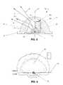
- FIG. 4is a rotated isometric view of the embodiment of the invention shown in FIG. 1 .
- FIG. 5is an enlarged side cross-sectional view of Section A-A as shown in FIG. 2 .
- FIG. 6is a computer generated plot of a two dimensional surface representing a typical iso-foot-candle graph of the embodiment of FIGS. 1-5 .
- FIG. 7is top perspective view of a second embodiment of the invention shown in exploded view.
- FIG. 8is bottom perspective view of the second embodiment of the invention of FIG. 7 shown in exploded view.
- FIG. 9 ais a top cross-sectional view of an embodiment of the invention for providing an approximately 120° azimuthally spread beam as seen through the section lines C-C of FIG. 9 b.
- FIG. 9 bis a side plan view of the embodiment of the invention of FIG. 9 a with underlying structures shown in dotted outline.
- FIG. 10 ais a top cross-sectional view of an embodiment of the invention for providing an approximately 180° azimuthally spread beam as seen through the section lines A-A of FIG. 10 b.
- FIG. 10 bis a side plan view of the embodiment of the invention of FIG. 10 a with underlying structures shown in dotted outline.
- FIG. 11 ais a top cross-sectional view of an embodiment of the invention for providing an approximately 270° azimuthally spread beam as seen through the section lines B-B of FIG. 11 b.
- FIG. 11 bis a side plan view of the embodiment of the invention of FIG. 11 a with underlying structures shown in dotted outline.
- FIG. 12is a schematic plan view of a building footprint in which azimuthally spread beam luminaries are provided in various positions of the building outline to provide for approximately 270°, 180° and 90° illumination ground patterns using various embodiments of the invention.
- FIG. 13is a side cross-sectional view of a prior art TIR optic.
- FIG. 14is a perspective view of a luminaire using the devices of the invention.
- FIG. 15is a perspective view of an assembled array using the devices of the invention.
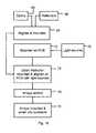
- FIG. 16is a flow diagram showing the assembly of the device including the light source, reflector, and optic into an array and luminaire.
- FIG. 1illustrates a side plan view of a device 10 corresponding to a first embodiment of the invention.
- Device 10comprises an LED (light emitting diode) or LED package, the base of package 1 of which only is viewable in the view of FIG. 1 and a base 6 to an optical surface 11 of the optic 22 , the outer surface 11 of which is shown in FIG. 1 as generally hemispherical.
- the smooth outer surface 11 of the optic 22minimizes the amount of dust, dirt or debris that tends to lodge, stick or otherwise adhere to the optic 22 , so that when device 10 is used as an exposed light source in a luminaire, it tends to shed environmental borne material that might otherwise obscure or reduce the optical transmissibility of outer surface 11 of the optic 22 over time.
- FIG. 1shows a substantially hemispherical outer surface 11
- the outer surface 11could be provided with other smooth three dimensional shapes which would have selective refractive qualities according to design.
- FIG. 2is a cross-sectional view of the embodiment of the invention shown in FIG. 1 taken through section lines A-A.
- FIG. 2shows an optic 22 device 10 in side cross sectional view as seen in section lines A-A of FIG. 1 with a reflective surface 3 of a reflector or mirror 16 (hereinafter “reflector”)) situated inside the space between the LED package 1 and the optic 22 defined by the inner surface 4 of the optic 22 .
- reflectora reflector or mirror 16
- a “mirror”is generally understood to be an optic with a reflective surface created by a reflective or aluminized coating or film
- the term “reflector” as used in the specification and claimsis to be understood as including a mirror, a totally internally reflecting surface, a reflective grating, or any other kind of optical device which reflects light in whole or part.
- Dome 14 of the LED package 1is disposed into the cavity or space defined by inner surface 4 in the optic 22 . There is an air gap so that inner surface 4 of the optic 22 is a refracting surface which is positioned around dome 14 of the LED package 1 .
- the ray set from the LED chip or source 12can be modified to accommodate user-defined system requirements, which may vary from one application to another.
- the reflective surface 3 of reflector 16may be selectively curved and sized to provide a ray set with controlled parameters as dictated by the ultimately needed illumination pattern on the target surface.
- the side cross-sectional view of FIG. 2shows the reflector 16 to be curved in the longitudinal axis or as a function of the polar angle and also curved azimuthally as best shown in the top cross-sectional view of FIG. 3 .
- reflective surface 3is a first surface reflector, namely the innermost surface of reflector 16 is provided with the reflective coating, although use of a second surface reflector is included within the scope of the invention.
- FIG. 3shows an embodiment of the invention where the inner surface 4 of the optic 22 is radially disposed about the centerline of the dome 14 of the LED package 1 .
- Off-center configurations of optic 22 with respect to the centerline of the radiation pattern of the LED package 1are also contemplated as within the scope of possible design options of the invention.
- the surface 4 of the optic 22 that is occluded by reflective surface 3 from the light source 12can be any shape needed for the assembly of the primary elements of the invention.
- the portion of surface 4 occluded by reflector 16is shaped to provide a supporting and registering surface to support and align reflector 16 in the correct position and angular orientation with respect to light source 12 to obtain the designed net radiation pattern from device 10 .
- surface 4has a notch 4 a defined in it as shown in FIG. 5 into which a post integrally extending from reflector 16 is positioned during assembly.
- Locating flanges 5as best seen in FIG. 4 extend from surface 4 to provide a multiple-point guide for the lower curved portion of reflector 16 .
- Side clips 5 aextend from surface 4 to snap into matching indentations defined in the lower forward edges of reflector 16 as seen in FIGS. 4 and 5 .
- Many different mounting and alignment schemescan be used for the assembly of reflector 16 in the optic 22 .
- An additional embodimentis shown in the second embodiment of FIGS. 7-11 b , which by no means limits the range of equivalent designs.
- the LED package 1is vertically removed from the cavity in the optic 22 to show the inside detail of the optic 22 .
- Base flange 6as shown in FIGS. 1-5 is an optional feature of the optic 22 which is utilized for rotational mounting orientation or angular indexing.
- reflector 16may be replaced by a specially contoured or curved portion of inner surface 4 which has been metalized or otherwise formed or treated to form a reflective surface in place of the separate reflector 16 for the zone 2 light. Zone 1 and 2 light is further described below in greater detail.
- FIG. 5shows sample rays 7 , 8 , 9 , and 13 radiating from LED light source 12 and propagating through the optic 22 .
- Rays 7 and 8represent the set of rays that would radiate from the source in a first zone or solid angle (zone 1 ) and directly refract from or through surfaces 4 and 11 of the optic 22 .
- Directly incident rays 9 and 13represent the set of rays that would radiate from the light source (e.g., LED) 12 in a second zone or solid angle (zone 2 ), reflect off reflective surface 3 of the reflector 16 with a single reflection and then refract from or through surfaces 4 and 11 of the optic 22 .
- the light sourcee.g., LED
- the optic 22 and reflector 16are spatially and angularly oriented relative to the radiation pattern of the light source 12 such that substantially all the light from the light source 12 is collected from zone 1 and directly refracted by surfaces 4 and/or 11 or collected in zone 2 and reflected by reflector 16 into refracting surfaces 4 and/or 11 to join the ray set of rays 7 and 8 into the corresponding illumination pattern from the optic 22 . Hence, substantially all of the light is collected from the light source 12 and distributed into the beam from the optic 22 .
- substantiallyis understood in this context to mean all of the light radiated out of the dome 14 of the LED light source 12 in the intended Lambertian or designed radiation pattern less a fraction of light inherently lost due to imperfect optics or imperfect light sources often due to imperfect refraction, reflection or small imprecision in optical geometries or figure losses.
- FIG. 6represents the iso foot-candle illumination pattern of device 10 of the embodiment of FIGS. 1-5 .
- the optic assembly(s) 10is positioned above the illumined surface, such as a street, most likely as an array or plurality of arrays of such devices 10 mounted in a luminaire or fixture.
- the illumination patternis shown by the majority of energy radiating from the device 10 falling on the street side of the surface and a lesser amount falling on the curb side as delineated by artificial horizontal line 18 .
- Varying surfaces 3 , 4 and/or 11 in FIGS. 1-5allows the optic designer to vary or form the resultant energy distribution 20 of the device according to the design specifications, e.g. one of the various patterns meeting IES standards including the Type I-V street lighting patterns.
- Optic 22 assembly 10may be additionally modified by a curved or shaped portion of inner surface 4 to redirect it to a selected portion of outer surface 11 of optic 22 for a user-defined system requirement as may be desired in any given application.
- inner surface 4will then have an altered shape in its crown region adjacent or proximate to axis 17 to refract the central axis light from LED package 1 into the desired azimuthal and polar direction or directions.
- inner surface 4may be formed such that light incident on a portion of surface 4 lying on one side of an imaginary vertical plane including axis 17 is directed to the opposite side of the imaginary vertical plane.
- optical effectis not limiting on the scope or spirit of the invention which contemplates all possible optical effects achievable from modification of inner surface 4 alone or in combination with correlated modifications of exterior surface 11 of optic 22 .
- design controlsavailable to the designer in the device 10 of the illustrated embodiments.
- choice of materials for the optical elementsis expressly contemplated as another design control, which by no means exhaust the possible range of design controls that may be manipulated.
- the outer surface 11 of optic 22may be selectively shaped to independently control either the azimuthal or polar angular distribution of light being refracted or distributed through surface 11 .
- the inner surface 4 of optic 22may be selectively shaped to independently control either the azimuthal or polar angular distribution of light being refracted or distributed through surface 4 .
- the surface 3 of reflector 16may be selectively shaped to independently control either the azimuthal or polar angular distribution of light being reflected from surface 3 .
- Each of these six design inputs or parameterscan be selectively controlled independently from the others. While in the illustrated embodiments surfaces 3 , 4 , and 11 are each selectively shaped to control both the azimuthal and polar angular distribution of light from the corresponding surface, it is possible to control only one angular aspect of the light distribution from the surface to the exclusion of either one or both of the other surfaces.
- the azimuthal distribution of the refracted portion or zone 1 portion of the beamcan be entirely or substantially controlled only by the outer surface 11 while the polar distribution of the zone 1 portion of the beam will be entirely or substantially controlled only by the inner surface 4 , or vice versa. It is also contemplated that the azimuthal spread and amount of the illumination beam derived from the zone 2 light can be controlled with respect to the zone 2 light by the curvature and outline of the reflector 16 and its distance from the light source 12 . Similarly, the reflector 16 can be used to entirely or substantially control the azimuthal or polar distribution of the reflected beam or control both the azimuthal and polar distributions of the reflected beam.
- FIGS. 7-12The same elements are referenced by the same reference numerals and incorporate the same features and aspects as described above.
- the illustrated embodimentis denoted by the applicant as “blob optics” incorporated into device 10 of FIGS. 7-11 b , combined with any one of a plurality of commercially available LED package(s) 1 .
- blob opticis a type of optic where it is meant that the refracting surface is free-form in design and is particularly characterized by refracting surfaces that form positively or negatively defined lobes in surfaces 4 and/or 11 with respect to surrounding portions of the optical surfaces.
- a “blob optic”is but one type of optic that may be employed in the embodiments of the invention.
- the lobesare defined positively in the outer surface 11 of the optic 22 , while the inner surface 4 of the optic 22 remains substantially hemispherical.
- portions of inner surface 4may also either be smoothly flattened or lobed to provide selectively refractive local surfaces in addition to refractive lobed cavities defined on outer surface 11 .
- lobesOne way in which the notion of positively or negatively defined lobes may be visualized or defined is that if an imaginary spherical surface where placed into contact with a portion of a refracting surface, that portion of the refracting surface most substantially departing from the spherical surface would define the lobe.
- the lobewould be positively defined if defined on the surface 4 or 11 so that the optical material of the optic 22 extended in the volume of the lobe beyond the imaginary spherical surface, or negatively defined if defined into the surface 4 or 11 so that an empty space or cavity were defined into the optical material of the optic 22 beyond the imaginary spherical surface.
- lobescan be locally formed on or into the inner or outer surfaces 4 , 11 of the optic 22 in multiple locations and extending in multiple directions.
- the design of lobed opticsis further disclosed in copending application Ser. No. 11/711,218, filed on Feb. 26, 2007, assigned to the same assignee of present application, which copending application is hereby incorporated by reference.
- reflector 16again is entirely housed inside of optic 22 within the cavity defined by inner surface 4 .
- Reflector 16is integrally provided with a basal flange 24 extending rearwardly.
- the basal flange 24flatly mates onto a shoulder 26 defined in surface 4 , as seen in FIG. 8 , which serves both to position and orient reflector 16 in the designed configuration.
- there is no notch in the crown of optic 22nor is there a post extending from reflector 16 .
- Flange 24integrally extends rearwardly from reflector 16 to flushly fit onto shoulder 26 of optic 22 adjacent to rivet post 30 .
- Rivet post 30is heat staked during assembly to soften and deform over the bottom surface of flange 24 to effectively form a rivet post head which fixes reflector 16 into the position and orientation defined for it by flange 24 and mating shoulder 26 .
- FIGS. 9 a -11 billustrate various embodiments where the beam spread of the illumination pattern is varied.
- the embodiment of FIGS. 9 a and 9 bdefine a device 10 of the type shown in FIGS. 7 and 8 in which the azimuthal beam spread produced by surfaces 4 and 11 and reflector 16 include an azimuthal angle of approximately 120°.
- the azimuthal angular spread of the illumination pattern on the groundneed not be exactly 120° but may vary ⁇ 15° or more from that normal azimuthal spread.
- FIG. 9 aas seen through section C-C of FIG.
- imaginary beam spread edges 32are shown extended from the center of light source 12 , touching the forward extremity of the reflective surface 3 of reflector 16 to form the spread angle, shown as being of the order of 120°.
- the outline of reflector 16need not be uniform in the vertical axis so that greater or lesser angular segments of the zone 2 from light source 12 may impinge on the reflective surface 3 .
- FIGS. 10 a and 10 bdefine a device 10 of the type shown in FIGS. 7 and 8 in which the azimuthal beam spread produced by surfaces 4 and 11 and reflector 16 include an azimuthal angle of approximately 180°.
- the azimuthal angular spread of the illumination pattern on the groundneed not be exactly 180° but may vary ⁇ 15° or more from that normal azimuthal spread.
- imaginary beam spread edges 32are shown extended from the center of light source 12 , touching the forward extremity of the reflective surface 3 of reflector 16 to form the spread angle, shown as being of the order of 180° or, in the illustrated embodiment, somewhat in excess of 180°.
- a luminaire including device 10it will be mounted on a pole or fixture which extends some distance away from the building to which it is mounted or, in the case of a street light, away from the pole on which the luminaire is mounted.
- the illumination pattern on the ground or streethas an azimuthal spread with respect to nadir of more than 180° to include a portion of the illumination pattern extending back to the building or to the curb as shown in the iso-foot-candle plot of FIG. 6 .
- the other embodiments like those of FIGS. 9 a , 9 b , 11 a and 11 bmay be increased or decreased from the nominal designed azimuthal angular spread.
- the outline of reflector 16need not be uniform in the vertical axis so that greater or lesser angular segments of the zone 2 from light source 12 may impinge on the reflective surface 3 , and the azimuthal beam spread may be a selectively chosen function of the vertical distance about the base of optic 22 .
- FIGS. 11 a and 11 bdefine a device 10 of the type shown in FIGS. 7 and 8 in which the azimuthal beam spread produced by surfaces 4 and 11 and reflector 16 include an azimuthal angle of approximately 270°.
- the azimuthal angular spread of the illumination pattern on the groundneed not be exactly 270° but may vary ⁇ 15° or more from that normal azimuthal spread.
- imaginary beam spread edges 32are shown extended from the center of light source 12 , touching the forward extremity of the reflective surface 3 of reflector 16 to form the spread angle, shown as being of the order of 270°.
- reflector 16 of FIGS. 11 a and 11 bis a saddle-shaped reflector with a concave surface facing toward light source 12 defined along its vertical axis as seen in dotted outline in FIG. 11 b and a convex surface facing toward light source 12 defined along its horizontal axis as seen in section B-B in FIG. 11 a.
- an embodimentmay be provided according to the teachings of the invention to provide a device 10 with an azimuthal beam spread of the order of 90° ⁇ 15° or more or any other angular spread as may be needed by the application.
- FIG. 12illustrates one application where such varied beam spread devices 10 may be advantageously employed.
- the footprint of an L-shaped building 34is shown.
- At different points in the building perimeter or footprint lights with different azimuthal spreadsare required to provide efficient and effective ground illumination.
- a 90° device 10can efficiently illuminate the adjacent ground surface with minimal wasted light energy being expended on walls or portions of the roof which have no need for illumination.
- Outside corners 38 and 40advantageously employ a device 10 with a 270° spread to cover the proximate ground areas to these corners of the building, again with minimal wasted light energy being thrown onto walls or other surfaces which require no illumination.
- Position 42 along a long flat wall of building 34 , where there may be a door or walkway,is advantageously provided with a device 10 with a 180° beam spread, again with minimal wasted illumination energy.
- a device 10 with a 180° beam spreadagain with minimal wasted illumination energy.
- the energy of nearly two additional light sourcesis wasted by being directed onto surfaces for which illumination is not usefully employed.
- the use of directional fixtures or angulations to achieve the pattern distribution of FIG. 12is so complex or expensive that, in general, it is impractical and no attempt is made to direct substantially all of the light from the sources to just those areas where it is needed.
- the number of LEDs incorporated into the arrays 60 or luminaires 62 of the inventioncan also be varied to match the beam spread so that the light intensity or energy on the ground is uniform for each embodiment.
- the 90° light at position 36could have one third the number of LEDs in it than the 270° light at points 38 and 40 and half as many LEDs in it as the 180° light used at position 42 .
- the light intensity patterns on the ground from each of the pointswould be similar or equal, but the energy would be provided by the luminaires used at each position to efficiently match the application which it was intended to serve.
- Position 40is illustrated in a first embodiment in solid outline as having an idealized three-quarter or 270° circular ground pattern.
- An optional squared ground patternis illustrated in dotted outline in FIG. 12 for a lobed device 10 .
- device 10 used at position 40would comprise an optic 22 which would have three lobes defined in the inner and/or outer surfaces of the optic 22 to provide a three-cornered or 270° squared ground pattern.
- the lobesmay be defined in inner surface 4 and include one lobe on a centerline aligned with reflector 16 and two symmetrically disposed side lobes lying on a line perpendicular to the centerline. While the shape of inner surface 4 and reflector 16 would be azimuthally asymmetric, device 10 would have reflector symmetry across the centerline plane.
- FIGS. 14 and 15An illustration of the arrays 60 and luminaires 62 incorporating devices 10 is shown in FIGS. 14 and 15 .
- a plurality of such arrays 60each provided with a plurality of oriented devices 10 , are assembled into a fixture or luminaire 62 as depicted in one embodiment shown in FIG. 14 .
- Additional conventional heat sinking elementsmay be included and thermally coupled to a circuit board included in array 60 and light sources 1 .
- the plurality of optics 22are left exposed to the environment to avoid any loss or degradation of optical performance over time that might arise from the deterioration or obscuring by environmental factors of any protective transparent covering.
- a cover, bezel or other coveringcould be included.
- Luminaire 62then, in turn, is coupled to a pole or other mounting structure to function as a pathway or street light or other type of illumination device for a target surface.
- FIG. 16An idealized flow diagram of the assembly of luminaire 62 is illustrated in FIG. 16 .
- Reflectors 16 provided at step 66are mounted and aligned at step 68 into optics 22 provided at step 64 .
- Light sources 12are provided at step 70 and aligned to, mounted on or into a printed circuit board and electrically to corresponding drivers and wiring at step 72 .
- the optics/reflectors 16 , 22 from step 68are then aligned and mounted onto the printed circuit board at step 74 to form a partially completed array 60 .
- the array 60is then finished or sealed for weatherproofing and mechanical integrity at step 76 .
- the finished array 60is then mounted into, onto and wired into a luminaire 62 at step 78 .
Landscapes
- Engineering & Computer Science (AREA)
- General Engineering & Computer Science (AREA)
- Non-Portable Lighting Devices Or Systems Thereof (AREA)
- Optical Elements Other Than Lenses (AREA)
Abstract
Description
| Nominal or approximate azimuthal | |
| Approximate angle subtended by the | beam spread in degrees on target |
| mirror in degrees | surface |
| More than 0 | Less than 360 |
| 45 | 315 |
| 60 | 300 |
| 90 | 270 |
| 120 | 240 |
| 180 | 180 |
| 240 | 120 |
| 250 | 90 |
| 300 | 60 |
| 315 | 45 |
| 330 | 30 |
Claims (19)
Priority Applications (3)
| Application Number | Priority Date | Filing Date | Title |
|---|---|---|---|
| US15/083,074US10222030B2 (en) | 2008-08-14 | 2016-03-28 | LED devices for offset wide beam generation |
| US16/292,097US10400996B2 (en) | 2008-08-14 | 2019-03-04 | LED devices for offset wide beam generation |
| US16/557,928US10976027B2 (en) | 2008-08-14 | 2019-08-30 | LED devices for offset wide beam generation |
Applications Claiming Priority (7)
| Application Number | Priority Date | Filing Date | Title |
|---|---|---|---|
| US8881208P | 2008-08-14 | 2008-08-14 | |
| US12233908P | 2008-12-12 | 2008-12-12 | |
| US12/541,060US7854536B2 (en) | 2008-08-14 | 2009-08-13 | LED devices for offset wide beam generation |
| US12/945,515US8132942B2 (en) | 2008-08-14 | 2010-11-12 | LED devices for offset wide beam generation |
| US13/418,896US8454205B2 (en) | 2008-08-14 | 2012-03-13 | LED devices for offset wide beam generation |
| US13/908,663US9297517B2 (en) | 2008-08-14 | 2013-06-03 | LED devices for offset wide beam generation |
| US15/083,074US10222030B2 (en) | 2008-08-14 | 2016-03-28 | LED devices for offset wide beam generation |
Related Parent Applications (1)
| Application Number | Title | Priority Date | Filing Date |
|---|---|---|---|
| US13/908,663ContinuationUS9297517B2 (en) | 2008-08-14 | 2013-06-03 | LED devices for offset wide beam generation |
Related Child Applications (1)
| Application Number | Title | Priority Date | Filing Date |
|---|---|---|---|
| US16/292,097ContinuationUS10400996B2 (en) | 2008-08-14 | 2019-03-04 | LED devices for offset wide beam generation |
Publications (2)
| Publication Number | Publication Date |
|---|---|
| US20160252234A1 US20160252234A1 (en) | 2016-09-01 |
| US10222030B2true US10222030B2 (en) | 2019-03-05 |
Family
ID=41669307
Family Applications (7)
| Application Number | Title | Priority Date | Filing Date |
|---|---|---|---|
| US12/541,060ActiveUS7854536B2 (en) | 2008-08-14 | 2009-08-13 | LED devices for offset wide beam generation |
| US12/945,515ActiveUS8132942B2 (en) | 2008-08-14 | 2010-11-12 | LED devices for offset wide beam generation |
| US13/418,896ActiveUS8454205B2 (en) | 2008-08-14 | 2012-03-13 | LED devices for offset wide beam generation |
| US13/908,663Active2029-09-28US9297517B2 (en) | 2008-08-14 | 2013-06-03 | LED devices for offset wide beam generation |
| US15/083,074ActiveUS10222030B2 (en) | 2008-08-14 | 2016-03-28 | LED devices for offset wide beam generation |
| US16/292,097ActiveUS10400996B2 (en) | 2008-08-14 | 2019-03-04 | LED devices for offset wide beam generation |
| US16/557,928ActiveUS10976027B2 (en) | 2008-08-14 | 2019-08-30 | LED devices for offset wide beam generation |
Family Applications Before (4)
| Application Number | Title | Priority Date | Filing Date |
|---|---|---|---|
| US12/541,060ActiveUS7854536B2 (en) | 2008-08-14 | 2009-08-13 | LED devices for offset wide beam generation |
| US12/945,515ActiveUS8132942B2 (en) | 2008-08-14 | 2010-11-12 | LED devices for offset wide beam generation |
| US13/418,896ActiveUS8454205B2 (en) | 2008-08-14 | 2012-03-13 | LED devices for offset wide beam generation |
| US13/908,663Active2029-09-28US9297517B2 (en) | 2008-08-14 | 2013-06-03 | LED devices for offset wide beam generation |
Family Applications After (2)
| Application Number | Title | Priority Date | Filing Date |
|---|---|---|---|
| US16/292,097ActiveUS10400996B2 (en) | 2008-08-14 | 2019-03-04 | LED devices for offset wide beam generation |
| US16/557,928ActiveUS10976027B2 (en) | 2008-08-14 | 2019-08-30 | LED devices for offset wide beam generation |
Country Status (6)
| Country | Link |
|---|---|
| US (7) | US7854536B2 (en) |
| EP (1) | EP2326870B1 (en) |
| CN (1) | CN103459919B (en) |
| BR (1) | BRPI0918716A2 (en) |
| MX (1) | MX2011001685A (en) |
| WO (1) | WO2010019810A1 (en) |
Families Citing this family (74)
| Publication number | Priority date | Publication date | Assignee | Title |
|---|---|---|---|---|
| US7674018B2 (en) | 2006-02-27 | 2010-03-09 | Illumination Management Solutions Inc. | LED device for wide beam generation |
| US8434912B2 (en) | 2006-02-27 | 2013-05-07 | Illumination Management Solutions, Inc. | LED device for wide beam generation |
| US8430538B2 (en) | 2007-05-21 | 2013-04-30 | Illumination Management Solutions, Inc. | LED device for wide beam generation and method of making the same |
| US9423096B2 (en) | 2008-05-23 | 2016-08-23 | Cree, Inc. | LED lighting apparatus |
| US8388193B2 (en)* | 2008-05-23 | 2013-03-05 | Ruud Lighting, Inc. | Lens with TIR for off-axial light distribution |
| US8348475B2 (en) | 2008-05-23 | 2013-01-08 | Ruud Lighting, Inc. | Lens with controlled backlight management |
| US7891835B2 (en) | 2008-07-15 | 2011-02-22 | Ruud Lighting, Inc. | Light-directing apparatus with protected reflector-shield and lighting fixture utilizing same |
| CN103459919B (en) | 2008-08-14 | 2016-10-26 | 库帕技术公司 | For biasing the LED device that angle pencil of ray generates |
| US8215814B2 (en)* | 2008-11-21 | 2012-07-10 | Dbm Reflex Enterprises Inc. | Solid state optical illumination apparatus |
| US9217854B2 (en)* | 2009-04-28 | 2015-12-22 | Cree, Inc. | Lens with controlled light refraction |
| US9416926B2 (en) | 2009-04-28 | 2016-08-16 | Cree, Inc. | Lens with inner-cavity surface shaped for controlled light refraction |
| US10119662B2 (en) | 2009-04-28 | 2018-11-06 | Cree, Inc. | Lens with controlled light refraction |
| US9255686B2 (en) | 2009-05-29 | 2016-02-09 | Cree, Inc. | Multi-lens LED-array optic system |
| US9404634B2 (en) | 2009-10-30 | 2016-08-02 | Cree, Inc. | LED light fixture with facilitated lensing alignment and method of manufacture |
| US9028097B2 (en) | 2009-10-30 | 2015-05-12 | Cree, Inc. | LED apparatus and method for accurate lens alignment |
| US8348461B2 (en)* | 2009-10-30 | 2013-01-08 | Ruud Lighting, Inc. | LED apparatus and method for accurate lens alignment |
| US8545049B2 (en) | 2009-11-25 | 2013-10-01 | Cooper Technologies Company | Systems, methods, and devices for sealing LED light sources in a light module |
| CN102116453A (en)* | 2010-01-05 | 2011-07-06 | 富士迈半导体精密工业(上海)有限公司 | Optical lens and illuminating device |
| US8240878B2 (en)* | 2010-08-20 | 2012-08-14 | Safety Traffic Equipment Co., Ltd. | Waterproof LED diffuser |
| KR101756825B1 (en)* | 2010-08-24 | 2017-07-11 | 삼성전자주식회사 | Optical lens, led module and lighting apparatus having the optical lens |
| US8388198B2 (en) | 2010-09-01 | 2013-03-05 | Illumination Management Solutions, Inc. | Device and apparatus for efficient collection and re-direction of emitted radiation |
| TW201213877A (en)* | 2010-09-16 | 2012-04-01 | Foxsemicon Integrated Tech Inc | Lens and light source module |
| US20140140069A1 (en)* | 2011-02-24 | 2014-05-22 | Philip Premysler | Led illumination assemblies including partial lenses and metal reflectors |
| US9140430B2 (en) | 2011-02-28 | 2015-09-22 | Cooper Technologies Company | Method and system for managing light from a light emitting diode |
| US9052086B2 (en) | 2011-02-28 | 2015-06-09 | Cooper Technologies Company | Method and system for managing light from a light emitting diode |
| USD673307S1 (en) | 2011-05-12 | 2012-12-25 | Cooper Technologies Company | Light bar |
| WO2013043743A1 (en)* | 2011-09-19 | 2013-03-28 | Ruud Lighting, Inc. | Led retrofit lighting fixture |
| CN103196040B (en) | 2012-01-06 | 2015-03-11 | 扬升照明股份有限公司 | Lens structure, light source device and light source module |
| CN103216745B (en)* | 2012-01-20 | 2016-07-20 | 扬升照明股份有限公司 | lighting device |
| US10408429B2 (en) | 2012-02-29 | 2019-09-10 | Ideal Industries Lighting Llc | Lens for preferential-side distribution |
| US9541257B2 (en) | 2012-02-29 | 2017-01-10 | Cree, Inc. | Lens for primarily-elongate light distribution |
| US9541258B2 (en) | 2012-02-29 | 2017-01-10 | Cree, Inc. | Lens for wide lateral-angle distribution |
| EP2834556B1 (en)* | 2012-04-06 | 2017-08-02 | Cree, Inc. | Multi-lens led-array optic system |
| USD697664S1 (en)* | 2012-05-07 | 2014-01-14 | Cree, Inc. | LED lens |
| EP2847512B1 (en)* | 2012-05-07 | 2019-07-17 | Cree, Inc. | Lens for preferential-side distribution |
| TWI422861B (en)* | 2012-06-29 | 2014-01-11 | 一品光學工業股份有限公司 | Light control lens and light source device using the same |
| USD737499S1 (en)* | 2012-07-13 | 2015-08-25 | Asahi Rubber Inc. | Lens for light-emitting diode |
| US8974077B2 (en) | 2012-07-30 | 2015-03-10 | Ultravision Technologies, Llc | Heat sink for LED light source |
| US9080739B1 (en)* | 2012-09-14 | 2015-07-14 | Cooper Technologies Company | System for producing a slender illumination pattern from a light emitting diode |
| US9200765B1 (en) | 2012-11-20 | 2015-12-01 | Cooper Technologies Company | Method and system for redirecting light emitted from a light emitting diode |
| US9062849B2 (en) | 2012-12-05 | 2015-06-23 | Cooper Technologies Company | LED luminaire having grooved modifier |
| US8847261B1 (en) | 2013-03-14 | 2014-09-30 | Cooledge Lighting Inc. | Light-emitting devices having engineered phosphor elements |
| US20140268812A1 (en)* | 2013-03-15 | 2014-09-18 | Abl Ip Holding Llc | Led Assembly Having a Reflector That Provides Improved Light Control |
| US9080746B2 (en)* | 2013-03-15 | 2015-07-14 | Abl Ip Holding Llc | LED assembly having a refractor that provides improved light control |
| USD718490S1 (en)* | 2013-03-15 | 2014-11-25 | Cree, Inc. | LED lens |
| EP2971945B1 (en)* | 2013-03-15 | 2018-05-02 | ABL IP Holding LLC | Led assembly having a reflector or refractor that provides improved light control |
| WO2014183113A2 (en) | 2013-05-10 | 2014-11-13 | Abl Ip Holding Llc | Silicone optics |
| US9233510B2 (en) | 2013-07-22 | 2016-01-12 | GE Lighting Solutions, LLC | Lenses for cosine cubed, typical batwing, flat batwing distributions |
| US9816672B1 (en)* | 2013-11-18 | 2017-11-14 | Cooper Technologies Company | Configurable light source |
| RU2561191C2 (en)* | 2013-12-04 | 2015-08-27 | Закрытое акционерное общество "Светлана-Оптоэлектроника" | Optical element |
| US9523479B2 (en) | 2014-01-03 | 2016-12-20 | Cree, Inc. | LED lens |
| EP2894395B1 (en)* | 2014-01-10 | 2021-04-07 | ZG Lighting France S.A. | Lighting device for illumination tunnels, underpasses or subways |
| KR101665760B1 (en)* | 2014-05-12 | 2016-10-24 | 엘지전자 주식회사 | Light emitting module and lighting apparatus having the same |
| US20150338040A1 (en)* | 2014-05-20 | 2015-11-26 | Karl T. Swope | Lighting device |
| US9410674B2 (en) | 2014-08-18 | 2016-08-09 | Cree, Inc. | LED lens |
| US9757912B2 (en) | 2014-08-27 | 2017-09-12 | Cree, Inc. | One-piece multi-lens optical member with ultraviolet inhibitor and method of manufacture |
| CN104566215B (en)* | 2014-12-24 | 2017-12-29 | 上海小糸车灯有限公司 | A kind of vehicle light illumination local aluminizing lens |
| US9903561B1 (en) | 2015-11-09 | 2018-02-27 | Abl Ip Holding Llc | Asymmetric vision enhancement optics, luminaires providing asymmetric light distributions and associated methods |
| USD792010S1 (en)* | 2016-03-01 | 2017-07-11 | Neptun Light, Inc. | Light fixture |
| USD792011S1 (en)* | 2016-05-10 | 2017-07-11 | Neptun Light, Inc. | Light fixture |
| US20180073690A1 (en)* | 2016-09-12 | 2018-03-15 | Ameritech Llc | Luminaire including light emitting diodes and an anti-glare material |
| US10429035B2 (en) | 2017-01-25 | 2019-10-01 | Ledil Oy | Optical device for modifying light distribution |
| US10468566B2 (en) | 2017-04-10 | 2019-11-05 | Ideal Industries Lighting Llc | Hybrid lens for controlled light distribution |
| DE102017109079B4 (en) | 2017-04-27 | 2024-02-22 | OSRAM Opto Semiconductors Gesellschaft mit beschränkter Haftung | Optoelectronic component and component with such a component |
| US10274159B2 (en) | 2017-07-07 | 2019-04-30 | RAB Lighting Inc. | Lenses and methods for directing light toward a side of a luminaire |
| EP3470730B1 (en) | 2017-10-10 | 2023-01-25 | ZG Lighting France S.A.S | Lighting unit and luminaire for road and/or street lighting |
| KR101918923B1 (en) | 2017-10-23 | 2019-02-08 | 최종침 | Lighting apparatus having reflector |
| US11232684B2 (en) | 2019-09-09 | 2022-01-25 | Appleton Grp Llc | Smart luminaire group control using intragroup communication |
| US11219112B2 (en) | 2019-09-09 | 2022-01-04 | Appleton Grp Llc | Connected controls infrastructure |
| US11250284B2 (en)* | 2019-09-18 | 2022-02-15 | Veoneer Us, Inc. | Device for emitting radiation |
| US11343898B2 (en) | 2019-09-20 | 2022-05-24 | Appleton Grp Llc | Smart dimming and sensor failure detection as part of built in daylight harvesting inside the luminaire |
| CN113464881A (en)* | 2021-06-22 | 2021-10-01 | 深圳市睿光达光电有限公司 | Street lamp with polarisation anti-dazzle lens |
| CN114864795B (en)* | 2022-04-29 | 2025-02-18 | 弘凯光电(江苏)有限公司 | Light emitting module and electronic device |
| US11982440B1 (en)* | 2023-06-09 | 2024-05-14 | Dialight Corporation | Lens to produce wide angle light output in high density LED arrays |
Citations (174)
| Publication number | Priority date | Publication date | Assignee | Title |
|---|---|---|---|---|
| US1758977A (en) | 1926-04-21 | 1930-05-20 | Holophane Co Inc | Reflecting prism |
| US2254961A (en) | 1937-08-21 | 1941-09-02 | George M Cressaty | Unitary lens system |
| US2394992A (en) | 1943-06-30 | 1946-02-19 | Holophane Co Inc | Lighting unit |
| GB718425A (en) | 1951-05-10 | 1954-11-17 | Gen Electric Co Ltd | Improvements in or relating to refractor members for lighting fittings |
| US2818500A (en) | 1953-07-03 | 1957-12-31 | Holophane Co Inc | Prismatic reflectors |
| GB794670A (en) | 1955-05-20 | 1958-05-07 | Gen Electric Co Ltd | Improvements in or relating to refractor members for lighting fittings |
| GB815609A (en) | 1955-04-26 | 1959-07-01 | Corning Glass Works | Street lighting luminaire |
| US2908197A (en) | 1954-01-29 | 1959-10-13 | Westinghouse Air Brake Co | Wide angle lenses |
| US3278743A (en) | 1963-12-16 | 1966-10-11 | Holophane Co Inc | Street light refractor |
| US3596136A (en) | 1969-05-13 | 1971-07-27 | Rca Corp | Optical semiconductor device with glass dome |
| US3647148A (en) | 1969-12-11 | 1972-03-07 | Holophane Co Inc | Veiling glare control with luminaires |
| US3927290A (en) | 1974-11-14 | 1975-12-16 | Teletype Corp | Selectively illuminated pushbutton switch |
| US4345308A (en) | 1978-08-25 | 1982-08-17 | General Instrument Corporation | Alpha-numeric display array and method of manufacture |
| US4460945A (en) | 1982-09-30 | 1984-07-17 | Southern California Edison Company, Inc. | Luminaire shield |
| US4729076A (en) | 1984-11-15 | 1988-03-01 | Tsuzawa Masami | Signal light unit having heat dissipating function |
| US4734836A (en) | 1984-09-29 | 1988-03-29 | Masataka Negishi | Lighting apparatus |
| US4860177A (en) | 1988-01-25 | 1989-08-22 | John B. Simms | Bicycle safety light |
| US4907044A (en) | 1987-10-15 | 1990-03-06 | Siemens Aktiengesellschaft | Optical emission device |
| US4941072A (en) | 1988-04-08 | 1990-07-10 | Sanyo Electric Co., Ltd. | Linear light source |
| JPH06177424A (en) | 1992-12-03 | 1994-06-24 | Rohm Co Ltd | Light emitting diode lamp and collective type light emitting diode display device |
| US5404869A (en) | 1992-04-16 | 1995-04-11 | Tir Technologies, Inc. | Faceted totally internally reflecting lens with individually curved faces on facets |
| US5424931A (en) | 1994-05-09 | 1995-06-13 | Wheeler; Todd D. | Mobile illumination device |
| WO1996024802A1 (en) | 1995-02-10 | 1996-08-15 | Ecolux Inc. | Prismatic toroidal lens and traffic signal light using this lens |
| US5782555A (en) | 1996-06-27 | 1998-07-21 | Hochstein; Peter A. | Heat dissipating L.E.D. traffic light |
| WO1998033007A1 (en) | 1997-01-23 | 1998-07-30 | Koninklijke Philips Electronics N.V. | Luminaire |
| US5857767A (en) | 1996-09-23 | 1999-01-12 | Relume Corporation | Thermal management system for L.E.D. arrays |
| JPH11154766A (en) | 1997-09-22 | 1999-06-08 | Nichia Chem Ind Ltd | Light emitting diode and traffic light using the same |
| US5926320A (en) | 1997-05-29 | 1999-07-20 | Teldedyne Lighting And Display Products, Inc. | Ring-lens system for efficient beam formation |
| US5924788A (en) | 1997-09-23 | 1999-07-20 | Teledyne Lighting And Display Products | Illuminating lens designed by extrinsic differential geometry |
| US5939996A (en) | 1996-03-29 | 1999-08-17 | Rolls-Royce Power Engineering Plc | Display sign and an optical element for use in the same |
| US6045240A (en) | 1996-06-27 | 2000-04-04 | Relume Corporation | LED lamp assembly with means to conduct heat away from the LEDS |
| US6050707A (en) | 1996-06-14 | 2000-04-18 | Stanley Electric Co., Ltd. | Light emitting diode device |
| US6102558A (en) | 1997-05-23 | 2000-08-15 | Valeo Vision | Motor vehicle headlight with a reflector for generating a wide beam, and with a striated cover lens |
| US6227685B1 (en) | 1996-10-11 | 2001-05-08 | Mcdermott Kevin | Electronic wide angle lighting device |
| US6227684B1 (en) | 1997-04-07 | 2001-05-08 | U.S. Philips Corporation | Luminaire |
| US6273596B1 (en) | 1997-09-23 | 2001-08-14 | Teledyne Lighting And Display Products, Inc. | Illuminating lens designed by extrinsic differential geometry |
| US6341466B1 (en) | 2000-01-19 | 2002-01-29 | Cooper Technologies Company | Clip for securing an elongate member to a T-bar of a ceiling grid |
| US6345800B1 (en) | 1998-07-27 | 2002-02-12 | Nsi Enterprises, Inc. | Universal load-bearing hanger bracket and method for hanging a lighting fixture below a grid ceiling system at on-grid or off-grid locations |
| US20020034081A1 (en) | 2000-09-18 | 2002-03-21 | Koito Manufacturing Co., Ltd. | Vehicle lamp |
| US6441558B1 (en) | 2000-12-07 | 2002-08-27 | Koninklijke Philips Electronics N.V. | White LED luminary light control system |
| US6461008B1 (en) | 1999-08-04 | 2002-10-08 | 911 Emergency Products, Inc. | Led light bar |
| US20020181222A1 (en) | 2001-04-06 | 2002-12-05 | Boyd Gary T. | Linear illumination source |
| US20020196623A1 (en) | 2001-06-21 | 2002-12-26 | Star-Reach Corporation | High efficient tubular light emitting cylinder |
| US6502956B1 (en) | 1999-03-25 | 2003-01-07 | Leotek Electronics Corporation | Light emitting diode lamp with individual LED lenses |
| US6527422B1 (en) | 2000-08-17 | 2003-03-04 | Power Signal Technologies, Inc. | Solid state light with solar shielded heatsink |
| US6536923B1 (en) | 1998-07-01 | 2003-03-25 | Sidler Gmbh & Co. | Optical attachment for a light-emitting diode and brake light for a motor vehicle |
| US20030067787A1 (en) | 2001-10-04 | 2003-04-10 | Koito Manufacturing Co., Ltd. | Vehicle lamp |
| US6547423B2 (en) | 2000-12-22 | 2003-04-15 | Koninklijke Phillips Electronics N.V. | LED collimation optics with improved performance and reduced size |
| US6560038B1 (en) | 2001-12-10 | 2003-05-06 | Teledyne Lighting And Display Products, Inc. | Light extraction from LEDs with light pipes |
| US20030099115A1 (en) | 2001-11-28 | 2003-05-29 | Joachim Reill | Led illumination system |
| WO2003044870A1 (en) | 2001-11-22 | 2003-05-30 | Mireille Georges | Light-emitting diode illuminating optical device |
| US6582103B1 (en) | 1996-12-12 | 2003-06-24 | Teledyne Lighting And Display Products, Inc. | Lighting apparatus |
| US6598998B2 (en) | 2001-05-04 | 2003-07-29 | Lumileds Lighting, U.S., Llc | Side emitting light emitting device |
| US6639733B2 (en) | 2000-03-16 | 2003-10-28 | Light Prescriptions Innovators, Llc. | High efficiency non-imaging optics |
| US20040004828A1 (en) | 2002-07-05 | 2004-01-08 | Mark Chernick | Spinning illuminated novelty device with syncronized light sources |
| US20040037076A1 (en) | 2002-07-17 | 2004-02-26 | Sharp Kabushiki Kaisha | Light emitting diode lamp and light emitting diode display unit |
| US20040070855A1 (en) | 2002-10-11 | 2004-04-15 | Light Prescriptions Innovators, Llc, A Delaware Limited Liability Company | Compact folded-optics illumination lens |
| US20040105261A1 (en) | 1997-12-17 | 2004-06-03 | Color Kinetics, Incorporated | Methods and apparatus for generating and modulating illumination conditions |
| US20040105171A1 (en) | 2002-12-02 | 2004-06-03 | Light Prescriptions Innovators, Llc, A Delaware Limited Liability Company | Asymmetric TIR lenses producing off-axis beams |
| US20040105264A1 (en) | 2002-07-12 | 2004-06-03 | Yechezkal Spero | Multiple Light-Source Illuminating System |
| EP1431653A2 (en) | 2002-12-19 | 2004-06-23 | Toshiji Kishimura | Light source for white color LED lighting and white color led lighting device |
| WO2004068909A1 (en) | 2003-01-27 | 2004-08-12 | Matsushita Electric Industrial Co., Ltd. | Multichip led lighting device |
| US6785053B2 (en) | 2002-09-27 | 2004-08-31 | John M. Savage, Jr. | Threaded lens coupling to LED apparatus |
| US6784357B1 (en) | 2002-02-07 | 2004-08-31 | Chao Hsiang Wang | Solar energy-operated street-lamp system |
| US20040189933A1 (en) | 2002-12-02 | 2004-09-30 | Light Prescription Innovators, Llc | Apparatus and method for use in fulfilling illumination prescription |
| US20040207999A1 (en) | 2003-03-14 | 2004-10-21 | Toyoda Gosei Co., Ltd. | LED package |
| US20040218388A1 (en) | 2003-03-31 | 2004-11-04 | Fujitsu Display Technologies Corporation | Surface lighting device and liquid crystal display device using the same |
| US20040222947A1 (en) | 2003-05-07 | 2004-11-11 | James Newton | LED lighting array for a portable task light |
| US20040228127A1 (en) | 2003-05-16 | 2004-11-18 | Squicciarini John B. | LED clusters and related methods |
| US6850001B2 (en) | 2001-10-09 | 2005-02-01 | Agilent Technologies, Inc. | Light emitting diode |
| JP2005062461A (en) | 2003-08-12 | 2005-03-10 | Matsushita Electric Ind Co Ltd | Display device |
| US20050073849A1 (en) | 2003-10-06 | 2005-04-07 | Greg Rhoads | Light source using light emitting diodes and an improved method of collecting the energy radiating from them |
| US6895334B2 (en) | 2000-11-02 | 2005-05-17 | Fujinon Corporation | Method and apparatus for optimizing optical system and recording medium with program for optimizing optical system |
| WO2005057082A1 (en) | 2003-12-10 | 2005-06-23 | Okaya Electric Industries Co., Ltd. | Indicator lamp |
| US20050207165A1 (en) | 2001-08-09 | 2005-09-22 | Matsushita Electric Industrial Co., Ltd. | LED illumination apparatus and card-type LED illumination source |
| US6948838B2 (en) | 2002-01-15 | 2005-09-27 | Fer Fahrzeugelektrik Gmbh | Vehicle lamp having prismatic element |
| WO2005093316A1 (en) | 2004-03-25 | 2005-10-06 | Zhoulong Peng | Leds based street lamp |
| US6965715B2 (en) | 2001-10-01 | 2005-11-15 | Karl Storz Gmbh & Co. Kg | Lens and method for producing a lens |
| CN2750186Y (en) | 2004-12-01 | 2006-01-04 | 陈甲乙 | street lights with cooling effect |
| EP1621918A1 (en) | 2004-07-20 | 2006-02-01 | Osram Opto Semiconductors GmbH | Optical element comprising a beam exit surface with concave and convex portions allowing for uniform illumination of a given area with an arragement of light emitting diodes |
| US6997580B2 (en) | 2003-09-19 | 2006-02-14 | Mattel, Inc. | Multidirectional light emitting diode unit |
| US20060034082A1 (en) | 2004-08-12 | 2006-02-16 | Samsung Electro-Mechanics Co., Ltd. | Multi-lens light emitting diode |
| CN1737418A (en) | 2005-08-11 | 2006-02-22 | 周应东 | LED lamp for improving heat radiation effect |
| KR20060033572A (en) | 2004-10-15 | 2006-04-19 | 삼성전기주식회사 | Lens for LED Light Source |
| US20060081863A1 (en) | 2004-10-20 | 2006-04-20 | Samsung Electro-Mechanics Co., Ltd. | Dipolar side-emitting led lens and led module incorporating the same |
| KR20060071033A (en) | 2004-12-21 | 2006-06-26 | 엘지전자 주식회사 | LED lighting system and optical system |
| US20060138437A1 (en) | 2004-12-29 | 2006-06-29 | Tien-Fu Huang | Lens and LED using the lens to achieve homogeneous illumination |
| US7070310B2 (en) | 2002-10-01 | 2006-07-04 | Truck-Lite Co., Inc. | Light emitting diode headlamp |
| US7073931B2 (en) | 2003-02-10 | 2006-07-11 | Koito Manufacturing Co., Ltd. | Vehicular headlamp and optical unit |
| EP1686630A2 (en) | 2005-01-31 | 2006-08-02 | Samsung Electronics Co., Ltd. | Led device having diffuse reflective surface |
| US7090370B2 (en) | 2001-06-08 | 2006-08-15 | Advanced Leds Limited | Exterior luminaire |
| US7102172B2 (en) | 2003-10-09 | 2006-09-05 | Permlight Products, Inc. | LED luminaire |
| US7104672B2 (en) | 2004-10-04 | 2006-09-12 | A.L. Lightech, Inc. | Projection lens for light source arrangement |
| US20060238884A1 (en) | 2005-04-26 | 2006-10-26 | Jang Jun H | Optical lens, light emitting device package using the optical lens, and backlight unit |
| US20060245083A1 (en) | 2005-04-19 | 2006-11-02 | Coretronic Corporation | Lens for sideward light emission |
| US20060250803A1 (en) | 2005-05-04 | 2006-11-09 | Chia-Yi Chen | Street light with heat dispensing device |
| US20060255353A1 (en) | 2003-09-08 | 2006-11-16 | Taskar Nikhil R | Light efficient packaging configurations for LED lamps using high refractive index encapsulants |
| DE202006015981U1 (en) | 2006-07-06 | 2006-12-21 | AUGUX CO., LTD., Gueishan | LED street light combination with a heat dissipation arrangement has LED set in a frame and heat dissipating tubules connected to a heat dissipating body |
| US20060285311A1 (en) | 2005-06-19 | 2006-12-21 | Chih-Li Chang | Light-emitting device, backlight module, and liquid crystal display using the same |
| US7153015B2 (en) | 2001-12-31 | 2006-12-26 | Innovations In Optics, Inc. | Led white light optical system |
| US20070019415A1 (en) | 2005-04-22 | 2007-01-25 | Itt Industries | LED floodlight system |
| US20070019416A1 (en) | 2005-07-19 | 2007-01-25 | Samsung Electro-Mechanics Co., Ltd. | Light emitting diode package having dual lens structure for lateral light emission |
| US7172319B2 (en) | 2004-03-30 | 2007-02-06 | Illumination Management Solutions, Inc. | Apparatus and method for improved illumination area fill |
| KR20070015738A (en) | 2005-08-01 | 2007-02-06 | 서울반도체 주식회사 | Light emitting device having a silicon lens |
| US20070058369A1 (en) | 2005-01-26 | 2007-03-15 | Parkyn William A | Linear lenses for LEDs |
| US20070066310A1 (en) | 2005-09-21 | 2007-03-22 | Haar Rob V D | Mobile communication terminal and method |
| US20070063210A1 (en) | 2005-09-21 | 2007-03-22 | Tien-Lung Chiu | Backlight module and a light-emitting-diode package structure therefor |
| US20070081338A1 (en) | 2005-10-06 | 2007-04-12 | Thermalking Technology International Co. | Illumination device |
| US20070081340A1 (en) | 2005-10-07 | 2007-04-12 | Chung Huai-Ku | LED light source module with high efficiency heat dissipation |
| US7204627B2 (en) | 2003-09-29 | 2007-04-17 | Koito Manufacturing Co., Ltd. | Lamp unit for forming a cut-off line and vehicular headlamp using the same |
| US20070091615A1 (en) | 2005-10-25 | 2007-04-26 | Chi-Tang Hsieh | Backlight module for LCD monitors and method of backlighting the same |
| US7237936B1 (en) | 2005-05-27 | 2007-07-03 | Gibson David J | Vehicle light assembly and its associated method of manufacture |
| US20070183736A1 (en) | 2005-12-15 | 2007-08-09 | Pozdnyakov Vadim V | Lens for reforming light-emitting diode radiation |
| US20070201225A1 (en) | 2006-02-27 | 2007-08-30 | Illumination Management Systems | LED device for wide beam generation |
| US7281820B2 (en) | 2006-01-10 | 2007-10-16 | Bayco Products, Ltd. | Lighting module assembly and method for a compact lighting device |
| US20070258214A1 (en) | 2006-05-08 | 2007-11-08 | Yu-Nung Shen | Heat-Dissipating Device with Tapered Fins |
| US20080013322A1 (en) | 2006-04-24 | 2008-01-17 | Enplas Corporation | Illumination device and lens of illumination device |
| US20080019129A1 (en) | 2006-07-24 | 2008-01-24 | Chin-Wen Wang | LED Lamp Illumination Projecting Structure |
| US20080025044A1 (en) | 2006-02-09 | 2008-01-31 | Se-Ki Park | Point Light Source, Backlight Assembly Having the Same and Display Apparatus Having the Same |
| US7329029B2 (en) | 2003-05-13 | 2008-02-12 | Light Prescriptions Innovators, Llc | Optical device for LED-based lamp |
| US7329033B2 (en) | 2005-10-25 | 2008-02-12 | Visteon Global Technologies, Inc. | Convectively cooled headlamp assembly |
| US7329030B1 (en) | 2006-08-17 | 2008-02-12 | Augux., Ltd. | Assembling structure for LED road lamp and heat dissipating module |
| US20080043473A1 (en) | 2004-11-01 | 2008-02-21 | Nobuyuki Matsui | Light emitting module, lighting device, and display device |
| USD563036S1 (en) | 2005-03-02 | 2008-02-26 | Nichia Corporation | Light emitting diode lens |
| US7339200B2 (en) | 2005-08-05 | 2008-03-04 | Koito Manufacturing Co., Ltd. | Light-emitting diode and vehicular lamp |
| US20080055908A1 (en) | 2006-08-30 | 2008-03-06 | Chung Wu | Assembled structure of large-sized led lamp |
| US20080068799A1 (en) | 2006-09-14 | 2008-03-20 | Topson Optoelectronics Semi-Conductor Co., Ltd. | Heat sink structure for light-emitting diode based streetlamp |
| US7347599B2 (en) | 2003-02-04 | 2008-03-25 | Light Prescriptions Innovators, Llc | Etendue-squeezing illumination optics |
| US7348723B2 (en) | 2004-09-27 | 2008-03-25 | Enplas Corporation | Emission device, surface light source device, display and light flux control member |
| US7348604B2 (en) | 2005-05-20 | 2008-03-25 | Tir Technology Lp | Light-emitting module |
| US7352011B2 (en) | 2004-11-15 | 2008-04-01 | Philips Lumileds Lighting Company, Llc | Wide emitting lens for LED useful for backlighting |
| US20080080188A1 (en) | 2006-09-29 | 2008-04-03 | Chin-Wen Wang | Modulized Assembly Of A Large-sized LED Lamp |
| US20080100773A1 (en) | 2006-10-31 | 2008-05-01 | Hwang Seong Yong | Backlight, a lens for a backlight, and a backlight assembly having the same |
| US7374322B2 (en) | 2002-02-06 | 2008-05-20 | Steen Ronald L | Center high mounted stop lamp including leds and tir lens |
| US20080174996A1 (en) | 2007-01-18 | 2008-07-24 | Hong Kong Applied Science And Technology Research Institute Co., Ltd. | Light-emitting devices and lens therefor |
| US7410275B2 (en) | 2004-09-21 | 2008-08-12 | Lumination Llc | Refractive optic for uniform illumination |
| US20080239722A1 (en) | 2007-04-02 | 2008-10-02 | Ruud Lighting, Inc. | Light-Directing LED Apparatus |
| US20080273327A1 (en) | 2007-05-04 | 2008-11-06 | Ruud Lighting, Inc. | Safety Accommodation Arrangement in LED Package/Secondary Lens Structure |
| WO2008144672A1 (en) | 2007-05-21 | 2008-11-27 | Illumination Management Solutions, Inc. | An improved led device for wide beam generation and method of making the same |
| US7460985B2 (en) | 2003-07-28 | 2008-12-02 | Light Prescriptions Innovators, Llc | Three-dimensional simultaneous multiple-surface method and free-form illumination-optics designed therefrom |
| US7461948B2 (en) | 2005-10-25 | 2008-12-09 | Philips Lumileds Lighting Company, Llc | Multiple light emitting diodes with different secondary optics |
| JP2009021086A (en) | 2007-07-11 | 2009-01-29 | Panasonic Electric Works Co Ltd | Light emitting unit |
| US7507001B2 (en) | 2002-11-19 | 2009-03-24 | Denovo Lighting, Llc | Retrofit LED lamp for fluorescent fixtures without ballast |
| US7513639B2 (en) | 2006-09-29 | 2009-04-07 | Pyroswift Holding Co., Limited | LED illumination apparatus |
| US20090103308A1 (en) | 2007-10-19 | 2009-04-23 | Fu Zhun Precision Industry (Shen Zhen) Co., Ltd. | Led lamp with a heat sink |
| US7553051B2 (en) | 2004-03-18 | 2009-06-30 | Brasscorp Limited | LED work light |
| US7569802B1 (en) | 2003-03-20 | 2009-08-04 | Patrick Mullins | Photosensor control unit for a lighting module |
| US7572027B2 (en) | 2005-09-15 | 2009-08-11 | Integrated Illumination Systems, Inc. | Interconnection arrangement having mortise and tenon connection features |
| US7572654B2 (en) | 2006-09-22 | 2009-08-11 | Hon Hai Precision Industry Co., Ltd. | Method for making light emitting diode |
| US7575354B2 (en) | 2004-09-16 | 2009-08-18 | Magna International Inc. | Thermal management system for solid state automotive lighting |
| US20090244895A1 (en) | 2006-05-30 | 2009-10-01 | Neobulb Technologies, Inc. | Light-Emitting Diode Illuminating Equipment with High Power and High Heat Dissipation Efficiency |
| US20090262543A1 (en) | 2008-04-18 | 2009-10-22 | Genius Electronic Optical Co., Ltd. | Light base structure of high-power LED street lamp |
| US7618162B1 (en) | 2004-11-12 | 2009-11-17 | Inteled Corp. | Irradiance-redistribution lens and its applications to LED downlights |
| US7625102B2 (en) | 2004-10-14 | 2009-12-01 | Stanley Electric Co., Ltd. | Lighting device |
| US7637633B2 (en) | 2005-10-18 | 2009-12-29 | National Tsing Hua University | Heat dissipation devices for an LED lamp set |
| US20100014290A1 (en) | 2008-07-15 | 2010-01-21 | Ruud Lighting, Inc. | Light-directing apparatus with protected reflector-shield and lighting fixture utilizing same |
| US7651240B2 (en) | 2006-01-10 | 2010-01-26 | Bayco Products. Ltd. | Combination task lamp and flash light |
| WO2010019810A1 (en) | 2008-08-14 | 2010-02-18 | Cooper Technologies Company | Led devices for offset wide beam generation |
| US7775679B2 (en) | 2004-08-18 | 2010-08-17 | Advanced Illumination, Inc. | High intensity light source for a machine vision system and method of making same |
| US7777405B2 (en) | 2002-07-16 | 2010-08-17 | Odelo Gmbh | White LED headlight |
| KR20100105388A (en) | 2009-03-18 | 2010-09-29 | (주)알텍테크놀로지스 | Method for fabricating light emitting diode divice and light emitting diode package and light emitting diode module and lamp device having the same |
| US7817909B2 (en) | 2004-12-21 | 2010-10-19 | Sharp Kabushiki Kaisha | Optical device and light source |
| US20100296283A1 (en) | 2009-05-22 | 2010-11-25 | Elliptipar | Total internal reflective (tir) optic light assembly |
| US7841750B2 (en) | 2008-08-01 | 2010-11-30 | Ruud Lighting, Inc. | Light-directing lensing member with improved angled light distribution |
| US7972036B1 (en) | 2008-04-30 | 2011-07-05 | Genlyte Thomas Group Llc | Modular bollard luminaire louver |
| US7972035B2 (en) | 2007-10-24 | 2011-07-05 | Lsi Industries, Inc. | Adjustable lighting apparatus |
| WO2011098515A1 (en) | 2010-02-11 | 2011-08-18 | Ewo Srl/Gmbh | Lighting module for illuminating traffic routes, and traffic route luminaire |
| US8007140B2 (en) | 2009-09-03 | 2011-08-30 | Fu Zhun Precision Industry (Shen Zhen) Co., Ltd. | LED module |
| US8025428B2 (en) | 2004-12-07 | 2011-09-27 | Elumen Lighting Networks Inc. | Assembly of light emitting diodes for lighting applications |
| US20120044699A1 (en) | 2010-07-09 | 2012-02-23 | Anderson Leroy E | Led extended optic tir light cover with light beam control |
| US8207546B2 (en)* | 2006-05-17 | 2012-06-26 | Stanley Electric Co., Ltd. | Semiconductor light-emitting device and method for manufacturing the same |
| US8382338B2 (en) | 2010-06-25 | 2013-02-26 | Silitek Electronic (Guangzhou) Co., Ltd. | Light-emitting diode lens |
| US8469552B2 (en) | 2009-05-13 | 2013-06-25 | Hella Kgaa Hueck & Co. | Street lighting device |
| US20140016326A1 (en) | 2012-06-14 | 2014-01-16 | Universal Lighting Technologies, Inc. | Asymmetric area lighting lens |
Family Cites Families (6)
| Publication number | Priority date | Publication date | Assignee | Title |
|---|---|---|---|---|
| MY141789A (en)* | 2001-01-19 | 2010-06-30 | Lg Chem Investment Ltd | Novel acyclic nucleoside phosphonate derivatives, salts thereof and process for the preparation of the same. |
| CA2452348C (en) | 2003-03-05 | 2011-05-03 | Tir Systems Ltd. | System and method for manipulating illumination created by an array of light emitting devices |
| US7182480B2 (en)* | 2003-03-05 | 2007-02-27 | Tir Systems Ltd. | System and method for manipulating illumination created by an array of light emitting devices |
| US6971772B1 (en)* | 2003-06-12 | 2005-12-06 | Acuity Brands, Inc. | Luminaire globes having internal light control elements |
| WO2007018927A2 (en) | 2005-07-22 | 2007-02-15 | Illumination Management Solutions, Inc. | A light-conducting pedestal configuration for an led |
| CN101469819A (en)* | 2007-12-27 | 2009-07-01 | 富准精密工业(深圳)有限公司 | LED lamp |
- 2009
- 2009-08-13CNCN200980140502.1Apatent/CN103459919B/enactiveActive
- 2009-08-13MXMX2011001685Apatent/MX2011001685A/enactiveIP Right Grant
- 2009-08-13WOPCT/US2009/053767patent/WO2010019810A1/enactiveApplication Filing
- 2009-08-13USUS12/541,060patent/US7854536B2/enactiveActive
- 2009-08-13BRBRPI0918716Apatent/BRPI0918716A2/ennot_activeApplication Discontinuation
- 2009-08-13EPEP09807313.3Apatent/EP2326870B1/enactiveActive
- 2010
- 2010-11-12USUS12/945,515patent/US8132942B2/enactiveActive
- 2012
- 2012-03-13USUS13/418,896patent/US8454205B2/enactiveActive
- 2013
- 2013-06-03USUS13/908,663patent/US9297517B2/enactiveActive
- 2016
- 2016-03-28USUS15/083,074patent/US10222030B2/enactiveActive
- 2019
- 2019-03-04USUS16/292,097patent/US10400996B2/enactiveActive
- 2019-08-30USUS16/557,928patent/US10976027B2/enactiveActive
Patent Citations (199)
| Publication number | Priority date | Publication date | Assignee | Title |
|---|---|---|---|---|
| US1758977A (en) | 1926-04-21 | 1930-05-20 | Holophane Co Inc | Reflecting prism |
| US2254961A (en) | 1937-08-21 | 1941-09-02 | George M Cressaty | Unitary lens system |
| US2394992A (en) | 1943-06-30 | 1946-02-19 | Holophane Co Inc | Lighting unit |
| GB718425A (en) | 1951-05-10 | 1954-11-17 | Gen Electric Co Ltd | Improvements in or relating to refractor members for lighting fittings |
| US2818500A (en) | 1953-07-03 | 1957-12-31 | Holophane Co Inc | Prismatic reflectors |
| US2908197A (en) | 1954-01-29 | 1959-10-13 | Westinghouse Air Brake Co | Wide angle lenses |
| GB815609A (en) | 1955-04-26 | 1959-07-01 | Corning Glass Works | Street lighting luminaire |
| GB794670A (en) | 1955-05-20 | 1958-05-07 | Gen Electric Co Ltd | Improvements in or relating to refractor members for lighting fittings |
| US3278743A (en) | 1963-12-16 | 1966-10-11 | Holophane Co Inc | Street light refractor |
| US3596136A (en) | 1969-05-13 | 1971-07-27 | Rca Corp | Optical semiconductor device with glass dome |
| US3647148A (en) | 1969-12-11 | 1972-03-07 | Holophane Co Inc | Veiling glare control with luminaires |
| US3927290A (en) | 1974-11-14 | 1975-12-16 | Teletype Corp | Selectively illuminated pushbutton switch |
| US4345308A (en) | 1978-08-25 | 1982-08-17 | General Instrument Corporation | Alpha-numeric display array and method of manufacture |
| US4460945A (en) | 1982-09-30 | 1984-07-17 | Southern California Edison Company, Inc. | Luminaire shield |
| US4734836A (en) | 1984-09-29 | 1988-03-29 | Masataka Negishi | Lighting apparatus |
| US4729076A (en) | 1984-11-15 | 1988-03-01 | Tsuzawa Masami | Signal light unit having heat dissipating function |
| US4907044A (en) | 1987-10-15 | 1990-03-06 | Siemens Aktiengesellschaft | Optical emission device |
| US4860177A (en) | 1988-01-25 | 1989-08-22 | John B. Simms | Bicycle safety light |
| US4941072A (en) | 1988-04-08 | 1990-07-10 | Sanyo Electric Co., Ltd. | Linear light source |
| US5404869A (en) | 1992-04-16 | 1995-04-11 | Tir Technologies, Inc. | Faceted totally internally reflecting lens with individually curved faces on facets |
| JPH06177424A (en) | 1992-12-03 | 1994-06-24 | Rohm Co Ltd | Light emitting diode lamp and collective type light emitting diode display device |
| US5424931A (en) | 1994-05-09 | 1995-06-13 | Wheeler; Todd D. | Mobile illumination device |
| WO1996024802A1 (en) | 1995-02-10 | 1996-08-15 | Ecolux Inc. | Prismatic toroidal lens and traffic signal light using this lens |
| US5636057A (en) | 1995-02-10 | 1997-06-03 | Ecolux Inc. | Prismatic toroidal lens and traffic signal light using this lens |
| US5939996A (en) | 1996-03-29 | 1999-08-17 | Rolls-Royce Power Engineering Plc | Display sign and an optical element for use in the same |
| US6050707A (en) | 1996-06-14 | 2000-04-18 | Stanley Electric Co., Ltd. | Light emitting diode device |
| US5782555A (en) | 1996-06-27 | 1998-07-21 | Hochstein; Peter A. | Heat dissipating L.E.D. traffic light |
| US6045240A (en) | 1996-06-27 | 2000-04-04 | Relume Corporation | LED lamp assembly with means to conduct heat away from the LEDS |
| US5857767A (en) | 1996-09-23 | 1999-01-12 | Relume Corporation | Thermal management system for L.E.D. arrays |
| US6227685B1 (en) | 1996-10-11 | 2001-05-08 | Mcdermott Kevin | Electronic wide angle lighting device |
| US6582103B1 (en) | 1996-12-12 | 2003-06-24 | Teledyne Lighting And Display Products, Inc. | Lighting apparatus |
| WO1998033007A1 (en) | 1997-01-23 | 1998-07-30 | Koninklijke Philips Electronics N.V. | Luminaire |
| US6227684B1 (en) | 1997-04-07 | 2001-05-08 | U.S. Philips Corporation | Luminaire |
| US6102558A (en) | 1997-05-23 | 2000-08-15 | Valeo Vision | Motor vehicle headlight with a reflector for generating a wide beam, and with a striated cover lens |
| US5926320A (en) | 1997-05-29 | 1999-07-20 | Teldedyne Lighting And Display Products, Inc. | Ring-lens system for efficient beam formation |
| JPH11154766A (en) | 1997-09-22 | 1999-06-08 | Nichia Chem Ind Ltd | Light emitting diode and traffic light using the same |
| JP2001517855A (en) | 1997-09-23 | 2001-10-09 | テレダイン・ライティング・アンド・ディスプレイ・プロダクツ・インコーポレーテッド | Illumination lens designed by extrinsic differential geometry |
| US6273596B1 (en) | 1997-09-23 | 2001-08-14 | Teledyne Lighting And Display Products, Inc. | Illuminating lens designed by extrinsic differential geometry |
| US5924788A (en) | 1997-09-23 | 1999-07-20 | Teledyne Lighting And Display Products | Illuminating lens designed by extrinsic differential geometry |
| US20040105261A1 (en) | 1997-12-17 | 2004-06-03 | Color Kinetics, Incorporated | Methods and apparatus for generating and modulating illumination conditions |
| US6536923B1 (en) | 1998-07-01 | 2003-03-25 | Sidler Gmbh & Co. | Optical attachment for a light-emitting diode and brake light for a motor vehicle |
| US6345800B1 (en) | 1998-07-27 | 2002-02-12 | Nsi Enterprises, Inc. | Universal load-bearing hanger bracket and method for hanging a lighting fixture below a grid ceiling system at on-grid or off-grid locations |
| US6502956B1 (en) | 1999-03-25 | 2003-01-07 | Leotek Electronics Corporation | Light emitting diode lamp with individual LED lenses |
| US6461008B1 (en) | 1999-08-04 | 2002-10-08 | 911 Emergency Products, Inc. | Led light bar |
| US6341466B1 (en) | 2000-01-19 | 2002-01-29 | Cooper Technologies Company | Clip for securing an elongate member to a T-bar of a ceiling grid |
| US6639733B2 (en) | 2000-03-16 | 2003-10-28 | Light Prescriptions Innovators, Llc. | High efficiency non-imaging optics |
| US6527422B1 (en) | 2000-08-17 | 2003-03-04 | Power Signal Technologies, Inc. | Solid state light with solar shielded heatsink |
| US20020034081A1 (en) | 2000-09-18 | 2002-03-21 | Koito Manufacturing Co., Ltd. | Vehicle lamp |
| US6895334B2 (en) | 2000-11-02 | 2005-05-17 | Fujinon Corporation | Method and apparatus for optimizing optical system and recording medium with program for optimizing optical system |
| US6441558B1 (en) | 2000-12-07 | 2002-08-27 | Koninklijke Philips Electronics N.V. | White LED luminary light control system |
| US6547423B2 (en) | 2000-12-22 | 2003-04-15 | Koninklijke Phillips Electronics N.V. | LED collimation optics with improved performance and reduced size |
| US20020181222A1 (en) | 2001-04-06 | 2002-12-05 | Boyd Gary T. | Linear illumination source |
| US6598998B2 (en) | 2001-05-04 | 2003-07-29 | Lumileds Lighting, U.S., Llc | Side emitting light emitting device |
| US7090370B2 (en) | 2001-06-08 | 2006-08-15 | Advanced Leds Limited | Exterior luminaire |
| US20020196623A1 (en) | 2001-06-21 | 2002-12-26 | Star-Reach Corporation | High efficient tubular light emitting cylinder |
| US20050207165A1 (en) | 2001-08-09 | 2005-09-22 | Matsushita Electric Industrial Co., Ltd. | LED illumination apparatus and card-type LED illumination source |
| US6965715B2 (en) | 2001-10-01 | 2005-11-15 | Karl Storz Gmbh & Co. Kg | Lens and method for producing a lens |
| US20030067787A1 (en) | 2001-10-04 | 2003-04-10 | Koito Manufacturing Co., Ltd. | Vehicle lamp |
| US6850001B2 (en) | 2001-10-09 | 2005-02-01 | Agilent Technologies, Inc. | Light emitting diode |
| WO2003044870A1 (en) | 2001-11-22 | 2003-05-30 | Mireille Georges | Light-emitting diode illuminating optical device |
| US20030099115A1 (en) | 2001-11-28 | 2003-05-29 | Joachim Reill | Led illumination system |
| US6837605B2 (en) | 2001-11-28 | 2005-01-04 | Osram Opto Semiconductors Gmbh | Led illumination system |
| US6560038B1 (en) | 2001-12-10 | 2003-05-06 | Teledyne Lighting And Display Products, Inc. | Light extraction from LEDs with light pipes |
| US7153015B2 (en) | 2001-12-31 | 2006-12-26 | Innovations In Optics, Inc. | Led white light optical system |
| US6948838B2 (en) | 2002-01-15 | 2005-09-27 | Fer Fahrzeugelektrik Gmbh | Vehicle lamp having prismatic element |
| US7374322B2 (en) | 2002-02-06 | 2008-05-20 | Steen Ronald L | Center high mounted stop lamp including leds and tir lens |
| US6784357B1 (en) | 2002-02-07 | 2004-08-31 | Chao Hsiang Wang | Solar energy-operated street-lamp system |
| US20040004828A1 (en) | 2002-07-05 | 2004-01-08 | Mark Chernick | Spinning illuminated novelty device with syncronized light sources |
| US20040105264A1 (en) | 2002-07-12 | 2004-06-03 | Yechezkal Spero | Multiple Light-Source Illuminating System |
| US7777405B2 (en) | 2002-07-16 | 2010-08-17 | Odelo Gmbh | White LED headlight |
| US20060039143A1 (en) | 2002-07-17 | 2006-02-23 | Sharp Kabushiki Kaisha | Light emitting diode lamp and light emitting diode display unit |
| US20040037076A1 (en) | 2002-07-17 | 2004-02-26 | Sharp Kabushiki Kaisha | Light emitting diode lamp and light emitting diode display unit |
| US6785053B2 (en) | 2002-09-27 | 2004-08-31 | John M. Savage, Jr. | Threaded lens coupling to LED apparatus |
| US7070310B2 (en) | 2002-10-01 | 2006-07-04 | Truck-Lite Co., Inc. | Light emitting diode headlamp |
| US7181378B2 (en) | 2002-10-11 | 2007-02-20 | Light Prescriptions Innovators, Llc | Compact folded-optics illumination lens |
| US20040070855A1 (en) | 2002-10-11 | 2004-04-15 | Light Prescriptions Innovators, Llc, A Delaware Limited Liability Company | Compact folded-optics illumination lens |
| US7507001B2 (en) | 2002-11-19 | 2009-03-24 | Denovo Lighting, Llc | Retrofit LED lamp for fluorescent fixtures without ballast |
| US20040189933A1 (en) | 2002-12-02 | 2004-09-30 | Light Prescription Innovators, Llc | Apparatus and method for use in fulfilling illumination prescription |
| US20040105171A1 (en) | 2002-12-02 | 2004-06-03 | Light Prescriptions Innovators, Llc, A Delaware Limited Liability Company | Asymmetric TIR lenses producing off-axis beams |
| US6942361B1 (en) | 2002-12-19 | 2005-09-13 | Toshiji Kishimura | Light source for white color LED lighting and white color LED lighting device |
| EP1431653A2 (en) | 2002-12-19 | 2004-06-23 | Toshiji Kishimura | Light source for white color LED lighting and white color led lighting device |
| WO2004068909A1 (en) | 2003-01-27 | 2004-08-12 | Matsushita Electric Industrial Co., Ltd. | Multichip led lighting device |
| US7322718B2 (en) | 2003-01-27 | 2008-01-29 | Matsushita Electric Industrial Co., Ltd. | Multichip LED lighting device |
| US7347599B2 (en) | 2003-02-04 | 2008-03-25 | Light Prescriptions Innovators, Llc | Etendue-squeezing illumination optics |
| US7073931B2 (en) | 2003-02-10 | 2006-07-11 | Koito Manufacturing Co., Ltd. | Vehicular headlamp and optical unit |
| US20040207999A1 (en) | 2003-03-14 | 2004-10-21 | Toyoda Gosei Co., Ltd. | LED package |
| US7569802B1 (en) | 2003-03-20 | 2009-08-04 | Patrick Mullins | Photosensor control unit for a lighting module |
| US20040218388A1 (en) | 2003-03-31 | 2004-11-04 | Fujitsu Display Technologies Corporation | Surface lighting device and liquid crystal display device using the same |
| US20040222947A1 (en) | 2003-05-07 | 2004-11-11 | James Newton | LED lighting array for a portable task light |
| US7329029B2 (en) | 2003-05-13 | 2008-02-12 | Light Prescriptions Innovators, Llc | Optical device for LED-based lamp |
| US20040228127A1 (en) | 2003-05-16 | 2004-11-18 | Squicciarini John B. | LED clusters and related methods |
| US7460985B2 (en) | 2003-07-28 | 2008-12-02 | Light Prescriptions Innovators, Llc | Three-dimensional simultaneous multiple-surface method and free-form illumination-optics designed therefrom |
| JP2005062461A (en) | 2003-08-12 | 2005-03-10 | Matsushita Electric Ind Co Ltd | Display device |
| US20060255353A1 (en) | 2003-09-08 | 2006-11-16 | Taskar Nikhil R | Light efficient packaging configurations for LED lamps using high refractive index encapsulants |
| US6997580B2 (en) | 2003-09-19 | 2006-02-14 | Mattel, Inc. | Multidirectional light emitting diode unit |
| US7204627B2 (en) | 2003-09-29 | 2007-04-17 | Koito Manufacturing Co., Ltd. | Lamp unit for forming a cut-off line and vehicular headlamp using the same |
| WO2005041254A2 (en) | 2003-10-06 | 2005-05-06 | Illumination Management Solutions, Inc. | Improved light source using light emitting diodes and an improved method of collecting the energy radiating from them |
| US20050073849A1 (en) | 2003-10-06 | 2005-04-07 | Greg Rhoads | Light source using light emitting diodes and an improved method of collecting the energy radiating from them |
| US7102172B2 (en) | 2003-10-09 | 2006-09-05 | Permlight Products, Inc. | LED luminaire |
| WO2005057082A1 (en) | 2003-12-10 | 2005-06-23 | Okaya Electric Industries Co., Ltd. | Indicator lamp |
| US7553051B2 (en) | 2004-03-18 | 2009-06-30 | Brasscorp Limited | LED work light |
| WO2005093316A1 (en) | 2004-03-25 | 2005-10-06 | Zhoulong Peng | Leds based street lamp |
| US20070076414A1 (en) | 2004-03-30 | 2007-04-05 | Holder Ronald G | Apparatus and method for improved illumination area fill |
| US7172319B2 (en) | 2004-03-30 | 2007-02-06 | Illumination Management Solutions, Inc. | Apparatus and method for improved illumination area fill |
| EP1621918A1 (en) | 2004-07-20 | 2006-02-01 | Osram Opto Semiconductors GmbH | Optical element comprising a beam exit surface with concave and convex portions allowing for uniform illumination of a given area with an arragement of light emitting diodes |
| US20060034082A1 (en) | 2004-08-12 | 2006-02-16 | Samsung Electro-Mechanics Co., Ltd. | Multi-lens light emitting diode |
| US7775679B2 (en) | 2004-08-18 | 2010-08-17 | Advanced Illumination, Inc. | High intensity light source for a machine vision system and method of making same |
| US7575354B2 (en) | 2004-09-16 | 2009-08-18 | Magna International Inc. | Thermal management system for solid state automotive lighting |
| US7410275B2 (en) | 2004-09-21 | 2008-08-12 | Lumination Llc | Refractive optic for uniform illumination |
| US7348723B2 (en) | 2004-09-27 | 2008-03-25 | Enplas Corporation | Emission device, surface light source device, display and light flux control member |
| US7104672B2 (en) | 2004-10-04 | 2006-09-12 | A.L. Lightech, Inc. | Projection lens for light source arrangement |
| US7625102B2 (en) | 2004-10-14 | 2009-12-01 | Stanley Electric Co., Ltd. | Lighting device |
| KR20060033572A (en) | 2004-10-15 | 2006-04-19 | 삼성전기주식회사 | Lens for LED Light Source |
| US20060083003A1 (en) | 2004-10-15 | 2006-04-20 | Samsung Electro-Mechanics Co., Ltd. | Lens for LED light sources |
| US20060081863A1 (en) | 2004-10-20 | 2006-04-20 | Samsung Electro-Mechanics Co., Ltd. | Dipolar side-emitting led lens and led module incorporating the same |
| US20080043473A1 (en) | 2004-11-01 | 2008-02-21 | Nobuyuki Matsui | Light emitting module, lighting device, and display device |
| US7618162B1 (en) | 2004-11-12 | 2009-11-17 | Inteled Corp. | Irradiance-redistribution lens and its applications to LED downlights |
| US7352011B2 (en) | 2004-11-15 | 2008-04-01 | Philips Lumileds Lighting Company, Llc | Wide emitting lens for LED useful for backlighting |
| CN2750186Y (en) | 2004-12-01 | 2006-01-04 | 陈甲乙 | street lights with cooling effect |
| US8025428B2 (en) | 2004-12-07 | 2011-09-27 | Elumen Lighting Networks Inc. | Assembly of light emitting diodes for lighting applications |
| US7817909B2 (en) | 2004-12-21 | 2010-10-19 | Sharp Kabushiki Kaisha | Optical device and light source |
| KR20060071033A (en) | 2004-12-21 | 2006-06-26 | 엘지전자 주식회사 | LED lighting system and optical system |
| US20060138437A1 (en) | 2004-12-29 | 2006-06-29 | Tien-Fu Huang | Lens and LED using the lens to achieve homogeneous illumination |
| US7582913B2 (en) | 2004-12-29 | 2009-09-01 | Industrial Technology Research Institute | Lens and LED using the lens to achieve homogeneous illumination |
| US20070058369A1 (en) | 2005-01-26 | 2007-03-15 | Parkyn William A | Linear lenses for LEDs |
| EP1686630A2 (en) | 2005-01-31 | 2006-08-02 | Samsung Electronics Co., Ltd. | Led device having diffuse reflective surface |
| USD577852S1 (en) | 2005-03-02 | 2008-09-30 | Nichia Corporation | Light emitting diode lens |
| USD563036S1 (en) | 2005-03-02 | 2008-02-26 | Nichia Corporation | Light emitting diode lens |
| US20060245083A1 (en) | 2005-04-19 | 2006-11-02 | Coretronic Corporation | Lens for sideward light emission |
| US20070019415A1 (en) | 2005-04-22 | 2007-01-25 | Itt Industries | LED floodlight system |
| US20060238884A1 (en) | 2005-04-26 | 2006-10-26 | Jang Jun H | Optical lens, light emitting device package using the optical lens, and backlight unit |
| US20060250803A1 (en) | 2005-05-04 | 2006-11-09 | Chia-Yi Chen | Street light with heat dispensing device |
| US7348604B2 (en) | 2005-05-20 | 2008-03-25 | Tir Technology Lp | Light-emitting module |
| US7237936B1 (en) | 2005-05-27 | 2007-07-03 | Gibson David J | Vehicle light assembly and its associated method of manufacture |
| US20060285311A1 (en) | 2005-06-19 | 2006-12-21 | Chih-Li Chang | Light-emitting device, backlight module, and liquid crystal display using the same |
| US20070019416A1 (en) | 2005-07-19 | 2007-01-25 | Samsung Electro-Mechanics Co., Ltd. | Light emitting diode package having dual lens structure for lateral light emission |
| KR20070015738A (en) | 2005-08-01 | 2007-02-06 | 서울반도체 주식회사 | Light emitting device having a silicon lens |
| US7339200B2 (en) | 2005-08-05 | 2008-03-04 | Koito Manufacturing Co., Ltd. | Light-emitting diode and vehicular lamp |
| CN1737418A (en) | 2005-08-11 | 2006-02-22 | 周应东 | LED lamp for improving heat radiation effect |
| US7572027B2 (en) | 2005-09-15 | 2009-08-11 | Integrated Illumination Systems, Inc. | Interconnection arrangement having mortise and tenon connection features |
| US20070066310A1 (en) | 2005-09-21 | 2007-03-22 | Haar Rob V D | Mobile communication terminal and method |
| US20070063210A1 (en) | 2005-09-21 | 2007-03-22 | Tien-Lung Chiu | Backlight module and a light-emitting-diode package structure therefor |
| US7278761B2 (en) | 2005-10-06 | 2007-10-09 | Thermalking Technology International Co. | Heat dissipating pole illumination device |
| US20070081338A1 (en) | 2005-10-06 | 2007-04-12 | Thermalking Technology International Co. | Illumination device |
| US20070081340A1 (en) | 2005-10-07 | 2007-04-12 | Chung Huai-Ku | LED light source module with high efficiency heat dissipation |
| US7637633B2 (en) | 2005-10-18 | 2009-12-29 | National Tsing Hua University | Heat dissipation devices for an LED lamp set |
| US7461948B2 (en) | 2005-10-25 | 2008-12-09 | Philips Lumileds Lighting Company, Llc | Multiple light emitting diodes with different secondary optics |
| US7329033B2 (en) | 2005-10-25 | 2008-02-12 | Visteon Global Technologies, Inc. | Convectively cooled headlamp assembly |
| US20070091615A1 (en) | 2005-10-25 | 2007-04-26 | Chi-Tang Hsieh | Backlight module for LCD monitors and method of backlighting the same |
| US7809237B2 (en) | 2005-12-15 | 2010-10-05 | Samsung Electronics Co., Ltd. | Lens for reforming light-emitting diode radiation |
| US20070183736A1 (en) | 2005-12-15 | 2007-08-09 | Pozdnyakov Vadim V | Lens for reforming light-emitting diode radiation |
| US7281820B2 (en) | 2006-01-10 | 2007-10-16 | Bayco Products, Ltd. | Lighting module assembly and method for a compact lighting device |
| US7651240B2 (en) | 2006-01-10 | 2010-01-26 | Bayco Products. Ltd. | Combination task lamp and flash light |
| US20080025044A1 (en) | 2006-02-09 | 2008-01-31 | Se-Ki Park | Point Light Source, Backlight Assembly Having the Same and Display Apparatus Having the Same |
| US7674018B2 (en) | 2006-02-27 | 2010-03-09 | Illumination Management Solutions Inc. | LED device for wide beam generation |
| US20070201225A1 (en) | 2006-02-27 | 2007-08-30 | Illumination Management Systems | LED device for wide beam generation |
| US8414161B2 (en) | 2006-02-27 | 2013-04-09 | Cooper Technologies Company | LED device for wide beam generation |
| US7993036B2 (en) | 2006-02-27 | 2011-08-09 | Illumination Management Solutions, Inc. | LED device for wide beam generation |
| US7942559B2 (en) | 2006-02-27 | 2011-05-17 | Cooper Technologies Company | LED device for wide beam generation |
| WO2007100837A2 (en) | 2006-02-27 | 2007-09-07 | Illumination Management Solutions, Inc. | An improved led device for wide beam generation |
| US8905597B2 (en) | 2006-02-27 | 2014-12-09 | Illumination Management Solutions, Inc. | LED device for wide beam generation |
| US8210722B2 (en) | 2006-02-27 | 2012-07-03 | Cooper Technologies Company | LED device for wide beam generation |
| US20080013322A1 (en) | 2006-04-24 | 2008-01-17 | Enplas Corporation | Illumination device and lens of illumination device |
| US20070258214A1 (en) | 2006-05-08 | 2007-11-08 | Yu-Nung Shen | Heat-Dissipating Device with Tapered Fins |
| US8207546B2 (en)* | 2006-05-17 | 2012-06-26 | Stanley Electric Co., Ltd. | Semiconductor light-emitting device and method for manufacturing the same |
| US20090244895A1 (en) | 2006-05-30 | 2009-10-01 | Neobulb Technologies, Inc. | Light-Emitting Diode Illuminating Equipment with High Power and High Heat Dissipation Efficiency |
| DE202006015981U1 (en) | 2006-07-06 | 2006-12-21 | AUGUX CO., LTD., Gueishan | LED street light combination with a heat dissipation arrangement has LED set in a frame and heat dissipating tubules connected to a heat dissipating body |
| US20080019129A1 (en) | 2006-07-24 | 2008-01-24 | Chin-Wen Wang | LED Lamp Illumination Projecting Structure |
| US7329030B1 (en) | 2006-08-17 | 2008-02-12 | Augux., Ltd. | Assembling structure for LED road lamp and heat dissipating module |
| US20080055908A1 (en) | 2006-08-30 | 2008-03-06 | Chung Wu | Assembled structure of large-sized led lamp |
| US20080068799A1 (en) | 2006-09-14 | 2008-03-20 | Topson Optoelectronics Semi-Conductor Co., Ltd. | Heat sink structure for light-emitting diode based streetlamp |
| US7572654B2 (en) | 2006-09-22 | 2009-08-11 | Hon Hai Precision Industry Co., Ltd. | Method for making light emitting diode |
| US20080080188A1 (en) | 2006-09-29 | 2008-04-03 | Chin-Wen Wang | Modulized Assembly Of A Large-sized LED Lamp |
| US7513639B2 (en) | 2006-09-29 | 2009-04-07 | Pyroswift Holding Co., Limited | LED illumination apparatus |
| US20080100773A1 (en) | 2006-10-31 | 2008-05-01 | Hwang Seong Yong | Backlight, a lens for a backlight, and a backlight assembly having the same |
| US20080174996A1 (en) | 2007-01-18 | 2008-07-24 | Hong Kong Applied Science And Technology Research Institute Co., Ltd. | Light-emitting devices and lens therefor |
| US7618163B2 (en) | 2007-04-02 | 2009-11-17 | Ruud Lighting, Inc. | Light-directing LED apparatus |
| KR20100015957A (en) | 2007-04-02 | 2010-02-12 | 루드 라이팅 인코포레이티드 | Light-directing led apparatus |
| US20080239722A1 (en) | 2007-04-02 | 2008-10-02 | Ruud Lighting, Inc. | Light-Directing LED Apparatus |
| US20080273327A1 (en) | 2007-05-04 | 2008-11-06 | Ruud Lighting, Inc. | Safety Accommodation Arrangement in LED Package/Secondary Lens Structure |
| WO2008144672A1 (en) | 2007-05-21 | 2008-11-27 | Illumination Management Solutions, Inc. | An improved led device for wide beam generation and method of making the same |
| JP2009021086A (en) | 2007-07-11 | 2009-01-29 | Panasonic Electric Works Co Ltd | Light emitting unit |
| US20090103308A1 (en) | 2007-10-19 | 2009-04-23 | Fu Zhun Precision Industry (Shen Zhen) Co., Ltd. | Led lamp with a heat sink |
| US7972035B2 (en) | 2007-10-24 | 2011-07-05 | Lsi Industries, Inc. | Adjustable lighting apparatus |
| US20090262543A1 (en) | 2008-04-18 | 2009-10-22 | Genius Electronic Optical Co., Ltd. | Light base structure of high-power LED street lamp |
| US7972036B1 (en) | 2008-04-30 | 2011-07-05 | Genlyte Thomas Group Llc | Modular bollard luminaire louver |
| US7891835B2 (en) | 2008-07-15 | 2011-02-22 | Ruud Lighting, Inc. | Light-directing apparatus with protected reflector-shield and lighting fixture utilizing same |
| US20100014290A1 (en) | 2008-07-15 | 2010-01-21 | Ruud Lighting, Inc. | Light-directing apparatus with protected reflector-shield and lighting fixture utilizing same |
| US7841750B2 (en) | 2008-08-01 | 2010-11-30 | Ruud Lighting, Inc. | Light-directing lensing member with improved angled light distribution |
| WO2010019810A1 (en) | 2008-08-14 | 2010-02-18 | Cooper Technologies Company | Led devices for offset wide beam generation |
| US7854536B2 (en) | 2008-08-14 | 2010-12-21 | Cooper Technologies Company | LED devices for offset wide beam generation |
| KR20100105388A (en) | 2009-03-18 | 2010-09-29 | (주)알텍테크놀로지스 | Method for fabricating light emitting diode divice and light emitting diode package and light emitting diode module and lamp device having the same |
| US8469552B2 (en) | 2009-05-13 | 2013-06-25 | Hella Kgaa Hueck & Co. | Street lighting device |
| US20100296283A1 (en) | 2009-05-22 | 2010-11-25 | Elliptipar | Total internal reflective (tir) optic light assembly |
| US8007140B2 (en) | 2009-09-03 | 2011-08-30 | Fu Zhun Precision Industry (Shen Zhen) Co., Ltd. | LED module |
| WO2011098515A1 (en) | 2010-02-11 | 2011-08-18 | Ewo Srl/Gmbh | Lighting module for illuminating traffic routes, and traffic route luminaire |
| US8382338B2 (en) | 2010-06-25 | 2013-02-26 | Silitek Electronic (Guangzhou) Co., Ltd. | Light-emitting diode lens |
| US20120044699A1 (en) | 2010-07-09 | 2012-02-23 | Anderson Leroy E | Led extended optic tir light cover with light beam control |
| US20140016326A1 (en) | 2012-06-14 | 2014-01-16 | Universal Lighting Technologies, Inc. | Asymmetric area lighting lens |
Non-Patent Citations (34)
| Title |
|---|
| Aoyama, Y.; Yachi, T., "An LED Module Array System Designed for Streetlight Use," Energy 2030 Conference, 2008. Energy 2008. IEEE, vol., No., pp. 1-5, Nov. 17-18, 2008, doi: 10.1109/ENERGY.2008.4780996; URL: http://ieeexplore.ieee.org/stamp/stamp.jsp?tp=&arnumber=4780996&isnumber=4780986. |
| Bisberg, LED Magazine, The 5mm. Package Versus the Power LED: Not a Light choice for the Luminaire Designer, pp. 19-21, Dec. 2005. |
| Bortz, "Optimal Design of a Non imaging Projection Lens for Use with an LED Light Source and a Rectangular Sheet." SPIE, pp. 130-138, vol. 4092, USA, published 2000. |
| European Search Report for application No. 09807313.3, dated Sep. 25, 2014. |
| European Search Report for application No. 15170016, dated Nov. 16, 2015. |
| Expert Report of Dr. Rick Mistrick; Rebuttal of Dr. Roland Winston; Civil Action 2:11-cv-00034-JPS; Aug. 17, 2012. |
| Expert Report of Dr. Rick Mistrick; Validity of the '018 and'036 Patents; Civil Action 2:11-cv-00034-JPS; Aug. 17, 2012. |
| Expert Report of Dr. Roland Winston Regarding Invalidity, Civil Action 2:11-cv-00034-JPS; Jul. 17, 2012; Exhibits A-C. |
| Expert Report of Waqidi Falicoff; Civil Action 2:11-cv-00034-JPS; Jul. 17, 2012; Exhibits 1-24. |
| Extended Search Report for EP Application No. 08755907.6 dated May 10, 2012. |
| Extended Search Report for EP Application No. 11006189 dated Nov. 7, 2011. |
| Extended Search Report for EP Application No. 11006190 dated Nov. 7, 2011. |
| Extended Search Report for EP Application No. 11006191 dated Nov. 7, 2011. |
| International Search Report and Written Opinion for WO 2008-144672 dated Nov. 27, 2008. |
| International Search Report and Written Opinion for WO 2010-019810 dated Sep. 30, 2009. |
| International Search Report for PCT/US2012/026971; dated Sep. 27, 2012. |
| International Search Report for PCT-US08-64168 dated Aug. 15, 2008. |
| International Search Report for PCT-US11-049388 dated Apr. 9, 2012. |
| ISR and Written Opinion of ISA, PCT-US07-05118 dated Mar. 11, 2008. |
| Jolley L.B.W. et al., The Therory and Design of Illuminating Engineering Equipment, 1931. |
| LED Magazine, p. 36 Oct. 2005. |
| LED's Magazine; High-Power LED's; multi-watt LED light Engines Offer Challenges and Opportunities; ledmagazine.com Oct. 2005. |
| Order, Case No. 11-CV-34-JPS; United States District Court Eastern District of Wisconsin; filed Oct. 31, 2012. |
| Order; Case No. 11-CV-34-JPS; United States District Court Eastern District Of Wisconsin; Jun. 8, 2012; (referencing U.S. Pat. Nos. 7,674,018 and 7,993,036). |
| Petroski, J.; Norley, J.; Schober, J.; Reis, B.; Reynolds, R.A.; , "Conduction cooling of large LED array systems," Thermal and Thermomechanical Phenomena in Electronic Systems (ITherm), 2010 12th IEEE Intersociety Conference on , vol., No., pp. 1-10, Jun. 2-5, 2010; doi: 10.1109/ITHERM.2010.5501350; URL: http://ieeexplore.ieee.org/stamp/stamp.jsp?tp=&arnumber=5501350&isnumber=5501251. |
| Plantiff Illumination Management Solutions, Inc.'s Initial Claim Construction Brief; Case No. 2:11-cv-00034 JPS; Apr. 5, 2012. |
| Ries, Harold & Julius Muschaweck, Tailored Freeform Optical Surfaces, Optical Society of America, vol. 19, No. 3, Mar. 2002. |
| Ruud Lighting's Notice Pursuant to 35 U.S.C. §282; Civil Action 2:11-cv-00034-JPS; Oct. 12, 2012. |
| Streetworks fixture from Cooper Lighting and 2 IES files, Aug. 14, 2001. |
| Timinger, "Tailored Optical Surfaces Step up Illumination Design," Europhonics; Aug.-Sep. 2002 (color copy). |
| Timinger, Andreas, "Optical Design for LED-Street Lamps," Conference Paper, Solid-State and Organic Lighting (SOLED), Karlsruhe, Germany, Jun. 21, 2010. |
| Timinger, Andreas, Strategies Unlimited, "Charting New Directions in High-Brightness LED's ," Strategies in Light, Feb. 5-7, 2003. |
| Timinger, Dr. Andreas, High Performance Optics Design for LEDs, Strategies in Light, Feb. 2005. |
| Wankhede, M.; Khaire, V.; Goswami, A.; Mahajan, S.D.; , "Evaluation of Cooling Solutions for Out-door Electronics," Electronics Packaging Technology Conference, 2007. EPTC 2007. 9th , vol., No., pp. 858-863, Dec. 10-12, 2007; doi: 10.1109/EPTC.2007.4469682; URL: http://ieeexplore.ieee.org/stamp/stamp.jsp?tp=&arnumber=4469682&isnumber=4469670. |
Also Published As
| Publication number | Publication date |
|---|---|
| EP2326870A4 (en) | 2014-01-01 |
| WO2010019810A1 (en) | 2010-02-18 |
| CN103459919B (en) | 2016-10-26 |
| US20130258665A1 (en) | 2013-10-03 |
| US20100039810A1 (en) | 2010-02-18 |
| CN103459919A (en) | 2013-12-18 |
| US7854536B2 (en) | 2010-12-21 |
| MX2011001685A (en) | 2011-08-17 |
| EP2326870A1 (en) | 2011-06-01 |
| BRPI0918716A2 (en) | 2015-12-01 |
| US20160252234A1 (en) | 2016-09-01 |
| US20110115360A1 (en) | 2011-05-19 |
| US9297517B2 (en) | 2016-03-29 |
| US20200003396A1 (en) | 2020-01-02 |
| US10976027B2 (en) | 2021-04-13 |
| US10400996B2 (en) | 2019-09-03 |
| US20190203912A1 (en) | 2019-07-04 |
| US8454205B2 (en) | 2013-06-04 |
| EP2326870B1 (en) | 2017-01-25 |
| US8132942B2 (en) | 2012-03-13 |
| US20120224370A1 (en) | 2012-09-06 |
Similar Documents
| Publication | Publication Date | Title |
|---|---|---|
| US10976027B2 (en) | LED devices for offset wide beam generation | |
| US10174908B2 (en) | LED device for wide beam generation | |
| US9482394B2 (en) | LED device for wide beam generation and method of making the same | |
| US9388949B2 (en) | LED device for wide beam generation | |
| US9557033B2 (en) | Optical system for batwing distribution | |
| US11668445B2 (en) | Multi-beam vehicle light | |
| AU2011254053B2 (en) | An improved LED device for wide beam generation | |
| RU2574611C2 (en) | Illuminator with protective panel | |
| AU2012268832A1 (en) | An improved led device for wide beam generation |
Legal Events
| Date | Code | Title | Description |
|---|---|---|---|
| AS | Assignment | Owner name:COOPER TECHNOLOGIES COMPANY, TEXAS Free format text:ASSIGNMENT OF ASSIGNORS INTEREST;ASSIGNORS:HOLDER, RONALD G.;RHOADS, GREG;REEL/FRAME:042349/0652 Effective date:20090813 | |
| AS | Assignment | Owner name:EATON INTELLIGENT POWER LIMITED, IRELAND Free format text:ASSIGNMENT OF ASSIGNORS INTEREST;ASSIGNOR:COOPER TECHNOLOGIES COMPANY;REEL/FRAME:048207/0819 Effective date:20171231 | |
| STCF | Information on status: patent grant | Free format text:PATENTED CASE | |
| AS | Assignment | Owner name:EATON INTELLIGENT POWER LIMITED, IRELAND Free format text:CORRECTIVE ASSIGNMENT TO CORRECT THE COVER SHEET TO REMOVE APPLICATION NO. 15567271 PREVIOUSLY RECORDED ON REEL 048207 FRAME 0819. ASSIGNOR(S) HEREBY CONFIRMS THE ASSIGNMENT;ASSIGNOR:COOPER TECHNOLOGIES COMPANY;REEL/FRAME:048655/0114 Effective date:20171231 | |
| AS | Assignment | Owner name:SIGNIFY HOLDING B.V., NETHERLANDS Free format text:ASSIGNMENT OF ASSIGNORS INTEREST;ASSIGNOR:EATON INTELLIGENT POWER LIMITED;REEL/FRAME:052681/0475 Effective date:20200302 | |
| AS | Assignment | Owner name:SIGNIFY HOLDING B.V., NETHERLANDS Free format text:CORRECTIVE ASSIGNMENT TO CORRECT THE APPLICATION NUMBERS 12183490, 12183499, 12494944, 12961315, 13528561, 13600790, 13826197, 14605880, 15186648, RECORDED IN ERROR PREVIOUSLY RECORDED ON REEL 052681 FRAME 0475. ASSIGNOR(S) HEREBY CONFIRMS THE ASSIGNMENT;ASSIGNOR:EATON INTELLIGENT POWER LIMITED;REEL/FRAME:055965/0721 Effective date:20200302 | |
| MAFP | Maintenance fee payment | Free format text:PAYMENT OF MAINTENANCE FEE, 4TH YEAR, LARGE ENTITY (ORIGINAL EVENT CODE: M1551); ENTITY STATUS OF PATENT OWNER: LARGE ENTITY Year of fee payment:4 |