US10221843B2 - Systems and methods for supplying reduced pressure and measuring flow using a disc pump system - Google Patents
Systems and methods for supplying reduced pressure and measuring flow using a disc pump systemDownload PDFInfo
- Publication number
- US10221843B2 US10221843B2US14/957,362US201514957362AUS10221843B2US 10221843 B2US10221843 B2US 10221843B2US 201514957362 AUS201514957362 AUS 201514957362AUS 10221843 B2US10221843 B2US 10221843B2
- Authority
- US
- United States
- Prior art keywords
- disc pump
- pressure
- actuator
- valve
- disc
- Prior art date
- Legal status (The legal status is an assumption and is not a legal conclusion. Google has not performed a legal analysis and makes no representation as to the accuracy of the status listed.)
- Expired - Fee Related, expires
Links
- 238000000034methodMethods0.000titleabstractdescription12
- 230000002829reductive effectEffects0.000titledescription14
- 239000000758substrateSubstances0.000claimsdescription18
- 238000006073displacement reactionMethods0.000abstractdescription82
- 239000012530fluidSubstances0.000description62
- 230000010355oscillationEffects0.000description59
- 230000003287optical effectEffects0.000description36
- 238000007789sealingMethods0.000description33
- 230000014759maintenance of locationEffects0.000description28
- 230000006870functionEffects0.000description19
- 230000004044responseEffects0.000description16
- 230000033001locomotionEffects0.000description13
- 230000002093peripheral effectEffects0.000description12
- 239000000463materialSubstances0.000description10
- 230000007423decreaseEffects0.000description9
- 238000005452bendingMethods0.000description6
- 230000001965increasing effectEffects0.000description6
- 238000004891communicationMethods0.000description5
- 230000001276controlling effectEffects0.000description5
- 238000005259measurementMethods0.000description5
- 239000002184metalSubstances0.000description5
- 206010052428WoundDiseases0.000description4
- 208000027418Wounds and injuryDiseases0.000description4
- 239000000919ceramicSubstances0.000description4
- 230000003534oscillatory effectEffects0.000description4
- 238000012545processingMethods0.000description4
- 230000009467reductionEffects0.000description4
- 230000009471actionEffects0.000description3
- 230000008901benefitEffects0.000description3
- 230000008859changeEffects0.000description3
- 238000013461designMethods0.000description3
- 230000000694effectsEffects0.000description3
- 238000005086pumpingMethods0.000description3
- 239000007787solidSubstances0.000description3
- 238000003486chemical etchingMethods0.000description2
- 230000001419dependent effectEffects0.000description2
- 238000010586diagramMethods0.000description2
- 239000011521glassSubstances0.000description2
- 230000000670limiting effectEffects0.000description2
- 229920000139polyethylene terephthalatePolymers0.000description2
- 239000005020polyethylene terephthalateSubstances0.000description2
- 230000008569processEffects0.000description2
- 230000001105regulatory effectEffects0.000description2
- 238000003860storageMethods0.000description2
- 238000002560therapeutic procedureMethods0.000description2
- -1without limitationSubstances0.000description2
- YDOHPBBLOFQPQE-UHFFFAOYSA-NC1C(CC2)C3C2C13Chemical compoundC1C(CC2)C3C2C13YDOHPBBLOFQPQE-UHFFFAOYSA-N0.000description1
- KGTAVJYYBYXGFU-UHFFFAOYSA-NC1C2C(CC3)C3CC12Chemical compoundC1C2C(CC3)C3CC12KGTAVJYYBYXGFU-UHFFFAOYSA-N0.000description1
- KSFQAICACDPXJP-UHFFFAOYSA-NC1C2C3C1C2CC3Chemical compoundC1C2C3C1C2CC3KSFQAICACDPXJP-UHFFFAOYSA-N0.000description1
- 0CC(C(C1)C1C*1)*1(C)C1C(C2)C2C1Chemical compoundCC(C(C1)C1C*1)*1(C)C1C(C2)C2C10.000description1
- 229920000106Liquid crystal polymerPolymers0.000description1
- 239000004977Liquid-crystal polymers (LCPs)Substances0.000description1
- 229910000831SteelInorganic materials0.000description1
- 239000011149active materialSubstances0.000description1
- 230000003190augmentative effectEffects0.000description1
- 238000005422blastingMethods0.000description1
- 238000009530blood pressure measurementMethods0.000description1
- 238000009833condensationMethods0.000description1
- 230000005494condensationEffects0.000description1
- 230000003247decreasing effectEffects0.000description1
- 238000011161developmentMethods0.000description1
- 230000018109developmental processEffects0.000description1
- 238000002405diagnostic procedureMethods0.000description1
- 238000009826distributionMethods0.000description1
- 238000005553drillingMethods0.000description1
- 230000002708enhancing effectEffects0.000description1
- 230000035876healingEffects0.000description1
- 238000005286illuminationMethods0.000description1
- 230000001939inductive effectEffects0.000description1
- 230000002452interceptive effectEffects0.000description1
- 239000003562lightweight materialSubstances0.000description1
- 239000007788liquidSubstances0.000description1
- 238000003754machiningMethods0.000description1
- 238000004519manufacturing processMethods0.000description1
- 230000007246mechanismEffects0.000description1
- 239000012528membraneSubstances0.000description1
- 230000000116mitigating effectEffects0.000description1
- 238000012986modificationMethods0.000description1
- 230000004048modificationEffects0.000description1
- 239000002991molded plasticSubstances0.000description1
- 238000009581negative-pressure wound therapyMethods0.000description1
- 230000036961partial effectEffects0.000description1
- 230000037361pathwayEffects0.000description1
- 230000021715photosynthesis, light harvestingEffects0.000description1
- 239000004033plasticSubstances0.000description1
- 229920003023plasticPolymers0.000description1
- 229920000642polymerPolymers0.000description1
- 229920006254polymer filmPolymers0.000description1
- 239000000843powderSubstances0.000description1
- 238000005070samplingMethods0.000description1
- 230000035945sensitivityEffects0.000description1
- 229910052710siliconInorganic materials0.000description1
- 239000010703siliconSubstances0.000description1
- 230000003068static effectEffects0.000description1
- 239000010959steelSubstances0.000description1
- 239000000126substanceSubstances0.000description1
- 230000001502supplementing effectEffects0.000description1
- 230000003746surface roughnessEffects0.000description1
- 230000002195synergetic effectEffects0.000description1
- 230000007704transitionEffects0.000description1
- 238000001429visible spectrumMethods0.000description1
Images


Classifications
- F—MECHANICAL ENGINEERING; LIGHTING; HEATING; WEAPONS; BLASTING
- F04—POSITIVE - DISPLACEMENT MACHINES FOR LIQUIDS; PUMPS FOR LIQUIDS OR ELASTIC FLUIDS
- F04B—POSITIVE-DISPLACEMENT MACHINES FOR LIQUIDS; PUMPS
- F04B43/00—Machines, pumps, or pumping installations having flexible working members
- F04B43/02—Machines, pumps, or pumping installations having flexible working members having plate-like flexible members, e.g. diaphragms
- F04B43/025—Machines, pumps, or pumping installations having flexible working members having plate-like flexible members, e.g. diaphragms two or more plate-like pumping members in parallel
- F04B43/026—Machines, pumps, or pumping installations having flexible working members having plate-like flexible members, e.g. diaphragms two or more plate-like pumping members in parallel each plate-like pumping flexible member working in its own pumping chamber
- F—MECHANICAL ENGINEERING; LIGHTING; HEATING; WEAPONS; BLASTING
- F04—POSITIVE - DISPLACEMENT MACHINES FOR LIQUIDS; PUMPS FOR LIQUIDS OR ELASTIC FLUIDS
- F04B—POSITIVE-DISPLACEMENT MACHINES FOR LIQUIDS; PUMPS
- F04B43/00—Machines, pumps, or pumping installations having flexible working members
- F04B43/02—Machines, pumps, or pumping installations having flexible working members having plate-like flexible members, e.g. diaphragms
- F04B43/04—Pumps having electric drive
- F04B43/043—Micropumps
- F04B43/046—Micropumps with piezoelectric drive
- F—MECHANICAL ENGINEERING; LIGHTING; HEATING; WEAPONS; BLASTING
- F04—POSITIVE - DISPLACEMENT MACHINES FOR LIQUIDS; PUMPS FOR LIQUIDS OR ELASTIC FLUIDS
- F04B—POSITIVE-DISPLACEMENT MACHINES FOR LIQUIDS; PUMPS
- F04B49/00—Control, e.g. of pump delivery, or pump pressure of, or safety measures for, machines, pumps, or pumping installations, not otherwise provided for, or of interest apart from, groups F04B1/00 - F04B47/00
- F04B49/06—Control using electricity
- F04B49/065—Control using electricity and making use of computers
- G—PHYSICS
- G01—MEASURING; TESTING
- G01F—MEASURING VOLUME, VOLUME FLOW, MASS FLOW OR LIQUID LEVEL; METERING BY VOLUME
- G01F1/00—Measuring the volume flow or mass flow of fluid or fluent solid material wherein the fluid passes through a meter in a continuous flow
- G01F1/05—Measuring the volume flow or mass flow of fluid or fluent solid material wherein the fluid passes through a meter in a continuous flow by using mechanical effects
- G01F1/34—Measuring the volume flow or mass flow of fluid or fluent solid material wherein the fluid passes through a meter in a continuous flow by using mechanical effects by measuring pressure or differential pressure
- G01F1/36—Measuring the volume flow or mass flow of fluid or fluent solid material wherein the fluid passes through a meter in a continuous flow by using mechanical effects by measuring pressure or differential pressure the pressure or differential pressure being created by the use of flow constriction
- G01F1/38—Measuring the volume flow or mass flow of fluid or fluent solid material wherein the fluid passes through a meter in a continuous flow by using mechanical effects by measuring pressure or differential pressure the pressure or differential pressure being created by the use of flow constriction the pressure or differential pressure being measured by means of a movable element, e.g. diaphragm, piston, Bourdon tube or flexible capsule
- G01F1/383—Measuring the volume flow or mass flow of fluid or fluent solid material wherein the fluid passes through a meter in a continuous flow by using mechanical effects by measuring pressure or differential pressure the pressure or differential pressure being created by the use of flow constriction the pressure or differential pressure being measured by means of a movable element, e.g. diaphragm, piston, Bourdon tube or flexible capsule with electrical or electro-mechanical indication
- G—PHYSICS
- G01—MEASURING; TESTING
- G01F—MEASURING VOLUME, VOLUME FLOW, MASS FLOW OR LIQUID LEVEL; METERING BY VOLUME
- G01F1/00—Measuring the volume flow or mass flow of fluid or fluent solid material wherein the fluid passes through a meter in a continuous flow
- G01F1/05—Measuring the volume flow or mass flow of fluid or fluent solid material wherein the fluid passes through a meter in a continuous flow by using mechanical effects
- G01F1/34—Measuring the volume flow or mass flow of fluid or fluent solid material wherein the fluid passes through a meter in a continuous flow by using mechanical effects by measuring pressure or differential pressure
- G01F1/36—Measuring the volume flow or mass flow of fluid or fluent solid material wherein the fluid passes through a meter in a continuous flow by using mechanical effects by measuring pressure or differential pressure the pressure or differential pressure being created by the use of flow constriction
- G01F1/40—Details of construction of the flow constriction devices
- A—HUMAN NECESSITIES
- A61—MEDICAL OR VETERINARY SCIENCE; HYGIENE
- A61M—DEVICES FOR INTRODUCING MEDIA INTO, OR ONTO, THE BODY; DEVICES FOR TRANSDUCING BODY MEDIA OR FOR TAKING MEDIA FROM THE BODY; DEVICES FOR PRODUCING OR ENDING SLEEP OR STUPOR
- A61M5/00—Devices for bringing media into the body in a subcutaneous, intra-vascular or intramuscular way; Accessories therefor, e.g. filling or cleaning devices, arm-rests
- A61M5/14—Infusion devices, e.g. infusing by gravity; Blood infusion; Accessories therefor
- A61M5/142—Pressure infusion, e.g. using pumps
- A61M5/14212—Pumping with an aspiration and an expulsion action
- A61M5/14224—Diaphragm type
Definitions
- the illustrative embodiments of the inventionrelate generally to a disc pump system for pumping fluid and, more specifically, to a disc pump system having two or more pumps that are fluidly coupled by a known restriction.
- the illustrative embodimentsrelate to a disc pump system that measures the pressure at each end of the known restriction to determine the flow rate of fluid pumped by the disc pump system.
- thermo-acousticsThe generation of high amplitude pressure oscillations in closed cavities has received significant attention in the fields of thermo-acoustics and disc pump type compressors. Recent developments in non-linear acoustics have allowed the generation of pressure waves with higher amplitudes than previously thought possible.
- acoustic resonanceit is known to use acoustic resonance to achieve fluid pumping from defined inlets and outlets. This can be achieved using a cylindrical cavity with an acoustic driver at one end, which drives an acoustic standing wave. In such a cylindrical cavity, the acoustic pressure wave has limited amplitude. Varying cross-section cavities, such as cone, horn-cone, and bulb shapes have been used to achieve high amplitude pressure oscillations, thereby significantly increasing the pumping effect. In such high amplitude waves, the non-linear mechanisms with energy dissipation have been suppressed. However, high amplitude acoustic resonance has not been employed within disc-shaped cavities in which radial pressure oscillations are excited until recently.
- International Patent Application No. PCT/GB2006/001487published as WO 2006/111775, discloses a disc pump having a substantially disc-shaped cavity with a high aspect ratio, i.e., the ratio of the radius of the cavity to the height of the cavity.
- Such a disc pumphas a substantially cylindrical cavity comprising a side wall closed at each end by end walls.
- the disc pumpalso comprises an actuator that drives either one of the end walls to oscillate in a direction substantially perpendicular to the surface of the driven end wall.
- the spatial profile of the motion of the driven end wallis described as being matched to the spatial profile of the fluid pressure oscillations within the cavity, a state described herein as mode-matching.
- work done by the actuator on the fluid in the cavityadds constructively across the driven end wall surface, thereby enhancing the amplitude of the pressure oscillation in the cavity and delivering high disc pump efficiency.
- the efficiency of a mode-matched disc pumpis dependent upon the interface between the driven end wall and the side wall. It is desirable to maintain the efficiency of such a disc pump by structuring the interface to not decrease or dampen the motion of the driven end wall, thereby mitigating any reduction in the amplitude of the fluid pressure oscillations within the cavity.
- the actuator of the disc pump described abovecauses an oscillatory motion of the driven end wall (“displacement oscillations”) in a direction substantially perpendicular to the end wall or substantially parallel to the longitudinal axis of the cylindrical cavity, referred to hereinafter as “axial oscillations” of the driven end wall within the cavity.
- the axial oscillations of the driven end wallgenerate substantially proportional “pressure oscillations” of fluid within the cavity creating a radial pressure distribution approximating that of a Bessel function of the first kind as described in International Patent Application No. PCT/GB2006/001487, which is incorporated by reference herein.
- Such oscillationsare referred to hereinafter as “radial oscillations” of the fluid pressure within the cavity.
- a portion of the driven end wall between the actuator and the side wallprovides an interface with the side wall of the disc pump that decreases dampening of the displacement oscillations to mitigate any reduction of the pressure oscillations within the cavity.
- the portion of the driven end wall that provides such an interfaceis referred to hereinafter as an “isolator” as described more specifically in U.S. patent application Ser. No. 12/477,594, which is incorporated by reference herein.
- the illustrative embodiments of the isolatorare operatively associated with the peripheral portion of the driven end wall to reduce dampening of the displacement oscillations.
- Such disc pumpsalso have one or more valves for controlling the flow of fluid through the disc pump and, more specifically, valves being capable of operating at high frequencies.
- Conventional valvestypically operate at lower frequencies below 500 Hz for a variety of applications.
- many conventional compressorstypically operate at 50 or 60 Hz.
- Linear resonance compressorsthat are known in the art operate between 150 and 350 Hz.
- portable electronic devicesincluding medical devices, require disc pumps for delivering a positive pressure or providing a vacuum.
- the disc pumpsare relatively small in size, and it is advantageous for such disc pumps to be inaudible in operation to provide discrete operation. To achieve these objectives, such disc pumps must operate at very high frequencies requiring valves capable of operating at about 20 kHz and higher.
- valveTo operate at these high frequencies, the valve must be responsive to a high frequency oscillating pressure that can be rectified to create a net flow of fluid through the disc pump.
- a high frequency oscillating pressurethat can be rectified to create a net flow of fluid through the disc pump.
- Valvesmay be disposed in either a first or second aperture, or both apertures, for controlling the flow of fluid through the disc pump.
- Each valvecomprises a first plate having apertures extending generally perpendicular therethrough and a second plate also having apertures extending generally perpendicular therethrough, wherein the apertures of the second plate are substantially offset from the apertures of the first plate.
- the valvefurther comprises a sidewall disposed between the first and second plate, wherein the sidewall is closed around the perimeter of the first and second plates to form a cavity between the first and second plates in fluid communication with the apertures of the first and second plates.
- the valvefurther comprises a flap disposed and moveable between the first and second plates, wherein the flap has apertures substantially offset from the apertures of the first plate and substantially aligned with the apertures of the second plate.
- the flapis motivated between the first and second plates in response to a change in direction of the differential pressure of the fluid across the valve.
- a disc pump systemincludes a first disc pump having a first actuator and a second disc pump having a second actuator.
- the disc pump systemincludes a substrate having a known restriction that fluidly couples the first disc pump and the second disc pump, a first optical receiver, and a second optical receiver.
- the first optical receiveris operable to receive a first reflected optical signal that indicates a displacement of the first actuator and to transmit a first displacement signal to a processor.
- the second optical receiveris operable to receive a second reflected optical signal that indicates the displacement of the second actuator and to transmit a second displacement signal to the processor.
- the processoris coupled to the first disc pump, the second disc pump, the first optical receiver, and the second optical receiver.
- the processoris configured to determine a first pressure differential across the first disc pump in response to receiving the first displacement signal, and to determine a second pressure differential across the second disc pump in response to receiving the second displacement signal.
- the processoris also configured to determine a fluid flow rate of the disc pump system based on the first pressure differential and the second pressure differential.
- a disc pump systemincludes a first disc pump having a first actuator, a second disc pump having a second actuator, and a substrate having a known restriction.
- the first disc pump and the second disc pumpare fluidly coupled by the known restriction.
- a method for operating a disc pump systemincludes transmitting a first drive signal to a first disc pump, the first disc pump having a first actuator, and transmitting a second drive signal to a second disc pump, the second disc pump having a second actuator.
- the first disc pumpis fluidly coupled to a load via an aperture
- the second disc pumpis coupled to the aperture via a known restriction.
- the methodincludes supplying a reduced pressure to the load using the second disc pump, receiving a first displacement signal that indicates the displacement of the first actuator, and receiving a second displacement signal that indicates the displacement of the second actuator.
- the methodfurther includes determining a first pressure differential across the first disc pump in response to receiving the first displacement signal and determining a second pressure differential across the second disc pump in response to receiving the second displacement signal.
- the methodincludes determining a fluid flow rate of the disc pump system based on the first pressure differential and the second pressure differential.
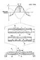
- FIG. 1Ais a cross-section view of a disc pump system having two disc pumps fluidly coupled to a restriction passage;
- FIG. 1Bis a schematic, top view of the disc pump system of FIG. 1A ;
- FIG. 2Ais a cross-section view of a first disc pump having an actuator shown in a rest position according to an illustrative embodiment
- FIG. 2Bis a cross-section view of the first disc pump of FIG. 2A showing the actuator in a biased position according to an illustrative embodiment
- FIG. 3Ashows a graph of the axial displacement oscillations for the fundamental bending mode of the actuator of the first disc pump of FIG. 2A ;
- FIG. 3Bshows a graph of the pressure oscillations of fluid within the cavity of the first disc pump of FIG. 2A in response to the bending mode shown in FIG. 3A ;
- FIG. 4is a detail view of a first sensor for measuring the displacement of the actuator of the first disc pump according to an illustrative embodiment
- FIG. 4Ais a schematic view of an illustrative receiver of the first sensor indicating the position of the actuator when in the rest position and the biased position;
- FIG. 5Ais a cross-section view of the first disc pump of FIG. 2A wherein the two valves are represented by a single valve illustrated in FIGS. 7A-7D ;
- FIG. 5Bis a cross-section view of a center portion of the valve of FIGS. 7A-7D ;
- FIG. 6shows a graph of pressure oscillations of fluid within the cavity of the first disc pump, shown in FIG. 5A , to illustrate the pressure differential applied across the valve of FIG. 5B as indicated by the dashed lines;
- FIG. 7Ais a cross-section view of an illustrative embodiment of a valve in a closed position
- FIG. 7Bis a detail, cross-section view of the valve of FIG. 7A taken along line 7 B- 7 B in FIG. 7D ;
- FIG. 7Cis a perspective view of the valve of FIG. 7A ;
- FIG. 7Dis a top view of the valve of FIG. 7B ;
- FIG. 8Ashows a cross-section view of the valve in FIG. 7A in an open position when fluid flows through the valve
- FIG. 8Bshows a cross-section view of the valve in FIG. 7A in transition between the open position and a closed position
- FIG. 8Cshows a cross-section view of the valve of FIG. 7B in a closed position when fluid flow is blocked by a valve flap;
- FIG. 9Ashows a pressure graph of an oscillating differential pressure applied across the valve of FIG. 7A according to an illustrative embodiment
- FIG. 9Bshows a fluid-flow graph of an operating cycle of the valve of FIG. 7A between an open and closed position
- FIGS. 10A and 10Bshow cross-section views of the disc pump of FIG. 2A , including a view of the center portion of the valves and a graph of the positive and negative portion of an oscillating pressure wave, respectively, being applied within a cavity;
- FIG. 11shows the open and closed states of the valves of the disc pump
- FIGS. 11A and 11Bshow the resulting flow and pressure characteristics, respectively, when the disc pump is in a free-flow mode
- FIG. 12shows a graph of the maximum differential pressure provided by the disc pump when the disc pump reaches the stall condition
- FIG. 13is a block diagram of an illustrative circuit of a disc pump system for measuring and controlling a reduced pressure generated by the disc pump system.
- FIG. 1Ashows a disc pump system 100 having a plurality of disc pumps.
- the plurality of disc pumpsincludes at least a first disc pump 10 and a second disc pump 80 that are operable to supply a positive or negative pressure to the load 38 to pressurize or depressurize a load 38 , respectively.
- the disc pumpsare mounted to a common substrate 28 , such as a printed circuit board.
- the substrate 28is mounted to a manifold 52 that fluidly couples the disc pumps 10 , 80 to a load 38 via an aperture 17 .
- the disc pump 10is fluidly coupled to the aperture 17
- the disc pump 80is fluidly coupled to the aperture 17 via a passage, such as a restriction 50 , between the manifold 52 and the substrate 28 .
- the restriction 50may be a conduit, fluid path, or similar feature that has known dimensions and accommodates fluid flow between the disc pump 80 and the aperture 17 .
- the restriction 50is a known restriction.
- the restriction 50is a cylindrical chamber of known dimensions. The cylindrical chamber may be adapted to follow a circuitous path, as shown in FIG. 1B , to lengthen the pathway of the restriction 50 and accommodate size limitations that might apply to the disc pump system 100 .
- Each of the disc pumps 10 , 80includes a sensor 238 to measure the pressure associated with each of the disc pumps 10 , 80 at each end of the restriction 50 .
- the difference between the pressures measured at each of the disc pumps 10 , 80is indicative of the pressure differential, or pressure drop, across the restriction.
- the pressure differential across the restriction 50may be measured to determine the airflow to or from the load 38 through the aperture 17 . Being able to determine the airflow through the aperture 17 facilitates control of the fluid dynamic characteristics for pressurizing or depressurizing the load 38 as the magnitude of the pressure increases or decreases at the load 38 .
- This flow measurement datacan be used to detect or locate a leak at the load 38 and to collect usage data.
- the disc pumps 10 , 80may each be designed for predetermined performance characteristics to pressurize or depressurize the load 38 .
- the second disc pump 80may be designed to deliver a higher airflow to the aperture 17 through the restriction 50 when the load 38 is at ambient pressure, while the first disc pump 10 may be designed to deliver a higher pressure differential but comparatively less airflow to the load 38 .
- the two disc pumps 10 , 80may function as a system to optimize the fluid dynamic characteristics for pressurizing or depressurizing the load 38 .
- the functionality of the disc pumps 10 , 80may also be reversed depending on the desired performance characteristics.
- the disc pumps 10 , 80which are substantially similar except for certain features of the valves that control the operational characteristics of the disc pumps 10 , 80 .
- the disc pump 10is described in detail to point out the valve features that can be varied to achieve different flow and pressure characteristics for either one of the disc pumps 10 , 80 .
- the second disc pump 80is considered to be in an off state so that the only airflow supplied to or from the load 38 is provided by the disc pump 10 .
- the disc pump 10comprises a disc pump body having a substantially elliptical shape including a cylindrical wall 11 closed at each end by end plates 12 , 13 .
- the cylindrical wall 11may be mounted to a substrate 28 , which forms the end plate 13 .
- the substrate 28may be a printed circuit board or another suitable material.
- the disc pump 10further comprises a pair of disc-shaped interior plates 14 , 15 supported within the disc pump 10 by an isolator 30 having a ring-shape and affixed to the cylindrical wall 11 .
- the internal surfaces of the cylindrical wall 11 , the end plate 12 , the interior plate 14 , and the isolator 30form a cavity 16 within the disc pump 10 .
- the internal surfaces of the cavity 16comprise a side wall 18 which is a first portion of the inside surface of the cylindrical wall 11 that is closed at both ends by end walls 20 , 22 wherein the end wall 20 is the internal surface of the end plate 12 and the end wall 22 comprises the internal surface of the interior plate 14 and a first side of the isolator 30 .
- the end wall 22thus comprises a central portion corresponding to the inside surface of the interior plate 14 and a peripheral portion corresponding to the inside surface of the isolator 30 .
- the disc pump 10 and its componentsare substantially elliptical in shape, the specific embodiment disclosed herein is a circular, elliptical shape.
- the cylindrical wall 11 and the end plates 12 , 13may be a single component comprising the disc pump body or separate components.
- the end plate 13is formed by the substrate 28 that may be a printed circuit board, an assembly board, or printed wire assembly (PWA) on which the disc pump 10 is mounted.
- PWAprinted wire assembly
- the cavity 16is substantially circular in shape, the cavity 16 may also be more generally elliptical in shape.
- the end wall 20 defining the cavity 16is shown as being generally frusto-conical.
- the end wall 20 defining the inside surfaces of the cavity 16may include a generally planar surface that is parallel to the actuator 40 , discussed below.
- a disc pump comprising frusto-conical surfacesis described in more detail in the WO2006/111775 publication, which is incorporated by reference herein.
- the end plates 12 , 13 and cylindrical wall 11 of the disc pump bodymay be formed from any suitable rigid material including, without limitation, metal, ceramic, glass, or plastic including, without limitation, inject-molded plastic.
- the interior plates 14 , 15 of the disc pump 10together form an actuator 40 that is operatively associated with the central portion of the end wall 22 , which forms the internal surfaces of the cavity 16 .
- One of the interior plates 14 , 15must be formed of a piezoelectric material that may include any electrically active material that exhibits strain in response to an applied electrical signal, such as, for example, an electrostrictive or magnetostrictive material.
- the interior plate 15is formed of piezoelectric material that exhibits strain in response to an applied electrical signal, i.e., the active interior plate.
- the other one of the interior plates 14 , 15preferably possesses a bending stiffness similar to the active interior plate and may be formed of a piezoelectric material or an electrically inactive material, such as a metal or ceramic.
- the interior plate 14possesses a bending stiffness similar to the active interior plate 15 and is formed of an electrically inactive material, such as a metal or ceramic, i.e., the inert interior plate.
- the active interior plate 15When the active interior plate 15 is excited by an electrical current, the active interior plate 15 expands and contracts in a radial direction relative to the longitudinal axis of the cavity 16 , causing the interior plates 14 , 15 to bend, thereby inducing an axial deflection of the end walls 22 in a direction substantially perpendicular to the end walls 22 (See FIG. 3A ).
- the isolator 30may support either one of the interior plates 14 , 15 , whether the active interior plate 15 or inert interior plate 14 , from the top or the bottom surfaces depending on the specific design and orientation of the disc pump 10 .
- the actuator 40may be replaced by a device in a force-transmitting relation with only one of the interior plates 14 , 15 such as, for example, a mechanical, magnetic or electrostatic device, wherein the selected interior plate 14 , 15 may be formed as an electrically inactive or passive layer of material driven into oscillation in the manner described above.
- the disc pump 10further comprises at least one aperture extending from the cavity 16 to the outside of the disc pump 10 , wherein the at least one aperture contains a valve to control the flow of fluid through the aperture.
- the aperturemay be located at any position in the cavity 16 where the actuator 40 generates a pressure differential.
- the embodiment of the disc pump 10 shown in FIGS. 2A-2Bcomprises an aperture 27 located at approximately the center of and extending through the end plate 12 .
- the aperture 27contains at least one end valve 29 that regulates the flow of fluid in one direction, as indicated by the arrows, so that end valve 29 functions as an outlet valve for the disc pump 10 .
- the disc pump 10further comprises at least one aperture extending through the actuator 40 , wherein the at least one aperture contains a valve to control the flow of fluid through the aperture.
- the aperturemay be located at any position on the actuator 40 where the actuator 40 generates a pressure differential.
- the illustrative embodiment of the disc pump 10 shown in FIGS. 2A-2Bcomprises an actuator aperture 31 located at approximately the center of and extending through the interior plates 14 , 15 .
- the actuator aperture 31contains an actuator valve 32 , which regulates the flow of fluid in one direction into the cavity 16 , as indicated by the arrow, so that the actuator valve 32 functions as an inlet valve to the cavity 16 .
- the actuator valve 32enhances the output of the disc pump 10 by augmenting the flow of fluid into the cavity 16 and supplementing the operation of the end valve 29 , as described in more detail below.
- the dimensions of the cavity 16 described hereinshould preferably satisfy certain inequalities with respect to the relationship between the height (h) of the cavity 16 at the side wall 18 and its radius (r) which is the distance from the longitudinal axis of the cavity 16 to the side wall 18 .
- the ratio of the cavity radius to the cavity heightis between about 10 and about 50 when the fluid within the cavity 16 is a gas.
- the volume of the cavity 16may be less than about 10 ml.
- the ratio of h 2 /ris preferably within a range between about 10 ⁇ 6 and about 10 ⁇ 7 meters where the working fluid is a gas as opposed to a liquid.
- the cavity 16 disclosed hereinshould preferably satisfy the following inequality relating the cavity radius (r) and operating frequency (f), which is the frequency at which the actuator 40 vibrates to generate the axial displacement of the end wall 22 .
- the inequalityis as follows:
- the frequency of the oscillatory motion of the actuator 40is preferably about equal to the lowest resonant frequency of radial pressure oscillations in the cavity 16 , but may be within 20% of that value.
- the lowest resonant frequency of radial pressure oscillations in the cavity 16is preferably greater than about 500 Hz.
- the relative dimensions of the cavity 16should not be limited to cavities having the same height and radius.
- the cavity 16may have a slightly different shape requiring different radii or heights creating different frequency responses so that the cavity 16 resonates in a desired fashion to generate the optimal output from the disc pump 10 .
- the disc pump 10may function as a source of positive pressure when the load 38 is positioned adjacent the end valve 29 to pressurize the load 38 , or as a source of negative or reduced pressure when the load 38 is placed adjacent the actuator inlet valve 32 to depressurize a load 38 , as illustrated by the arrows.
- the loadmay be a tissue treatment system that utilizes negative pressure for treatment.
- reduced pressureas used herein generally refers to a pressure less than the ambient pressure where the disc pump 10 is located.
- vacuum and negative pressuremay be used to describe the reduced pressure, the actual pressure reduction may be significantly less than the pressure reduction normally associated with a complete vacuum.
- the pressureis “negative” in the sense that the pressure is a gauge pressure, i.e., the pressure is reduced below ambient atmospheric pressure. Unless otherwise indicated, values of pressure stated herein are gauge pressures. References to increases in reduced pressure typically refer to a decrease in absolute pressure, while decreases in reduced pressure typically refer to an increase in absolute pressure.
- the disc pump 10comprises at least one actuator valve 32 and at least one end valve 29 .
- the disc pump 10may comprise a two cavity disc pump having an end valve 29 on each side of the actuator 40 .
- FIG. 3Ashows one possible displacement profile illustrating the axial oscillation of the driven end wall 22 of the cavity 16 .
- the solid curved line and arrowsrepresent the displacement of the driven end wall 22 at one point in time, and the dashed curved line represents the displacement of the driven end wall 22 one half-cycle later.
- the displacement as shown in this figure and the other figuresis exaggerated.
- the actuator 40is suspended by the isolator 30 and not rigidly mounted, the actuator 40 is free to oscillate about its center of mass in its fundamental mode. In this fundamental mode, the amplitude of the displacement oscillations of the actuator 40 is substantially zero at an annular displacement node 42 located between the center of the driven end wall 22 and the side wall 18 .
- a central displacement anti-node 43exists near the center of the actuator 40 and a peripheral displacement anti-node 43 ′ exists near the perimeter of the actuator 40 .
- the central displacement anti-node 43is represented by the dashed curve after one half-cycle.
- FIG. 3Bshows one possible pressure oscillation profile illustrating the pressure oscillation within the cavity 16 resulting from the axial displacement oscillations shown in FIG. 3A .
- the solid curved line and arrowsrepresent the pressure at one point in time.
- the amplitude of the pressure oscillationshas a peripheral pressure anti-node 45 ′ near the side wall 18 of the cavity 16 .
- the amplitude of the pressure oscillationsis substantially zero at the annular pressure node 44 between the central pressure anti-node 45 and the peripheral pressure anti-node 45 ′.
- the amplitude of the pressure oscillations as represented by the dashed linehas a negative central pressure anti-node 47 near the center of the cavity 16 with a peripheral pressure anti-node 47 ′ and the same annular pressure node 44 .
- the radial dependence of the amplitude of the pressure oscillations in the cavity 16may be approximated by a Bessel function of the first kind.
- the pressure oscillations described aboveresult from the radial movement of the fluid in the cavity 16 and so will be referred to as the “radial pressure oscillations” of the fluid within the cavity 16 as distinguished from the axial displacement oscillations of the actuator 40 .
- the radial dependence of the amplitude of the axial displacement oscillations of the actuator 40should approximate a Bessel function of the first kind so as to match more closely the radial dependence of the amplitude of the desired pressure oscillations in the cavity 16 (the “mode-shape” of the pressure oscillation).
- the mode-shape of the displacement oscillationssubstantially matches the mode-shape of the pressure oscillations in the cavity 16 , thus achieving mode-shape matching or, more simply, mode-matching.
- the axial displacement oscillations of the actuator 40 and the corresponding pressure oscillations in the cavity 16have substantially the same relative phase across the full surface of the actuator 40 .
- the radial position of the annular pressure node 44 of the pressure oscillations in the cavity 16 and the radial position of the annular displacement node 42 of the axial displacement oscillations of actuator 40are substantially coincident.
- the radial position of the annular displacement node 42will necessarily lie inside the radius of the actuator 40 when the actuator 40 vibrates in its fundamental bending mode as illustrated in FIG. 3A .
- the radius of the actuatorshould preferably be greater than the radius of the annular pressure node 44 to optimize mode-matching.
- the radius of the annular pressure node 44would be approximately 0.63 of the radius from the center of the end wall 22 to the side wall 18 , i.e., the radius of the cavity 16 (“r”), as shown in FIG. 2A . Therefore, the radius of the actuator 40 (r act ) should preferably satisfy the following inequality: r act ⁇ 0.63r.
- the isolator 30may be a flexible membrane that enables the edge of the actuator 40 to move more freely, as described above, by bending and stretching in response to the vibration of the actuator 40 as shown by the displacement at the peripheral displacement anti-node 43 ′ in FIG. 3A .
- the isolator 30mitigates the potential dampening effects of the side wall 18 on the actuator 40 by providing a low mechanical impedance support between the actuator 40 and the cylindrical wall 11 of the disc pump 10 , thereby reducing the dampening of the axial oscillations at the peripheral displacement anti-node 43 ′ of the actuator 40 .
- the isolator 30minimizes the energy being transferred from the actuator 40 to the side wall 18 with the outer peripheral edge of the isolator 30 remaining substantially stationary.
- the annular displacement node 42will remain substantially aligned with the annular pressure node 44 so as to maintain the mode-matching condition of the disc pump 10 .
- the axial displacement oscillations of the driven end wall 22continue to efficiently generate oscillations of the pressure within the cavity 16 from the central pressure anti-nodes 45 , 47 to the peripheral pressure anti-nodes 45 ′, 47 ′ at the side wall 18 as shown in FIG. 3B .
- FIG. 4shows a sensor 238 mounted on the substrate 28 , which may be a circuit board, to face the actuator 40 and measure the displacement of the actuator 40 of the disc pump 10 .
- the sensor 238which may also be referred to as an optical sensor, includes an optical transmitter 240 and optical receiver 242 for use in measuring displacement ( ⁇ y) of the actuator 40 .
- the optical transmitter 240communicates an optical signal 244 that may be a light wave in a visible or non-visible spectrum.
- the optical signal 244is reflected off the surface of the interior plate 15 of the actuator 40 so that the reflected signal is received by the optical receiver 242 , regardless of the displacement ( ⁇ y) of the actuator 40 , as shown in FIG. 4A .
- a first reflected signal 246impinges on the optical receiver 242 at the position shown in both FIGS. 4 and 4A .
- the first reflected signal 246is displaced by a corresponding reflected displacement ( ⁇ x) as a second reflected signal 248 depending on the displacement ( ⁇ y) of the actuator 40 .
- ⁇ xcorresponding reflected displacement
- ⁇ ydisplacement
- the image of the reflected signals that impinge on the optical receiver 242follow a path from the rest position 34 to the fully biased position 36 as shown in FIG. 4A .
- the reflected displacement ( ⁇ x)is proportional to the displacement ( ⁇ y) of the actuator 40 , which is a function of the pressure provided by the disc pump 10 . More particularly, the displacement ( ⁇ y) of the actuator 40 at the annular pressure node 44 is a function the difference in pressure on either side of the actuator 40 .
- This pressure-related displacement ( ⁇ y) of the actuator 40may be viewed as a quasi-static displacement that changes gradually as the disc pump 10 supplies pressure to (or removes pressure from) the load 38 .
- the displacements ( ⁇ y) or ( ⁇ x)may be measured and used to calculate the pressure differential across the actuator 40 by establishing the correlation between the pressure-related displacement ( ⁇ y) of the actuator 40 and the pressure differential across the actuator 40 (and the corresponding pressure provided by the disc pump 10 ).
- the optical transmitter 240may be a laser, a light emitting diode (LED), a vertical cavity surface emitting laser (VCSEL), or other light emitting element.
- the optical transmitter 240may be positioned on the substrate 28 and oriented to reflect the optical signal 244 off any point of the interior plate 15 of the actuator 40 as long as the first reflected signal 246 and the second reflected signal 248 are received and measured by the optical receiver 242 .
- the amplitude of the displacement oscillations of the actuator 40may be substantially zero at any annular displacement nodes 42 .
- the optical transmitter 240should be positioned and oriented so that the optical signal 244 is reflected from a position close to the annular displacement node 42 to minimize the effect of the high frequency oscillations of the actuator 40 and more accurately measure the displacement ( ⁇ y) of the actuator 40 as the actuator 40 moves more slowly from the rest position 34 to the biased position 36 .
- the optical receiver 242may include multiple pixels forming a sensor array.
- the optical receiver 242may be configured to sense the position of one or more reflected beams at one or more wavelengths.
- the optical receiver 242may be configured to sense the reflected displacement ( ⁇ x) between the first reflected signal 246 and the second reflected signal 248 .
- the optical receiver 242may be configured to convert the reflected signals 246 and 248 sensed by the optical receiver 242 into electrical signals by the respective pixels of the optical receiver 242 .
- the reflected displacement ( ⁇ x)may be measured or calculated in real-time or utilizing a specified sampling frequency to determine the position of the actuator 40 relative to the substrate 28 .
- the position of the actuator 40is computed as an average or mean position over a given time period. Pixels of the optical receiver 242 may be sized to provide additional sensitivity to detect relatively small displacements ( ⁇ y) of the actuator 40 to better monitor the pressure being provided by the disc pump 10 so that the disc pump 10 can be controlled in real-time.
- determining the displacement of the actuator 40may be accomplished relative to any other fixed-position element in the disc pump 10 .
- the reflected displacement ( ⁇ x)may equal the displacement ( ⁇ y) of the actuator 40 multiplied by a scale factor where the scale factor may be predetermined based on the configuration of the disc pump 10 or other alignment factors.
- the reduced pressure within the cavity 16 of the disc pump 10may be determined by sensing the displacement ( ⁇ y) of the actuator 40 without the need for pressure sensors that directly measure the pressure provided to a load.
- pressure sensors that directly measure pressuremay be too bulky or too expensive for application in measuring the pressure provided by the disc pump 10 within a reduced pressure system for example.
- the illustrative embodimentsoptimize the utilization of space within the disc pump 10 without interfering with the pressure oscillations being created within the cavity 16 of the disc pump 10 .
- FIG. 5Athe disc pump 10 of FIG. 1A is shown with the valves 29 , 32 , both of which are substantially similar in structure and represented, for example, by a valve 110 shown in FIGS. 7A-7D and having a center portion 111 shown in FIG. 5B .
- the following description associated with FIGS. 5A-9Bare all based on the function of a single valve 110 that may be positioned in any one of the apertures 27 , 31 of the disc pump 10 .
- FIG. 6shows a graph of the pressure oscillations of fluid within the disc pump 10 and shows that the valve 110 is located at or near the central pressure anti-node 45 as shown in FIG. 3B .
- the valve 110allows fluid to flow in only one direction as shown in FIG. 5B .
- the valve 110may be a check valve or any other valve that allows fluid to flow in only one direction. Some valve types may regulate fluid flow by switching between an open and closed position. For such valves to operate at the high frequencies generated by the actuator 40 , the valves 29 , 32 must have an extremely fast response time such that they are able to open and close on a timescale significantly shorter than the timescale of the pressure variation. One embodiment of the valves 29 , 32 achieves this by employing an extremely light flap valve, which has low inertia and consequently is able to move rapidly in response to changes in relative pressure across the valve structure.
- the valve 110is a flap valve.
- the valve 110comprises a substantially cylindrical wall 112 that is ring-shaped and closed at one end by a retention plate 114 and at the other end by a sealing plate 116 .
- the inside surface of the wall 112 , the retention plate 114 , and the sealing plate 116form a cavity 115 within the valve 110 .
- the valve 110further comprises a substantially circular valve flap 117 disposed between the retention plate 114 and the sealing plate 116 , but adjacent the sealing plate 116 .
- the circular valve flap 117may be disposed adjacent the retention plate 114 in another embodiment, and in this sense the valve flap 117 is considered to be “biased” against either one of the sealing plate 116 or the retention plate 114 .
- the peripheral portion of the valve flap 117is sandwiched between the sealing plate 116 and the wall 112 so that the motion of the valve flap 117 is restrained in the plane substantially perpendicular to the surface of the valve flap 117 .
- the motion of the valve flap 117 in such planemay also be restrained by the peripheral portion of the valve flap 117 being attached directly to either the sealing plate 116 or the wall 112 , or by the valve flap 117 being a close fit within the wall 112 .
- valve flap 117is sufficiently flexible and movable in a direction substantially perpendicular to the surface of the valve flap 117 , so that a force applied to either surface of the valve flap 117 will motivate the valve flap 117 between the sealing plate 116 and the retention plate 114 .
- the retention plate 114 and the sealing plate 116both have holes 118 and 120 , respectively, which extend through each plate.
- the valve flap 117also has holes 122 that are generally aligned with the holes 118 of the retention plate 114 to provide a passage through which fluid may flow as indicated by the dashed arrows 124 in FIGS. 5B and 8A .
- the holes 122 in the valve flap 117may also be partially aligned, i.e., having only a partial overlap, with the holes 118 in the retention plate 114 .
- the holes 118 , 120 , 122are shown to be of substantially uniform size and shape, they may be of different diameters or even different shapes without limiting the scope of the invention.
- the holes 118 and 120form an alternating pattern across the surface of the plates as shown by the solid and dashed circles, respectively, in FIG. 7D .
- the holes 118 , 120 , 122may be arranged in different patterns without affecting the operation of the valve 110 with respect to the functioning of the individual pairings of holes 118 , 120 , 122 as illustrated by individual sets of the dashed arrows 124 .
- the pattern of holes 118 , 120 , 122may be designed to increase or decrease the number of holes to control the total flow of fluid through the valve 110 as required. For example, the number of holes 118 , 120 , 122 may be increased to reduce the flow resistance of the valve 110 to increase the total flow rate of the valve 110 .
- the center portion 111 of the valve 110illustrates how the valve flap 117 is motivated between the sealing plate 116 and the retention plate 114 when a force applied to either surface of the valve flap 117 .
- the valve 110is in a “normally closed” position because the valve flap 117 is disposed adjacent the sealing plate 116 where the holes 122 of the flap are offset or not aligned with the holes 118 of the sealing plate 116 .
- this “normally closed” positionthe flow of fluid through the sealing plate 116 is substantially blocked or covered by the non-perforated portions of the valve flap 117 as shown in FIGS.
- valve 110moves from the normally closed position to an “open” position over a time period, i.e., an opening time delay (T o ), allowing fluid to flow in the direction indicated by the dashed arrows 124 .
- T oopening time delay
- valve flap 117When this happens, fluid will flow for a short time period, i.e., a closing time delay (T c ), in the opposite direction as indicated by the dashed arrows 132 until the valve flap 117 seals the holes 120 of the sealing plate 116 to substantially block fluid flow through the sealing plate 116 as shown in FIG. 8C .
- T cclosing time delay
- the valve flap 117may be biased against the retention plate 114 with the holes 118 , 122 aligned in a “normally open” position. In this embodiment, applying positive pressure against the valve flap 117 will be necessary to motivate the valve flap 117 into a “closed” position.
- valve operationin relation to valve operation are intended to include cases in which substantial (but incomplete) sealing or blockage occurs, such that the flow resistance of the valve is greater in the “closed” position than in the “open” position.
- the operation of the valve 110is a function of the change in direction of the differential pressure ( ⁇ P) of the fluid across the valve 110 .
- the differential pressurehas been assigned a negative value ( ⁇ P) as indicated by the downward pointing arrow.
- ⁇ Pnegative differential pressure
- the fluid pressure at the outside surface of the retention plate 114is greater than the fluid pressure at the outside surface of the sealing plate 116 .
- This negative differential pressure ( ⁇ P)drives the valve flap 117 into the fully closed position as described above wherein the valve flap 117 is pressed against the sealing plate 116 to block the holes 120 in the sealing plate 116 , thereby substantially preventing the flow of fluid through the valve 110 .
- the changing differential pressurecycles the valve 110 between closed and open positions based on the direction (i.e., positive or negative) of the differential pressure across the valve 110 .
- the valve flap 117could be biased against the retention plate 114 in an open position when no differential pressure is applied across the valve 110 , i.e., the valve 110 would then be in a “normally open” position.
- the operation of the valve 110is a function of the change in direction of the differential pressure ( ⁇ P) of the fluid across the valve 110 .
- the differential pressure ( ⁇ P)is assumed to be substantially uniform across the entire surface of the retention plate 114 because (1) the diameter of the retention plate 114 is small relative to the wavelength of the pressure oscillations in the cavity 115 , and (2) the valve 110 is located near the center of the cavity 16 where the amplitude of the positive central pressure anti-node 45 is relatively constant as indicated by the positive square-shaped portion 55 of the positive central pressure anti-node 45 and the negative square-shaped portion 65 of the negative central pressure anti-node 47 shown in FIG. 6 . Therefore, there is virtually no spatial variation in the pressure across the center portion 111 of the valve 110 .
- FIG. 9further illustrates the dynamic operation of the valve 110 when the valve 110 is subject to a differential pressure, which varies in time between a positive value (+ ⁇ P) and a negative value ( ⁇ P). While in practice the time-dependence of the differential pressure across the valve 110 may be approximately sinusoidal, the time-dependence of the differential pressure across the valve 110 is approximated as varying in the square-wave form shown in FIG. 9A to facilitate explanation of the operation of the valve.
- the positive differential pressure 55is applied across the valve 110 over the positive pressure time period (t P +) and the negative differential pressure 65 is applied across the valve 110 over the negative pressure time period (t P ⁇ ) of the square wave.
- FIG. 9Billustrates the motion of the valve flap 117 in response to this time-varying pressure.
- the retention plate 114 and the sealing plate 116should be strong enough to withstand the fluid pressure oscillations to which they are subjected without significant mechanical deformation.
- the retention plate 114 and the sealing plate 116may be formed from any suitable rigid material, such as glass, silicon, ceramic, or metal.
- the holes 118 , 120 in the retention plate 114 and the sealing plate 116may be formed by any suitable process including chemical etching, laser machining, mechanical drilling, powder blasting, and stamping.
- the retention plate 114 and the sealing plate 116are formed from sheet steel between 100 and 200 microns thick, and the holes 118 , 120 therein are formed by chemical etching.
- the valve flap 117may be formed from any lightweight material, such as a metal or polymer film.
- the valve flap 117may be formed from a thin polymer sheet between 1 micron and 20 microns in thickness.
- the valve flap 117may be formed from polyethylene terephthalate (PET) or a liquid crystal polymer film approximately 3 microns in thickness.
- FIGS. 10A and 10Ban exploded view of the two-valve disc pump 10 is shown that utilizes valve 110 as valves 29 and 32 .
- the actuator valve 32gates airflow 232 between the actuator aperture 31 and cavity 16 of the disc pump 10 ( FIG. 10A ), while end valve 29 gates airflow between the cavity 16 and the aperture 27 of the disc pump 10 ( FIG. 10B ).
- aperture 27functions as a pump outlet.
- Each of the figuresalso shows the pressure generated in the cavity 16 as the actuator 40 oscillates.
- Both of the valves 29 and 32are located near the center of the cavity 16 where the amplitudes of the positive and negative central pressure anti-nodes 45 and 47 , respectively, are relatively constant as indicated by the positive and negative square-shaped portions 55 and 65 , respectively, as described above.
- the valves 29 and 32are both biased in the closed position as shown by the valve flap 117 and operate as described above when the valve flap 117 is motivated to the open position as indicated by valve flap 117 ′.
- the figuresalso show an exploded view of the positive and negative square-shaped portions 55 , 65 of the central pressure anti-nodes 45 , 47 , the simultaneous impact on the operation of both valves 29 , 32 , and the corresponding airflow 229 and 232 , respectively, generated through each one.
- FIGS. 11, 11A and 11Bthe open and closed states of the valves 29 and 32 ( FIG. 11 ) and the resulting flow characteristics of each one ( FIG. 11A ) are shown as related to the pressure in the cavity 16 ( FIG. 11B ).
- the actuator aperture 31 and the aperture 27 of the disc pump 10are both at ambient pressure and the actuator 40 begins vibrating to generate pressure oscillations within the cavity 16 as described above, air begins flowing alternately through the valves 29 , 32 , causing air to flow from the actuator aperture 31 to the aperture 27 of the disc pump 10 , i.e., the disc pump 10 begins operating in a “free-flow” mode.
- the actuator aperture 31 of the disc pump 10may be supplied with air at ambient pressure while the aperture 27 of the disc pump 10 is pneumatically coupled to a load (not shown) that becomes pressurized through the action of the disc pump 10 .
- the actuator aperture 31 of the disc pump 10may be pneumatically coupled to a load (not shown) that becomes depressurized to generate a negative pressure in the load, such as a wound dressing, through the action of the disc pump 10 .
- the square-shaped portion 55 of the positive central pressure anti-node 45is generated within the cavity 16 by the vibration of the actuator 40 during one half of the disc pump cycle as described above.
- the square-shaped portion 55 of the positive central anti-node 45creates a positive differential pressure across the end valve 29 and a negative differential pressure across the actuator valve 32 .
- the actuator valve 32begins closing and the end valve 29 begins opening so that the actuator valve 32 blocks the airflow 232 x through the actuator aperture 31 , while the end valve 29 opens to release air from within the cavity 16 allowing the airflow 229 to exit the cavity 16 through the aperture 27 .
- the actuator valve 32 closes and the end valve 29 opensFIG.
- the airflow 229 at the aperture 27 of the disc pump 10increases to a maximum value dependent on the design characteristics of the end valve 29 ( FIG. 11A ).
- the opened end valve 29allows airflow 229 to exit the disc pump cavity 16 ( FIG. 11B ) while the actuator valve 32 is closed.
- the airflow 229begins to drop until the differential pressure across the end valve 29 reaches zero.
- the end valve 29begins to close allowing some back-flow 329 of air through the end valve 29 until the end valve 29 is fully closed to block the airflow 229 x , as shown in FIG. 10B .
- the square-shaped portion 65 of the negative central anti-node 47is generated within the cavity 16 by the vibration of the actuator 40 during the second half of the disc pump cycle as described above.
- the square-shaped portion 65 the negative central anti-node 47creates a negative differential pressure across the end valve 29 and a positive differential pressure across the actuator valve 32 .
- the actuator valve 32begins opening and the end valve 29 begins closing so that the end valve 29 blocks the airflow 229 x through the aperture 27 , while the actuator valve 32 opens allowing air to flow into the cavity 16 as shown by the airflow 232 through the actuator aperture 31 .
- the actuator valve 32opens and the end valve 29 closes ( FIG. 11 )
- the airflow at the aperture 27 of the disc pump 10is substantially zero except for the small amount of backflow 329 as described above ( FIG. 11A ).
- the opened actuator valve 32allows airflow 232 into the disc pump cavity 16 ( FIG. 11B ) while the end valve 29 is closed.
- the airflow 232begins to drop until the differential pressure across the actuator valve 32 reaches zero.
- the actuator valve 32When the differential pressure across the actuator valve 32 rises above zero, the actuator valve 32 begins to close again allowing some back-flow 332 of air through the actuator valve 32 until the actuator valve 32 is fully closed to block the airflow 232 x as shown in FIG. 10A . The cycle then repeats as described above with respect to FIG. 10A .
- the differential pressures across valves 29 and 32cause air to flow from the actuator aperture 31 to the aperture 27 of the disc pump 10 as shown by the airflows 232 , 229 , respectively.
- FIG. 12illustrates the pressures within the cavity 16 and outside the cavity 16 at the actuator aperture 31 and the aperture 27 when the disc pump 10 is in the stall condition. More specifically, the mean pressure in the cavity 16 is approximately 1 P above the inlet pressure (i.e.
- the pressure at the center of the cavity 16varies between approximately ambient pressure and approximately ambient pressure plus 2 P.
- the pressure oscillation in the cavity 16results in a sufficient positive differential pressure across either the actuator valve 32 or end valve 29 to significantly open either valve to allow any airflow through the disc pump 10 .
- the synergistic action of the two valves 29 , 32 described aboveis capable of increasing the differential pressure between the aperture 27 and the actuator aperture 31 to a maximum differential pressure of 2 P, double that of a single valve disc pump.
- the outlet pressure of the two-valve disc pump 10increases from ambient in the free-flow mode to a pressure of approximately ambient plus 2 P when the disc pump 10 reaches the stall condition.
- the disc pump system 100includes disc pumps 10 , 80 that employ the features described above with regard to FIGS. 2A-12 to supply airflow to a load 38 and measure the resulting increases or decreases in pressure at the load 38 .
- the valves of the disc pumps 10 , 80are configured to provide airflow from the aperture 17 to evacuate the load 38 , thereby reducing the pressure from ambient pressure, i.e., creating a negative pressure within the load 38 .
- the load 38may be, for example, a manifold of a negative pressure wound therapy device that provides a negative pressure to a wound to enhance healing.
- one or more disc pumpsare installed in parallel with a separate pressure sensor device to measure the pressure provided by both disc pumps for determining the airflow supplied to the load 38 .
- Such pressure sensor devicesare typically too bulky for wound therapy systems and difficult to integrate, as well as being a very expensive component to include in wound therapy systems.
- the configuration of the disc pump system 100 of FIG. 1Aobviates the need for a separate pressure sensor device because each of the disc pumps 10 , 80 include the integrated pressure sensors 238 described above that indirectly measure the pressure associated with each of the disc pumps 10 , 80 by measuring the displacement of the actuator 40 .
- the restriction 50having predefined dimensions between the two disc pumps 10 , 80 provides a pressure drop from which airflow may be calculated to obviate the need for a separate pressure sensor device that directly measures the pressure.
- the second disc pump 80is operable to measure the displacement of its actuator 40 to determine the pressure differential associated with its actuator aperture 31 .
- the disc pumps 10 , 80are mounted to the common substrate 28 that is in turn adhered to the manifold 52 .
- the restriction 50 having predetermined dimensionsmay be formed in the top surface of the manifold 52 .
- the restriction 50 of FIG. 1Amay be a sealed chamber formed by the underside of the substrate 28 and the manifold 52 upon which the substrate 28 is placed. The restriction 50 may be very small and may be easily fitted into a small space.
- the disc pumps 10 , 80can be used to measure the flow through the disc pump system 100 by measuring the pressure drop across the restriction 50 .
- the restriction 50is approximated as a tube having a circular cross-section. Assuming that the flow through the restriction 50 is fully turbulent, the pressure drop may be computed based on the following equation:
- ⁇is the flow velocity
- p 1is pressure incoming
- p 2is pressure exiting
- T 1is incoming temperature of the fluid
- T 2is outgoing temperature of the fluid
- f 1is the friction coefficient of the restriction
- Reis the Reynolds number
- kis absolute roughness of the restriction
- Dis the diameter of restriction
- ⁇ 2is density of the fluid (or incoming gas).
- the pipe friction coefficientvaries depending on the surface of the path but is otherwise constant.
- the pressure at both the first disc pump 10 and second disc pump 80is known, the equation above can be solved to determine the flow velocity, or flow rate. It is noted that in order for the measured flow rate to be representative of the flow provided by the disc pump system 100 , one of the disc pumps 10 , 80 , should be temporarily stopped and used only to measure pressure (and not to provide flow).
- the expected flow and associated pressure ranges provided by the disc pump system 100are known design parameters.
- the restriction 50can be tuned so that measurements taken using the methodology described above will have the desired level of precision.
- the length, diameter, and surface roughness of the restrictioncan be adjusted.
- the restriction 50may have a length of less than or equal to about 10 mm and a diameter greater than or equal to about 0.5 mm. It follows that a short, narrow, and rough restriction is best suited for a small space, but such a restriction is more likely to suffer from condensation build-up or obstruction by foreign debris. Further, the manufacturing tolerances for a smaller restriction are narrowed and more critical. A longer, wider, and smoother restriction can be manufactured more reliably and is less likely to occlude. A longer known restriction may be formed within a smaller space by arranging the known restriction in a tortuous path, as shown in FIG. 1B .
- the restriction 50 having a tortuous pathis formed between the two disc pumps 10 , 80 as shown in FIG. 1B , then flow through one of the disc pumps 10 , 80 will need to be stopped in order to make an accurate measurement of the flow between the two disc pumps 10 , 80 , i.e. the measurement of the flow through the restriction 50 .
- the disc pumps 10 , 80biased.
- the first disc pump 10may be biased to provide a lower flow rate that is associated with a higher pressure differential
- the second disc pump 80may be biased to provide a higher flow rate that is associated with a lower pressure differential.
- the second pump 80is a high-flow pump situated at the distal end of the restriction. In the embodiment, the second disc pump 80 continues to operate when flow is measured.
- the operation of first disc pump 10is less critical to the operation of the disc pump system 100 when the disc pump system 100 provides increased flow (e.g., at start-up or when a leak is present).
- the biased disc pump configurationsminimize the impact of temporarily ceasing operation of the first disc pump 10 so that the first disc pump 10 may act as a flow sensor because second disc pump 80 provides the majority of the flow.
- the high-flow biased second disc pump 80can be switched off and the high-pressure first disc pump 10 can function while the flow rate is measured.
- FIG. 13is a block diagram that illustrates the functionality of the disc pump system of FIG. 1A .
- the disc pump system 100includes a first disc pump 10 and second disc pump 80 .
- Each of the disc pumps 10 , 80includes an sensor 238 that is operable to measure the displacement of an actuator 40 , as described above with regard to FIG. 4 . It should be understood that other sensors may also be utilized as part of the disc pump system 100 in the place of the sensors 238 .
- the disc pump system 100comprises a battery 60 to power the disc pump system 100 .
- the elements of the disc pump system 100are interconnected and communicate through wires, paths, traces, leads, and other conductive elements.
- the disc pump system 100also includes a controller or processor 56 and a driver 58 that may comprise two distinct drivers 58 a , 58 b .
- the processor 56is adapted to communicate with the driver 58 .
- the driver 58is functional to receive a control signal 62 from the processor 56 .
- the control signal 62may include two distinct control signals 62 a , 62 b .
- the driver 58generates a first drive signal 64 a that energizes the actuator 40 in the first disc pump 10 and a second drive signal 64 b that energizes the actuator 40 in the second disc pump 80 .
- the processorcommunicates first and second control signals 62 a , 62 b , to first and second drivers 58 a , 58 b , respectively.
- the first and second drivers 58 a , 58 bthen generate first and second drive signals 64 a and 64 b to energize the actuators 40 of the disc pumps 10 , 80 .
- the first and second control signals 62 a , 62 b and the corresponding drive signals 64 a , 64 bmay be the same or different.
- the processor 56may also provide illumination signals 66 a , 66 b to the optical transmitters 240 for illuminating the actuators 40 with optical signals 244 .
- the optical signals 244are reflected by the actuators 40 to the optical receivers 242 as illustrated by the reflected signals 248 , which are also described above with regard to FIGS. 4 and 4A .
- the optical receivers 242provide displacement signals 68 a , 68 b to the processor 56 that correspond to the displacement ( ⁇ y) of the actuators 40 .
- the processor 56is configured to calculate the pressure generated by each of the disc pumps 10 , 80 at the load 38 as a function of the displacement ( ⁇ y) of the actuator 40 as represented by the displacement signal 68 a , 68 b .
- the processor 56may be configured to average a plurality of reflected signals 248 to determine average displacements of the actuator 40 over time.
- the processor 56may utilize the displacement signals 68 a , 68 b as feedback to adjust the control signal 62 and corresponding drive signals 64 a , 64 b for regulating the pressure at the load 38 .
- the processor 56calculates the flow rate provided by the disc pump system 100 as a function of the determined pressures generated at each of the disc pumps 10 , 80 , as described above.
- the processor 56 , driver 58 , and other control circuitry of the disc pump system 100may be referred to as an electronic circuit.
- the processor 56may be circuitry or logic enabled to control the disc pumps 10 , 80 .
- the processor 56may function as or comprise microprocessors, digital signal processors, application-specific integrated circuits (ASIC), central processing units, digital logic or other devices suitable for controlling an electronic device including one or more hardware and software elements, executing software, instructions, programs, and applications, converting and processing signals and information, and performing other related tasks.
- the processor 56may be a single chip or integrated with other computing or communications elements.
- the processor 56may include or communicate with a memory.
- the memorymay be a hardware element, device, or recording media configured to store data for subsequent retrieval or access at a later time.
- the memorymay be static or dynamic memory in the form of random access memory, cache, or other miniaturized storage medium suitable for storage of data, instructions, and information.
- the electronic circuitmay be analog circuitry that is configured to perform the same or analogous functionality for measuring the pressure and controlling the displacement of the actuators 40 in the cavities of the disc pumps 10 , 80 , as described above.
- the disc pump system 100may also include an RF transceiver 70 for communicating information and data relating to the performance of the disc pump system 100 including, for example, the flow rate, the current pressure measurements, the actual displacement ( ⁇ y) of the actuators 40 , and the current life of the battery 60 via wireless signals 72 and 74 transmitted from and received by the RF transceiver 70 .
- the disc pump system 100may utilize a communications interface that comprises RF transceiver 70 , infrared, or other wired or wireless signals to communicate with one or more external devices.
- the RF transceiver 70may utilize Bluetooth, WiFi, WiMAX, or other communications standards or proprietary communications systems.
- the RF transceiver 70may send the signals 72 to a computing device that stores a database of pressure readings for reference by a medical professional.
- the computing devicemay be a computer, mobile device, or medical equipment device that may perform processing locally or further communicate the information to a central or remote computer for processing of the information and data.
- the RF transceiver 70may receive the signals 72 for externally regulating the pressure generated by the disc pump system 100 at the load 38 based on the motion of the actuators 40 .
- the driver 58is an electrical circuit that energizes and controls the actuator 40 .
- the driver 58may be a high-power transistor, amplifier, bridge, and/or filters for generating a specific waveform as part of the drive signals 64 a , 64 b .
- Such a waveformmay be configured by the processor 56 and the driver 58 to provide drive signals 64 a , 64 b that cause the actuators 40 to vibrate in an oscillatory motion at the frequency (f), as described in more detail above.
- the oscillatory displacement motion of the actuators 40generates the radial pressure oscillations of the fluid within the cavities of the disc pumps 10 , 80 in response to the drive signals 64 a , 64 b to provide airflow and generate pressure at the load 38 .
- the disc pump system 100may include a user interface for displaying information to a user.
- the user interfacemay include a display, audio interface, or tactile interface for providing information, data, or signals to a user.
- a miniature LED screenmay display the pressure being generated by the disc pump system 100 .
- the user interfacemay also include buttons, dials, knobs, or other electrical or mechanical interfaces for adjusting the performance of the disc pump, and particularly, the reduced pressure generated. For example, the pressure may be increased or decreased by adjusting a knob or other control element that is part of the user interface.
- the flow rate of the disc pump system 100can be measured without the need for additional components or expense, and a smaller footprint is required.
- the flow rate datacan be used to determine conditions at the load 38 .
- the measured flow ratecan be used to determine whether there is a leak at the load 38 and to collect data on the performance of the disc pump system 100 .
- the disc pump system 100determines whether there is a leak at the load 38 based on the measured flow rate and pressure. For example, the disc pump system 100 may determine that a leak at the load 38 exists if the flow rate at the pumps 10 , 80 remains relatively constant over a time interval. In response to determining that a leak exists, the disc pump system 100 may shut down or transmit an alarm or alert signal via an audio interface. In one embodiment, in response to determining that a leak condition exists, the disc pump system 100 may conduct a diagnostic process to determine the cause of the leak. Such a process may include determining whether each of the pumps 10 , 80 functions properly, and whether pressure is maintained at the load 38 .
Landscapes
- Engineering & Computer Science (AREA)
- Physics & Mathematics (AREA)
- Fluid Mechanics (AREA)
- General Physics & Mathematics (AREA)
- Mechanical Engineering (AREA)
- General Engineering & Computer Science (AREA)
- Computer Hardware Design (AREA)
- Reciprocating Pumps (AREA)
- Measuring Volume Flow (AREA)
- Details Of Flowmeters (AREA)
- Examining Or Testing Airtightness (AREA)
- Micromachines (AREA)
Abstract
Description
r/h>1.2; and
h2/r>4×10−10meters.
wherein the speed of sound in the working fluid within the cavity16 (c) may range between a slow speed (cs) of about 115 m/s and a fast speed (cf) equal to about 1,970 m/s as expressed in the equation above, and k0is a constant (k0=3.83). The frequency of the oscillatory motion of the
Where the pipe friction coefficient is
Claims (6)
Priority Applications (1)
| Application Number | Priority Date | Filing Date | Title |
|---|---|---|---|
| US14/957,362US10221843B2 (en) | 2012-02-29 | 2015-12-02 | Systems and methods for supplying reduced pressure and measuring flow using a disc pump system |
Applications Claiming Priority (3)
| Application Number | Priority Date | Filing Date | Title |
|---|---|---|---|
| US201261604927P | 2012-02-29 | 2012-02-29 | |
| US13/764,510US9239059B2 (en) | 2012-02-29 | 2013-02-11 | Systems and methods for supplying reduced pressure and measuring flow using a disc pump system |
| US14/957,362US10221843B2 (en) | 2012-02-29 | 2015-12-02 | Systems and methods for supplying reduced pressure and measuring flow using a disc pump system |
Related Parent Applications (1)
| Application Number | Title | Priority Date | Filing Date |
|---|---|---|---|
| US13/764,510ContinuationUS9239059B2 (en) | 2012-02-29 | 2013-02-11 | Systems and methods for supplying reduced pressure and measuring flow using a disc pump system |
Publications (2)
| Publication Number | Publication Date |
|---|---|
| US20160138582A1 US20160138582A1 (en) | 2016-05-19 |
| US10221843B2true US10221843B2 (en) | 2019-03-05 |
Family
ID=47891916
Family Applications (2)
| Application Number | Title | Priority Date | Filing Date |
|---|---|---|---|
| US13/764,510Active2033-12-30US9239059B2 (en) | 2012-02-29 | 2013-02-11 | Systems and methods for supplying reduced pressure and measuring flow using a disc pump system |
| US14/957,362Expired - Fee RelatedUS10221843B2 (en) | 2012-02-29 | 2015-12-02 | Systems and methods for supplying reduced pressure and measuring flow using a disc pump system |
Family Applications Before (1)
| Application Number | Title | Priority Date | Filing Date |
|---|---|---|---|
| US13/764,510Active2033-12-30US9239059B2 (en) | 2012-02-29 | 2013-02-11 | Systems and methods for supplying reduced pressure and measuring flow using a disc pump system |
Country Status (7)
| Country | Link |
|---|---|
| US (2) | US9239059B2 (en) |
| EP (1) | EP2820385A1 (en) |
| JP (1) | JP6176498B2 (en) |
| CN (1) | CN104114981B (en) |
| AU (2) | AU2013226499A1 (en) |
| CA (1) | CA2862756A1 (en) |
| WO (1) | WO2013130255A1 (en) |
Cited By (6)
| Publication number | Priority date | Publication date | Assignee | Title |
|---|---|---|---|---|
| US10704021B2 (en) | 2012-03-15 | 2020-07-07 | Flodesign Sonics, Inc. | Acoustic perfusion devices |
| US10785574B2 (en) | 2017-12-14 | 2020-09-22 | Flodesign Sonics, Inc. | Acoustic transducer driver and controller |
| US10975368B2 (en) | 2014-01-08 | 2021-04-13 | Flodesign Sonics, Inc. | Acoustophoresis device with dual acoustophoretic chamber |
| US11214789B2 (en) | 2016-05-03 | 2022-01-04 | Flodesign Sonics, Inc. | Concentration and washing of particles with acoustics |
| US11377651B2 (en) | 2016-10-19 | 2022-07-05 | Flodesign Sonics, Inc. | Cell therapy processes utilizing acoustophoresis |
| US11708572B2 (en) | 2015-04-29 | 2023-07-25 | Flodesign Sonics, Inc. | Acoustic cell separation techniques and processes |
Families Citing this family (49)
| Publication number | Priority date | Publication date | Assignee | Title |
|---|---|---|---|---|
| US7753894B2 (en) | 2004-04-27 | 2010-07-13 | Smith & Nephew Plc | Wound cleansing apparatus with stress |
| ES2715605T3 (en) | 2007-11-21 | 2019-06-05 | Smith & Nephew | Wound dressing |
| US9526920B2 (en) | 2010-10-12 | 2016-12-27 | Smith & Nephew, Inc. | Medical device |
| US9084845B2 (en) | 2011-11-02 | 2015-07-21 | Smith & Nephew Plc | Reduced pressure therapy apparatuses and methods of using same |
| TW201326773A (en)* | 2011-12-30 | 2013-07-01 | Ind Tech Res Inst | Adjustment apparatus for pressure sensor and adjustment method thereof |
| AU2013237095B2 (en) | 2012-03-20 | 2017-10-05 | Smith & Nephew Plc | Controlling operation of a reduced pressure therapy system based on dynamic duty cycle threshold determination |
| US9427505B2 (en) | 2012-05-15 | 2016-08-30 | Smith & Nephew Plc | Negative pressure wound therapy apparatus |
| US9737649B2 (en) | 2013-03-14 | 2017-08-22 | Smith & Nephew, Inc. | Systems and methods for applying reduced pressure therapy |
| US10533406B2 (en) | 2013-03-14 | 2020-01-14 | Schlumberger Technology Corporation | Systems and methods for pairing system pumps with fluid flow in a fracturing structure |
| US9534604B2 (en)* | 2013-03-14 | 2017-01-03 | Schlumberger Technology Corporation | System and method of controlling manifold fluid flow |
| JP2016517318A (en) | 2013-03-14 | 2016-06-16 | スミス アンド ネフュー インコーポレーテッド | System and method for administering decompression therapy |
| US9506785B2 (en) | 2013-03-15 | 2016-11-29 | Rain Bird Corporation | Remote flow rate measuring |
| WO2015023515A1 (en) | 2013-08-13 | 2015-02-19 | Smith & Nephew, Inc. | Systems and methods for applying reduced pressure therapy |
| US20150226220A1 (en)* | 2014-02-13 | 2015-08-13 | Pentair Flow Technologies, Llc | Pump and Electric Insulating Oil for Use Therein |
| EP3604810B1 (en)* | 2014-02-21 | 2023-06-28 | Murata Manufacturing Co., Ltd. | Fluid control device and pump |
| US12133789B2 (en) | 2014-07-31 | 2024-11-05 | Smith & Nephew, Inc. | Reduced pressure therapy apparatus construction and control |
| CA3179001A1 (en) | 2014-07-31 | 2016-02-04 | Smith & Nephew, Inc. | Systems and methods for applying reduced pressure therapy |
| EP3237032B1 (en) | 2014-12-22 | 2024-08-07 | Smith & Nephew plc | Negative pressure wound therapy apparatus |
| US10615329B2 (en) | 2016-01-29 | 2020-04-07 | Microjet Technology Co., Ltd. | Piezoelectric actuator |
| US10584695B2 (en)* | 2016-01-29 | 2020-03-10 | Microjet Technology Co., Ltd. | Miniature fluid control device |
| EP3203078B1 (en) | 2016-01-29 | 2021-05-26 | Microjet Technology Co., Ltd | Miniature pneumatic device |
| US10529911B2 (en) | 2016-01-29 | 2020-01-07 | Microjet Technology Co., Ltd. | Piezoelectric actuator |
| US10487820B2 (en) | 2016-01-29 | 2019-11-26 | Microjet Technology Co., Ltd. | Miniature pneumatic device |
| EP3203079B1 (en) | 2016-01-29 | 2021-05-19 | Microjet Technology Co., Ltd | Piezoelectric actuator |
| US10385838B2 (en) | 2016-01-29 | 2019-08-20 | Microjet Technology Co., Ltd. | Miniature fluid control device |
| EP3203076B1 (en) | 2016-01-29 | 2021-05-12 | Microjet Technology Co., Ltd | Miniature fluid control device |
| US10451051B2 (en) | 2016-01-29 | 2019-10-22 | Microjet Technology Co., Ltd. | Miniature pneumatic device |
| EP3203080B1 (en) | 2016-01-29 | 2021-09-22 | Microjet Technology Co., Ltd | Miniature pneumatic device |
| CN109069713A (en) | 2016-05-13 | 2018-12-21 | 史密夫和内修有限公司 | Automatic wound in negative pressure wound treating system couples detection |
| US10634538B2 (en) | 2016-07-13 | 2020-04-28 | Rain Bird Corporation | Flow sensor |
| TWI602995B (en)* | 2016-09-05 | 2017-10-21 | 研能科技股份有限公司 | Fluid control device |
| TWI613367B (en) | 2016-09-05 | 2018-02-01 | 研能科技股份有限公司 | Fluid control device |
| TWI625468B (en) | 2016-09-05 | 2018-06-01 | 研能科技股份有限公司 | Fluid control device |
| US10655620B2 (en) | 2016-11-10 | 2020-05-19 | Microjet Technology Co., Ltd. | Miniature fluid control device |
| US10746169B2 (en) | 2016-11-10 | 2020-08-18 | Microjet Technology Co., Ltd. | Miniature pneumatic device |
| US10683861B2 (en) | 2016-11-10 | 2020-06-16 | Microjet Technology Co., Ltd. | Miniature pneumatic device |
| JP6815847B2 (en)* | 2016-11-25 | 2021-01-20 | 株式会社堀場エステック | Flow path formation structure, flow rate measuring device and flow rate control device |
| TWI650545B (en)* | 2017-08-22 | 2019-02-11 | 研能科技股份有限公司 | Apparatus with actuating sensor module |
| US10473494B2 (en) | 2017-10-24 | 2019-11-12 | Rain Bird Corporation | Flow sensor |
| TWI650484B (en)* | 2017-10-27 | 2019-02-11 | 研能科技股份有限公司 | Gas delivery device |
| WO2019130853A1 (en)* | 2017-12-26 | 2019-07-04 | 株式会社村田製作所 | Pump and fluid control device |
| JP6480612B1 (en)* | 2018-01-25 | 2019-03-13 | 日東工器株式会社 | Electromagnetic reciprocating fluid device |
| JP7055659B2 (en)* | 2018-02-15 | 2022-04-18 | 東芝テック株式会社 | Liquid circulation device and liquid discharge device |
| WO2019243116A1 (en)* | 2018-06-22 | 2019-12-26 | Koninklijke Philips N.V. | Patient interface valve arrangement |
| GB2569417B (en)* | 2018-07-31 | 2020-06-17 | Ttp Ventus Ltd | Microfluidic drive system |
| US11662242B2 (en) | 2018-12-31 | 2023-05-30 | Rain Bird Corporation | Flow sensor gauge |
| JPWO2020217934A1 (en)* | 2019-04-25 | 2020-10-29 | ||
| CN111521227B (en)* | 2020-06-01 | 2024-09-10 | 深圳国技仪器有限公司 | Wide-range flow stability testing device |
| GB2624475B (en) | 2023-02-08 | 2025-06-18 | Foster & Freeman Ltd | Volatile sampling device |
Citations (126)
| Publication number | Priority date | Publication date | Assignee | Title |
|---|---|---|---|---|
| US1355846A (en) | 1920-02-06 | 1920-10-19 | David A Rannells | Medical appliance |
| US2547758A (en) | 1949-01-05 | 1951-04-03 | Wilmer B Keeling | Instrument for treating the male urethra |
| US2632443A (en) | 1949-04-18 | 1953-03-24 | Eleanor P Lesher | Surgical dressing |
| GB692578A (en) | 1949-09-13 | 1953-06-10 | Minnesota Mining & Mfg | Improvements in or relating to drape sheets for surgical use |
| US2682873A (en) | 1952-07-30 | 1954-07-06 | Johnson & Johnson | General purpose protective dressing |
| US2910763A (en) | 1955-08-17 | 1959-11-03 | Du Pont | Felt-like products |
| US2969057A (en) | 1957-11-04 | 1961-01-24 | Brady Co W H | Nematodic swab |
| US3066672A (en) | 1960-09-27 | 1962-12-04 | Jr William H Crosby | Method and apparatus for serial sampling of intestinal juice |
| US3367332A (en) | 1965-08-27 | 1968-02-06 | Gen Electric | Product and process for establishing a sterile area of skin |
| US3520300A (en) | 1967-03-15 | 1970-07-14 | Amp Inc | Surgical sponge and suction device |
| US3568675A (en) | 1968-08-30 | 1971-03-09 | Clyde B Harvey | Fistula and penetrating wound dressing |
| US3648692A (en) | 1970-12-07 | 1972-03-14 | Parke Davis & Co | Medical-surgical dressing for burns and the like |
| US3682180A (en) | 1970-06-08 | 1972-08-08 | Coilform Co Inc | Drain clip for surgical drain |
| US3826254A (en) | 1973-02-26 | 1974-07-30 | Verco Ind | Needle or catheter retaining appliance |
| DE2640413A1 (en) | 1976-09-08 | 1978-03-09 | Wolf Gmbh Richard | CATHETER MONITORING DEVICE |
| US4080970A (en) | 1976-11-17 | 1978-03-28 | Miller Thomas J | Post-operative combination dressing and internal drain tube with external shield and tube connector |
| US4096853A (en) | 1975-06-21 | 1978-06-27 | Hoechst Aktiengesellschaft | Device for the introduction of contrast medium into an anus praeter |
| US4139004A (en) | 1977-02-17 | 1979-02-13 | Gonzalez Jr Harry | Bandage apparatus for treating burns |
| US4165748A (en) | 1977-11-07 | 1979-08-28 | Johnson Melissa C | Catheter tube holder |
| US4184510A (en) | 1977-03-15 | 1980-01-22 | Fibra-Sonics, Inc. | Valued device for controlling vacuum in surgery |
| WO1980002182A1 (en) | 1979-04-06 | 1980-10-16 | J Moss | Portable suction device for collecting fluids from a closed wound |
| US4233969A (en) | 1976-11-11 | 1980-11-18 | Lock Peter M | Wound dressing materials |
| US4245630A (en) | 1976-10-08 | 1981-01-20 | T. J. Smith & Nephew, Ltd. | Tearable composite strip of materials |
| US4256109A (en) | 1978-07-10 | 1981-03-17 | Nichols Robert L | Shut off valve for medical suction apparatus |
| US4261363A (en) | 1979-11-09 | 1981-04-14 | C. R. Bard, Inc. | Retention clips for body fluid drains |
| US4275721A (en) | 1978-11-28 | 1981-06-30 | Landstingens Inkopscentral Lic, Ekonomisk Forening | Vein catheter bandage |
| US4284079A (en) | 1979-06-28 | 1981-08-18 | Adair Edwin Lloyd | Method for applying a male incontinence device |
| US4297995A (en) | 1980-06-03 | 1981-11-03 | Key Pharmaceuticals, Inc. | Bandage containing attachment post |
| US4333468A (en) | 1980-08-18 | 1982-06-08 | Geist Robert W | Mesentery tube holder apparatus |
| US4373519A (en) | 1981-06-26 | 1983-02-15 | Minnesota Mining And Manufacturing Company | Composite wound dressing |
| US4382441A (en) | 1978-12-06 | 1983-05-10 | Svedman Paul | Device for treating tissues, for example skin |
| US4392858A (en) | 1981-07-16 | 1983-07-12 | Sherwood Medical Company | Wound drainage device |
| US4392853A (en) | 1981-03-16 | 1983-07-12 | Rudolph Muto | Sterile assembly for protecting and fastening an indwelling device |
| US4419097A (en) | 1981-07-31 | 1983-12-06 | Rexar Industries, Inc. | Attachment for catheter tube |
| EP0100148A1 (en) | 1982-07-06 | 1984-02-08 | Dow Corning Limited | Medical-surgical dressing and a process for the production thereof |
| US4465485A (en) | 1981-03-06 | 1984-08-14 | Becton, Dickinson And Company | Suction canister with unitary shut-off valve and filter features |
| EP0117632A2 (en) | 1983-01-27 | 1984-09-05 | Johnson & Johnson Products Inc. | Adhesive film dressing |
| US4475909A (en) | 1982-05-06 | 1984-10-09 | Eisenberg Melvin I | Male urinary device and method for applying the device |
| US4480638A (en) | 1980-03-11 | 1984-11-06 | Eduard Schmid | Cushion for holding an element of grafted skin |
| US4525374A (en) | 1984-02-27 | 1985-06-25 | Manresa, Inc. | Treating hydrophobic filters to render them hydrophilic |
| US4525166A (en) | 1981-11-21 | 1985-06-25 | Intermedicat Gmbh | Rolled flexible medical suction drainage device |
| US4540412A (en) | 1983-07-14 | 1985-09-10 | The Kendall Company | Device for moist heat therapy |
| US4543100A (en) | 1983-11-01 | 1985-09-24 | Brodsky Stuart A | Catheter and drain tube retainer |
| US4548202A (en) | 1983-06-20 | 1985-10-22 | Ethicon, Inc. | Mesh tissue fasteners |
| US4551139A (en) | 1982-02-08 | 1985-11-05 | Marion Laboratories, Inc. | Method and apparatus for burn wound treatment |
| EP0161865A2 (en) | 1984-05-03 | 1985-11-21 | Smith and Nephew Associated Companies p.l.c. | Adhesive wound dressing |
| US4569348A (en) | 1980-02-22 | 1986-02-11 | Velcro Usa Inc. | Catheter tube holder strap |
| AU550575B2 (en) | 1981-08-07 | 1986-03-27 | Richard Christian Wright | Wound drainage device |
| US4605399A (en) | 1984-12-04 | 1986-08-12 | Complex, Inc. | Transdermal infusion device |
| US4608041A (en) | 1981-10-14 | 1986-08-26 | Frese Nielsen | Device for treatment of wounds in body tissue of patients by exposure to jets of gas |
| US4640688A (en) | 1985-08-23 | 1987-02-03 | Mentor Corporation | Urine collection catheter |
| US4655754A (en) | 1984-11-09 | 1987-04-07 | Stryker Corporation | Vacuum wound drainage system and lipids baffle therefor |
| US4664662A (en) | 1984-08-02 | 1987-05-12 | Smith And Nephew Associated Companies Plc | Wound dressing |
| WO1987004626A1 (en) | 1986-01-31 | 1987-08-13 | Osmond, Roger, L., W. | Suction system for wound and gastro-intestinal drainage |
| US4710165A (en) | 1985-09-16 | 1987-12-01 | Mcneil Charles B | Wearable, variable rate suction/collection device |
| US4733659A (en) | 1986-01-17 | 1988-03-29 | Seton Company | Foam bandage |
| GB2195255A (en) | 1986-09-30 | 1988-04-07 | Vacutec Uk Limited | Method and apparatus for vacuum treatment of an epidermal surface |
| US4743232A (en) | 1986-10-06 | 1988-05-10 | The Clinipad Corporation | Package assembly for plastic film bandage |
| GB2197789A (en) | 1986-11-28 | 1988-06-02 | Smiths Industries Plc | Anti-foaming disinfectants used in surgical suction apparatus |
| US4758220A (en) | 1985-09-26 | 1988-07-19 | Alcon Laboratories, Inc. | Surgical cassette proximity sensing and latching apparatus |
| US4787888A (en) | 1987-06-01 | 1988-11-29 | University Of Connecticut | Disposable piezoelectric polymer bandage for percutaneous delivery of drugs and method for such percutaneous delivery (a) |
| US4826494A (en) | 1984-11-09 | 1989-05-02 | Stryker Corporation | Vacuum wound drainage system |
| US4838883A (en) | 1986-03-07 | 1989-06-13 | Nissho Corporation | Urine-collecting device |
| US4840187A (en) | 1986-09-11 | 1989-06-20 | Bard Limited | Sheath applicator |
| US4863449A (en) | 1987-07-06 | 1989-09-05 | Hollister Incorporated | Adhesive-lined elastic condom cathether |
| US4872450A (en) | 1984-08-17 | 1989-10-10 | Austad Eric D | Wound dressing and method of forming same |
| US4878901A (en) | 1986-10-10 | 1989-11-07 | Sachse Hans Ernst | Condom catheter, a urethral catheter for the prevention of ascending infections |
| GB2220357A (en) | 1988-05-28 | 1990-01-10 | Smiths Industries Plc | Medico-surgical containers |
| US4897081A (en) | 1984-05-25 | 1990-01-30 | Thermedics Inc. | Percutaneous access device |
| US4906240A (en) | 1988-02-01 | 1990-03-06 | Matrix Medica, Inc. | Adhesive-faced porous absorbent sheet and method of making same |
| US4906233A (en) | 1986-05-29 | 1990-03-06 | Terumo Kabushiki Kaisha | Method of securing a catheter body to a human skin surface |
| US4919654A (en) | 1988-08-03 | 1990-04-24 | Kalt Medical Corporation | IV clamp with membrane |
| CA2005436A1 (en) | 1988-12-13 | 1990-06-13 | Glenda G. Kalt | Transparent tracheostomy tube dressing |
| US4941882A (en) | 1987-03-14 | 1990-07-17 | Smith And Nephew Associated Companies, P.L.C. | Adhesive dressing for retaining a cannula on the skin |
| US4953565A (en) | 1986-11-26 | 1990-09-04 | Shunro Tachibana | Endermic application kits for external medicines |
| WO1990010424A1 (en) | 1989-03-16 | 1990-09-20 | Smith & Nephew Plc | Absorbent devices and precursors therefor |
| US4969880A (en) | 1989-04-03 | 1990-11-13 | Zamierowski David S | Wound dressing and treatment method |
| US4985019A (en) | 1988-03-11 | 1991-01-15 | Michelson Gary K | X-ray marker |
| GB2235877A (en) | 1989-09-18 | 1991-03-20 | Antonio Talluri | Closed wound suction apparatus |
| US5037397A (en) | 1985-05-03 | 1991-08-06 | Medical Distributors, Inc. | Universal clamp |
| US5086170A (en) | 1989-01-16 | 1992-02-04 | Roussel Uclaf | Process for the preparation of azabicyclo compounds |
| US5092858A (en) | 1990-03-20 | 1992-03-03 | Becton, Dickinson And Company | Liquid gelling agent distributor device |
| US5100396A (en) | 1989-04-03 | 1992-03-31 | Zamierowski David S | Fluidic connection system and method |
| US5134994A (en) | 1990-02-12 | 1992-08-04 | Say Sam L | Field aspirator in a soft pack with externally mounted container |
| US5149331A (en) | 1991-05-03 | 1992-09-22 | Ariel Ferdman | Method and device for wound closure |
| US5167613A (en) | 1992-03-23 | 1992-12-01 | The Kendall Company | Composite vented wound dressing |
| US5176663A (en) | 1987-12-02 | 1993-01-05 | Pal Svedman | Dressing having pad with compressibility limiting elements |
| WO1993009727A1 (en) | 1991-11-14 | 1993-05-27 | Wake Forest University | Method and apparatus for treating tissue damage |
| US5215522A (en) | 1984-07-23 | 1993-06-01 | Ballard Medical Products | Single use medical aspirating device and method |
| US5232453A (en) | 1989-07-14 | 1993-08-03 | E. R. Squibb & Sons, Inc. | Catheter holder |
| US5261893A (en) | 1989-04-03 | 1993-11-16 | Zamierowski David S | Fastening system and method |
| US5278100A (en) | 1991-11-08 | 1994-01-11 | Micron Technology, Inc. | Chemical vapor deposition technique for depositing titanium silicide on semiconductor wafers |
| US5279550A (en) | 1991-12-19 | 1994-01-18 | Gish Biomedical, Inc. | Orthopedic autotransfusion system |
| US5298015A (en) | 1989-07-11 | 1994-03-29 | Nippon Zeon Co., Ltd. | Wound dressing having a porous structure |
| US5342376A (en) | 1993-05-03 | 1994-08-30 | Dermagraphics, Inc. | Inserting device for a barbed tissue connector |
| US5344415A (en) | 1993-06-15 | 1994-09-06 | Deroyal Industries, Inc. | Sterile system for dressing vascular access site |
| DE4306478A1 (en) | 1993-03-02 | 1994-09-08 | Wolfgang Dr Wagner | Drainage device, in particular pleural drainage device, and drainage method |
| WO1994020041A1 (en) | 1993-03-09 | 1994-09-15 | Wake Forest University | Wound treatment employing reduced pressure |
| US5358494A (en) | 1989-07-11 | 1994-10-25 | Svedman Paul | Irrigation dressing |
| US5437622A (en) | 1992-04-29 | 1995-08-01 | Laboratoire Hydrex (Sa) | Transparent adhesive dressing with reinforced starter cuts |
| US5437651A (en) | 1993-09-01 | 1995-08-01 | Research Medical, Inc. | Medical suction apparatus |
| DE29504378U1 (en) | 1995-03-15 | 1995-09-14 | MTG Medizinisch, technische Gerätebau GmbH, 66299 Friedrichsthal | Electronically controlled low-vacuum pump for chest and wound drainage |
| WO1996005873A1 (en) | 1994-08-22 | 1996-02-29 | Kinetic Concepts Inc. | Wound drainage equipment |
| US5527293A (en) | 1989-04-03 | 1996-06-18 | Kinetic Concepts, Inc. | Fastening system and method |
| US5549584A (en) | 1994-02-14 | 1996-08-27 | The Kendall Company | Apparatus for removing fluid from a wound |
| US5556375A (en) | 1994-06-16 | 1996-09-17 | Hercules Incorporated | Wound dressing having a fenestrated base layer |
| US5607388A (en) | 1994-06-16 | 1997-03-04 | Hercules Incorporated | Multi-purpose wound dressing |
| WO1997018007A1 (en) | 1995-11-14 | 1997-05-22 | Kci Medical Limited | Portable wound treatment apparatus |
| GB2329127A (en) | 1997-09-12 | 1999-03-17 | Kci Medical Ltd | Suction head and drape wound treatment assembly |
| US6071267A (en) | 1998-02-06 | 2000-06-06 | Kinetic Concepts, Inc. | Medical patient fluid management interface system and method |
| US6135116A (en) | 1997-07-28 | 2000-10-24 | Kci Licensing, Inc. | Therapeutic method for treating ulcers |
| US6241747B1 (en) | 1993-05-03 | 2001-06-05 | Quill Medical, Inc. | Barbed Bodily tissue connector |
| US6287316B1 (en) | 1999-03-26 | 2001-09-11 | Ethicon, Inc. | Knitted surgical mesh |
| US20020077661A1 (en) | 2000-12-20 | 2002-06-20 | Vahid Saadat | Multi-barbed device for retaining tissue in apposition and methods of use |
| US20020115951A1 (en) | 2001-02-22 | 2002-08-22 | Core Products International, Inc. | Ankle brace providing upper and lower ankle adjustment |
| US20020120185A1 (en) | 2000-05-26 | 2002-08-29 | Kci Licensing, Inc. | System for combined transcutaneous blood gas monitoring and vacuum assisted wound closure |
| US20020143286A1 (en) | 2001-03-05 | 2002-10-03 | Kci Licensing, Inc. | Vacuum assisted wound treatment apparatus and infection identification system and method |
| US6488643B1 (en) | 1998-10-08 | 2002-12-03 | Kci Licensing, Inc. | Wound healing foot wrap |
| US6493568B1 (en) | 1994-07-19 | 2002-12-10 | Kci Licensing, Inc. | Patient interface system |
| AU755496B2 (en) | 1997-09-12 | 2002-12-12 | Kci Licensing, Inc. | Surgical drape and suction head for wound treatment |
| US20030012666A1 (en)* | 1999-03-03 | 2003-01-16 | Ngk Insulators, Ltd. | Pump |
| US20030068231A1 (en)* | 2001-10-09 | 2003-04-10 | Honeywell International Inc. | Electrostatically actuated pump with elastic restoring forces |
| US20030143122A1 (en)* | 2002-01-26 | 2003-07-31 | Dietmar Sander | Piezoelectrically controllable microfluid actor system |
| US20040000843A1 (en) | 2000-09-18 | 2004-01-01 | East W. Joe | Piezoelectric actuator and pump using same |
| JP4129536B2 (en) | 2000-02-24 | 2008-08-06 | ヴェネテック インターナショナル,インコーポレイテッド | Highly compatible catheter anchoring system |
| US20120034109A1 (en) | 2010-08-09 | 2012-02-09 | Aidan Marcus Tout | System and method for measuring pressure applied by a piezo-electric pump |
Family Cites Families (6)
| Publication number | Priority date | Publication date | Assignee | Title |
|---|---|---|---|---|
| US5062770A (en)* | 1989-08-11 | 1991-11-05 | Systems Chemistry, Inc. | Fluid pumping apparatus and system with leak detection and containment |
| JPH0412230A (en)* | 1990-04-30 | 1992-01-16 | Toyota Central Res & Dev Lab Inc | Semiconductor flow meter and micropump using this meter |
| US5798600A (en)* | 1994-08-29 | 1998-08-25 | Oceaneering International, Inc. | Piezoelectric pumps |
| GB0508194D0 (en) | 2005-04-22 | 2005-06-01 | The Technology Partnership Plc | Pump |
| US7981082B2 (en)* | 2007-08-21 | 2011-07-19 | Hospira, Inc. | System and method for reducing air bubbles in a fluid delivery line |
| GR20090100384A (en)* | 2009-07-08 | 2011-02-18 | Αχιλλεας Τσουκαλης | Insulin pump |
- 2013
- 2013-02-11WOPCT/US2013/025613patent/WO2013130255A1/enactiveApplication Filing
- 2013-02-11EPEP13710110.1Apatent/EP2820385A1/ennot_activeWithdrawn
- 2013-02-11USUS13/764,510patent/US9239059B2/enactiveActive
- 2013-02-11JPJP2014559908Apatent/JP6176498B2/ennot_activeExpired - Fee Related
- 2013-02-11AUAU2013226499Apatent/AU2013226499A1/ennot_activeAbandoned
- 2013-02-11CACA2862756Apatent/CA2862756A1/ennot_activeAbandoned
- 2013-02-11CNCN201380008642.XApatent/CN104114981B/ennot_activeExpired - Fee Related
- 2015
- 2015-12-02USUS14/957,362patent/US10221843B2/ennot_activeExpired - Fee Related
- 2016
- 2016-12-16AUAU2016273958Apatent/AU2016273958B2/ennot_activeCeased
Patent Citations (136)
| Publication number | Priority date | Publication date | Assignee | Title |
|---|---|---|---|---|
| US1355846A (en) | 1920-02-06 | 1920-10-19 | David A Rannells | Medical appliance |
| US2547758A (en) | 1949-01-05 | 1951-04-03 | Wilmer B Keeling | Instrument for treating the male urethra |
| US2632443A (en) | 1949-04-18 | 1953-03-24 | Eleanor P Lesher | Surgical dressing |
| GB692578A (en) | 1949-09-13 | 1953-06-10 | Minnesota Mining & Mfg | Improvements in or relating to drape sheets for surgical use |
| US2682873A (en) | 1952-07-30 | 1954-07-06 | Johnson & Johnson | General purpose protective dressing |
| US2910763A (en) | 1955-08-17 | 1959-11-03 | Du Pont | Felt-like products |
| US2969057A (en) | 1957-11-04 | 1961-01-24 | Brady Co W H | Nematodic swab |
| US3066672A (en) | 1960-09-27 | 1962-12-04 | Jr William H Crosby | Method and apparatus for serial sampling of intestinal juice |
| US3367332A (en) | 1965-08-27 | 1968-02-06 | Gen Electric | Product and process for establishing a sterile area of skin |
| US3520300A (en) | 1967-03-15 | 1970-07-14 | Amp Inc | Surgical sponge and suction device |
| US3568675A (en) | 1968-08-30 | 1971-03-09 | Clyde B Harvey | Fistula and penetrating wound dressing |
| US3682180A (en) | 1970-06-08 | 1972-08-08 | Coilform Co Inc | Drain clip for surgical drain |
| US3648692A (en) | 1970-12-07 | 1972-03-14 | Parke Davis & Co | Medical-surgical dressing for burns and the like |
| US3826254A (en) | 1973-02-26 | 1974-07-30 | Verco Ind | Needle or catheter retaining appliance |
| US4096853A (en) | 1975-06-21 | 1978-06-27 | Hoechst Aktiengesellschaft | Device for the introduction of contrast medium into an anus praeter |
| DE2640413A1 (en) | 1976-09-08 | 1978-03-09 | Wolf Gmbh Richard | CATHETER MONITORING DEVICE |
| US4245630A (en) | 1976-10-08 | 1981-01-20 | T. J. Smith & Nephew, Ltd. | Tearable composite strip of materials |
| US4233969A (en) | 1976-11-11 | 1980-11-18 | Lock Peter M | Wound dressing materials |
| US4080970A (en) | 1976-11-17 | 1978-03-28 | Miller Thomas J | Post-operative combination dressing and internal drain tube with external shield and tube connector |
| US4139004A (en) | 1977-02-17 | 1979-02-13 | Gonzalez Jr Harry | Bandage apparatus for treating burns |
| US4184510A (en) | 1977-03-15 | 1980-01-22 | Fibra-Sonics, Inc. | Valued device for controlling vacuum in surgery |
| US4165748A (en) | 1977-11-07 | 1979-08-28 | Johnson Melissa C | Catheter tube holder |
| US4256109A (en) | 1978-07-10 | 1981-03-17 | Nichols Robert L | Shut off valve for medical suction apparatus |
| US4275721A (en) | 1978-11-28 | 1981-06-30 | Landstingens Inkopscentral Lic, Ekonomisk Forening | Vein catheter bandage |
| US4382441A (en) | 1978-12-06 | 1983-05-10 | Svedman Paul | Device for treating tissues, for example skin |
| WO1980002182A1 (en) | 1979-04-06 | 1980-10-16 | J Moss | Portable suction device for collecting fluids from a closed wound |
| US4284079A (en) | 1979-06-28 | 1981-08-18 | Adair Edwin Lloyd | Method for applying a male incontinence device |
| US4261363A (en) | 1979-11-09 | 1981-04-14 | C. R. Bard, Inc. | Retention clips for body fluid drains |
| US4569348A (en) | 1980-02-22 | 1986-02-11 | Velcro Usa Inc. | Catheter tube holder strap |
| US4480638A (en) | 1980-03-11 | 1984-11-06 | Eduard Schmid | Cushion for holding an element of grafted skin |
| US4297995A (en) | 1980-06-03 | 1981-11-03 | Key Pharmaceuticals, Inc. | Bandage containing attachment post |
| US4333468A (en) | 1980-08-18 | 1982-06-08 | Geist Robert W | Mesentery tube holder apparatus |
| US4465485A (en) | 1981-03-06 | 1984-08-14 | Becton, Dickinson And Company | Suction canister with unitary shut-off valve and filter features |
| US4392853A (en) | 1981-03-16 | 1983-07-12 | Rudolph Muto | Sterile assembly for protecting and fastening an indwelling device |
| US4373519A (en) | 1981-06-26 | 1983-02-15 | Minnesota Mining And Manufacturing Company | Composite wound dressing |
| US4392858A (en) | 1981-07-16 | 1983-07-12 | Sherwood Medical Company | Wound drainage device |
| US4419097A (en) | 1981-07-31 | 1983-12-06 | Rexar Industries, Inc. | Attachment for catheter tube |
| AU550575B2 (en) | 1981-08-07 | 1986-03-27 | Richard Christian Wright | Wound drainage device |
| US4608041A (en) | 1981-10-14 | 1986-08-26 | Frese Nielsen | Device for treatment of wounds in body tissue of patients by exposure to jets of gas |
| US4525166A (en) | 1981-11-21 | 1985-06-25 | Intermedicat Gmbh | Rolled flexible medical suction drainage device |
| US4551139A (en) | 1982-02-08 | 1985-11-05 | Marion Laboratories, Inc. | Method and apparatus for burn wound treatment |
| US4475909A (en) | 1982-05-06 | 1984-10-09 | Eisenberg Melvin I | Male urinary device and method for applying the device |
| EP0100148A1 (en) | 1982-07-06 | 1984-02-08 | Dow Corning Limited | Medical-surgical dressing and a process for the production thereof |
| EP0117632A2 (en) | 1983-01-27 | 1984-09-05 | Johnson & Johnson Products Inc. | Adhesive film dressing |
| US4548202A (en) | 1983-06-20 | 1985-10-22 | Ethicon, Inc. | Mesh tissue fasteners |
| US4540412A (en) | 1983-07-14 | 1985-09-10 | The Kendall Company | Device for moist heat therapy |
| US4543100A (en) | 1983-11-01 | 1985-09-24 | Brodsky Stuart A | Catheter and drain tube retainer |
| US4525374A (en) | 1984-02-27 | 1985-06-25 | Manresa, Inc. | Treating hydrophobic filters to render them hydrophilic |
| EP0161865A2 (en) | 1984-05-03 | 1985-11-21 | Smith and Nephew Associated Companies p.l.c. | Adhesive wound dressing |
| US4897081A (en) | 1984-05-25 | 1990-01-30 | Thermedics Inc. | Percutaneous access device |
| US5215522A (en) | 1984-07-23 | 1993-06-01 | Ballard Medical Products | Single use medical aspirating device and method |
| US4664662A (en) | 1984-08-02 | 1987-05-12 | Smith And Nephew Associated Companies Plc | Wound dressing |
| US4872450A (en) | 1984-08-17 | 1989-10-10 | Austad Eric D | Wound dressing and method of forming same |
| US4655754A (en) | 1984-11-09 | 1987-04-07 | Stryker Corporation | Vacuum wound drainage system and lipids baffle therefor |
| US4826494A (en) | 1984-11-09 | 1989-05-02 | Stryker Corporation | Vacuum wound drainage system |
| US4605399A (en) | 1984-12-04 | 1986-08-12 | Complex, Inc. | Transdermal infusion device |
| US5037397A (en) | 1985-05-03 | 1991-08-06 | Medical Distributors, Inc. | Universal clamp |
| US4640688A (en) | 1985-08-23 | 1987-02-03 | Mentor Corporation | Urine collection catheter |
| US4710165A (en) | 1985-09-16 | 1987-12-01 | Mcneil Charles B | Wearable, variable rate suction/collection device |
| US4758220A (en) | 1985-09-26 | 1988-07-19 | Alcon Laboratories, Inc. | Surgical cassette proximity sensing and latching apparatus |
| US4733659A (en) | 1986-01-17 | 1988-03-29 | Seton Company | Foam bandage |
| WO1987004626A1 (en) | 1986-01-31 | 1987-08-13 | Osmond, Roger, L., W. | Suction system for wound and gastro-intestinal drainage |
| US4838883A (en) | 1986-03-07 | 1989-06-13 | Nissho Corporation | Urine-collecting device |
| US4906233A (en) | 1986-05-29 | 1990-03-06 | Terumo Kabushiki Kaisha | Method of securing a catheter body to a human skin surface |
| US4840187A (en) | 1986-09-11 | 1989-06-20 | Bard Limited | Sheath applicator |
| GB2195255A (en) | 1986-09-30 | 1988-04-07 | Vacutec Uk Limited | Method and apparatus for vacuum treatment of an epidermal surface |
| US4743232A (en) | 1986-10-06 | 1988-05-10 | The Clinipad Corporation | Package assembly for plastic film bandage |
| US4878901A (en) | 1986-10-10 | 1989-11-07 | Sachse Hans Ernst | Condom catheter, a urethral catheter for the prevention of ascending infections |
| US4953565A (en) | 1986-11-26 | 1990-09-04 | Shunro Tachibana | Endermic application kits for external medicines |
| GB2197789A (en) | 1986-11-28 | 1988-06-02 | Smiths Industries Plc | Anti-foaming disinfectants used in surgical suction apparatus |
| US4941882A (en) | 1987-03-14 | 1990-07-17 | Smith And Nephew Associated Companies, P.L.C. | Adhesive dressing for retaining a cannula on the skin |
| US4787888A (en) | 1987-06-01 | 1988-11-29 | University Of Connecticut | Disposable piezoelectric polymer bandage for percutaneous delivery of drugs and method for such percutaneous delivery (a) |
| US4863449A (en) | 1987-07-06 | 1989-09-05 | Hollister Incorporated | Adhesive-lined elastic condom cathether |
| US5176663A (en) | 1987-12-02 | 1993-01-05 | Pal Svedman | Dressing having pad with compressibility limiting elements |
| US4906240A (en) | 1988-02-01 | 1990-03-06 | Matrix Medica, Inc. | Adhesive-faced porous absorbent sheet and method of making same |
| US4985019A (en) | 1988-03-11 | 1991-01-15 | Michelson Gary K | X-ray marker |
| GB2220357A (en) | 1988-05-28 | 1990-01-10 | Smiths Industries Plc | Medico-surgical containers |
| EP0358302A2 (en) | 1988-05-28 | 1990-03-14 | Smiths Industries Public Limited Company | Medico-surgical suction container |
| US4919654A (en) | 1988-08-03 | 1990-04-24 | Kalt Medical Corporation | IV clamp with membrane |
| CA2005436A1 (en) | 1988-12-13 | 1990-06-13 | Glenda G. Kalt | Transparent tracheostomy tube dressing |
| US5086170A (en) | 1989-01-16 | 1992-02-04 | Roussel Uclaf | Process for the preparation of azabicyclo compounds |
| WO1990010424A1 (en) | 1989-03-16 | 1990-09-20 | Smith & Nephew Plc | Absorbent devices and precursors therefor |
| US5100396A (en) | 1989-04-03 | 1992-03-31 | Zamierowski David S | Fluidic connection system and method |
| US5261893A (en) | 1989-04-03 | 1993-11-16 | Zamierowski David S | Fastening system and method |
| US5527293A (en) | 1989-04-03 | 1996-06-18 | Kinetic Concepts, Inc. | Fastening system and method |
| US4969880A (en) | 1989-04-03 | 1990-11-13 | Zamierowski David S | Wound dressing and treatment method |
| US5358494A (en) | 1989-07-11 | 1994-10-25 | Svedman Paul | Irrigation dressing |
| US5298015A (en) | 1989-07-11 | 1994-03-29 | Nippon Zeon Co., Ltd. | Wound dressing having a porous structure |
| US5232453A (en) | 1989-07-14 | 1993-08-03 | E. R. Squibb & Sons, Inc. | Catheter holder |
| GB2235877A (en) | 1989-09-18 | 1991-03-20 | Antonio Talluri | Closed wound suction apparatus |
| US5134994A (en) | 1990-02-12 | 1992-08-04 | Say Sam L | Field aspirator in a soft pack with externally mounted container |
| US5092858A (en) | 1990-03-20 | 1992-03-03 | Becton, Dickinson And Company | Liquid gelling agent distributor device |
| US5149331A (en) | 1991-05-03 | 1992-09-22 | Ariel Ferdman | Method and device for wound closure |
| US5278100A (en) | 1991-11-08 | 1994-01-11 | Micron Technology, Inc. | Chemical vapor deposition technique for depositing titanium silicide on semiconductor wafers |
| US5645081A (en) | 1991-11-14 | 1997-07-08 | Wake Forest University | Method of treating tissue damage and apparatus for same |
| WO1993009727A1 (en) | 1991-11-14 | 1993-05-27 | Wake Forest University | Method and apparatus for treating tissue damage |
| US5636643A (en) | 1991-11-14 | 1997-06-10 | Wake Forest University | Wound treatment employing reduced pressure |
| US5279550A (en) | 1991-12-19 | 1994-01-18 | Gish Biomedical, Inc. | Orthopedic autotransfusion system |
| US5167613A (en) | 1992-03-23 | 1992-12-01 | The Kendall Company | Composite vented wound dressing |
| US5437622A (en) | 1992-04-29 | 1995-08-01 | Laboratoire Hydrex (Sa) | Transparent adhesive dressing with reinforced starter cuts |
| DE4306478A1 (en) | 1993-03-02 | 1994-09-08 | Wolfgang Dr Wagner | Drainage device, in particular pleural drainage device, and drainage method |
| WO1994020041A1 (en) | 1993-03-09 | 1994-09-15 | Wake Forest University | Wound treatment employing reduced pressure |
| US5342376A (en) | 1993-05-03 | 1994-08-30 | Dermagraphics, Inc. | Inserting device for a barbed tissue connector |
| US6241747B1 (en) | 1993-05-03 | 2001-06-05 | Quill Medical, Inc. | Barbed Bodily tissue connector |
| US5344415A (en) | 1993-06-15 | 1994-09-06 | Deroyal Industries, Inc. | Sterile system for dressing vascular access site |
| US5437651A (en) | 1993-09-01 | 1995-08-01 | Research Medical, Inc. | Medical suction apparatus |
| US5549584A (en) | 1994-02-14 | 1996-08-27 | The Kendall Company | Apparatus for removing fluid from a wound |
| US5556375A (en) | 1994-06-16 | 1996-09-17 | Hercules Incorporated | Wound dressing having a fenestrated base layer |
| US5607388A (en) | 1994-06-16 | 1997-03-04 | Hercules Incorporated | Multi-purpose wound dressing |
| US6493568B1 (en) | 1994-07-19 | 2002-12-10 | Kci Licensing, Inc. | Patient interface system |
| WO1996005873A1 (en) | 1994-08-22 | 1996-02-29 | Kinetic Concepts Inc. | Wound drainage equipment |
| DE29504378U1 (en) | 1995-03-15 | 1995-09-14 | MTG Medizinisch, technische Gerätebau GmbH, 66299 Friedrichsthal | Electronically controlled low-vacuum pump for chest and wound drainage |
| WO1997018007A1 (en) | 1995-11-14 | 1997-05-22 | Kci Medical Limited | Portable wound treatment apparatus |
| US6135116A (en) | 1997-07-28 | 2000-10-24 | Kci Licensing, Inc. | Therapeutic method for treating ulcers |
| EP1018967A1 (en) | 1997-09-12 | 2000-07-19 | KCI Medical Ltd. | Surgical drape and suction head for wound treatment |
| GB2333965A (en) | 1997-09-12 | 1999-08-11 | Kci Medical Ltd | Surgical drape |
| US6814079B2 (en) | 1997-09-12 | 2004-11-09 | Kci Licensing, Inc. | Surgical drape and suction head for wound treatment |
| US6345623B1 (en) | 1997-09-12 | 2002-02-12 | Keith Patrick Heaton | Surgical drape and suction head for wound treatment |
| AU745271B2 (en) | 1997-09-12 | 2002-03-14 | Kci Licensing, Inc. | Surgical drape and suction head for wound treatment |
| US6553998B2 (en) | 1997-09-12 | 2003-04-29 | Kci Licensing, Inc. | Surgical drape and suction head for wound treatment |
| WO1999013793A1 (en) | 1997-09-12 | 1999-03-25 | Kci Medical Limited | Surgical drape and suction head for wound treatment |
| AU755496B2 (en) | 1997-09-12 | 2002-12-12 | Kci Licensing, Inc. | Surgical drape and suction head for wound treatment |
| GB2329127A (en) | 1997-09-12 | 1999-03-17 | Kci Medical Ltd | Suction head and drape wound treatment assembly |
| US6071267A (en) | 1998-02-06 | 2000-06-06 | Kinetic Concepts, Inc. | Medical patient fluid management interface system and method |
| US6488643B1 (en) | 1998-10-08 | 2002-12-03 | Kci Licensing, Inc. | Wound healing foot wrap |
| US20030012666A1 (en)* | 1999-03-03 | 2003-01-16 | Ngk Insulators, Ltd. | Pump |
| US6287316B1 (en) | 1999-03-26 | 2001-09-11 | Ethicon, Inc. | Knitted surgical mesh |
| JP4129536B2 (en) | 2000-02-24 | 2008-08-06 | ヴェネテック インターナショナル,インコーポレイテッド | Highly compatible catheter anchoring system |
| US20020120185A1 (en) | 2000-05-26 | 2002-08-29 | Kci Licensing, Inc. | System for combined transcutaneous blood gas monitoring and vacuum assisted wound closure |
| US20040000843A1 (en) | 2000-09-18 | 2004-01-01 | East W. Joe | Piezoelectric actuator and pump using same |
| US20020077661A1 (en) | 2000-12-20 | 2002-06-20 | Vahid Saadat | Multi-barbed device for retaining tissue in apposition and methods of use |
| US20020115951A1 (en) | 2001-02-22 | 2002-08-22 | Core Products International, Inc. | Ankle brace providing upper and lower ankle adjustment |
| US20020143286A1 (en) | 2001-03-05 | 2002-10-03 | Kci Licensing, Inc. | Vacuum assisted wound treatment apparatus and infection identification system and method |
| US20030068231A1 (en)* | 2001-10-09 | 2003-04-10 | Honeywell International Inc. | Electrostatically actuated pump with elastic restoring forces |
| US20030143122A1 (en)* | 2002-01-26 | 2003-07-31 | Dietmar Sander | Piezoelectrically controllable microfluid actor system |
| US20120034109A1 (en) | 2010-08-09 | 2012-02-09 | Aidan Marcus Tout | System and method for measuring pressure applied by a piezo-electric pump |
Non-Patent Citations (43)
| Title |
|---|
| A.A. Safronov, Dissertation Abstract, Vacuum Therapy of Trophic Ulcers of the Lower Leg with Simultaneous Autoplasty of the Skin (Central Scientific Research Institute of Traumatology and Orthopedics, Moscow, U.S.S.R. 1967) (certified translation). |
| Arnljots, Björn et al.: "Irrigation Treatment in Split-Thickness Skin Grafting of Intractable Leg Ulcers", Scand J. Plast Reconstr. Surg., No. 19, 1985, pp. 211-213. |
| C.E. Tennants, "The Use of Hypermia in the Postoperative Treatment of Lesions of the Extremities and Thorax," Journal of the American Medical Association 64 (1915), pp. 1548-1549. |
| Chariker, Mark E., M.D., et al; "Effective Management of incisional and cutaneous fistulae with closed suction wound drainage"; Contemporary Surgery, vol. 34, Jun. 1989, pp. 59-63. |
| Chinese First Office Action dated Jun. 3, 2016, corresponding to CN Application No. 201380008642X with English translation. |
| Chinn, Steven D. et al.: "Closed Wound Suction Drainage", The Journal of Foot Surgery, vol. 24, No. 1, 1985, pp. 76-81. |
| D.E. Tribble, An Improved Sump Drain-Irrigation Device of Simple Construction, Archives of Surgery 105 (1972) pp. 511-513. |
| Dattilo, Philip P., Jr., et al; "Medical Textiles; Application of an Absorbable Barbed Bi-directional Surgical Suture"; Journal of Textile and Apparel, Technology and Management, vol. 2, Issue 2, Spring 2002, pp. 1-5. |
| Davydov, Yu. A., et al; "Vacuum Therapy in the Treatment of Purulent Lactation Mastitis"; Vestnik Khirurgi, May 14, 1986, pp. 66-70, and 9 page English translation thereof. |
| Davydov, Yu.A., et al; "Bacteriological and Cytological Assessment of Vacuum Therapy for Purulent Wounds"; Vestnik Khirugi, Oct. 1988, pp. 48-52, and 8 page English translation thereof. |
| Davydov, Yu.A., et al; "Concepts for the Clinical-Biological Management of the Wound Process in the Treatment of Purulent Wounds by Means of Vacuum Therapy"; Vestnik Khirurgi, Jul. 7, 1980, pp. 132-136, and 8 page English translation thereof. |
| Egnell Minor, Instruction Book, First Edition, 300 7502, Feb. 1975, pp. 24. |
| Egnell Minor: Addition to the Users Manual Concerning Overflow Protection-Concerns all Egnell Pumps, Feb. 3, 1983, pp. 2. |
| Egnell Minor: Addition to the Users Manual Concerning Overflow Protection—Concerns all Egnell Pumps, Feb. 3, 1983, pp. 2. |
| F.E. Johnson, "An Improved Technique for Skin Graft Placement Using a Suction Drain," Surgery, Gynecology, and Obstetrics 159 (1984), pp. 584-585. |
| G. {hacek over (Z)}ivadinovi?, V. ?uki?, {hacek over (Z)}{hacek over (e)}. Maksimovi?, ?. Radak, and P. Pe{hacek over (s)}ka, "Vacuum Therapy in the Treatment of Peripheral Blood Vessels," Timok Medical Journal 11 (1986), pp. 161-164 (certified translation). |
| George V. Letsou, MD., et al; "Stimulation of Adenylate Cyclase Activity in Cultured Endothelial Cells Subjected to Cyclic Stretch"; Journal of Cardiovascular Surgery, 31, 1990, pp. 634-639. |
| International Search Report for PCT International Application PCT/GB95/01983; dated Nov. 23, 1995. |
| James H. Blackburn II, MD et al.: Negative-Pressure Dressings as a Bolster for Skin Grafts; Annals of Plastic Surgery, vol. 40, No. 5, May 1998, pp. 453-457; Lippincott Williams & Wilkins, Inc., Philidelphia, PA, USA. |
| John Masters; "Reliable, Inexpensive and Simple Suction Dressings"; Letter to the Editor, British Journal of Plastic Surgery, 198, vol. 51 (3), p. 267; Elsevier Science/The British Association of Plastic Surgeons, UK. |
| K.F. Jeter, T.E. Tintle, and M. Chariker, "Managing Draining Wounds and Fistulae: New and Established Methods," Chronic Wound Care, edited by D. Krasner (Health Management Publications, Inc., King of Prussia, PA 1990), pp. 240-246. |
| Kostyuchenok, B.M., et al; "Vacuum Treatment in the Surgical Management of Purulent Wounds"; Vestnik Khirurgi, Sep. 1986, pp. 18-21 and 6 page English translation thereof. |
| Louis C. Argenta, MD and Michael J. Morykwas, PhD; Vacuum-Assisted Closure: A New Method for Wound Control and Treatment: Clinical Experience; Annals of Plastic Surgery. |
| M. Schein, R. Saadia, J.R. Jamieson, and G.A.G. Decker, "The 'Sandwich Technique' in the Management of the Open Abdomen," British Journal of Surgery 73 (1986), pp. 369-370. |
| M. Schein, R. Saadia, J.R. Jamieson, and G.A.G. Decker, "The ‘Sandwich Technique’ in the Management of the Open Abdomen," British Journal of Surgery 73 (1986), pp. 369-370. |
| M.J. Morykwas, L.C. Argenta, E.I. Shelton-Brown, and W. McGuirt, "Vacuum-Assisted Closure: A New Method for Wound Control and Treatment: Animal Studies and Basic Foundation," Annals of Plastic Surgery 38 (1997), pp. 553-562 (Morykwas I). |
| N.A. Bagautdinov, "Variant of External Vacuum Aspiration in the Treatment of Purulent Diseases of Soft Tissues," Current Problems in Modern Clinical Surgery: Interdepartmental Collection, edited by V. Ye Volkov et al. (Chuvashia State University, Cheboksary, U.S.S.R. 1986); pp. 94-96 (certified translation). |
| Orringer, Jay, et al; "Management of Wounds in Patients with Complex Enterocutaneous Fistulas"; Surgery, Gynecology & Obstetrics, Jul. 1987, vol. 165, pp. 79-80. |
| PCT International Examination and Search Report, PCT International Application PCT/GB96/02802; dated Jan. 15, 1998 & dated Apr. 29, 1997. |
| PCT International Search Report for PCT International Application PCT/GB98/02713; dated Jan. 8, 1999. |
| PCT Written Opinion, PCT International Application PCT/GB96/02802; dated Sep. 3, 1997. |
| PCT Written Opinion; PCT International Application PCT/GB98/02713; dated Jun. 8, 1999. |
| S.E. Greer, et al. "The Use of Subatmospheric Pressure Dressing Therapy to Close Lymphocutaneous Fistulas of the Groin" British Journal of Plastic Surgery (2000), 53, pp. 484-487. |
| Selections from W. Meyer and V. Schmieden, Bier's Hyperemic Treatment in Surgery, Medicine, and the Specialties: A Manual of Its Practical Application, (W.B. Saunders Co., Philadelphia, PA 1909), pp. 17-25, 44-64, 90-96, 167-170, and 210-211. |
| Susan Mendez-Eatmen, RN; "When wounds Won't Heal" RN Jan. 1998, vol. 61 (1); Medical Economics Company, Inc., Montvale, NJ, USA; pp. 20-24. |
| Svedman, P. et al: "A Dressing System Providing Fluid Supply and Suction Drainage Used for Continuous of Intermittent Irrigation", Annals of Plastic Surgery, vol. 17, No. 2, Aug. 1986, pp. 125-133. |
| Svedman, P.: "Irrigation Treatment of Leg Ulcers", The Lancet, Sep. 3, 1983, pp. 532-534. |
| Svedman, P.; "A Dressing Allowing Continuous Treatment of a Bicsurface", IRCS Medical Science: Biomedical Technology, Clinical Medicine, Surgery and Transplantation, vol. 7, 1979, p. 221. |
| V.A. Kuznetsov & N.a. Bagautdinov, "Vacuum and Vacuum-Sorption Treatment of Open Septic Wounds," in II All-Union Conference on Wounds and Wound Infections: Presentation Abstracts, edited by B.M. Kostyuchenok et al. (Moscow, U.S.S.R. Oct. 28-29, 1986) pp. 91-92 ("Bagautdinov II"). |
| V.A. Solovev et al., Guidelines, The Method of Treatment of Immature External Fistulas in the Upper Gastrointestinal Tract, editor-in-chief Prov. V.I. Parahonyak (S.M. Kirov Gorky State Medical Institute, Gorky, U.S.S.R. 1987) ("Solovev Guidelines"). |
| V.A. Solovev, Dissertation Abstract, Treatment and Prevention of Suture Failures after Gastric Resection (S.M. Kirov Gorky State Medical Institute, Gorky, U.S.S.R. 1988) ("Solovev Abstract"). |
| V.A.C.® Therapy Clinical Guidelines: A Reference Source for Clinicians; Jul. 2007. |
| Yusupov. Yu.N., et al; "Active Wound Drainage", Vestnki Khirurgi, vol. 138, Issue 4, 1987, and 7 page English translation thereof. |
Cited By (6)
| Publication number | Priority date | Publication date | Assignee | Title |
|---|---|---|---|---|
| US10704021B2 (en) | 2012-03-15 | 2020-07-07 | Flodesign Sonics, Inc. | Acoustic perfusion devices |
| US10975368B2 (en) | 2014-01-08 | 2021-04-13 | Flodesign Sonics, Inc. | Acoustophoresis device with dual acoustophoretic chamber |
| US11708572B2 (en) | 2015-04-29 | 2023-07-25 | Flodesign Sonics, Inc. | Acoustic cell separation techniques and processes |
| US11214789B2 (en) | 2016-05-03 | 2022-01-04 | Flodesign Sonics, Inc. | Concentration and washing of particles with acoustics |
| US11377651B2 (en) | 2016-10-19 | 2022-07-05 | Flodesign Sonics, Inc. | Cell therapy processes utilizing acoustophoresis |
| US10785574B2 (en) | 2017-12-14 | 2020-09-22 | Flodesign Sonics, Inc. | Acoustic transducer driver and controller |
Also Published As
| Publication number | Publication date |
|---|---|
| WO2013130255A1 (en) | 2013-09-06 |
| AU2016273958A1 (en) | 2017-01-12 |
| US20130223979A1 (en) | 2013-08-29 |
| CN104114981A (en) | 2014-10-22 |
| AU2016273958B2 (en) | 2018-12-13 |
| EP2820385A1 (en) | 2015-01-07 |
| US9239059B2 (en) | 2016-01-19 |
| JP2015511703A (en) | 2015-04-20 |
| CN104114981B (en) | 2017-07-14 |
| AU2013226499A1 (en) | 2014-07-31 |
| CA2862756A1 (en) | 2013-09-06 |
| US20160138582A1 (en) | 2016-05-19 |
| JP6176498B2 (en) | 2017-08-09 |
Similar Documents
| Publication | Publication Date | Title |
|---|---|---|
| US10221843B2 (en) | Systems and methods for supplying reduced pressure and measuring flow using a disc pump system | |
| US9234518B2 (en) | Systems and methods for monitoring reduced pressure supplied by a disc pump system | |
| US9422934B2 (en) | Systems and methods for monitoring a disc pump system using RFID | |
| US20120034109A1 (en) | System and method for measuring pressure applied by a piezo-electric pump | |
| US10502199B2 (en) | Systems and methods for supplying reduced pressure using a disc pump with electrostatic actuation | |
| US9279421B2 (en) | Systems and methods for electrochemical detection in a disc pump | |
| US9709042B2 (en) | Systems and methods for regulating the resonant frequency of a disc pump cavity | |
| US20130209279A1 (en) | Systems and methods for regulating the temperature of a disc pump system |
Legal Events
| Date | Code | Title | Description |
|---|---|---|---|
| AS | Assignment | Owner name:KCI LICENSING, INC., TEXAS Free format text:ASSIGNMENT OF ASSIGNORS INTEREST;ASSIGNORS:LOCKE, CHRISTOPHER BRIAN;TOUT, AIDAN MARCUS;SIGNING DATES FROM 20130912 TO 20131002;REEL/FRAME:037200/0674 | |
| AS | Assignment | Owner name:WILMINGTON TRUST, NATIONAL ASSOCIATION, AS COLLATERAL AGENT, MINNESOTA Free format text:SECOND LIEN SECURITY AGREEMENT;ASSIGNORS:KCI USA, INC.;LIFECELL CORPORATION;KCI LICENSING, INC.;REEL/FRAME:040098/0268 Effective date:20160920 Owner name:WILMINGTON TRUST, NATIONAL ASSOCIATION, AS COLLATE Free format text:SECOND LIEN SECURITY AGREEMENT;ASSIGNORS:KCI USA, INC.;LIFECELL CORPORATION;KCI LICENSING, INC.;REEL/FRAME:040098/0268 Effective date:20160920 | |
| AS | Assignment | Owner name:WILMINGTON TRUST, NATIONAL ASSOCIATION, AS COLLATERAL AGENT, MINNESOTA Free format text:LIMITED THIRD LIEN INTELLECTUAL PROPERTY SECURITY AGREEMENT;ASSIGNORS:KCI USA, INC.;LIFECELL CORPORATION;KCI LICENSING, INC.;REEL/FRAME:040291/0237 Effective date:20161006 Owner name:WILMINGTON TRUST, NATIONAL ASSOCIATION, AS COLLATE Free format text:LIMITED THIRD LIEN INTELLECTUAL PROPERTY SECURITY AGREEMENT;ASSIGNORS:KCI USA, INC.;LIFECELL CORPORATION;KCI LICENSING, INC.;REEL/FRAME:040291/0237 Effective date:20161006 | |
| AS | Assignment | Owner name:KCI USA, INC., TEXAS Free format text:RELEASE OF SECURITY INTEREST REEL/FRAME 040098/0268;ASSIGNOR:WILMINGTON TRUST;REEL/FRAME:041666/0320 Effective date:20170203 | |
| STCF | Information on status: patent grant | Free format text:PATENTED CASE | |
| AS | Assignment | Owner name:KCI USA, INC., TEXAS Free format text:RELEASE OF SECURITY INTEREST IN PATENTS;ASSIGNOR:WILMINGTON TRUST, NATIONAL ASSOCIATION;REEL/FRAME:050966/0547 Effective date:20191011 Owner name:KCI LICENSING, INC., TEXAS Free format text:RELEASE OF SECURITY INTEREST IN PATENTS;ASSIGNOR:WILMINGTON TRUST, NATIONAL ASSOCIATION;REEL/FRAME:050966/0547 Effective date:20191011 | |
| FEPP | Fee payment procedure | Free format text:MAINTENANCE FEE REMINDER MAILED (ORIGINAL EVENT CODE: REM.); ENTITY STATUS OF PATENT OWNER: LARGE ENTITY | |
| LAPS | Lapse for failure to pay maintenance fees | Free format text:PATENT EXPIRED FOR FAILURE TO PAY MAINTENANCE FEES (ORIGINAL EVENT CODE: EXP.); ENTITY STATUS OF PATENT OWNER: LARGE ENTITY | |
| STCH | Information on status: patent discontinuation | Free format text:PATENT EXPIRED DUE TO NONPAYMENT OF MAINTENANCE FEES UNDER 37 CFR 1.362 | |
| FP | Lapsed due to failure to pay maintenance fee | Effective date:20230305 |